Embed Size (px)
Citation preview

IIIINNNNTTTTEEEERRRRCCCCOOOONNNNNNNNEEEECCCCTTTT SSSSYYYYSSSSTTTTEEEEMMMMSSSS FFFFOOOORRRR
TTTTAAAACCCCTTTT IIIICCCCAAAALLLL CCCCOOOOMMMMMMMMUUUUNNNNIIIICCCCAAAATTTT IIIIOOOONNNNSSSS
A HUBZone Certified Company

WPIWPIGeneral Connector, an industry leader in tactical communications, designs andmanufactures audio, filtered audio and power connectors for the military market throughthe Salem production facility.
WPI General Connector’s competencies lie in the design and the production of customized productsquickly and efficiently, with its own tooling, molding and in-house manufacturing facilities.
A division of WPI Interconnect Products, WPI General Connector has a variety of standard products on theshelf, ready to ship, at competitive prices.
WPI General Connector meets several qualifications and offers testing and inspection services, includingthe following:
Quality SystemsISO 9002-2000 REGISTERED QUALITY SYSTEMMIL-I-45208A QUALITY SYSTEMMIL-I-45662A CALIBRATION SYSTEM
Qualified ProductsMILITARY QPL (QUALIFIED PRODUCTS LIST)
MIL-C-21097/21 CARD EDGE CONNECTORSMIL-DTL-24308/2 and 24308/4 D-SUBMINIATURE CONNECTORSMIL-C-55116 AUDIO CONNECTORSMIL-C-55181 POWER CONNECTORS
UL-Underwriter LaboratoriesFILE E115487 VOL. 1, Sections 1-4 card edge, 120 volt attachment plugs, d-sub and blue ribbon
connectors (225, 160, 117, 777, 177, and 26 series connectors).FILE E116778 VOL. 1, Sections 1-4 120 volt attachment plugs (160 series connectors).FILE E56473 VOL. 1, Section 1 relay sockets (146 series connectors).FILE E170219 Right angle d-subminiature connectors.
Testing and Inspection Capabilities
" x-ray fluorescence plating tester" optical comparator" ac hypot" continuity" insulation resistance" coordinate measuring machine (cmm)" video digital measuring microscope (vdm)" altitude" salt spray" hydrostatic pressure" moisture resistance/humidity" thermal cycling/thermal shock" vibration" mechanical shock
" solderability" impedance, capacitance and inductance" force and strain" bounce" insertion loss and voltage standing wave ratio
(vswr)" micro-sectioning and micro-hardness" beta-backscatter plating tester" water immersion" pressure testing" thread (plug and ring) gages" standard measuring equipment (micrometers,
dial calipers, indicators)" horizon cable testers

Table
of
Conten
ts
33
General Information 4-5
General Information 6-75-Contact-Standard 8-95-Contact-Lightweight 106-Contact-Standard 11-126-Contact-Lightweight 1310-Contact 14-15
General Information 16U-344/VRC, U-345/VRC 17U-288/U, U-290/U 18U-291/U, U-289/U, U393/U 19U-318/U, U-316/U 20
General Information 21Shorting Plugs 22Dust Caps 22
General Information 23Specifications 24UW Series 25-27MW Series-QPL 28-29
D-Subminiature
Audio
U-Type Multipurpose
Miscellaneous Components
Power
General Information 30EMI Filtered Connectors 31Audio Filtered, MIL-C-55116 Type 32-33MIL-DTL-24308 Type Series 34-35MIL-C-26482 Type Series 36-37Special Filtered Connectors 38
Filtered Connectors
TTTTaaaabbbblllleeee ooooffff CCCCoooonnnntttteeeennnnttttssss

WPI General Connector
D-S
ubm
inia
ture
s
44
MMMMIIIILLLL----DDDDTTTTLLLL----22224444333300008888
WPI’s D-subminiature rectangular connectors are space and weight saving,reliable and accommodate several circuits. These D-subminiatures arequalified to the requirements of MIL-DTL-24308. They are designed for rackand panel, cable-to-panel, and cable-to-cable connection. They have rearinsertion type crimp contacts and include 9, 15, 25, 37 and 50 contactarrangements, with two shell platings available.
Steel .0003 cadmium plate with yellow chromate coating or .0003 zinc platewith yellow chromate coating.
M39029/63-368.
M39029/64-369.
Glass-filled DAP SDG-F or GDI-30F per ASTM D 5948 or GPT-30F orGET-30F per MIL-M-24519.
Range-550 C to +850 C.
No damage or interruption of electrical conductivity longer than 1 microsecond, per MIL-STD 1344, method 2004, condition E.
7.5 amperes maximum.
1,000 VAC at sea level; 325 VAC at 70,000 ft.
Will not push out with 9 lbs. of force in the direction of the mating forces.
0.7 ounces minimum with minimum diameter pin. 18.0 ounces maximum withmaximum diameter pin, per MIL-DTL-24308, paragraph 3.5.10.
No interruption of electrical continuity longer than one microsecond perMIL-STD 1344, method 205, condition 4.
No mechanical or electrical defects harmful to the operation of the connectorafter 500 engagement and disengagement cycles, per MIL-DTL-24308,Paragraph 3.5.16.
GeneralInformation
Materials &Finish
Shells
Pin Contacts
Insulation
Current Rating
Voltage Rating
Mechanical
Contact RetentionStrength
EngagementSeparation Force
Vibration
Contact Durability
OperatingTemperature
Physical ShockResistance
Electrical
Environmental
Socket Contacts

23 Front Street, Salem, NJ 0807955
Shell ContactsPART NUMBER Size Gender Plating IncludedM24308/2-1 9 Female Zinc YesM24308/2-2 15 Female Zinc YesM24308/2-3 25 Female Zinc YesM24308/2-4 37 Female Zinc YesM24308/2-5 50 Female Zinc YesM24308/2-281 9 Female Zinc NoM24308/2-282 15 Female Zinc NoM24308/2-283 25 Female Zinc NoM24308/2-284 37 Female Zinc NoM24308/2-285 50 Female Zinc NoM24308/4-1 9 Male Zinc YesM24308/4-2 15 Male Zinc YesM24308/4-3 25 Male Zinc YesM24308/4-4 37 Male Zinc YesM24308/4-5 50 Male Zinc YesM24308/4-259 9 Male Zinc NoM24308/4-260 15 Male Zinc NoM24308/4-261 25 Male Zinc NoM24308/4-262 37 Male Zinc NoM24308/4-263 50 Male Zinc NoM24308/2-1F 9 Female Cadmium YesM24308/2-2F 15 Female Cadmium YesM24308/2-3F 25 Female Cadmium YesM24308/2-4F 37 Female Cadmium YesM24308/2-5F 50 Female Cadmium YesM24308/2-281F 9 Female Cadmium NoM24308/2-282F 15 Female Cadmium NoM24308/2-283F 25 Female Cadmium NoM24308/2-284F 37 Female Cadmium NoM24308/2-285F 50 Female Cadmium NoM24308/4-1F 9 Male Cadmium YesM24308/4-2F 15 Male Cadmium YesM24308/4-3F 25 Male Cadmium YesM24308/4-4F 37 Male Cadmium YesM24308/4-5F 50 Male Cadmium YesM24308/4-259F 9 Male Cadmium NoM24308/4-260F 15 Male Cadmium NoM24308/4-261F 25 Male Cadmium NoM24308/4-262F 37 Male Cadmium NoM24308/4-263F 50 Male Cadmium No
*Custom available. Consult factory.
Ordering Information*
D-Su
bm
iniatu
res

WPI General Connector
Audio
66
These connectors are universally used in communications equipment wherethe highest reliability is needed under the most severe environmentalconditions. The standard 5-contact connectors meet all requirements of MIL-C-55116, latest revision. 6-contact connectors as well as the light-weightversions are designed to meet all performance requirements of MIL-C-55116.Mating is accomplished quickly with a twist-lock motion. Non-rigid contactsare spring loaded and provide positive electrical connection with minimumvoltage drop.
5 & 6 Contact
10 Contact The 10-contact connectors conform to MIL-C-10544, latest revision.Construction and mating action are similar to the 5-contact line. Years ofsuccessful field experience have proven the remarkable reliability of this lineof connectors for all types of military and commercial communicationsequipment.
AAAAuuuuddddiiiioooo
GeneralInformation
23 Front Street, Salem, NJ 0807977
5 & 6 ContactMaterials &
Finish
Diallyl phthalate per MIL-M-14F, Type MDG.
Stainless steel, passivated, sand-blasted.
Stainless steel, passivated, sand-blasted.
Copper alloy, .000030 gold per MIL-G-45204, Type I, Class 0 over.001 nickel.
Dielectric Strength—500 V RMS.Insulation Resistance—1000 Megohms, Min.Contact Resistance (mated)—0.050 Ohms, Max.
Air Pressure—2.5 psi.Immersion—48 hrs. at 6 ft.Durability—3000 cycles, mate and unmate.
Specifications
Insulators
Electrical
Contacts
Panel Nuts
10 ContactMaterials &
FinishStainless steel, passivated, sand-blasted.
Stainless steel, black passivated.
Aluminum, black oxide.
Stainless steel, passivated, sand-blasted.
Copper alloy, .000030 gold.
Diallyl phthalate per MIL-M-14F, Type MDG.
SpecificationsDielectric Strength—500 V RMS.Insulation Resistance—1000 Megohms, Min.Contact Resistance (mated)—0.015 Ohms, Max.
Air Pressure—2.5 psi.Immersion—48 hrs. at 6 ft.Durability—3000 cycles, mate and unmate.
Mechanical
Plug Shells
Plug Rear Housing
Panel Nuts
ContactsInsulators
Electrical
Mechanical
Receptacle Shells
Shells
Audio

WPI General Connector
Audio
88
5-Contact Standard per MIL-C-55116
U-183/URECEPTACLESpring loaded contacts,solder terminals, mateswith U-229/U, GC 217& GC 217A.Other pin stylesavailable.
U-228/UPLUGSpring loaded contacts,barrel pin terminals,*mates with U-229/U,GC 217 & GC 217A.
U-229/UPLUGRigid contacts, barrel pinterminals,* mates withU-183/U, U-228/U& GC183S.
*Solder pin terminalsalso available.
.665/.655
.760/Ø.750
1/8 MAX. PANELL THICKNESS
51/64MAX.
8/321 MAX.
31/32ØMAX
AAAAuuuuddddiiiioooo

23 Front Street, Salem, NJ 0807999
GC429RECEPTACLERigid contacts, solderterminals, mates withU-183/U, U-228/U& GC183S.
GC629RECEPTACLERigid contacts, solderterminals, mates with U-183/U, U-228/U & GC183S.
.831.500 REF.
.779 REF.
.937SQ.
25/32 MAX.
.775DIA.
'O' RING SEAL
.710 SQ.±.005
.355SQ.
±.005
.615 DIA.±.005 #4-40 UNC-2B
(4) PLACES
MOUNTING HOLE PATTERN
7/32MAX.
Audio
Audio
WPI General Connector1010
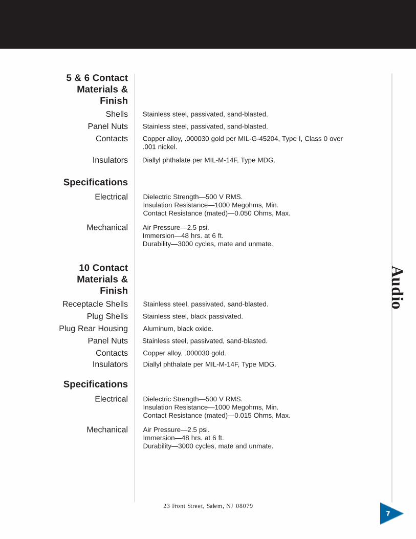
5-Contact Lightweight (Conforms to MIL-C-55116)
GC183SRECEPTACLESpring loaded contacts,solder terminals, mateswith U-229/U, GC217 & GC217A.Other pin stylesavailable.
GC217PLUGRigid contacts, solderterminals, mates withU-183/U, U-228/U & GC183S.
GC217A*PLUGRigid contacts, solderterminals, mates withU-183/U, U-228/U & GC183S.
*Shell material isaluminum.
5-ContactStandard
5-ContactLightweight
U-229/U2.02
NA
GC2171.20
GC217A0.81
U-183/U1.03
GC183S0.72
Weight In Ounces
ÿ.812
.655
1.135
.590/
.580
ÿ
.635/
.625
3 11/16
3/16 OR 1/4 DIA. CABLE
2
Ø.831OVERKNURL
3 11/16
3/16 OR 1/4 DIA. CABLE
2
Ø.831OVERKNURL
AAAAuuuuddddiiiioooo

6-Contact Standard (Conforms to MIL-C-55116)
GC283RECEPTACLESpring loaded contacts,solder terminals, mateswith GC329, GC617 & GC617A.Other pin stylesavailable.
GC328PLUGSpring loaded contacts,solder pin terminals,mates with GC329,GC617 & GC617A.
GC329PLUGRigid contacts, barrel pinterminals,* mates withGC283, GC328 & GC683S.
*Solder pin terminalsalso available.
.665/.655
.760/Ø.750
1/8 MAX. PANELL THICKNESS
51/64MAX.
8/321 MAX.
31/32ØMAX
2 1/4 MAX.
831DIA.
2 1/16 MAX. REF.
23 Front Street, Salem, NJ 080791111
Audio

Audio
WPI General Connector1212
GC529RECEPTACLERigid contacts, solderterminals, mates withGC283, GC328 & GC683S.Also available in 5-pinversion.
GC729RECEPTACLERigid contacts, solderterminals, mates withGC283, GC328 & GC683S.
.831.500 REF.
.779 REF.
.937SQ.
732
MAX.
25/32 MAX.
.775DIA.
'O' RING SEAL
.710 SQ.±.005
.355SQ.
±.005
.615 DIA.±.005 #4-40 UNC-2B
(4) PLACES
MOUNTING HOLE PATTERN
AAAAuuuuddddiiiioooo

6-ContactStandard
6-ContactLightweight
GC3292.01
NA
GC6171.19
GC617A0.80
GC2831.04
GC683S0.73
Weight In Ounces
6-Contact Lightweight (Conforms to MIL-C-55116)
GC683SRECEPTACLESpring loaded contacts,solder terminals, mateswith GC329, GC617 & GC617A.
GC617PLUGRigid contacts, solderterminals,* mates withGC283, GC328 & GC683S.
GC617A**PLUGRigid contacts, solderterminals,* mates withGC283, GC328 & GC683S.
*Also available withbarrel terminals.**Shell material isaluminum.
ÿ.812
.655
1.135
.590/
.580
ÿ.635/.625
3 11/16
3/16 OR 1/4 DIA. CABLE
2
Ø.831OVERKNURL
3 11/16
3/16 OR 1/4 DIA. CABLE
2
Ø.831OVERKNURL
23 Front Street, Salem, NJ 080791313
Audio

Audio
WPI General Connector1414
10-Contact Per MIL-C-10544
U-78/UPLUGNon-rigid, spring loadedcontacts, solderterminals, mates with U-77/U, U-126/U, U-127/U & U-161/U.
U-79/U or GC790RECEPTACLENon-rigid, spring loadedcontacts, solderterminals, mates with U-77/U, U-127/U & U-161/U.
U-126/URECEPTACLERigid contacts, solderterminals, mates withU-78/U.
50∞
15/32
3.0133
AAAAuuuuddddiiiioooo

U-77/UPLUGRigid contacts, solderterminals, mates withU-78/U & U-79/U.
U-127/UPLUGRigid contacts, solderterminals, mates withU-78/U & U-79/U.
U-161/UPLUGRigid contacts, taper pinterminals, mates withU-78/U & U-79/U.
3 13/32
2 1/8
1 19/64
REF. 3.356
Ø.963.959REF.
23 Front Street, Salem, NJ 080791515
Audio

U-T
ype
Multip
urp
ose
WPI General Connector1616
Typical Equip. Application
MT-1029MT-1898
VRC-12OA-3633
AS1729VRC-12CX4742
CX4722CX4722
OA-3633PRC-25PRC-77
General Information The following U-type connectors are used in a great variety of militarycommunications equipment and cable assemblies. Some specific applicationsare listed.
Designation
U-344/VRC
U-345/VRC
U-288/UU-291/UU-290/U*GC290RU-289/UU-393/U
U-316/UU-317/UU-318/U
Military Spec.or Dwg. No.
SC-D-621105
SM-D-414116
MIL-C-55243(EL)
MIL-C-55243(EL)MIL-C-26482
Description
Power receptacle.3 #12, 15 #16 socket contacts.
Power receptacle. 18 pin contacts.17 contactsintegrally filtered (1500 pf).Mates with U-344/VRC.
Medium power plugs and receptacles.12 #20 contacts.GC290R and U-393/U are right angle versionsof U-290/U and U-289/U, respectively.
Medium power plugs and receptacles.14 #20 contacts.
*U-type nomenclature not yet assigned.
UUUU----TTTTyyyyppppeeee MMMMuuuullll tttt iiiippppuuuurrrrppppoooosssseeee

U-344/VRCRECEPTACLE18 socket contacts,mates with U-345/VRC.
U-345/VRCRECEPTACLE18 pin contacts,17 integrally filtered(1500 pf), mates with U-344/VRC.
V
N
F
K
S
M
J
E
H
R P
U
L
DA
T C
B
1.066
4 5/8
1 19/32
2.78 REF.
1.72 REF.
23 Front Street, Salem, NJ 080791717
U-Typ
eM
ultip
urp
ose

U-T
ype
Multip
urp
ose
WPI General Connector1818
UUUU----TTTTyyyyppppeeee MMMMuuuullll tttt iiiippppuuuurrrrppppoooosssseeee
The following are 12-contact medium power, quick disconnect connectors meeting all requirements ofMIL-C-55243(EL), and they intermate.
U-288/URECEPTACLEPin contacts.
U-290/UPLUGSocket contacts.
.780
.776
7/8 -20 UNEF-2A
1.156DIA.
.852
2-3/8 MAX.
1.083MAX.
3/8 DIA.MAX. CABLE

The following are 12-contact medium power, quick disconnect connectors meeting all requirements ofMIL-C-55243(EL), and they intermate.
U-291/URECEPTACLESocket contacts.
U-289/UPLUGPin contacts.
U-393/URT. ANGLE PLUGPin contacts.
.852
.780
.776
7/8-20 UNEF-2A THD
1.156DIA.
L
N
K
H
CB
M
J
E D
A
2-3/8 MAX.
1.083
MAX DIA
3/8 DIA.MAX.
CABLE
1.125MAX.
2.150 MAX.
1.250 MAX.
23 Front Street, Salem, NJ 080791919
U-Typ
eM
ultip
urp
ose

U-T
ype
Multip
urp
ose
WPI General Connector2020
The following are 14-contact medium power, quick disconnect connectors conforming to applicablerequirements of MIL-C-55243(EL) and MIL-C-26482.
U-318/URECEPTACLESocket contacts.
U-316/UPLUGPin contacts.
.751
.745DIA.
.691
.137
.117
2.250 MAX. CLOSED
1.020DIA.
CABLE SIZE.386 DIA. THRU .445 DIA.
UUUU----TTTTyyyyppppeeee MMMMuuuullll tttt iiiippppuuuurrrrppppoooosssseeee

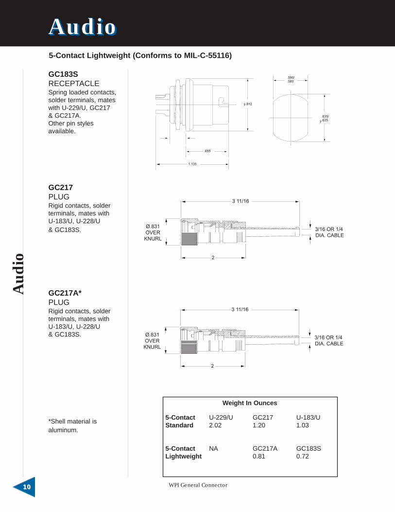
This section contains connectors, shorting plugs and dust caps, whichhave been used over the years in various military communicationsequipment. Specific applications are listed. Your inquiries are requestedfor modifications or variations as needed.
MilitaryDrawing No.
SM-C-447075
SM-C-447102
SM-D-414382
SM-C-447929
SM-B-454855
SM-B-454887
NA
NA
NA
NA
Typical Equip.Application
PRC-25PRC-77
PRC-25PRC-27
VRC-12
PRC-25PRC-77
VRC-12OA-3633
PRC-25PRC-77VRC-12OA-3633
Various
Various
Various
Various
General Information
Part Number
GC075
GC102
GC382
U-317/U
GC855
GC887
GC800
GC864
GC865
GC866
Description
3-contact battery connector with center post.
Antenna connector. Phosphor bronze insert,with spring loaded contact, molded in modifiedpolycholorotrifluoroethylene plastic.
Shorting type plug, 10-contact, 3 contact pairswired together. Mates with MIL-C-26482 #12shell size receptacle, GC07A12-10S.
Shorting type plug, 14-contact, 3 contact pairswired together. Mates with U-318/U.
Dust cap for GC07A12-10S
Dust cap for U-318/U.
Dust cap for 5- and 6-contact audioreceptacles.
Dust cap for 5- and 6-pin contact audio plugs.
Dust cap for 5- and 6-pin contact audio plugs
Dust cap for U-79/U or GC790.
Miscellan
eous
23 Front Street, Salem, NJ 080792121
MMMMiiiisssscccceeeellll llllaaaannnneeeeoooouuuussss
Mis
cella
neo
us
WPI General Connector2222
MMMMiiiisssscccceeeellll llllaaaannnneeeeoooouuuussss
Shorting Plugs
Dust Caps
GC382
U-317/U
GC 800
GC887
GC855 GC864
GC865
GC866

General Information
UW
MWQPL
The UW connectors meet all requirements of MIL-C-12520 for the latestrevision. These connectors are rugged, proven reliable, and are designedfor power and control interconnections. Featured is a center-locking,double-lead screw for maximum reliability, with a fold-down, wing-bladehandle. They are waterproof and can withstand the extreme range ofenvironmental conditions encountered by ground support equipment.
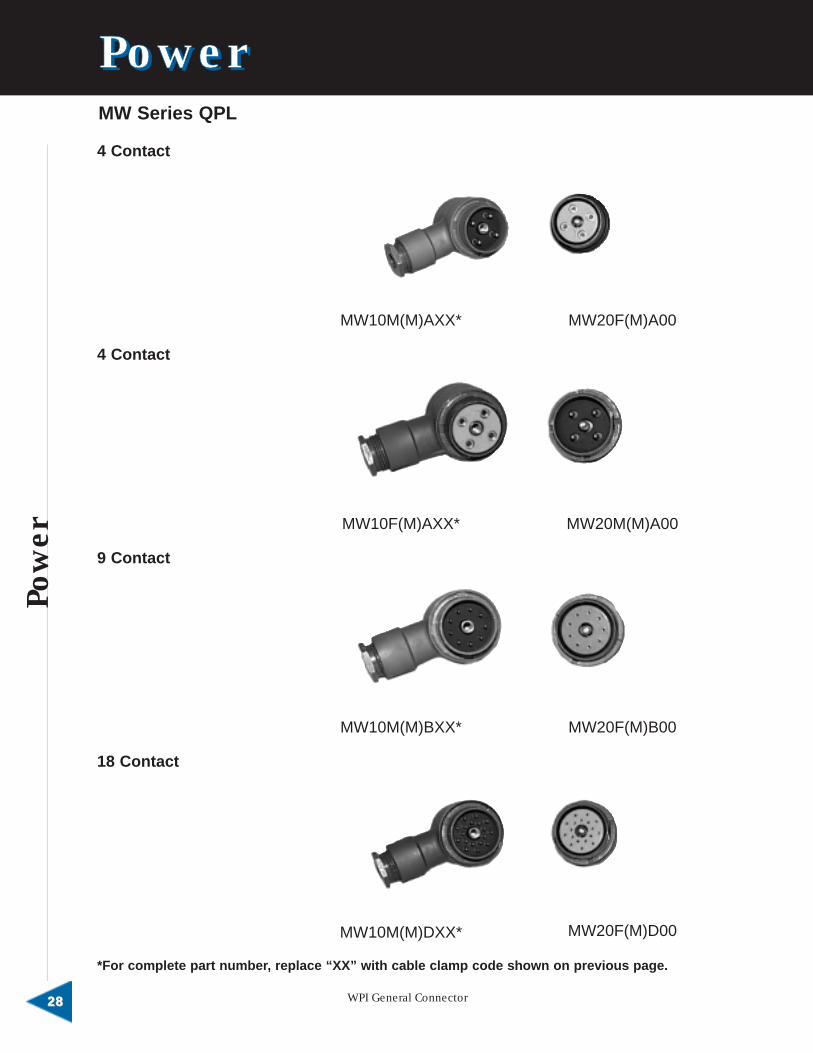
The MW connectors meet all requirements of MIL-C-55181 for the latestrevision. These connectors are similar in construction to the UW series,but provide greater contact density in the 18-pin configuration. These areused exclusively in the U.S. Army’s VRC-12 communication system, aswell as other applications.
Materials &Finish
Aluminum alloy body, steel alloy nosepiece .0003 cadmium plate witholive drab chromate.
Brass, .0003 cadmium plate will olive drab chromate.
High conductivity copper alloy with beryllium copper spring element,.000030 gold over 50-100 nickel.
Yellow brass, .000030 gold over 50-100 nickel.
Glass-filled diallyl phthalate, type GDI-30 F or SDG-F.
Shells
Plugs
Receptacles
Nosepieces
Drawscrews
Contacts
Socket
Pin
Insulators
Alloy steel, .0003 dacmium plate with olive drab chromate.
Stainless steel.
Pow
er
23 Front Street, Salem, NJ 080792323
PPPPoooowwwweeeerrrr

Pow
er
WPI General Connector2424
PPPPoooowwwweeeerrrr
1000 Megohms min. at 500 V DC.
2800 V RMS.
2000 V RMS.
20 MV at 35 A.
21 MV at 20 A.
6 ft., 48 hours.
500 cycles with a coupling torque of 25 in. -lbs.
2.5 psi.
15 lbs.
400 lbs.
QPL
2000 V RMS.
1500 V RMS.
1000 Megohms min. at 500 V DC.
20 MV at 35A.
25 MV at 7.5A.
2.5 psi.
6 ft., 48 hours.
500 cycles with a coupling torque of 12 in. -lbs.
10 lbs.
400 lbs.
UWSpecifications
MWSpecifications
ELECTRICAL
Dielectric Strength
4, 9 & 14 contacts
19 contacts
Insulation Resistance
Voltage Drop
4 contact
9, 18 contact
MECHANICAL
Air Pressure
Water Immersion
Durability
Contact Retention
Insert Strength
ELECTRICAL
Dielectric Strength
4 contact
9, 18 contact
Insulation Resistance
Voltage Drop
4 contact
9, 18 contact
MECHANICAL
Air Pressure
Water Immersion
Durability
Contact Retention
Insert Strength

UW Series
UW1220 Plug
UW1320 Plug
UW1326 Plug
8
2
2.500
.550 INLET
1.458 REF.
A
H
E
F
J
K
D
C
B
1 1/2 MAX.
1 15/16 MAX. REF.
31/32
1 15/16 MAX.CLOSED
1 7/8 MAX.
2.23REF.
23 Front Street, Salem, NJ 080792525
Pow
er

Pow
er
UW Receptacles
WPI General Connector2626
PPPPoooowwwweeeerrrr
1 3/16 MAX.
3/8
1 5/8-18 NEF-2A
1 15/32DIA.
1178-005ACROSS FLATS
+005
1 27/32
DIA.
3/8
1 3/16 MAX.
1 5/8-18 NEF-2A
+005
1153-005
ACROSS FLATS
UW2020Receptacle
UW2026Receptacle

Contact Size
12(.094 diameter)
16(.0625 diameter)
20
Number of Contacts
4
9
14
19
30
Plugs
UW1220MAXXUW1320MAXXUW1220FAXXUW1320FAXX
UW1220MBXXUW1320MBXXUW1220FBXXUW1320FBXX
UW1326MCXXUW1326FCXX
UW1326MDXXUW1326FDXX
UW1326FEXXUW1326MEXX
Mating Receptacles
UW2020FA00
UW2020MA00
UW2020FB00
UW2020MB00
UW2026FC00UW2026MC00
UW2026FD00UW2026MD00
UW2026FE00UW2026ME00
UW Part Numbers
Part Numbers per MIL-C-12520
“M” denotes pin contacts.“F” denotes socket contacts.*For complete part number, replace “XX” with cableclamp code as follows:
CableDiameter(inches)
.292 to .343
.323 to .406
.386 to .468
.448 to .531
.511 to .593
.573 to .656
.636 to .718
.698 to .781
.761 to .843
Cable ClampCode
111315171921232527
ApplicableConnectors byNo. of Contacts
4, 94, 94, 94, 9
4, 9, 14, 19, 304, 9, 14, 19, 30
14, 19, 3014, 19, 3014, 19, 30
23 Front Street, Salem, NJ 080792727
Pow
er
Pow
er
WPI General Connector2828
PPPPoooowwwweeeerrrrMW Series QPL
4 Contact
4 Contact
9 Contact
18 Contact
MW10M(M)AXX* MW20F(M)A00
MW20M(M)A00
MW20F(M)B00
MW20F(M)D00
MW10F(M)AXX*
MW10M(M)BXX*
MW10M(M)DXX*
*For complete part number, replace “XX” with cable clamp code shown on previous page.

GovernmentDesignation
M55181/1-01M55181/1-02M55181/1-03M55181/1-04M55181/1-05M55181/2-01M55181/3-01M55181/3-02M55181/3-03M55181/3-04M55181/3-05M55181/4-01M55181/5-01M55181/5-02M55181/5-03M55181/5-04M55181/6-01M55181/7-01M55181/7-02M55181/7-03M55181/7-04M55181/7-05M55181/8-01
Manufacturer’sDesignation
MW10F(M)A11MW10F(M)A13MW10F(M)A17MW10F(M)A19MW10F(M)A15MW20M(M)A00MW10M(M)A11MW10M(M)A13MW10M(M)A17MW10M(M)A19MW10M(M)A15MW20F(M)A00MW10M(M)B11MW10M(M)B13MW10M(M)B17MW10M(M)B19MW20F(M)B00MW10M(M)D11MW10M(M)D13MW10M(M)D17MW10M(M)D19MW10M(M)D15MW20F(M)D00
Test or QualificationReference
55181-1246-8555181-1246-8555181-1246-8555181-1246-8555181-1246-8555181-1246-8555181-1247-8555181-1247-8555181-1247-8555181-1247-8555181-1247-8555181-1247-8555181-1248-8555181-1248-8555181-1248-8555181-1248-8555181-1248-8555181-1249-8555181-1249-8555181-1249-8555181-1249-8555181-1249-8555181-1249-85
.90 REF.
2.47 REF.
Ø1.44 REF.
2 1/8 MAX.CLOSED
1.450MAX.
1.175±.005ACROSS FLATS
1 15/32DIA.
1 5/64MAX.
1 1/4-18 NEF-2A
3/8
Cable Diameter(inches)
.292 to .343
.323 to .406
.386 to .468
.448 to .531
.511 to .593
Cable ClampCode
1113151719
Substitute cable clamp code for“XX” as required.
MW 10 Plug
MW 20 Receptacle
23 Front Street, Salem, NJ 080792929
Pow
er

Filter
edC
onnec
tors
WPI General Connector3030
WPI General Connector is a leading manufacturer of audio, powerand U-type multipurpose connectors for tactical communicationssystems.
In order to meet the growing demand for cost-effective systems forcontrolling electro-magnetic (EMI) and radio frequency (RFI) interference,WPI General Connector offers an extensive line of filtered connectors, aswell as its special connector design capabilities.
The complete line of WPI filtered connectors now includes: 5- and 6-contact audio connectors, sub-rectangular (MIL-DTL-24308 type)connectors, MIL-C-26482 type connectors and U-type multipurposeconnectors. All are available in fully or selectively loaded configurations.
Used in commercial, industrial and military systems, WPI filteredconnectors are available in both pi-network, and “C-Type” configurations.WPI designs incorporate both tubular capacitors (where each filtersurrounds the pin to be filtered), or planar technology.
5 contact receptacles (GC183F).6 contact receptacles (GC283F).Per MIL-C-55116.Capacitance values: 8,000; 29,000; 32,000 (others available, consultfactory).Low pass/pi-network ferrite-ceramic capacitors.Solder-cup terminals (printed circuit terminals available on request).
Available in five shell sizes:E—9 contacts.A—15 contacts.B—25 contacts.C—37 contacts.D—50 contacts.
● Selective loading: filters, ground contacts and feed-thru contacts.● Four standard filter types: low frequency, mid range frequency,
standard frequency and high frequency (others available, consultfactory).
● Low pass pi-network ferrite-ceramic capacitors.● Solder cup terminals (printed circuit terminals available on request).
GeneralInformation
EMI FilteredConnectors Audio Filtered Connectors
MIL-DTL-24308 Type SeriesSubminiature Rectangular Filtered Connectors
FFFF iiii llll tttteeeerrrreeeedddd CCCCoooonnnnnnnneeeeccccttttoooorrrrssss

● Available in 9 shell sizes: 8, 10, 12, 14, 16, 18, 20, 22, 24.● Full or selective loading: filters, ground contacts and feed-thru
contacts.● Variety of filter types available—consult factory.● Low pass pi-network ferrite-ceramic capacitors—tubular capacitors or
planar technology.● Solder-cup terminals—printed circuit terminals available on request.● Pi-network, and “C-Type” configurations.
EMI FilteredConnectors MIL-C-26482 Type Series Filtered Connectors
Let us review your custom application. With over 30 years of experience,WPI can provide a wide range of services from design engineering tomanufacturing.
Some examples of our custom capabilities include the following:
MIL-C-26482 Type Adapters (For retrofitting over an existing connector,eliminating system shutdown and rework).
Transient Protection Connectors (Example: MIL-C-55116 audioconnector with transient voltage suppressors, capacitors and filterspackaged as integral part of connector).
U-Type Signal Corps Filtered Connectors.
Special Filtered Connectors
23 Front Street, Salem, NJ 080793131
FilteredC
onnecto
rs

Filter
edC
onnec
tors
WPI General Connector3232
FFFF iiii llll tttteeeerrrreeeedddd CCCCoooonnnnnnnneeeeccccttttoooorrrrssssAudio Filtered Connectors, MIL-C-55116 Type
GeneralInformation
Integrally filtered connectors for controlling electromagnetic interference(EMI) are available in various connectors such as the 5- and 6- contactaudio receptacles, U-183/U and GC283, per MIL-C-55116. The filtersused are low-pass, pi-network, ferrite-ceramic capacitors. Each filtersurrounds the pin to be filtered and is connected to a ground-plane builtinto the connector.
Stainless steel, passivated, sand blasted.
Stainless steel, passivated, sand blasted.
Diallyl phthalate per MIL-M-14F, Type MDG.
Air Pressure—2.5 psi.Durability—1500 cycles, mate and unmate.
Dielectric Strength—500 VDC.Insulation Resistance—10,000 Megohms, Min.Contact Resistance (Mated)—0.050 Ohms, Max.
Copper alloy, .000050 gold per MIL-G-45204, Type II, Class 1 over.00010 nickel.
5 Pin Part # GC183F-X-050 GC183F-X-025 GC183F-1-220
6 Pin Part # GC283F-X-050 GC283F-X-025 GC283F-1-220
DielectricWithstanding
Volts500 Volts DC 300 Volts DC 500 Volts DC
Capacitance250C
0.1 VRMS1 KHZ ± 1
5.000 Pf G.M.V. 2500 P.F. ±500 22,000 Pf G.M.V.
Insertion loss(typical) per
MIL-STD-220(250C No load)
50 DB Min.100 MHZ to
10 GHZ
55 DB Min.100 MHZ to
10 GHZ
Attributes Requirements
Working Volts 100 Volts DC
Insulation Res (Min)(250C 200 VDCCharging)Current < 50 MA)
10,000Megohms
Min.
OperatingTemperature Range -550C to + 850C
Specifications5 & 6 Contact
Materials & Finish
Shells
Panel Nuts
Contacts
Insulators
Electrical
Mechanical

.594 DIA
.787
1.405±.010
.810 DIA. .594 DIA.
.787
.810 DIA.
1.2351.230
- - /Part Number Code:
Example: GC183F
Filter Code*1 - “A” Pin Grounded3 - All Pins Filtered4 - “C” & “E” Pins Grounded5 - “E” Pin Grounded
Termination Code*Blank-Solder Cup
Conductor O-RingBlank, Standard O-Ring
Filter Value Code
*Consult factory for other configurations, PC tail dimensions and lengths.
C
Per MIL-C-55116
Insertion Loss (Typical) per MIL-STD-220 (250C, No Load)
0
20
40
60
80
100
120
10 KHZ 100 KHZ 1 MHZ 10 MHZ 100 MHZ 250 MHZ 1.0 GHZ 1.2 GHZ
GC183F-X-025GC283F-X-025
GC183F-X-050GC283F-X-050
GC183F-X-220GC283F-X-220
FREQUENCY (MHZ)
INS
ER
TIO
N L
OS
S (
dB
)
23 Front Street, Salem, NJ 080793333
FilteredC
onnecto
rs

Filter
edC
onnec
tors
WPI General Connector3434
FFFF iiii llll tttteeeerrrreeeedddd CCCCoooonnnnnnnneeeeccccttttoooorrrrssss
Typicalinsertion lossper MIL-STD-200 at 250 withno appliedvoltage orcurrent
GeneralInformation
● Cost effective way of solving EMI problems.● Used in both military and commercial applications to help equipment
meet FCC (Docket 20780, Class A & B) and military MIL-STD 461requirements.
● Compatibility with RS-232 and RS-449; will mount in existing chassishole patterns.
● Four standard filter types, plus a number of optional types and valuesavailable on request.
● Selective loading of connectors to include different filter values,ground contacts and feed-thru contacts.
● Special requirements including modifications to shells and filtersavailable on request.
Available Filter
Attenuation (db)
Filter Type
Voltage Rating (Working)
Current Rating (AMP DC)
Insulation Resistance, 2 Min.Electrification Time Max. at250C & 100 VDC
DWV, Sea Level, W/500Micro-Amps Max,Charge/Discharge
Capacitance at 1 KHz,0.1 Vrms Picofarads
50,000Minimum
4,00012,000
2,3005,000
5001,300
10,000 Megohms Minimum
500 VDC
1000MegohmsMinimum
300 VDC
Low Freq.
Freq. MHz
L
100 VDC
M
200 VDC
5.0
T H
Mid. Freq. Std. Freq. High Freq.
0.11210100
500 to 10,000
2-615 min.20 min.35 min.50 min.50 min.
2-65 min.15 min.50 min.55 min.
2-69 min.50 min.55 min.
2-630 min.50 min.
MIL-DTL-24308 Type Series Filtered Connectors
SubminiatureRectangularAvailable in shell sizesand insert arrangements:E - 9 contactsA - 15 contactsB - 25 contactsC - 37 contactsD - 50 contacts
Materials &Finishes
ContactsCopper alloy.
Shell, FrontSteel (standard).Brass (NM versions).
Shell, RearDie cast aluminum.
InsulatorsDiallyl phthalate.
Ground PlanePhoto-etched copperalloy.
FinishContacts
Gold plate.Shell, Front
Tin plate.Shell, Rear
Tin plate.Insulators
None.
Specifications: Electrical Characteristics
0
20
40
60
80
100
GJ Series 'L FilterGJ Series 'M' Filter
GJ Series 'T" Filter
GJ Series 'H Filter
10 KHZ 100 KHZ 1 MHZ 10 MHZ 100 MHZ 1.0 GHZ
FREQUENCY (MHZ)
INS
ER
TIO
N L
OS
S (
dB
)
TypicalInsertionLoss/Frequency

G J
MIL-DTL-24308 Type Series Filtered Connectors
1.045 REF.
J
H .080/.050
G
F10∞ TYP.
E D
A
C
K
B
ÿ.125/.115 TYP. 10∞
L
SubminiatureRectangular
Dimensions - Standard Line (Custom sizes also available. Consult factory)
Part Number Code(example) G B J 25 T P NM
Series Prefix:G - Subminiature Rectangular,solder termination
Shell Size:E, A, B, C, D
Filter Indicator:J - filtered connector
Contact Arrangement:9, 15, 25, 37, 50
Filter Type:L - low frequencyM - mid-range frequencyT - standard frequencyH - high frequency(Others available. Consult factory).
Contact Type:P - pin contactsS - socket contacts
Terminations:Solder cup (blank space).PCB terminals (Consult factory).
Non-Magnetic Version: (NM)
A± .015
1.213
1.213
1.541
1.541
2.087
2.087
2.729
2.729
2.635
2.635
B± .005
.643
.971
1.511
2.159
2.064
C± .005
.984
.984
1.312
1.312
1.852
1.852
2.500
2.500
2.406
2.406
D± .005
.311
.311
.311
.311
.423
E± .015
.494
.494
.494
.494
.494
.494
.494
.494
.605
.605
F± .010
.816
.816
1.144
1.144
1.683
1.683
2.332
2.332
2.237
2.237
G± 0.10
.456
.456
.456
.456
.456
.456
.456
.456
.573
.573
H± .010
.234
.243
.234
.243
.230
.243
.230
.243
.230
.243
J± .010
.950
.958
.950
.958
.954
.958
.954
.958
.954
.958
K± 005
.666
.994
1.534
2.182
2.079
L± 005
.329
.329
.329
.329
.436
Part Numberby Shell Size
GEJ-9P
GEJ-9S
GAJ-15P
GAJ-15S
GBJ-25P
GBJ-25S
GCJ-37P
GCJ-37S
GDJ-50P
GDJ-50S
G B J 25 T P NM
-
23 Front Street, Salem, NJ 080793535
FilteredC
onnecto
rs

Filter
edC
onnec
tors
WPI General Connector3636
FFFF iiii llll tttteeeerrrreeeedddd CCCCoooonnnnnnnneeeeccccttttoooorrrrssss
GeneralInformation
● Available in 8 shellsizes and a variety ofinsert arrangements:8, 10, 12, 14, 16, 18,20, 22.
● Full or selectiveloading: filters,ground contacts andfeed-thru contacts.
● Variety of filter typesavailable. Consultfactory.
● Low pass pi-networkferrite-ceramiccapacitors—tubularcapacitors or planartechnology.
● Solder-cupterminals—printedcircuit terminals,available on request.
● Pi-network, and “C-Type” configurations.
NOTE: Selective loading ofconnectors, including abroad range of filtervalues, ground contactsand feed-thru contacts,is a common requestfrom WPI GeneralConnector customers.We provide this customservice without the longlead times offered byother connectorcompanies.
MIL-C-26482 Type Series Filtered Connectors
Typical Filter Characteristics*
Attributes Requirements
Capacitance250C, 0.1 VRMS1 KHZ ± .1
5,000 Pf GMV 600 Pf GMV .22 uf GMV
Working Volts
Dielectric Withstanding Volts
200 VDC 100 VDC 50 VDC
500 VDC 250 VDC 150 VDC
Insulation Res. (Min.)(250C 200 VDC Charging)Current < 50 MA
Insertion loss (typical) perMIL-STD-220 (250C, no load)1 MHZ10 MHZ100 MHZ1 GHZ
2 db15 db50 db60 db
—2-6 db30 db50 db
28 db45 db55 db70 db
5,000 Megohms
R.F. Current (Max.)
Operating Temperature Range
Thermal Shock
0.25 Amperes
-550C to +1250C
Method 102A Cond. D Per MIL-STD 202(-550C to +1050C)
*Other filters available upon request
0
20
40
60
80
100
1 - 5000 Pf GMV
2 - 600 Pf GMV
3 - .22 uf GMV(consult factory foroptions)
10 KHZ 100 KHZ 1 MHZ 10 MHZ 100 MHZ 1.0 GHZ
FREQUENCY (MHZ)
INS
ER
TIO
N L
OS
S (
dB
)
Typical Insertion Loss/Frequency
MIL-C-26482 Type Series Filtered Connectors
ShellSize
8
10
12
14
16
18
20
22
24
A Dim.± .010
.812
.938
1.031
1.125
1.219
1.312
1.438
1.562
1.688
B (TP)
.594
.719
.812
.906
.969
1.062
1.156
1.250
1.375
C Dia.+ .001-.005
.473
.590
.750
.875
1.000
1.125
1.250
1.375
1.500
D Dia.+.011-.000
.438
.562
.688
.812
.938
1.062
1.188
1.312
1.438
E Max.
1.103
1.103
1.103
1.103
1.103
1.103
1.166
1.166
1.166
F Dim.± .015
0.62
0.62
0.62
0.62
0.62
0.62
.094
0.94
0.94
G Dim.+.020-.000
.431
.431
.431
.431
.431
.431
.556
.556
.589
H Dim.Max.
.810
.810
.810
.810
.810
.810
.715
.715
.682
J Dia.
.120
.120
.120
.120
.120
.120
.120
.120
.147
Conn.Size
8
10
12
14
16
18
20
22
24
A Dim.Max.
.954
1.078
1.266
1.391
1.516
1.641
1.828
1.954
2.078
B Dim.±.005
.525
.650
.813
.937
1.061
1.186
1.311
1.436
1.561
C Dia.+ .001-.005
.473
.590
.750
.875
1.000
1.125
1.250
1.375
1.500
D Dim.±.010
.705
.705
.705
.705
.705
.705
.894
.894
.927
E TH’DUNEF-2A
.5625-24
.6875-24
.875-20
1.000-20
1.125-18
1.250-18
1.375-18
1.500-18
1.625-18
F Dia.Max.
.500
.600
.720
.850
1.000
1.100
1.225
1.350
1.500
G Dim.Max.
.650
.650
.650
.650
.650
.650
.650
.650
.650
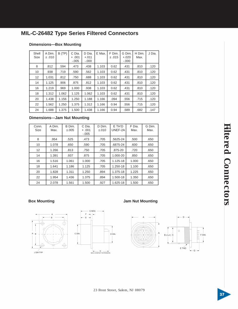
Dimensions—Box Mounting
Dimensions—Jam Nut Mounting
A
A
C
D
F DIA.
GE THD
B (FLAT)BA
B
A
J DIA TYP
C DIA.
G
F
E MAX.
HMAX (CONTACT EXTENSION)
D DIA.
Box Mounting Jam Nut Mounting
23 Front Street, Salem, NJ 080793737
FilteredC
onnecto
rs

Filter
ed
WPI General Connector3838
FFFF iiii llll tttteeeerrrreeeedddd CCCCoooonnnnnnnneeeeccccttttoooorrrrssss
GC 26
Part Number Code(example) GC 26 02 1 16-26 P
Series Prefix:GC
Filtered Series:26 Code
Mounting Configuration:02-box mount07-jam nut
Contact Arrangement:9, 15, 25, 37, 50
Filter Type:1-5000 PF GMV2-600 Pf GMV3-.22Pf GMV(consult factory for options).
Shell Size and InsertArrangement:(example: 16-26, consultfactory).
Contact Type:P-pin contactsS-socket contacts
Insert Position:(blank)-normal
GC 26 02 1 16 26 P
-
Ordering Information
WPI General Connector manufactures a line of filtered adapters whichincorporate all of the features of the 26482 series filtered connectors.They are available in many shell sizes, insert arrangements and filteringoptions. They are extremely useful for retrofitting over an existingconnector in a system, thus eliminating costly system shutdown andrework.
WPI General Connector has been supplying Signal Corps Connectors,both STD and filtered, for over 20 years. There is no need to doextensive vendor research the next time you require that “special” SignalCorps Connector.
WPI General Connector supplies Transient Protection Connectors, whichincorporate standard 5- and 6-pin audio connectors, conforming to MIL-C-55116, and discreet transient voltage suppressors, capacitors and filtersneatly packaged as an integral part of the connector. We welcome theopportunity to review your custom application.
Special Filtered Connector Series
26482 FilteredAdapters
U-TypeSignal Corps
FilteredConnectors
TransientProtection
Connectors


WPI General ConnectorA Division of WPI Interconnect Products
23 Front StreetSalem, NJ 08079
P: 856-935-7560; F: 856-935-0102; E: [email protected]: www.wpi-interconnect.com