Embed Size (px)
Citation preview

I. Previously on IET

© Tallal Elshabrawy 2
Basic Blocks of Digital Communications
Source of continuous-time
(i.e., analog) message signal
Low pass Filter
Sampler Quantizer Encoder Band Pass Modulated Signal
Analog-to-Digital Converter
m-ary SymbolEncoder
Transmitting Filter
Modulation

© Tallal Elshabrawy 3
Time-Limited Signal = Frequency Unlimited Spectrum
TS0
Fourier Transfor
m
It is desirable for transmitted signals to
be band-limited (limited frequency
spectrum)
Guarantee completely
orthogonal channels for pass-band signals
WHY?
Square Pulse is a Time-Limited Signal
1/TS 2/TS 3/TS-1/TS-2/TS-3/TS
0
© Tallal Elshabrawy 4
Inter-symbol Interference (ISI)
Sampling Instants
yk(t) yk(iTS)
Frequency Limited Spectrum=Time-Unlimited Signals
A time unlimited signal means inter-symbol interference (ISI)
Neighboring symbols affect the measured value and the corresponding decision at sampling instants
© Tallal Elshabrawy 5
Nyquist Criterion for No ISI
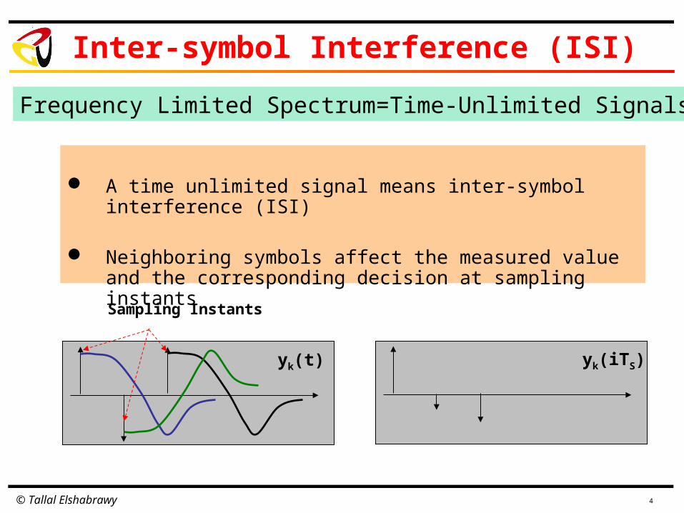
For a given symbol transmitted at iTS
S
A k=1z kT
0 o/w
Transmitting Filter g(t)
sk(t)
+
wk(t)
Receiving Filter g (TS-
t)
xk(t)yk(t)
yk(TS)ku
Sample at t=TS
Assume AWGN Noise wk(t) is negligible
Transmitting Filter g(t)
Receiving Filter g (TS-
t)
yk(t) yk(TS)
Sample at t=TS
z(t)=g(t)* g(TS-t)
ku

© Tallal Elshabrawy 6
z(t): Impulse
Response
Z(f): Spectrum(Transfer Function)
T: symbol interval
RS: symbol rater: roll-off factor
Z(f)
Raised Cosine Filter Bandwidth = RS(1+r)/2
Pulse-shaping with Raised-Cosine Filter
© Tallal Elshabrawy 7
Examples
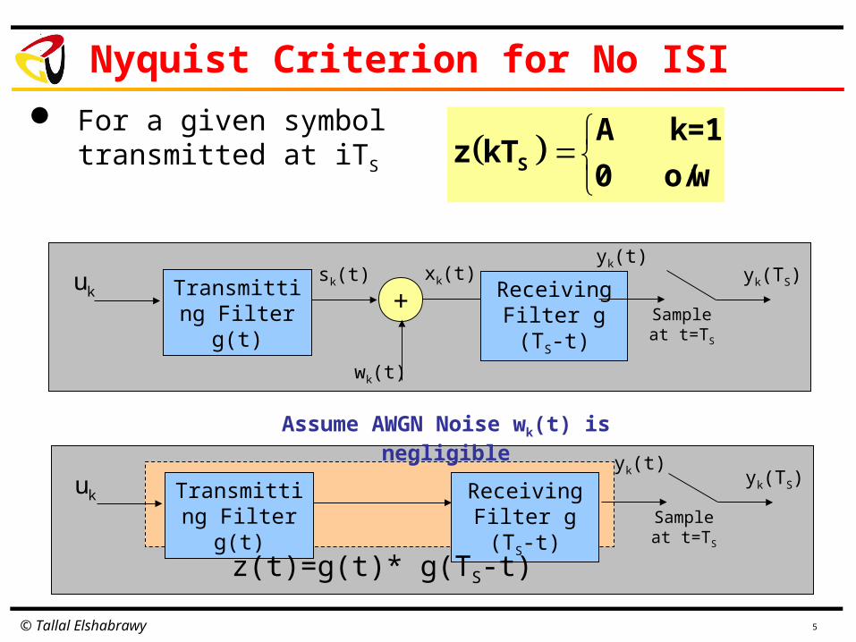
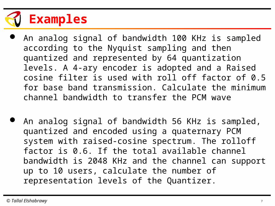
An analog signal of bandwidth 100 KHz is sampled according to the Nyquist sampling and then quantized and represented by 64 quantization levels. A 4-ary encoder is adopted and a Raised cosine filter is used with roll off factor of 0.5 for base band transmission. Calculate the minimum channel bandwidth to transfer the PCM wave
An analog signal of bandwidth 56 KHz is sampled, quantized and encoded using a quaternary PCM system with raised-cosine spectrum. The rolloff factor is 0.6. If the total available channel bandwidth is 2048 KHz and the channel can support up to 10 users, calculate the number of representation levels of the Quantizer.

© Tallal Elshabrawy 8
Phase Shift Keying (PSK) Modulation
1 0 1 1 0 1Base band Signal
X(t)
Band Pass SignalY(t)
X(t) x Y(t)
cos(2πfct)c cj2πf t j2πf te e
2

© Tallal Elshabrawy 9
PSK Demodulation
X(t)cos(2πfct)x
2cos(2πfct)
X(t)[2cos2(2πfct)]
Low Pass Filter X(t)
X(t)[2cos2(2πfct)] =X(t)[1+cos(4πfct)]
X(t)[2cos2(2πfct)]=X(t) +X(t)cos(4πfct)]
Base band Signal(i.e., low frequency content)
High frequency content

© Tallal Elshabrawy 10
Orthogonality of sin and cos Functions
X(t)cos(2πfct)
x
2sin(2πfct)
X(t)[2sin(2πfct)cos(2πfct)]
Low Pass Filter 0
X(t)[2sin(2πfct)cos(2πfct)]=X(t) sin(4πfct)]
High frequency content

© Tallal Elshabrawy
XI(t)
x
cos(2πfct)
XI(t)cos(2πfct)
XQ(t)
x
sin(2πfct)
XQ(t)sin(2πfct)
+Y(t)
Serial-to-
Parallel
X(t)
Quadrature- PSK Modulation (QPSK)
11

© Tallal Elshabrawy 12
QPSK Demodulation
x Low Pass FilterXI(t)
xXQ(t)
Y(t) Parallel-to-Serial
X(t)
Low Pass Filter
2cos(2πfct)
2sin(2πfct)
© Tallal Elshabrawy
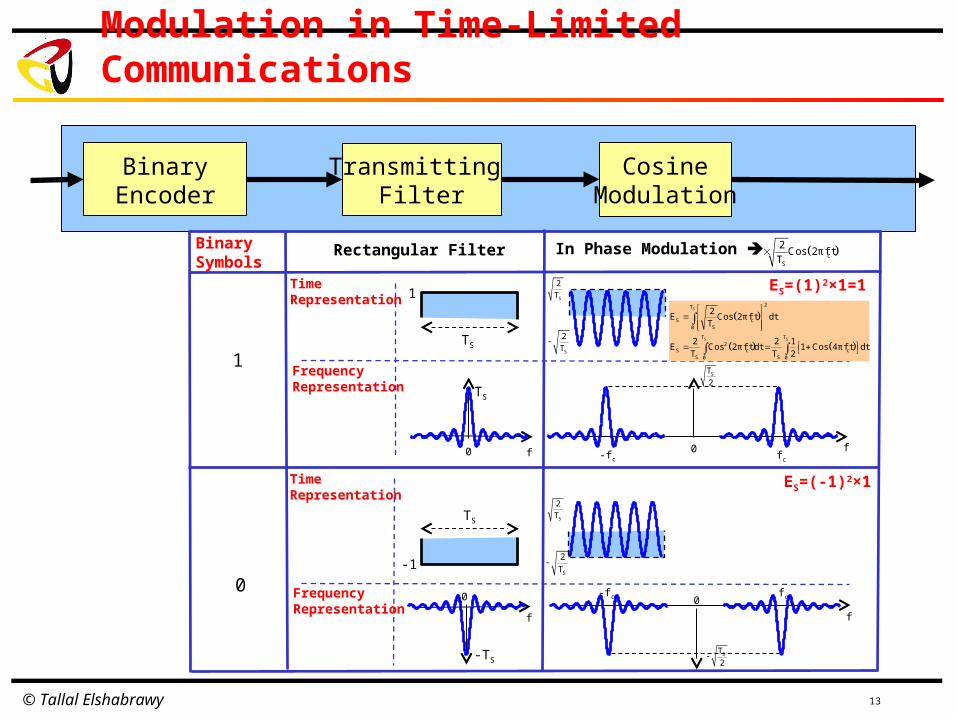
Modulation in Time-Limited Communications
13
BinaryEncoder
Transmitting Filter
CosineModulation
1
0
TS
Time Representation
Frequency Representation
1 ES=(1)2×1=1
cS
2Cos 2πf t
TBinary
Symbols
Time Representation
Frequency Representation
Rectangular Filter In Phase Modulation
0
TS
f 0 ffc-fc
TS
-1
0
-TS
f
0
f
fc-fc
S
S S
2T
S cS0
T T2
S c cS S0 0
2E Cos 2πf t dt
T
2 2 1E Cos 2πf t dt 1 Cos 4πf t dt
T T 2
ES=(-1)2×1
S
2
T
S
2
T
S
2
T
S
2
T
ST
2
ST
2

© Tallal Elshabrawy
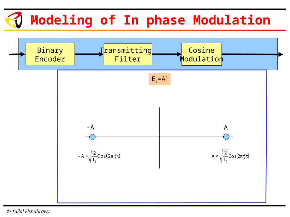
Modeling of In phase Modulation
BinaryEncoder
Transmitting Filter
CosineModulation
cS
2A Cos 2πf t
T
A-A
cS
2A Cos 2πf t
T
ES=A2
© Tallal Elshabrawy
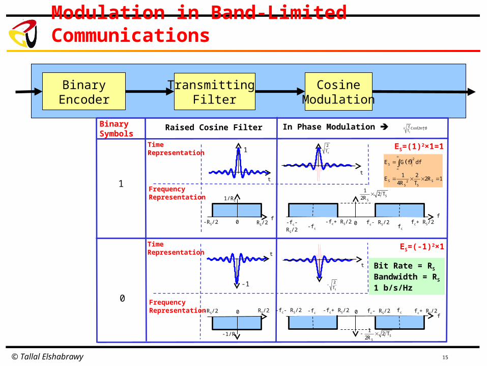
Modulation in Band-Limited Communications
15
BinaryEncoder
Transmitting Filter
CosineModulation
1
0
Time Representation
Frequency Representation 1/RS
ES=(1)2×1=1
Binary Symbols
Time Representation
Frequency Representation
Raised Cosine Filter
0fc-fc
ES=(-1)2×1
1
t
fRS/2-RS/2 fc+ RS/2-fc- RS/2
f
SS
12 T
2R
In Phase Modulation
t
S
2
T
t
-1
cS
2Cos 2πf t
T
S
2
T
t
fc- RS/2-fc- RS/2f
fc fc+ RS/2-fc -fc+ RS/2 0
SS
12 T
2R
0
0-RS/2 RS/2
-1/RS
2
S
S S2S S
E G f df
1 2E 2R 1
4R T
Bit Rate = RS
Bandwidth = RS
1 b/s/Hz
-fc+ RS/2 fc- RS/2
© Tallal Elshabrawy
Modeling of In phase Modulation
BinaryEncoder
Transmitting Filter
CosineModulation
( )tfπ2CosT2
×A cS
A-A
cS
2A Cos 2πf t
T
ES=A2

© Tallal Elshabrawy
Modulation in Time-Limited Communications
17
BinaryEncoder
Transmitting Filter
SineModulation
1
0
TS
Time Representation
Frequency Representation
1 ES=(1)2×1=1
( )tfπ2SinT2
× cS
Binary Symbols
Time Representation
Frequency Representation
Rectangular Filter In Quadrature Modulation
0
TS
f
0
f
fc
-fc
TS
-1
0
-TS
f
S
2T
S cS0
2E Sin 2πf t dt
T
ES=(-1)2×1
-fc
fc
f0
ST2
S
2
T
ST2
S
2
T
S
2j
T
S
2j
T
ST2
j
S
2j
T

© Tallal Elshabrawy
Modeling of In phase Modulation
BinaryEncoder
Transmitting Filter
SineModulation
( )tfπ2SinT2
×A cS
jA
-jA cS
2A Sin 2πf t
T
ES=A2

© Tallal Elshabrawy
Modulation in Band-Limited Communications
19
BinaryEncoder
Transmitting Filter
SineModulation
1
0
Time Representation
Frequency Representation 1/RS
ES=(1)2×1=1
Binary Symbols
Time Representation
Frequency Representation
Raised Cosine Filter
0
fc
-fc
ES=(-1)2×1
1
t
fRS/2-RS/2
fc+ RS/2
-fc- RS/2f
SS
T2×R21
j
t
ST2
t
-1S
2
T
t
fc- RS/2
-fc- RS/2f
fc fc+ RS/2
-fc -fc+ RS/2 0
SS
1j 2 T2R
0
0-RS/2 RS/2
-1/RS
2
S
S S2S S
E G f df
1 2E 2R 1
4R T
Bit Rate = RS
Bandwidth = RS
1 b/s/Hz
fc- RS/2
-fc+ RS/2
SS
1j 2 T2R
SS
T2×R21
j
( )tfπ2SinT2
× cS
In Quadrature Modulation

© Tallal Elshabrawy
Modeling of In phase Modulation
BinaryEncoder
Transmitting Filter
SineModulation
( )tfπ2SinT2
×A cS
jA
-jA cS
2A Sin 2πf t
T
ES=A2

© Tallal Elshabrawy
Modulation Constellations
21
BPSK QPSK
8-QPSK 16 QAM
1 b/s/Hz 2 b/s/Hz
4 b/s/Hz3 b/s/Hz
SE
( )2/E,2/E SS S SE / 2, E / 2
S SE / 2, E / 2 S SE / 2, E / 2
( )0,ES SE ,0
( )2/E,2/E SS S SE / 2, E / 2
S SE / 2, E / 2 S SE / 2, E / 2
( )SE,0
S0, E
SE

© Tallal Elshabrawy
Basic Communication Model in AWGN
Detection Performance: Correct Detection
S = S*
Erroneous Detection S ≠ S*
+S
N
Channel Model
R=S+N
TXR
RX DetectionS*

© Tallal Elshabrawy
BPSK Modulation over AWGN Channels
( )tfπ2CosT2
×E cS
S S cS
2E Cos 2πf t
T
ES Energy per Symbol S SS E , E
SESE

© Tallal Elshabrawy
BPSK Modulation over AWGN Channels
Gaussian Noise
2
2
n
2σN 2
1f n e
2πσ
N ,
0

© Tallal Elshabrawy
Received signal distribution given transmitted
BPSK Modulation over AWGN Channels
R , SE
0
2S
2
S
r E
2σR E 2
1f r e
2πσ
SESE

© Tallal Elshabrawy
BPSK Modulation over AWGN Channels
Error Calculation given transmitted] [∞,∞R -∈SE
0
SESE
S
Se EP Pr r 0 Pr n E
2S
2
S
E n
2σe E 2
1P e dn
2πσ
2z
2
x
1Q x e dz
2π
2 2S
2 2
S
E n n
2σ 2σ
2 2E
1 1e dn = e dn
2πσ 2πσ
Symmetry of Gaussian Distribution
Let S
S
Enz ,n E z ,dn σdz
σ σ
2 2
S
S S
z z22 2
Se E 2E σ E σ
σ 1P e dz e dz Q E σ
2π2πσ
1Q x erfc x 2
2
S
2Se E
1P erfc E 2σ
2
2S
2
S
r E
2σR E 2
1f r e
2πσ

© Tallal Elshabrawy
Received signal distribution given transmitted
BPSK Modulation over AWGN Channels
SE-
0
2S
2
S
r E
2σR E 2
1f r e
2πσ
SESE
] [∞,∞R -∈

© Tallal Elshabrawy
BPSK Modulation over AWGN Channels
Error Calculation given transmittedSE-
0
SESE-
S
Se EP Pr r 0 Pr n E
2
2
S
S
n
2σe - E 2
E
1P e dn
2πσ
Let S
S
Enz ,n E z ,dn σdz
σ σ
2 2
S
S S
z z22 2
Se - E 2E σ E σ
σ 1P e dz e dz Q E σ
2π2πσ
S
2Se E
1P erfc E 2σ
2
2S
2
S
r E
2σR E 2
1f r e
2πσ
] [∞,∞R -∈
2z
2
x
1Q x e dz
2π
1Q x erfc x 2
2

© Tallal Elshabrawy
BPSK Modulation over AWGN Channels
Signal Power & Symbol Error Performance
SE SE
0
S eE P

© Tallal Elshabrawy
BPSK Modulation over AWGN Channels
Signal Power & Symbol Error Performance
SE SE
0
2eσ P

© Tallal Elshabrawy
BER of PSK over AWGN Channels
Notes: Define N0 Total Noise Power
N0/2 Noise Power over Cosine axis, i.e., σ2=N0/2
Each symbol corresponds to a single bit Eb = ES
Pb = Pe
S S
e S Se E e E
2 2 2e S S S
P Pr E P Pr E P
1 1 1 1 1P erfc E 2σ erfc E 2σ erfc E 2σ
2 2 2 2 2
( )0bb NEerfc21
=P