Embed Size (px)
Citation preview
Flight Guidance Panel / Flight Guidance Panel / AutomationAutomation
FamiliarizationFamiliarization
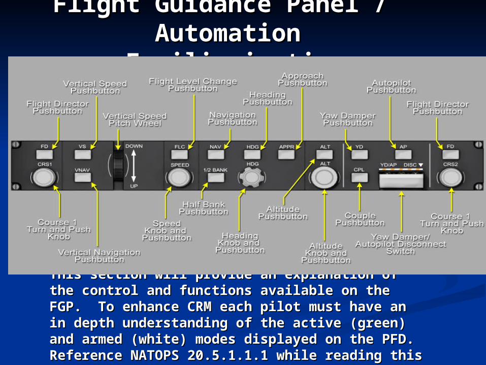
This section will provide an explanation of the This section will provide an explanation of the control and functions available on the FGP. To control and functions available on the FGP. To enhance CRM each pilot must have an in depth enhance CRM each pilot must have an in depth understanding of the active (green) and armed understanding of the active (green) and armed (white) modes displayed on the PFD. Reference (white) modes displayed on the PFD. Reference NATOPS 20.5.1.1.1 while reading this section.NATOPS 20.5.1.1.1 while reading this section.
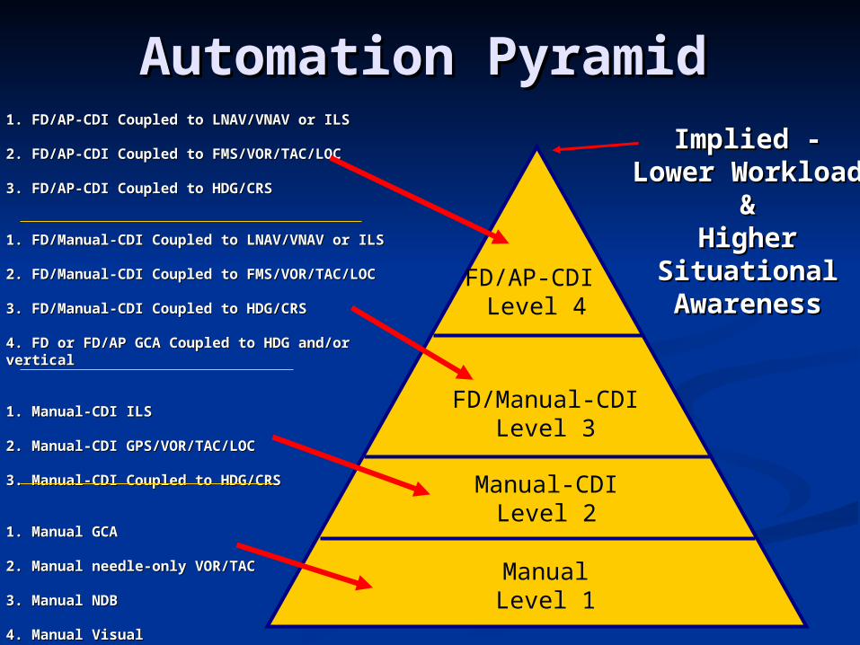
Automation PyramidAutomation Pyramid1. FD/AP-CDI Coupled to LNAV/VNAV or ILS1. FD/AP-CDI Coupled to LNAV/VNAV or ILS
2. FD/AP-CDI Coupled to FMS/VOR/TAC/LOC2. FD/AP-CDI Coupled to FMS/VOR/TAC/LOC
3. FD/AP-CDI Coupled to HDG/CRS3. FD/AP-CDI Coupled to HDG/CRS
1. FD/Manual-CDI Coupled to LNAV/VNAV or ILS1. FD/Manual-CDI Coupled to LNAV/VNAV or ILS
2. FD/Manual-CDI Coupled to FMS/VOR/TAC/LOC2. FD/Manual-CDI Coupled to FMS/VOR/TAC/LOC
3. FD/Manual-CDI Coupled to HDG/CRS3. FD/Manual-CDI Coupled to HDG/CRS
4. FD or FD/AP GCA Coupled to HDG and/or vertical 4. FD or FD/AP GCA Coupled to HDG and/or vertical
1. Manual-CDI ILS1. Manual-CDI ILS
2. Manual-CDI GPS/VOR/TAC/LOC2. Manual-CDI GPS/VOR/TAC/LOC
3. Manual-CDI Coupled to HDG/CRS3. Manual-CDI Coupled to HDG/CRS
1. Manual GCA1. Manual GCA
2. Manual needle-only VOR/TAC2. Manual needle-only VOR/TAC
3. Manual NDB3. Manual NDB
4. Manual Visual4. Manual Visual
FD/AP-CDI Level 4
FD/Manual-CDILevel 3
Manual-CDILevel 2
ManualLevel 1
Implied - Implied - Lower Lower
Workload &Workload &Higher Higher
Situational Situational AwarenessAwareness
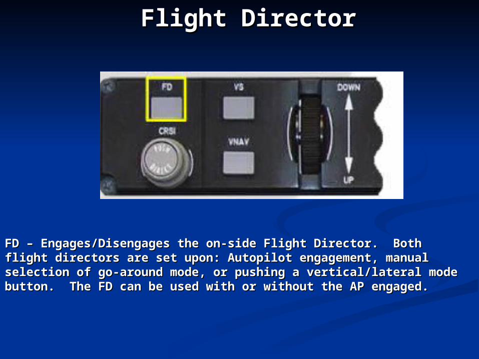
FD – Engages/Disengages the on-side Flight Director. Both flight FD – Engages/Disengages the on-side Flight Director. Both flight directors are set upon: Autopilot engagement, manual selection of directors are set upon: Autopilot engagement, manual selection of go-around mode, or pushing a vertical/lateral mode button. The FD go-around mode, or pushing a vertical/lateral mode button. The FD can be used with or without the AP engaged.can be used with or without the AP engaged.
Flight DirectorFlight Director
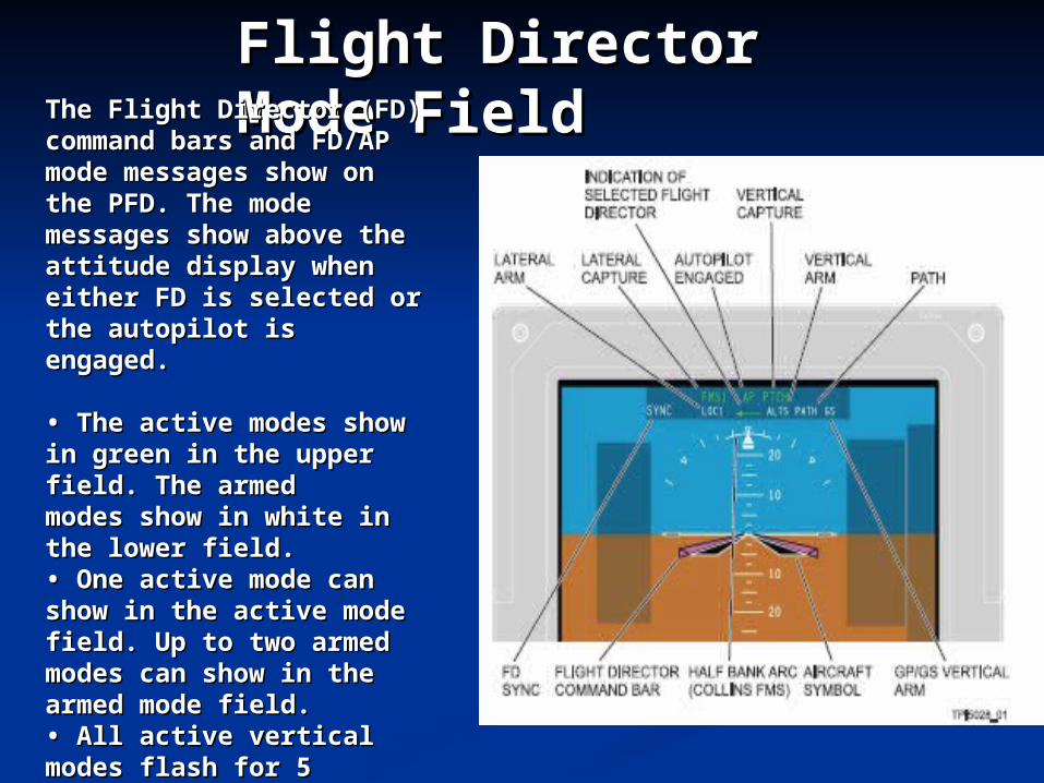
Flight Director Flight Director Mode FieldMode FieldThe Flight Director (FD) The Flight Director (FD)
command bars and FD/AP command bars and FD/AP mode messages show on mode messages show on the PFD. The mode the PFD. The mode messages show above the messages show above the attitude display when attitude display when either FD is selected or either FD is selected or the autopilot is engaged. the autopilot is engaged.
• • The active modes show The active modes show in green in the upper in green in the upper field. The armedfield. The armedmodes show in white in modes show in white in the lower field.the lower field.• • One active mode can One active mode can show in the active mode show in the active mode field. Up to two armed field. Up to two armed modes can show in the modes can show in the armed mode field.armed mode field.• • All active vertical All active vertical modes flash for 5 seconds modes flash for 5 seconds when they first come into when they first come into view, and then show view, and then show steady.steady.
Transfer flight guidance Transfer flight guidance between left and right sidebetween left and right side
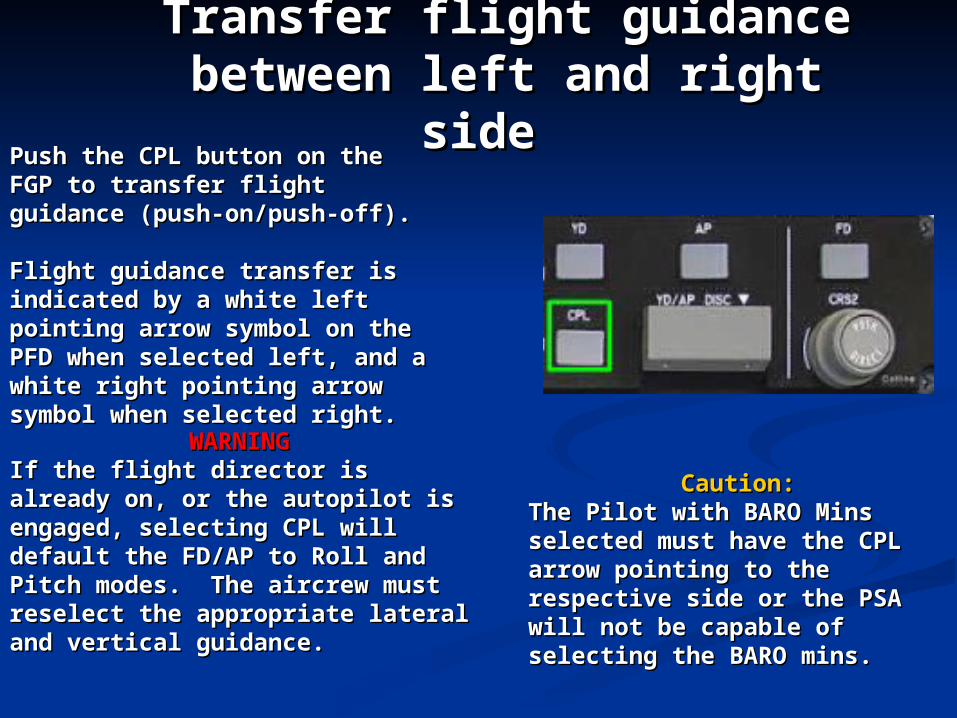
Push the CPL button on the Push the CPL button on the FGP to transfer flight guidance FGP to transfer flight guidance (push-on/push-off).(push-on/push-off).
Flight guidance transfer is Flight guidance transfer is indicated by a white left indicated by a white left pointing arrow symbol on the pointing arrow symbol on the PFD when selected left, and a PFD when selected left, and a white right pointing arrow white right pointing arrow symbol when selected right.symbol when selected right.
Caution:Caution:The Pilot with BARO Mins The Pilot with BARO Mins selected must have the CPL selected must have the CPL arrow pointing to the arrow pointing to the respective side or the PSA will respective side or the PSA will not be capable of selecting the not be capable of selecting the BARO mins.BARO mins.
WARNINGWARNINGIf the flight director is already on, If the flight director is already on, or the autopilot is engaged, or the autopilot is engaged, selecting CPL will default the selecting CPL will default the FD/AP to Roll and Pitch modes. FD/AP to Roll and Pitch modes. The aircrew must reselect the The aircrew must reselect the appropriate lateral and vertical appropriate lateral and vertical guidance.guidance.
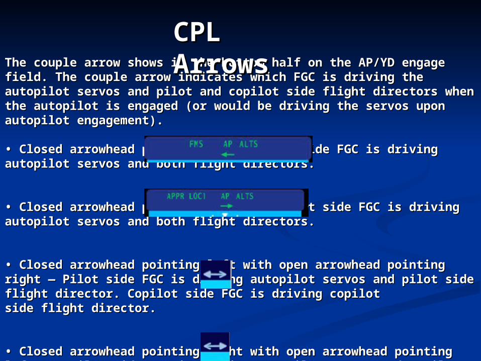
The couple arrow shows in the bottom half on the AP/YD engage The couple arrow shows in the bottom half on the AP/YD engage field. The couple arrow indicates which FGC is driving the autopilot field. The couple arrow indicates which FGC is driving the autopilot servos and pilot and copilot side flight directors when the autopilot is servos and pilot and copilot side flight directors when the autopilot is engaged (or would be driving the servos upon autopilot engagement). engaged (or would be driving the servos upon autopilot engagement).
• • Closed arrowhead pointing left — Pilot side FGC is driving autopilot Closed arrowhead pointing left — Pilot side FGC is driving autopilot servos and both flight directors.servos and both flight directors.
• • Closed arrowhead pointing right — Copilot side FGC is driving Closed arrowhead pointing right — Copilot side FGC is driving autopilot servos and both flight directors.autopilot servos and both flight directors.
• • Closed arrowhead pointing left with open arrowhead pointing right Closed arrowhead pointing left with open arrowhead pointing right — Pilot side FGC is driving autopilot servos and pilot side flight — Pilot side FGC is driving autopilot servos and pilot side flight director. Copilot side FGC is driving copilotdirector. Copilot side FGC is driving copilotside flight director.side flight director.
• • Closed arrowhead pointing right with open arrowhead pointing left Closed arrowhead pointing right with open arrowhead pointing left — Copilot side FGC is driving autopilot servos and copilot side flight — Copilot side FGC is driving autopilot servos and copilot side flight director. Pilot side FGC is driving pilot side flight director.director. Pilot side FGC is driving pilot side flight director.
CPL CPL ArrowsArrows
FLIGHT DIRECTOR FLIGHT DIRECTOR SYNCSYNC
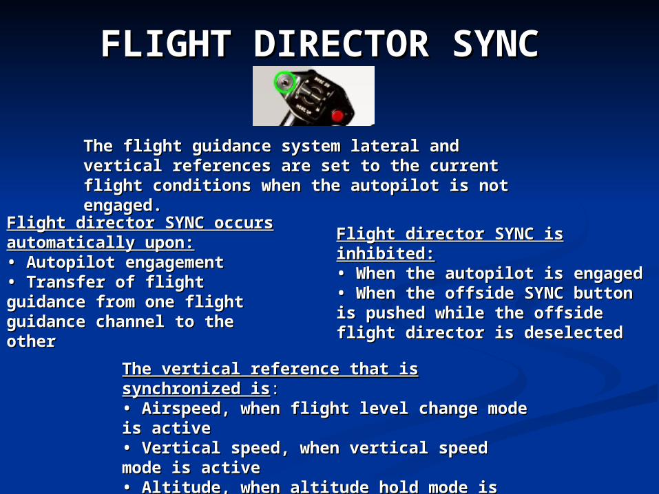
The flight guidance system lateral and vertical The flight guidance system lateral and vertical references are set to the current flight references are set to the current flight conditions when the autopilot is not engaged.conditions when the autopilot is not engaged.
Flight director SYNC is inhibited:Flight director SYNC is inhibited:• • When the autopilot is engagedWhen the autopilot is engaged• • When the offside SYNC button When the offside SYNC button is pushed while the offside flight is pushed while the offside flight director is deselecteddirector is deselected
Flight director SYNC occurs Flight director SYNC occurs automatically upon:automatically upon:• • Autopilot engagementAutopilot engagement• • Transfer of flight guidance Transfer of flight guidance from one flight guidance from one flight guidance channel to the otherchannel to the other
The vertical reference that is synchronized The vertical reference that is synchronized isis::• • Airspeed, when flight level change mode Airspeed, when flight level change mode is activeis active• • Vertical speed, when vertical speed mode Vertical speed, when vertical speed mode is activeis active• • Altitude, when altitude hold mode is Altitude, when altitude hold mode is activeactive• • Pitch, when pitch hold is activePitch, when pitch hold is active
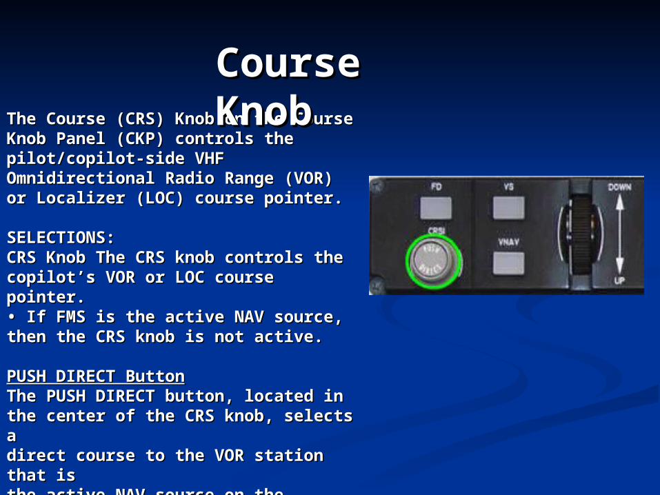
The Course (CRS) Knob on the The Course (CRS) Knob on the Course Knob Panel (CKP) controls Course Knob Panel (CKP) controls the pilot/copilot-side VHF the pilot/copilot-side VHF Omnidirectional Radio Range (VOR) Omnidirectional Radio Range (VOR) or Localizer (LOC) course pointer.or Localizer (LOC) course pointer.
SELECTIONS:SELECTIONS:CRS Knob The CRS knob controls the CRS Knob The CRS knob controls the copilot’s VOR or LOC course pointer.copilot’s VOR or LOC course pointer.• • If FMS is the active NAV source, If FMS is the active NAV source, then the CRS knob is not active.then the CRS knob is not active.
PUSH DIRECT ButtonPUSH DIRECT ButtonThe PUSH DIRECT button, located inThe PUSH DIRECT button, located inthe center of the CRS knob, selects athe center of the CRS knob, selects adirect course to the VOR station that direct course to the VOR station that isisthe active NAV source on the copilot-the active NAV source on the copilot-sidesidePFD.PFD.
Course Course KnobKnob
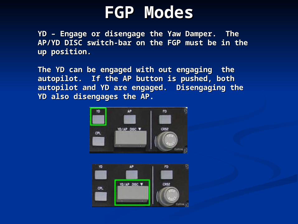
YD – Engage or disengage the Yaw Damper. The YD – Engage or disengage the Yaw Damper. The AP/YD DISC switch-bar on the FGP must be in the AP/YD DISC switch-bar on the FGP must be in the up position.up position.
The YD can be engaged with out engaging the The YD can be engaged with out engaging the autopilot. If the AP button is pushed, both autopilot. If the AP button is pushed, both autopilot and YD are engaged. Disengaging the YD autopilot and YD are engaged. Disengaging the YD also disengages the APalso disengages the AP.
FGP ModesFGP Modes
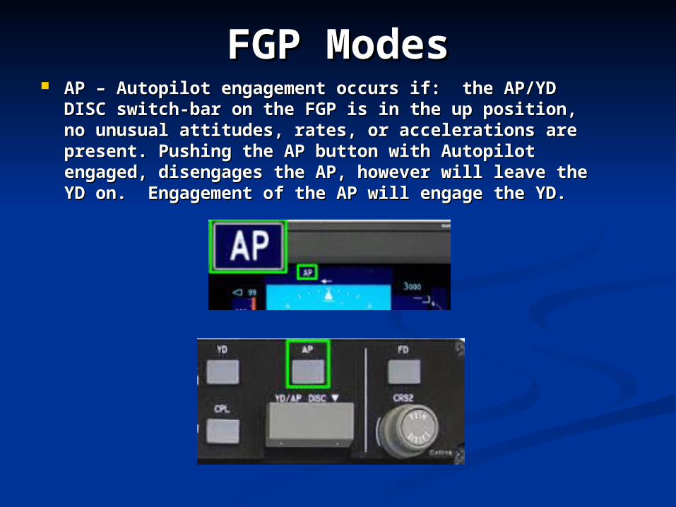
FGP ModesFGP Modes AP – Autopilot engagement occurs if: the AP/YD AP – Autopilot engagement occurs if: the AP/YD
DISC switch-bar on the FGP is in the up position, DISC switch-bar on the FGP is in the up position, no unusual attitudes, rates, or accelerations are no unusual attitudes, rates, or accelerations are present. Pushing the AP button with Autopilot present. Pushing the AP button with Autopilot engaged, disengages the AP, however will leave the engaged, disengages the AP, however will leave the YD on. Engagement of the AP will engage the YD.YD on. Engagement of the AP will engage the YD.
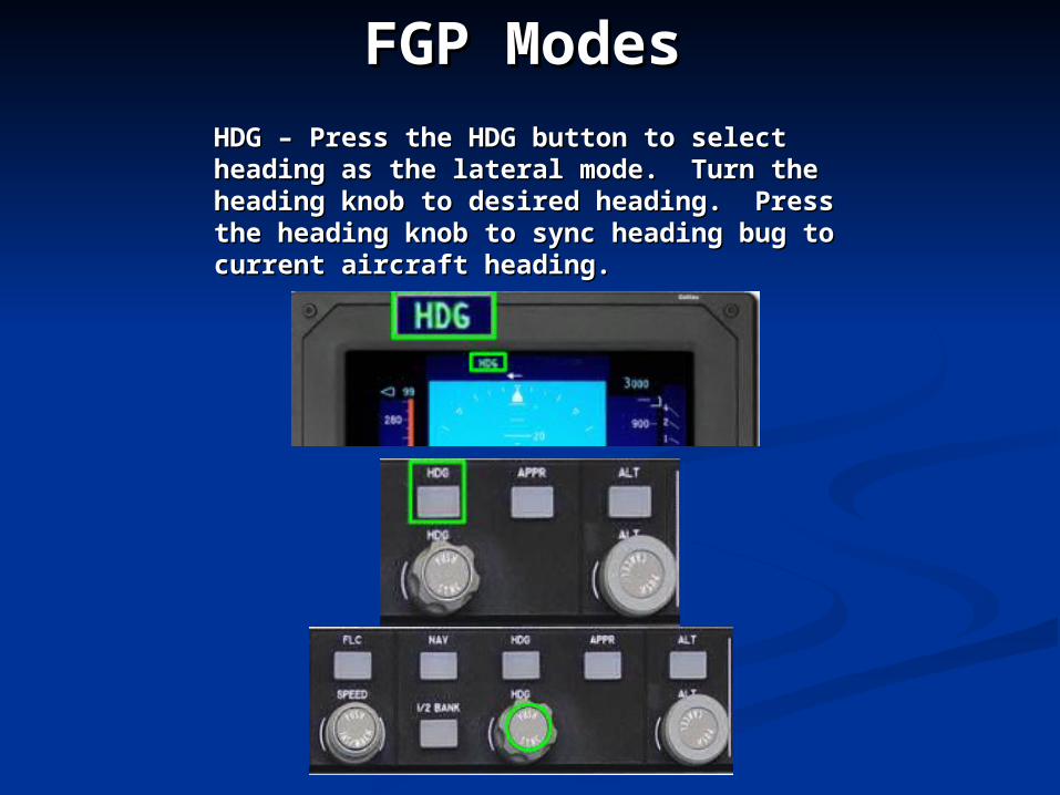
HDG – Press the HDG button to select HDG – Press the HDG button to select heading as the lateral mode. Turn the heading as the lateral mode. Turn the heading knob to desired heading. Press the heading knob to desired heading. Press the heading knob to sync heading bug to heading knob to sync heading bug to current aircraft heading.current aircraft heading.
FGP ModesFGP Modes
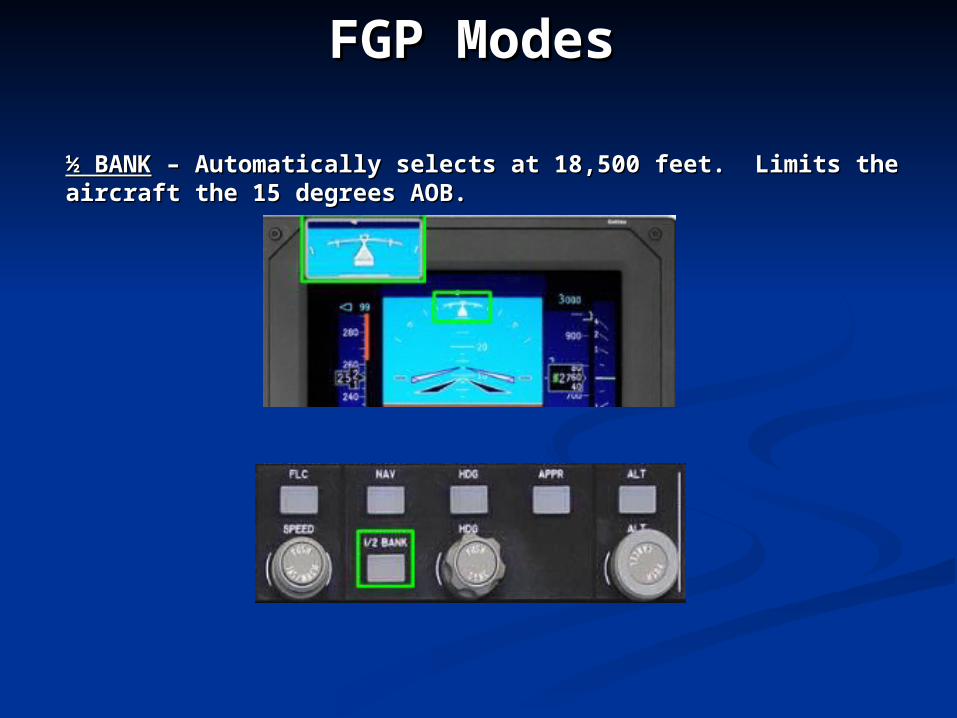
½ BANK½ BANK – Automatically selects at 18,500 feet. Limits the – Automatically selects at 18,500 feet. Limits the aircraft the 15 degrees AOB.aircraft the 15 degrees AOB.
FGP ModesFGP Modes
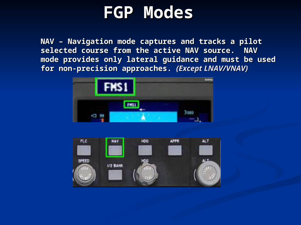
NAV – Navigation mode captures and tracks a pilot NAV – Navigation mode captures and tracks a pilot selected course from the active NAV source. NAV mode selected course from the active NAV source. NAV mode provides only lateral guidance and must be used for provides only lateral guidance and must be used for non-precision approaches. non-precision approaches. (Except LNAV/VNAV)(Except LNAV/VNAV)
FGP ModesFGP Modes
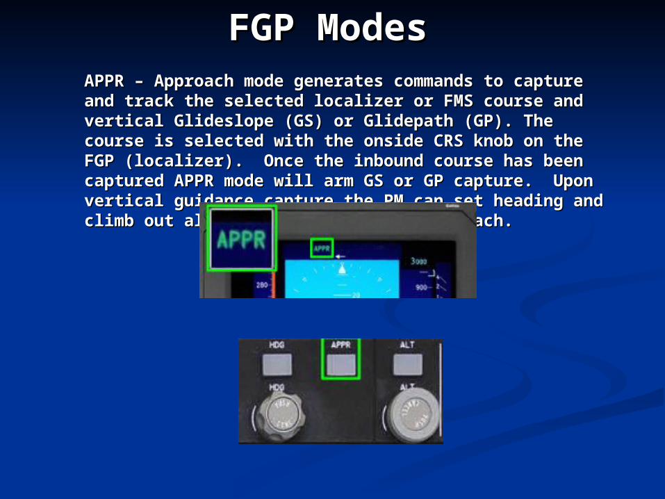
APPR – Approach mode generates commands to capture APPR – Approach mode generates commands to capture and track the selected localizer or FMS course and and track the selected localizer or FMS course and vertical Glideslope (GS) or Glidepath (GP). The course vertical Glideslope (GS) or Glidepath (GP). The course is selected with the onside CRS knob on the FGP is selected with the onside CRS knob on the FGP (localizer). Once the inbound course has been captured (localizer). Once the inbound course has been captured APPR mode will arm GS or GP capture. Upon vertical APPR mode will arm GS or GP capture. Upon vertical guidance capture the PM can set heading and climb out guidance capture the PM can set heading and climb out altitude for the missed approach.altitude for the missed approach.
FGP ModesFGP Modes
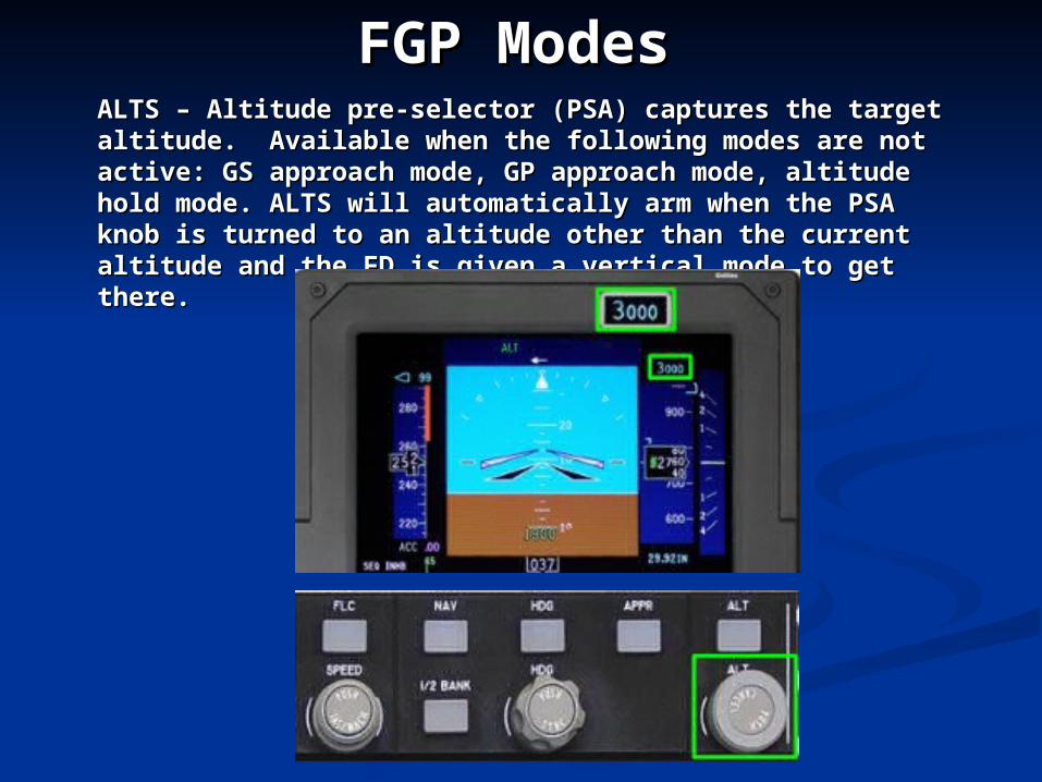
ALTS – Altitude pre-selector (PSA) captures the target ALTS – Altitude pre-selector (PSA) captures the target altitude. Available when the following modes are not altitude. Available when the following modes are not active: GS approach mode, GP approach mode, altitude active: GS approach mode, GP approach mode, altitude hold mode. ALTS will automatically arm when the PSA hold mode. ALTS will automatically arm when the PSA knob is turned to an altitude other than the current knob is turned to an altitude other than the current altitude and the FD is given a vertical mode to get there.altitude and the FD is given a vertical mode to get there.
FGP ModesFGP Modes
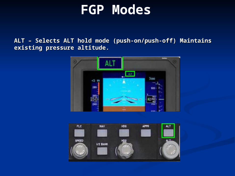
ALT – Selects ALT hold mode (push-on/push-off) Maintains existing ALT – Selects ALT hold mode (push-on/push-off) Maintains existing pressure altitude.pressure altitude.
FGP Modes
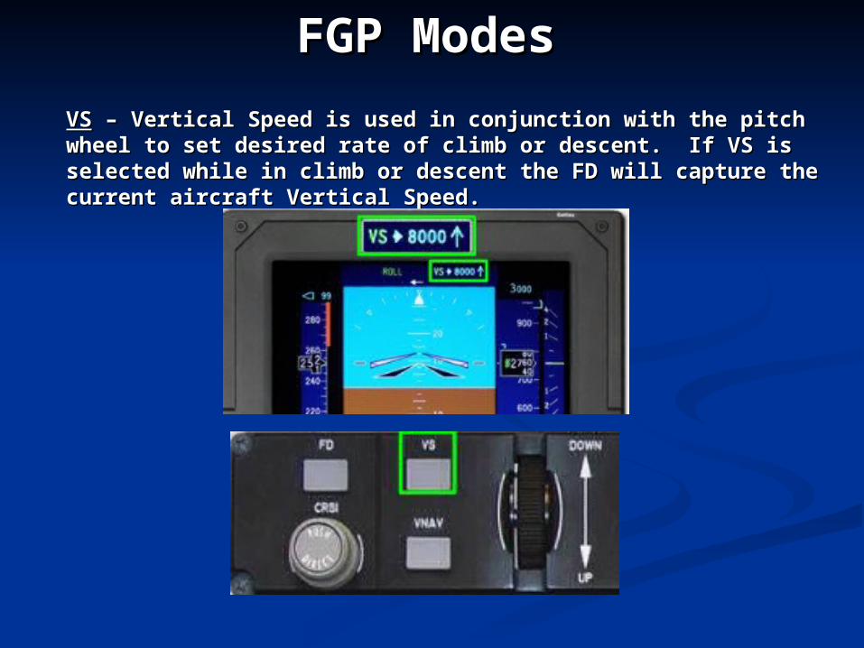
VSVS – Vertical Speed is used in conjunction with the pitch – Vertical Speed is used in conjunction with the pitch wheel to set desired rate of climb or descent. If VS is wheel to set desired rate of climb or descent. If VS is selected while in climb or descent the FD will capture the selected while in climb or descent the FD will capture the current aircraft Vertical Speed.current aircraft Vertical Speed.
FGP ModesFGP Modes
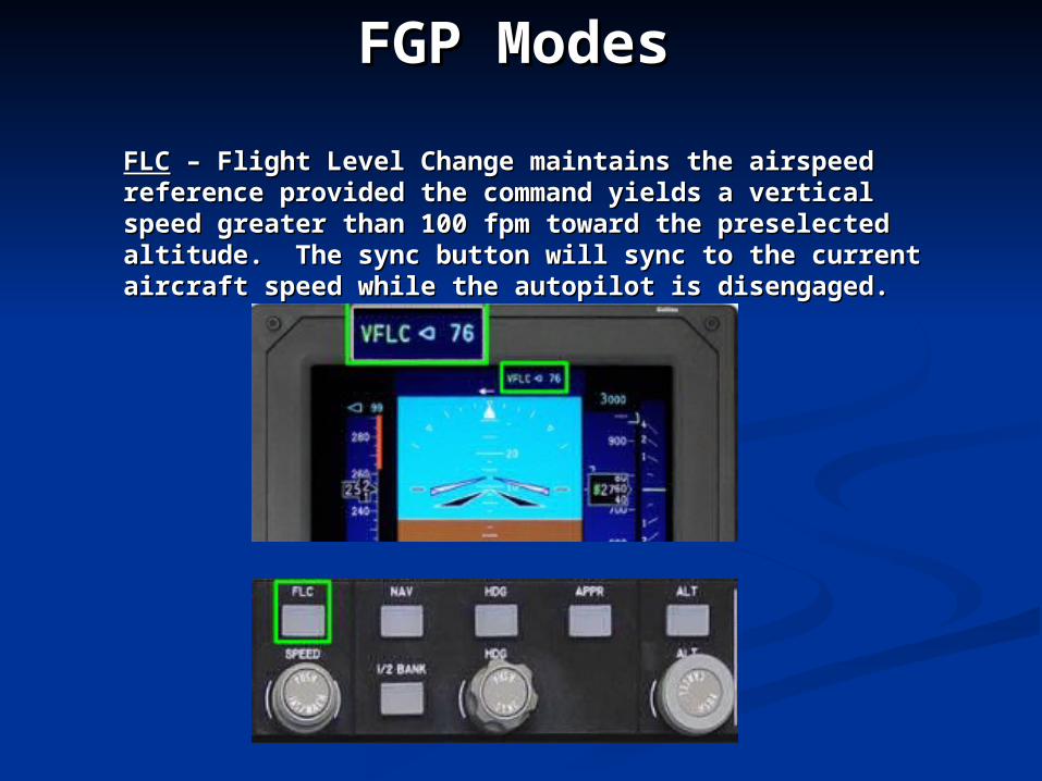
FLCFLC – Flight Level Change maintains the airspeed – Flight Level Change maintains the airspeed reference provided the command yields a vertical reference provided the command yields a vertical speed greater than 100 fpm toward the preselected speed greater than 100 fpm toward the preselected altitude. The sync button will sync to the current altitude. The sync button will sync to the current aircraft speed while the autopilot is disengaged.aircraft speed while the autopilot is disengaged.
FGP ModesFGP Modes
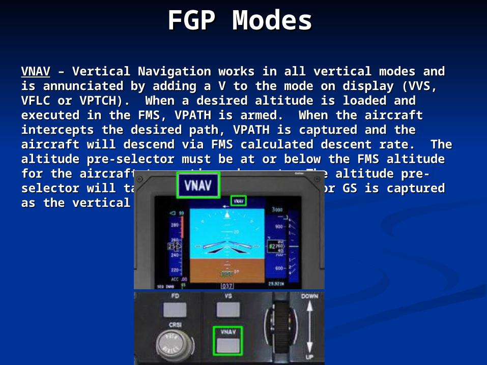
VNAVVNAV – Vertical Navigation works in all vertical modes and is – Vertical Navigation works in all vertical modes and is annunciated by adding a V to the mode on display (VVS, VFLC annunciated by adding a V to the mode on display (VVS, VFLC or VPTCH). When a desired altitude is loaded and executed in or VPTCH). When a desired altitude is loaded and executed in the FMS, VPATH is armed. When the aircraft intercepts the the FMS, VPATH is armed. When the aircraft intercepts the desired path, VPATH is captured and the aircraft will descend desired path, VPATH is captured and the aircraft will descend via FMS calculated descent rate. The altitude pre-selector must via FMS calculated descent rate. The altitude pre-selector must be at or below the FMS altitude for the aircraft to continue be at or below the FMS altitude for the aircraft to continue descent. The altitude pre-selector will take precedence unless descent. The altitude pre-selector will take precedence unless VGP or GS is captured as the vertical mode.VGP or GS is captured as the vertical mode.
FGP ModesFGP Modes
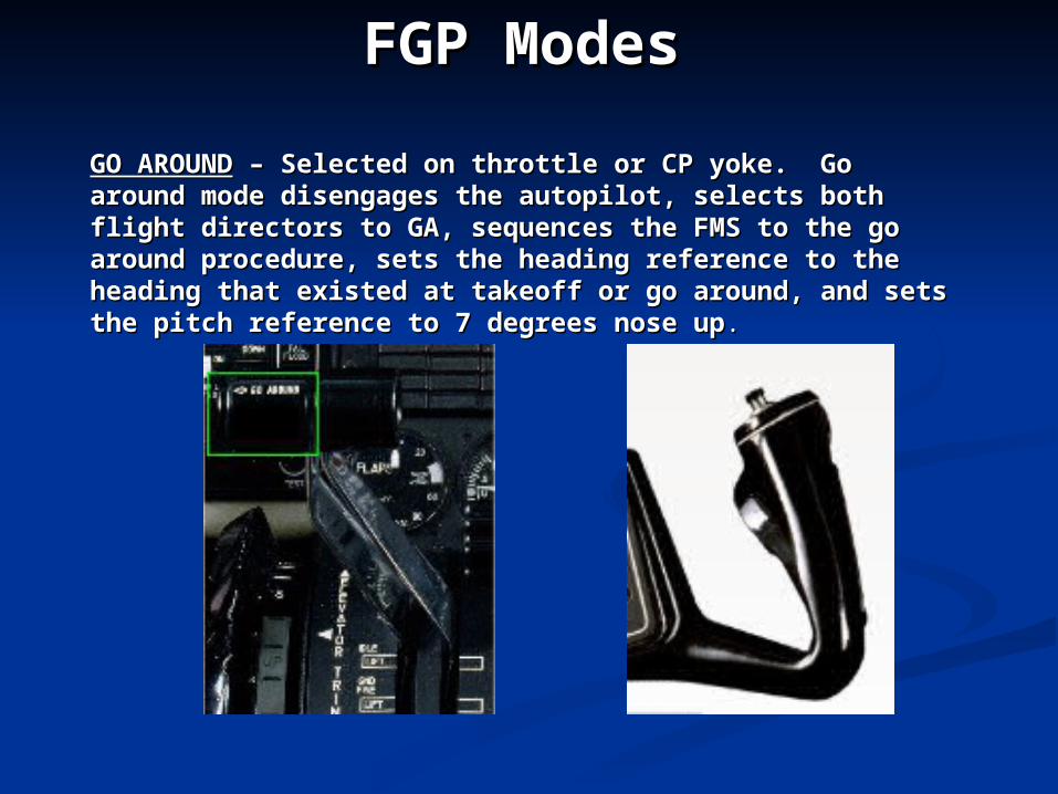
GO AROUNDGO AROUND – Selected on throttle or CP yoke. Go – Selected on throttle or CP yoke. Go around mode disengages the autopilot, selects both flight around mode disengages the autopilot, selects both flight directors to GA, sequences the FMS to the go around directors to GA, sequences the FMS to the go around procedure, sets the heading reference to the heading that procedure, sets the heading reference to the heading that existed at takeoff or go around, and sets the pitch existed at takeoff or go around, and sets the pitch reference to 7 degrees nose upreference to 7 degrees nose up..
FGP ModesFGP Modes
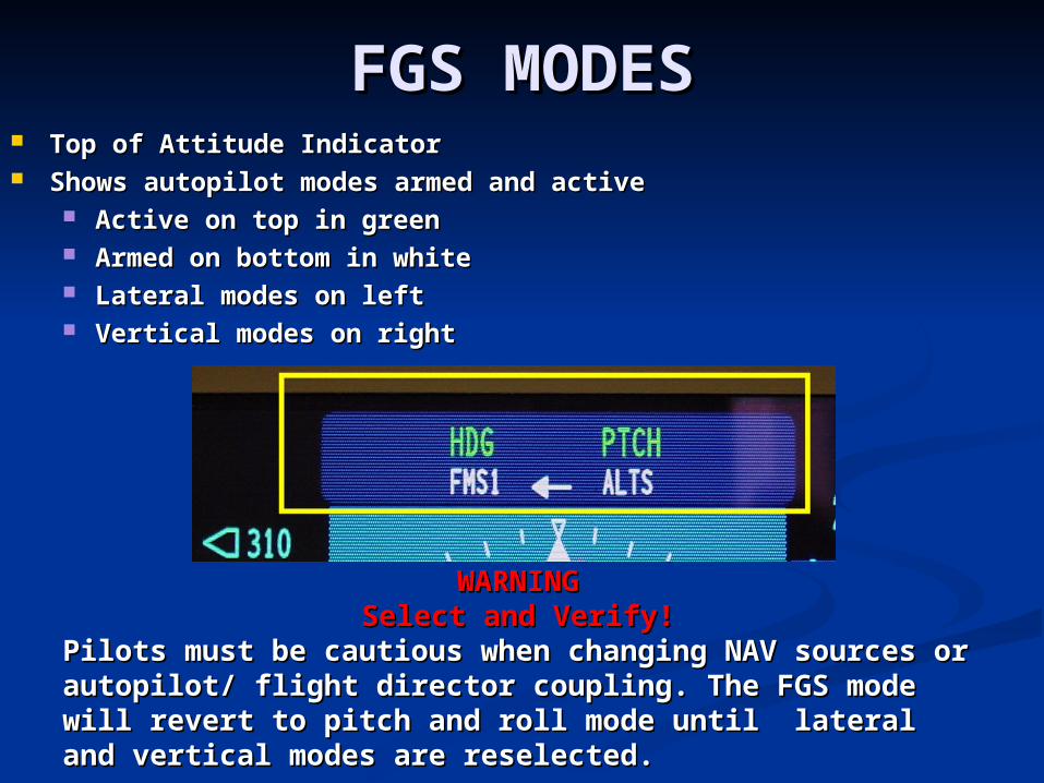
FGS MODESFGS MODES Top of Attitude IndicatorTop of Attitude Indicator Shows autopilot modes armed and activeShows autopilot modes armed and active
Active on top in greenActive on top in green Armed on bottom in whiteArmed on bottom in white Lateral modes on leftLateral modes on left Vertical modes on rightVertical modes on right
WARNINGWARNINGSelect and Verify!Select and Verify!
Pilots must be cautious when changing NAV sources or Pilots must be cautious when changing NAV sources or autopilot/ flight director coupling. The FGS mode will autopilot/ flight director coupling. The FGS mode will revert to pitch and roll mode until lateral and vertical revert to pitch and roll mode until lateral and vertical modes are reselected.modes are reselected.
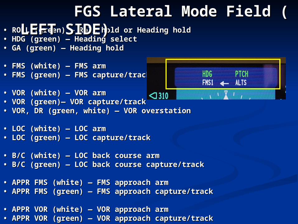
• • ROLL (green) — Roll hold or Heading holdROLL (green) — Roll hold or Heading hold• • HDG (green) — Heading selectHDG (green) — Heading select• • GA (green) — Heading holdGA (green) — Heading hold
• • FMS (white) — FMS armFMS (white) — FMS arm• • FMS (green) — FMS capture/trackFMS (green) — FMS capture/track
• • VOR (white) — VOR armVOR (white) — VOR arm• • VOR (green)— VOR capture/trackVOR (green)— VOR capture/track• • VOR, DR (green, white) — VOR overstationVOR, DR (green, white) — VOR overstation
• • LOC (white) — LOC armLOC (white) — LOC arm• • LOC (green) — LOC capture/trackLOC (green) — LOC capture/track
• • B/C (white) — LOC back course armB/C (white) — LOC back course arm• • B/C (green) — LOC back course capture/trackB/C (green) — LOC back course capture/track
• • APPR FMS (white) — FMS approach armAPPR FMS (white) — FMS approach arm• • APPR FMS (green) — FMS approach capture/trackAPPR FMS (green) — FMS approach capture/track
• • APPR VOR (white) — VOR approach armAPPR VOR (white) — VOR approach arm• • APPR VOR (green) — VOR approach capture/trackAPPR VOR (green) — VOR approach capture/track
FGS Lateral Mode Field FGS Lateral Mode Field ( LEFT SIDE)( LEFT SIDE)
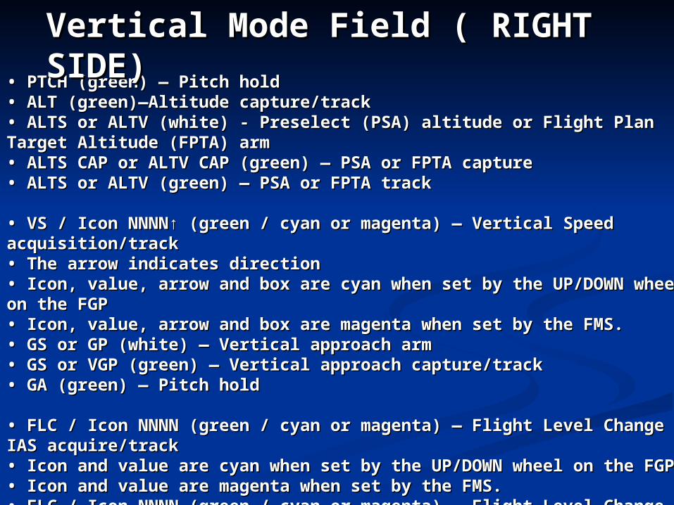
• • PTCH (green) — Pitch holdPTCH (green) — Pitch hold• • ALT (green)—Altitude capture/trackALT (green)—Altitude capture/track• • ALTS or ALTV (white) - Preselect (PSA) altitude or Flight Plan Target ALTS or ALTV (white) - Preselect (PSA) altitude or Flight Plan Target Altitude (FPTA) armAltitude (FPTA) arm• • ALTS CAP or ALTV CAP (green) — PSA or FPTA captureALTS CAP or ALTV CAP (green) — PSA or FPTA capture• • ALTS or ALTV (green) — PSA or FPTA trackALTS or ALTV (green) — PSA or FPTA track
• • VS / Icon NNNN↑ (green / cyan or magenta) — Vertical Speed VS / Icon NNNN↑ (green / cyan or magenta) — Vertical Speed acquisition/trackacquisition/track• • The arrow indicates directionThe arrow indicates direction• • Icon, value, arrow and box are cyan when set by the UP/DOWN wheel Icon, value, arrow and box are cyan when set by the UP/DOWN wheel on the FGPon the FGP• • Icon, value, arrow and box are magenta when set by the FMS.Icon, value, arrow and box are magenta when set by the FMS.• • GS or GP (white) — Vertical approach armGS or GP (white) — Vertical approach arm• • GS or VGP (green) — Vertical approach capture/trackGS or VGP (green) — Vertical approach capture/track• • GA (green) — Pitch holdGA (green) — Pitch hold
• • FLC / Icon NNNN (green / cyan or magenta) — Flight Level Change IAS FLC / Icon NNNN (green / cyan or magenta) — Flight Level Change IAS acquire/trackacquire/track• • Icon and value are cyan when set by the UP/DOWN wheel on the FGPIcon and value are cyan when set by the UP/DOWN wheel on the FGP• • Icon and value are magenta when set by the FMS.Icon and value are magenta when set by the FMS.• • FLC / Icon NNNN (green / cyan or magenta) — Flight Level Change FLC / Icon NNNN (green / cyan or magenta) — Flight Level Change Mach acquire/trackMach acquire/track• • Icon and value are cyan when set by the UP/DOWN wheel onIcon and value are cyan when set by the UP/DOWN wheel onthe FGPthe FGP• • Icon and value are magenta when set by the FMS.Icon and value are magenta when set by the FMS.
Vertical Mode Field ( RIGHT Vertical Mode Field ( RIGHT SIDE)SIDE)
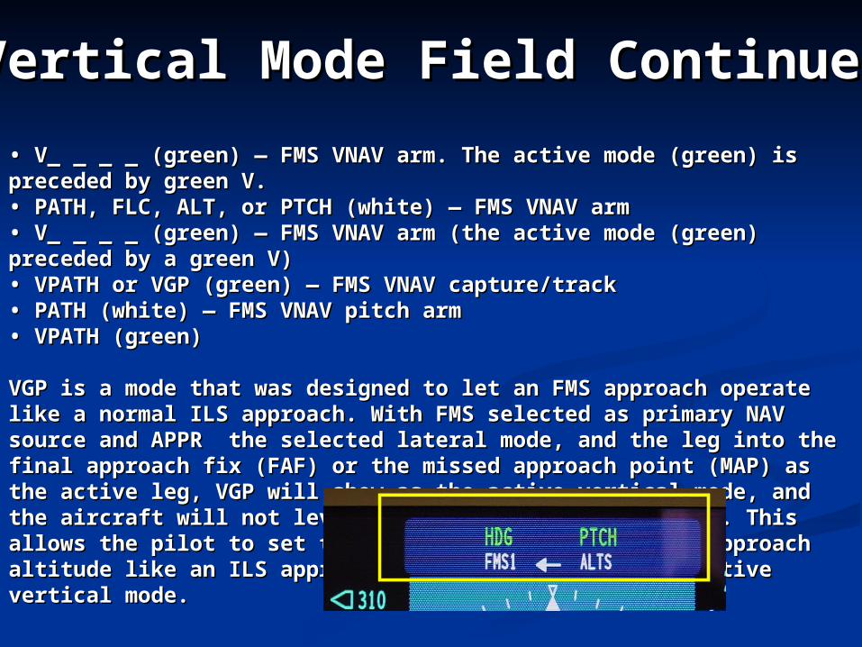
• • V_ _ _ _ (green) — FMS VNAV arm. The active mode (green) is V_ _ _ _ (green) — FMS VNAV arm. The active mode (green) is preceded by green V.preceded by green V.• • PATH, FLC, ALT, or PTCH (white) — FMS VNAV armPATH, FLC, ALT, or PTCH (white) — FMS VNAV arm• • V_ _ _ _ (green) — FMS VNAV arm (the active mode (green) V_ _ _ _ (green) — FMS VNAV arm (the active mode (green) preceded by a green V)preceded by a green V)• • VPATH or VGP (green) — FMS VNAV capture/trackVPATH or VGP (green) — FMS VNAV capture/track• • PATH (white) — FMS VNAV pitch armPATH (white) — FMS VNAV pitch arm• • VPATH (green)VPATH (green)
VGP is a mode that was designed to let an FMS approach operate like VGP is a mode that was designed to let an FMS approach operate like a normal ILS approach. With FMS selected as primary NAV source a normal ILS approach. With FMS selected as primary NAV source and APPR the selected lateral mode, and the leg into the final and APPR the selected lateral mode, and the leg into the final approach fix (FAF) or the missed approach point (MAP) as the active approach fix (FAF) or the missed approach point (MAP) as the active leg, VGP will show as the active vertical mode, and the aircraft will leg, VGP will show as the active vertical mode, and the aircraft will not level at the preselector altitude. This allows the pilot to set the not level at the preselector altitude. This allows the pilot to set the preselector to the missed approach altitude like an ILS approach preselector to the missed approach altitude like an ILS approach when glideslope is the active vertical mode.when glideslope is the active vertical mode.
Vertical Mode Field ContinuedVertical Mode Field Continued
VGP vs. VPATH:VGP vs. VPATH: During an FMS approach, with APPR mode and VNAV selected, During an FMS approach, with APPR mode and VNAV selected, the flight director will transition to the VGP mode. Whenever the flight director will transition to the VGP mode. Whenever VGP is active, the PSA will be disregarded by the flight director. VGP is active, the PSA will be disregarded by the flight director. Therefore, the flight director will not level off at the baro mins. Therefore, the flight director will not level off at the baro mins. Instead, it will continue on a 3 degree glide path to the runway. Instead, it will continue on a 3 degree glide path to the runway. However, in NAV mode (APPR However, in NAV mode (APPR notnot selected), VPATH is active and selected), VPATH is active and will level off at baro mins.will level off at baro mins.
NOTE:NOTE:As the VT-31 standard, use NAV mode for As the VT-31 standard, use NAV mode for
all non-precision approaches and use APPR all non-precision approaches and use APPR mode only for precision (ILS) or mode only for precision (ILS) or
LNAV/VNAV DA approaches.LNAV/VNAV DA approaches.
Vertical Mode Field Vertical Mode Field ContinuedContinued
Flight Director PF/PM CRM:Flight Director PF/PM CRM: In the T-44C, there are multiple methods to fly In the T-44C, there are multiple methods to fly the same approach. This can create confusion the same approach. This can create confusion between pilots when it is time to fly the between pilots when it is time to fly the approach. It is imperative for the pilots to be approach. It is imperative for the pilots to be on the same page about the level of automation on the same page about the level of automation to be used during all phases of flight. to be used during all phases of flight.
The following The following techniquestechniques will enhance the use will enhance the use of automation through CRM and standardize of automation through CRM and standardize the usage of the flight director during the the usage of the flight director during the advanced multi-engine training. During use of advanced multi-engine training. During use of Flight Director and Autopilot it is important for Flight Director and Autopilot it is important for both PF and PM to both PF and PM to selectselect desired modes anddesired modes and verifyverify on PFD/FGS. on PFD/FGS.
• The mantra for flight director and autopilot usage is select and verify. Ensure that the proper flight mode is selected then verified on the Flight Guidance System Display to confirm that the anticipated mode of operation is either activated or in sequence for activation.
• Be concise about what is desired for the flight director to display. Use the term “select” for mode selection (HDG, NAV, APPR, VNAV, FLC, VS etc.). Use the term “set” for headings, altitudes, speeds and vertical speeds.
Flight Director PhilosophyFlight Director Philosophy
• Pilots must remain vigilant about aircraft control including airspeed, courses and altitudes. The biggest dangers of automation are complacency and trusting systems too much. Flight directors are garbage in = garbage out systems, meaning if false information is selected it can be a distraction or dangerous to flight operation. If the flight director or autopilot is detracting from safety of flight, turn them off and fly manually.
• During flight director use, there may be times with the PM is unable to select desired modes in a timely fashion because of task saturation. Do not delay the execution of a clearance because of slow actuation of the Flight Guidance Panel.
Flight Director PhilosophyFlight Director Philosophy
• Ensure the PM is briefed about the expectations for mode selection before an approach or go-around. Briefing the expected modes will ensure timely and accurate FGP operation and consequently add to CRM and safety.
For initial takeoff, touch and go, or go around the autopilot shall not be engaged below 400’. (NATOPS)
Flight Director PhilosophyFlight Director Philosophy
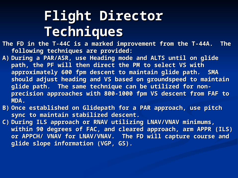
The FD in the T-44C is a marked improvement from the T-44A. The The FD in the T-44C is a marked improvement from the T-44A. The following techniques are provided: following techniques are provided:
A)A) During a PAR/ASR, use Heading mode and ALTS until on glide During a PAR/ASR, use Heading mode and ALTS until on glide path, the PF will then direct the PM to select VS with path, the PF will then direct the PM to select VS with approximately 600 fpm descent to maintain glide path. SMA approximately 600 fpm descent to maintain glide path. SMA should adjust heading and VS based on groundspeed to maintain should adjust heading and VS based on groundspeed to maintain glide path. The same technique can be utilized for non-precision glide path. The same technique can be utilized for non-precision approaches with 800-1000 fpm VS descent from FAF to MDA.approaches with 800-1000 fpm VS descent from FAF to MDA.
B)B) Once established on Glidepath for a PAR approach, use pitch sync Once established on Glidepath for a PAR approach, use pitch sync to maintain stabilized descent.to maintain stabilized descent.
C)C) During ILS approach or RNAV utilizing LNAV/VNAV minimums, During ILS approach or RNAV utilizing LNAV/VNAV minimums, within 90 degrees of FAC, and cleared approach, arm APPR (ILS) within 90 degrees of FAC, and cleared approach, arm APPR (ILS) or APPCH/ VNAV for LNAV/VNAV. The FD will capture course and or APPCH/ VNAV for LNAV/VNAV. The FD will capture course and glide slope information (VGP, GS).glide slope information (VGP, GS).
Flight Director Flight Director TechniquesTechniques
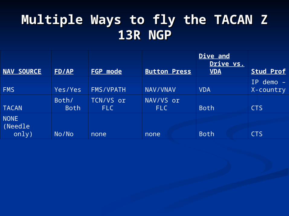
Multiple Ways to fly the TACAN Z Multiple Ways to fly the TACAN Z 13R NGP13R NGP
NAV SOURCE FD/AP FGP mode Button PressDive and Drive
vs. VDA Stud Prof
FMS Yes/Yes FMS/VPATH NAV/VNAV VDAIP demo – X-country
TACAN Both/Both TCN/VS or FLC NAV/VS or FLC Both CTS
NONE(Needle only) No/No none none Both CTS
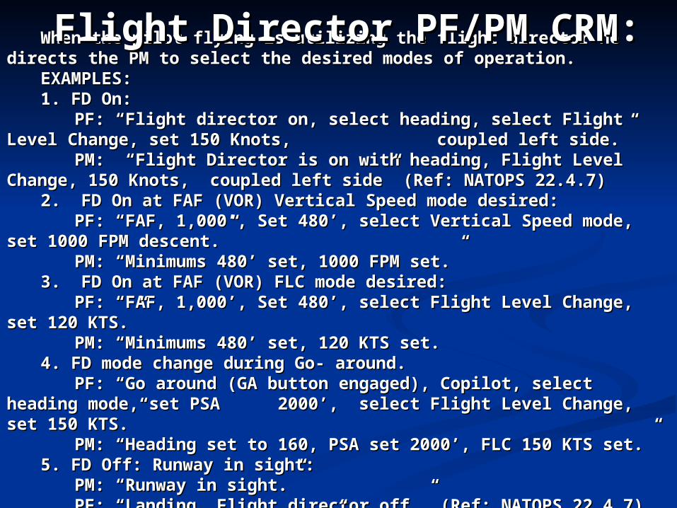
When the pilot flying is utilizing the flight director he directs the When the pilot flying is utilizing the flight director he directs the PM to select the desired modes of operation.PM to select the desired modes of operation.
EXAMPLES:EXAMPLES:1. FD On: 1. FD On:
PF: “Flight director on, select heading, select Flight Level PF: “Flight director on, select heading, select Flight Level Change, set 150 Knots, Change, set 150 Knots, coupled left side.” coupled left side.”
PM: “Flight Director is on with heading, Flight Level Change, PM: “Flight Director is on with heading, Flight Level Change, 150 Knots, 150 Knots, coupled left side” (Ref: NATOPS 22.4.7)coupled left side” (Ref: NATOPS 22.4.7)
2. FD On at FAF (VOR) Vertical Speed mode desired:2. FD On at FAF (VOR) Vertical Speed mode desired:PF: “FAF, 1,000’, Set 480’, select Vertical Speed mode, set PF: “FAF, 1,000’, Set 480’, select Vertical Speed mode, set
1000 FPM descent.”1000 FPM descent.”PM: “Minimums 480’ set, 1000 FPM set.”PM: “Minimums 480’ set, 1000 FPM set.”
3. FD On at FAF (VOR) FLC mode desired:3. FD On at FAF (VOR) FLC mode desired:PF: “FAF, 1,000’, Set 480’,PF: “FAF, 1,000’, Set 480’, select Flight Level Change, set 120 select Flight Level Change, set 120
KTS.”KTS.” PM: “Minimums 480’ set, 120 KTS set.PM: “Minimums 480’ set, 120 KTS set.4. FD mode change during Go- around.4. FD mode change during Go- around.
PF: “Go around (GA button engaged), Copilot, select heading PF: “Go around (GA button engaged), Copilot, select heading mode, set PSA mode, set PSA 2000’, select Flight Level Change, set 150 2000’, select Flight Level Change, set 150 KTS.”KTS.”
PM: “Heading set to 160, PSA set 2000’, FLC 150 KTS set.”PM: “Heading set to 160, PSA set 2000’, FLC 150 KTS set.”5. FD Off: Runway in sight:5. FD Off: Runway in sight:
PM: “Runway in sight.”PM: “Runway in sight.”PF: “Landing, Flight director off.” (Ref: NATOPS 22.4.7)PF: “Landing, Flight director off.” (Ref: NATOPS 22.4.7)PM: “Flight director off.”PM: “Flight director off.”
Flight Director PF/PM CRM:Flight Director PF/PM CRM:
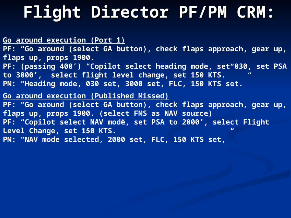
Go around execution (Port 1)PF: “Go around (select GA button), check flaps approach, gear up, flaps up, props 1900.PF: (passing 400’) “Copilot select heading mode, set 030, set PSA to 3000’, select flight level change, set 150 KTS.” PM: “Heading mode, 030 set, 3000 set, FLC, 150 KTS set.”
Go around execution (Published Missed)PF: “Go around (select GA button), check flaps approach, gear up, flaps up, props 1900. (select FMS as NAV source)PF: “Copilot select NAV mode, set PSA to 2000’, select Flight Level Change, set 150 KTS.”PM: “NAV mode selected, 2000 set, FLC, 150 KTS set,”
Flight Director PF/PM CRM:Flight Director PF/PM CRM:
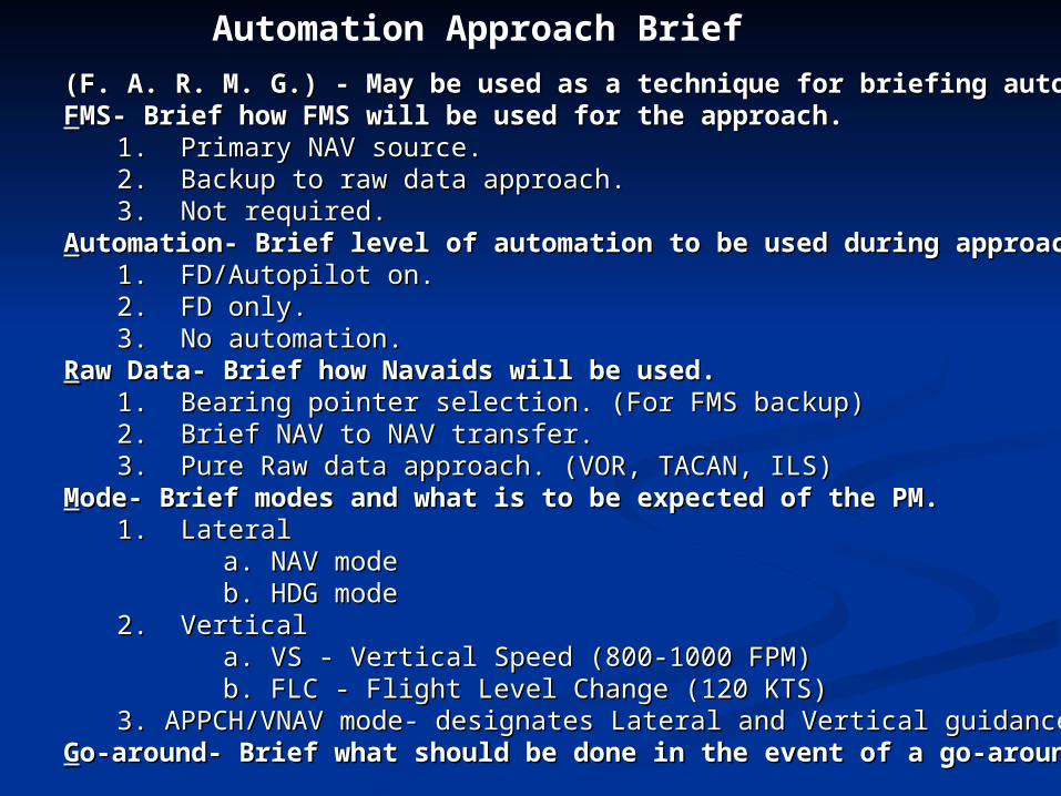
(F. A. R. M. G.) - May be used as a technique for briefing automation(F. A. R. M. G.) - May be used as a technique for briefing automationFFMS- Brief how FMS will be used for the approach.MS- Brief how FMS will be used for the approach.
1. Primary NAV source.1. Primary NAV source.2. Backup to raw data approach.2. Backup to raw data approach.3. Not required.3. Not required.
AAutomation- Brief level of automation to be used during approach.utomation- Brief level of automation to be used during approach.1. FD/Autopilot on.1. FD/Autopilot on.2. FD only. 2. FD only. 3. No automation.3. No automation.
RRaw Data-aw Data- Brief how Navaids will be used.Brief how Navaids will be used.1. Bearing pointer selection. (For FMS backup)1. Bearing pointer selection. (For FMS backup)2. Brief NAV to NAV transfer.2. Brief NAV to NAV transfer.3. Pure Raw data approach. (VOR, TACAN, ILS)3. Pure Raw data approach. (VOR, TACAN, ILS)
MMode- Brief modes and what is to be expected of the PM.ode- Brief modes and what is to be expected of the PM. 1. Lateral1. Lateral
a. NAV mode a. NAV mode b. HDG modeb. HDG mode
2. Vertical2. Verticala. VS - Vertical Speed (800-1000 FPM)a. VS - Vertical Speed (800-1000 FPM)b. FLC - Flight Level Change (120 KTS)b. FLC - Flight Level Change (120 KTS)
3. APPCH/VNAV mode- designates Lateral and Vertical guidance3. APPCH/VNAV mode- designates Lateral and Vertical guidanceGGo-around-o-around- Brief what should be done in the event of a go-around.Brief what should be done in the event of a go-around.
Automation Approach Brief
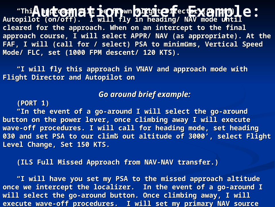
““This approach will be flown Flight Director (on/off), Autopilot This approach will be flown Flight Director (on/off), Autopilot (on/off). I will fly in heading/ NAV mode until cleared for the (on/off). I will fly in heading/ NAV mode until cleared for the approach. When on an intercept to the final approach course, I will approach. When on an intercept to the final approach course, I will select APPR/ NAV (as appropriate). At the FAF, I will (call for / select) select APPR/ NAV (as appropriate). At the FAF, I will (call for / select) PSA to minimums, Vertical Speed Mode/ FLC, set (1000 FPM descent/ PSA to minimums, Vertical Speed Mode/ FLC, set (1000 FPM descent/ 120 KTS).”120 KTS).”
““I will fly this approach in VNAV and approach mode with Flight I will fly this approach in VNAV and approach mode with Flight Director and Autopilot on”Director and Autopilot on”
Go around brief example:Go around brief example:(PORT 1)(PORT 1)““In the event of a go-around I will select the go-around button on In the event of a go-around I will select the go-around button on
the power lever, once climbing away I will execute wave-off the power lever, once climbing away I will execute wave-off procedures. I will call for heading mode, set heading 030 and set PSA procedures. I will call for heading mode, set heading 030 and set PSA to our climb out altitude of 3000’, select Flight Level Change, Set 150 to our climb out altitude of 3000’, select Flight Level Change, Set 150 KTS.”KTS.”
(ILS Full Missed Approach from NAV-NAV transfer.)(ILS Full Missed Approach from NAV-NAV transfer.)
““I will have you set my PSA to the missed approach altitude once I will have you set my PSA to the missed approach altitude once we intercept the localizer. In the event of a go-around I will select we intercept the localizer. In the event of a go-around I will select the go-around button. Once climbing away, I will execute wave-off the go-around button. Once climbing away, I will execute wave-off procedures. I will set my primary NAV source back to FMS and call procedures. I will set my primary NAV source back to FMS and call for NAV mode, Flight Level Change set 150 KTS to track the missed for NAV mode, Flight Level Change set 150 KTS to track the missed approach to CRP.” approach to CRP.”
Automation brief Example:
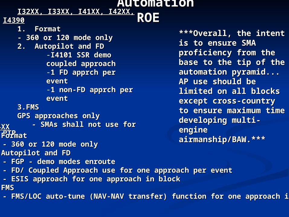
Automation Automation ROEROEI32XX, I33XX, I41XX, I42XX, I32XX, I33XX, I41XX, I42XX,
I4390I43901. Format1. Format- 360 or 120 mode only- 360 or 120 mode only2. Autopilot and FD 2. Autopilot and FD
-I4101 SSR demo I4101 SSR demo coupled approach coupled approach -1 FD apprch per event 1 FD apprch per event -1 non-FD apprch per 1 non-FD apprch per eventevent
3.FMS3.FMSGPS approaches onlyGPS approaches only
- SMAs shall not use for - SMAs shall not use for PTPPTPI44XXI44XX
1. Format1. Format- 360 or 120 mode only- 360 or 120 mode only
2. Autopilot and FD 2. Autopilot and FD - FGP - demo modes enroute- FGP - demo modes enroute- FD/ Coupled Approach use for one approach per event- FD/ Coupled Approach use for one approach per event- ESIS approach for one approach in block- ESIS approach for one approach in block
3. FMS3. FMS- FMS/LOC auto-tune (NAV-NAV transfer) function for one approach in - FMS/LOC auto-tune (NAV-NAV transfer) function for one approach in
blockblock
***Overall, the intent is to ***Overall, the intent is to ensure SMA proficiency ensure SMA proficiency from the base to the tip of from the base to the tip of the automation pyramid... the automation pyramid... AP use should be limited AP use should be limited on all blocks except cross-on all blocks except cross-country to ensure country to ensure maximum time developing maximum time developing multi-engine multi-engine airmanship/BAW.***airmanship/BAW.***
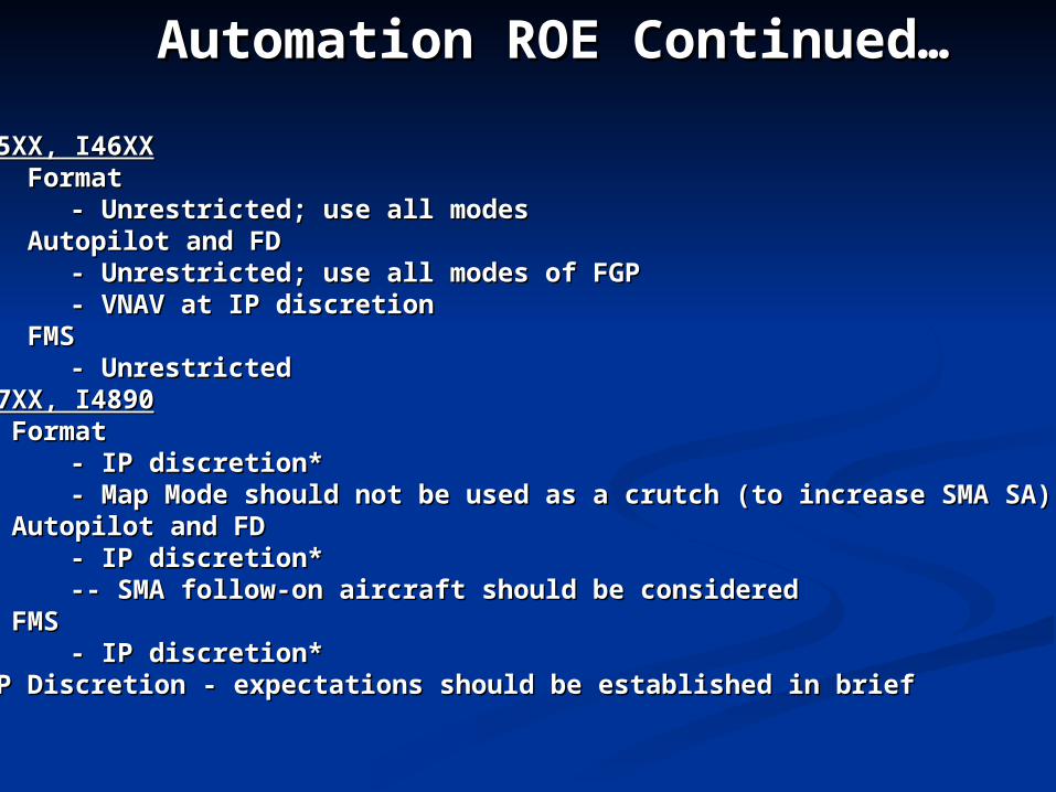
Automation ROE Continued…Automation ROE Continued…
I45XX, I46XXI45XX, I46XX1. Format1. Format
- Unrestricted; use all modes- Unrestricted; use all modes2. Autopilot and FD2. Autopilot and FD
- Unrestricted; use all modes of FGP- Unrestricted; use all modes of FGP- VNAV at IP discretion- VNAV at IP discretion
3. FMS3. FMS- Unrestricted- Unrestricted
I47XX, I4890I47XX, I48901. Format1. Format
- IP discretion*- IP discretion*- Map Mode should not be used as a crutch (to increase SMA SA)- Map Mode should not be used as a crutch (to increase SMA SA)
2. Autopilot and FD2. Autopilot and FD- IP discretion*- IP discretion*-- SMA follow-on aircraft should be considered-- SMA follow-on aircraft should be considered
3. FMS3. FMS- IP discretion*- IP discretion*
*IP Discretion - expectations should be established in brief*IP Discretion - expectations should be established in brief