Embed Size (px)
Citation preview
8/2/2019 i046igbd11 08 Protective Relays La2e-La3e-Lam
http://slidepdf.com/reader/full/i046igbd11-08-protective-relays-la2e-la3e-lam 1/5
LA2E - LA3E - LAM
3 3 I S T E C L A 3 E
I 4 6 I G
B D 1 1 0 8
DESCRIZIONEControllo amperometrico monofase diminima corrente.Misura diretta o tramite T.A.Contenitore estraibile zoccolato undecal.
REGOLAZIONI"Set-point Amp": soglia di intervento(potenziometro) 0,1÷1 Ie"Set-point Sec": tempo di intervento(potenziometro) 0,1÷10s"Inhibition Sec": tempo di inibizione(potenziometro) 0,1÷10s"Isteresi": isteresi al ripristino(trimmer-foro superiore) 5÷30%
INTERVENTOPer I < Set-point Amp, dopo il ritardo"Set-point Sec."L'intervento resta memorizzato se i morsetti9-11 sono collegati (cavallotto o contattoNC).
RIPRISTINO– automatico: quando I > (Set-point Amp +
Isteresi)– manuale: ad apertura dell'eventuale
contatto 9-11
STATO RELÈ– normalmente diseccitato– eccitato all'intervento
INIBIZIONE
– all’alimentazione il dispositivo rimaneinibito per la durata del tempo impostato.– con alimentazione già presente il
dispositivo può essere inibito collegando imorsetti 3-11 tramite contatto NC.All'apertura del contatto parte il tempo diinibizione, trascorso il quale il relè vienenuovamente abilitato.
LED ROSSO– acceso quando I < Set-point Amp oppure
a relè eccitato– spento a relè diseccitato
CODICE DI ORDINAZIONE
31 LA2E 5 24 (5A-24VAC)31 LA2E 5 110 (5A-110VAC)31 LA2E 5 230 (5A-220...240VAC)
DESCRIPTIONSingle-phase minimum current controlDirect measurement (in series with the load)or by C.T.Plug-in 11-pin housing
ADJUSTMENTS“Set-point Amp”: minimum current threshold(potentiometer) 0.1-1 Ie“Set-point Sec”: trip delay (potentiometer)0.1-10s“Inhibition Sec”: inhibiton time(potentiometer) 0.1-10s“Hysteresis”: reset hysteresis (trimmerthrough drilling in the top) 5-30%
TRIPFor I < Set-point Amp, after the time Set-point Sec.Tripping is stored if 9-11 terminals areconnection/closed (jumper or NC contact).
RESET– automatic for I > (Set-point Amp +
hysteresis)– manual at opening of the eventual contact
9-11
RELAY STATE– normally de-energized– energized at tripping
INHIBITION
– at the feeding, the inhibition time alwaystakes place.– if the unit is already fed, it can be
inhibited connecting terminals 3-11 by aNC contact.At contact opening the inhibition timebegins.
LED (red)– switched on when I < Set-point Amp or
when the relay is energized (alarm)– switched off when the relay is de-energized
(normal)
ORDER CODE
31 LA2E 5 24 (5A-24VAC)31 LA2E 5 110 (5A-110VAC)31 LA2E 5 230 (5A-220...240VAC)
I
RELÈ DI PROTEZIONE
GB
PROTECTIVE RELAYS
D
ÜBERWACHUNGSRELAIS
1
7
56
I
t
210
Inhibition 0.1-10s Delay 0.1-10s
5 - 3
0 %
Set Point
311
911
INHIBITION
RESET
0.1-1 Ie
0.1-10sDelay
0.1-10sInhibition Manual
Reset
7
56
210
Set Point
311
911
INHIBITION
RESET
0.1-1 Ie
t
I
91131 2 10 4 8 6 5 7
LA2E
L3
L2
L1
L1
L2
L3
/1÷5A
I N H I B I T I O N
R E S E T
Us
4 8
LA2E
RELÈ AMPEROMETRICO MONOFASE DIMINIMA CORRENTE
SINGLE-PHASE MINIMUM CURRENT RELAY
1 PHASIGER STROMWÄCHTER FÜR MIN.STROM
BESCHREIBUNGStromüberwachung 1 phasig für min. Strom.Messung direkt oder durch Stromwandler.Herausnehmbares Gehäuse mit 11 poligemSockel.
EINSTELLUNGEN“Set-point Amp”: Ansprechbereich(Potentiometer) 0,1÷1Ie“Set-point Sec”: Ansprechzeit(Potentiometer) 0,1÷10s“Inhibition Sec”: Sperrzeit (Potentiometer)0,1÷10s“Hysterese”: Hysterese bei Rückstellung(Trimmer-oberes Loch) 5÷30%
ANSPRECHENBei I < Set-point Amp, nach Verzögerung“Set-point Sec.”Das Ansprechen bleibt gespeichert, wenn dieKlemmen 9-11 verbunden sind (Schaltdrahtoder Öffner)
RÜCKSTELLUNG– automatisch: wenn I > (Set-point Amp +
Hysterese)– manuell: bei Öffnen des eventuellen
Kontakts 9-11
RELAISZUSTAND– normalerweise entregt– bei Ansprechen erregt
SPERRUNG
– bei Speisung bleibt die Vorrichtung fürdie Dauer der eingestellten Zeit gesperrt.– bei schon bestehender Speisung kann die
Vorrichtung gesperrt werden, indem dieKlemmen 3-11 durch einen Öffnerverbunden werden.Bei Öffnen des Kontakts beginnt dieSperrzeit, nach deren Ablauf das Relaiserneut aktiviert wird.
ROTE LED– ein, wenn I < Set-point Amp oder bei
erregtem Relais– aus bei entregtem Relais
BESTELLBEZEICHNUNG
31 LA2E 5 24 (5A-24VAC)31 LA2E 5 110 (5A-110VAC)31 LA2E 5 230 (5A-220...240VAC)
LOVATO ELECTRIC S.P.A.
24020 GORLE (BERGAMO) ITALIAVIA DON E. MAZZA, 12
TEL. 035 4282111TELEFAX (Nazionale): 035 4282200TELEFAX (International): +39 035 4282400
Web www.
Lovato
Electric.com
E-mail [email protected]
8/2/2019 i046igbd11 08 Protective Relays La2e-La3e-Lam
http://slidepdf.com/reader/full/i046igbd11-08-protective-relays-la2e-la3e-lam 2/52
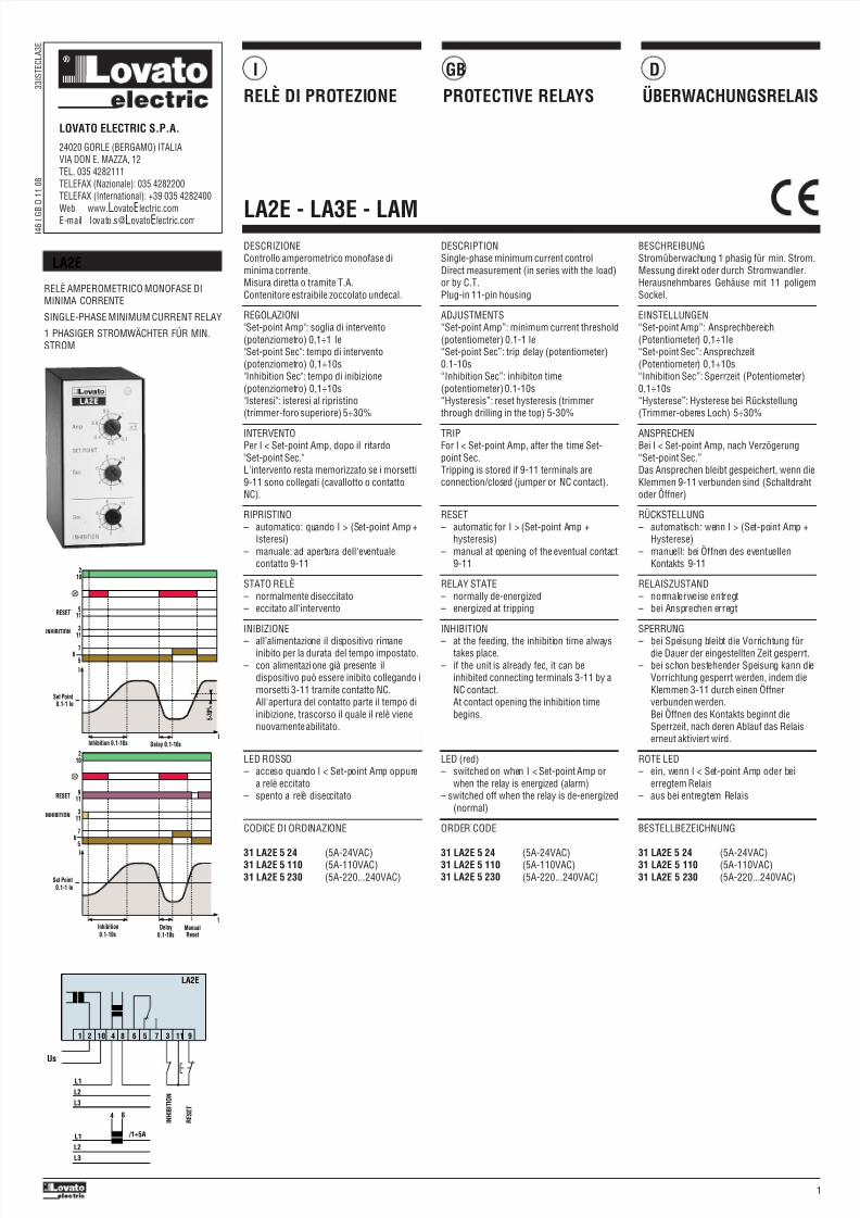
DESCRIZIONEControllo amperometrico monofase dimassima correnteMisura diretta o tramite T.A.Contenitore estraibile zoccolato undecal.
REGOLAZIONI"Set-point Amp”: soglia di intervento(potenziometro) 0,1÷1 Ie"Set-point Sec": tempo di intervento(potenziometro) 0,1÷10s"Inhibition Sec": tempo di inibizione
(potenziometro) 0,1÷10s"Isteresi": isteresi al ripristino (trimmer-forosuperiore) 5÷30%
INTERVENTOPer I > Set-point Amp, dopo il ritardo "Set-point Sec."L'intervento resta memorizzato se i morsetti9-11 sono collegati (cavallotto o contattoNC).
RIPRISTINO– automatico quando I < (Set-point Amp -
Isteresi)– manuale ad apertura dell'eventuale
contatto 9-11
STATO RELÈ
– normalmente diseccitato– eccitato all'intervento
INIBIZIONE– all’alimentazione il dispositivo rimane
inibito per la durata del tempo impostato.– con alimentazione già presente il
dispositivo può essere inibito collegando imorsetti 3-11 tramitecontatto NC.All'apertura del contatto parte il tempo diinibizione, trascorso il quale il relè vienenuovamente abilitato.
LED ROSSO– acceso quando I > Set-point Amp oppure
a relè eccitato
– spento a relè diseccitato
CODICE DI ORDINAZIONE
31 LA3E 5 24 (5A-24VAC)31 LA3E 5 110 (5A-110VAC)31 LA3E 5 230 (5A-220...240VAC)
DESCRIPTIONSingle-phase maximum current controlDirect measurement (in series with the load)or by C.T.)Plug-in 11-pin housing
ADJUSTMENTS“Set-point Amp”: maximum currentthreshold (potentiometer) 0.1-1 Ie“Set-point Sec”: trip delay (potentiometer)0.1-10s“Inhibition Sec”: inhibiton time
(potentiometer) 0.1-10s“Hysteresis”: reset hysteresis (trimmerthrough drilling in the top) 5-30%
TRIPFor I > Set-point Amp, after the delay“Set-point Sec”Tripping is stored if 9-11 terminals areconnection/closed (jumper or NC contact)
RESET– automatic for I < (Set-point Amp -
hysteresis)– manual at opening of the eventual contact
9-11
RELAY STATE
– normally de-energised– energised at tripping
INHIBITION– at the feeding, the inhibition time always
takes place.– if the unit is already fed it can be inhibited
connecting terminals 3-11 by a NCcontact.At contact opening, the inhibition timebegins.
LED (red)– switched on when I > Set-point Amp or
when the relay is energised (alarm)
– switched off when the relay is de-energised (normal)
ORDER CODE
31 LA3E 5 24 (5A-24VAC)31 LA3E 5 110 (5A-110VAC)31 LA3E 5 230 (5A-220...240VAC)
7
56
I
t
210
Inhibition 0.1-10s Delay 0.1-10s
5 - 3
0 %
Set Point0.1-1 Ie
113
911
Inhibition0.1-10s 0.1-10s
Delay
INHIBITION
RESET
ManualReset
t
7
56
210
Set Point0.1-1 Ie
113
911
INHIBITION
RESET
I
91131 2 10 4 8 6 5 7
LA3E
L3
L2
L1
L1
L2
L3
/1÷5A
I N H I B I T I O N
R E S E T
Us
4 8
LA3E
RELÈ AMPEROMETRICO MONOFASE DIMASSIMA CORRENTE
SINGLE-PHASE MAXIMUM CURRENTRELAY
1 PHASIGER STROMWÄCHTER FÜR MAX.STROM
BESCHREIBUNGStromüberwachung 1 phasig für max. Strom.Messung direkt oder durch Stromwandler.Herausnehmbares Gehäuse mit 11 poligemSockel.
EINSTELLUNGEN“Set-point Amp”: Ansprechbereich(Potentiometer) 0,1÷1Ie“Set-point Sec”: Ansprechzeit(Potentiometer) 0,1÷10s“Inhibition Sec”: Sperrzeit (Potentiometer)
0,1÷10s“Hysterese”: Hysterese bei Rückstellung(Trimmer-oberes Loch) 5÷30%
ANSPRECHENBei I > Set-point Amp, nach Verzögerung“Set-point Sec.”Das Ansprechen bleibt gespeichert, wenn dieKlemmen 9-11 verbunden sind (Schaltdrahtoder Öffner)
RÜCKSTELLUNG– automatisch: wenn I < (Set-point Amp -
Hysterese)– manuell: bei Öffnen des eventuellen
Kontakts 9-11
RELAISZUSTAND
– normalerweise entregt– bei Ansprechen erregt
SPERRUNG– bei Speisung bleibt die Vorrichtung für
die Dauer der eingestellten Zeit gesperrt.– bei schon bestehender Speisung kann die
Vorrichtung gesperrt werden, indem dieKlemmen 3-11 durch einen Öffnerverbunden werden.Bei Öffnen des Kontakts beginnt dieSperrzeit, nach deren Ablauf das Relaiserneut aktiviert wird.
ROTE LED– ein, wenn I > Set-point Amp oder bei
erregtem Relais
– aus bei entregtem Relais
BESTELLBEZEICHNUNG
31 LA3E 5 24 (5A-24VAC)31 LA3E 5 110 (5A-110VAC)31 LA3E 5 230 (5A-220...240VAC)
8/2/2019 i046igbd11 08 Protective Relays La2e-La3e-Lam
http://slidepdf.com/reader/full/i046igbd11-08-protective-relays-la2e-la3e-lam 3/5
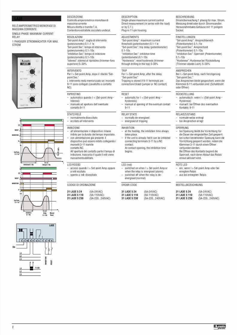
DESCRIZIONEControllo amperometrico trifase di massimacorrente (sovraccarico e corto-circuito);particolarmente adatto per gruppi elettrogenidi emergenza.Misura diretta o tramite T.A.Contenitore da incasso.
REGOLAZIONI"Set-point Overload": soglia sovraccarico(potenziometro) 1÷5A
"Delay": tempo di intervento sovraccarico(potenziometro) 1÷30s"Set-point Short-circuit": soglia corto circuito(potenziometro) 5÷25A
INTERVENTOAl verificarsi di una delle seguenti condizionisu una o più fasia) Sovraccarico
I > Set-point Overload, dopo il tempo"Delay"
b) Corto circuitoI > Set-point Short-circuit, istantaneo
L'intervento resta memorizzato in entrambi icasi.
RIPRISTINOSempre manuale mediante contatto NA
collegato ai morsetti 7-8 oppure mediantepulsante "Reset" sul fronte
STATO RELÈ– normalmente eccitato– diseccitato all'intervento
INIBIZIONEIn fase di avviamento la protezione disovraccarico può essere inibita mediantechiusura di un contatto collegato ai morsetti6-7.All'apertura del contatto inizia il controllo.
LED1 ROSSOI > Set-point overload oppure ad intervento
protezione sovraccaricoLED2 ROSSOIntervento protezione corto-circuito
LED3 VERDE– acceso con relè eccitato (normale
funzionamento)– spento con relè diseccitato (condizione di
allarme)
CODICE DI ORDINAZIONE
31 LAM 24 (24VAC)31 LAM 110 (110...127VAC)31 LAM 230 (220...240VAC)31 LAM 400 (380...415VAC)
DESCRIPTIONThree-phase maximum current control(overload and short-circuit);generally used with three-phase generators(emergency generating sets)Direct measurement: (in series with the load)or by C.T.Flush mounting, noryl housing.
ADJUSTMENTS“Set-point Overload”: overload threshold(potentiometer) 1-5A
“Delay”: overload trip delay (potentiometer)1-30s“Set-point Short-circuit”: short-circuitthreshold (potentiometer) 5-25A
TRIPWhenever one of the following conditionsoccurs on one or more phases:a) Overload
I > Set-point Overload, after the time“Delay”
b) Short-circuitI > Set-point Short-circuit, instantaneous
Tripping is stored in both cases.
RESETAlways manual at closing of a NO contact
(terminals 7-8) or by push button on thefront panel.
RELAY STATE– normally energised– de-energised at tripping
INHIBITIONDuring the starting phase, the overloadprotection can be inhibited by closing a NCcontact connected to terminals 6-7.Opening the contact, the protection isenabled.
LED 1 (red)Switched on for I > Set-point Overload or
after an overload tripLED 2 (red)Switched on for short-circuit trip
LED 3 (green)– switched on when the relay is energised
(normal)– switched off when the relay is de-
energised (alarm)
ORDER CODE
31 LAM 24 (24VAC)31 LAM 110 (110...127VAC)31 LAM 230 (220...240VAC)31 LAM 400 (380...415VAC)
5
43
I
t
12
Overload OverloadDelay1-30s
Set Point O/L
0.1-1 Ie
87
Set Point Short Circuit 1-5 Ie
1-30sDelay
Overload
Relay
Overload
Short Circuit
OVERLOAD SHORT CIRCUIT
InhibitionReset
67
Inhibition
Reset
Reset
Corrente nominale Ie = 5A
111091 2 3 4 5 6 7 8
LAM
L3
L2
L1
I N H I B I T I O N
R E S E T
1 2 1 3 1 4
U s
1615
/5A
LAM
RELÈ AMPEROMETRICO TRIFASE DIMASSIMA CORRENTE
THREE-PHASE MAXIMUM CURRENT RELAY
3 PHASIGER STROMWÄCHTER FÜR MAX.STROM
BESCHREIBUNGStromüberwachung 3 phasig für max. Strom(Überlast und Kurzschluß); besondersgeeignet für Not-Elektroaggregate.Messung direkt oder durch StromwandlerEinbaugehäuse.
EINSTELLUNGEN“Set-point Overload”: Überlastschwelle(Potentiometer) 1÷5A
“Delay”: Ansprechzeit Überlast(Potentiometer) 1÷30s“Set-point Short-circuit”:Kurzschlußschwelle (Potentiometer) 5÷25A
ANSPRECHENBei Auftreten einer der folgendenBedingungen auf einer oder mehrerenPhasena) Überlast
I > Set-point Overload, nach Zeit “Delay”b) Kurzschluß
I > Set-point Short-circuit, unverzögertDas Ansprechen bleibt in beiden Fällengespeichert.
RÜCKSTELLUNGStets manuell durch Schließer, der an die
Klemmen 7-8 angeschlossen ist oder durchTaster “Reset” auf der Vorderseite
RELAISZUSTAND– normalerweise erregt– bei Ansprechen entregt
SPERRUNGIn der Einschaltphase kann derÜberlastschutz durch Schließen einesKontakts gesperrt werden, der an dieKlemmen 6-7 angeschlossen ist.Bei Öffnen des Kontakts beginnt dieÜberwachung.
ROTE LED1I > Set-point Overload oder bei Ansprechen
des ÜberlastschutzesROTE LED2Ansprechen des Kurzschlußschutzes
GRÜNE LED3– ein bei erregtem Relais
(normaler Betrieb)– aus bei entregtem Relais
(Alarmzustand)
BESTELLBEZEICHNUN
31 LAM 24 (24VAC)31 LAM 110 (110...127VAC)31 LAM 230 (220...240VAC)31 LAM 400 (380...415VAC)
3
8/2/2019 i046igbd11 08 Protective Relays La2e-La3e-Lam
http://slidepdf.com/reader/full/i046igbd11-08-protective-relays-la2e-la3e-lam 4/5
8/2/2019 i046igbd11 08 Protective Relays La2e-La3e-Lam
http://slidepdf.com/reader/full/i046igbd11-08-protective-relays-la2e-la3e-lam 5/5
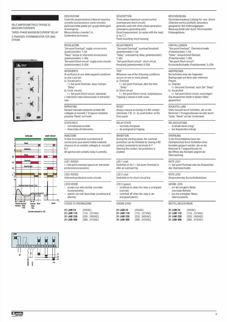
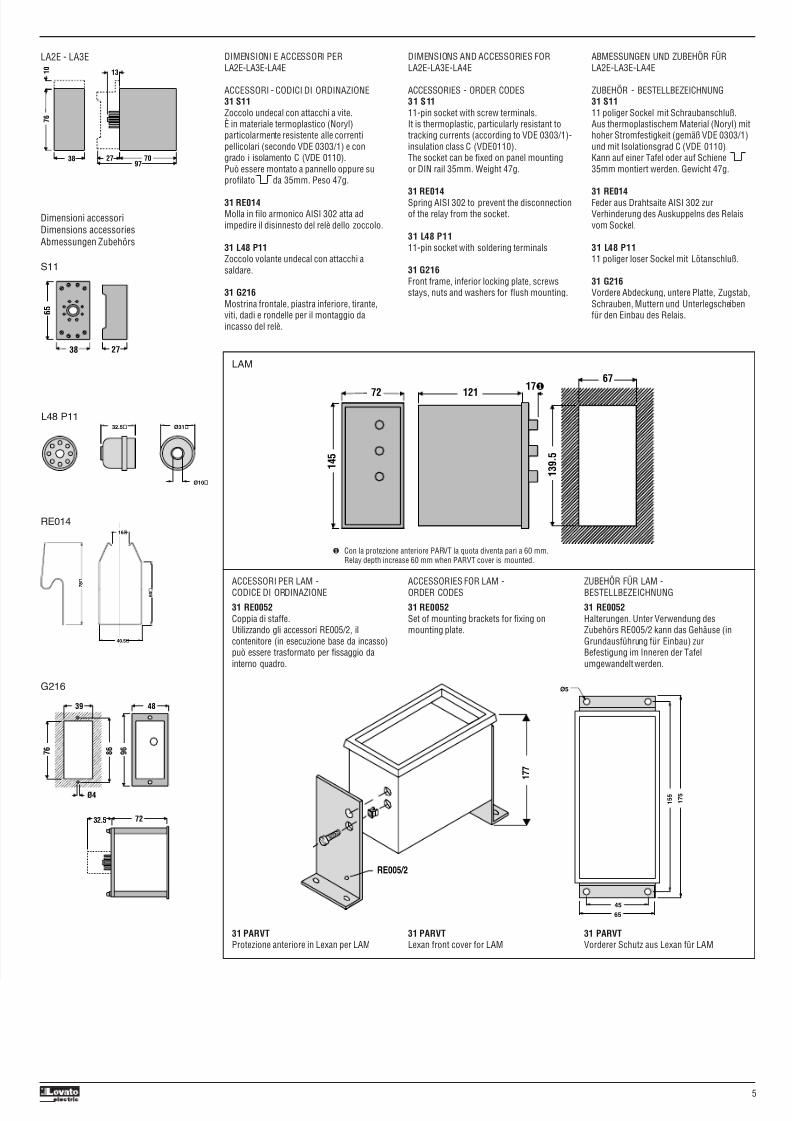
DIMENSIONI E ACCESSORI PERLA2E-LA3E-LA4E
ACCESSORI - CODICI DI ORDINAZIONE31 S11Zoccolo undecal con attacchi a vite.È in materiale termoplastico (Noryl)particolarmente resistente alle correntipellicolari (secondo VDE 0303/1) e congrado i isolamento C (VDE 0110).Può essere montato a pannello oppure suprofilato da 35mm. Peso 47g.
31 RE014Molla in filo armonico AISI 302 atta adimpedire il disinnesto del relè dello zoccolo.
31 L48 P11Zoccolo volante undecal con attacchi asaldare.
31 G216Mostrina frontale, piastra inferiore, tirante,viti, dadi e rondelle per il montaggio daincasso del relè.
DIMENSIONS AND ACCESSORIES FORLA2E-LA3E-LA4E
ACCESSORIES - ORDER CODES31 S1111-pin socket with screw terminals.It is thermoplastic, particularly resistant totracking currents (according to VDE 0303/1)-insulation class C (VDE0110).The socket can be fixed on panel mountingor DIN rail 35mm. Weight 47g.
31 RE014Spring AISI 302 to prevent the disconnectionof the relay from the socket.
31 L48 P1111-pin socket with soldering terminals
31 G216Front frame, inferior locking plate, screwsstays, nuts and washers for flush mounting.
ABMESSUNGEN UND ZUBEHÖR FÜRLA2E-LA3E-LA4E
ZUBEHÖR - BESTELLBEZEICHNUNG31 S1111 poliger Sockel mit Schraubanschluß.Aus thermoplastischem Material (Noryl) mithoher Stromfestigkeit (gemäß VDE 0303/1)und mit Isolationsgrad C (VDE 0110).Kann auf einer Tafel oder auf Schiene35mm montiert werden. Gewicht 47g.
31 RE014Feder aus Drahtsaite AISI 302 zurVerhinderung des Auskuppelns des Relaisvom Sockel.
31 L48 P1111 poliger loser Sockel mit Lötanschluß.
31 G216Vordere Abdeckung, untere Platte, Zugstab,Schrauben, Muttern und Unterlegscheibenfür den Einbau des Relais.
LA2E - LA3E
Dimensioni accessoriDimensions accessoriesAbmessungen Zubehörs
S11
G216
RE014
32.5 Ø31
Ø10
16
6 0
40.5
7 8
L48 P11
ACCESSORI PER LAM -
CODICE DI ORDINAZIONE31 RE0052Coppia di staffe.Utilizzando gli accessori RE005/2, ilcontenitore (in esecuzione base da incasso)può essere trasformato per fissaggio dainterno quadro.
31 PARVTProtezione anteriore in Lexan per LAM
ACCESSORIES FOR LAM -
ORDER CODES31 RE0052Set of mounting brackets for fixing onmounting plate.
31 PARVTLexan front cover for LAM
ZUBEHÖR FÜR LAM -
BESTELLBEZEICHNUNG31 RE0052Halterungen. Unter Verwendung desZubehörs RE005/2 kann das Gehäuse (inGrundausführung für Einbau) zurBefestigung im Inneren der Tafelumgewandelt werden.
31 PARVTVorderer Schutz aus Lexan für LAM
LAM
17❶12172
67
1 3 9 . 5
1 4 5
RE005/2
1 7 7
65
1 7 5
45
1 5 5
Ø5
❶ Con la protezione anteriore PARVT la quota diventa pari a 60 mm.Relay depth increase 60 mm when PARVT cover is mounted.
7 6
1 0
38 702797
13
6 5
38 27
32.5 72
4839
9 6
7 6
8 6
Ø4
5