Embed Size (px)
Citation preview

User’s Guide
i1800 Series Scanners
Eastman Kodak Company343 State StreetRochester, NY 14650 U.S.A.© Kodak, 2007. All rights reserved. TM: Kodak
COLORS
9E8273A
8.5 x 11” Folded
6079-232
GUIDE COVER-KODAK SCANNERS
FONTSWhitney K Family
SIZE
ECO
P/N
DESIGNER
MODIFIED10.11.07
9E8273A
DE MEYER
ARTWORK NAME
PRINTING INFORMATION
4 COLOR PROCESS
ENLANGUAGES
A-61555

A-61555 March 2007 i
Contents
1 Introduction . . . . . . . . . . . . . . . . . . . . . . . . . . . . . . . . . . . . . . . . . . . . . . . . 1-1Scanner features . . . . . . . . . . . . . . . . . . . . . . . . . . . . . . . . . . . . . . . . . . . . 1-2System requirements . . . . . . . . . . . . . . . . . . . . . . . . . . . . . . . . . . . . . . . . . 1-3Supporting documentation . . . . . . . . . . . . . . . . . . . . . . . . . . . . . . . . . . . . . 1-3Contacting Service and Support. . . . . . . . . . . . . . . . . . . . . . . . . . . . . . . . . 1-4Safety information . . . . . . . . . . . . . . . . . . . . . . . . . . . . . . . . . . . . . . . . . . . 1-5
MSDS . . . . . . . . . . . . . . . . . . . . . . . . . . . . . . . . . . . . . . . . . . . . . . . . . . 1-5User precautions . . . . . . . . . . . . . . . . . . . . . . . . . . . . . . . . . . . . . . . . . 1-5Gas springs warning . . . . . . . . . . . . . . . . . . . . . . . . . . . . . . . . . . . . . . . 1-5
Environmental information . . . . . . . . . . . . . . . . . . . . . . . . . . . . . . . . . . . . . 1-6European Union . . . . . . . . . . . . . . . . . . . . . . . . . . . . . . . . . . . . . . . . . . . . . 1-6EMC statements . . . . . . . . . . . . . . . . . . . . . . . . . . . . . . . . . . . . . . . . . . . . 1-6
United States . . . . . . . . . . . . . . . . . . . . . . . . . . . . . . . . . . . . . . . . . . . . 1-6Japan . . . . . . . . . . . . . . . . . . . . . . . . . . . . . . . . . . . . . . . . . . . . . . . . . . 1-6Taiwan . . . . . . . . . . . . . . . . . . . . . . . . . . . . . . . . . . . . . . . . . . . . . . . . . 1-6Peoples Republic of China . . . . . . . . . . . . . . . . . . . . . . . . . . . . . . . . . . 1-7Korean . . . . . . . . . . . . . . . . . . . . . . . . . . . . . . . . . . . . . . . . . . . . . . . . . . 1-7European Union. . . . . . . . . . . . . . . . . . . . . . . . . . . . . . . . . . . . . . . . . . . 1-7
Acoustic emission . . . . . . . . . . . . . . . . . . . . . . . . . . . . . . . . . . . . . . . . . . . 1-7Power system connection . . . . . . . . . . . . . . . . . . . . . . . . . . . . . . . . . . . . . 1-7
2 Getting Started . . . . . . . . . . . . . . . . . . . . . . . . . . . . . . . . . . . . . . . . . . . . . . 2-1Scanner components . . . . . . . . . . . . . . . . . . . . . . . . . . . . . . . . . . . . . . . . . 2-1
Front view . . . . . . . . . . . . . . . . . . . . . . . . . . . . . . . . . . . . . . . . . . . . . . . 2-1Internal components . . . . . . . . . . . . . . . . . . . . . . . . . . . . . . . . . . . . . . . 2-4Rear view . . . . . . . . . . . . . . . . . . . . . . . . . . . . . . . . . . . . . . . . . . . . . . . 2-5
3 Using the Scanner . . . . . . . . . . . . . . . . . . . . . . . . . . . . . . . . . . . . . . . . . . . 3-1Turning the scanner on . . . . . . . . . . . . . . . . . . . . . . . . . . . . . . . . . . . . . . . 3-1Turning the scanner off. . . . . . . . . . . . . . . . . . . . . . . . . . . . . . . . . . . . . . . . 3-3Starting and stopping scanning . . . . . . . . . . . . . . . . . . . . . . . . . . . . . . . . . 3-3Document preparation . . . . . . . . . . . . . . . . . . . . . . . . . . . . . . . . . . . . . . . 3-3Adjusting the input elevator . . . . . . . . . . . . . . . . . . . . . . . . . . . . . . . . . . . . 3-5
Adjusting the side guides. . . . . . . . . . . . . . . . . . . . . . . . . . . . . . . . . . . . 3-5Selecting your feeding position . . . . . . . . . . . . . . . . . . . . . . . . . . . . . . . 3-5Locking the side guides . . . . . . . . . . . . . . . . . . . . . . . . . . . . . . . . . . . . . 3-5Adjusting the height of the input elevator . . . . . . . . . . . . . . . . . . . . . . . 3-6Adjusting the input tray for document length . . . . . . . . . . . . . . . . . . . . . 3-6Installing the document extender. . . . . . . . . . . . . . . . . . . . . . . . . . . . . . 3-7
Output tray options . . . . . . . . . . . . . . . . . . . . . . . . . . . . . . . . . . . . . . . . . . . 3-7Adjusting the output tray. . . . . . . . . . . . . . . . . . . . . . . . . . . . . . . . . . . . . . . 3-7
Adjusting the side guides. . . . . . . . . . . . . . . . . . . . . . . . . . . . . . . . . . . . 3-7Adjusting the output tray for document lengths up to 43.2 cm (17 in.) . 3-8Positioning the output tray . . . . . . . . . . . . . . . . . . . . . . . . . . . . . . . . . . . 3-8Adjusting the end stop . . . . . . . . . . . . . . . . . . . . . . . . . . . . . . . . . . . . . . 3-9Adjusting the angle of the output tray . . . . . . . . . . . . . . . . . . . . . . . . . . 3-9The exit deflector . . . . . . . . . . . . . . . . . . . . . . . . . . . . . . . . . . . . . . . . . 3-11Adjusting the output tray for documents from 43.2 cm (17 in.) to 86 cm (34 in.) . . . . . . . . . . . . . . . . . . . . . . . . . . . . . . . . . . . . . . . . . . 3-12
Adjusting the short document tray . . . . . . . . . . . . . . . . . . . . . . . . . . . . . . 3-13

ii A-61555 March 2007
Adjusting the height of the scanner . . . . . . . . . . . . . . . . . . . . . . . . . . . . . 3-14Feeding documents using multi-feed detection . . . . . . . . . . . . . . . . . . . . 3-15Automatic feeding . . . . . . . . . . . . . . . . . . . . . . . . . . . . . . . . . . . . . . . . . . 3-15Continuous feeding . . . . . . . . . . . . . . . . . . . . . . . . . . . . . . . . . . . . . . . . . 3-16Manual feeding . . . . . . . . . . . . . . . . . . . . . . . . . . . . . . . . . . . . . . . . . . . . 3-16Feeding documents that require special handling . . . . . . . . . . . . . . . . . . 3-17Using the operator control panel touchscreen . . . . . . . . . . . . . . . . . . . . . 3-18Setting screen . . . . . . . . . . . . . . . . . . . . . . . . . . . . . . . . . . . . . . . . . . . . . 3-19
Changing the alarm volume. . . . . . . . . . . . . . . . . . . . . . . . . . . . . . . . . 3-20Selecting the tone . . . . . . . . . . . . . . . . . . . . . . . . . . . . . . . . . . . . . . . . 3-21Selecting a language . . . . . . . . . . . . . . . . . . . . . . . . . . . . . . . . . . . . . . 3-22Enabling/disabling image addressing . . . . . . . . . . . . . . . . . . . . . . . . . 3-23Calibrating the scanner . . . . . . . . . . . . . . . . . . . . . . . . . . . . . . . . . . . . 3-25
Idle screen . . . . . . . . . . . . . . . . . . . . . . . . . . . . . . . . . . . . . . . . . . . . . . . . 3-27Operator Log . . . . . . . . . . . . . . . . . . . . . . . . . . . . . . . . . . . . . . . . . . . . 3-28Accessing scanner information . . . . . . . . . . . . . . . . . . . . . . . . . . . . . . 3-29Count only mode . . . . . . . . . . . . . . . . . . . . . . . . . . . . . . . . . . . . . . . . . 3-30Performing a Print test . . . . . . . . . . . . . . . . . . . . . . . . . . . . . . . . . . . . . 3-31Performing a Patch test . . . . . . . . . . . . . . . . . . . . . . . . . . . . . . . . . . . . 3-32Performing a self test. . . . . . . . . . . . . . . . . . . . . . . . . . . . . . . . . . . . . . 3-32
Enabling the scanner . . . . . . . . . . . . . . . . . . . . . . . . . . . . . . . . . . . . . . . . 3-33Scanning . . . . . . . . . . . . . . . . . . . . . . . . . . . . . . . . . . . . . . . . . . . . . . . . . 3-33Using function keys when scanning . . . . . . . . . . . . . . . . . . . . . . . . . . . . . 3-34Changing image address levels . . . . . . . . . . . . . . . . . . . . . . . . . . . . . . . . 3-34Manually pausing and resuming the scanner . . . . . . . . . . . . . . . . . . . . . . 3-35Automatically pausing and resuming the scanner . . . . . . . . . . . . . . . . . . 3-35Power Saver mode. . . . . . . . . . . . . . . . . . . . . . . . . . . . . . . . . . . . . . . . . . 3-36Viewing messages . . . . . . . . . . . . . . . . . . . . . . . . . . . . . . . . . . . . . . . . . . 3-36
4 The Enhanced Printer/Patch Readers . . . . . . . . . . . . . . . . . . . . . . . . . . . 4-1Enhanced Printer overview . . . . . . . . . . . . . . . . . . . . . . . . . . . . . . . . . . . . 4-1Printer specifications . . . . . . . . . . . . . . . . . . . . . . . . . . . . . . . . . . . . . . . . . 4-2Changing print positions. . . . . . . . . . . . . . . . . . . . . . . . . . . . . . . . . . . . . . . 4-3
Changing the front horizontal print position . . . . . . . . . . . . . . . . . . . . . . 4-3Changing the rear horizontal print position . . . . . . . . . . . . . . . . . . . . . . 4-4Moving the printer carrier and cable from the front to the rear and vice versa . . . . . . . . . . . . . . . . . . . . . . . . . . . . . . . . . . . . . . . . . . . . . . 4-5
Replacing the ink cartridge . . . . . . . . . . . . . . . . . . . . . . . . . . . . . . . . . . . . 4-7Replacing the front blotter strips . . . . . . . . . . . . . . . . . . . . . . . . . . . . . . . 4-9Replacing the rear blotter strips . . . . . . . . . . . . . . . . . . . . . . . . . . . . . . . . 4-11The Patch Readers . . . . . . . . . . . . . . . . . . . . . . . . . . . . . . . . . . . . . . . . . 4-12
Patch types . . . . . . . . . . . . . . . . . . . . . . . . . . . . . . . . . . . . . . . . . . . . . 4-12Patch code placement . . . . . . . . . . . . . . . . . . . . . . . . . . . . . . . . . . . . . 4-13
A-61555 March 2007 iii
5 Maintenance . . . . . . . . . . . . . . . . . . . . . . . . . . . . . . . . . . . . . . . . . . . . . . . . 5-1Cleaning frequency chart . . . . . . . . . . . . . . . . . . . . . . . . . . . . . . . . . . . . . . 5-2Cleaning tools and materials . . . . . . . . . . . . . . . . . . . . . . . . . . . . . . . . . . . 5-2Supplies, consumables and accessories . . . . . . . . . . . . . . . . . . . . . . . . . 5-3Ordering parts. . . . . . . . . . . . . . . . . . . . . . . . . . . . . . . . . . . . . . . . . . . . . . . 5-3Cleaning procedures . . . . . . . . . . . . . . . . . . . . . . . . . . . . . . . . . . . . . . . . . 5-4
Cleaning the OCP touchscreen . . . . . . . . . . . . . . . . . . . . . . . . . . . . . . . 5-4Vacuuming the output tray and input elevator . . . . . . . . . . . . . . . . . . . . 5-4Cleaning the rollers . . . . . . . . . . . . . . . . . . . . . . . . . . . . . . . . . . . . . . . . 5-5Vacuuming the transport area . . . . . . . . . . . . . . . . . . . . . . . . . . . . . . . . 5-9Vacuuming under the background strips . . . . . . . . . . . . . . . . . . . . . . . . 5-9Cleaning the imaging guides - basic cleaning . . . . . . . . . . . . . . . . . . . 5-10Cleaning the imaging guides - thorough cleaning . . . . . . . . . . . . . . . . 5-11Running a transport cleaning sheet . . . . . . . . . . . . . . . . . . . . . . . . . . . 5-13Final cleaning steps . . . . . . . . . . . . . . . . . . . . . . . . . . . . . . . . . . . . . . . 5-14
Replacement procedures . . . . . . . . . . . . . . . . . . . . . . . . . . . . . . . . . . . . 5-15Replacing the feed module or feed module tires . . . . . . . . . . . . . . . . 5-15Replacing the separation roller or separation roller tires . . . . . . . . . . 5-19Replacing the pre-separation pad . . . . . . . . . . . . . . . . . . . . . . . . . . . . 5-20Replacing the imaging guides . . . . . . . . . . . . . . . . . . . . . . . . . . . . . . 5-20
6 Troubleshooting . . . . . . . . . . . . . . . . . . . . . . . . . . . . . . . . . . . . . . . . . . . . . 6-1Accessing the Operator Log . . . . . . . . . . . . . . . . . . . . . . . . . . . . . . . . . . . 6-1Accessing the Operator Log from the touchscreen . . . . . . . . . . . . . . . . . . 6-1Accessing the Operator Log from the Scan Validation Tool . . . . . . . . . . . . 6-2Message listing . . . . . . . . . . . . . . . . . . . . . . . . . . . . . . . . . . . . . . . . . . . . . 6-5Numerical message listing . . . . . . . . . . . . . . . . . . . . . . . . . . . . . . . . . . . . 6-10Contacting Service . . . . . . . . . . . . . . . . . . . . . . . . . . . . . . . . . . . . . . . . . . 6-11Problem solving . . . . . . . . . . . . . . . . . . . . . . . . . . . . . . . . . . . . . . . . . . . . 6-12
Appendix A Accessories . . . . . . . . . . . . . . . . . . . . . . . . . . . . . . . . . . . . .A-1Kodak Ultralightweight Paper Feed Module . . . . . . . . . . . . . . . . . . . . . . .A-1Kodak White Background Accessory . . . . . . . . . . . . . . . . . . . . . . . . . . . .A-1Kodak Manual Feeder . . . . . . . . . . . . . . . . . . . . . . . . . . . . . . . . . . . . . . . .A-1Kodak High Resolution Printer Accessory . . . . . . . . . . . . . . . . . . . . . . . . .A-1
Appendix B Specifications . . . . . . . . . . . . . . . . . . . . . . . . . . . . . . . . . . . .B-1

A-61555 March 2007 1-1
1 Introduction
This User’s Guide provides information and procedures for the Kodak i1800 Series Scanners.
Chapter 1, Introduction — provides general information about the i1800 Series Scanners including a product description, scanner features, safety information, user precautions and how to contact Service and Support.
Chapter 2, Getting Started — includes an overview of internal and external scanner components.
Chapter 3, Using the Scanner — includes information on how to prepare your documents for scanning, input elevator, output tray and workspace table adjustments, scanning your documents and using the touchscreen operator control panel.
Chapter 4, Using the Enhanced Printer and Patch Readers — provides procedures for using and maintaining the Enhanced Printer and the Patch Readers.
NOTE: Patch Reader functionality is for the Kodak i1860 Scanner only.
Chapter 5, Maintenance — provides maintenance procedures for the i1800 Series Scanners, including cleaning and replacement procedures for the feed module, separation roller, pre-separation pad and imaging guides.
Chapter 6, Troubleshooting — provides information about accessing the operator log, a problem solving chart, procedures for clearing a document jam and a listing of error messages.
Appendix A, Accessories — provides a description of the optional accessories that can be purchased to support the Kodak i1800 Series Scanners. Instructions for using these accessories are included with the accessory.
Appendix B, Specifications — provides a listing of the specifications for the Kodak i1800 Series Scanners.

1-2 A-61555 March 2007
Scanner features • Excellent paper handling, image quality, and reliability.• Color or grayscale at the same speed as black-and-white.• Color touchscreen for easy operator use.• Simultaneous black-and-white and color/grayscale image output.• Handles a broad range of paper weights and sizes.• Built-in Patch Readers accept patch types for post-scan image
control, image addressing and for switching between black-and-white/color or black-and-white/grayscale output streams.NOTE: Patch Reader and image address functionality is for the
Kodak i1860 Scanner only.
• Includes the Brightness and Contrast Control which allows you to create custom color tables.
• ISIS and TWAIN device drivers are included on a CD that is packed with each scanner.
• International language support.• Ergonomic design includes an integrated operator adjustable height,
sit- to stand-workspace table • 500-sheet input elevator.• Energy Star compliant.• Document printing capabilities using the Enhanced Printer or High
Resolution Printer accessory.• Electronic red, green and blue color dropout.• Output resolutions include:
- Black-and-white: 200, 240, 300, 400- Color: 100, 150, 200, 240, 300 - Grayscale: 100, 150, 200, 240, 300
• Multi-feed detection by multiple ultrasonic sensors as well as by length detection.
• Automatic and manual feeding.• JPEG compression for color and grayscale images. • Image processing features include Kodak’s Perfect Page technology
for black-and-white, grayscale and color images.• Easily replaceable feed module, separation roller and pre-separation
pad.
• Long lasting lamps.

A-61555 March 2007 1-3
System requirements Following is the minimum recommended system configuration to run the Kodak i1800 Series Scanners.
NOTE: The actual performance of the system depends on the scanning application, choice of scanning parameters, and the host computer configuration. If the scanner is not performing at the optimal speed, a faster computer and/or more RAM may be necessary to obtain the rated throughput.
• Intel PC (or compatible) with a Pentium IV 2 GHz processor • An available PCI slot (for FireWire card)• Microsoft Windows 2000 Professional, Windows XP (Professional/
Home)• 512 MB RAM
Supporting documentation
The following documentation is available to support the Kodak i1800 Series Scanners:
• Quick Tips Guide, A-61556 — is a summary of this User’s Guide and intended to be used as a quick reference for basic scanner use.
• Brightness and Contrast Control Reference Guide, A-61587— provides information and procedures for using the Brightness and Contrast Control which allows you to create your own custom color tables.
• Image Processing Guide, A-61580 — provides information on the Kodak Scan Validation Tool as well as descriptions of the features available for the i1800 Series Scanners that can be configured using the TWAIN Data source or ISIS Driver.
• On-line help — available when using the TWAIN Data source and ISIS Driver.
• Patch Code Information, A-61599 — provides detailed specifications for patch codes and includes camera-ready patches.
• Installation Planning Guide, A-61578 — provides site specification information to ensure a successful scanner installation.
• Supplies and Consumables, A-61403 — provides a complete listing of supplies and consumables for all Kodak Scanners.
• White Background Accessory Instructions, A-61576 — when you purchase the White Background Accessory, these instructions are included and provide a description of how to install the accessory.
• High Resolution Printer Accessory Instructions, A-61591 — provides instructions for using and maintaining the the High Resolution Printer.
• Ultra-Lightweight Feeder Accessory Instructions, A-61577 —when you purchase the Ultra-Lightweight Feeder Accessory these instructions are included and provide a description of how to use the Ultra-Lightweight Feed Module.
• Kodak Manual Feeder for i1800 Series Scanners, A-61559 — when you purchase the manual feeder this document provides instructions on how to install and use the manual feeder.

1-4 A-61555 March 2007
Contacting Service and Support
Telephone and on-site service by trained Kodak Field Engineer is available as part of the warranty and Service Agreement. Refer to your Service Agreement Terms and Conditions for hours of availability.
Only a trained scanner operator should place a call to the Kodak Service Center and have the following information ready:
• The K-number of the scanner, which is located on the top cover of the scanner.
• A brief description of the question or problem including error code numbers as displayed in the summary log file. See Chapter 6, Troubleshooting, for details.
• A contact name and phone number where the contact/customer can be reached.
Phone numbers:• United States and Canada:
Kodak Field Service: 1-800-356-3253Kodak Professional Services: 1-800-525-6325
• Other locations: the Kodak Field Engineer who installs your scanner will provide you with the contact numbers and procedure for contacting your local support center.
When a call is placed for Field Service, the contact name and phone number will be taken and a Kodak Field Engineer will return the call.
You may also use this procedure to schedule the Preventative Maintenance visits you are entitled to if you have purchased a Service Contract.
Call the Professional Services number to request additional training for scanner operators by a Kodak Certified Technical Trainer (CTT).
• Request any of the following Professional Services:
- Additional Preventative Maintenance visits at high usage times anytime you want to ensure your scanner is running at optimum performance.
- Scanner Relocation Services are available if you are moving down the hall, to another building or across the country. Damage incurred during transport is not covered under your warranty or Service Agreement. Kodak will help with your move by packing the scanner in packaging material that is specifically designed for the i1800 Series Scanners. Kodak will also unpack and test your equipment at the final destination.
- Kodak Capture Software Application Development. If you have selected Kodak software to drive your scanner, Kodak can send a trained and experienced technician to assist you in developing your applications.
- Customized consulting services.

A-61555 March 2007 1-5
Safety information Warning labels
MSDS Material Safety Data Sheets (MSDS) are available on the Kodak website at: www.kodak.com/go/msds. When accessing the MSDSs from the website, you will be required to provide the catalog number of the consumable for the Material Safety Data Sheet you are requesting. See Chapter 5, “Supplies, consumables and accessories” for consumables and catalog numbers.
User precautions Users and their employer need to observe the common sense precautions applicable to the operation of any machinery. These include, but are not limited to, the following:
• Do not wear loose clothing, unbuttoned sleeves, etc.• Do not wear loose jewelry, bracelets, bulky rings, long necklaces, etc.• Hair length should be kept short, using a hair net if needed, or tying
long hair up in a bundle.• Remove all other loose objects from the area that could be drawn into
the machine.• Take sufficient breaks to maintain mental alertness.• Use only the recommended cleaning supplies. • Do not use canned/compressed air.
Supervisors should review their practices and make compliance with these precautions a part of the job description for operation of the scanner or any mechanical device.
Gas springs warning Do not attempt to repair the gas springs. These are designed to be replaced by a Kodak Field Engineer.
CAUTION: Moving parts, avoid contact.
CAUTION: Hot surface, avoid contact.

1-6 A-61555 March 2007
Environmental information
• The product packaging is recyclable.
• The i1800 Series Scanners are Energy Star compliant and are shipped from the factory with the default time set to 15 minutes.
European Union This symbol indicates that when the last user wishes to discard this product, it must be sent to appropriate facilities for recovery and recycling. Please contact your local Kodak representative or refer to www.kodak.com/go/recycle for additional information on the collection and recovery programs available for this product.
EMC statements IMPORTANT: Compliance with regulations governing radio frequency emissions requires that the installation of your Kodak i1800 Series Scanners use the shielded data cable provided. Any data cable the user may choose to substitute also must be shielded to assure continued compliance.
United States This equipment has been tested and found to comply with the limits for a Class A digital device pursuant to Part 15 of the FCC rules. These limits are designed to provide reasonable protection against harmful interference when the equipment is operated in a commercial environment. This equipment generates, uses, and can radiate radio frequently energy and, if not installed and used in accordance with the instruction manual, may cause harmful interference to radio communications. Operation of this equipment in a residential area is likely to cause harmful interference in which case the user will be required to correct the interference at their own expense.
Japan This is a Class A product based on the standard of the Voluntary Control Council for interference by information Technology Equipment (VCCI). If this equipment is used in a domestic environment, radio disturbance may arise. When such trouble occurs, the user may be required to take corrective action.

A-61555 March 2007 1-7
Peoples Republic of China
WARNING: This is a Class A product. In a domestic environment this product may cause radio interference in which case the user may be required to take adequate measures.
Korean Please note that this equipment has obtained EMC registration for commercial use. In the event that it has been mistakenly sold or purchased, please exchange it for equipment certified for home use.
European Union WARNING: This is a Class A product. In a domestic environment this product may cause radio interference in which case the user may be required to take adequate measures.
Acoustic emission Maschinenlärminformationsverordnung – 3, GSGVDer arbeitsplatzbezogene Emissionswert beträgt <70 db(A).
[Machine Noise Information Ordinance — 3, GSGVThe operator-position noise emission value is <70 dB(A).]
Power system connection
This product is also designed for Norwegian IT power system with phase-to-phase voltage 230V.
NetzanschlußDas Gerät ist auch für die Verwendung im norwegischen IT-Stromsystem mit einer Leiterspannung von 230 V geeignet.
Connexion aux systèmes d’alimentation électriqueCe produit est également conçu pour les systèmes norvégiens d’alimentation électrique informatique, dont la tension par phase est de 230 V.
声明,该产
此为A级产品,在生活环境中品可能会造成无线电干扰。在这种情况下,可能需要
用户对其干扰采取切实可行的措施

A-61555 March 2007 2-1
2 Getting Started
Scanner components Front view
1 Power switch — press the power switch on (I) or off (O) as required.
2 Input elevator — holds documents for scanning. The input elevator can be set to accommodate stacks of 25-, 100-, 250- or 500-documents (20 lb. bond paper).
3 Input elevator extender — open the input elevator extender to accommodate long documents.
4 Input elevator side guides — slide the guides in or out to accommodate the document size you want to scan. Side guides can be left-, center- and right-adjusted to accommodate documents of various widths. The side guides can also be locked into position if desired.
5 Feed module — provides smooth document feeding of various sizes, thicknesses and textures.
6 Paper present sensor — detects the presence of documents in the input elevator.
7 Gap release button — allows you to manually adjust the space between the feed module and separation roller for documents that require special handling.
1
2
3
4
5
6
7

2-2 A-61555 March 2007
8 Service K-Number — the number on this sticker is the number you will be asked to provide when placing a call Kodak Service.
9 POD release latch — push up the POD release latch when you need to access the inside of the scanner.
10 Output tray and end stop — collects the scanned documents. The output tray width and end stop length can be adjusted.
11 Exit deflector — aids in document stacking.
12 Printer access cover — lift this cover to access the front printer for changing printer positions and maintenance.
13 Top access cover — lift this cover to access the rear printer for changing printer positions and maintenance.
14 Touchscreen — a variety of functions can be performed using the touchscreen. See Chapter 3, Using the Scanner for procedures on using these functions. If you need to move the scanner, the touchscreen can be rotated so it will easily fit through doorways or tight spaces.
15 LED — flashes green when the scanner is in Power Saver/Energy Star mode; LED is steady green when the scanner is idle and ready to scan.
16 Workspace table height adjustment switch — used to raise and lower the workspace table on the scanner. The workspace table can be raised or lowered approximately 10 inches up or down.
17 Height Adjustment Wire — located underneath the output tray (not shown in photo), this wire can be pulled out to raise the front of the output tray.
8
9
1011
12
1314
15
16
18

A-61555 March 2007 2-3
18 Storage pocket — provides a convenient and easy-access area for storing calibration targets and documentation.

2-4 A-61555 March 2007
Internal components
1 Separation roller — provides smooth document feeding of various sizes and textures one document at a time.
2 Pre-separation pad — provides smooth document feeding of various sizes and textures one document at a time.
3 Document sensor — detects the presence of documents in the paper path during feeding.
4 Ink blotter strip cover — remove this cover to provide access to the ink blotter strips. The ink blotter strips collect residue from the Enhanced Printer.
5 Imaging guides — the scanner has an upper and lower imaging guide. It is important to keep the imaging guides clean to obtain optimum image quality.
6 Rollers — transport the documents through the paper path.
7 Patch Readers — these four patch readers can be setup to read patches. You can enable the patch readers via the capture software application.
NOTE: Patch Reader functionality is for the Kodak i1860 Scanner only.
5
4
3
2
6
1
7
A-61555 March 2007 2-5
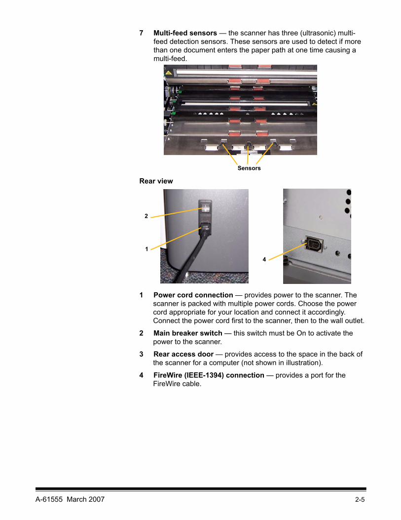
7 Multi-feed sensors — the scanner has three (ultrasonic) multi-feed detection sensors. These sensors are used to detect if more than one document enters the paper path at one time causing a multi-feed.
Rear view
1 Power cord connection — provides power to the scanner. The scanner is packed with multiple power cords. Choose the power cord appropriate for your location and connect it accordingly. Connect the power cord first to the scanner, then to the wall outlet.
2 Main breaker switch — this switch must be On to activate the power to the scanner.
3 Rear access door — provides access to the space in the back of the scanner for a computer (not shown in illustration).
4 FireWire (IEEE-1394) connection — provides a port for the FireWire cable.
Sensors
4
1
2

A-61555 March 2007 3-1
3 Using the Scanner
This chapter provides the following operational procedures:
• Turning on/off the scanner• Starting and stopping the scanner• Document preparation• Adjusting the input elevator• Adjusting the output tray • Adjusting the height of the scanner• Scanning documents• Automatic, continuous and manual feeding• Using the touchscreen
Turning the scanner on
The i1800 Series Scanners have two power switches. The main breaker switch is located on the back of the scanner on the lower left-side near the power cord.
1. Turn on the main breaker switch first. Under normal circumstances the main breaker switch should remain on.
2. After turning on the main breaker switch, press the power switch on the left side of the scanner to the on position (I).

3-2 A-61555 March 2007
After you power up the scanner, the following screen will be displayed.
When the scanner completes the power-up sequence, the Idle screen will be displayed. See the section entitled, Using the touchscreen” later in this chapter for information about the Idle screen.
IMPORTANT: Always power up the host computer to its ready state before powering up the scanner.

A-61555 March 2007 3-3
Turning the scanner off
• Press the power switch on the left-side of the scanner to the off (O) position.
NOTES:
• You do not need to turn the main breaker switch off unless you are going to move the scanner.
• There are four leveling feet on the bottom of the scanner. If you need to move the scanner, these leveling feet must be raised. Contact your Kodak Service Representative before attempting to relocate the scanner.
Starting and stopping scanning
The scanner is controlled by a capture software application. To start and stop scanning, refer to the documentation provided with your application software.
Document preparation
Kodak Scanners have been tested with a range of documents that represent the broad spectrum of document types found in the most common business applications. Optimal scanner performance is achieved when scanning documents within the recommended document specifications listed below. Scanning documents outside of these specifications may lead to undesirable results in terms of scanner reliability, image quality, and/or consumable life.
Materials:• Virgin, recycled and photographic papers• Clear protective sleeves meeting the size and thickness
requirements in this section
Paper Types: Bond, Laser, Inkjet, Offset
Paper Weights: The input elevator handles a broad range of paper weights from 45 to 200 g/m2 (12 to 110 lb.). The Kodak Feeder Kit for Ultralightweight Paper can handle paper weights from 25 to 75 g/m2 (7 to 20 lbs).
Minimum Document Size: 6.4 x 6.4 cm (2.5 x 2.5 in.).
Maximum Document Size: 30.5 x 86 cm (12 x 34 in.). Documents larger than 43 cm (17 in.) may require operator assistance and installation of optional document extenders.
Paper inks: All inks on the paper must be dry before scanning is started. This includes: Standard offset printing, Inkjet printer, Thermal transfer, Handwriting inks.
Correction Fluids: Liquid Paper®, Tipp-Ex®, Wite-out®, and other similar correction fluids must be dry before scanning is started.

3-4 A-61555 March 2007
Feeder Capacity: The input elevator can hold up to 500 sheets of 75 g/m2 (20 lb.) paper.
Before you begin scanning documents, make certain the documents can be fed through the scanner easily.
• A stack of documents to be fed into the scanner must be arranged so the leading edges of all documents are aligned under the feed module; this allows the feeder to introduce documents into the scanner one at a time.
• Staples and paper clips on documents may damage the scanner and documents. Remove all staples and paper clips before scanning.
• Documents with missing corners, perforated edges, hole punches in the margins, irregular and curled edges, torn, damaged, or crushed pages can be transported successfully through the scanner. These documents may require manual feeding.
• When scanning mixed-sized documents, in addition to lead-edge alignment, you may also want to left- or right-edge align the documents. This would allow offset feeding, especially when using the Enhanced Printer.
• If in doubt about whether a specific damaged document can be transported through the scanner, place the document in a clear protective sleeve with the lead edge of the document aligned with the folded edge of the sleeve. Sleeves should be manually fed, one at a time, folded edge first, while using the gap release button. Ultrasonic multi-feed detection is not recommended when using plastic sleeves.
NOTE: When scanning documents in a clear protective sleeve, the input elevator side guides must be adjusted to accommodate the width of the sleeve.

A-61555 March 2007 3-5
Adjusting the input elevator
Adjusting the side guides 1. Place the documents in the input elevator.
2. Adjust the side guides to fit the documents. The side guides should be far enough apart to accommodate the widest document that you are feeding.
Selecting your feeding position
The side guides can be adjusted for right-edge, left-edge or center feeding. The side guides can be moved together for center feeding or independently for offset feeding (right-edge or left-edge).
When using the Enhanced Printer, documents should be placed in the input elevator in a manner that will align the print string in the proper location. Offset feeding may be required.
If your stack of documents contain mixed sizes and has been left- or right-edge aligned, adjust the side guides for offset feeding.
Locking the side guides Side guides may be locked into position after they are adjusted. This may be helpful when the placement of print strings is important.
If you want to lock the side guides into position, move any documents which may be in the input tray and move the locking switch into the locked position.

3-6 A-61555 March 2007
Adjusting the height of the input elevator
The input elevator can be set to accommodate stacks of 25-, 100-, 250- or 500-documents of 20 lb. bond paper. Input elevator settings are made through the TWAIN Data source or ISIS Driver.
NOTE: In this document 25 will be referred to as the highest setting and 500 as the lowest.
Make this setting based on the number of documents you will place in the input elevator at one time.
When set to 25 (Document Feeder or Normal), the input elevator will remain in position. When set to 100, 250 or 500, the input elevator will automatically raise to feed documents and lower after the last document in your stack has been fed.
Adjusting the input tray for document length
• No adjustments are required for documents up to 14 inches long.
• If you are scanning documents from 14 to 17 inches in length, open the input elevator extension.
• Documents longer than 17 inches require a document extender. Three sizes of document extenders are available for scanning documents from 43 cm (17 in.) to 86 cm (34 in.). See the section entitled, “Ordering parts” in Chapter 5 or contact your Kodak Field Engineer at 1-800-3KODAK3 (1-800-356-3253).

A-61555 March 2007 3-7
Installing the document extender
• Insert the ends of the document extender into the holes on the input elevator and lower the extender into position.
Output tray options The scanner is shipped with a standard output tray and a short document tray. Use the short document tray when scanning documents less than 15.2 cm (6 in.) in length and 13.9 cm (5.5 in.) in width. See the section entitled “Adjusting the short document tray” for more information.
Adjusting the output tray
The output tray can be adjusted to a variety of positions to meet your stacking needs. Factors which determine the optimum output tray position are size and weight of your paper and the number of documents to be stacked in the output tray at one time.
Adjusting the side guides • Adjust the side guides on the output tray to match the position of the side guides on the input elevator.

3-8 A-61555 March 2007
Adjusting the output tray for document lengths up to 43.2 cm (17 in.)
Adjusting for document length involves selecting an output tray position and angle, positioning the end stop, or removing the end stop and installing a document extender. Reviewing the following table will help you determine the best position for your output tray and your stacking needs.
Positioning the output tray There are three positions that the output tray can be placed in.
1. Lift the front of the output tray and pull it out of position.
2. Set the back of the tray either in the upper position (1), lower position (2) or forward position (3) as desired.
Position Stacking capacity Maximum document length with end stop
1 Up to 250 documents 35.6 cm (14 in.)2 Up to 500 documents 35.6 cm (14 in.)3 Up to 500 documents 43.2 cm (17 in.)
1
2
3

A-61555 March 2007 3-9
Adjusting the end stop Adjust the output tray end stop to slightly longer than the longest document being fed.
Adjusting the angle of the output tray
In addition to adjusting the back of the output tray, you can adjust the front of the tray by swinging the height adjustment wire out from underneath the output tray and placing it in one of the detent positions.
1. Lift the front of the output tray.
1
2
3
4

3-10 A-61555 March 2007
2. Swing the height adjustment wire out from underneath the output tray and insert it into one of the grooves on the printer access cover.
3. When finished using the output tray in this position, tuck the height adjustment wire back into position and lower the output tray.

A-61555 March 2007 3-11
The exit deflector The exit deflector aids in document stacking. When feeding light-weight documents, it is suggested that the exit deflector be removed.
The exit deflector can be easily removed by gently pulling it out of the holding clips. There are three positions that the exit deflector can be placed in.
• If you are left-edge feeding documents, it is suggested that the exit deflector be positioned in the left position.
• If you are center feeding documents, it is suggested that the exit deflector be positioned in the center position.
• If you are right-edge feeding documents, it is suggested that the exit deflector be positioned in the right position.
NOTE: If you are feeding wider or heavy documents, additional exit deflectors can be used. Contact your Kodak Field Engineer at1-800-3KODAK3 (1-800-356-3253) to order additional exit deflectors (Part No. 3E9575).
Center positionLeft position Right position

3-12 A-61555 March 2007
Adjusting the output tray for documents from 43.2 cm (17 in.) to 86 cm (34 in.)
Documents longer than 17 inches require a document extender. Three sizes of document extenders are available for scanning documents from 43.2 cm (17 in.) to 86 cm (34 in.). See the section entitled, “Ordering parts” in Chapter 5 or contact your Kodak Field Engineer at 1-800-3KODAK3 (1-800-356-3253).
1. Remove the end stop.
2. Insert the ends of the document extender into the holes on the output tray and lower the extender into position.
A-61555 March 2007 3-13
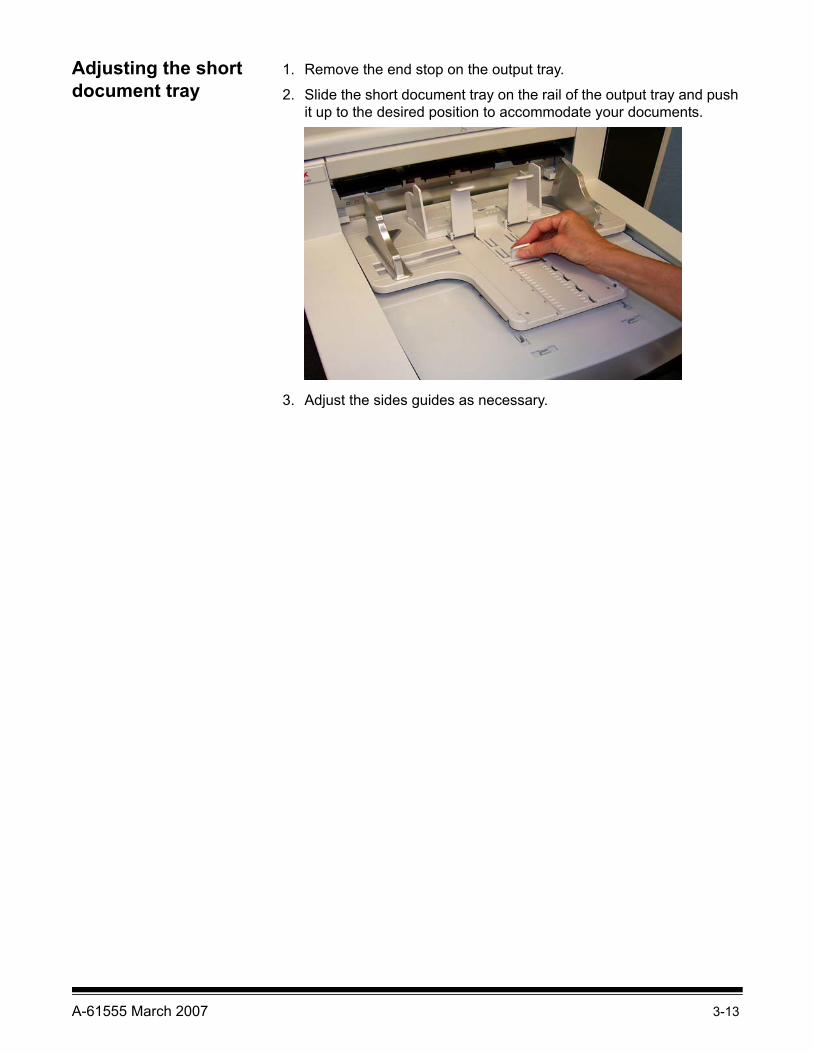
Adjusting the short document tray
1. Remove the end stop on the output tray.
2. Slide the short document tray on the rail of the output tray and push it up to the desired position to accommodate your documents.
3. Adjust the sides guides as necessary.
3-14 A-61555 March 2007
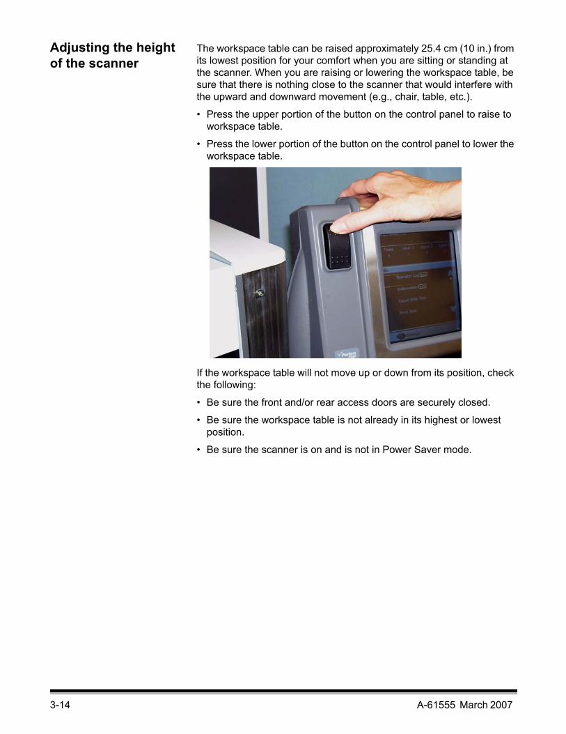
Adjusting the height of the scanner
The workspace table can be raised approximately 25.4 cm (10 in.) from its lowest position for your comfort when you are sitting or standing at the scanner. When you are raising or lowering the workspace table, be sure that there is nothing close to the scanner that would interfere with the upward and downward movement (e.g., chair, table, etc.).
• Press the upper portion of the button on the control panel to raise to workspace table.
• Press the lower portion of the button on the control panel to lower the workspace table.
If the workspace table will not move up or down from its position, check the following:
• Be sure the front and/or rear access doors are securely closed.
• Be sure the workspace table is not already in its highest or lowest position.
• Be sure the scanner is on and is not in Power Saver mode.

A-61555 March 2007 3-15
Feeding documents using multi-feed detection
The scanner has three multi-feed detection sensors that can be independently enabled or disabled. When multi-feed detection is enabled, adjust the side guides so the documents fully cover at least one sensor. If the document partially covers a sensor, false multi-feeds may occur.
Automatic feeding To scan a stack of documents follow the guidelines for size, type, quantity, etc., outlined in the “Document preparation” section.
For faster throughput, place documents into the input elevator in landscape orientation (longer side as the leading edge).
IMPORTANT: Staples and paper clips on documents may damage the scanner. Remove all staples and paper clips before scanning.
1. Align the leading edges of the stacked documents.
2. Position the stack of the documents, face up in the input elevator so the stack covers the paper present sensor.
Depending on how your capture application software is configured, your documents will automatically start feeding, or you may need to touch the Scan button on the touchscreen to begin feeding documents.

3-16 A-61555 March 2007
Continuous feeding Continuous feeding can be used when you want to continuously scan small stacks of documents (less than 25) without stopping/starting a scan session.
When the input elevator is in highest position, continuous feeding of small stacks of documents can be accomplished by adding them to the bottom of the stack while scanning.
1. Align the leading edges of the stacked documents.
2. Position the stack of the documents, face up in the input elevator so the stack covers the paper present sensor.
As the documents are being scanned, you can continuously add documents to the bottom of the stack. When adding documents, be sure that the paper present sensor remains covered at all times.
Manual feeding When the scanner is configured for manual feeding, the input elevator is raised to the highest position where approximately 25 documents can be loaded. The input elevator will remain in this position to allow documents to be fed one at a time.
To manually feed documents:
1. Position the document you want to feed in the input elevator so that the paper present sensor is covered.
2. Touch Scan on the touchscreen.
NOTE: The Kodak Manual Feeder Accessory is also available provides a larger surface for manual feeding. See Appendix A, Accessories for more information.

A-61555 March 2007 3-17
Feeding documents that require special handling
The gap release button allows you to manually adjust the space between the feed module and separation roller for documents that require special handling; e.g., documents that are badly torn. If you are in doubt about whether a damaged document can be transported through the scanner, use the gap release button and manually feed the document. Using the scanner in continuous feed mode is recommended when handling special documents.
1. Raise the input elevator to the highest position.
2. Press and hold the gap release button — this provides clearance to ease document feeding.
3. Push the document into the input elevator. If more than one document is to be scanned, feed them one at a time.
4. After the document(s) has been fed, release the gap release button.
3-18 A-61555 March 2007
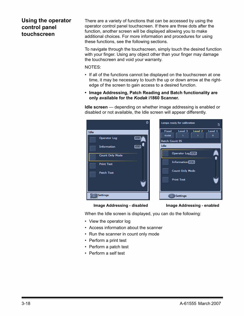
Using the operator control panel touchscreen
There are a variety of functions that can be accessed by using the operator control panel touchscreen. If there are three dots after the function, another screen will be displayed allowing you to make additional choices. For more information and procedures for using these functions, see the following sections.
To navigate through the touchscreen, simply touch the desired function with your finger. Using any object other than your finger may damage the touchscreen and void your warranty.
NOTES:
• If all of the functions cannot be displayed on the touchscreen at one time, it may be necessary to touch the up or down arrow at the right-edge of the screen to gain access to a desired function.
• Image Addressing, Patch Reading and Batch functionality are only available for the Kodak i1860 Scanner.
Idle screen — depending on whether image addressing is enabled or disabled or not available, the Idle screen will appear differently.
When the Idle screen is displayed, you can do the following:
• View the operator log• Access information about the scanner • Run the scanner in count only mode• Perform a print test• Perform a patch test• Perform a self test
Image Addressing - disabled Image Addressing - enabled

A-61555 March 2007 3-19
In addition from Idle mode, you can setup or change scanner configuration settings, and enable or disable imaging addressing by using the Settings screen. The Settings screen allows you to set or change the following options:
• Volume• Tones• Language• Enabling or disabling image addressing• Calibration
Settings screen The Settings screen is accessed by touching Settings on the Idle screen. The Settings screen provides scanner settings that will only need to be set infrequently.
NOTE: The value displayed under the option is the current setting.

3-20 A-61555 March 2007
Changing the alarm volume The Volume screen allows you to adjust the volume of the alarm from a Very High volume (loudest) to a Low volume (quietest) or to Off (no sound). The default is Low.
1. Touch Volume on the Settings screen to display the Volume screen.
2. Select the Volume option that you want. A tone will sound with each selection.
3. Touch Close to return to the Settings screen.

A-61555 March 2007 3-21
Selecting the tone You can select the tone you want the scanner to make when a particular scanner condition is encountered such as, document jam or multi-feed, etc.
1. Touch Tone Select to display the Tones screen.
2. Select the event (e.g., Warning, Jam, etc.) that you want a tone to be set for. When you select an Event, another screen will be displayed listing a variety of different sounds that you can choose from.
3. Select the type of sound you want to hear. A tone will sound with each selection.
4. Return to the Tones screen to set other tones for other events by repeating Steps 2 and 3.
5. Touch Close to return to the Settings screen.

3-22 A-61555 March 2007
Selecting a language The Kodak i1800 Series Scanners support several languages. Select the language you want the information on the touchscreen to be displayed in.
1. Touch Language to display the Language screen.
2. Touch the desired language. The screen will automatically be updated in the language of choice. If the language you want is not displayed on the screen, use the up and down arrows to display the desired language.
If the setting is changed, you will be prompted to power cycle the scanner.
3. Touch Close to return to the Settings screen.

A-61555 March 2007 3-23
Enabling/disabling image addressing (for i1860 Scanner only)
An image address is a unique identifier assigned to each individual document and may contain up to 30 characters (up to a maximum of 27 characters, plus 3 delimiters). An Image Address template is set up using the TWAIN Data source or ISIS Driver. See the on-line help file for more information on image addressing or the Image Processing Guide PDF located on the installation CD. You can enable or disable image addressing from the touchscreen.
IMPORTANT:If you change this setting, you will need to power cycle the scanner.
1. From the Idle screen, select Settings to display the Settings screen.
2. Touch Image Address. The following screen will be displayed.

3-24 A-61555 March 2007
If you change the status of the image address, the following message will be displayed.
3. Touch Yes to change the image address status and restart the system, otherwise click Close.
4. Restart the scanner.
NOTE: Disabling image addressing also disables the Patch Readers and batching. Toggle patch functionality will still be available.
A-61555 March 2007 3-25
Calibrating the scanner The Kodak i1800 Series Scanners allow you to perform an Image calibration (black-and-white, color, grayscale) and UDDS calibration (multi-feed detection). Calibration optimizes your scanner to achieve the best image quality and feeding performance. Your scanner is properly calibrated when you purchase it, therefore, frequent calibration is not necessary or recommended. Only calibrate the scanner when prompted to do so.
Before calibrating the scanner, clean the scanner (see the procedures outlined in Chapter 5, Maintenance). Failure to clean the scanner before calibrating may cause image quality issues.
Use the calibration target provided with your scanner. Be sure to use a good, clean calibration target. Additional calibration targets can be ordered. Refer to the “Supplies, consumables and accessories” section in Chapter 5 for ordering information.
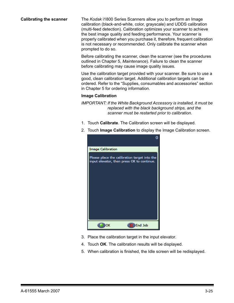
Image CalibrationIMPORTANT: If the White Background Accessory is installed, it must be
replaced with the black background strips, and the scanner must be restarted prior to calibration.
1. Touch Calibrate. The Calibration screen will be displayed.
2. Touch Image Calibration to display the Image Calibration screen.
3. Place the calibration target in the input elevator.
4. Touch OK. The calibration results will be displayed.
5. When calibration is finished, the Idle screen will be redisplayed.
3-26 A-61555 March 2007
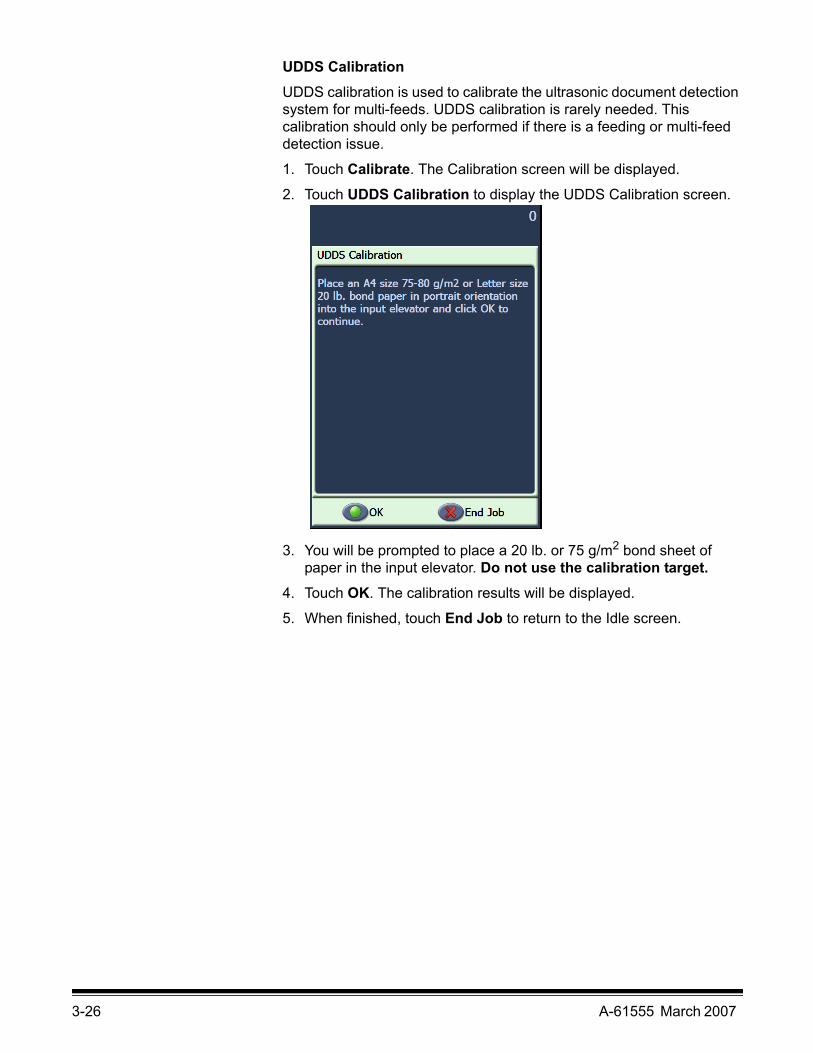
UDDS CalibrationUDDS calibration is used to calibrate the ultrasonic document detection system for multi-feeds. UDDS calibration is rarely needed. This calibration should only be performed if there is a feeding or multi-feed detection issue.
1. Touch Calibrate. The Calibration screen will be displayed.
2. Touch UDDS Calibration to display the UDDS Calibration screen.
3. You will be prompted to place a 20 lb. or 75 g/m2 bond sheet of paper in the input elevator. Do not use the calibration target.
4. Touch OK. The calibration results will be displayed.
5. When finished, touch End Job to return to the Idle screen.
A-61555 March 2007 3-27
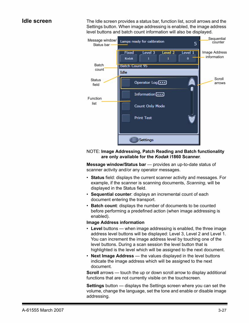
Idle screen The Idle screen provides a status bar, function list, scroll arrows and the Settings button. When image addressing is enabled, the image address level buttons and batch count information will also be displayed.
NOTE: Image Addressing, Patch Reading and Batch functionality are only available for the Kodak i1860 Scanner.
Message window/Status bar — provides an up-to-date status of scanner activity and/or any operator messages.
• Status field: displays the current scanner activity and messages. For example, if the scanner is scanning documents, Scanning, will be displayed in the Status field.
• Sequential counter: displays an incremental count of each document entering the transport.
• Batch count: displays the number of documents to be counted before performing a predefined action (when image addressing is enabled).
Image Address information• Level buttons — when image addressing is enabled, the three image
address level buttons will be displayed: Level 3, Level 2 and Level 1. You can increment the image address level by touching one of the level buttons. During a scan session the level button that is highlighted is the level which will be assigned to the next document.
• Next Image Address — the values displayed in the level buttons indicate the image address which will be assigned to the next document.
Scroll arrows — touch the up or down scroll arrow to display additional functions that are not currently visible on the touchscreen.
Settings button — displays the Settings screen where you can set the volume, change the language, set the tone and enable or disable image addressing.
Message window/
Image Address information
Functionlist
Scrollarrows
Status bar
Sequential counter
Status field
Batchcount
3-28 A-61555 March 2007
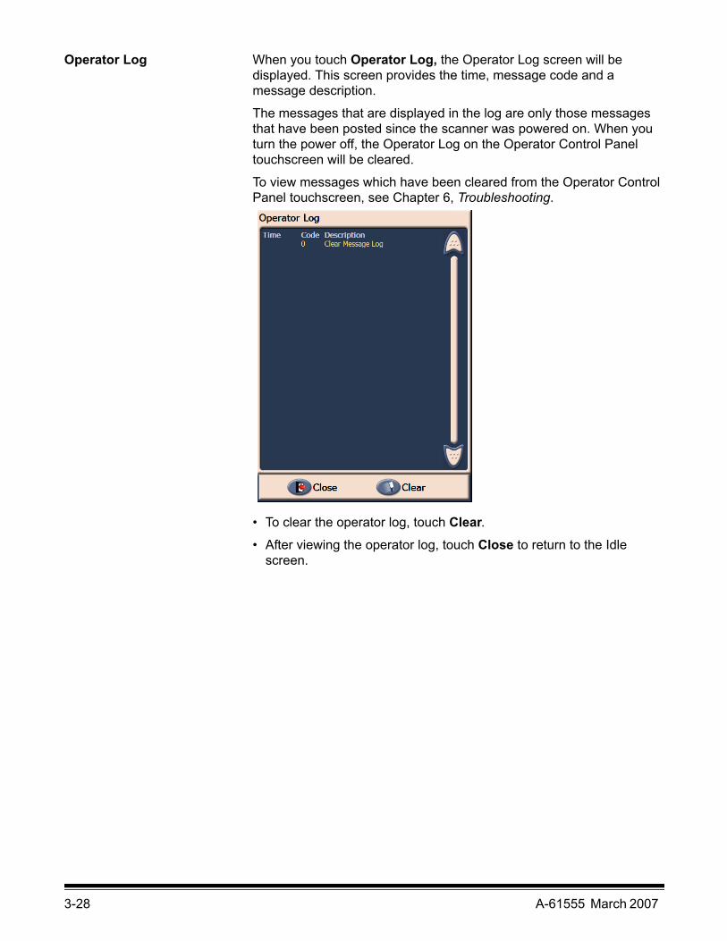
Operator Log When you touch Operator Log, the Operator Log screen will be displayed. This screen provides the time, message code and a message description.
The messages that are displayed in the log are only those messages that have been posted since the scanner was powered on. When you turn the power off, the Operator Log on the Operator Control Panel touchscreen will be cleared.
To view messages which have been cleared from the Operator Control Panel touchscreen, see Chapter 6, Troubleshooting.
• To clear the operator log, touch Clear.• After viewing the operator log, touch Close to return to the Idle
screen.
A-61555 March 2007 3-29
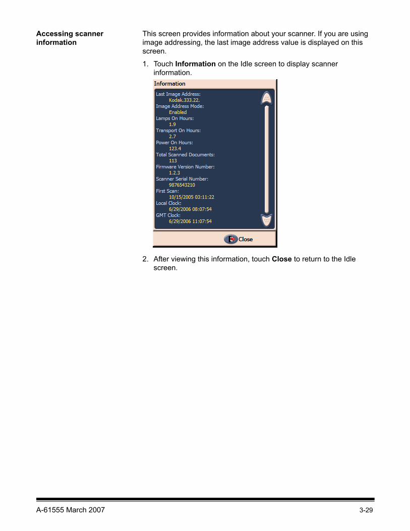
Accessing scanner information
This screen provides information about your scanner. If you are using image addressing, the last image address value is displayed on this screen.
1. Touch Information on the Idle screen to display scanner information.
2. After viewing this information, touch Close to return to the Idle screen.

3-30 A-61555 March 2007
Count only mode You may want to count the number of documents entering the scanner without actually scanning them.
1. Touch Count Only Mode. The Count Only screen will be displayed.
2. Place the documents you want to count in the input elevator.
3. Touch OK. When the scanner has scanned all documents, the total number will be displayed in the Status bar.
4. Touch End Job when finished to return to the Idle screen.
NOTE: When you touch the Pause button, the feeder and transport will stop. You can continue your Count only test by touching the Resume button.

A-61555 March 2007 3-31
Performing a Print test The print test checks to be sure the ink jets in the Enhanced Printer are working properly.
1. Touch Print Test. The Print Test screen will be displayed.
2. Place a blank sheet(s) of paper in the input elevator.
3. Touch OK. The document(s) in the output tray will display the results of the print test.
4. Remove the document(s) from the output tray and evaluate the appearance of the test pattern.
• If the pattern is complete, you are ready to begin.
• If the pattern is not legible:
− Check to see that the print cartridge is installed properly. Repeat the print test. See Chapter 4, Using the Enhanced Printer and Patch Readers.
− If the pattern is still not legible, replace the ink cartridge.5. Touch End Job to return to the Idle screen.

3-32 A-61555 March 2007
Performing a Patch test Use the Patch test to verify that the Patch Readers are operational and that your patches are being read.
1. Touch Patch Test. The Patch Test screen will be displayed.
2. Place a document(s) with a patch(es) in the input elevator.
3. Touch OK. When the document(s) has been scanned, the results of the patch test will be displayed on the touchscreen.
The results show the number of patches and patch types that were recognized by the scanner.
4. Touch End Job to return to the Idle screen.
Performing a self test The scanner self test will test the image capture subsystem to ensure that is functioning correctly.
Image Addressing - enabled Image Addressing - disabled

A-61555 March 2007 3-33
Enabling the scanner In order to scan documents, the scanner must be enabled. This is done using the capture application software. When the scanner is enabled, the following screen is displayed.
Scanning After enabling the scanner, depending on how your scanner is configured, your scanner will automatically start scanning, or you can touch the Scan button from the enabled screen. The following screen is displayed:
NOTE: The options that appear on the screens above may be different depending on how your OCP function keys are set up.
Enabled - Image Addressing - off Enabled - Image Addressing - on
Scanning - Image Addressing - off Scanning - Image Addressing - on
3-34 A-61555 March 2007
Using function keys when scanning
Up to three additional functions may appear on the touchscreen when scanning. These functions are set up by the capture software application. Options which may appear are:
• Omit patch• Omit print• Omit multifeed• End batch
To select a function, touch the function you want to perform.
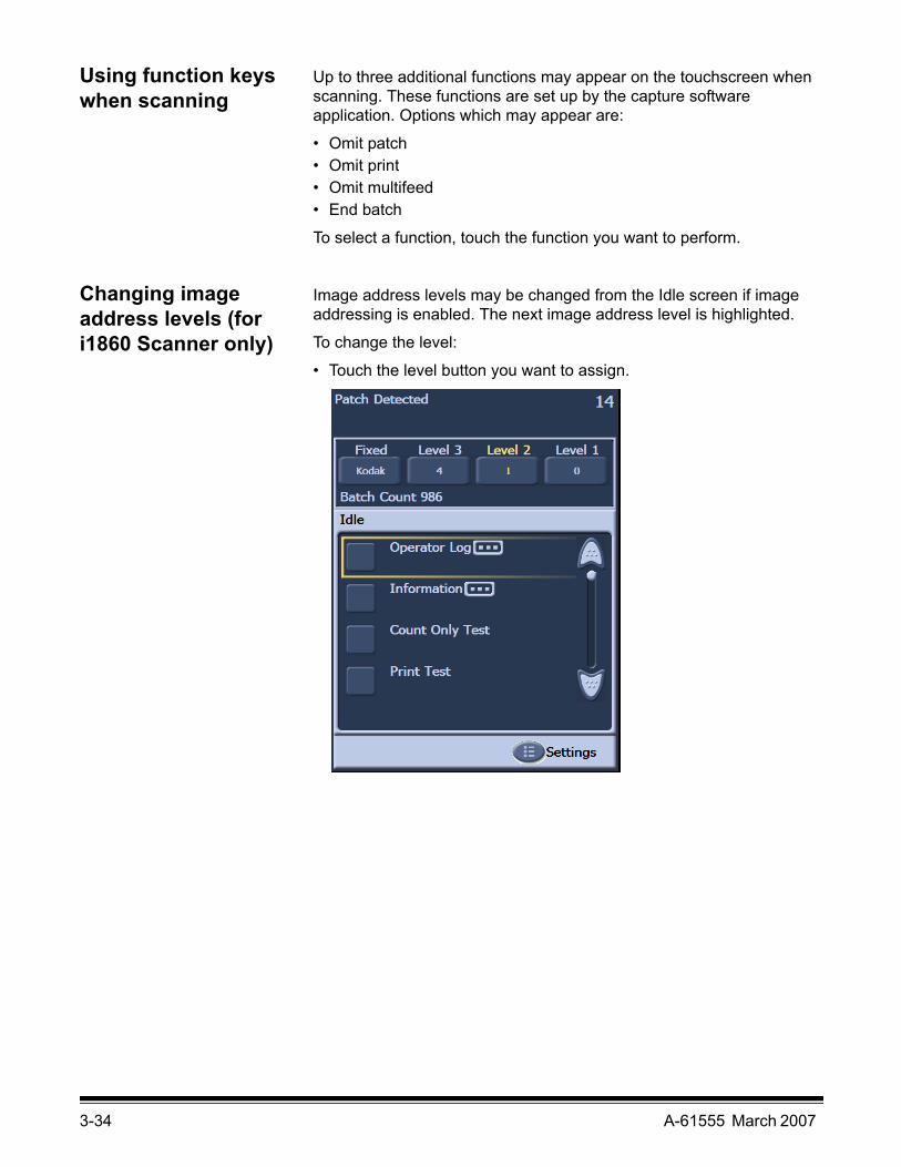
Changing image address levels (for i1860 Scanner only)
Image address levels may be changed from the Idle screen if image addressing is enabled. The next image address level is highlighted.
To change the level:
• Touch the level button you want to assign.

A-61555 March 2007 3-35
Manually pausing and resuming the scanner
You can manually pause and resume the scanner while scanning documents.
• Touch Pause on the touchscreen to stop scanning. The Pause button now becomes the Resume button.
• Touch Resume on the touchscreen to restart scanning after it has been paused.
Automatically pausing and resuming the scanner
During scanning the scanner monitors its own internal image buffer memory. In order to prevent overwriting images before the host computer can retrieve them, the scanner will automatically pause the feeder while waiting for the capture software application to read existing images.
The scanner resumes scanning by automatically restarting the feeder once the capture software application has caught up.

3-36 A-61555 March 2007
Power Saver mode The Kodak i1800 Series Scanners are configured from the factory to go into Power Saver mode after 15 minutes of inactivity. This setting can be changed by your capture software application. If Power Saver is enabled, the scanner will begin a one-minute count-down prior to entering Power Saver mode. When the scanner is in Power Saver mode, the green LED will be flashing and the touchscreen will be blank.
NOTE: If you do not want to go into Power Saver mode, touch Cancel.
Resuming from Power Saver mode• If there is paper in the input elevator, take the paper out and put it
back in.
• If no paper is in the input elevator, put paper in the input elevator.
The initializing screen will appear on the touchscreen.
Viewing messages The message window provides an up-to-date status of scanner activity and/or any operator messages. Only one message can be displayed at a time. To review previous messages use the Operator Log.

A-61555 March 2007 4-1
4 The Enhanced Printer and Patch Readers
This chapter provides instructions for using the Enhanced Printer and Patch Readers. The following information and procedures can be found in this chapter:
• Overview information about the Enhanced Printer, including information about print fields and printer specifications.
• Setting horizontal printer positions.
• Replacing the ink cartridge and ink blotter strips.
• Moving the printer carrier and cable from the front position to the rear position or vice versa.
• Overview information about the Patch Readers and patch types.
NOTE: More detailed information on the Enhanced Printer and Patch Readers can be found in the Image Processing Guide and Kodak publication, A-61599, Patch Code Information.
Enhanced Printer overview
The Kodak i1800 Series Scanners include a factory-installed, pre-configured front or rear printer. The printer operates at full scanner speed and prints on the front before scanning or rear after scanning. The printer can add a date, time, image address, and custom messages.
The printer is unique in that the document print string can be configured to include both literal (static) information (i.e., information that stays the same for each document, such as batch name or operator) and dynamic information (i.e., information that may change for each page scanned, such as the image address). The capture software application controls static fields; any information that the software allows you to enter can be sent to the printer.
All printer controls and functions are accessible through the ISIS Driver or TWAIN Data source. Printing must be enabled or disabled for each scan session.
NOTES:
• The scanner is shipped configured for front printing. See the section entitled, “Moving the printer carrier and cable from the front to the rear or vice versa” to change to the rear printing position.
• Clean the scanner’s paper path components daily when using the printer.
• You may only use one printer (either front or rear) at one time. If you attempt to print on both sides, an error will be displayed.
• The minimum document height for using the printer is 10 cm (4 in.) with adjustable side guides.
• The ink cartridge must be installed prior to powering on the scanner, or it could result in errors when printing is attempted.

4-2 A-61555 March 2007
Printer specificationsCharacteristic Description
Maximum lines 1 Maximum characters 40Print locations (horizontal) 12 front, 8 rear, manually set,Print locations (vertical) Set by capture software applicationPrint orientation 0, 90, 180 or 270 degreesFont size 2 selectable, Bold or Normal
NOTE: Not all languages can support a Bold font based on the complexity of the characters, such as half-width Katakana.
Ink cartridge Black: HP-C6602ARed: HP-C6602RGreen: HP-C6602GBlue: HP-C6602B
Print side Front (pre-scan) or Rear (post-scan) Minimum printing distance from document lead edge
0.89 cm (0.35 in.)
Static fields available User-specified messages via capture software application
Dynamic fields available Up to a nine-digit sequential document number, date, image address, four-digit time
Languages supported Any phonetic language (for example: Dutch, English, French, German, Italian, Portuguese, Spanish, Japanese (half-width Katakana)
A-61555 March 2007 4-3
Changing print positions
The horizontal print position can be changed manually. You can change the front or rear print position.
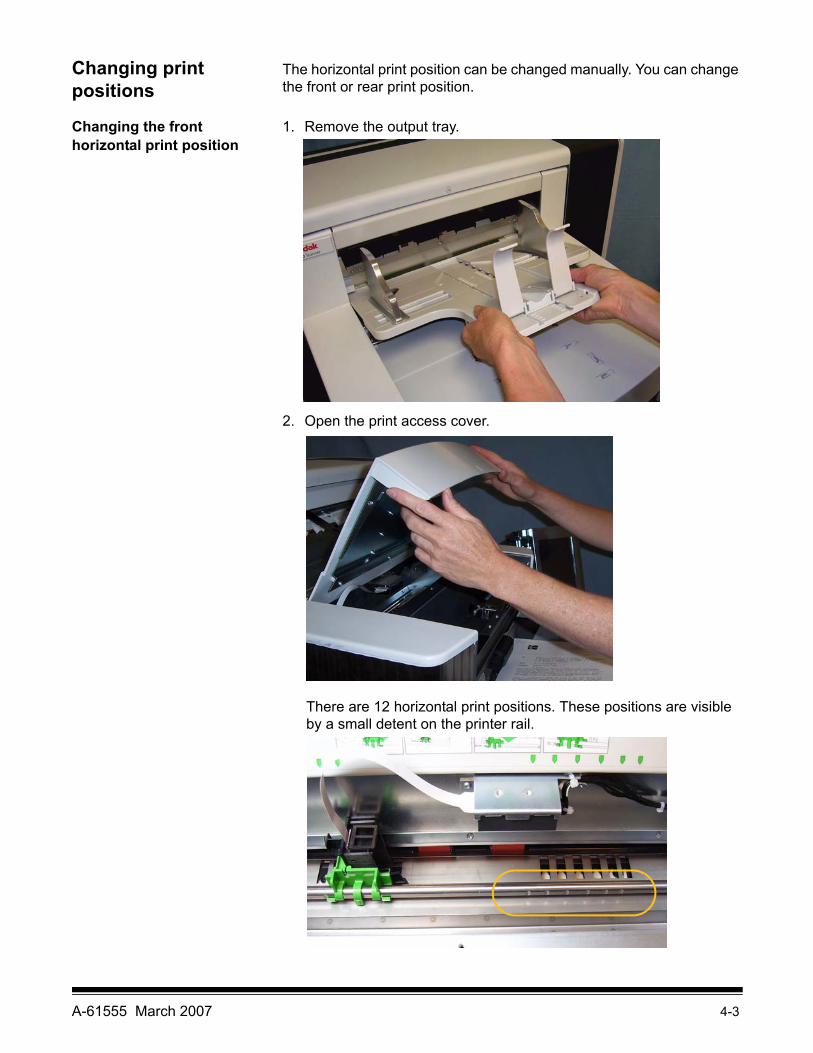
Changing the front horizontal print position
1. Remove the output tray.
2. Open the print access cover.
There are 12 horizontal print positions. These positions are visible by a small detent on the printer rail.

4-4 A-61555 March 2007
3. The printer carrier slides easily along the rail. There is a small arrow on the green printer carrier. Slide the printer carrier to the desired position aligning the arrow with the detent position on the rail.
4. Close the printer access cover.
5. Reinstall the output tray.
NOTE: Printing automatically stops approximately ½-inch (1.27 cm) from the trailing edge of the document, even if the information has not been completely printed.
Changing the rear horizontal print position
There are 8 horizontal print positions. These positions are visible by a small detent on the printer rail.
1. Lift the top access cover.
2. The printer carrier slides easily along the rail. There is a small arrow on the green printer carrier. Slide the printer carrier to the desired position aligning the arrow with the detent position on the rail.
3. Close the top access cover.
A-61555 March 2007 4-5
Moving the printer carrier and cable from the front to the rear or vice versa
The scanner comes with the printer carrier and ribbon cable installed for front pre-scan printing. If your application requires rear post-scan printing, the printer carrier and cable must be moved from the front to the rear position. Printing can only be done on the front or the rear.
If you alternate between front and rear printing frequently, you may want to purchase a second printer carrier, then you only need to move the ink cartridge from the front to the back or vice versa. Otherwise, you need to move the printer carrier and cable from the front to rear or rear to front as well as the ink cartridge.
NOTE: After you move the printer carrier and cable you must restart the scanner.
Moving the printer carrier and cable from front position to the rear positionNOTE: Remove the ink cartridge before you begin. See the next
section “Replacing the ink cartridge” for procedures.
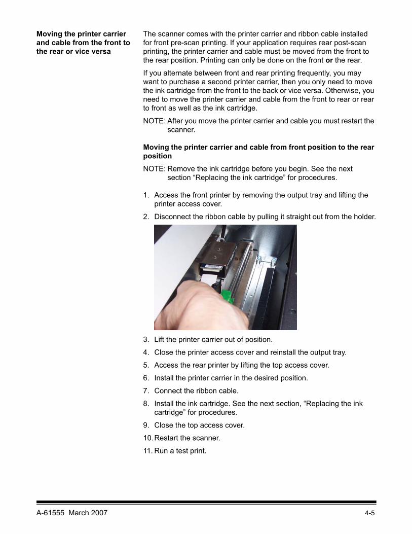
1. Access the front printer by removing the output tray and lifting the printer access cover.
2. Disconnect the ribbon cable by pulling it straight out from the holder.
3. Lift the printer carrier out of position.
4. Close the printer access cover and reinstall the output tray.
5. Access the rear printer by lifting the top access cover.
6. Install the printer carrier in the desired position.
7. Connect the ribbon cable.
8. Install the ink cartridge. See the next section, “Replacing the ink cartridge” for procedures.
9. Close the top access cover.
10.Restart the scanner.
11. Run a test print.

4-6 A-61555 March 2007
Moving the printer carrier and cable from rear position to the front positionNOTE: Remove the ink cartridge before you begin. See the next
section “Replacing the ink cartridge” for procedures.
1. Open the top access cover.
2. Disconnect the ribbon cable.
3. Remove the printer carrier.
4. Close the top access cover.
5. Remove the output tray and open the printer access cover.
6. Install the printer carrier in the desired position.
7. Connect the ribbon cable.
8. Install the ink cartridge.
9. Close the top access cover.
10.Restart the scanner.
11. Run a print test.

A-61555 March 2007 4-7
Replacing the ink cartridge
Replace the ink cartridge when:
• printed characters appear light or uneven• missing characters are evident• a print test reveals inconsistent character quality• cleaning has not improved the overall print quality
Procedures for changing the ink cartridge, whether it is in the front position or rear position, are the same; with the exception of how you access the printer.
1. Lift up the top access cover (rear position) or remove the output tray and lift the printer access cover (front position).
2. Holding the printer carrier as shown, press and hold the release tab on the bottom of the printer carrier and rotate the printer carrier to the left until it locks into position.
IMPORTANT: Dispose the empty ink cartridge in accordance with all federal, state and local laws.
3. Lift the ink cartridge out from the printer carrier.
4. Remove the tab from the new ink cartridge.
5. Slightly angle a new ink cartridge in the print carrier and snap it into place.
4-8 A-61555 March 2007
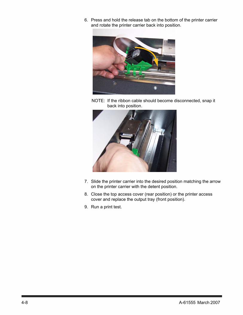
6. Press and hold the release tab on the bottom of the printer carrier and rotate the printer carrier back into position.
NOTE: If the ribbon cable should become disconnected, snap it back into position.
7. Slide the printer carrier into the desired position matching the arrow on the printer carrier with the detent position.
8. Close the top access cover (rear position) or the printer access cover and replace the output tray (front position).
9. Run a print test.

A-61555 March 2007 4-9
Replacing the front blotter strips
Blotter strips collect ink overflow. They should be replaced when there is a build-up of ink. Replacement blotter strips may be purchased through your supplier.
1. Open the pod.
2. Use the green tab to lift and remove the ink blotter strip cover to access the front blotter strips.
3. Carefully pull the blotter strip(s) off the transport. You can replace one or both of the strips as necessary..
4. Discard the soiled strip(s)5. Peel the backing away from the blotter strip.
Remove Ink Blotter Strip cover

4-10 A-61555 March 2007
6. Align the blotter strip in the transport channel. Be sure it is properly aligned before pressing the adhesive side into the channel.
7. Press the blotter strip firmly into the channel.
8. Repeat Steps 5 - 7 for the other blotter strip, if necessary.
9. Replace the ink blotter strip cover.
10.Close the pod.

A-61555 March 2007 4-11
Replacing the rear blotter strips
Blotter strips collect ink overflow. They should be replaced when there is a build-up of ink. Replacement blotter strips may be purchased through your supplier.
1. Remove the output tray. The rear blotter strips are located in the two drawers underneath the baffle.
2. Open the one of the drawers by pushing it in a little and lifting up slightly, then pull it out.
3. Peel off the soiled blotter strip.4. Peel the backing away from the new blotter strip.
5. Align the blotter strip in the channel. Be sure it is properly aligned before pressing the adhesive side into the channel.
6. Press the blotter strip firmly into place.
7. Repeat Steps 2 - 5 for the other blotter strip.
8. Close the drawer(s) by pushing it in and sliding it down slightly. This will lock the drawer in place.
9. Replace the output tray.

4-12 A-61555 March 2007
Patch function overview
All i1800 Series Scanners provide toggle patch capability. This type of patch is used to trigger the scanner to switch from the current image stream (black-and-white) to the alternative image stream (color/grayscale). Patches used for image address level changes are only valid when using an i1860 Scanner with image address enabled.
The Patch Readers The Patch Readers allow you to automatically increment the image address or initiate a special function. Image addressing must be enabled in order to use the Patch Readers. Patch sheets are inserted during document preparation.
For i1860 Scanner only: There are four off-center, permanently mounted Patch Readers. They can be independently enabled or disabled by your capture software application.
If more than one Patch Reader is enabled and any one of the enabled Patch Readers successfully decodes the patch, then the patch will be read. Also, if the patch bars pass under more than one patch head that is enabled, there is a higher probability that the patch will be read.
NOTE: Almost all patch reading problems are related to poor quality patch codes or patch sheets. Using only the best quality printed patch sheets will ensure the highest possible read rates.
See Kodak publication A-61599, Patch Code Information, for complete information.
Patch types Patch Types 1, 4, and 6 — these patch types can be used by the capture software application to perform post-scan functions. These patches are not used for image addressing.
IMPORTANT: Do not use these illustrated patches for production — they are not to spec.
Toggle Patch — the Toggle patch is a Type 4 patch that is used to trigger the scanner to switch from the current image stream (black-and-white) to the alternative image stream (color/grayscale).
NOTE: Toggle patch orientation is different depending on whether image addressing is disabled or enabled.
Patch 1 Patch 4 Patch 6

A-61555 March 2007 4-13
Toggle Patch
When image addressing is disabled, the Patch Readers are also disabled. However a Toggle patch can still be detected.
Patch Types 2, 3 and T — these patch types are used for image addressing.
The Patch Readers control document level changes by automatically sensing a predefined patch code and changing the document level accordingly.
IMPORTANT: Do not use these illustrated patches for production — they are not to spec.
The Transfer Patch Definition is also defined by the application. The Transfer Patch Definition controls the level assigned to the next document when a Transfer Patch is used. For example, if the Transfer Patch Definition for the current operation is defined as Level 3 and a Transfer Patch is used, the next document will be assigned Level 3.
Patch code placement See Kodak publication A-61599, Patch Code Information, for complete information about patch placement and specifications.
Patches can be tested using the Patch Test on the touchscreen. See Chapter 3, “Performing a Patch test” for more information.
Image addressing - disabled
Image addressing - enabled
Patch 2 — assigns a Level 2 to the current document
Patch 3 — assigns a Level 3 to the current document
Patch 5/T/Transfer Patch — assigns a predetermined level to the next document

A-61555 March 2007 5-1
5 Maintenance
This chapter provides:
• a cleaning frequency chart• a list of cleaning tools and materials• a list of supplies, consumables and accessories• cleaning procedures for the scanner• replacement procedures for customer-replaceable parts
IMPORTANT: Scanner components marked with a green tab indicate operator-accessible parts.
Cleaning your scanner and preventative maintenance on a regular basis is required to ensure the best possible image quality. The following is a preventative maintenance procedure that is recommended to prevent costly interruptions during production scanning. Following this procedure as recommended should take approximately 5 to 10 minutes.
Some document types generate more paper dust and debris and may require more frequent cleaning than recommended.
NOTES:
• Some debris from the rubber tires on the feed module and separation roller is normal. Tire debris does not always mean that the tires are worn or damaged. After cleaning, inspect the tires for wear and replace the separation roller or feed module if necessary.
• When cleaning rollers/tires, allow the rollers/tires to dry completely before scanning.
• Use only the recommended cleaning supplies.
• Do not use canned/compressed air.
• Using unapproved cleaning fluids or solvents may damage the rubber tires.

5-2 A-61555 March 2007
Cleaning frequency chart
A recommended cleaning sequence includes vacuuming the scanner transport, cleaning the residue from the feed module, separation roller or drive rollers and cleaning the imaging guides.
Use the chart below as a guide to the order and how frequently you should clean your scanner.
Cleaning tools and materials
Use only these cleaning tools and materials when performing routine maintenance on your scanner. Use of any other cleaning materials could damage your scanner.
• Kodak Digital Science Transport Cleaning Sheets
• Kodak Digital Science Roller Cleaning Pads
• Staticide wipes for Kodak Scanners
• A vacuum cleaner and tools
Procedure Start of day
Middle of shift
Start of new shift
Vacuum output tray and input areas (input elevator and transport)
x
Clean all rollers x xVacuum transport area x x xRemove and vacuum under background strips
x
Run transport cleaning sheet x xClean imaging guides - basic x x xClean imaging guides - thorough x x

A-61555 March 2007 5-3
Supplies, consumables and accessories
Contact your scanner supplier to order supplies.
NOTE: Items and catalog numbers are subject to change.
Ordering parts The following parts can be ordered from Parts Services.
Supplies/Consumables CAT No.Kodak Feeder Consumables Kit for i600/i1800 Series Scanners
108 4755
Kodak Feeder Kit for Ultralightweight Paper for i600/i1800 Series Scanners
896 5279
Kodak Extra-Large Feeder Consumables Kit for i600/i1800 Series Scanners
842 6157
Kodak Extra-Extra-Large Feeder Consumables Kit for i600/i1800 Series Scanners
134 3680
Kodak Imaging Guide Set / for i600/i1800 Series Scanners 197 6703Kodak Printer Ink Blotters, Front Side for i1800 Series Scanners
125 7633
Kodak Printer Ink Blotters, Rear Side for i1800 Series Scanners
114 1472
Enhanced Printer Black Ink Cartridge for Kodak i800/i1800 Series Scanners
818 3386
Enhanced Printer Red Ink Cartridge for Kodak i800/i1800 Series Scanners
159 6832
Kodak Digital Science Transport Cleaning Sheets (qty 50) 169 0783High Resolution Printer Maintenance Kit 877 6254High Resolution Printer Black Ink Cartridge for Kodak i1800 Series Scanners and Kodak Imagelink Microimager 70
822 1376
High Resolution Printer Red Ink Cartridge for Kodak i1800 Series Scanners and Kodak Imagelink Microimager 70
145 6532
Kodak Digital Science Roller Cleaning Pads (qty 24) 853 5981Staticide Wipes for Kodak Scanners (qty 144) 896 5519Kodak Calibration Targets (qty 5) 127 1436Accessories CAT No.Kodak White Background Accessory 894 9000Kodak Manual Feeder for the i1800 Series Scanners 874 1894Kodak High Resolution Printer Accessory 815 0237
Accessories Part No.Exit deflector 3E9575Black Background 9E335726 in. document extenders (qty 1 per box) 5E475430 in. document extenders (qty 1 per box) 9E321634 in. document extenders (qty 1 per box) 9E5277

5-4 A-61555 March 2007
Cleaning procedures Follow the cleaning procedure below to ensure the best scanner performance and image quality.
Cleaning the OCP touchscreen
The touchscreen requires very little maintenance. However, periodically, it is recommended that you use a Staticide wipe to clean the screen and dry it with a lint free cloth.
Vacuuming the output tray and input elevator
1. Power down the scanner.
2. Remove the output tray.
3. Thoroughly vacuum the output tray area and the input elevator area.

A-61555 March 2007 5-5
Cleaning the rollers Cleaning the rollers includes all of the rollers in the transport area, the separation roller tires and the feed module tires.
1. Pull up on the pod release lever and open the pod.
2. Manually rotate and wipe the rollers with a roller cleaning pad.
IMPORTANT: The roller cleaning pad contains sodium lauryl ether sulfate and sodium silicate which can cause eye irritation. Refer to the MSDS for more information.
3. Dry the rollers with a lint-free cloth.

5-6 A-61555 March 2007
Cleaning the separation roller tires4. Pull the separation pad holder forward and remove the separation
roller.
5. Manually rotate and wipe the separation roller tires with a roller cleaning pad. For best results wipe parallel to the ribs in order to remove any residue between the ribs.
6. Inspect the tires. If the tires show signs of wear or damage, replace the separation roller. See “Replacement procedures” later in this chapter.
7. Reinstall the separation roller by aligning the slots on the separation roller with the holders.
8. Close the pod.

A-61555 March 2007 5-7
Cleaning the feed module tires9. Lift up the printer access cover.
10.Push the release lever down (located underneath the printer access cover) to release and remove the feed module.

5-8 A-61555 March 2007
11. Manually rotate and wipe the feed module tires with a roller cleaning pad. For best results wipe parallel to the ribs in order to remove any residue between the ribs.
12. Inspect the tires. If the tires show signs of wear or damage, replace the feed module tires. See “Replacement procedures” later in this chapter.
13.Reinstall the feed module by aligning the pins and fitting it into position. Pull up on the release lever to lock it into place. Verify that the feed module is securely in place and moves freely after you install it.
14.Close the printer access cover.
Aligntheseareas

A-61555 March 2007 5-9
Vacuuming the transport area
1. Open the pod.
2. Thoroughly vacuum the entire transport area, paying particular attention to these areas:
Vacuuming under the background strips
1. Using the green tabs pull off the upper and lower background strips and set them aside.
2. Vacuum the areas where the background strips are adhered to.
3. Reinstall the upper and lower background strips.
the edges of the transport the reflective tape near the front of the transport
the reflective tape near the front of the pod
the three multifeed sensors at the base of the transport and the pod
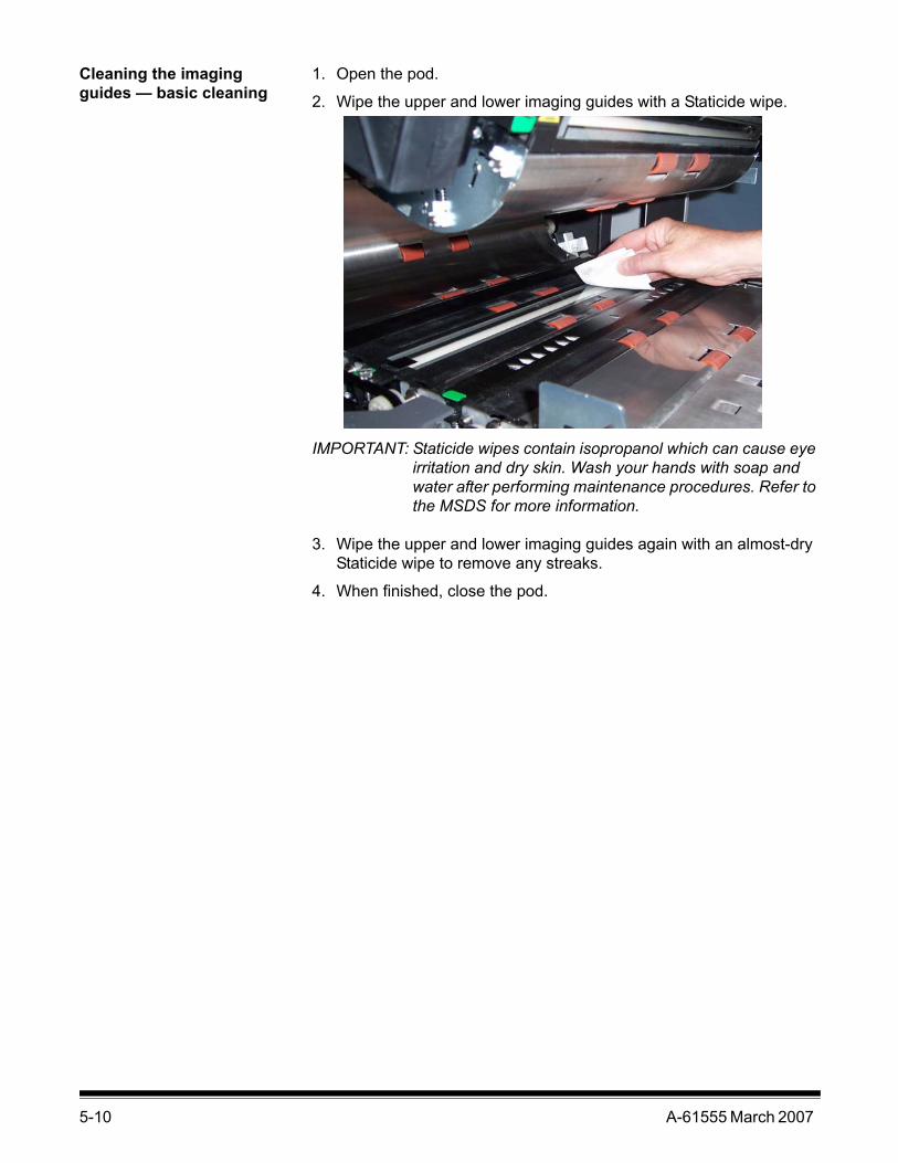
5-10 A-61555 March 2007
Cleaning the imaging guides — basic cleaning
1. Open the pod.
2. Wipe the upper and lower imaging guides with a Staticide wipe.
IMPORTANT: Staticide wipes contain isopropanol which can cause eye irritation and dry skin. Wash your hands with soap and water after performing maintenance procedures. Refer to the MSDS for more information.
3. Wipe the upper and lower imaging guides again with an almost-dry Staticide wipe to remove any streaks.
4. When finished, close the pod.

A-61555 March 2007 5-11
Cleaning the imaging guides — thorough cleaning
Thorough cleaning of the imaging guides is recommended at the start of the day and beginning of each shift.
NOTE: Hold the imaging guides at the green tabs to avoid getting fingerprints on the imaging guides during the cleaning procedure.
Upper imaging guide1. Open the pod.
2. Turn the screw on each end of the upper imaging guide and remove it from its position.
3. Clean the imaging guide thoroughly with a Staticide wipe.
4. Wipe the imaging guide again with an almost-dry Staticide wipe to remove any streaks.
IMPORTANT: There is no cover glass between the upper lamps. Do not insert any objects into the area between the upper lamps, as you may damage the reflective mirrors in the scan module.
5. Reinstall the upper imaging guide.

5-12 A-61555 March 2007
Lower imaging guide1. Turn the screw on each end of the lower imaging guide, remove it
from its position and set it aside.
2. Carefully vacuum the areas between the lamps, then use a Staticide wipe to thoroughly clean the glass plate between the lamps.
3. Clean the lower imaging guide thoroughly with a Staticide wipe.
4. Wipe the imaging guide again with an almost-dry Staticide wipe to remove any streaks.
5. Reinstall the lower imaging guide.
6. Close the pod.
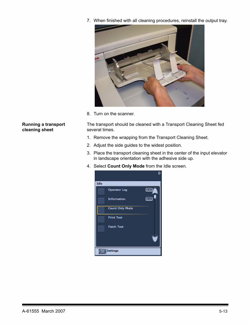
A-61555 March 2007 5-13
7. When finished with all cleaning procedures, reinstall the output tray.
8. Turn on the scanner.
Running a transport cleaning sheet
The transport should be cleaned with a Transport Cleaning Sheet fed several times.
1. Remove the wrapping from the Transport Cleaning Sheet.
2. Adjust the side guides to the widest position.
3. Place the transport cleaning sheet in the center of the input elevator in landscape orientation with the adhesive side up.
4. Select Count Only Mode from the Idle screen.

5-14 A-61555 March 2007
The Count Only screen will be displayed.
5. Touch Scan.
6. Remove the transport cleaning sheet from the output tray and place it in the center of the input elevator in landscape orientation with the adhesive side down and touch Scan.
7. When finished, touch End Job.
NOTE: When the transport sheet gets dirty, discard it and use a new one.
Final cleaning steps When finished running the transport cleaning sheet:
1. Open the pod.
2. Wipe the exposed side of the upper and lower imaging guides with a lint-free cloth.
3. Close the pod and scan a test image to ensure image quality.

A-61555 March 2007 5-15
Replacement procedures
This section provides procedures for replacing the following parts. Use the list below as a guideline for frequency of replacement.
• Feed module tires and separation roller tires — tire life will vary depending upon paper types, environment and cleanliness. Nominal tire life is approximately 500,000 documents; results will vary. Degradation of feeder performance, multiple feeds, stoppages, etc. indicate a need to change tires. Change all the tires on the feed module and separation roller at the same time.
• Feed module and separation roller — it is recommended that you install a new feed module and separation roller approximately every 4th tire change. Install a new feed module and separation roller at the same time.
• Pre-separation pad — it is recommended that you change the pre-separation pad at least as often as you change the feed module/separation roller tires.
• Imaging guides — replace when the imaging guides are heavily scratched and defects show in the image.
Replacing the feed module or feed module tires
1. Remove the output tray.
2. Lift up the printer access cover.
3. Open the pod.

5-16 A-61555 March 2007
4. Push down on the release lever (located underneath the printer access cover) to release and remove the feed module.
5. If you are just replacing the feed module, do the following. If you are replacing the tires, go to Step 6.
• Insert the new feed module by aligning the pins, fitting it into position and pulling up on the release lever to lock it into place. Verify that the feed module is securely in place and moves freely after you install it.
• Close the pod and the printer access cover.• Reinstall the output tray.
Align theseareas

A-61555 March 2007 5-17
If you want to replace the tires, proceed as follows:
6. With one hand, press the locking tabs (one on each side) while holding the bottom housing with the other hand, pull the upper housing up and away from the rollers.
7. Remove one core assembly.
8. Replace each tire by sliding the tire off the core.
9. Install each new tire by gently pulling it over the core. The tires do not need to be installed in any specific orientation.
IMPORTANT:Do not overstretch the tire; it may tear.
10.Replace the core assembly in the lower feed module housing.
11. Repeat the replacement procedure outlined above for the other core assembly.
Locking tab
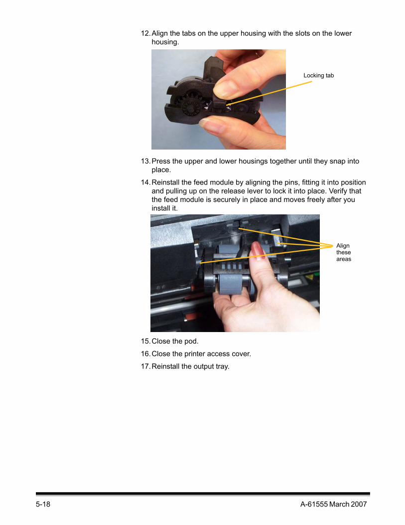
5-18 A-61555 March 2007
12.Align the tabs on the upper housing with the slots on the lower housing.
13.Press the upper and lower housings together until they snap into place.
14.Reinstall the feed module by aligning the pins, fitting it into position and pulling up on the release lever to lock it into place. Verify that the feed module is securely in place and moves freely after you install it.
15.Close the pod.
16.Close the printer access cover.
17.Reinstall the output tray.
Locking tab
Aligntheseareas

A-61555 March 2007 5-19
Replacing the separation roller or separation roller tires
1. Open the pod.
2. Pull the separation pad holder forward and remove the separation roller.
If you want to replace the separation roller, do Steps 3 and 4. If you want to replace the separation roller tires, go to Step 5.
3. Insert the new separation roller. Be sure to line up the slots on the separation roller with the holders.
4. Push the separation roller holder back in place and close the pod.
To replace the tires:
5. Replace each tire by sliding the tire off the core.
6. Install each new tire by gently pulling it over the core.
IMPORTANT:Do not overstretch the tire; it may tear.
7. Reinstall the separation roller. Be sure to line up the slots on the separation roller with the holders.
8. Push the separation roller holder back in place and close the pod.

5-20 A-61555 March 2007
Replacing the pre-separation pad
Change the pre-separation pad when the frequency of multi-fed documents increases.
1. Open the pod.
2. Remove the pre-separation pad by lifting the pad up and out of position.
3. Install the new pre-separation pad. Be sure it snaps into place.
4. Close the pod.
Replacing the imaging guides
The imaging guides should be replaced when they are heavily scratched and defects show in the image.
NOTE: Handle the imaging guides carefully so as to not put fingerprints on the guides.
1. Open the pod.
2. Turn the screw on each end of the lower imaging guide to remove it from its position.
3. Install the new imaging guide and turn the screws to secure the imaging guide.
4. Repeat Steps 2 and 3 to replace the upper imaging guide.
5. Close the pod.
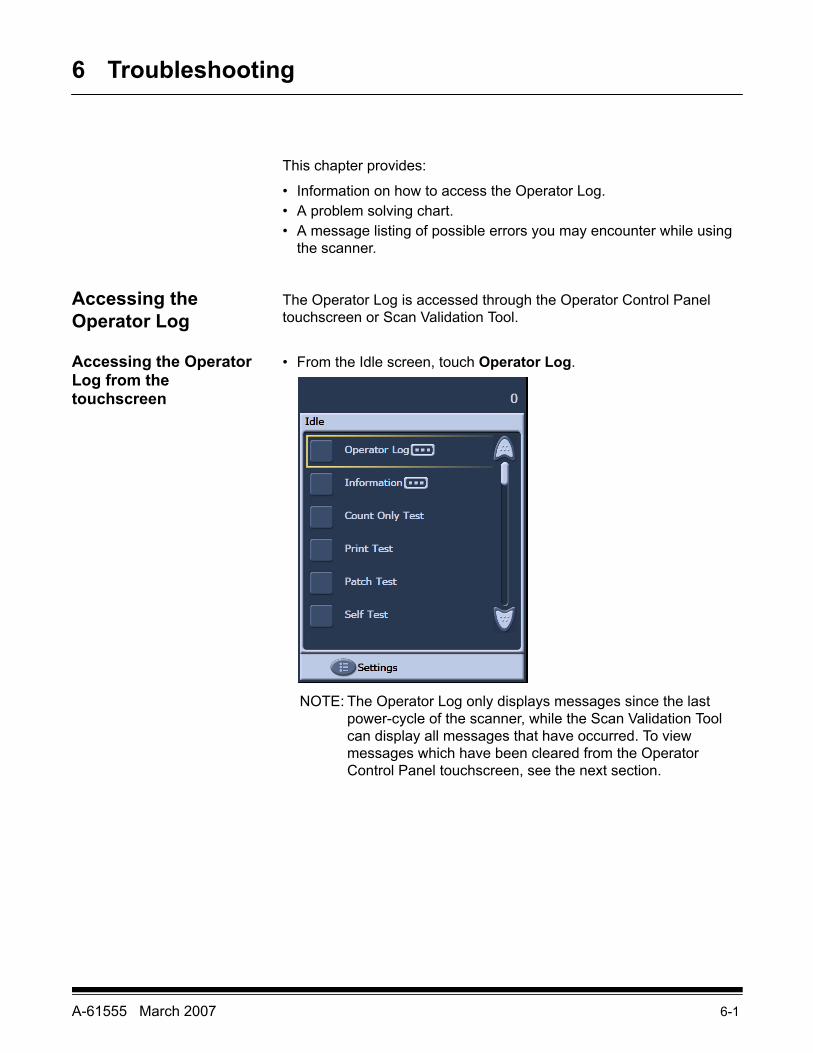
A-61555 March 2007 6-1
6 Troubleshooting
This chapter provides:
• Information on how to access the Operator Log.• A problem solving chart.• A message listing of possible errors you may encounter while using
the scanner.
Accessing the Operator Log
The Operator Log is accessed through the Operator Control Panel touchscreen or Scan Validation Tool.
Accessing the Operator Log from the touchscreen
• From the Idle screen, touch Operator Log.
NOTE: The Operator Log only displays messages since the last power-cycle of the scanner, while the Scan Validation Tool can display all messages that have occurred. To view messages which have been cleared from the Operator Control Panel touchscreen, see the next section.

6-2 A-61555 March 2007
Accessing the Operator Log from the Scan Validation tool
1. Select Start>Programs>Kodak>Document Imaging>Scan Validation Tool.
2. From the Driver Types box, select TWAIN.
3. From the Drivers box, select Kodak Scanner: i1800 and click OK.
4. Select the Scanner icon.
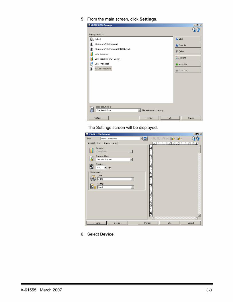
A-61555 March 2007 6-3
5. From the main screen, click Settings.
The Settings screen will be displayed.
6. Select Device.
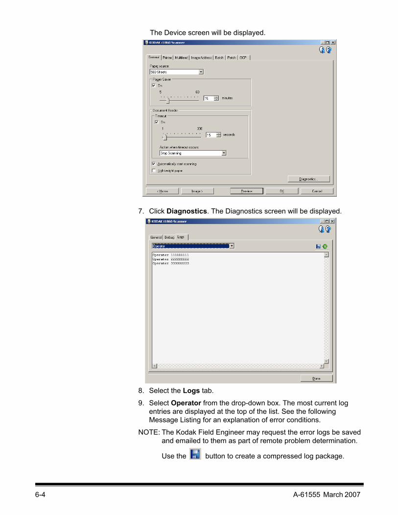
6-4 A-61555 March 2007
The Device screen will be displayed.
7. Click Diagnostics. The Diagnostics screen will be displayed.
8. Select the Logs tab.
9. Select Operator from the drop-down box. The most current log entries are displayed at the top of the list. See the following Message Listing for an explanation of error conditions.
NOTE: The Kodak Field Engineer may request the error logs be saved and emailed to them as part of remote problem determination.
Use the button to create a compressed log package.

A-61555 March 2007 6-5
Message listing Following is an alphabetic list of messages and corrective actions you can take if one of the following messages is encountered.
Messages ID# Operator MessageBackground accessory changed while powered up
381 The Background Accessory was changed while the scanner was powered on. • Turn the power off to the scanner, wait a few seconds and
power the scanner back on.• If you get this message and you did not change the
Background Accessory, clean the scanner.Cable unplugged 319 Some device on the FireWire bus was unplugged/plugged in.
• Check that all FireWire connectors are securely fastened.Calibration failed 106, 331 • Clean the imaging guides. See Chapter 5, Maintenance for
procedures. • Try to calibrate the scanner again. Be sure you are using the
correct calibration target. See Chapter 3, “Calibrating the scanner”.
• The calibration target is too small. A 12- x 12-inch calibration target is required for image calibration.
• Calibration target is too narrow.• If the problem persists, call Service.
Calibration succeeded 105, 342 Informational message. The scanner has been successfully calibrated.
Call Service Many ID numbers
A condition was detected that may require repair.• Turn the power off to the scanner, wait a few seconds and
power the scanner back on.• If the problem persists, call Service and provide the ID number
of the error.Cannot calibrate with white background
184 Both a front and rear print head is installed in the scanner. Only one print head can be installed at one time. • Remove one of the print heads.
Cannot run with both printers installed
90 The White Background Accessory is installed in the scanner while the scanner is trying the calibrate.• Remove the White Background Accessory before calibrating
the scanner. Check document preparation 123, 135,
81• The gap between your documents is too small.• Make sure the leading edges of the documents are aligned.
See Chapter 3, “Document preparation” for more information.• Check the condition of your feed module and separation roller
tires and your pre-separation pad. Clean and replace if necessary.
Check imaging guides and lamps 149, 178, 139
• Verify that the imaging guides are installed correctly. See Chapter 5, Maintenance.
• Clean both sides of the imaging guides and lower glass plate between the lamps.
• Check that the white patch on the imaging guides is clean and in good condition.
• If the problem persists, call Service.Clean lower imaging guide 294 The lower imaging guide is dirty or there may be a small piece of
paper in the imaging guide area. • Clean the imaging guides. See Chapter 5, Maintenance for
procedures.

6-6 A-61555 March 2007
Messages ID# Operator MessageClean upper imaging guide 293, 304 The upper imaging guide is dirty or there may be a small piece of
paper in the imaging guide area.• Clean the imaging guides. See Chapter 5, Maintenance for
procedures. Document count exceeded maximum value
124 The document counter is larger than the maximum configured value.• Reconfigure the scanner to allow a larger value for the
document counter. Refeed the document set. Document too dark to deskew 143 Informational message. The scanner was unable to find the
document edges to determine the skew angle. A full-width, non-deskewed image has been created.• The document is too dark.• The image is too large.• Rescan using a fixed-sized cropping window.
Document too long 35, 36, 183 A document was measured which exceeded the configured maximum allowable length. This may be due to a document overlap.• Check the host monitor to see if there are any overlapped
documents that may need to be rescanned. This condition may also be caused by poor document separation.• Replace the separation roller tires and pre-separation pad.
See Chapter 5, Maintenance for procedures.Front calibration failed 110 The front imaging path calibration failed.
• Clean the imaging guides. See Chapter 5, Maintenance for procedures.
• Try to calibrate the scanner again. Be sure you are using the correct calibration target. See Chapter 3, “Calibrating the Scanner”.
• If the problem persists, call Service.Front calibration succeeded 111 Informational message. The front image path has been
successfully calibrated.Image address overflow 120 One of the image address fields is not large enough for the next
image address (i.e., level 2 field width is 2, but the next level 2 value is 100).• Define the image address field to be wider.
Image calibration is suggested 109 • Calibrate the scanner when the current batch of documents has completed.
Image outside document area 177 Based on relative cropping parameters, the image to be generated from this document would be outside the document area. • Make sure the relative cropping offset, width and length are
correct and that the correct document is being scanned.Ink cartridge not installed 282 An attempt was made to use the Enhanced Printer without a ink
cartridge installed. • Be sure the cable is properly connected to the printer carrier
and the ink cartridge is installed in the printer carrier. See Chapter 4, The Enhanced Printer and Patch Readers for more information.
NOTE:The ink cartridge must be installed before turning on the scanner.

A-61555 March 2007 6-7
Messages ID# Operator MessageInput elevator too full, feed module missing or broken
297 • There is too much paper in the input elevator and it is holding the feed module up. The maximum input elevator capacity is 500 sheets. Remove some documents from the input elevator.
• The feed module is not installed properly. See Chapter 5, Maintenance, for correct installation procedures.
• If the problem persists, call Service.Invalid job setup 4 The image processing values sent by the host are invalid or in
conflict with one another.• Check the job settings for illegal combinations. Refer to the
Image Processing Guide for valid values.Jam in transport 30 A document is lodged in the transport.
• Remove the documents that have been scanned from the output tray.
• Open the pod.• Remove any jammed documents from inside the transport.• Close the pod.
NOTE: The following procedure is a general guideline. Your procedure may be different depending on how your application is set up.
• Verify the last document that was scanned correctly.• Place any documents that were not scanned at the top of the
batch.• Place the documents in the input elevator and begin scanning.
One or more documents that passed through the transport were not scanned. • Refeed all documents for which images were not obtained.
Lamps not ready for calibration 107 Calibration was attempted before the lamps were warmed up.• Wait until the lamps have completely warmed (90 seconds)
and try the calibration again.Lamps not ready for scanning 359, 19 Scanning was attempted before the lamps were warmed up.
• Wait for the message Lamps ready for scanning to be displayed and scan again.
Lamps ready for calibration 108 Informational message. The lamps are warmed and a calibration can be performed now, if needed. This does not indicate that a calibrate is needed.
Lamps ready for scanning 280 Informational message. The lamps are warmed and scanning can be initiated.
Lamps timed out 355 Informational message. The lamps were turned off due to inactivity.
No paper input elevator 46 The scanner was started with an empty input elevator or the portion of the document that is covering the paper present sensor is too dark (the back side of the bottom page). • Place the documents you want to scan in the input elevator
and try again.• Offset the document until the paper present sensor detects it.
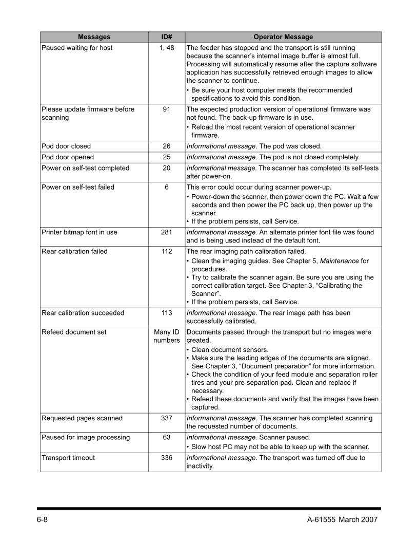
6-8 A-61555 March 2007
Messages ID# Operator MessagePaused waiting for host 1, 48 The feeder has stopped and the transport is still running
because the scanner’s internal image buffer is almost full. Processing will automatically resume after the capture software application has successfully retrieved enough images to allow the scanner to continue. • Be sure your host computer meets the recommended
specifications to avoid this condition. Please update firmware before scanning
91 The expected production version of operational firmware was not found. The back-up firmware is in use.• Reload the most recent version of operational scanner
firmware.Pod door closed 26 Informational message. The pod was closed.Pod door opened 25 Informational message. The pod is not closed completely.Power on self-test completed 20 Informational message. The scanner has completed its self-tests
after power-on. Power on self-test failed 6 This error could occur during scanner power-up.
• Power-down the scanner, then power down the PC. Wait a few seconds and then power the PC back up, then power up the scanner.
• If the problem persists, call Service.Printer bitmap font in use 281 Informational message. An alternate printer font file was found
and is being used instead of the default font.Rear calibration failed 112 The rear imaging path calibration failed.
• Clean the imaging guides. See Chapter 5, Maintenance for procedures.
• Try to calibrate the scanner again. Be sure you are using the correct calibration target. See Chapter 3, “Calibrating the Scanner”.
• If the problem persists, call Service.Rear calibration succeeded 113 Informational message. The rear image path has been
successfully calibrated.Refeed document set Many ID
numbersDocuments passed through the transport but no images were created. • Clean document sensors.• Make sure the leading edges of the documents are aligned.
See Chapter 3, “Document preparation” for more information.• Check the condition of your feed module and separation roller
tires and your pre-separation pad. Clean and replace if necessary.
• Refeed these documents and verify that the images have been captured.
Requested pages scanned 337 Informational message. The scanner has completed scanning the requested number of documents.
Paused for image processing 63 Informational message. Scanner paused.• Slow host PC may not be able to keep up with the scanner.
Transport timeout 336 Informational message. The transport was turned off due to inactivity.

A-61555 March 2007 6-9
Messages ID# Operator MessageUDDS calibration failed 333 The UDDS calibration failed.
• Be sure you are using the correct ultrasonics calibration target. See Chapter 3, “Calibrating the scanner”.
• Clean the sensors and try again.• If the problem persists, call Service.
UDDS calibration succeeded 332 Informational message. The scanner ultrasonics has been successfully calibrated.
UDDS is not calibrated 21 • Perform an Ultrasonics calibration. See Chapter 3, “Calibrating the scanner” for procedures.
UDDS multi-feed detected 23, 24, 334 A multi-feed document condition has been detected.• Check the host monitor to see if there are any overlapped
documents that may need to be rescanned. This condition may be caused by:• Poor document separation causing overlapped documents.• Stickers on the documents.• Wrinkles in the documents• Thick documents with high multi-feed settings.
Unable to scan 5 • The previous error condition has not been corrected. For example, there could be a document jam that has not been completely cleared.
• Incomplete or conflicting image processing parameters. • See other log entries for the actual condition.
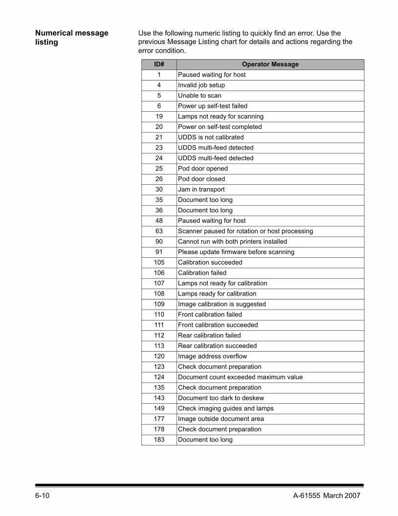
6-10 A-61555 March 2007
Numerical message listing
Use the following numeric listing to quickly find an error. Use the previous Message Listing chart for details and actions regarding the error condition.
ID# Operator Message1 Paused waiting for host4 Invalid job setup5 Unable to scan6 Power up self-test failed
19 Lamps not ready for scanning20 Power on self-test completed21 UDDS is not calibrated23 UDDS multi-feed detected24 UDDS multi-feed detected25 Pod door opened26 Pod door closed30 Jam in transport35 Document too long36 Document too long48 Paused waiting for host63 Scanner paused for rotation or host processing90 Cannot run with both printers installed91 Please update firmware before scanning105 Calibration succeeded106 Calibration failed107 Lamps not ready for calibration108 Lamps ready for calibration109 Image calibration is suggested110 Front calibration failed111 Front calibration succeeded112 Rear calibration failed113 Rear calibration succeeded120 Image address overflow123 Check document preparation124 Document count exceeded maximum value135 Check document preparation143 Document too dark to deskew149 Check imaging guides and lamps177 Image outside document area178 Check document preparation183 Document too long

A-61555 March 2007 6-11
Contacting Service Refer to the section entitled, “Contacting Support” in Chapter 1 for phone numbers and detailed information.
ID# Operator Message184 Cannot calibrate with white background260 No paper in input elevator 280 Lamps ready for scanning281 Printer bitmap font in use282 Ink cartridge not installed293 Clean upper imaging guide294 Clean lower imaging guide297 Input elevator too full, feed module missing or broken319 Cable unplugged331 Calibration failed332 UDDS calibration succeeded333 UDDS calibration failed336 Transport timeout337 Requested pages scanned355 Lamps timed out359 Lamps not ready for scanning381 Background accessory changed while powered up
Many IDs Call Service

6-12 A-61555 March 2007
Problem solving Use the chart below as a guide to check possible solutions to problems you may encounter when using the Kodak i1800 Series Scanners.
Problem Possible SolutionScanner does not power on Make sure that:
• the power cord is plugged securely into the receptacle in the back of the scanner.
• the wall outlet is not defective (call a licensed electrician).• both power switches are on (the main breaker switch on the back of the
scanner and the power switch located on the side of the scanner).Scanner is not being recognized by the Scan Validation Tool
Make sure that:• when the software was installed, it was installed by someone with
Administrator privileges.• the FireWire cable is plugged in securely.• the scanner shows up in the Device Manager as an “imaging” device.• you cycle power on the scanner and PC. First cycle power to the PC.
Then make sure the FireWire cable is securely fastened, then restart the scanner.
The scanner will not scan/feed documents
Make sure that:• the power cord is plugged in and the power is on.• the pod is completely closed.• the scanner is enabled from the host.• documents are making contact with the feed module.• for documents that require special handling, press the gap release
button during feeding.• the documents meet specifications for size, weight, etc.• if you are feeding small documents, be sure that the documents are
covering the paper present sensor in the input elevator.• you check the feed module, separation roller, and pre-separation pad
for signs of wear and replace these parts if necessary.• a very dark document or curled document is not on the bottom of the
stack. Place a white sheet of paper at the bottom of the stack and scan again.
• use Count Only mode to test feeding.Side guides will not move Remove all documents from the input elevator and be sure the locking
switch is in the unlocked position.More than one document is entering the transport at one time ortoo many multifeeds are being detected
Make sure that:• the guidelines for document preparation have been followed (e.g.,
staples, paper clips are removed; lead edges are aligned, etc.)• documents meet specifications for size and weight.• the multifeed sensors are clean.• the separation roller, feed module, and pre-separation pad are clean
and properly installed.• you have checked the feed module tires, separation roller tires and pre-
separation pad for signs of wear and replaced as needed.• ultrasonics have been calibrated.
Image quality is poor or has decreased Make sure that:• the imaging guides are clean. See Chapter 5, Maintenance.• the scanner has been calibrated. See Chapter 3, “Calibrating the
scanner”.• if using iThresholding, reduce the Contrast value.• try a different color table.• for color or grayscale images, consider creating a custom color table
using the Brightness and Contrast Control utility.If unsatisfactory image quality persists, call Service.

A-61555 March 2007 6-13
Problem Possible SolutionCalibration has failed Make sure that:
• you are using the proper calibration target and it is oriented correctly for the type of calibration you are performing. The Image calibration target and Ultrasonics calibration target are different.
• the imaging guides are clean.• the transport is clear of obstructions.• the sensors are clean.• the calibration target you are using is clean.If unsatisfactory image quality persists, call Service.
Documents are jamming Make sure that:• the guidelines for document preparation have been followed (e.g.,
staples, paper clips are removed; lead edges are aligned, etc.)• the output tray and side guides are adjusted for the length and width of
the documents being scanned.• all jammed documents have been removed from the transport area.• documents meet specifications for size and weight.• the sensors are clean.• the separation roller, feed module, and pre-separation pad are clean
and properly installed.• the transport rollers are clean.• the background strips are properly installed.• you have checked the feed module tires, separation roller tires and pre-
separation pad for signs of wear and replaced as needed.Long documents are not feeding or are jamming
Make sure that:• the input elevator extender is pulled out to provide support for long
documents.• the output tray is adjusted for the length of the documents being
scanned.• the output tray is installed properly.• document extenders are installed correctly.
Roller marks appear on the documents after scanning
Clean the feed module tires, separation roller tires and transport rollers.
Vertical streaks appear on the image Make sure that:• imaging guides are clean.• the scanner was thoroughly cleaned before the last image calibration.• when you calibrate the scanner that you are using a good, clean
calibration target. Use the calibration target provided with your scanner.• If you are using iThresholding, reduce the Contrast value.
The Enhanced Printer is not printing as desired
If you are having problems printing on scanned documents:• verify that the ink cartridge is not empty. • be sure the ink cartridge is properly installed.• be sure the ink cartridge is located in the correct position for printing.• make sure that the printer carrier is properly seated in its slot.• verify that all printer connectors are securely fastened and that the
ribbon cable is securely attached.• verify that the printer has been enabled through the host and that the
expected print string has been specified.Image too small or has a black border • Clean the imaging guides. See Chapter 5, Maintenance.
• Clean the scanner. See Chapter 5, Maintenance.• If using iThresholding, reduce the Contrast value.• Check for scratches on the black (or white) background strips. Replace
if necessary.

A-61555 March 2007 A-1
Appendix A Accessories
This chapter provides a description of the accessories that are available for use the Kodak i1800 Series Scanners.
Kodak Ultralightweight Paper Feed Module
The Kodak Feeder Kit for Ultralightweight Paper for i600/i1800 Series Scanners allows you to feed lightweight paper from a paper weight range of 25 g/m2 to 75 g/m2 kg (7 to 20 lbs). This kit includes a feed module and separation roller that are specially designed to feed light-weight paper through the scanner transport. This kit includes the following:
• 1 Feed Module• 1 Separation Roller• 4 Pre-separation Pads• 17 Replacement Tires for the Feed Module• 9 Replacement Tires for the Separation Roller
Instructions for installing the Ultralightweight Paper Feed Module are included with the kit. CAT No. 896 5279
Kodak White Background Accessory
When you scan translucent documents, the background often appears dark. The Kodak White Background Accessory for i600/i1800 Series Scanners will reduce black background bleed-through while scanning which produces whiter images.
The White Background Accessory comes with two white background strips that replace the two black background strips in the scanner. Instructions for installing the White Background Accessory are included with the kit. CAT No. 894 9000
Kodak Manual Feeder When the need arises to manually feed documents, the Kodak Manual Feeder for the i1800 Series Scanners provides a flat work surface. The Manual Feeder can be easily installed and removed. The Kodak Manual Feeder comes with the shelf and two side guides which can be adjusted to the desired position for scanning. CAT No. 874 1894
Kodak High Resolution Printer Accessory
The Kodak High Resolution Printer Accessory provides higher resolution printing on your documents — 600 dpi, front side, pre-scan only. When this printer is installed the Enhanced Printer will no longer be accessible. CAT No. 815 0237

A-61555 March 2007 B-1
Appendix B Specifications
Scanner Type/Speed i1840 Scanner: Duplex color scanner with an automatic document feeder including the enhanced printer, 160 pages per minute (landscape)
i1860 Scanner: Duplex color scanner with an automatic document feeder including the enhanced printer, 200 pages per minute (landscape)
Scanning Technology Dual Tricolor Plus CCDGrayscale output bit depth is 256 levels (8-bit)Color capture bit depth is 40-bit (10 bits per red, green, blue and black channels)Color output bit depth is 24-bit
Output Resolution Black and white: 200, 240, 300, 400Color/Grayscale: 100, 150, 200, 240, 300
Compression formats JPEG, CCITT Group 4, uncompressedScan Area Width: 6.4 to 30.5 cm (2.5 to 12 in.)
Length: 6.4 to 86 cm (2.5 to 34 in.) ADF Capacity 500 sheets of 20 lb. bond paper (up to A3)Recommended Daily Volume
Unlimited
Light Source Dual Xenon lamps per side, mercury-freeScanner operational voltage
100 - 240 VAC, 50/60 Hz, 7.0 - 3.5 A
Scanner Dimensions Height (adjustable): 102-127 cm (40-50 in.)Width (depending on touchscreen position): 78-83 cm (31-33 in.)Depth: 99 cm (39 in.)
Scanner Weight 218 kg (480 lbs.)Host Connection IEEE-1394 (FireWire) interface, 6-pin connectorMulti-feed Detection Multi-feed detection with ultrasonic technology; three ultrasonic sensors that can
work together or independently.Color Touchscreen Control
Operator control via color LCD touchscreen
Ergonomic Height Adjustment
Integrated height adjustment for seated or standing operation
Image Address i1860 Scanner only: Multi-level indexing/batching capabilitiesPatch Readers i1860 Scanner only: Four permanently mounted patch readers that can work
together or independentlyImprinting Front pre-scan or rear post-scan imprintingOperating Temperature 15 to 35°C (59 to 95°)Humidity 15 to 76% Environmental Factors Complies with Energy Star requirementsHeat Load 3024 kj/hr. (2866 BTU/hr.) max Altitude Up to 2440 m (8000 ft)Acoustic Noise Data was measured in accordance with DIN 45 635, ANSI S12.10-1985 and ISO
7779 in a semi-anechoic chamber.Operating: 63.4 dBAStandby: 42.3 dBA

User’s Guide
i1800 Series Scanners
Eastman Kodak Company343 State StreetRochester, NY 14650 U.S.A.© Kodak, 2007. All rights reserved. TM: Kodak
COLORS
9E8273A
8.5 x 11” Folded
6079-232
GUIDE COVER-KODAK SCANNERS
FONTSWhitney K Family
SIZE
ECO
P/N
DESIGNER
MODIFIED10.11.07
9E8273A
DE MEYER
ARTWORK NAME
PRINTING INFORMATION
4 COLOR PROCESS
ENLANGUAGES
A-61555