Embed Size (px)
Citation preview
IA-32 Intel® ArchitectureOptimization Reference
Manual
Order Number: 248966-012June 2005

INFORMATION IN THIS DOCUMENT IS PROVIDED IN CONNECTION WITH INTEL PRODUCTS. NO LICENSE, EXPRESS OR IMPLIED, BY ESTOPPEL OR OTHERWISE, TO ANY INTELLECTUAL PROPERTY RIGHTS IS GRANTED BY THIS DOCUMENT. EXCEPT AS PROVIDED IN INTEL’S TERMS AND CONDI-TIONS OF SALE FOR SUCH PRODUCTS, INTEL ASSUMES NO LIABILITY WHATSOEVER, AND INTEL DISCLAIMS ANY EXPRESS OR IMPLIED WARRANTY, RELATING TO SALE AND/OR USE OF INTEL PRODUCTS INCLUDING LIABILITY OR WARRANTIES RELATING TO FITNESS FOR A PARTICULAR PUR-POSE, MERCHANTABILITY, OR INFRINGEMENT OF ANY PATENT, COPYRIGHT OR OTHER INTELLEC-TUAL PROPERTY RIGHT. Intel products are not intended for use in medical, life saving, or life sustaining applications. Intel may make changes to specifications and product descriptions at any time, without notice.
This IA-32 Intel® Architecture Optimization Reference Manual as well as the software described in it is furnished under license and may only be used or copied in accordance with the terms of the license. The information in this man-ual is furnished for informational use only, is subject to change without notice, and should not be construed as a com-mitment by Intel Corporation. Intel Corporation assumes no responsibility or liability for any errors or inaccuracies that may appear in this document or any software that may be provided in association with this document.
Except as permitted by such license, no part of this document may be reproduced, stored in a retrieval system, or trans-mitted in any form or by any means without the express written consent of Intel Corporation.
Developers must not rely on the absence or characteristics of any features or instructions marked “reserved” or “unde-fined.” Improper use of reserved or undefined features or instructions may cause unpredictable behavior or failure in developer's software code when running on an Intel® processor. Intel reserves these features or instructions for future definition and shall have no responsibility whatsoever for conflicts or incompatibilities arising from their unauthorized use.
Hyper-Threading Technology requires a computer system with an Intel® Pentium®4 processor supporting Hyper-Threading Technology and an HT Technology enabled chipset, BIOS and operating system. Performance will vary depending on the specific hardware and software you use. See http://www.intel.com/info/hyperthreading for more information including details on which processors support HT Technology.
Intel, Pentium, Intel Xeon, Intel NetBurst, Itanium, MMX, and VTune are trademarks or registered trademarks of Intel Corporation or its subsidiaries in the United States and other countries.
*Other names and brands may be claimed as the property of others.
Copyright © 1999-2005 Intel Corporation.
ii

Contents
Introduction
Chapter 1 IA-32 Intel® Architecture Processor Family OverviewSIMD Technology.................................................................................................................... 1-2
Summary of SIMD Technologies ...................................................................................... 1-5MMX™ Technology..................................................................................................... 1-5Streaming SIMD Extensions....................................................................................... 1-5Streaming SIMD Extensions 2.................................................................................... 1-6Streaming SIMD Extensions 3.................................................................................... 1-6
Intel® Extended Memory 64 Technology (Intel® EM64T)........................................................ 1-7Intel NetBurst® Microarchitecture............................................................................................ 1-8
Design Goals of Intel NetBurst Microarchitecture ............................................................ 1-8Overview of the Intel NetBurst Microarchitecture Pipeline ............................................... 1-9
The Front End........................................................................................................... 1-11The Out-of-order Core .............................................................................................. 1-12Retirement ................................................................................................................ 1-12
Front End Pipeline Detail............................................................................................... 1-13Prefetching................................................................................................................ 1-13Decoder .................................................................................................................... 1-14Execution Trace Cache ............................................................................................ 1-14Branch Prediction ..................................................................................................... 1-15
Execution Core Detail..................................................................................................... 1-16Instruction Latency and Throughput ......................................................................... 1-17Execution Units and Issue Ports............................................................................... 1-18Caches...................................................................................................................... 1-19Data Prefetch............................................................................................................ 1-21Loads and Stores...................................................................................................... 1-24Store Forwarding ...................................................................................................... 1-25
Intel® Pentium® M Processor Microarchitecture ................................................................... 1-25The Front End........................................................................................................... 1-27Data Prefetching ....................................................................................................... 1-28
iii

IA-32 Intel® Architecture Optimization
Out-of-Order Core..................................................................................................... 1-29In-Order Retirement.................................................................................................. 1-30
Hyper-Threading Technology................................................................................................ 1-30Processor Resources and Hyper-Threading Technology............................................... 1-32
Replicated Resources............................................................................................... 1-32Partitioned Resources .............................................................................................. 1-32Shared Resources.................................................................................................... 1-33
Microarchitecture Pipeline and Hyper-Threading Technology........................................ 1-34 Front End Pipeline......................................................................................................... 1-34Execution Core............................................................................................................... 1-35Retirement ...................................................................................................................... 1-35
Dual-Core Processors........................................................................................................... 1-35Microarchitecture Pipeline and Dual-Core Processors................................................... 1-37
Chapter 2 General Optimization GuidelinesTuning to Achieve Optimum Performance .............................................................................. 2-1Tuning to Prevent Known Coding Pitfalls ................................................................................ 2-2General Practices and Coding Guidelines .............................................................................. 2-3
Use Available Performance Tools..................................................................................... 2-4Optimize Performance Across Processor Generations.................................................... 2-4Optimize Branch Predictability.......................................................................................... 2-5Optimize Memory Access................................................................................................. 2-5Optimize Floating-point Performance............................................................................... 2-6Optimize Instruction Selection.......................................................................................... 2-6Optimize Instruction Scheduling....................................................................................... 2-7Enable Vectorization......................................................................................................... 2-7
Coding Rules, Suggestions and Tuning Hints......................................................................... 2-8Performance Tools .................................................................................................................. 2-9
Intel® C++ Compiler ......................................................................................................... 2-9General Compiler Recommendations ............................................................................ 2-10VTune™ Performance Analyzer..................................................................................... 2-10
Processor Perspectives ........................................................................................................ 2-11CPUID Dispatch Strategy and Compatible Code Strategy ............................................. 2-13Transparent Cache-Parameter Strategy......................................................................... 2-13Threading Strategy and Hardware Multi-Threading Support .......................................... 2-14
Branch Prediction.................................................................................................................. 2-14Eliminating Branches...................................................................................................... 2-15Spin-Wait and Idle Loops................................................................................................ 2-18Static Prediction.............................................................................................................. 2-19Inlining, Calls and Returns ............................................................................................. 2-21
iv
Contents
Branch Type Selection ................................................................................................... 2-23 Loop Unrolling ............................................................................................................... 2-26Compiler Support for Branch Prediction......................................................................... 2-28
Memory Accesses................................................................................................................. 2-29Alignment ....................................................................................................................... 2-29Store Forwarding ............................................................................................................ 2-32
Store-to-Load-Forwarding Restriction on Size and Alignment.................................. 2-33Store-forwarding Restriction on Data Availability...................................................... 2-38
Data Layout Optimizations ............................................................................................. 2-39Stack Alignment.............................................................................................................. 2-42Capacity Limits and Aliasing in Caches.......................................................................... 2-43
Capacity Limits in Set-Associative Caches............................................................... 2-44Aliasing Cases in the Pentium 4 and Intel® Xeon™ Processors .............................. 2-45Aliasing Cases in the Pentium M Processor............................................................. 2-45
Mixing Code and Data.................................................................................................... 2-46Self-modifying Code ................................................................................................. 2-47
Write Combining ............................................................................................................. 2-48Locality Enhancement .................................................................................................... 2-49Minimizing Bus Latency.................................................................................................. 2-51Non-Temporal Store Bus Traffic ..................................................................................... 2-52Prefetching ..................................................................................................................... 2-54
Hardware Instruction Fetching.................................................................................. 2-54Software and Hardware Cache Line Fetching .......................................................... 2-54
Cacheability Instructions ................................................................................................ 2-56Code Alignment.............................................................................................................. 2-56
Improving the Performance of Floating-point Applications.................................................... 2-57Guidelines for Optimizing Floating-point Code............................................................... 2-57Floating-point Modes and Exceptions ............................................................................ 2-59
Floating-point Exceptions ......................................................................................... 2-59Floating-point Modes ................................................................................................ 2-62
Improving Parallelism and the Use of FXCH.................................................................. 2-67x87 vs. Scalar SIMD Floating-point Trade-offs ............................................................... 2-68Memory Operands.......................................................................................................... 2-69Floating-Point Stalls........................................................................................................ 2-69
x87 Floating-point Operations with Integer Operands .............................................. 2-70x87 Floating-point Comparison Instructions ............................................................. 2-70Transcendental Functions ........................................................................................ 2-70
Instruction Selection.............................................................................................................. 2-71Complex Instructions...................................................................................................... 2-71Use of the lea Instruction................................................................................................ 2-72
v
IA-32 Intel® Architecture Optimization
Use of the inc and dec Instructions ................................................................................ 2-72Use of the shift and rotate Instructions ........................................................................... 2-73Integer Divide ................................................................................................................. 2-73Operand Sizes................................................................................................................ 2-73Address Calculations...................................................................................................... 2-76Clearing Registers.......................................................................................................... 2-77Compares ....................................................................................................................... 2-77Floating Point/SIMD Operands....................................................................................... 2-78Prolog Sequences .......................................................................................................... 2-80Code Sequences that Operate on Memory Operands ................................................... 2-80
Instruction Scheduling........................................................................................................... 2-81Latencies and Resource Constraints.............................................................................. 2-81Spill Scheduling .............................................................................................................. 2-82Scheduling Rules for the Pentium 4 Processor Decoder ............................................... 2-82Scheduling Rules for the Pentium M Processor Decoder .............................................. 2-83
Vectorization ......................................................................................................................... 2-83Miscellaneous ....................................................................................................................... 2-85
NOPs.............................................................................................................................. 2-85Summary of Rules and Suggestions..................................................................................... 2-86
User/Source Coding Rules............................................................................................. 2-87Assembly/Compiler Coding Rules.................................................................................. 2-89Tuning Suggestions........................................................................................................ 2-98
Chapter 3 Coding for SIMD ArchitecturesChecking for Processor Support of SIMD Technologies ......................................................... 3-2
Checking for MMX Technology Support ........................................................................... 3-2Checking for Streaming SIMD Extensions Support .......................................................... 3-3Checking for Streaming SIMD Extensions 2 Support ....................................................... 3-5Checking for Streaming SIMD Extensions 3 Support ....................................................... 3-6
Considerations for Code Conversion to SIMD Programming.................................................. 3-8Identifying Hot Spots ...................................................................................................... 3-10Determine If Code Benefits by Conversion to SIMD Execution...................................... 3-11
Coding Techniques ............................................................................................................... 3-12Coding Methodologies.................................................................................................... 3-13
Assembly .................................................................................................................. 3-15Intrinsics.................................................................................................................... 3-15Classes ..................................................................................................................... 3-17Automatic Vectorization ............................................................................................ 3-18
Stack and Data Alignment..................................................................................................... 3-20Alignment and Contiguity of Data Access Patterns ........................................................ 3-20
vi
Contents
Using Padding to Align Data..................................................................................... 3-20Using Arrays to Make Data Contiguous.................................................................... 3-21
Stack Alignment For 128-bit SIMD Technologies ........................................................... 3-22Data Alignment for MMX Technology ............................................................................. 3-23Data Alignment for 128-bit data...................................................................................... 3-24
Compiler-Supported Alignment................................................................................. 3-24Improving Memory Utilization................................................................................................ 3-27
Data Structure Layout..................................................................................................... 3-27Strip Mining..................................................................................................................... 3-32Loop Blocking................................................................................................................. 3-34
Instruction Selection.............................................................................................................. 3-37Tuning the Final Application.................................................................................................. 3-38
Chapter 4 Optimizing for SIMD Integer ApplicationsGeneral Rules on SIMD Integer Code .................................................................................... 4-2Using SIMD Integer with x87 Floating-point............................................................................ 4-3
Using the EMMS Instruction............................................................................................. 4-3Guidelines for Using EMMS Instruction............................................................................ 4-4
Data Alignment........................................................................................................................ 4-6Data Movement Coding Techniques ....................................................................................... 4-6
Unsigned Unpack ............................................................................................................. 4-6Signed Unpack ................................................................................................................. 4-7Interleaved Pack with Saturation...................................................................................... 4-8Interleaved Pack without Saturation............................................................................... 4-10Non-Interleaved Unpack................................................................................................. 4-11Extract Word................................................................................................................... 4-13Insert Word ..................................................................................................................... 4-14Move Byte Mask to Integer............................................................................................. 4-16Packed Shuffle Word for 64-bit Registers ...................................................................... 4-18Packed Shuffle Word for 128-bit Registers .................................................................... 4-19Unpacking/interleaving 64-bit Data in 128-bit Registers................................................. 4-20Data Movement .............................................................................................................. 4-21Conversion Instructions.................................................................................................. 4-21
Generating Constants ........................................................................................................... 4-21Building Blocks...................................................................................................................... 4-23
Absolute Difference of Unsigned Numbers .................................................................... 4-23Absolute Difference of Signed Numbers ........................................................................ 4-24Absolute Value................................................................................................................ 4-25Clipping to an Arbitrary Range [high, low] ...................................................................... 4-26
Highly Efficient Clipping ............................................................................................ 4-27
vii
IA-32 Intel® Architecture Optimization
Clipping to an Arbitrary Unsigned Range [high, low] ................................................ 4-28Packed Max/Min of Signed Word and Unsigned Byte.................................................... 4-29
Signed Word ............................................................................................................. 4-29Unsigned Byte .......................................................................................................... 4-30
Packed Multiply High Unsigned...................................................................................... 4-30Packed Sum of Absolute Differences ............................................................................. 4-30Packed Average (Byte/Word) ......................................................................................... 4-31Complex Multiply by a Constant ..................................................................................... 4-32Packed 32*32 Multiply.................................................................................................... 4-33Packed 64-bit Add/Subtract............................................................................................ 4-33128-bit Shifts................................................................................................................... 4-33
Memory Optimizations .......................................................................................................... 4-34Partial Memory Accesses............................................................................................... 4-35
Supplemental Techniques for Avoiding Cache Line Splits........................................ 4-37Increasing Bandwidth of Memory Fills and Video Fills ................................................... 4-39
Increasing Memory Bandwidth Using the MOVDQ Instruction ................................. 4-39Increasing Memory Bandwidth by Loading and Storing to and from the
Same DRAM Page ................................................................................................ 4-39Increasing UC and WC Store Bandwidth by Using Aligned Stores........................... 4-40
Converting from 64-bit to 128-bit SIMD Integer .................................................................... 4-40
Chapter 5 Optimizing for SIMD Floating-point ApplicationsGeneral Rules for SIMD Floating-point Code.......................................................................... 5-1Planning Considerations ......................................................................................................... 5-2Using SIMD Floating-point with x87 Floating-point ................................................................. 5-3Scalar Floating-point Code...................................................................................................... 5-3Data Alignment........................................................................................................................ 5-4
Data Arrangement ............................................................................................................ 5-4Vertical versus Horizontal Computation...................................................................... 5-5Data Swizzling ............................................................................................................ 5-9Data Deswizzling ...................................................................................................... 5-14Using MMX Technology Code for Copy or Shuffling Functions ................................ 5-17Horizontal ADD Using SSE....................................................................................... 5-18
Use of cvttps2pi/cvttss2si Instructions .................................................................................. 5-21Flush-to-Zero and Denormals-are-Zero Modes .................................................................... 5-22SIMD Floating-point Programming Using SSE3 ................................................................... 5-22
SSE3 and Complex Arithmetics ..................................................................................... 5-23SSE3 and Horizontal Computation................................................................................. 5-26
viii

Contents
Chapter 6 Optimizing Cache UsageGeneral Prefetch Coding Guidelines....................................................................................... 6-2Hardware Prefetching of Data................................................................................................. 6-4Prefetch and Cacheability Instructions.................................................................................... 6-5Prefetch................................................................................................................................... 6-6
Software Data Prefetch .................................................................................................... 6-6The Prefetch Instructions – Pentium 4 Processor Implementation................................... 6-8Prefetch and Load Instructions......................................................................................... 6-9
Cacheability Control .............................................................................................................. 6-10The Non-temporal Store Instructions.............................................................................. 6-10
Fencing..................................................................................................................... 6-11Streaming Non-temporal Stores ............................................................................... 6-11Memory Type and Non-temporal Stores................................................................... 6-12Write-Combining ....................................................................................................... 6-13
Streaming Store Usage Models...................................................................................... 6-14Coherent Requests................................................................................................... 6-14Non-coherent requests ............................................................................................. 6-14
Streaming Store Instruction Descriptions ....................................................................... 6-15The fence Instructions .................................................................................................... 6-16
The sfence Instruction .............................................................................................. 6-16The lfence Instruction ............................................................................................... 6-17The mfence Instruction ............................................................................................. 6-17
The clflush Instruction .................................................................................................... 6-18Memory Optimization Using Prefetch.................................................................................... 6-19
Software-controlled Prefetch .......................................................................................... 6-19Hardware Prefetch ......................................................................................................... 6-20Example of Effective Latency Reduction with H/W Prefetch .......................................... 6-21 Example of Latency Hiding with S/W Prefetch Instruction ............................................ 6-23Software Prefetching Usage Checklist ........................................................................... 6-25Software Prefetch Scheduling Distance ......................................................................... 6-26Software Prefetch Concatenation................................................................................... 6-27Minimize Number of Software Prefetches ...................................................................... 6-30Mix Software Prefetch with Computation Instructions .................................................... 6-33Software Prefetch and Cache Blocking Techniques....................................................... 6-35Hardware Prefetching and Cache Blocking Techniques ................................................ 6-40Single-pass versus Multi-pass Execution ....................................................................... 6-42
Memory Optimization using Non-Temporal Stores................................................................ 6-44Non-temporal Stores and Software Write-Combining..................................................... 6-44Cache Management ....................................................................................................... 6-45
ix

IA-32 Intel® Architecture Optimization
Video Encoder .......................................................................................................... 6-46Video Decoder .......................................................................................................... 6-46Conclusions from Video Encoder and Decoder Implementation .............................. 6-47Using Prefetch and Streaming-store for a Simple Memory Copy ............................. 6-47TLB Priming.............................................................................................................. 6-48Optimizing the 8-byte Memory Copy ........................................................................ 6-49
Deterministic Cache Parameters .......................................................................................... 6-51Cache Sharing Using Deterministic Cache Parameters................................................. 6-53Cache Sharing in Single-core or Multi-core.................................................................... 6-53Determine Prefetch Stride Using Deterministic Cache Parameters ............................... 6-53
Chapter 7 Multiprocessor, Dual-Core and Hyper-Threading Technology
Performance and Usage Models............................................................................................. 7-2Multithreading................................................................................................................... 7-2Multitasking Environment ................................................................................................. 7-4
Programming Models and Multithreading ............................................................................... 7-6Parallel Programming Models .......................................................................................... 7-7
Domain Decomposition............................................................................................... 7-7Functional Decomposition ................................................................................................ 7-8Tools for Creating Multithreaded Applications .................................................................. 7-8
Optimization Guidelines ........................................................................................................ 7-10Key Practices of Thread Synchronization ...................................................................... 7-11Key Practices of System Bus Optimization .................................................................... 7-11Key Practices of Memory Optimization .......................................................................... 7-12Key Practices of Front-end Optimization........................................................................ 7-12Key Practices of Execution Resource Optimization ....................................................... 7-13Generality and Performance Impact............................................................................... 7-13
Thread Synchronization ........................................................................................................ 7-14Choice of Synchronization Primitives ............................................................................. 7-15Synchronization for Short Periods.................................................................................. 7-15Optimization with Spin-Locks ......................................................................................... 7-19Synchronization for Longer Periods ............................................................................... 7-20
Avoid Coding Pitfalls in Thread Synchronization ...................................................... 7-21Prevent False-Sharing of Data ....................................................................................... 7-23Placement of Shared Synchronization Variable ............................................................. 7-24
System Bus Optimization...................................................................................................... 7-24Conserve Bus Bandwidth ............................................................................................... 7-25Avoid Excessive Software Prefetches ............................................................................ 7-26
x
Contents
Improve Effective Latency of Cache Misses................................................................... 7-27Use Full Write Transactions to Achieve Higher Data Rate ............................................. 7-28
Memory Optimization ............................................................................................................ 7-28Cache Blocking Technique ............................................................................................. 7-29Shared-Memory Optimization......................................................................................... 7-30
Minimize Sharing of Data between Physical Processors.......................................... 7-30Eliminate 64-K-Aliased Data Accesses .......................................................................... 7-30Preventing Excessive Evictions in First-Level Data Cache ............................................ 7-31
Per-thread Stack Offset ............................................................................................ 7-32Per-instance Stack Offset ......................................................................................... 7-34
Front-end Optimization.......................................................................................................... 7-36Avoid Excessive Loop Unrolling ..................................................................................... 7-37Optimization for Code Size............................................................................................. 7-37
Execution Resource Optimization ......................................................................................... 7-38Optimization Priorities .................................................................................................... 7-38Using Shared Execution Resources in a Processor Core.............................................. 7-40
Using Thread Affinities to Manage Shared Platform Resources........................................... 7-42
Chapter 8 64-bit Mode Coding GuidelinesIntroduction ............................................................................................................................. 8-1Coding Rules Affecting 64-bit Mode........................................................................................ 8-1
Use Legacy 32-Bit Instructions When The Data Size Is 32 Bits....................................... 8-1Use Extra Registers to Reduce Register Pressure .......................................................... 8-2Use 64-Bit by 64-Bit Multiplies That Produce 128-Bit Results Only When Necessary..... 8-2Sign Extension to Full 64-Bits........................................................................................... 8-3
Alternate Coding Rules for 64-Bit Mode.................................................................................. 8-4Use 64-Bit Registers Instead of Two 32-Bit Registers for 64-Bit Arithmetic ..................... 8-4Use 32-Bit Versions of CVTSI2SS and CVTSI2SD When Possible ................................. 8-6Using Software Prefetch................................................................................................... 8-6
Appendix A Application Performance ToolsIntel® Compilers ..................................................................................................................... A-2
Code Optimization Options ............................................................................................. A-3Targeting a Processor (-Gn) ...................................................................................... A-3Automatic Processor Dispatch Support (-Qx[extensions] and -Qax[extensions])...... A-4
Vectorizer Switch Options ............................................................................................... A-5Loop Unrolling............................................................................................................ A-5Multithreading with OpenMP* .................................................................................... A-6
Inline Expansion of Library Functions (-Oi, -Oi-) ............................................................. A-6
xi

IA-32 Intel® Architecture Optimization
Floating-point Arithmetic Precision (-Op, -Op-, -Qprec, -Qprec_div, -Qpc, -Qlong_double)............................................................................................................. A-6
Rounding Control Option (-Qrcd) .................................................................................... A-6Interprocedural and Profile-Guided Optimizations .......................................................... A-7
Interprocedural Optimization (IPO) ............................................................................ A-7Profile-Guided Optimization (PGO) ........................................................................... A-7
Intel® VTune™ Performance Analyzer................................................................................... A-8Sampling ......................................................................................................................... A-9
Time-based Sampling................................................................................................ A-9Event-based Sampling............................................................................................. A-10Workload Characterization ...................................................................................... A-11
Call Graph ..................................................................................................................... A-13Counter Monitor............................................................................................................. A-14Intel® Tuning Assistant .................................................................................................. A-14
Intel® Performance Libraries................................................................................................ A-14Benefits Summary ......................................................................................................... A-15 Optimizations with the Intel® Performance Libraries .................................................... A-16
Enhanced Debugger (EDB) ................................................................................................. A-17Intel® Threading Tools.......................................................................................................... A-17
Intel® Thread Checker................................................................................................... A-17Thread Profiler............................................................................................................... A-19
Intel® Software College........................................................................................................ A-20
Appendix B Intel Pentium 4 Processor Performance MetricsPentium 4 Processor-Specific Terminology............................................................................ B-2
Bogus, Non-bogus, Retire ............................................................................................... B-2Bus Ratio......................................................................................................................... B-2Replay ............................................................................................................................. B-3Assist ............................................................................................................................... B-3Tagging............................................................................................................................ B-3
Counting Clocks..................................................................................................................... B-4Non-Halted Clockticks ..................................................................................................... B-5Non-Sleep Clockticks ...................................................................................................... B-6Time Stamp Counter........................................................................................................ B-7
Microarchitecture Notes ......................................................................................................... B-8Trace Cache Events ........................................................................................................ B-8Bus and Memory Metrics................................................................................................. B-8
Reads due to program loads ................................................................................... B-10Reads due to program writes (RFOs)...................................................................... B-10Writebacks (dirty evictions)...................................................................................... B-11
xii

Contents
Usage Notes for Specific Metrics .................................................................................. B-12Usage Notes on Bus Activities ...................................................................................... B-14
Metrics Descriptions and Categories ................................................................................... B-15Performance Metrics and Tagging Mechanisms .................................................................. B-45
Tags for replay_event .................................................................................................... B-45Tags for front_end_event............................................................................................... B-47Tags for execution_event .............................................................................................. B-47
Using Performance Metrics with Hyper-Threading Technology ........................................... B-49
Appendix C IA-32 Instruction Latency and ThroughputOverview ................................................................................................................................ C-2Definitions .............................................................................................................................. C-4Latency and Throughput ........................................................................................................ C-4
Latency and Throughput with Register Operands.......................................................... C-6Table Footnotes ....................................................................................................... C-19
Latency and Throughput with Memory Operands ......................................................... C-20
Appendix D Stack AlignmentStack Frames ......................................................................................................................... D-1
Aligned esp-Based Stack Frames ................................................................................... D-4Aligned ebp-Based Stack Frames ................................................................................... D-6Stack Frame Optimizations.............................................................................................. D-9
Inlined Assembly and ebx .................................................................................................... D-10
Appendix E Mathematics of Prefetch Scheduling DistanceSimplified Equation ................................................................................................................ E-1Mathematical Model for PSD ................................................................................................. E-2
No Preloading or Prefetch ............................................................................................... E-6Compute Bound (Case:Tc >= Tl + Tb) ............................................................................. E-7Compute Bound (Case: Tl + Tb > Tc > Tb) ..................................................................... E-8Memory Throughput Bound (Case: Tb >= Tc) ............................................................... E-10Example ........................................................................................................................ E-11
Index
xiii

IA-32 Intel® Architecture Optimization
xiv

Examples
Example 2-1 Assembly Code with an Unpredictable Branch ............................................2-17Example 2-2 Code Optimization to Eliminate Branches....................................................2-17Example 2-3 Eliminating Branch with CMOV Instruction...................................................2-18Example 2-4 Use of pause Instruction.............................................................................2-19Example 2-6 Static Taken Prediction Example..................................................................2-20Example 2-5 Pentium 4 Processor Static Branch Prediction Algorithm ............................2-20Example 2-7 Static Not-Taken Prediction Example...........................................................2-21Example 2-8 Indirect Branch With Two Favored Targets...................................................2-25Example 2-9 A Peeling Technique to Reduce Indirect Branch Misprediction....................2-26Example 2-10 Loop Unrolling ..............................................................................................2-28Example 2-11 Code That Causes Cache Line Split ............................................................2-31Example 2-12 Several Situations of Small Loads After Large Store ...................................2-35Example 2-13 A Non-forwarding Example of Large Load After Small Store .......................2-36Example 2-14 A Non-forwarding Situation in Compiler Generated Code............................2-36Example 2-15 Two Examples to Avoid the Non-forwarding Situation in
Example 2-142-36Example 2-16 Large and Small Load Stalls ........................................................................2-37Example 2-17 An Example of Loop-carried Dependence Chain.........................................2-39Example 2-18 Rearranging a Data Structure ......................................................................2-39Example 2-19 Decomposing an Array.................................................................................2-40Example 2-20 Dynamic Stack Alignment ............................................................................2-43Example 2-21 Non-temporal Stores and 64-byte Bus Write Transactions ..........................2-53Example 2-22 Non-temporal Stores and Partial Bus Write Transactions ............................2-54Example 2-23 Algorithm to Avoid Changing the Rounding Mode .......................................2-65Example 2-24 Dependencies Caused by Referencing Partial Registers ............................2-74Example 2-25 Recombining LOAD/OP Code into REG,MEM Form ...................................2-81Example 2-26 Spill Scheduling Example Code ...................................................................2-82Example 3-1 Identification of MMX Technology with cpuid..................................................3-3Example 3-2 Identification of SSE with cpuid......................................................................3-4Example 3-3 Identification of SSE by the OS......................................................................3-4Example 3-4 Identification of SSE2 with cpuid....................................................................3-5Example 3-5 Identification of SSE2 by the OS....................................................................3-6Example 3-6 Identification of SSE3 with cpuid....................................................................3-7Example 3-7 Identification of SSE3 by the OS....................................................................3-8
xv
IA-32 Intel® Architecture Optimization
Example 3-8 Simple Four-Iteration Loop...........................................................................3-14Example 3-9 Streaming SIMD Extensions Using Inlined Assembly Encoding..................3-15Example 3-10 Simple Four-Iteration Loop Coded with Intrinsics ........................................3-16Example 3-11 C++ Code Using the Vector Classes............................................................3-18Example 3-12 Automatic Vectorization for a Simple Loop...................................................3-19Example 3-13 C Algorithm for 64-bit Data Alignment..........................................................3-23Example 3-14 AoS Data Structure ......................................................................................3-27Example 3-15 SoA Data Structure ......................................................................................3-28Example 3-16 AoS and SoA Code Samples .......................................................................3-28Example 3-17 Hybrid SoA data structure............................................................................3-30Example 3-18 Pseudo-code Before Strip Mining ................................................................3-32Example 3-19 Strip Mined Code .........................................................................................3-33Example 3-20 Loop Blocking...............................................................................................3-35Example 3-21 Emulation of Conditional Moves...................................................................3-37Example 4-1 Resetting the Register between __m64 and FP Data Types .........................4-5Example 4-2 Unsigned Unpack Instructions .......................................................................4-7Example 4-3 Signed Unpack Code .....................................................................................4-8Example 4-4 Interleaved Pack with Saturation ..................................................................4-10Example 4-5 Interleaved Pack without Saturation .............................................................4-11Example 4-6 Unpacking Two Packed-word Sources in a Non-interleaved Way ................4-13Example 4-7 pextrw Instruction Code ...............................................................................4-14Example 4-8 pinsrw Instruction Code................................................................................4-15Example 4-9 Repeated pinsrw Instruction Code...............................................................4-16Example 4-10 pmovmskb Instruction Code.........................................................................4-17Example 4-11 pshuf Instruction Code .................................................................................4-19Example 4-12 Broadcast Using 2 Instructions ....................................................................4-19Example 4-13 Swap Using 3 Instructions............................................................................4-20Example 4-14 Reverse Using 3 Instructions .......................................................................4-20Example 4-15 Generating Constants ..................................................................................4-21Example 4-16 Absolute Difference of Two Unsigned Numbers...........................................4-23Example 4-17 Absolute Difference of Signed Numbers ......................................................4-24Example 4-18 Computing Absolute Value...........................................................................4-25Example 4-19 Clipping to a Signed Range of Words [high, low] .........................................4-27Example 4-20 Clipping to an Arbitrary Signed Range [high, low]........................................4-27Example 4-21 Simplified Clipping to an Arbitrary Signed Range ........................................4-28Example 4-22 Clipping to an Arbitrary Unsigned Range [high, low]....................................4-29Example 4-23 Complex Multiply by a Constant...................................................................4-32Example 4-24 A Large Load after a Series of Small Stores (Penalty).................................4-35Example 4-25 Accessing Data without Delay......................................................................4-35Example 4-26 A Series of Small Loads after a Large Store................................................4-36Example 4-27 Eliminating Delay for a Series of Small Loads after a Large Store ..............4-36Example 4-28 An Example of Video Processing with Cache Line Splits ............................4-37Example 4-29 Video Processing Using LDDQU to Avoid Cache Line Splits.......................4-38
xvi

Examples
Example 5-1 Pseudocode for Horizontal (xyz, AoS) Computation......................................5-8Example 5-2 Pseudocode for Vertical (xxxx, yyyy, zzzz, SoA) Computation ......................5-9Example 5-3 Swizzling Data..............................................................................................5-10Example 5-4 Swizzling Data Using Intrinsics ....................................................................5-12Example 5-5 Deswizzling Single-Precision SIMD Data.....................................................5-14Example 5-6 Deswizzling Data Using the movlhps and shuffle Instructions .....................5-15Example 5-7 Deswizzling Data 64-bit Integer SIMD Data.................................................5-16Example 5-8 Using MMX Technology Code for Copying or Shuffling................................5-18Example 5-9 Horizontal Add Using movhlps/movlhps.......................................................5-19Example 5-10 Horizontal Add Using Intrinsics with movhlps/movlhps ................................5-21Example 5-11 Multiplication of Two Pair of Single-precision Complex Number ..................5-24Example 5-12 Division of Two Pair of Single-precision Complex Number...........................5-25Example 5-13 Calculating Dot Products from AOS.............................................................5-26Example 6-1 Pseudo-code for Using cflush ......................................................................6-19Example 6-2 Populating an Array for Circular Pointer Chasing with
Constant Stride6-22Example 6-3 Prefetch Scheduling Distance ......................................................................6-27Example 6-4 Using Prefetch Concatenation .....................................................................6-29Example 6-5 Concatenation and Unrolling the Last Iteration of Inner Loop......................6-29Example 6-6 Spread Prefetch Instructions........................................................................6-34Example 6-7 Data Access of a 3D Geometry Engine without Strip-mining.......................6-38Example 6-8 Data Access of a 3D Geometry Engine with Strip-mining............................6-39Example 6-9 Using HW Prefetch to Improve Read-Once Memory Traffic.........................6-41Example 6-10 Basic Algorithm of a Simple Memory Copy..................................................6-47Example 6-11 An Optimized 8-byte Memory Copy .............................................................6-49Example 7-1 Spin-wait Loop and PAUSE Instructions ......................................................7-17Example 7-2 Coding Pitfall using Spin Wait Loop .............................................................7-22Example 7-3 Placement of Synchronization and Regular Variables .................................7-24Example 7-4 Adding an Offset to the Stack Pointer of Three Threads..............................7-33Example 7-5 Adding a Pseudo-random Offset to the Stack Pointer
in the Entry Function7-36Example 7-6 Assembling 3-level IDs, Affinity Masks for Each Logical Processor.............7-44Example 7-7 Assembling a Look up Table to Manage Affinity Masks and Schedule
Threads to Each Core First ..........................................................................7-47Example 7-8 Discovering the Affinity Masks for Sibling Logical Processors Sharing
the Same Cache ..........................................................................................7-48Example 7-9 Support Routine for Determining Cache-Sharing Topology .........................7-51Example D-1 Aligned esp-Based Stack Frames ................................................................. D-5Example D-2 Aligned ebp-based Stack Frames ................................................................. D-7Example E-1 Calculating Insertion for Scheduling Distance of 3........................................ E-3
xvii

IA-32 Intel® Architecture Optimization
xviii
Figures
Figure 1-1 Typical SIMD Operations................................................................................1-2Figure 1-2 SIMD Instruction Register Usage...................................................................1-4Figure 1-3 The Intel NetBurst Microarchitecture............................................................1-10Figure 1-4 Execution Units and Ports in the Out-Of-Order Core ...................................1-19Figure 1-5 The Intel Pentium M Processor Microarchitecture .......................................1-26Figure 1-6 Hyper-Threading Technology on an SMP ....................................................1-31Figure 1-7 Pentium D Processor and Pentium Processor Extreme Edition...................1-36Figure 2-1 Cache Line Split in Accessing Elements in a Array......................................2-31Figure 2-2 Size and Alignment Restrictions in Store Forwarding ..................................2-34Figure 3-1 Converting to Streaming SIMD Extensions Chart ..........................................3-9Figure 3-2 Hand-Coded Assembly and High-Level Compiler Performance
Trade-offs .....................................................................................................3-13Figure 3-3 Loop Blocking Access Pattern .....................................................................3-36Figure 4-1 PACKSSDW mm, mm/mm64 Instruction Example.........................................4-9Figure 4-2 Interleaved Pack with Saturation ....................................................................4-9Figure 4-3 Result of Non-Interleaved Unpack Low in MM0 ...........................................4-12Figure 4-4 Result of Non-Interleaved Unpack High in MM1 ..........................................4-12Figure 4-5 pextrw Instruction .........................................................................................4-14Figure 4-6 pinsrw Instruction .........................................................................................4-15Figure 4-7 pmovmskb Instruction Example ...................................................................4-17Figure 4-8 pshuf Instruction Example............................................................................4-18Figure 4-9 PSADBW Instruction Example .....................................................................4-31Figure 5-1 Homogeneous Operation on Parallel Data Elements.....................................5-5Figure 5-2 Dot Product Operation ...................................................................................5-8Figure 5-3 Horizontal Add Using movhlps/movlhps.......................................................5-19Figure 5-4 Asymmetric Arithmetic Operation of the SSE3 Instruction...........................5-23Figure 5-5 Horizontal Arithmetic Operation of the SSE3 Instruction HADDPD .............5-23Figure 6-1 Effective Latency Reduction as a Function of Access Stride .......................6-23Figure 6-2 Memory Access Latency and Execution Without Prefetch...........................6-24Figure 6-3 Memory Access Latency and Execution With Prefetch................................6-24Figure 6-4 Prefetch and Loop Unrolling.........................................................................6-30Figure 6-5 Memory Access Latency and Execution With Prefetch................................6-32Figure 6-6 Cache Blocking – Temporally Adjacent and Non-adjacent Passes..............6-36
xix
IA-32 Intel® Architecture Optimization
Figure 6-7 Examples of Prefetch and Strip-mining for Temporally Adjacent and Non-Adjacent Passes Loops........................................................................6-37
Figure 6-8 Single-Pass Vs. Multi-Pass 3D Geometry Engines......................................6-43Figure 7-1 Amdahl’s Law and MP Speed-up ...................................................................7-3Figure A-1 Sampling Analysis of Hotspots by Location ................................................ A-10Figure A-2 Intel Thread Checker Can Locate Data Race Conditions ........................... A-18Figure A-3 Intel Thread Profiler Can Show Critical Paths of Threaded Execution
Timelines..................................................................................................... A-20Figure B-1 Relationships Between the Cache Hierarchy, IOQ, BSQ and Front
Side Bus........................................................................................................ B-9Figure D-1 Stack Frames Based on Alignment Type ...................................................... D-3Figure E-1 Pentium II, Pentium III and Pentium 4 Processors Memory Pipeline
Sketch ........................................................................................................... E-4Figure E-2 Execution Pipeline, No Preloading or Prefetch ............................................. E-6Figure E-3 Compute Bound Execution Pipeline.............................................................. E-7Figure E-4 Another Compute Bound Execution Pipeline ................................................ E-8Figure E-5 Memory Throughput Bound Pipeline .......................................................... E-10Figure E-6 Accesses per Iteration, Example 1.............................................................. E-12Figure E-7 Accesses per Iteration, Example 2.............................................................. E-13
xx

Tables
Table 1-1 Pentium 4 and Intel Xeon Processor Cache Parameters .............................1-20Table 1-2 Trigger Threshold and CPUID Signatures for IA-32 Processor Families......1-29Table 1-3 The Pentium M Processor Cache Parameters .............................................1-29Table 1-4 Family And Model Designations...................................................................1-37Table 2-1 Coding Pitfalls Affecting Performance ............................................................2-2Table 5-1 SoA Form of Representing Vertices Data ......................................................5-7Table 6-1 Prefetch Implementation: Pentium III and Pentium 4 Processors ..................6-9Table 6-2 Software Prefetching Considerations into Strip-mining Code ......................6-40Table 6-3 Deterministic Cache Parameters Leaf .........................................................6-51Table B-1 Pentium 4 Processor Performance Metrics ................................................. B-17Table B-2 Metrics That Utilize Replay Tagging Mechanism......................................... B-46Table B-3 Table 3 Metrics That Utilize the Front-end Tagging Mechanism.................. B-47Table B-4 Metrics That Utilize the Execution Tagging Mechanism.............................. B-48Table B-5 New Metrics for Pentium 4 Processor (Family 15, Model 3) ....................... B-49Table B-6 Metrics That Support Qualification by Logical Processor and
Parallel Counting ......................................................................................... B-50Table B-7 Metrics That Are Independent of Logical Processors ................................. B-54Table C-1 Streaming SIMD Extension 3 SIMD Floating-point Instructions.................... C-6Table C-2 Streaming SIMD Extension 2 128-bit Integer Instructions ............................ C-7Table C-3 Streaming SIMD Extension 2 Double-precision Floating-point
Instructions.................................................................................................... C-9Table C-4 Streaming SIMD Extension Single-precision Floating-point
Instructions.................................................................................................. C-12Table C-5 Streaming SIMD Extension 64-bit Integer Instructions ............................... C-14Table C-6 MMX Technology 64-bit Instructions ........................................................... C-14Table C-7 IA-32 x87 Floating-point Instructions........................................................... C-16Table C-8 IA-32 General Purpose Instructions............................................................ C-17
xxi

IA-32 Intel® Architecture Optimization
xxii
Introduction
The IA-32 Intel® Architecture Optimization Reference Manual describes how to optimize software to take advantage of the performance characteristics of the current generation of IA-32 Intel architecture family of processors. The optimizations described in this manual apply to IA-32 processors based on the Intel NetBurst® microarchitecture, the Intel® Pentium® M processor family and IA-32 processors that support Hyper-Threading Technology.
The target audience for this manual includes software programmers and compiler writers. This manual assumes that the reader is familiar with the basics of the IA-32 architecture and has access to the Intel® Architecture Software Developer’s Manual: Volume 1, Basic Architecture; Volume 2A, Instruction Set Reference A-M; Volume 2B, Instruction Set Reference N-Z, and Volume 3, System Programmer’s Guide.
When developing and optimizing software applications to achieve a high level of performance when running on IA-32 processors, a detailed understanding of IA-32 family of processors is often required. In many cases, knowledge of IA-32 microarchitectures is required.
This manual provides an overview of the Intel NetBurst microarchitecture and the Intel Pentium M processor microarchitecture. It contains design guidelines for high-performance software applications, coding rules, and techniques for many aspects of code-tuning. These rules are useful to programmers and compiler developers.
xxiii

IA-32 Intel® Architecture Optimization
The design guidelines that are discussed in this manual for developing high-performance software apply to current as well as to future IA-32 processors. The coding rules and code optimization techniques listed target the Intel NetBurst microarchitecture and the Pentium M processor microarchitecture.
Tuning Your ApplicationTuning an application for high performance on any IA-32 processor requires understanding and basic skills in:• IA-32 architecture• C and Assembly language• the hot-spot regions in your application that have significant impact
on software performance• the optimization capabilities of your compiler• techniques to evaluate the application’s performance
The Intel® VTune™ Performance Analyzer can help you analyze and locate hot-spot regions in your applications. On the Pentium 4, Intel® Xeon™ and Pentium M processors, this tool can monitor an application through a selection of performance monitoring events and analyze the performance event data that is gathered during code execution.
This manual also describes information that can be gathered using the performance counters through Pentium 4 processor’s performance monitoring events.
For VTune Performance Analyzer order information, see the web page:http://developer.intel.com
xxiv

Introduction
About This ManualIn this document, the reference “Pentium 4 processor” refers to processors based on the Intel NetBurst microarchitecture. Currently this includes the Intel Pentium 4 processor and Intel Xeon processor. Where appropriate, differences between Pentium 4 processor and Intel Xeon processor are noted.
The manual consists of the following parts:
Introduction. Defines the purpose and outlines the contents of this manual.
Chapter 1: IA-32 Intel® Architecture Processor Family Overview. Describes the features relevant to software optimization of the current generation of IA-32 Intel architecture processors, including the architectural extensions to the IA-32 architecture and an overview of the Intel NetBurst microarchitecture, Pentium M processor microarchitecture and Hyper-Threading Technology.
Chapter 2: General Optimization Guidelines. Describes general code development and optimization techniques that apply to all applications designed to take advantage of the common features of the Intel NetBurst microarchitecture and Pentium M processor microarchitecture.
Chapter 3: Coding for SIMD Architectures. Describes techniques and concepts for using the SIMD integer and SIMD floating-point instructions provided by the MMX™ technology, Streaming SIMD Extensions, Streaming SIMD Extensions 2, and Streaming SIMD Extensions 3.
Chapter 4: Optimizing for SIMD Integer Applications. Provides optimization suggestions and common building blocks for applications that use the 64-bit and 128-bit SIMD integer instructions.
Chapter 5: Optimizing for SIMD Floating-point Applications. Provides optimization suggestions and common building blocks for applications that use the single-precision and double-precision SIMD floating-point instructions.
xxv
IA-32 Intel® Architecture Optimization
Chapter 6: Optimizing Cache Usage. Describes how to use the prefetch instruction, cache control management instructions to optimize cache usage, and the deterministic cache parameters.
Chapter 7: Multiprocessor and Hyper-Threading Technology. Describes guidelines and techniques for optimizing multithreaded applications to achieve optimal performance scaling. Use these when targeting multiprocessor (MP) systems or MP systems using IA-32 processors that support Hyper-Threading Technology.
Chapter 8: 64-Bit Mode Coding Guidelines. This chapter describes a set of additional coding guidelines for application software written to run in 64-bit mode.
Appendix A: Application Performance Tools. Introduces tools for analyzing and enhancing application performance without having to write assembly code.
Appendix B: Intel Pentium 4 Processor Performance Metrics. Provides information that can be gathered using Pentium 4 processor’s performance monitoring events. These performance metrics can help programmers determine how effectively an application is using the features of the Intel NetBurst microarchitecture.
Appendix C: IA-32 Instruction Latency and Throughput. Provides latency and throughput data for the IA-32 instructions. Instruction timing data specific to the Pentium 4 and Pentium M processors are provided.
Appendix D: Stack Alignment. Describes stack alignment conventions and techniques to optimize performance of accessing stack-based data.
Appendix E: The Mathematics of Prefetch Scheduling Distance. Discusses the optimum spacing to insert prefetch instructions and presents a mathematical model for determining the prefetch scheduling distance (PSD) for your application.
xxvi

Introduction
Related DocumentationFor more information on the Intel architecture, specific techniques, and processor architecture terminology referenced in this manual, see the following documents:• Intel® C++ Compiler User’s Guide• Intel® Fortran Compiler User’s Guide• VTune Performance Analyzer online help• Intel® Architecture Software Developer’s Manual:
— Volume 1: Basic Architecture, doc. number 253665— Volume 2A: Instruction Set Reference Manual A-M, doc.
number 253666— Volume 2B: Instruction Set Reference Manual N-Z, doc.
number 253667— Volume 3: System Programmer’s Guide, doc. number 253668
• Intel Processor Identification with the CPUID Instruction, doc. number 241618.
• Developing Multi-threaded Applications: A Platform Consistent Approach, available at http://cache-www.intel.com/cd/00/00/05/15/51534_developing_multithreaded_applications.pdf
Also, refer to the following Application Notes:• Adjusting Thread Stack Address To Improve Performance On Intel
Xeon MP Hyper-Threading Technology Enabled Processors • Detecting Hyper-Threading Technology Enabled Processors • Using Spin-Loops on Intel Pentium 4 Processor and Intel Xeon
Processor MP
In addition, refer to publications in the following web sites:• http://developer.intel.com/technology/hyperthread • http://cedar.intel.com/cgi-bin/ids.dll/topic.jsp?catCode=CDN
xxvii

IA-32 Intel® Architecture Optimization
Notational ConventionsThis manual uses the following conventions:This type style Indicates an element of syntax, a reserved
word, a keyword, a filename, instruction, computer output, or part of a program example. The text appears in lowercase unless uppercase is significant.
THIS TYPE STYLE Indicates a value, for example, TRUE, CONST1, or a variable, for example, A, B, or register names MMO through MM7.l indicates lowercase letter L in examples. 1 is the number 1 in examples. O is the uppercase O in examples. 0 is the number 0 in examples.
This type style Indicates a placeholder for an identifier, an expression, a string, a symbol, or a value. Substitute one of these items for the placeholder.
... (ellipses) Indicate that a few lines of the code are omitted.
This type style Indicates a hypertext link.
xxviii

1
IA-32 Intel® Architecture Processor Family OverviewThis chapter gives an overview of the features relevant to software optimization for the current generations of IA-32 processors, including: Intel® Pentium® 4, Intel® Xeon™ processors, Intel® Pentium® M processors, and IA-32 processors with dual-core architecture. These features include:• SIMD instruction extensions including MMX™ technology,
Streaming SIMD Extensions (SSE), Streaming SIMD Extensions 2 (SSE2), and Streaming SIMD Extensions 3 (SSE3)
• Microarchitectures that enable executing instructions with high throughput at high clock rates, a high speed cache hierarchy and the ability to fetch data with high speed system bus
• Intel® Extended Memory 64 Technology (Intel® EM64T).• Intel® processors supporting Hyper-Threading (HT) Technology1
• Dual-core architecture supported in Intel® Pentium® D processors and Pentium® processor Extreme Edition2
Intel Pentium 4 processors, Intel Xeon processors, Pentium D processors, Pentium processor Extreme Editions are based on Intel NetBurst® microarchitecture. The Intel Pentium M processor microarchitecture balances performance and low power consumption.
1. Hyper-Threading Technology requires a computer system with an Intel processor supporting HT Technology and an HT Technology enabled chipset, BIOS and operating system. Performance varies depending on the hardware and software used.
2. Dual-core platform requires an Intel Pentium D processor or Pentium processor Extreme Edition, with appropriate chipset, BIOS, and operating system. Performance varies depending on the hardware and software used.
1-1

IA-32 Intel® Architecture Optimization
SIMD TechnologySIMD computations (see Figure 1-1) were introduced in the IA-32 architecture with MMX technology. MMX technology allows SIMD computations to be performed on packed byte, word, and doubleword integers. The integers are contained in a set of eight 64-bit registers called MMX registers (see Figure 1-2).
The Pentium III processor extended the SIMD computation model with the introduction of the Streaming SIMD Extensions (SSE). SSE allows SIMD computations to be performed on operands that contain four packed single-precision floating-point data elements. The operands can be in memory or in a set of eight 128-bit XMM registers (see Figure 1-2). SSE also extended SIMD computational capability by adding additional 64-bit MMX instructions.
Figure 1-1 shows a typical SIMD computation. Two sets of four packed data elements (X1, X2, X3, and X4, and Y1, Y2, Y3, and Y4) are operated on in parallel, with the same operation being performed on each corresponding pair of data elements (X1 and Y1, X2 and Y2, X3 and Y3, and X4 and Y4). The results of the four parallel computations are sorted as a set of four packed data elements.
Figure 1-1 Typical SIMD Operations
X4 X3 X2 X1
Y4 Y3 Y2 Y1
X4 op Y4 X3 op Y3 X2 op Y2 X1 op Y1
OP OP OP OP
OM15148
1-2

IA-32 Intel® Architecture Processor Family Overview
The Pentium 4 processor further extended the SIMD computation model with the introduction of Streaming SIMD Extensions 2 (SSE2) and Streaming SIMD Extensions 3 (SSE3)
SSE2 works with operands in either memory or in the XMM registers. The technology extends SIMD computations to process packed double-precision floating-point data elements and 128-bit packed integers. There are 144 instructions in SSE2 that operate on two packed double-precision floating-point data elements or on 16 packed byte, 8 packed word, 4 doubleword, and 2 quadword integers.
SSE3 enhances x87, SSE and SSE2 by providing 13 instructions that can accelerate application performance in specific areas. These include video processing, complex arithmetics, and thread synchronization. SSE3 complements SSE and SSE2 with instructions that process SIMD data asymmetrically, facilitate horizontal computation, and help avoid loading cache line splits.
1-3
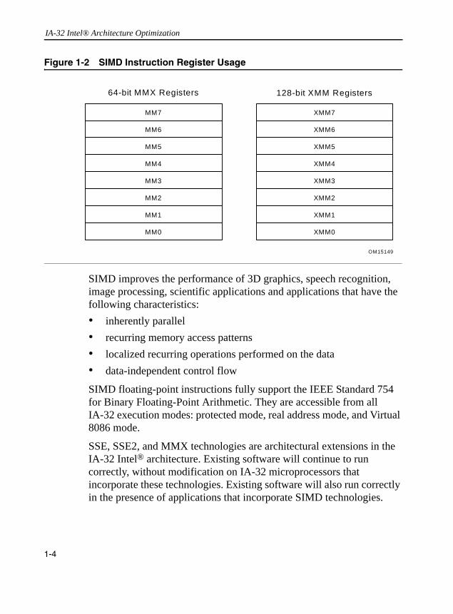
IA-32 Intel® Architecture Optimization
SIMD improves the performance of 3D graphics, speech recognition, image processing, scientific applications and applications that have the following characteristics:• inherently parallel• recurring memory access patterns• localized recurring operations performed on the data• data-independent control flow
SIMD floating-point instructions fully support the IEEE Standard 754 for Binary Floating-Point Arithmetic. They are accessible from all IA-32 execution modes: protected mode, real address mode, and Virtual 8086 mode.
SSE, SSE2, and MMX technologies are architectural extensions in the IA-32 Intel® architecture. Existing software will continue to run correctly, without modification on IA-32 microprocessors that incorporate these technologies. Existing software will also run correctly in the presence of applications that incorporate SIMD technologies.
Figure 1-2 SIMD Instruction Register Usage
MM7
MM6
MM7
MM3
MM2
MM1
MM0
MM5
MM4
MM7
XMM6
XMM7
XMM3
XMM2
XMM1
XMM0
XMM5
XMM4
64-bit MMX Registers 128-bit XMM Registers
OM15149
1-4
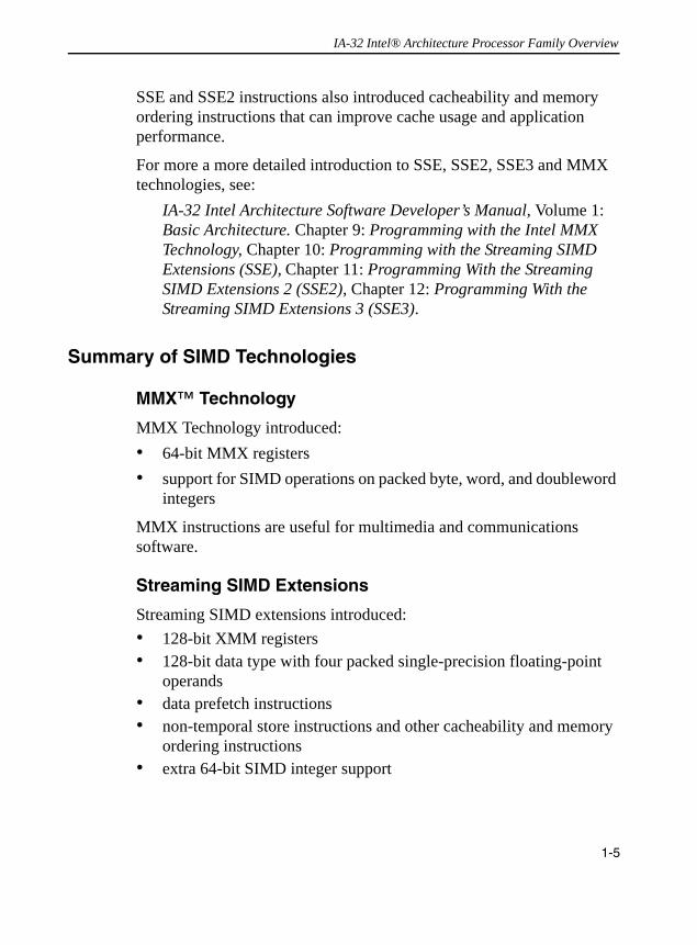
IA-32 Intel® Architecture Processor Family Overview
SSE and SSE2 instructions also introduced cacheability and memory ordering instructions that can improve cache usage and application performance.
For more a more detailed introduction to SSE, SSE2, SSE3 and MMX technologies, see:
IA-32 Intel Architecture Software Developer’s Manual, Volume 1: Basic Architecture. Chapter 9: Programming with the Intel MMX Technology, Chapter 10: Programming with the Streaming SIMD Extensions (SSE), Chapter 11: Programming With the Streaming SIMD Extensions 2 (SSE2), Chapter 12: Programming With the Streaming SIMD Extensions 3 (SSE3).
Summary of SIMD Technologies
MMX™ Technology
MMX Technology introduced:• 64-bit MMX registers• support for SIMD operations on packed byte, word, and doubleword
integers
MMX instructions are useful for multimedia and communications software.
Streaming SIMD Extensions
Streaming SIMD extensions introduced:• 128-bit XMM registers• 128-bit data type with four packed single-precision floating-point
operands• data prefetch instructions• non-temporal store instructions and other cacheability and memory
ordering instructions• extra 64-bit SIMD integer support
1-5
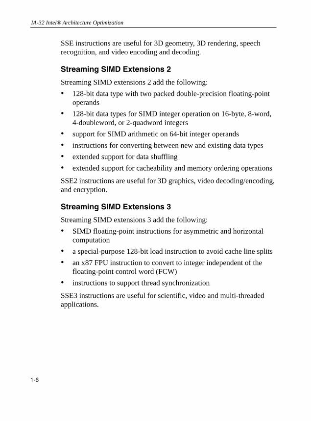
IA-32 Intel® Architecture Optimization
SSE instructions are useful for 3D geometry, 3D rendering, speech recognition, and video encoding and decoding.
Streaming SIMD Extensions 2
Streaming SIMD extensions 2 add the following:• 128-bit data type with two packed double-precision floating-point
operands• 128-bit data types for SIMD integer operation on 16-byte, 8-word,
4-doubleword, or 2-quadword integers• support for SIMD arithmetic on 64-bit integer operands• instructions for converting between new and existing data types• extended support for data shuffling• extended support for cacheability and memory ordering operations
SSE2 instructions are useful for 3D graphics, video decoding/encoding, and encryption.
Streaming SIMD Extensions 3
Streaming SIMD extensions 3 add the following:• SIMD floating-point instructions for asymmetric and horizontal
computation• a special-purpose 128-bit load instruction to avoid cache line splits• an x87 FPU instruction to convert to integer independent of the
floating-point control word (FCW)• instructions to support thread synchronization
SSE3 instructions are useful for scientific, video and multi-threaded applications.
1-6

IA-32 Intel® Architecture Processor Family Overview
Intel® Extended Memory 64 Technology (Intel® EM64T)
Intel EM64T is an extension of the IA-32 Intel architecture. Intel EM64T increases the linear address space for software to 64 bits and supports physical address space up to 40 bits. The technology also introduces a new operating mode referred to as IA-32e mode.
IA-32e mode consists of two sub-modes: (1) compatibility mode enables a 64-bit operating system to run most legacy 32-bit software unmodified, (2) 64-bit mode enables a 64-bit operating system to run applications written to access 64-bit linear address space.
In the 64-bit mode of Intel EM64T, software may access:• 64-bit flat linear addressing• 8 additional general-purpose registers (GPRs)• 8 additional registers for streaming SIMD extensions (SSE, SSE2
and SSE3)• 64-bit-wide GPRs and instruction pointers• uniform byte-register addressing• fast interrupt-prioritization mechanism• a new instruction-pointer relative-addressing mode
For optimizing 64-bit applications, the features that impact software optimizations include:• using a set of prefixes to access new registers or 64-bit register
operand• pointer size increases from 32 bits to 64 bits• instruction-specific usages
1-7
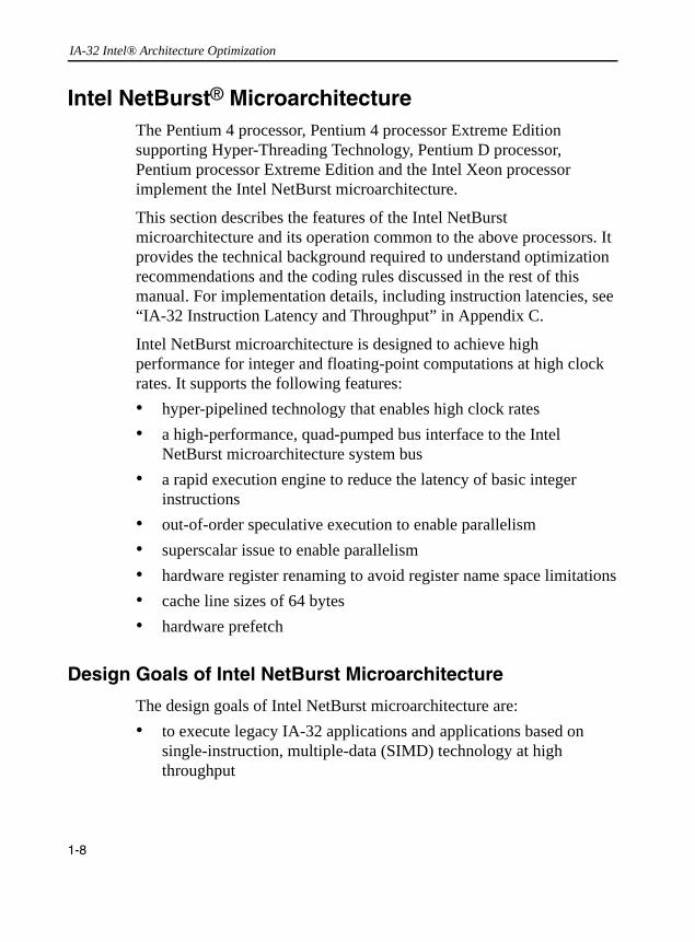
IA-32 Intel® Architecture Optimization
Intel NetBurst® MicroarchitectureThe Pentium 4 processor, Pentium 4 processor Extreme Edition supporting Hyper-Threading Technology, Pentium D processor, Pentium processor Extreme Edition and the Intel Xeon processor implement the Intel NetBurst microarchitecture.
This section describes the features of the Intel NetBurst microarchitecture and its operation common to the above processors. It provides the technical background required to understand optimization recommendations and the coding rules discussed in the rest of this manual. For implementation details, including instruction latencies, see “IA-32 Instruction Latency and Throughput” in Appendix C.
Intel NetBurst microarchitecture is designed to achieve high performance for integer and floating-point computations at high clock rates. It supports the following features:• hyper-pipelined technology that enables high clock rates• a high-performance, quad-pumped bus interface to the Intel
NetBurst microarchitecture system bus• a rapid execution engine to reduce the latency of basic integer
instructions• out-of-order speculative execution to enable parallelism• superscalar issue to enable parallelism• hardware register renaming to avoid register name space limitations• cache line sizes of 64 bytes• hardware prefetch
Design Goals of Intel NetBurst Microarchitecture
The design goals of Intel NetBurst microarchitecture are: • to execute legacy IA-32 applications and applications based on
single-instruction, multiple-data (SIMD) technology at high throughput
1-8
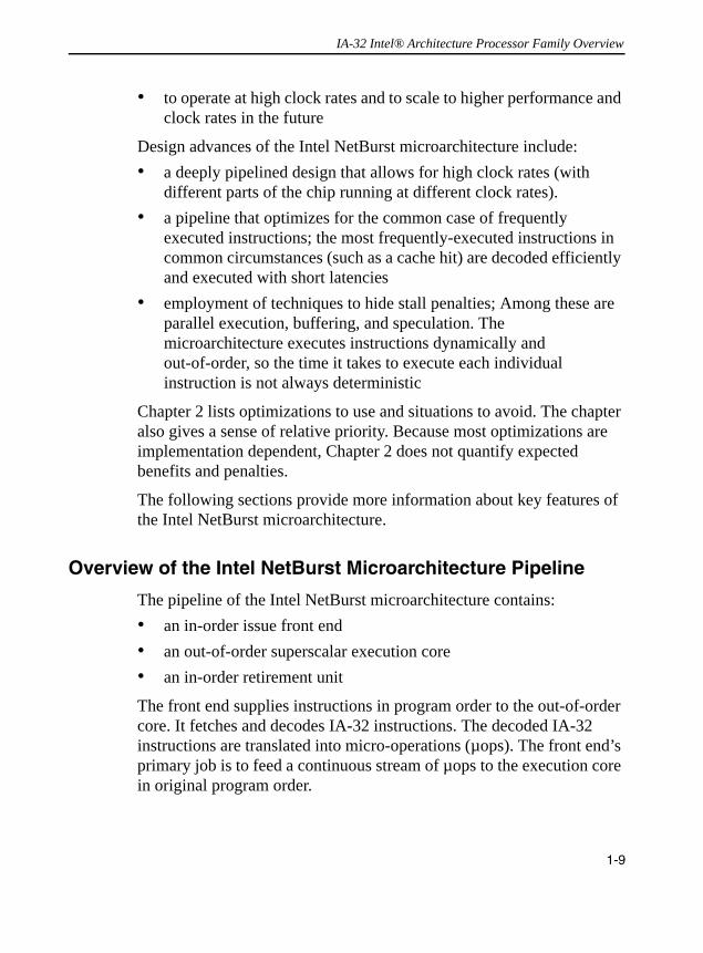
IA-32 Intel® Architecture Processor Family Overview
• to operate at high clock rates and to scale to higher performance and clock rates in the future
Design advances of the Intel NetBurst microarchitecture include:• a deeply pipelined design that allows for high clock rates (with
different parts of the chip running at different clock rates).• a pipeline that optimizes for the common case of frequently
executed instructions; the most frequently-executed instructions in common circumstances (such as a cache hit) are decoded efficiently and executed with short latencies
• employment of techniques to hide stall penalties; Among these are parallel execution, buffering, and speculation. The microarchitecture executes instructions dynamically and out-of-order, so the time it takes to execute each individual instruction is not always deterministic
Chapter 2 lists optimizations to use and situations to avoid. The chapter also gives a sense of relative priority. Because most optimizations are implementation dependent, Chapter 2 does not quantify expected benefits and penalties.
The following sections provide more information about key features of the Intel NetBurst microarchitecture.
Overview of the Intel NetBurst Microarchitecture Pipeline
The pipeline of the Intel NetBurst microarchitecture contains:• an in-order issue front end• an out-of-order superscalar execution core• an in-order retirement unit
The front end supplies instructions in program order to the out-of-order core. It fetches and decodes IA-32 instructions. The decoded IA-32 instructions are translated into micro-operations (µops). The front end’s primary job is to feed a continuous stream of µops to the execution core in original program order.
1-9

IA-32 Intel® Architecture Optimization
The out-of-order core aggressively reorders µops so that µops whose inputs are ready (and have execution resources available) can execute as soon as possible. The core can issue multiple µops per cycle.
The retirement section ensures that the results of execution are processed according to original program order and that the proper architectural states are updated.
Figure 1-3 illustrates a diagram of the major functional blocks associated with the Intel NetBurst microarchitecture pipeline. The following subsections provide an overview for each.
Figure 1-3 The Intel NetBurst Microarchitecture
1-10
IA-32 Intel® Architecture Processor Family Overview
The Front End
The front end of the Intel NetBurst microarchitecture consists of two parts:• fetch/decode unit• execution trace cache
It performs the following functions:• prefetches IA-32 instructions that are likely to be executed• fetches required instructions that have not been prefetched• decodes instructions into µops• generates microcode for complex instructions and special-purpose
code• delivers decoded instructions from the execution trace cache• predicts branches using advanced algorithms
The front end is designed to address two problems that are sources of delay:• the time required to decode instructions fetched from the target• wasted decode bandwidth due to branches or a branch target in the
middle of a cache line
Instructions are fetched and decoded by a translation engine. The translation engine then builds decoded instructions into µop sequences called traces. Next, traces are then stored in the execution trace cache.
The execution trace cache stores µops in the path of program execution flow, where the results of branches in the code are integrated into the same cache line. This increases the instruction flow from the cache and makes better use of the overall cache storage space since the cache no longer stores instructions that are branched over and never executed.
The trace cache can deliver up to 3 µops per clock to the core.
1-11

IA-32 Intel® Architecture Optimization
The execution trace cache and the translation engine have cooperating branch prediction hardware. Branch targets are predicted based on their linear address using branch prediction logic and fetched as soon as possible. Branch targets are fetched from the execution trace cache if they are cached, otherwise they are fetched from the memory hierarchy. The translation engine’s branch prediction information is used to form traces along the most likely paths.
The Out-of-order Core
The core’s ability to execute instructions out of order is a key factor in enabling parallelism. This feature enables the processor to reorder instructions so that if one µop is delayed while waiting for data or a contended resource, other µops that appear later in the program order may proceed. This implies that when one portion of the pipeline experiences a delay, the delay may be covered by other operations executing in parallel or by the execution of µops queued up in a buffer.
The core is designed to facilitate parallel execution. It can dispatch up to six µops per cycle through the issue ports (Figure 1-4, page 1-19). Note that six µops per cycle exceeds the trace cache and retirement µop bandwidth. The higher bandwidth in the core allows for peak bursts of greater than three µops and to achieve higher issue rates by allowing greater flexibility in issuing µops to different execution ports.
Most core execution units can start executing a new µop every cycle, so several instructions can be in flight at one time in each pipeline. A number of arithmetic logical unit (ALU) instructions can start at two per cycle; many floating-point instructions start one every two cycles. Finally, µops can begin execution out of program order, as soon as their data inputs are ready and resources are available.
Retirement
The retirement section receives the results of the executed µops from the execution core and processes the results so that the architectural state is updated according to the original program order. For semantically
1-12

IA-32 Intel® Architecture Processor Family Overview
correct execution, the results of IA-32 instructions must be committed in original program order before they are retired. Exceptions may be raised as instructions are retired. For this reason, exceptions cannot occur speculatively.
When a µop completes and writes its result to the destination, it is retired. Up to three µops may be retired per cycle. The reorder buffer (ROB) is the unit in the processor which buffers completed µops, updates the architectural state and manages the ordering of exceptions.
The retirement section also keeps track of branches and sends updated branch target information to the branch target buffer (BTB). This updates branch history. Figure 1-3 illustrates the paths that are most frequently executing inside the Intel NetBurst microarchitecture: an execution loop that interacts with multilevel cache hierarchy and the system bus.
The following sections describe in more detail the operation of the front end and the execution core. This information provides the background for using the optimization techniques and instruction latency data documented in this manual.
Front End Pipeline Detail
The following information about the front end operation is be useful for tuning software with respect to prefetching, branch prediction, and execution trace cache operations.
Prefetching
The Intel NetBurst microarchitecture supports three prefetching mechanisms:• a hardware instruction fetcher that automatically prefetches
instructions • a hardware mechanism that automatically fetches data and
instructions into the unified second-level cache
1-13

IA-32 Intel® Architecture Optimization
• a mechanism fetches data only and includes two distinct components: (1) a hardware mechanism to fetch the adjacent cache line within an 128-byte sector that contains the data needed due to a cache line miss, this is also referred to as adjacent cache line prefetch (2) a software controlled mechanism that fetches data into the caches using the prefetch instructions.
The hardware instruction fetcher reads instructions along the path predicted by the branch target buffer (BTB) into instruction streaming buffers. Data is read in 32-byte chunks starting at the target address. The second and third mechanisms are described later.
Decoder
The front end of the Intel NetBurst microarchitecture has a single decoder that decodes instructions at the maximum rate of one instruction per clock. Some complex instructions must enlist the help of the microcode ROM. The decoder operation is connected to the execution trace cache.
Execution Trace Cache
The execution trace cache (TC) is the primary instruction cache in the Intel NetBurst microarchitecture. The TC stores decoded IA-32 instructions (µops).
In the Pentium 4 processor implementation, TC can hold up to 12K µops and can deliver up to three µops per cycle. TC does not hold all of the µops that need to be executed in the execution core. In some situations, the execution core may need to execute a microcode flow instead of the µop traces that are stored in the trace cache.
The Pentium 4 processor is optimized so that most frequently-executed IA-32 instructions come from the trace cache while only a few instructions involve the microcode ROM.
1-14
IA-32 Intel® Architecture Processor Family Overview
Branch Prediction
Branch prediction is important to the performance of a deeply pipelined processor. It enables the processor to begin executing instructions long before the branch outcome is certain. Branch delay is the penalty that is incurred in the absence of correct prediction. For Pentium 4 and Intel Xeon processors, the branch delay for a correctly predicted instruction can be as few as zero clock cycles. The branch delay for a mispredicted branch can be many cycles, usually equivalent to the pipeline depth.
Branch prediction in the Intel NetBurst microarchitecture predicts all near branches (conditional calls, unconditional calls, returns and indirect branches). It does not predict far transfers (far calls, irets and software interrupts).
Mechanisms have been implemented to aid in predicting branches accurately and to reduce the cost of taken branches. These include:• the ability to dynamically predict the direction and target of
branches based on an instruction’s linear address, using the branch target buffer (BTB)
• if no dynamic prediction is available or if it is invalid, the ability to statically predict the outcome based on the offset of the target: a backward branch is predicted to be taken, a forward branch is predicted to be not taken
• the ability to predict return addresses using the 16-entry return address stack
• the ability to build a trace of instructions across predicted taken branches to avoid branch penalties.
The Static Predictor. Once a branch instruction is decoded, the direction of the branch (forward or backward) is known. If there was no valid entry in the BTB for the branch, the static predictor makes a prediction based on the direction of the branch. The static prediction mechanism predicts backward conditional branches (those with negative displacement, such as loop-closing branches) as taken. Forward branches are predicted not taken.
1-15

IA-32 Intel® Architecture Optimization
To take advantage of the forward-not-taken and backward-taken static predictions, code should be arranged so that the likely target of the branch immediately follows forward branches (see also “Branch Prediction” in Chapter 2).
Branch Target Buffer. Once branch history is available, the Pentium 4 processor can predict the branch outcome even before the branch instruction is decoded. The processor uses a branch history table and a branch target buffer (collectively called the BTB) to predict the direction and target of branches based on an instruction’s linear address. Once the branch is retired, the BTB is updated with the target address.
Return Stack. Returns are always taken; but since a procedure may be invoked from several call sites, a single predicted target does not suffice. The Pentium 4 processor has a Return Stack that can predict return addresses for a series of procedure calls. This increases the benefit of unrolling loops containing function calls. It also mitigates the need to put certain procedures inline since the return penalty portion of the procedure call overhead is reduced.
Even if the direction and target address of the branch are correctly predicted, a taken branch may reduce available parallelism in a typical processor (since the decode bandwidth is wasted for instructions which immediately follow the branch and precede the target, if the branch does not end the line and target does not begin the line). The branch predictor allows a branch and its target to coexist in a single trace cache line, maximizing instruction delivery from the front end.
Execution Core Detail
The execution core is designed to optimize overall performance by handling common cases most efficiently. The hardware is designed to execute frequent operations in a common context as fast as possible, at the expense of infrequent operations using rare contexts.
1-16

IA-32 Intel® Architecture Processor Family Overview
Some parts of the core may speculate that a common condition holds to allow faster execution. If it does not, the machine may stall. An example of this pertains to store-to-load forwarding (see “Store Forwarding” in this chapter). If a load is predicted to be dependent on a store, it gets its data from that store and tentatively proceeds. If the load turned out not to depend on the store, the load is delayed until the real data has been loaded from memory, then it proceeds.
Instruction Latency and Throughput
The superscalar out-of-order core contains hardware resources that can execute multiple µops in parallel. The core’s ability to make use of available parallelism of execution units can enhanced by software’s ability to:• select IA-32 instructions that can be decoded in less than 4 µops
and/or have short latencies• order IA-32 instructions to preserve available parallelism by
minimizing long dependence chains and covering long instruction latencies
• order instructions so that their operands are ready and their corresponding issue ports and execution units are free when they reach the scheduler
This subsection describes port restrictions, result latencies, and issue latencies (also referred to as throughput). These concepts form the basis to assist software for ordering instructions to increase parallelism. The order that µops are presented to the core of the processor is further affected by the machine’s scheduling resources.
It is the execution core that reacts to an ever-changing machine state, reordering µops for faster execution or delaying them because of dependence and resource constraints. The ordering of instructions in software is more of a suggestion to the hardware.
“IA-32 Instruction Latency and Throughput” in Appendix C, lists some of the more-commonly-used IA-32 instructions with their latency, their issue throughput, and associated execution units (where relevant). Some
1-17
IA-32 Intel® Architecture Optimization
execution units are not pipelined (meaning that µops cannot be dispatched in consecutive cycles and the throughput is less than one per cycle). The number of µops associated with each instruction provides a basis for selecting instructions to generate. All µops executed out of the microcode ROM involve extra overhead.
Execution Units and Issue Ports
At each cycle, the core may dispatch µops to one or more of four issue ports. At the microarchitecture level, store operations are further divided into two parts: store data and store address operations. The four ports through which µops are dispatched to execution units and to load and store operations are shown in Figure 1-4. Some ports can dispatch two µops per clock. Those execution units are marked Double Speed.
Port 0. In the first half of the cycle, port 0 can dispatch either one floating-point move µop (a floating-point stack move, floating-point exchange or floating-point store data), or one arithmetic logical unit (ALU) µop (arithmetic, logic, branch or store data). In the second half of the cycle, it can dispatch one similar ALU µop.
Port 1. In the first half of the cycle, port 1 can dispatch either one floating-point execution (all floating-point operations except moves, all SIMD operations) µop or one normal-speed integer (multiply, shift and rotate) µop or one ALU (arithmetic) µop. In the second half of the cycle, it can dispatch one similar ALU µop.
Port 2. This port supports the dispatch of one load operation per cycle.
Port 3. This port supports the dispatch of one store address operation per cycle.
The total issue bandwidth can range from zero to six µops per cycle. Each pipeline contains several execution units. The µops are dispatched to the pipeline that corresponds to the correct type of operation. For example, an integer arithmetic logic unit and the floating-point execution units (adder, multiplier, and divider) can share a pipeline.
1-18

IA-32 Intel® Architecture Processor Family Overview
Caches
The Intel NetBurst microarchitecture supports up to three levels of on-chip cache. At least two levels of on-chip cache are implemented in processors based on the Intel NetBurst microarchitecture. The Intel Xeon processor MP and selected Pentium and Intel Xeon processors may also contain a third-level cache.
The first level cache (nearest to the execution core) contains separate caches for instructions and data. These include the first-level data cache and the trace cache (an advanced first-level instruction cache). All other caches are shared between instructions and data.
Figure 1-4 Execution Units and Ports in the Out-Of-Order Core
OM15151
ALU 0DoubleSpeed
Port 0
ADD/SUBLogic
Store DataBranches
FP MoveFP Store Data
FXCH
ALU 1DoubleSpeed
ADD/SUB Shift/Rotate
FPExecute
FP_ADDFP_MULFP_DIV
FP_MISCMMX_SHFTMMX_ALU
MMX_MISC
Port 1
MemoryStore
MemoryLoad
All LoadsPrefetch
Port 2 Port 3
StoreAddress
FPMove
IntegerOperation
NormalSpeed
Note:FP_ADD refers to x87 FP, and SIMD FP add and subtract operationsFP_MUL refers to x87 FP, and SIMD FP multiply operationsFP_DIV refers to x87 FP, and SIMD FP divide and square root operationsMMX_ALU refers to SIMD integer arithmetic and logic operationsMMX_SHFT handles Shift, Rotate, Shuffle, Pack and Unpack operationsMMX_MISC handles SIMD reciprocal and some integer operations
1-19

IA-32 Intel® Architecture Optimization
Levels in the cache hierarchy are not inclusive. The fact that a line is in level i does not imply that it is also in level i+1. All caches use a pseudo-LRU (least recently used) replacement algorithm.
Table 1-1 provides parameters for all cache levels for Pentium and Intel Xeon Processors with CPUID model encoding equals 0, 1, 2 or 3.
1 Each read due to a cache miss fetches a sector, consisting of two adjacent cache lines; write operation is 64 bytes only. 2 Pentium 4 and Intel Xeon processors with CPUID model encoding value of 2 have a second level cache of 512 KB.
On processors without a third level cache, the second-level cache miss initiates a transaction across the system bus interface to the memory sub-system. On processors with a third level cache, the third-level cache miss initiates a transaction across the system bus. A bus write transaction writes 64 bytes to cacheable memory, or separate 8-byte chunks if the destination is not cacheable. A bus read transaction from cacheable memory fetches two cache lines of data.
The system bus interface supports using a scalable bus clock and achieves an effective speed that quadruples the speed of the scalable bus clock. It takes on the order of 12 processor cycles to get to the bus and
Table 1-1 Pentium 4 and Intel Xeon Processor Cache Parameters
Level (Model) Capacity
Associ-ativity (ways)
Line Size (bytes)
Access Latency, Integer/floating-point (clocks)
Write Update Policy
First (Model 0, 1, 2)
8 KB 4 64 2/9 write through
First (Model 3) 16 KB 8 64 4/12 write through
TC (All models)
12K µops 8 N/A N/A N/A
Second (Model 0, 1, 2)
256 KB or 512 KB2
8 641 7/7 write back
Second (Model 3, 4)
1 MB 8 641 18/18 write back
Third (Model 0, 1, 2)
0, 512 KB, 1 MB or 2 MB
8 641 14/14 write back
1-20
IA-32 Intel® Architecture Processor Family Overview
back within the processor, and 6-12 bus cycles to access memory if there is no bus congestion. Each bus cycle equals several processor cycles. The ratio of processor clock speed to the scalable bus clock speed is referred to as bus ratio. For example, one bus cycle for a 100 MHz bus is equal to 15 processor cycles on a 1.50 GHz processor. Since the speed of the bus is implementation-dependent, consult the specifications of a given system for further details.
Data Prefetch
The Pentium 4 processor and other IA-32 processors based on the NetBurst microarchitecture have two ways for prefetching data: a software prefetch and an automatic hardware prefetch.
Software controlled prefetch is enabled using the four prefetch instructions (PREFETCHh) introduced with SSE. The software prefetch is not intended for prefetching code. Using it can incur significant penalties on a multiprocessor system if code is shared.
Software prefetch can provide benefits in selected situations. These situations include:• when the pattern of memory access operations in software allows
the programmer to hide memory latency• when a reasonable choice can be made about how many cache lines
to fetch ahead of the line being execute• when an choice can be made about the type of prefetch to use
SSE prefetch instructions have different behaviors, depending on cache levels updated and the processor implementation. For instance, a processor may implement the non-temporal prefetch by returning data to the cache level closest to the processor core. This approach has the following effect:• minimizes disturbance of temporal data in other cache levels• avoids the need to access off-chip caches, which can increase the
realized bandwidth compared to a normal load-miss, which returns data to all cache levels
1-21

IA-32 Intel® Architecture Optimization
Situations that are less likely to benefit from software prefetch are:• for cases that are already bandwidth bound, prefetching tends to
increase bandwidth demands• prefetching far ahead can cause eviction of cached data from the
caches prior to the data being used in execution• not prefetching far enough can reduce the ability to overlap memory
and execution latencies
Software prefetches are treated by the processor as a hint to initiate a request to fetch data from the memory system, and consume resources in the processor and the use of too many prefetches can limit their effectiveness. Examples of this include prefetching data in a loop for a reference outside the loop and prefetching in a basic block that is frequently executed, but which seldom precedes the reference for which the prefetch is targeted.
See also: Chapter 6, “Optimizing Cache Usage”.
Automatic hardware prefetch is a feature in the Pentium 4 processor. It brings cache lines into the unified second-level cache based on prior reference patterns. See also: Chapter 6, “Optimizing Cache Usage”.
Pros and Cons of Software and Hardware Prefetching. Software prefetching has the following characteristics:• handles irregular access patterns, which would not trigger the
hardware prefetcher• handles prefetching of short arrays and avoids hardware prefetching
start-up delay before initiating the fetches• must be added to new code; so it does not benefit existing
applications
Hardware prefetching for Pentium 4 processor has the following characteristics:• works with existing applications• does not require extensive study of prefetch instructions
1-22
IA-32 Intel® Architecture Processor Family Overview
• requires regular access patterns• avoids instruction and issue port bandwidth overhead• has a start-up penalty before the hardware prefetcher triggers and
begins initiating fetches
The hardware prefetcher can handle multiple streams in either the forward or backward directions. The start-up delay and fetch-ahead has a larger effect for short arrays when hardware prefetching generates a request for data beyond the end of an array (not actually utilized). The hardware penalty diminishes if it is amortized over longer arrays.
Hardware prefetching is triggered after two successive cache misses in the last level cache and requires these cache misses to satisfy a condition that the linear address distance between these cache misses is within a threshold value. The threshold value depends on the processor implementation of the microarchitecture (see Table 1-2). However, hardware prefetching will not cross 4KB page boundaries. As a result, hardware prefetching can be very effective when dealing with cache miss patterns that have small strides that are significantly less than half the threshold distance to trigger hardware prefetching. On the other hand, hardware prefetching will not benefit cache miss patterns that have frequent DTLB misses or have access strides that cause successive cache misses that are spatially apart by more than the trigger threshold distance.
Software can proactively control data access pattern to favor smaller access strides (e.g., stride that is less than half of the trigger threshold distance) over larger access strides (stride that is greater than the trigger threshold distance), this can achieve additional benefit of improved temporal locality and reducing cache misses in the last level cache significantly.
Thus, software optimization of a data access pattern should emphasize tuning for hardware prefetch first to favor greater proportions of smaller-stride data accesses in the workload; before attempting to provide hints to the processor by employing software prefetch instructions.
1-23

IA-32 Intel® Architecture Optimization
Loads and Stores
The Pentium 4 processor employs the following techniques to speed up the execution of memory operations:• speculative execution of loads• reordering of loads with respect to loads and stores• multiple outstanding misses• buffering of writes• forwarding of data from stores to dependent loads
Performance may be enhanced by not exceeding the memory issue bandwidth and buffer resources provided by the processor. Up to one load and one store may be issued for each cycle from a memory port reservation station. In order to be dispatched to a reservation station, there must be a buffer entry available for each memory operation. There are 48 load buffers and 24 store buffers3. These buffers hold the µop and address information until the operation is completed, retired, and deallocated.
The Pentium 4 processor is designed to enable the execution of memory operations out of order with respect to other instructions and with respect to each other. Loads can be carried out speculatively, that is, before all preceding branches are resolved. However, speculative loads cannot cause page faults.
Reordering loads with respect to each other can prevent a load miss from stalling later loads. Reordering loads with respect to other loads and stores to different addresses can enable more parallelism, allowing the machine to execute operations as soon as their inputs are ready. Writes to memory are always carried out in program order to maintain program correctness.
3. Pentium 4 processors with CPUID model encoding equal to 3 have more than 24 store buffers.
1-24

IA-32 Intel® Architecture Processor Family Overview
A cache miss for a load does not prevent other loads from issuing and completing. The Pentium 4 processor supports up to four (or eight for Pentium 4 processor with CPUID signature corresponding to family 15, model 3) outstanding load misses that can be serviced either by on-chip caches or by memory.
Store buffers improve performance by allowing the processor to continue executing instructions without having to wait until a write to memory and/or cache is complete. Writes are generally not on the critical path for dependence chains, so it is often beneficial to delay writes for more efficient use of memory-access bus cycles.
Store Forwarding
Loads can be moved before stores that occurred earlier in the program if they are not predicted to load from the same linear address. If they do read from the same linear address, they have to wait for the store data to become available. However, with store forwarding, they do not have to wait for the store to write to the memory hierarchy and retire. The data from the store can be forwarded directly to the load, as long as the following conditions are met:• Sequence: the data to be forwarded to the load has been generated
by a programmatically-earlier store which has already executed• Size: the bytes loaded must be a subset of (including a proper
subset, that is, the same) bytes stored• Alignment: the store cannot wrap around a cache line boundary, and
the linear address of the load must be the same as that of the store
Intel® Pentium® M Processor MicroarchitectureLike the Intel NetBurst microarchitecture, the pipeline of the Intel Pentium M processor microarchitecture contains three sections:• in-order issue front end• out-of-order superscalar execution core• in-order retirement unit
1-25

IA-32 Intel® Architecture Optimization
Intel Pentium M processor microarchitecture supports a high-speed system bus with 64-byte line size. Most coding recommendations that apply to the Intel NetBurst microarchitecture also apply to the Intel Pentium M processor.
The Intel Pentium M processor microarchitecture is designed for lower power consumption. There are other specific areas of the Pentium M processor microarchitecture that differ from the Intel NetBurst microarchitecture. They are described next. A block diagram of the Intel Pentium M processor is shown in Figure 1-5.
Figure 1-5 The Intel Pentium M Processor Microarchitecture
1-26

IA-32 Intel® Architecture Processor Family Overview
The Front End
The Intel Pentium M processor uses a pipeline depth that enables high performance and low power consumption. It’s shorter than that of the Intel NetBurst microarchitecture.
The Intel Pentium M processor front end consists of two parts:• fetch/decode unit• instruction cache
The fetch and decode unit includes a hardware instruction prefetcher and three decoders that enable parallelism. It also provides a 32KB instruction cache that stores un-decoded binary instructions.
The instruction prefetcher fetches instructions in a linear fashion from memory if the target instructions are not already in the instruction cache. The prefetcher is designed to fetch efficiently from an aligned 16-byte block. If the modulo 16 remainder of a branch target address is 14, only two useful instruction bytes are fetched in the first cycle. The rest of the instruction bytes are fetched in subsequent cycles.
The three decoders decode IA-32 instructions and break them down into micro-ops (µops). In each clock cycle, the first decoder is capable of decoding an instruction with four or fewer µops. The remaining two decoders each decode a one µop instruction in each clock cycle.
The front end can issue multiple µops per cycle, in original program order, to the out-of-order core.
The Intel Pentium M processor incorporates sophisticated branch prediction hardware to support the out-of-order core. The branch prediction hardware includes dynamic prediction, and branch target buffers.
The Intel Pentium M processor has enhanced dynamic branch prediction hardware. Branch target buffers (BTB) predict the direction and target of branches based on an instruction’s address.
1-27
IA-32 Intel® Architecture Optimization
The Pentium M Processor includes two techniques to reduce the execution time of certain operations:• ESP Folding. This eliminates the ESP manipulation
micro-operations in stack-related instructions such as PUSH, POP, CALL and RET. It increases decode rename and retirement throughput. ESP folding also increases execution bandwidth by eliminating µops which would have required execution resources.
• Micro-ops (µops) fusion. Some of the most frequent pairs of µops derived from the same instruction can be fused into a single µops. The following categories of fused µops have been implemented in the Pentium M processor: — “Store address” and “store data” micro-ops are fused into a
single “Store” micro-op. This holds for all types of store operations, including integer, floating-point, MMX technology, and Streaming SIMD Extensions (SSE and SSE2) operations.
— A load micro-op in most cases can be fused with a successive execution micro-op.This holds for integer, floating-point and MMX technology loads and for most kinds of successive execution operations. Note that SSE Loads can not be fused.
Data Prefetching
The Intel Pentium M processor supports three prefetching mechanisms:• The first mechanism is a hardware instruction fetcher and is
described in the previous section. • The second mechanism automatically fetches data into the
second-level cache. The implementation of automatic hardware prefetching in Pentium M processor family is basically similar to those described for NetBurst microarchitecture. The trigger threshold distance for each relevant processor models is shown in Table 1-2
• The third mechanism is a software mechanism that fetches data into the caches using the prefetch instructions.
1-28

IA-32 Intel® Architecture Processor Family Overview
Data is fetched 64 bytes at a time; the instruction and data translation lookaside buffers support 128 entries. See Table 1-3 for processor cache parameters.
Out-of-Order Core
The processor core dynamically executes µops independent of program order. The core is designed to facilitate parallel execution by employing many buffers, issue ports, and parallel execution units.
The out-of-order core buffers µops in a Reservation Station (RS) until their operands are ready and resources are available. Each cycle, the core may dispatch up to five µops through the issue ports.
Table 1-2 Trigger Threshold and CPUID Signatures for IA-32 Processor Families
Trigger Thresh-old Distance (Bytes)
Extended Model ID
Extended Family ID Family ID Model ID
512 0 0 15 3, 4
256 0 0 15 0, 1, 2
256 0 0 6 9, 13
Table 1-3 The Pentium M Processor Cache Parameters
Level CapacityAssociativity (ways)
Line Size (bytes)
Access Latency (clocks)
Write Update Policy
First 32 KB 8 64 3 Writeback
Instruction 32 KB 8 N/A N/A N/A
Second (model 9)
1MB 8 64 9 Writeback
Second (model 13)
2MB 8 64 9 Writeback
1-29
IA-32 Intel® Architecture Optimization
In-Order Retirement
The retirement unit in the Pentium M processor buffers completed µops is the reorder buffer (ROB). The ROB updates the architectural state in order. Up to three µops may be retired per cycle.
Hyper-Threading TechnologyIntel® Hyper-Threading (HT) Technology is supported by specific members of the Intel Pentium 4 and Xeon processor families. The technology enables software to take advantage of task-level, or thread-level parallelism by providing multiple logical processors within a physical processor package. In its first implementation in Intel Xeon processor, Hyper-Threading Technology makes a single physical processor appear as two logical processors.
The two logical processors each have a complete set of architectural registers while sharing one single physical processor's resources. By maintaining the architecture state of two processors, an HT Technology capable processor looks like two processors to software, including operating system and application code.
By sharing resources needed for peak demands between two logical processors, HT Technology is well suited for multiprocessor systems to provide an additional performance boost in throughput when compared to traditional MP systems.
Figure 1-6 shows a typical bus-based symmetric multiprocessor (SMP) based on processors supporting Hyper-Threading Technology. Each logical processor can execute a software thread, allowing a maximum of two software threads to execute simultaneously on one physical processor. The two software threads execute simultaneously, meaning that in the same clock cycle an “add” operation from logical processor 0 and another “add” operation and load from logical processor 1 can be executed simultaneously by the execution engine.
1-30

IA-32 Intel® Architecture Processor Family Overview
In the first implementation of HT Technology, the physical execution resources are shared and the architecture state is duplicated for each logical processor. This minimizes the die area cost of implementing HT Technology while still achieving performance gains for multithreaded applications or multitasking workloads.
The performance potential due to HT Technology is due to:• the fact that operating systems and user programs can schedule
processes or threads to execute simultaneously on the logical processors in each physical processor
• the ability to use on-chip execution resources at a higher level than when only a single thread is consuming the execution resources; higher level of resource utilization can lead to higher system throughput
Figure 1-6 Hyper-Threading Technology on an SMP
OM15152
Bus Interface
Execution Engine
ArchitecturalState
ArchitecturalState
Local APIC Local APIC
System Bus
Execution Engine
ArchitecturalState
ArchitecturalState
Local APIC Local APIC
Bus Interface
1-31

IA-32 Intel® Architecture Optimization
Processor Resources and Hyper-Threading Technology
The majority of microarchitecture resources in a physical processor are shared between the logical processors. Only a few small data structures were replicated for each logical processor. This section describes how resources are shared, partitioned or replicated.
Replicated Resources
The architectural state is replicated for each logical processor. The architecture state consists of registers that are used by the operating system and application code to control program behavior and store data for computations. This state includes the eight general-purpose registers, the control registers, machine state registers, debug registers, and others. There are a few exceptions, most notably the memory type range registers (MTRRs) and the performance monitoring resources. For a complete list of the architecture state and exceptions, see the IA-32 Intel Architecture System Programming Guide.
Other resources such as instruction pointers and register renaming tables were replicated to simultaneously track execution and state changes of the two logical processors. The return stack predictor is replicated to improve branch prediction of return instructions.
In addition, a few buffers (for example, the 2-entry instruction streaming buffers) were replicated to reduce complexity.
Partitioned Resources
Several buffers are shared by limiting the use of each logical processor to half the entries. These are referred to as partitioned resources. Reasons for this partitioning include:• operational fairness• permitting the ability to allow operations from one logical processor
to bypass operations of the other logical processor that may have stalled
1-32

IA-32 Intel® Architecture Processor Family Overview
For example: a cache miss, a branch misprediction, or instruction dependencies may prevent a logical processor from making forward progress for some number of cycles. The partitioning prevents the stalled logical processor from blocking forward progress.
In general, the buffers for staging instructions between major pipe stages are partitioned. These buffers include µop queues after the execution trace cache, the queues after the register rename stage, the reorder buffer which stages instructions for retirement, and the load and store buffers.
In the case of load and store buffers, partitioning also provided an easier implementation to maintain memory ordering for each logical processor and detect memory ordering violations.
Shared Resources
Most resources in a physical processor are fully shared to improve the dynamic utilization of the resource, including caches and all the execution units. Some shared resources which are linearly addressed, like the DTLB, include a logical processor ID bit to distinguish whether the entry belongs to one logical processor or the other.
The first level cache can operate in two modes depending on a context-ID bit: • Shared mode: The L1 data cache is fully shared by two logical
processors.• Adaptive mode: In adaptive mode, memory accesses using the page
directory is mapped identically across logical processors sharing the L1 data cache.
The other resources are fully shared.
1-33

IA-32 Intel® Architecture Optimization
Microarchitecture Pipeline and Hyper-Threading Technology
This section describes the HT Technology microarchitecture and how instructions from the two logical processors are handled between the front end and the back end of the pipeline.
Although instructions originating from two programs or two threads execute simultaneously and not necessarily in program order in the execution core and memory hierarchy, the front end and back end contain several selection points to select between instructions from the two logical processors. All selection points alternate between the two logical processors unless one logical processor cannot make use of a pipeline stage. In this case, the other logical processor has full use of every cycle of the pipeline stage. Reasons why a logical processor may not use a pipeline stage include cache misses, branch mispredictions, and instruction dependencies.
Front End Pipeline
The execution trace cache is shared between two logical processors. Execution trace cache access is arbitrated by the two logical processors every clock. If a cache line is fetched for one logical processor in one clock cycle, the next clock cycle a line would be fetched for the other logical processor provided that both logical processors are requesting access to the trace cache.
If one logical processor is stalled or is unable to use the execution trace cache, the other logical processor can use the full bandwidth of the trace cache until the initial logical processor’s instruction fetches return from the L2 cache.
After fetching the instructions and building traces of µops, the µops are placed in a queue. This queue decouples the execution trace cache from the register rename pipeline stage. As described earlier, if both logical processors are active, the queue is partitioned so that both logical processors can make independent forward progress.
1-34

IA-32 Intel® Architecture Processor Family Overview
Execution Core
The core can dispatch up to six µops per cycle, provided the µops are ready to execute. Once the µops are placed in the queues waiting for execution, there is no distinction between instructions from the two logical processors. The execution core and memory hierarchy is also oblivious to which instructions belong to which logical processor.
After execution, instructions are placed in the re-order buffer. The re-order buffer decouples the execution stage from the retirement stage. The re-order buffer is partitioned such that each uses half the entries.
Retirement
The retirement logic tracks when instructions from the two logical processors are ready to be retired. It retires the instruction in program order for each logical processor by alternating between the two logical processors. If one logical processor is not ready to retire any instructions, then all retirement bandwidth is dedicated to the other logical processor.
Once stores have retired, the processor needs to write the store data into the level-one data cache. Selection logic alternates between the two logical processors to commit store data to the cache.
Dual-Core ProcessorsThe Intel Pentium D processor and The Pentium Processor Extreme Edition introduce dual-core feature into the IA-32 architecture. Dual-core IA-32 processors enhance hardware support for multi-threading by providing two processor cores in each physical processor package.
Intel Pentium D processor provides two logical processors in a physical package, each logical processor has a separate execution core and a cache hierarchy. Intel Pentium Processor Extreme Edition provides four logical processors in a physical package that has two execution cores,
1-35
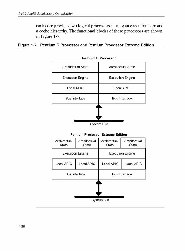
IA-32 Intel® Architecture Optimization
each core provides two logical processors sharing an execution core and a cache hierarchy. The functional blocks of these processors are shown in Figure 1-7.
Figure 1-7 Pentium D Processor and Pentium Processor Extreme Edition
1-36

IA-32 Intel® Architecture Processor Family Overview
Microarchitecture Pipeline and Dual-Core Processors
In general, each core in a dual-core processor resembles a single-core processor implementation of the underlying microarchitecture. The implementation of the cache hierarchy in a dual-core or multi-core processor may resemble less of the cache hierarchy implementation in a single-core processor. CPUID should be used to determine any cache-sharing topology information in a processor implementation and the underlying microarchitecture. The former is obtained by querying the deterministic cache parameter leaf (see Chapter 6), the latter by using the encoded values for extended family, family, extended model, and model fields. See Table 1-4.
Table 1-4 Family And Model Designations
Dual-Core Processor
Micro-
architectureExtended Family Family
Extended Model Model
Pentium D processor NetBurst 0 15 0 3 or 4
Pentium processor Extreme Edition
NetBurst 0 15 0 3 or 4
1-37

IA-32 Intel® Architecture Optimization
1-38

2
General Optimization GuidelinesThis chapter discusses general optimization techniques that can improve the performance of applications running on the Intel Pentium 4, Intel Xeon, Pentium M processors, as well as on dual-core processors. These techniques take advantage of the microarchitectural features of the generation of IA-32 processor family described in Chapter 1. Optimization guidelines for 64-bit mode applications are discussed in Chapter 8. Additional optimization guidelines applicable to dual-core processors and Hyper-Threading Technology are discussed in chapter 7.
This chapter explains the optimization techniques both for those who use the Intel® C++ or Fortran Compiler and for those who use other compilers. The Intel® compiler, which generates code specifically tuned for IA-32 processor family, provides the most of the optimization. For those not using the Intel C++ or Fortran Compiler, the assembly code tuning optimizations may be useful. The explanations are supported by coding examples.
Tuning to Achieve Optimum PerformanceThe most important factors in achieving optimum processor performance are:• good branch prediction• avoiding memory access stalls• good floating-point performance• instruction selection, including use of SIMD instructions• instruction scheduling (to maximize trace cache bandwidth)• vectorization
2-1

IA-32 Intel® Architecture Optimization
The following sections describe practices, tools, coding rules and recommendations associated with these factors that will aid in optimizing the performance on IA-32 processors.
Tuning to Prevent Known Coding PitfallsTo produce program code that takes advantage of the Intel NetBurst microarchitecture and the Pentium M processor microarchitecture, you must avoid the coding pitfalls that limit the performance of the target processor family. This section lists several known pitfalls that can limit performance of Pentium 4 and Intel Xeon processor implementations. Some of these pitfalls, to a lesser degree, also negatively impact Pentium M processor performance (store-to-load-forwarding restrictions, cache-line splits).
Table 2-1 lists coding pitfalls that cause performance degradation in some Pentium 4 and Intel Xeon processor implementations. For every issue, Table 2-1 references a section in this document. The section describes in detail the causes of the penalty and presents a recommended solution. Note that “aligned” here means that the address of the load is aligned with respect to the address of the store.
Table 2-1 Coding Pitfalls Affecting Performance
Factors Affecting Performance Symptom
Example (if applicable) Section Reference
Small, unaligned load after large store
Store-forwarding blocked
Example 2-12 Store Forwarding, Store-to-Load-Forwarding Restriction on Size and Alignment
Large load after small store;
Load dword after store dword, store byte;
Load dword, AND with 0xff after store byte
Store-forwarding blocked
Example 2-13, Example 2-14
Store Forwarding, Store-to-Load-Forwarding Restriction on Size and Alignment
continued
2-2

General Optimization Guidelines 2
* Streaming SIMD Extensions (SSE)
** Streaming SIMD Extensions 2 (SSE2)
General Practices and Coding GuidelinesThis section discusses guidelines derived from the performance factors listed in the “Tuning to Achieve Optimum Performance” section. It also highlights practices that use performance tools.
The majority of these guidelines benefit processors based on the Intel NetBurst microarchitecture and the Pentium M processor microarchitecture. Some guidelines benefit one microarchitecture more than the other. As a whole, these coding rules enable software to be optimized for the common performance features of the Intel NetBurst microarchitecture and the Pentium M processor microarchitecture.
The coding practices recommended under each heading and the bullets under each heading are listed in order of importance.
Cache line splits Access across cache line boundary
Example 2-11 Align data on natural operand size address boundaries. If the data will be accesses with vector instruction loads and stores, align the data on 16 byte boundaries.
Denormal inputs and outputs
Slows x87, SSE*, SSE2** floating-
point operations
Floating-point Exceptions
Cycling more than 2 values of Floating-point Control Word
fldcw not optimized
Floating-point Modes
Table 2-1 Coding Pitfalls Affecting Performance (continued)
Factors Affecting Performance Symptom
Example (if applicable) Section Reference
2-3

IA-32 Intel® Architecture Optimization
Use Available Performance Tools
• Current-generation compiler, such as the Intel C++ Compiler:— Set this compiler to produce code for the target processor
implementation— Use the compiler switches for optimization and/or
profile-guided optimization. These features are summarized in the “Intel® C++ Compiler” section. For more detail, see the Intel C++ Compiler User’s Guide.
• Current-generation performance monitoring tools, such as VTune™ Performance Analyzer:— Identify performance issues, use event-based sampling, code
coach and other analysis resource.— Measure workload characteristics such as instruction
throughput, data traffic locality, memory traffic characteristics, etc.
— Characterize the performance gain.
Optimize Performance Across Processor Generations
• Use a cpuid dispatch strategy to deliver optimum performance for all processor generations.
• Use deterministic cache parameter leaf of cpuid to deliver scalable performance that are transparent across processor families with different cache sizes.
• Use compatible code strategy to deliver optimum performance for the current generation of IA-32 processor family and future IA-32 processors.
• Use a low-overhead threading strategy so that a multi-threaded application delivers optimal multi-processor scaling performance when executing on processors that have hardware multi-threading support, or deliver nearly identical single-processor scaling when executing on a processor without hardware multi-threading support.
2-4

General Optimization Guidelines 2
Optimize Branch Predictability• Improve branch predictability and optimize instruction prefetching by arranging code to be consistent with the static branch prediction assumption: backward taken and forward not taken.
• Avoid mixing near calls, far calls and returns.• Avoid implementing a call by pushing the return address and
jumping to the target. The hardware can pair up call and return instructions to enhance predictability.
• Use the pause instruction in spin-wait loops.• Inline functions according to coding recommendations.• Whenever possible, eliminate branches.• Avoid indirect calls.
Optimize Memory Access
• Observe store-forwarding constraints.• Ensure proper data alignment to prevent data split across cache line.
boundary. This includes stack and passing parameters.• Avoid mixing code and data (self-modifying code).• Choose data types carefully (see next bullet below) and avoid type
casting.• Employ data structure layout optimization to ensure efficient use of
64-byte cache line size.• Favor parallel data access to mask latency over data accesses with
dependency that expose latency.• For cache-miss data traffic, favor smaller cache-miss strides to
avoid frequent DTLB misses.• Use prefetching appropriately.• Use the following techniques to enhance locality: blocking,
hardware-friendly tiling, loop interchange, loop skewing.
2-5
IA-32 Intel® Architecture Optimization
• Minimize use of global variables and pointers.• Use the const modifier; use the static modifier for global
variables.• Use new cacheability instructions and memory-ordering behavior.
Optimize Floating-point Performance
• Avoid exceeding representable ranges during computation, since handling these cases can have a performance impact. Do not use a larger precision format (double-extended floating point) unless required, since this increases memory size and bandwidth utilization.
• Use FISTTP to avoid changing rounding mode when possible or use optimized fldcw; avoid changing floating-point control/status registers (rounding modes) between more than two values.
• Use efficient conversions, such as those that implicitly include a rounding mode, in order to avoid changing control/status registers.
• Take advantage of the SIMD capabilities of Streaming SIMD Extensions (SSE) and of Streaming SIMD Extensions 2 (SSE2) instructions. Enable flush-to-zero mode and DAZ mode when using SSE and SSE2 instructions.
• Avoid denormalized input values, denormalized output values, and explicit constants that could cause denormal exceptions.
• Avoid excessive use of the fxch instruction.
Optimize Instruction Selection
• Focus instruction selection at the granularity of path length for a sequence of instructions versus individual instruction selections; minimize the number of uops, data/register dependency in aggregates of the path length, and maximize retirement throughput.
2-6

General Optimization Guidelines 2
• Avoid longer latency instructions: integer multiplies and divides.Replace them with alternate code sequences (e.g., use shifts instead of multiplies).
• Use the lea instruction and the full range of addressing modes to do address calculation.
• Some types of stores use more µops than others, try to use simpler store variants and/or reduce the number of stores.
• Avoid use of complex instructions that require more than 4 µops.• Avoid instructions that unnecessarily introduce dependence-related
stalls: inc and dec instructions, partial register operations (8/16-bit operands).
• Avoid use of ah, bh, and other higher 8-bits of the 16-bit registers, because accessing them requires a shift operation internally.
• Use xor and pxor instructions to clear registers and break dependencies for integer operations; also use xorps and xorpd to clear XMM registers for floating-point operations.
• Use efficient approaches for performing comparisons.
Optimize Instruction Scheduling
• Consider latencies and resource constraints.• Calculate store addresses as early as possible.
Enable Vectorization
• Use the smallest possible data type. This enables more parallelism with the use of a longer vector.
• Arrange the nesting of loops so the innermost nesting level is free of inter-iteration dependencies. It is especially important to avoid the case where the store of data in an earlier iteration happens lexically after the load of that data in a future iteration (called lexically-backward dependence).
2-7
IA-32 Intel® Architecture Optimization
• Avoid the use of conditionals.• Keep induction (loop) variable expressions simple.• Avoid using pointers, try to replace pointers with arrays and indices.
Coding Rules, Suggestions and Tuning HintsThis chapter includes rules, suggestions and hints. They are maintained in separately-numbered lists and are targeted for engineers who are: • modifying the source to enhance performance (user/source rules)• writing assembly or compilers (assembly/compiler rules)• doing detailed performance tuning (tuning suggestions)
Coding recommendations are ranked in importance using two measures:• Local impact (referred to as “impact”) is the difference that a
recommendation makes to performance for a given instance, with the impact’s priority marked as: H = high, M = medium, L = low.
• Generality measures how frequently such instances occur across all application domains, with the frequency marked as: H = high, M = medium, L = low.
These rules are very approximate. They can vary depending on coding style, application domain, and other factors. The purpose of including high, medium and low priorities with each recommendation is to provide some hints as to the degree of performance gain that one can expect if a recommendation is implemented.
Because it is not possible to predict the frequency of occurrence of a code instance in applications, priority hints cannot be directly correlated to application-level performance gain. However, in important cases where application-level performance gain has been observed, a more quantitative characterization of application-level performance gain is provided for information only (see: “Store-to-Load-Forwarding Restriction on Size and Alignment” and “Instruction Selection” in this document). In places where no priority is assigned, the impact has been deemed inapplicable.
2-8

General Optimization Guidelines 2
Performance ToolsIntel offers several tools that can facilitate optimizing your application’s performance.
Intel® C++ Compiler
Use the Intel C++ Compiler following the recommendations described here. The Intel Compiler’s advanced optimization features provide good performance without the need to hand-tune assembly code. However, the following features may enhance performance even further:• Inlined assembly• Intrinsics, which have a one-to-one correspondence with assembly
language instructions but allow the compiler to perform register allocation and instruction scheduling. Refer to the “Intel C++ Intrinsics Reference” section of the Intel C++ Compiler User’s Guide.
• C++ class libraries. Refer to the “Intel C++ Class Libraries for SIMD Operations Reference” section of the Intel C++ Compiler User’s Guide.
• Vectorization in conjunction with compiler directives (pragmas). Refer to the “Compiler Vectorization Support and Guidelines” section of the Intel C++ Compiler User’s Guide.
The Intel C++ Compiler can generate an executable which uses features such as Streaming SIMD Extensions 2. The executable will maximize performance on the current generation of IA-32 processor family (for example, a Pentium 4 processor) and still execute correctly on older processors. Refer to the “Processor Dispatch Support” section in the Intel C++ Compiler User’s Guide.
2-9

IA-32 Intel® Architecture Optimization
General Compiler Recommendations
A compiler that has been extensively tuned for the target microarchitec-ture can be expected to match or outperform hand-coding in a general case. However, if particular performance problems are noted with the compiled code, some compilers (like the Intel C++ and Fortran Compil-ers) allow the coder to insert intrinsics or inline assembly in order to exert greater control over what code is generated. If inline assembly is used, the user should verify that the code generated to integrate the inline assembly is of good quality and yields good overall performance.
Default compiler switches are targeted for the common case. An optimization may be made to the compiler default if it is beneficial for most programs. If a performance problem is root-caused to a poor choice on the part of the compiler, using different switches or compiling the targeted module with a different compiler may be the solution.
VTune™ Performance Analyzer
Where performance is a critical concern, use performance monitoring hardware and software tools to tune your application and its interaction with the hardware. IA-32 processors have counters which can be used to monitor a large number of performance-related events for each microarchitecture. The counters also provide information that helps resolve the coding pitfalls.
The VTune Performance Analyzer allow engineers to use these counters to provide with two kinds of tuning feedback:• indication of a performance improvement gained by using a specific
coding recommendation or microarchitectural feature,• information on whether a change in the program has improved or
degraded performance with respect to a particular metric.
The VTune Performance Analyzer also enables engineers to use these counters to measure a number of workload characteristics, including:
2-10
General Optimization Guidelines 2
• retirement throughput of instruction execution as an indication ofthe degree of extractable instruction-level parallelism in the workload,
• data traffic locality as an indication of the stress point of the cache and memory hierarchy,
• data traffic parallelism as an indication of the degree of effectiveness of amortization of data access latency.
Note that improving performance in one part of the machine does not necessarily bring significant gains to overall performance. It is possible to degrade overall performance by improving performance for some particular metric.
Where appropriate, coding recommendations in this chapter include descriptions of the VTune analyzer events that provide measurable data of performance gain achieved by following recommendations. Refer to the VTune analyzer online help for instructions on how to use the tool.
The VTune analyzer events include a number of Pentium 4 processor performance metrics described in Appendix B, “Intel Pentium 4 Processor Performance Metrics”.
Processor PerspectivesThe majority of the coding recommendations for the Pentium 4 and Intel Xeon processors also apply to Pentium M processors. However, there are situations where a recommendation may benefit one microarchitecture more than the other. The most important of these are:• Instruction decode throughput is important for the Pentium M
processor but less important for the Pentium 4 and Intel Xeon processors. Generating code with the 4-1-1 template (instruction with four µops followed by two instructions with one µop each) helps the Pentium M processor. The practice has no real impact on processors based on the Intel NetBurst microarchitecture.
2-11
IA-32 Intel® Architecture Optimization
• Dependencies for partial register writes incur large penalties when using the Pentium M processor (this applies to processors with CPUID signature family 6, model 9). On Pentium 4, Intel Xeon processors and Pentium M processor with CPUID signature family 6, model 13, such penalties are resolved by artificial dependencies between each partial register write. To avoid false dependences from partial register updates, use full register updates and extended moves.
• On Pentium 4 and Intel Xeon processors, some latencies have increased: shifts, rotates, integer multiplies, and moves from memory with sign extension are longer than before. Use care when using the lea instruction. See the section “Use of the lea Instruction” for recommendations.
• The inc and dec instructions should always be avoided. Using add and sub instructions instead avoids data dependence and improves performance.
• Dependence-breaking support is added for the pxor instruction.• Floating point register stack exchange instructions were free; now
they are slightly more expensive due to issue restrictions.• Writes and reads to the same location should now be spaced apart.
This is especially true for writes that depend on long-latency instructions.
• Hardware prefetching may shorten the effective memory latency for data and instruction accesses.
• Cacheability instructions are available to streamline stores and manage cache utilization.
• Cache lines are 64 bytes (see Table 1-1 and Table 1-3). Because of this, software prefetching should be done less often. False sharing, however, can be an issue.
• On the Pentium 4 and Intel Xeon processors, the primary code size limit of interest is imposed by the trace cache. On Pentium M processors, code size limit is governed by the instruction cache.
2-12

General Optimization Guidelines 2
• There may be a penalty when instructions with immediatesrequiring more than 16-bit signed representation are placed next to other instructions that use immediates.
Note that memory-related optimization techniques for alignments, complying with store-to-load-forwarding restrictions and avoiding data splits help Pentium 4 processors as well as Pentium M processors.
CPUID Dispatch Strategy and Compatible Code Strategy
Where optimum performance on all processor generations is desired, applications can take advantage of cpuid to identify the processor generation and integrate processor-specific instructions (such as SSE2 instructions) into the source code. The Intel C++ Compiler supports the integration of different versions of the code for different target processors. The selection of which code to execute at runtime is made based on the CPU identifier that is read with cpuid. Binary code targeted for different processor generations can be generated under the control of the programmer or by the compiler.
For applications run on both the Intel Pentium 4 and Pentium M processors, and where minimum binary code size and single code path is important, a compatible code strategy is the best. Optimizing applications for the Intel NetBurst microarchitecture is likely to improve code efficiency and scalability when running on processors based on current and future generations of IA-32 processors. This approach to optimization is also likely to deliver high performance on Pentium M processors.
Transparent Cache-Parameter Strategy
If CPUID instruction supports function leaf 4, also known as deterministic cache parameter leaf, this function leaf will report detailed cache parameters for each level of the cache hierarchy in a deterministic
2-13

IA-32 Intel® Architecture Optimization
and forward-compatible manner across current and future IA-32 processor families. (See CPUID instruction in IA-32 Intel Architecture Software Developer’s Manual, Vol. 2A.)
For coding techniques that rely on specific parameters of a cache level, using the deterministic cache parameter allow software to implement such coding technique to be forward-compatible with future generations of IA-32 processors, and be cross-compatible with processors equipped with different cache sizes. See Chapter 6, “”for additional details.
Threading Strategy and Hardware Multi-Threading Support
Current IA-32 processor families offer hardware multi-threading support in two forms: dual-core technology and Hyper-Threading Technology. Future trend for IA-32 processors will continue to improve in the direction of multi-core technology.
To fully harness the performance potentials of the hardware multi-threading capabilities in current and future generations of IA-32 processors, software must embrace a threaded approach in application design. At the same time, to address the widest range of installed base of machines, multi-threaded software should be able to run without failure on single processor without hardware multi-threading support, and multi-threaded software implementation should also achieve comparable performance on a single logical processor relative to an unthreaded implementation if such comparison can be made. This generally requires architecting a multi-threaded application to minimize the overhead of thread synchronization. Additional software optimization guidelines on multi-threading are discussed in Chapter 7.
Branch PredictionBranch optimizations have a significant impact on performance. By understanding the flow of branches and improving the predictability of branches, you can increase the speed of code significantly.
2-14
General Optimization Guidelines 2
Optimizations that help branch prediction are:• Keep code and data on separate pages (a very important item, seemore details in the “Memory Accesses” section).• Whenever possible, eliminate branches.• Arrange code to be consistent with the static branch prediction
algorithm.• Use the pause instruction in spin-wait loops.• Inline functions and pair up calls and returns.• Unroll as necessary so that repeatedly-executed loops have sixteen
or fewer iterations, unless this causes an excessive code size increase.
• Separate branches so that they occur no more frequently than every three µops where possible.
Eliminating Branches
Eliminating branches improves performance because it:• reduces the possibility of mispredictions• reduces the number of required branch target buffer (BTB) entries;
conditional branches, which are never taken, do not consume BTB resources
There are four principal ways of eliminating branches:• arrange code to make basic blocks contiguous• unroll loops, as discussed in the “Loop Unrolling” section• use the cmov instruction• use the setcc instructionAssembly/Compiler Coding Rule 1. (MH impact, H generality) Arrange code to make basic blocks contiguous and eliminate unnecessary branches.
2-15
IA-32 Intel® Architecture Optimization
For the Pentium M processor, every branch counts, even correctly predicted branches have a negative effect on the amount of useful code delivered to the processor. Also, taken branches consume space in the branch prediction structures and extra branches create pressure on the capacity of the structures.Assembly/Compiler Coding Rule 2. (M impact, ML generality) Use the setcc and cmov instructions to eliminate unpredictable conditional branches where possible. Do not do this for predictable branches. Do not use these instructions to eliminate all unpredictable conditional branches (because using these instructions will incur execution overhead due to the requirement for executing both paths of a conditional branch). In addition, converting conditional branches to cmovs or setcc trades of control flow dependence for data dependence and restricts the capability of the out of order engine. When tuning, note that all IA-32 based processors have very high branch prediction rates. Consistently mispredicted are rare. Use these instructions only if the increase in computation time is less than the expected cost of a mispredicted branch.
Consider a line of C code that has a condition dependent upon one of the constants:
X = (A < B) ? CONST1 : CONST2;
This code conditionally compares two values, A and B. If the condition is true, X is set to CONST1; otherwise it is set to CONST2. An assembly code sequence equivalent to the above C code can contain branches that are not predictable if there are no correlation in the two values.
Example 2-1 shows the assembly code with unpredictable branches. The unpredictable branches in Example 2-1 can be removed with the use of the setcc instruction. Example 2-2 shows an optimized code that does not have branches.
2-16
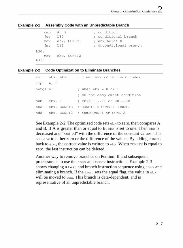
General Optimization Guidelines 2
See Example 2-2. The optimized code sets ebx to zero, then compares A and B. If A is greater than or equal to B, ebx is set to one. Then ebx is decreased and “and-ed” with the difference of the constant values. This sets ebx to either zero or the difference of the values. By adding CONST2 back to ebx, the correct value is written to ebx. When CONST2 is equal to zero, the last instruction can be deleted.
Another way to remove branches on Pentium II and subsequent processors is to use the cmov and fcmov instructions. Example 2-3 shows changing a test and branch instruction sequence using cmov and eliminating a branch. If the test sets the equal flag, the value in ebx will be moved to eax. This branch is data-dependent, and is representative of an unpredictable branch.
Example 2-1 Assembly Code with an Unpredictable Branch
cmp A, B ; conditionjge L30 ; conditional branchmov ebx, CONST1 ; ebx holds Xjmp L31 ; unconditional branch
L30:mov ebx, CONST2
L31:
Example 2-2 Code Optimization to Eliminate Branches
xor ebx, ebx ; clear ebx (X in the C code)
cmp A, B
setge bl ; When ebx = 0 or 1
; OR the complement condition
sub ebx, 1 ; ebx=11...11 or 00...00
and ebx, CONST3 ; CONST3 = CONST1-CONST2
add ebx, CONST2 ; ebx=CONST1 or CONST2
2-17
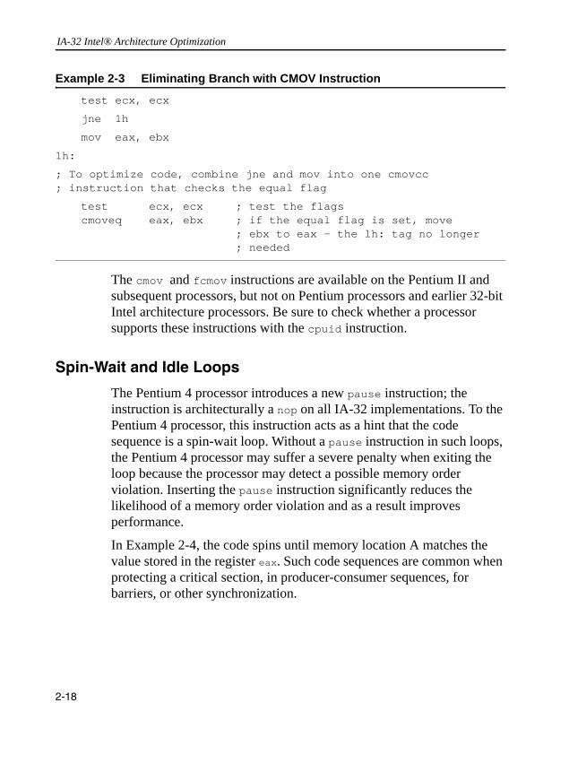
IA-32 Intel® Architecture Optimization
The cmov and fcmov instructions are available on the Pentium II and subsequent processors, but not on Pentium processors and earlier 32-bit Intel architecture processors. Be sure to check whether a processor supports these instructions with the cpuid instruction.
Spin-Wait and Idle Loops
The Pentium 4 processor introduces a new pause instruction; the instruction is architecturally a nop on all IA-32 implementations. To the Pentium 4 processor, this instruction acts as a hint that the code sequence is a spin-wait loop. Without a pause instruction in such loops, the Pentium 4 processor may suffer a severe penalty when exiting the loop because the processor may detect a possible memory order violation. Inserting the pause instruction significantly reduces the likelihood of a memory order violation and as a result improves performance.
In Example 2-4, the code spins until memory location A matches the value stored in the register eax. Such code sequences are common when protecting a critical section, in producer-consumer sequences, for barriers, or other synchronization.
Example 2-3 Eliminating Branch with CMOV Instruction
test ecx, ecx
jne 1h
mov eax, ebx
1h:
; To optimize code, combine jne and mov into one cmovcc ; instruction that checks the equal flag
test ecx, ecx ; test the flags cmoveq eax, ebx ; if the equal flag is set, move
; ebx to eax - the lh: tag no longer ; needed
2-18

General Optimization Guidelines 2
Static Prediction
Branches that do not have a history in the BTB (see the “Branch Prediction” section) are predicted using a static prediction algorithm. The Pentium 4, Pentium III and Pentium II processors have the static prediction algorithm that follows:• Predict unconditional branches to be taken.• Predict backward conditional branches to be taken. This rule is
suitable for loops.• Predict forward conditional branches to be NOT taken.• Predict indirect branches to be NOT taken.Assembly/Compiler Coding Rule 3. (M impact, H generality) Arrange code to be consistent with the static branch prediction algorithm: make the fall-through code following a conditional branch be the likely target for a branch with a forward target, and make the fall-through code following a conditional branch be the unlikely target for a branch with a backward target.
Pentium M processors do not predict conditional branches according to the jump direction. All conditional branches are dynamically predicted, even at their first appearance.
Example 2-5 illustrates the static branch prediction algorithm. The body of an if-then conditional is predicted to be executed.
Example 2-4 Use of pause Instruction
lock: cmp eax, A
jne loop
; code in critical section:
loop: pause
cmp eax, A
jne loop
jmp lock
2-19
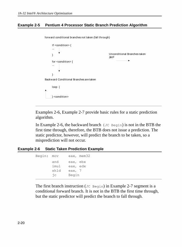
IA-32 Intel® Architecture Optimization
Examples 2-6, Example 2-7 provide basic rules for a static prediction algorithm.
In Example 2-6, the backward branch (JC Begin) is not in the BTB the first time through, therefore, the BTB does not issue a prediction. The static predictor, however, will predict the branch to be taken, so a misprediction will not occur.
The first branch instruction (JC Begin) in Example 2-7 segment is a conditional forward branch. It is not in the BTB the first time through, but the static predictor will predict the branch to fall through.
Example 2-5 Pentium 4 Processor Static Branch Prediction Algorithm
Example 2-6 Static Taken Prediction Example
Begin: mov eax, mem32
and eax, ebximul eax, edxshld eax, 7jc Begin
forward conditional branches not taken (fal l through)
If <condition> {...
} Unconditional Branches takenJMP
for <condition> {...
}
Backward Conditional Branches are taken
loop {
} <condition>
2-20
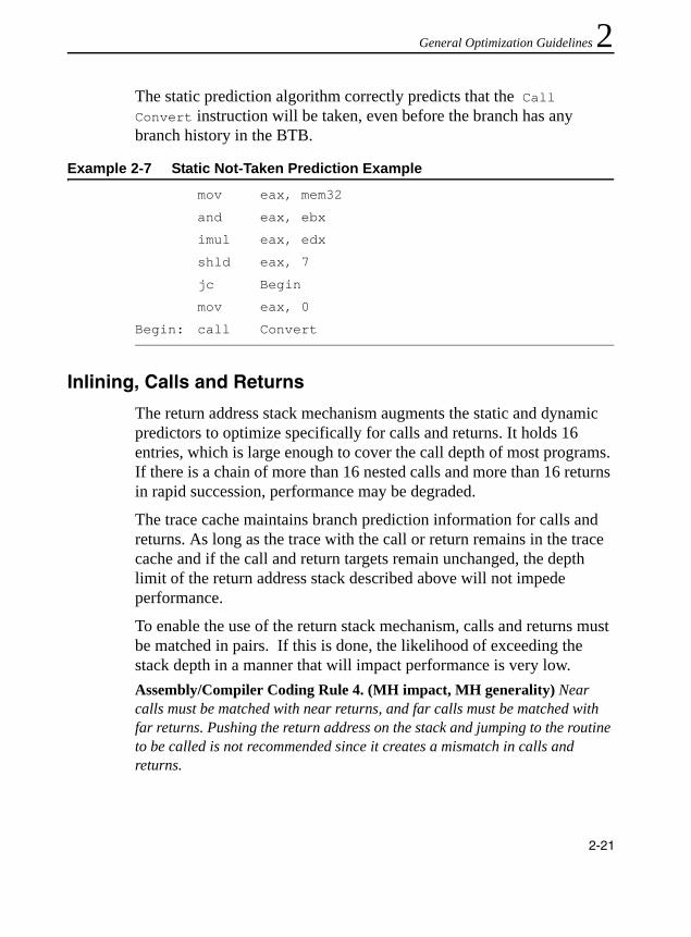
General Optimization Guidelines 2
The static prediction algorithm correctly predicts that the Call Convert instruction will be taken, even before the branch has any branch history in the BTB.Inlining, Calls and Returns
The return address stack mechanism augments the static and dynamic predictors to optimize specifically for calls and returns. It holds 16 entries, which is large enough to cover the call depth of most programs. If there is a chain of more than 16 nested calls and more than 16 returns in rapid succession, performance may be degraded.
The trace cache maintains branch prediction information for calls and returns. As long as the trace with the call or return remains in the trace cache and if the call and return targets remain unchanged, the depth limit of the return address stack described above will not impede performance.
To enable the use of the return stack mechanism, calls and returns must be matched in pairs. If this is done, the likelihood of exceeding the stack depth in a manner that will impact performance is very low.Assembly/Compiler Coding Rule 4. (MH impact, MH generality) Near calls must be matched with near returns, and far calls must be matched with far returns. Pushing the return address on the stack and jumping to the routine to be called is not recommended since it creates a mismatch in calls and returns.
Example 2-7 Static Not-Taken Prediction Example
mov eax, mem32
and eax, ebx
imul eax, edx
shld eax, 7
jc Begin
mov eax, 0
Begin: call Convert
2-21
IA-32 Intel® Architecture Optimization
Calls and returns are expensive; use inlining for the following reasons:• Parameter passing overhead can be eliminated.• In a compiler, inlining a function exposes more opportunity for
optimization.• If the inlined routine contains branches, the additional context of the
caller may improve branch prediction within the routine.• A mispredicted branch can lead to larger performance penalties
inside a small function than if that function is inlined.Assembly/Compiler Coding Rule 5. (MH impact, MH generality) Selectively inline a function where doing so decreases code size or if the function is small and the call site is frequently executed. Assembly/Compiler Coding Rule 6. (H impact, M generality) Do not inline a function if doing so increases the working set size beyond what will fit in the trace cache.Assembly/Compiler Coding Rule 7. (ML impact, ML generality) If there are more than 16 nested calls and returns in rapid succession; consider transforming the program with inline to reduce the call depth.Assembly/Compiler Coding Rule 8. (ML impact, ML generality) Favor inlining small functions that contain branches with poor prediction rates. If a branch misprediction results in a RETURN being prematurely predicted as taken, a performance penalty may be incurred.Assembly/Compiler Coding Rule 9. (L impact, L generality) If the last statement in a function is a call to another function, consider converting the call to a jump. This will save the call/ return overhead as well as an entry in the return stack buffer.Assembly/Compiler Coding Rule 10. (M impact, L generality) Do not put more than four branches in a 16-byte chunk. Assembly/Compiler Coding Rule 11. (M impact, L generality) Do not put more than two end loop branches in a 16-byte chunk.
2-22

General Optimization Guidelines 2
Branch Type SelectionThe default predicted target for indirect branches and calls is the fall-through path. The fall-through prediction is overridden if and when a hardware prediction is available for that branch. The predicted branch target from branch prediction hardware for an indirect branch is the previously executed branch target.
The default prediction to the fall-through path is only a significant issue if no branch prediction is available, due to poor code locality or pathological branch conflict problems. For indirect calls, predicting the fall-through path is usually not an issue, since execution will likely return to the instruction after the associated return.
Placing data immediately following an indirect branch can cause a performance problem. If the data consist of all zeros, it looks like a long stream of adds to memory destinations, which can cause resource conflicts and slow down branch recovery. Also, the data immediately following indirect branches may appear as branches to the branch predication hardware, which can branch off to execute other data pages. This can lead to subsequent self-modifying code problems.Assembly/Compiler Coding Rule 12. (M impact, L generality) When indirect branches are present, try to put the most likely target of an indirect branch immediately following the indirect branch. Alternatively, if indirect branches are common but they cannot be predicted by branch prediction hardware, then follow the indirect branch with a UD2 instruction, which will stop the processor from decoding down the fall-through path.
Indirect branches resulting from code constructs, such as switch statements, computed GOTOs or calls through pointers, can jump to an arbitrary number of locations. If the code sequence is such that the target destination of a branch goes to the same address most of the time, then the BTB will predict accurately most of the time. Since only one taken (non-fall-through) target can be stored in the BTB, indirect branches with multiple taken targets may have lower prediction rates.
2-23
IA-32 Intel® Architecture Optimization
The effective number of targets stored may be increased by introducing additional conditional branches. Adding a conditional branch to a target is fruitful if and only if:• The branch direction is correlated with the branch history leading up
to that branch, that is, not just the last target, but how it got to this branch.
• The source/target pair is common enough to warrant using the extra branch prediction capacity. (This may increase the number of overall branch mispredictions, while improving the misprediction of indirect branches. The profitability is lower if the number of mispredicting branches is very large).
User/Source Coding Rule 1. (M impact, L generality) If an indirect branch has two or more common taken targets, and at least one of those targets are correlated with branch history leading up to the branch, then convert the indirect branch into a tree where one or more indirect branches are preceded by conditional branches to those targets. Apply this “peeling” procedure to the common target of an indirect branch that correlates to branch history.
The purpose of this rule is to reduce the total number of mispredictions by enhancing the predictability of branches, even at the expense of adding more branches. The added branches must be very predictable for this to be worthwhile. One reason for such predictability is a strong correlation with preceding branch history, that is, the directions taken on preceding branches are a good indicator of the direction of the branch under consideration.
Example 2-8 shows a simple example of the correlation between a target of a preceding conditional branch with a target of an indirect branch.
2-24

General Optimization Guidelines 2
Correlation can be difficult to determine analytically, either for a compiler or sometimes for an assembly language programmer. It may be fruitful to evaluate performance with and without this peeling, to get the best performance from a coding effort. An example of peeling out the most favored target of an indirect branch with correlated branch history is shown in Example 2-9.
Example 2-8 Indirect Branch With Two Favored Targetsfunction ()
{
int n = rand(); // random integer 0 to RAND_MAX
if( !(n & 0x01) ){ // n will be 0 half the times
n = 0; // updates branch history to predict taken
}
// indirect branches with multiple taken targets
// may have lower prediction rates
switch (n) {
case 0: handle_0(); break; // common target, correlated with
// branch history that is forward taken
case 1: handle_1(); break;// uncommon
case 3: handle_3(); break;// uncommon
default: handle_other(); // common target
}
}
2-25

IA-32 Intel® Architecture Optimization
Loop Unrolling
The benefits of unrolling loops are:• Unrolling amortizes the branch overhead, since it eliminates
branches and some of the code to manage induction variables.• Unrolling allows you to aggressively schedule (or pipeline) the loop
to hide latencies. This is useful if you have enough free registers to keep variables live as you stretch out the dependence chain to expose the critical path.
• Unrolling exposes the code to various other optimizations, such as removal of redundant loads, common subexpression elimination, and so on.
• The Pentium 4 processor can correctly predict the exit branch for an inner loop that has 16 or fewer iterations, if that number of iterations is predictable and there are no conditional branches in the loop. Therefore, if the loop body size is not excessive, and the probable
Example 2-9 A Peeling Technique to Reduce Indirect Branch Mispredictionfunction ()
{
int n = rand(); // random integer 0 to RAND_MAX
if( !(n & 0x01) ) n = 0;
// n will be 0 half the times
if (!n) handle_0(); // peel out the most common target// with correlated branch history
else {
switch (n) {
case 1: handle_1(); break; // uncommon
case 3: handle_3(); break;// uncommon
default: handle_other(); // make the favored target in// the fall-through path
}
}
}
2-26

General Optimization Guidelines 2
number of iterations is known, unroll inner loops until they have a maximum of 16 iterations. With the Pentium M processor, do not unroll loops more than 64 iterations.The potential costs of unrolling loops are:• Excessive unrolling, or unrolling of very large loops can lead to
increased code size. This can be harmful if the unrolled loop no longer fits in the trace cache (TC).
• Unrolling loops whose bodies contain branches increases demands on the BTB capacity. If the number of iterations of the unrolled loop is 16 or less, the branch predictor should be able to correctly predict branches in the loop body that alternate direction.
Assembly/Compiler Coding Rule 13. (H impact, M generality) Unroll small loops until the overhead of the branch and the induction variable accounts, generally, for less than about 10% of the execution time of the loop.Assembly/Compiler Coding Rule 14. (H impact, M generality) Avoid unrolling loops excessively, as this may thrash the trace cache or instruction cache.Assembly/Compiler Coding Rule 15. (M impact, M generality) Unroll loops that are frequently executed and that have a predictable number of iterations to reduce the number of iterations to 16 or fewer, unless this increases code size so that the working set no longer fits in the trace cache or instruction cache. If the loop body contains more than one conditional branch, then unroll so that the number of iterations is 16/(# conditional branches).
Example 2-10 shows how unrolling enables other optimizations.
2-27
IA-32 Intel® Architecture Optimization
In this example, a loop that executes 100 times assigns x to every even-numbered element and y to every odd-numbered element. By unrolling the loop you can make both assignments each iteration, removing one branch in the loop body.
Compiler Support for Branch Prediction
Compilers can generate code that improves the efficiency of branch prediction in the Pentium 4 and Pentium M processors. The Intel C++ Compiler accomplishes this by:• keeping code and data on separate pages• using conditional move instructions to eliminate branches• generating code that is consistent with the static branch prediction
algorithm• inlining where appropriate• unrolling, if the number of iterations is predictable
With profile-guided optimization, the Intel compiler can lay out basic blocks to eliminate branches for the most frequently executed paths of a function or at least improve their predictability. Branch prediction need not be a concern at the source level. For more information, see the Intel® C++ Compiler User’s Guide.
Example 2-10 Loop Unrolling
Before unrolling:
do i=1,100 if (i mod 2 == 0) then a(i) = x else a(i) = yenddo
After unrolling
do i=1,100,2 a(i) = y a(i+1) = xenddo
2-28

General Optimization Guidelines 2
Memory AccessesThis section discusses guidelines for optimizing code and data memory accesses. The most important recommendations are:• align data, paying attention to data layout and stack alignment• enable store forwarding• place code and data on separate pages• enhance data locality• use prefetching and cacheability control instructions• enhance code locality and align branch targets• take advantage of write combining
Alignment and forwarding problems are among the most common sources of large delays on the Pentium 4 processor.
Alignment
Alignment of data concerns all kinds of variables:• dynamically allocated• members of a data structure• global or local variables• parameters passed on the stack
Misaligned data access can incur significant performance penalties. This is particularly true for cache line splits. The size of a cache line is64 bytes in the Pentium 4, Intel Xeon, and Pentium M processors.
On the Pentium 4 processor, an access to data unaligned on 64-byte boundary leads to two memory accesses and requires several µops to be executed (instead of one). Accesses that span 64-byte boundaries are likely to incur a large performance penalty, since they are executed near retirement, and can incur stalls that are on the order of the depth of the pipeline.
2-29
IA-32 Intel® Architecture Optimization
Assembly/Compiler Coding Rule 16. (H impact, H generality) Align data on natural operand size address boundaries. If the data will be accesses with vector instruction loads and stores, align the data on 16 byte boundaries.
For best performance, align data as follows:• Align 8-bit data at any address.• Align 16-bit data to be contained within an aligned four byte word.• Align 32-bit data so that its base address is a multiple of four.• Align 64-bit data so that its base address is a multiple of eight.• Align 80-bit data so that its base address is a multiple of sixteen.• Align 128-bit data so that its base address is a multiple of sixteen.
A 64-byte or greater data structure or array should be aligned so that its base address is a multiple of 64. Sorting data in decreasing size order is one heuristic for assisting with natural alignment. As long as 16-byte boundaries (and cache lines) are never crossed, natural alignment is not strictly necessary, though it is an easy way to enforce this.
Example 2-11 shows the type of code that can cause a cache line split. The code loads the addresses of two dword arrays. 029e70feh is not a 4-byte-aligned address, so a 4-byte access at this address will get 2 bytes from the cache line this address is contained in, and 2 bytes from the cache line that starts at 029e7100h. On processors with 64-byte cache lines, a similar cache line split will occur every 8 iterations. Figure 2-1 illustrates the situation of accessing a data element that span across cache line boundaries.
2-30
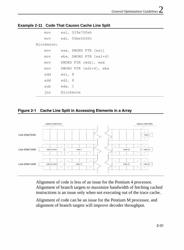
General Optimization Guidelines 2
Alignment of code is less of an issue for the Pentium 4 processor. Alignment of branch targets to maximize bandwidth of fetching cached instructions is an issue only when not executing out of the trace cache.
Alignment of code can be an issue for the Pentium M processor, and alignment of branch targets will improve decoder throughput.
Example 2-11 Code That Causes Cache Line Split
mov esi, 029e70feh
mov edi, 05be5260h
Blockmove:
mov eax, DWORD PTR [esi]
mov ebx, DWORD PTR [esi+4]
mov DWORD PTR [edi], eax
mov DWORD PTR [edi+4], ebx
add esi, 8
add edi, 8
sub edx, 1
jnz Blockmove
Figure 2-1 Cache Line Split in Accessing Elements in a Array
Index 1Index 0 cont'd
Index 0
Index 15 Index 16Line 029e7100h
Line 029e70c0h
Index 17Index 16 cont'd Index 31 Index 32Line 029e7140h
Address 029e70fehAddress 029e70c1h
2-31

IA-32 Intel® Architecture Optimization
Store Forwarding
The processor’s memory system only sends stores to memory (including cache) after store retirement. However, store data can be forwarded from a store to a subsequent load from the same address to give a much shorter store-load latency.
There are two kinds of requirements for store forwarding. If these requirements are violated, store forwarding cannot occur and the load must get its data from the cache (so the store must write its data back to the cache first). This incurs a penalty that is related to pipeline depth.
The first requirement pertains to the size and alignment of the store-forwarding data. This restriction is likely to have high impact to overall application performance. Typically, performance penalty due to violating this restriction can be prevented. Several examples of coding pitfalls that cause store-forwarding stalls and solutions to these pitfalls are discussed in detail in the “Store-to-Load-Forwarding Restriction on Size and Alignment” section. The second requirement is the availability of data, discussed in the “Store-forwarding Restriction on Data Availability” section.
A good practice is to eliminate redundant load operations, see some guidelines below.
It may be possible to keep a temporary scalar variable in a register and never write it to memory. Generally, such a variable must not be accessible via indirect pointers. Moving a variable to a register eliminates all loads and stores of that variable and eliminates potential problems associated with store forwarding. However, it also increases register pressure.
Load instructions tend to start chains of computation. Since the out of order engine is based on data dependence, load instructions play a significant role in the engine capability to execute at a high rate. Eliminating loads should be given a high priority.
2-32
General Optimization Guidelines 2
If a variable is known not to change between when it is stored and when it is used again, the register that was stored can be copied or used directly. If register pressure is too high, or an unseen function is called before the store and the second load, it may not be possible to eliminate the second load.Assembly/Compiler Coding Rule 17. (H impact, M generality) Pass parameters in registers instead of on the stack where possible. Passing arguments on the stack is a case of store followed by a reload. While this sequence is optimized in IA-32 processors by providing the value to the load directly from the memory order buffer without the need to access the data cache, floating point values incur a significant latency in forwarding. Passing floating point argument in (preferably XMM) registers should save this long latency operation.Parameter passing conventions may limit the choice of which parameters are passed in registers versus on the stack. However, these limitations may be overcome if the compiler has control of the compilation of the whole binary (using whole-program optimization).Store-to-Load-Forwarding Restriction on Size and Alignment
Data size and alignment restrictions for store-forwarding apply to the Pentium 4, Intel Xeon and Pentium M processor. The performance penalty from violating store-forwarding restrictions is less for Pentium M processors than that for Pentium 4 processors.
This section describes these restrictions in all cases. It prescribes recommendations to prevent the non-forwarding penalty. Fixing this problem for Pentium 4 and Intel Xeon processors also fixes problem on Pentium M processors.
2-33

IA-32 Intel® Architecture Optimization
The size and alignment restrictions for store forwarding are illustrated in Figure 2-2.
Coding rules to help programmers satisfy size and alignment restrictions for store forwarding follow.Assembly/Compiler Coding Rule 18. (H impact, M generality) A load that forwards from a store must have the same address start point and therefore the same alignment as the store data.Assembly/Compiler Coding Rule 19. (H impact, M generality) The data of a load which is forwarded from a store must be completely contained within the store data.
Figure 2-2 Size and Alignment Restrictions in Store Forwarding
OM15155
(a) Small load afterLarge Store
Store
Load
Load Aligned withStore W ill Forward
Non-Forwarding
Penalty
(b) Size of Load >=Store
Store
Load
Penalty
(c) Size of Load >=Store(s)
Store
Load
Penalty
(d) 128-bit ForwardMust Be 16-Byte
Aligned
Store
Load
Penalty
16-ByteBoundary
2-34

General Optimization Guidelines 2
A load that forwards from a store must wait for the store’s data to be written to the store buffer before proceeding, but other, unrelated loads need not wait. Assembly/Compiler Coding Rule 20. (H impact, ML generality) If it is necessary to extract a non-aligned portion of stored data, read out the smallest aligned portion that completely contains the data and shift/mask the data as necessary.This is better than incurring the penalties of a failed store-forward.Assembly/Compiler Coding Rule 21. (MH impact, ML generality) Avoid several small loads after large stores to the same area of memory by using a single large read and register copies as needed.
Example 2-12 contains several store-forwarding situations when small loads follow large stores. The first three load operations illustrate the situations described in Rule 22. However, the last load operation gets data from store-forwarding without problem.
Example 2-13 illustrates a store-forwarding situation when a large load follows after several small stores. The data needed by the load operation cannot be forwarded because all of the data that needs to be forwarded is not contained in the store buffer. Avoid large loads after small stores to the same area of memory.
Example 2-12 Several Situations of Small Loads After Large Store
mov [EBP],‘abcd’mov AL, [EBP] ; not blocked - same alignmentmov BL, [EBP + 1] ; blocked
mov CL, [EBP + 2] ; blocked
mov DL, [EBP + 3] ; blocked
mov AL, [EBP] ; not blocked - same alignment; n.b. passes older blocked loads
2-35
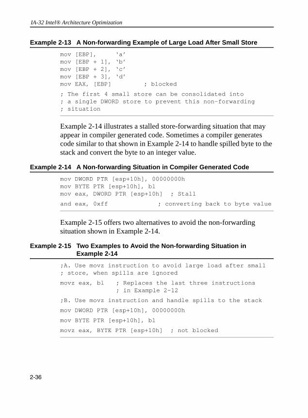
IA-32 Intel® Architecture Optimization
Example 2-14 illustrates a stalled store-forwarding situation that may appear in compiler generated code. Sometimes a compiler generates code similar to that shown in Example 2-14 to handle spilled byte to the stack and convert the byte to an integer value.
Example 2-15 offers two alternatives to avoid the non-forwarding situation shown in Example 2-14.
Example 2-13 A Non-forwarding Example of Large Load After Small Store
mov [EBP], ‘a’mov [EBP + 1], ‘b’mov [EBP + 2], ‘c’mov [EBP + 3], ‘d’mov EAX, [EBP] ; blocked
; The first 4 small store can be consolidated into ; a single DWORD store to prevent this non-forwarding; situation
Example 2-14 A Non-forwarding Situation in Compiler Generated Code
mov DWORD PTR [esp+10h], 00000000hmov BYTE PTR [esp+10h], blmov eax, DWORD PTR [esp+10h] ; Stall
and eax, 0xff ; converting back to byte value
Example 2-15 Two Examples to Avoid the Non-forwarding Situation in Example 2-14
;A. Use movz instruction to avoid large load after small; store, when spills are ignored
movz eax, bl ; Replaces the last three instructions ; in Example 2-12
;B. Use movz instruction and handle spills to the stack
mov DWORD PTR [esp+10h], 00000000h
mov BYTE PTR [esp+10h], bl
movz eax, BYTE PTR [esp+10h] ; not blocked
2-36
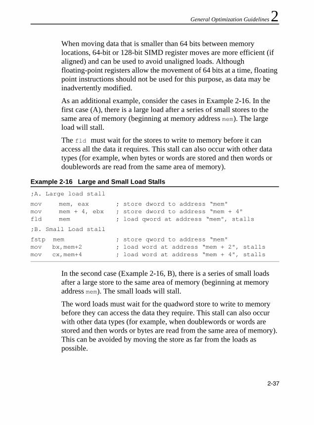
General Optimization Guidelines 2
When moving data that is smaller than 64 bits between memory locations, 64-bit or 128-bit SIMD register moves are more efficient (if aligned) and can be used to avoid unaligned loads. Although floating-point registers allow the movement of 64 bits at a time, floating point instructions should not be used for this purpose, as data may be inadvertently modified.As an additional example, consider the cases in Example 2-16. In the first case (A), there is a large load after a series of small stores to the same area of memory (beginning at memory address mem). The large load will stall.
The fld must wait for the stores to write to memory before it can access all the data it requires. This stall can also occur with other data types (for example, when bytes or words are stored and then words or doublewords are read from the same area of memory).
In the second case (Example 2-16, B), there is a series of small loads after a large store to the same area of memory (beginning at memory address mem). The small loads will stall.
The word loads must wait for the quadword store to write to memory before they can access the data they require. This stall can also occur with other data types (for example, when doublewords or words are stored and then words or bytes are read from the same area of memory). This can be avoided by moving the store as far from the loads as possible.
Example 2-16 Large and Small Load Stalls
;A. Large load stall
mov mem, eax ; store dword to address “mem"mov mem + 4, ebx ; store dword to address “mem + 4"fld mem ; load qword at address “mem", stalls
;B. Small Load stall
fstp mem ; store qword to address “mem"mov bx,mem+2 ; load word at address “mem + 2", stallsmov cx,mem+4 ; load word at address “mem + 4", stalls
2-37

IA-32 Intel® Architecture Optimization
Store-forwarding Restriction on Data Availability
The value to be stored must be available before the load operation can be completed. If this restriction is violated, the execution of the load will be delayed until the data is available. This delay causes some execution resources to be used unnecessarily, and that can lead to sizable but non-deterministic delays. However, the overall impact of this problem is much smaller than that from size and alignment requirement violations.
The Pentium 4 and Intel Xeon processors predict when loads are both dependent on and get their data forwarded from preceding stores. These predictions can significantly improve performance. However, if a load is scheduled too soon after the store it depends on or if the generation of the data to be stored is delayed, there can be a significant penalty.
There are several cases where data is passed through memory, where the store may need to be separated from the load:• spills, save and restore registers in a stack frame• parameter passing• global and volatile variables• type conversion between integer and floating point• when compilers do not analyze code that is inlined, forcing
variables that are involved in the interface with inlined code to be in memory, creating more memory variables and preventing the elimination of redundant loads
Assembly/Compiler Coding Rule 22. (H impact, MH generality) Where it is possible to do so without incurring other penalties, prioritize the allocation of variables to registers, as in register allocation and for parameter passing to minimize the likelihood and impact of store- forwarding problems. Try not to store-forward data generated from a long latency instruction, e.g. mul, div. Avoid store-forwarding data for variables with the shortest store-load distance. Avoid store-forwarding data for variables with many and/or long dependence chains, and especially avoid including a store forward on a loop-carried dependence chain.
2-38

General Optimization Guidelines 2
An example of a loop-carried dependence chain is shown in Example 2-17.Data Layout Optimizations
User/Source Coding Rule 2. (H impact, M generality) Pad data structures defined in the source code so that every data element is aligned to a natural operand size address boundary.
If the operands are packed in a SIMD instruction, align to the packed element size (64-bit or 128-bit).
Align data by providing padding inside structures and arrays. Programmers can reorganize structures and arrays to minimize the amount of memory wasted by padding. However, compilers might not have this freedom. The C programming language, for example, specifies the order in which structure elements are allocated in memory. Section “Stack and Data Alignment” of Chapter 3, and Appendix D, “Stack Alignment”, further defines the exact storage layout.
Example 2-18 shows how a data structure could be rearranged to reduce its size.
Example 2-17 An Example of Loop-carried Dependence Chain
for (i=0; i<MAX; i++) {
a[i] = b[i] * foo;
foo = a[i]/3;
} // foo is a loop-carried dependence
Example 2-18 Rearranging a Data Structure
struct unpacked { /* fits in 20 bytes due to padding */int a;char b;int c;char d;int e;
}struct packed { /* fits in 16 bytes */
2-39

IA-32 Intel® Architecture Optimization
Cache line size for Pentium 4 and Pentium M processors can impact streaming applications (for example, multimedia). These reference and use data only once before discarding it. Data accesses which sparsely utilize the data within a cache line can result in less efficient utilization of system memory bandwidth. For example, arrays of structures can be decomposed into several arrays to achieve better packing, as shown in Example 2-19.
The efficiency of such optimizations depends on usage patterns. If the elements of the structure are all accessed together but the access pattern of the array is random, then array_of_struct avoids unnecessary prefetch even though it wastes memory.
Example 2-19 Decomposing an Array
struct {/* 1600 bytes */
int a, c, e;char b, d;
} array_of_struct [100];
struct {/* 1400 bytes */int a[100], c[100], e[100];char b[100], d[100];
} struct_of_array;
struct {/* 1200 bytes */
int a, c, e;} hybrid_struct_of_array_ace[100];
struct {/* 200 bytes */
char b, d;} hybrid_struct_of_array_bd[100];
2-40
General Optimization Guidelines 2
However, if the access pattern of the array exhibits locality, such as if the array index is being swept through, then the Pentium 4 processor prefetches data from struct_of_array, even if the elements of the structure are accessed together.When the elements of the structure are not accessed with equal frequency, such as when element a is accessed ten times more often than the other entries, then struct_of_array not only saves memory, but it also prevents fetching unnecessary data items b, c, d, and e.
Using struct_of_array also enables the use of the SIMD data types by the programmer and the compiler.
Note that struct_of_array can have the disadvantage of requiring more independent memory stream references. This can require the use of more prefetches and additional address generation calculations. It can also have an impact on DRAM page access efficiency. An alternative, hybrid_struct_of_array blends the two approaches. In this case, only 2 separate address streams are generated and referenced: 1 for hybrid_struct_of_array_ace and 1 for hybrid_struct_of_array_bd. The second alterative also prevents fetching unnecessary data (assuming the variables a, c and e are always used together; whereas the variables b and d would be also used together, but not at the same time as a, c and e).
The hybrid approach ensures:• simpler/fewer address generation than struct_of_array• fewer streams, which reduces DRAM page misses• use of fewer prefetches due to fewer streams• efficient cache line packing of data elements that are used
concurrentlyAssembly/Compiler Coding Rule 23. (H impact, M generality) Try to arrange data structures such that they permit sequential access.
If the data is arranged into set of streams, the automatic hardware prefetcher can prefetch data that will be needed by the application, reducing the effective memory latency. If the data is accessed in a
2-41

IA-32 Intel® Architecture Optimization
non-sequential manner, the automatic hardware prefetcher cannot prefetch the data. The prefetcher can recognize up to eight concurrent streams. See Chapter 6 for more information and the hardware prefetcher.
Memory coherence is maintained on 64-byte cache lines on thePentium 4, Intel Xeon and Pentium M processors, rather than earlier processors’ 32-byte cache lines. This can increase the opportunity for false sharing.User/Source Coding Rule 3. (M impact, L generality) Beware of false sharing within a cache line (64 bytes) for Pentium 4, Intel Xeon, and Pentium M processors; and within a sector of 128 bytes on Pentium 4 and Intel Xeon processors.
Stack Alignment
The easiest way to avoid stack alignment problems is to keep the stack aligned at all times. For example: if a language only supports 8-bit, 16-bit, 32-bit, and 64-bit data quantities, but never uses 80-bit data quantities; the language can require the stack to always be aligned on a 64-bit boundary.Assembly/Compiler Coding Rule 24. (H impact, M generality) If 64-bit data is ever passed as a parameter or allocated on the stack, make sure that the stack is aligned to an 8-byte boundary.
Doing so will require the use of a general purpose register (such as EBP) as a frame pointer. The trade-off is between causing unaligned 64-bit references if the stack is not aligned and causing extra general purpose register spills if the stack is aligned. Note that a performance penalty is caused only when an unaligned access splits a cache line. This means that one out of eight spatially consecutive unaligned accesses is always penalized.
A routine that makes frequent use of 64-bit data can avoid stack misalignment by placing the code described in Example 2-20 in the function prologue and epilogue.
2-42

General Optimization Guidelines 2
If for some reason it is not possible to align the stack for 64-bits, the routine should access the parameter and save it into a register or known aligned storage, thus incurring the penalty only once.
Capacity Limits and Aliasing in Caches
There are cases where addresses with a given stride will compete for some resource in the memory hierarchy.
Typically, caches are implemented to have multiple ways of set associativity, with each way consisting of multiple sets of cache lines (or sectors in some cases). Multiple memory references that compete for the same set of each way in a cache can cause a capacity issue. There are aliasing conditions that apply to specific microarchitectures. Note that first-level cache lines are 64 bytes. Thus the least significant 6 bits are not considered in alias comparisons. For the Pentium 4 and Intel Xeon processors, data is loaded into the second level cache in a sector of 128 bytes, so the least significant 7 bits are not considered in alias comparisons.
Example 2-20 Dynamic Stack Alignment
prologue:subl esp, 4 ; save frame ptrmovl [esp], ebpmovl ebp, esp ; new frame pointerandl ebp, 0xFFFFFFFC; aligned to 64 bitsmovl [ebp], esp ; save old stack ptrsubl esp, FRAMESIZE ; allocate space; ... callee saves, etc.
epilogue:; ... callee restores, etc.movl esp, [ebp] ; restore stack ptrmovl ebp, [esp] ; restore frame ptraddl esp, 4ret
2-43
IA-32 Intel® Architecture Optimization
Capacity Limits in Set-Associative Caches
Capacity limits may occur if the number of outstanding memory references that are mapped to the same set in each way of a given cache exceeded the number of ways of that cache. The conditions that apply to the first-level data cache and second level cache are listed below:• L1 Set Conflicts–multiple references map to the same first-level
cache set. The conflicting condition is a stride determined by the size of the cache in bytes, divided by the number ways. These competing memory reference can cause excessive cache misses only if the number of outstanding memory references exceeds the number of ways in the working set. On Pentium 4 and Intel Xeon processors with CPUID signature of family encoding 15, model encoding of 0, 1 or 2, there will be an excess of first-level cache misses for more than 4 simultaneous, competing memory references to addresses with 2KB modulus. On Pentium 4 and Intel Xeon processors with CPUID signature of family encoding 15, model encoding 3, excessive first-level cache misses occur when more than 8 simultaneous, competing references to addresses that are apart by 2KB modulus. On Pentium M processors, a similar condition applies to more than 8 simultaneous references to addresses that are apart by 4KB modulus.
• L2 Set Conflicts – multiple references map to the same second-level cache set. The conflicting condition is also determined by the size of the cache/the number of ways. On Pentium 4 and Intel Xeon processors, excessive second-level cache miss occurs when more than 8 simultaneous competing references. The stride that can cause capacity issues are 32KB, 64KB, or 128 KB, depending of the size of the second level cache. On Pentium M processors, the stride size that can cause capacity issues are 128 KB or 256 KB, depending of the size of the second level cache.
2-44
General Optimization Guidelines 2
Aliasing Cases in the Pentium 4 and Intel® Xeon™ ProcessorsAliasing conditions that are specific to the Pentium 4 processor and Intel Xeon processor are:• 16K for code – there can only be one of these in the trace cache at a
time. If two traces whose starting addresses are 16K apart are in the same working set, the symptom will be a high trace cache miss rate. Solve this by offsetting one of the addresses by one or more bytes.
• Data conflict – can only have one instance of the data in the first-level cache at a time. If a reference (load or store) occurs with its linear address matching a data conflict condition with another reference (load or store) which is under way, then the second reference cannot begin until the first one is kicked out of the cache. On Pentium 4 and Intel Xeon processors with CPUID signature of family encoding 15, model encoding of 0, 1 or 2, the data conflict condition applies to addresses having identical value in bits 15:6 (also referred to as 64K aliasing conflict). If you avoid this kind of aliasing, you can speedup programs by a factor of three if they load frequently from preceding stores with aliased addresses and there is little other instruction-level parallelism available. The gain is smaller when loads alias with other loads, which cause thrashing in the first-level cache. On Pentium 4 and Intel Xeon processors with CPUID signature of family encoding 15, model encoding 3, the data conflict condition applies to addresses having identical value in bits 21:6.
Aliasing Cases in the Pentium M Processor
Pentium M processor aliasing cases are listed below.• Store forwarding - 4 KB for data will look the same to the
store-forwarding logic. If there has been a store to an address which aliases with the load, the load will stall until the store data is available.
2-45
IA-32 Intel® Architecture Optimization
Assembly/Compiler Coding Rule 25. (H impact, MH generality) Lay out data or order computation to avoid having cache lines that have linear addresses that are a multiple of 64 KB apart in the same working set. Avoid having more than 4 cache lines that are some multiple of 2 KB apart in the same first-level cache working set, and avoid having more than eight cache lines that are some multiple of 4 KB apart in the same first-level cache working set. Avoid having a store followed by a non-dependent load with addresses that differ by a multiple of 4 KB.
When declaring multiple arrays that are referenced with the same index and are each a multiple of 64 KB (as can happen with struct_of_array data layouts), pad them to avoid declaring them contiguously. Padding can be accomplished by either intervening declarations of other variables, or by artificially increasing the dimension. User/Source Coding Rule 4. (H impact, ML generality) Consider using a special memory allocation library to avoid aliasing.
One way to implement a memory allocator to avoid aliasing is to allocate more than enough space and pad. For example, allocate structures that are 68 KB instead of 64 KB to avoid the 64 KB aliasing; or have the allocator pad and return random offsets that are a multiple of 128 Bytes (the size of a cache line). User/Source Coding Rule 5. (M impact, M generality) When padding variable declarations to avoid aliasing, the greatest benefit comes from avoiding aliasing on second-level cache lines, suggesting an offset of 128 bytes or more.
Mixing Code and Data
The Pentium 4 processor’s aggressive prefetching and pre-decoding of instructions has two related effects:• Self-modifying code works correctly, according to the Intel
architecture processor requirements, but incurs a significant performance penalty. Avoid self-modifying code.
2-46

General Optimization Guidelines 2
• Placing writable data in the code segment might be impossible todistinguish from self-modifying code. Writable data in the code segment might suffer the same performance penalty as self-modifying code.
Assembly/Compiler Coding Rule 26. (M impact, L generality) If (hopefully read-only) data must occur on the same page as code, avoid placing it immediately after an indirect jump. For example, follow an indirect jump with its mostly likely target, and place the data after an unconditional branch.Tuning Suggestion 1. In rare cases, a performance problem may be noted due to executing data on a code page as instructions. The condition where this is very likely to happen is when execution is following an indirect branch that is not resident in the trace cache. If a performance problem is clearly due to this cause, try moving the data elsewhere or inserting an illegal opcode or a pause instruction immediately following the indirect branch. The latter two alternatives may degrade performance in some circumstances.Assembly/Compiler Coding Rule 27. (H impact, L generality) Always put code and data on separate pages. Avoid self-modifying code wherever possible. If code is to be modified, try to do it all at once and make sure the code that performs the modifications and the code being modified are on separate 4 KB pages or on separate aligned 1 KB subpages.
Self-modifying Code
Self-modifying code (SMC) that ran correctly on Pentium III processors and prior implementations will run correctly on subsequent implementations, including Pentium 4 and Intel Xeon processors. SMC and cross-modifying code (when more than one processor in a multi-processor system are writing to a code page) should be avoided when high performance is desired.
Software should avoid writing to a code page in the same 1 KB subpage of that is being executed or fetching code in the same 2 KB subpage of that is currently being written. In addition, sharing a page containing directly or speculatively executed code with another processor as a data
2-47

IA-32 Intel® Architecture Optimization
page can trigger an SMC condition that causes the entire pipeline of the machine and the trace cache to be cleared. This is due to the self-modifying code condition.
Dynamic code need not cause the SMC condition if the code written fills up a data page before that page is accessed as code. Dynamically-modified code (for example, from target fix-ups) is likely to suffer from the SMC condition and should be avoided where possible. Avoid the condition by introducing indirect branches and using data tables on data (not code) pages via register-indirect calls.
Write Combining
Write combining (WC) improves performance in two ways:• On a write miss to the first-level cache, it allows multiple stores to
the same cache line to occur before that cache line is read for ownership (RFO) from further out in the cache/memory hierarchy. Then the rest of line is read, and the bytes that have not been written are combined with the unmodified bytes in the returned line.
• Write combining allows multiple writes to be assembled and written further out in the cache hierarchy as a unit. This saves port and bus traffic. Saving traffic is particularly important for avoiding partial writes to uncached memory.
There are six write-combining buffers (on Pentium 4 and Intel Xeon processors with CPUID signature of family encoding 15, model encoding 3, there are 8 write-combining buffers). Two of these buffers may be written out to higher cache levels and freed up for use on other write misses; only four write-combining buffers are guaranteed to be available for simultaneous use. Write combining applies to memory type WC; it does not apply to memory type UC. Assembly/Compiler Coding Rule 28. (H impact, L generality) If an inner loop writes to more than four arrays, (four distinct cache lines), apply loop fission to break up the body of the loop such that only four arrays are being written to in each iteration of each of the resulting loops.
2-48
General Optimization Guidelines 2
The write combining buffers are used for stores of all memory types. They are particularly important for writes to uncached memory: writes to different parts of the same cache line can be grouped into a single, full-cache-line bus transaction instead of going across the bus (since they are not cached) as several partial writes. Avoiding partial writes can have a significant impact on bus bandwidth-bound graphics applica-tions, where graphics buffers are in uncached memory. Separating writes to uncached memory and writes to writeback memory into sepa-rate phases can assure that the write combining buffers can fill before getting evicted by other write traffic. Eliminating partial write transac-tions has been found to have performance impact of the order of 20% for some applications. Because the cache lines are 64 bytes, a write to the bus for 63 bytes will result in 8 partial bus transactions.When coding functions that execute simultaneously on two threads, reducing the number of writes that are allowed in an inner loop will help take full advantage of write-combining store buffers. For write-combining buffer recommendations for Hyper-Threading Technology, see Chapter 7.
Store ordering and visibility are also important issues for write combin-ing. When a write to a write-combining buffer for a previously-unwrit-ten cache line occurs, there will be a read-for-ownership (RFO). If a subsequent write happens to another write-combining buffer, a separate RFO may be caused for that cache line. Subsequent writes to the first cache line and write-combining buffer will be delayed until the second RFO has been serviced to guarantee properly ordered visibility of the writes. If the memory type for the writes is write-combining, there will be no RFO since the line is not cached, and there is no such delay. For details on write-combining, see the Intel Architecture Software Devel-oper’s Manual.
Locality Enhancement
Locality enhancement can reduce data traffic originating from an outer-level sub-system in the cache/memory hierarchy, this is to address the fact that the access-cost in terms of cycle-count from an outer level
2-49

IA-32 Intel® Architecture Optimization
will be more expensive than from an inner level. Typically, the cycle-cost of accessing a given cache level (or memory system) varies across different microarchitecture, processor implementations, and platform components. It may be sufficient to recognize the relative data access cost trend by locality rather than to follow a large table of numeric values of cycle-costs, listed per locality, per processor/platform implementations, etc. The general trend is typically that access cost from an outer sub-system may be somewhere between 3-10X more expensive than accessing data from the immediate inner level in the cache/memory hierarchy, assuming similar degrees of data access parallelism.
Thus locality enhancement should start with characterizing the dominant data traffic locality. “Workload Characterization” in Appendix A describes some techniques that can be used to determine the dominant data traffic locality for any workload.
Even if cache miss rates of the last level cache may be low relative to the number of cache references, processors typically spend a sizable portion of their execution time waiting for cache misses to be serviced. Reducing cache misses by enhancing a program’s locality is a key optimization. This can take several forms: • blocking to iterate over a portion of an array that will fit in the cache
(with the purpose that subsequent references to the data-block (or tile) will be cache hit references)
• loop interchange to avoid crossing cache lines or page boundaries• loop skewing to make accesses contiguous
Locality enhancement to the last level cache can be accomplished with sequencing the data access pattern to take advantage of hardware prefetching. This can also take several forms: • Transformation of a sparsely populated multi-dimensional array into
a one-dimension array such that memory references occur in a
2-50

General Optimization Guidelines 2
sequential, small-stride1, pattern that are friendly to the hardware prefetch.• Optimal tile size and shape selection can further improve temporal data locality by increasing hit rates into the last level cache and reduce memory traffic resulting from the actions of hardware prefetching. (See “Hardware Prefetching and Cache Blocking Techniques” in Chapter 6.)
It is important to avoid operations that work against locality-enhancing techniques. Using the lock prefix heavily can incur large delays when accessing memory, irrespective of whether the data is in the cache or in system memory.User/Source Coding Rule 6. (H impact, H generality) Optimization techniques such as blocking, loop interchange, loop skewing and packing are best done by the compiler. Optimize data structures to either fit in one-half of the first-level cache or in the second-level cache; turn on loop optimizations in the compiler to enhance locality for nested loops.
Optimizing for one-half of the first-level cache will bring the greatest performance benefit in terms of cycle-cost per data access. If one-half of the first-level cache is too small to be practical, optimize for the second-level cache. Optimizing for a point in between (for example, for the entire first-level cache) will likely not bring a substantial improvement over optimizing for the second-level cache.
Minimizing Bus Latency
The system bus on Intel Xeon and Pentium 4 processors provides up to6.4 GB/sec bandwidth of throughput at 200 MHz scalable bus clock rate. (See MSR_EBC_FREQUENCY_ID register.) The peak bus bandwidth is even higher with higher bus clock rates.
Each bus transaction includes the overhead of making request and arbitrations. The average latency of bus read and bus write transactions will be longer if reads and writes alternate. Segmenting reads and writes
1. See “Data Prefetch” in Chapter 1
2-51

IA-32 Intel® Architecture Optimization
into phases can reduce the average latency of bus transactions. This is because the number of incidences of successive transactions involving a read following a write or a write following a read are reduced.User/Source Coding Rule 7. (M impact, ML generality) If there is a blend of reads and writes on the bus, changing the code to separate these bus transactions into read phases and write phases can help performance.
Note, however, that the order of read and write operations on the bus are not the same as they appear in the program.
Bus latency of fetching a cache line of data can vary as a function of the access stride of data references. In general, bus latency will increase in response to increasing values of the stride of successive cache misses. Independently, bus latency will also increase as a function of increasing bus queue depths (the number outstanding bus requests of a given transaction type). The combination of these two trends can be highly non-linear, in that bus latency of large-stride, band-width sensitive situations are such that effective throughput of the bus system for data-parallel accesses can be significantly less than the effective throughput of small-stride, bandwidth sensitive situations.
To minimize the per-access cost of memory traffic or amortize raw memory latency effectively, software should control its cache miss pattern to favor higher concentration of smaller-stride cache misses.User/Source Coding Rule 8. (H impact, H generality) To achieve effective amortization of bus latency, software should pay attention to favor data access patterns that result in higher concentrations of cache miss patterns with cache miss strides that are significantly smaller than half of the hardware prefetch trigger threshold.
Non-Temporal Store Bus Traffic
Peak system bus bandwidth is shared by several types of bus activities, including: reads (from memory), read for ownership (of a cache line), and writes. The data transfer rate for bus write transactions is higher if 64 bytes are written out to the bus at a time.
2-52

General Optimization Guidelines 2
Typically, bus writes to Writeback (WB) type memory must share the system bus bandwidth with read-for-ownership (RFO) traffic. Non-temporal stores do not require RFO traffic; they do require care in managing the access patterns in order to ensure 64 bytes are evicted at once (rather than evicting several 8 byte chunks).Although full 64-byte bus writes due to non-temporal stores have data bandwidth that is twice that of bus writes to WB memory, transferring 8-byte chunks wastes bus request bandwidth and delivers significantly lower data bandwidth.
Example 2-21 Non-temporal Stores and 64-byte Bus Write Transactions
#define STRIDESIZE 256Lea ecx, p64byte_AlignedMov edx, ARRAY_LENXor eax, eaxslloop:movntps XMMWORD ptr [ecx + eax], xmm0movntps XMMWORD ptr [ecx + eax+16], xmm0movntps XMMWORD ptr [ecx + eax+32], xmm0movntps XMMWORD ptr [ecx + eax+48], xmm0; 64 bytes is written in one bus transactionadd eax, STRIDESIZEcmp eax, edxjl slloop
2-53
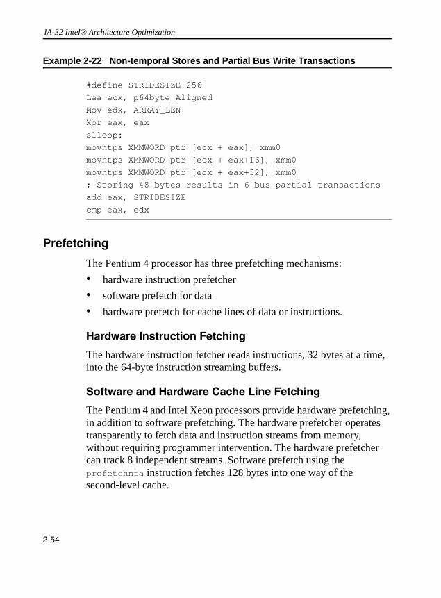
IA-32 Intel® Architecture Optimization
Example 2-22 Non-temporal Stores and Partial Bus Write Transactions
Prefetching
The Pentium 4 processor has three prefetching mechanisms: • hardware instruction prefetcher• software prefetch for data• hardware prefetch for cache lines of data or instructions.
Hardware Instruction Fetching
The hardware instruction fetcher reads instructions, 32 bytes at a time, into the 64-byte instruction streaming buffers.
Software and Hardware Cache Line Fetching
The Pentium 4 and Intel Xeon processors provide hardware prefetching, in addition to software prefetching. The hardware prefetcher operates transparently to fetch data and instruction streams from memory, without requiring programmer intervention. The hardware prefetcher can track 8 independent streams. Software prefetch using the prefetchnta instruction fetches 128 bytes into one way of the second-level cache.
#define STRIDESIZE 256Lea ecx, p64byte_AlignedMov edx, ARRAY_LENXor eax, eaxslloop:movntps XMMWORD ptr [ecx + eax], xmm0movntps XMMWORD ptr [ecx + eax+16], xmm0movntps XMMWORD ptr [ecx + eax+32], xmm0; Storing 48 bytes results in 6 bus partial transactionsadd eax, STRIDESIZEcmp eax, edx
2-54

General Optimization Guidelines 2
The Pentium M processor also provides a hardware prefetcher for data. It can track 12 separate streams in the forward direction and 4 streams in the backward direction. This processor’s prefetchnta instruction also fetches 64-bytes into the first-level data cache without polluting the second-level cache.Although hardware prefetcher will operate transparently requiring no intervention from the programmer, hardware prefetcher will operate most efficiently if programmers specifically tailor data access patterns to suit the characteristics of the hardware prefetcher because hardware prefetcher favor small-stride cache miss patterns. Optimizing data access patterns to suit the hardware prefetcher is highly recommended, and should be a higher-priority consideration than using software prefetch instructions.
The hardware prefetcher is best for small-stride data access patterns in either direction with cache-miss stride not far from 64 bytes. This is true for data accesses to addresses that are either known or unknown at the time of issuing the load operations. Software prefetch can complement the hardware prefetcher if used carefully.
There is a trade-off to make between hardware and software prefetching. This pertains to application characteristics such as regularity and stride of accesses. Bus bandwidth, issue bandwidth (the latency of loads on the critical path) and whether access patterns are suitable for non-temporal prefetch will also have an impact.
For a detailed description of how to use prefetching, see Chapter 6, “Optimizing Cache Usage”. User/Source Coding Rule 9. (M impact, H generality) Enable the prefetch generation in your compiler. Note: As a compiler’s prefetch implementation improves, it is expected that its prefetch insertion will outperform manual insertion except for that done by code tuning experts, but this is not always the case. If the compiler does not support software prefetching, intrinsics or inline assembly may be used to manually insert prefetch instructions.
Chapter 6 contains an example of using software prefetch to implement memory copy algorithm.
2-55
IA-32 Intel® Architecture Optimization
Tuning Suggestion 2. If a load is found to miss frequently, either insert a prefetch before it, or, if issue bandwidth is a concern, move the load up to execute earlier.
Cacheability Instructions
SSE2 provides additional cacheability instructions that extend further from the cacheability instructions provided in SSE. The new cacheability instructions include: • new streaming store instructions• new cache line flush instruction• new memory fencing instructions
For a detailed description of using cacheability instructions, see Chapter 6.
Code Alignment
Because the trace cache (TC) removes the decoding stage from the pipeline for frequently executed code, optimizing code alignment for decoding is not as important for Pentium 4 and Intel Xeon processors.
For the Pentium M processor, code alignment and the alignment of branch target will affect the throughput of the decoder.
Careful arrangement of code can enhance cache and memory locality. Likely sequences of basic blocks should be laid out contiguously in memory. This may involve pulling unlikely code, such as code to handle error conditions, out of that sequence. See “Prefetching” section on how to optimize for the instruction prefetcher. Assembly/Compiler Coding Rule 29. (M impact, H generality) All branch targets should be 16-byte aligned. Assembly/Compiler Coding Rule 30. (M impact, H generality) If the body of a conditional is not likely to be executed, it should be placed in another part of the program. If it is highly unlikely to be executed and code locality is an issue, the body of the conditional should be placed on a different code page.
2-56
General Optimization Guidelines 2
Improving the Performance of Floating-point Applications
When programming floating-point applications, it is best to start with a high-level programming language such as C, C++ or Fortran. Many compilers perform floating-point scheduling and optimization when it is possible. However in order to produce optimal code, the compiler may need some assistance.
Guidelines for Optimizing Floating-point Code
User/Source Coding Rule 10. (M impact, M generality) Enable the compiler’s use of SSE, SSE2 or SSE3 instructions with appropriate switches.Follow this procedure to investigate the performance of your floating-point application:• Understand how the compiler handles floating-point code. • Look at the assembly dump and see what transforms are already
performed on the program. • Study the loop nests in the application that dominate the execution
time.• Determine why the compiler is not creating the fastest code.• See if there is a dependence that can be resolved.• Determine the problem area: bus bandwidth, cache locality, trace
cache bandwidth or instruction latency. Focus on optimizing the problem area. For example, adding prefetch instructions will not help if the bus is already saturated. If trace cache bandwidth is the problem, added prefetch µops may degrade performance.
For floating-point coding, follow all the general coding recommendations discussed in this chapter, including:• blocking the cache• using prefetch• enabling vectorization• unrolling loops
2-57

IA-32 Intel® Architecture Optimization
User/Source Coding Rule 11. (H impact, ML generality) Make sure your application stays in range to avoid denormal values, underflows.
Out-of-range numbers cause very high overhead.User/Source Coding Rule 12. (M impact, ML generality) Do not use double precision unless necessary. Set the precision control (PC) field in the x87 FPU control word to “Single Precision”. This allows single precision (32-bit) computation to complete faster on some operations (for example, divides due to early out). However, be careful of introducing more than a total of two values for the floating point control word, or there will be a large performance penalty. See “Floating-point Modes”. User/Source Coding Rule 13. (H impact, ML generality) Use fast float-to-int routines, FISTTP, or SSE2 instructions. If coding these routines, use the fisttp instruction if SSE3 is available or cvttss2si, cvttsd2si instructions if coding with Streaming SIMD Extensions 2.
Many libraries do more work than is necessary. The FISTTP instruction in SSE3 can convert floating-point values to 16-bit, 32-bit or 64-bit integers using truncation without accessing the floating-point control word (FCW). The instructions cvttss2si/cvttsd2si save many µops and some store-forwarding delays over some compiler implementations. This avoids changing the rounding mode.User/Source Coding Rule 14. (M impact, ML generality) Break dependence chains where possible.
Removing data dependence enables the out of order engine to extract more ILP from the code. When summing up the elements of an array, use partial sums instead of a single accumulator. For example, to calculate z = a + b + c + d, instead of:
x = a + b;y = x + c;z = y + d;
use:x = a + b;
y = c + d;
z = x + y;
2-58

General Optimization Guidelines 2
User/Source Coding Rule 15. (M impact, ML generality) Usually, math libraries take advantage of the transcendental instructions (for example, fsin) when evaluating elementary functions. If there is no critical need to evaluate the transcendental functions using the extended precision of 80 bits, applications should consider alternate, software-based approach, such as look-up-table-based algorithm using interpolation techniques. It is possible to improve transcendental performance with these techniques by choosing the desired numeric precision, the size of the look-up tableland taking advantage of the parallelism of the Streaming SIMD Extensions and the Streaming SIMD Extensions 2 instructions.Floating-point Modes and Exceptions
When working with floating-point numbers, high-speed microprocessors frequently must deal with situations that need special handling in hardware or code. The Pentium 4 processor is optimized to handle the most common cases of such situations efficiently.
Floating-point Exceptions
The most frequent situation that can lead to performance degradation involve masked floating-point exception conditions such as:• arithmetic overflow• arithmetic underflow • denormalized operand
Refer to Chapter 4 of the IA-32 Intel® Architecture Software Developer's Manual, Volume 1 for the definition of overflow, underflow and denormal exceptions.
Denormalized floating-point numbers impact performance in two ways:• directly: when they are used as operands• indirectly: when they are produced as a result of an underflow
situation
2-59

IA-32 Intel® Architecture Optimization
If a floating-point application never underflows, the denormals can only come from floating-point constants. User/Source Coding Rule 16. (H impact, ML generality) Denormalized floating-point constants should be avoided as much as possible.
Denormal and arithmetic underflow exceptions can occur during the execution of either x87 instructions or SSE/SSE2 instructions. The Pentium 4 processor can handle these exceptions more efficiently when executing SSE/SSE2 instructions and when speed is more important than complying to IEEE standard. The following two paragraphs give recommendations on how to optimize your code to reduce performance degradations related to floating-point exceptions.
Dealing with floating-point exceptions in x87 FPU code
Every special situation listed in the “Floating-point Exceptions” section is costly in terms of performance. For that reason, x87 FPU code should be written to avoid these situations.
There are basically three ways to reduce the impact of overflow/underflow situations with x87 FPU code:• Choose floating-point data types that are large enough to
accommodate results without generating arithmetic overflow and underflow exceptions.
• Scale the range of operands/results to reduce as much as possible the number of arithmetic overflow/underflow situations.
• Keep intermediate results on the x87 FPU register stack until the final results have been computed and stored to memory. Overflow or underflow is less likely to happen when intermediate results are kept in the x87 FPU stack (this is because data on the stack is stored in double extended-precision format and overflow/underflow conditions are detected accordingly).
Denormalized floating-point constants (which are read only, and hence never change) should be avoided and replaced, if possible, with zeros of the same sign.
2-60

General Optimization Guidelines 2
Dealing with Floating-point Exceptions in SSE and SSE2 codeMost special situations that involve masked floating-point exceptions are handled efficiently on the Pentium 4 processor. When a masked overflow exception occurs while executing SSE or SSE2 code, the Pentium 4 processor handles it without performance penalty.
Underflow exceptions and denormalized source operands are usually treated according to the IEEE 754 specification. If a programmer is willing to trade pure IEEE 754 compliance for speed, two non-IEEE 754 compliant modes are provided to speed situations where underflows and input are frequent: FTZ mode and DAZ mode.
When the FTZ mode is enabled, an underflow result is automatically converted to a zero with the correct sign. Although this behavior is not IEEE 754 compliant, it is provided for use in applications where performance is more important than IEEE 754 compliance. Since denormal results are not produced when the FTZ mode is enabled, the only denormal floating-point numbers that can be encountered in FTZ mode are the ones specified as constants (read only).
The DAZ mode is provided to handle denormal source operands efficiently when running an SSE application. When the DAZ mode is enabled, input denormals are treated as zeros with the same sign. Enabling the DAZ mode is the way to deal with denormal floating-point constants when performance is the objective.
If departing from IEEE 754 specification is acceptable and if performance is critical, run an SSE/SSE2 application with FTZ and DAZ modes enabled.
NOTE. The DAZ mode is available with both the SSE and SSE2 extensions, although the speed improvement expected from this mode is fully realized only in SSE code.
2-61
IA-32 Intel® Architecture Optimization
Floating-point Modes
On the Pentium III processor, the FLDCW instruction is an expensive operation. On the Pentium 4 processor, FLDCW is improved for situations where an application alternates between two constant values of the x87 FPU control word (FCW), such as when performing conversions to integers.
Specifically, the optimization for FLDCW allows programmers to alternate between two constant values efficiently. For the FLDCW optimization to be effective, the two constant FCW values are only allowed to differ on the following 5 bits in the FCW:
FCW[8-9] precision controlFCW[10-11] rounding controlFCW[12] infinity control
If programmers need to modify other bits (for example: mask bits) in the FCW, the FLDCW instruction is still an expensive operation.
In situations where an application cycles between three (or more) constant values, FLDCW optimization does not apply and the performance degradation occurs for each FLDCW instruction.
One solution to this problem is to choose two constant FCW values, take advantage of the optimization of the FLDCW instruction to alternate between only these two constant FCW values, and devise some means to accomplish the task that requires the 3rd FCW value without actually changing the FCW to a third constant value. An alternative solution is to structure the code so that, for periods of time, the application alternates between only two constant FCW values. When the application later alternates between a pair of different FCW values, the performance degradation occurs only during the transition.
It is expected that SIMD applications are unlikely to alternate FTZ and DAZ mode values. Consequently, the SIMD control word does not have the short latencies that the floating-point control register does. A read of the MXCSR register has a fairly long latency, and a write to the register is a serializing instruction.
2-62

General Optimization Guidelines 2
There is no separate control word for single and double precision; both use the same modes. Notably, this applies to both FTZ and DAZ modes.Assembly/Compiler Coding Rule 31. (H impact, M generality) Minimize changes to bits 8-12 of the floating point control word. Changes for more than two values (each value being a combination of the following bits: precision, rounding and infinity control, and the rest of bits in FCW) leads to delays that are on the order of the pipeline depth.Rounding Mode
Many libraries provide the float-to-integer library routines that convert floating-point values to integer. Many of these libraries conform to ANSI C coding standards which state that the rounding mode should be truncation. With the Pentium 4 processor, one can use the cvttsd2si and cvttss2si instructions to convert operands with truncation and without ever needing to change rounding modes. The cost savings of using these instructions over the methods below is enough to justify using Streaming SIMD Extensions and Streaming SIMD Extensions 2 wherever possible when truncation is involved.
For x87 floating point, the fist instruction uses the rounding mode represented in the floating-point control word (FCW). The rounding mode is generally round to nearest, therefore many compiler writers implement a change in the rounding mode in the processor in order to conform to the C and FORTRAN standards. This implementation requires changing the control word on the processor using the fldcw instruction. For a change in the rounding, precision, and infinity bits; use the fstcw instruction to store the floating-point control word. Then use the fldcw instruction to change the rounding mode to truncation.
In a typical code sequence that changes the rounding mode in the FCW, a fstcw instruction is usually followed by a load operation. The load operation from memory should be a 16-bit operand to prevent store- forwarding problem. If the load operation on the previously-stored FCW word involves either an 8-bit or a 32-bit operand, this will cause a store-forwarding problem due to mismatch of the size of the data between the store operation and the load operation.
2-63

IA-32 Intel® Architecture Optimization
Make sure that the write and read to the FCW are both 16-bit operations, to avoid store-forwarding problems.
If there is more than one change to rounding, precision and infinity bits and the rounding mode is not important to the result; use the algorithm in Example 2-23 to avoid synchronization issues, the overhead of the fldcw instruction and having to change the rounding mode. The provided example suffers from a store-forwarding problem which will lead to a performance penalty. However, its performance is still better than changing the rounding, precision and infinity bits among more than two values.
2-64
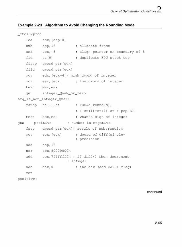
General Optimization Guidelines 2
Example 2-23 Algorithm to Avoid Changing the Rounding Mode_fto132proc
lea ecx,[esp-8]
sub esp,16 ; allocate frame
and ecx,-8 ; align pointer on boundary of 8
fld st(0) ; duplicate FPU stack top
fistp qword ptr[ecx]
fild qword ptr[ecx]
mov edx,[ecx+4]; high dword of integer
mov eax,[ecx] ; low dword of integer
test eax,eax
je integer_QnaN_or_zero
arg_is_not_integer_QnaN:
fsubp st(1),st ; TOS=d-round(d),
; { st(1)=st(1)-st & pop ST}
test edx,edx ; what’s sign of integer
jns positive ; number is negative
fstp dword ptr[ecx]; result of subtraction
mov ecx,[ecx] ; dword of diff(single-; precision)
add esp,16
xor ecx,80000000h
add ecx,7fffffffh ; if diff<0 then decrement; integer
adc eax,0 ; inc eax (add CARRY flag)
ret
positive:
continued
2-65

IA-32 Intel® Architecture Optimization
Assembly/Compiler Coding Rule 32. (H impact, L generality) Minimize the number of changes to the rounding mode. Do not use changes in the rounding mode to implement the floor and ceiling functions if this involves a total of more than two values of the set of rounding, precision and infinity bits.
Precision
If single precision is adequate, use it instead of double precision. This is true because:• Single precision operations allow the use of longer SIMD vectors,
since more single precision data elements can fit in a register.• If the precision control (PC) field in the x87 FPU control word is set
to “Single Precision,” the floating-point divider can complete a single-precision computation much faster than either a double-precision computation or an extended double-precision computation. If the PC field is set to “Double Precision,” this will enable those x87 FPU operations on double-precision data to complete faster than extended double-precision computation. These characteristics affect computations including floating-point divide and square root.
positive:
fstp dword ptr[ecx] ; 17-18 result of subtraction
mov ecx,[ecx] ; dword of diff(single precision)
add esp,16
add ecx,7fffffffh ; if diff<0 then decrement integer
sbb eax,0 ; dec eax (subtract CARRY flag)
ret
integer_QnaN_or_zero:
test edx,7fffffffh
jnz arg_is_not_integer_QnaN
add esp,16
ret
Example 2-23 Algorithm to Avoid Changing the Rounding Mode (continued)
2-66

General Optimization Guidelines 2
Assembly/Compiler Coding Rule 33. (H impact, L generality) Minimize the number of changes to the precision mode.Improving Parallelism and the Use of FXCH
The x87 instruction set relies on the floating point stack for one of its operands. If the dependence graph is a tree, which means each intermediate result is used only once and code is scheduled carefully, it is often possible to use only operands that are on the top of the stack or in memory, and to avoid using operands that are buried under the top of the stack. When operands need to be pulled from the middle of the stack, an fxch instruction can be used to swap the operand on the top of the stack with another entry in the stack.
The fxch instruction can also be used to enhance parallelism. Dependent chains can be overlapped to expose more independent instructions to the hardware scheduler. An fxch instruction may be required to effectively increase the register name space so that more operands can be simultaneously live.
Note, however, that fxch inhibits issue bandwidth in the trace cache. It does this not only because it consumes a slot, but also because of issue slot restrictions imposed on fxch. If the application is not bound by issue or retirement bandwidth, fxch will have no impact.
The Pentium 4 processor’s effective instruction window size is large enough to permit instructions that are as far away as the next iteration to be overlapped. This often obviates the need to use fxch to enhance parallelism.
The fxch instruction should be used only when it’s needed to express an algorithm or to enhance parallelism. If the size of register name space is a problem, the use of XMM registers is recommended (see the section).Assembly/Compiler Coding Rule 34. (M impact, M generality) Use fxch only where necessary to increase the effective name space.
2-67

IA-32 Intel® Architecture Optimization
This in turn allows instructions to be reordered to make instructions available to be executed in parallel. Out-of-order execution precludes the need for using fxch to move instructions for very short distances.
x87 vs. Scalar SIMD Floating-point Trade-offs
There are a number of differences between x87 floating-point code and scalar floating-point code (using SSE and SSE2). The following differences drive decisions about which registers and instructions to use:• When an input operand for a SIMD floating-point instruction
contains values that are less than the representable range of the data type, a denormal exception occurs. This causes significant performance penalty. SIMD floating-point operation has a flush-to-zero mode. In flush-to-zero mode, the results will not underflow. Therefore subsequent computation will not face the performance penalty of handling denormal input operands. For example, in the case of 3D applications with low lighting levels, using flush-to-zero mode can improve performance by as much as 50% for applications with large numbers underflows.
• Scalar floating point SIMD instructions have lower latencies. This generally does not matter much as long as resource utilization is low.
• Only x87 supports transcendental instructions.• x87 supports 80-bit precision, double extended floating point.
Streaming SIMD Extensions support a maximum of 32-bit precision, and Streaming SIMD Extensions 2 supports a maximum of 64-bit precision.
• On the Pentium 4 processor, floating point adds are pipelined for x87 but not for scalar floating-point code. Floating point multiplies are not pipelined for either case. For applications with a large number of floating-point adds relative to the number of multiplies, x87 may be a better choice.
2-68

General Optimization Guidelines 2
• Scalar floating-point registers may be accessed directly, avoidingfxch and top-of-stack restrictions. On the Pentium 4 processor, the floating-point register stack may be used simultaneously with XMM registers. The same hardware is used for both kinds of instructions, but the added name space may be beneficial.
• The cost of converting from floating point to integer with truncation is significantly lower with Streaming SIMD Extensions 2 and Streaming SIMD Extensions in the Pentium 4 processor than with either changes to the rounding mode or the sequence prescribed in the Example 2-23 above.
Assembly/Compiler Coding Rule 35. (M impact, M generality) Use scalar Streaming SIMD Extensions 2, Streaming SIMD Extensions unless you need an x87 feature. Most scalar SSE2 arithmetic operations have shorter latency then their X87 counterpart and they eliminate the overhead associated with the management of the X87 register stack.
Memory Operands
Double-precision floating-point operands that are eight-byte aligned have better performance than operands that are not eight-byte aligned, since they are less likely to incur penalties for cache and MOB splits. Floating-point operation on a memory operands require that the operand be loaded from memory. This incurs an additional µop, which can have a minor negative impact on front end bandwidth. Additionally, memory operands may cause a data cache miss, causing a penalty.
Floating-Point Stalls
Floating-point instructions have a latency of at least two cycles. But, because of the out-of-order nature of Pentium II and the subsequent processors, stalls will not necessarily occur on an instruction or µop basis. However, if an instruction has a very long latency such as an fdiv, then scheduling can improve the throughput of the overall application.
2-69
IA-32 Intel® Architecture Optimization
x87 Floating-point Operations with Integer Operands
For Pentium 4 processor, splitting floating-point operations (fiadd, fisub, fimul, and fidiv) that take 16-bit integer operands into two instructions (fild and a floating-point operation) is more efficient. However, for floating-point operations with 32-bit integer operands, using fiadd, fisub, fimul, and fidiv is equally efficient compared with using separate instructions.Assembly/Compiler Coding Rule 36. (M impact, L generality) Try to use 32-bit operands rather than 16-bit operands for fild. However, do not do so at the expense of introducing a store forwarding problem by writing the two halves of the 32-bit memory operand separately.
x87 Floating-point Comparison Instructions
On Pentium II and the subsequent processors, the fcomi and fcmov instructions should be used when performing floating-point comparisons. Using (fcom, fcomp, fcompp) instructions typically requires additional instruction like fstsw. The latter alternative causes more µops to be decoded, and should be avoided.
Transcendental Functions
If an application needs to emulate math functions in software due to performance or other reasons (see the “Guidelines for Optimizing Floating-point Code” section), it may be worthwhile to inline math library calls because the call and the prologue/epilogue involved with such calls can significantly affect the latency of operations.
Note that transcendental functions are supported only in x87 floating point, not in Streaming SIMD Extensions or Streaming SIMD Extensions 2.
2-70
General Optimization Guidelines 2
Instruction SelectionThis section explains how to generate optimal assembly code. The listed optimizations have been shown to contribute to the overall performance at the application level on the order of 5%. Performance gain for individual applications may vary.
The recommendations are prioritized as follows:• Choose instructions with shorter latencies and fewer µops.• Use optimized sequences for clearing and comparing registers.• Enhance register availability.• Avoid prefixes, especially more than one prefix.Assembly/Compiler Coding Rule 37. (M impact, H generality) Choose instructions with shorter latencies and fewer micro-ops. Favor single-micro-operation instructions.
A compiler may be already doing a good job on instruction selection as it is. In that case, user intervention usually is not necessary.Assembly/Compiler Coding Rule 38. (M impact, L generality) Avoid prefixes, especially multiple non-0F-prefixed opcodes.Assembly/Compiler Coding Rule 39. (M impact, L generality) Do not use many segment registers.
On the Pentium M processor, there is only one level of renaming of segment registers.
Complex Instructions
Assembly/Compiler Coding Rule 40. (ML impact, M generality) Avoid using complex instructions (for example, enter, leave, or loop) that have more than four µops and require multiple cycles to decode. Use sequences of simple instructions instead.
Complex instructions may save architectural registers, but incur a penalty of 4 µops to set up parameters for the microcode ROM.
2-71

IA-32 Intel® Architecture Optimization
Use of the lea Instruction
In many cases, the lea instruction or a sequence of lea, add, sub and shift instructions can replace constant multiply instructions. The lea instruction can also be used as a multiple operand addition instruction, for example: lea ecx, [eax + ebx + 4 + a]
Using lea in this way may avoid register usage by not tying up registers for operands of arithmetic instructions. This use may also save code space.
If the lea instruction uses a shift by a constant amount then the latency of the sequence of µops is shorter if adds are used instead of a shift, and the lea instruction may be replaced with an appropriate sequence of µops. This, however, this increases the total number of µops, leading to a trade-off.Assembly/Compiler Coding Rule 41. (ML impact, M generality) If a lea instruction using the scaled index is on the critical path, a sequence with adds may be better. If code density and bandwidth out of the trace cache are the critical factor, then use the lea instruction.
Use of the inc and dec Instructions
The inc and dec instructions modify only a subset of the bits in the flag register. This creates a dependence on all previous writes of the flag register. This is especially problematic when these instructions are on the critical path because they are used to change an address for a load on which many other instructions depend. Assembly/Compiler Coding Rule 42. (M impact, H generality) inc and dec instructions should be replaced with an add or sub instruction, because add and sub overwrite all flags, whereas inc and dec do not, therefore creating false dependencies on earlier instructions that set the flags.
2-72
General Optimization Guidelines 2
Use of the shift and rotate InstructionsThe shift and rotate instructions have a longer latency on Pentium 4 processor with CPUID signature corresponding to family 15 and model encoding of 0, 1 or 2. The latency of a sequence of adds will be shorter for left shifts of three or less. Fixed and variable shifts have the same latency.
The rotate by immediate and rotate by register instructions are more expensive than a shift. The rotate by 1 instruction has the same latency as a shift.Assembly/Compiler Coding Rule 43. (ML impact, L generality) Avoid rotate by register or rotate by immediate instructions. If possible, replace with a rotate by 1 instruction.
Integer Divide
Typically, an integer divide is preceded by a cwd or cdq instruction. Depending on the operand size, divide instructions use DX:AX or EDX:EAX for the dividend. The cwd or cdq instructions sign-extend AX or EAX into DX or EDX, respectively. These instructions are denser encoding than a shift and move would be, but they generate the same number of µops. If AX or EAX are known to be positive, replace these instructions with
xor dx, dx
orxor edx, edx
Operand Sizes
The Pentium 4 processor (and Pentium M processor with CPUID signature family 6, model 13) does not incur a penalty for partial register accesses as does the Pentium M processor model 9. This is
2-73

IA-32 Intel® Architecture Optimization
because every operation on a partial register updates the whole register. However, this does mean that there may be false dependencies between any references to partial registers.
Example 2-24 demonstrates a series of false and real dependencies caused by referencing partial registers.
If instructions 4 and 6 (see Example 2-24) are changed to use a movzx instruction instead of a mov, then the dependences of instructions 4 on 2 (and transitively 1 before it), and instructions 6 on 5 are broken. This creates two independent chains of computation instead of one serial one. In a tight loop with limited parallelism, the resulting optimization can yield several percent performance improvement.
Example 2-24 Dependencies Caused by Referencing Partial Registers
1: add ah, bh
2: add al, 3 ; instruction 2 has a false dependency on 1
3: mov bl, al ; depends on 2, but the dependence is real
4: mov ah, ch ; instruction 4 has a false dependency on 2
5: sar eax, 16 ; this wipes out the al/ah/ax part, so the
; result really doesn't depend on them programatically,
; but the processor must deal with the real dependency on al/ah/ax
6: mov al, bl ; instruction 6 has a real dependency on 5
7: add ah, 13 ; instruction 7 has a false dependency on 6
8: imul dl ; instruction 8 has a false dependency on 7
; because al is implicitly used
9: mov al, 17 ; instruction 9 has a false dependency on 7
; and a real dependency on 8
10: imul cx : implicitly uses ax and writes to dx, hence
; a real dependency
2-74

General Optimization Guidelines 2
Assembly/Compiler Coding Rule 44. (ML impact, L generality) Use simple instructions that are less than eight bytes in length.Assembly/Compiler Coding Rule 45. (M impact, MH generality) Avoid using prefixes to change the size of immediate and displacement.Long instructions (more than seven bytes) limit the number of decoded instructions per cycle on the Pentium M processor. Each prefix adds one byte to the length of instruction, possibly limiting the decoder’s throughput. In addition, multiple prefixes can only be decoded by the first decoder. These prefixes also incur a delay when decoded. If multiple prefixes or a prefix that changes the size of an immediate or displacement cannot be avoided, schedule them behind instructions that stall the pipe for some other reason.Assembly/Compiler Coding Rule 46. (M impact, MH generality) Break dependences on portions of registers between instructions by operating on 32-bit registers instead of partial registers. For moves, this can be accomplished with 32-bit moves or by using movzx.
On Pentium M processors, the movsx and movzx instructions both take a single µop, whether they move from a register or memory. On Pentium 4 processors, the movsx takes an additional µop. This is likely to cause less delay than the partial register update problem mentioned above, but the performance gain may vary. If the additional µop is a critical problem, movsx can sometimes be used as alternative.
Sometimes sign-extended semantics can be maintained by zero-extending operands. For example, the C code in the following statements does not need sign extension, nor does it need prefixes for operand size overrides:
static short int a, b;
if (a == b) {
. . .
}
2-75

IA-32 Intel® Architecture Optimization
Code for comparing these 16-bit operands might be:movzw eax, [a]
movzw ebx, [b]
cmp eax, ebx
These circumstances tend to be common. However, the technique will not work if the compare is for greater than, less than, greater than or equal, and so on; or if the values in eax or ebx are to be used in another operation where sign extension is required.Assembly/Compiler Coding Rule 47. (M impact, M generality) Try to use zero extension or operate on 32-bit operands instead of using moves with sign extension.
The trace cache can be packed more tightly when instructions with operands that can only be represented as 32 bits are not adjacent. Assembly/Compiler Coding Rule 48. (ML impact, M generality) Avoid placing instructions that use 32-bit immediates which cannot be encoded as a sign-extended 16-bit immediate near each other. Try to schedule µops that have no immediate immediately before or after µops with 32-bit immediates.
Address Calculations
Use the addressing modes for computing addresses rather than using the general-purpose computation. Internally, memory reference instructions can have four operands: • relocatable load-time constant • immediate constant • base register • scaled index register
In the segmented model, a segment register may constitute an additional operand in the linear address calculation. In many cases, several integer instructions can be eliminated by fully using the operands of memory references.
2-76

General Optimization Guidelines 2
Clearing RegistersPentium 4 processor provides special support to xor, sub, or pxor operations when executed within the same register. This recognizes that clearing a register does not depend on the old value of the register. The xorps and xorpd instructions do not have this special support. They cannot be used to break dependence chains.Assembly/Compiler Coding Rule 49. (M impact, ML generality) Use xor, sub, or pxor to set a register to 0, or to break a false dependence chain resulting from re-use of registers. In contexts where the condition codes must be preserved, move 0 into the register instead. This requires more code space than using xor and sub, but avoids setting the condition codes.
Compares
Use test when comparing a value in a register with zero. Test essentially ands the operands together without writing to a destination register. Test is preferred over and because and produces an extra result register. Test is better than cmp ..., 0 because the instruction size is smaller.
Use test when comparing the result of a logical and with an immediate constant for equality or inequality if the register is eax for cases such as:
if (avar & 8) { }
The test instruction can also be used to detect rollover of modulo a power of 2. For example, the C code:
if ( (avar % 16) == 0 ) { }
can be implemented using:test eax, 0x0F
jnz AfterIf
2-77
IA-32 Intel® Architecture Optimization
Assembly/Compiler Coding Rule 50. (ML impact, M generality) Use the test instruction instead of and when the result of the logical and is not used. This saves uops in execution. Use a test if a register with itself instead of a cmp of the register to zero, this saves the need to encode the zero and saves encoding space. Avoid comparing a constant to a memory operand. It is preferable to load the memory operand and compare the constant to a register.
Often a produced value must be compared with zero, and then used in a branch. Because most Intel architecture instructions set the condition codes as part of their execution, the compare instruction may be eliminated. Thus the operation can be tested directly by a jcc instruction. The notable exceptions are mov and lea. In these cases, use test.Assembly/Compiler Coding Rule 51. (ML impact, M generality) Eliminate unnecessary compare with zero instructions by using the appropriate conditional jump instruction when the flags are already set by a preceding arithmetic instruction. If necessary, use a test instruction instead of a compare. Be certain that any code transformations made do not introduce problems with overflow.
Floating Point/SIMD Operands
In initial Pentium 4 processor implementations, the latency of MMX or SIMD floating point register to register moves is significant. This can have implications for register allocation.
Moves that write a portion of a register can introduce unwanted dependences. The movsd reg, reg instruction writes only the bottom 64 bits of a register, not to all 128 bits. This introduces a dependence on the preceding instruction that produces the upper 64 bits (even if those bits are not longer wanted). The dependence inhibits register renaming, and thereby reduces parallelism.
2-78

General Optimization Guidelines 2
Use movapd as an alternative; it writes all 128 bits. Even though this instruction has a longer latency, the µops for movapd use a different execution port and this port is more likely to be free. The change can impact performance. There may be exceptional cases where the latency matters more than the dependence or the execution port.Assembly/Compiler Coding Rule 52. (M impact, ML generality) Avoid introducing dependences with partial floating point register writes, e.g. from the movsd xmmreg1, xmmreg2 instruction. Use the movapd xmmreg1, xmmreg2 instruction instead.The movsd xmmreg, mem instruction writes all 128 bits and breaks a dependence.
The movupd from memory instruction performs two 64-bit loads, but requires additional µops to adjust the address and combine the loads into a single register. This same functionality can be obtained using movsd xmmreg1, mem; movsd xmmreg2, mem+8; unpcklpd xmmreg1, xmmreg2, which uses fewer µops and can be packed into the trace cache more effectively. The latter alternative has been found to provide several percent of performance improvement in some cases. Its encoding requires more instruction bytes, but this is seldom an issue for the Pentium 4 processor. The store version of movupd is complex and slow, so much so that the sequence with two movsd and a unpckhpd should always be used.Assembly/Compiler Coding Rule 53. (ML impact, L generality) Instead of using movupd xmmreg1, mem for a unaligned 128-bit load, use movsd xmmreg1, mem; movsd xmmreg2, mem+8; unpcklpd xmmreg1, xmmreg2. If the additional register is not available, then use movsd xmmreg1, mem; movhpd xmmreg1, mem+8.
Assembly/Compiler Coding Rule 54. (M impact, ML generality) Instead of using movupd mem, xmmreg1 for a store, use movsd mem, xmmreg1; unpckhpd xmmreg1, xmmreg1; movsd mem+8, xmmreg1 instead.
2-79

IA-32 Intel® Architecture Optimization
Prolog Sequences
Assembly/Compiler Coding Rule 55. (M impact, MH generality) In routines that do not need a frame pointer and that do not have called routines that modify ESP, use ESP as the base register to free up EBP. This optimization does not apply in the following cases: a routine is called that leaves ESP modified upon return, for example, alloca; routines that rely on EBP for structured or C++ style exception handling; routines that use setjmp and longjmp; routines that use EBP to align the local stack on an 8- or 16-byte boundary; and routines that rely on EBP debugging.
If you are not using the 32-bit flat model, remember that EBP cannot be used as a general purpose base register because it references the stack segment.
Code Sequences that Operate on Memory Operands
Careful management of memory operands can improve performance. Instructions of the form “OP REG, MEM” can reduce register pressure by taking advantage of scratch registers that are not available to the compiler.Assembly/Compiler Coding Rule 56. (M impact, ML generality) For arithmetic or logical operations that have their source operand in memory and the destination operand is in a register, attempt a strategy that initially loads the memory operand to a register followed by a register to register ALU operation. Next, attempt to remove redundant loads by identifying loads from the same memory location. Finally, combine the remaining loads with their corresponding ALU operations.
The recommended strategy follows:1. Initially, operate on register operands and use explicit load and
store instructions, minimizing the number of memory accesses by merging redundant loads.
2. In a subsequent pass, free up the registers that contain the operands that were in memory for other uses by replacing any detected code sequence of the form shown in Example 2-25 with OP REG2, MEM1.
2-80
General Optimization Guidelines 2
Using memory as a destination operand may further reduce register pressure at the slight risk of making trace cache packing more difficult.
On the Pentium 4 processor, the sequence of loading a value from memory into a register and adding the results in a register to memory is faster than the alternate sequence of adding a value from memory to a register and storing the results in a register to memory. The first sequence also uses one less µop than the latter.Assembly/Compiler Coding Rule 57. (ML impact, M generality) Give preference to adding a register to memory (memory is the destination) instead of adding memory to a register. Also, give preference to adding a register to memory over loading the memory, adding two registers and storing the result.Assembly/Compiler Coding Rule 58. (M impact, M generality) When an address of a store is unknown, subsequent loads cannot be scheduled to execute out of order ahead of the store, limiting the out of order execution of the processor. When an address of a store is computed by a potentially long latency operation (such as a load that might miss the data cache) attempt to reorder subsequent loads ahead of the store.
Instruction SchedulingIdeally, scheduling or pipelining should be done in a way that optimizes performance across all processor generations. This section presents scheduling rules that can improve the performance of your code on the Pentium 4 processor.
Latencies and Resource Constraints
Assembly/Compiler Coding Rule 59. (M impact, MH generality) Calculate store addresses as early as possible to avoid having stores block loads.
Example 2-25 Recombining LOAD/OP Code into REG,MEM Form
LOAD reg1, mem1... code that does not write to reg1...OP reg2, reg1... code that does not use reg1 ...
2-81

IA-32 Intel® Architecture Optimization
Spill Scheduling
The spill scheduling algorithm used by a code generator will be impacted by the Pentium 4 processor memory subsystem. A spill scheduling algorithm is an algorithm that selects what values to spill to memory when there are too many live values to fit in registers. Consider the code in Example 2-26, where it is necessary to spill either A, B, or C.
For the Pentium 4 processor, using dependence depth information in spill scheduling is even more important than in previous processors. The loop- carried dependence in A makes it especially important that A not be spilled. Not only would a store/load be placed in the dependence chain, but there would also be a data-not-ready stall of the load, costing further cycles.Assembly/Compiler Coding Rule 60. (H impact, MH generality) For small loops, placing loop invariants in memory is better than spilling loop-carried dependencies.
A possibly counter-intuitive result: in such a situation it is better to put loop invariants in memory than in registers, since loop invariants never have a load blocked by store data that is not ready.
Scheduling Rules for the Pentium 4 Processor Decoder
The Pentium 4 and Intel Xeon processors have a single decoder that can decode instructions at the maximum rate of one instruction per clock. Complex instructions must enlist the help of the microcode ROM; see Chapter 1, “IA-32 Intel® Architecture Processor Family Overview” for details.
Example 2-26 Spill Scheduling Example Code
LOOPC := ...B := ...A := A + ...
2-82

General Optimization Guidelines 2
Because micro-ops are delivered from the trace cache in the common cases, decoding rules are not required.Scheduling Rules for the Pentium M Processor Decoder
The Pentium M processor has three decoders, but the decoding rules to supply micro-ops at high bandwidth are less stringent than those of the Pentium III processor. This provides an opportunity to build a front-end tracker in the compiler and try to schedule instructions correctly. The decoder limitations are as follows:• The first decoder is capable of decoding one macroinstruction made
up of four or fewer micro-ops In each clock cycle. It can handle any number of bytes up to the maximum of 15. Multiple prefix instructions require additional cycles.
• The two additional decoders can each decode one macroinstruction per clock cycle (assuming the instruction is one micro-op up to seven bytes in length).
• Instructions composed of more than four micro-ops take multiple cycles to decode.
Assembly/Compiler Coding Rule 61. (M impact, M generality) Avoid putting explicit references to ESP in a sequence of stack operations (POP, PUSH, CALL, RET).
VectorizationThis section provides a brief summary of optimization issues related to vectorization. Chapters 3, 4 and 5 provide greater detail.
Vectorization is a program transformation which allows special hardware to perform the same operation of multiple data elements at the same time. Successive processor generations have provided vector support through the MMX technology, Streaming SIMD Extensions technology and Streaming SIMD Extensions 2. Vectorization is a special case of SIMD, a term defined in Flynn’s architecture taxonomy to denote a Single Instruction stream capable of operating on Multiple
2-83

IA-32 Intel® Architecture Optimization
Data elements in parallel. The number of elements which can be operated on in parallel range from four single-precision floating point data elements in Streaming SIMD Extensions and two double-precision floating- point data elements in Streaming SIMD Extensions 2 to sixteen byte operations in a 128-bit register in Streaming SIMD Extensions 2. Thus the vector length ranges from 2 to 16, depending on the instruction extensions used and on the data type.
The Intel C++ Compiler supports vectorization in three ways:• The compiler may be able to generate SIMD code without
intervention from the user.• The user inserts pragmas to help the compiler realize that it can
vectorize the code.• The user may write SIMD code explicitly using intrinsics and C++
classes.
To help enable the compiler to generate SIMD code • avoid global pointers • avoid global variables
These may be less of a problem if all modules are compiled simultaneously, and whole-program optimization is used.User/Source Coding Rule 17. (H impact, M generality) Use the smallest possible floating-point or SIMD data type, to enable more parallelism with the use of a (longer) SIMD vector. For example, use single precision instead of double precision where possible.User/Source Coding Rule 18. (M impact, ML generality) Arrange the nesting of loops so that the innermost nesting level is free of inter-iteration dependencies. Especially avoid the case where the store of data in an earlier iteration happens lexically after the load of that data in a future iteration, something which is called a lexically backward dependence.
The integer part of the SIMD instruction set extensions are primarily targeted for 16-bit operands. Not all of the operators are supported for 32 bits, meaning that some source code will not be able to be vectorized at all unless smaller operands are used.
2-84

General Optimization Guidelines 2
User/Source Coding Rule 19. (M impact, ML generality) Avoid the use of conditional branches inside loops and consider using SSE instructions to eliminate branches. User/Source Coding Rule 20. (M impact, ML generality) Keep induction (loop) variables expressions simple.MiscellaneousThis section explains separate guidelines that do not belong to any category described above.
NOPs
Code generators generate a no-operation (NOP) to align instructions. The NOPs are recommended for the following operations:• 1-byte: xchg EAX, EAX• 2-byte: mov reg, reg• 3-byte: lea reg, 0 (reg) (8-bit displacement)• 6-byte: lea reg, 0 (reg) (32-bit displacement)
These are all true NOPs, having no effect on the state of the machine except to advance the EIP. Because NOPs require hardware resources to decode and execute, use the least number of NOPs to achieve the desired padding.
The one byte NOP, xchg EAX,EAX, has special hardware support. Although it still consumes a µop and its accompanying resources, the dependence upon the old value of EAX is removed. Therefore, this µop can be executed at the earliest possible opportunity, reducing the number of outstanding instructions. This is the lowest cost NOP possible.
2-85

IA-32 Intel® Architecture Optimization
The other NOPs have no special hardware support. Their input and output registers are interpreted by the hardware. Therefore, a code generator should arrange to use the register containing the oldest value as input, so that the NOP will dispatch and release RS resources at the earliest possible opportunity.
Try to observe the following NOP generation priority:• Select the smallest number of NOPs and pseudo-NOPs to provide
the desired padding.• Select NOPs that are least likely to execute on slower execution unit
clusters.• Select the register arguments of NOPs to reduce dependencies.
Summary of Rules and SuggestionsTo summarize the rules and suggestions specified in this chapter, be reminded that coding recommendations are ranked in importance according to these two criteria:• Local impact (referred to earlier as “impact”) – the difference that a
recommendation makes to performance for a given instance.• Generality – how frequently such instances occur across all
application domains.
Again, understand that this ranking is intentionally very approximate, and can vary depending on coding style, application domain, and other factors. Throughout the chapter you observed references to these criteria using the high, medium and low priorities for each recommendation. In places where there was no priority assigned, the local impact or generality has been determined not to be applicable.
The sections that follow summarize the sets of rules and tuning suggestions referenced in the manual.
2-86

General Optimization Guidelines 2
User/Source Coding RulesUser/Source Coding Rule 1. (M impact, L generality) If an indirect branch has two or more common taken targets, and at least one of those targets are correlated with branch history leading up to the branch, then convert the indirect branch into a tree where one or more indirect branches are preceded by conditional branches to those targets. Apply this “peeling” procedure to the common target of an indirect branch that correlates to branch history. 2-24User/Source Coding Rule 2. (H impact, M generality) Pad data structures defined in the source code so that every data element is aligned to a natural operand size address boundary. If the operands are packed in a SIMD instruction, align to the packed element size (64- or 128-bit). 2-39User/Source Coding Rule 3. (M impact, L generality) Beware of false sharing within a cache line (64 bytes) for both Pentium 4, Intel Xeon, and Pentium M processors; and within a sector of 128 bytes on Pentium 4 and Intel Xeon processors. 2-42User/Source Coding Rule 4. (H impact, ML generality) Consider using a special memory allocation library to avoid aliasing. 2-46User/Source Coding Rule 5. (M impact, M generality) When padding variable declarations to avoid aliasing, the greatest benefit comes from avoiding aliasing on second-level cache lines, suggesting an offset of 128 bytes or more. 2-46User/Source Coding Rule 6. (H impact, H generality) Optimization techniques such as blocking, loop interchange, loop skewing and packing are best done by the compiler. Optimize data structures to either fit in one-half of the first-level cache or in the second-level cache; turn on loop optimizations in the compiler to enhance locality for nested loops. 2-52
User/Source Coding Rule 7. (M impact, ML generality) If there is a blend of reads and writes on the bus, changing the code to separate these bus transactions into read phases and write phases can help performance. Note, however, that the order of read and write operations on the bus are not the same as they appear in the program. 2-52
2-87
IA-32 Intel® Architecture Optimization
User/Source Coding Rule 8. (H impact, H generality) To achieve effective amortization of bus latency, software should.pay attention to favor data access patterns that result in higher concentrations of cache miss patterns with cache miss strides that are significantly smaller than half of the hardware prefetch trigger threshold. 2-52User/Source Coding Rule 9. (M impact, H generality) Enable the prefetch generation in your compile. Note: As the compiler’s prefetch implementation improves, it is expected that its prefetch insertion will outperform manual insertion except for code tuning experts, but this is not always the case. If the compiler does not support software prefetching, intrinsics or inline assembly may be used to manually insert prefetch instructions. 2-56
User/Source Coding Rule 10. (M impact, M generality) Enable the compiler’s use of SSE, SSE2 and/or SSE3 instructions with appropriate switches. 2-58
User/Source Coding Rule 11. (H impact, ML generality) Make sure your application stays in range to avoid denormal values, underflows. 2-58User/Source Coding Rule 12. (M impact, ML generality) Do not use double precision unless necessary. Set the precision control (PC) field in the x87 FPU control word to “Single Precision”. This allows single precision (32-bit) computation to complete faster on some operations (for example, divides due to early out). However, be careful of introducing more than a total of two values for the floating point control word, or there will be a large performance penalty. See “Floating-point Modes”. 2-58User/Source Coding Rule 13. (H impact, ML generality) Use fast float-to-int routines, FISTTP or SSE2 instructions. If coding these routines, use FISTTP is SSE3 is available, or the cvttss2si, cvttsd2si instructions if coding with Streaming SIMD Extensions 2. 2-59User/Source Coding Rule 14. (M impact, ML generality) Break dependence chains where possible. 2-59User/Source Coding Rule 15. (M impact, ML generality) Usually, math libraries take advantage of the transcendental instructions (for example, fsin) when evaluating elementary functions. If there is no critical need to evaluate the transcendental functions using the extended precision of 80 bits, applications should consider alternate, software-based approach, such as
2-88

General Optimization Guidelines 2
look-up-table-based algorithm using interpolation techniques. It is possible to improve transcendental performance with these techniques by choosing the desired numeric precision, the size of the look-up tableland taking advantage of the parallelism of the Streaming SIMD Extensions and the Streaming SIMD Extensions 2 instructions. 2-59User/Source Coding Rule 16. (H impact, ML generality) Denormalized floating-point constants should be avoided as much as possible. 2-60User/Source Coding Rule 17. (H impact, M generality) Use the smallest possible floating-point or SIMD data type, to enable more parallelism with the use of a (longer) SIMD vector. For example, use single precision instead of double precision where possible. 2-85User/Source Coding Rule 18. (M impact, ML generality) Arrange the nesting of loops so that the innermost nesting level is free of inter-iteration dependencies. Especially avoid the case where the store of data in an earlier iteration happens lexically after the load of that data in a future iteration, something which is called a lexically backward dependence. 2-85User/Source Coding Rule 19. (M impact, ML generality) Avoid the use of conditional branches inside loops and consider using SSE instructions to eliminate branches. 2-86User/Source Coding Rule 20. (M impact, ML generality) Keep loop induction variables expressions simple. 2-86Assembly/Compiler Coding Rules
Assembly/Compiler Coding Rule 1. (MH impact, H generality) Arrange code to make basic blocks contiguous to eliminate unnecessary branches. 2-15Assembly/Compiler Coding Rule 2. (M impact, ML generality) Use the setcc and cmov instructions to eliminate unpredictable conditional branches where possible. Do not do this for predictable branches. Do not use these instructions to eliminate all unpredictable conditional branches, because using these instructions will incur execution overhead due to executing both paths of a conditional branch. In addition, converting conditional branches to cmovs or setcc trades of control flow dependence for data dependence and restricts the capability of the out of
2-89

IA-32 Intel® Architecture Optimization
order engine. When tuning, note that all IA-32 based processors have very high branch prediction rates. Consistently mispredicted are rare. Use these instructions only if the increase in computation time is less than the expected cost of a mispredicted branch. 2-16Assembly/Compiler Coding Rule 3. (M impact, H generality) Arrange code to be consistent with the static branch prediction algorithm: make the fall-through code following a conditional branch be the likely target for a branch with a forward target, and make the fall-through code following a conditional branch be the unlikely target for a branch with a backward target. 2-19 Assembly/Compiler Coding Rule 4. (MH impact, MH generality) Near calls must be matched with near returns, and far calls must be matched with far returns. Pushing the return address on the stack and jumping to the routine to be called is not recommended since it creates a mismatch in calls and returns. 2-21Assembly/Compiler Coding Rule 5. (MH impact, MH generality) Selectively inline a function where doing so decreases code size, or if the function is small and the call site is frequently executed. 2-22Assembly/Compiler Coding Rule 6. (H impact, M generality) Do not inline a function if doing so increases the working set size beyond what will fit in the trace cache. 2-22Assembly/Compiler Coding Rule 7. (ML impact, ML generality) If there are more than 16 nested calls and returns in rapid succession, consider transforming the program, for example, with inline, to reduce the call depth. 2-22Assembly/Compiler Coding Rule 8. (ML impact, ML generality) Favor inlining small functions that contain branches with poor prediction rates. If a branch misprediction results in a RETURN being prematurely predicted as taken, a performance penalty may be incurred. 2-22Assembly/Compiler Coding Rule 9. (L impact, L generality) If the last statement in a function is a call to another function, consider converting the call to a jump. This will save the call/ return overhead as well as an entry in the return stack buffer. 2-22
2-90
General Optimization Guidelines 2
Assembly/Compiler Coding Rule 10. (M impact, L generality) Do not put more than four branches in 16-byte chunks. 2-22Assembly/Compiler Coding Rule 11. (M impact, L generality) Do not put more than two end loop branches in a 16-byte chunk. 2-22Assembly/Compiler Coding Rule 12. (M impact, MH generality) If the average number of total iterations is less than or equal to 100, use a forward branch to exit the loop. 2-23Assembly/Compiler Coding Rule 13. (H impact, M generality) Unroll small loops until the overhead of the branch and the induction variable accounts, generally, for less than about 10% of the execution time of the loop. 2-27Assembly/Compiler Coding Rule 14. (H impact, M generality) Avoid unrolling loops excessively, as this may thrash the trace cache or instruction cache. 2-27Assembly/Compiler Coding Rule 15. (M impact, M generality) Unroll loops that are frequently executed and that have a predictable number of iterations to reduce the number of iterations to 16 or fewer, unless this increases code size so that the working set no longer fits in the trace cache. If the loop body contains more than one conditional branch, then unroll so that the number of iterations is 16/(# conditional branches). 2-27Assembly/Compiler Coding Rule 16. (H impact, H generality) Align data on natural operand size address boundaries. If the data will be accesses with vector instruction loads and stores, align the data on 16-byte boundaries. 2-30Assembly/Compiler Coding Rule 17. (H impact, M generality) Pass parameters in registers instead of on the stack where possible. Passing arguments on the stack is a case of store followed by a reload. While this sequence is optimized in IA-32 processors by providing the value to the load directly from the memory order buffer without the need to access the data cache, floating point values incur a significant latency in forwarding. Passing floating point argument in (preferably XMM) registers should save this long latency operation. 2-332-91

IA-32 Intel® Architecture Optimization
Assembly/Compiler Coding Rule 18. (H impact, M generality) A load that forwards from a store must have the same address start point and therefore the same alignment as the store data. 2-34Assembly/Compiler Coding Rule 19. (H impact, M generality) The data of a load which is forwarded from a store must be completely contained within the store data. 2-34Assembly/Compiler Coding Rule 20. (H impact, ML generality) If it is necessary to extract a non-aligned portion of stored data, read out the smallest aligned portion that completely contains the data and shift/mask the data as necessary. 2-35Assembly/Compiler Coding Rule 21. (MH impact, ML generality) Avoid several small loads after large stores to the same area of memory by using a single large read and register copies as needed. 2-35Assembly/Compiler Coding Rule 22. (H impact, MH generality) Where it is possible to do so without incurring other penalties, prioritize the allocation of variables to registers, as in register allocation and for parameter passing to minimize the likelihood and impact of store- forwarding problems. Try not to store-forward data generated from a long latency instruction, e.g. mul, div. Avoid store-forwarding data for variables with the shortest store-load distance. Avoid store-forwarding data for variables with many and/or long dependence chains, and especially avoid including a store forward on a loop-carried dependence chain. 2-38Assembly/Compiler Coding Rule 23. (H impact, M generality) Try to arrange data structures such that they permit sequential access. 2-41Assembly/Compiler Coding Rule 24. (H impact, M generality) If 64-bit data is ever passed as a parameter or allocated on the stack, make sure that the stack is aligned to an 8-byte boundary. 2-42Assembly/Compiler Coding Rule 25. (H impact, MH generality) Lay out data or order computation to avoid having cache lines that have linear addresses that are a multiple of 64 KB apart in the same working set. Avoid having more than 4 cache lines that are some multiple of 2 KB apart in the same first-level cache working set, and avoid having more than eight cache lines that are some multiple of 4 KB apart in the same
2-92

General Optimization Guidelines 2
first-level cache working set. Avoid having more than 8 cache lines that are some multiple of 64 KB apart in the same second-level cache working set. Avoid having a store followed by a non-dependent load with addresses that differ by a multiple of 4 KB. 2-46Assembly/Compiler Coding Rule 26. (M impact, L generality) If (hopefully read-only) data must occur on the same page as code, avoid placing it immediately after an indirect jump. For example, follow an indirect jump with its mostly likely target, and place the data after an unconditional branch. 2-47Assembly/Compiler Coding Rule 27. (H impact, L generality) Always put code and data on separate pages. Avoid self-modifying code wherever possible. If code is to be modified, try to do it all at once and make sure the code that performs the modifications and the code being modified are on separate 4 KB pages or on separate aligned 1 KB subpages. 2-47Assembly/Compiler Coding Rule 28. (H impact, L generality) If an inner loop writes to more than four arrays, (four distinct cache lines), apply loop fission to break up the body of the loop such that only four arrays are being written to in each iteration of each of the resulting loops. 2-48Assembly/Compiler Coding Rule 29. (M impact, H generality) All branch targets should be 16-byte aligned. 2-57 Assembly/Compiler Coding Rule 30. (M impact, H generality) If the body of a conditional is not likely to be executed, it should be placed in another part of the program. If it is highly unlikely to be executed and code locality is an issue, the body of the conditional should be placed on a different code page. 2-57 Assembly/Compiler Coding Rule 31. (H impact, M generality) Minimize changes to bits 8-12 of the floating point control word. Changing among more than two values (each value being a combination of these bits: precision, rounding and infinity control, and the rest of bits in FCW) leads to delays that are on the order of the pipeline depth. 2-642-93
IA-32 Intel® Architecture Optimization
Assembly/Compiler Coding Rule 32. (H impact, L generality) Minimize the number of changes to the rounding mode. Do not use changes in the rounding mode to implement the floor and ceiling functions if this involves a total of more than two values of the set of rounding, precision and infinity bits. 2-67Assembly/Compiler Coding Rule 33. (H impact, L generality) Minimize the number of changes to the precision mode. 2-68Assembly/Compiler Coding Rule 34. (M impact, M generality) Use fxch only where necessary to increase the effective name space. 2-68Assembly/Compiler Coding Rule 35. (M impact, M generality) Use Streaming SIMD Extensions 2 or Streaming SIMD Extensions unless you need an x87 feature. Most SSE2 arithmetic operations have shorter latency then their X87 counterparts and they eliminate the overhead associated with the management of the X87 register stack. 2-70Assembly/Compiler Coding Rule 36. (M impact, L generality) Try to use 32-bit operands rather than 16-bit operands for fild. However, do not do so at the expense of introducing a store forwarding problem by writing the two halves of the 32-bit memory operand separately. 2-71Assembly/Compiler Coding Rule 37. (M impact, H generality) Choose instructions with shorter latencies and fewer micro-ops. Favor single micro-operation instructions. 2-72 Assembly/Compiler Coding Rule 38. (M impact, L generality) Avoid prefixes, especially multiple non-0F-prefixed opcodes. 2-72Assembly/Compiler Coding Rule 39. (M impact, L generality) Do not use many segment registers. 2-72Assembly/Compiler Coding Rule 40. (ML impact, M generality) Avoid using complex instructions (for example, enter, leave, or loop) that generally have more than four µops and require multiple cycles to decode. Use sequences of simple instructions instead. 2-72Assembly/Compiler Coding Rule 41. (ML impact, M generality) If a lea instruction using the scaled index is on the critical path, a sequence with adds may be better. If code density and bandwidth out of the trace cache are the critical factor, then use the lea instruction. 2-73
2-94

General Optimization Guidelines 2
Assembly/Compiler Coding Rule 42. (M impact, H generality) inc and dec instructions should be replaced with an add or sub instruction, because add and sub overwrite all flags, whereas inc and dec do not, therefore creating false dependencies on earlier instructions that set the flags. 2-73 Assembly/Compiler Coding Rule 43. (ML impact, L generality) Avoid rotate by register or rotate by immediate instructions. If possible, replace with a rotate by 1 instruction. 2-74Assembly/Compiler Coding Rule 44. (ML impact, L generality) Use simple instructions that are less than eight bytes in length. 2-76Assembly/Compiler Coding Rule 45. (M impact, MH generality) Avoid using prefixes to change the size of immediate and displacement. 2-76Assembly/Compiler Coding Rule 46. (M impact, MH generality) Break dependences on portions of registers between instructions by operating on 32-bit registers instead of partial registers. For moves, this can be accomplished with 32-bit moves or by using movzx. 2-76Assembly/Compiler Coding Rule 47. (M impact, M generality) Try to use zero extension or operate on 32-bit operands instead of using moves with sign extension. 2-77Assembly/Compiler Coding Rule 48. (ML impact, M generality) Avoid placing instructions that use 32-bit immediates which cannot be encoded as a sign-extended 16-bit immediate near each other. Try to schedule µops that have no immediate immediately before or after µops with 32-bit immediates. 2-77Assembly/Compiler Coding Rule 49. (M impact, ML generality) Use xor, sub, or pxor to set a register to 0, or to break a false dependence chain resulting from re-use of registers. In contexts where the condition codes must be preserved, move 0 into the register instead. This requires more code space than using xor and sub, but avoids setting the condition codes. 2-78Assembly/Compiler Coding Rule 50. (ML impact, M generality) Use the test instruction instead of and when the result of the logical and is not used. This saves uops in execution. Use a test if a register with itself2-95

IA-32 Intel® Architecture Optimization
instead of a cmp of the register to zero, this saves the need to encode the zero and saves encoding space. Avoid comparing a constant to a memory operand. It is preferable to load the memory operand and compare the constant to a register. 2-79Assembly/Compiler Coding Rule 51. (ML impact, M generality) Eliminate unnecessary compare with zero instructions by using the appropriate conditional jump instruction when the flags are already set by a preceding arithmetic instruction. If necessary, use a test instruction instead of a compare. Be certain that any code transformations made do not introduce problems with overflow. 2-79Assembly/Compiler Coding Rule 52. (M impact, ML generality) Avoid introducing dependences with partial floating point register writes, e.g. from the movsd xmmreg1, xmmreg2 instruction. Use the movapd xmmreg1, xmmreg2 instruction instead. 2-80Assembly/Compiler Coding Rule 53. (ML impact, L generality) Instead of using movupd xmmreg1, mem for a unaligned 128-bit load, use movsd xmmreg1, mem; movsd xmmreg2, mem+8; unpcklpd xmmreg1, xmmreg2. If the additional register is not available, then use movsd xmmreg1, mem; movhpd xmmreg1, mem+8. 2-80Assembly/Compiler Coding Rule 54. (M impact, ML generality) Instead of using movupd mem, xmmreg1 for a store, use movsd mem, xmmreg1; unpckhpd xmmreg1, xmmreg1; movsd mem+8, xmmreg1 instead. 2-80Assembly/Compiler Coding Rule 55. (M impact, MH generality) In routines that do not need a frame pointer and that do not have called routines that modify ESP, use ESP as the base register to free up EBP. This optimization does not apply in the following cases: a routine is called that leaves ESP modified upon return, for example, alloca; routines that rely on EBP for structured or C++ style exception handling; routines that use setjmp and longjmp; routines that use EBP to align the local stack on an 8- or 16-byte boundary; and routines that rely on EBP debugging. 2-81
2-96

General Optimization Guidelines 2
Assembly/Compiler Coding Rule 56. (M impact, ML generality) For arithmetic or logical operations that have their source operand in memory and the destination operand is in a register, attempt a strategy that initially loads the memory operand to a register followed by a register to register ALU operation. Next, attempt to remove redundant loads by identifying loads from the same memory location. Finally, combine the remaining loads with their corresponding ALU operations. 2-81Assembly/Compiler Coding Rule 57. (ML impact, M generality) Give preference to adding a register to memory (memory is the destination) instead of adding memory to a register. Also, give preference to adding a register to memory over loading the memory, adding two registers and storing the result. 2-82Assembly/Compiler Coding Rule 58. (M impact, M generality) When an address of a store is unknown, subsequent loads cannot be scheduled to execute out of order ahead of the store, limiting the out of order execution of the processor. When an address of a store is computed by a potentially long latency operation (such as a load that might miss the data cache) attempt to reorder subsequent loads ahead of the store. 2-82Assembly/Compiler Coding Rule 59. (M impact, MH generality) Calculate store addresses as early as possible to avoid having stores block loads. 2-82Assembly/Compiler Coding Rule 60. (H impact, MH generality) For small loops, placing loop invariants in memory is better than spilling loop-carried dependencies. 2-83Assembly/Compiler Coding Rule 61. (M impact, M generality) Avoid putting explicit references to ESP in a sequence of stack operations (POP, PUSH, CALL, RET). 2-842-97

IA-32 Intel® Architecture Optimization
Tuning Suggestions
Tuning Suggestion 1. Rarely, a performance problem may be noted due to executing data on a code page as instructions. The only condition where this is likely to happen is following an indirect branch that is not resident in the trace cache. If a performance problem is clearly due to this problem, try moving the data elsewhere, or inserting an illegal opcode or a pause instruction immediately following the indirect branch. The latter two alternative may degrade performance in some circumstances. 2-47Tuning Suggestion 2. If a load is found to miss frequently, insert a prefetch before it or, if issue bandwidth is a concern, move the load up to execute earlier. 2-56
2-98

3
Coding for SIMD ArchitecturesIntel Pentium 4, Intel Xeon and Pentium M processors include support for Streaming SIMD Extensions 2, Streaming SIMD Extensions technology, and MMX technology. In addition, Streaming SIMD Extensions 3 is introduced with Pentium 4 processor supporting Hyper-Threading Technology at 90 nm technology. These single-instruction, multiple-data (SIMD) technologies enable the development of advanced multimedia, signal processing, and modeling applications.
To take advantage of the performance opportunities presented by these new capabilities, take into consideration the following:• Ensure that the processor supports MMX technology, Streaming
SIMD Extensions (SSE), Streaming SIMD Extensions 2 (SSE2), and Streaming SIMD Extensions 3 (SSE3).
• Ensure that the operating system supports MMX technology and SSE (OS support for SSE2 and SSE3 is the same as OS support for SSE).
• Employ all of the optimization and scheduling strategies described in this book.
• Use stack and data alignment techniques to keep data properly aligned for efficient memory use.
• Utilize the cacheability instructions offered by SSE and SSE2, where appropriate.
3-1

IA-32 Intel® Architecture Optimization
Checking for Processor Support of SIMD Technologies
This section shows how to check whether a processor supports MMX technology, SSE, SSE2, or SSE3.
SIMD technology can be included in your application in three ways: 1. Check for the SIMD technology during installation. If the desired
SIMD technology is available, the appropriate DLLs can be installed.
2. Check for the SIMD technology during program execution and install the proper DLLs at runtime. This is effective for programs that may be executed on different machines.
3. Create a “fat” binary that includes multiple versions of routines; versions that use SIMD technology and versions that do not. Check for SIMD technology during program execution and run the appropriate versions of the routines. This is especially effective for programs that may be executed on different machines.
Checking for MMX Technology Support
To check if MMX technology is available on your system, use cpuid to and check the feature flags in the edx register. If cpuid returns bit 23 set to 1 in the feature flags, the processor supports MMX technology.
Use the code segment in Example 3-1 to test for the existence of MMX technology.
3-2

Coding for SIMD Architectures 3
For more information on cpuid see, Intel® Processor Identification with CPUID Instruction, order number 241618.
Checking for Streaming SIMD Extensions Support
Checking for support of Streaming SIMD Extensions (SSE) on your processor is like checking for MMX technology. However, you must also check whether your operating system (OS) supports SSE. This is because the OS needs to manage saving and restoring the state introduced by SSE for your application to properly function.
To check whether your system supports SSE, follow these steps:1. Check that your processor supports the cpuid instruction.2. Check the feature bits of cpuid for SSE existence.3. Check for OS support for SSE.
Example 3-2 shows how to find the SSE feature bit (bit 25) in the cpuid feature flags.
Example 3-1 Identification of MMX Technology with cpuid
…identify existence of cpuid instruction… ;
… ; identify signature is genuine intel… ;
mov eax, 1 ; request for feature flagscpuid ; 0Fh, 0A2h cpuid instructiontest edx, 00800000h ; is MMX technology bit (bit
; 23)in feature flags equal to 1jnz Found
3-3

IA-32 Intel® Architecture Optimization
To find out whether the operating system supports SSE, execute an SSE instruction and trap for an exception if one occurs. Catching the exception in a simple try/except clause (using structured exception handling in C++) and checking whether the exception code is an invalid opcode will give you the answer. See Example 3-3.
Example 3-2 Identification of SSE with cpuid
…identify existence of cpuid instruction
… ; identify signature is genuine intel
mov eax, 1 ; request for feature flags
cpuid ; 0Fh, 0A2h cpuid instruction
test EDX, 002000000h ; bit 25 in feature flags equal to 1
jnz Found
Example 3-3 Identification of SSE by the OS
bool OSSupportCheck() {_try {
__asm xorps xmm0, xmm0 ;Streaming SIMD Extension
}
_except(EXCEPTION_EXECUTE_HANDLER) {
if (_exception_code()==STATUS_ILLEGAL_INSTRUCTION)
/* SSE not supported */
return (false);
}
/* SSE are supported by OS */
return (true);
}
3-4

Coding for SIMD Architectures 3
Checking for Streaming SIMD Extensions 2 SupportChecking for support of SSE2 is like checking for SSE support. You must also check whether your operating system (OS) supports SSE. The OS requirements for SSE2 Support are the same as the requirements for SSE.
To check whether your system supports SSE2, follow these steps:1. Check that your processor has the cpuid instruction.2. Check the feature bits of cpuid for SSE2 technology existence.3. Check for OS support for SSE.
Example 3-4 shows how to find the SSE2 feature bit (bit 26) in the cpuid feature flags.
SSE2 requires the same support from the operating system as SSE. To find out whether the operating system supports SSE2, execute an SSE2 instruction and trap for an exception if one occurs. Catching the exception in a simple try/except clause (using structured exception handling in C++) and checking whether the exception code is an invalid opcode will give you the answer. See Example 3-5.
Example 3-4 Identification of SSE2 with cpuid
…identify existence of cpuid instruction
… ; identify signature is genuine intel
mov eax, 1 ; request for feature flags
cpuid ; 0Fh, 0A2h cpuid instruction
test EDX, 004000000h ; bit 26 in feature flags equal to 1
jnz Found
3-5

IA-32 Intel® Architecture Optimization
Checking for Streaming SIMD Extensions 3 Support
SSE3 includes 13 instructions, 11 of those are suited for SIMD or x87 style programming. Checking for support of these SSE3 instructions is similar to checking for SSE support. You must also check whether your operating system (OS) supports SSE. The OS requirements for SSE3 Support are the same as the requirements for SSE.
To check whether your system supports the x87 and SIMD instructions of SSE3, follow these steps:1. Check that your processor has the cpuid instruction.2. Check the ECX feature bit 0 of cpuid for SSE3 technology
existence.3. Check for OS support for SSE.
Example 3-6 shows how to find the SSE3 feature bit (bit 0 of ECX) in the cpuid feature flags.
Example 3-5 Identification of SSE2 by the OS
bool OSSupportCheck() {_try {
__asm xorpd xmm0, xmm0 ; SSE2}
_except(EXCEPTION_EXECUTE_HANDLER) {
if _exception_code()==STATUS_ILLEGAL_INSTRUCTION)
/* SSE2not supported */
return (false);
}
/* SSE2 are supported by OS */
return (true);
}
3-6

Coding for SIMD Architectures 3
Example 3-6 Identification of SSE3 with cpuidSSE3 requires the same support from the operating system as SSE. To find out whether the operating system supports SSE3 (FISTTP and 10 of the SIMD instructions in SSE3), execute an SSE3 instruction and trap for an exception if one occurs. Catching the exception in a simple try/except clause (using structured exception handling in C++) and checking whether the exception code is an invalid opcode will give you the answer. See Example 3-7.
Detecting the availability of MONITOR and MWAIT instructions can be done using a code sequence similar to Example 3-6, the availability of MONITOR and MWAIT is indicated by bit 3 of the returned value in ECX.
Software must check for support of MONITOR and MWAIT before attempting to use MONITOR and MWAIT. Checking for support of MONITOR and MWAIT can be done by executing the MONITOR execution and trap for an exception similar to the sequence shown in Example 3-7.
…identify existence of cpuid instruction
… ; identify signature is genuine intel
mov eax, 1 ; request for feature flags
cpuid ; 0Fh, 0A2h cpuid instruction
test ECX, 000000001h ; bit 0 in feature flags equal to 1
jnz Found
3-7

IA-32 Intel® Architecture Optimization
Example 3-7 Identification of SSE3 by the OS
Considerations for Code Conversion to SIMD Programming
The VTune Performance Enhancement Environment CD provides tools to aid in the evaluation and tuning. But before implementing them, you need answers to the following questions:1. Will the current code benefit by using MMX technology, Streaming
SIMD Extensions, Streaming SIMD Extensions 2, or Streaming SIMD Extensions 3?
2. Is this code integer or floating-point?3. What integer word size or floating-point precision is needed?4. What coding techniques should I use?5. What guidelines do I need to follow?6. How should I arrange and align the datatypes?
Figure 3-1 provides a flowchart for the process of converting code to MMX technology, Streaming SIMD Extensions, or Streaming SIMD Extensions 2.
bool SSE3_SIMD_SupportCheck() {_try {
__asm addsubpd xmm0, xmm0 ; SSE3}
_except(EXCEPTION_EXECUTE_HANDLER) {
if _exception_code()==STATUS_ILLEGAL_INSTRUCTION)
/* SSE3not supported */
return (false);
}
/* SSE3 SIMD and FISTTP instructions are supported */
return (true);
}
3-8

Coding for SIMD Architectures 3
Figure 3-1 Converting to Streaming SIMD Extensions ChartOM15156
Code benefitsfrom SIMD
STOP
Identify Hot Spots in Code
Integer orfloating-point?
Yes
Floating Point
W hy FP?
Can convertto Integer?
Range orPrecision
If possible, re-arrange datafor SIMD efficiency
Integer
Change to useSIMD Integer
Yes
Change to useSingle Precision
Can convert toSingle-precision?
Yes
No
No
Align data structures
Convert to code to useSIMD Technologies
Follow general codingguidelines and SIMD
coding guidelines
Use memory optimizationsand prefetch if appropriate
Schedule instructions tooptimize performance
No
Performance
3-9

IA-32 Intel® Architecture Optimization
To use any of the SIMD technologies optimally, you must evaluate the following situations in your code:• fragments that are computationally intensive• fragments that are executed often enough to have an impact on
performance• fragments that with little data-dependent control flow• fragments that require floating-point computations• fragments that can benefit from moving data 16 bytes at a time• fragments of computation that can coded using fewer instructions• fragments that require help in using the cache hierarchy efficiently
Identifying Hot Spots
To optimize performance, use the VTune Performance Analyzer to find sections of code that occupy most of the computation time. Such sections are called the hotspots. For details on the VTune analyzer, see “Application Performance Tools” in Appendix A.
The VTune analyzer provides a hotspots view of a specific module to help you identify sections in your code that take the most CPU time and that have potential performance problems. For more explanation, see section “Sampling” in Appendix A, which includes an example of a hotspots report. The hotspots view helps you identify sections in your code that take the most CPU time and that have potential performance problems.
The VTune analyzer enables you to change the view to show hotspots by memory location, functions, classes, or source files. You can double-click on a hotspot and open the source or assembly view for the hotspot and see more detailed information about the performance of each instruction in the hotspot.
The VTune analyzer offers focused analysis and performance data at all levels of your source code and can also provide advice at the assembly language level. The code coach analyzes and identifies opportunities for
3-10
Coding for SIMD Architectures 3
better performance of C/C++, Fortran and Java* programs, and suggests specific optimizations. Where appropriate, the coach displays pseudo-code to suggest the use of highly optimized intrinsics and functions in the Intel® Performance Library Suite. Because VTune analyzer is designed specifically for all of the Intel architecture (IA)-based processors, including the Pentium 4 processor, it can offer these detailed approaches to working with IA. See “Code Optimization Options” in Appendix A for more details and example of a code coach advice.Determine If Code Benefits by Conversion to SIMD Execution
Identifying code that benefits by using SIMD technologies can be time-consuming and difficult. Likely candidates for conversion are applications that are highly computation intensive, such as the following:• speech compression algorithms and filters• speech recognition algorithms• video display and capture routines• rendering routines• 3D graphics (geometry)• image and video processing algorithms• spatial (3D) audio• physical modeling (graphics, CAD)• workstation applications• encryption algorithms• complex arithmetics
Generally, good candidate code is code that contains small-sized repetitive loops that operate on sequential arrays of integers of 8, 16 or 32 bits, single-precision 32-bit floating-point data, double precision 64-bit floating-point data (integer and floating-point data items should
3-11

IA-32 Intel® Architecture Optimization
be sequential in memory). The repetitiveness of these loops incurs costly application processing time. However, these routines have potential for increased performance when you convert them to use one of the SIMD technologies.
Once you identify your opportunities for using a SIMD technology, you must evaluate what should be done to determine whether the current algorithm or a modified one will ensure the best performance.
Coding TechniquesThe SIMD features of SSE3, SSE2, SSE, and MMX technology require new methods of coding algorithms. One of them is vectorization. Vectorization is the process of transforming sequentially-executing, or scalar, code into code that can execute in parallel, taking advantage of the SIMD architecture parallelism. This section discusses the coding techniques available for an application to make use of the SIMD architecture.
To vectorize your code and thus take advantage of the SIMD architecture, do the following:• Determine if the memory accesses have dependencies that would
prevent parallel execution.• “Strip-mine” the inner loop to reduce the iteration count by the
length of the SIMD operations (for example, four for single-precision floating-point SIMD, eight for 16-bit integer SIMD on the XMM registers).
• Re-code the loop with the SIMD instructions.
Each of these actions is discussed in detail in the subsequent sections of this chapter. These sections also discuss enabling automatic vectorization via the Intel C++ Compiler.
3-12
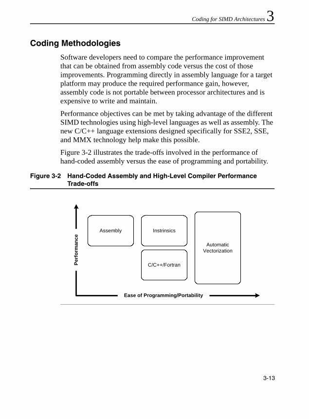
Coding for SIMD Architectures 3
Coding MethodologiesSoftware developers need to compare the performance improvement that can be obtained from assembly code versus the cost of those improvements. Programming directly in assembly language for a target platform may produce the required performance gain, however, assembly code is not portable between processor architectures and is expensive to write and maintain.
Performance objectives can be met by taking advantage of the different SIMD technologies using high-level languages as well as assembly. The new C/C++ language extensions designed specifically for SSE2, SSE, and MMX technology help make this possible.
Figure 3-2 illustrates the trade-offs involved in the performance of hand-coded assembly versus the ease of programming and portability.
Figure 3-2 Hand-Coded Assembly and High-Level Compiler Performance Trade-offs
Perf
orm
ance
Ease of Programming/Portability
InstrinsicsAssembly
C/C++/Fortran
AutomaticVectorization
3-13

IA-32 Intel® Architecture Optimization
The examples that follow illustrate the use of coding adjustments to enable the algorithm to benefit from the SSE. The same techniques may be used for single-precision floating-point, double-precision floating-point, and integer data under SSE2, SSE, and MMX technology.
As a basis for the usage model discussed in this section, consider a simple loop shown in Example 3-8.
Note that the loop runs for only four iterations. This allows a simple replacement of the code with Streaming SIMD Extensions.
For the optimal use of the Streaming SIMD Extensions that need data alignment on the 16-byte boundary, all examples in this chapter assume that the arrays passed to the routine, a, b, c, are aligned to 16-byte boundaries by a calling routine. For the methods to ensure this alignment, please refer to the application notes for the Pentium 4 processor available at http://developer.intel.com.
The sections that follow provide details on the coding methodologies: inlined assembly, intrinsics, C++ vector classes, and automatic vectorization.
Example 3-8 Simple Four-Iteration Loop
void add(float *a, float *b, float *c)
{
int i;
for (i = 0; i < 4; i++) {
c[i] = a[i] + b[i];
}
}
3-14
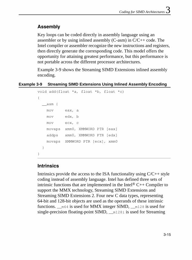
Coding for SIMD Architectures 3
AssemblyKey loops can be coded directly in assembly language using an assembler or by using inlined assembly (C-asm) in C/C++ code. The Intel compiler or assembler recognize the new instructions and registers, then directly generate the corresponding code. This model offers the opportunity for attaining greatest performance, but this performance is not portable across the different processor architectures.
Example 3-9 shows the Streaming SIMD Extensions inlined assembly encoding.
Intrinsics
Intrinsics provide the access to the ISA functionality using C/C++ style coding instead of assembly language. Intel has defined three sets of intrinsic functions that are implemented in the Intel® C++ Compiler to support the MMX technology, Streaming SIMD Extensions and Streaming SIMD Extensions 2. Four new C data types, representing 64-bit and 128-bit objects are used as the operands of these intrinsic functions. __m64 is used for MMX integer SIMD, __m128 is used for single-precision floating-point SIMD, __m128i is used for Streaming
Example 3-9 Streaming SIMD Extensions Using Inlined Assembly Encoding
void add(float *a, float *b, float *c)
{
__asm {
mov eax, a
mov edx, b
mov ecx, c
movaps xmm0, XMMWORD PTR [eax]
addps xmm0, XMMWORD PTR [edx]
movaps XMMWORD PTR [ecx], xmm0
}
}
3-15

IA-32 Intel® Architecture Optimization
SIMD Extensions 2 integer SIMD and __m128d is used for double precision floating-point SIMD. These types enable the programmer to choose the implementation of an algorithm directly, while allowing the compiler to perform register allocation and instruction scheduling where possible. These intrinsics are portable among all Intel architecture-based processors supported by a compiler. The use of intrinsics allows you to obtain performance close to the levels achievable with assembly. The cost of writing and maintaining programs with intrinsics is considerably less. For a detailed description of the intrinsics and their use, refer to the Intel C++ Compiler User’s Guide.
Example 3-10 shows the loop from Example 3-8 using intrinsics.
The intrinsics map one-to-one with actual Streaming SIMD Extensions assembly code. The xmmintrin.h header file in which the prototypes for the intrinsics are defined is part of the Intel C++ Compiler included with the VTune Performance Enhancement Environment CD.
Intrinsics are also defined for the MMX technology ISA. These are based on the __m64 data type to represent the contents of an mm register. You can specify values in bytes, short integers, 32-bit values, or as a 64-bit object.
Example 3-10 Simple Four-Iteration Loop Coded with Intrinsics
#include <xmmintrin.h>
void add(float *a, float *b, float *c)
{
__m128 t0, t1;
t0 = _mm_load_ps(a);
t1 = _mm_load_ps(b);
t0 = _mm_add_ps(t0, t1);
_mm_store_ps(c, t0);
}
3-16
Coding for SIMD Architectures 3
The intrinsic data types, however, are not a basic ANSI C data type, and therefore you must observe the following usage restrictions:• Use intrinsic data types only on the left-hand side of an assignmentas a return value or as a parameter. You cannot use it with other arithmetic expressions (for example, “+”, “>>”).
• Use intrinsic data type objects in aggregates, such as unions to access the byte elements and structures; the address of an __m64 object may be also used.
• Use intrinsic data type data only with the MMX technology intrinsics described in this guide.
For complete details of the hardware instructions, see the Intel Architecture MMX Technology Programmer’s Reference Manual. For descriptions of data types, see the Intel Architecture Software Developer's Manual, Volume 2: Instruction Set Reference Manual.
Classes
A set of C++ classes has been defined and available in Intel C++ Compiler to provide both a higher-level abstraction and more flexibility for programming with MMX technology, Streaming SIMD Extensions and Streaming SIMD Extensions 2. These classes provide an easy-to-use and flexible interface to the intrinsic functions, allowing developers to write more natural C++ code without worrying about which intrinsic or assembly language instruction to use for a given operation. Since the intrinsic functions underlie the implementation of these C++ classes, the performance of applications using this methodology can approach that of one using the intrinsics. Further details on the use of these classes can be found in the Intel C++ Class Libraries for SIMD Operations User’s Guide, order number 693500.
Example 3-11 shows the C++ code using a vector class library. The example assumes the arrays passed to the routine are already aligned to 16-byte boundaries.
3-17

IA-32 Intel® Architecture Optimization
Here, fvec.h is the class definition file and F32vec4 is the class representing an array of four floats. The “+” and “=” operators are overloaded so that the actual Streaming SIMD Extensions implementation in the previous example is abstracted out, or hidden, from the developer. Note how much more this resembles the original code, allowing for simpler and faster programming.
Again, the example is assuming the arrays, passed to the routine, are already aligned to 16-byte boundary.
Automatic Vectorization
The Intel C++ Compiler provides an optimization mechanism by which loops, such as in Example 3-8 can be automatically vectorized, or converted into Streaming SIMD Extensions code. The compiler uses similar techniques to those used by a programmer to identify whether a loop is suitable for conversion to SIMD. This involves determining whether the following might prevent vectorization:• the layout of the loop and the data structures used • dependencies amongst the data accesses in each iteration and across
iterations
Once the compiler has made such a determination, it can generate vectorized code for the loop, allowing the application to use the SIMD instructions.
Example 3-11 C++ Code Using the Vector Classes
#include <fvec.h>void add(float *a, float *b, float *c){
F32vec4 *av=(F32vec4 *) a;
F32vec4 *bv=(F32vec4 *) b;
F32vec4 *cv=(F32vec4 *) c;
*cv=*av + *bv;
}
3-18

Coding for SIMD Architectures 3
The caveat to this is that only certain types of loops can be automatically vectorized, and in most cases user interaction with the compiler is needed to fully enable this.Example 3-12 shows the code for automatic vectorization for the simple four-iteration loop (from Example 3-8).
Compile this code using the -Qax and -Qrestrict switches of the Intel C++ Compiler, version 4.0 or later.
The restrict qualifier in the argument list is necessary to let the compiler know that there are no other aliases to the memory to which the pointers point. In other words, the pointer for which it is used, provides the only means of accessing the memory in question in the scope in which the pointers live. Without the restrict qualifier, the compiler will still vectorize this loop using runtime data dependence testing, where the generated code dynamically selects between sequential or vector execution of the loop, based on overlap of the parameters (See documentation for the Intel C++ Compiler). The restrict keyword avoids the associated overhead altogether.
Refer to the Intel® C++ Compiler User’s Guide, for more details on the use of automatic vectorization.
Example 3-12 Automatic Vectorization for a Simple Loop
void add (float *restrict a, float *restrict b, float *restrict c)
{
int i;
for (i = 0; i < 4; i++) {
c[i] = a[i] + b[i];
}
}
3-19

IA-32 Intel® Architecture Optimization
Stack and Data AlignmentTo get the most performance out of code written for SIMD technologies data should be formatted in memory according to the guidelines described in this section. Assembly code with an unaligned accesses is a lot slower than an aligned access.
Alignment and Contiguity of Data Access Patterns
The 64-bit packed data types defined by MMX technology, and the 128-bit packed data types for Streaming SIMD Extensions and Streaming SIMD Extensions 2 create more potential for misaligned data accesses. The data access patterns of many algorithms are inherently misaligned when using MMX technology and Streaming SIMD Extensions. Several techniques for improving data access, such as padding, organizing data elements into arrays, etc. are described below. SSE3 provides a special-purpose instruction LDDQU that can avoid cache line splits is discussed in “Supplemental Techniques for Avoiding Cache Line Splits” in Chapter 4.
Using Padding to Align Data
However, when accessing SIMD data using SIMD operations, access to data can be improved simply by a change in the declaration. For example, consider a declaration of a structure, which represents a point in space plus an attribute.
typedef struct { short x,y,z; char a} Point;
Point pt[N];
Assume we will be performing a number of computations on x, y, z in three of the four elements of a SIMD word; see the “Data Structure Layout” section for an example. Even if the first element in array pt is aligned, the second element will start 7 bytes later and not be aligned (3 shorts at two bytes each plus a single byte = 7 bytes).
3-20

Coding for SIMD Architectures 3
By adding the padding variable pad, the structure is now 8 bytes, and if the first element is aligned to 8 bytes (64 bits), all following elements will also be aligned. The sample declaration follows:typedef struct { short x,y,z; char a; char pad; } Point;
Point pt[N];
Using Arrays to Make Data Contiguous
In the following code,for (i=0; i<N; i++) pt[i].y *= scale;
the second dimension y needs to be multiplied by a scaling value. Here the for loop accesses each y dimension in the array pt thus disallowing the access to contiguous data. This can degrade the performance of the application by increasing cache misses, by achieving poor utilization of each cache line that is fetched, and by increasing the chance for accesses which span multiple cache lines.
The following declaration allows you to vectorize the scaling operation and further improve the alignment of the data access patterns:
short ptx[N], pty[N], ptz[N];
for (i=0; i<N; i++) pty[i] *= scale;
With the SIMD technology, choice of data organization becomes more important and should be made carefully based on the operations that will be performed on the data. In some applications, traditional data arrangements may not lead to the maximum performance.
A simple example of this is an FIR filter. An FIR filter is effectively a vector dot product in the length of the number of coefficient taps.
Consider the following code:(data [ j ] *coeff [0] + data [j+1]*coeff [1]+...+data [j+num of taps-1]*coeff [num of taps-1]),
If in the code above the filter operation of data element i is the vector dot product that begins at data element j, then the filter operation of data element i+1 begins at data element j+1.
3-21

IA-32 Intel® Architecture Optimization
Assuming you have a 64-bit aligned data vector and a 64-bit aligned coefficients vector, the filter operation on the first data element will be fully aligned. For the second data element, however, access to the data vector will be misaligned. For an example of how to avoid the misalignment problem in the FIR filter, please refer to the application notes on Streaming SIMD Extensions and filters. The application notes are available at http://developer.intel.com/IDS.
Duplication and padding of data structures can be used to avoid the problem of data accesses in algorithms which are inherently misaligned. The “Data Structure Layout” section discusses further trade-offs for how data structures are organized.
Stack Alignment For 128-bit SIMD Technologies
For best performance, the Streaming SIMD Extensions and Streaming SIMD Extensions 2 require their memory operands to be aligned to 16-byte (16B) boundaries. Unaligned data can cause significant performance penalties compared to aligned data. However, the existing software conventions for IA-32 (stdcall, cdecl, fastcall) as implemented in most compilers, do not provide any mechanism for ensuring that certain local data and certain parameters are 16-byte aligned. Therefore, Intel has defined a new set of IA-32 software conventions for alignment to support the new __m128* datatypes (__m128, __m128d, and __m128i) that meet the following conditions:
CAUTION. The duplication and padding technique overcomes the misalignment problem, thus avoiding the expensive penalty for misaligned data access, at the cost of increasing the data size. When developing your code, you should consider this tradeoff and use the option which gives the best performance.
3-22

Coding for SIMD Architectures 3
• Functions that use Streaming SIMD Extensions or Streaming SIMDExtensions 2 data need to provide a 16-byte aligned stack frame.• The __m128* parameters need to be aligned to 16-byte boundaries,
possibly creating “holes” (due to padding) in the argument block.
These new conventions presented in this section as implemented by the Intel C++ Compiler can be used as a guideline for an assembly language code as well. In many cases, this section assumes the use of the __m128* data types, as defined by the Intel C++ Compiler, which represents an array of four 32-bit floats.
For more details on the stack alignment for Streaming SIMD Extensions and SSE2, see Appendix D, “Stack Alignment”.
Data Alignment for MMX Technology
Many compilers enable alignment of variables using controls. This aligns the variables’ bit lengths to the appropriate boundaries. If some of the variables are not appropriately aligned as specified, you can align them using the C algorithm shown in Example 3-13.
The algorithm in Example 3-13 aligns an array of 64-bit elements on a 64-bit boundary. The constant of 7 is derived from one less than the number of bytes in a 64-bit element, or 8-1. Aligning data in this manner avoids the significant performance penalties that can occur when an access crosses a cache line boundary.
Example 3-13 C Algorithm for 64-bit Data Alignment
/* Make newp a pointer to a 64-bit aligned array */
/* of NUM_ELEMENTS 64-bit elements. */
double *p, *newp;
p = (double*)malloc (sizeof(double)*(NUM_ELEMENTS+1));
newp = (p+7) & (~0x7);
3-23

IA-32 Intel® Architecture Optimization
Another way to improve data alignment is to copy the data into locations that are aligned on 64-bit boundaries. When the data is accessed frequently, this can provide a significant performance improvement.
Data Alignment for 128-bit data
Data must be 16-byte aligned when loading to or storing from the 128-bit XMM registers used by SSE and SSE2 to avoid severe performance penalties at best, and at worst, execution faults. Although there are move instructions (and intrinsics) to allow unaligned data to be copied into and out of the XMM registers when not using aligned data, such operations are much slower than aligned accesses. If, however, the data is not 16-byte-aligned and the programmer or the compiler does not detect this and uses the aligned instructions, a fault will occur. So, the rule is: keep the data 16-byte-aligned. Such alignment will also work for MMX technology code, even though MMX technology only requires 8-byte alignment. The following discussion and examples describe alignment techniques for Pentium 4 processor as implemented with the Intel C++ Compiler.
Compiler-Supported Alignment
The Intel C++ Compiler provides the following methods to ensure that the data is aligned.
Alignment by F32vec4 or __m128 Data Types. When compiler detects F32vec4 or __m128 data declarations or parameters, it will force alignment of the object to a 16-byte boundary for both global and local data, as well as parameters. If the declaration is within a function, the compiler will also align the function's stack frame to ensure that local data and parameters are 16-byte-aligned. For details on the stack frame layout that the compiler generates for both debug and optimized (“release”-mode) compilations, please refer to the relevant Intel application notes in the Intel Architecture Performance Training Center provided with the SDK.
3-24

Coding for SIMD Architectures 3
The __declspec(align(16)) specifications can be placed before data declarations to force 16-byte alignment. This is particularly useful for local or global data declarations that are assigned to 128-bit data types. The syntax for it is__declspec(align(integer-constant))
where the integer-constant is an integral power of two but no greater than 32. For example, the following increases the alignment to 16-bytes:
__declspec(align(16)) float buffer[400];
The variable buffer could then be used as if it contained 100 objects of type __m128 or F32vec4. In the code below, the construction of the F32vec4 object, x, will occur with aligned data.
void foo() {
F32vec4 x = *(__m128 *) buffer;
...
}
Without the declaration of __declspec(align(16)), a fault may occur.
Alignment by Using a union Structure. Preferably, when feasible, a union can be used with 128-bit data types to allow the compiler to align the data structure by default. Doing so is preferred to forcing alignment with __declspec(align(16)) because it exposes the true program intent to the compiler in that __m128 data is being used. For example:
union {
float f[400];
__m128 m[100];
} buffer;
The 16-byte alignment is used by default due to the __m128 type in the union; it is not necessary to use __declspec(align(16)) to force it.
3-25

IA-32 Intel® Architecture Optimization
In C++ (but not in C) it is also possible to force the alignment of a class/struct/union type, as in the code that follows:
struct __declspec(align(16)) my_m128{
float f[4];};
But, if the data in such a class is going to be used with the Streaming SIMD Extensions or Streaming SIMD Extensions 2, it is preferable to use a union to make this explicit. In C++, an anonymous union can be used to make this more convenient:
class my_m128 {
union {
__m128 m;
float f[4];
};
};
In this example, because the union is anonymous, the names, m and f, can be used as immediate member names of my__m128. Note that __declspec(align) has no effect when applied to a class, struct, or union member in either C or C++.
Alignment by Using __m64 or double Data. In some cases, for better performance, the compiler will align routines with __m64 or double data to 16-bytes by default. The command-line switch, -Qsfalign16, can be used to limit the compiler to only align in routines that contain 128-bit data. The default behavior is to use -Qsfalign8, which instructs to align routines with 8- or 16-byte data types to 16-bytes.
For more details, see relevant Intel application notes in the Intel Architecture Performance Training Center provided with the SDK and the Intel C++ Compiler User’s Guide.
3-26

Coding for SIMD Architectures 3
Improving Memory UtilizationMemory performance can be improved by rearranging data and algorithms for SSE 2, SSE, and MMX technology intrinsics. The methods for improving memory performance involve working with the following:• Data structure layout• Strip-mining for vectorization and memory utilization• Loop-blocking
Using the cacheability instructions, prefetch and streaming store, also greatly enhance memory utilization. For these instructions, see Chapter 6, “Optimizing Cache Usage”.
Data Structure Layout
For certain algorithms, like 3D transformations and lighting, there are two basic ways of arranging the vertex data. The traditional method is the array of structures (AoS) arrangement, with a structure for each vertex (see Example 3-14). However this method does not take full advantage of the SIMD technology capabilities.
The best processing method for code using SIMD technology is to arrange the data in an array for each coordinate (see Example 3-15). This data arrangement is called structure of arrays (SoA).
Example 3-14 AoS Data Structuretypedef struct{
float x,y,z;int a,b,c;. . .
} Vertex;Vertex Vertices[NumOfVertices];
3-27

IA-32 Intel® Architecture Optimization
There are two options for computing data in AoS format: perform operation on the data as it stands in AoS format, or re-arrange it (swizzle it) into SoA format dynamically. See Example 3-16 for code samples of each option based on a dot-product computation.
Example 3-15 SoA Data Structuretypedef struct{
float x[NumOfVertices];
float y[NumOfVertices];
float z[NumOfVertices];
int a[NumOfVertices];
int b[NumOfVertices];
int c[NumOfVertices];
. . .
} VerticesList;
VerticesList Vertices;
Example 3-16 AoS and SoA Code Samples
; The dot product of an array of vectors (Array) and a; fixed vector (Fixed) is a common operation in 3D; lighting operations,; where Array = (x0,y0,z0),(x1,y1,z1),...; and Fixed = (xF,yF,zF) ; A dot product is defined as the scalar quantity; d0 = x0*xF + y0*yF + z0*zF.; AoS code; All values marked DC are “don’t-care.”; In the AOS model, the vertices are stored in the; xyz formatmovaps xmm0, Array ; xmm0 = DC, x0, y0, z0movaps xmm1, Fixed ; xmm1 = DC, xF, yF, zFmulps xmm0, xmm1 ; xmm0 = DC, x0*xF, y0*yF, z0*zFmovhlps xmm1, xmm0 ; xmm1 = DC, DC, DC, x0*xF
continued
3-28
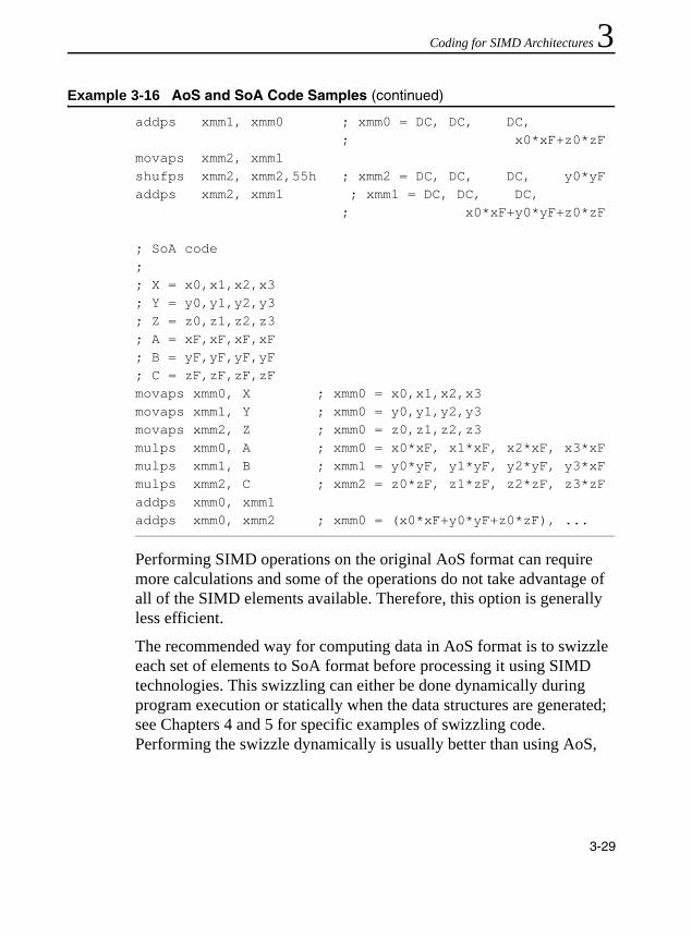
Coding for SIMD Architectures 3
Performing SIMD operations on the original AoS format can require more calculations and some of the operations do not take advantage of all of the SIMD elements available. Therefore, this option is generally less efficient.
The recommended way for computing data in AoS format is to swizzle each set of elements to SoA format before processing it using SIMD technologies. This swizzling can either be done dynamically during program execution or statically when the data structures are generated; see Chapters 4 and 5 for specific examples of swizzling code. Performing the swizzle dynamically is usually better than using AoS,
addps xmm1, xmm0 ; xmm0 = DC, DC, DC, ; x0*xF+z0*zFmovaps xmm2, xmm1shufps xmm2, xmm2,55h ; xmm2 = DC, DC, DC, y0*yFaddps xmm2, xmm1 ; xmm1 = DC, DC, DC, ; x0*xF+y0*yF+z0*zF
; SoA code;; X = x0,x1,x2,x3; Y = y0,y1,y2,y3; Z = z0,z1,z2,z3; A = xF,xF,xF,xF; B = yF,yF,yF,yF; C = zF,zF,zF,zFmovaps xmm0, X ; xmm0 = x0,x1,x2,x3movaps xmm1, Y ; xmm0 = y0,y1,y2,y3movaps xmm2, Z ; xmm0 = z0,z1,z2,z3mulps xmm0, A ; xmm0 = x0*xF, x1*xF, x2*xF, x3*xFmulps xmm1, B ; xmm1 = y0*yF, y1*yF, y2*yF, y3*xFmulps xmm2, C ; xmm2 = z0*zF, z1*zF, z2*zF, z3*zFaddps xmm0, xmm1addps xmm0, xmm2 ; xmm0 = (x0*xF+y0*yF+z0*zF), ...
Example 3-16 AoS and SoA Code Samples (continued)
3-29

IA-32 Intel® Architecture Optimization
but is somewhat inefficient as there is the overhead of extra instructions during computation. Performing the swizzle statically, when the data structures are being laid out, is best as there is no runtime overhead.
As mentioned earlier, the SoA arrangement allows more efficient use of the parallelism of the SIMD technologies because the data is ready for computation in a more optimal vertical manner: multiplying components x0,x1,x2,x3 by xF,xF,xF,xF using 4 SIMD execution slots to produce 4 unique results. In contrast, computing directly on AoS data can lead to horizontal operations that consume SIMD execution slots but produce only a single scalar result as shown by the many “don’t-care” (DC) slots in Example 3-16.
Use of the SoA format for data structures can also lead to more efficient use of caches and bandwidth. When the elements of the structure are not accessed with equal frequency, such as when element x, y, z are accessed ten times more often than the other entries, then SoA not only saves memory, but it also prevents fetching unnecessary data items a, b, and c.
Example 3-17 Hybrid SoA data structureNumOfGroups = NumOfVertices/SIMDwidthtypedef struct{
float x[SIMDwidth];float y[SIMDwidth];float z[SIMDwidth];
} VerticesCoordList;typedef struct{
int a[SIMDwidth];int b[SIMDwidth];int c[SIMDwidth];. . .
} VerticesColorList;VerticesCoordList VerticesCoord[NumOfGroups];VerticesColorList VerticesColor[NumOfGroups];
3-30

Coding for SIMD Architectures 3
Note that SoA can have the disadvantage of requiring more independent memory stream references. A computation that uses arrays x, y, and z in Example 3-15 would require three separate data streams. This can require the use of more prefetches, additional address generation calculations, as well as having a greater impact on DRAM page access efficiency. An alternative, a hybrid SoA approach blends the two alternatives (see Example 3-17). In this case, only 2 separate address streams are generated and referenced: one which contains xxxx,yyyy,zzzz,zzzz,... and the other which contains aaaa,bbbb,cccc,aaaa,dddd,.... This also prevents fetching unnecessary data, assuming the variables x, y, z are always used together; whereas the variables a, b, c would also used together, but not at the same time as x, y, z. This hybrid SoA approach ensures:• data is organized to enable more efficient vertical SIMDcomputation,• simpler/less address generation than AoS,• fewer streams, which reduces DRAM page misses,• use of fewer prefetches, due to fewer streams,• efficient cache line packing of data elements that are used
concurrently.
With the advent of the SIMD technologies, the choice of data organization becomes more important and should be carefully based on the operations to be performed on the data. This will become increasingly important in the Pentium 4 processor and future processors. In some applications, traditional data arrangements may not lead to the maximum performance. Application developers are encouraged to explore different data arrangements and data segmentation policies for efficient computation. This may mean using a combination of AoS, SoA, and Hybrid SoA in a given application.
3-31

IA-32 Intel® Architecture Optimization
Strip Mining
Strip mining, also known as loop sectioning, is a loop transformation technique for enabling SIMD-encodings of loops, as well as providing a means of improving memory performance. First introduced for vectorizers, this technique consists of the generation of code when each vector operation is done for a size less than or equal to the maximum vector length on a given vector machine. By fragmenting a large loop into smaller segments or strips, this technique transforms the loop structure twofold:• It increases the temporal and spatial locality in the data cache if the
data are reusable in different passes of an algorithm.• It reduces the number of iterations of the loop by a factor of the
length of each “vector,” or number of operations being performed per SIMD operation. In the case of Streaming SIMD Extensions, this vector or strip-length is reduced by 4 times: four floating-point data items per single Streaming SIMD Extensions single-precision floating-point SIMD operation are processed. Consider Example 3-18.
Example 3-18 Pseudo-code Before Strip Mining
typedef struct _VERTEX {float x, y, z, nx, ny, nz, u, v;
} Vertex_rec; main() {
Vertex_rec v[Num];....for (i=0; i<Num; i++) { Transform(v[i]);}
continued
3-32
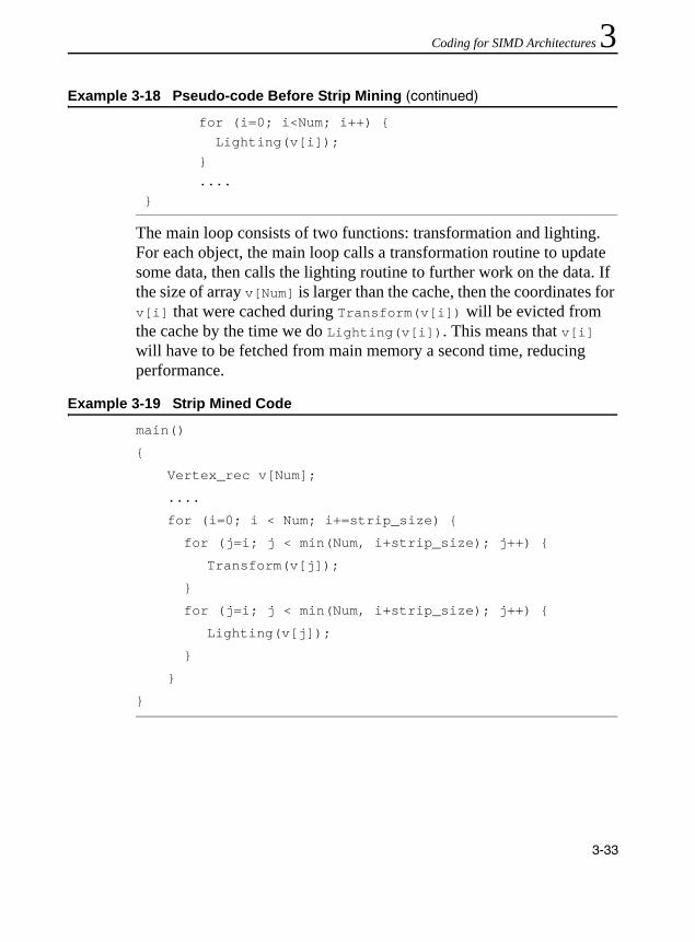
Coding for SIMD Architectures 3
The main loop consists of two functions: transformation and lighting. For each object, the main loop calls a transformation routine to update some data, then calls the lighting routine to further work on the data. If the size of array v[Num] is larger than the cache, then the coordinates for v[i] that were cached during Transform(v[i]) will be evicted from the cache by the time we do Lighting(v[i]). This means that v[i] will have to be fetched from main memory a second time, reducing performance.
for (i=0; i<Num; i++) { Lighting(v[i]);}....
}
Example 3-19 Strip Mined Code
main()
{
Vertex_rec v[Num];
....
for (i=0; i < Num; i+=strip_size) {
for (j=i; j < min(Num, i+strip_size); j++) {
Transform(v[j]);
}
for (j=i; j < min(Num, i+strip_size); j++) {
Lighting(v[j]);
}
}
}
Example 3-18 Pseudo-code Before Strip Mining (continued)
3-33

IA-32 Intel® Architecture Optimization
In Example 3-19, the computation has been strip-mined to a size strip_size. The value strip_size is chosen such that strip_size elements of array v[Num] fit into the cache hierarchy. By doing this, a given element v[i] brought into the cache by Transform(v[i]) will still be in the cache when we perform Lighting(v[i]), and thus improve performance over the non-strip-mined code.
Loop Blocking
Loop blocking is another useful technique for memory performance optimization. The main purpose of loop blocking is also to eliminate as many cache misses as possible. This technique transforms the memory domain of a given problem into smaller chunks rather than sequentially traversing through the entire memory domain. Each chunk should be small enough to fit all the data for a given computation into the cache, thereby maximizing data reuse. In fact, one can treat loop blocking as strip mining in two or more dimensions. Consider the code in Example 3-18 and access pattern in Figure 3-3. The two-dimensional array A is referenced in the j (column) direction and then referenced in the i (row) direction (column-major order); whereas array B is referenced in the opposite manner (row-major order). Assume the memory layout is in column-major order; therefore, the access strides of array A and B for the code in Example 3-20 would be 1 and MAX, respectively.
3-34
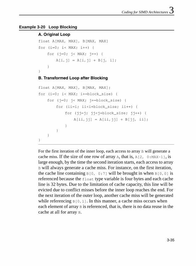
Coding for SIMD Architectures 3
For the first iteration of the inner loop, each access to array B will generate a cache miss. If the size of one row of array A, that is, A[2, 0:MAX-1], is large enough, by the time the second iteration starts, each access to array B will always generate a cache miss. For instance, on the first iteration, the cache line containing B[0, 0:7] will be brought in when B[0,0] is referenced because the float type variable is four bytes and each cache line is 32 bytes. Due to the limitation of cache capacity, this line will be evicted due to conflict misses before the inner loop reaches the end. For the next iteration of the outer loop, another cache miss will be generated while referencing B[0,1]. In this manner, a cache miss occurs when each element of array B is referenced, that is, there is no data reuse in the cache at all for array B.
Example 3-20 Loop Blocking
A. Original Loop
float A[MAX, MAX], B[MAX, MAX]
for (i=0; i< MAX; i++) {
for (j=0; j< MAX; j++) {
A[i,j] = A[i,j] + B[j, i];
}}
B. Transformed Loop after Blocking
float A[MAX, MAX], B[MAX, MAX];
for (i=0; i< MAX; i+=block_size) {
for (j=0; j< MAX; j+=block_size) {
for (ii=i; ii<i+block_size; ii++) {
for (jj=j; jj<j+block_size; jj++) {
A[ii,jj] = A[ii,jj] + B[jj, ii];
}}
}}
3-35
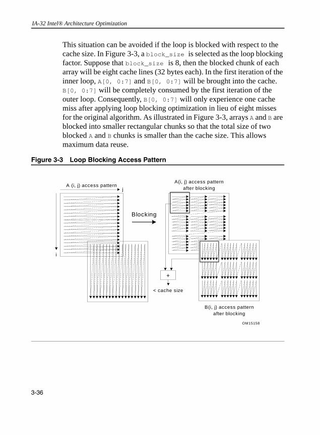
IA-32 Intel® Architecture Optimization
This situation can be avoided if the loop is blocked with respect to the cache size. In Figure 3-3, a block_size is selected as the loop blocking factor. Suppose that block_size is 8, then the blocked chunk of each array will be eight cache lines (32 bytes each). In the first iteration of the inner loop, A[0, 0:7] and B[0, 0:7] will be brought into the cache. B[0, 0:7] will be completely consumed by the first iteration of the outer loop. Consequently, B[0, 0:7] will only experience one cache miss after applying loop blocking optimization in lieu of eight misses for the original algorithm. As illustrated in Figure 3-3, arrays A and B are blocked into smaller rectangular chunks so that the total size of two blocked A and B chunks is smaller than the cache size. This allows maximum data reuse.
Figure 3-3 Loop Blocking Access Pattern
OM15158
A (i, j) access patternj
i
A(i, j) access patternafter blocking
B(i, j) access patternafter blocking
+
< cache size
Blocking
3-36
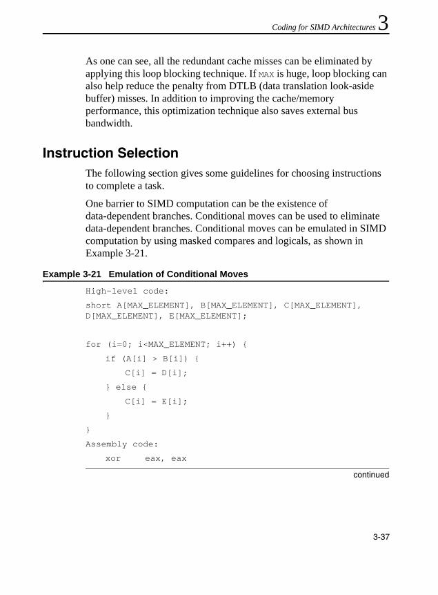
Coding for SIMD Architectures 3
As one can see, all the redundant cache misses can be eliminated by applying this loop blocking technique. If MAX is huge, loop blocking can also help reduce the penalty from DTLB (data translation look-aside buffer) misses. In addition to improving the cache/memory performance, this optimization technique also saves external bus bandwidth.Instruction SelectionThe following section gives some guidelines for choosing instructions to complete a task.
One barrier to SIMD computation can be the existence of data-dependent branches. Conditional moves can be used to eliminate data-dependent branches. Conditional moves can be emulated in SIMD computation by using masked compares and logicals, as shown in Example 3-21.
Example 3-21 Emulation of Conditional Moves
High-level code:
short A[MAX_ELEMENT], B[MAX_ELEMENT], C[MAX_ELEMENT], D[MAX_ELEMENT], E[MAX_ELEMENT];
for (i=0; i<MAX_ELEMENT; i++) {
if (A[i] > B[i]) {
C[i] = D[i];
} else {
C[i] = E[i];
}
}
Assembly code:
xor eax, eax
continued
3-37

IA-32 Intel® Architecture Optimization
Note that this can be applied to both SIMD integer and SIMD floating-point code.
If there are multiple consumers of an instance of a register, group the consumers together as closely as possible. However, the consumers should not be scheduled near the producer.
Tuning the Final ApplicationThe best way to tune your application once it is functioning correctly is to use a profiler that measures the application while it is running on a system. VTune analyzer can help you determine where to make changes in your application to improve performance. Using the VTune analyzer can help you with various phases required for optimized performance. See “Intel® VTune™ Performance Analyzer” in Appendix A for more details on how to use the VTune analyzer. After every effort to optimize, you should check the performance gains to see where you are making your major optimization gains.
top_of_loop:
movq mm0, [A + eax]
pcmpgtw mm0, [B + eax]; Create compare mask
movq mm1, [D + eax]
pand mm1, mm0; Drop elements where A<B
pandn mm0, [E + eax] ; Drop elements where A>B
por mm0, mm1; Crete single word
movq [C + eax], mm0
add eax, 8
cmp eax, MAX_ELEMENT*2
jle top_of_loop
Example 3-21 Emulation of Conditional Moves (continued)
3-38

4
Optimizing for SIMD Integer ApplicationsThe SIMD integer instructions provide performance improvements in applications that are integer-intensive and can take advantage of the SIMD architecture of Pentium 4, Intel Xeon, and Pentium M processors.
The guidelines for using these instructions in addition to the guidelines described in Chapter 2, will help develop fast and efficient code that scales well across all processors with MMX technology, processors that use Streaming SIMD Extensions (SSE) SIMD integer instructions, as well as processor with the SIMD integer instructions in SSE2 and SSE3.
For the sake of brevity, the collection of 64-bit and 128-bit SIMD integer instructions supported by MMX technology, SSE, SSE2, and SSE3 shall be referred to as SIMD integer instructions.
Unless otherwise noted, the following sequences are written for the 64-bit integer registers. Note that they can easily be adapted to use the 128-bit SIMD integer form available with SSE2 by replacing the references to mm0-mm7 with references to xmm0-xmm7, and including any pre-arrangement of data alignment on 16 byte boundary when dealing with loading or storing 16 bytes of data in some cases.
This chapter contains several simple examples that will help you to get started with coding your application. The goal is to provide simple, low-level operations that are frequently used. The examples use a minimum number of instructions necessary to achieve best performance on the current generation of IA-32 processors.
Each example includes a short description, sample code, and notes if necessary. These examples do not address scheduling as it is assumed the examples will be incorporated in longer code sequences.
4-1
IA-32 Intel® Architecture Optimization
For planning considerations of using the new SIMD integer instructions, refer to “Checking for Streaming SIMD Extensions 2 Support” in Chapter 3.
General Rules on SIMD Integer CodeThe overall rules and suggestions are as follows:• Do not intermix 64-bit SIMD integer instructions with x87
floating-point instructions. See “Using SIMD Integer with x87 Floating-point” section. Note that all of the SIMD integer instructions can be intermixed without penalty.
• When writing SSE2 code that works with both integer and floating-point data, use the subset of SIMD convert instructions or load/store instructions to ensure that the input operands in XMM registers contain properly defined data type to match the instruction. Code sequences containing cross-typed usage will produce the same result across different implementations, but will incur a significant performance penalty. Using SSE or SSE2 instructions to operate on type-mismatched SIMD data in the XMM register is strongly discouraged.
• Use the optimization rules and guidelines described in Chapters 2 and 3 that apply to the Pentium 4, Intel Xeon and Pentium M processors.
• Take advantage of hardware prefetcher where possible. Use prefetch instruction only when data access patterns are irregular and prefetch distance can be pre-determined. (for details, refer to Chapter 6, “Optimizing Cache Usage”).
• Emulate conditional moves by using masked compares and logicals instead of using conditional branches.
4-2
Optimizing for SIMD Integer Applications 4
Using SIMD Integer with x87 Floating-pointAll 64-bit SIMD integer instructions use the MMX registers, which share register state with the x87 floating-point stack. Because of this sharing, certain rules and considerations apply. Instructions which use the MMX registers cannot be freely intermixed with x87 floating-point registers. Care must be taken when switching between using 64-bit SIMD integer instructions and x87 floating-point instructions (see “Using the EMMS Instruction” section below).
The SIMD floating-point operations and 128-bit SIMD integer operations can be freely intermixed with either x87 floating-point operations or 64-bit SIMD integer operations. The SIMD floating-point operations and 128-bit SIMD integer operations use registers that are unrelated to the x87 FP / MMX registers. The emms instruction is not needed to transition to or from SIMD floating-point operations or 128-bit SIMD operations.
Using the EMMS Instruction
When generating 64-bit SIMD integer code, keep in mind that the eight MMX registers are aliased on the x87 floating-point registers. Switching from MMX instructions to x87 floating-point instructions incurs a finite delay, so it is the best to minimize switching between these instruction types. But when you need to switch, the emms instruction provides an efficient means to clear the x87 stack so that subsequent x87 code can operate properly on the x87 stack.
As soon as any instruction makes reference to an MMX register, all valid bits in the x87 floating-point tag word are set, which implies that all x87 registers contain valid values. In order for software to operate correctly, the x87 floating-point stack should be emptied when starting a series of x87 floating-point calculations after operating on the MMX registers.
4-3

IA-32 Intel® Architecture Optimization
Using emms clears all of the valid bits, effectively emptying the x87 floating-point stack and making it ready for new x87 floating-point operations. The emms instruction ensures a clean transition between using operations on the MMX registers and using operations on the x87 floating-point stack. On the Pentium 4 processor, there is a finite overhead for using the emms instruction.
Failure to use the emms instruction (or the _mm_empty() intrinsic) between operations on the MMX registers and operations on the x87 floating-point registers may lead to unexpected results.
Guidelines for Using EMMS Instruction
When developing code with both x87 floating-point and 64-bit SIMD integer instructions, follow these steps:1. Always call the emms instruction at the end of 64-bit SIMD integer
code when the code transitions to x87 floating-point code.2. Insert the emms instruction at the end of all 64-bit SIMD integer
code segments to avoid an x87 floating-point stack overflow exception when an x87 floating-point instruction is executed.
When writing an application that uses both floating-point and 64-bit SIMD integer instructions, use the following guidelines to help you determine when to use emms:• If next instruction is x87 FP: Use _mm_empty() after a 64-bit SIMD
integer instruction if the next instruction is an x87 FP instruction; for example, before doing calculations on floats, doubles or long doubles.
CAUTION. Failure to reset the tag word for FP instructions after using an MMX instruction can result in faulty execution or poor performance.
4-4

Optimizing for SIMD Integer Applications 4
• Don’t empty when already empty: If the next instruction uses anMMX register, _mm_empty() incurs a cost with no benefit.• Group Instructions: Try to partition regions that use x87 FP
instructions from those that use 64-bit SIMD integer instructions. This eliminates needing an emms instruction within the body of a critical loop.
• Runtime initialization: Use _mm_empty() during runtime initialization of __m64 and x87 FP data types. This ensures resetting the register between data type transitions. See Example 4-1 for coding usage.
Further, you must be aware that your code generates an MMX instruction, which uses the MMX registers with the Intel C++ Compiler, in the following situations:• when using a 64-bit SIMD integer intrinsic from MMX technology,
SSE, or SSE2• when using a 64-bit SIMD integer instruction from MMX
technology, SSE, or SSE2 through inline assembly• when referencing an __m64 data type variable
Additional information on the x87 floating-point programming model can be found in the IA-32 Intel® Architecture Software Developer’s Manual, Volume 1. For more documentation on emms, visit the http://developer.intel.com web site.
Example 4-1 Resetting the Register between __m64 and FP Data Types
Incorrect Usage Correct Usage
__m64 x = _m_paddd(y, z); __m64 x = _m_paddd(y, z);
float f = init(); float f = (_mm_empty(), init());
4-5

IA-32 Intel® Architecture Optimization
Data AlignmentMake sure that 64-bit SIMD integer data is 8-byte aligned and that 128-bit SIMD integer data is 16-byte aligned. Referencing unaligned 64-bit SIMD integer data can incur a performance penalty due to accesses that span 2 cache lines. Referencing unaligned 128-bit SIMD integer data will result in an exception unless the movdqu (move double-quadword unaligned) instruction is used. Using the movdqu instruction on unaligned data can result in lower performance than using 16-byte aligned references.
Refer to section “Stack and Data Alignment” in Chapter 3 for more information.
Data Movement Coding TechniquesIn general, better performance can be achieved if the data is pre-arranged for SIMD computation (see the “Improving Memory Utilization” section of Chapter 3). However, this may not always be possible. This section covers techniques for gathering and re-arranging data for more efficient SIMD computation.
Unsigned Unpack
The MMX technology provides several instructions that are used to pack and unpack data in the MMX registers. The unpack instructions can be used to zero-extend an unsigned number. Example 4-2 assumes the source is a packed-word (16-bit) data type.
4-6
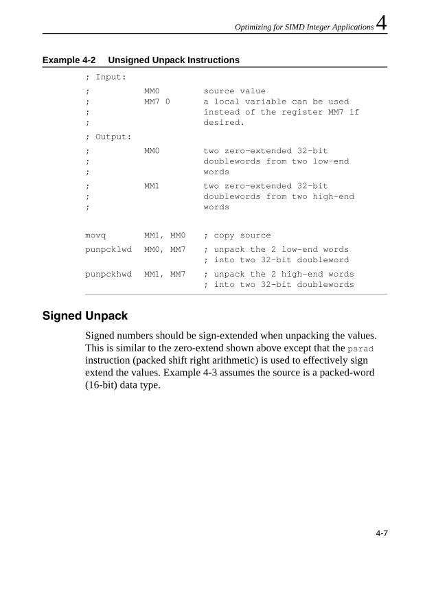
Optimizing for SIMD Integer Applications 4
Signed Unpack
Signed numbers should be sign-extended when unpacking the values. This is similar to the zero-extend shown above except that the psrad instruction (packed shift right arithmetic) is used to effectively sign extend the values. Example 4-3 assumes the source is a packed-word (16-bit) data type.
Example 4-2 Unsigned Unpack Instructions
; Input:
; MM0 source value; MM7 0 a local variable can be used; instead of the register MM7 if; desired.
; Output:
; MM0 two zero-extended 32-bit; doublewords from two low-end; words
; MM1 two zero-extended 32-bit; doublewords from two high-end ; words
movq MM1, MM0 ; copy source
punpcklwd MM0, MM7 ; unpack the 2 low-end words ; into two 32-bit doubleword
punpckhwd MM1, MM7 ; unpack the 2 high-end words; into two 32-bit doublewords
4-7

IA-32 Intel® Architecture Optimization
Interleaved Pack with Saturation
The pack instructions pack two values into the destination register in a predetermined order. Specifically, the packssdw instruction packs two signed doublewords from the source operand and two signed doublewords from the destination operand into four signed words in the destination register as shown in Figure 4-1.
Example 4-3 Signed Unpack Code
; Input:
; MM0 source value
; Output:
; MM0 two sign-extended 32-bit doublewords ; from the two low-end words; MM1 two sign-extended 32-bit doublewords ; from the two high-end words
;
movq MM1, MM0 ; copy source
punpcklwd MM0, MM0 ; unpack the 2 low end words of the source; into the second and fourth words of the; destination
punpckhwd MM1, MM1 ; unpack the 2 high-end words of the source; into the second and fourth words of the; destination
psrad MM0, 16 ; sign-extend the 2 low-end words of the source
; into two 32-bit signed doublewords
psrad MM1, 16 ; sign-extend the 2 high-end words of the; source into two 32-bit signed doublewords
4-8

Optimizing for SIMD Integer Applications 4
Figure 4-2 illustrates two values interleaved in the destination register, and Example 4-4 shows code that uses the operation. The two signed doublewords are used as source operands and the result is interleaved signed words. The pack instructions can be performed with or without saturation as needed.
Figure 4-1 PACKSSDW mm, mm/mm64 Instruction Example
Figure 4-2 Interleaved Pack with Saturation
OM15159
D C B A
D1 C1 B1 A1
mm/m64 mm
mm
OM15160
D C B A
D1 B1 C1 A1
MM/M64 mm
mm
4-9
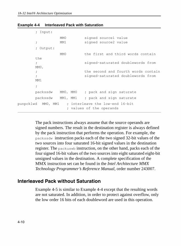
IA-32 Intel® Architecture Optimization
The pack instructions always assume that the source operands are signed numbers. The result in the destination register is always defined by the pack instruction that performs the operation. For example, the packssdw instruction packs each of the two signed 32-bit values of the two sources into four saturated 16-bit signed values in the destination register. The packuswb instruction, on the other hand, packs each of the four signed 16-bit values of the two sources into eight saturated eight-bit unsigned values in the destination. A complete specification of the MMX instruction set can be found in the Intel Architecture MMX Technology Programmer’s Reference Manual, order number 243007.
Interleaved Pack without Saturation
Example 4-5 is similar to Example 4-4 except that the resulting words are not saturated. In addition, in order to protect against overflow, only the low order 16 bits of each doubleword are used in this operation.
Example 4-4 Interleaved Pack with Saturation
; Input:
MM0 signed source1 value; MM1 signed source2 value
; Output:
MM0 the first and third words contain the ; signed-saturated doublewords from MM0, ; the second and fourth words contain; signed-saturated doublewords from MM1
;
packssdw MM0, MM0 ; pack and sign saturate
packssdw MM1, MM1 ; pack and sign saturate
punpcklwd MM0, MM1 ; interleave the low-end 16-bit ; values of the operands
4-10

Optimizing for SIMD Integer Applications 4
Non-Interleaved Unpack
The unpack instructions perform an interleave merge of the data elements of the destination and source operands into the destination register. The following example merges the two operands into the destination registers without interleaving. For example, take two adjacent elements of a packed-word data type in source1 and place this value in the low 32 bits of the results. Then take two adjacent elements of a packed-word data type in source2 and place this value in the high 32 bits of the results. One of the destination registers will have the combination illustrated in Figure 4-3.
Example 4-5 Interleaved Pack without Saturation
; Input:
; MM0 signed source value; MM1 signed source value
; Output:
; MM0 the first and third words contain the; low 16-bits of the doublewords in MM0,; the second and fourth words contain the ; low 16-bits of the doublewords in MM1
pslld MM1, 16 ; shift the 16 LSB from each of the ; doubleword values to the 16 MSB ; position
pand MM0, {0,ffff,0,ffff} ; mask to zero the 16 MSB; of each doubleword value
por MM0, MM1 ; merge the two operands
4-11
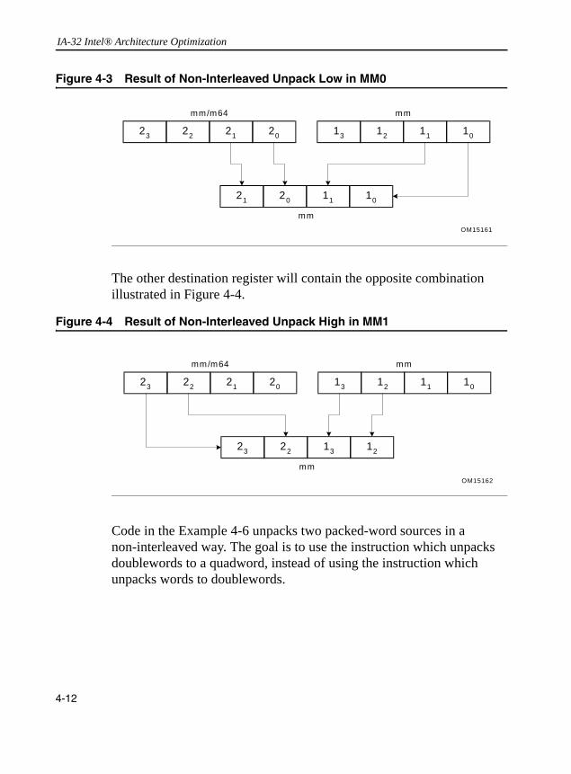
IA-32 Intel® Architecture Optimization
The other destination register will contain the opposite combination illustrated in Figure 4-4.
Code in the Example 4-6 unpacks two packed-word sources in a non-interleaved way. The goal is to use the instruction which unpacks doublewords to a quadword, instead of using the instruction which unpacks words to doublewords.
Figure 4-3 Result of Non-Interleaved Unpack Low in MM0
Figure 4-4 Result of Non-Interleaved Unpack High in MM1
OM15161
21 20 11 10
mm/m64 mm
mm
23 22 21 20 13 12 11 10
OM15162
23 22 13 12
mm/m64 mm
mm
23 22 21 20 13 12 11 10
4-12

Optimizing for SIMD Integer Applications 4
Extract Word
The pextrw instruction takes the word in the designated MMX register selected by the two least significant bits of the immediate value and moves it to the lower half of a 32-bit integer register, see Figure 4-5 and Example 4-7.
Example 4-6 Unpacking Two Packed-word Sources in a Non-interleaved Way
; Input:
; MM0 packed-word source value; MM1 packed-word source value
; Output:
; MM0 contains the two low-end words of the; original sources, non-interleaved ; MM2 contains the two high end words of the; original sources, non-interleaved.
movq MM2, MM0 ; copy source1
punpckldq MM0, MM1 ; replace the two high-end words ; of MMO with two low-end words of ; MM1; leave the two low-end words; of MM0 in place
punpckhdq MM2, MM1 ; move two high-end words of MM2; to the two low-end words of MM2;; place the two high-end words of; MM1 in two high-end words of MM2
4-13

IA-32 Intel® Architecture Optimization
Insert Word
The pinsrw instruction loads a word from the lower half of a 32-bit integer register or from memory and inserts it in the MMX technology destination register at a position defined by the two least significant bits of the immediate constant. Insertion is done in such a way that the three other words from the destination register are left untouched, see Figure 4-6 and Example 4-8.
Figure 4-5 pextrw Instruction
Example 4-7 pextrw Instruction Code
; Input:
; eax source value
; immediate value:“0”
; Output:
; edx 32-bit integer register containing the
; extracted word in the low-order bits &
; the high-order bits zero-extended
movq mm0, [eax]
pextrw edx, mm0, 0
OM15163
0 ..0 X1
MM
R3231 0
31 063
X4 X3 X2 X1
4-14

Optimizing for SIMD Integer Applications 4
If all of the operands in a register are being replaced by a series of pinsrw instructions, it can be useful to clear the content and break the dependence chain by either using the pxor instruction or loading the register. See the “Clearing Registers” section in Chapter 2.
Figure 4-6 pinsrw Instruction
Example 4-8 pinsrw Instruction Code
; Input:
; edx pointer to source value
; Output:
; mm0 register with new 16-bit value inserted
;
mov eax, [edx]
pinsrw mm0, eax, 1
OM15164
Y2
MM
R3231 0
31 063
X4 X3 Y1 X1
Y1
4-15

IA-32 Intel® Architecture Optimization
Move Byte Mask to Integer
The pmovmskb instruction returns a bit mask formed from the most significant bits of each byte of its source operand. When used with the 64-bit MMX registers, this produces an 8-bit mask, zeroing out the upper 24 bits in the destination register. When used with the 128-bit XMM registers, it produces a 16-bit mask, zeroing out the upper 16 bits in the destination register. The 64-bit version is shown in Figure 4-7 and Example 4-10.
Example 4-9 Repeated pinsrw Instruction Code
; Input:
; edx pointer to structure containing source
; values at offsets: of +0, +10, +13, and +24; immediate value: “1”
; Output:
; MMX register with new 16-bit value inserted
;
pxor mm0, mm0 ; Breaks dependedncy on previous value of mm0
mov eax, [edx]
pinsrw mm0, eax, 0
mov eax, [edx+10]
pinsrw mm0, eax, 1
mov eax, [edx+13]
pinsrw mm0, eax, 2
mov eax, [edx+24]
pinsrw mm0, eax, 3
4-16

Optimizing for SIMD Integer Applications 4
Figure 4-7 pmovmskb Instruction ExampleExample 4-10 pmovmskb Instruction Code
; Input:
; source value
; Output:
; 32-bit register containing the byte mask in the lower ; eight bits
;
movq mm0, [edi]
pmovmskb eax, mm0
OM15165
MM
R32
31 063
0..0
31
0..0
7 0
55 47 39 23 15 7
4-17

IA-32 Intel® Architecture Optimization
Packed Shuffle Word for 64-bit Registers
The pshuf instruction (see Figure 4-8, Example 4-11) uses the immediate (imm8) operand to select between the four words in either two MMX registers or one MMX register and a 64-bit memory location. Bits 1 and 0 of the immediate value encode the source for destination word 0 in MMX register ([15-0]), and so on as shown in the table:
Bits 7 and 6 encode for word 3 in MMX register ([63-48]). Similarly, the 2-bit encoding represents which source word is used, for example, binary encoding of 10 indicates that source word 2 in MMX register/memory (mm/mem[47-32]) is used, see Figure 4-8 and Example 4-11.
Bits Word
1 - 0 0
3 - 2 1
5 - 4 2
7 - 6 3
Figure 4-8 pshuf Instruction Example
OM15166
MM/m64063
X4 X3 X2 X1
MM063
X1 X2 X3 X4
4-18

Optimizing for SIMD Integer Applications 4
Packed Shuffle Word for 128-bit Registers
The pshuflw/pshufhw instruction performs a full shuffle of any source word field within the low/high 64 bits to any result word field in the low/high 64 bits, using an 8-bit immediate operand; the other high/low 64 bits are passed through from the source operand.
The pshufd instruction performs a full shuffle of any double-word field within the 128-bit source to any double-word field in the 128-bit result, using an 8-bit immediate operand.
No more than 3 instructions, using pshuflw/pshufhw/pshufd, are required to implement some common data shuffling operations. Broadcast, Swap, and Reverse are illustrated in Example 4-12, Example 4-13, and Example 4-14, respectively.
Example 4-11 pshuf Instruction Code
; Input:
; edi source value
; Output:
; MM1 MM register containing re-arranged words
movq mm0, [edi]
pshufw mm1, mm0, 0x1b
Example 4-12 Broadcast Using 2 Instructions
/* Goal: Broadcast the value from word 5 to all words */
/* Instruction Result */
| 7| 6| 5| 4| 3| 2| 1| 0|
PSHUFHW (3,2,1,1)| 7| 6| 5| 5| 3| 2| 1| 0|
PSHUFD (2,2,2,2)| 5| 5| 5| 5| 5| 5| 5| 5|
4-19

IA-32 Intel® Architecture Optimization
Unpacking/interleaving 64-bit Data in 128-bit Registers
The punpcklqdq/punpchqdq instructions interleave the low/high-order 64-bits of the source operand and the low/high-order 64-bits of the destination operand and writes them to the destination register. The high/low-order 64-bits of the source operands are ignored.
Example 4-13 Swap Using 3 Instructions
/* Goal: Swap the values in word 6 and word 1 */
/* Instruction Result */
| 7| 6| 5| 4| 3| 2| 1| 0|
PSHUFD (3,0,1,2)| 7| 6| 1| 0| 3| 2| 5| 4|
PSHUFHW (3,1,2,0)| 7| 1| 6| 0| 3| 2| 5| 4|
PSHUFD (3,0,1,2)| 7| 1| 5| 4| 3| 2| 6| 0|
Example 4-14 Reverse Using 3 Instructions
/* Goal: Reverse the order of the words */
/* Instruction Result */
| 7| 6| 5| 4| 3| 2| 1| 0|
PSHUFLW (0,1,2,3)| 7| 6| 5| 4| 0| 1| 2| 3|
PSHUFHW (0,1,2,3)| 4| 5| 6| 7| 0| 1| 2| 3|
PSHUFD (1,0,3,2)| 0| 1| 2| 3| 4| 5| 6| 7|
4-20

Optimizing for SIMD Integer Applications 4
Data MovementThere are two additional instructions to enable data movement from the 64-bit SIMD integer registers to the 128-bit SIMD registers.
The movq2dq instruction moves the 64-bit integer data from an MMX register (source) to a 128-bit destination register. The high-order 64 bits of the destination register are zeroed-out.
The movdq2q instruction moves the low-order 64-bits of integer data from a 128-bit source register to an MMX register (destination).
Conversion Instructions
New instructions have been added to support 4-wide conversion of single-precision data to/from double-word integer data. Also, conversions between double-precision data and double-word integer data have been added.
Generating ConstantsThe SIMD integer instruction sets do not have instructions that will load immediate constants to the SIMD registers. The following code segments generate frequently used constants in the SIMD register. Of course, you can also put constants as local variables in memory, but when doing so be sure to duplicate the values in memory and load the values with a movq, movdqa, or movdqu instructions, see Example 4-15.
Example 4-15 Generating Constants
pxor MM0, MM0 ; generate a zero register in MM0
pcmpeq MM1, MM1 ; Generate all 1's in register MM1,; which is -1 in each of the packed; data type fields
continued
4-21

IA-32 Intel® Architecture Optimization
pxor MM0, MM0
pcmpeq MM1, MM1
psubb MM0, MM1 [psubw MM0, MM1] (psubd MM0, MM1)
; three instructions above generate ; the constant 1 in every ; packed-byte [or packed-word] ; (or packed-dword) field
pcmpeq MM1, MM1
psrlw MM1, 16-n(psrld MM1, 32-n)
; two instructions above generate ; the signed constant 2n–1 in every ; packed-word (or packed-dword) field
pcmpeq MM1, MM1
psllw MM1, n (pslld MM1, n)
; two instructions above generate ; the signed constant -2n in every ; packed-word (or packed-dword) field
NOTE. Because the SIMD integer instruction sets do not support shift instructions for bytes, 2n–1 and -2n are relevant only for packed words and packed doublewords.
Example 4-15 Generating Constants (continued)
4-22

Optimizing for SIMD Integer Applications 4
Building BlocksThis section describes instructions and algorithms which implement common code building blocks efficiently.
Absolute Difference of Unsigned Numbers
Example 4-16 computes the absolute difference of two unsigned numbers. It assumes an unsigned packed-byte data type. Here, we make use of the subtract instruction with unsigned saturation. This instruction receives UNSIGNED operands and subtracts them with UNSIGNED saturation. This support exists only for packed bytes and packed words, not for packed doublewords.
This example will not work if the operands are signed.
Note that the psadbw instruction may also be used in some situations; see section “Packed Sum of Absolute Differences” for details.
Example 4-16 Absolute Difference of Two Unsigned Numbers
; Input:
; MM0 source operand; MM1 source operand
; Output:
; MM0 absolute difference of the unsigned; operands
movq MM2, MM0 ; make a copy of MM0
psubusb MM0, MM1 ; compute difference one way
psubusb MM1, MM2 ; compute difference the other way
por MM0, MM1 ; OR them together
4-23

IA-32 Intel® Architecture Optimization
Absolute Difference of Signed Numbers
Chapter 4 computes the absolute difference of two signed numbers.
The technique used here is to first sort the corresponding elements of the input operands into packed words of the maximum values, and packed words of the minimum values. Then the minimum values are subtracted from the maximum values to generate the required absolute difference. The key is a fast sorting technique that uses the fact that B = xor(A, xor (A,B)) and A = xor(A,0). Thus in a packed data type, having
some elements being xor(A,B) and some being 0, you could xor such an operand with A and receive in some places values of A and in some values of B. The following examples assume a packed-word data type, each element being a signed value.
NOTE. There is no MMX™ technology subtract instruction that receives SIGNED operands and subtracts them with UNSIGNED saturation.
Example 4-17 Absolute Difference of Signed Numbers
;Input:
; MM0 signed source operand; MM1 signed source operand
;Output:
; MM0 absolute difference of the unsigned; operands
continued
4-24

Optimizing for SIMD Integer Applications 4
Absolute Value
Use Example 4-18 to compute |x|, where x is signed. This example assumes signed words to be the operands.
movq MM2, MM0 ; make a copy of source1 (A)
pcmpgtw MM0, MM1 ; create mask of
; source1>source2 (A>B)
movq MM4, MM2 ; make another copy of A
pxor MM2, MM1 ; create the intermediate value of; the swap operation - xor(A,B)
pand MM2, MM0 ; create a mask of 0s and xor(A,B) ; elements. Where A>B there will ; be a value xor(A,B) and where ; A<=B there will be 0.
pxor MM4, MM2 ; minima-xor(A, swap mask)
pxor MM1, MM2 ; maxima-xor(B, swap mask)
psubw MM1, MM4 ; absolute difference = ; maxima-minima
Example 4-18 Computing Absolute Value
; Input:
; MM0 signed source operand
; Output:
; MM1 ABS(MMO)
pxor MM1, MM1 ; set MM1 to all zeros
psubw MM1, MM0 ; make each MM1 word contain the
; negative of each MM0 word
pmaxsw MM1, MM0 ; MM1 will contain only the positive
; (larger) values - the absolute value
Example 4-17 Absolute Difference of Signed Numbers (continued)
4-25

IA-32 Intel® Architecture Optimization
Clipping to an Arbitrary Range [high, low]
This section explains how to clip a values to a range [high, low]. Specifically, if the value is less than low or greater than high, then clip to low or high, respectively. This technique uses the packed-add and packed-subtract instructions with saturation (signed or unsigned), which means that this technique can only be used on packed-byte and packed-word data types.
The examples in this section use the constants packed_max and packed_min and show operations on word values. For simplicity we use the following constants (corresponding constants are used in case the operation is done on byte values):• packed_max equals 0x7fff7fff7fff7fff• packed_min equals 0x8000800080008000• packed_low contains the value low in all four words of the
packed-words data type• packed_high contains the value high in all four words of the
packed-words data type• packed_usmax all values equal 1 • high_us adds the high value to all data elements (4 words) of
packed_min
• low_us adds the low value to all data elements (4 words) of packed_min
CAUTION. The absolute value of the most negative number (that is, 8000 hex for 16-bit) cannot be represented using positive numbers. This algorithm will return the original value for the absolute value (8000 hex).
4-26

Optimizing for SIMD Integer Applications 4
Highly Efficient ClippingFor clipping signed words to an arbitrary range, the pmaxsw and pminsw instructions may be used. For clipping unsigned bytes to an arbitrary range, the pmaxub and pminub instructions may be used. Example 4-19 shows how to clip signed words to an arbitrary range; the code for clipping unsigned bytes is similar.
Example 4-19 Clipping to a Signed Range of Words [high, low]
; Input:
; MM0 signed source operands
; Output:
; MM0 signed words clipped to the signed ; range [high, low]
pminsw MM0, packed_high
pmaxsw MM0, packed_low
Example 4-20 Clipping to an Arbitrary Signed Range [high, low]
; Input:
; MM0 signed source operands
; Output:
; MM1 signed operands clipped to the unsigned ; range [high, low]
paddw MM0, packed_min ; add with no saturation
; 0x8000 to convert to unsigned
paddusw MM0, (packed_usmax - high_us)
; in effect this clips to high
psubusw MM0, (packed_usmax - high_us + low_us)
; in effect this clips to low
paddw MM0, packed_low ; undo the previous two offsets
4-27

IA-32 Intel® Architecture Optimization
The code above converts values to unsigned numbers first and then clips them to an unsigned range. The last instruction converts the data back to signed data and places the data within the signed range. Conversion to unsigned data is required for correct results when (high - low) < 0x8000.
If (high - low) >= 0x8000, the algorithm can be simplified as shown in Example 4-21.
This algorithm saves a cycle when it is known that (high - low) >= 0x8000. The three-instruction algorithm does not work when (high - low) < 0x8000, because 0xffff minus any number < 0x8000 will yield a number greater in magnitude than 0x8000, which is a negative number. When the second instruction, psubssw MM0, (0xffff - high + low), in the three-step algorithm (Example 4-21) is executed, a negative number is subtracted. The result of this subtraction causes the values in MM0 to be increased instead of decreased, as should be the case, and an incorrect answer is generated.
Clipping to an Arbitrary Unsigned Range [high, low]
Example 4-22 clips an unsigned value to the unsigned range [high, low]. If the value is less than low or greater than high, then clip to low or high, respectively. This technique uses the packed-add and
Example 4-21 Simplified Clipping to an Arbitrary Signed Range
; Input: MM0 signed source operands
; Output: MM1 signed operands clipped to the unsigned ; range [high, low]
paddssw MM0, (packed_max - packed_high)
; in effect this clips to high
psubssw MM0, (packed_usmax - packed_high + packed_ow)
; clips to low
paddw MM0, low ; undo the previous two offsets
4-28
Optimizing for SIMD Integer Applications 4
packed-subtract instructions with unsigned saturation, thus this technique can only be used on packed-bytes and packed-words data types.The example illustrates the operation on word values.
Packed Max/Min of Signed Word and Unsigned Byte
Signed Word
The pmaxsw instruction returns the maximum between the four signed words in either two SIMD registers, or one SIMD register and a memory location.
The pminsw instruction returns the minimum between the four signed words in either two SIMD registers, or one SIMD register and a memory location.
Example 4-22 Clipping to an Arbitrary Unsigned Range [high, low]
; Input:
; MM0 unsigned source operands
; Output:
; MM1 unsigned operands clipped to the unsigned; range [HIGH, LOW]
paddusw MM0, 0xffff - high
; in effect this clips to high
psubusw MM0, (0xffff - high + low)
; in effect this clips to low
paddw MM0, low
; undo the previous two offsets
4-29

IA-32 Intel® Architecture Optimization
Unsigned Byte
The pmaxub instruction returns the maximum between the eight unsigned bytes in either two SIMD registers, or one SIMD register and a memory location.
The pminub instruction returns the minimum between the eight unsigned bytes in either two SIMD registers, or one SIMD register and a memory location.
Packed Multiply High Unsigned
The pmulhuw and pmulhw instruction multiplies the unsigned/signed words in the destination operand with the unsigned/signed words in the source operand. The high-order 16 bits of the 32-bit intermediate results are written to the destination operand.
Packed Sum of Absolute Differences
The psadbw instruction (see Figure 4-9) computes the absolute value of the difference of unsigned bytes for either two SIMD registers, or one SIMD register and a memory location. These differences are then summed to produce a word result in the lower 16-bit field, and the upper three words are set to zero.
4-30
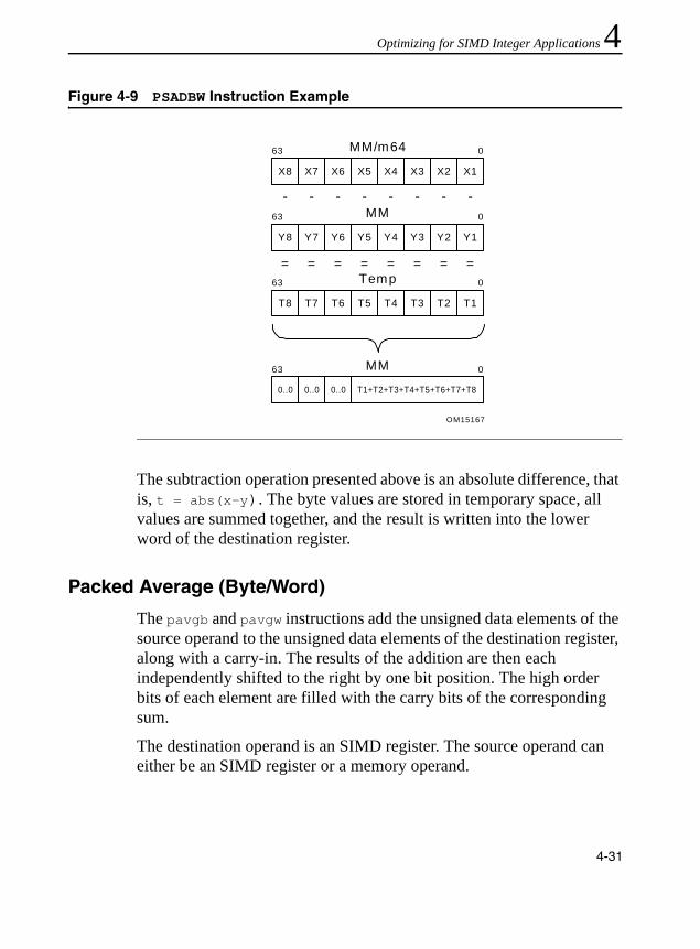
Optimizing for SIMD Integer Applications 4
The subtraction operation presented above is an absolute difference, that is, t = abs(x-y). The byte values are stored in temporary space, all values are summed together, and the result is written into the lower word of the destination register.
Packed Average (Byte/Word)
The pavgb and pavgw instructions add the unsigned data elements of the source operand to the unsigned data elements of the destination register, along with a carry-in. The results of the addition are then each independently shifted to the right by one bit position. The high order bits of each element are filled with the carry bits of the corresponding sum.
The destination operand is an SIMD register. The source operand can either be an SIMD register or a memory operand.
Figure 4-9 PSADBW Instruction Example
OM15167
MM/m64
X8 X7 X6 X5 X4 X3 X2 X1
063
MM
Y8 Y7 Y6 Y5 Y4 Y3 Y2 Y1
063
Temp
T8 T7 T6 T5 T4 T3 T2 T1
063
= = = = = = = =
- - - - - - - -
MM
0..0 0..0 0..0 T1+T2+T3+T4+T5+T6+T7+T8
063
4-31
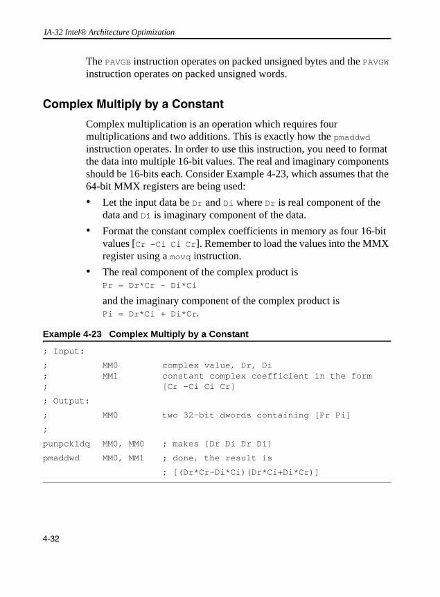
IA-32 Intel® Architecture Optimization
The PAVGB instruction operates on packed unsigned bytes and the PAVGW instruction operates on packed unsigned words.
Complex Multiply by a Constant
Complex multiplication is an operation which requires four multiplications and two additions. This is exactly how the pmaddwd instruction operates. In order to use this instruction, you need to format the data into multiple 16-bit values. The real and imaginary components should be 16-bits each. Consider Example 4-23, which assumes that the 64-bit MMX registers are being used:• Let the input data be Dr and Di where Dr is real component of the
data and Di is imaginary component of the data.• Format the constant complex coefficients in memory as four 16-bit
values [Cr -Ci Ci Cr]. Remember to load the values into the MMX register using a movq instruction.
• The real component of the complex product is Pr = Dr*Cr - Di*Ci and the imaginary component of the complex product is Pi = Dr*Ci + Di*Cr.
Example 4-23 Complex Multiply by a Constant
; Input:
; MM0 complex value, Dr, Di; MM1 constant complex coefficient in the form ; [Cr -Ci Ci Cr]
; Output:
; MM0 two 32-bit dwords containing [Pr Pi]
;
punpckldq MM0, MM0 ; makes [Dr Di Dr Di]
pmaddwd MM0, MM1 ; done, the result is
; [(Dr*Cr-Di*Ci)(Dr*Ci+Di*Cr)]
4-32

Optimizing for SIMD Integer Applications 4
Note that the output is a packed doubleword. If needed, a pack instruction can be used to convert the result to 16-bit (thereby matching the format of the input).Packed 32*32 Multiply
The PMULUDQ instruction performs an unsigned multiply on the lower pair of double-word operands within each 64-bit chunk from the two sources; the full 64-bit result from each multiplication is returned to the destination register. This instruction is added in both a 64-bit and 128-bit version; the latter performs 2 independent operations, on the low and high halves of a 128-bit register.
Packed 64-bit Add/Subtract
The PADDQ/PSUBQ instructions add/subtract quad-word operands within each 64-bit chunk from the two sources; the 64-bit result from each computation is written to the destination register. Like the integer ADD/SUB instruction, PADDQ/PSUBQ can operate on either unsigned or signed (two’s complement notation) integer operands. When an individual result is too large to be represented in 64-bits, the lower 64-bits of the result are written to the destination operand and therefore the result wraps around. These instructions are added in both a 64-bit and 128-bit version; the latter performs 2 independent operations, on the low and high halves of a 128-bit register.
128-bit Shifts
The pslldq/psrldq instructions shift the first operand to the left/right by the amount of bytes specified by the immediate operand. The empty low/high-order bytes are cleared (set to zero). If the value specified by the immediate operand is greater than 15, then the destination is set to all zeros.
4-33

IA-32 Intel® Architecture Optimization
Memory OptimizationsYou can improve memory accesses using the following techniques:• Avoiding partial memory accesses• Increasing the bandwidth of memory fills and video fills• Prefetching data with Streaming SIMD Extensions (see Chapter 6,
“Optimizing Cache Usage”).
The MMX registers and XMM registers allow you to move large quantities of data without stalling the processor. Instead of loading single array values that are 8, 16, or 32 bits long, consider loading the values in a single quadword or double quadword, then incrementing the structure or array pointer accordingly.
Any data that will be manipulated by SIMD integer instructions should be loaded using either:• the SIMD integer instruction that loads a 64-bit or 128-bit operand
(for example, movq MM0, m64) • the register-memory form of any SIMD integer instruction that
operates on a quadword or double quadword memory operand (for example, pmaddw MM0, m64).
All SIMD data should be stored using the SIMD integer instruction that stores a 64-bit or 128-bit operand (for example, movq m64, MM0)
The goal of these recommendations is twofold. First, the loading and storing of SIMD data is more efficient using the larger block sizes. Second, this helps to avoid the mixing of 8-, 16-, or 32-bit load and store operations with SIMD integer technology load and store operations to the same SIMD data. This, in turn, prevents situations in which small loads follow large stores to the same area of memory, or large loads follow small stores to the same area of memory. The Pentium II, Pentium III, and Pentium 4 processors stall in these situations; see Chapter 2, “General Optimization Guidelines” for more details.
4-34

Optimizing for SIMD Integer Applications 4
Partial Memory AccessesConsider a case with large load after a series of small stores to the same area of memory (beginning at memory address mem). The large load will stall in this case as shown in Example 4-24.
The movq must wait for the stores to write memory before it can access all the data it requires. This stall can also occur with other data types (for example, when bytes or words are stored and then words or doublewords are read from the same area of memory). When you change the code sequence as shown in Example 4-25, the processor can access the data without delay.
Example 4-24 A Large Load after a Series of Small Stores (Penalty)
mov mem, eax ; store dword to address “mem"
mov mem + 4, ebx ; store dword to address “mem + 4"
:
:
movq mm0, mem ; load qword at address “mem", stalls
Example 4-25 Accessing Data without Delay
movd mm1, ebx ; build data into a qword first
; before storing it to memory
movd mm2, eax
psllq mm1, 32
por mm1, mm2
movq mem, mm1 ; store SIMD variable to “mem" as ; a qword
:
:
movq mm0, mem ; load qword SIMD “mem", no stall
4-35
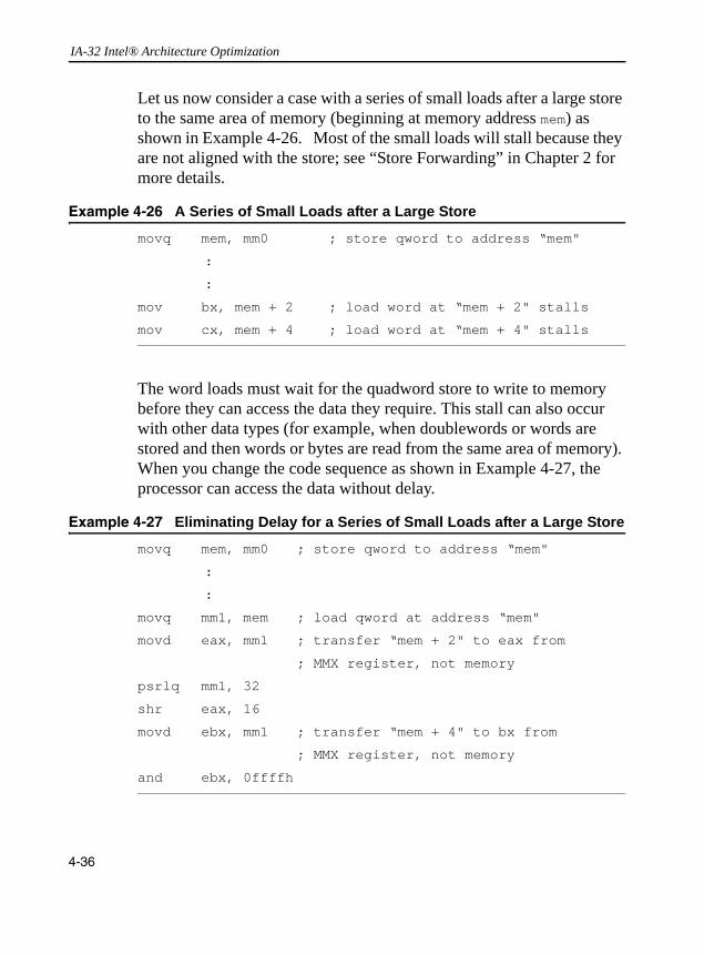
IA-32 Intel® Architecture Optimization
Let us now consider a case with a series of small loads after a large store to the same area of memory (beginning at memory address mem) as shown in Example 4-26. Most of the small loads will stall because they are not aligned with the store; see “Store Forwarding” in Chapter 2 for more details.
The word loads must wait for the quadword store to write to memory before they can access the data they require. This stall can also occur with other data types (for example, when doublewords or words are stored and then words or bytes are read from the same area of memory). When you change the code sequence as shown in Example 4-27, the processor can access the data without delay.
Example 4-26 A Series of Small Loads after a Large Store
movq mem, mm0 ; store qword to address “mem"
:
:
mov bx, mem + 2 ; load word at “mem + 2" stalls
mov cx, mem + 4 ; load word at “mem + 4" stalls
Example 4-27 Eliminating Delay for a Series of Small Loads after a Large Store
movq mem, mm0 ; store qword to address “mem"
:
:
movq mm1, mem ; load qword at address “mem"
movd eax, mm1 ; transfer “mem + 2" to eax from
; MMX register, not memory
psrlq mm1, 32
shr eax, 16
movd ebx, mm1 ; transfer “mem + 4" to bx from
; MMX register, not memory
and ebx, 0ffffh
4-36
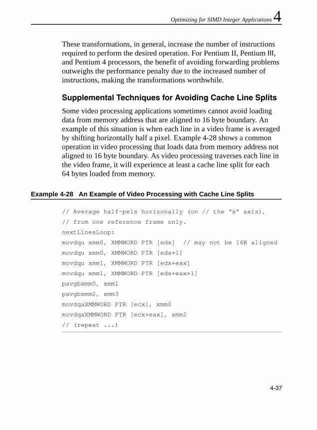
Optimizing for SIMD Integer Applications 4
These transformations, in general, increase the number of instructions required to perform the desired operation. For Pentium II, Pentium III, and Pentium 4 processors, the benefit of avoiding forwarding problems outweighs the performance penalty due to the increased number of instructions, making the transformations worthwhile.Supplemental Techniques for Avoiding Cache Line Splits
Some video processing applications sometimes cannot avoid loading data from memory address that are aligned to 16 byte boundary. An example of this situation is when each line in a video frame is averaged by shifting horizontally half a pixel. Example 4-28 shows a common operation in video processing that loads data from memory address not aligned to 16 byte boundary. As video processing traverses each line in the video frame, it will experience at least a cache line split for each 64 bytes loaded from memory.
Example 4-28 An Example of Video Processing with Cache Line Splits
// Average half-pels horizonally (on // the “x” axis),
// from one reference frame only.
nextLinesLoop:
movdqu xmm0, XMMWORD PTR [edx] // may not be 16B aligned
movdqu xmm0, XMMWORD PTR [edx+1]
movdqu xmm1, XMMWORD PTR [edx+eax]
movdqu xmm1, XMMWORD PTR [edx+eax+1]
pavgbxmm0, xmm1
pavgbxmm2, xmm3
movdqaXMMWORD PTR [ecx], xmm0
movdqaXMMWORD PTR [ecx+eax], xmm2
// (repeat ...)
4-37

IA-32 Intel® Architecture Optimization
SSE3 provides an instruction LDDQU for loading from memory address that are not 16 byte aligned. LDDQU is a special 128-bit unaligned load designed to avoid cache line splits. If the address of the load is aligned on a 16-byte boundary, LDQQU loads the 16 bytes requested. If the address of the load is not aligned on a 16-byte boundary, LDDQU loads a 32-byte block starting at the 16-byte aligned address immediately below the address of the load request. It then provides the requested 16 bytes. If the address is aligned on a 16-byte boundary, the effective number of memory requests is implementation dependent (one, or more).
LDDQU is designed for programming usage of loading data from memory without storing modified data back to the same address. Thus, the usage of LDDQU should be restricted to situations where no store-to-load forwarding is expected. For situations where store-to-load forwarding is expected, use regular store/load pairs (either aligned or unaligned based on the alignment of the data accessed).
Example 4-29 Video Processing Using LDDQU to Avoid Cache Line Splits
// Average half-pels horizonally (on // the “x” axis),
// from one reference frame only.
nextLinesLoop:
lddqu xmm0, XMMWORD PTR [edx] // may not be 16B aligned
lddqu xmm0, XMMWORD PTR [edx+1]
lddqu xmm1, XMMWORD PTR [edx+eax]
lddqu xmm1, XMMWORD PTR [edx+eax+1]
pavgbxmm0, xmm1
pavgbxmm2, xmm3
movdqaXMMWORD PTR [ecx], xmm0 //results stored elsewhere
movdqaXMMWORD PTR [ecx+eax], xmm2
// (repeat ...)
4-38

Optimizing for SIMD Integer Applications 4
Increasing Bandwidth of Memory Fills and Video FillsIt is beneficial to understand how memory is accessed and filled. A memory-to-memory fill (for example a memory-to-video fill) is defined as a 64-byte (cache line) load from memory which is immediately stored back to memory (such as a video frame buffer). The following are guidelines for obtaining higher bandwidth and shorter latencies for sequential memory fills (video fills). These recommendations are relevant for all Intel architecture processors with MMX technology and refer to cases in which the loads and stores do not hit in the first- or second-level cache.
Increasing Memory Bandwidth Using the MOVDQ Instruction
Loading any size data operand will cause an entire cache line to be loaded into the cache hierarchy. Thus any size load looks more or less the same from a memory bandwidth perspective. However, using many smaller loads consumes more microarchitectural resources than fewer larger stores. Consuming too many of these resources can cause the processor to stall and reduce the bandwidth that the processor can request of the memory subsystem.
Using movdq to store the data back to UC memory (or WC memory in some cases) instead of using 32-bit stores (for example, movd) will reduce by three-quarters the number of stores per memory fill cycle. As a result, using the movdq instruction in memory fill cycles can achieve significantly higher effective bandwidth than using the movd instruction.
Increasing Memory Bandwidth by Loading and Storing to and from the Same DRAM Page
DRAM is divided into pages, which are not the same as operating system (OS) pages. The size of a DRAM page is a function of the total size of the DRAM and the organization of the DRAM. Page sizes of several Kilobytes are common. Like OS pages, DRAM pages are constructed of sequential addresses. Sequential memory accesses to the
4-39

IA-32 Intel® Architecture Optimization
same DRAM page have shorter latencies than sequential accesses to different DRAM pages. In many systems the latency for a page miss (that is, an access to a different page instead of the page previously accessed) can be twice as large as the latency of a memory page hit (access to the same page as the previous access). Therefore, if the loads and stores of the memory fill cycle are to the same DRAM page, a significant increase in the bandwidth of the memory fill cycles can be achieved.
Increasing UC and WC Store Bandwidth by Using Aligned Stores
Using aligned stores to fill UC or WC memory will yield higher bandwidth than using unaligned stores. If a UC store or some WC stores cross a cache line boundary, a single store will result in two transaction on the bus, reducing the efficiency of the bus transactions. By aligning the stores to the size of the stores, you eliminate the possibility of crossing a cache line boundary, and the stores will not be split into separate transactions.
Converting from 64-bit to 128-bit SIMD IntegerThe SSE2 define a superset of 128-bit integer instructions currently available in MMX technology; the operation of the extended instructions remains the same and simply operate on data that is twice as wide. This simplifies porting of current 64-bit integer applications. However, there are few additional considerations:• Computation instructions which use a memory operand that may not
be aligned to a 16-byte boundary must be replaced with an unaligned 128-bit load (movdqu) followed by the same computation operation that uses instead register operands. Use of 128-bit integer computation instructions with memory operands that are not 16-byte aligned will result in a General Protection fault. The unaligned 128-bit load and store is not as efficient as the corresponding
4-40

Optimizing for SIMD Integer Applications 4
aligned versions; this can reduce the performance gains when using the 128-bit SIMD integer extensions. The general guidelines on the alignment of memory operands are:— The greatest performance gains can be achieved when allmemory streams are 16-byte aligned.— Reasonable performance gains are possible if roughly half of all
memory streams are 16-byte aligned, and the other half are not.— Little or no performance gain may result if all memory streams
are not aligned to 16-bytes; in this case, use of the 64-bit SIMD integer instructions may be preferable.
• Loop counters need to be updated because each 128-bit integer instruction operates on twice the amount of data as the 64-bit integer counterpart.
• Extension of the pshufw instruction (shuffle word across 64-bit integer operand) across a full 128-bit operand is emulated by a combination of the following instructions: pshufhw, pshuflw, pshufd.
• Use of the 64-bit shift by bit instructions (psrlq, psllq) are extended to 128 bits in these ways: — use of psrlq and psllq, along with masking logic operations— code sequence is rewritten to use the psrldq and pslldq
instructions (shift double quad-word operand by bytes).
4-41

IA-32 Intel® Architecture Optimization
4-42

5
Optimizing for SIMD Floating-point ApplicationsThis chapter discusses general rules of optimizing for the single-instruction, multiple-data (SIMD) floating-point instructions available in Streaming SIMD Extensions (SSE), Streaming SIMD Extensions 2 (SSE2)and Streaming SIMD Extensions 3 (SSE3). This chapter also provides examples that illustrate the optimization techniques for single-precision and double-precision SIMD floating-point applications.
General Rules for SIMD Floating-point CodeThe rules and suggestions listed in this section help optimize floating-point code containing SIMD floating-point instructions. Generally, it is important to understand and balance port utilization to create efficient SIMD floating-point code. The basic rules and suggestions include the following:• Follow all guidelines in Chapter 2 and Chapter 3.• Exceptions: mask exceptions to achieve higher performance. When
exceptions are unmasked, software performance is slower.• Utilize the flush-to-zero and denormals-are-zero modes for higher
performance to avoid the penalty of dealing with denormals and underflows.
• Incorporate the prefetch instruction where appropriate (for details, refer to Chapter 6, “Optimizing Cache Usage”).
• Use MMX technology instructions and registers if the computations can be done in SIMD integer for shuffling data.
5-1

IA-32 Intel® Architecture Optimization
• Use MMX technology instructions and registers or for copying data that is not used later in SIMD floating-point computations.
• Use the reciprocal instructions followed by iteration for increased accuracy. These instructions yield reduced accuracy but execute much faster. Note the following:— If reduced accuracy is acceptable, use them with no iteration. — If near full accuracy is needed, use a Newton-Raphson iteration. — If full accuracy is needed, then use divide and square root which
provide more accuracy, but slow down performance.
Planning ConsiderationsWhether adapting an existing application or creating a new one, using SIMD floating-point instructions to achieve optimum performance gain requires programmers to consider several issues. In general, when choosing candidates for optimization, look for code segments that are computationally intensive and floating-point intensive. Also consider efficient use of the cache architecture.
The sections that follow answer the questions that should be raised before implementation:• Can data layout be arranged to increase control parallelism or cache
utilization?• Which part of the code benefits from SIMD floating-point
instructions?• Is the current algorithm the most appropriate for SIMD
floating-point instructions?• Is the code floating-point intensive?• Do either single-precision floating-point or double-precision
floating- point computations provide enough range and precision?• Does the result of computation affected by enabling flush-to-zero or
denormals-to-zero modes?
5-2

Optimizing for SIMD Floating-point Applications 5
• Is the data arranged for efficient utilization of the SIMDfloating-point registers?• Is this application targeted for processors without SIMD
floating-point instructions?
For more details, see the section on “Considerations for Code Conversion to SIMD Programming” in Chapter 3.
Using SIMD Floating-point with x87 Floating-pointBecause the XMM registers used for SIMD floating-point computations are separate registers and are not mapped onto the existing x87 floating-point stack, SIMD floating-point code can be mixed with either x87 floating-point or 64-bit SIMD integer code.
Scalar Floating-point CodeThere are SIMD floating-point instructions that operate only on the least-significant operand in the SIMD register. These instructions are known as scalar instructions. They allow the XMM registers to be used for general-purpose floating-point computations.
In terms of performance, scalar floating-point code can be equivalent to or exceed x87 floating-point code, and has the following advantages:• SIMD floating-point code uses a flat register model, whereas x87
floating-point code uses a stack model. Using scalar floating-point code eliminates the need to use fxch instructions, which has some performance limit on the Intel Pentium 4 processor.
• Mixing with MMX technology code without penalty.• Flush-to-zero mode.• Shorter latencies than x87 floating-point.
5-3

IA-32 Intel® Architecture Optimization
When using scalar floating-point instructions, it is not necessary to ensure that the data appears in vector form. However, all of the optimizations regarding alignment, scheduling, instruction selection, and other optimizations covered in Chapters 2 and 3 should be observed.
Data AlignmentSIMD floating-point data is 16-byte aligned. Referencing unaligned 128-bit SIMD floating-point data will result in an exception unless the movups or movupd (move unaligned packed single or unaligned packed double) instruction is used. The unaligned instructions used on aligned or unaligned data will also suffer a performance penalty relative to aligned accesses.
Refer to section “Stack and Data Alignment” in Chapter 3 for more information.
Data Arrangement
Because the SSE and SSE2 incorporate a SIMD architecture, arranging the data to fully use the SIMD registers produces optimum performance. This implies contiguous data for processing, which leads to fewer cache misses and can potentially quadruple the data throughput when using SSE, or twice the throughput when using SSE2. These performance gains can occur because four data element can be loaded with 128-bit load instructions into XMM registers using SSE (movaps – move aligned packed single precision). Similarly, two data element can loaded with 128-bit load instructions into XMM registers using SSE2 (movapd – move aligned packed double precision).
Refer to the “Stack and Data Alignment” in Chapter 3 for data arrangement recommendations. Duplicating and padding techniques overcome the misalignment problem that can occur in some data structures and arrangements. This increases the data space but avoids the expensive penalty for misaligned data access.
5-4

Optimizing for SIMD Floating-point Applications 5
For some applications, e.g., 3D geometry, the traditional data arrangement requires some changes to fully utilize the SIMD registers and parallel techniques. Traditionally, the data layout has been an array of structures (AoS). To fully utilize the SIMD registers in such applications, a new data layout has been proposed—a structure of arrays (SoA) resulting in more optimized performance.Vertical versus Horizontal Computation
The majority of the floating-point arithmetic instructions in SSE and SSE2 are focused on vertical data processing of parallel data elements, i.e. the destination of each element is the result of a common arithmetic operation of the input operands in the same vertical position. This is shown in the diagram below. To supplement these homogeneous arithmetic operations on parallel data elements, SSE and SSE2 also provides several data movement instruction (e.g., shufps) to facilitate moving data elements horizontally.
The AoS data structure is often used in 3D geometry computations. SIMD technology can be applied to AoS data structure using a horizontal computation model. This means that the x, y, z, and w components of a single vertex structure (that is, of a single vector
Figure 5-1 Homogeneous Operation on Parallel Data Elements
X3 X2 X1 X0
Y3 Y2 Y1 Y0
X3 OP Y3 X2 OP Y2 X1 OP Y1 X0 OP Y0
OPOPOPOP
5-5

IA-32 Intel® Architecture Optimization
simultaneously referred to as an xyz data representation, see the diagram below) are computed in parallel, and the array is updated one vertex at a time.
When data structures are organized for the horizontal computation model, sometimes the availability of homogeneous arithmetic operations in SSE and SSE2 may cause inefficiency or require additional intermediate movement between data elements.
Alternatively, the data structure can be organized in the SoA format. The SoA data structure enables a vertical computation technique, and is recommended over horizontal computation for many applications, for the following reasons:• When computing on a single vector (xyz), it is common to use only
a subset of the vector components; for example, in 3D graphics the W component is sometimes ignored. This means that for single-vector operations, 1 of 4 computation slots is not being utilized. This typically results in a 25% reduction of peak efficiency.
• It may become difficult to hide long latency operations. For instance, another common function in 3D graphics is normalization, which requires the computation of a reciprocal square root (that is, 1/sqrt). Both the division and square root are long latency operations. With vertical computation (SoA), each of the 4 computation slots in a SIMD operation is producing a unique result, so the net latency per slot is L/4 where L is the overall latency of the operation. However, for horizontal computation, the 4 computation slots each produce the same result, hence to produce 4 separate results requires a net latency per slot of L.
X Y Z W
5-6

Optimizing for SIMD Floating-point Applications 5
To utilize all 4 computation slots, the vertex data can be reorganized to allow computation on each component of 4 separate vertices, that is, processing multiple vectors simultaneously. This can also be referred to as an SoA form of representing vertices data shown in Table 5-1.Organizing data in this manner yields a unique result for each computational slot for each arithmetic operation.
Vertical computation takes advantage of the inherent parallelism in 3D geometry processing of vertices. It assigns the computation of four vertices to the four compute slots of the Pentium III processor, thereby eliminating the disadvantages of the horizontal approach described earlier (using SSE alone). The dot product operation implements the SoA representation of vertices data. A schematic representation of dot product operation is shown in Figure 5-2.
Table 5-1 SoA Form of Representing Vertices Data
Vx array X1 X2 X3 X4 ..... Xn
Vy array Y1 Y2 Y3 Y4 ..... Yn
Vz array Z1 Z2 Z3 Y4 ..... Zn
Vw array W1 W2 W3 W4 ..... Wn
5-7
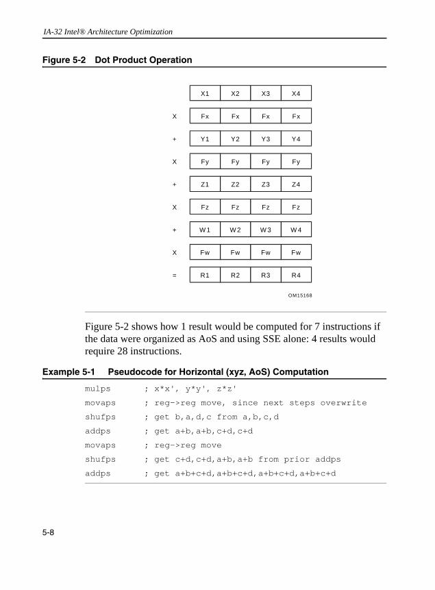
IA-32 Intel® Architecture Optimization
Figure 5-2 shows how 1 result would be computed for 7 instructions if the data were organized as AoS and using SSE alone: 4 results would require 28 instructions.
Figure 5-2 Dot Product Operation
Example 5-1 Pseudocode for Horizontal (xyz, AoS) Computation
mulps ; x*x', y*y', z*z'
movaps ; reg->reg move, since next steps overwrite
shufps ; get b,a,d,c from a,b,c,d
addps ; get a+b,a+b,c+d,c+d
movaps ; reg->reg move
shufps ; get c+d,c+d,a+b,a+b from prior addps
addps ; get a+b+c+d,a+b+c+d,a+b+c+d,a+b+c+d
OM15168
X
+
X
+
X
+
X
=
X1 X2 X3 X4
Fx Fx Fx Fx
Y1 Y2 Y3 Y4
Fy Fy Fy Fy
Z1 Z2 Z3 Z4
Fz Fz Fz Fz
W 1 W 2 W 3 W 4
Fw Fw Fw Fw
R1 R2 R3 R4
5-8

Optimizing for SIMD Floating-point Applications 5
Now consider the case when the data is organized as SoA. Example 5-2 demonstrates how 4 results are computed for 5 instructions.For the most efficient use of the four component-wide registers, reorganizing the data into the SoA format yields increased throughput and hence much better performance for the instructions used.
As can be seen from this simple example, vertical computation yielded 100% use of the available SIMD registers and produced 4 results. (The results may vary based on the application.) If the data structures must be in a format that is not “friendly” to vertical computation, it can be rearranged “on the fly” to achieve full utilization of the SIMD registers. This operation is referred to as “swizzling” operation and the reverse operation is referred to as “deswizzling.”
Data Swizzling
Swizzling data from one format to another may be required in many algorithms when the available instruction set extension is limited (e.g., only SSE is available). An example of this is AoS format, where the vertices come as xyz adjacent coordinates. Rearranging them into SoA format, xxxx, yyyy, zzzz, allows more efficient SIMD computations. For efficient data shuffling and swizzling use the following instructions:• movlps, movhps load/store and move data on half sections of the
registers• shufps, unpackhps, and unpacklps unpack data
Example 5-2 Pseudocode for Vertical (xxxx, yyyy, zzzz, SoA) Computation
mulps ; x*x' for all 4 x-components of 4 vertices
mulps ; y*y' for all 4 y-components of 4 vertices
mulps ; z*z' for all 4 z-components of 4 vertices
addps ; x*x' + y*y'
addps ; x*x'+y*y'+z*z'
5-9
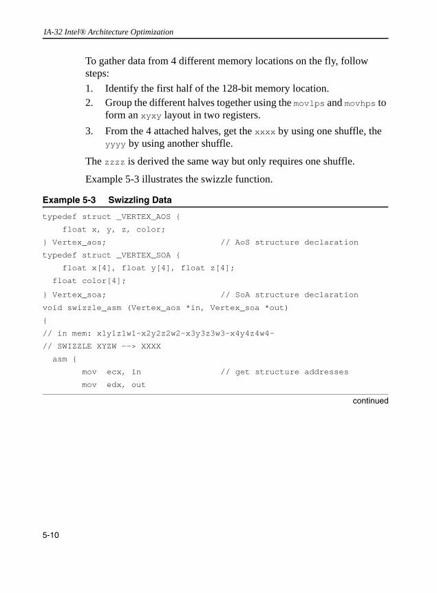
IA-32 Intel® Architecture Optimization
To gather data from 4 different memory locations on the fly, follow steps:1. Identify the first half of the 128-bit memory location. 2. Group the different halves together using the movlps and movhps to
form an xyxy layout in two registers. 3. From the 4 attached halves, get the xxxx by using one shuffle, the
yyyy by using another shuffle.
The zzzz is derived the same way but only requires one shuffle.
Example 5-3 illustrates the swizzle function.
Example 5-3 Swizzling Data
typedef struct _VERTEX_AOS {
float x, y, z, color;
} Vertex_aos; // AoS structure declaration
typedef struct _VERTEX_SOA {
float x[4], float y[4], float z[4];
float color[4];
} Vertex_soa; // SoA structure declaration
void swizzle_asm (Vertex_aos *in, Vertex_soa *out)
{
// in mem: x1y1z1w1-x2y2z2w2-x3y3z3w3-x4y4z4w4-
// SWIZZLE XYZW --> XXXX
asm {
mov ecx, in // get structure addresses
mov edx, out
continued
5-10

Optimizing for SIMD Floating-point Applications 5
y1 x1
movhps xmm7, [ecx+16] // xmm7 = y2 x2 y1 x1
movlps xmm0, [ecx+32] // xmm0 = -- -- y3 x3
movhps xmm0, [ecx+48] // xmm0 = y4 x4 y3 x3
movaps xmm6, xmm7 // xmm6 = y1 x1 y1 x1
shufps xmm7, xmm0, 0x88 // xmm7 = x1 x2 x3 x4 => X
shufps xmm6, xmm0, 0xDD // xmm6 = y1 y2 y3 y4 => Y
movlps xmm2, [ecx+8] // xmm2 = -- -- w1 z1
movhps xmm2, [ecx+24] // xmm2 = w2 z2 u1 z1
movlps xmm1, [ecx+40] // xmm1 = -- -- s3 z3
movhps xmm1, [ecx+56] // xmm1 = w4 z4 w3 z3
movaps xmm0, xmm2 // xmm0 = w1 z1 w1 z1
shufps xmm2, xmm1, 0x88 // xmm2 = z1 z2 z3 z4 => Z
movlps xmm7, [ecx] // xmm7 = -- --shufps xmm0, xmm1, // 0xDD xmm6 = w1 w2 w3 w4 => W
movaps [edx], xmm7 // store X
movaps [edx+16], xmm6 // store Y
movaps [edx+32], xmm2 // store Z
movaps [edx+48], xmm0 // store W
// SWIZZLE XYZ -> XXX
}
}
Example 5-3 Swizzling Data (continued)
5-11

IA-32 Intel® Architecture Optimization
Example 5-4 shows the same data -swizzling algorithm encoded using the Intel® C++ Compiler’s intrinsics for SSE.
Example 5-4 Swizzling Data Using Intrinsics
//Intrinsics version of data swizzle
void swizzle_intrin (Vertex_aos *in, Vertex_soa *out, int stride)
{
__m128 x, y, z, w;
__m128 tmp;
x = _mm_loadl_pi(x,(__m64 *)(in));
x = _mm_loadh_pi(x,(__m64 *)(stride + (char *)(in)));
y = _mm_loadl_pi(y,(__m64 *)(2*stride+(char *)(in)));
y = _mm_loadh_pi(y,(__m64 *)(3*stride+(char *)(in)));
tmp = _mm_shuffle_ps( x, y, _MM_SHUFFLE( 2, 0, 2, 0));
y = _mm_shuffle_ps( x, y, _MM_SHUFFLE( 3, 1, 3, 1));
x = tmp;
z = _mm_loadl_pi(z,(__m64 *)(8 + (char *)(in)));
z = _mm_loadh_pi(z,(__m64 *)(stride+8+(char *)(in)));
w = _mm_loadl_pi(w,(__m64 *)(2*stride+8+(char*)(in)));
w = _mm_loadh_pi(w,(__m64 *)(3*stride+8+(char*)(in)));
tmp = _mm_shuffle_ps( z, w, _MM_SHUFFLE( 2, 0, 2, 0));
w = _mm_shuffle_ps( z, w, _MM_SHUFFLE( 3, 1, 3, 1));
z = tmp;
_mm_store_ps(&out->x[0], x);
_mm_store_ps(&out->y[0], y);
_mm_store_ps(&out->z[0], z);
_mm_store_ps(&out->w[0], w);
}
5-12

Optimizing for SIMD Floating-point Applications 5
Although the generated result of all zeros does not depend on the specific data contained in the source operand (that is, XOR of a register with itself always produces all zeros), the instruction cannot execute until the instruction that generates xmm0 has completed. In the worst case, this creates a dependence chain that links successive iterations of the loop, even if those iterations are otherwise independent. The performance impact can be significant depending on how many other independent intra-loop computations are performed. Note that on the Pentium 4 processor, the SIMD integer pxor instructions, if used with the same register, do break the dependence chain, eliminating false dependencies when clearing registers.
The same situation can occur for the above movhps/movlps/shufps sequence. Since each movhps/movlps instruction bypasses part of the destination register, the instruction cannot execute until the prior instruction that generates this register has completed. As with the xorps example, in the worst case this dependence can prevent successive loop iterations from executing in parallel.
A solution is to include a 128-bit load (that is, from a dummy local variable, such as tmp in Example 5-4) to each register to be used with a movhps/movlps instruction. This action effectively breaks the dependence by performing an independent load from a memory or cached location.
CAUTION. Avoid creating a dependence chain from previous computations because the movhps/movlps instructions bypass one part of the register. The same issue can occur with the use of an exclusive-OR function within an inner loop in order to clear a register: xorps xmm0, xmm0 ; All 0’s written to xmm0
5-13

IA-32 Intel® Architecture Optimization
Data Deswizzling
In the deswizzle operation, we want to arrange the SoA format back into AoS format so the xxxx, yyyy, zzzz are rearranged and stored in memory as xyz. To do this we can use the unpcklps/unpckhps instructions to regenerate the xyxy layout and then store each half (xy) into its corresponding memory location using movlps/movhps followed by another movlps/movhps to store the z component.
Example 5-5 illustrates the deswizzle function:
Example 5-5 Deswizzling Single-Precision SIMD Data
void deswizzle_asm(Vertex_soa *in, Vertex_aos *out)
{
__asm {
mov ecx, in // load structure addresses
mov edx, out
movaps xmm7, [ecx] // load x1 x2 x3 x4 => xmm7
movaps xmm6, [ecx+16] // load y1 y2 y3 y4 => xmm6
movaps xmm5, [ecx+32] // load z1 z2 z3 z4 => xmm5
movaps xmm4, [ecx+48] // load w1 w2 w3 w4 => xmm4
// START THE DESWIZZLING HERE
movaps xmm0, xmm7 // xmm0= x1 x2 x3 x4
unpcklps xmm7, xmm6 // xmm7= x1 y1 x2 y2
movlps [edx], xmm7 // v1 = x1 y1 -- --
movhps [edx+16], xmm7 // v2 = x2 y2 -- --
unpckhps xmm0, xmm6 // xmm0= x3 y3 x4 y4
movlps [edx+32], xmm0 // v3 = x3 y3 -- --
movhps [edx+48], xmm0 // v4 = x4 y4 -- --
movaps xmm0, xmm5 // xmm0= z1 z2 z3 z4
continued
5-14

Optimizing for SIMD Floating-point Applications 5
You may have to swizzle data in the registers, but not in memory. This occurs when two different functions need to process the data in different layout. In lighting, for example, data comes as rrrr gggg bbbb aaaa, and you must deswizzle them into rgba before converting into integers. In this case you use the movlhps/movhlps instructions to do the first part of the deswizzle followed by shuffle instructions, see Example 5-6 and Example 5-7.
unpcklps xmm5, xmm4 // xmm5= z1 w1 z2 w2
unpckhps xmm0, xmm4 // xmm0= z3 w3 z4 w4
movlps [edx+8], xmm5 // v1 = x1 y1 z1 w1
movhps [edx+24], xmm5 // v2 = x2 y2 z2 w2
movlps [edx+40], xmm0 // v3 = x3 y3 z3 w3
movhps [edx+56], xmm0 // v4 = x4 y4 z4 w4
// DESWIZZLING ENDS HERE
}
}
Example 5-6 Deswizzling Data Using the movlhps and shuffle Instructions
void deswizzle_rgb(Vertex_soa *in, Vertex_aos *out){//---deswizzle rgb--- // assume: xmm1=rrrr, xmm2=gggg, xmm3=bbbb, xmm4=aaaa__asm { mov ecx, in // load structure addresses mov edx, out movaps xmm1, [ecx] // load r1 r2 r3 r4 => xmm1 movaps xmm2, [ecx+16] // load g1 g2 g3 g4 => xmm2 movaps xmm3, [ecx+32] // load b1 b2 b3 b4 => xmm3 movaps xmm4, [ecx+48] // load a1 a2 a3 a4 => xmm4
continued
Example 5-5 Deswizzling Single-Precision SIMD Data (continued)
5-15

IA-32 Intel® Architecture Optimization
// Start deswizzling here movaps xmm7, xmm4 // xmm7= a1 a2 a3 a4 movhlps xmm7, xmm3 // xmm7= b3 b4 a3 a4
movaps xmm6, xmm2 // xmm6= g1 g2 g3 g4 movlhps xmm3, xmm4 // xmm3= b1 b2 a1 a2 movhlps xmm2, xmm1 // xmm2= r3 r4 g3 g4 movlhps xmm1, xmm6 // xmm1= r1 r2 g1 g2 movaps xmm6, xmm2 // xmm6= r3 r4 g3 g4 movaps xmm5, xmm1 // xmm5= r1 r2 g1 g2 shufps xmm2, xmm7, 0xDD // xmm2= r4 g4 b4 a4 shufps xmm1, xmm3, 0x88 // xmm4= r1 g1 b1 a1 shufps xmm5, xmm3, 0x88 // xmm5= r2 g2 b2 a2 shufps xmm6, xmm7, 0xDD // xmm6= r3 g3 b3 a3 movaps [edx], xmm4 // v1 = r1 g1 b1 a1 movaps [edx+16], xmm5 // v2 = r2 g2 b2 a2 movaps [edx+32], xmm6 // v3 = r3 g3 b3 a3movaps [edx+48], xmm2 // v4 = r4 g4 b4 a4// DESWIZZLING ENDS HERE }}
Example 5-7 Deswizzling Data 64-bit Integer SIMD Data
void mmx_deswizzle(IVertex_soa *in, IVertex_aos *out){ __asm { mov ebx, in mov edx, out
movq mm0, [ebx] // mm0= u1 u2 }
continued
Example 5-6 Deswizzling Data Using the movlhps and shuffle Instructions (continued)
5-16
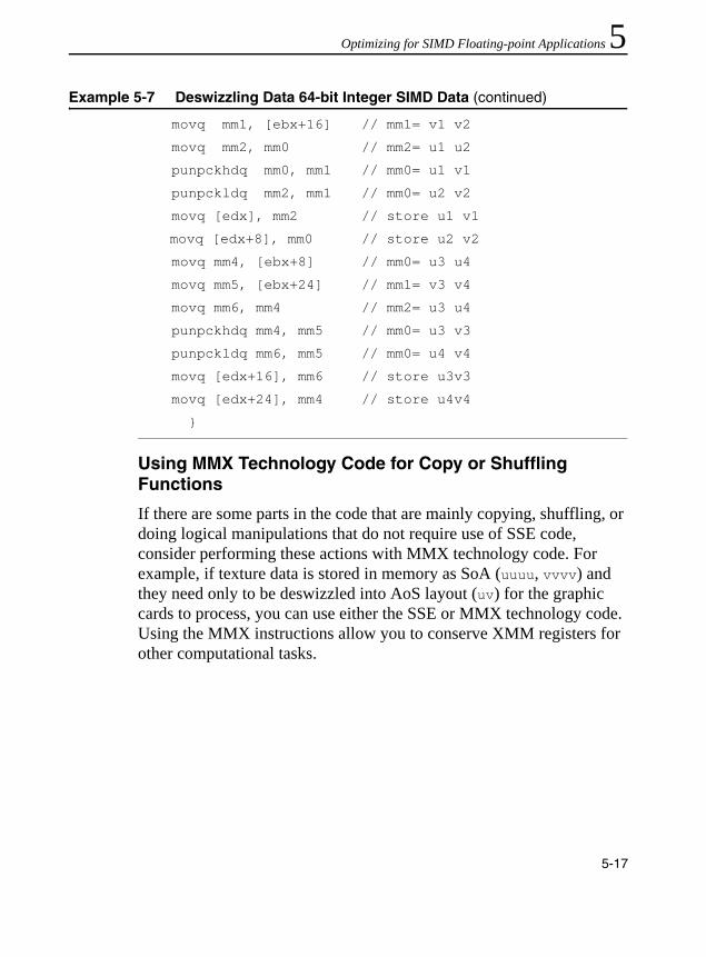
Optimizing for SIMD Floating-point Applications 5
Using MMX Technology Code for Copy or Shuffling Functions
If there are some parts in the code that are mainly copying, shuffling, or doing logical manipulations that do not require use of SSE code, consider performing these actions with MMX technology code. For example, if texture data is stored in memory as SoA (uuuu, vvvv) and they need only to be deswizzled into AoS layout (uv) for the graphic cards to process, you can use either the SSE or MMX technology code. Using the MMX instructions allow you to conserve XMM registers for other computational tasks.
movq mm1, [ebx+16] // mm1= v1 v2
movq mm2, mm0 // mm2= u1 u2
punpckhdq mm0, mm1 // mm0= u1 v1
punpckldq mm2, mm1 // mm0= u2 v2
movq [edx], mm2 // store u1 v1
movq [edx+8], mm0 // store u2 v2
movq mm4, [ebx+8] // mm0= u3 u4
movq mm5, [ebx+24] // mm1= v3 v4
movq mm6, mm4 // mm2= u3 u4
punpckhdq mm4, mm5 // mm0= u3 v3
punpckldq mm6, mm5 // mm0= u4 v4
movq [edx+16], mm6 // store u3v3
movq [edx+24], mm4 // store u4v4
}
Example 5-7 Deswizzling Data 64-bit Integer SIMD Data (continued)
5-17

IA-32 Intel® Architecture Optimization
Example 5-8 illustrates how to use MMX technology code for copying or shuffling.
Horizontal ADD Using SSE
Although vertical computations use the SIMD performance better than horizontal computations do, in some cases, the code must use a horizontal operation. The movlhps/movhlps and shuffle can be used to sum data horizontally. For example, starting with four 128-bit registers, to sum up each register horizontally while having the final results in one register, use the movlhps/movhlps instructions to align the upper and lower parts of each register. This allows you to use a vertical add. With the resulting partial horizontal summation, full summation follows easily. Figure 5-3 schematically presents horizontal add using movhlps/movlhps, while Example 5-9 and Example 5-10 provide the code for this operation.
Example 5-8 Using MMX Technology Code for Copying or Shuffling
movq mm0, [Uarray+ebx] ; mm0= u1 u2
movq mm1, [Varray+ebx] ; mm1= v1 v2
movq mm2, mm0 ; mm2= u1 u2
punpckhdq mm0, mm1 ; mm0= u1 v1
punpckldq mm2, mm1 ; mm2= u2 v2
movq [Coords+edx], mm0 ; store u1 v1
movq [Coords+8+edx], mm2 ; store u2 v2
movq mm4, [Uarray+8+ebx] ; mm4= u3 u4
movq mm5, [Varray+8+ebx] ; mm5= v3 v4
movq mm6, mm4 ; mm6= u3 u4
punpckhdq mm4, mm5 ; mm4= u3 v3
punpckldq mm6, mm5 ; mm6= u4 v4
movq [Coords+16+edx], mm4 ; store u3 v3
movq [Coords+24+edx], mm6 ; store u4 v4
5-18
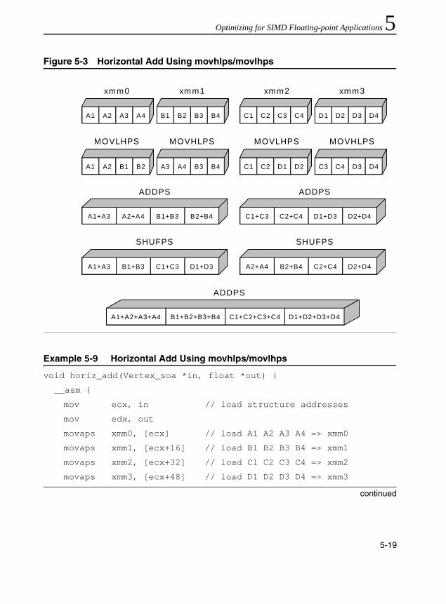
Optimizing for SIMD Floating-point Applications 5
Figure 5-3 Horizontal Add Using movhlps/movlhpsExample 5-9 Horizontal Add Using movhlps/movlhps
void horiz_add(Vertex_soa *in, float *out) {
__asm {
mov ecx, in // load structure addresses
mov edx, out
movaps xmm0, [ecx] // load A1 A2 A3 A4 => xmm0
movaps xmm1, [ecx+16] // load B1 B2 B3 B4 => xmm1
movaps xmm2, [ecx+32] // load C1 C2 C3 C4 => xmm2
movaps xmm3, [ecx+48] // load D1 D2 D3 D4 => xmm3
continued
A1+A2+A3+A4 B1+B2+B3+B4 C1+C2+C3+C4 D1+D2+D3+D4
A1+A3 B1+B3 C1+C3 D1+D3 A2+A4 B2+B4 C2+C4 D2+D4
A1+A3 A2+A4 B1+B3 B2+B4 C1+C3 C2+C4 D1+D3 D2+D4
A1 A2 A3 A4 B1 B2 B3 B4 C1 C2 C3 C4 D1 D2 D3 D4
A1 A2 B1 B2 A3 A4 B3 B4 C1 C2 D1 D2 C3 C4 D3 D4
ADDPS
SHUFPS SHUFPS
ADDPS ADDPS
MOVLHPS MOVLHPS
xmm0 xmm2
MOVHLPS MOVHLPS
xmm1 xmm3
5-19
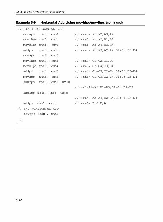
IA-32 Intel® Architecture Optimization
// START HORIZONTAL ADD
movaps xmm5, xmm0 // xmm5= A1,A2,A3,A4
movlhps xmm5, xmm1 // xmm5= A1,A2,B1,B2
movhlps xmm1, xmm0 // xmm1= A3,A4,B3,B4
addps xmm5, xmm1 // xmm5= A1+A3,A2+A4,B1+B3,B2+B4
movaps xmm4, xmm2
movlhps xmm2, xmm3 // xmm2= C1,C2,D1,D2
movhlps xmm3, xmm4 // xmm3= C3,C4,D3,D4
addps xmm3, xmm2 // xmm3= C1+C3,C2+C4,D1+D3,D2+D4
movaps xmm6, xmm3 // xmm6= C1+C3,C2+C4,D1+D3,D2+D4
shufps xmm3, xmm5, 0xDD
//xmm6=A1+A3,B1+B3,C1+C3,D1+D3
shufps xmm5, xmm6, 0x88
// xmm5= A2+A4,B2+B4,C2+C4,D2+D4
addps xmm6, xmm5 // xmm6= D,C,B,A
// END HORIZONTAL ADD
movaps [edx], xmm6
}
}
Example 5-9 Horizontal Add Using movhlps/movlhps (continued)
5-20
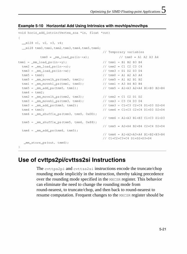
Optimizing for SIMD Floating-point Applications 5
Use of cvttps2pi/cvttss2si InstructionsThe cvttps2pi and cvttss2si instructions encode the truncate/chop rounding mode implicitly in the instruction, thereby taking precedence over the rounding mode specified in the MXCSR register. This behavior can eliminate the need to change the rounding mode from round-nearest, to truncate/chop, and then back to round-nearest to resume computation. Frequent changes to the MXCSR register should be
Example 5-10 Horizontal Add Using Intrinsics with movhlps/movlhps
void horiz_add_intrin(Vertex_soa *in, float *out)
{
__m128 v1, v2, v3, v4;
__m128 tmm0,tmm1,tmm2,tmm3,tmm4,tmm5,tmm6; // Temporary variables
tmm0 = _mm_load_ps(in->x); // tmm0 = A1 A2 A3 A4
tmm1 = _mm_load_ps(in->y); // tmm1 = B1 B2 B3 B4 tmm2 = _mm_load_ps(in->z); // tmm2 = C1 C2 C3 C4 tmm3 = _mm_load_ps(in->w); // tmm3 = D1 D2 D3 D4 tmm5 = tmm0; // tmm0 = A1 A2 A3 A4 tmm5 = _mm_movelh_ps(tmm5, tmm1); // tmm5 = A1 A2 B1 B2 tmm1 = _mm_movehl_ps(tmm1, tmm0); // tmm1 = A3 A4 B3 B4 tmm5 = _mm_add_ps(tmm5, tmm1); // tmm5 = A1+A3 A2+A4 B1+B3 B2+B4 tmm4 = tmm2; tmm2 = _mm_movelh_ps(tmm2, tmm3); // tmm2 = C1 C2 D1 D2 tmm3 = _mm_movehl_ps(tmm3, tmm4); // tmm3 = C3 C4 D3 D4 tmm3 = _mm_add_ps(tmm3, tmm2); // tmm3 = C1+C3 C2+C4 D1+D3 D2+D4 tmm6 = tmm3; // tmm6 = C1+C3 C2+C4 D1+D3 D2+D4 tmm6 = _mm_shuffle_ps(tmm3, tmm5, 0xDD);
// tmm6 = A1+A3 B1+B3 C1+C3 D1+D3 tmm5 = _mm_shuffle_ps(tmm5, tmm6, 0x88);
// tmm5 = A2+A4 B2+B4 C2+C4 D2+D4 tmm6 = _mm_add_ps(tmm6, tmm5);
// tmm6 = A1+A2+A3+A4 B1+B2+B3+B4 // C1+C2+C3+C4 D1+D2+D3+D4
_mm_store_ps(out, tmm6);}
5-21

IA-32 Intel® Architecture Optimization
avoided since there is a penalty associated with writing this register; typically, through the use of the cvttps2pi and cvttss2si instructions, the rounding control in MXCSR can be always be set to round-nearest.
Flush-to-Zero and Denormals-are-Zero ModesThe flush-to-zero (FTZ) and denormals-are-zero (DAZ) mode are not compatible with IEEE Standard 754. They are provided to improve performance for applications where underflow is common and where the generation of a denormalized result is not necessary. See “Floating-point Modes and Exceptions” in Chapter 2
SIMD Floating-point Programming Using SSE3SSE3 enhances SSE and SSE2 with 9 instructions targeted for SIMD floating-point programming. In contrast to many SSE and SSE2 instructions offering homogeneous arithmetic operations on parallel data elements (see Figure 5-1) and favoring the vertical computation model, SSE3 offers instructions that performs asymmetric arithmetic operation and arithmetic operation on horizontal data elements. ADDSUBPS and ADDSUBPD are two instructions with asymmetric arithmetic processing capability (see Figure 5-4). HADDPS, HADDPD, HSUBPS and HSUBPD offers horizontal arithmetic processing capability (see Figure 5-5). In addition, MOVSLDUP, MOVSHDUP and MOVDDUP can load data from memory (or XMM register) and replicate data elements at once.
5-22

Optimizing for SIMD Floating-point Applications 5
SSE3 and Complex Arithmetics
The flexibility of SSE3 in dealing with AOS-type of data structure can be demonstrated by the example of multiplication and division of complex numbers. For example, a complex number can be stored in a structure consisting of its real and imaginary part. This naturally leads to the use of an array of structure. Example 5-11 demonstrates using SSE3
Figure 5-4 Asymmetric Arithmetic Operation of the SSE3 Instruction
Figure 5-5 Horizontal Arithmetic Operation of the SSE3 Instruction HADDPD
X1 X0
X1 + Y1 X0 -Y0
SUB
Y1 Y0
ADD
X1 X0
Y0 + Y1 X0 + X1
ADD
Y1 Y0
ADD
5-23

IA-32 Intel® Architecture Optimization
instructions to perform multiplications of single-precision complex numbers. Example 5-12 demonstrates using SSE3 instructions to perform division of complex numbers.
In both of these examples, the complex numbers are store in arrays of structures. The MOVSLDUP, MOVSHDUP and the asymmetric ADDSUBPS instructions allow performing complex arithmetics on two pair of single-precision complex number simultaneously and without any unnecessary swizzling between data elements. The coding technique demonstrated in these two examples can be easily extended to perform complex arithmetics on double-precision complex numbers. In the case of double-precision complex arithmetics, multiplication or divisions is done on one pair of complex numbers at a time.
Example 5-11 Multiplication of Two Pair of Single-precision Complex Number
// Multiplication of (ak + i bk ) * (ck + i dk )
// a + i b can be stored as a data structure
movsldup xmm0, Src1; load real parts into the destination,
; a1, a1, a0, a0
movaps xmm1, src2; load the 2nd pair of complex values,
; i.e. d1, c1, d0, c0
mulps xmm0, xmm1; temporary results, a1d1, a1c1, a0d0,
; a0c0
shufps xmm1, xmm1, b1; reorder the real and imaginary
; parts, c1, d1, c0, d0
movshdup xmm2, Src1; load the imaginary parts into the
; destination, b1, b1, b0, b0
mulps xmm2, xmm1; temporary results, b1c1, b1d1, b0c0,
; b0d0
addsubps xmm0, xmm2; b1c1+a1d1, a1c1 -b1d1, b0c0+a0d0,
; a0c0-b0d0
5-24

Optimizing for SIMD Floating-point Applications 5
Example 5-12 Division of Two Pair of Single-precision Complex Number// Division of (ak + i bk ) / (ck + i dk )
movshdup xmm0, Src1; load imaginary parts into the
; destination, b1, b1, b0, b0
movaps xmm1, src2; load the 2nd pair of complex values,
; i.e. d1, c1, d0, c0
mulps xmm0, xmm1; temporary results, b1d1, b1c1, b0d0,
; b0c0
shufps xmm1, xmm1, b1; reorder the real and imaginary
; parts, c1, d1, c0, d0
movsldup xmm2, Src1; load the real parts into the
; destination, a1, a1, a0, a0
mulps xmm2, xmm1; temp results, a1c1, a1d1, a0c0, a0d0
addsubps xmm0, xmm2; a1c1+b1d1, b1c1-a1d1, a0c0+b0d0,
; b0c0-a0d0
mulps xmm1, xmm1; c1c1, d1d1, c0c0, d0d0
movps xmm2, xmm1; c1c1, d1d1, c0c0, d0d0
shufps xmm2, xmm2, b1; d1d1, c1c1, d0d0, c0c0
addps xmm2, xmm1; c1c1+d1d1, c1c1+d1d1, c0c0+d0d0,
; c0c0+d0d0
divps xmm0, xmm2
shufps xmm0, xmm0, b1 ; (b1c1-a1d1)/(c1c1+d1d1),
; (a1c1+b1d1)/(c1c1+d1d1),
; (b0c0-a0d0)/( c0c0+d0d0),
; (a0c0+b0d0)/( c0c0+d0d0)
5-25
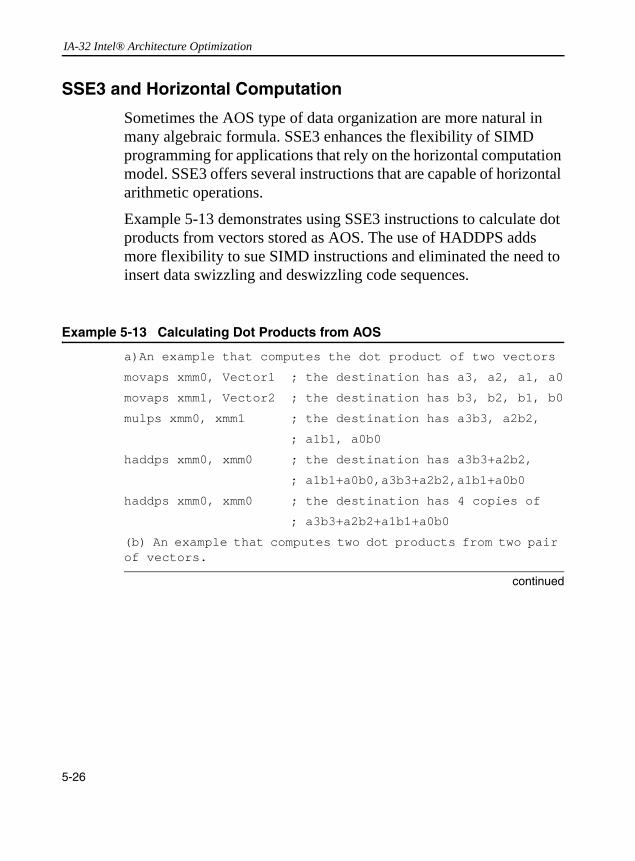
IA-32 Intel® Architecture Optimization
SSE3 and Horizontal Computation
Sometimes the AOS type of data organization are more natural in many algebraic formula. SSE3 enhances the flexibility of SIMD programming for applications that rely on the horizontal computation model. SSE3 offers several instructions that are capable of horizontal arithmetic operations.
Example 5-13 demonstrates using SSE3 instructions to calculate dot products from vectors stored as AOS. The use of HADDPS adds more flexibility to sue SIMD instructions and eliminated the need to insert data swizzling and deswizzling code sequences.
Example 5-13 Calculating Dot Products from AOS
a)An example that computes the dot product of two vectors
movaps xmm0, Vector1 ; the destination has a3, a2, a1, a0
movaps xmm1, Vector2 ; the destination has b3, b2, b1, b0
mulps xmm0, xmm1 ; the destination has a3b3, a2b2,
; a1b1, a0b0
haddps xmm0, xmm0 ; the destination has a3b3+a2b2,
; a1b1+a0b0,a3b3+a2b2,a1b1+a0b0
haddps xmm0, xmm0 ; the destination has 4 copies of
; a3b3+a2b2+a1b1+a0b0
(b) An example that computes two dot products from two pair of vectors.
continued
5-26
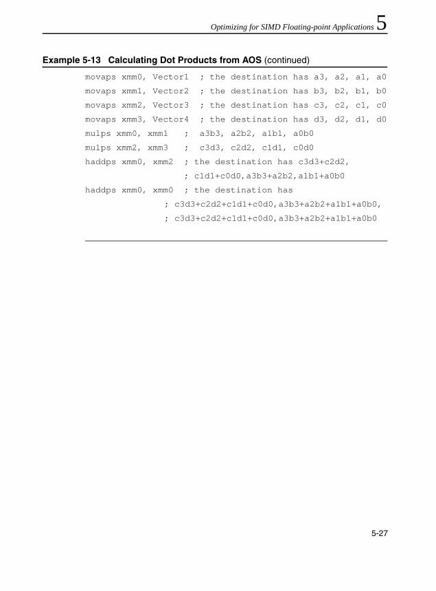
Optimizing for SIMD Floating-point Applications 5
movaps xmm0, Vector1 ; the destination has a3, a2, a1, a0
movaps xmm1, Vector2 ; the destination has b3, b2, b1, b0
movaps xmm2, Vector3 ; the destination has c3, c2, c1, c0
movaps xmm3, Vector4 ; the destination has d3, d2, d1, d0
mulps xmm0, xmm1 ; a3b3, a2b2, a1b1, a0b0
mulps xmm2, xmm3 ; c3d3, c2d2, c1d1, c0d0
haddps xmm0, xmm2 ; the destination has c3d3+c2d2,
; c1d1+c0d0,a3b3+a2b2,a1b1+a0b0
haddps xmm0, xmm0 ; the destination has
; c3d3+c2d2+c1d1+c0d0,a3b3+a2b2+a1b1+a0b0,
; c3d3+c2d2+c1d1+c0d0,a3b3+a2b2+a1b1+a0b0
Example 5-13 Calculating Dot Products from AOS (continued)
5-27

IA-32 Intel® Architecture Optimization
5-28

6
Optimizing Cache UsageOver the past decade, processor speed has increased more than ten times. Memory access speed has increased at a slower pace. The resulting disparity has made it important to tune applications in one of two ways: either (a) a majority of the data accesses are fulfilled from processor caches, or (b) effectively masking memory latency to utilize peak memory bandwidth as much as possible.
Hardware prefetching mechanisms are enhancements in microarchitecture to facilitate the latter aspect, and will be most effective when combined with software tuning. The performance of most applications can be considerably improved if the data required can be fetched from the processor caches or if memory traffic can take advantage of hardware prefetching effectively.
Standard techniques to bring data into the processor before it is needed involves additional programming which can be difficult to implement and may require special steps to prevent performance degradation. Streaming SIMD Extensions addressed this issue by providing the various prefetch instructions.
Streaming SIMD Extensions also introduced the various non-temporal store instructions. SSE2 extend this support to new data types and also introduce non-temporal store support for the 32-bit integer registers.
This chapter focuses on three subjects:• Hardware Prefetching Mechanism, Software Prefetch and
Cacheability Instructions: discusses microarchitectural feature and instructions that allow you to affect data caching in an application.
6-1
IA-32 Intel® Architecture Optimization
• Memory Optimization Using Hardware Prefetching, Software Prefetch and Cacheability Instructions: discusses techniques for implementing memory optimizations using the above instructions.
• Using deterministic cache parameters to manage cache hierarchy.
General Prefetch Coding GuidelinesThe following guidelines will help you to reduce memory traffic and utilize peak memory system bandwidth more effectively when large amounts of data movement must originate from the memory system:• Take advantage of the hardware prefetcher’s ability to prefetch data
that are accessed in linear patterns, either forward or backward direction.
• Take advantage of the hardware prefetcher’s ability to prefetch data that are accessed in a regular pattern with access stride that are substantially smaller than half of the trigger distance of the hardware prefetch (see Table 1-2).
• Use a current-generation compiler, such as the Intel® C++ Compiler that supports C++ language-level features for Streaming SIMD Extensions. Streaming SIMD Extensions and MMX technology instructions provide intrinsics that allow you to optimize cache utilization. The examples of such Intel® compiler intrinsics are _mm_prefetch, _mm_stream and _mm_load, _mm_sfence. For more details on these intrinsics, refer to the Intel C++ Compiler User’s Guide, doc. number 718195.
NOTE. In a number of cases presented in this chapter, the prefetching and cache utilization are specific to the current implementation of Intel NetBurst microarchitecture but are largely applicable for the future processors.
6-2

Optimizing Cache Usage 6
• Facilitate compiler optimization:— Minimize use of global variables and pointers— Minimize use of complex control flow — Use the const modifier, avoid register modifier — Choose data types carefully (see below) and avoid type casting.
• Use cache blocking techniques (for example, strip mining):— Improve cache hit rate by using cache blocking techniques such
as strip-mining (one dimensional arrays) or loop blocking (two dimensional arrays)
— Explore using hardware prefetching mechanism if your data access pattern has sufficient regularity to allow alternate sequencing of data accesses (e.g., tiling) for improved spatial locality; otherwise use prefetchnta.
• Balance single-pass versus multi-pass execution:— An algorithm can use single- or multi-pass execution defined as
follows: single-pass, or unlayered execution passes a single data element through an entire computation pipeline. Multi-pass, or layered execution performs a single stage of the pipeline on a batch of data elements before passing the entire batch on to the next stage.
— General guideline to minimize pollution: if your algorithm is single-pass use prefetchnta; if your algorithm is multi-pass use prefetcht0.
• Resolve memory bank conflict issues:— Minimize memory bank conflicts by applying array grouping to
group contiguously used data together or allocating data within 4 KB memory pages.
• Resolve cache management issues:— Minimize disturbance of temporal data held within the
processor’s caches by using streaming store instructions, as appropriate.
6-3

IA-32 Intel® Architecture Optimization
• Optimize software prefetch scheduling distance:— Far ahead enough to allow interim computation to overlap
memory access time.— Near enough that the prefetched data is not replaced from the
data cache.• Use software prefetch concatenation:
— Arrange prefetches to avoid unnecessary prefetches at the end of an inner loop and to prefetch the first few iterations of the inner loop inside the next outer loop.
• Minimize the number of software prefetches:— Prefetch instructions are not completely free in terms of bus
cycles, machine cycles and resources; excessive usage of prefetches can adversely impact application performance.
• Interleave prefetch with computation instructions:— For best performance, software prefetch instructions must be
interspersed with other computational instructions in the instruction sequence rather than clustered together.
Hardware Prefetching of DataThe Pentium 4, Intel Xeon, and Pentium M processors implement a hardware automatic data prefetcher which monitors application data access patterns and prefetches data automatically. This behavior is automatic and does not require programmer’s intervention directly.
Characteristics of the hardware data prefetcher for the Pentium 4 and Intel Xeon processors are:• Requires two successive cache misses in the last level cache to
trigger the mechanism and these two cache misses satisfying the condition that the strides of the cache misses is less than the trigger distance of the hardware prefetch mechanism (see Table 1-2).
• Attempts to stay 256 bytes ahead of current data access locations
6-4
Optimizing Cache Usage 6
• Follows only one stream per 4K page (load or store)• Can prefetch up to 8 simultaneous independent streams from eightdifferent 4K regions• Does not prefetch across 4K boundary; note that this is independent
of paging modes• Fetches data into second/third-level cache• Does not prefetch UC or WC memory types• Follows load and store streams. Issues Read For Ownership (RFO)
transactions for store streams and Data Reads for load streams.
The hardware prefetcher implemented in the Pentium M processor fetches data to the second level cache. It can track 12 independent streams in the forward direction and 4 independent streams in the backward direction.
Prefetch and Cacheability InstructionsThe prefetch instruction, inserted by the programmers or compilers, accesses a minimum of two cache line of data on the Pentium 4 processor (one cache line of data on the Pentium M processor) prior to that data actually being needed. This hides the latency for data access in the time required to process data already resident in the cache. Many algorithms can provide information in advance about the data that is to be required soon. In cases where the memory accesses are in long, regular data patterns, the automatic hardware prefetcher should be favored over software prefetches.
The cacheability control instructions allow you to control data caching strategy in order to increase cache efficiency and minimize cache pollution.
Data reference patterns can be classified as follows:Temporal data will be used again soonSpatial data will be used in adjacent locations, for example,
same cache line
6-5

IA-32 Intel® Architecture Optimization
Non-temporal data which is referenced once and not reused in the immediate future; for example, some multimedia data types, such as the vertex buffer in a 3D graphics application.
These data characteristics are used in the discussions that follow.
PrefetchThis section discusses the mechanics of the software prefetch instructions. In general, software prefetch instructions should be used to supplement the practice of tuning a access pattern to suit the automatic hardware prefetch mechanism.
Software Data Prefetch
The prefetch instruction can hide the latency of data access in performance-critical sections of application code by allowing data to be fetched in advance of its actual usage. The prefetch instructions do not change the user-visible semantics of a program, although they may affect the program’s performance. The prefetch instructions merely provide a hint to the hardware and generally will not generate exceptions or faults.
The prefetch instructions load either non-temporal data or temporal data in the specified cache level. This data access type and the cache level are specified as a hint. Depending on the implementation, the instruction fetches 32 or more aligned bytes, including the specified address byte, into the instruction-specified cache levels.
The prefetch instruction is implementation-specific; applications need to be tuned to each implementation to maximize performance.
NOTE. Using the prefetch instructions is recommended only if data does not fit in cache.
6-6
Optimizing Cache Usage 6
The prefetch instructions merely provide a hint to the hardware, and they will not generate exceptions or faults except for a few special cases (see the “Prefetch and Load Instructions” section). However, excessive use of prefetch instructions may waste memory bandwidth and result in performance penalty due to resource constraints.Nevertheless, the prefetch instructions can lessen the overhead of memory transactions by preventing cache pollution and by using the caches and memory efficiently. This is particularly important for applications that share critical system resources, such as the memory bus. See an example in the “Video Encoder” section.
The prefetch instructions are mainly designed to improve application performance by hiding memory latency in the background. If segments of an application access data in a predictable manner, for example, using arrays with known strides, then they are good candidates for using prefetch to improve performance.
Use the prefetch instructions in:• predictable memory access patterns• time-consuming innermost loops• locations where the execution pipeline may stall if data is not
available
6-7
IA-32 Intel® Architecture Optimization
The Prefetch Instructions – Pentium 4 Processor Implementation
Streaming SIMD Extensions include four flavors of prefetch instructions, one non-temporal, and three temporal. They correspond to two types of operations, temporal and non-temporal.
The non-temporal instruction isprefetchnta Fetch the data into the second-level cache, minimizing
cache pollution.
The temporal instructions areprefetcht0 Fetch the data into all cache levels, that is, to the
second-level cache for the Pentium 4 processor. prefetcht1 Identical to prefetcht0prefetcht2 Identical to prefetcht0
Table 6-1 lists the prefetch implementation differences between the Pentium III and Pentium 4 processors.
NOTE. At the time of prefetch, if the data is already found in a cache level that is closer to the processor than the cache level specified by the instruction, no data movement occurs.
6-8

Optimizing Cache Usage 6
Prefetch and Load Instructions
The Pentium 4 processor has a decoupled execution and memory architecture that allows instructions to be executed independently with memory accesses if there are no data and resource dependencies. Programs or compilers can use dummy load instructions to imitate prefetch functionality, but preloading is not completely equivalent to prefetch instructions. Prefetch instructions provide a greater performance than preloading.
Currently, the prefetch instruction provides a greater performance gain than preloading because it:• has no destination register, it only updates cache lines.• does not stall the normal instruction retirement.• does not affect the functional behavior of the program.• has no cache line split accesses.• does not cause exceptions except when LOCK prefix is used; the LOCK
prefix is not a valid prefix for use with the prefetch instructions and should not be used.
• does not complete its own execution if that would cause a fault.
Table 6-1 Prefetch Implementation: Pentium III and Pentium 4 Processors
Prefetch Type Pentium III Processor Pentium 4 Processor
Prefetch NTA
Fetch 32 bytes
Fetch into 1st- level cache
Do not fetch into 2nd-level cache
Fetch 128 bytes
Do not fetch into 1st-level cache
Fetch into 1 way of 2nd-level cache
PrefetchT0 Fetch 32 bytes
Fetch into 1st- level cache
Fetch into 2nd- level cache
Fetch 128 bytes
Do not fetch into 1st-level cache
Fetch into 2nd- level cache
PrefetchT1, PrefetchT2
Fetch 32 bytes
Fetch into 2nd- level cache only
Do not fetch into 1st-level cache
Fetch 128 bytes
Do not fetch into 1st-level cache
Fetch into 2nd- level cache only
6-9

IA-32 Intel® Architecture Optimization
The current advantages of the prefetch over preloading instructions are processor-specific. The nature and extent of the advantages may change in the future.
In addition, there are cases where a prefetch instruction will not perform the data prefetch. These include:• the prefetch causes a DTLB (Data Translation Lookaside Buffer)
miss. This applies to Pentium 4 processors with CPUID signature corresponding to family 15, model 0, 1 or 2. The prefetch instruction resolves a DTLB miss and fetches data on Pentium 4 processors with CPUID signature corresponding to family 15, model 3.
• an access to the specified address causes a fault/exception.• the memory subsystem runs out of request buffers between the
first-level cache and the second-level cache.• the prefetch targets an uncacheable memory region, for example,
USWC and UC.• a LOCK prefix is used. This causes an invalid opcode exception.
Cacheability ControlThis section covers the mechanics of the cacheability control instructions.
The Non-temporal Store Instructions
This section describes the behavior of streaming stores and reiterates some of the information presented in the previous section. In Streaming SIMD Extensions, the movntps, movntpd, movntq, movntdq, movnti, maskmovq and maskmovdqu instructions are streaming, non-temporal stores. With regard to memory characteristics and ordering, they are similar mostly to the Write-Combining (WC) memory type:• Write combining – successive writes to the same cache line are
combined
6-10

Optimizing Cache Usage 6
• Write collapsing – successive writes to the same byte(s) result inonly the last write being visible• Weakly ordered – no ordering is preserved between WC stores, or
between WC stores and other loads or stores• Uncacheable and not write-allocating – stored data is written around
the cache and will not generate a read-for-ownership bus request for the corresponding cache line
Fencing
Because streaming stores are weakly ordered, a fencing operation is required to ensure that the stored data is flushed from the processor to memory. Failure to use an appropriate fence may result in data being “trapped” within the processor and will prevent visibility of this data by other processors or system agents. WC stores require software to ensure coherence of data by performing the fencing operation; see “The fence Instructions” section for more information.
Streaming Non-temporal Stores
Streaming stores can improve performance in the following ways:• Increase store bandwidth if 64 bytes that fit within a cache line are
written consecutively, since they do not require read-for-ownership bus requests and 64 bytes are combined into a single bus write transaction.
• Reduce disturbance of frequently used cached (temporal) data, since they write around the processor caches.
Streaming stores allow cross-aliasing of memory types for a given memory region. For instance, a region may be mapped as write-back (WB) via the page attribute tables (PAT) or memory type range registers (MTRRs) and yet is written using a streaming store.
6-11
IA-32 Intel® Architecture Optimization
Memory Type and Non-temporal Stores
The memory type can take precedence over the non-temporal hint, leading to the following considerations:• If the programmer specifies a non-temporal store to
strongly-ordered uncacheable memory, for example, the Uncacheable (UC) or Write-Protect (WP) memory types, then the store behaves like an uncacheable store; the non-temporal hint is ignored and the memory type for the region is retained.
• If the programmer specifies the weakly-ordered uncacheable memory type of Write-Combining (WC), then the non-temporal store and the region have the same semantics, and there is no conflict.
• If the programmer specifies a non-temporal store to cacheable memory, for example, Write-Back (WB) or Write-Through (WT) memory types, two cases may result:1. If the data is present in the cache hierarchy, the instruction will
ensure consistency. A particular processor may choose different ways to implement this. The following approaches are probable: (a) updating data in-place in the cache hierarchy while preserving the memory type semantics assigned to that region or (b) evicting the data from the caches and writing the new non-temporal data to memory (with WC semantics). Note that the approaches, separate or combined, can be different for future processors. The Pentium 4 processor implements the latter policy, of evicting data from all processor caches. The Pentium III processor implements a combination of both approaches. If the streaming store hits a line that is present in the first-level cache, the store data is combined in place within the first-level cache. If the streaming store hits a line present in the second-level, the line and stored data is flushed from the second-level to system memory.
6-12
Optimizing Cache Usage 6
2. If the data is not present in the cache hierarchy, and thedestination region is mapped as WB or WT, the transaction will be weakly ordered, and is subject to all WC memory semantics. The non-temporal store will not write-allocate. Different implementations may choose to collapse and combine these stores.
Write-Combining
Generally, WC semantics require software to ensure coherence, with respect to other processors and other system agents (such as graphics cards). Appropriate use of synchronization and a fencing operation (see “The fence Instructions” later in this chapter) must be performed for producer-consumer usage models. Fencing ensures that all system agents have global visibility of the stored data; for instance, failure to fence may result in a written cache line staying within a processor, and the line would not be visible to other agents.
For processors which implement non-temporal stores by updating data in-place that already resides in the cache hierarchy, the destination region should also be mapped as WC. Otherwise if mapped as WB or WT, there is a potential for speculative processor reads to bring the data into the caches; in this case, non-temporal stores would then update in place, and data would not be flushed from the processor by a subsequent fencing operation.
The memory type visible on the bus in the presence of memory type aliasing is implementation-specific. As one possible example, the memory type written to the bus may reflect the memory type for the first store to this line, as seen in program order; other alternatives are possible. This behavior should be considered reserved, and dependence on the behavior of any particular implementation risks future incompatibility.
6-13
IA-32 Intel® Architecture Optimization
Streaming Store Usage Models
The two primary usage domains for streaming store are coherent requests and non-coherent requests.
Coherent Requests
Coherent requests are normal loads and stores to system memory, which may also hit cache lines present in another processor in a multi-processor environment. With coherent requests, a streaming store can be used in the same way as a regular store that has been mapped with a WC memory type (PAT or MTRR). An sfence instruction must be used within a producer-consumer usage model in order to ensure coherency and visibility of data between processors.
Within a single-processor system, the CPU can also re-read the same memory location and be assured of coherence (that is, a single, consistent view of this memory location): the same is true for a multi-processor (MP) system, assuming an accepted MP software producer-consumer synchronization policy is employed.
Non-coherent requests
Non-coherent requests arise from an I/O device, such as an AGP graphics card, that reads or writes system memory using non-coherent requests, which are not reflected on the processor bus and thus will not query the processor’s caches. An sfence instruction must be used within a producer-consumer usage model in order to ensure coherency and visibility of data between processors. In this case, if the processor is writing data to the I/O device, a streaming store can be used with a processor with any behavior of approach (a), page 6-12, above, only if the region has also been mapped with a WC memory type (PAT, MTRR).
6-14

Optimizing Cache Usage 6
In case the region is not mapped as WC, the streaming might update in-place in the cache and a subsequent sfence would not result in the data being written to system memory. Explicitly mapping the region as WC in this case ensures that any data read from this region will not be placed in the processor’s caches. A read of this memory location by a non-coherent I/O device would return incorrect/out-of-date results. For a processor which solely implements approach (b), page 6-12, above, a streaming store can be used in this non-coherent domain without requiring the memory region to also be mapped as WB, since any cached data will be flushed to memory by the streaming store.
Streaming Store Instruction Descriptions
The movntq/movntdq (non-temporal store of packed integer in an MMX technology or Streaming SIMD Extensions register) instructions store data from a register to memory. The instruction is implicitly weakly-ordered, does no write-allocate, and so minimizes cache pollution.
The movntps (non-temporal store of packed single precision floating point) instruction is similar to movntq. It stores data from a Streaming SIMD Extensions register to memory in 16-byte granularity. Unlike movntq, the memory address must be aligned to a 16-byte boundary or a general protection exception will occur. The instruction is implicitly weakly-ordered, does not write-allocate, and thus minimizes cache pollution.
CAUTION. Failure to map the region as WC may allow the line to be speculatively read into the processor caches, that is, via the wrong path of a mispredicted branch.
6-15

IA-32 Intel® Architecture Optimization
The maskmovq/maskmovdqu (non-temporal byte mask store of packed integer in an MMX technology or Streaming SIMD Extensions register) instructions store data from a register to the location specified by the edi register. The most significant bit in each byte of the second mask register is used to selectively write the data of the first register on a per-byte basis. The instruction is implicitly weakly-ordered (that is, successive stores may not write memory in original program-order), does not write-allocate, and thus minimizes cache pollution.
The fence Instructions
The following fence instructions are available: sfence, lfence, and mfence.
The sfence Instruction
The sfence (store fence) instruction makes it possible for every store instruction that precedes the sfence instruction in program order to be globally visible before any store instruction that follows the sfence. The sfence instruction provides an efficient way of ensuring ordering between routines that produce weakly-ordered results.
The use of weakly-ordered memory types can be important under certain data sharing relationships, such as a producer-consumer relationship. Using weakly-ordered memory can make assembling the data more efficient, but care must be taken to ensure that the consumer obtains the data that the producer intended to see. Some common usage models may be affected in this way by weakly-ordered stores. Examples are: • library functions, which use weakly-ordered memory to write
results• compiler-generated code, which also benefits from writing
weakly-ordered results• hand-crafted code
6-16

Optimizing Cache Usage 6
The degree to which a consumer of data knows that the data is weakly-ordered can vary for these cases. As a result, the sfence instruction should be used to ensure ordering between routines that produce weakly-ordered data and routines that consume this data. The sfence instruction provides a performance-efficient way by ensuring the ordering when every store instruction that precedes the store fence instruction in program order is globally visible before any store instruction which follows the fence.The lfence Instruction
The lfence (load fence) instruction makes it possible for every load instruction that precedes the lfence instruction in program order to be globally visible before any load instruction that follows the lfence. The lfence instruction provides a means of segregating certain load instructions from other loads.
The mfence Instruction
The mfence (memory fence) instruction makes it possible for every load and store instruction that precedes the mfence instruction in program order to be globally visible before any other load or store instruction that follows the mfence. The mfence instruction provides a means of segregating certain memory instructions from other memory references.
Note that the use of a lfence and sfence is not equivalent to the use of a mfence since the load and store fences are not ordered with respect to each other. In other words, the load fence can be executed before prior stores, and the store fence can be executed before prior loads. The mfence instruction should be used whenever the cache line flush instruction (clflush) is used to ensure that speculative memory references generated by the processor do not interfere with the flush; see “The clflush Instruction” for more information.
6-17

IA-32 Intel® Architecture Optimization
The clflush Instruction
The cache line associated with the linear address specified by the value of byte address is invalidated from all levels of the processor cache hierarchy (data and instruction). The invalidation is broadcast throughout the coherence domain. If, at any level of the cache hierarchy, the line is inconsistent with memory (dirty) it is written to memory before invalidation. Other characteristics include:• The data size affected is the cache coherency size, which is 64 bytes
on Pentium 4 processor.• The memory attribute of the page containing the affected line has no
effect on the behavior of this instruction.• The clflush instruction can be used at all privilege levels and is
subject to all permission checking and faults associated with a byte load.
clflush is an unordered operation with respect to other memory traffic including other clflush instructions. Software should use a mfence, memory fence for cases where ordering is a concern.
As an example, consider a video usage model, wherein a video capture device is using non-coherent AGP accesses to write a capture stream directly to system memory. Since these non-coherent writes are not broadcast on the processor bus, they will not flush any copies of the same locations that reside in the processor caches. As a result, before the processor re-reads the capture buffer, it should use clflush to ensure that any stale copies of the capture buffer are flushed from the processor caches. Due to speculative reads that may be generated by the processor, it is important to observe appropriate fencing, using mfence. Example 6-1 illustrates the pseudo-code for the recommended usage of cflush.
6-18

Optimizing Cache Usage 6
Memory Optimization Using PrefetchThe Pentium 4 processor has two mechanisms for data prefetch: software-controlled prefetch and an automatic hardware prefetch.
Software-controlled Prefetch
The software-controlled prefetch is enabled using the four prefetch instructions introduced with Streaming SIMD Extensions instructions. These instructions are hints to bring a cache line of data in to various levels and modes in the cache hierarchy. The software-controlled prefetch is not intended for prefetching code. Using it can incur significant penalties on a multiprocessor system when code is shared.
Software prefetching has the following characteristics:• Can handle irregular access patterns, which do not trigger the
hardware prefetcher.• Can use less bus bandwidth than hardware prefetching; see below.• Software prefetches must be added to new code, and do not benefit
existing applications.
Example 6-1 Pseudo-code for Using cflush
while (!buffer_ready} {}
mfence
for(i=0;i<num_cachelines;i+=cacheline_size) {
clflush (char *)((unsigned int)buffer + i)
}
mfence
prefnta buffer[0];
VAR = buffer[0];
6-19

IA-32 Intel® Architecture Optimization
Hardware Prefetch
The automatic hardware prefetch, can bring cache lines into the unified last-level cache based on prior data misses. The automatic hardware prefetcher will attempt to prefetch two cache lines ahead of the prefetch stream. This feature is introduced with the Pentium 4 processor.
The characteristics of the hardware prefetching are as follows:• Requires some regularity in the data access patterns:
— if a data access pattern has constant stride, hardware prefetching is effective only if access stride is less than half of the trigger distance of hardware prefetcher (see Table 1-2).
— if access stride is not constant, the automatic hardware prefetcher can mask memory latency if the strides of two successive cache misses are less than the trigger threshold distance (small-stride memory traffic).
— the automatic hardware prefetcher is most effective if the strides of two successive cache misses remain less than the trigger threshold distance and close to 64 bytes.
• Start-up penalty before hardware prefetcher triggers and extra fetches after array finishes. For short arrays this overhead can reduce effectiveness of the hardware prefetcher.— The hardware prefetcher requires a couple misses before it
starts operating.— Hardware prefetching will generate a request for data beyond
the end of an array, which will not be utilized. This behavior wastes bus bandwidth. In addition this behavior results in a start-up penalty when fetching the beginning of the next array; this occurs because the wasted prefetch should have been used instead to hide the latency for the initial data in the next array. Software prefetching can recognize and handle these cases.
• Will not prefetch across a 4K page boundary; i.e., the program would have to initiate demand loads for the new page before the hardware prefetcher will start prefetching from the new page.
6-20

Optimizing Cache Usage 6
• May consume extra system bandwidth if the application’s memorytraffic has significant portions with strides of cache misses greater than the trigger distance threshold of hardware prefetch (large-stride memory traffic).
• Effectiveness with existing applications depends on the proportions of small-stride versus large-stride accesses in the application’s memory traffic. Preponderance of small-stride memory traffic with good temporal locality will benefit greatly from the automatic hardware prefetcher.
• Some situations of memory traffic consisting of a preponderance of large-stride cache misses can be transformed by re-arrangement of data access sequences (e.g., tiling, packing a sparsely-populated, multi-dimensional, band array into a one-dimensional array) to alter the concentration of small-stride cache misses at the expense of large-stride cache misses to take advantage of the automatic hardware prefetcher.
Example of Effective Latency Reduction with H/W Prefetch
Consider the situation that an array is populated with data corresponding to a constant-access-stride, circular pointer chasing sequence (see Example 6-2). The potential of employing the automatic hardware prefetching mechanism to reduce the effective latency of fetching a cache line from memory can be illustrated by varying the access stride between 64 bytes and the trigger threshold distance of hardware prefetch when populating the array for circular pointer chasing.
The effective latency reduction for three microarchitecture implementation is shown in Figure 6-1. For a constant-stride access pattern, the benefit of the automatic hardware prefetcher begins at half the trigger threshold distance, and reaches maximum benefit when the cache-miss stride is 64 bytes.
6-21

IA-32 Intel® Architecture Optimization
Example 6-2 Populating an Array for Circular Pointer Chasing with Constant Stride
register char ** p;char *next; // Populating pArray for circular pointer // chasing with constant access stride// p = (char **)*p; loads a value pointing to next load
p = (char **)&pArray;for (i = 0; i < aperture; i += stride) { p = (char **)&pArray[i]; if (i + stride >= g_array_aperture) {
next = &pArray[0 ]; } else {
next = &pArray[i + stride];} *p = next; // populate the address of the next node}
6-22
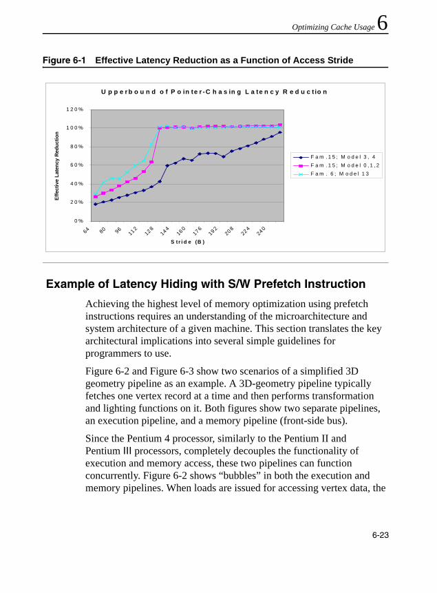
Optimizing Cache Usage 6
Example of Latency Hiding with S/W Prefetch Instruction
Achieving the highest level of memory optimization using prefetch instructions requires an understanding of the microarchitecture and system architecture of a given machine. This section translates the key architectural implications into several simple guidelines for programmers to use.
Figure 6-2 and Figure 6-3 show two scenarios of a simplified 3D geometry pipeline as an example. A 3D-geometry pipeline typically fetches one vertex record at a time and then performs transformation and lighting functions on it. Both figures show two separate pipelines, an execution pipeline, and a memory pipeline (front-side bus).
Since the Pentium 4 processor, similarly to the Pentium II andPentium III processors, completely decouples the functionality of execution and memory access, these two pipelines can function concurrently. Figure 6-2 shows “bubbles” in both the execution and memory pipelines. When loads are issued for accessing vertex data, the
Figure 6-1 Effective Latency Reduction as a Function of Access Stride
U p p e r b o u n d o f P o in te r -C h a s in g L a te n c y R e d u c t io n
0 %
2 0 %
4 0 %
6 0 %
8 0 %
1 0 0 %
1 2 0 %
64 80 96112
128144
160176
192208
224240
S tr i d e (B )
Effe
ctiv
e La
tenc
y R
educ
tion
F a m . 1 5 ; M o d e l 3 , 4F a m . 1 5 ; M o d e l 0 , 1 , 2F a m . 6 ; M o d e l 1 3
6-23

IA-32 Intel® Architecture Optimization
execution units sit idle and wait until data is returned. On the other hand, the memory bus sits idle while the execution units are processing vertices. This scenario severely decreases the advantage of having a decoupled architecture.
Figure 6-2 Memory Access Latency and Execution Without Prefetch
Figure 6-3 Memory Access Latency and Execution With Prefetch
OM15170
Execution units idle
Mem latency
Issue loads
Time
Vertex n+1
Execution units idleExecutionpipeline
Mem latency
Issue loads(vertex data)
Vertex n
Front-SideBus
FSB idle
OM15171
Time
Vertex n-2Executionpipeline
Mem latency for Vn
issue prefetchfor vertex n
Front-SideBus
Vertex n-1 Vertex n Vertex n+1
Mem latency for Vn+1
Mem latency for Vn+2
prefetchVn+1
prefetchVn+2
6-24
Optimizing Cache Usage 6
The performance loss caused by poor utilization of resources can be completely eliminated by correctly scheduling the prefetch instructions appropriately. As shown in Figure 6-3, prefetch instructions are issued two vertex iterations ahead. This assumes that only one vertex gets processed in one iteration and a new data cache line is needed for each iteration. As a result, when iteration n, vertex Vn, is being processed, the requested data is already brought into cache. In the meantime, the front-side bus is transferring the data needed for iteration n+1, vertex Vn+1. Because there is no dependence between Vn+1 data and the execution of Vn, the latency for data access of Vn+1 can be entirely hidden behind the execution of Vn. Under such circumstances, no “bubbles” are present in the pipelines and thus the best possible performance can be achieved.Prefetching is useful for inner loops that have heavy computations, or are close to the boundary between being compute-bound and memory-bandwidth-bound.
The prefetch is probably not very useful for loops which are predominately memory bandwidth-bound.
When data is already located in the first level cache, prefetching can be useless and could even slow down the performance because the extra µops either back up waiting for outstanding memory accesses or may be dropped altogether. This behavior is platform-specific and may change in the future.
Software Prefetching Usage Checklist
The following checklist covers issues that need to be addressed and/or resolved to use the software prefetch instruction properly:• Determine software prefetch scheduling distance• Use software prefetch concatenation• Minimize the number of software prefetches• Mix software prefetch with computation instructions• Use cache blocking techniques (for example, strip mining)
6-25
IA-32 Intel® Architecture Optimization
• Balance single-pass versus multi-pass execution• Resolve memory bank conflict issues• Resolve cache management issues
The subsequent sections discuss all the above items.
Software Prefetch Scheduling Distance
Determining the ideal prefetch placement in the code depends on many architectural parameters, including the amount of memory to be prefetched, cache lookup latency, system memory latency, and estimate of computation cycle. The ideal distance for prefetching data is processor- and platform-dependent. If the distance is too short, the prefetch will not hide any portion of the latency of the fetch behind computation. If the prefetch is too far ahead, the prefetched data may be flushed out of the cache by the time it is actually required.
Since prefetch distance is not a well-defined metric, for this discussion, we define a new term, prefetch scheduling distance (PSD), which is represented by the number of iterations. For large loops, prefetch scheduling distance can be set to 1, that is, schedule prefetch instructions one iteration ahead. For small loop bodies, that is, loop iterations with little computation, the prefetch scheduling distance must be more than one iteration.
A simplified equation to compute PSD is deduced from the mathematical model. For a simplified equation, complete mathematical model, and methodology of prefetch distance determination, refer to Appendix E, “Mathematics of Prefetch Scheduling Distance”.
Example 6-3 illustrates the use of a prefetch within the loop body. The prefetch scheduling distance is set to 3, esi is effectively the pointer to a line, edx is the address of the data being referenced and xmm1-xmm4 are the data used in computation. Example 6-4 uses two independent cache
6-26

Optimizing Cache Usage 6
lines of data per iteration. The PSD would need to be increased/decreased if more/less than two cache lines are used per iteration.Software Prefetch Concatenation
Maximum performance can be achieved when execution pipeline is at maximum throughput, without incurring any memory latency penalties. This can be achieved by prefetching data to be used in successive iterations in a loop. De-pipelining memory generates bubbles in the execution pipeline. To explain this performance issue, a 3D geometry pipeline that processes 3D vertices in strip format is used as an example. A strip contains a list of vertices whose predefined vertex order forms contiguous triangles. It can be easily observed that the memory pipe is de-pipelined on the strip boundary due to ineffective prefetch arrangement. The execution pipeline is stalled for the first two iterations for each strip. As a result, the average latency for completing an iteration will be 165(FIX) clocks. (See Appendix E, “Mathematics of Prefetch Scheduling Distance”, for a detailed memory pipeline description.)
Example 6-3 Prefetch Scheduling Distance
top_loop:prefetchnta [edx + esi + 128*3]prefetchnta [edx*4 + esi + 128*3]. . . . .movaps xmm1, [edx + esi]movaps xmm2, [edx*4 + esi]movaps xmm3, [edx + esi + 16]movaps xmm4, [edx*4 + esi + 16]. . . . .. . . . .add esi, 128cmp esi, ecxjl top_loop
6-27
IA-32 Intel® Architecture Optimization
This memory de-pipelining creates inefficiency in both the memory pipeline and execution pipeline. This de-pipelining effect can be removed by applying a technique called prefetch concatenation. With this technique, the memory access and execution can be fully pipelined and fully utilized.
For nested loops, memory de-pipelining could occur during the interval between the last iteration of an inner loop and the next iteration of its associated outer loop. Without paying special attention to prefetch insertion, the loads from the first iteration of an inner loop can miss the cache and stall the execution pipeline waiting for data returned, thus degrading the performance.
In the code of Example 6-4, the cache line containing a[ii][0] is not prefetched at all and always misses the cache. This assumes that no array a[][] footprint resides in the cache. The penalty of memory de-pipelining stalls can be amortized across the inner loop iterations. However, it may become very harmful when the inner loop is short. In addition, the last prefetch in the last PSD iterations are wasted and consume machine resources. Prefetch concatenation is introduced here in order to eliminate the performance issue of memory de-pipelining.
6-28
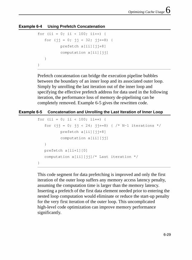
Optimizing Cache Usage 6
Prefetch concatenation can bridge the execution pipeline bubbles between the boundary of an inner loop and its associated outer loop. Simply by unrolling the last iteration out of the inner loop and specifying the effective prefetch address for data used in the following iteration, the performance loss of memory de-pipelining can be completely removed. Example 6-5 gives the rewritten code.
This code segment for data prefetching is improved and only the first iteration of the outer loop suffers any memory access latency penalty, assuming the computation time is larger than the memory latency. Inserting a prefetch of the first data element needed prior to entering the nested loop computation would eliminate or reduce the start-up penalty for the very first iteration of the outer loop. This uncomplicated high-level code optimization can improve memory performance significantly.
Example 6-4 Using Prefetch Concatenation
for (ii = 0; ii < 100; ii++) {
for (jj = 0; jj < 32; jj+=8) {
prefetch a[ii][jj+8]
computation a[ii][jj]
}
}
Example 6-5 Concatenation and Unrolling the Last Iteration of Inner Loop
for (ii = 0; ii < 100; ii++) {
for (jj = 0; jj < 24; jj+=8) { /* N-1 iterations */
prefetch a[ii][jj+8]
computation a[ii][jj]
}
prefetch a[ii+1][0]
computation a[ii][jj]/* Last iteration */
}
6-29
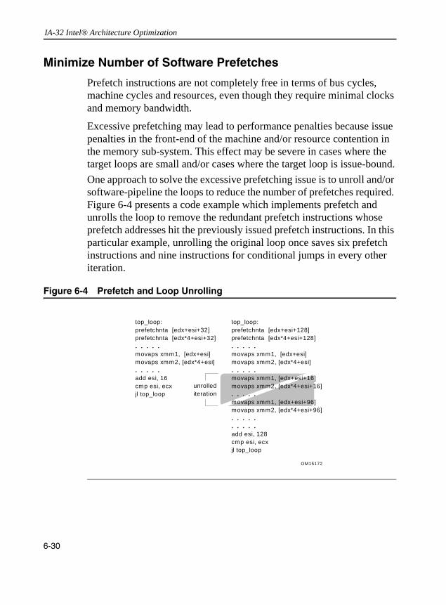
IA-32 Intel® Architecture Optimization
Minimize Number of Software Prefetches
Prefetch instructions are not completely free in terms of bus cycles, machine cycles and resources, even though they require minimal clocks and memory bandwidth.
Excessive prefetching may lead to performance penalties because issue penalties in the front-end of the machine and/or resource contention in the memory sub-system. This effect may be severe in cases where the target loops are small and/or cases where the target loop is issue-bound.One approach to solve the excessive prefetching issue is to unroll and/or software-pipeline the loops to reduce the number of prefetches required. Figure 6-4 presents a code example which implements prefetch and unrolls the loop to remove the redundant prefetch instructions whose prefetch addresses hit the previously issued prefetch instructions. In this particular example, unrolling the original loop once saves six prefetch instructions and nine instructions for conditional jumps in every other iteration.
Figure 6-4 Prefetch and Loop Unrolling
OM15172
top_loop:prefetchnta [edx+esi+32]prefetchnta [edx*4+esi+32]. . . . .movaps xmm1, [edx+esi]movaps xmm2, [edx*4+esi]. . . . .add esi, 16cmp esi, ecxjl top_loop
top_loop:prefetchnta [edx+esi+128]prefetchnta [edx*4+esi+128]. . . . .movaps xmm1, [edx+esi]movaps xmm2, [edx*4+esi]. . . . .movaps xmm1, [edx+esi+16]movaps xmm2, [edx*4+esi+16]. . . . .movaps xmm1, [edx+esi+96]movaps xmm2, [edx*4+esi+96]. . . . .. . . . .add esi, 128cmp esi, ecxjl top_loop
unrollediteration
6-30
Optimizing Cache Usage 6
Figure 6-5 demonstrates the effectiveness of software prefetches in latency hiding. The X axis indicates the number of computation clocks per loop (each iteration is independent). The Y axis indicates the execution time measured in clocks per loop. The secondary Y axis indicates the percentage of bus bandwidth utilization. The tests vary by the following parameters:1. The number of load/store streams. Each load and store streamaccesses one 128-byte cache line each, per iteration.2. The amount of computation per loop. This is varied by increasing
the number of dependent arithmetic operations executed.3. The number of the software prefetches per loop. (for example, one
every 16 bytes, 32 bytes, 64 bytes, 128 bytes).
As expected, the leftmost portion of each of the graphs in Figure 6-5 shows that when there is not enough computation to overlap the latency of memory access, prefetch does not help and that the execution is essentially memory-bound. The graphs also illustrate that redundant prefetches do not increase performance.
6-31

IA-32 Intel® Architecture Optimization
Figure 6-5 Memory Access Latency and Execution With Prefetch
2 Load streams, 1 store stream
50
100
150
200
250
300
350
54 108 144 192 240 336 390
Computations per loop
Eff
ecti
ve l
oo
p l
aten
cy
0.00%
10.00%
20.00%
30.00%
40.00%
50.00%
60.00%
70.00%
80.00%
90.00%
100.00%
% o
f B
us
Uti
lize
d
16 32 64 128 none
% Bus Utilization
One load and one store stream
0
50
100
150
200
250
300
350
48 108 144 192 240 336 408
Computations per loop
Eff
ecti
ve lo
op
lat
ency
0.00%
10.00%
20.00%
30.00%
40.00%
50.00%
60.00%
70.00%
80.00%
90.00%
100.00%
% o
f B
us U
tili
zati
on
16_por 32_por 64_por 128_por None_por
% Bus Utilization
6-32

Optimizing Cache Usage 6
Mix Software Prefetch with Computation InstructionsIt may seem convenient to cluster all of the prefetch instructions at the beginning of a loop body or before a loop, but this can lead to severe performance degradation. In order to achieve best possible performance, prefetch instructions must be interspersed with other computational instructions in the instruction sequence rather than clustered together. If possible, they should also be placed apart from loads. This improves the instruction level parallelism and reduces the potential instruction resource stalls. In addition, this mixing reduces the pressure on the memory access resources and in turn reduces the possibility of the prefetch retiring without fetching data.
Example 6-6 illustrates distributing prefetch instructions. A simple and useful heuristic of prefetch spreading for a Pentium 4 processor is to insert a prefetch instruction every 20 to 25 clocks. Rearranging prefetch instructions could yield a noticeable speedup for the code which stresses the cache resource.
6-33

IA-32 Intel® Architecture Optimization
Example 6-6 Spread Prefetch Instructions
NOTE. To avoid instruction execution stalls due to the over-utilization of the resource, prefetch instructions must be interspersed with computational instructions.
top_loop: prefetchnta [ebx+128] prefetchnta [ebx+1128] prefetchnta [ebx+2128] prefetchnta [ebx+3128] . . . . . . . . prefetchnta [ebx+17128] prefetchnta [ebx+18128] prefetchnta [ebx+19128] prefetchnta [ebx+20128] movps xmm1, [ebx] addps xmm2, [ebx+3000] mulps xmm3, [ebx+4000] addps xmm1, [ebx+1000] addps xmm2, [ebx+3016] mulps xmm1, [ebx+2000] mulps xmm1, xmm2 . . . . . . . . . . . . . . . . . . . add ebx, 128 cmp ebx, ecx jl top_loop
top_loop: prefetchnta [ebx+128] movps xmm1, [ebx] addps xmm2, [ebx+3000] mulps xmm3, [ebx+4000] prefetchnta [ebx+1128] addps xmm1, [ebx+1000] addps xmm2, [ebx+3016] prefetchnta [ebx+2128] mulps xmm1, [ebx+2000] mulps xmm1, xmm2 prefetchnta [ebx+3128] . . . . . . . . . . prefetchnta [ebx+18128] . . . . . . prefetchnta [ebx+19128] . . . . . . . . . . prefetchnta [ebx+20128] add ebx, 128 cmp ebx, ecx jl top_loop
spread
prefetch
es
6-34

Optimizing Cache Usage 6
Software Prefetch and Cache Blocking TechniquesCache blocking techniques, such as strip-mining, are used to improve temporal locality, and thereby cache hit rate. Strip-mining is a one-dimensional temporal locality optimization for memory. When two-dimensional arrays are used in programs, loop blocking technique (similar to strip-mining but in two dimensions) can be applied for a better memory performance.
If an application uses a large data set that can be reused across multiple passes of a loop, it will benefit from strip mining: data sets larger than the cache will be processed in groups small enough to fit into cache. This allows temporal data to reside in the cache longer, reducing bus traffic.
Data set size and temporal locality (data characteristics) fundamentally affect how prefetch instructions are applied to strip-mined code. Figure 6-6 shows two simplified scenarios for temporally-adjacent data and temporally-non-adjacent data.
6-35

IA-32 Intel® Architecture Optimization
In the temporally-adjacent scenario, subsequent passes use the same data and find it already in second-level cache. Prefetch issues aside, this is the preferred situation. In the temporally non-adjacent scenario, data used in pass m is displaced by pass (m+1), requiring data re-fetch into the first level cache and perhaps the second level cache if a later pass reuses the data. If both data sets fit into the second-level cache, load operations in passes 3 and 4 become less expensive.
Figure 6-6 Cache Blocking – Temporally Adjacent and Non-adjacent Passes
Dataset A
Dataset B
Dataset B
Dataset A
Dataset A
Dataset A
Dataset B
Dataset B
Pass 1
Pass 2
Pass 3
Pass 4
Temporally adjacent passes
Temporally non-adjacent
passes
6-36

Optimizing Cache Usage 6
Figure 6-7 shows how prefetch instructions and strip-mining can be applied to increase performance in both of these scenarios.For Pentium 4 processors, the left scenario shows a graphical implementation of using prefetchnta to prefetch data into selected ways of the second-level cache only (SM1 denotes strip mine one way of second-level), minimizing second-level cache pollution. Use prefetchnta if the data is only touched once during the entire execution pass in order to minimize cache pollution in the higher level caches. This provides instant availability, assuming the prefetch was issued far ahead enough, when the read access is issued.
Figure 6-7 Examples of Prefetch and Strip-mining for Temporally Adjacent and Non-Adjacent Passes Loops
T e m p o r a l ly n o n -a d ja c e n t
p a s s e s
T e m p o r a l ly a d ja c e n t p a s s e s
P r e fe t c h n taD a ta s e t Α
R e u s eD a ta s e t A
R e u s eD a ta s e t B
P r e fe t c h n taD a ta s e t B
S M 1
S M 1
P r e fe t c h t0 D a ta s e t A
P r e fe t c h t0 D a ta s e t B
R e u s e D a ta s e t B
R e u s e D a ta s e t A
S M 2
6-37
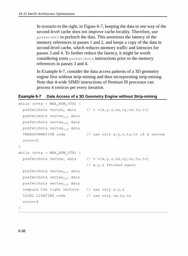
IA-32 Intel® Architecture Optimization
In scenario to the right, in Figure 6-7, keeping the data in one way of the second-level cache does not improve cache locality. Therefore, use prefetcht0 to prefetch the data. This amortizes the latency of the memory references in passes 1 and 2, and keeps a copy of the data in second-level cache, which reduces memory traffic and latencies for passes 3 and 4. To further reduce the latency, it might be worth considering extra prefetchnta instructions prior to the memory references in passes 3 and 4.
In Example 6-7, consider the data access patterns of a 3D geometry engine first without strip-mining and then incorporating strip-mining. Note that 4-wide SIMD instructions of Pentium III processor can process 4 vertices per every iteration.
Example 6-7 Data Access of a 3D Geometry Engine without Strip-mining
while (nvtx < MAX_NUM_VTX) {
prefetchnta vertexi data // v =[x,y,z,nx,ny,nz,tu,tv]
prefetchnta vertexi+1 data
prefetchnta vertexi+2 data
prefetchnta vertexi+3 data
TRANSFORMATION code // use only x,y,z,tu,tv of a vertex
nvtx+=4
}
while (nvtx < MAX_NUM_VTX) {
prefetchnta vertexi data // v =[x,y,z,nx,ny,nz,tu,tv]
// x,y,z fetched again
prefetchnta vertexi+1 data
prefetchnta vertexi+2 data
prefetchnta vertexi+3 data
compute the light vectors // use only x,y,z
LOCAL LIGHTING code // use only nx,ny,nz
nvtx+=4
}
6-38

Optimizing Cache Usage 6
Without strip-mining, all the x,y,z coordinates for the four vertices must be re-fetched from memory in the second pass, that is, the lighting loop. This causes under-utilization of cache lines fetched during transformation loop as well as bandwidth wasted in the lighting loop.Now consider the code in Example 6-8 where strip-mining has been incorporated into the loops.
With strip-mining, all the vertex data can be kept in the cache (for example, one way of second-level cache) during the strip-mined transformation loop and reused in the lighting loop. Keeping data in the cache reduces both bus traffic and the number of prefetches used.
Example 6-8 Data Access of a 3D Geometry Engine with Strip-mining
while (nstrip < NUM_STRIP) {
/* Strip-mine the loop to fit data into one way of the second-level cache */
while (nvtx < MAX_NUM_VTX_PER_STRIP) {
prefetchnta vertexi data // v=[x,y,z,nx,ny,nz,tu,tv]
prefetchnta vertexi+1 data
prefetchnta vertexi+2 data
prefetchnta vertexi+3 data
TRANSFORMATION code
nvtx+=4
}
while (nvtx < MAX_NUM_VTX_PER_STRIP) {
/* x y z coordinates are in the second-level cache, no prefetch is
required */
compute the light vectors
POINT LIGHTING code
nvtx+=4
}
}
6-39

IA-32 Intel® Architecture Optimization
Table 6-2 summarizes the steps of the basic usage model that incorporates only software prefetch with strip-mining. The steps are:• Do strip-mining: partition loops so that the dataset fits into
second-level cache. • Use prefetchnta if the data is only used once or the dataset fits
into 32K (one way of second-level cache). Use prefetcht0 if the dataset exceeds 32K.
The above steps are platform-specific and provide an implementation example. The variables NUM_STRIP and MAX_NUM_VX_PER_STRIP can be heuristically determined for peak performance for specific application on a specific platform.
Hardware Prefetching and Cache Blocking Techniques
Tuning data access patterns for the automatic hardware prefetch mechanism can minimize the memory access costs of the first-pass of the read-multiple-times and some of the read-once memory references. An example of the situations of read-once memory references can be illustrated with a matrix or image transpose, reading from a column-first orientation and writing to a row-first orientation, or vice versa.
Example 6-9 shows a nested loop of data movement that represents a typical matrix/image transpose problem. If the dimension of the array are large, not only the footprint of the dataset will exceed the last level cache but cache misses will occur at large strides. If the dimensions
Table 6-2 Software Prefetching Considerations into Strip-mining Code
Read-Once Array References
Read-Multiple-Times Array References
Adjacent Passes Non-Adjacent Passes
Prefetchnta Prefetch0, SM1 Prefetch0, SM1
(2nd Level Pollution)
Evict one way; Minimize pollution
Pay memory access cost for the first pass of each array; Amortize the first pass with subsequent passes
Pay memory access cost for the first pass of every strip; Amortize the first pass with subsequent passes
6-40

Optimizing Cache Usage 6
happen to be powers of 2, aliasing condition due to finite number of way-associativity (see “Capacity Limits and Aliasing in Caches” in Chapter 2) will exacerbate the likelihood of cache evictions.Example 6-9(b) shows applying the techniques of tiling with optimal selection of tile size and tile width to take advantage of hardware prefetch. With tiling, one can choose the size of two tiles to fit in the last level cache. Maximizing the width of each tile for memory read
Example 6-9 Using HW Prefetch to Improve Read-Once Memory Traffic
a) Un-optimized image transpose
// dest and src represent two-dimensional arrays
for( i = 0;i < NUMCOLS; i ++) {
// inner loop reads single column
for( j = 0; j < NUMROWS ; j ++) {
// Each read reference causes large-stride cache miss
dest[i*NUMROWS +j] = src[j*NUMROWS + i];
}
}
b)
// tilewidth = L2SizeInBytes/2/TileHeight/Sizeof(element)
for( i = 0; i < NUMCOLS; i += tilewidth) {
for( j = 0; j < NUMROWS ; j ++) {
// access multiple elements in the same row in the inner loop
// access pattern friendly to hw prefetch and improves hit rate
for( k = 0; k < tilewidth; k ++)
dest[j+ (i+k)* NUMROWS] = src[i+k+ j* NUMROWS];
}
}
6-41

IA-32 Intel® Architecture Optimization
references enables the hardware prefetcher to initiate bus requests to read some cache lines before the code actually reference the linear addresses.
Single-pass versus Multi-pass Execution
An algorithm can use single- or multi-pass execution defined as follows:• Single-pass, or unlayered execution passes a single data element
through an entire computation pipeline.• Multi-pass, or layered execution performs a single stage of the
pipeline on a batch of data elements, before passing the batch on to the next stage.
A characteristic feature of both single-pass and multi-pass execution is that a specific trade-off exists depending on an algorithm’s implementation and use of a single-pass or multiple-pass execution, see Figure 6-8.
Multi-pass execution is often easier to use when implementing a general purpose API, where the choice of code paths that can be taken depends on the specific combination of features selected by the application (for example, for 3D graphics, this might include the type of vertex primitives used and the number and type of light sources).
With such a broad range of permutations possible, a single-pass approach would be complicated, in terms of code size and validation. In such cases, each possible permutation would require a separate code sequence. For example, an object with features A, B, C, D can have a subset of features enabled, say, A, B, D. This stage would use one code path; another combination of enabled features would have a different code path. It makes more sense to perform each pipeline stage as a separate pass, with conditional clauses to select different features that are implemented within each stage. By using strip-mining, the number of vertices processed by each stage (for example, the batch size) can be
6-42

Optimizing Cache Usage 6
selected to ensure that the batch stays within the processor caches through all passes. An intermediate cached buffer is used to pass the batch of vertices from one stage or pass to the next one.Single-pass execution can be better suited to applications which limit the number of features that may be used at a given time. A single-pass approach can reduce the amount of data copying that can occur with a multi-pass engine, see Figure 6-8.
Figure 6-8 Single-Pass Vs. Multi-Pass 3D Geometry Engines
Transform
Lighting
Single-Pass
Culling
Lighting
Multi-Pass
Culling
40 vis
40 vis
60 invis80 vis
80 vis
Vertexprocessing(inner loop)
Outer loop isprocessingstrips
Transform
strip list
6-43
IA-32 Intel® Architecture Optimization
The choice of single-pass or multi-pass can have a number of performance implications. For instance, in a multi-pass pipeline, stages that are limited by bandwidth (either input or output) will reflect more of this performance limitation in overall execution time. In contrast, for a single-pass approach, bandwidth-limitations can be distributed/amortized across other computation-intensive stages. Also, the choice of which prefetch hints to use are also impacted by whether a single-pass or multi-pass approach is used (see “Hardware Prefetching of Data”).
Memory Optimization using Non-Temporal StoresThe non-temporal stores can also be used to manage data retention in the cache. Uses for the non-temporal stores include:• To combine many writes without disturbing the cache hierarchy.• To manage which data structures remain in the cache and which are
transient.
Detailed implementations of these usage models are covered in the following sections.
Non-temporal Stores and Software Write-Combining
Use non-temporal stores in the cases when the data to be stored is:• write-once (non-temporal)• too large and thus cause cache thrashing
Non-temporal stores do not invoke a cache line allocation, which means they are not write-allocate. As a result, caches are not polluted and no dirty writeback is generated to compete with useful data bandwidth. Without using non-temporal stores, bus bandwidth will suffer when caches start to be thrashed because of dirty writebacks.
In Streaming SIMD Extensions implementation, when non-temporal stores are written into writeback or write-combining memory regions, these stores are weakly-ordered and will be combined internally inside the processor’s write-combining buffer and be written out to memory as
6-44

Optimizing Cache Usage 6
a line burst transaction. To achieve the best possible performance, it is recommended to align data along the cache line boundary and write them consecutively in a cache line size while using non-temporal stores. If the consecutive writes are prohibitive due to programming constraints, then software write-combining (SWWC) buffers can be used to enable line burst transaction.You can declare small SWWC buffers (a cache line for each buffer) in your application to enable explicit write-combining operations. Instead of writing to non-temporal memory space immediately, the program writes data into SWWC buffers and combines them inside these buffers. The program only writes a SWWC buffer out using non-temporal stores when the buffer is filled up, that is, a cache line (128 bytes for the Pentium 4 processor). Although the SWWC method requires explicit instructions for performing temporary writes and reads, this ensures that the transaction on the front-side bus causes line transaction rather than several partial transactions. Application performance gains considerably from implementing this technique. These SWWC buffers can be maintained in the second-level and re-used throughout the program.
Cache Management
The streaming instructions (prefetch and stores) can be used to manage data and minimize disturbance of temporal data held within the processor’s caches.
In addition, the Pentium 4 processor takes advantage of the Intel C ++ Compiler that supports C ++ language-level features for the Streaming SIMD Extensions. The Streaming SIMD Extensions and MMX technology instructions provide intrinsics that allow you to optimize cache utilization. The examples of such Intel compiler intrinsics are _mm_prefetch, _mm_stream, _mm_load, _mm_sfence. For more details on these intrinsics, refer to the Intel C ++ Compiler User’s Guide, order number 718195.
6-45

IA-32 Intel® Architecture Optimization
The following examples of using prefetching instructions in the operation of video encoder and decoder as well as in simple 8-byte memory copy, illustrate performance gain from using the prefetching instructions for efficient cache management.
Video Encoder
In a video encoder example, some of the data used during the encoding process is kept in the processor’s second-level cache, to minimize the number of reference streams that must be re-read from system memory. To ensure that other writes do not disturb the data in the second-level cache, streaming stores (movntq) are used to write around all processor caches.
The prefetching cache management implemented for the video encoder reduces the memory traffic. The second-level cache pollution reduction is ensured by preventing single-use video frame data from entering the second-level cache. Using a non-temporal prefetch (prefetchnta) instruction brings data into only one way of the second-level cache, thus reducing pollution of the second-level cache. If the data brought directly to second-level cache is not re-used, then there is a performance gain from the non-temporal prefetch over a temporal prefetch. The encoder uses non-temporal prefetches to avoid pollution of the second-level cache, increasing the number of second-level cache hits and decreasing the number of polluting write-backs to memory. The performance gain results from the more efficient use of the second-level cache, not only from the prefetch itself.
Video Decoder
In the video decoder example, completed frame data is written to local memory of the graphics card, which is mapped to WC (Write-combining) memory type. A copy of reference data is stored to the WB memory at a later time by the processor in order to generate future data. The assumption is that the size of the reference data is too large to fit in the processor’s caches. A streaming store is used to write the data around the cache, to avoid displaying other temporal data held in the caches.
6-46

Optimizing Cache Usage 6
Later, the processor re-reads the data using prefetchnta, which ensures maximum bandwidth, yet minimizes disturbance of other cached temporal data by using the non-temporal (NTA) version of prefetch.Conclusions from Video Encoder and Decoder Implementation
These two examples indicate that by using an appropriate combination of non-temporal prefetches and non-temporal stores, an application can be designed to lessen the overhead of memory transactions by preventing second-level cache pollution, keeping useful data in the second-level cache and reducing costly write-back transactions. Even if an application does not gain performance significantly from having data ready from prefetches, it can improve from more efficient use of the second-level cache and memory. Such design reduces the encoder’s demand for such critical resource as the memory bus. This makes the system more balanced, resulting in higher performance.
Using Prefetch and Streaming-store for a Simple Memory Copy
Consider a memory copy task to transfer a large array of 8-byte data elements from one memory location to another. Example 6-10 presents the basic algorithm of the simple memory copy. This task can be sped up greatly using prefetch and streaming store instructions. The techniques are discussed in the following paragraph and a code example is shown in Example 6-11.
Example 6-10 Basic Algorithm of a Simple Memory Copy
#define N 512000
double a[N], b[N];
for (i = 0; i < N; i++) {
b[i] = a[i];
}
6-47

IA-32 Intel® Architecture Optimization
The memory copy algorithm can be optimized using the Streaming SIMD Extensions and these considerations:• alignment of data• proper layout of pages in memory • cache size• interaction of the transaction lookaside buffer (TLB) with memory
accesses• combining prefetch and streaming-store instructions.
The guidelines discussed in this chapter come into play in this simple example. TLB priming is required for the Pentium 4 processor just as it is for the Pentium III processor, since software prefetch instructions will not initiate page table walks on either processor.
TLB Priming
The TLB is a fast memory buffer that is used to improve performance of the translation of a virtual memory address to a physical memory address by providing fast access to page table entries. If memory pages are accessed and the page table entry is not resident in the TLB, a TLB miss results and the page table must be read from memory.
The TLB miss results in a performance degradation since another memory access must be performed (assuming that the translation is not already present in the processor caches) to update the TLB. The TLB can be preloaded with the page table entry for the next desired page by accessing (or touching) an address in that page. This is similar to prefetch, but instead of a data cache line the page table entry is being loaded in advance of its use. This helps to ensure that the page table entry is resident in the TLB and that the prefetch happens as requested subsequently.
6-48

Optimizing Cache Usage 6
Optimizing the 8-byte Memory CopyExample 6-11 presents the copy algorithm that uses second level cache. The algorithm performs the following steps:1. Uses blocking technique to transfer 8-byte data from memory into
second-level cache using the _mm_prefetch intrinsic, 128 bytes at a time to fill a block. The size of a block should be less than one half of the size of the second-level cache, but large enough to amortize the cost of the loop.
2. Loads the data into an xmm register using the _mm_load_ps intrinsic.3. Transfers the 8-byte data to a different memory location via the
_mm_stream intrinsics, bypassing the cache. For this operation, it is important to ensure that the page table entry prefetched for the memory is preloaded in the TLB.
Example 6-11 An Optimized 8-byte Memory Copy
#define PAGESIZE 4096;
#define NUMPERPAGE 512 // # of elements to fit a page
double a[N], b[N], temp;
for (kk=0; kk<N; kk+=NUMPERPAGE) {
temp = a[kk+NUMPERPAGE]; // TLB priming
// use block size = page size,
// prefetch entire block, one cache line per loop
for (j=kk+16; j<kk+NUMPERPAGE; j+=16) {
_mm_prefetch((char*)&a[j], _MM_HINT_NTA);
}
continued
6-49

IA-32 Intel® Architecture Optimization
In Example 6-11, eight _mm_load_ps and _mm_stream_ps intrinsics are used so that all of the data prefetched (a 128-byte cache line) is written back. The prefetch and streaming-stores are executed in separate loops to minimize the number of transitions between reading and writing data. This significantly improves the bandwidth of the memory accesses.
// copy 128 byte per loop
for (j=kk; j<kk+NUMPERPAGE; j+=16) {
_mm_stream_ps((float*)&b[j],
_mm_load_ps((float*)&a[j]));
_mm_stream_ps((float*)&b[j+2],
_mm_load_ps((float*)&a[j+2]));
_mm_stream_ps((float*)&b[j+4],
_mm_load_ps((float*)&a[j+4]));
_mm_stream_ps((float*)&b[j+6],
_mm_load_ps((float*)&a[j+6]));
_mm_stream_ps((float*)&b[j+8],
_mm_load_ps((float*)&a[j+8]));
_mm_stream_ps((float*)&b[j+10],
_mm_load_ps((float*)&a[j+10]));
_mm_stream_ps((float*)&b[j+12],
_mm_load_ps((float*)&a[j+12]));
_mm_stream_ps((float*)&b[j+14],
_mm_load_ps((float*)&a[j+14]));
} // finished copying one block
} // finished copying N elements
_mm_sfence();
Example 6-11 An Optimized 8-byte Memory Copy (continued)
6-50

Optimizing Cache Usage 6
The instruction, temp = a[kk+CACHESIZE], is used to ensure the page table entry for array, and a is entered in the TLB prior to prefetching. This is essentially a prefetch itself, as a cache line is filled from that memory location with this instruction. Hence, the prefetching starts from kk+4 in this loop.This example assumes that the destination of the copy is not temporally adjacent to the code. If the copied data is destined to be reused in the near future, then the streaming store instructions should be replaced with regular 128 bit stores(_mm_store_ps). This is required because the implementation of streaming stores on Pentium 4 processor writes data directly to memory, maintaining cache coherency.
Deterministic Cache ParametersIf CPUID support the function leaf with input EAX = 4, this is referred to as the deterministic cache parameter leaf of CPUID (see CPUID instruction in IA-32 Intel Architecture Software Developer’s Manual, Volume 2A). Software can use the deterministic cache parameter leaf to query each level of the cache hierarchy. Enumeration of each cache level is by specifying an index value (starting form 0) in the ECX register. The list of parameters is shown in Table 6-3.
Table 6-3 Deterministic Cache Parameters Leaf
Bit Location Name Meaning
EAX[4:0] Cache Type 0 = Null - No more caches1 = Data Cache2 = Instruction Cache3 = Unified Cache4-31 = Reserved
EAX[7:5] Cache Level Starts at 1
EAX[8] Self Initializing cache level 1: does not need SW initialization
EAX[9] Fully Associative cache 1: Yes
EAX[13:10] Reserved
continued
6-51
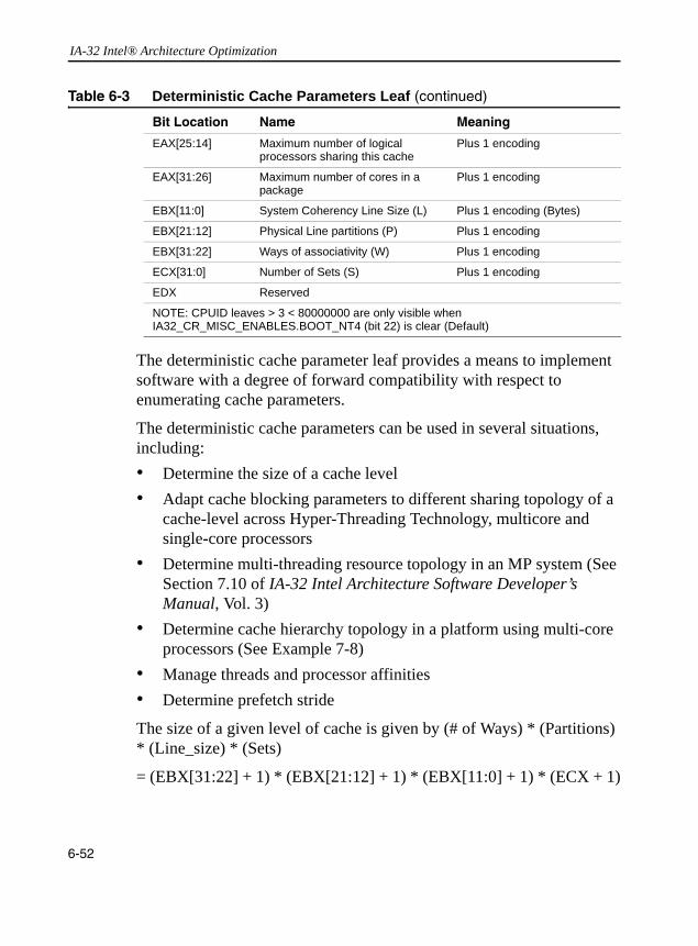
IA-32 Intel® Architecture Optimization
The deterministic cache parameter leaf provides a means to implement software with a degree of forward compatibility with respect to enumerating cache parameters.
The deterministic cache parameters can be used in several situations, including:• Determine the size of a cache level• Adapt cache blocking parameters to different sharing topology of a
cache-level across Hyper-Threading Technology, multicore and single-core processors
• Determine multi-threading resource topology in an MP system (See Section 7.10 of IA-32 Intel Architecture Software Developer’s Manual, Vol. 3)
• Determine cache hierarchy topology in a platform using multi-core processors (See Example 7-8)
• Manage threads and processor affinities• Determine prefetch stride
The size of a given level of cache is given by (# of Ways) * (Partitions) * (Line_size) * (Sets)
= (EBX[31:22] + 1) * (EBX[21:12] + 1) * (EBX[11:0] + 1) * (ECX + 1)
EAX[25:14] Maximum number of logical processors sharing this cache
Plus 1 encoding
EAX[31:26] Maximum number of cores in a package
Plus 1 encoding
EBX[11:0] System Coherency Line Size (L) Plus 1 encoding (Bytes)
EBX[21:12] Physical Line partitions (P) Plus 1 encoding
EBX[31:22] Ways of associativity (W) Plus 1 encoding
ECX[31:0] Number of Sets (S) Plus 1 encoding
EDX Reserved
NOTE: CPUID leaves > 3 < 80000000 are only visible when IA32_CR_MISC_ENABLES.BOOT_NT4 (bit 22) is clear (Default)
Table 6-3 Deterministic Cache Parameters Leaf (continued)
Bit Location Name Meaning
6-52
Optimizing Cache Usage 6
Cache Sharing Using Deterministic Cache ParametersImproving cache locality is an important part of software optimization. For example a cache blocking algorithm can be designed to optimize its block size at runtime for single-processor and a variety of multi-processor execution environments including processors supporting Hyper-Threading Technology (HT), or multi-core processors.
The basic technique is to place an upper limit of the blocksize to be less than the size of the target cache level divided by the number of logical processors serviced by the target level of cache. This technique is applicable to multithreaded application programming, and can benefit single-threaded applications that are part of a multi-tasking workloads.
Cache Sharing in Single-core or Multi-core
The deterministic cache parameters is useful for managing shared cache hierarchy in multithreaded applications for more sophisticated situations. A given cache level may be shared by logical processors in a processor or it may be implemented to be shared by logical processors in a physical processor package. Using deterministic cache parameter leaf and local APIC_ID associated with each logical processor in the platform, software can extract information on the number and the identities of each logical processor sharing that cache level and is made available to application by the OS. This is discussed in detail in “Using Shared Execution Resources in a Processor Core” in Chapter 7 and Example 7-8.
Determine Prefetch Stride Using Deterministic Cache Parameters
The prefetch stride provides the length of the region that the processor will prefetch with the PREFETCHh instructions (PREFETCHT0, PREFETCHT1, PREFETCHT2 and PREFETCHNTA). Software will use this length as the stride when prefetching into a particular level of
6-53

IA-32 Intel® Architecture Optimization
the cache hierarchy as identified by the particular prefetch instruction used. The prefetch size is relevant for cache types of Data Cache (1) and Unified Cache (3) and should be ignored for other cache types. Software should not assume that the coherency line size is the prefetch stride. If this field is zero, then software should assume a default size of 64 bytes is the prefetch stride. Software will use the following algorithm to determine what prefetch size to use depending on whether the deterministic cache parameter mechanism is supported or the legacy mechanism.• If a processor supports the deterministic cache parameters and
provides a non-zero prefetch size, then that prefetch size is used.• If a processor supports the deterministic cache parameters and does
not provides a prefetch size then default size for each level of the cache hierarchy is 64 bytes.
• If a processor does not support the deterministic cache parameters but provides a legacy prefetch size descriptor (0xF0 - 64 byte, 0xF1 - 128 byte) will be the prefetch size for all levels of the cache hierarchy.
• If a processor does not support the deterministic cache parameters and does not provide a legacy prefetch size descriptor, then 32-bytes is the default size for all levels of the cache hierarchy.
6-54
7
Multiprocessor, Dual-Core and Hyper-Threading TechnologyThis chapter describes software optimization techniques for multithreaded applications running in an environment using either multiprocessor (MP) systems or processors with hardware-based multi-threading support. Multiprocessor systems are systems with two or more sockets, each mated with a physical processor package. IA-32 processors that provide hardware multi-threading support include dual-core processors and processor supporting Hyper-Threading Technology 1.
Computational throughput in a multi-threading environment can increase as more hardware resources are added to take advantage of thread-level or task-level parallelism. Hardware resources can be added in the form of more than one physical-processor, and/or processor-core-per-package, and/or logical-processor-per-core. Therefore, there are some aspects of multi-threading optimization that apply across MP, multi-core, and Hyper-Threading Technology. There are also some specific microarchitectural resources that may be implemented differently in different hardware multi-threading configurations, e.g., execution resources are not shared across different
1. The presence of hardware multi-threading support in IA-32 processors can be detected by checking the feature flag CPUID .1.EDX[28]. A return value of 1 in bit 28 indicates that at least one form of hardware multi-threading is present in the physical processor package. The number of logical processors present in each package can also be obtained from CPUID. The application must check how many logical processors are enabled and made available to application at runtime by making the appropriate operating system calls. See Chapter 7 of the “IA-32 Intel Architecture Software Developer’s Manual”, Volume 3 for more information.
7-1

IA-32 Intel® Architecture Optimization
cores but shared by two logical processors in the same core if Hyper-Threading Technology is enabled. This chapter covers guidelines that apply to either situations.
This chapter covers• Performance characteristics and usage models,• Programming models for multithreaded applications,• Software optimization techniques in five specific areas.
Performance and Usage ModelsThe performance gains of using multiple processors or Hyper-Threading Technology are greatly affected by the usage model and the amount of parallelism in the control flow of the workload. Two common usage models are: • multithreaded applications• multitasking using single-threaded applications
Multithreading
When an application employs multi-threading to exploit task-level parallelism in a workload, the control flow of the multi-threaded software can be divided into two parts: parallel tasks and sequential tasks.
Amdahl’s law describes an application’s performance gain as it relates to the degree of parallelism in the control flow. It is a useful guide for selecting the code modules, functions, or instruction sequences that are most likely to realize the most gains from transforming sequential tasks and control flows into parallel code to take advantage multi-threading hardware support.
7-2
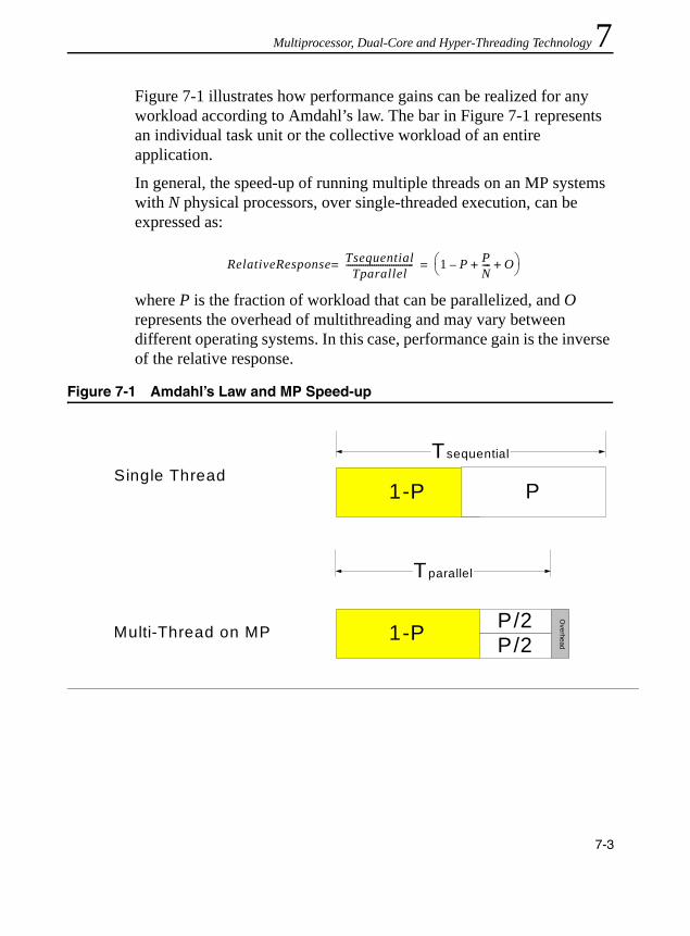
Multiprocessor, Dual-Core and Hyper-Threading Technology 7
Figure 7-1 illustrates how performance gains can be realized for any workload according to Amdahl’s law. The bar in Figure 7-1 represents an individual task unit or the collective workload of an entire application.In general, the speed-up of running multiple threads on an MP systems with N physical processors, over single-threaded execution, can be expressed as:
where P is the fraction of workload that can be parallelized, and O represents the overhead of multithreading and may vary between different operating systems. In this case, performance gain is the inverse of the relative response.
Figure 7-1 Amdahl’s Law and MP Speed-up
RelativeResponse TsequentialTparallel
-------------------------------= 1 P– PN---- O+ +⎝ ⎠
⎛ ⎞=
1-P P
Tsequential
1-P P/2
Tparallel
P/2
Single Thread
Multi-Thread on MP
Overhead
7-3
IA-32 Intel® Architecture Optimization
When optimizing application performance in a multithreaded environment, control flow parallelism is likely to have the largest impact on performance scaling with respect to the number of physical processors and to the number of logical processors per physical processor.
If the control flow of a multi-threaded application contains a workload in which only 50% can be executed in parallel, the maximum performance gain using two physical processors is only 33%, compared to using a single processor. Using four processors can deliver no more than a 60% speed-up over a single processor! Thus, it is critical to maximize the portion of control flow that can take advantage of parallelism. Improper implementation of thread synchronization can significantly increase the proportion of serial control flow and further reduce the application’s performance scaling.
In addition to maximizing the parallelism of control flows, interaction between threads in the form of thread synchronization and imbalance of task scheduling can also impact overall processor scaling significantly.
Excessive cache misses are one cause of poor performance scaling. In a multithreaded execution environment, they can occur from:• aliased stack accesses by different threads in the same process• thread contentions resulting in cache line evictions• false-sharing of cache lines between different processors
Techniques that address each of these situations (and many other areas) are described in sections in this chapter.
Multitasking Environment
Hardware multi-threading capabilities in IA-32 processors can exploit task-level parallelism when a workload consists of several single-threaded applications and these applications are scheduled to run concurrently under an MP-aware operating system. In this environment, hardware multi-threading capabilities can deliver higher throughput for the workload, although the relative performance of a single task (in
7-4

Multiprocessor, Dual-Core and Hyper-Threading Technology 7
terms of time of completion relative to the same task when in a single-threaded environment) will vary, depending on how much shared execution resources and memory are utilized.For development purposes, several popular operating systems (for example Microsoft Windows* XP Professional and Home, Linux* distributions using kernel 2.4.19 or later2) include OS kernel code that can manage the task scheduling and the balancing of shared execution resources within each physical processor to maximize the throughput.
Because applications run independently under a multi-tasking environment, thread synchronization issues are less likely to limit the scaling of throughput. This is because the control flow of the workload is likely to be 100% parallel3 (if no inter-processor communication is taking place and if there are no system bus constraints).
With a multi-tasking workload, however, bus activities and cache access patterns are likely to affect the scaling of the throughput. Running two copies of the same application or same suite of applications in a lock-step can expose an artifact in performance measuring methodology. This is because an access pattern to the 1st level data cache can lead to excessive cache misses and produce skewed performance results. Fix this problem by: • including a per-instance offset at the start-up of an application• introducing heterogeneity in the workload by using different
datasets with each instance of the application• randomizing the sequence of start-up of applications when running
multiple copies of the same suite
2. This code is included in Red Hat* Linux Enterprise AS 2.1. 3. A software tool that attempts to measure the throughput of a multi-tasking workload is
likely to introduce additional control flows that are not parallel. For example, seeExample 7-2 for coding pitfalls using spin-wait loop. Thus, thread synchronization issues must be considered as an integral part of its performance measuring methodology.
7-5

IA-32 Intel® Architecture Optimization
When two applications are employed as part of a multi-tasking workload, there is little synchronization overhead between these two processes. It is also important to ensure each application has minimal synchronization overhead within itself.
An application that uses lengthy spin loops for intra-process synchronization is less likely to benefit from Hyper-Threading Technology in a multi-tasking workload. This is because critical resources will be consumed by the long spin loops.
Programming Models and MultithreadingParallelism is the most important concept in designing a multithreaded application and realizing optimal performance scaling with multiple processors. An optimized multithreaded application is characterized by large degrees of parallelism or minimal dependencies in the following areas: • workload• thread interaction• hardware utilization
The key to maximizing workload parallelism is to identify multiple tasks that have minimal inter-dependencies within an application and to create separate threads for parallel execution of those tasks.
Concurrent execution of independent threads is the essence of deploying a multithreaded application on a multiprocessing system. Managing the interaction between threads to minimize the cost of thread synchronization is also critical to achieving optimal performance scaling with multiple processors.
Efficient use of hardware resources between concurrent threads requires optimization techniques in specific areas to prevent contentions of hardware resources. Coding techniques for optimizing thread synchronization and managing other hardware resources are discussed in subsequent sections.
7-6
Multiprocessor, Dual-Core and Hyper-Threading Technology 7
Parallel programming models are discussed next.Parallel Programming Models
Two common programming models for transforming independent task requirements into application threads are: • domain decomposition • functional decomposition
Domain Decomposition
Usually large compute-intensive tasks use data sets that can be divided into a number of small subsets, each having a large degree of computational independence. Examples include:• computation of a discrete cosine transformation (DCT) on
two-dimensional data by dividing the two-dimensional data into several subsets and creating threads to compute the transform on each subset
• matrix multiplication; here, threads can be created to handle the multiplication of half of matrix with the multiplier matrix
Domain Decomposition is a programming model based on creating identical or similar threads to process smaller pieces of data independently. This model can take advantage of duplicated execution resources present in a traditional multiprocessor system. It can also take advantage of shared execution resources between two logical processors in Hyper-Threading Technology. This is because a data domain thread typically consumes only a fraction of the available on-chip execution resources.
The section “Key Practices of Execution Resource Optimization” discusses additional guidelines that can help data domain threads use shared execution resources cooperatively and avoid the pitfalls creating contentions of hardware resources between two threads.
7-7

IA-32 Intel® Architecture Optimization
Functional Decomposition
Applications usually process a wide variety of tasks with diverse functions and many unrelated data sets. For example, a video codec needs several different processing functions. These include DCT, motion estimation and color conversion. Using a functional threading model, applications can program separate threads to do motion estimation, color conversion, and other functional tasks.
Functional decomposition will achieve more flexible thread-level parallelism if it is less dependent on the duplication of hardware resources. For example, a thread executing a sorting algorithm and a thread executing a matrix multiplication routine are not likely to require the same execution unit at the same time. A design recognizing this could advantage of traditional multiprocessor systems as well as multiprocessor systems using IA-32 processor supporting Hyper-Threading Technology.
Tools for Creating Multithreaded Applications
Programming directly to a multithreading application programming interface (API) is not the only method for creating multithreaded applications. New tools such as the Intel® Compiler have become available with capabilities that make the challenge of creating multithreaded application easier.
Two features available in the latest Intel Compilers are:• generating multithreaded code using OpenMP* directives4
• generating multithreaded code automatically from unmodified high-level code5
4. Intel Compiler 5.0 and later supports OpenMP directives. Visit http://developer.intel.com/software/products for details.
5. Intel Compiler 6.0 supports auto-parallelization.
7-8

Multiprocessor, Dual-Core and Hyper-Threading Technology 7
Programming with OpenMP Directives. OpenMP provides a standardized, non-proprietary, portable set of Fortran and C++ compiler directives supporting shared memory parallelism in applications. OpenMP supports directive-based processing. This uses special preprocessors or modified compilers to interpret parallelism expressed in Fortran comments or C/C++ pragmas. Benefits of directive-based processing include:• The original source can be compiled unmodified.• It is possible to make incremental code changes. This preservesalgorithms in the original code and enables rapid debugging.• Incremental code changes help programmers maintain serial
consistency. When the code is run on one processor, it gives the same result as the unmodified source code.
• Offering directives to fine tune thread scheduling imbalance.• Intel’s implementation of OpenMP runtime can add minimal
threading overhead relative to hand-coded multi-threading.
Automatic Parallelization of Code. While OpenMP directives allow programmers to quickly transform serial applications into parallel applications, programmers must identify specific portions of the application code that contain parallelism and add compiler directives. Intel Compiler 6.0 supports a new (-Qparallel) option, which can identify loop structures that contain parallelism. During program compilation, the compiler automatically attempts to decompose the parallelism into threads for parallel processing. No other intervention or programmer is needed.
Supporting Development Tools. The Intel® Threading Tools include Intel® Thread Checker and Thread Profiler.
Intel® Thread Checker. Use Intel Thread Checker to find threading errors (e.g. data races, stalls and deadlocks) and reduce the amount of time spent debugging threaded applications.
7-9

IA-32 Intel® Architecture Optimization
Intel Thread Checker product is an Intel VTune Performance Analyzer plug-in data collector that executes a program and automatically locates threading errors. As the program runs, Intel Thread Checker monitors memory accesses and other events and automatically detects situations which could cause unpredictable threading-related results.
Thread Profiler. Thread Profiler is a plug-in data collector for the Intel VTune Performance Analyzer. Use it to analyze threading performance and identify parallel performance bottlenecks. It graphically illustrates what each thread is doing at various levels of detail using a hierarchical summary. It can identify inactive threads, critical paths and imbalances in thread execution, etc. Data is collapsed into relevant summaries, sorted to identify parallel regions or loops that require attention.
Optimization GuidelinesThis section summarizes optimization guidelines for tuning multithreaded applications. Five areas are listed (in order of importance):• thread synchronization• bus utilization• memory optimization• front end optimization• execution resource optimization
Practices associated with each area are listed in this section. Guidelines for each area are discussed in greater depth in sections that follow.
Most of the coding recommendations improve performance scaling with processor cores; and scaling due to Hyper-Threading Technology. Techniques that apply to only one environment are noted.
7-10

Multiprocessor, Dual-Core and Hyper-Threading Technology 7
Key Practices of Thread SynchronizationKey practices for minimizing the cost of thread synchronization are summarized below:• Insert the PAUSE instruction in fast spin loops and keep the number
of loop repetitions to a minimum to improve overall system performance.
• Replace a spin lock that may be acquired by multiple threads with pipelined locks such that no more than two threads have write accesses to one lock. If only one thread needs to write to a variable shared by two threads, there is no need to acquire a lock.
• Use a thread-blocking API in a long idle loop to free up the processor.
• Prevent “false-sharing” of per-thread-data between two threads.• Place each synchronization variable alone, separated by 128 bytes
or in a separate cache line.
See “Thread Synchronization” for more details.
Key Practices of System Bus Optimization
Managing bus traffic can significantly impact the overall performance of multithreaded software and MP systems. Key practices of system bus optimization for achieving high data throughput and quick response are: • Improve data and code locality to conserve bus command
bandwidth.• Avoid excessive use of software prefetch instructions and allow the
automatic hardware prefetcher to work. Excessive use of software prefetches can significantly and unnecessarily increase bus utilization if used inappropriately.
• Consider using overlapping multiple back-to-back memory reads to improve effective cache miss latencies.
• Use full write transactions to achieve higher data throughput.
7-11

IA-32 Intel® Architecture Optimization
See “System Bus Optimization” for more details.
Key Practices of Memory Optimization
Key practices for optimizing memory operations are summarized below:• Use cache blocking to improve locality of data access. Target one
quarter to one half of cache size when targeting IA-32 processors supporting Hyper-Threading Technology.
• Minimize the sharing of data between threads that execute on different physical processors sharing a common bus.
• Minimize data access patterns that are offset by multiples of 64 KB in each thread.
• Adjust the private stack of each thread in an application so the spacing between these stacks is not offset by multiples of 64 KB or 1 MB (prevents unnecessary cache line evictions) when targeting IA-32 processors supporting Hyper-Threading Technology.
• Add a per-instance stack offset when two instances of the same application are executing in lock steps to avoid memory accesses that are offset by multiples of 64 KB or 1 MB when targeting IA-32 processors supporting Hyper-Threading Technology.
See “Memory Optimization” for more details.
Key Practices of Front-end Optimization
Key practices for front-end optimization are:• Avoid Excessive Loop Unrolling to ensure the Trace Cache is
operating efficiently.• Optimize code size to improve locality of Trace Cache and increase
delivered trace length.
See “Front-end Optimization” for more details.
7-12

Multiprocessor, Dual-Core and Hyper-Threading Technology 7
Key Practices of Execution Resource OptimizationEach physical processor has dedicated execution resources. Logical processors in physical processors supporting Hyper-Threading Technology share specific on-chip execution resources. Key practices for execution resource optimization include:• Optimize each thread to achieve optimal frequency scaling first.• Optimize multithreaded applications to achieve optimal scaling with
respect to the number of physical processors.• Use on-chip execution resources cooperatively if two threads are
sharing the execution resources in the same physical processor package.
• For each processor supporting Hyper-Threading Technology, consider adding functionally uncorrelated threads to increase the hardware resource utilization of each physical processor package.
See “Execution Resource Optimization” for more details.
Generality and Performance Impact
The next five sections cover the optimization techniques in detail. Recommendations discussed in each section are ranked by importance in terms of estimated local impact and generality.
Rankings are subjective and approximate. They can vary depending on coding style, application and threading domain. The purpose of including high, medium and low impact ranking with each recommendation is to provide a relative indicator as to the degree of performance gain that can be expected when a recommendation is implemented.
It is not possible to predict the likelihood of a code instance across many applications, so an impact ranking cannot be directly correlated to application-level performance gain. The ranking on generality is also subjective and approximate.
7-13

IA-32 Intel® Architecture Optimization
Coding recommendations that do not impact all three scaling factors are typically categorized as medium or lower.
Thread SynchronizationApplications with multiple threads use synchronization techniques in order to ensure correct operation. However, thread synchronization that are improperly implemented can significantly reduce performance.
The best practice to reduce the overhead of thread synchronization is to start by reducing the application’s requirements for synchronization. Intel Thread Profiler can be used to profile the execution timeline of each thread and detect situations where performance is impacted by frequent occurrences of synchronization overhead.
Several coding techniques and operating system (OS) calls that are frequently used for thread synchronization. These include spin-wait loops, spin-locks, critical sections, to name a few. Choosing the optimal OS calls for the circumstance and implementing synchronization code with parallelism in mind are critical in minimizing the cost of handling thread synchronization.
SSE3 provides two instructions (MONITOR/MWAIT) to help multithreaded software improve synchronization between multiple agents. In the first implementation of MONITOR and MWAIT, these instructions are available to operating system so that operating system can optimize thread synchronization in different areas. For example, an operating system can use MONITOR and MWAIT in its system idle loop (known as C0 loop) to reduce power consumption. An operating system can also use MONITOR and MWAIT implement its C1 loop to improve the responsiveness of C1 loop. (See Chapter 7 of IA-32 Intel Architecture Software Developer’s Manual, Volume 3.)
7-14

Multiprocessor, Dual-Core and Hyper-Threading Technology 7
Choice of Synchronization PrimitivesThread synchronization often involves modifying some shared data while protecting the operation using synchronization primitives. Typically, there are many primitives to choose from, some of the guidelines that are useful when selecting synchronization primitives are:• Favor compiler intrinsics or OS provided interlocked API for atomic
updates of simple data operation, such as increment, compare/exchange. This will be more efficient than other more complicated synchronization primitives with higher overhead. For more information on using different synchronization primitives, see the white paper “Developing Multi-threaded Applications: A Platform Consistent Approach”, referenced in the Introduction chapter.
• When choosing between different primitives to implement a synchronization construct, using Intel Thread Checker and Thread Profiler can be very useful in dealing with multi-threading functional correctness issue and performance impact under multi-threaded execution. Additional information on the capabilities of Intel Thread Checker and Thread Profiler are described in Appendix A.
Synchronization for Short Periods
The frequency and duration that a thread needs to synchronize with other threads depends application characteristics. When a synchronization loop needs very fast response, applications may use a spin-wait loop.
A spin-wait loop is typically used when one thread needs to wait a short amount of time for another thread to reach a point of synchronization. A spin-wait loop consists of a loop that compares a synchronization variable with some pre-defined value [see Example 7-1(a)].
7-15
IA-32 Intel® Architecture Optimization
On a modern microprocessor with a superscalar speculative execution engine, a loop like this results in the issue of multiple simultaneous read requests from the spinning thread. These requests usually execute out-of-order with each read request being allocated a buffer resource. On detection of a write by a worker thread to a load that is in progress, the processor must guarantee no violations of memory order occur. The necessity of maintaining the order of outstanding memory operations inevitably costs the processor a severe penalty that impacts all threads.
This penalty occurs on the Pentium Pro processor, the Pentium II processor and the Pentium III processor. However, the penalty on these processors is small compared with penalties suffered on the Pentium 4 and Intel Xeon processors. There the performance penalty for exiting the loop is about 25 times more severe.
On a processor supporting Hyper-Threading Technology, spin-wait loops can consume a significant portion of the execution bandwidth of the processor. One logical processor executing a spin-wait loop can severely impact the performance of the other logical processor.
7-16

Multiprocessor, Dual-Core and Hyper-Threading Technology 7
Example 7-1 Spin-wait Loop and PAUSE Instructions(a) An un-optimized spin-wait loop experiences performance penalty when exiting the loop. It consumes execution resources without contributing computational work.do {
// This loop can run faster than the speed of memory access, // other worker threads cannot finish modifying sync_var until// outstanding loads from the spinning loops are resolved.
} while( sync_var != constant_value);
(b) Inserting the PAUSE instruction in a fast spin-wait loop prevents performance-penalty to the spinning thread and the worker thread do { _asm pause
// Ensure this loop is de-pipelined, i.e. preventing more than one // load request to sync_var to be outstanding, // avoiding performance penalty when the worker thread updates // sync_var and the spinning thread exiting the loop.
} while( sync_var != constant_value);
7-17

IA-32 Intel® Architecture Optimization
User/Source Coding Rule 21. (M impact, H generality) Insert the PAUSE instruction in fast spin loops and keep the number of loop repetitions to a minimum to improve overall system performance.
On IA-32 processors that use the Intel NetBurst microarchitecture core, the penalty of exiting from a spin-wait loop can be avoided by inserting a PAUSE instruction in the loop. In spite of the name, the PAUSE instruction improves performance by introducing a slight delay in the loop and effectively causing the memory read requests to be issued at a rate that allows immediate detection of any store to the synchronization variable. This prevents the occurrence of a long delay due to memory order violation.
One example of inserting the PAUSE instruction in a simplified spin-wait loop is shown in Example 7-1(b). The PAUSE instruction is compatible with all IA-32 processors. On IA-32 processors prior to Intel NetBurst microarchitecture, the PAUSE instruction is essentially a NOP instruction.
(c) A spin-wait loop using a “test, test-and-set” technique to determine the availability of the synchronization variable. This technique is recommended when writing spin-wait loops to run on IA-32 architecture processors.Spin_Lock:
CMP lockvar, 0 ; // Check if lock is free.JE Get_lock
PAUSE; // Short delay.JMP Spin_Lock;
Get_Lock:MOV EAX, 1;XCHG EAX, lockvar; // Try to get lock.CMP EAX, 0; // Test if successful.JNE Spin_Lock;
Critical_Section:<critical section code>MOV lockvar, 0; // Release lock.
Example 7-1 Spin-wait Loop and PAUSE Instructions (Contd.)
7-18
Multiprocessor, Dual-Core and Hyper-Threading Technology 7
Additional examples of optimizing spin-wait loops using the PAUSE instruction are available in Application Note AP-949 “Using Spin-Loops on Intel Pentium 4 Processor and Intel Xeon Processor.”Inserting the PAUSE instruction has the added benefit of significantly reducing the power consumed during the spin-wait because fewer system resources are used.
Optimization with Spin-Locks
Spin-locks are typically used when several threads needs to modify a synchronization variable and the synchronization variable must be protected by a lock to prevent un-intentional overwrites. When the lock is released, however, several threads may compete to acquire it at once. Such thread contention significantly reduces performance scaling with respect to frequency, number of discrete processors, and Hyper-Threading Technology.
To reduce the performance penalty, one approach is to reduce the likelihood of many threads competing to acquire the same lock. Apply a software pipelining technique to handle data that must be shared between multiple threads.
Instead of allowing multiple threads to compete for a given lock, no more than two threads should have write access to a given lock. If an application must use spin-locks, include the PAUSE instruction in the wait loop. Example 7-1 (c) shows an example of the “test, test-and-set” technique for determining the availability of the lock in a spin-wait loop. User/Source Coding Rule 22. (M impact, L generality) Replace a spin lock that may be acquired by multiple threads with pipelined locks such that no more than two threads have write accesses to one lock. If only one thread needs to write to a variable shared by two threads, there is no need to use a lock.
7-19
IA-32 Intel® Architecture Optimization
Synchronization for Longer Periods
When using a spin-wait loop not expected to be released quickly, an application should follow these guidelines:• Keep the duration of the spin-wait loop to a minimum number of
repetitions.• Applications should use an OS service to block the waiting thread;
this can release the processor so that other runnable threads can make use of the processor or available execution resources.
On processors supporting Hyper-Threading Technology, operating systems should use the HLT instruction if one logical processor is active and the other is not. HLT will allow an idle logical processor to transition to a halted state; this allows the active logical processor to use all the hardware resources in the physical package. An operating system that does not use this technique must still execute instructions on the idle logical processor that repeatedly check for work. This “idle loop” consumes execution resources that could otherwise be used to make progress on the other active logical processor.
If an application thread must remain idle for a long time, the application should use a thread blocking API or other method to release the idle processor. The techniques discussed here apply to traditional MP system, but they have an even higher impact on IA-32 processors that support Hyper-Threading Technology.
Typically, an operating system provides timing services, for example Sleep(dwMilliseconds)6; such variables can be used to prevent frequent checking of a synchronization variable.
Another technique to synchronize between worker threads and a control loop is to use a thread-blocking API provided by the OS. Using a thread-blocking API allows the control thread to use less processor
6. The Sleep() API is not thread-blocking, because it does not guarantee the processor will be released. Example 7-2 (a) shows an example of using Sleep(0), which does not always realize the processor to another thread.
7-20
Multiprocessor, Dual-Core and Hyper-Threading Technology 7
cycles for spinning and waiting. This gives the OS more time quanta to schedule the worker threads on available processors. Furthermore, using a thread-blocking API also benefits from the system idle loop optimization that OS implements using the HLT instruction. User/Source Coding Rule 23. (H impact, M generality) Use a thread-blocking API in a long idle loop to free up the processor.Using a spin-wait loop in a traditional MP system may be less of an issue when the number of runnable threads is less than the number of processors in the system. If the number of threads in an application is expected to be greater than the number of processors (either one processor or multiple processors), use a thread-blocking API to free up processor resources. A multithreaded application adopting one control thread to synchronize multiple worker threads may consider limiting worker threads to the number of processors in a system and use thread-blocking APIs in the control thread.
Avoid Coding Pitfalls in Thread Synchronization
Synchronization between multiple threads must be designed and implemented with care to achieve good performance scaling with respect to the number of discrete processors and the number of logical processor per physical processor. No single technique is a universal solution for every synchronization situation.
The pseudo-code example in Example 7-2 (a) illustrates a polling loop implementation of a control thread. If there is only one runnable worker thread, an attempt to call a timing service API, such as Sleep(0), may be ineffective in minimizing the cost of thread synchronization. Because the control thread still behaves like a fast spinning loop, the only runnable worker thread must share execution resources with the spin-wait loop if both are running on the same physical processor that supports Hyper-Threading Technology. If there are more than one runnable worker threads, then calling a thread blocking API, such as
7-21

IA-32 Intel® Architecture Optimization
Sleep(0), could still release the processor running the spin-wait loop, allowing the processor to be used by another worker thread instead of the spinning loop.
A control thread waiting for the completion of worker threads can usually implement thread synchronization using a thread-blocking API or a timing service, if the worker threads require significant time to complete. Example 7-2 (b) shows an example that reduces the overhead of the control thread in its thread synchronization.
Example 7-2 Coding Pitfall using Spin Wait Loop
(a) A spin-wait loop attempts to release the processor incorrectly. It experiences a performance penalty if the only worker thread and the control thread runs on the same physical processor package. // Only one worker thread is running, // the control loop waits for the worker thread to complete.ResumeWorkThread(thread_handle);While (!task_not_done ) { Sleep(0) // Returns immediately back to spin loop. … }
(b) A polling loop frees up the processor correctly.
// Let a worker thread run and wait for completion.
ResumeWorkThread(thread_handle);While (!task_not_done ) { Sleep(FIVE_MILISEC) // This processor is released for some duration, the processor // can be used by other threads.… }
7-22

Multiprocessor, Dual-Core and Hyper-Threading Technology 7
In general, OS function calls should be used with care when synchronizing threads. When using OS-supported thread synchronization objects (critical section, mutex, or semaphore), preference should be given to the OS service that has the least synchronization overhead, such as a critical section.Prevent False-Sharing of Data
When two threads must share data, it is important to avoid false sharing. False sharing applies to data used by one thread that happens to reside on the same cache line as different data used by another thread.
An example of false sharing is when thread-private data and a thread synchronization variable are located within the line size boundary (64 bytes) or sector boundary (128 bytes). When one thread modifies the synchronization variable, the “dirty” cache line must be written out to memory and updated for each physical processor sharing the bus. Subsequently, data is fetched into each target processor 128 bytes at a time, causing previously cached data to be evicted from its cache on each target processor. False-sharing incurs a performance penalty, when two threads run on different physical processors or on two logical processors in the physical processor package. In the first case, the performance penalty is due to cache evictions to maintain cache coherency. In the latter case, performance penalty is due to memory order machine clear conditions. User/Source Coding Rule 24. (H impact, M generality) Beware of false sharing within a cache line (64 bytes on Intel Pentium 4, Intel Xeon and Pentium M processors), and within a sector (128 bytes on Pentium 4 and Intel Xeon processors).
When a common block of parameters is passed from a parent thread to several worker threads, it is desirable for each work thread to create a private copy of frequently accessed data in the parameter block.
7-23

IA-32 Intel® Architecture Optimization
Placement of Shared Synchronization Variable
Because bus reads typically fetch 128 bytes into a cache, the optimal spacing to minimize eviction of cached data is 128 bytes. To prevent false-sharing, synchronization variables and system objects (such as a critical section) should be allocated to reside alone in a 128-byte region and aligned to a 128-byte boundary. Example 7-3 shows a way to minimize the bus traffic required to maintain cache coherency in MP systems. This technique is also applicable to MP systems using IA-32 processors with or without Hyper-Threading Technology.User/Source Coding Rule 25. (M impact, ML generality) Place each synchronization variable alone, separated by 128 bytes or in a separate cache line. User/Source Coding Rule 26. (H impact, L generality) Do not place any spin lock variable to span a cache line boundary (64 bytes on Intel Pentium 4 and Intel Xeon processors).
System Bus OptimizationThe system bus services requests from bus agents (e.g. logical processors) to fetch data or code from the memory sub-system. The performance impact due data traffic fetched from memory depends on the characteristics of the workload, and the degree of software optimization on memory access, locality enhancements implemented in the software code. A number of techniques to characterize memory traffic of a workload is discussed in “Application Performance Tools” in
Example 7-3 Placement of Synchronization and Regular Variables
int regVar;int padding[32];int SynVar[32*NUM_SYNC_VARS];int AnotherVar;
7-24

Multiprocessor, Dual-Core and Hyper-Threading Technology 7
Appendix A. Optimization guidelines on locality enhancement is also discussed in “Locality Enhancement” in Chapter 2 and “Hardware Prefetching and Cache Blocking Techniques” in Chapter 6.The techniques described in Chapter 2 and Chapter 6 benefit application performance in a platform where the bus system is servicing a single-threaded environment. In a multi-threaded environment, the bus system typically services many more logical processors, each of which can issue bus requests independently. Thus, techniques on locality enhancements, conserving bus bandwidth, reducing large-stride-cache-miss-delay can have strong impact on processor scaling performance
Conserve Bus Bandwidth
In a multi-threading environment, bus bandwidth may be shared by memory traffic originated from multiple bus agents. Preserving the bus bandwidth can improve processor scaling performance. Also, effective bus bandwidth typically will decrease if there are significant large-stride cache-misses. Reducing the amount of large-stride cache misses (or reducing DTLB misses) will alleviate the problem of bandwidth reduction due to large-stride cache misses.
One way for conserving available bus command bandwidth is to improve the locality of code and data. Improving the locality of data reduces the number of cache line evictions and requests to fetch data. This technique also reduces the number of instruction fetches from system memory.User/Source Coding Rule 27. (M impact, H generality) Improve data and code locality to conserve bus command bandwidth.
Using a compiler that supports profiler-guided optimization can improve code locality by keeping frequently used code paths in the cache. This reduces instruction fetches. Loop blocking can also improve the data locality.
7-25
IA-32 Intel® Architecture Optimization
Other locality enhancement techniques, see “Memory Optimization Using Prefetch” in Chapter 6, can also be applied in a multi-threading environment to conserve bus bandwidth.
Because the system bus is shared between many bus agents (logical processors), software tuning should recognize symptoms of the bus approaching saturation. One useful technique is to examine the queue depth of bus read traffic (See “Workload Characterization” in Appendix A). When the bus queue depth is high, locality enhancement to improve cache utilization will benefit performance more than other techniques, such as inserting more software prefetches or masking memory latency with overlapping bus reads. An approximate working guideline for software to operate below bus saturation is to check if bus read queue depth is significantly below 5.
Avoid Excessive Software Prefetches
Pentium 4 and Intel Xeon Processors have an automatic hardware prefetcher. It can bring data and instructions into the unified second-level cache based on prior reference patterns. In most situations, the hardware prefetcher is likely to reduce system memory latency without explicit intervention from software prefetches. It is also preferable to adjust data access patterns in the code to take advantage of the characteristics of the automatic hardware prefetcher to improve locality or mask memory latency. Using software prefetch instructions excessively or indiscriminately will inevitably cause performance penalties. This is because excessively or indiscriminately using software prefetch instructions wastes the command and data bandwidth of the system bus.
Using software prefetches delays the hardware prefetcher from starting to fetch data needed by the processor core. It also consumes critical execution resources and can result in stalled execution. The guidelines for using software prefetch instructions are described in Chapter 2. The techniques of using automatic hardware prefetcher is discussed in Chapter 6.
7-26

Multiprocessor, Dual-Core and Hyper-Threading Technology 7
User/Source Coding Rule 28. (M impact, L generality) Avoid excessive use of software prefetch instructions and allow automatic hardware prefetcher to work. Excessive use of software prefetches can significantly and unnecessarily increase bus utilization if used inappropriately.Improve Effective Latency of Cache Misses
System memory access latency due to cache misses is affected by bus traffic. This is because bus read requests must be arbitrated along with other requests for bus transactions. Reducing the number of outstanding bus transactions helps improve effective memory access latency.
One technique to improve effective latency of memory read transactions is to use multiple overlapping bus reads to reduce the latency of sparse reads. In situations where there is little locality of data or when memory reads need to be arbitrated with other bus transactions, the effective latency of scattered memory reads can be improved by issuing multiple memory reads back-to-back to overlap multiple outstanding memory read transactions. The average latency of back-to-back bus reads is likely to be lower than the average latency of scattered reads interspersed with other bus transactions. This is because only the first memory read needs to wait for the full delay of a cache miss.User/Source Coding Rule 29. (M impact, M generality) Consider using overlapping multiple back-to-back memory reads to improve effective cache miss latencies.
Another technique to reduce effective memory latency is possible if one can adjust the data access pattern such that the access strides causing successive cache misses in the last-level cache is predominantly less than the trigger threshold distance of the automatic hardware prefetcher. See “Example of Effective Latency Reduction with H/W Prefetch” in Chapter 6.User/Source Coding Rule 30. (M impact, M generality) Consider adjusting the sequencing of memory references such that the distribution of distances of successive cache misses of the last level cache peaks towards 64 bytes.
7-27
IA-32 Intel® Architecture Optimization
Use Full Write Transactions to Achieve Higher Data Rate
Write transactions across the bus can result in write to physical memory either using the full line size of 64 bytes or less than the full line size. The latter is referred to as a partial write. Typically, writes to writeback (WB) memory addresses are full-size and writes to write-combine (WC) or uncacheable (UC) type memory addresses result in partial writes. Both cached WB store operations and WC store operations utilize a set of six WC buffers (64 bytes wide) to manage the traffic of write transactions. When competing traffic closes a WC buffer before all writes to the buffer are finished, this results in a series of 8-byte partial bus transactions rather than a single 64-byte write transaction.User/Source Coding Rule 31. (M impact, M generality) Use full write transactions to achieve higher data throughput.
Frequently, multiple partial writes to WC memory can be combined into full-sized writes using a software write-combining technique to separate WC store operations from competing with WB store traffic. To implement software write-combining, uncacheable writes to memory with the WC attribute are written to a small, temporary buffer (WB type) that fits in the first level data cache. When the temporary buffer is full, the application copies the content of the temporary buffer to the final WC destination.
When partial-writes are transacted on the bus, the effective data rate to system memory is reduced to only 1/8 of the system bus bandwidth.
Memory OptimizationEfficient operation of caches is a critical aspect of memory optimiza-tion. Efficient operation of caches needs to address the following: • cache blocking• shared memory optimization• eliminating 64-K-Aliased data accesses• preventing excessive evictions in first-level cache
7-28
Multiprocessor, Dual-Core and Hyper-Threading Technology 7
Cache Blocking TechniqueLoop blocking is useful for reducing cache misses and improving memory access performance. The selection of a suitable block size is critical when applying the loop blocking technique. Loop blocking is applicable to single-threaded applications as well as to multithreaded applications running on processors with or without Hyper-Threading Technology. The technique transforms the memory access pattern into blocks that efficiently fit in the target cache size.
When targeting IA-32 processors supporting Hyper-Threading Technology, the loop blocking technique for a unified cache can select a block size that is no more than one half of the target cache size, if there are two logical processors sharing that cache. The upper limit of the block size for loop blocking should be determined by dividing the target cache size by the number of logical processors available in a physical processor package. Typically, some cache lines are needed to access data that are not part of the source or destination buffers used in cache blocking, so the block size can be chosen between one quarter to one half of the target cache (see also, Chapter 3).
Software can use the deterministic cache parameter leaf of CPUID to discover which subset of logical processors are sharing a given cache. (See Chapter 6.) Therefore, guideline above can be extended to allow all the logical processors serviced by a given cache to use the cache simultaneously, by placing an upper limit of the block size as the total size of the cache divided by the number of logical processors serviced by that cache. This technique can also be applied to single-threaded applications that will be used as part of a multitasking workload. User/Source Coding Rule 32. (H impact, H generality) Use cache blocking to improve locality of data access. Target one quarter to one half of the cache size when targeting IA-32 processors supporting Hyper-Threading Technology or target a block size that allow all the logical processors serviced by a cache to share that cache simultaneously.
7-29
IA-32 Intel® Architecture Optimization
Shared-Memory Optimization
Maintaining cache coherency between discrete processors frequently involves moving data across a bus that operates at a clock rate substantially slower that the processor frequency.
Minimize Sharing of Data between Physical Processors
When two threads are executing on two physical processors and sharing data, reading from or writing to shared data usually involves several bus transactions (including snooping, request for ownership changes, and sometimes fetching data across the bus). A thread accessing a large amount of shared memory is likely to have poor processor-scaling performance.User/Source Coding Rule 33. (H impact, M generality) Minimize the sharing of data between threads that execute on different bus agents sharing a common bus.
One technique to minimize sharing of data is to copy data to local stack variables if it is to be accessed repeatedly over an extended period. If necessary, results from multiple threads can be combined later by writing them back to a shared memory location. This approach can also minimize time spent to synchronize access to shared data.
Eliminate 64-K-Aliased Data Accesses
The 64 KB aliasing condition is discussed in Chapter 2. Memory accesses that satisfy the 64 KB aliasing condition can cause excessive evictions of the first-level data cache. Eliminating 64-KB-aliased data accesses originating from each thread helps improve frequency scaling in general. Furthermore, it enables the first-level data cache to perform efficiently when Hyper-Threading Technology is fully utilized by software applications.User/Source Coding Rule 34. (H impact, H generality) Minimize data access patterns that are offset by multiples of 64 KB in each thread.
7-30

Multiprocessor, Dual-Core and Hyper-Threading Technology 7
The presence of 64-KB-aliased data access can be detected using Pentium 4 processor performance monitoring events. Appendix B includes an updated list of Pentium 4 processor performance metrics. These metrics are based on events accessed using the Intel VTune performance analyzer.Performance penalties associated with 64 KB aliasing are applicable mainly to current processor implementations of Hyper-Threading Technology or Intel NetBurst microarchitecture. The next section discusses memory optimization techniques that are applicable to multithreaded applications running on processors supporting Hyper-Threading Technology.
Preventing Excessive Evictions in First-Level Data Cache
Cached data in a first-level data cache are indexed to linear addresses but physically tagged. Data in second-level and third-level caches are tagged and indexed to physical addresses. While two logical processors in the same physical processor package execute in separate linear address space, the same processors can reference data at the same linear address in two address spaces but mapped to different physical addresses. When such competing accesses occur simultaneously, they can cause repeated evictions and allocations of cache lines in the first-level data cache. Preventing unnecessary evictions in the first-level data cache by two competing threads improves the temporal locality of the first-level data cache.
Multithreaded applications need to prevent unnecessary evictions in the first-level data cache when:• Multiple threads within an application try to access private data on
their stack, some data access patterns can cause excessive evictions of cache lines. Within the same software process, multiple threads have their respective stacks, and these stacks are located at different linear addresses. Frequently the linear addresses of these stacks are spaced apart by some fixed distance that increases the likelihood of a cache line being used by multiple threads.
7-31

IA-32 Intel® Architecture Optimization
• Two instances of the same application run concurrently and are executing in lock steps (for example, corresponding data in each instance are accessed more or less synchronously), accessing data on the stack (and sometimes accessing data on the heap) by these two processes can also cause excessive evictions of cache lines because of address conflicts.
Per-thread Stack Offset
To prevent private stack accesses in concurrent threads from thrashing the first-level data cache, an application can use a per-thread stack offset for each of its threads. The size of these offsets should be multiples of a common base offset. The optimum choice of this common base offset may depend on the memory access characteristics of the threads; but it should be multiples of 128 bytes.
One effective technique for choosing a per-thread stack offset in an application is to add an equal amount of stack offset each time a new thread is created in a thread pool.7 Example 7-4 shows a code fragment that implements per-thread stack offset for three threads using a reference offset of 1024 bytes.User/Source Coding Rule 35. (H impact, M generality) Adjust the private stack of each thread in an application so that the spacing between these stacks is not offset by multiples of 64 KB or 1 MB to prevent unnecessary cache line evictions (when using IA-32 processors supporting Hyper-Threading Technology).
7. For parallel applications written to run with OpenMP, the OpenMP runtime library inIntel KAP/Pro Toolset automatically provides the stack offset adjustment for each thread.
7-32

Multiprocessor, Dual-Core and Hyper-Threading Technology 7
Example 7-4 Adding an Offset to the Stack Pointer of Three Threads
Void Func_thread_entry(DWORD *pArg){DWORD StackOffset = *pArg;DWORD var1; // The local variable at this scope may not benefitDWORD var2; // from the adjustment of the stack pointer that ensue.
// Call runtime library routine to offset stack pointer._alloca(StackOffset) ; }// Managing per-thread stack offset to create three threads:// * Code for the thread function// * Stack accesses within descendant functions (do_foo1, do_foo2) // are less likely to cause data cache evictions because of the // stack offset.do_foo1();do_foo2();}
main (){ DWORD Stack_offset, ID_Thread1, ID_Thread2, ID_Thread3;Stack_offset = 1024;
// Stack offset between parent thread and the first child thread.ID_Thread1 = CreateThread(Func_thread_entry, &Stack_offset);
// Call OS thread API.Stack_offset = 2048;ID_Thread2 = CreateThread(Func_thread_entry, &Stack_offset);Stack_offset = 3072;ID_Thread3 = CreateThread(Func_thread_entry, &Stack_offset);}
7-33

IA-32 Intel® Architecture Optimization
Per-instance Stack Offset
Each instance an application runs in its own linear address space; but the address layout of data for stack segments is identical for the both instances. When the instances are running in lock step, stack accesses are likely to cause of excessive evictions of cache lines in the first-level data cache for some implementations of Hyper-Threading Technology in IA-32 processors.
Although this situation (two copies of an application running in lock step) is seldom an objective for multithreaded software or a multiprocessor platform, it can happen by an end-user’s direction. One solution is to allow application instance to add a suitable linear address-offset for its stack. Once this offset is added at start-up, a buffer of linear addresses is established even when two copies of the same application are executing using two logical processors in the same physical processor package. The space has negligible impact on running dissimilar applications and on executing multiple copies of the same application.
{ DWORD Stack_offset, ID_Thread1, ID_Thread2, ID_Thread3;Stack_offset = 1024;
// Stack offset between parent thread and the first child thread.ID_Thread1 = CreateThread(Func_thread_entry, &Stack_offset);
// Call OS thread API.Stack_offset = 2048;ID_Thread2 = CreateThread(Func_thread_entry, &Stack_offset);Stack_offset = 3072;ID_Thread3 = CreateThread(Func_thread_entry, &Stack_offset);}
Example 7-4 Adding an Offset to the Stack Pointer of Three Threads (Contd.)
7-34

Multiprocessor, Dual-Core and Hyper-Threading Technology 7
However, the buffer space does enable the first-level data cache to be shared cooperatively when two copies of the same application are executing on the two logical processors in a physical processor package.To establish a suitable stack offset for two instances of the same application running on two logical processors in the same physical processor package, the stack pointer can be adjusted in the entry function of the application using the technique shown in Example 7-5. The size of stack offsets should also be a multiple of a reference offset that may depend on the characteristics of the application’s data access pattern. One way to determine the per-instance value of the stack offsets is to choose a pseudo-random number that is also a multiple of the reference offset or 128 bytes. Usually, this per-instance pseudo-random offset can be less than 7 KB. Example 7-5 provides a code fragment for adjusting the stack pointer in an application entry function.User/Source Coding Rule 36. (M impact, L generality) Add per-instance stack offset when two instances of the same application are executing in lock steps to avoid memory accesses that are offset by multiples of 64 KB or 1 MB, when targeting IA-32 processors supporting Hyper-Threading Technology.
7-35
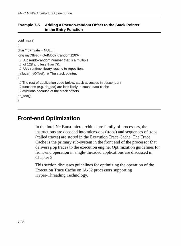
IA-32 Intel® Architecture Optimization
Front-end OptimizationIn the Intel NetBurst microarchitecture family of processors, the instructions are decoded into micro-ops (µops) and sequences of µops (called traces) are stored in the Execution Trace Cache. The Trace Cache is the primary sub-system in the front end of the processor that delivers µop traces to the execution engine. Optimization guidelines for front-end operation in single-threaded applications are discussed in Chapter 2.
This section discusses guidelines for optimizing the operation of the Execution Trace Cache on IA-32 processors supporting Hyper-Threading Technology.
Example 7-5 Adding a Pseudo-random Offset to the Stack Pointer in the Entry Function
void main(){char * pPrivate = NULL;long myOffset = GetMod7Krandom128X() // A pseudo-random number that is a multiple // of 128 and less than 7K. // Use runtime library routine to reposition._alloca(myOffset); // The stack pointer.} // The rest of application code below, stack accesses in descendant // functions (e.g. do_foo) are less likely to cause data cache // evictions because of the stack offsets.do_foo();}
7-36

Multiprocessor, Dual-Core and Hyper-Threading Technology 7
Avoid Excessive Loop UnrollingUnrolling loops can reduce the number of branches and improve the branch predictability of application code. Loop unrolling is discussed in detail in Chapter 2. Loop unrolling must be used judiciously. Be sure to consider the benefit of improved branch predictability and the cost of increased code size relative to the Trace Cache.User/Source Coding Rule 37. (M impact, L generality) Avoid excessive loop unrolling to ensure the Trace cache is operating efficiently.
On Hyper-Threading-Technology-enabled processors, excessive loop unrolling is likely to reduce the Trace Cache’s ability to deliver high bandwidth µop streams to the execution engine.
Optimization for Code Size
When the Trace Cache is continuously and repeatedly delivering µop traces that are pre-built, the scheduler in the execution engine can dispatch µops for execution at a high rate and maximize the utilization of available execution resources. Optimizing application code size by organizing code sequences that are repeatedly executed into sections, each with a footprint that can fit into the Trace Cache, can improve application performance greatly.
On Hyper-Threading-Technology-enabled processors, multithreaded applications should improve code locality of frequently executed sections and target one half of the size of Trace Cache for each application thread when considering code size optimization. If code size becomes an issue affecting the efficiency of the front end, this may be detected by evaluating performance metrics discussed in the previous sub-section with respect to loop unrolling.User/Source Coding Rule 38. (L impact, L generality) Optimize code size to improve locality of Trace cache and increase delivered trace length.
7-37

IA-32 Intel® Architecture Optimization
Execution Resource OptimizationFor applications based on the domain decomposition threading model, optimization techniques with respect to execution resources are essentially the same as single-threaded applications in the absence of Hyper-Threading Technology. Each thread should be optimized to achieved optimal frequency scaling first. Then, optimization in an area such as thread synchronization can improve MP scaling to supplement good frequency scaling.
Hyper-Threading Technology enables several threads to run simultaneously on a physical processor while sharing on-chip execution resources. There may be instances where one thread has a high resource utilization rate, which may be indicated by a low cycle per instruction (CPI) value. In these special situations, additional domain decomposition threads may not be able to take advantage of Hyper-Threading Technology to increase application performance. However, for the majority of applications, the average utilization rate of execution resources is low compared to the processor's peak execution bandwidth.
To help multithreaded applications utilize shared execution resources effectively, this section describes guidelines to deal with common situations as well as those limited situations where execution resource utilization between threads may impact overall performance of the application in a multiprocessor system supporting Hyper-Threading Technology.
Optimization Priorities
There are two aspects of performance scaling: • single-thread execution throughput • processor scaling to the number of logical processors
7-38

Multiprocessor, Dual-Core and Hyper-Threading Technology 7
These factors can be largely orthogonal in most cases, if code-tuning efforts follow the order of priorities listed below:Tuning Suggestion 3. (H Impact, H Generality) Optimize single threaded code to maximize execution throughput first.Each processor core has its own execution units and retirement resources. Most applications only use about 20-30% of peak execution resources when running in a single-threaded environment. A useful indicator that relates to this is by measuring the execution throughput at the retirement stage (See “Workload Characterization” in Appendix A). In a processor that supports Hyper-Threading Technology, execution throughput seldom reaches 50% of peak retirement bandwidth. Thus, improving single-thread execution throughput should also benefit multi-threading performance. And this is applicable to processors supporting Hyper-Threading Technology, and to single-core or dual-core processors.
The guidelines discussed in Chapters 2 through 6 address this aspect. Tuning Suggestion 4. (H Impact, M Generality) The next phase (after tuning for execution throughput) is to optimize multithreaded applications to achieve optimal processor scaling with respect to the number of physical processors or processor cores.
Following the guidelines, such as reduce thread synchronization costs, locality enhancements, and conserving bus bandwidth, will allow multi-threading hardware to exploit task-level parallelism in the workload and improve MP scaling. In general, reducing the dependence of resources shared between physical packages will benefit processor scaling with respect to the number of physical processors. Similarly, heavy reliance on resources shared with different cores is likely to reduce processor scaling performance. On the other hand, using shared resource effectively can deliver positive benefit in processor scaling, if the workload does saturate the critical resource in contention.Tuning Suggestion 5. (M Impact, L Generality) Schedule threads that compete for the same execution resource to separate processor cores.
7-39

IA-32 Intel® Architecture Optimization
Tuning Suggestion 6. (M Impact, L Generality) Use on-chip execution resources cooperatively if two logical processors are sharing the execution resources in the same processor core.
Using Shared Execution Resources in a Processor Core
One way to measure the degree of overall resource utilization by a single thread is to use performance-monitoring events to count the clock cycles that a logical processor is executing code and compare that number to the number of instructions executed to completion. Such performance metrics are described in Appendix B and can be accessed using the Intel VTune Performance Analyzer.
An event ratio like non-halted cycles per instructions retired (non-halted CPI) and non-sleep CPI can be useful in directing code-tuning efforts. The non-sleep CPI metric can be interpreted as the inverse of the overall throughput of a physical processor package. The non-halted CPI metric can be interpreted as the inverse of the throughput of a logical processor8.
When a single thread is executing and all on-chip execution resources are available to it, non-halted CPI can indicate the unused execution bandwidth available in the physical processor package. If the value of a non-halted CPI is significantly higher than unity and overall on-chip execution resource utilization is low, a multithreaded application can direct tuning efforts to encompass the factors discussed earlier.
An optimized single thread with exclusive use of on-chip execution resources may exhibit a non-halted CPI in the neighborhood of unity9. Because most frequently used instructions typically decode into a single micro-op and have throughput of no more than two cycles, an optimized thread that retires one micro-op per cycle is only consuming about one
8. Non-halted CPI can correlate to the resource utilization of an application thread, if the application thread is affinitized to a fixed logical processor.
9. In current implementations of processors based on Intel NetBurst microarchitecture, the theoretical lower bound for either non-halted CPI or non-sleep CPI is 1/3. Practical applications rarely achieve any value close to the lower bound.
7-40
Multiprocessor, Dual-Core and Hyper-Threading Technology 7
third of peak retirement bandwidth. Significant portions of the issue port bandwidth are left unused. Thus, optimizing single-thread performance usually can be complementary with optimizing a multithreaded application to take advantage of the benefits of Hyper-Threading Technology.On a processor supporting Hyper-Threading Technology, it is possible that an execution unit with lower throughput than one issue every two cycles may find itself in contention from two threads implemented using a data decomposition threading model. In one scenario, this can happen when the inner loop of both threads rely on executing a low-throughput instruction, such as fdiv, and the execution time of the inner loop is bound by the throughput of fdiv.
Using a function decomposition threading model, a multithreaded application can pair up a thread with critical dependence on a low-throughput resource with other threads that do not have the same dependency.User/Source Coding Rule 39. (M impact, L generality) If a single thread consumes half of the peak bandwidth of a specific execution unit (e.g. fdiv), consider adding a thread that seldom or rarely relies on that execution unit, when tuning for Hyper-Threading Technology.
To ensure execution resources are shared cooperatively and efficiently between two logical processors, it is important to reduce stall conditions, especially those conditions causing the machine to flush its pipeline.
The primary indicator of a Pentium 4 processor pipeline stall condition is called Machine Clear. The metric is available from the VTune Analyzer’s event sampling capability. When the machine clear condition occurs, all instructions that are in flight (at various stages of processing in the pipeline) must be resolved and then they are either retired or cancelled. While the pipeline is being cleared, no new instructions can be fed into the pipeline for execution. Before a machine clear condition is de-asserted, execution resources are idle.
7-41
IA-32 Intel® Architecture Optimization
Reducing the machine clear condition benefits single-thread performance because it increases the frequency scaling of each thread. The impact is even higher on processors supporting Hyper-Threading Technology, because a machine clear condition caused by one thread can impact other threads executing simultaneously.
Several performance metrics can be used to detect situations that may cause a pipeline to be cleared. The primary metric is the Machine Clear Count: it indicates the total number of times a machine clear condition is asserted due to any cause. Possible causes include memory order violations and self-modifying code. Assists while executing x87 or SSE instructions have a similar effect on the processor’s pipeline and should be reduced to a minimum.
Write-combining buffers are another example of execution resources shared between two logical processors. With two threads running simultaneously on a processor supporting Hyper-Threading Technology, the writes of both threads count toward the limit of four write-combining buffers. For example: if an inner loop that writes to three separate areas of memory per iteration is run by two threads simultaneously, the total number of cache lines written could be six. This being true, the code loses the benefits of write-combining. Loop-fission applied to this situation creates two loops, neither of which is allowed to write to more than two cache lines per iteration.
Using Thread Affinities to Manage Shared Platform Resources
Each logical processor in an MP system has unique initial APIC_ID which can be queried using CPUID. Resources shared by more than one logical processors in a multi-threading platform can be mapped into a three-level hierarchy for a non-clustered MP system. Each of the three levels can be identified by a label, which can be extracted from the
7-42

Multiprocessor, Dual-Core and Hyper-Threading Technology 7
initial APIC_ID (See Section 7.10 of IA-32 Intel Architecture Software Developer’s Manual, Voume 3 for more details) associated with a logical processor. The three levels are:• physical processor package. A PACKAGE_ID label can be used todistinguish different physical packages within a cluster.• core: A physical processor package consists of one or more
processor cores. A CORE_ID label can be used to distinguish different processor cores within a package.
• SMT: A processor core provides one or more logical processors sharing execution resources. A SMT_ID label can be used to distinguish different logical processors in the same processor core.
Typically, each logical processor that is enabled by the operating system and made available to application for thread-scheduling is represented by a bit in an OS construct, commonly referred to as an affinity mask10. Software can use an affinity mask to control the binding of a software thread to a specific logical processor at runtime.
Software can query CPUID on each enabled logical processor to assemble a table for each level of the three-level identifiers. These tables can be used to track the topological relationships between PACKAGE_ID, CORE_ID, and SMT_ID and to construct look-up tables of initial APIC_ID and affinity masks. The sequence to assemble tables of PACKAGE_ID, CORE_ID, and SMT_ID is shown in Example 7-6. The example uses support routines described in Section 7.10 of IA-32 Intel Architecture Software Developer’s Manual, Volume 3.
Affinity masks can be used to optimize shared multi-threading resources.
10. The number of non-zero bits in the affinity mask provided by the OS at runtime may be less than the total number of logical processors available in the platform hardware, due to various features implemented either in the BIOS or OS.
7-43
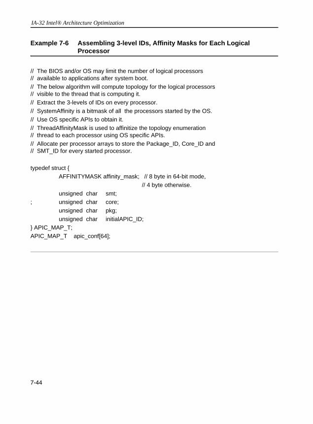
IA-32 Intel® Architecture Optimization
Example 7-6 Assembling 3-level IDs, Affinity Masks for Each Logical Processor
// The BIOS and/or OS may limit the number of logical processors // available to applications after system boot.// The below algorithm will compute topology for the logical processors // visible to the thread that is computing it.// Extract the 3-levels of IDs on every processor.// SystemAffinity is a bitmask of all the processors started by the OS. // Use OS specific APIs to obtain it.// ThreadAffinityMask is used to affinitize the topology enumeration// thread to each processor using OS specific APIs.// Allocate per processor arrays to store the Package_ID, Core_ID and// SMT_ID for every started processor.
typedef struct {AFFINITYMASK affinity_mask; // 8 byte in 64-bit mode,
// 4 byte otherwise.unsigned char smt;
; unsigned char core;unsigned char pkg;unsigned char initialAPIC_ID;
} APIC_MAP_T;APIC_MAP_T apic_conf[64];
7-44
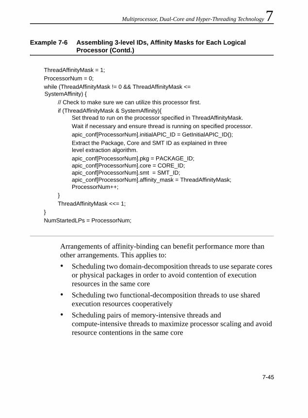
Multiprocessor, Dual-Core and Hyper-Threading Technology 7
Arrangements of affinity-binding can benefit performance more than other arrangements. This applies to: • Scheduling two domain-decomposition threads to use separate cores
or physical packages in order to avoid contention of execution resources in the same core
• Scheduling two functional-decomposition threads to use shared execution resources cooperatively
• Scheduling pairs of memory-intensive threads and compute-intensive threads to maximize processor scaling and avoid resource contentions in the same core
ThreadAffinityMask = 1;ProcessorNum = 0;while (ThreadAffinityMask != 0 && ThreadAffinityMask <=
SystemAffinity) {// Check to make sure we can utilize this processor first.if (ThreadAffinityMask & SystemAffinity){
Set thread to run on the processor specified in ThreadAffinityMask.Wait if necessary and ensure thread is running on specified processor.apic_conf[ProcessorNum].initialAPIC_ID = GetInitialAPIC_ID();Extract the Package, Core and SMT ID as explained in three
level extraction algorithm.apic_conf[ProcessorNum].pkg = PACKAGE_ID;apic_conf[ProcessorNum].core = CORE_ID;apic_conf[ProcessorNum].smt = SMT_ID;apic_conf[ProcessorNum].affinity_mask = ThreadAffinityMask;ProcessorNum++;
}ThreadAffinityMask <<= 1;
}NumStartedLPs = ProcessorNum;
Example 7-6 Assembling 3-level IDs, Affinity Masks for Each Logical Processor (Contd.)
7-45

IA-32 Intel® Architecture Optimization
An example using the 3-level hierarchy and relationships between the initial APIC_ID and the affinity mask to manage thread affinity binding is shown in Example 7-7. The example shows an implementation of building a lookup table so that the sequence of thread scheduling is mapped to an array of affinity masks such that threads are scheduled first to the primary logical processor of each processor core. This example is also optimized to the situations of scheduling two memory-intensive threads to run on separate cores and scheduling two compute-intensive threads on separate cores.User/Source Coding Rule 40. (M impact, L generality) Consider using thread affinity to optimize sharing resources cooperatively in the same core and subscribing dedicated resource in separate processor cores.
Some multi-core processor implementation may have a shared cache topology that is not uniform across different cache levels. The deterministic cache parameter leaf of CPUID will report such cache-sharing topology. The 3-level hierarchy and relationships between the initial APIC_ID and affinity mask can also be used to manage such a topology.
Example 7-8 illustrates the steps of discovering sibling logical processors in a physical package sharing a target level cache. The algorithm assumes initial APIC IDs are assigned in a manner that respect bit field boundaries, with respect to the modular boundary of the subset of logical processor sharing that cache level. Software can query the number of logical processors in hardware sharing a cache using the deterministic cache parameter leaf of CPUID. By comparing the relevant bits in the initial APIC_ID, one can construct a mask to represent sibling logical processors that are sharing the same cache.
Note the bit field boundary of the cache-sharing topology is not necessarily the same as the core boundary. Some cache levels can be shared across core boundary.
7-46

Multiprocessor, Dual-Core and Hyper-Threading Technology 7
Example 7-7 Assembling a Look up Table to Manage Affinity Masks and Schedule Threads to Each Core First
AFFINITYMASK LuT[64]; // A Lookup talbe to retrieve the affinity // mask we want to use from the thread // scheduling sequence index.int index =0; // Index to scheduling sequence.j = 0;
// Assemble the sequence for first LP consecutively to different core.while (j < NumStartedLPs) {
// Determine the first LP in each core.if( ! apic_conf [j ].smt) { // This is the first LP in a core
// supporting HT.LuT[index++] = apic_conf[j].affinitymask;
}j++;
} // Now the we have assigned each core to consecutive indices, // we can finish the table to use the rest of the // LPs in each core.
nThreadsPerCore = MaxLPPerPackage()/MaxCoresPerPackage();for (i = 0 ; i < nThreadsPerCore; i ++) {
for (j = 0 ; j < NumStartedLPs; j += nThreadsPerCore) {// Set the affinity binding for another logical
// processor in each core.if( apic_conf[ i+j ].SMT) {
LuT[ index++] = apic_id[ i+j ].affinitymask;}
}}
}
7-47
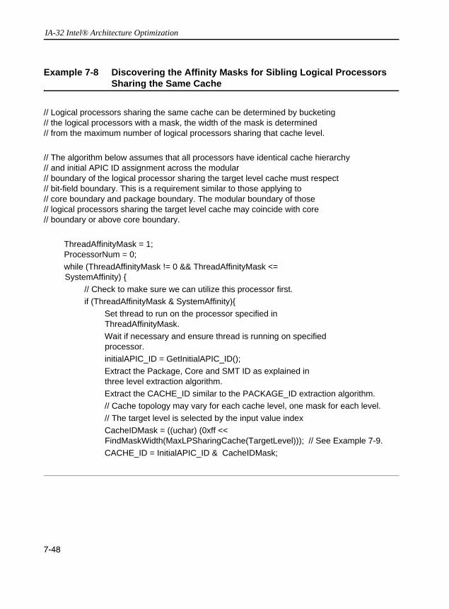
IA-32 Intel® Architecture Optimization
Example 7-8 Discovering the Affinity Masks for Sibling Logical Processors Sharing the Same Cache
// Logical processors sharing the same cache can be determined by bucketing // the logical processors with a mask, the width of the mask is determined // from the maximum number of logical processors sharing that cache level.
// The algorithm below assumes that all processors have identical cache hierarchy // and initial APIC ID assignment across the modular // boundary of the logical processor sharing the target level cache must respect // bit-field boundary. This is a requirement similar to those applying to // core boundary and package boundary. The modular boundary of those // logical processors sharing the target level cache may coincide with core // boundary or above core boundary.
ThreadAffinityMask = 1;ProcessorNum = 0;while (ThreadAffinityMask != 0 && ThreadAffinityMask <=
SystemAffinity) {// Check to make sure we can utilize this processor first.if (ThreadAffinityMask & SystemAffinity){
Set thread to run on the processor specified in ThreadAffinityMask.
Wait if necessary and ensure thread is running on specified processor.
initialAPIC_ID = GetInitialAPIC_ID();Extract the Package, Core and SMT ID as explained in
three level extraction algorithm.Extract the CACHE_ID similar to the PACKAGE_ID extraction algorithm.// Cache topology may vary for each cache level, one mask for each level. // The target level is selected by the input value indexCacheIDMask = ((uchar) (0xff <<
FindMaskWidth(MaxLPSharingCache(TargetLevel))); // See Example 7-9.CACHE_ID = InitialAPIC_ID & CacheIDMask;
7-48

Multiprocessor, Dual-Core and Hyper-Threading Technology 7
PackageID[ProcessorNUM] = PACKAGE_ID;CoreID[ProcessorNum] = CORE_ID;SmtID[ProcessorNum] = SMT_ID;CacheID[ProcessorNUM] = CACHE_ID; // Only the target cache is stored in this exampleProcessorNum++;
}ThreadAffinityMask <<= 1;
}NumStartedLPs = ProcessorNum;
CacheIDBucket is an array of unique Cache_ID values. Allocate an array of NumStartedLPs count of entries in this array for the target cache level. CacheProcessorMask is a corresponding array of the bit mask of logical processors sharing the same target level cache, these are logical processors with the same Cache_ID. The algorithm below assumes there is symmetry across the modular boundary of target cache topology if more than one socket is populated in an MP system, and only the topology of the target cache level is discovered. Topology of other cache level can be determined in a similar manner.
// Bucket Cache IDs and compute processor mask for the target cache of every package.CacheNum = 1;CacheIDBucket[0] = CacheID[0];ProcessorMask = 1;CacheProcessorMask[0] = ProcessorMask;
Example 7-8 Discovering the Affinity Masks for Sibling Logical Processors Sharing the Same Cache (Contd.)
7-49
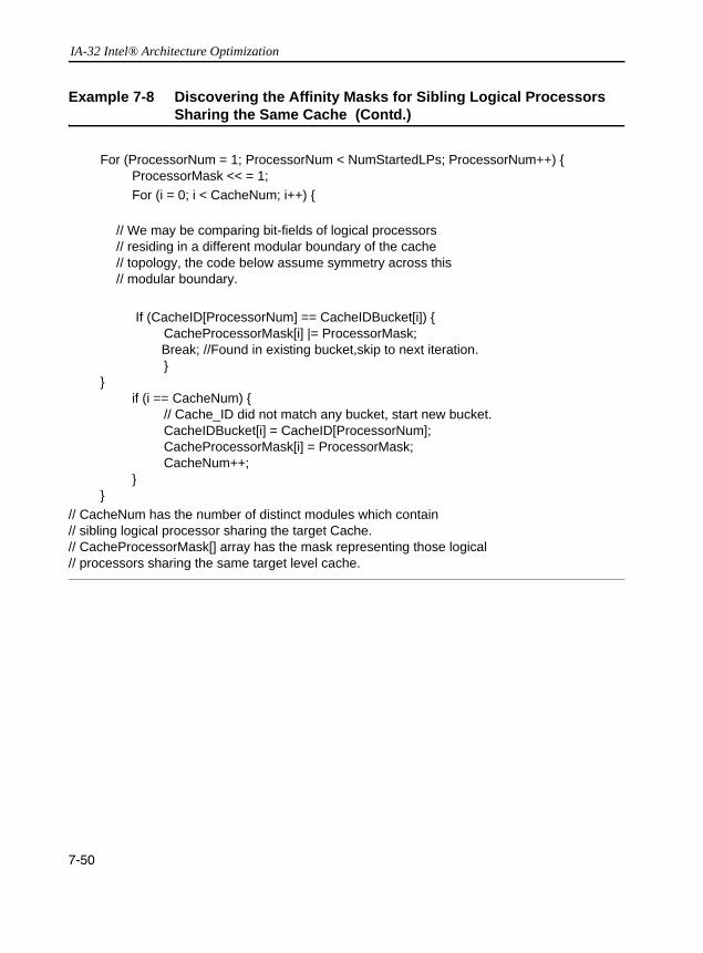
IA-32 Intel® Architecture Optimization
For (ProcessorNum = 1; ProcessorNum < NumStartedLPs; ProcessorNum++) {ProcessorMask << = 1;For (i = 0; i < CacheNum; i++) {
// We may be comparing bit-fields of logical processors // residing in a different modular boundary of the cache // topology, the code below assume symmetry across this // modular boundary.
If (CacheID[ProcessorNum] == CacheIDBucket[i]) {CacheProcessorMask[i] |= ProcessorMask;
Break; //Found in existing bucket,skip to next iteration.}
}if (i == CacheNum) {
// Cache_ID did not match any bucket, start new bucket.CacheIDBucket[i] = CacheID[ProcessorNum];CacheProcessorMask[i] = ProcessorMask;CacheNum++;
}}
// CacheNum has the number of distinct modules which contain // sibling logical processor sharing the target Cache.// CacheProcessorMask[] array has the mask representing those logical// processors sharing the same target level cache.
Example 7-8 Discovering the Affinity Masks for Sibling Logical Processors Sharing the Same Cache (Contd.)
7-50

Multiprocessor, Dual-Core and Hyper-Threading Technology 7
Example 7-9 Support Routine for Determining Cache-Sharing Topologyunsigned MaxLPSharingCache(int index){unsigned level_index = index; // The index for target cache level of CPUID.4 leaf.
unsigned int reg_eax = 0;if (!is_Hw_multithreading_supported()) {
// Must be single-core and discrete cache.return (unsigned char) 1;
}__asm {
mov eax, 0 // How many leaves does cpuid support?cpuidcmp eax, 4 // Does cpuid support leaf 4?jl lcl0 // If not, must be single core.mov eax, 4 // Call cpuid with eax = 4.mov ecx, level_index // Examine target cache level.cpuidand eax, 0x3ffc000shr eax, 14add eax, 1mov reg_eax, eax // Has info on number of cores
jmp lcl1lcl0:
// Must be single core, may be shared by more than one // logical processor.
mov eax, 1 // Call cpuid with eax = 1.cpuidand ebx, MAX_LOGICAL_PER_PKG_BITSshr ebx, 16mov reg_eax, ebx // Has info on number of logical
// processors.lcl1:
}return (unsigned ) (reg_eax );
} /*** end MaxLPSharingCache() ***/
7-51

IA-32 Intel® Architecture Optimization
7-52
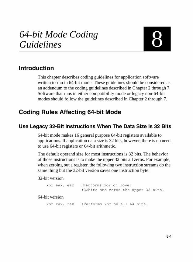
8
64-bit Mode Coding GuidelinesIntroductionThis chapter describes coding guidelines for application software written to run in 64-bit mode. These guidelines should be considered as an addendum to the coding guidelines described in Chapter 2 through 7. Software that runs in either compatibility mode or legacy non-64-bit modes should follow the guidelines described in Chapter 2 through 7.
Coding Rules Affecting 64-bit Mode
Use Legacy 32-Bit Instructions When The Data Size Is 32 Bits
64-bit mode makes 16 general purpose 64-bit registers available to applications. If application data size is 32 bits, however, there is no need to use 64-bit registers or 64-bit arithmetic.
The default operand size for most instructions is 32 bits. The behavior of those instructions is to make the upper 32 bits all zeros. For example, when zeroing out a register, the following two instruction streams do the same thing but the 32-bit version saves one instruction byte:
32-bit version xor eax, eax ;Performs xor on lower
;32bits and zeros the upper 32 bits.
64-bit version xor rax, rax ;Performs xor on all 64 bits.
8-1

IA-32 Intel® Architecture Optimization
This optimization holds true for the lower 8 general purpose registers: EAX, ECX, EBX, EDX, ESP, EBP, ESI, EDI. To access the data in registers r9-r15, the REX prefix is required. Using the 32-bit form there does not reduce code size.
Assembly/Compiler Coding ruleUse the 32-bit versions of instructions in 64-bit mode to reduce code size unless the 64-bit version is necessary to access 64-bit data or additional registers.
Use Extra Registers to Reduce Register Pressure
64-bit mode makes 8 additional 64-bit general purpose registers and 8 additional XMM registers available to applications. To access the additional registers, a single byte REX prefix is necessary. Using 8 additional registers can prevent the compiler from needing to spill values onto the stack.
Note that the potential increase in code size, due to the REX prefix, can increase cache misses. This can work against the benefit of using extra registers to access the data. When eight registers are sufficient for an algorithm, don’t use the registers that require an REX prefix. This will keep the code size smaller.
Assembly/Compiler Coding ruleWhen they are needed to reduce register pressure, use the 8 extra general purpose registers and 8 extra XMM registers for floating-point.
Use 64-Bit by 64-Bit Multiplies That Produce 128-Bit Results Only When Necessary
Integer multiplies of 64-bit by 64-bit operands that produce a 128-bit result cost more than multiplies that produce a 64-bit result. The upper 64-bits of a result take longer to compute than the lower 64 bits.
8-2
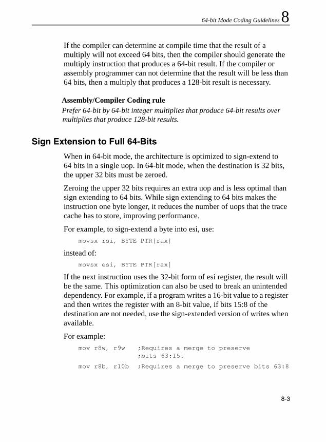
64-bit Mode Coding Guidelines 8
If the compiler can determine at compile time that the result of a multiply will not exceed 64 bits, then the compiler should generate the multiply instruction that produces a 64-bit result. If the compiler or assembly programmer can not determine that the result will be less than 64 bits, then a multiply that produces a 128-bit result is necessary.Assembly/Compiler Coding rulePrefer 64-bit by 64-bit integer multiplies that produce 64-bit results over multiplies that produce 128-bit results.
Sign Extension to Full 64-Bits
When in 64-bit mode, the architecture is optimized to sign-extend to 64 bits in a single uop. In 64-bit mode, when the destination is 32 bits, the upper 32 bits must be zeroed.
Zeroing the upper 32 bits requires an extra uop and is less optimal than sign extending to 64 bits. While sign extending to 64 bits makes the instruction one byte longer, it reduces the number of uops that the trace cache has to store, improving performance.
For example, to sign-extend a byte into esi, use:movsx rsi, BYTE PTR[rax]
instead of:movsx esi, BYTE PTR[rax]
If the next instruction uses the 32-bit form of esi register, the result will be the same. This optimization can also be used to break an unintended dependency. For example, if a program writes a 16-bit value to a register and then writes the register with an 8-bit value, if bits 15:8 of the destination are not needed, use the sign-extended version of writes when available.
For example:mov r8w, r9w ;Requires a merge to preserve
;bits 63:15.
mov r8b, r10b ;Requires a merge to preserve bits 63:8
8-3

IA-32 Intel® Architecture Optimization
Can be replaced with: movsx r8, r9w ;If bits 63:8 do not need to be
;preserved.
movsx r8, r10b ;If bits 63:8 do not need to ;be preserved.
In the above example, the moves to r8w and r8b both require a merge to preserve the rest of the bits in the register. There is an implicit real dependency on r8 between the 'mov r8w, r9w' and 'mov r8b, r10b'. Using movsx breaks the real dependency and leaves only the output dependency, which the processor can eliminate through renaming.
Assembly/Compiler Coding ruleSign extend to 64-bits instead of sign extending to 32 bits, even when the destination will be used as a 32-bit value.
Alternate Coding Rules for 64-Bit Mode
Use 64-Bit Registers Instead of Two 32-Bit Registers for 64-Bit Arithmetic
Legacy 32-bit mode offers the ability to support extended precision integer arithmetic (such as 64-bit arithmetic). However, 64-bit mode offers native support for 64-bit arithmetic. When 64-bit integers are desired, use the 64-bit forms of arithmetic instructions.
In 32-bit legacy mode, getting a 64-bit result from a 32-bit by 32-bit integer multiply requires three registers; the result is stored in 32-bit chunks in the EDX:EAX pair. When the instruction is available in 64-bit mode, using the 32-bit version of the instruction is not the optimal implementation if a 64-bit result is desired. Use the extended registers.
For example, the following code sequence loads the 32-bit values sign-extended into the 64-bit registers and performs a multiply:
MOVSX RAX, DWORD PTR[X]
MOVSX RCX, DWORD PTR[Y]
8-4

64-bit Mode Coding Guidelines 8
IMUL RAX, RCXThe 64-bit version above is more efficient than using the following 32-bit version:
MOV EAX, DWORD PTR[X]
MOV ECX, DWORD PTR[Y]
IMUL ECX
In the 32-bit case above, EAX is required to be a source. The result ends up in the EDX:EAX pair instead of in a single 64-bit register.
Assembly/Compiler Coding RuleUse the 64-bit versions of multiply for 32-bit integer multiplies that require a 64 bit result.
To add two 64-bit numbers in 32-bit legacy mode, the add instruction followed by the addc instruction is used. For example, to add two 64-bit variables (X and Y), the following four instructions could be used:
MOV EAX, DWORD PTR[X]
MOV EDX, DWORD PTR[X+4]
ADD EAX, DWORD PTR[Y]
ADC EDX, DWORD PTR[Y+4]
The result will end up in the two-register EDX:EAX.
In 64-bit mode, the above sequence can be reduced to the following:MOV RAX, QWORD PTR[X]
ADD RAX, QWORD PTR[Y]
The result is stored in rax. One register is required instead of two.
Assembly/Compiler Coding RuleUse the 64-bit versions of add for 64-bit adds.
8-5

IA-32 Intel® Architecture Optimization
Use 32-Bit Versions of CVTSI2SS and CVTSI2SD When Possible
The CVTSI2SS and CVTSI2SD instructions convert a signed integer in a general-purpose register or memory location to a single-precision or double-precision floating-point value. The signed integer can be either 32-bits or 64-bits.
The 32-bit version will result in traces delivered out of the trace cache; the 64-bit version will result in a microcode flow from the microcode ROM and takes longer to execute. In most cases, the 32-bit versions of CVTSI2SS and CVTSI2SD is sufficient.
Assembly/Compiler Coding ruleUse the 32-bit versions of CTVSI2SS and CVTSI2SD when possible.
Using Software Prefetch
Intel recommends that software developers follow the recommendations in Chapter 2 and Chapter 6 when considering the choice of organizing data access patterns to take advantage of the hardware prefetcher (versus using software prefetch).
Assembly/Compiler Coding RuleIf software prefetch instructions are necessary, use the prefetch instructions provided by SSE.
8-6

A
Application Performance ToolsIntel offers an array of application performance tools that are optimized to take advantage of the Intel architecture (IA)-based processors. This appendix introduces these tools and explains their capabilities for developing the most efficient programs without having to write assembly code.
The following performance tools are available:• Intel C++ Compiler and Intel® Fortran Compiler
The Intel compilers generate highly optimized executable code and provide high-level language support with unique features such as profile-guided optimizations and other advanced optimizations. This includes vectorization for MMX technology, the Streaming SIMD Extensions (SSE), Streaming SIMD Extensions 2 (SSE2), and the Streaming SIMD Extensions 3 (SSE3).
• Intel DebuggerThe Intel Debugger (IDB) enables you to debug C++, Fortran or mixed language programs. It allows you to view the XMM registers in a variety of formats corresponding to the data types supported by SSE and SSE2. These registers can also be viewed using the debugger supplied with Microsoft Visual C++* .NET.
• VTune Performance AnalyzerThe VTune analyzer collects, analyzes, and displays Intel architecture-specific software performance data from the system-wide view down to a specific line of code.
A-1

IA-32 Intel® Architecture Optimization
• Intel Performance LibrariesThe Intel Performance Library family consists of a set of software libraries optimized for Intel architecture processors. The library family includes the following: — Intel® Math Kernel Library (MKL)— Intel® Integrated Performance Primitives (IPP)
• Intel Threading Tools. The Intel Threading Tools consist of the following:— Intel Thread Checker— Thread Profiler
Intel® Compilers1
Intel C++ compilers can deliver significant application performance improvements for Microsoft Windows as well as Linux operating system environments. In the Windows environment, the Intel C++ compiler is source and binary compatible with Microsoft Visual C++* and plugs into the Microsoft .NET IDE. The Intel Visual Fortran Compiler is source compatible with Compaq* Visual Fortran, and also plugs into the Microsoft .NET IDE. In Linux environment, the Intel C++ Compilers are binary compatible with the corresponding version of gcc. The Intel C++ compiler may be used from the Borland* IDE, or standalone, like the Fortran compiler.
All compilers allow you to optimize your code by using special optimization options described in this section. There are several coding methods and optimizations, described here and in other sections of this manual, targeted specifically for enabling software developers to optimize applications for the Pentium 4 and Intel Xeon processor
1. The compiler options shown in this section use syntax specific to the Microsoft Windows-based compiler. Equivalent options, which may have slightly different syntax, exist for the Linux-based compiler. See your compiler documentation for a complete listing and description of the various options available.
A-2

Application Performance Tools A
family. Vectorization, processor dispatch, inter-procedural optimization, profile-guided optimization and OpenMP parallelism are all supported by the Intel compilers and can significantly aid the performance of an application.The most general optimization options are -O1, -02 and -O3. Each of them enables a number of specific optimization options. In most cases, -O2 is recommended over -O1 because the -O2 option enables function expansion, which helps programs that have many calls to small functions. The -01 may sometimes be preferred when code size is a concern. The -O2 option is on by default.
The -Od (-O0 on Linux) option disables all optimizations. The -03 option enables more aggressive loop optimizations, most of which are effective only in conjunction with processor-specific optimizations described below.
All the command-line options are described in the Intel C++ Compiler User’s Guide. Further advice on optimizing applications with the Intel compiler can be found in “Optimizing Applications with the Intel® C++ and Fortran Compilers for Windows* and Linux*” available at http://www.intel.com/software/products/compilers.
Code Optimization Options
This section describes specific options that may be used to optimize your code and improve the performance of your application.
Targeting a Processor (-Gn)
Use -Gn to target an application to run on a specific processor for maximum performance. Any of the -Gn suboptions you choose results in your binary being optimized for corresponding Intel architecture 32-bit processors. -G6 (-tpp6 on Linux) targets optimization for the Pentium II and Pentium III processors. -G7 (-tpp7 on Linux) is the
A-3

IA-32 Intel® Architecture Optimization
default, and targets the Intel Pentium 4 processor and subsequent processors. Code produced will run on any Intel architecture 32-bit processor, but will be optimized specifically for the targeted processor.
Automatic Processor Dispatch Support (-Qx[extensions] and -Qax[extensions])
The -Qx[extensions] and -Qax[extensions] options provide support to generate code that is specific to processor-instruction extensions. The corresponding options on Linux are -x[extensions] and -ax[extensions]. -Qx[extensions] generates specialized code to run exclusively on
the processors indicated by the extension(s).-Qax[extensions] generates code specialized to processors which
support the specified extensions, but also generates generic IA-32 code. The generic code usually executes slower than the specialized version. A runtime check for the processor type is made to determine which code executes.
You can specify the same extensions for either option as follows:i Pentium II and Pentium III processors, which use the
CMOV and FCMOV instructions.M Pentium processor with MMX technology, Pentium II,
and Pentium III processors.K Streaming SIMD Extensions. Includes the i and M
extensions.W Streaming SIMD Extensions 2. Includes the i, M,
and K extensions.B Streaming SIMD Extensions 2 and optimizations for
the Intel Pentium M processor. Includes the i, M, K,k and W extensions.
P Streaming SIMD Extensions 3. Includes the i, M, K, and W extensions.
A-4
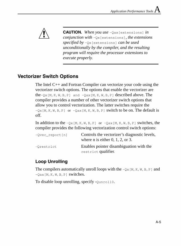
Application Performance Tools A
Vectorizer Switch Options
The Intel C++ and Fortran Compiler can vectorize your code using the vectorizer switch options. The options that enable the vectorizer are the-Qx[M,K,W,B,P] and -Qax[M,K,W,B,P] described above. The compiler provides a number of other vectorizer switch options that allow you to control vectorization. The latter switches require the -Qx[M,K,W,B,P] or -Qax[M,K,W,B,P] switch to be on. The default is off.
In addition to the -Qx[M,K,W,B,P] or -Qax[M,K,W,B,P] switches, the compiler provides the following vectorization control switch options:-Qvec_report[n] Controls the vectorizer’s diagnostic levels,
where n is either 0, 1, 2, or 3.-Qrestrict Enables pointer disambiguation with the
restrict qualifier.
Loop Unrolling
The compilers automatically unroll loops with the -Qx[M,K,W,B,P] and -Qax[M,K,W,B,P] switches.
To disable loop unrolling, specify -Qunroll0.
CAUTION. When you use -Qax[extensions] in conjunction with -Qx[extensions], the extensions specified by -Qx[extensions] can be used unconditionally by the compiler, and the resulting program will require the processor extensions to execute properly.
A-5

IA-32 Intel® Architecture Optimization
Multithreading with OpenMP*
Both the Intel C++ and Fortran Compilers support shared memory parallelism via OpenMP compiler directives, library functions and environment variables. OpenMP directives are activated by the compiler switch -Qopenmp. The available directives are described in the Compiler User's Guides available with the Intel C++ and Fortran Compilers. Further information about the OpenMP standard is available at http://www.openmp.org.
Automatic Multithreading
Both the Intel C++ and Fortran Compilers can generate multithreaded code automatically for simple loops with no dependencies. This is activated by the compiler switch -Qparallel.
Inline Expansion of Library Functions (-Oi, -Oi-)
The compiler inlines a number of standard C, C++, and math library functions by default. This usually results in faster execution of your program. Sometimes, however, inline expansion of library functions can cause unexpected results. For explanation, see the Intel® C++ Compiler User’s Guide.
Floating-point Arithmetic Precision (-Op, -Op-, -Qprec, -Qprec_div, -Qpc, -Qlong_double)
These options provide a means of controlling optimization that might result in a small change in the precision of floating-point arithmetic.
Rounding Control Option (-Qrcd)
The compiler uses the -Qrcd option to improve the performance of code that requires floating-point calculations. The optimization is obtained by controlling the change of the rounding mode.
A-6

Application Performance Tools A
The -Qrcd option disables the change to truncation of the rounding mode in floating-point-to-integer conversions.For complete details on all of the code optimization options, refer to the Intel C++ Compiler User’s Guide.
Interprocedural and Profile-Guided Optimizations
The following are two methods to improve the performance of your code based on its unique profile and procedural dependencies:
Interprocedural Optimization (IPO)
Use the -Qip option to analyze your code and apply optimizations between procedures within each source file. Use multifile IPO with -Qipo to enable the optimizations between procedures in separate source files.
Profile-Guided Optimization (PGO)
Creates an instrumented program from your source code and special code from the compiler. Each time this instrumented code is executed, the compiler generates a dynamic information file. When you compile a second time, the dynamic information files are merged into a summary file. Using the profile information in this file, the compiler attempts to optimize the execution of the most heavily travelled paths in the program.
Profile-guided optimization is particularly beneficial for the Pentium 4 and Intel Xeon processor family. It greatly enhances the optimization decisions the compiler makes regarding instruction cache utilization and memory paging. Also, because PGO uses execution-time information to guide the optimizations, branch-prediction can be significantly enhanced by reordering branches and basic blocks to keep the most commonly used paths in the microarchitecture pipeline, as well as generating the appropriate branch-hints for the processor.
A-7

IA-32 Intel® Architecture Optimization
When you use PGO, consider the following guidelines:• Minimize the changes to your program after instrumented execution
and before feedback compilation. During feedback compilation, the compiler ignores dynamic information for functions modified after that information was generated.
• Repeat the instrumentation compilation if you make many changes to your source files after execution and before feedback compilation.
For further details on the interprocedural and profile-guided optimizations, refer to the Intel C++ Compiler User’s Guide.
Intel® VTune™ Performance AnalyzerThe Intel VTune Performance Analyzer is a powerful software-profiling tool for Microsoft Windows and Linux. The VTune analyzer helps you understand the performance characteristics of your software at all levels: the system, application, microarchitecture.
The sections that follow describe the major features of the VTune analyzer and briefly explain how to use them. For more details on these features, run the VTune analyzer and see the online help or the built in Getting Started Guide.
All these features are available for Microsoft Windows. On Linux, sampling and call graph are available.
NOTE. The compiler issues a warning that the dynamic information corresponds to a modified function.
A-8
Application Performance Tools A
SamplingSampling allows you to profile all active software on your system, including operating system, device driver, and application software. It works by occasionally interrupting the processor and collecting the instruction address, process ID, and thread ID. After the sampling activity completes, the VTune analyzer displays the data by process, thread, software module, function, or line of source. There are two methods for generating samples: Time-based sampling and Event-based sampling.
Time-based Sampling• Time-based sampling (TBS) uses an operating system’s (OS) timer
to periodically interrupt the processor to collect samples. The sampling interval is user definable. TBS is useful for identifying the software on your computer that is taking the most CPU time.
A-9
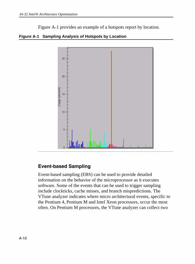
IA-32 Intel® Architecture Optimization
Figure A-1 provides an example of a hotspots report by location.
Event-based Sampling
Event-based sampling (EBS) can be used to provide detailed information on the behavior of the microprocessor as it executes software. Some of the events that can be used to trigger sampling include clockticks, cache misses, and branch mispredictions. The VTune analyzer indicates where micro architectural events, specific to the Pentium 4, Pentium M and Intel Xeon processors, occur the most often. On Pentium M processors, the VTune analyzer can collect two
Figure A-1 Sampling Analysis of Hotspots by Location
A-10
Application Performance Tools A
different events at a time. The number of the events that the VTune analyzer can collect at once on the Pentium 4 and Intel Xeon processor depends on the events selected.Event-based samples are collected after a specific number of processor events have occurred. The samples can then be attributed to the different processes, threads, software modules, functions, and lines of code running on the system.
Workload Characterization
Using event-based sampling and processor-specific events can provide useful insights into the nature of the interaction between a workload and the microarchitecture. A few metrics useful for workload characterization are given below:
Retirement Throughput: Table B-1 includes several ratios (measured from processor-specific events) that characterize the effective throughput of instructions (or µops) at the retirement stage. For example, UPC measure µops throughput at the retirement stage, which can be compared to the peak retirement bandwidth of the microarchitecture to evaluate the degree of extractable instruction-level parallelism in the workload. Non-halted CPI and Non-Sleep CPI measure the effective instruction execution throughput at the retirement stage. The former is usually set up for measurement on a per logical processor basis, while the latter is always set up for measurement on a per processor core basis (if a processor core provides two logical processors).
Data Traffic Locality: The processor event “Bus Reads Underway from the Processors” be used to characterize the dominant data traffic locality being the memory sub-system or the cache hierarchy. By customizing this event using the “Edit Event” dialog box to enable the “COMPARE” bit in the CCCR, one can measure the effective duration of bus read traffic from the memory sub-system. If the ratio of this
A-11

IA-32 Intel® Architecture Optimization
duration of read traffic compared to the duration of the workload is significantly less than unity, it indicates the dominant data locality of the workload is cache access traffic.
Average Bus Queue Depth: Using the default configuration of the processor event “Bus Reads Underway from the Processor”2, one can measure the weighted cycles of bus read traffic, where it is weighted by the depth of queue of bus reads. Thus, one can derive average queue depth from the ratio of weighted cycles over the effective duration of bus read traffic. Similarly, one can use other bus events to measure the average bus queue depth for other type of bus transactions.
Using the average queue depth of read traffic, one can characterize the degree of bus read traffic that originates from the cache miss pattern of the workload and are sensitive memory latency. This can be done by comparing whether the average bus queue depth of read traffic, under the condition of disabling hardware prefetch3 while measuring this bus event, is close to unity. When this ratio is very close to unity, it implies the workload has a data access pattern with very poor data parallelism and will fully exposes memory latency whenever cache misses occur.
Large Stride Inefficiency: Large-stride data accesses are much less efficient than smaller stride data accesses, because large stride accesses will incur more frequent DTLB misses during address translation. The penalty of large stride accesses apply to cache traffic as well as memory traffic. In terms of the quantitative impact on data access latency, large
2. Note that by default Pentium 4 processor events dealing with bus traffic, such as Bus Reads Underway from the Processor, will implicitly combine the interaction of two aspects: (a) a cache miss pattern of the last level cache as a result of the data reference pattern of the workload, each cache read miss is expected to require a bus read request to fetch data (a cache line) from the memory sub-system; (b) in the presence of hardware prefetch being enabled, a cache read miss may trigger the hardware prefetch to queue up additional bus read requests to fetch additional cache lines from the memory sub-system.
3. Hardware prefetch mechanisms can be controlled on demand using the model-specific register IA32_MISC_ENABLES. IA-32 Intel Architecture Software Developer’s Manual, Volume 3, Appendix B describes the specific bit locations of the IA32_MISC_ENABLES MSR.
A-12

Application Performance Tools A
stride inefficiency is most prominent on memory traffic. A useful indicator for large-stride inefficiency in a workload is to compare the ratio between bus read transactions and the number of DTLB pagewalks due to read traffic, under the condition of disabling the hardware prefetch while measuring bus traffic of the workload. The former can be measured using the event “Bus Reads from the processor.” The latter can be approximated by measuring the event “Page Walk DTLB All Misses.” The latter is an approximation because the event measures DTLB misses due to either read or write traffic, and does not distinguish between cache traffic versus memory traffic.Call Graph
Call graph helps you understand the relationships between the functions in your application by providing timing and caller / callee (functions called) information. Call graph works by instrumenting the functions in your application. Instrumentation is the process of modifying a function so that performance data can be captured when the function is executed. Instrumentation does not change the functionality of the program. However, it can reduce performance. The VTune analyzer can detect modules as they are loaded by the operating system, and instrument them at run-time. Call graph can be used to profile Win32*, Java*, and Microsoft.NET* applications. Call graph only works for application (ring 3) software.
Call graph profiling provides the following information on the functions called by your application: total time, self-time, total wait time, wait time, callers, callees, and the number of calls. This data is displayed using three different views: function summary, call graph, and call list. These views are all synchronized.
The Function Summary View can be used to focus the data displayed in the call graph and call list views. This view displays all the information about the functions called by your application in a sortable table format. However, it does not provide callee and caller information. It just provides timing information and number of times a function is called.
A-13

IA-32 Intel® Architecture Optimization
The Call Graph View depicts the caller / callee relationships. Each thread in the application is the root of a call tree. Each node (box) in the call tree represents a function. Each edge (line with an arrow) connecting two nodes represents the call from the parent to the child function. If the mouse pointer is hovered over a node, a tool tip will pop up displaying the function's timing information.
The Call List View is useful for analyzing programs with large, complex call trees. This view displays only the caller and callee information for the single function that you select in the Function Summary View. The data is displayed in a table format.
Counter Monitor
Counter monitor helps you identify system level performance bottlenecks. It periodically polls software and hardware performance counters. The performance counter data can help you understand how your application is impacting the performance of the computer's various subsystems. Counter monitor data can be displayed in real-time and logged to a file. The VTune analyzer can also correlate performance counter data with sampling data.
Intel® Tuning Assistant
The Intel Tuning Assistant can generate tuning advice based on counter monitor and sampling data. You can invoke the Intel Tuning Assistant from the source, counter monitor, or sampling views by clicking on the Intel Tuning Assistant icon.
Intel® Performance LibrariesThe Intel Performance Library family contains a variety of specialized libraries which has been optimized for performance on Intel processors. These optimizations take advantage of appropriate architectural features, including MMX technology, Streaming SIMD Extensions
A-14

Application Performance Tools A
(SSE), Streaming SIMD Extensions 2 (SSE2) and Streaming SIMD Extensions 3 (SSE3). The library set includes the Intel Math Kernel Library (MKL) and the Intel Integrated Performance Primitives (IPP).• The Intel Math Kernel Library for Linux* and Windows*: MKL iscomposed of highly optimized mathematical functions for engineering, scientific and financial applications requiring high performance on Intel platforms. The functional areas of the library include linear algebra consisting of LAPACK and BLAS, Discrete Fourier Transforms (DFT), vector transcendental functions (vector math library/VML) and vector statistical functions (VSL). Intel MKL is optimized for the latest features and capabilities of the Intel Pentium 4 processor, Pentium M processor, Intel Xeon processors and Intel® Itanium® 2 processors.
• Intel® Integrated Performance Primitives for Linux* and Windows*: IPP is a cross-platform software library which provides a range of library functions for multimedia, audio codecs, video codecs (for example H.263, MPEG-4), image processing (JPEG), signal processing, speech compression (for example, G.723.1, GSM AMR), cryptography plus computer vision as well as math support routines for such processing capabilities. Intel IPP is optimized for the broad range of Intel microprocessors: Intel Pentium 4 processor, Pentium M processor, Intel Xeon processors, the Intel Itanium architecture, Intel® SA-1110 and Intel® PCA application processors based on the Intel XScale® microarchitecture. With a single API across the range of platforms, the users can have platform compatibility and reduced cost of development.
Benefits Summary
The overall benefits the libraries provide to the application developers are as follows:• Time-to-Market: Low-level building block functions that support
rapid application development, improving time to market.
A-15

IA-32 Intel® Architecture Optimization
• Performance: Highly-optimized routines with a C interface that give Assembly-level performance in a C/C++ development environment (MKL also supports a Fortran interface).
• Platform tuned: Processor-specific optimizations that yield the best performance for each Intel processor.
• Compatibility: Processor-specific optimizations with a single application programming interface (API) to reduce development costs while providing optimum performance.
• Threaded application support: Applications can be threaded with the assurance that the MKL and IPP functions are safe for use in a threaded environment.
Optimizations with the Intel® Performance Libraries
The Intel Performance Libraries implement a number of optimizations that are discussed throughout this manual. Examples include architecture-specific tuning such as loop unrolling, instruction pairing and scheduling; and memory management with explicit and implicit data prefetching and cache tuning.
The Libraries take advantage of the parallelism in the SIMD instructions using MMX technology, Streaming SIMD Extensions (SSE), Streaming SIMD Extensions 2 (SSE2), and Streaming SIMD Extensions 3 (SSE3). These techniques improve the performance of computationally intensive algorithms and deliver hand coded performance in a high level language development environment.
For performance sensitive applications, the Intel Performance Libraries free the application developer from the time consuming task of assembly-level programming for a multitude of frequently used functions. The time required for prototyping and implementing new application features is substantially reduced and most important, the time to market is substantially improved. Finally, applications
A-16

Application Performance Tools A
developed with the Intel Performance Libraries benefit from new architectural features of future generations of Intel processors simply by relinking the application with upgraded versions of the libraries.Enhanced Debugger (EDB)The Enhanced Debugger (EDB) enables you to debug C++, Fortran or mixed language programs running under Windows NT* or Windows 2000 (not Windows 98). It allows you to display in a separate window the contents of the eight registers, XMM0 through XMM7, used by the Streaming SIMD Extensions and Streaming SIMD Extensions 2. You may select one of five formats for the register fields: byte (16 bytes); word (8 words); double word (4 double words); single precision (4 single precision floating point); and double precision (2 double precision floating point). When a register is updated, the new value appears in red. The corresponding Streaming SIMD Extensions or Streaming SIMD Extensions 2 instruction can be seen in the disassembly window. For further detail on the features and use of the Enhanced Debugger, refer to the online help.
Intel® Threading Tools4
The Intel® Threading Tools consist of the The Intel Thread Checker and Thread Profiler.
Intel® Thread Checker
The Intel Thread Checker locates programming errors (e.g., data races, stalls and deadlocks) in threaded applications. Use the Intel Thread Checker to find threading errors and reduce the amount of time you spend debugging your threaded application.
4. For additional threading resources, visit http://www.intel.com/software/products/threadtool.htm.
A-17

IA-32 Intel® Architecture Optimization
The Intel Thread Checker product is an Intel VTune Performance Analyzer plug-in data collector that executes your program and automatically locates threading errors. As your program runs, the Intel Thread Checker monitors memory accesses and other events and automatically detects situations which could cause unpredictable threading-related results. The Intel Thread Checker detects thread deadlocks, stalls, data race conditions and more.
Figure A-2 Intel Thread Checker Can Locate Data Race Conditions
A-18
Application Performance Tools A
Figure A-2 shows Intel Thread Checker displaying the source code of the selected instance from a list of detected data race conditions that occurred during threaded execution. The target operands (a synchronization variable shared by more than one threads) of the race condition, the type of data operation on the target operand, and source code locations are displayed in the graphical user interface.Thread Profiler
The thread profiler is a plug-in data collector for the Intel VTune Performance Analyzer. Use it to analyze threading performance and identify parallel performance problems. The thread profiler graphically illustrates what each thread is doing at various levels of detail using a hierarchical summary. It can identify inactive threads, critical paths and imbalances in thread execution, etc. Mountains of data are collapsed into relevant summaries, sorted to identify parallel regions or loops that require attention. Its intuitive, color-coded displays make it easy to assess your application's performance.
Figure A-3 shows the execution timeline of a multi-threaded application when run in (a) a single-threaded environment, (b) a multi-threaded environment capable of executing two threads simultaneously, (c) a multi-threaded environment capable of executing four threads simultaneously. In Figure A-3, the color-coded timeline of three hardware configurations are super-imposed together to compare processor scaling performance and illustrate the imbalance of thread execution.
Load imbalance problem is visually identified in the two-way platform by noting that there is a significant portion of the timeline, during which one logical processor had no task to execute. In the four-way platform, one can easily identify those portions of the timeline of three logical processors, each having no task to execute.
A-19

IA-32 Intel® Architecture Optimization
Intel® Software CollegeThe Intel® Software College is a valuable resource for classes on Streaming SIMD Extensions 2 (SSE2), Threading and the IA-32 Intel Architecture. For online training on how to use the SSE2 and Hyper-Threading Technology, refer to the IA-32 Architecture Training - Online Training at http://developer.intel.com/software/college/CourseCatalog.asp?CatID=web-based. For key algorithms and their optimization examples for the Pentium 4 processor, refer to the application notes. You can find additional information on classroom training from the Intel Software College Web site at http://developer.intel.com/software/college, and general information for developers from Intel Developer Services at http://www.intel.com/ids.
Figure A-3 Intel Thread Profiler Can Show Critical Paths of Threaded Execution Timelines
A-20
B
Intel Pentium 4 Processor Performance MetricsThe Intel Pentium 4 processor performance metrics are a set of quantities that are useful for tuning software performance when running applications on the Pentium 4 and Intel Xeon processors. The metrics are derived from the Pentium 4 and Intel Xeon processor performance monitoring events, which are described in Chapter 15 and Appendix A of the IA-32 Intel Architecture Software Developer’s Manual, Volume 3: “System Programming.”
The descriptions of the Intel Pentium 4 processor performance metrics use terminology that are specific to the Intel NetBurst microarchitecture and to the implementation in the Pentium 4 and Intel Xeon processors. The following sections explain the terminology specific to Pentium 4 and Intel Xeon processors, usage notes that apply to counting clock cycles, and notes for using some of the performance metrics dealing with bus, memory and Hyper-Threading Technology. The performance metrics for IA-32 processors with CPUID signature that matches family encoding 15, mode encoding 0, 1, 2 or 3 are listed in Tables B-1 through Table B-4. Several new performance metrics are available to IA-32 processors with CPUID signature that matches family encoding 15, mode encoding 3; these performance metrics are listed in Table B-5.
The performance metrics listed n Tables B-1 through Table B-5 may be applicable to processors that support Hyper-Threading Technology, see Using Performance Metrics with Hyper-Threading Technology section.
B-1

IA-32 Intel® Architecture Optimization
Pentium 4 Processor-Specific Terminology
Bogus, Non-bogus, Retire
Branch mispredictions incur a large penalty on microprocessors with deep pipelines. In general, the direction of branches can be predicted with a high degree of accuracy by the front end of the Intel Pentium 4 processor, such that most computations can be performed along the predicted path while waiting for the resolution of the branch.
In the event of a misprediction, instructions and micro-ops (µops) that were scheduled to execute along the mispredicted path must be cancelled. These instructions and µops are referred to as bogus instructions and bogus µops. A number of Pentium 4 processor performance monitoring events, for example, instruction_ retired and mops_retired, can count instructions or µops that are retired based on the characterization of bogus versus non-bogus.
In the event descriptions in Table B-1, the term “bogus” refers to instructions or micro-ops that must be cancelled because they are on a path taken from a mispredicted branch. The terms “retired” and “non-bogus” refer to instructions or micro-ops along the path that results in committed architectural state changes as required by the program execution. Thus instructions and µops are either bogus or non-bogus, but not both.
Bus Ratio
Bus Ratio is the ratio of the processor clock to the bus clock. In the Bus Utilization metric, it is the Bus_ratio.
B-2

Intel Pentium 4 Processor Performance Metrics B
ReplayIn order to maximize performance for the common case, the Intel NetBurst microarchitecture sometimes aggressively schedules µops for execution before all the conditions for correct execution are guaranteed to be satisfied. In the event that all of these conditions are not satisfied, µops must be reissued. This mechanism is called replay.
Some occurrences of replays are caused by cache misses, dependence violations (for example, store forwarding problems), and unforeseen resource constraints. In normal operation, some number of replays are common and unavoidable. An excessive number of replays indicate that there is a performance problem.
Assist
When the hardware needs the assistance of microcode to deal with some event, the machine takes an assist. One example of such situation is an underflow condition in the input operands of a floating-point operation. The hardware must internally modify the format of the operands in order to perform the computation. Assists clear the entire machine of µops before they begin to accumulate, and are costly. The assist mechanism on the Pentium 4 processor is similar in principle to that on the Pentium II processors, which also have an assist event.
Tagging
Tagging is a means of marking µops to be counted at retirement. See Appendix A of the IA-32 Intel Architecture Software Developer’s Manual, Volume 3: “System Programming” for the description of the tagging mechanisms. The same event can happen more than once per µop. The tagging mechanisms allow a µop to be tagged once during its lifetime. The retired suffix is used for metrics that increment a count once per µop, rather than once per event. For example, a µop may
B-3
IA-32 Intel® Architecture Optimization
encounter a cache miss more than once during its life time, but a Misses Retired metric (for example, 1st-Level Cache Misses Retired) will increment only once for that µop.
Counting ClocksThe count of cycles, also known as clock ticks, forms a fundamental basis for measuring how long a program takes to execute, and as part of efficiency ratios like cycles per instruction (CPI). Some processor clocks may stop “ticking” under certain circumstances:• The processor is halted, e.g. during I/O, there may be nothing for the
CPU to do while servicing a disk read request, and the processor may halt to save power. When Hyper-Threading Technology is enabled, both logical processors must be halted for performance-monitoring-related counters to be powered down.
• The processor is asleep, either as a result of being halted for a while, or as part of a power-management scheme. Note that there are different levels of sleep, and in the deeper sleep levels, the timestamp counter stops counting.
This section describes three mechanisms to count processor clock cycles for monitoring performance. They are:• Non-Halted Clockticks: clocks when the specified logical
processor is not halted nor in any power-saving states. These can be measured on a per-logical-processor basis, when Hyper-Threading Technology is enabled.
• Non-Sleep Clockticks: clocks when the physical processor is not in any of the sleep modes, nor power-saving states. These cannot be measured on a per-logical- processor basis.
• Timestamp Counter: clocks when the physical processor is not in deep sleep. These cannot be measured on a per-logical-processor basis.
B-4

Intel Pentium 4 Processor Performance Metrics B
The first two metrics use performance counters, and thus can be used to cause interrupt upon overflow for sampling. They may also be useful for those cases where it is easier for a tool to read a performance counter instead of the time stamp counter. The timestamp counter is accessed via an instruction, RDTSC.For applications with a significant amount of I/O, there may be two ratios of interest:• Non-halted CPI: non-halted clockticks/instructions retired
measures the CPI for the phases where the CPU was being used. This ratio can be measured on a per- logical-processor basis, when Hyper-Threading Technology is enabled.
• Nominal CPI: timestamp counter ticks/instructions retired measures the CPI over the entire duration of the program, including those periods the machine is halted while waiting for I/O.
The distinction between these two CPI is important for processors that support Hyper-Threading Technology. Non-halted CPI should use the “Non-Halted clockticks” performance metric as the numerator. Nominal CPI can use “Non-Sleep clockticks” in the numerator. “Non-sleep clockticks” is the same as the “clockticks” metric in previous editions of this manual.
Non-Halted Clockticks
Non-halted clockticks can be obtained by programming the appropriate ESCR and CCCR following the recipe listed in the general metrics category in Table B-1. Additionally, the desired T0_OS/T0_USR/T1_OS/T1_USR bits may be specified to qualify a specific logical processor and/or kernel vs. user mode.
B-5

IA-32 Intel® Architecture Optimization
Non-Sleep Clockticks
The performance monitoring counters can also be configured to count clocks whenever the performance monitoring hardware is not powered-down. To count “non-sleep clockticks” with a performance-monitoring counter, do the following:• Select any one of the 18 counters.• Select any of the possible ESCRs whose events the selected counter
can count, and set its event select to anything other than no_event. This may not seem necessary, but the counter may be disabled in some cases if this is not done.
• Turn threshold comparison on in the CCCR by setting the compare bit to 1.
• Set the threshold to 15 and the complement to 1 in the CCCR. Since no event can ever exceed this threshold, the threshold condition is met every cycle, and hence the counter counts every cycle. Note that this overrides any qualification (e.g. by CPL) specified in the ESCR.
• Enable counting in the CCCR for that counter by setting the enable bit.
The counts produced by the Non-halted and Non-sleep metrics are equivalent in most cases if each physical package supports one logical processor and is not in any power-saving states. An operating system may execute the HLT instruction and place a physical processor in a power-saving state.
On processors that support Hyper-Threading Technology, each physical package can support two or more logical processors. Current implementation of Hyper-Threading Technology provides two logical processors for each physical processor.
While both logical processors can execute two threads simultaneously, one logical processor may be halted to allow the other logical processor to execute without sharing execution resources between two logical processors. “Non-halted clockticks” can be qualified to count the number of processor clock cycles for each logical processor whenever
B-6

Intel Pentium 4 Processor Performance Metrics B
that logical processor is not halted (it may include some portion of the clock cycles for that logical processor to complete a transition into a halted state). A physical processor that supports Hyper-Threading Technology enters into a power-saving state if all logical processors are halted.“Non-sleep clockticks” use is based on the filtering mechanism in the CCCR: it will continue to increment as long as one logical processor is not halted, nor is it in any power-saving states. An application may indirectly cause a processor to enter into a power-saving state via an OS service that transfers control into the operating system's idle loop. The system idle loop may place the processor into a power-saving state after an implementation-dependent period if there is no work for the processor to do.
Time Stamp Counter
The time stamp counter increments whenever the sleep pin is not asserted or when the clock signal on the system bus is active. It can be read with the RDTSC instruction. The difference in values between two reads (modulo 2**64) gives the number of processor clocks between those reads.
The time stamp counter and “Non-sleep clockticks” counts should agree in practically all cases if the physical processor is not in any power-saving states. However, it is possible to have both logical processors in a physical package halted, which results in most of the chip (including the performance monitoring hardware) being powered down. In this situation, it is possible for the time stamp counter to continue incrementing because the clock signal on the system bus is still active, but “non-sleep clockticks” will no longer increment because the performance monitoring hardware is powered down in power-saving states.
B-7
IA-32 Intel® Architecture Optimization
Microarchitecture Notes
Trace Cache Events
The trace cache is not directly comparable to an instruction cache. The two are organized very differently. For example, a trace can span many lines' worth of instruction-cache data. As with most microarchitectural elements, trace cache performance is only an issue if something else is not a bigger bottleneck. If an application is bus bandwidth bound, the bandwidth that the front end is getting uops to the core may be irrelevant. When front-end bandwidth is an issue, the trace cache, in deliver mode, can issue uops to the core faster than either the decoder (build mode) or the microcode store (the MS ROM). Thus the percent of time in trace cache deliver mode, or similarly, the percentage of all bogus and non-bogus uops from the trace cache can be a useful metric for determining front-end performance.
The metric that is most analogous to an instruction cache miss is a trace cache miss. An unsuccessful lookup of the trace cache (colloquially, a miss) is not interesting, per se, if we are in build mode and don't find a trace available; we just keep building traces. The only “penalty” in that case is that we continue to have a lower front-end bandwidth. The trace cache miss metric that is currently used is not just any TC miss, but rather one that is incurred while the machine is already in deliver mode; i.e., when a 15-20 cycle penalty is paid. Again, care must be exercised: a small average number of TC misses per instruction does not indicate good front-end performance if the percentage of time in deliver mode is also low.
Bus and Memory Metrics
In order to correctly interpret the observed counts of performance metrics related to bus events, it is helpful to understand transaction sizes, when entries are allocated in different queues, and how sectoring and prefetching affect counts.
B-8

Intel Pentium 4 Processor Performance Metrics B
There is a simplified block diagram below of the sub-systems connected to the IOQ unit in the front side bus sub-system and the BSQ unit that interface to the IOQ. A two-way SMP configuration is illustrated. 1st-level cache misses and writebacks (also called core references) result in references to the 2nd-level cache. The Bus Sequence Queue (BSQ) holds requests from the processor core or prefetcher that are to be serviced on the front side bus (FSB), or in the local XAPIC. If a 3rd-level cache is present on-die, the BSQ also holds writeback requests (dirty, evicted data) from the 2nd-level cache. The FSB's IOQ holds requests that have gone out onto the front side bus.Core references are nominally 64 bytes, the size of a 1st-level cache line. Smaller sizes are called partials, e.g., uncacheable and write combining reads, uncacheable, write-through and write-protect writes, and all I/O. Writeback locks, streaming stores and write combining stores may be full line or partials. Partials are not relevant for cache
Figure B-1 Relationships Between the Cache Hierarchy, IOQ, BSQ and Front Side Bus
Chip SetSystem Memory
1st Level DataCache
3rd Level Cache
FSB_ IOQ
BSQ
Unified 2nd LevelCache
1st Level DataCache
3rd Level Cache
FSB_ IOQ
BSQ
Unified 2nd LevelCache
B-9
IA-32 Intel® Architecture Optimization
references, since they are associated with non-cached data. Likewise, writebacks (due to the eviction of dirty data) and RFOs (reads for ownership due to program stores) are not relevant for non-cached data.
The granularity at which the core references are counted by different bus and memory metrics listed in Table B-1 varies, depending on the underlying performance-monitoring events that these bus and memory metrics are derived from. The granularities of core references are listed below, according to the performance monitoring events that are docu-mented in Appendix A of the IA-32 Intel Architecture Software Devel-oper’s Manual, Volume 3: “System Programming”.
Reads due to program loads• BSQ_cache_reference: 128 bytes for misses (on current
implementations), 64 bytes for hits• BSQ_allocation: 128 bytes for hits or misses (on current
implementations), smaller for partials' hits or misses• BSQ_active_entries: 64 bytes for hits or misses, smaller for partials'
hits or misses• IOQ_allocation, IOQ_active_entries: 64 bytes, smaller for partials'
hits or misses
Reads due to program writes (RFOs)• BSQ_cache_reference: 64 bytes for hits or misses• BSQ_allocation: 64 bytes for hits or misses (the granularity for
misses may change in future implementations of BSQ_allocation), smaller for partials' hits or misses
• BSQ_active_entries: 64 bytes for hits or misses, smaller for partials' hits or misses
• IOQ_allocation, IOQ_active_entries: 64 bytes for hits or misses, smaller for partials' hits or misses
B-10
Intel Pentium 4 Processor Performance Metrics B
Writebacks (dirty evictions)• BSQ_cache_reference: 64 bytes • BSQ_allocation: 64 bytes • BSQ_active_entries: 64 bytes• IOQ_allocation, IOQ_active_entries: 64 bytesThe count of IOQ allocations may exceed the count of corresponding BSQ allocations on current implementations for several reasons, including: • Partials:
In the FSB IOQ, any transaction smaller than 64 bytes is broken up into one to eight partials, each being counted separately as a or one to eight-byte chunks. In the BSQ, allocations of partials get a count of one. Future implementations will count each partial individually.
• Different transaction sizes: The allocations of non-partial programmatic load requests get a count of one per 128 bytes in the BSQ on current implementations, and a count of one per 64 bytes in the FSB IOQ. The allocations of RFOs get a count of 1 per 64 bytes for earlier processors and for the FSB IOQ (This granularity may change in future implementations).
• Retries: If the chipset requests a retry, the FSB IOQ allocations get one count per retry.
There are two noteworthy cases where there may be BSQ allocations without FSB IOQ allocations. The first is UC reads and writes to the local XAPIC registers. Second, if a cache line is evicted from the 2nd-level cache but it hits in the on-die 3rd-level cache, then a BSQ entry is allocated but no FSB transaction is necessary, and there will be no allocation in the FSB IOQ. The difference in the number of write transactions of the writeback (WB) memory type for the FSB IOQ and
B-11
IA-32 Intel® Architecture Optimization
the BSQ can be an indication of how often this happens. It is less likely to occur for applications with poor locality of writes to the 3rd-level cache, and of course cannot happen when no 3rd-level cache is present.
Usage Notes for Specific Metrics
The difference between the metrics “Read from the processor” and “Reads non-prefetch from the processor” is nominally the number of hardware prefetches.
The paragraphs below cover several performance metrics that are based on the Pentium 4 processor performance-monitoring event “BSQ_cache_rerference”. The metrics are:• 2nd-Level Cache Read Misses• 2nd-Level Cache Read References• 3rd-Level Cache Read Misses• 3rd-Level Cache Read References• 2nd-Level Cache Reads Hit Shared• 2nd-Level Cache Reads Hit Modified• 2nd-Level Cache Reads Hit Exclusive• 3rd-Level Cache Reads Hit Shared• 3rd-Level Cache Reads Hit Modified• 3rd-Level Cache Reads Hit Exclusive
These metrics based on BSQ_cache_reference may be useful as an indicator of the relative effectiveness of the 2nd-level cache, and the 3rd-level cache if present. But due to the current implementation of BSQ_cache_reference in Pentium 4 and Intel Xeon processors, they should not be used to calculate cache hit rates or cache miss rates. The following three paragraphs describe some of the issues related to BSQ_cache_reference, so that its results can be better interpreted.
B-12

Intel Pentium 4 Processor Performance Metrics B
Current implementations of the BSQ_cache_reference event do not distinguish between programmatic read and write misses. Programmatic writes that miss must get the rest of the cache line and merge the new data. Such a request is called a read for ownership (RFO). To the “BSQ_cache_reference” hardware, both a programmatic read and an RFO look like a data bus read, and are counted as such. Further distinction between programmatic reads and RFOs may be provided in future implementations.Current implementations of the BSQ_cache_reference event can suffer from perceived over- or under-counting. References are based on BSQ allocations, as described above. Consequently, read misses are generally counted once per 128-byte line BSQ allocation (whether one or both sectors are referenced), but read and write (RFO) hits and most write (RFO) misses are counted once per 64-byte line, the size of a core reference. This makes the event counts for read misses appear to have a 2-times overcounting with respect to read and write (RFO) hits and write (RFO) misses. This granularity mismatch cannot always be corrected for, making it difficult to correlate to the number of programmatic misses and hits. If the user knows that both sectors in a 128 -byte line are always referenced soon after each other, then the number of read misses can be multiplied by two to adjust miss counts to a 64-byte granularity.
Prefetches themselves are not counted as either hits or misses, as of Pentium 4 and Intel Xeon processors with a CPUID signature of 0xf21. However, in Pentium 4 Processor implementations with a CPUID signature of 0xf07 and earlier have the problem that reads to lines that are already being prefetched are counted as hits in addition to misses, thus overcounting hits.
The number of “Reads Non-prefetch from the Processor” is a good approximation of the number of outermost cache misses due to loads or RFOs, for the writeback memory type.
B-13

IA-32 Intel® Architecture Optimization
Usage Notes on Bus Activities
A number of performance metrics in Table B-1 are based on IOQ_active_entries and BSQ_active entries. The next three paragraphs provide information of various bus transaction underway metrics. These metrics nominally measure the end-to-end latency of transactions entering the BSQ; i.e., the aggregate sum of the allocation-to-deallocation durations for the BSQ entries used for all individual transaction in the processor. They can be divided by the corresponding number-of-transactions metrics (i.e., those that measure allocations) to approximate an average latency per transaction. However, that approximation can be significantly higher than the number of cycles it takes to get the first chunk of data for the demand fetch (e.g., load), because the entire transaction must be completed before deallocation. That latency includes deallocation overheads, and the time to get the other half of the 128-byte line, which is called an adjacent-sector prefetch. Since adjacent-sector prefetches have lower priority than demand fetches, there is a high probability on a heavily utilized system that the adjacent-sector prefetch will have to wait until the next bus arbitration cycle from that processor. Note also that on current implementations, the granularities at which BSQ_allocation and BSQ_active_entries count can differ, leading to a possible 2-times overcounting of latencies for non-partial programmatic loads.
Users of the bus transaction underway metrics would be best served by employing them for relative comparisons across BSQ latencies of all transactions. Users that want to do cycle-by-cycle or type-by-type analysis should be aware that this event is known to be inaccurate for “UC Reads Chunk Underway” and “Write WC partial underway” metrics. Relative changes to the average of all BSQ latencies should be viewed as an indication that overall memory performance has changed. That memory performance change may or may not be reflected in the measured FSB latencies.
Also note that for Pentium 4 and Intel Xeon Processor implementations with an integrated 3rd-level cache, BSQ entries are allocated for all 2nd-level writebacks (replaced lines), not just those that become bus
B-14
Intel Pentium 4 Processor Performance Metrics B
accesses (i.e., are also 3rd-level misses). This can decrease the average measured BSQ latencies for workloads that frequently thrash (miss or prefetch a lot into) the 2nd-level cache but hit in the 3rd-level cache. This effect may be less of a factor for workloads that miss all on-chip caches, since all BSQ entries due to such references will become bus transactions.Metrics Descriptions and CategoriesThe Performance metrics for Intel Pentium 4 and Intel Xeon processors are listed in Table B-1. These performance metrics consist of recipes to program specific Pentium 4 and Intel Xeon processor performance monitoring events to obtain event counts that represent one of the following: number of instructions, cycles, or occurrences. Table B-1 also includes a few ratios that are derived from counts of other performance metrics.
On IA-32 processors that support Hyper-Threading Technology, the performance counters and associated model specific registers (MSRs) are extended to support Hyper-Threading Technology. A subset of the performance monitoring events allow the event counts to be qualified by logical processors. The programming interface for qualification of performance monitoring events by logical processors is documented in IA-32 Intel Architecture Software Developer’s Manual, Volume 3: “System Programming.” Other performance monitoring events produce counts that are independent of which logical processor is associated with the microarchitectural events. The qualification of the performance metrics on IA-32 processors that support Hyper-Threading Technology is listed in Table B-5 and B-6.
In Table B-1, the recipe for programming the performance metrics using performance-monitoring event is arranged as follows: • Column 1 specifies performance metrics. This may be a
single-event metric; for example, the metric Instructions Retired is based on the counts of the performance monitoring event instr_retired, using a specific set of event mask bits. Or it can be
B-15

IA-32 Intel® Architecture Optimization
an expression built up from other metrics; for example, IPC is derived from two single-event metrics.
• Column 2 provides a description of the metric in column 1. Please refer to the previous section, “Pentium 4 Processor-Specific Terminology” for various terms that are specific to the Pentium 4 processor’s performance monitoring capabilities.
• Column 3 specifies the performance monitoring event(s) or an algebraic expression(s) that form(s) the metric. There are several metrics that require yet another sub-event in addition to the counting event. The additional sub-event information is included in column 3 as various tags, which are described in “Performance Metrics and Tagging Mechanisms”. For event names that appear in this column, refer to the IA-32 Intel Architecture Software Developer’s Manual, Volume 3: “System Programming.”
• Column 4 specifies the event mask bit that is needed to use the counting event. The addresses of various model-specific registers (MSR), the event mask bits in Event Select Control registers (ESCR), the bit fields in Counter Configuration Control registers (CCCR) are described in IA-32 Intel Architecture Software Developer’s Manual, Volume 3: “System Programming.”
The metrics listed in Table B-1 are grouped into several categories:General Operation not specific to any
sub-system of the microarchitectureBranching Branching activities Trace Cache and Front End Front end activities and trace cache
operation modesMemory Memory operation related to the
cache hierarchBus Activities related to Front-Side Bus
(FSB)Characterization Operations specific to the processor
core
B-16
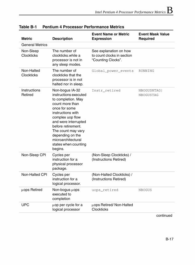
Intel Pentium 4 Processor Performance Metrics B
Table B-1 Pentium 4 Processor Performance MetricsMetric DescriptionEvent Name or Metric Expression
Event Mask Value Required
General Metrics
Non-Sleep Clockticks
The number of clockticks.while a processor is not in any sleep modes.
See explanation on how to count clocks in section “Counting Clocks”.
Non-Halted Clockticks
The number of clockticks that the processor is in not halted nor in sleep.
Global_power_events RUNNING
Instructions Retired
Non-bogus IA-32 instructions executed to completion. May count more than once for some instructions with complex uop flow and were interrupted before retirement. The count may vary depending on the microarchitectural states when counting begins.
Instr_retired NBOGUSNTAG|NBOGUSTAG
Non-Sleep CPI Cycles per instruction for a physical processor package.
(Non-Sleep Clockticks) / (Instructions Retired)
Non-Halted CPI Cycles per instruction for a logical processor.
(Non-Halted Clockticks) / (Instructions Retired)
µops Retired Non-bogus µops executed to completion
uops_retired NBOGUS
UPC µop per cycle for a logical processor
µops Retired/ Non-Halted Clockticks
continued
B-17

IA-32 Intel® Architecture Optimization
Speculative Uops Retired
Number of uops retired (include both instructions executed to completion and speculatively executed in the path of branch mispredictions).
uops_retired NBOGUS|BOGUS
Branching Metrics
Branches Retired
All branch instructions executed to completion
Branch_retired MMTM|MMNM|MMTP|MMNP
Tagged Mispredicted Branches Retired
The events counts the number of retired branch instructions that were mispredicted. This stat can be used with precise event-based sampling.
Replay_event; set the following replay tag: Tagged_mispred_branch
NBOGUS
Mispredicted Branches Retired
Mispredicted branch instructions executed to completion. This stat is often used in a per-instruction ratio.
Mispred_branch_retired
NBOGUS
Misprediction Ratio
Misprediction rate per branch
(Mispredicted Branches Retired) /(Branches Retired)
All returns The number of return branches
retired_branch_type RETURN
All indirect branches
All returns and indirect calls and indirect jumps
retired_branch_type INDIRECT
All calls All direct and indirect calls
retired_branch_type CALL
continued
Table B-1 Pentium 4 Processor Performance Metrics (continued)
Metric DescriptionEvent Name or Metric Expression
Event Mask Value Required
B-18

Intel Pentium 4 Processor Performance Metrics B
Mispredicted returns
The number of mispredicted returns including all causes.
retired_mispred_branch_type
RETURN
All conditionals The number of branches that are conditional jumps (may overcount if the branch is from build mode or there is a machine clear near the branch)
retired_branch_type CONDITIONAL
Mispredicted indirect branches
All Mispredicted returns and indirect calls and indirect jumps
retired_mispred_branch_type
INDIRECT
Mispredicted calls
All Mispredicted indirect calls
retired_branch_type CALL
Mispredicted conditionals
The number of mispredicted branches that are conditional jumps
retired_mispred_branch_type
CONDITIONAL
Trace Cache (TC) and Front-End Metrics
Page Walk Miss ITLB
The number of page walk requests due to ITLB misses.
page_walk_type ITMISS
ITLB Misses The number of ITLB lookups that resulted in a miss. Page Walk Miss ITLB.is less speculative than ITLB Misses and is the recommended alternative.
ITLB_reference MISS
continued
Table B-1 Pentium 4 Processor Performance Metrics (continued)
Metric DescriptionEvent Name or Metric Expression
Event Mask Value Required
B-19

IA-32 Intel® Architecture Optimization
TC Flushes Number of TC flushes (The counter will count twice for each occurrence. Divide the count by 2 to get the number of flushes.)
TC_misc FLUSH
Logical Processor 0 Deliver Mode
The number of cycles that the trace and delivery engine (TDE) is delivering traces associated with logical processor 0, regardless of the operating modes of the TDE for traces associated with logical processor 1. If a physical processor supports only one logical processor, all traces are associated with logical processor 0. This is the formerly known as “Trace Cache Deliver Mode“
TC_deliver_mode SS|SB|SI
continued
Table B-1 Pentium 4 Processor Performance Metrics (continued)
Metric DescriptionEvent Name or Metric Expression
Event Mask Value Required
B-20

Intel Pentium 4 Processor Performance Metrics B
Logical Processor 1 Deliver Mode
The number of cycles that the trace and delivery engine (TDE) is delivering traces associated with logical processor 1, regardless of the operating modes of the TDE for traces associated with logical processor 0. This metric is applicable only if a physical processor supports Hyper-Threading Technology and have two logical processors per package.
TC_deliver_mode SS|BS|IS
% Logical Processor N In Deliver Mode
Fraction of all non-halted cycles that the trace cache is delivering µops associated with a given logical processor.
(Logical Processor N Deliver Mode)*100/(Non-Halted Clockticks)
continued
Table B-1 Pentium 4 Processor Performance Metrics (continued)
Metric DescriptionEvent Name or Metric Expression
Event Mask Value Required
B-21

IA-32 Intel® Architecture Optimization
Logical Processor 0 Build Mode
The number of cycles that the trace and delivery engine (TDE) is building traces associated with logical processor 0, regardless of the operating modes of the TDE for traces associated with logical processor 1. If a physical processor supports only one logical processor, all traces are associated with logical processor 0.
TC_deliver_mode BB|BS|BI
Logical Processor 1 Build Mode
The number of cycles that the trace and delivery engine (TDE) is building traces associated with logical processor 1, regardless of the operating modes of the TDE for traces associated with logical processor 0. This metric is applicable only if a physical processor supports Hyper-Threading Technology and have two logical processors per package.
TC_deliver_mode BB|SB|IB
continued
Table B-1 Pentium 4 Processor Performance Metrics (continued)
Metric DescriptionEvent Name or Metric Expression
Event Mask Value Required
B-22

Intel Pentium 4 Processor Performance Metrics B
Trace Cache Misses
The number of times that significant delays occurred in order to decode instructions and build a trace because of a TC miss.
BPU_fetch_request TCMISS
TC to ROM Transfers
Twice the number of times that the ROM microcode is accessed to decode complex IA-32 instructions instead of building|delivering traces. (Divide the count by 2 to get the number of occurrence.)
tc_ms_xfer CISC
Speculative TC-Built Uops
The number of speculative uops originating when the TC is in build mode.
uop_queue_writes FROM_TC_BUILD
Speculative TC-Delivered Uops
The number of speculative uops originating when the TC is in deliver mode.
uop_queue_writes FROM_TC_DELIVER
Speculative Microcode Uops
The number of speculative uops originating from the microcode ROM (Not all uops of an instruction from the microcode ROM will be included).
uop_queue_writes FROM_ROM
continued
Table B-1 Pentium 4 Processor Performance Metrics (continued)
Metric DescriptionEvent Name or Metric Expression
Event Mask Value Required
B-23
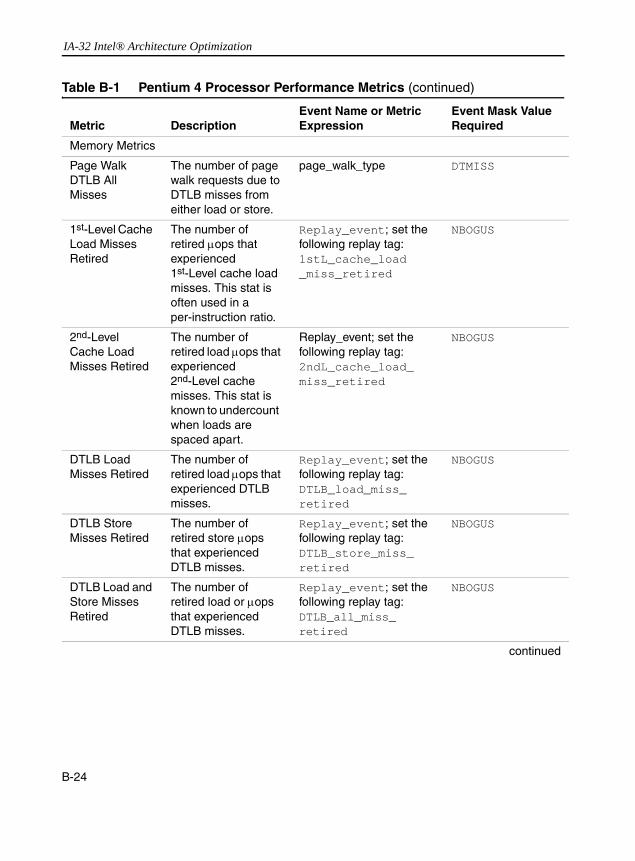
IA-32 Intel® Architecture Optimization
Memory Metrics
Page Walk DTLB All Misses
The number of page walk requests due to DTLB misses from either load or store.
page_walk_type DTMISS
1st-Level Cache Load Misses Retired
The number of retired µops that experienced 1st-Level cache load misses. This stat is often used in a per-instruction ratio.
Replay_event; set the following replay tag: 1stL_cache_load_miss_retired
NBOGUS
2nd-Level Cache Load Misses Retired
The number of retired load µops that experienced 2nd-Level cache misses. This stat is known to undercount when loads are spaced apart.
Replay_event; set the following replay tag: 2ndL_cache_load_miss_retired
NBOGUS
DTLB Load Misses Retired
The number of retired load µops that experienced DTLB misses.
Replay_event; set the following replay tag: DTLB_load_miss_retired
NBOGUS
DTLB Store Misses Retired
The number of retired store µops that experienced DTLB misses.
Replay_event; set the following replay tag: DTLB_store_miss_retired
NBOGUS
DTLB Load and Store Misses Retired
The number of retired load or µops that experienced DTLB misses.
Replay_event; set the following replay tag: DTLB_all_miss_retired
NBOGUS
continued
Table B-1 Pentium 4 Processor Performance Metrics (continued)
Metric DescriptionEvent Name or Metric Expression
Event Mask Value Required
B-24

Intel Pentium 4 Processor Performance Metrics B
64K Aliasing Conflicts1
The number of 64K aliasing conflicts. A memory reference causing 64K aliasing conflict can be counted more than once in this stat. The performance penalty resulted from 64K-aliasing conflict can vary from being unnoticeable to considerable. Some implementations of the Pentium 4 processor family can incur significant penalties for loads that alias to preceding stores.
Memory_cancel 64K_CONF
Split Load Replays
The number of load references to data that spanned two cache lines.
Memory_complete LSC
Split Loads Retired
The number of retired load µops that spanned two cache lines.
Replay_event; set the following replay tag: Split_load_retired.
NBOGUS
Split Store Replays
The number of store references that spans across cache line boundary.
Memory_complete SSC
Split Stores Retired
The number of retired store µops that spanned two cache lines.
Replay_event; set the following replay tag: Split_store_retired.
NBOGUS
continued
Table B-1 Pentium 4 Processor Performance Metrics (continued)
Metric DescriptionEvent Name or Metric Expression
Event Mask Value Required
B-25

IA-32 Intel® Architecture Optimization
MOB Load Replays
The number of replayed loads related to the Memory Order Buffer (MOB). This metric counts only the case where the store-forwarding data is not an aligned subset of the stored data.
MOB_load_replay PARTIAL_DATA, UNALGN_ADDR
2nd-Level Cache Read Misses2
The number of 2nd-level cache read misses (load and RFO misses). Beware of granularity differences.
BSQ_cache_reference RD_2ndL_MISS
2nd-Level Cache Read References2
The number of 2nd-level cache read references (loads and RFOs). Beware of granularity differences.
BSQ_cache_reference RD_2ndL_HITS, RD_2ndL_HITE, RD_2ndL_HITM, RD_2ndL_MISS
3rd-Level Cache Read Misses2
The number of 3rd-level cache read misses (load and RFOs misses). Beware of granularity differences.
BSQ_cache_reference RD_3rdL_MISS
3rd-Level Cache Read References2
The number of 3rd-level cache read references (loads and RFOs). Beware of granularity differences.
BSQ_cache_reference RD_3rdL_HITS, RD_3rdL_HITE, RD_3rdL_HITM, RD_3rdL_MISS
continued
Table B-1 Pentium 4 Processor Performance Metrics (continued)
Metric DescriptionEvent Name or Metric Expression
Event Mask Value Required
B-26

Intel Pentium 4 Processor Performance Metrics B
2nd-Level Cache Reads Hit Shared
The number of 2nd-level cache read references (loads and RFOs) that hit the cache line in shared state. Beware of granularity differences.
BSQ_cache_reference RD_2ndL_HITS
2nd-Level Cache Reads Hit Modified
The number of 2nd-level cache read references (loads and RFOs) that hit the cache line in modified state. Beware of granularity differences.
BSQ_cache_reference RD_2ndL_HITM
2nd-Level Cache Reads Hit Exclusive
The number of 2nd-level cache read references (loads and RFOs) that hit the cache line in exclusive state. Beware of granularity differences.
BSQ_cache_reference RD_2ndL_HITE
3rd-Level Cache Reads Hit Shared
The number of 3rd-level cache read references (loads and RFOs) that hit the cache line in shared state. Beware of granularity differences.
BSQ_cache_reference RD_3rdL_HITS
continued
Table B-1 Pentium 4 Processor Performance Metrics (continued)
Metric DescriptionEvent Name or Metric Expression
Event Mask Value Required
B-27

IA-32 Intel® Architecture Optimization
3rd-Level Cache Reads Hit Modified
The number of 3rd-level cache read references (loads and RFOs) that hit the cache line in modified state. Beware of granularity differences.
BSQ_cache_reference RD_3rdL_HITM
3rd-Level Cache Reads Hit Exclusive
The number of 3rd-level cache read references (loads and RFOs) that hit the cache line in exclusive state. Beware of granularity differences.
BSQ_cache_reference RD_3rdL_HITE
MOB Load Replays Retired
The number of retired load µops that experienced replays related to the MOB.
Replay_event; set the following replay tag: MOB_load_replay_retired
NBOGUS
Loads Retired The number of retired load operations that were tagged at the front end.
Front_end_event; set the following front end tag: Memory_loads
NBOGUS
Stores Retired The number of retired stored operations that were tagged at the front end. This stat is often used in a per-instruction ratio.
Front_end_event; set the following front end tag: Memory_stores
NBOGUS
continued
Table B-1 Pentium 4 Processor Performance Metrics (continued)
Metric DescriptionEvent Name or Metric Expression
Event Mask Value Required
B-28

Intel Pentium 4 Processor Performance Metrics B
All WCB Evictions
The number of times a WC buffer eviction occurred due to any causes (This can be used to distinguish 64K aliasing cases that contribute more significantly to performance penalty, e.g., stores that are 64K aliased. A high count of this metric when there is no significant contribution due to write combining buffer full condition may indicate such a situation.)
WC_buffer WCB_EVICTS
WCB Full Evictions
The number of times a WC buffer eviction occurred when all of the WC buffers are already allocated.
WC_buffer WCB_FULL_EVICT
continued
Table B-1 Pentium 4 Processor Performance Metrics (continued)
Metric DescriptionEvent Name or Metric Expression
Event Mask Value Required
B-29

IA-32 Intel® Architecture Optimization
Bus Metrics
Bus Accesses from the Processor
The number of all bus transactions that were allocated in the IO Queue from this processor. Beware of granularity issues with this event. Also Beware of different recipes in mask bits for Pentium 4 and Intel Xeon processors between CPUID model field value of 2 and model value less than 2.
IOQ_allocation 1a. ReqA0, ALL_READ, ALL_WRITE, OWN, PREFETCH (CPUID model < 2);
1b.ReqA0, ALL_READ, ALL_WRITE, MEM_WB, MEM_WT, MEM_WP, MEM_WC, MEM_UC, OWN, PREFETCH (CPUID model >= 2).
2. Enable edge filtering6 in the CCCR.
Non-prefetch Bus Accesses from the Processor
The number of all bus transactions that were allocated in the IO Queue from this processor excluding prefetched sectors. Beware of granularity issues with this event. Also Beware of different recipes in mask bits for Pentium 4 and Intel Xeon processors between CPUID model field value of 2 and model value less than 2.
IOQ_allocation 1a. ReqA0, ALL_READ, ALL_WRITE, OWN (CPUID model < 2);
1b. ReqA0, ALL_READ, ALL_WRITE, MEM_WB, MEM_WT, MEM_WP, MEM_WC, MEM_UC, OWN (CPUID model < 2).
2. Enable edge filtering6 in the CCCR.
continued
Table B-1 Pentium 4 Processor Performance Metrics (continued)
Metric DescriptionEvent Name or Metric Expression
Event Mask Value Required
B-30

Intel Pentium 4 Processor Performance Metrics B
Prefetch Ratio Fraction of all bus transactions (including retires) that were for HW or SW prefetching.
(Bus Accesses – Nonprefetch Bus Accesses)/ (Bus Accesses)
FSB Data Ready
The number of front-side bus clocks that the bus is transmitting data driven by this processor (includes full reads|writes and partial reads|writes and implicit writebacks).
FSB_data_activity 1. DRDY_OWN, DRDY_DRV
2. Enable edge filtering6 in the CCCR.
Bus Utilization The % of time that the bus is actually occupied
(FSB Data Ready) *Bus_ratio*100/ Non-Sleep Clockticks
Reads from the Processor
The number of all read (includes RFOs) transactions on the bus that were allocated in IO Queue from this processor (includes prefetches). Beware of granularity issues with this event. Also Beware of different recipes in mask bits for Pentium 4 and Intel Xeon processors between CPUID model field value of 2 and model value less than 2.
IOQ_allocation 1a. ReqA0, ALL_READ,
OWN, PREFETCH (CPUID model < 2);
1b. ReqA0, ALL_READ, MEM_WB, MEM_WT, MEM_WP, MEM_WC, MEM_UC,
OWN, PREFETCH (CPUID model >= 2);
2. Enable edge filtering6 in the CCCR.
continued
Table B-1 Pentium 4 Processor Performance Metrics (continued)
Metric DescriptionEvent Name or Metric Expression
Event Mask Value Required
B-31

IA-32 Intel® Architecture Optimization
Writes from the Processor
The number of all write transactions on the bus that were allocated in IO Queue from this processor (excludes RFOs). Beware of granularity issues with this event. Also Beware of different recipes in mask bits for Pentium 4 and Intel Xeon processors between CPUID model field value of 2 and model value less than 2.
IOQ_allocation 1a. ReqA0, ALL_WRITE, OWN
(CPUID model < 2);1b. ReqA0, ALL_WRITE, MEM_WB, MEM_WT, MEM_WP, MEM_WC, MEM_UC, OWN
(CPUID model >= 2).
2. Enable edge filtering6 in the CCCR.
Reads Non-prefetch from the Processor
The number of all read transactions (includes RFOs but excludes prefetches) on the bus that originated from this processor. Beware of granularity issues with this event. Also Beware of different recipes in mask bits for Pentium 4 and Intel Xeon processors between CPUID model field value of 2 and model value less than 2.
IOQ_allocation 1a. ReqA0, ALL_READ, OWN (CPUID model < 2);
1b. ReqA0, ALL_READ, MEM_WB, MEM_WT, MEM_WP, MEM_WC, MEM_UC, OWN (CPUID model >= 2).
2. Enable edge filtering6 in the CCCR.
continued
Table B-1 Pentium 4 Processor Performance Metrics (continued)
Metric DescriptionEvent Name or Metric Expression
Event Mask Value Required
B-32

Intel Pentium 4 Processor Performance Metrics B
All WC from the Processor
The number of Write Combining memory transactions on the bus that originated from this processor. Beware of granularity issues with this event. Also Beware of different recipes in mask bits for Pentium 4 and Intel Xeon processors between CPUID model field value of 2 and model value less than 2.
IOQ_allocation 1a. ReqA0, MEM_WC, OWN (CPUID model < 2);
1a. ReqA0,ALL_READ, ALL_WRITE, MEM_WC, OWN (CPUID model >= 2)
2. Enable edge filtering6 in the CCCR.
All UC from the Processor
The number of UC (Uncacheable) memory transactions on the bus that originated from this processor. User Note: Beware of granularity issues. e.g. a store of dqword to UC memory requires two entries in IOQ allocation. Also Beware of different recipes in mask bits for Pentium 4 and Intel Xeon processors between CPUID model field value of 2 and model value less than 2.
IOQ_allocation 1a. ReqA0, MEM_UC, OWN (CPUID model < 2);
1a. ReqA0,ALL_READ, ALL_WRITE, MEM_UC, OWN (CPUID model >= 2)
2. Enable edge filtering6 in the CCCR.
continued
Table B-1 Pentium 4 Processor Performance Metrics (continued)
Metric DescriptionEvent Name or Metric Expression
Event Mask Value Required
B-33
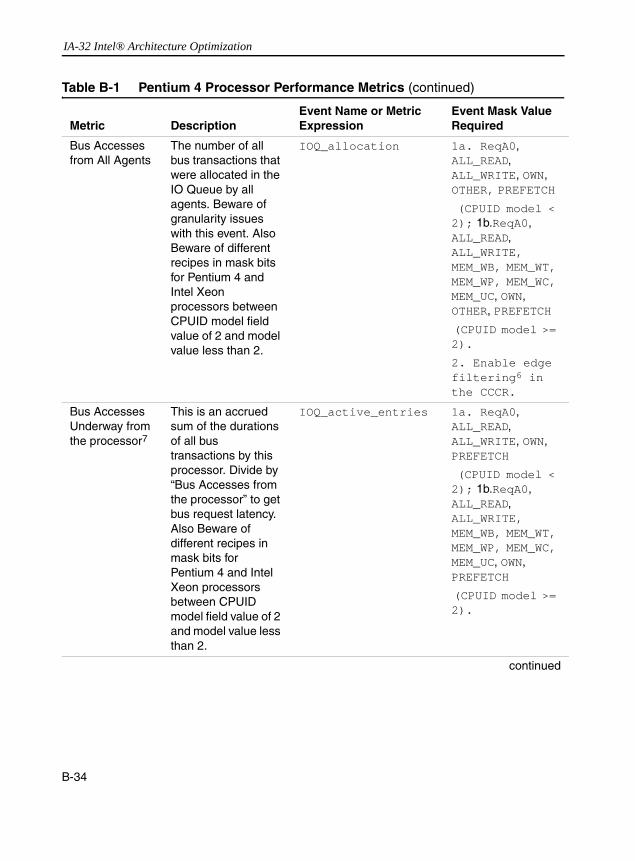
IA-32 Intel® Architecture Optimization
Bus Accesses from All Agents
The number of all bus transactions that were allocated in the IO Queue by all agents. Beware of granularity issues with this event. Also Beware of different recipes in mask bits for Pentium 4 and Intel Xeon processors between CPUID model field value of 2 and model value less than 2.
IOQ_allocation 1a. ReqA0, ALL_READ, ALL_WRITE, OWN, OTHER, PREFETCH
(CPUID model < 2); 1b.ReqA0, ALL_READ, ALL_WRITE, MEM_WB, MEM_WT, MEM_WP, MEM_WC, MEM_UC, OWN, OTHER, PREFETCH
(CPUID model >= 2).
2. Enable edge filtering6 in the CCCR.
Bus Accesses Underway from the processor7
This is an accrued sum of the durations of all bus transactions by this processor. Divide by “Bus Accesses from the processor” to get bus request latency. Also Beware of different recipes in mask bits for Pentium 4 and Intel Xeon processors between CPUID model field value of 2 and model value less than 2.
IOQ_active_entries 1a. ReqA0, ALL_READ, ALL_WRITE, OWN, PREFETCH
(CPUID model < 2); 1b.ReqA0, ALL_READ, ALL_WRITE, MEM_WB, MEM_WT, MEM_WP, MEM_WC, MEM_UC, OWN, PREFETCH
(CPUID model >= 2).
continued
Table B-1 Pentium 4 Processor Performance Metrics (continued)
Metric DescriptionEvent Name or Metric Expression
Event Mask Value Required
B-34
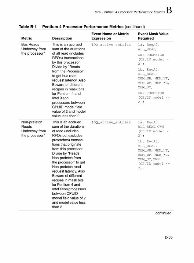
Intel Pentium 4 Processor Performance Metrics B
Bus Reads Underway from the processor7
This is an accrued sum of the durations of all read (includes RFOs) transactions by this processor. Divide by “Reads from the Processor” to get bus read request latency. Also Beware of different recipes in mask bits for Pentium 4 and Intel Xeon processors between CPUID model field value of 2 and model value less than 2.
IOQ_active_entries 1a. ReqA0, ALL_READ,
OWN, PREFETCH (CPUID model < 2);
1b. ReqA0, ALL_READ, MEM_WB, MEM_WT, MEM_WP, MEM_WC, MEM_UC,
OWN, PREFETCH (CPUID model >= 2);
Non-prefetch Reads Underway from the processor7
This is an accrued sum of the durations of read (includes RFOs but excludes prefetches) transac-tions that originate from this processor. Divide by “Reads Non-prefetch from the processor” to get Non-prefetch read request latency. Also Beware of different recipes in mask bits for Pentium 4 and Intel Xeon processors between CPUID model field value of 2 and model value less than 2.
IOQ_active_entries 1a. ReqA0, ALL_READ, OWN (CPUID model < 2);
1b. ReqA0, ALL_READ, MEM_WB, MEM_WT, MEM_WP, MEM_WC, MEM_UC, OWN (CPUID model >= 2).
continued
Table B-1 Pentium 4 Processor Performance Metrics (continued)
Metric DescriptionEvent Name or Metric Expression
Event Mask Value Required
B-35

IA-32 Intel® Architecture Optimization
All UC Underway from the processor7
This is an accrued sum of the durations of all UC transactions by this processor. Divide by “All UC from the processor” to get UC request latency. Also Beware of different recipes in mask bits for Pentium 4 and Intel Xeon processors between CPUID model field value of 2 and model value less than 2.
IOQ_active_entries 1a. ReqA0, MEM_UC, OWN (CPUID model < 2);
1a. ReqA0,ALL_READ, ALL_WRITE, MEM_UC, OWN (CPUID model >= 2)
All WC Underway from the processor7
This is an accrued sum of the durations of all WC transactions by this processor. Divide by “All WC from the processor” to get WC request latency. Also Beware of different recipes in mask bits for Pentium 4 and Intel Xeon processors between CPUID model field value of 2 and model value less than 2.
IOQ_active_entries 1a. ReqA0, MEM_WC, OWN (CPUID model < 2);
1a. ReqA0,ALL_READ, ALL_WRITE, MEM_WC, OWN (CPUID model >= 2)
continued
Table B-1 Pentium 4 Processor Performance Metrics (continued)
Metric DescriptionEvent Name or Metric Expression
Event Mask Value Required
B-36

Intel Pentium 4 Processor Performance Metrics B
Bus Writes Underway from the processor7
This is an accrued sum of the durations of all write transactions by this processor. Divide by “Writes from the Processor” to get bus write request latency. Also Beware of different recipes in mask bits for Pentium 4 and Intel Xeon processors between CPUID model field value of 2 and model value less than 2.
IOQ_active_entries 1a. ReqA0, ALL_WRITE, OWN
(CPUID model < 2);
1b. ReqA0, ALL_WRITE, MEM_WB, MEM_WT, MEM_WP, MEM_WC, MEM_UC, OWN
(CPUID model >= 2).
Bus Accesses Underway from All Agents7
This is an accrued sum of the durations of entries by all agents on the bus. Divide by “Bus Accesses from All Agents” to get bus request latency. Also Beware of different recipes in mask bits for Pentium 4 and Intel Xeon processors between CPUID model field value of 2 and model value less than 2.
IOQ_active_entries 1a. ReqA0, ALL_READ, ALL_WRITE, OWN, OTHER, PREFETCH
(CPUID model < 2); 1b.ReqA0, ALL_READ, ALL_WRITE, MEM_WB, MEM_WT, MEM_WP, MEM_WC, MEM_UC, OWN, OTHER, PREFETCH
(CPUID model >= 2).
continued
Table B-1 Pentium 4 Processor Performance Metrics (continued)
Metric DescriptionEvent Name or Metric Expression
Event Mask Value Required
B-37
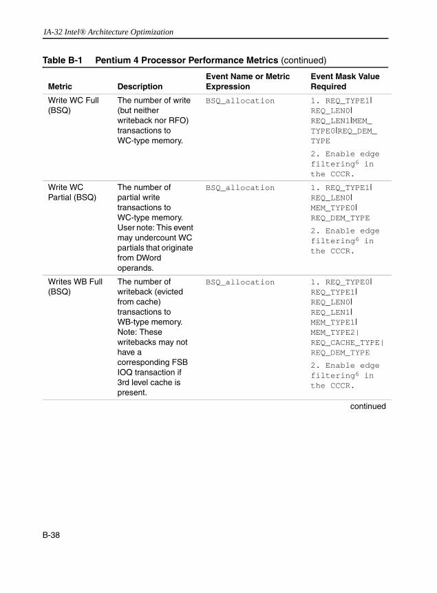
IA-32 Intel® Architecture Optimization
Write WC Full (BSQ)
The number of write (but neither writeback nor RFO) transactions to WC-type memory.
BSQ_allocation 1. REQ_TYPE1| REQ_LEN0|REQ_LEN1|MEM_TYPE0|REQ_DEM_TYPE
2. Enable edge filtering6 in the CCCR.
Write WC Partial (BSQ)
The number of partial write transactions to WC-type memory. User note: This event may undercount WC partials that originate from DWord operands.
BSQ_allocation 1. REQ_TYPE1| REQ_LEN0|MEM_TYPE0|REQ_DEM_TYPE
2. Enable edge filtering6 in the CCCR.
Writes WB Full (BSQ)
The number of writeback (evicted from cache) transactions to WB-type memory. Note: These writebacks may not have a corresponding FSB IOQ transaction if 3rd level cache is present.
BSQ_allocation 1. REQ_TYPE0| REQ_TYPE1|REQ_LEN0|REQ_LEN1|MEM_TYPE1|MEM_TYPE2|REQ_CACHE_TYPE|REQ_DEM_TYPE
2. Enable edge filtering6 in the CCCR.
continued
Table B-1 Pentium 4 Processor Performance Metrics (continued)
Metric DescriptionEvent Name or Metric Expression
Event Mask Value Required
B-38
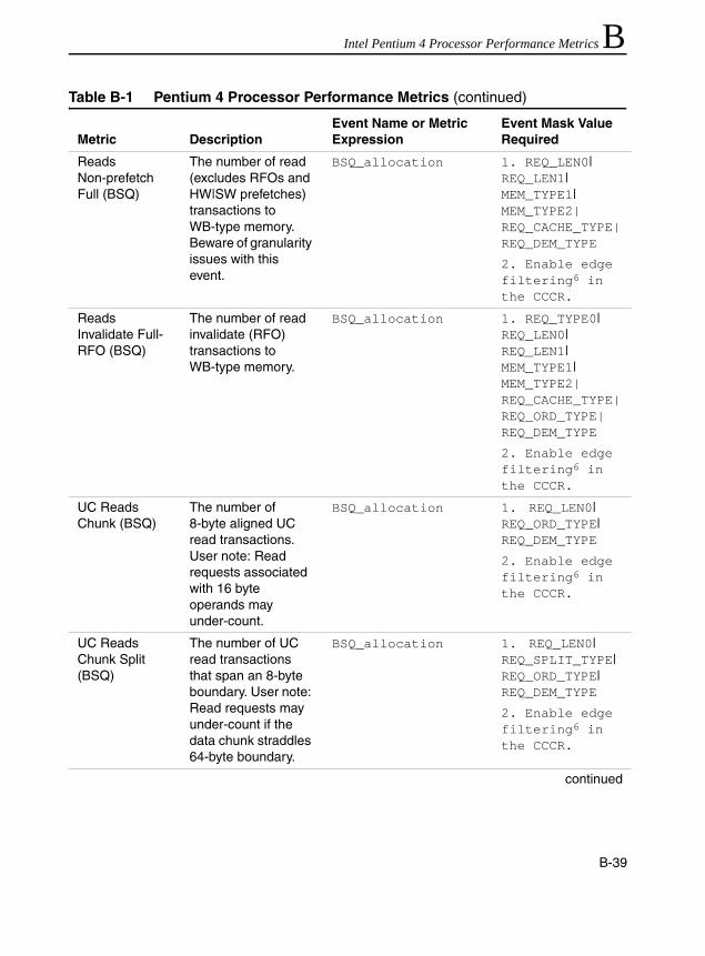
Intel Pentium 4 Processor Performance Metrics B
Reads Non-prefetch Full (BSQ)
The number of read (excludes RFOs and HW|SW prefetches) transactions to WB-type memory. Beware of granularity issues with this event.
BSQ_allocation 1. REQ_LEN0| REQ_LEN1|MEM_TYPE1|MEM_TYPE2|REQ_CACHE_TYPE|REQ_DEM_TYPE
2. Enable edge filtering6 in the CCCR.
Reads Invalidate Full- RFO (BSQ)
The number of read invalidate (RFO) transactions to WB-type memory.
BSQ_allocation 1. REQ_TYPE0| REQ_LEN0|REQ_LEN1|MEM_TYPE1|MEM_TYPE2|REQ_CACHE_TYPE|REQ_ORD_TYPE|REQ_DEM_TYPE
2. Enable edge filtering6 in the CCCR.
UC Reads Chunk (BSQ)
The number of 8-byte aligned UC read transactions. User note: Read requests associated with 16 byte operands may under-count.
BSQ_allocation 1. REQ_LEN0| REQ_ORD_TYPE|REQ_DEM_TYPE
2. Enable edge filtering6 in the CCCR.
UC Reads Chunk Split (BSQ)
The number of UC read transactions that span an 8-byte boundary. User note: Read requests may under-count if the data chunk straddles 64-byte boundary.
BSQ_allocation 1. REQ_LEN0| REQ_SPLIT_TYPE|REQ_ORD_TYPE|REQ_DEM_TYPE
2. Enable edge filtering6 in the CCCR.
continued
Table B-1 Pentium 4 Processor Performance Metrics (continued)
Metric DescriptionEvent Name or Metric Expression
Event Mask Value Required
B-39

IA-32 Intel® Architecture Optimization
UC Write Partial (BSQ)
The number of UC write transactions. Beware of granularity issues between BSQ and FSB IOQ events.
BSQ_allocation 1. REQ_TYPE0| REQ_LEN0| REQ_SPLIT_TYPE|REQ_ORD_TYPE|REQ_DEM_TYPE
2. Enable edge filtering6 in the CCCR.
IO Reads Chunk (BSQ)
The number of 8-byte aligned IO port read transactions.
BSQ_allocation 1. REQ_LEN0| REQ_ORD_TYPE|REQ_IO_TYPE|REQ_DEM_TYPE
2. Enable edge filtering6 in the CCCR.
IO Writes Chunk (BSQ)
The number of IO port write transactions.
BSQ_allocation 1. REQ_TYPE0| REQ_LEN0| REQ_ORD_TYPE|REQ_IO_TYPE|REQ_DEM_TYPE
2. Enable edge filtering6 in the CCCR.
continued
Table B-1 Pentium 4 Processor Performance Metrics (continued)
Metric DescriptionEvent Name or Metric Expression
Event Mask Value Required
B-40

Intel Pentium 4 Processor Performance Metrics B
WB Writes Full Underway (BSQ)8
This is an accrued sum of the durations of writeback (evicted from cache) transactions to WB-type memory. Divide by Writes WB Full (BSQ) to estimate average request latency. User note: Beware of effects of writebacks from 2nd-level cache that are quickly satisfied from the 3rd-level cache (if present).
BSQ_active_entries 1. REQ_TYPE0| REQ_TYPE1|REQ_LEN0|REQ_LEN1|MEM_TYPE1|MEM_TYPE2|REQ_CACHE_TYPE|REQ_DEM_TYPE
UC Reads Chunk Underway (BSQ)8
This is an accrued sum of the durations of UC read transactions. Divide by UC Reads Chunk (BSQ) to estimate average request latency. User note: Estimated latency may be affected by undercount in allocated entries.
BSQ_active_entries 1. REQ_LEN0| REQ_ORD_TYPE|REQ_DEM_TYPE
2. Enable edge filtering6 in the CCCR.
continued
Table B-1 Pentium 4 Processor Performance Metrics (continued)
Metric DescriptionEvent Name or Metric Expression
Event Mask Value Required
B-41
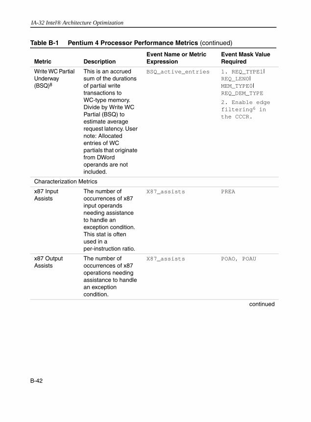
IA-32 Intel® Architecture Optimization
Write WC Partial Underway (BSQ)8
This is an accrued sum of the durations of partial write transactions to WC-type memory. Divide by Write WC Partial (BSQ) to estimate average request latency. User note: Allocated entries of WC partials that originate from DWord operands are not included.
BSQ_active_entries 1. REQ_TYPE1| REQ_LEN0|MEM_TYPE0|REQ_DEM_TYPE
2. Enable edge filtering6 in the CCCR.
Characterization Metrics
x87 Input Assists
The number of occurrences of x87 input operands needing assistance to handle an exception condition. This stat is often used in a per-instruction ratio.
X87_assists PREA
x87 Output Assists
The number of occurrences of x87 operations needing assistance to handle an exception condition.
X87_assists POAO, POAU
continued
Table B-1 Pentium 4 Processor Performance Metrics (continued)
Metric DescriptionEvent Name or Metric Expression
Event Mask Value Required
B-42

Intel Pentium 4 Processor Performance Metrics B
SSE Input Assists
The number of occurrences of SSE/SSE2 floating-point operations needing assistance to handle an exception condition. The number of occurrences includes speculative counts.
SSE_input_assist ALL
Packed SP Retired3
Non-bogus packed single-precision instructions retired.
Execution_event; set this execution tag: Packed_SP_retired
NONBOGUS0
Packed DP Retired3
Non-bogus packed double-precision instructions retired.
Execution_event; set this execution tag:
Packed_DP_retired
NONBOGUS0
Scalar SP Retired3
Non-bogus scalar single-precision instructions retired.
Execution_event; set this execution tag:
Scalar_SP_retired
NONBOGUS0
Scalar DP Retired3
Non-bogus scalar double-precision instructions retired.
Execution_event; set this execution tag:
Scalar_DP_retired
NONBOGUS0
64-bit MMX Instructions Retired3
Non-bogus 64-bit integer SIMD instruction (MMX instructions) retired.
Execution_event; set the following execution tag:
64_bit_MMX_retired
NONBOGUS0
128-bit MMX Instructions Retired3
Non-bogus 128-bit integer SIMD instructions retired.
Execution_event; set this execution tag:
128_bit_MMX_retired
NONBOGUS0
X87 Retired4 Non-bogus x87 floating-point instructions retired.
Execution_event; set this execution tag: X87_FP_retired
NONBOGUS0
continued
Table B-1 Pentium 4 Processor Performance Metrics (continued)
Metric DescriptionEvent Name or Metric Expression
Event Mask Value Required
B-43

IA-32 Intel® Architecture Optimization
1. A memory reference causing 64K aliasing conflict can be counted more than once in this stat. The resulting performance penalty can vary from unnoticeable to considerable. Some implementations of the Pentium 4 processor family can incur significant penalties from loads that alias to preceding stores.
2. Currently, bugs in this event can cause both overcounting and undercounting by as much as a factor of 2.
3. Most MMX technology instructions, Streaming SIMD Extensions and Streaming SIMD Extensions 2 decode into a single µop. There are some instructions that decode into several µops; in these limited cases, the metrics count the number of µops that are actually tagged.
Stalled Cycles of Store Buffer Resources (non-standard5)
The duration of stalls due to lack of store buffers.
Resource_stall SBFULL
Stalls of Store Buffer Resources (non-standard5)
The number of allocation stalls due to lack of store buffers.
Resource_stall SBFULL(Also Set the following CCCR bits:
Compare=1; Edge=1;
Threshold=0)
Machine Clear Metrics
Machine Clear Count
The number of cycles that the entire pipeline of the machine is cleared for all causes.
Machine_clear CLEAR
(Also Set the following CCCR bits:
Compare=1; Edge=1;
Threshold=0)
Memory Order Machine Clear
The number of times that the entire pipeline of the machine is cleared due to memory-ordering issues.
Machine_clear MOCLEAR
Self-modifying Code Clear
The number of times the entire pipeline of the machine is cleared due to self-modifying code issues.
Machine_clear SMCCLEAR
Table B-1 Pentium 4 Processor Performance Metrics (continued)
Metric DescriptionEvent Name or Metric Expression
Event Mask Value Required
B-44

Intel Pentium 4 Processor Performance Metrics B
4. Most commonly used x87 instructions (e.g., fmul, fadd, fdiv, fsqrt, fstp, etc.) decode into a singleµop.However, transcendental and some x87 instructions decode into several µops; in these limited cases, the metrics will count the number of µops thatare actually tagged.
5. This metric may not be supported in all models of the Pentium 4 processor family.
6. Set the following CCCR bits to make edge triggered: Compare=1; Edge=1; Threshold=0
7. Must program both MSR_FSB_ESCR0 and MSR_FSB_ESCR1.
8. Must program both MSR_BSU_ESCR0 and MSR_BSU_ESCR1.
Performance Metrics and Tagging MechanismsA number of metrics require more tags to be specified in addition to programming a counting event; for example, the metric Split Loads Retired requires specifying a split_load_retired tag in addition to programming the replay_event to count at retirement. This section describes three sets of tags that are used in conjunction with three at-retirement counting events: front_end_event, replay_event, and execution_event. Please refer to Appendix A of the “IA-32 Intel® Architecture Software Developer’s Manual, Volume 3: System Programming” for the description of the at-retirement events.
Tags for replay_event
Table B-2 provides a list of the tags that are used by various metrics in Table B-1. These tags enable you to mark µops at earlier stage of execution and count the µops at retirement using the replay_event. These tags require at least two MSR’s (see Table B-2, column 2 and column 3) to tag the µops so they can be detected at retirement. Some tags require additional MSR (see Table B-2, column 4) to select the event types for these tagged µops. The event names referenced in column 4 are those from the Pentium 4 processor performance monitoring events.
B-45

IA-32 Intel® Architecture Optimization
Table B-2 Metrics That Utilize Replay Tagging Mechanism
Replay Metric Tags1
Bit field to set:
IA32_PEBS_ENABLE
Bit field to set: MSR_PEBS_MATRIX_VERT Additional MSR
See Event Mask Parameter for Replay_event
1stL_cache_load_miss_retired
Bit 0, BIT 24, BIT 25
Bit 0 None NBOGUS
2ndL_cache_load_miss_retired
Bit 1, BIT 24, BIT 25
Bit 0 None NBOGUS
continued
DTLB_load_miss_retired
Bit 2, BIT 24, BIT 25
Bit 0 None NBOGUS
DTLB_store_miss_retired
Bit 2, BIT 24, BIT 25
Bit 1 None NBOGUS
DTLB_all_miss_retired
Bit 2, BIT 24, BIT 25
Bit 0, Bit 1 None NBOGUS
Tagged_mispred_branch
Bit 15, Bit 16, Bit 24, Bit 25
Bit 4 None NBOGUS
MOB_load_replay_retired
Bit 9, BIT 24, BIT 25
Bit 0 Select MOB_load_replay and set the PARTIAL_DATA and UNALGN_ADDR bits
NBOGUS
Split_load_retired
Bit 10, BIT 24, BIT 25
Bit 0 Select Load_port_replay event on SAAT_CR_ESCR1 and set SPLIT_LD bit
NBOGUS
Split_store_retired
Bit 10, BIT 24, BIT 25
Bit 1 Select Store_port_replay event on SAAT_CR_ESCR0 and set SPLIT_ST bit
NBOGUS
1. Certain kinds of µops cannot be tagged. These include I/O operations, UC and locked accesses, returns, and far transfers.
B-46

Intel Pentium 4 Processor Performance Metrics B
Tags for front_end_eventTable B-3 provides a list of the tags that are used by various metrics derived from the front_end_event. The event names referenced in column 2 can be found from the Pentium 4 processor performance monitoring events.
Tags for execution_event
Table B-4 provides a list of the tags that are used by various metrics derived from the execution_event. These tags require programming an upstream ESCR to select event mask with its TagUop and TagValue bit fields. The event mask for the downstream ESCR is specified in column 4. The event names referenced in column 4 can be found in the Pentium 4 processor performance monitoring events.
Table B-3 Table 3 Metrics That Utilize the Front-end Tagging Mechanism
Front-end MetricTags1
1. There may be some undercounting of front end events when there is an overflow or underflow of the floating point stack.
Additional MSRSee Event Mask Parameter for Front_end_event
Memory_loads Set the TAGLOADS bit in Uop_Type
NBOGUS
Memory_stores Set the TAGSTORES bit in Uop_Type
NBOGUS
B-47
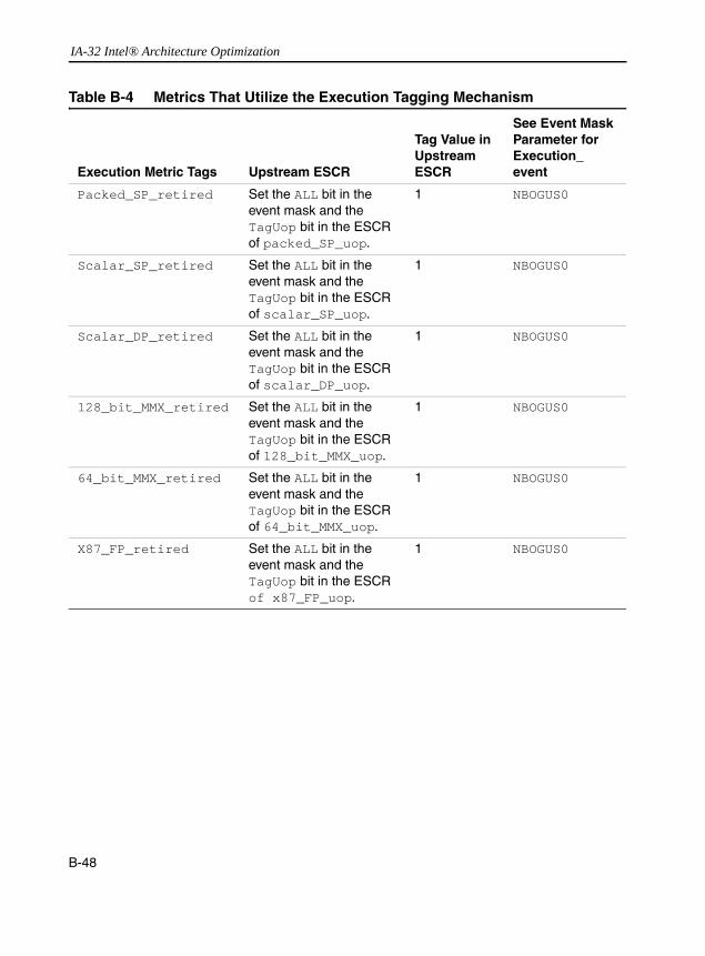
IA-32 Intel® Architecture Optimization
Table B-4 Metrics That Utilize the Execution Tagging Mechanism
Execution Metric Tags Upstream ESCR
Tag Value in Upstream ESCR
See Event Mask Parameter for Execution_event
Packed_SP_retired Set the ALL bit in the event mask and the TagUop bit in the ESCR of packed_SP_uop.
1 NBOGUS0
Scalar_SP_retired Set the ALL bit in the event mask and the TagUop bit in the ESCR of scalar_SP_uop.
1 NBOGUS0
Scalar_DP_retired Set the ALL bit in the event mask and the TagUop bit in the ESCR of scalar_DP_uop.
1 NBOGUS0
128_bit_MMX_retired Set the ALL bit in the event mask and the TagUop bit in the ESCR of 128_bit_MMX_uop.
1 NBOGUS0
64_bit_MMX_retired Set the ALL bit in the event mask and the TagUop bit in the ESCR of 64_bit_MMX_uop.
1 NBOGUS0
X87_FP_retired Set the ALL bit in the event mask and the TagUop bit in the ESCR of x87_FP_uop.
1 NBOGUS0
B-48

Intel Pentium 4 Processor Performance Metrics B
Table B-5 New Metrics for Pentium 4 Processor (Family 15, Model 3)Using Performance Metrics with Hyper-Threading Technology
On Intel Xeon processors that support Hyper-Threading Technology, the performance metrics listed in Table B-1 may be qualified to associate the counts with a specific logical processor, provided the relevant performance monitoring events supports qualification by logical processor. Within the subset of those performance metrics that support qualification by logical processors, some of them can be programmed with parallel ESCRs and CCCRs to collect separate counts for each logical processor simultaneously. For some metrics, qualification by logical processor is supported but there is not sufficient number of MSRs for simultaneous counting of the same metric on both logical processors. In both cases, it is also possible to program the relevant ESCR for a performance metric that supports qualification by logical processor to produce counts that are, typically, the sum of contributions from both logical processors.
A number of performance metrics are based on performance monitoring events that do not support qualification by logical processor. Any attempts to program the relevant ESCRs to qualify counts by logical processor will not produce different results. The results obtained in this manner should not be summed together.
Metric DescriptionsEvent Name or Metric Expression
Event Mask value required
Instructions Completed
Non-bogus IA-32 instructions completed and retired.
instr_completed NBOGUS
Speculative Instructions Completed
Number of IA-32 instructions decoded and executed speculatively.
instr_completed BOGUS
B-49
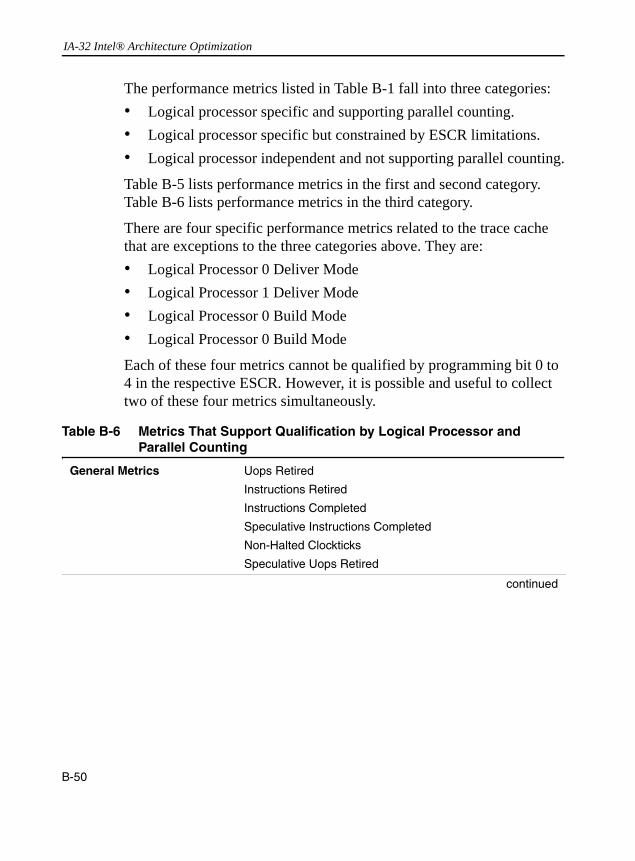
IA-32 Intel® Architecture Optimization
The performance metrics listed in Table B-1 fall into three categories:• Logical processor specific and supporting parallel counting.• Logical processor specific but constrained by ESCR limitations.• Logical processor independent and not supporting parallel counting.
Table B-5 lists performance metrics in the first and second category. Table B-6 lists performance metrics in the third category.
There are four specific performance metrics related to the trace cache that are exceptions to the three categories above. They are:• Logical Processor 0 Deliver Mode• Logical Processor 1 Deliver Mode• Logical Processor 0 Build Mode• Logical Processor 0 Build Mode
Each of these four metrics cannot be qualified by programming bit 0 to 4 in the respective ESCR. However, it is possible and useful to collect two of these four metrics simultaneously.
Table B-6 Metrics That Support Qualification by Logical Processor and Parallel Counting
General Metrics Uops Retired
Instructions Retired
Instructions Completed
Speculative Instructions Completed
Non-Halted Clockticks
Speculative Uops Retired
continued
B-50

Intel Pentium 4 Processor Performance Metrics B
Branching Metrics Branches Retired
Tagged Mispredicted Branches Retired
Mispredicted Branches Retired
All returns
All indirect branches
All calls
All conditionals
Mispredicted returns
Mispredicted indirect branches
Mispredicted calls
Mispredicted conditionals
TC and Front End Metrics Trace Cache Misses
ITLB Misses
TC to ROM Transfers
TC Flushes
Speculative TC-Built Uops
Speculative TC-Delivered Uops
Speculative Microcode Uops
continued
Table B-6 Metrics That Support Qualification by Logical Processor and Parallel Counting (continued)
B-51

IA-32 Intel® Architecture Optimization
Memory Metrics Split Load Replays1
Split Store Replays1
MOB Load Replays1
64k Aliasing Conflicts
1st-Level Cache Load Misses Retired
2nd-Level Cache Load Misses Retired
DTLB Load Misses Retired
Split Loads Retired1
Split Stores Retired1
MOB Load Replays Retired
Loads Retired
Stores Retired
DTLB Store Misses Retired
DTLB Load and Store Misses Retired
2nd-Level Cache Read Misses
2nd-Level Cache Read References
3rd-Level Cache Read Misses
3rd-Level Cache Read References
2nd-Level Cache Reads Hit Shared
2nd-Level Cache Reads Hit Modified
2nd-Level Cache Reads Hit Exclusive
3rd-Level Cache Reads Hit Shared
3rd-Level Cache Reads Hit Modified
3rd-Level Cache Reads Hit Exclusive
continued
Table B-6 Metrics That Support Qualification by Logical Processor and Parallel Counting (continued)
B-52
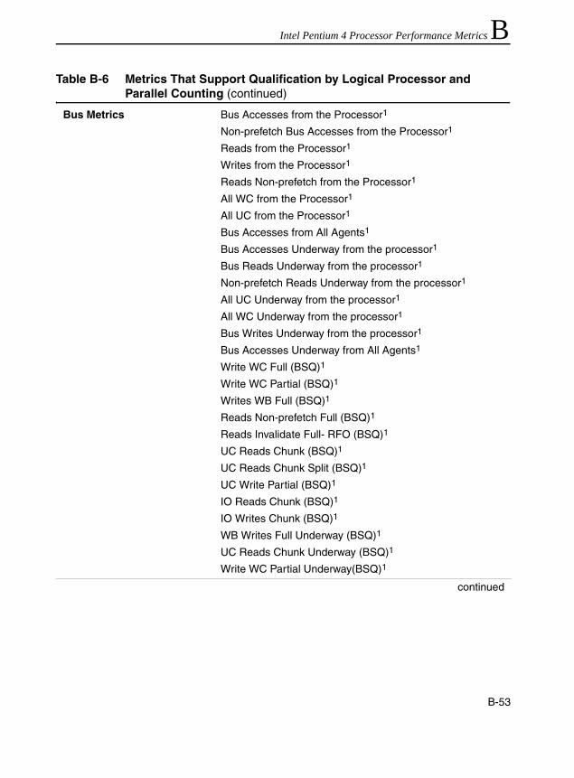
Intel Pentium 4 Processor Performance Metrics B
Bus Metrics Bus Accesses from the Processor1
Non-prefetch Bus Accesses from the Processor1
Reads from the Processor1
Writes from the Processor1
Reads Non-prefetch from the Processor1
All WC from the Processor1
All UC from the Processor1
Bus Accesses from All Agents1
Bus Accesses Underway from the processor1
Bus Reads Underway from the processor1
Non-prefetch Reads Underway from the processor1
All UC Underway from the processor1
All WC Underway from the processor1
Bus Writes Underway from the processor1
Bus Accesses Underway from All Agents1
Write WC Full (BSQ)1
Write WC Partial (BSQ)1
Writes WB Full (BSQ)1
Reads Non-prefetch Full (BSQ)1
Reads Invalidate Full- RFO (BSQ)1
UC Reads Chunk (BSQ)1
UC Reads Chunk Split (BSQ)1
UC Write Partial (BSQ)1
IO Reads Chunk (BSQ)1
IO Writes Chunk (BSQ)1
WB Writes Full Underway (BSQ)1
UC Reads Chunk Underway (BSQ)1
Write WC Partial Underway(BSQ)1
continued
Table B-6 Metrics That Support Qualification by Logical Processor and Parallel Counting (continued)
B-53

IA-32 Intel® Architecture Optimization
Characterization Metrics x87 Input Assists
x87 Output Assists
Machine Clear Count
Memory Order Machine Clear
Self-Modifying Code Clear
Scalar DP Retired
Scalar SP Retired
Packed DP Retired
Packed SP Retired
128-bit MMX Instructions Retired
64-bit MMX Instructions Retired
x87 Instructions Retired
Stalled Cycles of Store Buffer Resources
Stalls of Store Buffer Resources1 Parallel counting is not supported due to ESCR restrictions.
Table B-7 Metrics That Are Independent of Logical Processors
General Metrics Non-Sleep Clockticks
TC and Front End Metrics Page Walk Miss ITLB
Memory Metrics Page Walk DTLB All Misses
All WCB Evictions
WCB Full Evictions
Bus Metrics Bus Data Ready from the Processor
Characterization Metrics SSE Input Assists
Table B-6 Metrics That Support Qualification by Logical Processor and Parallel Counting (continued)
B-54
C
IA-32 Instruction Latency and ThroughputThis appendix contains tables of the latency, throughput and execution units that are associated with more-commonly-used IA-32 instructions1. The instruction timing data varies within the IA-32 family of processors. Only data specific to the Intel Pentium 4, Intel Xeon processors and Intel Pentium M processor are provided. The relevance of instruction throughput and latency information for code tuning is discussed in Chapter 1 and Chapter 2, see “Execution Core Detail” in Chapter 1 and “Floating Point/SIMD Operands” in Chapter 2.
This appendix contains the following sections:• “Overview”– an overview of issues related to instruction selection
and scheduling.• “Definitions” – the definitions for the primary information
presented in the tables in section “Latency and Throughput.”• “Latency and Throughput of Pentium 4 and Intel Xeon processors”
– the listings of IA-32 instruction throughput, latency and execution units associated with commonly-used instruction.
1. Although instruction latency may be useful in some limited situations (e.g., a tight loop with a dependency chain that exposes instruction latency), software optimization on super-scalar, out-of-order microarchitecture, in general, will benefit much more on increasing the effective throughput of the larger-scale code path. Coding techniques that rely on instruction latency alone to influence the scheduling of instruction is likely to be sub-optimal as such coding technique is likely to interfere with the out-of-order machine or restrict the amount of instruction-level parralelism.
C-1

IA-32 Intel® Architecture Optimization
OverviewThe current generation of IA-32 family of processors use out-of-order execution with dynamic scheduling and buffering to tolerate poor instruction selection and scheduling that may occur in legacy code. It can reorder µops to cover latency delays and to avoid resource conflicts. In some cases, the microarchitecture’s ability to avoid such delays can be enhanced by arranging IA-32 instructions. While reordering IA-32 instructions may help, the execution core determines the final schedule of µops.
This appendix provides information to assembly language programmers and compiler writers, to aid in selecting the sequence of instructions which minimizes dependency chain latency, and to arrange instructions in an order which assists the hardware in processing instructions efficiently while avoiding resource conflicts. The performance impact of applying the information presented in this appendix has been shown to be on the order of several percent, for applications which are not completely dominated by other performance factors, such as:• cache miss latencies• bus bandwidth• I/O bandwidth
Instruction selection and scheduling matters when the compiler or assembly programmer has already addressed the performance issues discussed in Chapter 2:• observe store forwarding restrictions• avoid cache line and memory order buffer splits• do not inhibit branch prediction• minimize the use of xchg instructions on memory locations
C-2

IA-32 Instruction Latency and Throughput C
While several items on the above list involve selecting the right instruction, this appendix focuses on the following issues. These are listed in an expected priority order, though which item contributes most to performance will vary by application.• Maximize the flow of µops into the execution core. IA-32instructions which consist of more than four µops require additional steps from microcode ROM. These instructions with longer µop flows incur a delay in the front end and reduce the supply of uops to the execution core. In Pentium 4 and Intel Xeon processors, transfers to microcode ROM often reduce how efficiently µops can be packed into the trace cache. Where possible, it is advisable to select instructions with four or fewer µops. For example, a 32-bit integer multiply with a memory operand fits in the trace cache without going to microcode, while a 16-bit integer multiply to memory does not.
• Avoid resource conflicts. Interleaving instructions so that they don’t compete for the same port or execution unit can increase throughput. For example, alternating PADDQ and PMULUDQ, each have a throughput of one issue per two clock cycles. When interleaved, they can achieve an effective throughput of one instruction per cycle because they use the same port but different execution units. Selecting instructions with fast throughput also helps to preserve issue port bandwidth, hide latency and allows for higher software performance.
• Minimize the latency of dependency chains that are on the critical path. For example, an operation to shift left by two bits executes faster when encoded as two adds than when it is encoded as a shift. If latency is not an issue, the shift results in a denser byte encoding.
In addition to the general and specific rules, coding guidelines and the instruction data provided in this manual, you can take advantage of the software performance analysis and tuning toolset available at http://developer.intel.com/software/products/index.htm. The tools include the VTune Performance Analyzer, with its performance-monitoring capabilities.
C-3

IA-32 Intel® Architecture Optimization
DefinitionsThe IA-32 instruction performance data are listed in several tables. The tables contain the following information:Instruction Name:The assembly mnemonic of each instruction.Latency: The number of clock cycles that are required for the
execution core to complete the execution of all of the µops that form a IA-32 instruction.
Throughput: The number of clock cycles required to wait before the issue ports are free to accept the same instruction again. For many IA-32 instructions, the throughput of an instruction can be significantly less than its latency.
Execution units: The names of the execution units in the execution core that are utilized to execute the µops for each instruction. This information is provided only for IA-32 instructions that are decoded into no more than 4 µops. µops for instructions that decode into more than 4 µops are supplied by microcode ROM. Note that several execution units may share the same port, such as FP_ADD, FP_MUL, or MMX_SHFT in the FP_EXECUTE cluster (see Figure 1-4, Figure 1-4 applies to Pentium 4 and Intel Xeon processors with CPUID signature of family 15, model encoding = 0, 1, 2).
Latency and ThroughputThis section presents the latency and throughput information for the IA-32 instruction set including the Streaming SIMD Extensions 2, Streaming SIMD Extensions, MMX technology, and most of the frequently used general-purpose integer and x87 floating-point instructions.
Due to the complexity of dynamic execution and out-of-order nature of the execution core, the instruction latency data may not be sufficient to
C-4
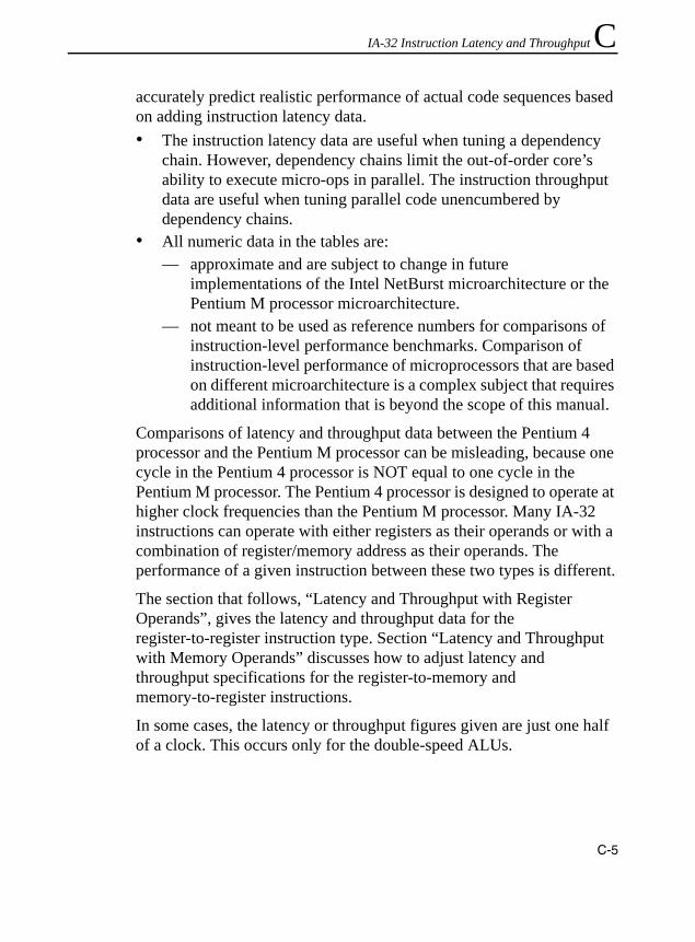
IA-32 Instruction Latency and Throughput C
accurately predict realistic performance of actual code sequences based on adding instruction latency data.• The instruction latency data are useful when tuning a dependencychain. However, dependency chains limit the out-of-order core’s ability to execute micro-ops in parallel. The instruction throughput data are useful when tuning parallel code unencumbered by dependency chains.
• All numeric data in the tables are: — approximate and are subject to change in future
implementations of the Intel NetBurst microarchitecture or the Pentium M processor microarchitecture.
— not meant to be used as reference numbers for comparisons of instruction-level performance benchmarks. Comparison of instruction-level performance of microprocessors that are based on different microarchitecture is a complex subject that requires additional information that is beyond the scope of this manual.
Comparisons of latency and throughput data between the Pentium 4 processor and the Pentium M processor can be misleading, because one cycle in the Pentium 4 processor is NOT equal to one cycle in the Pentium M processor. The Pentium 4 processor is designed to operate at higher clock frequencies than the Pentium M processor. Many IA-32 instructions can operate with either registers as their operands or with a combination of register/memory address as their operands. The performance of a given instruction between these two types is different.
The section that follows, “Latency and Throughput with Register Operands”, gives the latency and throughput data for the register-to-register instruction type. Section “Latency and Throughput with Memory Operands” discusses how to adjust latency and throughput specifications for the register-to-memory and memory-to-register instructions.
In some cases, the latency or throughput figures given are just one half of a clock. This occurs only for the double-speed ALUs.
C-5

IA-32 Intel® Architecture Optimization
Latency and Throughput with Register Operands
IA-32 instruction latency and throughput data are presented in Table C-2 through Table C-8. The tables include the Streaming SIMD Extension 3, Streaming SIMD Extension 2, Streaming SIMD Extension, MMX technology and most of commonly used IA-32 instructions. Instruction latency and throughput of the Pentium 4 processor and of the Pentium M processor are given in separate columns. Pentium 4 processor instruction timing data is implementation specific, i.e. can vary between model encoding value = 3 and model < 2. Separate data sets of instruction latency and throughput are shown in the columns for CPUID signature 0xF2n and 0xF3n. The notation 0xF2n represents the hex value of the lower 12 bits of the EAX register reported by CPUID instruction with input value of EAX = 1; ‘F’ indicates the family encoding value is 15, ‘2’ indicates the model encoding is 2, ‘n’ indicates it applies to any value in the stepping encoding. Pentium M processor instruction timing data is shown in the columns represented by CPUID signature 0x69n. The instruction timing for Pentium M processor with CPUID signature 0x6Dn is the same as that of 0x69n.
Table C-1 Streaming SIMD Extension 3 SIMD Floating-point Instructions
Instruction Latency1 Throughput Execution Unit
CPUID 0F3n 0F3n 0F3n
ADDSUBPD/ADDSUBPS 5 2 FP_ADD
HADDPD/HADDPS 13 4 FP_ADD,FP_MISC
HSUBPD/HSUBPS 13 4 FP_ADD,FP_MISC
MOVDDUP xmm1, xmm2 4 2 FP_MOVE
MOVSHDUP xmm1, xmm2
6 2 FP_MOVE
MOVSLDUP xmm1, xmm2
6 2 FP_MOVE
See “Table Footnotes”
C-6

IA-32 Instruction Latency and Throughput C
Table C-2 Streaming SIMD Extension 2 128-bit Integer InstructionsInstruction Latency1 ThroughputExecution Unit2
CPUID 0F3n 0F2n 0x69n 0F3n 0F2n 0x69n 0F2n
CVTDQ2PS3 xmm, xmm 5 5 2 2 FP_ADD
CVTPS2DQ3 xmm, xmm 5 5 3+1 2 2 2 FP_ADD
CVTTPS2DQ3 xmm, xmm 5 5 3+1 2 2 2 FP_ADD
MOVD xmm, r32 6 6 1 2 2 2 MMX_MISC,MMX_SHFT
MOVD r32, xmm 10 10 1+1 1 1 2 FP_MOVE,FP_MISC
MOVDQA xmm, xmm 6 6 1 1 1 1 FP_MOVE
MOVDQU xmm, xmm 6 6 1 1 1 1 FP_MOVE
MOVDQ2Q mm, xmm 8 8 1 2 2 1 FP_MOVE,MMX_ALU
MOVQ2DQ xmm, mm 8 8 1 2 2 1 FP_MOVE,MMX_SHFT
MOVQ xmm, xmm 2 2 1 2 2 1 MMX_SHFT
PACKSSWB/PACKSSDW/PACKUSWB xmm, xmm
4 4 2+1 2 2 2 MMX_SHFT
PADDB/PADDW/PADDD xmm, xmm
2 2 1 2 2 1 MMX_ALU
PADDSB/PADDSW/PADDUSB/PADDUSW xmm, xmm
2 2 1 2 2 1 MMX_ALU
PADDQ mm, mm 2 2 2 1 1 1 FP_MISC
PSUBQ mm, mm 2 2 2+1 1 1 2 FP_MISC
PADDQ/ PSUBQ3 xmm, xmm
6 6 2+1 2 2 2 FP_MISC
PAND xmm, xmm 2 2 1 2 2 1 MMX_ALU
PANDN xmm, xmm 2 2 1 2 2 1 MMX_ALU
PAVGB/PAVGW xmm, xmm 2 2 2 2 MMX_ALU
PCMPEQB/PCMPEQD/PCMPEQW xmm, xmm
2 2 1 2 2 1 MMX_ALU
continued
C-7

IA-32 Intel® Architecture Optimization
PCMPGTB/PCMPGTD/PCMPGTW xmm, xmm
2 2 1 2 2 1 MMX_ALU
PEXTRW r32, xmm, imm8 7 7 3 2 2 2 MMX_SHFT,FP_MISC
PINSRW xmm, r32, imm8 4 4 1+1 2 2 2 MMX_SHFT,MMX_MISC
PMADDWD xmm, xmm 9 8 3+1 2 2 2 FP_MUL
PMAX xmm, xmm 2 2 2 2 MMX_ALU
PMIN xmm, xmm 2 2 2 2 MMX_ALU
PMOVMSKB3 r32, xmm 7 7 2 2 FP_MISC
PMULHUW/PMULHW/PMULLW3 xmm, xmm
9 8 3+1 2 2 2 FP_MUL
PMULUDQ mm, mm 9 8 6 1 2 FP_MUL
PMULUDQ xmm, xmm 9 8 6+2 2 2 4 FP_MUL
POR xmm, xmm 2 2 1 2 2 1 MMX_ALU
PSADBW xmm, xmm 4 4 5+2 2 2 4 MMX_ALU
PSHUFD xmm, xmm, imm8 4 4 2+1 2 2 2 MMX_SHFT
PSHUFHW xmm, xmm, imm8
2 2 1 2 2 1 MMX_SHFT
PSHUFLW xmm, xmm, imm8
2 2 1 2 2 1 MMX_SHFT
PSLLDQ xmm, imm8 4 4 4 2 2 4 MMX_SHFT
PSLLW/PSLLD/PSLLQ xmm, xmm/imm8
2 2 1+1 2 2 2 MMX_SHFT
PSRAW/PSRAD xmm, xmm/imm8
2 2 1+1 2 2 2 MMX_SHFT
PSRLDQ xmm, imm8 4 4 4 2 2 4 MMX_SHFT
PSRLW/PSRLD/PSRLQ xmm, xmm/imm8
2 2 1+1 2 2 2 MMX_SHFT
continued
Table C-2 Streaming SIMD Extension 2 128-bit Integer Instructions (continued)
Instruction Latency1 ThroughputExecution Unit2
C-8

IA-32 Instruction Latency and Throughput C
PSUBB/PSUBW/PSUBD xmm, xmm
2 2 1 2 2 1 MMX_ALU
PSUBSB/PSUBSW/PSUBUSB/PSUBUSW xmm, xmm
2 2 1 2 2 1 MMX_ALU
PUNPCKHBW/PUNPCKHWD/PUNPCKHDQ xmm, xmm
4 4 1+1 2 2 2 MMX_SHFT
PUNPCKHQDQ xmm, xmm 4 4 1_1 2 2 2 MMX_SHFT
PUNPCKLBW/PUNPCKLWD/PUNPCKLDQ xmm, xmm
2 2 2 2 2 2 MMX_SHFT
PUNPCKLQDQ3 xmm, xmm
4 4 1 1 1 1 FP_MISC
PXOR xmm, xmm 2 2 1 2 2 1 MMX_ALU
See “Table Footnotes”
Table C-3 Streaming SIMD Extension 2 Double-precision Floating-point Instructions
Instruction Latency1 ThroughputExecution Unit2
CPUID 0F3n 0F2n 0x69n 0F3n 0F2n 0x69n 0F2n
ADDPD xmm, xmm 5 4 4 2 2 2 FP_ADD
ADDSD xmm, xmm 5 4 3 2 2 1 FP_ADD
ANDNPD3 xmm, xmm 4 4 1 2 2 1 MMX_ALU
ANDPD3 xmm, xmm 4 4 1 2 2 1 MMX_ALU
CMPPD xmm, xmm, imm8
5 4 4 2 2 2 FP_ADD
CMPSD xmm, xmm, imm8
5 4 3 2 2 1 FP_ADD
continued
Table C-2 Streaming SIMD Extension 2 128-bit Integer Instructions (continued)
Instruction Latency1 ThroughputExecution Unit2
C-9
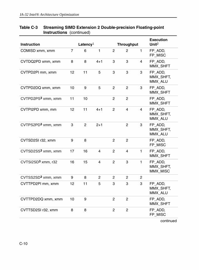
IA-32 Intel® Architecture Optimization
COMISD xmm, xmm 7 6 1 2 2 1 FP_ADD, FP_MISC
CVTDQ2PD xmm, xmm 8 8 4+1 3 3 4 FP_ADD, MMX_SHFT
CVTPD2PI mm, xmm 12 11 5 3 3 3 FP_ADD, MMX_SHFT,MMX_ALU
CVTPD2DQ xmm, xmm 10 9 5 2 2 3 FP_ADD, MMX_SHFT
CVTPD2PS3 xmm, xmm 11 10 2 2 FP_ADD, MMX_SHFT
CVTPI2PD xmm, mm 12 11 4+1 2 4 4 FP_ADD, MMX_SHFT,MMX_ALU
CVTPS2PD3 xmm, xmm 3 2 2+1 2 3 FP_ADD, MMX_SHFT,MMX_ALU
CVTSD2SI r32, xmm 9 8 2 2 FP_ADD, FP_MISC
CVTSD2SS3 xmm, xmm 17 16 4 2 4 1 FP_ADD, MMX_SHFT
CVTSI2SD3 xmm, r32 16 15 4 2 3 1 FP_ADD, MMX_SHFT, MMX_MISC
CVTSS2SD3 xmm, xmm 9 8 2 2 2 2
CVTTPD2PI mm, xmm 12 11 5 3 3 3 FP_ADD, MMX_SHFT,MMX_ALU
CVTTPD2DQ xmm, xmm 10 9 2 2 FP_ADD, MMX_SHFT
CVTTSD2SI r32, xmm 8 8 2 2 FP_ADD, FP_MISC
continued
Table C-3 Streaming SIMD Extension 2 Double-precision Floating-point Instructions (continued)
Instruction Latency1 ThroughputExecution Unit2
C-10

IA-32 Instruction Latency and Throughput C
DIVPD xmm, xmm 70 69 32+31 70 69 62 FP_DIV
DIVSD xmm, xmm 39 38 32 39 38 31 FP_DIV
MAXPD xmm, xmm 5 4 4 2 2 2 FP_ADD
MAXSD xmm, xmm 5 4 3 2 2 1 FP_ADD
MINPD xmm, xmm 5 4 4 2 2 2 FP_ADD
MINSD xmm, xmm 5 4 3 2 2 1 FP_ADD
MOVAPD xmm, xmm 6 6 1 1 FP_MOVE
MOVMSKPD r32, xmm 6 6 2 2 FP_MISC
MOVSD xmm, xmm 6 6 2 2 MMX_SHFT
MOVUPD xmm, xmm 6 6 1 1 FP_MOVE
MULPD xmm, xmm 7 6 2 2 FP_MUL
MULSD xmm, xmm 7 6 2 2 FP_MUL
ORPD3 xmm, xmm 4 4 2 2 MMX_ALU
SHUFPD3 xmm, xmm, imm8
6 6 2 2 MMX_SHFT
SQRTPD xmm, xmm 70 69 58+57 70 69 114 FP_DIV
SQRTSD xmm, xmm 39 38 58 39 38 57 FP_DIV
SUBPD xmm, xmm 5 4 4 2 2 2 FP_ADD
SUBSD xmm, xmm 5 4 3 2 2 1 FP_ADD
UCOMISD xmm, xmm 7 6 1 2 2 1 FP_ADD, FP_MISC
UNPCKHPD3 xmm, xmm 6 6 1 2 2 1 MMX_SHFT
UNPCKLPD3 xmm, xmm 4 4 1 2 2 1 MMX_SHFT
XORPD3 xmm, xmm 4 4 1 2 2 1 MMX_ALU
See “Table Footnotes”
Table C-3 Streaming SIMD Extension 2 Double-precision Floating-point Instructions (continued)
Instruction Latency1 ThroughputExecution Unit2
C-11

IA-32 Intel® Architecture Optimization
Table C-4 Streaming SIMD Extension Single-precision Floating-point Instructions
Instruction Latency1 Throughput Execution Unit2
CPUID 0F3n 0F2n 0x69n 0F3n 0F2n 0x69n 0F2n
ADDPS xmm, xmm 5 4 4 2 2 2 FP_ADD
ADDSS xmm, xmm 5 4 3 2 2 1 FP_ADD
ANDNPS3 xmm, xmm 4 4 2 2 2 2 MMX_ALU
ANDPS3 xmm, xmm 4 4 2 2 2 2 MMX_ALU
CMPPS xmm, xmm 5 4 4 2 2 2 FP_ADD
CMPSS xmm, xmm 5 4 3 2 2 1 FP_ADD
COMISS xmm, xmm 7 6 1 2 2 1 FP_ADD,FP_MISC
CVTPI2PS xmm, mm 12 11 3 2 4 1 MMX_ALU,FP_ADD,MMX_SHFT
CVTPS2PI mm, xmm 8 7 3 2 2 1 FP_ADD,MMX_ALU
CVTSI2SS3 xmm, r32 12 11 4 2 2 2 FP_ADD,MMX_SHFT, MMX_MISC
CVTSS2SI r32, xmm 9 8 4 2 2 1 FP_ADD,FP_MISC
CVTTPS2PI mm, xmm 8 7 3 2 2 1 FP_ADD,MMX_ALU
CVTTSS2SI r32, xmm 9 8 4 2 2 1 FP_ADD,FP_MISC
DIVPS xmm, xmm 40 39 18+17
40 39 36 FP_DIV
DIVSS xmm, xmm 32 23 32 23 FP_DIV
MAXPS xmm, xmm 5 4 2 2 FP_ADD
MAXSS xmm, xmm 5 4 2 2 FP_ADD
MINPS xmm, xmm 5 4 2 2 FP_ADD
MINSS xmm, xmm 5 4 2 2 FP_ADD
MOVAPS xmm, xmm 6 6 1 1 FP_MOVE
MOVHLPS3 xmm, xmm 6 6 2 2 MMX_SHFT
continued
C-12

IA-32 Instruction Latency and Throughput C
MOVLHPS3 xmm, xmm 4 4 2 2 MMX_SHFT
MOVMSKPS r32, xmm 6 6 2 2 FP_MISC
MOVSS xmm, xmm 4 4 2 2 MMX_SHFT
MOVUPS xmm, xmm 6 6 1 1 FP_MOVE
MULPS xmm, xmm 7 6 4+1 2 2 2 FP_MUL
MULSS xmm, xmm 7 6 2 2 FP_MUL
ORPS3 xmm, xmm 4 4 2 2 2 2 MMX_ALU
RCPPS3 xmm, xmm 6 6 2 4 4 2 MMX_MISC
RCPSS3 xmm, xmm 6 6 1 2 2 1 MMX_MISC,MMX_SHFT
RSQRTPS3 xmm, xmm 6 6 2 4 4 2 MMX_MISC
RSQRTSS3 xmm, xmm 6 6 4 4 1 MMX_MISC,MMX_SHFT
SHUFPS3 xmm, xmm, imm8
6 6 2 2 2 2 MMX_SHFT
SQRTPS xmm, xmm 40 39 29+28 40 39 58 FP_DIV
SQRTSS xmm, xmm 32 23 30 32 23 29 FP_DIV
SUBPS xmm, xmm 5 4 4 2 2 2 FP_ADD
SUBSS xmm, xmm 5 4 3 2 2 1 FP_ADD
UCOMISS xmm, xmm 7 6 1 2 2 1 FP_ADD, FP_MISC
UNPCKHPS3 xmm, xmm
6 6 3 2 2 2 MMX_SHFT
UNPCKLPS3 xmm, xmm
4 4 3 2 2 2 MMX_SHFT
XORPS3 xmm, xmm 4 4 2 2 2 2 MMX_ALU
FXRSTOR 150
FXSAVE 100
See “Table Footnotes”
Table C-4 Streaming SIMD Extension Single-precision Floating-point Instructions (continued)
Instruction Latency1 Throughput Execution Unit2
C-13

IA-32 Intel® Architecture Optimization
Table C-5 Streaming SIMD Extension 64-bit Integer Instructions
Instruction Latency1 Throughput Execution Unit
CPUID 0F3n 0F2n 0x69n 0F3n 0F2n 0x69n 0F2n
PAVGB/PAVGW mm, mm 2 2 1 1 MMX_ALU
PEXTRW r32, mm, imm8 7 7 2 2 2 1 MMX_SHFT,FP_MISC
PINSRW mm, r32, imm8 4 4 1 1 1 1 MMX_SHFT,MMX_MISC
PMAX mm, mm 2 2 1 1 MMX_ALU
PMIN mm, mm 2 2 1 1 MMX_ALU
PMOVMSKB3 r32, mm 7 7 1 2 2 1 FP_MISC
PMULHUW3 mm, mm 9 8 1 1 FP_MUL
PSADBW mm, mm 4 4 5 1 1 2 MMX_ALU
PSHUFW mm, mm, imm8 2 2 1 1 1 1 MMX_SHFT
See “Table Footnotes”
Table C-6 MMX Technology 64-bit Instructions
Instruction Latency1 Throughput Execution Unit2
CPUID 0F3n 0F2n 0x69n 0f3n 0F2n 0x69n 0F2n
MOVD mm, r32 2 2 1 1 MMX_ALU
MOVD3 r32, mm 5 5 1 1 FP_MISCMOVQ mm, mm 6 6 1 1 FP_MOV
PACKSSWB/PACKSSDW/PACKUSWB mm, mm
2 2 1 1 MMX_SHFT
PADDB/PADDW/PADDD mm, mm
2 2 1 1 MMX_ALU
PADDSB/PADDSW/PADDUSB/PADDUSW mm, mm
2 2 1 1 MMX_ALU
PAND mm, mm 2 2 1 1 MMX_ALUPANDN mm, mm 2 2 1 1 MMX_ALU
PCMPEQB/PCMPEQDPCMPEQW mm, mm
2 2 1 1 MMX_ALU
continued
C-14

IA-32 Instruction Latency and Throughput C
PCMPGTB/PCMPGTD/PCMPGTW mm, mm
2 2 1 1 MMX_ALU
PMADDWD3 mm, mm 9 8 1 1 FP_MUL
PMULHW/PMULLW3 mm, mm
9 8 1 1 FP_MUL
POR mm, mm 2 2 1 1 MMX_ALU
PSLLQ/PSLLW/PSLLD mm, mm/imm8
2 2 1 1 MMX_SHFT
PSRAW/PSRAD mm, mm/imm8
2 2 1 1 MMX_SHFT
PSRLQ/PSRLW/PSRLD mm, mm/imm8
2 2 1 1 MMX_SHFT
PSUBB/PSUBW/PSUBD mm, mm
2 2 1 1 MMX_ALU
PSUBSB/PSUBSW/PSUBUSB/PSUBUSW mm, mm
2 2 1 1 MMX_ALU
PUNPCKHBW/PUNPCKHWD/PUNPCKHDQ mm, mm
2 2 1 1 MMX_SHFT
PUNPCKLBW/PUNPCKLWD/PUNPCKLDQ mm, mm
2 2 1 1 MMX_SHFT
PXOR mm, mm 2 2 1 1 MMX_ALU
EMMS1 12 12
See “Table Footnotes”
Table C-6 MMX Technology 64-bit Instructions (continued)
Instruction Latency1 Throughput Execution Unit2
C-15
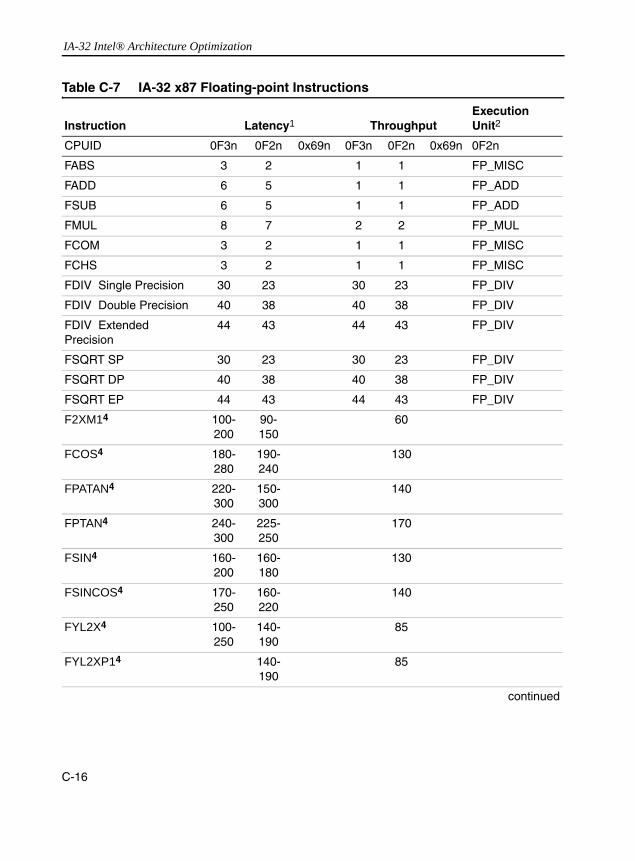
IA-32 Intel® Architecture Optimization
Table C-7 IA-32 x87 Floating-point Instructions
Instruction Latency1 ThroughputExecution Unit2
CPUID 0F3n 0F2n 0x69n 0F3n 0F2n 0x69n 0F2n
FABS 3 2 1 1 FP_MISC
FADD 6 5 1 1 FP_ADD
FSUB 6 5 1 1 FP_ADD
FMUL 8 7 2 2 FP_MUL
FCOM 3 2 1 1 FP_MISC
FCHS 3 2 1 1 FP_MISC
FDIV Single Precision 30 23 30 23 FP_DIV
FDIV Double Precision 40 38 40 38 FP_DIV
FDIV Extended Precision
44 43 44 43 FP_DIV
FSQRT SP 30 23 30 23 FP_DIV
FSQRT DP 40 38 40 38 FP_DIV
FSQRT EP 44 43 44 43 FP_DIV
F2XM14 100-200
90-150
60
FCOS4 180-280
190-240
130
FPATAN4 220-300
150-300
140
FPTAN4 240-300
225-250
170
FSIN4 160-200
160-180
130
FSINCOS4 170-250
160-220
140
FYL2X4 100-250
140-190
85
FYL2XP14 140-190
85
continued
C-16
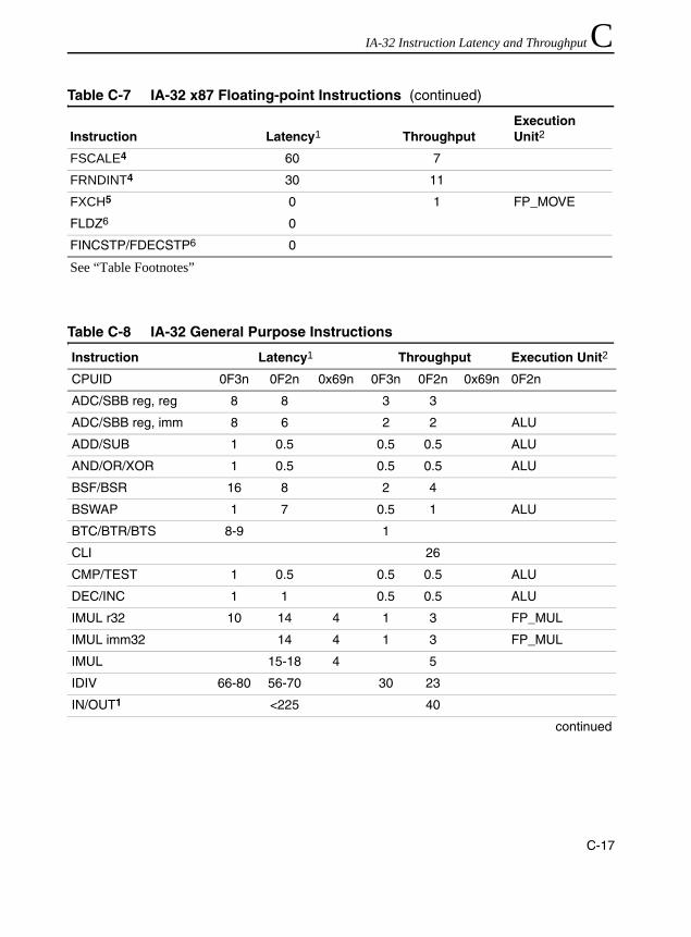
IA-32 Instruction Latency and Throughput C
FSCALE4 60 7
FRNDINT4 30 11
FXCH5 0 1 FP_MOVE
FLDZ6 0
FINCSTP/FDECSTP6 0
See “Table Footnotes”
Table C-8 IA-32 General Purpose Instructions
Instruction Latency1 Throughput Execution Unit2
CPUID 0F3n 0F2n 0x69n 0F3n 0F2n 0x69n 0F2n
ADC/SBB reg, reg 8 8 3 3
ADC/SBB reg, imm 8 6 2 2 ALU
ADD/SUB 1 0.5 0.5 0.5 ALU
AND/OR/XOR 1 0.5 0.5 0.5 ALU
BSF/BSR 16 8 2 4
BSWAP 1 7 0.5 1 ALU
BTC/BTR/BTS 8-9 1
CLI 26
CMP/TEST 1 0.5 0.5 0.5 ALU
DEC/INC 1 1 0.5 0.5 ALU
IMUL r32 10 14 4 1 3 FP_MUL
IMUL imm32 14 4 1 3 FP_MUL
IMUL 15-18 4 5
IDIV 66-80 56-70 30 23
IN/OUT1 <225 40
continued
Table C-7 IA-32 x87 Floating-point Instructions (continued)
Instruction Latency1 ThroughputExecution Unit2
C-17

IA-32 Intel® Architecture Optimization
Jcc7 Not App-
licable
0.5 ALU
LOOP 8 1.5 ALU
MOV 1 0.5 0.5 0.5 ALU
MOVSB/MOVSW 1 0.5 0.5 0.5 ALU
MOVZB/MOVZW 1 0.5 0.5 0.5 ALU
NEG/NOT/NOP 1 0.5 0.5 0.5 ALU
POP r32 1.5 1 MEM_LOAD,ALU
PUSH 1.5 1 MEM_STORE,ALU
RCL/RCR reg, 18 6 4 1 1
ROL/ROR 1 4 0.5 1
RET 8 1 MEM_LOAD,ALU
SAHF 1 0.5 0.5 0.5 ALU
SAL/SAR/SHL/SHR 1 4 1 0.5 1
SCAS 4 1.5 ALU,MEM_LOAD
SETcc 5 1.5 ALU
STI 36
STOSB 5 2 ALU,MEM_STORE
XCHG 1.5 1.5 1 1 ALU
CALL 5 1 ALU,MEM_STORE
MUL 10 14-18 1 5
DIV 66-80 56-70 30 23
See “Table Footnotes”
Table C-8 IA-32 General Purpose Instructions (continued)
Instruction Latency1 Throughput Execution Unit2
C-18
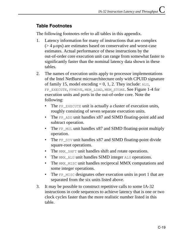
IA-32 Instruction Latency and Throughput C
Table FootnotesThe following footnotes refer to all tables in this appendix.1. Latency information for many of instructions that are complex
(> 4 µops) are estimates based on conservative and worst-case estimates. Actual performance of these instructions by the out-of-order core execution unit can range from somewhat faster to significantly faster than the nominal latency data shown in these tables.
2. The names of execution units apply to processor implementations of the Intel NetBurst microarchitecture only with CPUID signature of family 15, model encoding = 0, 1, 2. They include: ALU, FP_EXECUTE, FPMOVE, MEM_LOAD, MEM_STORE. See Figure 1-4 for execution units and ports in the out-of-order core. Note the following:• The FP_EXECUTE unit is actually a cluster of execution units,
roughly consisting of seven separate execution units. • The FP_ADD unit handles x87 and SIMD floating-point add and
subtract operation. • The FP_MUL unit handles x87 and SIMD floating-point multiply
operation. • The FP_DIV unit handles x87 and SIMD floating-point divide
square-root operations. • The MMX_SHFT unit handles shift and rotate operations. • The MMX_ALU unit handles SIMD integer ALU operations. • The MMX_MISC unit handles reciprocal MMX computations and
some integer operations.• The FP_MISC designates other execution units in port 1 that are
separated from the six units listed above.3. It may be possible to construct repetitive calls to some IA-32
instructions in code sequences to achieve latency that is one or two clock cycles faster than the more realistic number listed in this table.
C-19

IA-32 Intel® Architecture Optimization
4. Latency and Throughput of transcendental instructions can vary substantially in a dynamic execution environment. Only an approximate value or a range of values are given for these instructions.
5. The FXCH instruction has 0 latency in code sequences. However, it is limited to an issue rate of one instruction per clock cycle.
6. The load constant instructions, FINCSTP, and FDECSTP have 0 latency in code sequences.
7. Selection of conditional jump instructions should be based on the recommendation of section “Branch Prediction” to improve the predictability of branches. When branches are predicted successfully, the latency of jcc is effectively zero.
8. RCL/RCR with shift count of 1 are optimized. Using RCL/RCR with shift count other than 1 will be executed more slowly. This applies to the Pentium 4 and Intel Xeon processors.
Latency and Throughput with Memory Operands
The discussion of this section applies to the Intel Pentium 4 and Intel Xeon processors. Typically, instructions with a memory address as the source operand, add one more µop to the “reg, reg” instructions type listed in Table C-1 through C-7. However, the throughput in most cases remains the same because the load operation utilizes port 2 without affecting port 0 or port 1.
Many IA-32 instructions accept a memory address as either the source operand or as the destination operand. The former is commonly referred to as a load operation, while the latter a store operation.
The latency for IA-32 instructions that perform either a load or a store operation are typically longer than the latency of corresponding register-to-register type of the IA-32 instructions. This is because load or store operations require access to the cache hierarchy and, in some cases, the memory sub-system.
C-20

IA-32 Instruction Latency and Throughput C
For the sake of simplicity, all data being requested is assumed to reside in the first level data cache (cache hit). In general, IA-32 instructions with load operations that execute in the integer ALU units require two more clock cycles than the corresponding register-to-register flavor of the same instruction. Throughput of these instructions with load operation remains the same with the register-to-register flavor of the instructions.Floating-point, MMX technology, Streaming SIMD Extensions and Streaming SIMD Extension 2 instructions with load operations require 6 more clocks in latency than the register-only version of the instructions, but throughput remains the same.
When store operations are on the critical path, their results can generally be forwarded to a dependent load in as few as zero cycles. Thus, the latency to complete and store isn’t relevant here.
C-21

IA-32 Intel® Architecture Optimization
C-22

D
Stack AlignmentThis appendix details on the alignment of the stacks of data for Streaming SIMD Extensions and Streaming SIMD Extensions 2.
Stack FramesThis section describes the stack alignment conventions for both esp-based (normal), and ebp-based (debug) stack frames. A stack frame is a contiguous block of memory allocated to a function for its local memory needs. It contains space for the function’s parameters, return address, local variables, register spills, parameters needing to be passed to other functions that a stack frame may call, and possibly others. It is typically delineated in memory by a stack frame pointer (esp) that points to the base of the frame for the function and from which all data are referenced via appropriate offsets. The convention on IA-32 is to use the esp register as the stack frame pointer for normal optimized code, and to use ebp in place of esp when debug information must be kept. Debuggers use the ebp register to find the information about the function via the stack frame.
It is important to ensure that the stack frame is aligned to a 16-byte boundary upon function entry to keep local __m128 data, parameters, and xmm register spill locations aligned throughout a function invocation.The Intel C++ Compiler for Win32* Systems supports conventions presented here help to prevent memory references from incurring penalties due to misaligned data by keeping them aligned to 16-byte boundaries. In addition, this scheme supports improved
D-1

IA-32 Intel® Architecture Optimization
alignment for __m64 and double type data by enforcing that these 64-bit data items are at least eight-byte aligned (they will now be 16-byte aligned).
For variables allocated in the stack frame, the compiler cannot guarantee the base of the variable is aligned unless it also ensures that the stack frame itself is 16-byte aligned. Previous IA-32 software conventions, as implemented in most compilers, only ensure that individual stack frames are 4-byte aligned. Therefore, a function called from a Microsoft-compiled function, for example, can only assume that the frame pointer it used is 4-byte aligned.
Earlier versions of the Intel C++ Compiler for Win32 Systems have attempted to provide 8-byte aligned stack frames by dynamically adjusting the stack frame pointer in the prologue of main and preserving 8-byte alignment of the functions it compiles. This technique is limited in its applicability for the following reasons:• The main function must be compiled by the Intel C++ Compiler.• There may be no functions in the call tree compiled by some other
compiler (as might be the case for routines registered as callbacks). • Support is not provided for proper alignment of parameters.
The solution to this problem is to have the function’s entry point assume only 4-byte alignment. If the function has a need for 8-byte or 16-byte alignment, then code can be inserted to dynamically align the stack appropriately, resulting in one of the stack frames shown in Figure D-1.
D-2

Stack Alignment D
As an optimization, an alternate entry point can be created that can be called when proper stack alignment is provided by the caller. Using call graph profiling of the VTune analyzer, calls to the normal (unaligned) entry point can be optimized into calls to the (alternate) aligned entry point when the stack can be proven to be properly aligned. Furthermore, a function alignment requirement attribute can be modified throughout the call graph so as to cause the least number of calls to unaligned entry points. As an example of this, suppose function F has only a stack alignment requirement of 4, but it calls function G at many call sites, and in a loop. If G’s alignment requirement is 16, then by promoting F’s alignment requirement to 16, and making all calls to G go to its aligned entry point, the compiler can minimize the number of times that control passes through the unaligned entry points. Example D-1 and
Figure D-1 Stack Frames Based on Alignment Type
ParameterPointer
EBP
ESP
EBP-based Aligned Frame
Parameters
Return Address
Padding
Previous EBP
Local Variables andSpill Slots
Parameter PassingSpace
EBP-frame SavedRegister Area
Return Address 1
SEH/CEH Record
ParameterPointer
ESP
ESP-based Aligned Frame
Parameters
Return Address
Padding
Register Save Area
Local Variables andSpill Slots
__cdecl ParameterPassing Space
__stdcall ParameterPassing Space
D-3
Stack Alignment D
Example D-1 in the following sections illustrate this technique. Note the entry points foo and foo.aligned, the latter is the alternate aligned entry point.Aligned esp-Based Stack Frames
This section discusses data and parameter alignment and the declspec(align) extended attribute, which can be used to request alignment in C and C++ code. In creating esp-based stack frames, the compiler adds padding between the return address and the register save area as shown in Example 3-11. This frame can be used only when debug information is not requested, there is no need for exception handling support, inlined assembly is not used, and there are no calls to alloca within the function.
If the above conditions are not met, an aligned ebp-based frame must be used. When using this type of frame, the sum of the sizes of the return address, saved registers, local variables, register spill slots, and parameter space must be a multiple of 16 bytes. This causes the base of the parameter space to be 16-byte aligned. In addition, any space reserved for passing parameters for stdcall functions also must be a multiple of 16 bytes. This means that the caller needs to clean up some of the stack space when the size of the parameters pushed for a call to a stdcall function is not a multiple of 16. If the caller does not do this, the stack pointer is not restored to its pre-call value.
In Example D-1, we have 12 bytes on the stack after the point of alignment from the caller: the return pointer, ebx and edx. Thus, we need to add four more to the stack pointer to achieve alignment. Assuming 16 bytes of stack space are needed for local variables, the compiler adds 16 + 4 = 20 bytes to esp, making esp aligned to a 0 mod 16 address.
D-4

Stack Alignment D
Example D-1 Aligned esp-Based Stack Framesvoid _cdecl foo (int k)
{
int j;
foo: // See Note A
push ebx
mov ebx, esp
sub esp, 0x00000008
and esp, 0xfffffff0
add esp, 0x00000008
jmp common
foo.aligned:
push ebx
mov ebx, esp
common: // See Note B
push edx
sub esp, 20
j = k;
mov edx, [ebx + 8]
mov [esp + 16], edx
foo(5);
mov [esp], 5
call foo.aligned
return j;
mov eax, [esp + 16]
add esp, 20
pop edx
mov esp, ebx
pop ebx
ret
D-5
Stack Alignment D
Aligned ebp-Based Stack Frames
In ebp-based frames, padding is also inserted immediately before the return address. However, this frame is slightly unusual in that the return address may actually reside in two different places in the stack. This occurs whenever padding must be added and exception handling is in effect for the function. Example D-2 shows the code generated for this type of frame. The stack location of the return address is aligned 12 mod 16. This means that the value of ebp always satisfies the condition (ebp & 0x0f) == 0x08. In this case, the sum of the sizes of the return address, the previous ebp, the exception handling record, the local variables, and the spill area must be a multiple of 16 bytes. In addition, the parameter passing space must be a multiple of 16 bytes. For a call to a stdcall function, it is necessary for the caller to reserve some stack space if the size of the parameter block being pushed is not a multiple of 16.
NOTE. A. Aligned entry points assume that parameter block beginnings are aligned. This places the stack pointer at a 12 mod 16 boundary, as the return pointer has been pushed. Thus, the unaligned entry point must force the stack pointer to this boundary. B. The code at the common label assumes the stack is at an 8 mod 16 boundary, and adds sufficient space to the stack so that the stack pointer is aligned to a 0 mod 16 boundary.
D-6
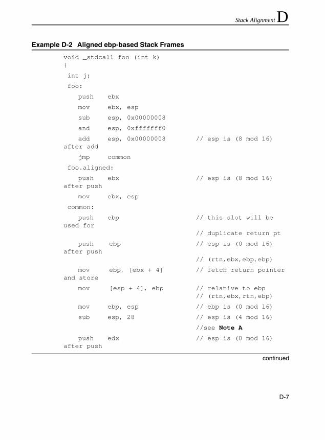
Stack Alignment D
Example D-2 Aligned ebp-based Stack Framesvoid _stdcall foo (int k){
int j;
foo:
push ebx
mov ebx, esp
sub esp, 0x00000008
and esp, 0xfffffff0
add esp, 0x00000008 // esp is (8 mod 16) after add
jmp common
foo.aligned:
push ebx // esp is (8 mod 16) after push
mov ebx, esp
common:
push ebp // this slot will be used for
// duplicate return pt
push ebp // esp is (0 mod 16) after push
// (rtn,ebx,ebp,ebp)
mov ebp, [ebx + 4] // fetch return pointer and store
mov [esp + 4], ebp // relative to ebp // (rtn,ebx,rtn,ebp)
mov ebp, esp // ebp is (0 mod 16)
sub esp, 28 // esp is (4 mod 16)
//see Note A
push edx // esp is (0 mod 16) after push
continued
D-7
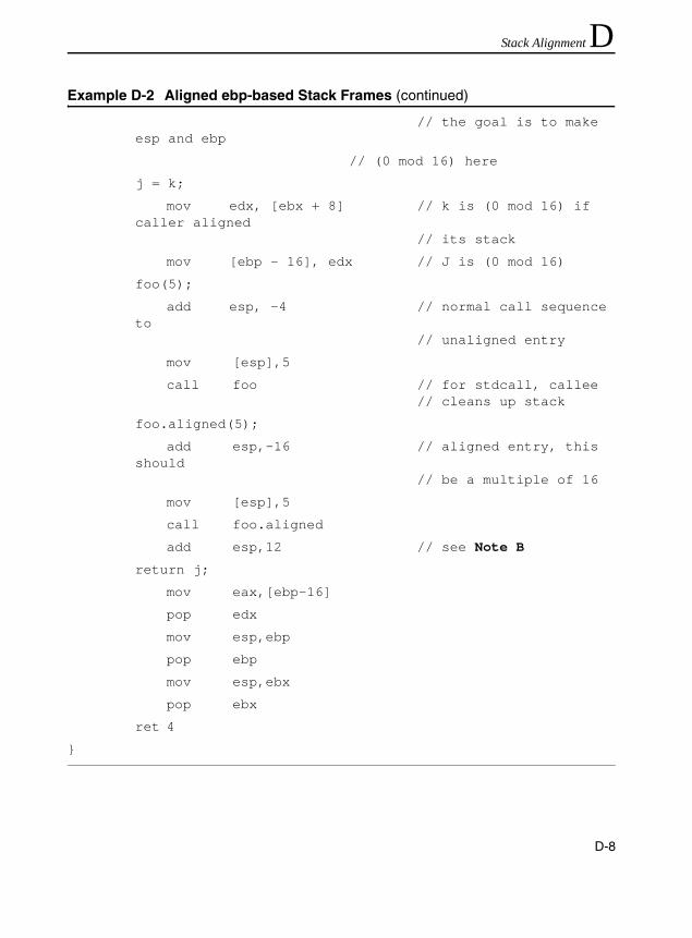
Stack Alignment D
// the goal is to make esp and ebp
// (0 mod 16) here
j = k;
mov edx, [ebx + 8] // k is (0 mod 16) if caller aligned
// its stack
mov [ebp - 16], edx // J is (0 mod 16)
foo(5);
add esp, -4 // normal call sequence to
// unaligned entry
mov [esp],5
call foo // for stdcall, callee // cleans up stack
foo.aligned(5);
add esp,-16 // aligned entry, this should
// be a multiple of 16
mov [esp],5
call foo.aligned
add esp,12 // see Note B
return j;
mov eax,[ebp-16]
pop edx
mov esp,ebp
pop ebp
mov esp,ebx
pop ebx
ret 4
}
Example D-2 Aligned ebp-based Stack Frames (continued)
D-8

Stack Alignment D
Stack Frame Optimizations
The Intel C++ Compiler provides certain optimizations that may improve the way aligned frames are set up and used. These optimizations are as follows:• If a procedure is defined to leave the stack frame 16-byte-aligned
and it calls another procedure that requires 16-byte alignment, then the callee’s aligned entry point is called, bypassing all of the unnecessary aligning code.
• If a static function requires 16-byte alignment, and it can be proven to be called only by other functions that require 16-byte alignment, then that function will not have any alignment code in it. That is, the compiler will not use ebx to point to the argument block and it will not have alternate entry points, because this function will never be entered with an unaligned frame.
NOTE. A. Here we allow for local variables. However, this value should be adjusted so that, after pushing the saved registers, esp is 0 mod 16. B. Just prior to the call, esp is 0 mod 16. To maintain alignment, esp should be adjusted by 16. When a callee uses the stdcall calling sequence, the stack pointer is restored by the callee. The final addition of 12 compensates for the fact that only 4 bytes were passed, rather than 16, and thus the caller must account for the remaining adjustment.
D-9

IA-32 Intel® Architecture Optimization
Inlined Assembly and ebxWhen using aligned frames, the ebx register generally should not be modified in inlined assembly blocks since ebx is used to keep track of the argument block. Programmers may modify ebx only if they do not need to access the arguments and provided they save ebx and restore it before the end of the function (since esp is restored relative to ebx in the function’s epilog).
For additional information on the use of ebx in inline assembly code and other related issues, see relevant application notes in the Intel Architecture Performance Training Center.
CAUTION. Do not use the ebx register in inline assembly functions that use dynamic stack alignment for double, __m64, and __m128 local variables unless you save and restore ebx each time you use it. The Intel C++ Compiler uses the ebx register to control alignment of variables of these types, so the use of ebx, without preserving it, will cause unexpected program execution.
D-10

E
Mathematics of Prefetch Scheduling DistanceThis appendix discusses how far away to insert prefetch instructions. It presents a mathematical model allowing you to deduce a simplified equation which you can use for determining the prefetch scheduling distance (PSD) for your application.
For your convenience, the first section presents this simplified equation; the second section provides the background for this equation: the mathematical model of the calculation.
Simplified EquationA simplified equation to compute PSD is as follows:
wherepsd is prefetch scheduling distance.Nlookup is the number of clocks for lookup latency. This
parameter is system-dependent. The type of memory used and the chipset implementation affect its value.
Nxfer is the number of clocks to transfer a cache-line. This parameter is implementation-dependent.
Npref and Nst are the numbers of cache lines to be prefetched and stored.
CPI is the number of clocks per instruction. This parameter is implementation-dependent.
psd Nlookup Nxfer Npref Nst+( )⋅+
CPI Ninst⋅-------------------------------------------------------------------------------=
E-1

IA-32 Intel® Architecture Optimization
Ninst is the number of instructions in the scope of one loop iteration.
Consider the following example of a heuristic equation assuming that parameters have the values as indicated:
where 60 corresponds to Nlookup, 25 to Nxfer, and 1.5 to CPI.
The values of the parameters in the equation can be derived from the documentation for memory components and chipsets as well as from vendor datasheets.
Mathematical Model for PSDThe parameters used in the mathematics discussed are as follows:psd prefetch scheduling distance (measured in number of
iterations)il iteration latencyTc computation latency per iteration with prefetch cachesTl memory leadoff latency including cache miss latency,
chip set latency, bus arbitration, etc.
CAUTION. The values in this example are for illustration only and do not represent the actual values for these parameters. The example is provided as a “starting point approximation” of calculating the prefetch scheduling distance using the above formula. Experimenting with the instruction around the “starting point approximation” may be required to achieve the best possible performance.
psd 60 25 Npref Nst+( )⋅+
1.5 Ninst⋅-----------------------------------------------------=
E-2

Mathematics of Prefetch Scheduling Distance E
Tb data transfer latency which is equal to number of linesper iteration * line burst latency
Note that the potential effects of µop reordering are not factored into the estimations discussed.
Examine Example E-1 that uses the prefetchnta instruction with a prefetch scheduling distance of 3, that is, psd = 3. The data prefetched in iteration i, will actually be used in iteration i+3. Tc represents the cycles needed to execute top_loop - assuming all the memory accesses hit L1 while il (iteration latency) represents the cycles needed to execute this loop with actually run-time memory footprint. Tc can be determined by computing the critical path latency of the code dependency graph. This work is quite arduous without help from special performance characterization tools or compilers. A simple heuristic for estimating the Tc value is to count the number of instructions in the critical path and multiply the number with an artificial CPI. A reasonable CPI value would be somewhere between 1.0 and 1.5 depending on the quality of code scheduling.
Example E-1 Calculating Insertion for Scheduling Distance of 3
top_loop:
prefetchnta [edx+esi+32*3]
prefetchnta [edx*4+esi+32*3]
. . . . .
movaps xmm1, [edx+esi]
movaps xmm2, [edx*4+esi]
movaps xmm3, [edx+esi+16]
movaps xmm4, [edx*4+esi+16]
. . . . .
. . .
add esi, 32
cmp esi, ecx
jl top_loop
E-3

IA-32 Intel® Architecture Optimization
Memory access plays a pivotal role in prefetch scheduling. For more understanding of a memory subsystem, consider Streaming SIMD Extensions and Streaming SIMD Extensions 2 memory pipeline depicted in Figure E-1.
Assume that three cache lines are accessed per iteration and four chunks of data are returned per iteration for each cache line. Also assume these 3 accesses are pipelined in memory subsystem. Based on these assumptions,Tb = 3 * 4 = 12 FSB cycles.
Figure E-1 Pentium II, Pentium III and Pentium 4 Processors Memory Pipeline Sketch
1 2 3 4 1
1 2 3 4 1
1 2 3 4 1
T l T b
: L2 lookup miss latency
: Memory page access leadoff latency
: Latency for 4 chunks returned per line 2 3 1 4
E-4
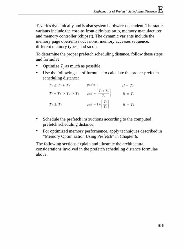
Mathematics of Prefetch Scheduling Distance E
Tl varies dynamically and is also system hardware-dependent. The static variants include the core-to-front-side-bus ratio, memory manufacturer and memory controller (chipset). The dynamic variants include the memory page open/miss occasions, memory accesses sequence, different memory types, and so on.To determine the proper prefetch scheduling distance, follow these steps and formulae:• Optimize Tc as much as possible• Use the following set of formulae to calculate the proper prefetch
scheduling distance:
• Schedule the prefetch instructions according to the computed prefetch scheduling distance.
• For optimized memory performance, apply techniques described in “Memory Optimization Using Prefetch” in Chapter 6.
The following sections explain and illustrate the architectural considerations involved in the prefetch scheduling distance formulae above.
E-5

IA-32 Intel® Architecture Optimization
No Preloading or Prefetch
The traditional programming approach does not perform data preloading or prefetch. It is sequential in nature and will experience stalls because the memory is unable to provide the data immediately when the execution pipeline requires it. Examine Figure E-2.
As you can see from Figure E-2, the execution pipeline is stalled while waiting for data to be returned from memory. On the other hand, the front side bus is idle during the computation portion of the loop. The memory access latencies could be hidden behind execution if data could be fetched earlier during the bus idle time.
Further analyzing Figure E-2,• assume execution cannot continue till last chunk returned and• δf indicates flow data dependency that stalls the execution pipelines
With these two things in mind the iteration latency (il) is computed as follows:
Figure E-2 Execution Pipeline, No Preloading or Prefetch
Execution cycles
Execution pipeline
(i+1)th iteration
Tl Tb
δf
Tc- T∆ T∆
Tl Tb
δf
T∆Tc- T∆
Front-SideBus
ith iteration
issue loads issue loads
Execution units idle Execution units idle
FSB idle
il Tc T+ l Tb+≅
E-6
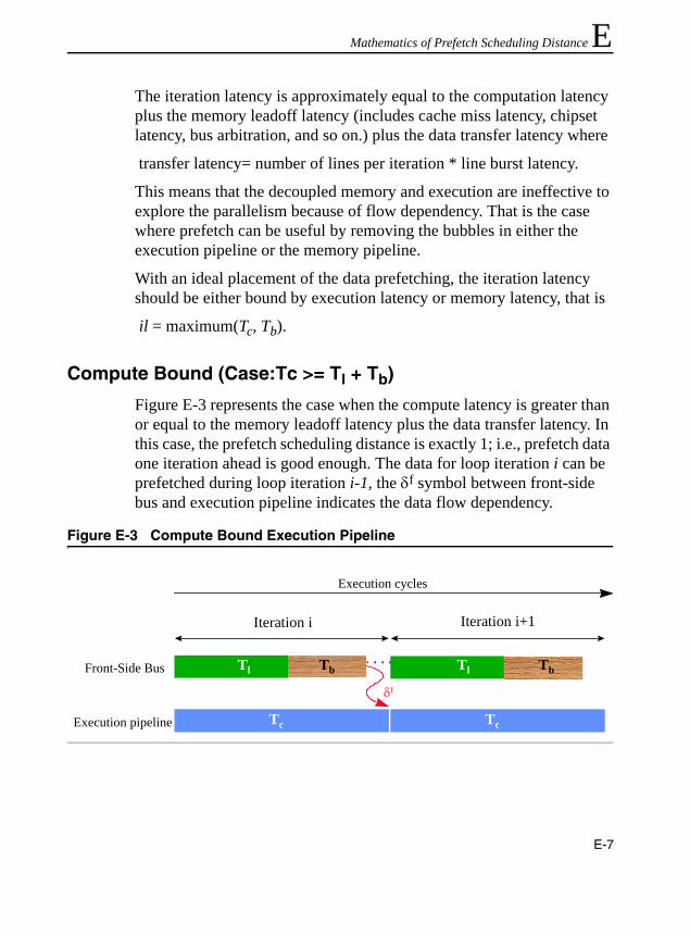
Mathematics of Prefetch Scheduling Distance E
The iteration latency is approximately equal to the computation latency plus the memory leadoff latency (includes cache miss latency, chipset latency, bus arbitration, and so on.) plus the data transfer latency wheretransfer latency= number of lines per iteration * line burst latency.
This means that the decoupled memory and execution are ineffective to explore the parallelism because of flow dependency. That is the case where prefetch can be useful by removing the bubbles in either the execution pipeline or the memory pipeline.
With an ideal placement of the data prefetching, the iteration latency should be either bound by execution latency or memory latency, that is
il = maximum(Tc, Tb).
Compute Bound (Case:Tc >= Tl + Tb)
Figure E-3 represents the case when the compute latency is greater than or equal to the memory leadoff latency plus the data transfer latency. In this case, the prefetch scheduling distance is exactly 1; i.e., prefetch data one iteration ahead is good enough. The data for loop iteration i can be prefetched during loop iteration i-1, the δf symbol between front-side bus and execution pipeline indicates the data flow dependency.
Figure E-3 Compute Bound Execution Pipeline
Front-Side Bus
Execution pipeline Tc
Tl Tb
Iteration i Iteration i+1
Tc
Tl Tb
Execution cycles
δf
E-7

IA-32 Intel® Architecture Optimization
The following formula shows the relationship among the parameters:
It can be seen from this relationship that the iteration latency is equal to the computation latency, which means the memory accesses are executed in background and their latencies are completely hidden.
Compute Bound (Case: Tl + Tb > Tc > Tb)
Now consider the next case by first examining Figure E-4.
Figure E-4 Another Compute Bound Execution Pipeline
Execution cycles
Front-Side Bus
Execution pipeline
i
i+1
i+2
i+3
i
i+1
i+2
i+3
Tc
Tc
Tc
Tc
Tl Tb
Tl Tb
Tl Tb
Tl Tbδf
δf
Tc
δf
i+4
E-8

Mathematics of Prefetch Scheduling Distance E
For this particular example the prefetch scheduling distance is greater than 1. Data being prefetched for iteration i will be consumed in iteration i+2. Figure E-4 represents the case when the leadoff latency plus data transfer latency is greater than the compute latency, which is greater than the data transfer latency. The following relationship can be used to compute the prefetch scheduling distance.In consequence, the iteration latency is also equal to the computation latency, that is, compute bound program.
E-9
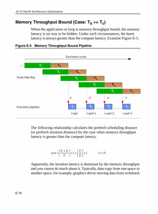
IA-32 Intel® Architecture Optimization
Memory Throughput Bound (Case: Tb >= Tc)
When the application or loop is memory throughput bound, the memory latency is no way to be hidden. Under such circumstances, the burst latency is always greater than the compute latency. Examine Figure E-5.
The following relationship calculates the prefetch scheduling distance (or prefetch iteration distance) for the case when memory throughput latency is greater than the compute latency.
Apparently, the iteration latency is dominant by the memory throughput and you cannot do much about it. Typically, data copy from one space to another space, for example, graphics driver moving data from writeback
Figure E-5 Memory Throughput Bound Pipeline
i
Execution cycles
Execution pipeline
i+pid
Tc
δf
Tc Tc Tc
i+pid+1 i+pid+2 i+pid+3
Front-Side Bus
Tl Tb
Tl Tb
Tl Tb
Tl Tb
Tl Tb
δf δf δf
E-10

Mathematics of Prefetch Scheduling Distance E
memory to you cannot do much about it. Typically, data copy from one space to another space, for example, graphics driver moving data from writeback memory to write-combining memory, belongs to this category, where performance advantage from prefetch instructions will be marginal.Example
As an example of the previous cases consider the following conditions for computation latency and the memory throughput latencies. Assume Tl = 18 and Tb = 8 (in front side bus cycles).
E-11

IA-32 Intel® Architecture Optimization
Now for the case Tl =18, Tb =8 (2 cache lines are needed per iteration) examine the following graph. Consider the graph of accesses per iteration in example 1, Figure E-6.
The prefetch scheduling distance is a step function of Tc, the computation latency. The steady state iteration latency (il) is either memory-bound or compute-bound depending on Tc if prefetches are scheduled effectively.
The graph in example 2 of accesses per iteration in Figure E-7 shows the results for prefetching multiple cache lines per iteration. The cases shown are for 2, 4, and 6 cache lines per iteration, resulting in differing burst latencies. (Tl = 18, Tb = 8, 16, 24).
Figure E-6 Accesses per Iteration, Example 1
E-12

Mathematics of Prefetch Scheduling Distance E
In reality, the front-side bus (FSB) pipelining depth is limited, that is, only four transactions are allowed at a time in the Pentium III and Pentium 4 processors. Hence a transaction bubble or gap, Tg, (gap due to idle bus of imperfect front side bus pipelining) will be observed on FSB activities. This leads to consideration of the transaction gap in computing the prefetch scheduling distance. The transaction gap, Tg, must be factored into the burst cycles, Tb, for the calculation of prefetch scheduling distance.
The following relationship shows computation of the transaction gap.
where Tl is the memory leadoff latency, c is the number of chunks per cache line and n is the FSB pipelining depth.
Figure E-7 Accesses per Iteration, Example 2
0
1
2
3
4
5
1 3 5 7 9 11 13 15 17 19 21 23 25 27 29 31 33 35 37 39 41 43 45
Tc (in FSB clocks)
psd
2 lines
4 lines
6 lines
psd for different number of cache lines prefetched per iteration
E-13

IA-32 Intel® Architecture Optimization
E-14

Index
Aabsolute difference of signed numbers, 4-24absolute difference of unsigned numbers, 4-23absolute value, 4-25accesses per iteration, E-12, E-13algorithm to avoid changing the rounding mode,
2-65aligned ebp-based frame, D-4, D-6aligned esp-based stack frames, D-4Alignment
stack, 2-42alignment, 2-29
code, 2-56AoS format, 3-29application performance tools, A-1Arrays
Aligning, 2-39automatic processor dispatch support, A-4automatic vectorization, 3-18, 3-19
BBranch Prediction, 2-14branch prediction, 2-5
Ccache blocking techniques, 6-35cache level, 6-6
cache managementsimple memory copy, 6-47video decoder, 6-46video encoder, 6-46
calculating insertion for scheduling distance, E-3
call graph profiling, A-13changing the rounding mode, 2-64checking for MMX technology support, 3-2checking for Streaming SIMD Extensions
support, 3-3classes (C/C++), 3-17clipping to an arbitrary signed range, 4-26clipping to an arbitrary unsigned range, 4-28code optimization options, A-3Code segment
Data in, 2-47coding methodologies, 3-13coding techniques, 3-12
absolute difference of signed numbers, 4-24absolute difference of unsigned numbers,
4-23absolute value, 4-25clipping to an arbitrary signed range, 4-26clipping to an arbitrary unsigned range,
4-28generating constants, 4-21interleaved pack with saturation, 4-8interleaved pack without saturation, 4-10non-interleaved unpack, 4-11signed unpack, 4-7
Index-1
IA-32 Intel® Architecture Optimization
simplified clipping to an arbitrary signed range, 4-28
unsigned unpack, 4-6coherent requests, 6-14command-line options, A-2
automatic processor dispatch support, A-4floating-point arithmetic precision, A-6inline expansion of library functions, A-6loop unrolling, A-5rounding control, A-6targeting a processor, A-3vectorizer switch, A-5
comparing register values, 2-77compiler intrinsics
_mm_load, 6-2, 6-45_mm_prefetch, 6-2, 6-45_mm_stream, 6-2, 6-45
compiler plug-in, A-2compiler-supported alignment, 3-24complex instructions, 2-71computation latency, E-8computation-intensive code, 3-11compute bound, E-7, E-8converting code to MMX technology, 3-8CPUID instruction, 3-2
DData
Code segment and, 2-47data alignment, 3-20data arrangement, 5-4data copy, E-11data deswizzling, 5-14, 5-15Data structures
Access pattern versus alignment, 2-40Aligning, 2-39
data swizzling, 5-9data swizzling using intrinsics, 5-12
decoupled memory, E-7divide instructions, 2-73
Eeliminating branches, 2-15, 2-18EMMS instruction, 4-3, 4-4extract word instruction, 4-13
Ffist instruction, 2-63fldcw instruction, 2-63floating-point applications, 2-57floating-point arithmetic precision options, A-6floating-point code
improving parallelism, 2-67loop unrolling, 2-26memory access stall information, 2-37memory operands, 2-69operations with integer operands, 2-70optimizing, 2-57transcendental functions, 2-70
floating-point operations with integer operands, 2-70
floating-point stalls, 2-69flow dependency, E-7flush to zero, 5-22FXCH instruction, 2-69
Ggeneral optimization techniques, 2-1
branch prediction, 2-14static prediction, 2-19
generating constants, 4-21
Hhorizontal computations, 5-18
Index-2

Index
hotspots, 3-10Hyper-Threading Technology, 7-1
avoid excessive software prefetches, 7-26cache blocking technique, 7-29conserve bus command bandwidth, 7-25eliminate 64-K-aliased data accesses, 7-30Front-end Optimization, 7-36front-end optimization, 7-36full write transactions, 7-28functional decomposition, 7-8improve effective latency of cache misses,
7-27managing heavily-used execution
Resources, 7-40memory optimization, 7-28minimize data sharing between physical
processors, 7-30Multitasking Environment, 7-4optimization guidelines, 7-10optimization with spin-locks, 7-19parallel programming models, 7-7per-instance stack offset, 7-34per-thread stack offset, 7-32placement of shared synchronization
variable, 7-24prevent false-sharing of data, 7-23preventing excessive evictions in first-level
data cache, 7-31shared-memory optimization, 7-30synchronization for longer periods, 7-20synchronization for short periods, 7-15system bus optimization, 7-24thread synchronization, 7-14tools for creating multithreaded
applications, 7-8
Iincreasing bandwidth of memory fills, 4-39increasing bandwidth of video fills, 4-39indirect branch, 2-23inline assembly, 4-5
inline expansion of library functions option, A-6
inlined assembly blocks, D-10inlined-asm, 3-15insert word instruction, 4-14instruction scheduling, 2-46, 4-40instruction selection, 2-71integer and floating-point multiply, 2-73integer divide, 2-73integer-intensive application, 4-1Intel Performance Library Suite, A-2interleaved pack with saturation, 4-8interleaved pack without saturation, 4-10interprocedural optimization, A-7IPO. See interprocedural optimization
Llarge load stalls, 2-37latency, 2-69, 6-5lea instruction, 2-72loading and storing to and from the same
DRAM page, 4-39loop blocking, 3-34loop unrolling, 2-26loop unrolling option, A-5, A-6
Mmemory bank conflicts, 6-3memory O=optimization U=using P=prefetch,
6-19memory operands, 2-69memory optimization, 4-34memory optimizations
loading and storing to and from the same DRAM page, 4-39
partial memory accesses, 4-35using aligned stores, 4-40
Index-3

IA-32 Intel® Architecture Optimization
memory performance, 3-27memory reference instructions, 2-76memory throughput bound, E-10minimizing prefetches number, 6-30misaligned data access, 3-20misalignment in the FIR filter, 3-22move byte mask to integer, 4-16MOVQ Instruction, 4-39
Nnew SIMD-integer instructions
extract word, 4-13insert word, 4-14move byte mask to integer, 4-16packed average byte or word), 4-31packed multiply high unsigned, 4-30packed shuffle word, 4-18packed signed integer word maximum, 4-29packed sum of absolute differences, 4-30
Newton-Raphson iteration, 5-2non-coherent requests, 6-14non-interleaved unpack, 4-11non-temporal stores, 6-44NOPs, 2-85
To align instructions, 2-85XCHG EAX,EAX
Special hardware support for, 2-85numeric exceptions
flush to zero, 5-22
Ooptimizing cache utilization
cache management, 6-45examples, 6-16non-temporal store instructions, 6-10prefetch and load, 6-9prefetch Instructions, 6-8prefetching, 6-7SFENCE instruction, 6-16, 6-17
streaming, non-temporal stores, 6-10optimizing floating-point applications
copying, shuffling, 5-17data arrangement, 5-4data deswizzling, 5-14data swizzling using intrinsics, 5-12horizontal ADD, 5-18planning considerations, 5-2rules and suggestions, 5-1scalar code, 5-3vertical versus horizontal computation, 5-5
optimizing floating-point code, 2-57
Ppack instruction, 4-10pack instructions, 4-8packed average byte or word), 4-31packed multiply high unsigned, 4-30packed shuffle word, 4-18packed signed integer word maximum, 4-29packed sum of absolute differences, 4-30parallelism, 3-12, E-7parameter alignment, D-4partial memory accesses, 4-35PAVGB instruction, 4-31PAVGW instruction, 4-31Performance and Usage Models
Multithreading, 7-2Performance and Usage Models, 7-2
Performance Library Suite, A-14optimizations, A-16
PEXTRW instruction, 4-13PGO. See profile-guided optimizationPINSRW instruction, 4-14PMINSW instruction, 4-29PMINUB instruction, 4-30PMOVMSKB instruction, 4-16PMULHUW instruction, 4-30
Index-4

Index
predictable memory access patterns, 6-7prefetch and cacheability Instructions, 6-4prefetch and load Instructions, 6-9prefetch concatenation, 6-27, 6-29prefetch instruction, 6-1prefetch instruction considerations, 6-25
cache blocking techniques, 6-35concatenation, 6-27minimizing prefetches number, 6-30no preloading or prefetch, E-6prefetch scheduling distance, E-5scheduling distance, 6-26single-pass execution, 6-3, 6-42spread prefetch with computation
instructions, 6-33strip-mining, 6-38
prefetch instructions, 6-7prefetch scheduling distance, 6-26, E-5, E-7,
E-10prefetch use
predictable memory access patterns, 6-7time-consuming innermost loops, 6-7
prefetching concept, 6-6prefetchnta instruction, 6-37profile-guided optimization, A-7prolog sequences, 2-80PSADBW instruction, 4-30PSHUF instruction, 4-18
Rreciprocal instructions, 5-2rounding control option, A-6
Ssampling
event-based, A-10Self-modifying code, 2-46SFENCE Instruction, 6-16, 6-17
signed unpack, 4-7SIMD integer code, 4-2SIMD-floating-point code, 5-1simple memory copy, 6-47simplified 3D geometry pipeline, 6-23simplified clipping to an arbitrary signed range,
4-28single-pass versus multi-pass execution, 6-42SoA format, 3-29software write-combining, 6-44spread prefetch, 6-34Stack Alignment
Example of dynamic, 2-43Stack alignment, 2-42stack alignment, 3-22stack frame, D-2stack frame optimization, D-9static branch prediction algorithm, 2-20static prediction, 2-19static prediction algorithm, 2-19streaming store, 6-47streaming stores
coherent requests, 6-14non-coherent requests, 6-14
strip mining, 3-32, 3-34strip-mining, 6-38, 6-39Structs
Aligning, 2-39swizzling data. See data swizzling.System Bus Optimization, 7-24
Ttargeting a processor option, A-3time-based sampling, A-9time-consuming innermost loops, 6-7TLB. See transaction lookaside buffertransaction lookaside buffer, 6-48
Index-5

IA-32 Intel® Architecture Optimization
transcendental functions, 2-70transfer latency, E-7, E-9
Uunpack instructions, 4-11unsigned unpack, 4-6using MMX code for copy or shuffling
functions, 5-17
Vvector class library, 3-17vectorization, 3-12
vectorized code, 3-18vectorizer switch options, A-5vertical versus horizontal computation, 5-5VTune analyzer, 3-10, A-1VTune Performance Analyzer, 3-10
Wwrite-combining buffer, 6-44write-combining memory, 6-44
Index-6

INTEL SALES OFFICES
ASIA PACIFICAustraliaIntel Corp.Level 2448 St Kilda Road Melbourne VIC3004AustraliaFax:613-9862 5599ChinaIntel Corp.Rm 709, Shaanxi Zhongda Int'l BldgNo.30 Nandajie Street Xian AX710002ChinaFax:(86 29) 7203356
Intel Corp.Rm 2710, Metropolian Tower68 Zourong Rd Chongqing CQ400015China
Intel Corp.C1, 15 Flr, Fujian Oriental HotelNo. 96 East Street Fuzhou FJ350001China
Intel Corp.Rm 5803 CITIC Plaza233 Tianhe Rd Guangzhou GD510613China
Intel Corp.Rm 1003, Orient PlazaNo. 235 Huayuan Street Nangang DistrictHarbin HL150001China
Intel Corp.Rm 1751 World Trade Center, No 2Han Zhong Rd Nanjing JS210009China
Intel Corp.Hua Xin International Tower215 Qing Nian St. ShenYang LN110015China
Intel Corp.Suite 1128 CITIC Plaza Jinan150 Luo Yuan St. Jinan SNChina
Intel Corp.Suite 412, Holiday Inn Crowne Plaza31, Zong Fu Street Chengdu SU610041ChinaFax:86-28-6785965
Intel Corp.Room 0724, White Rose HotelNo 750, MinZhu Road WuChang DistrictWuhan UB430071China
IndiaIntel Corp.Paharpur Business Centre21 Nehru Place New Delhi DH110019India
Intel Corp.Hotel Rang Sharda, 6th FloorBandra Reclamation Mumbai MH400050IndiaFax:91-22-6415578
Intel Corp.DBS Corporate Club31A Cathedral Garden Road Chennai TD600034India
Intel Corp.DBS Corporate Club2nd Floor, 8 A.A.C. Bose Road Calcutta WB700017India
JapanIntel Corp.Kokusai Bldg 5F, 3-1-1, MarunouchiChiyoda-Ku, Tokyo 1000005Japan
Intel Corp.2-4-1 TerauchiToyonaka-Shi Osaka 5600872Japan
MalaysiaIntel Corp.Lot 102 1/F Block A Wisma Semantan12 Jalan Gelenggang Damansara HeightsKuala Lumpur SL50490Malaysia
ThailandIntel Corp.87 M. Thai Tower, 9th Fl.All Seasons Place, Wireless Road Lumpini, PatumwanBangkok 10330Thailand
Viet NamIntel Corp.Hanoi Tung Shing Square, Ste #11062 Ngo Quyen St Hoan Kiem DistrictHanoi Viet Nam
EUROPE & AFRICABelgiumIntel Corp.Woluwelaan 158Diegem 1831Belgium
Czech RepIntel Corp.Nahorni 14Brno 61600Czech Rep
DenmarkIntel Corp.Soelodden 13Maaloev DK2760Denmark
GermanyIntel Corp.Sandstrasse 4Aichner 86551Germany
Intel Corp.Dr Weyerstrasse 2Juelich 52428Germany
Intel Corp.Buchenweg 4Wildberg 72218Germany
Intel Corp.Kemnader Strasse 137Bochum 44797Germany
Intel Corp.Klaus-Schaefer Strasse 16-18Erfstadt NW50374Germany
Intel Corp.Heldmanskamp 37Lemgo NW32657Germany
ItalyIntel Corp Italia SpaMilanofiori Palazzo E/4Assago Milan 20094ItalyFax:39-02-57501221
NetherlandIntel Corp.Strausslaan 31Heesch 5384CWNetherland
PolandIntel Poland Developments, IncJerozolimskie Business ParkJerozolimskie 146c Warsaw 2305PolandFax:+48-22-570 81 40
PortugalIntel Corp.PO Box 20Alcabideche 2765Portugal
SpainIntel Corp.Calle Rioja, 9Bajo F Izquierda Madrid 28042Spain
South AfricaIntel SA CorporationBldg 14, South Wing, 2nd FloorUplands, The Woodlands Western Services RoadWoodmead 2052Sth AfricaFax:+27 11 806 4549
Intel Corp.19 Summit Place, Halfway HouseCnr 5th and Harry Galaun Streets Midrad 1685Sth Africa
United KingdomIntel Corp.The ManseSilver Lane Needingworth CAMBSPE274SLUK
Intel Corp.2 Cameron CloseLong Melford SUFFKCO109TSUK
IsraelIntel Corp.MTM Industrial Center, P.O.Box 498Haifa 31000IsraelFax:972-4-8655444
LATIN AMERICA & CANADAArgentinaIntel Corp.Dock IV - Bldg 3 - Floor 3Olga Cossentini 240Buenos AiresC1107BVAArgentina
BrazilIntel Corp.Rua Carlos Gomez 111/403Porto Alegre 90480-003Brazil
Intel Corp.Av. Dr. Chucri Zaidan940 - 10th FloorSan Paulo04583-904Brazil
Intel Corp.Av. Rio Branco,1 - Sala 1804Rio de Janeiro20090-003Brazil
ColumbiaIntel Corp.Carrera 7 No. 71021Torre B, Oficina 603Santefe de BogotaColumbia
MexicoIntel Corp.Av. Mexico No. 2798-9B, S.H.Guadalajara 44680Mexico
Intel Corp.Torre Esmeralda II, 7th FloorBlvd. Manuel Avila Comacho #36Mexico Cith DF11000Mexico
Intel Corp.Piso 19, Suite 4Av. Batallon de San Patricio No 111Monterrey, Nuevo le66269Mexico
CanadaIntel Corp.168 Bonis Ave, Suite 202Scarborough MIT3V6CanadaFax:416-335-7695
Intel Corp.3901 Highway #7, Suite 403Vaughan L4L 8L5CanadaFax:905-856-8868

Intel Corp.999 CANADA PLACE, Suite 404,#11Vancouver BCV6C 3E2CanadaFax:604-844-2813
Intel Corp.2650 Queensview Drive, Suite 250Ottawa ONK2B 8H6CanadaFax:613-820-5936
Intel Corp.190 Attwell Drive, Suite 500Rexcdale ONM9W 6H8CanadaFax:416-675-2438
Intel Corp.171 St. Clair Ave. E, Suite 6Toronto ONCanada
Intel Corp.1033 Oak Meadow RoadOakville ONL6M 1J6Canada
USACaliforniaIntel Corp.551 Lundy PlaceMilpitas CA95035-6833USAFax:408-451-8266
Intel Corp.1551 N. Tustin Avenue, Suite 800Santa Ana CA92705USAFax:714-541-9157
Intel Corp.Executive Center del Mar12230 El Camino Real Suite 140San Diego CA92130USAFax:858-794-5805
Intel Corp.1960 E. Grand Avenue, Suite 150El Segundo CA90245USAFax:310-640-7133
Intel Corp.23120 Alicia Parkway, Suite 215Mission Viejo CA92692USAFax:949-586-9499
Intel Corp.30851 Agoura RoadSuite 202 Agoura Hills CA91301USAFax:818-874-1166
Intel Corp.28202 Cabot Road, Suite #363 & #371Laguna Niguel CA92677USA
Intel Corp.657 S Cendros AvenueSolana Beach CA90075USA
Intel Corp.43769 Abeloe TerraceFremont CA94539USA
Intel Corp.1721 Warburton, #6Santa Clara CA95050USA
ColoradoIntel Corp.600 S. Cherry Street, Suite 700Denver CO80222USAFax:303-322-8670
ConnecticutIntel Corp.Lee Farm Corporate Pk83 Wooster Heights Road Danbury CT6810USAFax:203-778-2168
FloridaIntel Corp.7777 Glades RoadSuite 310BBoca Raton FL33434USAFax:813-367-5452
GeorgiaIntel Corp.20 Technology Park, Suite 150Norcross GA30092USAFax:770-448-0875
Intel Corp.Three Northwinds Center2500 Northwinds Parkway, 4th FloorAlpharetta GA30092USAFax:770-663-6354
IdahoIntel Corp.910 W. Main Street, Suite 236Boise ID83702USAFax:208-331-2295
IllinoisIntel Corp.425 N. Martingale Road Suite 1500Schaumburg IL60173USAFax:847-605-9762
Intel Corp.999 Plaza Drive Suite 360Schaumburg IL60173USA
Intel Corp.551 Arlington LaneSouth Elgin IL60177USA
IndianaIntel Corp.9465 Counselors Row, Suite 200Indianapolis IN46240USAFax:317-805-4939
MassachusettsIntel Corp.125 Nagog ParkActon MA01720USAFax:978-266-3867
Intel Corp.59 Composit Waysuite 202Lowell MA01851USA
Intel Corp.800 South Street, Suite 100Waltham MA02154USA
MarylandIntel Corp.131 National Business Parkway, Suite 200Annapolis Junction MD20701USAFax:301-206-3678
MichiganIntel Corp.32255 Northwestern Hwy., Suite 212Farmington Hills MI48334USAFax:248-851-8770
MInnesotaIntel Corp.3600 W 80Th StSuite 450 Bloomington MN55431USAFax:952-831-6497
North CarolinaIntel Corp.2000 CentreGreen Way, Suite 190Cary NC27513USAFax:919-678-2818
New HampshireIntel Corp.7 Suffolk ParkNashua NH03063USA
New JerseyIntel Corp.90 Woodbridge Center Dr, Suite. 240Woodbridge NJ07095USAFax:732-602-0096
New YorkIntel Corp.628 Crosskeys Office PkFairport NY14450USAFax:716-223-2561
Intel Corp.888 Veterans Memorial HighwaySuite 530 Hauppauge NY11788USAFax:516-234-5093
OhioIntel Corp.3401 Park Center Drive Suite 220Dayton OH45414USAFax:937-890-8658
Intel Corp.56 Milford DriveSuite 205Hudson OH44236USAFax:216-528-1026
OregonIntel Corp.15254 NW Greenbrier Parkway, Building BBeaverton OR97006USAFax:503-645-8181
PennsylvaniaIntel Corp.925 Harvest DriveSuite 200Blue Bell PA19422USAFax:215-641-0785
Intel Corp.7500 BrooktreeSuite 213Wexford PA15090USAFax:714-541-9157
TexasIntel Corp.5000 Quorum Drive, Suite 750Dallas TX75240USAFax:972-233-1325
Intel Corp.20445 State Highway 249, Suite 300Houston TX77070USAFax:281-376-2891
Intel Corp.8911 Capital of Texas Hwy, Suite 4230Austin TX78759USAFax:512-338-9335
Intel Corp.7739 La Verdura DriveDallas TX75248USA
Intel Corp.77269 La Cabeza DriveDallas TX75249USA
Intel Corp.3307 Northland DriveAustin TX78731USA
Intel Corp.15190 Prestonwood Blvd. #925Dallas TX75248USAIntel Corp.
WashingtonIntel Corp.2800 156Th Ave. SESuite 105 Bellevue WA98007USAFax:425-746-4495
Intel Corp.550 Kirkland WaySuite 200Kirkland WA98033USA
WisconsinIntel Corp.405 Forest StreetSuites 109/112Oconomowoc Wi53066USA