Embed Size (px)
Citation preview
APPLICATION FOR CONSTRUCTION PERMIT
PLEASANTS COUNTY METHANOL PLANT
APPLICANT
West Virginia Methanol, Inc
23 NOVEMBER 2020
PREPARED BY:
Global Imperium Group
1 of 164

Table of Contents 1.0 INTRODUCTION ................................................................................................................................. 4
2.0 PROJECT DESCRIPTION ...................................................................................................................... 5
2.1 Site Location ........................................................................................................................................ 5
2.2 Summary of Proposed Facility ............................................................................................................ 5
2.2.1 Pre-Reformer Section ................................................................................................................... 6
2.2.2 Steam Methane Reformer ........................................................................................................... 6
2.2.3 Methanol Synthesis Section ......................................................................................................... 6
2.2.4 Methanol Distillation System ....................................................................................................... 7
2.2.5 Methanol Storage ........................................................................................................................ 7
2.2.6 Methanol Loadout ....................................................................................................................... 7
2.2.7 Flare ............................................................................................................................................. 8
2.2.8 Reciprocating Engine Generators ................................................................................................ 8
2.3 Methanol Unit Operations .................................................................................................................. 8
2.3.1 Normal Operation ....................................................................................................................... 8
2.3.2 Startup, Shutdown, and Maintenance Operations ..................................................................... 8
3.0 EMISSIONS INVENTORY .................................................................................................................... 9
3.1 Emissions Units ................................................................................................................................. 10
3.1.1 Pre-Reformer ............................................................................................................................. 10
3.1.2 Steam Methane Reformer ......................................................................................................... 10
3.1.3 Methanol Synthesis Section and Distillation System ................................................................ 11
3.1.4 Methanol Storage and Loading .................................................................................................. 11
3.1.5 Flare ........................................................................................................................................... 11
3.1.6 Reciprocating Engines ................................................................................................................ 12
3.2 Fugitive Sources ................................................................................................................................ 12
3.3 Summary of Calculated Potential Emissions ..................................................................................... 13
4.0 Regulatory Review .......................................................................................................................... 14
4.1 Prevention of Significant Deterioration (40 CFR 52.21 and 45CSR14) ............................................. 14
4.2 Nonattainment New Source Review (40 CFR 51.165 and 45CSR19) ................................................ 14
4.3 Title V Operating Program (40 CFR 70 and 45CSR30) ....................................................................... 14
4.4 Compliance Assurance Monitoring (40 CFR 64)................................................................................ 15
4.5 New Source Performance Standards (40 CFR 60 and 45CSR16) ....................................................... 15
4.5.1 40 CFR 60 Subpart A – General Provisions ................................................................................. 15
2 of 164

4.5.2 40 CFR 60 Subpart Kb - Standards of Performance for Volatile Organic Liquid Storage Vessels ............................................................................................................................................................ 15
4.5.4 40 CFR 60 Subpart NNN - Standards of Performance for VOC Emissions SOCMI Distillation Operations .......................................................................................................................................... 16
4.5.5 40 CFR 60 Subpart RRR - Standards of Performance for VOC Emissions from SOCMI Reactor . 16
4.5.6 40 CFR 60 Subpart JJJJ- Standards of Performance for Stationary Spark Ignition Internal Combustion Engines............................................................................................................................ 17
4.6 National Emission Standards for Hazardous Air Pollutants (40 CFR 63 Subpart ZZZZ) ..................... 17
4.7 West Virginia Code of State Regulations (45CSR) ............................................................................. 17
4.7.1 45CSR2 Particulate Air Pollution from Combustion of Fuel ........................................................... 17
4.7.2 45CSR13 Permit Requirements ...................................................................................................... 18
4.7.3 45CSR22 Air Quality Management Fees .................................................................................... 18
4.8 Regulatory Analysis Summary ........................................................................................................... 18
Application for Construction Permit WVM Pleasants County Methanol Plant .......................................... 19
NSR/Title V Permit Application Form ...................................................................................................... 20
ATTACHMENT A: BUSINESS CERTIFICATE ............................................................................................... 25
ATTACHMENT B: GENERAL LOCATION MAP ........................................................................................... 27
ATTACHMENT C: INSTALLATION AND STARTUP SCHEDULE ................................................................... 29
ATTACHMENT D: REGULATORY DISCUSSION .......................................................................................... 30
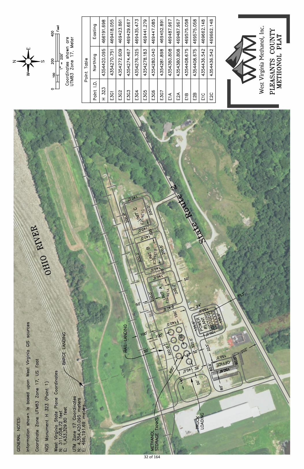
ATTACHMENT E: PLOT PLAN ................................................................................................................... 31
ATTACHMENT F: DETAILED PROCESS FLOW DIAGRAM .......................................................................... 33
ATTACHMENT G: PROCESS DESCRIPTION ............................................................................................... 35
ATTACHMENT H: MATERIAL SAFETY DATA SHEETS ................................................................................ 36
ATTACHMENT I: EMISSION UNITS TABLE ................................................................................................ 59
ATTACHMENT J: EMISSION POINTS DATA SUMMARY SHEET ................................................................. 61
ATTACHMENT K: FUGITIVE EMISSIONS DATA SUMMARY SHEET ........................................................... 65
ATTACHMENT L: EMISSIONS UNIT DATA SHEETS .................................................................................. 68
ATTACHMENT M: AIR POLLUTION CONTROL DEVICES ..........................................................................110
ATTACHMENT N: SUPPORTING EMISSIONS CALCULATIONS .................................................................133
ATTACHMENT O: MONITORING, RECORDKEEPING, REPORTING, TESTING PLANS ...............................162
ATTACHMENT P: PUBLIC NOTICE ............................................................................................................163
3 of 164
1.0 INTRODUCTION
West Virginia Methanol, Inc., (“WVM”) is proposing to construct the Pleasants County Methanol Plant (the “Plant”). The Plant is proposed to consist of 3 nominal 300 metric ton per day methanol units and 7, 4MW reciprocating engines to generate electricity needed to operate the Plant. The Plant will be located in an unincorporated area of Pleasants County, WV, near Belmont, WV. The site formerly hosted the Cabot Carbon Black plant that was demolished in the 2008-2009 time frame.
WVM is applying for a construction permit under the West Virginia Code of State Regulations (CSR) at 45CSR13. The project will be a minor source of air emissions with respect to the U.S. Environmental Protection Agency’s (USEPA) Prevention of Significant Deterioration (PSD) and USEPA’s Title V Operating Permit program.
The purpose of this air permit application is to provide the technical information required by the WVDEP air permitting program, and demonstrate that the proposed facility will be in compliance with regulations related to ambient air quality. This document includes:
• Section 2.0 Project Description• Section 3.0 Emissions Inventory• Section 4.0 Regulatory Review• Application for Construction Permit WVM Pleasants County Methanol Plant.
4 of 164
2.0 PROJECT DESCRIPTION
2.1 Site Location The proposed site for the Pleasants County Methanol Plant is located in an unincorporated area of Pleasants County. The site was formerly a part of the Cabot Carbon Black Plant. The site address will be 9764 South Pleasants Highway, St. Marys, WV 26170. It is approximately 9 miles West of St. Marys on State Route 2. The site boundaries include the Ohio River to the northwest and State Highway 2 along the southeast side. A CSXT rail corridor runs through the site parallel to the river. 2.2 Summary of Proposed Facility The proposed plant will utilize three MeOH-To-Go™ units, each with a nominal production capacity of 300 metric tons per day of International Methanol Producers & Consumers Association (IMPCA) and Grade AA specification methanol derived from pipeline-grade natural gas supplies sourced from the region. For permitting purposes, the availability of each unit is assumed to be 8,760 hours per year, resulting in an assumed operating capacity of the combined three MeOH-To-Go™ units of nominally 328,500 metric tons per year.
Each MeOH-To-Go™ unit (“Unit” or “Units”) will be comprised of the following equipment:
• Pre-Reformer section • One Steam Methane Reformer (SMR) consisting of a Haldor Topsoe Convection Reformer
(HTCR) system (natural gas and off-gas fired), including a waste heat recovery boiler with supplemental duct firing. The HTCR is equipped with selective catalytic reduction (SCR) for control of nitrogen oxides (NOX) and an oxidation catalyst for Carbon Monoxide (CO) emissions control;
• One methanol synthesis section and off-gas recovery to the HTCR fuel system; • One methanol distillation system and off-gas recovery system to the HTCR fuel system.
The methanol plant storage and loading system will consist of:
• Nine API 620 methanol storage tanks with vent return to the process • Two truck loading racks with two loading spots, equipped with closed dome loading and vapor
balancing systems. • Two rail loading spots, equipped with closed dome loading and vapor balancing systems. • One barge loading spot, configured for closed dome loading with a vapor balancing system.
The methanol plant will be powered by natural gas fuel reciprocating internal combustion engines (RICE) which are referred to as the “Power Plant”. The Power Plant will consist of seven nominal 4 MW RICE generators. While it is not anticipated that all seven RICE generators will operate at the same time, for the purposes of this air permit application it is assumed that they all will operate for 8,760 hours per year.
The Power Plant will be comprised of:
• Seven Spark Ignition (SI) Internal Combustion Engines (Caterpillar CG260-16 Engines)
5 of 164
• Seven Synchronous Generators (Marelli MJH 800 LA8 or similar) at medium voltage • An SCR system for control of NOx emissions • Oxidation catalyst for control of CO and volatile organic compounds (VOCs).
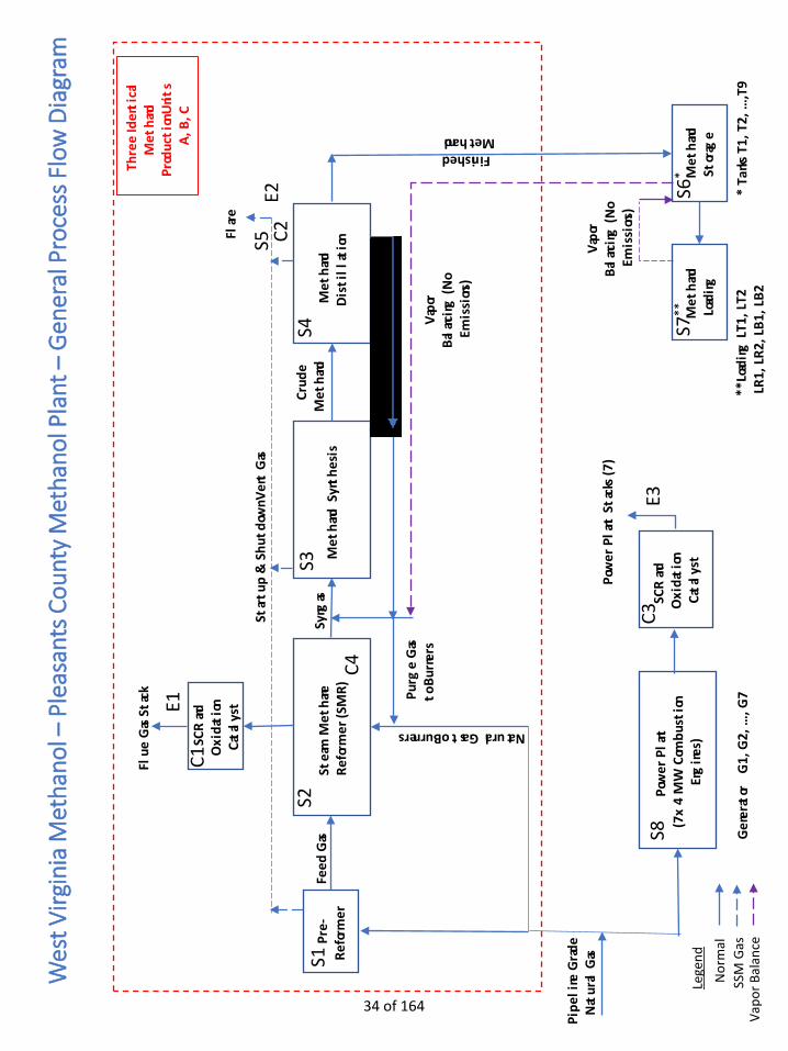
Attachment F provides a schematic process flow diagram of the Methanol Plant. The basis for the calculation of emissions from the various processes is provided in Section 3.
2.2.1 Pre-Reformer Section
Each methanol unit has a pre-reformer section that includes a desulfurization system, feed preheaters, a hydrogenator, and a pre-reformer vessel. The desulfurization system removes sulfur-containing compounds from the pipeline-grade natural gas feeding the pre-reformer. The pre-reformer section converts the higher hydrocarbons in the pipeline natural gas to methane, hydrogen, carbon monoxide, and carbon dioxide in preparation for SMR feed. 2.2.2 Steam Methane Reformer
The Steam Methane Reformer is a Haldor Topsoe Convection Reformer (HTCR) that utilizes convection heat transfer which minimizes surplus steam production and hence minimizes additional fuel firing. The HTCR-based synthesis gas (syngas) production allows for an efficient small-scale methanol plant that is balanced on steam production and steam consumption. The HTCR produces syngas from pipeline-grade natural gas and self-generated steam. The syngas production requires heat which is primarily supplied by the combustion of hydrogen-rich process purge gases and supplemented with the combustion of pipeline natural gas as needed. The HTCR consists of:
• A single burner in a furnace where heat for the reforming reaction is generated,
• A multi-tube reforming reactor where syngas is produced by the reaction of pre-reformed natural gas and steam over a catalyst, and
• A flue gas waste heat boiler section with supplemental firing (duct firing) where heat from the reforming section is recovered and fuel is combusted to supply additional heat for the production of steam.
Combustion emissions from the HTCR burner and duct burners will be exhausted to an SCR unit for NOX emissions control and an oxidation catalyst for CO emissions control. Good combustion practices and the use of low-sulfur gaseous fuels will minimize emissions of other combustion pollutants. The HTCR reactor, which normally operates under high pressure, is not vented to atmosphere under normal operating conditions. 2.2.3 Methanol Synthesis Section
The methanol synthesis section consists of a series of heat exchangers, knock-out drums and catalytic reactors that convert the syngas to a crude methanol liquid stream comprised of approximately 80 percent methanol and 20 percent water. The methanol synthesis system includes off-gas recovery from the knock-out drums and a hydrogen-rich, sulfur free off gas stream which are both directed to the HTCR burner and duct burners, where these purge gases serve as the primary fuel. The methanol synthesis section, which normally operates under high pressure, is not vented to atmosphere under normal operating conditions.
6 of 164
For facility startups and for emergency purposes, the reactor system is connected to the process flare header which is routed to the high pressure flare section for control of emissions.
2.2.4 Methanol Distillation System
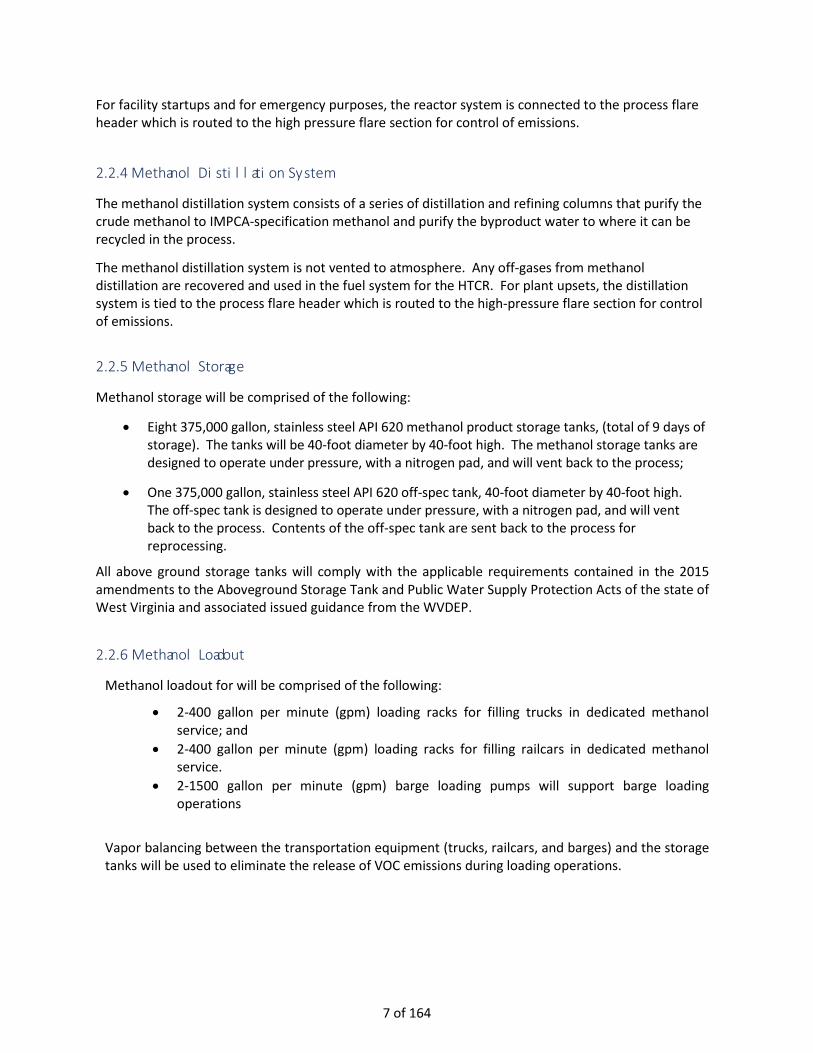
The methanol distillation system consists of a series of distillation and refining columns that purify the crude methanol to IMPCA-specification methanol and purify the byproduct water to where it can be recycled in the process.
The methanol distillation system is not vented to atmosphere. Any off-gases from methanol distillation are recovered and used in the fuel system for the HTCR. For plant upsets, the distillation system is tied to the process flare header which is routed to the high-pressure flare section for control of emissions. 2.2.5 Methanol Storage
Methanol storage will be comprised of the following:
• Eight 375,000 gallon, stainless steel API 620 methanol product storage tanks, (total of 9 days of storage). The tanks will be 40-foot diameter by 40-foot high. The methanol storage tanks are designed to operate under pressure, with a nitrogen pad, and will vent back to the process;
• One 375,000 gallon, stainless steel API 620 off-spec tank, 40-foot diameter by 40-foot high. The off-spec tank is designed to operate under pressure, with a nitrogen pad, and will vent back to the process. Contents of the off-spec tank are sent back to the process for reprocessing.
All above ground storage tanks will comply with the applicable requirements contained in the 2015 amendments to the Aboveground Storage Tank and Public Water Supply Protection Acts of the state of West Virginia and associated issued guidance from the WVDEP.
2.2.6 Methanol Loadout
Methanol loadout for will be comprised of the following:
• 2-400 gallon per minute (gpm) loading racks for filling trucks in dedicated methanol service; and
• 2-400 gallon per minute (gpm) loading racks for filling railcars in dedicated methanol service.
• 2-1500 gallon per minute (gpm) barge loading pumps will support barge loading operations
Vapor balancing between the transportation equipment (trucks, railcars, and barges) and the storage tanks will be used to eliminate the release of VOC emissions during loading operations.
7 of 164

2.2.7 Flare Each Methanol Unit is equipped with an elevated flare located adjacent to the HTCR stack. The flare is a dual flare with a High Pressure (HP) flare section and a Low Pressure (LP) flare section. There is a natural gas fueled pilot that serves the HP and LP sections. The HP flare section is utilized during startup, shutdown, and maintenance (SSM) events and is sometimes referred to as the SSM flare. The LP flare section is available to handle small equipment leaks (between repairs of those leaks).
2.2.8 Reciprocating Engine Generators
The reciprocating engine generators are not connected to the utility grid and therefore they can supply power to meet the methanol units’ power load requirements. WVM is planning to construct a 28 MW power plant consisting of seven, 4 MW reciprocating engine-driven generators to supply electricity. Most of the time, the Plant will operate with 5 or 6 engines operating. The other engine will either be in reserve or undergoing planned/unplanned maintenance. Each engine requires routine maintenance for oil changes and replacement of wearable components.
Each engine’s exhaust will be equipped with a SCR system to reduce and control NOx emissions. There will also be an oxidation catalyst to reduce and control VOC, CO, and Hazard Air Pollutants (HAPs).
The engine generators only take a few minutes to go from no load to full load during a startup. The SCR/Oxidation catalyst heat up times are only a few minutes to be fully functional. For the purposes of this air permit application the potential to emit calculation is based on all seven engines operating at full load for 8760 hours per year. This approach is conservative as the calculated emissions are greater than the emissions associated with 5 or 6 engines operating.
2.3 Methanol Unit Operations
Methanol unit operations consist of 1) normal operation and 2) Startup, Shutdown, or Maintenance (SSM) conditions as described below.
2.3.1 Normal Operation During normal operations, natural gas is converted to methanol in the methanol unit. There are emissions from SMR flue gas stacks from firing on purge gas. There are also emissions from the flare pilots.
2.3.2 Startup, Shutdown, and Maintenance Operations
The SSM operations consist of four cases: cold startup, hot startup from an HTCR trip, methanol synthesis trip, and a total unit trip. The table below provides the duration and the number of occurrences per year for each methanol unit.
Case Duration, hrs Number of Occurrences, per Unit
Cold Startup 32.5 4
Hot startup from HTCR Trip 18.9 2
Methanol Synthesis Trip 15.3 2
Total Unit Trip 4 4
8 of 164
The operational sequence of each case is discussed below.
2.3.2.1 Cold Startup
There are various stages of a cold startup of a MeOH-To-Go™ unit that produce emissions including:
• Charging the Distillation Section with methanol and starting distillation operation in recirculationmode
• Firing of the Waste Heat Recovery Section with the duct burners to generate steam for heating themethanol Distillation Section and to provide steam to the SMR Section
• Heating of the various equipment in preparation for Syngas production
• Initial syngas production, prior to startup of the Methanol Synthesis Loop
2.3.2.2 HTCR Trip and Restart
When the HTCR is shutdown, there will be emissions as equipment is automatically vented to the Flare System. The HTCR burner firing and syngas production is stopped when the HTCR trips. In the Hot Restart scenario, steam flow is maintained to the HTCR. When the HTCR trips and syngas production stops, methanol production and purge gas production decrease to zero. During this time, purge gas and light gases from the Distillation Section are flared. When purge gas flow is stopped to the fuel header, fuel for the duct burner firing is automatically switched from purge gas to natural gas and the duct burner firing is increased to maintain steam production to allow continued operation of the Distillation Section in recycle mode.
During restart of Syngas production, the syngas from the HTCR is sent to the Flare System for combustion. Duct burners continue to operate on natural gas until the HTCR is fully fired-out. 2.3.2.3 Methanol Synthesis Loop Trip When the Methanol Synthesis Loop (Methanol Synthesis section) trips, methanol production stops and the syngas must be flared to keep the SMR Section operating. Shutting down the SMR Section would result in more emissions. Purge gas is lost to the fuel gas header, so the fuel to the HTCR main burner and the duct burners is automatically switched to Natural Gas. Syngas production rates are ramped down to 50% (the minimum operating rate) to reduce natural gas consumption and emissions.
2.3.2.4 Total Unit Trip (purging emissions only) When the complete Unit is tripped offline and is not to be restarted, it must be purged free of hydrocarbons. The gases from the SMR and the Methanol Synthesis sections are purged to the Flare.
3.0 EMISSIONS INVENTORY The projected emissions of the proposed Plant are calculated based upon data supplied by West Virginia Methanol’s contractors and vendors, emission factors obtained from USEPA’s AP-42 Compilation of Air Pollutant Emission Factors (AP-42), and other recognized standards. Attachment N provides the detailed emissions calculations.
9 of 164

The New Source Review (NSR) is a Clean Air Act (CAA) program that requires industrial facilities to install modern pollution control equipment when they are built. The Section 111 of the federal CAA requires the EPA to set National Ambient Air Quality Standards (NAAQS) for six common air pollutants that are subject to the New Source Performance Standards (NSPS).
The six criteria pollutants are ozone (O3), particulate matter (PM), carbon monoxide (CO), lead (Pb), sulfur dioxide (SO2), and nitrogen dioxide (NO2). Volatile organic compounds (VOCs) and nitrogen oxides (NOX) are ozone precursors so they are included. PM is further classified by size. PM2.5 refers to all particles that have an aerodynamic diameter of less than 2.5 microns. PM10 refers to all particles that have an aerodynamic diameter of less than 10 microns. Another term is total suspended particulate (TSP) and refers to particles of all sizes. The 45 CSR 21 regulation on VOC for certain counties in WV do not apply for this project. VOC Subject to Reasonably Available Control Technology (RACT) is not applicable.
The CAA in Section 112(b) defines a list of Hazardous Air Pollutants (HAPs) and for the proposed project are subsets of the NSR PM and VOC pollutants. Technically, trace metals are part of PM and trace organics are part of VOCs. Methanol is classified as both a HAP and a VOC.
This section provides a summary of the annual emissions for compared to permitting thresholds, as well as the short-term emissions (durations of 24 hours or less). A summary of the emissions of regulated NSR pollutants and HAPs are provided. Emissions from point sources and fugitive sources are broken out separately. Point sources come from emission sources that are vented through a stack or vent. Fugitive sources come from emission sources that have no specific emission point.
3.1 Emissions Units 3.1.1 Pre-Reformer
Pre-Reformer does not have point source emissions, during non-normal operations venting is directed to a flare dedicated for control of releases during such SSM events (SSM Flare). Emissions from startups and process upsets are described below in the discussion of the SSM Flare.
3.1.2 Steam Methane Reformer
During normal operations the SMR is fueled by the process (purge) gases, high in hydrogen content, and combustion emissions from the HTCR for each unit are calculated based on the maximum hourly heat input of the unit and vendor-supplied emissions data. Under SSM scenarios (startup, shutdown, and trip conditions) when fueled by natural gas, the emissions (including HAPs) are calculated based on USEPA’s AP-42 for natural gas-fired boilers. The HTCR will be equipped with SCR for NOX emissions control and an oxidation catalyst for CO emissions control.
The calculated emissions during normal operation for the SMR flue gas stack for each unit and total for 3 units are included in Table 3-1. Detailed emissions calculations are presented in Attachment N.
10 of 164
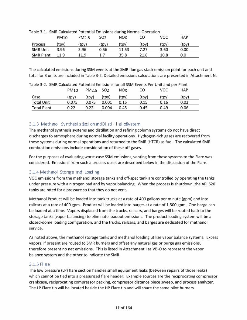
Table 3-1. SMR Calculated Potential Emissions during Normal Operation PM10 PM2.5 SO2 NOX CO VOC HAP
Process (tpy) (tpy) (tpy) (tpy) (tpy) (tpy) (tpy) SMR Unit 3.96 3.96 0.56 11.53 7.27 3.60 0.00 SMR Plant 11.9 11.9 1.7 35.8 21.8 10.8 0.0
The calculated emissions during SSM events at the SMR flue gas stack emission point for each unit and total for 3 units are included in Table 3-2. Detailed emissions calculations are presented in Attachment N.
Table 3-2. SMR Calculated Potential Emissions for all SSM Events Per Unit and per Plant PM10 PM2.5 SO2 NOX CO VOC HAP
Case (tpy) (tpy) (tpy) (tpy) (tpy) (tpy) (tpy) Total Unit 0.075 0.075 0.001 0.15 0.15 0.16 0.02 Total Plant 0.22 0.22 0.004 0.45 0.45 0.49 0.06
3.1.3 Methanol Synthesis Section and Distillation System The methanol synthesis systems and distillation and refining column systems do not have direct discharges to atmosphere during normal facility operations. Hydrogen-rich gases are recovered from these systems during normal operations and returned to the SMR (HTCR) as fuel. The calculated SMR combustion emissions include consideration of these off-gases.
For the purposes of evaluating worst-case SSM emissions, venting from these systems to the Flare was considered. Emissions from such a process upset are described below in the discussion of the Flare.
3.1.4 Methanol Storage and Loading VOC emissions from the methanol storage tanks and off-spec tank are controlled by operating the tanks under pressure with a nitrogen pad and by vapor balancing. When the process is shutdown, the API 620 tanks are rated for a pressure so that they do not vent.
Methanol Product will be loaded into tank trucks at a rate of 400 gallons per minute (gpm) and into railcars at a rate of 400 gpm. Product will be loaded into barges at a rate of 1,500 gpm. One barge can be loaded at a time. Vapors displaced from the trucks, railcars, and barges will be routed back to the storage tanks (vapor balancing) to eliminate loadout emissions. The product loading system will be a closed-dome loading configuration, and the trucks, railcars, and barges are dedicated for methanol service.
As noted above, the methanol storage tanks and methanol loading utilize vapor balance systems. Excess vapors, if present are routed to SMR burners and offset any natural gas or purge gas emissions, therefore present no net emissions. This is listed in Attachment I as VB-O to represent the vapor balance system and the other to indicate the SMR.
3.1.5 Flare The low pressure (LP) flare section handles small equipment leaks (between repairs of those leaks) which cannot be tied into a pressurized flare header. Example sources are the reciprocating compressor crankcase, reciprocating compressor packing, compressor distance piece sweep, and process analyzer. The LP Flare tip will be located beside the HP Flare tip and will share the same pilot burners.
11 of 164

The calculated emissions during normal operation from the LP flare section for each unit and total for 3 units are included in Table 3-3. Detailed emissions calculations are presented in Attachment N. This calculation is based on emissions from all of the flare pilot burners operating 8760 hours per year. This is also referred to as Flare Normal emissions in Table 3-6.
Table 3-3. LP Flare Section Calculated Potential Emissions PM10 PM2.5 SO2 NOX CO VOC HAP
Case (tpy) (tpy) (tpy) (tpy) (tpy) (tpy) (tpy) Flare Normal Unit
0.003 0.003 0.001 0.080 0.330 0.006 0.002
Flare Normal Plant
0.009 0.009 0.002 0.240 0.991 0.019 0.006
During startup, shutdown, and upset conditions, gas is sent to the process flare header which feeds the HP section of the flare (also referred to as the SSM Flare).
The calculated emissions during SSM events at the HP Flare section for each unit and total for 3 units are included in Table 3-4. Detailed emissions calculations are presented in Attachment N. This is also referred to as Flare SSM Event emissions in Table 3-6.
Table 3-4. HP Flare Section Calculated Potential Emissions during SSM Events Per Unit and Total Plant PM10 PM2.5 SO2 NOX CO VOC HAP
Case (tpy) (tpy) (tpy) (tpy) (tpy) (tpy) (tpy) Total Unit 0.314 0.314 0.001 1.19 9.12 0.161 0.004 Total Plant 0.94 0.94 0.002 3.57 27.35 0.48 0.01
3.1.6 Reciprocating Engines Combustion emissions from the reciprocating internal combustion engines are provided based on the maximum RICE output from vendor-supplied emissions data. Emissions of HAPs are based on vendor supplied data as well as data from USEPA’s AP-42 for natural gas-fired reciprocating, 4-stroke lean-burn engines. Each of the 7 reciprocating internal combustion engines (RICE) will have its own SCR for NOX emissions control and an oxidation catalyst for CO, VOC, and HAPs emissions control.
The calculated emissions for the RICEs are included in Table 3-5. Detailed emissions calculations are presented in Appendix B.
Table 3-5. RICE Calculated Potential Emissions. PM10 PM2.5 SO2 NOX CO VOC HAP
Process (tpy) (tpy) (tpy) (tpy) (tpy) (tpy) (tpy) Unit RICE 0.478 0.478 0.090 7.48 5.44 4.2 2.37 Plant RICE 3.35 3.35 0.61 52.4 38.1 29.4 16.6
3.2 Fugitive Sources
Fugitive VOC emissions from equipment leaks were calculated in accordance with USEPA’s “Protocol for Equipment Leak Emission Estimates” (USEPA, 1995d) using SOCMI emission factors. Pumps with magnetic drive or canned motor pumps and have no fugitive emissions so were not included in the fugitive emission inventory. Pumps with a more conventional design do have fugitive emissions and were
12 of 164

included in the fugitive emission inventory. Component counts, including valves, flanges, and fittings were estimated from preliminary engineering drawings of the proposed facility. Total fugitive VOC emissions from equipment leaks were calculated to be 5.7 tpy for the plant. Some of the fugitive VOC emissions where associated with natural gas in the methanol process or power plant and consequently not all of the VOC emissions are comprised of methanol (HAP). HAP emissions were calculated to be 5.6 tpy for the plant. Detailed fugitive emissions calculations are presented in Attachment N. Fugitive equipment leaks will be minimized by implementation of a leak detection and repair (LDAR) monitoring program in accordance with New Source Performance Standard (NSPS) 40 CFR Part 60, Subpart VVa. 3.3 Summary of Calculated Potential Emissions
A summary of calculated potential emissions for the Plant is provided in Table 3-6. Table 3-7 provides a list of the top HAPs to be emitted from the plant. A more detailed summary of pollutant emissions is provided in Attachment J: Emission Points Data Summary Sheet and Attachment K: Fugitive Emissions Data Summary along with detailed emission calculations in Attachment N.
Table 3-6. Summary of the Calculated Potential Emissions for Pleasants County Methanol Plant
Potential Emissions for Pleasants County Methanol Plant Pollutants, tpy PROCESS PM PM10 PM2.5 SO2 NOx CO VOC HAP SMR Normal 11.89 11.89 11.89 1.7 35.8 21.8 10.8 0.0 SMR SSM Events 0.22 0.22 0.22 0.0 0.45 0.45 0.49 0.06 Flare SSM Events 0.94 0.94 0.94 0.0 3.57 27.35 0.48 0.32 Flare Normal 0.01 0.01 0.01 0.0 0.24 0.99 0.02 0.01 Power Plant 3.35 3.35 3.35 0.61 52.4 38.1 29.4 16.6 Subtotal Point Sources 16.4 16.4 16.1 2.3 92.4 88.7 41.2 17.0 Equipment Leaks -- -- -- -- -- -- 5.7 5.6 Haul Road 1.2 0.2 0.1 -- -- -- -- -- Subtotal Fugitive 1.2 0.2 0.1 0 0 0 5.7 5.6 Total Plant Emissions 17.6 16.7 16.2 2.3 92.4 88.7 46.9 22.6
Table 3.7. Top HAP Constituents Emitted from the Plant
HAP Constituent TPY Acetaldehyde 2.82 Acrolein 1.40 Formaldehyde 9.05 Methanol 6.88 n-Hexane 0.85 Naphthalene 0.08 Total 21.08
13 of 164

4.0 Regulatory Review Clean Air Act permitting in West Virginia is the shared responsibility of the West Virginia Department of Environmental Protection and USEPA. The proposed facility is located in USEPA Region 3. Pleasants County is designated as attainment or unclassifiable for all criteria pollutants. The Pleasants County Methanol project is subject to the meet federal emissions performance standards under 40 CFR Part 60 New Source Performance Standards (NSPS). In addition, the plant must comply with the National Emission Standards for Hazardous Air Pollutants (NESHAP) for Reciprocating Internal Combustion Engines (RICE) as outlined in the Code of Federal Regulations under 40 CFR 63 Subpart ZZZZ. Further the project must meet the state permitting requirements under the West Virginia Code of State Regulations (CSR). The project is considered a minor source under the Prevention of Significant Deterioration (PSD) and Title V Operating Permit programs. The following is a review of the regulatory requirements for this project.
4.1 Prevention of Significant Deterioration (40 CFR 52.21 and 45CSR14) The PSD regulations stipulate that any major new stationary source within an air quality attainment area undergo PSD review and obtain applicable federal and state preconstruction air permits prior to the commencement of construction. PSD addresses eight criteria pollutants: SO2, NO2, PM, PM10, PM2.5, CO, VOC, and Pb. It also includes other NSR Regulated Pollutants. The PSD permitting requirements do not apply to HAPs.
The PSD regulations apply to any source type listed in any of 28 designated industrial source categories having potential emissions of 100 tpy or more of any pollutant regulated under the CAA. They also apply to any other source having potential emissions of 250 tpy or more of any pollutant regulated under the CAA.
The proposed plant will be in Pleasants County, which is designated as attainment or unclassifiable for all criteria pollutants. Sources with emissions of the attainment pollutants exceeding the PSD applicability thresholds noted above would be required to obtain a PSD permit prior to commencing construction.
The Pleasants County Methanol Plant falls within the 28 designated industrial source categories (chemical process plants) and is therefore subject to the 100 tpy applicability threshold of criteria pollutants. However, based on the total potential to emit of the plant, as summarized in Table 3-6, the project does not trigger the PSD permitting requirements.
4.2 Nonattainment New Source Review (40 CFR 51.165 and 45CSR19) The proposed plant is located in the Pleasants County, which is designated as attainment and non-classified area. Therefore, the project will not trigger NNSR permitting requirements.
4.3 Title V Operating Program (40 CFR 70 and 45CSR30) The Title V Operating Permit program applies to major sources which are facilities that have the potential to emit greater than 100 tons per year of any criteria pollutant, 25 tons per year of HAPs collectively, and 10 tons per year of an individual HAP. The proposed project does not exceed this
14 of 164

potential to emit and consequently is a minor source for criteria pollutants and HAPs. Therefore, a Title V Operating Permit will not be required for the project.
4.4 Compliance Assurance Monitoring (40 CFR 64) The project does not require Compliance Assurance Monitoring (CAM) per 40 CFR 64, which is required only for major source projects under Title V operating permits.
4.5 New Source Performance Standards (40 CFR 60 and 45CSR16) Section 111 of the Clean Air Act authorizes the EPA to develop technology-based standards which apply to specific categories of stationary sources. These standards are referred to as New Source Performance Standards (NSPS) and are found in 40 CFR Part 60. NSPS standards have been adopted by reference in 45CSR16 for standards in effect as of June 1, 2015. The following NSPS will apply to the proposed facility:
Subpart Title A General Provisions Kb Standards of Performance for Volatile Organic Liquid Storage Vessels (Including Petroleum
Liquid Storage Vessels) for Which Construction, Reconstruction, or Modification Commenced after July 23, 1984
VVa Standards of Performance for Equipment Leaks of VOC in the Synthetic Organic Chemical Manufacturing Industry for Which Construction, Reconstruction, or Modification Commenced after November 7, 2006
NNN Standards of Performance for VOC Emissions from Synthetic Organic Chemical Manufacturing Industry (SOCMI) Distillation Operations
RRR Standards of Performance for VOC Emissions from SOCMI Reactor Processes JJJJ Standards of Performance for Stationary Spark Ignition Internal Combustion Engines
4.5.1 40 CFR 60 Subpart A – General Provisions The facility will be subject to the requirements under Subpart A. Subpart A stipulates notification and recordkeeping requirements (40 CFR §60.7), testing requirements (40 CFR §60.8), monitoring requirements (40 CFR §60.13), and flare requirements (40 CFR §60.18(b)).
4.5.2 40 CFR 60 Subpart Kb - Standards of Performance for Volatile Organic Liquid Storage Vessels Subpart Kb will apply to the 375,000 gallon methanol storage tanks with maximum vapor pressure of 4.95 psia (34.13 kPA) as its capacity is greater than 19,813 gallons and is used to store volatile organic liquids. In addition, the storage tank does not meet the exemption in 60.110b(b) because its capacity is greater than 39,890 gallons and methanol has a maximum true vapor pressure greater than 0.51 psia at the site. The facility will comply with Subpart Kb by utilizing a vapor balance system which is in accordance 60.112b(a)(3). Methanol storage tanks and methanol unloading utilize vapor balance systems. Excess vapors, if present. are routed to SMR burners and offset any natural gas or
15 of 164
process/purge gas emissions, therefore present no net emissions. The flue gas from the SMR is subsequently treated by a SCR and oxidation catalyst.
4.5.3 40 CFR 60 Subpart VVa - Standards of Performance for Equipment Leaks of VOC
Subpart VVa will apply to the proposed facility because the facility is a synthetic organic chemical manufacturing industry (SOCMI) facility as defined under 60.481a and produces a chemical (methanol, CAS No. 67-56-1) listed in 40 CFR 60.489. Equipment leaks include leaks from pumps, compressors, relief devices, flanges, valves, etc. Subpart VVa has specific requirements for controls, monitoring, repair, recordkeeping, and reporting. It requires that this facility implement a Leak Detection and Repair (LDAR) program to identify and control leaks to ensure compliance with Subpart VVa.
4.5.4 40 CFR 60 Subpart NNN - Standards of Performance for VOC Emissions SOCMI Distillation Operations 40 CFR 60 Subpart NNN applies to the plant because it produces methanol (CAS No. 67-56-1) which is covered in 40 CFR §60.667 and is an affected facility per 40 CFR §60.66o(b)(1),(2), (3)]. Further, there may be during SSM events a stream exiting the unit to the high pressure flares.
The emissions standards require one of the following:
• Reduce TOC emissions by 98% (weight) • TOC (less methane and ethane) less than 20 ppmvd @3% O2 • Use of a flare that meets the specifications of 60.18 • Maintain a TRE index of greater than 1 without VOC control devices. Because the distillation area has a vent stream routed to the flare, Subpart NNN applies to the project. Combustion of the vent stream in the flare will reduce TOC emissions by 98 percent. Thus, the project will meet the emissions requirements of Subpart NNN.
4.5.5 40 CFR 60 Subpart RRR - Standards of Performance for VOC Emissions from SOCMI Reactor 40 CFR 60 Subpart RRR applies to the plant because it produces methanol (CAS No. 67-56-1) covered in 40 CFR §60.700(a) and is and affected facility per 40 CFR §60.700 (b)(1),(2), (3)].
For each unit, natural gas or purge gases are combusted in the SMR and the exhaust is routed to its associated SCR and oxidation catalyst and then emitted to atmosphere. During non-normal operation, the methanol synthesis section maybe vented to the flare. Therefore, the project is subject to Subpart RRR.
Subpart RRR emissions standards require one of the following:
• Reduce TOC emissions by 98% (weight);
• TOC (less methane and ethane) less than 20 ppmvd @3% O2;
• Use of a flare that meets the specifications of 60.18; or
• Maintain a TRE index of greater than 1 without VOC control devices.
16 of 164

The project will comply with Subpart RRR by reducing TOC by 98 weight percent when the SMR when natural gas is combusted in the SMR. There are no VOCs emitted in SMR when firing process gases. Further the TOC in the gases going to the flare are reduced by 98 weight percent in the flare.
4.5.6 40 CFR 60 Subpart JJJJ- Standards of Performance for Stationary Spark Ignition Internal Combustion Engines 40 CFR 60 Subpart JJJJ applies to stationary spark ignition internal combustion engines. The provisions of this subpart are applicable to stationary spark ignition (SI) internal combustion engines (ICE) with a maximum engine power greater than or equal to 1,350 HP. The emission rates from the SI ICE must not exceed the table below over the entire life of the engine.
Emissions Standards g/HP-hr ppmvd at 15% O2 NOX CO VOC d NOX CO VOC d
Non-Emergency Natural Gas 2 4 1 160 540 86
To ensure compliance, a maintenance program with record keeping and periodic testing is required. Testing is to occur within 1 year of initial engine startup and is subsequently repeated ever every 8,760 hours or 3 years, whichever comes first.
4.6 National Emission Standards for Hazardous Air Pollutants (40 CFR 63 Subpart ZZZZ) National Emission Standards for Hazardous Air Pollutants (NESHAP) for Stationary Reciprocating Internal Combustion Engines (40 CFR 63, Subpart ZZZZ) – The plant has seven SI RICE generators that are subject to this NESHAP. These emission units must meet the requirements of NESHAP subpart ZZZZ by meeting the requirements of NSPS subparts JJJJ discussed above.
4.7 West Virginia Code of State Regulations (45CSR) Emissions sources at the Pleasants County Methanol Plant will be required to comply with regulations established by the WVDEP under 45CSR.
The following regulations are applicable to the project.
4.7.1 45CSR2 Particulate Air Pollution from Combustion of Fuel The particulate air emissions from the SMR stacks will be subject to §45-2-3 (visible emissions) and §45-2-4 (weight emissions standards). The opacity from the units are limited to 10 percent based on a six-minute block average. If the 10 percent opacity cannot be achieved, the applicant may petition for a different opacity standard under §45-2-3. The §45-2-4 limits particulate emissions based on the “type” of combustion unit. For this project, the SMRs employ Type ‘b’ burning units. The Particulate emissions (pounds per hour [lb/hour]) for the SMR are limited to 0.09 times the heat input of 240.8 MMBtu/hour, or 21.7 lb/hour.
17 of 164

4.7.2 45CSR13 Permit Requirements WV 45CSR13 requires a construction permit for projects with sources that have the potential to emit in excess of the following:
• 6 pounds per hour and 10 tons per year of any regulated air pollutant;
• 144 pounds per calendar day, of any regulated air pollutant; and
• 2 pounds per hour or 5 tons per year of hazardous air pollutants considered on an aggregated basis.
The facility will have VOC, NOX, and CO emissions greater than 6 pounds per hour and 10 tons per year. The project will not trigger major source requirements under PSD or NNSR. Therefore, a state minor source permit will be required under 45CSR13.
45CSR13 requires that Public Notice be provided a via a legal advertisement; refer to Attachment P: Public Notice.
4.7.3 45CSR22 Air Quality Management Fees 45CSR22 regulation addresses fees for permits to construct and certificates to operate. All applicants filing for a permit to construct, modify, or relocate must submit a permit application fee of $1,000 per §45-22-3.4a. The project is subject to four NSPS subparts and §45-22-3.4b imposes additional fees for NSPS sources of $1,000. Therefore, the total fee is $2,000.
4.8 Regulatory Analysis Summary The Pleasants County Methanol Plant will be subject to the following regulations:
Regulation Finding 40 CFR 52.21 and 45 CSR 14 PSD permit not required 40 CFR 51.165 and 45CSR19 NNSR review is not required 40 CFR 60 Subpart A and 45CSR16 Facility is subject to this Federal NSPS 40 CFR 64 Compliance Assurance Monitoring is not required 40 CFR 70 and 45CSR30 Title V Operating Permit is not required 45 CSR 13 Construction Permit is required
The equipment or areas will be subject to the following requirements.
Equipment or Area Requirement Storage Tanks Federal NSPS at 40 CFR 60 Subpart Kb Fugitive Equipment Leaks Federal NSPS at 40 CFR 60 Subpart VVa and WVDEP 45CSR21 Distillation System Federal NSPS at 40 CFR 60 Subpart NNN SMR and Methanol Synthesis Section Federal NSPS at 40 CFR 60 Subpart RRR Stationary Spark Ignition Engines Federal NSPS at 40 CFR 60 Subpart JJJJ
Federal NESHAP at 40 CFR 63 Subpart ZZZZ SMR Stacks WVDEP PM emissions standards at 45CSR2
18 of 164

Application for Construction Permit WVM Pleasants County Methanol Plant
19 of 164

NSR/Title V Permit Application Form
20 of 164

WEST VIRGINIA DEPARTMENT OF ENVIRONMENTAL PROTECTION
DIVISION OF AIR QUALITY 601 57th Street, SE
Charleston, WV 25304 (304) 926-0475
www.dep.wv.gov/daq
APPLICATION FOR NSR PERMIT
AND
TITLE V PERMIT REVISION (OPTIONAL)
PLEASE CHECK ALL THAT APPLY TO NSR (45CSR13) (IF KNOWN):
CONSTRUCTION MODIFICATION RELOCATION
CLASS I ADMINISTRATIVE UPDATE TEMPORARY
CLASS II ADMINISTRATIVE UPDATE AFTER-THE-FACT
PLEASE CHECK TYPE OF 45CSR30 (TITLE V) REVISION (IF ANY):
ADMINISTRATIVE AMENDMENT MINOR MODIFICATION SIGNIFICANT MODIFICATION
IF ANY BOX ABOVE IS CHECKED, INCLUDE TITLE V REVISION INFORMATION AS ATTACHMENT S TO THIS APPLICATION
FOR TITLE V FACILITIES ONLY: Please refer to “Title V Revision Guidance” in order to determine your Title V Revision options (Appendix A, “Title V Permit Revision Flowchart”) and ability to operate with the changes requested in this Permit Application.
Section I. General 1. Name of applicant (as registered with the WV Secretary of State’s Office): West Virginia Methanol, Inc.
2. Federal Employer ID No. (FEIN): 82-3396067
3. Name of facility (if different from above):
Pleasants County Methanol Plant
4. The applicant is the:
OWNER OPERATOR BOTH
5A. Applicant’s mailing address: 1 Landy Lane Cincinnati, OH 45215
5B. Facility’s present physical address: 9764 South Pleasants Hwy St. Marys, WV 26170
6. West Virginia Business Registration. Is the applicant a resident of the State of West Virginia? YES NO − If YES, provide a copy of the Certificate of Incorporation/Organization/Limited Partnership (one page) including any name
change amendments or other Business Registration Certificate as Attachment A. − If NO, provide a copy of the Certificate of Authority/Authority of L.L.C./Registration (one page) including any name change
amendments or other Business Certificate as Attachment A.
7. If applicant is a subsidiary corporation, please provide the name of parent corporation:
8. Does the applicant own, lease, have an option to buy or otherwise have control of the proposed site? YES NO
− If YES, please explain: West Virginia Methanol holds an option to purchase the site.
− If NO, you are not eligible for a permit for this source.
9. Type of plant or facility (stationary source) to be constructed, modified, relocated, administratively updated or temporarily permitted (e.g., coal preparation plant, primary crusher, etc.): Methanol Production Plant
10. North American Industry Classification System (NAICS) code for the facility:
325199
11A. DAQ Plant ID No. (for existing facilities only): NA
11B. List all current 45CSR13 and 45CSR30 (Title V) permit numbers associated with this process (for existing facilities only):
NA
All of the required forms and additional information can be found under the Permitting Section of DAQ’s website, or requested by phone.
21 of 164

12A.
− For Modifications, Administrative Updates or Temporary permits at an existing facility, please provide directions to the present location of the facility from the nearest state road;
− For Construction or Relocation permits, please provide directions to the proposed new site location from the nearest state road. Include a MAP as Attachment B.
12.B. New site address (if applicable):
9764 South Pleasants Highway
St. Marys, WV 26170
12C. Nearest city or town:
Waverly
12D. County:
Pleasants
12.E. UTM Northing (KM): 4,354.380808 12F. UTM Easting (KM): 469.487967
12G. UTM Zone: 17
13. Briefly describe the proposed change(s) at the facility: This application is for a new facility. 14A. Provide the date of anticipated installation or change: 10/01/2023 − If this is an After-The-Fact permit application, provide the date upon which the proposed
change did happen: / /
14B. Date of anticipated Start-Up if a permit is granted: 3/15/2023
14C. Provide a Schedule of the planned Installation of/Change to and Start-Up of each of the units proposed in this permit application as Attachment C (if more than one unit is involved).
15. Provide maximum projected Operating Schedule of activity/activities outlined in this application: Hours Per Day 24 Days Per Week 7 Weeks Per Year 52
16. Is demolition or physical renovation at an existing facility involved? YES NO
17. Risk Management Plans. If this facility is subject to 112(r) of the 1990 CAAA, or will become subject due to proposed
changes (for applicability help see www.epa.gov/ceppo), submit your Risk Management Plan (RMP) to U. S. EPA Region III.
18. Regulatory Discussion. List all Federal and State air pollution control regulations that you believe are applicable to the
proposed process (if known). A list of possible applicable requirements is also included in Attachment S of this application
(Title V Permit Revision Information). Discuss applicability and proposed demonstration(s) of compliance (if known). Provide this
information as Attachment D.
Section II. Additional attachments and supporting documents. 19. Include a check payable to WVDEP – Division of Air Quality with the appropriate application fee (per 45CSR22 and 45CSR13).
20. Include a Table of Contents as the first page of your application package.
21. Provide a Plot Plan, e.g. scaled map(s) and/or sketch(es) showing the location of the property on which the stationary source(s) is or is to be located as Attachment E (Refer to Plot Plan Guidance) .
− Indicate the location of the nearest occupied structure (e.g. church, school, business, residence).
22. Provide a Detailed Process Flow Diagram(s) showing each proposed or modified emissions unit, emission point and control device as Attachment F.
23. Provide a Process Description as Attachment G. − Also describe and quantify to the extent possible all changes made to the facility since the last permit review (if applicable). All of the required forms and additional information can be found under the Permitting Section of DAQ’s website, or requested by phone.
22 of 164
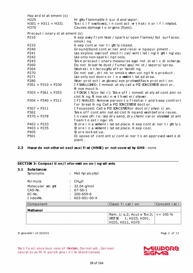
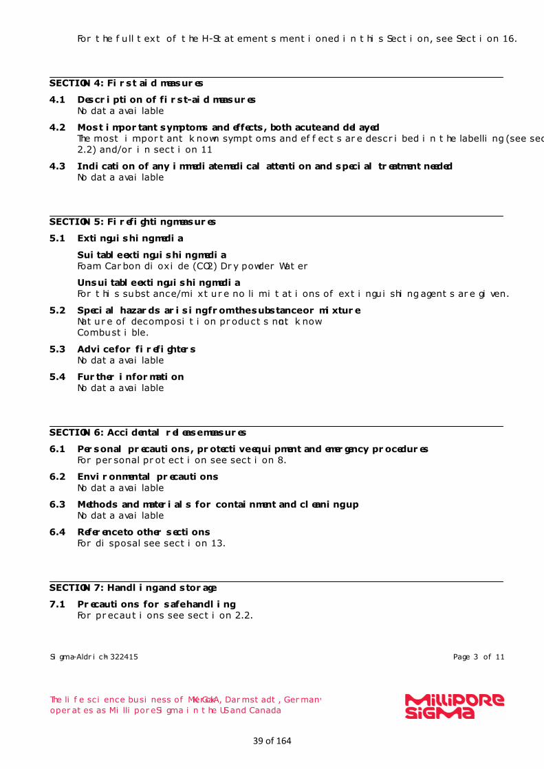
24. Provide Material Safety Data Sheets (MSDS) for all materials processed, used or produced as Attachment H. − For chemical processes, provide a MSDS for each compound emitted to the air. 25. Fill out the Emission Units Table and provide it as Attachment I. 26. Fill out the Emission Points Data Summary Sheet (Table 1 and Table 2) and provide it as Attachment J. 27. Fill out the Fugitive Emissions Data Summary Sheet and provide it as Attachment K. 28. Check all applicable Emissions Unit Data Sheets listed below:
Bulk Liquid Transfer Operations Chemical Processes Concrete Batch Plant Grey Iron and Steel Foundry
Haul Road Emissions Hot Mix Asphalt Plant Incinerator Indirect Heat Exchanger
Quarry Solid Materials Sizing, Handling and Storage
Facilities Storage Tanks
General Emission Unit, specify See Section L Fill out and provide the Emissions Unit Data Sheet(s) as Attachment L. 29. Check all applicable Air Pollution Control Device Sheets listed below:
Absorption Systems Adsorption Systems Afterburner
Baghouse Condenser Electrostatic Precipitator
Flare Mechanical Collector Wet Collecting System
Other Collectors, specify HTCR SCR & Oxidation Catalyst and RICE SCR & Oxidation Catalyst Fill out and provide the Air Pollution Control Device Sheet(s) as Attachment M. 30. Provide all Supporting Emissions Calculations as Attachment N, or attach the calculations directly to the forms listed in
Items 28 through 31.
31. Monitoring, Recordkeeping, Reporting and Testing Plans. Attach proposed monitoring, recordkeeping, reporting and testing plans in order to demonstrate compliance with the proposed emissions limits and operating parameters in this permit application. Provide this information as Attachment O.
Please be aware that all permits must be practically enforceable whether or not the applicant chooses to propose such measures. Additionally, the DAQ may not be able to accept all measures proposed by the applicant. If none of these plans are proposed by the applicant, DAQ will develop such plans and include them in the permit.
32. Public Notice. At the time that the application is submitted, place a Class I Legal Advertisement in a newspaper of general circulation in the area where the source is or will be located (See 45CSR§13-8.3 through 45CSR§13-8.5 and Example Legal Advertisement for details). Please submit the Affidavit of Publication as Attachment P immediately upon receipt.
33. Business Confidentiality Claims. Does this application include confidential information (per 45CSR31)? YES NO If YES, identify each segment of information on each page that is submitted as confidential and provide justification for each
segment claimed confidential, including the criteria under 45CSR§31-4.1, and in accordance with the DAQ’s “Precautionary Notice – Claims of Confidentiality” guidance found in the General Instructions as Attachment Q.
Section III. Certification of Information
34. Authority/Delegation of Authority. Only required when someone other than the responsible official signs the application. Check applicable Authority Form below:
Authority of Corporation or Other Business Entity
Authority of Governmental Agency
Authority of Partnership
Authority of Limited Partnership
Submit completed and signed Authority Form as Attachment R.
All of the required forms and additional information can be found under the Permitting Section of DAQ’s website, or requested by phone.
23 of 164

ATTACHMENT A: BUSINESS CERTIFICATE
25 of 164

26 of 164

ATTACHMENT B: GENERAL LOCATION MAP
27 of 164

28 of 164
ATTACHMENT C: INSTALLATION AND STARTUP SCHEDULE
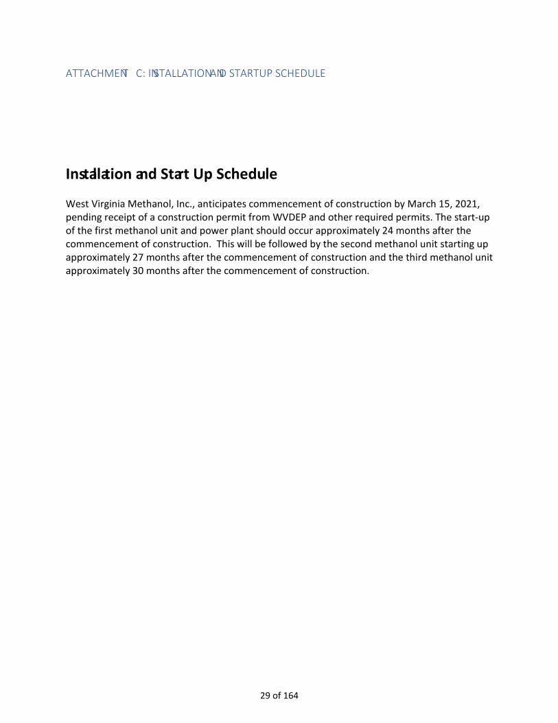
Installation and Start Up Schedule
West Virginia Methanol, Inc., anticipates commencement of construction by March 15, 2021, pending receipt of a construction permit from WVDEP and other required permits. The start-up of the first methanol unit and power plant should occur approximately 24 months after the commencement of construction. This will be followed by the second methanol unit starting up approximately 27 months after the commencement of construction and the third methanol unit approximately 30 months after the commencement of construction.
29 of 164
ATTACHMENT D: REGULATORY DISCUSSION
REGULATORY DISCUSSION
Refer to the write-up in Section 4: Regulatory Review.
30 of 164

ATTACHMENT E: PLOT PLAN
31 of 164
32 of 164

ATTACHMENT F: DETAILED PROCESS FLOW DIAGRAM
33 of 164
Pipe
line
Gra
de
Nat
ural
Gas
Pow
er P
lant
(7x
4 M
W C
ombu
stio
n En
gine
s)
SCR
and
Oxi
datio
n Ca
taly
st
Pow
er P
lant
Sta
cks (
7)
Stea
m M
etha
ne
Refo
rmer
(SM
R)Pr
e-Re
form
erFe
ed G
as
SCR
and
Oxi
datio
n Ca
taly
st
Flue
Gas
Sta
ck
Met
hano
l Syn
thes
is
Met
hano
l Di
still
atio
n
Star
tup
& S
hutd
own
Vent
Gas
Flar
e
Natural Gas to Burners
Met
hano
l St
orag
eM
etha
nol
Load
ing
Vapo
r Ba
lanc
ing
(No
Emis
sion
s)
Wes
t Virg
inia
Met
hano
l –Pl
easa
nts C
ount
y M
etha
nol P
lant
–G
ener
al P
roce
ss F
low
Dia
gram
Thre
e Id
entic
al
Met
hano
l Pr
oduc
tion
Uni
tsA,
B, C
Syng
asCr
ude
Met
hano
l
FinishedMethanol
Purg
e G
asto
Bur
ners
S1S2
S3S4
S6*
S7**
S8
E1
E2
E3
*Ta
nks T
1, T
2, …
,T9
S5
Gen
erat
orG
1, G
2, …
, G7
**Lo
adin
g LT
1, L
T2
LR1,
LR2
, LB1
, LB2
C1
C2
C3
C4
Vapo
r Ba
lanc
ing
(No
Emis
sion
s)
Lege
ndN
orm
al
SSM
Gas
Vapo
r Bal
ance
34 of 164

ATTACHMENT G: PROCESS DESCRIPTION
PROCESS DESCRIPTION
Section 2, Project Description, provides a process description and identifies the major plant components:
• Pre-Reformer Section • Steam Methane Reformer • Methanol synthesis section • Methanol distillation system • Methanol storage • Methanol loading • Power plant
Section 3, Emissions Inventory, further discusses the emissions units and provides additional process description including details regarding the operation of the plant.
35 of 164

ATTACHMENT H: MATERIAL SAFETY DATA SHEETS
36 of 164

Sigma-Aldrich - 322415 Page 1 of 11
The life science business of Merck KGaA, Darmstadt, Germany
operates as MilliporeSigma in the US and Canada
SAFETY DATA SHEET
Version 6.6 Revision Date 08/21/2020
Print Date 08/29/2020
SECTION 1: Identification of the substance/mixture and of the company/undertaking
1.1 Product identifiers
Product name : Methanol
Product Number : 322415
Brand : Sigma-Aldrich
Index-No. : 603-001-00-X
CAS-No. : 67-56-1
1.2 Relevant identified uses of the substance or mixture and uses advised against
Identified uses : Laboratory chemicals, Synthesis of substances
1.3 Details of the supplier of the safety data sheet
Company : Sigma-Aldrich Inc.
3050 Spruce Street
ST. LOUIS MO 63103
UNITED STATES Telephone : +1 314 771-5765
Fax : +1 800 325-5052
1.4 Emergency telephone
Emergency Phone # : 800-424-9300 CHEMTREC (USA) +1-703-
527-3887 CHEMTREC (International) 24
Hours/day; 7 Days/week
SECTION 2: Hazards identification
2.1 Classification of the substance or mixture
GHS Classification in accordance with 29 CFR 1910 (OSHA HCS)
Flammable liquids (Category 2), H225
Acute toxicity, Oral (Category 3), H301
Acute toxicity, Inhalation (Category 3), H331
Acute toxicity, Dermal (Category 3), H311
Specific target organ toxicity - single exposure (Category 1), Eyes, H370
For the full text of the H-Statements mentioned in this Section, see Section 16.
2.2 GHS Label elements, including precautionary statements
Pictogram
Signal word Danger
37 of 164
Sigma-Aldrich - 322415 Page 2 of 11
The life science business of Merck KGaA, Darmstadt, Germany
operates as MilliporeSigma in the US and Canada
Hazard statement(s)
H225 Highly flammable liquid and vapor.
H301 + H311 + H331 Toxic if swallowed, in contact with skin or if inhaled.
H370 Causes damage to organs (Eyes). Precautionary statement(s)
P210 Keep away from heat/ sparks/ open flames/ hot surfaces. No
smoking.
P233 Keep container tightly closed.
P240 Ground/bond container and receiving equipment.
P241 Use explosion-proof electrical/ ventilating/ lighting/ equipment.
P242 Use only non-sparking tools.
P243 Take precautionary measures against static discharge.
P260 Do not breathe dust/ fume/ gas/ mist/ vapors/ spray.
P264 Wash skin thoroughly after handling.
P270 Do not eat, drink or smoke when using this product.
P271 Use only outdoors or in a well-ventilated area.
P280 Wear protective gloves/ eye protection/ face protection.
P301 + P310 + P330 IF SWALLOWED: Immediately call a POISON CENTER/ doctor.
Rinse mouth.
P303 + P361 + P353 IF ON SKIN (or hair): Take off immediately all contaminated
clothing. Rinse skin with water/ shower.
P304 + P340 + P311 IF INHALED: Remove person to fresh air and keep comfortable
for breathing. Call a POISON CENTER/ doctor.
P307 + P311 IF exposed: Call a POISON CENTER or doctor/ physician.
P362 Take off contaminated clothing and wash before reuse.
P370 + P378 In case of fire: Use dry sand, dry chemical or alcohol-resistant
foam to extinguish.
P403 + P233 Store in a well-ventilated place. Keep container tightly closed.
P403 + P235 Store in a well-ventilated place. Keep cool.
P405 Store locked up.
P501 Dispose of contents/ container to an approved waste disposal
plant.
2.3 Hazards not otherwise classified (HNOC) or not covered by GHS - none
SECTION 3: Composition/information on ingredients
3.1 Substances
Synonyms : Methyl alcohol
Formula : CH4O
Molecular weight : 32.04 g/mol
CAS-No. : 67-56-1
EC-No. : 200-659-6
Index-No. : 603-001-00-X Component Classification Concentration
Methanol
Flam. Liq. 2; Acute Tox. 3;
STOT SE 1; H225, H301,
H331, H311, H370
<= 100 %
38 of 164
Sigma-Aldrich - 322415 Page 3 of 11
The life science business of Merck KGaA, Darmstadt, Germany
operates as MilliporeSigma in the US and Canada
For the full text of the H-Statements mentioned in this Section, see Section 16.
SECTION 4: First aid measures
4.1 Description of first-aid measures
No data available
4.2 Most important symptoms and effects, both acute and delayed
The most important known symptoms and effects are described in the labelling (see section
2.2) and/or in section 11
4.3 Indication of any immediate medical attention and special treatment needed
No data available
SECTION 5: Firefighting measures
5.1 Extinguishing media
Suitable extinguishing media
Foam Carbon dioxide (CO2) Dry powder Water
Unsuitable extinguishing media
For this substance/mixture no limitations of extinguishing agents are given.
5.2 Special hazards arising from the substance or mixture
Nature of decomposition products not known.
Combustible.
5.3 Advice for firefighters
No data available
5.4 Further information
No data available
SECTION 6: Accidental release measures
6.1 Personal precautions, protective equipment and emergency procedures
For personal protection see section 8.
6.2 Environmental precautions
No data available
6.3 Methods and materials for containment and cleaning up
No data available
6.4 Reference to other sections
For disposal see section 13.
SECTION 7: Handling and storage
7.1 Precautions for safe handling
For precautions see section 2.2.
39 of 164
Sigma-Aldrich - 322415 Page 4 of 11
The life science business of Merck KGaA, Darmstadt, Germany
operates as MilliporeSigma in the US and Canada
7.2 Conditions for safe storage, including any incompatibilities
No data available
7.3 Specific end use(s)
Apart from the uses mentioned in section 1.2 no other specific uses are stipulated
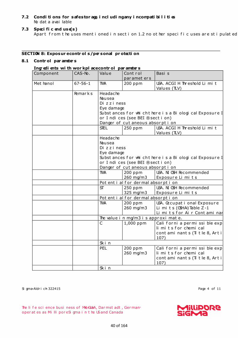
SECTION 8: Exposure controls/personal protection
8.1 Control parameters
Ingredients with workplace control parameters
Component CAS-No. Value Control
parameters
Basis
Methanol
67-56-1
TWA 200 ppm
USA. ACGIH Threshold Limit
Values (TLV)
Remarks Headache
Nausea
Dizziness
Eye damage
Substances for which there is a Biological Exposure Index
or Indices (see BEI® section)
Danger of cutaneous absorption STEL 250 ppm
USA. ACGIH Threshold Limit
Values (TLV) Headache
Nausea
Dizziness
Eye damage
Substances for which there is a Biological Exposure Index
or Indices (see BEI® section)
Danger of cutaneous absorption TWA 200 ppm
260 mg/m3
USA. NIOSH Recommended
Exposure Limits Potential for dermal absorption ST 250 ppm
325 mg/m3
USA. NIOSH Recommended
Exposure Limits Potential for dermal absorption TWA 200 ppm
260 mg/m3
USA. Occupational Exposure
Limits (OSHA) - Table Z-1
Limits for Air Contaminants The value in mg/m3 is approximate. C 1,000 ppm
California permissible exposure
limits for chemical
contaminants (Title 8, Article
107) Skin PEL 200 ppm
260 mg/m3
California permissible exposure
limits for chemical
contaminants (Title 8, Article
107) Skin
40 of 164
Sigma-Aldrich - 322415 Page 5 of 11
The life science business of Merck KGaA, Darmstadt, Germany
operates as MilliporeSigma in the US and Canada
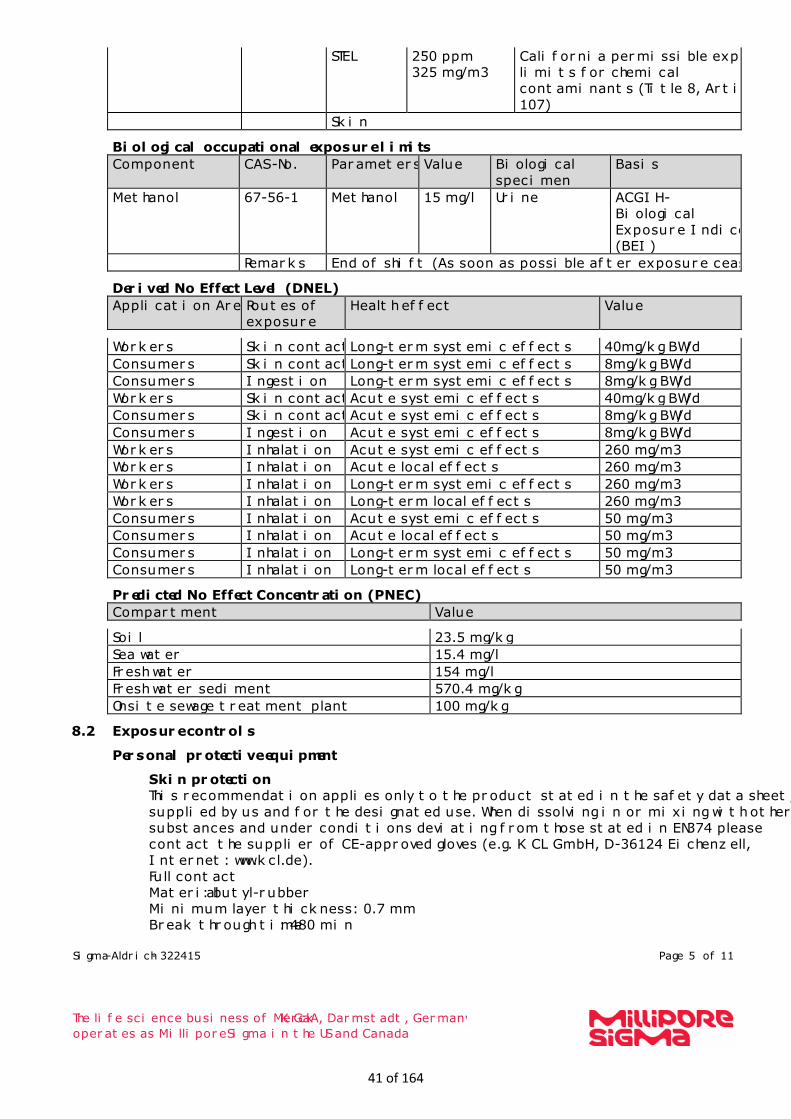
STEL 250 ppm
325 mg/m3
California permissible exposure
limits for chemical
contaminants (Title 8, Article
107) Skin
Biological occupational exposure limits
Component CAS-No. Parameters Value Biological
specimen
Basis
Methanol
67-56-1
Methanol 15 mg/l Urine ACGIH -
Biological
Exposure Indices
(BEI)
Remarks End of shift (As soon as possible after exposure ceases)
Derived No Effect Level (DNEL)
Application Area Routes of
exposure
Health effect Value
Workers Skin contact Long-term systemic effects 40mg/kg BW/d
Consumers Skin contact Long-term systemic effects 8mg/kg BW/d
Consumers Ingestion Long-term systemic effects 8mg/kg BW/d
Workers Skin contact Acute systemic effects 40mg/kg BW/d
Consumers Skin contact Acute systemic effects 8mg/kg BW/d
Consumers Ingestion Acute systemic effects 8mg/kg BW/d
Workers Inhalation Acute systemic effects 260 mg/m3
Workers Inhalation Acute local effects 260 mg/m3
Workers Inhalation Long-term systemic effects 260 mg/m3
Workers Inhalation Long-term local effects 260 mg/m3
Consumers Inhalation Acute systemic effects 50 mg/m3
Consumers Inhalation Acute local effects 50 mg/m3
Consumers Inhalation Long-term systemic effects 50 mg/m3
Consumers Inhalation Long-term local effects 50 mg/m3
Predicted No Effect Concentration (PNEC)
Compartment Value
Soil 23.5 mg/kg
Sea water 15.4 mg/l
Fresh water 154 mg/l
Fresh water sediment 570.4 mg/kg
Onsite sewage treatment plant 100 mg/kg
8.2 Exposure controls
Personal protective equipment
Skin protection
This recommendation applies only to the product stated in the safety data sheet,
supplied by us and for the designated use. When dissolving in or mixing with other
substances and under conditions deviating from those stated in EN374 please
contact the supplier of CE-approved gloves (e.g. KCL GmbH, D-36124 Eichenzell,
Internet: www.kcl.de).
Full contact
Material: butyl-rubber
Minimum layer thickness: 0.7 mm
Break through time: 480 min
41 of 164

Sigma-Aldrich - 322415 Page 6 of 11
The life science business of Merck KGaA, Darmstadt, Germany
operates as MilliporeSigma in the US and Canada
Material tested:Butoject® (KCL 898) This recommendation applies only to the product stated in the safety data sheet,
supplied by us and for the designated use. When dissolving in or mixing with other
substances and under conditions deviating from those stated in EN374 please
contact the supplier of CE-approved gloves (e.g. KCL GmbH, D-36124 Eichenzell,
Internet: www.kcl.de).
Splash contact
Material: Viton®
Minimum layer thickness: 0.7 mm
Break through time: 120 min
Material tested:Vitoject® (KCL 890 / Aldrich Z677698, Size M)
Respiratory protection
Where risk assessment shows air-purifying respirators are appropriate use a full-
face respirator with multi-purpose combination (US) or type AXBEK (EN 14387)
respirator cartridges as a backup to engineering controls. If the respirator is the sole
means of protection, use a full-face supplied air respirator. Use respirators and
components tested and approved under appropriate government standards such as
NIOSH (US) or CEN (EU).
Control of environmental exposure
Prevent product from entering drains.
SECTION 9: Physical and chemical properties
9.1 Information on basic physical and chemical properties
a) Appearance Form: liquid
Color: colorless
b) Odor characteristic
c) Odor Threshold 10 ppm
d) pH No data available
e) Melting
point/freezing point
Melting point/range: -98 °C (-144 °F)
f) Initial boiling point
and boiling range
64.7 °C 148.5 °F
g) Flash point 11.0 °C (51.8 °F) - closed cup
h) Evaporation rate 6.3 - Diethyl ether1.9 - n-butyl acetate
i) Flammability (solid,
gas)
No data available
j) Upper/lower
flammability or
explosive limits
Upper explosion limit: 44 %(V)
Lower explosion limit: 5.5 %(V)
k) Vapor pressure 128 hPa at 20 °C (68 °F)
l) Vapor density 1.11
m) Relative density 0.791 g/mL at 25 °C (77 °F)
n) Water solubility 1,000 g/l at 20 °C (68 °F) - completely misciblesoluble
o) Partition coefficient:
n-octanol/water
log Pow: -0.77 at 25 °C (77 °F) - (Lit.), Bioaccumulation is not
expected.
42 of 164

Sigma-Aldrich - 322415 Page 7 of 11
The life science business of Merck KGaA, Darmstadt, Germany
operates as MilliporeSigma in the US and Canada
p) Autoignition
temperature
455.0 °C (851.0 °F) at 1,013 hPa - DIN 51794
q) Decomposition
temperature
Distillable in an undecomposed state at normal pressure.
r) Viscosity 0.54 - 0.59 mm2/s at 20 °C (68 °F) -
s) Explosive properties No data available
t) Oxidizing properties No data available
9.2 Other safety information
Minimum ignition
energy
0.14 mJ
Conductivity < 1 µS/cm
Relative vapor
density
1.11
SECTION 10: Stability and reactivity
10.1 Reactivity
Vapors may form explosive mixture with air.
10.2 Chemical stability
The product is chemically stable under standard ambient conditions (room temperature) .
10.3 Possibility of hazardous reactions
Risk of explosion with:Oxidizing agents, Halogens, sodium hypochlorite, sulfuric acid,
nitrogen oxides, chlorates, chromium(VI) oxide, chromosulfuric acid, halogen oxides,
hydrides, salts of oxyhalogenic acids, perchlorates, perchloric acid, permanganic acid,
hydrogen peroxide, zinc diethyl, nonmetallic oxides, powdered magnesium, Nitric
acidExothermic reaction with:Acids, Chloroform, Acid anhydrides, Reducing agents,
Bromine, Chlorine, tetrachloromethane, acid halides, magnesiumRisk of ignition or
formation of inflammable gases or vapours with:Fluorine, Oxides of phosphorus, Raney-
nickelGenerates dangerous gases or fumes in contact with:Alkali metals, Alkaline earth
metals
10.4 Conditions to avoid
Warming.
10.5 Incompatible materials
various plastics, magnesium, zinc alloys
10.6 Hazardous decomposition products
Other decomposition products - No data available
Hazardous decomposition products formed under fire conditions. - Nature of decomposition
products not known.
In the event of fire: see section 5
43 of 164
Sigma-Aldrich - 322415 Page 8 of 11
The life science business of Merck KGaA, Darmstadt, Germany
operates as MilliporeSigma in the US and Canada
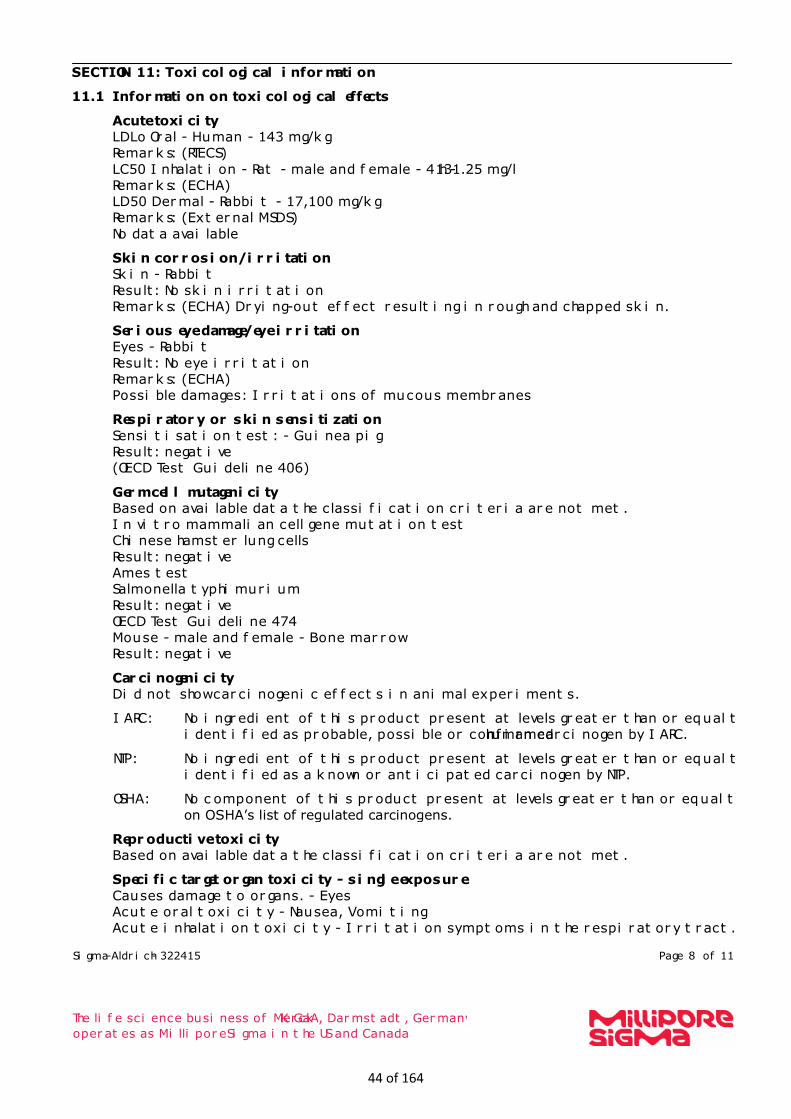
SECTION 11: Toxicological information
11.1 Information on toxicological effects
Acute toxicity
LDLo Oral - Human - 143 mg/kg
Remarks: (RTECS)
LC50 Inhalation - Rat - male and female - 4 h - 131.25 mg/l
Remarks: (ECHA)
LD50 Dermal - Rabbit - 17,100 mg/kg
Remarks: (External MSDS)
No data available
Skin corrosion/irritation
Skin - Rabbit
Result: No skin irritation
Remarks: (ECHA) Drying-out effect resulting in rough and chapped skin.
Serious eye damage/eye irritation
Eyes - Rabbit
Result: No eye irritation
Remarks: (ECHA)
Possible damages: Irritations of mucous membranes
Respiratory or skin sensitization
Sensitisation test: - Guinea pig
Result: negative
(OECD Test Guideline 406)
Germ cell mutagenicity
Based on available data the classification criteria are not met.
In vitro mammalian cell gene mutation test
Chinese hamster lung cells
Result: negative
Ames test
Salmonella typhimurium
Result: negative
OECD Test Guideline 474
Mouse - male and female - Bone marrow
Result: negative
Carcinogenicity
Did not show carcinogenic effects in animal experiments.
IARC: No ingredient of this product present at levels greater than or equal to 0.1% is
identified as probable, possible or confirmed human carcinogen by IARC.
NTP: No ingredient of this product present at levels greater than or equal to 0.1% is
identified as a known or anticipated carcinogen by NTP.
OSHA: No component of this product present at levels greater than or equal to 0.1% is
on OSHA’s list of regulated carcinogens.
Reproductive toxicity
Based on available data the classification criteria are not met.
Specific target organ toxicity - single exposure
Causes damage to organs. - Eyes
Acute oral toxicity - Nausea, Vomiting
Acute inhalation toxicity - Irritation symptoms in the respiratory tract.
44 of 164

Sigma-Aldrich - 322415 Page 9 of 11
The life science business of Merck KGaA, Darmstadt, Germany
operates as MilliporeSigma in the US and Canada
Specific target organ toxicity - repeated exposure
No data available
Aspiration hazard
No aspiration toxicity classification
Additional Information
RTECS: PC1400000
To the best of our knowledge, the chemical, physical, and toxicological properties have not
been thoroughly investigated. Systemic effects:
acidosis, drop in blood pressure, agitation, spasms, inebriation, Dizziness, Drowsiness,
Headache, Impairment of vision, Blindness, narcosis, Coma
Symptoms may be delayed.
Damage to:
Liver, Kidney, Cardiac, Irreversible damage of the optical nerve.
Other dangerous properties can not be excluded.
This substance should be handled with particular care. Stomach - Irregularities - Based on Human Evidence
Stomach - Irregularities - Based on Human Evidence
SECTION 12: Ecological information
12.1 Toxicity Toxicity to fish flow-through test LC50 - Lepomis macrochirus (Bluegill) - 15,400.0
mg/l - 96 h
(US-EPA) Toxicity to daphnia
and other aquatic
invertebrates
semi-static test EC50 - Daphnia magna (Water flea) - 18,260 mg/l -
96 h
(OECD Test Guideline 202) Toxicity to algae static test ErC50 - Pseudokirchneriella subcapitata (green algae) - ca.
22,000.0 mg/l - 96 h
(OECD Test Guideline 201) Toxicity to bacteria static test IC50 - activated sludge - > 1,000 mg/l - 3 h
(OECD Test Guideline 209)
12.2 Persistence and degradability
Biodegradability Result: 99 % - Readily biodegradable.
(OECD Test Guideline 301D) Biochemical Oxygen
Demand (BOD)
600 - 1,120 mg/g
Remarks: (IUCLID) Chemical Oxygen
Demand (COD)
1,420 mg/g
Remarks: (IUCLID) Theoretical oxygen
demand
1,500 mg/g
Remarks: (Lit.) Ratio BOD/ThBOD 76 %
Remarks: Closed Bottle test(IUCLID)
12.3 Bioaccumulative potential
45 of 164
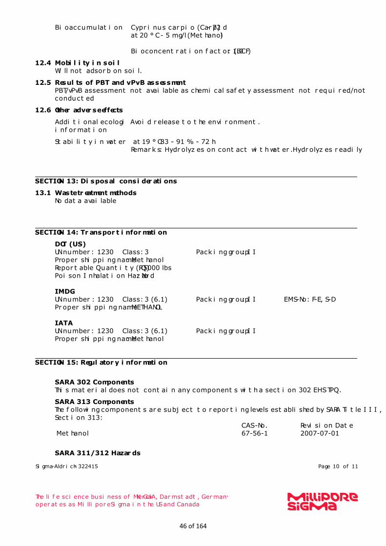
Sigma-Aldrich - 322415 Page 10 of 11
The life science business of Merck KGaA, Darmstadt, Germany
operates as MilliporeSigma in the US and Canada
Bioaccumulation Cyprinus carpio (Carp) - 72 d
at 20 °C - 5 mg/l(Methanol)
Bioconcentration factor (BCF): 1.0
12.4 Mobility in soil
Will not adsorb on soil.
12.5 Results of PBT and vPvB assessment
PBT/vPvB assessment not available as chemical safety assessment not required/not
conducted
12.6 Other adverse effects Additional ecological
information
Avoid release to the environment.
Stability in water at 19 °C83 - 91 % - 72 h
Remarks: Hydrolyzes on contact with water.Hydrolyzes readily.
SECTION 13: Disposal considerations
13.1 Waste treatment methods
No data available
SECTION 14: Transport information
DOT (US)
UN number: 1230 Class: 3 Packing group: II
Proper shipping name: Methanol
Reportable Quantity (RQ): 5000 lbs
Poison Inhalation Hazard: No
IMDG
UN number: 1230 Class: 3 (6.1) Packing group: II EMS-No: F-E, S-D
Proper shipping name: METHANOL
IATA
UN number: 1230 Class: 3 (6.1) Packing group: II
Proper shipping name: Methanol
SECTION 15: Regulatory information
SARA 302 Components
This material does not contain any components with a section 302 EHS TPQ.
SARA 313 Components
The following components are subject to reporting levels established by SARA Title III,
Section 313:
Methanol
CAS-No.
67-56-1
Revision Date
2007-07-01
SARA 311/312 Hazards
46 of 164

Sigma-Aldrich - 322415 Page 11 of 11
The life science business of Merck KGaA, Darmstadt, Germany
operates as MilliporeSigma in the US and Canada
Fire Hazard, Acute Health Hazard, Chronic Health Hazard
Massachusetts Right To Know Components
No components are subject to the Massachusetts Right to Know Act.
SECTION 16: Other information
The branding on the header and/or footer of this document may temporarily not visually
match the product purchased as we transition our branding. However, all of the
information in the document regarding the product remains unchanged and matches the
product ordered. For further information please contact [email protected]. Version: 6.6 Revision Date: 08/21/2020 Print Date: 08/29/2020
47 of 164

SAFETY DATA SHEET
1. Product and Company Identification
Material name Natural Gas - Odorized
Revision date September 9, 2019
SDS number SWG SDS 1
Product use Fuel gas.
Manufacturer/Supplier Southwest Gas Corporation P.O. Box 98510, Las Vegas, NV 89150-0002 Telephone: (702) 876-7011
Contact Person: Corporate Safety Department
Emergency 877-860-6020
2. Hazards Identification
Physical state Gas.
Appearance Colorless gas.
Odor Gassy, sulfurous, rotten egg type odor.
Emergency overview DANGER Flammable gas - may cause flash fire. Gas reduces oxygen available for breathing.
OSHA regulatory status This product is hazardous according to OSHA 29 CFR 1910.1200.
Potential health effects
Routes of exposure Inhalation.
Eyes Pressurized gas, and contaminants within piping, may cause mechanical injury.
Skin Pressurized gas, and contaminants within piping, may cause mechanical injury.
Inhalation Sufficient concentrations can displace oxygen in the air and can cause symptoms
of oxygen deprivation (asphyxiation), including unconsciousness.
Ingestion Not applicable.
Target organs Not applicable.
Chronic effects Not applicable.
Signs and symptoms Not applicable.
Potential environmental effects Not expected to be harmful to aquatic organisms.
48 of 164
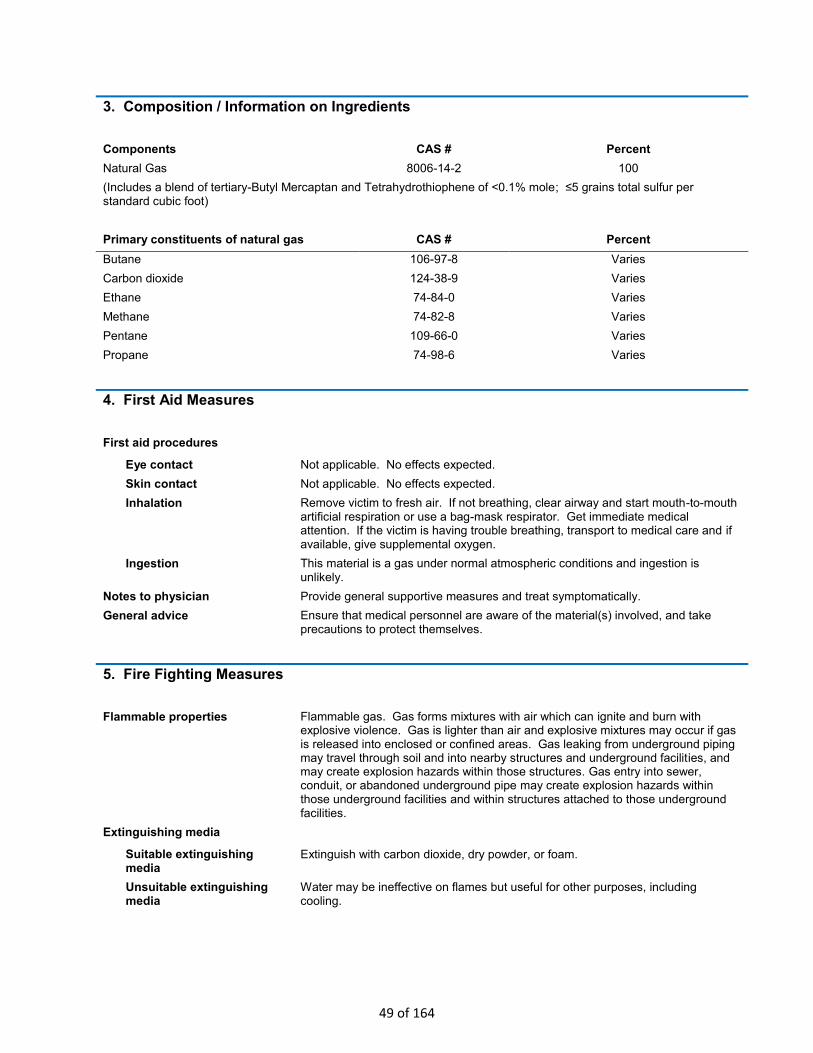
3. Composition / Information on Ingredients
Components CAS # Percent
Natural Gas 8006-14-2 100
(Includes a blend of tertiary-Butyl Mercaptan and Tetrahydrothiophene of <0.1% mole; ≤5 grains total sulfur per standard cubic foot)
Primary constituents of natural gas CAS # Percent
Butane 106-97-8 Varies
Carbon dioxide 124-38-9 Varies
Ethane 74-84-0 Varies
Methane 74-82-8 Varies
Pentane 109-66-0 Varies
Propane 74-98-6 Varies
4. First Aid Measures
First aid procedures
Eye contact Not applicable. No effects expected.
Skin contact Not applicable. No effects expected.
Inhalation Remove victim to fresh air. If not breathing, clear airway and start mouth-to-mouth artificial respiration or use a bag-mask respirator. Get immediate medical attention. If the victim is having trouble breathing, transport to medical care and if available, give supplemental oxygen.
Ingestion This material is a gas under normal atmospheric conditions and ingestion is unlikely.
Notes to physician Provide general supportive measures and treat symptomatically.
General advice Ensure that medical personnel are aware of the material(s) involved, and take precautions to protect themselves.
5. Fire Fighting Measures
Flammable properties Flammable gas. Gas forms mixtures with air which can ignite and burn with explosive violence. Gas is lighter than air and explosive mixtures may occur if gas is released into enclosed or confined areas. Gas leaking from underground piping may travel through soil and into nearby structures and underground facilities, and may create explosion hazards within those structures. Gas entry into sewer, conduit, or abandoned underground pipe may create explosion hazards within those underground facilities and within structures attached to those underground facilities.
Extinguishing media
Suitable extinguishing media
Extinguish with carbon dioxide, dry powder, or foam.
Unsuitable extinguishing media
Water may be ineffective on flames but useful for other purposes, including cooling.
49 of 164
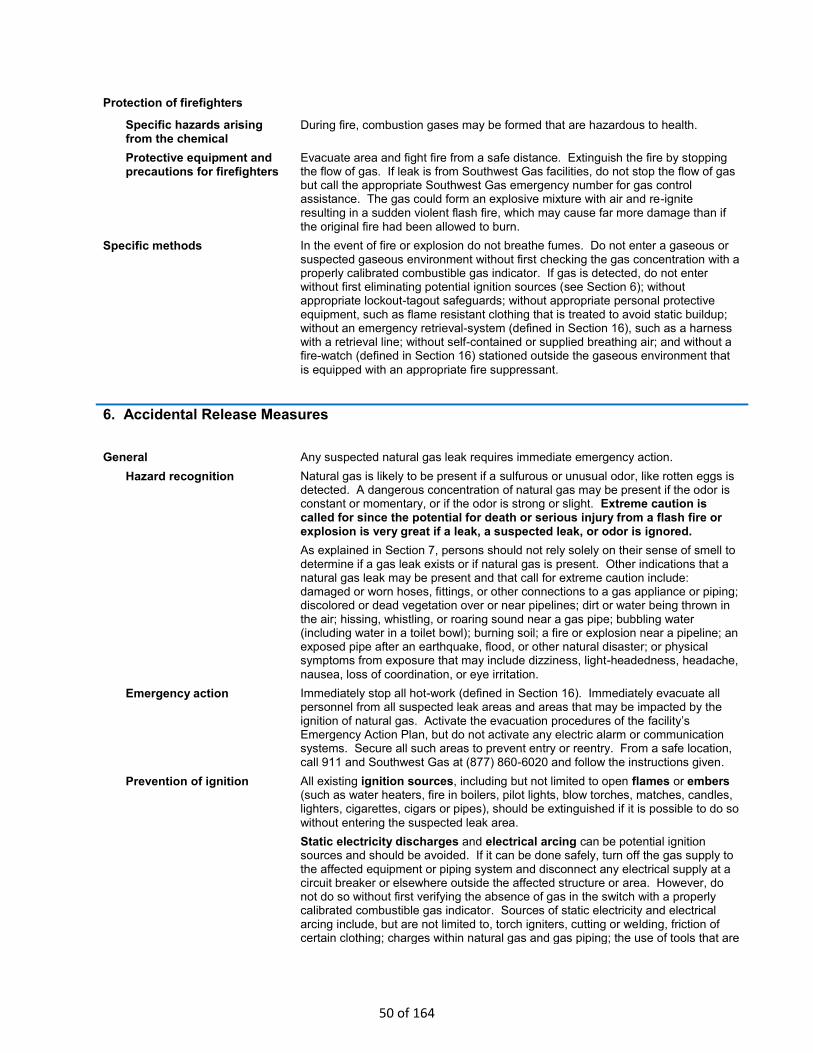
Protection of firefighters
Specific hazards arising from the chemical
During fire, combustion gases may be formed that are hazardous to health.
Protective equipment and precautions for firefighters
Evacuate area and fight fire from a safe distance. Extinguish the fire by stopping the flow of gas. If leak is from Southwest Gas facilities, do not stop the flow of gas but call the appropriate Southwest Gas emergency number for gas control assistance. The gas could form an explosive mixture with air and re-ignite resulting in a sudden violent flash fire, which may cause far more damage than if the original fire had been allowed to burn.
Specific methods In the event of fire or explosion do not breathe fumes. Do not enter a gaseous or suspected gaseous environment without first checking the gas concentration with a properly calibrated combustible gas indicator. If gas is detected, do not enter without first eliminating potential ignition sources (see Section 6); without appropriate lockout-tagout safeguards; without appropriate personal protective equipment, such as flame resistant clothing that is treated to avoid static buildup; without an emergency retrieval-system (defined in Section 16), such as a harness with a retrieval line; without self-contained or supplied breathing air; and without a fire-watch (defined in Section 16) stationed outside the gaseous environment that
is equipped with an appropriate fire suppressant.
6. Accidental Release Measures
General Any suspected natural gas leak requires immediate emergency action.
Hazard recognition Natural gas is likely to be present if a sulfurous or unusual odor, like rotten eggs is detected. A dangerous concentration of natural gas may be present if the odor is constant or momentary, or if the odor is strong or slight. Extreme caution is called for since the potential for death or serious injury from a flash fire or explosion is very great if a leak, a suspected leak, or odor is ignored.
As explained in Section 7, persons should not rely solely on their sense of smell to determine if a gas leak exists or if natural gas is present. Other indications that a natural gas leak may be present and that call for extreme caution include: damaged or worn hoses, fittings, or other connections to a gas appliance or piping; discolored or dead vegetation over or near pipelines; dirt or water being thrown in the air; hissing, whistling, or roaring sound near a gas pipe; bubbling water (including water in a toilet bowl); burning soil; a fire or explosion near a pipeline; an exposed pipe after an earthquake, flood, or other natural disaster; or physical symptoms from exposure that may include dizziness, light-headedness, headache,
nausea, loss of coordination, or eye irritation.
Emergency action Immediately stop all hot-work (defined in Section 16). Immediately evacuate all personnel from all suspected leak areas and areas that may be impacted by the ignition of natural gas. Activate the evacuation procedures of the facility’s Emergency Action Plan, but do not activate any electric alarm or communication systems. Secure all such areas to prevent entry or reentry. From a safe location, call 911 and Southwest Gas at (877) 860-6020 and follow the instructions given.
Prevention of ignition All existing ignition sources, including but not limited to open flames or embers (such as water heaters, fire in boilers, pilot lights, blow torches, matches, candles, lighters, cigarettes, cigars or pipes), should be extinguished if it is possible to do so
without entering the suspected leak area.
Static electricity discharges and electrical arcing can be potential ignition sources and should be avoided. If it can be done safely, turn off the gas supply to the affected equipment or piping system and disconnect any electrical supply at a circuit breaker or elsewhere outside the affected structure or area. However, do not do so without first verifying the absence of gas in the switch with a properly calibrated combustible gas indicator. Sources of static electricity and electrical arcing include, but are not limited to, torch igniters, cutting or welding, friction of certain clothing; charges within natural gas and gas piping; the use of tools that are
50 of 164
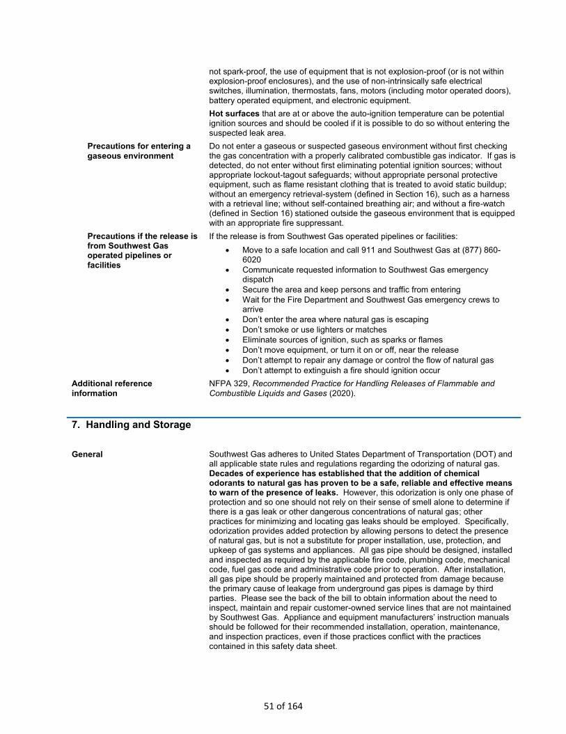
not spark-proof, the use of equipment that is not explosion-proof (or is not within explosion-proof enclosures), and the use of non-intrinsically safe electrical switches, illumination, thermostats, fans, motors (including motor operated doors),
battery operated equipment, and electronic equipment.
Hot surfaces that are at or above the auto-ignition temperature can be potential ignition sources and should be cooled if it is possible to do so without entering the suspected leak area.
Precautions for entering a
gaseous environment
Do not enter a gaseous or suspected gaseous environment without first checking the gas concentration with a properly calibrated combustible gas indicator. If gas is detected, do not enter without first eliminating potential ignition sources; without appropriate lockout-tagout safeguards; without appropriate personal protective equipment, such as flame resistant clothing that is treated to avoid static buildup; without an emergency retrieval-system (defined in Section 16), such as a harness with a retrieval line; without self-contained breathing air; and without a fire-watch (defined in Section 16) stationed outside the gaseous environment that is equipped with an appropriate fire suppressant.
Precautions if the release is from Southwest Gas operated pipelines or
facilities
If the release is from Southwest Gas operated pipelines or facilities:
• Move to a safe location and call 911 and Southwest Gas at (877) 860-6020
• Communicate requested information to Southwest Gas emergency dispatch
• Secure the area and keep persons and traffic from entering
• Wait for the Fire Department and Southwest Gas emergency crews to arrive
• Don’t enter the area where natural gas is escaping
• Don’t smoke or use lighters or matches
• Eliminate sources of ignition, such as sparks or flames
• Don’t move equipment, or turn it on or off, near the release
• Don’t attempt to repair any damage or control the flow of natural gas
• Don’t attempt to extinguish a fire should ignition occur
Additional reference
information
NFPA 329, Recommended Practice for Handling Releases of Flammable and
Combustible Liquids and Gases (2020).
7. Handling and Storage
General Southwest Gas adheres to United States Department of Transportation (DOT) and all applicable state rules and regulations regarding the odorizing of natural gas. Decades of experience has established that the addition of chemical odorants to natural gas has proven to be a safe, reliable and effective means to warn of the presence of leaks. However, this odorization is only one phase of protection and so one should not rely on their sense of smell alone to determine if there is a gas leak or other dangerous concentrations of natural gas; other practices for minimizing and locating gas leaks should be employed. Specifically, odorization provides added protection by allowing persons to detect the presence of natural gas, but is not a substitute for proper installation, use, protection, and upkeep of gas systems and appliances. All gas pipe should be designed, installed and inspected as required by the applicable fire code, plumbing code, mechanical code, fuel gas code and administrative code prior to operation. After installation, all gas pipe should be properly maintained and protected from damage because the primary cause of leakage from underground gas pipes is damage by third parties. Please see the back of the bill to obtain information about the need to inspect, maintain and repair customer-owned service lines that are not maintained by Southwest Gas. Appliance and equipment manufacturers’ instruction manuals should be followed for their recommended installation, operation, maintenance, and inspection practices, even if those practices conflict with the practices contained in this safety data sheet.
51 of 164

Other Precautions
Impaired sense of smell and environmental conditions that reduce odorant effectiveness
As noted above, persons should not rely solely on their sense of smell to determine if a gas leak exists or if natural gas is present. Some persons may not be able to detect the added odorant because they have a diminished or impaired sense of smell or olfactory fatigue. It has been reported that exposure to extreme cold may temporarily impair the ability to smell. Some people suffer from temporary or permanent anosmia. That is, they have no sense of smell. When a person’s ability to smell natural gas odorant is in doubt, the person may undergo an evaluation by a physician or other licensed health care professional.
Certain environmental conditions including competing odors may cover up or mask the smell of odorized gas.
Special precautions, including but not limited to the use of gas detection equipment, should be taken by persons using odorized gas or persons who may be exposed to planned or accidental releases of odorized gas, where those persons have a diminished or impaired sense of smell or work in environments that may mask or reduce the effectiveness of the odorant.
Odor fade Certain conditions cause odor fade, a phenomenon that causes the odorant to diminish so that it is not as detectable and, in some cases, is not detectable at all. Persons should not rely on their sense of smell alone to detect the presence of natural gas without first considering the presence or absence of conditions that may cause odor fade and without advance consideration of the potential for the creation or presence of a flammable concentration of odor-faded gas. Odor fade (loss of odorant) occurs when the level of odorant in the gas is reduced due to physical and/or chemical processes including adsorption, absorption and oxidation. This causes the effectiveness of odorant as a warning agent to be reduced. In piping systems conveying dry natural gas, like that delivered by Southwest Gas, odor fade occurs predominantly in installations of new pipe rather than in pipe that has been in continuous use. It is generally more pronounced in new steel pipe of larger diameters and longer lengths with intermittent, little or no gas flow through the piping system over an extended period of time. Other factors that may cause odor fade in a gas piping system include: the construction and configuration of the gas piping system; the presence of rust, moisture, liquids or other substances in the pipe; and gas composition, pressure and/or flow.
In industrial, commercial, and public applications and in large residential applications such as housing tracts and residential towers, new pipeline installations may require periodic purging, the conditioning of the pipe, or fuel gas system modifications (including pressure reduction) during start-up operations to prevent occurrences of odor fade. If Southwest Gas conditioned the customer’s pipe before it was placed into service, contact Southwest Gas for instruction on work controls and personal protective equipment recommendations before cutting the pipe with an oxyacetylene torch or welding pipe that is near to, and downstream of, the odorant injection point(s).
If a natural gas leak occurs underground, the surrounding soil may cause odor fade. Inspections for underground gas leaks should include looking for discolored or dead vegetation over or near pipe areas.
Immediately call the appropriate Southwest Gas emergency number (Section 1) if odor-faded gas is detected or suspected and follow the instructions given by the emergency dispatch.
Purging gas piping Gas piping should only be purged by a licensed professional that is fully trained and knowledgeable about safe gas purging practices, the proper use of gas detectors, and the danger of relying on the sense of smell alone to detect the presence of gas during purging operations. An improperly performed purge may cause serious bodily injury or death to the person(s) performing the purge and to
all other persons in the affected area.
Piping purges shall be performed in accordance with Section 8.3 of NFPA 54, National Fuel Gas Code or with NFPA 56, Standard for Fire Explosion Prevention During Cleaning and Purging of Flammable Gas Piping Systems, as applicable.
52 of 164

Immediately call the Southwest Gas emergency number if odor-faded gas is detected or suspected and follow the instructions given by the emergency dispatch.
Do not purge the contents of a gas pipe into a confined space. (See 29 CFR 1910.146).
Consider stopping hot-work (defined in Section 16) in the area receiving the product of the purge.
Special additional precautions should be taken when purging piping systems that contain extensive branch piping, that cannot maintain appropriate purge velocities, or that are exceptionally large. For example, Southwest Gas employs special precautions when purging its pipelines that cannot maintain a purge velocity greater than 200 feet per minute or are 6 inches or larger with a volume of 200
cubic feet or more. Special precautions may include but are not limited to
• Preparing and following a written purge plan that minimizes gas mixing due to turbulence, minimizes the stratification of gases within the piping, and addresses the diffusion due to the contact duration of the gases;
• Evacuating nonessential personnel;
• Providing supplemental ventilation with appropriate equipment that discharges the air away from the enclosed space, such as a grounded air-ejector (defined in Section 16);
• Wearing flame-resistant clothing that is appropriately treated to avoid static buildup;
• Eliminating open flames and other ignition sources;
• Employing appropriate lockout-tagout safeguards to control access to piping and valves and to control access to ignition sources including electrical switches, circuit breakers, appliances, equipment, and motors;
• Purging at a controlled rate that takes into account the volume of gas or air displaced from the gas piping, the amount of ventilation present, and the volume of the enclosed premises or structure receiving the product of
the purge; and
Using gas detection equipment at appropriate locations within an enclosed space where the purged gases are released and stopping the purge upon the detection of
a concentration of gas.
Additional reference information
(1) National Fire Protection Association's NFPA 54, National Fuel Gas Code (2018); NFPA 56, Standard for Fire and Explosion Prevention During Cleaning and Purging of Flammable Gas Piping Systems (2017); National Fire Protection Association's NFPA 70, National Electrical Code, Chapter 5, Special Occupancies (2017); NFPA 72, National Fire Alarm and Signaling Code (2010); and NFPA 77, Recommended Practice on Static Electricity (2019).
(2) American Gas Association's Purging Manual (2018) and Gas Engineers Handbook (1965).
8. Exposure Controls / Personal Protection
Occupational exposure limits
ACGIH Components Type Value
Butane (106-97-8) TWA 1000 ppm
Carbon dioxide (124-38-9) STEL TWA
30000 ppm 5000 ppm
Ethane (74-84-0) TWA 1000 ppm
Methane (74-82-8) TWA 1000 ppm
Natural Gas (8006-14-2) TWA 1000 ppm
Pentane (109-66-0) TWA 600 ppm
Propane (74-98-6) TWA 1000 ppm
53 of 164
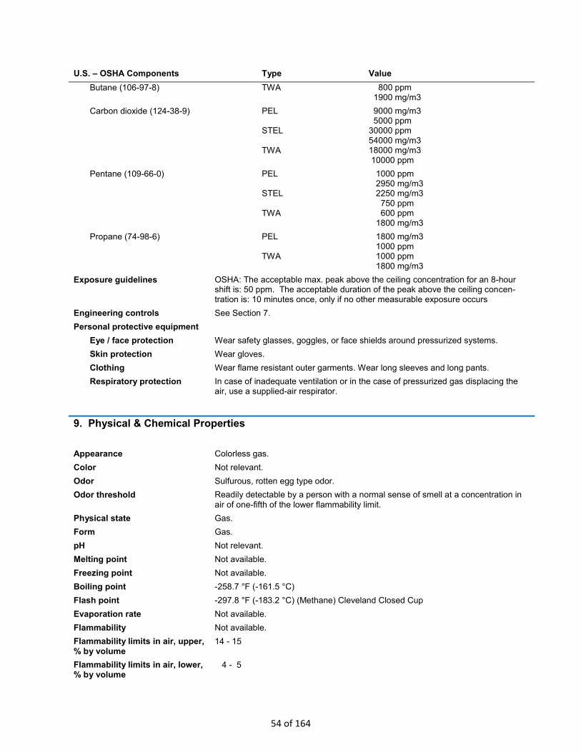
U.S. – OSHA Components Type Value
Butane (106-97-8) TWA 800 ppm 1900 mg/m3
Carbon dioxide (124-38-9) PEL STEL TWA
9000 mg/m3 5000 ppm 30000 ppm 54000 mg/m3 18000 mg/m3 10000 ppm
Pentane (109-66-0) PEL STEL TWA
1000 ppm 2950 mg/m3 2250 mg/m3 750 ppm 600 ppm 1800 mg/m3
Propane (74-98-6) PEL TWA
1800 mg/m3 1000 ppm 1000 ppm 1800 mg/m3
Exposure guidelines OSHA: The acceptable max. peak above the ceiling concentration for an 8-hour shift is: 50 ppm. The acceptable duration of the peak above the ceiling concen-tration is: 10 minutes once, only if no other measurable exposure occurs
Engineering controls See Section 7.
Personal protective equipment
Eye / face protection Wear safety glasses, goggles, or face shields around pressurized systems.
Skin protection Wear gloves.
Clothing Wear flame resistant outer garments. Wear long sleeves and long pants.
Respiratory protection In case of inadequate ventilation or in the case of pressurized gas displacing the air, use a supplied-air respirator.
9. Physical & Chemical Properties
Appearance Colorless gas.
Color Not relevant.
Odor Sulfurous, rotten egg type odor.
Odor threshold Readily detectable by a person with a normal sense of smell at a concentration in
air of one-fifth of the lower flammability limit.
Physical state Gas.
Form Gas.
pH Not relevant.
Melting point Not available.
Freezing point Not available.
Boiling point -258.7 °F (-161.5 °C)
Flash point -297.8 °F (-183.2 °C) (Methane) Cleveland Closed Cup
Evaporation rate Not available.
Flammability Not available.
Flammability limits in air, upper,
% by volume 14 - 15
Flammability limits in air, lower, % by volume
4 - 5
54 of 164

Vapor pressure Not available.
Vapor density Not relevant.
Specific gravity 0.56 - 0.625 at 60°F (15°C)
Solubility (water) Insoluble.
Partition coefficient (n-octanol/water)
No data available.
Auto-ignition temperature 900 - 1170 °F (482.2 - 632.2 °C)
Decomposition temperature Not available.
Viscosity Not relevant.
10. Chemical Stability & Reactivity Information
Chemical stability Stable at normal conditions.
Conditions to avoid Heat, flames and sparks.
Incompatible materials Strong oxidizing agents.
Hazardous decomposition products
Carbon dioxide. Carbon monoxide.
Possibility of hazardous
reactions Hazardous polymerization does not occur.
11. Toxicological Information
Toxicological data
Components Test Results
Butane (106-97-8) Acute Inhalation LC50 Rat: 658 mg/l 4 Hours
Pentane (109-66-0) Acute Inhalation LC50 Rat: 364 mg/l 4 Hours
Propane (74-98-6) Acute Inhalation LC50 Rat: > 1442.847 mg/l 15 Minutes
Methane (74-82-8) Not available
Acute effects Asphyxiants displace oxygen in the air and can cause symptoms of oxygen deprivation (asphyxiation): breathing of high vapor concentrations may cause dizziness, light-headedness, headache, nausea and loss of coordination. Continued inhalation may result in unconsciousness. .
Local effects Contact with compressed gas can cause damage (frostbite) due to rapid
evaporative cooling.
Sensitization Not a skin sensitizer.
Chronic effects No data available.
Carcinogenicity No data available.
Mutagenicity No data available.
Reproductive effects No data available.
Teratogenicity No data available.
Further information No other specific acute or chronic health impact noted.
55 of 164

12. Ecological Information
Ecotoxicity The product is a volatile organic compound which has a photochemical ozone creation potential.
Aquatic toxicity Not expected to be harmful to aquatic organisms.
Persistence and degradability The product is easily biodegradable.
Bioaccumulation / Accumulation
The product is not bioaccumulating.
Mobility in environmental media The product is a volatile substance, which may spread in the atmosphere.
Partition coefficient (n-octanol/water)
No data available.
13. Disposal Considerations
Waste codes D001: Waste Flammable material with a flash point <140 °F
Disposal instructions This safety data sheet concerns non-containerized natural gas that is delivered by pipeline from a Southwest Gas meter. See Section 16 for more information.
Do not dispose of waste into sewer. This product, in its unaltered state, when discarded or disposed of, is not a hazardous waste according to Federal regulations (40 CFR 261.4(b)(4)). Under RCRA, it is the responsibility of the user of the product to determine, at the time of disposal, whether the product meets RCRA criteria for hazardous waste.
14. Transport Information
DOT This safety data sheet concerns non-containerized natural gas that is delivered by pipeline from a Southwest Gas meter. Re-transportation of natural gas by pipeline
may be governed by 49 CFR Part 192 and applicable pipeline safety codes.
Basic shipping requirements If this product is placed into a pressurized container and offered for shipment, refer to 49 CFR, Parts 171 to 185, for appropriate regulatory information. See Section 16.
15. Regulatory Information
US federal regulations This product is a "Hazardous Chemical" as defined by the OSHA Hazard Communication Standard, 29 CFR 1910.1200.
Some components are on the U.S. EPA TSCA Inventory List.
US TSCA Section 12(b) Export Notification: Export Notification requirement / De minimis concentration Pentane (CAS 109-66-0) 1.0 % One-Time Export Notification only.
Natural gas reporting requirements are contained in 40 CFR Part 311, 40 CFR Part 370, and 40 CFR Part 372 for industrial users of natural gas and for government employees of hazardous waste operations. Southwest Gas has not attempted to assess the applicability of these regulations to the unique operating characteristics of the applicable employers
56 of 164

Superfund Amendments and Reauthorization Act of 1986 (SARA)
Section 302 extremely hazardous substance
No
Section 311 hazardous chemical
Yes
State regulations California Safe Drinking Water and Toxic Enforcement Act of 1986 (Proposition 65) Warning: By-products of the incomplete combustion of natural gas are known to the State of California to cause cancer, birth defects or other reproductive harm.
US - California Hazardous Substances (Director's): Listed substance
Carbon Monoxide (CAS 630-08-0) Listed.
Formaldehyde (CAS 50-00-0) Listed.
Soot Listed.
16. Other Information
Containerized natural gas and
LNG
This safety data sheet concerns non-containerized natural gas that is delivered by pipeline from a Southwest Gas meter. Containerized natural gas and liquefied natural gas have their own unique hazards that are not provided for in this material safety data sheet. For example, those products require substantially different and specialized engineering controls, safe handling precautions, personal protective equipment, accidental release measures, fire fighting measures, transportation requirements, and product labeling requirements.
Odorant added by
Southwest Gas
This safety data sheet is for natural gas that is odorized by Southwest Gas. Some natural gas transported by Southwest Gas is already odorized from upstream distributors and may contain different odorant blends than those used by Southwest Gas. Please contact Southwest Gas for more information about the source of the natural gas for any particular location. Some downstream users may remove the odorant from the natural gas supplied by Southwest Gas, or may add similar or different odorant blends.
HMIS® ratings Health: 1* Flammability: 4 Physical hazard: 0 (HMIS® is a registered trade and service mark of the NPCA.)
NFPA ratings Health: 1 Flammability: 4 Instability: 0
Definitions
Air-ejector A device that uses the Venturi principle to siphon air or other gases. Compressed air or pressurized inert gas is introduced to allow the pressure at the throat to drop below atmospheric pressure, allowing air or other gases at atmospheric pressure
to flow into the throat.
Fire-watch The assignment of a person or persons to an area for the express purpose of notifying the fire department, the building occupants, or both of an emergency; preventing a fire from occurring; extinguishing small fires; or protecting the public from fire or life safety dangers.
Hot-work Work or operations capable of providing a source of ignition. Includes, but is not limited to: burning, heating, thermal spraying, thawing pipe, torch-applied roofing, or other work involving open flames; sparking of electrical equipment; and cutting, welding, grinding, riveting, buffing, drilling, blasting, chipping, scraping, sawing, brazing, soldering, or other similar operations that create hot metal, sparks, or hot
surfaces from friction or impact.
Retrieval-system Combinations of rescue equipment used for nonentry (external) rescue of persons from hazardous environments or confined spaces.
57 of 164
Disclaimer This product has not been tested by Southwest Gas to determine its specific health hazards. Therefore, the information in this safety data sheet may be incomplete. The information includes health hazard information on the product components that was drawn from external sources. All information is provided without warranty, express or implied. The information is believed to be correct: if errors are discovered, please promptly report them to Southwest Gas. All information contained in this safety data sheet is provided to allow the user to make an independent determination of the methods required to safeguard workers, the public and the environment. This document is not intended to convey legal advice: users should consult all applicable building and construction codes, occupational and process safety codes, environmental regulations, and all other applicable ordinances, rules, codes, regulations, statutes or other law that may include different or more stringent provisions. No effort is made to identify any transportation, environmental, or other regulatory requirements beyond the states of Arizona, California, and Nevada.
Notice of future revisions Notices of revision to this safety data sheet will be provided in customer bill inserts and in messages on the front of the customer bill. Request a current version of this safety data sheet by contacting Southwest Gas (Section 1) or by visiting
www.swgas.com.
Original issue date 02-26-2010
History of revisions The prior version was dated 03-17-2010.
58 of 164

ATTACHMENT I: EMISSION UNITS TABLE
59 of 164

Attachment I Emission Units Table
(includes all emission units and air pollution control devices that will be part of this permit application review, regardless of permitting status)
Emission Unit ID
Emission Point ID
Emission Unit Description Year Installed/ Modified
Design Capacity4
Type and Date of Change
Control Device
S1A S1B S1C
E2A E2B E2C
Pre-Reformer Upon Permit N/A New NA
S2A S2B S2C
E1A E1B E1C
Steam Methane Reformer (SMR) Upon Permit 331 tpd MeOH per unit A, B, and C New
C1A C1B C1C
S3A S3B S3C
E2A E2B E2C
Methanol Synthesis1 Upon Permit 331 tpd MeOH per unit A, B, and C New
C2A C2B C2C
S4A S4B S4C
E2A E2B E2C
Distillation and Refining Columns Upon Permit 331 tpd MeOH per unit A, B, and C New
C2A C2B C2C
S5A S5B S5C
E2A E2B E2C
Flare Upon Permit N/A New C2A C2B C2C
S6T1 S6T2 S6T3 S6T4 S6T5 S6T6 S6T7 S6T8 S6T9
E1A E1B E1C
Methanol Storage Upon Permit
375,000 gal 375,000 gal 375,000 gal 375,000 gal 375,000 gal 375,000 gal 375,000 gal 375,000 gal
New
VB-O2 VB-O2 VB-O2 VB-O2 VB-O2 VB-O2 VB-O2 VB-O2 VB-O2
S7LT1 S7LT2
E1A E1B E1C
Methanol Loading2 – Truck Tanks Upon Permit 800 gal/min per pump New
VB-O2
VB-O2 VB-O2
S7LR1 S7LR2
E1A E1B E1C
Methanol Loading2 – Rail Tank Cars Upon Permit 800 gal/min per pump New
VB-O2
VB-O2 VB-O2
S7PLB E1A E1B E1C
Methanol Loading2 – Barge Upon Permit 1,200 gal/min with spare New
VB-O2
VB-O2 VB-O2
SG1 SG2 SG3 SG4 SG5 SG6 SG7
E3G1 E3G2 E3G3 E3G4 E3G5 E3G6 E3G7
Power Plant3 Upon Permit
5,500 bhp 5,500 bhp 5,500 bhp 5,500 bhp 5,500 bhp 5,500 bhp
New
C3G1 C3G2 C3G3 C3G4 C3G5 C3G6 C3G7
1 During normal operation methanol synthesis recycle loop feeds the purge gas to the SMR burners and its flue gas is subsequently treated by a SCR/oxidation catalyst. During startup, shutdown, and maintenance events, gases are purged to the flare during the event. 2 Methanol storage tanks and methanol unloading utilize vapor balance systems. Excess vapors, if present. are routed to SMR burners and offset any natural gas or purge gas emissions, therefore present no net emissions. This is listed as VB-O to represent the vapor balance system and the other to indicate the SMR. 3 Power plant consists of seven CAT CG260-16 rated at 4000 kWelec (4102 kW engine mechanical power, 5499 bhp) with each engine exhausting to a dedicated SCR/oxidation catalyst and stack. 4 Design capacities are nominal and depend on the ambient conditions and final design.
Page of Emission Units Table
03/2007
60 of 164

ATTACHMENT J: EMISSION POINTS DATA SUMMARY SHEET
61 of 164

Attachment J EMISSION POINTS DATA SUMMARY SHEET
Table 1: Emissions Data
Emission Point ID No. (Must match
Emission Units Table & Plot Plan)
Emission Point
Type1
Emission Unit Vented
Through This Point
(Must match Emission Units
Table & Plot Plan)
Air Pollution Control Device
(Must match Emission Units
Table & Plot Plan)
Vent Time for Emission Unit
(chemical processes only)
All Regulated Pollutants - Chemical
Name/CAS3
(Speciate VOCs
& HAPS)
Maximum Potential
Uncontrolled Emissions 4
Maximum Potential Controlled Emissions 5
Emission Form or Phase
(At exit
conditions, Solid, Liquid
or Gas/Vapor)
Est. Method Used 6
Emission Concentration 7
(ppmv or mg/m3)
ID No. Source ID No. Device Type
Short Term2
Max (hr/yr)
lb/hr ton/yr lb/hr ton/yr
E1A E1B E1C
Upward
Vertical Stack
S2A S2B S2C
SMR
C1A C1B C1B
SCR Oxy-Cat
NA NA NOX
CO
VOC
PM/PM10/PM2.5
SO2
HAP
27.5
3.00
0.903
0.905
0.127
0.00
118.9
13.2
3.96
3.96
0.55
0.00
2.72
1.03
0.513
0.903
0.127
0.00
11.94
7.27
3.60
3.96
0.55
0.00
Gas
EE
8 ppmv
8 ppmv
8 ppmv
See
Attachment
N8
E2A E2B
E2C
Upward
Vertical Stack
S1A, S3A S4A, S5A S1B, S3B S4B, S5B S1C, S3C S4C, S5C
PREFR
MEOH SYNTH
DIST
C2A C2B
C2C
Flare
NA NA NOX
CO
VOC
PM/PM10/PM2.5
SO2
HAP
1.27
9.45
0.17
0.32
0.00
0.11
Gas
EE
See
Attachment
N9
E3G1 E3G2 E3G3 E3G4 E3G5 E3G6 E3G7
Upward
Vertical Stack
SG1 SG2 SG3 SG4 SG5 SG6 SG7
RICE
C3G1 C3G2 C3G3 C3G4 C3G5 C3G6 C3G7
SCR Oxy-Cat
NA NA NOX
CO
VOC
PM/PM10/PM2.5
SO2
HAP
Formaldehyde
11.38
15.54
1.913
0.109
0.02
3.98
3.28
49.88
68.04
8.39
0.48
0.087
17.43
14.37
1.71
1.243
0.958
0.109
0.02
0.542
0.238
7.48
5..44
4.20
0.48
0.087
2.38
1.29
Gas
EE
See
Attachment
N
The EMISSION POINTS DATA SUMMARY SHEET provides a summation of emissions by emission unit. Note that uncaptured process emission unit emissions are not typically considered to be fugitive and must be accounted for on the appropriate EMISSIONS UNIT DATA SHEET and on the EMISSION POINTS DATA SUMMARY SHEET. Please note that total emissions from the source are equal to all vented emissions, all fugitive emissions, plus all other emissions (e.g. uncaptured emissions). Please complete the FUGITIVE EMISSIONS DATA SUMMARY SHEET for fugitive emission activities.
1 Please add descriptors such as upward vertical stack, downward vertical stack, horizontal stack, relief vent, rain cap, etc.
62 of 164

2 Indicate by "C" if venting is continuous. Otherwise, specify the average short-term venting rate with units, for intermittent venting (ie., 15 min/hr). Indicate as many rates as needed to clarify frequency of venting (e.g., 5 min/day, 2 days/wk). 3 List all regulated air pollutants. Speciate VOCs, including all HAPs. Follow chemical name with Chemical Abstracts Service (CAS) number. LIST Acids, CO, CS2, VOCs, H2S, Inorganics, Lead, Organics, O3, NO, NO2, SO2, SO3, all applicable Greenhouse Gases (including CO2 and methane), etc. DO NOT LIST H2, H2O, N2, O2, and Noble Gases. 4 Give maximum potential emission rate with no control equipment operating. If emissions occur for less than 1 hr, then record emissions per batch in minutes (e.g. 5 lb VOC/20 minute batch). Maximum emissions per constituent are from its associated worst case see detailed calculations in Attachment N. Emissions are on a per unit basis. Therefore to obtain entire plant emissions multiple by number of units (3 for first two rows and 7 for last row). 5 Give maximum potential emission rate with proposed control equipment operating. If emissions occur for less than 1 hr, then record emissions per batch in minutes (e.g. 5 lb VOC/20 minute batch). Maximum emissions per constituent are from its associated worst case see detailed calculations in Attachment N. Emissions are on a per unit basis. Therefore to obtain entire plant emissions multiple by number of units (3 for first two rows and 7 for last row). 6 Indicate method used to determine emission rate as follows: MB = material balance; ST = stack test (give date of test); EE = engineering estimate; O = other (specify). 7 Provide for all pollutant emissions. Typically, the units of parts per million by volume (ppmv) are used. If the emission is a mineral acid (sulfuric, nitric, hydrochloric or phosphoric) use units of milligram per dry cubic meter (mg/m3) at standard conditions (68 °F and 29.92 inches Hg) (see 45CSR7). If the pollutant is SO2, use units of ppmv (See 45CSR10). 8 Values shown are for normal operations and do not include SSM events. 9 Only total values are shown as they are made of combinations of different SSM events that have different durations and releases. Within each event the admissions vary over time. Therefore, refer to Attachment N for the detailed uncontrolled emissions and maximum hourly emissions.
page _1_ of _2_ WVDEP-DAQ Revision 2/11
63 of 164
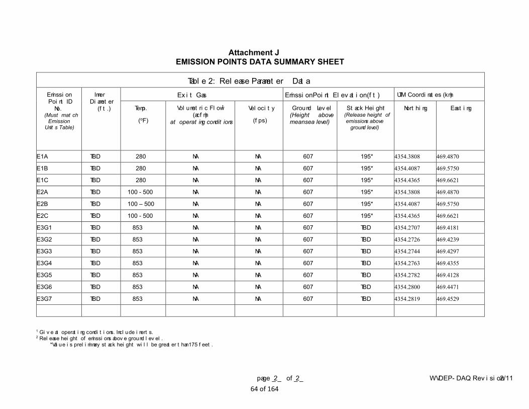
Attachment J EMISSION POINTS DATA SUMMARY SHEET
Table 2: Release Parameter Data Emission Point ID
No. (Must match
Emission Units Table)
Inner Diameter
(ft.)
Exit Gas Emission Point Elevation (ft) UTM Coordinates (km)
Temp.
(oF)
Volumetric Flow 1
(acfm) at operating conditions
Velocity
(fps)
Ground Level (Height above mean sea level)
Stack Height 2 (Release height of emissions above
ground level)
Northing Easting
E1A TBD 280 NA NA 607 195* 4354.3808 469.4870
E1B TBD 280 NA NA 607 195* 4354.4087 469.5750
E1C TBD 280 NA NA 607 195* 4354.4365 469.6621
E2A TBD 100 - 500 NA NA 607 195* 4354.3808 469.4870
E2B TBD 100 – 500 NA NA 607 195* 4354.4087 469.5750
E2C TBD 100 - 500 NA NA 607 195* 4354.4365 469.6621
E3G1 TBD 853 NA NA 607 TBD 4354.2707 469.4181
E3G2 TBD 853 NA NA 607 TBD 4354.2726 469.4239
E3G3 TBD 853 NA NA 607 TBD 4354.2744 469.4297
E3G4 TBD 853 NA NA 607 TBD 4354.2763 469.4355
E3G5 TBD 853 NA NA 607 TBD 4354.2782 469.4128
E3G6 TBD 853 NA NA 607 TBD 4354.2800 469.4471
E3G7 TBD 853 NA NA 607 TBD 4354.2819 469.4529
1 Give at operating conditions. Include inerts. 2 Release height of emissions above ground level.
*Value is preliminary stack height will be greater than 175 feet.
page _2_ of _2_ WVDEP-DAQ Revision 2/11 64 of 164

ATTACHMENT K: FUGITIVE EMISSIONS DATA SUMMARY SHEET
65 of 164

Attachment K FUGITIVE EMISSIONS DATA SUMMARY SHEET
The FUGITIVE EMISSIONS SUMMARY SHEET provides a summation of fugitive emissions. Fugitive emissions are those emissions which could not reasonably pass through a stack, chimney, vent or other functionally equivalent opening. Note that uncaptured process emissions are not typically considered to be fugitive, and must be accounted for on the appropriate EMISSIONS UNIT DATA SHEET and on the EMISSION POINTS DATA SUMMARY SHEET.
Please note that total emissions from the source are equal to all vented emissions, all fugitive emissions, plus all other emissions (e.g. uncaptured emissions).
APPLICATION FORMS CHECKLIST - FUGITIVE EMISSIONS
1.) Will there be haul road activities?
Yes No See Attachment N For Detailed calculations
If YES, then complete the HAUL ROAD EMISSIONS UNIT DATA SHEET.
2.) Will there be Storage Piles?
Yes No
If YES, complete Table 1 of the NONMETALLIC MINERALS PROCESSING EMISSIONS UNIT DATA SHEET.
3.) Will there be Liquid Loading/Unloading Operations?
Yes No
If YES, complete the BULK LIQUID TRANSFER OPERATIONS EMISSIONS UNIT DATA SHEET.
4.) Will there be emissions of air pollutants from Wastewater Treatment Evaporation?
Yes No
If YES, complete the GENERAL EMISSIONS UNIT DATA SHEET.
5.) Will there be Equipment Leaks (e.g. leaks from pumps, compressors, in-line process valves, pressure relief devices, open-ended valves, sampling connections, flanges, agitators, cooling towers, etc.)?
Yes No See Attachment N for Detailed Calculations
If YES, complete the LEAK SOURCE DATA SHEET section of the CHEMICAL PROCESSES EMISSIONS UNIT DATA SHEET.
6.) Will there be General Clean-up VOC Operations?
Yes No
If YES, complete the GENERAL EMISSIONS UNIT DATA SHEET.
7.) Will there be any other activities that generate fugitive emissions?
Yes No
If YES, complete the GENERAL EMISSIONS UNIT DATA SHEET or the most appropriate form.
If you answered “NO” to all of the items above, it is not necessary to complete the following table, “Fugitive Emissions Summary.”
66 of 164
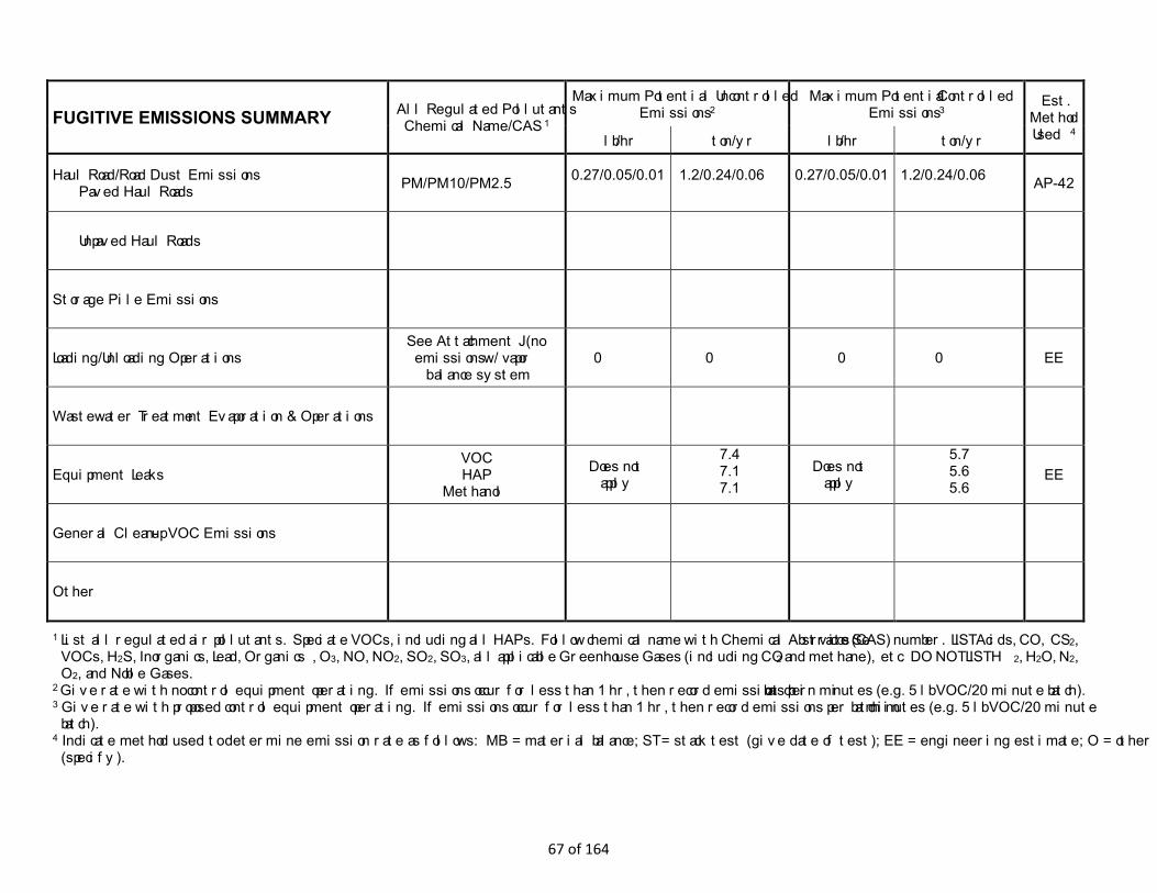
FUGITIVE EMISSIONS SUMMARY All Regulated Pollutants -
Chemical Name/CAS 1
Maximum Potential Uncontrolled Emissions 2
Maximum Potential Controlled Emissions 3
Est. Method Used 4 lb/hr ton/yr lb/hr ton/yr
Haul Road/Road Dust Emissions Paved Haul Roads PM/PM10/PM2.5 0.27/0.05/0.01
1.2/0.24/0.06
0.27/0.05/0.01
1.2/0.24/0.06
AP-42
Unpaved Haul Roads
Storage Pile Emissions
Loading/Unloading Operations See Attachment J (no emissions w/ vapor
balance system 0 0 0 0 EE
Wastewater Treatment Evaporation & Operations
Equipment Leaks VOC HAP
Methanol
Does not apply
7.4 7.1 7.1
Does not apply
5.7 5.6 5.6
EE
General Clean-up VOC Emissions
Other
1 List all regulated air pollutants. Speciate VOCs, including all HAPs. Follow chemical name with Chemical Abstracts Service (CAS) number. LIST Acids, CO, CS2, VOCs, H2S, Inorganics, Lead, Organics, O3, NO, NO2, SO2, SO3, all applicable Greenhouse Gases (including CO2 and methane), etc. DO NOT LIST H2, H2O, N2, O2, and Noble Gases.
2 Give rate with no control equipment operating. If emissions occur for less than 1 hr, then record emissions per batch in minutes (e.g. 5 lb VOC/20 minute batch). 3 Give rate with proposed control equipment operating. If emissions occur for less than 1 hr, then record emissions per batch in minutes (e.g. 5 lb VOC/20 minute
batch). 4 Indicate method used to determine emission rate as follows: MB = material balance; ST = stack test (give date of test); EE = engineering estimate; O = other
(specify).
67 of 164

ATTACHMENT L: EMISSIONS UNIT DATA SHEETS
68 of 164
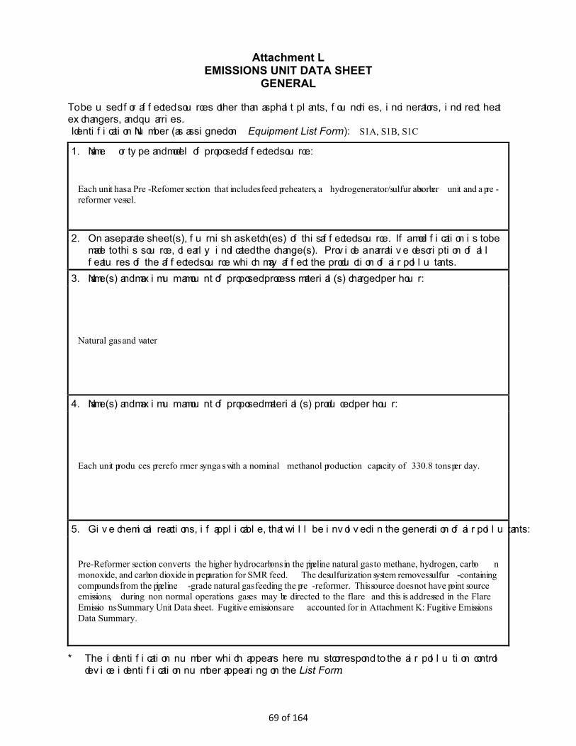
Attachment L EMISSIONS UNIT DATA SHEET
GENERAL
To be used for affected sources other than asphalt plants, foundries, incinerators, indirect heat exchangers, and quarries. Identification Number (as assigned on Equipment List Form): S1A, S1B, S1C 1. Name or type and model of proposed affected source:
Each unit has a Pre-Refomer section that includes feed preheaters, a hydrogenerator/sulfur absorber unit and a pre-reformer vessel.
2. On a separate sheet(s), furnish a sketch(es) of this affected source. If a modification is to be made to this source, clearly indicated the change(s). Provide a narrative description of all features of the affected source which may affect the production of air pollutants.
3. Name(s) and maximum amount of proposed process material(s) charged per hour:
Natural gas and water
4. Name(s) and maximum amount of proposed material(s) produced per hour:
Each unit produces prereformer syngas with a nominal methanol production capacity of 330.8 tons per day.
5. Give chemical reactions, if applicable, that will be involved in the generation of air pollutants:
Pre-Reformer section converts the higher hydrocarbons in the pipeline natural gas to methane, hydrogen, carbon monoxide, and carbon dioxide in preparation for SMR feed. The desulfurization system removes sulfur-containing compounds from the pipeline-grade natural gas feeding the pre-reformer. This source does not have point source emissions, during non normal operations gases may be directed to the flare and this is addressed in the Flare Emissions Summary Unit Data sheet. Fugitive emissions are accounted for in Attachment K: Fugitive Emissions Data Summary.
* The identification number which appears here must correspond to the air pollution control device identification number appearing on the List Form.
69 of 164
6. Combustion Data (if applicable): (a) Type and amount in appropriate units of fuel(s) to be burned:
(b) Chemical analysis of proposed fuel(s), excluding coal, including maximum percent sulfur and ash:
(c) Theoretical combustion air requirement (ACF/unit of fuel):
@ °F and psia.
(d) Percent excess air:
(e) Type and BTU/hr of burners and all other firing equipment planned to be used:
(f) If coal is proposed as a source of fuel, identify supplier and seams and give sizing of the coal as it will be fired:
(g) Proposed maximum design heat input: × 106 BTU/hr.
7. Projected operating schedule:
Hours/Day 24 Days/Week 7 Weeks/Year 52
70 of 164

8. Projected amount of pollutants that would be emitted from this affected source if no control devices were used:
@ °F and psia
a. NOX NA lb/hr grains/ACF
b. SO2 NA lb/hr grains/ACF
c. CO NA lb/hr grains/ACF
d. PM10 NA lb/hr grains/ACF
e. Hydrocarbons NA lb/hr grains/ACF
f. VOCs NA lb/hr grains/ACF
g. Pb NA lb/hr grains/ACF
h. Specify other(s)
lb/hr grains/ACF
lb/hr grains/ACF
lb/hr grains/ACF
lb/hr grains/ACF
NOTE: (1) An Air Pollution Control Device Sheet must be completed for any air pollution device(s) used to control emissions from this affected source.
(2) Complete the Emission Points Data Sheet.
71 of 164
9. Proposed Monitoring, Recordkeeping, Reporting, and Testing Please propose monitoring, recordkeeping, and reporting in order to demonstrate compliance with the proposed operating parameters. Please propose testing in order to demonstrate compliance with the proposed emissions limits.
MONITORING
RECORDKEEPING
REPORTING
TESTING
MONITORING. PLEASE LIST AND DESCRIBE THE PROCESS PARAMETERS AND RANGES THAT ARE PROPOSED TO BE MONITORED IN ORDER TO DEMONSTRATE COMPLIANCE WITH THE OPERATION OF THIS PROCESS EQUIPMENT OPERATION/AIR POLLUTION CONTROL DEVICE. RECORDKEEPING. PLEASE DESCRIBE THE PROPOSED RECORDKEEPING THAT WILL ACCOMPANY THE MONITORING. REPORTING. PLEASE DESCRIBE THE PROPOSED FREQUENCY OF REPORTING OF THE RECORDKEEPING. TESTING. PLEASE DESCRIBE ANY PROPOSED EMISSIONS TESTING FOR THIS PROCESS EQUIPMENT/AIR POLLUTION CONTROL DEVICE. 10. Describe all operating ranges and maintenance procedures required by Manufacturer to maintain warranty Each Pre-Reformer section will be operated and maintained in accordance with the design and the plant's Operating and Maintenance procedures.
72 of 164
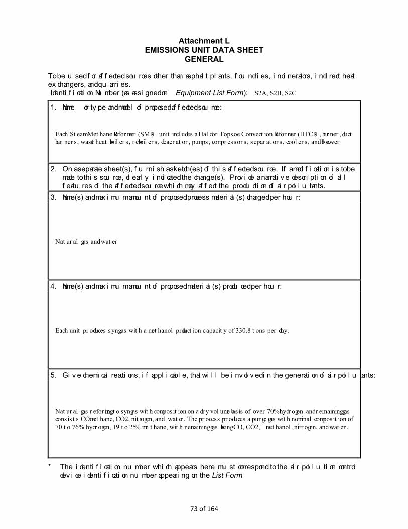
Attachment L EMISSIONS UNIT DATA SHEET
GENERAL
To be used for affected sources other than asphalt plants, foundries, incinerators, indirect heat exchangers, and quarries. Identification Number (as assigned on Equipment List Form): S2A, S2B, S2C 1. Name or type and model of proposed affected source:
Each Steam Methane Reformer (SMR) unit includes a Haldor Topsoe Convection Reformer (HTCR), burner, duct burners, waste heat boilers, reboilers, deaerator, pumps, compressors, separators, coolers, and blowers.
2. On a separate sheet(s), furnish a sketch(es) of this affected source. If a modification is to be made to this source, clearly indicated the change(s). Provide a narrative description of all features of the affected source which may affect the production of air pollutants.
3. Name(s) and maximum amount of proposed process material(s) charged per hour:
Natural gas and water
4. Name(s) and maximum amount of proposed material(s) produced per hour:
Each unit produces syngas with a methanol production capacity of 330.8 tons per day.
5. Give chemical reactions, if applicable, that will be involved in the generation of air pollutants:
Natural gas reforming to syngas with composition on a dry volume basis of over 70% hydrogen and remaining gas consists CO, methane, CO2, nitrogen, and water. The process produces a purge gas with nominal composition of 70 to 76% hydrogen, 19 to 25% methane, with remaining gas being CO, CO2, methanol, nitrogen, and water.
* The identification number which appears here must correspond to the air pollution control device identification number appearing on the List Form.
73 of 164
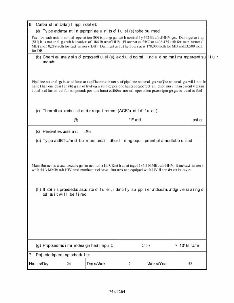
6. Combustion Data (if applicable): (a) Type and amount in appropriate units of fuel(s) to be burned:
Fuel for each unit in normal operation (NO) is purge gas with nominally 462 Btu/scf HHV gas. During start up (SU) it is natural gas with lean value of 1084 Btu/scf HHV. Flow rates for NO are 406,475 scfh for main burner ( MB) and 50,289 scfh for duct burners (DB). During startup the flow rate is 178,000 scfh for MB and 53,500 scfh for DB.
(b) Chemical analysis of proposed fuel(s), excluding coal, including maximum percent sulfur and ash:
Pipeline natural gas is used for startup. The constituents of pipeline natural gas vary The natural gas will not be more than one quarter (1/4) grain of hydrogen sulfide per one hundred cubic feet and not more than twenty grains total sulfur or sulfur compounds per one hundred feet. For normal operation process (purge) gas is used as fuel.
(c) Theoretical combustion air requirement (ACF/unit of fuel):
@ °F and psia.
(d) Percent excess air: 10%
(e) Type and BTU/hr of burners and all other firing equipment planned to be used:
Main Burner is a dual nozzle gas burner for a HTCR with a rating of 186.5 MMBtu/h HHV. In line duct burners with 54.3 MMBtu/h HHV maximum heat release. Burners are equipped with UV flame detection device.
(f) If coal is proposed as a source of fuel, identify supplier and seams and give sizing of the coal as it will be fired:
(g) Proposed maximum design heat input: 240.8 × 10⁶ BTU/hr.
7. Projected operating schedule:
Hours/Day 24 Days/Week 7 Weeks/Year 52
74 of 164

8. Projected amount of pollutants that would be emitted from this affected source if no control devices were used:
@ °F and psia
a. NOX See Attachment N lb/hr grains/ACF
b. SO2 See Attachment N lb/hr grains/ACF
c. CO See Attachment N lb/hr grains/ACF
d. PM10 See Attachment N lb/hr grains/ACF
e. Hydrocarbons See Attachment N lb/hr grains/ACF
f. VOCs See Attachment N lb/hr grains/ACF
g. Pb See Attachment N lb/hr grains/ACF
h. Specify other(s)
See Attachment N lb/hr grains/ACF
lb/hr grains/ACF
lb/hr grains/ACF
lb/hr grains/ACF
NOTE: (1) An Air Pollution Control Device Sheet must be completed for any air pollution device(s) used to control emissions from this affected source.
(2) Complete the Emission Points Data Sheet.
75 of 164
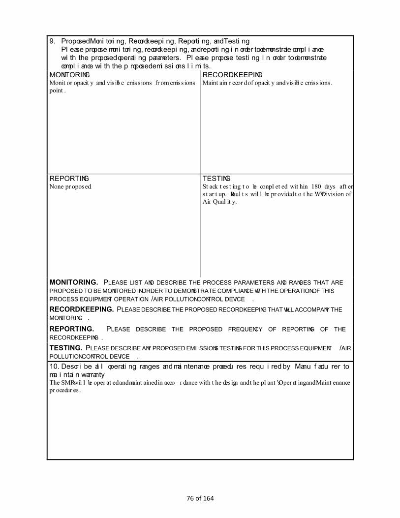
9. Proposed Monitoring, Recordkeeping, Reporting, and Testing Please propose monitoring, recordkeeping, and reporting in order to demonstrate compliance with the proposed operating parameters. Please propose testing in order to demonstrate compliance with the proposed emissions limits.
MONITORING Monitor opacity and visible emissions from emissions point.
RECORDKEEPING Maintain record of opacity and visible emissions.
REPORTING None proposed.
TESTING Stack testing to be completed within 180 days after startup. Results will be provided to the WV Division of Air Quality.
MONITORING. PLEASE LIST AND DESCRIBE THE PROCESS PARAMETERS AND RANGES THAT ARE PROPOSED TO BE MONITORED IN ORDER TO DEMONSTRATE COMPLIANCE WITH THE OPERATION OF THIS PROCESS EQUIPMENT OPERATION/AIR POLLUTION CONTROL DEVICE. RECORDKEEPING. PLEASE DESCRIBE THE PROPOSED RECORDKEEPING THAT WILL ACCOMPANY THE MONITORING. REPORTING. PLEASE DESCRIBE THE PROPOSED FREQUENCY OF REPORTING OF THE RECORDKEEPING. TESTING. PLEASE DESCRIBE ANY PROPOSED EMISSIONS TESTING FOR THIS PROCESS EQUIPMENT/AIR POLLUTION CONTROL DEVICE. 10. Describe all operating ranges and maintenance procedures required by Manufacturer to maintain warranty The SMR will be operated and maintained in accordance with the design and the plant's Operating and Maintenance procedures.
76 of 164
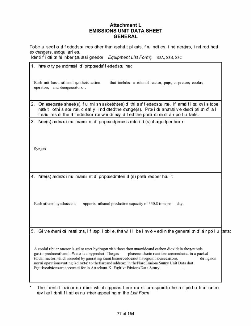
Attachment L EMISSIONS UNIT DATA SHEET
GENERAL
To be used for affected sources other than asphalt plants, foundries, incinerators, indirect heat exchangers, and quarries. Identification Number (as assigned on Equipment List Form): S3A, S3B, S3C 1. Name or type and model of proposed affected source:
Each unit has a methanol synthesis section that includes a methanol reactor, pumps, compressors, coolers, seperators, and steam generators. .
2. On a separate sheet(s), furnish a sketch(es) of this affected source. If a modification is to be made to this source, clearly indicated the change(s). Provide a narrative description of all features of the affected source which may affect the production of air pollutants.
3. Name(s) and maximum amount of proposed process material(s) charged per hour:
Syngas
4. Name(s) and maximum amount of proposed material(s) produced per hour:
Each methanol synthesis unit supports methanol production capacity of 330.8 tons per day.
5. Give chemical reactions, if applicable, that will be involved in the generation of air pollutants:
A cooled tubular reactor is used to react hydrogen with the carbon monoxide and carbon dioxide in the synthesis gas to produce methanol. Water is a byproduct. The gas-phase exothermic reactions are conducted in a packed tubular reactor, which is cooled by generating steam.This source does not have point source emissions, during non normal operations venting is directed to the flare and addressed in the Flare Emissions Summary Unit Data sheet. Fugitive emissions are accounted for in Attachment K: Fugitive Emissions Data Summary.
* The identification number which appears here must correspond to the air pollution control device identification number appearing on the List Form.
77 of 164
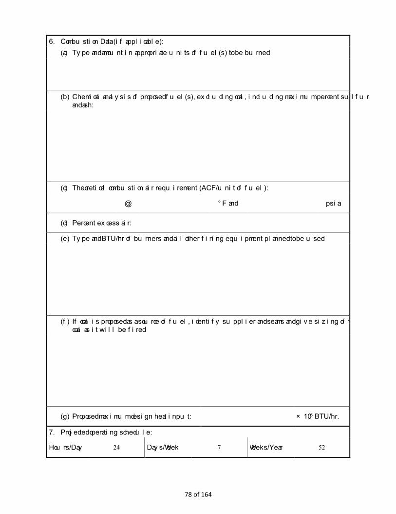
6. Combustion Data (if applicable): (a) Type and amount in appropriate units of fuel(s) to be burned:
(b) Chemical analysis of proposed fuel(s), excluding coal, including maximum percent sulfur and ash:
(c) Theoretical combustion air requirement (ACF/unit of fuel):
@ °F and psia.
(d) Percent excess air:
(e) Type and BTU/hr of burners and all other firing equipment planned to be used:
(f) If coal is proposed as a source of fuel, identify supplier and seams and give sizing of the coal as it will be fired:
(g) Proposed maximum design heat input: × 106 BTU/hr.
7. Projected operating schedule:
Hours/Day 24 Days/Week 7 Weeks/Year 52
78 of 164

8. Projected amount of pollutants that would be emitted from this affected source if no control devices were used:
@ °F and psia
a. NOX NA lb/hr grains/ACF
b. SO2 NA lb/hr grains/ACF
c. CO NA lb/hr grains/ACF
d. PM10 NA lb/hr grains/ACF
e. Hydrocarbons NA lb/hr grains/ACF
f. VOCs NA lb/hr grains/ACF
g. Pb NA lb/hr grains/ACF
h. Specify other(s)
lb/hr grains/ACF
lb/hr grains/ACF
lb/hr grains/ACF
lb/hr grains/ACF
NOTE: (1) An Air Pollution Control Device Sheet must be completed for any air pollution device(s) used to control emissions from this affected source.
(2) Complete the Emission Points Data Sheet.
79 of 164

9. Proposed Monitoring, Recordkeeping, Reporting, and Testing Please propose monitoring, recordkeeping, and reporting in order to demonstrate compliance with the proposed operating parameters. Please propose testing in order to demonstrate compliance with the proposed emissions limits.
MONITORING
RECORDKEEPING
REPORTING
TESTING
MONITORING. PLEASE LIST AND DESCRIBE THE PROCESS PARAMETERS AND RANGES THAT ARE PROPOSED TO BE MONITORED IN ORDER TO DEMONSTRATE COMPLIANCE WITH THE OPERATION OF THIS PROCESS EQUIPMENT OPERATION/AIR POLLUTION CONTROL DEVICE. RECORDKEEPING. PLEASE DESCRIBE THE PROPOSED RECORDKEEPING THAT WILL ACCOMPANY THE MONITORING. REPORTING. PLEASE DESCRIBE THE PROPOSED FREQUENCY OF REPORTING OF THE RECORDKEEPING. TESTING. PLEASE DESCRIBE ANY PROPOSED EMISSIONS TESTING FOR THIS PROCESS EQUIPMENT/AIR POLLUTION CONTROL DEVICE. 10. Describe all operating ranges and maintenance procedures required by Manufacturer to maintain warranty Each Methanol Synthesis Section will be operated and maintained in accordance with the design and the plant's Operating and Maintenance procedures.
80 of 164

Attachment L EMISSIONS UNIT DATA SHEET
GENERAL
To be used for affected sources other than asphalt plants, foundries, incinerators, indirect heat exchangers, and quarries. Identification Number (as assigned on Equipment List Form): S4A, S4B, S4C 1. Name or type and model of proposed affected source:
Each unit has a methanol distillation system consists of a series of distillation columns that purify the crude methanol to IMPCA-specification methanol and purify the byproduct water to where it can be recycled in the processs. The system inclues columns, tanks, pumps, reboilers, accumulators, strippers, condensers, and coolers .
2. On a separate sheet(s), furnish a sketch(es) of this affected source. If a modification is to be made to this source, clearly indicated the change(s). Provide a narrative description of all features of the affected source which may affect the production of air pollutants.
3. Name(s) and maximum amount of proposed process material(s) charged per hour:
Raw methanol and water
4. Name(s) and maximum amount of proposed material(s) produced per hour:
Each methanol dsitillation system unit supports a nominal methanol production capacity of 330.8 tons per day.
5. Give chemical reactions, if applicable, that will be involved in the generation of air pollutants:
Distillation columns purify the crude methanol to IMPCA-specification methanol and purify the byproduct water to a quality where it can be recycled in the processs. This source does not have point source emissions, during non normal operations venting is directed to the flare and addressed in the Flare Emissions Summary Unit Data sheet. Fugitive emissions are accounted for in Attachment K: Fugitive Emissions Data Summary.
* The identification number which appears here must correspond to the air pollution control device identification number appearing on the List Form.
81 of 164

6. Combustion Data (if applicable): (a) Type and amount in appropriate units of fuel(s) to be burned:
(b) Chemical analysis of proposed fuel(s), excluding coal, including maximum percent sulfur and ash:
(c) Theoretical combustion air requirement (ACF/unit of fuel):
@ °F and psia.
(d) Percent excess air:
(e) Type and BTU/hr of burners and all other firing equipment planned to be used:
(f) If coal is proposed as a source of fuel, identify supplier and seams and give sizing of the coal as it will be fired:
(g) Proposed maximum design heat input: × 106 BTU/hr.
7. Projected operating schedule:
Hours/Day 24 Days/Week 7 Weeks/Year 52
82 of 164

8. Projected amount of pollutants that would be emitted from this affected source if no control devices were used:
@ °F and psia
a. NOX NA lb/hr grains/ACF
b. SO2 NA lb/hr grains/ACF
c. CO NA lb/hr grains/ACF
d. PM10 NA lb/hr grains/ACF
e. Hydrocarbons NA lb/hr grains/ACF
f. VOCs NA lb/hr grains/ACF
g. Pb NA lb/hr grains/ACF
h. Specify other(s)
lb/hr grains/ACF
lb/hr grains/ACF
lb/hr grains/ACF
lb/hr grains/ACF
NOTE: (1) An Air Pollution Control Device Sheet must be completed for any air pollution device(s) used to control emissions from this affected source.
(2) Complete the Emission Points Data Sheet.
83 of 164

9. Proposed Monitoring, Recordkeeping, Reporting, and Testing Please propose monitoring, recordkeeping, and reporting in order to demonstrate compliance with the proposed operating parameters. Please propose testing in order to demonstrate compliance with the proposed emissions limits.
MONITORING
RECORDKEEPING
REPORTING
TESTING
MONITORING. PLEASE LIST AND DESCRIBE THE PROCESS PARAMETERS AND RANGES THAT ARE PROPOSED TO BE MONITORED IN ORDER TO DEMONSTRATE COMPLIANCE WITH THE OPERATION OF THIS PROCESS EQUIPMENT OPERATION/AIR POLLUTION CONTROL DEVICE. RECORDKEEPING. PLEASE DESCRIBE THE PROPOSED RECORDKEEPING THAT WILL ACCOMPANY THE MONITORING. REPORTING. PLEASE DESCRIBE THE PROPOSED FREQUENCY OF REPORTING OF THE RECORDKEEPING. TESTING. PLEASE DESCRIBE ANY PROPOSED EMISSIONS TESTING FOR THIS PROCESS EQUIPMENT/AIR POLLUTION CONTROL DEVICE. 10. Describe all operating ranges and maintenance procedures required by Manufacturer to maintain warranty Each Methanol Distillation System will be operated and maintained in accordance with the design and the plant's Operating and Maintenance procedures.
84 of 164

Attachment L EMISSIONS UNIT DATA SHEET
GENERAL
To be used for affected sources other than asphalt plants, foundries, incinerators, indirect heat exchangers, and quarries. Identification Number (as assigned on Equipment List Form): S5A, S5B, S5C 1. Name or type and model of proposed affected source:
Each methanol unit is equipped with a dual flare with a High Pressure (HP) flare section and a Low Pressure (LP) flare section. There is a natural gas fueled pilot that serves the HP and LP sections. The HP flare section is utilized during startup, shutdown, and maintenance (SSM) events and is sometimes referred to as the SSM flare. The LP flare section is available to handle small equipment leaks (between repairs of those leaks). Additional informaton on flare is provided in Attachment M, Air Pollution Control Device for Flare System.
2. On a separate sheet(s), furnish a sketch(es) of this affected source. If a modification is to be made to this source, clearly indicated the change(s). Provide a narrative description of all features of the affected source which may affect the production of air pollutants.
3. Name(s) and maximum amount of proposed process material(s) charged per hour:
LP flare section serves as the control device for equipment leaks. Tyically, there are no equipment leaks. When there is an equipment leak, the leaked gases go to the LP flare section. Leaks occur when there is an equipment or component issue and occurs until a repair is made or the equipment or component is isolated and taken out of service. HP flare section has no gases during normal operation. During startup, shutdown, or trip situations natural gas or process syngas is routed to the flare. The HP/LP flare has six pilot burners to keep the flare lit.
4. Name(s) and maximum amount of proposed material(s) produced per hour:
The primary effluents from the flare are CO2, nitrogen, water vapor, and oxyen (See Attachment N for details).
5. Give chemical reactions, if applicable, that will be involved in the generation of air pollutants:
The flare treats the gases via a combusion process. Generally, carbon is converted to CO2 and Hydrogen is converted to water.
* The identification number which appears here must correspond to the air pollution control device identification number appearing on the List Form.
85 of 164
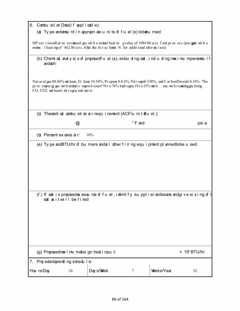
6. Combustion Data (if applicable): (a) Type and amount in appropriate units of fuel(s) to be burned:
HP section will process natural gas with a nominal heating value of 1084 Btu/scf and process (purge) gas with a nominal heating of 462 Btu/scf. (See See Attachment N for additional information.)
(b) Chemical analysis of proposed fuel(s), excluding coal, including maximum percent sulfur and ash:
Natural gas: 88.86% methane, Ethane 10.54%, Propane 0.06%, Nitrogen 0.338%, and Carbon Dioxide 0.16%. The process/purge gas with nominal composition of 70 to 76% hydrogen, 19 to 25% methane, with remaining gas being CO, CO2, methanol, nitrogen, and water.
(c) Theoretical combustion air requirement (ACF/unit of fuel):
@ °F and psia.
(d) Percent excess air: 10%
(e) Type and BTU/hr of burners and all other firing equipment planned to be used:
(f) If coal is proposed as a source of fuel, identify supplier and seams and give sizing of the coal as it will be fired:
(g) Proposed maximum design heat input: × 106 BTU/hr.
7. Projected operating schedule:
Hours/Day 24 Days/Week 7 Weeks/Year 52
86 of 164

8. Projected amount of pollutants that would be emitted from this affected source if no control devices were used:
@ °F and psia
a. NOX See Attachment N lb/hr grains/ACF
b. SO2 See Attachment N lb/hr grains/ACF
c. CO See Attachment N lb/hr grains/ACF
d. PM10 See Attachment N lb/hr grains/ACF
e. Hydrocarbons See Attachment N lb/hr grains/ACF
f. VOCs See Attachment N lb/hr grains/ACF
g. Pb See Attachment N lb/hr grains/ACF
h. Specify other(s)
lb/hr grains/ACF
lb/hr grains/ACF
lb/hr grains/ACF
lb/hr grains/ACF
NOTE: (1) An Air Pollution Control Device Sheet must be completed for any air pollution device(s) used to control emissions from this affected source.
(2) Complete the Emission Points Data Sheet.
87 of 164

9. Proposed Monitoring, Recordkeeping, Reporting, and Testing Please propose monitoring, recordkeeping, and reporting in order to demonstrate compliance with the proposed operating parameters. Please propose testing in order to demonstrate compliance with the proposed emissions limits.
MONITORING See Attachment M, Air Pollution Control Device for Flare System.
RECORDKEEPING See Attachment M, Air Pollution Control Device for Flare System.
REPORTING See Attachment M, Air Pollution Control Device for Flare System.
TESTING See Attachment M, Air Pollution Control Device for Flare System.
MONITORING. PLEASE LIST AND DESCRIBE THE PROCESS PARAMETERS AND RANGES THAT ARE PROPOSED TO BE MONITORED IN ORDER TO DEMONSTRATE COMPLIANCE WITH THE OPERATION OF THIS PROCESS EQUIPMENT OPERATION/AIR POLLUTION CONTROL DEVICE. RECORDKEEPING. PLEASE DESCRIBE THE PROPOSED RECORDKEEPING THAT WILL ACCOMPANY THE MONITORING. REPORTING. PLEASE DESCRIBE THE PROPOSED FREQUENCY OF REPORTING OF THE RECORDKEEPING. TESTING. PLEASE DESCRIBE ANY PROPOSED EMISSIONS TESTING FOR THIS PROCESS EQUIPMENT/AIR POLLUTION CONTROL DEVICE. 10. Describe all operating ranges and maintenance procedures required by Manufacturer to maintain warranty See Attachment M, Air Pollution Control Device for Flare System.
88 of 164
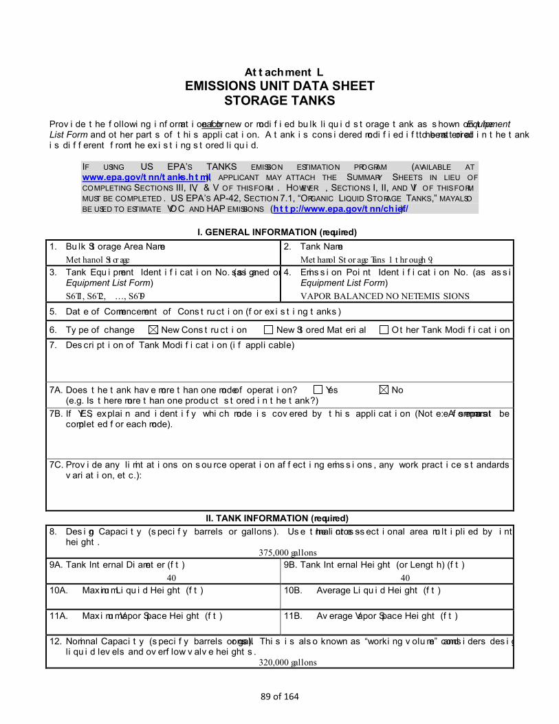
Attachment L EMISSIONS UNIT DATA SHEET
STORAGE TANKS Provide the following information for each new or modified bulk liquid storage tank as shown on the Equipment List Form and other parts of this application. A tank is considered modified if the material to be stored in the tank is different from the existing stored liquid.
IF USING US EPA’S TANKS EMISSION ESTIMATION PROGRAM (AVAILABLE AT www.epa.gov/tnn/tanks.html), APPLICANT MAY ATTACH THE SUMMARY SHEETS IN LIEU OF COMPLETING SECTIONS III, IV, & V OF THIS FORM. HOWEVER, SECTIONS I, II, AND VI OF THIS FORM MUST BE COMPLETED. US EPA’S AP-42, SECTION 7.1, “ORGANIC LIQUID STORAGE TANKS,” MAY ALSO BE USED TO ESTIMATE VOC AND HAP EMISSIONS (http://www.epa.gov/tnn/chief/).
I. GENERAL INFORMATION (required) 1. Bulk Storage Area Name
Methanol Storage 2. Tank Name
Methanol Storage Tans 1 through 9, 3. Tank Equipment Identification No. (as assigned on
Equipment List Form) S6T1, S6T2, …, S6T9
4. Emission Point Identification No. (as assigned on Equipment List Form) VAPOR BALANCED NO NET EMISSIONS
5. Date of Commencement of Construction (for existing tanks)
6. Type of change New Construction New Stored Material Other Tank Modification 7. Description of Tank Modification (if applicable)
7A. Does the tank have more than one mode of operation? Yes No (e.g. Is there more than one product stored in the tank?)
7B. If YES, explain and identify which mode is covered by this application (Note: A separate form must be completed for each mode).
7C. Provide any limitations on source operation affecting emissions, any work practice standards (e.g. production variation, etc.):
II. TANK INFORMATION (required) 8. Design Capacity (specify barrels or gallons). Use the internal cross-sectional area multiplied by internal
height. 375,000 gallons
9A. Tank Internal Diameter (ft) 40
9B. Tank Internal Height (or Length) (ft) 40
10A. Maximum Liquid Height (ft)
10B. Average Liquid Height (ft)
11A. Maximum Vapor Space Height (ft)
11B. Average Vapor Space Height (ft)
12. Nominal Capacity (specify barrels or gallons). This is also known as “working volume” and considers design liquid levels and overflow valve heights.
320,000 gallons
89 of 164

13A. Maximum annual throughput (gal/yr) 13,718,608 (average tank)
13B. Maximum daily throughput (gal/day) 37,585 (average tank)
14. Number of Turnovers per year (annual net throughput/maximum tank liquid volume) 43 (average tank)
15. Maximum tank fill rate (gal/min) 450
16. Tank fill method Submerged Splash Bottom Loading
17. Complete 17A and 17B for Variable Vapor Space Tank Systems Does Not Apply 17A. Volume Expansion Capacity of System (gal)
17B. Number of transfers into system per year
18. Type of tank (check all that apply):
Fixed Roof x vertical horizontal flat roof cone roof dome roof other (describe)
External Floating Roof pontoon roof double deck roof Domed External (or Covered) Floating Roof Internal Floating Roof vertical column support self-supporting Variable Vapor Space lifter roof diaphragm Pressurized spherical X cylindrical Underground Other (describe)
III. TANK CONSTRUCTION & OPERATION INFORMATION (optional if providing TANKS Summary Sheets) 19. Tank Shell Construction:
Riveted Gunite lined Epoxy-coated rivets Other (describe) welded 20A. Shell Color SS 20B. Roof Color SS 20C. Year Last Painted 21. Shell Condition (if metal and unlined):
No Rust Light Rust Dense Rust Not applicable 22A. Is the tank heated? YES NO
22B. If YES, provide the operating temperature (°F)
22C. If YES, please describe how heat is provided to tank.
23. Operating Pressure Range (psig): <0 to 6
24. Complete the following section for Vertical Fixed Roof Tanks Does Not Apply
24A. For dome roof, provide roof radius (ft) TBD
24B. For cone roof, provide slope (ft/ft)
25. Complete the following section for Floating Roof Tanks Does Not Apply
25A. Year Internal Floaters Installed:
25B. Primary Seal Type: Metallic (Mechanical) Shoe Seal Liquid Mounted Resilient Seal (check one) Vapor Mounted Resilient Seal Other (describe):
25C. Is the Floating Roof equipped with a Secondary Seal? YES NO
25D. If YES, how is the secondary seal mounted? (check one) Shoe Rim Other (describe):
25E. Is the Floating Roof equipped with a weather shield? YES NO
90 of 164
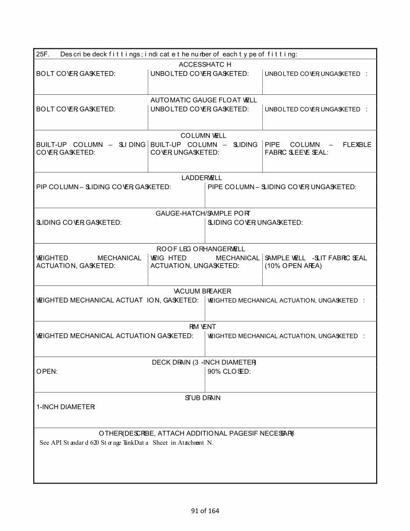
25F. Describe deck fittings; indicate the number of each type of fitting: ACCESS HATCH
BOLT COVER, GASKETED:
UNBOLTED COVER, GASKETED:
UNBOLTED COVER, UNGASKETED:
AUTOMATIC GAUGE FLOAT WELL BOLT COVER, GASKETED:
UNBOLTED COVER, GASKETED:
UNBOLTED COVER, UNGASKETED:
COLUMN WELL BUILT-UP COLUMN – SLIDING COVER, GASKETED:
BUILT-UP COLUMN – SLIDING COVER, UNGASKETED:
PIPE COLUMN – FLEXIBLE FABRIC SLEEVE SEAL:
LADDER WELL PIP COLUMN – SLIDING COVER, GASKETED:
PIPE COLUMN – SLIDING COVER, UNGASKETED:
GAUGE-HATCH/SAMPLE PORT SLIDING COVER, GASKETED:
SLIDING COVER, UNGASKETED:
ROOF LEG OR HANGER WELL WEIGHTED MECHANICAL ACTUATION, GASKETED:
WEIGHTED MECHANICAL ACTUATION, UNGASKETED:
SAMPLE WELL-SLIT FABRIC SEAL (10% OPEN AREA)
VACUUM BREAKER WEIGHTED MECHANICAL ACTUATION, GASKETED:
WEIGHTED MECHANICAL ACTUATION, UNGASKETED:
RIM VENT WEIGHTED MECHANICAL ACTUATION GASKETED:
WEIGHTED MECHANICAL ACTUATION, UNGASKETED:
DECK DRAIN (3-INCH DIAMETER) OPEN:
90% CLOSED:
STUB DRAIN 1-INCH DIAMETER:
OTHER (DESCRIBE, ATTACH ADDITIONAL PAGES IF NECESSARY) See API Standard 620 Storage Tank Data Sheet in Attachment N.
91 of 164

26. Complete the following section for Internal Floating Roof Tanks Does Not Apply
26A. Deck Type: Bolted Welded 26B. For Bolted decks, provide deck construction:
26C. Deck seam: Continuous sheet construction 5 feet wide Continuous sheet construction 6 feet wide Continuous sheet construction 7 feet wide Continuous sheet construction 5 × 7.5 feet wide Continuous sheet construction 5 × 12 feet wide Other (describe)
26D. Deck seam length (ft) 26E. Area of deck (ft2) For column supported tanks: 26F. Number of columns:
26G. Diameter of each column:
IV. SITE INFORMANTION (optional if providing TANKS Summary Sheets) 27. Provide the city and state on which the data in this section are based.
Pittsburgh, PA 28. Daily Average Ambient Temperature (°F) 50.31
29. Annual Average Maximum Temperature (°F) 92.6
30. Annual Average Minimum Temperature (°F) 7.5
31. Average Wind Speed (miles/hr) 9.08
32. Annual Average Solar Insulation Factor (BTU/(ft2·day)) 1.203
33. Atmospheric Pressure (psia) 14.109
V. LIQUID INFORMATION (optional if providing TANKS Summary Sheets) 34. Average daily temperature range of bulk liquid:
34A. Minimum (°F) 17.5 34B. Maximum (°F) 102.6
35. Average operating pressure range of tank:
35A. Minimum (psig) 0 35B. Maximum (psig) 6
36A. Minimum Liquid Surface Temperature (°F) 17.5
36B. Corresponding Vapor Pressure (psia) 0.58
37A. Average Liquid Surface Temperature (°F) 051.94
37B. Corresponding Vapor Pressure (psia) 1.113
38A. Maximum Liquid Surface Temperature (°F) 102.6
38B. Corresponding Vapor Pressure (psia) 4.95
39. Provide the following for each liquid or gas to be stored in tank. Add additional pages if necessary. 39A. Material Name or Composition Methanol
39B. CAS Number 67-56-1
39C. Liquid Density (lb/gal) 6.63
39D. Liquid Molecular Weight (lb/lb-mole) 32.04
39E. Vapor Molecular Weight (lb/lb-mole) 32.04
92 of 164
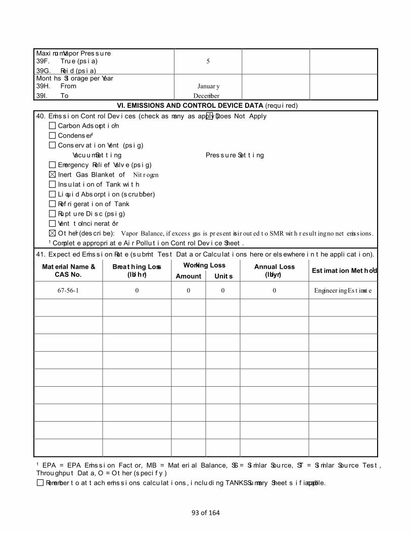
Maximum Vapor Pressure 39F. True (psia) 39G. Reid (psia)
5
Months Storage per Year 39H. From 39I. To
January
Decemiber
VI. EMISSIONS AND CONTROL DEVICE DATA (required) 40. Emission Control Devices (check as many as apply): Does Not Apply
Carbon Adsorption1 Condenser1 Conservation Vent (psig)
Vacuum Setting Pressure Setting Emergency Relief Valve (psig) Inert Gas Blanket of Nitrogen Insulation of Tank with Liquid Absorption (scrubber)1 Refrigeration of Tank Rupture Disc (psig) Vent to Incinerator1 Other1 (describe): Vapor Balance, if excess gas is present ti is routed to SMR with resulting no net emissions.
1 Complete appropriate Air Pollution Control Device Sheet. 41. Expected Emission Rate (submit Test Data or Calculations here or elsewhere in the application).
Material Name & CAS No.
Breathing Loss (lb/hr)
Working Loss Annual Loss (lb/yr) Estimation Method1
Amount Units
67-56-1 0 0 0 0 Engineering Estimate
1 EPA = EPA Emission Factor, MB = Material Balance, SS = Similar Source, ST = Similar Source Test, Throughput Data, O = Other (specify)
Remember to attach emissions calculations, including TANKS Summary Sheets if applicable.
93 of 164
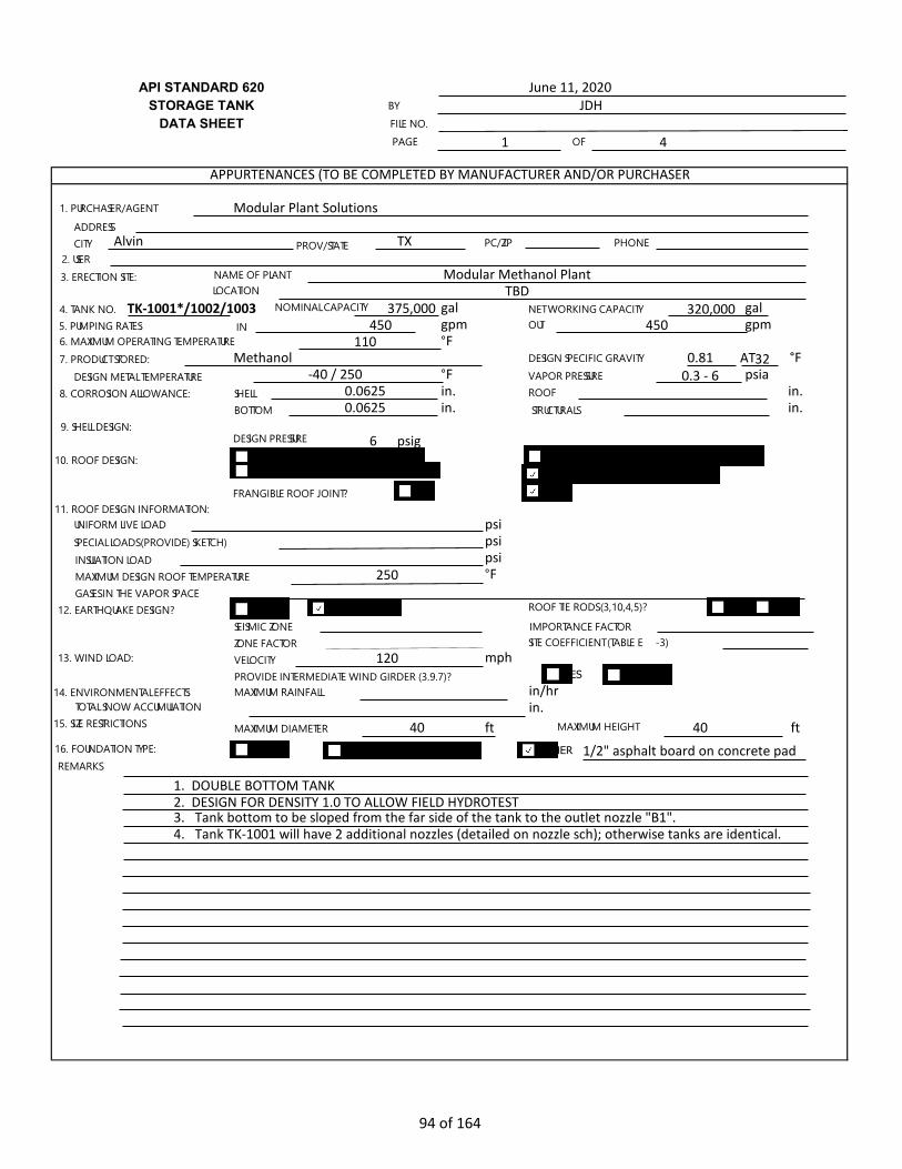
API STANDARD 620STORAGE TANK
DATA SHEET1 4
TX
gal 320,000 galgpm gpm°F
0.81 °F°F 0.3 - 6 psiain. in.in. in.
6 psig
psipsipsi°F
mph
in/hrin.
ft 40 ft
1. DOUBLE BOTTOM TANK2. DESIGN FOR DENSITY 1.0 TO ALLOW FIELD HYDROTEST3. Tank bottom to be sloped from the far side of the tank to the outlet nozzle "B1". 4. Tank TK-1001 will have 2 additional nozzles (detailed on nozzle sch); otherwise tanks are identical.
June 11, 2020JDH
APPURTENANCES (TO BE COMPLETED BY MANUFACTURER AND/OR PURCHASER
Modular Plant Solutions
TBD375,000
450 450110
TK-1001*/1002/1003
Alvin
Modular Methanol Plant
250
Methanol-40 / 250
0.06250.0625
1/2" asphalt board on concrete pad
120
40
BYFILE NO.PAGE OF
1. PURCHASER/AGENT
ADDRESSCITY PROV/STATE PC/ZIP PHONE
2. USER3. ERECTION SITE: NAME OF PLANT
LOCATION
4. TANK NO. NOMINAL CAPACITY NET WORKING CAPACITY5. PUMPING RATES: IN OUT6. MAXIMUM OPERATING TEMPERATURE7. PRODUCT STORED: DESIGN SPECIFIC GRAVITY
DESIGN METAL TEMPERATURE VAPOR PRESSURE8. CORROSION ALLOWANCE: SHELL ROOF
BOTTOM STRUCTURALS9. SHELL DESIGN:
DESIGN PRESSURE
10. ROOF DESIGN: SELF-SUPPORTED CONE ROOF SELF-SUPPORTED UMBRELLA ROOFSUPPORTED CONE ROOF SELF-SUPPORTED DOME ROOF
FRANGIBLE ROOF JOINT? YES11. ROOF DESIGN INFORMATION:
UNIFORM LIVE LOADSPECIAL LOADS (PROVIDE) SKETCH)INSULATION LOADMAXIMUM DESIGN ROOF TEMPERATUREGASES IN THE VAPOR SPACE
12. EARTHQUAKE DESIGN? YES NO ROOF TIE RODS (3,10,4,5)? YES NO
SEISMIC ZONE IMPORTANCE FACTORZONE FACTOR SITE COEFFICIENT (TABLE E-3)
13. WIND LOAD: VELOCITYPROVIDE INTERMEDIATE WIND GIRDER (3.9.7)? YES NO
14. ENVIRONMENTAL EFFECTS: MAXIMUM RAINFALLTOTAL SNOW ACCUMULATION
15. SIZE RESTRICTIONS MAXIMUM DIAMETER MAXIMUM HEIGHT
16. FOUNDATION TYPE: EARTH CONCRETE RINGWALL OTHERREMARKS
AT32
NO
94 of 164

2 4
1.2.3.
in.DOUBLE BOTTOM in/ft
ft ft
CONSTRUCTION DETAILS (TO BE COMPLETED BY MANUFACTURER AND/OR PURCHASER
304 / 304L SS304 / 304L SS304 / 304L SS
304 / 304L SS
0.25
YES
40 40
YES
1. MANUFACTURERADDRESSCITY PROV/STATE PC/ZIP PHONE
SERIAL NO.
2. FABRICATORADDRESSADDRESSCITY PROV/STATE PC/ZIP PHONE
SERIAL NO.3. MATERIAL SPECIFICATIONS SHELL
ROOF
BOTTOMSTRUCTURALS
4. NO. OF SHELL COURSES5. PLATE WIDTHS AND THICKNESSES (INCLUDING CORROSION ALLOWANCE), IN inches
4. 7. 5. 8. 6. 9.
6. TANK BOTTOM: PLATE THICKNESS LAP BUTT SEASLOPE TO FROM CENT
7. MINIMUM WIDTH AND THICKNESS OF BOTTOM ANNULAR PLATES (3.5) IN mm (in.):
8. ROOF-TO-SHELL DETAIL (FIGURE F-1)9. INTERMEDIATE WIND GIRDER? YES NO TOP WIND GIRDER FOR USE AS WALKWAY? YES NO10. ROOF TYPE: SUPPORTED SELF-SUPPORTED FLOATING
SLOPE OR RADIUS mm (in.)11. ROOF PLATE: THICKNESS mm (in.) LAP BUTT JOINT12. PAINT:
SHELL-- EXTERIOR? YES NO INTERIOR? YES NOSURFACE PREPARATION
BOTTOM-- UNDERSIDE? YES NO INTERIOR? YES NOSURFACE PREPARATION
STRUCTURAL STEEL-- EXTERIOR? YES NO INTERIOR? YES NOSPECIFICATION
13. TANK BOTTOM COATING: INTERIOR? YES NO MATERIALAPPLICATION SPECIFICATION
14. INSPECTION BY: SHOP FIELD
15. WELD EXAMINATION: RADIOGRAPHSUPPLEMENTARY LIQUID PENETRANT OR ULTRASONIC
16. FILMS PROPERTY OF
17. LEAK TESTING: BOTTOM ROOFSHELL
18. MILL TEST REPORTS: REQUIRED? YES NOPLATE STRUCTURAL SHAPES
19. PURCHASER'S REFERENCE DRAWING20. TANK SIZE: DIAMETER HEIGHT21. DATE OF STANDARD 620 EDITIONREMARKS
PAGE OF
95 of 164

3 4
in.
ft2
ORIENTATION HEIGHT FROMMARK SIZE SGL DBL SPL A B C D E N=0 BOTTOM SERVICE
A-1 2" 150 RFWN Product Inlet B-1 6" 150 RFWN Product Outlet B-2 4" 150 RFWN Recirculation D-1 4" 150 RFWN DrainT-1 1-1/2" 150 RFWN Thermowell
M-1 24" 150# RF LJ ManwayM-2 24" 150# RF LJ Manway
A3* 3" 150 RFWN Raw productA-4* 1-1/2" 150 RFWN KO liquid
Note: *Nozzles A-3, and A-4 are only in the TK-1001 scope.
11. ROOF NOZZLES, INCLUDING VENTING CONNECTION (SEE FIGURES 3-14 AND 3-15 AND TABLES 3-16 AND 3-17
ORIENTATIONDISTANCE FROMMARK SIZE N=0 CENTER SERVICE
V-1 2" 150# RFWN VentU-1 2" 150# RFWN NitrogenL-1 2" 150# RFWN LevelL-2 2" 150# RFWN LevelS-1 8" 150# RFWN PVMHS-2 8" 150# RFWN PVRVP-1 1-1/2" 150# RFWN PressureA-2 3" 150# RFWN Equalization
M-3 24" 150# RF LJ Manway
NOTE: SKETCHES AND/OR SEPARATE SHEETS MAY BE ATTACHED TO COVER SPECIAL REQUIREMENTS.
APPURTENANCES (TO BE COMPLETED BY MANUFACTURER AND/OR PURCHASER
2 @ 24"1 @ 24"
36No sump; sloped bottom
FLANGED THREADED
FLANGED THREADED REINFORCEMENT
1. STAIRWAY STYLE: CIRCULAR STRAIGHT ANGLE TO HORIZONTAL DEGREESLADDER
2. WALKWAY: WIDTH LENGTH m (ft)3. DRAWOFF SUMP: STANDARD SPECIAL4. BOLTED DOOR SHEET? YES NO RAISED FLUSH5. SCAFFOLD HITCH6. INTERNAL PIPING: SWING LINE SUCTION LINE
HEATING COIL SURFACE AREA7. ROOF DRAIN: HOSE JOINTED
SIPHON8. NO. AND SIZE OF SHELL MANHOLES9. NO. AND SIZE OF ROOF MANHOLES10. SHELL NOZZLES
PAGE OF
96 of 164

4 4
Nozzles A-3 and A-4 are only required on TK-1001. All other nozzles are on all 3 Tanks.
PAGE OF
97 of 164
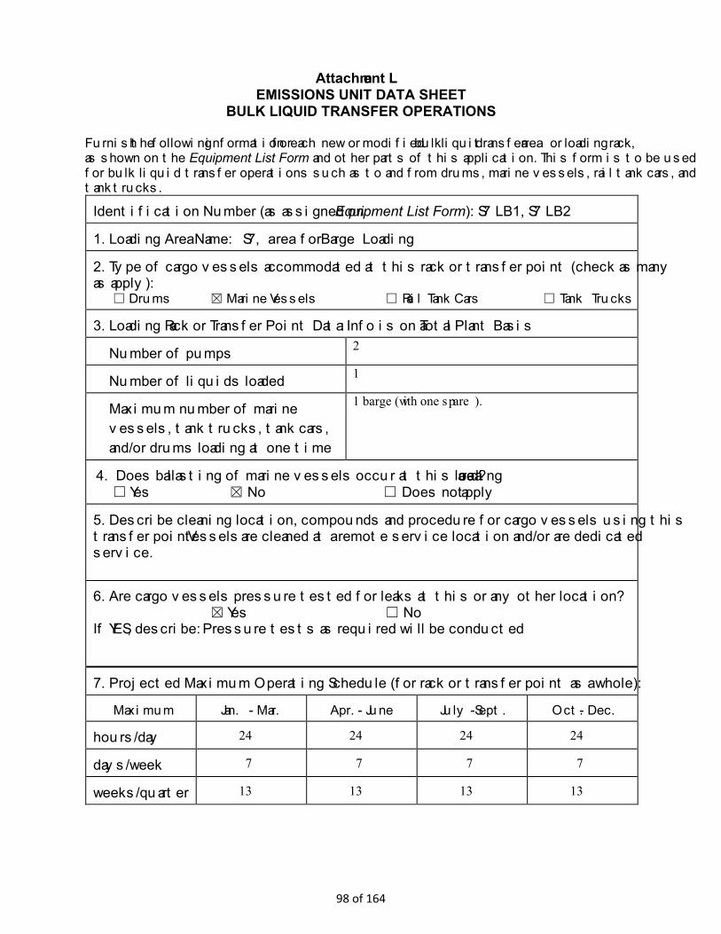
Attachment L EMISSIONS UNIT DATA SHEET
BULK LIQUID TRANSFER OPERATIONS Furnish the following information for each new or modified bulk liquid transfer area or loading rack, as shown on the Equipment List Form and other parts of this application. This form is to be used for bulk liquid transfer operations such as to and from drums, marine vessels, rail tank cars, and tank trucks.
Identification Number (as assigned on Equipment List Form): S7LB1, S7LB2
1. Loading Area Name: S7, area for Barge Loading
2. Type of cargo vessels accommodated at this rack or transfer point (check as many as apply):
☐ Drums ☒ Marine Vessels ☐ Rail Tank Cars ☐ Tank Trucks
3. Loading Rack or Transfer Point Data: Info is on a Total Plant Basis
Number of pumps 2
Number of liquids loaded 1
Maximum number of marine vessels, tank trucks, tank cars, and/or drums loading at one time
1 barge (with one spare).
4. Does ballasting of marine vessels occur at this loading area? ☐ Yes ☒ No ☐ Does not apply
5. Describe cleaning location, compounds and procedure for cargo vessels using this transfer point: Vessels are cleaned at a remote service location and/or are dedicated service.
6. Are cargo vessels pressure tested for leaks at this or any other location? ☒ Yes ☐ No
If YES, describe: Pressure tests as required will be conducted
7. Projected Maximum Operating Schedule (for rack or transfer point as a whole):
Maximum Jan. - Mar. Apr. - June July - Sept. Oct. - Dec.
hours/day 24 24 24 24
days/week 7 7 7 7
weeks/quarter 13 13 13 13
98 of 164
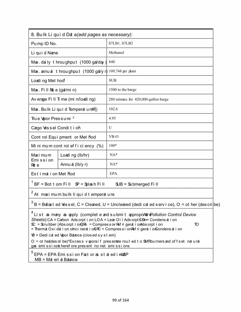
8. Bulk Liquid Data (add pages as necessary):
Pump ID No. S7LB1. S7LB2
Liquid Name Methanol
Max. daily throughput (1000 gal/day) 840
Max. annual throughput (1000 gal/yr) 109,748 per plant
Loading Method 1 SUB
Max. Fill Rate (gal/min) 1500 to the barge
Average Fill Time (min/loading) 280 minutes for 420,000-gallon barge
Max. Bulk Liquid Temperature (oF) 102.6
True Vapor Pressure 2 4.95
Cargo Vessel Condition 3 U
Control Equipment or Method 4 VB-O
Minimum control efficiency (%) 100*
Maximum Emission Rate
Loading (lb/hr) NA*
Annual (lb/yr) NA*
Estimation Method 5 EPA
1 BF = Bottom Fill SP = Splash Fill SUB = Submerged Fill
2 At maximum bulk liquid temperature
3 B = Ballasted Vessel, C = Cleaned, U = Uncleaned (dedicated service), O = other (describe)
4 List as many as apply (complete and submit appropriate Air Pollution Control Device Sheets):CA = Carbon Adsorption LOA = Lean Oil Adsorption CO = Condensation SC = Scrubber (Absorption) CRA = Compressor- Refrigeration-Absorption TO = Thermal Oxidation or Incineration CRC = Compression-Refrigeration-Condensation VB = Dedicated Vapor Balance (closed system) O = other (describe) *Excess vapors, if present. are routed to SMR burners and offset natural gas emissions, therefore present no net emissions 5 EPA = EPA Emission Factor as stated in AP-42
MB = Material Balance
99 of 164

9. Proposed Monitoring, Recordkeeping, Reporting, and Testing Please propose monitoring, recordkeeping, and reporting in order to demonstrate compliance with the proposed operating parameters. Please propose testing in order to demonstrate compliance with the proposed emissions limits.
MONITORING None proposed
RECORDKEEPING Track Daily and Yearly Throughput
REPORTING None proposed
TESTING None proposed
MONITORING. PLEASE LIST AND DESCRIBE THE PROCESS PARAMETERS AND RANGES THAT ARE PROPOSED TO BE MONITORED IN ORDER TO DEMONSTRATE COMPLIANCE WITH THE OPERATION OF THIS PROCESS EQUIPMENT OPERATION/AIR POLLUTION CONTROL DEVICE.
RECORDKEEPING. PLEASE DESCRIBE THE PROPOSED RECORDKEEPING THAT WILL ACCOMPANY THE MONITORING.
REPORTING. PLEASE DESCRIBE THE PROPOSED FREQUENCY OF REPORTING OF THE RECORDKEEPING.
TESTING. PLEASE DESCRIBE ANY PROPOSED EMISSIONS TESTING FOR THIS PROCESS EQUIPMENT/AIR POLLUTION CONTROL DEVICE.
10. Describe all operating ranges and maintenance procedures required by Manufacturer to maintain warranty Manufacturer’s operating ranges and maintenance procedures will be followed as recommended upon selection/design of the system.
TM = Test Measurement based upon test data submittal O = other (describe)
100 of 164
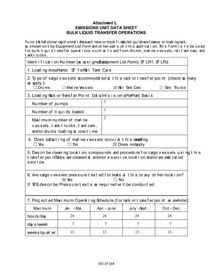
Attachment L EMISSIONS UNIT DATA SHEET
BULK LIQUID TRANSFER OPERATIONS Furnish the following information for each new or modified bulk liquid transfer area or loading rack, as shown on the Equipment List Form and other parts of this application. This form is to be used for bulk liquid transfer operations such as to and from drums, marine vessels, rail tank cars, and tank trucks.
Identification Number (as assigned on Equipment List Form): S7LR1, S7LR2
1. Loading Area Name: S7 for Rail Tank Cars
2. Type of cargo vessels accommodated at this rack or transfer point (check as many as apply):
☐ Drums ☐ Marine Vessels ☒ Rail Tank Cars ☐ Tank Trucks
3. Loading Rack or Transfer Point Data: Info is on a Per Plant Basis
Number of pumps 2
Number of liquids loaded 1
Maximum number of marine vessels, tank trucks, tank cars, and/or drums loading at one time
2
4. Does ballasting of marine vessels occur at this loading area? ☐ Yes ☐ No ☒ Does not apply
5. Describe cleaning location, compounds and procedure for cargo vessels using this transfer point: Tanks are cleaned at a remote service location and/or are dedicated service.
6. Are cargo vessels pressure tested for leaks at this or any other location? ☒ Yes ☐ No
If YES, describe: Pressure tests as required will be conducted
7. Projected Maximum Operating Schedule (for rack or transfer point as a whole):
Maximum Jan. - Mar. Apr. - June July - Sept. Oct. - Dec.
hours/day 24 24 24 24
days/week 7 7 7 7
weeks/quarter 13 13 13 13
101 of 164
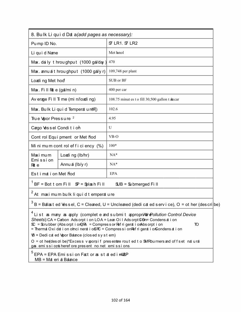
8. Bulk Liquid Data (add pages as necessary):
Pump ID No. S7LR1. S7LR2
Liquid Name Methanol
Max. daily throughput (1000 gal/day) 470
Max. annual throughput (1000 gal/yr) 109,748 per plant
Loading Method 1 SUB or BF
Max. Fill Rate (gal/min) 400 per car
Average Fill Time (min/loading) 108.75 minutes to fill 30,500 gallon tank car
Max. Bulk Liquid Temperature (oF) 102.6
True Vapor Pressure 2 4.95
Cargo Vessel Condition 3 U
Control Equipment or Method 4 VB-O
Minimum control efficiency (%) 100*
Maximum Emission Rate
Loading (lb/hr) NA*
Annual (lb/yr) NA*
Estimation Method 5 EPA
1 BF = Bottom Fill SP = Splash Fill SUB = Submerged Fill
2 At maximum bulk liquid temperature
3 B = Ballasted Vessel, C = Cleaned, U = Uncleaned (dedicated service), O = other (describe)
4 List as many as apply (complete and submit appropriate Air Pollution Control Device Sheets):CA = Carbon Adsorption LOA = Lean Oil Adsorption CO = Condensation SC = Scrubber (Absorption) CRA = Compressor- Refrigeration-Absorption TO = Thermal Oxidation or Incineration CRC = Compression-Refrigeration-Condensation VB = Dedicated Vapor Balance (closed system) O = other (describe) *Excess vapors, if present. are routed to SMR burners and offset natural gas emissions, therefore present no net emissions 5 EPA = EPA Emission Factor as stated in AP-42
MB = Material Balance
102 of 164

9. Proposed Monitoring, Recordkeeping, Reporting, and Testing Please propose monitoring, recordkeeping, and reporting in order to demonstrate compliance with the proposed operating parameters. Please propose testing in order to demonstrate compliance with the proposed emissions limits.
MONITORING None proposed
RECORDKEEPING Track Daily and Yearly Throughput
REPORTING None proposed
TESTING None proposed
MONITORING. PLEASE LIST AND DESCRIBE THE PROCESS PARAMETERS AND RANGES THAT ARE PROPOSED TO BE MONITORED IN ORDER TO DEMONSTRATE COMPLIANCE WITH THE OPERATION OF THIS PROCESS EQUIPMENT OPERATION/AIR POLLUTION CONTROL DEVICE.
RECORDKEEPING. PLEASE DESCRIBE THE PROPOSED RECORDKEEPING THAT WILL ACCOMPANY THE MONITORING.
REPORTING. PLEASE DESCRIBE THE PROPOSED FREQUENCY OF REPORTING OF THE RECORDKEEPING.
TESTING. PLEASE DESCRIBE ANY PROPOSED EMISSIONS TESTING FOR THIS PROCESS EQUIPMENT/AIR POLLUTION CONTROL DEVICE.
10. Describe all operating ranges and maintenance procedures required by Manufacturer to maintain warranty Manufacturer’s operating ranges and maintenance procedures will be followed as recommended upon selection/design of the system.
TM = Test Measurement based upon test data submittal O = other (describe)
103 of 164

Attachment L EMISSIONS UNIT DATA SHEET
BULK LIQUID TRANSFER OPERATIONS Furnish the following information for each new or modified bulk liquid transfer area or loading rack, as shown on the Equipment List Form and other parts of this application. This form is to be used for bulk liquid transfer operations such as to and from drums, marine vessels, rail tank cars, and tank trucks.
Identification Number (as assigned on Equipment List Form): S7LT1, S7LT2
1. Loading Area Name: S7, area for Truck Tanks
2. Type of cargo vessels accommodated at this rack or transfer point (check as many as apply):
☐ Drums ☐ Marine Vessels ☐ Rail Tank Cars ☒ Tank Trucks
3. Loading Rack or Transfer Point Data: Information below is on a Per Plant Basis
Number of pumps 2
Number of liquids loaded 1
Maximum number of marine vessels, tank trucks, tank cars, and/or drums loading at one time
2
4. Does ballasting of marine vessels occur at this loading area? ☐ Yes ☐ No ☒ Does not apply
5. Describe cleaning location, compounds and procedure for cargo vessels using this transfer point: Tanks are cleaned at a remote service location and/or are dedicated service.
6. Are cargo vessels pressure tested for leaks at this or any other location? ☒ Yes ☐ No
If YES, describe: Tank trucks are pressure tested with nitrogen.
7. Projected Maximum Operating Schedule (for rack or transfer point as a whole):
Maximum Jan. - Mar. Apr. - June July - Sept. Oct. - Dec.
hours/day 24 24 24 24
days/week 7 7 7 7
weeks/quarter 13 13 13 13
104 of 164

8. Bulk Liquid Data (add pages as necessary):
Pump ID No. S7LT1, S7LT2
Liquid Name Methanol
Max. daily throughput (1000 gal/day) 432 per unit (A, B, C)
Max. annual throughput (1000 gal/yr) 109,749 per plant
Loading Method 1 BF
Max. Fill Rate (gal/min) 400 single tank truck, 800 two tank trucks
Average Fill Time (min/loading) 15 minutes loading, total truck time 35 to 40 minutes
Max. Bulk Liquid Temperature (oF) 102.6
True Vapor Pressure 2 4.95
Cargo Vessel Condition 3 U
Control Equipment or Method 4 VB-O
Minimum control efficiency (%) 100*
Maximum Emission Rate
Loading (lb/hr) NA*
Annual (lb/yr) NA*
Estimation Method 5 EPA
1 BF = Bottom Fill SP = Splash Fill SUB = Submerged Fill
2 At maximum bulk liquid temperature
3 B = Ballasted Vessel, C = Cleaned, U = Uncleaned (dedicated service), O = other (describe)
4 List as many as apply (complete and submit appropriate Air Pollution Control Device Sheets):CA = Carbon Adsorption LOA = Lean Oil Adsorption CO = Condensation SC = Scrubber (Absorption) CRA = Compressor- Refrigeration-Absorption TO = Thermal Oxidation or Incineration CRC = Compression-Refrigeration-Condensation VB = Dedicated Vapor Balance (closed system) O = other (describe) *Excess vapors, if present. are routed to SMR burners and offset natural gas emissions, therefore present no net emissions 5 EPA = EPA Emission Factor as stated in AP-42
MB = Material Balance
105 of 164
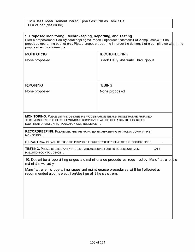
9. Proposed Monitoring, Recordkeeping, Reporting, and Testing Please propose monitoring, recordkeeping, and reporting in order to demonstrate compliance with the proposed operating parameters. Please propose testing in order to demonstrate compliance with the proposed emissions limits.
MONITORING None proposed
RECORDKEEPING Track Daily and Yearly Throughput
REPORTING None proposed
TESTING None proposed
MONITORING. PLEASE LIST AND DESCRIBE THE PROCESS PARAMETERS AND RANGES THAT ARE PROPOSED TO BE MONITORED IN ORDER TO DEMONSTRATE COMPLIANCE WITH THE OPERATION OF THIS PROCESS EQUIPMENT OPERATION/AIR POLLUTION CONTROL DEVICE.
RECORDKEEPING. PLEASE DESCRIBE THE PROPOSED RECORDKEEPING THAT WILL ACCOMPANY THE MONITORING.
REPORTING. PLEASE DESCRIBE THE PROPOSED FREQUENCY OF REPORTING OF THE RECORDKEEPING.
TESTING. PLEASE DESCRIBE ANY PROPOSED EMISSIONS TESTING FOR THIS PROCESS EQUIPMENT/AIR POLLUTION CONTROL DEVICE.
10. Describe all operating ranges and maintenance procedures required by Manufacturer to maintain warranty Manufacturer’s operating ranges and maintenance procedures will be followed as recommended upon selection/design of the system.
TM = Test Measurement based upon test data submittal O = other (describe)
106 of 164

ATTACHMENT N INTERNAL COMBUSTION ENGINE DATA SHEET Complete this data sheet for each internal combustion engine at the facility. Include manufacturer performance data sheet(s) or any other supporting document if applicable. Use extra pages if necessary. Generator(s) and microturbine generator(s) shall also use this form. Emission Unit ID# 1 S8G1, S8G2, …, S8G7
Engine Manufacturer/Model Caterpillar/CG260-16
Manufacturers Rated bhp/rpm 5500/900
Source Status2 NS
Date Installed/ Modified/Removed/Relocated 3
2022
Engine Manufactured /Reconstruction Date4
2021
X 40CFR60 Subpart JJJJ 40CFR60 Subpart JJJJ 40CFR60 Subpart JJJJ JJJJ Certified? JJJJ Certified? JJJJ Certified? 40CFR60 Subpart IIII 40CFR60 Subpart IIII 40CFR60 Subpart IIII
Check all applicable Federal Rules for the engine (include EPA Certificate of Conformity if applicable)5
IIII Certified?
X 40CFR63 Subpart ZZZZ
NESHAP ZZZZ/ NSPS JJJJ Window
IIII Certified?
40CFR63 Subpart ZZZZ
NESHAP ZZZZ/ NSPS JJJJ Window
IIII Certified?
40CFR63 Subpart ZZZZ
NESHAP ZZZZ/ NSPS JJJJ Window
NESHAP ZZZZ Remote Sources
NESHAP ZZZZ Remote Sources
NESHAP ZZZZ Remote Sources
Engine Type6 4SLB
APCD Type7 SCR and OXCAT
Fuel Type8 Natural Gas
H2 S (gr/100 scf) 0.25
Operating bhp/rpm 5500/900
BSFC (BTU/bhp-hr) 5815
Hourly Fuel Throughput 32,515 sft 3/hr gal/hr
ft3/hr gal/hr
ft 3/hr gal/hr
Annual Fuel Throughput (Must use 8,760 hrs/yr unless emergency generator)
2852 MMft3/yr gal/yr
MMft3/yr gal/yr
MMft3/yr gal/yr
Fuel Usage or Hours of Operation Metered
Yes X No Yes No Yes No
Hourly Annual Hourly Annual Hourly Annual Calculation Methodology 9 Pollutant10 PTE
(lb/hr)11 PTE
(tons/year) PTE
(lb/hr) 11 PTE
(tons/year) PTE
(lb/hr) 11 PTE
(tons/year) 11 11 11
MD NOx 1.708 7.48
MD CO 1.243 5.44 MD VOC 0.958 4.20
AP-42 SO2 0.02 0.087
MD PM10 0.109 0.48
MD Formaldehyde 0.295 1.293
MD/AP-42 Total HAPs 0.542 2.375
GHG (CO2 e)
1 Enter the appropriate Source Identification Number for each natural gas-fueled reciprocating internal combustion engine/generator engine located at
the well site. Multiple engines should be designated CE-1, CE-2, CE-3 etc. Generator engines should be designated GE-1, GE-2, GE-3 etc. Microturbine generator engines should be designated MT-1, MT-2, MT-3 etc. If more than three (3) engines exist, please use additional sheets.
2 Enter the Source Status using the following codes:
107 of 164
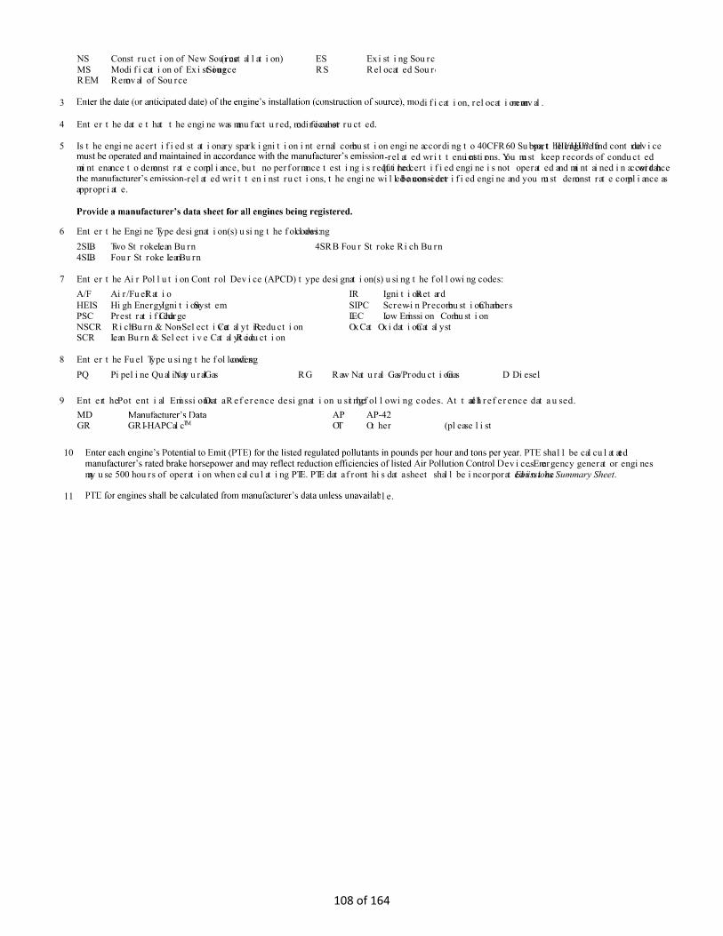
NS Construction of New Source (installation) ES Existing Source MS Modification of Existing Source RS Relocated Source REM Removal of Source
3 dification, relocation or removal.
4 Enter the date that the engine was manufactured, modified or reconstructed.
5 Is the engine a certified stationary spark ignition internal combustion engine according to 40CFR60 Subpart IIII/JJJJ? If so, the engine and control device -related written instructions. You must keep records of conducted
maintenance to demonstrate compliance, but no performance testing is required. If the certified engine is not operated and maintained in accordance with -related written instructions, the engine will be considered a non-certified engine and you must demonstrate compliance as
appropriate.
6 Enter the Engine Type designation(s) using the following codes: 2SLB Two Stroke Lean Burn 4SRB Four Stroke Rich Burn 4SLB Four Stroke Lean Burn
7 Enter the Air Pollution Control Device (APCD) type designation(s) using the following codes: A/F Air/Fuel Ratio IR Ignition Retard HEIS High Energy Ignition System SIPC Screw-in Precombustion Chambers PSC Prestratified Charge LEC Low Emission Combustion NSCR Rich Burn & Non-Selective Catalytic Reduction OxCat Oxidation Catalyst SCR Lean Burn & Selective Catalytic Reduction
8 Enter the Fuel Type using the following codes:
PQ Pipeline Quality Natural Gas RG Raw Natural Gas /Production Gas D Diesel
9 Enter the Potential Emissions Data Reference designation using the following codes. Attach all reference data used.
MD
AP AP-42
GR GRI-HAPCalcTM OT Other (please list)
10 ll be calculated at evices. Emergency generator engines
may use 500 hours of operation when calculating PTE. PTE data from this data sheet shall be incorporated in the Emissions Summary Sheet.
11 le.
108 of 164

Project Name: WV Methane
Reference O2 at mg/m3 [%] (Europe) 5Reference O2 at ppm [%] (USA) 15
INPUT14894410240009.90
Emission [mg/mn3] at 5 %O2 NOx 500.00Emission [mg/mn3] at 5 %O2 CO 682.00Emission [mg/mn3] at 5 %O2 THC 843.00Emission [mg/mn3] at 5 %O2 NMHC (VOC) 126.45Emission [mg/mn3] at 5 %O2 HCHO 144.00Emission [mg/mn3] at 5 %O2 PM 2.5 5.00Emission [mg/mn3] at 5 %O2 PM 10 5.00
OUTPUTEmission [ppm] at 15 %O2 NOx 91.46Emission [ppm] at 15 %O2 CO 204.60Emission [ppm] at 15 %O2 THC 252.90Emission [ppm] at 15 %O2 NMHC (VOC) 66.23Emission [ppm] at 15 %O2 HCHO 45.00Emission [ppm] at 15 %O2 ParticlesEmission [ppm] at 15 %O2 SO2 0.00
Emission [g/bhp-hr] NOx 0.939Emission [g/bhp-hr] CO 1.281Emission [g/bhp-hr] THC 1.583Emission [g/bhp-hr] NMHC (VOC) 0.238Emission [g/bhp-hr] HCHO 0.270Emission [g/bhp-hr] PM 2.5 0.009Emission [g/bhp-hr] PM 10 0.009Emission [g/bhp-hr] SO2 0.000Emission [g/bhp-hr] CO2 336
Emission [lb/hr] NOx 11.390Emission [lb/hr] CO 15.536Emission [lb/hr] THC 19.203Emission [lb/hr] NMHC (VOC) 2.880Emission [lb/hr] HCHO 3.280Emission [lb/hr] PM 2.5 0.114Emission [lb/hr] PM 10 0.114Emission [lb/hr] SO2 0.000Emission [lb/hr] CO2 4074
Emission [lb/MWh] NOx 2.847Emission [lb/MWh] CO 3.884Emission [lb/MWh] THC 4.801Emission [lb/MWh] NMHC (VOC) 0.720Emission [lb/MWh] HCHO 0.820Emission [lb/MWh] PM 2.5 0.028Emission [lb/MWh] PM 10 0.028Emission [lb/MWh] SO2 0.000Emission [lb/MWh] CO2 1019
Emission [kg/MWh] NOx 1.292Emission [kg/MWh] CO 1.762Emission [kg/MWh] THC 2.178Emission [kg/MWh] NMHC (VOC) 0.327Emission [kg/MWh] HCHO 0.372Emission [kg/MWh] PM 2.5 0.013Emission [kg/MWh] PM 10 0.013Emission [kg/MWh] SO2 0.000Emission [kg/MWh] CO2 462
Exhaust volume flow dry O2 [%]
Engine: CG260-16, 900rpm, 25C Air Inlet, 190mFuel gas: Standard 80MN fuel
Dry exhaust gas volume [mn³/h]Engine mechanical power [kW]Genset electrical power [ekW]
#Caterpillar: Confidential Green 109 of 164

ATTACHMENT M: AIR POLLUTION CONTROL DEVICES
110 of 164

Attachment M Air Pollution Control Device Sheet
(OTHER COLLECTORS)
Control Device ID No. (must match Emission Units Table): C1A, C1B, C1C Equipment Information
1. Manufacturer:Model No.
2. Control Device Name:Type: Selective Catalytic Reduction/oxidation cat
3. Provide diagram(s) of unit describing capture system with duct arrangement and size of duct, air volume,capacity, horsepower of movers. If applicable, state hood face velocity and hood collection efficiency.
4. On a separate sheet(s) supply all data and calculations used in selecting or designing this collection device.
5. Provide a scale diagram of the control device showing internal construction.
6. Submit a schematic and diagram with dimensions and flow rates.
7. Guaranteed minimum collection efficiency for each pollutant collected:
8. Attached efficiency curve and/or other efficiency information.
9. Design inlet volume: 69,103SCFM
10. Capacity:
11. Indicate the liquid flow rate and describe equipment provided to measure pressure drop and flow rate, if any.Ammonia injection with rates TBD
12. Attach any additional data including auxiliary equipment and operation details to thoroughly evaluate the controlequipment.
13. Description of method of handling the collected material(s) for reuse of disposal.
Gas Stream Characteristics
14. Are halogenated organics present? Yes No Are particulates present? Yes No Are metals present? Yes No
15. Inlet Emission stream parameters: Maximum Typical
Pressure (mmHg):
Heat Content (BTU/scf): NA
Oxygen Content (%): 9.36
Moisture Content (%): 19.04
Relative Humidity (%):
111 of 164
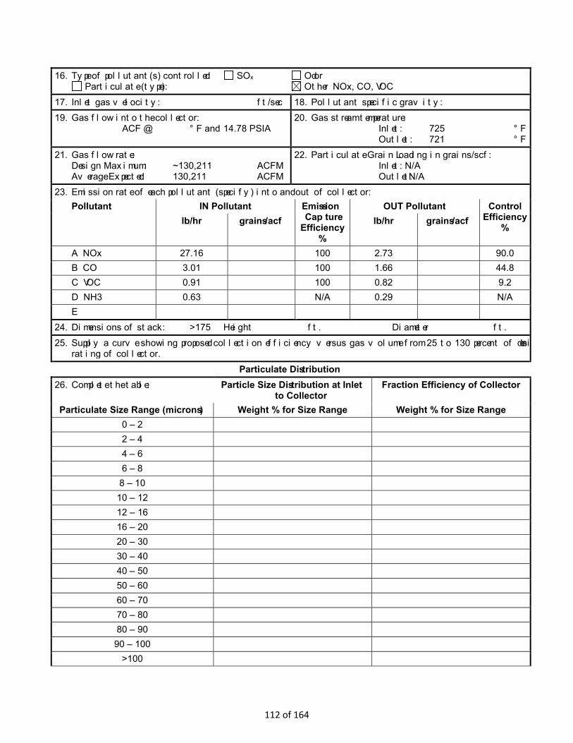
16. Type of pollutant(s) controlled: SOx Odor Particulate (type): Other NOx, CO, VOC
17. Inlet gas velocity: ft/sec 18. Pollutant specific gravity:19. Gas flow into the collector:
ACF @ °F and 14.78 PSIA 20. Gas stream temperature:
Inlet: 725 °F Outlet: 721 °F
21. Gas flow rate:Design Maximum: ~130,211 ACFM Average Expected: 130,211 ACFM
22. Particulate Grain Loading in grains/scf:Inlet: N/A Outlet: N/A
23. Emission rate of each pollutant (specify) into and out of collector:Pollutant IN Pollutant Emission
Capture Efficiency
%
OUT Pollutant Control Efficiency
% lb/hr grains/acf lb/hr grains/acf
A NOx 27.16 100 2.73 90.0 B CO 3.01 100 1.66 44.8 C VOC 0.91 100 0.82 9.2 D NH3 0.63 N/A 0.29 N/A E
24. Dimensions of stack: >175 Height ft. Diameter ft. 25. Supply a curve showing proposed collection efficiency versus gas volume from 25 to 130 percent of design
rating of collector.Particulate Distribution
26. Complete the table: Particle Size Distribution at Inlet to Collector
Fraction Efficiency of Collector
Particulate Size Range (microns) Weight % for Size Range Weight % for Size Range 0 – 2 2 – 4 4 – 6 6 – 8 8 – 10 10 – 12 12 – 16 16 – 20 20 – 30 30 – 40 40 – 50 50 – 60 60 – 70 70 – 80 80 – 90 90 – 100
>100
112 of 164
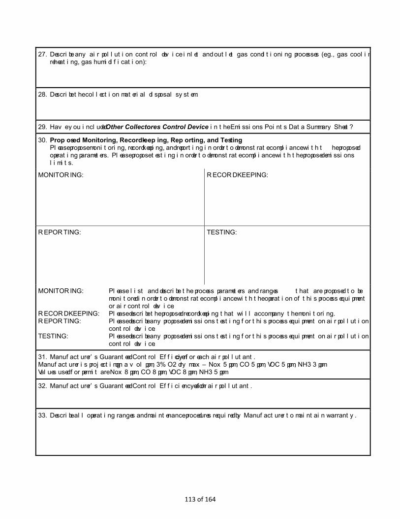
27. Describe any air pollution control device inlet and outlet gas conditioning processes (e.g., gas cooling, gas reheating, gas humidification):
28. Describe the collection material disposal system:
29. Have you included Other Collectores Control Device in the Emissions Points Data Summary Sheet?
30. Proposed Monitoring, Recordkeeping, Reporting, and Testing Please propose monitoring, recordkeeping, and reporting in order to demonstrate compliance with the proposed operating parameters. Please propose testing in order to demonstrate compliance with the proposed emissions limits.
MONITORING: RECORDKEEPING:
REPORTING: TESTING:
MONITORING: Please list and describe the process parameters and ranges that are proposed to be monitored in order to demonstrate compliance with the operation of this process equipment or air control device.
RECORDKEEPING: Please describe the proposed recordkeeping that will accompany the monitoring. REPORTING: Please describe any proposed emissions testing for this process equipment on air pollution
control device. TESTING: Please describe any proposed emissions testing for this process equipment on air pollution
control device.
31. Manufacturer’s Guaranteed Control Efficiency for each air pollutant. Manufacturer is projecting on a vol ppm, 3% O2 dry max – Nox 5 ppm, CO 5 ppm, VOC 5 ppm, NH3 3 ppm Values used for permit are Nox 8 ppm, CO 8 ppm, VOC 8 ppm, NH3 5 ppm
32. Manufacturer’s Guaranteed Control Efficiency for each air pollutant.
33. Describe all operating ranges and maintenance procedures required by Manufacturer to maintain warranty.
113 of 164

Attachment M Air Pollution Control Device Sheet
(FLARE SYSTEM)
Control Device ID No. (must match Emission Units Table): C5A, C5B, C5C Equipment Information
1. Manufacturer: Manufactuer not selected
Model No.
2. Method: Elevated flare Ground flare Other Describe
Dual HP/LP Flare
3. Provide diagram(s) of unit describing capture system with duct arrangement and size of duct, air volume, capacity, horsepower of movers. If applicable, state hood face velocity and hood collection efficiency.
4. Method of system used: Steam-assisted Air-assisted Pressure-assisted Non-assisted
5. Maximum capacity of flare: scf/min scf/hr
6. Dimensions of stack: Diameter ft. Height >175 ft.
7. Estimated combustion efficiency: (Waste gas destruction efficiency)
Estimated: 99 % Minimum guaranteed: 98 %
8. Fuel used in burners: Natural Gas Fuel Oil, Number Other, Specify:
9. Number of burners:
Rating: BTU/hr
11. Describe method of controlling flame:
10. Will preheat be used? Yes No
12. Flare height: >175 ft 14. Natural gas flow rate to flare pilot flame per pilot light: 2491 scf/min
41.5 scf/hr 13. Flare tip inside diameter: ft
15. Number of pilot lights: Total 6 @ 45,000 BTU/hr
16. Will automatic re-ignition be used? Yes No
17. If automatic re-ignition will be used, describe the method:
18. Is pilot flame equipped with a monitor? Yes No If yes, what type? Thermocouple Infra-Red
Ultra Violet Camera with monitoring control room Other, Describe:
19. Hours of unit operation per year: 8,760
114 of 164
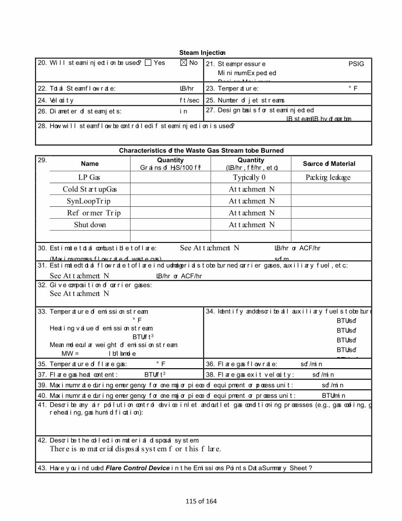
Steam Injection 20. Will steam injection be used? Yes No 21. Steam pressure PSIG
Minimum Expected: Design Maximum:
22. Total Steam flow rate: LB/hr 23. Temperature: °F
24. Velocity ft/sec 25. Number of jet streams 26. Diameter of steam jets: in 27. Design basis for steam injected:
LB steam/LB hydrocarbon 28. How will steam flow be controlled if steam injection is used?
Characteristics of the Waste Gas Stream to be Burned 29. Name Quantity
Grains of H2S/100 ft3 Quantity
(LB/hr, ft3/hr, etc) Source of Material
LP Gas Typically 0 Packing leakage
Cold Startup Gas Attachment N
Syn Loop Trip Attachment N
Reformer Trip Attachment N
Shutdown Attachment N
30. Estimate total combustible to flare: See Attachment N LB/hr or ACF/hr (Maximum mass flow rate of waste gas) scfm
31. Estimated total flow rate to flare including materials to be burned, carrier gases, auxiliary fuel, etc.: See Attachment N LB/hr or ACF/hr
32. Give composition of carrier gases: See Attachment N
33. Temperature of emission stream: °F
Heating value of emission stream: BTU/ft3
Mean molecular weight of emission stream: MW = lb/lb-mole
34. Identify and describe all auxiliary fuels to be burned. BTU/scf BTU/scf BTU/scf BTU/scf BTU/ f 35. Temperature of flare gas: °F 36. Flare gas flow rate: scf/min
37. Flare gas heat content: BTU/ft3 38. Flare gas exit velocity: scf/min 39. Maximum rate during emergency for one major piece of equipment or process unit: scf/min 40. Maximum rate during emergency for one major piece of equipment or process unit: BTU/min 41. Describe any air pollution control device inlet and outlet gas conditioning processes (e.g., gas cooling, gas
reheating, gas humidification):
42. Describe the collection material disposal system: There is no material disposal system for this flare.
43. Have you included Flare Control Device in the Emissions Points Data Summary Sheet?
115 of 164

44. Proposed Monitoring, Recordkeeping, Reporting, and Testing Please propose monitoring, recordkeeping, and reporting in order to demonstrate compliance with the proposed operating parameters. Please propose testing in order to demonstrate compliance with the proposed emissions limits.
MONITORING: Monitor the emission point opacity via Method 9 and Method 22.
RECORDKEEPING: As required per 40CFR60, Subpart A, Section 60.18.
REPORTING: None proposed.
TESTING: None proposed.
MONITORING: Please list and describe the process parameters and ranges that are proposed to be monitored in order to demonstrate compliance with the operation of this process equipment or air control device.
RECORDKEEPING: Please describe the proposed recordkeeping that will accompany the monitoring. REPORTING: Please describe any proposed emissions testing for this process equipment on air pollution
control device. TESTING: Please describe any proposed emissions testing for this process equipment on air pollution
control device. 45. Manufacturer’s Guaranteed Capture Efficiency for each air pollutant.
Capture efficiency is based on facility design and is anticipated to be 100% for vents and emission sources that are vented to the flare.
46. Manufacturer’s Guaranteed Control Efficiency for each air pollutant. 98%
47. Describe all operating ranges and maintenance procedures required by Manufacturer to maintain warranty. The flare is specifically design for each process and the final design has not been completed. Operating ranges and maintenance procedures will be identified in the final design and with the flare system vendor. The recommended operating and maintenance procedures will be followed.
116 of 164

Attachment M Air Pollution Control Device Sheet
(OTHER COLLECTORS)
Control Device ID No. (must match Emission Units Table): C3G1, C3G2, …, C3G7 Equipment Information
1. Manufacturer: Model No. Miratech
2. Control Device Name: SCR/Oxidation System Type: SCR and OxyCat
3. Provide diagram(s) of unit describing capture system with duct arrangement and size of duct, air volume, capacity, horsepower of movers. If applicable, state hood face velocity and hood collection efficiency.
4. On a separate sheet(s) supply all data and calculations used in selecting or designing this collection device.
5. Provide a scale diagram of the control device showing internal construction. See Miratech Data Sheets
6. Submit a schematic and diagram with dimensions and flow rates. See Miratech Data Sheets
7. Guaranteed minimum collection efficiency for each pollutant collected:
8. Attached efficiency curve and/or other efficiency information.
9. Design inlet volume: SCFM 10. Capacity:
11. Indicate the liquid flow rate and describe equipment provided to measure pressure drop and flow rate, if any. Urea, 32.5%, system dosing capacity is 20 L/hr. Estimated reactant consumption is 3.1 gal/h (11.9 l/h) per engine
12. Attach any additional data including auxiliary equipment and operation details to thoroughly evaluate the control equipment.
13. Description of method of handling the collected material(s) for reuse of disposal.
Gas Stream Characteristics
14. Are halogenated organics present? Yes No Are particulates present? Yes No Are metals present? Yes No
15. Inlet Emission stream parameters: Maximum Typical
Pressure (mmHg):
Heat Content (BTU/scf):
Oxygen Content (%):
Moisture Content (%):
Relative Humidity (%):
117 of 164
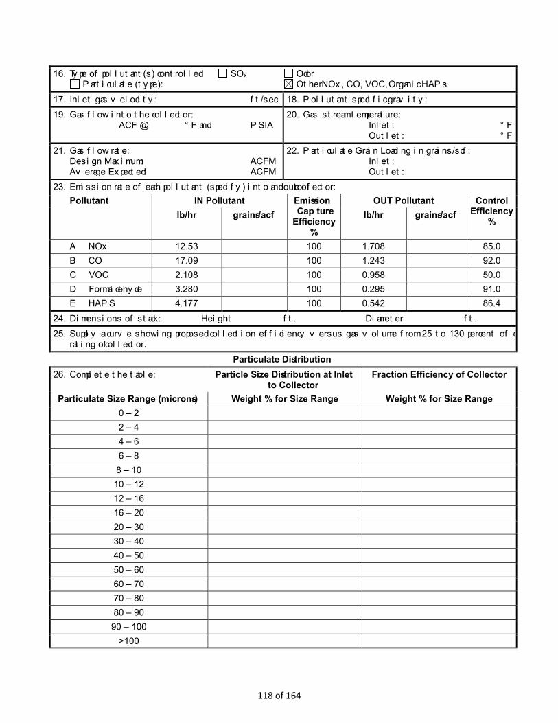
16. Type of pollutant(s) controlled: SOx Odor Particulate (type): Other NOx, CO, VOC, Organic HAPs
17. Inlet gas velocity: ft/sec 18. Pollutant specific gravity: 19. Gas flow into the collector:
ACF @ °F and PSIA 20. Gas stream temperature:
Inlet: °F Outlet: °F
21. Gas flow rate: Design Maximum: ACFM Average Expected: ACFM
22. Particulate Grain Loading in grains/scf: Inlet: Outlet:
23. Emission rate of each pollutant (specify) into and out of collector: Pollutant IN Pollutant Emission
Capture Efficiency
%
OUT Pollutant Control Efficiency
% lb/hr grains/acf lb/hr grains/acf
A NOx 12.53 100 1.708 85.0 B CO 17.09 100 1.243 92.0 C VOC 2.108 100 0.958 50.0 D Formaldehyde 3.280 100 0.295 91.0 E HAPS 4.177 100 0.542 86.4
24. Dimensions of stack: Height ft. Diameter ft. 25. Supply a curve showing proposed collection efficiency versus gas volume from 25 to 130 percent of design
rating of collector. Particulate Distribution
26. Complete the table: Particle Size Distribution at Inlet to Collector
Fraction Efficiency of Collector
Particulate Size Range (microns) Weight % for Size Range Weight % for Size Range 0 – 2 2 – 4 4 – 6 6 – 8 8 – 10 10 – 12 12 – 16 16 – 20 20 – 30 30 – 40 40 – 50 50 – 60 60 – 70 70 – 80 80 – 90 90 – 100
>100
118 of 164
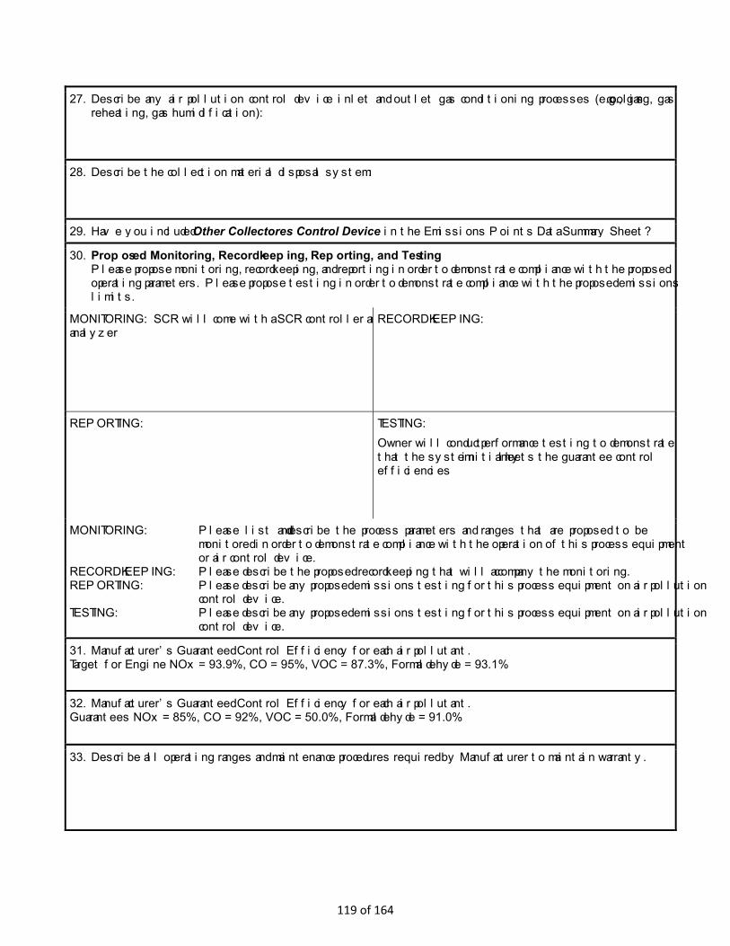
27. Describe any air pollution control device inlet and outlet gas conditioning processes (e.g., gas cooling, gas reheating, gas humidification):
28. Describe the collection material disposal system:
29. Have you included Other Collectores Control Device in the Emissions Points Data Summary Sheet?
30. Proposed Monitoring, Recordkeeping, Reporting, and Testing Please propose monitoring, recordkeeping, and reporting in order to demonstrate compliance with the proposed operating parameters. Please propose testing in order to demonstrate compliance with the proposed emissions limits.
MONITORING: SCR will come with a SCR controller and analyzer
RECORDKEEPING:
REPORTING: TESTING: Owner will conduct performance testing to demonstrate that the system initially meets the guarantee control efficiencies
MONITORING: Please list and describe the process parameters and ranges that are proposed to be monitored in order to demonstrate compliance with the operation of this process equipment or air control device.
RECORDKEEPING: Please describe the proposed recordkeeping that will accompany the monitoring. REPORTING: Please describe any proposed emissions testing for this process equipment on air pollution
control device. TESTING: Please describe any proposed emissions testing for this process equipment on air pollution
control device.
31. Manufacturer’s Guaranteed Control Efficiency for each air pollutant. Target for Engine NOx = 93.9%, CO = 95%, VOC = 87.3%, Formaldehyde = 93.1%
32. Manufacturer’s Guaranteed Control Efficiency for each air pollutant. Guarantees NOx = 85%, CO = 92%, VOC = 50.0%, Formaldehyde = 91.0%
33. Describe all operating ranges and maintenance procedures required by Manufacturer to maintain warranty.
119 of 164
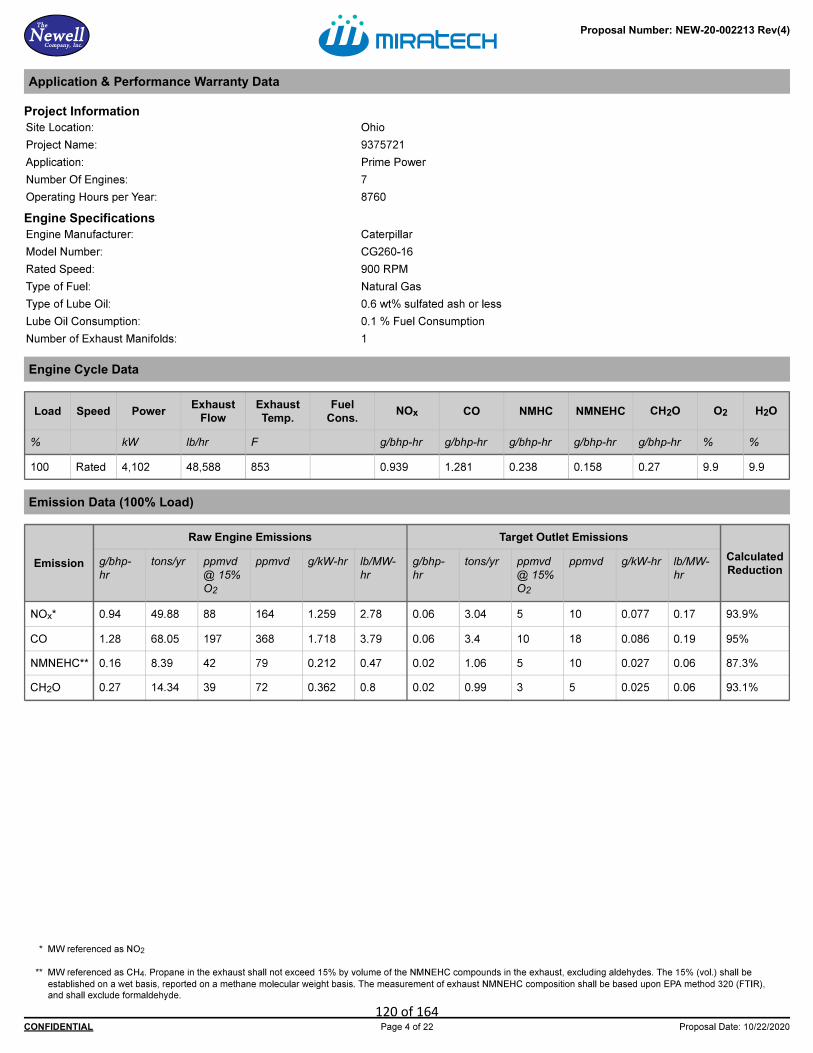
120 of 164

121 of 164

122 of 164
123 of 164

124 of 164

125 of 164

126 of 164

127 of 164
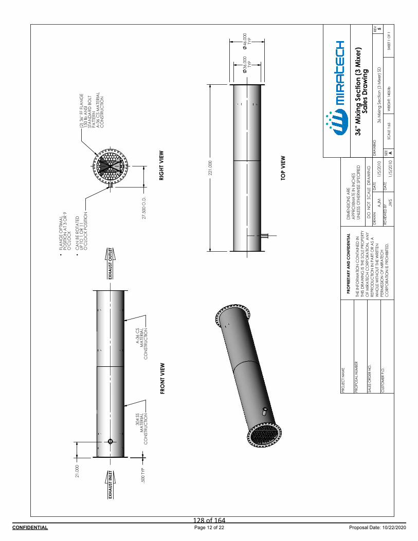
128 of 164

129 of 164

130 of 164
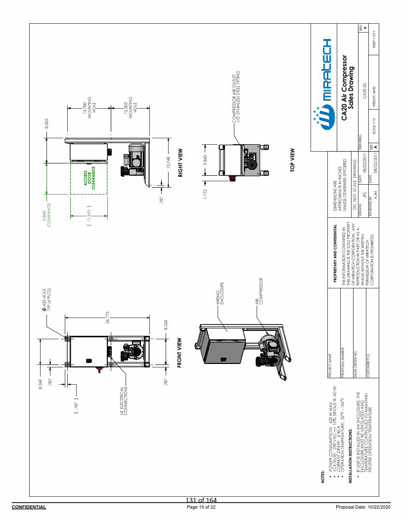
131 of 164
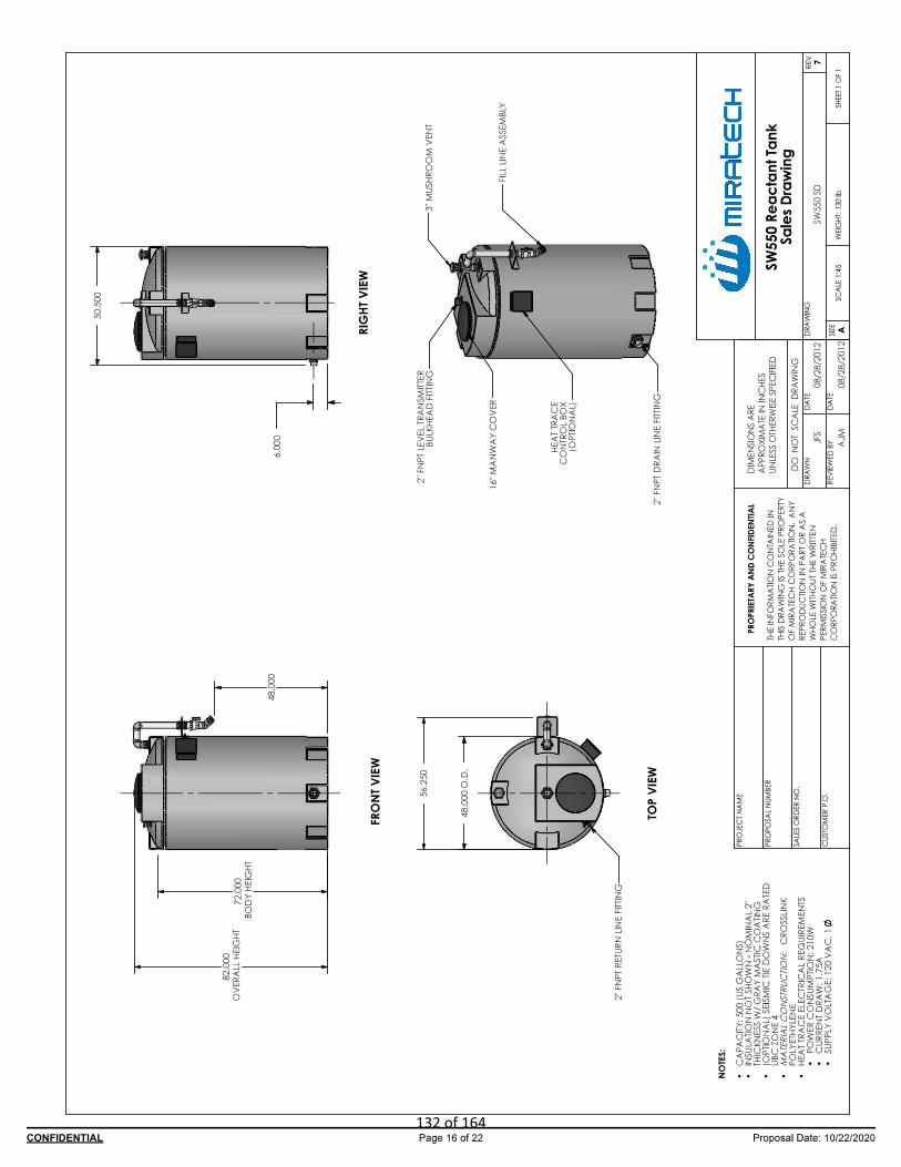
132 of 164

ATTACHMENT N: SUPPORTING EMISSIONS CALCULATIONS
133 of 164
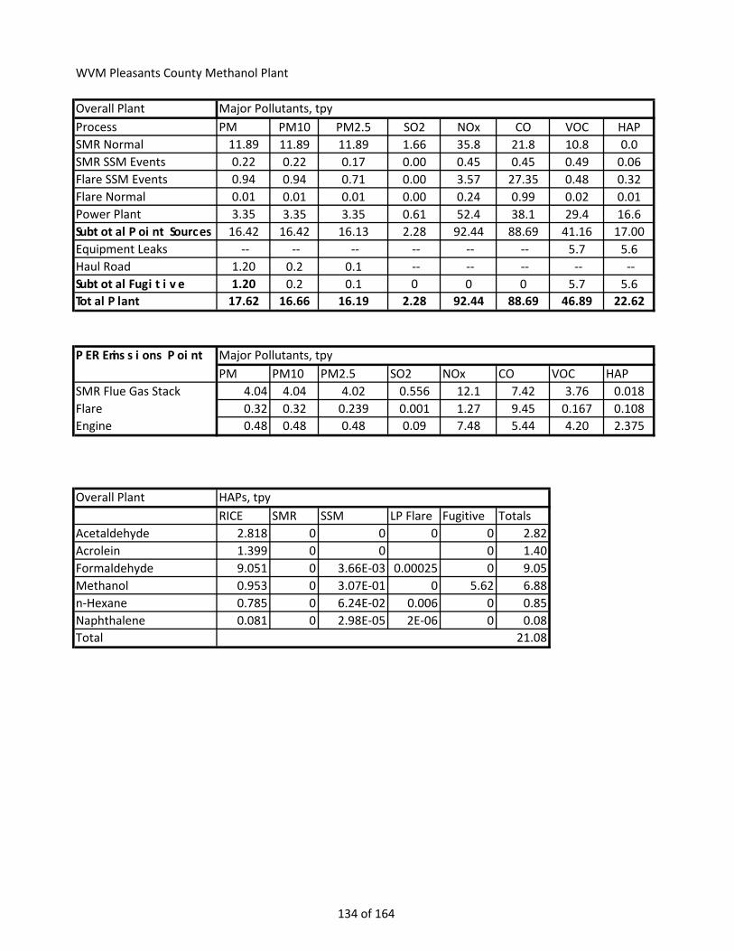
WVM Pleasants County Methanol Plant
Overall PlantProcess PM PM10 PM2.5 SO2 NOx CO VOC HAPSMR Normal 11.89 11.89 11.89 1.66 35.8 21.8 10.8 0.0SMR SSM Events 0.22 0.22 0.17 0.00 0.45 0.45 0.49 0.06Flare SSM Events 0.94 0.94 0.71 0.00 3.57 27.35 0.48 0.32Flare Normal 0.01 0.01 0.01 0.00 0.24 0.99 0.02 0.01Power Plant 3.35 3.35 3.35 0.61 52.4 38.1 29.4 16.6Subtotal Point Sources 16.42 16.42 16.13 2.28 92.44 88.69 41.16 17.00Equipment Leaks -- -- -- -- -- -- 5.7 5.6Haul Road 1.20 0.2 0.1 -- -- -- -- --Subtotal Fugitive 1.20 0.2 0.1 0 0 0 5.7 5.6Total Plant 17.62 16.66 16.19 2.28 92.44 88.69 46.89 22.62
PER Emissions Point Major Pollutants, tpyPM PM10 PM2.5 SO2 NOx CO VOC HAP
SMR Flue Gas Stack 4.04 4.04 4.02 0.556 12.1 7.42 3.76 0.018Flare 0.32 0.32 0.239 0.001 1.27 9.45 0.167 0.108Engine 0.48 0.48 0.48 0.09 7.48 5.44 4.20 2.375
Overall Plant HAPs, tpyRICE SMR SSM LP Flare Fugitive Totals
Acetaldehyde 2.818 0 0 0 0 2.82Acrolein 1.399 0 0 0 1.40Formaldehyde 9.051 0 3.66E-03 0.00025 0 9.05Methanol 0.953 0 3.07E-01 0 5.62 6.88n-Hexane 0.785 0 6.24E-02 0.006 0 0.85Naphthalene 0.081 0 2.98E-05 2E-06 0 0.08Total 21.08
Major Pollutants, tpy
134 of 164
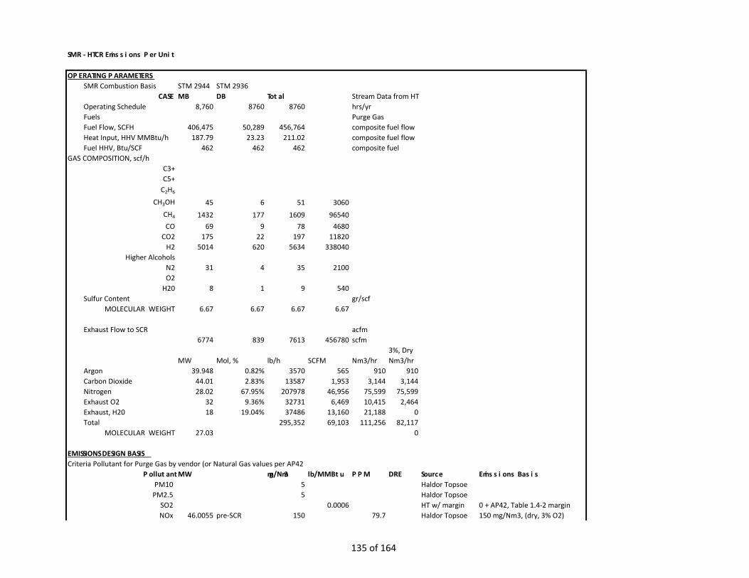
SMR - HTCR Emissions Per Unit
OPERATING PARAMETERS SMR Combustion Basis STM 2944 STM 2936
CASE MB DB Total Stream Data from HTOperating Schedule 8,760 8760 8760 hrs/yrFuels Purge GasFuel Flow, SCFH 406,475 50,289 456,764 composite fuel flow Heat Input, HHV MMBtu/h 187.79 23.23 211.02 composite fuel flow Fuel HHV, Btu/SCF 462 462 462 composite fuel
GAS COMPOSITION, scf/hC3+C5+
C2H6
CH3OH 45 6 51 3060CH4 1432 177 1609 96540CO 69 9 78 4680
CO2 175 22 197 11820H2 5014 620 5634 338040
Higher AlcoholsN2 31 4 35 2100O2
H20 8 1 9 540Sulfur Content gr/scf
MOLECULAR WEIGHT 6.67 6.67 6.67 6.67
Exhaust Flow to SCR acfm6774 839 7613 456780 scfm
3%, DryMW Mol, % lb/h SCFM Nm3/hr Nm3/hr
Argon 39.948 0.82% 3570 565 910 910Carbon Dioxide 44.01 2.83% 13587 1,953 3,144 3,144Nitrogen 28.02 67.95% 207978 46,956 75,599 75,599Exhaust O2 32 9.36% 32731 6,469 10,415 2,464Exhaust, H20 18 19.04% 37486 13,160 21,188 0Total 295,352 69,103 111,256 82,117
MOLECULAR WEIGHT 27.03 0
EMISSIONS DESIGN BASISCriteria Pollutant for Purge Gas by vendor (or Natural Gas values per AP42
Pollutant MW mg/Nm3 lb/MMBtu PPM DRE Source Emissions BasisPM10 5 Haldor Topsoe
PM2.5 5 Haldor TopsoeSO2 0.0006 HT w/ margin 0 + AP42, Table 1.4-2 marginNOx 46.0055 pre-SCR 150 79.7 Haldor Topsoe 150 mg/Nm3, (dry, 3% O2)
135 of 164

NOx post-SCR 15.05 8 90.0% HT w/ margin 5 ppm, (dry, 3% O2) + 3 ppmCO 28.0101 pre-Oxy Cat 16.6 14.5 Haldor Topsoe
post-Oxy Cat 9.16 8 44.8% HT w/ margin 5 ppm, (dry, 3% O2) + 3 ppmVOC 13.87539 pre-Oxy Cat 5 8.8 Haldor Topsoe
13.87539 post-Oxy Cat 4.54 8 9.2% HT w/ margin 5 ppm, (dry, 3% O2) + 3 ppmPb 0.00000103 AP42, Table 1.4-2
N2O GWP 298 0.00454 AP42, Table 1.4-5NH3 17.031 3.48 5 Haldor Topsoe 3 ppm, (dry, 3% O2) + 2 ppm
CALCULATIONS PER UNITTypical Emissions lb/hr mg/h kg/h tpy Per Plant
PM 0.9052 410,583 0.411 3.96 11.89PM10 0.9052 410,583 0.411 3.96 11.89PM2.5 0.9052 410,583 0.411 3.96 11.89SO2 0.1266 0.55 1.66
Nox (pre-SCR) 27.1554 12,317,496 12.317 118.94 356.82Nox (post-controlled) 2.7251 1,236,102 1.236 11.94 35.81
CO (pre OXY-CAT) 3.0052 1,363,136 1.363 13.16 39.49CO (post-controlled) 1.6592 752,591 0.753 7.27 21.80
VOC (pre OXY-CAT) 0.9052 410,583 0.411 3.96 11.89VOC (post-controlled) 0.8219 372,812 0.373 3.60 10.80
Pb 0.0002 0.00 0.00N2O 0.9581 4.20 12.59NH3 0.6305 285,999 0.286 2.76 8.29
Annual Emissions TPYPM 3.96PM10 3.96PM2.5 3.96SO2 0.55
Nox (pre-SCR) 118.94Nox (post-controlled) 11.94
CO (pre OXY-CAT) 13.16CO (post-controlled) 7.27
VOC (pre OXY-CAT) 3.96VOC (post-controlled) 3.60
Pb 0.001N2O 4.20NH3 2.76
No HAPS generated while on the purge gas
136 of 164

ESTIMATED EMISSIONS PER SSM EVENT
CS CS CS SLT SLT SLT RTR RTR RTR SD SD
Flare HTCR Total Flare HTCR Total Flare HTCR Total Flare TotalH tons tons tons tons tons tons tons tons tons tons tons
1-Butanol 0.000 0.000 0.000 0.000 0.000 0.000 0.000 0.000 0.000 0.000 0.0001-Pentanol 0.000 0.000 0.000 0.000 0.000 0.000 0.000 0.000 0.000 0.000 0.0001-Propanol 0.000 0.000 0.000 0.000 0.000 0.000 0.000 0.000 0.000 0.000 0.000
N 2,2-Dimethylpropane 0.000 0.005 0.005 0.000 0.002 0.002 0.000 0.003 0.003 0.000 0.0002-Butanol 0.000 0.000 0.000 0.000 0.000 0.000 0.000 0.000 0.000 0.000 0.000
2-Methyl-1-Propanol 0.000 0.000 0.000 0.000 0.000 0.000 0.000 0.000 0.000 0.000 0.000N 2-Methylbutane 0.000 0.005 0.005 0.000 0.002 0.002 0.000 0.003 0.003 0.000 0.000
2-Propanol 0.000 0.000 0.000 0.000 0.000 0.000 0.000 0.000 0.000 0.000 0.000Acetone 0.000 0.000 0.000 0.000 0.000 0.000 0.000 0.000 0.000 - 0.000
Argon 0.000 42.520 42.520 0.000 9.554 9.554 0.000 22.021 22.021 - 0.000Carbon Dioxide 289.6 201.7 491.3 157.5 68.4 225.9 203.5 115.6 319.1 4.217 4.2
Carbon Monoxide 1.184 0.026 1.210 1.246 0.009 1.255 0.898 0.015 0.913 0.023 0.023Dimethyl Ether 0.000 0.000 0.000 0.000 0.000 0.000 0.000 0.000 0.000 0.000 0.000
N Ethane 0.030 0.005 0.036 0.000 0.002 0.002 0.018 0.003 0.021 0.001 0.001Ethanol 0.000 0.000 0.000 0.000 0.000 0.000 0.000 0.000 0.000 0.000 0.000
Formic Acid 0.000 0.000 0.000 0.000 0.000 0.000 0.000 0.000 0.000 0.000 0.000Hydrogen 0.337 0.000 0.337 0.369 0.000 0.369 0.254 0.000 0.254 0.006 0.006
N i-Butane 0.002 0.004 0.005 0.000 0.001 0.001 0.001 0.002 0.003 0.000 0.000N Methane 1.556 0.004 1.560 0.358 0.002 0.360 0.990 0.002 0.992 0.026 0.026
Methanol 0.019 0.000 0.019 0.006 0.000 0.006 0.007 0.000 0.007 0.001 0.001Methyl Ethyl Ketone 0.000 0.000 0.000 0.000 0.000 0.000 0.000 0.000 0.000 - 0.000
Methyl Formate 0.000 0.000 0.000 0.000 0.000 0.000 0.000 0.000 0.000 0.000 0.000Nitrogen 1.300 2472 2473 0.448 556 556 0.553 1280 1281 1.118 1.118Oxygen 0.000 472.8 472.8 0.000 73.184 73.184 0.000 229 229 - 0.000
N Propane 0.006 0.003 0.008 0.000 0.001 0.001 0.003 0.002 0.005 0.000 0.000Water 0.623 302.5 303.2 0.813 86.495 87.308 0.624 165.6 166.3 0.079 0.079
N n-Butane 0.002 0.004 0.005 0.000 0.001 0.001 0.001 0.002 0.003 0.000 0.000n-Heptane 0.000 0.000 0.000 0.000 0.000 0.000 0.000 0.000 0.000 0.000 0.000
Y n-Hexane 0.001 0.003 0.004 0.000 0.001 0.001 0.000 0.002 0.002 0.000 0.000N n-Pentane 0.000 0.005 0.005 0.000 0.002 0.002 0.000 0.003 0.003 0.000 0.000
Hydrogen Sulfide 0.000 0.000 0.000 0.000 0.000 0.000 0.000 0.000 0.000 0.000 0.000Y 2-Methylnaphthalene 0.000 0.000 0.000 0.000 0.000 0.000 0.000 0.000 0.000 0.000 0.000Y 3-Methylcholanthrene 0.000 0.000 0.000 0.000 0.000 0.000 0.000 0.000 0.000 0.000 0.000Y12-Dimethylbenz(a)anthrace 0.000 0.000 0.000 0.000 0.000 0.000 0.000 0.000 0.000 0.000 0.000Y Acenaphthene 0.000 0.000 0.000 0.000 0.000 0.000 0.000 0.000 0.000 0.000 0.000Y Acenaphthylene 0.000 0.000 0.000 0.000 0.000 0.000 0.000 0.000 0.000 0.000 0.000Y Anthracene 0.000 0.000 0.000 0.000 0.000 0.000 0.000 0.000 0.000 0.000 0.000Y Benz(a)anthracene 0.000 0.000 0.000 0.000 0.000 0.000 0.000 0.000 0.000 0.000 0.000Y Benzene 0.000 0.000 0.000 0.000 0.000 0.000 0.000 0.000 0.000 0.000 0.000Y Benzo(a)pyrene 0.000 0.000 0.000 0.000 0.000 0.000 0.000 0.000 0.000 0.000 0.000Y Benzo(b)fluoranthene 0.000 0.000 0.000 0.000 0.000 0.000 0.000 0.000 0.000 0.000 0.000Y Benzo(g,h,i)perylene 0.000 0.000 0.000 0.000 0.000 0.000 0.000 0.000 0.000 0.000 0.000Y Benzo(k)fluoranthene 0.000 0.000 0.000 0.000 0.000 0.000 0.000 0.000 0.000 0.000 0.000Y Chrysene 0.000 0.000 0.000 0.000 0.000 0.000 0.000 0.000 0.000 0.000 0.000Y Dibenzo(a,h)anthracene 0.000 0.000 0.000 0.000 0.000 0.000 0.000 0.000 0.000 0.000 0.000Y Dichlorobenzene 0.000 0.000 0.000 0.000 0.000 0.000 0.000 0.000 0.000 0.000 0.000Y Formaldehyde 0.000 0.000 0.000 0.000 0.000 0.000 0.000 0.000 0.000 0.000 0.000Y Naphthalene 0.000 0.000 0.000 0.000 0.000 0.000 0.000 0.000 0.000 0.000 0.000Y Toluene 0.000 0.000 0.000 0.000 0.000 0.000 0.000 0.000 0.000 0.000 0.000
Sulfur Dioxide 0.000 0.000 0.000 0.000 0.000 0.000 0.000 0.000 0.000 0.000 0.000
Total VOC 0.029 0.028 0.057 0.007 0.010 0.016 0.013 0.016 0.029 0.001 0.001NOx 0.182 0.027 0.209 0.103 0.006 0.109 0.124 0.014 0.137 0.003 0.003
PM10 0.043 0.013 0.056 0.037 0.004 0.041 0.032 0.007 0.039 0.001 0.001PM2.5 0.033 0.010 0.042 0.028 0.003 0.031 0.024 0.006 0.029 0.001 0.001
Ammonia 0.000 0.011 0.011 0.000 0.002 0.002 0.000 0.006 0.006 - 0.000
SSM EVENT EMISSIONS - TPY PER UNIT
Component
137 of 164

CS CS CS SLT SLT SLT RTR RTR RTR SD SDFlare HTCR Total Flare HTCR Total Flare HTCR Total Flare Total
H tons tons tons tons tons tons tons tons tons tons tonsN 1-Butanol 0.000 0.000 0.000 0.000 0.000 0.000 0.000 0.000 0.000 0.000 0.000N 1-Pentanol 0.000 0.000 0.000 0.000 0.000 0.000 0.000 0.000 0.000 0.000 0.000N 1-Propanol 0.000 0.000 0.000 0.000 0.000 0.000 0.000 0.000 0.000 0.000 0.000N 2,2-Dimethylpropane 0.001 0.015 0.016 0.000 0.005 0.005 0.001 0.008 0.009 0.000 0.000N 2-Butanol 0.000 0.000 0.000 0.000 0.000 0.000 0.000 0.000 0.000 0.000 0.000N 2-Methyl-1-Propanol 0.000 0.000 0.000 0.000 0.000 0.000 0.000 0.000 0.000 0.000 0.000N 2-Methylbutane 0.000 0.015 0.015 0.000 0.005 0.005 0.000 0.008 0.009 0.000 0.000N 2-Propanol 0.000 0.000 0.000 0.000 0.000 0.000 0.000 0.000 0.000 0.000 0.000N Acetone 0.000 0.000 0.000 0.000 0.000 0.000 0.000 0.000 0.000 0.000 0.000N Argon 0.0 127.6 127.6 0.0 28.7 28.7 0.0 66.1 66.1 0.0 0.0N Carbon Dioxide 869 605 1,474 472 205 678 611 347 957 13 13N Carbon Monoxide 3.553 0.077 3.630 3.739 0.026 3.765 2.694 0.044 2.739 0.068 0.068N Dimethyl Ether 0.000 0.000 0.000 0.000 0.000 0.000 0.000 0.000 0.000 0.000 0.000N Ethane 0.091 0.016 0.107 0.001 0.005 0.006 0.055 0.009 0.064 0.003 0.003N Ethanol 0.000 0.000 0.000 0.000 0.000 0.000 0.000 0.000 0.000 0.000 0.000N Formic Acid 0.000 0.000 0.000 0.000 0.000 0.000 0.000 0.000 0.000 0.000 0.000N Hydrogen 1.011 0.000 1.011 1.108 0.000 1.108 0.763 0.000 0.763 0.017 0.017N i-Butane 0.005 0.011 0.015 0.000 0.004 0.004 0.003 0.006 0.009 0.000 0.000N Methane 4.668 0.012 4.680 1.074 0.005 1.079 2.969 0.007 2.976 0.077 0.077Y Methanol 0.056 0.000 0.056 0.019 0.000 0.019 0.020 0.000 0.020 0.002 0.002Y Methyl Ethyl Ketone 0.000 0.000 0.000 0.000 0.000 0.000 0.000 0.000 0.000 0.000 0.000N Methyl Formate 0.000 0.000 0.000 0.000 0.000 0.000 0.000 0.000 0.000 0.000 0.000N Nitrogen 3.9 7,416.6 7,420.5 1.3 1,666.6 1,668.0 1.7 3,841.2 3,842.9 3.4 3.4N Oxygen 0.0 1,418.3 1,418.3 0.0 219.6 219.6 0.0 686.7 686.7 0.0 0.0N Propane 0.017 0.008 0.025 0.000 0.004 0.004 0.010 0.005 0.015 0.001 0.001N Water 1.87 907.59 909.45 2.44 259.49 261.92 1.87 496.88 498.75 0.24 0.24N n-Butane 0.005 0.011 0.015 0.000 0.004 0.004 0.003 0.006 0.009 0.000 0.000N n-Heptane 0.000 0.000 0.000 0.000 0.000 0.000 0.000 0.000 0.000 0.000 0.000Y n-Hexane 0.002 0.009 0.011 0.000 0.003 0.003 0.001 0.005 0.006 0.000 0.000N n-Pentane 0.001 0.015 0.016 0.000 0.005 0.005 0.001 0.008 0.009 0.000 0.000Y Hydrogen Sulfide 0.000 0.000 0.000 0.000 0.000 0.000 0.000 0.000 0.000 0.000 0.000Y 2-Methylnaphthalene 0.000 0.000 0.000 0.000 0.000 0.000 0.000 0.000 0.000 0.000 0.000Y 3-Methylcholanthrene 0.000 0.000 0.000 0.000 0.000 0.000 0.000 0.000 0.000 0.000 0.000Y 7,12-Dimethylbenz(a)anthracene 0.000 0.000 0.000 0.000 0.000 0.000 0.000 0.000 0.000 0.000 0.000Y Acenaphthene 0.000 0.000 0.000 0.000 0.000 0.000 0.000 0.000 0.000 0.000 0.000Y Acenaphthylene 0.000 0.000 0.000 0.000 0.000 0.000 0.000 0.000 0.000 0.000 0.000Y Anthracene 0.000 0.000 0.000 0.000 0.000 0.000 0.000 0.000 0.000 0.000 0.000Y Benz(a)anthracene 0.000 0.000 0.000 0.000 0.000 0.000 0.000 0.000 0.000 0.000 0.000Y Benzene 0.000 0.000 0.000 0.000 0.000 0.000 0.000 0.000 0.000 0.000 0.000Y Benzo(a)pyrene 0.000 0.000 0.000 0.000 0.000 0.000 0.000 0.000 0.000 0.000 0.000Y Benzo(b)fluoranthene 0.000 0.000 0.000 0.000 0.000 0.000 0.000 0.000 0.000 0.000 0.000Y Benzo(g,h,i)perylene 0.000 0.000 0.000 0.000 0.000 0.000 0.000 0.000 0.000 0.000 0.000Y Benzo(k)fluoranthene 0.000 0.000 0.000 0.000 0.000 0.000 0.000 0.000 0.000 0.000 0.000Y Chrysene 0.000 0.000 0.000 0.000 0.000 0.000 0.000 0.000 0.000 0.000 0.000Y Dibenzo(a,h)anthracene 0.000 0.000 0.000 0.000 0.000 0.000 0.000 0.000 0.000 0.000 0.000Y Dichlorobenzene 0.000 0.000 0.000 0.000 0.000 0.000 0.000 0.000 0.000 0.000 0.000Y Fluoranthene 0.000 0.000 0.000 0.000 0.000 0.000 0.000 0.000 0.000 0.000 0.000Y Fluorene 0.000 0.000 0.000 0.000 0.000 0.000 0.000 0.000 0.000 0.000 0.000Y Formaldehyde 0.000 0.000 0.001 0.000 0.000 0.000 0.000 0.000 0.000 0.000 0.000Y Indeno(1,2,3-cd)pyrene 0.000 0.000 0.000 0.000 0.000 0.000 0.000 0.000 0.000 0.000 0.000Y Naphthalene 0.000 0.000 0.000 0.000 0.000 0.000 0.000 0.000 0.000 0.000 0.000Y Phenanathrene 0.000 0.000 0.000 0.000 0.000 0.000 0.000 0.000 0.000 0.000 0.000Y Pyrene 0.000 0.000 0.000 0.000 0.000 0.000 0.000 0.000 0.000 0.000 0.000Y Toluene 0.000 0.000 0.000 0.000 0.000 0.000 0.000 0.000 0.000 0.000 0.000N Sulfur Dioxide 0.000 0.001 0.001 0.000 0.000 0.000 0.000 0.000 0.001 0.000 0.000
Total VOC 0.087 0.083 0.170 0.020 0.029 0.049 0.039 0.048 0.086 0.004 0.004NOx 0.545 0.082 0.626 0.308 0.019 0.327 0.371 0.041 0.412 0.009 0.009
PM10 0.130 0.038 0.169 0.111 0.013 0.124 0.095 0.022 0.117 0.002 0.002PM2.5 0.098 0.029 0.127 0.083 0.010 0.093 0.071 0.017 0.088 0.002 0.002
Ammonia 0.000 0.032 0.032 0.000 0.007 0.007 0.000 0.017 0.017 0.000 0.000HAPS 0.058 0.010 0.067 0.019 0.003 0.022 0.021 0.005 0.026 0.002 0.002
SSM EVENT EMISSIONS - TPY PER OVERALL PLANT
Component
138 of 164
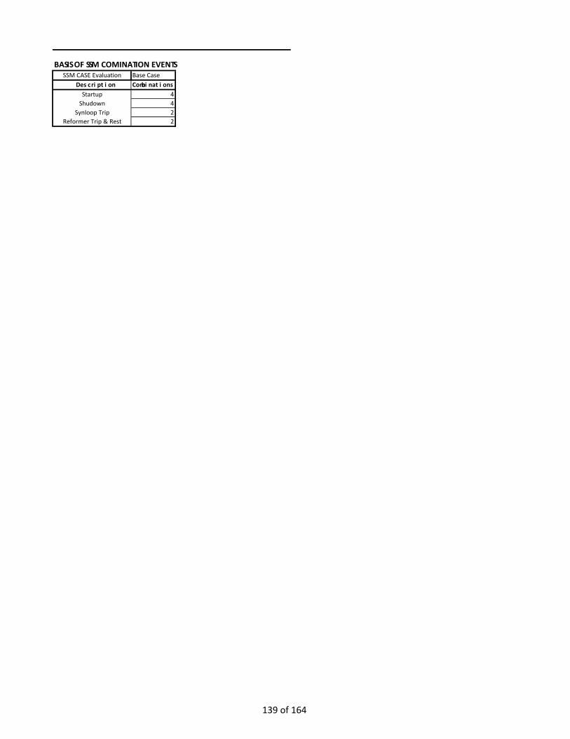
BASIS OF SSM COMINATION EVENTS SSM CASE Evaluation Base Case
Description CombinationsStartup 4
Shudown 4Synloop Trip 2
Reformer Trip & Rest 2
139 of 164
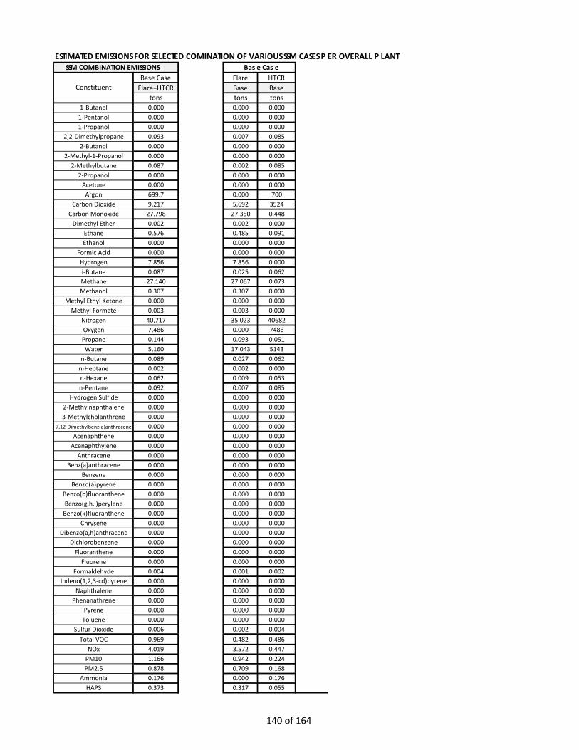
ESTIMATED EMISSIONS FOR SELECTED COMINATION OF VARIOUS SSM CASES PER OVERALL PLANT
Base Case Flare HTCRFlare+HTCR Base Base
tons tons tons1-Butanol 0.000 0.000 0.000
1-Pentanol 0.000 0.000 0.0001-Propanol 0.000 0.000 0.000
2,2-Dimethylpropane 0.093 0.007 0.0852-Butanol 0.000 0.000 0.000
2-Methyl-1-Propanol 0.000 0.000 0.0002-Methylbutane 0.087 0.002 0.085
2-Propanol 0.000 0.000 0.000Acetone 0.000 0.000 0.000
Argon 699.7 0.000 700Carbon Dioxide 9,217 5,692 3524
Carbon Monoxide 27.798 27.350 0.448Dimethyl Ether 0.002 0.002 0.000
Ethane 0.576 0.485 0.091Ethanol 0.000 0.000 0.000
Formic Acid 0.000 0.000 0.000Hydrogen 7.856 7.856 0.000i-Butane 0.087 0.025 0.062Methane 27.140 27.067 0.073Methanol 0.307 0.307 0.000
Methyl Ethyl Ketone 0.000 0.000 0.000Methyl Formate 0.003 0.003 0.000
Nitrogen 40,717 35.023 40682Oxygen 7,486 0.000 7486Propane 0.144 0.093 0.051Water 5,160 17.043 5143
n-Butane 0.089 0.027 0.062n-Heptane 0.002 0.002 0.000n-Hexane 0.062 0.009 0.053n-Pentane 0.092 0.007 0.085
Hydrogen Sulfide 0.000 0.000 0.0002-Methylnaphthalene 0.000 0.000 0.0003-Methylcholanthrene 0.000 0.000 0.000
7,12-Dimethylbenz(a)anthracene 0.000 0.000 0.000Acenaphthene 0.000 0.000 0.000
Acenaphthylene 0.000 0.000 0.000Anthracene 0.000 0.000 0.000
Benz(a)anthracene 0.000 0.000 0.000Benzene 0.000 0.000 0.000
Benzo(a)pyrene 0.000 0.000 0.000Benzo(b)fluoranthene 0.000 0.000 0.000Benzo(g,h,i)perylene 0.000 0.000 0.000
Benzo(k)fluoranthene 0.000 0.000 0.000Chrysene 0.000 0.000 0.000
Dibenzo(a,h)anthracene 0.000 0.000 0.000Dichlorobenzene 0.000 0.000 0.000
Fluoranthene 0.000 0.000 0.000Fluorene 0.000 0.000 0.000
Formaldehyde 0.004 0.001 0.002Indeno(1,2,3-cd)pyrene 0.000 0.000 0.000
Naphthalene 0.000 0.000 0.000Phenanathrene 0.000 0.000 0.000
Pyrene 0.000 0.000 0.000Toluene 0.000 0.000 0.000
Sulfur Dioxide 0.006 0.002 0.004Total VOC 0.969 0.482 0.486
NOx 4.019 3.572 0.447PM10 1.166 0.942 0.224PM2.5 0.878 0.709 0.168
Ammonia 0.176 0.000 0.176HAPS 0.373 0.317 0.055
Base CaseSSM COMBINATION EMISSIONS
Constituent
140 of 164

Summary of SSM Plant Emissions for selected SSM Combination EventsEmission PLANT, tpy Flare, tpy HTCR, tpyPM 1.17 0.94 0.224PM10 1.17 0.94 0.224PM2.5 0.88 0.71 0.168SO2 0.01 0.002 0.004Nox 4.02 3.57 0.447CO 27.80 27.35 0.448VOC 0.97 0.48 0.486HAP 0.37 0.32 0.055
141 of 164

ESTIMATED EMISSIONS DURING A COLD STARTUP EVENT
HA lb/hr tons/hr lb/hr tons/hr lbm tons lbm tons lb/hr tons/hr lb/hr tons/hr lbm tons lbm tonsN 1-Butanol 0.000 0.000 0.000 0.000 0.000 0.000 0.000 0.000 1-Butanol 0.000 0.000 0.000 0.000 0.000 0.000 0.000 0.000N 1-Pentanol 0.000 0.000 0.000 0.000 0.000 0.000 0.000 0.000 1-Pentanol 0.000 0.000 0.000 0.000 0.000 0.000 0.000 0.000N 1-Propanol 0.000 0.000 0.000 0.000 0.001 0.000 0.000 0.000 1-Propanol 0.000 0.000 0.000 0.000 0.000 0.000 0.000 0.000N 2,2-Dimethylpropane 4.997 0.002 0.100 0.000 45.805 0.023 0.923 0.000 2,2-Dimethylpropane 0.351 0.000 0.351 0.000 9.783 0.005 9.783 0.005N 2-Butanol 0.001 0.000 0.000 0.000 0.002 0.000 0.000 0.000 2-Butanol 0.000 0.000 0.000 0.000 0.000 0.000 0.000 0.000N 2-Methyl-1-Propanol 0.000 0.000 0.000 0.000 0.000 0.000 0.000 0.000 2-Methyl-1-Propanol 0.000 0.000 0.000 0.000 0.000 0.000 0.000 0.000N 2-Methylbutane 0.000 0.000 0.004 0.000 0.000 0.000 0.111 0.000 2-Methylbutane 0.351 0.000 0.351 0.000 9.783 0.005 9.783 0.005N 2-Propanol 0.000 0.000 0.000 0.000 0.001 0.000 0.000 0.000 2-Propanol 0.000 0.000 0.000 0.000 0.000 0.000 0.000 0.000N Acetone 0.243 0.000 0.005 0.000 0.582 0.000 0.012 0.000 Acetone 0.000 0.000 0.000 0.000 0.000 0.000 0.000 0.000N Argon 0.000 0.000 0.000 0.000 0.000 0.000 0.000 0.000 Argon 3421.644 1.711 3421.644 1.711 85039.434 42.520 85039.434 42.520N Carbon Dioxide 15,683 7.842 48,418 24.209 91,683 45.841 579,228 289.614 Carbon Dioxide 14872.906 7.436 14889.711 7.445 402951.436 201.476 403408.028 201.704N Carbon Monoxide 8,584 4.292 290.061 0.145 35,677 17.838 2,369 1.184 Carbon Monoxide 12.583 0.006 1.887 0.001 341.884 0.171 51.283 0.026N Dimethyl Ether 3.077 0.002 0.062 0.000 7.910 0.004 0.158 0.000 Dimethyl Ether 0.000 0.000 0.000 0.000 0.000 0.000 0.000 0.000N Ethane 322.8 0.161 6.497 0.003 2959 1.479 60.555 0.030 Ethane 0.375 0.000 0.375 0.000 10.457 0.005 10.457 0.005N Ethanol 0.002 0.000 0.000 0.000 0.006 0.000 0.000 0.000 Ethanol 0.000 0.000 0.000 0.000 0.000 0.000 0.000 0.000N Formic Acid 0.000 0.000 0.000 0.000 0.000 0.000 0.000 0.000 Formic Acid 0.000 0.000 0.000 0.000 0.000 0.000 0.000 0.000N Hydrogen 3890.4 1.945 77.808 0.039 33,714 16.857 674.3 0.337 Hydrogen 0.000 0.000 0.000 0.000 0.000 0.000 0.000 0.000N i-Butane 16.102 0.008 0.326 0.000 148 0.074 3.087 0.002 i-Butane 0.254 0.000 0.254 0.000 7.084 0.004 7.084 0.004N Methane 10,377 5.189 207.9 0.104 154,905 77.452 3112.2 1.556 Methane 0.278 0.000 0.278 0.000 8.037 0.004 8.037 0.004Y Methanol 494 0.247 9.880 0.005 1,857 0.928 37.137 0.019 Methanol 0.000 0.000 0.000 0.000 0.000 0.000 0.000 0.000Y Methyl Ethyl Ketone 0.002 0.000 0.000 0.000 0.005 0.000 0.000 0.000 Methyl Ethyl Ketone 0.000 0.000 0.000 0.000 0.000 0.000 0.000 0.000N Methyl Formate 5.239 0.003 0.105 0.000 12.890 0.006 0.258 0.000 Methyl Formate 0.000 0.000 0.000 0.000 0.000 0.000 0.000 0.000N Nitrogen 705 0.352 706 0.353 2596 1.298 2600 1.300 Nitrogen 198932.548 99.466 198932.548 99.466 4944395.033 2472.198 4944395.033 2472.198N Oxygen 0.000 0.000 0.000 0.000 0.000 0.000 0.000 0.000 Oxygen 45201.708 22.601 45197.066 22.599 945686.280 472.843 945520.290 472.760N Propane 58.025 0.029 1.180 0.001 531.898 0.266 11.234 0.006 Propane 0.194 0.000 0.194 0.000 5.591 0.003 5.591 0.003N Water 184.251 0.092 184.3 0.092 1246 0.623 1246 0.623 Water 20334.204 10.167 20334.204 10.167 605056.943 302.528 605056.943 302.528N n-Butane 16.102 0.008 0.330 0.000 147.598 0.074 3.180 0.002 n-Butane 0.254 0.000 0.254 0.000 7.084 0.004 7.084 0.004N n-Heptane 0.000 0.000 0.004 0.000 0.000 0.000 0.113 0.000 n-Heptane 0.000 0.000 0.000 0.000 0.000 0.000 0.000 0.000Y n-Hexane 5.533 0.003 0.113 0.000 50.7 0.025 1.099 0.001 n-Hexane 0.218 0.000 0.218 0.000 6.072 0.003 6.072 0.003N n-Pentane 3.818 0.002 0.079 0.000 35.0 0.017 0.779 0.000 n-Pentane 0.351 0.000 0.351 0.000 9.783 0.005 9.783 0.005Y Hydrogen Sulfide 0.118 0.000 0.002 0.000 0.108 0.000 0.002 0.000 Hydrogen Sulfide 0.001 0.000 0.001 0.000 0.015 0.000 0.015 0.000Y 2-Methylnaphthalene 0.000 0.000 0.000 0.000 0.000 0.000 0.000 0.000 2-Methylnaphthalene 0.000 0.000 0.000 0.000 0.000 0.000 0.000 0.000Y 3-Methylcholanthrene 0.000 0.000 0.000 0.000 0.000 0.000 0.000 0.000 3-Methylcholanthrene 0.000 0.000 0.000 0.000 0.000 0.000 0.000 0.000Y 12-Dimethylbenz(a)anthrace 0.000 0.000 0.000 0.000 0.000 0.000 0.000 0.000 7,12-Dimethylbenz(a)anthracene 0.000 0.000 0.000 0.000 0.000 0.000 0.000 0.000Y Acenaphthene 0.000 0.000 0.000 0.000 0.000 0.000 0.000 0.000 Acenaphthene 0.000 0.000 0.000 0.000 0.000 0.000 0.000 0.000Y Acenaphthylene 0.000 0.000 0.000 0.000 0.000 0.000 0.000 0.000 Acenaphthylene 0.000 0.000 0.000 0.000 0.000 0.000 0.000 0.000Y Anthracene 0.000 0.000 0.000 0.000 0.000 0.000 0.000 0.000 Anthracene 0.000 0.000 0.000 0.000 0.000 0.000 0.000 0.000Y Benz(a)anthracene 0.000 0.000 0.000 0.000 0.000 0.000 0.000 0.000 Benz(a)anthracene 0.000 0.000 0.000 0.000 0.000 0.000 0.000 0.000Y Benzene 0.000 0.000 0.001 0.000 0.000 0.000 0.005 0.000 Benzene 0.000 0.000 0.000 0.000 0.007 0.000 0.007 0.000Y Benzo(a)pyrene 0.000 0.000 0.000 0.000 0.000 0.000 0.000 0.000 Benzo(a)pyrene 0.000 0.000 0.000 0.000 0.000 0.000 0.000 0.000Y Benzo(b)fluoranthene 0.000 0.000 0.000 0.000 0.000 0.000 0.000 0.000 Benzo(b)fluoranthene 0.000 0.000 0.000 0.000 0.000 0.000 0.000 0.000Y Benzo(g,h,i)perylene 0.000 0.000 0.000 0.000 0.000 0.000 0.000 0.000 Benzo(g,h,i)perylene 0.000 0.000 0.000 0.000 0.000 0.000 0.000 0.000Y Benzo(k)fluoranthene 0.000 0.000 0.000 0.000 0.000 0.000 0.000 0.000 Benzo(k)fluoranthene 0.000 0.000 0.000 0.000 0.000 0.000 0.000 0.000Y Chrysene 0.000 0.000 0.000 0.000 0.000 0.000 0.000 0.000 Chrysene 0.000 0.000 0.000 0.000 0.000 0.000 0.000 0.000Y Dibenzo(a,h)anthracene 0.000 0.000 0.000 0.000 0.000 0.000 0.000 0.000 Dibenzo(a,h)anthracene 0.000 0.000 0.000 0.000 0.000 0.000 0.000 0.000Y Dichlorobenzene 0.000 0.000 0.000 0.000 0.000 0.000 0.003 0.000 Dichlorobenzene 0.000 0.000 0.000 0.000 0.004 0.000 0.004 0.000Y Fluoranthene 0.000 0.000 0.000 0.000 0.000 0.000 0.000 0.000 Fluoranthene 0.000 0.000 0.000 0.000 0.000 0.000 0.000 0.000Y Fluorene 0.000 0.000 0.000 0.000 0.000 0.000 0.000 0.000 Fluorene 0.000 0.000 0.000 0.000 0.000 0.000 0.000 0.000Y Formaldehyde 0.000 0.000 0.020 0.000 0.000 0.000 0.182 0.000 Formaldehyde 0.009 0.000 0.009 0.000 0.253 0.000 0.253 0.000Y Indeno(1,2,3-cd)pyrene 0.000 0.000 0.000 0.000 0.000 0.000 0.000 0.000 Indeno(1,2,3-cd)pyrene 0.000 0.000 0.000 0.000 0.000 0.000 0.000 0.000Y Naphthalene 0.000 0.000 0.000 0.000 0.000 0.000 0.001 0.000 Naphthalene 0.000 0.000 0.000 0.000 0.002 0.000 0.002 0.000Y Toluene 0.000 0.000 0.001 0.000 0.000 0.000 0.008 0.000 Toluene 0.000 0.000 0.000 0.000 0.011 0.000 0.011 0.000N Sulfur Dioxide 0.000 0.000 0.248 0.000 0.000 0.000 0.230 0.000 Sulfur Dioxide 0.118 0.000 0.118 0.000 0.425 0.000 0.425 0.000
Total VOC 497.066 0.249 9.986 0.005 2,823 1.412 58.022 0.029 Total VOC 1.984 0.001 1.984 0.001 55.457 0.028 55.457 0.028NOx 0.000 0.000 28.626 0.014 0.000 0.000 363.041 0.182 NOx 19.123 0.010 1.912 0.001 543.961 0.272 54.396 0.027
PM10 0.000 0.000 8.481 0.004 0.000 0.000 86.828 0.043 PM10 0.950 0.000 0.950 0.000 25.667 0.013 25.667 0.013PM2.5 0.000 0.000 6.361 0.003 0.000 0.000 65.194 0.033 PM2.5 0.712 0.000 0.712 0.000 19.250 0.010 19.250 0.010
Ammonia 0.000 0.000 0.000 0.000 0.000 0.000 0.000 0.000 Ammonia 0.000 0.000 0.850 0.000 0.000 0.000 21.368 0.011Notes NotesNOx is 0.068 lb/MMBtu and CO is 0.31 lb/MMBtu per AP-42 13.51 and 13.52, respectively. DRE of CO in the flare is 98%. Natural Gas – Emissions were calculated by MPS per AP-42 Section 1.4. Emissions factors were based on guidance in Table 1.4-1, 1.4-2, VOC are per AP42, Table 1.-4.3. VOC for natural gas components not listed in Table 1-4.3 are calculated using a DRE of 98%. and 1.4-3 with adjustments per OEM guidance. A DRE of 98% is used for any hydrocarbon not mentioned on Table 1.4-3.For purge gas, a balance across the flare is taken with a DRE of 98% is used for each component. The calculations assume a control efficiency associated with SCR-Oxycat as indicated in the Emission Flare accounts for additional natural gas required to maintain 200 Btu/scf (EPA minimum) and associated VOC Syngas – HT provided the calculations based on internal design and test experience.were considered per are per AP42, Table 1.-4.3.
Max Hourly Emissions for Cold Startup Total Emissions / Cold Startup
FLARE EMISSIONS HTCR STACK EMISSIONS
Pre-Treatment Post-Treatment Pre-Treatment Post-TreatmentComponent ComponentMax Hourly Emissions for Cold Startup Total Emissions / Cold Startup
Pre-Treatment Post-Treatment Pre-Treatment Post-Treatment
142 of 164
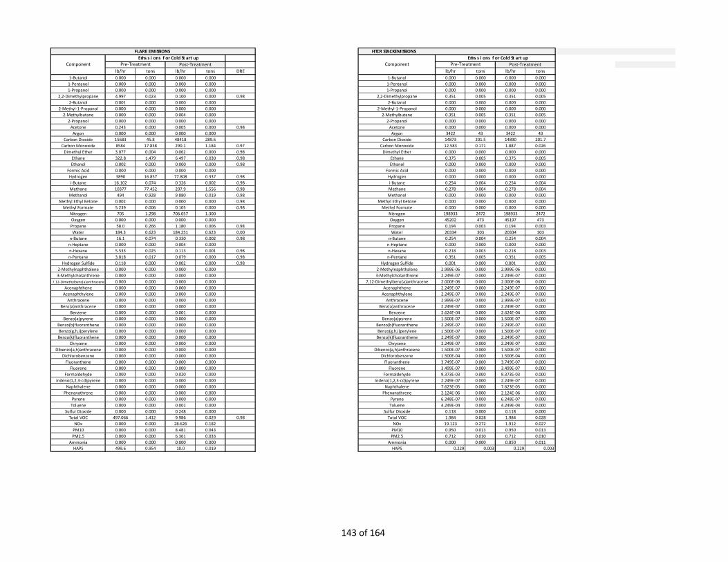
HTCR STACK EMISSIONS
lb/hr tons lb/hr tons DRE lb/hr tons lb/hr tons1-Butanol 0.000 0.000 0.000 0.000 1-Butanol 0.000 0.000 0.000 0.000
1-Pentanol 0.000 0.000 0.000 0.000 1-Pentanol 0.000 0.000 0.000 0.0001-Propanol 0.000 0.000 0.000 0.000 1-Propanol 0.000 0.000 0.000 0.000
2,2-Dimethylpropane 4.997 0.023 0.100 0.000 0.98 2,2-Dimethylpropane 0.351 0.005 0.351 0.0052-Butanol 0.001 0.000 0.000 0.000 2-Butanol 0.000 0.000 0.000 0.000
2-Methyl-1-Propanol 0.000 0.000 0.000 0.000 2-Methyl-1-Propanol 0.000 0.000 0.000 0.0002-Methylbutane 0.000 0.000 0.004 0.000 2-Methylbutane 0.351 0.005 0.351 0.005
2-Propanol 0.000 0.000 0.000 0.000 2-Propanol 0.000 0.000 0.000 0.000Acetone 0.243 0.000 0.005 0.000 0.98 Acetone 0.000 0.000 0.000 0.000Argon 0.000 0.000 0.000 0.000 Argon 3422 43 3422 43
Carbon Dioxide 15683 45.8 48418 289.6 Carbon Dioxide 14873 201.5 14890 201.7Carbon Monoxide 8584 17.838 290.1 1.184 0.97 Carbon Monoxide 12.583 0.171 1.887 0.026
Dimethyl Ether 3.077 0.004 0.062 0.000 0.98 Dimethyl Ether 0.000 0.000 0.000 0.000Ethane 322.8 1.479 6.497 0.030 0.98 Ethane 0.375 0.005 0.375 0.005Ethanol 0.002 0.000 0.000 0.000 0.98 Ethanol 0.000 0.000 0.000 0.000
Formic Acid 0.000 0.000 0.000 0.000 Formic Acid 0.000 0.000 0.000 0.000Hydrogen 3890 16.857 77.808 0.337 0.98 Hydrogen 0.000 0.000 0.000 0.000i-Butane 16.102 0.074 0.326 0.002 0.98 i-Butane 0.254 0.004 0.254 0.004Methane 10377 77.452 207.9 1.556 0.98 Methane 0.278 0.004 0.278 0.004Methanol 494 0.928 9.880 0.019 0.98 Methanol 0.000 0.000 0.000 0.000
Methyl Ethyl Ketone 0.002 0.000 0.000 0.000 0.98 Methyl Ethyl Ketone 0.000 0.000 0.000 0.000Methyl Formate 5.239 0.006 0.105 0.000 0.98 Methyl Formate 0.000 0.000 0.000 0.000
Nitrogen 705 1.298 706.057 1.300 Nitrogen 198933 2472 198933 2472Oxygen 0.000 0.000 0.000 0.000 Oxygen 45202 473 45197 473Propane 58.0 0.266 1.180 0.006 0.98 Propane 0.194 0.003 0.194 0.003Water 184.3 0.623 184.251 0.623 0.00 Water 20334 303 20334 303
n-Butane 16.1 0.074 0.330 0.002 0.98 n-Butane 0.254 0.004 0.254 0.004n-Heptane 0.000 0.000 0.004 0.000 n-Heptane 0.000 0.000 0.000 0.000n-Hexane 5.533 0.025 0.113 0.001 0.98 n-Hexane 0.218 0.003 0.218 0.003n-Pentane 3.818 0.017 0.079 0.000 0.98 n-Pentane 0.351 0.005 0.351 0.005
Hydrogen Sulfide 0.118 0.000 0.002 0.000 0.98 Hydrogen Sulfide 0.001 0.000 0.001 0.0002-Methylnaphthalene 0.000 0.000 0.000 0.000 2-Methylnaphthalene 2.999E-06 0.000 2.999E-06 0.0003-Methylcholanthrene 0.000 0.000 0.000 0.000 3-Methylcholanthrene 2.249E-07 0.000 2.249E-07 0.000
7,12-Dimethylbenz(a)anthracene 0.000 0.000 0.000 0.000 7,12-Dimethylbenz(a)anthracene 2.000E-06 0.000 2.000E-06 0.000Acenaphthene 0.000 0.000 0.000 0.000 Acenaphthene 2.249E-07 0.000 2.249E-07 0.000
Acenaphthylene 0.000 0.000 0.000 0.000 Acenaphthylene 2.249E-07 0.000 2.249E-07 0.000Anthracene 0.000 0.000 0.000 0.000 Anthracene 2.999E-07 0.000 2.999E-07 0.000
Benz(a)anthracene 0.000 0.000 0.000 0.000 Benz(a)anthracene 2.249E-07 0.000 2.249E-07 0.000Benzene 0.000 0.000 0.001 0.000 Benzene 2.624E-04 0.000 2.624E-04 0.000
Benzo(a)pyrene 0.000 0.000 0.000 0.000 Benzo(a)pyrene 1.500E-07 0.000 1.500E-07 0.000Benzo(b)fluoranthene 0.000 0.000 0.000 0.000 Benzo(b)fluoranthene 2.249E-07 0.000 2.249E-07 0.000Benzo(g,h,i)perylene 0.000 0.000 0.000 0.000 Benzo(g,h,i)perylene 1.500E-07 0.000 1.500E-07 0.000
Benzo(k)fluoranthene 0.000 0.000 0.000 0.000 Benzo(k)fluoranthene 2.249E-07 0.000 2.249E-07 0.000Chrysene 0.000 0.000 0.000 0.000 Chrysene 2.249E-07 0.000 2.249E-07 0.000
Dibenzo(a,h)anthracene 0.000 0.000 0.000 0.000 Dibenzo(a,h)anthracene 1.500E-07 0.000 1.500E-07 0.000Dichlorobenzene 0.000 0.000 0.000 0.000 Dichlorobenzene 1.500E-04 0.000 1.500E-04 0.000
Fluoranthene 0.000 0.000 0.000 0.000 Fluoranthene 3.749E-07 0.000 3.749E-07 0.000Fluorene 0.000 0.000 0.000 0.000 Fluorene 3.499E-07 0.000 3.499E-07 0.000
Formaldehyde 0.000 0.000 0.020 0.000 Formaldehyde 9.373E-03 0.000 9.373E-03 0.000Indeno(1,2,3-cd)pyrene 0.000 0.000 0.000 0.000 Indeno(1,2,3-cd)pyrene 2.249E-07 0.000 2.249E-07 0.000
Naphthalene 0.000 0.000 0.000 0.000 Naphthalene 7.623E-05 0.000 7.623E-05 0.000Phenanathrene 0.000 0.000 0.000 0.000 Phenanathrene 2.124E-06 0.000 2.124E-06 0.000
Pyrene 0.000 0.000 0.000 0.000 Pyrene 6.248E-07 0.000 6.248E-07 0.000Toluene 0.000 0.000 0.001 0.000 Toluene 4.249E-04 0.000 4.249E-04 0.000
Sulfur Dioxide 0.000 0.000 0.248 0.000 Sulfur Dioxide 0.118 0.000 0.118 0.000Total VOC 497.066 1.412 9.986 0.029 0.98 Total VOC 1.984 0.028 1.984 0.028
NOx 0.000 0.000 28.626 0.182 NOx 19.123 0.272 1.912 0.027PM10 0.000 0.000 8.481 0.043 PM10 0.950 0.013 0.950 0.013PM2.5 0.000 0.000 6.361 0.033 PM2.5 0.712 0.010 0.712 0.010
Ammonia 0.000 0.000 0.000 0.000 Ammonia 0.000 0.000 0.850 0.011HAPS 499.6 0.954 10.0 0.019 HAPS 0.229 0.003 0.229 0.003
Component Emissions for Cold Startup
Pre-Treatment Post-Treatment
FLARE EMISSIONS
ComponentEmissions for Cold Startup
Pre-Treatment Post-Treatment
143 of 164

HAPS 5.653 0.025 0.138 0.001 HAPS 0.229 0.003 0.229 0.003FLARE EMISSIONS FLARE EMISSIONSPer Unit Emissions from Cold Startup Per Unit Emissions from Cold Startup
lb/hr tons lb/hr tons lb/hr tons lb/hr tonsPM10 0.00 0.00 8.48 0.04 PM10 0.95 0.01 0.95 0.01PM2.5 0.00 0.00 6.36 0.03 PM2.5 0.71 0.01 0.71 0.01SO2 0.00 0.00 0.25 0.00 SO2 0.12 0.00 0.12 0.00Nox 0.00 0.00 28.63 0.18 Nox 19.12 0.27 1.91 0.03CO 8584 17.84 290.06 1.18 CO 12.58 0.17 1.89 0.03VOC 497 1.41 9.99 0.03 VOC 1.98 0.03 1.98 0.03HAP 500 0.95 10.02 0.02 HAP 0.23 0.00 0.23 0.00
Pre-Treatment Post-Treatment Pre-Treatment Post-Treatment
144 of 164

ESTIMATED EMISSIONS DURING A SYNTHESIS LOOP TRIP EVENT
lb/hr tons/hr lb/hr tons/hr lbm tons lbm tons lb/hr tons/hr lb/hr tons/hr lbm tons lbm tons1-Butanol 0.000 0.000 0.000 0.000 0.000 0.000 0.000 0.000 1-Butanol 0.000 0.000 0.000 0.000 0.000 0.000 0.000 0.000
1-Pentanol 0.000 0.000 0.000 0.000 0.000 0.000 0.000 0.000 1-Pentanol 0.000 0.000 0.000 0.000 0.000 0.000 0.000 0.0001-Propanol 0.000 0.000 0.000 0.000 0.001 0.000 0.000 0.000 1-Propanol 0.000 0.000 0.000 0.000 0.000 0.000 0.000 0.000
2,2-Dimethylpropane 0.000 0.000 0.000 0.000 0.000 0.000 0.002 0.000 2,2-Dimethylpropane 0.510 0.000 0.510 0.000 3.319 0.002 3.319 0.0022-Butanol 0.001 0.000 0.000 0.000 0.002 0.000 0.000 0.000 2-Butanol 0.000 0.000 0.000 0.000 0.000 0.000 0.000 0.000
2-Methyl-1-Propanol 0.000 0.000 0.000 0.000 0.000 0.000 0.000 0.000 2-Methyl-1-Propanol 0.000 0.000 0.000 0.000 0.000 0.000 0.000 0.0002-Methylbutane 0.000 0.000 0.004 0.000 0.000 0.000 0.050 0.000 2-Methylbutane 0.510 0.000 0.510 0.000 3.319 0.002 3.319 0.002
2-Propanol 0.000 0.000 0.000 0.000 0.001 0.000 0.000 0.000 2-Propanol 0.000 0.000 0.000 0.000 0.000 0.000 0.000 0.000Acetone 0.243 0.000 0.005 0.000 0.582 0.000 0.012 0.000 Acetone 0.000 0.000 0.000 0.000 0.000 0.000 0.000 0.000
Argon 0.000 0.000 0.000 0.000 0.000 0.000 0.000 0.000 Argon 3563 1.781 3563 1.781 19108 9.554 19108 9.554Carbon Dioxide 21195 10.60 62641 31.3 97854 48.927 314991 157 Carbon Dioxide 21403 10.702 21427 10.714 136635 68.318 136790 68.395
Carbon Monoxide 17302 8.651 523 0.262 77849 38.925 2493 1.246 Carbon Monoxide 18.054 0.009 2.708 0.001 115.534 0.058 17.330 0.009Dimethyl Ether 2.612 0.001 0.052 0.000 6.270 0.003 0.125 0.000 Dimethyl Ether 0.000 0.000 0.000 0.000 0.000 0.000 0.000 0.000
Ethane 0.000 0.000 0.041 0.000 0.000 0.000 0.547 0.000 Ethane 0.545 0.000 0.545 0.000 3.547 0.002 3.547 0.002Ethanol 0.002 0.000 0.000 0.000 0.006 0.000 0.000 0.000 Ethanol 0.000 0.000 0.000 0.000 0.000 0.000 0.000 0.000
Formic Acid 0.000 0.000 0.000 0.000 0.000 0.000 0.000 0.000 Formic Acid 0.000 0.000 0.000 0.000 0.000 0.000 0.000 0.000Hydrogen 7316.2 3.658 146.3 0.073 36931 18.465 738.6 0.369 Hydrogen 0.000 0.000 0.000 0.000 0.000 0.000 0.000 0.000i-Butane 0.000 0.000 0.004 0.000 0.000 0.000 0.057 0.000 i-Butane 0.369 0.000 0.369 0.000 2.403 0.001 2.403 0.001Methane 5486 2.743 110.0 0.055 35588 17.794 715.9 0.358 Methane 0.404 0.000 0.404 0.000 3.639 0.002 3.639 0.002Methanol 259.1 0.130 5.182 0.003 622 0.311 12.4 0.006 Methanol 0.000 0.000 0.000 0.000 0.000 0.000 0.000 0.000
Methyl Ethyl Ketone 0.002 0.000 0.000 0.000 0.005 0.000 0.000 0.000 Methyl Ethyl Ketone 0.000 0.000 0.000 0.000 0.000 0.000 0.000 0.000Methyl Formate 4.958 0.002 0.099 0.000 11.898 0.006 0.238 0.000 Methyl Formate 0.000 0.000 0.000 0.000 0.000 0.000 0.000 0.000
Nitrogen 138.2 0.069 138.3 0.069 895 0.447 896 0.448 Nitrogen 207145 103.6 207145 103.6 1111093 555.5 1111093 555.5Oxygen 0.000 0.000 0.000 0.000 0.000 0.000 0.000 0.000 Oxygen 33135 16.6 33126 16.6 146424 73.2 146368 73.2Propane 0.000 0.000 0.019 0.000 0.000 0.000 0.254 0.000 Propane 0.281 0.000 0.281 0.000 2.531 0.001 2.531 0.001Water 352.8 0.176 352.8 0.176 1626 0.813 1626 0.813 Water 28967 14.483 28967 14.483 172991 86.495 172991 86.495
n-Butane 0.000 0.000 0.007 0.000 0.000 0.000 0.099 0.000 n-Butane 0.369 0.000 0.369 0.000 2.403 0.001 2.403 0.001n-Heptane 0.000 0.000 0.004 0.000 0.000 0.000 0.051 0.000 n-Heptane 0.000 0.000 0.000 0.000 0.000 0.000 0.000 0.000n-Hexane 0.000 0.000 0.003 0.000 0.000 0.000 0.037 0.000 n-Hexane 0.316 0.000 0.316 0.000 2.060 0.001 2.060 0.001n-Pentane 0.000 0.000 0.003 0.000 0.000 0.000 0.034 0.000 n-Pentane 0.510 0.000 0.510 0.000 3.319 0.002 3.319 0.002
Hydrogen Sulfide 0.000 0.000 0.000 0.000 0.000 0.000 0.000 0.000 Hydrogen Sulfide 0.002 0.000 0.002 0.000 0.004 0.000 0.004 0.0002-Methylnaphthalene 0.000 0.000 0.000 0.000 0.000 0.000 0.000 0.000 2-Methylnaphthalene 0.000 0.000 0.000 0.000 0.000 0.000 0.000 0.0003-Methylcholanthrene 0.000 0.000 0.000 0.000 0.000 0.000 0.000 0.000 3-Methylcholanthrene 0.000 0.000 0.000 0.000 0.000 0.000 0.000 0.000
7,12-Dimethylbenz(a)anthracene 0.000 0.000 0.000 0.000 0.000 0.000 0.000 0.000 7,12-Dimethylbenz(a)anthracene 0.000 0.000 0.000 0.000 0.000 0.000 0.000 0.000Acenaphthene 0.000 0.000 0.000 0.000 0.000 0.000 0.000 0.000 Acenaphthene 0.000 0.000 0.000 0.000 0.000 0.000 0.000 0.000
Acenaphthylene 0.000 0.000 0.000 0.000 0.000 0.000 0.000 0.000 Acenaphthylene 0.000 0.000 0.000 0.000 0.000 0.000 0.000 0.000Anthracene 0.000 0.000 0.000 0.000 0.000 0.000 0.000 0.000 Anthracene 0.000 0.000 0.000 0.000 0.000 0.000 0.000 0.000
Benz(a)anthracene 0.000 0.000 0.000 0.000 0.000 0.000 0.000 0.000 Benz(a)anthracene 0.000 0.000 0.000 0.000 0.000 0.000 0.000 0.000Benzene 0.000 0.000 0.000 0.000 0.000 0.000 0.000 0.000 Benzene 0.000 0.000 0.000 0.000 0.002 0.000 0.002 0.000
Benzo(a)pyrene 0.000 0.000 0.000 0.000 0.000 0.000 0.000 0.000 Benzo(a)pyrene 0.000 0.000 0.000 0.000 0.000 0.000 0.000 0.000Benzo(b)fluoranthene 0.000 0.000 0.000 0.000 0.000 0.000 0.000 0.000 Benzo(b)fluoranthene 0.000 0.000 0.000 0.000 0.000 0.000 0.000 0.000Benzo(g,h,i)perylene 0.000 0.000 0.000 0.000 0.000 0.000 0.000 0.000 Benzo(g,h,i)perylene 0.000 0.000 0.000 0.000 0.000 0.000 0.000 0.000
Benzo(k)fluoranthene 0.000 0.000 0.000 0.000 0.000 0.000 0.000 0.000 Benzo(k)fluoranthene 0.000 0.000 0.000 0.000 0.000 0.000 0.000 0.000Chrysene 0.000 0.000 0.000 0.000 0.000 0.000 0.000 0.000 Chrysene 0.000 0.000 0.000 0.000 0.000 0.000 0.000 0.000
Dibenzo(a,h)anthracene 0.000 0.000 0.000 0.000 0.000 0.000 0.000 0.000 Dibenzo(a,h)anthracene 0.000 0.000 0.000 0.000 0.000 0.000 0.000 0.000Dichlorobenzene 0.000 0.000 0.000 0.000 0.000 0.000 0.000 0.000 Dichlorobenzene 0.000 0.000 0.000 0.000 0.001 0.000 0.001 0.000
Fluoranthene 0.000 0.000 0.000 0.000 0.000 0.000 0.000 0.000 Fluoranthene 0.000 0.000 0.000 0.000 0.000 0.000 0.000 0.000Fluorene 0.000 0.000 0.000 0.000 0.000 0.000 0.000 0.000 Fluorene 0.000 0.000 0.000 0.000 0.000 0.000 0.000 0.000
Formaldehyde 0.000 0.000 0.000 0.000 0.000 0.000 0.000 0.000 Formaldehyde 0.013 0.000 0.013 0.000 0.086 0.000 0.086 0.000Indeno(1,2,3-cd)pyrene 0.000 0.000 0.000 0.000 0.000 0.000 0.000 0.000 Indeno(1,2,3-cd)pyrene 0.000 0.000 0.000 0.000 0.000 0.000 0.000 0.000
Naphthalene 0.000 0.000 0.000 0.000 0.000 0.000 0.000 0.000 Naphthalene 0.000 0.000 0.000 0.000 0.001 0.000 0.001 0.000Phenanathrene 0.000 0.000 0.000 0.000 0.000 0.000 0.000 0.000 Phenanathrene 0.000 0.000 0.000 0.000 0.000 0.000 0.000 0.000
Pyrene 0.000 0.000 0.000 0.000 0.000 0.000 0.000 0.000 Pyrene 0.000 0.000 0.000 0.000 0.000 0.000 0.000 0.000Toluene 0.000 0.000 0.000 0.000 0.000 0.000 0.000 0.000 Toluene 0.001 0.000 0.001 0.000 0.004 0.000 0.004 0.000
Sulfur Dioxide 0.000 0.000 0.000 0.000 0.000 0.000 0.001 0.000 Sulfur Dioxide 0.169 0.000 0.169 0.000 0.261 0.000 0.261 0.000
Total VOC 261.72 0.131 5.279 0.003 628.1 0.314 13.15 0.007 Total VOC 2.880 0.001 2.880 0.001 19.448 0.010 19.448 0.010NOx 0.000 0.000 38.820 0.019 0.000 0.000 205.3 0.103 NOx 18.326 0.009 1.833 0.001 127.928 0.064 12.793 0.006
PM10 0.000 0.000 14.696 0.007 0.000 0.000 74.108 0.037 PM10 1.366 0.001 1.366 0.001 8.727 0.004 8.727 0.004PM2.5 0.000 0.000 11.022 0.006 0.000 0.000 55.6 0.028 PM2.5 1.024 0.001 1.024 0.001 6.545 0.003 6.545 0.003
Ammonia 0.000 0.000 0.000 0.000 0.000 0.000 0.000 0.000 Ammonia 0.000 0.000 0.904 0.000 0.000 0.000 4.890 0.002Notes NotesNOx is 0.068 lb/MMBtu and CO is 0.31 lb/MMBtu per AP-42 13.51 and 13.52, respectively. DRE of CO in the flare is 98%. Natural Gas – Emissions were calculated by MPS per AP-42 Section 1.4. Emissions factors were based on guidance in Table 1.4-1, 1.4-2, VOC are per AP42, Table 1.-4.3. VOC for natural gas components not listed in Table 1-4.3 are calculated using a DRE of 98%. and 1.4-3 with adjustments per OEM guidance. A DRE of 98% is used for any hydrocarbon not mentioned on Table 1.4-3.For purge gas, a balance across the flare is taken with a DRE of 98% is used for each component. The calculations assume a control efficiency associated with SCR-Oxycat as indicated in the Emission Flare accounts for additional natural gas required to maintain 200 Btu/scf (EPA minimum) and associated VOC Syngas – HT provided the calculations based on internal design and test experience.were considered per are per AP42, Table 1.-4.3.
FLARE EMISSIONS HTCR STACK EMISSIONS
ComponentMax Hourly Emissions for Syn. Loop Trip Total Emissions / Syn. Loop Trip
Pre-Treatment Post-Treatment Pre-Treatment Post-Treatment
Total Emissions / Syn. Loop Trip
Pre-Treatment Post-Treatment Pre-Treatment Post-TreatmentComponentMax Hourly Emissions for Syn. Loop Trip
145 of 164

FLARE EMISSIONS
lb/hr tons lb/hr tons DRE lb/hr tons lb/hr tons1-Butanol 0.000 0.000 0.000 0.000 1-Butanol 0.000 0.000 0.000 0.000
1-Pentanol 0.000 0.000 0.000 0.000 1-Pentanol 0.000 0.000 0.000 0.0001-Propanol 0.000 0.000 0.000 0.000 1-Propanol 0.000 0.000 0.000 0.000
2,2-Dimethylpropane 0.000 0.000 0.000 0.000 2,2-Dimethylpropane 0.510 0.002 0.510 0.0022-Butanol 0.001 0.000 0.000 0.000 0.980 2-Butanol 0.000 0.000 0.000 0.000
2-Methyl-1-Propanol 0.000 0.000 0.000 0.000 2-Methyl-1-Propanol 0.000 0.000 0.000 0.0002-Methylbutane 0.000 0.000 0.004 0.000 2-Methylbutane 0.510 0.002 0.510 0.002
2-Propanol 0.000 0.000 0.000 0.000 2-Propanol 0.000 0.000 0.000 0.000Acetone 0.243 0.000 0.005 0.000 0.980 Acetone 0.000 0.000 0.000 0.000
Argon 0.000 0.000 0.000 0.000 Argon 3562.6 9.554 3562.6 9.554Carbon Dioxide 21195 48.9 62641 157.5 Carbon Dioxide 21403 68.318 21427 68.395
Carbon Monoxide 17302 38.9 523.0 1.246 0.970 Carbon Monoxide 18.054 0.058 2.708 0.009Dimethyl Ether 2.612 0.003 0.052 0.000 0.980 Dimethyl Ether 0.000 0.000 0.000 0.000
Ethane 0.000 0.000 0.041 0.000 Ethane 0.545 0.002 0.545 0.002Ethanol 0.002 0.000 0.000 0.000 0.980 Ethanol 0.000 0.000 0.000 0.000
Formic Acid 0.000 0.000 0.000 0.000 Formic Acid 0.000 0.000 0.000 0.000Hydrogen 7316 18.465 146.325 0.369 0.980 Hydrogen 0.000 0.000 0.000 0.000i-Butane 0.000 0.000 0.004 0.000 i-Butane 0.369 0.001 0.369 0.001Methane 5486 17.794 110.0 0.358 0.980 Methane 0.404 0.002 0.404 0.002Methanol 259.1 0.311 5.182 0.006 0.980 Methanol 0.000 0.000 0.000 0.000
Methyl Ethyl Ketone 0.002 0.000 0.000 0.000 0.980 Methyl Ethyl Ketone 0.000 0.000 0.000 0.000Methyl Formate 4.958 0.006 0.099 0.000 0.980 Methyl Formate 0.000 0.000 0.000 0.000
Nitrogen 138.2 0.447 138.3 0.448 Nitrogen 207145 556 207145 556Oxygen 0.000 0.000 0.000 0.000 Oxygen 33135 73 33126 73Propane 0.000 0.000 0.019 0.000 Propane 0.281 0.001 0.281 0.001Water 352.8 0.813 352.8 0.813 0.000 Water 28967 86 28967 86
n-Butane 0.000 0.000 0.007 0.000 n-Butane 0.369 0.001 0.369 0.001n-Heptane 0.000 0.000 0.004 0.000 n-Heptane 0.000 0.000 0.000 0.000n-Hexane 0.000 0.000 0.003 0.000 n-Hexane 0.316 0.001 0.316 0.001n-Pentane 0.000 0.000 0.003 0.000 n-Pentane 0.510 0.002 0.510 0.002
Hydrogen Sulfide 0.000 0.000 0.000 0.000 Hydrogen Sulfide 0.002 0.000 0.002 0.0002-Methylnaphthalene 0.000 0.000 0.000 0.000 2-Methylnaphthalene 0.000 0.000 0.000 0.0003-Methylcholanthrene 0.000 0.000 0.000 0.000 3-Methylcholanthrene 0.000 0.000 0.000 0.000
7,12-Dimethylbenz(a)anthracene 0.000 0.000 0.000 0.000 7,12-Dimethylbenz(a)anthracene 0.000 0.000 0.000 0.000Acenaphthene 0.000 0.000 0.000 0.000 Acenaphthene 0.000 0.000 0.000 0.000
Acenaphthylene 0.000 0.000 0.000 0.000 Acenaphthylene 0.000 0.000 0.000 0.000Anthracene 0.000 0.000 0.000 0.000 Anthracene 0.000 0.000 0.000 0.000
Benz(a)anthracene 0.000 0.000 0.000 0.000 Benz(a)anthracene 0.000 0.000 0.000 0.000Benzene 0.000 0.000 0.000 0.000 Benzene 0.000 0.000 0.000 0.000
Benzo(a)pyrene 0.000 0.000 0.000 0.000 Benzo(a)pyrene 0.000 0.000 0.000 0.000Benzo(b)fluoranthene 0.000 0.000 0.000 0.000 Benzo(b)fluoranthene 0.000 0.000 0.000 0.000Benzo(g,h,i)perylene 0.000 0.000 0.000 0.000 Benzo(g,h,i)perylene 0.000 0.000 0.000 0.000
Benzo(k)fluoranthene 0.000 0.000 0.000 0.000 Benzo(k)fluoranthene 0.000 0.000 0.000 0.000Chrysene 0.000 0.000 0.000 0.000 Chrysene 0.000 0.000 0.000 0.000
Dibenzo(a,h)anthracene 0.000 0.000 0.000 0.000 Dibenzo(a,h)anthracene 0.000 0.000 0.000 0.000Dichlorobenzene 0.000 0.000 0.000 0.000 Dichlorobenzene 0.000 0.000 0.000 0.000
Fluoranthene 0.000 0.000 0.000 0.000 Fluoranthene 0.000 0.000 0.000 0.000Fluorene 0.000 0.000 0.000 0.000 Fluorene 0.000 0.000 0.000 0.000
Formaldehyde 0.000 0.000 0.000 0.000 Formaldehyde 0.013 0.000 0.013 0.000Indeno(1,2,3-cd)pyrene 0.000 0.000 0.000 0.000 Indeno(1,2,3-cd)pyrene 0.000 0.000 0.000 0.000
Naphthalene 0.000 0.000 0.000 0.000 Naphthalene 0.000 0.000 0.000 0.000Phenanathrene 0.000 0.000 0.000 0.000 Phenanathrene 0.000 0.000 0.000 0.000
Pyrene 0.000 0.000 0.000 0.000 Pyrene 0.000 0.000 0.000 0.000Toluene 0.000 0.000 0.000 0.000 Toluene 0.001 0.000 0.001 0.000
Sulfur Dioxide 0.000 0.000 0.000 0.000 Sulfur Dioxide 0.169 0.000 0.169 0.000
Total VOC 261.7 0.314 5.279 0.007 0.980 Total VOC 2.880 0.010 2.880 0.010NOx 0.000 0.000 38.820 0.103 NOx 18.33 0.064 1.833 0.006
PM10 0.000 0.000 14.696 0.037 PM10 1.366 0.004 1.366 0.004PM2.5 0.000 0.000 11.022 0.028 PM2.5 1.024 0.003 1.024 0.003
Ammonia 0.000 0.000 0.000 0.000 Ammonia 0.000 0.000 0.904 0.002HAPS 259.1 0.311 5.185 0.006 HAPS 0.333 0.001 0.333 0.001HAPS 0.002 0.000 0.003 0.000 HAPS 0.333 0.001 0.333 0.001
Component Emissions for SLT Event
Component Emissions for SLT Event
Pre-Treatment Post-Treatment Pre-Treatment Post-Treatment
HTCR STACK EMISSIONS
146 of 164

FLARE EMISSIONS FLARE EMISSIONSPer Unit Emissions from Syn Loop Trip Per Unit Emissions from Syn Loop Trip
lb/hr tons lb/hr tons lb/hr tons lb/hr tonsPM10 0.00 0.00 14.70 0.04 PM10 1.37 0.00 1.37 0.00PM2.5 0.00 0.00 11.02 0.03 PM2.5 1.02 0.00 1.02 0.00SO2 0.00 0.00 0.00 0.00 SO2 0.17 0.00 0.17 0.00Nox 0.00 0.00 38.82 0.10 Nox 18.33 0.06 1.83 0.01CO 17,302 38.92 523 1.25 CO 18 0.06 3 0.01VOC 261.72 0.31 5.28 0.01 VOC 2.88 0.01 2.88 0.01HAP 259.10 0.31 5.18 0.01 HAP 0.33 0.00 0.33 0.00
Pre-Treatment Post-Treatment Pre-Treatment Post-Treatment
147 of 164

ESTIMATED EMISSIONS DURING A REFORMER TRIP AND HOT RESTART
lb/hr tons/hr lb/hr tons/hr lbm tons lbm tons lb/hr tons/hr lb/hr tons/hr lbm tons lbm tons1-Butanol 0.012 0.000 0.000 0.000 0.002 0.000 0.000 0.000 1-Butanol 0.000 0.000 0.000 0.000 0.000 0.000 0.000 0.000
1-Pentanol 0.008 0.000 0.000 0.000 0.001 0.000 0.000 0.000 1-Pentanol 0.000 0.000 0.000 0.000 0.000 0.000 0.000 0.0001-Propanol 0.024 0.000 0.000 0.000 0.006 0.000 0.000 0.000 1-Propanol 0.000 0.000 0.000 0.000 0.000 0.000 0.000 0.000
2,2-Dimethylpropane 4.997 0.002 0.100 0.000 27.505 0.014 0.553 0.000 2,2-Dimethylpropane 0.351 0.000 0.351 0.000 5.606 0.003 5.606 0.0032-Butanol 0.020 0.000 0.000 0.000 0.005 0.000 0.000 0.000 2-Butanol 0.000 0.000 0.000 0.000 0.000 0.000 0.000 0.000
2-Methyl-1-Propanol 0.007 0.000 0.000 0.000 0.001 0.000 0.000 0.000 2-Methyl-1-Propanol 0.000 0.000 0.000 0.000 0.000 0.000 0.000 0.0002-Methylbutane 2.022 0.001 0.044 0.000 0.394 0.000 0.078 0.000 2-Methylbutane 0.351 0.000 0.351 0.000 5.606 0.003 5.606 0.003
2-Propanol 0.013 0.000 0.000 0.000 0.003 0.000 0.000 0.000 2-Propanol 0.000 0.000 0.000 0.000 0.000 0.000 0.000 0.000Acetone 0.243 0.000 0.005 0.000 0.582 0.000 0.012 0.000 Acetone 0.000 0.000 0.000 0.000 0.000 0.000 0.000 0.000
Argon 0.000 0.000 0.000 0.000 0.000 0.000 0.000 0.000 Argon 3422 1.7 3422 1.7 44043 22.0 44043 22.0Carbon Dioxide 15351 7.676 48993 24.50 81570 40.785 407045 203.5 Carbon Dioxide 14873 7.436 14890 7.445 230948 115.5 231209 115.6
Carbon Monoxide 8584 4.292 292.3 0.146 33382 16.691 1796 0.898 Carbon Monoxide 12.583 0.006 1.887 0.001 195.778 0.098 29.367 0.015Dimethyl Ether 2.612 0.001 0.052 0.000 6.285 0.003 0.126 0.000 Dimethyl Ether 0.000 0.000 0.000 0.000 0.000 0.000 0.000 0.000
Ethane 322.8 0.161 6.497 0.003 1780 0.890 36.369 0.018 Ethane 0.375 0.000 0.375 0.000 5.993 0.003 5.993 0.003Ethanol 0.080 0.000 0.002 0.000 0.021 0.000 0.000 0.000 Ethanol 0.000 0.000 0.000 0.000 0.000 0.000 0.000 0.000
Formic Acid 0.005 0.000 0.000 0.000 0.001 0.000 0.000 0.000 Formic Acid 0.000 0.000 0.000 0.000 0.000 0.000 0.000 0.000Hydrogen 3654 1.827 73.1 0.037 25434 12.717 508.7 0.254 Hydrogen 0.000 0.000 0.000 0.000 0.000 0.000 0.000 0.000i-Butane 16.102 0.008 0.326 0.000 89.005 0.045 1.861 0.001 i-Butane 0.254 0.000 0.254 0.000 4.060 0.002 4.060 0.002Methane 10377 5.189 207.9 0.104 98691 49.345 1980 0.990 Methane 0.278 0.000 0.278 0.000 4.635 0.002 4.635 0.002Methanol 259 0.130 5.182 0.003 655 0.327 13.099 0.007 Methanol 0.000 0.000 0.000 0.000 0.000 0.000 0.000 0.000
Methyl Ethyl Ketone 0.002 0.000 0.000 0.000 0.005 0.000 0.000 0.000 Methyl Ethyl Ketone 0.000 0.000 0.000 0.000 0.000 0.000 0.000 0.000Methyl Formate 4.958 0.002 0.099 0.000 11.908 0.006 0.238 0.000 Methyl Formate 0.000 0.000 0.000 0.000 0.000 0.000 0.000 0.000
Nitrogen 138 0.069 138 0.069 1104 0.552 1105.3 0.553 Nitrogen 198933 99 198933 99 2560795 1280 2560795 1280Oxygen 0.000 0.000 0.000 0.000 0.000 0.000 0.000 0.000 Oxygen 45202 23 45197 23 457878 229 457783 229Propane 58.0 0.029 1.180 0.001 321 0.161 6.783 0.003 Propane 0.194 0.000 0.194 0.000 3.224 0.002 3.224 0.002
Water 238.8 0.119 238.8 0.119 1248 0.624 1248.2 0.624 Water 20334 10.167 20334 10.167 331253 166 331253 166n-Butane 16.1 0.008 0.330 0.000 89.384 0.045 1.927 0.001 n-Butane 0.254 0.000 0.254 0.000 4.060 0.002 4.060 0.002
n-Heptane 2.239 0.001 0.049 0.000 0.436 0.000 0.080 0.000 n-Heptane 0.000 0.000 0.000 0.000 0.000 0.000 0.000 0.000n-Hexane 5.533 0.003 0.113 0.000 30.71 0.015 0.666 0.000 n-Hexane 0.218 0.000 0.218 0.000 3.480 0.002 3.480 0.002n-Pentane 3.818 0.002 0.079 0.000 21.31 0.011 0.475 0.000 n-Pentane 0.351 0.000 0.351 0.000 5.606 0.003 5.606 0.003
Hydrogen Sulfide 0.118 0.000 0.002 0.000 0.065 0.000 0.001 0.000 Hydrogen Sulfide 0.001 0.000 0.001 0.000 0.009 0.000 0.009 0.0002-Methylnaphthalene 0.000 0.000 0.000 0.000 0.000 0.000 0.000 0.000 2-Methylnaphthalene 0.000 0.000 0.000 0.000 0.000 0.000 0.000 0.0003-Methylcholanthrene 0.000 0.000 0.000 0.000 0.000 0.000 0.000 0.000 3-Methylcholanthrene 0.000 0.000 0.000 0.000 0.000 0.000 0.000 0.000
7,12-Dimethylbenz(a)anthracene 0.000 0.000 0.000 0.000 0.000 0.000 0.000 0.000 7,12-Dimethylbenz(a)anthracene 0.000 0.000 0.000 0.000 0.000 0.000 0.000 0.000Acenaphthene 0.000 0.000 0.000 0.000 0.000 0.000 0.000 0.000 Acenaphthene 0.000 0.000 0.000 0.000 0.000 0.000 0.000 0.000
Acenaphthylene 0.000 0.000 0.000 0.000 0.000 0.000 0.000 0.000 Acenaphthylene 0.000 0.000 0.000 0.000 0.000 0.000 0.000 0.000Anthracene 0.000 0.000 0.000 0.000 0.000 0.000 0.000 0.000 Anthracene 0.000 0.000 0.000 0.000 0.000 0.000 0.000 0.000
Benz(a)anthracene 0.000 0.000 0.000 0.000 0.000 0.000 0.000 0.000 Benz(a)anthracene 0.000 0.000 0.000 0.000 0.000 0.000 0.000 0.000Benzene 0.000 0.000 0.001 0.000 0.000 0.000 0.003 0.000 Benzene 0.000 0.000 0.000 0.000 0.004 0.000 0.004 0.000
Benzo(a)pyrene 0.000 0.000 0.000 0.000 0.000 0.000 0.000 0.000 Benzo(a)pyrene 0.000 0.000 0.000 0.000 0.000 0.000 0.000 0.000Benzo(b)fluoranthene 0.000 0.000 0.000 0.000 0.000 0.000 0.000 0.000 Benzo(b)fluoranthene 0.000 0.000 0.000 0.000 0.000 0.000 0.000 0.000Benzo(g,h,i)perylene 0.000 0.000 0.000 0.000 0.000 0.000 0.000 0.000 Benzo(g,h,i)perylene 0.000 0.000 0.000 0.000 0.000 0.000 0.000 0.000
Benzo(k)fluoranthene 0.000 0.000 0.000 0.000 0.000 0.000 0.000 0.000 Benzo(k)fluoranthene 0.000 0.000 0.000 0.000 0.000 0.000 0.000 0.000Chrysene 0.000 0.000 0.000 0.000 0.000 0.000 0.000 0.000 Chrysene 0.000 0.000 0.000 0.000 0.000 0.000 0.000 0.000
Dibenzo(a,h)anthracene 0.000 0.000 0.000 0.000 0.000 0.000 0.000 0.000 Dibenzo(a,h)anthracene 0.000 0.000 0.000 0.000 0.000 0.000 0.000 0.000Dichlorobenzene 0.000 0.000 0.000 0.000 0.000 0.000 0.002 0.000 Dichlorobenzene 0.000 0.000 0.000 0.000 0.002 0.000 0.002 0.000
Fluoranthene 0.000 0.000 0.000 0.000 0.000 0.000 0.000 0.000 Fluoranthene 0.000 0.000 0.000 0.000 0.000 0.000 0.000 0.000Fluorene 0.000 0.000 0.000 0.000 0.000 0.000 0.000 0.000 Fluorene 0.000 0.000 0.000 0.000 0.000 0.000 0.000 0.000
Formaldehyde 0.000 0.000 0.020 0.000 0.000 0.000 0.109 0.000 Formaldehyde 0.009 0.000 0.009 0.000 0.145 0.000 0.145 0.000Indeno(1,2,3-cd)pyrene 0.000 0.000 0.000 0.000 0.000 0.000 0.000 0.000 Indeno(1,2,3-cd)pyrene 0.000 0.000 0.000 0.000 0.000 0.000 0.000 0.000
Naphthalene 0.000 0.000 0.000 0.000 0.000 0.000 0.001 0.000 Naphthalene 0.000 0.000 0.000 0.000 0.001 0.000 0.001 0.000Phenanathrene 0.000 0.000 0.000 0.000 0.000 0.000 0.000 0.000 Phenanathrene 0.000 0.000 0.000 0.000 0.000 0.000 0.000 0.000
Pyrene 0.000 0.000 0.000 0.000 0.000 0.000 0.000 0.000 Pyrene 0.000 0.000 0.000 0.000 0.000 0.000 0.000 0.000Toluene 0.000 0.000 0.001 0.000 0.000 0.000 0.005 0.000 Toluene 0.000 0.000 0.000 0.000 0.007 0.000 0.007 0.000
Sulfur Dioxide 0.000 0.000 0.248 0.000 0.000 0.000 0.137 0.000 Sulfur Dioxide 0.118 0.000 0.118 0.000 0.289 0.000 0.289 0.000
Total VOC 261.72 0.131 5.279 0.003 1241 0.621 25.767 0.013 Total VOC 1.984 0.001 1.984 0.001 31.802 0.016 31.802 0.016NOx 0.000 0.000 26.461 0.013 0.000 0.000 247.576 0.124 NOx 19.123 0.010 1.912 0.001 274.190 0.137 27.419 0.014
PM10 0.000 0.000 8.520 0.004 0.000 0.000 63.544 0.032 PM10 0.950 0.000 0.950 0.000 14.722 0.007 14.722 0.007PM2.5 0.000 0.000 6.390 0.003 0.000 0.000 47.658 0.024 PM2.5 0.712 0.000 0.712 0.000 11.041 0.006 11.041 0.006
Ammonia 0.000 0.000 0.000 0.000 0.000 0.000 0.000 0.000 Ammonia 0.000 0.000 0.850 0.000 0.000 0.000 11.109 0.006Notes NotesNOx is 0.068 lb/MMBtu and CO is 0.31 lb/MMBtu per AP-42 13.51 and 13.52, respectively. DRE of CO in the flare is 98%. Natural Gas – Emissions were calculated by MPS per AP-42 Section 1.4. Emissions factors were based on guidance in Table 1.4-1, 1.4-2, VOC are per AP42, Table 1.-4.3. VOC for natural gas components not listed in Table 1-4.3 are calculated using a DRE of 98%. and 1.4-3 with adjustments per OEM guidance. A DRE of 98% is used for any hydrocarbon not mentioned on Table 1.4-3.For purge gas, a balance across the flare is taken with a DRE of 98% is used for each component. The calculations assume a control efficiency associated with SCR-Oxycat as indicated in the Emission Flare accounts for additional natural gas required to maintain 200 Btu/scf (EPA minimum) and associated VOC Syngas – HT provided the calculations based on internal design and test experience.were considered per are per AP42, Table 1.-4.3.
FLARE EMISSIONS HTCR STACK EMISSIONS
ComponentMax Hourly Emissions for HTCR Trip & Restart Total Emissions / HTCR Trip & Restart
Pre-Treatment Post-Treatment Pre-Treatment Post-Treatment
Total Emissions / HTCR Trip & Restart
Pre-Treatment Post-Treatment Pre-Treatment Post-TreatmentComponentMax Hourly Emissions for HTCR Trip & Restart
148 of 164

lb/hr tons lb/hr tons DRE lb/hr tons lb/hr tons1-Butanol 0.012 0.000 0.000 0.000 0.98 1-Butanol 0.000 0.000 0.000 0.000
1-Pentanol 0.008 0.000 0.000 0.000 0.98 1-Pentanol 0.000 0.000 0.000 0.0001-Propanol 0.024 0.000 0.000 0.000 0.98 1-Propanol 0.000 0.000 0.000 0.000
2,2-Dimethylpropane 4.997 0.014 0.100 0.000 0.98 2,2-Dimethylpropane 0.351 0.003 0.351 0.0032-Butanol 0.020 0.000 0.000 0.000 0.98 2-Butanol 0.000 0.000 0.000 0.000
2-Methyl-1-Propanol 0.007 0.000 0.000 0.000 0.98 2-Methyl-1-Propanol 0.000 0.000 0.000 0.0002-Methylbutane 2.022 0.000 0.044 0.000 0.98 2-Methylbutane 0.351 0.003 0.351 0.003
2-Propanol 0.013 0.000 0.000 0.000 0.98 2-Propanol 0.000 0.000 0.000 0.000Acetone 0.243 0.000 0.005 0.000 0.98 Acetone 0.000 0.000 0.000 0.000
Argon 0.000 0.000 0.000 0.000 Argon 3421.644 22.021 3421.644 22.021Carbon Dioxide 15351 40.8 48993 203.5 Carbon Dioxide 14872.906 115.474 14889.711 115.605
Carbon Monoxide 8584 16.691 292 0.898 0.98 Carbon Monoxide 12.583 0.098 1.887 0.015Dimethyl Ether 2.612 0.003 0.052 0.000 0.98 Dimethyl Ether 0.000 0.000 0.000 0.000
Ethane 322.789 0.890 6.497 0.018 0.98 Ethane 0.375 0.003 0.375 0.003Ethanol 0.080 0.000 0.002 0.000 0.98 Ethanol 0.000 0.000 0.000 0.000
Formic Acid 0.005 0.000 0.000 0.000 0.98 Formic Acid 0.000 0.000 0.000 0.000Hydrogen 3654.3 12.717 73.087 0.254 0.98 Hydrogen 0.000 0.000 0.000 0.000i-Butane 16.102 0.045 0.326 0.001 0.98 i-Butane 0.254 0.002 0.254 0.002Methane 10377.3 49.345 207.859 0.990 0.98 Methane 0.278 0.002 0.278 0.002Methanol 259.098 0.327 5.182 0.007 0.98 Methanol 0.000 0.000 0.000 0.000
Methyl Ethyl Ketone 0.002 0.000 0.000 0.000 0.98 Methyl Ethyl Ketone 0.000 0.000 0.000 0.000Methyl Formate 4.958 0.006 0.099 0.000 0.98 Methyl Formate 0.000 0.000 0.000 0.000
Nitrogen 138.247 0.552 138.337 0.553 Nitrogen 198932.548 1280.398 198932.548 1280.398Oxygen 0.000 0.000 0.000 0.000 Oxygen 45201.708 228.939 45197.066 228.892Propane 58.025 0.161 1.180 0.003 0.98 Propane 0.194 0.002 0.194 0.002
Water 238.8 0.624 238.8 0.624 Water 20334.204 165.627 20334.204 165.627n-Butane 16.102 0.045 0.330 0.001 0.98 n-Butane 0.254 0.002 0.254 0.002
n-Heptane 2.239 0.000 0.049 0.000 0.98 n-Heptane 0.000 0.000 0.000 0.000n-Hexane 5.533 0.015 0.113 0.000 0.98 n-Hexane 0.218 0.002 0.218 0.002n-Pentane 3.818 0.011 0.079 0.000 0.98 n-Pentane 0.351 0.003 0.351 0.003
Hydrogen Sulfide 0.118 0.000 0.002 0.000 0.98 Hydrogen Sulfide 0.001 0.000 0.001 0.0002-Methylnaphthalene 0.000 0.000 0.000 0.000 2-Methylnaphthalene 0.000 0.000 0.000 0.0003-Methylcholanthrene 0.000 0.000 0.000 0.000 3-Methylcholanthrene 0.000 0.000 0.000 0.000
7,12-Dimethylbenz(a)anthracene 0.000 0.000 0.000 0.000 7,12-Dimethylbenz(a)anthracene 0.000 0.000 0.000 0.000Acenaphthene 0.000 0.000 0.000 0.000 Acenaphthene 0.000 0.000 0.000 0.000
Acenaphthylene 0.000 0.000 0.000 0.000 Acenaphthylene 0.000 0.000 0.000 0.000Anthracene 0.000 0.000 0.000 0.000 Anthracene 0.000 0.000 0.000 0.000
Benz(a)anthracene 0.000 0.000 0.000 0.000 Benz(a)anthracene 0.000 0.000 0.000 0.000Benzene 0.000 0.000 0.001 0.000 Benzene 0.000 0.000 0.000 0.000
Benzo(a)pyrene 0.000 0.000 0.000 0.000 Benzo(a)pyrene 0.000 0.000 0.000 0.000Benzo(b)fluoranthene 0.000 0.000 0.000 0.000 Benzo(b)fluoranthene 0.000 0.000 0.000 0.000Benzo(g,h,i)perylene 0.000 0.000 0.000 0.000 Benzo(g,h,i)perylene 0.000 0.000 0.000 0.000
Benzo(k)fluoranthene 0.000 0.000 0.000 0.000 Benzo(k)fluoranthene 0.000 0.000 0.000 0.000Chrysene 0.000 0.000 0.000 0.000 Chrysene 0.000 0.000 0.000 0.000
Dibenzo(a,h)anthracene 0.000 0.000 0.000 0.000 Dibenzo(a,h)anthracene 0.000 0.000 0.000 0.000Dichlorobenzene 0.000 0.000 0.000 0.000 Dichlorobenzene 0.000 0.000 0.000 0.000
Fluoranthene 0.000 0.000 0.000 0.000 Fluoranthene 0.000 0.000 0.000 0.000Fluorene 0.000 0.000 0.000 0.000 Fluorene 0.000 0.000 0.000 0.000
Formaldehyde 0.000 0.000 0.020 0.000 Formaldehyde 0.009 0.000 0.009 0.000Indeno(1,2,3-cd)pyrene 0.000 0.000 0.000 0.000 Indeno(1,2,3-cd)pyrene 0.000 0.000 0.000 0.000
Naphthalene 0.000 0.000 0.000 0.000 Naphthalene 0.000 0.000 0.000 0.000Phenanathrene 0.000 0.000 0.000 0.000 Phenanathrene 0.000 0.000 0.000 0.000
Pyrene 0.000 0.000 0.000 0.000 Pyrene 0.000 0.000 0.000 0.000Toluene 0.000 0.000 0.001 0.000 Toluene 0.000 0.000 0.000 0.000
Sulfur Dioxide 0.000 0.000 0.248 0.000 Sulfur Dioxide 0.118 0.000 0.118 0.000
Total VOC 261.7 0.621 5.279 0.013 0.980 Total VOC 1.984 0.016 1.984 0.016NOx 0.000 0.000 26.461 0.124 NOx 19.123 0.137 1.912 0.014
PM10 0.000 0.000 8.520 0.032 PM10 0.950 0.007 0.950 0.007PM2.5 0.000 0.000 6.390 0.024 PM2.5 0.712 0.006 0.712 0.006
Ammonia 0.000 0.000 0.000 0.000 Ammonia 0.000 0.000 0.850 0.006HAPS 264.751 0.343 5.319 0.007 HAPS 0.229 0.002 0.229 0.002
FLARE EMISSIONS HTCR STACK EMISSIONS
ComponentEmissions for Reformer Trip and Restart
ComponentEmissions for Reformer Trip and Restart
Pre-Treatment Post-Treatment Pre-Treatment Post-Treatment
149 of 164
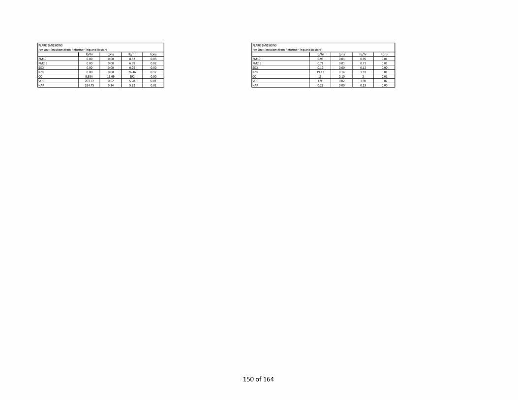
HAPS 5.653 0.015 0.138 0.000 HAPS 0.229 0.002 0.229 0.002
FLARE EMISSIONS FLARE EMISSIONSPer Unit Emissions from Reformer Trip and Restart Per Unit Emissions from Reformer Trip and Restart
lb/hr tons lb/hr tons lb/hr tons lb/hr tonsPM10 0.00 0.00 8.52 0.03 PM10 0.95 0.01 0.95 0.01PM2.5 0.00 0.00 6.39 0.02 PM2.5 0.71 0.01 0.71 0.01SO2 0.00 0.00 0.25 0.00 SO2 0.12 0.00 0.12 0.00Nox 0.00 0.00 26.46 0.12 Nox 19.12 0.14 1.91 0.01CO 8,584 16.69 292 0.90 CO 13 0.10 2 0.01VOC 261.72 0.62 5.28 0.01 VOC 1.98 0.02 1.98 0.02HAP 264.75 0.34 5.32 0.01 HAP 0.23 0.00 0.23 0.00
150 of 164
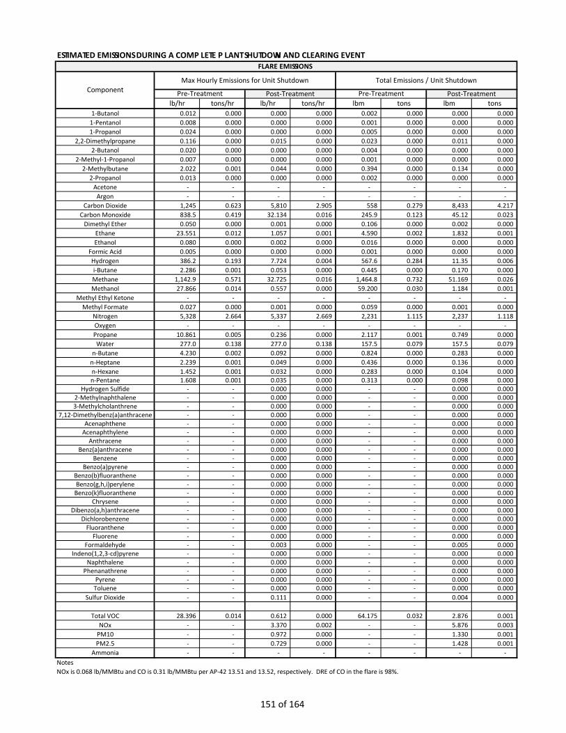
ESTIMATED EMISSIONS DURING A COMPLETE PLANT SHUTDOWN AND CLEARING EVENT
lb/hr tons/hr lb/hr tons/hr lbm tons lbm tons1-Butanol 0.012 0.000 0.000 0.000 0.002 0.000 0.000 0.000
1-Pentanol 0.008 0.000 0.000 0.000 0.001 0.000 0.000 0.000 1-Propanol 0.024 0.000 0.000 0.000 0.005 0.000 0.000 0.000
2,2-Dimethylpropane 0.116 0.000 0.015 0.000 0.023 0.000 0.011 0.000 2-Butanol 0.020 0.000 0.000 0.000 0.004 0.000 0.000 0.000
2-Methyl-1-Propanol 0.007 0.000 0.000 0.000 0.001 0.000 0.000 0.000 2-Methylbutane 2.022 0.001 0.044 0.000 0.394 0.000 0.134 0.000
2-Propanol 0.013 0.000 0.000 0.000 0.002 0.000 0.000 0.000 Acetone - - - - - - - -
Argon - - - - - - - - Carbon Dioxide 1,245 0.623 5,810 2.905 558 0.279 8,433 4.217
Carbon Monoxide 838.5 0.419 32.134 0.016 245.9 0.123 45.12 0.023 Dimethyl Ether 0.050 0.000 0.001 0.000 0.106 0.000 0.002 0.000
Ethane 23.551 0.012 1.057 0.001 4.590 0.002 1.832 0.001 Ethanol 0.080 0.000 0.002 0.000 0.016 0.000 0.000 0.000
Formic Acid 0.005 0.000 0.000 0.000 0.001 0.000 0.000 0.000 Hydrogen 386.2 0.193 7.724 0.004 567.6 0.284 11.35 0.006 i-Butane 2.286 0.001 0.053 0.000 0.445 0.000 0.170 0.000 Methane 1,142.9 0.571 32.725 0.016 1,464.8 0.732 51.169 0.026 Methanol 27.866 0.014 0.557 0.000 59.200 0.030 1.184 0.001
Methyl Ethyl Ketone - - - - - - - - Methyl Formate 0.027 0.000 0.001 0.000 0.059 0.000 0.001 0.000
Nitrogen 5,328 2.664 5,337 2.669 2,231 1.115 2,237 1.118 Oxygen - - - - - - - - Propane 10.861 0.005 0.236 0.000 2.117 0.001 0.749 0.000 Water 277.0 0.138 277.0 0.138 157.5 0.079 157.5 0.079
n-Butane 4.230 0.002 0.092 0.000 0.824 0.000 0.283 0.000 n-Heptane 2.239 0.001 0.049 0.000 0.436 0.000 0.136 0.000 n-Hexane 1.452 0.001 0.032 0.000 0.283 0.000 0.104 0.000 n-Pentane 1.608 0.001 0.035 0.000 0.313 0.000 0.098 0.000
Hydrogen Sulfide - - 0.000 0.000 - - 0.000 0.000 2-Methylnaphthalene - - 0.000 0.000 - - 0.000 0.000 3-Methylcholanthrene - - 0.000 0.000 - - 0.000 0.000
7,12-Dimethylbenz(a)anthracene - - 0.000 0.000 - - 0.000 0.000 Acenaphthene - - 0.000 0.000 - - 0.000 0.000
Acenaphthylene - - 0.000 0.000 - - 0.000 0.000 Anthracene - - 0.000 0.000 - - 0.000 0.000
Benz(a)anthracene - - 0.000 0.000 - - 0.000 0.000 Benzene - - 0.000 0.000 - - 0.000 0.000
Benzo(a)pyrene - - 0.000 0.000 - - 0.000 0.000 Benzo(b)fluoranthene - - 0.000 0.000 - - 0.000 0.000 Benzo(g,h,i)perylene - - 0.000 0.000 - - 0.000 0.000
Benzo(k)fluoranthene - - 0.000 0.000 - - 0.000 0.000 Chrysene - - 0.000 0.000 - - 0.000 0.000
Dibenzo(a,h)anthracene - - 0.000 0.000 - - 0.000 0.000 Dichlorobenzene - - 0.000 0.000 - - 0.000 0.000
Fluoranthene - - 0.000 0.000 - - 0.000 0.000 Fluorene - - 0.000 0.000 - - 0.000 0.000
Formaldehyde - - 0.003 0.000 - - 0.005 0.000 Indeno(1,2,3-cd)pyrene - - 0.000 0.000 - - 0.000 0.000
Naphthalene - - 0.000 0.000 - - 0.000 0.000 Phenanathrene - - 0.000 0.000 - - 0.000 0.000
Pyrene - - 0.000 0.000 - - 0.000 0.000 Toluene - - 0.000 0.000 - - 0.000 0.000
Sulfur Dioxide - - 0.111 0.000 - - 0.004 0.000
Total VOC 28.396 0.014 0.612 0.000 64.175 0.032 2.876 0.001 NOx - - 3.370 0.002 - - 5.876 0.003
PM10 - - 0.972 0.000 - - 1.330 0.001 PM2.5 - - 0.729 0.000 - - 1.428 0.001
Ammonia - - - - - - - - NotesNOx is 0.068 lb/MMBtu and CO is 0.31 lb/MMBtu per AP-42 13.51 and 13.52, respectively. DRE of CO in the flare is 98%.
FLARE EMISSIONS
ComponentMax Hourly Emissions for Unit Shutdown Total Emissions / Unit Shutdown
Pre-Treatment Post-Treatment Pre-Treatment Post-Treatment
151 of 164

VOC are per AP42, Table 1.-4.3. VOC for natural gas components not listed in Table 1-4.3 are calculated using a DRE of 98%.For purge gas, a balance across the flare is taken with a DRE of 98% is used for each component. Flare accounts for additional natural gas required to maintain 200 Btu/scf (EPA minimum) and associated VOC were considered per are per AP42, Table 1.-4.3.
152 of 164
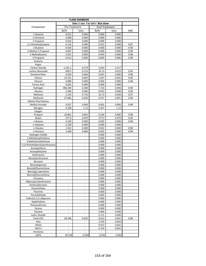
lb/hr tons lb/hr tons DRE1-Butanol 0.012 0.000 0.000 0.000
1-Pentanol 0.008 0.000 0.000 0.000 1-Propanol 0.024 0.000 0.000 0.000
2,2-Dimethylpropane 0.116 0.000 0.015 0.000 0.872-Butanol 0.020 0.000 0.000 0.000 0.98
2-Methyl-1-Propanol 0.007 0.000 0.000 0.000 0.982-Methylbutane 2.022 0.000 0.044 0.000 0.98
2-Propanol 0.013 0.000 0.000 0.000 0.98Acetone - - - -
Argon - - - - Carbon Dioxide 1,245.1 0.279 5,810 4.217
Carbon Monoxide 838.5 0.123 32.13 0.023 0.96Dimethyl Ether 0.050 0.000 0.001 0.000 0.98
Ethane 23.551 0.002 1.057 0.001 0.96Ethanol 0.080 0.000 0.002 0.000 0.98
Formic Acid 0.005 0.000 0.000 0.000 Hydrogen 386.200 0.284 7.724 0.006 0.98i-Butane 2.286 0.000 0.053 0.000 0.98Methane 1,143 0.732 32.72 0.026 0.97Methanol 27.866 0.030 0.557 0.001 0.98
Methyl Ethyl Ketone - - - - Methyl Formate 0.027 0.000 0.001 0.000 0.98
Nitrogen 5,328 1.12 5,337 1.12 Oxygen - - - - Propane 10.861 0.001 0.236 0.000 0.98Water 277.0 0.079 277.0 0.079 0.00
n-Butane 4.230 0.000 0.092 0.000 0.98n-Heptane 2.239 0.000 0.049 0.000 n-Hexane 1.452 0.000 0.032 0.000 0.98n-Pentane 1.608 0.000 0.035 0.000 0.98
Hydrogen Sulfide - - 0.000 0.000 2-Methylnaphthalene - - 0.000 0.000 3-Methylcholanthrene - - 0.000 0.000
7,12-Dimethylbenz(a)anthracene - - 0.000 0.000 Acenaphthene - - 0.000 0.000
Acenaphthylene - - 0.000 0.000 Anthracene - - 0.000 0.000
Benz(a)anthracene - - 0.000 0.000 Benzene - - 0.000 0.000
Benzo(a)pyrene - - 0.000 0.000 Benzo(b)fluoranthene - - 0.000 0.000 Benzo(g,h,i)perylene - - 0.000 0.000
Benzo(k)fluoranthene - - 0.000 0.000 Chrysene - - 0.000 0.000
Dibenzo(a,h)anthracene - - 0.000 0.000 Dichlorobenzene - - 0.000 0.000
Fluoranthene - - 0.000 0.000 Fluorene - - 0.000 0.000
Formaldehyde - - 0.003 0.000 Indeno(1,2,3-cd)pyrene - - 0.000 0.000
Naphthalene - - 0.000 0.000 Phenanathrene - - 0.000 0.000
Pyrene - - 0.000 0.000 Toluene - - 0.000 0.000
Sulfur Dioxide - - 0.111 0.000 Total VOC 28.396 0.032 0.612 0.001 0.98
NOx - - 3.370 0.003 PM10 - - 0.972 0.001 PM2.5 - - 0.729 0.001
Ammonia - - - - HAPS 29.318 0.030 0.593 0.001HAPS 1.452 0.000 0.035 0.000
ComponentEmissions for Unit Shutdown
Pre-Treatment Post-Treatment
FLARE EMISSIONS
153 of 164
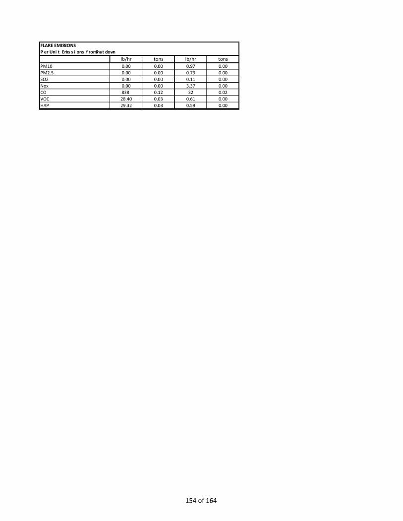
FLARE EMISSIONSPer Unit Emissions from Shutdown
lb/hr tons lb/hr tonsPM10 0.00 0.00 0.97 0.00PM2.5 0.00 0.00 0.73 0.00SO2 0.00 0.00 0.11 0.00Nox 0.00 0.00 3.37 0.00CO 838 0.12 32 0.02VOC 28.40 0.03 0.61 0.00HAP 29.32 0.03 0.59 0.00
154 of 164

FLARE LP SECTION EMISSIONSOPERATING PARAMETERS
Normal OperationsOperating Schedule 8760 hrs/yrNatural Gas HHV 1,084 Btu/scf Number of burners 6 Pilot Burners serve both HP and LP sections of flareBtu/h per burner 45,000 but are included under LP section for calculationPilot Natural Gas Heat Duty 0.27 MMBtu/h purposes.LP Gas to Flare 0 MMBtu/hTotal LP Gas Duty 0.27Annual Natural Gas Heat Rate (Pilot) 2365.2 MMBtu/yr
EMISSION CALCULATIONSCombustion Emissions HHV
Emission Factor lb/scf lb/MMBtu mg/lSO2 0.6018 0.00059 Ref 1, Table 1.4-2NOx 0.068 Ref 2, Table 13.5-1, note CCO 0.279279279 Ref 2, Table 13.5-2THC 0.14 Ref 2, Table 13.5-3PM 0.0024 40 Ref 2, Table 13.5-1 lightly smoking
VOC (comb) 5.5 0.0054 Ref 1, Table 1.4-2GWP
CO2 1 117 40 CFT 98 Table C-1CH4 25 0.0022 40 CFT 98 Table C-2N2O 298 0.00022 40 CFT 98 Table C-2
1Emission factors in EPA AP-42, Section 1.5, “Natural Gas Combustor”, July 19982Emission factors in EPA AP-42, Section 13.5, “Industrial Flares”, February 2018
Emissions From LP Flare due to Pilot PerPlant
lb/h tpy tpyPM 0.00 0.003 0.01PM10 0.00 0.003 0.009PM2.5 0.00 0.003 0.01SO2 0.00 0.001 0.002NOx 0.02 0.080 0.241CO 0.08 0.330 0.991VOC 0.00 0.006 0.019HAP 0.00 0.002 0.006CH4 0.00 0.003 0.008N2O 0.00 0.000 0.001THC 0.04 0.166 0.497
155 of 164
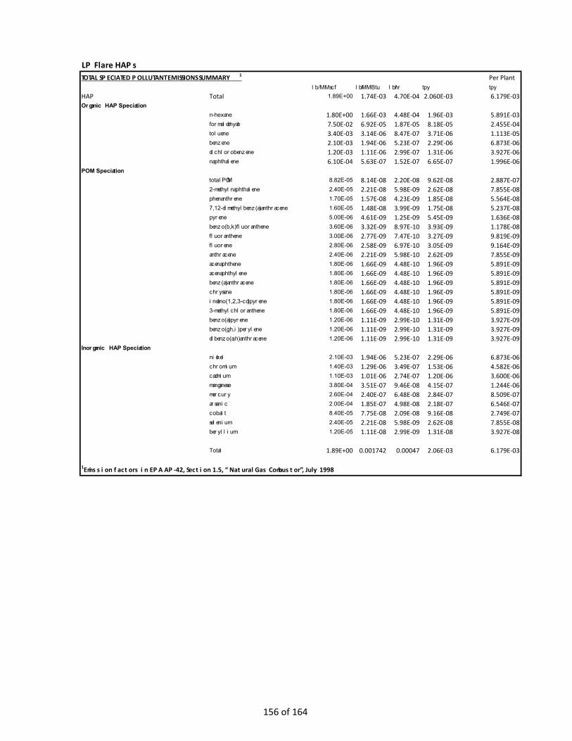
LP Flare HAPsTOTAL SPECIATED POLLUTANT EMISSIONS SUMMARY1 Per Plant
lb/MMscf lb/MMBtu lb/hr tpy tpyHAP Total 1.89E+00 1.74E-03 4.70E-04 2.060E-03 6.179E-03Organic HAP Speciation
n-hexane 1.80E+00 1.66E-03 4.48E-04 1.96E-03 5.891E-03formaldehyde 7.50E-02 6.92E-05 1.87E-05 8.18E-05 2.455E-04toluene 3.40E-03 3.14E-06 8.47E-07 3.71E-06 1.113E-05benzene 2.10E-03 1.94E-06 5.23E-07 2.29E-06 6.873E-06dichlorobenzene 1.20E-03 1.11E-06 2.99E-07 1.31E-06 3.927E-06naphthalene 6.10E-04 5.63E-07 1.52E-07 6.65E-07 1.996E-06
POM Speciation total POM 8.82E-05 8.14E-08 2.20E-08 9.62E-08 2.887E-072-methylnaphthalene 2.40E-05 2.21E-08 5.98E-09 2.62E-08 7.855E-08phenanthrene 1.70E-05 1.57E-08 4.23E-09 1.85E-08 5.564E-087,12-dimethylbenz(a)anthracene 1.60E-05 1.48E-08 3.99E-09 1.75E-08 5.237E-08pyrene 5.00E-06 4.61E-09 1.25E-09 5.45E-09 1.636E-08benzo(b,k)fluoranthene 3.60E-06 3.32E-09 8.97E-10 3.93E-09 1.178E-08fluoranthene 3.00E-06 2.77E-09 7.47E-10 3.27E-09 9.819E-09fluorene 2.80E-06 2.58E-09 6.97E-10 3.05E-09 9.164E-09anthracene 2.40E-06 2.21E-09 5.98E-10 2.62E-09 7.855E-09acenaphthene 1.80E-06 1.66E-09 4.48E-10 1.96E-09 5.891E-09acenaphthylene 1.80E-06 1.66E-09 4.48E-10 1.96E-09 5.891E-09benz(a)anthracene 1.80E-06 1.66E-09 4.48E-10 1.96E-09 5.891E-09chrysene 1.80E-06 1.66E-09 4.48E-10 1.96E-09 5.891E-09indeno(1,2,3-cd)pyrene 1.80E-06 1.66E-09 4.48E-10 1.96E-09 5.891E-093-methylchloranthene 1.80E-06 1.66E-09 4.48E-10 1.96E-09 5.891E-09benzo(a)pyrene 1.20E-06 1.11E-09 2.99E-10 1.31E-09 3.927E-09benzo(g,h,i)perylene 1.20E-06 1.11E-09 2.99E-10 1.31E-09 3.927E-09dibenzo(a,h)anthracene 1.20E-06 1.11E-09 2.99E-10 1.31E-09 3.927E-09
Inorganic HAP Speciation nickel 2.10E-03 1.94E-06 5.23E-07 2.29E-06 6.873E-06chromium 1.40E-03 1.29E-06 3.49E-07 1.53E-06 4.582E-06cadmium 1.10E-03 1.01E-06 2.74E-07 1.20E-06 3.600E-06manganese 3.80E-04 3.51E-07 9.46E-08 4.15E-07 1.244E-06mercury 2.60E-04 2.40E-07 6.48E-08 2.84E-07 8.509E-07arsenic 2.00E-04 1.85E-07 4.98E-08 2.18E-07 6.546E-07cobalt 8.40E-05 7.75E-08 2.09E-08 9.16E-08 2.749E-07selenium 2.40E-05 2.21E-08 5.98E-09 2.62E-08 7.855E-08beryllium 1.20E-05 1.11E-08 2.99E-09 1.31E-08 3.927E-08
Total 1.89E+00 0.001742 0.00047 2.06E-03 6.179E-03
1Emission factors in EPA AP-42, Section 1.5, “Natural Gas Combustor”, July 1998
156 of 164

Client: West Virginia MethanolProject: Pleasants County Methanol PlantPower Plant (RICE) Emissions Calculations
Parameter Value Units
Capacity 4102 kW per engine
Number of Engines 7 #
Operation 8760 hours per year
Gross Output 4102 kW per engine
Heat Rate LHV 7798 Btu/kWh
Heat Rate HHV 8,656 Btu/kWh
Fuel Consumption 533109 Btu/min
Natural Gas Use HHV 35.51 MMBtu/h
Natural Gas Use LHV 31.99 MMBtu/h
Btu/ft^3 LHV 983.7
Btu/ft^3 HHV 1092.0
Efficiency, LHV 43.76%
Efficiency, HHV 39.42%
Pollutant
Uncontrolled Emission Factor (g/bhphr)
Uncontrolled Emission Factor (g/kWhr)
Uncontrolled Emission Factor converted for limits (lb/MMBtu)
Emission Factor Source
Destruction and Removal Efficiency (DRE), [5]
Controlled Emission Factor (g/kWhr)
Controlled Emission Factor converted for limits (lb/MMBtu)
Max Uncontrolled per Engine (lb/hr)
Max Controlled per Engine (lb/hr)
Max Uncontrolled per Engine (ton/yr)
Max Controlled per Engine (ton/yr)
All Engines Total Max Uncontrolled (ton/yr)
All Engines Total Max Controlled (ton/yr)
Total PM 0.009 0.012 0.0031 Caterpillar [1] 0.0120692 0.0031 0.109 0.109 0.48 0.48 3.35 3.35PM10 0.009 0.012 0.0031 Caterpillar [1] 0.0120692 0.0031 0.109 0.109 0.48 0.48 3.35 3.35PM2.5 0.009 0.012 0.0031 Caterpillar [1] 0.0120692 0.0031 0.109 0.109 0.48 0.48 3.35 3.35
SO2 0.0016 0.0022 0.0006 AP-42 [2][3] 0.0022 0.0006 0.020 0.020 0.087 0.09 0.61 0.61NOx 0.939 1.259 0.3207 Caterpillar [1] 85.0% 0.1889 0.0481 11.388 1.708 49.88 7.48 349.1 52.4CO 1.281 1.718 0.4375 Caterpillar [1] 92.0% 0.1374 0.0350 15.535 1.243 68.04 5.44 476.3 38.1
VOC 0.158 0.212 0.0540 Caterpillar [1] 50.0% 0.1059 0.0270 1.916 0.958 8.39 4.20 58.7 29.4CH4 3.660 4.91 1.25 AP-42 [2][3] 4.91 1.2500 44.381 44.381 194 194 1,361 1,361N2O 0.01 0.0025 0.01 0.0025 0.090 0.090 0.40 0.40 2.8 2.8
Total HAP 0.4399 0.1120 CAT [1], AP-42 [2][3][4] 0.06 0.02 3.978 0.542 17.42 2.37 121.97 16.62
[1] Estimated values from Caterpillar and KW are shaft power
[2] AP-42 Emission Factors from Chapter 3.2: Natural Gas-fired Reciprocating Engines, Table 3.2.-2 Uncontrolled Emission
Factors for 4-Stroke Lean-Burn Engines.
[3] AP-42 equivalent emission factor estimated from CAT design capacities for MMBtu/hr and kW/hr
[4] Total uncontrolled HAP is the sum of all AP-42 equivalent emission factors and CAT provided emission factor for Formaldehyde
[5] DRE values from Miratech with margin added
157 of 164

RICE HAP Basis
Pollutant
Uncontrolled Emission Factor converted for Limits (g/kWhr)
Uncontrolled Emission Factor (lb/MMBtu)
Emission Factor Source DRE [4]
Controlled Emission Factor converted for Limits (g/kWhr)
Controlled Emission Factor (lb/MMBtu)
Max Uncontrolled per Engine (lb/hr)
Max Controlled per Engine (lb/hr)
Max Uncontrolled per Engine (ton/yr)
Max Controlled per Engine (ton/yr)
All Engines Total Max Uncontrolled (ton/yr)
All Engines Total Max Controlled (ton/yr)
1,1,2,2-Tetrachloroethane 0.00016 0.00004 AP-42 [2][3] 0.00016 0.00004 0.0014 0.0014 0.0062 0.0062 0.044 0.0441,1,2-Trichloroethane 0.00012 0.00003 AP-42 [2][3] 0.00012 0.00003 0.0011 0.0011 0.0049 0.0049 0.035 0.0351,3-Butadiene 0.00105 0.00027 AP-42 [2][3] 70% 0.00031 0.00008 0.0095 0.0028 0.0415 0.0125 0.291 0.0871,3-Dichloropropene 0.00010 0.00003 AP-42 [2][3] 0.00010 0.00003 0.0009 0.0009 0.0041 0.0041 0.029 0.0292-Methylnaphthalene 0.00013 0.00003 AP-42 [2][3] 0.00013 0.00003 0.0012 0.0012 0.0052 0.0052 0.036 0.0362,2,4-Trimethylpentane 0.00098 0.00025 AP-42 [2][3] 0.00098 0.00025 0.0089 0.0089 0.0389 0.0389 0.272 0.272Acenaphthene 0.00000 0.00000 AP-42 [2][3] 0.00000 0.00000 0.0000 0.0000 0.0002 0.0002 0.001 0.001Acenaphthylene 0.00002 0.00001 AP-42 [2][3] 0.00002 0.00001 0.0002 0.0002 0.0009 0.0009 0.006 0.006Acetaldehyde 0.03388 0.00863 AP-42 [2][3] 70% 0.01016 0.00259 0.3064 0.0919 1.3421 0.4026 9.394 2.818Acrolein 0.02018 0.00514 AP-42 [2][3] 75% 0.00505 0.00129 0.1825 0.0456 0.7993 0.1998 5.595 1.399Benzene 0.00173 0.00044 AP-42 [2][3] 65% 0.00060 0.00015 0.0156 0.0055 0.0684 0.0239 0.479 0.168Benzo(b)fluoranthene 0.00000 0.00000 AP-42 [2][3] 0.00000 0.00000 0.0000 0.0000 0.0000 0.0000 0.000 0.000Benzo(e)pyrene 0.00000 0.00000 AP-42 [2][3] 0.00000 0.00000 0.0000 0.0000 0.0001 0.0001 0.000 0.000Benzo(g,h,i)perylene 0.00000 0.00000 AP-42 [2][3] 0.00000 0.00000 0.0000 0.0000 0.0001 0.0001 0.000 0.000Biphenyl 0.00083 0.00021 AP-42 [2][3] 0.00083 0.00021 0.0075 0.0075 0.0330 0.0330 0.231 0.231CarbonTetrachloride 0.00014 0.00004 AP-42 [2][3] 0.00014 0.00004 0.0013 0.0013 0.0057 0.0057 0.040 0.040Chlorobenzene 0.00012 0.00003 AP-42 [2][3] 0.00012 0.00003 0.0011 0.0011 0.0047 0.0047 0.033 0.033Chloroform 0.00011 0.00003 AP-42 [2][3] 0.00011 0.00003 0.0010 0.0010 0.0044 0.0044 0.031 0.031Chrysene 0.00000 0.00000 AP-42 [2][3] 0.00000 0.00000 0.0000 0.0000 0.0001 0.0001 0.001 0.001Ethylbenzene 0.00016 0.00004 AP-42 [2][3] 0.00016 0.00004 0.0014 0.0014 0.0062 0.0062 0.043 0.043EthyleneDibromide 0.00017 0.00004 AP-42 [2][3] 0.00017 0.00004 0.0016 0.0016 0.0069 0.0069 0.048 0.048Fluoranthene 0.00000 0.00000 AP-42 [2][3] 0.00000 0.00000 0.0000 0.0000 0.0002 0.0002 0.001 0.001Fluorene 0.00002 0.00001 AP-42 [2][3] 0.00002 0.00001 0.0002 0.0002 0.0009 0.0009 0.006 0.006Formaldehyde 0.36270 0.09238 Caterpillar [1] 91.0% 0.03264 0.00831 3.2800 0.2952 14.3664 1.2930 100.565 9.051Methanol 0.00982 0.00250 AP-42 [2][3] 65% 0.00344 0.00088 0.0888 0.0311 0.3888 0.1361 2.721 0.953MethyleneChloride 0.00008 0.00002 AP-42 [2][3] 0.00008 0.00002 0.0007 0.0007 0.0031 0.0031 0.022 0.022n-Hexane 0.00436 0.00111 AP-42 [2][3] 35% 0.00283 0.00072 0.0394 0.0256 0.1726 0.1122 1.208 0.785Naphthalene 0.00029 0.00007 AP-42 [2][3] 0.00029 0.00007 0.0026 0.0026 0.0116 0.0116 0.081 0.081PAH 0.00011 0.00003 AP-42 [2][3] 0.00011 0.00003 0.0010 0.0010 0.0042 0.0042 0.029 0.029Phenanthrene 0.00004 0.00001 AP-42 [2][3] 0.00004 0.00001 0.0004 0.0004 0.0016 0.0016 0.011 0.011Phenol 0.00009 0.00002 AP-42 [2][3] 0.00009 0.00002 0.0009 0.0009 0.0037 0.0037 0.026 0.026Pyrene 0.00001 0.00000 AP-42 [2][3] 0.00001 0.00000 0.0000 0.0000 0.0002 0.0002 0.001 0.001Styrene 0.00009 0.00002 AP-42 [2][3] 0.00009 0.00002 0.0008 0.0008 0.0037 0.0037 0.026 0.026Tetrachloroethane 0.00001 0.00000 AP-42 [2][3] 0.00001 0.00000 0.0001 0.0001 0.0004 0.0004 0.003 0.003Toluene 0.00160 0.00041 AP-42 [2][3] 55% 0.00072 0.00018 0.0145 0.0065 0.0634 0.0286 0.444 0.200VinylChloride 0.00006 0.00001 AP-42 [2][3] 0.00006 0.00001 0.0005 0.0005 0.0023 0.0023 0.016 0.016Xylene 0.00072 0.00018 AP-42 [2][3] 55% 0.00033 0.00008 0.0065 0.0029 0.0286 0.0129 0.200 0.090
Total 0.439904675 0.112046488 0.0599577 0.0152716 3.978 0.542 17.425 2.375 121.97 16.62
[1] Estimated values from CAT
[2] AP-42 Emission Factors from Chapter 3.2: Natural Gas-fired Reciprocating Engines, Table 3.2.-2 Uncontrolled Emission
Factors for 4-Stroke Lean-Burn Engines.
[3] AP-42 equivalent emission factor estimated from CAT design capacity for mmbtu/hr and kW/hr
[4] Destruction and Removal Efficiency (DRE) from Miratech with margin applied
158 of 164
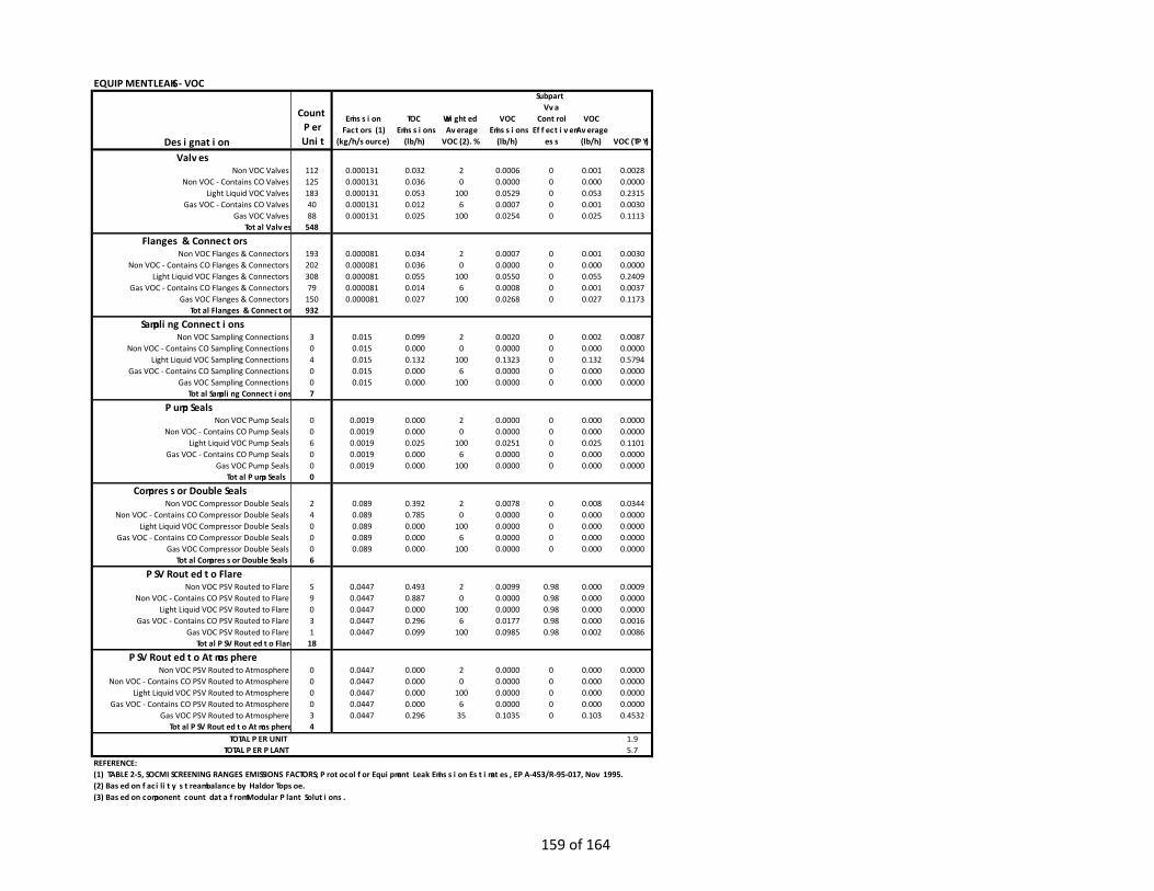
EQUIPMENT LEAKS - VOC
Count Per Unit
Emission Factors (1)
(kg/h/source)
TOC Emissions
(lb/h)
Weighted Average
VOC (2). %
VOC Emissions
(lb/h)
Subpart Vva
Control Effectiven
ess
VOC Average
(lb/h) VOC (TPY)
112 0.000131 0.032 2 0.0006 0 0.001 0.0028125 0.000131 0.036 0 0.0000 0 0.000 0.0000183 0.000131 0.053 100 0.0529 0 0.053 0.231540 0.000131 0.012 6 0.0007 0 0.001 0.003088 0.000131 0.025 100 0.0254 0 0.025 0.1113
548
193 0.000081 0.034 2 0.0007 0 0.001 0.0030202 0.000081 0.036 0 0.0000 0 0.000 0.0000308 0.000081 0.055 100 0.0550 0 0.055 0.240979 0.000081 0.014 6 0.0008 0 0.001 0.0037
150 0.000081 0.027 100 0.0268 0 0.027 0.1173932
3 0.015 0.099 2 0.0020 0 0.002 0.00870 0.015 0.000 0 0.0000 0 0.000 0.00004 0.015 0.132 100 0.1323 0 0.132 0.57940 0.015 0.000 6 0.0000 0 0.000 0.00000 0.015 0.000 100 0.0000 0 0.000 0.00007
0 0.0019 0.000 2 0.0000 0 0.000 0.00000 0.0019 0.000 0 0.0000 0 0.000 0.00006 0.0019 0.025 100 0.0251 0 0.025 0.11010 0.0019 0.000 6 0.0000 0 0.000 0.00000 0.0019 0.000 100 0.0000 0 0.000 0.00000
2 0.089 0.392 2 0.0078 0 0.008 0.03444 0.089 0.785 0 0.0000 0 0.000 0.00000 0.089 0.000 100 0.0000 0 0.000 0.00000 0.089 0.000 6 0.0000 0 0.000 0.00000 0.089 0.000 100 0.0000 0 0.000 0.00006
5 0.0447 0.493 2 0.0099 0.98 0.000 0.00099 0.0447 0.887 0 0.0000 0.98 0.000 0.00000 0.0447 0.000 100 0.0000 0.98 0.000 0.00003 0.0447 0.296 6 0.0177 0.98 0.000 0.00161 0.0447 0.099 100 0.0985 0.98 0.002 0.0086
18
0 0.0447 0.000 2 0.0000 0 0.000 0.00000 0.0447 0.000 0 0.0000 0 0.000 0.00000 0.0447 0.000 100 0.0000 0 0.000 0.00000 0.0447 0.000 6 0.0000 0 0.000 0.00003 0.0447 0.296 35 0.1035 0 0.103 0.45324
TOTAL PER UNIT 1.9TOTAL PER PLANT 5.7
REFERENCE: (1) TABLE 2-5, SOCMI SCREENING RANGES EMISSIONS FACTORS; Protocol for Equipment Leak Emission Estimates, EPA-453/R-95-017, Nov 1995.(2) Based on facility stream balance by Haldor Topsoe.(3) Based on component count data from Modular Plant Solutions.
Total PSV Routed to Flare
PSV Routed to AtmosphereNon VOC PSV Routed to Atmosphere
Non VOC - Contains CO PSV Routed to AtmosphereLight Liquid VOC PSV Routed to Atmosphere
Gas VOC - Contains CO PSV Routed to AtmosphereGas VOC PSV Routed to Atmosphere
Total PSV Routed to Atmosphere
Gas VOC PSV Routed to Flare
Non VOC Compressor Double SealsNon VOC - Contains CO Compressor Double Seals
Light Liquid VOC Compressor Double SealsGas VOC - Contains CO Compressor Double Seals
Gas VOC Compressor Double SealsTotal Compressor Double Seals
PSV Routed to FlareNon VOC PSV Routed to Flare
Non VOC - Contains CO PSV Routed to FlareLight Liquid VOC PSV Routed to Flare
Gas VOC - Contains CO PSV Routed to Flare
Compressor Double Seals
Light Liquid VOC Sampling ConnectionsGas VOC - Contains CO Sampling Connections
Gas VOC Sampling ConnectionsTotal Sampling Connections
Pump SealsNon VOC Pump Seals
Non VOC - Contains CO Pump SealsLight Liquid VOC Pump Seals
Gas VOC - Contains CO Pump SealsGas VOC Pump Seals
Total Pump Seals
Non VOC - Contains CO Sampling Connections
Gas VOC ValvesTotal Valves
Flanges & ConnectorsNon VOC Flanges & Connectors
Non VOC - Contains CO Flanges & ConnectorsLight Liquid VOC Flanges & Connectors
Gas VOC - Contains CO Flanges & ConnectorsGas VOC Flanges & Connectors
Total Flanges & Connectors
Sampling ConnectionsNon VOC Sampling Connections
Gas VOC - Contains CO Valves
DesignationValves
Non VOC ValvesNon VOC - Contains CO Valves
Light Liquid VOC Valves
159 of 164

EQUIPMENT LEAKS - HAP
Count Per Unit
Emission Factors (1)
(kg/h/source)
TOC Emissions
(lb/h)
Weighted Average
HAP(2), %
HAP Emissions
(lb/h)
Subpart Vva
Control Effectiven
ess
HAP Average
(lb/h) HAP (TPY)
112 0.000131 0.032 0.5 0.0002 0 0.000 0.0007125 0.000131 0.036 0 0.0000 0 0.000 0.0000183 0.000131 0.053 100 0.0529 0 0.053 0.231540 0.000131 0.012 6 0.0007 0 0.001 0.003088 0.000131 0.025 100 0.0254 0 0.025 0.1113
548
193 0.000081 0.034 0.5 0.0002 0 0.000 0.0008202 0.000081 0.036 0 0.0000 0 0.000 0.0000308 0.000081 0.055 100 0.0550 0 0.055 0.240979 0.000081 0.014 6 0.0008 0 0.001 0.0037
150 0.000081 0.027 100 0.0268 0 0.027 0.1173932
3 0.015 0.099 0.5 0.0005 0 0.000 0.00220 0.015 0.000 0 0.0000 0 0.000 0.00004 0.015 0.132 100 0.1323 0 0.132 0.57940 0.015 0.000 6 0.0000 0 0.000 0.00000 0.015 0.000 100 0.0000 0 0.000 0.00007
0 0.0019 0.000 0.5 0.0000 0 0.000 0.00000 0.0019 0.000 0 0.0000 0 0.000 0.00006 0.0019 0.025 100 0.0251 0 0.025 0.11010 0.0019 0.000 6 0.0000 0 0.000 0.00000 0.0019 0.000 100 0.0000 0 0.000 0.00000
2 0.089 0.392 0.5 0.0020 0 0.002 0.00864 0.089 0.785 0 0.0000 0 0.000 0.00000 0.089 0.000 100 0.0000 0 0.000 0.00000 0.089 0.000 6 0.0000 0 0.000 0.00000 0.089 0.000 100 0.0000 0 0.000 0.00006
5 0.0447 0.493 0.5 0.0025 0.98 0.000 0.00029 0.0447 0.887 0 0.0000 0.98 0.000 0.00000 0.0447 0.000 100 0.0000 0.98 0.000 0.00003 0.0447 0.296 6 0.0177 0.98 0.000 0.00161 0.0447 0.099 100 0.0985 0.98 0.002 0.0086
18
0 0.0447 0.000 0.5 0.0000 0 0.000 0.00000 0.0447 0.000 0 0.0000 0 0.000 0.00000 0.0447 0.000 100 0.0000 0 0.000 0.00000 0.0447 0.000 6 0.0000 0 0.000 0.00003 0.0447 0.296 35 0.1035 0 0.103 0.45324
TOTAL PER UNIT 1.9TOTAL PER PLANT 5.6
REFERENCE: (1) TABLE 2-5, SOCMI SCREENING RANGES EMISSIONS FACTORS; Protocol for Equipment Leak Emission Estimates, EPA-453/R-95-017, Nov 1995.(2) Based on facility stream balance.(3) Based on component count data from Modular Plant Solutions.
Light Liquid VOC PSV Routed to AtmosphereGas VOC - Contains CO PSV Routed to Atmosphere
Gas VOC PSV Routed to AtmosphereTotal PSV Routed to Atmosphere
Gas VOC - Contains CO PSV Routed to FlareGas VOC PSV Routed to Flare
Total PSV Routed to Flare
PSV Routed to AtmosphereNon VOC PSV Routed to Atmosphere
Non VOC - Contains CO PSV Routed to Atmosphere
Light Liquid VOC PSV Routed to Flare
Total Pump Seals
Compressor Double SealsNon VOC Compressor Double Seals
Non VOC - Contains CO Compressor Double SealsLight Liquid VOC Compressor Double Seals
Gas VOC - Contains CO Compressor Double SealsGas VOC Compressor Double Seals
Total Compressor Double Seals
PSV Routed to FlareNon VOC PSV Routed to Flare
Non VOC - Contains CO PSV Routed to Flare
Gas VOC Pump Seals
Non VOC Sampling ConnectionsNon VOC - Contains CO Sampling Connections
Light Liquid VOC Sampling ConnectionsGas VOC - Contains CO Sampling Connections
Gas VOC Sampling ConnectionsTotal Sampling Connections
Pump SealsNon VOC Pump Seals
Non VOC - Contains CO Pump SealsLight Liquid VOC Pump Seals
Gas VOC - Contains CO Pump Seals
Sampling Connections
Light Liquid VOC ValvesGas VOC - Contains CO Valves
Gas VOC ValvesTotal Valves
Flanges & ConnectorsNon VOC Flanges & Connectors
Non VOC - Contains CO Flanges & ConnectorsLight Liquid VOC Flanges & Connectors
Gas VOC - Contains CO Flanges & ConnectorsGas VOC Flanges & Connectors
Total Flanges & Connectors
Non VOC - Contains CO Valves
DesignationValves
Non VOC Valves
160 of 164
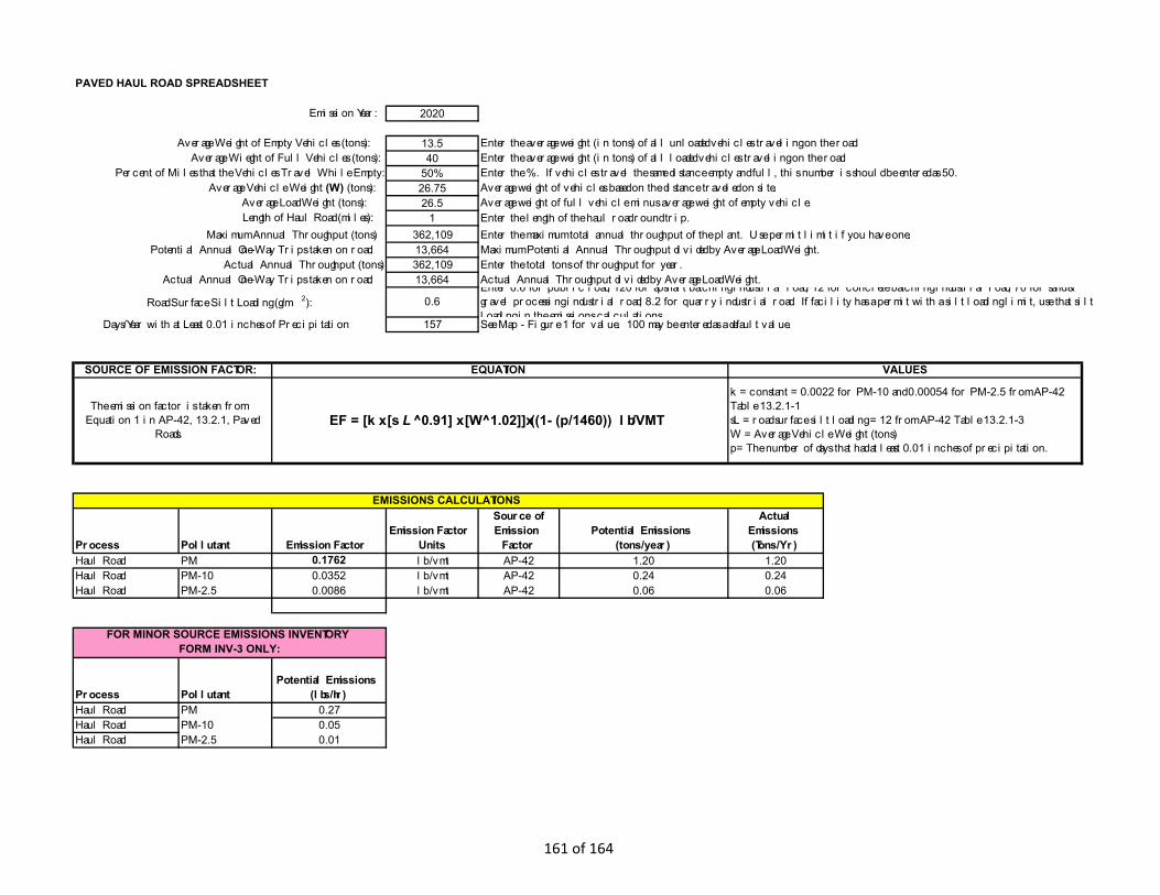
2020
13.540
50%26.7526.5
1 Enter the length of the haul road round trip.362,10913,664362,10913,664
157
Process Pollutant Emission Factor Emission Factor
Units
Source of Emission
FactorPotential Emissions
(tons/year)
Actual Emissions (Tons/Yr)
Haul Road PM 0.1762 lb/vmt AP-42 1.20 1.20Haul Road PM-10 0.0352 lb/vmt AP-42 0.24 0.24Haul Road PM-2.5 0.0086 lb/vmt AP-42 0.06 0.06
Process PollutantPotential Emissions
(lbs/hr)Haul Road PM 0.27Haul Road PM-10 0.05Haul Road PM-2.5 0.01
EMISSIONS CALCULATIONS
FOR MINOR SOURCE EMISSIONS INVENTORY FORM INV-3 ONLY:
SOURCE OF EMISSION FACTOR: EQUATION VALUES
The emission factor is taken from Equation 1 in AP-42, 13.2.1, Paved
Roads.EF = [k x [sL ^0.91] x [W^1.02]]x((1- (p/1460)) lb/VMT
k = constant = 0.0022 for PM-10 and 0.00054 for PM-2.5 from AP-42 Table 13.2.1-1sL = road surface silt loading = 12 from AP-42 Table 13.2.1-3W = Average Vehicle Weight (tons)p= The number of days that had at least 0.01 inches of precipitation.
Days/Year with at Least 0.01 inches of Precipitation See Map - Figure 1 for value. 100 may be entered as a default value.
Length of Haul Road (miles):Maximum Annual Throughput (tons) Enter the maximum total annual throughput of the plant. Use permit limit if you have one.
Potential Annual One-Way Trips taken on road: Maximum Potential Annual Throughput divided by Average Load Weight.Actual Annual Throughput (tons) Enter the total tons of throughput for year.
Actual Annual One-Way Trips taken on road: Actual Annual Throughput divided by Average Load Weight.
Road Surface Silt Loading (g/m2): 0.6Enter 0.6 for public road, 120 for apshalt batching industrial road, 12 for concrete batching industrial road, 70 for sand & gravel processing industrial road, 8.2 for quarry industrial road. If facility has a permit with a silt loading limit, use that silt loading in the emissions calculations
Percent of Miles that the Vehicles Travel While Empty: Enter the %. If vehicles travel the same distance empty and full, this number is should be entered as 50.Average Vehicle Weight (W) (tons): Average weight of vehicles based on the distance traveled on site.
Average Load Weight (tons): Average weight of full vehicle minus average weight of empty vehicle.
Average Wieght of Full Vehicles (tons): Enter the average weight (in tons) of all loaded vehicles traveling on the road.
PAVED HAUL ROAD SPREADSHEET
Emission Year:
Average Weight of Empty Vehicles (tons): Enter the average weight (in tons) of all unloaded vehicles traveling on the road.
161 of 164

ATTACHMENT O: MONITORING, RECORDKEEPING, REPORTING, TESTING PLANS
MONITORING, RECORDKEEPING, REPORTING, TESTING PLANS
WVM requests monitoring, recordkeeping, reporting and testing as stated in the Emissions Unit Data Sheets contained in Attachment L.
162 of 164

ATTACHMENT P: PUBLIC NOTICE
163 of 164
LEGAL ADVERTISEMENT
AIR QUALITY PERMIT NOTICE Notice of Application
Notice is given that West Virginia Methanol, Inc., has applied to the West Virginia Department of Environmental Protection, Division of Air Quality, for a Construction Permit for a new methanol production facility located at 9764 South Pleasants Highway near Belmont, in Pleasants County, WV. The latitude and longitude coordinates are: 39.33832 and -81.353048.
The applicant estimates the potential to discharge the Regulated Air Pollutants will be: 92.4 tons of nitrogen oxides per year; 88.7 tons of carbon monoxide per year; 46.9 tons of volatile organic compounds per year; 17.6 tons of particulate matter per year; 2.3 tons of sulfur dioxide per year; and 22.6 tons of hazardous air pollutants per year.
Startup of operations is planned to begin on or about the 15th day of March, 2023. Written comments will be received by the West Virginia Department of Environmental Protection, Division of Air Quality, 601 57th Street, SE, Charleston, WV 25304, for at least 30 calendar days from the date of publication of this notice. Written comments will also be received via email at [email protected].
Any questions regarding this permit application should be directed to the DAQ at (304) 926-0499, extension 41281, during normal business hours.
Dated this 23rd day of November, 2020.
By: West Virginia Methanol, Inc. Lars Scott Executive Vice President 1 Landy Lane Cincinnati, OH 45215
164 of 164