Embed Size (px)
Citation preview
IACS Common Structural Rules Knowledge Centre
Bulker Q&As and CIs on the IACS CSR Knowledge Centre
KCIDNo. Ref. Type Topic Date
completed Question/CI Answer Attachment
205 3/1.2.3.11 Question thickness 2006/11/30
In case of bulk carriers, thicker plates greater than 20 mm are normally usedfor main structural members. Since this requirement is vague, we would like toask you to clearly explain your intention of the regulation 2.3.11 and to makeclear the application of this requirement or criteria. If there is no criteria, it isbetter to delete the requirement to avoid confusion in design approval stage.
The reason of this requirement is the same as the one requiring D/DH for theSPECIAL elements i.e. Class III) with notes (4), (5) and (6), which are highlystressed elements. In this requirement, the notion of thickness greater than 20mm is added to the notion of highly stressed element. This corresponds in factD/DH for Class III elements according to Table 3.However, since theapplication of this requirement is already covered by Table 1 and otherrequirements such as 2.3.2, we propose that this requirement should bedeleted according to your suggestion.
206 3/3.1.2.1 Question Corrosionaddition 2006/11/8
According to our understanding on CSR, rules relating to corrosion additionhave been harmonized with JTP.However, there is a difference in definition of tank top between JTP and JBP.Note (3) in Table 1 should be revised as follows:"Note (3) Only applicable to ballast tanks with weather deck as the tank top"from CSR for Tankers
Note (3) to be kept as it is. Example is Hopper Side Tk. not connected toTSWB Tk. Air-/Water-Mixture will be below top of tank."This question and answer are superseded by KC ID 638. Please refer toKC ID 638."
207 3/6.2.3.1 Question hatchcoaming 2006/11/30
As for hatch coamings, ClassNK approves hatch coamings having lower steelgrade than that of upper deck plating, in case of the hatch coaming lengthbeing less than 0.15L. We therefore propose to delete hatch coamings fromthe last sentence.
First, it is to be noticed that this requirement is not dealing with steel grade, butwith yield strength of the steel. Secondly, the stress in shorter hatch coamings(length much more less than 0,15L) is generally equivalent to the one in thedeck. It becomes negligible only for very short hatch coaming. Some criteriacould be developed, including parameters such as length and height of hatchcoaming and their position along the ship. It seems quite complicated to solvethis easy problem. Finally we have to keep in mind a stress check is to becarried out for the hatch coaming. Consequently, we prefer to keep the text asit is, or we may suggest to open a door by adding the word "generally" between"The same requirement" and "is applicable".
208 3/6.2.3.1 Question high strengthsteel 2006/11/29
The last sentence of 2.3.1 is excess and differs from the present applicationaccepted by many classification societies. Higher strength steels are normallyapplied taking account of not only hull girder bending stresses but also localstresses. For instance, higher strength steel is used to double bottom girderstaking into account local shearing stresses caused by cargo and external sealoads acting on double bottom.And some sniped longitudinal stiffeners notcontributing hull girder longitudinal strength, which are mild steel, are weldedon the girders to prevent panel buckling. Such design has been alreadyapproved by many classification societies. We consider that the steel grade ofstiffeners not contributing hull girder longitudinal strength can be selected on acase by case basis. We would like to ask you to revise the rule taking intoaccount the above.
The last sentence in Ch 3, Sec 6, [2.3.1] is not a matter of steel grade, butconcerns the yield strength of the steel. The matter of steel grade is relevant toCh 3, Sec 1. Having said that, it is understood that the original question is notabout steel grade. Ch 3, Sec 6, [2.3.1] could be considered as therequirements in general. If the stress level due to hull girder bending, inlongitudinal member not contributing to hull girder longitudinal strength, shouldbe verified as to satisfy the requirement in Ch 5, Sec 1, [3.1.1], application ofthe requirements in Ch 3, Sec 6, [2.3.1] might be mitigated. As a matter ofopening the door, the word "generally" should be added between "The samerequirement" and "is applicable...".
209 3/6.6.1.6 Questionscantling
determina-tion
2006/11/1
As shown in the caption, main intention of this requirement is continuity ofstrength, not scantling.In the scantling determination of sloped bulkhead plating, yielding, buckling,grab handling and fatigue strength are taken into account. Continuity ofstrength can be realized by the consideration.Therefore we would like to ask you to delete the requirement.
In applying the last sentence of 6.1.6, where the scantling of lower strake of thesloped bulkhead of hopper tanks and inner bottom plate adjacent thereto aredetermined by the requirements on FEA and fatigue strength assessment,such structures are regarded as the satisfaction of the requirement oncontinuity of strength.
210 3/6.6.4.2 Question GRABnotation 2006/11/1
At least, please exclude the required material properties and net thickness ofstool side plating by GRAB from this requirement.It is not necessary to apply the required material properties and net thicknessof stool side plating by GRAB to the supporting floors.
In applying this requirement 6.4.2, the net thickness and material propertiesrequired for the bulkhead plating, or when a stool is fitted, of the stool sideplating mean that they are required by the scantling requirement except for thegrab loading and under flooded condition.
Page 1 of 30

IACS Common Structural Rules Knowledge Centre
KCIDNo. Ref. Type Topic Date
completed Question/CI Answer Attachment
211 3/6.9.6.3 Question extent ofinsert plate 2006/11/1
The extent of insert plate is larger than that of present designs. Since thestress concentration occurs in way of corner radius, we consider that therequirement should be reconsidered taking account of your experience. Pleasepermit us to determine the extent of insert plate taking into account FEAresults.
The following sentence should be added at the end of requirement 9.6.3: "Forships having length L of 150m and above, the extent of insert plate may bedetermined by the results of a direct strength assessment, including bucklingcheck and of a fatigue assessment of hatch corners."
243 3/3.1.2 Question
Corrosionadditiondetermination
2006/11/22
Corrosion addition determinationFor ships equal to and larger than 150m inlength, corrosion addition for lower stool of 5.2m is very large compared withthat for sloped plating of hopper tank of 3.7m. Corrosion addition for lowerstool should be the same as that for sloped plating of hopper tank.
The corrosion additions are set according to the results estimated byprobabilistic carrion model which are calibrated by huge amount of thicknessmeasurement data. Therefore, the value specified in Table 1 of Chapter 3 isconsidered appropriate.
244 3/6.6.1.2 Question longi framingsystem 2006/11/22
Framing system; For ships larger than 120m in length, longitudinal framingsystem is required for bottom, double bottom and sloped bulkheads of hoppertanks in cargo hold. For fore and aft parts of cargo hold, however, it may bedifficult to apply this system because of abrupt change of hull form there. Soplease add 'in general' to allow transverse system for these parts.
The word “in general” has been deleted from the text as far as practicable inorder to eliminate the vague expression. Furthermore, from structuralcontinuity point of view, the same framing system is desirable to adopt inwhole length of cargo hold region. However, as you pointed out, we canunderstand that it may be difficult to apply the longitudinal framing system tofore part and aft parts of cargo hold because of abrupt change of hullform.Where it is difficult for the longitudinal system to apply to fore and aftparts of cargo hold region due to its hull form, the Society may accept on acase by case basis the changing the framing system. for such parts subject toprovide an appropriate bracket or other arrangements to provide structuralcontinuity in way of changes in the framing system.
SOLAS XII Regulation 6.5.2 says, “effective continuity between the side shellstructure and the rest of the hull structure shall be assured,” Although theapplication of this regulation is limited to bulk carriers of 150m in length andupwards carrying solid bulk cargoes having density of 1,000 kg/m3 and above,it is considered that the intention of this regulation is applicable to all ships.From the structural continuity point of view, the second paragraph of Ch 3 Sec6 [9.2.4] (topside tank structure) of CSR for Bulk Carriers says “Where adouble side primary supporting member is fitted outside of plane of the topsidetank web frame, a large bracket is to be fitted in line with.”In addition to the side structure, to alter the large bracket in order to ensure thestructural continuity between the hatch end beams and topside tank web frameseems to overdo.
However, in oder to clarify whether the partial transverse web or large bracketprovided in the top side tank in line with hatch end beam is acceptable insteadof providing the ordinary transverse web, for clarification, we will consider arule correction with addition of the following text:"Alternatively, the appropriate supporting structures shall be provided in topside tanks in line with the hatch end beam."
246 3/6.9.5.3 Editiorialhatch
supportingstructure
2006/11/28
Hatch supporting structureThe face plate of hatch coamings and longitudinaldeck girders are required to be effectively connected. On the other hand, theface plate of hatch end beam is normally tapered at end. Please explainconcrete requirements of 9.5.3.
In order to clarify this requirement, we will consider a rule correction as follows:At hatchway corners, the face plate of hatch deck girders or their extensionparts and the face plates of hatch end beams on both ends are to beeffectively connected so as to maintain the continuity in strength.
hatch endbeams 2006/11/30
Hatch supporting structureHatch end beams are required to be aligned withtransverse web frames in topside tanks. Partial transverse web or largebracket that is sufficient to transfer load should be considered as an alternativeto transverse web. They are normal structural arrangement of existing vessels.
Editiorial245 3/6.9.5.2
Page 2 of 30
IACS Common Structural Rules Knowledge Centre
KCIDNo. Ref. Type Topic Date
completed Question/CI Answer Attachment
247 3/6.10.4.1 Question UR S18 2006/11/10
Lower and upper stools of corrugated bulkheadsLower and upper stools arerequired for corrugated watertight bulkheads of ships equal to and larger than150m in length. According to UR s18, stools are not required for ships lessthan 190m in length. In view of the fact that many existing ships havingcorrugated watertight bulkheads without stools less than 190m in length havebeen operated with successful results, we request this requirement bemodified so as to be the same as UR S18.
The issue is under consideration by IACS.
273 3/6.10.4.1 Question corrugatedBHD 2006/11/23
Lower stool with bottom width not less than 2.5 times mean depth ofcorrugation is required for L>=150m bulkers instead of L>=190m as defined inIACS UR S18.We think this contradiction to be corrected as editorial error inthe corrigendum. If it is difficult to add new item in the corrigendum, IACSshould take it in the next earliest chance. As you know, most of Handy classbulkers and also significant number of Handy max. bulkers with length between150m < L 190m have corrugated bulkheads without lower stool and/or withrectangular lower stool which bottom width is same as corrugation depth. If thedefined lower stools are installed for those vessels, necessary hold clear lengthabout 27m for these class bulkers to load 2 rows of 40 feet length product suchas pipes, etc. can not obtained. The economical loss to the shipping industryby the lower stool requirement is seemed tremendously big. Huge number ofsafely operating bulkers without required lower stools prove the safeness andpropriety of this proposal.
The corrected text in the next Corrigenda should be: "For ships of 190 m oflength and above, the transverse vertically corrugated watertight bulkheads areto be fitted with a lower stool, and generally with an upper stool is fittedbelowthe deck.For ships less than 190 m in length, corrugations may extend frominner bottom to deck."
274 3/6.10.4.8 Question Upper stool 2006/11/22 We think that "The stool top" is correct(This comment is not for your summarybut for original rule).
The right wording should be “stool top of non-rectangular stools”. Thisrequirement comes from UR S18 (18.4.1.(b)).
275 3/6.10.4.1 Question CorrugatedBHD 2006/11/23
Lower and upper stools are required for corrugated watertight bulkheads ofships equal to and larger than 150m in length. According to UR S18, stools arenot required for ships less that 190m in length. Since there are many existingships having corrugated watertight bulkheads without stools less thabn 190min length and they have successful experiences, please amend as shownbelow:"In ships less than 190m in length, corrugations may extend from theinner botton to the deck."
The corrected text in the next Corrigenda should be: "For ships of 190 m oflength and above, the transverse vertically corrugated watertight bulkheads areto be fitted with a lower stool, and generally with an upper stool is fittedbelowthe deck.For ships less than 190 m in length, corrugations may extend frominner bottom to deck."
316 3/5.1.2.2 CI
Application ofCSR vs IMOPSCS(SOLA
S II-1/3-2)
2006/12/7
For ships contracted for construction on or after the date of IMO adoption ofthe amended SOLAS regulation II-1/3-2, by which an IMO “Performancestandard for protective coatings for ballast tanks and void spaces” will be mademandatory, the coatings of internal spaces subject to the amended SOLASregulation are to satisfy the requirements of the IMO performance standard.
Interpreation: This is the date of adoption by IMO MSC 82(Maritime SafetyCommittee 82nd session) of the resolution amending the SOLAS regulation II-1/3-2. (Note: (1)The date of adoption is 8 December 2006; (2)IMO PSPC = IMO Resolution MSC.215(82); (3) SOLAS II-1, Part A-1, Reg.3-2 = IMO Resolution MSC.216(82))
322 3/6.6.1.3 Question FEA 2007/1/4
The text reads: "Unless otherwise specified, the height of double bottom is notto be less than B/20 or 2m whichever is the lesser." Does this require that thedouble bottom height in way of cargo holds is not to be less than B/20 or 2mwhichever is the lesser IN ANY CASE? For instance, even if the strength ofdouble bottom structures is verified by FEA, is this requirement to bemaintained?
Yes, this requirement is mandatory. The double bottom height in way of cargoholds is not to be less than B/20 or 2m whichever is the lesser in any case.
Page 3 of 30
IACS Common Structural Rules Knowledge Centre
KCIDNo. Ref. Type Topic Date
completed Question/CI Answer Attachment
328 3/6.5.2.1 Question brackets 2007/3/23
The net thickness of web stiffeners and brackets are not to be less than theminimum net thickness of primary members on which they are fitted.The situation is the following one: for capesize with usual length of 275m, tminnet is 10mm. Thus tgross is ranging from 13 to 14mm due to tc of about 3 to4mm.For primary members of wider height such as Top side frames and hoppertank frames, web stiffening are made of angles instead of flat bars. Usualangles or T shape sections have web thickness not exceeding 12mm and thecurrent requirement can't be complied with.Additionally, there are two requirements which are applicable at C6.S2. 4.1.1and 4.1.2.Our request:Alter the formula in C3.S6 5.2.1 to limit the tgross thickness to 12mm orrestreint its field of application to only flat bars or disregard C3S6 5.2.1 shouldC6.S2. 4.1.1 and/ or 4.1.2. been satisfied.?
We agree with you that the requirement asking that "the net thickness of webstiffeners and brackets are not to be less than the minimum net thickness ofprimary members on which they are fitted" seems quite severe.Our interpretation is that "the net thickness of web stiffeners and brackets arenot to be less than the minimum net thickness defined in Ch 6, Sec 2, [2.2.1]",i.e. the minimum thickness of ordinary stiffeners (3 + 0.015 L2).We will consider the Rule Change according to our interpretation
329 Ch 3/ 3 Question cargo hold 2007/1/12
Corrosion deduction on cross deck beams between hatches:As per corrosion deduction table – Dry bulk cargo hold area with othermembers in upper part - the corrosion margin is 1.8mm on each side, i.e. 4.5mm in total. Such corrosion margin for deck beams seems too severe.Is use of this corrosion margin mandatory or may an alternative be used?
CSR doesn't allow to use an alternative for corrosion addition table. Thecorrosion additions are to be considered as being mandatory.
330 3/6.6.4.2 Question UR S18 2007/1/12
The net thickness and material properties of the supporting floors and pipetunnel beams are to be not less than those required for the bulkhead plating or,when a stool is fitted, of the stool side plating.This requirement is similar to that of UR18 in case where there is no lowerstool. CSR extends it to the case where a lower stool is arranged. Thisextension could lead to up to +4mm for floors underneath deep tank stools oncapesize bulkers whereas all assessments show that it is not necessary.Is this requirement possible to excuse when FEM calculation is satisfied? Itshould be cancelled, at least for L>150m for which FE is mandatory.
In general CSR doesn't allow alternative analysis. Alternative analysis such asdirect calculation could be allowed in some cases for ships greater than 150 min length. However, it is a general question for the totality of CSR (oil or bulk)and it should be discussed as a general matter.
Page 4 of 30

IACS Common Structural Rules Knowledge Centre
KCIDNo. Ref. Type Topic Date
completed Question/CI Answer Attachment
(1) Primary supporting member are defined as: members of the beam, girderof stringer type which ensure the overall structural integrity of the hull envelopeand tank boundaries, e.g double bottom floors and girders, transverse sidestructures, web frames/diaphragms in hopper side tanks, topside tanks, lowerstools and upper stools, side stringers, horizontal girders/transverse webframes, hatch side/end coaming.(2) The requirements in Ch 6, Sec2, [2.2] adn [2.3] are not applicable to webstiffeners but to ordinary stiffeners, The only requirements applicatle to webstiffeners in CSR for bulk carriers are the following ones:- Ch 3, Sec6 [5.2.1]for the net thickness of such stiffeners, which refers to the minimum netthickness of the primary members on which they are fitted, i.e. to Ch 6, Sec 4,[1.5.1], and - Ch 6, Sec 2 [4] for the net scantlings of web stiffeners of primarysupporting members.(3) The same requirements as stated in (2) above apply to web stiffeners fittedonwatertight side girders, centre girders and floors, i.e. Ch 3, Sec 6, [5.2.1]for thenet thickness of such stiffeners ( and so Ch 6, Sec 4, [1.5.1] and Ch 6, Sec 2,[4].(4) See our comment in (1) as we consider that stiffeners on these bulkheadsare considered as ordinary stiffeners and not as web stiffeners.
337 3/6.10.4.7
&11/2.2.4.3
Question S18 2007/2/22
For the weld of corrugations and stool side plating to the stool top plate, onlyfull penetration is accepted in the requirement of Ch 3, Sec 6, 10.4.7. On theother hand, not only full penetration but deep penetration is accepted in therequirement of Ch 11, Sec 2, 2.4.3. It is considered that this requirement isbased on IACS UR 18.4.1(a), as follows:The stool side plating is to be connected to the stool top plate and the innerbottom plating by either full penetration or deep penetration welds. Therefore,the requirement of Ch 3, Sec 6, 10.4.7 should be changed to be consistentwith Ch 13, Sec 2, 2.4.3 and IACS UR. Please confirm.
We will consider the editorial correction according to UR S18.Also Included in Corrigenda 5
362 3/4.2.4.1 Question hull girder 2007/3/20
“Longitudinal strength of hull girder in cargo hold flooded condition is to beassessed in accordance with Ch 5 Sec 2.” Reference to Sec 1 should also begiven for longitudinal strength in hold flooding, which is however limited to BC-A and BC-B. Sec.2 is about ultimate strength of hull girder for ships with lengthequal to 150 m in length L and above, i.e., including BC-C. Please confirm.
Yes, your understanding is correct.
363 3/4.2.4.3 Question cargo hold 2007/2/22
“Bulkhead structure in cargo hold flooded condition is to be assessed inaccordance with Ch 6 Sec 4.” Sec 4 does not give any requirement forbulkhead structure in flooding scenario. Is this a typo error of Sec 1 and Sec2?
Yes, it is typo and the correct wordings are “Sec 1 and Sec 2” instead of“Sec.4”.
WebStiffener Y2006/12/18
Web stiffeners of primary supporting members:(1) Because there is no definition for “primary supporting member”, themeaning of “web stiffener of primary supporting member” itself is unidentified.Please clarify the definition of “primary supporting members”.(2) Please see the attached summary table about rule applications for webstiffeners of primary supporting members based on our understanding. Itshows that which requirements should be applied to web stiffeners. Pleaseconfirm.(3) We also would like to confirm that whether the web stiffeners fitted onwatertight girders, e.g. watertight centre girder and floors, should be applied tothe both requirements for primary supporting members of Chapter6/Section4and for ordinary stiffeners of Chapter6/Section2 or not.(4) If there is any needs to satisfy both requirements for primary supportingmembers and for members subject to lateral pressure, I would like to knowwhether the web stiffeners fitted on the watertight bulkheads in the topsidetanks and bilge hopper tanks are treated the same or not.
333attc
3/6.5.26/2.2.26/2.2.36/4.1.5
Question
Page 5 of 30

IACS Common Structural Rules Knowledge Centre
KCIDNo. Ref. Type Topic Date
completed Question/CI Answer Attachment
388 3/5.1.2.2 Question PSPC 2007/2/5Since PSPC has been adopted by IACS as of Dec. 8, 2006, not by IMO, if theBuilder and Ship owner agreed not to apply PSPC, is it acceptable to the Classor not?
On 8 December 2006, IMO adopted amendments to SOLAS by resolutionMSC. 216(82) which mandate compliance with the new IMO "PerformanceStandard for Protective Coatings for dedicated seawater ballast tanks in alltypes of ships and double-side skin spaces of bulk carriers", (IMO PSPC,Resolution MSC. 215(82)). Compliance with the IMO PSPC is required by theIACS Common Structural Rules for Bulk Carriers and for Oil Tankers for shipssubject to those Rules which are contracted for construction between shipbuilder and ship owner on or after 8 December 2006. The relevant Rulereferences are the following:- IACS CSR for Bulk Carriers Chapter 3, Section 5, 1.2.2;- IACS CSR for double hull oil tankers, Section 6, 2.1.1.2. Therefore, for suchships (i.e. ships subject to CSR) the answer is "PSPC is to be applied if theyare contracted for construction between ship builder and ship owner on or after8 December 2006". For other ships, the answer is that PSPC is to be appliedin accordance with IMO Resolution MSC 215(82) and IMO MSC 216(82).
398attc 3/6.2.3.1 Question Structural
Design 2007/6/15
According to this requirement, structural members welded to the strength deckor bottom plating is to be made of the same higher tensile steel of strengthdeck or bottom plating. The same requirement is applicable for non continuouslongitudinal stiffeners welded on the web of a primary member contributing tothe hull girder longitudinal strength. However, it is not clear which membershould be applied to this requirement. Please confirm if our understanding ofthis requirement is correct as summarized in the attached Table.
Ch 3, Sec 6, [2.3.1] could be considered as the requirements in general. If thestress level due to hull girder bending, in longitudinal member not contributingto hull girder longitudinal strength, should be verified as to satisfy therequirement in Ch 5, Sec 1, [3.1.1], application of the requirements in Ch 3,Sec 6, [2.3.1] might be mitigated.As a matter of opening the door, the word "generally" should be addedbetween "The same requirement" and "is applicable...".
Y
400 3/5.1 CI Ballast Hold 2007/3/16
1) In CSR for BC, Ch 3, Sec 5, [1.2], there are already mentioned areas whichare to comply with IMO PSPC. This means that IMO PSPC shall be applied toall dedicated seawater ballast tanks and void double skin spaces in bulkcarriers. Therefore, we believe that the cating for the ballast hold spacesdescribed in [1.4.1] is not related to PSPC, we would like to request thebackground for the interpretation.(2) Additionally, the ballast hold spaces are keeping in dry condition as otherholds in sea-going condition. also, after cargo unloading, the tank bottom willbe damaged due to unloading action. Therefore, we would like to recommendthat the coating for tank bottom of all cargo hold spaces sahll not be painted asdescribed in [1.3](3) Furthermore,please clarify whether the partially floodable hold spaces arethe ballast hold spaces or mornal cargo hold spaces in respect of coatingissues.
(1) Ballast hold used in heavy weather condition and partially floodable holdsused in harbour condition for loading/unloading operations are not consideredas dedicated sea water ballast tanks and need not comply with IMO PSPC.(2) Regarding [1.4.1], an effective protective coating is not required to innerbottom in ballast hold by the CSR/Bulker.(3) The partially floodable holds used in harbour condition for loading/unloadingoperations are not to be considered as ballast hold spaces in respect ofcoating issues.
403 3/6.10.4.2 CI BendingRadius 2007/4/10
According to CSR-Bulker Ch.3 Sec.6 [10.4.2], the bending radius R is not lessthan 3.0 t but using net plate thickness. If the intention is to control coldforming, is it reasonable to use as-built thickness? For sake of clarity, thebending radius R should be defined as the "radius of inner plate surface" asillustrated in Figure 3.6.28.
The intention of this requirement is to control the cold forming. As described inIACS Rec. No.47, the minimum bending radius is 3 x t, where t is the grossthickness. The definition of "R" is defined as he "radius of inner plate surface".Threrefore, we will consider the editorial correction according to yoursuggestion.
Page 6 of 30
IACS Common Structural Rules Knowledge Centre
KCIDNo. Ref. Type Topic Date
completed Question/CI Answer Attachment
414 3/6.1 CI Cargo holdareas 2007/7/11
Ch.3Sec.6 [1]The requirements in section [6] are only applicable for the cargo hold area. Ouropinion is that the subsections dealing with general principles, plating,stiffeners and primary supporting members should also apply to otherstructures, as we can not find any corresponding requirements in Ch.9. Pleaseadvise.
The requirements in Ch.3 Sec.6 are applicable to not only cargo hold area butalso other areas, where the application is appropriate, including the areasrelated to Ch.9 in general, as defined in Ch.1 Sec.1 Table.1. Actually somesubsections in Ch.3 Sec.6 specify the requirements to the structures outside ofcargo hold area.
However where the requirements in Ch.9 should contradict those in Ch.3Sec.6 the former should govern.
415 3/6.2.2.5 CI PlatingThickness 2007/4/2
A change in plating thickness is not to exceed 50% of thicker plate thicknessfor load carrying direction.” Please specify whether the requirement is basedon gross or net thickness.
In this case, Plating thickness means the as-built thickness of plating. We willconsider the Editorial Change.
Ch.3Sec.6 [10.5.1] and Ch.3Sec.6 [5.2.1]. The requirement "Depth of stiffeneris to be more than 1/12 of stiffener length”. Case 1: Typical web spacing is(3x800mm) = 2.4meter. A flat bar on longitudinal girder is then required to be200mm. With a ship length of 200meters, utilizing the interpretation KC#328 ina typical pipe duct (tc=2), the required thickness is (3+0.015x200+2=) 8mm.That is minimum FB 200x8. Current comparable design is FB150x12. Case 2:Wash bulkhead in way of ER with a height of 4.5 m. Minimum height ofsupporting stiffeners is 375mm. Current comparable design is HP200x9.Q1: Please explain background of these requirements.Q2: With reference to Case1. The minimum required scantling is high andslender. Compared to current design the cross sectional area is smaller,(200x8 = )16cm2 vs. (150x12=) 18cm2. The slender profile will be more proneto tripping . It is also outside the slenderness requirement for ordinarystiffeners listed in Ch. 6 Sec. 2 [2.3.1]. We consider the original scantling to bea better choice. Please advise.Q3: With reference to Case 2. The dimensions required for the wash bulkheadstiffeners will be larger than for a comparable water tight bulkhead. This doesnot seem reasonable.
Depth ofStiffener Y2007/5/14
A1. The requirement of 5.2.1 has been based on the modified one of thecurrent classification rules, taking into account the net scantling concept. Thisrequirement is provided to ensure the appropriate scantling and rigidity of webstiffener for the purpose of avoiding the buckling of web plate of primarysupporting member based on the experiences.
Please refer to the attached documents for the background of the requirementof 5.2.1 of Ch 3 Sec 5.
A2 and A3: Such stiffeners as described in the question are to be consideredas ordinary stiffeners, with application of the full requirements of Ch 6, Sec 2.
3/6.10.5.1& 3/6.5.2.1
416attc CI
Page 7 of 30
IACS Common Structural Rules Knowledge Centre
KCIDNo. Ref. Type Topic Date
completed Question/CI Answer Attachment
417 Ch 3 Sec6/ 10.5.1 CI Bulkhead
Stiffener 2007/5/14
The requirement “The net thickness of bulkhead stiffener is not to be less thanthe minimum thickness required for the considered bulkhead plate” . Withreference to KC #328 approved 22/01/07 regarding web stiffeners on primarysupporting members. Can the same interpretation be applied to [10.5.1]?
Yes, the same interpretation specified in KC 328 can be applied to [10.5.1].This interpretation is the following one:It is agreed that the requirement asking that "the net thickness of bulkheadstiffener is not to be less than the minimum net thickness required for theconsidered bulkhead plate" seems quite severe.The interpretation is that "the net thickness of bulkhead stiffener is not to beless than the minimum net thickness defined in Ch 6, Sec 2, [2.2.1]", i.e. theminimum thickness of ordinary stiffeners (3 + 0.015 L2).We will consider the Rule Change according to our interpretation.
422 3/5.1.2.2 CI Measurements 2007/3/7
What is the interpretation of whether under CSR the ballast tanks and thedouble side skin spaves of bulk carriers is for length of 150m and upwards.CSR say".. For ships contracted the coating of internal spaces subject to theamended SOLAS regulations are to satisfy the requirements of the IMOperformance standard". this would indicate that this is applicable to 150 L forboth the ballast tanks and the double side skin spaces of bulk carrier; althoughthe CSR for bulk carriers si for 90m and upwards
IMO PSPC is applicable for all ballast tanks of new ships of 500gt above anddouble side skin spaces of new bulk carriers of 150m above. CSR BC makesIMO PSPC effective for CSR bulk carriers contacted for construction on andafter 8 Dec 06. Therefore, under CSR BC, IMO PSPC is applicable for allballast tanks of bulk carriers of 90m above and double side skin space of bulkcarriers of 150m above. If double side skin space is of ballast tank, PSPC isapplicable for such space of bulk carriers of 90m above. If double side skinspace is of void space, PSPC is applicable to such space of bulk carriers of150m above.
Page 8 of 30

IACS Common Structural Rules Knowledge Centre
KCIDNo. Ref. Type Topic Date
completed Question/CI Answer Attachment
[Q1] “Note” in IACS UR S18 Figure 2b indicates the following restrictions forthe definition of corrugation span “l”:“For the definition of l, the internal end of the upper stool is not to be takenmore than a distance from the deck at the centre line equal to:- 3 times the depth of corrugation, in general- 2 times the depth of corrugation, for rectangular stool “Instead, neither CSR for BC Ch.3 Sec.6 /10.4.4 nor Figure 29 has suchrestrictions. If the intent of CSR is the same as IACS UR S18, such restrictionsshould be clearly indicated in the Rules.[Q2] On the other hand, CSR for BC Ch.3 Sec.6 /10.4.4 indicates “For thedefinition of lc, the height of the upper and lower stools may not be takensmaller than the values specified in [10.4.7] and [10.4.8]”.This is just the opposite from IACS UR S18. Presume that this sentenceshould read “For the definition of lc, the height of the upper and lower stoolsmay not be taken GREATER than the values specified in [10.4.7] and[10.4.8]”. Please confirm.
[Q3] If the restrictions in [Q1] are applicable to CSR, please further advise onthe relation 'between the upper stool width at top and maximum 'effectivedepth for the calculation of corrugation span “lc”.CSR Ch.3 Sec.6/10.4.8 indicates “The stool top of non-rectangular stools is tohave a width not less than twice the depth of corrugations”. In this connection,in case of a non-rectangular upper stool has a width at top of 1.5d and heightof 3d, where d is the depth of corrugation, how to measure the corrugationspan? There may be two options as follows. Which option (or any other else) isto be applied?Option 1: Treat this as a rectangular stool since the width at top is less than2d, and take into account 2d for the calculation of “lc”.Option 2: Calculate “lc” by linear interpolation between rectangular stool andnon-rectangular stool having a width at top of 2d. In case of this example, 2.5dis used for the calculation of “lc”.
[Q4] CSR Ch.3 Sec.6 /10.4.2 indicates that the thickness of the middle part ofcorrugations is to be maintained for a distance from the deck (if no upper stoolis fitted) or the bottom of the upper stool not greater than 0.3lc. In case “lc” isadjusted by [Q1], is “0.3lc” to be measured from the upper end of corrugationspan “lc” or may be measured from the actual upper stool bottom? Pleaseadvise.
The intent of these requirement is the same as IACS UR S18. Namely,for thedefinition of lc, the lower end of the upper stool is not to be taken more than adistance from the deck at the center line equal to:- 3 times the depth of corrugation, for non-rectangular stool- 2 times the depth of corrugation, for rectangular stool. [A2]Same reply as in [A1].[A3] Option 1 should be used for calculation "lc".[A4] "0.3lc" should be measured from the upper end of corrugation span "lc".Also Included in Corrigenda 5
definition ofcorrugation
span “l”:2007/3/9CI424
3/6.10.4.2,3/6.10.4.4
&3/6.10.4.8
Page 9 of 30

IACS Common Structural Rules Knowledge Centre
KCIDNo. Ref. Type Topic Date
completed Question/CI Answer Attachment
426 3/5.1.2.1 CI Double sideSkin Space 2007/5/14
Ref. Ch. 3 Sec. 5 [1.2.1]"All dedicated seawater ballast tanks and void double side skin spaces are tohave an efficient corrosion prevention system (..)" Please advice on belowrelated questions. Q1:Could you please clarify "double side skin spaces". Isthis only covering cargo hold area or entire ship?Q2: If a ship is arranged with double side in machinery space enclosing voidspaces, should such spaces have corrosion prevention according to [1.2]? Q3:If you have a top wing tank that is a fuel oil tank the new Marpol require thatyou add a cofferdam toward the side skin, will this then be considered as adouble side skin space in bulk carriers? Or when you have fuel oil tanks in theengine room that is, for the same reason fitted with a coffrdam towards theside, is this a double side space in bulk carriers?
A1. Chapter 1 Section 1 [1.1.1] of CSR for Bulk Carrier describe “With bulkcarrier ……..and with single or double side skin construction cargo length area…..”. Accordingly, the double side skin spaces specified in Ch 3 Sec 5 [1.2.1]are covering the cargo hold length spaces.A2. The double side spaces in machinery space is not necessary to apply tothe requirement of [1.2]
A3. Yes, such spaces arranged in cargo length area are considered as adouble side skin spaces but such spaces arranged in spaces other than cargolength area are not considered as a double side skin spaces.
429 3 Question Portballasting 2009/10/6
Currently CSR Bulk has no requirement/mention of port use ballasting ofordinary dry cargo holds which is a common practice of large bulk carrierstypically Capesize. In our opinion, the following items (may not be exhaustive)should be clarified urgently:1. In the past, acceptable filling height was determined for the given scantlingsand based on design formula and criteria for ballast tanks. The same approachmay be used in CSR for local plates and stiffeners, hold frames and all internalmembers, i.e., boundaries of topside and hopper tanks, inner bottom andbulkhead stools.2. In an extreme case, the hold in question may have to be filled up to thehatchtop, then we definitely should check the strength of various membersbounding the hold in question unless it is a dedicated heavy ballast hold.3. How much dynamic load to be considered?
We note your comments and requirements for the treatment of port use ballasthold will be included in the rules at a future revision.
4. For corrugations and primary support members, scantlings have to beverified by a hold FEA with a separate “intact-harbour” load case becausethere is no formula for corrugation in intact condition vaide for ships above 150meters. (Ref. Ch. 6 Sec. 2 [3.2.4])5. Any requirements against over filling, alarms, etc. if partial filling?6. Should tank test be required?7. What should be stated in the Loading Manual?8. According to Chapter 3, Section 5 [1.4.1], all internal and external surace ofhatch coamings and hatch covers, and all internal surfaces of ballast holds areto have an effictive protective coating.Is Chapter 3, Section 5 [1.4.1] applicable to port filled ballast holds?
444 3/6.7.2.1 CI StructuralDesign 2007/6/11
In Chapter 3, Section 6, [7.2.1] it is stated that "Where the double side spaceis void, the structural members bounding this space are to be structurallydesigned as a water ballast tank according to Ch.6. In such case thecorresponding airpipe is considered as extending 0.76m above the freeboarddeck at side"Does this requirement apply to both scontling and welding design?.
Yes, this requirement applies both to the scantling and welding designs.
Page 10 of 30
IACS Common Structural Rules Knowledge Centre
KCIDNo. Ref. Type Topic Date
completed Question/CI Answer Attachment
445 3/6.10.4.4 RCP Span ofcorrugations 2007/7/11
In Chapter 3, Section 6, [10.4.4]- Span of corrugations", it is stated that "Thespan lc of the corrugations is to be taken as the distance shown in Fig 29. Forthe definition of lc, the height of the upper and lower stools may not be takensmaller that the values specified in [10.4.7] and [10.4.8]".On the basis of UR S18-fig 2b and its note, it seems that the word "smaller"could be replaced by "greater".
The intent of these requirement is the same as IACS UR S18. Namely,for thedefinition of lc, the lower end of the upper stool is not to be taken more than adistance from the deck at the center line equal to:- 3 times the depth of corrugation, for non-rectangular stool- 2 times the depth of corrugation, for rectangular stool.
The draft Corrigenda for clarification of this requirement will be issued.Also Included in Corrigenda 5
446 3/6.2.3.1 Question Hull GirderBending 2007/6/11 According to the answer of question #208 of IACS CSR KC,is the material of
mild steel for the flat bar on the double bottom girders accepted?It is accepted, provided that the stress level due to hull girder bending in suchflat bar complies with the requirements in Chapter 5, section 1, [3.1.1]
447 3/6.5.2.1 CI Depth ofStiffener 2007/7/11
The last sentence "Depth of stiffener is to be more than 1/12 of stiffenerlength".What is the definition of "depth of stiffener"?Does it mean the web height + flange thickness if any?
Answer:In order to be in line woth the Chapter 6,section 2, [2.3] the depth of stiffenershould be considered as only the height of its web.
450attc 3/6.10.4.7 CI
NetThickness &Corrugation
Flange
2007/5/14
Would you give me a clear interpretation for CSR BC Rule Ch.3 Sec. 6, 10.4.7.
The quoted para. is as below. "The net thickness and material of the stool topplate are to be not less than those required for the bulkhead plating above.The thickness and material properties of the upper portion of vertical or slopingstool side plating within the depth equal to the corrugation flange width fromthe stool top are to be not less than the required flange plate thickness andmaterial to meet the bulkhead stiffness requirement at the lower end of thecorrugation." My interpretation is (t_S_TOP)net >= (t_BHD)net and(t_S_SIDE)gross >= (t_BHD)gross. (refer to the attached picture) It is becauselower stool side plate has lower corrosion addition that transverse BHD plate.Do I interpret correctly?
First, all the requirement (coming from UR S18.4.1) should be given in netthickness. Secondly, the word "flange" in the text means "flange of thecorrugation of the transverse bulkhead".Consequently, the text should be modified as:"The net thickness and material of the stool top plate are to be not less thanthose required for the bulkhead plating above. The net thickness and materialproperties of the upper portion of vertical or sloping stool side plating within thedepth equal to the corrugation flange width from the stool top are to be not lessthan the required corrugation flange net plate thickness and material to meetthe bulkhead stiffness requirement at the lower end of the corrugation."
Y
498attc 3/6.5.7.4 Question
PrimarySupport
Members2007/8/2
A] Where opening is provided, as per the attachment, in primary supportingmembers such as double bottom girders, etc., should Ch.3, Sec.6, [5.7.4] beinterpreted as follows regarding distances between the opening and slotopenings for longitudinals ?1) at the mid-part within 0.5 times of the span of the primary supportingmembers: l <= d1, d2, d3 and d4,2) at the ends of the span, l<=0.25x(d1, d2, d3 and d4).[B] If Ch.3, Sec.6, [5.7.4] should not be applicable to the distances between theopening in primary supporting members and the slot openings, isn't there anyrestrictions to the distances ?
A): Your understanding is correct. You may see Fig.15 of Ch 3 Sec 6 that theexample without collar plate in cut-outs is shown.B] According to the 1st sentence of 5.7.5, the reinforcement of such openingsis required. Y
Page 11 of 30

IACS Common Structural Rules Knowledge Centre
KCIDNo. Ref. Type Topic Date
completed Question/CI Answer Attachment
502 Table3.1.4 Question
Steel gradeof lower
bracket, ofhold frames,of single side
BCA/BCBbulk carriers
2007/8/2
Steel grade of lower bracket of hold frames of single side BCA/BCB bulkcarriers. Reference is made to Chapter 3 Section 1 Table 4. The requirementis originating from SOLAS XII/6.5.3. Please advice if the requirement shouldbe applied to lower bracket web and flange or web plate only.
This requirement is applied to web plate of lower bracket only.
It is considered that this answer is an interpretation but there is no change oftechnical background and no scantling impact.Therefore, in order to clarify this matter, the corrigenda will be issued.Also Included in Corrigenda 5
510attc 3/6.7.2.1 Question
Upper andDouble sideVoid Space
2007/8/3
In the attached document is a cross section of a DSS-BC shown, which has avoid space in the area of the top wing tank to separate a FOT from the sideshell. Is this upper part of the void spaces a double side void space accordingCH3, Sec6, 7.2.1, which has to be treated like a water ballast tank?
the area dashed in red in the attached document should be designed as awater ballast tank, as specified in the text of Ch 3 Sec 6 7.2.1. Y
534attc 3/6.6.1.3 CI
Position ofthe main
propulsionmachinery
2007/10/23
The position where the main propulsion machinery is seated is normallyrecessed from the main double bottom structure in engine room. And thebaseline of this seating can be located at which the height from the baseline isless than required. Please refer to the sketch as an example (Moulded of thisship is 45m).In this circumstance, we would like to have your confirmation whether theabove arrangement is acceptable or not for the SOLAS and CSR points ofview.In addition, we would like to have your general interpretation on the aboveregulations such as the extent of exemption, necessity of bottom damagecalculation, etc.
The minimum height for the double bottom is defined in CH9, Sec3, 2.1.2.
The proposed arrangement with a reduced double bottom height in way of themain engine is acceptable provided the lateral extent is limited to the M/Ebreadth and by lateral tight girders for the CSR for bulk carriers view point andprovided the Administration agrees for SOLAS view point.
The rigidity of the engine seating and the surrounding bottom structure mustbe adequate to keep the deformations of the system due to the loadswithin the permissible limits, given by the engine manufactures. In specialcases, proof of deformations and stresses may be required.
Y
540 3/6.6.5.2 Question The bilgekeel length 2007/10/19
The last sentence in the 1st paragraph of Ch.3 Sec.6 [6.5.2] reads:" The bilgekeel with a length greater than 0.15L is to be made with the same grade ofsteel as the one of bilge strake." In this connection please confirm that theintermediate flat is not required to be made with the same grade of steel as theone of bilge strake regardless of the length of the intermediate flat.
The intermediate flat is also to be of the same steel grade as the bilge strakeand the bilge keel in case of a bilge keel length > 0.15L.
560 3/6.5.7.2 RCP
Lightenignholes inprimary
supportingmembers
2008/4/11
The first sentence of Ch 3, Sec 6, 5.7.2 states:"Where openings such as lightening holes are cut in primary supportingmembers, they are to be equidistant from the face plate and corners of cut-outs."Even though the above, the distance from the opening to the face plate of theprimary supporting member is larger than the ones to the corners of the cuts-out as "a" indicated in Fig 15.At the same time, the location of the opening is restricted by the note,"h<=d/2", as indicated in Fig 15.We consider that this requirement is obviously impractical.Therefore, the word "the face plate and" should be deleted from the 1stsentence of 5.7.2.Furthermore, we would like to confirm the following:(a) this requirement is not applicable to the access hole;(b) "phi" in the figure means the width of the lightening hole, not the height ofthe hole;(c) even if the arrangement of holes in primary supporting member does notmeet Ch 3, Sec 6, 5.7.2, it can be accepted based on the results of DSA.
We will consider a rule change with considering your comment.
The answers to the items (a) to (c) in the question are as follows.(a) This requirement is not applicable to the access hole.(b) “phi” is the diameter of lightening hole, neither height nor width of openings.(c) As there are too many locations to be assessed, it is consideredimpracticable to determine the arrangement by FEA. Therefore, thearrangement of holes in primary supporting member meets this requirement asa principle. However, since it might be possible to determine the arrangementof hole in primary supporting member based on the results of FEA, it could beaccepted based on the FEA at the discretion of the Classification Society.
Page 12 of 30
IACS Common Structural Rules Knowledge Centre
KCIDNo. Ref. Type Topic Date
completed Question/CI Answer Attachment
564 3/6.8.3.1 Question Side Frames- General 2007/11/2
Reference is made to Ch. 3 Sec. 6 [8.3.1] Side frames – generalThis requirement is originating from UR S12.5.In CSR the formula states r= 0.3 x (..) wihile in UR S12.5 r = 0.4 x (..).Is this a typo? If not, what is the reason for the formula change.
We will consider the rule change in order to be in line with IACS UR S12.Also Included In Corrigenda 5
590attc 3/6.5.4.1 Question
Definition ofAttachedplatins ofprimary
members
2008/5/28
The main concern is on the definition of ATTACHED PLATINGS of primarymembers (girders/ webs etc). I have been using a LOGICAL spreadsheet tocalculate the Effective width of attached plating for Primary members (as forsecondary members the effective width is the normal frame spacing and is welldefined).The spreadsheet I have been using for the same is attached for yourreference.Based on the Latest ABS CSR 2006 requirement the definition says…”effective breadth of attached plating of primary supporting member to beconsidered in the actual net section modulus for the yielding check is to betaken as the mean spacing between adjacent primary members.”This would mean that the primary would be stronger if the spacing of theprimary is higher (in some cases). I have attached a case study on theEffective Width of plating considered based on IACS requirement and earlierShip Rules. The summary is also attached in the same.I would request if you could arrange to clarify my little query on the same.
The definition of the effective breadth in CH3, Sec6, 5.4.1 is an antagonism tothe definition, given in CH6, Sec4 Symbols. In this paragraph it is clearly statedthat the effective breadth b_p is defined according CH3, Sec6, 4.3, which isb_p = min(s, 0.2l).The definition given in CH3, Sec6, 5.4.1 will be corrected accordingly.
Y
598 3/6.6.3.3 QuestionOrdinarystiffenerspacing
2008/1/10
According to CH3, Sec6, 6.3.3 a spacing of MIN (4.5m; 5x ordinary stiffenerspacing) is required DB side girders in case of longitudinal framed doublebottom.According to the GL rules and our experience, a spacing of maximum 2xordinary stiffener spacing is appropriate in the strengthening forward area of avessel.According CH9, Sec1, 5.4.1. the spacing "S" is not limited. is this limitationmissing for the strengthening forward part?
In CSR of BC, the scantlings of girders and floors in the strengthened bottomforward are determined by the scantling formulae which in turn define thespans and spacing of the floors and girders. Therefore, by using the scantlingformulae, there is no need to separately define the spacing of the girders andfloors in the strengthened bottom forward.
Page 13 of 30

IACS Common Structural Rules Knowledge Centre
KCIDNo. Ref. Type Topic Date
completed Question/CI Answer Attachment
6123/6.9.6.3 &Figure3.6.25
Question
Extremecorners of
endhatchways
2008/5/30
[Q1] C3S6[9.6.3] reads in its 3rd last paragraph: "For the extreme corners ofend hatchways,…"Please clarify the location of "the extreme corners of end hatchways".
[Q2] According to C3S6[9.6.3], for the extreme corners of end hatchways, thethickness of insert plates is to be 60% greater than the actual thickness of theadjacent deck plating. Is this requirement also applicable to hatch corners withthe elliptical or parabolic profile?
[Q3] For the dimension requirements of hatch corner inserts as specified inFig.25 of C3S6[9.6.3], is this requirement also applicable to the corner insertswith the elliptical or parabolic profile? If yes, how to determine the value of "R"as indicated in Fig.25 for the elliptical or parabolic profile?
[A1] The extreme corners of end hatchways are:a) the fore end hatch corners of foremost hatch, andb) the aft end hatch corners of aftmost hatch.
[A2] Please refer to 4th paragraph in Ch.3 Sec.6 [9.6.3] which reads:"Forhatchways...insert plates are, in general, not required .....where the plating cut-out has an elliptical or parabolic profile and the half ....● twice the transversedimension, in the fore and aft direction." According to this paragraph "60% greater" requirement needs not be appliedif the afore-quoted condition of 4th paragraph is satisfied.In case the condition is not satisfied a strake or an insert plate containing thehatch corner needs to comply with the requirements of thickness in [9.6.3]including "60% greater" requirement.
[Q4] With regard to the question [Q3], since the required material class ofhatch corner plating is Class III and that for adjacent deck plating is Class II,the insert plate may be required in some cases even if the corner profile is anelliptical or parabolic profile. In this case, are there any dimensionrequirements for such inserts? Are the requirements in Fig.25 of C3S6[9.6.3]applicable and if yes, how is the value of "R" shown in fig. 25 determined?
[A3] Dimension requirements of Fig.25 needs not be applied to the elliptical orparabolic profile which complies with the half axes and half lengthsrequirements of 4th paragraph of C3S6[9.6.3]. In case the foregoing 4thparagraph requirements are not satisfied a strake or an insert plate containingthe hatch corner needs to comply with the dimension requirements of Fig.25.In such a case the starting points of d2 and d3 are to be taken from the radii'sends of the elliptical or parabolic profile.
[A4] Please consider separately the steel grade from insert plate. In case astrake or an insert plate within 0.4L amidship includes the hatch corner, gradeIII or grade E/EH is to be applied. In case a strake or an insert plate does notcontain the hatch corner and is not the stringer plate, grade II is to be applied.Dimension requirements for insert plate need not be applied to an elliptical orparabolic profile which complies with half axes and half length requirements of4th paragraph of C3S6[9.6.3]. Fig.25 needs to be applied only when insertplate is required by [9.6.3].If elliptical or parabolic profile does not satisfy therequirements of half axes and half length requirements, a strake or an insertplate containing the hatch corner needs to comply with the dimensionrequirement of Fig.25. Then the steel grade of the strake or the insert platewithin 0.4L amidship to be III or grade E/EH.
Page 14 of 30
IACS Common Structural Rules Knowledge Centre
KCIDNo. Ref. Type Topic Date
completed Question/CI Answer Attachment
Comment to the answer, A3 of KC#426Since coating requirements of double-side skin spaces of bulk carriers inregulation 3/5.1.2.1 of CSR for Bulk Carriers are developed based on theformer SOLAS regulation XII/6.3, definition of “double-side skin” should be inaccordance with SOLAS regulation XII/1.4.***quote***Former SOLAS Regulation XII/6.3 (Resolution MSC.170(79))Double-side skin spaces and dedicated seawater ballast tanks arranged in bulkcarriers of 150 m in length and upwards constructed on or after 1 July 2006shall be coated in accordance with the requirements of regulation II-1/3-2 andalso based on the Performance standards for coatings* to be adopted by theOrganization.SOLAS Regulation XII/1.4 (Resolution MSC.170(79))Double-side skin means a configuration where each ship side is constructedby the side shell and a longitudinal bulkhead connecting the double bottom andthe deck. Hopper side tanks and top-side tanks may, where fitted, be integralparts of the double-side skin configuration.
***unquote***Accordingly, the said regulation 3/5.1.2.1 is only applicable to void spaceswhen located within cargo length area in bulk carriers of double-side skinconstruction.Therefore, the asked void spaces arranged as a part of top-side tank, whenprovided in bulk carriers of single-side skin construction, need not to beconsidered as a double-side skin space.The attached interpretation would be effective to the amended SOLASregulation II-1/3-2 (resolution MSC.216(82)).Please clarify the above again.
617 3/1.2.3.9 CI
Weldedattachments
on hullplating
2008/5/30
Ch3, Sec1, 2.3.9 states as below;"Rolled products used for welded attachments on hull plating, such as gutterbars, are to be of the same grade asthat used for the hull plating in way."Is it applicable to small members, such as coaming plates fitted aroundmooring winch on upper deck?Please clarify the applicability of this requirement.
This requirement applies to the longitudinal members attached to hull platingexcept internal members and which are considered in the longitudinal strengthcalculation such as gutter bars.
630 3/6.9.2.3 CI Cross deckbeams 2008/6/19
Regarding Ch.3, Sec.6-9.2.3, the following question and suggestion areoffered for reply.
1. The passage says, ‘…, beams are to be adequately supported by girdersand extended up to the second longitudinal from the hatch side girderstowards the bulwark’. Clarification of the beams is requested as to whether itmeans hatch end beam only or ordinary cross deck beams inclusive. A bulwarkis not always arranged hence rewording such as 'deck side' is suggested.
2. In case that ordinary cross deck beams are inclusive, the paragraph doesnot seem to reflect practical design. It is therefore proposed that the extensionof beams up to the second longitudinals…can be waived provided a directstrength analysis in compliance with the requirements in Ch.7 be foundsatisfactory.
A1: The continuity of structures and integration is the purpose of this section.Base on the original intention, it is considered that the beams means not onlyhatch end beams but also cross deck beams.We agree to editorial correction that bulwark is changed to deck side.
A2: As mentioned by the questioner, this requirement does not seem to matchthe recent practice of design.We will consider the rule change proposal in order to match the practicaldesign.
Y614attc 3/5.1.2.1 Question
Coatingrequirements
of double-side skinspaces of
bulk carriers
2008/5/6 We agree to your interpretation.
Page 15 of 30
IACS Common Structural Rules Knowledge Centre
KCIDNo. Ref. Type Topic Date
completed Question/CI Answer Attachment
638attc
3/3.1.2.1 &Table3.3.1
CI
Corrosionaddition for
ballast watertanks
2008/4/22
Regarding corrosion addition for ballast water tank within 3 m below the top oftank in Table 1 in Ch.3, Sec.3 of CSR BC Rule, our interpretation is that itshould be applicable only to ballast tanks with weather deck as the tank top.This interpretation is in line with Table 3 of Technical Background on Corrosionaddition and Note 1. of Table 6.3.1 of CSR for Double Hull Oil Tanker Rule.Please confirm if our interpretation is correct.According to Table 3 of the attached Technical Background, the corrosionvalue of 1.7 is shown for topside tank in WBT when the tank is subject to hightemperature. The high temperature is expected for the members in ballastwater tank with weather deck as the tank top.Therefore, a tank top of WBT which is not weather deck, e.g. the tank top ofWBT(APT) below steering gear room, should be treated not as ‘within 3 mbelow the top of tank’ but as ‘elsewhere’ in Table 1 in Ch.3, Sec.3 of CSR BCRule.In addition, if this interpretation is acceptable, an answer of KC ID 206(corrosion addition of hopper side tank not connected to top side WBT) shouldbe re-considered.
We examined the thickness measurement data regarding the position ofstructural members in bilge hopper within 3m below from the tank top. As theresult, the corrosion diminution of structural members within 3m below from thetank top was not different from other than those.Therefore, we will consider the rule change proposal based on the results ofthe examination.Accordingly, we will modify the answer in KC ID 206
Y
Page 16 of 30

IACS Common Structural Rules Knowledge Centre
KCIDNo. Ref. Type Topic Date
completed Question/CI Answer Attachment
646 Figure3.6.2 RCP
Span lengthdefinition for
ordinarystiffeners
2008/5/28
Reference is made to Chapter 3 Section 6 Figure 2 “Span length definition forordinary stiffeners.”The span l of ordinary stiffeners is to be measured as shown in Figure 2, Ch.3Sec.3 4.2.1. The fourth sketch of Figure 2 indicates that the span length onone side is to be related to the end bracket fitted on that side and on the otherside related to the depth of the web stiffener fitted on the other side. There isno indication in the figure that the span reduction should be symmetrical, whichimplies that an unbalance moment will be set up at the support. There is,however, not found any requirement in the rules that may ascertain that theunbalance moment can be supported by the web stiffener or the girder. Thereis also not found any requirement formulation that ensures that the rotationalstiffness of such a support is such that the unbalance moment will begenerated.
We will review your question and proposal in the course of harmonizationprocess with CSR for Tanker.
Proposal:Sketch 4 of Figure 2 in Ch.3 Sec.6 4.2.1 is amended to show that the spanreduction on either side is not to be taken larger than the smaller of the spanreduction by the bracket and the depth of the web stiffener. Refer also to CSRTank Figure 4.2.2 b)
Applicable requirements to Web stiffeners on primary supporting members.Reference is made to KC 204/328/333/416/419 which all considers therequirements to web stiffeners on primary supporting members.We have looked into the above 5 KC items in order to gain a completeoverview. To us it seem like the some of the KC is out of date and some arecontradictory. Summary of our findings is enclosed in Excel spreadsheet.Based on the summary findings, we would like KC to clarify and update therules on the following items:1.Update if Ch.3Sec.6 with clear definition of web stiffeners with clear sketchesshowing the arrangement and table referring to applicable requirements. (KCalso refer to buckling stiffeners.)2.Update of Ch.3Sec.6 with clear definition of ordinary stiffeners with sketchesand table referring to applicable requirements.3.Ref. KC id416 where PT advice that Ch3Sec.6 5.2.1 is ..”to ensure theappropriate scantling and rigidity of web stiffeners for the purpose of avoidingthe buckling of web plate(..)”.
If the buckling stiffeners are calculated for buckling according to Ch.6 Sec.3and minimum scantlings according to Ch.6 Sec.2, can the requirement of Ch.3Sec. 6 5.2.1 be waived? If so, this should be clearly written in the rules.4.Please delete/consolidate above 5 KC items in order to avoid futureconfusion.
661 3/6.6.5.2 RCP
NetThickness of
theintermediate
flat
2008/5/9
Ch3, Sect6,6.5.2 of the subject rules states "The net thickness of theintermediate flat is to be equal to that of the bilge strake. However, thicknessmay generally not be greater that 15mm."It is understood that the 15mm maximum should be the 'as-built' thickness, inkeeping with previous rule sets.We propose the following corrigenda to clarify this:"The net thickness of the intermediate flat is to be equal to that of the bilgestrake. However, the gross thickness need not be greater than 15mm."
Yes, the 15mm maxumum should be the "as-built' thickness.
We will consider the editorial correction in order to clarify this.
2008/5/13
The answers given to all KC items relevant to this subject (scantlings of webstiffeners - KC 204/328/333/416/419) are considered are being self-explanatory.However, the following is reminded:1 - It is clearly mentioned in Ch 3, Sec 6, [5.2.1] that this requirement appliesto stiffening arrangement of primary supporting members. No additional sketchor definition is needed.2 - In addition, the answer to KC#419 states clearly that web stiffeners ofprimary supporting members are not to be considered as “ordinary stiffeners”.3 - Then both the answers (b) in KC#204 and (2) in KC#333 states that onlythe following requirements are applicable to web stiffeners:- Ch 3, Sec 6, [5.2.1] for the net thickness of such stiffeners, which refers tothe minimum net thickness of the primary members on which they are fitted,i.e. to Ch 6, Sec 4, [1.5.1],and- Ch 6, Sec 2, [4] for the net scantlings of web stiffeners of primary supportingmembers.In conclusion, we agree that all the KC items on this matter should beconsolidated in a future corrigenda
Y647attc 3/6.5.2.1 RCP
WebStiffeners on
primarysupportingmembers
Page 17 of 30
IACS Common Structural Rules Knowledge Centre
KCIDNo. Ref. Type Topic Date
completed Question/CI Answer Attachment
674 3/6.7.2.1 CI DSS BC 2008/4/24
In case of a DSS BC which hopper and double side space forming a single seawater ballast tank, whereas the topside tank is a dry compartment, we havethe following question:1 - In relation to KC#510, should this topside tank be considered as a waterballast compartment for the purpose of net scantling and fatigue assessment?In case of yes:2 - Should this topside tank be considered as a separated water ballast tank orcontinuous with the double side tank?3 - Since it is for the purpose of NET scantling, does that mean that corrosionthickness tc should be considered as that of the actual dry compartmentinstead of the virtual water ballast compartment?
Answer or Interpretation:A1- The topside tank in this case (dry compartment from the water ballast tankin double side space) should be considered as a dry compartment since it isphysicaly separated from the double side space.A2- Not relevantA3- It is considered as a dry compartment for corrosion addition tc as similar tothe design principle specified in Ch 3 Sec 6 7.2.1.
689 3/6.7.2.1 CIWhere thedouble side
space is void2008/5/28
Chapter 3 Section 6 Par 7.2.1 states as follows:"Where the double side space is void, the structural members bounding thisspace are to be structurally designedas a water ballast tank according to Ch 6. In such case the corresponding airpipe is considered as extending 0.76m above the freeboard deck at side."Is therefore to be interpreted that in fatigue calculations, performed accordingto Chapter 8, these spaces are to be considered void? This is reasonablebecause such spaces are actually void in operating conditions. If confirmed, itcould be useful to give explicit mention of this in Ch 3 Sec 6 Par 7.2.1.
Where the double side space is void, the requirement in Ch 3, Sec 6, [7.2.1] isclear enough as it requires only the application of Ch 6 as water ballast tankand doesn't require anything for fatigue. It is confirmed that these spaces areto be considered as void for the fatigue assessment.
701 Table3.3.1 Question
Corrosionaddition onone side ofstructuralmembers
2008/5/28
Ch3 Sec3, Table 1 regulates the corrosion addition on one side of structuralmembers.Please advise which corrosiion addition in Table 1 should be applied to theinner side of hollow pillar.
A hollow pillar or the space behind a shedder or gusset plate is airtight closed.This means that oxygen will be dissipated in the first corrosion process and willbe not replaced by new one. This is different from void spaces, where irregularinspections are carried out through man holes.
Therefore, the corrosion addition for the inside of a hollow pillar and gusset orshedder plate is to be taken equal to 0.5mm as a void space.
702attc 3/6.4.5.2 Question Ordinary
stiffeners 2008/5/30
Ch3 Sec6, 4.5.2 regulates as follows;Where ordinary stiffeners are cut at primary supporting members, brackets areto be fitted to ensure structural continuity. In this case, the net section modulusand net sectional area of the brackets are to be not less than those of theordinary stiffener.Please confirm the definition of “the net section modulus and net sectionalarea of the brackets” as follows.1. The section of the bracket and the stiffener;1-a. at the end of the stiffener.1-b. at the mid-point of the free edge of the bracket.In case 1, is the snipped flange of the stiffener included in the calculations?2. The section of the bracket;2-a. normal to the free edge of the bracket.2-b. at the end of the stiffener.2-c. attached to the stiffener.2-d. smaller of 2-b and 2-c.(Refer to the attached sketch)
When web and/or flange of stiffener is welded to primary supporting member(1-a) may be taken. For other cases (2-b) should be taken. Y
Page 18 of 30

IACS Common Structural Rules Knowledge Centre
KCIDNo. Ref. Type Topic Date
completed Question/CI Answer Attachment
711 3/1.2.3.3 CI Steel gradeof bedplates 2008/5/28
Technical Background document says that Ch.3, Sec.1-2.3.3 is derived fromBV Rule Part B, Ch.4, Sec.1, Note 2 of Table 3. The requirement of Ch.3,Sec.1-2.3.3 is, however, different from the latest BV Rule, saying:‘The steel grade of bedplates of seats for propulsion and auxiliary enginesinserted in the inner bottom is not to be less than A/AH for plate thicknesslower than 40 mm. For plate thickness greater than 40 mm, different gradesmay be required by the Society on a case by case basis’.Hence the requirement of CSR BC Rule should be interpreted as same as thelatest BV Rule. Please confirm...
The requirement in CSR is correct. Referring to Class I (Tab3),it means thatA/AH is required for thicknesses up to 30 mm, then B/AH up to 40 mm andD/DH up to 50 mm.In BV Rules it was required A/AH up to 40 mm and requirement "on a case bycase basis" above 40 mm.We think that the requirement in CSR-BC is more clear and more easilyapplicable.
720 3/1.2.3.9 Question Grades ofsteel 2009/6/2 What kind of plate member shall be considered here ? Is it also applied to
small plate members such as oil spill coaming at mooring winches?
This requirement applies to the longitudinal members attached to the outsideplating of the hull and which have lengths greater than 0.15L such as gutterbars. For example, an isolated oil spill coaming at mooring winches is not inthe range of the application.
756 3/6.5.2.4 RCP
Symbolmissing in
the 2ndFormula
2008/5/30
A symbol, b, is missing in the 2nd formula in Ch3 Sec6, 5.2.4.Ch3 Sec6, 5.2.4. requires the arm length of tripping brackets, where originatesin 4.7.6, Section 3, Chapter, 4, Part B of the BV Rules.Please correct it.
This is a typo. we will consider the editorial correction.
758attc 3/6.6.1.3 CI
Minimumheight ofdoublebottom
2008/7/16
1st sentence of Ch 3 Sec 6 [6.1.3] requires the minimum height of doublebottom.There are attached designs where the double bottom height varies accordingto the transverse locations. This is due to that bottom shell is not kept flat overthe extent of inner bottom width.
Please advise whether the foregoing requirement means:a) only double bottom height at centerline (h_CL) is to be kept to be not lessthan B/20 or 2m whichever is lesser, orb) B/20 or 2m whichever is the lesser is to be kept over the extent of innerbottom width including h_s.
The double bottom height h, measured vertically from the plane parallel withkeel line to inner bottom, is not to be less than B/20 or 2 m whichever is thelesser. However, in no case is the value of h to be less than 760 mm.
Y
760 3/6.5.2.1 CI web stiffners 2009/3/3
Applicability of minimum thickness requirement to web stiffeners: Regardingapplicability of minimum thickness requirement to web stiffeners, the type ofweb stiffeners is referred at the end in the question in KC328, however, theanswers in KC328 and KC647, relevant to KC328, are not clear to webstiffener type.
The requirements of minimum thickness of web stiffener are as follows;-Ch3 Sec6, 5.2.1 : minimum net thickness of primary support members,referred to Ch6 Sec4, 1.5.1.-Ch6 Sec2, 2.2.1 : minimum net thickness of web of ordinary stiffenersThe types of web stiffeners are as follows;- Flat bar type- Angle or T type
Please clarify the applicability of the above two requirements to the two typesof web stiffeners.
Ch 3 Sec 6 [5.2.1] is only applicable to web stiffener with flat bar type.The minimum net web thickness for web stiffener with angle or T type is to benot less that that for ordinary stiffener specified in Ch 6 Sec 2 [2.2.1].
Page 19 of 30

IACS Common Structural Rules Knowledge Centre
KCIDNo. Ref. Type Topic Date
completed Question/CI Answer Attachment
761 3/6.5.6.2 CI
end brackethight ofprimarysupport
members
2009/6/26
Ch3 Sec6,5.6.2 requires that the end bracket height of primary supportmembers should be not less than that of the primary supporting member. Withreference to the interpretation of KC414, the requirements in Ch3 Sec6 areapplicable not only cargo hold area but also other areas, where the applicationis appropriate. Please confirm whether the above requirement in Ch3Sec6,5.6.2 is applicable to side transverse web in steering gear room. Ifapplicable, providing large bracket according to the above requirementinterrupts the arrangement of fittings in steering gear room.
The mandatory requirements for the scantlings of the end connection is givenwith the sentence "The scantlings of end brackets are to be such that thesection modulus of the PSM with end brackets is not less than that of the PSMat mid-span". An editorial change will be made by introducing the word"generally" in the sentence in Ch3 Sec6,5.6.2, stating that "the height of endbracket is generally to be not less than that of the primary supporting member".
762 3/6.6.3.1 CI centre girder 2009/3/3
Ch3 Sec6, 6.3.1 requires tightness of center girders as follows: Where doublebottom compartments are used for the carriage of fuel oil, fresh water orballast water, the centre girder is to be watertight, except for the case such asnarrow tanks at the end parts or when other watertight girders are providedwithin 0.25B from the centreline, etc.With reference to “etc” at the end, it seems that the CSR permit non-tightcenter girders under specific conditions. Please indicate the conditions inwhich non-tight center girders are permitted.
The word "etc." means the case of small watertight compartments that freesurface effects thereof are considered very small, compared with thearrangement specified in this requirement.
765 Text 3/6 Question continuity ofstrength 2009/3/3
Please confirm that the requirements in Ch3 Sec6 are not required to beapplied to areas other than cargo hold area, provided there is no crossreference to Ch3 Sec6 in the requirements to those areas specified in therelevant chapters, such as Ch9, etc
According to Ch 3 Sec 6 [1], the requirements of this section apply to the cargohold area. For other areas, the requirements of Ch 9 Sec 1 to Ch 9 Sec 4 areto be applied.In fact some requirements are applicable in the whole ship, e.g. CH3, Sec6,5.1.1 "Continuity of strength". We will make a rule change proposal in order toclarify the applicability of this chapter.
Page 20 of 30
IACS Common Structural Rules Knowledge Centre
KCIDNo. Ref. Type Topic Date
completed Question/CI Answer Attachment
769 Table3.1.4 RCP
Application ofmaterial
classes andgrades
2008/10/15
With respect to CSR-BC, Ch.3, Sec.1, Table 4: Application of material classesand grades, it is proposed that the following parts in Special structural membercategory be editorially corrected.
1. The terms, 'ore carriers' and 'combination carriers' are inapproriate in viewof the application set out in Ch.1, Sec.1, 1.1.2 where these ships are clearyruled out. The text being a transcription from C5 in Table 1 as available inIACS URS6, Rev.5, this column should be more appropriated to CSR bulkcarriers hence can only be changed to 'Strength deck plating at corners ofcargo hatch openings (2)'.
1. We agree to your proposal.2. Our understanding is that the bottom column of table 4 is applicable to bulkcarrier having the longitudinal hatch coamings of length greater than 0.15L.This is in line with the third column from the bottom of the table. In order toclarify these items and to cover the revision of IACS UR S6 Rev. 5, we willconsider the RCP.
2. The bottom of the category specifying 'End brackets and deck housetransition of longitudinal cargo hatch coamings (5)' is most likely to be properto container ships and not to bulk carriers. Should this be the case, pleasedelete this column. If this should not be the case and applicable to CSR bulkcarriers, clarification is requested as to whether the column refers to endbrackets of discontinuous hatch side coamings having the length less than0.15L. Otherwise, grade D/DH would be irrationally mandatory even for smallbulk carriers.
772 3/6.8.6.1 Question
bracketssupportinglongitudinalstiffeners
2008/10/15
According to Ch3 Sec6, 8.6.1 of Bulker CSR, brackets above the side framesin every frame space are fitted to ensure structural continuity. Consequently atleast one side of the lowest longitudinal stiffeners on topside slant plates arenormally supported by the brackets in every frame space. Please clarify how totake into account the effect of such brackets supporting longitudinal stiffenerswith a view to determining the longiudinal stiffener span.
Span,"l", is the spacing of bracket or the distance between the transverse webin bilge hopper tank or topside tank, as applicable, and the adjacent bracket,when applying the formulas in Ch.6, Sec.2,[3.2.3], [3.2.5] or [3.2.7]. Pleasenote that spacing, s, is to be a half longitudinal spacing between the adjacentlongitudinal plus the half distance between the longitudinal and the connectionof topside tank/bilge hopper tank sloping plate and side shell.
773 Table3.3.1 RCP
Corrosionaddition inway of a
WBT
2008/10/10
This issue relates to the application of Table.1 in Ch3 Sec3 with respect to thecorrosion addition in way of a WBT (particulary, Top Side Tank) within 3m ofthe tank top. If only the part of face plate of an ordinary stiffener is locatedwithin 3m of the tank top while the web plate of the ordinary stiffener is locatedoutside 3m from the tank top, which corrosion addition applies to such astiffener?(1) Corrosion addition in way of a WBT within 3m of the tank top, or(2) Corrosion addition in way of a WBT oustside 3m from the tank top. Pleaseclarify it.
According to the 2nd sentence from the bottom of Ch 3 Sec 3 [1.2.1], where astreuctural member are affected by more than one value of the corrosionaddition, the scantling criteria are generally to be applied considering theseverest value of corrosion addition applicable to the member. This is ageneral principle. Normally, the location of stiffener is judged from thecoordinate at the conection of the attached plate. Therefore, for the case inquestion, corrosion addition in way of a WBT oustside 3m below the tank top.In order to clarify this, we will consider the RCP.
777
Tanker12/1.1.3 &
Bulker3/2.3.3
CI as-builtthickness 2009/5/19
The plans to be supplied onboard the ship are to include both the as-built andthe renewal thickness. Does this mean all thicknesses on all drawings shallinclude as-built and renewal thickess ? Is it sufficient that renewal thicknessare shown on main drawing or in a separate document?
The submitted structural drawings (Section 3, 2.2.2.1, (a) & (c) in CSR-Tankers and Ch 3 Sec 2, 3.3 in CSR-BC) is to show renewal thickness and as-built thickness. Any owner's extra thickness is also to be clearly indicated. Forthe plans to be supplied on board the ship, see Section 3/2.2.3 in CSR-Tankers. Alternatively, it is acceptable to present renewal thickness in aseparate plan ("Renewal thickness plan") in which the as-built thickness maynot be presented, and any owner's extra thickness is also to be clearlyindicated. This plan is to be approved and supplied on board the ship.
780 3/6.8.2.1 Question air pipes 2009/3/3
The 2nd sentence in Ch.3 Sec.6 [8.2.1] reads: " If air pipes are passingthrough the cargo hold, they are to be protected by appropriate measures toavoid a mechanical damage." Please advise what the appropriatemeasures are.
Appropriate measures to avoid mechanical damages to air pipes passingthrough the cargo hold should be subjected to the Class Society.
Page 21 of 30
IACS Common Structural Rules Knowledge Centre
KCIDNo. Ref. Type Topic Date
completed Question/CI Answer Attachment
786 3/6.4.1.1 Question bulb profile 2008/9/10
In CSR-BC, Ch 3 Sec 6, [4.1.1], the thickness tw of the web of the built-upsection equivalent to a bulb profile is not defined. We assume that thethickness of the web is taken equal to the thickness t'w of the web of the bulbprofile. Please confirm our interpretion.
Your interpretation is correct: in CSR-BC, Ch 3, Sec 6, [4.1.1] the thickness twof the web of the built-up section equivalent to a bulb profile is to be takenequal to the original thickness t'w of the web of the bulb profile.
787 3/1.2.3 Question UR S6 2008/9/10 Considering Rev.5 (Sept 2007) of IACS UR S6, it seems necessary to updateCSR-BC Ch 3, Sec 1, [2.3] to be in accordance with this revision.
We agree with your comment. The requirements in CSR-BC Ch 3, Sec 1, [2.3]will be updated to be in line with Rev.5 (sept2007) of IACS UR S6.
794 3/1.2.3.3 CI
top plate ofengine seats
- materialgrade
2009/4/1
1.Reference is made to IACS KC ID: 711 regarding the material grade of thetop plate of main engine seats inserted into inner bottom.2.It is understood that a thicker top plate of main engine seats is required tosuit securing the engine bolts on installation of a main engine, then, it isconsidered to be a very local strength item.3.Consequently it is also understood that Grade A/AH is acceptable for the topplate of the engine seats located outside 0.6L amidships of any plate thicknessand the requirement of Ch. 3, Sec.1, Para. 2.3.3 of the CSR BC is applicableto the top plate of the engine seats located inside 0.6L amidships.4.For information, LR Rules accept A/AH for the top plate of the engine seatsoutside 0.6L amidships and few damage has been reported for it so far. Mostof the classification societies’ Rules are understood to be in line with thisrequirement.5.A prompt confirmation on Para. 3 as above would be very much appreciated.
This question will be addressed within the harmonisation process of both CSRBC and CSR OT.
808 3/6.6.4.2 RCP alignment 2009/3/3
Ch3 Sec6, 6.4.2 requires that the net thickness and material of floors in way oflower stools should not be less than those of lower stool side plating. Therequirement originates from the requirement of UR S18.4.1 (c)-"Alignment",which requires the net thickness and material of floors in way of corrugatebulkheads not to be less than those of corrugation flanges, in cases withoutlower stools. In cases without lower stools, the floor supports bulkheadcorrugation and the necessities of equal net thickness and material of the floorare understandable from a structural viewpoint.In cases with lower stools, however, bulkhead corrugation is supported by suchlower stools and the floor supports the stool side plating. Accordingly, anyconnections between lower stool side plating and floors are considered to becontinuous enough by assuring equal thickness. Therefore, we would like torequest a rule change stating that the material of floors will not be required inCh3 Sec6, 6.4.2 in cases with lower stools.
This issues are included in RCP4 (Rule Change Notice 1, 2009) which hasbeen reviewed according to PR32.
817 3/6.5.2.2 Question trippingbrackets 2009/3/10
Ch3 Sec6, 5.2.2 generally requires tripping brackets welded to the face plates.In addition, the last sentence in Ch3 Sec6, 5.2.2 also requires that the faceplates of the primary supporting members, which exceed 180 mm on eitherside, should be supported by tripping brackets. We are of the opinion that thetripping brackets shoud only support the face plate of PSM in case where suchface plates exceed either side of the web. Please confirm the above.
Ch.3 Sec.6 [5.2.2] means that the side of the flange should be supported whenthe size of the side exceeds 180mm.
Page 22 of 30
IACS Common Structural Rules Knowledge Centre
KCIDNo. Ref. Type Topic Date
completed Question/CI Answer Attachment
827attc 3/6.7.2.1 CI void space 2009/3/3
Please refer to the attached sketch of a bulk carrier with double side skinconstruction. This bulk carrier has FOT and pipe trunk in the topside area. Thepipe trunk is considered as void space.Ch3 Sec6, 7.2.1 requires as follows; Where the double side space is void,the structural members bounding this space are to be structurally designed asa water ballast tank according to Ch 6.In the bulk carrier, FOTs are arranged with cargo hold length and the pipetrunk is running through whole the cargo area length. According to ourcalculation based on the above, the dynamic pressure in the long pipe trunk isestimated about twice the large pressure in FOTs and excessive scantlings arerequired by the calculation based on the pipe trunk pressure. However,taking into account the technical background of Ch3 Sec6, 7.2.1 as quotedbelow, requiring the above-mentioned excessive scantling is irrational;
It was not the intention of the CSR to derive irrational dimensions for voidbounding structures. We suggest to use the corresponding cargo hold lengthfor l_H in the formula for inertial water ballast pressure.We will make a rule change proposal to eliminate this drawback.
Y
If the double side skin part is to be used as a void space, and cargo of highdensity is to be carried in the cargo holds, then local loads are not presumed toact on the side structure of the cargo hold on the double skin side. Even insuch cases, appropriate thickness exceeding the minimum thickness isconsidered necessary. As a conclusion, even if the double skin side part is avoid space, it is treated as a ballast tank and assessment of local strength isspecified.In this bulk carrier, the longitudinal bulkhead can be considered appropriatelyby the estimation of the pressure in FOT.Therefore, we are of the opinion that the longitudinal bulkhead between thepipe trunk and the FOT has an appropriate construction by calculating FOTinternal pressure, therefore, the bulk carrier is in compliance with Ch3 Sec6,7.2.1, without calculation of the pipe trunk internal pressure.
842 3/6.5 Question curved faceplates 2009/7/6
Ch.3 Sec.6 [5]In CSR Tanker rules 4/2.3.4 there is a correction formula for the effectiveflange area of curved primary supporting members. In CSR Bulk there is nosuch formula. Does this mean that curved flanges, e.g. in the top wing websand bilge webs, are to be considered 100% effective?
There is no formula to evaluate the effectiveness of the curved part in thecurved flange in CSR –BC. The formula to evaluate the effective breadth oreffective area of curved flange is necessary in order to take into account theeffect due to cross bending phenomenon.Therefore, this matter should be submitted to the Hull Panel to make aharmonized interpretation.Furthermore, the RCP will be considered in accordance with the harmonizedinterpretation.
843 Text3/6.2.2.5 Question tapering 2009/6/25
Ch.3 Sec.6 [2.2.5] Change in plating thicknessMain machinery seatings are typically more than double the thickness of theinner bottom. In case the seating is included in the double bottom strucure, isthe requirement Ch.3 Sec.6 [2.2.5] to be complied with? If this is the case,insert plates will often be required in the inner bottom plating.In our opinion it is sufficient to use tapering in accordance with Ch.11 Sec.2[2.2.2]. Please advise.
The meaning of "load" in "load carrying direction" in Ch. 3 Sec. 6 [2.2.5] isconsidered to be of a global type, such as hull girder loads. Where global loadsare considered small or can be ignored, e.g. machinery seatings or reinforcedopenings in bulkhead, tapering according to Ch.11 Sec. 2 [2.2.2] is consideredsufficient.
Page 23 of 30

IACS Common Structural Rules Knowledge Centre
KCIDNo. Ref. Type Topic Date
completed Question/CI Answer Attachment
844 3/6.10.3.4 Question
Stiffenerbrackets on
planebulkheads
2010/1/18
Ch.3 Sec.6 [10.3.4]The requirement for arm length a for stiffener brackets is very large for longstiffeners not subject to pressure.Example: Bulkhead in engine room between platform deck and upper deck.Length is 5.5 m. 9 mm plating is stiffened with HP140x8 stiffeners. Therequirement to the arm length a then becomes 550 mm for the lower bracketsand 440 mm for the upper brackets. The actual arm length a is 250 mm.In our opinion the bracket size should be decided based on the requiredsection modulus for the stiffener, not the length. Please comment.
You are right. The bracket size should be decided based on the requiredsection modulus for the stiffener, not the length. We will consider a rule changeproposal in order to harmonize CSR for BC with CSR for OT.
Page 24 of 30
IACS Common Structural Rules Knowledge Centre
KCIDNo. Ref. Type Topic Date
completed Question/CI Answer Attachment
871attc 3/6.10.4.7 Question S 18 2009/5/13 See the attached comment/question forwarded by ABS re BC CSR
Ch.3/6.10.4.7.
The requirement of Ch3/Sec6/[10.4.7] comes from S18, and is in line withSOLAS Ch. XII - SOLAS/CONF.4-Resolution of the Conference of ContractingGovernments to the International Convention for Safety of Life at Sea, 1974-(November 1997) – Resolution3 –Recommendation on Compliance withSOLAS Regulation XII/5 – (Adopted on 27 November 1997). We should keep itas is.
Y
884 Text3/2.3.3.1 question net scantling
approach 2009/6/24
From a viewpoint of net scantling approach, Ch3 Sec2, 3.3.1 requires thatrenewal thicknesses of structural members be indicated on the structuraldrawing. A renewal thickness is defined in Ch13 Sec2 as follows; t_renewal = t_as_built - t_C – t_voluntary_additionOn the other hand, superstructures and deck houses required in Ch9 Sec4 arebased on gross scantling as indicated in Ch3 Sec2, 2.1.1. Accordingly, it isconsidered that renewal thicknesses of superstructures and deck houses arenot in line with the above definition and consequently follow that specified ineach Class Rules. Therefore, we consider it unnecessary to indicate renewalthicknesses of superstructures and deck houses on the structural drawing.Please confirm the above.
Renewal of structures of superstructures and deck houses is to be left todiscretion of each classification society. The same goes to all structures listedin Ch.3 Sec.2 [2.1.1].
885 Table3.3.1 Question
collisionbulkhead &machineryspace frontbulkhead
2009/8/27
The question is on collision bulkhead and machinery space front bulkheadwithout upper stool and lower stool.Please confirm that only "Transverse bulkhead"-"Other parts" & "Upper parts"of "Structural member" category, in Ch.3 Sec.3 Table 1,are to be applied to thecorrosion addition on cargo hold side of these bulkheads but that "Lower stoolsloping plate, vertical plate and top plate" category needs not be applied.
The corrosion addition for lower stool plates intend to deal with the high level ofcorrosion that takes place within the lower stool space. As there is no lowerstool, the corrosion addition to be considered here is the "Transverse bulkhead/ other parts".
920 3/6.10.4.5 Question corrugatedBHD 2009/7/16
In Ch.3 Sec.6 [10.4.5], it is stated that "In general, the first vertical corrugationconnected to the boundary structures is to have a width not smaller thantypical width of corrugation flange".
Q1. We assume that "boundary structures" is side shell plate.Please advise correct interpretation of "boundary structure".
Q2. We understand that the width of first vertical corrugation connected to sideshell plate is more than typical width of corrugation flange.Please clarify the meaning of above paragraph whether our understading iscorrect or not.
A1: Boundary structure is the ship side structure.
A2: The first corrugation is to be at least as width as a "typical" corrugation ofthe bulkhead. A larger width is not mandatory.
926 Text3/6.4.1.1 question built-up
stiffener 2009/6/24
Ch.3 Sec.6 [4.1.1] Bulb section, equivalent built-up stiffener.It is not clear if the text and Fig.1 are referring to net or gross dimensions ofthe bulb profile and the equivalent built-up profile. Please clarify if t'w, tw, h'w,bf and tf are net or gross dimensions
t'w, tw, h'w, bf and tf used in Ch.3 Sec.6 [4.1.1] are net dimensions. Acorrigenda will be prepared to clarify it.
Page 25 of 30
IACS Common Structural Rules Knowledge Centre
KCIDNo. Ref. Type Topic Date
completed Question/CI Answer Attachment
931 Table3.3.1 Question corrosion
addition 2009/7/24 Please clarify the corrosion addition for bilge tank/drainage store tank.
This question has to be considered within the scope of the harmonisation. Theposition expressed by ABS hereafter will be submitted to the relevantharmonisation team.
ABS proposal:Bilge and drainage store tanks would generally contain a combination of oiland water.However, in the extreme case they may contain salt water only. Consideringstiffeners of FOT the two sided corrosion addition (without t-reserve) is 1.4mm-> 1.5mm and in the case of a Ballast Tank the two sided corrosion additionwould be 2.4mm -> 2.5mm.It is believed that a two sided corrosion addition of 2.0mm to 2.5mm would beappropriate.Considering the amount of the structure to which this would be applied, and“fitting” of this category of tank into the existing categories of compartments itis recommended that these be treated as Ballast Tanks.
933attc 3/5.1.3.4 CI cargo hold
painting spec 2009/7/16
We, from HHIC-Phil had a discussion regarding the Painting Specification ofour Bulk Carrier which will be constructed in our yard by next year. ThePainting Specification was prepared in accordance with the CSR and PSPCRules together with the paint maker's recommendation and buildingspecification. Regarding this matter we encountered a problem on theinterpretation of the CSR for Bulk Carriers on the Transverse bulkhead Areasto be coated. If we apply the CSR strictly, the painting demarcation line of thetransverse bulkhead will vary according to the position of the frame endbrackets.We would like to request an interpretation of the Common Structural Rules(CSR) regarding the cargo hold painting demarcation line for Single Side BulkCarrier. Please see the attachment to give us some clarification on the paintedareas and no-painting areas of the cargo hold corrugated transverse bulkheadand the likes.Thank You very much in advance. Your kind attention and prompt reply wouldbe much appreciated.
your interpretation is correct. Y
944attc
Table3.1.4 Question
categories ofstructuralmembers
2009/9/1
Ch.3 Sec.1 Table 4 defines the category of structural member, regardingwhich, Q1: Is the deck plate strake (Deck Plate 2 in the attachment) in way ofhatch side girder to be regarded as of "PRIMARY" category?Q2: The design is provided with longitudinal watertight bulkhead separating thetopside space into two compartments. Is the deck plate strake (Deck Plate 1 inthe attachment) above longitudinal bulkhead to be regarded as of "PRIMARY"category? Please advise.
Q1: Yes, your understanding is correct and "Deck Plate 2" is regarded as"PRIMARY" category, except that "Deck Plate 2" is to be regarded as of"SPECIAL" category when the strake contains the strength deck plating at thecorners of cargo hatch openings.Q2: In the Table 4 "Deck plate at longitudinal bulkhead" is categorized as"SPECIAL". However UR S6 (Rev.4), which is the basis of Table 4, adds theNote [2] to "Deck plate at longitudinal bulkhead" as follows:"Excluding deckplating in way of inner-skin bulkhead of double hull ships". This exception maybe applied similarly to the longitudinal bulkhead in the topside space in theattachment. Accordingly "Deck Plate 1" may be regarded as of "PRIMARY"category.
Y
Page 26 of 30

IACS Common Structural Rules Knowledge Centre
KCIDNo. Ref. Type Topic Date
completed Question/CI Answer Attachment
945 3/6.9.5.4 RCP protection ofhatches 2009/7/30
We noticed that paragraph 9.5.4 of Ch3, Sec6 is not in line with IACS UISC208.The requirement stated in the CSR-BC
QUOTE9.5.4Wire rope grooving in way of cargo holds openings is to be prevented by fittingsuitable protection such as halfround bar on the hatch side girders (i.e. upperportion of top side tank plates)/hatch end beams in cargo hold or upper portionof hatch coamings.UNQUOTE
leads to the wrong assumption that exclusive protection of hatch girder ORhatch coaming is sufficient.
The correction of this paragraph to be in line with IACS UI SC208 is alreadyincluded in the RCP2-6". It will be changed as follows:" For ships with holds designed for loading / discharging by grabs and havingthe additional class notation GRAB[X], wire rope grooving in way of cargoholds openings is to be prevented by fitting suitable protection such as half-round bar on the hatch side girders (i.e. upper portion of top side tankplates)/hatch end beams in cargo hold and upper portion of hatch coamings."
949 3/5.1.3.4 CI
coating oftransversebulkhead
areas
2009/9/3
It is specified in CSR Background Document that the requirements of 1.3.3and 1.3.4 are in accordance with UR Z 9. According to 1.3.4, some area oftransverse bulkhead (below horizontal level located at distance of 300 mmbelow the frame end bracket for single side bulk carriers or below the hoppertank upper end for double side bulk carriers) may not be coated. But accordingto UR Z 9, all area of tranverse bulkhead including stool are to be coated.Please clarify the coating area.
Quote: UR Z 9 ~ and all internal surfaces of the cargo holds, excluding the flattank top areas and the hopper tanks sloping plating approximately 300 mmbelow the side shell frame and brackets, are to have an efficient protectivecoating ~ Unquote
Quote: CSR Bulk Carriers Ch3 Sec 5 1.3.4 The areas of transverse bulkheadsto be coated are all the areas located above an horizontal level located at adistance of 300 mm below the frame end bracket for single side bulk carriersor below the hopper tank upper end for double side bulk carriers. Unquote
The coating of transverse bulkhead is to be considered as per Ch.3 Sec.5[1.3.4] as the requirement of UR Z9 should be applicable to the stool plating,sloped or not.
Page 27 of 30
IACS Common Structural Rules Knowledge Centre
KCIDNo. Ref. Type Topic Date
completed Question/CI Answer Attachment
950 3/6.10.4.9 CI weldingrequirements 2009/9/4
This requirement comes from of UR S 18 like as 10.4.7 and 10.4.8. But I thinkthat the requirement specified below quotations is different from UR S 18.According to UR S 18, full or deep penetration welding can be used forconnection between plating of supporting floor and inner bottom. But in Ch 3Sec.6 10.4.9, only full penetration welding can be used for it. On the otherhand, not only full penetration but deep penetration is accepted in therequirement of Ch 11, Sec 2, 2.4.4. Please clarify which type of welding isright.
You are right: both full and deep penetration welding can be used forconnection between plating of supporting floor and inner bottom. Thesentence, “The weld of corrugations and floors or girders to the inner bottomplating are to be full penetration ones”, in Ch3 Sec6 10.4.9 will be revised as:Corrugated bulkhead plating is to be connected to the inner bottom plating byfull penetration welds. The plating of supporting floors or girders is to beconnected to the inner bottom by either full penetration or deep penetrationwelds.
Quote: UR S 18. 4. 1 (c) Alignment At bottom, if no stool is fitted, thecorrugation flanges are to be in line with the supporting floors. Corrugatedbulkhead plating is to be connected to the inner bottom plating by fullpenetration welds. The plating of supporting floors is to be connected to theinner bottom by either full penetration or deep penetration welds. UnquoteQuote: CSR Bulk Carriers Ch3 Sec 6 10.4.9 At bottom, if no lower stool isfitted, the corrugation flanges are to be in line with the supporting floors orgirders. The weld of corrugations and floors or girders to the inner bottomplating are to be full penetration ones. Unquote
952 3/1.2.3.1 RCP Grades ofsteel 2009/7/21
Correction of wrong reference number.The last sentence of Ch.3 Sec.1 [2.3.1] states;"For strength members not mentioned in Tab 3, grade A/AH may be used."
Please correct the reference "Tab 3" into "Tab 4".
You are right. The strength members are considered in Table 4, not in Table 3.We will prepare corrigenda to correct it as following:
For strength members not mentioned in Tab 4, grade A/AH may be used.
954 3/6.4.4 CIOrdinary
stiffeners -shear section
2009/9/10
For the yielding check of shear sectional area Ash of ordinary stiffeners asrequired in Ch 6, Sec 2, [3] of CSR-BC, the actual shear sectional area of theordinary stiffener needs to be calculated. However, it is not stated in CSR-BC(Ch 3, Sec 6, [4.4]) how to calculate the actual shear sectional area of suchstiffener, and in particular if the net thicknesses of attached plate and flange, ifany, are to be included in this calculation. In CSR-OT (Ref Section 4, 2.4.2.2),thicknesses of attached plate and flange, if any, are included in thedetermination of the "effective shear depth dshr" used for the yielding check ofthe shear sectional area. Our interpretation is that both CSRs should have thesame approach, i.e. the one of CSR-OT.
It is agreed that the way to calculate the actual shear sectional area of ordinarystiffener should be defined in CSR-BC Ch 3, Sec 6, [4.4]. It is also agreed thatboth CSRs should have the same approach, i.e. the one of CSR-OT. It meansthat the thicknesses of attached plate and flange, if any, are to be consideredfor the calculation of the actual shear sectional area of an ordinary stiffener.
Page 28 of 30
IACS Common Structural Rules Knowledge Centre
KCIDNo. Ref. Type Topic Date
completed Question/CI Answer Attachment
961 Table3.3.1 Question
Normalballast
draught2009/9/3
Definition of “normal ballast draught” According to Ch.3, Sec.3, Table1 Note(7), “Outer side shell between normal ballast draught and scantling draught isto be increased by 0.5mm”.We understand that the definition of “normal ballast draught” is same as that inCh.6, Sec.1 [2.2.1], which has been interpreted as the minimum design lowestballast waterline amidships in KC ID409. Please confirm the above.
Your interpretation is correct.
978 Table3.3.1
Interpretation
Corrosionaddition forlower stool
2010/3/30
Ch3 Sec3 Table 1, Corrosion addition for lower stoolReference is made to KC 243. The corrosion addition for hopper plating issmaller than for the lower stool plating. Our understanding is that the reasonfor this difference is that the hopper plating is cooled down by the ballast waterinside in ballast conditions. The lower stool is normally void, so the lower stoolplating will not experience the same cooling effect.Based on the above, it seems reasonable to apply tc=3.7 mm instead of tc=5.2mm to the lower stool plating if the stool is arranged as ballast water tank.Please confirm our interpretation.
We agree with your interpretation.
1004 3/6.4.1.1 Question bulb sections 2009/12/16
In CSR BC, a bulb section may be taken as equivalent to an angle section,which is defined in Ch.3 Sec.6 [4.1.1]. From our experience, for some kinds ofbulb sections, the section properties of bulb sections are comparable to thoseof equivalent angle sections; for others, they are not.For example: the inertial moment about the horizontal neutral axis of a bulb200x101. Equivalent to an angle section, I=1019cm4.2.Direct method. For Holland Profile, I=1017cm4.For Russian Profile, I=1083cm4.In CSR OT RCN2, the descriptive method, calculating the section properties ofa bulb section, is deleted, and a direct method should be adopted.The two set of rules should be harmonized.
Your comment is noted. Ch.3, Sec.6, [4.1.1] will be modified. The followingparagraph will be included in [4.1.1]: The sections properties of bulb profilesshould be determined by direct calculations. Otherwise... [4.1.1 as it is now].
1030 3/5.1.4.1 RCPProtectivecoating in
ballast holds2010/4/14
Regarding the protective coating in ballast holds, the paragraph of 3/5.1.4should be deleted in order to be in line with IACS UR Z9.CSR for Bulk Carriers January 2006 Background Document Chapter 3 saysthat “This regulation (3/5.1.4.1 Protection of ballast hold spaces) is inaccordance with IACS UR Z9.” And Z9 stipulates the same requirement ofprotective coating in both ballast holds and other cargo holds, which isequivalent to 3/5.1.3 of CSR BC Rules.
However, 3/5.1.4 requires that all internal surfaces of ballast holds are to havean effective protective coating (It is noted that IACS KC 400 exempts innerbottoms in ballast holds.), and are beyond the requirement of Z9.
Therefore, 3/5.1.4 should be deleted so that 3/5.1.3 can cover both ballastholds and other cargo holds..
This KC is same as KC400, that is, Ch.3 Sec.5 [1.3] should have be modifiedto include dry cargo holds which may carry water ballast and [1.4] should bedeleted. A corrigenda will be considered.
Page 29 of 30
IACS Common Structural Rules Knowledge Centre
KCIDNo. Ref. Type Topic Date
completed Question/CI Answer Attachment
1046 3/6.6.52 QuestionSteel graderequirementof Bilge Keel
2010/8/4
CSR-B Ch.3, Sec.6, 6.5.2 Bilge keelThe following requirement is to prevent cracks propagated to bilge strakesfrom these occurred in bilge keels due to longitudinal bending moments.“The bilge keel and intermediate flat are to be made of steel with the sameyield stress as the one of the bilge strake.”
For bilge strakes, even when the use of HT steel is not required by Ch.5,Sec.1, 4.5 for longitudinal strength consideration, HT steel may be used forconvenience of design.
However, in light of the above, we consider that this requirement may bedispensed with if bilge keels are not located in the HT zones specified Ch.5,Sec.1, 4.5.
Since a large number of comments from shipowners have been received aboutbilge keel and prevention of damage to its ends, it was decided that thematerial of the bilge keel should have the same strength as the bilge strake.
Similar to long hatch side coamings of 0.15L specified in the IACS UR S6, ifthe length of the bilge keel is greater than 0.15L, the material of the bilge keelis required to be the same as that of the bilge strake.
The material requirement for the bilge keel is also found in Ch3/Sec6/[2.3.1].The intermediate flat is to be made of steel with the same yield stress as theone of the bilge strake in order to ensure continuity of material.
1065 3/2.3.3.1 Interpretation
Indication ofgross andrenewal
thickness inthe structural
drawings
2010/11/15
Refer to Chapter 3/ Section 2.Quoted3.3 Available information on structural drawings3.3.1 The structural drawings are to indicate for each structural elementthe gross scantling and the renewal thickness as specified in Ch 13, Sec 2.2".UnquotedOur understanding of this paragraph could only be interpreted that allstructural drawings submitted to the IACS class are to indicate for eachstructural member the Gross and RENEWAL THICKNESS.We would appreciate if our understanding is correct.
As you mention, Chapter 3 Section 2 3.3.1 states that for each structuralmember, gross scantling and renewal thickness should be indicated.However, for clarification of extension and alternative methods we refer toKC777, KC948 and KC1058.A common position will be issued by the harmonization project.
1077attc
Bulker3/6.5.7 Question Depth of cut-
outs 2010/11/10 Harmonisation request for depth of cut-outs and naming of cut-outs/slots?(Original request: Please refer to attachment)
Your comment is noted. We will retain your comment for consideration duringthe harmonisation of the two CSR Rules.
Y
Page 30 of 30
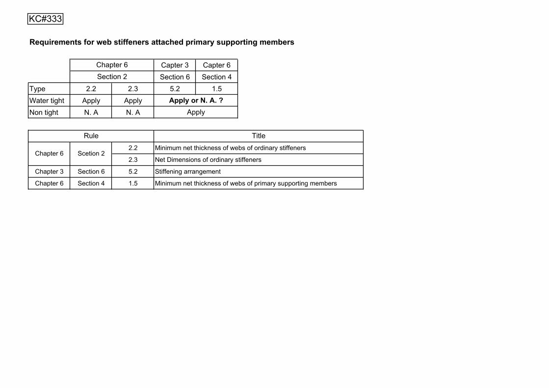
Requirements for web stiffeners attached primary supporting members
Capter 3 Capter 6Section 6 Section 4
Type 2.2 2.3 5.2 1.5Water tight Apply ApplyNon tight N. A N. A
2.2 Minimum net thickness of webs of ordinary stiffeners
2.3 Net Dimensions of ordinary stiffeners
Chapter 3 Section 6 5.2 Stiffening arrangement
Chapter 6 Section 4 1.5 Minimum net thickness of webs of primary supporting members
Chapter 6 Scetion 2
TitleRule
Chapter 6Section 2
Apply or N. A. ?Apply
KC#333
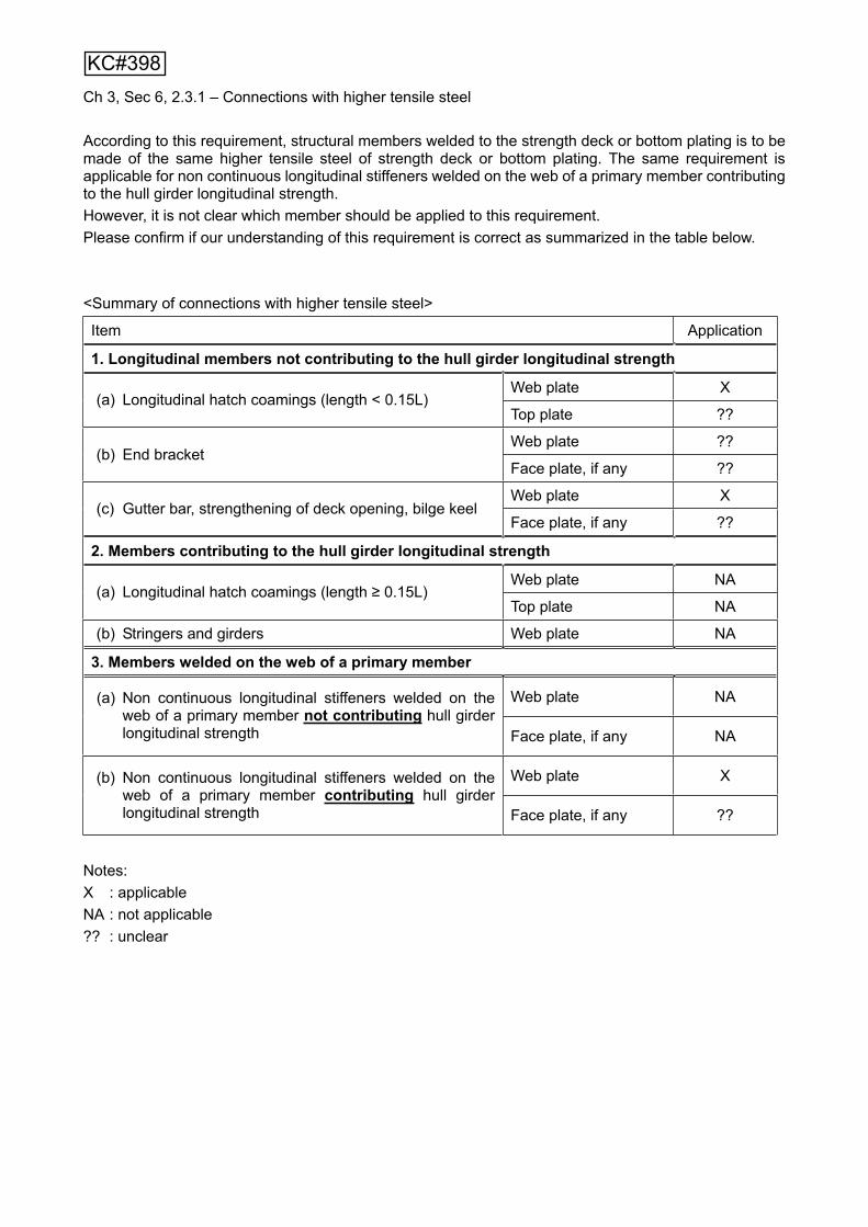
Ch 3, Sec 6, 2.3.1 – Connections with higher tensile steel
According to this requirement, structural members welded to the strength deck or bottom plating is to be made of the same higher tensile steel of strength deck or bottom plating. The same requirement is applicable for non continuous longitudinal stiffeners welded on the web of a primary member contributing to the hull girder longitudinal strength. However, it is not clear which member should be applied to this requirement. Please confirm if our understanding of this requirement is correct as summarized in the table below.
<Summary of connections with higher tensile steel>
Item Application
1. Longitudinal members not contributing to the hull girder longitudinal strength
Web plate X(a) Longitudinal hatch coamings (length < 0.15L)
Top plate ??
Web plate ??(b) End bracket
Face plate, if any ??
Web plate X(c) Gutter bar, strengthening of deck opening, bilge keel
Face plate, if any ??
2. Members contributing to the hull girder longitudinal strength
Web plate NA (a) Longitudinal hatch coamings (length 0.15L)
Top plate NA
(b) Stringers and girders Web plate NA
3. Members welded on the web of a primary member
Web plate NA (a) Non continuous longitudinal stiffeners welded on the web of a primary member not contributing hull girder longitudinal strength Face plate, if any NA
Web plate X (b) Non continuous longitudinal stiffeners welded on the web of a primary member contributing hull girder longitudinal strength Face plate, if any ??
Notes: X : applicable NA : not applicable ?? : unclear
KC#398

bWeb plate
Web stiffener
a
t
Technical Background of Ch 3 Sec 6 [5.2.1] of CSR for Bulker
The web stiffener of the primary supporting member (PSM) is provided to prevent the buckling failure of the web plate of PSM. Even if the buckling failure occurs in the web plate of PSM, the web stiffener has to withstand the buckling loads. For that reason, the stiffness of the web stiffener is always larger than that of the web plate of PSM. Now, the ratio of the stiffness of the web stiffener to that of the web plate of PSM sets to C and the web stiffener is assumed to be of flat bar with thickness “t” and depth “h”
The stiffness of the web plate of PSM:
)1(12 23Et
The stiffness of the web stiffener: 3/3Eth
The critical value “C” can be obtained by the following formula;
3
23
3
64.3)1(12/
3/th
bt
bEtEthC
The critical value C varies depending on the aspect ratio of web plate. Here, the critical value C is taken to 20, based on the actual designs. Then, we can get the following formula.
32
77.1ht
bh
The ratio of thickness and height of flat bar varies to 135 to 80 which are obtained from the
current design, then, 101
151095.0067.0 toto
bh can be obtained.
The value “1/12” is the average value of bh above.
Considering the actual design, it was found that this relationship between web stiffener height and panel length can apply to web stiffeners with flat bar fitted to all PSM. Then, to simplify this relationship, the web stiffener length l has been used instead of b.
As a conclusion, CSR has been adopted the last sentence of the requirement of Ch 3 Sec 6 5.1.2 that the depth of web stiffener is to be more than 1/12 of stiffener length.
***
KC#416
KC#450
d1 d2
d3 d4
h
KC#498

FOT
Void
WBT
KC#510
KC#534
For Bracket Design (LR) CLICK>>
For Corossion allowance to SM CLICK>>>
INPUTSFlange (S,D for Single,Double sided flange) SType number of equally spaced load point on member 0Input 0 for stiffener/ secondary; 1 for girder/ primary 1 56 X 10Thickness of attached Plating (t1) mm 10Depth of Web (d)mm 560 d/t2= 56.00 Check d/t2 Max.55Thickness of Web (t2)mm 10Width of flange (wf)mm 150 wf/t3,D= 15.00 Wf/t3 OK N/AThickness of flange (t3),mm 10 wf/t3,S= 15.00 Wf/t3 OK Max. 15
4410 C1Value= 0.77 0.771830 C2Value= 0.46 0.46
Effective Width of attached plating (w)mm 838.99 C Value= 0.46
A (sqmm) L(mm) AL ALL IownWidth atached pltg (mm) 838.992273 8389.92 565 4740306 2678273082 69916.02Thk. Attached pltg (mm) 10Depth of web (mm) 550 5500.00 285 1567500 446737500 138645833.33Thk. Of web (mm) 10Width of flange (mm) 150 1500.00 5 7500 37500 12500.00Thk. Of flange (mm) 10
15389.92 6315306 3125048082 138728249.36
Height Of N/A from BaseLine (mm) 410.35 Ymin= 159.6467Height Of N/A from TopLine (mm) 159.65 Ymax= 410.3533MOI about BaseLine (mm^4) 3263776331.76 55.74 Kg/m (Stiffener OR Primary ONLY)MOI about Neutral Axis (mm^4) 672269221.34 67226.92 cm^4 I N/AZmax (mm^3)=I NA/Ymin 4210982 mm^3 4210.98 cm^3Zmin (mm^3)=I NA/Ymax 1638269 mm^3 1638.27 cm^3 Z min.
Max.Shear Area (Web) 5700 mm^2 57.00 cm^2 A shearTotal sectional area (Web+Fl.) 15390 mm^2 153.90 cm^2 A total
For Clarifications Contact: G.Jayasankar ([email protected])
<<<Provide Tripping Brackets>>>
Area Total
<<Double Sided Flange,D>> <<Single Sided Flange,S>>
Web Stiff FB (Reqd.)=
NOTE:Openings in primary WEB to be REINFORCED ALONG EDGE OF OPENING if the Opening depth>d/4 (or) 300mm (AND) Opening length>web depth,d (OR) Opening length >60% Secondary spacing
Note Kg/m below is EXCLUDING ATTACHED PLTG
Span of member (mm)Spacing of member (mm)
SECTION MODULUS CALCULATION (IRS, Part 3 ,Chapter 3, Section 4)
wf/t3 STATUS
d/t2 STATUS
<<<Web Stiffening Required>>>
Project:- aaaaa
<<PRIMARY>>t2
t3
w
wf
t1w
d
wf
t1
t2
t3
d
KC#590
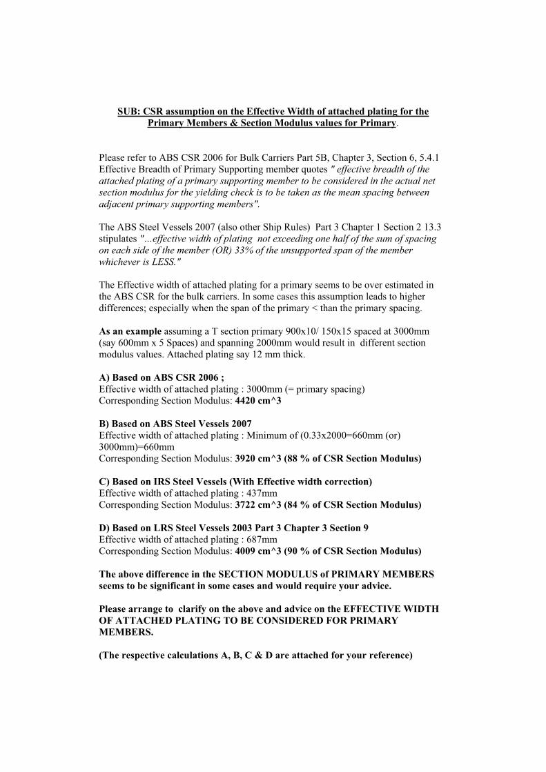
SUB: CSR assumption on the Effective Width of attached plating for the Primary Members & Section Modulus values for Primary.
Please refer to ABS CSR 2006 for Bulk Carriers Part 5B, Chapter 3, Section 6, 5.4.1 Effective Breadth of Primary Supporting member quotes " effective breadth of the attached plating of a primary supporting member to be considered in the actual net section modulus for the yielding check is to be taken as the mean spacing between adjacent primary supporting members".
The ABS Steel Vessels 2007 (also other Ship Rules) Part 3 Chapter 1 Section 2 13.3 stipulates "…effective width of plating not exceeding one half of the sum of spacing on each side of the member (OR) 33% of the unsupported span of the member whichever is LESS."
The Effective width of attached plating for a primary seems to be over estimated in the ABS CSR for the bulk carriers. In some cases this assumption leads to higher differences; especially when the span of the primary < than the primary spacing.
As an example assuming a T section primary 900x10/ 150x15 spaced at 3000mm (say 600mm x 5 Spaces) and spanning 2000mm would result in different section modulus values. Attached plating say 12 mm thick.
A) Based on ABS CSR 2006 ; Effective width of attached plating : 3000mm (= primary spacing) Corresponding Section Modulus: 4420 cm^3
B) Based on ABS Steel Vessels 2007 Effective width of attached plating : Minimum of (0.33x2000=660mm (or) 3000mm)=660mm Corresponding Section Modulus: 3920 cm^3 (88 % of CSR Section Modulus)
C) Based on IRS Steel Vessels (With Effective width correction) Effective width of attached plating : 437mm Corresponding Section Modulus: 3722 cm^3 (84 % of CSR Section Modulus)
D) Based on LRS Steel Vessels 2003 Part 3 Chapter 3 Section 9 Effective width of attached plating : 687mm Corresponding Section Modulus: 4009 cm^3 (90 % of CSR Section Modulus)
The above difference in the SECTION MODULUS of PRIMARY MEMBERS seems to be significant in some cases and would require your advice.
Please arrange to clarify on the above and advice on the EFFECTIVE WIDTH OF ATTACHED PLATING TO BE CONSIDERED FOR PRIMARY MEMBERS.
(The respective calculations A, B, C & D are attached for your reference)

(A) ABS CSR 2006 Section Modulus Calculation (Effective width of attached plating 3000mm= Primary Spacing)
(B) ABS Steel Vessels 2007 Section Modulus Calculation (Effective width of attached plating =Minimum of 1 Primary Spacing OR 33% of Span=.33x2000=660mm)
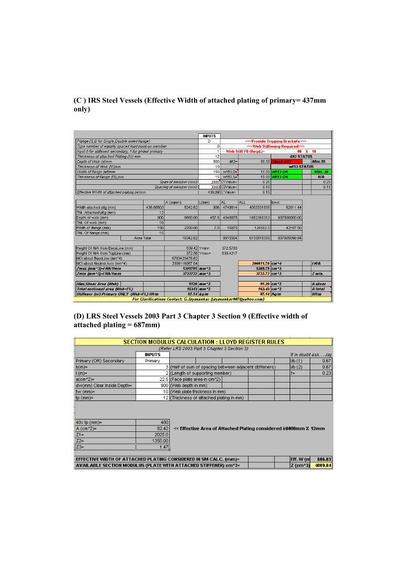
(C ) IRS Steel Vessels (Effective Width of attached plating of primary= 437mm only)
(D) LRS Steel Vessels 2003 Part 3 Chapter 3 Section 9 (Effective width of attached plating = 687mm)
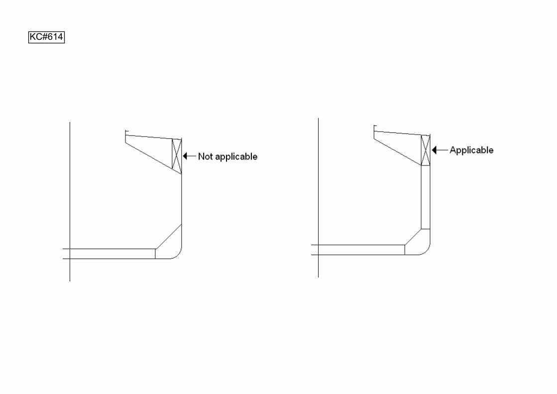
KC#614
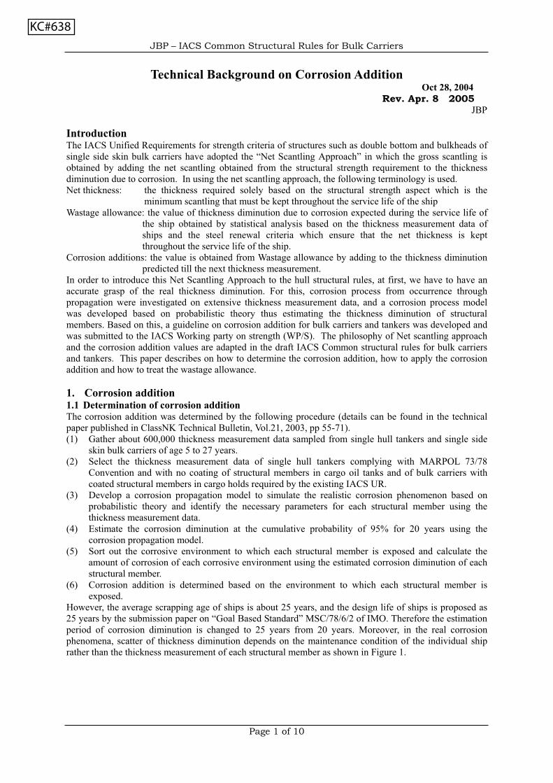
JBP – IACS Common Structural Rules for Bulk Carriers
Page 1 of 10
Technical Background on Corrosion AdditionOct 28, 2004
Rev. Apr. 8 2005JBP
IntroductionThe IACS Unified Requirements for strength criteria of structures such as double bottom and bulkheads ofsingle side skin bulk carriers have adopted the “Net Scantling Approach” in which the gross scantling isobtained by adding the net scantling obtained from the structural strength requirement to the thicknessdiminution due to corrosion. In using the net scantling approach, the following terminology is used.Net thickness: the thickness required solely based on the structural strength aspect which is the
minimum scantling that must be kept throughout the service life of the shipWastage allowance: the value of thickness diminution due to corrosion expected during the service life of
the ship obtained by statistical analysis based on the thickness measurement data ofships and the steel renewal criteria which ensure that the net thickness is keptthroughout the service life of the ship.
Corrosion additions: the value is obtained from Wastage allowance by adding to the thickness diminutionpredicted till the next thickness measurement.
In order to introduce this Net Scantling Approach to the hull structural rules, at first, we have to have anaccurate grasp of the real thickness diminution. For this, corrosion process from occurrence throughpropagation were investigated on extensive thickness measurement data, and a corrosion process modelwas developed based on probabilistic theory thus estimating the thickness diminution of structuralmembers. Based on this, a guideline on corrosion addition for bulk carriers and tankers was developed andwas submitted to the IACS Working party on strength (WP/S). The philosophy of Net scantling approachand the corrosion addition values are adapted in the draft IACS Common structural rules for bulk carriersand tankers. This paper describes on how to determine the corrosion addition, how to apply the corrosionaddition and how to treat the wastage allowance.
1. Corrosion addition1.1 Determination of corrosion additionThe corrosion addition was determined by the following procedure (details can be found in the technicalpaper published in ClassNK Technical Bulletin, Vol.21, 2003, pp 55-71).(1) Gather about 600,000 thickness measurement data sampled from single hull tankers and single side
skin bulk carriers of age 5 to 27 years.(2) Select the thickness measurement data of single hull tankers complying with MARPOL 73/78
Convention and with no coating of structural members in cargo oil tanks and of bulk carriers withcoated structural members in cargo holds required by the existing IACS UR.
(3) Develop a corrosion propagation model to simulate the realistic corrosion phenomenon based onprobabilistic theory and identify the necessary parameters for each structural member using thethickness measurement data.
(4) Estimate the corrosion diminution at the cumulative probability of 95% for 20 years using thecorrosion propagation model.
(5) Sort out the corrosive environment to which each structural member is exposed and calculate theamount of corrosion of each corrosive environment using the estimated corrosion diminution of eachstructural member.
(6) Corrosion addition is determined based on the environment to which each structural member isexposed.
However, the average scrapping age of ships is about 25 years, and the design life of ships is proposed as25 years by the submission paper on “Goal Based Standard” MSC/78/6/2 of IMO. Therefore the estimationperiod of corrosion diminution is changed to 25 years from 20 years. Moreover, in the real corrosionphenomena, scatter of thickness diminution depends on the maintenance condition of the individual shiprather than the thickness measurement of each structural member as shown in Figure 1.
KC#638
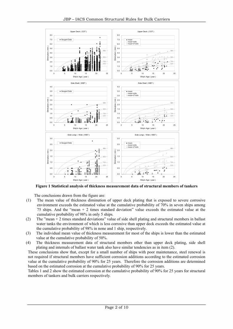
JBP – IACS Common Structural Rules for Bulk Carriers
Page 2 of 10
Figure 1 Statistical analysis of thickness measurement data of structural members of tankers
The conclusions drawn from the figure are: (1) The mean value of thickness diminution of upper deck plating that is exposed to severe corrosive
environment exceeds the estimated value at the cumulative probability of 70% in seven ships among75 ships. And the “mean + 2 times standard deviation” value exceeds the estimated value at thecumulative probability of 98% in only 5 ships.
(2) The ”mean + 2 times standard deviations” value of side shell plating and structural members in ballastwater tanks the environment of which is less corrosive than upper deck exceeds the estimated value atthe cumulative probability of 98% in none and 1 ship, respectively.
(3) The individual mean value of thickness measurement for most of the ships is lower than the estimatedvalue at the cumulative probability of 50%.
(4) The thickness measurement data of structural members other than upper deck plating, side shellplating and internals of ballast water tank also have similar tendencies as in item (2).
These conclusions show that, except for a small number of ships with poor maintenance, steel renewal isnot required if structural members have sufficient corrosion additions according to the estimated corrosionvalue at the cumulative probability of 90% for 25 years. Therefore the corrosion additions are determinedbased on the estimated corrosion at the cumulative probability of 90% for 25 years.Tables 1 and 2 show the estimated corrosion at the cumulative probability of 90% for 25 years for structuralmembers of tankers and bulk carriers respectively.
Upper Deck ( COT )
50%70%
90%
98%
0.0
1.0
2.0
3.0
4.0
5.0
6.0
7.0
8.0
0 5 10 15 20 25
Ship's Age ( year )
Dim
inut
ion
( mm
)
Gauged Data
Upper Deck ( COT )
50%70%
90%
98%
0.0
1.0
2.0
3.0
4.0
5.0
6.0
7.0
8.0
0 5 10 15 20 25
Ship's Age ( year )
Dim
inut
ion
( mm
)
meanmean+stdv.mean+2*stdv.
Side Shell ( WBT )
50%70%
90%
98%
0.0
0.5
1.0
1.5
2.0
2.5
3.0
3.5
4.0
0 5 10 15 20 25
Ship's Age ( year )
Dim
inut
ion
( mm
)
Gauged Data
Side Shell ( WBT )
50%70%
90%
98%
0.0
0.5
1.0
1.5
2.0
2.5
3.0
3.5
4.0
0 5 10 15 20 25
Ship's Age ( year )
Dim
inut
ion
( mm
)
meanmean+stdv.mean+2*stdv.
Side Longl. / Web ( WBT )
50%
70%
90%
98%
0.0
0.5
1.0
1.5
2.0
2.5
3.0
0 5 10 15 20 25
Ship's Age ( year )
Dim
inut
ion
( mm
)
Gauged Data
Side Longl. / Web ( WBT )
50%
70%
90%
98%
0.0
0.5
1.0
1.5
2.0
2.5
3.0
0 5 10 15 20 25
Ship's Age ( year )
Dim
inut
ion
( mm
)
meanmean+stdv.mean+2*stdv.
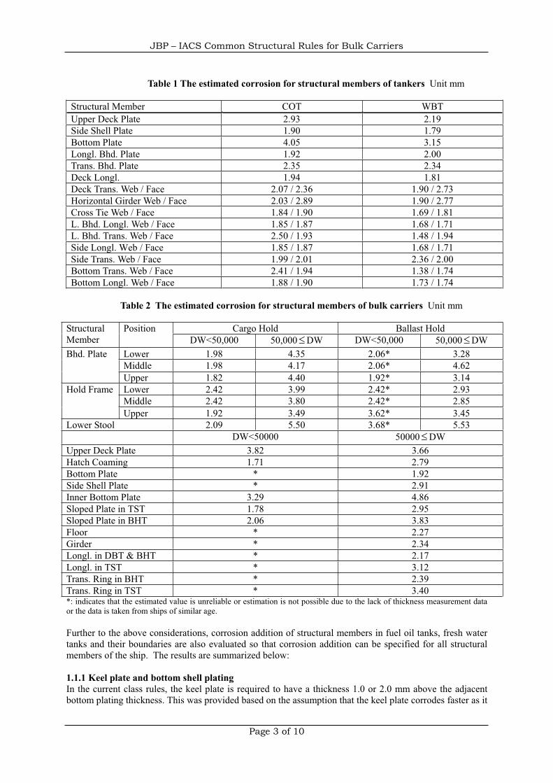
JBP – IACS Common Structural Rules for Bulk Carriers
Page 3 of 10
Table 1 The estimated corrosion for structural members of tankers Unit mm
Structural Member COT WBTUpper Deck Plate 2.93 2.19Side Shell Plate 1.90 1.79Bottom Plate 4.05 3.15Longl. Bhd. Plate 1.92 2.00Trans. Bhd. Plate 2.35 2.34Deck Longl. 1.94 1.81Deck Trans. Web / Face 2.07 / 2.36 1.90 / 2.73Horizontal Girder Web / Face 2.03 / 2.89 1.90 / 2.77Cross Tie Web / Face 1.84 / 1.90 1.69 / 1.81L. Bhd. Longl. Web / Face 1.85 / 1.87 1.68 / 1.71L. Bhd. Trans. Web / Face 2.50 / 1.93 1.48 / 1.94Side Longl. Web / Face 1.85 / 1.87 1.68 / 1.71Side Trans. Web / Face 1.99 / 2.01 2.36 / 2.00Bottom Trans. Web / Face 2.41 / 1.94 1.38 / 1.74Bottom Longl. Web / Face 1.88 / 1.90 1.73 / 1.74
Table 2 The estimated corrosion for structural members of bulk carriers Unit mm
Cargo Hold Ballast HoldStructuralMember
PositionDW<50,000 50,000 DW DW<50,000 50,000 DW
Lower 1.98 4.35 2.06* 3.28Middle 1.98 4.17 2.06* 4.62
Bhd. Plate
Upper 1.82 4.40 1.92* 3.14Lower 2.42 3.99 2.42* 2.93Middle 2.42 3.80 2.42* 2.85
Hold Frame
Upper 1.92 3.49 3.62* 3.45Lower Stool 2.09 5.50 3.68* 5.53
DW<50000 50000 DWUpper Deck Plate 3.82 3.66Hatch Coaming 1.71 2.79Bottom Plate * 1.92Side Shell Plate * 2.91Inner Bottom Plate 3.29 4.86Sloped Plate in TST 1.78 2.95Sloped Plate in BHT 2.06 3.83Floor * 2.27Girder * 2.34Longl. in DBT & BHT * 2.17Longl. in TST * 3.12Trans. Ring in BHT * 2.39Trans. Ring in TST * 3.40*: indicates that the estimated value is unreliable or estimation is not possible due to the lack of thickness measurement dataor the data is taken from ships of similar age.
Further to the above considerations, corrosion addition of structural members in fuel oil tanks, fresh watertanks and their boundaries are also evaluated so that corrosion addition can be specified for all structuralmembers of the ship. The results are summarized below:
1.1.1 Keel plate and bottom shell platingIn the current class rules, the keel plate is required to have a thickness 1.0 or 2.0 mm above the adjacentbottom plating thickness. This was provided based on the assumption that the keel plate corrodes faster as it
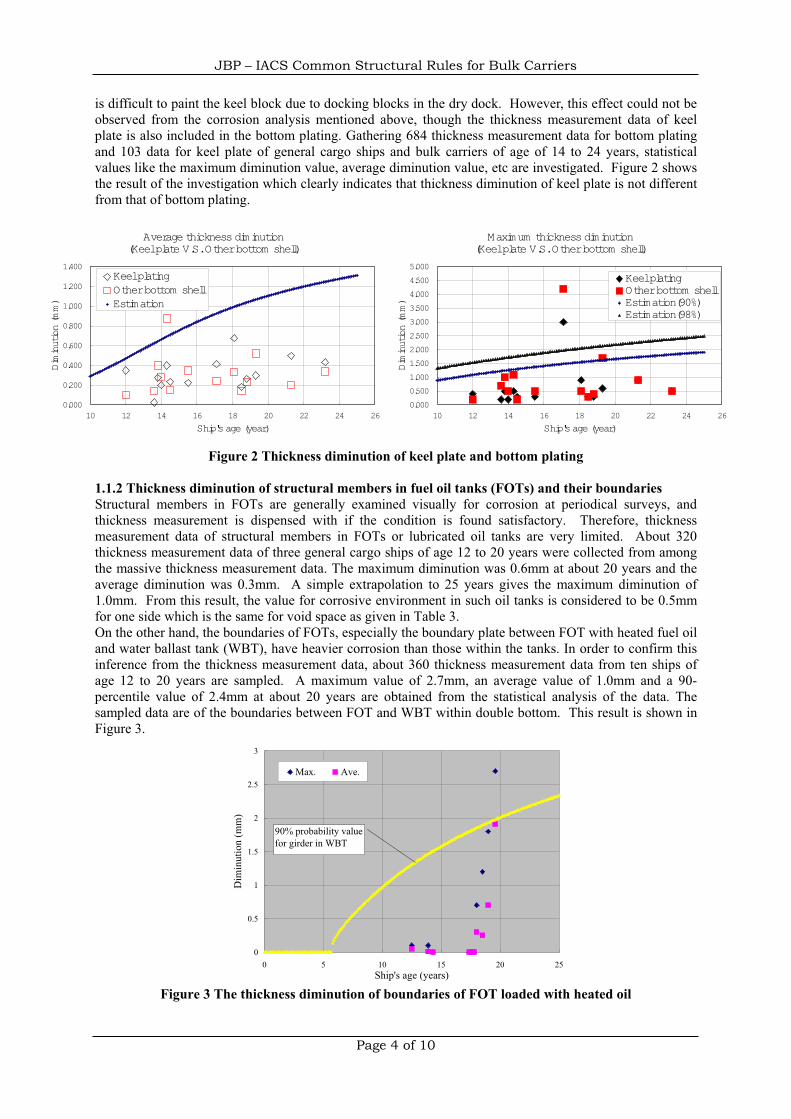
JBP – IACS Common Structural Rules for Bulk Carriers
Page 4 of 10
is difficult to paint the keel block due to docking blocks in the dry dock. However, this effect could not beobserved from the corrosion analysis mentioned above, though the thickness measurement data of keelplate is also included in the bottom plating. Gathering 684 thickness measurement data for bottom platingand 103 data for keel plate of general cargo ships and bulk carriers of age of 14 to 24 years, statisticalvalues like the maximum diminution value, average diminution value, etc are investigated. Figure 2 showsthe result of the investigation which clearly indicates that thickness diminution of keel plate is not differentfrom that of bottom plating.
Figure 2 Thickness diminution of keel plate and bottom plating
1.1.2 Thickness diminution of structural members in fuel oil tanks (FOTs) and their boundariesStructural members in FOTs are generally examined visually for corrosion at periodical surveys, andthickness measurement is dispensed with if the condition is found satisfactory. Therefore, thicknessmeasurement data of structural members in FOTs or lubricated oil tanks are very limited. About 320thickness measurement data of three general cargo ships of age 12 to 20 years were collected from amongthe massive thickness measurement data. The maximum diminution was 0.6mm at about 20 years and theaverage diminution was 0.3mm. A simple extrapolation to 25 years gives the maximum diminution of1.0mm. From this result, the value for corrosive environment in such oil tanks is considered to be 0.5mmfor one side which is the same for void space as given in Table 3.On the other hand, the boundaries of FOTs, especially the boundary plate between FOT with heated fuel oiland water ballast tank (WBT), have heavier corrosion than those within the tanks. In order to confirm thisinference from the thickness measurement data, about 360 thickness measurement data from ten ships ofage 12 to 20 years are sampled. A maximum value of 2.7mm, an average value of 1.0mm and a 90-percentile value of 2.4mm at about 20 years are obtained from the statistical analysis of the data. Thesampled data are of the boundaries between FOT and WBT within double bottom. This result is shown inFigure 3.
0
0.5
1
1.5
2
2.5
3
0 5 10 15 20 25Ship's age (years)
Dim
inut
ion
(mm
)
Max. Ave.
90% probability valuefor girder in WBT
Figure 3 The thickness diminution of boundaries of FOT loaded with heated oil
Average thickness diminution(Keelplate V.S.Otherbottom shell)
0.000
0.200
0.400
0.600
0.800
1.000
1.200
1.400
10 12 14 16 18 20 22 24 26
Ship'sage (year)
Diminution (mm)
KeelplatingOtherbottom shellEstimation
Maximum thickness diminution(Keelplate V.S.Other bottom shell)
0.000
0.500
1.000
1.500
2.000
2.500
3.000
3.500
4.000
4.500
5.000
10 12 14 16 18 20 22 24 26
Ship'sage (year)
Diminution (mm)
KeelplatingOtherbottom shellEstimation(90%)Estimation(98%)
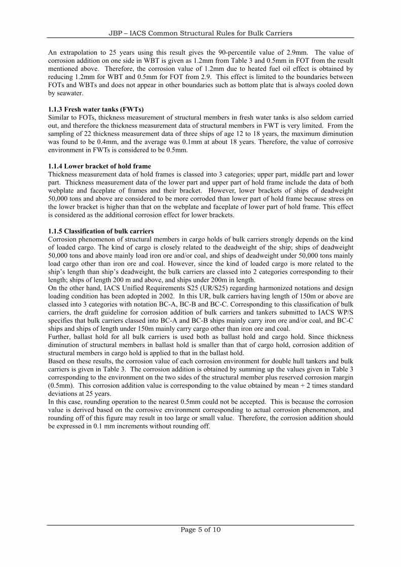
JBP – IACS Common Structural Rules for Bulk Carriers
Page 5 of 10
An extrapolation to 25 years using this result gives the 90-percentile value of 2.9mm. The value ofcorrosion addition on one side in WBT is given as 1.2mm from Table 3 and 0.5mm in FOT from the resultmentioned above. Therefore, the corrosion value of 1.2mm due to heated fuel oil effect is obtained byreducing 1.2mm for WBT and 0.5mm for FOT from 2.9. This effect is limited to the boundaries betweenFOTs and WBTs and does not appear in other boundaries such as bottom plate that is always cooled downby seawater.
1.1.3 Fresh water tanks (FWTs)Similar to FOTs, thickness measurement of structural members in fresh water tanks is also seldom carriedout, and therefore the thickness measurement data of structural members in FWT is very limited. From thesampling of 22 thickness measurement data of three ships of age 12 to 18 years, the maximum diminutionwas found to be 0.4mm, and the average was 0.1mm at about 18 years. Therefore, the value of corrosiveenvironment in FWTs is considered to be 0.5mm.
1.1.4 Lower bracket of hold frameThickness measurement data of hold frames is classed into 3 categories; upper part, middle part and lowerpart. Thickness measurement data of the lower part and upper part of hold frame include the data of bothwebplate and faceplate of frames and their bracket. However, lower brackets of ships of deadweight50,000 tons and above are considered to be more corroded than lower part of hold frame because stress onthe lower bracket is higher than that on the webplate and faceplate of lower part of hold frame. This effectis considered as the additional corrosion effect for lower brackets.
1.1.5 Classification of bulk carriersCorrosion phenomenon of structural members in cargo holds of bulk carriers strongly depends on the kindof loaded cargo. The kind of cargo is closely related to the deadweight of the ship; ships of deadweight50,000 tons and above mainly load iron ore and/or coal, and ships of deadweight under 50,000 tons mainlyload cargo other than iron ore and coal. However, since the kind of loaded cargo is more related to theship’s length than ship’s deadweight, the bulk carriers are classed into 2 categories corresponding to theirlength; ships of length 200 m and above, and ships under 200m in length.On the other hand, IACS Unified Requirements S25 (UR/S25) regarding harmonized notations and designloading condition has been adopted in 2002. In this UR, bulk carriers having length of 150m or above areclassed into 3 categories with notation BC-A, BC-B and BC-C. Corresponding to this classification of bulkcarriers, the draft guideline for corrosion addition of bulk carriers and tankers submitted to IACS WP/Sspecifies that bulk carriers classed into BC-A and BC-B ships mainly carry iron ore and/or coal, and BC-Cships and ships of length under 150m mainly carry cargo other than iron ore and coal.Further, ballast hold for all bulk carriers is used both as ballast hold and cargo hold. Since thicknessdiminution of structural members in ballast hold is smaller than that of cargo hold, corrosion addition ofstructural members in cargo hold is applied to that in the ballast hold.Based on these results, the corrosion value of each corrosion environment for double hull tankers and bulkcarriers is given in Table 3. The corrosion addition is obtained by summing up the values given in Table 3corresponding to the environment on the two sides of the structural member plus reserved corrosion margin(0.5mm). This corrosion addition value is corresponding to the value obtained by mean + 2 times standarddeviations at 25 years.In this case, rounding operation to the nearest 0.5mm could not be accepted. This is because the corrosionvalue is derived based on the corrosive environment corresponding to actual corrosion phenomenon, androunding off of this figure may result in too large or small value. Therefore, the corrosion addition shouldbe expressed in 0.1 mm increments without rounding off.
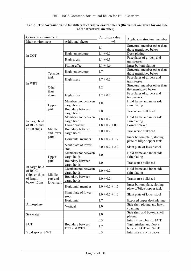
JBP – IACS Common Structural Rules for Bulk Carriers
Page 6 of 10
Table 3 The corrosion value for different corrosive environments (the values are given for one sideof the structural member)
Corrosive environmentMain environment Additional factor
Corrosion value(mm) Applicable structural member
1.1 Structural member other thanthose mentioned below
High temperature 1.1 + 0.5 Deck plating
High stress 1.1 + 0.3 Faceplates of girders andtransverses
In COT
Pitting effect 1.1 + 1.6 Inner bottom plating
High temperature 1.7 Structural member other thanthose mentioned belowTopside
tank High stress 1.7 + 0.3 Faceplates of girders andtransverses
1.2 Structural member other thanthat mentioned below
In WBTOtherthanabove High stress 1.2 + 0.3 Faceplates of girders and
transversesMembers not betweencargo holds 1.8 Hold frame and inner side
skin platingUpperpart Boundary between
cargo holds 2.0 Transverse bulkhead
Members not betweencargo holds 1.8 + 0.2 Hold frame and inner side
skin platingLower bracket 1.8 + 0.2 + 0.3 Lower bracketBoundary betweencargo holds 2.0 + 0.2 Transverse bulkhead
Horizontal member 1.8 + 0.2 + 1.7 Inner bottom plate, slopingplate of bilge hopper tank
In cargo holdof BC-A andBC-B ships Middle
and lowerparts
Slant plate of lowerstool 2.0 + 0.2 + 2.2 Slant plate of lower stool
Members not betweencargo holds 1.0 Hold frame and inner side
skin platingUpperpart Boundary between
cargo holds 1.0 Transverse bulkhead
Members not betweencargo holds 1.0 + 0.2 Hold frame and inner side
skin platingBoundary betweencargo holds 1.0 + 0.2 Transverse bulkhead
Middlepart andlower part
Horizontal member 1.0 + 0.2 + 1.2 Inner bottom plate, slopingplate of bilge hopper tank
In cargo holdof BC-Cships or shipsof lengthbelow 150m
Slant plate of lowerstool 1.0 + 0.2 + 1.0 Slant plate of lower stool
Horizontal 1.7 Exposed upper deck platingAtmosphere Vertical 1.0 Side shell plating and hatch
coaming
Sea water 1.0 Side shell and bottom shellplating
0.5 Internal members in FOTFOT Boundary between
FOT and WBT 1.7 Tight girders and floorsbetween FOT and WBT
Void spaces, FWT 0.5 Internals in such spaces
JBP – IACS Common Structural Rules for Bulk Carriers
Page 7 of 10
1.2 Application of corrosion addition1.2.1 Corrosion addition for local strength membersCorrosion addition is applied to the local strength member according to the definition of net scantlingapproach. That is, the necessary minimum scantling of a structural member
requiredgrosst _ is given by adding
the necessary scantling from the strength point of view Nett and corrosion addition
CAt . This is obvious fromthe basic assumption of local strength assessment.Generally, the necessary scantling from the strength point of view
Nett given by the scantling formula isexpressed in increments of 0.1mm by rounding off the two decimal places to the nearest single digit. Alsothe corrosion addition
CAt is expressed in increments of 0.1mm as mentioned above. Therefore, thenecessary minimum scantling of a structural member
requiredgrosst _ is also expressed in increments of 0.1mm.
Though current classification rules for hull structure do not allow the actual scantling to be less than thatobtained from the rule formula, conventionally classification societies may accept a smaller scantlingexpressed in increments of 0.5mm obtained by rounding off to the nearest 0.5 mm that may correspond tothe nominal thickness of rolled steels which comes in increments of 0.5mm. This is possible because
requiredgrosst _ is considered to have sufficient safety margin including corrosion, and hence the safety margin
compensates for the reduction in scantling due to rounding down in the current rules. However, in the netscantling approach, such a rounding down will result in the reduction in values of
Nett or CAt which is not
appropriate. As the solution, the following 3 approaches may be adapted in the new structural rules.(1)
requiredgrosst _ is expressed in intervals of 0.1mm and rounding down is not accepted.
(2)requiredgrosst _
is rounded up to the nearest higher 0.5mm unit(3) Both
Nett and CAt are rounded up to the nearest 0.5mm unit
Since the approach specified in above (1) is in terms of 0.1mm unit, it will require a great deal to order,produce, and control rolled steels and it will be likely that the problem of minus tolerance of thickness ofrolled steels is brought to the scantling requirements. On the other hand, the approach (2) or (3) is notlikely to have the above problem. Furthermore, the approach (3) results in scantlings 0.25mm greater thanthat specified in (2). The designers and some owners may not welcome the approach (3) because of theweight increase due to the addition of 0.25mm on an average, but some owners may welcome this due tothe merit of increased wastage allowance. Since the proposed corrosion addition is sufficient to minimizethe steel renewal of structural members for a ship which is properly maintained, approach (2) is consideredto be an optimal one.
1.2.2 Corrosion addition for global strength membersThe strength assessment of major load carrying structural members such as transverse girders is carried outconsidering the mutual interaction of such members covering a wide extent of the structure rather thanusing simplified scantling formula such as for a local strength member. Generally, finite element analysis(FEA) is widely used for the strength assessment of such structures. In FEA, a wide extent of the structureis modeled in order to consider the mutual interaction of primary supporting members and the structuralresponse of the whole structure when the loads act on them is obtained. In this case, when the thicknessdiminution of one structural component is uniformly reached its corrosion addition value, it is mostunlikely that the rest of the structure also has reached its corrosion addition value from the viewpoint ofprobabilistic theory. Normally, corroded areas and less corroded areas are scattered in the structure atrandom. The structural response in the corroded condition mentioned above is considered equivalent tothat in uniformly corroded condition with average diminution. In this case, it is necessary to consider theaverage corrosion value of all the structural members, but it is a complicated task to prepare the averagecorrosion value of each structural member that has a different corrosion addition value. The averagecorrosion value is nearly equal to half the corrosion addition of each structural member. Therefore, half thecorrosion addition value is applied to the structural strength analysis of primary supporting members inusing the FEA. Hence the actual structural model for FEA is prepared by reducing half the corrosionaddition value from the original scantling in the drawings, and strength assessment is carried out. Hullgirder strength assessment and ultimate strength assessment for hull girder when a ship is regarded as asimple girder are also carried out in the same manner.When assessing the buckling strength of panel elements of shell plating and web plate of primarysupporting members, the stress acting on the panel element estimated from the result of the FEA is used.
JBP – IACS Common Structural Rules for Bulk Carriers
Page 8 of 10
However, critical buckling stress of the panel element is calculated using the scantling obtained by reducingthe full corrosion addition from the original scantling because the panel element is regarded as a localstrength member.
1.2.3 Corrosion addition for fatigue strength assessmentFatigue strength of structural members can be assessed by the cumulative damage estimated against thecyclic loads encountered by the ship during her design life. The scantling of the structural member variesfrom no thickness diminution at the initial stage to thickness diminution equal to the corrosion addition atthe end of the design life. However, it is not practical and is very difficult to consider the diminution of thescantling which varies over time in fatigue strength assessment. Therefore fatigue assessment consideringthe corrosion effect is generally used instead of considering the actual scantling diminution. In this case, itis necessary to consider many coefficients of corrosion effect for every corrosive environment because thecorrosion effect depends on the environment to which structural members are exposed. Thus this method isalso seemed to be impractical. Assuming that the thickness diminution is zero prior to service andthickness diminution reaches full corrosion addition at the ship’s design life, the average diminution can behalf the corrosion addition through the ship’s design life. Therefore, half the corrosion addition can beapplied for fatigue strength assessment.
2 Wastage allowance in the current rules and the net scantling approach2.1 Wastage allowance for the local strength memberThe current classification rules give scantlings that are necessary to prevent structural damage mainly basedon extensive experience, but it is not clear what is the actual scantling that is sufficient enough. Further thelower acceptable level of structural strength due to corrosion is also not clear. Surveys of the ships inservice have been carried out by experienced surveyors using specified wastage allowance set as apercentage of original thickness based on experience. For that reason, the chances of causing seriousproblems due to corrosion are very limited.For example, in the case where the thickness diminution limit of the upper deck plate is 20% of the originalthickness at the midship region and the thickness of the whole upper plate is worn out about 20% of theoriginal thickness, the section modulus of the transverse section also reaches 80% of the original. And thiscase is never accepted from the viewpoint on longitudinal strength of hull girder in the current rules.Therefore wastage allowance criteria for the transverse section modulus are defined in the currentclassification rules to ensure sufficient hull girder strength. The more critical criteria among the twowastage allowance criteria mentioned above are applied in actual survey of ships in service. For theexample case mentioned above, wastage allowance is 10% diminution of the original thickness. Thewastage allowance criteria from a similar point of view are also applied to the bottom plates whichcontribute to the longitudinal strength of hull girder. In case of inner bottom plating, since it is close to theneutral axis of transverse section, the wastage allowance is set as about 20% of the original thickness.Considering the example of a Cape size bulk carrier with deck plating 38mm, inner bottom plating 25mm,and bottom plating 20mm, the wastage allowance and proposed corrosion addition mentioned above isgiven in Table 4.
Table 4 Current Wastage allowance and proposed corrosion addition
Originalthicknesst
Wastage allowancefrom the viewpoint oflocal strength
Wastage allowancefrom the viewpointof longitudinalstrength
Proposedwastageallowance
Proposedcorrosionaddition
Upper deck plating 38mm 8.6mm (20% *t +1mm) 3.8mm 3.5mm 3.9mm
Inner bottomplating 25mm 6.0mm (20% *t +
1mm) 5.0mm 5.0mm 5.4mm
Bottom plating 20mm 5.0mm (20% *t +1mm) 2.0mm 2.5mm 2.7mm
In can be concluded that the proposed wastage allowance is approximately equal to the current actualwastage allowance criteria applied in actual survey. Therefore, the proposed wastage allowance andcorrosion addition provide a sufficient value considering the actual wastage allowance in the new structural
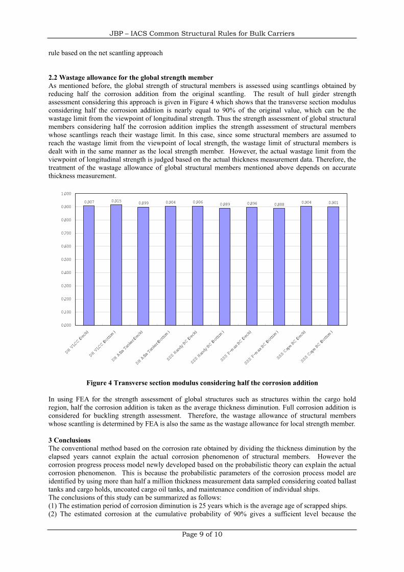
JBP – IACS Common Structural Rules for Bulk Carriers
Page 9 of 10
rule based on the net scantling approach
2.2 Wastage allowance for the global strength memberAs mentioned before, the global strength of structural members is assessed using scantlings obtained byreducing half the corrosion addition from the original scantling. The result of hull girder strengthassessment considering this approach is given in Figure 4 which shows that the transverse section modulusconsidering half the corrosion addition is nearly equal to 90% of the original value, which can be thewastage limit from the viewpoint of longitudinal strength. Thus the strength assessment of global structuralmembers considering half the corrosion addition implies the strength assessment of structural memberswhose scantlings reach their wastage limit. In this case, since some structural members are assumed toreach the wastage limit from the viewpoint of local strength, the wastage limit of structural members isdealt with in the same manner as the local strength member. However, the actual wastage limit from theviewpoint of longitudinal strength is judged based on the actual thickness measurement data. Therefore, thetreatment of the wastage allowance of global structural members mentioned above depends on accuratethickness measurement.
Figure 4 Transverse section modulus considering half the corrosion addition
In using FEA for the strength assessment of global structures such as structures within the cargo holdregion, half the corrosion addition is taken as the average thickness diminution. Full corrosion addition isconsidered for buckling strength assessment. Therefore, the wastage allowance of structural memberswhose scantling is determined by FEA is also the same as the wastage allowance for local strength member.
3 ConclusionsThe conventional method based on the corrosion rate obtained by dividing the thickness diminution by theelapsed years cannot explain the actual corrosion phenomenon of structural members. However thecorrosion progress process model newly developed based on the probabilistic theory can explain the actualcorrosion phenomenon. This is because the probabilistic parameters of the corrosion process model areidentified by using more than half a million thickness measurement data sampled considering coated ballasttanks and cargo holds, uncoated cargo oil tanks, and maintenance condition of individual ships.The conclusions of this study can be summarized as follows:(1) The estimation period of corrosion diminution is 25 years which is the average age of scrapped ships.(2) The estimated corrosion at the cumulative probability of 90% gives a sufficient level because the
0.907 0.915 0.899 0.904 0.906 0.889 0.896 0.888 0.904 0.901
0.000
0.100
0.200
0.300
0.400
0.500
0.600
0.700
0.800
0.900
1.000
DH VLCC(Deck)
DH VLCC(Bottom)
DH AfraTanker(Deck)
DH AfraTanker(Bottom)
SSSHandy BC(Deck)
SSSHandy BC(Bottom)
SSSP-max BC(Deck)
SSSP-maxBC(Bottom)
SSSCape BC(Deck)
SSSCape BC(Bottom)
JBP – IACS Common Structural Rules for Bulk Carriers
Page 10 of 10
thickness diminution of most of the structural members of ships that are properly maintained does notexceed the estimated corrosion values during their life.
(3) Based on the estimated corrosion, the wastage allowance is defined which minimizes the steel renewalof structural members during the ship’s design life as given the following formula.
)( 25.0_ cCAallowancewastage ttrounduptThis wastage allowance is close to the actual current criteria on wastage allowance applied in thesurvey of ships in service.
(4) The wastage allowance is defined for each side of the structural member as the corrosive environmentto which each side is exposed may be different. The total corrosion addition
CAt is obtained by adding
the corrosion addition value of one side 1Ct and that of the other side
2Ct plus 0.5mm taken as reservet ,which are expressed in increments of 0.1mm. Where
reservet (=0.5mm) is the thickness in reserve toaccount for anticipated maximum thickness diminution t hat may occur during the assumed inspectionintervals of 2.5 years after the thickness measurement. Then corrosion addition value is nearly equal tothe estimated corrosion diminution taking into account the 2 standard deviation at 25 years.
(5) The scantling of a structural member consists of two necessary minimum components as follows:One is
Nett which is the net scantling required from the structural strength viewpoint that should be keptthroughout the design life of the ship. The other is the corrosion addition
CAt which corresponds to the
estimated thickness diminution during the design life of the ship plus reservet . The estimation ofrational corrosion addition makes the introduction of the net scantling approach to the new structuralrules.
(6) The required scantling of local structural members offeredgrosst _
is obtained by the following formula.)(5.0_ CANetrequiredgross ttroundupt
It is preferable that requiredgrosst _
is rounded up to the nearest higher 0.5mm.(7) Transverse section modulus considering half the corrosion addition is about 90% of the original value
which corresponds to the wastage allowance from the viewpoint of hull girder longitudinal strength.Wastage allowance for global structural members can be obtained using the same formulation as forlocal structural members.
(8) Global strength members such as those contributing to the hull girder strength can be assessed by FEAconsidering half the corrosion addition.
(9) Fatigue strength of structural details can be assessed considering half the corrosion addition as a meanthickness diminution during the design life of ships.
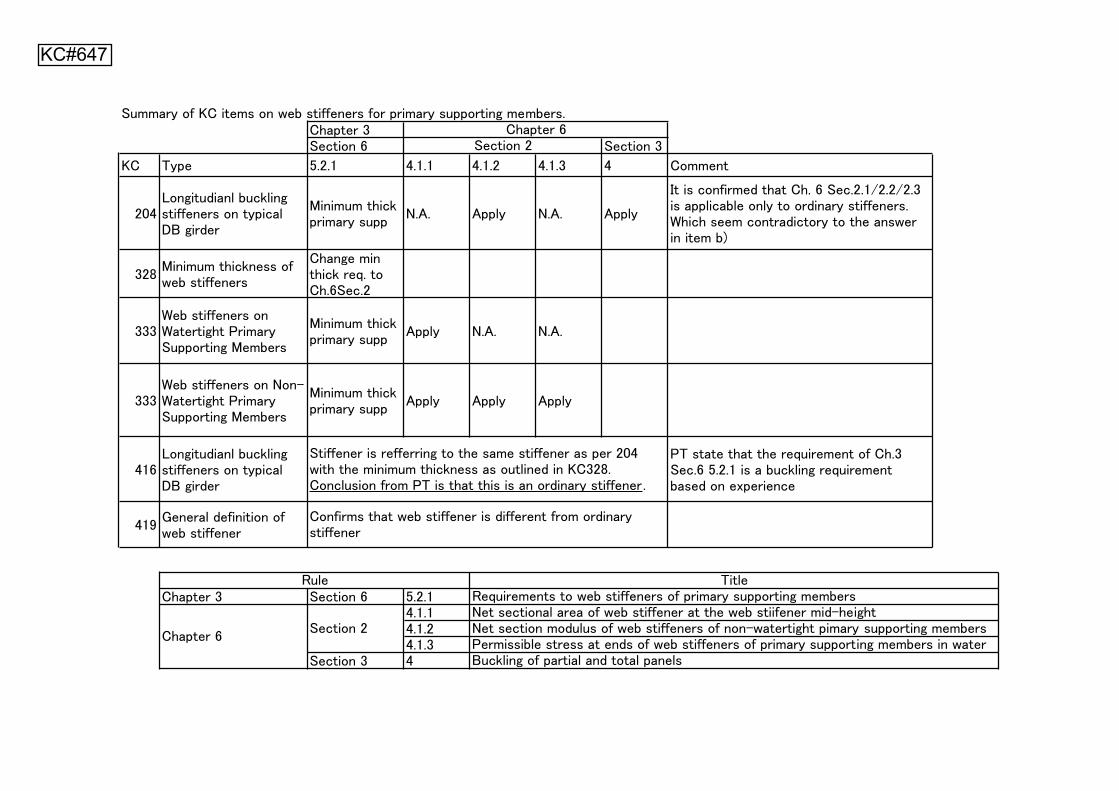
KC#647
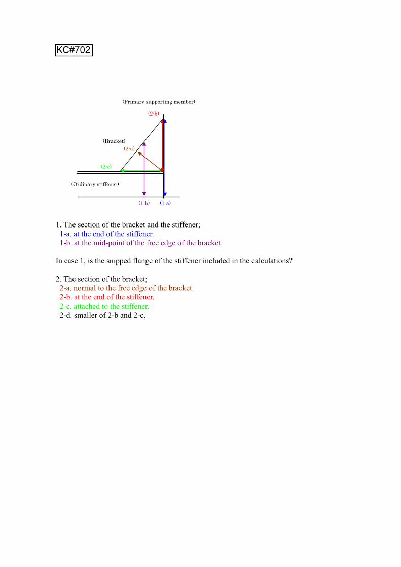
1. The section of the bracket and the stiffener; 1-a. at the end of the stiffener. 1-b. at the mid-point of the free edge of the bracket.
In case 1, is the snipped flange of the stiffener included in the calculations?
2. The section of the bracket; 2-a. normal to the free edge of the bracket. 2-b. at the end of the stiffener. 2-c. attached to the stiffener. 2-d. smaller of 2-b and 2-c.
(1-b)
(Bracket)
(Primary supporting member)
(1-a)
(2-a)
(2-b)
(2-c)
(Ordinary stiffener)
KC#702
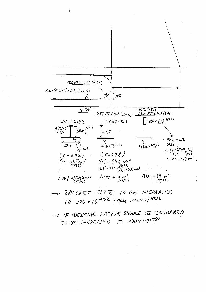
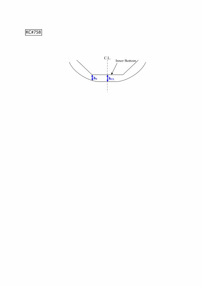
Inner BottomC.L.
hCLhS
KC#758

DBWBT
FOT
SWBT
PIPE TRUNK, running through whole
the cargo area length
KC#827
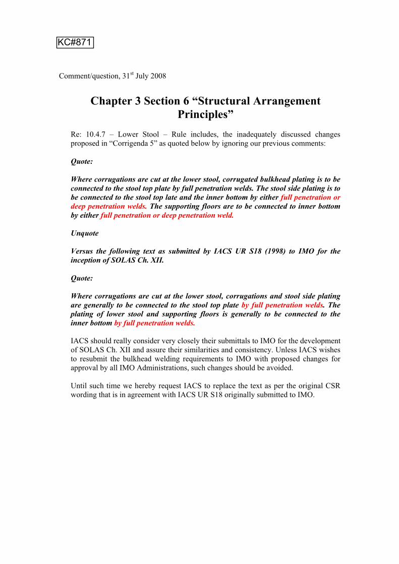
Comment/question, 31st July 2008
Chapter 3 Section 6 “Structural Arrangement Principles”
Re: 10.4.7 – Lower Stool – Rule includes, the inadequately discussed changes proposed in “Corrigenda 5” as quoted below by ignoring our previous comments:
Quote:
Where corrugations are cut at the lower stool, corrugated bulkhead plating is to be connected to the stool top plate by full penetration welds. The stool side plating is to be connected to the stool top late and the inner bottom by either full penetration or deep penetration welds. The supporting floors are to be connected to inner bottom by either full penetration or deep penetration weld.
Unquote
Versus the following text as submitted by IACS UR S18 (1998) to IMO for the inception of SOLAS Ch. XII.
Quote:
Where corrugations are cut at the lower stool, corrugations and stool side plating are generally to be connected to the stool top plate by full penetration welds. The plating of lower stool and supporting floors is generally to be connected to the inner bottom by full penetration welds.
IACS should really consider very closely their submittals to IMO for the development of SOLAS Ch. XII and assure their similarities and consistency. Unless IACS wishes to resubmit the bulkhead welding requirements to IMO with proposed changes for approval by all IMO Administrations, such changes should be avoided.
Until such time we hereby request IACS to replace the text as per the original CSR wording that is in agreement with IACS UR S18 originally submitted to IMO.
KC#871
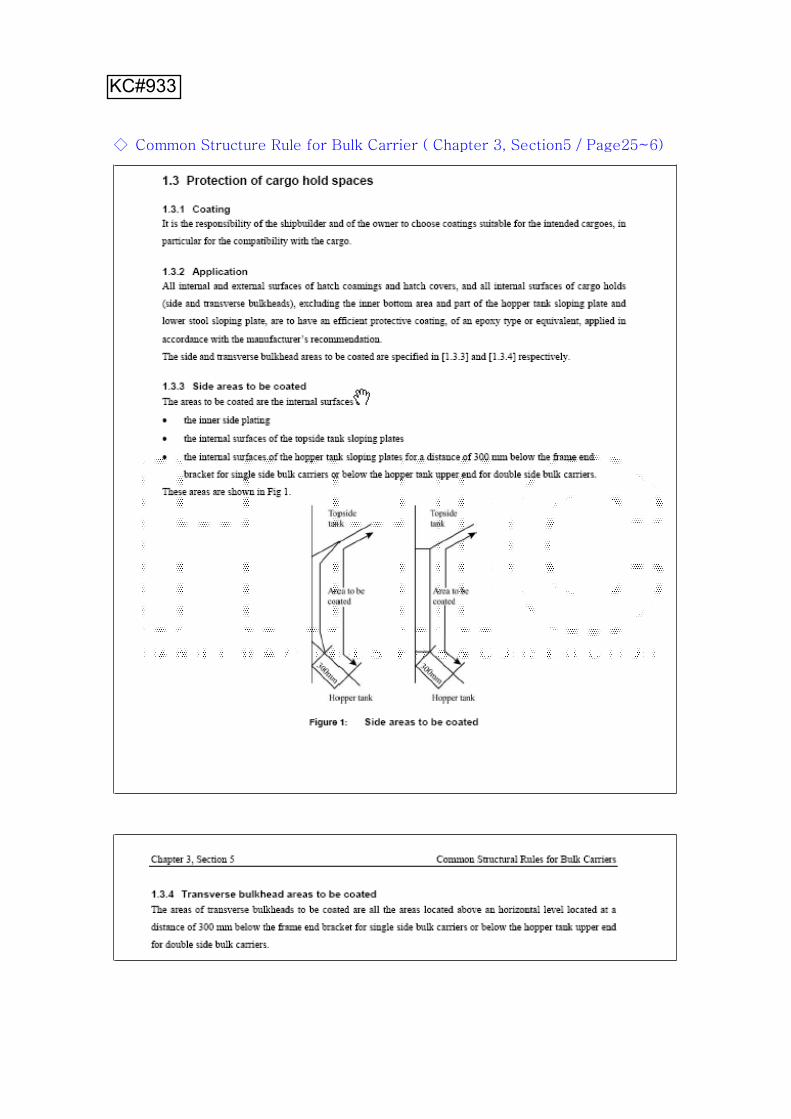
KC#933
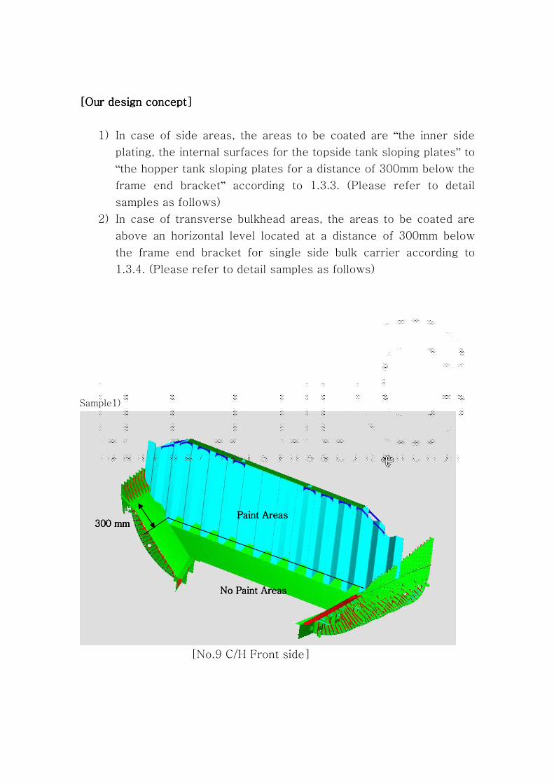
“”
“”
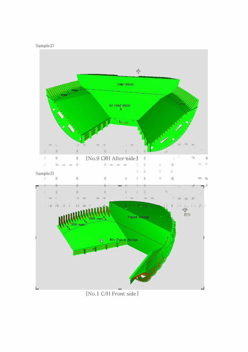
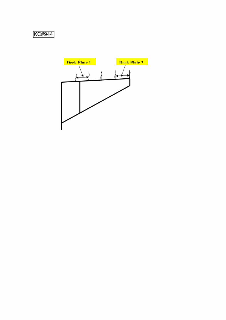
Deck Plate 1 Deck Plate 2
KC#944

Dear sir,
Chapter 3, Section 6 Common Structural Rules for Bulk Carriers
5.7 Cut-outs and holes5.7.1Cut-outs for the passage of ordinary stiffeners are to be as small as possible and well rounded with smooth edges.The depth of cut-outs is to be not greater than 50% of the depth of the primary supporting member.
Section 8 Common Structural Rules For Oil Tankers
SECTION 8.2/PAGE 24
2.6.1.7 Webs of the primary support members are to have a depth of not less than given bythe requirements of 2.6.4.1, 2.6.6.1 and 2.6.7.1, as applicable. Lesser depths may beaccepted where equivalent stiffness is demonstrated. See 3/5.3.3.4. Primary supportmembers that have open slots for stiffeners are to have a depth not less than 2.5times the depth of the slots.SECTION 8.3/PAGE 53.3.3.5 The web depth of primary support members is not to be less than 14% of thebending span and is to be at least 2.5 times as deep as the slots for stiffeners if theslots are not closed.SECTION 8.4/PAGE 54.3.4.4 The web depth is to be not less than 2.5 times the web depth of the adjacent framesif the slots are not closed.SECTION 8.5/PAGE 75.3.3.5 The web depth of primary support members is not to be less than 14% of thebending span and is to be at least 2.5 times as deep as the slots for stiffeners if theslots are not closed.
For tankers, D>=2.5d, then d<=40%D. It could be described as " The depth of cut-outs is to be not greater than 40% of the depth of the primary supporting member."
I suggested the requirement in two rules to be harmonized as well as the names 'cut-out' and 'slot'.
KC#1077


![Bulker Q&As and CIs on the IACS CSR Knowledge Centre KCID ... · Appendix 1, [2.2.8], please refer to the file attachement "Draft Answer Ch 5, App 1, [2.2.8].doc". Also Included in](https://img.pdfslide.net/doc/110x75/5f9de6169c6ce326b074c6b3/bulker-qas-and-cis-on-the-iacs-csr-knowledge-centre-kcid-appendix-1-228.jpg)