Embed Size (px)
Citation preview
IADC/SPE-199584-MS
The Development and Application of Real-Time Deep Learning Models toDrive Directional Drilling Efficiency
Dingzhou Cao, Occidental Petroleum Corporation; Don Hender, IPCOS; Sam Ariabod, Apex Systems; ChrisJames, Yuxing Ben, and Micheal Lee, Occidental Petroleum Corporation
Copyright 2020, IADC/SPE International Drilling Conference and Exhibition
This paper was prepared for presentation at the IADC/SPE International Drilling Conference and Exhibition held in Galveston, Texas, 3–5 March 2020.
This paper was selected for presentation by an IADC/SPE program committee following review of information contained in an abstract submitted by the author(s).Contents of the paper have not been reviewed by the International Association of Drilling Contractors or the Society of Petroleum Engineers and are subject to correctionby the author(s). The material does not necessarily reflect any position of the International Association of Drilling Contractors or the Society of Petroleum Engineers,its officers, or members. Electronic reproduction, distribution, or storage of any part of this paper without the written consent of the International Association of DrillingContractors or the Society of Petroleum Engineers is prohibited. Permission to reproduce in print is restricted to an abstract of not more than 300 words; illustrationsmay not be copied. The abstract must contain conspicuous acknowledgment of IADC/SPE copyright.
AbstractThis paper provides the technical details to develop a real-time deep learning model to detect and estimatethe duration of downlinking sequences of Rotary Steerable Systems (RSS) based on a single measurement(standpipe pressure, SPP). Further analytics are derived based on the downlink recognition results togetherwith other real-time log data (ROP, RPM, Torque, etc.) to drive directional drilling efficiency.
Real-time RSS downlink recognition is treated as an image segmentation problem. The Deep Learning(DL) models were created using the dynamic U-Net concept and materialized with a pre-trained ResNet-34as the underlying architecture. Transfer learning was used due to the limited number of training samples (≪100 downlinks per onshore well) to help with speed and accuracy. The SPP time series data was segmentedbased on stand of pipe drilled (one image per stand). This "image" was then fed into the model for downlinkrecognition. To further increase the accuracy, a second opinion mechanism was applied when the modelswere tested and deployed into the Real-Time Drilling (RTD) system. Using a dual model approach greatlyreduced the number of false positives due to non-downlink pressure fluctuations causing "noise". Thepatterns of SPP and its rate of change (delta SPP) are quite different. They both have pros and cons foridentifying the downlink, thus two independent models were built based on these two signals. The DL modelA is trained based on the original SPP signal and the DL model B is trained based on delta SPP. A downlinkis confirmed only when both models show positive results.
Data of 10 onshore wells (2 rigs) drilled with RSS were segmented (8165 images in total) and labeled.There were 671 images with 795 downlinks and 7980 images without downlink. The five-fold cross-validation technique was used to identify the best model(s). The F1 score of blind test result was .991(accuracy was ~99.82%, see Table 2). The relative error of duration estimation is 2.49%. The current rig fleetwithin the RTD system has a mix of drilling tool configurations - RSS and mud motors. To further validatethe models’ robustness regarding drilling tools, additional tests were conducted using mud motor wells’datasets from 21 rigs (25431 images without downlink). There were 3 false negatives from this extendedtest set, which resulted in a ~99.93% accuracy for the aggregated 31 wells dataset. These results suggestthat the models are accurate, reliable and robust.
2 IADC/SPE-199584-MS
The real-time DL solution presented in this paper enables operators to analyze RSS performance duringand between downlinking events. This would allow drilling engineers and rig supervisors to make faster,more reliable data-driven decisions to optimize performance and directional control of the well path.
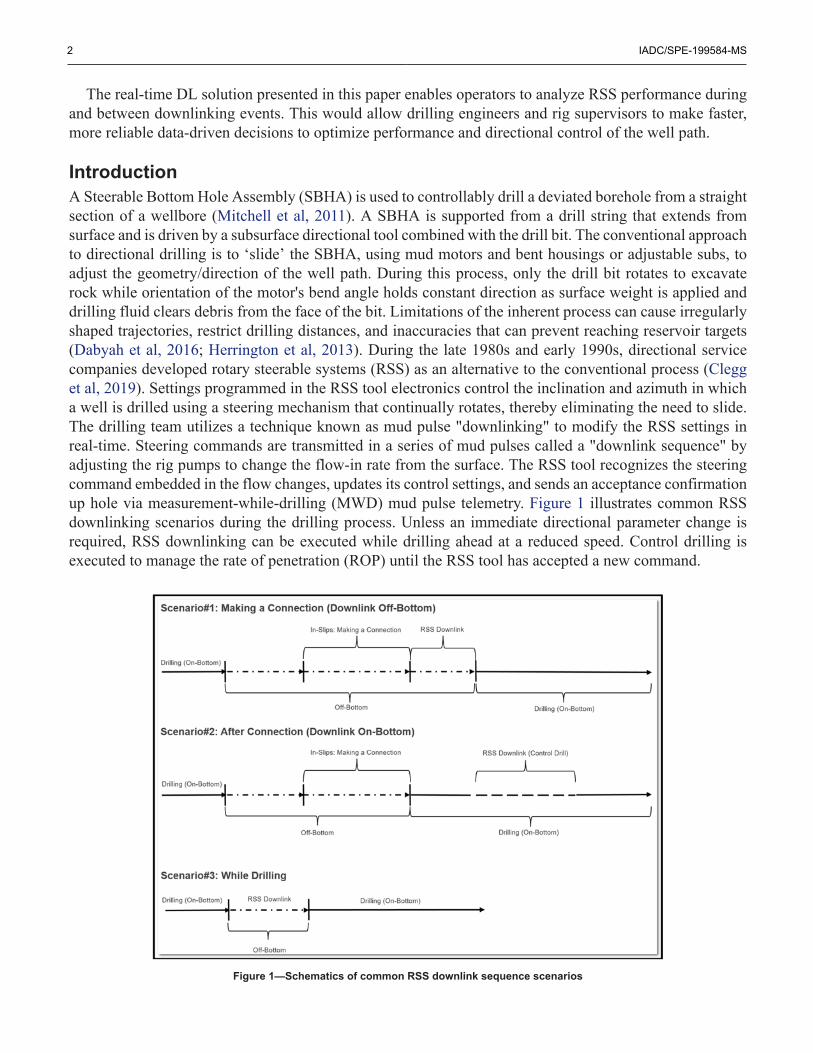
IntroductionA Steerable Bottom Hole Assembly (SBHA) is used to controllably drill a deviated borehole from a straightsection of a wellbore (Mitchell et al, 2011). A SBHA is supported from a drill string that extends fromsurface and is driven by a subsurface directional tool combined with the drill bit. The conventional approachto directional drilling is to ‘slide’ the SBHA, using mud motors and bent housings or adjustable subs, toadjust the geometry/direction of the well path. During this process, only the drill bit rotates to excavaterock while orientation of the motor's bend angle holds constant direction as surface weight is applied anddrilling fluid clears debris from the face of the bit. Limitations of the inherent process can cause irregularlyshaped trajectories, restrict drilling distances, and inaccuracies that can prevent reaching reservoir targets(Dabyah et al, 2016; Herrington et al, 2013). During the late 1980s and early 1990s, directional servicecompanies developed rotary steerable systems (RSS) as an alternative to the conventional process (Clegget al, 2019). Settings programmed in the RSS tool electronics control the inclination and azimuth in whicha well is drilled using a steering mechanism that continually rotates, thereby eliminating the need to slide.The drilling team utilizes a technique known as mud pulse "downlinking" to modify the RSS settings inreal-time. Steering commands are transmitted in a series of mud pulses called a "downlink sequence" byadjusting the rig pumps to change the flow-in rate from the surface. The RSS tool recognizes the steeringcommand embedded in the flow changes, updates its control settings, and sends an acceptance confirmationup hole via measurement-while-drilling (MWD) mud pulse telemetry. Figure 1 illustrates common RSSdownlinking scenarios during the drilling process. Unless an immediate directional parameter change isrequired, RSS downlinking can be executed while drilling ahead at a reduced speed. Control drilling isexecuted to manage the rate of penetration (ROP) until the RSS tool has accepted a new command.
Figure 1—Schematics of common RSS downlink sequence scenarios
IADC/SPE-199584-MS 3
RSS technologies are widely used by oil & gas operators for its drilling performance, hole cleaning andaccurate geo-steering capabilities (Felczak et al, 2012).
Operators are continuously analyzing drilling performance when deciding to use RSS as part of theirdrilling programs. Any recognizable improvements should at least match the increased cost of the RSScompared to drilling with conventional technology (Gorrara et al, 2015). This is particularly important inthe lower-cost land market. Some performance indicators are easily verified and measured, while othersare more complex and require in-depth analysis to extract results (Lenamond et al, 2005). Dogleg severity(DLS), build rate, turn rate, and steering times achieved by RSS settings have been used as criteria toquantify steerability (Lenamond et al, 2005; Sugiura et al, 2018).
Location, frequency and durations of RSS downlinking sequences while on and off bottom are keyreference points to extract performance indicators that impact the drilling process. Service providers havedirect accessibility to RSS data retrieved from the tool's memory (post-run) or during real-time drilling; thelatter being dependent on availability of parameters sent up hole via MWD mud-pulse transmission. It isnot common practice for the service provider to submit time-series RSS tech-logs to the operator. Real-timedownlinking reports are made available if requested by the drilling engineer, although details are limited;e.g. missing interval lengths, date-time omits seconds. From the operator's perspective, having an automatedreal-time RSS downlink detection algorithm derived from surface measurements eliminates dependencieson downhole or vendor data availability. This enables drilling engineers and rig supervisors to make faster,more reliable, data-driven engineering decisions and optimize directional performance.
In this paper, technical details are provided to develop a real-time deep learning application to auto-detect and estimate interval lengths of RSS downlinking events (stand by stand) based on a single surfacemeasurement (standpipe pressure, SPP). The downlink recognition results are then combined with surfacedrilling parameters and drilling rig state classification to assess the impact on drilling performance and drivedirectional efficiency. The authors of this paper are unaware of any real-time drilling applications publishedusing the proposed deep learning technologies and architecture, and as such will be the first of its kind.
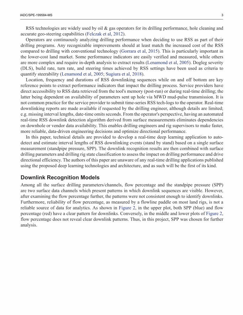
Downlink Recognition ModelsAmong all the surface drilling parameters/channels, flow percentage and the standpipe pressure (SPP)are two surface data channels which present patterns in which downlink sequences are visible. However,after examining the flow percentage further, the patterns were not consistent enough to identify downlinks.Furthermore, reliability of flow percentage, as measured by a flowline paddle on most land rigs, is not areliable source of data for analytics. As shown in Figure 2, in the upper plot, both SPP (blue) and flowpercentage (red) have a clear pattern for downlinks. Conversely, in the middle and lower plots of Figure 2,flow percentage does not reveal clear downlink patterns. Thus, in this project, SPP was chosen for furtheranalysis.
4 IADC/SPE-199584-MS
Figure 2—SPP (blue) and flow percentage (red) channels with downlinks (green dashed rectangle)
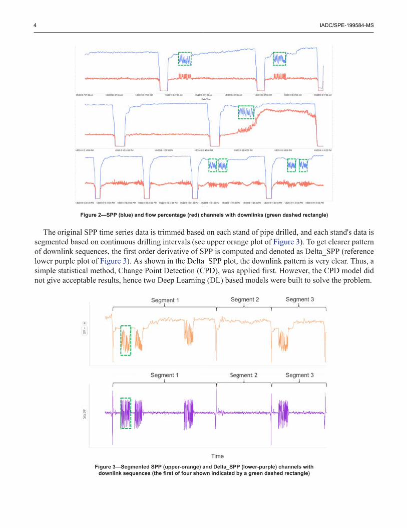
The original SPP time series data is trimmed based on each stand of pipe drilled, and each stand's data issegmented based on continuous drilling intervals (see upper orange plot of Figure 3). To get clearer patternof downlink sequences, the first order derivative of SPP is computed and denoted as Delta_SPP (referencelower purple plot of Figure 3). As shown in the Delta_SPP plot, the downlink pattern is very clear. Thus, asimple statistical method, Change Point Detection (CPD), was applied first. However, the CPD model didnot give acceptable results, hence two Deep Learning (DL) based models were built to solve the problem.
Figure 3—Segmented SPP (upper-orange) and Delta_SPP (lower-purple) channels withdownlink sequences (the first of four shown indicated by a green dashed rectangle)
IADC/SPE-199584-MS 5
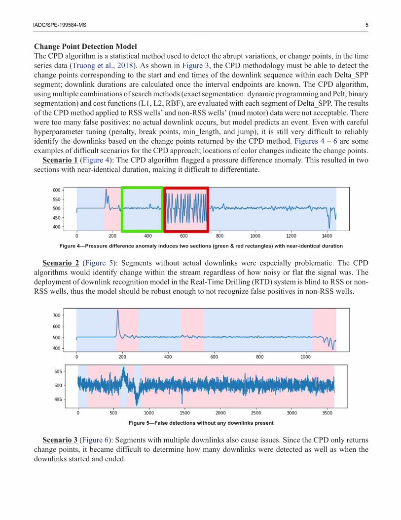
Change Point Detection ModelThe CPD algorithm is a statistical method used to detect the abrupt variations, or change points, in the timeseries data (Truong et al., 2018). As shown in Figure 3, the CPD methodology must be able to detect thechange points corresponding to the start and end times of the downlink sequence within each Delta_SPPsegment; downlink durations are calculated once the interval endpoints are known. The CPD algorithm,using multiple combinations of search methods (exact segmentation: dynamic programming and Pelt, binarysegmentation) and cost functions (L1, L2, RBF), are evaluated with each segment of Delta_SPP. The resultsof the CPD method applied to RSS wells’ and non-RSS wells’ (mud motor) data were not acceptable. Therewere too many false positives: no actual downlink occurs, but model predicts an event. Even with carefulhyperparameter tuning (penalty, break points, min_length, and jump), it is still very difficult to reliablyidentify the downlinks based on the change points returned by the CPD method. Figures 4 – 6 are someexamples of difficult scenarios for the CPD approach; locations of color changes indicate the change points.
Scenario 1 (Figure 4): The CPD algorithm flagged a pressure difference anomaly. This resulted in twosections with near-identical duration, making it difficult to differentiate.
Figure 4—Pressure difference anomaly induces two sections (green & red rectangles) with near-identical duration
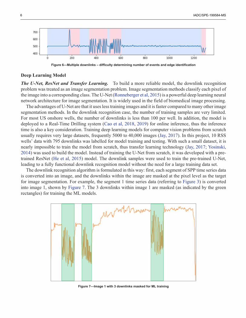
Scenario 2 (Figure 5): Segments without actual downlinks were especially problematic. The CPDalgorithms would identify change within the stream regardless of how noisy or flat the signal was. Thedeployment of downlink recognition model in the Real-Time Drilling (RTD) system is blind to RSS or non-RSS wells, thus the model should be robust enough to not recognize false positives in non-RSS wells.
Figure 5—False detections without any downlinks present
Scenario 3 (Figure 6): Segments with multiple downlinks also cause issues. Since the CPD only returnschange points, it became difficult to determine how many downlinks were detected as well as when thedownlinks started and ended.
6 IADC/SPE-199584-MS
Figure 6—Multiple downlinks – difficulty determining number of events and edge identification
Deep Learning Model
The U-Net, ResNet and Transfer Learning. To build a more reliable model, the downlink recognitionproblem was treated as an image segmentation problem. Image segmentation methods classify each pixel ofthe image into a corresponding class. The U-Net (Ronneberger et al, 2015) is a powerful deep learning neuralnetwork architecture for image segmentation. It is widely used in the field of biomedical image processing.
The advantages of U-Net are that it uses less training images and it is faster compared to many other imagesegmentation methods. In the downlink recognition case, the number of training samples are very limited.For most US onshore wells, the number of downlinks is less than 100 per well. In addition, the model isdeployed to a Real-Time Drilling system (Cao et al, 2018, 2019) for online inference, thus the inferencetime is also a key consideration. Training deep learning models for computer vision problems from scratchusually requires very large datasets, frequently 5000 to 40,000 images (Jay, 2017). In this project, 10 RSSwells’ data with 795 downlinks was labelled for model training and testing. With such a small dataset, it isnearly impossible to train the model from scratch, thus transfer learning technology (Jay, 2017; Yosinski,2014) was used to build the model. Instead of training the U-Net from scratch, it was developed with a pre-trained ResNet (He et al, 2015) model. The downlink samples were used to train the pre-trained U-Net,leading to a fully functional downlink recognition model without the need for a large training data set.
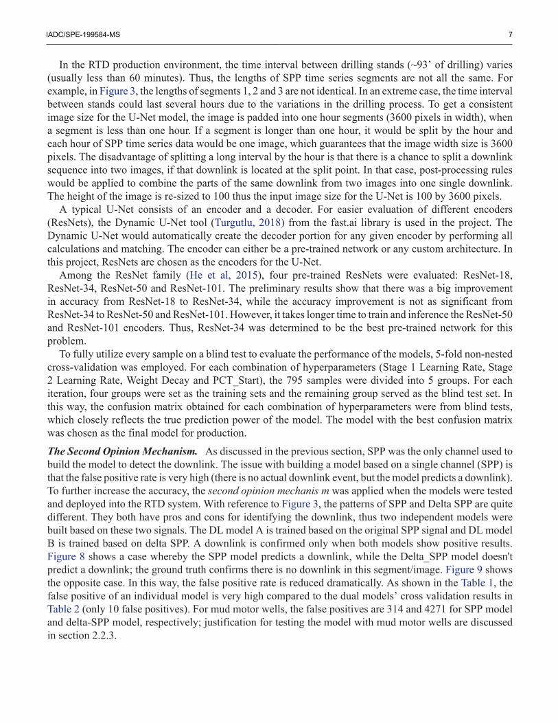
The downlink recognition algorithm is formulated in this way: first, each segment of SPP time series datais converted into an image, and the downlinks within the image are masked at the pixel level as the targetfor image segmentation. For example, the segment 1 time series data (referring to Figure 3) is convertedinto image 1, shown by Figure 7. The 3 downlinks within image 1 are masked (as indicated by the greenrectangles) for training the ML models.
Figure 7—Image 1 with 3 downlinks masked for ML training
IADC/SPE-199584-MS 7
In the RTD production environment, the time interval between drilling stands (~93’ of drilling) varies(usually less than 60 minutes). Thus, the lengths of SPP time series segments are not all the same. Forexample, in Figure 3, the lengths of segments 1, 2 and 3 are not identical. In an extreme case, the time intervalbetween stands could last several hours due to the variations in the drilling process. To get a consistentimage size for the U-Net model, the image is padded into one hour segments (3600 pixels in width), whena segment is less than one hour. If a segment is longer than one hour, it would be split by the hour andeach hour of SPP time series data would be one image, which guarantees that the image width size is 3600pixels. The disadvantage of splitting a long interval by the hour is that there is a chance to split a downlinksequence into two images, if that downlink is located at the split point. In that case, post-processing ruleswould be applied to combine the parts of the same downlink from two images into one single downlink.The height of the image is re-sized to 100 thus the input image size for the U-Net is 100 by 3600 pixels.
A typical U-Net consists of an encoder and a decoder. For easier evaluation of different encoders(ResNets), the Dynamic U-Net tool (Turgutlu, 2018) from the fast.ai library is used in the project. TheDynamic U-Net would automatically create the decoder portion for any given encoder by performing allcalculations and matching. The encoder can either be a pre-trained network or any custom architecture. Inthis project, ResNets are chosen as the encoders for the U-Net.
Among the ResNet family (He et al, 2015), four pre-trained ResNets were evaluated: ResNet-18,ResNet-34, ResNet-50 and ResNet-101. The preliminary results show that there was a big improvementin accuracy from ResNet-18 to ResNet-34, while the accuracy improvement is not as significant fromResNet-34 to ResNet-50 and ResNet-101. However, it takes longer time to train and inference the ResNet-50and ResNet-101 encoders. Thus, ResNet-34 was determined to be the best pre-trained network for thisproblem.
To fully utilize every sample on a blind test to evaluate the performance of the models, 5-fold non-nestedcross-validation was employed. For each combination of hyperparameters (Stage 1 Learning Rate, Stage2 Learning Rate, Weight Decay and PCT_Start), the 795 samples were divided into 5 groups. For eachiteration, four groups were set as the training sets and the remaining group served as the blind test set. Inthis way, the confusion matrix obtained for each combination of hyperparameters were from blind tests,which closely reflects the true prediction power of the model. The model with the best confusion matrixwas chosen as the final model for production.
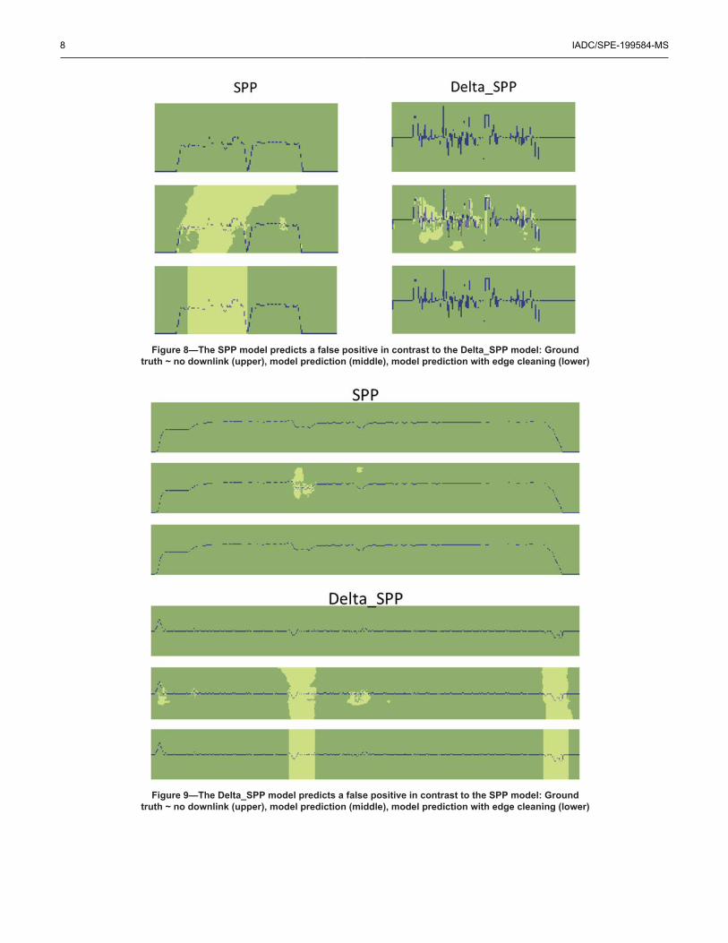
The Second Opinion Mechanism. As discussed in the previous section, SPP was the only channel used tobuild the model to detect the downlink. The issue with building a model based on a single channel (SPP) isthat the false positive rate is very high (there is no actual downlink event, but the model predicts a downlink).To further increase the accuracy, the second opinion mechanis m was applied when the models were testedand deployed into the RTD system. With reference to Figure 3, the patterns of SPP and Delta SPP are quitedifferent. They both have pros and cons for identifying the downlink, thus two independent models werebuilt based on these two signals. The DL model A is trained based on the original SPP signal and DL modelB is trained based on delta SPP. A downlink is confirmed only when both models show positive results.Figure 8 shows a case whereby the SPP model predicts a downlink, while the Delta_SPP model doesn'tpredict a downlink; the ground truth confirms there is no downlink in this segment/image. Figure 9 showsthe opposite case. In this way, the false positive rate is reduced dramatically. As shown in the Table 1, thefalse positive of an individual model is very high compared to the dual models’ cross validation results inTable 2 (only 10 false positives). For mud motor wells, the false positives are 314 and 4271 for SPP modeland delta-SPP model, respectively; justification for testing the model with mud motor wells are discussedin section 2.2.3.
8 IADC/SPE-199584-MS
Figure 8—The SPP model predicts a false positive in contrast to the Delta_SPP model: Groundtruth ~ no downlink (upper), model prediction (middle), model prediction with edge cleaning (lower)
Figure 9—The Delta_SPP model predicts a false positive in contrast to the SPP model: Groundtruth ~ no downlink (upper), model prediction (middle), model prediction with edge cleaning (lower)
IADC/SPE-199584-MS 9
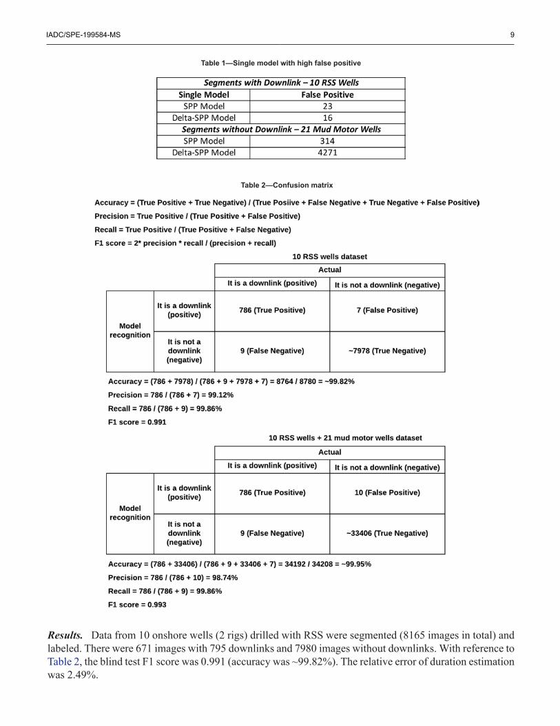
Table 1—Single model with high false positive
Table 2—Confusion matrix
Results. Data from 10 onshore wells (2 rigs) drilled with RSS were segmented (8165 images in total) andlabeled. There were 671 images with 795 downlinks and 7980 images without downlinks. With reference toTable 2, the blind test F1 score was 0.991 (accuracy was ~99.82%). The relative error of duration estimationwas 2.49%.
10 IADC/SPE-199584-MS
The current rig fleet within the RTD system has a mix of drilling tool configurations; some wells useRSS while others use conventional mud motors. The RTD system is blind to the drilling tool configuration,thus the downlink detection model will process data from both RSS and conventional drilling assemblies.The model should be robust enough to handle this situation, meaning it should detect all downlinks if thewell used RSS, and it should not detect any downlinks if the well used a mud motor. To validate the models’robustness regarding drilling tools, additional tests were conducted with data from 21 wells from 21 rigs(25431 images without downlink). As shown in Table 2, there are 3 false positives from this extended testset, which resulted in a ~99.93% accuracy for the aggregate 31 well dataset. These results suggest that themodels are accurate, reliable, and robust.
Engineering and Operational ApplicationsA decision to utilize rotary steerable assemblies or conventional mud motor assemblies is anchored ineconomical and operational considerations. Generally, RSS assemblies have a higher day rate compared toconventional assemblies, but their advantages promise to yield operational time savings which can lower thenet cost to an operator. This is usually attributed to elimination of slide drilling at lower rates of penetrationand the potential elimination of downhole tools like agitators to optimize slide drilling. Operationally, RSSsystems tend to have lower failure rates and advertise a reduction in wellbore tortuosity. However, RSSsystems often have disadvantages when it comes to azimuthal walk in horizontal wellbores and time spentcontrol drilling at lower rates of penetration while downlinking on bottom or time spent downlinking offbottom.
For conventional assemblies, analysis of slide drilling time, footage, and efficiency is relativelystraightforward using the RTD system (Cao et al, 2018, 2019). However, similar metrics are difficultto obtain for RSS without knowledge of the location and duration of downlinks, which, as previouslymentioned, can be difficult to source and digitize on a repeatable and scalable basis. The driver fordevelopment of a real-time RSS downlink detection model was to allow continuous and instantaneousevaluation of the following: RSS versus conventional bottom hole assembly economics, comparisons of bitand BHA design changes between RSS assemblies, and evaluations of RSS vendor performance rig to rig.
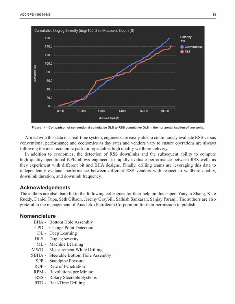
As a starting point for repeatable economic evaluation, the drilling team wanted to compare slide footageto downlink footage (while control drilling), slide time to downlink time (both on and off bottom), slideand rotate ROP to downlink (while control drilling) and rotate ROP, total bit hours between RSS andconventional assemblies, and cumulative horizontal dogleg between RSS and conventional assemblies. Theside by side comparison of these metrics allow engineers to see a complete picture of performance betweenthe two types of assemblies to quantify actual time savings and wellbore quality. See figures 10 – 14 forexamples of these metrics for comparable RSS and conventional wells which were recently drilled.
IADC/SPE-199584-MS 11
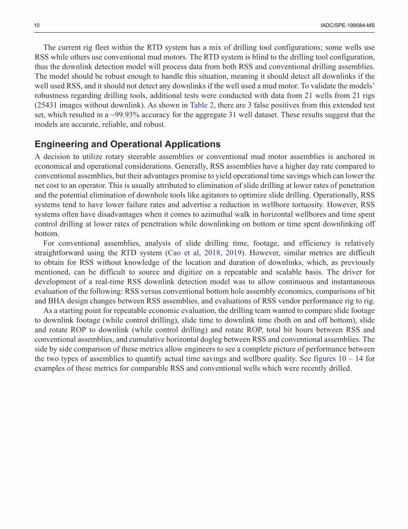
Figure 10—Comparison of conventional slide footage to footage spent controldrilling while downlinking on bottom with a RSS assembly on two wells.
Figure 11—Comparison of conventional slide time to time spent control drilling whiledownlinking on bottom and time spent downlinking off bottom with a RSS assembly on two wells.
12 IADC/SPE-199584-MS
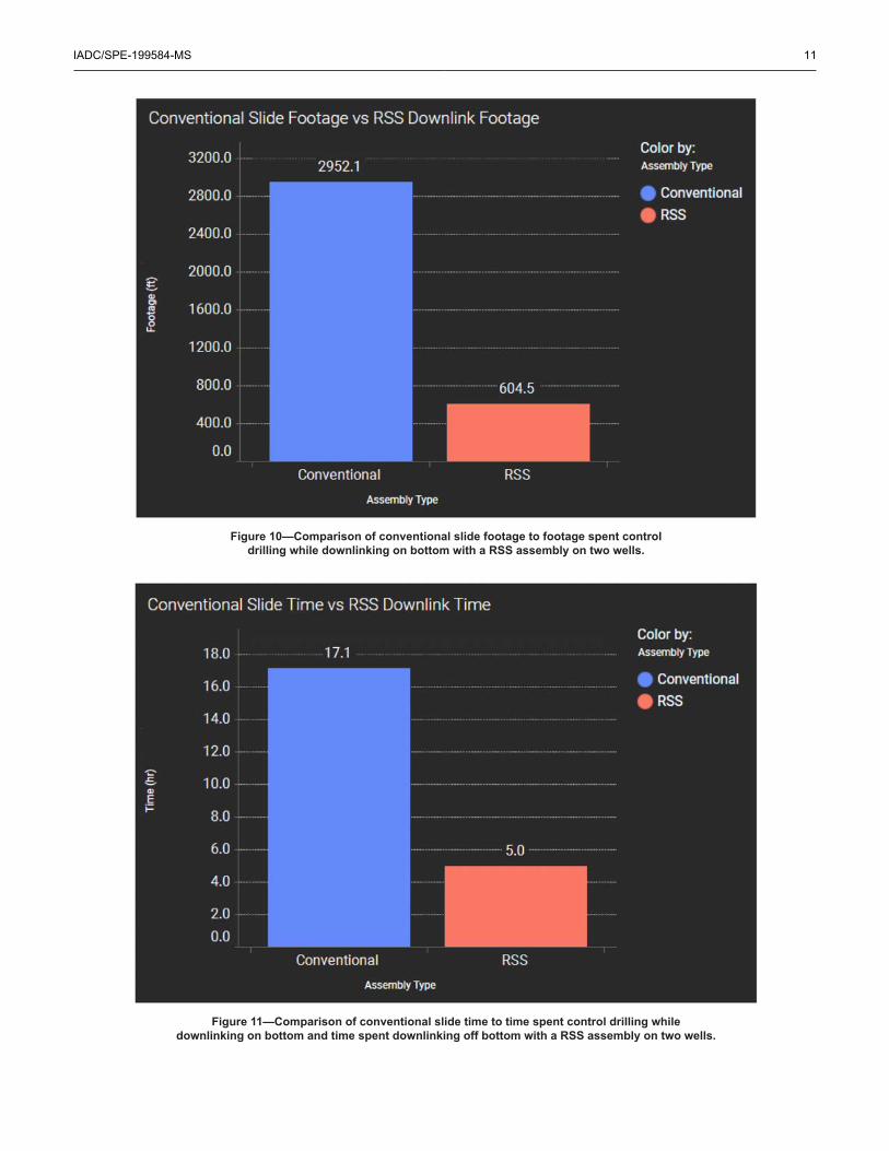
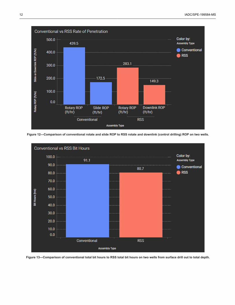
Figure 12—Comparison of conventional rotate and slide ROP to RSS rotate and downlink (control drilling) ROP on two wells.
Figure 13—Comparison of conventional total bit hours to RSS total bit hours on two wells from surface drill out to total depth.
IADC/SPE-199584-MS 13
Figure 14—Comparison of conventional cumulative DLS to RSS cumulative DLS in the horizontal section of two wells.
Armed with this data in a real-time system, engineers are easily able to continuously evaluate RSS versusconventional performance and economics as day rates and vendors vary to ensure operations are alwaysfollowing the most economic path for repeatable, high quality wellbore delivery.
In addition to economics, the detection of RSS downlinks and the subsequent ability to computehigh quality operational KPIs allows engineers to rapidly evaluate performance between RSS wells asthey experiment with different bit and BHA designs. Finally, drilling teams are leveraging this data toindependently evaluate performance between different RSS vendors with respect to wellbore quality,downlink duration, and downlink frequency.
AcknowledgementsThe authors are also thankful to the following colleagues for their help on this paper: Yanyan Zhang, KateRuddy, Daniel Tupa, Seth Gibson, Jeremy Graybill, Sathish Sankaran, Sanjay Paranji. The authors are alsograteful to the management of Anadarko Petroleum Corporation for their permission to publish.
NomenclatureBHA - Bottom Hole AssemblyCPD - Change Point Detection
DL - Deep LearningDLS - Dogleg severityML - Machine Learning
MWD - Measurement While DrillingSBHA - Steerable Bottom Hole Assembly
SPP - Standpipe PressureROP - Rate of PenetrationRPM - Revolutions per MinuteRSS - Rotary Steerable SystemsRTD - Real-Time Drilling
14 IADC/SPE-199584-MS
ReferencesCao, D., Ben, Y., James, C., and Ruddy, K. 2019. Developing an Integrated Real-Time Drilling Ecosystem to Provide a
One-Stop Solution for Drilling Monitoring and Optimization. SPE Annual Technical Conference and Exhibition to beheld 30 September – 2 October. SPE 196228-MS.
Cao, D., Loesel, C., and Paranji S. 2018. Rapid Development of Real-Time Drilling Analytics System. IADC/SPE DrillingConference and Exhibition, 6-8 March, Fort Worth, TX, USA. SPE-189595-MS. https://doi.org/10.2118/189595-MS
Clegg, J., Mejia, C., and Farley, S. 2019. A Paradigm in Rotary Steerable Drilling – Market Demands Drive a NewSolution. SPE/IADC International Drilling Conference and Exhibition, 5-7 March 2019. The Hague, The Netherlands,194170-MS, https://doi.org/10.2118/194170-MS
Dabyah, A.A., Biscaro, E., and Mayer, H. 2016. New Generation of Rotary Steerable System Enables Higher BUR andPerformance. SPE Annual Technical Conference and Exhibition, 26-28 September, Dubai, UAE, SPE 181358-MS,https://doi.org/10.2118/181358-MS
Felczak, E., Torre, A., Godwin, N., Mantle, K, Naganathan, S., Hawkins, R., Li, K., Jones, S. and Slayden, F. 2012. TheBest of Both Worlds – A Hybrid Rotary Steerble System. Oildfield Review Winter 2011/2012: 23, no. 4. RetrievedAugust 05, 2019, https://pdfs.semanticscholar.org/3919/a98dda8f3e4dbccb76147b657ce44cfece40.pdf
Gorrara, A., Grant, S., et al 2015. Designing and Testing a New Rotary Steerable System (RSS) for the Onshore DrillingMarket, SPE/IADC Drilling Conference and Exhibition, 17-19 March, London, England, UK, 173093-MS, https://doi.org/10.2118/173093-MS
He, K., Zhang, X., Ren, S. and Sun, J. 2015. Deep Residual Learning for Image Recognition. arXiv:1512.03385v1 [cs.CV].Dec. 2015. https://arxiv.org/pdf/1512.03385.pdf
Herrington, D. and Mercer, S. 2013. Fully Mechanical 3D Rotary Steering Technology Provides Economical Alternativeto Conventional Rotary Steerable Tools, SPE Annual Technical Conference and Exhibition, 2013, 30-September to 2-Octomber, New Orleans, Louisiana, USA, SPE-166517-MS, https://doi.org/10.2118/166517-MS
Jay, Prakash. 2017. Transfer learning using Keras [Web log post]. Retrieved July 29, 2019, from https://medium.com/@14prakash/transfer-learning-using-keras-d804b2e04ef8
Lenamond, C., Marques, L., et al 2005. Performance Gains for Rotary Steerable Through Specialized Bit Design. AADENational Technical Conference and Exhibition. 5-7 April, Wyndam Greenspoint, Houston, Texas. AADE-05-NTCE-46
Mitchell, R.F. and Miska, S.Z. 2011. Fundamentals of Drilling Engineering, SPE Textbook Series No. 12, ISBN:978-1-55563-207-6
Ronneberger, O., Fischer, P. and Brox T. 2015. U-Net: Convolutional Networks for Biomedical Image Segmentation.arXiv:1505.04597 [cs.CV]. May 2015. https://arxiv.org/pdf/1505.04597.pdf
Sugiura, J. and Jones, S. Rotary Steerable Sytem Enhances Drilling Performance on Horizontal Shale Wells,2018, International Oil and Gas Conference and Exhibition, 8-10 June, Beijing, China, 131357-MS, https://doi.org/10.2118/131357-MS
Truong, C., Vayatis, N. and Oudre, L. 2018. Ruptures: Change Point Detection in Python. arXiv:1801.00826v1 [stat. CO].Jan. 2018.
Turgutlu, K. 2018. Semantic Segmentation – U-Net [Web log post]. Retrieved July 29, 2019, from https://medium.com/@keremturgutlu/semantic-segmentation-u-net-part-1-d8d6f6005066
Yosinski, J., Clune, J., Bengio Y. and Lipson, H. How transferable are features in deep neural networks?arXiv:1411.1792v1 [cs.LG]. Dec. 2014. https://arxiv.org/pdf/1411.1792.pdf