Embed Size (px)
Citation preview
Basic Principles
Objectives
IAEA Nuclear Energy Series
TechnicalReports
Electric Grid Reliability and Interface with Nuclear Power Plants
No. NG-T-3.8
Guides
IAEA Nuclear Energy Series No. NG-T-3.8Electric Grid Reliability and Interface w
ith Nuclear Power Plants
INTERNATIONAL ATOMIC ENERGY AGENCYVIENNA
ISBN 978–92–0–126110–6ISSN 1995–7807
IAEA NUCLEAR ENERGY SERIES PUBLICATIONS
STRUCTURE OF THE IAEA NUCLEAR ENERGY SERIES
Under the terms of Articles III.A and VIII.C of its Statute, the IAEA is authorized to foster the exchange of scientific and technical information on the peaceful uses of atomic energy. The publications in the IAEA Nuclear Energy Series provide information in the areas of nuclear power, nuclear fuel cycle, radioactive waste management and decommissioning, and on general issues that are relevant to all of the above mentioned areas. The structure of the IAEA Nuclear Energy Series comprises three levels: 1 — Basic Principles and Objectives; 2 — Guides; and 3 — Technical Reports.
The Nuclear Energy Basic Principles publication describes the rationale and vision for the peaceful uses of nuclear energy.
Nuclear Energy Series Objectives publications explain the expectations to be met in various areas at different stages of implementation.
Nuclear Energy Series Guides provide high level guidance on how to achieve the objectives related to the various topics and areas involving the peaceful uses of nuclear energy.
Nuclear Energy Series Technical Reports provide additional, more detailed, information on activities related to the various areas dealt with in the IAEA Nuclear Energy Series.
The IAEA Nuclear Energy Series publications are coded as follows: NG — general; NP — nuclear power; NF — nuclear fuel; NW — radioactive waste management and decommissioning. In addition, the publications are available in English on the IAEA’s Internet site:
http://www.iaea.org/Publications/index.html
For further information, please contact the IAEA at PO Box 100, Vienna International Centre, 1400 Vienna, Austria.
All users of the IAEA Nuclear Energy Series publications are invited to inform the IAEA of experience in their use for the purpose of ensuring that they continue to meet user needs. Information may be provided via the IAEA Internet site, by post, at the address given above, or by email to [email protected].
ELECTRIC GRID RELIABILITY AND INTERFACEWITH NUCLEAR POWER PLANTS

AFGHANISTANALBANIAALGERIAANGOLAARGENTINAARMENIAAUSTRALIAAUSTRIAAZERBAIJANBAHRAINBANGLADESHBELARUSBELGIUMBELIZEBENINBOLIVIABOSNIA AND HERZEGOVINABOTSWANABRAZILBULGARIABURKINA FASOBURUNDICAMBODIACAMEROONCANADACENTRAL AFRICAN REPUBLICCHADCHILECHINACOLOMBIACONGOCOSTA RICACÔTE D�IVOIRECROATIACUBACYPRUSCZECH REPUBLICDEMOCRATIC REPUBLIC OF THE CONGODENMARKDOMINICADOMINICAN REPUBLICECUADOREGYPTEL SALVADORERITREAESTONIAETHIOPIAFINLANDFRANCEGABONGEORGIAGERMANY
GHANAGREECEGUATEMALAHAITIHOLY SEEHONDURASHUNGARYICELANDINDIAINDONESIAIRAN, ISLAMIC REPUBLIC OF IRAQIRELANDISRAELITALYJAMAICAJAPANJORDANKAZAKHSTANKENYAKOREA, REPUBLIC OFKUWAITKYRGYZSTANLAO PEOPLE�S DEMOCRATIC REPUBLICLATVIALEBANONLESOTHOLIBERIALIBYALIECHTENSTEINLITHUANIALUXEMBOURGMADAGASCARMALAWIMALAYSIAMALIMALTAMARSHALL ISLANDSMAURITANIAMAURITIUSMEXICOMONACOMONGOLIAMONTENEGROMOROCCOMOZAMBIQUEMYANMARNAMIBIANEPALNETHERLANDSNEW ZEALANDNICARAGUANIGER
NIGERIANORWAYOMANPAKISTANPALAUPANAMAPAPUA NEW GUINEAPARAGUAYPERUPHILIPPINESPOLANDPORTUGALQATARREPUBLIC OF MOLDOVAROMANIARUSSIAN FEDERATIONSAUDI ARABIASENEGALSERBIASEYCHELLESSIERRA LEONESINGAPORESLOVAKIASLOVENIASOUTH AFRICASPAINSRI LANKASUDANSWEDENSWITZERLANDSYRIAN ARAB REPUBLICTAJIKISTANTHAILANDTHE FORMER YUGOSLAV REPUBLIC OF MACEDONIATUNISIATURKEYUGANDAUKRAINEUNITED ARAB EMIRATESUNITED KINGDOM OF GREAT BRITAIN AND NORTHERN IRELANDUNITED REPUBLIC OF TANZANIAUNITED STATES OF AMERICAURUGUAYUZBEKISTANVENEZUELAVIETNAMYEMENZAMBIAZIMBABWE
The Agency’s Statute was approved on 23 October 1956 by the Conference on the Statute of the IAEA held at United Nations Headquarters, New York; it entered into force on 29 July 1957. The Headquarters of the Agency are situated in Vienna. Its principal objective is “to accelerate and enlarge the contribution of atomic energy to peace, health and prosperity throughout the world’’.
The following States are Members of the International Atomic Energy Agency:
ELECTRIC GRID RELIABILITY AND INTERFACE WITH NUCLEAR POWER PLANTS
IAEA NUCLEAR ENERGY SERIES No. NG-T-3.8
INTERNATIONAL ATOMIC ENERGY AGENCYVIENNA, 2012
IAEA Library Cataloguing in Publication Data
Electric grid reliability and interface with nuclear power plants. – Vienna : International Atomic Energy Agency, 2012.
p. ; 29 cm. – (IAEA nuclear energy series, ISSN1995-7807 ; no. NG-T-3.8)STI/PUB/1542ISBN 978-92-0-126110-6Includes bibliographical references.
1. Nuclear power plants – Power supply – Safety measures. 2. Electric power systems – Reliability 3. Nuclear power plants – Government policy. I. International Atomic Energy Agency. II. Series.
IAEAL 12-00737
COPYRIGHT NOTICE
All IAEA scientific and technical publications are protected by the terms of the Universal Copyright Convention as adopted in 1952 (Berne) and as revised in 1972 (Paris). The copyright has since been extended by the World Intellectual Property Organization (Geneva) to include electronic and virtual intellectual property. Permission to use whole or parts of texts contained in IAEA publications in printed or electronic form must be obtained and is usually subject to royalty agreements. Proposals for non-commercial reproductions and translations are welcomed and considered on a case-by-case basis. Enquiries should be addressed to the IAEA Publishing Section at:
Marketing and Sales Unit, Publishing SectionInternational Atomic Energy AgencyVienna International CentrePO Box 1001400 Vienna, Austriafax: +43 1 2600 29302tel.: +43 1 2600 22417email: [email protected] http://www.iaea.org/books
© IAEA, 2012
Printed by the IAEA in AustriaMarch 2012
STI/PUB/1542
FOREWORD
One of the IAEA’s statutory objectives is to “seek to accelerate and enlarge the contribution of atomic energy to peace, health and prosperity throughout the world”. One way this objective is achieved is through the publication of a range of technical series. Two of these are the IAEA Nuclear Energy Series and the IAEA Safety Standards Series.
According to Article III.A.6 of the IAEA Statute, the safety standards establish “standards of safety for protection of health and minimization of danger to life and property.” The safety standards include the Safety Fundamentals, Safety Requirements and Safety Guides. These standards are written primarily in a regulatory style, and are binding on the IAEA for its own programmes. The principal users are the regulatory bodies in Member States and other national authorities.
The IAEA Nuclear Energy Series comprises reports designed to encourage and assist R&D on, and application of, nuclear energy for peaceful uses. This includes practical examples to be used by owners and operators of utilities in Member States, implementing organizations, academia, and government officials, among others. This information is presented in guides, reports on technology status and advances, and best practices for peaceful uses of nuclear energy based on inputs from international experts. The IAEA Nuclear Energy Series complements the IAEA Safety Standards Series.
Nuclear power plants (NPPs) are connected to an electrical grid system to allow export of their electrical energy; the electrical grid system also provides electrical power to the NPP for safe startup, operation and shutdown. Experience in Member States has shown that careful attention must be paid to the performance of the electrical grid system and the interface between the NPPs and the grid, in order to avoid events that might challenge the safety of the nuclear plant.
Particular attention should be given to small power systems, where a single nuclear unit provides a large percentage of the total power generation of the system, and where tripping a nuclear reactor would cause a sizeable disturbance in the electrical grid.
There are two IAEA publications on the grid interface with NPPs, published a quarter of a century ago (IAEA TRS No. 224, Interaction of Grid Characteristics with Design and Performance of Nuclear Power Plants (1983) and IAEA TRS No. 271, Introducing Nuclear Power Plants into Electrical Power Systems of Limited Capacity (1987)). Since that time technology has evolved and significant experience has accumulated on the interaction between NPPs and the grid systems in many Member States.
Currently there is an increase in the number of Member States considering embarking on a nuclear power programme, and other Member States are considering adding new NPPs to their existing nuclear programme. Considering the fact that a significant number of developing countries with small or weak grids are among those considering a nuclear power programme, it is necessary to update the previous publications.
This publication addresses significant issues related to the grid interface with NPPs. It is intended for decision makers, advisors and senior managers in governmental organizations, utilities, industrial organizations and regulatory bodies in those countries adopting or expanding a nuclear power programme. It aims to assist managers and engineers in organizations that are developing or operating NPPs, to help them understand the issues concerning the grid system, as well as managers and engineers in organizations that are responsible for developing and operating grid systems, to help them understand the special characteristics and requirements of nuclear plants. The information is also useful for a supplier country to consider when assessing whether a recipient country is in an acceptable condition to begin the implementation of a nuclear power programme.
The publication was produced by a committee of international experts and advisors from nine Member States. The IAEA wishes to thank all the participants and their Member States for their valuable contributions, in particular, D. Ward (United Kingdom) for chairing the preparatory meetings. The IAEA officer responsible for this publication was O. Glöckler of the Division of Nuclear Power.

EDITORIAL NOTE
This report has been edited by the editorial staff of the IAEA to the extent considered necessary for the reader’s assistance. It does not address questions of responsibility, legal or otherwise, for acts or omissions on the part of any person.
Although great care has been taken to maintain the accuracy of information contained in this publication, neither the IAEA nor its Member States assume any responsibility for consequences which may arise from its use.
The use of particular designations of countries or territories does not imply any judgement by the publisher, the IAEA, as to the legal status of such countries or territories, of their authorities and institutions or of the delimitation of their boundaries.
The mention of names of specific companies or products (whether or not indicated as registered) does not imply any intention to infringe proprietary rights, nor should it be construed as an endorsement or recommendation on the part of the IAEA.
CONTENTS
1. INTRODUCTION . . . . . . . . . . . . . . . . . . . . . . . . . . . . . . . . . . . . . . . . . . . . . . . . . . . . . . . . . . . . . . . . . . . 1
1.1. Background . . . . . . . . . . . . . . . . . . . . . . . . . . . . . . . . . . . . . . . . . . . . . . . . . . . . . . . . . . . . . . . . . . . 11.2. Objectives . . . . . . . . . . . . . . . . . . . . . . . . . . . . . . . . . . . . . . . . . . . . . . . . . . . . . . . . . . . . . . . . . . . . 21.3. Scope of the publication . . . . . . . . . . . . . . . . . . . . . . . . . . . . . . . . . . . . . . . . . . . . . . . . . . . . . . . . . . 21.4. Intended users of the publication . . . . . . . . . . . . . . . . . . . . . . . . . . . . . . . . . . . . . . . . . . . . . . . . . . . 21.5. Structure . . . . . . . . . . . . . . . . . . . . . . . . . . . . . . . . . . . . . . . . . . . . . . . . . . . . . . . . . . . . . . . . . . . . . . 2
2. OVERVIEW OF AN ELECTRICAL GRID SYSTEM . . . . . . . . . . . . . . . . . . . . . . . . . . . . . . . . . . . . . . 3
2.1. Component parts of the grid system . . . . . . . . . . . . . . . . . . . . . . . . . . . . . . . . . . . . . . . . . . . . . . . . 32.2. Management and ownership . . . . . . . . . . . . . . . . . . . . . . . . . . . . . . . . . . . . . . . . . . . . . . . . . . . . . . 42.3. Commercial arrangements . . . . . . . . . . . . . . . . . . . . . . . . . . . . . . . . . . . . . . . . . . . . . . . . . . . . . . . . 52.4. Control arrangements . . . . . . . . . . . . . . . . . . . . . . . . . . . . . . . . . . . . . . . . . . . . . . . . . . . . . . . . . . . . 52.5. Interconnections . . . . . . . . . . . . . . . . . . . . . . . . . . . . . . . . . . . . . . . . . . . . . . . . . . . . . . . . . . . . . . . . 62.6. Key definitions . . . . . . . . . . . . . . . . . . . . . . . . . . . . . . . . . . . . . . . . . . . . . . . . . . . . . . . . . . . . . . . . . 6
3. SPECIAL FEATURES OF AN NPP . . . . . . . . . . . . . . . . . . . . . . . . . . . . . . . . . . . . . . . . . . . . . . . . . . . . 7
3.1. Basic safety requirements . . . . . . . . . . . . . . . . . . . . . . . . . . . . . . . . . . . . . . . . . . . . . . . . . . . . . . . . 73.2. Requirements for electricity supply . . . . . . . . . . . . . . . . . . . . . . . . . . . . . . . . . . . . . . . . . . . . . . . . . 73.3. Requirements for grid reliability . . . . . . . . . . . . . . . . . . . . . . . . . . . . . . . . . . . . . . . . . . . . . . . . . . . 83.4. Size of nuclear units . . . . . . . . . . . . . . . . . . . . . . . . . . . . . . . . . . . . . . . . . . . . . . . . . . . . . . . . . . . . . 93.5. Limits to flexible operation . . . . . . . . . . . . . . . . . . . . . . . . . . . . . . . . . . . . . . . . . . . . . . . . . . . . . . . 103.6. Development and construction time . . . . . . . . . . . . . . . . . . . . . . . . . . . . . . . . . . . . . . . . . . . . . . . . 113.7. Nuclear licensing requirements . . . . . . . . . . . . . . . . . . . . . . . . . . . . . . . . . . . . . . . . . . . . . . . . . . . . 11
4. PLANNING AND OPERATING A RELIABLE GRID . . . . . . . . . . . . . . . . . . . . . . . . . . . . . . . . . . . . . 12
4.1. Introduction . . . . . . . . . . . . . . . . . . . . . . . . . . . . . . . . . . . . . . . . . . . . . . . . . . . . . . . . . . . . . . . . . . . 124.2. Grid performance . . . . . . . . . . . . . . . . . . . . . . . . . . . . . . . . . . . . . . . . . . . . . . . . . . . . . . . . . . . . . . . 134.3. Control of frequency . . . . . . . . . . . . . . . . . . . . . . . . . . . . . . . . . . . . . . . . . . . . . . . . . . . . . . . . . . . . 134.4. Control of power flow . . . . . . . . . . . . . . . . . . . . . . . . . . . . . . . . . . . . . . . . . . . . . . . . . . . . . . . . . . . 144.5. Control of voltage . . . . . . . . . . . . . . . . . . . . . . . . . . . . . . . . . . . . . . . . . . . . . . . . . . . . . . . . . . . . . . 154.6. Grid faults and power system reliability standards . . . . . . . . . . . . . . . . . . . . . . . . . . . . . . . . . . . . . 154.7. Requirements on generators . . . . . . . . . . . . . . . . . . . . . . . . . . . . . . . . . . . . . . . . . . . . . . . . . . . . . . . 174.8. Stability . . . . . . . . . . . . . . . . . . . . . . . . . . . . . . . . . . . . . . . . . . . . . . . . . . . . . . . . . . . . . . . . . . . . . . 194.9. Electrical protection . . . . . . . . . . . . . . . . . . . . . . . . . . . . . . . . . . . . . . . . . . . . . . . . . . . . . . . . . . . . . 194.10. Control of fault level . . . . . . . . . . . . . . . . . . . . . . . . . . . . . . . . . . . . . . . . . . . . . . . . . . . . . . . . . . . . 204.11. Cyber-security . . . . . . . . . . . . . . . . . . . . . . . . . . . . . . . . . . . . . . . . . . . . . . . . . . . . . . . . . . . . . . . . . 204.12. Prevention of major blackouts and blackout restoration . . . . . . . . . . . . . . . . . . . . . . . . . . . . . . . . . 214.13. Control and communication arrangements . . . . . . . . . . . . . . . . . . . . . . . . . . . . . . . . . . . . . . . . . . . 22
5. SIZE OF THE NUCLEAR UNIT . . . . . . . . . . . . . . . . . . . . . . . . . . . . . . . . . . . . . . . . . . . . . . . . . . . . . . 23
5.1. Introduction . . . . . . . . . . . . . . . . . . . . . . . . . . . . . . . . . . . . . . . . . . . . . . . . . . . . . . . . . . . . . . . . . . . 235.2. Controlling the fall in frequency . . . . . . . . . . . . . . . . . . . . . . . . . . . . . . . . . . . . . . . . . . . . . . . . . . . 235.3. The benefits of interconnections . . . . . . . . . . . . . . . . . . . . . . . . . . . . . . . . . . . . . . . . . . . . . . . . . . . 245.4. Restoring power flows after a reactor trip . . . . . . . . . . . . . . . . . . . . . . . . . . . . . . . . . . . . . . . . . . . . 255.5. Controlling voltage . . . . . . . . . . . . . . . . . . . . . . . . . . . . . . . . . . . . . . . . . . . . . . . . . . . . . . . . . . . . . 25
6. DEVELOPMENT ACTIVITIES . . . . . . . . . . . . . . . . . . . . . . . . . . . . . . . . . . . . . . . . . . . . . . . . . . . . . . . 26
6.1. Introduction . . . . . . . . . . . . . . . . . . . . . . . . . . . . . . . . . . . . . . . . . . . . . . . . . . . . . . . . . . . . . . . . . . . 266.2. Transmission system operator’s activities . . . . . . . . . . . . . . . . . . . . . . . . . . . . . . . . . . . . . . . . . . . . 266.3. NPP developer’s activities . . . . . . . . . . . . . . . . . . . . . . . . . . . . . . . . . . . . . . . . . . . . . . . . . . . . . . . . 266.4. Constraints . . . . . . . . . . . . . . . . . . . . . . . . . . . . . . . . . . . . . . . . . . . . . . . . . . . . . . . . . . . . . . . . . . . . 276.5. Modelling . . . . . . . . . . . . . . . . . . . . . . . . . . . . . . . . . . . . . . . . . . . . . . . . . . . . . . . . . . . . . . . . . . . . . 27
6.5.1. Transmission system modelling . . . . . . . . . . . . . . . . . . . . . . . . . . . . . . . . . . . . . . . . . . . . . . 276.5.2. Steady state operation (load flow analysis) . . . . . . . . . . . . . . . . . . . . . . . . . . . . . . . . . . . . . 286.5.3. Power transfer capabilities . . . . . . . . . . . . . . . . . . . . . . . . . . . . . . . . . . . . . . . . . . . . . . . . . . 296.5.4. Transient stability . . . . . . . . . . . . . . . . . . . . . . . . . . . . . . . . . . . . . . . . . . . . . . . . . . . . . . . . . 296.5.5. Frequency stability . . . . . . . . . . . . . . . . . . . . . . . . . . . . . . . . . . . . . . . . . . . . . . . . . . . . . . . . 296.5.6. Voltage stability . . . . . . . . . . . . . . . . . . . . . . . . . . . . . . . . . . . . . . . . . . . . . . . . . . . . . . . . . . 29
7. SITE CHOICE AND ASSESSMENT . . . . . . . . . . . . . . . . . . . . . . . . . . . . . . . . . . . . . . . . . . . . . . . . . . . 30
7.1. Introduction . . . . . . . . . . . . . . . . . . . . . . . . . . . . . . . . . . . . . . . . . . . . . . . . . . . . . . . . . . . . . . . . . . . 307.2. Step one: regional analysis . . . . . . . . . . . . . . . . . . . . . . . . . . . . . . . . . . . . . . . . . . . . . . . . . . . . . . . . 30
7.2.1. Energy market and demand . . . . . . . . . . . . . . . . . . . . . . . . . . . . . . . . . . . . . . . . . . . . . . . . . 307.2.2. Land availability . . . . . . . . . . . . . . . . . . . . . . . . . . . . . . . . . . . . . . . . . . . . . . . . . . . . . . . . . 317.2.3. Grid capacity and grid connection . . . . . . . . . . . . . . . . . . . . . . . . . . . . . . . . . . . . . . . . . . . . 31
7.3. Step two: screening of potential sites . . . . . . . . . . . . . . . . . . . . . . . . . . . . . . . . . . . . . . . . . . . . . . . . 317.4. Step three: comparison and ranking . . . . . . . . . . . . . . . . . . . . . . . . . . . . . . . . . . . . . . . . . . . . . . . . . 32
8. CONNECTING A NUCLEAR POWER PLANT TO THE GRID . . . . . . . . . . . . . . . . . . . . . . . . . . . . . 32
8.1. Requirements of the TSO . . . . . . . . . . . . . . . . . . . . . . . . . . . . . . . . . . . . . . . . . . . . . . . . . . . . . . . . . 328.2. Calculation of the reliability of the off-site power . . . . . . . . . . . . . . . . . . . . . . . . . . . . . . . . . . . . . . 328.3. Requirements of the NPP for two independent connections . . . . . . . . . . . . . . . . . . . . . . . . . . . . . . 338.4. Generator transformer design and sizing . . . . . . . . . . . . . . . . . . . . . . . . . . . . . . . . . . . . . . . . . . . . . 358.5. Unit transformer design and sizing . . . . . . . . . . . . . . . . . . . . . . . . . . . . . . . . . . . . . . . . . . . . . . . . . 368.6. Station transformer design and sizing . . . . . . . . . . . . . . . . . . . . . . . . . . . . . . . . . . . . . . . . . . . . . . . 378.7. Generator design and sizing . . . . . . . . . . . . . . . . . . . . . . . . . . . . . . . . . . . . . . . . . . . . . . . . . . . . . . . 37
9. CONSIDERATION OF UNUSUAL OR ABNORMAL EVENTS . . . . . . . . . . . . . . . . . . . . . . . . . . . . . 38
10. ARRANGEMENTS BETWEEN THE TSO AND THE NPP OPERATOR . . . . . . . . . . . . . . . . . . . . . . 40
10.1. Introduction . . . . . . . . . . . . . . . . . . . . . . . . . . . . . . . . . . . . . . . . . . . . . . . . . . . . . . . . . . . . . . . . . . 4010.2. Notification and coordination of outages . . . . . . . . . . . . . . . . . . . . . . . . . . . . . . . . . . . . . . . . . . . . 4110.3. Notification of loss of contingency . . . . . . . . . . . . . . . . . . . . . . . . . . . . . . . . . . . . . . . . . . . . . . . . 42
11. ROADMAP FOR CONNECTION OF AN NPP . . . . . . . . . . . . . . . . . . . . . . . . . . . . . . . . . . . . . . . . . . . 42
11.1. Introduction . . . . . . . . . . . . . . . . . . . . . . . . . . . . . . . . . . . . . . . . . . . . . . . . . . . . . . . . . . . . . . . . . . 4211.2. Overall grid studies . . . . . . . . . . . . . . . . . . . . . . . . . . . . . . . . . . . . . . . . . . . . . . . . . . . . . . . . . . . . 4311.3. Grid reliability and performance . . . . . . . . . . . . . . . . . . . . . . . . . . . . . . . . . . . . . . . . . . . . . . . . . . 4311.4. Unit size . . . . . . . . . . . . . . . . . . . . . . . . . . . . . . . . . . . . . . . . . . . . . . . . . . . . . . . . . . . . . . . . . . . . . 4411.5. NPP operating characteristics . . . . . . . . . . . . . . . . . . . . . . . . . . . . . . . . . . . . . . . . . . . . . . . . . . . . . 4411.6. Site assessment and grid connections to the NPP site . . . . . . . . . . . . . . . . . . . . . . . . . . . . . . . . . . 4411.7. Power system standards . . . . . . . . . . . . . . . . . . . . . . . . . . . . . . . . . . . . . . . . . . . . . . . . . . . . . . . . 4511.8. Grid control and communication arrangements . . . . . . . . . . . . . . . . . . . . . . . . . . . . . . . . . . . . . . . 4511.9. Interface between NPP operator and TSO . . . . . . . . . . . . . . . . . . . . . . . . . . . . . . . . . . . . . . . . . . . 4511.10. Readiness to commission . . . . . . . . . . . . . . . . . . . . . . . . . . . . . . . . . . . . . . . . . . . . . . . . . . . . . . . . 46

12. EFFECTS OF CLIMATE CHANGE . . . . . . . . . . . . . . . . . . . . . . . . . . . . . . . . . . . . . . . . . . . . . . . . . . . . 46
12.1. Introduction . . . . . . . . . . . . . . . . . . . . . . . . . . . . . . . . . . . . . . . . . . . . . . . . . . . . . . . . . . . . . . . . . . . 4612.2. Effect on NPPs and transmission system reliability . . . . . . . . . . . . . . . . . . . . . . . . . . . . . . . . . . . . 46
12.2.1. Strong winds . . . . . . . . . . . . . . . . . . . . . . . . . . . . . . . . . . . . . . . . . . . . . . . . . . . . . . . . . . . . 4612.2.2. Cold weather, ice and snow . . . . . . . . . . . . . . . . . . . . . . . . . . . . . . . . . . . . . . . . . . . . . . . . . 4712.2.3. Thunderstorms . . . . . . . . . . . . . . . . . . . . . . . . . . . . . . . . . . . . . . . . . . . . . . . . . . . . . . . . . . . 4712.2.4. High temperatures . . . . . . . . . . . . . . . . . . . . . . . . . . . . . . . . . . . . . . . . . . . . . . . . . . . . . . . . 4712.2.5. Floods and rising sea levels . . . . . . . . . . . . . . . . . . . . . . . . . . . . . . . . . . . . . . . . . . . . . . . . . 47
13. CASE STUDIES OF PLANNING AND OPERATING EXPERIENCE . . . . . . . . . . . . . . . . . . . . . . . . 47
13.1. Introduction . . . . . . . . . . . . . . . . . . . . . . . . . . . . . . . . . . . . . . . . . . . . . . . . . . . . . . . . . . . . . . . . . . . 4713.2. China . . . . . . . . . . . . . . . . . . . . . . . . . . . . . . . . . . . . . . . . . . . . . . . . . . . . . . . . . . . . . . . . . . . . . . . . 4813.3. Finland . . . . . . . . . . . . . . . . . . . . . . . . . . . . . . . . . . . . . . . . . . . . . . . . . . . . . . . . . . . . . . . . . . . . . . . 4913.4. Sweden . . . . . . . . . . . . . . . . . . . . . . . . . . . . . . . . . . . . . . . . . . . . . . . . . . . . . . . . . . . . . . . . . . . . . . . 5013.5. United States of America . . . . . . . . . . . . . . . . . . . . . . . . . . . . . . . . . . . . . . . . . . . . . . . . . . . . . . . . . 5113.6. United kingdom . . . . . . . . . . . . . . . . . . . . . . . . . . . . . . . . . . . . . . . . . . . . . . . . . . . . . . . . . . . . . . . . 5213.7. Japan . . . . . . . . . . . . . . . . . . . . . . . . . . . . . . . . . . . . . . . . . . . . . . . . . . . . . . . . . . . . . . . . . . . . . . . . 53
14. SUMMARY AND CONCLUSIONS . . . . . . . . . . . . . . . . . . . . . . . . . . . . . . . . . . . . . . . . . . . . . . . . . . . . 54
APPENDIX I: EXAMPLES OF GRID FAULTS . . . . . . . . . . . . . . . . . . . . . . . . . . . . . . . . . . . . . . . . . . . . . . 57
APPENDIX II: MAXIMUM UNIT SIZE . . . . . . . . . . . . . . . . . . . . . . . . . . . . . . . . . . . . . . . . . . . . . . . . . . . . 59
APPENDIX III: CHECK LIST OF QUESTIONS AT VARIOUS STAGES OF AN NPP PROJECT . . . . . . 63
REFERENCES . . . . . . . . . . . . . . . . . . . . . . . . . . . . . . . . . . . . . . . . . . . . . . . . . . . . . . . . . . . . . . . . . . . . . . . . . . 67GLOSSARY . . . . . . . . . . . . . . . . . . . . . . . . . . . . . . . . . . . . . . . . . . . . . . . . . . . . . . . . . . . . . . . . . . . . . . . . . . . . 69ABBREVIATIONS . . . . . . . . . . . . . . . . . . . . . . . . . . . . . . . . . . . . . . . . . . . . . . . . . . . . . . . . . . . . . . . . . . . . . . 75CONTRIBUTORS TO DRAFTING AND REVIEW . . . . . . . . . . . . . . . . . . . . . . . . . . . . . . . . . . . . . . . . . . . . 77STRUCTURE OF THE IAEA NUCLEAR ENERGY SERIES . . . . . . . . . . . . . . . . . . . . . . . . . . . . . . . . . . . . 78

1. INTRODUCTION
1.1. BACKGROUND
The safe and economic operation of a nuclear power plant (NPP) requires the plant to be connected to an electrical grid system that has adequate capacity for exporting the power from the NPP, and for providing a reliable electrical supply to the NPP for safe startup, operation and normal or emergency shutdown of the plant. Connection of any large new power plant to the electrical grid system in a country may require significant modification and strengthening of the grid system, but for NPPs there may be added requirements to the structure of the grid system and the way it is controlled and maintained to ensure adequate reliability. The organization responsible for the NPP and the organization responsible for the grid system will need to establish and agree the necessary characteristics of the grid and of the NPP, well before the NPP is built, so that they are compatible with each other. They will also need to agree the necessary modifications to the grid system, and how they are to be financed.
For a Member State that does not yet use nuclear power, the introduction and development of nuclear power is a major undertaking. It requires the country to build physical infrastructure and develop human resources so it can construct and operate a nuclear power plant (NPP) in a safe, secure and technically sound manner. The IAEA is preparing a series of guides to assist Member States in these endeavours. Reference [1] is one of these guides which identifies and provides guidance on nineteen infrastructure issues that need to be addressed in the introduction of a nuclear power programme. One of these infrastructure issues is the development of the electrical grid.
Whilst most Member States already have an electrical grid system, it may require significant development to be suitable for the connection of an NPP. For a country that does not yet have an NPP, the necessary modifications to the grid system may be extensive. The modifications will include the new physical connections from the existing grid system to the NPP site, but may also include other changes to the grid system and the way it is operated and maintained to ensure that it can provide a reliable electrical supply to the NPP, to ensure safe and secure operation of the NPP. The key issues are the particular requirements of the NPP with regard to nuclear safety and a reliable electrical supply, and the large unit size of standard NPP designs. Experience in Member States that have operating NPPs shows that careful attention must be paid to the design and operation of the electrical grid system and the interface between the NPPs and the grid, in order to avoid events that might challenge the safety of the nuclear plant. Connecting an NPP to the grid requires the consideration of issues in addition to those that would be considered to connect a large fossil fuel power station or hydroelectric power station.
Even for a country that already uses nuclear power, the addition of a new NPP may require significant investment to develop and strengthen the existing electric grid, depending on the size and location of the new NPP. In many Member States, the organization of the electricity industry now is very different from the organization at the time that the earlier NPPs were built, with separation now between the transmission system operator and the operators of power plants, and with different commercial arrangements for the trading of electricity. Hence, the arrangements for connecting a new NPP may require negotiations and new commercial agreements between separate organizations.
Recent IAEA publications [1–3] provide a brief indication of some of the issues related to the electrical grid and NPPs; this publication provides more detail, and also updates the advice that was contained in technical reports published by the IAEA in the 1980s [4–6], making use of the experience in Member States since those publications were written.
In March 2011, while this publication was in preparation, the Fukushima Daiichi NPP in Japan suffered severe damage from an exceptionally strong earthquake followed by flooding from a tsunami. The details of this event are still being investigated, and it will be some time before all the lessons from it are known and published. However, as the vulnerability of the grid connections to the plant were a contributory cause of the severe damage, this publication makes some initial comments on this event.
1
1.2. OBJECTIVES
This publication is intended to provide an understanding of the characteristics of the electrical grid system from the point of view of an NPP and the special requirements of an NPP with regard to its grid connection; the quality and reliability of its electrical supply. It should be of particular assistance to Member States that are considering the introduction of nuclear power for the first time to ensure that they consider all the interactions between the electrical grid and the NPP.
This publication is also intended to be helpful to Member States that already have NPPs in operation and may be considering the installation of new NPPs after an interval of many years. For these Member States, this report provides a reminder of the issues related to the electrical grid system that should be considered when installing a new NPP. This is important because many Member States have changed the structure of the electricity supply industry so that the organization that is responsible for the electrical grid system is now separate from the organization that will be responsible for a new NPP.
1.3. SCOPE OF THE PUBLICATION
This publication provides information on the requirements of the electrical grid and the requirements of NPPs, the way in which they rely on each other, and the recommended interactions. It describes the necessary characteristics of the electrical grid system that are required for the connection and successful operation of an NPP, and the characteristics of an NPP that are significant for the design and operation of the electrical grid system. The publication explains the issues that should be considered when a NPP is being planned, and the information that must be exchanged between the developer of an NPP and the organization that is responsible for the electrical grid during the design and construction of an NPP. It also describes the requirements for the way that the grid system is operated when the NPP is in operation, and the relationship between the operator of an NPP and the organization that operates the grid system at that time.
This publication is not intended to be a detailed guide to the design, analysis and operation of grid systems, which are described in many electrical engineering textbooks. Nor does this publication describe the detailed design of electrical systems within NPPs, which is dealt with in Ref. [7].
1.4. INTENDED USERS OF THE PUBLICATION
The intended users of this publication are Member States considering the construction of a new nuclear power plant. This includes Member States introducing nuclear power for the first time, and those that already have NPPs in operation and are considering building a new NPP after many years..
For Member States that are considering the introduction of nuclear power for the first time, this publication is intended to be useful to the organization set up to carry out a feasibility study and advise the government before a decision has been made to proceed with a nuclear power programme [2], to allow that organization to understand the issues related to the electrical grid, so they can be properly included in the feasibility study.
When a decision has been made to build a new NPP, it is necessary to consider all the issues where the NPP and the electrical grid system can interact. This publication is intended to enable engineers and managers in the organization responsible for the NPP to understand the issues related to the grid, and to enable engineers and managers in the organization responsible for the transmission system to understand the special requirements of NPPs that affect the design and operation of the electrical grid.
1.5. STRUCTURE
This publication has been divided into sections including this introduction followed by three appendices.Section 2 presents an overview of the main features of an electrical grid system and outlines the differences in
organization of the electricity supply industry that may be present in different Member States. It also defines and
2
explains the terms ‘transmission system operator’ (TSO) and ‘NPP developer’ or ‘NPP operator’ that are used throughout this publication.
Section 3 presents the key features of NPPs and their requirements for a stable and reliable electrical grid system so that TSOs may understand the ways in which nuclear plants are different from other forms of generation. Section 4 describes the features of the design and operation of the transmission system to ensure its reliability, the impact of this on an NPP, and how the design and operation of the transmission system can be affected by the introduction of a new NPP.
Section 5 discusses the issues concerning the large size of currently available nuclear units, as this is a particular issue for smaller grid networks, or smaller countries that are not strongly connected to the grid systems of neighbouring countries.
Section 6 discusses the activities of the TSO and NPP developer in order to progress an NPP project, and introduces the various types of modelling that are needed for the design and development of the grid system.
Section 7 discusses the choice and assessment of a site for a new NPP, and the issues related to the connection to the electricity transmission system connection.
Section 8 describes the issues that arise when designing the connections to the transmission system and the electricity substation for a NPP.
Section 9 summarizes a range of grid events that need to be considered for their potential effect on the NPP and it safety systems, and which should be included in the training for NPP operators.
Section 10 describes the arrangements that need to be in place when the NPP starts operation, to ensure proper communication between the NPP operator and the transmission system operator (TSO) during future operation of the NPP.
Section 11 presents a roadmap of the activities that have to be undertaken by the transmission system operator (TSO) and the NPP developer in order to connect a NPP.
Section 12 provides a brief discussion of the possible effects of climate change on grid transmission systems, and on generation.
Section 13 presents some case studies of experience of Member States related to grid planning, reliability and operation as they affect the planning and operation of NPPs, including some initial comments on the events at the Fukushima Daiichi NPP in March 2011.
Section 14 provides a general summary and conclusions.There are three appendices. The first presents a detailed summary of faults that can occur on a high voltage
transmission system. The second presents the results of a computer simulation of system frequency following the trip of a large nuclear unit connected to a small system, which illustrates the issues discussed in Section 5. The third appendix is a checklist of the issues related to the transmission system that should be considered at various stages of an NPP project.
Finally there is a list of abbreviations and a glossary.
2. OVERVIEW OF AN ELECTRICAL GRID SYSTEM
2.1. COMPONENT PARTS OF THE GRID SYSTEM
In most Member States, the public electricity supply system comprises a single interconnected alternating current network that connects together all the power plants and other sources of electrical power with electricity to consumers. The electricity supply system uses a range of voltage levels: extra high voltage lines (e.g. 400 kV and higher three-phase) are used to transmit large amounts of power long distances; medium voltage lines are used to transmit power shorter distances and to connect large industrial consumers; and low voltages (such as 230 V single phase in Europe or 110 V single phase in the USA) are used to provide supplies to domestic consumers. Some electricity systems also include one or more high voltage direct current (HVDC) links to interconnect to neighbouring countries, or to transmit power long distances.
3
The main components of the electricity supply system include:
— Power plants of various kinds and sizes; — Overhead lines operated at various voltages;— Underground cables operated at various voltages;— Substations (switchyards) with switching facilities where overhead lines and underground cables are
interconnected, and where power plants may be connected; — Transformers (often located in substations) to connect parts of the network operating at different voltages; — HVDC connections (comprising a converter station at each end, and an overhead line or underground cable
connection between them);— Electrical protection, monitoring and metering equipment; — Communication and control systems;— One or more control centres.
The public electricity system can be considered to comprise two significantly different kinds of networks: the transmission system(s), and the distribution systems(s). Because of their different purposes, the transmission systems and distribution systems are designed, operated and controlled in different ways.
The transmission system (also commonly called the ‘grid system’) comprises those parts of the system (overhead lines, underground cables, substations, transformers) operating at very high voltage (generally greater than 100 kV), which are used to transmit large amounts of power long distances between large power plants and load centres. In most countries, the large majority of circuits on the transmission system are overhead lines, because of the ease and speed of installation and the much lower cost compared to underground cables. Overhead lines on the transmission system are normally carried on tall steel lattice towers.
The distribution systems comprise those parts of the system operated at lower voltages (less than 100 kV), and used to transmit smaller amounts of power shorter distances from the high voltage transmission network to individual customers at the voltage level the customer needs. The overhead lines on distribution systems may be carried on smaller steel lattice towers, or wooden or concrete poles. In urban areas underground cables are often used instead of overhead lines. In many countries the transmission and distribution systems are owned and operated by different companies or organizations.
Because of their large capacity, NPPs would be connected to the transmission network, similar to other large power plants. Because of this, distribution systems are not generally important to NPPs and are not discussed further in this publication.
2.2. MANAGEMENT AND OWNERSHIP
The arrangements for ownership and operation of the public electricity system are different in different countries.
In some Member States the public electricity system is entirely state owned, where the construction and operation of power plants, the transmission network, and the distribution networks are the responsibility of a single organization. By contrast, in other Member States, the public electricity system has been divided and deregulated so that the company or organization that is responsible for the transmission system is separate from the companies or organizations that are responsible for power stations or distribution systems; and many or all of these organizations can be privately-owned commercial companies. Other Member States have electricity systems where arrangements are between these two. In some Member States there is a single transmission system operator, while other Member States have two or more transmission system operators with each one responsible for a defined geographical area of the country.
Where the electricity system in a Member State has been divided between separate organizations, it is important to recognize that each different organization will have its own objectives and responsibilities that may conflict with the objectives and responsibilities of other organizations. The organization that will be the operator of a new NPP has the primary responsibility for the safety of the NPP [8] and will have to satisfy the requirements of the nuclear regulatory authority in the country. The operator of the transmission system usually has the responsibility for the secure and economic operation of the electricity system as a whole, and may have to satisfy
4
the different requirements of the energy ministry or energy regulator in the country. Where the electricity system in the country has been deregulated, the operator of the transmission network may also have a legal obligation to encourage commercial competition between power stations, and may not be permitted to treat different power stations differently.
2.3. COMMERCIAL ARRANGEMENTS
There are many differences between the commercial arrangements in Member States for the sale of electricity, and for the financing of the transmission system.
In countries where the electricity industry is wholly or largely owned by the government, it is normal for the government to set the price for the sale of electricity. In some countries where the power stations and the grid system are owned and operated by commercial companies, they may still be regulated by the government, with the government or a government agency setting or agreeing the price of electricity. In countries where power plants are owned by private companies, and the electricity industry has been completely deregulated, the price of electricity is determined by market competition. Because of the expected benefit of greater efficiency and lower electricity prices, many Member States are considering changing their electricity systems from state owned or regulated arrangements to partially deregulated or fully deregulated arrangements where there is commercial competition between generating companies.
In countries where there has been full deregulation of the electricity system, the generating companies have the opportunity to sell their power at the time and location that is most profitable for them. Changes in the electricity market, based on commercial decisions, can modify the power flows on short timescales, which can cause difficulties for the transmission system operator in controlling the system. This is discussed further in Section 4.4. Reference [9] provides evidence that deregulation of the electricity system may cause a change in the reliability of the grid connections to NPPs.
There are differences between Member States in the way that the cost of the transmission system is paid for. In some countries, the transmission system is paid for by the government, or directly by electricity consumers as part of the price of electricity. In other countries, power plants pay part of the cost of the transmission system. The power plants may pay a fee based on their capacity (MW) or their output (MW h) or a combination of the two. A new power plant may have to pay directly for the capital cost of additions or modification to the transmission system that are needed to allow the power plant to connect.
2.4. CONTROL ARRANGEMENTS
In all countries the transmission system is controlled from one or more control centres: a single control centre may control the whole country, or there may be several control centres, each controlling one geographical area of the country. The duties of the control centre are to control the transmission system as a whole, to ensure that generation and demand are balanced so that frequency is controlled, to control voltage levels, to control power flows, and to ensure that the system has sufficient redundancy to be secure against anticipated faults.
The transmission control centre will carry out switching operations on transmission circuits as necessary, but also needs to control the operation of power plants. In Member States where the electricity industry is state owned, the transmission control centre would normally instruct each power plant at what level to generate, and to increase or decrease generation as necessary to match the varying demand. In Member States where the electricity market has been completely deregulated, the operators of the individual power stations would decide on their planned generation based on commercial considerations, and notify the transmission control centre of their intentions. However the transmission control centre must still have power to instruct power stations to change generation output when necessary, and to provide ancillary services (as defined in the glossary) so that the system can be controlled in both normal and abnormal circumstances to preserve system stability.
The grid control centre itself needs to be secure, and needs secure and diverse communication routes to power plants and other control centres. This is discussed further in Section 4.13.
5

2.5. INTERCONNECTIONS
There are differences between Member States concerning connections to neighbouring countries. In some Member States the electricity system has no electrical connection to neighbouring countries. Other Member States have weak connections to one or more neighbouring countries that can be used to import or export a small amount of power. In yet other Member States the connections to neighbouring countries are strong, with the capability for large power flows between countries, and the neighbouring countries can be considered a single integrated network.
Where there are interconnections between Member States, it is necessary for there to be appropriate legal and commercial agreements between the Member States and their transmission system operators for the necessary control of the interconnection. It is necessary to have agreed procedures for good communication between the control centres for planning and controlling power flows on the interconnector, for the provision of ancillary services for control of frequency and voltage, and for prompt action in emergency situations. Poor communication between control centres is a potential cause of widespread blackouts, as discussed in Section 4.12.
Interconnections between Member States may be very important for providing assistance to control system frequency after the trip of a nuclear unit. This is discussed further in Section 5.
2.6. KEY DEFINITIONS
The various organizational and commercial arrangements previously described do not change the technical issues related to the connection of an NPP into the transmission system of a country but they may change the nature of agreements between the different organizations and the commercial effect on them of different options. It is not possible in one publication to consider all the possible organizations of the electricity supply system in a Member State. This publication has been written assuming that the future owner or operator of the NPP is a separate legal entity from the operator of the transmission system, and the responsibilities of these entities is summarized below.
NPP developer and NPP operator
In this publication the term ‘NPP operator’ is used to describe the company or organization that will operate the NPP, to distinguish it from transmission system operator. The NPP operator has the primary responsibility for the safe operation of the NPP [8], and will have to satisfy the requirements of the nuclear regulatory authority in the country. Before the NPP has been built, the NPP operator may also be called the ‘NPP developer’.
In other IAEA publications [1, 3] the term 'owner/operator' is used for this company or organization and Ref. [3] provides a summary of the responsibilities and necessary capabilities of such an organization.
Transmission system operator (TSO)
In this publication the term ‘transmission system operator’ (TSO) is used for the company or organization that is responsible for the transmission system to which the NPP will connect. There may be more than one TSO in the country, each responsible for its own geographical area. The TSO will normally have to satisfy the requirements of the energy ministry or energy regulator in the country. It is assumed that the responsibilities of this organization include:
— Long term studies of the transmission system, to understand the impact of changes in electricity demand and the effect of new power plants or the closure of old power plants;
— Design and construction of additions and reinforcements to the transmission system because of changes in electricity demand, to allow new power plants to connect, and to meet defined performance standards;
— Planning outages of transmission system circuits and components for maintenance, and carrying out such maintenance;
— Real time operation of the transmission system in normal conditions, following anticipated faults, and in emergency conditions, from a national or regional control centre;
— Communicating and collaborating with TSOs in neighbouring regions or countries to which there are interconnections, for all the actions required for real time operation.
6
The actions required for real time operation include:
— Ensuring that the system has sufficient redundancy to be secure against anticipated faults;— Forecasting demand;— Instructing power plants to change output to match demand;— Monitoring and controlling power flows;— Monitoring and controlling system frequency and voltage;— Developing and practicing procedures for the restoration of supply after local or widespread blackouts, and
carrying out these procedures if blackouts occur.
In some Member States, the responsibilities of the TSO, as previously summarized, may be divided between two or more organizations, where some are transmission system owners, (who own the transmission equipment, and are primarily responsible for its maintenance, etc.) and some are system operators (who are primarily responsible for the operation of the system from the national or regional control centre). The precise division of responsibilities between these organizations would depend on the arrangements in the country concerned, and the NPP operator would need to enter into the appropriate legally binding agreements with each organization. However, in this publication, it is assumed that the TSO is a single organization that combines these responsibilities of the transmission system owner and system operator.
3. SPECIAL FEATURES OF AN NPP
3.1. BASIC SAFETY REQUIREMENTS
NPPs have some similarities to large fossil fuel power plants. The steam turbine, the generator and the large power transformers, and the arrangements for cooling via cooling towers or seawater, are similar. The nuclear reactor is the source of heat to produce steam, similar to the combustion chamber and boiler in a fossil fuel power plant.
The key difference between NPPs and other power plants is that a nuclear reactor has the potential to cause serious harm to employees and members of the public and cause widespread damage to the environment, if it is not safely controlled. This was illustrated by the severe accidents that happened at Unit 4 of Chernobyl NPP in Ukraine in April 1986, and at Fukushima Daiichi NPP in Japan in March 2011. Hence nuclear safety is the primary consideration at all times in the design and operation of an NPP.
Because of the potential safety issue with nuclear plants, all Member States with NPPs have an independent nuclear regulatory body, established by the government, that licenses and regulates the commercial use of nuclear materials to ensure adequate protection of public health and safety, promote the security of nuclear materials, and protect the environment [8]. The design of the NPP must be licensed by the regulatory body, and the NPP operator must also be licensed to operate the plant. The NPP operator may only operate the NPP within the limits set by the plant’s operating license or operating rules, and the NPP operator does not have the freedom to change the operation of the NPP if this would take the plant outside the limits set by the operating license or operating rules. This places limits on the kind of operational instructions from the TSO’s grid control centre that the NPP operator can accept.
3.2. REQUIREMENTS FOR ELECTRICITY SUPPLY
An important characteristic of all nuclear power plants is that after a nuclear reactor is shut down, it continues to produce a significant amount of heat for an extended period. With current designs, the thermal power of the reactor immediately after shutdown is around 6.5% of the power before shutdown, although this reduces to around 1.5% after one hour, and 0.4% after one day. Hence the reactor cooling systems must continue to operate for several days after a reactor shuts down, to prevent overheating and damage to the reactor core. Therefore, reliable cooling arrangements
7
must be provided, and this requires robust and diverse sources of reliable electrical supply. The prolonged unavailability of offsite electrical power and the failure of on-site power systems was a significant contributor to the damage to the reactors and release of radioactivity from Fukushima Daiichi NPP in Japan in March 2011.
Depending on the plant design, electrical power is needed for most or all safety functions. The fundamental safety functions of a nuclear reactor safety systems identified in Ref. [10] are:
— Control of reactivity;— Transport of heat from the core; — Confinement of radioactive materials; — Control of operational discharges; — Limitation of accidental releases.
As electrical power is needed for these safety functions, all possible measures should be taken to protect the electrical systems against common cause failures (CCF). Elements in this defence against CCF are a good understanding of events that could challenge the electrical systems and a robust defence against these challenges, clearly defined design bases that are regularly confirmed and a suitable diversity of the power supplies.
The electrical power systems are needed during all modes of operation: startup; normal operation; during and after reactor shutdown; and as a high priority source of power during certain nuclear events. Special attention must be given during the periods when the reactor is shut down, that the electrical power systems continue to fulfil the applicable safety requirements. Special attention must also be given when parts of the transmission system near to the NPP are taken out of operation for maintenance or surveillance testing.
The safety systems of the NPP are designed for continuous operation with limited variations in voltage and frequency from the nominal values. This operating area defines the initial values for pump speed (giving flow and pressure) in the thermo-hydraulic safety analyses for the NPP. Hence voltage and frequency of the electricity supply must also be controlled within a defined narrow range.
Because of this reliance on electrical power, nuclear plants are normally required by their operating licence to have multiple sources of electricity [11], including a minimum of two independent offsite power sources (i.e. two connections from the transmission system to the NPP), and onsite power sources (typically a combination of batteries and diesels or small gas turbines).
Based on the operating experience gathered from extreme external events such as hurricanes, tornados, flooding, earthquakes and tsunamis, many NPP operators have taken additional measures to ensure availability of AC power. Some examples of such design improvements are to have hardened structures to house emergency power sources using diesel oil and gas, diverse electrical paths through overhead and underground cables, and connectivity to geographically separate electrical grid networks.
Some modern advanced designs of NPP with passive safety features may not be required to have two independent off site supplies to satisfy their operating licence. However, for practical reasons (e.g. to allow maintenance on transformers and switchgear) it would be normal to have at least two connections.
The full electrical load of the auxiliaries of a NPP is typically 5–8% of the NPP rated load. Hence the electrical connection to the NPP must be able to supply this load during reactor startup, and immediately after reactor shutdown, whether from a planned shut down or an unplanned reactor trip that may occur at any time.
3.3. REQUIREMENTS FOR GRID RELIABILITY
The transmission system is the source of power to the offsite power system. In Member States that already have operating NPPs, the transmission system is generally demonstrated to have higher availability and reliability than the on-site emergency power system because of the diverse and multiple generators connected to the transmission system. Hence NPPs generally consider offsite power as the primary source (preferred source) of power for cooling down the reactor during normal and emergency shutdowns. This means that the connections to the grid must have adequate capacity and capability to provide rated power to safety grade electrical equipment in the NPP to perform its function. The degree to which the grid can maintain an uninterruptible power supply to the NPP with sufficient capacity, and with adequate voltage and frequency, is the measure of grid reliability from the point of view of the NPP.
8
The loss of all alternating current (AC) power to the safety and non-safety busses at a NPP involves the simultaneous loss of offsite power (LOOP), turbine trip, and the loss of the onsite power supplies. Such a condition is referred to as a station blackout (SBO). Risk analyses performed for NPPs indicate that a station blackout event is a significant contributor to the calculated core damage probability [12]. Although NPPs are designed to cope with a LOOP event through the use of on-site power supplies, LOOP events are considered precursors to station blackout. An increase in the frequency or duration of LOOP events increases the probability of station blackout and hence of core damage. Hence it is important that the transmission system can provide a reliable electrical supply to an NPP, with adequate capacity.
Faults on the grid system at a significant distance from a NPP can be the cause of reactor trips or the loss of offsite power (LOOP). This is illustrated by the events described in Refs [13, 14] and in Section 13.5. The appendix in Ref. [9] gives examples of other events where unreliability of the grid presented a challenge to nuclear safety.
In addition to requiring the grid system and the grid connection to the NPP to be reliable, NPPs also require the grid supply to have sufficient capacity, and to be of an appropriate quality, with both voltage and frequency to be maintained within defined ranges. It may be a requirement of the nuclear regulatory body in the country that the NPP disconnects or shuts down if the grid frequency goes outside the acceptable range, or if the grid voltage becomes so high or low that voltages within the plant are unacceptable.
NPPs also require a stable and reliable grid for other reasons:
— So that the number of unplanned trips of the nuclear unit from power caused by grid faults or unusual grid behaviour is small compared with the total number of unplanned trips allowed in the design and safety assessments;
— For commercial reasons so that the nuclear units can achieve a high load factor, unconstrained by grid restrictions or grid faults, and that trips caused by grid behaviour do not shorten the life of the plant.
3.4. SIZE OF NUCLEAR UNITS
The size of a nuclear unit in this context refers to the maximum electrical power that a nuclear unit can export to the transmission system. Partly driven by economies of scale, there has been a steady increase in the size of new nuclear units, so the designs of nuclear units that are currently available from international nuclear plant vendors are large, generally greater than 1000 MW. Designs for small and medium size reactors are under development, but are not likely to be available for commercial use for a number of years.
As a consequence, a new nuclear unit built now is almost certain to be the largest single generating unit on the system to which it is connected. This will be a particular issue if it is to be connected to a relatively small system, as a single nuclear unit will represent a large percentage of the generation capacity installed on that system. The particular issues are:
— The need to control the large and rapid changes in frequency, voltage and power flow that will occur after a trip of the nuclear unit or if a fault on the transmission system disconnects the nuclear unit;
— The need to have sufficient generation to meet electricity demand during periods that the nuclear unit is shut down, whether for planned maintenance or following a fault or unplanned trip;
— From the point of view of the NPP, the need to ensure that a trip of a nuclear unit will not cause a loss of offsite power to the NPP, and the voltage and frequency of the offsite supply will remain within the acceptable range.
If the current or future electricity demand of the country is too small, and there is not a reasonable prospect of developing strong grid connections to neighbouring countries, then a conclusion of a feasibility study of the introduction of nuclear power into a Member State could be that the country is not able to consider nuclear power until smaller nuclear units become available.
This issue is discussed further in Section 5.
9
3.5. LIMITS TO FLEXIBLE OPERATION
All grid systems require some generation to be able to operate flexibly, to allow generation to change to match variations in demand, not only hour-by-hour, but also minute-by-minute and second-by-second. Countries that have a grid system that is interconnected to the grid systems of other countries will also need to operate generation flexibly in order to control power flows across the interconnectors to other networks as demand varies. In countries that have deregulated and privatized their electricity systems there is usually a payment to the generator for operating flexibly. This is sometimes termed an ‘ancillary service’ or ‘balancing mechanism’.
Flexible operation of a generating unit could include one or more of the following:
(a) Reducing or increasing generated output in a planned way over a number of hours (e.g. gradually reducing output in the late evening and increasing output again in the early morning);
(b) Reducing or increasing output either on instruction from the control centre of the TSO, or in response to a control signal from the control centre, which would normally require the output from the unit to start to change within a few minutes of the instruction;
(c) Operating in automatic frequency control mode (as defined in the glossary), so that the output changes automatically in response to changes in system frequency. This would require the generated output to change within a few seconds.
Normally, load following (a or b above) or automatic frequency control (c above) is provided by those generators most easily able to provide it, such as large hydroelectric units or certain designs of fossil fired units. Nuclear units generally are less flexible than fossil fired units, and the different nuclear technologies (PWR, BWR, and CANDU) have different capabilities. Some early nuclear units had extremely limited ability to change output on instruction. More modern nuclear units generally have greater capability, but because of the effect of thermal transients during load changes, will have restrictions in their safety cases or operating licences that limit the magnitude or speed of load variation or the number of load cycles. The nuclear regulatory authorities in some Member States only permit load changes that are under the direct control of the NPP’s licensed operating staff, because of nuclear safety considerations; this means that automatic load following in response to a control signal from the grid control centre, or automatic frequency control mode, would not be permitted in those Member States.
Nuclear units have high capital cost, but relatively low fuel costs, so for purely commercial reasons, it is also preferable to operate nuclear units at full load, and to use other generating units (e.g. fossil fuel units that have higher fuel cost) to do load following or provide automatic frequency control. International experience from operating nuclear units is that frequent operation in load following or automatic frequency control modes leads to poorer reliability of the nuclear plant, less efficient use of the nuclear fuel, increased maintenance requirements and possibly shorter plant life.
Because of this, the most preferred mode of operation of NPPs is at steady full load, with load reductions only when required for shutdown for maintenance and refuelling. The second preferred mode of operation is normally at steady load, but increasing or reducing load at a controlled rate on a limited number of occasions when required by grid conditions, as in (a) above. The least preferred mode of operation is continuously varying output, as in (b) or (c) above, particularly if large variations of system frequency are common.
The time required to start up a nuclear unit from a fully shutdown condition is typically considerably longer than required by a conventional fossil fuel plant and very much longer than required for a hydroelectric power plant. During a reactor startup after a refuelling outage, there is usually a need for tests, and a rather slow increase in power over several days in order to condition the fuel. If the nuclear unit has shut down because of an unplanned trip there is likely to be an additional delay before the reactor can restart because of requirements in the NPPs operating licence to investigate and understand the cause of the reactor trip before the reactor can be returned to power. Because of this longer startup time and other restrictions in their operating licences, nuclear units are not used as black start power plants (as defined in the glossary).
For reactor designs that shut down for refuelling (PWRs and BWRs), the ability of the reactor to change output is greatly reduced towards the end of the fuel cycle — in the few weeks before the reactor shuts down for refuelling. After a PWR or BWR has been refuelled, the new fuel has to be ‘conditioned’ when the reactor returns to power, which means that in the first few days after return to service, the reactor power has to be kept steady and increased slowly, so the reactor cannot operate flexibly during this period of a few days at the beginning of the fuel cycle.
10

If the TSO believes there is a requirement for the nuclear units to be able to operate flexibly, then the requirements should be discussed with the NPP developer very early in the design stage, so it can be considered fully in the design and safety assessment of the plant.
As a result of the concern about global warming, and also because of concern about the future cost and availability of fossil fuels, the governments in many Member States are considering ways of reducing the carbon dioxide emissions arising from electricity generation. This has resulted in renewed interest in building NPPs, and also plans to increase the use of other forms of generation that have lower or zero emissions of carbon dioxide. In a number of Member States this has resulted in rapid growth in the number of wind turbines, and in future may cause an increase in other generating technologies such as solar photovoltaic or solar thermal generation, wave power, or tidal power. A common characteristic of these forms of generation is the variability and limited predictability of their output. One effect of the growth of these forms of renewable generation is to increase the need for other generating units to operate flexibly, to assist in balancing generation with demand where there are large variations in the output from renewable generation. This may increase the need for nuclear units to be able to load follow. The TSO should consider this future change in generating technology in the assessment of the need for flexible operation.
3.6. DEVELOPMENT AND CONSTRUCTION TIME
Historically, the construction time of many NPPs had been significantly longer than the construction time of conventional fossil fuel power stations. Developments in construction techniques and improved project management techniques have reduced the planned construction time of the latest NPP designs, but the construction time is still longer than can be achieved with modern fossil fuel alternatives, such as combined cycle gas turbines. In addition, several years will be required for selection, assessment and approval of the location of the site for the NPP, assessment of the available designs, and to obtain the approval of the nuclear regulatory body as discussed in Section 3.7, before construction can start. Hence the overall length of the full development cycle, from the first proposal to build the NPP until it enters commercial service is likely to be more than 10 years, which is considerably longer than for fossil fuel plant. As a consequence, conditions on the transmission system may change significantly while the NPP is being planned and then constructed. Hence grid system studies related to the NPP may need to be re-assessed several times before the NPP enters service.
3.7. NUCLEAR LICENSING REQUIREMENTS
In all Member States that have operating NPPs, it is necessary for the NPP operator to apply to that country’s nuclear regulatory authority for a license or licences. Historically, the licensing had been done in two phases with first a construction license, which is required before construction can start, and the second a license for operation. The evolving issues surrounding the operational license added delays and uncertainties. As a result, the application for a NPP construction license has been streamlined in many Member State to a single step process for both construction and operating licenses.
The first step towards the beginning construction of a NPP is for the NPP developer to prepare an application for a construction license for the specific design and location planned. The typical duration for a regulatory review for a fully developed and completed application is two years after the application has been received. If the information provided with the application is not fully developed, then the process is likely to take longer. The application is essentially a preliminary safety analysis of the plant addressing the following:
— The specific number, type, and thermal power level of the facilities, for which the site will be used; — A description and safety assessment of the site with an analysis and evaluation of the major structures,
systems, and components of the facility that bear significantly on the acceptability of the site under the radiological consequence evaluation;
— The electrical grid to which the plant will be connected, its reliability and capability to ensure the safety of the plant;
11
— The anticipated maximum levels of radiological and thermal effluents each facility will produce and its impact on the people and environment;
— The type of cooling systems, intakes, and outflows that may be associated with the facility;— The seismic, meteorological, hydrologic, and geologic characteristics of the proposed site with appropriate
consideration of the most severe of the natural phenomena that have been historically reported for the site and surrounding area and with sufficient margin for the limited accuracy, quantity, and period of time in which the historical data have been accumulated.
There are other regional specific and country specific requirements required as part of the application to provide assurance to the regulator that a NPP installation and its operation will not be detrimental to safety of the public.
It will be seen from the list above that some of the information that the NPP developer needs for the licence application will require the assistance of the transmission system operator, and that the TSO will need to provide this information to the NPP developer several years before the planned start of construction of the NPP.
4. PLANNING AND OPERATING A RELIABLE GRID
4.1. INTRODUCTION
Section 3 has explained that NPPs require reliable connections to a stable and reliable transmission system, so that the transmission system can provide a reliable supply to the NPP for startup, safe operation and shut down, the NPP can operate with high load factor with few restrictions on output, and reactor shutdowns caused by problems on the grid system are rare events. This section describes the various strategies that a TSO will need to follow, and the actions that a TSO will need to take, to ensure that the grid system remains stable and reliable, and how these strategies and actions may be affected by the installation of a new NPP.
A stable and reliable grid would be one where voltage and frequency are controlled within pre-defined limits and disconnections are infrequent events. Typical values are:
— Frequency is controlled within +/–1% of nominal frequency for the majority of the time. Frequency may go outside +/–1% for short periods on a few occasions per year, to a limit of around +3% and –5%;
— Voltage is controlled within +/–5% of the nominal value on the high voltage transmission system for the majority of the time. Voltage can go outside this range for short periods on a few occasions each year, with a limit of up to +/–10%, depending on the nominal voltage;
— Events that disconnect parts of the grid, or lead to blackout of a major part of the grid are rare (much less than once per year). This applies particularly to that part of the grid to which the NPP is connected;
— The grid recovery following a regional blackout restores power for essential services, including offsite power for NPPs, in less than two hours.
In the majority of Member States that already have operating nuclear power plants, the voltage and frequency are controlled more closely than the figures quoted above, and blackout events affecting a significant area occur less often than once in five years.
The developer of an NPP will need to establish the likely performance of the transmission system at the location where the NPP is to connect, to establish that the performance is adequate. This will require the TSO to provide the necessary performance data. In some Member States that plan to install a NPP the present performance and reliability of the grid system is significantly worse than indicated above. In this case, significant investment in the grid system may be necessary before it is possible to connect an NPP.
The transmission system characteristics will need to be specified in the bid invitation specification (BIS) that is issued to vendor companies, and it will also be necessary to demonstrate to the nuclear regulatory authorities in
12
the country, as part of the application for a construction or operating licence, that the grid characteristics are acceptable for nuclear safety.
For the TSO to be able to control the transmission system to meet the required performance characteristics, it is necessary for the generating units to have certain performance characteristics. The TSO will need to specify required performance characteristics, as discussed in Section 4.7.
4.2. GRID PERFORMANCE
In order to understand the performance of the grid system, to use for system planning, and for predicting future performance, the TSO should routinely collect data on the operational performance of the power system. Data that should be collected and analyzed include:
— Daily, weekly and monthly load variation;— The magnitudes and frequencies of random load variations;— The frequency variations during normal system operation, i.e. without any major disturbances such as
generation losses, line losses or faults;— Voltage variations at selected points, particularly at the proposed connection point of the NPP;— The power flow through the tie lines;— The frequency of transmission line faults;— The voltage, frequency and tie line flow oscillations and recovery time after faults;— The speed and reliability of protective systems;— The frequency of planned outages and forced outages of generating units;— The frequency of severance of the interconnection with neighbouring systems;— The swings in system frequency and voltage following generator or line trip, particularly the initial rate of
frequency drop, the lowest frequency reached and the time for recovery;— The frequency of the load shedding operation to manage shortages;— The frequency of line outages leading to the formation of islands within the grid;— The frequency and duration of grid collapses (blackouts), if any;— The amount of reserve capacity maintained during the year.
Major grid events (such as blackouts) should be investigated and documented with root causes identified and addressed and suitable training on lessons learned.
4.3. CONTROL OF FREQUENCY
The transmission system operator has the primary responsibility for controlling system frequency, and for controlling power flows on the tie lines to neighbouring systems.
Coarse control of frequency is achieved by the grid control centre issuing instructions to generating units to increase or decrease output, as system demand varies, to maintain generation and demand approximately in balance. Fine control of frequency is achieved by some generating units operating at less than full output, in automatic frequency control mode, so that they can automatically increase or decrease their output when system frequency falls or rises. If the frequency control arrangements fail, and system frequency raises to an abnormally high or abnormally low value, then it is likely that many generating units will trip off, probably leading to more extreme frequencies and eventually system blackout.
In some Member States, the TSO has commercial arrangements with a number of large electricity consumers to disconnect in the event of low frequency, to reduce the number of generating units that have to be operated at part load in automatic frequency control mode. In addition, most Member States also have arrangements that require a portion of all the consumer demand to be disconnected automatically if the system frequency falls too low, as a defence against very low frequencies leading to system blackout. This automatic demand disconnection arrangement is generally meant to operate only on rare occasions as a safety net, and is not considered part of normal frequency control arrangements.
13

At an early stage the transmission system operator will need to consider the likely effect of the new NPP on frequency control, as the new NPP is likely to be the largest generating unit on the system, so that an unplanned trip of the nuclear unit will cause a much larger fall in frequency than the trip of other generating units. This is discussed further in Section 5.
The transmission system operator will also need to consider whether it will be necessary for the new NPP to have the ability to operate in automatic frequency control mode, and to specify the performance required. This requirement will need to be compatible with the capability of the NPP and could have a significant impact on the design and cost of the NPP. It should be remembered that NPP designs are unlikely to be able to achieve the frequency response performance that can be achieved by conventional fossil fired generating units or hydroelectric generating units.
Where the country is connected to a number of other countries to form a very large network, then system frequency is likely to be very stable. In this case, the control philosophy if the grid control centre will change, and the ‘coarse control’ mentioned above will primarily be used to control the power flows across the tie lines connecting to the neighbouring countries.
Even where a NPP is connected to a large and strong grid network with a stable frequency, there is a potential issue with high or low frequency and rapid rate of change of frequency, if the NPP becomes separated from the main transmission system (‘islanded’) on its own or with some local load. If the NPP is islanded with a small amount of local load, the local frequency will rise rapidly, limited only by the speed governors on its generating units(s), typically to less than +5%. If there is a governor fault, then frequency could rise to a figure determined by the setting of overspeed bolts or other protective devices (typically +10%). On the other hand, if a nuclear plant is islanded with a large amount of local load, then the local frequency will fall rapidly, limited only by the automatic arrangements to disconnect load at low frequency, if these exist. The nuclear plant’s safety systems should be able to operate as intended following such rapid rises or falls of frequency.
4.4. CONTROL OF POWER FLOW
In addition to ensuring that total generation balances the total load on the system, the TSO has to monitor and control the flow of power in various parts of the system. Each overhead transmission line, underground cable or transformer has a maximum rating, generally determined by its maximum permissible temperature rise, which limits the maximum power flow through it, in order to avoid damage to it. In addition, there may be lower limits to the maximum power flow in some transmission circuits to ensure dynamic and transient stability, as discussed in Section 4.8. If the system is operated with some redundancy as described in Section 4.6, the power flows will in practice be limited to lower levels, to ensure that the power flow limits would not be exceeded after a fault which disconnects a line or a transformer.
In designing and developing the transmission system, the TSO will endeavour to provide sufficient transmission lines, transformers etc., to satisfy the maximum forecast demand, yet keep all power flows less than the various limits described above. In operation the TSO’s grid control centre will normally have indications of the power flow in all the main components of the transmission system, with alarms if the power flows exceed their limits. If particular circuits are carrying power flows close to their limit, the TSO may have to instruct certain generating units to reduce output, and instruct other generating units to increase output, to restore the power flows to an acceptable level, while maintaining an overall balance between generation and demand. In the extreme, the TSO may have to instruct the disconnection of some load based on pre-engineered criteria.
The connection of a new NPP is likely to have a significant effect on the power flows in the transmission system, and the TSO will need to carry out the system studies to design any modifications to the transmission system so that it can accept the maximum output from the NPP without exceeding any power flow limits, for a wide range of system conditions (e.g. maximum demand and minimum demand, and with various transmission circuits out of service for maintenance etc.). The TSO should carry out similar studies if the power of an existing NPP is to be uprated.
Where the country is connected by tie lines to other countries, the TSO will also need to control the power flows across those lines, and will need to consider the effect of a new NPP on these power flows. This is significant if the power flow from other countries is going to be used to assist the control of frequency after a reactor trip. This is discussed further in Section 5.
14
In countries where there has been full deregulation of the electricity system, the generating companies have the opportunity to sell their power to any locations in the market area where it is most profitable. The various power plants and electricity supply companies enter into contractual agreements for the supply of power, varying from the long term (years ahead) to very short term (a few hours ahead). Hourly changes in the electricity market, based on commercial decisions, can modify the power flow pattern on short timescales, which can cause increased difficulties for the transmission system operator in controlling the power flows on the system. To allow the transmission system operator to control the system, the TSO control centre must retain the authority to instruct power plants to change output where necessary, and there are usually technical and commercial rules (a ‘grid code’ or ‘market rules’) that define the performance characteristics of the generating units, and the way they are permitted to operate. This is discussed further in Section 4.6.
4.5. CONTROL OF VOLTAGE
The transmission system operator has the primary responsibility for ensuring that the voltage at all points on the transmission system is within the allowed range. Controlling the voltage on the transmission system is closely associated with controlling the flow of reactive power.
Individual generating units connected to the transmission system are generally operated with the automatic voltage regulator controlling the generator terminal voltage to a constant value. The transmission system operators control the voltage on the system by issuing instructions to generating units to change the reactive power output of the generating unit. In some countries the standard practice is that the generating unit step-up transformer is operated at fixed tap. In this case, the change in reactive power is achieved by changing the generator terminal voltage. In other countries, the standard practice is that the generating unit step-up transformer has an on-load tap-changer, and the change in reactive power is achieved by changing the tap position on the step-up transformer, and the generator terminal voltage is not changed. There is a limit to the range of control that a generating unit can provide, due to the limits on the range of variation of generator terminal voltage, the limited tap range of the step-up transformer, or the reactive power capability of the generating unit.
The transmission system operator can also control voltage by the use of reactive compensation equipment as described in the glossary.
The ability of generating units at NPPs to provide voltage control and a range of reactive power is similar to that of large fossil fuel units. To provide voltage control from a nuclear unit generally does not affect the control of the nuclear reactor in normal operation. However, there is a potential nuclear safety problem for the nuclear unit if there is a disturbance that results in islanding of the NPP at a time when it is exporting a large amount of reactive power; this can transiently cause abnormally high voltage locally that could affect safety systems. The event described in Section 13.4 is an example of this.
It is important to the NPP that the grid voltage is also controlled within the acceptable range to provide power to the auxiliary plant when the reactor is shut down. If a nuclear unit trips at a time when it is exporting a large amount of reactive power to the system, then the local grid voltage will fall after the trip. The voltage control arrangements on the grid should ensure that the grid voltage will remain within the acceptable range after such an event.
4.6. GRID FAULTS AND POWER SYSTEM RELIABILITY STANDARDS
Electrical transmission systems experience a wide range of events or ‘faults’ that lead to a transmission circuit, or an item of transmission equipment, being switched out of service. The transmission circuit may be switched out of service automatically by the electrical protection system, or manually by the system operator in response to an alarm signal. Some faults may directly disconnect load or generation. Generating units may also trip off because of a fault within the power plant unrelated to the grid system
Grid faults may arise from a wide variety of causes such as:
— Severe or extreme weather conditions (strong winds, tornado, freezing rain, extreme snow, ice, lightning, etc.);
— Environmental effects (pollution on insulators etc.);
15
— Equipment faults (mechanical failure, internal flashover etc.);— Control or protection faults;— Human error during maintenance or operation; — Malicious damage.
Appendix I gives further detail of the kinds of faults that can affect a transmission system. In many cases the fault will result in a short circuit between two live conductors or between a live conductor and earth. It is universal practice that transmission networks are fitted with electrical protection devices to detect such an event, and rapidly disconnect the circuit or component with the fault before further damage can occur. Hence a fault will cause an overhead line, underground cable, bus bar in a substation, or transformer, to be disconnected from the system. It is common practice in transmission networks also to have a system of ‘auto-reclose’ applied to overhead line circuits. Many faults on overhead lines are transient in nature so that disconnecting the faulted circuit will remove the fault and it is possible to reconnect the circuit after a short delay. Therefore, the consequence of the fault followed by ‘auto-reclose’ is that the faulted circuit is only out of service for a few seconds.
In order for the grid system to be reliable, it needs to be designed and operated so that the performance is not adversely affected by the common faults, and that unusual or severe events such as multiple faults have limited consequences. This requires the system to be designed and operated with sufficient redundancy.
In Member States that have deregulated their electricity supply systems, it is common for there to be published codes or standards to regulate the electricity system. These codes may define the required performance of the grid (for example the range of frequency and voltage) and the requirements for planning and operation to ensure there is sufficient redundancy to ensure reliability. The codes or standards may also specify the requirements for system studies that are carried out to verify the system design. Other codes or standards may define the technical requirement for generating units as described in Section 4.7. Compliance with the standards may be enforced by a government agency. In other Member States that have not deregulated their electricity system, the current practice for designing and operating the grid system and for specifying generating units may be adequate but does not yet exist as a published code or standard.
A minimum standard for security and reliability (normally called an ‘N-1 standard’) would be one that ensured the system is designed and operated to have sufficient redundancy to be secure against any single event such as:
— Trip of a single generating unit (which could be a unit at an NPP);— Short-circuit fault or earth fault on an overhead line;— Short-circuit fault or earth fault on an underground cable;— Fault on a section of bus bar;— Failure of any one grid transformer.
The system is considered secure against the events listed above if such events do not lead to consequences such as:
— Frequency outside normal range;— Voltage outside normal range;— Overloading of other transmission circuits or generators; — Cascade tripping of other transmission circuits;— Loss of synchronism (grid separation) between parts of the network.
A significant difficulty in complying with such an N-1 standard is to have sufficient redundancy so that the system is still secure against single events when some transmission circuits are out of service for planned maintenance. A further difficulty is to restore the level of redundancy in a reasonable time after the first fault has occurred (i.e. so that the system will then be secure against the next fault). If the level of redundancy cannot be restored within a reasonably short time (10–20 minutes) another additional (N-1) situation has to be considered.
It is also usual to consider worse conditions, such as credible pairs of events (the ‘N-2’ condition), to ensure that short periods of very bad weather, which may cause several grid faults in a short time, do not have serious consequences. In this case, temporary excursions of frequency and voltage outside normal range and short term
16
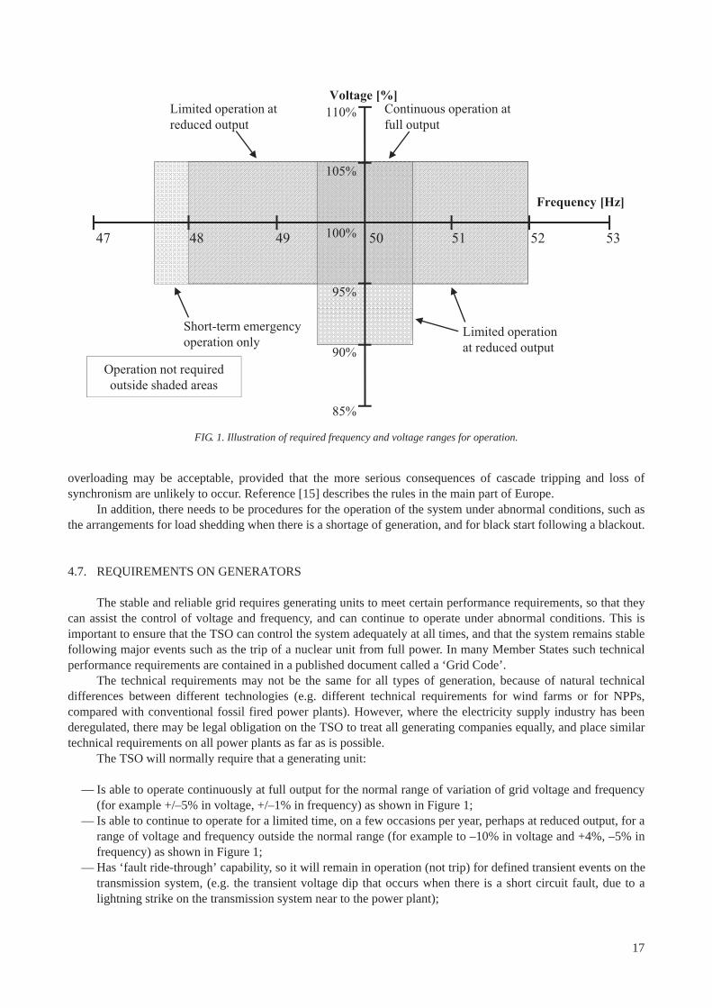
overloading may be acceptable, provided that the more serious consequences of cascade tripping and loss of synchronism are unlikely to occur. Reference [15] describes the rules in the main part of Europe.
In addition, there needs to be procedures for the operation of the system under abnormal conditions, such as the arrangements for load shedding when there is a shortage of generation, and for black start following a blackout.
4.7. REQUIREMENTS ON GENERATORS
The stable and reliable grid requires generating units to meet certain performance requirements, so that they can assist the control of voltage and frequency, and can continue to operate under abnormal conditions. This is important to ensure that the TSO can control the system adequately at all times, and that the system remains stable following major events such as the trip of a nuclear unit from full power. In many Member States such technical performance requirements are contained in a published document called a ‘Grid Code’.
The technical requirements may not be the same for all types of generation, because of natural technical differences between different technologies (e.g. different technical requirements for wind farms or for NPPs, compared with conventional fossil fired power plants). However, where the electricity supply industry has been deregulated, there may be legal obligation on the TSO to treat all generating companies equally, and place similar technical requirements on all power plants as far as is possible.
The TSO will normally require that a generating unit:
— Is able to operate continuously at full output for the normal range of variation of grid voltage and frequency (for example +/–5% in voltage, +/–1% in frequency) as shown in Figure 1;
— Is able to continue to operate for a limited time, on a few occasions per year, perhaps at reduced output, for a range of voltage and frequency outside the normal range (for example to –10% in voltage and +4%, –5% in frequency) as shown in Figure 1;
— Has ‘fault ride-through’ capability, so it will remain in operation (not trip) for defined transient events on the transmission system, (e.g. the transient voltage dip that occurs when there is a short circuit fault, due to a lightning strike on the transmission system near to the power plant);
47 48 49 50 51 52 53
Limited operation at reduced output
Operation not required outside shaded areas
Short-term emergency operation only
Limited operation at reduced output
Continuous operation at full output
110%
105%
100%
95%
90%
85%
Frequency [Hz]
Voltage [%]
FIG. 1. Illustration of required frequency and voltage ranges for operation.
17
— Is able to provide a specified range of reactive power to assist control of system voltage;— Is able to continue operation for a defined value of harmonic distortion of the voltage waveform, or a defined
level of phase imbalance (negative phase sequence voltage).
The TSO may also require that a generating unit:
— Is able to operate continuously at any point between full load, and a defined minimum load. (for example 50% of full load);
— Is able to increase or decrease output at a specified rate when instructed. (i.e. to be able to load follow);— Has a speed governor with a specified performance characteristic, and to be able to operate in automatic
frequency control mode;— Has a generator excitation control system with specified performance characteristics, including a system able
to stabilize power and voltage oscillations (PSS);— Is able to trip to ‘house load operation’ (as defined in Glossary) for specified faults;— Has at least a specified value of inertia or simulated inertia.
Figure 1 gives an example of the frequency and voltage ranges for operation that the operating that the TSO may require. (The detailed requirements will be different in different Member States; this is an illustration of the general kind of requirements).
If generators do not have the necessary capabilities, then this limits the ability of the TSO to control the system, and increases the risk to the security of the system after certain faults. For example, if some generating units are not able to provide the range of reactive power that is expected, they may not be able to control voltage adequately after faults. This has been a contributory factor to a number of blackout events around the world. If some generating units, which are supposed to be operating in automatic frequency control mode, are not able to respond as expected after the trip of a large generating unit then frequency may fall too low; this has also been a factor in some blackout events.
The developer of a new NPP will need to consider whether the various capabilities of a generating unit that are requested by the TSO are compatible with the available designs of nuclear units, and the requirements of the nuclear regulatory body in the country. This applies particularly to the ability to load follow quickly, or to operate in automatic frequency control mode, as this affects the design of the nuclear reactor and its control system. It has already been indicated in Section 3.5 that the preferred mode of operation of nuclear plants is at steady full load, and not providing automatic frequency control. The NPP developer and the TSO will need to agree on the capability required for the nuclear unit; because of the special requirements for nuclear safety, it may be necessary for the technical requirements for the nuclear unit to be different from the technical requirements for other generating units in the country.
The requirements for voltage control and the provision of reactive power will impact the design of the generating unit and the step-up transformer as follows.
— The reactive power capability of the generating unit itself;— If the step-up transformer has an on-load tap changer, the tapping range required;— If the step-up transformer has a fixed tap, the range of generator terminal voltage required.
The first two points above should not affect the design of the nuclear island within the NPP. However, the last point may affect the design of the nuclear island if the TSO wants a wide range of voltage control, because of the effect on the voltage of the auxiliary supply buses within the NPP that are supplied from the generating unit. A typical value of acceptable voltage variation is up to +/-5% of the terminal voltage to the generating unit, leading to no more than +/-10% variation of the voltage supplied to the NPP’s auxiliary equipment. It is important that the range of voltage of the electrical supplies to the auxiliary equipment remains within the equipment’s design limits.
18
4.8. STABILITY
There are various kinds of instability that can affect a transmission system, which must be considered by the TSO, including dynamic stability and transient stability.
The system is said to be dynamically unstable if there are sustained oscillations of power between different parts of the system. Such oscillations of the system (typically within the frequency range 0.2 Hz to 1 Hz) can occur in transmission systems if two parts of the system are connected by a weak connection (for example a single long transmission circuit), when the power flow through the connection exceeds a critical value. This may arise following the introduction of a new NPP, if the NPP is located far from a load centre, or if it causes an increase in power flow between two parts of the system that are weakly connected. The transmission system operator should carry out the necessary computer studies at the design stage to establish if this is likely to be a problem.
Transient stability refers to the stability of the system following a fault or transient. For example, consider a lightning strike causing a short circuit on one of the transmission circuits connecting a generating unit to the rest of the transmission system. This short circuit fault will be cleared by the electrical protection that will disconnect that circuit but leave other transmission circuits in service. During the time that the short circuit is present, generating units close to the fault will accelerate with respect to other generating units that are connected farther from the fault. If the system is transiently stable then after the fault is cleared the generating units near to the fault may oscillate with respect to the rest of the system for a few seconds, but remain in synchronism with the rest of the system. If the system is transiently unstable, one or more generating units will lose synchronism with the rest of the system (‘pole-slip’) after the fault is cleared. Such loss of synchronism may affect a single generating unit on its own, or a number of generating units in one part of the system may remain in synchronism with each other, but lose synchronism with the rest of the system. The transmission system operator will need to carry out computer modelling studies to check the proposed design of the transmission system with the NPP in operation to confirm whether there is a problem with transient stability.
If there are problems with dynamic and transient stability, then the remedial measures can include: limiting the power flows on the transmission circuits that give rise to the instability; or strengthening the system by installing additional transmission circuits. It is possible to monitor power flows to give an early warning of the onset of dynamic instability, so that the TSO will know when the power flows need to be reduced. Dynamic stability can also be improved by installing power system stabilisers (see glossary) in the excitation systems of some generators. Problems with transient stability may also be avoided by reducing the fault clearance time on the transmission circuits involved by using faster protection, and by increasing the performance of the excitation systems of the generators involved (e.g. make the excitation system faster, with a higher maximum voltage). However, a fast excitation system has the disadvantage that the generator voltage when islanding can initially be very high as in the event described in Section 13.4.
4.9. ELECTRICAL PROTECTION
The function of electrical protection on the grid is to rapidly disconnect a part of the grid that has an electrical fault. For example, if there is a lightning strike on an overhead line, a common consequence is an arc between two phase conductors or between a phase conductor and ground. The large current that would flow is detected by the electrical protection relay, which would send a signal to the two circuit breakers at each end of the circuit with the fault; the circuited breakers would open, to remove the faulted circuit from service. The aim of the protection design is to remove the faulted circuit from service rapidly before permanent damage is caused but to leave other circuits in service. With modern circuit breakers and protection systems, the circuit breakers can open to clear the fault within around 100 milliseconds. The transmission system operator has the responsibility to design the electrical protection on the transmission system, and to ensure that the electrical protection on generating units connected to the system is coordinated correctly with the transmission system protection.
The addition of an NPP to the system with a large generating unit may require improvements to the existing protection system, so that the protection has a shorter operating time (shorter fault clearance time) to ensure transient stability as mentioned in Section 4.8.
As mentioned in Section 4.6, it is common practice for protection systems to provide auto-reclose, so that the circuit breakers that have tripped are closed shortly after clearing the fault to return the faulted circuit to service, provided that the fault has been cleared. If auto-reclose is to be used on circuits near a NPP then the transients
19

caused by the reclose action should be investigated to determine that they do not cause damaging torque transients to the turbine shaft. In some Member States, the practice is to first attempt auto-reclose of the circuit breaker at the far end of the circuit (not the end nearest to the NPP) so that the NPP is not subjected to an additional transient if the fault has not been cleared.
4.10. CONTROL OF FAULT LEVEL
When there is a fault on a transmission circuit, then the electrical protection will detect the increased current and send a signal to circuit breakers to open to remove the faulted circuit. This requires the circuit breakers to interrupt the fault current, which could be very large. Circuit breakers are designed and tested for a maximum current, and it is important that the maximum fault current through the circuit breaker is less than this value. As part of the design and operation of the transmission system, the transmission system operator has to establish and monitor the maximum ‘fault level’ (as defined in the glossary) at each part of the network.
Adding a new power plant to a network will increase the fault level in the network near the power plant. Adding additional transmission circuits to accommodate the new power plant will also increase the fault level in the network near to the points where those circuits connect. This may cause the fault level at some points in the network to exceed the fault rating of the existing circuit breakers and associated equipment. Hence the addition of a NPP to a network may require measures to deal with the increased fault levels. The remedial measures for a problem with increased fault levels include:
— Replace the circuit breakers and other transmission equipment affected with new equipment of higher rating, or modify the equipment to increase its rating;
— Change the standard running arrangement of the transmission system, for example by splitting a substation;— Use high voltage transformers with higher impedance;— Install series reactors (inductors) in some circuits to increase their impedance.
There is also the opposite problem of ensuring the minimum fault level (short circuit power) is not too low. The short circuit power of the connection to a NPP must be sufficient to permit the starting of the big motors in the plant and to power the plant during shutdown and startup conditions without the voltage falling too low.
4.11. CYBER-SECURITY
The control and operation of a transmission system requires a lot of communication and control actions from a distance. Many modern data, communication, and control and protection schemes use digital technology or interface with network based systems or other communication protocols. Hence it is possible for an incorrect or corrupted data signal sent via the communication system to cause incorrect operation of equipment. An incorrect data signal may be sent by accident, or be due to an equipment fault, but may also result from a deliberate attempt to cause damage (cyber attack). Cyber security refers to arrangements to ensure that digital equipment is reasonably secure against accidental or malicious actions that may change the intended operation of digital electronic equipment. Since the NPP safety and control systems generally do not interact with network based systems outside the plant, susceptibility for external malicious attack is limited. The design diversity and redundancy provide reasonable protection against this susceptibility.
Cyber attacks can affect the integrity and the availability of the grid connection to the NPP. The vulnerability for such attack is higher because the signals are often communicated through networks or the digital equipment can be accessed in substations that are not physically secure. Therefore, arrangements for cyber security are necessary in control and communication systems of the transmission system.
Some examples of possible cyber attacks from the grid to the plant:
— Fake signals coming from the grid asking the plant to trip or to reduce output;— Transmission of wrong voltage set points that could make certain voltage sensitive equipment inoperable or
cause premature trips;
20
— Wrong power and voltage measurements;— Other changes to plant parameters or plant status that could initiate undesirable behaviour.
Cyber attacks also have the potential to cause major damage to connected electrical equipment. In particular, transmission and distribution systems that have circuit breakers that can open and reclose within 12 to 15 cycles have the potential to cause considerable damage to rotating plant (generators, motors) as a result of a cyber attack that caused such operation. This is because the rotating plant is likely to speed up or slow down during the brief time that the circuit breaker is open, so that the rotating plant will be out of phase with voltage on the grid at the instant of reclose; this will cause a large transient torque on the plant which can cause physical damage. This potential vulnerability could be exploited through digital protection and control devices such as protective relays, programmable logic controllers, bay controllers and other digital devices that can control circuit breaker operations. These devices are common protection and control devices found in process control systems and electricity grid substations. Vulnerability testing has demonstrated certain digital protective relays in specific locations can cause destructive damage to rotating plant, by using them to open and close circuit breakers. The electrical generators, motors and pumps could suffer significant damage if this vulnerability is successfully exploited and as a consequence nuclear safety could be compromised. Electrical equipment in a NPP could be impacted if the substations in the zone of influence of the nuclear power plant are not secure. It may be possible to gain access to digital equipment in the substation to execute such malicious control either through communication networks, or through local portals at substations intended for computer connectivity.
The security of digital safety systems involves addressing potential security vulnerabilities as part of the system development process and maintaining the security of the system after it is installed. The NPP operator and the TSO need to identify critical assets and take protective and mitigating actions to ensure that the digital system development platforms that are anticipated for use in transmission systems are designed and tested for all known vulnerabilities.
Security assessments of cyber vulnerabilities should be periodically performed to determine if digital systems used at the NPP and in the control of the transmission system have any inherent susceptibility to malicious activity based on known security information.
4.12. PREVENTION OF MAJOR BLACKOUTS AND BLACKOUT RESTORATION
From time to time electricity grid systems experience a major event that causes a loss of electricity supply (a blackout) in a large part of a country or region. For example, in 2003, there were major blackouts as follows:
— USA and Canada, 14 August 2003; — Sweden and Denmark, 23 September 2003;— Italy, 28 September 2003.
The blackouts in the USA and Canada and in Sweden and Denmark caused prolonged loss of off-site power (LOOP) at a number of nuclear power stations.
Some blackouts result from a period of extreme weather, (e.g. a hurricane) which causes multiple faults on the transmission system or significant damage to the transmission system in a short period of time. However, many blackouts have resulted from less severe causes, and grew from one or two relatively minor events. The analysis of a number of major blackouts [16] has found that there have been a number of common factors that caused an event to grow from a small grid disturbance to a major blackout, and which were not directly related to severe or extreme weather. These were:
— Overhead line conductors contacting trees; — Overestimation of dynamic reactive output of system generators (i.e. of the ability of generators to control
system voltage); — Inability of system operators or coordinators to visualize events on the entire system (e.g. because the grid
control centre did not have sufficient graphic displays of the state of the system, or did not have on-line security analysis capability to identify potential vulnerabilities);
21
— Failure to ensure that system operation was within safe limits; (e.g. inaccurate modelling, no reassessment of system conditions following the loss of a circuit);
— Lack of coordination on system protection (which resulted in failure to operate or incorrect operation of one or more relays as an event developed);
— Ineffective communication, particularly between different grid control centres;— Lack of ‘safety nets’ (e.g. automatic load shedding or automatic tripping of generation);— Inadequate training of operating personnel, particularly for practicing emergency situations.
The TSO needs to pay attention to all of these issues to reduce the likelihood of such major blackouts.TSOs also need to have well-developed procedures for recovery from a blackout condition. To recover from a
blackout condition requires the grid system to have a sufficient number of power stations that are able to start up quickly and operate reliably without the normal electricity supplies from the grid. Where the grid system is connected to other grid systems under the control of other TSOs, then the blackout restoration procedures need to be coordinated with other TSOs. As blackout recovery can be complicated and requires quick actions, the person directing the actions should have the most current wide-area view of the power system and have suitable tools to identify the best solution. The recovery procedures should be practiced regularly.
For an NPP, the priority in a blackout situation is to have the off-site supplies restored as soon as possible. However, the main priority for the TSO would be to re-establish the grid system and restore electricity supplies to customers, particularly priority customers. Hence in a blackout event the TSO will wish to reconnect as quickly as possible any power plant that is able to start generating immediately to assist the recovery of the system. A nuclear unit that has tripped off is generally not able to restart generation in less than 24 hours, so from the grid operator’s narrow point of view it would not be a high priority to restore supplies to a nuclear unit that has been disconnected from the grid if it has tripped. For this reason, it will be necessary for the NPP operators to enter into agreements with the TSO to ensure that appropriate priority is given to restoring grid supplies to nuclear power plants during recovery from a blackout. The recovery time would be of great significance to nuclear safety.
4.13. CONTROL AND COMMUNICATION ARRANGEMENTS
Reliable operation of the grid system during normal and abnormal events, the avoidance of major blackouts, and rapid restoration of power after a blackout, requires effective arrangements for monitoring and control of the system and for secure communications.
In most countries with NPPs, the main grid control centres have facilities such as:
— Indications of the status of all transmission circuits, circuit breakers etc; — Indications of the status of all large generating units;— Indications of voltage at key points on the system, and power flows through main circuits;— Secure communication routes to all large power stations, very large loads and other control centres;— Alarm indications when faults occur, or when voltages, power flows etc. go outside planned limits;— Computer software tools that continuously monitor and analyse the status of the grid system and warn the
operators if there are reduced margins.
The control centre should be physically secure and have secure and diverse electrical supplies, to make it resistant to environmental hazards such as fire, hurricane, etc., or malicious acts. It should also have arrangements for cyber security of its communications and controls. It is also normal to have arrangements for a backup control centre which is available to preserve the essential controls of the grid system when the primary control centre cannot be used for any reason.
The staff at the grid control centre must have the authority to instruct generating units to change output, or to startup and shutdown. They should also have the authority to instruct load shedding when necessary. If there are several control centres controlling different parts of the network in a country, there need to be arrangements to ensure good communications between the control centres at all times, and agreed procedures for actions to take when events in one grid control area can affect another grid control area. If the grid in the country is also connected
22
to the grid systems of neighbouring countries, there must also be good communications with the grid control centres in those countries and agreed procedures for joint operation.
The communications arrangements need to have adequate reliability and diversity to allow secure and reliable communications between the TSO grid control centres, power plants, distribution system operators and the TSOs in neighbouring countries, under all conditions. This requires redundant and diverse communication arrangements because in severe weather and environmental events such as hurricanes, tornadoes, earthquakes, fires, etc. and during blackouts, normal public communication channels may become disabled. For example, a local fire could immobilize telephone lines, preventing the communication between an NPP and the TSO’s control centre if there are not diverse channels of communication; diverse channels can include private wire telephone systems, cellular phone systems, carrier wave systems, radios, etc.
There also need to be agreed procedures for the command structure between control centres and power plants for decision making and communications in emergency conditions such as extreme weather conditions, a major blackout or loss of grid connections to neighbouring countries.
5. SIZE OF THE NUCLEAR UNIT
5.1. INTRODUCTION
It was mentioned in Section 3.4 that the designs of nuclear units that are currently available from international nuclear plant vendors are large, generally greater than 1000 MW. As a consequence, a new nuclear unit is almost certain to be the largest single generating unit on the system to which is connected. This is significant because there is a practical limit to the size of generating unit that can be installed in an electrical power system if the system is to remain stable and secure after the unplanned disconnection of that generating unit.
From the point of view of the NPP, a trip of a nuclear unit should not cause the transmission system voltage and frequency at the point of connection of the NPP to go outside the acceptable range, so that the grid system can continue to provide a reliable electrical supply to the NPP after the trip. From the point of view of electricity users, a trip of the nuclear unit should not lead to load shedding or to a high risk of system collapse or blackout.
Experience with existing NPPs is that unexpected reactor trips can be quite frequent in the first one or two years following the commissioning date (from a few to a dozen). Later the frequency of reactor trips reduces to once per two years or fewer.
The generation from a nuclear unit may be lost to the system as the result of an event on the transmission system that disconnects the generator of the nuclear unit from the grid, or from an event within the NPP that causes a trip of the nuclear unit. Whatever the cause, the main issues for the transmission system operator are:
— To control the rapid fall in system frequency after a reactor trip, to prevent the frequency falling below the minimum acceptable level (if frequency falls too far, it is likely that other generating units will also trip off, leading to a system blackout);
— To control the step change in voltage that occurs on the transmission system near to the point of connection of the nuclear unit immediately after the reactor trip;
— To restore power flows to desired levels, and return system frequency to its normal value as soon as practicable after the fall in frequency has been controlled.
5.2. CONTROLLING THE FALL IN FREQUENCY
A stable frequency situation (50 Hz or 60 Hz) corresponds to a good balance between demand and generation. After a reactor trip, the total generation on the system is suddenly lower than the demand and the frequency drops.
23
The rate at which frequency falls immediately after a reactor trip depends on:
(a) The amount of generation lost;(b) The inertia of the system as a whole (i.e. the inertia of all the generating units and motors connected to the
system);(c) The natural tendency of the demand to reduce as frequency falls (due to the motors present in the load on the
system).
Factor (a) above means that the larger the amount of generation loss, the faster the frequency falls. Factors (b) and (c) mean that for a given loss of generation, frequency will fall much faster on a small system (i.e. the total system demand is small), than on a large system (total system demand is large). Frequency will also fall faster on a given system at the time of minimum demand than at times of maximum demand. This makes frequency control more difficult on a small system, especially at the time of minimum demand. The problem is to limit the fall in frequency after a unit trip to an acceptable figure. If the frequency falls by 5% or more, it is very likely that most generating units would trip off on their own low frequency protection, and there would be a country wide blackout.
The fall in frequency can be contained by a combination of increasing the generation and decreasing the demand:
— Generating units operating at less than full load, in automatic frequency control mode, that will increase their power output automatically under the control of their speed governors when frequency falls;
— Disconnecting some demand by a trip signal from the nuclear unit (an example of this is described in Section 13.3);
— Disconnecting some demand using low frequency relays;— The natural tendency of the demand to reduce as frequency falls (due to the motors present in the load on the
system).
There is a practical limit to the rate at which a generating unit can increase its output when operating in automatic frequency control mode, and there is a limit to the maximum increase that can be achieved. As a consequence there is a practical limit to the size of the largest generating unit that can be installed, if system frequency is to be controlled reliably after a trip of that generating unit. This practical limit is around 10% of the system load, unless it is acceptable to disconnect a large amount of demand immediately after a reactor trip. This is demonstrated by the results of a simulation presented in Appendix II. If it is planned to connect a nuclear unit that is close to or greater than 10% of minimum system load, it will necessary to carry out detailed studies to establish whether it is possible to achieve acceptable control of frequency after a reactor trip.
5.3. THE BENEFITS OF INTERCONNECTIONS
Where several countries or regions are interconnected to form a larger system, it is feasible to have a single nuclear unit which is larger than 10% of the minimum load in a country, provided it is less than 10% of the minimum load of the total system. However, this will require the interconnections between the countries to be sufficiently reliable and to have sufficient capacity to carry the increased power flow after the trip of the nuclear unit. This arrangement will also require suitable legal and commercial agreements between the countries involved to ensure they will cooperate to operate their grid systems with sufficient generating units in automatic frequency control mode at all times.
This is illustrated by a simple example shown in Figure 2, where a country with a demand of 5 GW and a 1000 MW nuclear unit (Country A) is connected a neighbouring country (Country B) with a demand of 20 GW. Hence the nuclear unit represents 20% of the demand of country A, but only 4% of the combined system. Although the nuclear unit would be too large for country A by itself, it is acceptable for the combined system.
The amount of frequency response that each country provides will be the subject of agreement between the countries. A common arrangement is that the amount of response each country provides is approximately proportional to the generation or demand in the country [17]. If that arrangement is used then if the 1000 MW reactor in country A trips, only around 200 MW of the response will be provided by country A and around 800 MW
24
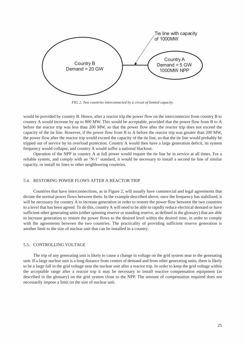
would be provided by country B. Hence, after a reactor trip the power flow on the interconnector from country B to country A would increase by up to 800 MW. This would be acceptable, provided that the power flow from B to A before the reactor trip was less than 200 MW, so that the power flow after the reactor trip does not exceed the capacity of the tie line. However, if the power flow from B to A before the reactor trip was greater than 200 MW, the power flow after the reactor trip would exceed the capacity of the tie line, so that the tie line would probably be tripped out of service by its overload protection. Country A would then have a large generation deficit, its system frequency would collapse, and country A would suffer a national blackout.
Operation of the NPP in country A at full power would require the tie line be in service at all times. For a reliable system, and comply with an ‘N-1’ standard, it would be necessary to install a second tie line of similar capacity, or install tie lines to other neighbouring countries.
5.4. RESTORING POWER FLOWS AFTER A REACTOR TRIP
Countries that have interconnections, as in Figure 2, will usually have commercial and legal agreements that dictate the normal power flows between them. In the example described above, once the frequency has stabilized, it will be necessary for country A to increase generation in order to restore the power flow between the two countries to a level that has been agreed. To do this, country A will need to be able to rapidly reduce electrical demand or have sufficient other generating units (either spinning reserve or standing reserve, as defined in the glossary) that are able to increase generation to restore the power flows to the desired level within the desired time, in order to comply with the agreements between the two countries. The practicality of providing sufficient reserve generation is another limit to the size of nuclear unit that can be installed in a country.
5.5. CONTROLLING VOLTAGE
The trip of any generating unit is likely to cause a change in voltage on the grid system near to the generating unit. If a large nuclear unit is a long distance from centres of demand and from other generating units, there is likely to be a large fall in the grid voltage near the nuclear unit after a reactor trip. In order to keep the grid voltage within the acceptable range after a reactor trip it may be necessary to install reactive compensation equipment (as described in the glossary) on the grid system close to the NPP. The amount of compensation required does not necessarily impose a limit on the size of nuclear unit.
Country B Demand = 20 GW
Country A Demand = 5 GW
1000MW NPP
Tie line with capacity of 1000MW
FIG. 2. Two countries interconnected by a circuit of limited capacity.
25

6. DEVELOPMENT ACTIVITIES
6.1. INTRODUCTION
This section summarizes the basic activities to be performed by the NPP developer and by the transmission system operator, for connecting a NPP to the grid system, once a decision has been made to build a NPP.
It is recommended, from the very launch of the project to install a NPP, to encourage team efforts and agreements between the NPP development teams and the design teams in the TSO, in order to address the main issues introduced below. Such a team effort is recommended because in general there is no existing company or organization that integrates, in a single entity, all the engineering and operational skills for a specific nuclear plant design, and the competencies of grid planning, design and operation.
6.2. TRANSMISSION SYSTEM OPERATOR’S ACTIVITIES
Because they are responsible for grid planning and operation, TSOs have to consider the need for the development of the transmission system, and the need to balance generation and demand in the short, medium and long term. From this point of view, the TSO has to:
(1) Consider new generation units in terms of availability relative to the forecast demand (for example the variation in demand between summer and winter) and to identify the likely generation reserves or shortfalls;
(2) Ensure that there will be sufficient reserves of generation capacity at all times to prevent frequency collapse and avoid the need for load shedding in case of loss of a large generating unit, such as a nuclear unit;
(3) Check the dynamic and transient stability of the system for a wide range of system conditions, especially the most severe situations, usually at the times of maximum and minimum demand; the purpose is to avoid instabilities such as oscillations of power flow and loss of synchronism following faults;
(4) Check the voltage levels at all points on the transmission system, with particular attention to the voltage levels on the system near the NPP, for a wide range of system conditions including immediately after a reactor trip;
(5) Define and plan the necessary reinforcements of the network, so that energy can be exported from power plants and transmitted across the system without significant restrictions, and avoiding overload of transmission circuits that might lead to unwanted tripping or limitations to generation;
(6) Design new substations to accommodate new power stations, which for nuclear units will be in agreement with the NPP developer, so that the substation design is compatible the requirements for reliable off-site power supplies to the NPP and to satisfy the requirements of the nuclear regulatory authority;
(7) Design the electrical protection schemes for substations to which power plants connect, and to coordinate the substation protection schemes with the protection schemes of the power plants to ensure that only the necessary circuits are disconnected following grid faults;
(8) Revise and adapt defence plans and grid blackout recovery procedures in order to restore power as soon as possible, and considering the NPP as a priority load centre;
(9) Consider the effect of different generation patterns for power plants near to the planned NPP, as this may affect grid conditions (voltage, reliability etc.) at the NPP connection point.
The above activities are normal for other power plants, but will require more consideration for NPPs because of the longer project duration, the larger unit size, the need for very reliable connections to the NPP with good control of voltage and frequency, and the possible need for greater network reinforcements.
6.3. NPP DEVELOPER’S ACTIVITIES
The NPP developer has to run a project to ensure that the NPP being developed will meet all the safety requirements and also meet the requirements of the transmission system, which may be specified by the TSO or in
26
the national ‘grid code’, and remain within the planned costs and schedule. The NPP developer and its engineering support teams should therefore run activities aiming to:
(a) Evaluate the feasibility of the grid connection in the site assessment, looking at qualitative and quantitative aspects of transmission capacity, the robustness of the connection, the risk of loss of off-site power (LOOP), the required grid reinforcements and the costs of connection;
(b) Liaise at the right moment, with the transmission system operator to make a formal request for connection to the grid at the chosen site; validate the technical solutions proposed by the TSO for the connection and protection schemes, including the best possible independent connections to the generator and the station transformer;
(c) Carry out analysis to assess the compliance of the NPP with the TSO’s technical requirements such as in the local grid code; if there is non-compliance, develop a strategy either to change the plant design or to negotiate changes to the technical requirements or the grid code;
(d) Assess the frequency and the duration of events of loss of off-site power, as required by the nuclear licensing process, to calculate the criteria for availability of external power sources;
(e) Provide proof for the nuclear regulatory authority that the plant is well protected against all external electrical disturbances arising in the network. These disturbances could be in the form of events that cause very fast voltage transient (e.g. lightning), abnormal voltages (brownouts) and frequency, temporary or prolonged loss of offsite power;
(f) Consider the way the new nuclear unit units will be integrated into the energy market. This could include the capability for load following or the capability for automatic frequency control or load following, and the minimum operating level;
(g) Liaise with the system operator in the long term to guarantee during the operational period the availability of the transmission capacity, and the quality and availability of offsite power sources, during the operation of the NPP.
6.4. CONSTRAINTS
The activities described above should be integrated into the project development in the early stages, and should be continuously coordinated and managed with external parties (the TSO, energy sector regulators, construction companies, plant designers and safety authorities) in order to minimize the constraints for the transmission system operator and for the plant owner.
The principal constraints for the transmission system operator include the design of the connection arrangement for the new nuclear unit, designing the grid reinforcements and line construction so that these can be implemented in the timescale required without affecting grid operation. The constraints also include planning the arrangements for the management of new large units, and ensuring there will be sufficient automatic frequency control capability in future to control frequency after the trip of a large nuclear unit.
The principal constraints for the plant owner include the reliability and robustness of the grid connection scheme, demonstrating the adequacy of the grid arrangements to the nuclear regulatory authority and ensuring compliance with the technical requirements of the TSO or grid code.
Figure 3 indicates the different phases and their associated activities, with the main project milestones, assuming a 10-year fast track development.
6.5. MODELLING
6.5.1. Transmission system modelling
As a part of the NPP development process, it is important to consider the quality and robustness of the transmission system when selecting potential sites for newly proposed NPPs. To perform such studies, one needs to model the existing transmission system and generators in the NPP and other power plants nearby. The studies will cover both steady state operations and transients such as a trip of the nuclear unit or faults in the substation or on the
27
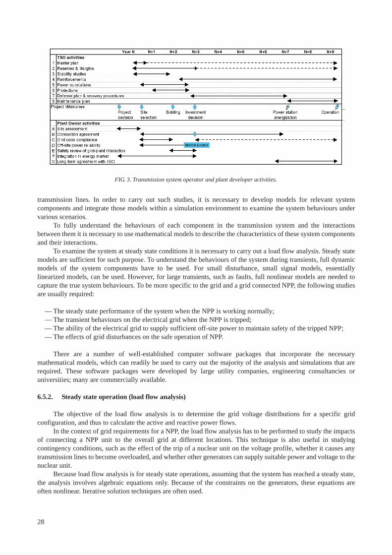
transmission lines. In order to carry out such studies, it is necessary to develop models for relevant system components and integrate those models within a simulation environment to examine the system behaviours under various scenarios.
To fully understand the behaviours of each component in the transmission system and the interactions between them it is necessary to use mathematical models to describe the characteristics of these system components and their interactions.
To examine the system at steady state conditions it is necessary to carry out a load flow analysis. Steady state models are sufficient for such purpose. To understand the behaviours of the system during transients, full dynamic models of the system components have to be used. For small disturbance, small signal models, essentially linearized models, can be used. However, for large transients, such as faults, full nonlinear models are needed to capture the true system behaviours. To be more specific to the grid and a grid connected NPP, the following studies are usually required:
— The steady state performance of the system when the NPP is working normally; — The transient behaviours on the electrical grid when the NPP is tripped; — The ability of the electrical grid to supply sufficient off-site power to maintain safety of the tripped NPP; — The effects of grid disturbances on the safe operation of NPP.
There are a number of well-established computer software packages that incorporate the necessary mathematical models, which can readily be used to carry out the majority of the analysis and simulations that are required. These software packages were developed by large utility companies, engineering consultancies or universities; many are commercially available.
6.5.2. Steady state operation (load flow analysis)
The objective of the load flow analysis is to determine the grid voltage distributions for a specific grid configuration, and thus to calculate the active and reactive power flows.
In the context of grid requirements for a NPP, the load flow analysis has to be performed to study the impacts of connecting a NPP unit to the overall grid at different locations. This technique is also useful in studying contingency conditions, such as the effect of the trip of a nuclear unit on the voltage profile, whether it causes any transmission lines to become overloaded, and whether other generators can supply suitable power and voltage to the nuclear unit.
Because load flow analysis is for steady state operations, assuming that the system has reached a steady state, the analysis involves algebraic equations only. Because of the constraints on the generators, these equations are often nonlinear. Iterative solution techniques are often used.
FIG. 3. Transmission system operator and plant developer activities.
28
6.5.3. Power transfer capabilities
During steady state operation, the generated power is delivered to the load over transmission lines. The maximum power that can be transferred depends on the thermal capacity (rating) of the lines, which is a physical constraint. At the modelling stage, the amount of power (MW) being transferred over a transmission line is determined by the voltage at each end of the transmission line, the impedance of the line, and most importantly, the phase angle difference at each end of the line. The maximum phase shift must be much less than 90° for stable system operation. When the phase shifts among all generators are small enough, the generators are said to be in synchronism and the power system is stable.
The power transfer capability is a very important consideration in the site selection and grid design phase of new NPP. Often, a NPP is located away from major load centres. It is important to ensure that transmission lines have sufficient capability.
6.5.4. Transient stability
Even though steady state load flow analysis can show that the grids with associated system components satisfy all the steady state operation, it does not mean that the entire system can reach a new equilibrium at the steady state following some severe disturbances, such as short-circuit of the transmission lines, or trip of one or more generating units.
Transient stability is particularly important for safety reasons if a NPP is connected to the grid. To examine the transient stability of a power system, one has to use models involving time to describe the dynamic behaviours of the system. The models are often in the form of differential equations.
The critical period for the grid to achieve transient stability is a few tens of seconds after the disturbance. If the generators can maintain synchronism in this period, the transients will diminish gradually. The transient oscillation can last as long as a few minutes. During this period, automatic frequency control and voltage control loops will regulate system frequency and voltage to help generators to maintain synchronism.
6.5.5. Frequency stability
Because the speed of rotation of synchronous generators depends on the net difference between the load and the supplied mechanical power, the frequency will fluctuate around the nominal values (50 Hz or 60 Hz). It is very important to maintain the system frequency within a narrow band, as many loads are frequency dependent, including pumps and fans that are designed for maximum efficiency at a particular operating speed. The power electronics based inverters used for grid connection of renewable energy sources are also sensitive to the system frequency. Dynamic simulations can be performed to investigate the frequency stability under various contingent conditions. This calls for detailed dynamic models of system components, such as the speed governors and power controllers on the turbines in power plants.
6.5.6. Voltage stability
The voltage profile on the transmission system is also critical to sustain reliable operation; the voltage at all point on the transmission system should be kept within the allowed range. There are several ways to regulate the voltage profile; one is by controlling the excitation level of the field winding in the generator through the automatic voltage regulator of the generator; another way is to use on-load tap-changer at the transformer side. On the transmission line side, the voltage can also be controlled using reactive compensating devices, such as static var compensators (SVCs).
The steady state voltage profile can be obtained by load flow analysis. However, dynamic voltage stabilities still need to be investigated.
If the NPP is located far away from the load centre, voltage profile of the transmission lines from the NPP to the load centre should be examined, and it is important to examine the voltage levels when an unplanned trip occurs at the NPP to ensure that the voltage remains adequate for providing off-site power for safe reactor shutdown. It may be necessary to use reactive compensation devices to regulate the voltage within the desired range.
29

7. SITE CHOICE AND ASSESSMENT
7.1. INTRODUCTION
The choice of location for installation of a nuclear power plant is a complex process that is specific for each project. The range of choice may include the entire country, limited only by technical specification, public policy and local environmental laws. To ensure a successful project, a key parameter — but out of the scope of this publication — is to secure as wide a public acceptance as possible.
The criteria for the choice of a site for the NPP include many factors as given in Ref. [1]. The cost and practicality of connecting to the existing grid system is an additional criterion, but probably not the dominating one.
This section focuses on the technical and economic aspects involved in the siting process that are related to the electrical grid. The procedure and methodology described here follow guidelines in Ref. [18] and similar guidelines in one of the IAEA’s safety standards [19]. At the beginning of the site selection process, little information is available, so the process generally requires several iterations before the final decision to launch the project.
The site selection process comprises three steps:
Step one: Regional analysis: The main purpose of this step is to eliminate unsuitable areas and to highlight candidate sites. The analysis is based on all existing documents (geographical, geological, hydrological, seismic data, satellite photos, land register, etc.). The single conclusion is a decision of acceptable or not acceptable for further consideration.
Step two: Screening of potential sites: The purpose is to select suitable candidate sites from among the potential sites, and to reduce the number of sites where detailed investigations have to be carried out. In addition to the information available for step one, preliminary investigations are performed. A set of criteria must be established to draw a preliminary comparison between the sites by identifying those that have significant disadvantages in one or more aspects. This second step primarily is qualitative, but a quantitative approach may also be used. At the end of this step several candidate sites will remain.
Step three: Comparison and ranking: During this step, a comprehensive assessment is made for each candidate site with the goal of selecting the most suitable from a short list. On-site investigations may be required to be able to provide more accurate information, and provide more confidence in the conclusions. Another fundamental aspect is the public acceptance of the project.
7.2. STEP ONE: REGIONAL ANALYSIS
7.2.1. Energy market and demand
Increasing electricity demand is the obvious prerequisite for deciding to construct a power plant. A strategic analysis is necessary to check the adequacy of the project, taking into account that as a nuclear project takes a long time, power demand must be considered on a long term basis. To satisfy this demand, the price risk due to existing power plant and short term and long term entrants to the market have to be considered.
The market may be regulated or free, and the energy price trend will affect the profitability of the project. If a power purchase agreement (PPA) is possible, it secures project revenue.
The assumptions made at the beginning of the project should be updated periodically and if further changes in the assumptions threaten the project, the means to mitigate its consequences should be defined. At the state or regional level a long term plan is generally defined to develop an adequate supply of power. Knowledge of the governmental (federal, regional, etc.) plan and how the project fits into this plan is one of the key issues of the siting decision.
30
7.2.2. Land availability
Typically a NPP with a single nuclear unit and its auxiliary buildings will require about 40 ha; an additional area of around 30 ha is needed for the construction zone. If it is planned to construct two nuclear units then a larger area will be required, around 50 ha for the plant, and 45 ha for the construction zone if the units are to be constructed at the same time. In addition an area of 10 ha more will be required nearby for a typical high voltage substation of the outdoor type.
A preliminary layout should be drafted at an early stage to locate buildings, structures, power station and outgoing power lines to permit checking suitability of the proposed perimeter.
7.2.3. Grid capacity and grid connection
Suitable high voltage power lines are required to export the electrical power from the NPP to the grid. A large NPP available from international vendors (1000 MW or more per unit) typically a transmission voltage of 400 kV line or more will be required. After defining where the plant will be connected, the grid capacity must be assessed not only in terms exporting the power from the plant but also in terms of grid stability. To ensure grid capacity and stability it may be necessary to carry out significant grid reinforcements far from the NPP site.
In addition, the construction of a large NPP of the type available from international vendors will require an electrical supply with a capacity of a few tens of megawatts to be available at the NPP site throughout the construction period.
New transmission lines will require agreement for rights-of-way. If a site is to be included for further assessment it is desirable to get agreement from government agencies at this stage, that suitable rights-of-way will be granted. This is a very sensitive area, because public opposition to new line corridors could be strong.
7.3. STEP TWO: SCREENING OF POTENTIAL SITES
The site evaluation includes a qualitative approach and a tentative quantitative approach, giving a qualitative score ranging from ‘very favourable’ to ‘not acceptable’. This qualitative approach is used for each aspect that is to be considered and should include both technical and socio-political aspects. The following section focuses on aspects related to the grid connection.
Generation development opportunity: The evaluation should consider the need for generation capacity in the region and the long term generation development plan for the region.
Transmission lines: The evaluation should consider if the plant can be connected to existing transmission lines, the license process for new transmission lines and any substation siting outside the plant area. Aspects that should be considered include historical fault rate and predicted faults rates.
Grid connection and capacity: The evaluation should further detail the earlier studies on grid capacity and grid stability. The number of transmission lines connected to the plant should be evaluated.
Grid enhancements: The evaluation should consider the need for strengthening the grid, based on the results from the evaluation of transmission lines and grid capacity.
Reliable off-site power: The evaluation should consider the safety need of a stable and reliable off-site power source to the NPP during all modes of operation and during different events, and maintenance activities, on the grid
31
7.4. STEP THREE: COMPARISON AND RANKING
At this stage, candidate sites are ranked, and given a priority. The highest priority is given to those sites that score ‘very favourable’ or ‘favourable’ for most criteria, and excluding sites that score ‘unacceptable’ in one or more criteria.
As part of this ranking a more detailed or quantitative assessment may be made of individual criteria. For the issues related to the electrical grid this could include:
— The distance to the centres of demand;— The number and length of new transmission lines, and their cost;— The cost of other grid investments that may be needed (e.g. to provide reactive compensation, to deal with
increased fault levels etc.);— The difficulty and cost of providing a secure and diverse power supply to the NPP site.
The final ranking leading to a short list should integrate the socio-political aspects.
8. CONNECTING A NUCLEAR POWER PLANT TO THE GRID
8.1. REQUIREMENTS OF THE TSO
The TSO is responsible for planning and operation of the transmission system, and has to consider short, medium and long-term planning for the balance of generation and demand, as well as the need to develop and extend the grid to accommodate changes in generation and demand.
In order to carry out the necessary studies of the grid system, the TSO will require the NPP developer to provide all the information necessary to carry out such system studies. This information will include the size (in MW) of the nuclear unit, and a large number of electrical parameters. At the beginning of the project to install a nuclear unit, it will not be possible to provide all the detailed parameters, as the design of the nuclear unit may not have been selected or finalised. Hence initial studies will need to be done using typical values, but can be refined when actual plant data is available.
The TSO will also need to specify the technical characteristics or performance requirements the nuclear unit will need to have to meet the needs of the transmission system. Where the electricity market has been deregulated the TSO may be under an obligation from the energy regulator or market regulator in the country to impose the similar technical requirements on the nuclear units as on other generators. The technical requirements are likely to be similar to those summarized in Section 4.7.
The TSO will need to agree with the NPP operator the details of the grid connections to the planned NPP, including the number of connections and the high voltage substation design, to satisfy the requirements for security of grid connections that are needed by the NPP.
8.2. CALCULATION OF THE RELIABILITY OF THE OFF-SITE POWER
The NPP developer will need to arrange the calculation of the expected reliability of off-site power. The grid reliability data will be needed to assist the probabilistic safety assessment to be presented into the pre-construction safety report. This calculation would normally be performed by the TSO, but the NPP Developer would need to specify the studies that are needed.
The calculation of the reliability of offsite power will need to use historic data on grid faults and events involving loss of grid connection, such as the information summarizedsummarized in Section 4.2. It will also require a provisional design for the proposed connection scheme for the future NPP. The analysis should consider all the possible causes of LOOP, and it would be useful to provide information on which are the main causes of the
32
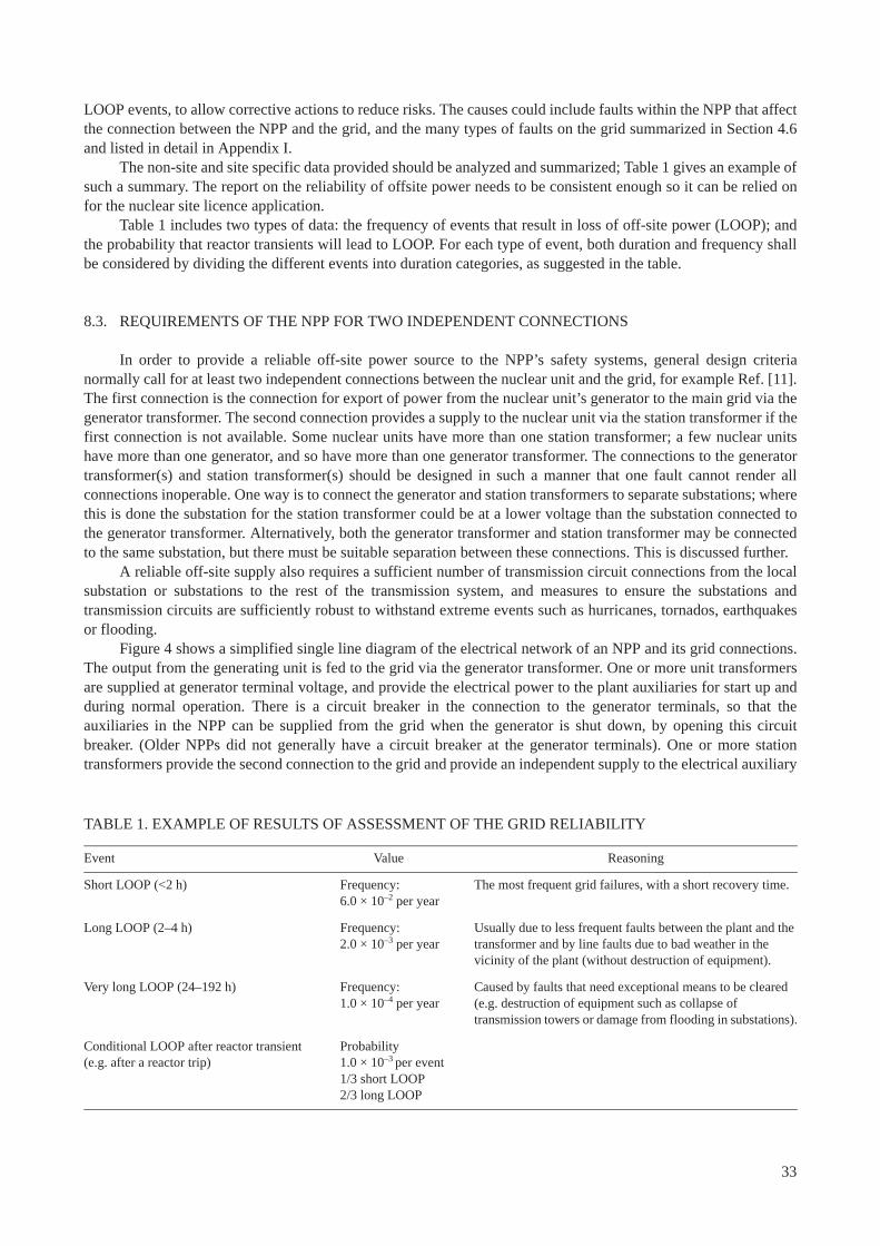
LOOP events, to allow corrective actions to reduce risks. The causes could include faults within the NPP that affect the connection between the NPP and the grid, and the many types of faults on the grid summarized in Section 4.6 and listed in detail in Appendix I.
The non-site and site specific data provided should be analyzed and summarized; Table 1 gives an example of such a summary. The report on the reliability of offsite power needs to be consistent enough so it can be relied on for the nuclear site licence application.
Table 1 includes two types of data: the frequency of events that result in loss of off-site power (LOOP); and the probability that reactor transients will lead to LOOP. For each type of event, both duration and frequency shall be considered by dividing the different events into duration categories, as suggested in the table.
8.3. REQUIREMENTS OF THE NPP FOR TWO INDEPENDENT CONNECTIONS
In order to provide a reliable off-site power source to the NPP’s safety systems, general design criteria normally call for at least two independent connections between the nuclear unit and the grid, for example Ref. [11]. The first connection is the connection for export of power from the nuclear unit’s generator to the main grid via the generator transformer. The second connection provides a supply to the nuclear unit via the station transformer if the first connection is not available. Some nuclear units have more than one station transformer; a few nuclear units have more than one generator, and so have more than one generator transformer. The connections to the generator transformer(s) and station transformer(s) should be designed in such a manner that one fault cannot render all connections inoperable. One way is to connect the generator and station transformers to separate substations; where this is done the substation for the station transformer could be at a lower voltage than the substation connected to the generator transformer. Alternatively, both the generator transformer and station transformer may be connected to the same substation, but there must be suitable separation between these connections. This is discussed further.
A reliable off-site supply also requires a sufficient number of transmission circuit connections from the local substation or substations to the rest of the transmission system, and measures to ensure the substations and transmission circuits are sufficiently robust to withstand extreme events such as hurricanes, tornados, earthquakes or flooding.
Figure 4 shows a simplified single line diagram of the electrical network of an NPP and its grid connections. The output from the generating unit is fed to the grid via the generator transformer. One or more unit transformers are supplied at generator terminal voltage, and provide the electrical power to the plant auxiliaries for start up and during normal operation. There is a circuit breaker in the connection to the generator terminals, so that the auxiliaries in the NPP can be supplied from the grid when the generator is shut down, by opening this circuit breaker. (Older NPPs did not generally have a circuit breaker at the generator terminals). One or more station transformers provide the second connection to the grid and provide an independent supply to the electrical auxiliary
TABLE 1. EXAMPLE OF RESULTS OF ASSESSMENT OF THE GRID RELIABILITY
Event Value Reasoning
Short LOOP (<2 h) Frequency:6.0 × 10⁻² per year
The most frequent grid failures, with a short recovery time.
Long LOOP (2–4 h) Frequency: 2.0 × 10⁻³ per year
Usually due to less frequent faults between the plant and the transformer and by line faults due to bad weather in the vicinity of the plant (without destruction of equipment).
Very long LOOP (24–192 h) Frequency:1.0 × 10⁻⁴ per year
Caused by faults that need exceptional means to be cleared (e.g. destruction of equipment such as collapse of transmission towers or damage from flooding in substations).
Conditional LOOP after reactor transient(e.g. after a reactor trip)
Probability 1.0 × 10⁻³ per event1/3 short LOOP2/3 long LOOP
33
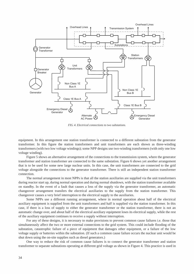
34
equipment. In this arrangement one station transformer is connected to a different substation from the generator transformer. In this figure the station transformers and unit transformers are each shown as three-winding transformers (with two low voltage windings); some NPP designs use two-winding transformers (with only one low voltage winding).
Figure 5 shows an alternative arrangement of the connections to the transmission system, where the generator transformer and station transformer are connected to the same substation. Figure 6 shows yet another arrangement that is to be used for some new large nuclear units. In this case, the unit transformers are connected to the grid voltage alongside the connections to the generator transformer. There is still an independent station transformer connection.
The normal arrangement in most NPPs is that all the station auxiliaries are supplied via the unit transformers during reactor start up, during normal operation and during normal shutdown, with the station transformer available on standby. In the event of a fault that causes a loss of the supply via the generator transformer, an automatic changeover arrangement transfers the electrical auxiliaries to the supply from the station transformer. This changeover causes a very brief interruption to the electrical supply to the auxiliaries.
Some NPPs use a different running arrangement, where in normal operation about half of the electrical auxiliary equipment is supplied from the unit transformers and half is supplied via the station transformer. In this case, if there is a loss of supply to either the generator transformer or the station transformer, there is not an automatic change over, and about half of the electrical auxiliary equipment loses its electrical supply, while the rest of the auxiliary equipment continues to receive a supply without interruption.
For any of these designs, it is necessary to make provisions to prevent common cause failures i.e. those that simultaneously affect the two or more external connections to the grid system. This could include flooding of the substation, catastrophic failure of a piece of equipment that damages other equipment, or a failure of the low voltage supply or batteries within the substation. (If such a common cause failure occurs the nuclear unit would be shut down using the on-site supplies such as diesel generators.)
One way to reduce the risk of common cause failures is to connect the generator transformer and station transformer to separate substations operating at different grid voltage as shown in Figure 4. This practice is used in
Alternate AC Power
Non Class 1E Bus A
Class 1E Bus A
Substations
Transmission System
Generator Breaker
Generator
Emergency Diesel Generator
Unit Transformers
Generator Transformer
Station Transformers
Emergency Diesel Generator
Class 1E Bus B
Non Class 1E Bus B
Overhead LinesOverhead Lines
FIG. 4. Electrical connections to two substations.
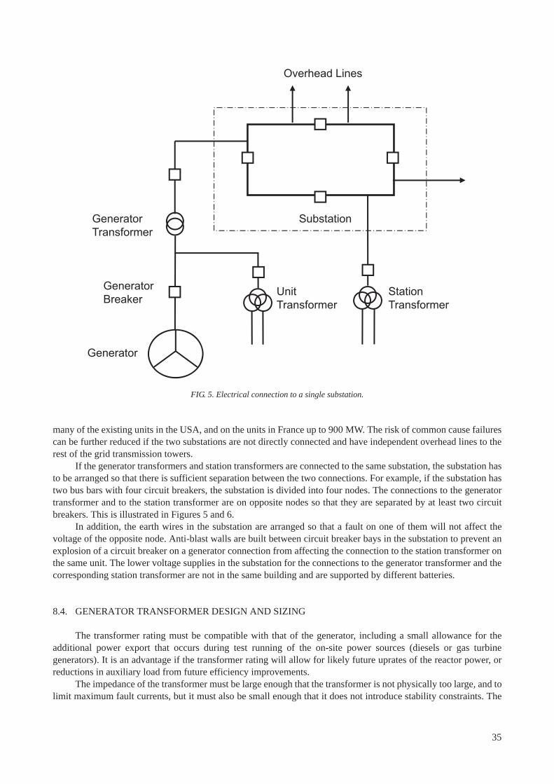
many of the existing units in the USA, and on the units in France up to 900 MW. The risk of common cause failures can be further reduced if the two substations are not directly connected and have independent overhead lines to the rest of the grid transmission towers.
If the generator transformers and station transformers are connected to the same substation, the substation has to be arranged so that there is sufficient separation between the two connections. For example, if the substation has two bus bars with four circuit breakers, the substation is divided into four nodes. The connections to the generator transformer and to the station transformer are on opposite nodes so that they are separated by at least two circuit breakers. This is illustrated in Figures 5 and 6.
In addition, the earth wires in the substation are arranged so that a fault on one of them will not affect the voltage of the opposite node. Anti-blast walls are built between circuit breaker bays in the substation to prevent an explosion of a circuit breaker on a generator connection from affecting the connection to the station transformer on the same unit. The lower voltage supplies in the substation for the connections to the generator transformer and the corresponding station transformer are not in the same building and are supported by different batteries.
8.4. GENERATOR TRANSFORMER DESIGN AND SIZING
The transformer rating must be compatible with that of the generator, including a small allowance for the additional power export that occurs during test running of the on-site power sources (diesels or gas turbine generators). It is an advantage if the transformer rating will allow for likely future uprates of the reactor power, or reductions in auxiliary load from future efficiency improvements.
The impedance of the transformer must be large enough that the transformer is not physically too large, and to limit maximum fault currents, but it must also be small enough that it does not introduce stability constraints. The
Substation
Generator Breaker
Generator
Unit Transformer
Generator Transformer
Station Transformer
Overhead Lines
FIG. 5. Electrical connection to a single substation.
35
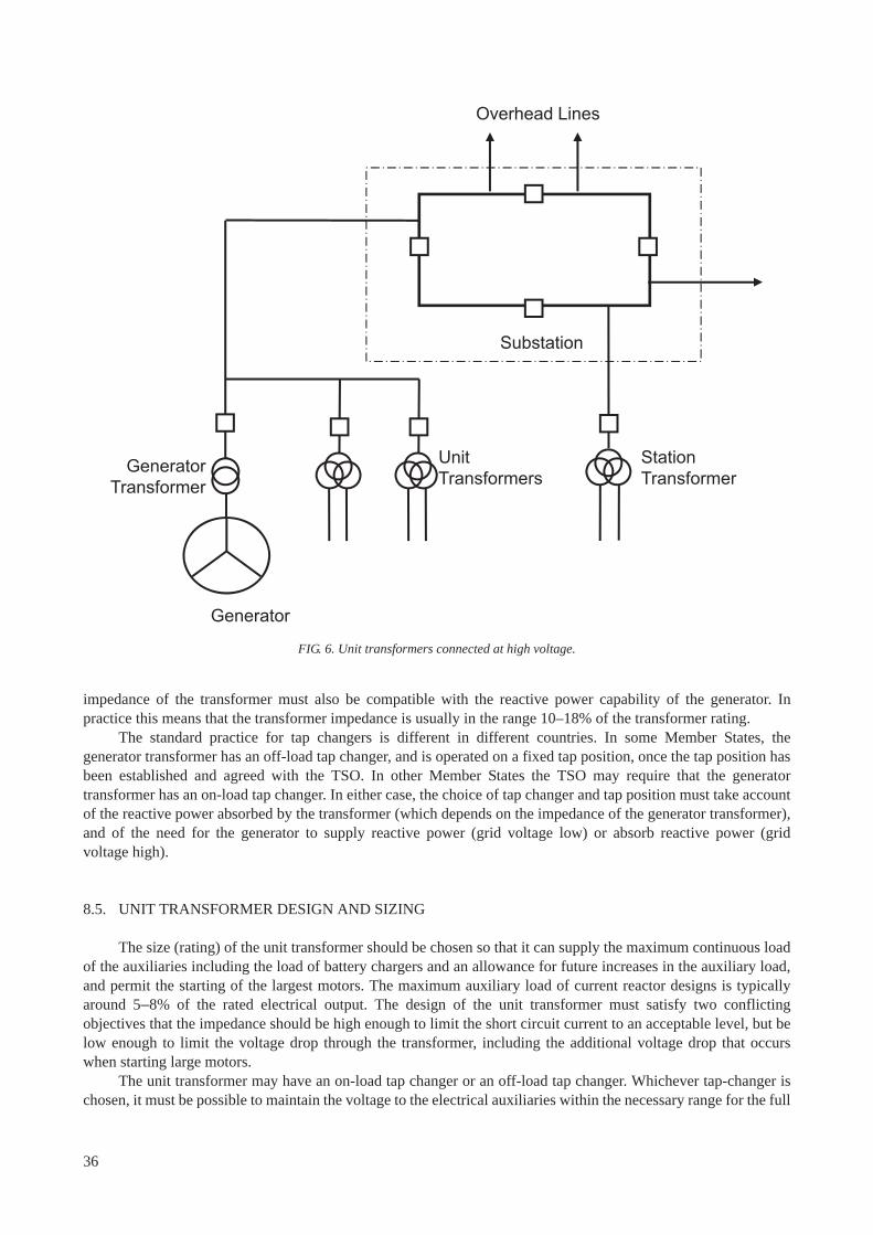
impedance of the transformer must also be compatible with the reactive power capability of the generator. In practice this means that the transformer impedance is usually in the range 10–18% of the transformer rating.
The standard practice for tap changers is different in different countries. In some Member States, the generator transformer has an off-load tap changer, and is operated on a fixed tap position, once the tap position has been established and agreed with the TSO. In other Member States the TSO may require that the generator transformer has an on-load tap changer. In either case, the choice of tap changer and tap position must take account of the reactive power absorbed by the transformer (which depends on the impedance of the generator transformer), and of the need for the generator to supply reactive power (grid voltage low) or absorb reactive power (grid voltage high).
8.5. UNIT TRANSFORMER DESIGN AND SIZING
The size (rating) of the unit transformer should be chosen so that it can supply the maximum continuous load of the auxiliaries including the load of battery chargers and an allowance for future increases in the auxiliary load, and permit the starting of the largest motors. The maximum auxiliary load of current reactor designs is typically around 5–8% of the rated electrical output. The design of the unit transformer must satisfy two conflicting objectives that the impedance should be high enough to limit the short circuit current to an acceptable level, but be low enough to limit the voltage drop through the transformer, including the additional voltage drop that occurs when starting large motors.
The unit transformer may have an on-load tap changer or an off-load tap changer. Whichever tap-changer is chosen, it must be possible to maintain the voltage to the electrical auxiliaries within the necessary range for the full
Substation
Generator
Unit Transformers
Generator Transformer
Station Transformer
Overhead Lines
FIG. 6. Unit transformers connected at high voltage.
36
range of auxiliary load, and the full range of variation of the grid voltage or generator terminal voltage. This should include the ability to allow reactor start up when the grid voltage is low. Computer studies should also be carried out to verify the dynamic behaviour of the auxiliary motors for the transformer design that has been chosen.
In practice, the design and sizing of the unit transformer may be carried out as follows:
(1) Establish the largest power loading, which normally corresponds to the nuclear unit at full power;(2) Decide the number of windings (for example two-winding or three winding transformer) and hence the power
rating of each winding;(3) Carry out a calculation of short-circuit currents to check that the rating of the circuit breakers is compatible
with various operations considered;(4) Deduce the maximum value of the reactance of the unit transformer, starting from the tolerances on the
impedances of power transformers;(5) Use computer transient studies to check that the rating of the unit transformer is compatible with various
events on the transmission system (close short-circuit, voltage dip, islanding following a grid fault).
The results of calculations of short-circuit currents or electrical transients, and changes in the input data may require the design and sizing of the unit transformer to be re-assessed. If it is necessary to change the sizing of one element of the electrical supply chain then the validation studies must be repeated.
8.6. STATION TRANSFORMER DESIGN AND SIZING
As for the unit transformer, the design of the station transformer must satisfy two conflicting objectives that the impedance should be high enough to limit the short circuit current to an acceptable level, but be low enough to limit the voltage drop through the transformer, including the additional voltage drop that occurs when starting large motors. The size (rating) of the station transformer should be chosen so that it can supply the maximum continuous load of the auxiliaries including the load of battery chargers and an allowance for future increases in the auxiliary load, and permit the starting of the largest motors.
As explained in Section 8.3, in most nuclear units the normal supply to the auxiliaries is via the unit transformer, so for these nuclear units the station transformer spends most of the time energized from the grid but carrying no load.
The station transformer may have an on-load tap changer or an off-load tap changer. The choice of tap-changer must ensure that the voltage supplied to the auxiliaries is within the normal range when the auxiliaries are supplied via the station transformer, and that the voltage on the low voltage winding of the station transformer is compatible with its continuous voltage rating when it is energised from the transmission system but not supplying load. These conditions must be met for the full range of variation of transmission system voltage.
The design and sizing of the station transformer may be carried out similar to the unit transformer as described in Section 8.5.
8.7. GENERATOR DESIGN AND SIZING
The generator size and rating should be chosen so that the generator is able to accept the full power supplied by the reactor, including an allowance for possible future power increases.
The TSO may specify the range of power factors, and hence the range of reactive power that the generator should be capable of supplying or absorbing. The wider the range of reactive power is that is required, the larger will be the physical size of the generator. The range of reactive power required may also influence the design of the generator transformer.
The TSO may specify the performance required from the generator excitation system (AVR), in order to ensure transient and dynamic stability. This may include the requirement for the excitation system to be fast acting and have a high ceiling voltage. The NPP operator should carry out studies to establish the maximum voltage that may occur after a loss-of-load event, as this will be affected by the speed of the AVR and the ceiling voltage. This maximum voltage must be compatible with the allowable voltage range of the electrical supplies via the unit
37
transformer to the auxiliary equipment. A special attention has to be paid to the control of the high voltage transient situations when rejecting load and/or when losing the excitation systems, because high voltage transients may be a severe common mode failure for all electrical components. Such events have occurred in several NPPs generating voltage overshoot higher than 150% of the nominal voltage during about half second. An example of such overvoltage is described in Section 13.4.
9. CONSIDERATION OF UNUSUAL OR ABNORMAL EVENTS
The preceding sections have described the normal variation of grid conditions, including those due to commonly occurring faults. Problems may arise following more unusual faults, or when two or more faults occur together. The nuclear regulatory authority will require the NPP developer to demonstrate that for any credible combination of grid faults, or a grid fault combined with a fault in the NPP, a nuclear reactor can be safely shut down, using its own on-site emergency supplies if necessary, and that the combination of faults should not damage safety systems, or prevent their proper operation for the safe shutdown of the NPP. The nuclear regulatory authority will also require that the control room operating staff at the NPP are properly trained to deal with such events, and practice dealing with simulated events. It is recommended that the plant simulator that is used for training the NPP operating staff has facilities to simulate a variety of abnormal grid conditions as described below.
The design of the NPP and its onsite power system should take into consideration steady state, short term operation and transient conditions originating from the grid that can happen whether the NPP is operating or at shutdown [7]. These include:
— Switching surges;— Lighting surges;— Voltage sags and swells in conjunction with clearing of faults on the grid;— Brownout events;— Frequency variations and transients;— Voltage and frequency variations and transients when the grid (and main generator) is affected by faults;— Prolonged loss of all off-site supplies from the grid.
The protection scheme of the NPP should be designed in such a manner that safety electrical systems are shielded against adverse effects caused by such off-site events.
Figure 7 shows an example of on-site voltage and frequency variations during fault clearing on the transmission system, where the NPP stays connected to the grid. Starting from nominal voltage and frequency, the voltage drops when the fault occurs and returns when the fault is cleared, reaching a maximum during the first voltage swing. During the 180 ms fault time the turbine speed is increasing (shown as frequency in the figure) and will after some oscillations come back to stable synchronous operation. During these speed oscillations the output power will also change.
Table 2 presents some examples of abnormal grid events, or events where two or more faults occur together, that might affect operation and challenge safety systems if proper protection is not present. It is not necessary to design the NPP to be able to continue generation despite such abnormal events, but the safety assessment should consider the possibility of such events, to provide confidence that the NPP could either operate safety through such events, or could shut down in a safe manner, without the risk of losing the correct operation of the safety systems. The nuclear regulatory authority would require such studies to be done to support the application for the operating licence.
38
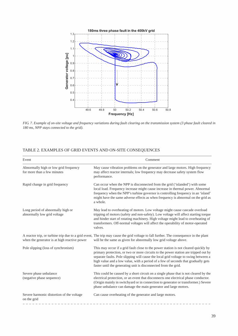
TABLE 2. EXAMPLES OF GRID EVENTS AND ON-SITE CONSEQUENCES
Event Comment
Abnormally high or low grid frequencyfor more than a few minutes
May cause vibration problems on the generator and large motors. High frequency may affect reactor internals; low frequency may decrease safety system flow performance.
Rapid change in grid frequency Can occur when the NPP is disconnected from the grid (‘islanded’) with some local load. Frequency increase might cause increase in thermal power. Abnormal frequency when the NPP’s turbine governor is controlling frequency in an ‘island’ might have the same adverse effects as when frequency is abnormal on the grid as a whole.
Long period of abnormally high orabnormally low grid voltage
May lead to overheating of motors. Low voltage might cause cascade overload tripping of motors (safety and non-safety). Low voltage will affect starting torque and hinder start of rotating machinery. High voltage might lead to overheating of transformers. Off-normal voltages will affect the operability of motor-operated valves.
A reactor trip, or turbine trip due to a grid event, when the generator is at high reactive power
The trip may cause the grid voltage to fall further. The consequence in the plant will be the same as given for abnormally low grid voltage above.
Pole slipping (loss of synchronism) This may occur if a grid fault close to the power station is not cleared quickly by primary protection, or two or more circuits to the power station are tripped out by separate faults. Pole slipping will cause the local grid voltage to swing between a high value and a low value, with a period of a few of seconds that gradually gets faster until the generating unit is disconnected from the grid.
Severe phase unbalance(negative phase sequence)
This could be caused by a short circuit on a single phase that is not cleared by the electrical protection, or an event that disconnects one electrical phase conductor. (Origin mainly in switchyard or in connection to generator or transformer.) Severe phase unbalance can damage the main generator and large motors.
Severe harmonic distortion of the voltageon the grid
Can cause overheating of the generator and large motors.
49.6 49.8 50 50.2 50.4 50.6 50.8
0.4
0.5
0.6
0.7
0.8
0.9
1
1.1
1.2
1.3
Frequency [Hz]
Gen
erat
or v
olta
ge [p
u]
180ms three phase fault in the 400kV grid
FIG. 7. Example of on-site voltage and frequency variations during fault clearing on the transmission system (3 phase fault cleared in 180 ms, NPP stays connected to the grid).
39
10. ARRANGEMENTS BETWEEN THE TSOAND THE NPP OPERATOR
10.1. INTRODUCTION
Before a NPP starts operation the NPP Operator will need to establish agreements with the TSO to ensure that the TSO will operate and maintain the transmission system in a way that is consistent with the safety requirements of the NPP and that the NPP Operator and TSO will exchange all the information that is necessary for the continued safe and secure operation of the NPP and the grid. The operating procedures and arrangements for exchange of information must continue throughout the operating life of the NPP. The NPP operator should ensure that the TSO staff continue to understand the special requirements of nuclear plant. The importance of this relationship between the TSO and the NPP operator throughout the operating life of the NPP is explained and emphasised in Refs [20–22].
There may be legal obligations on the TSO to take many of the actions that the NPP operator requires. If there are not, then the NPP operator should establish appropriate legal agreements with the TSO to ensure the necessary actions and behaviours by the TSO. The topics that should be considered for inclusion in such an agreement include:
— Acceptable ranges of grid voltage and frequency (for NPP operation, and for supplies to the NPP when shut down or during nuclear incidents);
— Arrangements to ensure that the capacity of the connections to the NPP are always sufficient to provide supplies for post-trip cooling;
— Arrangements for rapid repair and reconnection of grid connections to the NPP following disconnection due to grid faults;
— Priority for restoration of supply to the NPP during a blackout recovery (black start);— An obligation on the TSO to notify the NPP control room promptly if there are problems on the grid system
that may affect the reliability of the grid supply (e.g. expected very severe weather that will cause multiple grid faults);
— An obligation on the TSO to notify the NPP owner/operator of all planned grid outages that may affect it (to allow the coordination of outages on the transmission system with planned maintenance in the NPP);
A grid fault near to the NPP, which causesa transient depression of the grid voltageto a very low value
Small electrical auxiliaries connected via electrically held contactors (fed from the AC distribution system) are likely to trip off if the on-site voltage goes low (probable during shutdown). Some electronic equipment may see the voltage depression as a loss of supply and stop operating.
A grid fault near to the NPP, which is clearedvery slowly because of incorrect or faultyelectrical protection
The generator AVR will boost the generator excitation during the fault, but when the fault is cleared and the plant is islanded, the generator voltage will be abnormally high, causing an abnormally high voltage to the electrical auxiliaries. The rapid voltage decrease and increase on the onsite system might cause voltage excursions in semi-conductor devices output. (An example of such an event is described in more detail in Section 13.4).
Prolonged loss (several days) of all offsitepower from the grid
On-site power sources (batteries, diesel generators or gas turbine generators) may be required to operate continuously for longer than assumed in original design.
TABLE 2. EXAMPLES OF GRID EVENTS AND ON-SITE CONSEQUENCES (cont.)
Event Comment
40
— An obligation on the TSO to notify the NPP control room promptly of fault outages on the transmission system that may affect the NPP;
— Agreement on the ownership and responsibilities for equipment in the substation(s) to which the NPP is connected, including the arrangements for its maintenance;
— Arrangements for enhanced maintenance if necessary on transmission system components that significantly affect the reliability of grid connections to the NPP;
— An obligation on the TSO to notify the NPP owner/operator of any planned modifications to the grid system near the NPP, and to seek agreement from the NPP owner/operator before the modifications are carried out;
— Arrangements for the physical security and cyber security of the transmission circuits to the NPP as discussed in Section 4.11.
There should also be obligations on the NPP operator to supply certain information to the TSO. It is likely that these obligations will be similar to the obligations on all power plant operators, and will include notifying the TSO of:
— Planned generation levels from the plant;— Dates of future plant outages/shutdowns;— Any planned changes to the plant design, configuration, operations, limits, protection systems, or capabilities
that would impact the ability of the TSO to control the system, or may affect other users of the transmission system.
Some particular examples of the necessary behaviours and communications are given below.
10.2. NOTIFICATION AND COORDINATION OF OUTAGES
There is a need for close cooperation between the grid operator and the NPP operator in maintenance planning as well as outage planning. Experience has shown that a formal agreement on coordination of planning, including definition of responsibilities, is beneficial in ensuring the reliability of the offsite power from the grid. It is particularly important to coordinate maintenance activities on plant safety systems with transmission maintenance activities.
The TSO may already have an established procedure for exchanging outage information with other power plants but this procedure may need to be modified to provide extra information to the NPP operator. In some Member States, knowledge of transmission system outages may provide commercial advantage to certain power plants, so for this reason the TSO restricts the amount of information that it releases to power plants. If this is the case, the NPP operator may need a special agreement to ensure that it receives all the necessary outage information. The NPP operator may also need agreements with the TSO that certain transmission circuits are not taken out of service for planned maintenance while the NPP is in operation. This would apply particularly to transmission circuits that would provide auxiliary power to the NPP after a reactor trip.
The NPP’s operating rules should include the details of such restrictions on transmission system outages, and the NPP’s operating procedures should include the routine checking of the schedules of transmission system outages for any outages for which there is a restriction. As maintenance activities can cause power reliability problems, NPP staff should carry out a risk assessment on grid maintenance to manage the risk within acceptable limits.
Occasionally, it may be necessary for the grid operator to take a transmission circuit out of service at short notice (within hours or a few days), because of a developing problem. This could include problems such as a grid transformer overheating because of a failure of cooling, high voltage arcing across insulators because of pollution, or failure of the suspension insulators on overhead lines. The agreed procedures for communication between the grid operator and the NPP should include communication about such emergency situations. The NPP’s ‘operating rules’ or ‘abnormal operating procedures’ should include guidance to the NPP operating staff so that they can respond quickly and correctly to such emergency situations.
41
10.3. NOTIFICATION OF LOSS OF CONTINGENCY
In order to ensure that the transmission system is secure, it is normal practice in developed countries for the transmission control centre to operate a real time computer system that continuously monitors the condition of the system, and alerts the control centre operating staff if changing conditions on the system mean that there has been a reduction in the required redundancy against unplanned events. The TSO should notify the NPP operator if there is a loss of contingency that could affect the NPP.
For example, a transmission system fault may weaken the system so that although the transmission system voltage at the NPP connection may be adequate, a subsequent trip of the NPP would result in a low grid voltage that is below the NPP design requirements for offsite power (i.e. the system does not meet one of the criteria for N-1 security, as described in Section 4.6.). In this case, the TSO control centre should notify the NPP of the loss of contingency. The NPP operating staff should then declare the offsite power not available and follow the operation requirements for inoperable offsite power source(s) in accordance with the plant-specific operating specifications. This is so that the risk to the plant can be reduced by making sure that other safe shutdown emergency power sources are available, and staff take actions to prevent performing any maintenance and testing on systems that are needed for accident mitigation and safe shutdown.
11. ROADMAP FOR CONNECTION OF AN NPP
11.1. INTRODUCTION
The other sections of this publication discuss various conditions that need to be met in order to successfully connect a NPP to a transmission system and achieve safe and reliable operation of the NPP and the grid, and the activities that need to be completed to achieve this. This section is a road map for the development of a NPP with regards to the development of the transmission network and the interaction between the NPP and that network. It presents a summary of the activities required, under a number of headings, and the order in which these activities are carried out.
For a Member State that does not yet use nuclear power, it is likely that activities to consider the feasibility of starting a nuclear power programme will be led by an agency set up by the government such as the NEPIO described in Refs [1–2], although matters related to the transmission system may be undertaken for the NEPIO by the existing TSO. The matters related to the electrical grid will be among many inputs to the feasibility study that will be used as the basis for an informed decision by the government whether to proceed with a nuclear power programme. Once the decision to start a nuclear power programme has been made, the responsibility for the activities related to the development of the grid and the NPP will transfer to the TSO and the NPP developer. For a country that already has NPPs in operation, the decision to start a project to build a new NPP will probably be taken by an existing NPP operator.
After a decision has been made to start a project to construct a NPP, it is strongly recommended that the NPP developer and the TSO should have regular collaborative meetings. Initially, a firm decision has to be made on the location of the planned NPP, and the TSO will carry out studies to design the grid additions and modifications that will be needed to connect the NPP and maintain or improve the security and reliability of the grid. The NPP developer will need to agree with TSO those aspects of the technical specification for the NPP that relate to the grid, and gather all the information needed to be able to issue a bid invitation specification (BIS) to potential NPP vendors, and to submit an application for the construction licence to the nuclear regulatory authority in the country.
42
11.2. OVERALL GRID STUDIES
The feasibility study that is carried out before a decision is made to start a nuclear programme should include a consideration of the main technical issues related to the operation of the grid system with NPPs, to demonstrate that the introduction of nuclear power is practicable. This is an extension of the long term planning and system studies that should be carried out routinely by the transmission system operator in the country. It should include studies of interconnections to other countries or networks, if such interconnections exist or are planned. The analysis of the grid system for the inclusion of nuclear generation should include the topics that are summarized in Section 4 of this publication.
The studies of the grid system will include:
— Analysis of the growth of load, and the effect of adding new power stations;— Studies to ensure that there will be enough power reserve;— Load flow studies to demonstrate that acceptable power flows can be achieved, with an acceptable voltage
profile for a variety of grid operating conditions including at maximum or minimum system load with NPP at full power or shut down;
— Stability studies to check the dynamic stability of the system in normal operation (i.e. the system does not have inter-area oscillations);
— Stability studies to check the transient stability of the system (i.e. following a fault on a transmission circuit, there is not loss of synchronism);
— Studies to calculate the fault levels at all points in the grid system, and to check against the fault ratings of the installed equipment.
These studies should identify the general modifications and reinforcements to the grid that are required to accommodate the NPP, and to ensure a secure and reliable grid when the NPP is in operation. The likely cost of such modifications should be estimated, and a decision made on how they are to be funded.
Once the decision has been made to build an NPP, it will be necessary to carry out more detailed studies, in order to assist with the final decision on the location of the NPP, and to design the necessary grid reinforcements and the transmission connection to the NPP site.
The TSO should review and update the system studies during the time that the NPP is being built, to take account of continuing changes to the grid system, for example if load growth has been significantly different from earlier predictions or if generation patterns have changed. Such studies should also continue during the life of the nuclear plant.
11.3. GRID RELIABILITY AND PERFORMANCE
The feasibility study should consider the performance and reliability of the electricity supply system in the country because of the NPP’s requirement for a stable and reliable grid. This requires the TSO to have records for a number of years of grid performance as summarized in Section 4.2. If the TSO has not been keeping and analysing such data, this should be started immediately, and such recording and analysis should be continued into the future.
One outcome of the feasibility study is whether the general performance of the electricity supply system is adequate. The typical performance requirements are summarized in Section 4.1. If the performance is significantly worse than this, then the feasibility study should include credible plans that could improve the performance and reliability of the grid before the NPP is connected, including the likely cost of such improvements and how they are to be funded. It is desirable that the government establishes a policy that the grid system should be reliable; this is necessary for the NPP, but is also a commercial benefit to the country as a whole.
Once the NPP project has started, it will be necessary to establish the grid performance sufficiently well to provide information to be included in the bid invitation specification, and later in the application for a construction or operating licence. The nuclear regulatory body will need to be satisfied that the grid performance characteristics are adequate or that planned improvements will provide adequate performance by the time that the NPP is due to start operation.
43
11.4. UNIT SIZE
The feasibility study should consider the issue of the size of nuclear units that are available and the current and forecast electricity demand in the country, for the reasons described in Section 5. If the size of the nuclear unit is likely to be close to 10% of the minimum electrical demand in the country, the feasibility study should include outline plans for ensuring that frequency and voltage will remain within acceptable limits after a trip of the nuclear unit, and for meeting the electricity demand in the country when the nuclear unit is shut down.
When the NPP project starts, the TSO will need to start to make arrangements to implement those plans. This could include building or strengthening electrical connections to neighbouring countries, and entering into the necessary legal and commercial agreements with those countries. These arrangements need to be fully in force before the NPP is ready to commission.
11.5. NPP OPERATING CHARACTERISTICS
The analysis of the options for an NPP should consider whether there is any need for the NPP to have the capability for flexible operation, as described in Section 3.5, and the maximum amount of flexibility that may be required. This should include a consideration of whether flexible operation may be required at some time in the future if there are changes to the grid system.
Once a decision has been made to start the NPP project, then the NPP developer will need to come to an early agreement with the TSO on the technical performance requirements of the NPP, including the requirements for flexible operation. These characteristics will need to be compatible with the capabilities of existing nuclear units, and will need to be included in the bid invitation specification, and the application for a construction licence.
The TSO may require that during commissioning the NPP operator demonstrate that the nuclear unit complies with the technical performance requirements.
11.6. SITE ASSESSMENT AND GRID CONNECTIONS TO THE NPP SITE
The feasibility study undertaken before the start of a NPP project should consider the possible candidate sites for an NPP, from the point of view of the connection to the grid, as described in Section 7 of this publication. This should include the practicality and cost of making sufficient number of suitable grid connections to these sites and any associated grid reinforcements, the difficulties of building new transmission circuits and the difficulty of getting rights of way for those circuits. It should also include consideration of the arrangements for the physical security and for the cyber security of the grid connections, their electronic control and protection systems, and the systems for communicating with the grid control centre. An outcome of the feasibility study is the selection of a small number of suitable candidate sites.
Once the decision has been made to start an NPP project, a final decision should be made fairly soon on the site to be used for the NPP. A more detailed design and assessment of the necessary grid connections to the site, and any associated grid reinforcements, can then be carried out. The assessment of the planned connections, together with the data on historic fault rates, should allow a reliable estimate of the likely future reliability of the grid connections to the planned NPP site, which can be included in the BIS, and in the application for a construction licence.
The electrical supply to the NPP construction site (typically with a capacity of a few tens of megawatts) needs to be available before the major construction work can start. The final details of the main grid connections at the NPP site, such as the layout of the substation, may not be finalised until after the contract for the construction of the NPP has been awarded to a vendor because of the differences in electrical requirements of different NPP designs.
The grid connections to the NPP site that are required for operation of the NPP do not need to be completed until shortly before the NPP is ready to commission, but the progress of this work should be monitored during the construction of the NPP.
44
11.7. POWER SYSTEM STANDARDS
As indicated in Sections 4.6 and 4.7, in order for a grid system to be reliable, it needs to be designed and operated to have sufficient redundancy that common faults to not have significant consequences. The feasibility study should consider the current codes, standards or technical rules if any that are used for the design and operation of the transmission system in the country and whether it is necessary to modify any existing standards or to create new ones, to achieve a standard that is similar to or better than the ‘N-1’ standard described in Section 4.6.
The feasibility study should also consider the performance characteristics of the existing generating units in the country, and whether there is a code or standard that specifies what is required, and if it is monitored and enforced.
Once a decision has been made to start the NPP project, arrangements should be made to introduce or improve the grid and generator standards identified in the feasibility study, and to start to use these standards for the design and operation of the grid and for specifying the performance of generating units.
11.8. GRID CONTROL AND COMMUNICATION ARRANGEMENTS
As indicated in Section 4.12 and 4.13 of this publication, for a grid system to be reliable, there needs to be suitable control and monitoring from a well equipped grid control centre, with sufficient well trained staff. The feasibility study should consider whether there is a need to upgrade the control centre, whether the communications arrangements have adequate diversity and reliability to withstand abnormal events, and the arrangements for a back-up control centre if the primary control centre cannot be used. It should also consider the need for measures to improve the cyber security of their electronic control, protection and communication systems.
If the feasibility study has identified the need to upgrade the control centre, the communications arrangements, or the backup arrangements so that they comply with best practice as described in Sections 4.11– 4.13, then this work should be planned once the NPP project starts, and be completed before the NPP is due to start commissioning.
Before the NPP is due to commission, the operator should ensure that the grid control centre’s operating procedures have been updated to deal correctly with the nuclear unit and that control room staff have been trained in those procedures. The procedures should ensure that auxiliary power supplied to a nuclear unit (for example while a nuclear unit is shut down) is not part of any emergency load-shedding scheme; that the procedure for energizing circuits connecting to the NPP site after a circuit outage or fault does not pose a risk to the nuclear units; and that the blackout restoration plans will treat the NPP as a high priority load.
Where the grid control arrangements rely on connections to grid networks in neighbouring countries or regions to control frequency after events such as an unplanned disconnection or trip of a nuclear unit, then extra attention must be paid to the joint control arrangements with those countries or regions. The necessary agreements and procedures should be in place before the NPP is ready to commission.
11.9. INTERFACE BETWEEN NPP OPERATOR AND TSO
The feasibility study that is carried out before the decision is made to start a nuclear power programme should consider whether the government or energy ministry needs to impose additional legal obligations directly on the TSO, or place an obligation on the TSO to enter into binding agreements with the NPP operator, so that the TSO will be obliged to operate the grid system in a way that is compatible with the safe and secure operation of a NPP and the requirements of the NPP’s operating licence. Once a decision has been made to start construction of an NPP, the government or energy ministry should make arrangements to establish such obligations.
As soon as a decision has been made to construct a new nuclear unit, the NPP developer needs to establish a good working relationship between the NPP development teams and the design teams in the TSO. This working relationship needs to continue throughout the preparation of the BIS, the submission of the application for the construction licence, and subsequently during the construction of the NPP, the substation and the grid connections. Many issues are likely to arise that will require close cooperation between the NPP developer and the TSO.
Before the NPP is ready to commission the NPP operator will need to establish the necessary interfaces with the TSO for future operation of the NPP operation. Section 10 of this publication summarizes the necessary
45
agreements between the TSO and the NPP operator, if there are not equivalent legal obligations placed on the TSO from the government or energy ministry in the country.
11.10. READINESS TO COMMISSION
The feasibility study may have identified various additions and enhancements to the grid that were needed for the connection of the NPP. After the start of the NPP project, the NPP developer and the TSO would have discussed and agreed to the design of the substation for the NPP and its connection to the rest of the grid system, and other additions to the grid system that were needed. During the construction of the NPP, the NPP developer should monitor that the construction projects for the additions and enhancements are progressing to schedule, so that they will be ready before the NPP is due to start commissioning. A final check should be made before the NPP is due to start commissioning that all these works have been completed, and that they are consistent with what was included in the bid invitation specification, and the applications for construction or operating licences.
The NPP developer should also confirm that any additions or changes to TSO’s operational procedures that were required for the NPP have been completed, and that the TSO’s operating staff have received the necessary training in any new or revised procedures.
12. EFFECTS OF CLIMATE CHANGE
12.1. INTRODUCTION
It is well established that the concentration of carbon dioxide in the atmosphere has increased during the last few centuries, and the concentration is still increasing at an accelerating rate, due to human activities and the use of fossil fuels. The international scientific consensus is that this increase in the concentration of carbon dioxide, and some other gases, in the atmosphere is causing global temperatures to rise as a consequence of the greenhouse effect, and this will cause changes in climate that may change the frequency and severity of extreme weather events.
12.2. EFFECT ON NPPS AND TRANSMISSION SYSTEM RELIABILITY
NPPs that are being planned or constructed now, have planned operating lives up to 60 years, so there is the potential for significant change to climate and weather conditions during the life of the plant. The change in weather conditions may lead to more frequent periods of severe weather, or weather events that are more extreme. These events may affect the reliability of the grid system, so this should be considered during the design of the NPP and its grid connections. The effects of severe weather events on the transmission system are summarized here.
12.2.1. Strong winds
Experience worldwide is that strong winds can cause considerable disruption or damage to lower voltage distribution networks, because of falling trees, but generally do not have a significant effect of higher voltage transmission circuits, because of the greater height of transmission towers. Transmission circuits are generally only affected by extreme high winds, which cause physical damage to transmission towers. The risk of such damage can be reduced by designing the towers for higher wind loading.
Strong winds from a salty sea will also pollute insulators on overhead lines and in switchyards situated in the vicinity of the coast and increase the risk for flashover.
Civil structures at the NPP, including exhaust stacks for onsite power sources, should be designed for extreme high winds.
46
12.2.2. Cold weather, ice and snow
Heavy snow can cause failure of overhead lines by the weight. The extreme event is the ‘ice storm’ when super cooled rain combines with high winds, to rapidly build up an ice layer on overhead line conductors. The remedial action is to design for higher static loading, although it may not be possible to protect against the most severe ice storms.
Extreme snow should also be considered for the civil structures of the NPP. Heavy snow could clog the air intakes for onsite power sources. Extreme cold weather might affect intermediate cooling water system temperature for onsite power sources, especially if the NPP is at shutdown.
12.2.3. Thunderstorms
Thunderstorms with lightning are the most common cause of faults on overhead lines in some Member States, so that if thunderstorms become more common, the number of faults will increase significantly. It is probably not possible to make a significant change to the likelihood of lightning strikes by changes to the tower design, but attention should be paid to measures to prevent significant damage from lightning strikes, such as proper earthing of transmission towers, correct maintenance of spark gaps and surge arresters, etc.
12.2.4. High temperatures
If high air temperatures are combined with high power flows on overhead lines, the temperature of the overhead lines will be maximum, so the sag of the line will be greater, causing an increased risk of flashover faults to trees growing near or under the lines. The remedial measures are to increase the current rating of the lines by using a conductors of greater cross-section or increase the temperature rating of the lines by increasing the line tension, and to trim of trees under the overhead lines more frequently.
Prolonged high temperatures may also lead to increased risk of forest and grass fires. In addition to the normal measures for avoiding forest fires, the overhead lines should be routed away from forest areas where this is possible.
Prolonged high temperatures might also lead to high intake temperatures or high discharge temperatures for any of the cooling systems at the NPP, so that the temperatures are above permissible limits. This could be taken care of in the design phase in order to accommodate a wider range of temperature limits.
12.2.5. Floods and rising sea levels
The main risk to the transmission system from floods due to heavy rain or rising sea levels is to electrical and control equipment mounted at ground level in substations. The main remedial action is to avoid building substations on low ground in areas susceptible to flooding.
13. CASE STUDIES OF PLANNINGAND OPERATING EXPERIENCE
13.1. INTRODUCTION
This section summarizes some particular experience of Member States for the planning of new NPPs, or the operation of NPPs and the grid systems as follows:
China: The planning that took place for the connection of the first nuclear units.
Finland: The arrangements that are planned because the new nuclear unit being built is much larger than the existing nuclear units on the system.
47
Sweden: Description of an event at a NPP when an unusual fault in the substation beside an NPP had serious safety consequences on a nuclear unit.
USA: Description of an event where a simple fault on the grid system caused loss of offsite power to several nuclear units because of a deficiency in the design of the electrical protection arrangements on the grid.
United Kingdom: Discussion of the causes of loss of off-site power (LOOP) to the NPPs in the UK based on many plant-years experience.
Japan: Brief description and discussion of the grid aspects of the serious accident at Fukushima Daiichi NPP in March 2011, based on currently available information.
13.2. CHINA
The government of China started economic reform and opening the country to the outside world in 1978. This economic development caused a very fast increase in electricity demand. There was a significant shortage of electricity in the Guangdong province of Southern China — demand exceeded generation capacity by as much as 30%. Guangdong lacked primary energy resources; coal had to be imported and the transport capacity could only provide about 50% of what was needed at that time. The hydroelectric resources were very limited in the coastal and low-lying area. Nuclear power was the best choice for additional generation capacity.
In 1980, the Guangdong grid had an installed capacity 1870 MW, and a peak demand of 1450MW. The transmission network operated at a voltage of 220 kV, and the electrical interconnections were weak. The grid structure could not allow a large generating unit to connect. The Guangdong grid often kept the balance of generation and demand through mandatory load shedding , the quality of frequency and voltage was not good.
After the second oil crisis in the 1970s, energy prices had risen very much, and CLP (China Light and Power, the main electric power supplier in Hong Kong) was seeking a long term cheaper source of electricity. In 1977, CLP started to build a large coal-fired power plant (Qingshan) instead of the oil-fired units that it had used before. The IAEA had finished a feasibility study for CLP of construction of a NPP in Hong Kong; this study concluded that the cost of nuclear power generation would be cheaper than coal-fired power in the long term, but Hong Kong is too small to have enough space to develop a NPP. The Hong Kong transmission system operated at 400 kV, the installed capacity was 3470 MW and the maximum demand 2800 MW. The grid performance was good with strong electrical connections and sufficient reserve capacity.
Guangdong is adjacent to Hong Kong and had the land available, but lacked the capital to develop a NPP. Hong Kong had the market with foreign currency earnings that could be used to repay the loan for the project. There was a common benefit to establish a joint venture to have a NPP in Guangdong.
The load in Guangdong was expected to grow by 10.8% per year between 1980 and 1990, while the load on CLP grid was expected to grow by 8.8% in the same period. The maximum load demand was expected to reach 4040 MW in Guangdong and 6470 MW in CLP by 1990, so the total load of the two grids would be around 10 500 MW, which would be large enough to allow a single unit of 1000 MW to be connected to the grid by 1990.
The 10-year plan for developing electric power in Guangdong was worked out one year before the Daya Bay project was approved. Four coal fired power plants and seven small hydroelectric power stations were to be built in Guangdong, and a 500 kV transmission grid would be established in 1990 to connect to those new coal fired power plants and NPP. By 1990, the Guangdong grid would be connected with that of the three west provinces, Guangxi, Yunnan and Guizhou to establish a regional electrical network.
The government of China approved the construction of Daya Bay NPP (2 × 984 MW) in Guangdong province at the end of 1982, and the negotiations for the joint venture were completed in 1985. Seventy per cent of the NPP output goes to CLP grid and 30% to Guangdong. Construction started with first concrete at Daya Bay NPP in September of 1987; unit 1 was put into operation in February of 1994 and unit 2 in May of the same year.
The decision was made in 1987 to construct a 4 × 300 MW Guangzhou pumped storage power station (GPSPS); this would increase the NPP load factor and deal with load following in the limited capacity system. The construction of this power plant started on 25 May 1989, the first unit was put into operation on 29 June 1993, and all four units were completed by 12 March 1994.
48

The Guangdong and CLP grid system was small when Daya Bay NPP units were first connected. There was a large daily variation of demand and a large variation with season also. There was inadequate system reserve. The interconnection with the neighbouring grids was very weak. Daya Bay NPP has maintained safe and stable operations since its commercial operation. The three key elements of good performance in this power system were as follows:
Interconnection with neighbouring grids: A 500 kV transmission line of 1240 km was put into operation at the end of 1993 to transfer hydropower from the west to Guangdong, which connected the three west ern provinces with Guangdong and CLP grid. The load of the western three provinces was approximately 6600 MW. The grid scale was expanded from this tie line before the NPP big unit operation. This was one of the foundations for the grid stability.
Interface between grid and NPP: A coordination mechanism was set up between the grids and the NPP. An Interconnection Operational Management Committee (IOMC) was formed, consisting of the Guangdong grid, the CLP grid, the Daya Bay NPP and the GPSPS. There were regular meetings to coordinate grid and NPP construction, operation, maintenance and testing. The IOMC drew up the Nuclear Interconnection Operational Management Rules (NIOR), which were observed by all the parties. The NPP specifications and grid requirement were made compatible with NIOR. The NIOR played a very important role for system safety and reliability during the construction and early operation of Daya Bay NPP. The NIOR provided common standards, and defined the responsibilities of all parties in the operation of the interconnected system, in order to lessen the possibility of misunderstanding among operators in both normal and emergency conditions. The NIOR ensure that the NPP operators understand and observe the rules and policies of the grid for dispatch, operation and management of the interconnected system. NIOR also ensure that the power system operators have a clear conception of NPP characteristics and limits, emergency handling procedures, and maintenance coo rdination requirements.
Guangdong pumped storage power station (GPSPS): In a power system of limited capacity with large NPP units, a trip of NPP unit could create a big disturbance on the grid. The NPP units were also difficult to operate at base load mode since there was the great variation between peak and off-peak demand on the grid. The GPSPS flattened out load variations on the grid permitting the NPP to operate at base load. It can respond to sudden changes in electrical demand and generation caused by the trips of NPP or transmission lines within seconds. It has contributed a lot to the grid stability and the load factors of the NPP units.
The Guangdong grid has continued to expand along with the economical development: peak load increased from 6900 MW in 1994 when Daya Bay NPP was put into operation, to 78 000 MW in 2011. The interconnection with the western grids has been greatly strengthened: the Guangdong grid receives power of 23 000 MW through 10 AC and 5 DC circuits from external grids, and now has 5 nuclear units of 1000 MW each in operation, and 9 units in construction on 3 sites.
13.3. FINLAND
Finland has two NPPs in operation, comprising four nuclear units, (two units of 510 MW and two units of 870 MW), in a country with a maximum demand of 12 500 MW. But Finland is part of the Nordic grid system (Norway, Sweden, Finland, Eastern Denmark), which is a synchronized system with a maximum demand of around 60 000 MW. There are other nuclear units in Sweden.
The next reactor to be built in Finland is Olkiluoto 3, with a planned capacity of 1630 MW. The installation of such a large unit requires close cooperation between the NPP owner and Fingrid, the transmission system operator, for development of the transmission system. The new unit has to comply with the technical requirements of the Nordic Grid Code, which establishes a set of common rules for planning, connection, operation and data exchange in the Nordic countries. This includes the need for the system to remain stable for a fault such as a 250 millisecond short-circuit fault on the high voltage side of the generator step-up transformer. This requirement is crucial for the Nordic network, which has long transmission distances and a risk of voltage collapse.
Various parameters were considered for their effect on the stability of the planned nuclear unit, including the moment of inertia of the turbine-generator unit, the electrical parameters of the generator, and the performance of the automatic voltage regulator and the excitation system, the speed governor and the possible use of fast valving.
The planned Olkiluoto 3 is significantly larger than the largest existing unit of the Nordic grid, so it is a challenge to provide adequate reserves for frequency control after an event that trips or disconnects the unit. To
49

accommodate the larger generation loss from a trip of Olkiluoto 3, it has been decided to install a tripping scheme that will automatically disconnect 300–400 MW of large industrial load immediately after a reactor trip. This load is located in Finland but at several sites remote from the NPP site. The requirement is that the tripping scheme is reliable and fast (tripping time less than 200 milliseconds). To ensure reliability it requires redundant equipment and telecommunication signals. The effect of this tripping scheme is that a trip of 1630 MW at Olkiluoto is seen as a loss of around 1300 MW by the power system as a whole, which is no larger than the largest loss from tripping one of the existing NPPs in Sweden. The tripping scheme can be activated or de-activated by remote control, and the amount of load that can be tripped by the protection scheme will be under real time control. Disturbance recorders will be installed to monitor and verify the speed of tripping.
13.4. SWEDEN
An incident occurred at 13.20 on Tuesday 25th July 2006 at unit 1 of Forsmark NPP, which was then in operation at full power, 990 MW. This incident demonstrates the importance of considering the possibility of unusual events on the grid when designing and operating a NPP.
The TSO was carrying out some work in the 400 kV substation next to Forsmark NPP, and had misjudged the need to interlock an earth fault protection. An incorrect switching operation resulted in a disconnector opening, causing an arc across the disconnector and a two-phase short circuit on the 400 kV network, with a resulting voltage drop. Because the earth fault protection had been interlocked, the short circuit fault was not cleared rapidly by the bus bar protection, but was cleared slowly.
The generator excitation systems responded automatically to the voltage drop by boosting the generator excitation, so that when the protection automatically disconnected the two turbine generator units of Forsmark Unit 1 from the grid, there was a brief but substantial overvoltage on the generating units, and hence on the power plant’s internal electrical network.
The reactor output power was then automatically reduced to 25% as the result of a reduction in the water inflow rate to the reactor, and because some of the control rods had been inserted. The plant therefore changed to house load operation, i.e. generating electricity only for the power station’s own needs.
Within the plant there are four independent electrical subsystems, (A, B, C and D) which can provide power to safety systems. Each of these four subsystems contains an uninterruptible power supply (UPS) system, which contains rectifiers, batteries and inverters, to provide an uninterruptible supply of alternating current to important safety systems. The initial voltage drop during the fault forced the battery chargers in the UPS system to open their thyristors fully. Then when there was a substantial overvoltage after the fault was cleared, there was an overvoltage on the DC side of the chargers and inverters. This high voltage caused the inverter to trip the UPS systems in subsystems A and B. Fortunately the UPS systems in C and D subsystems continued to operate which meant that equipment supplied from them operated as intended.
The transfer to house load operation did not succeed and power to the 500 V AC safety buses was lost. Start commands were issued automatically to the four diesel driven generators (one in each subsystem) that supply standby power to the power station. All the diesel generators started automatically. However, the connection of their electrical outputs to the subsystems is dependent on the availability of power to their supervision circuits from the uninterruptible AC system. Hence two of the generators failed to connect. The two other diesel generators, in subsystems C and D, supplied power to the internal network throughout the entire incident.
The AC network also supplies the equipment that measures the water level and pressure in the reactor pressure vessel. This, too, is divided up into four subsystems. As two of the four instrumentation systems were not working, this resulted (as intended) in an automatic scram of the reactor. Much of the instrumentation, recording and supervisory facilities in the control room (including indications of the positions of control rods) were also lost, as they are supplied from subsystems A and B in the no break 220 V AC system.
After 22 minutes the offsite power was restored manually, after which the two other diesel units were started. The result was that supervisory facilities were restored in the control room, motor powered insertion of the control rods was completed in subsystems A and B, accompanied by indication that all the rods were inserted, and greater capacity was available for pumping water into the reactor pressure vessel, so that the normal water level was quickly restored. After extensive checks, the control room personnel were able — 45 minutes from the initial event — to enter a brief record in the logbook that “The reactor is safely sub critical and operational status is stable”.
50

This event demonstrated a series of errors that challenged the concept of ‘defence in depth’:
(1) The short circuit in the 400 kV substation and the long time to clear the fault were due to the fact that work there was not carried out in the correct manner. The short circuit in the substation resulted in a more severe disturbance to the electrical systems in the power station than the systems had been designed for.
(2) The under frequency protection of both turbine generators did not operate correctly. New under frequency protection systems had been installed in 2005 and their initial testing had been inadequate.
(3) The battery backed no break AC system is intended to supply equipment that is essential for safe shutdown of the reactor. The UPS systems were installed at Forsmark 1 and 2 over ten years before, as a replacement for older equipment based on mechanical technology, which was more resistant to electrical disturbances. The transient voltage variation that occurred during this event was much greater than that for which the equipment was tested; this resulted in UPS units in subsystems A and B being knocked out.
(4) Although all four diesel generator units started automatically, the A and B diesels failed to connect to their respective 500 V bus bars, as they required auxiliary power from the no break AC systems. This shows how vital the no break systems are for plant safety, but also shows that there was a functional relationship between the distribution systems that meant that they could be knocked out by a common cause failure.
The lessons that can be learned from this event are discussed in Ref. [23].
13.5. UNITED STATES OF AMERICA
The following significant operating event demonstrates a grid reliability issue that resulted from inadequate design of a relay protection on a transmission system [13].
External fouling on a 230 kV insulator resulted in the de-energizing of a 500 kV substation, removing all sources of power to three nuclear units. The initial fault was across the 230 kV insulator with external fouling. Protective relaying detected the fault and isolated the line from the remote substation. The protective relaying scheme at the other substation received a transfer trip signal actuating an auxiliary relay in the tripping scheme for two breakers connected to the faulted line. The relay had four output contacts, all of which were actuated by a single lever arm. The tripping scheme used two contacts in redundant trip coils for each breaker.
One breaker tripped, demonstrating that the relay coil picked up, and at least one of the relay contacts closed. The other breaker did not trip. Bench testing of this type of relay showed that, even with normal voltage applied to the coil, neither of the tripping contacts for the failed breaker closed. The breaker failure scheme for the failed breaker featured a design where the tripping contacts for the respective redundant trip coils also energized redundant breaker failure relays. Since the tripping contacts for the failed breaker apparently did not close, the breaker failure scheme was not activated, resulting in a persistent uncleared fault on the 230 kV line.
Various transmission system event recorders show that, during approximately the first 12 seconds after fault inception, several transmission lines on the interconnected 69 kV, 230 kV, 345 kV, and 500 kV systems tripped on overcurrent. Also during the first 12 seconds, three cogeneration plants tripped, two with combustion turbines and one with a steam turbine, and the fault alternated between a single-phase-to-ground fault and a two-phase-to-ground fault, apparently as a result of a failed shield wire (earth wire) bouncing on the faulted line. After 12 seconds, the fault became a three-phase-to-ground fault and additional 500 kV lines tripped. Approximately 17 seconds after fault inception, the three transmission lines between the NPP substation and the nearby 500 kV substation tripped simultaneously due to the action of their negative sequence relaying, thereby isolating the fault from the several cogeneration plants connected to that substation. Approximately 24 seconds after fault inception, the last two 500 kV lines connected to the NPP substation tripped, isolating the NPP substation from the transmission system. At approximately 28 seconds after fault inception, the three NPP generators were isolated from the substation and, by approximately 38 seconds, all remaining lines feeding the fault had tripped and the fault was isolated.
The trips resulted in a total loss of nearly 5500 MW of local electric generation. Because of the loss of offsite power, a ‘Notice of Unusual Event’ was declared for all three units at the NPP. The Unit 2 train A emergency diesel generator started but failed early in the load sequence process due to a diode that short-circuited. The subject diode had less than 70 hours of run time in the exciter rectifier circuit. As a result, the train A engineered safeguards features busses de-energized, limiting the availability of certain safety equipment for operators. Because of this
51
failure, the emergency declaration for Unit 2 was elevated to an Alert at 7:54 a.m. All three units were safely shut down and stabilized under hot shutdown conditions. Units 1, 2 and 3 were without offsite power for approximately 4 hours and 9 minutes, 1 hour and 46 minutes, and 2 hours 15 minutes, respectively.
The primary cause of the cascading blackout was the susceptibility of a transmission line protection system to a single failure. The insulator degradation caused by external fouling did not, by itself, represent a concern about the reliability of the insulators on the 230 kV transmission system. Nevertheless, the failed relay and the lack of a robust tripping scheme raised concerns about the maintenance, testing, and design of 230 kV system protective relaying. The 230 kV substation where the relay failure occurred was subject to annual maintenance and testing. Following the event, the failed relay was visually inspected. No apparent signs of contamination or deterioration were found.
The tripping scheme lacked redundancy that could have prevented the failure of the protective scheme to clear the fault. The review of the design of the substations connected to the substation indicated that two transmission lines at the subject substation featured a tripping scheme with only one relay of this type. The newer lines had two relays of these relays. However, the review found that the bus-sectioning breakers at the subject substation contained only one trip coil instead of two trip coils.
To improve reliability, the tripping schemes for the two identified lines were modified to have two of the relays energizing separate trip coils for each breaker. The utility is considering installation of two trip coils in all single-trip-coil breakers. The tie lines that connected the 500 kV and 230 kV substations did not have overcurrent or ground fault protection. The installation of overcurrent protection for these tie lines was completed in a later modification.
13.6. UNITED KINGDOM
A total of 19 commercial NPPs have been built in the United Kingdom, comprising 41 reactors, although the older ones have now ceased generation. These 19 NPPs provide a sufficient number of plant-years operation to provide some useful statistics concerning events of loss of off-site power. With one exception, the NPPs had more than one nuclear unit, with the possibility to provide electrical supplies to auxiliaries from one unit to another. Hence the significant LOOP events are those that disconnect the electrical power from the NPP as a whole, and not those that disconnect supplies from just one nuclear unit.
The NPPs were connected to the transmission system at 132 kV, 275 kV or 400 kV, depending on their size. The majority of the NPPs had all their grid connections to a single substation. Some had their station transformers and generator transformers connected to different substations as different voltages, but in each case the lower voltage substation was fed from the higher voltage substation, so was not really independent. The majority of the NPPs had four or more transformer connections between the NPP and the substations. The connections from the substation to the rest of the grid system comprised four different arrangements:
(a) For the majority of the NPPs, the substation was connected via four circuits, on two rows of transmission towers (double circuit towers) which ran over separate routes for most of their length to two or more different substations at the far ends;
(b) For three of the NPPs, the substation was connected by just two circuits to a higher voltage substation that was nearby (much less than 1 km away), which in turn was connected to the grid similar to (a);
(c) For three of the oldest NPPs, the substation was connected by more than four circuits (five or six);(d) For two of the NPPs, the substation was connected by just two circuits, running on the same row of
transmission towers (double circuit towers), to a single substation at the far end.
Historic data on grid events is available for the full plant life of nearly all these NPPs. A study carried out in 2009 collected the data for approximately 630 plant-years of operation (corresponding to approximately 1460 reactor-years). This included some plant-years after some NPPs ceased operation but remained connected to the transmission system. In the 630 plant-years of operation there were 55 identified events in which a NPP experienced a complete loss of off-site power (LOOP). Only one of the LOOP events was due to the loss of all connections between the NPP and the substation, and a small number were due to faults in the substation. The large
52

majority were due to faults that caused the loss of grid connections between the substation and the rest of the grid system.
The frequency of LOOP events varied between the different NPPs; it was approximately once in three years for two NPPs, and there have been none in the plant lifetime for three NPPs. The two NPPs with frequent LOOP were the two NPPs with the connection arrangement (d), with just two connecting circuits. Excluding these two NPPs, the average rate of LOOP for the all other NPPs was about once in twenty years.
More than half the LOOP events were of short duration (less than 30 minutes). The longest duration of LOOP was about 12 hours, and was due to the ‘Great Storm of 1987’ in which high winds caused a great deal of damage to built structures. (This is considered to have been the most severe storm in the UK in more than 250 years).
The main cause of the majority of the LOOP events was bad weather (severe storms with frequent lightning strikes, freezing fog or heavy snow) during which there were multiple faults on the transmission system near the NPP during a period of a few hours, and some of the fault outages overlapped (i.e. several circuits were out of service simultaneously following faults). About 15% of LOOP events were attributed to salt pollution, which is to be expected as all except one of the NPPs is located on the sea coast or close to the coast, and the transmission circuits to them run close to the coast for a significant distance. About 10% of the events had human error as the main cause, and only 6% were caused by equipment failure.
The number of faults per year on the transmission connections to the NPP’s substation varied very much from year to year. In some years with periods of very bad weather, there were ten times as many faults as in other years, but the large majority of transmission system faults did not lead to LOOP events.
The general conclusion is that the main cause of LOOP events in the UK is a period of unusually bad weather or environmental conditions (salt pollution) that affects the transmission lines connecting the NPP’s substation to the rest of the transmission system. The use of four connecting circuits with two independent routes significantly reduces the risk of LOOP compared with using just two connecting circuits on a single route. However, even where an NPP has four connecting circuits, one or two LOOP events can be expected during the life of the NPP.
For comparison, an analysis of recent LOOP events in the USA is presented in Refs [9, 12].
13.7. JAPAN
On 11 March 2011 the strongest earthquake in Japan’s modern history (magnitude 9) occurred under the seabed of the Pacific Ocean approximately 70km from the north-east coast of the main Japanese island of Honshu. The intensity of the earthquake (the ground acceleration) along the coast of Honshu was great enough to cause all the nuclear units in that part of Japan to shut down automatically, based on their seismic trip settings.
At Tokyo Electric Power Company’s Fukushima Daiichi NPP, the measured maximum intensity of the earthquake (the magnitude of the horizontal acceleration) was close to or slightly above the reference maximum earthquake that had been used in the design of the plant. The earthquake itself did not cause significant damage to the nuclear plant, but did cause loss of off-site supply, because of loss of all seven grid connections to the site. The earthquake caused a lot of damage in the switchyards at the NPP, at the nearby Shin-Fukushima substation to which it is connected and to the circuits between them, including:
— Collapse of one transmission tower, built on sloping ground, because of a landslide caused by the earthquake;— Damage to underground cables by subsidence;— Collapse of several high voltage circuit breakers;— Distortion, damage or collapse of several line switches (disconnectors);— Failure of suspension insulators;— Failure of an overhead earth wire (ground wire) which fell on the equipment below it.
Because of the loss of all offsite power, the emergency diesel generators started and initially provided the necessary electrical power for the cooling of the reactors.
However, approximately one hour after the earthquake, the tsunami, which was caused by the earthquake, reached the coast. The height of the tsunami at the Fukushima Daiichi plant was much greater than the maximum height for which the plant had been designed. As a result the site was flooded, and the equipment that was damaged by the flooding included most of the high voltage switchyards and high voltage distribution boards at the NPP. The
53
flooding also damaged all except one of the emergency diesel generators. Hence there was a station blackout, with electrical power available for a limited time only from the plant’s emergency batteries. Because of the extent of the damage caused by the earthquake and flooding, it was not possible to restart the diesel generators, nor was it possible to restore electrical power from the grid for several days, and the batteries were completely discharged after a few hours. Without electrical power available, there was significant overheating of the reactor cores and the fuel in the spent fuel storage ponds. Some of the fuel in three of the reactor cores melted and hydrogen was generated, which led to some hydrogen explosions and major releases of radioactive contamination to the environment.
This was clearly a beyond design basis accident, and the accident management that was achieved was not sufficient to prevent the escalation of the event into a severe accident. There are many lessons to be learnt from this event involving all aspects of design, operation, and safety management. With reference to the grid connections some initial conclusions are:
(a) Plans for severe accident management should include consideration of beyond design basis accidents which result in the loss of all off-site power from the grid for an extended period, combined with extended unavailability of on-site emergency supplies;
(b) Plans for accident management should include actions to be taken by the transmission system operator for emergency repair and restoration of grid connections to an NPP;
(c) While it is probably not feasible to design an entire grid system to be robust against severe earthquakes, the design of the substations and grid connections in the zone of influence of an NPP should include consideration of their ability to withstand earthquakes of the intensity used for the design basis accidents of the NPP;
(d) Electricity substations and grid connections that are in the zone of influence of an NPP should be located away from areas of flood risk, or be designed to be resistant to flooding.
14. SUMMARY AND CONCLUSIONS
This publication has described the ways in which the electrical grid system can affect a NPP, and the NPP can affect the operation of the grid.
Although the NPP operator has the prime responsibility for the safety of the NPP, the actions of the TSO can have an effect on the NPP's safety because the design of the high voltage transmission system and the way it is operated and controlled will affect its performance in both normal circumstances and following faults. Hence the TSO’s actions can affect the reliability of electrical supplies from the grid to the NPP. Similarly, the NPP can have a significant effect on the grid system, mainly because of the large unit size of modern nuclear units. This particular issue is discussed at length in Section 5 of this publication, and illustrated in Appendix 2.
Because of this interaction between the NPP and the grid, this publication has indicated the importance of close collaboration between the NPP developer and the TSO from the very beginning of the design stage of the NPP. This collaboration needs to continue during the construction of the NPP and its grid connections, and subsequently the NPP operator and TSO must collaborate during the operation of the NPP for the full life of the NPP. The need for collaboration is emphasised in this publication because changes in electricity markets in many Member States mean that that now and in the future the NPP operator and the TSO may be different companies or organizations with different commercial and legal obligations, and it may be necessary for the government of the country to pass legislation to permit or require such close collaboration.
To assist in the collaboration between the TSO and NPP operator, this publication has attempted in Section 3 to explain to TSO staff the issues that are important to an NPP; similarly Section 4 explains, from an NPP operator, to staff the issues of importance to the TSO. Other sections in this publication describe the information that has to be exchanged and matters that must be considered and agreed jointly between the two organization s at various stages such as site selection, design of the grid connections to the NPP, and during operation of the NPP.
For a country that does not yet have nuclear power, there may be a need for considerable expenditure for improving the control of voltage and frequency, and for improving the reliability and robustness of the transmission
54

system in order to accommodate a new nuclear unit. This can include building new transmission connections including connections to neighbouring countries. However, although the performance and reliability of the transmission system can be improved, it will always be vulnerable to unusual or extreme weather, environmental and other events, such as those listed in Appendix I. For this reason, the NPP operator will need to consider the possible effect of such unusual events or combinations of events on the NPP, as discussed in Section 9, to satisfy the nuclear regulatory body that the NPP can be operated safely or shut down safely if such events happen. The NPP operator and TSO should also consider the possible effects of climate change during the operating life of the NPP, as summarized in Section 12.
Section 13 describes some experience of Member States of planning for new nuclear units, and of events on the transmission system that led to loss of electrical supplies to NPPs, or other undesirable consequences. The most serious example was the severe accident at Fukushima Daiichi NPP in Japan that happened while this publication was being prepared.
To assist Member States in ensuring that all the issues related to the grid system are considered at the various stages of development of an NPP, Appendix III provides a checklist of questions for self-assessment.
55

56
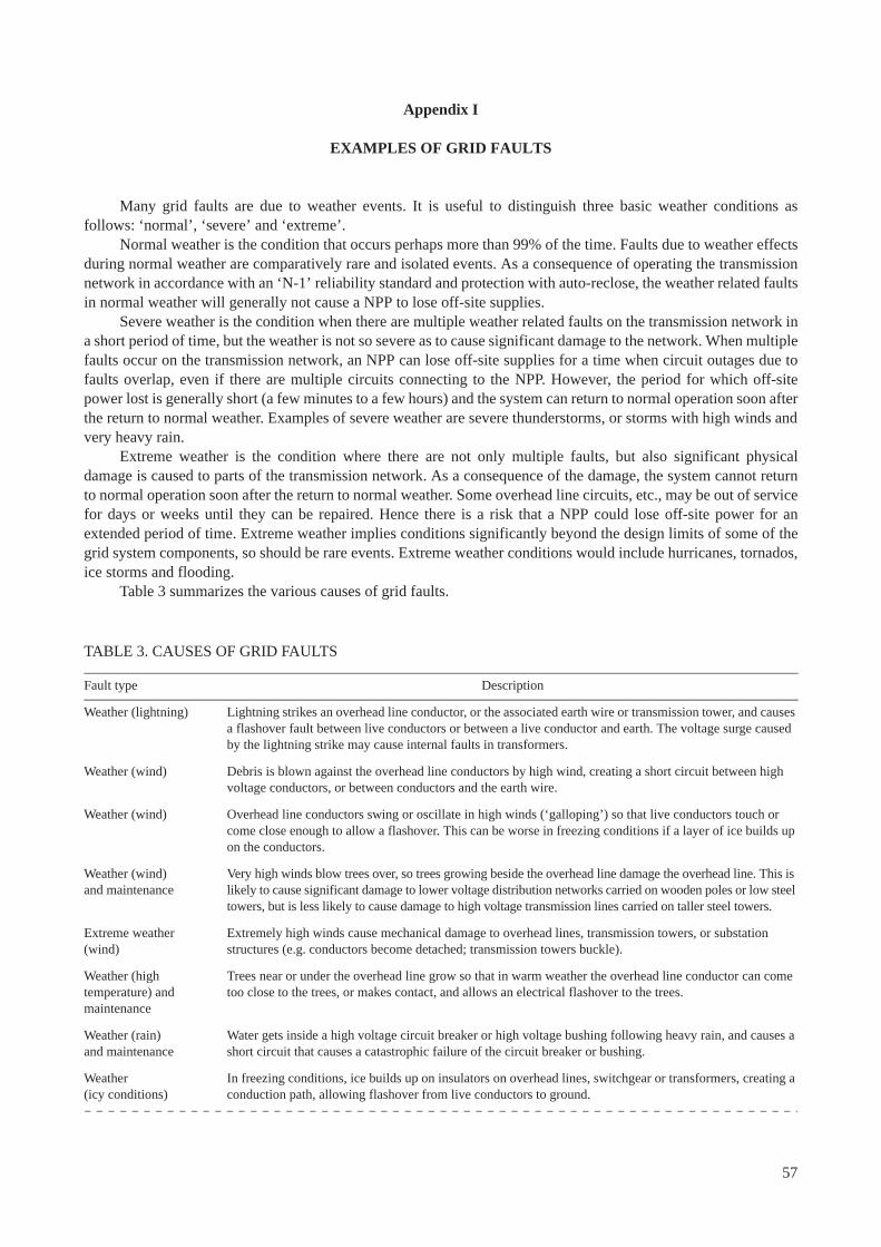
Appendix I
EXAMPLES OF GRID FAULTS
Many grid faults are due to weather events. It is useful to distinguish three basic weather conditions as follows: ‘normal’, ‘severe’ and ‘extreme’.
Normal weather is the condition that occurs perhaps more than 99% of the time. Faults due to weather effects during normal weather are comparatively rare and isolated events. As a consequence of operating the transmission network in accordance with an ‘N-1’ reliability standard and protection with auto-reclose, the weather related faults in normal weather will generally not cause a NPP to lose off-site supplies.
Severe weather is the condition when there are multiple weather related faults on the transmission network in a short period of time, but the weather is not so severe as to cause significant damage to the network. When multiple faults occur on the transmission network, an NPP can lose off-site supplies for a time when circuit outages due to faults overlap, even if there are multiple circuits connecting to the NPP. However, the period for which off-site power lost is generally short (a few minutes to a few hours) and the system can return to normal operation soon after the return to normal weather. Examples of severe weather are severe thunderstorms, or storms with high winds and very heavy rain.
Extreme weather is the condition where there are not only multiple faults, but also significant physical damage is caused to parts of the transmission network. As a consequence of the damage, the system cannot return to normal operation soon after the return to normal weather. Some overhead line circuits, etc., may be out of service for days or weeks until they can be repaired. Hence there is a risk that a NPP could lose off-site power for an extended period of time. Extreme weather implies conditions significantly beyond the design limits of some of the grid system components, so should be rare events. Extreme weather conditions would include hurricanes, tornados, ice storms and flooding.
Table 3 summarizes the various causes of grid faults.
TABLE 3. CAUSES OF GRID FAULTS
Fault type Description
Weather (lightning) Lightning strikes an overhead line conductor, or the associated earth wire or transmission tower, and causes a flashover fault between live conductors or between a live conductor and earth. The voltage surge caused by the lightning strike may cause internal faults in transformers.
Weather (wind) Debris is blown against the overhead line conductors by high wind, creating a short circuit between high voltage conductors, or between conductors and the earth wire.
Weather (wind) Overhead line conductors swing or oscillate in high winds (‘galloping’) so that live conductors touch or come close enough to allow a flashover. This can be worse in freezing conditions if a layer of ice builds up on the conductors.
Weather (wind)and maintenance
Very high winds blow trees over, so trees growing beside the overhead line damage the overhead line. This is likely to cause significant damage to lower voltage distribution networks carried on wooden poles or low steel towers, but is less likely to cause damage to high voltage transmission lines carried on taller steel towers.
Extreme weather(wind)
Extremely high winds cause mechanical damage to overhead lines, transmission towers, or substation structures (e.g. conductors become detached; transmission towers buckle).
Weather (hightemperature) andmaintenance
Trees near or under the overhead line grow so that in warm weather the overhead line conductor can come too close to the trees, or makes contact, and allows an electrical flashover to the trees.
Weather (rain)and maintenance
Water gets inside a high voltage circuit breaker or high voltage bushing following heavy rain, and causes a short circuit that causes a catastrophic failure of the circuit breaker or bushing.
Weather(icy conditions)
In freezing conditions, ice builds up on insulators on overhead lines, switchgear or transformers, creating a conduction path, allowing flashover from live conductors to ground.
57
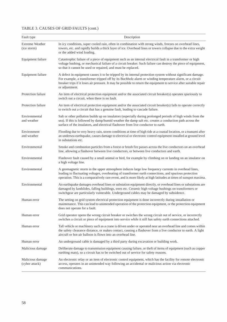
Extreme Weather(ice storm)
In icy conditions, super cooled rain, often in combination with strong winds, freezes on overhead lines, towers, etc. and rapidly builds a thick layer of ice. Overhead lines or towers collapse due to the extra weight or the added wind loading.
Equipment failure Catastrophic failure of a piece of equipment such as an internal electrical fault in a transformer or high voltage bushing, or mechanical failure of a circuit breaker. Such failure can destroy the piece of equipment, so that it cannot be used or repaired, and must be replaced.
Equipment failure A defect in equipment causes it to be tripped by its internal protection system without significant damage. For example, a transformer tripped off by its Buchholz alarm or winding temperature alarm, or a circuit breaker trips if it loses air pressure. It may be possible to return the equipment to service after suitable repair or adjustment.
Protection failure An item of electrical protection equipment and/or the associated circuit breaker(s) operates spuriously to switch out a circuit, when there is no fault.
Protection failure An item of electrical protection equipment and/or the associated circuit breaker(s) fails to operate correctly to switch out a circuit that has a genuine fault, leading to cascade failure.
Environmentaland weather
Salt or other pollution builds up on insulators (especially during prolonged periods of high winds from the sea). If this is followed by damp/humid weather the damp salt etc. creates a conduction path across the surface of the insulators, and electrical flashover from live conductor to earth.
Environmentand weather
Flooding due to very heavy rain, storm conditions at time of high tide at a coastal location, or a tsunami after an undersea earthquake, causes damage to electrical or electronic control equipment installed at ground level in substations etc.
Environmental Smoke and combustion particles from a forest or brush fire passes across the live conductors on an overhead line, allowing a flashover between live conductors, or between live conductors and earth.
Environmental Flashover fault caused by a small animal or bird, for example by climbing on or landing on an insulator on a high voltage line.
Environmental A geomagnetic storm in the upper atmosphere induces large low frequency currents in overhead lines, leading to fluctuating voltages, overheating of transformer earth connections, and spurious protection operation. This is a comparatively rare event, and is more likely at high latitudes at times of sunspot maxima.
Environmental An earthquake damages overhead lines or substation equipment directly, or overhead lines or substations are damaged by landslides, falling buildings, trees etc. Ceramic high voltage bushings on transformers or switchgear are particularly vulnerable. Underground cables may be damaged by subsidence.
Human error The setting on grid system electrical protection equipment is done incorrectly during installation or maintenance. This can lead to unintended operation of the protection equipment, or the protection equipment does not operate for a fault.
Human error Grid operator opens the wrong circuit breaker or switches the wrong circuit out of service, or incorrectly switches a circuit or piece of equipment into service while it still has safety earth connections attached.
Human error Tall vehicle or machinery such as a crane is driven under or operated near an overhead line and comes within the safety clearance distance, or makes contact, causing a flashover from a live conductor to earth. A light aircraft or hot-air balloon is flown into an overhead line.
Human error An underground cable is damaged by a third party during excavation or building work.
Malicious damage Deliberate damage to transmission equipment causing failure, or theft of items of equipment (such as copper earthing mats), so a circuit has to be switched out of service for safety reasons.
Malicious damage(cyber attack)
An electronic relay or an item of electronic control equipment, which has the facility for remote electronic access, operates in an unintended way following an accidental or malicious action via electronic communications.
TABLE 3. CAUSES OF GRID FAULTS (cont.)
Fault type Description
58
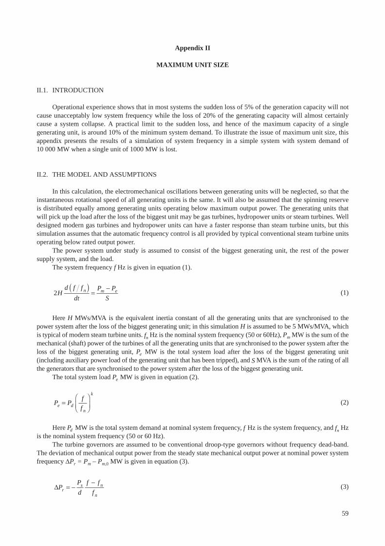
Appendix II
MAXIMUM UNIT SIZE
II.1. INTRODUCTION
Operational experience shows that in most systems the sudden loss of 5% of the generation capacity will not cause unacceptably low system frequency while the loss of 20% of the generating capacity will almost certainly cause a system collapse. A practical limit to the sudden loss, and hence of the maximum capacity of a single generating unit, is around 10% of the minimum system demand. To illustrate the issue of maximum unit size, this appendix presents the results of a simulation of system frequency in a simple system with system demand of 10 000 MW when a single unit of 1000 MW is lost.
II.2. THE MODEL AND ASSUMPTIONS
In this calculation, the electromechanical oscillations between generating units will be neglected, so that the instantaneous rotational speed of all generating units is the same. It will also be assumed that the spinning reserve is distributed equally among generating units operating below maximum output power. The generating units that will pick up the load after the loss of the biggest unit may be gas turbines, hydropower units or steam turbines. Well designed modern gas turbines and hydropower units can have a faster response than steam turbine units, but this simulation assumes that the automatic frequency control is all provided by typical conventional steam turbine units operating below rated output power.
The power system under study is assumed to consist of the biggest generating unit, the rest of the power supply system, and the load.
The system frequency f Hz is given in equation (1).
(1)
Here H MWs/MVA is the equivalent inertia constant of all the generating units that are synchronised to the power system after the loss of the biggest generating unit; in this simulation H is assumed to be 5 MWs/MVA, which is typical of modern steam turbine units. fn Hz is the nominal system frequency (50 or 60Hz), Pm MW is the sum of the mechanical (shaft) power of the turbines of all the generating units that are synchronised to the power system after the loss of the biggest generating unit, Pe MW is the total system load after the loss of the biggest generating unit (including auxiliary power load of the generating unit that has been tripped), and S MVA is the sum of the rating of all the generators that are synchronised to the power system after the loss of the biggest generating unit.
The total system load Pe MW is given in equation (2).
(2)
Here Pd MW is the total system demand at nominal system frequency, f Hz is the system frequency, and fn Hz is the nominal system frequency (50 or 60 Hz).
The turbine governors are assumed to be conventional droop-type governors without frequency dead-band. The deviation of mechanical output power from the steady state mechanical output power at nominal power system frequency Pr = Pm – Pm,0 MW is given in equation (3).
(3)
2Hd f f
dt
P P
Sn m e( )
=-
P Pf
fe dn
k
=Ê
ËÁˆ
¯̃
DPP
d
f f
frs n
n
= --
59
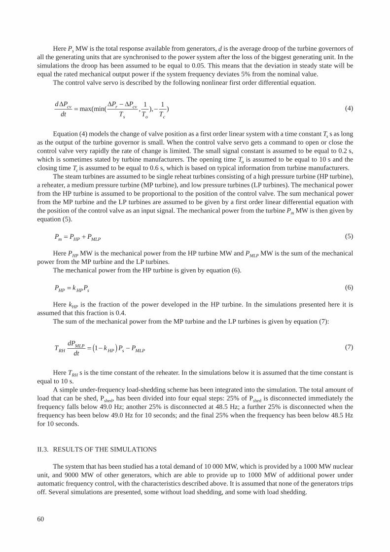
Here Ps MW is the total response available from generators, d is the average droop of the turbine governors of all the generating units that are synchronised to the power system after the loss of the biggest generating unit. In the simulations the droop has been assumed to be equal to 0.05. This means that the deviation in steady state will be equal the rated mechanical output power if the system frequency deviates 5% from the nominal value.
The control valve servo is described by the following nonlinear first order differential equation.
(4)
Equation (4) models the change of valve position as a first order linear system with a time constant Ts s as long as the output of the turbine governor is small. When the control valve servo gets a command to open or close the control valve very rapidly the rate of change is limited. The small signal constant is assumed to be equal to 0.2 s, which is sometimes stated by turbine manufacturers. The opening time To is assumed to be equal to 10 s and the closing time Tc is assumed to be equal to 0.6 s, which is based on typical information from turbine manufacturers.
The steam turbines are assumed to be single reheat turbines consisting of a high pressure turbine (HP turbine), a reheater, a medium pressure turbine (MP turbine), and low pressure turbines (LP turbines). The mechanical power from the HP turbine is assumed to be proportional to the position of the control valve. The sum mechanical power from the MP turbine and the LP turbines are assumed to be given by a first order linear differential equation with the position of the control valve as an input signal. The mechanical power from the turbine Pm MW is then given by equation (5).
(5)
Here PHP MW is the mechanical power from the HP turbine MW and PMLP MW is the sum of the mechanical power from the MP turbine and the LP turbines.
The mechanical power from the HP turbine is given by equation (6).
(6)
Here kHP is the fraction of the power developed in the HP turbine. In the simulations presented here it is assumed that this fraction is 0.4.
The sum of the mechanical power from the MP turbine and the LP turbines is given by equation (7):
(7)
Here TRH s is the time constant of the reheater. In the simulations below it is assumed that the time constant is equal to 10 s.
A simple under-frequency load-shedding scheme has been integrated into the simulation. The total amount of load that can be shed, Pshed, has been divided into four equal steps: 25% of Pshed is disconnected immediately the frequency falls below 49.0 Hz; another 25% is disconnected at 48.5 Hz; a further 25% is disconnected when the frequency has been below 49.0 Hz for 10 seconds; and the final 25% when the frequency has been below 48.5 Hz for 10 seconds.
II.3. RESULTS OF THE SIMULATIONS
The system that has been studied has a total demand of 10 000 MW, which is provided by a 1000 MW nuclear unit, and 9000 MW of other generators, which are able to provide up to 1000 MW of additional power under automatic frequency control, with the characteristics described above. It is assumed that none of the generators trips off. Several simulations are presented, some without load shedding, and some with load shedding.
d P
dt
P P
T T Tcv r cv
s o c
D D D=
--max(min( , ), )
1 1
P P Pm HP MLP= +
P k PHP HP s=
TdP
dtk P PRH
MLPHP s MLP= -( ) -1
60
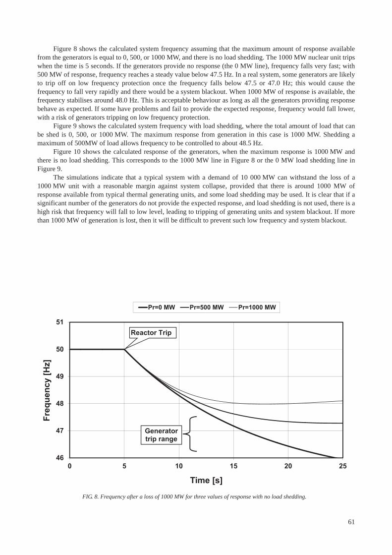
Figure 8 shows the calculated system frequency assuming that the maximum amount of response available from the generators is equal to 0, 500, or 1000 MW, and there is no load shedding. The 1000 MW nuclear unit trips when the time is 5 seconds. If the generators provide no response (the 0 MW line), frequency falls very fast; with 500 MW of response, frequency reaches a steady value below 47.5 Hz. In a real system, some generators are likely to trip off on low frequency protection once the frequency falls below 47.5 or 47.0 Hz; this would cause the frequency to fall very rapidly and there would be a system blackout. When 1000 MW of response is available, the frequency stabilises around 48.0 Hz. This is acceptable behaviour as long as all the generators providing response behave as expected. If some have problems and fail to provide the expected response, frequency would fall lower, with a risk of generators tripping on low frequency protection.
Figure 9 shows the calculated system frequency with load shedding, where the total amount of load that can be shed is 0, 500, or 1000 MW. The maximum response from generation in this case is 1000 MW. Shedding a maximum of 500MW of load allows frequency to be controlled to about 48.5 Hz.
Figure 10 shows the calculated response of the generators, when the maximum response is 1000 MW and there is no load shedding. This corresponds to the 1000 MW line in Figure 8 or the 0 MW load shedding line in Figure 9.
The simulations indicate that a typical system with a demand of 10 000 MW can withstand the loss of a 1000 MW unit with a reasonable margin against system collapse, provided that there is around 1000 MW of response available from typical thermal generating units, and some load shedding may be used. It is clear that if a significant number of the generators do not provide the expected response, and load shedding is not used, there is a high risk that frequency will fall to low level, leading to tripping of generating units and system blackout. If more than 1000 MW of generation is lost, then it will be difficult to prevent such low frequency and system blackout.
46
47
48
49
50
51
0 5 10 15 20 25
Freq
uenc
y [H
z]
Time [s]
Pr=0 MW Pr=500 MW Pr=1000 MW
Generator trip range
Reactor Trip
FIG. 8. Frequency after a loss of 1000 MW for three values of response with no load shedding.
61
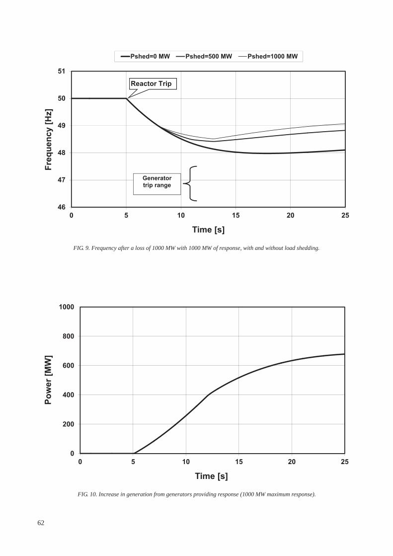
46
47
48
49
50
51
0 5 10 15 20 25
Freq
uenc
y [H
z]
Time [s]
Pshed=0 MW Pshed=500 MW Pshed=1000 MW
Generator trip range
Reactor Trip
FIG. 9. Frequency after a loss of 1000 MW with 1000 MW of response, with and without load shedding.
0
200
400
600
800
1000
0 5 10 15 20 25
Pow
er [M
W]
Time [s]
FIG. 10. Increase in generation from generators providing response (1000 MW maximum response).
62

Appendix III
CHECKLIST OF QUESTIONS AT VARIOUS STAGES OF AN NPP PROJECT
III.1. INTRODUCTION
This appendix gives a series of questions that may be used as a checklist for self-assessment at various stages in the development of a new NPP. The first section after this introduction presents questions to be considered for a feasibility study or pre-feasibility study, before a firm decision has been made to build a NPP. The following section presents questions to be considered by the NPP developer in the period for the preparation of the bid invitation specification (BIS) and the application to the nuclear regulatory authority for a construction licence, before construction starts. The final section presents questions to be considered when construction of nuclear unit is nearly complete, and the NPP developer is planning the commissioning of the nuclear units. Some of these questions relate to information that may need to be supplied to the nuclear regulatory authority to support the application for an operating licence.
III.2. FOR A PRE-FEASIBILITY STUDY OR FEASIBILITY STUDY
— Is there a long term energy policy for the country, including the electricity system? — Has there been an analysis of the inclusion of nuclear power in the electricity system to demonstrate that it is
feasible? — Is the present behaviour of the electrical grid system well understood?— Does the transmission system operator collect sufficient data on the behaviour of the system, and analyse
major grid events such as blackouts? — Is the current electrical grid system stable and reliable, with well controlled voltage and frequency?— If not, is it feasible to improve the reliability of the electrical grid system by the time that a nuclear plant might
be brought into service?— Has the cost of improving the grid been considered as part of the feasibility study for the inclusion of nuclear
power?— Are there technical specifications or standards that define the requirements for the design and operation of the
electrical grid system and for the performance characteristics of generating units? And if not, are there plans to develop such standards?
— Are there agreed procedures for emergency situations such as system blackout, and are these procedures practiced?
— Has a decision been made on the preferred size of nuclear unit?— If so, is this size significantly less than 10% of the minimum electrical system load?— Is there a plan for how the system could be controlled after an unplanned trip of a nuclear unit so that there would
not be an uncontrolled fall in system frequency, leading to system collapse and blackout of the whole country?— Has the choice of potential sites for the nuclear power plant considered the difficulty and costs of a reliable
connection from the site to the grid system? — Does the feasibility study for the inclusion of nuclear power assume that the nuclear unit will operate flexibly
(i.e. change output frequently)?— If so, can plans be changed so that the nuclear unit is able to operate at steady full load for most of the time?— Are the facilities at the grid control centre typical of current international best practice, and if not can they be
improved?— Is there a secondary control centre available at a separate secure location, which is able to carry out essential
actions to control the system if the main grid control centre is unavailable for any reason? If not, are there plans to develop a secondary control centre.
— Are the arrangements for communications between the national grid control centre and other control centres and power stations robust, diverse and reliable so they will continue to operate during a national blackout, or extreme events such as hurricanes?
63
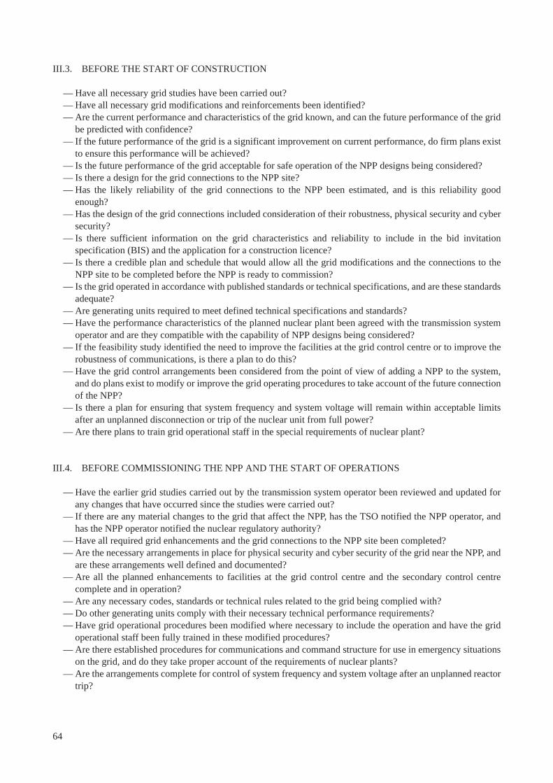
III.3. BEFORE THE START OF CONSTRUCTION
— Have all necessary grid studies have been carried out?— Have all necessary grid modifications and reinforcements been identified?— Are the current performance and characteristics of the grid known, and can the future performance of the grid
be predicted with confidence?— If the future performance of the grid is a significant improvement on current performance, do firm plans exist
to ensure this performance will be achieved? — Is the future performance of the grid acceptable for safe operation of the NPP designs being considered?— Is there a design for the grid connections to the NPP site?— Has the likely reliability of the grid connections to the NPP been estimated, and is this reliability good
enough?— Has the design of the grid connections included consideration of their robustness, physical security and cyber
security?— Is there sufficient information on the grid characteristics and reliability to include in the bid invitation
specification (BIS) and the application for a construction licence? — Is there a credible plan and schedule that would allow all the grid modifications and the connections to the
NPP site to be completed before the NPP is ready to commission? — Is the grid operated in accordance with published standards or technical specifications, and are these standards
adequate?— Are generating units required to meet defined technical specifications and standards?— Have the performance characteristics of the planned nuclear plant been agreed with the transmission system
operator and are they compatible with the capability of NPP designs being considered?— If the feasibility study identified the need to improve the facilities at the grid control centre or to improve the
robustness of communications, is there a plan to do this?— Have the grid control arrangements been considered from the point of view of adding a NPP to the system,
and do plans exist to modify or improve the grid operating procedures to take account of the future connection of the NPP?
— Is there a plan for ensuring that system frequency and system voltage will remain within acceptable limits after an unplanned disconnection or trip of the nuclear unit from full power?
— Are there plans to train grid operational staff in the special requirements of nuclear plant?
III.4. BEFORE COMMISSIONING THE NPP AND THE START OF OPERATIONS
— Have the earlier grid studies carried out by the transmission system operator been reviewed and updated for any changes that have occurred since the studies were carried out?
— If there are any material changes to the grid that affect the NPP, has the TSO notified the NPP operator, and has the NPP operator notified the nuclear regulatory authority?
— Have all required grid enhancements and the grid connections to the NPP site been completed?— Are the necessary arrangements in place for physical security and cyber security of the grid near the NPP, and
are these arrangements well defined and documented?— Are all the planned enhancements to facilities at the grid control centre and the secondary control centre
complete and in operation? — Are any necessary codes, standards or technical rules related to the grid being complied with?— Do other generating units comply with their necessary technical performance requirements?— Have grid operational procedures been modified where necessary to include the operation and have the grid
operational staff been fully trained in these modified procedures?— Are there established procedures for communications and command structure for use in emergency situations
on the grid, and do they take proper account of the requirements of nuclear plants?— Are the arrangements complete for control of system frequency and system voltage after an unplanned reactor
trip?
64
— If the grid system is interconnected to other countries, are there legal and commercial agreements and operating procedure in place for proper control of system frequency after a reactor trip and for grid emergency situations?
— Have grid operating staff been trained in the new procedures and understand the special requirements of NPPs?
— Has the NPP operator identified all areas where a legal obligation or binding agreement with transmission system operator is required, and are such agreements in force?
— Is there sufficient information on the grid characteristics, reliability and operating procedures to include in the application to the nuclear regulatory authority for the operating licence?
— There is an agreed maintenance policy for the grid system components that form the grid connection to the NPP?
— Is there an agreed procedure for exchange of information between the TSO and NPP operator concerning grid outages or modifications to the grid?
— Does the NPP have procedures for assessing the safety impact of grid outages and coordination grid outages with maintenance on NPP safety equipment?
— Have the NPP operating staff been trained for the safe operation of the NPP in normal and abnormal grid conditions and grid emergency situations?
— Do the NPP’s plans for accident management or severe accident management include beyond design basis accidents where there is loss of off-site power for a prolonged period because of damage to all grid connections?
65

.

REFERENCES
[1] INTERNATIONAL ATOMIC ENERGY AGENCY, Milestones in the Development of a National Infrastructure for Nuclear Power, IAEA Nuclear Energy Series No. NG-G-3.1, IAEA, Vienna (2007).
[2] INTERNATIONAL ATOMIC ENERGY AGENCY, Responsibilities and Competencies of the Nuclear Energy Programme Implementing Organization, IAEA Nuclear Energy Series No. NG-T-3.6, IAEA, Vienna (2009).
[3] INTERNATIONAL ATOMIC ENERGY AGENCY, Initiating Nuclear Power Programmes: Responsibilities and Capabilities of Owners and Operators, IAEA Nuclear Energy Series No. NG-T-3.1, IAEA, Vienna (2009).
[4] INTERNATIONAL ATOMIC ENERGY AGENCY, Interaction of Grid Characteristics with Design and Performance of Nuclear Power Plants: A Guidebook, IAEA Technical Reports Series No. 224, IAEA, Vienna (1983).
[5] INTERNATIONAL ATOMIC ENERGY AGENCY, Introducing Nuclear Power Plants into Electrical Power Systems of Limited Capacity, IAEA Technical Reports Series No. 271, IAEA, Vienna (1987).
[6] INTERNATIONAL ATOMIC ENERGY AGENCY, Expansion Planning for Electrical Generating Systems: A Guidebook, IAEA Technical Reports Series No. 241, IAEA, Vienna (1984).
[7] INTERNATIONAL ATOMIC ENERGY AGENCY, Design of Electrical Power Systems for Nuclear Power Plants, IAEA Safety Standards Series No. NS-G-1.8, IAEA, Vienna (2004).
[8] INTERNATIONAL ATOMIC ENERGY AGENCY, Fundamental Safety Principles — Safety Fundamentals, IAEA Safety Standards Series No. SF-1, IAEA, Vienna (2006).
[9] UNITED STATES NUCLEAR REGULATORY COMMISSION, Operating Experience Assessment — Effects of Grid Events on Nuclear Power Plant Performance, NRC Report No. NUREG-1784, USNRC, Washington DC (2003).
[10] INTERNATIONAL ATOMIC ENERGY AGENCY, Safety of Nuclear Power Plants: Design, IAEA Safety Standards Series, No. NS-R-1, IAEA, Vienna (2000).
[11] UNITED STATES NUCLEAR REGULATORY COMMISSION, General Design Criteria for Nuclear Power Plants — Criterion 17 — Electric Power Systems, 10CFR50 Appendix A, USNRC Washington DC USA.
[12] UNITED STATES NUCLEAR REGULATORY COMMISSION, Re-evaluation of Station Blackout Risk at Nuclear Power Plants, NUREG/CR-6890, USNRC Washington DC, (2005).
[13] UNITED STATES NUCLEAR REGULATORY COMMISSION, Three-Unit Trip and Loss of Offsite Power at Palo Verde Nuclear Generating Station, NRC Information Notice 2005-15, USNRC, Washington DC (2005).
[14] UNITED STATES NUCLEAR REGULATORY COMMISSION, Loss of Offsite Power and Dual-Unit Trip at Catawba Nuclear Generating Station, NRC Information Notice 2007-14, USNRC, Washington DC (2007).
[15] UNION FOR THE COOPERATION IN THE TRANSMISSION OF ELECTRICITY (UCTE), UCTE Operation Handbook — Appendix 3 – Operational Security, ENTSO-E / UCTE, Brussels (2009).
[16] US CANADA TASK FORCE. Final Report on the August 14, 2003 Blackout in the United States and Canada: Causes and Recommendations, US-Canada Task Force (2004).
[17] UNION FOR THE COOPERATION IN THE TRANSMISSION OF ELECTRICITY (UCTE), UCTE Operation Handbook — Policy 1 – Load-Frequency Control and Performance, ENTSO-E/ UCTE, Brussels (2009).
[18] ELECTRIC POWER RESEARCH INSTITIUTE, Siting Guide: Site Selection and Evaluation Criteria for an Early Site Permit Application, Reference 1006878, EPRI, Palo Alto, California, USA (2002).
[19] INTERNATIONAL ATOMIC ENERGY AGENCY, Site Evaluation for Nuclear Installations — Safety Requirements, IAEA Safety Standards Series No. NS-R-3, IAEA, Vienna (2003).
[20] WORLD ASSOCIATION OF NUCLEAR OPERATORS, Loss of Grid — Addendum, Significant Operating Experience Report No. SOER99-1 (Addendum), WANO, Paris (2005).
[21] WORLD ASSOCIATION OF NUCLEAR OPERATORS, Guidelines for Achieving Excellence in Transformer, Switchyard, and Grid Reliability, Guideline WANO GL 2010-02, WANO, Paris (2010).
[22] UNITED STATES NUCLEAR REGULATORY COMMISSION, Grid Reliability and the Impact on Plant Risk and the Operability of Offsite Power, NRC Generic Letter 2006-02, USNRC, Washington DC (2006).
[23] NUCLEAR ENERGY AGENCY, Defence in Depth of Electrical Systems and Grid Interaction, NEA/CSNI/R(2009)10, NEA, Paris (2009).
[24] INTERNATIONAL ATOMIC ENERGY AGENCY, Bid Invitation Specifications for Nuclear Power Plants — A Guidebook, IAEA Technical Reports Series No. 275, IAEA, Vienna (1987).
[25] INTERNATIONAL ATOMIC ENERGY AGENCY, IAEA Safety Glossary — Terminology used in Nuclear Safety, and Radiation Protection, 2007 Edition, IAEA, Vienna (2007).
67

.

GLOSSARY
This glossary provides definitions for a range of technical terms as they are used in this publication. Different terms may be used in some countries, and this is indicated for some terms. Where a term is already defined in an IAEA glossary, this is indicated, and that definition is given.
accident management. The taking of a set of actions during the evolution of a beyond design basis accident:(a) To prevent the escalation of the event into a severe accident;(b) To mitigate the consequences of a severe accident;(c) To achieve a long term safe stable state.The second aspect of accident management (to mitigate the consequences of a severe accident) is also termed severe accident management. [25]
ancillary service. A service that may be provided by generating units to assist the control of the grid system. Ancillary services can include: provision of reactive power and control of system voltage; automatic frequency control; load following; provision of spinning reserve; provision of standing reserve; provision of black start capability. In electricity systems that have been deregulated, there would normally be a payment to generators for providing ancillary services.
automatic frequency control. A method of operating a generating unit, so that its output increases automatically if the system frequency falls, and decreases automatically if the system frequency rises. Generating units operating under ‘automatic frequency control’ are part of the ‘spinning reserve’.
automatic voltage regulator (AVR). This is part of the excitation system of the generator. It controls the output voltage of the generator at a constant value, by controlling the current through the generator rotor winding. The AVR is important for controlling the grid system voltage, and its dynamic performance is important for ensuring the generator can remain synchronised to the grid system after grid faults. The AVR may include a power system stabilizer function.
base load operation. Operation of a power station or generating unit at steady full load as far as possible, and not ‘load following’ nor providing frequency control.
beyond design basis accident. Accident conditions more severe than a design basis accident. [25]
bid invitation specification (BIS). A detailed specification prepared by the prospective NPP operator to inform bidders (prospective suppliers of the NPP) of the requirements for the NPP, which should include the main characteristics of the electrical grid system in the country and the expected performance of the NPP. More information on preparing a BIS is provided in Ref. [24]
blackout. A condition in which all electrical power has been lost in all or a large part of the grid system in the country or region.
black start. (blackout recovery). Restarting the electrical power system from a blackout condition. The black start process will be controlled by the TSO’s grid control centre, but will require the co-operation of all the power plants in the system. For a black start to be possible, there must be a sufficient number of black start power plants.
black start power plant. A power plant that has the capability to start up fairly quickly from a shutdown condition with no external source of power. NPPs do not have this capability.
brownout. A condition in which the voltage on a part of the grid falls to a low level following a fault, and the voltage control arrangements are not sufficient, so the voltage continues to fall over period of one or two minutes. If the network operator does not start rapid remedial action, the voltage will continue to fall and lead to a blackout.
69
ceiling voltage. The ceiling voltage is the maximum voltage that the generator excitation system can apply to the generator rotor. A high ceiling voltage may be required to ensure that the generator does not lose synchronism with the transmission system after a fault, but poses a risk of overvoltage to the electrical auxiliaries in certain fault situations.
common cause failure. Failure of two or more structures, systems and components due to a single specific event or cause. [25]
core damage probability. Core damage refers to an event in which the core of the nuclear reactor in a NPP suffers significant damage. This may result from prolonged loss of cooling of the reactor core, so that the core overheats, and parts of the core melt. Core damage probability is calculated as the likelihood per year of a core damage event happening, based on fault studies. A core damage event may lead to a significant release of radioactive material.
cyber attack. A deliberate attempt to cause abnormal operation or damage to a system with digital electronic controls by signals sent via remote communication links (internet connections or telephone lines), or by using malicious embedded software.
cyber security. Many modern items of electronic control and protection equipment have the facility to be controlled remotely, or have their settings changed remotely, via an internet or telephone line connection. Cyber security refers to arrangements to ensure that such equipment is secure against accidental or malicious actions that would change its intended operation i.e. to prevent cyber attacks.
design basis accident. Accident conditions against which a facility is designed according to established design criteria, and for which the damage to the fuel and the release of radioactive material are kept within authorized limits. [25]
distribution system. Those parts of the public electricity system operated at lower voltages (typical voltages are 33 kV, 11 kV, 400/230 V, but this varies between countries). The distribution system connects the transmission system to customers supplied at low voltage. The configuration and behaviour of the distribution systems are not generally relevant to NPPs, which are normally connected only to the transmission system.
fault. Any unplanned event that results in a transmission circuit or item of transmission equipment being switched out of service manually or automatically by an electrical protection system. Examples include a lightning strike on an overhead line causing a short circuit, or a short circuit between the windings in a transformer; further examples are listed in Appendix II. Faults are unplanned but are anticipated events i.e. faults are expected to happen from time to time, and the transmission system should remain secure if a fault happens (see ‘N-1 standard’).
fault level. A measure of the maximum current that could flow if there is a short-circuit fault at a point on the grid system. It is important to know the maximum fault level at each point in the network, as circuit breakers and other equipment on the transmission system each have a maximum fault current rating for safe operation.
fault ride-through capability. The ability of a generating unit to remain in operation (i.e. not trip) during and after specified faults on the transmission system (e.g. the transient voltage depression caused by a short circuit on the transmission system near to the generating unit.)
fast valving. A control arrangement for closing the governor valves on a steam turbine very quickly, if there is a sudden acceleration of the turbine rotor. The purpose is to rapidly reduce the steam supply to the turbine, and hence reduce the rapid acceleration of the rotor that can occur during a short-circuit fault on the grid system close to the power plant. This can assist in keeping the generating unit synchronised to the system after the fault is removed.
70
generator transformer. (Also called ‘step-up transformer’). The transformer connected between the generator (alternator) and the transmission system. The generator transformer is the route for export of generated power from the NPP.
grid code. A document that describes the required technical characteristics, performance and operation of the transmission system and generating units, as defined by the TSO or government agency.
grid control centre (dispatch centre). The control centre that provides high-level control of the grid system. It issues instructions to generating units to increase or decrease output, or to shut down or start up in order to balance generation with load. The control centre will also control the transmission system, switching circuits into or out of service as necessary. A large grid system may have several control centres. Often the lower voltage distribution systems and the high voltage transmission system will have separate control centres.
grid system. The grid system may refer to just the transmission system in a country, or in interconnected countries, or include both the transmission and distribution systems.
house load operation. Operating a nuclear unit so that it is generating electricity only for the unit’s own needs (i.e. supplying the electrical power to the auxiliary equipment, but not exporting power to the grid system).
inertia. Inertia is the energy stored in rotating machines because they are rotating. Large rotating machines have stored energy due to the rotating mass of their rotor, driving turbine shafts etc. When a disturbance occurs e.g. the unanticipated loss of a generator, the stored energy is released into the system and slows down the rate at which the system frequency changes.
load following. Varying the output of a generating unit in a planned way, or in response to an instruction or control signal from the grid control centre, reducing the output when the electrical load on the system is reduced (for example at night, at weekends and on public holidays) and increasing the output to maximum when the electrical load is high.
load shedding. Arrangements for disconnecting some electricity customers to reduce load when there is a shortage of generation and/or when system frequency is below a defined value. Load shedding is used in grid defence plans to restore the balance of demand and generation in situations where demand is too high. Load shedding may be automatic (initiated by low frequency relays) or by manual disconnection instructed by the grid control centre.
loss of load. An event where the NPP loses the connection between the generating unit and the grid, so that the generating unit is not able to export power, but the power supply from the grid via the station transformer or other route is still available.
loss of offsite power (LOOP). An event in which a nuclear unit loses all electrical power supply from the grid system. This may be the result of events that disconnect all the connections between the NPP and the local substation, or between the substation and the rest of the grid system, or because of a total blackout of the grid system in the country or region.
NPP operator. The company or organization that will be the operator of the nuclear power plant. This organization has the primary responsibility for the safe operation of the NPP and will have to satisfy the requirements of the nuclear regulatory body in the country.
nuclear unit. A nuclear unit comprises a nuclear reactor and all the auxiliary equipment (generator, transformers, motors, pumps, electrical supplies, protection systems etc.) that are required for its operation. A nuclear power plant (NPP) may have one or more nuclear units.
71
N-1 standard. A common rule to describe the minimum level of security used in the planning and operation of the transmission system. ‘N’ refers to the total number of transmission circuits that are in service at the time after allowing for planned outages of circuits for maintenance, and the ‘-1’ refers to an unplanned event that causes one of those circuits to be switched out of service. The ‘N-1’ standard requires the system to have sufficient redundancy that the unplanned loss of any one circuit in this way would not have unacceptable consequences. Further explanation of an N-1 standard is given in section 4.6 of this publication.
off-load tap-changer. A transformer tap-changer that may only be operated when the transformer is isolated. (i.e. has no voltage applied to any windings). To operate an off-load tap changer when the transformer is energised, even if it is not carrying any load, is almost certain to cause a dangerous catastrophic failure.
on-load tap-changer. A transformer tap-changer that may be operated while the transformer is energised.
power system stabiliser (PSS). Part of the automatic voltage regulator (AVR) that provides an additional control function that helps to provide damping of potential oscillations of the power system.
pre-construction safety report. A report submitted by a NPP developer to the nuclear regulatory body, in order to obtain a construction licence, which would allow the construction of the NPP to start.
probabilistic safety assessment. A comprehensive, structured approach to identifying failure scenarios, constituting a conceptual and mathematical tool for deriving numerical estimates of risk [25].
reactive compensation. Equipment such as switchable capacitors that are used to balance the inductance of overhead line transmission circuits, or switchable inductors that are used to balance the capacitance of underground cable transmission circuits. Reactive compensation equipment may also include capacitors fitted with power electronic controls to provide the effect of a continuously variable capacitance. Reactive compensation equipment assists the control of the voltage on the transmission system.
reactive power. The product of the magnitude the voltage and current and the sine of the phase angle between them, normally expressed in units of Mvar, which can be positive or negative. The inductance of overhead lines and of motor load within consumer demand motors is said to “absorb” reactive power, while the capacitance of underground cables is said to “produce” reactive power. Generating units and reactive compensation devices need to produce or absorb varying amounts of reactive power as necessary to balance this, which is important for controlling the voltage on the transmission system.
redundancy. Provision of alternative (identical or diverse) structures, systems or components, so that any one can perform the required function regardless of the state of operation or failure of any other [25]. In the operation of a transmission system, redundancy refers to the existence of spare capacity in the transmission system, so that anticipated faults will not have undesirable consequences. For example, transmission circuits are normally operated at less than their full load rating, so that a fault on one transmission circuit does not lead to overload of other circuits. Loss of redundancy refers to a circumstance where there is no longer sufficient spare capacity; for example, if a fault on one transmission circuit would lead to overload of other circuits.
severe accident. Accident conditions more severe than a design basis accident and involving significant core degradation.
short circuit capacity. The short circuit capacity of a point on the grid is a measure of the strength of the grid. It represents the current that would flow from the grid through a short circuit at that point. This is significant when considering the electricity supply from the grid to the NPP for reactor start up or after a reactor trip, and for the connection to the station transformer. If the short circuit capacity is too low (the impedance of the grid is too high), the dip in voltage when large motors start will be too large. This may be an issue if the station transformer is to be connected to a substation at a lower voltage than the connection to the generator transformer
72
spinning reserve. Generating units operating at less than full load that can rapidly increase or decrease output when necessary, either when instructed by the grid control centre, or automatically when operated in ‘automatic frequency control’ mode
standing reserve. Generating units that are in a shutdown condition, but are able to start up rapidly when necessary, either automatically or when instructed by the grid control centre. NPPs do not provide standing reserve.
start-up transformer. See ‘station transformer’.
static var compensator (SVC): One form of reactive compensation equipment.
station blackout. A condition in which a nuclear unit loses all electrical power supply from the grid system (LOOP), the reactor and generator have tripped, and the onsite AC power sources (typically diesel generators) have all failed to start or have tripped off.
station transformer. (Also called ‘start up transformer’ in some countries). A transformer connected to a grid substation that can provide a supply directly to the electrical auxiliaries in the NPP. The high voltage side of the transformer may be connected to the same substation at the same grid voltage as the generator transformer, or it may be connected to a different substation at a lower voltage. The low voltage side of the transformer supplies the highest auxiliary voltage used in the NPP (typical values are 13.8 kV or 11 kV, but this varies between countries). The station transformer provides the offsite electrical supply to the auxiliaries when the supply via the generator transformer and unit transformer is not available.
substation. Also called ‘switchyard’. An installation on the transmission system to which transmission circuits, generating units and customer load may be connected, and which has facilities for switching. Equipment in a substation can include circuit breakers and other switches, bus bars, transformers, and protection and control equipment. A NPP would normally be connected to one or two substations located close to the NPP site.
switchyard. See ‘substation’
system frequency. The frequency of the alternating voltage on the system. In an interconnected system, the frequency is the same throughout the system at any instant in time. The nominal frequency in almost all countries is either 50 Hz or 60 Hz.
transmission system. Those parts of the public electricity system operated at very high voltages (typical voltages are 400 kV, 275 kV, etc., but this varies between countries). The transmission system is used to interconnect large power stations with centres of load, and to transmit large amounts of power long distances. NPPs are normally connected to the transmission system, so the design and performance of the transmission system is important to NPPs.
transmission system operator (TSO). The company or organization that is responsible for the transmission system to which the NPP will connect. Further information on the typical responsibilities of a TSO is given in Section 2.6 of this publication
trip. The unplanned disconnection or rapid shut down of a transmission circuit, generating unit, or nuclear unit. The rapid emergency shutdown of a nuclear unit also called a ‘scram’ [25].
trip to house load. The ability of a nuclear reactor to remain at power (reactor critical) if there is an unplanned event that disconnects the NPP from the electrical grid. The reactor continues to provide electrical power to the ‘house load’ (all the auxiliary electrical load of the NPP), and the reactor control system reduces reactor power to allow stable operation in this low power condition.
73

unit transformer. (also called auxiliary transformer in some countries). A transformer that provides a supply from the generator to one or more busses that supply the main electrical auxiliary equipment of the reactor. Some nuclear units have more than one unit transformer. In most NPP designs, the unit transformer(s) provide most or all of the power to the auxiliary electrical equipment when the reactor is on load.
74

ABBREVIATIONS
AC Alternating currentAVR Automatic voltage regulatorBIS Bid invitation specification BWR Boiling water reactorCANDU Canadian deuterium uranium reactorDC Direct currentEDG Emergency diesel generatorGPSPS Guangdong Pumped Storage Power Station HVDC High voltage direct currentIOMC Interconnection Operational Management Committee LOOP Loss of off-site power (also known as LOSP)NEPIO Nuclear energy programme implementing organization NIOR Nuclear Interconnection Operational Management Rules PSS Power system stabilizerSBO Station blackoutSVC Static var compensatorTSO Transmission system operator
75

.

CONTRIBUTORS TO DRAFTING AND REVIEW
Fredlund, L. Ringhals AB, Sweden
Glöckler, O. International Atomic Energy Agency
Jiang, J. University of Western Ontario, Canada
Johnson, G. International Atomic Energy Agency
Koshy, T. United States Nuclear Regulatory Commission, United States of America
Koskinen, M. Fingrid, Finland
Lebreton, Ph. EdF, France
Lindahl, S. Gothia Power AB, Sweden
Matthew, R. United States Nuclear Regulatory Commission, United States of America
Nkong-Njock, V. International Atomic Energy Agency
Ray, S. United States Nuclear Regulatory Commission, United States of America
Shankar, R. Signatech Systems, Inc, United States of America
Volkanovski, A. Jožef Stefan Institute, Slovenia
Ward, D.M. Magnox Ltd, United Kingdom
Xie, C. Taishan Nuclear Power Joint Venture Co, China
Consultants Meetings
Vienna, Austria: 19–22 October 2009, 15–18 December 2009, 14–17 February 2011
Technical Meetings
Vienna, Austria: 4–6 August 2009, 3–6 August 2010
77
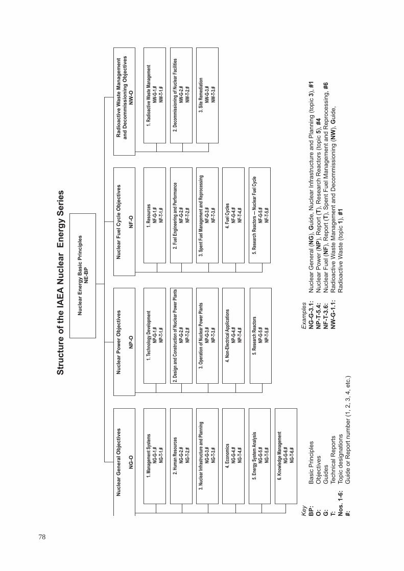
Key
Examples
BP
: B
asic
Princip
les
NG
-G-3
.1:
Nu
cle
ar
Ge
ne
ral (N
G),
Guid
e, N
ucle
ar
Infr
astr
uctu
re a
nd P
lannin
g (
topic
3),
#1
O:
Obje
ctives
NP
-T-5
.4:
Nu
cle
ar
Po
we
r (N
P),
Report
(T
), R
esearc
h R
eacto
rs (
topic
5),
#4
G:
Guid
es
NF
-T-3
.6:
Nu
cle
ar
Fu
el (N
F),
Report
(T
), S
pent F
uel M
anagem
ent and R
epro
cessin
g, #6
T:
Technic
al R
eport
s
NW
-G-1
.1:
Radio
active W
aste
Managem
ent and D
ecom
mis
sio
nin
g (
NW
), G
uid
e,
No
s. 1-6
: Topic
desig
nations
R
adio
active W
aste
(to
pic
1),
#1
#:
Guid
e o
r R
eport
num
ber
(1, 2, 3, 4, etc
.)
Str
uc
ture
of
the
IA
EA
Nu
cle
ar
En
erg
y S
eri
es
Ra
dio
ac
tiv
e W
as
te M
an
ag
em
en
t
an
d D
ec
om
mis
sio
nin
g O
bje
cti
ve
s
NW
-O
Nu
cle
ar
Fu
el
Cy
cle
Ob
jec
tiv
es
NF
-O
Nu
cle
ar
Po
we
r O
bje
cti
ve
s
NP
-O
Nu
cle
ar
Ge
ne
ral
Ob
jec
tiv
es
NG
-O
Nu
cle
ar
En
erg
y B
as
ic P
rin
cip
les
NE
-BP
1. M
anag
emen
t Sys
tem
s
NG
-G-1
.#
NG
-T-1
.#
2. H
uman
Res
ourc
es
NG
-G-2
.#
NG
-T-2
.#
3. N
ucle
ar In
fras
truc
ture
and
Pla
nnin
g
NG
-G-3
.#
NG
-T-3
.#
4. E
cono
mic
s
NG
-G-4
.#
NG
-T-4
.#
5. E
nerg
y S
yste
m A
naly
sis
NG
-G-5
.#
NG
-T-5
.#
6. K
now
ledg
e M
anag
emen
t
NG
-G-6
.#
NG
-T-6
.#
1. T
echn
olog
y D
evel
opm
ent
NP
-G-1
.#
NP
-T-1
.#
2. D
esig
n an
d C
onst
ruct
ion
of N
ucle
ar P
ower
Pla
nts
NP
-G-2
.#
NP
-T-2
.#
3. O
pera
tion
of N
ucle
ar P
ower
Pla
nts
NP
-G-3
.#
NP
-T-3
.#
4. N
on-E
lect
rica
l App
licat
ions
NP
-G-4
.#
NP
-T-4
.#
5. R
esea
rch
Rea
ctor
s
NP
-G-5
.#
NP
-T-5
.#
1. R
esou
rces
NF-
G-1
.#
NF-
T-1.
#
2. F
uel E
ngin
eeri
ng a
nd P
erfo
rman
ce
NF-
G-2
.#
NF-
T-2.
#
3. S
pent
Fue
l Man
agem
ent a
nd R
epro
cess
ing
NF-
G-3
.#
NF-
T-3.
#
4. F
uel C
ycle
s
NF-
G-4
.#
NF-
T-4.
#
5. R
esea
rch
Rea
ctor
s —
Nuc
lear
Fue
l Cyc
le
NF-
G-5
.#
NF-
T-5.
#
1. R
adio
activ
e W
aste
Man
agem
ent
NW
-G-1
.#
NW
-T-1
.#
2. D
ecom
mis
sion
ing
of N
ucle
ar F
acili
ties
NW
-G-2
.#
NW
-T-2
.#
3. S
ite R
emed
iatio
n
NW
-G-3
.#
NW
-T-3
.#
78
@������
��������� ���������������� ��������������������������������� �������������������������� ������������ ���������
����������������������������������� �������������������������������� �����!"#����������
������! �$��������� ���!��%�����&'*�+� �������-�����/�0"5�/�6768��
0�������9�:&7�6�;87<�====�>�?�@9�:&7�6�;87<�==**��
���9����%��A������ ��������>�+���� �9�� �9CC���������� ��������
"�!$ �%E�������H��������%��������-��8<8��JK77;<�J��������
0�������9�:68�8�L6*�'6�<*�>�?�@9�:68�8�L6*�<*�'7��
���9��������������A������������>�+���� �9�� �9CC��������K��K���������
&���'�J������������ ����'L<7�?������J%���!� ��8<<��H�������/$�8<=<&K'6'&���!���
0�������9�7K*<<K*&LK6'L=�>�?�@9�7K*<<K*&LK6'L<��
���9���� ��������A�����������>�+���� �9�� �9CC���������������
-������������Q�"�������H ����7KL6&;�"��� ���-����# �����#� �����U7E�;E6��
0�������9�:&76�='L�8&&L�>�?�@9�:&76�='L�=&&<��
���9���������� A����������������>�+���� �9�� �9CC��������������������
&( ������������ ������"�����9�"���������������Q������� ���"������ ����0����� ���!�� ������#��J�@�87<6��J���Q�
&)�&(���*�"! &!������"V��!�-�#���U�����%��6'=��7*<�87�������;��
0�������9�:'8<�8&&<6�L6&'�>�?�@9�:'8<�8*'*8�7&'&��
���9������A��������X�>�+���� �9�� �9CC������������X�
+ �!��'��� �������U������������#�J#Y�78*�ZU������� ��7[��?��K<<7<7�5������
0�������9�:6L*�;�787�'7�>�?�@9�:6L*�;�787�''L<��
���9���� ���A��� �����������>�+���� �9�� �9CC������� �����������
+���&�?���K�� ��L������E����������#��J�@�8L��?K=L;87������"���@�7;��
0�������9�:66�7�'8�<7�';�';�>�?�@9�:66�7�'8�<7�;<�;<��
���9������� A������ ����>�+���� �9�� �9CC����������� ����
H�%�����!�!��7'L�����������%Q����;'86&�"������"���@��
0�������9�:�66�7�'=�'<�&=�<8�>�?�@�:66�7�'=�'<�&=�<8��
���9��������%�����A�%��������>�+���� �9�� �9CC�����%��������
$��%��,��#K\���Q��\�� ����K�����\���Q��]��5�����5��Q�� ���7<��$KL6776�J�����
0�������9�:�';�88*�;'�;<�8<�>�?�@9�:';�88*�;'�;<�8<����:';�88*�;'�;<�888��
���9���� ���QA���K%���Q����>�+���� �9�� �9CC�������K%���Q����
(��$��,H��� �����H ����J��������� ����#��J�@�78&��5K7&L&�J������ ��
0�������9�:6&�7�8L=�====�>�?�@9�:6&�7�8L=�='=8�>����9������A��� ��������
�' ��������������]������7� �?�����$������5������7L��E�����5������/��Q��J������� � ���/�����'<<�<<7���
0�������9�:;7�88�88&7=;8&C8=�>�?�@9�:;7�88�88&7=;8*��
���9�����A%�������>�+���� �9�� �9CC��������������������
J�������8C=8����������"������$���77<<<;��
0�������9�:;7�77�868&*=*&��:;7�77�868L=8&'�>�?�@9�:;7�77�868*767L��
���9�������A%����� �
��!,H������!��� ^���$� ��H������J����_���#�`��\��"������&���K8<7'&�/����
0�������9�:6;�<8�'*�;L�'L�L8����'*�;L�'L�&8�>�?�@9�:6;�<8�'*�;L�'L�'*��
���9����A�������������>�+��� �9�����������������
/�*��/���X���"��������H ����76K&�����������6��������"���K����0�����7<6K<<8=��
0�������9�:*7�6�68=L�*L*8�>�?�@9�:*7�6�68=L�;<=8��
���9�������A����X���������>�+���� �9�� �9CC��������X���������
��*�"! &�0+�70���U��!�������������� ���J�������$�� ��!�����J�Q��8���?�����8=LK7�k��Q�E��K���Q�!��"��K]��!����76=K76<�
0�������9�:<8�L*;�7='<�>�?�@9�:<8�L*;�7='&�>�+���� �9�� �9CC��������������
���(��!��'�$��H���������� ���� ���������� ���J�\���/�������-�� ��� ��� �8<����HK='*8�JV�5�������Q����
0�������9�:67�Z<[�L6�L='<<<'�>�?�@9�:67�Z<[�L6�L=8;8;&��
���9������A��������������>�+���� �9�� �9CC������������������
/�� ������������� ���� �����U���������L<����#��J�@�7*L6��8=<<�"V�V�� ��������
0�������9�:67�=;6�&*'�'<<�>�?�@9�:67�=;6�&7L�&;*��
���9����A���������>�+���� �9�� �9CC�������������
!�� ������V� �Q�����%�����#��J�@�*6<��87&<�!V�H�����
0�������9�:67�8L8�'6L�777�>�?�@9�:67�8L8�'7L�***��
���9������A��� ����>�+���� �9�� �9CC������� ����
����)��!��'$��������� ���!��%�����&'*�+� �������-�����/�0"5�/�6768����� �����
0�������9�:&7�6�;87<�====�>�?�@9�:&7�6�;87<�==**��
���9����%��A������ ��������>�+���� �9�� �9CC���������� ��������
�!08�� �"�������%��V��X���������U�� ����%��8��!�K7L78�H���������
0�������9�:6*&�7�'68�67�''�>�?�@9�:6*&�7�86<�7'�6L��
���9����� ������A��������%�KX���>�+���� �9�� �9CC������������%�KX��C�%�X�
�*� �$q�X����!�� ����!������C�E����J��%���6����K8*<<&�/������
0�������9�:6'�;7�=*7�;'�*<�>�?�@9�:6'�;7�L=L�LL�&6��
���9��������A��X����� �������������A��X����� ���������������A��X����� ����������A��X����� �����
+���� �9�� �9CC������X����� ������
�� ��'�7 �$'0%0���! � ������#�^���H ����� ���� ����!�����Q�������#�J�@�8;�����������-6�7�]���
0��������Z������[9�:''�*=<�&<<�LLL8�>�Z��x����[9�:''�8<=�*=6�*6=8�>�?�@9�:''�8<=�*=6�*8<6��
����Z������[9������������A ���������>�Z��x����[9��������x����A ���������>�+���� �9�� �9CC���� ���������
#�K�����������
$�H0���� ��J����+���������H ����6;���@������-���������� �����!�������U07L�8�y��
���9����A��������������>�+���� �9�� �9CC������������������
J�������� �����%������ ��
��� ���� �H ������#��J�@�77;��! �%���Q��!]7�'0���
0�������9�:''�7'6*='*777�>�?�@9�:''�7'6*='**''��
���9�������A��� ���� �����>�+���� �9�� �9CC������� ���� ����
�� ��'���� 0��$�� ���<<'��-����$"8K<*L6��?�� ��%������ �'& ��! ��� ������k�������k��7<<7=���!���
Z��[�0�������9�:*<<�8L6K;&'&����:878�;&6K*6<8�>�?�@9�:878�;&6K6'*;��
���9������ ���A�����Q�>�+���� �9�� �9CC���������Q�
�� ��'��������0+��%�� &�J������������ ����'L<7�?������J%����!� ��8<<��H�������/$�8<=<&K'6'&�
0�������9�7K*<<K*&LK6'L=�>�?�@9�7K*<<K*&LK6'L<��
���9���� ��������A�����������z�+���� �9�� �9CC���������������
-������������Q�"�������H ����*78����� ����%����#Q�������Q���k��76&&;��
0�������9�:***�LL7�='=<�Z �K����[�>�?�@9�:***�L&*�*L'&�Z �K����[��
���9���������� A����������������>�+���� �9�� �9CC��������������������
0�������9������������;������������������������������� �� �9�
%�<������������������=� ��������������;������>�����>��
\������� ���� ����"�� �����#�J�@�7<<��7'<<�\��������� ���
0�������9�:'6�7�8&<<�88L8;�Z���88L6<[�>�?�@9�:'6�7�8&<<�8;6<8�
���9����������� ���A������Q�>�+���� �9�� �9CC����������QC�����


12-0
6821

Basic Principles
Objectives
IAEA Nuclear Energy Series
TechnicalReports
Electric Grid Reliability and Interface with Nuclear Power Plants
No. NG-T-3.8
Guides
IAEA Nuclear Energy Series No. NG-T-3.8Electric Grid Reliability and Interface w
ith Nuclear Power Plants
INTERNATIONAL ATOMIC ENERGY AGENCYVIENNA
ISBN 978–92–0–126110–6ISSN 1995–7807