Embed Size (px)
Citation preview
©Ian Sommerville 2000 Software Engineering. Chapter 11 Slide 1
Chapter 11
Architectural Design
©Ian Sommerville 2000 Software Engineering. Chapter 11 Slide 2
Part 3 Design
Chap 11, Architectural design Chap 12, Distributed systems architectures Chap 13, Application Architectures Chap 14, Object-oriented design Chap 15, Real-time software design Chap 16, User interface design
---------- (+ Chap 31, Service-oriented software engineering) (+ Chap 32, Aspect-oriented software development)

©Ian Sommerville 2000 Software Engineering. Chapter 11 Slide 3
Architectural Design
Establishing the overall structure of a software system

©Ian Sommerville 2000 Software Engineering. Chapter 11 Slide 4
Objectives
To introduce architectural design and to discuss its importance
To explain why multiple models are required to document an architecture
To describe types of architectural models that may be used
To discuss use of “domain-specific architectural reference models”

©Ian Sommerville 2000 Software Engineering. Chapter 11 Slide 5
Topics covered
Architectural design context System structuring models System control models Modular decomposition models Domain-specific architectures
©Ian Sommerville 2000 Software Engineering. Chapter 11 Slide 6
Topics covered
Architectural design context System structuring models System control models Modular decomposition models Domain-specific architectures
©Ian Sommerville 2000 Software Engineering. Chapter 11 Slide 7
What is architectural design?
The process of identifying the sub-systems making up a system and a framework for sub-system communication and control.
A boot-strapping process undertaken in parallel with the abstract specification of sub-systems.
The output of this process is the software architecture.

©Ian Sommerville 2000 Software Engineering. Chapter 11 Slide 8
What is architectural design?
The process of identifying the sub-systems making up a system and a framework for sub-system communication and control.
A boot-strapping process undertaken in parallel with the abstract specification of sub-systems.
The output of this process is the software architecture.

©Ian Sommerville 2000 Software Engineering. Chapter 11 Slide 9
Boot-strapping
©Ian Sommerville 2000 Software Engineering. Chapter 11 Slide 10
What is architectural design?
The process of identifying the sub-systems making up a system and a framework for sub-system communication and control.
A boot-strapping process undertaken in parallel with the abstract specification of sub-systems.
The output of this process is the software architecture.

©Ian Sommerville 2000 Software Engineering. Chapter 11 Slide 11
The software design process
Architecturaldesign
Abstractspecification
Interfacedesign
Componentdesign
Datastructuredesign
Algorithmdesign
Systemarchitecture
Softwarespecification
Interfacespecification
Componentspecification
Datastructure
specification
Algorithmspecification
Requirementsspecification
Design activities
Design products

©Ian Sommerville 2000 Software Engineering. Chapter 11 Slide 12
Advantages of explicit architecture design and documentation (Bass)
Stakeholder communication – the archi-tecture may be used as a focus of discussion by system stakeholders.
System analysis – the feasibility of meeting critical non-functional requirements (e.g., perfor-mance, reliability, maintainability) can be studied early-on.
Large-scale reuse – the architecture may be reusable across a range of systems with similar requirements.
(Requirements can be organized by sub-system.)

©Ian Sommerville 2000 Software Engineering. Chapter 11 Slide 13
“Architectural design” process
System structuring – the system is decom-posed into major sub-systems and commun-ication (e.g., data sharing) mechanisms are identified.
Control modelling – a model of the control relationships between the sub-systems is established.
Modular decomposition – the identified sub-systems are decomposed into lower-level modules (components, objects, etc.)

©Ian Sommerville 2000 Software Engineering. Chapter 11 Slide 14
Terminology issues
“Modular decomposition” is sometimes called “high-level (system) design”.
A “sub-system” is usually a system in its own right, and is sometimes called a “Product”. (or perhaps a stand-alone “increment”)
A “module” is a lower-level element that would not normally be considered a separate system; modules are sometimes called “Components” or “Objects”.

©Ian Sommerville 2000 Software Engineering. Chapter 11 Slide 15
Traditional (and Sommerville’s) terminology
System (System)
Product (Sub-System)
Component (Module)
Module (Unit) (Algorithm)

©Ian Sommerville 2000 Software Engineering. Chapter 11 Slide 16
Graphical models
Different graphical models may be used to represent an architectural design.
Each presents a different perspective (viewpoint) on the architecture.
For example…

©Ian Sommerville 2000 Software Engineering. Chapter 11 Slide 17
Graphical model types Static structural models show the major
system components. (e.g., block diagrams)
Dynamic process models show the process structure of the system at run-time. (e.g., UML Sequence Models)
Interface models define the sub-system services offered through public interfaces.
Relationship models show relationships (e.g., dataflow) among sub-systems for some attribute.

©Ian Sommerville 2000 Software Engineering. Chapter 11 Slide 18
Architectural styles
The architecture of a system may conform to a single generic model or style, although most do not.
An awareness of these styles and how they can affect system attributes can simplify the problem of choosing an appropriate architecture…

©Ian Sommerville 2000 Software Engineering. Chapter 11 Slide 19
System attributes and (associated) architectural styles / structures
Performance – localize operations by using fewer, large-grain components to minimize sub-system communication. (reflected in repository model)
Security – use a layered architecture with critical assets in inner layers. (reflected in abstract machine model)

©Ian Sommerville 2000 Software Engineering. Chapter 11 Slide 20
System attributes and (associated) architectural styles / structures
Safety – isolate safety-critical compo-nents in one or just a few sub-systems.
Availability – include redundant com-ponents in the architecture.
Maintainability – use (more) fine-grain, self-contained components. (reflected in objected-oriented model)

©Ian Sommerville 2000 Software Engineering. Chapter 11 Slide 21
Topics covered
Architectural design context System structuring models System control models Modular decomposition models Domain-specific architectures

©Ian Sommerville 2000 Software Engineering. Chapter 11 Slide 22
System structuring
Concerned with decomposing the system into interacting sub-systems.
The basic system structure is often expressed as a block diagram.
More specific models showing how sub-systems share data, are distributed, and interface with each other may also be developed. (Examples follow.)
©Ian Sommerville 2000 Software Engineering. Chapter 11 Slide 23
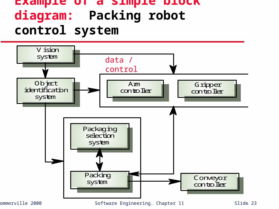
Example of a simple block diagram: Packing robot control system
Visionsystem
Objectidentification
system
Armcontroller
Grippercontroller
Packagingselectionsystem
Packingsystem
Conveyorcontroller
data / control

©Ian Sommerville 2000 Software Engineering. Chapter 11 Slide 24
THE REPOSITORY MODEL

©Ian Sommerville 2000 Software Engineering. Chapter 11 Slide 25
The repository model Sub-systems must exchange info. This
may be done in two ways: Shared data is held in a central database or
repository and may be accessed by all sub-systems. (data is “global”)
Each sub-system maintains its own database and passes data explicitly to other sub-systems.
When large amounts of data are used, the repository model of sharing is commonly used.

©Ian Sommerville 2000 Software Engineering. Chapter 11 Slide 26
CASE toolset architecture
Projectrepository
Designtranslator
Programeditor
Designeditor
Codegenerator
Designanalyser
Reportgenerator

©Ian Sommerville 2000 Software Engineering. Chapter 11 Slide 27
Repository model advantages
Simple and efficient way to share large amounts of data locally. (versus a number of distributed machines)
Sub-systems which use data need not be concerned with how that data is produced, and vice-versa.
Management activities such as backup, access control, and recovery are centralized.
Sharing model is published as the repository schema. Integration of compatible tools is relatively easy.

©Ian Sommerville 2000 Software Engineering. Chapter 11 Slide 28
Repository model disadvantages
Sub-systems must agree on a single repository data model -- inevitably a compromise.
Data model evolution is difficult and expensive.
No provision for sub-system-specific data management requirements related to backup, access control, and recovery.
May be difficult to distribute efficiently over a number of machines due to problems with data redundancy and inconsistency.

©Ian Sommerville 2000 Software Engineering. Chapter 11 Slide 29
THE CLIENT-SERVER MODEL

©Ian Sommerville 2000 Software Engineering. Chapter 11 Slide 30
The client-server model Distributed system model which shows
how data and processing are distributed across a range of processors. (machines)
Major components: A set of stand-alone servers which provide
specific services such as printing, file management, etc.
A set of clients which call on these services A network which allows clients to access
these services

©Ian Sommerville 2000 Software Engineering. Chapter 11 Slide 31
Example of a simple client-server based system: Film and picture library
Catalogueserver
Catalogue
Videoserver
Film clipfiles
Pictureserver
Digitizedphotographs
Hypertextserver
Hypertextweb
Client 1 Client 2 Client 3 Client 4
Wide-bandwidth network
©Ian Sommerville 2000 Software Engineering. Chapter 11 Slide 32
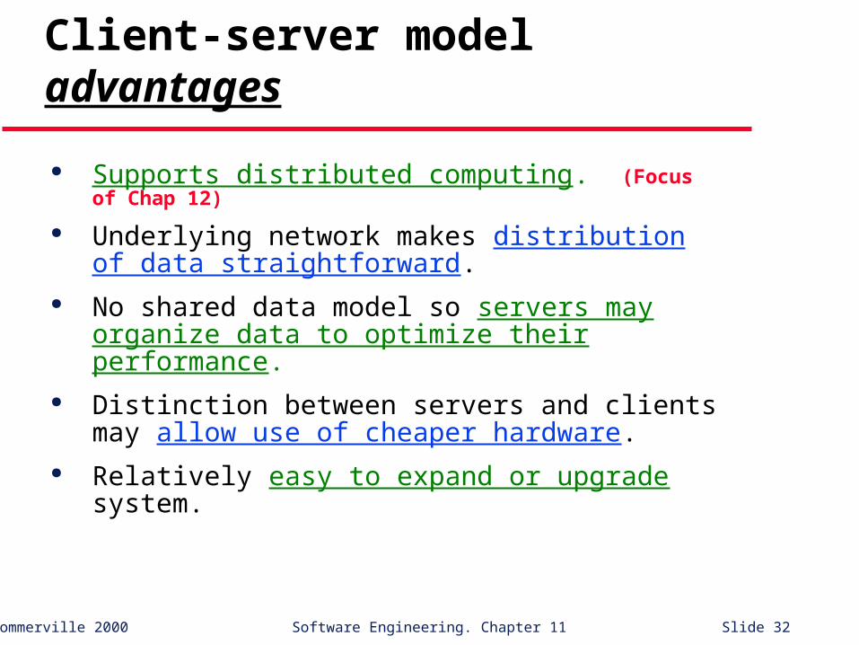
Client-server model advantages
Supports distributed computing. (Focus of Chap 12)
Underlying network makes distribution of data straightforward.
No shared data model so servers may organize data to optimize their performance.
Distinction between servers and clients may allow use of cheaper hardware.
Relatively easy to expand or upgrade system.

©Ian Sommerville 2000 Software Engineering. Chapter 11 Slide 33
Client-server model disadvantages
Relatively complex architecture – problem determination can be difficult. (!)
No shared data model so data integration may be problematic. (must be ad hoc)
Redundant data management activities in each server, possibly. (Consider film and picture library.)
No central register of names and services, so it may be hard to find out what servers and services are available.

©Ian Sommerville 2000 Software Engineering. Chapter 11 Slide 34
THE ABSTRACT MACHINE MODEL

©Ian Sommerville 2000 Software Engineering. Chapter 11 Slide 35
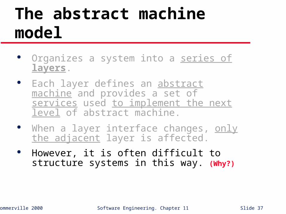
The abstract machine model Organizes a system into a series of layers. Each layer defines an abstract machine and
provides a set of services used to implement the next level of abstract machine.
When a layer interface changes, only the adjacent layer is affected.
However, it is often difficult to structure systems in this way. (Why?)

©Ian Sommerville 2000 Software Engineering. Chapter 11 Slide 36
Example of a simple abstract machine based version management system
Operatingsystem
Database system
Object management
Version management
©Ian Sommerville 2000 Software Engineering. Chapter 11 Slide 37
The abstract machine model Organizes a system into a series of layers. Each layer defines an abstract machine and
provides a set of services used to implement the next level of abstract machine.
When a layer interface changes, only the adjacent layer is affected.
However, it is often difficult to structure systems in this way. (Why?)

©Ian Sommerville 2000 Software Engineering. Chapter 11 Slide 38
Topics covered
Architectural design context System structuring models System control models Modular decomposition models Domain-specific architectures

©Ian Sommerville 2000 Software Engineering. Chapter 11 Slide 39
Control models
Concerned with the control flow between sub-systems. Distinct from the system structure model.
Two general approaches: Centralized control – one sub-system has
overall responsibility for control and starts and stops other sub-systems.
Event-based control – each sub-system can respond to externally generated events from other sub-systems, or from the system’s environment.

©Ian Sommerville 2000 Software Engineering. Chapter 11 Slide 40
Centralized control models
1. Call-return model – top-down subroutine model where control starts at the top of a subroutine hierarchy and moves downwards. Applicable to sequential systems only.
2. Manager model – applicable to concurrent systems. One system component controls the stopping, starting and coordination of other system processes. Also applicable to sequential systems where it is usually implemented as a case statement within a management routine.

©Ian Sommerville 2000 Software Engineering. Chapter 11 Slide 41
Call-return model
Routine 1.2Routine 1.1 Routine 3.2Routine 3.1
Routine 2 Routine 3Routine 1
Mainprogram
call
return

©Ian Sommerville 2000 Software Engineering. Chapter 11 Slide 42
Centralized control models
1. Call-return model – top-down subroutine model where control starts at the top of a subroutine hierarchy and moves downwards. Applicable to sequential systems only.
2. Manager model – applicable to concurrent systems. One system component controls the stopping, starting and coordination of other system processes. Also applicable to sequential systems where it is usually implemented as a case statement within a management routine.

©Ian Sommerville 2000 Software Engineering. Chapter 11 Slide 43
Manager model: real-time system control
Systemcontroller
Userinterface
Faulthandler
Computationprocesses
Actuatorprocesses
Sensorprocesses

©Ian Sommerville 2000 Software Engineering. Chapter 11 Slide 44
Control models
Concerned with the control flow between sub-systems. Distinct from the system structure model.
Two general approaches: Centralized control – one sub-system has
overall responsibility for control and starts and stops other sub-systems.
Event-based control – each sub-system can respond to externally generated events from other sub-systems, or from the system’s environment.

©Ian Sommerville 2000 Software Engineering. Chapter 11 Slide 45
Principal Event-based control models (several variations exist)
1. Broadcast model – an event is broadcast to all (or possibly just some) sub-systems; any sub-system which can handle the event may do so.
2. Interrupt-driven model – used in real-time systems where interrupts are detected by an interrupt handler and passed to some other component for processing.
(Other event-based models include compound documents and production systems.)
©Ian Sommerville 2000 Software Engineering. Chapter 11 Slide 46
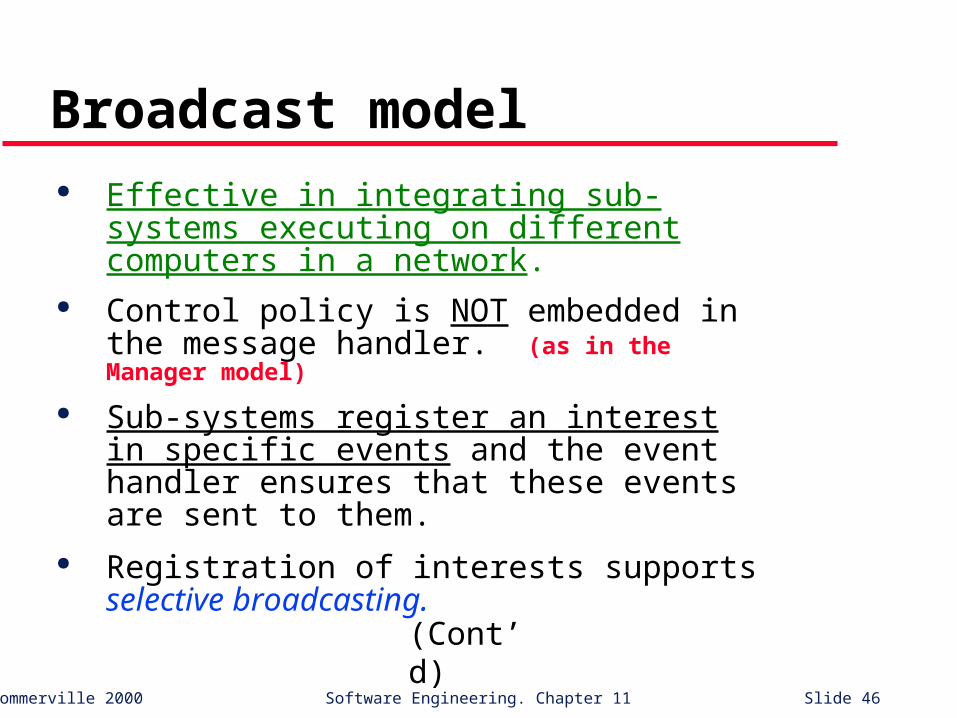
Broadcast model Effective in integrating sub-systems executing
on different computers in a network. Control policy is NOT embedded in the
message handler. (as in the Manager model)
Sub-systems register an interest in specific events and the event handler ensures that these events are sent to them.
Registration of interests supports selective broadcasting.
(Cont’d)

©Ian Sommerville 2000 Software Engineering. Chapter 11 Slide 47
Broadcast model (cont’d) Evolution is relatively easy since a new sub-system
can be integrated by registering its events with the event handler.
However, sub-systems don’t know if or when an event will be handled by some other sub-system.

©Ian Sommerville 2000 Software Engineering. Chapter 11 Slide 48
Selective broadcasting
Sub-system1
Event and message handler
Sub-system2
Sub-system3
Sub-system4
Events broadcasted only to registered sub-systems

©Ian Sommerville 2000 Software Engineering. Chapter 11 Slide 49
Interrupt-driven systems
Used in real-time systems where fast response to an event is essential.
A handler is defined for each type of interrupt.
Each type is associated with a memory location and a hardware switch causes transfer to its handler – fast!
Allows fast response but is complex to program and difficult to verify. (why?)

©Ian Sommerville 2000 Software Engineering. Chapter 11 Slide 50
Interrupt-driven control
Handler1
Handler2
Handler3
Handler4
Process1
Process2
Process3
Process4
Interrupts
Interruptvector
©Ian Sommerville 2000 Software Engineering. Chapter 11 Slide 51
Topics covered
Architectural design context System structuring models System control models Modular decomposition models Domain-specific architectures

©Ian Sommerville 2000 Software Engineering. Chapter 11 Slide 52
Modular decomposition (a.k.a.
high-level design) models
Sub-systems are decomposed into lower-level elements.
Two models are considered: An object model where the system is decom-
posed into interacting objects. (object-oriented design)
A data-flow model where the system is decomposed into functional modules which transform inputs into outputs. (function-oriented
design)

©Ian Sommerville 2000 Software Engineering. Chapter 11 Slide 53
Object models (o-o design) Structure the system into a set of loosely coupled
objects with well-defined interfaces. Object-oriented decomposition is concerned with
identifying object classes, their attributes and operations.
When implemented, objects are created from these classes and some control model is used to coordinate object operations.

©Ian Sommerville 2000 Software Engineering. Chapter 11 Slide 54
Example of simple object model: Invoice processing system
issue ()sendReminder ()acceptPayment ()sendReceipt ()
invoice#dateamountcustomer
Invoice
invoice#dateamountcustomer#
Receipt
invoice#dateamountcustomer#
Payment
customer#nameaddresscredit period
Customer

©Ian Sommerville 2000 Software Engineering. Chapter 11 Slide 55
Data-flow models (functional design)
Functional transformations process inputs to produce outputs.
Sometimes referred to as a pipe and filter model (after terminology used in UNIX).
In the UK?
(Cont’d)

©Ian Sommerville 2000 Software Engineering. Chapter 11 Slide 56
Data-flow models (cont’d)
Variants of this approach have a long history in software design. (e.g., SA/SD, SADT, etc.)
When transformations are sequential, this is a batch sequential model which is extensively used in data processing systems.
Not really suitable for interactive systems (focus on input data streams vs. events)

©Ian Sommerville 2000 Software Engineering. Chapter 11 Slide 57
Invoice processing system
Read issuedinvoices
Identifypayments
Issuereceipts
Findpayments
due
Receipts
Issuepaymentreminder
Reminders
Invoices Payments
Continuous input streams

©Ian Sommerville 2000 Software Engineering. Chapter 11 Slide 58
Topics covered
Architectural design context System structuring models System control models Modular decomposition models Domain-specific architectures

©Ian Sommerville 2000 Software Engineering. Chapter 11 Slide 59
Domain-specific architectures
Models which are specific to some application domain
Two types of domain-specific models:1. Generic models encapsulate the traditional, time-
tested characteristics of real systems.
2. Reference models are more abstract and describe a larger class of systems. They provide a means of comparing different systems in a domain.
Generic models are usually bottom-up models; Reference models are top-down models.
©Ian Sommerville 2000 Software Engineering. Chapter 11 Slide 60
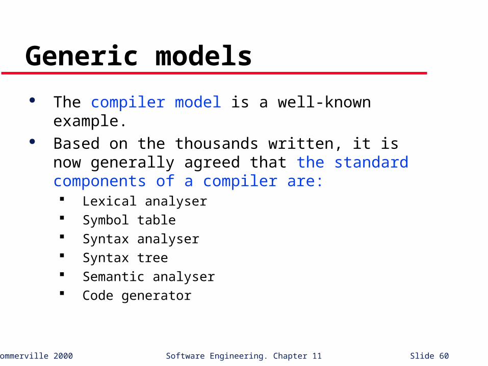
Generic models
The compiler model is a well-known example. Based on the thousands written, it is now
generally agreed that the standard components of a compiler are: Lexical analyser Symbol table Syntax analyser Syntax tree Semantic analyser Code generator

©Ian Sommerville 2000 Software Engineering. Chapter 11 Slide 61
Compiler model
Lexicalanalysis
Syntacticanalysis
Semanticanalysis
Codegeneration
Symboltable
Sequential function model (batch processing oriented)

©Ian Sommerville 2000 Software Engineering. Chapter 11 Slide 62
Syntaxanalyser
Lexicalanalyser
Semanticanalyser
Abstractsyntax tree
Grammardefinition
Symboltable
Outputdefinition
Pretty-printer
Editor
Optimizer
Codegenerator
Repository
Another example: language processing system
Repository-based model

©Ian Sommerville 2000 Software Engineering. Chapter 11 Slide 63
Domain-specific architectures
Models which are specific to some application domain
Two types of domain-specific models:1. Generic models encapsulate the traditional, time-
tested characteristics of real systems.
2. Reference models are more abstract and describe a larger class of systems. They provide a means of comparing different systems in a domain.
Generic models are usually bottom-up models; Reference models are top-down models.
©Ian Sommerville 2000 Software Engineering. Chapter 11 Slide 64
Reference architectures Reference models are derived from a study
of the application domain rather than from existing systems.
May be used as a basis for system implementation, or to compare different systems. It acts as a standard against which systems can be evaluated.
The OSI (Open System Interconnection) model is a layered model for communication systems. (in particular, data processing / point-of-sale applications)

©Ian Sommerville 2000 Software Engineering. Chapter 11 Slide 65
A view of the OSI reference model
Application
Presentation
Session
Transport
Network
Data link
Physical
7
6
5
4
3
2
1
Communica tions medium
Network
Data link
Physical
Application
Presentation
Session
Transport
Network
Data link
Physical
Application
Goal: to allow conformant systems to communicate
with one another.

©Ian Sommerville 2000 Software Engineering. Chapter 11 Slide 66
Another example: CASE reference model (Fig. 11.12)
Data repository services Storage and management of data items.
Data integration services Managing groups of entities.
Task management services Definition and enaction (enactment) of process models.
Messaging services Tool-tool and tool-environment communication.
User interface services User interface development.
(Identifies 5 sets of services that a CASE environment should provide.)

©Ian Sommerville 2000 Software Engineering. Chapter 11 Slide 67
Key points
The software architect is responsible for deriving a structural system model, a control model, and (possibly) a sub-system decomposition model.
Large systems rarely conform to a single archi-tectural model.
System decomposition (structural) models include the repository model, client-server model, and abstract machine model.
Control models include centralized control and event-based models.
(Cont’d)

©Ian Sommerville 2000 Software Engineering. Chapter 11 Slide 68
Key points (cont’d)
Modular decomposition models include data-flow and object models.
Domain specific architectural models are abstractions over an application domain.
They may be constructed by abstracting from existing systems (generic) or they may be idealized (reference) models.

©Ian Sommerville 2000 Software Engineering. Chapter 11 Slide 69
Chapter 11
Architectural Design