Embed Size (px)
Citation preview

ibm.com/redbooks Redpaper
Front cover
IBM System p5 590 and 595Technical Overview and Introduction
Carlo CostantiniCharlie Cler
Jim Wood
Finer system granularity using Micro-Partitioning technology to help lower TCO
Support for versions of AIX 5L, Linux, and i5/OS operating systems
Enterprise class features for applications that require a robust environment


International Technical Support Organization
IBM System p5 590 and 595 Technical Overview and Introduction
September 2006

© Copyright International Business Machines Corporation 2005, 2006. All rights reserved.Note to U.S. Government Users Restricted Rights -- Use, duplication or disclosure restricted by GSA ADP ScheduleContract with IBM Corp.
Second Edition (September 2006)
This edition applies to the IBM System p5 590 and 595, and AIX 5L Version 5.3, product number 5765-G03.
Note: Before using this information and the product it supports, read the information in “Notices” on page vii.

Contents
Notices . . . . . . . . . . . . . . . . . . . . . . . . . . . . . . . . . . . . . . . . . . . . . . . . . . . . . . . . . . . . . . . . . viiTrademarks . . . . . . . . . . . . . . . . . . . . . . . . . . . . . . . . . . . . . . . . . . . . . . . . . . . . . . . . . . . . . viii
Preface . . . . . . . . . . . . . . . . . . . . . . . . . . . . . . . . . . . . . . . . . . . . . . . . . . . . . . . . . . . . . . . . . ixThe team that wrote this Redpaper . . . . . . . . . . . . . . . . . . . . . . . . . . . . . . . . . . . . . . . . . . . . ixBecome a published author . . . . . . . . . . . . . . . . . . . . . . . . . . . . . . . . . . . . . . . . . . . . . . . . . . .xComments welcome. . . . . . . . . . . . . . . . . . . . . . . . . . . . . . . . . . . . . . . . . . . . . . . . . . . . . . . . .x
Chapter 1. General description . . . . . . . . . . . . . . . . . . . . . . . . . . . . . . . . . . . . . . . . . . . . . 11.1 Model abstract for 9119-590 and 9119-595 . . . . . . . . . . . . . . . . . . . . . . . . . . . . . . . . . . 21.2 System frames . . . . . . . . . . . . . . . . . . . . . . . . . . . . . . . . . . . . . . . . . . . . . . . . . . . . . . . . 31.3 Installation planning . . . . . . . . . . . . . . . . . . . . . . . . . . . . . . . . . . . . . . . . . . . . . . . . . . . . 4
1.3.1 System specifications . . . . . . . . . . . . . . . . . . . . . . . . . . . . . . . . . . . . . . . . . . . . . . . 41.3.2 Physical package . . . . . . . . . . . . . . . . . . . . . . . . . . . . . . . . . . . . . . . . . . . . . . . . . . 51.3.3 Service clearances . . . . . . . . . . . . . . . . . . . . . . . . . . . . . . . . . . . . . . . . . . . . . . . . . 5
1.4 Power and cooling. . . . . . . . . . . . . . . . . . . . . . . . . . . . . . . . . . . . . . . . . . . . . . . . . . . . . . 61.5 Minimum and optional features . . . . . . . . . . . . . . . . . . . . . . . . . . . . . . . . . . . . . . . . . . . . 7
1.5.1 Processor features . . . . . . . . . . . . . . . . . . . . . . . . . . . . . . . . . . . . . . . . . . . . . . . . . 91.5.2 Memory features . . . . . . . . . . . . . . . . . . . . . . . . . . . . . . . . . . . . . . . . . . . . . . . . . . 101.5.3 USB diskette drive . . . . . . . . . . . . . . . . . . . . . . . . . . . . . . . . . . . . . . . . . . . . . . . . 111.5.4 Hardware Management Console models . . . . . . . . . . . . . . . . . . . . . . . . . . . . . . . 11
1.6 External disk subsystems . . . . . . . . . . . . . . . . . . . . . . . . . . . . . . . . . . . . . . . . . . . . . . . 121.6.1 IBM TotalStorage EXP24 . . . . . . . . . . . . . . . . . . . . . . . . . . . . . . . . . . . . . . . . . . . 121.6.2 IBM TotalStorage DS4000 series . . . . . . . . . . . . . . . . . . . . . . . . . . . . . . . . . . . . . 121.6.3 IBM TotalStorage DS6000 and DS8000 series. . . . . . . . . . . . . . . . . . . . . . . . . . . 12
1.7 Statement of Direction. . . . . . . . . . . . . . . . . . . . . . . . . . . . . . . . . . . . . . . . . . . . . . . . . . 13
Chapter 2. Architecture and technical overview . . . . . . . . . . . . . . . . . . . . . . . . . . . . . . 152.1 System design. . . . . . . . . . . . . . . . . . . . . . . . . . . . . . . . . . . . . . . . . . . . . . . . . . . . . . . . 16
2.1.1 Central Electronics Complex. . . . . . . . . . . . . . . . . . . . . . . . . . . . . . . . . . . . . . . . . 162.1.2 CEC backplane . . . . . . . . . . . . . . . . . . . . . . . . . . . . . . . . . . . . . . . . . . . . . . . . . . . 172.1.3 Processor books . . . . . . . . . . . . . . . . . . . . . . . . . . . . . . . . . . . . . . . . . . . . . . . . . . 182.1.4 The POWER5+ processor . . . . . . . . . . . . . . . . . . . . . . . . . . . . . . . . . . . . . . . . . . 182.1.5 Multi-chip module and system interconnect . . . . . . . . . . . . . . . . . . . . . . . . . . . . . 202.1.6 Simultaneous multithreading. . . . . . . . . . . . . . . . . . . . . . . . . . . . . . . . . . . . . . . . . 222.1.7 Dynamic power management . . . . . . . . . . . . . . . . . . . . . . . . . . . . . . . . . . . . . . . . 232.1.8 Available processor speeds . . . . . . . . . . . . . . . . . . . . . . . . . . . . . . . . . . . . . . . . . 23
2.2 System flash memory configuration . . . . . . . . . . . . . . . . . . . . . . . . . . . . . . . . . . . . . . . 242.2.1 Vital product data and system smart chips . . . . . . . . . . . . . . . . . . . . . . . . . . . . . . 24
2.3 Light strip. . . . . . . . . . . . . . . . . . . . . . . . . . . . . . . . . . . . . . . . . . . . . . . . . . . . . . . . . . . . 252.4 Memory subsystem . . . . . . . . . . . . . . . . . . . . . . . . . . . . . . . . . . . . . . . . . . . . . . . . . . . . 27
2.4.1 Memory cards . . . . . . . . . . . . . . . . . . . . . . . . . . . . . . . . . . . . . . . . . . . . . . . . . . . . 282.4.2 Memory configuration and placement . . . . . . . . . . . . . . . . . . . . . . . . . . . . . . . . . . 292.4.3 Memory throughput . . . . . . . . . . . . . . . . . . . . . . . . . . . . . . . . . . . . . . . . . . . . . . . . 31
2.5 System buses . . . . . . . . . . . . . . . . . . . . . . . . . . . . . . . . . . . . . . . . . . . . . . . . . . . . . . . . 322.5.1 GX+ and RIO-2 buses. . . . . . . . . . . . . . . . . . . . . . . . . . . . . . . . . . . . . . . . . . . . . . 32
2.6 Internal I/O subsystem . . . . . . . . . . . . . . . . . . . . . . . . . . . . . . . . . . . . . . . . . . . . . . . . . 332.6.1 I/O drawer . . . . . . . . . . . . . . . . . . . . . . . . . . . . . . . . . . . . . . . . . . . . . . . . . . . . . . . 332.6.2 I/O drawer attachment . . . . . . . . . . . . . . . . . . . . . . . . . . . . . . . . . . . . . . . . . . . . . 34
© Copyright IBM Corp. 2005, 2006. All rights reserved. iii

2.6.3 Single loop (full-drawer) cabling . . . . . . . . . . . . . . . . . . . . . . . . . . . . . . . . . . . . . . 352.6.4 Dual looped (half-drawer) cabling . . . . . . . . . . . . . . . . . . . . . . . . . . . . . . . . . . . . . 362.6.5 Disks and boot devices . . . . . . . . . . . . . . . . . . . . . . . . . . . . . . . . . . . . . . . . . . . . . 362.6.6 Media options . . . . . . . . . . . . . . . . . . . . . . . . . . . . . . . . . . . . . . . . . . . . . . . . . . . . 372.6.7 PCI-X slots and adapters . . . . . . . . . . . . . . . . . . . . . . . . . . . . . . . . . . . . . . . . . . . 372.6.8 LAN adapters . . . . . . . . . . . . . . . . . . . . . . . . . . . . . . . . . . . . . . . . . . . . . . . . . . . . 382.6.9 SCSI adapters. . . . . . . . . . . . . . . . . . . . . . . . . . . . . . . . . . . . . . . . . . . . . . . . . . . . 382.6.10 iSCSI. . . . . . . . . . . . . . . . . . . . . . . . . . . . . . . . . . . . . . . . . . . . . . . . . . . . . . . . . . 382.6.11 Fibre Channel adapters . . . . . . . . . . . . . . . . . . . . . . . . . . . . . . . . . . . . . . . . . . . 402.6.12 Graphic accelerators . . . . . . . . . . . . . . . . . . . . . . . . . . . . . . . . . . . . . . . . . . . . . . 412.6.13 Asynchronous PCI-X adapters . . . . . . . . . . . . . . . . . . . . . . . . . . . . . . . . . . . . . . 412.6.14 PCI-X Cryptographic Coprocessor . . . . . . . . . . . . . . . . . . . . . . . . . . . . . . . . . . . 412.6.15 Internal storage . . . . . . . . . . . . . . . . . . . . . . . . . . . . . . . . . . . . . . . . . . . . . . . . . . 42
2.7 Logical partitioning . . . . . . . . . . . . . . . . . . . . . . . . . . . . . . . . . . . . . . . . . . . . . . . . . . . . 422.7.1 Dynamic logical partitioning . . . . . . . . . . . . . . . . . . . . . . . . . . . . . . . . . . . . . . . . . 42
2.8 Virtualization . . . . . . . . . . . . . . . . . . . . . . . . . . . . . . . . . . . . . . . . . . . . . . . . . . . . . . . . . 432.8.1 POWER Hypervisor . . . . . . . . . . . . . . . . . . . . . . . . . . . . . . . . . . . . . . . . . . . . . . . 43
2.9 Advanced POWER Virtualization feature . . . . . . . . . . . . . . . . . . . . . . . . . . . . . . . . . . . 452.9.1 Micro-Partitioning technology . . . . . . . . . . . . . . . . . . . . . . . . . . . . . . . . . . . . . . . . 462.9.2 Logical, virtual, and physical processor mapping . . . . . . . . . . . . . . . . . . . . . . . . . 472.9.3 Virtual I/O Server . . . . . . . . . . . . . . . . . . . . . . . . . . . . . . . . . . . . . . . . . . . . . . . . . 492.9.4 Partition Load Manager. . . . . . . . . . . . . . . . . . . . . . . . . . . . . . . . . . . . . . . . . . . . . 522.9.5 Operating system support for Advanced POWER Virtualization. . . . . . . . . . . . . . 522.9.6 IBM System Planning Tool . . . . . . . . . . . . . . . . . . . . . . . . . . . . . . . . . . . . . . . . . . 532.9.7 Client-specific placement and eConfig . . . . . . . . . . . . . . . . . . . . . . . . . . . . . . . . . 54
2.10 Operating system support . . . . . . . . . . . . . . . . . . . . . . . . . . . . . . . . . . . . . . . . . . . . . . 552.10.1 AIX 5L . . . . . . . . . . . . . . . . . . . . . . . . . . . . . . . . . . . . . . . . . . . . . . . . . . . . . . . . . 552.10.2 Linux . . . . . . . . . . . . . . . . . . . . . . . . . . . . . . . . . . . . . . . . . . . . . . . . . . . . . . . . . . 572.10.3 i5/OS V5R3 . . . . . . . . . . . . . . . . . . . . . . . . . . . . . . . . . . . . . . . . . . . . . . . . . . . . . 58
2.11 System management . . . . . . . . . . . . . . . . . . . . . . . . . . . . . . . . . . . . . . . . . . . . . . . . . 582.11.1 Power on. . . . . . . . . . . . . . . . . . . . . . . . . . . . . . . . . . . . . . . . . . . . . . . . . . . . . . . 582.11.2 Service processor . . . . . . . . . . . . . . . . . . . . . . . . . . . . . . . . . . . . . . . . . . . . . . . . 592.11.3 HMC . . . . . . . . . . . . . . . . . . . . . . . . . . . . . . . . . . . . . . . . . . . . . . . . . . . . . . . . . . 622.11.4 HMC connectivity . . . . . . . . . . . . . . . . . . . . . . . . . . . . . . . . . . . . . . . . . . . . . . . . 632.11.5 HMC code . . . . . . . . . . . . . . . . . . . . . . . . . . . . . . . . . . . . . . . . . . . . . . . . . . . . . . 652.11.6 Hardware management user interfaces . . . . . . . . . . . . . . . . . . . . . . . . . . . . . . . 652.11.7 Determining the HMC serial number. . . . . . . . . . . . . . . . . . . . . . . . . . . . . . . . . . 672.11.8 Server firmware. . . . . . . . . . . . . . . . . . . . . . . . . . . . . . . . . . . . . . . . . . . . . . . . . . 67
Chapter 3. Capacity on Demand . . . . . . . . . . . . . . . . . . . . . . . . . . . . . . . . . . . . . . . . . . . 733.1 Types of Capacity on Demand . . . . . . . . . . . . . . . . . . . . . . . . . . . . . . . . . . . . . . . . . . . 74
3.1.1 Capacity Upgrade on Demand (CUoD) for processors. . . . . . . . . . . . . . . . . . . . . 753.1.2 Capacity Upgrade on Demand for memory. . . . . . . . . . . . . . . . . . . . . . . . . . . . . . 763.1.3 On/Off Capacity on Demand (On/Off CoD). . . . . . . . . . . . . . . . . . . . . . . . . . . . . . 763.1.4 Reserve Capacity on Demand (Reserve CoD) . . . . . . . . . . . . . . . . . . . . . . . . . . . 773.1.5 Trial Capacity on Demand. . . . . . . . . . . . . . . . . . . . . . . . . . . . . . . . . . . . . . . . . . . 773.1.6 Capacity on Demand feature codes . . . . . . . . . . . . . . . . . . . . . . . . . . . . . . . . . . . 783.1.7 Capacity BackUp . . . . . . . . . . . . . . . . . . . . . . . . . . . . . . . . . . . . . . . . . . . . . . . . . 78
Chapter 4. RAS and manageability . . . . . . . . . . . . . . . . . . . . . . . . . . . . . . . . . . . . . . . . . 814.1 Reliability, fault tolerance, and data integrity. . . . . . . . . . . . . . . . . . . . . . . . . . . . . . . . . 82
4.1.1 Fault avoidance. . . . . . . . . . . . . . . . . . . . . . . . . . . . . . . . . . . . . . . . . . . . . . . . . . . 824.1.2 First-failure data capture . . . . . . . . . . . . . . . . . . . . . . . . . . . . . . . . . . . . . . . . . . . . 82
iv IBM System p5 590 and 595 Technical Overview and Introduction

4.1.3 Permanent monitoring. . . . . . . . . . . . . . . . . . . . . . . . . . . . . . . . . . . . . . . . . . . . . . 834.1.4 Self-healing . . . . . . . . . . . . . . . . . . . . . . . . . . . . . . . . . . . . . . . . . . . . . . . . . . . . . . 844.1.5 N+1 redundancy . . . . . . . . . . . . . . . . . . . . . . . . . . . . . . . . . . . . . . . . . . . . . . . . . . 854.1.6 Fault masking . . . . . . . . . . . . . . . . . . . . . . . . . . . . . . . . . . . . . . . . . . . . . . . . . . . . 854.1.7 Resource deallocation . . . . . . . . . . . . . . . . . . . . . . . . . . . . . . . . . . . . . . . . . . . . . 85
4.2 Serviceability . . . . . . . . . . . . . . . . . . . . . . . . . . . . . . . . . . . . . . . . . . . . . . . . . . . . . . . . . 874.3 Manageability . . . . . . . . . . . . . . . . . . . . . . . . . . . . . . . . . . . . . . . . . . . . . . . . . . . . . . . . 87
4.3.1 Service processor . . . . . . . . . . . . . . . . . . . . . . . . . . . . . . . . . . . . . . . . . . . . . . . . . 874.3.2 Partition diagnostics . . . . . . . . . . . . . . . . . . . . . . . . . . . . . . . . . . . . . . . . . . . . . . . 884.3.3 Service Agent . . . . . . . . . . . . . . . . . . . . . . . . . . . . . . . . . . . . . . . . . . . . . . . . . . . . 894.3.4 IBM System p5 firmware maintenance . . . . . . . . . . . . . . . . . . . . . . . . . . . . . . . . . 91
4.4 Cluster solution . . . . . . . . . . . . . . . . . . . . . . . . . . . . . . . . . . . . . . . . . . . . . . . . . . . . . . . 92
Appendix A. Servicing an IBM System p5 system . . . . . . . . . . . . . . . . . . . . . . . . . . . . . 95Resource link . . . . . . . . . . . . . . . . . . . . . . . . . . . . . . . . . . . . . . . . . . . . . . . . . . . . . . . . . . . . 95IBM Systems Hardware Information Center. . . . . . . . . . . . . . . . . . . . . . . . . . . . . . . . . . . . . 96
Related publications . . . . . . . . . . . . . . . . . . . . . . . . . . . . . . . . . . . . . . . . . . . . . . . . . . . . . 99IBM Redbooks . . . . . . . . . . . . . . . . . . . . . . . . . . . . . . . . . . . . . . . . . . . . . . . . . . . . . . . . . . . 99Other publications . . . . . . . . . . . . . . . . . . . . . . . . . . . . . . . . . . . . . . . . . . . . . . . . . . . . . . . . 99Online resources . . . . . . . . . . . . . . . . . . . . . . . . . . . . . . . . . . . . . . . . . . . . . . . . . . . . . . . . 100How to get IBM Redbooks . . . . . . . . . . . . . . . . . . . . . . . . . . . . . . . . . . . . . . . . . . . . . . . . . 100Help from IBM . . . . . . . . . . . . . . . . . . . . . . . . . . . . . . . . . . . . . . . . . . . . . . . . . . . . . . . . . . 101
Contents v

vi IBM System p5 590 and 595 Technical Overview and Introduction

Notices
This information was developed for products and services offered in the U.S.A.
IBM® may not offer the products, services, or features discussed in this document in other countries. Consult your local IBM representative for information on the products and services currently available in your area. Any reference to an IBM product, program, or service is not intended to state or imply that only that IBM product, program, or service may be used. Any functionally equivalent product, program, or service that does not infringe any IBM intellectual property right may be used instead. However, it is the user's responsibility to evaluate and verify the operation of any non-IBM product, program, or service.
IBM may have patents or pending patent applications covering subject matter described in this document. The furnishing of this document does not give you any license to these patents. You can send license inquiries, in writing, to: IBM Director of Licensing, IBM Corporation, North Castle Drive Armonk, NY 10504-1785 U.S.A.
The following paragraph does not apply to the United Kingdom or any other country where such provisions are inconsistent with local law: INTERNATIONAL BUSINESS MACHINES CORPORATION PROVIDES THIS PUBLICATION "AS IS" WITHOUT WARRANTY OF ANY KIND, EITHER EXPRESS OR IMPLIED, INCLUDING, BUT NOT LIMITED TO, THE IMPLIED WARRANTIES OF NON-INFRINGEMENT, MERCHANTABILITY OR FITNESS FOR A PARTICULAR PURPOSE. Some states do not allow disclaimer of express or implied warranties in certain transactions, therefore, this statement may not apply to you.
This information could include technical inaccuracies or typographical errors. Changes are periodically made to the information herein; these changes will be incorporated in new editions of the publication. IBM may make improvements and/or changes in the product(s) and/or the program(s) described in this publication at any time without notice.
Any references in this information to non-IBM Web sites are provided for convenience only and do not in any manner serve as an endorsement of those Web sites. The materials at those Web sites are not part of the materials for this IBM product and use of those Web sites is at your own risk.
IBM may use or distribute any of the information you supply in any way it believes appropriate without incurring any obligation to you.
Any performance data contained herein was determined in a controlled environment. Therefore, the results obtained in other operating environments may vary significantly. Some measurements may have been made on development-level systems and there is no guarantee that these measurements will be the same on generally available systems. Furthermore, some measurement may have been estimated through extrapolation. Actual results may vary. Users of this document should verify the applicable data for their specific environment.
Information concerning non-IBM products was obtained from the suppliers of those products, their published announcements or other publicly available sources. IBM has not tested those products and cannot confirm the accuracy of performance, compatibility or any other claims related to non-IBM products. Questions on the capabilities of non-IBM products should be addressed to the suppliers of those products.
This information contains examples of data and reports used in daily business operations. To illustrate them as completely as possible, the examples include the names of individuals, companies, brands, and products. All of these names are fictitious and any similarity to the names and addresses used by an actual business enterprise is entirely coincidental.
COPYRIGHT LICENSE: This information contains sample application programs in source language, which illustrates programming techniques on various operating platforms. You may copy, modify, and distribute these sample programs in any form without payment to IBM, for the purposes of developing, using, marketing or distributing application programs conforming to the application programming interface for the operating platform for which the sample programs are written. These examples have not been thoroughly tested under all conditions. IBM, therefore, cannot guarantee or imply reliability, serviceability, or function of these programs. You may copy, modify, and distribute these sample programs in any form without payment to IBM for the purposes of developing, using, marketing, or distributing application programs conforming to IBM's application programming interfaces.
© Copyright IBM Corp. 2005, 2006. All rights reserved. vii

TrademarksThe following terms are trademarks of the International Business Machines Corporation in the United States, other countries, or both:
Eserver
Redbooks (logo)eServer™i5/OS®pSeries®AIX 5L™AIX®Chipkill™DS4000™DS6000™DS8000™
HACMP™IBM®Micro-Partitioning™PowerPC®POWER™POWER Hypervisor™POWER4™POWER5™POWER5+™POWER6™Redbooks™
Resource Link™RS/6000®Service Director™System i5™System p™System p5™System Storage™TotalStorage®Virtualization Engine™
The following terms are trademarks of other companies:
Internet Explorer, Microsoft, Windows, and the Windows logo are trademarks of Microsoft Corporation in the United States, other countries, or both.
UNIX is a registered trademark of The Open Group in the United States and other countries.
Linux is a trademark of Linus Torvalds in the United States, other countries, or both.
Other company, product, or service names may be trademarks or service marks of others.
viii IBM System p5 590 and 595 Technical Overview and Introduction

Preface
This IBM Redpaper is a comprehensive guide covering the IBM® System p5™ 590 and 595 servers. We introduce major hardware offerings and discuss their prominent functions.
Professionals wishing to acquire a better understanding of IBM System p5 products should consider reading this document. The intended audience includes:
� Clients
� Marketing representatives
� Technical support professionals
� IBM Business Partners
� Independent software vendors
This document expands the current set of IBM System p5 documentation by providing a desktop reference that offers a detailed technical description of the p5-590 and p5-595 servers.
This publication does not replace the latest IBM System p5 marketing materials and tools. It is intended as an additional source of information that, together with existing sources, can be used to enhance your knowledge of IBM server solutions.
The team that wrote this RedpaperThis Redpaper was produced by a team of specialists from around the world working at the International Technical Support Organization, Austin Center.
Charlie Cler is a Certified IT Specialist for IBM and has over 21 years of experience with IBM. He currently works in the United States as a presales Systems Architect representing IBM Systems and Technology Group product offerings. He has been working with IBM System p™ servers for over 16 years.
Carlo Costantini is a Certified IT Specialist for IBM and has over 28 years of experience with IBM and IBM Business Partners. He currently works in Italy Presales Field Technical Sales Support for IBM Sales Representatives and IBM Business Partners for all pSeries® and IBM eServer™ p5 systems offerings. He has broad marketing experience. He is a certified specialist for pSeries and IBM System p servers.
Jim Wood is a Technical Support Specialist for IBM and has 21 years of experience with IBM and IBM Business Partners. He currently works in the UK Hardware Front Office supporting customers and IBM Service Representatives for all pSeries and RS/6000® products. He holds a First Class Honours Degree in IT and Computing and is a Chartered Member of the British Computer Society. He is also an AIX® 5L™ certified specialist.
The project that created this publication was managed by:Scott Vetter
Thanks to the following people for their contributions to this project:
Arzu Gucer and Lupe BrownInternational Technical Support Organization, Austin Center
© Copyright IBM Corp. 2005, 2006. All rights reserved. ix
Salim A. Agha, George H. Ahrens, Gary Anderson, Ron Barker, Robert Bluethman, Daniel Henderson, Tenley Jackson, Ajay K. Mahajan, Bill Mihaltse, Jim Mitchell, Matt Robbins, Todd Rosedahl, Doug Szerdi, and Pete WendlingIBM U.S.
Clive Benjamin, Derrick Daines, and Dave WilliamsIBM U.K.
Giuliano AnselmiIBM Italy
Timothy Gilson Visa Europe Unix Platform Team
Become a published authorJoin us for a two- to six-week residency program! Help write an IBM Redbook dealing with specific products or solutions, while getting hands-on experience with leading-edge technologies. You'll team with IBM technical professionals, Business Partners and/or clients.
Your efforts will help increase product acceptance and customer satisfaction. As a bonus, you'll develop a network of contacts in IBM development labs, and increase your productivity and marketability.
Find out more about the residency program, browse the residency index, and apply online at:
ibm.com/redbooks/residencies.html
Comments welcomeYour comments are important to us!
We want our papers to be as helpful as possible. Send us your comments about this Redpaper or other Redbooks™ in one of the following ways:
� Use the online Contact us review redbook form found at:
ibm.com/redbooks
� Send your comments in an email to:
� Mail your comments to:
IBM Corporation, International Technical Support OrganizationDept. HYTD Mail Station P0992455 South RoadPoughkeepsie, NY 12601-5400
x IBM System p5 590 and 595 Technical Overview and Introduction

Chapter 1. General description
The IBM System p5 590 and IBM System p5 595 are the servers redefining the IT economics of enterprise UNIX and Linux computing. The up to 64-core p5-595 server is the flagship of the product line. Accompanying the p5-595 is the up to 32-core p5-590.
As standard, these servers come with mainframe-inspired reliability, availability, and serviceability (RAS) capabilities and IBM Virtualization Engine™ systems technology with breakthrough innovations such as Micro-Partitioning™ technology. Micro-Partitioning technology allows you to define as many as ten logical partitions (LPARs) per processor. Both systems can be configured with up to 254 virtual servers with a choice of AIX 5L, Linux, and i5/OS® operating systems in a single server, designed to enable cost-saving consolidation opportunities.
1
Note: Not all system features available under the AIX 5L operating system are available under the Linux operating system. The i5/OS operating system is supported only on 1.65 GHz POWER5™ processors.
© Copyright IBM Corp. 2005, 2006. All rights reserved. 1

1.1 Model abstract for 9119-590 and 9119-595The 9119-590 and 595 provide an expandable high-end enterprise solution for managing e-business computing requirements.
Table 1-1 represents the major product attributes of these models with the major differences highlighted by shading.
Table 1-1 9119-590 and 9119-595 attributes
Each 16-core processor book also includes 16 slots for memory cards and six Remote I/O-2 attachment cards for connection of the system I/O drawers.
Each I/O drawer contains 20 3.3-volt PCI-X adapter slots and up to 16 disk bays.
Attribute 9119-590 9119-595
SMP processor configurations 8-core to 32-core 16-core, 32-core, 48-core, and 64-core
Maximum 16-core CPU books 2 4
POWER5+™ processor clock rate 2.1 GHz 2.1 GHz Standard or2.3 GHz Turbo
POWER5 processor clock rate 1.65 GHz 1.65 GHz Standard or 1.9 GHz Turbo
Processor cache per processor pair 1.9 MB Level 236 MB Level 3
1.9 MB Level 236 MB Level 3
Processor packaging MCM MCM
64-bit copper processor technology Y Y
Maximum memory configuration 1 TB 2 TB
Rack space 42U 24-inch custom rack
42U 24-inch custom rack
Maximum number of I/O drawers 8 12
Maximum number of PCI-X slots 160 240
Maximum number of 15K rpm disks 128 192
Dual service processors Y Y
Integrated redundant power Y Y
Battery backup option Y Y
Powered expansion rack available N Y
Dynamic LPAR Y Y
Micro-Partitioning technology with up to 254 partitions Y Y
Acoustic rack doors available Y Y
Support for AIX 5L, Linux, and i5/OS Y Y
2 IBM System p5 590 and 595 Technical Overview and Introduction

The AIX 5L V5.2 and V5.3, Linux, and i5/OS V5 operating systems can run simultaneously in different partitions within the same server.
1.2 System framesBoth the p5-590 and p5-595 systems are based on the same 24-inch wide, 42 EIA height frame. Inside this frame all the server components are placed in predetermined positions. This design and mechanical organization offer advantages in the optimization of floor space usage.
The p5-590 and p5-595 servers are designed with a basic server configuration that starts with a single frame (Figure 1-1) and is featured with optional and required components.
Figure 1-1 Primary system frame organization
For additional capacity, either a powered or non-powered frame can be configured for a p5-595, or a non-powered frame for the p5-590, as shown in Figure 1-2 on page 4.
IBM Hardware Management Consolerequired
(HMC)
Bulk Power Assembly(second fully redundant Bulk Power Assembly on rear)Central Electronics Complex (CEC)Up to four 16-core booksEach book contains:
- two Multichip Modules- up to 512 GB memory- six RIO-2 I/O hub adapters
24-inch System Frame, 42U
8U
18U
4U
4U
4U
4U
Two hot-plug redundant blowers with two more on the rear of the CEC
First I/O Drawer (required)
Optional I/O Drawer or High Performance Switch
Optional I/O Drawer orInternal batteries
Optional I/O Drawer orInternal batteries
First I/O Drawer (required)
Optional I/O Drawer or High Performance Switch
Optional I/O Drawer orInternal batteries
Optional I/O Drawer orInternal batteries
Chapter 1. General description 3

Figure 1-2 Powered and non-powered bolt-on frames
IBM Door Kits with Rear Door Heat Exchanger (FC 6857) provide an effective way to assist your server room air conditioning to maintain your server temperature requirements. It removes heat generated by the systems in the rack before the heat enters the room, allowing your AC unit to handle the increasingly dense system deployment your organization requires to meet its growing computing needs. It also offers a convenient way to handle dangerous hot spots in your data center. A heat exchanger with sealed tubes that are filled with circulating chilled water resides inside the rear door of this feature. This can remove up to 55 percent of the heat generated in a fully populated rack and can dissipate the heat so that the heat is not released into the data center. The Door Kits with Rear Door Heat Exchanger can remove up to 15 kW (50,000 BTU/hr.) of heat generated by a full server rack, based on total rack output.
1.3 Installation planningProduct installation and in-depth system cabling are beyond the scope of this paper. Complete installation instructions are shipped with each order. Comprehensive planning advice is available at this address:
http://publib.boulder.ibm.com/infocenter/eserver/v1r3s/index.jsp
Key specifications are described in the following sections.
1.3.1 System specificationsTable 1-2 on page 5 lists the general system specifications of the p5-590 and p5-595 servers.
4 IBM System p5 590 and 595 Technical Overview and Introduction

Table 1-2 IBM p5-590 and p5-595 server specifications
1.3.2 Physical packageTable 1-3 lists the major physical attributes of the p5-590 and p5-595 servers.
Table 1-3 IBM p5-590 and p5-595 server physical packaging
1.3.3 Service clearancesThere are several possible frame configurations of the p5-590 and p5-595 servers. FC 7960 provides a two-part rack option that is required when door openings are less than 2.02 meters (79.5 inches) in order to wheel the rack through the door. Figure 1-3 on page 6 shows service clearances for double-frame systems with acoustical doors.
Description Range
Recommended operating temperature (8-core, 16-core, and 32-core)
10 degrees to 32 degrees C (50 degrees to 89.6 degrees F)
Recommended operating temperature(48-core and 64-core)
10 degrees to 28 degrees C (50 degrees to 82.4 degrees F)
Operating voltage 200 to 240, 380 to 415, or 480 volts ac
Operating frequency 50/60 plus or minus 0.5 Hz
Maximum power consumption (1.9 GHz processor) 22.7 kW
Maximum power consumption (1.65 GHz processor) 20.3 kW
Maximum thermal output (1.9 GHz processor) 77.5 KBTU/hr. (British Thermal Unit)
Maximum thermal output (1.65 GHz processor) 69.3 KBTU/hr. (British Thermal Unit)
Dimension
Height 2025 mm (79.7 in.)
Width 785 mm (30.9 in.)
Depth 1326 mm (52.2 in.)a or 1681 mm (66.2 in.)b
a. With slim-line doors installedb. With acoustical doors installed
Weight
Minimum configuration 1419 kg (3128 lb.)
Maximum configuration 2458 kg (5420 lb.)
Note: The p5-595 server must be installed in a raised floor environment.
Chapter 1. General description 5

Figure 1-3 Service clearances
Service clearances for other configurations can be found at:
http://publib.boulder.ibm.com/infocenter/eserver/v1r3s/index.jsp?topic=/iphad/serviceclearance.htm
1.4 Power and coolingThe p5-590 and p5-595 provide full power and cooling redundancy, with dual power cords and variable-speed fans and blowers, for both the Central Electronics Complex (CEC) and the I/O drawers. Redundant hot-plug power and cooling subsystems provide power and cooling backup in case units fail and allow for concurrent replacement. In the event of a complete power failure, early power off warning capabilities are designed to perform an orderly shutdown.
The primary system rack and powered Expansion Rack always incorporate two bulk power assemblies for redundancy. These provide 350 V dc power for devices located in those racks and associated nonpowered Expansion Racks. These bulk power assemblies are mounted in front and rear positions and occupy the top 8U of the rack. To help provide optimum system availability, you should power these bulk power assemblies from separate power sources with separate line cords.
An optional Integrated Battery Feature (IBF) is available. The battery backup features are designed to protect against power line disturbances such as short-term power loss or brown-out conditions. Each battery backup feature requires 2U of space in the primary system rack or in the powered Expansion Rack. The battery backup features attach to the system bulk power regulators. The IBF is not an Uninterruptible Power Supply (UPS) that is meant to keep the system powered on indefinitely in case of ac line outage.
In case of a fan or blower failure, the remaining fans automatically increase speed to compensate for the lost air flow from the failed component.
6 IBM System p5 590 and 595 Technical Overview and Introduction

1.5 Minimum and optional featuresThis section discusses the minimum configuration for a p5-590 and a p5-595. We also provide the appropriate feature codes for each system component. The IBM Configurator tool also identifies the feature code for each component used to build your system configuration. Table 1-4 identifies the components required in a minimum configuration for a p5-590.
Table 1-4 p5-590 minimum system configuration
Note: Throughout this chapter, all feature codes are referenced as FC xxxx, where xxxx is the appropriate feature code number of the particular item.
Quantity Component description Feature code
One p5-590 9119-590
One Media drawer for installation and service actions (additional media features might be required) without the Network Installation Manager (NIM)
19-inch 7212-103 or FC 5795
One 16-core, POWER5+ processor book, 0-core active or16-core, POWER5 processor book, 0-core active
FC 8967 orFC 7981
Eight 1-core, POWER5+ processor activations or1-core, POWER5 processor activations
FC 7667 orFC 7925
Two Memory cards with a minimum of 8 GB of activated memory
Refer to the Sales Manual for valid memory configuration feature codes.
Two Processor clock cards, programmable FC 7810
One Power cable group, bulk power to CEC and fans FC 7821
Three Power converter assemblies, Central Electronics Complex
FC 7809
One Power cable group, first processor book FC 7822
Two System service processors FC 7811
One Multiplexer card FC 7812
Two RIO-2 loop adapters, single loop FC 7818
One I/O drawerNote: requires 4U frame space
FC 5791 or FC 5794
One Remote I/O (RIO) cable, 0.6 M Note: used to connect drawer halves
FC 7924
Two Remote I/O (RIO) cables, 3.5 M FC 3147
Two 15,000 rpm Ultra3 SCSI disk drive assemblies FC 3277, FC 3278, or FC 3279
One I/O drawer attachment cable group FC 6122
One Slim-line or acoustic door kit FC 6251, FC 6252, FC 6861, or FC 6862
Two Bulk power regulators FC 6186
Two Bulk power controller assemblies FC 7803
Chapter 1. General description 7

Table 1-5 identifies the components required to construct a minimum configuration for a p5-595.
Table 1-5 p5-595 minimum system configuration
Two Bulk power distribution assemblies FC 7837
Two Line cords FC 86xxRefer to the Sales Manual for specific line cord feature code options.
One Language specify FC 9xxxRefer to the Sales Manual for specific language feature code options.
One Hardware management console 7310-C05 or 7310-CR3 (*)
Quantity Component description Feature code
One p5-595 9119-595
One Media drawer for installation and service actions (additional media features might be required) without NIM
19-inch 7212-103 or FC 5795
One 16-core, POWER5+ processor book, 0-core activeor16-core, POWER5 processor book, 0-core active
FC 8968, FC 8970orFC 8969, FC 7988
Note: The following two components must be added to p5-595 servers with one processor book (FC 8969)One - Cooling Group (FC 7807)One - Power Cable Group (FC 7826)
Sixteen 1-core, processor activations FC 7668, FC 7693, FC 7815 or FC 7990
Two Memory cards with a minimum of 8 GB of activated memory
Refer to the Sales Manual for valid memory configuration feature codes.
Two Processor clock cards, programmable FC 7810
One Power cable group, bulk power to CEC and fans FC 7821
Three Power converter assemblies, Central Electronics Complex
FC 7809
One Power cable group, first processor book FC 7822
One Multiplexer card FC 7812
Two Service processors FC 7811
Two RIO-2 loop adapter, single loop FC 7818
One I/O drawer Note: 4U frame space required
FC 5791 or FC 5794
One Remote I/O (RIO) cable, 0.6 M Note: Used to connect drawer halves
FC 7924
Quantity Component description Feature code
8 IBM System p5 590 and 595 Technical Overview and Introduction

(*) An HMC is required, and two HMCs are recommended. A private network with the HMC providing DHCP services is mandatory on these systems; see 2.11, “System management” on page 58.
The system supports 32-bit and 64-bit applications and requires specific levels of the AIX 5L and Linux operating systems. For more information, see 2.10, “Operating system support” on page 55.
1.5.1 Processor featuresThe p5-590 system features base 8-core Capacity On Demand (CoD), 16-core, and 32-core configurations with the POWER5+ processor running at 2.1 GHz or the POWER5 processor running at 1.65 GHz. The p5-595 system features base 16-core, 32-core, 48-core, and 64-core configurations with the POWER5+ processor running at 2.1 GHz or 2.3 GHz, or the POWER5 processor running at 1.65 GHz or 1.9 GHz. Processors can be activated in increments of 1 (refer to 3.1.1, “Capacity Upgrade on Demand (CUoD) for processors” on page 75).
The p5-590 and p5-595 system configuration is based on the processor book. To configure it, it is necessary to order one or more of the following components:
� One or more 16-core processor book, 0-core active
� Activation codes to reach the expected configuration
For a list of available processor features, refer to Table 1-6 on page 10.
Two Remote I/O (RIO) cables, 3.5 M FC 3147
Two 15,000 rpm Ultra3 SCSI disk drive assembly FC 3277, FC 3278, or FC 3279
One PCI SCSI Adapter or PCI LAN Adapter for attachment of a device to read CD media or attachment to a NIM server
Refer to the Sales Manual for valid adapter feature code.
One I/O drawer attachment cable group FC 6122
One Slim-line or acoustic door kit FC 6251, FC 6252, FC 6861, or FC 6862
Two Bulk power regulators FC 6186
Two Power controller assemblies FC 7803
Two Power distribution assemblies FC 7837
Two Line cords FC 86xxRefer to your Sales Manual for specific line cord feature code options.
One Language specify FC 9xxxRefer to your Sales Manual for specific language feature code options.
One Hardware management console 7310-C05 or 7310-CR3 (*)
Quantity Component description Feature code
Note: Any p5-595 or p5-590 system made of more than one processor book must have all processors running at the same speed.
Chapter 1. General description 9

Table 1-6 Available processor options
1.5.2 Memory featuresThe p5-590 and p5-595 have the following minimum and maximum configurable memory resource allocation requirements:
� Both the p5-590 and p5-595 require a minimum of 8 GB of configurable system memory.
� Each processor book provides 16 memory card slots for a maximum of 32 memory cards (p5-590) or 64 memory cards (p5-595) per server.
� The p5-590 supports a maximum of 1024 GB DDR1 memory or 1024 GB DDR2 memory.
� The p5-595 supports a maximum of 2048 GB DDR1 memory or 2048 GB DDR2 memory.
Table 1-7 on page 11 lists the available memory features. Memory can be activated in increments of 1 GB. Refer to 3.1.2, “Capacity Upgrade on Demand for memory” on page 76 for additional information. FC 4503 and FC 8200 will be generally available January 19, 2007.
Feature code Description Model
8967 16-core POWER5+ Standard CUoD Processor Book, 0-core active p5-590
7981 16-core POWER5 Standard CUoD Processor Book, 0-core active p5-590
7667 Activation, FC 8967 CUoD Processor Book, One Processor p5-590
7925 Activation, FC 7981 CUoD Process Book, One Processor p5-590
8968 16-core POWER5+ Turbo CUoD Processor Book, 0-core active p5-595
8970 16-core POWER5+ Standard CUoD Processor Book, 0-core active p5-595
8969 16-core POWER5 Turbo CUoD Processor Book, 0-core active p5-595
7988 16-core POWER5 Standard CUoD Processor Book, 0-core active p5-595
7668 Activation, FC 8968 CUoD Processor Book, One Processor p5-595
7693 Activation, FC 8970 CUoD Process Book, One Processor p5-595
7815 Activation, FC 7813 CUoD Processor Book, One Processor p5-595
7990 Activation, FC 7988 CUoD Processor Book, One Processor p5-595
Note: The POWER5+ turbo processor uses 2.3 GHz clocking and the POWER5+ standard processor uses 2.1 GHz clocking. The POWER5 turbo processor uses 1.9 GHz clocking and the POWER5 standard processor uses 1.65 GHz clocking.
10 IBM System p5 590 and 595 Technical Overview and Introduction

Table 1-7 Memory feature codes
1.5.3 USB diskette driveAn external USB 1.44 MB USB 2.0 diskette drive for p5-590 and p5-595 servers (FC 2591) takes its power requirements from the USB port. A USB cable is provided. The drive can be attached to the USB adapter (FC 2738). A maximum of one USB diskette drive is supported per controller. The same controller can share a USB mouse and keyboard. Only features available through IBM are supported on the USB ports.
1.5.4 Hardware Management Console modelsThe Hardware Management Console (HMC) is a dedicated workstation that allows you to configure and manage partitions. The hardware management application helps you configure and partition the server through a graphical user interface. An HMC is mandatory for a p5-590 or p5-595 server; however, IBM highly recommends redundant HMCs.
Functions performed by the HMC include:
� Creating and maintaining a multiple partition environment
� Displaying a virtual operating system session terminal for each partition
� Displaying a virtual operator panel of contents for each partition
� Detecting, reporting, and storing changes in hardware conditions
� Powering managed systems on and off
� Acting as a service local point to help determine an appropriate service strategy
� Controlling CoD resources
See 2.11, “System management” on page 58 for detailed information about the HMC. Table 1-8 on page 12 lists the HMC options for POWER5 processor-based systems available at the time of writing.
Feature Code Description
4500 0/4 GB 533 MHz DDR2 CUoD memory card (2 GB must be activated.)
4501 0/8 GB 533 MHz DDR2 CUoD memory card (4 GB must be activated.)
4502 0/16 GB 533 MHz DDR2 CUoD memory card (16 GB must be activated.)
4503 0/32 GB 400 MHz DDR2 CUoD memory card (32 GB must be activated.)
8200 512 GB DDR2 memory package (16 x 32 GB 400 MHz cards with full activation)
7669 1 GB DDR2 memory activation for FC 4500, FC 4501, FC 4502, and FC 4503 cards
7280 256 GB DDR2 memory activation for FC 4500, FC 4501, FC 4502, and FC 4503
8151 0/512 GB DDR2 CUoD memory package (32 x 16 GB 533 MHz cards, 512 GB must be activated.)
8493 256 GB DDR2 memory activations for FC 8151 memory package
7829 32 GB fully activated 200 MHz card, DDR1
8198 512 GB package of 16 fully activated 32 GB 200 MHz cards, DDR1
Chapter 1. General description 11

Table 1-8 Available HMCs
1.6 External disk subsystemsThe p5-590 and p5-595 servers have internal hot-swappable drives supported in I/O drawers. The I/O drawers can be FC 5791, FC 5794, or existing 7040-61D drawers migrated from a 7040 server. Internal disks are commonly used for the base OS and paging space. Specific client requirements can be satisfied with several external disk possibilities that the p5-590 and p5-595 servers support.
The following section covers storage subsystems available at the time of writing. For further information about IBM disk storage subsystems, including withdrawn products, visit:
http://www.ibm.com/servers/storage/disk/
1.6.1 IBM TotalStorage EXP24The IBM TotalStorage® EXP24 Expandable Storage Disk Enclosure is a low-cost 4U disk subsystem that supports up to 24 Ultra320 SCSI disks ranging in size from 36.4 GB to 300 GB. This subsystem can be arranged into four independent SCSI groups of up to six drives, or in two groups of up to twelve drives. Up to four LPARs can be connected to a single DS4 subsystem. Each connection requires a PCI-X DDR Dual Channel Ultra320 SCSI Adapter (FC 5736) or PCI-X DDR Dual Channel Ultra320 SCSI RAID Adapter (FC 5737).
1.6.2 IBM TotalStorage DS4000 seriesThe IBM TotalStorage DS4000™ Storage server family consists of several models: DS4100, DS4300, DS4400, DS4500, DS4700, and DS4800. The Model DS4100 is the smallest model that scales up to 44.8 TB, and the Model DS4800 is the largest, which scales up to 89.6 TB of disk storage at the time this publication was written. The IBM TotalStorage DS4800 is the most powerful in the highly successful IBM TotalStorage DS4000 Series. The p5-590 or p5-595 server is connected to the TotalStorage Storage servers using Fibre Channel, either directly, or over a storage area network (SAN).
1.6.3 IBM TotalStorage DS6000 and DS8000 series The IBM TotalStorage DS6000™ series is designed to deliver the resiliency, performance, and many of the key features of the IBM TotalStorage DS8000™ in a small, modular package. The DS6000 series can be scaled from 292 GB to 67.2 TB. The DS6000 is a 19 inch rack mountable package with a 3U base storage server and 3U modular expansion enclosures, which add capacity as your needs grow. The DS6000 would normally connect to the p5-590 and p5-595 using Fibre Channel—either directly, or over a storage area network (SAN).
The IBM TotalStorage DS8000 series is the high-end premier storage solution for use in storage area networks. Created specifically for medium and large enterprises, the IBM
Type-model Description
7310-C05 IBM 7310 Model C05 Desktop Hardware Management Console
7310-CR3 IBM 7310 Model CR3 Rack-Mount Hardware Management Console
Note: External I/O Drawers 7311-D11 and 7311-D20 are not supported on the p5-590 and p5-595 servers.
12 IBM System p5 590 and 595 Technical Overview and Introduction

TotalStorage DS8000 series offers high-capacity storage systems that are designed to deliver performance, scalability, resiliency, and value. The DS8000 series uses 64-bit IBM POWER5 microprocessors in dual 2-core (for the DS8100) or dual 4-core (for the DS8300) processor complexes to help reduce cycle times and accelerate response times, giving users fast access to vital information. The DS8000 series is designed to offer outstanding performance scalability—scaling up nearly linearly in disk, cache, and fabric infrastructure, with the number of processor cores (2-core, 4-core, and so on). The physical storage capacity of the DS8000 series systems can range from 1.1 TB to 192 TB of physical capacity, and it has an architecture designed to scale up to a petabyte (one thousand terabytes). The DS8000 would normally connect to the p5-590 and p5-595 using Fibre Channel—either directly, or over a storage area network (SAN).
1.7 Statement of DirectionIBM is committed to enhancing their client’s investments in the IBM System p product line. Based on this commitment, IBM plans to provide an upgrade path from the current p5-590 and p5-595 servers to the next generation of IBM POWER6™ processor-based enterprise servers.
All statements regarding the future direction and intent of IBM are subject to change or withdrawal without notice, and represent goals and objectives only. Any reliance on these Statements of Direction is at the relying party’s sole risk and will not create liability or obligation for IBM.
Chapter 1. General description 13

14 IBM System p5 590 and 595 Technical Overview and Introduction

Chapter 2. Architecture and technical overview
This chapter discusses the overall system architecture represented by Figure 2-1. The following sections describe the major components of this diagram. The bandwidths provided throughout this section are theoretical maximums provided for reference. We always recommend that you obtain real-world performance measurements using production workloads.
Figure 2-1 p5-590 and p5-595 64-core processor system
2
CEC Backplane Inter MCM
(Processors Book)8B @2:1
Processor book 0 Processor book 3Processor book 2Processor book 1
Legenda :Intra MCM=MCM to MCM intra processor book
Inter MCM=MCM to MCM inter processors book
8B@ 2:1
© Copyright IBM Corp. 2005, 2006. All rights reserved. 15

2.1 System designBoth the p5-590 and p5-595 servers are based on a modular design, where all components are mounted in 24-inch racks. Inside this rack, all the server components are placed in specific positions. This design and mechanical organization offer advantages in optimization of floor space usage.
There are three major subsystems:
� The Central Electronics Complex (CEC)
� The power subsystem
� The I/O subsystem
In addition, an external management workstation, named the Hardware Management Console (HMC), manages all of these components.
2.1.1 Central Electronics Complex The Central Electronics Complex is an 18 EIA unit drawer that houses:
� One to four processor books (nodes)
The processor book contains the POWER5+ or POWER5 processors, the L3 cache located in multi-chip modules, memory, and RIO-2 attachment cards.
� CEC backplane (double-sided passive backplane) that serves as the system component mounting unit
Processor books plug into the front side of the backplane. The node distributed converter assemblies (DCA) plug into the back side of the backplane. The DCAs are the power supplies for the individual processor books.
A fabric bus structure on the backplane board provides communication between books.
� Service processor unit
Located in the panel above the distributed converter assemblies (DCA). It contains redundant service processors and oscillator cards.
� Remote I/O (RIO) adapters to support attached I/O drawers
� Fans and blowers for CEC cooling
� Light strip (front, rear) to attenuate the system status
Figure 2-2 on page 17 provides a logical view of the CEC components.
16 IBM System p5 590 and 595 Technical Overview and Introduction

Figure 2-2 CEC components
2.1.2 CEC backplaneA top view of the p5-595 CEC backplane is shown in Figure 2-3.
Figure 2-3 p5-595 backplane
Processor book 1
Processor book 2
Processor Book 3
Processor book 0required
DCA11
DCA12
DCA13
DCA21
DCA22
DCA23
DCA31
DCA32
DCA33
DCA01
DCA02
DCA03
SP0
SP1
OSC 0
Front Side Back Side
1-4 book-packaged OSC 1
CEC Backplane
System VPDbehind the fans
Backplane board VPD
2 Flexible Service Processor cards
2 Oscillator cards
3 DCAs per node
Chapter 2. Architecture and technical overview 17

The double-sided, passive backplane is positioned vertically in the center of the CEC. The front side of the backplane provides mounting spaces for processor books. The back side is populated with additional components. There are no physical differences between the p5-590 backplane and the p5-595 backplane.
The CEC backplane provides the following types of slots:
� Slots for up to four processor books
Processor books plug into the front side of the backplane and are isolated into their own power planes, which allows the system to power on and power off individual nodes within the CEC.
� Slots for up to 12 distributed converter assemblies DCA
Three DCAs per processor book provide N+1 logic redundancy. The DCA trio is located on the rear CEC, behind the processor book it supports.
� Fabric bus for communications between processor books
Located in the panel above the CEC DCAs are:
� Service processor and OSC unit assembly
� Vital product data (VPD) card
2.1.3 Processor booksIn the p5-590 and p5-595 systems, the POWER5+ or POWER5 processors are packaged with the L3 cache into a cost-effective multi-chip module package. The storage structure for the POWER5+ or POWER5 processors is a distributed memory architecture that provides high-memory bandwidth. Each processor can address all memory and sees a single shared memory resource. As such, two MCMs with their associated L3 cache and memory are packaged on a single processor book. Access to memory behind another processor is accomplished through the fabric buses. The p5-590 supports up to two processor books (each book is a 16-core), and the p5-595 supports up to four processor books. Each processor book has dual MCMs containing POWER5+ or POWER5 processors and 36 MB L3 modules. Each 16-core processor book also includes 16 slots for memory cards (as shown in Figure 2-12 on page 30) and six remote I/O attachment cards (RIO-2) for connection of the system I/O drawers.
2.1.4 The POWER5+ processorThe POWER5+ processor capitalizes on all the enhancements brought by the POWER5 processor. Figure 2-4 on page 19 shows a high-level view of the POWER5+ processor.
Note: In the p5-590 configuration, book 2 and book 3 are not available.
18 IBM System p5 590 and 595 Technical Overview and Introduction

Figure 2-4 POWER5+ processor (logical layout)
The CMOS9S technology POWER5 processor used a 130 nanometer (nm) fabrication process. The new CMOS10S technology POWER5+ processor uses a 90 nm fabrication process, enabling for:
� Performance gains through faster clock rates
� Size reduction (243 mm versus 389 mm)
Compared to POWER5, the 37 percent smaller POWER5+ processor consumes less power, thus, requiring less sophisticated cooling.
The POWER5+ design provides the following enhancements over its predecessor:
� New page sizes in ERAT and TLB. Two new page sizes (64 KB and 16 GB) recently added in the PowerPC® architecture.
� New segment size in the SLB. One new segment size (1 TB) recently added in the PowerPC architecture that is the common base architecture for all POWER™ and PowerPC processors.
� TLB size has been doubled in POWER5+ over POWER5. TLB in POWER5+ has 2048 entries.
� Floating-point round to integer instructions. New instructions (frfin, frfiz, frfip, frfim) have been added to round floating-point numbers with the following rounding modes: nearest, zero, integer plus, integer minus.
� Improved floating-point performance.
� Lock performance enhancement.
� Enhanced SLB read.
� True Little-Endian mode. Support for the True Little-Endian mode as defined in the PowerPC architecture.
� 2xSMP support. Changes have been made in the fabric, L2 and L3 controller, memory controller, GX+ controller, and processor RAS to provide support for the QCM (quad-core module) that allows the SMP system sizes to be double the size that is available in
GX+2x4B (3:1)
L3L3 Dir / Ctl
MemCtl
Enhanced distributed switch
2x 16B (2:1)
4x 2 B Write DDR2
POWER5+
Core
* Used for MCM-MCM communications within processor books
SMI-IISMI-II
PDIMMPDIMMPDIMMPDIMM
Memory bus
SMI-IISMI-II
PDIMMPDIMMPDIMMPDIMM
SMI-IISMI-II
PDIMMPDIMMPDIMMPDIMM
SMI-IISMI-II
PDIMMPDIMMPDIMMPDIMM
Memory bus
SMI-IISMI-II
PDIMMPDIMMPDIMMPDIMM
SMI-IISMI-II
PDIMMPDIMMPDIMMPDIMM
Memory
POWER5+
Core
Intra MCM 2x8B (2:1) *
Inter MCM 2x8B (2:1) **
Chip-Chip 2x8B (1:1) +
Intra MCM 2x8B (2:1 )*
Inter MCM 2x8B (2:1) **
Chip-Chip 2x8B (1:1)+
** Used for processor book communications
+ Used for Chip-Chip (module-module) communications within MCM
4x 4 B Read DDR2
1.9 MB L2 Cache
L2 Slice L2 Slice L2 Slice
Chapter 2. Architecture and technical overview 19

POWER5 DCM-based servers. Current POWER5+ implementations support only a single address loop.
� Enhanced memory controller. Several enhancements have been made in the memory controller for improved performance.
� Enhanced redundancy in L1 Dcache, L2 cache, and L3 directory. Independent control of the L2 cache and the L3 directory for redundancy to allow split-repair action has been added. More wordline redundancy has been added in the L1 Dcache. In addition, Array Built-In Self Test (ABIST) column repair for the L2 cache and the L3 directory has been added.
2.1.5 Multi-chip module and system interconnectPOWER5+ or POWER5 processors can be packaged in several ways, such as a multi-chip module (MCM), dual-core module (DCM), or single-core module (SCM). MCMs are used for the basic building block for p5-590 and p5-595 systems. A logical view of an MCM is shown in Figure 2-5.
Figure 2-5 MCM logical view
Each MCM has four POWER5+ or POWER5 processors (with a total of eight cores) and four L3 cache modules. The processors and their associated L3 cache are connected using processor-to-processor ports. There are separate communication buses between processors in the same MCM and processors in different MCMs.
The POWER5+ or POWER5 processors are mounted on an MCM in order that they are all rotated 90 degrees from one another. Figure 2-6 on page 21 shows a picture of an MCM. This arrangement minimizes the interconnect distances, which improves the speed of the inter-processor communication.
20 IBM System p5 590 and 595 Technical Overview and Introduction

Figure 2-6 Multi-chip module
Two POWER5+ or POWER5 MCMs can be tightly coupled to form a book, as shown in Figure 2-7. These books are interconnected again to form larger SMPs with up to 64-cores. The MCMs and books can be interconnected to form 8-core, 16-core, 32-core, 48-core, and 64-core SMPs with one, two, four, six, and eight MCMs, respectively.
Figure 2-7 16-core POWER5+ processor book interconnect layout
The POWER5+ and POWER5 architecture defines how a set of processors are designed to be interconnected together to build a system. POWER5+ or POWER5 technology exploits the enhanced distributed switch for interconnects. Systems that are built by interconnecting POWER5+ or POWER5 processors can form up to 64-core symmetric multiprocessors.
All processor interconnections operate at half-processor frequency and scale with processor frequency. Intra-MCM buses have been enhanced from POWER4™ to allow operation at full processor speeds. The inter-MCM buses continue to operate at half-processor speeds. Figure 2-7 shows the processor book interconnect layout. Figure 2-1 on page 15 provides an interconnect layout for a 64-core p5-595 system.
Memory Memory Memory Memory
L3POWER5+
L3POWER5+
L3POWER5+
L3POWER5+
MemoryI/O
MemoryI/O
MemoryI/O
MemoryI/O
MCM
L3POWER5+
L3POWER5+
L3POWER5+
L3POWER5+
I/O I/O I/O I/O
MCM
Processor Book
Intra MCM( Processor book)
Chip-Chip( MCM)
Chapter 2. Architecture and technical overview 21
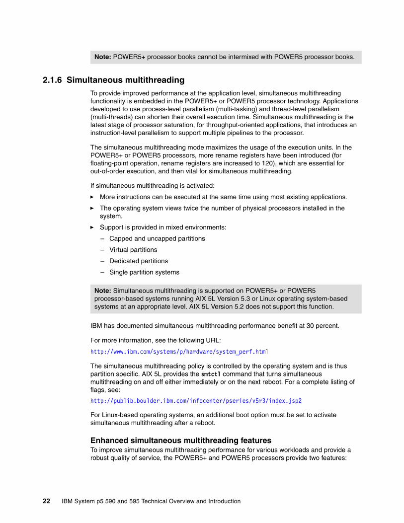
2.1.6 Simultaneous multithreadingTo provide improved performance at the application level, simultaneous multithreading functionality is embedded in the POWER5+ or POWER5 processor technology. Applications developed to use process-level parallelism (multi-tasking) and thread-level parallelism (multi-threads) can shorten their overall execution time. Simultaneous multithreading is the latest stage of processor saturation, for throughput-oriented applications, that introduces an instruction-level parallelism to support multiple pipelines to the processor.
The simultaneous multithreading mode maximizes the usage of the execution units. In the POWER5+ or POWER5 processors, more rename registers have been introduced (for floating-point operation, rename registers are increased to 120), which are essential for out-of-order execution, and then vital for simultaneous multithreading.
If simultaneous multithreading is activated:
� More instructions can be executed at the same time using most existing applications.
� The operating system views twice the number of physical processors installed in the system.
� Support is provided in mixed environments:
– Capped and uncapped partitions
– Virtual partitions
– Dedicated partitions
– Single partition systems
IBM has documented simultaneous multithreading performance benefit at 30 percent.
For more information, see the following URL:
http://www.ibm.com/systems/p/hardware/system_perf.html
The simultaneous multithreading policy is controlled by the operating system and is thus partition specific. AIX 5L provides the smtctl command that turns simultaneous multithreading on and off either immediately or on the next reboot. For a complete listing of flags, see:
http://publib.boulder.ibm.com/infocenter/pseries/v5r3/index.jsp2
For Linux-based operating systems, an additional boot option must be set to activate simultaneous multithreading after a reboot.
Enhanced simultaneous multithreading featuresTo improve simultaneous multithreading performance for various workloads and provide a robust quality of service, the POWER5+ and POWER5 processors provide two features:
Note: POWER5+ processor books cannot be intermixed with POWER5 processor books.
Note: Simultaneous multithreading is supported on POWER5+ or POWER5 processor-based systems running AIX 5L Version 5.3 or Linux operating system-based systems at an appropriate level. AIX 5L Version 5.2 does not support this function.
22 IBM System p5 590 and 595 Technical Overview and Introduction

� Dynamic resource balancing
Dynamic resource balancing is designed to ensure that the two threads executing on the same processor flow smoothly through the system. Depending on the situation, the POWER5+ or POWER5 processor resource balancing logic has different thread throttling mechanisms (a thread reaching a threshold of L2 cache misses will be throttled to allow other threads to pass the stalled thread).
� Adjustable thread priority
Adjustable thread priority allows software to determine when one thread should have a greater (or lesser) share of execution resources. The POWER5+ and POWER5 processors support eight software-controlled priority levels for each thread.
Single threading operationHaving threads executing on the same processor does not increase the performance of applications with execution unit limited performance, or applications that consume all the processor’s memory bandwidth. For this reason, the POWER5+ and POWER5 processors support the single threading execution mode. In this mode, the POWER5+ and POWER5 processors give all the physical resources to the active thread, allowing it to achieve higher performance than a POWER4 processor-based system at equivalent frequencies. Highly optimized scientific codes are one example where single threading operation will provide optimized throughput.
2.1.7 Dynamic power managementIn current Complementary Metal Oxide Semiconductor (CMOS) technologies, processor power draw is one of the most important design parameters. With the introduction of simultaneous multithreading, more instructions execute per cycle per processor core, thus increasing each core’s and therefore the processor’s total switching power. To reduce switching power, POWER5+ and POWER5 processors use a fine-grained, dynamic clock gating mechanism extensively. This mechanism gates off clocks to a local clock buffer if dynamic power management logic knows the set of latches driven by the buffer will not be used in the next cycle. This allows substantial power saving with no performance impact. In every cycle, the dynamic power management logic determines whether a local clock buffer that drives a set of latches can be clock gated in the next cycle.
2.1.8 Available processor speedsThe p5-590 system features 8-core (CoD), 16-core, and 32-core configurations with POWER5+ processors running at 2.1 GHz or POWER5 processors running at 1.65 GHz. The p5-595 system features base 16-core, 32-core, 48-core, and 64-core configurations with POWER5+ processors running at 2.1 GHz and 2.3 GHz or POWER5 processors running at 1.65 GHz and 1.9 GHz.
To determine the processor characteristics on a running system, use one of the following commands:
lsattr -El procX Where X is the number of the processor; for example, proc0 is the first processor in the system. The output from the command1 would be similar to this:
Note: Any p5-595 or p5-590 system made of more than one processor book must have all processors running at the same speed and adopt the same technology (POWER5+ or POWER5).
Chapter 2. Architecture and technical overview 23

frequency 210000000 Processor Speed Falsesmt_enabled true Processor SMT enabled Falsesmt_threads 2 Processor SMT threads Falsestate enable Processor state Falsetype powerPC_POWER5 Processor type False
(False, as used in this output, signifies that the value cannot be changed through an AIX 5L command interface.)
pmcycles -m This command (AIX 5L Version 5.3 and later) uses the performance monitor cycle counter and the processor real-time clock to measure the actual processor clock speed in MHz. This is the sample output of a 16-core p5-590 running at 2.1 GHz:
Cpu 0 runs at 2100 MHzCpu 1 runs at 2100 MHzCpu 2 runs at 2100 MHzCpu 3 runs at 2100 MHz...Cpu 13 runs at 2100 MHzCpu 14 runs at 2100 MHzCpu 15 runs at 2100 MHz
2.2 System flash memory configurationIn the p5-590 and p5-595, a serial electronically erasable programmable read-only memory (sEEPROM) adapter plugs into the back of the Central Electronics Complex backplane. The platform firmware binary image is programmed into the system’s EEPROM, also known as system FLASH memory. FLASH memory is initially programmed during manufacturing of the p5-590 and p5-595 systems. However, this single binary image can be reprogrammed to accommodate firmware fixes provided to the client using the hardware management console.
The firmware binary image contains boot code for the p5-590 and p5-595. This boot code includes, but is not limited to, system service processor code; code to initialize the POWER5+ or POWER5 processors, memory, and I/O subsystem components; partition management code; and code to support the virtualization features. The firmware binary image also contains hardware monitoring code used during partition run time.
During boot time, the system service processor dynamically allocates the firmware image from flash memory into main system memory. The firmware code is also responsible for loading the operating system image into main memory.
2.2.1 Vital product data and system smart chipsVital product data (VPD) carries all of the necessary information for the service processor to determine if the hardware is compatible and how to configure the hardware and system processors on the card. The VPD also contains the part number and serial number of the card used for servicing the machine, as well as the location information of each device for failure analysis. Because the VPD in the card carries all information necessary to configure the card, no card device drivers or special code have to be sent with each card for installation.
Smart chips are micro-controllers used to store vital product data (VPD). The smart chip provides a means for securely storing data that cannot be read, altered, or written other than by IBM privileged code. The smart chip provides a means of verifying IBM System On/Off Capacity on Demand and IBM System Capacity Upgrade on Demand activation codes that
1 The output of the lsattr command has been expanded with AIX 5L to include the processor clock rate.
24 IBM System p5 590 and 595 Technical Overview and Introduction

only the smart chip on the intended system can verify. This allows clients to purchase additional spare capacity and pay for use only when needed. The smart chip is the basis for the CoD function and verifying the data integrity of the data stored in the card.
2.3 Light stripThere is no operator panel on p5-590 and p5-595 servers. The p5-590 and p5-595 have a light strip on both the front and the rear of the system unit. The light strips contain several LEDs, each representing the status of a particular field replaceable unit (FRU) or component. Under normal system operating conditions:
� No amber LEDs are lit. An amber LED that is lit indicates a problem with the component associated with that LED.
� If an active component has a green LED associated with it, that LED is lit.
� Processor books, oscillator cards, SP cards, and the light strips themselves are FRUs for which both green and amber LEDS are assigned. If, for example, PU book 3 is not active (as would be the case in a 48-core system), both the green and amber LEDs would be unlit.
� If the System Attention LED is lit, a serviceable event has been detected and recorded by the system.
A light strip is composed of a printed circuit card mounted on a plastic bezel. Figure 2-8 shows the front light strip.
Figure 2-8 p5-590 and p5-595 front light strip
The following three tables (left, middle, and right sections) help identify LED meanings. Table 2-1 on page 26, Table 2-2 on page 26, and Table 2-3 on page 26 are grouped by light strip section.
Note: The following abbreviations are used:
� Proc. book - Processor book
� AMD - Air moving device (blower)
� MCM - Multi-chip module
� OSC - Oscillator
� SP - Service processor
� DCA - Distributed converter assembly
� CEC - Central electronic complex
Chapter 2. Architecture and technical overview 25

Table 2-1 Front light strip left section
Table 2-2 Front light strip middle section
Table 2-3 Front light strip right section
Figure 2-9 shows the rear light strip followed by Table 2-4 on page 27, Table 2-5 on page 27, and Table 2-6 on page 27, which are grouped by light strip section (left, middle, and right) and list LED status indicators.
.
Figure 2-9 p5-590 and p5-595 rear light strip
Front light strip left section
P6 (upper)Front light strip (green)
P2 (upper)Proc. book 0 (green)
A2- AMD2(amber)
P6 (lower)Front light strip (amber)
P2 (lower)Proc. book 0 (amber)
A1- AMD1(amber)
!- systemSystem attention
P3 (upper)Proc. book 1 (green)
P3 (lower)Proc. book 1 (amber)
Front light strip middle section(all amber)
C27- M1 MCM C13 - D8 RIO adapter C12 - MC04 memory card
C26 - M0 MCM C11 - D7 RIO adapter C10 - MC03 memory card
C9 - D6 RIO adapter C8 - D5 RIO adapter C7 mux card
C6 - D4 RIO adapter C5 - D3 RIO adapter C4 - MC02 memory card
C3 - D2 RIO adapter C2 - MC04 memory card C1 - D1 RIO adapter
C25 - MC16 memory card C24 - MC15 memory card C23 - MC14 memory card
C22 - MC13 memory card C21 - MC12 memory card C20 - MC11 memory card
C19 - MC10 memory card C18 - MC09 memory card C17 - MC08 memory card
C16 - MC07 memory card C15 - MC06 memory card C14 - MC05 memory card
Front light strip right section
P4 (upper)Proc. book 2 (green)
A4- AMD 4(amber)
P5 (upper)Proc. book 3 (green)
P4 (lower)Proc. book 2 (amber)
A3- AMD3(amber)
P5 (lower)Proc. book 3 (amber)
26 IBM System p5 590 and 595 Technical Overview and Introduction

Table 2-4 Rear light strip left section
Table 2-5 Rear light strip middle section
Table 2-6 Rear light strip right section
2.4 Memory subsystemThe p5-590 and p5-595 memory controllers are internal to the POWER5+ or POWER5 processor. The memory controller interfaces to four Synchronous Memory Interface II (SMI-II) buffers and eight DIMM cards per processor as shown in Figure 2-10 on page 28. There are 16 memory card slots per processor book and each processor on an MCM owns a pair of memory cards.
The p5-590 and p5-595 use Double Data Rate (DDR) DRAM memory cards. The two types of DDR memory used are the higher-speed DDR2 and DDR1. POWER5+ servers require DDR2 only, p5-590 and p5-595 DDR1 memory is orderable only as MES upgrades. DDR1 memory migration from previous systems is not supported.
Rear light strip left section
P7 (upper)Rear light strip (green)
A5- AMD5(amber)
E1 - DCA 30 (amber)
P7 (lower)Rear light strip (amber)
E2 - DCA 31 (amber)
E3 - DCA 32 (amber)
!- systemSystem attention
E4 - DCA 20 (amber)
Rear light strip middle section
C1 (upper)SP 1 (green)
C2 (upper)OSC 1 (green)
C3 (upper)OSC 2 (green)
C1 (lower)SP 1 (amber)
C2 (lower)OSC 1 (amber)
C3 (lower)OSC 2 (amber)
C5 - Anchor 1 (amber)
E5 - DCA 21(amber)
E6- DCA 22(amber)
P1 - CEC backplane
E7 - DCA 10(amber)
E8 - DCA 11(amber)
Rear light strip right section
A6- AMD6(amber)
C4 (upper)SP 0 (green)
E9 - DCA 12(amber)
E10 - DCA 00(amber)
C4 (lower)SP 0 (amber)
E11 - DCA 01(amber)
E12 - DCA 02 (amber)
Note: Because the DDR1 and DDR2 modules use different voltages, mixing the memory technologies is not allowed within a server.
Chapter 2. Architecture and technical overview 27

Figure 2-10 Memory flow diagram for MCM 0
2.4.1 Memory cardsThe p5-590 and the p5-595 system memory is seated on a memory card as shown in Figure 2-11 on page 29. Each memory card has four soldered DIMM cards and two SMI-II components for address, controls, and data buffers. Individual DIMM cards cannot be removed or added, and memory cards have a fixed amount of memory.
SMI-II
SMI-II
PDIMM
PDIMM
PDIMM
PDIMM
SMI-II
SMI-II
PDIMM
PDIMM
PDIMM
PDIMM
SMI-II
SMI-II
PDIMM
PDIMM
PDIMM
PDIMM
SMI-II
SMI-II
PDIMM
PDIMM
PDIMM
PDIMM
SMI-II
SMI-II
PDIMM
PDIMM
PDIMM
PDIMM
SMI-II
SMI-II
PDIMM
PDIMM
PDIMM
PDIMM
SMI-II
SMI-II
PDIMM
PDIMM
PDIMM
PDIMM
SMI-II
SMI-II
PDIMM
PDIMM
PDIMM
PDIMM
PU
L2
PU
Chip-Chip Comm
PU
L2
PU
Chip-Chip Comm
PU
L2
PU
Chip-Chip Comm
PU
L2
PU
Chip-Chip Comm
L3
A B
C D
L3
L3L3
SMIadrs/ctlbus
L3 bus
Memory Card Pair A0
SMI data bus
Memory bus
Memory Card Pair B0
SMI data bus
Memory bus
Memory Card Pair C0
SMI data bus
Memory bus
Memory Card Pair D0
SMI data bus
Memory bus
SMIadrs/ctlbus
RIO GPorts
GX Adapter
Card
L3 bus
L3 bus L3 bus
RIO GPorts
GX Adapter
Card
RIO GPorts
GX Adapter
Card
RIO GPorts
GX Adapter
Card
Memory Flow for MCM 0
28 IBM System p5 590 and 595 Technical Overview and Introduction

Figure 2-11 Memory card with four DIMM slots
The memory features that are available for the p5-590 and the p5-595 at the time of writing are listed in Table 2-7. Note that FC 4503 and FC 8200 will be generally available January 19, 2007.
Table 2-7 Available memory cards for p5-590 and p5-595
2.4.2 Memory configuration and placement The p5-590 and p5-595 utilize DDR1 or DDR2 memory DIMMs, which are permanently mounted onto memory cards. Each processor book has 16 memory card slots. The maximum
Memory type Size Speed Number of memory cards
Feature code
Max595/590
DDR2COD Cards
0/4 GB 533 MHz 1 4500 64/32
0/8 GB 533 MHz 1 4501 64/32
0/16 GB 533 MHz 1 4502 64/32
0/32 GB 400 MHz 1 4503 64/32
DDR2 packages
256 GB activation package (no cards)
533 MHz n/a 7280 4/2
512 GB DDR2 COD card package (no activations)
533 MHz 32 * 16 GB 8151 2/1
512 GB package (fully activated cards)
400 MHz 16 * 32 GB 8200 4/2
DDR1COD Cards
4 GB (2 GB active)
266 MHz 1 7816 64/32
8 GB (4 GB active)
266 MHz 1 7835 64/32
DDR1packages
32 GB (fully activated card)
200 MHz 1 7829 64/32
512 GB package (fully activated cards)
200 MHz 16 * 32 GB 8198 4/2
Chapter 2. Architecture and technical overview 29

memory that you can configure depends on the number of installed processor books. Table 2-8 lists the minimum and maximum memory configurations.
Table 2-8 Memory configuration table
The memory locations for each processor in the MCMs are illustrated in Figure 2-12.
Figure 2-12 Memory placement for the p5-590 and p5-595
You must observe the following rules:
� Memory must be installed in identical pairs.
� Servers with one processor book must have a minimum of two memory cards installed.
� Servers with two processor books must have a minimum of four memory cards installed per processor book (two per MCM).
We recommend the following memory configuration guidelines:
� The same amount of memory should be used for each MCM (two per processor book) in the system.
� Each 8-core MCM (two per processor book) should have some memory.
System p5-590 p5-595
Minimum configurable memory 8 GB 8 GB
Maximum configurable memory using DDR1 memory 1,024 GB 2,048 GB
Maximum configurable memory using DDR2 memory 1,024 GB 2048 GB
Maximum number of memory cards 32 64
Note: DDR1 and DDR2 memory cards cannot be intermixed in the same system.
A1
A1I/O
I/O
I/O
I/O
I/O
I/O
I/O
I/O
D0
D0
C0
A0
A0
C0
B1
D1
C1
C1
MEZZANINEBASE CONNECTOR.
MC04
MC03
MC02
MC01
J1_BASEJ2_EXT
A0
B0
B0
B0
D0
C0
A1
B1
D1
C1
MUX1D1
B1
D1
D2
D3
D4
D5
D6
D7
D8
PWR
CBYTE
PWR
A
B
C
A1
TP
BERG - TP
A1
DOWN
DOWN
DOWN
DOWN
UP
UP
DOWN
DOWN
DOWN
DOWN
UP
UP
DOWN
DOWN
DOWN
DOWN
DOWN
UP
UP
UP
UP
UP
UP
DOWN
C1
C2
C3
C4
C5
C6
C7
C8
C9
C10
C11
C12
C13
C14
C15
C16
C17
C18
C19
C20
C21
C22
C23
C24
C25
Memory
Memory
Memory
MC07
MC06
MC05
MC08
MC09
MC10
MC11
MC12
MC13
MC14
MC15
MC16
Memory
Memory
Memory
Memory
Memory
Memory
Memory
Memory
Memory
Memory
Memory
Memory
Memory
A0-D0 = MCM0 Chip A-D A1-D1 = MCM1 Chip A-D
C26
C27
MCM 0
MCM 1
A B
C D
A B
C D
30 IBM System p5 590 and 595 Technical Overview and Introduction

� No more than two different sizes of memory cards should be used in each processor book.
� All MCMs (two per processor book) in the system should have the same aggregate memory size.
� A minimum of half of the available memory slots in the system should contain memory.
� It is better to install more cards of smaller capacity than fewer cards of larger capacity. On the other hand, cards with larger capacity would occupy fewer slots, providing room for future expansion and the reuse of the currently installed memory.
For p5-590 and p5-595 servers that are used for high-performance computing, we strongly recommend the following:
� Use DDR2 memory.
� Install some memory in support of each 8-core MCM (two MCMs per processor book).
� Use the same size of memory cards across all MCMs and processor books in the system.
2.4.3 Memory throughputThe memory subsystem throughput is based on the speed of the memory, not the speed of the processor. An elastic interface, contained in the POWER5+ processor, buffers reads and writes to and from memory and the processor. On 2.1 GHz or 2.3 GHz processor books, there are two SMIs per processor. There are four 4-byte read buses and four 2-byte write buses between each processor, and an associated pair of memory, therefore giving a total of 24 bytes available for simultaneous read and write operations. A DDR2 bus allows double reads or writes per clock cycle. In this configuration, the paths are 4 bytes for read operations and 2 bytes for write. Therefore, the throughput is (4 + 2) * 4 * 2 * 528 = 25.34 GBps or 101.3 GBps for an 8-core 2.1 GHz MCM. These values are maximum theoretical throughputs for comparison purposes only. Table 2-9 on page 32 provides the theoretical throughput values for different configurations.
Chapter 2. Architecture and technical overview 31

Table 2-9 Theoretical throughput rates
2.5 System busesThe following sections provide additional information related to the internal GX buses. For information regarding other buses, refer to 2.1.4, “The POWER5+ processor” on page 18.
2.5.1 GX+ and RIO-2 busesThe processor module provides a GX+ bus that is used to connect to the I/O subsystem. Table 2-10 on page 33 shows the relationship between RIO cards, MCMs, and processors:
� Each processor book has eight GX+ slots that support communication with the I/O drawer.
� Each processor on an MCM can own one GX+ I/O card.
� Each GX+ I/O card has two RIO-2 ports.
Remote I/O (RIO-2) links allow for connectivity to external I/O drawers and PCI-X technology.
� Table 2-10 on page 33 provides a GX+ card layout in relation to the MCMs.
Processor speed(GHz)
Processor type Cores Memory(GBps)
L2 to L3(GBps)
GX+(GBps)
2.1 POWER5+ 8-core 101.3 134.4 22.4
2.1 POWER5+ 16-core 202.7 268.8 44.8
2.1 POWER5+ 24-core 304.1 403.2 67.2
2.1 POWER5+ 32-core 404.5 537.6 89.6
2.1 POWER5+ 40-core 506.8 672 112
2.1 POWER5+ 48-core 608.2 806.4 134.4
2.1 POWER5+ 56-core 709.6 940.8 156.8
2.1 POWER5+ 64-core 811 1075.2 179.2
2.3 POWER5+ 16-core 202.7 294.4 49.1
2.3 POWER5+ 24-core 304.1 441.6 73.6
2.3 POWER5+ 32-core 405.5 588.8 98.1
2.3 POWER5+ 40-core 506.8 736 122.7
2.3 POWER5+ 48-core 608.2 883.2 147.2
2.3 POWER5+ 56-core 709.6 1030.4 171.7
2.3 POWER5+ 64-core 811 1177.6 196.3
32 IBM System p5 590 and 595 Technical Overview and Introduction
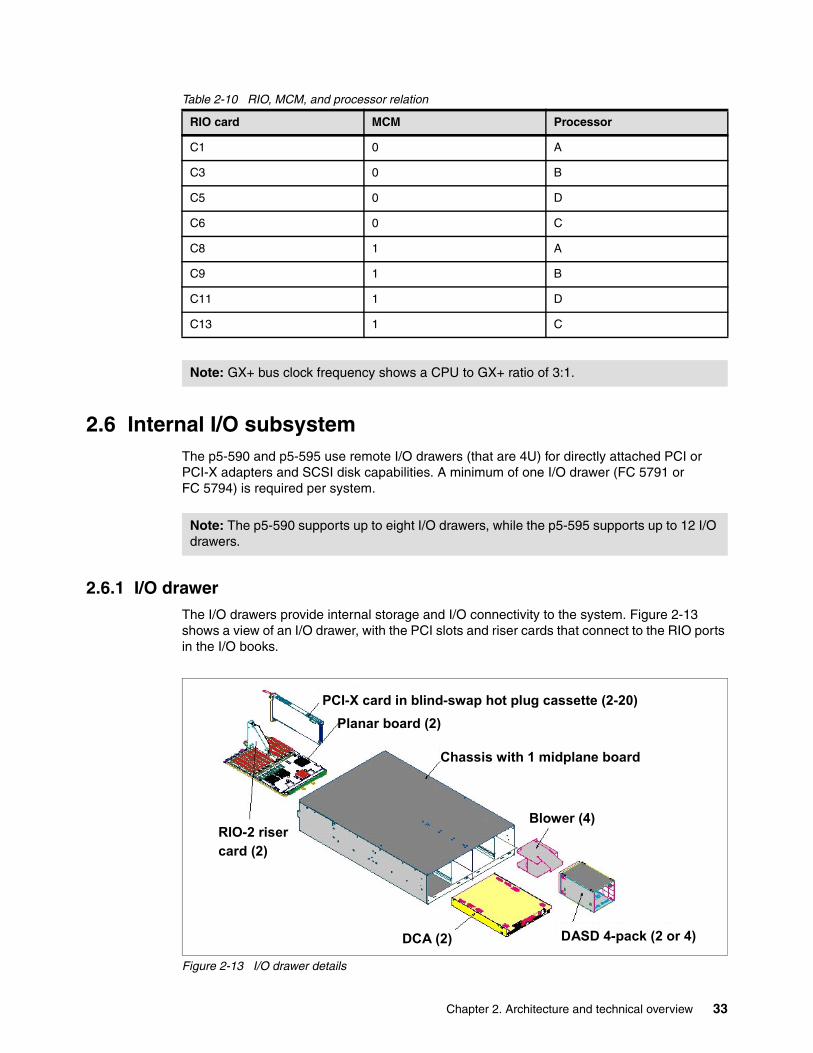
Table 2-10 RIO, MCM, and processor relation
2.6 Internal I/O subsystemThe p5-590 and p5-595 use remote I/O drawers (that are 4U) for directly attached PCI or PCI-X adapters and SCSI disk capabilities. A minimum of one I/O drawer (FC 5791 or FC 5794) is required per system.
2.6.1 I/O drawerThe I/O drawers provide internal storage and I/O connectivity to the system. Figure 2-13 shows a view of an I/O drawer, with the PCI slots and riser cards that connect to the RIO ports in the I/O books.
Figure 2-13 I/O drawer details
RIO card MCM Processor
C1 0 A
C3 0 B
C5 0 D
C6 0 C
C8 1 A
C9 1 B
C11 1 D
C13 1 C
Note: GX+ bus clock frequency shows a CPU to GX+ ratio of 3:1.
Note: The p5-590 supports up to eight I/O drawers, while the p5-595 supports up to 12 I/O drawers.
DCA (2)
RIO-2 risercard (2)
Planar board (2)
Chassis with 1 midplane board
PCI-X card in blind-swap hot plug cassette (2-20)
Blower (4)
DASD 4-pack (2 or 4)
Chapter 2. Architecture and technical overview 33

Each I/O drawer is divided into two halves. Each half contains 10 blind-swap PCI-X slots (3.3 volt) and one or two Ultra3 SCSI 4-pack backplanes for a total of 20 PCI slots and up to 16 hot-swap disk bays per drawer (these internal SCSI backplanes do not support external SCSI device attachments). Each half of the I/O drawer is powered separately.
Existing 7040-61D I/O drawers can be attached to p5-590 and p5-595 servers as additional I/O drawers, if available:
� Only 7040-61D I/O drawers containing FC 6571 PCI-X planars are supported. Any FC 6563 PCI planars must be replaced with FC 6571 PCI-X planars, before the drawer can be attached.
� Only adapters supported on the p5-590 I/O drawers are supported in 7040-61D I/O drawers, if attached. Unsupported adapters must be removed before attaching the drawer to the p5-590 server.
Additional I/O drawer configuration requirements:
� A minimum of one I/O drawer (FC 5791 or FC 5794) is required per system. I/O drawer FC 5791 contains 20 PCI-X slots and 16 disk bays, and FC 5794 contains 20 PCI-X slots and eight disk bays.
� A maximum of eight I/O drawers can be connected to a p5-590. Fully configured, the p5-590 can support 160 PCI adapters and 128 disks at 15,000 rpm.
� A maximum of 12 I/O drawers can be connected to a p5-595. Fully configured, the p5-595 can support 240 PCI adapters and 192 disks at 15,000 rpm.
� A blind-swap hot-plug cassette (equivalent to those in FC 4599) is provided in each PCI-X slot of the I/O drawer. Cassettes not containing an adapter are shipped with a plastic filler card installed to help ensure proper environmental characteristics for the drawer. If you need additional blind-swap hot-plug cassettes, you should order FC 4599.
� All 10 PCI-X slots on each I/O drawer planar are capable of supporting either 64-bit or 32-bit PCI or PCI-X adapters. Each I/O drawer planar provides 10 PCI-X slots capable of supporting 3.3 V signaling PCI or PCI-X adapters operating at speeds up to 133 MHz.
2.6.2 I/O drawer attachmentSystem I/O drawers are connected to the p5-590 and p5-595 CEC using RIO-2 loops. Drawer connections are made in loops to help protect against errors resulting from an open, missing, or disconnected cable. If a fault is detected, the system can reduce the speed on a cable, or disable part of the loop. Systems with non-looped configurations could experience degraded performance and serviceability. The system has a non-looped configuration if only one RIO-2 path is running.
RIO-2 loop connections operate at 1 GHz. RIO-2 loops connect to the system CEC using RIO-2 loop attachment adapters (FC 7818). Each of these adapters has two ports and can support one RIO-2 loop. Up to six of the adapters can be installed in each 16-core processor book. Up to 8 or 12 I/O drawers can be attached to the p5-590 or p5-595, depending on the model and attachment configuration.
I/O drawers can be connected to the CEC in either single-loop or dual-loop mode:
� Single-loop (Figure 2-14 on page 35) mode connects an entire I/O drawer to the CEC using one RIO-2 loop (2 ports). The two I/O planars in the I/O drawer are connected together using a short RIO-2 cable. Single-loop connection requires one RIO-2 Loop Attachment Adapter (FC 7818) per I/O drawer.
� Dual-loop (Figure 2-15 on page 36) mode connects each I/O planar in the drawer to the CEC separately. Each I/O planar is connected to the CEC using a separate RIO-2 loop.
34 IBM System p5 590 and 595 Technical Overview and Introduction

A dual-loop connection requires two RIO-2 Loop Attachment Adapters (FC 7818) per I/O drawer. With a dual-loop configuration, the RIO-2 bandwidth for the I/O drawer is higher.
Table 2-11 lists the number of single-looped and double-looped I/O drawers that can be connected to a p5-590 or p5-595 server based on the number of processor books installed.
Table 2-11 Number of RIO drawers that can be connected
On initial orders of p5-590 or p5-595 servers, IBM Manufacturing will place dual-loop-connected I/O drawers as the lowest numerically designated drawers followed by any single-looped I/O drawers.
2.6.3 Single loop (full-drawer) cablingSingle loop I/O drawer connections are shown in Figure 2-14.
Figure 2-14 Single loop I/O drawer (FC 5791)
The short RIO-2 cable connecting the two halves of the drawer ensures that each side of the drawer (P1 and P2) can be accessed by the CEC I/O (RIO-2 adapter) card, even if one of the
Note: We recommend that you use Dual-loop mode whenever possible, because it provides the maximum bandwidth between the I/O drawer and the CEC.
Number of processor books Single-looped Dual-looped
1 6 3
2 8 (590) 12 (595) 6
3 12 (p5-595) 9 (p5-595)
4 12 (p5-595) 12 (p5-595)
1
RIO-2 CARD0
1
RIO-2 CARD0
1
0
1
0
RIO-2 CARD
RIO-2 CARD
P1 P2
P1 P2
0 1
0 1
CEC GX+ I/O RIO-2 PORTS
Drawer 1
Drawer 2
Chapter 2. Architecture and technical overview 35

cables is damaged. Each half of the I/O drawer can communicate with the CEC I/O card for its own uses or on behalf of the other side of the drawer.
2.6.4 Dual looped (half-drawer) cablingAlthough I/O drawers will not be built in half-drawer configurations, they can be cabled and addressed by the CEC individually using dual loop (half drawer) increments as shown in Figure 2-15).
Figure 2-15 Dual loop I/O drawer (FC 5791)
We strongly recommend that you configure I/O loops as described in the IBM Systems Hardware Information Center, and that you only follow a different order when absolutely necessary.
It is extremely important for the ongoing management of the system to keep up-to-date cabling documentation of your systems, because it might differ from the cabling diagrams of the installation guides.
2.6.5 Disks and boot devices A minimum of two internal SCSI hard disks are required per server. We recommend that these disks are used as mirrored boot devices. These disks should be mounted in the first I/O drawer whenever possible. This configuration provides service personnel with the maximum amount of diagnostic information if the system encounters errors in the boot sequence.
Boot support is also available from local SCSI and Fibre Channel adapters (as well as existing SSA), or from networks using Ethernet adapters (as well as existing token-ring). If the boot source other than internal disk is configured, the supporting adapter should also be in the first I/O drawer.
RIO-2 CARD0
RIO-2 CARD
1 1
0
P1 P2
0 1
0 1
CEC GX+ I/O RIO-2 PORTS
Drawer 1
RAID capacity limitation: There are limits to the amount of disk drive capacity allowed in a single RAID array. Using the 32-bit AIX 5L kernel, there is a capacity limitation of 1 TB per RAID array. Using the 64 bit kernel, there is a capacity limitation of 2 TB per RAID array. For RAID adapter and RAID enablement cards, this limitation is enforced by AIX 5L when RAID arrays are created using the PCI-X SCSI Disk Array Manager.
36 IBM System p5 590 and 595 Technical Overview and Introduction

2.6.6 Media optionsThe p5-590 and p5-595 servers must have access either to a device capable of reading CD media or to a NIM server:
� The recommended devices for reading CD media are the rack-mounted media drawer (FC 5795) or an IBM Storage Device Enclosure. The Media Drawer (FC 5795) is mounted in the 13U location of the CEC Rack; the 7212-102, 7210-025, and 7210-030 enclosures attach using a PCI SCSI adapter in one of the system I/O drawers.
� If a NIM server is used, it must attach through a PCI LAN adapter in one of the system I/O drawers. An Ethernet connection is recommended.
Rack-mounted Media Drawer (FC 5795) provides a 1U high internal media drawer for use with the p5-590 and p5-595 servers. The media drawer displaces any I/O drawer or battery backup feature components that would be located in the same location of the primary system rack. The Media Drawer provides a fixed configuration that must be ordered with three media devices and all required SCSI and power attachment cabling.
This media drawer can be mounted in the CEC rack with three available media bays, two in the front and one in the rear. The device in the rear is only accessible from the rear of the system. New storage devices for the media bays include:
� 4.7 GB, SCSI DVD-RAM drive (FC 5752)
� 200/400 GB half high Utrium2 (FC 5755)
� 80/60 GB Internal Tape drive with VXA technology (FC 6120)
� 36/72 GB, 4 mm internal tape drive (FC 6258)
� 160 GB VXA-320 Tape drive (FC 6279)
2.6.7 PCI-X slots and adaptersPCI-X, where the X stands for extended, is an enhanced PCI bus, delivering a theoretical peak bandwidth of up to 1 GBps, running a 64-bit bus at 133 MHz. PCI-X is backward compatible, so the p5-590 and p5-595 I/O drawers can support existing 3.3 volt PCI adapters.
Most PCI and PCI-X adapters for the p5-590 and p5-595 servers are capable of being hot-plugged. Any PCI adapter supporting a boot device or system console should not be hot-plugged. The POWER GXT135P Graphics Accelerator with Digital Support (FC 2849) is not hot-plug-capable.
System maximum limits for adapters and devices might not provide optimal system performance. These limits are given to help assure connectivity and function.
Configuration limitations have been established to help ensure appropriate PCI or PCI-X bus loading, adapter addressing, and system and adapter functional characteristics when ordering I/O drawers. These I/O drawer limits are in addition to individual adapter limits shown in the feature description section of the Sales Manual.
The maximum number of a specific PCI or PCI-X adapter allowed per p5-590 and p5-595 server might be less than the number allowed per I/O drawer multiplied by the maximum number of I/O drawers.
The PCI-X slots in the I/O drawers of p5-590 and p5-595 servers support Extended Error Handling (EEH). In the unlikely event of a problem, EEH-enabled adapters respond to a special data packet generated from the affected PCI-X slot hardware by calling system
Chapter 2. Architecture and technical overview 37

firmware, which is designed to examine the affected bus, allow the device driver to reset it, and continue without a system reboot.
To find more information about PCI adapter placement, look at the IBM Systems Hardware Information Center by searching for PCI placement:http://publib.boulder.ibm.com/infocenter/eserver/v1r3s/index.jsp
2.6.8 LAN adaptersTable 2-12 lists the LAN adapters, which are available at the time of writing. IBM supports installation using the Network Installation Manager (NIM) using Ethernet adapters (CHRP2 is the platform type).
Table 2-12 Available LAN adapter
2.6.9 SCSI adaptersThe p5-590 and p5/595 I/O drawers have four integrated Ultra3 SCSI adapters. Integrated adapters support the SCSI Enclosure Services (SES hot-swappable control functions). The integrated Ultra3 SCSI adapters are for internal storage only and cannot be used for external disks. Table 2-13 lists additional SCSI adapters available at the time of writing. All listed adapters can be used as boot adapters.
Table 2-13 Available SCSI adapters
2.6.10 iSCSIiSCSI is an open, standards-based approach by which SCSI information is encapsulated using the TCP/IP protocol to allow its transport over IP networks. It allows transfer of data
Note: As soon as a p5-590 or p5-595 server is connected to a Hardware Management Console, the POWER Hypervisor™ software prevents the system from using non-EEH OEM adapters.
2 CHRP stands for Common Hardware Reference Platform, a specification for PowerPC processor-based systems that can run multiple operating systems.
Feature code
Adapter description Size Maximum595/590
5700 Gigabit Ethernet-SX PCI-X Adapter Short 192/160
5701 10/100/1000 Base-TX Ethernet PCI-X Adapter Short 192/160
5706 2-Port 10/100/1000 Base-TX Ethernet PCI-X Adapter Short 192/160
5707 2-Port Gigabit Ethernet-SX PCI-X Adapter Short 192/160
5721 10 Gigabit Ethernet-SR PCI-X (Fiber) Short 128/64
5722 10 Gigabit Ethernet-LR PCI-X (Fiber) Short 128/64
5740 4-port 10/100/1000 Gigabit Ethernet PCI-X Short 128/64
Feature code
Adapter description Size Maximum595 and 590
5736 PCI-X Dual Channel Ultra320 SCSI Adapter Long 240/160
5737 PCI-X Dual Channel Ultra320 SCSI RAID Adapter Long 16
38 IBM System p5 590 and 595 Technical Overview and Introduction

between storage and servers in block I/O formats (defined by iSCSI protocol) and thus enables the creation of IP SANs. With iSCSI, an existing network can transfer SCSI commands and data with full location independence and define the rules and processes to accomplish the communication. The iSCSI protocol is defined in iSCSI IETF draft-20.
For more information about this standard, see:
http://tools.ietf.org/html/rfc3720
Although iSCSI can be, by design, supported over any physical media that supports TCP/IP as a transport, today's implementations are only on Gigabit Ethernet. At the physical and link level layers, systems that support iSCSI can be directly connected to standard Gigabit Ethernet switches and IP routers. iSCSI also enables the access to block-level storage that resides on Fibre Channel SANs over an IP network using iSCSI-to-Fibre Channel gateways such as storage routers and switches.
The iSCSI protocol is implemented on top of the physical and data-link layers and presents the operating system with the standard SCSI Access Method command set. It supports SCSI-3 commands and reliable delivery over IP networks. The iSCSI protocol runs on the host initiator and the receiving target device. It can either be optimized in hardware for better performance on an iSCSI host bus adapter (such as FC 1986 and FC 1987 supported in IBM System p5 servers) or run in software over a standard Gigabit Ethernet network interface card. System p5 systems support iSCSI in the following two modes:
Hardware Using iSCSI adapters (see “IBM iSCSI adapters” on page 39).
Software Supported on standard Gigabit adapters, additional software (see “IBM iSCSI software Host Support Kit” on page 40) must be installed.
Initial iSCSI implementations are targeted for small to medium-sized businesses and departments or branch offices of larger enterprises that have not deployed Fibre Channel SANs. iSCSI is an affordable way to create IP SANs from a number of local or remote storage devices. If Fibre Channel is present, which is typical in a data center, it can be accessed by the iSCSI SANs (and vice versa) using iSCSI-to-Fibre Channel storage routers and switches.
iSCSI solutions always involve the following software and hardware components:
Initiators These are the device drivers and adapters that are located on the client. They encapsulate SCSI commands and route them over the IP network to the target device.
Targets The target software receives the encapsulated SCSI commands over the IP network. The software can also provide configuration support and storage-management support. The underlying target hardware can be a storage appliance that contains embedded storage; it can also be a gateway or bridge product that contains no internal storage of its own.
IBM iSCSI adaptersNew iSCSI adapters in IBM System p5 platforms offer the advantage of increased bandwidth through the hardware support of the iSCSI protocol. The 1 Gigabit iSCSI TOE PCI-X adapters support hardware encapsulation of SCSI commands and data into TCP and transport it over the Ethernet using IP packets. The adapter operates as an iSCSI TCP/IP Offload Engine. This offload function eliminates host protocol processing and reduces CPU interrupts. The adapter uses a small form factor LC type fiber optic connector or copper RJ45 connector. Table 2-14 lists the iSCSI adapters that can be ordered.
Chapter 2. Architecture and technical overview 39

Table 2-14 Available iSCSI adapters
IBM iSCSI software Host Support KitThe iSCSI protocol can also be used over standard Gigabit Ethernet adapters. To utilize this approach, download the appropriate iSCSI Host Support Kit for your operating system from the IBM NAS support Web site at:
http://www.ibm.com/storage/support/nas/
The iSCSI Host Support Kit on AIX 5L and Linux operating systems acts as a software iSCSI initiator and allows access to iSCSI target storage devices using standard Gigabit Ethernet network adapters. To ensure the best performance, enable TCP Large Send, TCP send and receive flow control, and Jumbo Frame for the Gigabit Ethernet Adapter and the iSCSI target. Also, tune network options and interface parameters for maximum iSCSI I/O throughput in the operating system based on your performance monitoring data.
IBM System Storage N seriesThe combination of System p5 and IBM System Storage™ N series as the first of a new generation of iSCSI-enabled storage products provides an end-to-end set of solutions. Currently, the System Storage N series features three models: N3700, N5200, and N5500 with:
� Support for entry-level and midrange clients that require Network Attached Storage (NAS) or Internet Small Computer System Interface (iSCSI) functionality
� Support for Network File System (NFS), Common Internet File System (CIFS), and iSCSI protocols
� Data ONTAP software (at no charge), with plenty of additional functions such as data movement, consistent snapshots, and NDMP server protocol, some available through optional licensed functions
� Enhanced reliability with optional clustered (2-node) failover support
2.6.11 Fibre Channel adaptersThe p5-590 and p5-595 servers support direct or SAN connection to devices using Fibre Channel adapters. Single-port Fibre Channel adapters are available in 2 Gbps and 4 Gbps speeds. A dual-port 4 Gbps Fibre Channel adapter is also available. Table 2-15 provides a summary of the available adapters.
All of these adapters have LC connectors. If you are attaching a device or switch with an SC type fiber connector, an LC-SC 50 Micron Fiber Converter Cable (FC 2456) or an LC-SC 62.5 Micron Fiber Converter Cable (FC 2459) is required.
Supported data rates between the server and the attached device or switch are as follows: Distances of up to 500 meters running at 1 Gbps, distances up to 300 meters running at 2 Gbps data rate, and distances up to 150 meters running at 4 Gbps. When these adapters are used with IBM supported Fibre Channel storage switches supporting long-wave optics, distances of up to 10 kilometers are capable running at either 1 Gbps, 2 Gbps, or 4 Gbps data rates.
Feature code Description Slot Size Maximum
5713 Gigabit iSCSI TOE PCI-X on copper media adapter 64-bit Short 48/32
5714 Gigabit iSCSI TOE PCI-X on optical media adapter 64-bit Short 48/32
40 IBM System p5 590 and 595 Technical Overview and Introduction

Table 2-15 Available Fibre Channel adapters
2.6.12 Graphic acceleratorsThe p5-590 and p5-595 systems support up to 16 enhanced POWER GXT135P (FC 2848 or FC 2849) 2D graphic accelerators. The POWER GXT135P is a low-priced 2D graphics accelerator for IBM System p5 servers. This adapter supports both analog and digital monitors.
2.6.13 Asynchronous PCI-X adaptersThe asynchronous PCI-X adapters provide connection of asynchronous EIA-232 or RS-422 devices. However, if you have a cluster configuration or high-availability configuration and plan to connect the IBM System p5 servers using a serial connection, you cannot use the two default system ports. Table 2-16 lists the required features.
Table 2-16 Asynchronous PCI-X adapters
In many cases, the FC 5723 asynchronous adapter is configured to supply a backup HACMP™ heartbeat. In these cases, a serial cable (FC 3928) must be also configured. FC 3928 and FC 5723 have 9-pin connectors.
2.6.14 PCI-X Cryptographic Coprocessor The PCI-X Cryptographic Coprocessor (FIPS 4) (FC 4764) for selected System p servers provides both cryptographic coprocessor and secure-key cryptographic accelerator functions in a single PCI-X card. The coprocessor functions are targeted to banking and finance applications. Financial PIN processing and credit card functions are provided. EMV is a standard for integrated chip-based credit cards. The secure-key accelerator functions are targeted at improving the performance of Secure Sockets Layer (SSL) transactions. FC 4764 provides the security and performance required to support On Demand Business and the emerging digital signature application.
The PCI-X Cryptographic Coprocessor (FIPS 4) (FC 4764) for selected System p servers provides secure storage of cryptographic keys in a tamper resistant hardware security module (HSM), which is designed to meet FIPS 140 security requirements. FIPS 140 is a U.S. Government National Institute of Standards and Technology (NIST)-administered standard and certification program for cryptographic modules. The firmware for the FC 4764 is available on a separately ordered and distributed CD. This firmware is an LPO product: 5733-CY1 Cryptographic Device Manager. The FC 4764 also requires LPP 5722-AC3 Cryptographic Access Provider to enable data encryption.
Feature code Description Slot
5716 2 Gigabit single-port Fibre Channel PCI-X Adapter (LC) 64-bit
5758 4 Gigabit single-port Fibre Channel PCI-X 2.0 Adapter (LC) 64-bit
5759 4 Gigabit dual-port Fibre Channel PCI-X 2.0 Adapter (LC) 64-bit
Feature code Description
2943 8-Port Asynchronous Adapter EIA-232/RS-422
5723 2-Port Asynchronous EIA-232 PCI Adapter
Chapter 2. Architecture and technical overview 41

2.6.15 Internal storageEach I/O drawer contains four integrated Ultra3 SCSI adapters and SCSI Enclosure Services (SES hot-swappable control functions). In drawer FC 5791, all four adapters are used, and each adapter is connected to a SCSI 4-pack backplane. In drawer FC 5794, only two 4-packs are installed.
Each 4-pack supports up to four hot-swappable Ultra3 SCSI disk drives, which can be used for installation of the operating system or for storing data. Table 2-17 lists hot-swappable disk drives.
Table 2-17 Hot-swappable disk drive options
Prior to the hot-swap of a disk in the hot-swappable capable bay, all necessary operating system actions must be undertaken to ensure that the disk is capable of being deconfigured. After the disk drive has been deconfigured, the SCSI enclosure device powers off the bay, enabling the safe removal of the disk. You should ensure that the appropriate planning has been given to any operating system-related disk layout, such as the AIX 5L Logical Volume Manager, when using disk hot-swap capabilities. For more information, see Problem Solving and Troubleshooting in AIX 5L, SG24-5496.
2.7 Logical partitioningDynamic logical partitions (LPARs) and virtualization increase utilization of system resources and add a new level of configuration possibilities. This section provides details and configuration specifications about this topic. The virtualization discussion includes virtualization enabling technologies that are standard on the system, such as the POWER Hypervisor, and optional ones, such as the Advanced POWER Virtualization feature.
2.7.1 Dynamic logical partitioningLogical partitioning (LPAR) technology offers the capability to divide a system into separate logical systems, allowing each LPAR to run an operating environment on dedicated attached devices, such as processors, memory, and I/O components.
System resources, such as processors, memory, and I/O components, can be added and deleted from dedicated partitions while they are executing. Starting with AIX 5L Version 5.2, system administrators can dynamically redefine all available system resources to reach the optimum capacity for each defined dynamic LPAR.
Note: This feature has country-specific usage. Refer to your IBM marketing representative for availability or restrictions.
Feature code Description
3277 36.4 GB 15,000 rpm Ultra320 SCSI hot-swappable disk drive
3278 73.4 GB 15,000 rpm Ultra320 SCSI hot-swappable disk drive
3279 146.8 GB 15,000 rpm Ultra320 SCSI hot-swappable disk drive
Note: Disks with 10 K rpm rotational speeds from earlier systems are not supported.
42 IBM System p5 590 and 595 Technical Overview and Introduction

Operating system support for dynamic reconfiguration of LPARsTable 2-18 on page 43 lists AIX 5L and Linux operating system support for dynamic LPAR capabilities.
Table 2-18 Operating system supported function
2.8 VirtualizationWith the introduction of the POWER5 processor, partitioning technology moved from a dedicated resource allocation model to a virtualized shared resource model. This section briefly discusses the key components of virtualization on System p5 and eServer p5 servers.
For more information about virtualization, see the following Web site:
http://www.ibm.com/servers/eserver/about/virtualization/systems/pseries.html
You can also consult the following IBM Redbooks:
� Advanced POWER Virtualization on IBM System p5, SG24-7940:
http://www.redbooks.ibm.com/abstracts/sg247940.html?Open
� Advanced POWER Virtualization on IBM Sserver p5 Servers: Architecture and Performance Considerations, SG24-5768:
http://www.redbooks.ibm.com/abstracts/sg245768.html?Open
2.8.1 POWER HypervisorCombined with features designed into the POWER5 and POWER5+ processors, the POWER Hypervisor delivers functions that enable other system technologies, including Micro-Partitioning technology, virtualized processors, IEEE VLAN, compatible virtual switch, virtual SCSI adapters, and virtual consoles. The POWER Hypervisor is a basic component of system firmware that is always active, regardless of the system configuration.
The POWER Hypervisor provides the following functions:
� Provides an abstraction between the physical hardware resources and the logical partitions that use them
� Enforces partition integrity by providing a security layer between logical partitions
� Controls the dispatch of virtual processors to physical processors (see later discussion in 2.9.2, “Logical, virtual, and physical processor mapping” on page 47)
� Saves and restores all processor state information during logical processor context switch
� Controls hardware I/O interrupt management facilities for logical partitions
� Provides virtual LAN channels between physical partitions that help to reduce the need for physical Ethernet adapters for inter-partition communication
Function AIX 5L Version 5.2
AIX 5L Version 5.3
LinuxSLES 9
LinuxRHEL AS 3
LinuxRHEL AS 4
Dynamic LPAR capabilities (add, remove, and move operations)
Processor Y Y Y N Y
Memory Y Y N N N
I/O slot Y Y Y N Y
Chapter 2. Architecture and technical overview 43

The POWER Hypervisor is always active when the server is running, partitioned or not, and also when not connected to the HMC. It requires memory to support the logical partitions on the server. The amount of memory required by the POWER Hypervisor firmware varies according to several factors. Factors influencing the POWER Hypervisor memory requirements include the following:
� Number of logical partitions
� Partition environments of the logical partitions
� Number of physical and virtual I/O devices used by the logical partitions
� Maximum memory values given to the logical partitions
The minimum amount of physical memory for each partition is 128 MB. In most cases, the actual requirements and recommendations are between 256 MB and 512 MB for AIX 5L, Red Hat, and Novell SUSE Linux. Physical memory is assigned to partitions in increments of Logical Memory Block (LMB). For POWER5+ processor-based systems, the LMB can be adjusted from 16 MB to 256 MB.
The POWER Hypervisor provides the following types of virtual I/O adapters:
� Virtual SCSI� Virtual Ethernet� Virtual (TTY) console
Virtual SCSIThe POWER Hypervisor provides virtual SCSI mechanism for virtualization of storage devices (a special logical partition to install the Virtual I/O Server is required to use this feature, as described in 2.9.3, “Virtual I/O Server” on page 49). The storage virtualization is accomplished using two, paired, adapters: a virtual SCSI server adapter and a virtual SCSI client adapter. Only the Virtual I/O Server partition can define virtual SCSI server adapters, other partitions are client partitions. The Virtual I/O Server is available with the optional Advanced POWER Virtualization feature (FC 7942).
Virtual EthernetThe POWER Hypervisor provides a virtual Ethernet switch function that allows partitions on the same server to use a fast and secure communication without any need for physical interconnection. Virtual Ethernet allows transmission speed in the range of 1 to 3 GBps, depending on the maximum transmission unit (MTU) size and CPU entitlement. Virtual Ethernet requires either AIX 5L Version 5.3 or an appropriate level of Linux supporting virtual Ethernet devices (see 2.10, “Operating system support” on page 55). Virtual Ethernet is part of the base system configuration.
Virtual Ethernet has the following major features:
� Virtual Ethernet adapters can be used for both IPv4 and IPv6 communication and can transmit packets with a size up to 65408 bytes. Therefore, the maximum MTU for the corresponding interface can be up to 65394 (65390 if VLAN tagging is used).
Note: Use the IBM System Planning Tool to estimate the memory requirements of the POWER Hypervisor.
In AIX 5L V5.3, the lparstat command using the -h and -H flags displays the POWER Hypervisor statistical data. Using the -h flag adds summary POWER Hypervisor statistics to the default lparstat output.
44 IBM System p5 590 and 595 Technical Overview and Introduction

� The POWER Hypervisor presents itself to partitions as a virtual 802.1Q compliant switch. The maximum number of VLANs is 4096. Virtual Ethernet adapters can be configured as either untagged or tagged (following the IEEE 802.1Q VLAN standard).
� A partition supports 256 virtual Ethernet adapters. Besides a default port VLAN ID, the number of additional VLAN ID values that can be assigned per virtual Ethernet adapter is 20, which implies that each virtual Ethernet adapter can be used to access 21 virtual networks.
� Each partition operating system detects the virtual local area network (VLAN) switch as an Ethernet adapter without the physical link properties and asynchronous data transmit operations.
Any virtual Ethernet can also have connection outside of the server if a layer-2 bridging to a physical Ethernet adapter is set in one Virtual I/O server partition (see 2.9.3, “Virtual I/O Server” on page 49 for more details about shared Ethernet).
Virtual (TTY) consoleEach partition needs to have access to a system console. Tasks such as operating system installation, network setup, and some problem analysis activities require a dedicated system console. The POWER Hypervisor provides the virtual console using a virtual TTY or serial adapter and a set of Hypervisor calls to operate on them. Virtual TTY does not require the purchase of any additional features or software such as the Advanced POWER Virtualization feature.
Depending on the system configuration, the operating system console can be provided by the Hardware Management Console virtual TTY, or from a terminal emulator that is connected to a system port.
2.9 Advanced POWER Virtualization featureThe Advanced POWER Virtualization feature (FC 7992) is a standard feature. This feature enables the implementation of more fine-grained virtual partitions on IBM System p5 servers.
The Advanced POWER Virtualization feature includes:
� Firmware enablement for Micro-Partitioning technology.
Support for up to 10 partitions per processor using 1/100 of the processor granularity. Minimum CPU requirement per partition is 1/10 and then can be increased in 1/100th increments. All processors are enabled for micro-partitions (the number of processors on the system equals the number of Advanced POWER Virtualization features ordered).
� Installation image for the Virtual I/O Server software that is shipped as a system image on DVD. Client partitions can be either AIX 5L Version 5.3 or Linux. It supports:
– Ethernet adapter sharing (Ethernet bridge from virtual Ethernet to external network).
– Virtual SCSI Server.
� Partition Load Manager (AIX 5L Version 5.3 only)
– Automated CPU and memory reconfiguration.
– Real-time partition configuration and load statistics.
Note: Virtual Ethernet is based on the IEEE 802.1Q VLAN standard. No physical I/O adapter is required when creating a VLAN connection between partitions, and no access to an outside network is required.
Chapter 2. Architecture and technical overview 45

– Graphical user interface.
For more details about Advanced POWER Virtualization and virtualization in general, see:
http://www.ibm.com/servers/eserver/pseries/ondemand/ve/resources.html
2.9.1 Micro-Partitioning technologyThe concept of Micro-Partitioning technology allows you to allocate fractions of processors to the partition. Micro-Partitioning technology is only available with POWER5 and POWER5+ processor-based systems. From an operating system perspective, a virtual processor cannot be distinguished from a physical processor, unless the operating system has been enhanced to be made aware of the difference. Physical processors are abstracted into virtual processors that are available to partitions. See 2.9.2, “Logical, virtual, and physical processor mapping” on page 47 for more details.
When defining a shared partition, you must define several options:
� Minimum, desired, and maximum processing units. Processing units are defined as processing power, or fraction of time, that the partition is dispatched on physical processors.
� The processing sharing mode, either capped or uncapped.
� Weight (preference) in the case of uncapped partition.
� Minimum, desired, and maximum number of virtual processors.
POWER Hypervisor calculates a partition’s processing entitlement based on its desired processing units and logical processor settings, sharing mode, and also based on other active partitions’ requirements. The actual entitlement is never smaller than the desired processing unit value and can exceed the desired processing unit value if the LPAR is an uncapped partition.
A partition can be defined with a processor capacity as small as 0.10 processing units. This represents one-tenth of a physical processor. Each physical processor can be shared by up to 10 shared processor partitions and a partition’s entitlement can be incremented fractionally by as little as one-hundredth of the processor. The shared processor partitions are dispatched and time-sliced on the physical processors under the control of the POWER Hypervisor. The shared processor partitions are created and managed by the HMC. There is only one pool of shared processors at the time of writing this publication and all shared partitions are dispatched by the Hypervisor within this pool. Dedicated partitions and micro-partitions can coexist on the same POWER5+ processor-based server as long as enough processors are available.
The p5-590 and p5 595 support up to a 32-core and 64-core configuration, therefore up to 64 dedicated partitions, or up to 254 micro-partitions can be created. It is important to point out that the maximums stated are supported by the hardware, but the practical limits depend on the application workload demands. Table 2-19 lists processor partitioning information related to the p5-590 and p5-595 servers.
Table 2-19 Processor partitioning overview of the p5-590 and p5-595 servers
Partitioning implementation Model 590 Model 595
Processors (maximum configuration) 32 64
Dedicated processor partitions (maximum configuration) 32 64
Shared processor partitions (maximum configuration) 254 254
46 IBM System p5 590 and 595 Technical Overview and Introduction

2.9.2 Logical, virtual, and physical processor mappingThe meaning of the term physical processor in this section is a processor core. For example, in a 2-core server with a DCM (dual-core module), there are two physical processors.
In dedicated mode, physical processors are assigned as a whole to partitions. The simultaneous multithreading feature in the POWER5+ processor core allows the core to execute instructions from two independent software threads simultaneously. To support this feature, the concept of logical processors was introduced. The operating system (AIX 5L or Linux) sees one physical processor as two logical processors if the simultaneous multithreading feature is on. The simultaneous multithreading feature can be turned off while the operating system is executing (for AIX 5L, use the smtctl command). If simultaneous multithreading is off, then each physical processor is presented as one logical processor and, thus, only one thread is executed on the physical processor at a time.
In a micro-partitioned environment with shared mode partitions, an additional concept of virtual processors was introduced. Shared partitions can define any number of virtual processors (maximum number is 10 times the number of processing units assigned to the partition). To the POWER Hypervisor, the virtual processors represent dispatching objects (for example, the POWER Hypervisor dispatches virtual processors to physical processors according to partition’s processing unit entitlement). At the end of the POWER Hypervisor’s dispatch cycle (10 ms), all partitions should receive total CPU time equal to their processing unit entitlement. Virtual processors are either running (dispatched) on a physical processor or standby (waiting). An operating system is able to dispatch its software threads to these virtual processors and is completely screened from the actual number of physical processors. The logical processors are defined on top of virtual processors in the same way that physical processors are defined. So, even with a virtual processor, the concept of logical processor exists and the number of logical processors depends whether the simultaneous multithreading is turned on or off.
Some additional information related to the virtual processors is as follows:
� There is a one-to-one mapping of running virtual processors to physical processors at any given time. The number of virtual processors that can be active at any given time cannot exceed the total number of physical processors in the shared processor pool.
� A virtual processor can be either running (dispatched) on a physical processor or standby waiting for a physical processor to become available.
� Virtual processors do not introduce any additional abstraction level, they are really only a dispatch entity. When running on a physical processor, virtual processors run at the same speed as the physical processor.
� Each partition’s profile defines the CPU entitlement, which determines how much processing power any given partition should receive. The total sum of CPU entitlement of all partitions cannot exceed number of available physical processors in the shared processor pool.
� A partition has the same amount of processing power regardless of the number of virtual processors that it defines.
� A partition can use more processing power, regardless of its entitlement, if it is defined as an uncapped partition in the partition profile. If there is spare processing power available in the shared processor pool or other partitions are not using their entitlement, an uncapped partition can use additional processing units if its entitlement is not enough to satisfy its application processing demand in the given processing entitlement.
� When the partition is uncapped, the number of defined virtual processors determines the limitation of the maximum processing power it can receive. For example, if the number of virtual processors is two, then the maximum usable processor units are two.
Chapter 2. Architecture and technical overview 47

� It is allowed to define more virtual processors than physical processors. In that case, a virtual processor waits for dispatch more often and you should consider some performance impact that is caused by redispatching virtual processors on physical processors. It is also true that some applications can benefit from using more virtual processors than physical processors.
� The number of virtual processors can be changed dynamically through an LPAR operation.
Virtual processor recommendationsFor each partition, you can define a number of virtual processors set to the maximum processing power the partition could ever request. If there are, for example, four physical processors installed in the system, one production partition and three test partitions, then:
� Define the production LPAR with four virtual processors, so that it can receive the full processing power of all four physical processors during the time the other partitions are idle.
� If you know that the test system will never consume more than one processor computing unit, then the test system should be defined with one virtual processor. Some test systems might require additional virtual processors, such as four, in order to use idle processing power left over by a production system during off-business hours.
Logical, virtual, and physical processor mapping is shown in Figure 2-16 along with an example of how virtual processors and logical processors can be dispatched to physical processors.
Figure 2-16 Logical, virtual, and physical processor mapping
physicalCPU
(proc0)
physicalCPU
(proc1)
LPAR1 - shared mode5 virual CPU'sSMT ON
shared pool
virtualprocessor
(VP0)
logi
cal C
PU
0
logi
cal C
PU
1
virtualprocessor
(VP1)
logi
cal C
PU
2
logi
cal C
PU
3
virtualprocessor
(VP2)
logi
cal C
PU
4
logi
cal C
PU
5
virtualprocessor
(VP3)
logi
cal C
PU
6
logi
cal C
PU
7
virtualprocessor
(VP4)
logi
cal C
PU
8
logi
cal C
PU
9
physicalCPU
(proc2)
virtualprocessor
(VP0)
logi
cal C
PU
0
logi
cal C
PU
1
virtualprocessor
(VP1)
logi
cal C
PU
2
logi
cal C
PU
3
physicalCPU
(proc3)
dedicatedHW - physical resources driven by Hypervisor
LPAR3 - shared mode2 virual CPU'sSMT ON
LPAR2 - shared mode1 virual CPUSMT OFF
LPAR4 - dedicated 1 physical CPUSMT ON
.allw
ays
disp
atch
ed
phys
ical
leve
lvi
rtual
leve
lO
S le
vel -
ope
ratin
g sy
tem
(AIX
, Lin
ux) o
nly
sees
logi
cal p
roce
ssor
s
virtualprocessor
(VP0)
logi
cal C
PU
0
logi
cal C
PU
0
logi
cal C
PU
1
LPAR1 VP0
LP0+1
LPAR1VP2
LP4+5
LPAR1VP3
LP6+7
LPAR1VP2
LP2+3
LPAR2VP0LP0
LPAR3VP0
LP0+1
LPAR3VP0
LP0+1
LPAR3VP1
LP2+3
LPAR3VP1
LP2+3
SpareProcessing units
SpareProcessing units
SpareProcessing units
Physical CPU proc0
Physical CPU proc1
Physical CPU proc2
0 msec
10msec
Dispatching example with:
LPAR1 entitlement = 0.5LPAR2 entitlement = 0.5LPAR3 entitlement = 1.0
LPAR1VP4
LP8+9
Spare
sample time
dispatched dispatched dispatched
48 IBM System p5 590 and 595 Technical Overview and Introduction

In Figure 2-16 on page 48, a system with four physical processors and four partitions is presented; one partition (LPAR4) is in dedicated mode and three partitions (LPAR1, LPAR2, and LPAR3) are running in shared mode. The dedicated mode LPAR4 is using one physical processor and, thus, three processors are available for the shared processor pool. LPAR1 defines five virtual processors and the simultaneous multithreading feature is on (thus, it sees 10 logical processors), LPAR2 defines one virtual processor and simultaneous multithreading is off (one logical processor). LPAR3 defines two virtual processors and simultaneous multithreading is on. Currently (sample time), virtual processors 2 and 3 of LPAR1 and virtual processor 0 of LPAR2 are dispatched on physical processors in the shared pool. Other virtual processors are idle waiting for dispatch by the Hypervisor. When more virtual processors are defined within a partition, any virtual processors share equal parts of the partition processing entitlement.
2.9.3 Virtual I/O ServerThe Virtual I/O Server (VIOS) is a special purpose partition that provides virtual I/O resources to other partitions. The Virtual I/O Server owns the physical resources (SCSI, Fibre Channel, and network adapters, and optical devices) and allows client partitions to share access to them, thus minimizing the number of physical adapters in the system. The Virtual I/O Server eliminates the requirement that every partition must own a dedicated network adapter, disk adapter, and disk drive.
Figure 2-17 shows an organization view of a micro-partitioned system including the Virtual I/O Server. The figure also includes virtual SCSI and Ethernet connections and mixed operating system partitions.
Figure 2-17 Micro-Partitioning technology and VIOS
Because the Virtual I/O Server is an operating system-based appliance server, redundancy for physical devices attached to the Virtual I/O Server can be provided by using capabilities such as Multipath I/O and IEEE 802.3ad Link Aggregation.
Installation of the Virtual I/O Server partition is performed from a special system backup DVD that is provided to clients that order the Advanced POWER Virtualization feature. This dedicated software is only for the Virtual I/O Server and is only supported in special Virtual I/O Server partitions.
Virtual I/OServer
Virtualadapter
VirtualSCSI
Linux AIXv5.2
AIXv5.3
AIX
v5.
3A
IX v
5.3
Linu
xLi
nux
AIX
v5.
3A
IX v
5.3
Linu
xLi
nux
AIX
v5.
3A
IX v
5.3
POWER HypervisorVirtual Ethernet
I/OStorage Network
I/OSto Net
I/OSto Net
I/OSto Net HMC
2 CPUs 2 CPUs 3 CPUs 3 CPUs 6 CPUs
I/OS N
Network
External storage
Micro-Partitioning
POWER5 Partitioning
Chapter 2. Architecture and technical overview 49

The Virtual I/O Server can be installed by:
� Media (assigning the DVD-ROM drive to the partition and booting from the media)
� The HMC (inserting the media in the DVD-ROM drive on the HMC and using the installios command)
� Using the Network Installation Manager (NIM)
Two major functions are provided with the Virtual I/O Server: a shared Ethernet adapter and Virtual SCSI.
Shared Ethernet adapterA shared Ethernet adapter (SEA) is a Virtual I/O Server service that acts as a layer 2 network bridge between a physical Ethernet adapter or an aggregation of physical adapters (EtherChannel) and one or more virtual Ethernet adapters defined by Hypervisor on the Virtual I/O Server. A SEA enables LPARs on the virtual Ethernet to share access to the physical Ethernet and communicate with stand-alone servers and LPARs on other systems. The shared Ethernet network provides this access by connecting the internal Hypervisor VLANs with the VLANs on the external switches. Because the shared Ethernet network processes packets at layer 2, the original MAC address and VLAN tags of the packet are visible to other systems on the physical network. IEEE 802.1 VLAN tagging is supported.
The virtual Ethernet adapters that are used to configure a shared Ethernet adapter are required to have the trunk setting enabled. The trunk setting causes these virtual Ethernet adapters to operate in a special mode, so that they can deliver and accept external packets from the POWER5 internal switch to the external physical switches. The trunk setting should only be used for the virtual Ethernet adapters that are part of a shared Ethernet setup in the Virtual I/O Server.
A single SEA setup can have up to 16 virtual Ethernet trunk adapters and each virtual Ethernet trunk adapter can support up to 20 VLAN networks. Therefore, it is possible for a single physical Ethernet to be shared between 320 internal VLANs. The number of shared Ethernet adapters that can be set up in a Virtual I/O server partition is limited only by the resource availability, because there are no configuration limits.
For a more detailed discussion about virtual networking, see:
http://www.ibm.com/servers/aix/whitepapers/aix_vn.pdf
Virtual SCSIAccess to real storage devices is implemented through the virtual SCSI services, a part of the Virtual I/O Server partition. This is accomplished using a pair of virtual adapters: a virtual SCSI server adapter and a virtual SCSI client adapter. The virtual SCSI server and client adapters are configured using an HMC. The virtual SCSI server (target) adapter is responsible for executing any SCSI commands it receives. It is owned by the Virtual I/O
Note: To increase the performance of I/O-intensive applications, use dedicated physical adapters that use dedicated partitions.
We recommend that you install the Virtual I/O Server in a partition with dedicated resources or at least 0.5 processor entitlement to help ensure consistent performance.
The Virtual I/O Server supports RAID configurations and SAN-attached devices (possibly with multipath driver). Logical volumes created on RAID or JBOD configurations are bootable, and the number of logical volumes is limited to the amount of storage available and architectural limits of the Logical Volume Manager.
50 IBM System p5 590 and 595 Technical Overview and Introduction

Server partition. The virtual SCSI client adapter allows a client partition to access physical SCSI and SAN-attached devices and LUNs that are assigned to the client partition.
Physical disks owned by the Virtual I/O Server partition can either be exported and assigned to a client partition as a whole device, or can be configured into a volume group and partitioned into several logical volumes. These logical volumes can then be assigned to individual partitions. From the client partition point of view, these two options are equivalent.
The Virtual I/O Server provides mapping between backing devices (physical devices or logical volumes assigned to client partitions in VIOS nomenclature) and client partitions by a command line interface. The appropriate command is the mkvdev command. For syntax and semantics, see the Virtual I/O Server documentation.
All current storage device types, such as SAN, SCSI, and RAID are supported. SSA and iSCSI are not supported at the time of writing. For more information about the specific storage devices that are supported, see:
http://techsupport.services.ibm.com/server/vios/home.html
Tracking the latest virtualization enhancementsThe development of new functions for virtualization is an ongoing process. Therefore, it is best to visit the Web where you can find more information about the new features and other features:
http://techsupport.services.ibm.com/server/vios/documentation/home.html
This section provides a short review of the new functions noteworthy at the time of writing.
VIOS Version 1.2In VIOS Version 1.2, there are several new features for system management and availability:
� The Integrated Virtualization Manager (IVM) can support Virtual I/O Server and virtual I/O client management through a Web browser without needing a Hardware Management Console (HMC). The IVM can be used on IBM System p5 platforms, especially low-end systems, instead of an HMC. The IVM is not available on IBM System p5 Models 570,575, 590, and 595.
� Virtual optical media can be supported through virtual SCSI between VIOS and virtual I/O clients. Support for virtual optical was first introduced with VIOS Version 1.2. CD-ROM, DVD-RAM, or DVD-ROM can back a virtual optical device.
� With the previous version, network high availability with dual Virtual I/O Servers could only be configured with the Network Interface Backup (NIB) function of AIX 5L. Now you can configure network failover between Virtual I/O Servers using Shared Ethernet Adapter (SEA) Failover.
� Storage pools are a new feature. Although these are similar to volume groups, storage pools can make device management simpler for the novice user.
VIOS Version 1.3In VIOS Version 1.3, there are several additional features, including:
Note: Mirrored Logical Volumes (LVs) on the Virtual I/O Server level are not recommended as backing devices. If mirroring is required, two independent devices (possibly from two separate VIO servers) should be assigned to the client partition and the client partition should define a mirror on top of them.
Chapter 2. Architecture and technical overview 51

� Improvements to monitoring, such as additional topas and viostat performance metrics, and the enablement of the Performance PTX® agent. (PTX is a licensed program that can be purchased separately.)
� Virtual SCSI and virtual Ethernet performance improvements, command line enhancements, and enablement of additional storage solutions are also included.
� The Integrated Virtualization Manager (IVM) adds leadership function in this release: support for dynamic logical partitioning for memory and processors in managed partitions. Additionally, a number of usability enhancements include support through the browser-based interface for IP configuration of the VIOS.
� IBM System Planning Tool (previously named LVT) enhancements.
To support your virtualization planning needs, the System Planning Tool (SPT) is available at no charge for download from:
http://www.ibm.com/servers/eserver/support/tools/systemplanningtool/
You can use the System Planning Tool for designing System p and System i partitions.
The resulting design, represented by a System Plan, can then be imported onto your Hardware Management Console (HMC) Version 5.2, where, using the new System Plans feature, you can automate configuration of the partitions designed using the System Planning Tool. The System Plans feature of the HMC also enables the generation of system plans using the mksysplan command. See 2.9.6, “IBM System Planning Tool” on page 53.
For further information on VIOS, refer to IBM System p Advanced POWER Virtualization Best Practices, redp-4194.
2.9.4 Partition Load ManagerThe Partition Load Manager (PLM) provides automated processor and memory distribution between a dynamic LPAR and a Micro-Partitioning technology-capable logical partition running AIX 5L. The PLM application is based on a client/server model to share system information, such as processor or memory events, across the concurrent present logical partitions.
The following events are registered on all managed partition nodes:
� Memory-pages-steal high thresholds and low thresholds� Memory-usage high thresholds and low thresholds� Processor-load-average high threshold and low threshold
2.9.5 Operating system support for Advanced POWER VirtualizationTable 2-20 on page 53 lists AIX 5L and Linux operating system support for Advanced POWER Virtualization.
Note: PLM is supported on the AIX 5L Version 5.2 and AIX 5L Version 5.3 operating systems; it is not supported on Linux.
52 IBM System p5 590 and 595 Technical Overview and Introduction
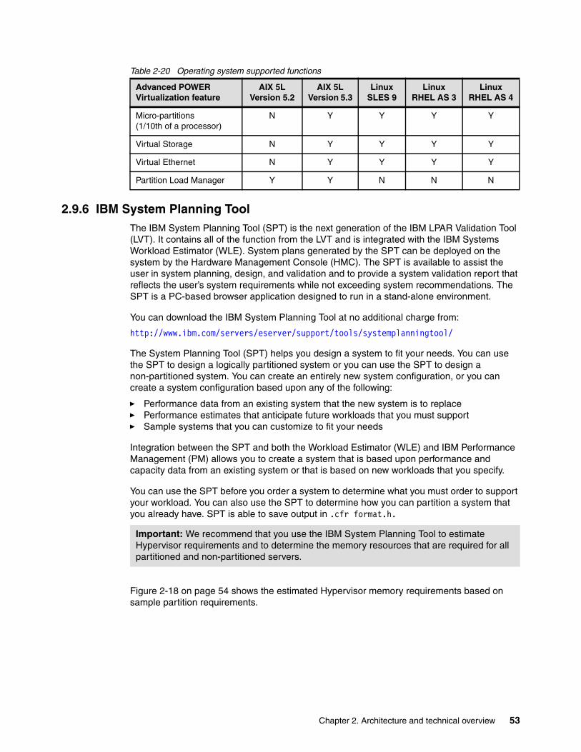
Table 2-20 Operating system supported functions
2.9.6 IBM System Planning ToolThe IBM System Planning Tool (SPT) is the next generation of the IBM LPAR Validation Tool (LVT). It contains all of the function from the LVT and is integrated with the IBM Systems Workload Estimator (WLE). System plans generated by the SPT can be deployed on the system by the Hardware Management Console (HMC). The SPT is available to assist the user in system planning, design, and validation and to provide a system validation report that reflects the user’s system requirements while not exceeding system recommendations. The SPT is a PC-based browser application designed to run in a stand-alone environment.
You can download the IBM System Planning Tool at no additional charge from:
http://www.ibm.com/servers/eserver/support/tools/systemplanningtool/
The System Planning Tool (SPT) helps you design a system to fit your needs. You can use the SPT to design a logically partitioned system or you can use the SPT to design a non-partitioned system. You can create an entirely new system configuration, or you can create a system configuration based upon any of the following:
� Performance data from an existing system that the new system is to replace � Performance estimates that anticipate future workloads that you must support � Sample systems that you can customize to fit your needs
Integration between the SPT and both the Workload Estimator (WLE) and IBM Performance Management (PM) allows you to create a system that is based upon performance and capacity data from an existing system or that is based on new workloads that you specify.
You can use the SPT before you order a system to determine what you must order to support your workload. You can also use the SPT to determine how you can partition a system that you already have. SPT is able to save output in .cfr format.h.
Figure 2-18 on page 54 shows the estimated Hypervisor memory requirements based on sample partition requirements.
Advanced POWER Virtualization feature
AIX 5L Version 5.2
AIX 5L Version 5.3
LinuxSLES 9
LinuxRHEL AS 3
LinuxRHEL AS 4
Micro-partitions(1/10th of a processor)
N Y Y Y Y
Virtual Storage N Y Y Y Y
Virtual Ethernet N Y Y Y Y
Partition Load Manager Y Y N N N
Important: We recommend that you use the IBM System Planning Tool to estimate Hypervisor requirements and to determine the memory resources that are required for all partitioned and non-partitioned servers.
Chapter 2. Architecture and technical overview 53

Figure 2-18 IBM System Planning Tool window showing Hypervisor requirements
2.9.7 Client-specific placement and eConfigeConfig provides the output report that is used for the Customer-Specified Placement (CSP) offering. The CSP offering enables the placement of adapters and disks for an exact built-to-order system based on a client’s specifications. Manufacturing uses the output to custom build the server.
The CFReport (_.cfr) output file generated from eConfig is needed to define your placement requirements to IBM manufacturing. The CFReport, including feature codes, FC 0453, FC 8453, and FC 0456, must be submitted to IBM through this Web site.
This CSP feature code is selected on the Code tab in the IBM Configurator for e-business (eConfig) wizard. Figure 2-19 on page 55 shows a window of FC 8453 in the eConfig wizard.
54 IBM System p5 590 and 595 Technical Overview and Introduction

Figure 2-19 eConfig tab for CSP selection
CSP is available on a limited number of POWER5+ or POWER5 systems. See the following Web site for details:
http://www.ibm.com/servers/eserver/power/csp/systemp.html
2.10 Operating system supportThe p5-590 and p5-595 servers are capable of running AIX 5L and i5/OS, and supporting appropriate versions of the Linux operating system. AIX 5L has been specifically developed and enhanced to exploit and support the extensive RAS features on IBM System p5 servers.
2.10.1 AIX 5LIf installing AIX 5L on the p5-590 and p5-595 servers, the following minimum requirements are needed:
Chapter 2. Architecture and technical overview 55

� For POWER5+ processors
– AIX 5L for POWER V5.2 with 5200-09 Technology Level (APAR IY82425), or later
– AIX 5L for POWER V5.3 with 5300-05 Technology Level (APAR IY82426), or later
� For POWER5 processors
– AIX 5L for POWER V5.2 with the 5200-04 Recommended Maintenance Package (APAR IY56722), or later, plus APAR IY60347
– AIX 5L for POWER V5.3 with APAR IY60349, or later
IBM periodically releases technical level packages for the AIX 5L operating system. These packages are available on CD-ROM or they can be downloaded from the Internet at:
http://www.ibm.com/servers/eserver/support/pseries/aixfixes.html
Information about how to obtain the CD-ROM can be found on the Web page mentioned above.
You can also get individual operating system fixes and information about obtaining AIX 5L service at this Web site. In AIX 5L Version 5.3, the suma command is also available, which helps the administrator to automate the task of checking and downloading operating system downloads. For more information about the suma command functionality, refer to:
http://techsupport.services.ibm.com/server/fixget
Electronic Software Delivery (ESD) for AIX 5L V5.2 and V5.3 for POWER5 systems is also available. This delivery method is a way for you to receive software and associated publications online, instead of waiting for a physical shipment to arrive. To request ESD, order FC 3450.
ESD has the following requirements:
� POWER5+ or POWER5 system
� Internet connectivity from a POWER5+ or POWER5 system or PC, with a reasonable connection speed for downloading large products such as AIX 5L
� Registration on the ESD Web site
For additional information, contact your IBM marketing representative.
Software support for new features in the POWER5+ processorFor a complete list of new features introduced in POWER5+ processor, see 2.1.4, “The POWER5+ processor” on page 18. Support for two new virtual memory page sizes was introduced - 64 KB and 16 GB as well as support for 1 TB segment size. While 16 GB pages are intended to only be used in very high performance environments, 64 KB pages are general purpose. AIX 5L Version 5.3 with the 5300-04 Technology Level 64-bit kernel is required for 64 KB and 16 GB page size support.
As with all previous versions of AIX 5L, 4 KB is the default page size. A process continues to use 4 KB pages, unless you specifically request that another page size is used. AIX 5L has rich support of 64 KB pages. They are easy to use, and it is expected that many applications will see performance benefits when using 64 KB pages rather than 4 KB pages. No system configuration changes are necessary to enable a system to use 64 KB pages, they are fully
Note: The Advanced POWER Virtualization feature is not supported on AIX 5L for POWER Version 5.2; it requires AIX 5L Version 5.3.
56 IBM System p5 590 and 595 Technical Overview and Introduction

pageable, and the size of the pool of 64 KB page frames on a system is dynamic and fully managed by AIX 5L.
The main benefit of a larger page size is improved performance for applications that allocate and repeatedly access large amounts of memory. The performance improvement from larger page sizes is due to the system load generated by the translation of a page address as it is used in an application, to the page address that is understood by the computer's memory subsystem. To improve performance, the information needed to translate a given page is usually cached in the processor. In POWER5+, this cache takes the form of a translation lookaside buffer (TLB). Because there are a limited number of TLB entries, using a large page size increases the amount of address space that can be accessed without incurring translation delays. Also, the size of TLB in POWER5+ has been doubled compared to POWER5.
Huge pages (16 GB) are intended to be used only in very high performance environments, and AIX 5L does not automatically configure a system to use these page sizes. A system administrator must configure AIX 5L to use these page sizes and specify their number through the HMC before a partition starts.
A user can specify page sizes to use for three regions process' address space with an environment variable or with settings in an application's XCOFF binary using the ldedit or ld commands. These three regions are: data, stack, and program text. An application programmer can also select the page size to use for System V shared memory using a new SHM_PAGESIZE command to the shmctl() system call.
The following is an example of using system variables to start a program with 64 KB page size support:
LDR_CNTRL=DATAPSIZE=64K@TEXTPSIZE=64K@STACKPSIZE=64K <program>
System commands (ps, vmstat, svmon, and pagesize) have been enhanced to report various page size usage.
2.10.2 LinuxOne-year and three-year Linux subscriptions are available through IBM when you order p5-590 and p5-595 servers through IBM. Linux distributions are also available through Novell SUSE Linux and Red Hat at the time this publication was written. The p5-590 and p5-595 servers require the following versions of Linux distributions:
� For POWER5+ processors
– SUSE Linux Enterprise Server 9 for POWER, SP3, or later
– Red Hat Enterprise Linux AS for POWER Version 4.4, or later
� For POWER5 processors
– SUSE Linux Enterprise Server 9 for POWER, or later
– Red Hat Enterprise Linux AS for POWER Version 3, or later
Information about features and external devices supported by Linux on the p5-590 or p5-595 can be found at:
http://www.ibm.com/servers/eserver/pseries/linux/
Note: Not all p5-590 and p5-595 server features available on the AIX 5L operating system are available on the Linux operating systems.
Chapter 2. Architecture and technical overview 57

Information about SUSE Linux Enterprise Server 9 can be found at:
http://www.novell.com/products/linuxenterpriseserver/
For information about Red Hat Enterprise Linux AS for pSeries from Red Hat, see:
http://www.redhat.com/software/rhel/details/
Many of the features described in this document are operating system dependent and might not be available on Linux. For more information, see:
http://www.ibm.com/systems/p/software/whitepapers/linux_overview.html
2.10.3 i5/OS V5R3IBM i5/OS on System p5 servers is intended for clients with a relatively small number of i5/OS applications, and clients whose focus and IT strategy center around UNIX. IBM i5/OS on System p5 servers is available as a solution for server consolidation for a partitioned system.
i5/OS V5R3 or later has the following dependencies:
� Supported on 1.65 GHz POWER5 models only.
� Only one or two processors on the p5-590 and p5-595 systems can be dedicated to i5/OS.
� Only an AIX 5L or Linux logical partition can be designated as the service partition. An i5/OS partition cannot be designated as the service partition on a System p5 server.
2.11 System managementThe following section provides an overview of powering on the managed system, the service processor, HMC, and firmware.
2.11.1 Power onThere is no physical operator panel on the p5-590 and p5-595. The light-strip on the bulk power controller (BPC) front panel (Figure 2-20 on page 59) or the HMC (Figure 2-21 on page 59) can be used to obtain information similar to what an operator panel would provide. The power on sequence is described in Table 2-21 on page 59.
Note: IBM only supports the Linux systems of clients with a SupportLine contract covering Linux. Otherwise, the Linux distributor should be contacted for support.
58 IBM System p5 590 and 595 Technical Overview and Introduction

Table 2-21 Power on sequence
Figure 2-20 BPC front panel
Figure 2-21 Operating states as seen from the HMC
2.11.2 Service processorUnlike entry IBM System p5 servers, the p5-590 and p5-595 have two service processors. The p5-590 and p5-595 service processor function is located on redundant service processor cards (same role of any service processor of IBM System p5 servers) in the CEC; one is considered the primary and the other secondary. The two service processor cards are in the same assembly with two redundant oscillator cards (OSC) shared by all processor books. Figure 2-22 on page 60 shows the oscillator and service processor assembly.
State Indicationa
a. See Figure 2-20 on page 59 for LED locations.
Power cords connected - EPO switch Off On the bulk power controllers (BPCs), the UEPO Power LED is on. (Also, Power Good LED, on the far right of the panel, will be on throughout this sequence.)
Power available - EPO switch ON UEPO Power LED remains on, UEPO CMPLT turns on. The service processors become active. Power STBY LED is flashing. During this step, the service processors and BPCs will get their IP addresses from the HMC (DHCP server).
Standby Power Complete Power STBY LED is solid. Fans are running in flushing mode.
System Power On Distributed converter assemblies (DCAs) power on (using commands received from the Ethernet). Light Strips powered on. Fans running in fast mode. (Note: it is quite normal for the fans to continue to run in fast mode for about the first 20 minutes.)
Chapter 2. Architecture and technical overview 59

Figure 2-22 Oscillator and service processor assembly
The service processor is an embedded controller running the service processor internal operating system. The service processor operating system contains specific programs and device drivers for the service processor hardware. The host interface is a 32-bit PCI-X interface connected to the Enhanced I/O Controller.
The service processor is used to monitor and manage the system hardware resources and devices. The service processor offers two Ethernet 10/100 Mbps ports for connection:
� Both Ethernet ports are only visible to the service processor and can be used to attach the p5-550 or p5-550Q to an HMC or to access the Advanced System Management Interface (ASMI) options from a client Web browser, using the HTTP server integrated into the service processor internal operating system.
� Both Ethernet ports have a default IP address:
– Service processor Eth0 or HMC1 port is configured as 192.168.2.147 with netmask 255.255.255.0
– Service processor Eth1 or HMC2 port is configured as 192.168.3.147 with netmask 255.255.255.0
Server use communications portsEach p5-590 or p5-595 server must be connected to a Hardware Management Console (HMC) for system control, LPAR, Capacity Upgrade on Demand, and service functions. The HMC is capable of supporting multiple p5 servers. We strongly recommend that you have two HMCs connected.
The p5-590 or p5-595 servers do not connect directly to HMC. They are connected through an Ethernet hub connection provided by the Bulk Power Controllers (FC 7803) part of the Bulk Power Assembly. The p5-590 and p5-595 are designed with dual bulk power controllers (BPC).
The Bulk Power Controller (FC 7803) provides the base power distribution and control for the internal power assemblies and communications hub function for the HMC and the BPC. The BPC is part of the Bulk Power Assembly (BPA).
C1
C2C3
C4
SP and OSC packaging
60 IBM System p5 590 and 595 Technical Overview and Introduction
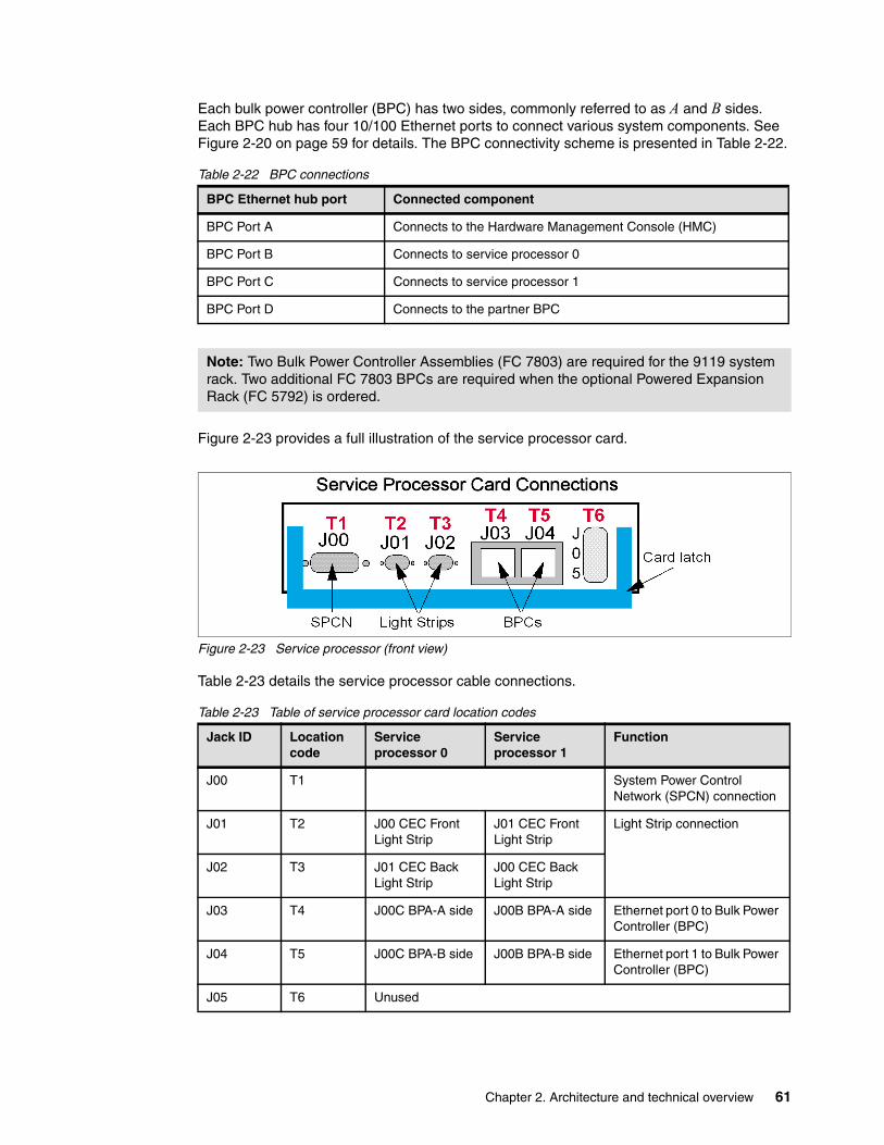
Each bulk power controller (BPC) has two sides, commonly referred to as A and B sides. Each BPC hub has four 10/100 Ethernet ports to connect various system components. See Figure 2-20 on page 59 for details. The BPC connectivity scheme is presented in Table 2-22.
Table 2-22 BPC connections
Figure 2-23 provides a full illustration of the service processor card.
Figure 2-23 Service processor (front view)
Table 2-23 details the service processor cable connections.
Table 2-23 Table of service processor card location codes
BPC Ethernet hub port Connected component
BPC Port A Connects to the Hardware Management Console (HMC)
BPC Port B Connects to service processor 0
BPC Port C Connects to service processor 1
BPC Port D Connects to the partner BPC
Note: Two Bulk Power Controller Assemblies (FC 7803) are required for the 9119 system rack. Two additional FC 7803 BPCs are required when the optional Powered Expansion Rack (FC 5792) is ordered.
Jack ID Location code
Service processor 0
Service processor 1
Function
J00 T1 System Power Control Network (SPCN) connection
J01 T2 J00 CEC Front Light Strip
J01 CEC Front Light Strip
Light Strip connection
J02 T3 J01 CEC Back Light Strip
J00 CEC Back Light Strip
J03 T4 J00C BPA-A side J00B BPA-A side Ethernet port 0 to Bulk Power Controller (BPC)
J04 T5 J00C BPA-B side J00B BPA-B side Ethernet port 1 to Bulk Power Controller (BPC)
J05 T6 Unused
Chapter 2. Architecture and technical overview 61

2.11.3 HMCThe HMC is a dedicated workstation that provides a graphical user interface for configuring, operating, and performing basic system tasks for the System p5 servers functioning in either non-partitioned, LPAR, or clustered environments. In addition, the Hardware Management Console is used to configure and manage partitions. One HMC is capable of controlling multiple POWER5 and POWER5+ processor-based systems.
At the time of writing, one HMC supports up to 48 POWER5 and POWER5+ processor-based systems and up to 254 LPARs using the HMC machine code Version 5.1. For updates of the machine code, HMC functions, and hardware prerequisites, refer to the following Web site:
http://techsupport.services.ibm.com/server/hmc
POWER5 and POWER5+ processor-based system HMCs require Ethernet connectivity between the HMC and the server’s service processor; moreover, if dynamic LPAR operations are required, all AIX 5L and Linux partitions must be enabled to communicate over network to the HMC. Ensure that sufficient Ethernet adapters are available to enable public and private networks, if you need both:
� The HMC 7310 Model C05 is a deskside model with one integrated 10/100/1000 Mbps Ethernet port and two additional PCI slots.
� The 7310 Model CR3 is a 1U, 19-inch rack-mountable drawer that has two native 10/100/1000 Mbps Ethernet ports and two additional PCI slots.
For any partition in a server, you can use the shared Ethernet adapter in the Virtual I/O Server for a unique connection from the HMC to partitions. Therefore, client partitions do not require their own physical adapter in order to be able to communicate to the HMC.
Local HMCA local HMC is any physical HMC that is directly connected to the system it manages through a private service network. An HMC in a private service network is a Dynamic Host Control Protocol (DHCP) server from which the managed system obtains the address for its service processor and bulk power controller.
Remote HMCA remote HMC is a stand-alone HMC or an HMC installed in a 19-inch rack that is used to access another HMC. A remote HMC can be present in an open network.
Redundant HMCA redundant HMC manages a system that is already managed by another HMC. When two HMCs manage one system, those HMCs are peers and can be used simultaneously to manage the system.
For more detailed information about usage of the HMC, refer to the IBM Systems Hardware Information Center:
http://publib.boulder.ibm.com/infocenter/eserver/v1r3s/index.jsp?topic=/iphby/asmihmc.htm
Functions performed by the HMC include:
� Creating and maintaining a multiple partition environment
� Displaying a virtual operating system session terminal for each partition
� Displaying a virtual operator panel of contents for each partition
� Detecting, reporting, and storing changes in hardware conditions
62 IBM System p5 590 and 595 Technical Overview and Introduction

� Powering managed systems on and off
� Acting as a service focal point
The HMC provides both graphical and command line interface for all management tasks. Remote connection to the HMC using Web-based System Manager or SSH is possible. For accessing the graphical interface, you can use the Web-based System Manager Remote Client running on the AIX 5L, Linux, or Windows operating system. The Web-based System Manager client installation image can be downloaded from the HMC itself from the following URL:
http://<hmc_address_or_name>/remote_client.html
Both unencrypted and encrypted Web-based System Manager connections are supported. The command line interface is also available by using the SSH secure shell connection to the HMC. It can be used by an external management system or a partition to perform HMC operations remotely.
2.11.4 HMC connectivityThere are some significant differences regarding the HMC connection to the managed server with the p5-590 and p5-595 servers and other POWER5+ or POWER5 processor-based systems.
� At least one HMC is mandatory, and two are recommended.
� The first (or only) HMC is connected using a private network to Bulk Power Controller (BPC-A). The HMC must be set up to provide DHCP addresses on that private (eth0) network.
� A secondary (redundant) HMC is connected using a separate private network to BPC-B. The second HMC must be set up as a DHCP server to use a different range of addresses for DHCP.
� An additional provision has to be made for a HMC connection to the BPC in a powered expansion frame.
If there is a single managed server (with powered expansion frame), then no additional LAN components are required (Ethernet Cable (either FC 7801 or FC 7802) or a client-provided cable is required). However, if there are multiple managed servers, additional LAN switches and cables are needed for the HMC private networks. These switches and cables must be planned for. Figure 2-24 on page 64 shows two p5-590s controlled with dual HMCs.
Note: DHCP must be used, because the BPCs are dependent upon the HMC to provide them with addresses. There is no way to set a static address on a BPC.
Chapter 2. Architecture and technical overview 63

Figure 2-24 Network for two p5-590s controlled with dual HMCs
HMC network interfacesThe HMC supports up to three separate physical Ethernet interfaces. In the desktop version of the HMC, this consists of one integrated Ethernet and up to two plug-in adapters. In the rack-mounted version, this consists of two integrated Ethernet adapters and up to one plug-in adapter. Use each of these interfaces in the following ways:
� One network interface can be used exclusively (private) for HMC-to-managed system communications (and must be the eth0 connection on the HMC). This means that only the HMC, Bulk Power Controllers (BPC), and service processors of the managed systems would be on that network. Even though the network interfaces into the service processors are SSL-encrypted and password-protected, having a separate dedicated network can provide a higher level of security for these interfaces.
� Another network interface would typically be used for the network connection between the HMC and the logical partitions on the managed systems (open network), for the HMC-to-logical partition communications.
� The third interface is an optional additional Ethernet connection that can be used for remote management of the HMC. This third interface can also be used to provide a separate HMC connection to different groups of logical partitions. For example, you could do any of the following:
– An administrative LAN that is separate from the LAN on which all the usual business transactions are running. Remote administrators could access HMCs and other managed units using this method.
– Different network security domains for your partitions, perhaps behind a firewall with different HMC network connections into each of those two domains.
64 IBM System p5 590 and 595 Technical Overview and Introduction

2.11.5 HMC codeFor updates of the machine code, HMC functions, and hardware prerequisites, refer to the following Web site:
http://www14.software.ibm.com/webapp/set2/sas/f/hmc/home.html
2.11.6 Hardware management user interfacesIn the following sections, we give you a brief overview of the different p5-590 and p5-595 server hardware management user interfaces available.
Advanced System Management Interface The Advanced System Management Interface (ASMI) is the interface to the service processor that enables you to set flags that affect the operation of the server, such as auto power restart, and to view information about the server, such as the error log and vital product data.
This interface is accessible using a Web browser on a client system that is connected directly to the service processor (in this case, either use a standard Ethernet cable or a crossed cable) or through an Ethernet network. Using the network configuration menu, the ASMI enables you to have the capability to change the service processor IP addresses or to apply some security policies to avoid access from undesired IP addresses or a range. The ASMI can also be accessed using a terminal attached to the system service processor ports on the server, if the server is not HMC-managed. The service processor and the ASMI are standard on all IBM System p servers.
You might be able to use the service processor's default settings. In that case, accessing the ASMI is not necessary.
Accessing the ASMI using a Web browserThe Web interface to the Advanced System Management Interface is accessible through Microsoft Internet Explorer 6.0, Netscape 7.1, or Opera 7.23 running on a PC or mobile computer connected to the service processor. The Web interface is available during all phases of system operation, including the initial program load and run time. However, some of the menu options in the Web interface are unavailable during IPL or run time to prevent usage or ownership conflicts if the system resources are in use during that phase.
Accessing the ASMI using an ASCII consoleThe Advanced System Management Interface on an ASCII console supports a subset of the functions provided by the Web interface and is available only when the system is in the platform standby state. The ASMI on an ASCII console is not available during some phases of system operation, such as the initial program load and run time.
Accessing the ASMI using an HMCTo access the Advanced System Management Interface using the Hardware Management Console, complete the following steps:
1. Ensure that the HMC is set up and configured.
2. In the navigation area, expand the managed system with which you want to work.
Note: With the rack-mounted HMC, if an additional (third) Ethernet port is installed in the HMC (by using a PCI Ethernet card), then that PCI-card becomes the eth0 port. Normally (without the additional card), eth0 is the first of the two integrated Ethernet ports.
Chapter 2. Architecture and technical overview 65

3. Expand Service Applications and click Service Focal Point.
4. In the content area, click Service Utilities.
5. From the Service Utilities window, select the managed system with which you want to work.
6. From the Selected menu on the Service Utilities window, select Launch ASM menu.
System Management ServicesUse the System Management Services (SMS) menus to view information about your system or partition and to perform tasks such as changing the boot list, or setting the network parameters.
To start System Management Services, perform the following steps:
1. For a server that is connected to an HMC, use the HMC to restart the server or partition.
If the server is not connected to an HMC, stop the system, and then restart the server by pressing the power button on the control panel.
2. For a partitioned server, watch the virtual terminal window on the HMC.
For a full server partition, watch the firmware console.
3. Look for the power-on self-test (POST) indicators: memory, keyboard, network, SCSI, and speaker that appear across the bottom of the screen. Press the numeric 1 key after the word keyboard appears and before the word speaker appears.
The SMS menu is useful to define the operating system installation method, choosing the installation boot device or setting the boot device priority list for a fully managed server or a logical partition. In the case of a network boot, there are SMS menus provided to set up the network parameters and network adapter IP address.
For more detailed information about usage of SMS, refer to the IBM Systems Hardware Information Center:
http://publib.boulder.ibm.com/infocenter/eserver/v1r3s/index.jsp?topic=/iphau/usingsms.htm
HMCThe Hardware Management Console is a system that controls managed systems, including IBM System p5 hardware and logical partitions. To provide flexibility and availability, there are different ways to implement HMCs.
Web-based System Manager Remote ClientThe Web-based System Manager Remote Client is an application that is usually installed on a PC and can be downloaded directly from an installed HMC. When an HMC is installed and HMC Ethernet IP addresses have been assigned, you can download the Web-based System Manager Remote Client from a Web browser, using the following Web site:
http://HMC_IP_address/remote_client.html
You can then use the PC to access other HMCs remotely. Web-based System Manager Remote Clients can be present in private and open networks. You can perform most management tasks using the Web-based System Manager Remote Client. The remote HMC and the Web-based System Manager Remote Client allow you the flexibility to access your managed systems (including HMCs) from multiple locations using multiple HMCs.
For more detailed information about the use of the HMC, refer to the IBM Systems Hardware Information Center.
66 IBM System p5 590 and 595 Technical Overview and Introduction

2.11.7 Determining the HMC serial numberFor some HMC or service processor troubleshooting situations, an IBM service representative will have to log into the HMC. The service password changes daily and is not available for normal client use. If the PE determines a local service engineer can sign on to the HMC, the service representative might request the HMC serial number.
To find the HMC serial number, open a restricted shell window and run the following command:
#lshmc -v
2.11.8 Server firmware Server firmware is the part of the Licensed Internal Code that enables hardware, such as the service processor. Check for available server firmware fixes regularly. Depending on your service environment, you can download your server firmware fixes using different interfaces and methods. The p5-590 and p5-595 servers must use the HMC to install server firmware fixes. Firmware is loaded on to the server and to the bulk power controller over the HMC to the frame’s Ethernet network.
See 4.3.4, “IBM System p5 firmware maintenance” on page 91 for a detailed description of System p5 firmware.
Server firmwareThe server firmware binary image is a single image that includes code for the service processor, the POWER Hypervisor firmware, and platform partition firmware. This server firmware binary image is stored in the service processor’s flash memory and executed in the service processor main memory.
Because there are dual service processors per CEC, both service processors are updated when firmware updates are applied and activated using the Licensed Internal Code Updates section of the HMC.
Firmware is available for download at:
http://www14.software.ibm.com/webapp/set2/firmware/gjsn
Power subsystem firmwarePower subsystem firmware is the part of the Licensed Internal Code that enables the power subsystem hardware in the model p5-590 and p5-595 servers. You must use an HMC to update or upgrade power subsystem firmware fixes.
The bulk power controller (BPC) has its own service processor. The power firmware not only has the code load for the BPC service processor itself, but it also has the code for the distributed converter assemblies (DCAs), bulk power regulators (BPRs), fans, and other more granular field replaceable units that have firmware to help manage the frame and its power
Note: Normally, installing the server firmware fixes through the operating system is a nonconcurrent process.
Note: Firmware version 01SF230_120 and later provide support for concurrent firmware maintenance (CFM). Only updates within a release can be concurrent. However, some updates that are for critical problems might be designated disruptive even if they are within a release. See 4.3.4, “IBM System p5 firmware maintenance” on page 91 for information regarding release and service packs.
Chapter 2. Architecture and technical overview 67

and cooling controls. The BPC service processor code load also has the firmware for the cluster switches that can be installed in the frame.
In the same way that the Central Electronics Complex (CEC) has dual service processors, the power subsystem has dual BPCs. Both are updated when firmware changes are made using the Licensed Internal Code Updates section of the HMC.
The BPC initialization sequence after the reboot is unique. The BPC service processor must check the code levels of all the power components it manages, including DCAs, BPRs, fans, cluster switches, and it must load those if they are different than what is in the active flash side of the BPC. Code is cascaded to the downstream power components over universal power interface controller (UPIC) cables.
Platform initial program loadThe main function of the p5-590 and p5-595 service processors is to initiate platform initial program load (IPL), also referred to as platform boot. The service processor has a self-initialization procedure and then initiates a sequence of initializing and configuring many components on the CEC backplane.
The service processor has various functional states, which can be queried and reported to the POWER Hypervisor component. Service processor states include, but are not limited to, standby, reset, power up, power down, and run time. As part of the IPL process, the primary service processor checks the state of the backup. The primary service processor is responsible for reporting the condition of the backup service processor to the POWER Hypervisor component. The primary service processor waits for the backup service processor to indicate that it is ready to continue with the IPL (for a finite time duration). If the backup service processor fails to initialize in a timely fashion, the primary service processor reports the backup service processor as a non-functional device to the POWER Hypervisor component and marks it as a guarded resource before continuing with the IPL. The backup service processor can later be integrated into the system.
Open FirmwareIBM System p5 servers have one instance of Open Firmware, both when in the partitioned environment and when running as a full system partition. Open Firmware has access to all devices and data in the system. Open Firmware is started when the system goes through a power-on reset. Open Firmware, which runs in addition to the Hypervisor firmware in a partitioned environment, runs in two modes: global and partition. Each mode of Open Firmware shares the same firmware binary that is stored in the flash memory.
In a partitioned environment, partition Open Firmware runs on top of the global Open Firmware instance. The partition Open Firmware is started when a partition is activated. Each partition has its own instance of Open Firmware and has access to all the devices assigned to that partition. However, each instance of partition Open Firmware has no access to devices outside of the partition in which it runs. Partition firmware resides within the partition memory and is replaced when AIX 5L takes control. Partition firmware is needed only for the time that is necessary to load AIX 5L into the partition system memory.
The global Open Firmware environment includes the partition manager component. That component is an application in the global Open Firmware that establishes partitions and their corresponding resources (such as CPU, memory, and I/O slots), which are defined in partition profiles. The partition manager manages the operational partitioning transactions. It responds to commands from the service processor external command interface that originate in the application that is running on the HMC.
68 IBM System p5 590 and 595 Technical Overview and Introduction

For more information about Open Firmware, refer to Partitioning Implementations for IBM Sserver p5 Servers, SG24-7039, at:
http://www.redbooks.ibm.com/redpieces/abstracts/SG247039.html?Open
Temporary and permanent sides of the service processorThe service processor and the BPC maintain two copies of the firmware:
� One copy is considered the permanent or backup copy and is stored on the permanent side, sometimes referred to as the p side.
� The other copy is considered the installed or temporary copy and is stored on the temporary side, sometimes referred to as the t side. We recommend that you start and run the server from the temporary side.
� The copy actually booted from is called the activated level, sometimes referred to as b.
The concept of sides is an abstraction. The firmware is located in flash memory and pointers in nvram determine which is p and t.
To view the firmware levels on the HMC, select Licensed Internal Code → Updates Change Internal Code → Select managed system → View System Information → None, and the window in Figure 2-25 is displayed. (The power subsystem is always machine type 9458, while the server is machine type 9119.)
Figure 2-25 p5-590 and p5-595 code levels
The levels are:
� The Installed Level indicates the level of firmware that has been installed and is installed into memory after the managed system is powered off and powered on using the default temporary side.
� The Activated Level indicates the level of firmware that is active and running in memory.
� The Accepted Level indicates the backup level (or permanent side) of firmware. You can return to the backup level of firmware if you decide to remove the installed level.
Note: The default value that the system boots is temporary.
Chapter 2. Architecture and technical overview 69

The following example is the output of the lsmcode command for AIX 5L and Linux, showing the firmware levels as they are displayed in the outputs:
� AIX 5L:
The current permanent system firmware image is SF230_120The current temporary system firmware image is SF230_120The system is currently booted from the temporary firmware image.
The lsmcode command is part of bos.diag.util.
� Linux:
system:SF230_120 (t) SF230_120 (p) SF230_120 (b)
When you install a server firmware fix, it is installed on the temporary side.
You might want to use the new level of firmware for a period of time to verify that it works correctly. When you are sure that the new level of firmware works correctly, you can permanently install the server firmware fix. When you permanently install a server firmware fix, you copy the temporary firmware level from the temporary side to the permanent side.
Conversely, if you decide that you do not want to keep the new level of server firmware, you can remove the current level of firmware. When you remove the current level of firmware, you copy the firmware level that is currently installed on the permanent side from the permanent side to the temporary side.
Choosing which firmware to use when powering on the system is done using the Power-On Parameters tab in the server properties box, as shown in Figure 2-26 on page 71.
Note: The following points are of special interest:
� The server firmware fix is installed on the temporary side only after the existing contents of the temporary side are permanently installed on the permanent side (the service processor performs this process automatically when you install a server firmware fix).
� If you want to preserve the contents of the permanent side, you need to remove the current level of firmware (copy the contents of the permanent side to the temporary side) before you install the fix.
� However, if you get your fixes using Advanced features on the HMC interface and you indicate that you do not want the service processor to automatically accept the firmware level, the contents of the temporary side are not automatically installed on the permanent side. In this situation, you do not need to remove the current level of firmware to preserve the contents of the permanent side before you install the fix.
70 IBM System p5 590 and 595 Technical Overview and Introduction

Figure 2-26 Power on parameters
For a detailed description of firmware levels refer to the IBM System Hardware Information Center and select Service and support → Customer service and support → Getting fixes → Firmware (Licensed Internal Code) fixes → Concepts → Temporary and permanent side of the service processor at:
http://publib.boulder.ibm.com/infocenter/eserver/v1r3s/index.jsp
System firmware download siteFor the system firmware download site for the p5-590 and p5-595, go to:
http://techsupport.services.ibm.com/server/mdownload
Receive server firmware fixes using an HMCIf you use an HMC to manage your server and you periodically configured several partitions on the server, you need to download and install fixes for your server and power subsystem firmware.
How you get the fix depends on whether the HMC or server is connected to the Internet:
� The HMC or server is connected to the Internet.
There are several repository locations from which you can download the fixes using the HMC. For example, you can download the fixes from your service provider's Web site or
Chapter 2. Architecture and technical overview 71

support system, from optical media that you order from your service provider, or from an FTP server on which you previously placed the fixes.
� Neither the HMC nor your server is connected to the Internet (server firmware only).
You need to download your new server firmware level to a CD-ROM media or FTP server.
For both of these options, you can use the interface on the HMC to install the firmware fix (from one of the repository locations or from the optical media). The Change Internal Code wizard on the HMC provides a step-by-step process for you to perform the procedure to install the fix. Perform these steps:
1. Ensure that you have a connection to the service provider (if you have an Internet connection from the HMC or server).
2. Determine the available levels of server and power subsystem firmware.
3. Create optical media (if you do not have an Internet connection from the HMC or server).
4. Use the Change Internal Code wizard to update your server and power subsystem firmware.
5. Verify that the fix installed successfully.
For a detailed description of each task, select Customer service, support, and troubleshooting → Fixes and upgrades → Getting fixes and upgrades from the IBM Systems Hardware Information Center Web site at:
http://publib.boulder.ibm.com/infocenter/eserver/v1r3s/index.jsp?lang=en
For a detailed description of each task, go to the IBM Sserver Hardware Information Center and select Service and support → Customer service and support → Getting fixes → Firmware (Licensed Internal Code) fixes → Scenarios: Firmware (Licensed Internal Code) fixes → Scenario: Get server firmware fixes without an HMC at:
http://publib.boulder.ibm.com/infocenter/eserver/v1r3s/index.jsp
Note: To view existing levels of server firmware using the lsmcode command, you need to have the following service tools installed on your server:
� AIX 5L
You must have AIX 5L diagnostics installed on your server to perform this task. AIX 5L diagnostics are installed when you install the AIX 5L operating system on your server. However, it is possible to deinstall the diagnostics. Therefore, you need to ensure that the online AIX 5L diagnostics are installed before proceeding with this task.
� Linux
– Platform Enablement Library - librtas-xxxxx.rpm
– Service Aids - ppc64-utils-xxxxx.rpm
– Hardware Inventory - lsvpd-xxxxx.rpm
Where xxxxx represents a specific version of the RPM file.
If you do not have the service tools on your server, you can download them at the following Web page:
https://www14.software.ibm.com/webapp/set2/sas/f/lopdiags/home.html
72 IBM System p5 590 and 595 Technical Overview and Introduction

Chapter 3. Capacity on Demand
Through Capacity on Demand (CoD) offerings, p5-590 and p5-595 servers can offer either permanent or temporary increases or decreases in processor and memory capacity. CoD is available in four activation configurations, each with specific pricing and availability terms. The four types of CoD activation configurations are discussed within this chapter, from a functional standpoint. Contractual and pricing issues are outside the scope of this document and should be discussed with your IBM Global Financing Representative, IBM Business Partner, or IBM Marketing Representative.
Capacity on Demand is supported by the following operating systems:
� AIX 5L Version 5.2 and Version 5.3
� i5/OS V5R3 or later
� SUSE Linux Enterprise Server 9 for POWER, or later
� Red Hat Enterprise Linux AS 3 for POWER (update 4), or later
For additional information about Capacity on Demand, see:
http://www.ibm.com/servers/eserver/pseries/ondemand/cod/
3
© Copyright IBM Corp. 2005, 2006. All rights reserved. 73

3.1 Types of Capacity on DemandCapacity on Demand for the p5-590 and p5-595 systems with dynamic logical partitioning (dynamic LPAR) offers the ability to nondisruptively activate processors and memory without rebooting partitions. CoD also provides the option to temporarily activate processors to meet varying performance needs and to activate additional capacity on a trial basis.
IBM has established four types of CoD offerings on the p5-590 and p5-595 systems, each with a specific activation plan. Providing different types of CoD offerings gives clients flexibility when determining their resource needs and establishing their IT budgets. IBM Global Financing can help match individual payments with capacity usage and competitive financing for fixed and variable costs related to IBM Capacity on Demand offerings. By financing Capacity on Demand costs and associated charges together with a base lease, spikes in demand do not need to become spikes in a budget.
After a system with CoD features is delivered, it can be activated in the following ways:
� Capacity Upgrade on Demand (CUoD) for processors and memory
� On/Off Capacity on Demand (CoD) for processors and memory
� Reserve Capacity on Demand (CoD) for processors only
� Trial Capacity on Demand (CoD) for processors and memory
� Capacity BackUp
The p5-590 and p5-595 servers use specific feature codes to enable CoD capabilities. All types of CoD transactions for processors are in whole numbers of processors, not in fractions of processors. All types of CoD transactions for memory are in 1 GB increments.
Table 3-1 on page 75 provides a brief description of the five types of CoD offerings, identifies the proper name of the associated activation plan, and indicates the default type of payment offering and scope of enablement resources. The payment offering information is intended for reference only; all pricing agreements and service contracts should be handled by your IBM representative. A functional overview of each CoD offering is provided in the subsequent sections.
74 IBM System p5 590 and 595 Technical Overview and Introduction

Table 3-1 Types of Capacity on Demand (functional categories)
3.1.1 Capacity Upgrade on Demand (CUoD) for processorsCapacity Upgrade on Demand (CUoD) for processors is available for the p5-590 and p5-595 servers. CoD for processors allows inactive processors to be installed in the p5-590 and p5-595 server and can be permanently activated by the client as required.
All processor books available on the p5-590 and p5-595 are initially implemented as 16-core CoD offerings with zero active processors.
A minimum of 8 or 16 permanently activated processors are required on the p5-590 or p5-595 server, respectively.
The number of permanently activated processors is based on the number of processor books installed as follows:
� One processor book installed requires 8 (p5-590) or 16 (p5-595) permanently activated processors.
� Two processor books installed require 16 permanently activated processors.
� Three processor books installed require 24 permanently activated processors.
� Four processor books installed require 32 permanently activated processors.
Additional processors on the CoD books are activated in increments of one by ordering the appropriate activation feature number. If more than one processor is to be activated at the same time, the activation feature should be ordered in multiples.
After receiving an order for a CUoD for the processor activation feature, IBM provides the client with a 34-character encrypted key. You enter this key into the system using the HMC to activate the desired number of additional processors.
Activation plan Functional category
Applicable system resources
Type of payment offering
Description
Capacity Upgrade on Demand
Permanent capacity for nondisruptive growth
Processor and memory resources
Pay when purchased
Provides a means of planned growth for clients who know they will need increased capacity but are not sure when
On/Off Capacity on Demand (CoD)
Temporary capacity for fluctuating workloads
Processor and memory resources
Pay after activation
Provides for planned and unplanned short-term growth driven by temporary processing requirements such as seasonal activity, period-end requirements, or special promotionsReserve
Capacity on Demand
Processor resources only
Pay before activation
Trial Capacity on Demand
Temporary capacity for workload testing or any one-time need
Processor and memory resources
One-time, no-cost activation for a maximum period of 30 consecutive days
Provides the flexibility to evaluate how additional resources will affect existing workloads, or to test new applications by activating additional processing power or memory capacity (up to the limit installed on the server) for up to 30 contiguous days
Capacity BackUp
Disaster recovery
Off-site machine
Pay when purchased
Provides a means to purchase a machine for use when off-site computing is required, such as during disaster recovery
Chapter 3. Capacity on Demand 75

CUoD processors that have not been activated are available to the server for dynamic processor sparing when running the AIX 5L operating system. If the server detects the impending failure of an active processor, it attempts to activate one of the unused CoD processors and add it to the system configuration. This helps to keep the server's processing power at full strength until a repair action can be scheduled.
3.1.2 Capacity Upgrade on Demand for memoryCapacity Upgrade on Demand (CUoD) for memory is available for p5-590 and p5-595 servers. CUoD for memory allows inactive memory to be installed in the server and can be permanently activated by the client as required. CUoD for memory can be installed in any available memory position.
CUoD memory can be activated in increments of 1 GB by ordering the appropriate activation feature number. If more than one 1 GB memory increment is to be activated at the same time, the activation code should be ordered in multiples. After receiving an order for a CUoD for memory activation feature, IBM provides the client with a 34-character encrypted key. This key is entered into the system to activate the additional 1 GB memory increments.
Memory configuration rules for the p5-590 and p5-595 servers apply to CUoD for memory cards as well as conventional memory cards. The memory configuration rules are applied based upon the maximum capacity of the memory card:
� Apply 4 GB configuration rules for 0/4 GB CUoD memory cards with less than 4 GB of active memory.
� Apply 8 GB configuration rules for 0/8 GB CUoD memory cards with less than 8 GB of active memory.
3.1.3 On/Off Capacity on Demand (On/Off CoD)On/Off Capacity on Demand (On/Off CoD) is available for p5-590 and p5-595 servers. On/Off CoD allows customers to temporarily activate installed CUoD processors and memory resources and later deactivate the resources as desired.
On/Off processor and memory resources are implemented on a pay-as-you-go basis using:
� On/Off Processor and Memory Enablement features - Signing an On/Off Capacity on Demand contract is required. IBM then supplies an enablement code to activate the enablement feature.
� After the On/Off Enablement feature is ordered and the associated enablement code is entered into the system, the client must report on/off usage to IBM at least monthly. This information, which is used to compute the billing data on a quarterly basis, is provided to the sales channel, which then places an order for the quantity of On/Off Processor Day and Memory Day billing features used and invoices the client.
Each On/Off CoD (Capacity on Demand) enablement feature provides 360 processor days of available usage under On/Off CoD for processors. When the client is near this total, a new enablement feature should be ordered at no charge. Enablement features cannot be added; each new feature resets the available amount to 360 days:
� On/Off CoD billing is based on processor days and memory GB days. Processor days are charged at the time of activation and entail the use of the processor for the next 24-hour period.
� Each time processors are activated starts a new measurement day. If a client activates four processors for a two-hour test and later in the same 24-hour period activates two
76 IBM System p5 590 and 595 Technical Overview and Introduction

processors for two hours to meet a peak workload, the result is six processor days of usage.
3.1.4 Reserve Capacity on Demand (Reserve CoD)Reserve Capacity on Demand (Reserve CoD) is available for p5-590 and p5-595 servers. Reserve CoD is an innovative offering allowing clients to temporarily activate in an automated manner installed CoD processors used within a shared processor pool. Charges for the temporary activation of Reserve CoD processors are only incurred when processing needs exceed the fully entitled level.
Reserve CoD is a pre-pay method of temporary activation. It is ordered by purchasing the quantity of Reserve CoD features appropriated for the model and speed of the installed processors. Each feature includes 30 days of temporary usage time. When Reserve CoD is ordered, the client receives a 34-digit activation code to be entered at the HMC. The activation code establishes the Reserve CoD balance of available usage time. Inactive CoD processors can then be assigned to the shared processor pool, which is available for workload processing. Charges for the inactive processors is only incurred when the workload in the shared pool exceeds 100 percent of the entitled (permanently activated) level of performance. Charges are made against the Reserve CoD account balance in increments of processor days and Advanced Power Virtualization must be activated in order to use Reserve CoD.
3.1.5 Trial Capacity on DemandTrial Capacity on Demand (Trial CoD) is a function delivered with all IBM System p servers supporting CUoD resources beginning May 30, 2003. Those servers with standby CoD processors or memory are capable of using a one-time, no-cost activation for a maximum period of 30 consecutive days. This enhancement allows for benchmarking of CoD resources or can be used to provide immediate access to standby resources when the purchase of a permanent activation is pending.
If you purchase permanent processor activation on p5-590 or p5-595 servers, you have another 30 contiguous day trial available for use. These subsequent trials are limited to the activation of 2 processors and 4 GB of memory.
Trial CoD is a complimentary service offered by IBM. Although IBM intends to continue it for the foreseeable future, IBM reserves the right to withdraw Trial CoD at any time, with or without notice.
Chapter 3. Capacity on Demand 77

3.1.6 Capacity on Demand feature codesThe CoD feature codes you use to order CoD capabilities on the p5-590 and p5-595 are summarized in Table 3-2.
Table 3-2 p5-590 and p5-595 CoD feature codes
3.1.7 Capacity BackUpAlso available are Capacity BackUp features, which allow you to configure systems for disaster recovery purposes. Capacity BackUp for p5-590 and p5-595 systems offers an off-site, disaster recovery machine at an affordable price. This disaster recovery machine has primarily inactive Capacity on Demand (CoD) processors that can be activated in the event of a disaster. The Capacity BackUp offering includes:
� Four processors that are permanently activated and can be used for any workload
� CoD processor resources:
– 28 standby processors with 900 On/Off CoD processor days available
– 60 standby processors with 1800 On/Off CoD processor days available (p5-595 only)
Inactive resource feature CoD feature codes
Description Feature code (FC)
Permanent activation
CUoD
Reserve CoD
On/OffEnablement/Billing
Processor Memory
p5-590
0/16 Processors (2.1 GHz POWER5+)
FC 8967 FC 7667 FC 8467 FC 7592FC 7971
0/16 Processors (1.65 GHz POWER5)
FC 7981 FC 7925 FC 7926 FC 7839 FC 7993
0/4 GB DDR2 Memory FC 4500 FC 7669FC 7280*
FC 7973 FC 7974
0/8 GB DDR2 Memory FC 4501 FC 7669FC 7280*
FC 7973 FC 7974
p5-595
0/16 Processors (2.1 GHz POWER5+)
FC 8970 FC 7693 FC 7694 FC 7588FC 7971
0/16 Processors (2.3 GHz POWER5+)
FC 8968 FC 7668 FC 8468 FC 7593FC 7971
0/16 Processors (1.65 GHz POWER5)
FC 7988 FC 7990 FC 7991 FC 7994 FC 7996
0/16 Processors (1.9 GHz POWER5)
FC 8969 FC 7815 FC 7975 FC 7971 FC 7972
0/4 GB DDR2 Memory FC 4500 FC 7669FC 7280*
FC 7973 FC 7974
0/8 GB DDR2 Memory FC 4501 FC 7669FC 7280*
FC 7973 FC 7974
* Qty 1 of FC 7280 enables 256 1 GB memory activations for FC 4500 or FC 4501.
78 IBM System p5 590 and 595 Technical Overview and Introduction

Capacity BackUp processor resources can be turned on at any time for testing or in the event of a disaster by using the On/Off CoD activation procedure. Each Capacity BackUp configuration is limited to 450 On/Off CoD credit days per processor book. For clients who require additional capacity or processor days, additional processor capacity can be purchased under IBM CoD at regular On/Off CoD activation prices. IBM HACMP V5 and HACMP/XD software (5765-F62), when installed, can automatically activate Capacity BackUp resources upon failover. When needed, HACMP can also activate dynamic LPAR and CoD resources.
The processor book and CoD feature codes for each Capacity BackUp configuration option are shown in Table 3-3. Configuration rules for I/O and memory minimums and maximums are the same as for the IBM p5-590 and p5-595 offerings.
Table 3-3 Capacity Backup configuration feature codes
Model Active/CoD processors
Processor Processor books Processor activations
p5-590 4/28 2.1 GHz POWER5+Standard
2 x FC 7704 4 x FC 7667
1.65 GHz POWER5Standard
2 x FC 7730 4 x FC 7925
p5-595 4/28 2.3 GHz POWER5+ Turbo
2 x FC 7705 4 x FC 7668
2.1 GHz POWER5+Standard
2 x FC 7587 4 x FC 7693
1.9 GHzPOWER5Turbo
2 x FC 7731 4 x FC 7815
1.65 GHz POWER5Standard
2 x FC 7732 4 x FC 7990
4/60 2.3 GHz POWER5+ Turbo
4 x FC 7705 4 x FC 7668
2.1 GHz POWER5+Standard
4 x FC 7587 4 x FC 7693
1.9 GHzPOWER5Turbo
4 x FC 7731 4 x FC 7815
1.65 GHz POWER5Standard
4 x FC 7732 4 x FC 7990
Chapter 3. Capacity on Demand 79

80 IBM System p5 590 and 595 Technical Overview and Introduction

Chapter 4. RAS and manageability
This chapter provides information about IBM System p5 design features that help lower the total cost of ownership (TCO). The state of the art IBM Reliability, Availability, and Serviceability (RAS) technology provides you the capability to improve your TCO architecture by reducing unplanned down time. This chapter includes several features that are based on the benefits available when using the AIX 5L operating system. Support of these features using a Linux operating system offering can vary.
4
© Copyright IBM Corp. 2005, 2006. All rights reserved. 81

4.1 Reliability, fault tolerance, and data integrityExcellent quality and reliability are inherent in all aspects of the IBM System p5 design and manufacturing. The fundamental objective of the design approach is to minimize outages. The RAS features help to ensure that the system operates when required, performs reliably, and efficiently handles any failures that might occur. This is achieved using capabilities provided by both the hardware and the AIX 5L operating system.
The p5-590 and p5-595, as POWER5 and POWER5+ processor-based servers, enhance the RAS capabilities implemented in POWER4 processor-based servers. The RAS enhancements available are:
� Most firmware updates allow the system to remain operational.
� The ECC has been extended to inter-processor connections for the fabric and processor bus.
� Partial L2 cache deallocation is possible.
� The number of L3 cache line deletes improved from two to ten for better self-healing capability.
The following sections describe the concepts that form the basis of the leadership RAS features of the IBM System p5 product line in more detail.
4.1.1 Fault avoidanceSystem p5 servers are built on a quality-based design intended to keep errors from happening. This design includes the following features:
� Reduced power consumption, cooler operating temperatures for increased reliability, enabled by the use of copper circuitry, silicon-on-insulator, and dynamic clock gating
� Mainframe-inspired components and technologies
4.1.2 First-failure data captureIf a problem should occur, the ability to correctly diagnose it is a fundamental requirement upon which improved availability is based. The p5-590 and p5-595 incorporate advanced capability in start-up diagnostics and in run-time First-failure data capture (FFDC) that is based on strategic error checkers built into the processors.
Any errors that are detected by the pervasive error checkers are captured into Fault Isolation Registers (FIRs), which can be interrogated by the service processor. The service processor has the capability to access system components using special purpose ports or by access to the error registers. Figure 4-1 on page 83 shows a schematic of a Fault Register Implementation.
82 IBM System p5 590 and 595 Technical Overview and Introduction

Figure 4-1 Schematic of Fault Isolation Register implementation
The FIRs are important, because they enable an error to be uniquely identified, thus enabling the appropriate action to be taken. Appropriate actions might include such things as a bus retry, ECC correction, or system firmware recovery routines. Recovery routines can include dynamic deallocation of potentially failing components.
Errors are logged into the system non-volatile random access memory (NVRAM) and the service processor event history log, along with a notification of the event to AIX 5L for capture in the operating system error log. Diagnostic Error Log Analysis (diagela) routines analyze the error log entries and invoke a suitable action such as issuing a warning message. If the error can be recovered, or after suitable maintenance, the service processor resets the FIRs so that they can accurately record any future errors.
The ability to correctly diagnose any pending or firm errors is a key requirement before any dynamic or persistent component deallocation or any other reconfiguration can take place.
For further details, see 4.1.7, “Resource deallocation” on page 85.
4.1.3 Permanent monitoringThe service processor included in the p5-590 and p5-595 servers is designed for an immediate means to diagnose, check status, and sense operational conditions of a remote system, even when the main processor is inoperable:
� The service processor enables firmware and operating system surveillance, several remote power controls, environmental monitoring (only critical errors are supported under Linux), reset, boot features, remote maintenance, and diagnostic activities, including console mirroring.
� The service processor can place calls to report surveillance failures, critical environmental faults, and critical processing faults.
For more detailed information about the service processor, refer to 2.11.2, “Service processor” on page 59.
Mutual surveillanceThe service processor can monitor the operation of the firmware during the boot process, and it can monitor the operating system for loss of control. This allows the service processor to take appropriate action, including calling for service, when it detects that the firmware or the
CPU
L1 Cache
L2/L3 Cache
Memory
Fault Isolation Register (FIR)(unique fingerprint of each error captured)
ServiceProcessor
Non-volatileRAM
Error Checkers
Log Error
Disk
Chapter 4. RAS and manageability 83

operating system has lost control. Mutual surveillance also allows the operating system to monitor for service processor activity and can request a service processor repair action if necessary.
Environmental monitoringEnvironmental monitoring related to power, fans, and temperature is done by the System Power Control Network (SPCN). Environmental critical and non-critical conditions generate Early Power-Off Warning (EPOW) events. Critical events (for example, loss of primary power) trigger appropriate signals from hardware to impacted components in order to prevent any data loss without the operating system or firmware involvement. Non-critical environmental events are logged and reported using Event Scan.
The operating system cannot program or access the temperature threshold using the service processor.
EPOW events can, for example, trigger the following actions:
� Temperature monitoring, which increases the speed of the fan’s rotation when ambient temperature is above a preset operating range.
� Temperature monitoring warns the system administrator of potential environment-related problems. It also performs an orderly system shutdown when the operating temperature exceeds a critical level.
� Voltage monitoring provides warning and an orderly system shutdown when the voltage is out of the operational specification.
4.1.4 Self-healingFor a system to be self-healing, it must be able to recover from a failing component by first detecting and isolating the failed component, taking it offline, fixing or isolating it, and reintroducing the fixed or replacement component into service without any application disruption. Examples include:
� Bit steering to redundant memory in the event of a failed memory module to keep the server operational.
� Bit-scattering, thus allowing for error correction and continued operation in the presence of a complete chip failure (Chipkill™ recovery).
� There is ECC on the data received on the cache chip from the processor, which protects the interface for data from the processor to the cache.
� There is ECC on the data read out of the eDRAM, which flags an array error.
� There is ECC on the processor receive interface, which protects the interface for data from the cache to the processor.
� L3 cache line deletes extended from two to ten for additional self-healing.
� ECC extended to inter-chip connections on fabric and processor bus.
� Memory scrubbing to help prevent soft-error memory faults.
Memory reliability, fault tolerance, and integrityThep5-590 and p5-595 use Error Checking and Correcting (ECC) circuitry for system memory to correct single-bit and to detect double-bit memory failures. Detection of double-bit memory failures helps maintain data integrity. Furthermore, the memory chips are organized such that the failure of any specific memory module only affects a single bit within a four-bit ECC word (bit-scattering), thus allowing for error correction and continued operation in the presence of a complete chip failure (Chipkill recovery). The memory DIMMs also use
84 IBM System p5 590 and 595 Technical Overview and Introduction

memory scrubbing and thresholding to determine when spare memory modules within each bank of memory should be used to replace ones that have exceeded their threshold of error count (dynamic bit-steering). Memory scrubbing is the process of reading the contents of the memory during idle time and checking and correcting any single-bit errors that have accumulated by passing the data through the ECC logic. This function is a hardware function on the memory controller and does not influence normal system memory performance.
4.1.5 N+1 redundancyThe use of redundant parts allows the p5-590 and p5-595 to remain operational with full resources:
� Redundant spare memory bits in L1, L2, L3, and main memory
� Redundant fans
� Redundant service processors (optional)
� Redundant power supplies
� Redundant system clocks and service processors
The system allows dynamic failover of service processors at run time and activation of redundant clocks and service processors at system boot time.
4.1.6 Fault maskingIf corrections and retries succeed and do not exceed threshold limits, the system remains operational with full resources, and no intervention is required:
� CEC bus retry and recovery� PCI-X bus recovery� ECC Chipkill soft error
4.1.7 Resource deallocationIf recoverable errors exceed threshold limits, resources can be deallocated with the system remaining operational, allowing deferred maintenance at a convenient time.
Dynamic or persistent deallocation Dynamic deallocation of potentially failing components is nondisruptive, allowing the system to continue to run. Persistent deallocation occurs when a failed component is detected, which is then deactivated at a subsequent reboot.
Dynamic deallocation functions include:
� Processor� L3 cache line delete� Partial L2 cache deallocation� PCI-X bus and slots
For dynamic processor deallocation, the service processor performs a predictive failure analysis based on any recoverable processor errors that have been recorded. If these transient errors exceed a defined threshold, the event is logged and the processor is deallocated from the system while the operating system continues to run. This feature (named CPU Guard) enables maintenance to be deferred until a suitable time. Processor deallocation can only occur if there are sufficient functional processors (at least two).
Chapter 4. RAS and manageability 85

To verify whether CPU Guard has been enabled, run the following command:
lsattr -El sys0 | grep cpuguard
If enabled, the output will be similar to the following:
cpuguard enable CPU Guard True
If the output shows CPU Guard as disabled, enter the following command to enable it:
chdev -l sys0 -a cpuguard='enable'
Cache or cache-line deallocation is aimed at performing dynamic reconfiguration to bypass potentially failing components. This capability is provided for both L2 and L3 caches. Dynamic run-time deconfiguration is provided if a threshold of L1 or L2 recovered errors is exceeded.
In the case of an L3 cache run-time array single-bit solid error, the spare chip resources are used to perform a line delete on the failing line.
PCI-X hot-plug slot fault tracking helps prevent slot errors from causing a system machine check interrupt and subsequent reboot. This provides superior fault isolation, and the error affects only the single adapter. Run-time errors on the PCI bus caused by failing adapters result in recovery action. If this is unsuccessful, the PCI device is gracefully shut down. Parity errors on the PCI bus itself result in bus retry, and if uncorrected, the bus and any I/O adapters or devices on that bus are deconfigured.
The p5-590 and p5-595 support PCI Extended Error Handling (EEH) if it is supported by the PCI-X adapter. In the past, PCI bus parity errors caused a global machine check interrupt, which eventually required a system reboot in order to continue. In the p5-590 and p5-595 system, hardware, system firmware, and AIX 5L interaction have been designed to allow transparent recovery of intermittent PCI bus parity errors and graceful transition to the I/O device available state in the case of a permanent parity error in the PCI bus.
EEH-enabled adapters respond to a special data packet generated from the affected PCI-X slot hardware by calling system firmware, which examines the affected bus, allows the device driver to reset it, and continues without a system reboot.
Persistent deallocation functions include:
� Processor� Memory� Deconfiguration or bypass of the failing I/O adapters� L3 cache
Following a hardware error that has been flagged by the service processor, the subsequent reboot of the system invokes extended diagnostics. If a processor or L3 cache has been marked for deconfiguration by persistent processor deallocation, the boot process attempts to proceed to completion with the faulty device automatically deconfigured. Failing I/O adapters are deconfigured or bypassed during the boot process.
Note: The auto-restart (reboot) option, when enabled, can reboot the system automatically following an unrecoverable software error, software hang, hardware failure, or environmentally induced failure (such as loss of the power supply).
86 IBM System p5 590 and 595 Technical Overview and Introduction

4.2 ServiceabilityThe p5-590 and p5-595 servers are designed for an IBM service representative to set up the machine, and at a later time, perform the installation of additional features internal to the machine (adapters and devices):
� The p5-590 and p5-595 server service processor enables the analysis of a system that does not boot.
� The diagnostics consist of Stand-alone Diagnostics, which are loaded from the DVD-ROM drive, and Online Diagnostics.
� Online Diagnostics, when installed, are resident with AIX 5L on the disk or system. They can be booted in single-user mode (service mode), run in maintenance mode, or run concurrently (concurrent mode) with other applications. They have access to the AIX 5L Error Log and the AIX 5L Configuration Data.
– Service mode allows checking of system devices and features.
– Concurrent mode allows the normal system functions to continue while selected resources are being checked.
– Maintenance mode allows checking of most system resources.
� The System Management Services (SMS) error log is accessible from the SMS menu for tests performed through SMS programs. For results of service processor tests, access the error log from the service processor menu.
Concurrent maintenanceConcurrent maintenance provides replacement of the following parts while the system remains running:
� I/O drawer� Disk drives� Cooling fans� Power subsystems� PCI-X adapter cards
4.3 ManageabilityWe describe the functions and tools provided for IBM System p5 servers to ease management in the next sections.
4.3.1 Service processorThe service processor (SP) is always working regardless of the main p5 Central Electronic Complex (CEC) state. CEC can be in the following states:
� Power standby mode (power off)
� Operating, ready to start partitions
� Operating with some partitions running and an AIX 5L or Linux system in control of the machine.
The service processor on the p5-590 and p5-595 supports dynamic failover to the redundant service processor.
The SP is still working and checking the system for errors, ensuring the connection to the HMC (if present) for manageability purposes and accepting Advanced System Management
Chapter 4. RAS and manageability 87

Interface (ASMI) SSL network connections. The SP provides the capability to view and manage the machine-wide settings using the ASMI and allows complete system and partition management from the HMC. Also, the surveillance function of the SP is monitoring the operating system to check that it is still running and has not stalled.
See Figure 4-2 for an example of the ASMI when accessed from a Web browser.
Figure 4-2 Advanced System Management main menu
4.3.2 Partition diagnosticsThe diagnostics consist of stand-alone diagnostics, which are loaded from the DVD-ROM drive, and online diagnostics (available in AIX 5L):
� Online diagnostics, when installed, are resident with AIX 5L on the disk or server. They can be booted in single-user mode (service mode), run in maintenance mode, or run concurrently (concurrent mode) with other applications. They have access to the AIX 5L error log and the AIX 5L configuration data.
– Service mode (requires service mode boot) enables checking system devices and features. Service mode provides the most complete checkout of the system resources. All system resources, except the SCSI adapter and the disk drives used for paging, can be tested.
Note: The IBM System p5 service processor enables the analysis of a system that does not boot. It can be performed either from ASMI, an HMC, or an ASCI console (depending on the presence of an HMC). ASMI is provided in any case.
88 IBM System p5 590 and 595 Technical Overview and Introduction

– Concurrent mode enables the normal system functions to continue while selected resources are being checked. Because the system is running in normal operation, some devices might require additional actions by the user or diagnostic application before testing can be done.
– Maintenance mode enables checking most system resources. Maintenance mode provides the exact same test coverage as Service Mode. The difference between the two modes is the way they are invoked. Maintenance mode requires that all activity on the operating system is stopped. The shutdown -m command is used to stop all activity on the operating system and put the operating system into maintenance mode.
� The System Management Services (SMS) error log is accessible from the SMS menu for tests performed through SMS programs. For results of service processor tests, access the error log from the service processor menu.
4.3.3 Service Agent Service Agent is an application program that operates on an IBM System p computer and monitors the system for hardware errors. It reports detected errors, assuming they meet certain criteria for severity, to IBM for service with no intervention. It is an enhanced version of Service Director™ with a graphical user interface.
Key things you can accomplish using Service Agent for System p5, pSeries, and RS/6000 include:
� Automatic VPD collection
� Automatic problem analysis
� Problem-definable threshold levels for error reporting
� Automatic problem reporting; service calls placed to IBM without intervention
� Automatic client notification
In addition:
� Commonly viewed hardware errors. You can view hardware event logs for any monitored machine in the network from any Service Agent host user interface.
� High-availability cluster multiprocessing (HACMP) support for full fallback. This includes high-availability cluster workstation (HACWS) for the IBM 9076.
� Network environment support with minimum telephone lines for modems.
� Communication base provided for performance data collection and reporting tool Performance Management (PM/AIX). For more information about PM/AIX, see:
http://www.ibm.com/servers/aix/pmaix.html
Machines are defined by using the Service Agent user interface. After the machines are defined, they are registered with the IBM Service Agent Server (SAS). During the registration process, an electronic key is created that becomes part of your resident Service Agent program. This key is used each time the Service Agent places a call for service. The IBM Service Agent Server checks the current client service status from the IBM entitlement database; if this reveals that you are not on Warranty or MA, the service call is refused and posted back using an e-mail notification.
Note: Because the p5-590 and p5-595 system has an optional DVD-RAM (FC 5752), alternate methods for maintaining and servicing the system need to be available if the DVD-RAM is not ordered. You can use Network Installation Manager (NIM) server for this purpose.
Chapter 4. RAS and manageability 89

Service agent can be configured to connect to IBM either using modem or network connection. In any case, the communication is encrypted and strong authentication is used. Service Agent sends outbound transmissions only and does not allow any inbound connection attempts. Only hardware machine configuration, machine status, or error information is transmitted. Service Agent does not access or transmit any other data on the monitored systems.
Three principal ways of communication are possible:
� Dial-up using attached modem device (uses the AT&T Global Network dialer for modem access, does not accept incoming calls to modem)
� VPN (IPsec is used in this case)
� HTTPS (can be configured to work with firewalls and authenticating proxies)
Figure 4-3 shows possible communication paths and how you can configure an IBM System p5 system to utilize all features of Service Agent. The communication we show to IBM support can be by either modem or network. If an HMC is present, Service Agent is an integral part of it, and, if activated, Service Agent collects hardware-related information and error messages about the entire system and partitions. If software level information (such as performance data, for example) is also required, Service Agent can also be installed on any of the partitions and can be configured to act as either a gateway and Connection Manager or a client. The Electronic Service Agent gateway and Connection Manager gather data from clients and communicate to IBM on behalf of the clients.
Figure 4-3 Service agent and possible connections to IBM
Additional services provided by Service Agent:
� My Systems: Client and IBM personnel authorized by the client can view Hardware information and error messages gathered by Service Agent on Electronic Services WWW pages:
http://www.ibm.com/support/electronic
� Premium Search: Search service using information gathered by Service Agents (this is a fee service that requires a special contract).
� Performance Management: Service Agent provides the means for collecting long-term performance data. The data is collected in reports accessed by the client on WWW pages of Electronic Services (this is a fee service that requires a special contract).
90 IBM System p5 590 and 595 Technical Overview and Introduction

You can download the latest version of Service Agent at:
ftp://ftp.software.ibm.com/aix/service_agent_code
Service Focal PointTraditional service strategies become more complicated in a partitioned environment. Each logical partition reports errors that it detects, without determining whether other logical partitions also detect and report the errors. For example, if one logical partition reports an error for a shared resource, such as a managed system power supply, other active logical partitions might report the same error. The Service Focal Point application helps you to avoid long lists of repetitive call-home information by recognizing that these are repeated or redundant errors and correlating them into one error.
Service Focal Point is an application on the HMC that enables you to diagnose and repair problems on the system. In addition, you can use Service Focal Point to initiate service functions on systems and logical partitions that are not associated with a particular problem. You can configure the HMC to use the Service Agent call-home feature to send IBM event information. It allows you to manage serviceable events, create serviceable events, manage dumps, and collect vital product data (VPD), but no reporting using Service Agent is possible.
4.3.4 IBM System p5 firmware maintenanceIBM System p Customer-Managed Microcode is a methodology that enables you to manage and install microcode updates on System p servers and associated I/O adapters. The IBM System p5 Microcode can be installed from the HMC. For update details, see 2.11.8, “Server firmware” on page 67.
You can use the HMC interface to view the levels of server firmware and power subsystem firmware that are installed on your server, and are available to download and install.
Each System p5 server has the following levels of server firmware and power subsystem firmware:
� Installed level – This is the level of server firmware or power subsystem firmware that has been installed and will be installed into memory after the managed system is powered off and powered on. It is installed on the t side of the system firmware. For additional discussion about firmware sides, see 2.11.8, “Server firmware” on page 67.
� Activated level – This is the level of server firmware or power subsystem firmware that is active and running in memory.
� Accepted level – This is the backup level of server or power subsystem firmware. You can return to this level of server or power subsystem firmware if you decide to remove the installed level. It is installed on the p side of the system firmware. For an additional discussion about firmware sides, see 4.3.1, “Service processor” on page 87.
IBM introduced the Concurrent Firmware Maintenance (CFM) function on System p5 servers in system firmware level 01SF230_126_120, which was released on 16 June 2005. This function supports nondisruptive system firmware service packs that you can apply to the system concurrently (without requiring a reboot to activate changes). For systems that are not managed by an HMC, the installation of system firmware is always disruptive.
The concurrent levels of system firmware might, on occasion, contain fixes that are known as deferred. These deferred fixes can be installed concurrently, but they are not activated until the next IPL. Deferred fixes, if any, are identified in the Firmware Update Descriptions table of this document. For deferred fixes within a service pack, only the fixes in the service pack, which cannot be concurrently activated, are deferred.
Chapter 4. RAS and manageability 91

Use the following information as a reference to determine whether your installation will be concurrent or disruptive.
Figure 4-4 shows the system firmware file naming convention.
Figure 4-4 System firmware file naming convention
An installation is disruptive if:
� The release levels (XXX) of currently installed and new firmware are different.
� The service pack level (YYY) and the last disruptive service pack level (ZZZ) are equal in the new firmware.
Otherwise, an installation is concurrent if:
� If the service pack level (YYY) of the new firmware is higher than the service pack level currently installed on the system and the above conditions for disruptive installation are not met.
4.4 Cluster solutionToday's IT infrastructure requires that servers meet increasing demands, while offering the flexibility and manageability to rapidly develop and deploy new services. IBM clustering hardware and software provide the building blocks, with availability, scalability, security, and single-point-of-management control, to satisfy these needs. The advantages of clusters are:
� Large-capacity data and transaction volumes, including support of mixed workloads� Scale-up (add processors) or scale-out (add servers) without down time� Single point-of-control for distributed and clustered server management� Simplified use of IT resources� Designed for 24 x 7 access to data applications� Business continuity in the event of disaster
The POWER5+ processor-based AIX 5L and Linux cluster targets scientific and technical computing, large-scale databases, and workload consolidation. IBM Cluster Systems Management software (CSM) is designed to provide a robust, powerful, and centralized way to manage a large number of POWER5 processor-based servers, all from a single point-of-control. Cluster Systems Management can help lower the overall cost of IT ownership by helping to simplify the tasks of installing, operating, and maintaining clusters of servers. Cluster Systems Management can provide one consistent interface for managing both AIX 5L and Linux nodes (physical systems or logical partitions), with capabilities for remote parallel network install, remote hardware control, and distributed command execution.
Cluster Systems Management for AIX 5L and Linux on POWER is supported on the p5-590 and p5-595. For hardware control, an HMC is required. One HMC can also control several servers that are part of the cluster. If a p5-590 or a p5-595 that is configured in partition mode
01SFXXX_YYY_ZZZ
Firmware Releaselevel
Firmware ServicePack level
Last disruptive Firmware Service Pack level
01SFXXX_YYY_ZZZ
Firmware Releaselevel
Firmware ServicePack level
Last disruptive Firmware Service Pack level
92 IBM System p5 590 and 595 Technical Overview and Introduction

(with physical or virtual resources) is part of the cluster, all partitions must be part of the cluster.
Monitoring is much easier to use, and the system administrator can monitor all of the network interfaces, not just the switch and administrative interfaces. The management server pushes information out to the nodes, which releases the management server from having to trust the node. In addition, the nodes do not have to be network-connected to each other. This means that giving root access on one node does not mean giving root access on all nodes. The base security setup is all done automatically at install time.
For information regarding the IBM Cluster Systems Management for AIX 5L, HMC control, cluster building block servers, and cluster software available, visit the following links:
� Cluster 1600
http://www.ibm.com/servers/eserver/clusters/hardware/1600.html
The CSM ships with AIX 5L (a 60-day Try and Buy license is shipped with AIX 5L). The CSM client side is automatically installed and ready when you install AIX 5L, so each system or logical partition is cluster-ready.
The CSM V1.4 on AIX 5L and Linux introduces an optional IBM CSM High Availability Management Server feature, which is designed to allow automated failover of the CSM management server to a backup management server. In addition, sample scripts for setting up Network Time Protocol (NTP) and network tuning (AIX 5L only) configurations, and the capability to copy files across nodes or node groups in the cluster can improve cluster ease of use and site customization.
Information regarding the IBM System Cluster 1600, HMC control, cluster building block servers, and cluster software available can be found at:
http://techsupport.services.ibm.com/server/cluster/
Chapter 4. RAS and manageability 93

94 IBM System p5 590 and 595 Technical Overview and Introduction

Appendix A. Servicing an IBM System p5 system
POWER5 servers can be designated as:
� Client Set-Up (CSU) with Client Installable Features (CIF) and Client Replaceable Units (CRU)
� Authorized service representative setup, upgrades, and maintenance
A number of Web-based resources are available to assist clients and service providers with planning, installing, and maintaining p5 servers.
Resource linkResource Link™ is a customized Web-based solution, providing access to information for planning, installing, and maintaining IBM System p5 servers and associated software. It also includes similar information about other selected IBM servers. Access to the site is by IBM registration ID and password, which are available free of charge. Resource Link screens can vary by user authorization level and are continually updated; the detail that you see when accessing Resource Link might not exactly match that mentioned here.
Resource Link contains links to:
� Education– Resource Link highlights– IBM Systems Hardware Information Center education – Customer Course for Servicing the IBM System i5™ and p5
� Planning� Forums� Fixes
Note: This section is not specific to p5-590 and p5-595 and deals with IBM System p5 in general.
© Copyright IBM Corp. 2005, 2006. All rights reserved. 95
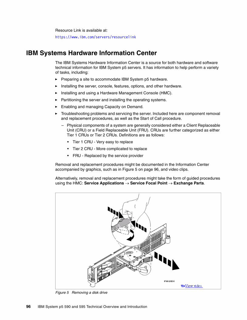
Resource Link is available at:
https://www.ibm.com/servers/resourcelink
IBM Systems Hardware Information CenterThe IBM Systems Hardware Information Center is a source for both hardware and software technical information for IBM System p5 servers. It has information to help perform a variety of tasks, including:
� Preparing a site to accommodate IBM System p5 hardware.
� Installing the server, console, features, options, and other hardware.
� Installing and using a Hardware Management Console (HMC).
� Partitioning the server and installing the operating systems.
� Enabling and managing Capacity on Demand.
� Troubleshooting problems and servicing the server. Included here are component removal and replacement procedures, as well as the Start of Call procedure.
– Physical components of a system are generally considered either a Client Replaceable Unit (CRU) or a Field Replaceable Unit (FRU). CRUs are further categorized as either Tier 1 CRUs or Tier 2 CRUs. Definitions are as follows:
• Tier 1 CRU - Very easy to replace
• Tier 2 CRU - More complicated to replace
• FRU - Replaced by the service provider
Removal and replacement procedures might be documented in the Information Center accompanied by graphics, such as in Figure 5 on page 96, and video clips.
Alternatively, removal and replacement procedures might take the form of guided procedures using the HMC: Service Applications → Service Focal Point → Exchange Parts.
Figure 5 Removing a disk drive
96 IBM System p5 590 and 595 Technical Overview and Introduction

The IBM Hardware Information Center is available:
� On the Internet
http://www.ibm.com/servers/library/infocenter
� On the HMC
– Click Information Center and Setup Wizard → Launch the Information Center.
� On CD-ROM
– Shipped with the hardware (English: SK3T-8159)
– Also available to order from IBM Publications Center
Note: Part classification, contractual agreements, and implementation in specific geographies all affect how CRUs and FRUs are determined.
Appendix A. Servicing an IBM System p5 system 97

98 IBM System p5 590 and 595 Technical Overview and Introduction

Related publications
The publications listed in this section are considered particularly suitable for a more detailed discussion of the topics covered in this Redpaper.
IBM RedbooksFor information about ordering these publications, see “How to get IBM Redbooks” on page 100. Note that some of the documents referenced here may be available in softcopy only.
� Advanced POWER Virtualization on IBM System p5, SG24-7940
� Partitioning Implementations for IBM Eserver p5 Servers, SG24-7039
� Advanced POWER Virtualization on IBM Eserver p5 Servers: Architecture and Performance Considerations, SG24-5768
� Problem Solving and Troubleshooting in AIX 5L, SG24-5496
� IBM Eserver pSeries Sizing and Capacity Planning: A Practical Guide, SG24-7071
� IBM Eserver p5 590 and 595 System Handbook, SG24-9119
� IBM Eserver p5 590 and 595 Technical Overview and Introduction, REDP-4024
� IBM Eserver p5 510 Technical Overview and Introduction, REDP-4001
� IBM Eserver p5 520 Technical Overview and Introduction, REDP-9111
� IBM Eserver p5 550 Technical Overview and Introduction, REDP-9113
� IBM Eserver p5 570 Technical Overview and Introduction, REDP-9117
� IBM System p5 505 and 505Q Technical Overview and Introduction, REDP-4079
� IBM System p5 510 and 510Q Technical Overview and Introduction, REDP-4136
� IBM System p5 520 and 520Q Technical Overview and Introduction, REDP-4137
� IBM System p5 550 and 550Q Technical Overview and Introduction, REDP-4138
� IBM System p5 560Q Technical Overview and Introduction, REDP-4139
� LPAR Simplification Tools Handbook, SG24-7231
Other publicationsThese publications are also relevant as further information sources:
� 7014 Series Model T00 and T42 Rack Installation and Service Guide, SA38-0577, contains information regarding the 7014 Model T00 and T42 Rack, in which you can install this server.
� IBM Sserver Hardware Management Console for pSeries Installation and Operations Guide, SA38-0590, provides information to operators and system administrators about how to use an IBM Hardware Management Console for pSeries (HMC) to manage a system. It also discusses the issues associated with logical partitioning planning and implementation.
© Copyright IBM Corp. 2005, 2006. All rights reserved. 99

� Planning for Partitioned-System Operations, SA38-0626, provides information to planners, system administrators, and operators about how to plan for installing and using a partitioned server. It also discusses some issues associated with the planning and implementation of partitioning.
� RS/6000 and Sserver pSeries Diagnostics Information for Multiple Bus Systems, SA38-0509, contains diagnostic information, service request numbers (SRNs), and failing function codes (FFCs).
� System p5, Sserver p5 Customer service support and troubleshooting, SA38-0538, contains information regarding slot restrictions for adapters that you can use in this system.
� System Unit Safety Information, SA23-2652, contains translations of safety information used throughout the system documentation.
Online resourcesThese Web sites and URLs are also relevant as further information sources:
� AIX 5L operating system maintenance packages downloads
http://www.ibm.com/servers/eserver/support/unixservers/aixfixes.html
� News on computer technologies
http://www.ibm.com/chips/micronews
� Copper circuitry
http://domino.research.ibm.com/comm/pr.nsf/pages/rsc.copper.html
� IBM Systems Hardware Information Center
http://publib.boulder.ibm.com/infocenter/eserver/v1r3s/index.jsp
� IBM Systems Information Centers
http://publib.boulder.ibm.com/eserver/
� IBM microcode download
http://www14.software.ibm.com/webapp/set2/firmware/gjsn
� Support for IBM System p servers
http://www.ibm.com/servers/eserver/support/unixservers/index.html
� IBMLink
http://www.ibmlink.ibm.com
� Linux for IBM System p5
http://www.ibm.com/systems/p/linux/
� Microcode Discovery Service
http://www14.software.ibm.com/webapp/set2/mds/fetch?page=mds.html
How to get IBM RedbooksYou can search for, view, or download Redbooks, Redpapers, Hints and Tips, draft publications and Additional materials, as well as order hardcopy Redbooks or CD-ROMs, at this Web site:
ibm.com/redbooks
100 IBM System p5 590 and 595 Technical Overview and Introduction

Help from IBMIBM Support and downloads
ibm.com/support
IBM Global Services
ibm.com/services
Related publications 101

102 IBM System p5 590 and 595 Technical Overview and Introduction


®
INTERNATIONAL TECHNICALSUPPORTORGANIZATION
BUILDING TECHNICAL INFORMATION BASED ON PRACTICAL EXPERIENCE
IBM Redbooks are developed by the IBM International Technical Support Organization. Experts from IBM, Customers and Partners from around the world create timely technical information based on realistic scenarios. Specific recommendations are provided to help you implement IT solutions more effectively in your environment.
For more information:ibm.com/redbooks
Redpaper
IBM System p5 590 and 595Technical Overview and Introduction
Finer system granularity using Micro-Partitioning technology to help lower TCO
Support for versions of AIX 5L, Linux, and i5/OS operating systems
Enterprise class features for applications that require a robust environment
This IBM Redpaper is a comprehensive guide covering the IBM System p5 590 and p5 595 AIX 5L and Linux operating system servers. We introduce major hardware offerings and discuss their prominent functions.
Professionals wishing to acquire a better understanding of IBM System p5 products should consider reading this document. The intended audience includes:
-Clients -Marketing representatives-Technical support professionals-IBM Business Partners-Independent software vendors
This document expands the current set of IBM System p5 documentation by providing a desktop reference that offers a detailed technical description of the p5-590 and p5-595 servers.
This publication does not replace the latest IBM System p5 marketing materials and tools. It is intended as an additional source of information that, together with existing sources, can be used to enhance your knowledge of IBM server solutions.
Back cover