Embed Size (px)
Citation preview
ibm.com/redbooks
Front cover
IBM System Storage DS Storage ManagerCopy Services Guide
Sangam RacherlaReza Fanaei Aghdam
Hartmut LonzerL G (Len) O’NeillMario RodriguezVaclav Sindelar
Alexander Watson
Introduction to Copy Services features
Implementation and best practices
ERM concepts, design, and planning

International Technical Support Organization
IBM System Storage DS Storage Manager Copy Services Guide
February 2011
SG24-7822-01

© Copyright International Business Machines Corporation 2011. All rights reserved.Note to U.S. Government Users Restricted Rights -- Use, duplication or disclosure restricted by GSA ADP ScheduleContract with IBM Corp.
Second Edition (February 2011)
This edition applies to:IBM System Storage DS models DS3000, DS4000, and DS5000 running v7.70 firmwareIBM System Storage DS Storage Manager v10.70
Note: Before using this information and the product it supports, read the information in “Notices” on page vii.

Contents
Notices . . . . . . . . . . . . . . . . . . . . . . . . . . . . . . . . . . . . . . . . . . . . . . . . . . . . . . . . . . . . . . . . . viiTrademarks . . . . . . . . . . . . . . . . . . . . . . . . . . . . . . . . . . . . . . . . . . . . . . . . . . . . . . . . . . . . . viii
Preface . . . . . . . . . . . . . . . . . . . . . . . . . . . . . . . . . . . . . . . . . . . . . . . . . . . . . . . . . . . . . . . . . ixThe team who wrote this book . . . . . . . . . . . . . . . . . . . . . . . . . . . . . . . . . . . . . . . . . . . . . . . . ixNow you can become a published author, too! . . . . . . . . . . . . . . . . . . . . . . . . . . . . . . . . . . . xiiComments welcome. . . . . . . . . . . . . . . . . . . . . . . . . . . . . . . . . . . . . . . . . . . . . . . . . . . . . . . . xiiStay connected to IBM Redbooks . . . . . . . . . . . . . . . . . . . . . . . . . . . . . . . . . . . . . . . . . . . . xiii
Summary of changes . . . . . . . . . . . . . . . . . . . . . . . . . . . . . . . . . . . . . . . . . . . . . . . . . . . . . .xvSeptember 2010, Second Edition . . . . . . . . . . . . . . . . . . . . . . . . . . . . . . . . . . . . . . . . . . . . .xv
Chapter 1. Introduction to IBM Midrange System Storage Copy Services . . . . . . . . . . 11.1 FlashCopy . . . . . . . . . . . . . . . . . . . . . . . . . . . . . . . . . . . . . . . . . . . . . . . . . . . . . . . . . . . . 21.2 VolumeCopy . . . . . . . . . . . . . . . . . . . . . . . . . . . . . . . . . . . . . . . . . . . . . . . . . . . . . . . . . . 21.3 Enhanced Remote Mirroring (ERM) . . . . . . . . . . . . . . . . . . . . . . . . . . . . . . . . . . . . . . . . 31.4 Planning for premium features . . . . . . . . . . . . . . . . . . . . . . . . . . . . . . . . . . . . . . . . . . . . 4
1.4.1 Available premium features. . . . . . . . . . . . . . . . . . . . . . . . . . . . . . . . . . . . . . . . . . . 51.4.2 Enabling the premium features . . . . . . . . . . . . . . . . . . . . . . . . . . . . . . . . . . . . . . . . 51.4.3 Disabling premium features . . . . . . . . . . . . . . . . . . . . . . . . . . . . . . . . . . . . . . . . . 10
Chapter 2. FlashCopy . . . . . . . . . . . . . . . . . . . . . . . . . . . . . . . . . . . . . . . . . . . . . . . . . . . . 132.1 How it works . . . . . . . . . . . . . . . . . . . . . . . . . . . . . . . . . . . . . . . . . . . . . . . . . . . . . . . . . 14
2.1.1 FlashCopy creation prerequisites . . . . . . . . . . . . . . . . . . . . . . . . . . . . . . . . . . . . . 142.1.2 Estimating FlashCopy repository logical drive capacity . . . . . . . . . . . . . . . . . . . . 162.1.3 FlashCopy failure policy . . . . . . . . . . . . . . . . . . . . . . . . . . . . . . . . . . . . . . . . . . . . 172.1.4 Maximum supported FlashCopies. . . . . . . . . . . . . . . . . . . . . . . . . . . . . . . . . . . . . 18
2.2 FlashCopy with the GUI wizard: Step-by-step . . . . . . . . . . . . . . . . . . . . . . . . . . . . . . . 182.2.1 Checking the status of the FlashCopy premium feature . . . . . . . . . . . . . . . . . . . . 192.2.2 Creating a FlashCopy logical drive . . . . . . . . . . . . . . . . . . . . . . . . . . . . . . . . . . . . 202.2.3 Mapping a FlashCopy drive to a host . . . . . . . . . . . . . . . . . . . . . . . . . . . . . . . . . . 352.2.4 Viewing the FlashCopy drive status . . . . . . . . . . . . . . . . . . . . . . . . . . . . . . . . . . . 382.2.5 Disabling a FlashCopy logical drive . . . . . . . . . . . . . . . . . . . . . . . . . . . . . . . . . . . 412.2.6 Re-creating a FlashCopy logical drive . . . . . . . . . . . . . . . . . . . . . . . . . . . . . . . . . 432.2.7 Resizing a FlashCopy Repository logical drive . . . . . . . . . . . . . . . . . . . . . . . . . . . 442.2.8 Deleting a FlashCopy drive. . . . . . . . . . . . . . . . . . . . . . . . . . . . . . . . . . . . . . . . . . 49
2.3 FlashCopy: Using the CLI . . . . . . . . . . . . . . . . . . . . . . . . . . . . . . . . . . . . . . . . . . . . . . . 502.3.1 Creating a FlashCopy logical drive by using the CLI . . . . . . . . . . . . . . . . . . . . . . 512.3.2 The set logicalDrive command . . . . . . . . . . . . . . . . . . . . . . . . . . . . . . . . . . . . . . . 542.3.3 The disableFlashCopy logicalDrive command . . . . . . . . . . . . . . . . . . . . . . . . . . . 562.3.4 The recreateFlashCopy logicalDrive command . . . . . . . . . . . . . . . . . . . . . . . . . . 572.3.5 The delete logicalDrive command. . . . . . . . . . . . . . . . . . . . . . . . . . . . . . . . . . . . . 58
2.4 Practical scenario . . . . . . . . . . . . . . . . . . . . . . . . . . . . . . . . . . . . . . . . . . . . . . . . . . . . . 592.4.1 Backing up a Windows 2008 Server . . . . . . . . . . . . . . . . . . . . . . . . . . . . . . . . . . . 59
Chapter 3. VolumeCopy . . . . . . . . . . . . . . . . . . . . . . . . . . . . . . . . . . . . . . . . . . . . . . . . . . 653.1 Introduction to VolumeCopy . . . . . . . . . . . . . . . . . . . . . . . . . . . . . . . . . . . . . . . . . . . . . 66
3.1.1 Copying data for greater access . . . . . . . . . . . . . . . . . . . . . . . . . . . . . . . . . . . . . . 683.1.2 Creating and managing VolumeCopy copies . . . . . . . . . . . . . . . . . . . . . . . . . . . . 69
© Copyright IBM Corp. 2011. All rights reserved. iii

3.1.3 Understanding VolumeCopy . . . . . . . . . . . . . . . . . . . . . . . . . . . . . . . . . . . . . . . . . 713.1.4 VolumeCopy and performance considerations . . . . . . . . . . . . . . . . . . . . . . . . . . . 72
3.2 VolumeCopy with the GUI wizard: Step-by-step . . . . . . . . . . . . . . . . . . . . . . . . . . . . . . 733.2.1 Checking the status of the VolumeCopy premium feature . . . . . . . . . . . . . . . . . . 743.2.2 Creating a VolumeCopy pair . . . . . . . . . . . . . . . . . . . . . . . . . . . . . . . . . . . . . . . . . 753.2.3 Viewing VolumeCopy properties . . . . . . . . . . . . . . . . . . . . . . . . . . . . . . . . . . . . . . 793.2.4 Using the Copy Manager . . . . . . . . . . . . . . . . . . . . . . . . . . . . . . . . . . . . . . . . . . . 813.2.5 Recopying a logical drive . . . . . . . . . . . . . . . . . . . . . . . . . . . . . . . . . . . . . . . . . . . 833.2.6 Changing VolumeCopy priority . . . . . . . . . . . . . . . . . . . . . . . . . . . . . . . . . . . . . . . 853.2.7 Setting the read-only attribute for a target logical drive. . . . . . . . . . . . . . . . . . . . . 863.2.8 Stopping VolumeCopy . . . . . . . . . . . . . . . . . . . . . . . . . . . . . . . . . . . . . . . . . . . . . 873.2.9 Removing copy pairs . . . . . . . . . . . . . . . . . . . . . . . . . . . . . . . . . . . . . . . . . . . . . . 88
3.3 VolumeCopy: Using the CLI . . . . . . . . . . . . . . . . . . . . . . . . . . . . . . . . . . . . . . . . . . . . . 893.3.1 The create volumeCopy command . . . . . . . . . . . . . . . . . . . . . . . . . . . . . . . . . . . . 903.3.2 The show volumeCopy command. . . . . . . . . . . . . . . . . . . . . . . . . . . . . . . . . . . . . 913.3.3 The stop volumeCopy command . . . . . . . . . . . . . . . . . . . . . . . . . . . . . . . . . . . . . 913.3.4 The set volumeCopy command . . . . . . . . . . . . . . . . . . . . . . . . . . . . . . . . . . . . . . 913.3.5 The recopy volumeCopy command . . . . . . . . . . . . . . . . . . . . . . . . . . . . . . . . . . . 923.3.6 The remove volumeCopy command . . . . . . . . . . . . . . . . . . . . . . . . . . . . . . . . . . . 92
Chapter 4. Enhanced Remote Mirroring (ERM) concepts, planning, and design . . . . 934.1 Introduction to ERM . . . . . . . . . . . . . . . . . . . . . . . . . . . . . . . . . . . . . . . . . . . . . . . . . . . 94
4.1.1 ERM terminology . . . . . . . . . . . . . . . . . . . . . . . . . . . . . . . . . . . . . . . . . . . . . . . . . 954.2 Basic functions of ERM . . . . . . . . . . . . . . . . . . . . . . . . . . . . . . . . . . . . . . . . . . . . . . . . . 97
4.2.1 Metro Mirroring (synchronous mirroring). . . . . . . . . . . . . . . . . . . . . . . . . . . . . . . . 974.2.2 Global Mirroring (asynchronous mirroring with write consistency group) . . . . . . . 984.2.3 Global Copy (asynchronous mirroring without write consistency group) . . . . . . 1004.2.4 Other ERM capabilities and functions. . . . . . . . . . . . . . . . . . . . . . . . . . . . . . . . . 1014.2.5 Requirements . . . . . . . . . . . . . . . . . . . . . . . . . . . . . . . . . . . . . . . . . . . . . . . . . . . 103
4.3 Mirror repository logical drives . . . . . . . . . . . . . . . . . . . . . . . . . . . . . . . . . . . . . . . . . . 1044.4 Primary and secondary logical drives . . . . . . . . . . . . . . . . . . . . . . . . . . . . . . . . . . . . . 106
4.4.1 Logical drive parameters, roles, and maximum number of mirrored pairs . . . . . 1064.4.2 Host accessibility of secondary logical drive . . . . . . . . . . . . . . . . . . . . . . . . . . . . 1074.4.3 Mirrored logical drive controller ownership . . . . . . . . . . . . . . . . . . . . . . . . . . . . . 1074.4.4 Deleting a mirrored logical drive . . . . . . . . . . . . . . . . . . . . . . . . . . . . . . . . . . . . . 1084.4.5 ERM and dynamic functions . . . . . . . . . . . . . . . . . . . . . . . . . . . . . . . . . . . . . . . . 1084.4.6 Logical drive role compatibility . . . . . . . . . . . . . . . . . . . . . . . . . . . . . . . . . . . . . . 1094.4.7 ERM and FlashCopy premium feature . . . . . . . . . . . . . . . . . . . . . . . . . . . . . . . . 1104.4.8 ERM and VolumeCopy premium feature . . . . . . . . . . . . . . . . . . . . . . . . . . . . . . 1104.4.9 ERM and storage partitioning premium feature . . . . . . . . . . . . . . . . . . . . . . . . . 110
4.5 Mirror relationship . . . . . . . . . . . . . . . . . . . . . . . . . . . . . . . . . . . . . . . . . . . . . . . . . . . . 1114.6 Data replication process . . . . . . . . . . . . . . . . . . . . . . . . . . . . . . . . . . . . . . . . . . . . . . . 113
4.6.1 Data resynchronization process . . . . . . . . . . . . . . . . . . . . . . . . . . . . . . . . . . . . . 1134.6.2 Data synchronization priority. . . . . . . . . . . . . . . . . . . . . . . . . . . . . . . . . . . . . . . . 115
4.7 SAN fabric and Ethernet connectivity . . . . . . . . . . . . . . . . . . . . . . . . . . . . . . . . . . . . . 1154.7.1 SAN fabric and SAN zoning configuration . . . . . . . . . . . . . . . . . . . . . . . . . . . . . 1174.7.2 Ethernet management network configuration for ERM . . . . . . . . . . . . . . . . . . . . 123
4.8 Performance considerations . . . . . . . . . . . . . . . . . . . . . . . . . . . . . . . . . . . . . . . . . . . . 1234.8.1 ERM in a DR solution . . . . . . . . . . . . . . . . . . . . . . . . . . . . . . . . . . . . . . . . . . . . . 1234.8.2 Planning for ERM as part of a DR solution . . . . . . . . . . . . . . . . . . . . . . . . . . . . . 1244.8.3 Design recommendations . . . . . . . . . . . . . . . . . . . . . . . . . . . . . . . . . . . . . . . . . . 1254.8.4 Network latency and bandwidth considerations . . . . . . . . . . . . . . . . . . . . . . . . . 1314.8.5 Mirroring connection distance and performance. . . . . . . . . . . . . . . . . . . . . . . . . 137
iv IBM System Storage DS Storage Manager Copy Services Guide
4.8.6 Application considerations . . . . . . . . . . . . . . . . . . . . . . . . . . . . . . . . . . . . . . . . . 1374.8.7 Other design considerations . . . . . . . . . . . . . . . . . . . . . . . . . . . . . . . . . . . . . . . . 140
4.9 Site readiness and installation checklist . . . . . . . . . . . . . . . . . . . . . . . . . . . . . . . . . . . 1424.9.1 Details of the site readiness and installation checklists . . . . . . . . . . . . . . . . . . . 143
4.10 The Bandwidth Estimator Tool . . . . . . . . . . . . . . . . . . . . . . . . . . . . . . . . . . . . . . . . . 147
Chapter 5. ERM implementation . . . . . . . . . . . . . . . . . . . . . . . . . . . . . . . . . . . . . . . . . . 1555.1 ERM: Step-by-step . . . . . . . . . . . . . . . . . . . . . . . . . . . . . . . . . . . . . . . . . . . . . . . . . . . 156
5.1.1 Enabling and activating ERM . . . . . . . . . . . . . . . . . . . . . . . . . . . . . . . . . . . . . . . 1575.1.2 Creating ERM relationships . . . . . . . . . . . . . . . . . . . . . . . . . . . . . . . . . . . . . . . . 1655.1.3 Viewing ERM properties and status . . . . . . . . . . . . . . . . . . . . . . . . . . . . . . . . . . 1725.1.4 Changing mirror write mode . . . . . . . . . . . . . . . . . . . . . . . . . . . . . . . . . . . . . . . . 1775.1.5 Changing mirror synchronization settings. . . . . . . . . . . . . . . . . . . . . . . . . . . . . . 1805.1.6 Suspending and resuming a mirror relationship . . . . . . . . . . . . . . . . . . . . . . . . . 1825.1.7 Removing mirror relationships . . . . . . . . . . . . . . . . . . . . . . . . . . . . . . . . . . . . . . 1925.1.8 Mapping a secondary drive. . . . . . . . . . . . . . . . . . . . . . . . . . . . . . . . . . . . . . . . . 194
5.2 ERM and disaster recovery. . . . . . . . . . . . . . . . . . . . . . . . . . . . . . . . . . . . . . . . . . . . . 1955.2.1 Role reversal concept . . . . . . . . . . . . . . . . . . . . . . . . . . . . . . . . . . . . . . . . . . . . . 1955.2.2 Re-establishing Remote Mirroring after failure recovery. . . . . . . . . . . . . . . . . . . 200
5.3 ERM solution design . . . . . . . . . . . . . . . . . . . . . . . . . . . . . . . . . . . . . . . . . . . . . . . . . . 2005.3.1 Intra-site configuration . . . . . . . . . . . . . . . . . . . . . . . . . . . . . . . . . . . . . . . . . . . . 2025.3.2 Inter-site configuration with redundant fabric . . . . . . . . . . . . . . . . . . . . . . . . . . . 2035.3.3 High-availability inter-site configuration. . . . . . . . . . . . . . . . . . . . . . . . . . . . . . . . 204
5.4 ERM maintenance. . . . . . . . . . . . . . . . . . . . . . . . . . . . . . . . . . . . . . . . . . . . . . . . . . . . 2055.4.1 Unsynchronized state indication . . . . . . . . . . . . . . . . . . . . . . . . . . . . . . . . . . . . . 2055.4.2 Link interruptions. . . . . . . . . . . . . . . . . . . . . . . . . . . . . . . . . . . . . . . . . . . . . . . . . 2065.4.3 Fibre Channel mirror link test function . . . . . . . . . . . . . . . . . . . . . . . . . . . . . . . . 2075.4.4 Secondary logical drive error . . . . . . . . . . . . . . . . . . . . . . . . . . . . . . . . . . . . . . . 2085.4.5 Primary controller failure . . . . . . . . . . . . . . . . . . . . . . . . . . . . . . . . . . . . . . . . . . . 2085.4.6 Primary controller reset . . . . . . . . . . . . . . . . . . . . . . . . . . . . . . . . . . . . . . . . . . . . 2095.4.7 Secondary controller failure . . . . . . . . . . . . . . . . . . . . . . . . . . . . . . . . . . . . . . . . 2095.4.8 Write consistency group and unsynchronized state . . . . . . . . . . . . . . . . . . . . . . 209
5.5 ERM Configuration guide using the CLI . . . . . . . . . . . . . . . . . . . . . . . . . . . . . . . . . . . 2115.5.1 Executing a script . . . . . . . . . . . . . . . . . . . . . . . . . . . . . . . . . . . . . . . . . . . . . . . . 2115.5.2 Activate Remote Mirror feature . . . . . . . . . . . . . . . . . . . . . . . . . . . . . . . . . . . . . . 2135.5.3 Create Remote Mirror . . . . . . . . . . . . . . . . . . . . . . . . . . . . . . . . . . . . . . . . . . . . . 2155.5.4 Set Remote Mirror. . . . . . . . . . . . . . . . . . . . . . . . . . . . . . . . . . . . . . . . . . . . . . . . 2175.5.5 Deactivate Remote Mirror . . . . . . . . . . . . . . . . . . . . . . . . . . . . . . . . . . . . . . . . . . 2195.5.6 Remove Remote Mirror. . . . . . . . . . . . . . . . . . . . . . . . . . . . . . . . . . . . . . . . . . . . 2205.5.7 Diagnose Remote Mirror . . . . . . . . . . . . . . . . . . . . . . . . . . . . . . . . . . . . . . . . . . . 2205.5.8 Suspend Remote Mirror . . . . . . . . . . . . . . . . . . . . . . . . . . . . . . . . . . . . . . . . . . . 2215.5.9 Resume Remote Mirror. . . . . . . . . . . . . . . . . . . . . . . . . . . . . . . . . . . . . . . . . . . . 2225.5.10 Start Remote Mirror Synchronization . . . . . . . . . . . . . . . . . . . . . . . . . . . . . . . . 2235.5.11 Show Remote Mirror synchronization progress . . . . . . . . . . . . . . . . . . . . . . . . 224
Appendix A. Additional instructions for FlashCopy logical drives . . . . . . . . . . . . . . 225Operating system resources for additional instructions . . . . . . . . . . . . . . . . . . . . . . . . . . . 226Instructions for Windows 2003 or 2008 . . . . . . . . . . . . . . . . . . . . . . . . . . . . . . . . . . . . . . . 226
Creating a Flashcopy logical drive process overview . . . . . . . . . . . . . . . . . . . . . . . . . . 227Instructions for AIX. . . . . . . . . . . . . . . . . . . . . . . . . . . . . . . . . . . . . . . . . . . . . . . . . . . . . . . 230Instructions for Linux . . . . . . . . . . . . . . . . . . . . . . . . . . . . . . . . . . . . . . . . . . . . . . . . . . . . . 234Instructions for IBM i . . . . . . . . . . . . . . . . . . . . . . . . . . . . . . . . . . . . . . . . . . . . . . . . . . . . . 236
Related publications . . . . . . . . . . . . . . . . . . . . . . . . . . . . . . . . . . . . . . . . . . . . . . . . . . . . 237
Contents v

IBM Redbooks . . . . . . . . . . . . . . . . . . . . . . . . . . . . . . . . . . . . . . . . . . . . . . . . . . . . . . . . . . 237Other publications . . . . . . . . . . . . . . . . . . . . . . . . . . . . . . . . . . . . . . . . . . . . . . . . . . . . . . . 237Online resources . . . . . . . . . . . . . . . . . . . . . . . . . . . . . . . . . . . . . . . . . . . . . . . . . . . . . . . . 238Help from IBM . . . . . . . . . . . . . . . . . . . . . . . . . . . . . . . . . . . . . . . . . . . . . . . . . . . . . . . . . . 238
Index . . . . . . . . . . . . . . . . . . . . . . . . . . . . . . . . . . . . . . . . . . . . . . . . . . . . . . . . . . . . . . . . . 239
vi IBM System Storage DS Storage Manager Copy Services Guide

Notices
This information was developed for products and services offered in the U.S.A.
IBM may not offer the products, services, or features discussed in this document in other countries. Consult your local IBM representative for information on the products and services currently available in your area. Any reference to an IBM product, program, or service is not intended to state or imply that only that IBM product, program, or service may be used. Any functionally equivalent product, program, or service that does not infringe any IBM intellectual property right may be used instead. However, it is the user's responsibility to evaluate and verify the operation of any non-IBM product, program, or service.
IBM may have patents or pending patent applications covering subject matter described in this document. The furnishing of this document does not give you any license to these patents. You can send license inquiries, in writing, to: IBM Director of Licensing, IBM Corporation, North Castle Drive, Armonk, NY 10504-1785 U.S.A.
The following paragraph does not apply to the United Kingdom or any other country where such provisions are inconsistent with local law: INTERNATIONAL BUSINESS MACHINES CORPORATION PROVIDES THIS PUBLICATION "AS IS" WITHOUT WARRANTY OF ANY KIND, EITHER EXPRESS OR IMPLIED, INCLUDING, BUT NOT LIMITED TO, THE IMPLIED WARRANTIES OF NON-INFRINGEMENT, MERCHANTABILITY OR FITNESS FOR A PARTICULAR PURPOSE. Some states do not allow disclaimer of express or implied warranties in certain transactions, therefore, this statement may not apply to you.
This information could include technical inaccuracies or typographical errors. Changes are periodically made to the information herein; these changes will be incorporated in new editions of the publication. IBM may make improvements and/or changes in the product(s) and/or the program(s) described in this publication at any time without notice.
Any references in this information to non-IBM Web sites are provided for convenience only and do not in any manner serve as an endorsement of those Web sites. The materials at those Web sites are not part of the materials for this IBM product and use of those Web sites is at your own risk.
IBM may use or distribute any of the information you supply in any way it believes appropriate without incurring any obligation to you.
Information concerning non-IBM products was obtained from the suppliers of those products, their published announcements or other publicly available sources. IBM has not tested those products and cannot confirm the accuracy of performance, compatibility or any other claims related to non-IBM products. Questions on the capabilities of non-IBM products should be addressed to the suppliers of those products.
This information contains examples of data and reports used in daily business operations. To illustrate them as completely as possible, the examples include the names of individuals, companies, brands, and products. All of these names are fictitious and any similarity to the names and addresses used by an actual business enterprise is entirely coincidental.
COPYRIGHT LICENSE:
This information contains sample application programs in source language, which illustrate programming techniques on various operating platforms. You may copy, modify, and distribute these sample programs in any form without payment to IBM, for the purposes of developing, using, marketing or distributing application programs conforming to the application programming interface for the operating platform for which the sample programs are written. These examples have not been thoroughly tested under all conditions. IBM, therefore, cannot guarantee or imply reliability, serviceability, or function of these programs.
© Copyright IBM Corp. 2011. All rights reserved. vii

Trademarks
IBM, the IBM logo, and ibm.com are trademarks or registered trademarks of International Business Machines Corporation in the United States, other countries, or both. These and other IBM trademarked terms are marked on their first occurrence in this information with the appropriate symbol (® or ™), indicating US registered or common law trademarks owned by IBM at the time this information was published. Such trademarks may also be registered or common law trademarks in other countries. A current list of IBM trademarks is available on the Web at http://www.ibm.com/legal/copytrade.shtml
The following terms are trademarks of the International Business Machines Corporation in the United States, other countries, or both:
AIX®BladeCenter®DS4000®DS6000™DS8000®
FlashCopy®IBM®Redbooks®Redbooks (logo) ®System p®
System Storage DS®System Storage®System x®
The following terms are trademarks of other companies:
Microsoft, Windows, and the Windows logo are trademarks of Microsoft Corporation in the United States, other countries, or both.
UNIX is a registered trademark of The Open Group in the United States and other countries.
Linux is a trademark of Linus Torvalds in the United States, other countries, or both.
Other company, product, or service names may be trademarks or service marks of others.
viii IBM System Storage DS Storage Manager Copy Services Guide

Preface
The purpose of this IBM® Redbooks® publication is to provide customers with guidance and recommendations for how and when to use the IBM System Storage® Copy Services premium features. The topics discussed in this publication apply to the IBM System Storage DS® models DS3000, DS4000®, and DS5000 running the firmware v7.70, and IBM System Storage DS Storage Manager v10.70.
Customers in today’s IT world are finding a major need to ensure a good archive of their data and a requirement to create these archives with minimal interruptions. The IBM Midrange System Storage helps to fulfill these requirements by offering three copy services premium features:
� IBM FlashCopy®� VolumeCopy� Enhanced Remote Mirroring (ERM)
This publication specifically addresses the copy services premium features and can be used in conjunction with the following IBM DS System Storage books:
� IBM System Storage DS4000 and Storage Manager V10.30, SG24-7010� IBM System Storage DS3000: Introduction and Implementation Guide, SG24-7065� IBM System Storage DS3500: Introduction and Implementation Guide, SG24-7914� IBM Midrange System Storage Hardware Guide, SG24-7676� IBM Midrange System Storage Implementation and Best Practices Guide, SG24-6363
The team who wrote this book
This book was produced by a working at the International Technical Support Organization (ITSO), Raleigh Center.
Sangam Racherla is an IT Specialist and Project Leader working at ITSO, San Jose Center. He holds a degree in electronics and communication engineering and has ten years of experience in the IT field. He has been with ITSO for the past seven years and has extensive experience installing and supporting the ITSO lab equipment for various Redbooks publication projects. His areas of expertise include Microsoft® Windows®, Linux®, AIX®, System x®, and System p® servers, and various SAN and storage products.
© Copyright IBM Corp. 2011. All rights reserved. ix

Reza Fanaei Aghdam is a Senior IT Specialist working in Zurich, Switzerland. He has 17 years of professional experience with x86-based hardware, storage technologies, and systems management. More than12 of those years of experience at IBM. He instructs Business Partners and customers on how to configure and install the System x, BladeCenter®, Systems Director, Storage, VMware and Hyper-V. He is an IBM Certified Systems Expert - System x BladeCenter, IBM Certified Specialist - Midrange Storage Technical Support, and VMware Certified Professional.
Hartmut Lonzer is a Technical Consultant in the Partnership Solution Center Southwest / Germany. As a former Storage FTSS member, his main focus is on Storage and System x. He is responsible for educating and supporting the Business Partners and customers in his area in technical matters. His experience regarding the DS Storage goes back to the beginning of this product. He has been with IBM in various technical roles for 33 years.
L G (Len) O’Neill is a Product Field Engineer (PFE) for IBM System x hardware support based at IBM Greenock in the UK. The PFE team in IBM Greenock provides post-sales technical support for all IBM System x and IBM BladeCenter products for the EMEA (Europe, Middle-East and Africa) region. He has been with IBM for 12 years and in his current role for 11 years. He specializes in providing post-sales technical support for the IBM DS3000 storage products and has previously specialized in supporting IBM SCSI, ServeRAID and Microsoft Windows clustering products within the System x product range. He holds a degree in Physics from Trinity College Dublin.
Mario Rodriguez is an IT Specialist in IBM Uruguay. He holds MCSE, AIX, LPI and other Comptia certifications. His areas of expertise include SAN switches (Brocade, Cisco MDS), SAN Storage (DS3000, DS4000, DS6000™, and DS8000®), Linux, AIX, TSM and VMware. His role in IBM Uruguay is to provide technical support services for virtualization and storage products.
x IBM System Storage DS Storage Manager Copy Services Guide

Vaclav Sindelar is a Field Technical Support Specialist (FTSS) for IBM System Storage at the IBM Czech Republic headquarters in Prague. His daily support activities include pre-sales support for IBM Storage products. He has 7 years of FTSS Storage experience with a focus on IBM disk arrays and SAN. He has been with IBM since 2001 and worked as storage specialist before he came to IBM. He holds a master’s degree in computer science from the Technical University of Brno in the Czech Republic.
Alexander Watson is an ATS Specialist for Storage Advanced Technical Skills (ATS) Americas in the United States. He is a subject matter expert on SAN switches and the IBM Midrange system storage products. He has more than 15 years of experience in planning, managing, designing, implementing, problem analysis, and tuning of SAN environments and storage systems. He has worked at IBM for 11 years. His areas of expertise include SAN fabric networking, Open System Storage IO and the IBM Midrange Storage solutions.
Thanks to the following people for their contributions to this project:
Tamikia BarrowMargaret TicknorDavid WattsInternational Technical Support Organization, Raleigh Center
Doris KoniecznyHarold PikeTony IlesPete UrbisciJohn FasanoRoger BullardDanh T LeRaul A GallardoPaul GoetzGene CullumJames l (Jim) KennishDavid BenninRichard ConwayDonald BrennanIBM
David WorleyStacey DershemJamal BoudiLSI Corporation
Brian StefflerYong ChoiAlan HicksBrocade Communications Systems, Inc.
Preface xi

Thanks to the authors of the previous editions of this book.
Authors of the first edition, IBM System Storage DS Storage Manager Copy Services Guide, published in February 2010 were:
Bruce AllworthAlessio BagnaresiChris BogdanowiczCorne LotteringPablo PedrazasFrank SchubertJohn Sexton
Now you can become a published author, too!
Here's an opportunity to spotlight your skills, grow your career, and become a published author—all at the same time! Join an ITSO residency project and help write a book in your area of expertise, while honing your experience using leading-edge technologies. Your efforts will help to increase product acceptance and customer satisfaction, as you expand your network of technical contacts and relationships. Residencies run from two to six weeks in length, and you can participate either in person or as a remote resident working from your home base.
Find out more about the residency program, browse the residency index, and apply online at:
ibm.com/redbooks/residencies.html
Comments welcome
Your comments are important to us!
We want our books to be as helpful as possible. Send us your comments about this book or other IBM Redbooks publications in one of the following ways:
� Use the online Contact us review Redbooks form found at:
ibm.com/redbooks
� Send your comments in an email to:
� Mail your comments to:
IBM Corporation, International Technical Support OrganizationDept. HYTD Mail Station P0992455 South RoadPoughkeepsie, NY 12601-5400
xii IBM System Storage DS Storage Manager Copy Services Guide

Stay connected to IBM Redbooks
� Find us on Facebook:
http://www.facebook.com/IBMRedbooks
� Follow us on Twitter:
http://twitter.com/ibmredbooks
� Look for us on LinkedIn:
http://www.linkedin.com/groups?home=&gid=2130806
� Explore new Redbooks publications, residencies, and workshops with the IBM Redbooks weekly newsletter:
https://www.redbooks.ibm.com/Redbooks.nsf/subscribe?OpenForm
� Stay current on recent Redbooks publications with RSS Feeds:
http://www.redbooks.ibm.com/rss.html
Preface xiii

xiv IBM System Storage DS Storage Manager Copy Services Guide
Summary of changes
This section describes the technical changes made in this edition of the book and in previous editions. This edition might also include minor corrections and editorial changes that are not identified.
Summary of Changesfor SG24-7822-01for IBM System Storage DS Storage Manager Copy Services Guideas created or updated on February 28, 2011.
February 2011, Second Edition
This revision reflects the addition, deletion, or modification of new and changed information described in the sections that follow.
New information� Added DS3500 hardware
Changed information� Firmware Version 7.70� IBM System Storage DS Storage Manager Version 10.70
© Copyright IBM Corp. 2011. All rights reserved. xv

xvi IBM System Storage DS Storage Manager Copy Services Guide

Chapter 1. Introduction to IBM Midrange System Storage Copy Services
The purpose of this book is to provide customers with guidance and recommendations for how and when to use the IBM Midrange System Storage Copy Services premium features.
Customers require that their data be archived and that the archives be created with minimal interruptions. To fulfill these requirements, IBM Midrange System Storage offers the following copy services premium features:
� FlashCopy� VolumeCopy � Enhanced Remote Mirroring (ERM)
All of these premium features require license keys to be used. FlashCopy and ERM can be purchased individually. VolumeCopy requires the purchase of a combined FlashCopy/VolumeCopy license key.
These features can be used individually, or can be combined together to provide a solution to customers for designing a disaster recovery answer for their critical data protection needs.
This chapter provides a brief overview of these premium features, their capabilities, and how to enable them.
1
Note: Additional information about using IBM DS Midrange Storage copy services can be found in the IBM System Storage DS Storage Manager Version 10.70 Copy Services User's Guide, which can be downloaded from the IBM Support website:
https://www.ibm.com/support/entry/myportal/docdisplay?lndocid=MIGR-61173
© Copyright IBM Corp. 2011. All rights reserved. 1
1.1 FlashCopy
For doing backups, customers do not want long application backup windows. With the IBM midrange storage subsystem, this capability is handled by the use of the FlashCopy premium feature.
A FlashCopy is a virtual logical drive that is a point-in-time (PiT) image of a real logical drive. The FlashCopy is the logical equivalent of its complete physical source, at the time created, but it requires less physical disk space and is created quickly when compared to the time required to create a full copy of the source.
Flashcopies can be used for the following tasks:
� Performing backup images
� Creating a temporary test image
� Creating a source image for a VolumeCopy operation that can be copied without extended effects to the production operations.
The real logical drive that is copied is known as the base logical drive. You can create up to four FlashCopies from each base logical drive. When you create a FlashCopy, the controller suspends write operations to the base logical drive for a few seconds as it creates a FlashCopy repository logical drive. The repository is a physical logical drive where FlashCopy metadata and copy-on-write data are stored.
Using the FlashCopy feature requires less disk space, because the repository logical drive is used for storing only data change operations that have been made since its creation. Because the FlashCopy is not a full physical copy, if the source logical drive is damaged, the FlashCopy logical drive itself cannot be used for recovery.
For more information, see Chapter 2, “FlashCopy” on page 13.
1.2 VolumeCopy
The VolumeCopy premium feature creates a complete PiT copy of a source logical drive on a target logical drive within a single midrange storage subsystem. The target logical drive is an exact copy or clone of the source logical drive. When defined, the combination of the source and target logical drives in a VolumeCopy relationship is referred to as a VolumeCopy logical drive pair. This feature can be used to migrate data from one array to another. The arrays do not have to be of a common RAID type, physical drive type, or size. The only requirement is that the target logical drive must be at least the same size as the source logical drive.
The VolumeCopy feature can be used to perform the following tasks:
� Copy data from arrays that use smaller capacity drives to arrays that use larger capacity drives
� Back up data
� Restore FlashCopy logical drive data to the base logical drive
� Create a logical drive image to be used in analysis, data mining, and testing without placing additional overhead on the source production logical drives.
The VolumeCopy feature includes a Create Copy wizard to create a logical drive copy, and a Copy Manager wizard to monitor logical drive pairs after they have been created.
2 IBM System Storage DS Storage Manager Copy Services Guide

The source logical drive must be quiesced when the FlashCopy is being created so that the source image is not being changed when the FlashCopy is being made. To ensure that there is minimal impact to production, VolumeCopy is best performed in conjunction with the FlashCopy feature (discussed in Chapter 2, “FlashCopy” on page 13).
For more information about using VolumeCopy, see Chapter 3, “VolumeCopy” on page 65.
1.3 Enhanced Remote Mirroring (ERM)
ERM is the premium feature that enables the midrange storage subsystem to create a full image mirror of its logical drives on a second midrange storage subsystem, and keep both images synchronized with one another.
ERM is used by customers to migrate their data from one midrange storage subsystem to another, or as the Remote Mirroring engine for their disaster recovery (DR) solution between two site locations across varying distances.
ERM supports three mirroring methods for creating the target images over various distances and networks:
� Metro mirror method
Metro mirroring is a synchronous mirroring method, and is used for a campus or local distances (up to 10 miles). Any host write request is written to the primary (local) storage subsystem and transferred to the secondary (remote) storage subsystem. The host application must wait until receiving acknowledgement that the write request has been executed on both (local and remote) storage controllers.
� Global mirror method
Global mirroring is an asynchronous method of mirroring that uses write order consistency (WOC) to ensure that the I/O changes are sent to the secondary subsystem in the same sequence they were processed on the primary. This method must be used when the host application has its critical data, which is to be mirrored, spread across several logical drives. This method writes all requests from a host to the primary (local) storage subsystem and immediately reports them as completed to the host. The WOC ensures that the inter-dependent write requests are carried out in the same order at the remote site as they were performed at primary (local) site. It performs the mirroring writes in the same order that they were received. This is performed through the use of a consistency group that tracks the order the member logical drive’s I/Os were received and processed.
� Global copy method
Global copy is a second asynchronous ERM write method. With this method, all write requests from a host are written to its primary (local) storage subsystem and are immediately reported to the host system as completed, as is the case with the Global Mirroring method. The secondary (target) is also written to at a later time. No inter-dependency checking is done to the other logical drives to determine whether relationships exist there. This method of mirroring can be used to copy static logical drives that have no I/O being performed to them. It also can be used to mirror logical unit
Important: During the VolumeCopy data transfer operation, any write requests to the source logical drive are rejected. If the source logical drive is used in a production environment, the FlashCopy feature must be enabled and the FlashCopy of the logical drive must be specified as the VolumeCopy source logical drive instead of using the actual logical drive itself. This requirement is to prevent the source logical drive from being inaccessible to the users.
Chapter 1. Introduction to IBM Midrange System Storage Copy Services 3

numbers (LUNs) that are totally independent from all other logical drives that are being mirrored.
For more information, see Chapter 4, “Enhanced Remote Mirroring (ERM) concepts, planning, and design” on page 93. In the remainder of this book, we show how to plan, set up, and use all of the functions and capabilities of the Copy Services features. We also discuss several best practices associated with the copy services.
1.4 Planning for premium featuresPremium features are optional features that are activated, after purchase, by registering a key using the IBM System Storage DS Storage Manager software. When planning for any of the premium features, it is a good idea to document the goals and rationale for purchasing the feature. This planning clearly defines what you want to achieve and why.
The following premium features (including the copy services premium features) are available, depending on your DS storage subsystem:
� Disk Encryption or Full Disk Encryption (FDE)� Storage partitioning� Drive slot limit� FlashCopy logical drives� VolumeCopy� Remote logical drive mirroring� FC/SATA intermix� Storage partitioning
Feature bundleIn addition to the premium features that are normally available for a specific function for all DS storage subsystems, you can receive a feature bundle activation, which is a bundle of optional features packed together in a single activation file. The basic feature bundle depends on the model of the DS storage server.
For more information about the other premium features not discussed in this publication, see the following Redbooks:
� IBM Midrange System Storage Hardware Guide, SG24-7676, � IBM Midrange System Storage Implementation and Best Practices Guide, SG24-6363 � IBM System Storage DS4000 and Storage Manager V10.30, SG24-7010� IBM System Storage DS3000: Introduction and Implementation Guide, SG24-7065� IBM System Storage DS3500: Introduction and Implementation Guide, SG24-7914
4 IBM System Storage DS Storage Manager Copy Services Guide

1.4.1 Available premium features
Table 1-1 lists the supported copy services features for each of the Midrange DS storage subsystems.
Table 1-1 Copy Services feature support
Visit the IBM System Storage Interoperation Center (SSIC) for the latest information of the details mentioned in Table 1-1:
http://www.ibm.com/systems/support/storage/ssic/interoperability.wss
1.4.2 Enabling the premium features
Activating he optional premium features you purchased consists of three distinct processes:
� Obtain the feature enable identifier for your storage subsystem.� Use the web to generate the activation file.� Install the activation file using the DS Storage Manager.
These three processes are explained in more detail in the following sections.
For complete information about using Storage Manager and the premium feature activation, see the following IBM Redbooks publications:
� IBM System Storage DS3000: Introduction and Implementation Guide, SG24-7065� IBM System Storage DS4000 and Storage Manager V10.30, SG24-7010� IBM Midrange System Storage Hardware Guide, SG24-7676� IBM Midrange System Storage Implementation and Best Practices Guide, SG24-6363� IBM System Storage DS3500: Introduction and Implementation Guide, SG24-7914
Feature DS3500 DS3950 DS5020 DS5100 DS5300
FlashCopy supported? Yes Yes Yes Yes Yes
� Maximum number of logical drives that can be defined� Maximum total FlashCopy logical drives a
� Maximum FlashCopy logical drives per base logical drive
a. The total number of FlashCopy logical drives is limited to one half of the total number of logical drives.
256648
10245128
10245128
2048102416
2048102416
VolumeCopy supported? Yes Yes Yes Yes Yes
� Maximum number of VolumeCopy target logical drives for a given source logical drive
� Maximum copy relationships per subsystem� Maximum running copies per subsystemb
b. Refers to logical drives in the copy-in-progress state.
128
1288
1023
10238
1023
10238
2047
20478
2047
20478
Enhanced Remote Mirror supported?c
c. See the IBM DS Storage Manager Installation and User's Guide for your host operating system for more infor-mation about DS Storage Manager controller firmware support for the various storage subsystems
Yes Yes Yes Yes Yes
� Total Remote Mirror logical drives 8 64 64 128 128
Chapter 1. Introduction to IBM Midrange System Storage Copy Services 5
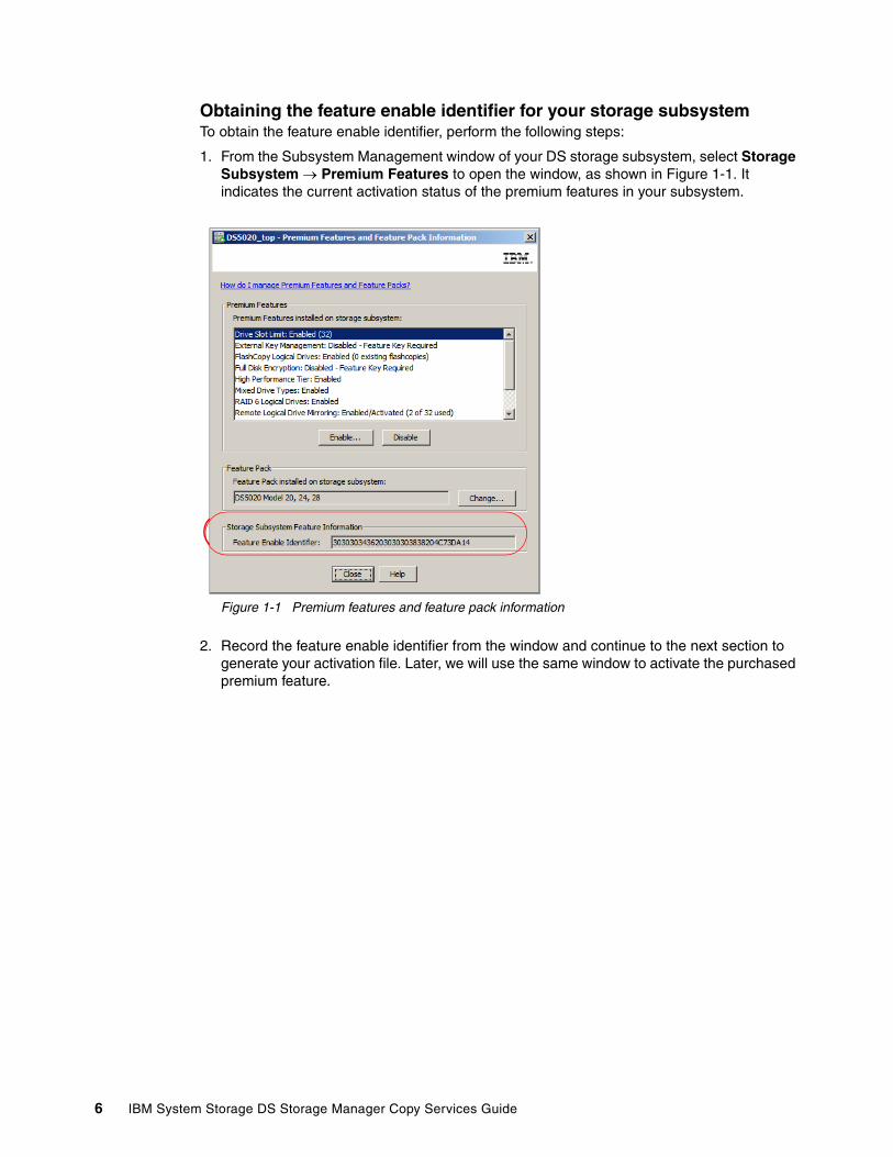
Obtaining the feature enable identifier for your storage subsystemTo obtain the feature enable identifier, perform the following steps:
1. From the Subsystem Management window of your DS storage subsystem, select Storage Subsystem Premium Features to open the window, as shown in Figure 1-1. It indicates the current activation status of the premium features in your subsystem.
Figure 1-1 Premium features and feature pack information
2. Record the feature enable identifier from the window and continue to the next section to generate your activation file. Later, we will use the same window to activate the purchased premium feature.
6 IBM System Storage DS Storage Manager Copy Services Guide

Using the web to generate the activation fileTo generate the activation file, perform the following steps:
1. With the feature enable identifier and the registration card provided with the machine for the premium feature purchased, go to the following website (shown in Figure 1-2):
https://www-912.ibm.com/PremiumFeatures/
Figure 1-2 Premium features website
2. On the website, select the Activate a Premium Feature or Software Feature Pack option, read the requirements, and click Continue.
Chapter 1. Introduction to IBM Midrange System Storage Copy Services 7

3. Complete the information presented in the next window, as shown in Figure 1-3:
– The feature activation code on the card included with the DS subsystem
– The feature enable identifier obtained in the previous section (“Obtaining the feature enable identifier for your storage subsystem” on page 6)
– Your specific machine type, model number, and serial number
Figure 1-3 Premium feature registration page
Scroll down and complete the remaining fields with your email address and select the appropriate check boxes.
4. Click Continue to submit the information. The activation key file is then emailed to you.
5. Save the received file in your folder, and continue with next section (“Installing the activation file using the DS Storage Manager” on page 9).
8 IBM System Storage DS Storage Manager Copy Services Guide
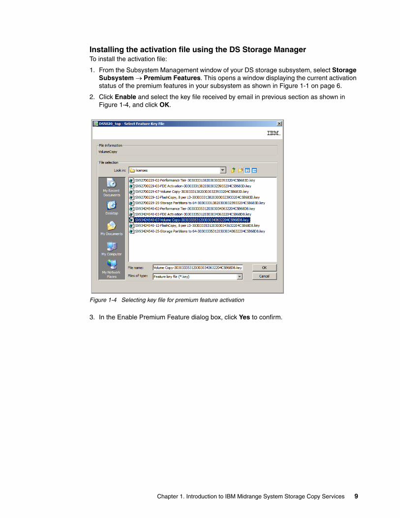
Installing the activation file using the DS Storage ManagerTo install the activation file:
1. From the Subsystem Management window of your DS storage subsystem, select Storage Subsystem Premium Features. This opens a window displaying the current activation status of the premium features in your subsystem as shown in Figure 1-1 on page 6.
2. Click Enable and select the key file received by email in previous section as shown in Figure 1-4, and click OK.
Figure 1-4 Selecting key file for premium feature activation
3. In the Enable Premium Feature dialog box, click Yes to confirm.
Chapter 1. Introduction to IBM Midrange System Storage Copy Services 9
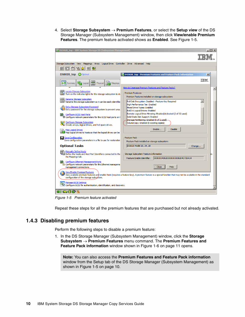
4. Select Storage Subsystem Premium Features, or select the Setup view of the DS Storage Manager (Subsystem Management) window, then click View/enable Premium Features. The premium feature activated shows as Enabled. See Figure 1-5.
Figure 1-5 Premium feature activated
Repeat these steps for all the premium features that are purchased but not already activated.
1.4.3 Disabling premium features
Perform the following steps to disable a premium feature:
1. In the DS Storage Manager (Subsystem Management) window, click the Storage Subsystem Premium Features menu command. The Premium Features and Feature Pack information window shown in Figure 1-6 on page 11 opens.
Note: You can also access the Premium Features and Feature Pack information window from the Setup tab of the DS Storage Manager (Subsystem Management) as shown in Figure 1-5 on page 10.
10 IBM System Storage DS Storage Manager Copy Services Guide
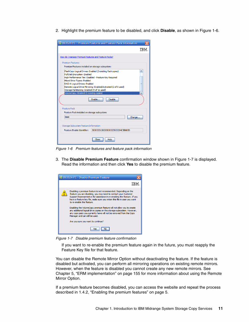
2. Highlight the premium feature to be disabled, and click Disable, as shown in Figure 1-6.
Figure 1-6 Premium features and feature pack information
3. The Disable Premium Feature confirmation window shown in Figure 1-7 is displayed. Read the information and then click Yes to disable the premium feature.
Figure 1-7 Disable premium feature confirmation
If you want to re-enable the premium feature again in the future, you must reapply the Feature Key file for that feature.
You can disable the Remote Mirror Option without deactivating the feature. If the feature is disabled but activated, you can perform all mirroring operations on existing remote mirrors. However, when the feature is disabled you cannot create any new remote mirrors. See Chapter 5, “ERM implementation” on page 155 for more information about using the Remote Mirror Option.
If a premium feature becomes disabled, you can access the website and repeat the process described in 1.4.2, “Enabling the premium features” on page 5.
Chapter 1. Introduction to IBM Midrange System Storage Copy Services 11

12 IBM System Storage DS Storage Manager Copy Services Guide
Chapter 2. FlashCopy
This chapter covers the details of the FlashCopy feature and looks at the various components of FlashCopy, what they do, and how to set them up. It also offers guidance and recommendations on various usage models that might be of interest in certain environments.
The FlashCopy premium feature is sold and enabled by the use of premium feature license keys, which allow for the storage subsystem to support a specific quantity of FlashCopies to be used per base logical drive. For the specific midrange storage subsystem types, the following license keys are offered to provide set quantities:
� DS3500
Two FlashCopies are available at no cost, initial key is for four FlashCopies per base logical drive, which is upgradeable to eight.
� DS4700 and DS5020
Two FlashCopies are available at no cost, initial key is for four FlashCopies per base logical drive, which is upgradeable to eight.
� DS4800, DS5100, and DS5300
Two FlashCopies are available at no cost. A single key is offered for a maximum of sixteen FlashCopies per base logical drive.
These keys offer the ability to create a number of FlashCopies for a base logical drive, allowing the use of each of the copies to be used for specific read or write operational purposes to perform testing, analysis, or backup operations as needed for the specific environment.
The following sections present many guidelines and recommendations for how to plan and implement the use of FlashCopy, and a step-by-step procedural guide to help with creation and usage commands for the FlashCopy function, both through the Storage Manager client graphical user interface (GUI) and by use of the command-line interface (CLI) and scripts.
2
© Copyright IBM Corp. 2011. All rights reserved. 13

2.1 How it works
A FlashCopy logical drive is a point-in-time (PiT) image of a logical drive. It is the virtual logical equivalent of a complete physical copy, but is created by using a smaller logical drive to record only changes onto the PiT image.
In this manner, the FlashCopy only has to perform an initial creation of the repository for use of recording changes to (and record the change operations made to) the original image, and if used for testing, any changes made to the PiT image. This process affects the creation and usage to the production environment far less, and results in less overhead for the storage subsystem to maintain a temporary image of the original logical drive image.
FlashCopy also requires less disk space because only changes are written to the repository known as the FlashCopy repository drive. However, FlashCopy is not a real physical copy, because it does not copy all the data from the original logical drive. Consequently, if the source logical drive is damaged, the FlashCopy logical drive cannot be used for recovery.
In the IBM System Storage DS Storage Manager, the logical drive from which you are creating the FlashCopy, is called the base logical drive. It can be defined from either a standard logical drive defined on the production storage subsystem, or from a secondary logical drive (target) of a remote mirror relationship. Typically, you create a FlashCopy so that an application (for example, a backup of a VolumeCopy) can access the FlashCopy and read the PiT image when the base logical drive is active online and user-accessible.
When the FlashCopy logical drive is no longer needed, it can be disabled rather than deleted, so future use can be easily reinstated without having to create it from scratch completely.
Before you upgrade your database management system, for example, you can use FlashCopy logical drives to test various changes. Then, you can use the results of the testing to help you decide what changes to implement on your live database system.
2.1.1 FlashCopy creation prerequisites
When you create a FlashCopy image, temporarily quiesce all I/O to the base logical drive when the image is created. For the local subsystem base logical drive, this process generally takes only a few seconds and is frequently performed by many applications with what is known as a warm stop or backup process.
When the I/O is stopped, the creation process creates the FlashCopy repository logical drive, where it stores FlashCopy metadata and copy-on-write data (Figure 2-1 on page 15). It builds a metadata database (DB) that contains only pointers. When the controller finishes creating the FlashCopy repository logical drive, production I/O (both read and write) the requests to the base logical drive can resume.
Important: For analysis, data mining, and testing without affecting the production base logical drive performance, use FlashCopy in conjunction with VolumeCopy, as explained later in Chapter 3, “VolumeCopy” on page 65.
14 IBM System Storage DS Storage Manager Copy Services Guide

Figure 2-1 FlashCopy read and write schema
ERM secondary target usageWhen used with ERM to create a FlashCopy of a remote secondary target logical drive this procedure can take a long time to complete depending on the design of the ERM environment and the degree of synchronization of the primary and secondary drives.
To create a usable FlashCopy image with the remote mirrored target, you must first ensure that the drives in the mirrored pair are fully synchronized and that the primary logical drive has been quiesced by the production host’s application so that all I/O can be flushed to the storage subsystem.
After all mirrored I/O has been flushed to the primary and mirrored to the secondary, we must suspend the mirror relationship and create the FlashCopy logical drive on the secondary target storage subsystem. This process is frequently used to develop disaster recovery (DR) solutions with a separate recoverable image at the DR site for faster recovery time objectives (RTO). See Chapter 4, “Enhanced Remote Mirroring (ERM) concepts, planning, and design” on page 93 and Chapter 5, “ERM implementation” on page 155 for further details.
General usage modelWhen a data block on the base logical drive receives a write I/O request, a copy-on-write occurs, copying the contents of the blocks to be modified into the FlashCopy repository logical drive, for safekeeping. Subsequently, the corresponding pointer in metadata database is changed.
Because the FlashCopy repository logical drive stores copies of the original data in those data blocks, further changes to the same data blocks on the base logical drive can occur without further copy-on-write operations being performed.
Chapter 2. FlashCopy 15

Because the only data blocks that are physically stored in the FlashCopy repository logical drive are those that record the blocks that have changed since the creation of the FlashCopy relationship, the FlashCopy repository logical drive uses less disk space than a full physical copy.
When you create a FlashCopy logical drive, specify where to create the FlashCopy repository logical drive, its capacity, its warning threshold, and other parameters. You can disable the FlashCopy when you are finished with the purpose for which i was created (for example, after a backup completes).
The next time that you recreate the FlashCopy it reuses the existing FlashCopy repository logical drive. Deleting a FlashCopy logical drive deletes the associated FlashCopy repository logical drives and future FlashCopy creations must start from scratch.
2.1.2 Estimating FlashCopy repository logical drive capacity
The FlashCopy repository logical drive is created to store FlashCopy metadata (data about the FlashCopy) and any copy-on-write data needed during the life of the FlashCopy logical drive. By default, the FlashCopy repository logical drive’s capacity is set to 20% of the base logical drive's capacity. In general, this capacity is sufficient.
Use the following information to help determine the appropriate capacity of the FlashCopy repository logical drive:
� A FlashCopy repository logical drive cannot be smaller than 8 MB in size.
� Set a larger percentage if a large percentage of data blocks will change on the base logical drive during the life of the FlashCopy logical drive because of heavy I/O activity. The Storage Manager’s Performance Monitor can help you determine typical I/O activity to the base logical drive.
� Set a larger percentage if you must keep the FlashCopy logical drive for an extended period of time.
Calculating expected overheadNormally, the default setting is okay. You will be given a warning when the FlashCopy repository logical drive reaches a certain percentage full. Increase its capacity using the Logical Drive Increase Capacity option in Storage Manager.
Use the following formula to calculate the amount of management overhead required to store FlashCopy data on the FlashCopy repository logical drive. In the formula, X is the capacity of the base logical drive in bytes:
192 KB + (X/2000)
This formula should be used as a guide, and FlashCopy repository logical drive capacity should be re-estimated periodically.
Note: Conversion from bytes to kilobytes, and then to megabytes, is required for this formula.
16 IBM System Storage DS Storage Manager Copy Services Guide
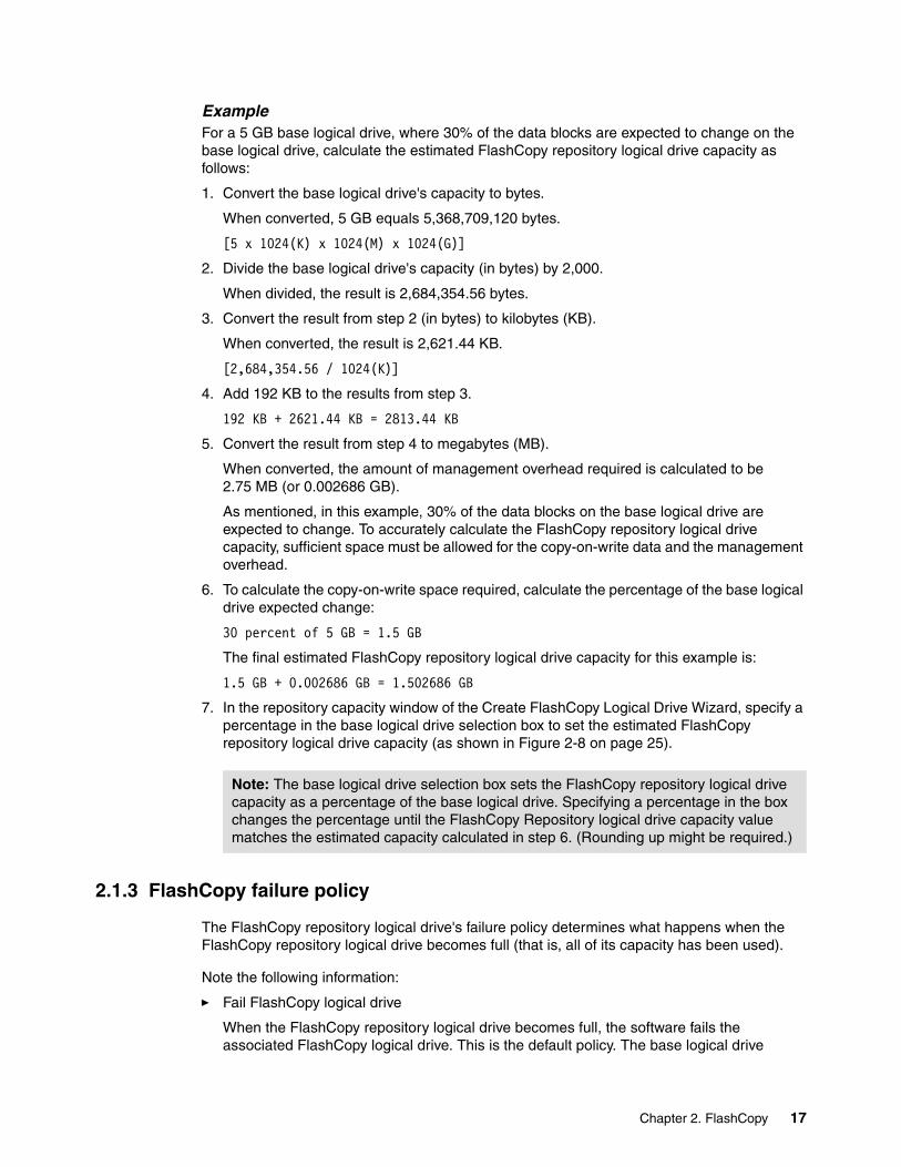
ExampleFor a 5 GB base logical drive, where 30% of the data blocks are expected to change on the base logical drive, calculate the estimated FlashCopy repository logical drive capacity as follows:
1. Convert the base logical drive's capacity to bytes.
When converted, 5 GB equals 5,368,709,120 bytes.
[5 x 1024(K) x 1024(M) x 1024(G)]
2. Divide the base logical drive's capacity (in bytes) by 2,000.
When divided, the result is 2,684,354.56 bytes.
3. Convert the result from step 2 (in bytes) to kilobytes (KB).
When converted, the result is 2,621.44 KB.
[2,684,354.56 / 1024(K)]
4. Add 192 KB to the results from step 3.
192 KB + 2621.44 KB = 2813.44 KB
5. Convert the result from step 4 to megabytes (MB).
When converted, the amount of management overhead required is calculated to be 2.75 MB (or 0.002686 GB).
As mentioned, in this example, 30% of the data blocks on the base logical drive are expected to change. To accurately calculate the FlashCopy repository logical drive capacity, sufficient space must be allowed for the copy-on-write data and the management overhead.
6. To calculate the copy-on-write space required, calculate the percentage of the base logical drive expected change:
30 percent of 5 GB = 1.5 GB
The final estimated FlashCopy repository logical drive capacity for this example is:
1.5 GB + 0.002686 GB = 1.502686 GB
7. In the repository capacity window of the Create FlashCopy Logical Drive Wizard, specify a percentage in the base logical drive selection box to set the estimated FlashCopy repository logical drive capacity (as shown in Figure 2-8 on page 25).
2.1.3 FlashCopy failure policy
The FlashCopy repository logical drive's failure policy determines what happens when the FlashCopy repository logical drive becomes full (that is, all of its capacity has been used).
Note the following information:
� Fail FlashCopy logical drive
When the FlashCopy repository logical drive becomes full, the software fails the associated FlashCopy logical drive. This is the default policy. The base logical drive
Note: The base logical drive selection box sets the FlashCopy repository logical drive capacity as a percentage of the base logical drive. Specifying a percentage in the box changes the percentage until the FlashCopy Repository logical drive capacity value matches the estimated capacity calculated in step 6. (Rounding up might be required.)
Chapter 2. FlashCopy 17

remains online and user accessible and writable. The FlashCopy logical drive is no longer valid.
� Fail writes to base logical drive
When the FlashCopy repository logical drive becomes full, the software does not write to the base logical drive. The FlashCopy logical drive is preserved and remains valid because no new copy-on-write data is generated for the FlashCopy repository logical drive.
If a FlashCopy logical drive or FlashCopy repository logical drive is displayed as a missing logical drive, the storage subsystem has determined that the drives are no longer accessible. Missing logical drives, in most cases, are recoverable.
2.1.4 Maximum supported FlashCopies
With firmware v7.10 and later, a total of up to 16 FlashCopies per logical drives (LUN) is supported, depending on the midrange storage subsystem. For the number of maximum FlashCopies per logical drive for a specific model, see Table 2-1.
Table 2-1 Supported maximum FlashCopies with firmware v7.10 and later
2.2 FlashCopy with the GUI wizard: Step-by-step
This section presents a procedure for implementing a midrange FlashCopy solution.
Attention: Do not ignore the FlashCopy repository logical drive threshold exceeded notification.
Important: Using a defragmentation utility to defragment a base logical drive with an associated FlashCopy repository logical drive can cause a copy-on-write of every data block in the base logical drive, which can then cause the FlashCopy repository logical drive to become full before the defragmentation operation is completed.
To prevent this from happening during a base logical drive defragmentation, ensure that the capacity of the FlashCopy repository logical drives is set to 105% of the size of the base logical drive before starting the defragmentation utility. This is the minimum size needed to support a copy-on-write of every data block in the base logical drive.
Midrange model Number of supported FlashCopies per logical drive
DS3500 4, can upgrade to 8
DS4700 4, can upgrade to 8
DS5020 4, can upgrade to 8
DS4800 4, can upgrade to 16
DS5100 4, can upgrade to 16
DS5300 4, can upgrade to 16
18 IBM System Storage DS Storage Manager Copy Services Guide

You can create FlashCopy logical drives by either using the GUI wizard, or by using the following command with the CLI:
create FlashCopyLogicaldrive
The CLI can be scripted to support automatic operations.
The procedure in this section uses the GUI wizard. For CLI instructions, see 2.3, “FlashCopy: Using the CLI” on page 50.
The tasks covered in this section are as follows:
� Checking the status of the FlashCopy premium feature� Creating a FlashCopy logical drive� Mapping a FlashCopy drive to a host� Viewing the FlashCopy drive status� Disabling a FlashCopy logical drive� Re-creating a FlashCopy logical drive� Resizing a FlashCopy Repository logical drive� Deleting a FlashCopy drive
2.2.1 Checking the status of the FlashCopy premium feature
Use this procedure to check premium features enabled on the storage subsystem and to view the FlashCopy icon to check for status.
Checking the premium featuresTo check the premium features, perform the following steps:
1. From the Subsystem Management window, select Storage Subsystem Premium Features
The List Premium Features dialog box opens. It lists the following items:
– Premium features enabled on the storage subsystem– Feature Pack– Feature Enable Identifier– Amount of existing FlashCopies; total FlashCopies in use per storage subsystem
2. Verify that FlashCopy Logical Drives is enabled. If the feature is not enabled, see the following publications for information about how to enable a premium feature:
– IBM System Storage DS3000: Introduction and Implementation Guide, SG24-7065– IBM System Storage DS4000 and Storage Manager V10.30, SG24-7010– IBM Midrange System Storage Implementation and Best Practices Guide, SG24-6363 – IBM Midrange System Storage Hardware Guide, SG24-7676– IBM System Storage DS3500: Introduction and Implementation Guide, SG24-7914
3. Click Close to close the dialog box.
Chapter 2. FlashCopy 19
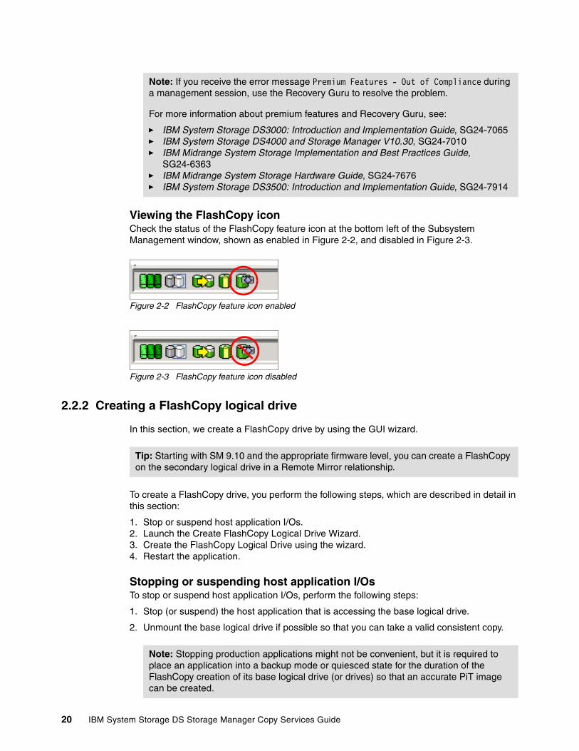
Viewing the FlashCopy iconCheck the status of the FlashCopy feature icon at the bottom left of the Subsystem Management window, shown as enabled in Figure 2-2, and disabled in Figure 2-3.
Figure 2-2 FlashCopy feature icon enabled
Figure 2-3 FlashCopy feature icon disabled
2.2.2 Creating a FlashCopy logical drive
In this section, we create a FlashCopy drive by using the GUI wizard.
To create a FlashCopy drive, you perform the following steps, which are described in detail in this section:
1. Stop or suspend host application I/Os.2. Launch the Create FlashCopy Logical Drive Wizard.3. Create the FlashCopy Logical Drive using the wizard.4. Restart the application.
Stopping or suspending host application I/OsTo stop or suspend host application I/Os, perform the following steps:
1. Stop (or suspend) the host application that is accessing the base logical drive.
2. Unmount the base logical drive if possible so that you can take a valid consistent copy.
Note: If you receive the error message Premium Features - Out of Compliance during a management session, use the Recovery Guru to resolve the problem.
For more information about premium features and Recovery Guru, see:
� IBM System Storage DS3000: Introduction and Implementation Guide, SG24-7065� IBM System Storage DS4000 and Storage Manager V10.30, SG24-7010� IBM Midrange System Storage Implementation and Best Practices Guide,
SG24-6363 � IBM Midrange System Storage Hardware Guide, SG24-7676� IBM System Storage DS3500: Introduction and Implementation Guide, SG24-7914
Tip: Starting with SM 9.10 and the appropriate firmware level, you can create a FlashCopy on the secondary logical drive in a Remote Mirror relationship.
Note: Stopping production applications might not be convenient, but it is required to place an application into a backup mode or quiesced state for the duration of the FlashCopy creation of its base logical drive (or drives) so that an accurate PiT image can be created.
20 IBM System Storage DS Storage Manager Copy Services Guide

3. Back up any application recovery files, such as rollback and redo logs.
4. In Windows, run the SMrepassist (replication assistance) utility in the Storage Manager Util directory. This tool flushes all the memory-resident data for the file system (indicated by [filesystem-identifier]on the command line) to ensure that the storage subsystem hardware creates an accurate FlashCopy logical drive or logical drive copy, and that signatures and file system partitions are recognized.
To run the utility, enter the SMrepassist -f [filesystem-identifier] command.
For example, in the SMrepassist -f e: command, e: is the logical drive from the server.
Launching the Create FlashCopy Logical Drive WizardTo launch the Create FlashCopy Logical Drive Wizard, perform the following steps:
1. Select a base logical drive from the logical view.
2. Select Logical Drive FlashCopy Create. Alternatively, you can right-click and select Create FlashCopy Logical Drive.
The Create FlashCopy Logical Drive Wizard begins, as shown in Figure 2-4.
Figure 2-4 Create FlashCopy Logical Drive Wizard startup
Important: This step is important because these files and logs can be located on separate physical disk storage or logical drives.
Important: Operating system specific procedures can be found in Appendix A, “Additional instructions for FlashCopy logical drives” on page 225.
Chapter 2. FlashCopy 21

If you reach the limit of the total allowed FlashCopies per logical drive, a message window (Figure 2-5) opens. Reduce the amount of current FlashCopies per logical drive in question or upgrade the FlashCopy Premium Feature license. See 2.1.4, “Maximum supported FlashCopies” on page 18, for more information.
Figure 2-5 FlashCopy limit reached
Creating the FlashCopy logical drive using the wizardTo create the FlashCopy logical drive using the wizard, perform the following steps:
1. Review the information about the initial window, as shown in Figure 2-4 on page 21. Click Close to proceed to the wizard introduction window.
Follow the instructions on each wizard panel, and click Next when you are ready to continue to the next panel.
The introduction window (Figure 2-6 on page 23) defines what a FlashCopy logical drive is and the physical components that are associated with a FlashCopy logical drive.
Attention: If the FlashCopy logical drive is based on the root disk of the host operating system, the final point-in-time image might not be completely consistent with the base logical drive.
Note: Starting with firmware v7.10, a maximum of 16 FlashCopies per logical drive is supported, depending on the midrange storage subsystem model.
Note: Each wizard panel has context-sensitive help. Click Help on a particular panel to receive help for that panel.
22 IBM System Storage DS Storage Manager Copy Services Guide
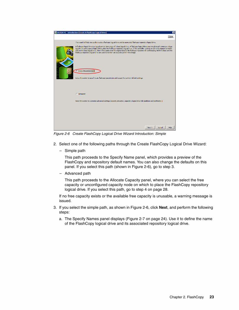
Figure 2-6 Create FlashCopy Logical Drive Wizard Introduction: Simple
2. Select one of the following paths through the Create FlashCopy Logical Drive Wizard:
– Simple path
This path proceeds to the Specify Name panel, which provides a preview of the FlashCopy and repository default names. You can also change the defaults on this panel. If you select this path (shown in Figure 2-6), go to step 3.
– Advanced path
This path proceeds to the Allocate Capacity panel, where you can select the free capacity or unconfigured capacity node on which to place the FlashCopy repository logical drive. If you select this path, go to step 4 on page 28.
If no free capacity exists or the available free capacity is unusable, a warning message is issued.
3. If you select the simple path, as shown in Figure 2-6, click Next, and perform the following steps:
a. The Specify Names panel displays (Figure 2-7 on page 24). Use it to define the name of the FlashCopy logical drive and its associated repository logical drive.
Chapter 2. FlashCopy 23

Figure 2-7 Create FlashCopy Logical Drive Wizard: Specify names
The default naming convention for the first FlashCopy is to use the base logical drive name and add a suffix of -1 for the logical drive and -R1 for the repository drive. The second FlashCopy uses 2 instead of 1. This numbering is repeated up to the maximal amount of supported FlashCopy‘s.
For example, if you are creating the first FlashCopy logical drive for a base logical drive named data 1, the default FlashCopy logical drive name is Data 1-1, and the associated FlashCopy repository logical drive default name is Data 1-R1. The default name of the next FlashCopy logical drive that you create based on Data 1 is Data 1-2, with the corresponding FlashCopy repository logical drive named Data 1-R2 by default.
Change the default names if required.
Click Next.
Tips: Consider the following information:
� Regardless of whether you use the software-supplied sequence number that (by default) populates the FlashCopy logical drive name or FlashCopy repository logical drive name field, the next default name for a FlashCopy or FlashCopy repository logical drive still uses the sequence number determined by the software. For example, you might name the first FlashCopy of base logical drive Data 1 DataVolJune18, and not use the software-supplied sequence number of 1. The default name for the next FlashCopy of accounting is still Data 1-2.
� The next available sequence number is based on the number of existing FlashCopies of a base logical drive. If you delete a FlashCopy logical drive, its sequence number becomes available again.
� You must choose a unique name for the FlashCopy and FlashCopy repository logical drives. Otherwise, an error message is displayed.
24 IBM System Storage DS Storage Manager Copy Services Guide

b. The Specify Repository Logical Drive Capacity window (Figure 2-8) displays. Set the repository drive capacity as a percentage of the base logical drive's capacity. This value defaults to 20%.
Figure 2-8 Specify Repository Logical Drive Capacity: Percent value
c. Set the proper capacity in the percent (%) of base logical drive selection box. Click Next.
d. The Create FlashCopy Wizard Preview panel (Figure 2-9) is displayed. It lists components associated with the FlashCopy. Review the information and click Finish.
Figure 2-9 Create FlashCopy Logical Drive Wizard: Preview
Important: In most situations, the 20% default value should be enough capacity for your FlashCopy repository logical drive. For information about determining the size, see 2.1.2, “Estimating FlashCopy repository logical drive capacity” on page 16.
Chapter 2. FlashCopy 25

e. At the completion message (Figure 2-10), click OK.
Figure 2-10 Create a FlashCopy Logical Drive: Complete
The newly created FlashCopy logical drive and its associated repository logical drive from the Subsystem Management window (Figure 2-11) is displayed.
Figure 2-11 New FlashCopy volume in subsystem management
Figure 2-12 shows the Flashcopy Summary View
Figure 2-12 Flashcopy SummaryFigure 2-13 on page 27 shows the Repository Summary.
New FlashCopy Logical
Repository Logical Volume
26 IBM System Storage DS Storage Manager Copy Services Guide

Figure 2-13 Repository summary
Chapter 2. FlashCopy 27

4. If you select the Advanced path from the Create FlashCopy Logical Drive Wizard Introduction window (shown in Figure 2-14), click Next.
Figure 2-14 Create FlashCopy Logical Drive Wizard: Advanced
Perform the following steps:
a. On the Specify Names panel (Figure 2-7 on page 24) define the FlashCopy logical drive name and the name of its associated FlashCopy repository logical drive. Click Next.
b. The Allocate Capacity window opens, as shown in Figure 2-15.
Figure 2-15 Create FlashCopy Logical Drive Wizard: Allocate capacity
28 IBM System Storage DS Storage Manager Copy Services Guide
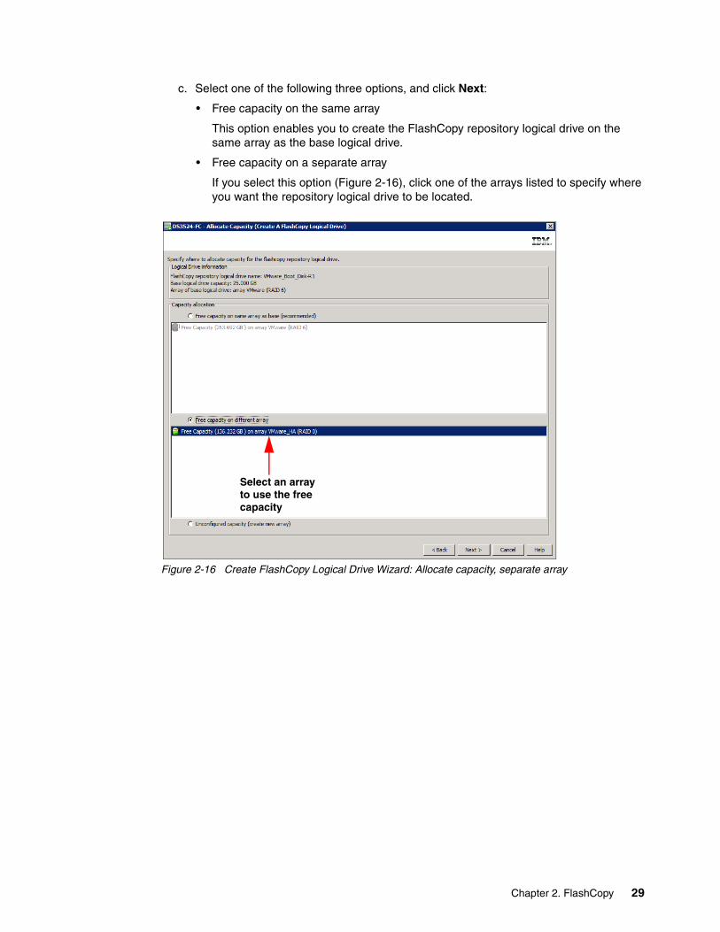
c. Select one of the following three options, and click Next:
• Free capacity on the same array
This option enables you to create the FlashCopy repository logical drive on the same array as the base logical drive.
• Free capacity on a separate array
If you select this option (Figure 2-16), click one of the arrays listed to specify where you want the repository logical drive to be located.
Figure 2-16 Create FlashCopy Logical Drive Wizard: Allocate capacity, separate array
Select an arrayto use the freecapacity
Chapter 2. FlashCopy 29

• Unconfigured capacity (create new array)
Select this option (Figure 2-17), to create a new array and allocate space for the FlashCopy repository logical drive.
Figure 2-17 Create FlashCopy Logical Drive Wizard: Allocate capacity, unconfigured space
Select unconfiguredspace to create a new array
30 IBM System Storage DS Storage Manager Copy Services Guide
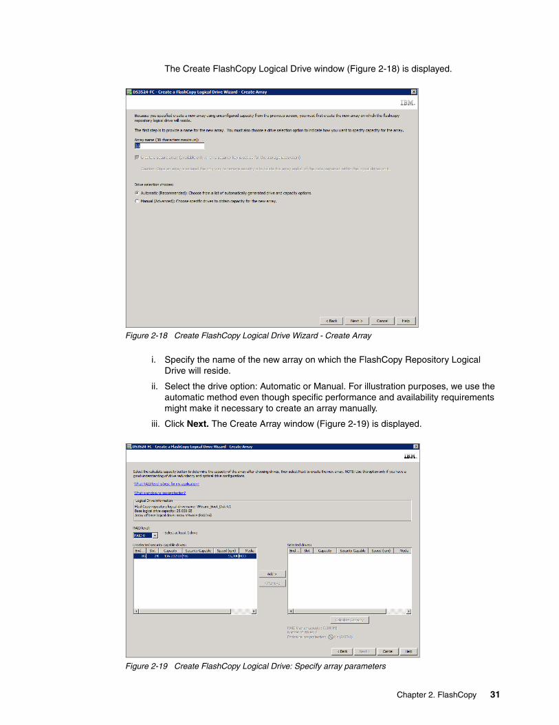
The Create FlashCopy Logical Drive window (Figure 2-18) is displayed.
Figure 2-18 Create FlashCopy Logical Drive Wizard - Create Array
i. Specify the name of the new array on which the FlashCopy Repository Logical Drive will reside.
ii. Select the drive option: Automatic or Manual. For illustration purposes, we use the automatic method even though specific performance and availability requirements might make it necessary to create an array manually.
iii. Click Next. The Create Array window (Figure 2-19) is displayed.
Figure 2-19 Create FlashCopy Logical Drive: Specify array parameters
Chapter 2. FlashCopy 31
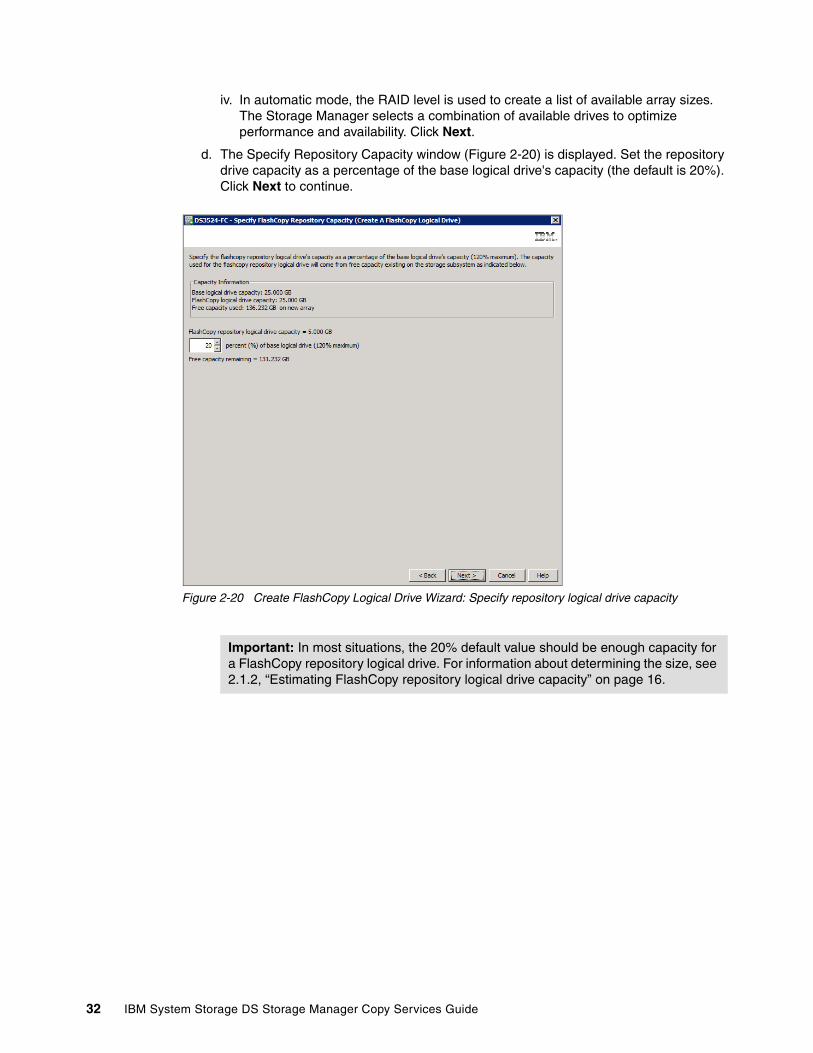
iv. In automatic mode, the RAID level is used to create a list of available array sizes. The Storage Manager selects a combination of available drives to optimize performance and availability. Click Next.
d. The Specify Repository Capacity window (Figure 2-20) is displayed. Set the repository drive capacity as a percentage of the base logical drive's capacity (the default is 20%). Click Next to continue.
Figure 2-20 Create FlashCopy Logical Drive Wizard: Specify repository logical drive capacity
Important: In most situations, the 20% default value should be enough capacity for a FlashCopy repository logical drive. For information about determining the size, see 2.1.2, “Estimating FlashCopy repository logical drive capacity” on page 16.
32 IBM System Storage DS Storage Manager Copy Services Guide
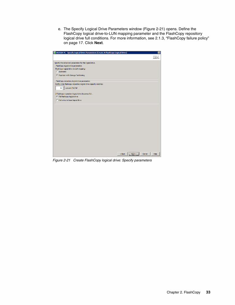
e. The Specify Logical Drive Parameters window (Figure 2-21) opens. Define the FlashCopy logical drive-to-LUN mapping parameter and the FlashCopy repository logical drive full conditions. For more information, see 2.1.3, “FlashCopy failure policy” on page 17. Click Next.
Figure 2-21 Create FlashCopy logical drive: Specify parameters
Chapter 2. FlashCopy 33

f. The Preview window (Figure 2-22) opens and shows the FlashCopy and repository parameters. Click Back to return to the previous windows and edit the parameters or click Finish to continue.
Notice that more information is available regarding logical drive parameters than was displayed in the Preview window when the simple path was used. The extra details associated with creating a new array from unconfigured space for the repository logical drive are shown in Figure 2-22.
Figure 2-22 Create FlashCopy Logical Drive Wizard: Preview
34 IBM System Storage DS Storage Manager Copy Services Guide

g. Click Finish. The Create FlashCopy Wizard Complete message box opens. Read the notice and click OK to continue.
You can now view the newly created FlashCopy logical drive and its associated repository logical drive from the Subsystem Management window. Figure 2-23 is an example in which the repository logical drive is allocated from another array than the base logical drive.
Figure 2-23 Repository logical drive on another array
Restarting the host applicationAfter you have created one or more FlashCopy logical drives, mount the base logical drive and restart the host applications using that base logical drive.
2.2.3 Mapping a FlashCopy drive to a host
You can assign logical drive-to-LUN mappings between the FlashCopy logical drive and the host that accesses the FlashCopy logical drive by using the mappings view of the Subsystem Management window. In certain cases, depending on the host operating system and whether any logical drive manager software in use, mapping the same host to both a base logical drive and its associated FlashCopy logical drive might result in conflicts. Instructions for specific operating systems are in Appendix A, “Additional instructions for FlashCopy logical drives” on page 225.
To map the FlashCopy logical drive to a host, perform the following steps:
1. Open the mappings view of the Subsystem Management window. The newly created FlashCopy logical drive is shown in the undefined mapping section.
2. Select the host or host group to which you want to map the drive.
Important: Additional steps for specific operating systems are in Appendix A, “Additional instructions for FlashCopy logical drives” on page 225. Failure to complete the additional steps might result in an inaccurate point-in-time image of the base logical drive.
Base Logical Drive on Array VMware
Repository Logical Driveon Array VMware HA
Chapter 2. FlashCopy 35
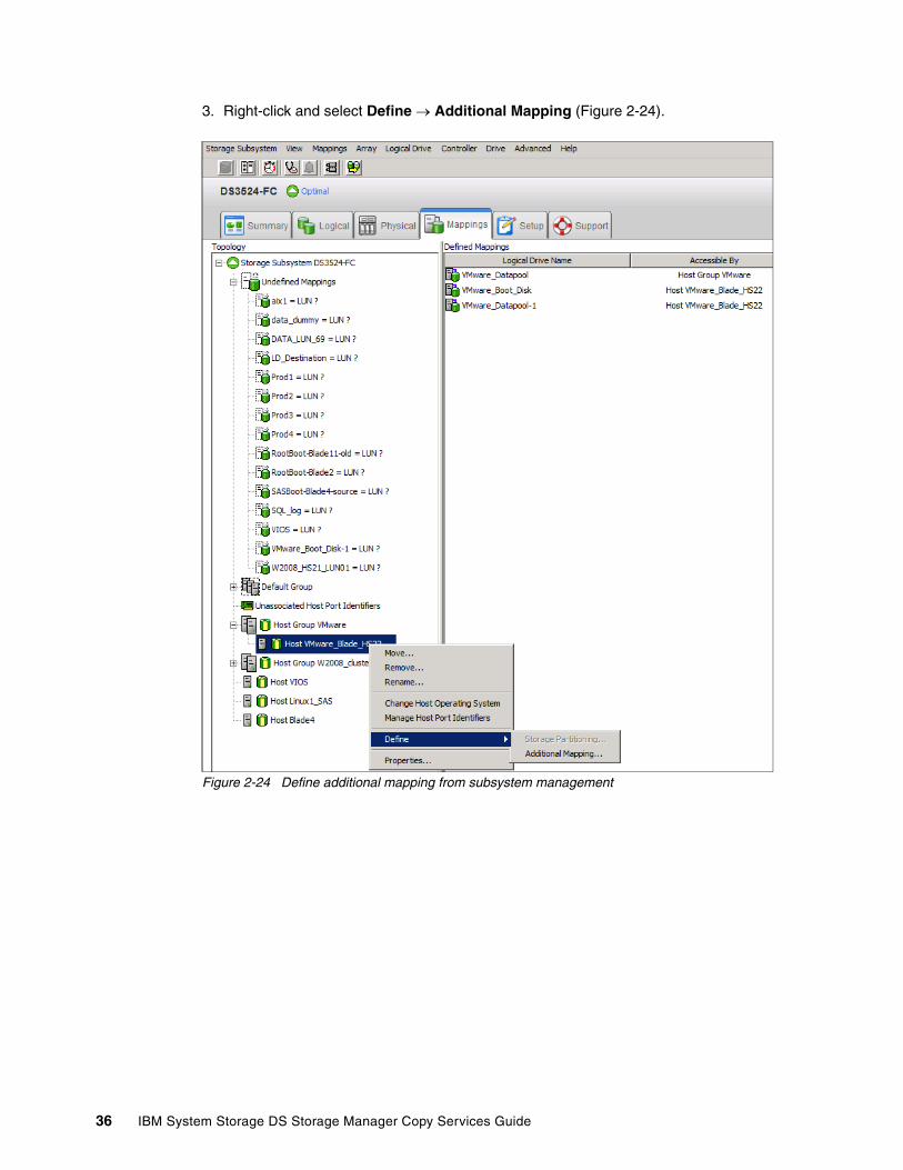
3. Right-click and select Define Additional Mapping (Figure 2-24).
Figure 2-24 Define additional mapping from subsystem management
36 IBM System Storage DS Storage Manager Copy Services Guide

4. In the Define Additional Mapping window (Figure 2-25), follow these steps:
a. Select the FlashCopy drive (VMware_Boot_Disk_1).b. Select the host group or host.c. Set the Logical unit number (LUN).d. Click Add.
Figure 2-25 Define Additional Mapping
In the examples shown in Figure 2-24 on page 36 and Figure 2-25, the FlashCopy logical disk VMware_Boot_Disk_1 is made available to the Host VMware_Blade_HS22 host. This availability enables the Host VMware_Blade_HS22 to access and mount the disk as part of its own file system.
Although mapping the FlashCopy logical disk to the same server that owns the base logical disk is possible, note that the two logical disks, immediately after creating the FlashCopy, appear exactly the same (a block-by-block copy). Many operating systems do not allow seeing an exact duplicate volume. In Microsoft Windows, for example, when a FlashCopy source logical drive is a dynamic disk, the FlashCopy source and target logical drive get the same DiskID in Logical Disk Manager (LDM), which causes problems. When the FlashCopy source logical drive is a basic disk, FlashCopy source and target logical drives receive the same disk signature. Map the FlashCopy destination logical drive to another host.
For more information about Windows disk best practices, go to this Microsoft website:
http://support.microsoft.com/kb/816307/en-us
You might be required to complete other steps before you can access the FlashCopy logical drive. The mapping is shown in Figure 2-26 on page 38.
Chapter 2. FlashCopy 37

Figure 2-26 Mapped FlashCopy logical drive
Finally, use specific operating system and host utilities to mount and use the mapped FlashCopy drive. The basic procedure is as follows:
1. Run the host-based hot_add utility (or an operating-system-specific utility) utility to register the FlashCopy logical drive with the host operating system.
2. Run the host-based SMdevices utility to associate the mapping between the physical device name and the logical drive name.
3. Mount the logical drive to the host.
For information about specific host operating system procedures, see Appendix A, “Additional instructions for FlashCopy logical drives” on page 225.
2.2.4 Viewing the FlashCopy drive status
The status of the FlashCopy logical drive can be determined by viewing the icons. The logical drive’s properties display (open by right-clicking the logical drive) is also useful in determining the state of the logical drive.
Use the FlashCopy Repository Logical Drive - Properties dialog box to view the FlashCopy repository logical drive base and capacity properties. You might also use this dialog box to specify the capacity percentage full and the action to be taken if the FlashCopy repository logical drive becomes full.
The progress of modification operations is displayed at the bottom of the dialog box.
Important: If you use a FlashCopy drive on a regular basis (for example, for backup purposes), consider using the Disable FlashCopy and Re-create FlashCopy options as a way to reuse the FlashCopy repository logical drive. Using these options preserves the existing mappings to the FlashCopy logical drive. For more information see 2.2.5, “Disabling a FlashCopy logical drive” on page 41.
38 IBM System Storage DS Storage Manager Copy Services Guide
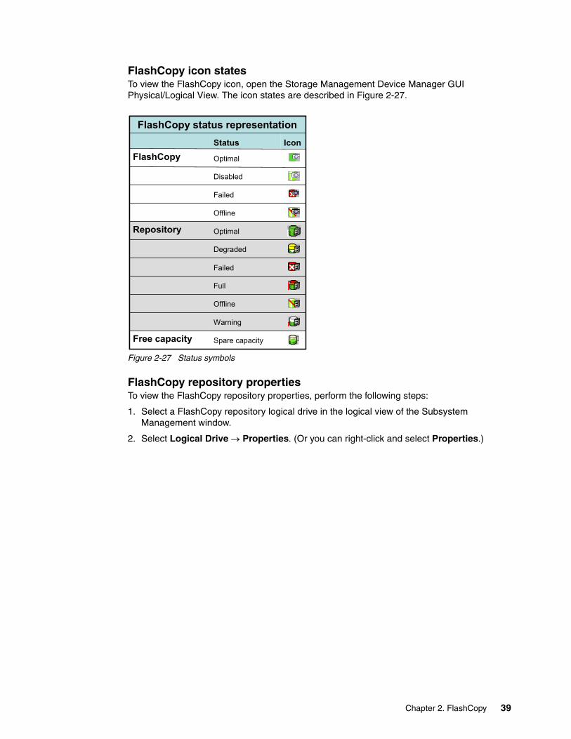
FlashCopy icon statesTo view the FlashCopy icon, open the Storage Management Device Manager GUI Physical/Logical View. The icon states are described in Figure 2-27.
Figure 2-27 Status symbols
FlashCopy repository propertiesTo view the FlashCopy repository properties, perform the following steps:
1. Select a FlashCopy repository logical drive in the logical view of the Subsystem Management window.
2. Select Logical Drive Properties. (Or you can right-click and select Properties.)
Spare capacityFree capacity
Warning
Offline
Full
Failed
Degraded
OptimalRepository
Offline
Failed
Disabled
OptimalFlashCopy
IconStatus
FlashCopy status representation
Spare capacityFree capacity
Warning
Offline
Full
Failed
Degraded
OptimalRepository
Offline
Failed
Disabled
OptimalFlashCopy
IconStatus
FlashCopy status representation
Chapter 2. FlashCopy 39

3. The FlashCopy Repository Logical Drive - Properties window (Figure 2-28).
Figure 2-28 FlashCopy Repository Logical Drive properties: Base tab
The Base tab lists the following information for the selected FlashCopy repository logical drive:
– Logical drive name– Repository drive status– Associated base logical drive – Associated FlashCopy logical drive – Capacity– Worldwide name – Drive type– Controller ownership – Segment size– RAID level – Modification priority – Read cache– Write cache– Pre-Read redundancy check
40 IBM System Storage DS Storage Manager Copy Services Guide

4. Right-click the Repository and select Manage Capacity Settings as in Figure 2-29.
Figure 2-29 Manage Capacity Settings
5. View or set the following FlashCopy repository logical drive capacity properties on the Manage Capacity Settings panel (Figure 2-30). The text box allows the user to set the percentage capacity at which the FlashCopy repository logical drive issues a warning indicating that the repository is nearing its capacity. The default percentage setting is 50% of the FlashCopy repository logical drive’s maximum capacity.
Figure 2-30 FlashCopy Repository Logical Drive - Properties: Capacity tab
See 2.1.3, “FlashCopy failure policy” on page 17, for more information about the Repository full policy.
2.2.5 Disabling a FlashCopy logical drive
When you no longer need a FlashCopy logical drive, you might want to disable it because, when it is enabled, the storage subsystem performance can be affected by the copy-on-write activity to the associated FlashCopy Repository logical drive. When disabling a FlashCopy logical drive, the copy-on-write activity stops.
If you disable the FlashCopy logical drive instead of deleting it, you can retain it and its associated repository. Then, when you must create a separate FlashCopy of the same base
Repository Full Policy
Chapter 2. FlashCopy 41

logical drive, use the re-create option to reuse the disabled FlashCopy. This takes less time than creating a new one.
When you disable a FlashCopy logical drive, note the following caveats:
� You cannot use that FlashCopy logical drive again until you use the re-create option on that logical drive.
� Only that FlashCopy logical drive is disabled. All other FlashCopy logical drives remain functional.
If you do not intend to re-create a FlashCopy, you can delete that FlashCopy logical drive instead of disabling it.
To disable a FlashCopy logical drive, perform the following steps:
1. Right-click the FlashCopy logical drive and select Disable, as shown in Figure 2-31.
Figure 2-31 FlashCopy logical drive: Disable
42 IBM System Storage DS Storage Manager Copy Services Guide

2. The Disable FlashCopy logical drive confirmation window opens. On this window, type Yes and click OK to begin the disable operation.
The FlashCopy icon in the physical/logical view now appears as disabled, as shown in Figure 2-32.
Figure 2-32 Icon showing the disabled FlashCopy logical drive
2.2.6 Re-creating a FlashCopy logical drive
Re-creating a FlashCopy logical drive takes less time than creating a new one. If you have a FlashCopy logical drive that you no longer need, instead of deleting it, you can reuse it (and its associated FlashCopy Repository logical drive) to create a separate FlashCopy logical drive of the same base logical drive.
When you re-create a FlashCopy logical drive, note the following caveats:
� The FlashCopy logical drive must be either in an optimal or a disabled state. If the FlashCopy logical drive is in an optimal state, it is first disabled and then re-created. This invalidates the current FlashCopy and creates a new point-in time copy.
� All copy-on-write data on the FlashCopy Repository logical drive is deleted.
� FlashCopy logical drive and FlashCopy Repository logical drive parameters remain the same as the previously disabled FlashCopy logical drive and its associated FlashCopy Repository logical drive. After the FlashCopy logical drive is re-created you can change parameters on the FlashCopy Repository logical drive through the appropriate menu options.
� The original names for the FlashCopy logical drive and FlashCopy Repository logical drives are retained. You can change these names after the re-create option completes.
� When using the re-create option, the previously configured FlashCopy name, parameters, and FlashCopy repository logical drive are used.
Light shaded icon
Chapter 2. FlashCopy 43
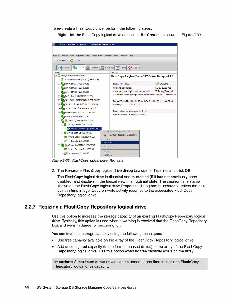
To re-create a FlashCopy drive, perform the following steps:
1. Right-click the FlashCopy logical drive and select Re-Create, as shown in Figure 2-33.
Figure 2-33 FlashCopy logical drive: Recreate
2. The Re-create FlashCopy logical drive dialog box opens. Type Yes and click OK.
The FlashCopy logical drive is disabled and re-created (if it had not previously been disabled) and displays in the logical view in an optimal state. The creation time stamp shown on the FlashCopy logical drive Properties dialog box is updated to reflect the new point-in-time image. Copy-on-write activity resumes to the associated FlashCopy Repository logical drive.
2.2.7 Resizing a FlashCopy Repository logical drive
Use this option to increase the storage capacity of an existing FlashCopy Repository logical drive. Typically, this option is used when a warning is received that the FlashCopy Repository logical drive is in danger of becoming full.
You can increase storage capacity using the following techniques:
� Use free capacity available on the array of the FlashCopy Repository logical drive.
� Add unconfigured capacity (in the form of unused drives) to the array of the FlashCopy Repository logical drive. Use this option when no free capacity exists on the array.
Important: A maximum of two drives can be added at one time to increase FlashCopy Repository logical drive capacity.
44 IBM System Storage DS Storage Manager Copy Services Guide
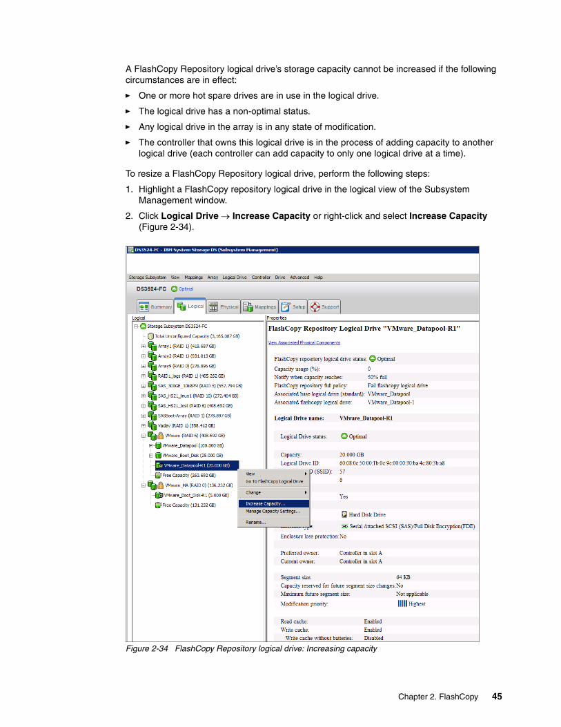
A FlashCopy Repository logical drive’s storage capacity cannot be increased if the following circumstances are in effect:
� One or more hot spare drives are in use in the logical drive.
� The logical drive has a non-optimal status.
� Any logical drive in the array is in any state of modification.
� The controller that owns this logical drive is in the process of adding capacity to another logical drive (each controller can add capacity to only one logical drive at a time).
To resize a FlashCopy Repository logical drive, perform the following steps:
1. Highlight a FlashCopy repository logical drive in the logical view of the Subsystem Management window.
2. Click Logical Drive Increase Capacity or right-click and select Increase Capacity (Figure 2-34).
Figure 2-34 FlashCopy Repository logical drive: Increasing capacity
Chapter 2. FlashCopy 45
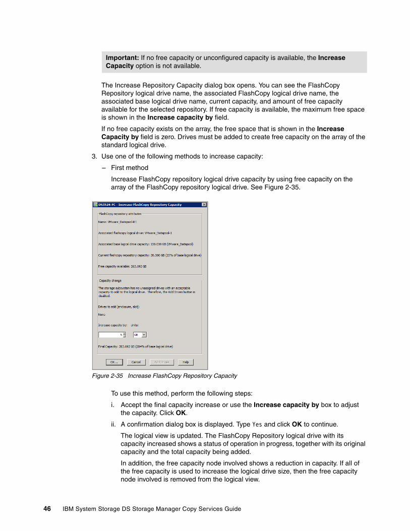
The Increase Repository Capacity dialog box opens. You can see the FlashCopy Repository logical drive name, the associated FlashCopy logical drive name, the associated base logical drive name, current capacity, and amount of free capacity available for the selected repository. If free capacity is available, the maximum free space is shown in the Increase capacity by field.
If no free capacity exists on the array, the free space that is shown in the Increase Capacity by field is zero. Drives must be added to create free capacity on the array of the standard logical drive.
3. Use one of the following methods to increase capacity:
– First method
Increase FlashCopy repository logical drive capacity by using free capacity on the array of the FlashCopy repository logical drive. See Figure 2-35.
Figure 2-35 Increase FlashCopy Repository Capacity
To use this method, perform the following steps:
i. Accept the final capacity increase or use the Increase capacity by box to adjust the capacity. Click OK.
ii. A confirmation dialog box is displayed. Type Yes and click OK to continue.
The logical view is updated. The FlashCopy Repository logical drive with its capacity increased shows a status of operation in progress, together with its original capacity and the total capacity being added.
In addition, the free capacity node involved shows a reduction in capacity. If all of the free capacity is used to increase the logical drive size, then the free capacity node involved is removed from the logical view.
Important: If no free capacity or unconfigured capacity is available, the Increase Capacity option is not available.
46 IBM System Storage DS Storage Manager Copy Services Guide

– Second method
Increase FlashCopy repository logical drive capacity by adding unconfigured capacity (drives) to the array of the FlashCopy repository logical drive:
i. If no unassigned drives are available and empty slots in the drive enclosures are available, insert new drives.
If no unassigned drives are available, and no empty slots are available in the drive enclosures, install another drive enclosure and additional drives.
ii. In the Increase FlashCopy Repository Capacity window (Figure 2-35 on page 46) select Add Drives.
The Increase Repository Capacity - Add Drives window opens, as shown in Figure 2-36. Enclosure, slot, and usable capacity details for the available free drives are listed.
Figure 2-36 Adding drives
iii. Select a single drive or two drives to be added. Note the following information:
• Press Ctrl and click to select the nonadjacent drives.
• Press Shift and click to select the adjacent drives.
Note: The drives that are listed have a capacity that is either the same size or larger than the capacity of the drives already being used by the array.
Chapter 2. FlashCopy 47

iv. Select Add. The Add Drives window is closed. Check the “Drives to add [enclosure, slot]” section to ensure that the correct drives are added. See Figure 2-37.
Figure 2-37 Increase FlashCopy Repository capacity: Added drives
v. Accept the final capacity or use the Increase capacity by box to adjust the capacity and click OK.
vi. A confirmation dialog box is displayed. Type Yes to confirm the operation and click OK to continue.
The FlashCopy Repository logical drive having its capacity increased shows a status of operation in progress, together with its original capacity and the total capacity being added. In addition, the free capacity node involved in the increase shows a reduction in capacity.
If all of the free capacity is used to increase the logical drives size, the free capacity node involved is removed from the logical view.
If a free capacity node did not exist prior to the addition of capacity and not all of the capacity that is added will be used to increase the FlashCopy Repository logical drives capacity, a new free capacity node is created and displayed in the logical view.
Unassigned drives (unconfigured capacity) added to increase the FlashCopy Repository logical drives capacity changes in the physical view to assigned drives, and becomes associated with the array of the FlashCopy repository logical drive.
Drives to add Information
48 IBM System Storage DS Storage Manager Copy Services Guide

4. View the progress of the increase of the capacity process. Highlight the FlashCopy repository logical drive. Select Logical Drive Properties or right-click and select Properties.
The FlashCopy Repository logical drive - Properties dialog box opens. A progress bar at the bottom of the dialog box indicates the status of the capacity increase.
2.2.8 Deleting a FlashCopy drive
Use this option to delete a FlashCopy logical drive that is no longer needed for backup or application testing purposes. This option results in an increase of free capacity in the array or additional unconfigured capacity.
To delete a FlashCopy logical drive, perform the following steps:
1. Select the FlashCopy logical drive in the logical view.
2. Click Logical Drive Delete (or right-click and select Delete, as shown in Figure 2-38).
Figure 2-38 Deleting the FlashCopy logical drive
Attention: Consider the following caveats:
� Deleting a logical drive causes loss of all data on the logical drive. Back up the data and stop all I/O before performing this operation, if necessary.
� If a file system is mounted on the logical drive, unmount it before attempting to delete it.
� Deleting a base logical drive automatically deletes the associated FlashCopy logical drives and FlashCopy Repository logical drives.
� Deleting a FlashCopy logical drive automatically deletes the associated FlashCopy Repository logical drive.
� Although you cannot delete a FlashCopy Repository logical drive using the Delete logical drive option, it is possible by using the delete command in the Script Editor or CLI. See the Enterprise Management window online help system for more information about using the delete command.
Chapter 2. FlashCopy 49

3. The Delete FlashCopy logical drive window (Figure 2-39) opens. Highlight the FlashCopy logical drives that you want to delete and click OK.
Figure 2-39 Delete FlashCopy logical drive dialog box
4. The Confirm Delete Logical Drives window opens. Read the warning message, type Yes, and click OK.
The FlashCopy logical drive and FlashCopy repository logical drive are deleted. Any data on them is destroyed.
2.3 FlashCopy: Using the CLI
This section discusses the command-line interface (CLI) and commands that are specific to the FlashCopy feature.
The following list of command-line interface (CLI) commands are pertinent to FlashCopy:
� create FlashCopyLogicalDrive � set logicalDrive � disableFlashCopy logicalDrive � recreateFlashCopy logicalDrive � delete logicalDrive
Note: For more in-depth information about using the command-line interface and the Script Editor, see any of the following documents:
� IBM Midrange System Storage Implementation and Best Practices Guide, SG24-6363,� IBM Midrange System Storage Hardware Guide, SG24-7676,� IBM System Storage DS3500: Introduction and Implementation Guide, SG24-7914, � Command Line Interface and Script Commands Programming Guide found on the
following web page:http://www-947.ibm.com/support/entry/portal/docdisplay?brand=5000008&lndocid=MIGR-5076792
Use the commands, mentioned in this book, only as reference. The commands can vary from firmware level to firmware level. So always refer to the actual CLI Guide.
50 IBM System Storage DS Storage Manager Copy Services Guide
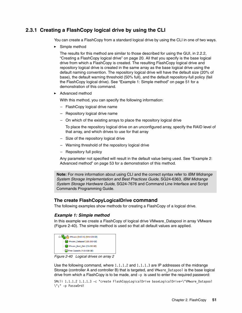
2.3.1 Creating a FlashCopy logical drive by using the CLI
You can create a FlashCopy from a standard logical drive by using the CLI in one of two ways.
� Simple method
The results for this method are similar to those described for using the GUI, in 2.2.2, “Creating a FlashCopy logical drive” on page 20. All that you specify is the base logical drive from which a FlashCopy is created. The resulting FlashCopy logical drive and repository logical drive is created in the same array as the base logical drive using the default naming convention. The repository logical drive will have the default size (20% of base), the default warning threshold (50% full), and the default repository-full policy (fail the FlashCopy logical drive). See “Example 1: Simple method” on page 51 for a demonstration of this command.
� Advanced method
With this method, you can specify the following information:
– FlashCopy logical drive name
– Repository logical drive name
– On which of the existing arrays to place the repository logical drive
To place the repository logical drive on an unconfigured array, specify the RAID level of that array, and which drives to use for that array
– Size of the repository logical drive
– Warning threshold of the repository logical drive
– Repository full policy
Any parameter not specified will result in the default value being used. See “Example 2: Advanced method” on page 53 for a demonstration of this method.
The create FlashCopyLogicalDrive commandThe following examples show methods for creating a FlashCopy of a logical drive.
Example 1: Simple methodIn this example we create a FlashCopy of logical drive VMware_Datapool in array VMware (Figure 2-40). The simple method is used so that all default values are applied.
Figure 2-40 Logical drives on array 2
Use the following command, where 1.1.1.2 and 1.1.1.3 are IP addresses of the midrange Storage (controller A and controller B) that is targeted, and VMware_Datapool is the base logical drive from which a FlashCopy is to be made, and -p is used to enter the required password:
SMcli 1.1.1.2 1.1.1.3 -c "create FlashCopyLogicalDrive baseLogicalDrive=\"VMware_Datapool \";" -p Passw0rd!
Note: For more information about using CLI and the correct syntax refer to IBM Midrange System Storage Implementation and Best Practices Guide, SG24-6363, IBM Midrange System Storage Hardware Guide, SG24-7676 and Command Line Interface and Script Commands Programming Guide.
Chapter 2. FlashCopy 51
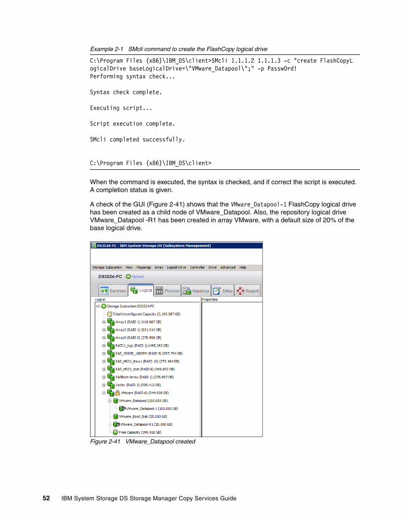
Example 2-1 SMcli command to create the FlashCopy logical drive
C:\Program Files (x86)\IBM_DS\client>SMcli 1.1.1.2 1.1.1.3 -c "create FlashCopyLogicalDrive baseLogicalDrive=\"VMware_Datapool\";" -p Passw0rd!Performing syntax check...
Syntax check complete.
Executing script...
Script execution complete.
SMcli completed successfully.
C:\Program Files (x86)\IBM_DS\client>
When the command is executed, the syntax is checked, and if correct the script is executed. A completion status is given.
A check of the GUI (Figure 2-41) shows that the VMware_Datapool-1 FlashCopy logical drive has been created as a child node of VMware_Datapool. Also, the repository logical drive VMware_Datapool -R1 has been created in array VMware, with a default size of 20% of the base logical drive.
Figure 2-41 VMware_Datapool created
52 IBM System Storage DS Storage Manager Copy Services Guide

A check of the repository logical drive properties, shown in Figure 2-42, indicates that the default warning threshold of 50% full and the default repository full policy of fail FlashCopy logical drive have been set.
Figure 2-42 Repository Logical Drive - Properties
Example 2: Advanced methodIn this example, we create a FlashCopy of logical drive VMware_Datapool in Array VMware (see Figure 2-40 on page 51). The advanced method is used to specify the following values:
� FlashCopy logical drive name =ITSO� Repository logical drive name = Log1� Repository logical drive:
– Is created on a new array– Uses two disk drives– Is RAID level 1– Is 35% of the base size– Warns when it is 66% full– Fails writes to the base logical drive
Enter the following command:
SMcli 1.1.1.2 1.1.1.3 -c "create FlashCopyLogicalDrive baseLogicalDrive=\"VMware_Datapool\" repositoryRaidLevel=1 repositoryDrives(1,1 1,9) userLabel=\"ITSO\" repositoryUserLabel=\"Log1\" repositoryPercentofBase=35 warningThresholdPercent=66 repositoryFullPolicy=failBaseWrites;" -p Passw0rd!
Example 2-2 SMcli Command to create a Flashcopy with the advance method
C:\Program Files (x86)\IBM_DS\client>SMcli 1.1.1.2 1.1.1.3 -c "create FlashCopyLogicalDrive baseLogicalDrive=\"VMware_Datapool\"repositoryRaidLevel=1 repositoryDrives=(1,1 1,9) userLabel=\"ITSO\"repositoryUserLabel=\"Log1\" repositoryPercentofBase=35 warningThresholdPercent=66 repositoryFullPolicy=failBaseWrites;" -p Passw0rd!Performing syntax check...
Syntax check complete.
Executing script...
Script execution complete.
SMcli completed successfully.
C:\Program Files (x86)\IBM_DS\client>
Chapter 2. FlashCopy 53
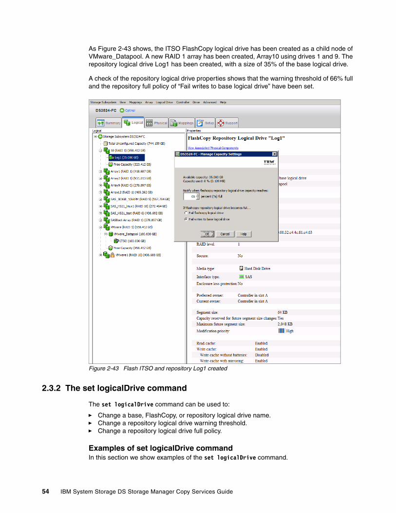
As Figure 2-43 shows, the ITSO FlashCopy logical drive has been created as a child node of VMware_Datapool. A new RAID 1 array has been created, Array10 using drives 1 and 9. The repository logical drive Log1 has been created, with a size of 35% of the base logical drive.
A check of the repository logical drive properties shows that the warning threshold of 66% full and the repository full policy of “Fail writes to base logical drive” have been set.
Figure 2-43 Flash ITSO and repository Log1 created
2.3.2 The set logicalDrive command
The set logicalDrive command can be used to:
� Change a base, FlashCopy, or repository logical drive name.� Change a repository logical drive warning threshold.� Change a repository logical drive full policy.
Examples of set logicalDrive commandIn this section we show examples of the set logicalDrive command.
54 IBM System Storage DS Storage Manager Copy Services Guide

Changing the name of the FlashCOpy logical driveIn example 1, the name of a FlashCopy logical drive is changed from ITSO to NewITSO. This is achieved through the following text in the command in Example 2-3:
SMcli 1.1.1.2 1.1.1.3 -c "set logicalDrive [\"ITSO\"] userLabel=\"NewITSO\";" -p Passw0rd!
Example 2-3 Command to change the FlashCopy Name
C:\Program Files (x86)\IBM_DS\client>SMcli 1.1.1.2 1.1.1.3 -c "set logicalDrive[\"ITSO\"] userLabel=\"NewITSO\";" -p Passw0rd!Performing syntax check...
Syntax check complete.
Executing script...
Script execution complete.
SMcli completed successfully.
C:\Program Files (x86)\IBM_DS\client>
The results are shown in Figure 2-44 on page 56.
Changing the logical drive warning percentageIn example 2, the repository logical drive warning percentage has been changed to 25% and the repository logical drive full policy has been changed to fail the FlashCopy. This is achieved by using the following text in the command in Example 2-4.
SMcli 1.1.1.2 1.1.1.3 -c "set logicalDrive [\"Log1\"] warningThresholdPercent=25 repositoryFullpolicy=failFlashCopy;" -p Passw0rd!
Example 2-4 Change the percentage and policy of the repository
C:\Program Files (x86)\IBM_DS\client>SMcli 1.1.1.2 1.1.1.3 -c "set logicalDrive[\"Log1\"] warningThresholdPercent=25 repositoryFullpolicy=failFlashCopy;" -p Passw0rd!Performing syntax check...
Syntax check complete.
Executing script...
Script execution complete.
SMcli completed successfully.
C:\Program Files (x86)\IBM_DS\client>
Chapter 2. FlashCopy 55

The results are shown in Figure 2-44.
Figure 2-44 Set logicalDrive examples
2.3.3 The disableFlashCopy logicalDrive commandThe disableFlashCopy logicalDrive command disables a FlashCopy, as discussed in 2.2.5, “Disabling a FlashCopy logical drive” on page 41.
ExampleIn this example, FlashCopy logical drive NewITSO is disabled by using the following command. The output is shown in Example 2-5:
SMcli 1.1.1.2 1.1.1.3 -c "disableFlashCopy logicalDrive [\"NewITSO\"];"-p Passw0rd!
Example 2-5 Disabling FlashCopy
C:\Program Files (x86)\IBM_DS\client>SMcli 1.1.1.2 1.1.1.3 -c "disableFlashCopylogicalDrive [\"NewITSO\"];" -p Passw0rd!Performing syntax check...
Syntax check complete.
Executing script...
Script execution complete.
SMcli completed successfully.
C:\Program Files (x86)\IBM_DS\client>
New percentage
New name of FlashCopy
Fail FlashCopy statement
56 IBM System Storage DS Storage Manager Copy Services Guide
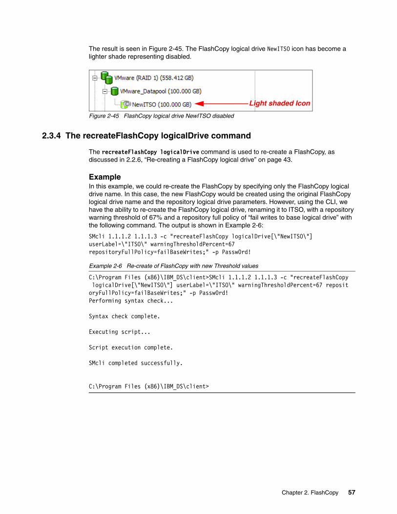
The result is seen in Figure 2-45. The FlashCopy logical drive NewITSO icon has become a lighter shade representing disabled.
Figure 2-45 FlashCopy logical drive NewITSO disabled
2.3.4 The recreateFlashCopy logicalDrive command
The recreateFlashCopy logicalDrive command is used to re-create a FlashCopy, as discussed in 2.2.6, “Re-creating a FlashCopy logical drive” on page 43.
ExampleIn this example, we could re-create the FlashCopy by specifying only the FlashCopy logical drive name. In this case, the new FlashCopy would be created using the original FlashCopy logical drive name and the repository logical drive parameters. However, using the CLI, we have the ability to re-create the FlashCopy logical drive, renaming it to ITSO, with a repository warning threshold of 67% and a repository full policy of “fail writes to base logical drive” with the following command. The output is shown in Example 2-6:
SMcli 1.1.1.2 1.1.1.3 -c "recreateFlashCopy logicalDrive[\"NewITSO\"] userLabel=\"ITSO\" warningThresholdPercent=67 repositoryFullPolicy=failBaseWrites;" -p Passw0rd!
Example 2-6 Re-create of FlashCopy with new Threshold values
C:\Program Files (x86)\IBM_DS\client>SMcli 1.1.1.2 1.1.1.3 -c "recreateFlashCopy logicalDrive[\"NewITSO\"] userLabel=\"ITSO\" warningThresholdPercent=67 repositoryFullPolicy=failBaseWrites;" -p Passw0rd!Performing syntax check...
Syntax check complete.
Executing script...
Script execution complete.
SMcli completed successfully.
C:\Program Files (x86)\IBM_DS\client>
Light shaded Icon
Chapter 2. FlashCopy 57

The results are shown in Figure 2-46.
Figure 2-46 Using recreateFlashCopy logicalDrive
2.3.5 The delete logicalDrive command
A FlashCopy logical drive can be deleted using this command. When deleting the FlashCopy logical drive the associated repository logical drive is also deleted. An example of this command is shown here with the output in Example 2-7:
SMcli 1.1.1.2 1.1.1.3 -c "delete logicalDrive [\"ITSO\"];" -p Passw0rd!
Example 2-7 Delete FlashCopy
C:\Program Files (x86)\IBM_DS\client>SMcli 1.1.1.2 1.1.1.3 -c "delete logicalDrive [\"ITSO\"];" -p Passw0rd!Performing syntax check...
Syntax check complete.
Executing script...
Script execution complete.
SMcli completed successfully.
C:\Program Files (x86)\IBM_DS\client>
58 IBM System Storage DS Storage Manager Copy Services Guide

2.4 Practical scenario
This section presents a typical customer scenario for implementing and using FlashCopy. The intent is to give you a starting point for implementing FlashCopy solutions on a DS3500.
2.4.1 Backing up a Windows 2008 Server
In this scenario, we have two System x servers in a Windows 2008 Server environment. One server is the backup client and the other is the backup server.
The aim is to get a FlashCopy of two logical drives of the backup client (one for the database, the other for database logs) and mount them to the backup server at regular time intervals for making backups to tape.
Figure 2-47 illustrates the configuration used for this scenario.
Figure 2-47 FlashCopy test setup
Attention: Before using FlashCopy, check the midrange interoperability matrix on the web for any restrictions regarding specific models and host platforms. You can find the midrange interoperability matrix at the following web pages:
� http://www-03.ibm.com/systems/support/storage/config/ssic/displayesssearchwithoutjs.wss?start_over=yes
� http://www.ibm.com/systems/storage/disk/ds4000/interop-matrix.html� http://www.ibm.com/systems/storage/disk/ds5000/interop-matrix.html
System x3950 M2
0
1
2
3
ESD
1 2
3 4
System x3950 M2
0
1
2
3
ESD
1 2
3 4
HBA1
Switch 2
HBA2 HBA1 HBA2
Backup Client Backup Server
Switch 1
DS3500
DB_Data DB_Data-1
DB_Logs DB_Logs-1
System Storage
Backup Tape Library
Chapter 2. FlashCopy 59

We assume that both servers have an operational Windows 2008 environment, and that:
� On both servers, the appropriate Multipath, SMutil (SMrepassist), and the SMclient (SMcli) software are installed.
� Both servers have access to the midrange through the SAN, and the appropriate zoning is already implemented.
� Logical drives (LUNs) have been defined on the midrange and are mapped to the backup client.
� Required applications (database, file server, and so on) have been installed and configured on the backup client.
� On the backup client, utilities such as RCMD and RCMDSVC tools from the Windows Resource Kit that allow you to run remote commands are installed. (You can use any other preferred remote command-line tool.)
The setup is as follows:
� Backup client:
– IP address: 9.42.170.11– Mapped logical drives: DB_Data and DB_Logs– Operating system assigned drive letter: O and P, respectively
� Backup server:
– IP address: 9.42.170.10– Mapped logical drives: DB_Data-1 and DB_Logs-1– Operating system assigned drive letter: E and F, respectively
� Midrange storage server
– IP address of controller A: 1.1.1.2– IP address of controller B: 1.1.1.3
Now, perform the following steps to back up the WIndows 208 server:
1. Using the Storage Manager GUI, create the initial FlashCopy for each logical drive, then map and mount the FlashCopy logical drives to the backup server.
2. Create a script that can be run from the backup server. (We use the RCMD tool from the Windows Resource Kit.) The script will do the following operations for us:
a. Stop the application on the backup client (or at least bring the application into a state so that the data on the disk is consistent).
b. Flush the OS file system or database caches on the backup client.
c. Flush the OS file system or database caches on the backup server.
d. Run the SMcli commands to re-create the FlashCopy.
e. Restart the application on the backup client.
f. Start the backup, initiated from the backup server.
3. Disable the FlashCopy logical drive when it is no longer needed.
60 IBM System Storage DS Storage Manager Copy Services Guide

Creating the initial FlashCopy driveThe first task is to create a FlashCopy logical drive for each of the base logical drives that contain the data to be backed up.
In our example, we have two logical drives (DB_Data and DB_Logs), one for the database data, the second for the database logs. Thus, in our case, we must also create two FlashCopy logical drives (called DB_Data_1 and DB_Logs_1). We do this by following the procedure previously given in 2.2, “FlashCopy with the GUI wizard: Step-by-step” on page 18.
After creating the FlashCopy volumes, we see the following in the Logical/Physical View tab of the Storage Manager GUI (Figure 2-48).
� Base logical drives: DB_Data, DB_Logs� FlashCopy logical drives: DB_Data-1, DB_Logs-1� FlashCopy repositories: DB_Data-R1, DB_Logs-R1
Figure 2-48 FlashCopy created for DB_Data and DB_Logs
At this stage, a good solution is to temporarily disable the FlashCopy logical drive to eliminate the performance impact resulting from the copy-on write operations.
Using storage partitioning, we now map the FlashCopy logical drives to the backup server.
Next we run the following command on the backup server so that the new devices are discovered:
C:\Program Files (x86)\IBM_DS\util>hot_add.exe
Or we can use another OS-specific command or even reboot the backup server system.
Using the Windows Device Manager (on the backup server), check that all the LUNs are showing correctly.
Chapter 2. FlashCopy 61
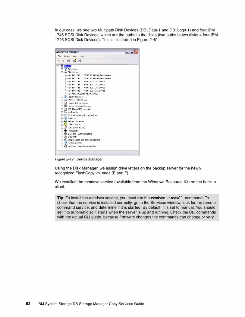
In our case, we see two Multipath Disk Devices (DB_Data-1 and DB_Logs-1) and four IBM 1746 SCSI Disk Devices, which are the paths to the disks (two paths to two disks = four IBM 1746 SCSI Disk Devices). This is illustrated in Figure 2-49.
Figure 2-49 Device Manager
Using the Disk Manager, we assign drive letters on the backup server for the newly recognized FlashCopy volumes (E and F).
We installed the rcmdsvc service (available from the Windows Resource Kit) on the backup client.
Tip: To install the rcmdsvc service, you must run the rcmdsvc -install command. To check that the service is installed correctly, go to the Services window, look for the remote command service, and determine if it is started. By default, it is set to manual. You should set it to automatic so it starts when the server is up and running. Check the CLI commands with the actual CLI guide, because firmware changes the commands can change or vary.
62 IBM System Storage DS Storage Manager Copy Services Guide

We used the script in Example 2-8 to perform a re-create operation of our FlashCopy logical drives, as happens in a regular backup routine on the server.
Example 2-8 FlashCopy demo script
@ECHO OFFREM This is a basic script example intended for a scenario where we have one orREM more backup clients that will hold some sort of application. It shows theREM steps required to recreate a FlashCopy of the disks mapped to the backup clientsREM and how to make sure that the data is consistent before it is accessed by theREM backup server for backup.
REM -------------------------------------------------------------------------------REM 1. STOPPING THE IO FROM THE BACKUP CLIENT TO THE DS3500REMREM The first step is to make sure that the IO from the backup client to the DS3500REM Storage Server is stopped. If we cannot stop the application, place it in backup mode REM or use another method to bring the data into a consistent state before backup.REM If we want for example to stop a special service like an SQL Server we can doREM that using net stop mssqlserver
net stop mssqlserverREM -------------------------------------------------------------------------------REM 2. FLUSHING THE FILE SYSTEM CACHES ON THE BACKUP CLIENTREMREM After we have stopped the IO to the local disks of the backup client weREM have to flush the caches on the backup client. In this example the disksREM on the backup client are O: and P:ECHO Flushing caches on Backup Client
rcmd \\9.42.171.11 C:\Program Files <x86>\IBM_DS\util\SMRepassist -f O:rcmd \\9.42.171.10 C:\Program Files <x86>\IBM_DS\util\SMRepassist -f P:
REM -------------------------------------------------------------------------------REM 3. FLUSHING THE FILE SYSTEM CACHES ON THE BACKUP SERVERREMREM After that we also need to flush the caches on the disks that areREM mapped to the backup server. In our example that would be E: and F:ECHO Flushing caches on Backup Server
C:\Program Files <x86>\IBM_DS\util\SMRepassist -f E:C:\Program Files <x86>\IBM_DS\util\SMRepassist -f F:
REM -------------------------------------------------------------------------------REM 4. DOING THE FLASHCOPY ON THE DS3500REMREM Now we need to recreate the Flashcopy logical Drives on the DS3500.
ECHO Recreating the Flashcopy DrivesC:\Program Files <x86>\IBM_DS\client\SMcli 1.1.1.2 1.1.1.3 -c "recreateFlashCopy logicalDrive[\"DB_Data-1\"];"C:\Program Files <x86>\IBM_DS\client\SMcli 1.1.1.2 1.1.1.3 -c "recreateFlashCopy logicalDrive[\"DB_Logs-1\"];"
REM -------------------------------------------------------------------------------REM 5. REM Mount the disks representing the Flashcopy Logical DrivesREM (E: and F: in our example)
mountvol E: \\?\Volume{01c8f186-babc-11df-b743-e41f137a8ffe}\mountvol F: \\?\Volume{01c8f18a-babc-11df-b743-e41f137a8ffe}\
Chapter 2. FlashCopy 63

REM -------------------------------------------------------------------------------REM 6. RESUMING IO ON THE BACKUP CLIENTREMREM After everything is finished we will start the services and applications onREM the backup client. With something likeREM net start mssqlserver
net start mssqlserver
REM -------------------------------------------------------------------------------REM 7. NOW YOU CAN USE THE FLASHCOPY DRIVES ON THE BACKUP SERVERREMREM Here we then can start to use our backup application for backing up the dataREM from the Flashcopy drivers (E: and F: in our example)
Run BakcupApplication
REM -------------------------------------------------------------------------------
REM 8. UNMOUNT THE VOLUMES ON THE BACKUP SERVERREM ECHO Dismounting volumes on Backup Server
mountvol E: /pmountvol F: /p
REM -------------------------------------------------------------------------------REM 9. DISABLE FLASHCOPY DRIVESREM When backup has completed , the FLashCopy logical drives can be disabled
C:\Program Files <x86>\IBM_DS\client\SMcli 1.1.1.2 1.1.1.3 -c "disableFlashCopy logicalDrive[\"DB_Data-1\"];"C:\Program Files <x86>\IBM_DS\client\SMcli 1.1.1.2 1.1.1.3 -c "disableFlashCopy logicalDrive[\"DB_Logs-1\"];"
64 IBM System Storage DS Storage Manager Copy Services Guide

Chapter 3. VolumeCopy
This chapter covers the usage of the VolumeCopy feature. The first part of this chapter presents the various components of VolumeCopy, describes what they do, and explains how to set them up. This is followed by a step-by-step guide of how to use VolumeCopy, first by using the IBM System Storage DS Storage Manager client graphical interface (GUI), then through the command-line interface (CLI).
3
© Copyright IBM Corp. 2011. All rights reserved. 65

3.1 Introduction to VolumeCopy
VolumeCopy is a premium feature that comes with the DS Storage Manager software and is enabled by purchasing a premium feature key. VolumeCopy can be used in conjunction with FlashCopy and, therefore, it can be purchased together with FlashCopy as a single copy service option, or at a later time as an enhancement to FlashCopy.
The VolumeCopy feature is a firmware-based mechanism that you use to create a physical copy, or a clone, of one logical drive (the source logical drive) to another logical drive (the target logical drive) in the same storage subsystem as shown in Figure 3-1. The source logical drive and the target logical drive in a VolumeCopy operation that are located on the same storage subsystem can also be referred to as a VolumeCopy pair.
Figure 3-1 VolumeCopy
A VolumeCopy appears and functions as a standard logical drive. The host server can address the VolumeCopy. You can read from, write to, or copy from the VolumeCopy. VolumeCopy is a background operation with user-defined priority settings, enabling administrators to minimize either the copy time or the overall I/O impact to the storage subsystem. If the storage subsystem controller experiences a reset, the copy request is restored and the copy process resumes from the last known progress boundary.
The VolumeCopy relationship is established between a source logical drive and a target logical drive. To ensure data integrity, all I/O to the target logical drive is suspended during the procedure. I/O suspension is necessary because the state of data on the target logical drive is inconsistent until the procedure is complete. Also, all updates to the source logical drive are suspended to prevent chronological inconsistencies from being created on the target logical drive. After the VolumeCopy operation is complete, the target logical drive automatically becomes read-only to the hosts. To preserve the data on the target logical drive, keep the write protection setting set to Read-Only.
The VolumeCopy can be used to copy data from arrays that use smaller capacity drives to arrays that use larger capacity drives, to back up data, or to restore a FlashCopy logical drive data to a new full base logical drive. The VolumeCopy premium feature includes a Create Copy wizard to assist in creating a logical drive copy, and a Copy Manager to monitor logical drive copies after they have been created.
66 IBM System Storage DS Storage Manager Copy Services Guide

VolumeCopy is a full point-in-time replication. It allows for analysis, mining, and testing without impacting the original production logical drive’s performance. It also brings improvements to backup and restore operations, making them faster and eliminating I/O contention on the primary (source) logical drive.
Users submit a VolumeCopy request by specifying two compatible volumes (logical drives). One logical drive is designated as the source, and the other is the target.
After submitting a copy request, the source logical drive is only available for read I/O activity, when a logical drive copy has a status of in progress, pending, or failed. Write requests are allowed after the logical drive copy is completed.
If the host that the source logical drive is assigned to use a journaling file system (for example Linux and AIX), you must use a FlashCopy logical drive of the original source to create a VolumeCopy, because journaling file systems attempt a write to the source prior to performing a read I/O request.
Note: If the logical drive that you want to copy is used in a production environment, the FlashCopy feature must be enabled. A FlashCopy of the logical drive must be created, and then specified as the VolumeCopy source logical drive, instead of using the actual logical drive itself. This requirement allows the original logical drive to continue to be accessible during the VolumeCopy operation.
Important: Because all write requests to the source logical drive are rejected when the VolumeCopy is taking place, minimizing the completion time of the copy operation is essential. For this reason, VolumeCopy must always be used in conjunction with FlashCopy. In other words, first make a FlashCopy of the source logical drive, then perform a VolumeCopy of the FlashCopy.
Chapter 3. VolumeCopy 67

As illustrated in Figure 3-2, FlashCopy, which allows a point-in-time copy to be made while maintaining read/write access, enables a complete copy to be created without requiring a halt to the write I/O activity of the production logical drive.
Figure 3-2 VolumeCopy integration with FlashCopy
3.1.1 Copying data for greater accessSeveral advantages of the VolumeCopy feature are discussed in this section.
MigrationLogical drive requirements can and do change over time. The overall required capacity might increase. Usage patterns might change from a mix of read and write operations to read-only operations predominantly. Access patterns might change from predominantly random requests to sequential requests predominantly.
VolumeCopy lets you optimize logical drive performance by moving a data set from one set of disk drives to another set. In a single operation, you can optimize application performance and capacity use for virtually every aspect of logical drive geometry for the data sets.
This approach provides an opportunity to move data to larger drives (for example, 73–300 GB), change to drives with a higher data transfer rate (for example, 2 Gbps–4 Gbps), or to change to drives using other technologies (from SATA to SAS) for higher performance and reliability.
Backing up dataThe VolumeCopy function enables you to create a backup of a logical drive by copying data from one logical drive to another logical drive in the same storage subsystem.
You can use the VolumeCopy procedure as a high-throughput backup solution that provides disk-based backup. The storage subsystem manages the data transfer internally, intelligently balancing backup-related traffic against production traffic on the drive channels. This internal
68 IBM System Storage DS Storage Manager Copy Services Guide

management minimizes the impact on production processing and isolates all traffic within the storage subsystem itself.
Restoring FlashCopy logical drive data for a full base imageIf you must restore the PiT image of a FlashCopy logical drive back onto the base logical drive, you must first create a separate VolumeCopy from the FlashCopy logical drive to another available logical drive. The VolumeCopy function can be used to copy the data from the FlashCopy logical drive to the new target logical drive. The original base logical drive cannot be a target of a VolumeCopy if FlashCopy logical drives are associated to it. After the FlashCopy logical drive is copied to the new logical drive, the FlashCopy relationship can be deleted and the original base logical drive is available for use as a VolumeCopy target.
With the new VolumeCopy target you created, you have a full image of the original PiT. You can now create a separate FlashCopy and VolumeCopy set of relationships with which to build the original PiT data back onto the first base logical drive.
3.1.2 Creating and managing VolumeCopy copiesVolumeCopy can be managed by using the IBM DS Storage Manager graphical user interface (GUI) or by using the relevant CLI commands and scripts.
When you configure a VolumeCopy, use separate disk drives and arrays for the source logical drive and the target logical drive. Doing so increases the availability of your data. If the array that contains the source logical drive becomes unavailable, or if the target logical drive become unavailable, you can still access the other array and your data.
Create Copy wizardThe Create Copy wizard guides you through the process of selecting a source logical drive from a list of available logical drives, selecting a target logical drive from a list of available logical drives, and setting the copy priority for the VolumeCopy. When you have completed the wizard dialog boxes, the VolumeCopy starts and data is read from the source logical drive and written to the target logical drive.
Icons that indicate the progress of the operation are displayed on the source logical drive and target logical drive when the VolumeCopy has a status of in progress or pending. For a detailed description of how to use the Create Copy wizard, see 3.2, “VolumeCopy with the GUI wizard: Step-by-step” on page 73.
For more information about source logical drives and target logical drives, see “Restrictions” on page 72.
Note: Before creating or recreating a VolumeCopy, stop all I/O activity to the source logical drive and to the target logical drive. Also run SMrepassist on the source logical drive. SMrepassist (replication assistance) is a host-based utility for Windows that makes sure that all the memory-resident data for the file system is flushed to the logical drive.
Chapter 3. VolumeCopy 69

Copy ManagerAfter you create a VolumeCopy with the Create Copy wizard, the VolumeCopy can be monitored and managed through the Copy Manager. From the Copy Manager, a VolumeCopy can be recopied, stopped, or removed. Its attributes, including the copy priority and the target logical drive read-only attribute, can be modified.
The status of a VolumeCopy can be viewed in the Copy Manager. Also, if you must determine what logical drives are involved in a VolumeCopy, use the Copy Manager or the storage subsystem profile. Brief descriptions of the options of the Copy Manager are as follows:
� Set the target logical drive read-only attribute
This option determines how read and write requests to the target logical drive are handled after a VolumeCopy is complete or if the VolumeCopy fails prior to completing. After the VolumeCopy is complete, the target logical drive automatically becomes read-only to hosts, and write requests to the target logical drive will not take place. When the read-only attribute for a target logical drive is enabled, a lock icon is displayed in the target logical drive column of the Copy Manager. The read-only attribute can be changed in the Copy Manager only after the VolumeCopy is completed.
� Re-copy a logical drive
This option allows you to create a new VolumeCopy of the data on a selected copy pair. Re-copy can be used to create a new VolumeCopy from the beginning if the original VolumeCopy failed or was stopped. You can also use this option for backup purposes. For instance, if the data on the source logical drive changes, you can use the re-copy option to duplicate any new data to the target logical drive.
� Stop a VolumeCopy
This option can stop a VolumeCopy with a status of pending, in progress, or failed. If you decide not to use a particular logical drive as a source logical drive or target logical drive, you can use this option to stop the VolumeCopy before it completes. The logical drives can then be used in a new VolumeCopy. Using this function on a VolumeCopy with a status of failed clears the needs-attention condition on the storage subsystem.
� Change copy priority
This option is used to balance I/O activity with VolumeCopy activity on a storage subsystem. You can set the copy priority to a rate that will have the least impact on I/O activity. Five copy priority rates are available:
– Lowest– Low– Medium– High– Highest
If the copy priority is set at the lowest rate, I/O activity is prioritized and the VolumeCopy takes longer. If the copy priority is set to the highest priority rate, the VolumeCopy is prioritized, but I/O activity for the storage subsystem can be affected.
� Remove Copy Pairs
This option allows you to remove a VolumeCopy from the Copy Manager. After the VolumeCopy is removed, the source logical drive and target logical drive can be used in a new VolumeCopy. When the VolumeCopy is removed, the read-only attribute for the target logical drive is also removed.
For a full description of using the Copy Manager, see 3.2, “VolumeCopy with the GUI wizard: Step-by-step” on page 73.
70 IBM System Storage DS Storage Manager Copy Services Guide
3.1.3 Understanding VolumeCopyA VolumeCopy fails all FlashCopy logical drives associated with the target logical drive if any exist. If you select a base logical drive of a FlashCopy logical drive, you must disable all FlashCopy logical drives that are associated with the base logical drive before you can select it as a target logical drive. Otherwise, the base logical drive cannot be used as a target logical drive.
If eight logical drive copies have a status of in progress, any subsequent VolumeCopy will have a status of pending until one of the eight logical drive copies completes.
VolumeCopy and modification operationsIf a modification operation is running on a source logical drive or target logical drive, and the VolumeCopy has a status of in progress, pending, or failed, the VolumeCopy does not take place. If a modification operation is running on a source logical drive or target logical drive after a VolumeCopy has been created, the modification operation must complete before the VolumeCopy can start. If a VolumeCopy has a status of in progress, any modification operation will not take place. Modification operations are as follows:
� Defragmenting an array
� Copy back to a drive that is part of an array
� Initialization of a logical drive
� Dynamic segment sizing (DSS) change for a logical drive
� Dynamic reconstruction rate (DRR) of a drive that is part of an array
� Dynamic RAID level migration (DRM) change for an array
� Dynamic capacity expansion (DCE), to increase an array's capacity using unconfigured capacity (in the form of unused drives)
� Dynamic logical drive expansion (DVE), to increase a logical drive capacity using free capacity available on the array of the standard or FlashCopy repository logical drive
Failed VolumeCopyA VolumeCopy can fail because of a read error from the source logical drive, a write error to the target logical drive, or because of a failure on the storage subsystem that affects the source logical drive or target logical drive (such as a Remote Mirror role reversal). A critical event is logged in the event log when the VolumeCopy fails, and a needs-attention icon is displayed in the Enterprise Management window. When a VolumeCopy has this status, the host has read-only access to the source logical drive. Read and write requests to the target logical drive do not take place until the failure is corrected by using the Recovery Guru.
Preferred controller ownershipDuring a VolumeCopy, the same controller must own both the source logical drive and the target logical drive. If both logical drives do not have the same preferred controller when the VolumeCopy starts, the ownership of the target logical drive is automatically transferred to the preferred controller of the source logical drive. When the VolumeCopy is completed or is stopped, ownership of the target logical drive is restored to its preferred controller. If ownership of the source logical drive is changed during the VolumeCopy, ownership of the target logical drive is also changed.
Important: A VolumeCopy overwrites data on the target logical drive and automatically makes the target logical drive read only to hosts.
Chapter 3. VolumeCopy 71

Failed controllerController ownership must be manually changed to the alternate controller to allow the VolumeCopy to complete under the following conditions: If a VolumeCopy has a status of in progress and its preferred controller fails, the ownership transfer does not occur automatically in the failover.
RestrictionsThe following restrictions apply to the source logical drive, target logical drive, and storage subsystem:
� The source logical drive is available for read I/O activity only when a VolumeCopy has a status of in progress or pending. Write requests are allowed after the VolumeCopy is completed.
� A logical drive can be used as a target logical drive in only one VolumeCopy at a time.
� The maximum allowable number of logical drive copies per storage subsystem is dependent upon the number of target logical drives available on your storage subsystem.
� A storage subsystem can have up to eight VolumeCopies running at any given time.
� The target logical drive capacity must be equal to or greater than the source logical drive capacity.
� A source logical drive can be a standard logical drive, FlashCopy logical drive, FlashCopy base logical drive, or a Remote Mirror primary logical drive.
� A target logical drive can be a standard logical drive, a base logical drive of a disabled or failed FlashCopy logical drive, or a Remote Mirror primary logical drive.
Logical drives that have the following status situations cannot be used as a source logical drive or target logical drive:
� A logical drive that is reserved by the host cannot be selected as a source or target logical drive
� A logical drive that is in a modification operation
� A logical drive that is the source logical drive or target logical drive in another VolumeCopy with a status of failed, in progress, or pending
� A logical drive with a status of failed
� A logical drive with a status of degraded
3.1.4 VolumeCopy and performance considerationsDuring a VolumeCopy, data is read from the source logical drive and written to the target logical drive in the same storage subsystem. Because the VolumeCopy diverts controller process resources from I/O activity, it can affect I/O activity on the storage subsystem. The copy priority defines how much processing time is allocated for a VolumeCopy versus I/O activity.
Tip: In practice, VolumeCopy must only be used with FlashCopy, to shorten the source logical drive’s read-only period of time.
Important: If you choose a base logical drive of a FlashCopy logical drive as your target logical drive, you must disable all FlashCopy logical drives that are associated with the base logical drive before you can select it as a target logical drive, otherwise, the base logical drive cannot be used as a target logical drive.
72 IBM System Storage DS Storage Manager Copy Services Guide

VolumeCopy priority ratesSeveral factors contribute to system performance, including I/O activity, logical drive RAID level, logical drive configuration (number of drives in the array or cache parameters), and logical drive type (FlashCopy logical drives can take more time to copy than standard logical drives).
You can select the copy priority when you are creating a new VolumeCopy, or you can change it later by using the Copy Manager. The following copy priority rates are available:
� Lowest� Low� Medium� High� Highest
Viewing the progress of a copy operationThe progress of the VolumeCopy is displayed in the status bar at the bottom-right of the Copy Manager. The status bar shows an estimate of the time remaining for the VolumeCopy to complete. You can view the progress of a VolumeCopy in the Copy Manager only when a VolumeCopy has a status of in progress.
Making the new VolumeCopy target usableUpon completion of the Volume Copy process to the new target logical drive, the new drive image will be in a read-only state. When the Read-Only attribute for a target logical drive is enabled, a lock icon appears in the Target Logical Drive column of the Copy Manager. To make the volume completely read-write accessible, you must change the Read-Only attribute in the Copy Manager.
3.2 VolumeCopy with the GUI wizard: Step-by-step
This section presents a step-by-step procedure of common administration tasks for a VolumeCopy. The tasks that are covered include:
� Checking the status of the VolumeCopy premium feature� Creating a VolumeCopy pair� Viewing logical copy drive properties� Using the Copy Manager� Re-copying a logical copy drive� Changing the copy priority� Setting the target logical copy drive read-only attributes� Stopping a logical copy� Removing logical copy pairs
Note: The lowest priority rate supports I/O activity, but the VolumeCopy takes longer. The highest priority rate supports the VolumeCopy, but I/O activity might be affected. Remember, however, that VolumeCopy must always be used in conjunction with FlashCopy.
Important: A VolumeCopy overwrites any data on the target logical drive and automatically makes the target logical drive read only permissions to hosts.
Chapter 3. VolumeCopy 73

3.2.1 Checking the status of the VolumeCopy premium featureUse this procedure to view a list of premium features on the storage subsystem and to verify that the VolumeCopy feature has been enabled:
1. Check the premium features list.2. View the VolumeCopy icon to verify that the feature has been enabled.
Checking the premium featureTo check the premium feature, perform the following steps:
1. From the Subsystem Management window, select Storage Subsystem Premium Features
The List Premium Features dialog box (Figure 3-3) opens. It lists the following items:
– Premium features installed on the storage subsystem– FeaturePack installed on storage subsystem– Feature enable identifier
Figure 3-3 Premium Feature Verification
2. Verify that VolumeCopy Logical Drives indicates enabled. If you identify that the VolumeCopy feature is not enabled, see IBM Midrange System Storage Implementation and Best Practices Guide, SG24-6363 and IBM System Storage DS3500: Introduction and Implementation Guide, SG24-7914 for information about how to enable a premium feature.
3. Click Close to close the dialog box.
74 IBM System Storage DS Storage Manager Copy Services Guide

For more information about enabling premium features, see IBM Midrange System Storage Hardware Guide, SG24-7676 and IBM System Storage DS3500: Introduction and Implementation Guide, SG24-7914.
Viewing the VolumeCopy iconCheck the status of the VolumeCopy feature icon at the bottom left of the Subsystem Management window, shown as enabled in Figure 3-4 and disabled in Figure 3-5.
Figure 3-4 Logical Copy Feature icon: Enabled
Figure 3-5 Logical Copy Feature icon: Disabled
3.2.2 Creating a VolumeCopy pairThis section describes how to create VolumeCopies by using the Create Copy wizard from the Subsystem Management console. The wizard guides you through the VolumeCopy creation process.
Note: If you receive a Premium Features - Out of Compliance error message during a management session, use the Recovery Guru to resolve the problem.
Tip: Make a FlashCopy of the logical drive and then use the FlashCopy as the source of the VolumeCopy.
Chapter 3. VolumeCopy 75
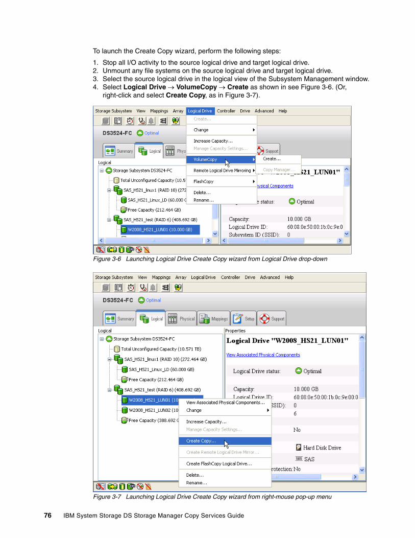
To launch the Create Copy wizard, perform the following steps:
1. Stop all I/O activity to the source logical drive and target logical drive.2. Unmount any file systems on the source logical drive and target logical drive.3. Select the source logical drive in the logical view of the Subsystem Management window.4. Select Logical Drive VolumeCopy Create as shown in see Figure 3-6. (Or,
right-click and select Create Copy, as in Figure 3-7).
Figure 3-6 Launching Logical Drive Create Copy wizard from Logical Drive drop-down
Figure 3-7 Launching Logical Drive Create Copy wizard from right-mouse pop-up menu
76 IBM System Storage DS Storage Manager Copy Services Guide

The Create Copy wizard Introduction dialog box opens. The logical drive that you selected to start the wizard is highlighted in the table (if it is a valid source logical drive). Follow the instructions on each wizard dialog box and select Next when you are ready to move to the next wizard dialog box.
Operation in progress icons are displayed on the source logical drive and target logical drive when the VolumeCopy has a status of in progress or pending.
Create Copy wizard: IntroductionThe first dialog box of the Create Copy wizard (Figure 3-8) defines a VolumeCopy and allows you to choose a source logical drive.
Figure 3-8 Create Copy wizard: Introduction
The source logical drive is available for read I/O requests only, when a VolumeCopy has one of the following choices for status:
� In progress� Pending� Failed
Write requests are only allowed after the VolumeCopy is completed. All valid source logical drives on the storage subsystem are displayed in the list in alphanumeric order. The logical drive that you selected to start the wizard is highlighted.
You can also create a source logical drive specifically for the VolumeCopy. Highlight the preferred source logical drive and click Next.
Note: Each wizard dialog box has context-sensitive help. Select Help to receive help applicable to that particular dialog box.
Chapter 3. VolumeCopy 77
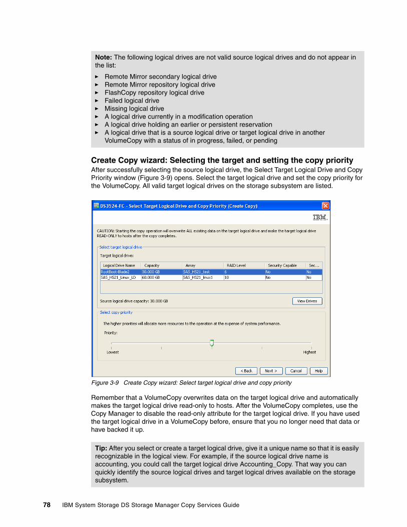
Create Copy wizard: Selecting the target and setting the copy priorityAfter successfully selecting the source logical drive, the Select Target Logical Drive and Copy Priority window (Figure 3-9) opens. Select the target logical drive and set the copy priority for the VolumeCopy. All valid target logical drives on the storage subsystem are listed.
Figure 3-9 Create Copy wizard: Select target logical drive and copy priority
Remember that a VolumeCopy overwrites data on the target logical drive and automatically makes the target logical drive read-only to hosts. After the VolumeCopy completes, use the Copy Manager to disable the read-only attribute for the target logical drive. If you have used the target logical drive in a VolumeCopy before, ensure that you no longer need that data or have backed it up.
Note: The following logical drives are not valid source logical drives and do not appear in the list:
� Remote Mirror secondary logical drive � Remote Mirror repository logical drive � FlashCopy repository logical drive� Failed logical drive � Missing logical drive � A logical drive currently in a modification operation � A logical drive holding an earlier or persistent reservation� A logical drive that is a source logical drive or target logical drive in another
VolumeCopy with a status of in progress, failed, or pending
Tip: After you select or create a target logical drive, give it a unique name so that it is easily recognizable in the logical view. For example, if the source logical drive name is accounting, you could call the target logical drive Accounting_Copy. That way you can quickly identify the source logical drives and target logical drives available on the storage subsystem.
78 IBM System Storage DS Storage Manager Copy Services Guide

The View Drives dialog box can be launched when you are in the Select Target Logical Drive and Copy Priority windows. See Figure 3-9 on page 78. From the View Drives pop-up window, you can view the drives, slots, and capacities of the source and target logical drives. This information can be used to copy high-access logical drives to separate arrays for increased accessibility, or to copy logical drives to an array that uses larger capacity drives.
After you have selected the target logical drive and set the copy priority, click Next to continue.
Create Copy wizard: PreviewThe next window to open is the Preview (Create Copy) window (Figure 3-10). It provides an overview of the selected source logical drive, target logical drive, and copy priority for the VolumeCopy, and allows you to return to previous dialog boxes to edit the parameters.
Type Yes to confirm the operation and click Finish to start the copy operation.
Figure 3-10 Create Copy wizard: Preview
After you click Finish, the Copy Started dialog box opens to indicate that the VolumeCopy has begun. You have the option to create a new VolumeCopy or exit the wizard. To close the Copy Started dialog box, select one of the following options:
� Yes: Create a new VolumeCopy.� No: Exit the wizard.
Operation in progress icons are displayed on the source logical drive and target logical drive when the VolumeCopy has a status of in progress or pending.
3.2.3 Viewing VolumeCopy propertiesSelect the source logical drive or target logical drive to see information about a selected source logical drive or target logical drive, such as the copy status, copy priority, completion time stamp, and whether the read-only attribute is enabled on the target logical drive.
You can view the progress of a VolumeCopy only if the status indicates in progress. The Copying properties are available only if the logical drive that you selected is part of a VolumeCopy relationship.
Chapter 3. VolumeCopy 79
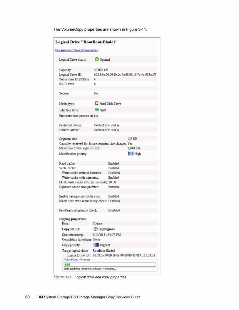
The VolumeCopy properties are shown in Figure 3-11.
Figure 3-11 Logical drive and copy properties
80 IBM System Storage DS Storage Manager Copy Services Guide
The logical drive properties that are displayed include:
� Role: Source or target� Copy status: Pending, in progress, completed, stopped, failed� Copy priority: Lowest, low, medium, high, highest� Start time stamp: MM/DD/YY HH/MM/SS (month/day/year hours/minutes/seconds)� Completion time stamp: MM/DD/YY HH/MM/SS� Read-Only: Enabled/disabled (only if target logical drive is selected)� Source/Target Logical Drive: Logical drive name� Source/Target Logical Drive ID: WWN (worldwide name)
If a source logical drive has multiple target logical drives, then the details will be repeated for each target logical drive.
3.2.4 Using the Copy ManagerThe Copy Manager dialog box is used to monitor the progress of a VolumeCopy and perform the following tasks for all logical drive copies on the storage subsystem:
� Recopy a logical drive� Stop VolumeCopy� Remove copy pairs� Copy priority� Target Logical Drive Permissions
Information is displayed for all of the logical drive copies on the storage subsystem:
� Source logical drive� Target logical drive, the status of the VolumeCopy� Time stamp for any completed copies� VolumeCopy priority assigned to the VolumeCopy
If a target logical drive is read-only to hosts, a lock icon is displayed in the target logical drive column. You can view the progress of a VolumeCopy in the status column.
The progress of the VolumeCopy is displayed in the status bar at the bottom-right of the Copy Manager. The status bar shows an estimate of the time remaining for the VolumeCopy to complete. You can view the progress of a VolumeCopy in the Copy Manager only when a VolumeCopy has a status of in progress.
Tip: If a logical drive is part of a VolumeCopy relationship, by right-clicking the logical drive, the Go To Source/Target Logical Drive menu item is available. This is a convenient way to find the copy pair partner.
Chapter 3. VolumeCopy 81
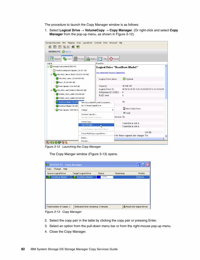
The procedure to launch the Copy Manager window is as follows:
1. Select Logical Drive VolumeCopy Copy Manager. (Or right-click and select Copy Manager from the pop-up menu, as shown in Figure 3-12).
Figure 3-12 Launching the Copy Manager
The Copy Manger window (Figure 3-13) opens.
Figure 3-13 Copy Manager
2. Select the copy pair in the table by clicking the copy pair or pressing Enter.
3. Select an option from the pull-down menu bar or from the right-mouse pop-up menu.
4. Close the Copy Manager.
82 IBM System Storage DS Storage Manager Copy Services Guide
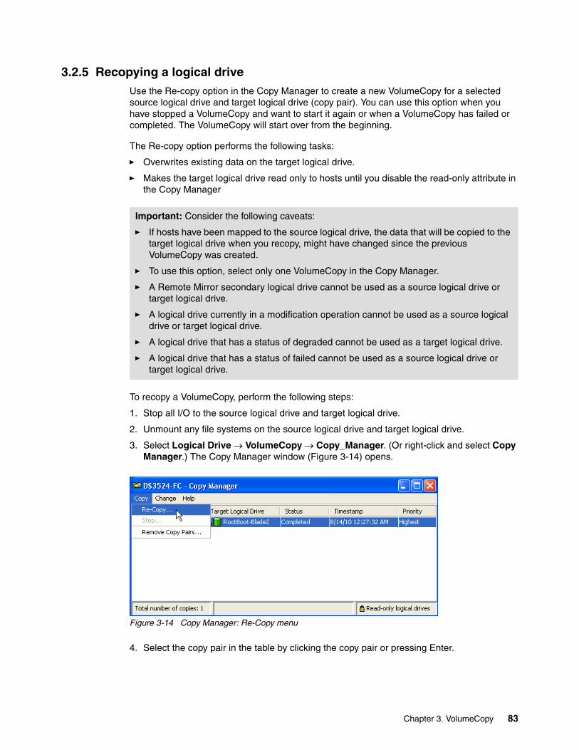
3.2.5 Recopying a logical driveUse the Re-copy option in the Copy Manager to create a new VolumeCopy for a selected source logical drive and target logical drive (copy pair). You can use this option when you have stopped a VolumeCopy and want to start it again or when a VolumeCopy has failed or completed. The VolumeCopy will start over from the beginning.
The Re-copy option performs the following tasks:
� Overwrites existing data on the target logical drive.
� Makes the target logical drive read only to hosts until you disable the read-only attribute in the Copy Manager
To recopy a VolumeCopy, perform the following steps:
1. Stop all I/O to the source logical drive and target logical drive.
2. Unmount any file systems on the source logical drive and target logical drive.
3. Select Logical Drive VolumeCopy Copy_Manager. (Or right-click and select Copy Manager.) The Copy Manager window (Figure 3-14) opens.
Figure 3-14 Copy Manager: Re-Copy menu
4. Select the copy pair in the table by clicking the copy pair or pressing Enter.
Important: Consider the following caveats:
� If hosts have been mapped to the source logical drive, the data that will be copied to the target logical drive when you recopy, might have changed since the previous VolumeCopy was created.
� To use this option, select only one VolumeCopy in the Copy Manager.
� A Remote Mirror secondary logical drive cannot be used as a source logical drive or target logical drive.
� A logical drive currently in a modification operation cannot be used as a source logical drive or target logical drive.
� A logical drive that has a status of degraded cannot be used as a target logical drive.
� A logical drive that has a status of failed cannot be used as a source logical drive or target logical drive.
Chapter 3. VolumeCopy 83

5. Select Copy Re-Copy. (Or right-click the copy pair and select Re-Copy.) The Re-Copy dialog box (Figure 3-15) opens.
Figure 3-15 Re-copy window
6. Set the copy priority. The five copy priority rates are as follows:
– Lowest– Low– Medium– High– Highest
If the copy priority is set at the lowest rate, I/O activity is prioritized and the VolumeCopy takes longer. If the copy priority is set to the highest priority rate, the VolumeCopy is prioritized, but I/O activity for the storage subsystem might be affected.
7. Type Yes and select OK to start the VolumeCopy.
8. Close the Copy Manager. Operation in progress icons are displayed on the source logical drive and target logical drive when the VolumeCopy has a status of in progress or pending.
Note: You can view the progress of a VolumeCopy in the Copy Manager only when a VolumeCopy has a status of in progress.
84 IBM System Storage DS Storage Manager Copy Services Guide

3.2.6 Changing VolumeCopy priority
Use this option in the Copy Manager to select the rate at which a VolumeCopy completes for a selected copy pair. You can change the copy priority for a copy pair before the VolumeCopy begins, when the VolumeCopy has a status of in progress, or after the VolumeCopy has completed (for a recopy). To change the VolumeCopy priority, perform the following steps:
1. Select Logical Drive VolumeCopy Copy Manager. (Or right-click and select Copy Manager from the pop-up menu.) The Copy Manager dialog box opens.
2. Select one or more copy pairs in the table. You can select more than one copy pair by pressing Ctrl and clicking the left mouse button.
3. Select Change Copy Priority. (Or, right-click and select Copy Priority.) See Figure 3-16.
Figure 3-16 Select Copy Priority from Copy Manager
The Change Copy Priority window opens, as shown in Figure 3-17.
Figure 3-17 Change Copy Priority
Chapter 3. VolumeCopy 85

4. In the Copy priority section, use the slide bar to select the appropriate copy priority, depending on your system performance needs.
5. Click OK. The copy priority for the selected copy pair is changed.
6. Close the Copy Manager.
3.2.7 Setting the read-only attribute for a target logical driveRead and write requests to the target logical drive do not take place when the VolumeCopy has a status of pending or in progress, or if the VolumeCopy fails prior to completing.
After the VolumeCopy has completed, the target logical drive automatically becomes read-only to hosts. Figure 3-18 shows target logical drives with the read-only attribute set to enabled (small lock icon next to logical drive name).
Figure 3-18 Copy Manager showing read-only attribute icon enabled
You might want to keep this attribute enabled to preserve the data on the target logical drive, for example, if you are using the target logical drive for backup purposes, if you are copying data from one array to a larger array for greater accessibility, or if you are using the data on the target logical drive to copy back to the base logical drive of a disabled or failed FlashCopy logical drive.
If you decide not to preserve the data on the target logical drive after the VolumeCopy is completed, use the Copy Manager to disable the read-only attribute for the target logical drive.
Disabling the read-only attributeTo disable the read-only attribute perform the following steps:
1. Select Logical Drive VolumeCopy Copy_Manager. (Or, right-click and select Copy Manager from the pop-up menu.)
2. Select one or more copy pairs in the table. You can select more than one copy pair by pressing Ctrl and clicking the left mouse button.
Note: The five copy priority rates are available (lowest, low, medium, high, and highest). If the copy priority is set at the lowest rate, I/O activity is prioritized and the VolumeCopy will take longer. If the copy priority is set to the highest priority rate, the VolumeCopy is prioritized, but I/O activity for the storage subsystem might be affected.
86 IBM System Storage DS Storage Manager Copy Services Guide

3. Select Change Target Logical Drive Permissions Disable Read-Only. (Or, right-click and select Disable Read-Only from the pop-up menu. See Figure 3-19.
Figure 3-19 Copy Manager: Disable Read-Only menu
The read-only attribute is disabled on the selected target logical drives. Write requests to the target logical drive are permitted. Figure 3-20 shows target logical drives with the read-only attribute set to enabled (small lock icon next to logical drive name has been removed).
Figure 3-20 Copy Manager showing read-only attribute icon disabled
4. Close the Copy Manager.
3.2.8 Stopping VolumeCopyThis option in the Copy Manager is used to stop a VolumeCopy with a status of in progress, pending, or failed. Using this option on a VolumeCopy with a status of failed clears the needs-attention condition on a storage subsystem.
Important: Consider the following caveats:
� To use this option, select only one copy pair in the Copy Manager.
� When the VolumeCopy is stopped, all mapped hosts will have write access to the source logical drive. If data is written to the source logical drive, the data on the target logical drive will no longer match the data on the source logical drive.
Chapter 3. VolumeCopy 87

To stop a VolumeCopy perform the following steps:
1. Select Logical Drive VolumeCopy Copy Manager. (Or, right-click and select Copy Manager from the pop-up menu.) The Copy Manager opens.
2. Highlight the copy pair in the table by clicking the copy pair.
3. Select Copy Stop. (Or, right-click and select Stop Copy from the pop-up menu.) See Figure 3-21.
Figure 3-21 Copy Manager: Stop copy menu
4. The Stop Copy dialog box opens, as shown in Figure 3-22. Read the information. Click Yes to proceed. The VolumeCopy is stopped.
Figure 3-22 Stop Copy dialog box
5. Close the Copy Manager.
3.2.9 Removing copy pairsUse this option to remove one or more logical drive copies from the Copy Manager. Any VolumeCopy-related information for the source and target logical drive is removed from the Logical Drive Properties (no Copy tab) and Storage Subsystem Profile dialog boxes. When you remove a VolumeCopy from the storage subsystem, the read-only attribute for the target logical drive is also removed.
After the VolumeCopy is removed from the Copy Manager, the target logical drive can be selected as a source logical drive or target logical drive for a new VolumeCopy.
88 IBM System Storage DS Storage Manager Copy Services Guide

If you remove a VolumeCopy, the source logical drive and target logical drive are no longer displayed in the Copy Manager.
To remove VolumeCopy, perform the following steps:
1. Select Logical Drive VolumeCopy Copy_Manager. (Or, right-click and select Copy Manager from the pop-up menu.) The Copy Manager dialog box opens.
2. Select one or more copy pairs in the table. You can select more than one copy pair by pressing Ctrl and clicking the left mouse button.
3. Select Copy Remove Copy Pairs. (Or, right-click and select Remove Copy Pairs from the pop-up menu. See Figure 3-23.
Figure 3-23 Copy Manager: Remove Copy Pairs menu
4. The Remove Copy Pairs confirmation window opens. Read the information. Select Yes to proceed. The VolumeCopy is removed.
5. Close the Copy Manager.
3.3 VolumeCopy: Using the CLI
For more in-depth information and usage of the CLI and the Script Editor, see:
� IBM Midrange System Storage Hardware Guide, SG24-7676 � IBM Midrange System Storage Implementation and Best Practices Guide, SG24-6363� IBM System Storage DS3500: Introduction and Implementation Guide, SG24-7914� Command Line Interface and Script Commands Programming Guide - IBM System
Storage DS3000, DS4000, and DS5000
Important: Consider the following caveats:
� This option does not delete the data on the source logical drive or target logical drive.
� If the VolumeCopy has a status of in progress, it must be stopped before you can remove the copy pair from the Copy Manager.
Chapter 3. VolumeCopy 89

The Table 3-1 lists the VolumeCopy commands and briefly describes what the commands do
Table 3-1 VolumeCopy commands
This section discusses commands that are specific to the VolumeCopy function:
� create volumeCopy� show volumeCopy� stop volumeCopy� set volumeCopy� recopy volumeCopy� remove volumeCopy
3.3.1 The create volumeCopy command
Use the create volumeCopy command to create a VolumeCopy. Specify the source logical drive, the target logical drive, and the copy priority.
Example 3-1 shows how to create a VolumeCopy, specifying logical drive Prod1 as the source logical drive and Prod2 as the target logical drive, with a copy priority of low.
Example 3-1 The create volumeCopy command
create volumeCopy source="Prod1" target="Prod2" copyPriority=low targetReadOnlyEnabled=FALSE;
Command Description
create volumeCopy Creates a VolumeCopy and starts the VolumeCopy operation.
disable storageSubsystem featurevolumeCopy
Turns off the current VolumeCopy operation.
enable storageSubsystem feature Activates the VolumeCopy premium feature.
recopy volumeCopy Re-initiates a VolumeCopy operation using an existing VolumeCopy pair.
remove volumeCopy Removes a VolumeCopy pair.
set volumeCopy Defines the properties for a VolumeCopy pair.
show volumeCopy show volumeCopy Returns information about VolumeCopy operations. You can retrieve information about a specific VolumeCopy pair, or all of the VolumeCopy pairs in the storage subsystem.
show volumeCopysourceCandidates
Returns information about the candidate logical drives that you can use as the source for a VolumeCopy operation.
show volumeCopy targetCandidates Returns information about the candidate logical drives that you can use as the target for a VolumeCopy operation.
stop volumeCopy Stops a VolumeCopy operation
90 IBM System Storage DS Storage Manager Copy Services Guide

3.3.2 The show volumeCopy command
The show volumeCopy command shows data about all VolumeCopy pairs on the storage subsystem or data about a specific VolumeCopy pair if the source logical drive is specified.
In Example 3-2, the allLogicalDrives parameter is specified and data is displayed about all VolumeCopy pairs on the subsystem.
Example 3-2 The show volumeCopy command
show volumeCopy allLogicalDrives;Performing syntax check...Syntax check complete.Executing script...Copy pair: Prod1 and Prod2Copy status: In progress Completion timestamp: None Copy priority: Low Source volume: Prod1 Target volume: Prod2Script execution complete.
3.3.3 The stop volumeCopy command
You can stop a VolumeCopy that is in progress, pending, or failed. This was discussed in 3.2.8, “Stopping VolumeCopy” on page 87. To stop a copy pair, specify the target and source logical drives names. Example 3-3 shows how to stop the copy pair that has a source of Prod1 2 and a target of Prod2.
Example 3-3 The stop volumeCopy command
stop volumeCopy target["Prod2"] source ["Prod1"];
3.3.4 The set volumeCopy command
Use the set volumeCopy command to:
� Change the copy priority of a copy pair, as discussed in 3.2.6, “Changing VolumeCopy priority” on page 85
� Set the read-only attribute of a copy pair, as discussed in 3.2.7, “Setting the read-only attribute for a target logical drive” on page 86.
The name of the target and source logical drives of the copy pair must be specified. Example 3-4 shows how to choose the copy pair consisting of target Prod2 and source Prod1. The example changes the original copy priority from high to lowest and set the target read-only attribute to disabled.
Example 3-4 The set volumeCopy command
set volumeCopy target["Prod2"] source ["Prod1"] copyPriority=lowest targetReadOnlyEnabled=FALSE;
Chapter 3. VolumeCopy 91

3.3.5 The recopy volumeCopy command
As discussed in 3.2.5, “Recopying a logical drive” on page 83, the recopy volumeCopy command can be used to reinitiate a logical drive copy operation using an existing logical drive copy pair. Example 3-5 shows how to reinitiate the logical drive copy operation for a pair consisting of target Prod2 and source Prod1.
Example 3-5 The recopy volumeCopy command
recopy volumeCopy target["Prod2"] source ["Prod1"] copyPriority=high targetReadOnlyEnabled=FALSE;
3.3.6 The remove volumeCopy command
Removing a copy pair relationship was discussed in 3.2.9, “Removing copy pairs” on page 88. Example 3-6 shows how to remove the copy pair with the target of Prod2 and the source of Prod1.
Example 3-6 remove volumeCopy
remove volumeCopy target["Prod2"] source ["Prod1"];
As a result, the copy pair consisting of Prod1 and Prod2 is removed and these logical drives no longer have any association with each other.
92 IBM System Storage DS Storage Manager Copy Services Guide

Chapter 4. Enhanced Remote Mirroring (ERM) concepts, planning, and design
Enhanced Remote Mirroring (ERM) is an important Copy Services feature of the IBM DS System Storage. With the DS3500 and DS3950 products this capability has been added to the DS3000 products as well. ERM provides the technology that enables the mirroring of a logical drive image from one system storage to another. In this regard, ERM is a major component of business continuity solutions for use in the event of a disaster or unrecoverable error at one system storage. It achieves this by providing the means to maintain two copies of a data set in two separate locations, on two separate storage servers, and enabling a second system storage to take over primary responsibility.
With the recent occurrences of major disasters, there is also a need for increased recovery capabilities with fast recovery time objectives (RTO), and short acceptable periods of loss referred to as recovery point objectives (RPO). To fulfill these requirements, designing a robust and effective ERM solution relies on understanding the needs, capabilities, and the requirement goals; and planning, selecting, and implementing the appropriate parts and options, to provide a successful solution. Implementation must be carefully planned and requires understanding of the effect on the resources and performance of your environment.
This chapter focuses on describing the concepts of ERM and provides details about how information is mirrored between system storages. We provide guidelines and present critical considerations, which you can review with your solution in mind so that a successful solution can be implemented.
ERM has three standard mirroring methods (or modes) that it supports:
� Metro Mirroring� Global Mirroring� Global Copy
We explain each of these mirroring methods, their terminology, and what differentiates them. We also include an installation checklist and describe the ERM Bandwidth Estimator Tool, which can be used to determine the amount of bandwidth a solution might need.
4
© Copyright IBM Corp. 2011. All rights reserved. 93

4.1 Introduction to ERM
The ERM (also known as Remote Mirroring) option is a premium feature of the IBM DS System Storage and can be activated through the use of the IBM DS Storage Manager software by purchasing a premium feature key.
The ERM option is used for online, real-time replication of data between system storages either locally or over a remote distance. See Figure 4-1. In the event of disaster or unrecoverable error at one system storage, you can promote the second system storage to take over responsibility for normal I/O operations.
Figure 4-1 ERM model
A remote mirroring capability is an important and essential feature of a robust storage solution. Many customers have a high business need to have a disaster recovery (DR) solution that protects their production data and provides them with a fast recovery time for bringing production back online in case of a regional disaster.
IBM DS System Storage can protect critical business data through real-time mirroring of data writes to a second DS system storage either co-located or remotely located at another site. This advanced capability, enables the system storage to provide the basis on which to build a robust disaster recovery solution. ERM for the DS system storage is a technical capability that provides only one component of the DR solution. It is not a complete DR solution by itself.
Note: The Bandwidth Estimator Tool is not directly available to customers. Ask your IBM Sales or Service Representative for assistance.
94 IBM System Storage DS Storage Manager Copy Services Guide
4.1.1 ERM terminology
Before discussing in more detail the functions and characteristics of ERM, we include here, for reference, a definition of the terms used in the context of ERM.
The naming convention is generally based on the data flow direction in a mirror relationship.
Primary siteThe primary site is the location of the system storage acting in the role of the primary. This location with its systems provides the productive data to hosts and users. Data is mirrored from here to the secondary site.
The primary site is also referred as the local or source site.
Secondary siteThe secondary site is the location of the secondary system storage. This location with its systems holds the mirrored data. Data is mirrored from the primary site to here.
The secondary site is also referred as the remote or target site.
Primary system storageThis is the system storage that provides the production data to hosts and users. Data is mirrored from here to the secondary system storage.
The primary system storage is also referred to as the local system storage.
Secondary system storageThis is the system storage that holds the mirrored data. Data is mirrored from the primary system storage to here.
The secondary system storage is also referred as the remote system storage.
Mirroring storage controller pairIn a mirror relationship of a logical volume there are two controllers involved; on in the primary and one in the secondary system. These two controllers create a mirroring storage controller pair which handle all IO request for the logical drive mirroring operations. The relationship for this mirroring is between the A to A controllers and the B to B controllers of the primary and secondary systems.
Mirror Fibre Channel connectionA dedicated Fibre Channel connection for mirror I/Os exists from the primary controller to the secondary controller. The use of switches for the Mirror Fibre Channel connection is mandatory. Because this connection requires the use of Fabric Name Services to work, direct connections are not supported. This connection must not be used for any other purposes. See also “Management network environment” on page 104.
Note: The primary and secondary system storages are not required to be of the same model. However, ensuring that the secondary is of a size and capability to maintain and acceptable level of performance is critical to the success of the solution. In the end, you will want to consider performance requirements of both of the sites equally.
Chapter 4. Enhanced Remote Mirroring (ERM) concepts, planning, and design 95
Primary logical drive and secondary logical driveWhen you create an ERM relationship, a mirrored logical drive pair is defined and consists of a primary logical drive at the primary system storage and a secondary logical drive at a secondary system storage.
Mirror repository logical driveA mirror repository logical drive is a special logical drive in the system storage created as a resource for the controller owner of the primary logical drives in a mirror relationship.
Mirror relationshipA mirror relationship is an established mirroring connection between two logical drives, defined on two separate system storages. It is defined through the corresponding mirror repository drive, the mirrored logical drives pair, and controller ownership of the mirrored logical drives.
Mirror roleThere is always the primary role of a mirror relationship, which allows for both read and write access to the primary logical drive by the host system; and a secondary role of a mirror relationship, which prohibits the write access to the secondary logical drive from any host systems. The secondary can only be written to through the mirror relationship of the owning controllers.
Role reversalThis is the ability to make the primary system storage become the secondary; and the secondary become the primary in their relationship. This is generally used as a part of the recovery of the production site after a catastrophic failure. In the event of a site failure or for maintenance tasks, you can switch the roles of a mirrored logical drive in a given mirror relationship from primary to secondary and vice versa, and grant or deny (to the hosts) write access on these logical drives. This procedure is called role reversal.
Write consistency groupIn a configuration with multiple mirror relationships between logical drives, depending upon the application needs, it might be necessary to preserve the write order on secondary logical drives. The write consistency group contains the logical drives for which the write order must be preserved. The write consistency group option is only available for Global Mirroring (asynchronous) operation mode.
Full synchronizationWhen you first create the mirror relationship, all data is initially copied from the primary logical drive to the remote logical drive. This procedure is called full synchronization. Under normal circumstances, full synchronization is not necessary because data changes can be logged on the mirror repository logical drive. If all segments for the given logical drive are changed before the synchronization can take place (because of link error conditions, for example), the full synchronization is needed. Therefore, a full synchronization will occur when a relationship is re-created after it has been deleted as well. An example of this process would be an outage where the secondary was required to become the primary and the role reversal process was not able to be followed.
Suspend and ResumeWhen a mirror relationship encounters a network link issue that prevents it from being able to transfer data from the primary to the secondary across the connection the mirror will suspend the mirrored pair relationship. This action causes the primary side to place all changes into
96 IBM System Storage DS Storage Manager Copy Services Guide
the repository hold area known as the delta bitmap for future updating when the network recovers; this recovery is called resume and uses the delta update process to recover the synchronization.
4.2 Basic functions of ERM
ERM is a system storage logical drive (LUN)-based mirroring capability that is independent of and transparent to host application servers. ERM supports three standard mirroring modes:
� Metro Mirroring� Global Mirroring� Global Copy.
4.2.1 Metro Mirroring (synchronous mirroring)
Metro Mirror is a synchronous mirroring mode. Any host-write request is written to the primary (local) system storage and then transferred to the secondary (remote) system storage. The remote storage controller reports the result of the write request operation to the local storage controller, which then reports the success of the full operation to the host. This mode is called synchronous because the host application does not get the write request result until the write request has been executed on the local and remote storage controllers.
The process sequenceWhen a primary controller (the controller owner of the primary logical drive) receives a write request from a host, the controller first logs information about the write request on the mirror repository logical drive (the information is placed in a queue). In parallel, it writes the data to the primary logical drive. The controller then initiates a remote write operation to copy the affected data blocks to the secondary logical drive at the remote site. When the remote write operation is complete, the primary controller removes the log record from the mirror repository logical drive (deletes it from the queue). Finally, the controller sends an I/O completion indication back to the host system.
When write caching is enabled on both the primary and the secondary logical drives, the I/O completion can be sent when data is in the cache on both sides (primary or secondary) where write caching is enabled. When write caching is disabled on either the primary or the secondary logical drive, the I/O completion requires the data be stored to physical media on that side prior to being sent.
Note: The owning primary controller writes only status and control information to the repository logical drive. The repository is not used to store actual host data.
Chapter 4. Enhanced Remote Mirroring (ERM) concepts, planning, and design 97
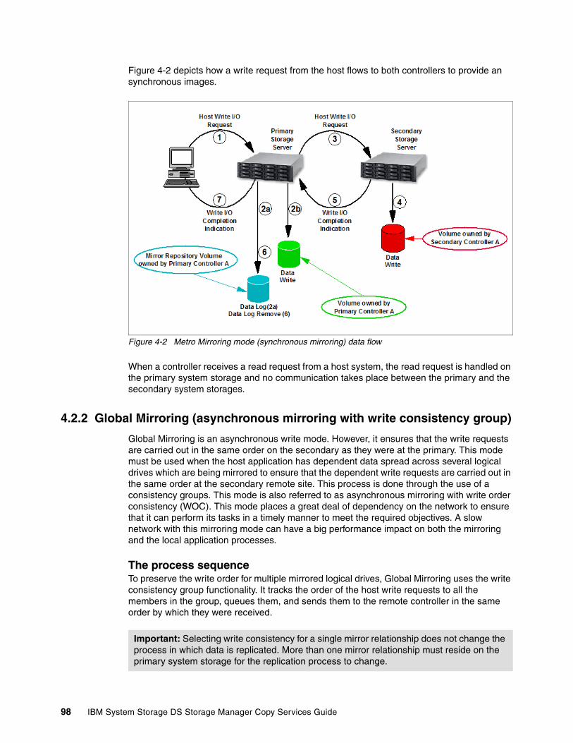
Figure 4-2 depicts how a write request from the host flows to both controllers to provide an synchronous images.
Figure 4-2 Metro Mirroring mode (synchronous mirroring) data flow
When a controller receives a read request from a host system, the read request is handled on the primary system storage and no communication takes place between the primary and the secondary system storages.
4.2.2 Global Mirroring (asynchronous mirroring with write consistency group)
Global Mirroring is an asynchronous write mode. However, it ensures that the write requests are carried out in the same order on the secondary as they were at the primary. This mode must be used when the host application has dependent data spread across several logical drives which are being mirrored to ensure that the dependent write requests are carried out in the same order at the secondary remote site. This process is done through the use of a consistency groups. This mode is also referred to as asynchronous mirroring with write order consistency (WOC). This mode places a great deal of dependency on the network to ensure that it can perform its tasks in a timely manner to meet the required objectives. A slow network with this mirroring mode can have a big performance impact on both the mirroring and the local application processes.
The process sequenceTo preserve the write order for multiple mirrored logical drives, Global Mirroring uses the write consistency group functionality. It tracks the order of the host write requests to all the members in the group, queues them, and sends them to the remote controller in the same order by which they were received.
Important: Selecting write consistency for a single mirror relationship does not change the process in which data is replicated. More than one mirror relationship must reside on the primary system storage for the replication process to change.
98 IBM System Storage DS Storage Manager Copy Services Guide

The logical drives for which the write request order must be preserved must be defined as members of a write consistency group. The write consistency group can be defined from the Storage Manager GUI.
When a primary controller (the controller owner of the primary logical drive) receives a write request from a host, the controller first logs information about the write on the mirror repository logical drive. It then writes the data to the primary logical drive. The controller then initiates a remote write operation to copy the affected data blocks to the secondary logical drive at the remote site. The remote write request order corresponds to the host write request order.
It should be understood that membership in the write consistency group with other logical drives creates an interdependency between them that might not have existed prior. For this reason, keeping membership of this group limited to only those mirrors that have a requirement to be linked by their consistency can be important to the success of the solution. Additionally, having multiple applications that require their logical drives to be consistent in the same group can impact a number of production applications across a number of separate hosts.
After the host write to the primary logical drive is completed and the data has been copied to the secondary logical drive at the remote site, the controller removes the log record from the mirror repository logical drive. See Figure 4-3 for a logical view of the data flow.
Figure 4-3 Global Mirroring logical data flow
The mirror repository logical drive has a queue for up to 128 I/O requests per logical drive. Until the maximum number has been reached, the mirrored pair state is said to be in a
Important: Care should be taken when developing a consistency group to ensure a true need exists between the members of the group. Mixing host applications in a group can place an interdependency on them that previously might not have existed.
Chapter 4. Enhanced Remote Mirroring (ERM) concepts, planning, and design 99
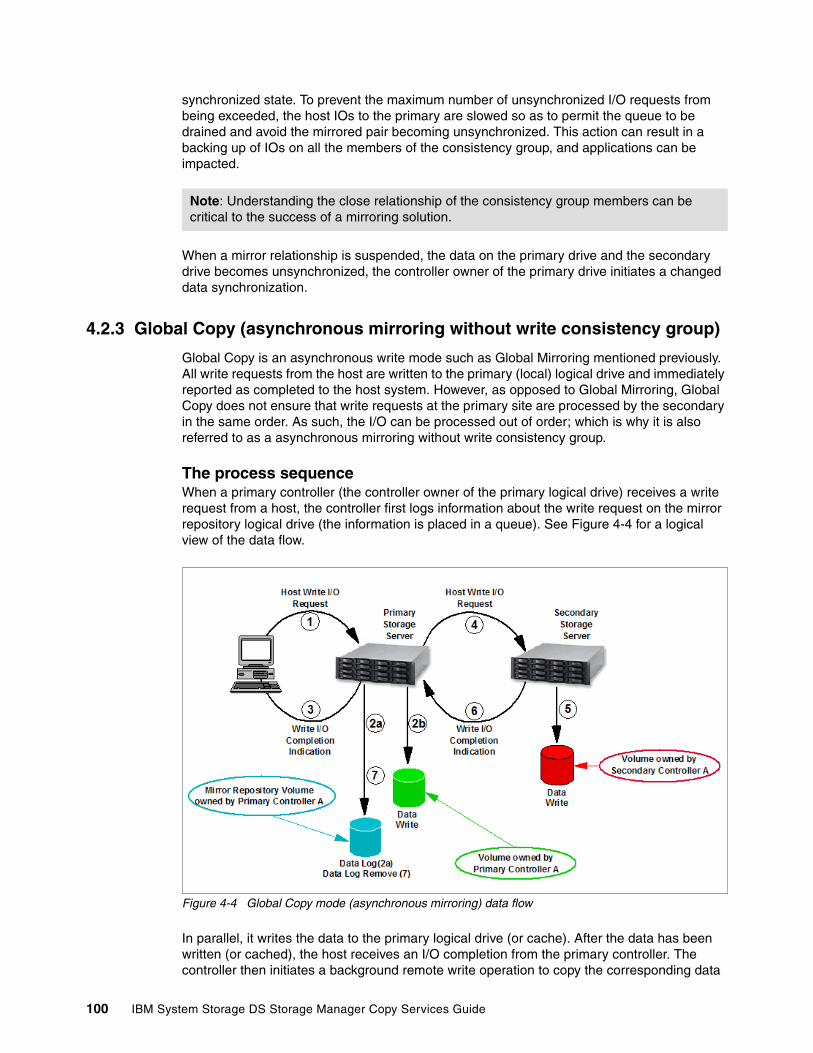
synchronized state. To prevent the maximum number of unsynchronized I/O requests from being exceeded, the host IOs to the primary are slowed so as to permit the queue to be drained and avoid the mirrored pair becoming unsynchronized. This action can result in a backing up of IOs on all the members of the consistency group, and applications can be impacted.
When a mirror relationship is suspended, the data on the primary drive and the secondary drive becomes unsynchronized, the controller owner of the primary drive initiates a changed data synchronization.
4.2.3 Global Copy (asynchronous mirroring without write consistency group)
Global Copy is an asynchronous write mode such as Global Mirroring mentioned previously. All write requests from the host are written to the primary (local) logical drive and immediately reported as completed to the host system. However, as opposed to Global Mirroring, Global Copy does not ensure that write requests at the primary site are processed by the secondary in the same order. As such, the I/O can be processed out of order; which is why it is also referred to as a asynchronous mirroring without write consistency group.
The process sequenceWhen a primary controller (the controller owner of the primary logical drive) receives a write request from a host, the controller first logs information about the write request on the mirror repository logical drive (the information is placed in a queue). See Figure 4-4 for a logical view of the data flow.
Figure 4-4 Global Copy mode (asynchronous mirroring) data flow
In parallel, it writes the data to the primary logical drive (or cache). After the data has been written (or cached), the host receives an I/O completion from the primary controller. The controller then initiates a background remote write operation to copy the corresponding data
Note: Understanding the close relationship of the consistency group members can be critical to the success of a mirroring solution.
100 IBM System Storage DS Storage Manager Copy Services Guide

blocks to the secondary logical drive at the remote site. After the data has been copied to the secondary logical drive at the remote site (or cached), the primary controller removes the log record on the mirror repository logical drive (delete from the queue).
When multiple mirror relationships are defined on the system storage, the background synchronization of affected data blocks between the primary and secondary controller for the various relationships are conducted in parallel (a multi-threaded process). Thus, the write order for multiple volumes (for example, write requests to a database data volume and a database log volume on a data base server) is not guaranteed with Global Copy mode.
When write caching is enabled on either the primary or the secondary logical drive, the I/O completion is sent when data is in the cache on the site (primary or secondary) where write caching is enabled. When write caching is disabled on either the primary or the secondary logical drive, the I/O completion is not sent until the data has been stored to physical media on that site.
The host can continue to issue write requests to the primary logical drive, but remote writes to the secondary logical drive will be from the delta mode during this period. The new requests are stored in the Remote Mirror repository on the primary site in the delta log bitmap. When using mirroring across a minimally configured network Global Copy can be used to perform replication tasks where Metro Mirror and Global Mirror will fail due to insufficient bandwidth.
4.2.4 Other ERM capabilities and functions
For the primary and secondary logical drives that form a mirror pair, ERM supports a variety of capabilities, functions, features, and mirroring options as follows:
� Bidirectional mirroring capabilities
With ERM both DS system storage can be operating in the primary and secondary role at the same time. This allows both ends to provide a backup to the other for DR solutions.
� Existence of multiple mirroring relationships with multiple subsystems
This capability enables a central DR site to be the secondary for multiple satellite locations. However, a logical drive member can only be a member of one mirror relationship at a time.
� Read-only access to secondary mirrored logical drives at the remote site
With this capability the secondary target can be mounted onto a system as a “read-only” drive and have checks performed on it. This also enables the secondary to be FlashCopied during a short warm-stop operation and returned to the application when a complete point-in-time (PiT) VolumeCopy is created from the FlashCopy image. Allowing these backup and recovery operations to be performed on the secondary, relieving overhead on the primary.
� Automatic and manual suspension and resume capabilities
This capability allows for the mirrored network to recover automatically from a network outage and catch up its synchronization of mirrored pairs. You can also manually suspend
Note: The mirror repository logical drive can queue up to 128 I/O requests. Until the maximum number has been reached, the mirrored pair state is said to be in a synchronized state. If the maximum number of queued I/O requests is exceeded, the state of the mirrored pair changes to unsynchronized. When this occurs the Global Copy mode drops into the delta update process, and performs bitmap updates until such time as the queued I/Os are caught up.
Chapter 4. Enhanced Remote Mirroring (ERM) concepts, planning, and design 101

the mirroring for the creation of completely synchronized PiT copies, which are created using the read capability previously mentioned and the FlashCopy feature.
� Delta resynchronization after a suspend and resume
A resume operation synchronizes only the data written to the primary logical drive when the mirror was stopped (resynchronization), including a mirror that was manually halted (suspend) or dropped because of unplanned loss of remote communication. This process is made possible by a delta log that keeps track of changes to the primary volume during a communication interruption (planned or unplanned).
� Dynamic mode switching
You can switch among the various mirroring modes at any time for an established mirror relationship. This is called dynamic mode switching. You can switch between the following modes:
– Metro Mirroring (synchronous write mode)– Global Mirroring (asynchronous write mode with write consistency group)– Global Copy (asynchronous write mode without write consistency group)
This feature can be used to help recover from temporary high I/O peaks that can cause mirroring performance or host side issues with low bandwidth environments by switching to Global Copy. When switching from Global Copy to Global Mirroring or Metro Mirroring you must first be synchronized. See “Dynamic mode switching” on page 130
� Role reversal
In the event of a site failure or for maintenance, you can change the role of a logical drive in a given mirror relationship from primary to secondary and vice versa. When the role is reversed, the new primary logical drive can have write permission granted or denied to hosts that are mapped for access to them. This feature requires the mirror be synchronized prior to the reversal function being performed or data loss can occur. See “Role reversal” on page 131.
� Suspend mirror and resume mirror capabilities
This function allows you to suspend the mirroring process independently of the mirroring mode. When in a suspended state, the secondary subsystem no longer receives any write I/Os from the primary subsystem, and all data blocks that change are logged in a special volume (logical drive) called the mirroring repository volume (see 4.3, “Mirror repository logical drives” on page 104).
In this state the data on the secondary logical drive is not changing, and you can access the secondary logical drive to see if it is consistent as long as you are only performing read operations to this device. As long as the mirrored pair is still defined to each other, there cannot be any writes performed on the secondary logical drive.
To resume the mirroring, invoke the resume mirror function. This causes the pair to resynchronize any changes that were done on the primary to the secondary logical drive. No full synchronization needs to take place, as the only changes made are again recorded to the delta bitmap for updating.
� Test Mirror Communication function
After the mirroring relationship between the primary and the secondary logical drive is established, it is possible and easy to test the mirror communication status. Using the Storage Manager (SM) graphical user interface (GUI) client, you can perform the test with only one mouse click, and the result is graphically displayed (green or red traffic light picture).
Designing a robust and effective ERM solution relies on understanding the need, capabilities, and the requirements; and planning, selecting and implementing the appropriate parts and
102 IBM System Storage DS Storage Manager Copy Services Guide
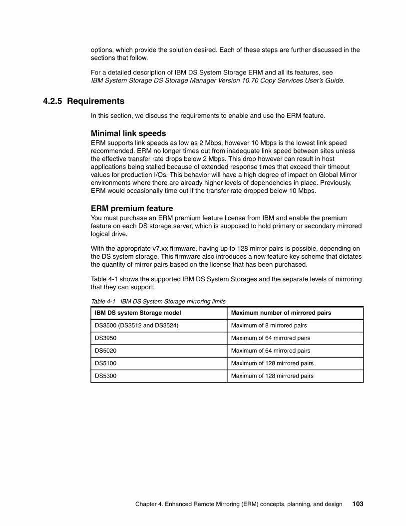
options, which provide the solution desired. Each of these steps are further discussed in the sections that follow.
For a detailed description of IBM DS System Storage ERM and all its features, see IBM System Storage DS Storage Manager Version 10.70 Copy Services User’s Guide.
4.2.5 Requirements
In this section, we discuss the requirements to enable and use the ERM feature.
Minimal link speedsERM supports link speeds as low as 2 Mbps, however 10 Mbps is the lowest link speed recommended. ERM no longer times out from inadequate link speed between sites unless the effective transfer rate drops below 2 Mbps. This drop however can result in host applications being stalled because of extended response times that exceed their timeout values for production I/Os. This behavior will have a high degree of impact on Global Mirror environments where there are already higher levels of dependencies in place. Previously, ERM would occasionally time out if the transfer rate dropped below 10 Mbps.
ERM premium featureYou must purchase an ERM premium feature license from IBM and enable the premium feature on each DS storage server, which is supposed to hold primary or secondary mirrored logical drive.
With the appropriate v7.xx firmware, having up to 128 mirror pairs is possible, depending on the DS system storage. This firmware also introduces a new feature key scheme that dictates the quantity of mirror pairs based on the license that has been purchased.
Table 4-1 shows the supported IBM DS System Storages and the separate levels of mirroring that they can support.
Table 4-1 IBM DS System Storage mirroring limits
IBM DS system Storage model Maximum number of mirrored pairs
DS3500 (DS3512 and DS3524) Maximum of 8 mirrored pairs
DS3950 Maximum of 64 mirrored pairs
DS5020 Maximum of 64 mirrored pairs
DS5100 Maximum of 128 mirrored pairs
DS5300 Maximum of 128 mirrored pairs
Chapter 4. Enhanced Remote Mirroring (ERM) concepts, planning, and design 103
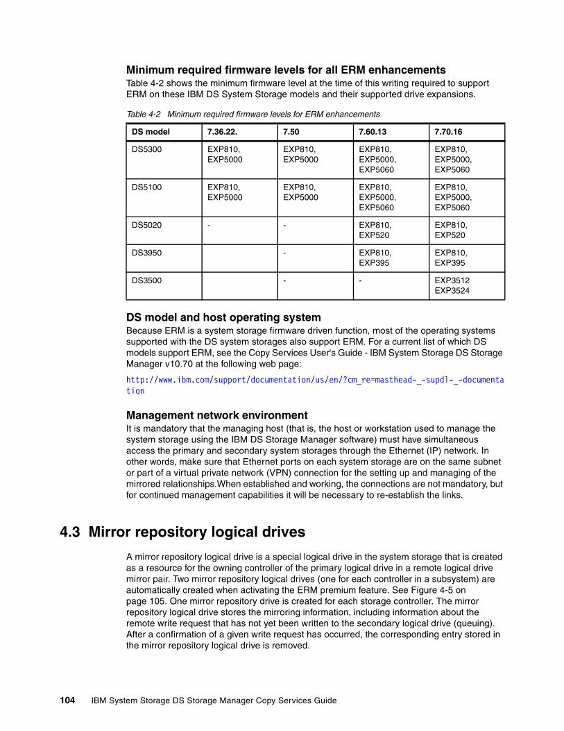
Minimum required firmware levels for all ERM enhancementsTable 4-2 shows the minimum firmware level at the time of this writing required to support ERM on these IBM DS System Storage models and their supported drive expansions.
Table 4-2 Minimum required firmware levels for ERM enhancements
DS model and host operating systemBecause ERM is a system storage firmware driven function, most of the operating systems supported with the DS system storages also support ERM. For a current list of which DS models support ERM, see the Copy Services User's Guide - IBM System Storage DS Storage Manager v10.70 at the following web page:
http://www.ibm.com/support/documentation/us/en/?cm_re=masthead-_-supdl-_-documentation
Management network environmentIt is mandatory that the managing host (that is, the host or workstation used to manage the system storage using the IBM DS Storage Manager software) must have simultaneous access the primary and secondary system storages through the Ethernet (IP) network. In other words, make sure that Ethernet ports on each system storage are on the same subnet or part of a virtual private network (VPN) connection for the setting up and managing of the mirrored relationships.When established and working, the connections are not mandatory, but for continued management capabilities it will be necessary to re-establish the links.
4.3 Mirror repository logical drives
A mirror repository logical drive is a special logical drive in the system storage that is created as a resource for the owning controller of the primary logical drive in a remote logical drive mirror pair. Two mirror repository logical drives (one for each controller in a subsystem) are automatically created when activating the ERM premium feature. See Figure 4-5 on page 105. One mirror repository drive is created for each storage controller. The mirror repository logical drive stores the mirroring information, including information about the remote write request that has not yet been written to the secondary logical drive (queuing). After a confirmation of a given write request has occurred, the corresponding entry stored in the mirror repository logical drive is removed.
DS model 7.36.22. 7.50 7.60.13 7.70.16
DS5300 EXP810, EXP5000
EXP810, EXP5000
EXP810, EXP5000, EXP5060
EXP810, EXP5000, EXP5060
DS5100 EXP810, EXP5000
EXP810, EXP5000
EXP810, EXP5000, EXP5060
EXP810, EXP5000, EXP5060
DS5020 - - EXP810, EXP520
EXP810, EXP520
DS3950 - EXP810, EXP395
EXP810, EXP395
DS3500 - - EXP3512 EXP3524
104 IBM System Storage DS Storage Manager Copy Services Guide

Figure 4-5 Mirror repository logical drives after activating ERM feature
The mirroring process for all primary drives that are defined on a storage controller is monitored by the corresponding controller’s mirror repository drive.
Note: Two mirror repository logical drives are created, one for each controller, in every system storage that has Enhanced Remote Mirroring activated.
No actual host data is written to the repository logical drive. It is only used for status and control data in relation to the Enhanced Remote Mirroring relationships.
Chapter 4. Enhanced Remote Mirroring (ERM) concepts, planning, and design 105

The current capacity is set at 129.094 MB for each repository logical drive. The segment size is set at 32 KB (or 64 blocks). The repository logical drive capacity, segment size, and modification priority are defined by the controller’s firmware and cannot be changed.
4.4 Primary and secondary logical drives
To create an ERM relationship, a mirrored logical drive pair is defined and consists of a primary logical drive at the primary system storage and a secondary logical drive at a remote system storage.
A standard logical drive can be defined in only one mirrored logical drive pair.
Figure 4-6 shows that both the primary and secondary logical drive are displayed at the primary site when the pairing is defined, when only the secondary logical drive is displayed at the secondary site. The secondary does show that it is in a relationship with another logical drive so that you can view the details to see with which drive.
Figure 4-6 Primary and secondary volumes on the primary (right) and secondary (left) sites
4.4.1 Logical drive parameters, roles, and maximum number of mirrored pairs
The primary or secondary roles are determined at the logical drive level, not the system storage level. Any given logical drive, however, can exclusively be in either primary or secondary role. In other words, a system storage can have a combination of logical drives in a primary role and other logical drives in a secondary role.
The maximum number of mirror relationships that can be defined on a system storage is the number of established mirrored pairs. The number of pairs is not dependent of the role (primary or secondary) of the logical drives. ERM places no additional restrictions on the number of logical drives that are defined on a system storage beyond those defined by the code level and model of the system storage. With the introduction of firmware v7.10 and later, the maximum supported number of mirror pairs on the DS5100 and DS5300 system storage is 128. For example, you can have defined 64 primary and 64 secondary logical drives on a
106 IBM System Storage DS Storage Manager Copy Services Guide

DS5300, or any other combination (one primary and 127 secondary, two primary and 126 secondary, and so on). For the DS5020 and DS3950, the maximum supported number of mirror pairs is 64 and for the DS3500 models the current maximum is 8. See “ERM premium feature” on page 103 for more information.
Characteristics such as RAID level, caching parameters, and segment size can differ between the primary and the secondary logical drives of an ERM relationship. The mirrored logical drive can be configured on separate expansion enclosure types. Another possibility is to mirror a logical drive in an EXP5000 to a logical drive in an EXP810 or even to a logical drive in an EXP5060 populated with SATA2 disks and vice versa. Care should be taken to ensure that the primary and secondary combination is capable of meeting the solution expectations when selecting the pairing.
Several restrictions apply:
� Only a standard logical drive can participate in a mirroring relationship.� The secondary logical drive must be at least as large as the primary logical drive.� Any given standard logical drive can participate in only one mirror relationship.
Note that separate mirrored pairs can be established between various system storages, allowing for a DR site to be the recovery for more than just one primary location.
Also, in the case of role reversal, the primary and secondary logical drives must be the same size.
4.4.2 Host accessibility of secondary logical drive
When you first create the mirror relationship, all data from the primary logical drive is copied to the remote logical drive (full synchronization).
During the full synchronization, the primary logical drive remains accessible for all normal host I/Os. The secondary logical drive can be mapped to a host and read access is possible. The read/write behavior changes automatically if a role reversal of the logical drive occurs (this applies in both directions: from secondary to primary and vice versa). Keep in mind, however, that because of mapping of LUNs to specific IDs, certain operating systems, such as Windows with dynamic disks, and VMware do not support mapping of identical drives to the same host without special steps being performed to change these mappings.
Also keep in mind that many operating systems such as Windows and AIX write a signature or a dirty bit when mounting a volume. In this case no direct read access is possible. The workaround for these operating systems is to start a FlashCopy of the volume and create a VolumeCopy to a separate logical drive for its use.
4.4.3 Mirrored logical drive controller ownership
Any logical drive belonging to controller A in the primary storage server must be mirrored to a logical drive owned by controller A in the secondary subsystem. The same rule applies for logical drives owned by controller B.
Important: Though a supported configuration, mixing drive performance types can result in performance impacts and is not a general best practice. As a general guideline, both the primary and secondary logical drive should be capable of the same workload performance levels to avoid production impacts.
Chapter 4. Enhanced Remote Mirroring (ERM) concepts, planning, and design 107

A primary controller will only attempt to communicate with its matching controller in the secondary system storage. The controller (A or B) that owns the primary logical drive determines the controller owner of the secondary logical drive. If the primary logical drive is owned by controller A on the primary site, the secondary logical drive is therefore owned by controller A on the secondary side. If the primary controller A cannot communicate with the secondary controller A, no controller ownership changes take place, and the remote mirror link is broken for that logical drive pair.
If an ownership change of the logical drive on the primary site occurs (caused by an I/O path error or administrator interaction), an ownership change of the logical drive on the remote controller takes place with the first write request (from the primary controller to the secondary controller) issued through the mirror connection. A prerequisite is that the ownership transfer on the secondary side occurs and that the Needs Attention status is not displayed.
The logical drive ownership of the secondary controller cannot be changed by either the host or through the GUI. It is entirely controlled by the primary side. If there is a need to move the logical drive to the other controller it must be done by performing the move on the primary system storage.
4.4.4 Deleting a mirrored logical drive
When deleting a primary logical drive, the ERM first deletes the corresponding mirror relationship, then the primary logical drive. If a secondary logical drive must be deleted, the corresponding mirror relationship must be deleted manually prior to the actual deletion of the secondary logical drive.
4.4.5 ERM and dynamic functions
This section describes how dynamic functions are eventually affected by a remote mirroring relationship.
ERM and dynamic volume expansion (DVE)The ERM feature does not restrict the ability to use the DVE function. However, when using DVE on a primary logical drive member of an ERM relationship there is a requirement that the secondary logical drive already be of a size that is equal to or larger than the new size that the primary logical drive will be growing to. If the capacity of the primary logical drive and the capacity of the secondary logical drive both need to be increased in the same way then the secondary must be grown first. The logical drive capacity of the secondary logical drive must be at least the capacity of the primary logical drive at all times. Operating system restrictions to increasing the capacity of a logical drive still remain. Mirror repository drives cannot be increased by DVE.
ERM and dynamic capacity expansion (DCE)The number of disk drives in an array that contain the primary or secondary logical drive can be increased by DCE in the same manner as on the other arrays. The array group sizes of the
Important: The CLI deletes the primary volume without deleting the mirror relationship. The mirror relationship can be removed on the secondary site, after deletion of the primary logical drive through CLI.
Tip: The secondary must be at least the size of the primary or greater. Therefore, always plan for the secondary logical drive to be checked and if needed increased prior to attempting to perform a DVE function to the primary.
108 IBM System Storage DS Storage Manager Copy Services Guide
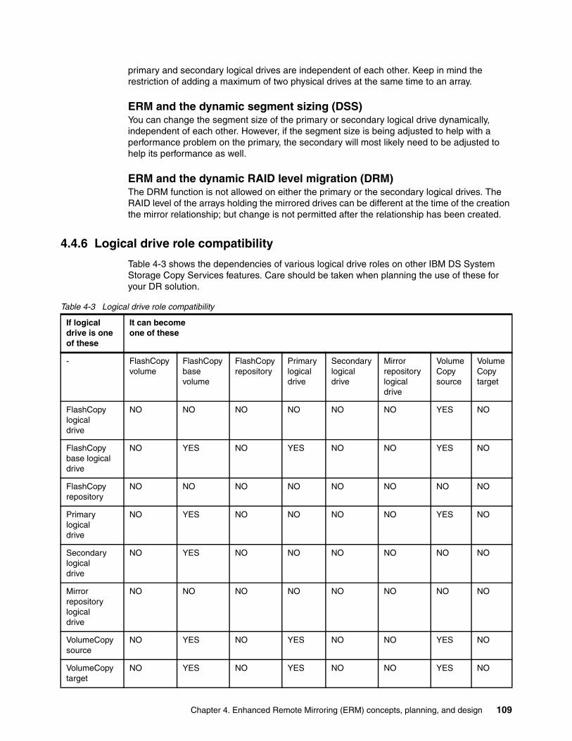
primary and secondary logical drives are independent of each other. Keep in mind the restriction of adding a maximum of two physical drives at the same time to an array.
ERM and the dynamic segment sizing (DSS)You can change the segment size of the primary or secondary logical drive dynamically, independent of each other. However, if the segment size is being adjusted to help with a performance problem on the primary, the secondary will most likely need to be adjusted to help its performance as well.
ERM and the dynamic RAID level migration (DRM)The DRM function is not allowed on either the primary or the secondary logical drives. The RAID level of the arrays holding the mirrored drives can be different at the time of the creation the mirror relationship; but change is not permitted after the relationship has been created.
4.4.6 Logical drive role compatibility
Table 4-3 shows the dependencies of various logical drive roles on other IBM DS System Storage Copy Services features. Care should be taken when planning the use of these for your DR solution.
Table 4-3 Logical drive role compatibility
If logical drive is one of these
It can become one of these
- FlashCopy volume
FlashCopy base volume
FlashCopy repository
Primary logical drive
Secondary logical drive
Mirror repository logical drive
VolumeCopy source
VolumeCopy target
FlashCopylogical drive
NO NO NO NO NO NO YES NO
FlashCopybase logical drive
NO YES NO YES NO NO YES NO
FlashCopyrepository
NO NO NO NO NO NO NO NO
Primarylogical drive
NO YES NO NO NO NO YES NO
Secondarylogical drive
NO YES NO NO NO NO NO NO
Mirrorrepositorylogical drive
NO NO NO NO NO NO NO NO
VolumeCopysource
NO YES NO YES NO NO YES NO
VolumeCopytarget
NO YES NO YES NO NO YES NO
Chapter 4. Enhanced Remote Mirroring (ERM) concepts, planning, and design 109

4.4.7 ERM and FlashCopy premium feature
With the ERM premium feature, you can take a FlashCopy of a primary and secondary logical drive (because read access to the secondary logical drive is now possible). Role reversals that cause a primary logical drive to reverse to a secondary logical drive does not fail any associated FlashCopy.
For data consistency, you should prevent the FlashCopy source from write I/Os. This process is fairly straight forward for the primary logical drive, but becomes a bit tricky when the source is the secondary. When flashing the primary logical drive, you must stop the application and flush the write cache entries out to the disks. When flashing the secondary logical drive you must first you must stop the application and flush the write cache entries and ensure that the mirror relationship is completely synchronized (no further I/Os to be processed). Then suspend the mirror relationship and create the FlashCopy image. After the FlashCopy of the secondary drive has been made, the mirroring can be resumed and the application functionality can be restored.
4.4.8 ERM and VolumeCopy premium feature
A primary logical drive can be a source or target logical drive in a VolumeCopy. A secondary logical drive cannot be a source or target logical drive in a VolumeCopy unless it was the primary at the time of the VolumeCopy and a role reversal was initiated after the VolumeCopy process had completed. If a role reversal is initiated during a copy in progress, the copy fails and cannot be restarted.
4.4.9 ERM and storage partitioning premium feature
Storage partitioning is not affected by ERM. You must ensure that you have enough licensed partitions for all of your host attachment needs on both the primary and secondary independently.
Attention: Starting a VolumeCopy for a given primary logical drive sets it to read-only access. The host application or host OS will not be able to issue write requests to this resource during this time period.
110 IBM System Storage DS Storage Manager Copy Services Guide

4.5 Mirror relationship
A mirror relationship is an established mirroring connection between two system storages. It contains the definitions of mirror repository drives and mirroring pairs of the logical drives.
Before you can establish a mirror relationship between two system storages, you must:
� Establish a proper Fibre Channel fabric network between the two IBM DS system storages, and an Ethernet communication link between the IBM DS Storage Manager client server and both of the system storages.
� Enable the ERM premium feature on both system storages.
� Activate the ERM function on both system storages. This step creates the mirror repository drives. These two repository drives on each system storage are used for all mirrored logical drives that will ever be created.
� Create a standard logical drive on the remote site with an equal to or greater than capacity of the primary logical drive.
See 4.7, “SAN fabric and Ethernet connectivity” on page 115, for information about ERM communication issues.
Remote Mirror statusThe status of a Remote Mirror indicates whether the data on the primary logical drive is identical (fully synchronized) with data on the secondary logical drive. A mirror status is independent of the status of the actual logical drives in the mirrored pair. The primary and secondary logical drive icons in the logical view indicate both the state of the logical drive and the state of the Remote Mirror.
Remote Mirror has four status types:
� Synchronized� Synchronizing� Suspended� Unsynchronized
Attention: You cannot create a mirror relationship if the primary logical drive contains unreadable sectors. Furthermore, if an unreadable sector is discovered during a mirroring operation, the mirror relationship fails.
Chapter 4. Enhanced Remote Mirroring (ERM) concepts, planning, and design 111
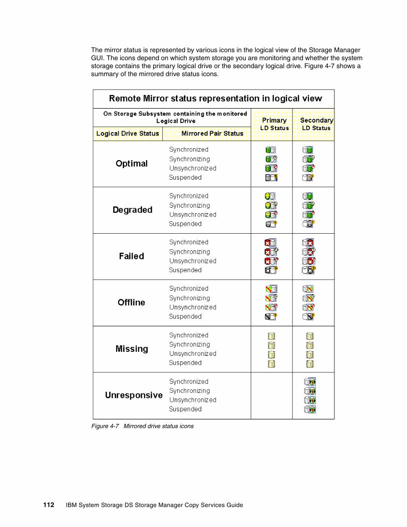
The mirror status is represented by various icons in the logical view of the Storage Manager GUI. The icons depend on which system storage you are monitoring and whether the system storage contains the primary logical drive or the secondary logical drive. Figure 4-7 shows a summary of the mirrored drive status icons.
Figure 4-7 Mirrored drive status icons
112 IBM System Storage DS Storage Manager Copy Services Guide

4.6 Data replication process
This section describes how data is replicated between system storages for the various mirroring modes. Understanding how data flows between the subsystems is critical for setting the appropriate mirroring configuration and performing maintenance tasks.
We previously mentioned that when a new mirror relationship is created, a full synchronization takes place between the primary and the secondary logical drives. This is true for all mirroring modes. We assume here that a mirror relationship has already been established and that the full synchronization is complete and successful. Remember also that data replication between the primary logical drive and the secondary logical drive is managed at the logical drive level. It is transparent to the attached host systems and applications.
In the remainder of this section, we explain the write operation sequences and processes involved for the various ERM mirroring modes:
� Metro Mirroring� Global Mirroring� Global Copy
In any case, data on the secondary logical drive of a mirror relationship can only be changed through the mirroring process. It cannot be changed by the host or manually.
The read operations are identically treated in all three modes because, for a read request, there is no data exchange between the primary and the secondary logical drives.
4.6.1 Data resynchronization process
If a link interruption or logical drive error prevents communication with the secondary system storage, the controller owner of the primary logical drive transitions the mirrored pair into an unsynchronized status and sends an I/O completion to the host that sent the write request. The host can continue to issue write requests to the primary logical drive, but remote writes to the secondary logical drive will not take place. The requests are stored in the Remote Mirror repository on the primary site (delta logging).
When connectivity is restored between the controller owner of the primary logical drive and the controller owner of the secondary logical drive, a resynchronization takes place.
If the mirroring state is changed to suspended (see 5.1.6, “Suspending and resuming a mirror relationship” on page 182), the host can also continue to issue write requests to the primary logical drive.
Two differences exist between the unsynchronized and the suspended states. The first is an error condition indication (see 5.4, “ERM maintenance” on page 205); the second is an administrator-provided status change. The behavior for data resynchronization differs for these two states.
When in a suspended state, the administrator must manually resume the mirroring to return to a synchronized state. The unsynchronized state can either be manually or automatically changed to a synchronized state.
Tip: The mirroring mode can be changed at any time and is called dynamic mode switching.
Chapter 4. Enhanced Remote Mirroring (ERM) concepts, planning, and design 113

Normally, when resuming a mirror relationship or re-establishing the communication between the subsystems, only changed data blocks are sent to the remote site. However, in certain cases, full synchronization of the primary and secondary logical drive is needed:
� Establishing a new mirror relationship between two given logical drives
� Any kind of total failure of the mirror relationship members
� Any kind of mirror repository logical drive failure
� Change of all data block track entries in the mirror repository logical drive when any kind of mirroring communication errors occurred
� Change of all data block track entries in the mirror repository logical drive in suspended state of the mirror relationship
Manual resynchronizationManual resynchronization is the recommended method for resynchronization of an unsynchronized mirror pair because it allows you to manage the resynchronization process in a way that provides the best opportunity for recovering data.
Automatic resynchronizationAutomatic resynchronization starts automatically after the controller detects that communication is restored for an unsynchronized mirrored pair. When the automatic resynchronization option is selected and a communication failure occurs between the primary and the secondary system storages, the controller owner of the primary logical drive starts resynchronizing the primary and the secondary logical drives immediately after detecting that communication has been restored.
Note: Keep in mind the following caveats:
� Data resynchronization is needed when a mirrored pair has become unsynchronized.
� The suspended state is a subset of the unsynchronized state. The specification of the unsynchronized and suspended states lets you differentiate between error (unsynchronized) and maintenance (suspended) conditions of a given mirrored logical drive pair.
� Only the blocks of data that have changed on the primary logical drive during an unsynchronized or a suspended state are copied to the secondary logical drive.
Note: Information about changed data blocks (delta logging) is logged in the mirror repository logical drive. The resynchronization process uses this log to send only the changed data to the remote site. If during the interruption of the mirroring all data blocks on the primary repository logical drive were changed, a full synchronization takes place. The amount of time necessary to change all data blocks on the repository logical drive depends on the number of I/O write requests, application write behavior, and the capacity of the mirror repository logical drive.
Important: Any communication disruptions between the primary and the secondary system storage when resynchronization is underway can result in a mix of new and old data on the secondary logical drive. This can render the data unusable in a disaster recovery situation.
114 IBM System Storage DS Storage Manager Copy Services Guide
4.6.2 Data synchronization priority
Data synchronization priority is a parameter in a mirror relationship that defines the proportion between system resources for host I/Os and system resources used to synchronize data in a given mirror relationship.
You can choose from five synchronization priorities, from lowest to highest, for the primary controller owner. The higher the priority, the more performance impact will occur to host applications.
The synchronization priority is set when creating the Remote Mirror, but can be changed later using the change synchronization settings option. Although the primary controller owner performs the full synchronization and uses the synchronization priority, you can adjust it on either the primary or the secondary, and it will be set for both the primary and secondary logical drives.
For a description of the priority rate settings and an understanding of their impacts, see Table 4-8 on page 130.
4.7 SAN fabric and Ethernet connectivity
For a correct implementation of ERM, several important requirements and rules must be followed regarding Fibre Channel connections and storage area network (SAN) fabric attachment. SAN planning is a critical task and must include SAN ports, SAN zoning, and cabling considerations. This section reviews these SAN considerations and also addresses the Ethernet management network configuration.
SAN environmentTo use ERM, attaching the storage servers to a SAN fabric using Fibre Channel switches or Fibre Channel-IP (FC-IP) routers is mandatory. For detailed implementations for FC-IP routing configuration examples, see IBM System Storage/Brocade Multiprotocol Routing: An Introduction and Implementation, SG24-7544. The ERM Fibre Channel connection must be dedicated for data replication between the subsystems. The ports used for ERM cannot receive I/Os from any host. See the interoperability matrix for choosing supported switch models. The matrix is located at:
http://www.ibm.com/systems/storage/product/interop.html
These requirements are addressed by defining SAN zoning. The zones must separate the host ports from the system storage mirroring ports and also separate the mirroring ports between the redundant controllers. This means that the mirroring ports from pair A (primary and secondary controller A) must be in a separate zone from the mirroring ports from pair B (primary and secondary controller B). Zoning and site configuration examples are provided later in this chapter.
Network informationBecause the network is so important to the overall solution, obtain all required information before the design is finalized. A good practice is to develop a detailed SAN/LAN/WAN
Tip: The name server service of SAN switch is required for ERM communication; this means a switch with (soft) zoning capability. The SAN switch attachment is mandatory. You can have one switch to connect both DS storage subsystems if the distance can be satisfied.
Chapter 4. Enhanced Remote Mirroring (ERM) concepts, planning, and design 115

diagram so that any discrepancies or problems can be discovered early on during implementation.
Required network information can be answered by the following questions:
� What switches are involved (number, layout, type)?
� What is the actual data path to be used for the interconnect between system storages?
� Will the WAN/LAN connection be dedicated or shared?
� How much of the available bandwidth will be used by other applications or users?
� Are any changes planned that might affect available bandwidth?
� What network monitoring tools are available? Can they be made available during implementation?
� How will performance be monitored?
� How will a network failure affect mirroring? Will mirrors be suspended? If so, how long?
ZoningThe connection ports that are used for ERM must be specifically zoned for only the primary and secondary controllers of the mirrored pair to be members. This means that two zones must be created for the ERM environment: one zone should have the primary and secondary controller A as members; a second zone should have primary and secondary controller B as its members. No other members can be in these zones and share them. The ports in these zones must be attached to the last host side port on each controller.
Buffer creditsA Fibre Channel switch uses buffers to allow multiple data frames over a single Fibre Channel link. The more buffers your switch allows, the more frames it can process in a sequence (that is, without requiring acknowledgement between single frames). The amount of buffers is called buffer credit (BBcredit). It is limited by default to a maximum of 16 in a standard Brocade switch, but can be increased slightly.
Specifying the correct number of buffer credits ensures that the Fibre Channel link is running at optimal efficiency in terms of data delivery. When longer distances are involved, the appropriate number of buffer credits becomes important to prevent a networking term called drooping. Drooping occurs when data cannot be sent because the sending system is waiting for the opportunity to send more data through the link. Fibre Channel drooping can be caused by not having enough buffer credits.
The optimal number of buffer credits is a function of bandwidth and distance. A standard Fibre Channel frame contains roughly 2 KB of data. With a link speed of 2 Gbps, and knowing that the frame is moving at the speed of light in the fiber (200,000 kmps), you can calculate that the frame will span over about 2 km. For a 4 Gbps link, this frame will be 1 km long and 500 meters for an 8 Gbps link. To calculate the optimal number of buffer credits that is required to optimize mirroring performance, divide distance between sites by the frame length. If the distance is increasing, more frames can be accommodated on the link and the number of buffer credits should be increased. With the faster Fibre Channel speeds, greater buffer credit settings might be needed to ensure performance.
In any case, consult with your SAN extension provider for details about buffer credits. Certain devices such as the Storage Net Edge Router from CNT/McData (now part of Brocade Communication Systems, Inc.) can handle buffers locally with the FC-device and does not depend on any buffer credits when communicating on long-distance over IP.
116 IBM System Storage DS Storage Manager Copy Services Guide

Fast writesBoth Brocade and Cisco offer with their IP-converters a feature which emulates the remote device locally. This can have functional benefits with streaming requirements, but with transaction oriented random I/O or write oriented striped Logical drives, this functionality might not be of value. Care should be taken when using any of the enhanced switch and router response features; ensuring the consistency of the primary and secondary are a prime concern.
Compression Vendors also offer hardware-based compression for data flow. This is a way to carry more application data within the same I/O limitations imposed by the distance. However, the compression-factor is dictated by the nature of data itself and therefore can vary over time with various applications or workload changes.
Best practicesA useful approach is to create a detailed diagram of the whole SAN/WAN/LAN layout including IP addresses for management ports, data paths, maximum I/O rates, bandwidth on the lines, and contract details, which are defined with the telecommunication providers.
Another good practice is to have monitoring of the telecommunication lines in place. This step can be supplemented with performance monitoring on the storage and networking hardware also.
When contracting with a telecommunication provider, things might not always be that clear; the service level agreements (SLAs) give you a means for insisting on guarantees of availability and support for the network services you buy. A common inclusion with the SLA is a quality of service (QOS) level statement. Although penalties are often not included, this might be something you will really need because your business dependency on the reliability of these communication lines might increase.
In certain cases with shorter distances, another possibility is to use local networking methods that incorporate CWDM or DWDM technology and dedicated fiber for mirroring. But for long distances, the leased line is the solution of choice for cost and design constraints.
However, even with leased lines, the WAN typically is the most expensive component of a DR solution. Cutting cost on the bandwidth might result in the solution not working at all, which means the entire implementation might result in a loss.
4.7.1 SAN fabric and SAN zoning configuration
In this section, we examine the SAN requirements from a general, conceptual standpoint. Detailed information and procedures for implementing the SAN fabric, configuring SAN switches and SAN zones are beyond the scope of this book.
SAN fabric configurationDedicated Remote Mirroring ports (A2 and B2 host-side controller ports) must be attached to a SAN fabric with support for the directory service and name service interfaces. In other words, at least one SAN switch with SAN zoning capability must be installed in the mirroring environment. Because ERM is typically for providing a high-availability solution, a strong recommendation is to use at least two switches in the SAN. For SAN fabric configuration examples, see Figure 4-8 on page 119 and 5.1, “ERM: Step-by-step” on page 156.
Chapter 4. Enhanced Remote Mirroring (ERM) concepts, planning, and design 117

SAN fabric zoningKeeping ERM links and the host links in separate SAN zones is mandatory. A recommendation is that you create separate zones within the fabric (assuming that only two system storages are involved), as follows:
� First zone, for a host connection to controller A� Second zone, for a host connection to controller B� Third zone, for controller A Remote Mirroring links between system storages� Fourth zone, for controller B Remote Mirroring links between system storages
No special recommendation exists for defining the SAN zones. They can be based on either switch ports or worldwide port names (WWPNs). However, for easier maintenance and troubleshooting, do not use mixed zoning definitions (ports and WWPN zones simultaneously), or at least differentiate these across the fabrics (one fabric with port zoning, one with WWPN zoning).
Tip: IBM and other SAN switch vendors recommend configuring two SAN fabrics with independent SAN zones for the highest level of redundancy when implementing ERM.
Note: You can have multiple zones for host connections on each controller, based on the number of connections available. For example, the DS4800 permits up to three host connections per controller, reserving the fourth for the Remote Mirror link.
118 IBM System Storage DS Storage Manager Copy Services Guide

Figure 4-8 shows a basic example of zoning fabrics for a DS5300 Enhanced Remote Mirroring environment. The various colors for cables represent various zones across the network.
Figure 4-8 Basic Enhanced Remote Mirroring fabric configuration and zones
DS system storage Fibre Channel configuration for ERMThe Enhanced Remote Mirroring option requires two dedicated controller host port connections for each system storage that will participate in Enhanced Remote Mirroring.
Chapter 4. Enhanced Remote Mirroring (ERM) concepts, planning, and design 119
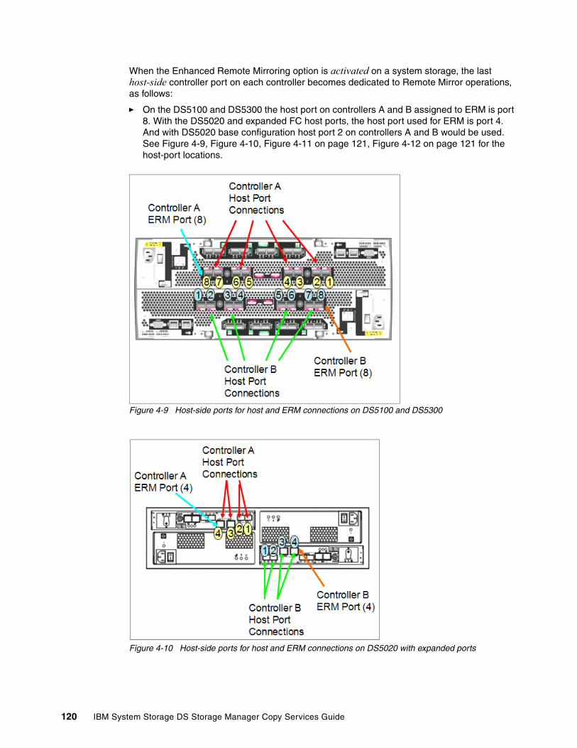
When the Enhanced Remote Mirroring option is activated on a system storage, the last host-side controller port on each controller becomes dedicated to Remote Mirror operations, as follows:
� On the DS5100 and DS5300 the host port on controllers A and B assigned to ERM is port 8. With the DS5020 and expanded FC host ports, the host port used for ERM is port 4. And with DS5020 base configuration host port 2 on controllers A and B would be used. See Figure 4-9, Figure 4-10, Figure 4-11 on page 121, Figure 4-12 on page 121 for the host-port locations.
Figure 4-9 Host-side ports for host and ERM connections on DS5100 and DS5300
Figure 4-10 Host-side ports for host and ERM connections on DS5020 with expanded ports
120 IBM System Storage DS Storage Manager Copy Services Guide

� On the DS5020 with four 4 Gbps FC host ports, use host ports A2 and B2; see Figure 4-11 for the host-side port locations.
Figure 4-11 Host-side ports for host and ERM connections on DS5020 base model
� With the DS3500 you must purchase the FC option to include the FC host interface daughter cards with the controllers. The port assignments for the FC ports are port 3 through 6 (port 1 and port 2 are the built-in SAS ports on the controllers). For ERM you must dedicate FC ports A6 and B6 to the mirroring. on See Figure 4-12 for the port locations.
Figure 4-12 Host-side ports for host and ERM connections on DS3500
After ERM activation, the last host-side controller ports no longer permit host system I/O requests. The persistent reservations are also removed from these ports. The last host-side controller ports are able to communicate only to other system storages that have the Enhanced Remote Mirroring option activated and are connected by the same fabric with a proper SAN zoning configuration.
Chapter 4. Enhanced Remote Mirroring (ERM) concepts, planning, and design 121

The level of redundancy within the fabric depends on the fabric design and Fibre Channel switch configuration. This publication does not specifically address SAN design issues. However, you can find three sample configurations in 5.3, “ERM solution design” on page 200.
Fibre Channel distance limitsThe distance between primary and remote system storages is normally limited by the distance limitations of Fibre Channel inter-switch links (ISLs). See Table 4-4.
Table 4-4 Fibre Channel distance limits
With the Global Copy and Global Mirror Remote Mirroring operating modes, establishing mirroring for distances of more than 5000 km (3200 miles) is now possible. For more information, see “Final thoughts for long-distance ERM” on page 135.
Table 4-5, Table 4-6 on page 123, and Table 4-7 on page 123 show the distance limitations for the various cable types used with the IBM DS Storage family. Note that the maximum distances listed in the tables can be reduced because of low quality fiber, poor terminations, patch panels, and so on.
Table 4-5 For single-mode fiber cables specifications
Fiber cable type Laser type Distance limit (kilometers) Distance limit (miles)
Single mode 9 micron Long wave 10 km 6.25 miles
Multi mode 50 micron Short wave 0.5 km 0.32 mile
Important: The maximum distance for the shortwave small form-factor pluggables (SFPs) affects the maximum connection bandwidth. The SFP automatically changes the connection speed down if the maximum distance for a connection at a higher speed is exceeded (8 Gbps to 4 Gbps, and 4 Gbps to 2 Gbps). It should be noted that newer switch and SFP’s are now running at 8 Gbps and do not support the 1 Gbps speed.
For the shortwave SFP, the maximum length for a 8 Gbps connection (with OM2 cables) is 50 m.
For more information about cable specs and distance limitations, see the following web page:
http://www.t11.org/ftp/t11/member/fc/pi-4/07-155v3.pdf
FC-0 100-SM-LC-L
200-SM-LC-L
400-SM-LC-M
400-SM-LC-L
800-SM-LC-L
Sub clause 6.3 6.3 6.3 6.3 6.3
Operating Range (m)
2 - 10,000 2 - 10,000 2 - 4,000 2 - 10,000 2 - 10,000
Loss Budget (dB)
7.8 7.8 4.8 7.8 6.4a
a. Lower loss fiber is assumed for 8GFC than other speeds.
122 IBM System Storage DS Storage Manager Copy Services Guide

Table 4-6 For multi-mode cables meeting OM2 specifications
Table 4-7 For multi-mode cables meeting OM3 specifications
4.7.2 Ethernet management network configuration for ERM
The managing workstation (with the DS Storage Manager client software) must be able to simultaneously access both sites (primary and secondary) through the Ethernet network. This is mandatory. Ethernet ports from each storage server must be on the same subnet or part of a VPN connection.
As shown in Figure 4-8 on page 119, the best practice is to set up a separate Ethernet management network, isolated from the user LAN. This configuration helps prevent LAN users from unauthorized access to the system storage management functions. It is also better for maintenance.
4.8 Performance considerations
This section contains general performance considerations that apply only in the context of designing a Remote Mirror configuration. Many factors come into play, such as host operating system settings and various application requirements; usually, to tune a configuration for better performance in a given environment, experimentation and observation over time are involved.
4.8.1 ERM in a DR solution
The needs and reasons to mirror data are critical for many customers. Companies might be mandated through regulations to mirror data, they want to maintain a copy of data at a remote
FC-0 100-M5-SN-I 200-M5-SN-I 400-M5-SN-I 800-M5-SN-S
Sub clause 6.4 6.4 6.4 6.4
Data Rate 100 200 400 800
Operating Range (m)
0.5 - 500 0.5 - 300 0.5 - 150 0.5 - 50
Loss Budget (dB)
3.85 2.62 2.06 1.68
FC-0 100-M5E-SN-I 200-M5E-SN-I 400-M5E-SN-I 800-M5E-SN-I
Sub clause 6.4 6.4 6.4 6.4
Data Rate 100 200 400 800
Operating Range (m)
0.5 - 860 0.5 - 500 0.5 - 380 0.5 - 150
Loss Budget (dB)
4.62 3.31 2.88 2.04
Note: For detailed cable and distance specifications, see the Fibre Channel Physical Interface-4 Specifications, which was drafted by the American National Standard for Information Technology Council in agreement with INCITS.
Chapter 4. Enhanced Remote Mirroring (ERM) concepts, planning, and design 123

location without physically shipping tapes, or they might want a method to migrate from one host to another or from one DS system storage to another with as little disruption as possible. As modern business pressures have increased, the requirement for 24-hour data availability has also increased. Many companies need to ensure that critical data is safeguarded against potential disasters and they need ERM as part of a disaster recovery (DR) or business continuity (BC) solution.
In the remainder of this chapter and the next chapter, we review important elements to consider when planning for ERM as part of a DR or BC solution. The focus of these discussions are on ERM. A complete DR solution encompasses much more than just mirroring, and is beyond the scope of this document. For comprehensive information about disaster recovery and business continuity solutions, see:
� IBM System Storage Business Continuity Solutions Overview, SG24-6684� IBM System Storage Business Continuity: Part 1 Planning Guide, SG24-6547� IBM System Storage Business Continuity: Part 2 Solutions Guide, SG24-6548
In any case, before starting your plans for a DR and ERM solution, make sure that you understand the cost and complexity of such an undertaking and have a complete understanding of the expectations that others have of what will be accomplished with the design.
The total price to implement a complete disaster recovery solution is an important test of commitment to pass before moving forward. Price might involve more than finances. It can involve new technical skills and changes to business processes.
DR solutions often require extended periods of time to implement. Establishing executive expectations is critical to successful completion. Unrealistic expectations (such as finishing the project next week or even within a month in many cases) are red flags that need to be addressed promptly by resetting expectations. Timeframes for implementing DR solutions are typically measured in quarters of a year.
The development a company has to undergo to find, design, and implement suitable ways for an adequate disaster recovery solution typically is a project for months. Usually, the difficulty is not just the technical implementation of the disaster recovery solution. It also lies in the necessary inspection of internal processes required to find a clear and structurized way to handle actions and responsibilities across departments or between persons.
The analysis required when planing a disaster recovery solution is an endeavour that is particular to each individual company. This analysis should give the company a better understanding of its data, not just in terms of its size or nature, but also in categorizing and rating data in terms of criticality to their business. After the values and priorities are clarified, the company can begin to work on a plan for disaster recovery, and IBM can provide valuable assistance with this step.
4.8.2 Planning for ERM as part of a DR solution
To prepare and design an ERM networked environment as part of a DR solution, you must understand important parameters and how they relate to each other. These are the distance between sites, the maximum IOPS, the bandwidth required and whether you use a synchronous or asynchronous mirroring method.
Prioritize and characterize the data to be mirroredBecause the amount of data to be mirrored directly affects the bandwidth, analyze the data used by specific applications to determine whether always mirroring all the data is required.
124 IBM System Storage DS Storage Manager Copy Services Guide

For most organizations, differing types of data have different levels of business value, and for DR purposes, they should have differing recovery point objectives and differing recovery time objectives. Assuming that all data has equal value, trying to mirror it equally for DR purposes is usually not realistic. Data mirroring should be prioritized by data value which translates to recovery point objective (RPO) versus time to recover (recovery time objective, or RTO). This is where the business impact analysis (BIA) becomes important.
Types of business data typically range from simple user files and directories to complex database tables, logs, and indices. Each data type has its own set of requirements for integrity and proper recovery. Understanding the types of data to be mirrored and the associated requirements for successful recovery is important.
In particular, with databases, it is usually only necessary for a DR solution to mirror the log files. Assuming that you had initially replicated the database at the remote site, you only need to apply the logs against the database at the remote site. Only replicating what is necessary can have a substantial positive impact on the bandwidth requirements.
For more discussion about bandwidth and distance and how to estimate them, see 4.10, “The Bandwidth Estimator Tool” on page 147.
4.8.3 Design recommendations
Several recommendations apply to ERM in general and others are more specific to a particular type of application, such as a database. In this section, we list them by the system storage that is affected.
Mirroring mode selectionWhen selecting the mode to be used for a mirroring relationship consider how much impact will be seen on the primary host and applications. Metro Mirror and Global Mirror can have major impacts on the primary. Great thought should be used when deciding on the use of these two modes with high numbers of pairs that are supporting a variety of applications (databases, mailservers, fileservers, and so forth). Remember that consistency group membership adds interdependencies to all the members on each other for their performance. Larger logical drives built to handle the entire capacity need might be a better solution to having multiple smaller logical drives in the consistency group.
General mirroring logical drive In a configuration where both mirrored system storages are holding primary and secondary logical drives (cross-mirroring) the count of host I/O requests to a local system storage and the synchronization I/O requests to the remote system storage are the two factors influencing the system’s overall performance.
The write performance of a given logical drive is estimated by four key factors:
� Logical drive cache settings� Performance of a single physical drive in the array in which the logical drive is created� Number of physical drives in the array in which the logical drive is created� RAID level of the array in which the logical drive is created
Important: A single logical drive used by an application can be mirrored using Global Copy mode and is a consistent image with its primary when it is synchronized. Adding this logical drive to the consistency group does not add any benefits, but increases dependencies.
Chapter 4. Enhanced Remote Mirroring (ERM) concepts, planning, and design 125
Balance resources among the mirrored logical drives:
� Write cache settings should be the same on both storage servers.
� Do not configure read cache for secondary logical drives.
� Use as many drives as you can get to create primary and secondary array behave equally.
� If the write cache is disabled for the secondary logical drive, use more disks (than on the primary site) to create the array for the secondary logical drive.
� Use at least as strong a performing RAID level for the secondary logical drives receiving data from the primary logical drive to balance the performance. What RAID level will suite best is dependent on the workload of the primary logical drive.
With the possibility for FC/SATA Drive Intermixing, you might be tempted to mirror data from FC drives to SATA drives; however, you should plan to increase the secondary drive count to encompass the performance hit that comes with the slower drives and consider the workload pattern being all writes at the secondary. It is difficult to build a mirroring solution that is successful with slow target performance.
On the primary storageWhen building an ERM solution, a frequent finding is that the impact on the current (primary) production storage is not fully understood and considered. Consider the following points that affect production storage:
� DS storage ERM reserves the last port of each controller for its own use, reducing the overall bandwidth available between the DS system storage and the host SAN ports. If all the last ports of the DS system storage are currently being used, host port assignments and zoning must be changed to accommodate this restriction.
� A minimum overall 25% overhead on all system resources is needed to support ERM on the primary system storage. This is because of the following additional processes that are being run in the background:
– Double the write I/O operations of the logical drives that are mirrored. Mirroring requires the DS system storage to perform two write operations for every write, requiring a minimum of 25% subsystem resource overhead on the primary system storage. Planning for a larger DS system storage model than what is needed for the production environment is a good practice when planning to add DR support as part of the solution. The additional resources of the larger system can aid in compensating for the added performance needs to cover the impact that might be encountered with the following mirroring functions: when logical drive synchronization is being performed; and when the extra buffer is provided for the continuous mirroring environment.
– Increase the read rate of all logical drives by 25% to account for mirroring latencies, synchronization, and overhead. The data transfer rate, mirroring priority, and network latencies all have an influence, but 25% is a reasonable rule of thumb.
� Other IBM DS System Storage Copy Services features that are being used when remote mirroring is in progress also affect performance. Consider them when sizing the primary system storage. Of particular note are backups that use FlashCopy or VolumeCopy.
– Increase the possible write I/O rate of the mirrored drives at the primary site by 25% if FlashCopy is integrated on the primary site. Increase the read rate by 15% for the same reason.
Note: When using ERM for a remote target or DR solution, FlashCopy and VolumeCopy functions should be performed on the secondary for minimal production impact.
126 IBM System Storage DS Storage Manager Copy Services Guide
� Place the ERM repositories on a separate array of fast disks (15K rpm) that do not contain a mirrored logical drive and is not heavily busy with I/O workload. Doing so can minimize the impact of ERM operations, especially during synchronization operations and when the consistency group is being used.
On the secondary storageFrequently, when an ERM solution is being built, the secondary subsystem is planned and designed for the lowest cost that can be developed. This approach has a large impact on the production storage because of slow secondary performance and mirroring workload being backed up. The secondary storage requires a lot more thought and planning than ensuring capacity to hold the mirrored logical drives.
The remote system storage presents a more complex sizing effort than the primary system storage. Consider the following points about the recovery system storage:
� Remember that one port on each controller is reserved for ERM.
� The logical drives belonging to controller A in the primary storage server must be mirrored to logical drives owned by controller A in the secondary subsystem. The same rule applies for the logical drives owned by controller B.
� ERM has a limit on the number of mirrored pairs supported that varies by DS subsystem model. Consider the limits when sizing solutions:
– DS3500 models support 8 mirrored pairs.– DS5020 and DS3950 support 64 mirror pairs. – DS5100, DS5300 and DS4800 support 128 mirror pairs.
� Remember to compensate for any impact on performance that are caused by DS system storage data replication features.
In addition, ask the following questions about the recovery system storage:
� How many primary systems (locations) are mirroring to the secondary?
� What is the performance expectation in the event of DR failover incident?
� Will more or fewer applications be running on it (compared to the primary system storage) after failover?
� How will post-failover backup affect the DR workload?
� Will it become a new primary system storage for remote mirroring to another site (for example, to facilitate failback)?
� Will the secondary system and logical drives be used for more than a mirror repository for recovery purposes? For example:
– Will it be the location of the production backup facility?
– Will it have its own remote host servers that will be accessing it?
– Is the secondary system storage also a primary system storage for another application?
– Does the secondary mirror its current applications to (act as primary) to another system storage, or back to the original primary (bidirectional mirroring)?
– Will it be used to provide DR operational storage environment from where the applications can be run?
• What is the recovery point objective expected?• What is the recovery time objective expected?
Chapter 4. Enhanced Remote Mirroring (ERM) concepts, planning, and design 127

Secondary drivesIf the recovery mirrors are expected to perform as well as the primary logical drives, the same drive type, count, and sizing used for the primary production workloads must be applied to the secondary system storage. Using either a slower or a larger drive type to house multiple secondary logical drives can result in mirroring failures because of workload model, drive saturation, or I/O queuing issues.
In addition to the initial mirror is the additional space to allow for meeting desired recovery time objectives (RTO) to be met. In many cases trying to meet the RTO can come down to cost.
Several guidelines for choosing the appropriate amount of storage for your secondary site are as follows:
� The same initial capacity (1X) is for the continuous mirroring of production logical disks that takes place prior to failover.
� You must have another equivalent of the initial capacity (2X) to sustain a second copy of point-in-time mirrors. This addition enables database roll-forward capability in case a corruption of the database at the primary site is mirrored to the recovery site.
� You must have yet another equivalent of the initial capacity (3X) to replicate the mirrored logical disks for testing or online backup.
� An additional 20% (0.2X) provides incremental capacity to enable FlashCopy for the mirrored logical disks.
The 320% increase enables all items in the list (that is, the increase provides capacity for the ERM mirrors, a point-in-time copy for fall-back, space to copy the database for testing or backup, and capacity for FlashCopy repositories).
In other words, if 10 TB of production data at the primary site is to be mirrored and put into production at the recovery site after failover, the recovery system storage should have at least 32 TB of capacity, with enough spindles (physical disks) to meet performance expectations.
It is not unusual is to have a smaller system storage at the recovery site because the applications running at the primary side might not be necessary in the event of a site failure. This is why it is so important to determine what data will be mirrored and what applications will actually need to run at the remote site.
However, after a failover, the recovery site is expected to mirror the data back for failback operations or to another site for further mirror protection, the recovery system storage must be sized accordingly. It will, in fact, function as a primary system storage in the new data mirroring scheme, which is separate from the first with its own mirrored pairs and logical drive members, and therefore must have its sizing altered accordingly to meet the rules outlined in “Primary system storage” on page 95.
If the data stored on the primary system is being mirrored to a bunker site instead of a recovery site, performance is not as important as price. This is the only case where SATA drives should be considered for remote mirrors. A bunker site is typically used for online
Tip: When mirroring critical data in a high transaction environment, use the same drive type for the secondary target logical drives.
Tip: The capacity sizing for production work at the recovery site must be multiplied by a factor of at least 3.2.
128 IBM System Storage DS Storage Manager Copy Services Guide
archiving, data mining or centralized backup, and the appropriate sizing rules apply. Care should be taken to not decrease the drive count to a level that impacts the ability of the mirroring mode to keep up with the change rate.
Assess current and future storage needs When adding ERM to an existing DS storage solution, consider the following questions:
� Is the data already stored on DS system storage?
� Will it have to be migrated from the current system storage to a newer system storage?
� Are firmware levels up to date, and supportive of ERM?
� What about future storage growth needs? Most likely growth will require additional capacity, but how much?
� Will additional DS system storage be required in the future?
To keep costs down, you might want to start with DS3500 or DS5020s and upgrade to DS5100s or DS5300s as growth takes place. However, a complete review of the storage plan and long term goals might show that a DS5100 is the better solution to meet the goals. Remember to consider the overhead needs.
Synchronization priorityThe controller owner of a primary logical drive performs a synchronization in the background when processing local I/O write operations to the primary logical drive and associated remote write operations to the secondary logical drive.
Because the synchronization diverts controller processing resources from I/O activity, it can have a performance impact to the host application. The synchronization priority defines how much processing time is allocated for synchronization activities relative to system performance.
If for any reason a link drop occurs and the mirror goes into the suspended state until the link is re-established, a full resynchronization will be required and will depend on the available bandwidth. There is also a strong dependency on the synchronization settings: When changing the synchronization setting from medium (that is the default) to highest, a reduction in the time required for re-synchronistation can be observed of up to a factor of 10. Therefore, a recommendation is set the synchronization to the highest value when manually restarting the link after a failure, and a quick re-synchronization period is what you want.
Chapter 4. Enhanced Remote Mirroring (ERM) concepts, planning, and design 129

Table 4-8 lists priority rates and describes the goal for each setting.
Table 4-8 Priority rates
Many other factors can affect the resynchronization time of a mirrored relationship. The rate of change on the LUN can be affected by issues with the FC pipe and switches, networks, stacking of mirrors that are resynchronizing, and I/O workload. These variables, and others, can affect the completion time or production performance.
Dynamic mode switchingOne of the interesting features of the DS storage ERM is that you can dynamically switch between the various mirroring modes (from Metro Mirror to Global Mirror or Global Copy and vice versa). The feature is also useful if a network problem results in degraded network bandwidth as it can allow mirroring to run more efficiently when the bandwidth is in its limited state.
When changing the mode, the mirrored pair first performs whatever actions are required to reach an acceptable state to switch. If for example, the previous mode was Global Mirror and the new mode is to be Metro Mirror, any I/O operations that are in the queue are performed and completed before the new mode begins functioning. This can result in the mirror reporting an unsynchronized state when it is cleaning up the outstanding I/O’s. On the other hand, if for example the change was from Global Mirror to Global Copy the queued I/Os would
Rate Description
Lowest The goal is to have the absolute least impact on the performance of the production workload, with the resynchronization time being able to take as long as needed. This setting has a built-in delay of 3900 ms to ensure that maximum resources are available to the production workload.
Low The goal is to have a low impact on the production workload, with the resynchronization time being able to complete in less time than that needed for the lowest priority rate. This setting has a built-in delay of 2600 ms to ensure substantial resources are allotted to the production workload.
Medium The goal is to lower the impact on the production workload but still improve the resynchronization time and shorten the time to complete. This setting has a built-in delay of 1300 ms to give better resource availability to the production workload.
High The goal is to complete the resynchronization in a reasonable period of time without an unreasonable amount of impact on the production workload. This setting has a built-in delay of 750 ms to allow good resource availability to the production workload.
Highest The goal is to complete the resynchronization in a short period of time without any consideration of impact on the production workload. This setting has no built-in delay and is recommended to be used when the resynchronization is the major concern (for example during an outage window) and host I/O performance is of least concern.
Important: The data synchronization priority parameter is only used during the data resynchronization process. Data resynchronization is needed any time that a mirrored pair becomes unsynchronized. The data resynchronization process can be started manually (resuming Remote Mirroring) or automatically depending on synchronization settings for a given mirrored pair.
Because the suspended state is a sub-state of the unsynchronized state, the synchronization priority is also used when resuming mirroring from a suspended to a synchronized state.
130 IBM System Storage DS Storage Manager Copy Services Guide
be handled in the normal operation of the Global Copy process and as long as the 128 I/O queue has not been exceeded the Async Copy mode would report as synchronized.
Role reversalAnother feature of the DS storage ERM is its ability to reverse roles of the primary and secondary mirrors. Role reversal allows the secondary to become the primary storage, which is useful when the primary storage must be down for an extended period of time, or for when updates must be passed back up to the primary after it has been out of service. For a stable and synchronized transition, role reversal requires that the two mirrors first be synchronized, and that the host I/O be halted and flushed before the reversal is performed. The following procedure is a step by step guide outlining the process to perform this operation:
1. Wait for processing on the host server to complete.
2. Flush all I/O from host server to system storage.
3. Ensure that all I/O requests have been recorded on secondary (no I/O in queue or flight).
4. Change replication direction.
5. Verify fabric configuration (the right ports on the right fabric) for host connections to secondary.
6. Restart host application using the secondary logical drive as primary.
7. Confirm application data integrity on the secondary.
8. Repeat these steps to reverse replication direction to original primary.
4.8.4 Network latency and bandwidth considerations
One of the most important aspects of designing a successful ERM (and DR) solution is properly sizing the network that connects the primary and secondary sites. In this section, we discuss the major concerns to consider, from the networking perspective.
LatencyLatency is the amount of time for a mirrored I/O and its acknowledgment to traverse a network link. The longer the distance travelled between primary and recovery sites, the more time it takes to send the data and receive an acknowledgement. Distance becomes a limiting factor for the number of I/Os that can be sent per second. Therefore, latency is the controlling factor for I/O rate that can be supported in a disaster recovery solution. Latency is also impacted by the number of hops and equipment that are being used to provide the path. Calculations of projected latency can be made, but only true round trip measurements are accurate. One method that is commonly used to measure the actual latency of a network is to use a ping command.
Attention: Care should be taken to ensure that the current state and mode’s behavior can be better served by the planned mode and benefits the mirror solution and not have a negative impact.
Attention: It is critical to ensure all I/Os are properly flushed all the way out to the secondary logical drive prior to reversing the roles as data loss will occur if not complete.
Tip: Use the IBM DS Storage Manager Performance Monitor to observe I/O operations that are taking place on the primary and secondary logical drives to determine when all I/Os are complete and it is safe to reverse the roles.
Chapter 4. Enhanced Remote Mirroring (ERM) concepts, planning, and design 131

Distance and maximum IOPSIn a remote mirroring solution the effective transfer rate between sites has to be taken into account in comparison to the nominal link speed.
What limits the effective transfer rate from the nominal link speed? The most important factor usually is the total latency on the link. These latencies are the result of delays that are introduced by the equipment (switches, protocol converters for IP, firewalls) and the transport medium itself. The latency in the transport medium itself is determined by the finite speed of the light in the glass fiber. The effective speed of light in the fiber is about 200,000 kmps. This is a fundamental constant in an ERM (and DR) solution, and its impact gets stronger as the distance between sites increases. Figure 4-13 shows the correlation between the distance separating the sites and the latency of the link. Remember also that with a synchronous mirroring method, the signal (light) must travel the distance between sites twice (to there and back) for an I/O to complete before the host will receive its acknowledgement.
Figure 4-13 Maximum I/O by distance
The chart also displays the maximum theoretical input/output operations per second (IOPS) that can be sustained. Again, there is a direct, linear correlation between IOPS and the distance. To understand the correlation, think of the following situation:
Assuming a synchronous mirroring, an I/O is started at time t=t0 and begins its way through the fiber until it reaches the other site after t1. The remote site sends an I/O completion back, and it again takes t1 to reach the local site. The sum of time taken for (2 x t1) represents the total I/O time, or tIO (tIO is also called round-trip time, RTT). Each I/O originated by a LUN at the local site takes tIO to complete before the next I/O can be sent. In other words, the maximum IOPS is 1/tIO.
For example, if the distance between sites is 100 km, the light needs the following amount of time to get to the remote site, and we have a tIO time of 0.001 seconds:
100 km / 200000 km/s = 0.0005
The maximum IOPS is 1s / 0.001 s = 1000.
Important: The effects of latency can be overcome only by multiplying the number of links that carry mirroring I/Os simultaneously allowing multiple I/O to be in flight at the same time.
132 IBM System Storage DS Storage Manager Copy Services Guide
The chart shows the theoretical limitations of a remote mirroring relationship of a single LUN that works in a synchronous mode. It is of general meaning and does not reflect only the theoretical limitations of a DS storage ERM implementation.
The chart represents the theoretical, best-case maximum for a round trip operation. It does not reflect the actual synchronous remote mirroring relationship, as it does not account for other limiting elements such as switches and IP converters and the actual storage operation itself, which all introduce additional latencies to the complete mirroring operation.
Be aware of the additional latencies inherent to an IP network. An IP network is often used for long-distance mirroring. In this case the quality of the IP network becomes a critical part of the overall remote mirroring solution. Make sure that the IP network delivers the required service level. A good, professional approach is to work with your supplier for IP converters and your telecommunication provider. They can act as agents who have the experience and knowledge to measure the quality and reliability of an IP network and check the fulfillment of such guarantees. These guarantees are commonly known as quality of service (QOS) level guarantees.
Distance is a crucial element and essential design point of an ERM solution. As the previous chart shows, distance limits IOPS in a synchronous mirroring environment and can have a substantial negative affect on intense I/O applications such as transaction processing and database operations.
With an asynchronous mirroring solution, longer distances are generally encountered and and thus a smaller number of IOPS can be performed. This limitation impacts the recovery point objective (RPO) of your DR solution and might require creative design to build a solution that meets the need.
Distance also affects the implementation cost. For short distances in up to 10 Km, the infrastructure costs are far lower than the costs of an implementation with a distance between sites measured in hundreds or thousands of miles.
In DR solutions for particular industries, such as banking, government regulations define minimum distances between sites. For others, the cost of providing adequate network bandwidth is the primary consideration. In certain cases, special region-specific conditions must also be considered. For example, in southern California, US, the recovery site should be on a separate tectonic plate than the primary site. But, in London, UK, the recovery site might only have to be blocks away to enable recovery from a terrorist attack or a fire. The potential for flooding and the need to put the sites on separate power grids are two other factors that can dictate a minimum (or maximum) distance.
BandwidthBandwidth defines how much data can be sent through the data link. If bandwidth is inadequate, required throughput can never be achieved.
This becomes a important factor to consider when the network is required to take into consideration the amount of time required to perform initial synchronization, and ongoing resynchronizations for maintenance and backup or FlashCopy operations. Additional
Note: The best method of determining the actual latency of a network is to use a ping command to measure it. Knowing this value can help with problem determination efforts when diagnosing a slow mirror relationship.
Important: The distance between sites is an essential design point of an ERM solution.
Chapter 4. Enhanced Remote Mirroring (ERM) concepts, planning, and design 133
bandwidth might be needed for these tasks to get mirrors synchronized in a reasonable time frame after resuming. If the network is to be shared, sizing for synchronization is especially important because ERM could potentially use all available bandwidth or, worst case, not have enough bandwidth.
When sizing bandwidth, a best practice is to use actual performance measurements. The IBM System Storage DS Storage Manager has a built-in performance monitor that can be used to gather the details of your daily workload which can be used to help with sizing. Your IBM representative has access to a network bandwidth calculator (see 4.10, “The Bandwidth Estimator Tool” on page 147) that can size the minimum bandwidth required for a successful DR solution and set realistic performance expectations.
Table 4-9 shows several industry standard wide area network (WAN) speeds and feeds.
Table 4-9 Bandwidth chart of common WAN networks
Distance and bandwidthIf the connection bandwidth is not sufficient, the throughput required for the mirroring to function well cannot be achieved.
The data link bandwidth requirement encompasses the amount of data that needs to be replicated and the link speed required to provide acceptable performance. Because the amount of data to be mirrored will likely grow (usually at a hefty rate) over time, the link speed must be dynamically adaptable to meet future requirements.
There are several questions to ask when planning:
� What is the minimum bandwidth to provide adequate performance for the distance between sites and the amount of data that is to be mirrored initially?
Important: Bandwidth is typically measured in bits per second: kilobit (Kb), megabit (Mb), or gigabit (Gb) per second (Kbps, Mbps, or Gbps). When you perform sizing calculations, remember that a bit is only one-eighth of a byte. Therefore, divide the network bandwidth (in bits per second) by ten to roughly estimate the equivalent storage rate of bytes per second.
Also remember that, if the data being transmitted is tunneling across TCP/IP, a significant increase in overhead can reduce the effective bandwidth by up to 50%.
Line Type Capacity
T-1 1.544 MbPS 193 KBPS
T-3 43.232 MbPS 5.404 MBPS
OC-3 155.6352 MbPS 19.4544 MBPS
OC12 622.5408 MbPS 77.8176 MBPS
OC48 2490.1632 MbPS 311.2704 MBPS
OC192 9960.6528 MbPS 1245.082 MBPS
Important: Due to the cost involved with bandwidth, it has been found to be the primary cause of mirroring solutions being unsuccessful. Without adequate bandwidth, mirroring solutions cannot meet expectations.
134 IBM System Storage DS Storage Manager Copy Services Guide
� What is the expected rate of growth of the mirrored data?
� What minimum bandwidth is recommended for the expected data growth?
� If the data is being mirrored to an existing site, how much bandwidth is available now? Is it planned to be shared? If so, what portion is available for mirroring today? What will be available in the future?
� Do plans exist to increase the bandwidth? If not, what is required to plan it?
If the data link drops for any reason, mirroring is suspended until the link is re-established. When the link is re-established, the mirrors must resynchronize before they can be used for disaster recovery; this can take a significant amount of time. Make sure that you plan enough bandwidth to cope with resynchronization situations.
Final thoughts for long-distance ERM With Global Copy and Global Mirror operating modes, ERM provides the capability to mirror data over the longer distances. Asynchronous mirroring, combined with the use of devices known as channel extenders, allows replication over distances of more than 5000 km (3200 miles).
The three main characteristics for a connection are:
� Connection bandwidth
Connection bandwidth defines how much information can be transferred over a connection in a given period of time. This is usually measured in bits per second (bps) or bytes per second (Bps). Fibre Channel bandwidths are currently 8 Gbps, 4 Gbps, 2 Gbps, or 1 Gbps. The connection bandwidth must be measured as the lowest level of bandwidth encountered on any leg of the entire end to end link.
� Connection latency
Connection latency specifies how long it takes get a response in return for a request. Most applications expect values of 1–10 ms in a local production environment.
� Connection protocol
Connection protocol is the set of the communication rules that both communication partners must use to understand each other.
For long distance, you could in theory use native Fibre Channel, low-latency, high-bandwidth connections such as dense wavelength division multiplexing (DWDM) or coarse wavelength division multiplexing (CWDM) technologies. But this is only a speculative possibility for most situations because of the connection and equipment costs.
Another possibility is to build a long-distance connection based on Internet topology and TCP/IP protocols. TCP/IP implementations offer good bandwidth (10 Mbps to 1 Gbps) for storage mirroring purposes and can be secured by known and tested technologies such as VPN.
Important: ERM requires dedicated bandwidth for its use. Therefore, avoid sharing the network bandwidth being used for ERM with other networking traffic, which can have a fluctuating QOS as ERM will misinterpret a change in the bandwidth as a link failure and result in mirroring operations being suspended.
Tip: A good ERM design provides enough network bandwidth to minimize resynchronization time.
Chapter 4. Enhanced Remote Mirroring (ERM) concepts, planning, and design 135

The latency is the main issue of using IP connections for storage mirroring. Because of the complexity of the Internet topology and many other various factors, the latency of an IP network does not have a constant value and can Have a large range of variance.
The second issue is the latency value itself. Latency values of about 50–200 ms are common for an Internet connection. Although the storage controller I/O completion acknowledgement timeout can accommodate such latency, many host applications are not designed for this to be the normal response time. Keep in mind that you have not even considered the high I/O rates and possible connection breaks yet.
The solution to circumvent this high latency problem is to use an asynchronous mirroring mode such as Global Copy or Global Mirror for connection based on IP networks.
Even though the mirror repository logical drive can queue up a number of I/O requests, it is best to not use this queuing in your calculations. Using this queue as an extreme emergency buffer is what it is designed for. The queue allows a maximum of 128 write requests per logical drive to be pending between primary and secondary.
During the queuing process, the mirrored pair state remains synchronized. If the maximum number of unsynchronized I/O requests exceeds the queue for the logical drive, the state of the mirrored pair changes to unsynchronized. The time that you have before the mirroring state changes from synchronized to unsynchronized mainly depends on two factors:
� The rate of unsynchronized write requests� I/O write request per second to the primary system storage
For example, if the queue is holding a maximum of 1,024 I/Os and you have an impact of 2,500 I/O write requests per second, the time difference between each I/O is as follows:
1s / 2500 IOPS = 0.4 ms
The period of time that you can hold the synchronized state with your queue can be calculated as follows:
1024 writes * 0.4ms/write = 409.6ms
You can assume that the connection can have a maximum latency of 200 ms (you must send the data and receive the confirmation). The theoretical value that can be assumed for an IP network is about 100 km/ms. In this case you could theoretically have a maximum connection length of 20,000 km. In reality, the value is slightly less because of the unknown number of routing hops, alternate traffic volume, and other factors.
Now you must look at the communication protocol. Channel extenders must be used to route SAN data frames (based on FCP) over a TCP/IP Ethernet Network, and vice versa.
By using Global Copy or Global Mirror ERM mode, configurations with a distance of more than 5,150 km (3200 miles) can be achieved. Lab tests with simulated IP networks have reached a distance of 10,000 km (6200 miles) without synchronization problems.
Note: The queue size is 128 outstanding I/Os per logical drive. For a subsystem with 32 mirrored pairs, the queue length is 128x32=4096. For 64 pairs, it is 8192, and for 128 pairs, it is 16384. A recommendation is to use as many logical drives as possible for ERM long distance to keep the I/Os on one particular logical drive in the smallest possible range.
136 IBM System Storage DS Storage Manager Copy Services Guide

4.8.5 Mirroring connection distance and performance
In most cases distances longer than 10 km (6.25 miles), will want to use asynchronous mirroring due to response time needs of the production environment. Note that distances greater than 10 km (up to 150 km) can be supported in Metro Mirror mode, but support requires a request for price quotation (RPQ).
The maximum distance that can be supported whether using shortwave or longwave SFPs is greater in fabric of 1 Gbps and 2 Gbps speeds than at the 4 Gbps and 8 Gbps speeds (see the tables in “Fibre Channel distance limits” on page 122); however, the throughput is much less. When considering the speed to use it is important to consider the expected resynchronization time desired and the bandwidth required to meet it.
The major performance factor for long-distance solutions is the IP connection bandwidth between the Fibre Channel extenders. If you connect to a 100 Mbps IP network, you are able to transfer about 10 MB of data per second (assuming that the connection is stable).
Note the following caveats:
� Estimate the time needed for the first full synchronization.
� Understand the amount of data that is changing on average on the primary logical drives over a period of time and compare it to the available connection bandwidth.
� Always keep a reserve for unexpected transfer rate peaks.
4.8.6 Application considerations
To optimize your ERM implementation, you can make several decisions or take certain actions at the host or application level.
I/O block sizeAs a rule, make I/O block size as large as possible, when keeping performance acceptable. With a bigger block size you will use less I/O for the same throughput.
Databases and file systems are designed with standard block sizes, which result from balancing the size of a block with server memory caching efficiency. Databases offer the ability to change block size, but the change is a disruptive process. Even so, the database table space is frequently still a smaller I/O than that desired for a ERM type of solution if heavy write change is expected.
File system, database layoutDatabases that make use of a file system for file access can have additional overhead that you should consider when designing and building the ERM (and DR) solution. Specifically, a journaled file system requires additional I/Os because an I/O is staged in the file system
Important: The mirroring network’s performance is only as good as its slowest link. Trunked paths can aid in gaining the bandwidth needed to help increase the performance.
Important: Even if the distances are in the range of shortwave fiber specification, a good practice is to use asynchronous mirroring mode if the system storage is heavily loaded with host I/O requests. The performance of the system storage does not improve by using asynchronous mode but the application performance will be almost unaffected when using Remote Mirroring.
Chapter 4. Enhanced Remote Mirroring (ERM) concepts, planning, and design 137
journal before it is written to the main area on disk. A journaled file system might result in increased cost for the ERM solution if it requires additional network bandwidth.
When possible, avoid file systems and use raw devices to reduce this overhead as much as possible. This might not be important with smaller databases, but it becomes increasingly important as databases grow.
Temporary/scratch files and table spaces When possible, temporary/scratch files and temporary/scratch table spaces should be assigned to a separate logical drive that is not mirrored. These temporary data holders are typically used for reports or data conversions and are not part of the data that has to be mirrored to the recovery site. If mirrored, they will translate to additional I/Os (and possibly additional bandwidth cost) with no advantage in the event of a failover. The database or system administrator can determine whether this condition exists and remedy it.
Another storage object that should not be replicated is the swap file, for the same reasons. In Windows environments, the swap file must be moved from the normal %systemroot% device to another drive if the %systemroot% device is to be replicated. Replicating the %systemroot% device is not recommended, so this might not be an issue.
DR guidelines for databasesThis section describes possibilities for a DR method to be used for a database using ERM. There are several ways to mirror a database for disaster recovery. Each method has advantages and disadvantages. Understanding them will help in designing the best solution for a specific environment.
What needs to be mirrored in a database? The two most popular database mirroring methods are: mirror everything and mirror log files only.
Method 1: Mirror everythingWith this approach, the entire database and the log files are mirrored. The advantage is that massive database updates will normally be handled without additional procedures or resources. There are several disadvantages, however. This approach is more susceptible to problems, it leads to a more complex solution, and it requires more network bandwidth.
A typical sequence of events for mirroring a database and logs is as follows:
1. Establish mirroring for all database logical drives.
2. On a regular basis, perform the following tasks:
a. Put the primary database into hot backup mode.
b. Flush all cached or queued I/O out to primary and secondary to ensure a completely synchronized state is existing for both the mirrored images.
c. Suspend mirroring to the recovery site.
d. Create a FlashCopy of the mirrored image at the recovery site.
e. Resume mirroring between sites.
f. Exit database hot backup mode at the primary site and resume normal operation.
g. Using the FlashCopy, a VolumeCopy image can now be created for data migration tasks or as a DR image for fast recovery time to be achieved.
Important: Mirror only data that is required; place temporary space and swap devices on separate logical drives which are not being mirrored to increase performance and avoid mirroring unnecessary write workload.
138 IBM System Storage DS Storage Manager Copy Services Guide

h. If processing power is available, keep (do not delete) the FlashCopy active.
i. When a future PiT image is needed, create a second FlashCopy to support it.
j. Perform the VolumeCopy creation at scheduled intervals of longer time periods as “full image” rollups; and use the FlashCopyies as incrementals.
Always have at least one FlashCopy/Volumecopy image available at the recovery site in case database corruption at the primary site is mirrored to the recovery site. Having more FlashCopies can allow for images that can be used for data integrity checks. The number of FlashCopies must be weighed against the additional overhead that they place on the secondary mirroring environment, and the subsystem resources that are required to handle them. Having a full VolumeCopy PiT image can allow for rollups to be performed, and protects from data corruption being passed, enabling a fast recovery time objective. FlashCopy is not the full image and requires the secondary mirror to perform more actions on a per write operation basis.
Method 2: Mirror log files onlyUsing this approach, the entire database is replicated to the recovery system storage initially, and placed on a complete separate table space image of logical drives. Then only the log files are mirrored thereafter (until it becomes necessary to replicate the database again). The logs are applied to the database at the remote site. This reduces the bandwidth required for mirroring, but also requires a host server have access to the recovery site to apply the logs. If a massive database change is made, the entire database should be copied over again, which takes time and additional bandwidth temporarily. One significant advantage of this approach is that the two database images are truly separate from each other. In the event of database corruption at the primary site, the database is still intact at the recovery location.
A typical sequence of events for mirroring only log files is as follows:
1. Establish mirroring for all database logical drives.
2. Suspend or remove mirroring of the database when synchronization is complete.
3. Continue mirroring the log files.
4. On a regular basis, perform the following tasks:
a. Put the primary database into hot backup mode.b. Suspend mirroring to the recovery site.c. Create a FlashCopy of the log files at the recovery site.d. Resume mirroring of log files between sites.e. Exit database hot backup mode at the primary site and resume normal operation.f. Using the FlashCopy, apply the log files to the recovery site database.
The FlashCopys can be removed after the log files have been applied. Retain at least one FlashCopy image of the log files.
The log file space on the primary system storage must be able to retain a minimum of 24 hours of logs in case problems occur at the recovery site (such as a failure that prevents the log files from being applied). Another important task is to make sure that the log files are not deleted on the primary side until they have been applied at the recovery side. This can be accomplished with scripts.
RTO and RPO also influence the DR solution design. Must the data be synchronized at all times or can images be sent over the data link in batch mode on a regular basis (for example, hourly or at a shift change)? Can the organization afford to lose an hour or more of work? Must the DR solution provide an RPO within a single transaction? All these questions must be addressed during the RTO and RPO evaluation and answers must be provided in the design.
Chapter 4. Enhanced Remote Mirroring (ERM) concepts, planning, and design 139
Other database guidelinesConsider multiplexing the log files (if this is supported by the database). It can reduce the performance impact. Most databases allow for multiple copies of log files. If the log files are multiplexed (two or three copies of the data instead of just one) and only one log image is replicated, the primary system will have nearly the same performance with replication as it does without it.
In a database environment, the best rule is to place the database logical drives and the log files into the consistency group if Mirror Everything is the method selected. Otherwise, place the log files into the consistency group if you select Mirror Log Files only and the log files span more than one logical drive.
4.8.7 Other design considerations
A DR solution addresses primary site failure by providing failover and recovery at a secondary site. If processing is to be resumed at the primary site at a time in the future, a failback process might be designed into the DR solution. However, failback introduces new requirements for the DR solution design that affect both implementation and testing of the solution.
For example, failback adds the potential of losing transactions beyond the disaster recovery window. Any data with an RPO less than zero is subject to loss during disaster recovery failover and during failback. Failback also causes a second window of application downtime because it takes a finite amount of time to restore any application. The organization must be prepared to handle these realities.
If failback is not needed, testing the DR solution is much easier because failover testing proceeds without taking down the primary systems. Failback testing requires that the primary site be used as a recovery site. Therefore, normal production cannot be continued with the primary systems when failback tests are conducted.
If failback is required, a modified approach might possibly address the testing issue discussed previously. The modified approach is to treat failback as a second failover and test it only after the first failover has occurred. In other words, delay testing failback until recovery has been completed at the secondary site. This involves starting the mirroring process over again from the secondary site that has now taken on primary status. The disadvantage of this approach is that it can take longer to fail over to the original primary site than the failover/failback approach because the new failover process will have to be implemented and tested first. If resources at the secondary site do not provide adequate performance, this extra time might be unacceptable. Planning ahead for this modified approach will minimize the time required to get the original primary site up and running again.
With either approach, there is no guarantee that the original primary site will survive the disaster so that failback or the modified approach described previously can actually be carried out. Therefore, a complete DR solution should plan for the possibility of never resuming operations at the original primary site.
To safely and adequately test failover and failback, multiple servers and large amounts of additional storage are required, which adds to the cost of the overall solution. One way to lessen this cost is to use equipment allocated to another project for the tests and then deploy it for the intended purpose after the planned DR testing exercise has finished.
Keep in mind, however, that DR testing is never complete. There must be an ongoing executive commitment to keep the DR solution current and to do regular testing to ensure that it remains a viable means to business continuity.
140 IBM System Storage DS Storage Manager Copy Services Guide

Failover and failbackThe goal of a DR solution is to provide failover of selected applications to a recovery site that is not critically affected by the disaster. To restore full business operations after the disaster, failback to the primary site or failover to a third site (depending on the status of the primary site) can be required. This is an important consideration that should be factored into the DR solution design. As mentioned previously, failback can be complicated and needs careful planning before implementation and testing begin.
The simplest and preferred way to implement failback is to reverse the pre-disaster process of mirroring. Because the data integrity of primary storage is unknown after a disaster, copying back all of the recovery data to the primary site is necessary. A major concern is the amount of time necessary to perform the mirroring, which can be days or weeks, especially if the database has increased its size substantially since the failover occurred. Regular reviews of failback time requirements ensure that failback time objectives are met. Reducing the time to fail back can require physically moving a fresh backup copy from the recovery site to the primary site. After the database has been restored, mirroring the logs and applying them is accomplished in a much shorter time frame.
Testing failover and failback can be a significant challenge and must be included when you define the DR solution. In many cases, executive management does not want to do the testing, primarily because of the time duration necessary to fail back to the primary site. But these procedures must be tested to verify that they work and to develop efficiency enhancements. Simulating failover is fairly easy and can be tested without a lot of effort. However, simulating failback can be a much more complicated task and requires additional equipment (including additional storage capacity or system storages), which is why failback is often left out of the overall solution.
In cases where a planned failover is needed (for example, evacuating an area that is in the path of an approaching hurricane), shutting down the servers at the primary site, suspending the mirrors, and then reversing the direction of mirroring is an acceptable way to fail over quickly and facilitate rapid failback.
If failover is triggered by an unplanned outage, a complete copy of the recovery database must be restored at the primary site before resuming operations. This is because servers at the primary site will likely be running when the failure occurs, so the two images of the database will not be synchronized. There is no practical way to merge the two images and guarantee data integrity, hence one site or the other must be designated as the master and the other must have its data overwritten with the master image.
Chapter 4. Enhanced Remote Mirroring (ERM) concepts, planning, and design 141
4.9 Site readiness and installation checklist
ERM and DR projects are typically long-term projects. The time scale is months rather than weeks. IBM has developed a checklist for ERM that can serve as an initial project plan. This site readiness and installation checklist can be used together with the tool described in 4.10, “The Bandwidth Estimator Tool” on page 147.
The checklist reveals three phases of a basic project plan:
� Identify key items.
In this phase the physical locations, applications, and logical drives are identified. Also, the corresponding RTO and RPO expectations are set. Questions to ask:
– What locations will be used as primary and secondary sites?– What applications are to be mirrored?– What are the associated volumes (LUNs) to be mirrored?– What are the DR requirements and expectations?
� Measure application workloads.
This phase requires performance measurements of the mirrored logical drives. The measurements are used to calculate the necessary bandwidth.
For more information, see the following resources:
– The calculations can be done by using IBM Bandwidth Estimator Tool, described in 4.10, “The Bandwidth Estimator Tool” on page 147.
– For an overview of methods and tools that can be used to measure performance, see IBM Midrange System Storage Implementation and Best Practices Guide, SG24-6363. Those methods and tools include IOMeter, iostat, PerfMon, PERFMON, the DS system storage Performance Monitor, and the Microsoft Windows Performance Monitor.
– To help you easily collect measurements performed over a long time period and help you understand differences between average and peak workloads, see the TPC section of IBM Midrange System Storage Implementation and Best Practices Guide, SG24-6363.
Questions to ask about measurements:
– What are the average measured IOPS of each mirrored LUN?– What are the peak IOPS (for each mirrored LUN)?– What are the average measured throughputs for each mirrored LUN?– What are the peak throughputs?– What are the average I/O block sizes of each mirrored LUN?– What is the read/write ratio?– What is the distance between the mirroring sites?
� Plan critical aspects.
In this phase, the detailed design for the whole DR setup is planned and implemented. Network equipment and SAN infrastructure must be identified, and support of all involved components must be granted by the appropriate support process (if not supported by the compatibility matrix). Note that for Europe, an RPQ is always required for ERM distances longer than 10 km.
Questions to ask:
– Are all involved components of the setup being supported?– Does the management station have access to primary and secondary system storage?– Does the telecommunication provider assure the minimum bandwidth and I/O rates?– Is the network being tested?– Is the mirroring performance being tested and adequate?
142 IBM System Storage DS Storage Manager Copy Services Guide

4.9.1 Details of the site readiness and installation checklists
So that you can have a complete draft for a project plan, we include the Installation checklists. Print each checklist table as you need it.
Use the checklists to help plan, design, implement, and test a disaster recovery solution using the ERM capability of IBM DS System Storage. The lists focus technical aspects of ERM and can help with tracking and monitoring milestone progress toward ERM implementation.
The project checklist is designed for the disaster recovery project leader and acts as a template for developing a basic project plan. Because every ERM implementation project is different, additional steps and checks can be added as required.
List your project information in Table 4-10.
Table 4-10 Project Information
In phase one, key items that affect DS system storage ERM implementation options are identified. They include applications and associated logical drives to be mirrored, along with the recovery objectives for each application. Primary and recovery sites are also identified. List your milestones in Table 4-11.
Table 4-11 Phase one milestones
Business Name ABC
Project name ERM implementation
Project start date
Project leader
Project leader email
Project leader phone
Milestone Date completed
Identify IT project leader and alternate.
Identify primary and recovery sites.
Identify key applications to be mirrored for disaster recovery.
Identify associated logical drives.
Identify data mirroring method to be used.
Identify which logical drives must be in the ERM consistency group.
Identify Recovery Point Objective (RPO) for each application.
Identify Recovery Time Objective (RTO) for each application.
Identify Network Recovery Objective (NRO) for each application.
Identify expected capacity growth rate of applications to be mirrored.
Chapter 4. Enhanced Remote Mirroring (ERM) concepts, planning, and design 143

List contact information in Table 4-12.
Table 4-12 Contact information
List the site information in Table 4-13.
Table 4-13 Site information
IT project leader
Phone
Alternate IT project leader
Phone
Primary site location
Installation address
Attention
Contact information
Ship to address (if different)
Attention
Contact information
144 IBM System Storage DS Storage Manager Copy Services Guide

In phase two, performance measurements of the logical drives to be mirrored are taken. These measurements are critical to sizing required network bandwidth and latency. The measurements provide input for IBM ERM Bandwidth Estimator Tool. This tool identifies key network requirements for a successful disaster recovery solution. It also calculates minimum times required for initial synchronization and subsequent resynchronizations. Taking actual measurements in this phase is critical so that you are able to size the network bandwidth accurately.
List the milestones for phase two in Table 4-14.
Table 4-14 Phase two milestones
Milestone Date completed
Average I/Os per second measured for each logical drive (measurements taken for at least 24 hours a week is even better)
Peak I/Os per second measured for each logical drive (measurements should be taken at peak monthly or quarterly processing times)
Peak throughput in MBps measured for each logical drive (measurements should be taken at peak processing times)
Average read/write ratio measured for each logical drive
Block size determined for each logical drive
Significant weekly/monthly patterns identified
Current capacity determined for each logical drive
Expected future capacity projected for each logical drive
Circuit miles/kilometers identified between mirroring sites
Telecommunications options identified and discussed with provider
Measurements entered into ERM Bandwidth Estimator Tool
Chapter 4. Enhanced Remote Mirroring (ERM) concepts, planning, and design 145

In phase three, a detailed design of the disaster recovery solution is completed. Along with the DS system storages that are involved, several other components must be identified. They include SAN switches, network equipment, and network bandwidth and latency. The network components must support ERM according to IBM interoperability matrix. A network planning diagram should be created that contains the following information:
� TCP/IP addresses and masking information for the primary and recovery DS system storage system storages
� Detailed information about the Fibre Channel SAN switches that will be used
� Detailed information about the telecommunications devices that will be used
– DWDM: number of ports, port numbers, number of lambdas– FCIP: device-specific information, compression used, encryption choice– FCP: device-specific information, compression used, encryption choice– Long-wave Fibre Channel: device-specific information
Test the communications network for distance and quality. It must be operational before ERM can function. A DS system storage management station must have access to both the primary and recovery system storages to configure ERM. Results obtained from the ERM Bandwidth Estimator Tool identify the required bandwidth and latency effects imposed by distance between sites.
List the milestones for phase three in Table 4-15.
Table 4-15 Phase three milestones
Milestone Date completed
IBM interoperability website consulted to ensure that all devices in the mirroring path are supported
Telecommunications provider consulted to assure that minimum effective bandwidth and I/O rate will be provided
Network planning diagram created
Networking equipment installed and operational
Networking settings and addresses set to optimum and recorded
Minimum effective network bandwidth and I/O rate available and operational
Network circuit numbers, device ports and settings set to optimum and recorded
Management access provided to primary and recovery system storages
Primary and recovery logical drives set to EXACTLY the same size(Note: The ERM default varies with various DS System Storage models.)
Network tested for distance and quality
Mirroring performance tested and adequate
146 IBM System Storage DS Storage Manager Copy Services Guide

4.10 The Bandwidth Estimator Tool
A successful remote mirroring solution is dependent upon the network (WAN) bandwidth. Calculating the bandwidth is usually a rather complex task. To facilitate the task, IBM has developed a tool to help estimate minimum bandwidth ERM requirements for a given storage configuration.
You can use the performance monitor data from the IBM System Storage DS Storage Manager to gather the details of your daily workload as input for your calculations. Example 4-1 is a sample script that can be used to gather a daily performance run for your use.
Example 4-1 Performance monitor script file for gathering a day of performance statistics
// Date: 03/09/2010// Created by: Al Watson, Storage ATS, Americas// Revision: 1// Setup and capture Performance Monitor data using a script command// for a number of intervals, for a number of iterations// set session performanceMonitorInterval=150 performanceMonitorIterations=192;save storageSubsystem performanceStats file="Sample_PerfOutput"; //// (Note; this will get you a run every 2.5 minutes, for a 8 hour period,// if it is desired to get a run at a different interval (ie every 10 // minutes) set the "performanceMonitorinterval=[number of seconds] (ie 600 // for 10 mins)", if it is desired to get a different number of runs (ie 6 for// a total of an hour) with the "performanceMonitorinterval=600" setting) you // will need to change the "performanceMonitorIterations=[number of runs]"//
This script can be modified to gather data at many separate intervals and for any number of iterations desired. The greater the time frame of the gathering the better the understanding of the workload need. Running the script for a couple of days and over all work hours of the day can provide important details that might need to be considered with your planning.
The ERM Bandwidth Estimator Tool is a Microsoft Excel-based spreadsheet. The tool can help you determine the best ERM mirroring mode for your environment. It takes into account distances and the corresponding maximum number of IOPS that can be achieved with a remote mirroring solution.
The spreadsheet contains four tabs:
� Site Info� Logical Drive Info� Output� How To
The tool is laid out to work the tabs from left to right, first entering required information and then viewing the results. You can work iteratively by updating the input information. However, previous inputs will be lost, so print all three tabs before making a change.
Note: The Bandwidth Estimator Tool is not directly available to customers. Ask your IBM Service Representative.
Chapter 4. Enhanced Remote Mirroring (ERM) concepts, planning, and design 147
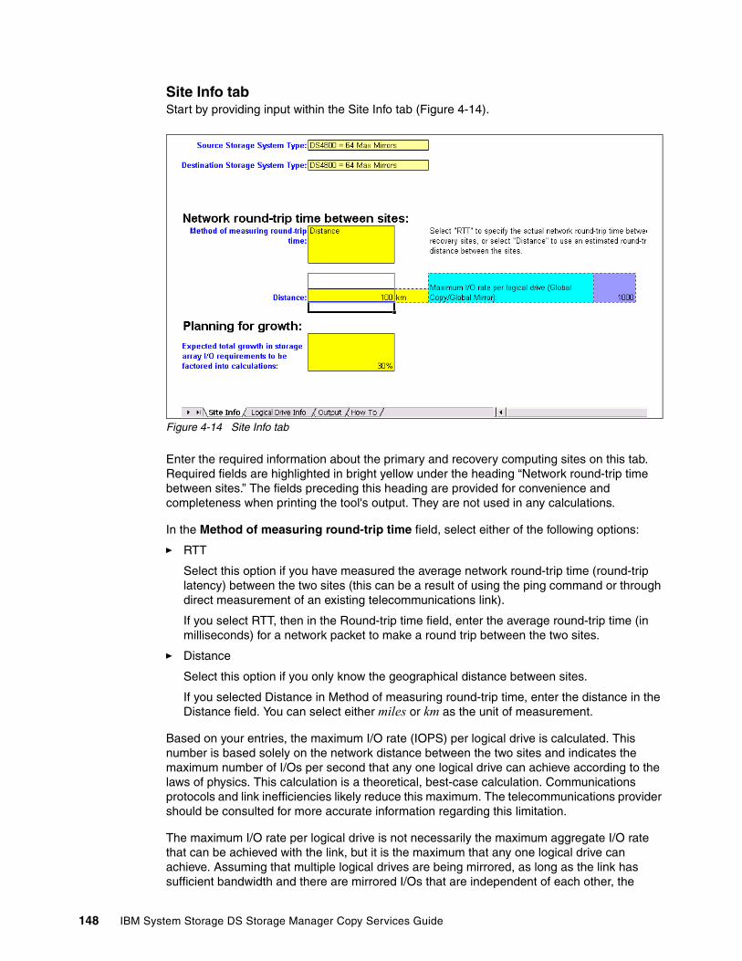
Site Info tabStart by providing input within the Site Info tab (Figure 4-14).
Figure 4-14 Site Info tab
Enter the required information about the primary and recovery computing sites on this tab. Required fields are highlighted in bright yellow under the heading “Network round-trip time between sites.” The fields preceding this heading are provided for convenience and completeness when printing the tool's output. They are not used in any calculations.
In the Method of measuring round-trip time field, select either of the following options:
� RTT
Select this option if you have measured the average network round-trip time (round-trip latency) between the two sites (this can be a result of using the ping command or through direct measurement of an existing telecommunications link).
If you select RTT, then in the Round-trip time field, enter the average round-trip time (in milliseconds) for a network packet to make a round trip between the two sites.
� Distance
Select this option if you only know the geographical distance between sites.
If you selected Distance in Method of measuring round-trip time, enter the distance in the Distance field. You can select either miles or km as the unit of measurement.
Based on your entries, the maximum I/O rate (IOPS) per logical drive is calculated. This number is based solely on the network distance between the two sites and indicates the maximum number of I/Os per second that any one logical drive can achieve according to the laws of physics. This calculation is a theoretical, best-case calculation. Communications protocols and link inefficiencies likely reduce this maximum. The telecommunications provider should be consulted for more accurate information regarding this limitation.
The maximum I/O rate per logical drive is not necessarily the maximum aggregate I/O rate that can be achieved with the link, but it is the maximum that any one logical drive can achieve. Assuming that multiple logical drives are being mirrored, as long as the link has sufficient bandwidth and there are mirrored I/Os that are independent of each other, the
148 IBM System Storage DS Storage Manager Copy Services Guide

independent I/Os can be multiplexed over the telecommunications link so that the aggregate I/O rate of all the logical drives can exceed the maximum I/O rate per logical drive.
If the maximum I/O rate per logical drive is the bottleneck for the mirroring solution, the only way it can be increased is to reduce the distance between primary and recovery sites.
Another point to consider when sizing ERM is the expected growth. Storage capacity demand is typically growing in the range of 30–40% per year. The IOPS demand is usually not growing at the same pace, and you can assume a rate of 15% per year or 30% for two years.
Logical Drive Info tabThe next tab, with required input, is the Logical Drive Info (Figure 4-15) tab.
Figure 4-15 Logical Drive Info tab
Column headings highlighted in yellow indicate required information. Column headings highlighted in green indicate output information.
Logical drive information inputIn this section, provide details about all logical drives (LUNs) that must be mirrored:
� The columns (not shown in the figure) “Application for the logical drive” and “Logical drive name or description” are provided to describe the logical drives to be mirrored, but are not used in any calculations. They are merely descriptive entries provided for convenience and correlation of applications with logical drives.
� In the column “Type of data stored on logical drive,” select one of the following options:
– logs
For database logs
– table spaces
For database table spaces,
– other
For all other types of data.
� In the Mirroring Mode column, select the type of mirroring to be used for the logical drive (Metro Mirror, Global Mirror, or Global Copy). The selected mode is used in calculating the requirements for the WAN connection.
� In the “Logical drive size” column, enter the size of the logical drive in gigabytes.
� In the “Average block size” column, enter the logical drive's average write block size in kilobytes. This is a critical factor used in the calculations.
Chapter 4. Enhanced Remote Mirroring (ERM) concepts, planning, and design 149

� In the “Peak I/O rate” column, enter the measured peak I/O rate for the logical drive, in I/O operations per second,. This is a critical factor used in the calculations. If a measured value cannot be obtained, enter an estimated or anticipated peak I/O rate, but understand that the output of the tool is only be as accurate as the estimate.
� In the “WRITE percentage,” column, enter the average percentage of I/O operations for the logical drive that are writes (as opposed to reads). This is a critical factor that is used in the calculations.
� In the “24-hour total Megabytes written” column, enter the total amount of data written during one typical 24-hour period. This factor is used in calculations for Global Mirror mode
Logical drive information outputBased on your input, you can see the resulting output (green header columns) in Figure 4-16. You see, for example, the Peak Write I/O rate per LUN.
Figure 4-16 Peak write I/O per LUN
The columns indicate the following information:
� The “Peak write I/O rate” column indicates the peak number of I/O operations per second that are write operations for the logical drive, calculated from the peak I/O rate, the WRITE percentage, and the Planning for growth fields.
� The “Maximum link I/O rate” column allows peak write I/O rate for this logical drive using Global Mirror?” column indicates Yes, No, or N/A:
– Yes
If the distance is within acceptable calculated limits, Yes is displayed.
– No
If the distance between the primary site and the recovery site is too long to support the selected global mode, No is displayed.
– N/A
If the selected mode is Metro Mirror or Global Mirror, N/A is displayed.
The calculation that determines a yes or no answer is a comparison of the peak write I/O rate for the logical drive and the maximum I/O rate per logical drive value that was calculated on the Site Info tab.
� The “Global Copy/Global Mirror rate of data written” column shows the bandwidth required for global operations for this logical drive. If Global Mirror mode was specified, this is the product of the peak write I/O rate and the average block size divided by 1024. If Global Mirror mode was chosen, this is calculated by dividing the 24-hour total megabytes written by the number of seconds in a day.
150 IBM System Storage DS Storage Manager Copy Services Guide

� The “Metro Mirror rate of data written” column shows the bandwidth required if Metro Mirror mode was specified for this logical drive. It is the product of the peak write I/O rate and the average block size divided by 1024.
� The Notes column (not shown in the figure) contains information about detected problems with the selected configuration for the logical drive.
Other output results, as shown in Figure 4-17, include:
� “Maximum I/O rate per logical drive” repeats the value calculated for the Site Info tab. It is provided here for quick comparison when viewing the Peak write I/O Rate column.
� “Total bandwidth required: Global Copy/Global Mirror” is the aggregate WAN bandwidth needed to mirror all the logical drives that use global operations (Global Mirror or Global Copy). The value is the sum of bandwidths calculated in the Global Copy/Global Mirror rate of data written column, multiplied by 10 bits/byte. This total bandwidth is required to enable WAN multiplexing for optimal performance.
Figure 4-17 Target IOPS
� “Target I/Os per second for Global Mirror” is the aggregate peak I/O rate obtained by summing the values in the “Peak write I/O Rate” column that apply to logical drives that will use Global Mirror mode. This target I/O rate can only be achieved if all I/Os generated by these logical drives can be multiplexed and none of the peak write I/O rates are limited by the distance between sites (as identified in the “Maximum link I/O rate allows peak write I/O rate for this logical drive using Global Mirror?” column, shown in Figure 4-16 on page 150).
� “Total bandwidth required: Metro Mirror” is the aggregate SAN bandwidth needed to mirror all of the logical drives that use Metro Mirror mode. The value is the sum of bandwidths calculated in the Metro Mirror rate of data written column multiplied by 10 bits/byte. This total bandwidth is required to enable SAN multiplexing for optimal performance.
� “Target I/Os per second for Metro Mirror” is the aggregate peak I/O rate obtained by summing the values in the “Peak write I/O Rate” column that apply to logical drives which will use Metro Mirror mode. This target I/O rate can only be achieved if all I/Os generated by these logical drives can be multiplexed and none of the peak write I/O rates are limited by the distance between sites.
Output tabThe output tab summarizes the calculated SAN and WAN link requirements for a successful mirroring solution. Note the disclaimer that applies to the tool’s output.
The minimum aggregate requirements for the Metro Mirror links are listed as Total Metro Mirror bandwidth requirement and Total Metro Mirror I/O rate requirement. Use this information to ensure that the Metro Mirror infrastructure provides sufficient bandwidth and I/O rate.
Chapter 4. Enhanced Remote Mirroring (ERM) concepts, planning, and design 151

The section labeled “Summary of Long-Distance Network Parameters,” shown in Figure 4-18, summarizes critical factors that determine which of the proposed Global Mirror/Global Copy mirroring solution (as characterized to the tool by the input fields) is expected to be successful.
Figure 4-18 Tab output with total bandwidth requirement for global operations
For Metro Mirror, the assumption is that the links run at FC speed, so its bandwidth requirements are not mentioned here.
The minimum aggregate bandwidth requirement for all logical drives that use either Global Copy or Global Mirror is listed as “Total required long-distance bandwidth for global operations.” This value is the same value that was calculated in the “Total bandwidth required: Global Copy/Global Mirror” column of the Logical Drive Info tab. The tool assumes that all global operations apply to the same recovery site. Use this information to ensure that the WAN infrastructure provides sufficient bandwidth. Consult the telecommunications provider to assure that at least this much effective bandwidth will be available for the mirroring solution.
For convenience and reference, the following information is listed:
� Distance between sites for global operations� Best case round trip time� Maximum I/O rate per logical drive (which is limited by the round trip time)
152 IBM System Storage DS Storage Manager Copy Services Guide

The “Long-Distance Network Connection Analysis for Global Modes” section provides useful information for deciding on the WAN connection type required for the Global Mirror/Global Copy configuration, as follows:
� In the first two columns, a variety of connection types are analyzed for their suitability. For each connection type, the geographic availability and maximum bandwidth of the connection are provided.
� The third column indicates whether the maximum bandwidth of the connection type is sufficient to support the total required long-distance bandwidth for global operations.
� The fourth column indicates whether the WAN can support all peak write I/O rates of logical drives that use Global Mirror mode. This is a key criterion of acceptable performance that is based on the maximum I/O rate per logical drive, which in turn is based on the distance between sites. If the connection does not support all these peak write I/O rates, then those logical drives that have a No in the Maximum link I/O rate allows peak write I/O rate for this logical drive using Global Mirror? column of the Logical Drive Info tab will have their peak write I/O rate throttled by the link I/O rate.
� The fifth column indicates the minimum amount of time it will take to do initial synchronization of all the data contained in the logical drives that use Global Mirror. Initial synchronization (replication) of the data stored on a logical drive is required before mirroring is started. Note that these calculations are theoretical, best-case calculations. Communications protocols, link inefficiencies, and other factors will likely increase them. The telecommunications provider should be consulted for more accurate information regarding initial synchronization time.
� The sixth column summarizes whether the connection allows optimal write rates for global modes. Optimal write rates are achieved when the link has sufficient bandwidth to support the Total required long-distance bandwidth for global operations and the maximum I/O rate per logical drive does not throttle peak write I/O rates of any logical drives. Connections that do not allow optimal write rates can still function, but the performance of the mirroring solution will be adversely impacted.
Return to the Logical Drive Info tab and look at the Notes column (Figure 4-19). If you see the line The I/O rate for the logical drive will be throtteled by the link I/O rate, it means that the link will not to support the peak write I/O rates of LUNs that use Global Mirror.
Figure 4-19 I/O throttling on Logical Drive Info tab
Chapter 4. Enhanced Remote Mirroring (ERM) concepts, planning, and design 153

Such a situation is indicated on the Output tab (Figure 4-20).
Figure 4-20 I/O throttling on Output tab
154 IBM System Storage DS Storage Manager Copy Services Guide
Chapter 5. ERM implementation
In this chapter, we cover the procedures for setting up and maintaining and Enhanced Remote Mirroring (ERM) environment. We cover the steps in the procedure by using both the IBM DS Storage Manager graphical user interface (GUI) and the command-line interface (smcli) for several common functions that are performed when creating a disaster recovery site.
5
© Copyright IBM Corp. 2011. All rights reserved. 155
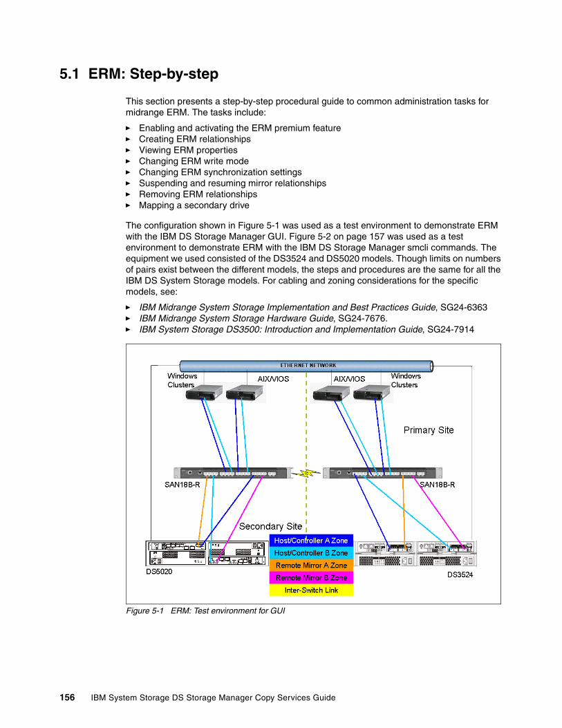
5.1 ERM: Step-by-step
This section presents a step-by-step procedural guide to common administration tasks for midrange ERM. The tasks include:
� Enabling and activating the ERM premium feature� Creating ERM relationships� Viewing ERM properties� Changing ERM write mode� Changing ERM synchronization settings� Suspending and resuming mirror relationships� Removing ERM relationships� Mapping a secondary drive
The configuration shown in Figure 5-1 was used as a test environment to demonstrate ERM with the IBM DS Storage Manager GUI. Figure 5-2 on page 157 was used as a test environment to demonstrate ERM with the IBM DS Storage Manager smcli commands. The equipment we used consisted of the DS3524 and DS5020 models. Though limits on numbers of pairs exist between the different models, the steps and procedures are the same for all the IBM DS System Storage models. For cabling and zoning considerations for the specific models, see:
� IBM Midrange System Storage Implementation and Best Practices Guide, SG24-6363 � IBM Midrange System Storage Hardware Guide, SG24-7676.� IBM System Storage DS3500: Introduction and Implementation Guide, SG24-7914
Figure 5-1 ERM: Test environment for GUI
156 IBM System Storage DS Storage Manager Copy Services Guide
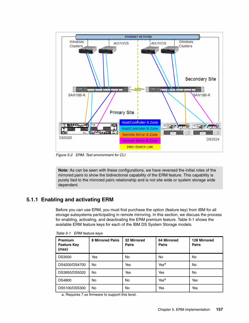
Figure 5-2 ERM: Test environment for CLI
5.1.1 Enabling and activating ERM
Before you can use ERM, you must first purchase the option (feature key) from IBM for all storage subsystems participating in remote mirroring. In this section, we discuss the process for enabling, activating, and deactivating the ERM premium feature. Table 5-1 shows the available ERM feature keys for each of the IBM DS System Storage models.
Table 5-1 ERM feature keys
Note: As can be seen with these configurations, we have reversed the initial roles of the mirrored pairs to show the bidirectional capability of the ERM feature. This capability is purely tied to the mirrored pairs relationship and is not site wide or system storage wide dependent.
Premium Feature Key (max)
8 Mirrored Pairs 32 Mirrored Pairs
64 Mirrored Pairs
128 Mirrored Pairs
DS3500 Yes No No No
DS4200/DS4700 No Yes Yesa
a. Requires 7.xx firmware to support this level.
No
DS3950/DS5020 No Yes Yes No
DS4800 No No Yesa Yes
DS5100/DS5300 No No Yes Yes
Chapter 5. ERM implementation 157

The four possible states for the ERM option are:
� Disabled/deactivated
This is the default state if the feature key has not been installed.
� Enabled/deactivated
This is the state when the feature key has been enabled, but ERM has not been activated. No changes are made to the storage subsystem configuration and all host connectivity is normal.
� Enabled/activated
This state makes the following controller host ports available for mirroring only:
– Host port 6 on the FC daughter card host interface ports DS3500 models equipped with this feature.
– Host port 2 of the FC host interface ports on the DS3950 model.
– Host port 2 or 4 depending on the number of host interface ports available on the option model of the DS4700 and DS5020.
– Host port 4 on both controllers for the DS4800.
– Host port 4 or 8, depending on the number of host interface cards (HIC) installed on the DS5100 and DS5300 subsystems
No host system I/Os are allowed on these ports when ERM is Enabled. This is the normal state for ERM operations.
� Disabled/activated
This state is possible when the premium feature has been disabled before deactivation.
If mirrored pairs are present when in this state, an Out of Compliance error message occurs. Removing the mirrored pairs removes this error. However, if the feature is disabled/activated, controller ports A2 and B2 continue to be unavailable for normal host I/O activity. This is an undesirable state. The status icon shown in Figure 5-3 illustrates this state.
Figure 5-3 ERM option disabled/activated
Enabling the ERM premium featureUse this section to perform the following tasks:
� Check the premium features list� Enable ERM
Remember to enable the premium feature on all participating storage subsystems.
Note: Only DS3500’s with FC daughter card can be used to support the ERM premium feature
Remote icon active (green)but disabled (red line)
158 IBM System Storage DS Storage Manager Copy Services Guide

Checking the premium features listTo check the premium feature, from the Subsystem Management window, select Storage Subsystem Premium Features List. The List Premium Features dialog box opens (Figure 5-4). It lists the premium features enabled/disabled on the storage subsystem, and the feature enable identifier.
Figure 5-4 List of premium features
You can also view the premium feature icon in the lower left of the Subsystem Management window (Figure 5-5).
Figure 5-5 ERM feature icon: Disabled/deactivated
ERM
Icon - Disabled/Deactivated
Chapter 5. ERM implementation 159
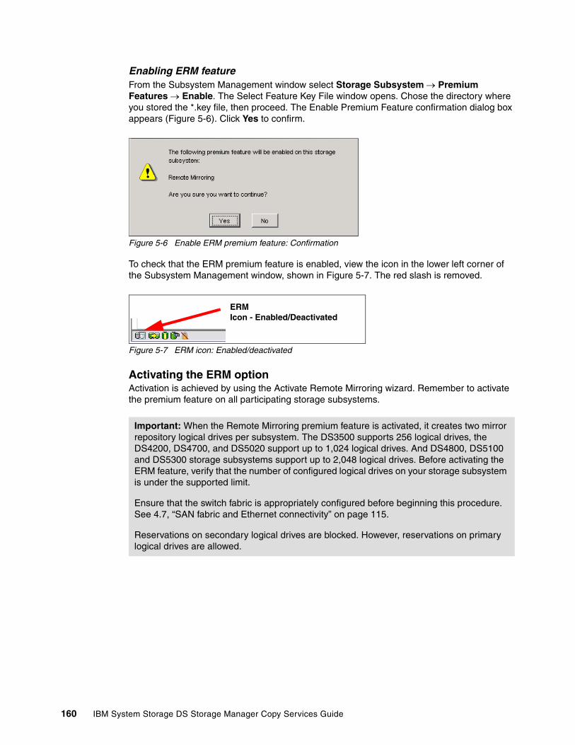
Enabling ERM featureFrom the Subsystem Management window select Storage Subsystem Premium Features Enable. The Select Feature Key File window opens. Chose the directory where you stored the *.key file, then proceed. The Enable Premium Feature confirmation dialog box appears (Figure 5-6). Click Yes to confirm.
Figure 5-6 Enable ERM premium feature: Confirmation
To check that the ERM premium feature is enabled, view the icon in the lower left corner of the Subsystem Management window, shown in Figure 5-7. The red slash is removed.
Figure 5-7 ERM icon: Enabled/deactivated
Activating the ERM option Activation is achieved by using the Activate Remote Mirroring wizard. Remember to activate the premium feature on all participating storage subsystems.
Important: When the Remote Mirroring premium feature is activated, it creates two mirror repository logical drives per subsystem. The DS3500 supports 256 logical drives, the DS4200, DS4700, and DS5020 support up to 1,024 logical drives. And DS4800, DS5100 and DS5300 storage subsystems support up to 2,048 logical drives. Before activating the ERM feature, verify that the number of configured logical drives on your storage subsystem is under the supported limit.
Ensure that the switch fabric is appropriately configured before beginning this procedure. See 4.7, “SAN fabric and Ethernet connectivity” on page 115.
Reservations on secondary logical drives are blocked. However, reservations on primary logical drives are allowed.
ERMIcon - Enabled/Deactivated
160 IBM System Storage DS Storage Manager Copy Services Guide

To activate the ERM feature, perform the following steps:
1. Select Storage Subsystem Remote Mirroring Activate. (Or, you can right-click and select Remote Mirroring Activate.) See Figure 5-8.
Figure 5-8 Activating remote mirroring
Chapter 5. ERM implementation 161
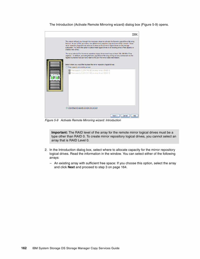
The Introduction (Activate Remote Mirroring wizard) dialog box (Figure 5-9) opens.
Figure 5-9 Activate Remote Mirroring wizard: Introduction
2. In the Introduction dialog box, select where to allocate capacity for the mirror repository logical drives. Read the information in the window. You can select either of the following arrays:
– An existing array with sufficient free space: If you choose this option, select the array and click Next and proceed to step 3 on page 164.
Important: The RAID level of the array for the remote mirror logical drives must be a type other than RAID 0. To create mirror repository logical drives, you cannot select an array that is RAID Level 0.
162 IBM System Storage DS Storage Manager Copy Services Guide

– An unconfigured array: Click Next to proceed to the Create Array window (Figure 5-10).
Figure 5-10 Activate Remote Mirroring wizard: Create new array
In this panel, you can define your new array for the repositories to reside on. You can select to have the drive members automatically selected or define them manually. We chose the automatic option here in our example, with the results shown in Figure 5-11.
Figure 5-11 Define the new array for the repositories to reside on
Chapter 5. ERM implementation 163

We defined a small RAID 1 array for the repository use. In this manner the unused space can be used for the creation of FlashCopy repositories as well and as such have minimal impact on production LUNs with multiple copy service needs.
Create the array and click Next.
3. After choosing where to create the mirror repository logical drives, the Preview window (Figure 5-12) opens.
Figure 5-12 Activate Remote Mirroring wizard: Preview
4. Read the information and click Next to continue.
5. The Activate Remote Mirroring wizard completed message (Figure 5-13) is displayed. Click OK to close the dialog box.
Figure 5-13 Activate Remote Mirroring wizard: Completed
Note: Warning 2 states that any host using the highest FC host ports on A and B controllers will be logged out.
164 IBM System Storage DS Storage Manager Copy Services Guide
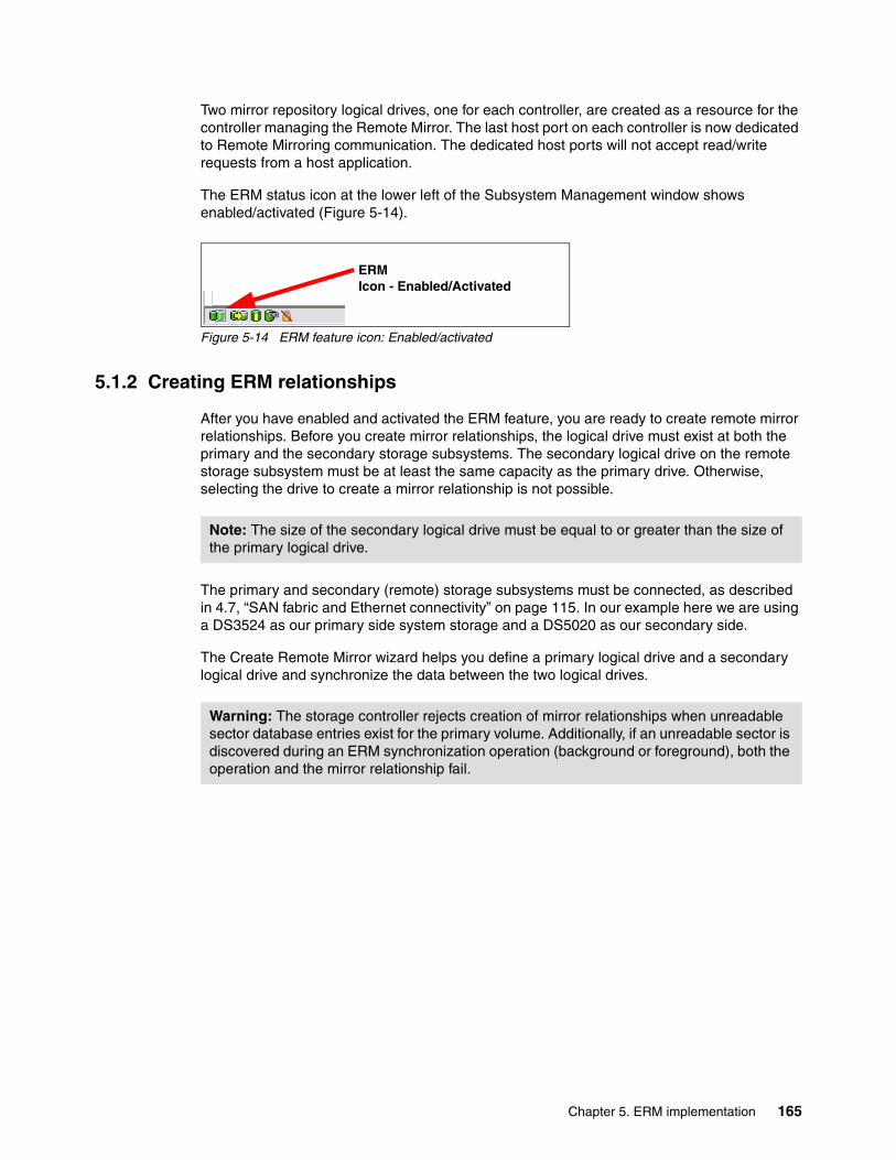
Two mirror repository logical drives, one for each controller, are created as a resource for the controller managing the Remote Mirror. The last host port on each controller is now dedicated to Remote Mirroring communication. The dedicated host ports will not accept read/write requests from a host application.
The ERM status icon at the lower left of the Subsystem Management window shows enabled/activated (Figure 5-14).
Figure 5-14 ERM feature icon: Enabled/activated
5.1.2 Creating ERM relationships
After you have enabled and activated the ERM feature, you are ready to create remote mirror relationships. Before you create mirror relationships, the logical drive must exist at both the primary and the secondary storage subsystems. The secondary logical drive on the remote storage subsystem must be at least the same capacity as the primary drive. Otherwise, selecting the drive to create a mirror relationship is not possible.
The primary and secondary (remote) storage subsystems must be connected, as described in 4.7, “SAN fabric and Ethernet connectivity” on page 115. In our example here we are using a DS3524 as our primary side system storage and a DS5020 as our secondary side.
The Create Remote Mirror wizard helps you define a primary logical drive and a secondary logical drive and synchronize the data between the two logical drives.
ERMIcon - Enabled/Activated
Note: The size of the secondary logical drive must be equal to or greater than the size of the primary logical drive.
Warning: The storage controller rejects creation of mirror relationships when unreadable sector database entries exist for the primary volume. Additionally, if an unreadable sector is discovered during an ERM synchronization operation (background or foreground), both the operation and the mirror relationship fail.
Chapter 5. ERM implementation 165
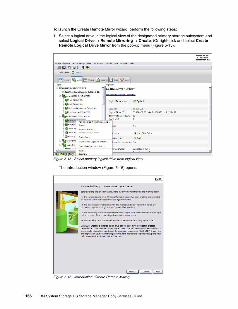
To launch the Create Remote Mirror wizard, perform the following steps:
1. Select a logical drive in the logical view of the designated primary storage subsystem and select Logical Drive Remote Mirroring Create. (Or right-click and select Create Remote Logical Drive Mirror from the pop-up menu (Figure 5-15).
Figure 5-15 Select primary logical drive from logical view
The Introduction window (Figure 5-16) opens.
Figure 5-16 Introduction (Create Remote Mirror)
166 IBM System Storage DS Storage Manager Copy Services Guide

2. Read the information displayed in the window and click Next. The Select Storage Subsystem window (Figure 5-17) opens.
Figure 5-17 Select Storage Subsystem (Create Remote Mirror)
3. Select the storage subsystem that contains the secondary logical drive that you want to include in the mirrored pair. Click Next.
4. Select a secondary logical drive for the remote mirror pair in the next window (Figure 5-18).
Figure 5-18 Select Secondary Logical Drive
Chapter 5. ERM implementation 167

The logical drives listed in the table are sorted by capacity, starting with the logical drive nearest to the primary logical drive's capacity. Logical drives with identical capacity are sorted alphabetically. Selected primary and secondary logical drives can have various RAID levels, segment sizes, and caching parameters.
5. Select the secondary logical drive to be included in the mirrored pair. You can select only one. Click Next. The Set Write Mode window (Figure 5-19) opens.
Figure 5-19 Create Remote Mirror: Write mode settings
6. Select the mode according to the mirroring requirements:
– Metro Mirror: Select Synchronous write mode.
– Global Mirror: Select Asynchronous write mode and make sure that the “Add to write consistency group” box must be checked.
– Global Copy: Select Asynchronous write mode and make sure that the “Add to write consistency group” box is not checked.
Click Next.
Important: Logical drives that are not valid secondary logical drive candidates do not appear in the list.
168 IBM System Storage DS Storage Manager Copy Services Guide

7. Set the synchronization priority in the next window (Figure 5-20). Use this window to set the rate at which the controller owner of the primary logical drive synchronizes data with the secondary logical drive. The controller owner of the primary logical drive uses the synchronization priority, but a synchronization priority is also set on the secondary logical drive at this time (in case it is promoted to a primary logical drive, in a role reversal). See 4.6.2, “Data synchronization priority” on page 115.
Figure 5-20 Create Remote Mirror: Set Synchronization Priority
This setting applies to both primary and secondary logical drives. Click Next.
Important: If you decide later that the synchronization priority is too low or too high, you can change it. For more information about the available settings, see Chapter 4, “Enhanced Remote Mirroring (ERM) concepts, planning, and design” on page 93. For information about changing these settings, see 5.1.4, “Changing mirror write mode” on page 177.
Chapter 5. ERM implementation 169

8. The Preview window, shown in Figure 5-21, is the last step before the remote mirror is created. Type Yes in the box and then click Finish to create the remote mirror.
Figure 5-21 Preview (Create Remote Mirror)
The Creation Successful message dialog box (Figure 5-22) is displayed.
Figure 5-22 Creation Successful (Create Remote Mirror)
170 IBM System Storage DS Storage Manager Copy Services Guide

If you click Yes, you are returned to the Select Primary Logical Drive (Create Remote Mirror) window (Figure 5-23), to create more mirror pairs, if required.
Figure 5-23 Select Primary Logical Drive (Create Remote Mirror)
If you have no more mirror pairs to create, click No to finish. The Completed dialog box message opens (Figure 5-24).
Figure 5-24 Completed (Create Remote Mirror)
Chapter 5. ERM implementation 171
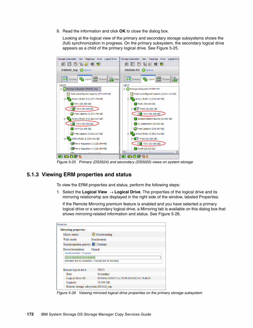
9. Read the information and click OK to close the dialog box.
Looking at the logical view of the primary and secondary storage subsystems shows the (full) synchronization in progress. On the primary subsystem, the secondary logical drive appears as a child of the primary logical drive. See Figure 5-25.
Figure 5-25 Primary (DS3524) and secondary (DS5020) views on system storage
5.1.3 Viewing ERM properties and status
To view the ERM properties and status, perform the following steps:
1. Select the Logical View Logical Drive. The properties of the logical drive and its mirroring relationship are displayed in the right side of the window, labeled Properties.
If the Remote Mirroring premium feature is enabled and you have selected a primary logical drive or a secondary logical drive, a Mirroring tab is available on this dialog box that shows mirroring-related information and status. See Figure 5-26.
Figure 5-26 Viewing mirrored logical drive properties on the primary storage subsystem
172 IBM System Storage DS Storage Manager Copy Services Guide

The properties listed on this tab include:
– Mirror status
• Synchronized• Synchronizing• Suspended• Unsynchronized
This property is not displayed for remote secondary logical drives.
– Synchronization priority
• Lowest• Low• Medium• High• Highest
This property is not displayed for local or remote secondary logical drives.
– Resynchronization method
• Manual • Automatic
This property is not displayed for local or remote secondary logical drives.
– Remote logical drive
Name of the logical drive that this logical drive is paired with.
– Role of the remote logical drive
• Primary • Secondary
– Logical Drive ID: Worldwide name (WWN) of the remote logical drive.
– Actual/usable capacity.
– Remote storage subsystem
Subsystem name defined for the remote storage subsystem containing the remote logical drive.
Note: When running a progress bar follows the Resynchronization method in this dialog box, and displays the progress of any ongoing synchronizations running.
Note: If the remote logical drive in the mirrored pair is in an unresponsive state, the following properties are displayed in place of the properties in the previous lists:
� Unresponsive remote logical drive
User label of the remote logical drive, from last known data in the cache
� Unresponsive remote logical drive worldwide name (WWN)
WWN of the remote logical drive, from last known data in the cache
� Unresponsive remote storage subsystem
WWN of the remote storage subsystem, from last known data in the cache
Chapter 5. ERM implementation 173

ERM can also be monitored by viewing the storage subsystem profile. To view the storage subsystem profile, select Storage Subsystem View Profile. (Or, right-click and select View Profile from the pop-up menu.) The Storage Subsystem Profile dialog box (Figure 5-27) opens.
Figure 5-27 Storage Subsystem Profile: All tab
174 IBM System Storage DS Storage Manager Copy Services Guide

Several tabs are available:
� All
This tab shows a summary of available storage subsystem profile data and includes a summary of mirror repositories and number of mirror pairs in use.
� Logical Drives
This tab has five sections, with separate tabs providing access to information for each type of logical drive.
� Repositories tab
This tab contains a section of logical drive information that shows FlashCopy and mirror repository logical drive properties. See Figure 5-28.
Figure 5-28 Storage Subsystem Profile: Repositories tab
Chapter 5. ERM implementation 175

� Mirrors
This tab is a section of logical drive information that lists remote mirror properties. The Mirrors tab is available only when the Remote Mirroring premium feature is enabled and activated. See Figure 5-29.
Figure 5-29 Storage Subsystem Profile: Mirrors tab
176 IBM System Storage DS Storage Manager Copy Services Guide

The View Associated Elements window (Figure 5-30) provides a graphical representation of the logical drives that are participating in the mirror relationship. In addition, details are provided for all components, rather than only for the logical drive initially selected. To view all associated components in a mirror relationship, including primary, secondary, and mirror repository logical drives:
1. Select the primary or secondary logical drive in a mirror relationship.
2. Right-click and select View Associated Components.
Figure 5-30 View Associated Elements
5.1.4 Changing mirror write mode
This section describes how to change the write mode (synchronous or asynchronous with or without write consistency group) for the controller owner of the primary logical drive. See 4.6, “Data replication process” on page 113, for a description of the available mirroring modes. Any configured mode can be changed to any of the other modes. Care should be taken when making this change to avoid unexpected production impacts.
Chapter 5. ERM implementation 177
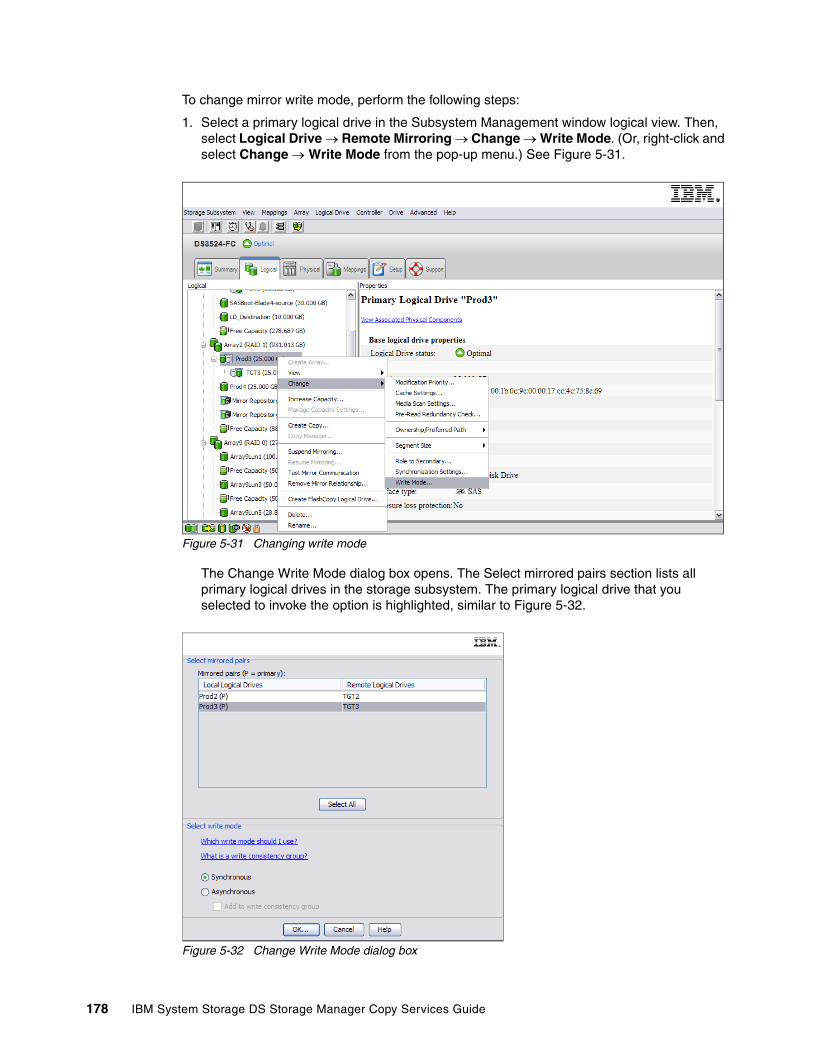
To change mirror write mode, perform the following steps:
1. Select a primary logical drive in the Subsystem Management window logical view. Then, select Logical Drive Remote Mirroring Change Write Mode. (Or, right-click and select Change Write Mode from the pop-up menu.) See Figure 5-31.
Figure 5-31 Changing write mode
The Change Write Mode dialog box opens. The Select mirrored pairs section lists all primary logical drives in the storage subsystem. The primary logical drive that you selected to invoke the option is highlighted, similar to Figure 5-32.
Figure 5-32 Change Write Mode dialog box
178 IBM System Storage DS Storage Manager Copy Services Guide

2. In the Select mirrored pairs section, select the primary logical drives for which you want to change the write mode, as follows:
– To select multiple logical drives, press and hold the Ctrl or Shift key and click the drives. – To select all of the primary logical drives, click Select All.
3. In the Select Write Mode area, select the appropriate write mode.
The default selection indicates the mode that is currently set for the selected drive. If you change the mode from synchronous to asynchronous write mode, you also have the option to add the logical drive to the write consistency group by selecting the Add to Write Consistency Group check box under the Asynchronous radio button. For a detailed description, see “Adding logical drives to the write consistency group”.
Click OK. The Change Write Mode confirmation dialog box (Figure 5-33) opens.
Figure 5-33 Change Write Mode confirmation
4. If the parameters that you selected are correct, click Yes to continue. The Completed dialog box message opens. Click OK to return to the logical view.
Adding logical drives to the write consistency groupIf you are changing the write mode of a logical drive in a mirror relationship from synchronous (Metro Mirroring) to asynchronous (Global Copy) and you have multiple interdependent primary logical drives, you might also have to add the given logical drive to the write consistency group. In other words, you are setting a Global Mirroring data replication mode.
As shown in Figure 5-34, you have three mirrored pairs with their logical drives defined. In our example, we assume that the logical drive Prod2 is holding database data and the logical drive Prod3 is holding its transaction logs. For database consistency, a critical step is to have the remote write requests transferred to the secondary storage controller in the same order as the host write requests initially occurred on the primary storage controller. You assume that the write consistency is not needed for the logical drive LD_Destination, and it is thus excluded from the write consistency group.
Figure 5-34 Adding logical drives to the write consistency group
Chapter 5. ERM implementation 179
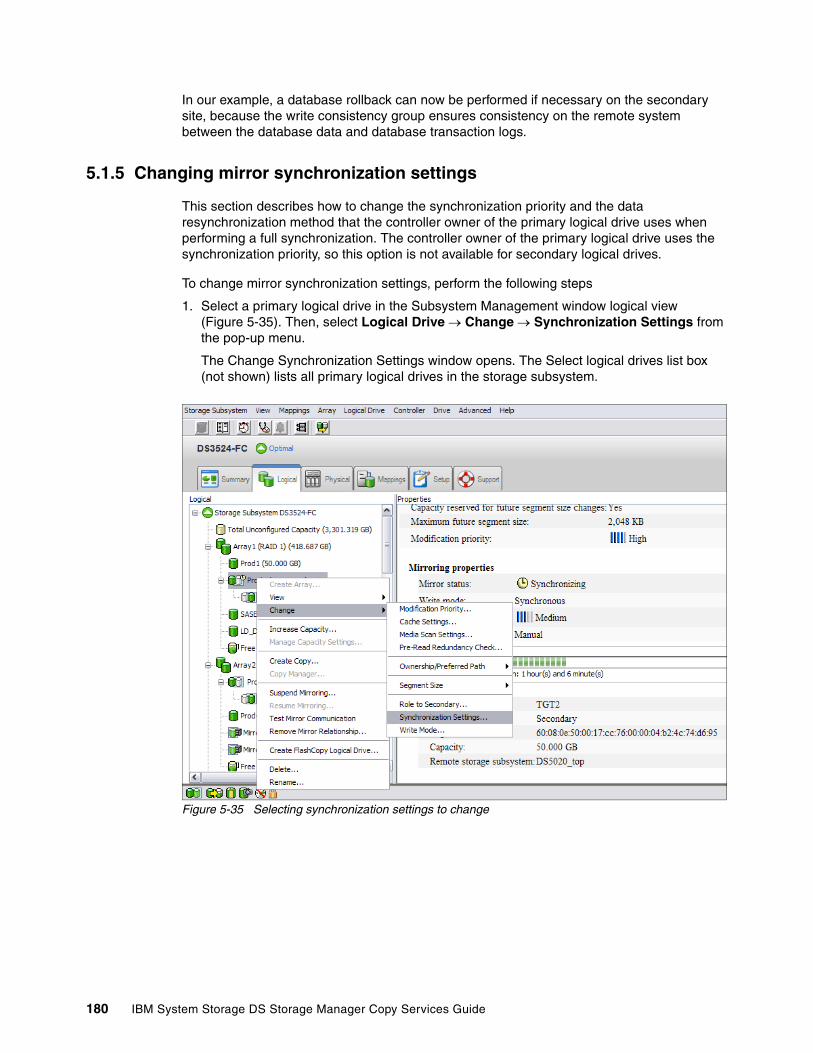
In our example, a database rollback can now be performed if necessary on the secondary site, because the write consistency group ensures consistency on the remote system between the database data and database transaction logs.
5.1.5 Changing mirror synchronization settings
This section describes how to change the synchronization priority and the data resynchronization method that the controller owner of the primary logical drive uses when performing a full synchronization. The controller owner of the primary logical drive uses the synchronization priority, so this option is not available for secondary logical drives.
To change mirror synchronization settings, perform the following steps
1. Select a primary logical drive in the Subsystem Management window logical view (Figure 5-35). Then, select Logical Drive Change Synchronization Settings from the pop-up menu.
The Change Synchronization Settings window opens. The Select logical drives list box (not shown) lists all primary logical drives in the storage subsystem.
Figure 5-35 Selecting synchronization settings to change
180 IBM System Storage DS Storage Manager Copy Services Guide

The primary logical drive that you selected to invoke the option is highlighted, as in Figure 5-36.
Figure 5-36 Synchronization modification window
2. Select the primary logical drives for which you want to change the synchronization priority from the Mirrored pairs list. To select multiple logical drives, use the Ctrl+click or Shift+click keyboard options. To select all of the primary logical drives, click Select All.
3. In the Select synchronization priority area, use the slider bar to set the appropriate synchronization priority. The five choices are:
– Lowest– Low– Medium– High– Highest
These settings are indicated on the slider by the five vertical bars (|). The Lowest and Highest settings are labeled. The higher the setting, the more the primary controller will prioritize a full synchronization over host I/O, and the larger the impact to system performance.
4. In the Select resynchronization method area, use the radio buttons to select the appropriate synchronization method. The two choices are:
– Manual resynchronization – Automatic resynchronization
When the primary storage controller is in an unsynchronized state and resynchronization was set to automatic, a resynchronization starts immediately when the primary storage controller can communicate again with the secondary controller.
Chapter 5. ERM implementation 181
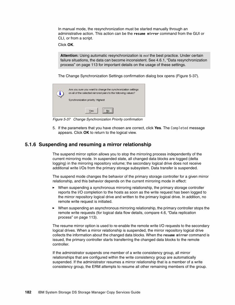
In manual mode, the resynchronization must be started manually through an administrative action. This action can be the resume mirror command from the GUI or CLI, or from a script.
Click OK.
The Change Synchronization Settings confirmation dialog box opens (Figure 5-37).
Figure 5-37 Change Synchronization Priority confirmation
5. If the parameters that you have chosen are correct, click Yes. The Completed message appears. Click OK to return to the logical view.
5.1.6 Suspending and resuming a mirror relationship
The suspend mirror option allows you to stop the mirroring process independently of the current mirroring mode. In suspended state, all changed data blocks are logged (delta logging) in the mirroring repository volume; the secondary logical drive does not receive additional write I/Os from the primary storage subsystem. Data transfer is suspended.
The suspend mode changes the behavior of the primary storage controller for a given mirror relationship, and this behavior depends on the current mirroring mode in effect:
� When suspending a synchronous mirroring relationship, the primary storage controller reports the I/O completion to the hosts as soon as the write request has been logged to the mirror repository logical drive and written to the primary logical drive. In addition, no remote write request is initiated.
� When suspending an asynchronous mirroring relationship, the primary controller stops the remote write requests (for logical data flow details, compare 4.6, “Data replication process” on page 113).
The resume mirror option is used to re-enable the remote write I/O requests to the secondary logical drives. When a mirror relationship is suspended, the mirror repository logical drive collects the information about the changed data blocks. When the resume mirror command is issued, the primary controller starts transferring the changed data blocks to the remote controller.
If the administrator suspends one member of a write consistency group, all mirror relationships that are configured within the write consistency group are automatically suspended. If the administrator resumes a mirror relationship that is a member of a write consistency group, the ERM attempts to resume all other remaining members of the group.
Attention: Using automatic resynchronization is not the best practice. Under certain failure situations, the data can become inconsistent. See 4.6.1, “Data resynchronization process” on page 113 for important details on the usage of these settings.
182 IBM System Storage DS Storage Manager Copy Services Guide
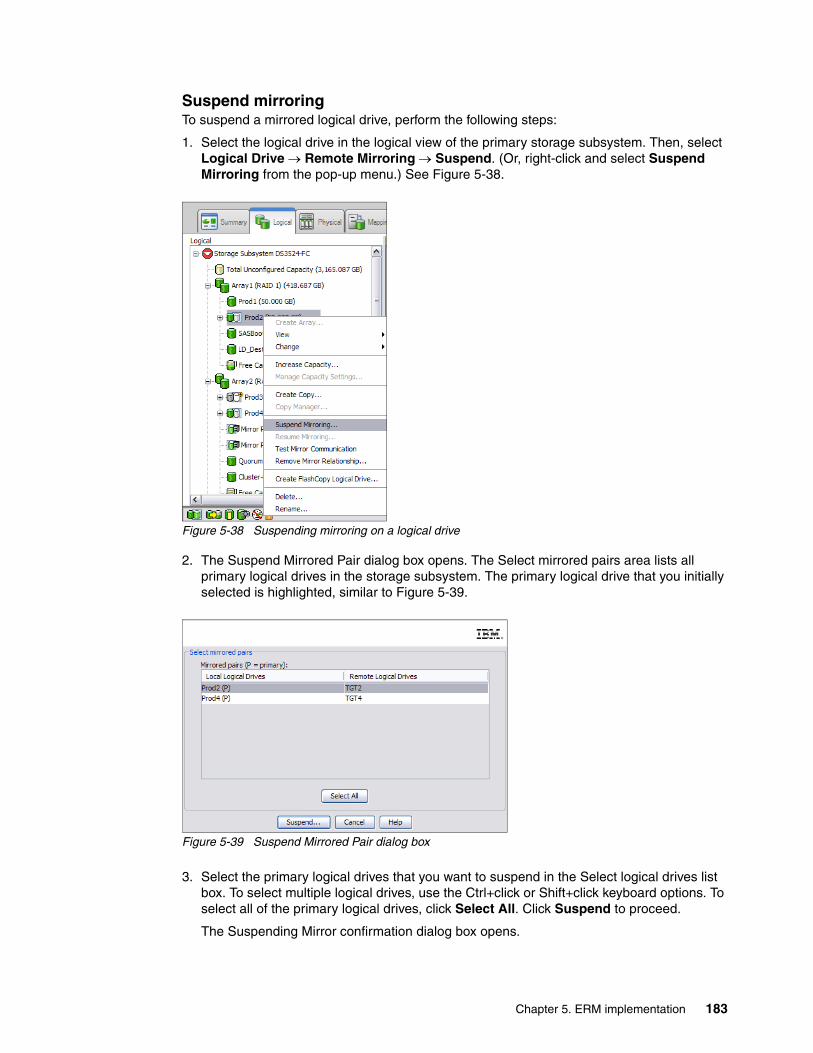
Suspend mirroringTo suspend a mirrored logical drive, perform the following steps:
1. Select the logical drive in the logical view of the primary storage subsystem. Then, select Logical Drive Remote Mirroring Suspend. (Or, right-click and select Suspend Mirroring from the pop-up menu.) See Figure 5-38.
Figure 5-38 Suspending mirroring on a logical drive
2. The Suspend Mirrored Pair dialog box opens. The Select mirrored pairs area lists all primary logical drives in the storage subsystem. The primary logical drive that you initially selected is highlighted, similar to Figure 5-39.
Figure 5-39 Suspend Mirrored Pair dialog box
3. Select the primary logical drives that you want to suspend in the Select logical drives list box. To select multiple logical drives, use the Ctrl+click or Shift+click keyboard options. To select all of the primary logical drives, click Select All. Click Suspend to proceed.
The Suspending Mirror confirmation dialog box opens.
Chapter 5. ERM implementation 183

4. Type Yes in the text box and click OK. The Suspend Mirrored Pair - Progress window opens, as shown in Figure 5-40. Click OK to return to the logical view.
Figure 5-40 Suspend Mirrored Pair - Progress
A suspension status bar window is opened as shown in Figure 5-41. Select OK to continue.
Figure 5-41 Suspension status bar
184 IBM System Storage DS Storage Manager Copy Services Guide
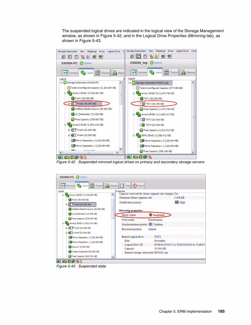
The suspended logical drives are indicated in the logical view of the Storage Management window, as shown in Figure 5-42, and in the Logical Drive Properties (Mirroring tab), as shown in Figure 5-43.
Figure 5-42 Suspended mirrored logical drives on primary and secondary storage servers
Figure 5-43 Suspended state
Chapter 5. ERM implementation 185
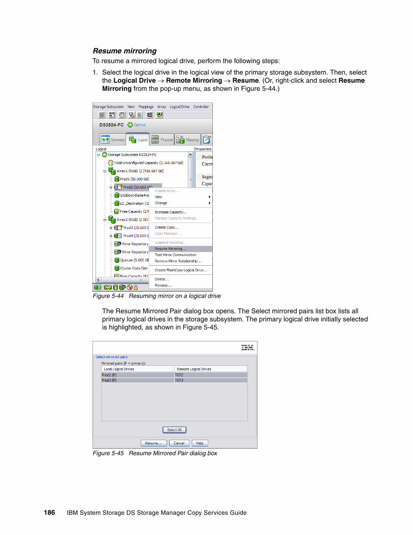
Resume mirroringTo resume a mirrored logical drive, perform the following steps:
1. Select the logical drive in the logical view of the primary storage subsystem. Then, select the Logical Drive Remote Mirroring Resume. (Or, right-click and select Resume Mirroring from the pop-up menu, as shown in Figure 5-44.)
Figure 5-44 Resuming mirror on a logical drive
The Resume Mirrored Pair dialog box opens. The Select mirrored pairs list box lists all primary logical drives in the storage subsystem. The primary logical drive initially selected is highlighted, as shown in Figure 5-45.
Figure 5-45 Resume Mirrored Pair dialog box
186 IBM System Storage DS Storage Manager Copy Services Guide
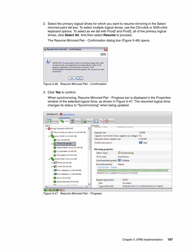
2. Select the primary logical drives for which you want to resume mirroring in the Select mirrored pairs list box. To select multiple logical drives, use the Ctrl+click or Shift+click keyboard options. To select as we did with Prod2 and Prod3, all of the primary logical drives, click Select All. And then select Resume to proceed.
The Resume Mirrored Pair - Confirmation dialog box (Figure 5-46) opens.
Figure 5-46 Resume Mirrored Pair - Confirmation
3. Click Yes to confirm.
When synchronizing, Resume Mirrored Pair - Progress bar is displayed in the Properties window of the selected logical drive, as shown in Figure 5-47. The resumed logical drive changes its status to “Synchronizing” when being updated.
Figure 5-47 Resume Mirrored Pair - Progress
Chapter 5. ERM implementation 187

There are no special icons or indicators to indicate that a mirror has been resumed. The synchronizing icons are displayed. When completed the progress bar is removed and the status returns to “Synchronized” as shown in Figure 5-48.
Figure 5-48 Synchronization is completed for the resumed mirrored pair
Suspend/resume through CLIPerforming data backups and creating a FlashCopy are the types of operations for which you suspend (and resume afterwards) a mirroring relationship.
Example 5-1 shows a typical Windows batch file that can be used to suspend a mirror relationship.
Example 5-1 Windows batch file for suspending mirror relationship on mirrored logical drive
@ECHO OFFREM This is a basic script example which is intended for a scenario where you have REM at least two Storage Servers using the ERM Feature. REM It will show you how to suspend a mirror relationship between a primary and REM secondary mirrored logical drive.REM -------------------------------------------------------------------------------REM SUSPEND MIRROR FOR LOGICAL DRIVE RB7010_ERM_PRIMARY defined on DS4400_PrimaryREM STORAGE SUBSYSTEMREM REM ECHO Showing Synchronization Status for the Logical DriveREM C:\Progra~1\IBM_FAStT\client\SMcli 10.1.1.101 10.1.1.102 -c "show remoteMirror localVolume [RB7010_ERM_PRIMARY] synchronizationProgress;"REM REMECHO Suspending Mirror for RB7010_ERM_PRIMARY logical drive on DS4400_PrimaryREMC:\Progra~1\IBM_FAStT\client\SMcli 10.1.1.101 10.1.1.102 -c "suspend remoteMirror primary [RB7010_ERM_PRIMARY] writeConsistency=FALSE;"REM REM
188 IBM System Storage DS Storage Manager Copy Services Guide

ECHO Showing Synchronization Status for the Logical DriveREM C:\Progra~1\IBM_FAStT\client\SMcli 10.1.1.101 10.1.1.102 -c "show remoteMirror localVolume [RB7010_ERM_PRIMARY] synchronizationProgress;"REMREM-------------------------------------------------------------------------------
Example 5-2 shows the suspending of mirror batch file output.
Example 5-2 Suspending mirror batch file output
C:\Program Files\IBM_FAStT\client>suspend
Showing Synchronization Status for the Logical DrivePerforming syntax check...
Syntax check complete.
Executing script...
Mirror pair (primary RB7010_ERM_PRIMARY/secondary RB7010_ERM_SECONDARY): SynchronizedScript execution complete.
SMcli completed successfully.
Suspending Mirror for RB7010_ERM_PRIMARY logical drive on DS4400_PrimaryPerforming syntax check...
Syntax check complete.
Executing script...
Script execution complete.
SMcli completed successfully.
Showing Synchronization Status for the Logical DrivePerforming syntax check...
Syntax check complete.
Executing script...
Mirror pair (primary RB7010_ERM_PRIMARY/secondary RB7010_ERM_SECONDARY): Suspended - 1% out of syncScript execution complete.
SMcli completed successfully.
Chapter 5. ERM implementation 189
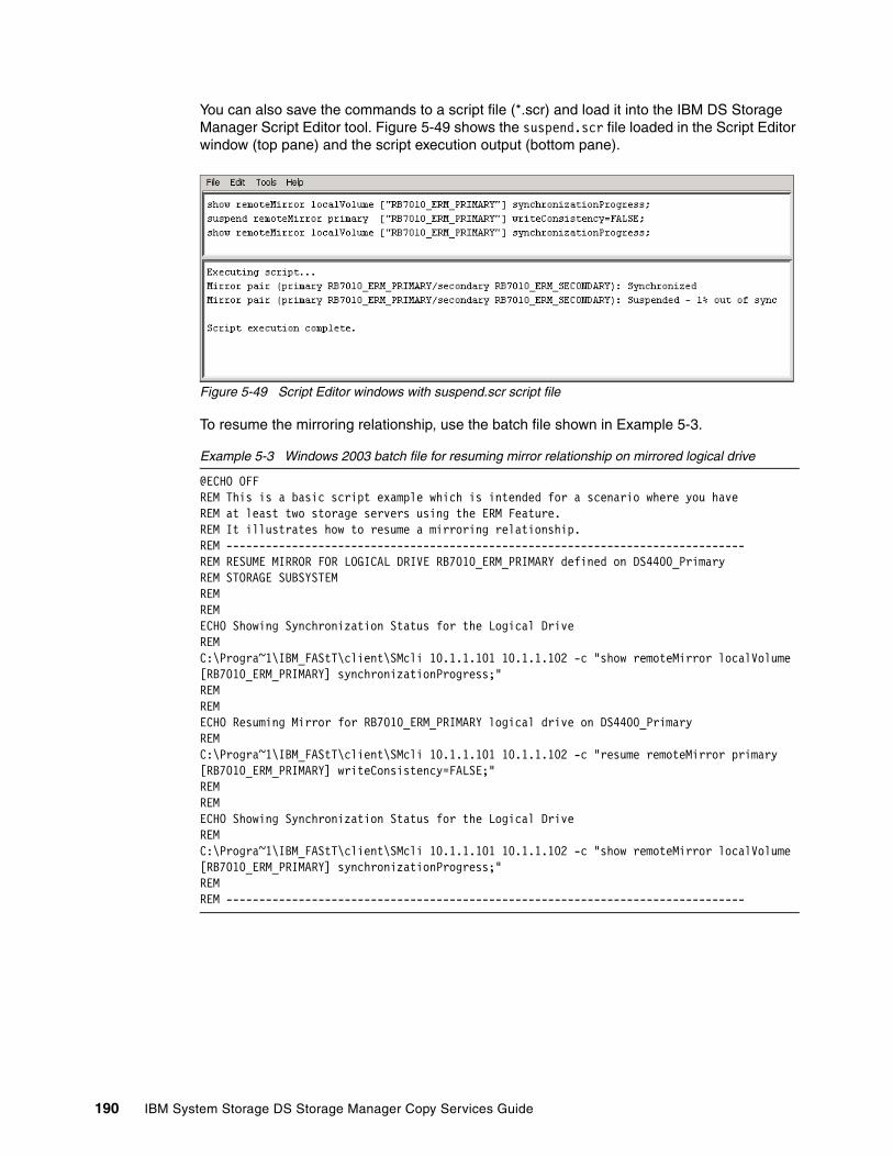
You can also save the commands to a script file (*.scr) and load it into the IBM DS Storage Manager Script Editor tool. Figure 5-49 shows the suspend.scr file loaded in the Script Editor window (top pane) and the script execution output (bottom pane).
Figure 5-49 Script Editor windows with suspend.scr script file
To resume the mirroring relationship, use the batch file shown in Example 5-3.
Example 5-3 Windows 2003 batch file for resuming mirror relationship on mirrored logical drive
@ECHO OFFREM This is a basic script example which is intended for a scenario where you have REM at least two storage servers using the ERM Feature. REM It illustrates how to resume a mirroring relationship.REM -------------------------------------------------------------------------------REM RESUME MIRROR FOR LOGICAL DRIVE RB7010_ERM_PRIMARY defined on DS4400_PrimaryREM STORAGE SUBSYSTEMREM REM ECHO Showing Synchronization Status for the Logical DriveREM C:\Progra~1\IBM_FAStT\client\SMcli 10.1.1.101 10.1.1.102 -c "show remoteMirror localVolume [RB7010_ERM_PRIMARY] synchronizationProgress;"REM REMECHO Resuming Mirror for RB7010_ERM_PRIMARY logical drive on DS4400_PrimaryREMC:\Progra~1\IBM_FAStT\client\SMcli 10.1.1.101 10.1.1.102 -c "resume remoteMirror primary [RB7010_ERM_PRIMARY] writeConsistency=FALSE;"REM REMECHO Showing Synchronization Status for the Logical DriveREM C:\Progra~1\IBM_FAStT\client\SMcli 10.1.1.101 10.1.1.102 -c "show remoteMirror localVolume [RB7010_ERM_PRIMARY] synchronizationProgress;"REMREM -------------------------------------------------------------------------------
190 IBM System Storage DS Storage Manager Copy Services Guide

Example 5-4 shows the batch file output.
Example 5-4 Resuming mirror batch file output
C:\Program Files\IBM_FAStT\client>resumeShowing Synchronization Status for the Logical DrivePerforming syntax check...
Syntax check complete.
Executing script...
Mirror pair (primary RB7010_ERM_PRIMARY/secondary RB7010_ERM_SECONDARY): Suspended - 3% out of syncScript execution complete.
SMcli completed successfully.
Resuminng Mirror for RB7010_ERM_PRIMARY logical drive on DS4400_PrimaryPerforming syntax check...
Syntax check complete.
Executing script...
Script execution complete.
SMcli completed successfully.
Showing Synchronization Status for the Logical DrivePerforming syntax check...
Syntax check complete.
Executing script...
Mirror pair (primary RB7010_ERM_PRIMARY/secondary RB7010_ERM_SECONDARY): Synchronizing - 1% completeScript execution complete.
SMcli completed successfully.
Figure 5-50 shows the same example, but using the Script Editor window.
Figure 5-50 Script Editor windows with resume.scr script file
Chapter 5. ERM implementation 191
5.1.7 Removing mirror relationships
Use the remove mirror relationship option to remove the link between the primary and secondary logical drives in a mirrored relationship.
This action does not delete the primary logical drive, secondary logical drive, or mirror repository logical drives. Data on the logical drives is not affected and the primary logical drive still continues normal I/O operation. As a result of this operation the primary logical drive and secondary logical drive become standard, host-accessible, non-mirrored logical drives.
This option is only available for the local logical drive (primary or secondary) that is present in the storage subsystem that you are currently managing. This option is not available if you select a remote secondary logical drive in the logical view.
The mirror relationship is first removed on the local storage subsystem, then on the remote storage subsystem. If the mirror relationship is successfully removed on the local storage subsystem but cannot be removed on the remote storage subsystem because of a communication problem, an error message is displayed. The error message shows the name of the remote storage subsystem with the orphaned mirrored logical drive and the name of the logical drive. Open the Subsystem Management window for the remote storage subsystem, select the specified logical drive, and remove the mirror relationship.
If the mirror relationship was successfully removed on the secondary side but not the primary side, then the first I/O write to the primary logical drive can cause the mirror state to be unsynchronized. The primary Subsystem Management window logical view also then shows an unresponsive remote secondary logical drive. Remove the mirror relationship on the primary storage subsystem to correct the problem.
If the mirror relationship was successfully removed on the primary side, but not on the secondary side, then typically no change occurs to the representation of the secondary logical drive in the secondary Subsystem Management window logical view. Remove the mirror relationship on the secondary storage subsystem to correct the problem and make the logical drive accessible by hosts.
192 IBM System Storage DS Storage Manager Copy Services Guide
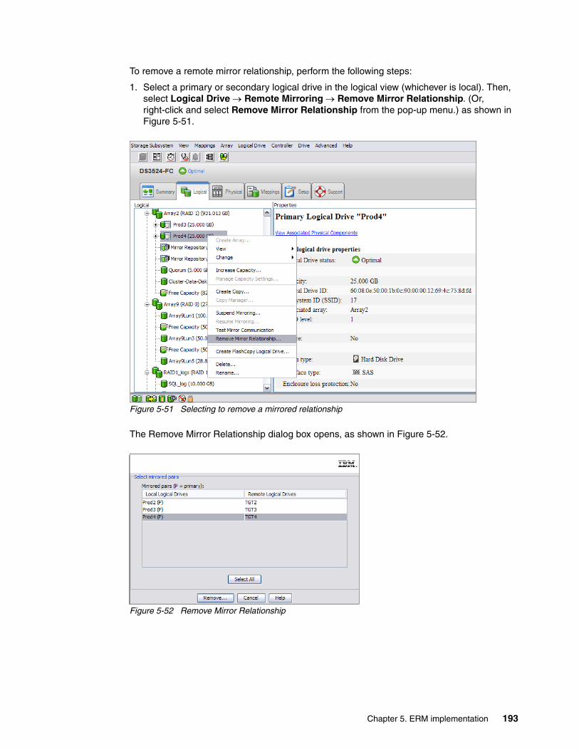
To remove a remote mirror relationship, perform the following steps:
1. Select a primary or secondary logical drive in the logical view (whichever is local). Then, select Logical Drive Remote Mirroring Remove Mirror Relationship. (Or, right-click and select Remove Mirror Relationship from the pop-up menu.) as shown in Figure 5-51.
Figure 5-51 Selecting to remove a mirrored relationship
The Remove Mirror Relationship dialog box opens, as shown in Figure 5-52.
Figure 5-52 Remove Mirror Relationship
Chapter 5. ERM implementation 193

2. Select the mirrored logical drive pairs for which you want to remove the mirror relationship. To select multiple mirrored pairs, use the Ctrl+click or Shift+click keyboard options. To select all of the mirrored pairs, click Select All. Click Remove. The Remove Mirror Relationship - Confirmation dialog box opens, as shown in Figure 5-53.
Figure 5-53 Remove Mirror Relationship - Confirmation
3. Click Yes. The Remove Mirror Relationship - Progress window (Figure 5-54) opens. Click OK. All data on the logical drives remains intact and available. Logical drives that were the secondary logical drive in the mirrored pair are now accessible (read/write) by hosts that are mapped to them.
Figure 5-54 Mirror relationship removal progress
5.1.8 Mapping a secondary drive
A secondary mirror drive can be mapped to a host or host group, similar to any standard virtual drive. The difference is that the mirrored drive is write-protected to any host system until it is promoted to a primary drive.
The Mapping a secondary drive option is useful because it enables the administrator to preconfigure the mapping of the secondary mirrored drives prior to the changing roles. This approach eases the transition in a failover or backup situation. Remember, certain operating systems do not accept multiple identical drives on single host. In such a case, you can prepare the mapping on the storage server but hide it from the host (using zoning).
Attention: See any operating system restrictions if you are mapping the secondary logical drive to the same host as the primary logical drive.
Tip: An easier and faster approach is to change the zoning configuration in the case of failure. Most zoning software allows the definition of multiple zoning configurations that can be activated only when needed. The change is more difficult if you must change WWPNs and LUNs, especially in the stressful situation of trying to recover from a failure.
194 IBM System Storage DS Storage Manager Copy Services Guide

5.2 ERM and disaster recovery
As modern business pressures increasingly require 24-hour data availability, system administrators are required to ensure that critical data is safeguarded against potential disasters. Additionally, storage administrators are searching for methods to migrate from one host to another or from one storage subsystem to another, with as little disruption as possible.
ERM is one method that can be implemented to assist in business continuity and disaster recovery. After critical data has been mirrored from a primary storage subsystem to a remote storage subsystem, primary and secondary logical drives can have their roles reversed so that the copied data can be accessed from the remote storage subsystem.
This section discusses how to reverse the roles of the primary and secondary logical drives. However, it does not cover building and implementing a complete disaster recovery plan.
5.2.1 Role reversal concept
A role reversal promotes a selected secondary logical drive to become the primary logical drive of the mirrored pair. As previously explained, roles of primary and secondary logical drives are naming conventions, based on direction of data flow. They differentiate as follows:
� The relevant administrative commands for ERM must be provided on the primary site.� The mirror states are determined by the primary storage subsystem.� The connection examination is provided by the primary storage subsystem.� The secondary logical drive is only read-access enabled.
A role reversal is performed by using one of the following options:
� Changing a secondary logical drive to a primary logical drive� Changing a primary to a secondary logical drive� Forcing a role reversal
Changing a secondary logical drive to a primary logical driveUse this option to perform a role reversal between the two paired logical drives in a mirror relationship. This option promotes a selected secondary logical drive to become the primary logical drive of the mirrored pair. If the associated primary logical drive can be contacted, the primary logical drive is automatically demoted to be the secondary logical drive. Use this option when a normally interruptible maintenance task on the primary site is needed or in a case of an unrecoverable failure to the storage subsystem that contains the primary logical drive and you want to promote the secondary logical drive so that hosts can access data and business operations can continue.
Note: The graphical examples in this section were done with IBM System Storage Manager for linux.
Important: When the secondary logical drive becomes a primary logical drive, any hosts that are mapped to the logical drive through a logical drive-to-LUN mapping are now able to write to the logical drive.
If a communication problem between the secondary and primary sites prevents the demotion of the primary logical drive, an error message is displayed. However, you are given the opportunity to proceed with the promotion of the secondary logical drive, even though this leads to a dual primary remote mirror status condition. For more information, see “Forcing a role reversal” on page 198.
Chapter 5. ERM implementation 195
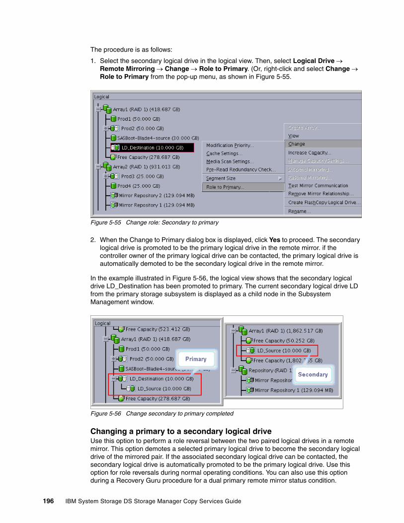
The procedure is as follows:
1. Select the secondary logical drive in the logical view. Then, select Logical Drive Remote Mirroring Change Role to Primary. (Or, right-click and select Change Role to Primary from the pop-up menu, as shown in Figure 5-55.
Figure 5-55 Change role: Secondary to primary
2. When the Change to Primary dialog box is displayed, click Yes to proceed. The secondary logical drive is promoted to be the primary logical drive in the remote mirror. if the controller owner of the primary logical drive can be contacted, the primary logical drive is automatically demoted to be the secondary logical drive in the remote mirror.
In the example illustrated in Figure 5-56, the logical view shows that the secondary logical drive LD_Destination has been promoted to primary. The current secondary logical drive LD from the primary storage subsystem is displayed as a child node in the Subsystem Management window.
Figure 5-56 Change secondary to primary completed
Changing a primary to a secondary logical driveUse this option to perform a role reversal between the two paired logical drives in a remote mirror. This option demotes a selected primary logical drive to become the secondary logical drive of the mirrored pair. If the associated secondary logical drive can be contacted, the secondary logical drive is automatically promoted to be the primary logical drive. Use this option for role reversals during normal operating conditions. You can also use this option during a Recovery Guru procedure for a dual primary remote mirror status condition.
196 IBM System Storage DS Storage Manager Copy Services Guide

If a communication problem between the primary and secondary sites prevents the promotion of the secondary logical drive, an error message is displayed. However, you are given the opportunity to proceed with the demotion of the primary logical drive, even though this leads to a dual secondary Remote Mirror status condition. For more information, see “Forcing a role reversal” on page 198.
1. Select the primary logical drive in the logical view. Then, select Logical Drive Remote Mirroring Change Role to Secondary as shown in Figure 5-57. (Or, right-click and select Change Role to Secondary from the pop-up menu.)
Figure 5-57 Change role: primary to secondary
2. The Change to Secondary Confirmation dialog box opens. Read the information and click Yes.
3. The primary logical drive is demoted to be the secondary logical drive in the remote mirror. If the controller owner of the secondary logical drive can be contacted, the secondary logical drive is automatically promoted to be the primary logical drive in the remote mirror.
The Figure 5-58 illustrates that the primary logical drive LD_Destination has been demoted to secondary.
Figure 5-58 Change primary to secondary completed
Important: Any hosts that are mapped to the primary logical drive through a logical drive-to-LUN mapping will no longer be able to write to the logical drive.
Chapter 5. ERM implementation 197
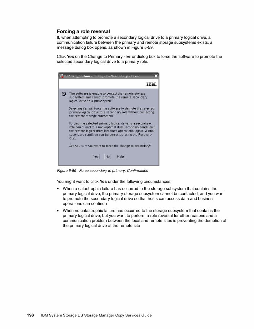
Forcing a role reversalIf, when attempting to promote a secondary logical drive to a primary logical drive, a communication failure between the primary and remote storage subsystems exists, a message dialog box opens, as shown in Figure 5-59.
Click Yes on the Change to Primary - Error dialog box to force the software to promote the selected secondary logical drive to a primary role.
Figure 5-59 Force secondary to primary: Confirmation
You might want to click Yes under the following circumstances:
� When a catastrophic failure has occurred to the storage subsystem that contains the primary logical drive, the primary storage subsystem cannot be contacted, and you want to promote the secondary logical drive so that hosts can access data and business operations can continue
� When no catastrophic failure has occurred to the storage subsystem that contains the primary logical drive, but you want to perform a role reversal for other reasons and a communication problem between the local and remote sites is preventing the demotion of the primary logical drive at the remote site
198 IBM System Storage DS Storage Manager Copy Services Guide

Figure 5-60 shows a logical volume LD_Source on a remote subsystem that was forced to primary. Because the connection with the primary is lost, it is shown as unsynchronized.
Figure 5-60 Unsynchronized secondary
When the remote storage subsystem has recovered and communication problems have been resolved, a dual primary error condition is raised. Perform the following steps:
1. Click the Recovery Guru to resolve the condition as shown in Figure 5-61.
2. Follow the procedure to remove and recreate the mirror relationship.
Figure 5-61 Recovery Guru: Mirror data unsynchronized
3. To avoid the dual primary error condition and subsequent recovery steps when no catastrophic failure has occurred to the storage subsystem containing the primary logical drive, wait until the connection between the storage subsystems is operational to perform the role reversal.
Chapter 5. ERM implementation 199

5.2.2 Re-establishing Remote Mirroring after failure recovery
When the damaged site is back online and properly configured, mirror relationships can be resumed. Re-create a mirror relationship by completing the following steps:
1. Ensure that SAN connections and SAN zoning are properly configured.
2. From the active secondary site, define a mirror relationship using the logical drive on the recovered primary site as the secondary logical drive. For more information see 5.1, “ERM: Step-by-step” on page 156.
3. Ensure that storage partitioning and host mapping are properly defined on the recovered primary site so that it can take over normal operation from the secondary site.
4. Ensure that the host software is properly configured so that the host systems at the recovered primary site can take over I/O from the secondary site host systems.
After the full synchronization has completed, perform a manual role reversal so that the recovered primary site now possesses the active primary logical drive, and the secondary logical drive now exists on the secondary site. For more information, see “Changing a primary to a secondary logical drive” on page 196.
5.3 ERM solution design
A SAN design is normally based on storage, flexibility, performance, and redundancy requirements. The ERM option is one piece of the solution.
This section presents three sample configurations showing how the ERM option can be implemented. The level of redundancy is determined by the type of configuration that you choose to use. However, they are only suggestions for how to build a reliable and highly available system environment based on IBM recommendations. The three sample solutions are as follows:
� Intra-site configuration with minimum redundancy
This solution shows a simple departmental solution implemented using two Fibre Channel switches and two midrange storage subsystems.
� Inter-site configuration with redundant fabric
Similar to the previous solution except for the storage subsystems being located in two physically separate sites.
� High-availability intersite configuration with redundant fabric
A solution that provides for the highest level of redundancy. This configuration can be expanded over long distances with proper switch and multiprotocol routers and network designs.
200 IBM System Storage DS Storage Manager Copy Services Guide
When designing a SAN storage solution, complete the following steps:
1. Produce a statement that outlines the solution requirements that can be used to determine the type of configuration that you need. It should also be used to cross-check that the solution design delivers the basic requirements. The statement should have easily defined bullet points covering the requirements, for example:
– Required capacity– Required redundancy levels– Backup and restore windows– Type of data protection needed– Network backups– LAN free backups– FlashCopy– ERM– Host and operating system types to be connected to SAN– Number of host connections required
2. Produce a hardware checklist. It should cover such items that require you to perform the following steps:
– Ensure that the minimum hardware requirements are met. – Create a complete list of hardware requirements including required premium options.– Ensure that your primary and secondary storage subsystems are properly configured. – Ensure that your Fibre Channel switches and cables are properly configured. The
Remote Mirroring links must be in a separate zone.
3. Produce a software checklist to cover all the required items that must be certified and checked. It should include items that require you to perform the following steps:
– Ensure that data on the primary and secondary storage subsystems participating in ERM is backed up.
– Ensure that the correct versions of firmware and storage-management software are installed.
– Ensure that the ERM option is enabled on both the primary and the secondary storage subsystems.
– Ensure that the ERM option is activated and that a mirror repository logical drive is created for each controller all participating storage subsystem.
– Ensure that the required primary and secondary logical drives are created on the primary and remote storage subsystems.
Note: Additional information about ERM planning and implementation best practices are in IBM Midrange System Storage Implementation and Best Practices Guide, SG24-6363.
Chapter 5. ERM implementation 201

5.3.1 Intra-site configuration
This section shows a simple departmental configuration. The configuration consists of two storage subsystems and two Fibre Channel switches that are connected with a Fibre Channel fabric, as shown in Figure 5-62.
The primary storage subsystem and remote storage subsystem can have a maximum connection distance of up to 500 m (0.32 mi.) and can be located in the same room or in the same building.
Figure 5-62 Intra-site (co-located) solution
The solution provides for switch redundancy, in that a failed switch causes a failover of the logical disk to the opposite controller where the host access is through the second Fibre Channel switch.
ERM can be configured in either direction. That is, a few can be configured with primary logical disks on the primary storage subsystem and secondary disks on the secondary, as well as having primary disks on the secondary system and secondary drives on the primary. Considering that, with this configuration, the two storage subsystems are usually in the same building, spreading the production load over both subsystems can offer the best performance.
The disadvantage of this configuration is a high number of Fibre Channel connections between both sites.
202 IBM System Storage DS Storage Manager Copy Services Guide
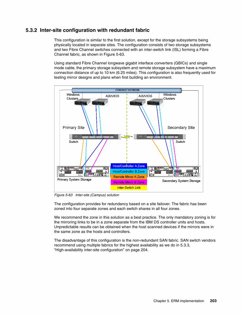
5.3.2 Inter-site configuration with redundant fabric
This configuration is similar to the first solution, except for the storage subsystems being physically located in separate sites. The configuration consists of two storage subsystems and two Fibre Channel switches connected with an inter-switch link (ISL) forming a Fibre Channel fabric, as shown in Figure 5-63.
Using standard Fibre Channel longwave gigabit interface converters (GBICs) and single mode cable, the primary storage subsystem and remote storage subsystem have a maximum connection distance of up to 10 km (6.25 miles). This configuration is also frequently used for testing mirror designs and plans when first building an environment.
Figure 5-63 Inter-site (Campus) solution
The configuration provides for redundancy based on a site failover. The fabric has been zoned into four separate zones and each switch shares in all four zones.
We recommend the zone in this solution as a best practice. The only mandatory zoning is for the mirroring links to be in a zone separate from the IBM DS controller units and hosts. Unpredictable results can be obtained when the host scanned devices if the mirrors were in the same zone as the hosts and controllers.
The disadvantage of this configuration is the non-redundant SAN fabric. SAN switch vendors recommend using multiple fabrics for the highest availability as we do in 5.3.3, “High-availability inter-site configuration” on page 204.
Chapter 5. ERM implementation 203

5.3.3 High-availability inter-site configuration
The highest availability configuration is fully redundant and includes two storage subsystems and four Fibre Channel switches connected with ISLs forming Fibre Channel fabrics, as shown in Figure 5-64. The primary storage subsystem and remote storage subsystem have a maximum connection distance of up to 10 km. (6.25 miles). This configuration can also be expanded over long distances with proper switch and multiprotocol routers and WAN network design for the ISL traffic for the mirrors.
Figure 5-64 Highest availability campus solution
Apart from the greater redundancy of dual switch fabric in each site, a greater number of host ports are now available, allowing greater flexibility in the use and connectivity.
With this type of configuration, consider putting the primary drives on the remote site. This approach offers an advantage of attaching the primary disk to the standby servers at the secondary site with a simple procedure when the primary site fails.
204 IBM System Storage DS Storage Manager Copy Services Guide
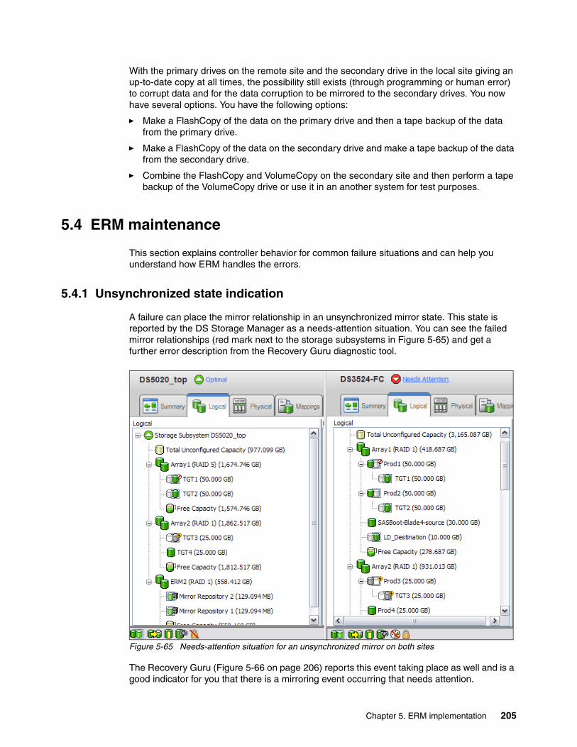
With the primary drives on the remote site and the secondary drive in the local site giving an up-to-date copy at all times, the possibility still exists (through programming or human error) to corrupt data and for the data corruption to be mirrored to the secondary drives. You now have several options. You have the following options:
� Make a FlashCopy of the data on the primary drive and then a tape backup of the data from the primary drive.
� Make a FlashCopy of the data on the secondary drive and make a tape backup of the data from the secondary drive.
� Combine the FlashCopy and VolumeCopy on the secondary site and then perform a tape backup of the VolumeCopy drive or use it in an another system for test purposes.
5.4 ERM maintenance
This section explains controller behavior for common failure situations and can help you understand how ERM handles the errors.
5.4.1 Unsynchronized state indication
A failure can place the mirror relationship in an unsynchronized mirror state. This state is reported by the DS Storage Manager as a needs-attention situation. You can see the failed mirror relationships (red mark next to the storage subsystems in Figure 5-65) and get a further error description from the Recovery Guru diagnostic tool.
Figure 5-65 Needs-attention situation for an unsynchronized mirror on both sites
The Recovery Guru (Figure 5-66 on page 206) reports this event taking place as well and is a good indicator for you that there is a mirroring event occurring that needs attention.
Chapter 5. ERM implementation 205

Figure 5-66 Recovery Guru error explanation
5.4.2 Link interruptions
Loss of communication can be caused by FC link failure but also by other hardware errors.
Fibre Channel mirror link interruptions in synchronous write modeIn synchronous mode, if the link is interrupted and the primary controller receives a write request from an attached host, the write request cannot be transferred to the secondary logical drive and the primary and secondary logical drives are no longer appropriately mirrored. The primary controller transitions the mirrored pair into an unsynchronized state and sends an I/O completion to the primary host. The host can continue to write to the primary logical drive but remote writes will not take place.
When connectivity is restored between the controller owner of the primary logical drive and the controller owner of the secondary logical drive, depending on the configured resynchronization method, either an automatic resynchronization takes place or a manual resysnchronization must be performed. The delta log bitmap is used to update the secondary with the changed blocks during the resynchronization process. The status of the mirrored pair changes from an unsynchronized state to a synchronization-in-progress state.
Note: Always use the Recovery Guru tool to check a needs-attention situation. The Recovery Guru utility provides an explanation of the error, and a procedure and hints for error recovery.
Note: A loss of communication between the primary and the secondary does not result in the controllers attempting to change ownership of drives. The only time ownership changes is on a host path failover. This results in the secondary mirror to change ownership to match the primary on the next write I/O.
206 IBM System Storage DS Storage Manager Copy Services Guide

Fibre Channel mirror link interruptions in asynchronous write modeIn asynchronous mode, if the link is broken, the primary controller periodically attempts to reestablish the connection to the secondary controller.
The mirror repository logical drive queues I/O requests until the 128 IO maximum of write requests that could not be sent to the secondary subsystem has been reached. When requests are being queued, the mirrored pair remains in a synchronized state. If the queue maximum of unsynchronized I/O requests is exceeded, the state of the mirrored pair changes to unsynchronized.
The host can continue to write to the primary logical drive but remote writes will not take place. If the link is recovered, depending on synchronizing settings, the resynchronization starts automatically or must be started through an administrative command (resume mirroring).
5.4.3 Fibre Channel mirror link test functionStorage Manager provides a feature to test the communication between two storage subsystems of a mirror pair. To invoke the Fibre Channel mirror link test function, right-click the primary logical drive and select Test Mirror Communication from the pop-up menu. See Figure 5-67. The result displays, represented by the image of a traffic light.
Figure 5-67 Fibre Channel mirror link test
Chapter 5. ERM implementation 207

Figure 5-68 shows the test result optimal link conditions (green light).
Figure 5-68 Fibre Channel mirror link test result display in optimal state
Figure 5-69 shows the test result with link error conditions (red light).
Figure 5-69 Fibre Channel mirror link test result display in error state
5.4.4 Secondary logical drive error
The primary controller also marks the mirrored pair as unsynchronized when a logical drive error on the secondary site prevents the remote write from completing. For example, an offline or a failed secondary logical drive can cause the ERM to become unsynchronized. The host can continue to write to the primary logical drive, but remote writes do not take place. After the logical drive error is corrected (the secondary logical drive is placed online or recovered to an optimal state), the resynchronization process can begin. Depending on synchronizing settings, the resynchronization starts automatically or must be started manually by issuing an administrative command (resume mirroring).
5.4.5 Primary controller failure
If a remote write is interrupted by a primary controller failure before it can be written to the secondary logical drive, the primary storage subsystem provides controller ownership change from the preferred controller owner to the alternate controller in the storage subsystem. The first write request to the remote site changes the ownership of the secondary logical drive. After the transition of the ownership is completed the mirroring is proceeds as usual.
208 IBM System Storage DS Storage Manager Copy Services Guide

5.4.6 Primary controller reset
If a remote write is interrupted by a primary controller reset before it can be written to the secondary logical drive, there is normally no ownership change. After reboot, the controller reads information stored in a log file in the mirror repository logical drive and uses the information to copy the affected data blocks from the primary logical drive to the secondary logical drive. Suspend mirror relationships before resetting the controller.
5.4.7 Secondary controller failure
If the secondary controller fails, the primary site can no longer communicate with the secondary logical drive. The mirror state becomes unsynchronized. The host can continue to write to the primary logical drive, but remote writes will not take place. After the secondary controller failure has been recovered, depending on the synchronization settings, the primary controller changes the mirror state to synchronizing either automatically or through a resume command.
5.4.8 Write consistency group and unsynchronized state
Mirror relationships that are configured within a write consistency group are considered an interdependent set with respect to the integrity of the data on the remote logical drives. A given secondary logical drive cannot be considered fully synchronized until all members of the write consistency group are synchronized. Similarly, when one mirrored logical drive pair of the write consistency group is in an unsynchronized state, all members of the group halt remote write activity to protect the consistency of the remote data of the entire group.
The controller changes the state of all mirrored pairs within the group to unsynchronized when any mirror within the set becomes unsynchronized or failed. All pending write requests for the member of the write consistency croup are moved to the mirror repository logical drive. Mirror relationships configured with the manual resynchronization setting remain in the suspended state until a user intervenes by issuing a resume command. Mirror relationships that are configured to allow automatic resynchronization automatically resynchronize.
You can use the synchronization priority to establish how the controller owner prioritizes the resources needed for the synchronization process relative to host I/O activity.
Chapter 5. ERM implementation 209
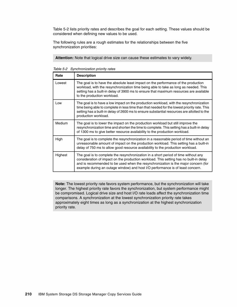
Table 5-2 lists priority rates and describes the goal for each setting. These values should be considered when defining new values to be used.
The following rules are a rough estimates for the relationships between the five synchronization priorities:
Table 5-2 Synchronization priority rates
Attention: Note that logical drive size can cause these estimates to vary widely.
Rate Description
Lowest The goal is to have the absolute least impact on the performance of the production workload, with the resynchronization time being able to take as long as needed. This setting has a built-in delay of 3900 ms to ensure that maximum resources are available to the production workload.
Low The goal is to have a low impact on the production workload, with the resynchronization time being able to complete in less time than that needed for the lowest priority rate. This setting has a built-in delay of 2600 ms to ensure substantial resources are allotted to the production workload.
Medium The goal is to lower the impact on the production workload but still improve the resynchronization time and shorten the time to complete. This setting has a built-in delay of 1300 ms to give better resource availability to the production workload.
High The goal is to complete the resynchronization in a reasonable period of time without an unreasonable amount of impact on the production workload. This setting has a built-in delay of 750 ms to allow good resource availability to the production workload.
Highest The goal is to complete the resynchronization in a short period of time without any consideration of impact on the production workload. This setting has no built-in delay and is recommended to be used when the resynchronization is the major concern (for example during an outage window) and host I/O performance is of least concern.
Note: The lowest priority rate favors system performance, but the synchronization will take longer. The highest priority rate favors the synchronization, but system performance might be compromised. Logical drive size and host I/O rate loads affect the synchronization time comparisons. A synchronization at the lowest synchronization priority rate takes approximately eight times as long as a synchronization at the highest synchronization priority rate.
210 IBM System Storage DS Storage Manager Copy Services Guide

5.5 ERM Configuration guide using the CLI
In this section, we discuss sample configurations to show how to configure remote mirroring using the Command Line Interface(CLI). In this case we are using the following environment:
Only when using a shell other than windows, for example bash, ksh, csh, etc. is usual to get the following error after executing a script with SMcli from the command prompt:
Was expecting one of: <STRING_LITERAL>
The reason for this is that the syntax to define a String could vary depending on each terminal shell. In that case try using the syntax [\”String”\] or \”String”\ to specify a string. An example is shown in Example 5-5.
Example 5-5 How to specify a string when using a UNIX® based shell.
# SMcli 1.1.1.8 1.1.1.9 -c "start remotemirror primary [\"LD_Source\"] synchronize;"
Alternatively, it is possible to execute the script from the IBM Storage Manager Script Editor.
5.5.1 Executing a script
To execute a script you can use either of the following two methods:
� From the IBM Storage Manager enterprise management window select Tools Execute Script as shown in Figure 5-70.
Figure 5-70 Tools menu from the IBM Storage Manager Enterprise window
Storage Subsystem name Storage Subsystem IP address
DS3524-FC DS3524 Controller A 1.1.1.2
DS3524 Controller B 1.1.1.3
DS5020_bottom DS5020 Controller A 1.1.1.8
DS5020 Controller B 1.1.1.9
Storage Subsystem Password Remote Mirror Logical Drives
DS3524-FC Passw0rd! LD_Destination
DS5020_bottom Passw0rd! LD_Source
Chapter 5. ERM implementation 211

After, you can write the script in the window and execute it, as shown in Figure 5-71.
Figure 5-71 Script Editor window
� Use SMcli.exe from a terminal window as shown in Example 5-6.
Example 5-6 SMcli help output
# SMcli -?SMcli <DNS-network-name-or-IP-address> [<DNS-network-name-or-IP-address>] [-c "<command>;[<command2>;...]"] [-n <storage-array-name> | -w <WWID>] [-o <outputfile>] [-p <password>] [-e] [-S] [-quick] SMcli <DNS-network-name-or-IP-address> [<DNS-network-name-or-IP-address>] [-f <scriptfile>] [-n <storage-array-name> | -w <WWID>] [-o <outputfile>] [-p <password>] [-e] [-S] [-quick]SMcli {-n <storage-array-name> | -w <WWID>} [-c "<command>;[<command2>;...]"] [-o <outputfile>] [-p <password>] [-e] [-S] [-quick]SMcli {-n <storage-array-name> | -w <WWID>} [-f <scriptfile>] [-o <outputfile>] [-p <password>] [-e] [-S] [-quick]SMcli -d [-i] [-s] [-w] [-v] [-S]SMcli -A [<DNS-network-name-or-IP-address1> [DNS-network-name-or-IP-address2]] [-S]SMcli -X (-n <storage-array-name> | -w <WWID> | -h <hostName>)SMcli -m <ip address> -F <email address> [-g <contactInfoFile>] [-S]SMcli -x email:<email address> [<hostname or IP address1> [<hostname or IP address2>]]
212 IBM System Storage DS Storage Manager Copy Services Guide

[-n <storage-array-name> | -w WWID | -h <hostName>] [-S]SMcli -a email:<email address> [<hostname or IP address1> [<hostname or IP address2>]] [-n <storage-array-name> | -w <WWID> | -h <hostName>]} [-I <informationToInclude>] [-q <frequency>] [-S]SMcli {-a | -x} trap:<community>,<hostname or IP address> [<hostname or IP address1> [<hostname or IP address2>]] [-n <storage-array-name> | -w <WWID> | -h <hostName>] [-S]
5.5.2 Activate Remote Mirror feature
This command creates the mirror repository logical drive and activates the Remote Mirror feature. When you use this command, you can define the repository logical drive in one of three ways:
� User-defined physical disks� User-defined array� User-defined number of physical disks for the repository logical drive
If you choose to define a number of physical disks the controller firmware chooses that physical disks to use for the repository logical drive.
Syntax (User-Defined Physical Disks) activate storageSubsystem feature=remoteMirror repositoryRAIDLevel=(1 | 3 | 5) repositoryDrives=(trayID1,slotID1 ... trayIDn,slotIDn) [enclosureLossProtect=(TRUE | FALSE)]
Syntax (User-Defined Array) activate storageSubsystem feature=remoteMirror repositoryArray= Array Number [freeCapacityArea=freeCapacityIndexNumber]
Syntax (User-Defined Number of Physical Disks) activate storageSubsystem feature=remoteMirror repositoryRAIDLevel=(1 | 3 | 5) repositoryDriveCount=numberOfDrives [driveType=(fibre | SATA | SAS) [enclosureLossProtect=(TRUE | FALSE)]
ParametersIn this section we define the individual parameters used in the syntax mentioned previously.
repositoryRAIDLevel The RAID level for the repository logical drive. Valid values are 1, 3, or 5.
repositoryDrives The physical disks for the repository logical drive. Specify the enclosure ID and slot ID for each physical disk you assign to the logical drive. Enclosure ID values are 0 to 99. Slot ID values are 1 to 32. Enclose the enclosure ID and slot ID values in parentheses.
repositoryArray The sequence number of the array where the repository logical drive will be located. (To determine the sequence numbers of the logical drive groups in your storage subsystem, enter the show storageSubsystem profile command.)
Chapter 5. ERM implementation 213

freeCapacityArea The index number of the free space in an existing array that you want to use to create the remote logical drive mirror repository logical drives. Free capacity area is defined as the free capacity between existing logical drives in an array. For example, an array might have the following areas: logical drive 1, free capacity, logical drive 2, free capacity, logical drive 3 free capacity. To use the free capacity following logical drive 2, you would specify: freeCapacityArea=2. Use the show Array command to determine if free capacity area exists.
repositoryDriveCount The number of unassigned physical disks that you want to use for the repository logical drive.
driveType The type of physical disks that you want to use for the repository logical drive. Valid physical disk types are Fibre, SATA, or SAS. Use this parameter only when you use the repositoryDriveCount parameter. You need to use this parameter only when you have more than one type of drive in your storage subsystem.
enclosureLossProtect Specifies that enclosure loss protection will be enforced when creating the repository. To enforce enclosure loss protection, set this parameter to TRUE. The default setting is FALSE.
ExampleExample 5-7 shows how to activate the remote mirroring feature by User-Defined physical disks.
Example 5-7 Remote Mirror Activation by User-Defined physical Disks
# SMcli 1.1.1.8 1.1.1.9 -c "activate storagesubsystem feature=remotemirror repositoryraidlevel=1 repositorydrives=(85,14 85,15);" -p Passw0rd!Performing syntax check...
Syntax check complete.
Executing script...
Script execution complete.
SMcli completed successfully.
Two logical drives are created. One for each controller as shown in Figure 5-72.
Figure 5-72 Mirror Repositories created
214 IBM System Storage DS Storage Manager Copy Services Guide

If the drives you select for the repositoryDrives parameter are not compatible with other parameters (such as the repositoryRAIDLevel parameter), the command will return an error, and Remote Mirroring will not be activated. The error returns the amount of space needed for the repository logical drive. You can then reenter the command, specifying the appropriate amount of space.
If you enter a value for the repository storage space that is too small for the mirror repository logical drives, the firmware will return an error message giving the amount of space needed for the mirror repository logical drives. The command will not attempt to activate the Remote Mirror. You can reenter the command using the value from the error message for the repository storage space value.
When you assign the physical disks, if you set enclosureLossProtect to true and have selected more than one physical disk from any one enclosure, the storage subsystem will return an error. If you set enclosureLossProtect to false, the storage subsystem will perform operations, but the array you create might not have enclosure loss protection.
When the controller firmware assigns the physical disks, if you set enclosureLossProtect to true, the storage subsystem will error the function if the controller firmware cannot provide drives that will result in the new array having enclosure loss protection. If you set enclosureLossProtect to false, the storage subsystem will perform the operation even if it means the array might not have enclosure loss protections.
5.5.3 Create Remote Mirror
This command creates both the primary and secondary logical drives for a Remote Mirror. This command also sets the write mode (synchronous or asynchronous) and synchronization priority.
Syntaxcreate remoteMirror primary="primaryLogical Drive Name" secondary="secondaryLogical DriveName" (remoteStorageSubsystemName="storageArrayName" | remoteStorageSubsystemWwn="wwn") [remotePassword= "password" syncPriority=(highest | high | medium | low | lowest) autoResync=(enabled | disabled) writeOrder=(preserved | notPreserved) writeMode=(synchronous | asynchronous)]
ParametersIn this section we define the individual parameters used in the syntax mentioned previously.
primary The name of an existing logical drive on the local storage subsystem you want to use for the primary logical drive. Enclose the primary logical drive name in double quotes (" ").
secondary The name of an existing logical drive on the remote storage subsystem you want to use for the secondary logical drive. Enclose the secondary logical drive name in double quotes (" ").
remoteStorageSubsystemName The name of the remote storage subsystem. Enclose the remote storage subsystem name in double quotes (" ").
Chapter 5. ERM implementation 215

remoteStorageSubsystemWwn The world wide name of the remote storage subsystem. Enclose the world wide name in double quotes (" ").
remotePassword The password for the remote storage subsystem. Use when the remote storage subsystem is password protected. Enclose the password in double quotes (" ").
syncPriority Defines the priority full synchronization will have relative to host I/O activity. Valid entries are highest, high, medium, low, or lowest
autoResync This parameter defines the settings for automatic resynchronization between the primary logical drives and the secondary logical drives of a Remote Mirroring pair. This parameter has the following arguments:
enabled Automatic resynchronization is turned on. You do not need to do anything further to resynchronize the primary and secondary logical drives.
disabled Automatic resynchronization is turned off. To resynchronize the primary logical drives and the secondary logical drives, you must enter the resume remoteMirror command.
writeOrder Defines write order for data transmission between the primary logical drive and secondary logical drive. Valid values are preserved or notPreserved.
writeMode Defines how the primary logical drive writes to the secondary logical drive. Valid values are synchronous or asynchronous.
You can use any combination of alphanumeric characters, hyphens, and underscores for the name. Names can have a maximum of 30 characters. When choosing the primary and secondary logical drives, the secondary logical drive must be of equal or greater size than the primary logical drive. The RAID level of the secondary logical drive does not have to be the same as the primary logical drive. For a 2882 controller, you can define 32 remote mirrors. For the 4884 and 5884 controllers, you can define 64 remote mirrors.
Passwords are stored on each storage subsystem in a management domain. If a password was not previously set, you do not need a password. The password can be any combination of a alphanumeric characters with a maximum of 30 characters. (You can define a storage subsystem password using the set storageSubsystem command.)
Synchronization priority defines the amount of system resources used to synchronize the data between the primary and secondary logical drives of a mirror relationship. If you select the highest priority level, the data synchronization uses the most system resource to perform the full synchronization, which will decrease performance for host data transfers.
The writeOrder parameter applies only to asynchronous mirrors and makes them become part of a consistency group. Setting the write order to preserved causes the mirrored pair to transmit data from the primary to secondary in the same order as the host writes to the primary. In the event of a transmission link failure, the data is buffered until a full
216 IBM System Storage DS Storage Manager Copy Services Guide
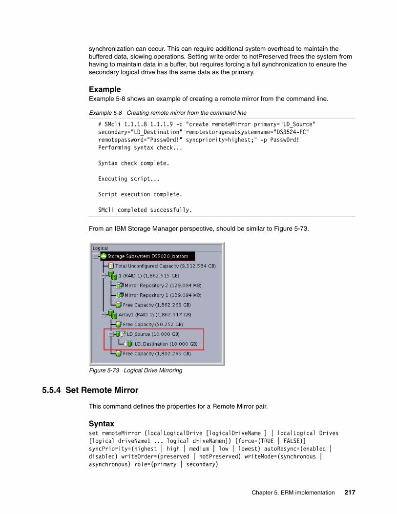
synchronization can occur. This can require additional system overhead to maintain the buffered data, slowing operations. Setting write order to notPreserved frees the system from having to maintain data in a buffer, but requires forcing a full synchronization to ensure the secondary logical drive has the same data as the primary.
ExampleExample 5-8 shows an example of creating a remote mirror from the command line.
Example 5-8 Creating remote mirror from the command line
# SMcli 1.1.1.8 1.1.1.9 -c "create remoteMirror primary="LD_Source" secondary="LD_Destination" remotestoragesubsystemname="DS3524-FC" remotepassword="Passw0rd!" syncpriority=highest;" -p Passw0rd!Performing syntax check...
Syntax check complete.
Executing script...
Script execution complete.
SMcli completed successfully.
From an IBM Storage Manager perspective, should be similar to Figure 5-73.
Figure 5-73 Logical Drive Mirroring
5.5.4 Set Remote Mirror
This command defines the properties for a Remote Mirror pair.
Syntaxset remoteMirror (localLogicalDrive [logicalDriveName ] | localLogical Drives [logical driveName1 ... logical driveNamen]) [force=(TRUE | FALSE)] syncPriority=(highest | high | medium | low | lowest) autoResync=(enabled | disabled) writeOrder=(preserved | notPreserved) writeMode=(synchronous | asynchronous) role=(primary | secondary)
Chapter 5. ERM implementation 217

ParametersIn this section we define the individual parameters used in the syntax mentioned previously.
logicalDriveName Name of the primary logical drive for which you want to define properties. You can enter more than one primary logical drive name. Enclose the primary logical drive name in square brackets ([ ]). If the primary logical drive name has special characters, you must also enclose the primary logical drive name in double quotes (" ").
role Defines whether the logical drive acts as the primary or secondary logical drive. To define the logical drive as the primary logical drive, set this parameter to primary. To define the logical drive as the secondary logical drive, set this parameter to secondary. This parameter applies only when the logical drive is part of a mirror relationship.
force Defines that you want to force the role reversal if the communications link between the storage subsystems is down and promotion or demotion on the local side will result in a dual primary or dual secondary condition. To force a role change, set this parameter to TRUE. The default is FALSE.
syncPriority Defines the priority full synchronization will have relative to host I/O activity. Valid entries are highest, high, medium, low, or lowest
autoResync This parameter defines the settings for automatic resynchronization between the primary logical drives and the secondary logical drives of a Remote Mirroring pair. This parameter has the following arguments:
enabled Automatic resynchronization is turned on. You do not need to do anything further to resynchronize the primary and secondary logical drives.
disabledAutomatic resynchronization is turned off. To resynchronize the primary logical drives and the secondary logical drives, you must enter the resume remoteMirror command.
writeOrder Defines write order for data transmission between the primary logical drive and secondary logical drive. Valid values are preserved or notPreserved.
writeMode Defines how the primary logical drive writes to the secondary logical drive. Valid values are synchronous or asynchronous. When you use this command, you can specify one or more of the parameters. You do not, however, need to use all of the parameters.
You cannot change remote mirror logical drive roles and set other parameters in the same command. If you want to change remote mirror logical drive roles and set other parameters, you must first issue a command to change the remote mirror logical drive role and then issue a second command to set other parameters. Synchronization priority defines the amount of system resources used to synchronize the data between the primary and secondary logical drives of a mirror relationship. If you select the highest priority level, the data synchronization uses the most system resources to perform the full synchronization, which will decrease
218 IBM System Storage DS Storage Manager Copy Services Guide
performance for host data transfers. Setting the writer order to preserved causes the mirrored pair to transmit data from the primary to secondary in the same order as the host writes to the primary. In the event of a transmission link failure, the data is buffered until a full synchronization can occur. This can require additional system overhead to maintain the buffered data, slowing operations. Setting write order to notPreserved frees the system from having to maintain data in a buffer, but it requires forcing a full synchronization to ensure the secondary logical drive has the same data as the primary logical drive.
Use set remoteMirror command to perform role reversalAs an example of this command, we will show how to perform a role reversal with the command line. The concept of role reversal is explained in Chapter 4, “Enhanced Remote Mirroring (ERM) concepts, planning, and design” on page 93.
ExampleExample 5-9 shows an example of performing role reversal execution
Example 5-9 Performing role reversal execution
# SMcli 1.1.1.2 1.1.1.3 -c "set remoteMirror locallogicaldrive ["LD_Destination"] role=primary force=FALSE syncpriority=high;" -p Passw0rd!Performing syntax check...
Syntax check complete.
Executing script...
Script execution complete.
SMcli completed successfully.
5.5.5 Deactivate Remote Mirror
This command deactivates the Remote Mirror feature and tears down the mirror repository logical drive. The host bus adapter (HBA) host port dedicated to the Remote Mirror is made available for host data transfers.
Syntaxdeactivate storageSubsystem feature=remoteMirror
ExampleExample 5-10 shows an example of deactivating the remote mirror
Example 5-10 Deactivate Remote Mirror
# SMcli 1.1.1.8 1.1.1.9 -c "deactivate storagesubsystem feature=remotemirror;" -p Passw0rd!Performing syntax check...
Syntax check complete.
Note: This command must be executed on the Storage Array where the logical drive with the current secondary role is.
Chapter 5. ERM implementation 219
Executing script...
Script execution complete.
SMcli completed successfully.
5.5.6 Remove Remote Mirror
This command removes the mirror relationship between the primary logical drive and secondary logical drive.
Syntaxremove remoteMirror (localLogicalDrive [logicalDriveName] | localLogicalDrives [logicalDriveName1 ... volumeNamen])
ParametersIn this section we define the individual parameters used in the syntax mentioned previously.
localLogicalDrive Name of the primary logical drive (logical drive on the local storage subsystem) you want to remove. You can enter more than one logical drive name. Enclose the logical drive name in square brackets ([ ]). If the logical drive name has special characters, you must also enclose the logical drive name in double quotes (" ").
ExampleExample 5-11 shows an example of removing a remote mirror
Example 5-11 Removing a remote mirror
# SMcli 1.1.1.8 1.1.1.9 -c "remove remotemirror locallogicaldrive["LD_Source"];" -p Passw0rd!Performing syntax check...
Syntax check complete.
Executing script...
Script execution complete.
SMcli completed successfully.
5.5.7 Diagnose Remote Mirror
This command tests the connection between the specified primary logical drives and mirror logical drives on a storage subsystem with the Remote Mirror feature installed.
Syntaxdiagnose remoteMirror (primary [primaryLogical Drive Name] | primaries [primaryLogical DriveName1 ... primaryLogical DriveNamen]) testID=connectivity
220 IBM System Storage DS Storage Manager Copy Services Guide

ParametersIn this section we define the individual parameters used in the syntax mentioned previously.
primaryLogical DriveName Name of the primary logical drive of the Remote Mirror you want to test. You can enter more than one primary logical drive name. Enclose the primary logical drive names in square brackets ([ ]). If the primary logical drive name has special characters, you must also enclose the host group name in double quotes (" ").
ExampleExample 5-12 shows an example of diagnosing a remote mirror.
Example 5-12 Diagnose Remote Mirror
# SMcli 1.1.1.8 1.1.1.9 -c "diagnose remotemirror primary ["LD_Source"] testid=connectivity;" -p Passw0rd!Performing syntax check...
Syntax check complete.
Executing script...
Communication between the owning controllers of Primary Logical Drive LD_Source and Secondary Logical Drive LD_Destination is normal.
Maximum allowed round trip time: 10,000,000 microsecondsAverage round trip time: 150 microsecondsShortest round trip time: 136 microsecondsScript execution complete.
SMcli completed successfully.
5.5.8 Suspend Remote Mirror
This command suspends a Remote Mirror operation.
Syntax suspend remoteMirror ( primary [primary Volume Name] | primaries [primary VolumeName1 ... primary Volume Name]) writeConsistency=(TRUE | FALSE)
ParametersIn this section we define the individual parameters used in the syntax mentioned previously.
logicalDriveName Name of the logical drive for which you want to suspend operation. Enclose the logical drive name in square brackets ([ ]). If the logical drive name has special characters, you must also enclose the logical drive name in double quotes (" ").
writeConsistency Defines whether the logical drives identified in this command are in a write-consistency group or are separate. For the logical drives in the same write-consistency group, set this parameter to TRUE. For the logical drives that are separate, set this parameter to FALSE.
Chapter 5. ERM implementation 221

If you set writeConsistency to TRUE, the logical drives must be in a write-consistency group (or groups). The action of the command is to suspend all consistency groups containing the logical drives. For example, if logical drives A, B, and C are in a consistency group and they have remote counterparts A', B', and C', the command suspend remoteMirror logicalDrive["A"] writeConsistency=true suspends A-A', B-B', and C-C'. If you have a consistency group 1={A, B, C} and consistency group 2={D, E, F}, the command suspend remoteMirror logical drives["A", "D"] writeConsistnecy=true suspends both consistency groups.
ExampleExample 5-13 shows an example of suspending a remote mirror
Example 5-13 Suspend Remote Mirror
# SMcli 1.1.1.8 1.1.1.9 -c "suspend remotemirror primary ["LD_Source"];" -p Passw0rd!Performing syntax check...
Syntax check complete.
Executing script...
Script execution complete.
SMcli completed successfully.
From an IBM Storage Manager perspective, should be similar to Figure 5-74.
Figure 5-74 Suspending Remote Mirror
5.5.9 Resume Remote Mirror
This command resumes a suspended Remote Mirror operation.
Syntaxresume remoteMirror (primary [logicalDriveName] | primaries [logicalDriveName1 ... logicalDriveName]) writeConsistency=(TRUE | FALSE)]
222 IBM System Storage DS Storage Manager Copy Services Guide

ParametersIn this section we define the individual parameters used in the syntax mentioned previously.
primary or primaries The name of the primary logical drive for which you want to resume operation. You can enter more than one logical drive name. Enclose the logical drive name in square brackets ([ ]). If the logical drive name has special characters, you must also enclose the logical drive name in double quotes (“ “).
writeConsistency Defines whether the logical drives identified in this command must be in a write-consistency group or can be separate. For the logical drives to be in the same write-consistency group, set this parameter to TRUE. For the logical drives to be separate, set this parameter to FALSE.
Defines whether the logical drives identified in this command must be in a write-consistency group or can be separate. For the logical drives to be in the same write-consistency group, set this parameter to TRUE. For the logical drives to be separate, set this parameter to FALSE.
Example 5-14 shows how to resume a remote mirror logical drive.
Example 5-14 Resume a remote mirror logical drive
# SMcli 1.1.1.8 1.1.1.9 -c "resume remotemirror primary ["LD_Source"];" -p Passw0rd!Performing syntax check...
Syntax check complete.
Executing script...
Script execution complete.
SMcli completed successfully.
5.5.10 Start Remote Mirror Synchronization
This command starts Remote Mirror synchronization.
Syntax start remoteMirror primary ["logicalDriveName"] synchronize
ParametersIn this section we define the individual parameters used in the syntax mentioned previously.
logicalDriveName Name of the primary logical drive for which you want to start synchronization. Enclose the primary logical drive name in double quotation marks (" ") inside square brackets ([ ]).
ExampleExample 5-15 shows an example of remote mirror synchronization.
Example 5-15 Remote Mirror Synchronization
# SMcli 1.1.1.8 1.1.1.9 -c "start remotemirror primary ["LD_Source"] synchronize;" -p Passw0rd!
Chapter 5. ERM implementation 223

Performing syntax check...
Syntax check complete.
Executing script...
Script execution complete.
SMcli completed successfully.
5.5.11 Show Remote Mirror synchronization progress
This command returns the percentage progress of a Remote Mirror synchronization. Use this command to determine when a synchronization finish.
The Example 5-16 shows the output for a mirror logical drive in suspended status.
Example 5-16 Displaying the Remote Mirror synchronization progress
# SMcli 1.1.1.8 1.1.1.9 -c "show remotemirror locallogicaldrive ["LD_Source"] synchronizationprogress;" -p Passw0rd!Performing syntax check...
Syntax check complete.
Executing script...
Mirror pair (primary LD_Source/secondary LD_Destination): Suspended - 0% out of sync
Script execution complete.
SMcli completed successfully.
224 IBM System Storage DS Storage Manager Copy Services Guide
Appendix A. Additional instructions for FlashCopy logical drives
This appendix provides an overview of using FlashCopy logical drives with specific operating systems and disk file systems.
A
Attention: Always check the appropriate support website before connecting hosts to the storage server or using the advanced functions. See the System Storage Interoperation Center (SSIC):
http://www.ibm.com/systems/support/storage/config/ssic/displayesssearchwithoutjs.wss
© Copyright IBM Corp. 2011. All rights reserved. 225
Operating system resources for additional instructions
After you use the Create FlashCopy Logical Drive Wizard to create the FlashCopy logical drive as described in 2.2, “FlashCopy with the GUI wizard: Step-by-step” on page 18and map the FlashCopy logical drive to the host as described in 2.2.3, “Mapping a FlashCopy drive to a host” on page 35, you must complete additional steps to configure the host operating system. See the following sections for additional instructions that are required when creating FlashCopy logical drives on your host operating system.
� “Instructions for Windows 2003 or 2008” on page 226
– “Creating a Flashcopy logical drive process overview” on page 227– “Reusing a Flashcopy logical drive process overview” on page 229
� “Instructions for AIX” on page 230
– “Creating a FlashCopy logical drive process overview” on page 230– “Reusing FlashCopy logical drive process overview” on page 233
� “Instructions for Linux” on page 234
– “Creating a Flashcopy logical drive process overview” on page 234– “Reusing a Flashcopy logical drive process overview” on page 236
� “Instructions for IBM i” on page 236
Instructions for Windows 2003 or 2008
This section discusses the procedures for Windows basic disk (also called regular disks). Use the following procedure when creating FlashCopy logical drives on a host running Windows Server 2003 or Windows Server 2008, using basic disks. Failure to complete the steps listed can result in an inaccurate point-in-time image of the base logical drive.
FlashCopy logical drives can be reused (for frequent or nightly backups) or created for one-time usage (speculative change or upgrade testing).
Attention: Failure to complete the steps listed for your host operating system can result in a loss of FlashCopy data consistency.
Note: For additional instructions and host operating systems, see the Copy Services User's Guide - IBM System Storage DS Storage Manager v10.70 available from the IBM Support Portal: https://www.ibm.com/support/entry/myportal/docdisplay?lndocid=MIGR-61173
Attention: Making a FlashCopy of a Windows Dynamic Disk is not supported.
226 IBM System Storage DS Storage Manager Copy Services Guide

Creating a Flashcopy logical drive process overview
The process shown in Figure A-1 outlines the key steps required to create a FlashCopy logical drive on Windows Server 2003 or Windows Server 2008 (using basic or regular disks).
Figure A-1 Create a Flashcopy logical drive in Windows
Create the flashcopy logical driveusing create
flashcopyLogicalDrive CLI command or GUI equivalent
Create logical drive-to-LUN mapping(s) for the flashcopy
logical drive(s) to the host where it will be used
Stop the host application that is using the base logical drive or
suspend data transfer to the base logical drive
Run SMrepassist -f utility on the host where the base logical drive is
mapped
End of Process
FlashCopy logical drive is now ready for use
Disable flashcopy logical drive until required again using stop flashcopy logicalDrive CLI command or GUI equivalent
Assign a drive letter to the flashcopy logical drive using Disk
Administrator
Restart the host application or re-enable data transfer
Register the flashcopy logical drive LUN(s)
(reboot the host or use the hot_add utility)
Appendix A. Additional instructions for FlashCopy logical drives 227

Attention: You cannot add the FlashCopy logical drive to the same Windows server that the FlashCopy base logical drive is mapped to. You must add the FlashCopy logical drive to another Windows server, or unmap the base logical drive from the server that it is mapped to.
Windows operating systems traditionally support a master boot record (MBR) disk partition format. The 64-bit Windows Server 2003 and 32/64-bit Windows Server 2008 systems support the new GUID Partition Table (GPT) disk partition format. The 32-bit Windows Server 2003 operating system does not have support for this new partition format and does not know how to properly access a GPT disk.
When a base logical drive that is mapped to a 64 bit Windows Server 2003 or 32/64-bit Windows Server 2008 host is initialized with the GPT disk partition format, any FlashCopy logical drives created of this base logical drive must also be mapped to a 64-bit Windows Server 2003 or a 32/64-bit Windows Server 2008 host. If you map the FlashCopy logical drive to a 32-bit Windows Server 2003, the operating system does not recognize the partition format of the FlashCopy logical drive.
Alternatively, you can initialize the base logical drive on the 64-bit Windows Server 2003 and 32/64-bit Windows Server 2008 host with the older MBR disk partition format, and any FlashCopies of that base logical drive will be accessible by other 32-bit Windows hosts.
Note: The SMrepassist and hot_add utilities are installed with the DS Storage Manager software
228 IBM System Storage DS Storage Manager Copy Services Guide

Reusing a Flashcopy logical drive process overviewThe process shown in Figure A-2 outlines the key steps required to reuse a FlashCopy logical drive on Windows Server 2003 or Windows Server 2008 (using basic or regular disks)
Figure A-2 Reuse a FlashCopy logical drives in Windows
Stop the host application or suspend data transfer to the base logical
drive
Run SMrepassist -f utility on the host where the base logical drive is
mapped
Re-create the flashcopy logical drive using recreate flashcopy
logicalDrive CLI command or GUI
equivalent)
Restart the host application or re-enable data transfer
End of Process
FlashCopy logical drive ready for use
Disable flashcopy logical drive until required again using stop flashcopy logicalDrive CLI command or GUI equivalent
Run SMreppassist -f utility on the host where the flashcopy logical
drive is mapped.
Stop the flashcopy logical drive using stop flashcopy logicalDrive
CLI command or GUI equivalent
Appendix A. Additional instructions for FlashCopy logical drives 229
Instructions for AIX
This section describes creating and reusing a FlashCopy logical drive on AIX with LogicalDrive Manager.
Creating a FlashCopy logical drive process overview
Figure A-3 on page 231 shows an overview of the key steps in the process of creating a Flashcopy logical drive for use with AIX.
Note: To ensure that an accurate point-in-time image of the base logical drive is captured, all I/O activity to the base logical drive should be stopped before proceeding with the FlashCopy logical drive creation.
230 IBM System Storage DS Storage Manager Copy Services Guide

Figure A-3 Create a Flashcopy logical drive for use in AIX
Create the Flashcopy logical drive(create flashcopy
logicalDrive CLI command or GUI equivalent)
Create logical drive-to-LUN mappings for Flashcopy
logical drive to host where it will be used
Enter command cfgmgr at the host prompt to discover the flashcopy
logical drive(s)
Enter command mount mount-point at the host prompt to mount each Flashcopy logical drive to the
host
End of Process
Enter command df -k at host prompt to confirm that the
Flashcopy logical drives are online and ready for use
(backup, speculative test, upgrades)
Disable Flashcopy logical drive until required again (for backup or
testing)using stop flashcopy
logicaDrive CLI command or GUI equivalent)
Enter command lspv to display all drives recognised by the host
system and identify the Flashcopy logical drive(s)
Enter command chdev -l os_device_name -a pv=clear at the host prompt to clear the PVID for
each new Flashcopy logical drive
Enter command recreatevg -y logical drivegroupname -L /directoryname os_device_name
at the host prompt to re-create a new array containing the Flashcopy
logical drives
Enter command umount mount-point at host prompt to unmount the Flashcopy logical drive(s) when
no longer required
Enter command varyoffvg logical drivegroupname
exportvg logical drivegroupname at host prompt to delete each array that contains the Flashcopy logical drive(s) when no
longer required
Appendix A. Additional instructions for FlashCopy logical drives 231

Note: The following restrictions apply when you create FlashCopy logical drives on AIX:
� To map FlashCopy logical drives to the same host as the base logical drive, use:
– AIX Version 4.3.3 with the AIX Version 4.3.3 Recommended Maintenance Level 06 (AIX 4330-06) maintenance package
– AIX Version 5.x
– AIX Version 6.1
� If a FlashCopy drive is created for a logical drive within an AIX LVM volume group, FlashCopy drives must be created for all logical drives in the volume group. This is a requirement for the recreatevg command to work successfully.
� AIX does not support the “Fail writes to base logical drive” option of the repository full policy. Selecting this option might cause data loss on the base logical drive. You must ensure that the repository full policy is set to the default option, “Fail FlashCopy logical drive.”
Note: On VIOS hosts, substitute the cfgdev command for the cfgmgr command in the previously mentioned process.
232 IBM System Storage DS Storage Manager Copy Services Guide

Reusing FlashCopy logical drive process overviewThe process in Figure A-4 outlines the steps to re-use a Flashcopy Logical drive in AIX.
Figure A-4 Reuse a Flashcopy logical drive in AIX
Enter command umount mount-point at the host prompt to
unmount the filesystems on the array containing the Flashcopy
logical drives
Re-create the flashcopy logical drive using recreate flashcopy
logicalDrive CLI command or GUI equivalent)
Enter command cfgmgr at the host prompt to discover the flashcopy
logical drive(s)
Enter command mount mount-point at the host prompt to mount each Flashcopy logical drive to the
host
End of Process
Enter command df -k at host prompt to confirm that the
Flashcopy logical drives are online and ready for use
(backup, speculative test, upgrades)
Disable Flashcopy logical drive until required again (for backup or
testing)using stop flashcopy
logicaDrive CLI command or GUI equivalent)
Enter command lspv to display all drives recognised by the host
system and identify the Flashcopy logical drive(s)
Enter command chdev -l os_device_name -a pv=clear at the host prompt to clear the PVID for
each new Flashcopy logical drive
Enter command recreatevg -y logical drivegroupname -L /directoryname os_device_name
at the host prompt to re-create a new array containing the Flashcopy
logical drives
Enter command umount mount-point at host prompt to unmount the Flashcopy logical drive(s) when
no longer required
Enter command varyoffvg logical drivegroupname
exportvg logical drivegroupname at host prompt to delete each array that contains the Flashcopy logical drive(s) when no
longer required
Appendix A. Additional instructions for FlashCopy logical drives 233

Instructions for Linux
This section describes creating and reusing a FlashCopy logical drive on Linux.
Creating a Flashcopy logical drive process overviewUse the procedure shown in Figure A-5 on page 235 to create a Flashcopy logical drive on a host that is running Linux. Failure to complete the steps listed can result in an inaccurate point-in-time image of the base logical drive.
Note: The hot_add and SMdevices utilities used in this process are part of the DS Storage Manager software. See the following publications for more information about installing IBM System Storage DS Storage Manager in Linux:
� IBM Midrange System Storage Implementation and Best Practices Guide, SG24-6363� IBM System Storage DS4000 and Storage Manager V10.30, SG24-7010� IBM System Storage DS3500: Introduction and Implementation Guide, SG24-7914
234 IBM System Storage DS Storage Manager Copy Services Guide

Figure A-5 Creating a Flashcopy logical drive on a Linux host
Create the flashcopy logical driveusing create
flashcopyLogicalDrive CLI command or GUI equivalent
Create logical drive-to-LUN mapping(s) for the flashcopy
logical drive(s) to the host where it will be used
Stop the host application that is using the base logical drive or
suspend data transfer to the base logical drive
End of Process
FlashCopy logical drive is now ready for use
Disable flashcopy logical drive until required again using stop flashcopy logicalDrive CLI command or GUI equivalent
Mount the FlashCopy logical drive to the intended host
Restart the host application or re-enable data transfer
Register the flashcopy logical drive LUN(s)
(reboot the host or use the /usr/
sbin/hot_add utility)
Run the SMdevices utility to associate the Flashcopy LUN with a host operating system device and to ensure that the FlashCopy logical drive is recognized by the host
Unmount the Flashcopy logical drive when no longer required
Appendix A. Additional instructions for FlashCopy logical drives 235

Reusing a Flashcopy logical drive process overviewUse the procedure shown in Figure A-6 to reuse a Flashcopy logical drive on a host that is running Linux. Failure to complete the steps listed can result in an inaccurate point-in-time image of the base logical drive.
Figure A-6 Reuse a Flashcopy logical drive with Linux process overview
Instructions for IBM i
See IBM i and IBM System Storage: A Guide to Implementing External Disks on IBM i, SG24-7120 for information about this procedure on IBM i.
Unmount the base logical drive from the host
Re-create the flashcopy logical drive using recreate flashcopy
logicalDrive CLI command or GUI equivalent)
Remount the base logical drive to the host
End of Process
Disable Flashcopy logical drive until required again using the stop flashcopy logicaDrive CLI
command or GUI equivalent)
Stop the host application or suspend data transfer to the base logical
drive
Mount the Flashcopy logical drive to the host
Re-enable the host application or resume data transfer to the base
logical drive
Unmount the Flashcopy logical drive from the host when no longer
required
Unmount the Flashcopy logical drive from the host (if currently mounted
to a host)
FlashCopy logical drive ready for use
236 IBM System Storage DS Storage Manager Copy Services Guide

Related publications
The publications listed in this section are considered particularly suitable for a more detailed discussion of the topics covered in this book.
IBM Redbooks
The following IBM Redbooks publications provide additional information about the topic in this document. Note that publications referenced in this list might be available in softcopy only.
� IBM System Storage DS4000 and Storage Manager V10.30, SG24-7010
� IBM System Storage DS3000: Introduction and Implementation Guide, SG24-7065
� IBM System Storage DS3500: Introduction and Implementation Guide, SG24-7914
� Implementing an IBM/Cisco SAN, SG24-75455
� Implementing an IBM/Brocade SAN with 8 Gbps Directors and Switches, SG24-6116
� IBM Midrange System Storage Implementation and Best Practices Guide, SG24-6363
� IBM System Storage/Brocade Multiprotocol Routing: An Introduction and Implementation, SG24-7544
� IBM Midrange System Storage Hardware Guide, SG24-7676
� IBM System Storage Copy Services and IBM i: A Guide to Planning and Implementation, SG24-7103
� IBM System Storage Business Continuity: Part 1 Planning Guide, SG24-6547
� IBM System Storage Business Continuity: Part 2 Solutions Guide, SG24-6548
You can search for, view, or download Redbooks, Redpapers, Technotes, draft publications and Additional materials, and order hardcopy Redbooks publications, at this website:
ibm.com/redbooks
Other publications
These publications are also relevant as further information sources:
� IBM System Storage DS4000 Concepts Guide
� IBM System Storage DS Storage Manager Version 10.70 Copy Services User’s Guide
� IBM System Storage DS Storage Manager Version10 Installation and Host Support Guide
� IBM System Storage DS4800 Storage Subsystem Installation, User's, and Maintenance Guide
� IBM System Storage DS5100 and DS5300 Storage Subsystems Installation, User's, and Maintenance Guide
� IBM System Storage DS3000, DS4000, and DS5000 Command Line Interface and Script Commands Programming Guide
All these publications are available for download from the IBM Support website http://www.ibm.com/systems/support/storage/disk
© Copyright IBM Corp. 2011. All rights reserved. 237

Online resources
These websites are also relevant as further information sources:
� System Storage Interoperation Center (SSIC) http://www.ibm.com/systems/support/storage/config/ssic
� Support for IBM Disk system http://www.ibm.com/systems/support/storage/disk
� Generate an activation filehttps://www-912.ibm.com/PremiumFeatures/
� Using FlashCopy with DB2 http://www.ibm.com/developerworks/db2/library/techarticle/dm-0508quazi/index.html
� List of compatible hosts for ERM, and which midrange models support ERM http://www.ibm.com/systems/storage/product/interop.html
� Interoperability matrix for the IBM System Storage and TotalStorage products http://www.ibm.com/systems/storage/disk/ds4000/interop-matrix.html
Help from IBM
IBM Support and downloads
ibm.com/support
IBM Global Services
ibm.com/services
238 IBM System Storage DS Storage Manager Copy Services Guide

Index
Aactivate 5activate a premium feature 7Activate Remote Mirroring wizard 160actual/usable capacity 173advanced path 23, 28associated base logical drive 40associated FlashCopy logical drive 40asynchronous 3, 96asynchronous mirroring with write order consistency (WOC) 98asynchronous mirroring without write consistency group 100asynchronous write mode 98, 100automatic resynchronization 114, 181, 206
Bbacking up data 68bandwidth 133–134Bandwidth Estimator Tool 147base logical drive 14BBcredit 116bidirectional mirroring 101, 127buffer credits 116business impact analysis (BIA) 125
Ccache settings 125capacity 40chronological inconsistencies 66coarse wavelength division multiplexing (CWDM) 135command-line interface (CLI) 13, 50, 65, 89, 155, 188compression 117connection bandwidth 135connection latency 135connection protocol 135consistency group 3consistency groups 98consistent copy 20controller owner 96controller ownership 40copy back 71Copy Manager 2, 70, 73, 81copy priority 70, 73, 81copy priority rates 84copy services premium features 4copy status 81copy-on-write 15, 18copy-on-write data 14, 16, 18create a FlashCopy drive 20Create Copy wizard 2, 69, 75create FlashCopy logical drive 19–20create FlashCopylogical drive 50
© Copyright IBM Corp. 2011. All rights reserved.
create remote mirror relationship 165create volumeCopy 90creating a VolumeCopy pair 73cross-mirroring 125CWDM 117, 135
Ddata resynchronization method 180database layout 137DCE 108Deactivate 219default naming convention 24default policy 17defragment 18defragmentation utility 18defragmenting an array 71delete FlashCopy logical drive 50delete logicalDrive 50, 58deleting a mirrored logical drive 108delta bitmap 97delta log bitmap 206delta resynchronization 102delta update 97dense wavelength division multiplexing (DWDM) 135Diagnose 220disable a FlashCopy logical drive 42disable storageSubsystem feature volumeCopy 90disabled/activated 158disabled/deactivated 158disableFlashCopy logicalDrive 50, 56Disabling 41disabling premium features 10disaster recovery (DR) 3, 94DiskID 37drive intermixing 126drive slot limit 4drive type 40drive-to-LUN mapping 35drooping 116DSS 109dual secondary Remote Mirror status 197DVE 108DWDM 117, 135, 146Dynamic 130dynamic capacity expansion (DCE) 71, 108dynamic logical drive expansion (DVE) 71dynamic mode switching 102dynamic RAID level migration (DRM) 71, 109dynamic reconstruction rate (DRR) 71dynamic segment sizing (DSS) 71, 109dynamic volume expansion (DVE) 108
Eenable premium feature 9
239

enable storageSubsystem feature 90enabled/activated 158enabled/deactivated 158Enhanced Remote Mirroring (ERM) 1, 3, 15, 93, 155
premium feature 103, 157
Ffabric 111fail FlashCopy logical drive 17fail writes to base logical drive 18failback 140failed controller 72failed logical drive 78failed VolumeCopy 71failover 141failure policy 17failure recovery 200fast writes 117FC/SATA intermix 4FCIP 146FCP 146feature bundle 4feature Enable Identifier 19feature enable identifier 6feature pack 19Fibre 122Fibre Channel inter-switch links (ISLs) 122Fibre Channel mirror link test 207Fibre Channel switches 115Fibre Channel-IP (FC-IP) 115File system 137FlashCopies 13FlashCopies per base logical drive 13FlashCopy 1–2, 13FlashCopy drive status 38FlashCopy icon 20, 39FlashCopy logical drive 18FlashCopy logical drives 4FlashCopy logical drive-to-LUN mapping parameter 33FlashCopy metadata 14, 16FlashCopy premium feature 2, 13FlashCopy repository drive 14FlashCopy repository logical drive 2, 16, 18, 78FlashCopy repository logical drive full condition 33FlashCopy repository properties 39Forcing 198formula 16Full Disk Encryption (FDE) 4Full synchronization 96full synchronization 113
Ggenerate the activation file 7gigabit interface converters (GBICs) 203Global Copy 93, 100, 168Global copy 3Global Mirror 168Global mirror 3Global Mirroring 93, 96, 98
graphical user interface (GUI) 19–20, 65, 155
Hhigh-availability intersite configuration with redundant fab-ric 200
II/O block size 137I/O request 15I/O suspension 66IBM ERM Bandwidth Estimator Tool 145increase storage capacity 44initialization of a logical drive 71install the activation file 9installation checklist 142inter-site configuration 203inter-site configuration with redundant fabric 200inter-switch link (ISL) 203intra-site configuration 202intra-site configuration with minimum redundancy 200IOPS 132, 148
Jjournaling file system 67
Llatency 131license key 1link interruptions 206list premium features 19logical copy drive properties 73Logical Disk Manager (LDM) 37logical drive ID 173logical drive name 40Logical Drive Parameters 33logical unit numbers (LUNs) 3longwave 203Long-wave Fibre Channel 146
Mmanagement overhead 16Manual resynchronization 114, 181Mapping a secondary drive 194maximum FlashCopies per logical drive 18maximum number of mirror relationships 106metadata database (DB) 14Metro Mirror 93, 97, 168Metro mirror 3migration 68minimal link speeds 103minimum firmware level 104Mirror Fibre Channel connection 95mirror relationship 96, 100, 111mirror repository logical drive 96, 99–100, 104mirror role 96mirror status 173mirror write mode 178
240 IBM System Storage DS Storage Manager Copy Services Guide

mirroring mode 125mirroring relationship 107mirroring storage controller pair 95mirrors tab 176missing logical drive 78missing logical drives 18modification operation 71modification priority 40multi-mode cables 123multiple mirroring relationship 101
Nneeds attention 108new mirror relationship 114
OOM2 specification 123OM3 specification 123
Pperformance considerations 72persistent reservation 78point-in-time (PiT) 2
copy 2image 14replication 67
preferred controller ownership 71premium feature 19premium feature icon 159premium features 1, 4pre-read redundancy check 40primary controller failure 208primary controller reset 209primary site 95primary system storage 95process sequence 97–98, 100progress of a copy operation 73
Qquality of service (QOS) 117, 133queuing 104
RRAID level 40RAID type 2RCMD 60RCMDSVC 60read cache 40read-only access 101recopy 83recopy a logical drive 70, 81recopy volumeCopy 90recopying a logical copy drive 73Recovery Guru 199Recovery Guru diagnostic tool 205recovery point objectives (RPO) 93recovery time objectives (RTO) 93
recreateFlashCopy logicalDrive 50, 57re-creating a FlashCopy logical drive 43registration card 7remote logical drive 173remote logical drive mirroring 4remote mirror relationship 14remote mirror repository logical drive 78remote mirror secondary logical drive 78remote mirror status 111remote mirror synchronization 223remote mirroring 94remote storage subsystem 173Remove 220remove copy pairs 70, 81remove mirror relationship 192remove volumeCopy 90removing logical copy pairs 73replication assistance 21repositories tab 175repository 2repository capacity 17repository default names 23repository drive status 40repository logical drive capacity 25resize a FlashCopy Repository logical drive 45Resizing 44restoring FlashCopy logical drive 69resume 96resume mirror 102, 182resume mirroring 186resume remote mirror 222resynchronization method 173Role 131role of the remote logical drive 173role reversal 96, 102, 195RPO 93, 125, 133RTO 93, 125, 128RTT 148
SSAN fabric 117SAN zoning 117secondary controller failure 209secondary logical drive 14secondary logical drive error 208secondary mirror drive 194secondary site 95secondary system storage 95segment size 40, 106service level agreements (SLAs) 117Set 217set logicalDrive 50, 54set volumeCopy 90show volumeCopy 90show volumeCopy sourceCandidates 90show volumeCopy targetCandidates 90simple path 23single-mode fiber cables 122site readiness 142smcli 155
Index 241

SMrepassist 21, 60Software Feature Pack 7sorage partitioning 4source logical drive 2special logical drive 96, 104standard logical drive 14stop VolumeCopy 70, 81stop volumeCopy 90stopping a logical copy 73Storage Manager client GUI 13storage partitioning 4, 110suspend 96suspend host application I/Os 20suspend mirror 102, 182suspend remote mirror 221Suspended 111suspended 113synchronization 3, 111synchronization priority 129, 173, 180synchronization settings 180synchronized state 100synchronous mirroring mode 97
Ttarget logical copy drive read-only attributes 73target logical drive 2target logical drive permissions 81target logical drive read-only attribute 70temporary/scratch files 138temporary/scratch table spaces 138Test Mirror Communication 102, 207threshold exceeded 18
Uunconfigured capacity 30, 44unmount the base logical drive 20unsynchronized 100, 111, 113unsynchronized state 205, 209
Vview associated elements 177virtual private network (VPN) 104VolumeCopy 1, 4, 65–66VolumeCopy icon 75VolumeCopy pair 75VolumeCopy premium feature 2, 73VolumeCopy priority rates 73VolumeCopy properties 79VolumeCopy target 73
Wwarm stop 14worldwide name 40write cache 40, 126write consistency group 96, 168, 179, 209write order consistency (WOC) 3, 98write protection 66
Zzoning 116
242 IBM System Storage DS Storage Manager Copy Services Guide

(0.5” spine)0.475”<
->0.873”
250 <->
459 pages
IBM System
Storage DS Storage Manager Copy Services Guide
IBM System
Storage DS Storage M
anager Copy Services Guide
IBM System
Storage DS Storage M
anager Copy Services Guide
IBM System
Storage DS Storage Manager Copy Services Guide

IBM System
Storage DS Storage M
anager Copy Services Guide
IBM System
Storage DS Storage M
anager Copy Services Guide

®
SG24-7822-01 0738435279
INTERNATIONAL TECHNICALSUPPORTORGANIZATION
BUILDING TECHNICAL INFORMATION BASED ON PRACTICAL EXPERIENCE
IBM Redbooks are developed by the IBM International Technical Support Organization. Experts from IBM, Customers and Partners from around the world create timely technical information based on realistic scenarios. Specific recommendations are provided to help you implement IT solutions more effectively in your environment.
For more information:ibm.com/redbooks
®
IBM System Storage DS Storage ManagerCopy Services GuideIntroduction to Copy Services features
Implementation and best practices
ERM concepts, design, and planning
The purpose of this IBM Redbooks publication is to provide customers with guidance and recommendations for how and when to use the IBM System Storage Copy Services premium features. The topics discussed in this publication apply to the IBM System Storage DS models DS3000, DS4000, and DS5000 running the firmware v7.70, and IBM System Storage DS Storage Manager v10.70.
Customers in today’s IT world are finding a major need to ensure a good archive of their data and a requirement to create these archives with minimal interruptions. The IBM Midrange System Storage helps to fulfill these requirements by offering three copy services premium features:
� IBM FlashCopy� VolumeCopy� Enhanced Remote Mirroring (ERM)
This publication specifically addresses the copy services premium features and can be used in conjunction with the following IBM DS System Storage books:
� IBM System Storage DS4000 and Storage Manager V10.30, SG24-7010
� IBM System Storage DS3000: Introduction and Implementation Guide, SG24-7065
� IBM System Storage DS3500: Introduction and Implementation Guide, SG24-7914
� IBM Midrange System Storage Hardware Guide, SG24-7676� IBM Midrange System Storage Implementation and Best Practices
Guide, SG24-6363
Back cover