Embed Size (px)
Citation preview
���
IBM System Storage DS3500 and EXP3500 Rack Installationand Quick Start Guide
This Rack Installation and Quick Start Guide describes the basic procedure for installing the IBM® SystemStorage® DS3500 storage subsystem and the IBM System Storage EXP3500 storage enclosure. Theinformation in this document pertains to the DS3512 and DS3524 storage subsystems, and the EXP3512and EXP3524 storage enclosures.
For information about cabling and configuring the DS3500 storage subsystem and the EXP3500 storageenclosure, see the IBM System Storage DS3500 and EXP3500 Installation, User's, and Maintenance Guide thatcame with the hardware.
For educational information about the DS3500 and other IBM System Storage products, go tohttp://ibmdsseriestraining.com/.
For the latest information about IBM System Storage disk storage systems, including all of the DS3000storage subsystems and storage enclosures, go to http://www.ibm.com/systems/support/storage/disk.
For safety information, see the multilingual IBM Safety Information document on the Documentation CD.
Rack installation guidelinesReview the documentation that came with your rack cabinet for safety and cabling information. Beforeyou install the storage subsystem in a rack cabinet, review the following guidelines:v Two or more people are required to install devices 18 kg (39.7 lb) or heavier in a rack cabinet.v Make sure that the room air temperature is below 35°C (95°F).v Do not block any air vents; usually 15 cm (6 in.) of space provides proper airflow.v Do not leave open spaces above or below an installed storage subsystem in your rack cabinet. To help
prevent damage to storage subsystem components, always install a blank filler panel to cover the openspace and to help ensure proper air circulation.
v Install the storage subsystem or expansion enclosure only in a rack cabinet with perforated doors.v Plan the device installation starting from the bottom of the rack cabinet.v Install the heaviest device in the bottom of the rack cabinet.v Do not extend more than one device out of the rack cabinet at the same time.v Remove the rack doors and side panels to provide easier access during installation.v Connect the storage subsystem or expansion enclosure to a properly grounded outlet.v Do not overload the power outlet when you install multiple devices in the rack cabinet.v The storage subsystem or expansion enclosure requires 2 U of vertical space in the rack cabinet.
Use safe practices when lifting.
≥18 kg (39.7 lb) ≥32 kg (70.5 lb) ≥55 kg (121.2 lb)
Power and cabling information for NEBS (Network Equipment-BuildingSystem) GR-1089-COREThe following comments apply to IBM storage devices that have been designated as conforming to NEBS(Network Equipment-Building System) GR-1089-CORE.
The equipment is suitable for installation at:v Network telecommunications facilitiesv Locations where the NEC (NFPA 70 National Electrical Code) applies.
CAUTION:Intra-building wiring (cabling) must be shielded and grounded at each end when used with thestorage device.
Note:
v The intra-building ports of this equipment are suitable for connection to intra-building orunexposed wiring or cabling only. The intra-building ports of this equipment must not bemetallically connected to the interfaces that connect to the OSP (outside plant) or its wiring.These interfaces are designed for use as intra-building interfaces only (Type 2 or Type 4 ports asdescribed in GR-1089-CORE, issue 5 or latest revision) and require isolation from the exposedOSP cabling. The addition of primary protectors is not sufficient protection to connect theseinterfaces metallically to OSP wiring.
v The ac-powered system does not require the use of an external surge protection device (SPD).v The dc-powered system employs an isolated DC return (DC-I) design. The DC battery return
terminal shall not be connected to the chassis or frame ground.v The storage device (dc power) is intended to be installed in a Common Bonding Network (or
mesh network) as described in GR-1089-CORE, Issue 5 or latest revision.
2
Inventory listThe following inventory list describes the items that you need to install the DS3500 storage subsystem orEXP3500 storage enclosure in the rack cabinet. If any items are missing or damaged, contact your place ofpurchase.
Notes:
1. Depending on your DS3500 or EXP3500 order, your shipping box might contain additional materialsnot listed in the following checklist. Review the inventory checklist in the IBM System Storage DS3500and EXP3500 Installation, User's, and Maintenance Guide that came with the hardware for any additionalparts, and use that checklist in combination with the following information.
2. The host-interface cables, Ethernet cables, Fibre Channel signal cables, and iSCSI signal cables that areshipped vary with the hardware, and not included in the following list.
After you unpack the DS3500 or EXP3500, verify that you have the following items for each storagesubsystem or storage expansion controller.v Hard disk drives or blank trays (12 or 24) (Your storage subsystem or expansion enclosure might come
with up to 24 drives.)v RAID controllers (DS3500 only, up to 2)v Environmental Service Modules (ESM) (EXP3500 only, 1)v AC power models:
– AC power supply and fan units (2)– Rack jumper line cords (2)
v DC power models:– DC power supply and fan units (2)– DC jumper cables (2)
v Rack-mounting hardware kit (1), including:– Support rails (2) (right and left assembly)– M5 black hex-head slotted screws (8)– M5 washers (6)– Small diameter spacers (8) (these come installed, four in each rail)– Large diameter spacers (8)– M4 pan-head screws (2)
Important: The DS3500 and EXP3500 ac power models do not ship with region-specific ac power cords.You must obtain the IBM-approved power cords for your region. The DS3500 and EXP3500 dcpower models do not ship with a 30A rated disconnect device (circuit-breaker) that isrequired for the -48V DC power connection. See the IBM System Storage DS3500 and EXP3500Installation, User's, and Maintenance Guide for more information.
ToolsBefore you install the DS3500 or EXP3500, the installation area must have an Internet connection, and youmust have the following tools:v A cart to hold the storage subsystem and its componentsv A 5 mm (3/16-in.) flat-blade screwdriverv Anti-static protection
Note: A No. 2 Phillips screwdriver and an 8 mm wrench are optional.
3
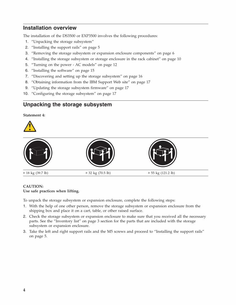
Installation overviewThe installation of the DS3500 or EXP3500 involves the following procedures:1. “Unpacking the storage subsystem”2. “Installing the support rails” on page 53. “Removing the storage subsystem or expansion enclosure components” on page 64. “Installing the storage subsystem or storage enclosure in the rack cabinet” on page 105. “Turning on the power - AC models” on page 126. “Installing the software” on page 157. “Discovering and setting up the storage subsystem” on page 168. “Obtaining information from the IBM Support Web site” on page 179. “Updating the storage subsystem firmware” on page 17
10. “Configuring the storage subsystem” on page 17
Unpacking the storage subsystem
Statement 4:
≥ 18 kg (39.7 lb) ≥ 32 kg (70.5 lb) ≥ 55 kg (121.2 lb)
CAUTION:Use safe practices when lifting.
To unpack the storage subsystem or expansion enclosure, complete the following steps:1. With the help of one other person, remove the storage subsystem or expansion enclosure from the
shipping box and place it on a cart, table, or other raised surface.2. Check the storage subsystem or expansion enclosure to make sure that you received all the necessary
parts. See the “Inventory list” on page 3 section for the parts that are included with the storagesubsystem or expansion enclosure.
3. Take the left and right support rails and the M5 screws and proceed to “Installing the support rails”on page 5.
4
Installing the support railsNotes:
1. For proper weight distribution, install the support rails from the storage subsystem ship group in thelower portion of the rack cabinet.
2. If you are installing a storage subsystem, make sure that you allow for room above and below thestorage subsystem for storage enclosures.
3. The support rails are marked “R” and “L” for right and left.
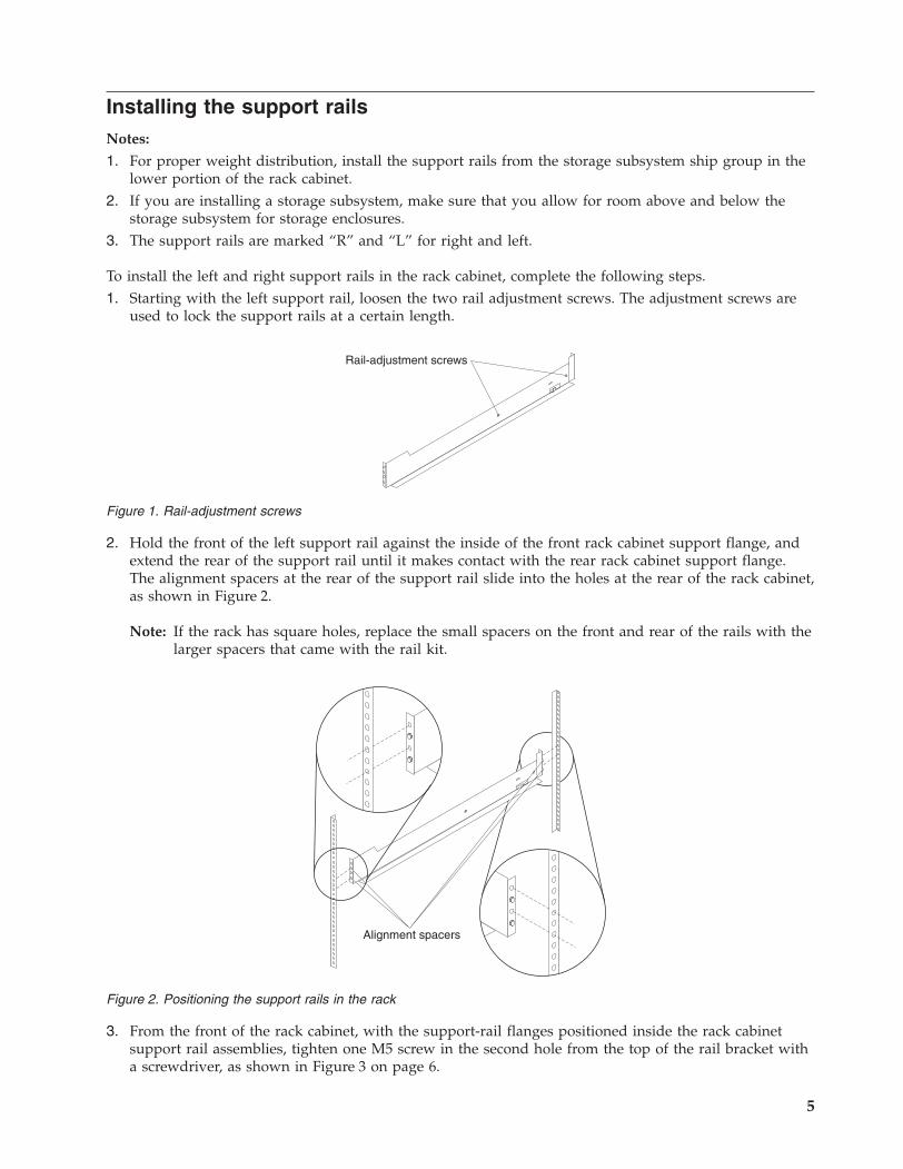
To install the left and right support rails in the rack cabinet, complete the following steps.1. Starting with the left support rail, loosen the two rail adjustment screws. The adjustment screws are
used to lock the support rails at a certain length.
2. Hold the front of the left support rail against the inside of the front rack cabinet support flange, andextend the rear of the support rail until it makes contact with the rear rack cabinet support flange.The alignment spacers at the rear of the support rail slide into the holes at the rear of the rack cabinet,as shown in Figure 2.
Note: If the rack has square holes, replace the small spacers on the front and rear of the rails with thelarger spacers that came with the rail kit.
3. From the front of the rack cabinet, with the support-rail flanges positioned inside the rack cabinetsupport rail assemblies, tighten one M5 screw in the second hole from the top of the rail bracket witha screwdriver, as shown in Figure 3 on page 6.
Rail-adjustment screws
Figure 1. Rail-adjustment screws
Alignment spacers
Figure 2. Positioning the support rails in the rack
5
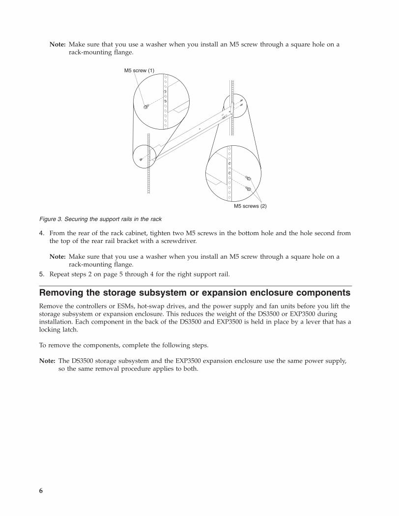
Note: Make sure that you use a washer when you install an M5 screw through a square hole on arack-mounting flange.
4. From the rear of the rack cabinet, tighten two M5 screws in the bottom hole and the hole second fromthe top of the rear rail bracket with a screwdriver.
Note: Make sure that you use a washer when you install an M5 screw through a square hole on arack-mounting flange.
5. Repeat steps 2 on page 5 through 4 for the right support rail.
Removing the storage subsystem or expansion enclosure componentsRemove the controllers or ESMs, hot-swap drives, and the power supply and fan units before you lift thestorage subsystem or expansion enclosure. This reduces the weight of the DS3500 or EXP3500 duringinstallation. Each component in the back of the DS3500 and EXP3500 is held in place by a lever that has alocking latch.
To remove the components, complete the following steps.
Note: The DS3500 storage subsystem and the EXP3500 expansion enclosure use the same power supply,so the same removal procedure applies to both.
M5 screw (1)
M5 screws (2)
Figure 3. Securing the support rails in the rack
6
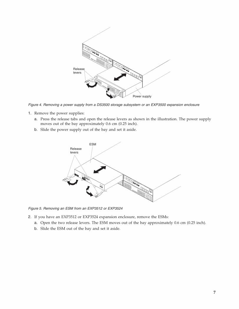
1. Remove the power supplies:a. Press the release tabs and open the release levers as shown in the illustration. The power supply
moves out of the bay approximately 0.6 cm (0.25 inch).b. Slide the power supply out of the bay and set it aside.
2. If you have an EXP3512 or EXP3524 expansion enclosure, remove the ESMs:a. Open the two release levers. The ESM moves out of the bay approximately 0.6 cm (0.25 inch).b. Slide the ESM out of the bay and set it aside.
Power supply
Releaselevers
Figure 4. Removing a power supply from a DS3500 storage subsystem or an EXP3500 expansion enclosure
Releaselevers
ESM
1
2
ESM
Figure 5. Removing an ESM from an EXP3512 or EXP3524
7
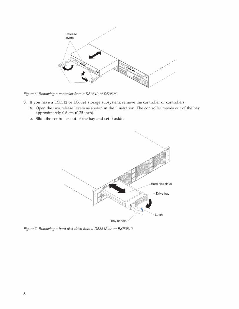
3. If you have a DS3512 or DS3524 storage subsystem, remove the controller or controllers:a. Open the two release levers as shown in the illustration. The controller moves out of the bay
approximately 0.6 cm (0.25 inch).b. Slide the controller out of the bay and set it aside.
Releaselevers
Figure 6. Removing a controller from a DS3512 or DS3524
Drive tray
Tray handle
Latch
Hard disk drive
System
Storage
Figure 7. Removing a hard disk drive from a DS3512 or an EXP3512
8
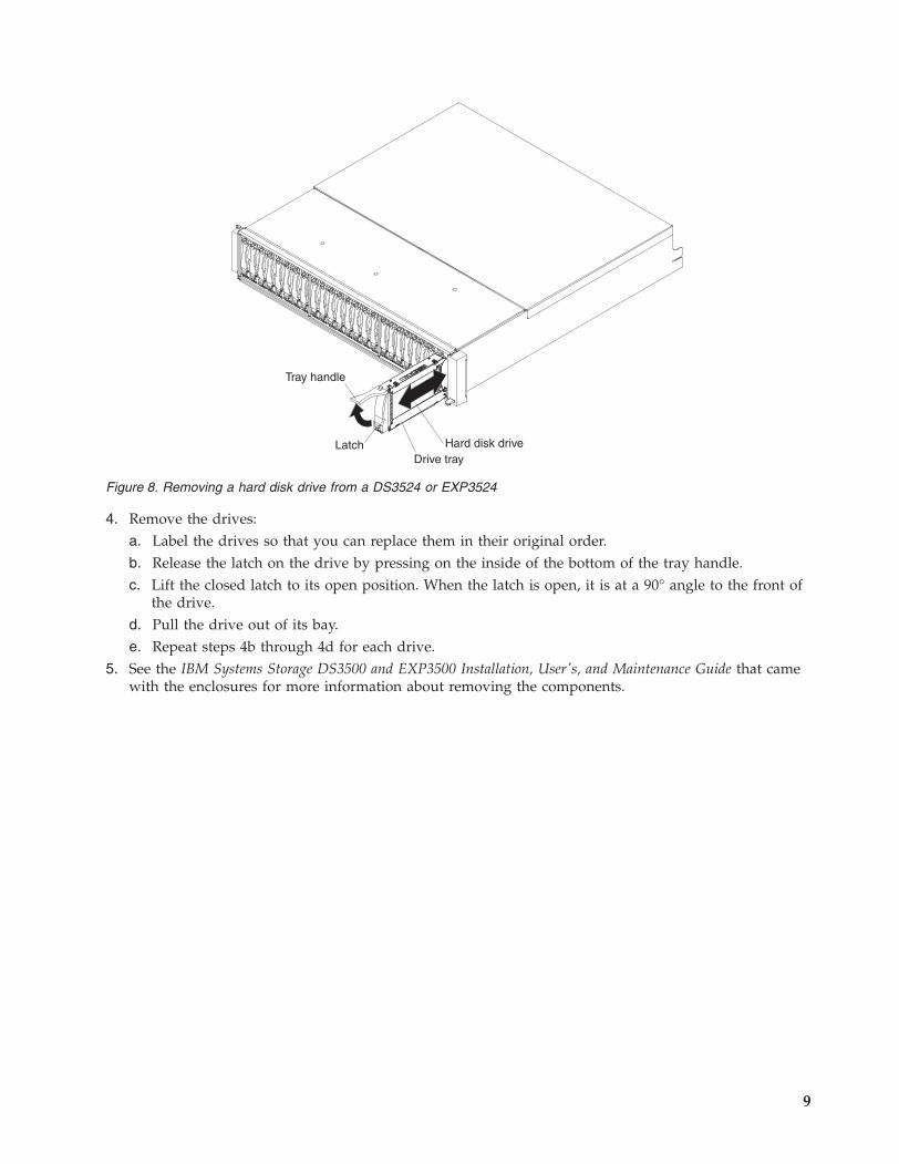
4. Remove the drives:a. Label the drives so that you can replace them in their original order.b. Release the latch on the drive by pressing on the inside of the bottom of the tray handle.c. Lift the closed latch to its open position. When the latch is open, it is at a 90° angle to the front of
the drive.d. Pull the drive out of its bay.e. Repeat steps 4b through 4d for each drive.
5. See the IBM Systems Storage DS3500 and EXP3500 Installation, User's, and Maintenance Guide that camewith the enclosures for more information about removing the components.
Drive tray
Tray handle
Latch Hard disk drive
Figure 8. Removing a hard disk drive from a DS3524 or EXP3524
9
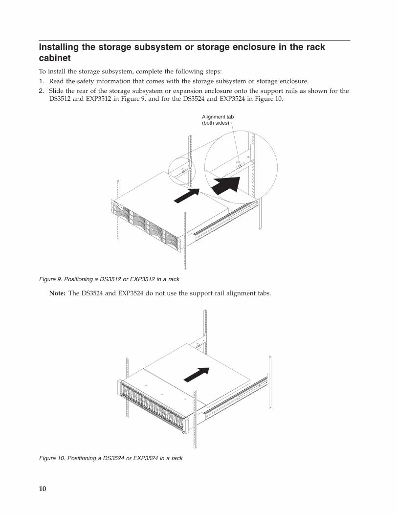
Installing the storage subsystem or storage enclosure in the rackcabinetTo install the storage subsystem, complete the following steps:1. Read the safety information that comes with the storage subsystem or storage enclosure.2. Slide the rear of the storage subsystem or expansion enclosure onto the support rails as shown for the
DS3512 and EXP3512 in Figure 9, and for the DS3524 and EXP3524 in Figure 10.
Note: The DS3524 and EXP3524 do not use the support rail alignment tabs.
Alignment tab(both sides)
Figure 9. Positioning a DS3512 or EXP3512 in a rack
Figure 10. Positioning a DS3524 or EXP3524 in a rack
10
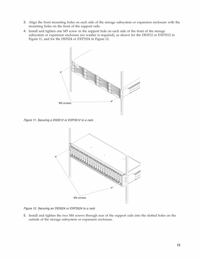
3. Align the front mounting holes on each side of the storage subsystem or expansion enclosure with themounting holes on the front of the support rails.
4. Install and tighten one M5 screw in the support hole on each side of the front of the storagesubsystem or expansion enclosure (no washer is required), as shown for the DS3512 or EXP3512 inFigure 11, and for the DS3524 or EXP3524 in Figure 12.
5. Install and tighten the two M4 screws through rear of the support rails into the slotted holes on theoutside of the storage subsystem or expansion enclosure.
M5 screws
Figure 11. Securing a DS3512 or EXP3512 to a rack
M5 screws
Figure 12. Securing an DS3524 or EXP3524 to a rack
11
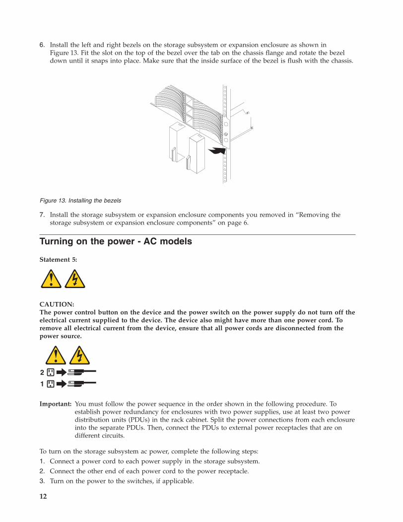
6. Install the left and right bezels on the storage subsystem or expansion enclosure as shown inFigure 13. Fit the slot on the top of the bezel over the tab on the chassis flange and rotate the bezeldown until it snaps into place. Make sure that the inside surface of the bezel is flush with the chassis.
7. Install the storage subsystem or expansion enclosure components you removed in “Removing thestorage subsystem or expansion enclosure components” on page 6.
Turning on the power - AC models
Statement 5:
CAUTION:The power control button on the device and the power switch on the power supply do not turn off theelectrical current supplied to the device. The device also might have more than one power cord. Toremove all electrical current from the device, ensure that all power cords are disconnected from thepower source.
1
2
Important: You must follow the power sequence in the order shown in the following procedure. Toestablish power redundancy for enclosures with two power supplies, use at least two powerdistribution units (PDUs) in the rack cabinet. Split the power connections from each enclosureinto the separate PDUs. Then, connect the PDUs to external power receptacles that are ondifferent circuits.
To turn on the storage subsystem ac power, complete the following steps:1. Connect a power cord to each power supply in the storage subsystem.2. Connect the other end of each power cord to the power receptacle.3. Turn on the power to the switches, if applicable.
Figure 13. Installing the bezels
12
4. Turn on both power switches on all of the attached storage enclosures, and wait 60 seconds.5. Turn on both power switches on the storage subsystem.
Note: When you turn off the power to the storage subsystem, complete the preceding steps in reverseorder. Turn off the power to the storage subsystem first; then, turn off the power to the storageenclosures.
Turning on the power - DC models
Statement 29:
CAUTION:This equipment is designed to permit the connection of the earthed conductor of the dc supply circuitto the earthing conductor at the equipment. If this connection is made, all of the following conditionsmust be met:
v This equipment shall be connected directly to the dc supply system earthing electrode conductor orto a bonding jumper from an earthing terminal bar or bus to which the dc supply system earthingelectrode conductor is connected.
v This equipment shall be located in the same immediate area (such as, adjacent cabinets) as anyother equipment that has a connection between the earthed conductor of the same dc supply circuitand the earthing conductor, and also the point of earthing of the dc system. The dc system shall notbe earthed elsewhere.
v The dc supply source shall be located within the same premises as this equipment.
v Switching or disconnecting devices shall not be in the earthed circuit conductor between the dcsource and the point of connection of the earthing electrode conductor.
Statement 34:
CAUTION:To reduce the risk of electric shock or energy hazards:
v This equipment must be installed by trained service personnel in a restricted-access location, asdefined by the NEC and IEC 60950-1, First Edition, The Standard for Safety of InformationTechnology Equipment.
v Connect the equipment to a reliably grounded safety extra low voltage (SELV) source. An SELVsource is a secondary circuit that is designed so that normal and single fault conditions do not causethe voltages to exceed a safe level (60 V direct current).
v Incorporate a readily available approved and rated disconnect device in the field wiring.
v See the specifications in the product documentation for the required circuit-breaker rating forbranch circuit overcurrent protection.
v Use copper wire conductors only. See the specifications in the product documentation for therequired wire size.
v See the specifications in the product documentation for the required torque values for thewiring-terminal nuts.
To turn on the storage subsystem dc power, complete the following steps:
13
1. Make sure that the power on-off switches of both dc power supplies in the storage subsystem and allattached storage enclosures are in the off position.
2. Connect a dc jumper cable to each dc power supply in the storage subsystem and to all attachedstorage enclosures:a. Using the supplied strap, tie the dc power supply cable to the rail to provide strain relief for the
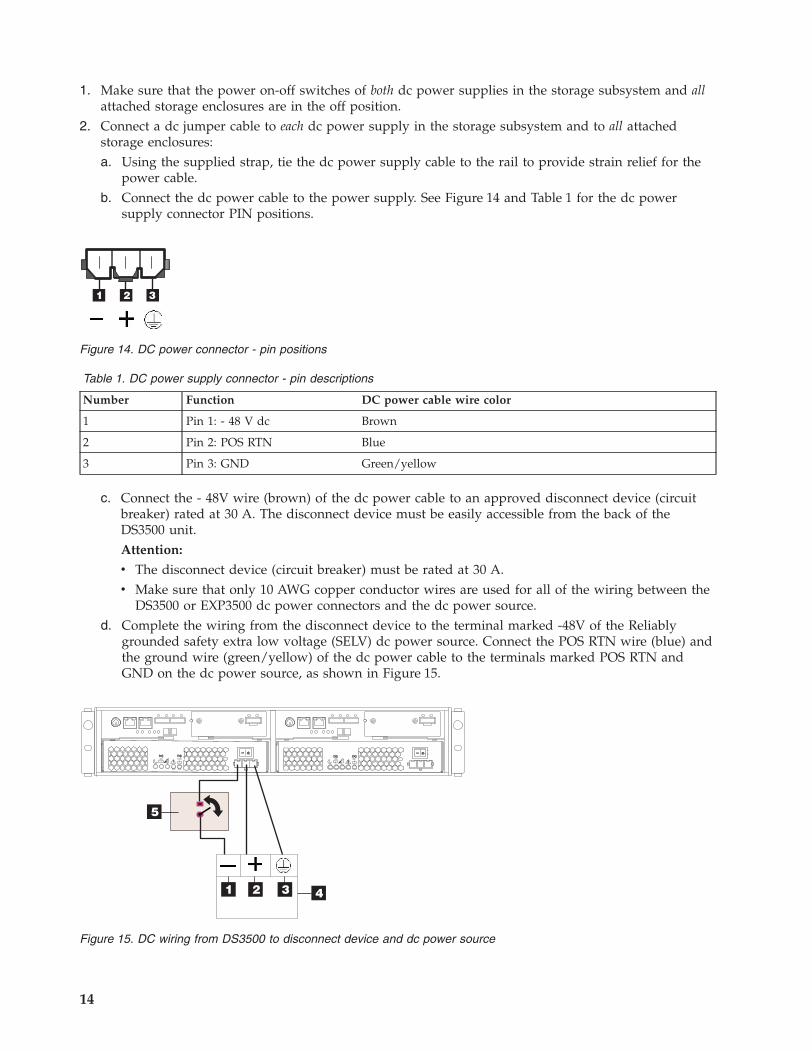
power cable.b. Connect the dc power cable to the power supply. See Figure 14 and Table 1 for the dc power
supply connector PIN positions.
Table 1. DC power supply connector - pin descriptions
Number Function DC power cable wire color
1 Pin 1: - 48 V dc Brown
2 Pin 2: POS RTN Blue
3 Pin 3: GND Green/yellow
c. Connect the - 48V wire (brown) of the dc power cable to an approved disconnect device (circuitbreaker) rated at 30 A. The disconnect device must be easily accessible from the back of theDS3500 unit.Attention:
v The disconnect device (circuit breaker) must be rated at 30 A.v Make sure that only 10 AWG copper conductor wires are used for all of the wiring between the
DS3500 or EXP3500 dc power connectors and the dc power source.d. Complete the wiring from the disconnect device to the terminal marked -48V of the Reliably
grounded safety extra low voltage (SELV) dc power source. Connect the POS RTN wire (blue) andthe ground wire (green/yellow) of the dc power cable to the terminals marked POS RTN andGND on the dc power source, as shown in Figure 15.
Figure 14. DC power connector - pin positions
Figure 15. DC wiring from DS3500 to disconnect device and dc power source
14
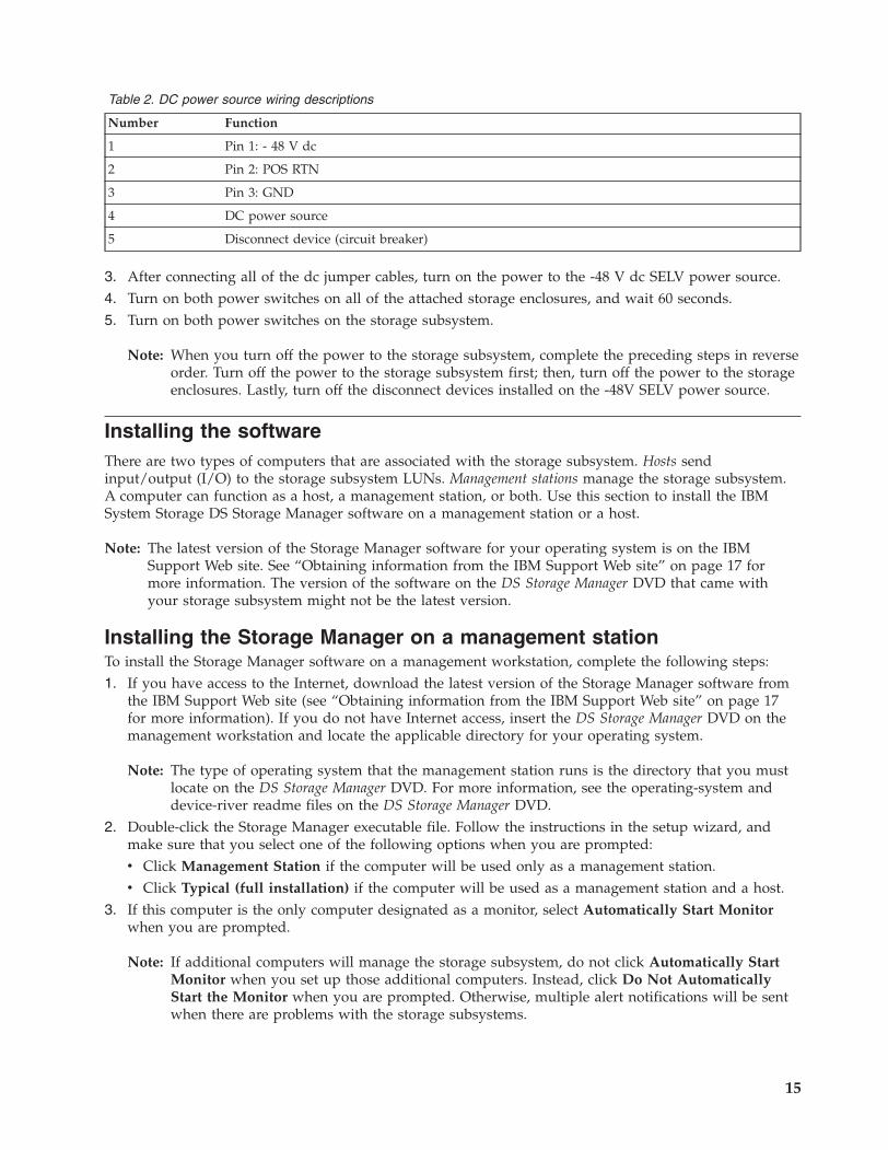
Table 2. DC power source wiring descriptions
Number Function
1 Pin 1: - 48 V dc
2 Pin 2: POS RTN
3 Pin 3: GND
4 DC power source
5 Disconnect device (circuit breaker)
3. After connecting all of the dc jumper cables, turn on the power to the -48 V dc SELV power source.4. Turn on both power switches on all of the attached storage enclosures, and wait 60 seconds.5. Turn on both power switches on the storage subsystem.
Note: When you turn off the power to the storage subsystem, complete the preceding steps in reverseorder. Turn off the power to the storage subsystem first; then, turn off the power to the storageenclosures. Lastly, turn off the disconnect devices installed on the -48V SELV power source.
Installing the softwareThere are two types of computers that are associated with the storage subsystem. Hosts sendinput/output (I/O) to the storage subsystem LUNs. Management stations manage the storage subsystem.A computer can function as a host, a management station, or both. Use this section to install the IBMSystem Storage DS Storage Manager software on a management station or a host.
Note: The latest version of the Storage Manager software for your operating system is on the IBMSupport Web site. See “Obtaining information from the IBM Support Web site” on page 17 formore information. The version of the software on the DS Storage Manager DVD that came withyour storage subsystem might not be the latest version.
Installing the Storage Manager on a management stationTo install the Storage Manager software on a management workstation, complete the following steps:1. If you have access to the Internet, download the latest version of the Storage Manager software from
the IBM Support Web site (see “Obtaining information from the IBM Support Web site” on page 17for more information). If you do not have Internet access, insert the DS Storage Manager DVD on themanagement workstation and locate the applicable directory for your operating system.
Note: The type of operating system that the management station runs is the directory that you mustlocate on the DS Storage Manager DVD. For more information, see the operating-system anddevice-river readme files on the DS Storage Manager DVD.
2. Double-click the Storage Manager executable file. Follow the instructions in the setup wizard, andmake sure that you select one of the following options when you are prompted:v Click Management Station if the computer will be used only as a management station.v Click Typical (full installation) if the computer will be used as a management station and a host.
3. If this computer is the only computer designated as a monitor, select Automatically Start Monitorwhen you are prompted.
Note: If additional computers will manage the storage subsystem, do not click Automatically StartMonitor when you set up those additional computers. Instead, click Do Not AutomaticallyStart the Monitor when you are prompted. Otherwise, multiple alert notifications will be sentwhen there are problems with the storage subsystems.
15
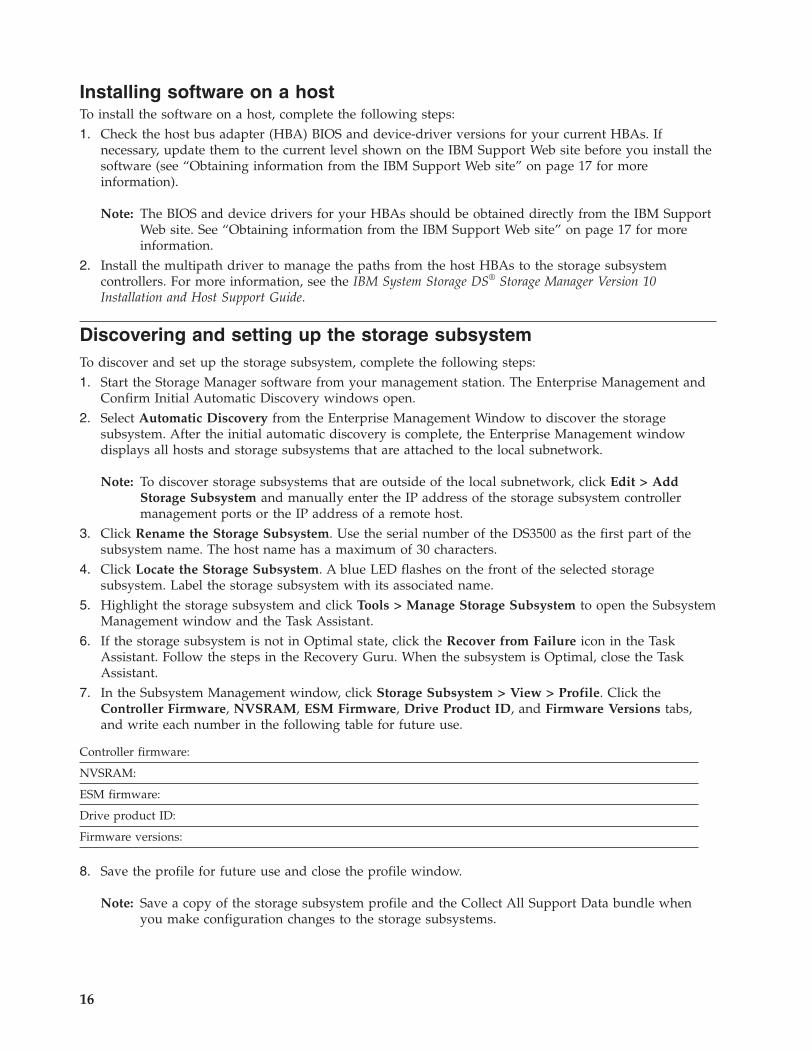
Installing software on a hostTo install the software on a host, complete the following steps:1. Check the host bus adapter (HBA) BIOS and device-driver versions for your current HBAs. If
necessary, update them to the current level shown on the IBM Support Web site before you install thesoftware (see “Obtaining information from the IBM Support Web site” on page 17 for moreinformation).
Note: The BIOS and device drivers for your HBAs should be obtained directly from the IBM SupportWeb site. See “Obtaining information from the IBM Support Web site” on page 17 for moreinformation.
2. Install the multipath driver to manage the paths from the host HBAs to the storage subsystemcontrollers. For more information, see the IBM System Storage DS® Storage Manager Version 10Installation and Host Support Guide.
Discovering and setting up the storage subsystemTo discover and set up the storage subsystem, complete the following steps:1. Start the Storage Manager software from your management station. The Enterprise Management and
Confirm Initial Automatic Discovery windows open.2. Select Automatic Discovery from the Enterprise Management Window to discover the storage
subsystem. After the initial automatic discovery is complete, the Enterprise Management windowdisplays all hosts and storage subsystems that are attached to the local subnetwork.
Note: To discover storage subsystems that are outside of the local subnetwork, click Edit > AddStorage Subsystem and manually enter the IP address of the storage subsystem controllermanagement ports or the IP address of a remote host.
3. Click Rename the Storage Subsystem. Use the serial number of the DS3500 as the first part of thesubsystem name. The host name has a maximum of 30 characters.
4. Click Locate the Storage Subsystem. A blue LED flashes on the front of the selected storagesubsystem. Label the storage subsystem with its associated name.
5. Highlight the storage subsystem and click Tools > Manage Storage Subsystem to open the SubsystemManagement window and the Task Assistant.
6. If the storage subsystem is not in Optimal state, click the Recover from Failure icon in the TaskAssistant. Follow the steps in the Recovery Guru. When the subsystem is Optimal, close the TaskAssistant.
7. In the Subsystem Management window, click Storage Subsystem > View > Profile. Click theController Firmware, NVSRAM, ESM Firmware, Drive Product ID, and Firmware Versions tabs,and write each number in the following table for future use.
Controller firmware:
NVSRAM:
ESM firmware:
Drive product ID:
Firmware versions:
8. Save the profile for future use and close the profile window.
Note: Save a copy of the storage subsystem profile and the Collect All Support Data bundle whenyou make configuration changes to the storage subsystems.
16
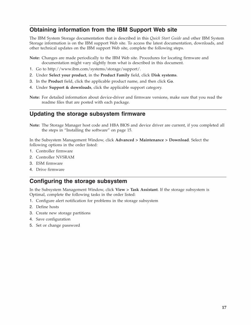
Obtaining information from the IBM Support Web siteThe IBM System Storage documentation that is described in this Quick Start Guide and other IBM SystemStorage information is on the IBM support Web site. To access the latest documentation, downloads, andother technical updates on the IBM support Web site, complete the following steps.
Note: Changes are made periodically to the IBM Web site. Procedures for locating firmware anddocumentation might vary slightly from what is described in this document.
1. Go to http://www.ibm.com/systems/storage/support/.2. Under Select your product, in the Product Family field, click Disk systems.3. In the Product field, click the applicable product name, and then click Go.4. Under Support & downloads, click the applicable support category.
Note: For detailed information about device-driver and firmware versions, make sure that you read thereadme files that are posted with each package.
Updating the storage subsystem firmware
Note: The Storage Manager host code and HBA BIOS and device driver are current, if you completed allthe steps in “Installing the software” on page 15.
In the Subsystem Management Window, click Advanced > Maintenance > Download. Select thefollowing options in the order listed:1. Controller firmware2. Controller NVSRAM3. ESM firmware4. Drive firmware
Configuring the storage subsystemIn the Subsystem Management Window, click View > Task Assistant. If the storage subsystem isOptimal, complete the following tasks in the order listed:1. Configure alert notification for problems in the storage subsystem2. Define hosts3. Create new storage partitions4. Save configuration5. Set or change password
17

18

This edition applies to the IBM System Storage DS3500 and EXP3500 Storage Subsystem with controller firmwareversion 7.70, and to all subsequent releases and modifications until otherwise indicated in new editions.
Printed in the U.S.A.
IBM and System Storage are trademarks of the IBM Corporation in the United States, other countries, or both.
Microsoft and Windows are trademarks of Microsoft Corporation in the United States, other countries, or both.
© Copyright IBM Corporation 2010, 2013.US Government Users Restricted Rights – Use, duplication or disclosure restricted by GSA ADP Schedule Contractwith IBM Corp.
(1P) P/N: 00Y8865