Embed Size (px)
Citation preview
IBM System z Long Distance Extension and FCIP Network Primer Dr. Steve Guendert Brocade Communications Wednesday 12 March 2014 130PM Session Number 14986
Insert Custom Session QR if Desired.
Abstract
• This session will discuss Fibre Channel over IP (FCIP) networking for IBM System z environments. We will discuss basics, such as tunnels, circuits, and the protocol itself. We will also cover several more advanced technical subjects, such as FCIP trunking, metrics/failover, lossless link loss, and how TCP plays a role in FCIP networks. Finally, we will discuss different FICON protocol emulation techniques used to improve performance over very long distances.
• Specific hardware product references will be discussed when applicable.
2 © 2014 Brocade Communications Systems, Inc
Agenda
• Basics-standards/protocol, tunneling , circuits, batching • The role TCP plays with FCIP • FCIP trunking, metrics/failover, and lossless link loss • FICON protocol emulation: improved long distance
performance
3
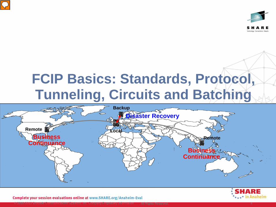
FCIP Basics: Standards, Protocol, Tunneling, Circuits and Batching
© 2010-2013 Brocade Communications Systems, Inc. Company Proprietary Information 4 All Rights Reserved.
Disaster Recovery
Business Continuance
Business Continuance
Local
Backup
Remote
Remote
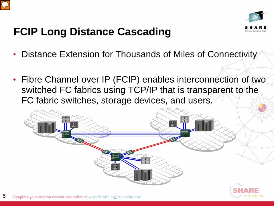
FCIP Long Distance Cascading
• Distance Extension for Thousands of Miles of Connectivity
• Fibre Channel over IP (FCIP) enables interconnection of two switched FC fabrics using TCP/IP that is transparent to the FC fabric switches, storage devices, and users.
5
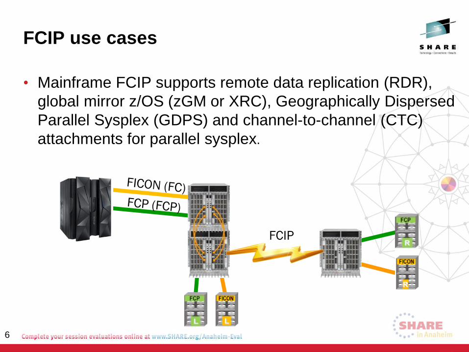
FCIP use cases
• Mainframe FCIP supports remote data replication (RDR), global mirror z/OS (zGM or XRC), Geographically Dispersed Parallel Sysplex (GDPS) and channel-to-channel (CTC) attachments for parallel sysplex.
6
FCIP
Why Fibre Channel over IP?
• Why FCIP instead of extended native FC? • Cost of IP bandwidth vs. FC bandwidth • Eliminate distance constraints • Leverage investment in existing IP network • IP ubiquity – it is just everywhere! • Reduce consumption of fiber
• Dramatically improve recovery time with reasonable cost • Recovery in hours vs. days as required with manual off-site vaulting • Less cost to backup multiple applications with in-house Disaster
Recovery versus a single application performed by a 3rd party data warehousing company
7
Standards and FCIP
• Fibre Channel over TCP/IP (FCIP) is IETF RFC 3821 • July 2004
• Relevant Fibre Channel standards include, but are not limited to: • FC-BB series (Fibre Channel Backbone) • FC-SW series (Fibre Channel Switch Fabric) • FC-FS series (Fibre Channel Framing and Signaling)
• The FC-BB series is the Fibre Channel documentation
describing the relationships between FC and TCP/IP
8
FCIP Overview
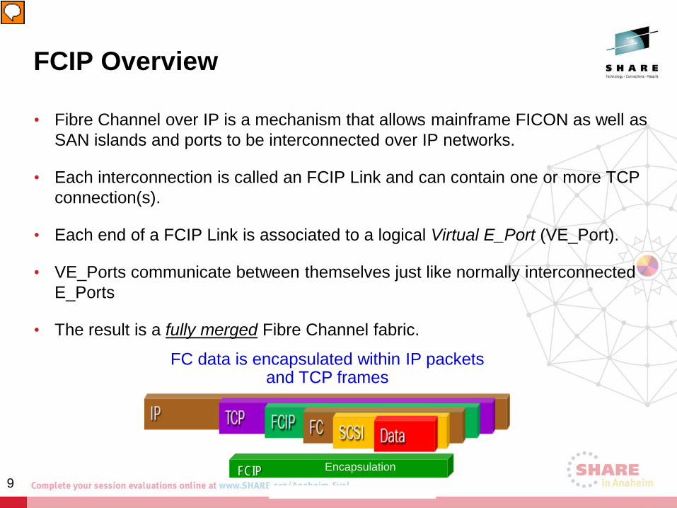
• Fibre Channel over IP is a mechanism that allows mainframe FICON as well as SAN islands and ports to be interconnected over IP networks.
• Each interconnection is called an FCIP Link and can contain one or more TCP connection(s).
• Each end of a FCIP Link is associated to a logical Virtual E_Port (VE_Port).
• VE_Ports communicate between themselves just like normally interconnected E_Ports
• The result is a fully merged Fibre Channel fabric.
FC data is encapsulated within IP packets and TCP frames
FCIP Encapsulation 9
FCIP Overview
• Fibre Channel over IP (FCIP) enables customers to use their IP wide area network (WAN) infrastructure to connect Fibre Channel SANs while keeping the targets and initiators unaware of the presence of the WAN in the data path
• FCIP supports applications such as remote data replication (RDR), centralized SAN backup, and data migration over very long distances and can provide improved performance when compared to typical long distance ISL links
• FCIP tunnels are used to pass Fibre Channel I/O through an IP network. • FCIP tunnels are built on a physical connection between two peer switches or
blades.
• FC frames enter FCIP through virtual E_Ports (VE_Ports) • Frames are encapsulated and passed to the Transmission Control Protocol
(TCP) layer connections. 10
The role TCP plays in FCIP
• Viewed from the IP Network perspective, FCIP entities are peers and communicate using TCP/IP.
• TCP/IP is used as the underlying transport to provide congestion control and in-order delivery of error-free data. • If FC was really being managed by IP there could be many
frame drops. TCP prevents this. • The TCP connections ensure in-order delivery of FC frames and
lossless transmission. • FCIP may use TCP/IP quality of service features (QoS)
11
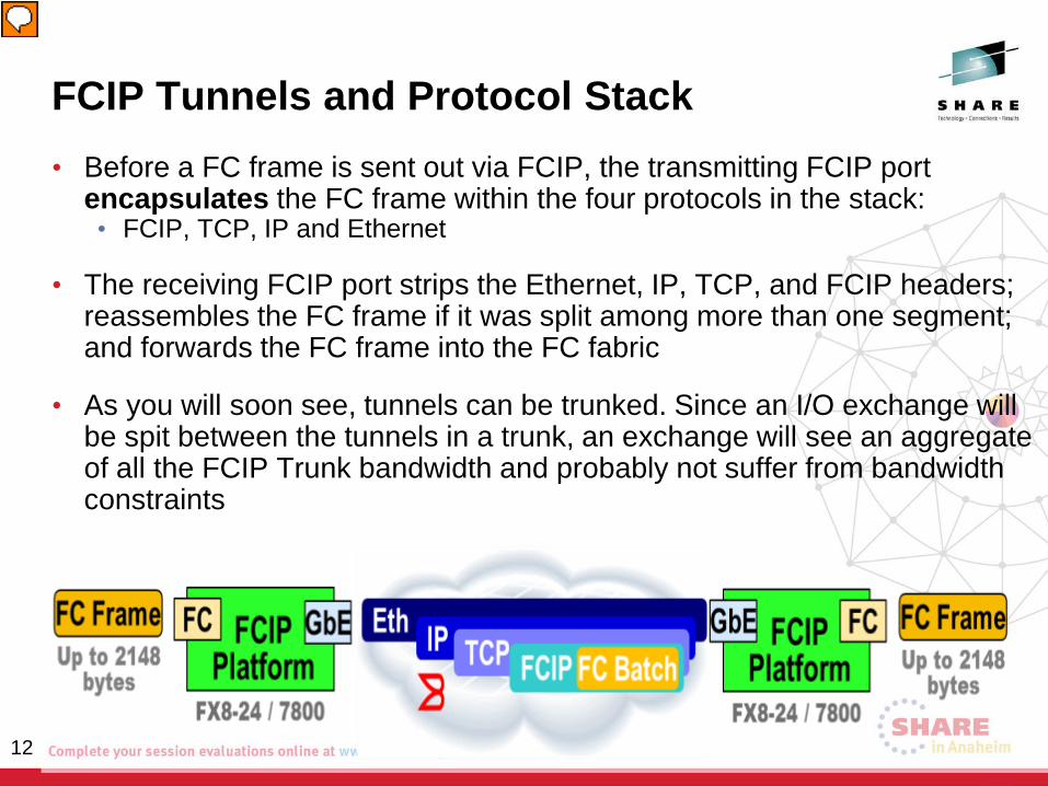
FCIP Tunnels and Protocol Stack • Before a FC frame is sent out via FCIP, the transmitting FCIP port
encapsulates the FC frame within the four protocols in the stack: • FCIP, TCP, IP and Ethernet
• The receiving FCIP port strips the Ethernet, IP, TCP, and FCIP headers; reassembles the FC frame if it was split among more than one segment; and forwards the FC frame into the FC fabric
• As you will soon see, tunnels can be trunked. Since an I/O exchange will be spit between the tunnels in a trunk, an exchange will see an aggregate of all the FCIP Trunk bandwidth and probably not suffer from bandwidth constraints
12
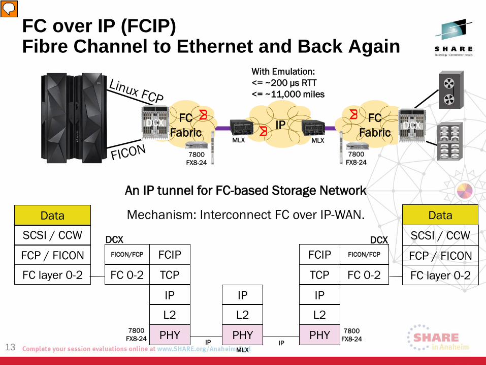
FC over IP (FCIP) Fibre Channel to Ethernet and Back Again
13
Data
SCSI / CCW
FC layer 0-2 FC 0-2
FCIP
TCP
IP
L2
PHY
IP
L2
PHY
TCP
IP
L2
PHY
FC 0-2
FCP / FICON
An IP tunnel for FC-based Storage Network
Mechanism: Interconnect FC over IP-WAN.
FCIP
FICON/FCP
FICON/FCP
Data
SCSI / CCW
FC layer 0-2
FCP / FICON
FC Fabric IP FC
Fabric
7800 FX8-24
7800 FX8-24
DCX DCX MLX MLX
With Emulation: <= ~200 μs RTT <= ~11,000 miles
7800 FX8-24
7800 FX8-24
MLX
DCX DCX
IP IP
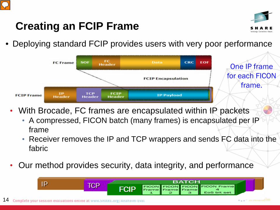
• With Brocade, FC frames are encapsulated within IP packets • A compressed, FICON batch (many frames) is encapsulated per IP
frame • Receiver removes the IP and TCP wrappers and sends FC data into the
fabric
• Our method provides security, data integrity, and performance
14
Creating an FCIP Frame • Deploying standard FCIP provides users with very poor performance
One IP frame for each FICON
frame.
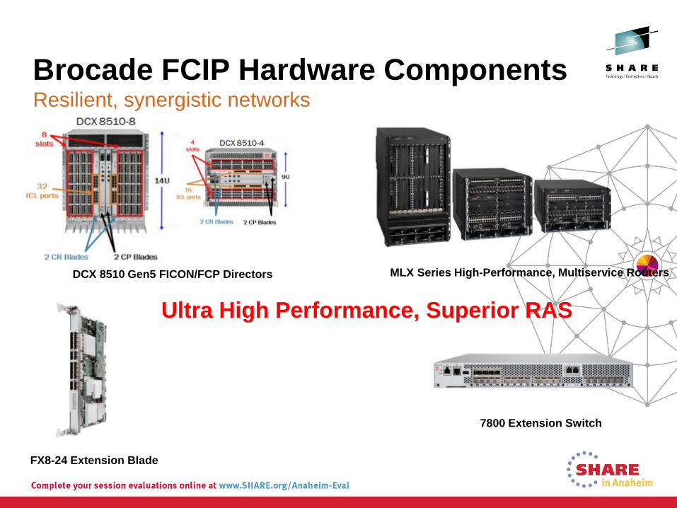
Brocade FCIP Hardware Components Resilient, synergistic networks
DCX 8510 Gen5 FICON/FCP Directors MLX Series High-Performance, Multiservice Routers
FX8-24 Extension Blade
7800 Extension Switch
Ultra High Performance, Superior RAS
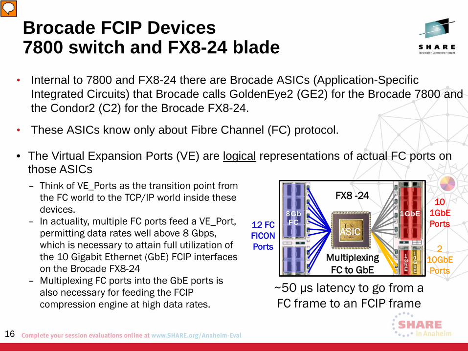
Brocade FCIP Devices 7800 switch and FX8-24 blade
• Internal to 7800 and FX8-24 there are Brocade ASICs (Application-Specific Integrated Circuits) that Brocade calls GoldenEye2 (GE2) for the Brocade 7800 and the Condor2 (C2) for the Brocade FX8-24.
• These ASICs know only about Fibre Channel (FC) protocol.
8Gb FC
1GbE
1 G b E
1 0 G b E
12 FC FICON Ports
10 1GbE Ports
2 10GbE Ports
FX8 -24
Multiplexing FC to GbE
ASIC
• The Virtual Expansion Ports (VE) are logical representations of actual FC ports on those ASICs – Think of VE_Ports as the transition point from
the FC world to the TCP/IP world inside these devices.
– In actuality, multiple FC ports feed a VE_Port, permitting data rates well above 8 Gbps, which is necessary to attain full utilization of the 10 Gigabit Ethernet (GbE) FCIP interfaces on the Brocade FX8-24
– Multiplexing FC ports into the GbE ports is also necessary for feeding the FCIP compression engine at high data rates.
~50 µs latency to go from a FC frame to an FCIP frame
16
Brocade FCIP 7800 Considerations
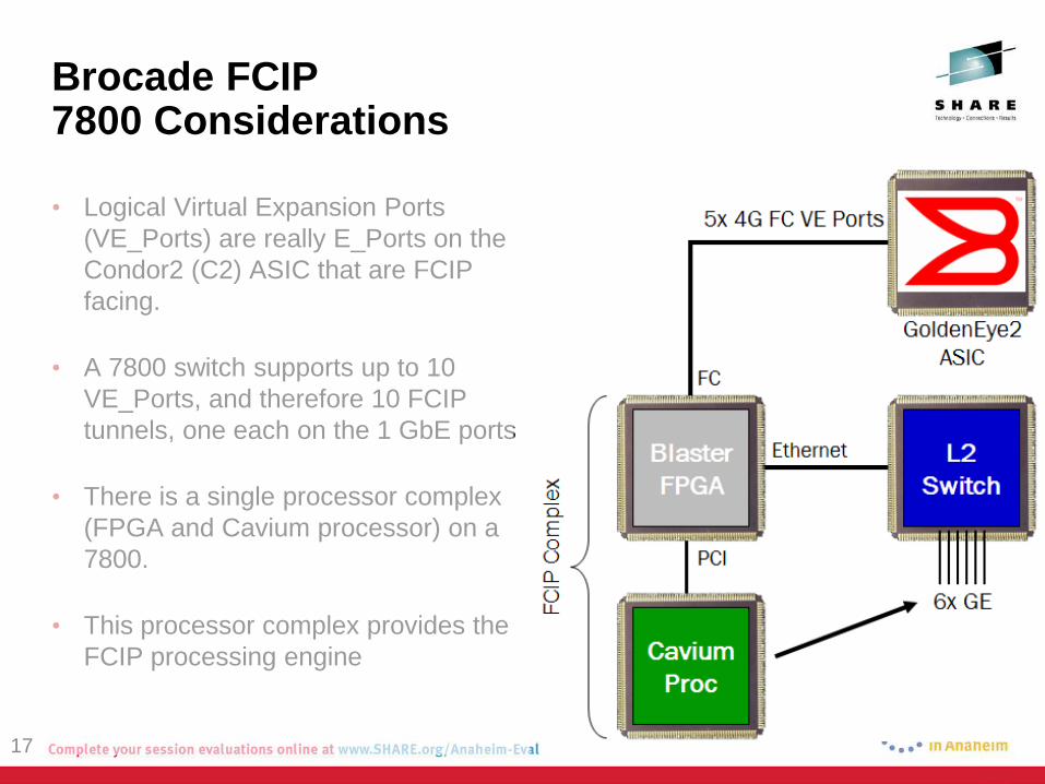
• Logical Virtual Expansion Ports (VE_Ports) are really E_Ports on the Condor2 (C2) ASIC that are FCIP facing.
• A 7800 switch supports up to 10 VE_Ports, and therefore 10 FCIP tunnels, one each on the 1 GbE ports
• There is a single processor complex (FPGA and Cavium processor) on a 7800.
• This processor complex provides the FCIP processing engine
17
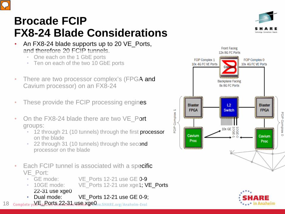
Brocade FCIP FX8-24 Blade Considerations • An FX8-24 blade supports up to 20 VE_Ports,
and therefore 20 FCIP tunnels. • One each on the 1 GbE ports • Ten on each of the two 10 GbE ports
• There are two processor complex’s (FPGA and Cavium processor) on an FX8-24
• These provide the FCIP processing engines
• On the FX8-24 blade there are two VE_Port groups:
• 12 through 21 (10 tunnels) through the first processor on the blade
• 22 through 31 (10 tunnels) through the second processor on the blade
• Each FCIP tunnel is associated with a specific VE_Port:
• GE mode: VE_Ports 12-21 use GE 0-9 • 10GE mode: VE_Ports 12-21 use xge1; VE_Ports
22-31 use xge0 • Dual mode: VE_Ports 12-21 use GE 0-9;
VE_Ports 22-31 use xge0 18
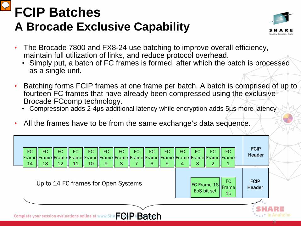
FCIP Batches A Brocade Exclusive Capability • The Brocade 7800 and FX8-24 use batching to improve overall efficiency,
maintain full utilization of links, and reduce protocol overhead. • Simply put, a batch of FC frames is formed, after which the batch is processed
as a single unit.
• Batching forms FCIP frames at one frame per batch. A batch is comprised of up to fourteen FC frames that have already been compressed using the exclusive Brocade FCcomp technology. • Compression adds 2-4µs additional latency while encryption adds 5µs more latency
• All the frames have to be from the same exchange’s data sequence.
19
FCIP Header
FC Frame
8
FC Frame
6
FC Frame
4
FC Frame
2
FCIP Header FC Frame 16
EoS bit set
FC Frame
15
FC Frame
7
FC Frame
5
FC Frame
3
FC Frame
1
FC Frame
14
FC Frame
12
FC Frame
10
FC Frame
13
FC Frame
11
FC Frame
9
Up to 14 FC frames for Open Systems
FCIP Batch
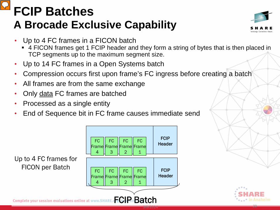
• Up to 4 FC frames in a FICON batch 4 FICON frames get 1 FCIP header and they form a string of bytes that is then placed in
TCP segments up to the maximum segment size. • Up to 14 FC frames in a Open Systems batch • Compression occurs first upon frame’s FC ingress before creating a batch • All frames are from the same exchange • Only data FC frames are batched • Processed as a single entity • End of Sequence bit in FC frame causes immediate send
20
FCIP Header
FC Frame
4
FC Frame
2
FC Frame
3
FC Frame
1
FCIP Header
FC Frame
4
FC Frame
2
FC Frame
3
FC Frame
1
Up to 4 FC frames for FICON per Batch
FCIP Batches A Brocade Exclusive Capability
3/6/2014 FCIP Batch
FCIP Circuits
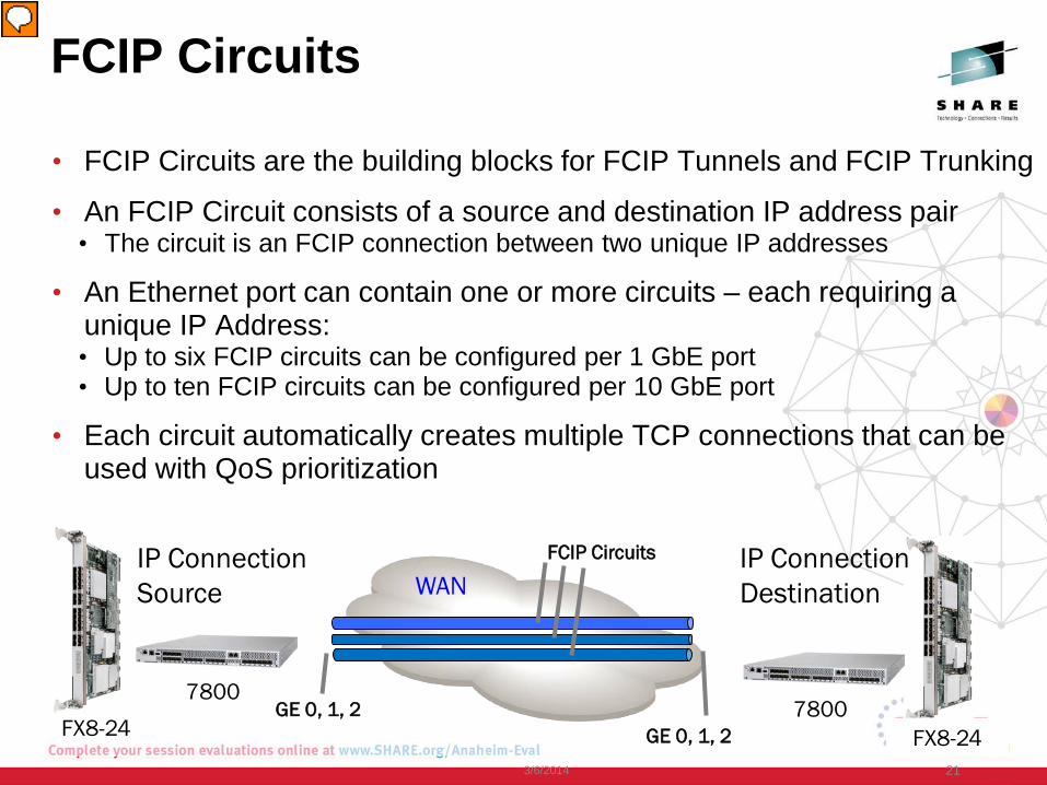
• FCIP Circuits are the building blocks for FCIP Tunnels and FCIP Trunking
• An FCIP Circuit consists of a source and destination IP address pair • The circuit is an FCIP connection between two unique IP addresses
• An Ethernet port can contain one or more circuits – each requiring a unique IP Address: • Up to six FCIP circuits can be configured per 1 GbE port • Up to ten FCIP circuits can be configured per 10 GbE port
• Each circuit automatically creates multiple TCP connections that can be used with QoS prioritization
21
WAN
GE 0, 1, 2 GE 0, 1, 2 FX8-24
7800
FCIP Circuits IP Connection Source
IP Connection Destination
FX8-24 7800
3/6/2014
FCIP Tunnels and Protocol Stack
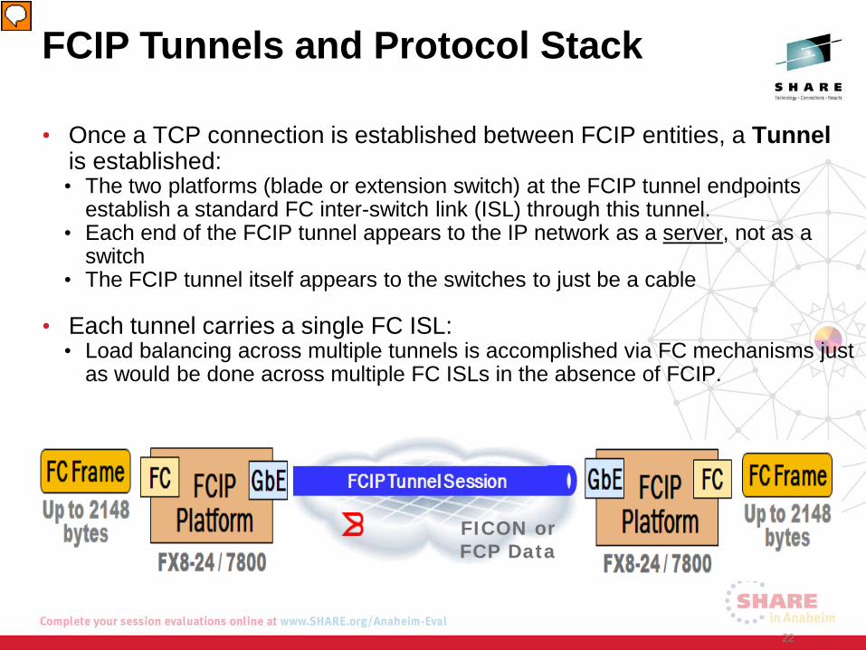
• Once a TCP connection is established between FCIP entities, a Tunnel is established: • The two platforms (blade or extension switch) at the FCIP tunnel endpoints
establish a standard FC inter-switch link (ISL) through this tunnel. • Each end of the FCIP tunnel appears to the IP network as a server, not as a
switch • The FCIP tunnel itself appears to the switches to just be a cable
• Each tunnel carries a single FC ISL: • Load balancing across multiple tunnels is accomplished via FC mechanisms just
as would be done across multiple FC ISLs in the absence of FCIP.
22
FICON or FCP Data
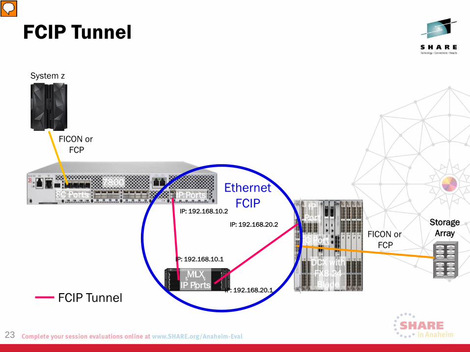
System z
7800
MLX IP Ports
DCX with FX8-24 Blade
Storage Array
FC Ports IP Ports IP
Port
FC Port
FICON or FCP
FICON or FCP
FCIP Tunnel
Ethernet FCIP
FCIP Tunnel
IP: 192.168.10.2
IP: 192.168.10.1
IP: 192.168.20.1
IP: 192.168.20.2
23
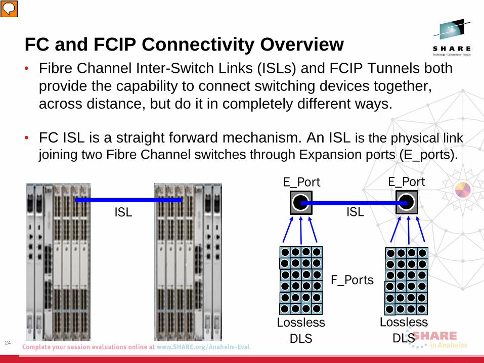
FC and FCIP Connectivity Overview • Fibre Channel Inter-Switch Links (ISLs) and FCIP Tunnels both
provide the capability to connect switching devices together, across distance, but do it in completely different ways.
• FC ISL is a straight forward mechanism. An ISL is the physical link joining two Fibre Channel switches through Expansion ports (E_ports).
24
ISL ISL
Lossless DLS
Lossless DLS
E_Port E_Port
F_Ports
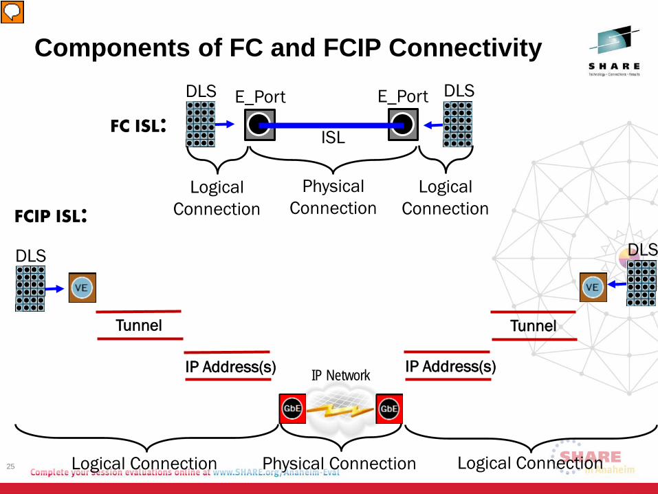
Components of FC and FCIP Connectivity
25
IP Network
FCIP ISL: DLS
IP Address(s)
Tunnel
Logical Connection
IP Address(s)
Tunnel
DLS
Logical Connection Physical Connection
FC ISL: ISL
E_Port E_Port DLS DLS
Physical Connection
Logical Connection
Logical Connection
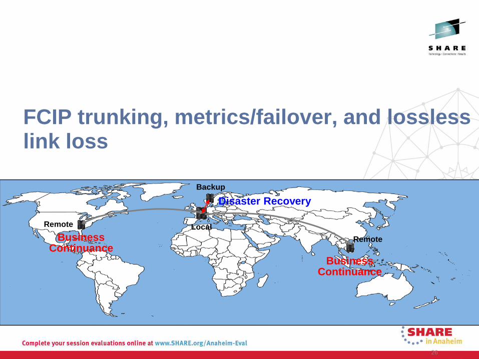
FCIP trunking, metrics/failover, and lossless link loss
26
Disaster Recovery
Business Continuance
Business Continuance
Local
Backup
Remote
Remote
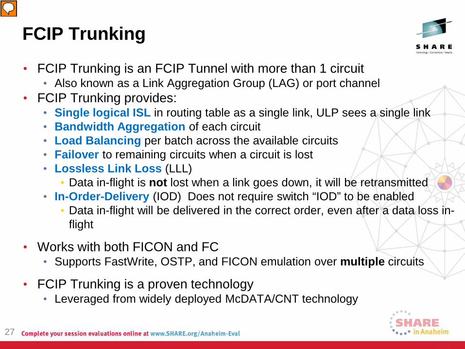
FCIP Trunking
• FCIP Trunking is an FCIP Tunnel with more than 1 circuit • Also known as a Link Aggregation Group (LAG) or port channel
• FCIP Trunking provides: • Single logical ISL in routing table as a single link, ULP sees a single link • Bandwidth Aggregation of each circuit • Load Balancing per batch across the available circuits • Failover to remaining circuits when a circuit is lost • Lossless Link Loss (LLL)
• Data in-flight is not lost when a link goes down, it will be retransmitted • In-Order-Delivery (IOD) Does not require switch “IOD” to be enabled
• Data in-flight will be delivered in the correct order, even after a data loss in-flight
• Works with both FICON and FC • Supports FastWrite, OSTP, and FICON emulation over multiple circuits
• FCIP Trunking is a proven technology • Leveraged from widely deployed McDATA/CNT technology
27
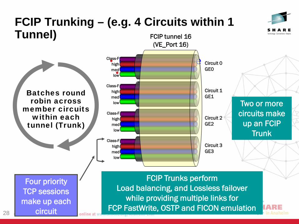
FCIP Trunking – (e.g. 4 Circuits within 1 Tunnel)
• Unique to Brocade • Patent Pending!
28
Class-F high med low
Circuit 0 GE0
Class-F high med low
Circuit 1 GE1
Class-F high med low
Circuit 2 GE2
Class-F high med low
Circuit 3 GE3
FCIP tunnel 16 (VE_Port 16)
Batches round robin across
member circuits within each
tunnel (Trunk)
Four priority TCP sessions make up each
circuit
Two or more circuits make
up an FCIP Trunk
FCIP Trunks perform Load balancing, and Lossless failover
while providing multiple links for FCP FastWrite, OSTP and FICON emulation
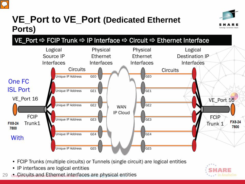
VE_Port to VE_Port (Dedicated Ethernet Ports)
29
VE_Port 16
FCIP Trunk1
Logical Source IP Interfaces
Logical Destination IP
Interfaces
Physical Ethernet
Interfaces
VE_Port 16
FCIP Trunk 1
Physical Ethernet
Interfaces Circuits Circuits
VE_Port FCIP Trunk IP Interface Circuit Ethernet Interface
Unique IP Address
Unique IP Address
Unique IP Address
Unique IP Address
GE0
GE1
GE2
GE3
GE0
GE1
GE2
GE3
GE4
GE5
Unique IP Address
Unique IP Address
GE4
GE5
WAN IP Cloud
• FCIP Trunks (multiple circuits) or Tunnels (single circuit) are logical entities • IP interfaces are logical entities • Circuits and Ethernet interfaces are physical entities
One FC ISL Port
With
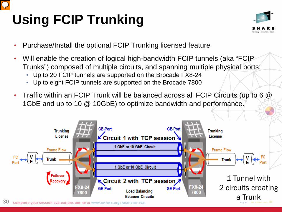
• Purchase/Install the optional FCIP Trunking licensed feature
• Will enable the creation of logical high-bandwidth FCIP tunnels (aka “FCIP Trunks”) composed of multiple circuits, and spanning multiple physical ports:
• Up to 20 FCIP tunnels are supported on the Brocade FX8-24 • Up to eight FCIP tunnels are supported on the Brocade 7800
• Traffic within an FCIP Trunk will be balanced across all FCIP Circuits (up to 6 @ 1GbE and up to 10 @ 10GbE) to optimize bandwidth and performance.
Using FCIP Trunking
30
1 Tunnel with 2 circuits creating
a Trunk
FX8-24 7800
FX8-24 7800
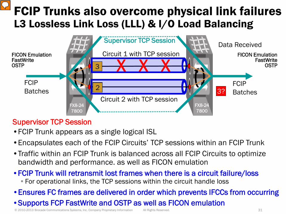
FCIP Trunks also overcome physical link failures
Supervisor TCP Session •FCIP Trunk appears as a single logical ISL •Encapsulates each of the FCIP Circuits’ TCP sessions within an FCIP Trunk •Traffic within an FCIP Trunk is balanced across all FCIP Circuits to optimize
bandwidth and performance. as well as FICON emulation
L3 Lossless Link Loss (LLL) & I/O Load Balancing
All Rights Reserved. © 2010-2013 Brocade Communications Systems, Inc. Company Proprietary Information 31
1 3
4
Circuit 1 with TCP session
Circuit 2 with TCP session
FCIP Batches
FCIP Batches 3?
Data Received
3
FICON Emulation FastWrite OSTP
FICON Emulation FastWrite
OSTP
2
X X X
Supervisor TCP Session
•FCIP Trunk will retransmit lost frames when there is a circuit failure/loss •For operational links, the TCP sessions within the circuit handle loss
•Ensures FC frames are delivered in order which prevents IFCCs from occurring •Supports FCP FastWrite and OSTP as well as FICON emulation
FCIP Trunking
FCIP Circuit Keep Alive Timers1
• The FCIP Circuit Keep Alive timeout has a FOS default value of 10,000ms (10 seconds)
• For FICON the Keep Alive timeout value should only be 1,000ms (1 second) • Local and remote Keep Alive values need to match or the tunnel uses the lowest value • Will need to modify the FOS default Keep Alive Timer value to support FICON
• 1 sec is the maximum supported for FICON • FICON has strict timing requirements • 1 second KATOV will work well for all circuits
• Non-FICON circuits default to keepalives of 10 sec • Best practice is to set all keepalives to 1 sec • If the user knows that their IP network has congestion and deep buffers then the keep
alive may need to be longer than 1 sec • If a keepalive does not arrive within 1/5th of the value, it may cause link flapping
32
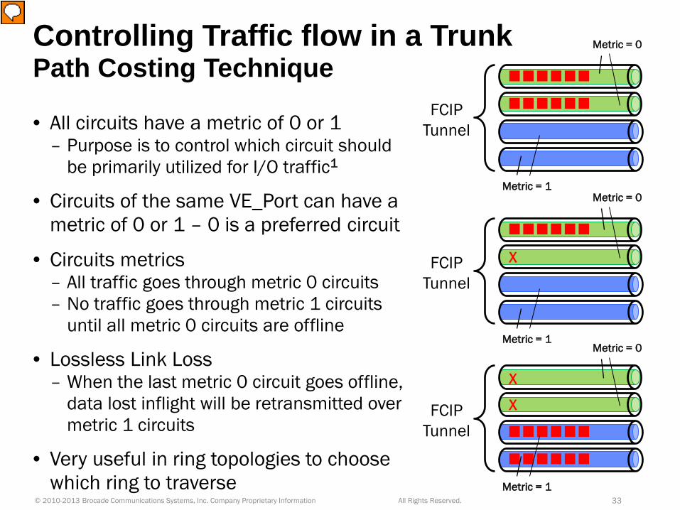
Controlling Traffic flow in a Trunk Path Costing Technique
• All circuits have a metric of 0 or 1 – Purpose is to control which circuit should
be primarily utilized for I/O traffic1
• Circuits of the same VE_Port can have a metric of 0 or 1 – 0 is a preferred circuit
• Circuits metrics – All traffic goes through metric 0 circuits – No traffic goes through metric 1 circuits
until all metric 0 circuits are offline
• Lossless Link Loss – When the last metric 0 circuit goes offline,
data lost inflight will be retransmitted over metric 1 circuits
• Very useful in ring topologies to choose which ring to traverse
All Rights Reserved. © 2010-2013 Brocade Communications Systems, Inc. Company Proprietary Information 33
FCIP Tunnel
Metric = 1
Metric = 0
FCIP Tunnel
Metric = 1
X
Metric = 0
FCIP Tunnel
X
X
Metric = 0
Metric = 1
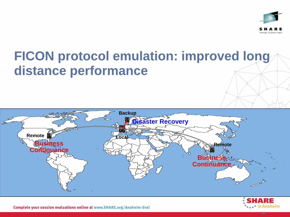
FICON protocol emulation: improved long distance performance
34
Disaster Recovery
Business Continuance
Business Continuance
Local
Backup
Remote
Remote
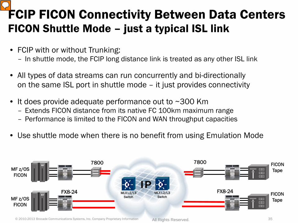
• FCIP with or without Trunking: – In shuttle mode, the FCIP long distance link is treated as any other ISL link
• All types of data streams can run concurrently and bi-directionally on the same ISL port in shuttle mode – it just provides connectivity
• It does provide adequate performance out to ~300 Km – Extends FICON distance from its native FC 100km maximum range – Performance is limited to the FICON and WAN throughput capacities
• Use shuttle mode when there is no benefit from using Emulation Mode
FCIP FICON Connectivity Between Data Centers FICON Shuttle Mode – just a typical ISL link
IP MF z/OS
FICON
FICON Tape
MF z/OS FICON
FICON Tape
7800
FX8-24
7800
FX8-24 MLX L2/L3 Switch
MLX L2/L3 Switch
35 © 2010-2013 Brocade Communications Systems, Inc. Company Proprietary Information All Rights Reserved.
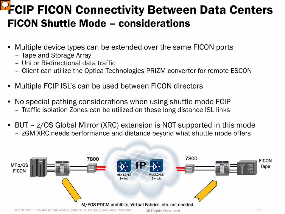
M/EOS PDCM prohibits, Virtual Fabrics, etc. not needed.
IP MF z/OS FICON
FICON Tape
7800 7800
• Multiple device types can be extended over the same FICON ports – Tape and Storage Array – Uni or Bi-directional data traffic – Client can utilize the Optica Technologies PRIZM converter for remote ESCON
• Multiple FCIP ISL’s can be used between FICON directors
• No special pathing considerations when using shuttle mode FCIP – Traffic Isolation Zones can be utilized on these long distance ISL links
• BUT – z/OS Global Mirror (XRC) extension is NOT supported in this mode – zGM XRC needs performance and distance beyond what shuttle mode offers
FCIP FICON Connectivity Between Data Centers FICON Shuttle Mode – considerations
MLX L2/L3 Switch
MLX L2/L3 Switch
36 © 2010-2013 Brocade Communications Systems, Inc. Company Proprietary Information All Rights Reserved.
Brocade Innovation for FICON Extension FICON Advanced Accelerator for FICON
• A licensed function of an FX8-24 blade and/or 7800 extension switch
• Conserves WAN bandwidth, reducing costs
• Provides exceptional FICON read and write performance over distance
• Enables improved disaster recovery and data protection, supporting: – FICON Read and Write Tape Pipelining – FICON Pipelining for Teradata – FICON Emulation for IBM z/OS Global Mirror (formerly XRC)
• Faster backups, faster recoveries over distance
• Flexibility to place FICON disk and tape where needed, regardless of location
© 2010-2013 Brocade Communications Systems, Inc. Company Proprietary Information 37 All Rights Reserved.
Protocol Optimization Consideration
• Mainframe users rely upon z/OS services such as path group to maintain load balancing and to provide a “stateful” link environment1
• FCIP Emulation is outside the bounds of IOS and therefore the extension hardware is tasked with maintaining a stateful environment from a transmitter to a receiver in FCIP when emulation is in use
• In order to keep that responsibility as simple as possible, only a single deterministic path is allowed to be configured for emulated data
• Protocol optimization for emulation is based in a VE_Port – A deterministic path to the VE_Port is required for both outbound and
return traffic. Possible methods: • Single physical path from end-to-end • VF Logical Switches with one VE_Port per LS • Traffic Isolation Zones (TIZ)
All Rights Reserved. © 2010-2013 Brocade Communications Systems, Inc. Company Proprietary Information 38
Brocade Write Tape Pipelining for FICON FICON Based Tape and Virtual Tape Extension
IP
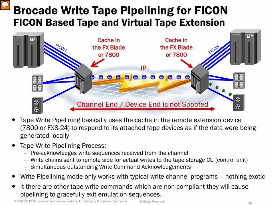
Tape Write Pipelining basically uses the cache in the remote extension device (7800 or FX8-24) to respond to its attached tape devices as if the data were being generated locally
Tape Write Pipelining Process: – Pre-acknowledges write sequences received from the channel – Write chains sent to remote side for actual writes to the tape storage CU (control unit) – Simultaneous outstanding Write Command Acknowledgements
Write Pipelining mode only works with typical write channel programs – nothing exotic It there are other tape write commands which are non-compliant they will cause
pipelining to gracefully exit emulation sequences.
Channel End / Device End is not Spoofed
Cache in the FX Blade
or 7800
Cache in the FX Blade
or 7800
© 2010-2013 Brocade Communications Systems, Inc. Company Proprietary Information 39 All Rights Reserved.
Brocade Read Tape Pipelining for FICON FICON Based Tape and Virtual Tape Extension
IP
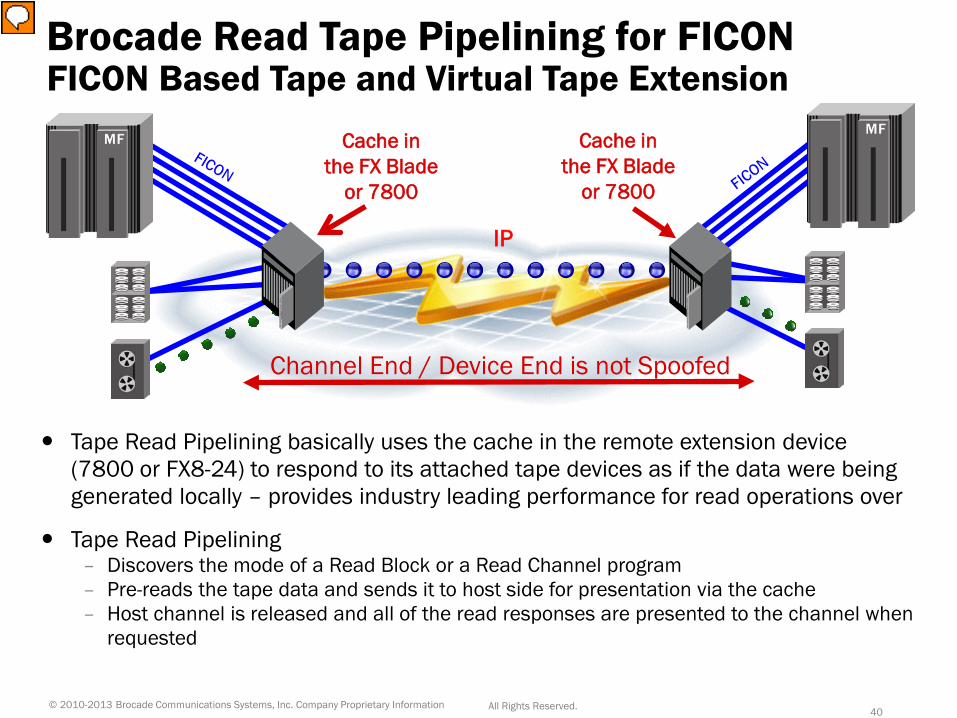
Tape Read Pipelining basically uses the cache in the remote extension device (7800 or FX8-24) to respond to its attached tape devices as if the data were being generated locally – provides industry leading performance for read operations over
Tape Read Pipelining – Discovers the mode of a Read Block or a Read Channel program – Pre-reads the tape data and sends it to host side for presentation via the cache – Host channel is released and all of the read responses are presented to the channel when
requested
Channel End / Device End is not Spoofed
Cache in the FX Blade
or 7800
Cache in the FX Blade
or 7800
© 2010-2013 Brocade Communications Systems, Inc. Company Proprietary Information 40 All Rights Reserved.
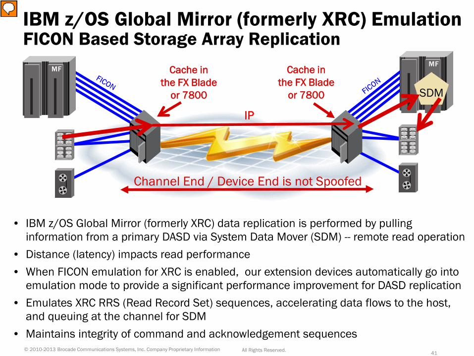
• IBM z/OS Global Mirror (formerly XRC) data replication is performed by pulling information from a primary DASD via System Data Mover (SDM) -- remote read operation
• Distance (latency) impacts read performance • When FICON emulation for XRC is enabled, our extension devices automatically go into
emulation mode to provide a significant performance improvement for DASD replication • Emulates XRC RRS (Read Record Set) sequences, accelerating data flows to the host,
and queuing at the channel for SDM • Maintains integrity of command and acknowledgement sequences
IBM z/OS Global Mirror (formerly XRC) Emulation FICON Based Storage Array Replication
IP
Channel End / Device End is not Spoofed
Cache in the FX Blade
or 7800
Cache in the FX Blade
or 7800 SDM
© 2010-2013 Brocade Communications Systems, Inc. Company Proprietary Information 41 All Rights Reserved.
• Auto-detection of Teradata, XRC (Storage Array) and Tape devices for emulation
• Control block structures are dynamically allocated so that the devices can be emulated as they are discovered – z/OS Global Mirror (XRC) Storage Array – Tape (i.e. VTS/VSM, as well as standalone FICON tape) – Teradata Warehouse Storage Array data
• On FCIP links, automatically switch between Emulation Mode and Shuttle/Tunnel Mode based on the operation being performed – Device specific intelligence
FCIP FICON Connectivity Between Data Centers FICON Emulation Mode – Advanced FICON Accelerator
42 © 2010-2013 Brocade Communications Systems, Inc. Company Proprietary Information All Rights Reserved.
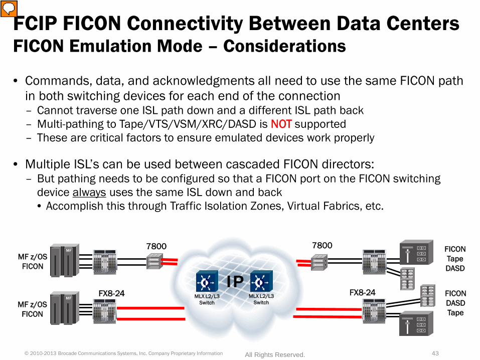
• Commands, data, and acknowledgments all need to use the same FICON path in both switching devices for each end of the connection – Cannot traverse one ISL path down and a different ISL path back – Multi-pathing to Tape/VTS/VSM/XRC/DASD is NOT supported – These are critical factors to ensure emulated devices work properly
• Multiple ISL’s can be used between cascaded FICON directors: – But pathing needs to be configured so that a FICON port on the FICON switching
device always uses the same ISL down and back • Accomplish this through Traffic Isolation Zones, Virtual Fabrics, etc.
FCIP FICON Connectivity Between Data Centers FICON Emulation Mode – Considerations
IP MF z/OS
FICON
FICON Tape DASD
MF z/OS FICON
FICON DASD Tape
7800
FX8-24
7800
FX8-24 MLX L2/L3 Switch
MLX L2/L3 Switch
43 © 2010-2013 Brocade Communications Systems, Inc. Company Proprietary Information All Rights Reserved.
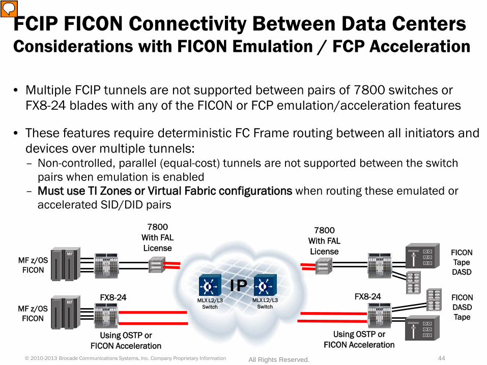
• Multiple FCIP tunnels are not supported between pairs of 7800 switches or FX8-24 blades with any of the FICON or FCP emulation/acceleration features
• These features require deterministic FC Frame routing between all initiators and devices over multiple tunnels: – Non-controlled, parallel (equal-cost) tunnels are not supported between the switch
pairs when emulation is enabled – Must use TI Zones or Virtual Fabric configurations when routing these emulated or
accelerated SID/DID pairs
FCIP FICON Connectivity Between Data Centers Considerations with FICON Emulation / FCP Acceleration
44 © 2010-2013 Brocade Communications Systems, Inc. Company Proprietary Information All Rights Reserved.
IP MF z/OS
FICON
FICON Tape DASD
MF z/OS FICON
FICON DASD Tape
7800 With FAL License
FX8-24
7800 With FAL License
FX8-24 MLX L2/L3 Switch
MLX L2/L3 Switch
Using OSTP or FICON Acceleration
Using OSTP or FICON Acceleration
Can be used independently
IPSEC (this is encryption) • Internet Protocol Security (IPsec) is a protocol for securing Internet
Protocol (IP) communications by authenticating and encrypting each IP packet of a communication session: – There is no license and no cost for IPsec on our extension devices – IPsec adds only 5 µs (microseconds) of latency to each FCIP frame – IPsec is not a performance problem since it operates at line rate – FX8-24 has IPsec on 1 of the 2 FCIP engines while the new FX8-24E (FOS 7.1.0c) can
do IPsec on both FCIP engines.
Hardware Compression (can be used with or independent of IPsec) • Advanced Compression architecture provides flexibility to optimize
compression ratios and maximize throughput: – Capacity of our compression engine to maintain data flow at line rate – Optimization of the Maximum Transmission Unit (MTU) of datagrams – 7800/FX8-24 compress data and batch multiple FC frames per TCP segment
• Three different compression modes to choose from
FCIP Compression and Security Should always use IPsec and Compression with FCIP
45 © 2010-2013 Brocade Communications Systems, Inc. Company Proprietary Information All Rights Reserved.
Summary and Conclusions
• FCIP provides a robust DR/BC network solution for a variety of distances.
• FCIP is ideal for both open systems, as well as System z environments
• FCIP takes advantage of the TCP protocol for error recovery and data integrity.
• FCIP protocol emulation technology provides high performance at very long (global) distances
46

47
Questions?