Embed Size (px)
Citation preview
Full HD 20M IR Vari-
Focal Dome IP Camera ICA-E3550V
5 Mega-pixel Bullet IR PoE IP
Camera with Extended Support
►ICA-E3550V
5 Mega-pixel Bullet IR PoE IP Camera ICA-E3550V
2
Copyright
Copyright 2018 by PLANET Technology Corp. All rights reserved. No part of this publication may be
reproduced, transmitted, transcribed, stored in a retrieval system, or translated into any language or
computer language, in any form or by any means, electronic, mechanical, magnetic, optical, chemical,
manual or otherwise, without the prior written permission of PLANET.
PLANET makes no representations or warranties, either expressed or implied, with respect to the
contents hereof and specifically disclaims any warranties, merchantability or fitness for any particular
purpose. Any software described in this manual is sold or licensed "as is". Should the programs prove
defective following their purchase, the buyer (and not PLANET, its distributor, or its dealer) assumes
the entire cost of all necessary servicing, repair, and any incidental or consequential damages
resulting from any defect in the software. Further, PLANET reserves the right to revise this publication
and to make changes from time to time in the contents hereof without obligation to notify any person of
such revision or changes.
All brand and product names mentioned in this manual are trademarks and/or registered trademarks
of their respective holders.
Federal Communication Commission Interference Statement
This equipment has been tested and found to comply with the limits for a Class B digital device,
pursuant to Part 15 of FCC Rules. These limits are designed to provide reasonable protection against
harmful interference in a residential installation. This equipment generates, uses, and can radiate radio
frequency energy and, if not installed and used in accordance with the instructions, may cause harmful
interference to radio communications. However, there is no guarantee that interference will not occur
in a particular installation. If this equipment does cause harmful interference to radio or television
reception, which can be determined by turning the equipment off and on, the user is encouraged to try
to correct the interference by one or more of the following measures:
1. Reorient or relocate the receiving antenna.
2. Increase the separation between the equipment and receiver.
3. Connect the equipment into an outlet on a circuit different from that to which the receiver is
connected.
4. Consult the dealer or an experienced radio technician for help.
FCC Caution
To assure continued compliance, for example, use only shielded interface cables when connecting to
computer or peripheral devices. Any changes or modifications not expressly approved by the party
responsible for compliance could void the user’s authority to operate the equipment.

5 Mega-pixel Bullet IR PoE IP Camera ICA-E3550V
3
This device complies with Part 15 of the FCC Rules. Operation is subject to the following two
conditions: (1) This device may not cause harmful interference, and (2) this device must accept any
interference received, including interference that may cause undesired operation.
Federal Communication Commission (FCC) Radiation Exposure Statement
This equipment complies with FCC radiation exposure set forth for an uncontrolled environment. In
order to avoid the possibility of exceeding the FCC radio frequency exposure limits, human proximity
to the antenna shall not be less than 20 cm (8 inches) during normal operation.
Safety
This equipment is designed with the utmost care for the safety of those who install and use it.
However, special attention must be paid to the dangers of electric shock and static electricity when
working with electrical equipment. All guidelines of this and of the computer manufacture must
therefore be allowed at all times to ensure the safe use of the equipment.
CE Mark Warning
This is a Class B product. In a domestic environment, this product may cause radio interference, in
which case the user may be required to take adequate measures.
WEEE Regulation
To avoid the potential effects on the environment and human health as a result of the
presence of hazardous substances in electrical and electronic equipment, end users of
electrical and electronic equipment should understand the meaning of the crossed-out
wheeled bin symbol. Do not dispose of WEEE as unsorted municipal waste; they should be collected
separately.
Revision
User’s Manual of PLANET 5 Mega-pixel Bullet IR PoE IP Camera
Model: ICA-E3550V
Rev: 1.2 (August, 2018)
Part No. EM-ICA-E3550V_v1.2
5 Mega-pixel Bullet IR PoE IP Camera ICA-E3550V
4
Table of Contents
Chapter 1. Product Introduction ......................................................................................................... 6
1.1 Package Contents ................................................................................................................................................. 6
1.2 Overview ............................................................................................................................................................... 6
1.3 Features .............................................................................................................................................................. 10
1.4 Product Specifications .......................................................................................................................................... 11
Chapter 2. Hardware Interface .........................................................................................................13
2.1 Physical Descriptions .......................................................................................................................................... 13
2.1.1 Identification of ICA-E3550V connectors ................................................................................................ 13
2.1.2 I/O Control Instruction ............................................................................................................................. 14
2.2 Hardware Installation .......................................................................................................................................... 17
2.3 Initial Utility Installation ........................................................................................................................................ 18
2.4 Using UPnP of Windows XP or 7 ........................................................................................................................ 21
2.4.1 Windows XP ............................................................................................................................................ 21
2.4.2 Windows 7 .............................................................................................................................................. 25
2.5 Setting Up ActiveX for Internet Camera .............................................................................................................. 28
2.5.1 Internet Explorer 6 for Windows XP ........................................................................................................ 28
2.5.2 Internet Explorer 7 for Windows XP ........................................................................................................ 29
2.5.3 Internet Explorer 7 for Windows Vista ..................................................................................................... 29
Chapter 3. Web-based Management ...............................................................................................31
3.1. Introduction ........................................................................................................................................................ 31
3.2. Connecting to Internet Camera .......................................................................................................................... 31
3.3 Live Viewing ........................................................................................................................................................ 32
3.4 Configuration ....................................................................................................................................................... 35
3.5 Host Setup .......................................................................................................................................................... 36
3.5.1 Host ......................................................................................................................................................... 36
3.5.2 GPS Position ........................................................................................................................................... 37
3.6 Date and Time ..................................................................................................................................................... 37
3.7 Network ............................................................................................................................................................... 39
3.7.1 IP Address Filtering ................................................................................................................................. 39
3.7.2 Port Mapping ........................................................................................................................................... 41
3.7.3 HTTPS .................................................................................................................................................... 42
3.7.4 IEEE802.1X ............................................................................................................................................ 43
3.7.5 SNMP Setting ......................................................................................................................................... 44
3.7.6 RTP ......................................................................................................................................................... 47
3.7.7 Network ................................................................................................................................................... 47
3.8 IP Settings ........................................................................................................................................................... 50
3.8.1 Connection Type ..................................................................................................................................... 50
3.8.2 DNS ........................................................................................................................................................ 52
3.8.3 DDNS & P2P ........................................................................................................................................... 53
3.9 Video & Audio ...................................................................................................................................................... 55
3.9.1 Camera Options ...................................................................................................................................... 55
3.9.2 Video ....................................................................................................................................................... 55
3.9.3 Audio ....................................................................................................................................................... 72
3.10 Event ................................................................................................................................................................. 74
5 Mega-pixel Bullet IR PoE IP Camera ICA-E3550V
5
3.10.1 Event Server ......................................................................................................................................... 74
3.10.2 Event Configuration .............................................................................................................................. 77
3.10.3 Event List .............................................................................................................................................. 85
3.10.4 Manual Event ........................................................................................................................................ 89
3.11 System .............................................................................................................................................................. 89
3.11.1 User Account ......................................................................................................................................... 89
3.11.2 System Info ........................................................................................................................................... 90
3.11.3 Factory Default ...................................................................................................................................... 91
3.11.4 Firmware Upload ................................................................................................................................... 92
3.11.5 Save & Reboot ...................................................................................................................................... 92
3.11.6 Logout ................................................................................................................................................... 93
Appendix A. Factory Default ...............................................................................................................94
Appendix B. Ping IP Address ..............................................................................................................95
Appendix C. Planet DDNS Application ................................................................................................96
Appendix D. Configuring Port Forwarding Manually ...........................................................................97
5 Mega-pixel Bullet IR PoE IP Camera ICA-E3550V
6
Chapter 1. Product Introduction
1.1 Package Contents
The package should contain the following items:
Camera Unit x 1
Quick Installation Guide x 1
Mounting Screw Kit x 1
Cable Gland Package x 1
Sunshield x 1
Bracket x 1
Bracket Plate x 1
Terminal block x 1
1. If any of the above items are missing, please contact your dealer immediately.
2. Using the power supply that is not the one included in the Internet Camera packet will
cause damage and void the warranty for this product.
1.2 Overview
Extended Support with Specific Software
PLANET E-series of IP cameras, ICA-E3550V and ICA-E5550V, are able to provide advanced
surveillance monitoring applications with specific software such as video analytics and vehicle license
plate recognition. Firstly, through the NVR-E6480, it can help users monitor and record images/videos
from multiple cameras simultaneously by using a 64-Ch Windows-based NVR and is able to operate up
to 64 channels with advanced features including event management and recording, tri-display
monitoring, smart motion detection, PTZ control and e-map. Secondly, PLANET E-series of IP cameras
support the CV7-VA, a software of video analytics that is designed to transform your video surveillance
network into a smart detection system.
The software provides Entering Area, People Counting, Missing Object, Line Crossing, Unattended
Object and Tamper functions. Once a suspicious activity is detected, users can play back to watch these
events and use them as references or evidences if needed. Moreover, the cameras also support the
CV7-LP video analytics software that is designed to detect and recognize vehicle license plates. This
software is able to automatically locate and read license plates appearing in a certain area, and match

5 Mega-pixel Bullet IR PoE IP Camera ICA-E3550V
7
this data against the database. It provides efficiency in parking and traffic control, as well as law
enforcement.
Professional, High Resolution, Day and Night Network Camera
PLANET ICA-E3550V Network Camera with IR Illuminator is a high-resolution camera for the round-
the-clock surveillance over IP networks. This camera supports H.264 and MJPEG compression formats
and delivers excellent picture quality in 5 mega-pixel resolutions at 15 frames per second (fps) and full
HD resolutions at 30fps. The ICA-E3550V is also equipped with IP68-rated and IK10-rated vandalproof
housing to protect the camera body against rain and dust and ensures operation under extreme weather
conditions, which makes it an ideal solution for outdoor applications, e.g., surveillance of buildings, roads,
parking areas, garages, railway stations, and airports.
Day & Night Functionality
To adapt to constantly changing lighting conditions during the day and night, the ICA-E3550V comes
with a removable IR-cut filter and built-in IR illuminators, which enable the camera to provide color video

5 Mega-pixel Bullet IR PoE IP Camera ICA-E3550V
8
when there is sufficient light, and black/white video in dark conditions. The ICA-E3550V is able to
maintain clear images 24 hours a day.
Exceptional Image Quality
Together with powerful image processing attributes like Wide Dynamic Range (WDR) and 3-dimensional
Noise Reduction (3DNR) technology, the ICA-E3550V is able to filter the intense backlight surrounding
a subject and remove noises from video signal. The result is that an extremely clear and exquisite picture
quality can be produced even under any challenging lighting conditions.
Advanced Event Management
The ICA-E3550V supports a number of advanced features to enhance surveillance flexibility and event
management capabilities. The advanced features include 4 configurable regions of privacy mask to
5 Mega-pixel Bullet IR PoE IP Camera ICA-E3550V
9
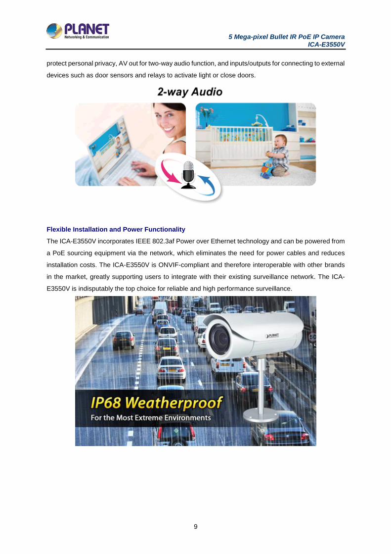
protect personal privacy, AV out for two-way audio function, and inputs/outputs for connecting to external
devices such as door sensors and relays to activate light or close doors.
Flexible Installation and Power Functionality
The ICA-E3550V incorporates IEEE 802.3af Power over Ethernet technology and can be powered from
a PoE sourcing equipment via the network, which eliminates the need for power cables and reduces
installation costs. The ICA-E3550V is ONVIF-compliant and therefore interoperable with other brands
in the market, greatly supporting users to integrate with their existing surveillance network. The ICA-
E3550V is indisputably the top choice for reliable and high performance surveillance.
5 Mega-pixel Bullet IR PoE IP Camera ICA-E3550V
10
1.3 Features
Camera
■ 1/3.2” 5MP progressive scan CMOS sensor
■ 2.8~12 mm vari-focal, fixed-iris lens
■ 0.1 lux minimum illumination at F1.4
■ Maximum resolution 2592 x 1944
■ Removable IR-cut filter for Day & Night function
Video and Audio
■ H.264/M-JPEG video compression
■ Simultaneous multi-stream support
■ H.264 high profile, main profile and baseline
■ Max. resolution of 1080p at 30fps and 5 mega-pixel at 15fps
■ 3DNR to improve picture quality at low lux
■ WDR enhancement function strengthens visibility under extremely bright or dark environments
■ Two-way audio support with enhanced audio quality
Network and Configuration
■ Compliant with IEEE 802.3af PoE interface for flexible deployment
■ Supports both IPv6 and IPv4 protocols
■ RTSP/UPnP/Bonjour/HTTPS protocols selectable
Easy Installation and Management
■ ONVIF compliant for interoperability
■ Built-in 15 IR illuminators, effective up to 30 meters
■ IK10/IP68 classification with vandal and weather proof
■ Micro SD card local video recording supported
■ Digital Input/Output for integration with sensors and alarms
5 Mega-pixel Bullet IR PoE IP Camera ICA-E3550V
11
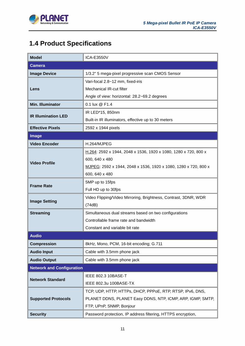
1.4 Product Specifications
Model ICA-E3550V
Camera
Image Device 1/3.2" 5 mega-pixel progressive scan CMOS Sensor
Lens
Vari-focal 2.8~12 mm, fixed-iris
Mechanical IR-cut filter
Angle of view: horizontal: 28.2~69.2 degrees
Min. Illuminator 0.1 lux @ F1.4
IR Illumination LED IR LED*15, 850nm
Built-in IR illuminators, effective up to 30 meters
Effective Pixels 2592 x 1944 pixels
Image
Video Encoder H.264/MJPEG
Video Profile
H.264: 2592 x 1944, 2048 x 1536, 1920 x 1080, 1280 x 720, 800 x
600, 640 x 480
MJPEG: 2592 x 1944, 2048 x 1536, 1920 x 1080, 1280 x 720, 800 x
600, 640 x 480
Frame Rate 5MP up to 15fps
Full HD up to 30fps
Image Setting Video Flipping/Video Mirroring, Brightness, Contrast, 3DNR, WDR
(74dB)
Streaming Simultaneous dual streams based on two configurations
Controllable frame rate and bandwidth
Constant and variable bit rate
Audio
Compression 8kHz, Mono, PCM, 16-bit encoding; G.711
Audio Input Cable with 3.5mm phone jack
Audio Output Cable with 3.5mm phone jack
Network and Configuration
Network Standard IEEE 802.3 10BASE-T
IEEE 802.3u 100BASE-TX
Supported Protocols
TCP, UDP, HTTP, HTTPs, DHCP, PPPoE, RTP, RTSP, IPv6, DNS,
PLANET DDNS, PLANET Easy DDNS, NTP, ICMP, ARP, IGMP, SMTP,
FTP, UPnP, SNMP, Bonjour
Security Password protection, IP address filtering, HTTPS encryption,
5 Mega-pixel Bullet IR PoE IP Camera ICA-E3550V
12
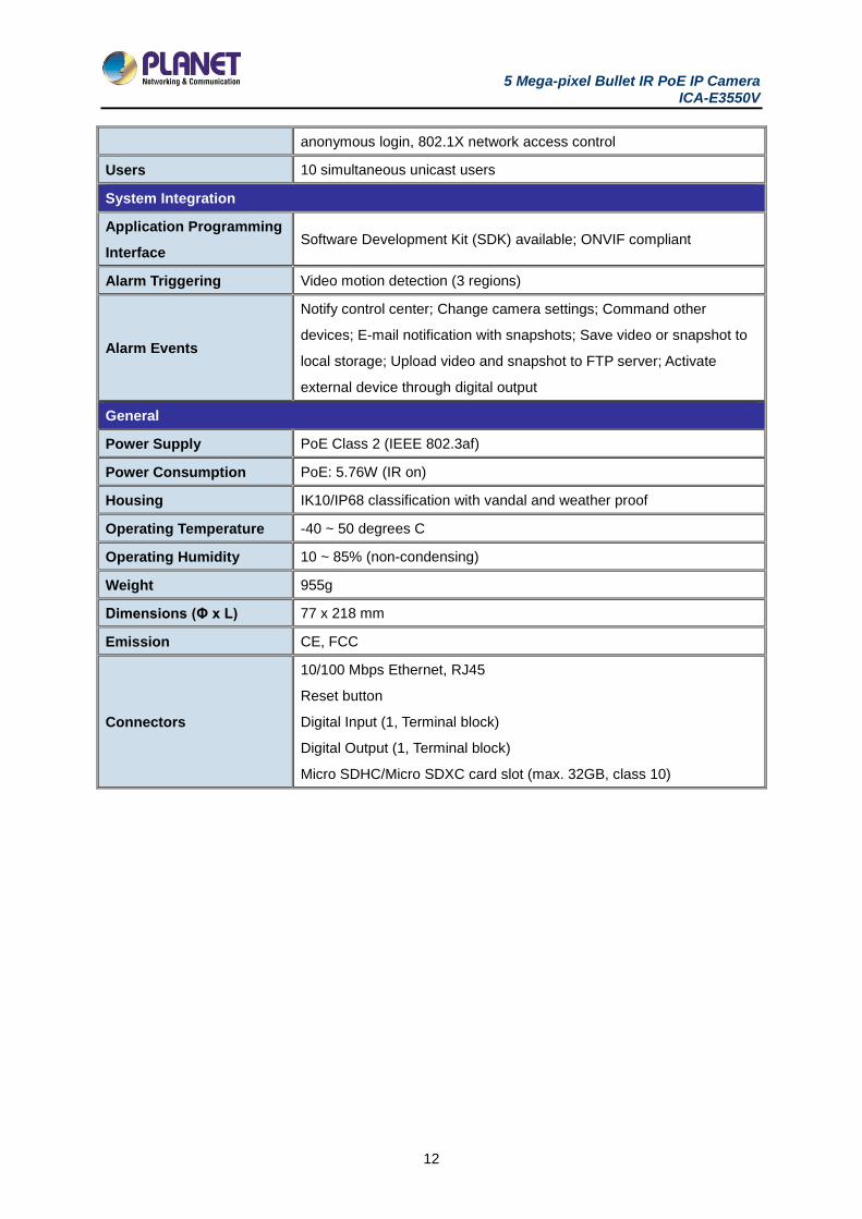
anonymous login, 802.1X network access control
Users 10 simultaneous unicast users
System Integration
Application Programming
Interface Software Development Kit (SDK) available; ONVIF compliant
Alarm Triggering Video motion detection (3 regions)
Alarm Events
Notify control center; Change camera settings; Command other
devices; E-mail notification with snapshots; Save video or snapshot to
local storage; Upload video and snapshot to FTP server; Activate
external device through digital output
General
Power Supply PoE Class 2 (IEEE 802.3af)
Power Consumption PoE: 5.76W (IR on)
Housing IK10/IP68 classification with vandal and weather proof
Operating Temperature -40 ~ 50 degrees C
Operating Humidity 10 ~ 85% (non-condensing)
Weight 955g
Dimensions (Φ x L) 77 x 218 mm
Emission CE, FCC
Connectors
10/100 Mbps Ethernet, RJ45
Reset button
Digital Input (1, Terminal block)
Digital Output (1, Terminal block)
Micro SDHC/Micro SDXC card slot (max. 32GB, class 10)
5 Mega-pixel Bullet IR PoE IP Camera ICA-E3550V
13
Chapter 2. Hardware Interface
2.1 Physical Descriptions
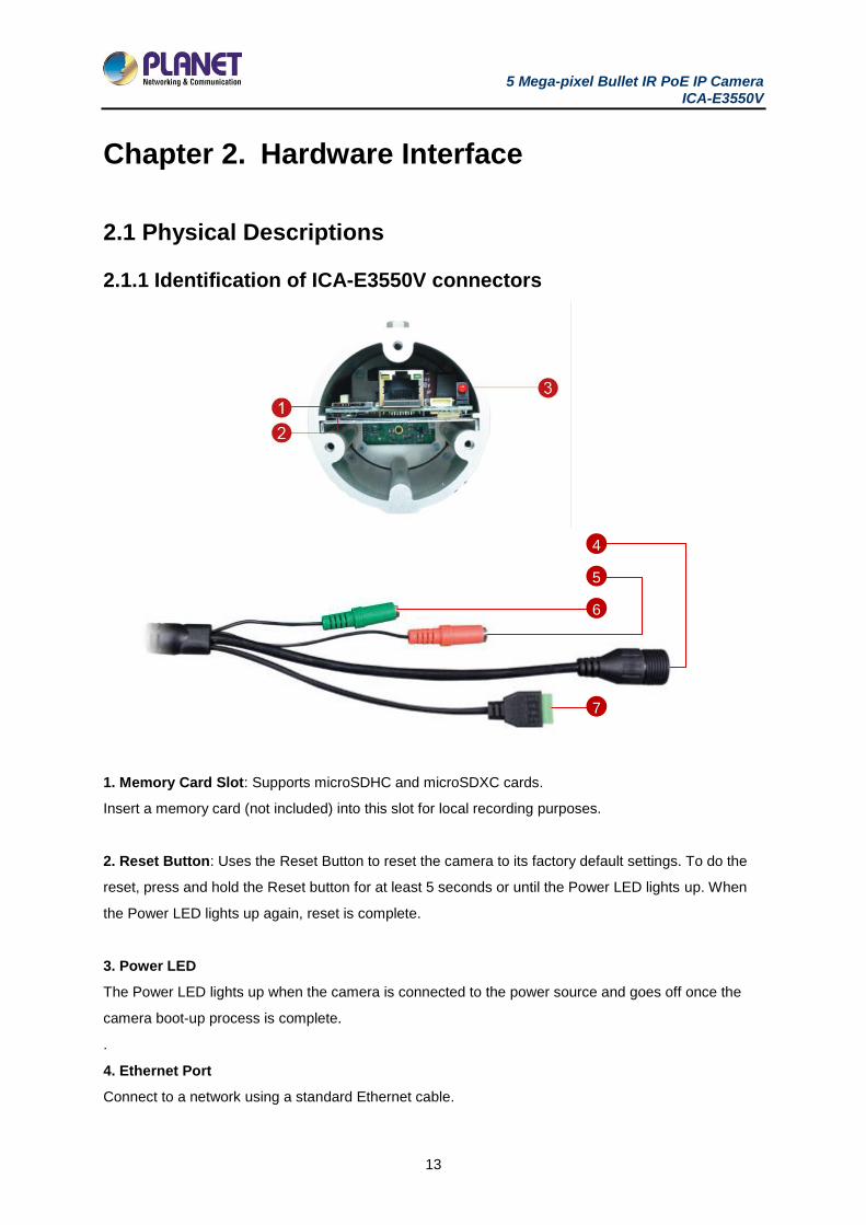
2.1.1 Identification of ICA-E3550V connectors
1. Memory Card Slot: Supports microSDHC and microSDXC cards.
Insert a memory card (not included) into this slot for local recording purposes.
2. Reset Button: Uses the Reset Button to reset the camera to its factory default settings. To do the
reset, press and hold the Reset button for at least 5 seconds or until the Power LED lights up. When
the Power LED lights up again, reset is complete.
3. Power LED
The Power LED lights up when the camera is connected to the power source and goes off once the
camera boot-up process is complete.
.
4. Ethernet Port
Connect to a network using a standard Ethernet cable.
6
5
4
7
5 Mega-pixel Bullet IR PoE IP Camera ICA-E3550V
14
5. Audio Input
Connect to audio input devices, such as a microphone with built-in amplifier, etc.
6. Audio Output
Connect to audio output devices, such as a speaker, etc.
7. Digital Input/Output
Connect to digital input or output devices, such as an alarm trigger, panic button, etc. Digital Input (DI)
and Digital Output (DO) devices are used in applications like motion detection, event triggering, alarm
notifications, etc.
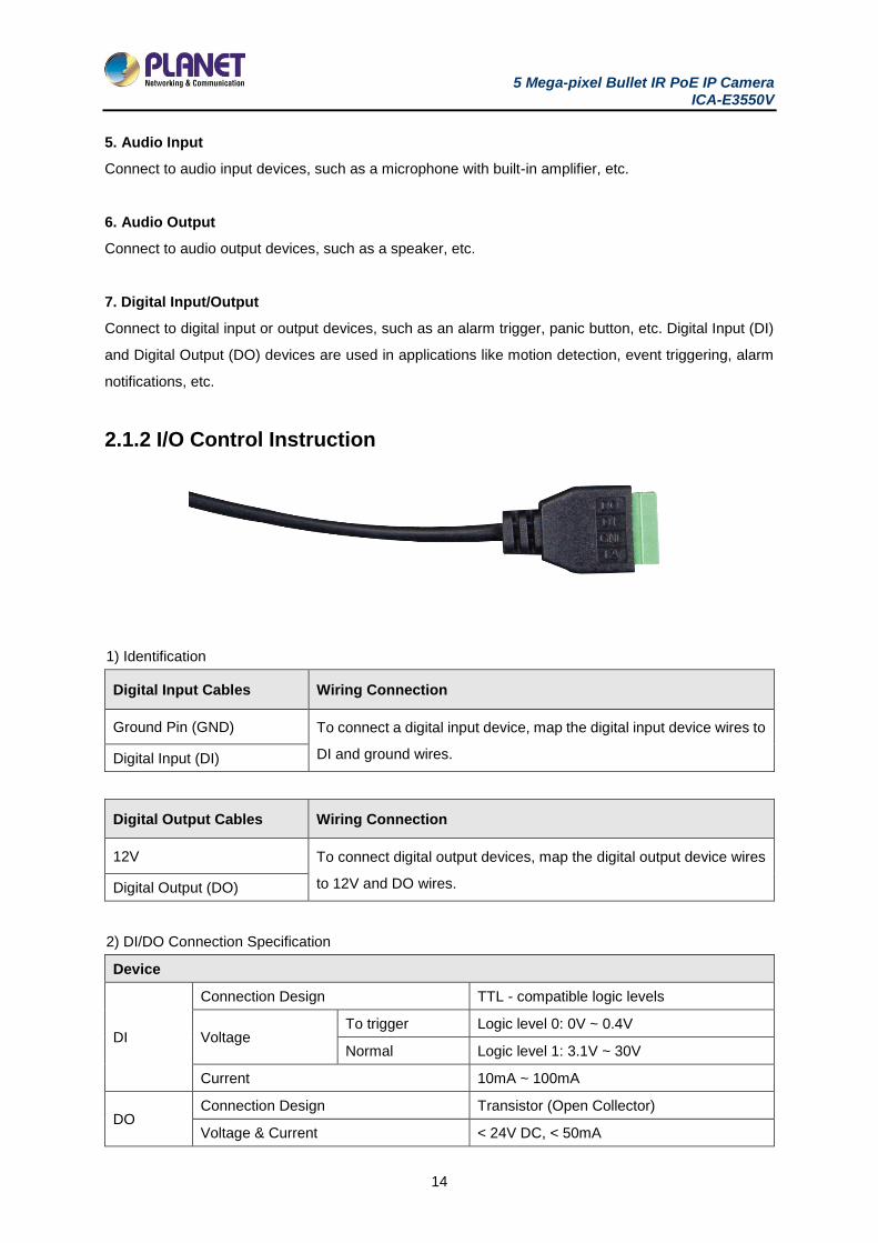
2.1.2 I/O Control Instruction
1) Identification
Digital Input Cables Wiring Connection
Ground Pin (GND) To connect a digital input device, map the digital input device wires to
DI and ground wires. Digital Input (DI)
Digital Output Cables Wiring Connection
12V To connect digital output devices, map the digital output device wires
to 12V and DO wires. Digital Output (DO)
2) DI/DO Connection Specification
Device
DI
Connection Design TTL - compatible logic levels
Voltage To trigger Logic level 0: 0V ~ 0.4V
Normal Logic level 1: 3.1V ~ 30V
Current 10mA ~ 100mA
DO Connection Design Transistor (Open Collector)
Voltage & Current < 24V DC, < 50mA
5 Mega-pixel Bullet IR PoE IP Camera ICA-E3550V
15
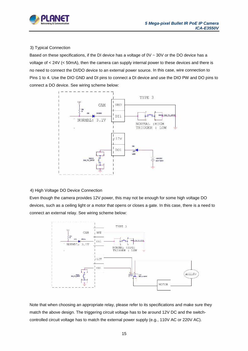
3) Typical Connection
Based on these specifications, if the DI device has a voltage of 0V ~ 30V or the DO device has a
voltage of < 24V (< 50mA), then the camera can supply internal power to these devices and there is
no need to connect the DI/DO device to an external power source. In this case, wire connection to
Pins 1 to 4. Use the DIO GND and DI pins to connect a DI device and use the DIO PW and DO pins to
connect a DO device. See wiring scheme below:
4) High Voltage DO Device Connection
Even though the camera provides 12V power, this may not be enough for some high voltage DO
devices, such as a ceiling light or a motor that opens or closes a gate. In this case, there is a need to
connect an external relay. See wiring scheme below:
Note that when choosing an appropriate relay, please refer to its specifications and make sure they
match the above design. The triggering circuit voltage has to be around 12V DC and the switch-
controlled circuit voltage has to match the external power supply (e.g., 110V AC or 220V AC).
5 Mega-pixel Bullet IR PoE IP Camera ICA-E3550V
16
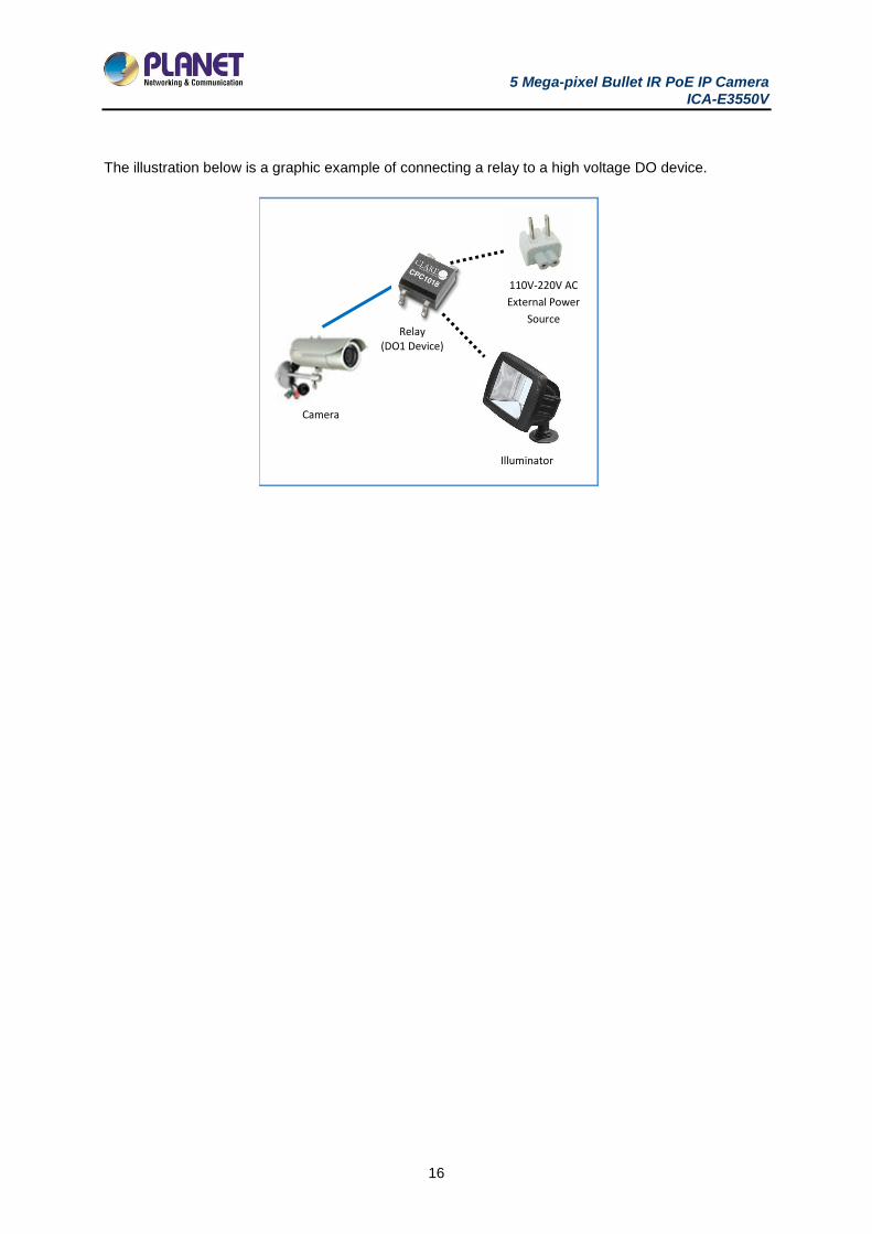
The illustration below is a graphic example of connecting a relay to a high voltage DO device.
Relay (DO1 Device)
)
Camera
Illuminator
110V-220V AC
External Power
Source
5 Mega-pixel Bullet IR PoE IP Camera ICA-E3550V
17
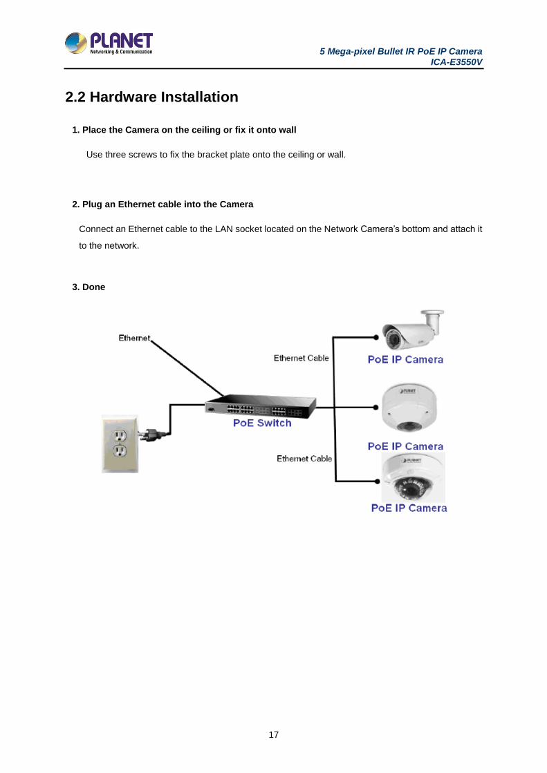
2.2 Hardware Installation
1. Place the Camera on the ceiling or fix it onto wall
Use three screws to fix the bracket plate onto the ceiling or wall.
2. Plug an Ethernet cable into the Camera
Connect an Ethernet cable to the LAN socket located on the Network Camera’s bottom and attach it
to the network.
3. Done
5 Mega-pixel Bullet IR PoE IP Camera ICA-E3550V
18
2.3 Initial Utility Installation
This chapter shows how to quickly set up your H.264 camera. The camera is with the default settings.
However, to help you find the networked camera quickly, the windows utility PLANET Smart Discovery
Lite can search the cameras in the network that will help you to configure some basic settings before
you start advanced management and monitoring.
1. Go to PLANET website and download the Smart Discovery Lite utility.
http://planet.com.tw/en/support/download.php?view=8184&key=ICA-E#list
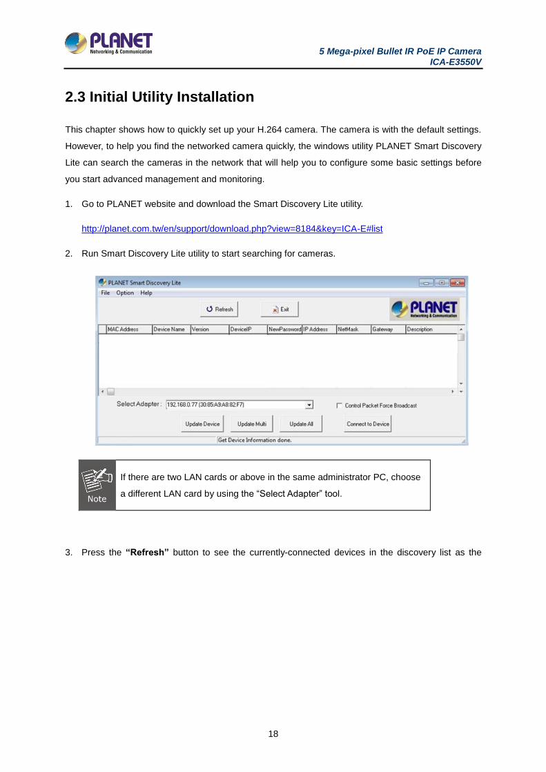
2. Run Smart Discovery Lite utility to start searching for cameras.
If there are two LAN cards or above in the same administrator PC, choose
a different LAN card by using the “Select Adapter” tool.
3. Press the “Refresh” button to see the currently-connected devices in the discovery list as the
5 Mega-pixel Bullet IR PoE IP Camera ICA-E3550V
19
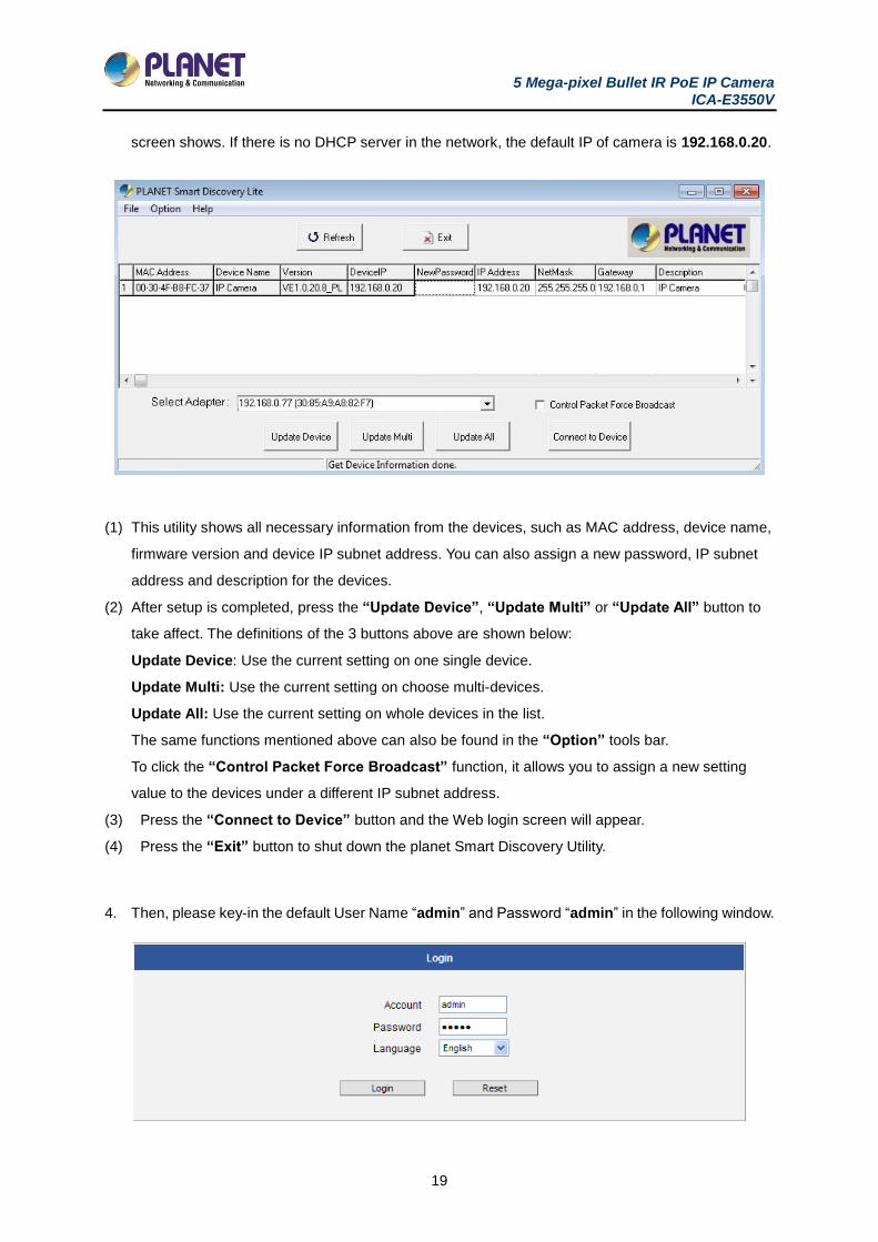
screen shows. If there is no DHCP server in the network, the default IP of camera is 192.168.0.20.
(1) This utility shows all necessary information from the devices, such as MAC address, device name,
firmware version and device IP subnet address. You can also assign a new password, IP subnet
address and description for the devices.
(2) After setup is completed, press the “Update Device”, “Update Multi” or “Update All” button to
take affect. The definitions of the 3 buttons above are shown below:
Update Device: Use the current setting on one single device.
Update Multi: Use the current setting on choose multi-devices.
Update All: Use the current setting on whole devices in the list.
The same functions mentioned above can also be found in the “Option” tools bar.
To click the “Control Packet Force Broadcast” function, it allows you to assign a new setting
value to the devices under a different IP subnet address.
(3) Press the “Connect to Device” button and the Web login screen will appear.
(4) Press the “Exit” button to shut down the planet Smart Discovery Utility.
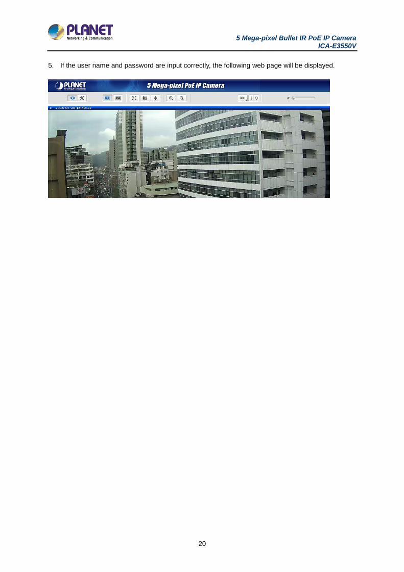
4. Then, please key-in the default User Name “admin” and Password “admin” in the following window.
5 Mega-pixel Bullet IR PoE IP Camera ICA-E3550V
20
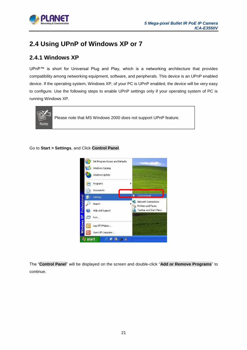
5. If the user name and password are input correctly, the following web page will be displayed.
5 Mega-pixel Bullet IR PoE IP Camera ICA-E3550V
21
2.4 Using UPnP of Windows XP or 7
2.4.1 Windows XP
UPnP™ is short for Universal Plug and Play, which is a networking architecture that provides
compatibility among networking equipment, software, and peripherals. This device is an UPnP enabled
device. If the operating system, Windows XP, of your PC is UPnP enabled, the device will be very easy
to configure. Use the following steps to enable UPnP settings only if your operating system of PC is
running Windows XP.
Please note that MS Windows 2000 does not support UPnP feature.
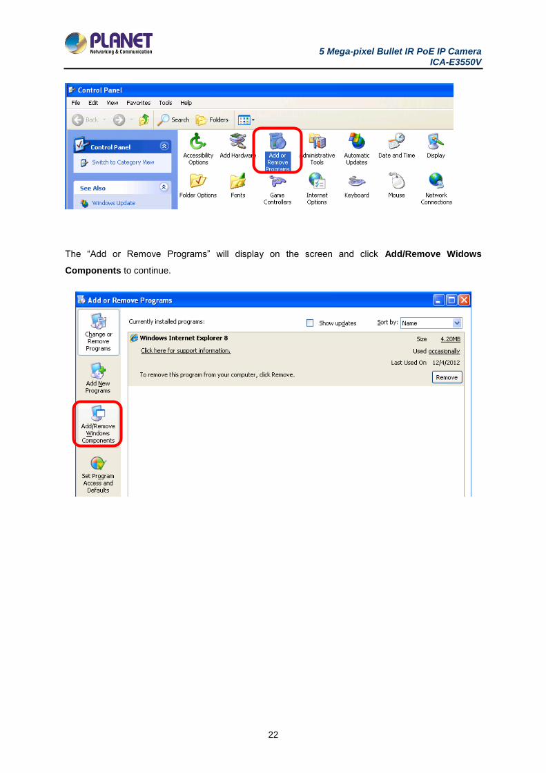
Go to Start > Settings, and Click Control Panel.
The “Control Panel” will be displayed on the screen and double-click “Add or Remove Programs” to
continue.
5 Mega-pixel Bullet IR PoE IP Camera ICA-E3550V
22
The “Add or Remove Programs” will display on the screen and click Add/Remove Widows
Components to continue.
5 Mega-pixel Bullet IR PoE IP Camera ICA-E3550V
23
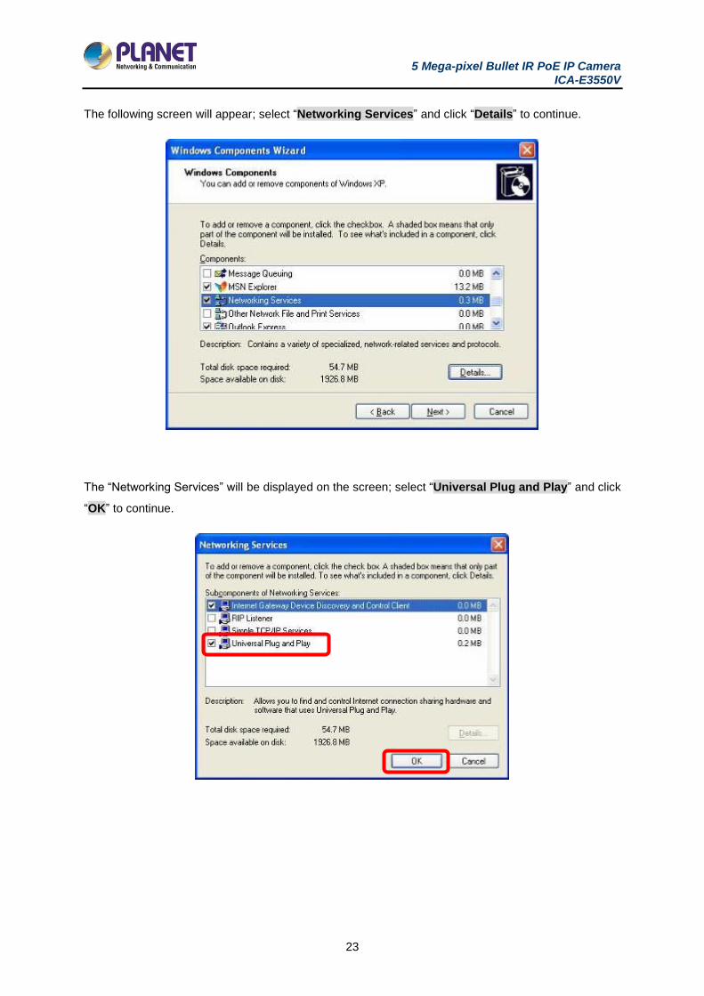
The following screen will appear; select “Networking Services” and click “Details” to continue.
The “Networking Services” will be displayed on the screen; select “Universal Plug and Play” and click
“OK” to continue.
5 Mega-pixel Bullet IR PoE IP Camera ICA-E3550V
24
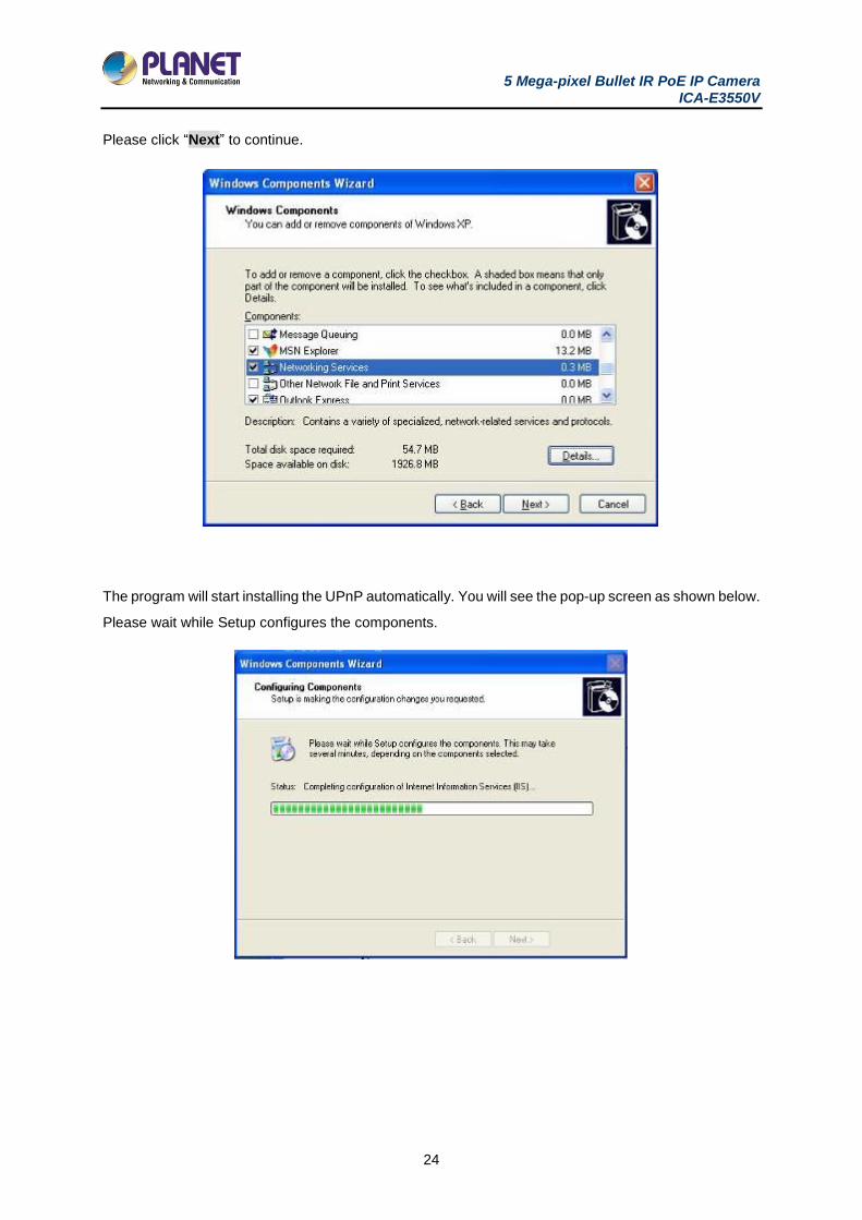
Please click “Next” to continue.
The program will start installing the UPnP automatically. You will see the pop-up screen as shown below.
Please wait while Setup configures the components.
5 Mega-pixel Bullet IR PoE IP Camera ICA-E3550V
25
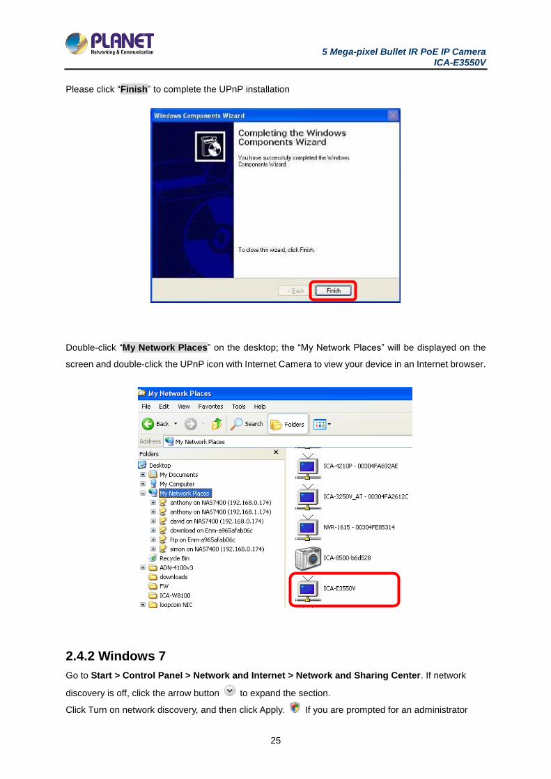
Please click “Finish” to complete the UPnP installation
Double-click “My Network Places” on the desktop; the “My Network Places” will be displayed on the
screen and double-click the UPnP icon with Internet Camera to view your device in an Internet browser.
2.4.2 Windows 7
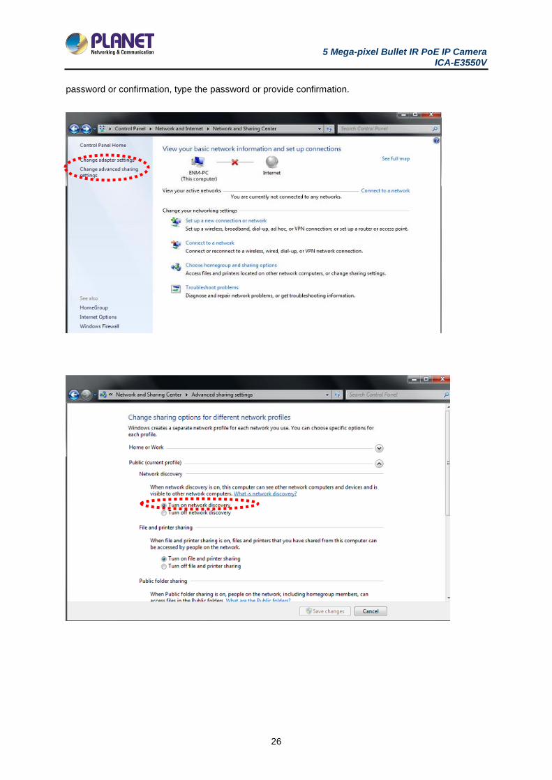
Go to Start > Control Panel > Network and Internet > Network and Sharing Center. If network
discovery is off, click the arrow button to expand the section.
Click Turn on network discovery, and then click Apply. If you are prompted for an administrator
5 Mega-pixel Bullet IR PoE IP Camera ICA-E3550V
26
password or confirmation, type the password or provide confirmation.
5 Mega-pixel Bullet IR PoE IP Camera ICA-E3550V
27
5 Mega-pixel Bullet IR PoE IP Camera ICA-E3550V
28
2.5 Setting Up ActiveX for Internet Camera
The Internet Camera web pages communicate with the Internet Camera using an ActiveX control. The
ActiveX control must be downloaded from the Internet Camera and installed on your PC. Your Internet
Explorer security settings must allow for the web page to work correctly. To use the Internet Camera,
user must set up his IE browser as follows:
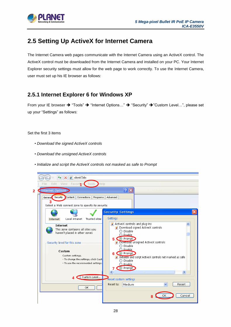
2.5.1 Internet Explorer 6 for Windows XP
From your IE browser “Tools” “Internet Options…” “Security” ”Custom Level…”, please set
up your “Settings” as follows:
Set the first 3 items
• Download the signed ActiveX controls
• Download the unsigned ActiveX controls
• Initialize and script the ActiveX controls not masked as safe to Prompt
1
2
3
4
5
6
7
8
5 Mega-pixel Bullet IR PoE IP Camera ICA-E3550V
29
By now, you have finished your entire PC configuration for Internet Camera.
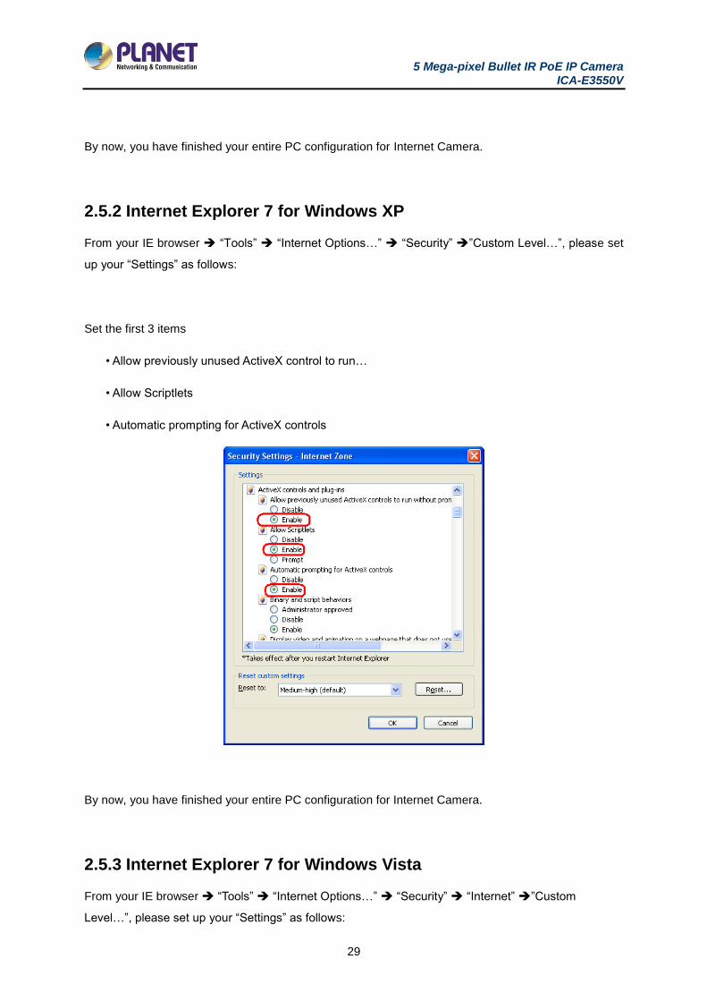
2.5.2 Internet Explorer 7 for Windows XP
From your IE browser “Tools” “Internet Options…” “Security” ”Custom Level…”, please set
up your “Settings” as follows:
Set the first 3 items
• Allow previously unused ActiveX control to run…
• Allow Scriptlets
• Automatic prompting for ActiveX controls
By now, you have finished your entire PC configuration for Internet Camera.
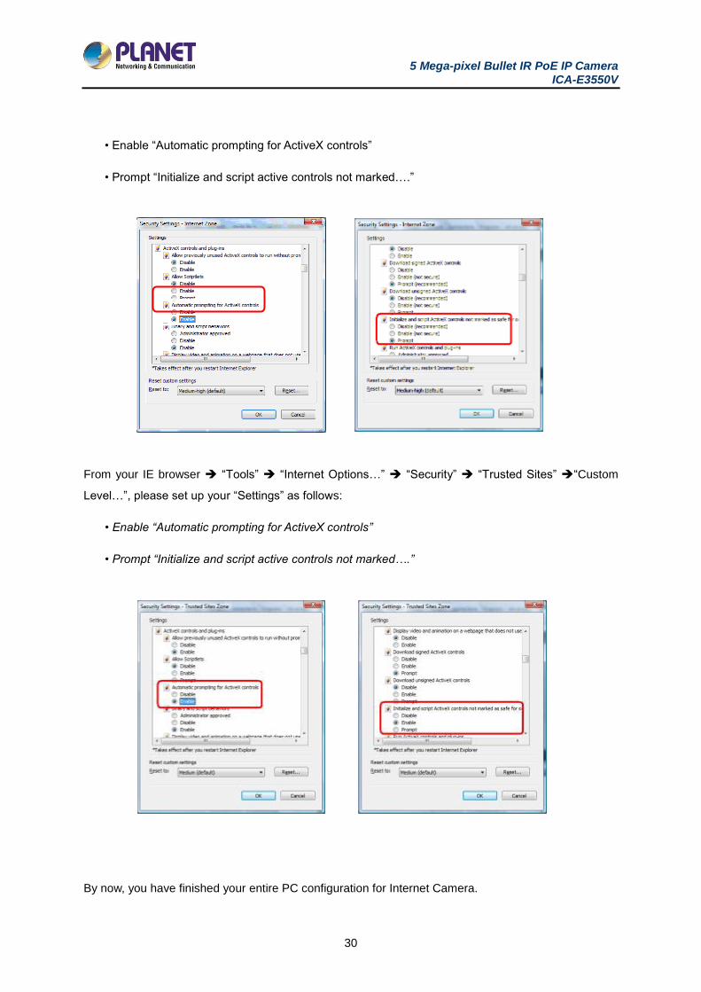
2.5.3 Internet Explorer 7 for Windows Vista
From your IE browser “Tools” “Internet Options…” “Security” “Internet” ”Custom
Level…”, please set up your “Settings” as follows:
5 Mega-pixel Bullet IR PoE IP Camera ICA-E3550V
30
• Enable “Automatic prompting for ActiveX controls”
• Prompt “Initialize and script active controls not marked….”
From your IE browser “Tools” “Internet Options…” “Security” “Trusted Sites” “Custom
Level…”, please set up your “Settings” as follows:
• Enable “Automatic prompting for ActiveX controls”
• Prompt “Initialize and script active controls not marked….”
By now, you have finished your entire PC configuration for Internet Camera.
5 Mega-pixel Bullet IR PoE IP Camera ICA-E3550V
31
Chapter 3. Web-based Management
This chapter provides setup details of the Internet Camera’s Web-based Interface.
3.1. Introduction
The Internet Camera can be configured with your Web browser. Before configuring, please make sure
your PC is under the same IP segment as Internet Camera.
3.2. Connecting to Internet Camera
A. Use the following procedures to establish a connection from your PC to the Internet Camera.
B. Once the camera is connected, you can add the camera to your browser’s Favorites or Bookmarks.
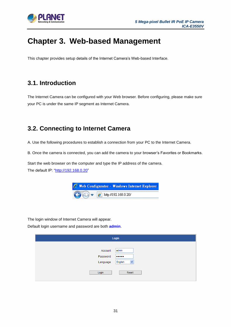
Start the web browser on the computer and type the IP address of the camera.
The default IP: “http://192.168.0.20”
The login window of Internet Camera will appear.
Default login username and password are both admin.
5 Mega-pixel Bullet IR PoE IP Camera ICA-E3550V
32
If the User Name and Password have been changed with PLANET IP Utility, please enter
the new User Name and Password here.
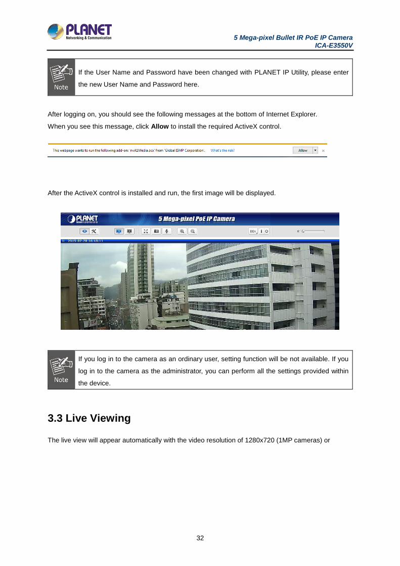
After logging on, you should see the following messages at the bottom of Internet Explorer.
When you see this message, click Allow to install the required ActiveX control.
After the ActiveX control is installed and run, the first image will be displayed.
If you log in to the camera as an ordinary user, setting function will be not available. If you
log in to the camera as the administrator, you can perform all the settings provided within
the device.
3.3 Live Viewing
The live view will appear automatically with the video resolution of 1280x720 (1MP cameras) or
5 Mega-pixel Bullet IR PoE IP Camera ICA-E3550V
33
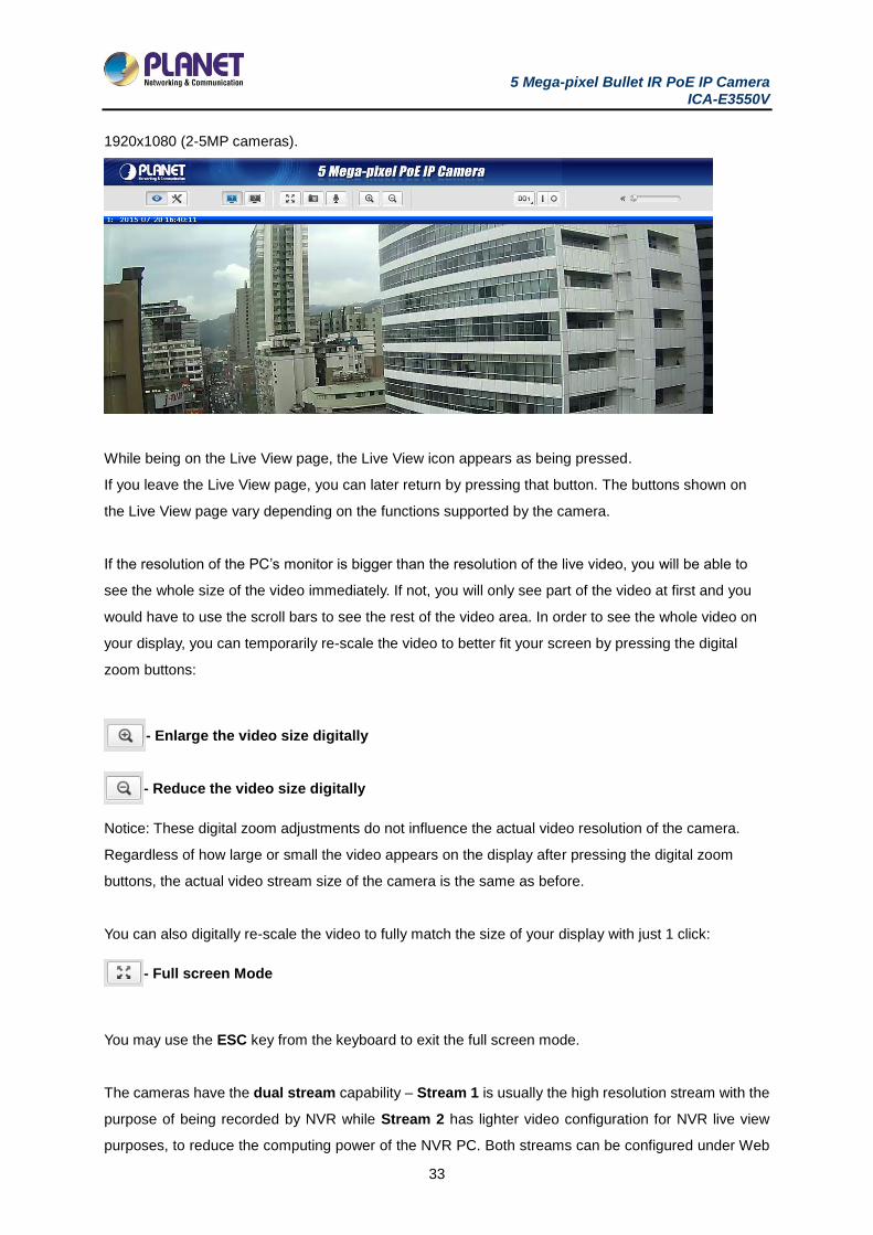
1920x1080 (2-5MP cameras).
While being on the Live View page, the Live View icon appears as being pressed.
If you leave the Live View page, you can later return by pressing that button. The buttons shown on
the Live View page vary depending on the functions supported by the camera.
If the resolution of the PC’s monitor is bigger than the resolution of the live video, you will be able to
see the whole size of the video immediately. If not, you will only see part of the video at first and you
would have to use the scroll bars to see the rest of the video area. In order to see the whole video on
your display, you can temporarily re-scale the video to better fit your screen by pressing the digital
zoom buttons:
- Enlarge the video size digitally
- Reduce the video size digitally
Notice: These digital zoom adjustments do not influence the actual video resolution of the camera.
Regardless of how large or small the video appears on the display after pressing the digital zoom
buttons, the actual video stream size of the camera is the same as before.
You can also digitally re-scale the video to fully match the size of your display with just 1 click:
- Full screen Mode
You may use the ESC key from the keyboard to exit the full screen mode.
The cameras have the dual stream capability – Stream 1 is usually the high resolution stream with the
purpose of being recorded by NVR while Stream 2 has lighter video configuration for NVR live view
purposes, to reduce the computing power of the NVR PC. Both streams can be configured under Web
5 Mega-pixel Bullet IR PoE IP Camera ICA-E3550V
34
Configurator’s Setup page. To see how each of the streams looks like, there are quick buttons on the
Live View page:
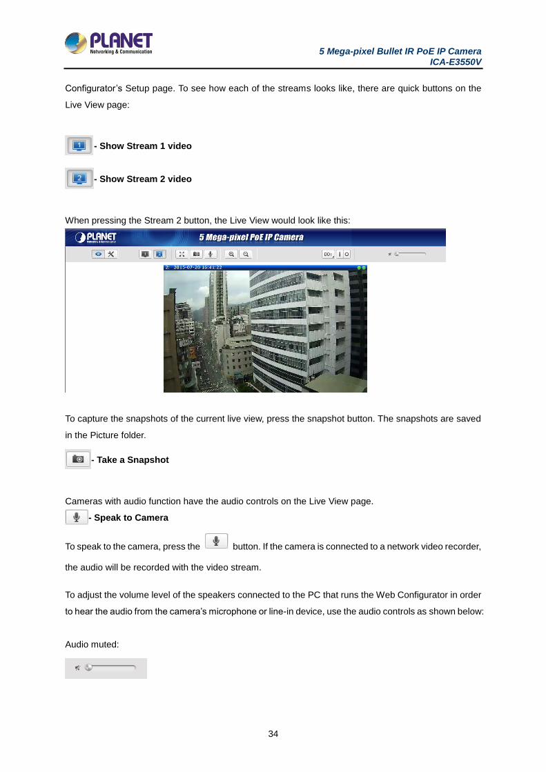
- Show Stream 1 video
- Show Stream 2 video
When pressing the Stream 2 button, the Live View would look like this:
To capture the snapshots of the current live view, press the snapshot button. The snapshots are saved
in the Picture folder.
- Take a Snapshot
Cameras with audio function have the audio controls on the Live View page.
- Speak to Camera
To speak to the camera, press the button. If the camera is connected to a network video recorder,
the audio will be recorded with the video stream.
To adjust the volume level of the speakers connected to the PC that runs the Web Configurator in order
to hear the audio from the camera’s microphone or line-in device, use the audio controls as shown below:
Audio muted:
5 Mega-pixel Bullet IR PoE IP Camera ICA-E3550V
35
Audio level adjusted to the maximum:
This volume control appears on the user interface only when the Audio-in function of the camera has
been “Enabled” under the Setup page.
The digital output controls appear on the Live View page of the cameras with digital input/output function.
The controls allow users to manually trigger a DO device.
- Select DO Port
Each DO port is controlled separately. For cameras with more than one DO port, select the DO port and
press to set the output power level to high or to set the output power level to low. Consequently,
setting the port to a high power level “activates” the DO device and setting the port to a low power level
“deactivates” the DO device. For example, if an alarm is set as DO1 and is pressed, the alarm will
continuously sound until is pressed to deactivate the device.
3.4 Configuration
To configure any of the camera settings, go to the Setup menu by pressing the following button on the
Live View page:
- Go to
The left side of the Setup page contains the list of Setup items.
The exact content of the menu list varies for each
camera, depending on the actual capabilities of each
camera. This manual, however, is designed to explain
all the possible functions.
Several items on the Setup page are divided into groups, such as Network, IP Settings, etc. You can
expand the groups to see the sub-items by pressing the [+] button.
The following chapters of this manual explain each Setup item separately. The chapters are listed in
the same order as the list of Setup menu items.
5 Mega-pixel Bullet IR PoE IP Camera ICA-E3550V
36
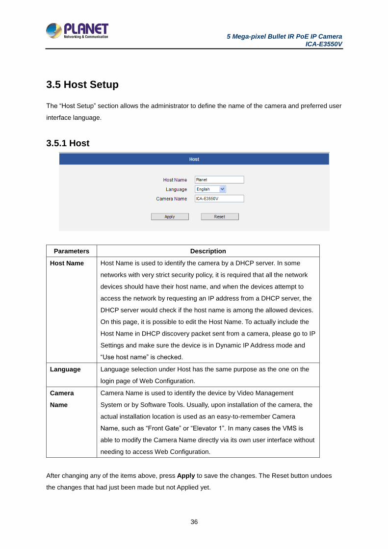
3.5 Host Setup
The “Host Setup” section allows the administrator to define the name of the camera and preferred user
interface language.
3.5.1 Host
Parameters Description
Host Name Host Name is used to identify the camera by a DHCP server. In some
networks with very strict security policy, it is required that all the network
devices should have their host name, and when the devices attempt to
access the network by requesting an IP address from a DHCP server, the
DHCP server would check if the host name is among the allowed devices.
On this page, it is possible to edit the Host Name. To actually include the
Host Name in DHCP discovery packet sent from a camera, please go to IP
Settings and make sure the device is in Dynamic IP Address mode and
“Use host name” is checked.
Language Language selection under Host has the same purpose as the one on the
login page of Web Configuration.
Camera
Name
Camera Name is used to identify the device by Video Management
System or by Software Tools. Usually, upon installation of the camera, the
actual installation location is used as an easy-to-remember Camera
Name, such as “Front Gate” or “Elevator 1”. In many cases the VMS is
able to modify the Camera Name directly via its own user interface without
needing to access Web Configuration.
After changing any of the items above, press Apply to save the changes. The Reset button undoes
the changes that had just been made but not Applied yet.
5 Mega-pixel Bullet IR PoE IP Camera ICA-E3550V
37
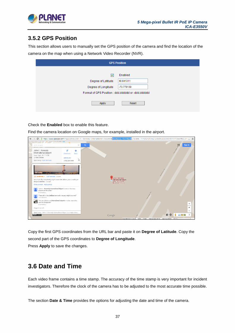
3.5.2 GPS Position
This section allows users to manually set the GPS position of the camera and find the location of the
camera on the map when using a Network Video Recorder (NVR).
Check the Enabled box to enable this feature.
Find the camera location on Google maps, for example, installed in the airport.
Copy the first GPS coordinates from the URL bar and paste it on Degree of Latitude. Copy the
second part of the GPS coordinates to Degree of Longitude.
Press Apply to save the changes.
3.6 Date and Time
Each video frame contains a time stamp. The accuracy of the time stamp is very important for incident
investigators. Therefore the clock of the camera has to be adjusted to the most accurate time possible.
The section Date & Time provides the options for adjusting the date and time of the camera.
5 Mega-pixel Bullet IR PoE IP Camera ICA-E3550V
38
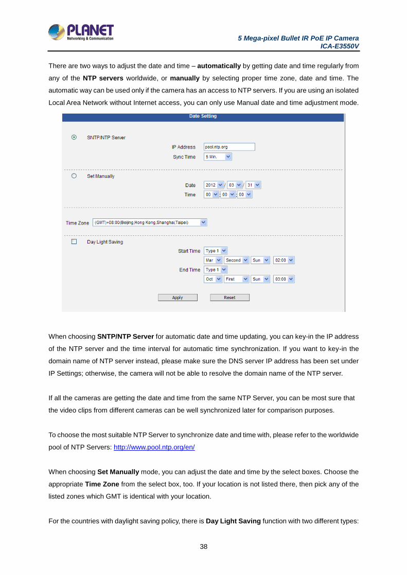
There are two ways to adjust the date and time – automatically by getting date and time regularly from
any of the NTP servers worldwide, or manually by selecting proper time zone, date and time. The
automatic way can be used only if the camera has an access to NTP servers. If you are using an isolated
Local Area Network without Internet access, you can only use Manual date and time adjustment mode.
When choosing SNTP/NTP Server for automatic date and time updating, you can key-in the IP address
of the NTP server and the time interval for automatic time synchronization. If you want to key-in the
domain name of NTP server instead, please make sure the DNS server IP address has been set under
IP Settings; otherwise, the camera will not be able to resolve the domain name of the NTP server.
If all the cameras are getting the date and time from the same NTP Server, you can be most sure that
the video clips from different cameras can be well synchronized later for comparison purposes.
To choose the most suitable NTP Server to synchronize date and time with, please refer to the worldwide
pool of NTP Servers: http://www.pool.ntp.org/en/
When choosing Set Manually mode, you can adjust the date and time by the select boxes. Choose the
appropriate Time Zone from the select box, too. If your location is not listed there, then pick any of the
listed zones which GMT is identical with your location.
For the countries with daylight saving policy, there is Day Light Saving function with two different types:
5 Mega-pixel Bullet IR PoE IP Camera ICA-E3550V
39
Type 1 – define the starting or ending time of daylight saving period by the number of the week in the
month (First, Second, Third or Last week).
Type 2 – define the starting or ending time of daylight saving period by the exact date in the month (1-
31).
Whether to choose Type 1 or Type 2, please refer to the daylight saving policy of the given country.
After changing any of the items above, press Apply to save the changes. The Reset button undoes the
changes that had just been made but not Applied yet.
3.7 Network
The section Network provides the list of network related functions and services. The [+] mark before
Network indicates that the list can be expanded by clicking on it. Once expanded, the list can later be
collapsed again by clicking on the [-] mark.
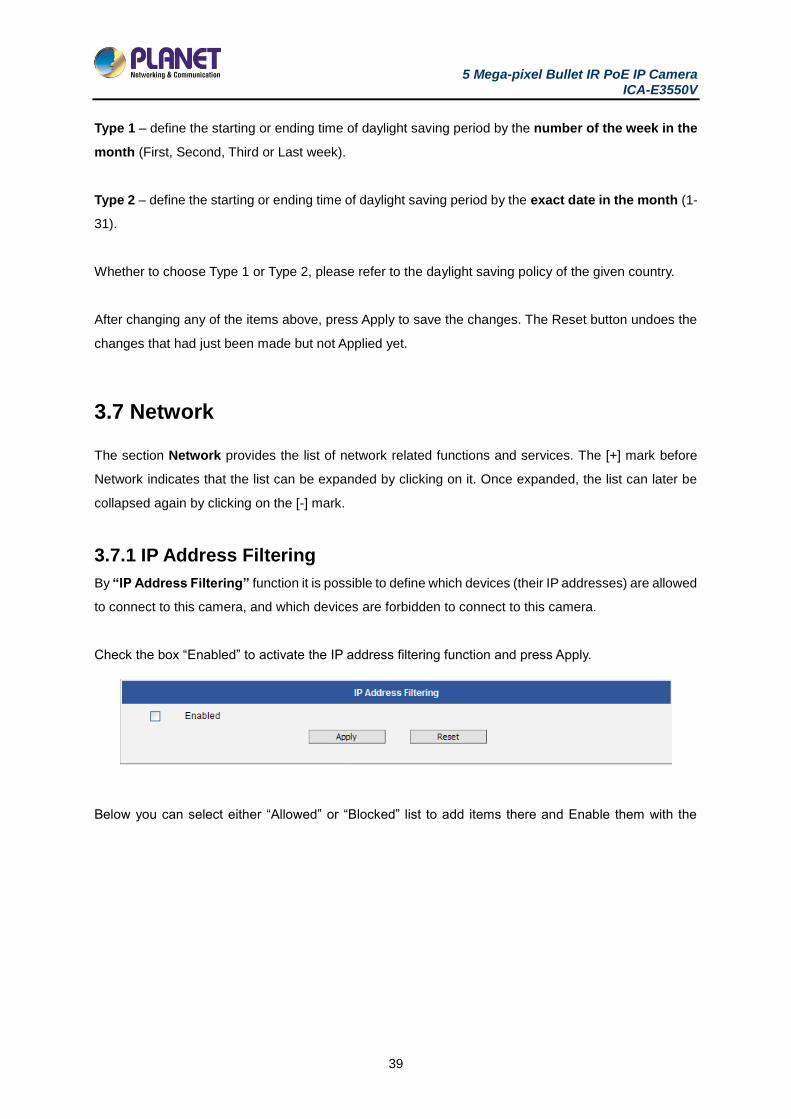
3.7.1 IP Address Filtering
By “IP Address Filtering” function it is possible to define which devices (their IP addresses) are allowed
to connect to this camera, and which devices are forbidden to connect to this camera.
Check the box “Enabled” to activate the IP address filtering function and press Apply.
Below you can select either “Allowed” or “Blocked” list to add items there and Enable them with the
5 Mega-pixel Bullet IR PoE IP Camera ICA-E3550V
40
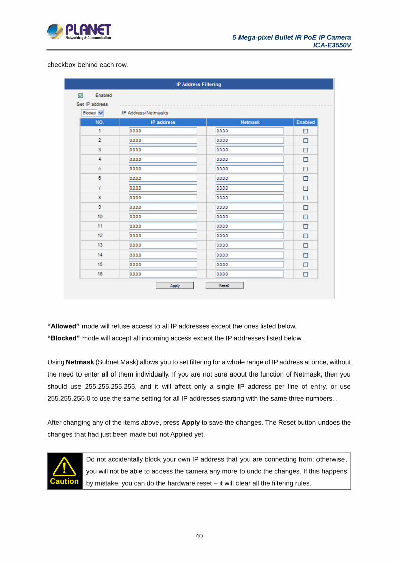
checkbox behind each row.
“Allowed” mode will refuse access to all IP addresses except the ones listed below.
“Blocked” mode will accept all incoming access except the IP addresses listed below.
Using Netmask (Subnet Mask) allows you to set filtering for a whole range of IP address at once, without
the need to enter all of them individually. If you are not sure about the function of Netmask, then you
should use 255.255.255.255, and it will affect only a single IP address per line of entry, or use
255.255.255.0 to use the same setting for all IP addresses starting with the same three numbers. .
After changing any of the items above, press Apply to save the changes. The Reset button undoes the
changes that had just been made but not Applied yet.
Do not accidentally block your own IP address that you are connecting from; otherwise,
you will not be able to access the camera any more to undo the changes. If this happens
by mistake, you can do the hardware reset – it will clear all the filtering rules.
5 Mega-pixel Bullet IR PoE IP Camera ICA-E3550V
41
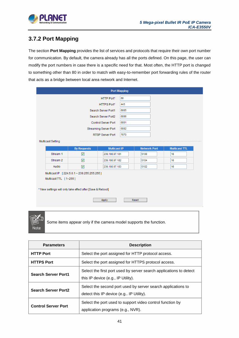
3.7.2 Port Mapping
The section Port Mapping provides the list of services and protocols that require their own port number
for communication. By default, the camera already has all the ports defined. On this page, the user can
modify the port numbers in case there is a specific need for that. Most often, the HTTP port is changed
to something other than 80 in order to match with easy-to-remember port forwarding rules of the router
that acts as a bridge between local area network and Internet.
Some items appear only if the camera model supports the function.
Parameters Description
HTTP Port Select the port assigned for HTTP protocol access.
HTTPS Port Select the port assigned for HTTPS protocol access.
Search Server Port1 Select the first port used by server search applications to detect
this IP device (e.g., IP Utility).
Search Server Port2 Select the second port used by server search applications to
detect this IP device (e.g.. IP Utility).
Control Server Port Select the port used to support video control function by
application programs (e.g., NVR).
5 Mega-pixel Bullet IR PoE IP Camera ICA-E3550V
42
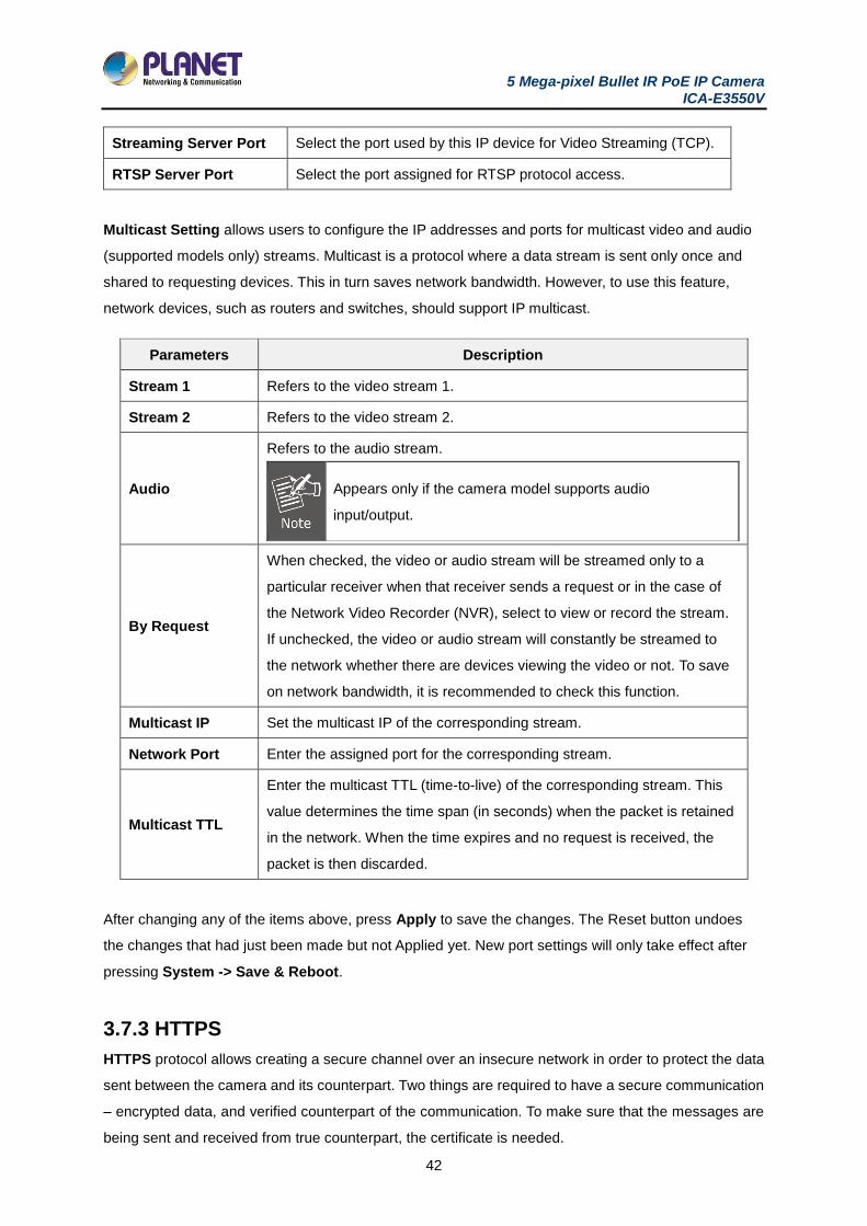
Streaming Server Port Select the port used by this IP device for Video Streaming (TCP).
RTSP Server Port Select the port assigned for RTSP protocol access.
Multicast Setting allows users to configure the IP addresses and ports for multicast video and audio
(supported models only) streams. Multicast is a protocol where a data stream is sent only once and
shared to requesting devices. This in turn saves network bandwidth. However, to use this feature,
network devices, such as routers and switches, should support IP multicast.
Parameters Description
Stream 1 Refers to the video stream 1.
Stream 2 Refers to the video stream 2.
Audio
Refers to the audio stream.
Appears only if the camera model supports audio
input/output.
By Request
When checked, the video or audio stream will be streamed only to a
particular receiver when that receiver sends a request or in the case of
the Network Video Recorder (NVR), select to view or record the stream.
If unchecked, the video or audio stream will constantly be streamed to
the network whether there are devices viewing the video or not. To save
on network bandwidth, it is recommended to check this function.
Multicast IP Set the multicast IP of the corresponding stream.
Network Port Enter the assigned port for the corresponding stream.
Multicast TTL
Enter the multicast TTL (time-to-live) of the corresponding stream. This
value determines the time span (in seconds) when the packet is retained
in the network. When the time expires and no request is received, the
packet is then discarded.
After changing any of the items above, press Apply to save the changes. The Reset button undoes
the changes that had just been made but not Applied yet. New port settings will only take effect after
pressing System -> Save & Reboot.
3.7.3 HTTPS
HTTPS protocol allows creating a secure channel over an insecure network in order to protect the data
sent between the camera and its counterpart. Two things are required to have a secure communication
– encrypted data, and verified counterpart of the communication. To make sure that the messages are
being sent and received from true counterpart, the certificate is needed.
5 Mega-pixel Bullet IR PoE IP Camera ICA-E3550V
43
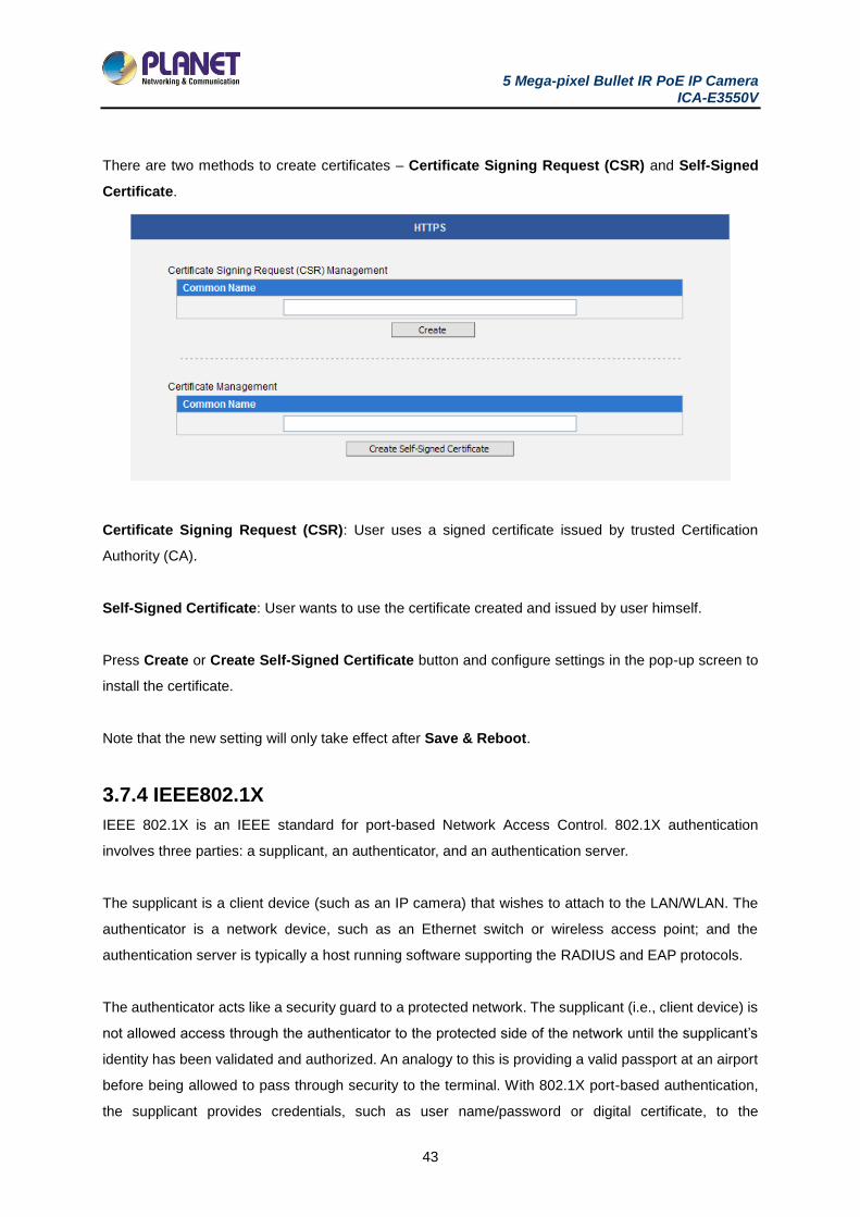
There are two methods to create certificates – Certificate Signing Request (CSR) and Self-Signed
Certificate.
Certificate Signing Request (CSR): User uses a signed certificate issued by trusted Certification
Authority (CA).
Self-Signed Certificate: User wants to use the certificate created and issued by user himself.
Press Create or Create Self-Signed Certificate button and configure settings in the pop-up screen to
install the certificate.
Note that the new setting will only take effect after Save & Reboot.
3.7.4 IEEE802.1X
IEEE 802.1X is an IEEE standard for port-based Network Access Control. 802.1X authentication
involves three parties: a supplicant, an authenticator, and an authentication server.
The supplicant is a client device (such as an IP camera) that wishes to attach to the LAN/WLAN. The
authenticator is a network device, such as an Ethernet switch or wireless access point; and the
authentication server is typically a host running software supporting the RADIUS and EAP protocols.
The authenticator acts like a security guard to a protected network. The supplicant (i.e., client device) is
not allowed access through the authenticator to the protected side of the network until the supplicant’s
identity has been validated and authorized. An analogy to this is providing a valid passport at an airport
before being allowed to pass through security to the terminal. With 802.1X port-based authentication,
the supplicant provides credentials, such as user name/password or digital certificate, to the
5 Mega-pixel Bullet IR PoE IP Camera ICA-E3550V
44
authenticator, and the authenticator forwards the credentials to the authentication server for verification.
If the authentication server determines the credentials are valid, the supplicant (client device) is allowed
to access resources located on the protected side of the network.
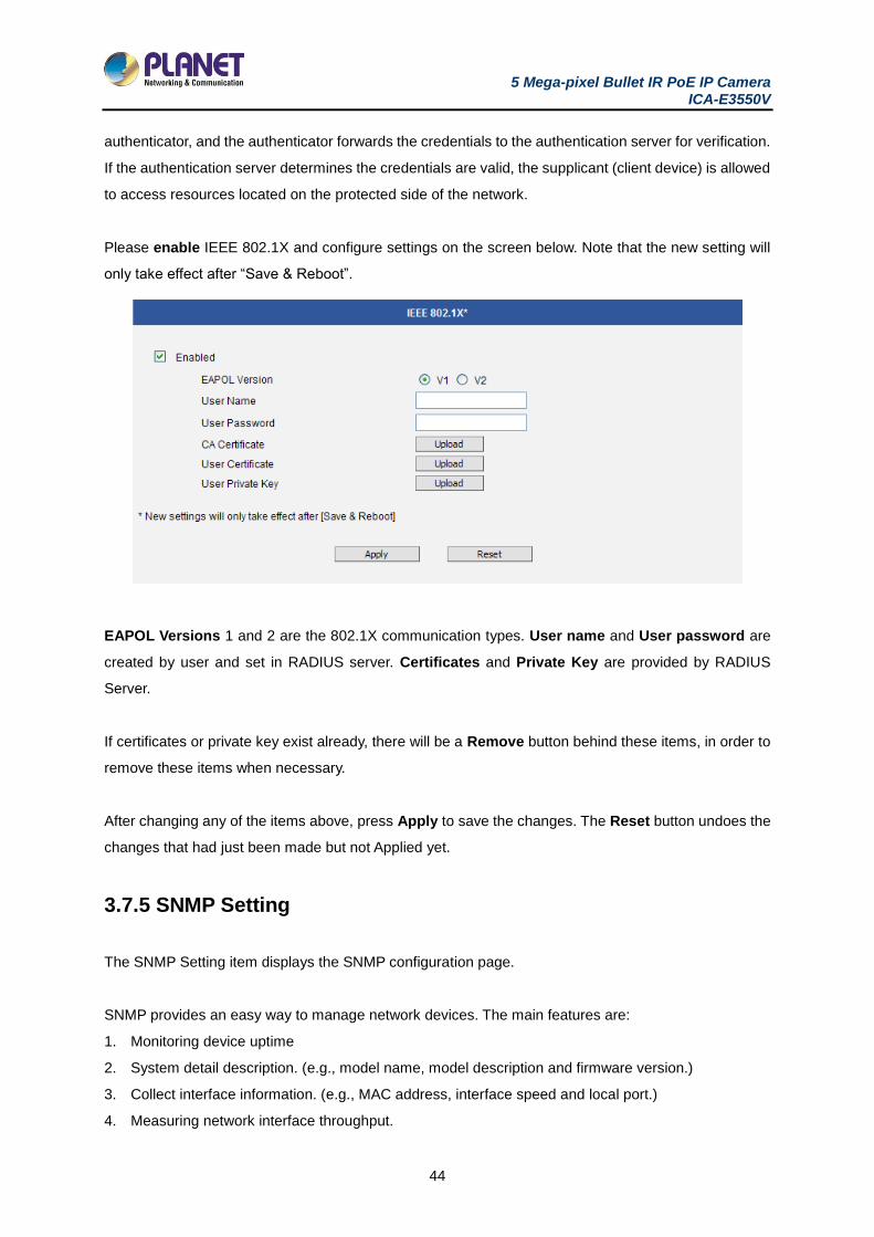
Please enable IEEE 802.1X and configure settings on the screen below. Note that the new setting will
only take effect after “Save & Reboot”.
EAPOL Versions 1 and 2 are the 802.1X communication types. User name and User password are
created by user and set in RADIUS server. Certificates and Private Key are provided by RADIUS
Server.
If certificates or private key exist already, there will be a Remove button behind these items, in order to
remove these items when necessary.
After changing any of the items above, press Apply to save the changes. The Reset button undoes the
changes that had just been made but not Applied yet.
3.7.5 SNMP Setting
The SNMP Setting item displays the SNMP configuration page.
SNMP provides an easy way to manage network devices. The main features are:
1. Monitoring device uptime
2. System detail description. (e.g., model name, model description and firmware version.)
3. Collect interface information. (e.g., MAC address, interface speed and local port.)
4. Measuring network interface throughput.
5 Mega-pixel Bullet IR PoE IP Camera ICA-E3550V
45
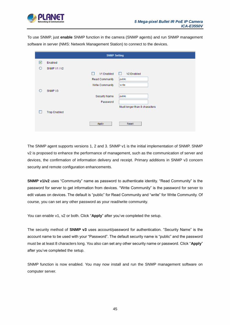
To use SNMP, just enable SNMP function in the camera (SNMP agents) and run SNMP management
software in server (NMS: Network Management Station) to connect to the devices.
The SNMP agent supports versions 1, 2 and 3. SNMP v1 is the initial implementation of SNMP. SNMP
v2 is proposed to enhance the performance of management, such as the communication of server and
devices, the confirmation of information delivery and receipt. Primary additions in SNMP v3 concern
security and remote configuration enhancements.
SNMP v1/v2 uses “Community” name as password to authenticate identity. “Read Community” is the
password for server to get information from devices. “Write Community” is the password for server to
edit values on devices. The default is “public” for Read Community and “write” for Write Community. Of
course, you can set any other password as your read/write community.
You can enable v1, v2 or both. Click “Apply” after you’ve completed the setup.
The security method of SNMP v3 uses account/password for authentication. “Security Name” is the
account name to be used with your “Password”. The default security name is “public” and the password
must be at least 8 characters long. You also can set any other security name or password. Click “Apply”
after you’ve completed the setup.
SNMP function is now enabled. You may now install and run the SNMP management software on
computer server.
5 Mega-pixel Bullet IR PoE IP Camera ICA-E3550V
46
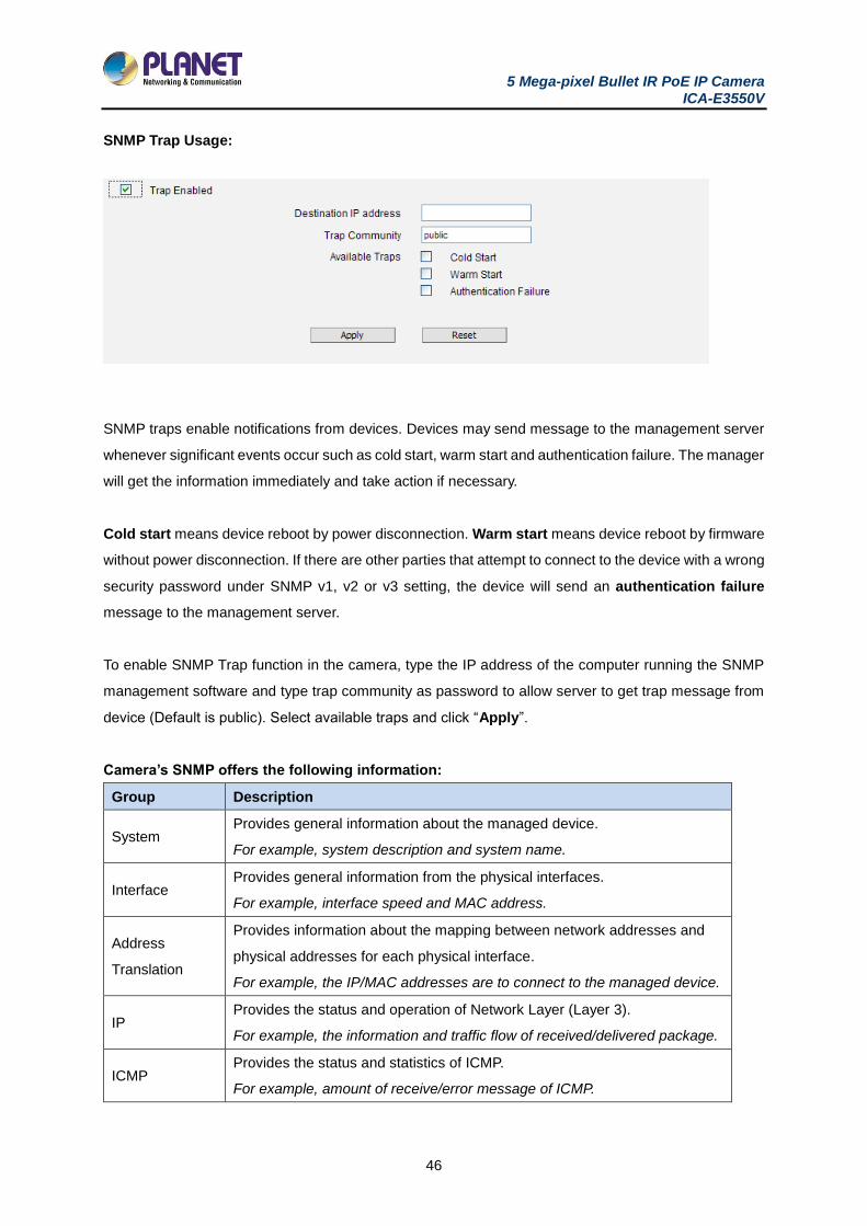
SNMP Trap Usage:
SNMP traps enable notifications from devices. Devices may send message to the management server
whenever significant events occur such as cold start, warm start and authentication failure. The manager
will get the information immediately and take action if necessary.
Cold start means device reboot by power disconnection. Warm start means device reboot by firmware
without power disconnection. If there are other parties that attempt to connect to the device with a wrong
security password under SNMP v1, v2 or v3 setting, the device will send an authentication failure
message to the management server.
To enable SNMP Trap function in the camera, type the IP address of the computer running the SNMP
management software and type trap community as password to allow server to get trap message from
device (Default is public). Select available traps and click “Apply”.
Camera’s SNMP offers the following information:
Group Description
System Provides general information about the managed device.
For example, system description and system name.
Interface Provides general information from the physical interfaces.
For example, interface speed and MAC address.
Address
Translation
Provides information about the mapping between network addresses and
physical addresses for each physical interface.
For example, the IP/MAC addresses are to connect to the managed device.
IP Provides the status and operation of Network Layer (Layer 3).
For example, the information and traffic flow of received/delivered package.
ICMP Provides the status and statistics of ICMP.
For example, amount of receive/error message of ICMP.
5 Mega-pixel Bullet IR PoE IP Camera ICA-E3550V
47
Group Description
TCP
Provides the status and operation of Transport Layer (Layer 4) using TCP
protocol.
For example, TCP Local Port and incoming/outgoing TCP segments.
UDP
Provides the status and operation of Transport Layer (Layer 4) using UDP
protocol.
For example, UDP Local Port and in/out datagram.
SNMP Provides the related statistics through SNMP
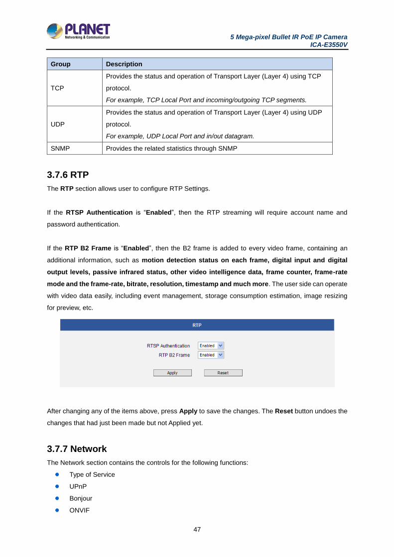
3.7.6 RTP
The RTP section allows user to configure RTP Settings.
If the RTSP Authentication is “Enabled”, then the RTP streaming will require account name and
password authentication.
If the RTP B2 Frame is “Enabled”, then the B2 frame is added to every video frame, containing an
additional information, such as motion detection status on each frame, digital input and digital
output levels, passive infrared status, other video intelligence data, frame counter, frame-rate
mode and the frame-rate, bitrate, resolution, timestamp and much more. The user side can operate
with video data easily, including event management, storage consumption estimation, image resizing
for preview, etc.
After changing any of the items above, press Apply to save the changes. The Reset button undoes the
changes that had just been made but not Applied yet.
3.7.7 Network
The Network section contains the controls for the following functions:
Type of Service
UPnP
Bonjour
ONVIF
5 Mega-pixel Bullet IR PoE IP Camera ICA-E3550V
48
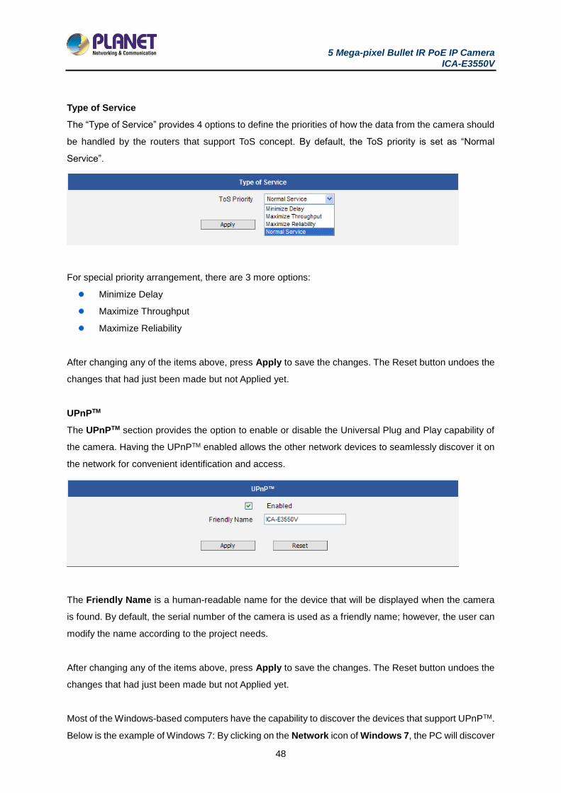
Type of Service
The “Type of Service” provides 4 options to define the priorities of how the data from the camera should
be handled by the routers that support ToS concept. By default, the ToS priority is set as “Normal
Service”.
For special priority arrangement, there are 3 more options:
Minimize Delay
Maximize Throughput
Maximize Reliability
After changing any of the items above, press Apply to save the changes. The Reset button undoes the
changes that had just been made but not Applied yet.
UPnPTM
The UPnPTM section provides the option to enable or disable the Universal Plug and Play capability of
the camera. Having the UPnPTM enabled allows the other network devices to seamlessly discover it on
the network for convenient identification and access.
The Friendly Name is a human-readable name for the device that will be displayed when the camera
is found. By default, the serial number of the camera is used as a friendly name; however, the user can
modify the name according to the project needs.
After changing any of the items above, press Apply to save the changes. The Reset button undoes the
changes that had just been made but not Applied yet.
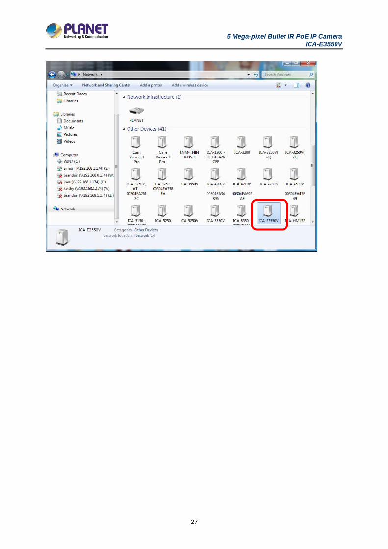
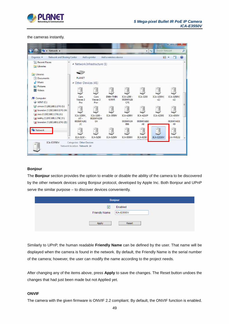
Most of the Windows-based computers have the capability to discover the devices that support UPnPTM.
Below is the example of Windows 7: By clicking on the Network icon of Windows 7, the PC will discover
5 Mega-pixel Bullet IR PoE IP Camera ICA-E3550V
49
the cameras instantly.
Bonjour
The Bonjour section provides the option to enable or disable the ability of the camera to be discovered
by the other network devices using Bonjour protocol, developed by Apple Inc. Both Bonjour and UPnP
serve the similar purpose – to discover devices conveniently.
Similarly to UPnP, the human readable Friendly Name can be defined by the user. That name will be
displayed when the camera is found in the network. By default, the Friendly Name is the serial number
of the camera; however, the user can modify the name according to the project needs.
After changing any of the items above, press Apply to save the changes. The Reset button undoes the
changes that had just been made but not Applied yet.
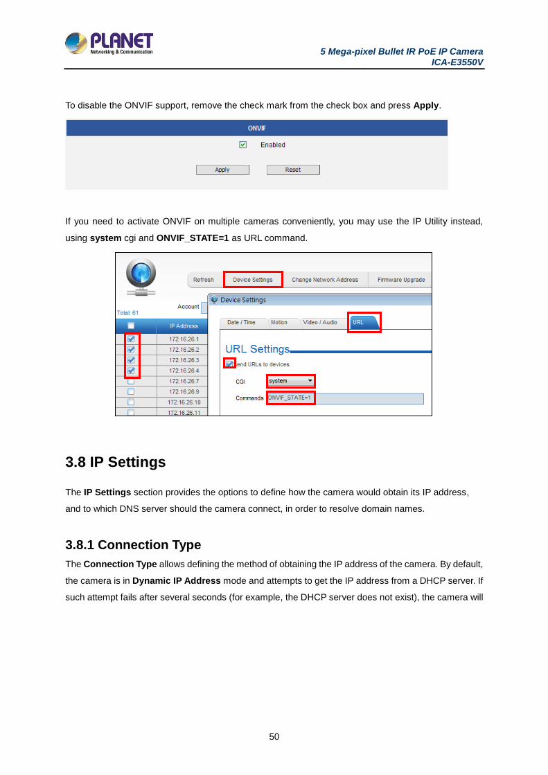
ONVIF
The camera with the given firmware is ONVIF 2.2 compliant. By default, the ONVIF function is enabled.
5 Mega-pixel Bullet IR PoE IP Camera ICA-E3550V
50
To disable the ONVIF support, remove the check mark from the check box and press Apply.
If you need to activate ONVIF on multiple cameras conveniently, you may use the IP Utility instead,
using system cgi and ONVIF_STATE=1 as URL command.
3.8 IP Settings
The IP Settings section provides the options to define how the camera would obtain its IP address,
and to which DNS server should the camera connect, in order to resolve domain names.
3.8.1 Connection Type
The Connection Type allows defining the method of obtaining the IP address of the camera. By default,
the camera is in Dynamic IP Address mode and attempts to get the IP address from a DHCP server. If
such attempt fails after several seconds (for example, the DHCP server does not exist), the camera will
5 Mega-pixel Bullet IR PoE IP Camera ICA-E3550V
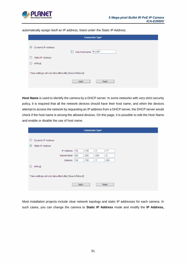
51
automatically assign itself an IP address, listed under the Static IP Address.
Host Name is used to identify the camera by a DHCP server. In some networks with very strict security
policy, it is required that all the network devices should have their host name, and when the devices
attempt to access the network by requesting an IP address from a DHCP server, the DHCP server would
check if the host name is among the allowed devices. On this page, it is possible to edit the Host Name
and enable or disable the use of host name.
Most installation projects include clear network topology and static IP addresses for each camera. In
such cases, you can change the camera to Static IP Address mode and modify the IP Address,
5 Mega-pixel Bullet IR PoE IP Camera ICA-E3550V
52
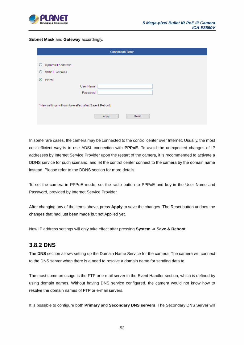
Subnet Mask and Gateway accordingly.
In some rare cases, the camera may be connected to the control center over Internet. Usually, the most
cost efficient way is to use ADSL connection with PPPoE. To avoid the unexpected changes of IP
addresses by Internet Service Provider upon the restart of the camera, it is recommended to activate a
DDNS service for such scenario, and let the control center connect to the camera by the domain name
instead. Please refer to the DDNS section for more details.
To set the camera in PPPoE mode, set the radio button to PPPoE and key-in the User Name and
Password, provided by Internet Service Provider.
After changing any of the items above, press Apply to save the changes. The Reset button undoes the
changes that had just been made but not Applied yet.
New IP address settings will only take effect after pressing System -> Save & Reboot.
3.8.2 DNS
The DNS section allows setting up the Domain Name Service for the camera. The camera will connect
to the DNS server when there is a need to resolve a domain name for sending data to.
The most common usage is the FTP or e-mail server in the Event Handler section, which is defined by
using domain names. Without having DNS service configured, the camera would not know how to
resolve the domain names of FTP or e-mail servers.
It is possible to configure both Primary and Secondary DNS servers. The Secondary DNS Server will

5 Mega-pixel Bullet IR PoE IP Camera ICA-E3550V
53
be used when the connection to the Primary DNS Server fails.
After changing any of the items above, press Apply to save the changes. The Reset button undoes the
changes that had just been made but not Applied yet.
3.8.3 DDNS and P2P
There are surveillance solutions that consist of single cameras scattered over a wide territory, therefore,
each of those cameras should be connected to Internet in order to become accessible by Control
Centers, such as chain stores, bus stops, currency exchange booths, etc.
In such cases, one of the practical networking solutions is to use DSL modem on camera site and let
the camera obtain the dynamic IP address from the Internet Service Provider through the DSL modem
using PPPoE connection, which is much more cost-effective than applying for static IP address.
However, there is one drawback in this solution – in order to do the remote surveillance from the Control
Center, the NVR Server in the Control Center has to know the address of the IP camera at all times in
order to get the video stream from the camera. If the camera’s network connection has been reset for
any reason, the camera will get a new IP address through DSL modem, which may be different from the
previous one. NVR will not know about this change, and the connection between the camera and NVR
will fail.
There however exists a solution that makes sure the NVR can find the camera even if the camera IP
changes frequently. Our cameras support Dynamic DNS or DDNS service that allows frequently
changing IP be mapped to a certain unchangeable domain name. The mapping database and its
updating engine are hosted in one of the Dynamic DNS servers, most of which offer basic services for
free, such as www.dyndns.org.
Every time the IP camera gets an IP that is different from previous one, it notifies the public DDNS
Service about the change. The DDNS Service updates its database immediately, mapping the
assigned domain name (for example camera123.dyndns.org) to the new IP address. In NVR settings,
only the domain name (camera123.dyndns.org) is used to identify the camera. Every time when NVR
needs to connect to the camera, it asks from DDNS Service what the current camera’s IP is. The
5 Mega-pixel Bullet IR PoE IP Camera ICA-E3550V
54
DDNS Service instantly responds to NVR and tells it the camera’s IP. Now NVR will use the IP of the
camera to connect to the camera and the video stream from the camera to NVR can be initiated.
As a result, NVR can always find the IP camera regardless of frequently changing IP address of the
camera. Since there are so many public DDNS Services available for free, the PPPoE-based connection
is really a good and low-cost solution for single-camera sites.
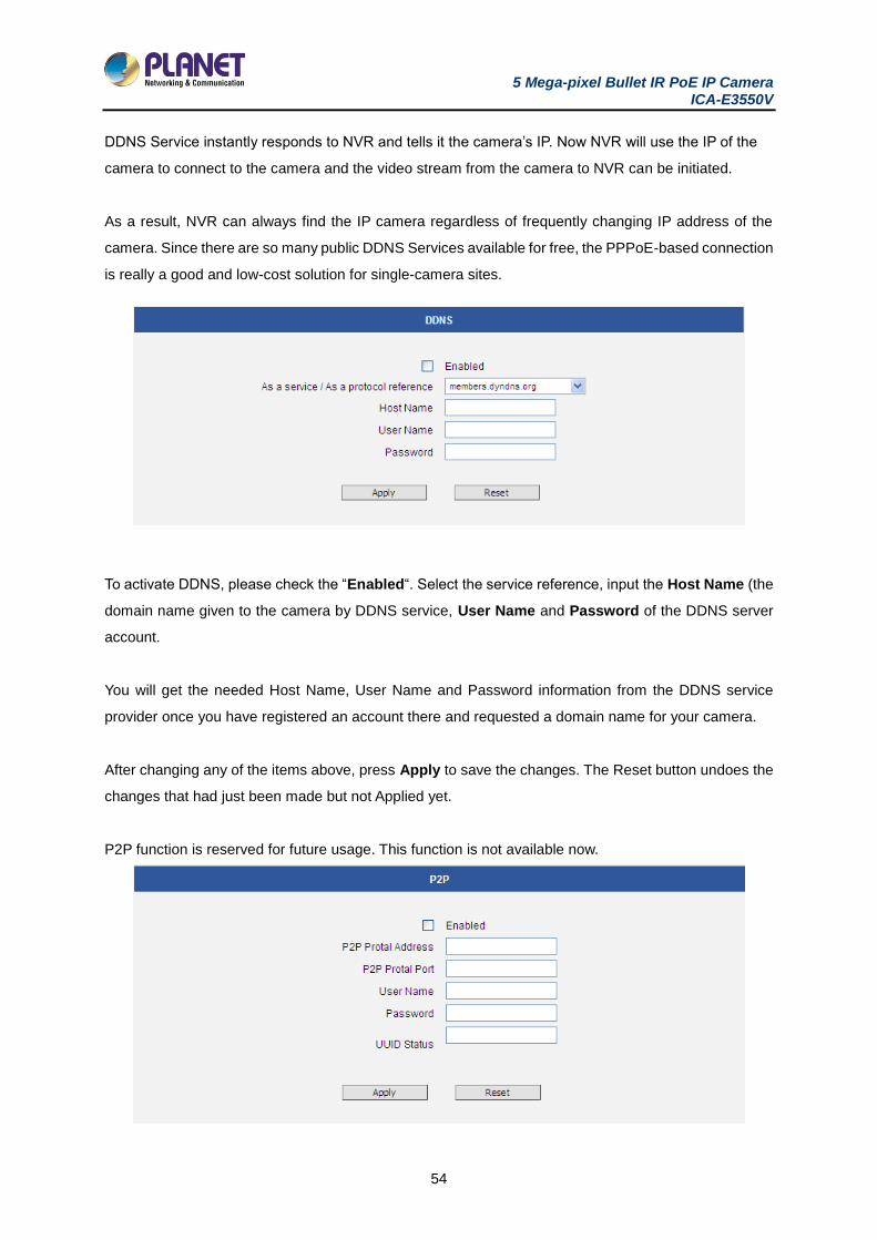
To activate DDNS, please check the “Enabled“. Select the service reference, input the Host Name (the
domain name given to the camera by DDNS service, User Name and Password of the DDNS server
account.
You will get the needed Host Name, User Name and Password information from the DDNS service
provider once you have registered an account there and requested a domain name for your camera.
After changing any of the items above, press Apply to save the changes. The Reset button undoes the
changes that had just been made but not Applied yet.
P2P function is reserved for future usage. This function is not available now.
5 Mega-pixel Bullet IR PoE IP Camera ICA-E3550V
55
3.9 Video and Audio
The section Video or Video and Audio (for audio supported cameras) provides the options to adjust
the video quality, configure the streaming details of the camera, and audio settings (for Audio supported
cameras only), which will be described on the succeeding pages.
The default settings of the camera are sufficient for most environments and the video adjustments are
not necessary. The following sections explain the ways to configure the video quality or streaming details
in case it is required to do so.
The [+] mark before Video indicates that the list can be expanded by clicking on it. Once expanded, the
list can later be collapsed again by clicking on the [-] mark.
3.9.1 Camera Options
In general, the Camera Options allows users to set line frequency of the camera.
Line Frequency is the function that adjusts the shutter speed options to match with the frequence of
artificial light source of given country. For example, in Europe the light frequency (due to power supply
frequency of lights) is 50Hz, that is 50 flashes per second. By setting line frequency to 50Hz in such
case, the shutter speed options will be proportional with light source frequency, such as 1/25s, 1/50s,
1/100s, etc.
It is necessary to have the camera’s Line Frequency adjusted according to the power frequency
of the light source to avoid flickering effect.
The natural light source (sun light) is a seamless flow of light – the Line Frequency setting does not
matter for the cameras that are only exposed to natural light.
3.9.2 Video
The sub-section is also named Video. For Audio supported cameras, there will also be a sub-section
named Audio. The video section is divided into tabs. The functionality of each tab is explained separately
below.
Upon opening the sub-section named Video, the live view of the Stream 1 of the camera will appear.
Since the camera is a dual stream device, it is possible to see how each of the 2 streaming configurations
5 Mega-pixel Bullet IR PoE IP Camera ICA-E3550V
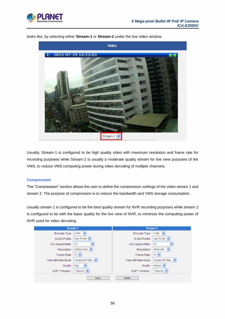
56
looks like, by selecting either Stream-1 or Stream-2 under the live video window.
Usually, Stream-1 is configured to be high quality video with maximum resolution and frame rate for
recording purposes while Stream-2 is usually a moderate quality stream for live view purposes of the
VMS, to reduce VMS computing power during video decoding of multiple channels.
Compression
The “Compression” section allows the user to define the compression settings of the video stream 1 and
stream 2. The purpose of compression is to reduce the bandwidth and VMS storage consumption.
Usually stream 1 is configured to be the best quality stream for NVR recording purposes while stream 2
is configured to be with the basic quality for the live view of NVR, to minimize the computing power of
NVR used for video decoding.

5 Mega-pixel Bullet IR PoE IP Camera ICA-E3550V
57
Parameters Description
Encoder Type There are two encoder types available: H.264 (High Profile) and
MJPEG.
H.264 Profile
This item is available only if the Encoder Type is H.264. The H.264
Profile defines the video compression scheme: High Profile, Main
Profile, and Baseline. These schemes vary from least compressed,
Baseline, to most compressed, High Profile. By default, the H.264
Profile is High Profile, which provides the most compression with the
best video quality, but more computing power.
Some third-party video management system has longer latency or
takes more time to decode High Profile compression scheme, in this
case, you can select Main Profile or Baseline. In order to get the
same video quality, you can select a higher bit rate with lower
compression; this is the same as having a lower bit rate with a High
Profile. For example, a video on High Profile with 2M bit rate will have
the same video quality as a video with Baseline Profile at 3.5M bit
rate.
VGA Aspect Ratio
It is used to define the aspect ratio of VGA stream – it can be either
4:3 ratio (640x480) or 16:9 ratio (640x360). When “Auto Detected” is
chosen, the VGA stream will follow the ratio of the higher resolution
stream, to ensure the identical view of stream 1 and stream 2.
Resolution
Depending on the camera model, the number of available resolutions
may be different. The default resolution setting of the camera may not
necessarily be the maximum resolution of the camera. If the user
wants to use the maximum resolution, it is possible to do it here. The
maximum possible resolution of stream 2 will be smaller than stream
1.
Frame Rate Defines the amount of frames per second.
Video Bit Rate Mode
(only for H.264)
Under “Constant Bit Rate” mode (CBR), the camera keeps the stable
bitrate regardless of the complexity of the scene. Under this mode,
the video quality may vary if the bit rate value is set too low. It is easier
to do storage and network bandwidth consumption estimations under
this mode compared to Variable Bit Rate mode.
Under “Variable Bit Rate” mode (VBR), the camera will keep the video
quality stable while the bit rate may occasionally go up or down,
depending on the complexity of the scene.
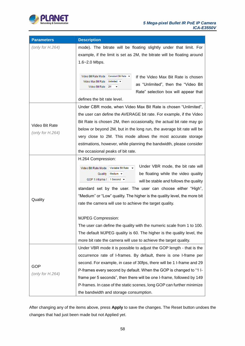
Video Max Bit Rate Defines the upper limit of the bitrate (only available under CBR
5 Mega-pixel Bullet IR PoE IP Camera ICA-E3550V
58
Parameters Description
(only for H.264) mode). The bitrate will be floating slightly under that limit. For
example, if the limit is set as 2M, the bitrate will be floating around
1.6~2.0 Mbps.
If the Video Max Bit Rate is chosen
as “Unlimited”, then the “Video Bit
Rate” selection box will appear that
defines the bit rate level.
Video Bit Rate
(only for H.264)
Under CBR mode, when Video Max Bit Rate is chosen “Unlimited”,
the user can define the AVERAGE bit rate. For example, if the Video
Bit Rate is chosen 2M, then occasionally, the actual bit rate may go
below or beyond 2M, but in the long run, the average bit rate will be
very close to 2M. This mode allows the most accurate storage
estimations, however, while planning the bandwidth, please consider
the occasional peaks of bit rate.
Quality
H.264 Compression:
Under VBR mode, the bit rate will
be floating while the video quality
will be stable and follows the quality
standard set by the user. The user can choose either “High”,
“Medium” or “Low” quality. The higher is the quality level, the more bit
rate the camera will use to achieve the target quality.
MJPEG Compression:
The user can define the quality with the numeric scale from 1 to 100.
The default MJPEG quality is 60. The higher is the quality level, the
more bit rate the camera will use to achieve the target quality.
GOP
(only for H.264)
Under VBR mode it is possible to adjust the GOP length - that is the
occurrence rate of I-frames. By default, there is one I-frame per
second. For example, in case of 30fps, there will be 1 I-frame and 29
P-frames every second by default. When the GOP is changed to “1 I-
frame per 5 seconds”, then there will be one I-frame, followed by 149
P-frames. In case of the static scenes, long GOP can further minimize
the bandwidth and storage consumption.
After changing any of the items above, press Apply to save the changes. The Reset button undoes the
changes that had just been made but not Applied yet.
5 Mega-pixel Bullet IR PoE IP Camera ICA-E3550V
59
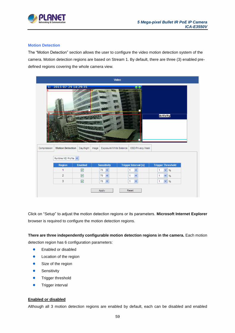
Motion Detection
The “Motion Detection” section allows the user to configure the video motion detection system of the
camera. Motion detection regions are based on Stream 1. By default, there are three (3) enabled pre-
defined regions covering the whole camera view.
Click on “Setup” to adjust the motion detection regions or its parameters. Microsoft Internet Explorer
browser is required to configure the motion detection regions.
There are three independently configurable motion detection regions in the camera. Each motion
detection region has 6 configuration parameters:
Enabled or disabled
Location of the region
Size of the region
Sensitivity
Trigger threshold
Trigger interval
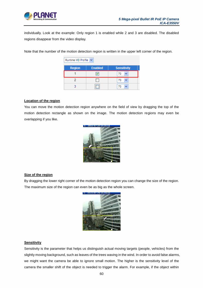
Enabled or disabled
Although all 3 motion detection regions are enabled by default, each can be disabled and enabled
5 Mega-pixel Bullet IR PoE IP Camera ICA-E3550V
60
individually. Look at the example: Only region 1 is enabled while 2 and 3 are disabled. The disabled
regions disappear from the video display.
Note that the number of the motion detection region is written in the upper left corner of the region.
Location of the region
You can move the motion detection region anywhere on the field of view by dragging the top of the
motion detection rectangle as shown on the image. The motion detection regions may even be
overlapping if you like.
Size of the region
By dragging the lower right corner of the motion detection region you can change the size of the region.
The maximum size of the region can even be as big as the whole screen.
Sensitivity
Sensitivity is the parameter that helps us distinguish actual moving targets (people, vehicles) from the
slightly moving background, such as leaves of the trees waving in the wind. In order to avoid false alarms,
we might want the camera be able to ignore small motion. The higher is the sensitivity level of the
camera the smaller shift of the object is needed to trigger the alarm. For example, if the object within
5 Mega-pixel Bullet IR PoE IP Camera ICA-E3550V
61
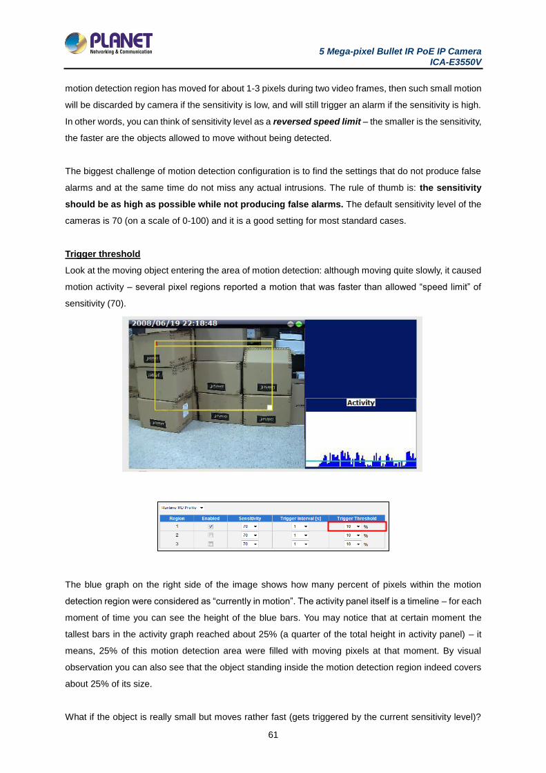
motion detection region has moved for about 1-3 pixels during two video frames, then such small motion
will be discarded by camera if the sensitivity is low, and will still trigger an alarm if the sensitivity is high.
In other words, you can think of sensitivity level as a reversed speed limit – the smaller is the sensitivity,
the faster are the objects allowed to move without being detected.
The biggest challenge of motion detection configuration is to find the settings that do not produce false
alarms and at the same time do not miss any actual intrusions. The rule of thumb is: the sensitivity
should be as high as possible while not producing false alarms. The default sensitivity level of the
cameras is 70 (on a scale of 0-100) and it is a good setting for most standard cases.
Trigger threshold
Look at the moving object entering the area of motion detection: although moving quite slowly, it caused
motion activity – several pixel regions reported a motion that was faster than allowed “speed limit” of
sensitivity (70).
The blue graph on the right side of the image shows how many percent of pixels within the motion
detection region were considered as “currently in motion”. The activity panel itself is a timeline – for each
moment of time you can see the height of the blue bars. You may notice that at certain moment the
tallest bars in the activity graph reached about 25% (a quarter of the total height in activity panel) – it
means, 25% of this motion detection area were filled with moving pixels at that moment. By visual
observation you can also see that the object standing inside the motion detection region indeed covers
about 25% of its size.
What if the object is really small but moves rather fast (gets triggered by the current sensitivity level)?

5 Mega-pixel Bullet IR PoE IP Camera ICA-E3550V
62
For example, we want to detect people but not the cat walking in the room. Although both people and
cat may move with the speed that will trigger motion, they have different size of triggered pixels. For
example, a human passing by the motion detection region will trigger 25% of pixels in that region while
the cat would trigger only 2%. Since we want to have a real alarm in case of human or vehicle passing
by while ignoring birds, cats, butterflies, mice, etc, we need a filter that can define how many percent of
triggered pixels will be considered as a real alarm. This parameter is called trigger threshold. The
default value of trigger threshold is 10%. It means, only the objects that are bigger than 10% of the
motion detection region size and move faster than allowed by sensitivity level (70) will produce actual
alarm.
How to choose the most optimal trigger threshold level? The rule of thumb, keep the trigger threshold
as small as possible while not causing false alarms by the moving objects that are not humans
or vehicles.
You can have a different sensitivity level and trigger threshold level for each motion detection region.
In order to understand all of the above even better, please refer to the table below containing four
possible combinations of settings using sensitivity level and trigger threshold percentage.
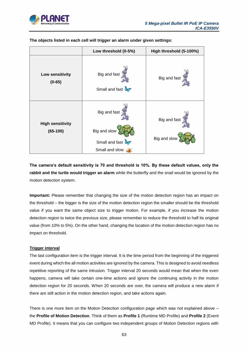
5 Mega-pixel Bullet IR PoE IP Camera ICA-E3550V
63
The objects listed in each cell will trigger an alarm under given settings:
Low threshold (0-5%) High threshold (5-100%)
Low sensitivity
(0-65)
Big and fast
Small and fast
Big and fast
High sensitivity
(65-100)
Big and fast
Big and slow
Small and fast
Small and slow
Big and fast
Big and slow
The camera’s default sensitivity is 70 and threshold is 10%. By these default values, only the
rabbit and the turtle would trigger an alarm while the butterfly and the snail would be ignored by the
motion detection system.
Important: Please remember that changing the size of the motion detection region has an impact on
the threshold – the bigger is the size of the motion detection region the smaller should be the threshold
value if you want the same object size to trigger motion. For example, if you increase the motion
detection region to twice the previous size, please remember to reduce the threshold to half its original
value (from 10% to 5%). On the other hand, changing the location of the motion detection region has no
impact on threshold.
Trigger interval
The last configuration item is the trigger interval. It is the time period from the beginning of the triggered
event during which the all motion activities are ignored by the camera. This is designed to avoid needless
repetitive reporting of the same intrusion. Trigger interval 20 seconds would mean that when the even
happens, camera will take certain one-time actions and ignore the continuing activity in the motion
detection region for 20 seconds. When 20 seconds are over, the camera will produce a new alarm if
there are still action in the motion detection region, and take actions again.
There is one more item on the Motion Detection configuration page which was not explained above –
the Profile of Motion Detection. Think of them as Profile 1 (Runtime MD Profile) and Profile 2 (Event
MD Profile). It means that you can configure two independent groups of Motion Detection regions with
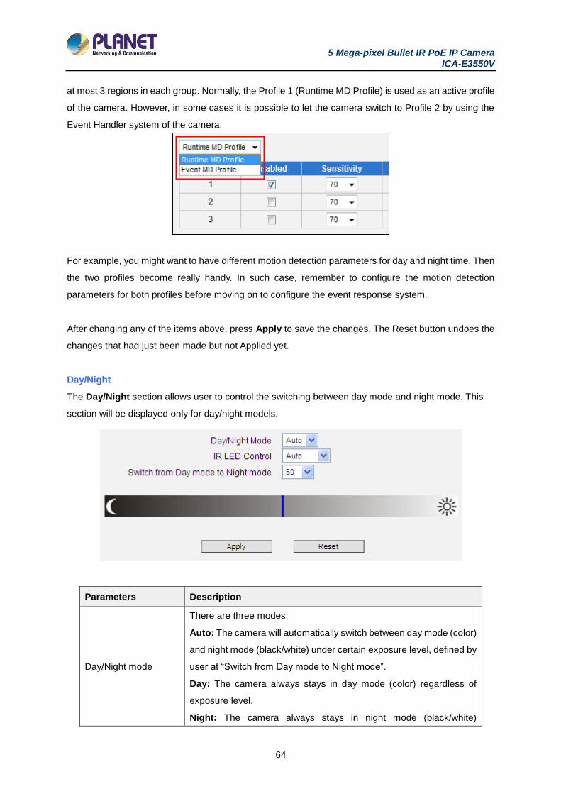
5 Mega-pixel Bullet IR PoE IP Camera ICA-E3550V
64
at most 3 regions in each group. Normally, the Profile 1 (Runtime MD Profile) is used as an active profile
of the camera. However, in some cases it is possible to let the camera switch to Profile 2 by using the
Event Handler system of the camera.
For example, you might want to have different motion detection parameters for day and night time. Then
the two profiles become really handy. In such case, remember to configure the motion detection
parameters for both profiles before moving on to configure the event response system.
After changing any of the items above, press Apply to save the changes. The Reset button undoes the
changes that had just been made but not Applied yet.
Day/Night
The Day/Night section allows user to control the switching between day mode and night mode. This
section will be displayed only for day/night models.
Parameters Description
Day/Night mode
There are three modes:
Auto: The camera will automatically switch between day mode (color)
and night mode (black/white) under certain exposure level, defined by
user at “Switch from Day mode to Night mode”.
Day: The camera always stays in day mode (color) regardless of
exposure level.
Night: The camera always stays in night mode (black/white)
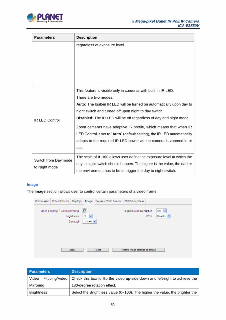
5 Mega-pixel Bullet IR PoE IP Camera ICA-E3550V
65
Parameters Description
regardless of exposure level.
IR LED Control
This feature is visible only in cameras with built-in IR LED.
There are two modes:
Auto: The built-in IR LED will be turned on automatically upon day to
night switch and turned off upon night to day switch.
Disabled: The IR LED will be off regardless of day and night mode.
Zoom cameras have adaptive IR profile, which means that when IR
LED Control is set to “Auto” (default setting), the IR LED automatically
adapts to the required IR LED power as the camera is zoomed in or
out.
Switch from Day mode
to Night mode
The scale of 0~100 allows user define the exposure level at which the
day to night switch should happen. The higher is the value, the darker
the environment has to be to trigger the day to night switch.
Image
The Image section allows user to control certain parameters of a video frame.
Parameters Description
Video Flipping/Video
Mirroring
Check this box to flip the video up-side-down and left-right to achieve the
180-degree rotation effect.
Brightness Select the Brightness value (0~100). The higher the value, the brighter the
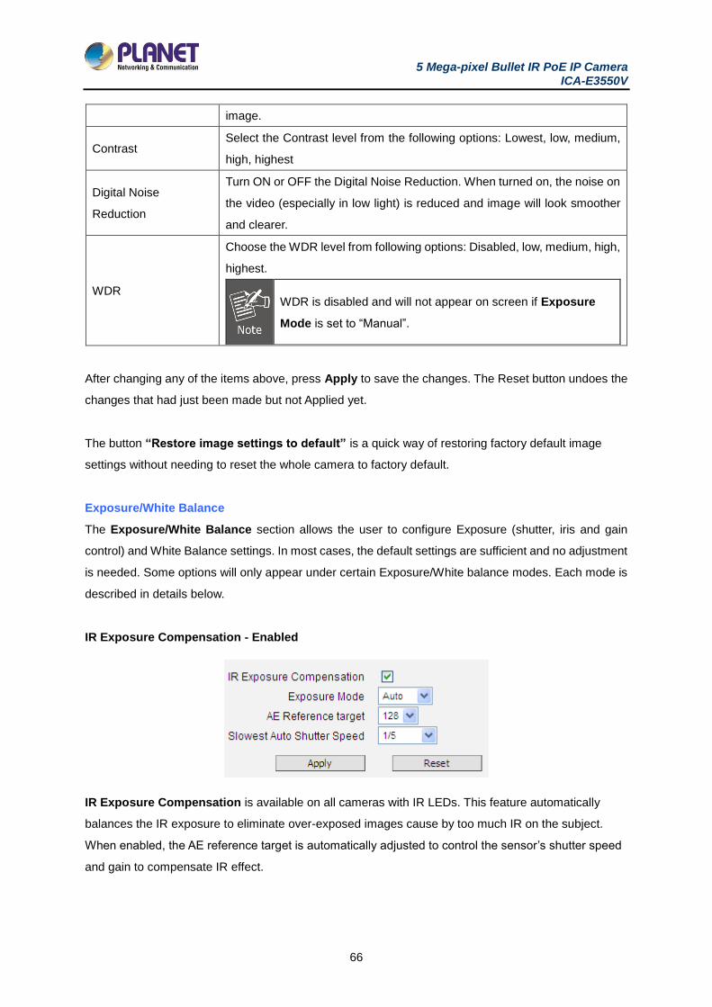
5 Mega-pixel Bullet IR PoE IP Camera ICA-E3550V
66
image.
Contrast Select the Contrast level from the following options: Lowest, low, medium,
high, highest
Digital Noise
Reduction
Turn ON or OFF the Digital Noise Reduction. When turned on, the noise on
the video (especially in low light) is reduced and image will look smoother
and clearer.
WDR
Choose the WDR level from following options: Disabled, low, medium, high,
highest.
WDR is disabled and will not appear on screen if Exposure
Mode is set to “Manual”.
After changing any of the items above, press Apply to save the changes. The Reset button undoes the
changes that had just been made but not Applied yet.
The button “Restore image settings to default” is a quick way of restoring factory default image
settings without needing to reset the whole camera to factory default.
Exposure/White Balance
The Exposure/White Balance section allows the user to configure Exposure (shutter, iris and gain
control) and White Balance settings. In most cases, the default settings are sufficient and no adjustment
is needed. Some options will only appear under certain Exposure/White balance modes. Each mode is
described in details below.
IR Exposure Compensation - Enabled
IR Exposure Compensation is available on all cameras with IR LEDs. This feature automatically
balances the IR exposure to eliminate over-exposed images cause by too much IR on the subject.
When enabled, the AE reference target is automatically adjusted to control the sensor’s shutter speed
and gain to compensate IR effect.
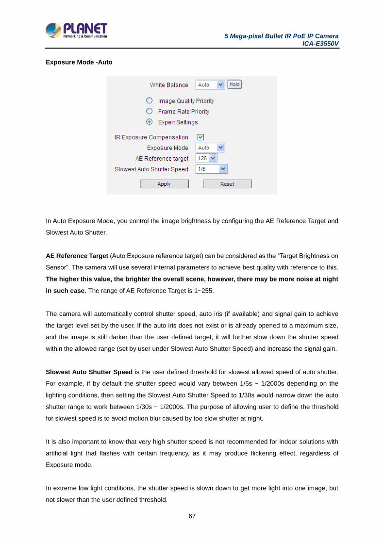
5 Mega-pixel Bullet IR PoE IP Camera ICA-E3550V
67
Exposure Mode -Auto
In Auto Exposure Mode, you control the image brightness by configuring the AE Reference Target and
Slowest Auto Shutter.
AE Reference Target (Auto Exposure reference target) can be considered as the “Target Brightness on
Sensor”. The camera will use several internal parameters to achieve best quality with reference to this.
The higher this value, the brighter the overall scene, however, there may be more noise at night
in such case. The range of AE Reference Target is 1~255.
The camera will automatically control shutter speed, auto iris (if available) and signal gain to achieve
the target level set by the user. If the auto iris does not exist or is already opened to a maximum size,
and the image is still darker than the user defined target, it will further slow down the shutter speed
within the allowed range (set by user under Slowest Auto Shutter Speed) and increase the signal gain.
Slowest Auto Shutter Speed is the user defined threshold for slowest allowed speed of auto shutter.
For example, if by default the shutter speed would vary between 1/5s ~ 1/2000s depending on the
lighting conditions, then setting the Slowest Auto Shutter Speed to 1/30s would narrow down the auto
shutter range to work between 1/30s ~ 1/2000s. The purpose of allowing user to define the threshold
for slowest speed is to avoid motion blur caused by too slow shutter at night.
It is also important to know that very high shutter speed is not recommended for indoor solutions with
artificial light that flashes with certain frequency, as it may produce flickering effect, regardless of
Exposure mode.
In extreme low light conditions, the shutter speed is slown down to get more light into one image, but
not slower than the user defined threshold.
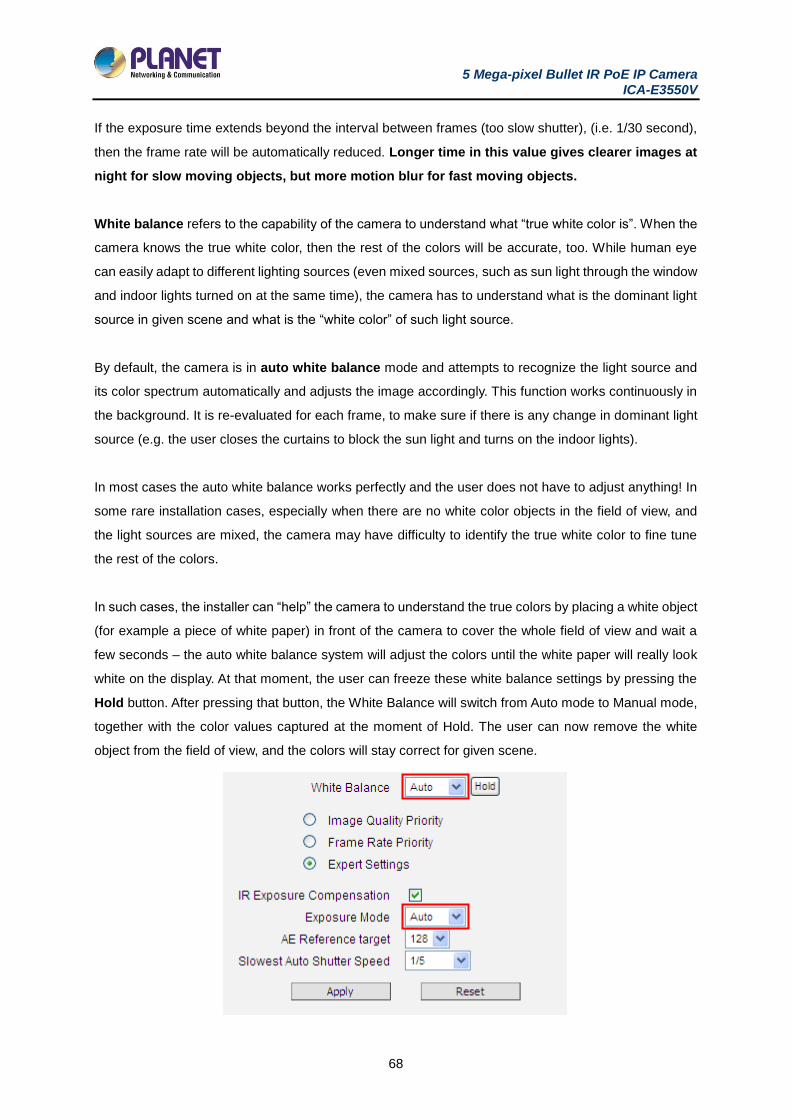
5 Mega-pixel Bullet IR PoE IP Camera ICA-E3550V
68
If the exposure time extends beyond the interval between frames (too slow shutter), (i.e. 1/30 second),
then the frame rate will be automatically reduced. Longer time in this value gives clearer images at
night for slow moving objects, but more motion blur for fast moving objects.
White balance refers to the capability of the camera to understand what “true white color is”. When the
camera knows the true white color, then the rest of the colors will be accurate, too. While human eye
can easily adapt to different lighting sources (even mixed sources, such as sun light through the window
and indoor lights turned on at the same time), the camera has to understand what is the dominant light
source in given scene and what is the “white color” of such light source.
By default, the camera is in auto white balance mode and attempts to recognize the light source and
its color spectrum automatically and adjusts the image accordingly. This function works continuously in
the background. It is re-evaluated for each frame, to make sure if there is any change in dominant light
source (e.g. the user closes the curtains to block the sun light and turns on the indoor lights).
In most cases the auto white balance works perfectly and the user does not have to adjust anything! In
some rare installation cases, especially when there are no white color objects in the field of view, and
the light sources are mixed, the camera may have difficulty to identify the true white color to fine tune
the rest of the colors.
In such cases, the installer can “help” the camera to understand the true colors by placing a white object
(for example a piece of white paper) in front of the camera to cover the whole field of view and wait a
few seconds – the auto white balance system will adjust the colors until the white paper will really look
white on the display. At that moment, the user can freeze these white balance settings by pressing the
Hold button. After pressing that button, the White Balance will switch from Auto mode to Manual mode,
together with the color values captured at the moment of Hold. The user can now remove the white
object from the field of view, and the colors will stay correct for given scene.
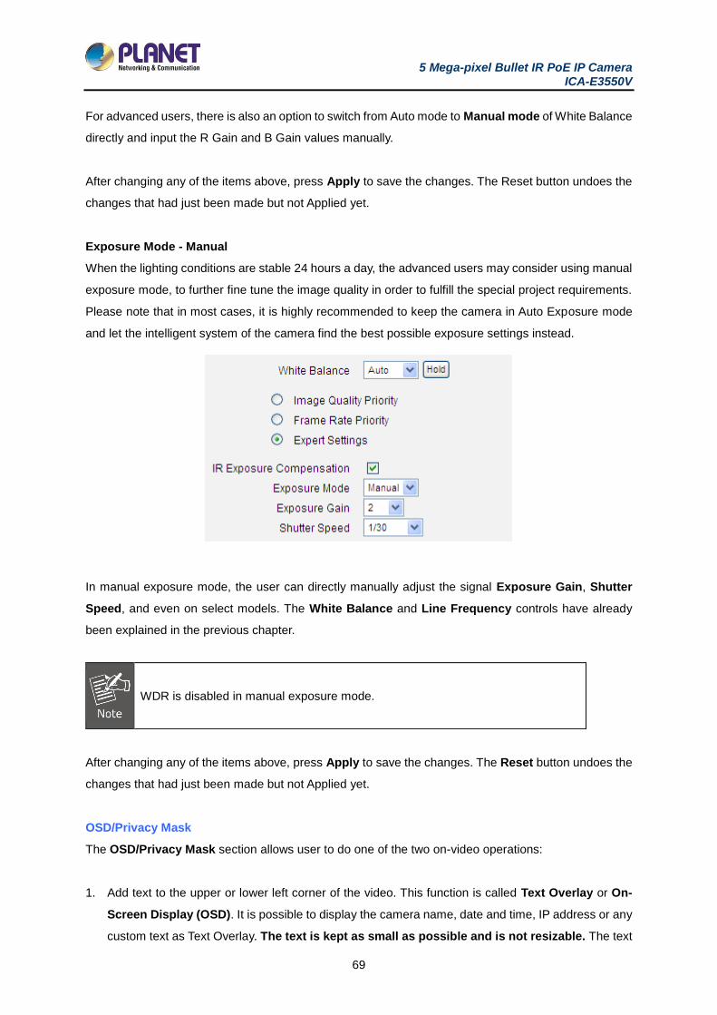
5 Mega-pixel Bullet IR PoE IP Camera ICA-E3550V
69
For advanced users, there is also an option to switch from Auto mode to Manual mode of White Balance
directly and input the R Gain and B Gain values manually.
After changing any of the items above, press Apply to save the changes. The Reset button undoes the
changes that had just been made but not Applied yet.
Exposure Mode - Manual
When the lighting conditions are stable 24 hours a day, the advanced users may consider using manual
exposure mode, to further fine tune the image quality in order to fulfill the special project requirements.
Please note that in most cases, it is highly recommended to keep the camera in Auto Exposure mode
and let the intelligent system of the camera find the best possible exposure settings instead.
In manual exposure mode, the user can directly manually adjust the signal Exposure Gain, Shutter
Speed, and even on select models. The White Balance and Line Frequency controls have already
been explained in the previous chapter.
WDR is disabled in manual exposure mode.
After changing any of the items above, press Apply to save the changes. The Reset button undoes the
changes that had just been made but not Applied yet.
OSD/Privacy Mask
The OSD/Privacy Mask section allows user to do one of the two on-video operations:
1. Add text to the upper or lower left corner of the video. This function is called Text Overlay or On-
Screen Display (OSD). It is possible to display the camera name, date and time, IP address or any
custom text as Text Overlay. The text is kept as small as possible and is not resizable. The text
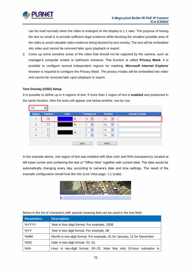
5 Mega-pixel Bullet IR PoE IP Camera ICA-E3550V
70
can be read normally when the video is enlarged on the display to 1:1 ratio. The purpose of having
the text so small is to provide sufficient legal evidence while blocking the smallest possible area of
the video to avoid valuable video evidence being blocked by text overlay. The text will be embedded
into video and cannot be removed later upon playback or export.
2. Cover up some sensitive areas of the video that should not be captured by the camera, such as
manager’s computer screen or bathroom entrance. This function is called Privacy Mask. It is
possible to configure several independent regions for masking. Microsoft Internet Explorer
browser is required to configure the Privacy Mask. The privacy masks will be embedded into video
and cannot be removed later upon playback or export.
Text Overlay (OSD) Setup
It is possible to define up to 4 regions of text. If more than 1 region of text is enabled and positioned in
the same location, then the texts will appear one below another, row by row.
In the example above, one region of text was enabled with blue color and 50% transparency, located at
left lower corner and containing the text of “Office View“ together with current date. The date would be
automatically changing every day, according to camera’s date and time settings. The result of the
example configuration would look like this (Live View page, 1:1 scale):
Below is the list of characters with special meaning that can be used in the text field:
Parameters Description
%YYYY Year in four-digit format. For example, 2008
%YY Year in two-digit format. For example, 08
%MM Month in two-digit format. For example, 01 for January, 12 for December
%DD Date in two-digit format. 01~31
%hh Hour in two-digit format. 00~23. Note that only 24-hour indication is
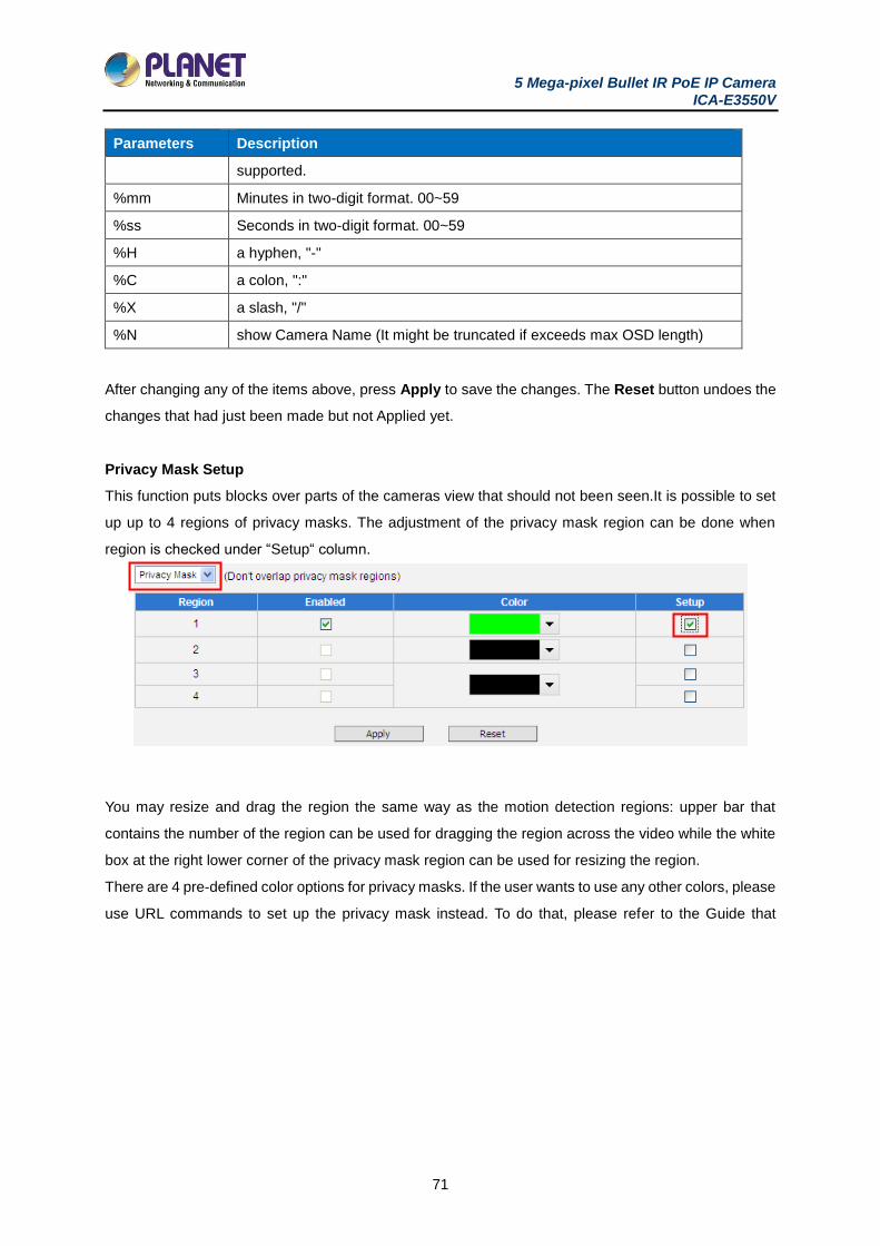
5 Mega-pixel Bullet IR PoE IP Camera ICA-E3550V
71
Parameters Description
supported.
%mm Minutes in two-digit format. 00~59
%ss Seconds in two-digit format. 00~59
%H a hyphen, "-"
%C a colon, ":"
%X a slash, "/"
%N show Camera Name (It might be truncated if exceeds max OSD length)
After changing any of the items above, press Apply to save the changes. The Reset button undoes the
changes that had just been made but not Applied yet.
Privacy Mask Setup
This function puts blocks over parts of the cameras view that should not been seen.It is possible to set
up up to 4 regions of privacy masks. The adjustment of the privacy mask region can be done when
region is checked under “Setup“ column.
You may resize and drag the region the same way as the motion detection regions: upper bar that
contains the number of the region can be used for dragging the region across the video while the white
box at the right lower corner of the privacy mask region can be used for resizing the region.
There are 4 pre-defined color options for privacy masks. If the user wants to use any other colors, please
use URL commands to set up the privacy mask instead. To do that, please refer to the Guide that
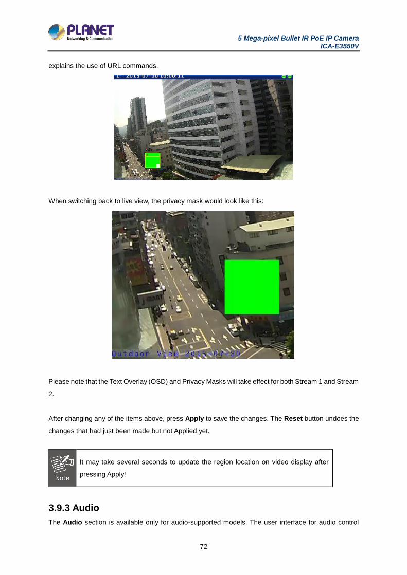
5 Mega-pixel Bullet IR PoE IP Camera ICA-E3550V
72
explains the use of URL commands.
When switching back to live view, the privacy mask would look like this:
Please note that the Text Overlay (OSD) and Privacy Masks will take effect for both Stream 1 and Stream
2.
After changing any of the items above, press Apply to save the changes. The Reset button undoes the
changes that had just been made but not Applied yet.
It may take several seconds to update the region location on video display after
pressing Apply!
3.9.3 Audio
The Audio section is available only for audio-supported models. The user interface for audio control
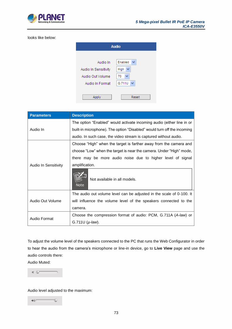
5 Mega-pixel Bullet IR PoE IP Camera ICA-E3550V
73
looks like below:
Parameters Description
Audio In
The option “Enabled” would activate incoming audio (either line in or
built-in microphone). The option “Disabled” would turn off the incoming
audio. In such case, the video stream is captured without audio.
Audio In Sensitivity
Choose “High” when the target is farther away from the camera and
choose “Low” when the target is near the camera. Under “High” mode,
there may be more audio noise due to higher level of signal
amplification.
Not available in all models.
Audio Out Volume
The audio out volume level can be adjusted in the scale of 0-100. It
will influence the volume level of the speakers connected to the
camera.
Audio Format Choose the compression format of audio: PCM, G.711A (A-law) or
G.711U (µ-law).
To adjust the volume level of the speakers connected to the PC that runs the Web Configurator in order
to hear the audio from the camera’s microphone or line-in device, go to Live View page and use the
audio controls there:
Audio Muted:
Audio level adjusted to the maximum:
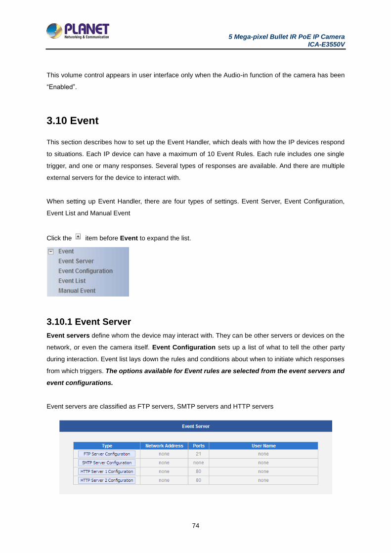
5 Mega-pixel Bullet IR PoE IP Camera ICA-E3550V
74
This volume control appears in user interface only when the Audio-in function of the camera has been
“Enabled”.
3.10 Event
This section describes how to set up the Event Handler, which deals with how the IP devices respond
to situations. Each IP device can have a maximum of 10 Event Rules. Each rule includes one single
trigger, and one or many responses. Several types of responses are available. And there are multiple
external servers for the device to interact with.
When setting up Event Handler, there are four types of settings. Event Server, Event Configuration,
Event List and Manual Event
Click the item before Event to expand the list.
3.10.1 Event Server
Event servers define whom the device may interact with. They can be other servers or devices on the
network, or even the camera itself. Event Configuration sets up a list of what to tell the other party
during interaction. Event list lays down the rules and conditions about when to initiate which responses
from which triggers. The options available for Event rules are selected from the event servers and
event configurations.
Event servers are classified as FTP servers, SMTP servers and HTTP servers
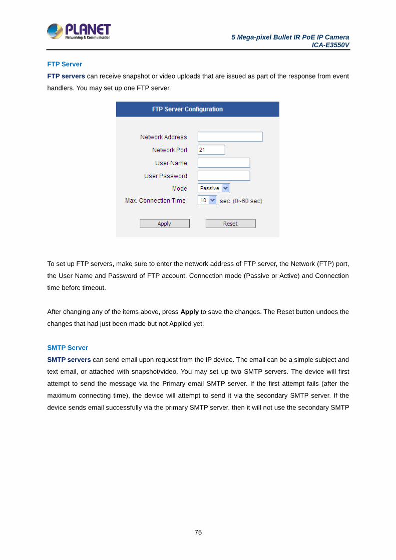
5 Mega-pixel Bullet IR PoE IP Camera ICA-E3550V
75
FTP Server
FTP servers can receive snapshot or video uploads that are issued as part of the response from event
handlers. You may set up one FTP server.
To set up FTP servers, make sure to enter the network address of FTP server, the Network (FTP) port,
the User Name and Password of FTP account, Connection mode (Passive or Active) and Connection
time before timeout.
After changing any of the items above, press Apply to save the changes. The Reset button undoes the
changes that had just been made but not Applied yet.
SMTP Server
SMTP servers can send email upon request from the IP device. The email can be a simple subject and
text email, or attached with snapshot/video. You may set up two SMTP servers. The device will first
attempt to send the message via the Primary email SMTP server. If the first attempt fails (after the
maximum connecting time), the device will attempt to send it via the secondary SMTP server. If the
device sends email successfully via the primary SMTP server, then it will not use the secondary SMTP
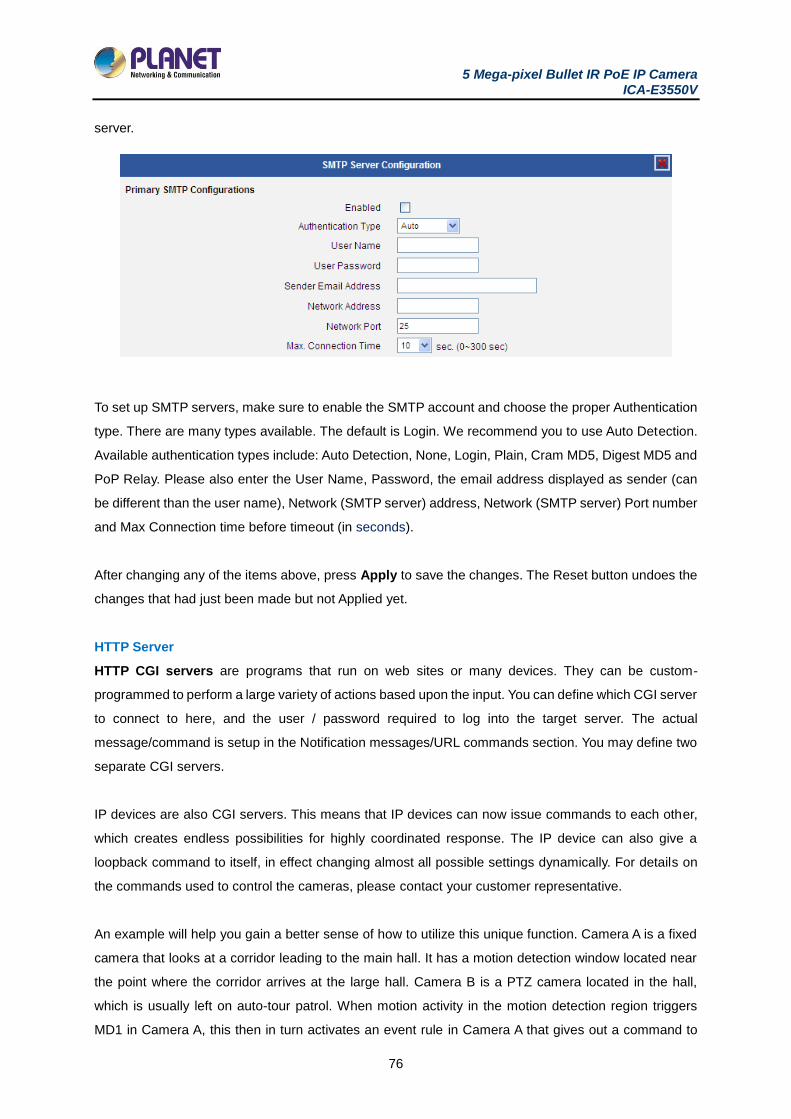
5 Mega-pixel Bullet IR PoE IP Camera ICA-E3550V
76
server.
To set up SMTP servers, make sure to enable the SMTP account and choose the proper Authentication
type. There are many types available. The default is Login. We recommend you to use Auto Detection.
Available authentication types include: Auto Detection, None, Login, Plain, Cram MD5, Digest MD5 and
PoP Relay. Please also enter the User Name, Password, the email address displayed as sender (can
be different than the user name), Network (SMTP server) address, Network (SMTP server) Port number
and Max Connection time before timeout (in seconds).
After changing any of the items above, press Apply to save the changes. The Reset button undoes the
changes that had just been made but not Applied yet.
HTTP Server
HTTP CGI servers are programs that run on web sites or many devices. They can be custom-
programmed to perform a large variety of actions based upon the input. You can define which CGI server
to connect to here, and the user / password required to log into the target server. The actual
message/command is setup in the Notification messages/URL commands section. You may define two
separate CGI servers.
IP devices are also CGI servers. This means that IP devices can now issue commands to each other,
which creates endless possibilities for highly coordinated response. The IP device can also give a
loopback command to itself, in effect changing almost all possible settings dynamically. For details on
the commands used to control the cameras, please contact your customer representative.
An example will help you gain a better sense of how to utilize this unique function. Camera A is a fixed
camera that looks at a corridor leading to the main hall. It has a motion detection window located near
the point where the corridor arrives at the large hall. Camera B is a PTZ camera located in the hall,
which is usually left on auto-tour patrol. When motion activity in the motion detection region triggers
MD1 in Camera A, this then in turn activates an event rule in Camera A that gives out a command to
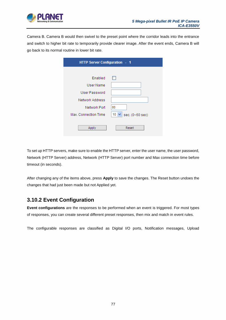
5 Mega-pixel Bullet IR PoE IP Camera ICA-E3550V
77
Camera B. Camera B would then swivel to the preset point where the corridor leads into the entrance
and switch to higher bit rate to temporarily provide clearer image. After the event ends, Camera B will
go back to its normal routine in lower bit rate.
To set up HTTP servers, make sure to enable the HTTP server, enter the user name, the user password,
Network (HTTP Server) address, Network (HTTP Server) port number and Max connection time before
timeout (in seconds).
After changing any of the items above, press Apply to save the changes. The Reset button undoes the
changes that had just been made but not Applied yet.
3.10.2 Event Configuration
Event configurations are the responses to be performed when an event is triggered. For most types
of responses, you can create several different preset responses, then mix and match in event rules.
The configurable responses are classified as Digital I/O ports, Notification messages, Upload
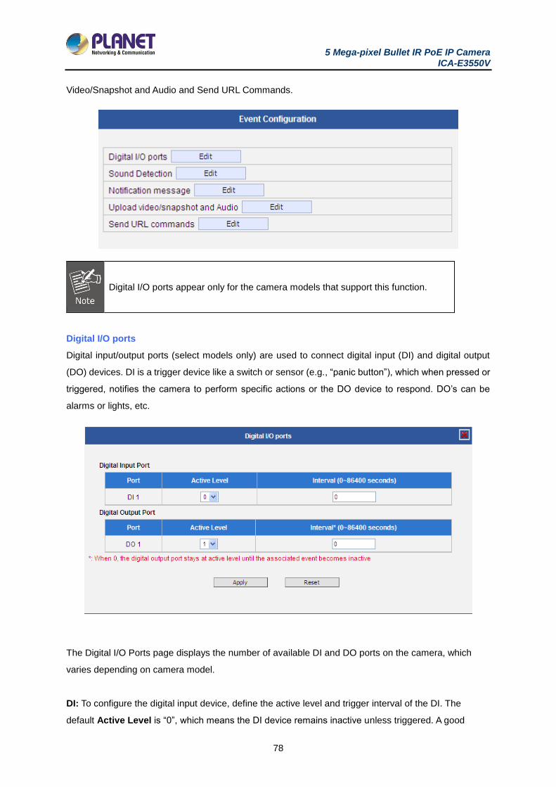
5 Mega-pixel Bullet IR PoE IP Camera ICA-E3550V
78
Video/Snapshot and Audio and Send URL Commands.
Digital I/O ports appear only for the camera models that support this function.
Digital I/O ports
Digital input/output ports (select models only) are used to connect digital input (DI) and digital output
(DO) devices. DI is a trigger device like a switch or sensor (e.g., “panic button”), which when pressed or
triggered, notifies the camera to perform specific actions or the DO device to respond. DO’s can be
alarms or lights, etc.
The Digital I/O Ports page displays the number of available DI and DO ports on the camera, which
varies depending on camera model.
DI: To configure the digital input device, define the active level and trigger interval of the DI. The
default Active Level is “0”, which means the DI device remains inactive unless triggered. A good
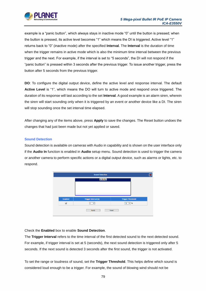
5 Mega-pixel Bullet IR PoE IP Camera ICA-E3550V
79
example is a “panic button”, which always stays in inactive mode “0” until the button is pressed; when
the button is pressed, its active level becomes “1” which means the DI is triggered. Active level “1”
returns back to “0” (inactive mode) after the specified Interval. The Interval is the duration of time
when the trigger remains in active mode which is also the minimum time interval between the previous
trigger and the next. For example, if the interval is set to “5 seconds”, the DI will not respond if the
“panic button” is pressed within 3 seconds after the previous trigger. To issue another trigger, press the
button after 5 seconds from the previous trigger.
DO: To configure the digital output device, define the active level and response interval. The default
Active Level is “1”, which means the DO will turn to active mode and respond once triggered. The
duration of its response will last according to the set Interval. A good example is an alarm siren, wherein
the siren will start sounding only when it is triggered by an event or another device like a DI. The siren
will stop sounding once the set interval time elapsed.
After changing any of the items above, press Apply to save the changes. The Reset button undoes the
changes that had just been made but not yet applied or saved.
Sound Detection
Sound detection is available on cameras with Audio in capability and is shown on the user interface only
if the Audio In function is enabled in Audio setup menu. Sound detection is used to trigger the camera
or another camera to perform specific actions or a digital output device, such as alarms or lights, etc. to
respond.
Check the Enabled box to enable Sound Detection.
The Trigger Interval refers to the time interval of the first detected sound to the next detected sound.
For example, if trigger interval is set at 5 (seconds), the next sound detection is triggered only after 5
seconds. If the next sound is detected 3 seconds after the first sound, the trigger is not activated.
To set the range or loudness of sound, set the Trigger Threshold. This helps define which sound is
considered loud enough to be a trigger. For example, the sound of blowing wind should not be
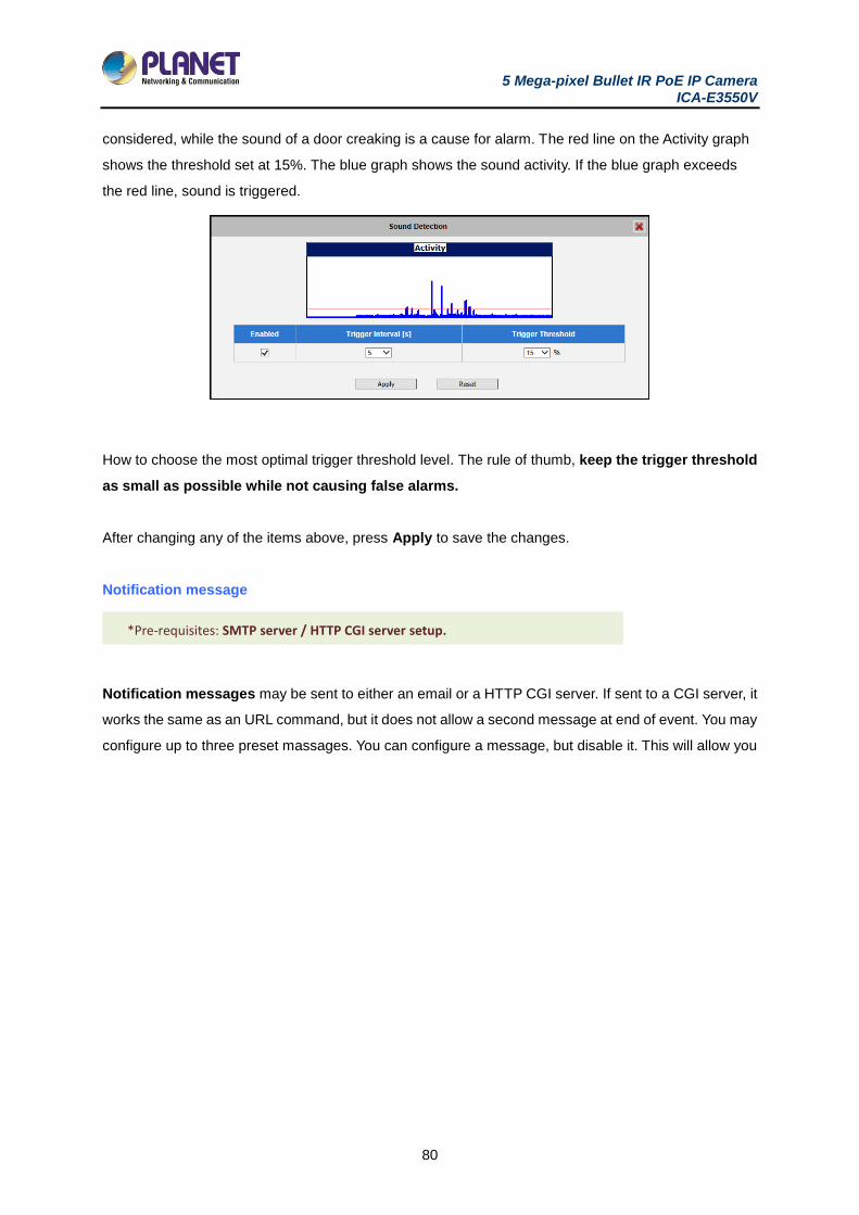
5 Mega-pixel Bullet IR PoE IP Camera ICA-E3550V
80
considered, while the sound of a door creaking is a cause for alarm. The red line on the Activity graph
shows the threshold set at 15%. The blue graph shows the sound activity. If the blue graph exceeds
the red line, sound is triggered.
How to choose the most optimal trigger threshold level. The rule of thumb, keep the trigger threshold
as small as possible while not causing false alarms.
After changing any of the items above, press Apply to save the changes.
Notification message
Notification messages may be sent to either an email or a HTTP CGI server. If sent to a CGI server, it
works the same as an URL command, but it does not allow a second message at end of event. You may
configure up to three preset massages. You can configure a message, but disable it. This will allow you
*Pre-requisites: SMTP server / HTTP CGI server setup.
*Pre-requisites: SMTP server / HTTP CGI server setup.
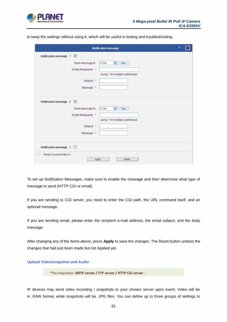
5 Mega-pixel Bullet IR PoE IP Camera ICA-E3550V
81
to keep the settings without using it, which will be useful in testing and troubleshooting.
To set up Notification Messages, make sure to enable the message and then determine what type of
message to send (HTTP CGI or email).
If you are sending to CGI server, you need to enter the CGI path, the URL command itself, and an
optional message.
If you are sending email, please enter the recipient e-mail address, the email subject, and the body
message.
After changing any of the items above, press Apply to save the changes. The Reset button undoes the
changes that had just been made but not Applied yet.
Upload Video/snapshot and Audio
IP devices may send video recording / snapshots to your chosen server upon event. Video will be
in .RAW format, while snapshots will be .JPG files. You can define up to three groups of settings to
*Pre-requisites: SMTP server / FTP server / HTTP CGI server .
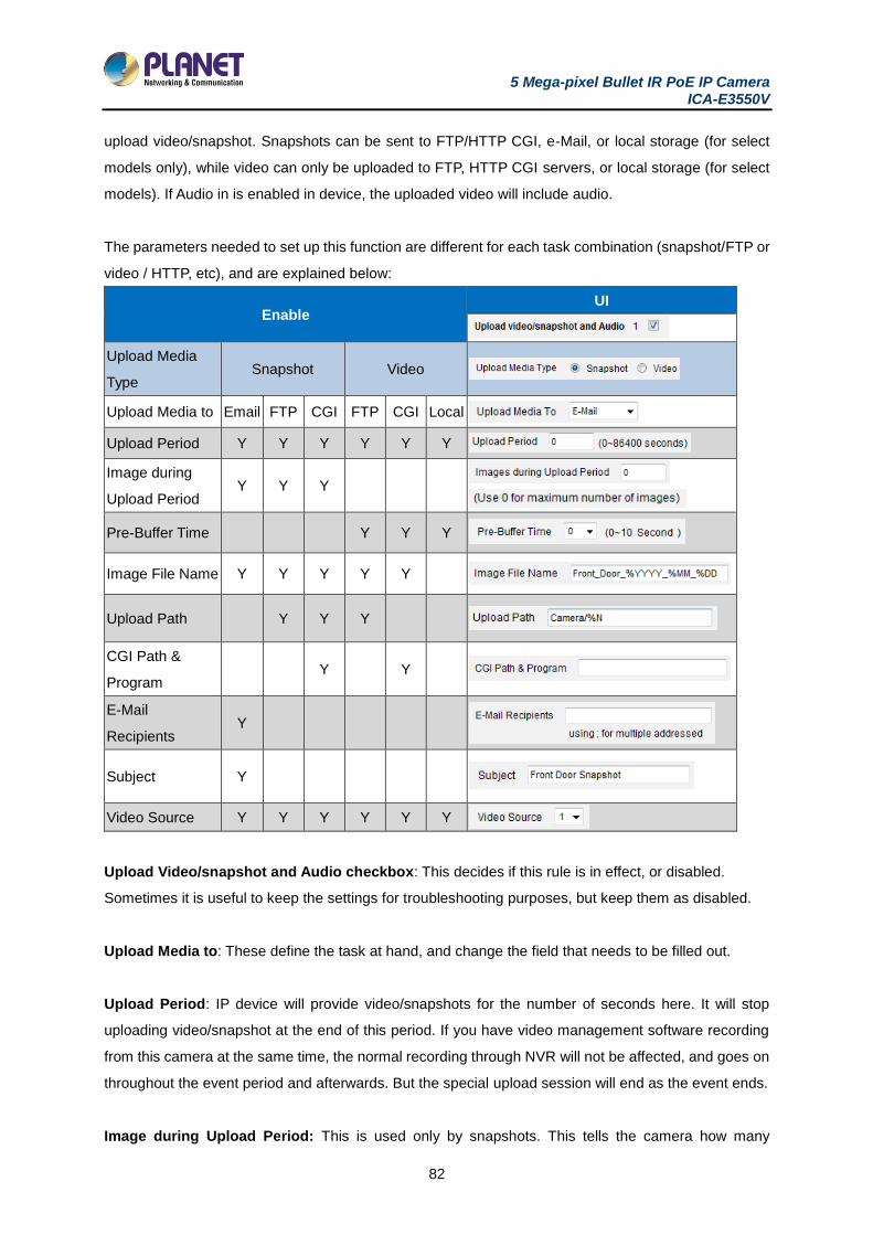
5 Mega-pixel Bullet IR PoE IP Camera ICA-E3550V
82
upload video/snapshot. Snapshots can be sent to FTP/HTTP CGI, e-Mail, or local storage (for select
models only), while video can only be uploaded to FTP, HTTP CGI servers, or local storage (for select
models). If Audio in is enabled in device, the uploaded video will include audio.
The parameters needed to set up this function are different for each task combination (snapshot/FTP or
video / HTTP, etc), and are explained below:
Enable UI
Upload Media
Type Snapshot Video
Upload Media to Email FTP CGI FTP CGI Local
Upload Period Y Y Y Y Y Y
Image during
Upload Period Y Y Y
Pre-Buffer Time Y Y Y
Image File Name Y Y Y Y Y
Upload Path Y Y Y
CGI Path &
Program Y Y
Recipients Y
Subject Y
Video Source Y Y Y Y Y Y
Upload Video/snapshot and Audio checkbox: This decides if this rule is in effect, or disabled.
Sometimes it is useful to keep the settings for troubleshooting purposes, but keep them as disabled.
Upload Media to: These define the task at hand, and change the field that needs to be filled out.
Upload Period: IP device will provide video/snapshots for the number of seconds here. It will stop
uploading video/snapshot at the end of this period. If you have video management software recording
from this camera at the same time, the normal recording through NVR will not be affected, and goes on
throughout the event period and afterwards. But the special upload session will end as the event ends.
Image during Upload Period: This is used only by snapshots. This tells the camera how many

5 Mega-pixel Bullet IR PoE IP Camera ICA-E3550V
83
snapshots it should attempt to capture during the Upload Time. If this value is set to 0, then the IP device
will attempt to capture as many snapshots as possible. Depending upon the device loading, the number
of snapshots taken may not reach the number you specified.
Pre-Buffer Time: This is only used by video. If this is set to more than 0, then the IP device will start to
buffer video in its internal memory. The maximum pre buffer is 10 seconds. When an event requires
video upload, the IP device will first upload the video taken right before the event then keep uploading
until it reaches the upload time.
Image File Name/ Upload Path: You will need to specify rule for file names and upload paths (upload
path is not needed for Email. Just put a slash “/” in the field). The rules contain flexible parameters. A
sample rule and corresponding filename will look like this:
Front_Door_%YYYY_%MM_%DD@%hh%mm%ss
Upload Path folders may also be named dynamically. For the IP device to create folders on FTP and
HTTP CGI servers properly, your FTP/CGI account will need to have permission to create folders. For
syntax on auto naming, please see online help or the inset box at the end of this section.
The symbol “%” cannot be the first character in filename or upload path. Please use either an alphabet
or a number as the starting character. For Upload Path, be sure to start and end eight a backslash“\”.
An example will be : \Backgate%MM%DD\
CGI path & Program: Some CGI servers may require special info and settings. Please refer to CGI
server designer for this section. IP devices do not allow upload of Snapshots / Video into their
embedded CGI servers.
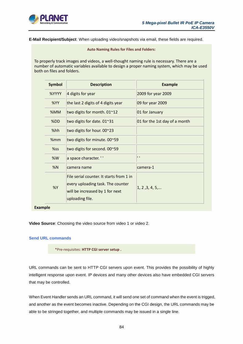
5 Mega-pixel Bullet IR PoE IP Camera ICA-E3550V
84
E-Mail Recipient/Subject: When uploading video/snapshots via email, these fields are required.
Video Source: Choosing the video source from video 1 or video 2.
Send URL commands
URL commands can be sent to HTTP CGI servers upon event. This provides the possibility of highly
intelligent response upon event. IP devices and many other devices also have embedded CGI servers
that may be controlled.
When Event Handler sends an URL command, it will send one set of command when the event is trigged,
and another as the event becomes inactive. Depending on the CGI design, the URL commands may be
able to be stringed together, and multiple commands may be issued in a single line.
Auto Naming Rules for Files and Folders:
To properly track images and videos, a well-thought naming rule is necessary. There are a number of automatic variables available to design a proper naming system, which may be used both on files and folders.
Symbol Description Example
%YYYY 4 digits for year 2009 for year 2009
%YY the last 2 digits of 4 digits year 09 for year 2009
%MM two digits for month. 01~12 01 for January
%DD two digits for date. 01~31 01 for the 1st day of a month
%hh two digits for hour. 00~23
%mm two digits for minute. 00~59
%ss two digits for second. 00~59
%W a space character. ' ' ' '
%N camera name camera-1
%Y
File serial counter. It starts from 1 in
every uploading task. The counter
will be increased by 1 for next
uploading file.
1, 2 ,3, 4, 5,...
Example
1. Entrance-%YYYY-%MM-%DD@%hh%mm%ss for time 2009/06/05 22:50:30.
The full name is Entrance-2009-06-05@225030
2. X_%w-%N_TEST%Y for camera name is 'my-camera' and three successive uploaded files.
The full names of these three files are
X_ -my-camera_TEST1, X_ -my-camera_TEST2, X_ -my-camera_TEST3 *Pre-requisites: HTTP CGI server setup .
*Pre-requisites: SMTP server / HTTP CGI server setup.

5 Mega-pixel Bullet IR PoE IP Camera ICA-E3550V
85
An example would be when the access control device at the entrance detects an entry, this device
provides a DI signal to the PTZ camera, and triggers an event. This event then sends a loopback
command to the PTZ Camera itself (by setting its own IP as the HTTP CGI server). The PTZ Camera
then moves to a preset location, stays until the event is over, and then moves back to another location.
At the same time it moves to the pre-set location, it increases the bitrate from 1M to 3M, and the frame
rate from 4 fps to 8 fps. The bitrate / fps changes are reverted at the end of event.
3.10.3 Event List
You may define a maximum of 10 Event rules, which will be shown in the abbreviated form in the Event
List panel. It will display under each Event ID, the days of the week it will be active, the start time and
duration of the active period, the type of the source of trigger, and the actions used in the response. If
the row is grayed out, this means the rule is currently not enabled and stays inactive.
You may start creating a new event by clicking the event ID number in the list, for example “2”.
There are several parts to the Event rule:
When is it active?
You may choose to enable the rule or not. The settings will be kept in internal memory even if the event
rule is disabled. Select the days in a weekly cycle in which this rule and schedule is active.
Determine the start time and duration of the active period. For example, a rule that lets motion detection
trigger snapshot uploads to FTP would only take place after 19:00 each day for 12 hours. Outside of
this time the rule will not be active.

5 Mega-pixel Bullet IR PoE IP Camera ICA-E3550V
86
In the example below, the event handler rule is active 24 hours a day, 7 days a week.
How is it triggered?
Events may be triggered by one of the several sources.
Scheduler: You can trigger an event based on the set schedule. For example, in the example below,
the schedule is set for an alarm to sound at 4:00, and will sound once every 5 minutes within the next
10 minutes.
DIs: For selected models only, the IP device may be triggered by Digital Input. Select the digital input
and make sure to configure it on the Event Configuration page
Motion: You may trigger the event if one or many Motion Detection regions encounter a motion trigger.
Trigger from any of them will initiate the event. The duration of event will be the same as the MD trigger
length, or the Trigger interval time, defined in the Motion Detection section on Video Adjust page. In the
example below, Motion Detection region 1 is used as the event trigger.

5 Mega-pixel Bullet IR PoE IP Camera ICA-E3550V
87
You may also ask the event to be repeatedly triggered during this scheduled time. The interval is
determined in minutes. You may use this with email / FTP upload to take snapshots at regular intervals.
Sound Detection: The event may be triggered when sound is detected. This feature is available on
cameras with Audio in capabilities only. The Sound Detection must be configured first to use this feature.
Switch to Night mode: This is available to selected models only. When camera changes between day
and night modes, the embedded event handler will notice this change, and may act upon this information.
Potential uses include changing the motion detection profile to another set of Event MD parameters. By
having two sets of parameters each optimized for day and night, this provide better overall accuracy in
both day and night conditions. Some night time only MD regions may also be activated this way. The
event period will end when the camera returns to day mode, which will then reset the camera to the
original settings.
Device boots successfully: This will trigger the event responses once the device boots up. You can
use this to create a notification system that keeps record of when the device has been rebooted via
email.
Reboot device: This triggers the event response when the device is shut down via web UI “Save and
Reboot”. Use this to keep record of when was the device setting edited. Note that this will not take effect
when the device is unplugged, as this is not normal shutdown.
Fail to write storage (with storage card only): Trigger occurs when there is an error in writing data to
the memory card.
Remove storage media (with storage card only): Trigger occurs when the memory card is suddenly
removed from the device.
What responses will occur?
Available responses vary depending on what triggered the event.
Digital Output (selected models only): This is a useful link to other devices. Click to include this in the
5 Mega-pixel Bullet IR PoE IP Camera ICA-E3550V
88
response for this rule.
Send notification Message: Select from the three pre-defined messages which you’ve setup in the
Event Configuration section. You may enable multiple messages at the same time. For sending Email,
please limit the recipient to one per event rule. If you need to send email to more than one recipient,
please use separate event rules triggered by the same trigger.
Upload video/snapshots: Select which of the event configurations to include in this response set. If
you are sending email via upload video and sending notification message at the same time, the system
will automatically merge the two emails into one. The subject and image will be based upon the Upload
snapshot Event configuration enabled, but the message in the body text will be based upon the
Notification messages.
In general, please stick to the “one email per event rule” limit for best performance.
Change Motion Detection profile: This will switch the profile of the selected Motion Detection region
from Runtime profile to Event profile. The profile will return to runtime settings at the end of this event.
You may program one motion detection region to be disabled at runtime, but enable it with event handler
under some circumstances.
Send URL command: Select the URL command to include in the response set. Two different commands
will be sent at the time when the event is triggered and un-triggered. For example, going to a preset
point, if the device is a PTZ camera, and there are preset points already configured in PTZ setup page,
then you may include this in the response section of the event rule by using Send URL Command
method. It is possible to let the camera return to another preset point at the end of the event.
Change to Day/Night Mode (Selected models only): For some models, you may force the Camera into
Day or Night mode. The camera will return to its previous setting (whether auto or forced day/ night)
upon the end of the event.
After changing any of the items above, press Apply to save the changes. The Reset button undoes the
changes that had just been made but not Applied yet.
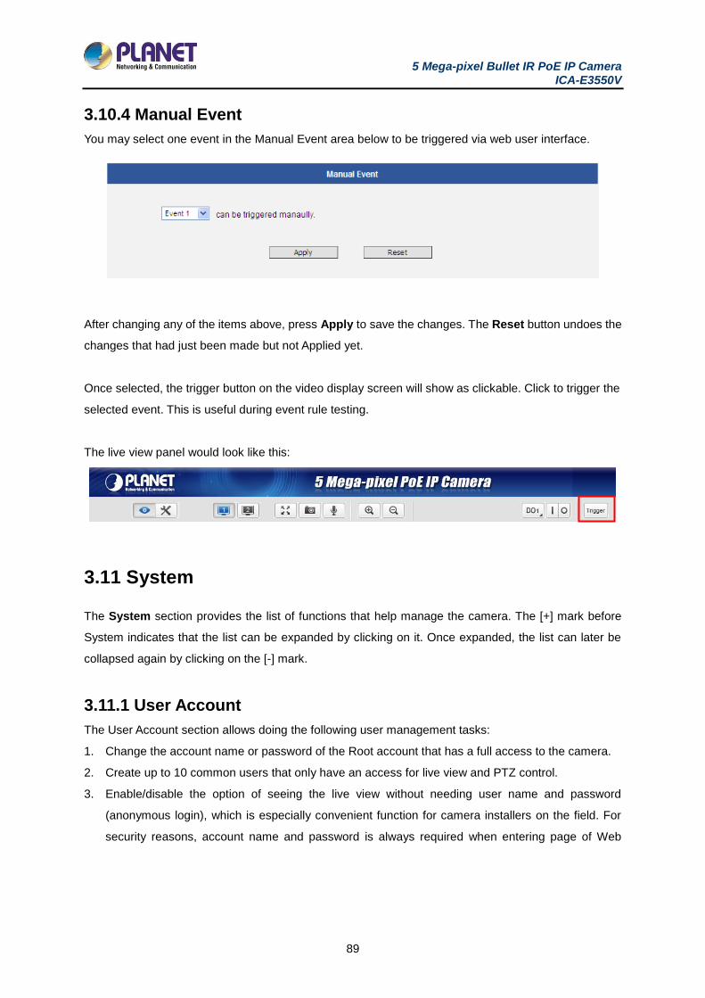
5 Mega-pixel Bullet IR PoE IP Camera ICA-E3550V
89
3.10.4 Manual Event
You may select one event in the Manual Event area below to be triggered via web user interface.
After changing any of the items above, press Apply to save the changes. The Reset button undoes the
changes that had just been made but not Applied yet.
Once selected, the trigger button on the video display screen will show as clickable. Click to trigger the
selected event. This is useful during event rule testing.
The live view panel would look like this:
3.11 System
The System section provides the list of functions that help manage the camera. The [+] mark before
System indicates that the list can be expanded by clicking on it. Once expanded, the list can later be
collapsed again by clicking on the [-] mark.
3.11.1 User Account
The User Account section allows doing the following user management tasks:
1. Change the account name or password of the Root account that has a full access to the camera.
2. Create up to 10 common users that only have an access for live view and PTZ control.
3. Enable/disable the option of seeing the live view without needing user name and password
(anonymous login), which is especially convenient function for camera installers on the field. For
security reasons, account name and password is always required when entering page of Web
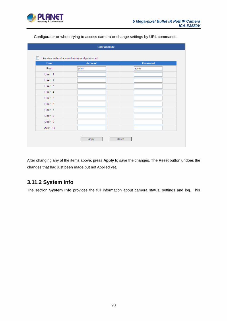
5 Mega-pixel Bullet IR PoE IP Camera ICA-E3550V
90
Configurator or when trying to access camera or change settings by URL commands.
After changing any of the items above, press Apply to save the changes. The Reset button undoes the
changes that had just been made but not Applied yet.
3.11.2 System Info
The section System Info provides the full information about camera status, settings and log. This
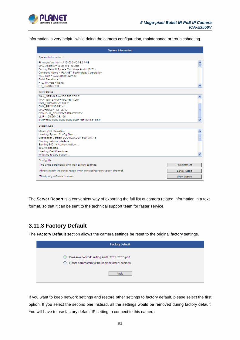
5 Mega-pixel Bullet IR PoE IP Camera ICA-E3550V
91
information is very helpful while doing the camera configuration, maintenance or troubleshooting.
The Server Report is a convenient way of exporting the full list of camera related information in a text
format, so that it can be sent to the technical support team for faster service.
3.11.3 Factory Default
The Factory Default section allows the camera settings be reset to the original factory settings.
If you want to keep network settings and restore other settings to factory default, please select the first
option. If you select the second one instead, all the settings would be removed during factory default.
You will have to use factory default IP setting to connect to this camera.
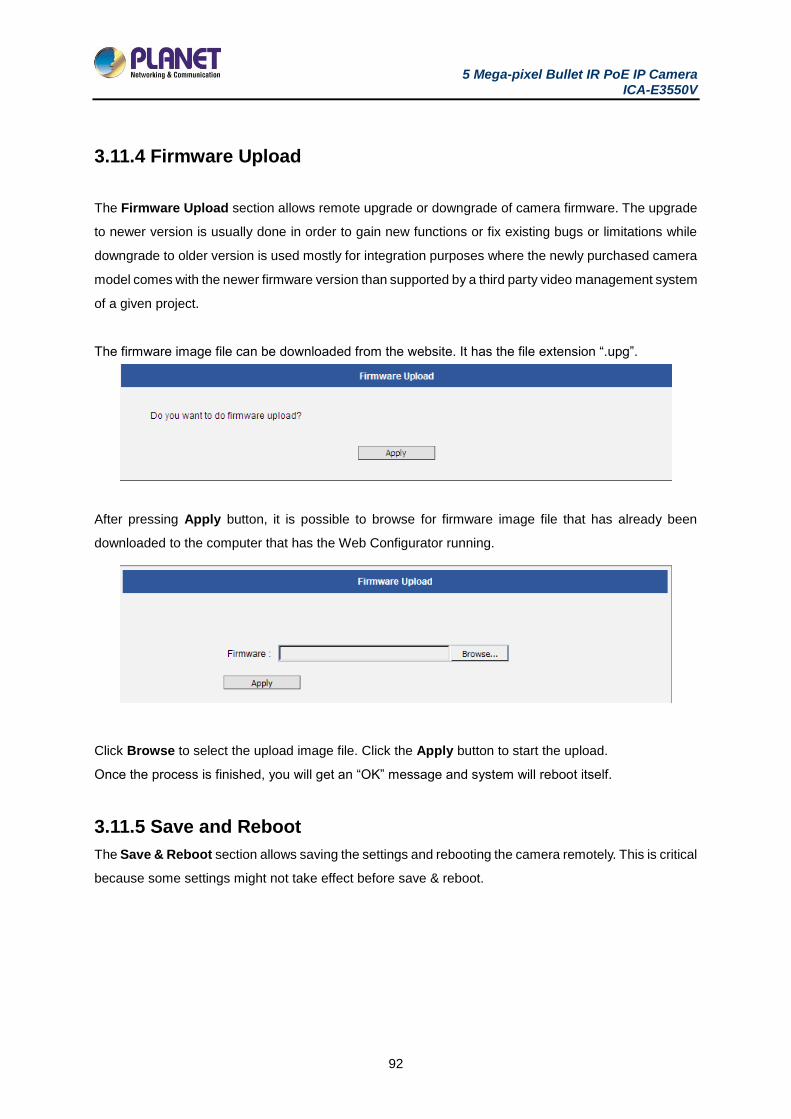
5 Mega-pixel Bullet IR PoE IP Camera ICA-E3550V
92
3.11.4 Firmware Upload
The Firmware Upload section allows remote upgrade or downgrade of camera firmware. The upgrade
to newer version is usually done in order to gain new functions or fix existing bugs or limitations while
downgrade to older version is used mostly for integration purposes where the newly purchased camera
model comes with the newer firmware version than supported by a third party video management system
of a given project.
The firmware image file can be downloaded from the website. It has the file extension “.upg”.
After pressing Apply button, it is possible to browse for firmware image file that has already been
downloaded to the computer that has the Web Configurator running.
Click Browse to select the upload image file. Click the Apply button to start the upload.
Once the process is finished, you will get an “OK” message and system will reboot itself.
3.11.5 Save and Reboot
The Save & Reboot section allows saving the settings and rebooting the camera remotely. This is critical
because some settings might not take effect before save & reboot.
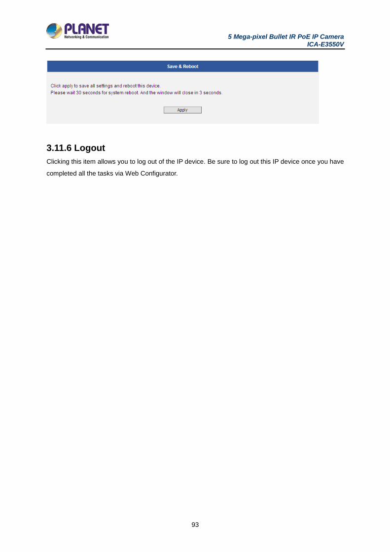
5 Mega-pixel Bullet IR PoE IP Camera ICA-E3550V
93
3.11.6 Logout
Clicking this item allows you to log out of the IP device. Be sure to log out this IP device once you have
completed all the tasks via Web Configurator.
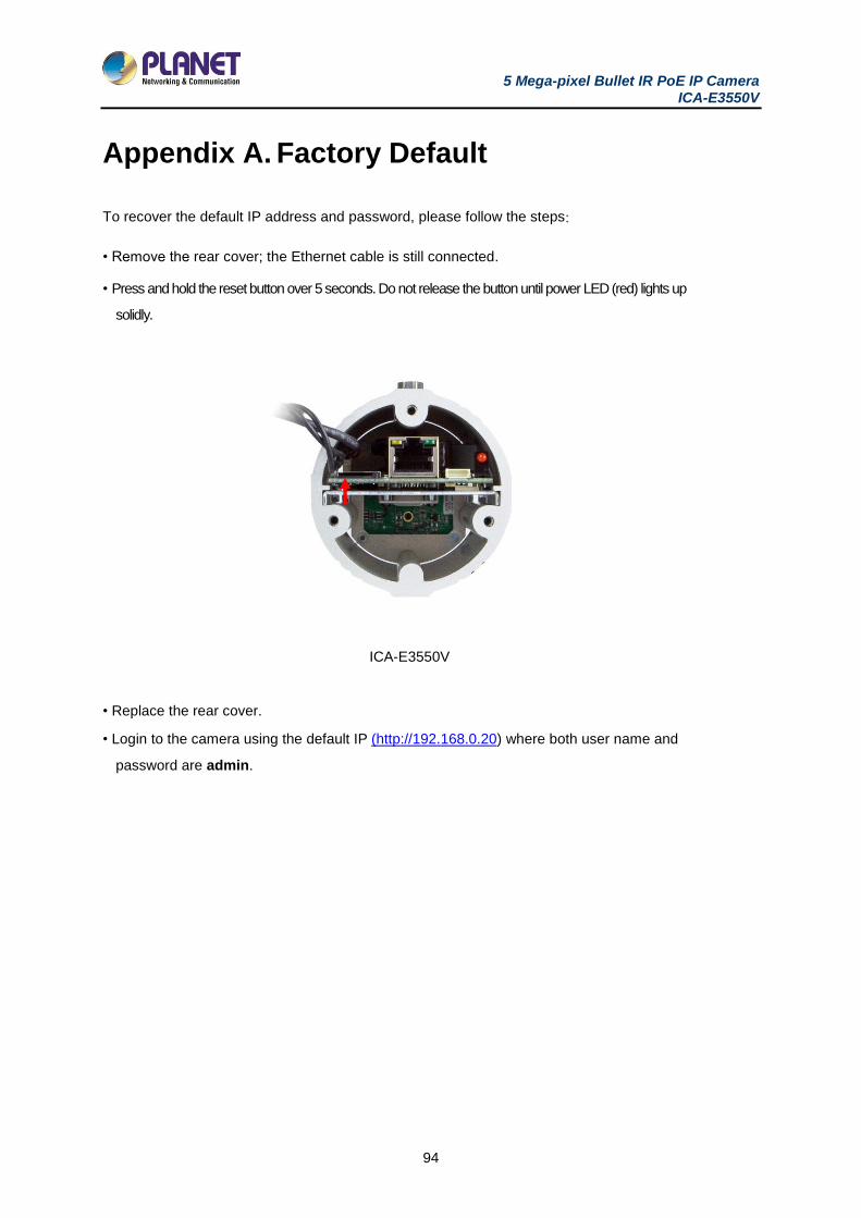
5 Mega-pixel Bullet IR PoE IP Camera ICA-E3550V
94
Appendix A. Factory Default
To recover the default IP address and password, please follow the steps:
• Remove the rear cover; the Ethernet cable is still connected.
• Press and hold the reset button over 5 seconds. Do not release the button until power LED (red) lights up
solidly.
ICA-E3550V
• Replace the rear cover.
• Login to the camera using the default IP (http://192.168.0.20) where both user name and
password are admin.
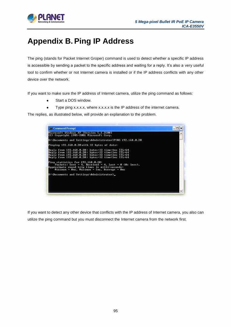
5 Mega-pixel Bullet IR PoE IP Camera ICA-E3550V
95
Appendix B. Ping IP Address
The ping (stands for Packet Internet Groper) command is used to detect whether a specific IP address
is accessible by sending a packet to the specific address and waiting for a reply. It’s also a very useful
tool to confirm whether or not Internet camera is installed or if the IP address conflicts with any other
device over the network.
If you want to make sure the IP address of Internet camera, utilize the ping command as follows:
Start a DOS window.
Type ping x.x.x.x, where x.x.x.x is the IP address of the internet camera.
The replies, as illustrated below, will provide an explanation to the problem.
If you want to detect any other device that conflicts with the IP address of Internet camera, you also can
utilize the ping command but you must disconnect the Internet camera from the network first.

5 Mega-pixel Bullet IR PoE IP Camera ICA-E3550V
96
Appendix C. Planet DDNS Application
Configuring PLANET DDNS steps:
Step 1: Visit DDNS provider’s web site and register an account if you do not have one yet. For
example, register an account at http://planetddns.com
Step 2: Enable DDNS option through accessing web page of the camera.
Step 3: Input all DDNS settings.
5 Mega-pixel Bullet IR PoE IP Camera ICA-E3550V
97
Appendix D. Configuring Port Forwarding
Manually
The device can be used with a router. If the device wants to be accessed from the WAN, its IP address
needs to be set up as a fixed IP address. The port forwarding or Virtual Server function of router also
needs to be set up. This device supports UPnP traversal function. Therefore, user could use this feature
to configure port forwarding of NAT router first. However, if user needs to configure port forwarding
manually, please follow the steps below:
Manually installing the device with a router on your network is an easy 3–step procedure as follows:
1. Assign a local/fixed IP address to your device
2. Access the Router with Your Web browser
3. Open/Configure Virtual Server Ports of Your Router
1. Assign a local/fixed IP address to your device
The device must be assigned a local and fixed IP Address that allows it to be recognized by the router.
Manually setup the device with a fixed IP address, for example, 192.168.0.100.
2. Access the Router with Your Web browser
The following steps generally apply to any router that you have on your network. PLANET wireless AP
is used as an example to clarify the configuration process. Configure the initial settings of the router by
following the steps outlined in the router’s Quick Installation Guide.
If you have cable or DSL service, you will most likely have a dynamically assigned WAN IP address.
‘Dynamic’ means that your router’s WAN IP address can change from time to time depending on your
ISP. A dynamic WAN IP address identifies your router on the public network and allows it to access the
Internet. To find out what your router’s WAN IP address is, go to the Status screen on your router and
locate the WAN information for your router. As shown on the following page the WAN IP address will be
listed. This will be the address that you will need to type in your web browser to view your camera over
the Internet. Be sure to uncheck the Reset IP address at next boot button at the top of the screen after
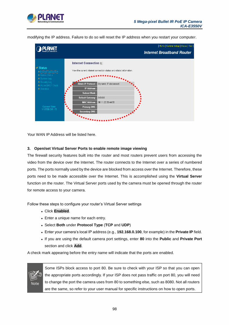
5 Mega-pixel Bullet IR PoE IP Camera ICA-E3550V
98
modifying the IP address. Failure to do so will reset the IP address when you restart your computer.
Your WAN IP Address will be listed here.
3. Open/set Virtual Server Ports to enable remote image viewing
The firewall security features built into the router and most routers prevent users from accessing the
video from the device over the Internet. The router connects to the Internet over a series of numbered
ports. The ports normally used by the device are blocked from access over the Internet. Therefore, these
ports need to be made accessible over the Internet. This is accomplished using the Virtual Server
function on the router. The Virtual Server ports used by the camera must be opened through the router
for remote access to your camera.
Follow these steps to configure your router’s Virtual Server settings
Click Enabled.
Enter a unique name for each entry.
Select Both under Protocol Type (TCP and UDP)
Enter your camera’s local IP address (e.g., 192.168.0.100, for example) in the Private IP field.
If you are using the default camera port settings, enter 80 into the Public and Private Port
section and click Add.
A check mark appearing before the entry name will indicate that the ports are enabled.
Some ISPs block access to port 80. Be sure to check with your ISP so that you can open
the appropriate ports accordingly. If your ISP does not pass traffic on port 80, you will need
to change the port the camera uses from 80 to something else, such as 8080. Not all routers
are the same, so refer to your user manual for specific instructions on how to open ports.
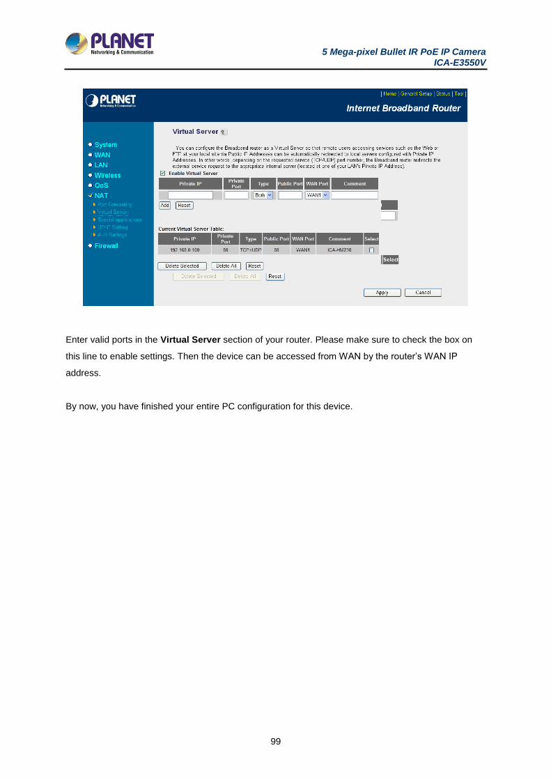
5 Mega-pixel Bullet IR PoE IP Camera ICA-E3550V
99
Enter valid ports in the Virtual Server section of your router. Please make sure to check the box on
this line to enable settings. Then the device can be accessed from WAN by the router’s WAN IP
address.
By now, you have finished your entire PC configuration for this device.