Embed Size (px)
Citation preview

Central Washington University Central Washington University
ScholarWorks@CWU ScholarWorks@CWU
All Undergraduate Projects Undergraduate Student Projects
Spring 2016
Icarus Avionics Device Icarus Avionics Device
Robert A. Gread Central Washington University, [email protected]
Follow this and additional works at: https://digitalcommons.cwu.edu/undergradproj
Part of the Mechanical Engineering Commons
Recommended Citation Recommended Citation Gread, Robert A., "Icarus Avionics Device" (2016). All Undergraduate Projects. 23. https://digitalcommons.cwu.edu/undergradproj/23
This Dissertation/Thesis is brought to you for free and open access by the Undergraduate Student Projects at ScholarWorks@CWU. It has been accepted for inclusion in All Undergraduate Projects by an authorized administrator of ScholarWorks@CWU. For more information, please contact [email protected].

Non-Invasive Angle of Attack Indicator
By
Robert Gread

2
ContentsINTRODUCTION .................................................................................................................................................. 4
Abstract ............................................................................................................................................................... 4
Motivation: .......................................................................................................................................................... 4
Function Statement: ............................................................................................................................................ 4
Design Requirements: ......................................................................................................................................... 5
Success Criteria: .................................................................................................................................................. 5
Scope of Effort: ................................................................................................................................................... 5
Benchmark: ......................................................................................................................................................... 6
Success Criteria: .................................................................................................................................................. 6
DESIGN & ANALYSIS ......................................................................................................................................... 7
Vane Shape: ........................................................................................................................................................ 7
Vane Shaft ........................................................................................................................................................... 9
Exterior Housing ................................................................................................................................................. 9
3D Matrix Interior Housing .............................................................................................................................. 10
Electronic Package ............................................................................................................................................ 10
Fasteners: Exterior ............................................................................................................................................ 11
Lever Toggle Plunger ....................................................................................................................................... 11
Lever Toggle Spring Design ............................................................................................................................. 11
Materials ........................................................................................................................................................... 12
Adhesion Method (Interior and Exterior Assemblies) ...................................................................................... 12
METHODS & CONSTRUCTION ....................................................................................................................... 13
DRAWING TREE ................................................................................................................................................ 15
DEVICE OPERATION ........................................................................................................................................ 15
Benchmark Comparison.................................................................................................................................... 16
Performance Predictions ................................................................................................................................... 16
TESTING METHOD ............................................................................................................................................ 17
Exterior Housing: .............................................................................................................................................. 17
Vane: ................................................................................................................................................................. 17
Attachment Method: ......................................................................................................................................... 17
Weight: .............................................................................................................................................................. 17
Sound Intensity: ................................................................................................................................................ 17
Operation Temperature: .................................................................................................................................... 18
Concluding Steps: ............................................................................................................................................. 18
Final Step: Test Flights ..................................................................................................................................... 18
BUDGET/SCHEDULE/PROJECT MANAGEMENT ........................................................................................ 19
DISCUSSION ....................................................................................................................................................... 20

3
CONCLUSION ..................................................................................................................................................... 21
ACKNOWLEDGEMENTS .................................................................................................................................. 21
APPENDICIES ..................................................................................................................................................... 22
4
INTRODUCTION Abstract
Angle of attack refers to the directionality of air flow at the leading edge of the wing compared to the wing chord. Angle of attack information is invaluable to pilots as at a certain angle between the airflow and wing chord, laminar flow is disrupted over the wing and stall conditions can arise. This device would provide an easy way to add access to information on current angle of attack to older aircraft without extensive medication to existing flight surface. The device will work utilizing an exterior vane that measures the direction of oncoming air and transfers this to rotational input on a connected turret. This turret will transfer information via a magnet in the base to a hall switch on the interior components that when activated will enable a buzzer to sound an alert. This design offers an improvement over existing methods by providing an audio warning, more reliable components, and an easy install method. The device will be manufactured and tested and compared to design requirements set in the next sections.
Motivation: The Federal Aviation Administration released a statement in February 2015 declaring an angle of attack indicator as a non-essential piece of avionics would greatly improve safety in GA aircraft and other civilian applications. They also released specifications for the installation of such devices into existing aircraft as there are thousands of older aircraft without these devices. Such a device that is easy for the pilot to install and makes no changes to the existing airframe/components of the aircraft would enable a user to add another margin of safety to the function of their aircraft without requiring refitting and airframe mechanic approval. Designing such a device that utilizes a no fastener approach of installation would be a solution to forgo this process while still adding safety enhancement.
Function Statement: This device will measure the difference between oncoming airflow and the wing chord, providing accurate angle of attack audio feedback to the pilot. It will be simple to install without requiring extensive fitting. It will be considered a minor alteration for experimental flight use on civilian aircraft.

5
Design Requirements: The Angle of Attack indicator will fulfill all design requirements specified by the FAA per Memo No. AIR 100-14-110-PM01 and adhere to ASTM F3011-13. The Angle of Attack Indicator will also fulfill the following requirements:
Angle of attack indicator will transfer input from external conditions through .25 inch plexiglass Alert pilot via audio alarm exceeding 88dB The device will be no more than 2lb Attached to exterior surface with no fasteners requiring physical alteration to existing aircraft surface. External components must resist 100lb of sustained, oncoming force at operational angle without
deforming. Fastening method must sustain 30lbf at 200 mph. Device must not exceed a space of 9 in x 9 internally and externally Device must endure temperatures of -10 to 150 degrees Fahrenheit. Cost of Materials and Assembly must fall under $400 Impart a drag force of less than 40lbs Interior housing must resist 20lbs of impact force without shifting .1inches. Friction force between moving parts must be no more thann 0.25 lbf
Success Criteria: To be determined a successful Angle of Attack indicator device the device will need to meet the following desired criterion; The completed assembly will successfully indicate oncoming air stream 45knots to 120 knots within 2 degrees of accuracy. It must mount to an aircraft with no structural modification to existing aircraft surfaces. It must trigger an audio alarm of 88 dB within the cockpit when reaching a defined angle of attack within 2 degree of accuracy. The External surfaces must resist 100lbs of force without shifting or becoming dislodged. Device must endure 12 hours of UV exposure daily, oil and solvent exposure, temperature ranges -20 to 150 degrees Fahrenheit, and be easily modified for production at a later date.
Scope of Effort: The Angle of attack indicator will include an external sensor capable of detecting oncoming airstream, a method of transferring input from this sensor to inside the aircraft, an interior component capable of receiving the input from the external sensor, an adjustment method, and an electronics package capable of transferring input to an alarm audible to the pilot in all conditions. The design will insure easy installation and removal with limited lasting effect on the airframe should it be removed.
6
Benchmark:
The most similar solution available is a system that utilizes a flexible thread centered between two indicator lines. The thread shifts into oncoming air flow and shows an approximate visualization of the angle of attack.
This device will provide more accurate and constant feedback to a pilot of glider aircraft, single engine aircraft, and multiengine platforms with a similar non-invasive attachment method.
Success Criteria: The success of this design depends on obtaining a functional device capable of attaching non-invasively to an aircraft, accurately measuring the angle of attack, and providing the pilot with information feedback. The device will meet or exceed design requirements and be capable of being installed easily with no modification to the airframe. \
String type Angle of Attack Indicator

7
DESIGN & ANALYSIS The proposed design is an exterior vane on a rotating base that will rotate according to drag induced on the vane by oncoming airflow outside the aircraft. This rotating base will transmit input from the vane via magnetic field on a position adjustable hall device on the interior component. The magnetic field imparted by the vane turret will trigger a ratiometric hall device to increase or decrease current to a buzzer and amplifier. It will be adhered to the exterior and interior sides of the canopy such that the magnet path passes over the positionable range of the hall device.
Updated Solidworks Rendering of 3.0 Assembly.
Figure 1- Solidworks Rendering The interior Housing will be largely 3D printed using solid matrix for maximum durability to meet impact resistance requirements laid out in the design requirements. The power source, buzzer and resistor will be stationary within the interior housing and the hall sensor will be mounted to the adjustable surface. The adjustment lever will have a spring loaded plunger to lock into the adjoining surface (Interior baseplate) and provide a stable, permanent position for the Hall device.
Vane Shape: Requirements:
8
Shape must induce drag capable of maintaining into the wind orientation with a margin of error of 2 degrees.
Must be less than 9 in x 9 in
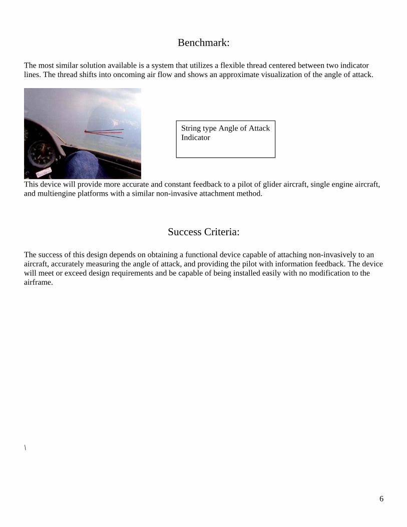
Results of analysis show that a rectangular vane 2.5in x 1.5 in x 0.0625 in will meet design requirements with 18.56lbs of force imparted on the vane when operating into the wind at 200 Mph. 2.96lbs of force will hit the vane at 80Mph. The vane will be mounted to the rear of an aluminum shaft Design Parameter: The vane will therefore be a 1.5 in x 2.5 in x 0.0625 in Sheet of 6061-T6 Aircraft aluminum mounted to the rear of a 5 inch 6061 T6 aluminum shaft with a diameter of 0.20inches. Addition: Vane has been redesigned per Figure EA-9 for a simplified manufacturing process. 3FEB2016
Figure XXX 3D FEA analysis of New Vane Design showing a max stress of about 34KSI, well below yield point and proving the design. Max stress occurs along the groove feature in place for forming the plate into a 90 degree angle. A note for consideration is the yield point will have been raised along this area due to the manufacturing method of taking the material past yield.

9
Vane Shaft Requirements:
Will not experience deformation. (0 in of deformation). Find max bending strain and compare to max allowable bending strain Find max shear and compare to max allowable shear
The 6061-T6. Aluminum shaft, 0.5 inch diameter, 2 inches long, experiences 2037 psi bending stress which is well under the max allowable bending stress of 6061 – T6 Aluminum. Quarter inch shaft was checked for comparable resistance for weight and bulk saving, but it was found the induced bending stress at 200Mph exceeds allowable bending stress within the specified factor of safety (4.0). Design Parameter The shaft will therefore be a 0.5 inch diameter, 2 inch long shaft manufactured from 6061 – T6 Aircraft aluminum Part has been removed from assembly. Replaced with one piece vane.
Exterior Housing Requirements:
Induce less than 40lbs of drag at max speed Find drag induced on airframe by housing
The housing induces 4.73lbs of drag at 80mph and 29.54 lbs of frag at 200mph. It undergoes a force of 190lbs from oncoming air. *Note: Total drag on the vane, shaft, and housing is 5.15lb at force at 80mph and 32.22lbs at 200mph. This meets the 40lbs of drag requirement on exterior components. Design Parameter: Structure of the housing will therefore be a 3in Diameter by 2 inch high housing, cylindrical in shape.
10
3D Matrix Interior Housing Requirements
ABS 3D Printing Matrix Resist 20lbs impact force without deformation
ABS has the following material properties obtained from MATWEB. Ultimate Tensile Strength 3200 psi IZOD Impact: 5.6 ft-lbs/in Softening Temperature: 210 F Calculations: Appendix: A1 It was found that a hollow cylinder with shell thickness 0.125 inches, diameter, 4 inches, height 1.25 inches can resist the 20lbs of impact force specified in the design requirements at the corner and a total average thickness of 0.088 inches. The middle of the flat surface undergoes 1228.8psi of bending stress with 20lbs of force applied, under the UTS of printed ABS. Design Parameter: Cylinder must be 0.125 inches thick to resist 20lbs impact and constant pressure. 4 inch diameter and 2.5 inch height provides an open volume of 28.75 in3 .
Electronic Package Requirements
Receive input from exterior vane accurately Adjustable to actual aircraft characteristics
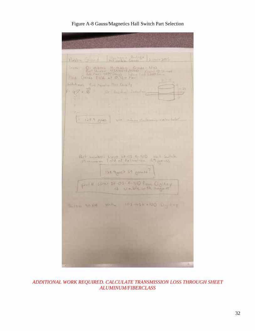
Calculations: Appendix Design: Utilizing a hall switch to sense magnetic fields within 0.75 inches of the chip, the circuit will activate a 90DB buzzer. It will run off readily available power sources and be self-contained within an interior housing. Calculations: Appendix A -8 Design Parameter: Gauss field from Magnet Part number N5N0575/N40 at .75 in; 128.9 gauss Hall switch Part number: 55140-3H-02-A-ND, gauss field minimum: 59 gauss Buzzer Part number: 102-1456-6ND, 90 DB, 5 cm x 3 cm Circuit will be included on a single card with attached battery source supplying 3.6 Volts minimum and 80ma.

11
Fasteners: Exterior Requirements:
Fastener on exterior component plate will resist shear force applied by attached component (i.e. Top Housing Cover, Housing, etc)
Calculations: Reference A-7 Design Parameter: # 6-40 UNC Fasteners 1.25 inch. Shortened to 1.125.
Lever Toggle Plunger Requirements:
Interior Components must withstand 20lbs of force Plunger must resist 20lbs of vertical shear across the surface of the baseplate and lever arm.
Calculations: Appendix A-12 Design Parameter: 1040 Hot Rolled Steel pin, OAL 1 inch, Effected Diameter: 0.10 inch Part Removed from Design.
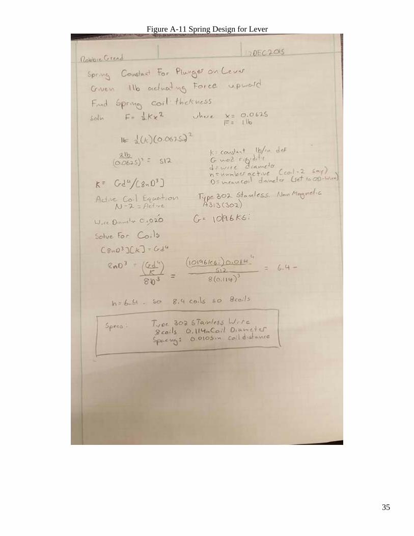
Lever Toggle Spring Design
Requirements: Not from Design Requirements, Resulting Design based Require 1lb of force to compress fully Non Magnetic (Placed laterally to Hall Effect Sensor)
Calculations: Appendix A-11 Design Parameter: Spring Design:
Material: Type 302 Stainless Extruded Wire 0.020in (Standard size, Reference Mott) Coils: 8 coils, 6 active Spacing 0.0105 in Coil Diameter: 0.114 in
Part removed from design.

12
Materials
Requirements: Exterior components must withstand 100lbs of Force Interior components must withstand 20lbs of Force Withstand temperature ranging from 0F to 150F
Other Requirements (Not from Design Requirements, resulting design based)
Non-magnetic Calculations: Appendix A-2, A-7, A-9, and A-10. Other material specifications included in other calculations included elsewhere. Design Parameters: Housing (exterior): 6061-T6 Aircraft aluminum Turret: 6061-T6 Aircraft Aluminum Baseplate (exterior): Nylon (low friction) Vane: 6061-T6 Aircraft Aluminum Housing (interior): 3D Printed ABS Baseplate (Interior): Nylon (low friction)
Adhesion Method (Interior and Exterior Assemblies)
Requirements: Adhesion method must resist 30lbf Must be non-invasive and require minimal surface prep
Calculations: Appendix A-6 It was found that at the fastening surface on the exterior where the most sustained force is experienced, the amount of sheer developed at the adhering surface would be 14.25lbs which is under the rated shear resistance of 3M VHB tape. The mount of force experienced due to allowable stresses on the exterior assembly was found to be 2.07psi. Design Parameter: The interior and exterior assemblies will be installed utilizing 3M VHB tape, 5 inch width trimmed to fit base of components. To compensate for irregular surfaces, varying thickness of tape (vertical distance) will be utilized based on airframe.
13
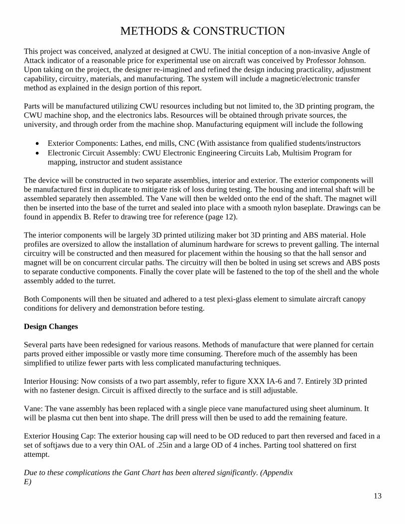
METHODS & CONSTRUCTION This project was conceived, analyzed at designed at CWU. The initial conception of a non-invasive Angle of Attack indicator of a reasonable price for experimental use on aircraft was conceived by Professor Johnson. Upon taking on the project, the designer re-imagined and refined the design inducing practicality, adjustment capability, circuitry, materials, and manufacturing. The system will include a magnetic/electronic transfer method as explained in the design portion of this report. Parts will be manufactured utilizing CWU resources including but not limited to, the 3D printing program, the CWU machine shop, and the electronics labs. Resources will be obtained through private sources, the university, and through order from the machine shop. Manufacturing equipment will include the following
Exterior Components: Lathes, end mills, CNC (With assistance from qualified students/instructors Electronic Circuit Assembly: CWU Electronic Engineering Circuits Lab, Multisim Program for
mapping, instructor and student assistance The device will be constructed in two separate assemblies, interior and exterior. The exterior components will be manufactured first in duplicate to mitigate risk of loss during testing. The housing and internal shaft will be assembled separately then assembled. The Vane will then be welded onto the end of the shaft. The magnet will then be inserted into the base of the turret and sealed into place with a smooth nylon baseplate. Drawings can be found in appendix B. Refer to drawing tree for reference (page 12). The interior components will be largely 3D printed utilizing maker bot 3D printing and ABS material. Hole profiles are oversized to allow the installation of aluminum hardware for screws to prevent galling. The internal circuitry will be constructed and then measured for placement within the housing so that the hall sensor and magnet will be on concurrent circular paths. The circuitry will then be bolted in using set screws and ABS posts to separate conductive components. Finally the cover plate will be fastened to the top of the shell and the whole assembly added to the turret. Both Components will then be situated and adhered to a test plexi-glass element to simulate aircraft canopy conditions for delivery and demonstration before testing. Design Changes Several parts have been redesigned for various reasons. Methods of manufacture that were planned for certain parts proved either impossible or vastly more time consuming. Therefore much of the assembly has been simplified to utilize fewer parts with less complicated manufacturing techniques. Interior Housing: Now consists of a two part assembly, refer to figure XXX IA-6 and 7. Entirely 3D printed with no fastener design. Circuit is affixed directly to the surface and is still adjustable. Vane: The vane assembly has been replaced with a single piece vane manufactured using sheet aluminum. It will be plasma cut then bent into shape. The drill press will then be used to add the remaining feature. Exterior Housing Cap: The exterior housing cap will need to be OD reduced to part then reversed and faced in a set of softjaws due to a very thin OAL of .25in and a large OD of 4 inches. Parting tool shattered on first attempt. Due to these complications the Gant Chart has been altered significantly. (Appendix E)

14
Manufacturing Issues Several Issues were encountered during manufacturing that had to be addressed. The initial Vane design was changed to be bent aluminum plate and originally was to be cut using the CWU plasma cutter. Heat issues and low tolerances as well as finish and warping concerns caused the part to be formed with plate sheers and the 90 degree bend tool. The part came out of tolerance by 0.10 or greater but this was deemed acceptable variance for the method. The hole locations were marked for placement on the exterior housing lid and then drilled as one part, clamping and placing on the drill press. Holes were then enlarged on the lid for clearance fits with the fasteners. Tapping was delicate because of the elasticity of the 6061-T6 aluminum. Though the tapping was designed to be a through hole tap, a tapered tap was used first to reduce torsion on the tap and then followed for cleanup with a bottom tool. The completed exterior assembly exhibited too much friction resistance on the vane and turret. The exterior turret and inside race of the exterior housing had to be sanded and polished until a free rotation was achieved. Improvements in this smooth friction could be achieved with modifying a store bought bearing perhaps. The circuit design, prototyping, and assembly was the most difficult part of this project. The only Hall Effect switches available for purchase in the correct high current capacity and sensitivity had a steady state closed effect, causing the opposite effect then what was desired (alarm constantly on, silenced with magnetic triggering of Hall device). The fix was found by splitting voltage to a 5V IC chip part number 47404 and inverting the output twice. This unfortunately drops the voltage input to the buzzer, decreasing the volume below design requirement specified range. There are plans in place to amplify the buzzer and or attempt to find a new Hall Effect Switch.

15
DRAWING TREE Figure 2 – Drawing Tree
DEVICE OPERATION
Assembly AOA
Interior Assembly IA Exterior Assembly EA
IA 2 - Housing
IA 1- Circuit
EA 1 – Vane Assembly
EA 2 - Turret
IA 3 – Housing
Knob
EA 3 - Baseplate
EA 4 – Turret
Housing Cap
EA 5 – Turret Lower
Housing
EA 6 – Exterior Gasket

16
The device will be attached via epoxy, exterior to the exterior of the aircraft and interior component to the interior of the aircraft, nylon baseplates to canopy surface. Proper surface preparation of a thorough cleaning and light surface abrasion via emery cloth. Care will be taken to select a proper location with a flat surface. See figure X
The device will be oriented such that the pilot can easily reach it while not obscuring vision. Epoxy must be allowed to set for 48 hours before flight. The device will be utilized during a test flight. The aircraft will assume station at a safe altitude with an established soft deck of 10,000 feet. Stall conditions will then be induced by the pilot and when stall is almost reach, the dial on the device should be adjusted such that the alarm is triggered. Return the aircraft to level flight then repeat stall conditions to test functionality. The device is then ready to be utilized.
Benchmark Comparison This device will provide indication of an approach to an unsafe angle of attack like the string gauge, but provide audio warning to impending stall conditions as well as a non-oscillating method. It will meet the capability of versatile attachment.
Performance Predictions This device will meet specified requirements and function attached to an actual aircraft traveling a speeds that range from 80-200mph. It will not fail in any structural way. It will impart drag force less then 30lbs to the aircraft by adding it to the exterior surface.
Figure 3: Suggested Installation location generalized for Cessna 172.

17
TESTING METHOD Test Plan: Procedures:
Exterior Housing: A force of 25lbs will be applied to the housing to simulate performance at 200mph. Strain gauges will be used to measure induced strain on 2 axis. This will be done on the compression tester. The test will be performed three times.
Vane: The torque required to turn the vane and turret will be measured in this benchmark test. A force of 4lbs will be applied to the vane cross section. A strain gauge will measure induced strain on 2 axis. A positive The test will be performed three times.
Attachment Method: This test will determine the force required to dislodge the device from a proper mounting surface. The housing will be attached to plexi-glass element via chosen adhesive. Force to dislodge must not fall under 30lbs. This will be tested by creating a wooden jig with a semi-circle socket. This jig will be placed above the device vertically. Weight will slowly be added until the unit is dislodged from the mounting surface. Test will be performed three times. Testing Form is included in the Appendix
Weight: This test will determine if the device is within the overall weight requirement. The device will be weighed to three degrees of precision (0.00X). This test will be performed three times.
Sound Intensity: Testing for sound level will test intensity and activation. The alarm will be triggered and the intensity measured to the nearest decibel. This will be done utilizing a meter application via Samsung. This testing will be done three times.

18
Operation Temperature: Exterior: Device will be chilled to 32 Fahrenheit and heated to 150 Fahrenheit via convection oven set for 160 Fahrenheit and tested for functionality on a Go/ No Go criteria. This test will be performed three times. One failure will fail the device. Interior: Device will be chilled to -10 Fahrenheit and heated to 150 Fahrenheit. Test for functionality on a Go/No Go criteria. This test will be performed three times. One failure will fail the device.
Concluding Steps: The device will be tested thoroughly through NDT methods for any flaws developed during testing. Replacement parts will be manufactured accordingly. It is recommended at this point to manufacture another exterior assembly to prevent time loss in flight testing.
Final Step: Test Flights Device will be mounted on Automobile according to mounting specifications for aircraft. Device will be attached to vehicle via the mount as well as a tether and cushioning to prevent damage should separation occur. Vehicle will obtain speeds of 80mph for periods of 30 Seconds three times to test for separation at low speed. This will be a go/ no go test. Device will be mounted to aircraft (single prop) to flattest window surface possible utilizing mounting procedure. Device will be then tested according to operation instructions at minimum speed, and maximum speed. Careful consideration will be given to proper operation at landing pattern velocities. This is a go no go test. If device is lost another will have to be constructed and a new mounting procedure developed. If the opportunity presents itself, attack to pusher style aircraft or glider. Deliverables:
Completed Testing Documentation Completed Testing Report Adhere to Testing Schedule No damage done to parts (tested by NDT) Flight Test is a Go.
19
BUDGET/SCHEDULE/PROJECT MANAGEMENT
The budget for this project is $400 which will be privately obtained. A parts list, costs, and other expenses can be found in detail in appendix C. Parts will be purchased from varying sources that will vary based on cost at time of purchase. The university will be an important source of raw material acquisition. The Gant chart for project progress can be found in Appendix E. Notable dates requiring deliverables are as follows:
December 9th: Completed project proposal January 3rd: Completed drawings with tolerances and manufacturing information February 7th: Manufacturing completed for exterior assembly March 7th: Manufacturing completed for interior assembly March 14th: Manufacturing completed AOA assembly April 1st: Testing concluded exterior components April 20th: Testing concluded interior components May 14th: Low speed ground testing concluded May 20th: Flight testing concluded June: Source Presentation; Power-point June: Source Fair, Presentation Board, Prototype display, Information Cards, Resumes June: Deliverables due to instructors
Human resources include instructor access (Professors Pringle, Johnson, Beardsley, Bramble, Hobbs, etc), lab technician resources (Matt Burvy), fellow student assistance, and primarily construction will be managed by the designer. CNC operations if approved will be guided by Bruce Bernard and Bradley Barringer Software utilized for design, manufacturing, and testing will be Solidworks (for design and manufacturing i.e. CAD CAM), FEA Software (to be determined), and MultiSim for circuit analysis. Project management will account for risk in broken parts during testing. Two exterior assemblies will need to be created in case of loss during flight testing. A secondary mounting method should be devised in the case of failure of initial flight testing. Interior components should be printed well ahead of schedule as they will require fitting. To maintain adherence to the schedule, progress reports will be written every week including issues run into, part and tool availability, and any updates to requirements.

20
DISCUSSION Based upon calculations, performance should meet or exceed all expectations laid out in the design requirements section. Actual installation may be varied as all airframes have difference windscreen contouring, but use of 3M tape of varying thicknesses should allow versatility in adhesion with the side effect of slightly increases exposed cross section wind on exterior components and decreasing gauss field. Many changes occurred during the design process, most notably the fluid condition of the housing based on circuit design. The circuit is still being optimized at this stage so the housing is being kept as a larger catch all design. This may change during optimization process. The most crucial design change came early in the project phase when complications were found with a direct magnet to magnet transfer of force and an open/closed circuit alarm system (Appendix A-1). The best solution to the complexity and reliability issues from this concept was found to be a Hall sensor device wired in the interior assembly. This reduced the need for precise alignment of the two sub-assemblies on an aircraft, reduced the contact reliability issue of having a rotating bearing holding contact with a surface, and assembly issues such as extremely high tolerances. The vane design had to be changed after calculations on the initial design indicated it would not meet the design requirements. The new vane design is a two part assembly that adds to the complexity of construction, but avoids initial plans to utilize aluminum welding methods, a skill the designer does not possess. The cross section of the exterior sub assembly had to be reduced significantly after calculations showed that though the structure would withstand the drag and airflow imparted forces, the adhesion method would be the critical failure point that should be designed for. This project was a living design that changed up until the submission of this document and tested the flexibility, imagination, and planning skills of the designer.

21
CONCLUSION The current design specified in this document and in the attached drawings (Appendix B) will be manufacturable within the budget and a finished device will be completed on schedule. The finished device will fit all stated requirements in the design requirement section. Initially this project seemed much more involved than what was possible for a single student considering the electronic components, aerospace applications, and various other aspects not covered in the MET curriculum. However utilizing the solid base in fluid, mechanical, material, and electronic studies that is covered, expanded applications of these subjects were reached and the calculations completed. manageable. Approximately 160 hours of research, design, calculations, drawings, and revising has been put over the past 10 week period. It is thoroughly researched, the plan in place for manufacture will ensure its production, and the designer is very capable at performing the necessary manufacturing processes. Construction was completed and testing showed that the device meets the original design specifications. It is the opinion of the designer that this should be viewed as a rough prototype and testbed for the design and that significant alterations should be made to streamline manufacturing, increase capabilities, and further refine the Icarus Angle of Attack Indicator.
ACKNOWLEDGEMENTS The input from my professors was extremely useful in all periods of the design process. Particularly of note is the assistance of Professor Johnson in concept development and brainstorming. Professor Beardsley was of great help in designing the exterior components as a reference on fluid dynamics applications. Professor Pringle provided hard hitting criticism that helped maintain progress towards the final form of all documentation, especially drawings and format. The help of fellow engineering students as a source of peer review and objective idea formation ensured that fresh ideas flowed into the design. Without these sources of input, this project would not have resulted in the level of practicality, manufacturing ease, and accuracy that it did. Electronic package design and manufacture was completed with the indispensable help of the EE department in particular Geena Wilkerson. Huge thanks is directed to all of those parties mentioned and those that are not directly included in this section.
22
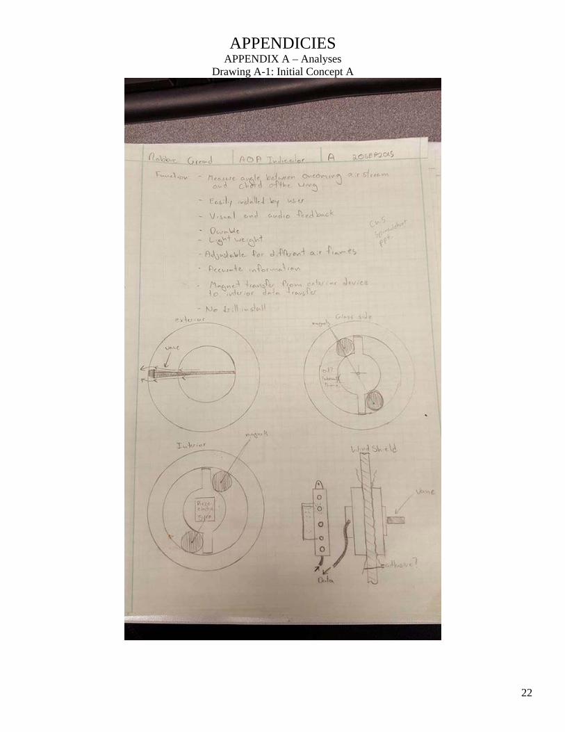
APPENDICIES APPENDIX A – Analyses
Drawing A-1: Initial Concept A

23
Drawing A-2: Initial Concept B

24
Figure A-1: Drag and Force on Vane

25
Drag on Vane (Continued)

26
Figure A-2 Stress on housing

27
Figure A-3 Total Drag Force on Assembly

28
Figure A-4 Required Surface Area for Drag

29
Figure A-5 Current Drag/ Current Surface Area

30
Figure A-6 Shear/ Peel Resistance 3M VHB

31
Figure A-7 Shear for Fasteners (Exterior)
32
Figure A-8 Gauss/Magnetics Hall Switch Part Selection
ADDITIONAL WORK REQUIRED. CALCULATE TRANSMISSION LOSS THROUGH SHEET ALUMINUM/FIBERCLASS

33
Figure A -9 Vane Bending (Critical Failure Discovered, Redesign calculations Included

34
Figure A-10 Interior Housing Stresses
35
Figure A-11 Spring Design for Lever

36
A-12
37
APPENDIX B – Drawings
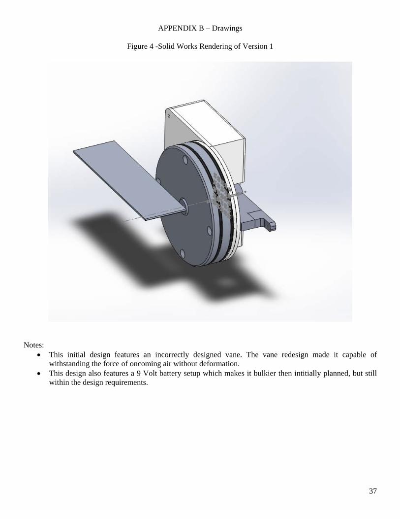
Figure 4 -Solid Works Rendering of Version 1
Notes: This initial design features an incorrectly designed vane. The vane redesign made it capable of
withstanding the force of oncoming air without deformation. This design also features a 9 Volt battery setup which makes it bulkier then intitially planned, but still
within the design requirements.

38
Render 2.0 Design

39
Figure 5 – Assembly 2.0
Notes: The second design features an appropriate vane. The center of mass of the vane assembly was also
shifted to the pivot point to lower the impact of intertia on accurate readings. This design still features the 9 volt 90Db buzzer housing. The plan is to reduce this power requirement,
and thus the bulk of the interior assembly.
40
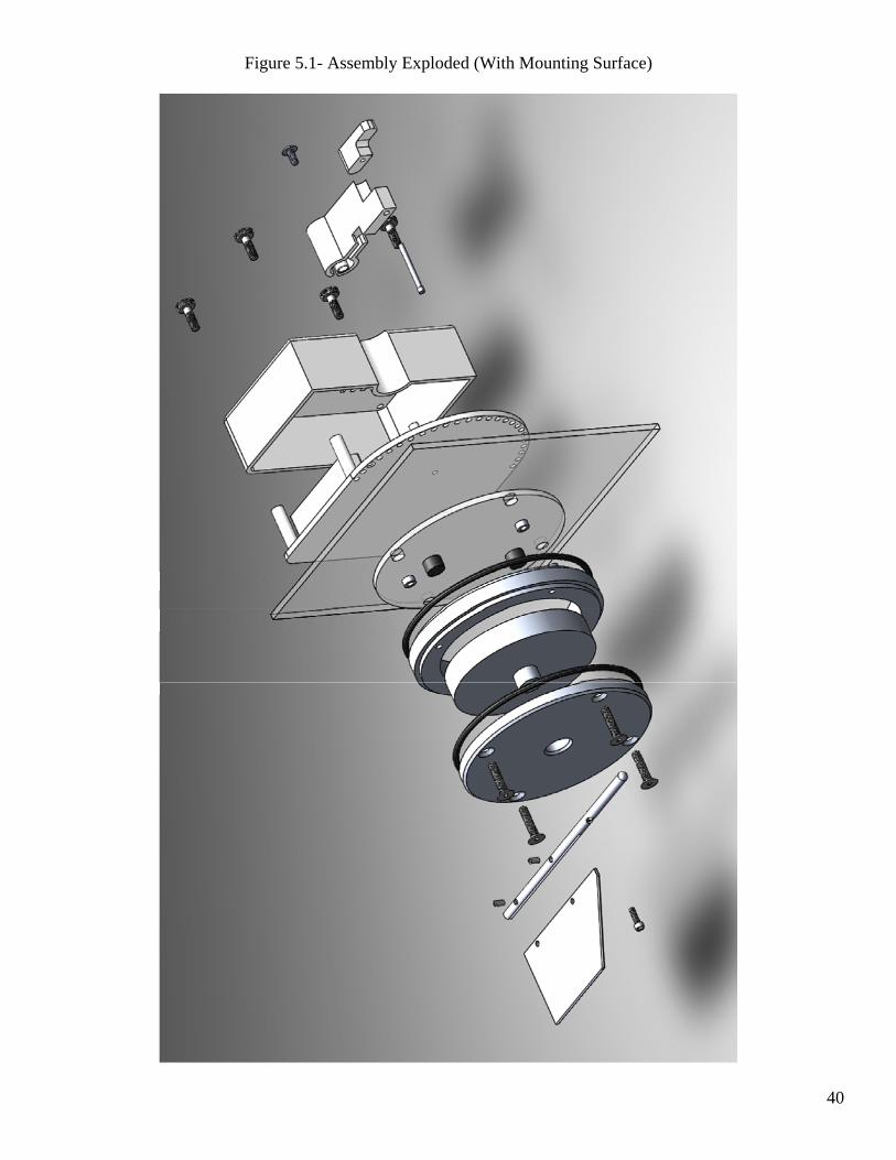
Figure 5.1- Assembly Exploded (With Mounting Surface)

41
Assembly 3.0 Rendering
Figure XXX – A -1 Assembly Drawing and Bill of Materials (MK1, Outdated)

42
Figure XXX –A-1.1 Exploded View Assembly
Figure 6 – EA -1 Exterior Assembly 1.0

43
Figure 7 – IA – 1 Interior Asssembly
Figure 8 – EA-4 Turret Lower housing

44
Figure 9 – EA-5 Exterior Cap
Figure 10 – EA – 3 Vane (Discarded Design)
45
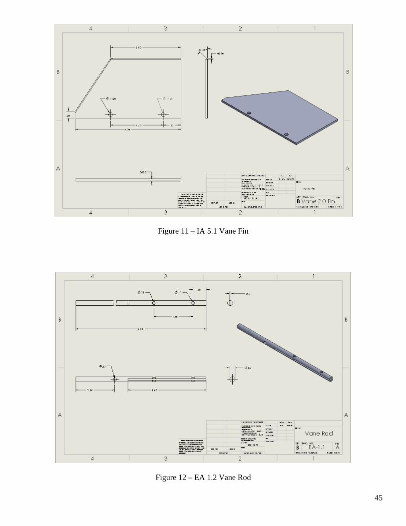
Figure 11 – IA 5.1 Vane Fin
Figure 12 – EA 1.2 Vane Rod

46
EA-9 One Piece Vane (Assembly 3.0)
Figure 13 – EA -2 Turret

47
Figure 14 – IA -1 Baseplate
Figure 15 – IA – 2 Housing

48
IA -6 Interior Housing Knob (3.0 Assembly)
Figure 16 – IA -3 Lever (Outdated, Replaced by IA-6)

49
Figure 17 – IA -4 Lever (Outdated replaced by IA-6)
IA-7 Inner Housing (Assembly 3.0)

50
Figure 18 – IA-5 Plunger (Outdated Replaced by IA-6)

51
APPENDIX C – Parts List and Costs
Part Ident Part Description Source Cost Disposition 6061-T6 Aluminum
6” stick, 4”Round CWU $150
Fasteners 4 x #7 Fine thread Cap Local Hardware $6.00 ABS (3D Print) 20 in3 CWU $134.99 Magnets 3/8” x .25” cylinder Mag-craft $16.00 Hall Device 55140-3H-02-A-ND Digi Key $3.00 Battery Pack 102-1456-6-ND Digi Key $2.00 Resistor TBD $0.50
Actual Cost Part Identity Part Description Source Cost Disposition 6061-T6 12” L, 4.25” D CWU 78.99 8” Utilized, 4”
Donated to CWU Fasteners #8-32 UNC Socket Amazon 10.99 40 left Fasteners #8-32 UNC Button Top Amazon 10.99 40 left Magnets 3/8” x .25” cylinder Mag-Craft 16.00 Hall Device 55140-3H-02-A-ND Digi Key 14.99 Battery Pack 102-1456-6-ND Digi Key 3.99 47404 IC IC Inverter CWU Free Resistors Resistors CWU Free Kydex Sheet Free VHB Tape Amazon 74.99
APPENDIX D – Budget
Parts and Materials: $312.59 Manufacturing:
Time in lab: 50 hours x $10 an hour (Theoretical cost of labor) = $500 Mistakes/ Extra Material $100 Redesign Decisions

52
Appendix E
Project: Non‐Invasive Angle of Attack Indicator
Designer: Robert Gread
Task Description Est Time (hrs) Act Time (hrs)
ID #
1 Proposal
1a Outline 4 3
1b Introduction 5 3
1c Methods 5 5
1d Analysis 10 20
1e Discussion 5 4
1f Parts and Budget 10 15
1g Drawings 25
1h Schedule 2
1i Summary & Appendicies 5
2 Analysis
2a Exterior Housing 1 1
2b Exterior Turret 1 1
2c Exterior Vane 1 0.5
2d Exterior Gasket 1 2
2e Exterior Baseplate 1 0.5
2f Friction (Exterior) 1 0.5
2g Interior Housing 1 2
2h Interior Housing (Lid) 1 1
2i Interior Lever 1 0.5
2j Interior Handle 1 2
2k Interior Electronics 1 5
2l Gauss Field 1 3
3 Drawings and Modeling
3a Drawing: Lower Housing 2 4
3b Drawing: Exterior Plate 2 0.5
3c Drawing: Vane 2 0.25
3d Drawing: Turret 2 0.5
3e Drawing: Interior Housing 2 2.5
3f Drawing: Interior Lid 2 1
3g Drawing: Lever 2
3h Drawing: Handle 2
3i Drawing: Interior Baseplate 2
3j Exterior Assembly 3
3k Interior Assembly 3
3l Full Assembly 3
4 Manufacturing & Assembly
4a Exterior Housing
Reduce OD
4b Ream
4c Groove
4d Exterior Housing Upper
4e Reduce OD
4f Chamfer
4g Drill Press
4h Turret
4i Reduce OD
4j Form Shoulder
Face
5 Vane
5a Cut Vane
5b Drill Press
5c Slot Vane Rod
5d Drill Press Vane Rod
5e Assemble
5f Interior Housing
5g 3D Print
5h Interior Lid
5i 3D Print
5j Tap
5k Lever
5l 3D Print
5m Mount
5n Handle
3D Print
6 Circuit
6a Assembly
6b Fit to Housing
6c Assembly
6d Fit
6e Assemble
March April May JuneSeptember October November December January February
53
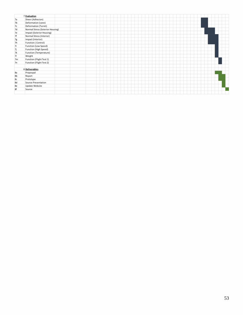
7 Evaluation
7a Sheer (Adhesion)
7b Deformation (vane)
7c Deformation (Turret)
7d Normal Stress (Exterior Housing)
7e Impact (Exterior Housing)
7f Normal Stress (Interior)
7g Impact (Interior)
7h Function ( Control)
7i Function (Low Speed)
7j Function (High Speed)
7k Function (Temperature)
7l Weight
7m Function (Flight Test 1)
7n Function (Flight Test 2)
8 Deliverables
8a Propospal
8b Report
8c Prototype
8d Source Presentation
8e Update Website
8f Source

54
APPENDIX F – Expertise and Resources Write:
Electronics: EE Student Geena Wilkerson, Instructor Hobbs, assistance with formatting circuit diagram and obtaining part numbers. Aviation Resource and Reference: Professor Johnson Fluid dynamics Airflow consulting: Professor Beardsley
55
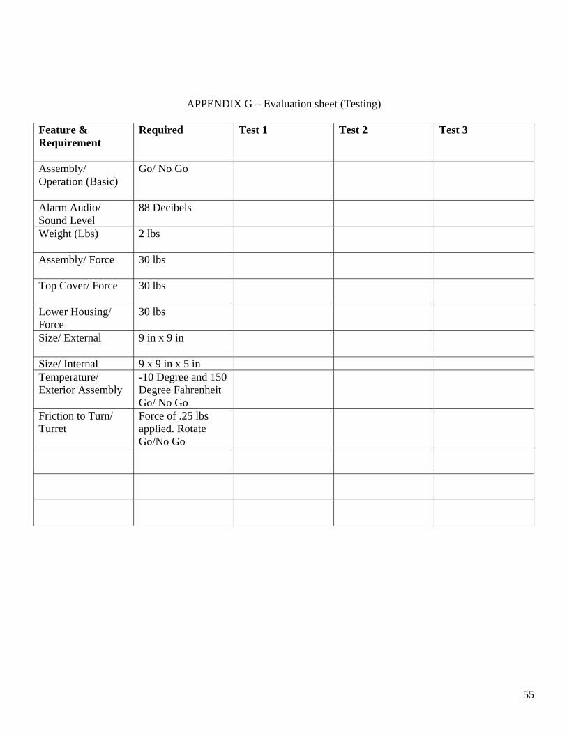
APPENDIX G – Evaluation sheet (Testing)
Feature & Requirement
Required Test 1 Test 2 Test 3
Assembly/ Operation (Basic)
Go/ No Go
Alarm Audio/ Sound Level
88 Decibels
Weight (Lbs)
2 lbs
Assembly/ Force
30 lbs
Top Cover/ Force
30 lbs
Lower Housing/ Force
30 lbs
Size/ External
9 in x 9 in
Size/ Internal 9 x 9 in x 5 in Temperature/ Exterior Assembly
-10 Degree and 150 Degree Fahrenheit Go/ No Go
Friction to Turn/ Turret
Force of .25 lbs applied. Rotate Go/No Go

56
APPENDIX H – Testing Report
Testing Report
Robbie Gread 4MAY2016

57
Magnetic Field Transmissivity Testing Plan Introduction Testing Requirement: Device must operate through 0.25 inches of plexiglass Notes: This requirement must include any other material in between the magnet and sensor therefore the operating distance must be 0.25 inches + Thickness of components. In this case approximately 0.675 inches. Parameter of Interest: Sensitivity of the combination of the Hall Effect Device and Magnetic base. This experiment will determine if the transmissivity requirement of the magnetic base to the Hall Effect Sensor. The calculated distance that the magnetic field emanating from the utilized magnetic component 0.74 inches through air to trigger the chosen Hall Effect Sensor. The device will be tested through materials that are frequently used aboard aircraft and that the prototype may be adhered to beyond plexiglass. Predicted Performance: 0.71 inches per the spec sheet of Hall Sensor Device. Data acquisition: Distance between the magnet and the sensor will be measured at activation of the attached buzzer. Data will then be recorded in hard copy on the attached testing sheet. Schedule: According to Gant, Testing was started and completed on schedule in April. Method/Approach Resources:
Completed Circuit (IA-5) (1) 3/8in Neodymium Magnet (1) Magnet Fixture (1) Steel Rule (1) Hall sensor Fixture (1) Operator (1) Data Recording Sheet 0.25 in Plexiglass Tab 0.25 in Aluminum Tab 0.25 In Fiberglass Tab
Data Capture: Results of this test will be recorded on the attached data sheet. Final Results will be recorded electronically on the testing report.

58
Procedure Overview: Hall device will be placed in fixture at the 0 of the ruler. A Tab of the specified material will be placed in front of the hall device. The magnet will be placed in the tab at the other end of the ruler and advanced towards the 0 and waiting sensor until the buzzer triggers. The resulting distance will be measured and recorded. 3 tests for each material. Accuracy and Precision: Accuracy will be limited to readability on the ruler i.e 1/32nd of an inch. Precision should be maintainable to 1/32nd of an inch as well as magnetic fields do not vary. Test Procedure
1) Place ruler on flat surface with hall device fixture at the 0 end and the test material tab placed flush to the device (0.25in thickness)
2) Place Magnet in Magnet Fixture and place fixture at least 1 inch from 0 on the ruler. Ensure correct pole for device engagement is facing 0.
3) Slide Magnet fixture towards Hall Device along the ruler. 4) Record distance at which buzzer on the complete circuit engages. Repeat 3 times for Plexiglass,
Aluminum, Acrylic Safety Glass, and Polycarbonate. 5) Record Averages 6) CRITICAL STEP: If any average falls below 0.675 engagement range, that material is not to be used as
a mounting surface for the prototype on flight test.
There is little risk involved in this experiment. Ensure slow movement to obtain accurate measurements. Below is the Raw Data obtained from this test as well as averages and conclusions Material Test 1 Test 2 Test 3 Average
Plexiglass 0.625in 0.625in 0.656in 0.635in
Aluminum 0.593in 0.596in 0.598in 0.596in
Acrylic Safety Glass
0.562in 0.593in 0.562in 0.572in
Polycarbonate .625in 0.593in .656in 0.624in
Air (Control) 0.6875in 0.6875in 0.6875in 0.6875in
Conclusions: Based on this initial testing, the components do not meet requirements. However below are ammendments to testing that change the results significantly. Due to a 3.5% underperformance in the chosen component compared to the spec sheet, all materials fail to meet the required 0.675in.

59
Amendments for Installation Procedure: a) Utilize a plastic or nonferrous material ruler for distance measurement.
With this change, redo the test as prescribed in previous sections: Results of Amended Test: Material Test 1 Test 2 Test 3 Average
Plexiglass 0.7125 0.7125 0.700 0.708
Aluminum 0.700 0.700 0.700 0.700
Acrylic Safety Glass
0.700 0.7125 0.700 0.705
Polycarbonate 0.7250 0.7125 .7250 0.720
Air (Control) 0.7250 0.7125 0.7125 0. 717
Conclusion: Upon retesting with the changes mentioned, it was found the components are performing to specifications and will be acceptably mounted on most surfaces besides Aluminum and Acrylic (at or over 0.25 inches in thickness). The results of the test are a success as the design requirement only specifies Plexiglass as a mounting surface.

60
Sheer Adhesion Requirements: The requirements for adhesive sheer say that the device must resist a 50lbf force parallel to the mounting surface without separating. Parameter of Interest: Adhesive Sheer. Predicted Performance: Based on the selected adhesive (3M VHB Tape 4in W) the sheer resistance of a 4 inch round surface should be 55.264 lb. The applied force to the housing is only 29lbf per calculations so this 50lbf resistance will exceed required function by a factor of safety of 3.5. Data Acquisition: Data will be recorded on the Instron machine and transferred to this report. Materials
4 Inch OD aluminum Round atleast 1inch thick. Sheet Metal (thickness to avoid bending moment of off center tensions 2.08mm Wire (PLC Class Wire) Instron Machine 3M VHB Tape (4 in wide)
Data Capture: Data displayed on the Instron Computer will be utilized as the recorded data. Application of force in tension is the number to be recorded. Operational Limitations: Do not exceed adhesive failure to prevent damage to instruments. A factor of safety of 3 is the max the part will be tested to. Precision And Accuracy: Limited to denominations of 0.25lbs. Procedure:
1) Adhere (1) 4 inch round to (1) sheet of stock metal utilizing VHB. Choose thickness of sheet metal that will resist bending. Ensure entire 4 inch round is mounted at the base.
2) Place Assembled testing part into bottom vice on Instron machine. 3) Place 2.08mm 600A wire around the 4 inch round and fasten into top vice to form a noose like fit. 4) Tension Instron for wire to be semi taut then calibrate 5) Run standard tension test to ensure round does not separate under a factor of safety of 3 of stated
adhesive sheer strength (55.264lbf according to Spec Sheet). Run to Factor of safety of about 2.5 at most (150lbf). Factor of Safety of 3 can be attempted but watch closely to preven sudden separation that may damage the machine.
6) Record Data runs actual testing force and pass or fail.
Risk/Safety: Do not exceed adhesive failure as part may separate suddenly.
61
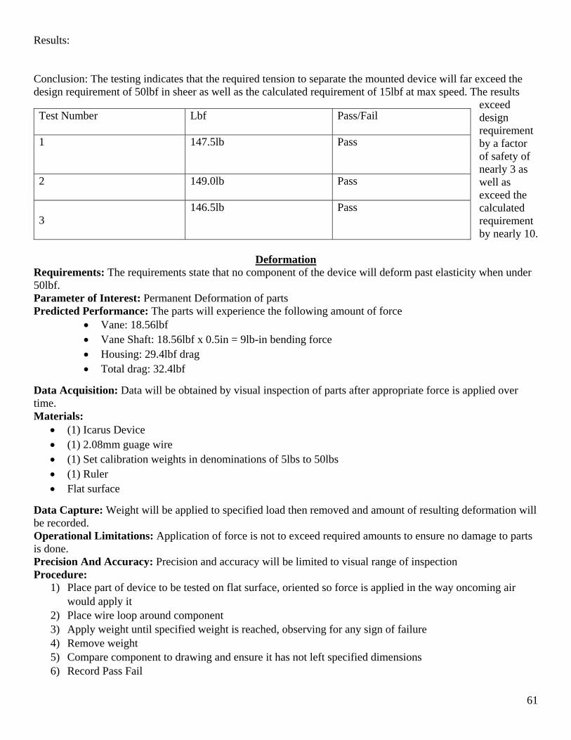
Results: Conclusion: The testing indicates that the required tension to separate the mounted device will far exceed the design requirement of 50lbf in sheer as well as the calculated requirement of 15lbf at max speed. The results
exceed design requirement by a factor of safety of nearly 3 as well as exceed the calculated requirement by nearly 10.
Deformation
Requirements: The requirements state that no component of the device will deform past elasticity when under 50lbf. Parameter of Interest: Permanent Deformation of parts Predicted Performance: The parts will experience the following amount of force
Vane: 18.56lbf Vane Shaft: 18.56lbf x 0.5in = 9lb-in bending force Housing: 29.4lbf drag Total drag: 32.4lbf
Data Acquisition: Data will be obtained by visual inspection of parts after appropriate force is applied over time. Materials:
(1) Icarus Device (1) 2.08mm guage wire (1) Set calibration weights in denominations of 5lbs to 50lbs (1) Ruler Flat surface
Data Capture: Weight will be applied to specified load then removed and amount of resulting deformation will be recorded. Operational Limitations: Application of force is not to exceed required amounts to ensure no damage to parts is done. Precision And Accuracy: Precision and accuracy will be limited to visual range of inspection Procedure:
1) Place part of device to be tested on flat surface, oriented so force is applied in the way oncoming air would apply it
2) Place wire loop around component 3) Apply weight until specified weight is reached, observing for any sign of failure 4) Remove weight 5) Compare component to drawing and ensure it has not left specified dimensions 6) Record Pass Fail
Test Number Lbf
Pass/Fail
1
147.5lb Pass
2
149.0lb Pass
3
146.5lb Pass

62
Risk/Safety: If any part fails, be cautious of sharp edges, falling weights, and snapping wire. Results Part Pass/Fail (If Fail, Deformation Number) Vane Pass Vane Shaft Pass Housing Pass
Conclusion: This device does not experience any permanent deformation at calculated ranges. It also does not experience any deformation with weights exceeding specified force by 25%. This test passes the device on this design requirement. Other Testing: Weight: The device will be measured and should not exceed 2lbs. Failure. The device weighs 2lbs and 4oz. This is presumably due to a last minute redesign of the vane which added mass. Size: The device should not exceed a 9” by 9” by 9” dimension: Pass. Device is within required dimensions. Low Speed Testing: Device does not separate from vehicle traveling at ground speed 80mph and is intelligible over vehicle noise
High Speed Testing: Has not been accomplished due to lack of aircraft. Confer with Doctor Johnson to obtain aircraft for testing before SOURCE presentation if poss

63
APPENDIX I – Testing Data
Magnetic Field Transmissivity .
Material Test 1 Test 2 Test 3 Average
Plexiglass 0.625in 0.625in 0.656in 0.635in
Aluminum 0.593in 0.596in 0.598in 0.596in
Acrylic Safety Glass
0.562in 0.593in 0.562in 0.572in
Polycarbonate .625in 0.593in .656in 0.624in
Air (Control) 0.6875in 0.6875in 0.6875in 0.6875in
Magnetic Field Transmissivity II
Material Test 1 Test 2 Test 3 Average
Plexiglass 0.7125 0.7125 0.700 0.708
Aluminum 0.700 0.700 0.700 0.700
Acrylic Safety Glass
0.700 0.7125 0.700 0.705
Polycarbonate 0.7250 0.7125 .7250 0.720
Air (Control) 0.7250 0.7125 0.7125 0. 717

64
Adhesive Sheer Resistance
Deformation of Components
Part Pass/Fail (If Fail, Deformation Number) Vane Pass Vane Shaft Pass Housing Pass
Test Number Lbf
Pass/Fail
1
147.5lb Pass
2
149.0lb Pass
3
146.5lb Pass

65
APPENDIX J – Resume
Robert A. Gread [email protected] | 300 E Helena Ave. Apt 93 Ellensburg, WA 98926 | (714)-519-1996 |
OBJECTIVE: To obtain employment in a fast paced, creative, engineering work environment that challenges my problem solving abilities and increasingly expands my capabilities as an Engineer. EDUCATION: Central Washington University Ellensburg, WA Bachelor of Science in Mechanical Engineering Technology Anticipated date of graduation: June 2016 Relevant Coursework and Hands-on Skills: Mechanics, Structural Analysis, Fluid Dynamics, Heat Transfer, Energy Systems, AutoCad, SolidWorks, Material Science, Finite Element Analysis, Plastics and Composites, Project Cost Analysis, Casting, Machining, Rapid Prototyping. GPA: 3.630 University of Washington Seattle, WA Bachelor of Science in Environmental Science and Resource Management 2009-2013 Minor: Naval Science
United States Navy Pensacola, FL Division Officer Leadership Course October 2013 EXPERIENCE: United States Navy Active 2013-2014, Reserve 2014-present Lieutenant Junior Grade Maintained a Secret Level Security Clearance eligibility indicating trust and responsibility Provided strong intrapersonal skills when coordinating with several internal organizations to ensure proper student
flow including Naval Aviation Medicine, Medical Records storage, Introductory Flight Screening, and Naval Station Corry Division officer leadership courses instructors
Demonstrated work ethic by obtaining a degree while simultaneously receiving Naval training with active participation in sailing, marksmanship, and community service clubs
Lead Ensign (Section Supervisor) Pensacola, FL Naval Aviation Schools Command 2013-2014 Demonstrated organizational skills when assigned to instructing, supervising, and managing over 700 students Ensured cohesion of processing team for NASC Pensacola A-Pool, managing up to seven personnel at peak. Guided A-pool students safely through National Emergency scale flooding and response in 2014.
Boy Scouts of America Fullerton, CA Eagle Scout Award Recipient May 2007 Developed leadership skills early by executing a service project at a local church while managing over 15 volunteers.
CERTIFICATIONS AND SKILLS: 3D Modeling and Assemblies: Solid Works Associate February 2015 Finite Element Analysis: Autodesk Simulation Mechanical 2016 Solo top down design work
o Designed an avionics device capable of being non-invasively mounted to aircraft while transmitting exterior conditions data to inside the cockpit. Plans and prototype will be submitted to the FAA for certification and approval. For documentation and other portfolio projects, please visit http://robbiegread.wix.com/greadavionics
Team Engineering

66
o Collaborated with several peers to design gear trains, shafts, robotics, and PLC simulations, and other engineering-oriented tasks.