Embed Size (px)
Citation preview
ICC-ES Evaluation Reports are not to be construed as representing aesthetics or any other attributes not specifically addressed, nor are they to be construed as an endorsement of the subject of the report or a recommendation for its use. There is no warranty by ICC Evaluation Service, LLC, express or implied, as to any finding or other matter in this report, or as to any product covered by the report.
Copyright © 2014 Page 1 of 35 1000
ICC-ES Legacy Report NER-405* Reissued April 2004
www.icc-es.org | (800) 423-6587 | (562) 699-0543 A Subsidiary of the International Code Council ®
DIVISION 06 — WOOD AND PLASTICS Section 06160 — Sheathing DIVISION 07 — THERMAL AND MOISTURE
PROTECTION Section 07450 — Fiber-Reinforced Cementitious Panels Section 07460 — Siding JAMES HARDIE BUILDING PRODUCTS, INC. 10901 ELM AVENUE FONTANA, CALIFORNIA 92337 (909) 356-6366 www.jameshardie.com 1.0 SUBJECT
1.1 SIDING AND SOFFIT BOARDS
1.1.1 Hardiplank ® lapsiding 1.1.2 Hardiflex™ panel 1.1.3 Hardipanel ® siding 1.1.4 Harditex ® baseboard 1.1.5 Hardisoffit ® panel 1.1.6 Hardishingle™ cladding 1.1.7 Hardishingle™ panel 1.1.8 Hardipanel ® Shiplap
1.2 LINING BOARD AND UNDERLAYMENT
1.2.1 Titan ® panel 1.2.2 Hardibacker ® backerboard 1.2.3 Hardibacker ® underlayment 1.2.4 Titan ®-FR panel 1.2.5 Hardibacker 500 ® backerboard
1.3 SUBFLOOR PANELS
1.3.1 Compressed Sheet™
2.0 PROPERTY FOR WHICH EVALUATION IS SOUGHT
2.1 Exterior Wall Covering 2.2 Structural Performance 2.3 Noncombustible Construction 2.4 Fire-resistive Construction 2.5 Thermal Resistance
3.0 DESCRIPTION
3.1 GENERAL
The exterior siding and soffit boards, interior lining and underlayment, and subfloor panels are single-faced, cellulose fiber-reinforced cement (fiber-cement) building boards. The Titan ®-FR panel is a composite panel composed of a 1/8-inch-thick (3.2 mm) fiber-cement skin laminated to 1/2-inch-thick (12.7 mm) proprietary Type X gypsum board.
All fiber-cement planks and panels are produced from the same components and differ in surface treatments and board configurations. Exterior siding and soffit boards are identified as Hardiplank® (Hardihome™, Sentry™, Colonial Smooth®, Colonial Roughsawn®, Cemplank® and Hardishingle™), Hardiflex™, Hardipanel®, Cempanel®, Harditex® baseboard, Hardisoffit ®, Cemsoffit® boards, Hardishingle™ panel and Hardishingle™ cladding shingles. Interior backerboards and underlayments are identified as Titan®, Hardibacker® (backerboard), Hardibacker® (underlayment), Ultraboard® and Titan®-FR panel. Subfloor panels are identified as Compressed Sheet. The planks, panels, and shingles are manufactured by the Hatschek process and cured by high-pressure steam autoclaving. All products are cut to shape on-site by the score-and-snap method using a tool available from the manufacturer, a hand guillotine or a handsaw utilizing a carbide blade.
The fiber-cement products have a flame-spread index of 0 and a smoke developed index of 5 when tested in accordance with ASTM E84. The products are classified as noncombustible when tested in accordance with ASTM E136. The siding and soffit products comply with ASTM C1186, Standard Specification for Grade II, Type A, Non-Asbestos Fiber-Cement Flat Sheets. The subfloor panels comply with ASTM C1186, Standard Specification for Grade IV, Type A, Non-Asbestos Fiber-Cement Flat Sheets. The interior lining products, Hardibacker® and Titan®, comply with ASTM C1288, Standard Specification for Grade II Discrete Non-Asbestos Fiber-Cement Interior Substrate Sheets. The interior lining product Hardibacker 500® complies with ASTM C1288, Standard Specification for Grade I Discrete Non-Asbestos Fiber-Cement Interior
Legacy report on the 2000 International Building Code®, the BOCA® National Building Code/1999, the 1999 Standard Building Code©, the 1997 Uniform Building Code™, the 2000 International Residential Code®, the 2002 Accumulative Supplement to the International Codes™ and the 1998 International One and Two Family Dwelling Code©
*Revised May 2014
LEGACY
REPO
RT
NER-405 | Most Widely Accepted and Trusted Page 2 of 35
Substrate Sheets. All interior lining boards comply with ANSI A118.9 as cementitious backer units. When tested in accordance with ASTM C177, “K” and “R” values for the products are as shown in Table 4 of this report. When tested in accordance with ASTM E96, products with a thickness of 1/4-inch (6.4 mm) or greater have demonstrated the permeance values given in Table 5 of this report.
3.1.1 James Hardie Trade Names
Hardiplank® Hardihome™
Cemplank® Hardipanel®
Sentry™ Cempanel®
Colonial Smooth® Hardiflex™
Colonial Woodgrain® Harditex®
Hardisoffit® Hardie®
Cemsoffit® James Hardie®
Hardibacker® Titan®-FR
Ultraboard® Max “C”™
Titan® Hardibacker 500®
Hardirock®
3.2 SIDING AND SOFFIT BOARDS
Hardiplank®, Hardiflex™, Hardipanel®, Harditex® baseboard, Hardishingle™ planks and panels, Hardisingle™ cladding shingles, and Hardisoffit® boards are used as siding on exterior walls and soffits. The exterior siding and soffit products may be supplied unprimed or primed for subsequent application of a compatible primer and/or exterior-grade topcoat(s).
Nominal dimensions are noted in Table 1 of this report, maximum basic wind speeds in Tables 2a, 2b, 6, 7, 8, and 9 of this report, and maximum shear values in Table 3 of this report.
3.2.1 Hardiplank® (Hardihome™, Sentry™, Colonial Smooth®, Colonial Roughsawn®, Hardishingle™ and Cemplank®) Lap Siding
3.2.1.1 General: Lap siding is available in various finish textures. The siding is applied horizontally commencing from the bottom course of a wall with minimum 11/4-inch-wide (32 mm) laps at the top edge. Vertical joints butt over studs except where the “off-stud splice device” is utilized as described in Section 3.2.1.2 of this report, or where the planks are installed over solid panel sheathing.
When installed on wood-framing members, the siding shall be fastened either through the overlapping planks (face nailed) or through the top edge of single planks (blind nailed) with corrosion-resistant nails into each wood-framing member. The lap conceals the fasteners in the previous course when blind nailed. When attached to metal framing members, the siding is fastened either through the overlapping planks with 15/8-inch-long (41 mm) No. 8 by 0.323-inch (8.2 mm) HD, self-drilling, corrosion-resistant, ribbed buglehead screws or with 0.100 in. (2.54 mm) shank by 0.25-in. (6.4 mm) HD by 11/2-in.-long (38 mm) ET & F brand pin fasteners at each metal framing member, or through the top edge of single planks with minimum 11/4—inch-long (32 mm) No. 8 by 0.375-inch (9.5 mm) HD, self-drilling, corrosion-resistant, ribbed waferhead screws or with 0.100 in. (2.54 mm) shank by 0.313 in. (7.5 mm) HD by 1½ in.-long (38 mm) ET & F Panelfast® brand fasteners at each metal framing member. Planks may also be fastened to a wall constructed of concrete masonry units complying with ASTM C90 with 0.14 in. (3.5 mm)
shank by 0.300 in. (7.6 mm) HD by 1 1/4 in.-long (32 mm) ET & F brand Stud Nails. The lap conceals the fasteners in the previous course.
Off-Stud Splice Device: Vertical joints of the planks shall butt over framing members or between the framing members when an “off-stud splice device” is placed on each plank end. The splice device's bottom lip is placed over the adjacent solid course of planks. The plank is then fastened to the framing. The abutting plank is positioned and fastened into place ensuring that the lower edges of the two planks align. The metal device is located centrally over the joint. Restrictions on the “off-stud splice device” locations are as follows:
Splices shall be located a minimum of two stud cavities from wall corners.
Successive splices within the same plank course shall be located no closer than 48 inches (1219 mm) from one another.
Splices shall be staggered at minimum 24-inch (610 mm) intervals when located in the same wall cavity.
Splices shall be at least one stud cavity away from door or window openings.
Where a specified level of wind resistance is required, plank lap siding shall be attached to solid panel sheathing or framing members, appropriately spaced, with fastener types, lengths, and spacing described in Tables 2b and 9 of this report.
3.2.2 Hardiflex™ Siding (Hardipanel® Smooth)
Hardiflex™ siding is used as an exterior wall cladding. The siding has a smooth unsanded surface. Dimensions are as noted in Table 1 of this report. Fasteners are installed with a minimum 3/8-inch (9.5 mm) edge distance and a minimum 2- inch (51 mm) clearance from corners. Joints are fastened at abutting sheet edges and optionally protected by polyvinyl chloride (PVC) joint treatment, lumber battens or sealant.
Where a specified level of wind resistance or shear resistance is required, the Hardiflex™ panel is attached to framing members, appropriately spaced, with fastener types, lengths, and spacing described in Table 2a and Table 3 of this report.
3.2.3 Hardipanel® Siding (Cemplank® Siding)
Hardipanel® siding is available in various surface textures including smooth. Dimensions are noted in Table 1 of this report. Fasteners are installed with a minimum 3/8-inch (9.5 mm) edge distance and a minimum 2-inch (51 mm) clearance from corners. Joints are fastened at abutting sheet edges and optionally covered by polyvinyl chloride (PVC) joint treatment, lumber battens or sealant.
Where a specified level of wind resistance or shear resistance is required, the Hardipanel® siding is attached to framing members, appropriately spaced, with fastener types, lengths, and spacing described in Tables 2a and 3 of this report.
3.2.4 Harditex® Baseboard
Harditex® baseboard is for exterior applications to walls and soffits. Dimensions are noted in Table 1 of this report. Harditex® baseboard has a smooth finish and is available with either tapered or trough edges on the two long sides for joint treatment or all square edges. Harditex® baseboard is supplied either sealed or unsealed for the subsequent application of a primer or sealer by the end user as a component in a direct-applied exterior coating or finish system. Joints shall be sealed with a sealant or bedding compound, including any required joint reinforcing
LEGACY
REPO
RT

NER-405 | Most Widely Accepted and Trusted Page 3 of 35
mesh or tape, specified by the coating manufacturer. Other installation details are in accordance with Section 3.2.2 of this report. Harditex® baseboard has been evaluated for water-resistive qualities but its use as an alternative to a weather-resistive barrier is outside the scope of this report, see Section 7.4 of this report.
Where a specified level of wind resistance or shear resistance is required, the Harditex® baseboard is attached to framing members, appropriately spaced, with fastener types, lengths, and spacing described in Table 2a or 3 of this report.
3.2.5 Hardisoffit® Board (Cemsoffit® Board)
Hardisoffit® board is for use as exterior vented or unvented soffits. Hardisoffit® board is available with either a wood-grain texture or a smooth unsanded surface. Vented Hardisoffit® provides 5 square inches of net free ventilation per lineal foot of soffit. Dimensions are noted in Table 1 of this report. All Hardisoffit® board edges are supported by framing with fasteners installed with a minimum 3/8-inch (9.5 mm) edge distance and minimum 2-inch (51 mm) clearance from corners. Hardisoffit® boards are attached to framing members with fastener types, lengths, and spacings described in Tables 2a and 3 of this report.
3.2.6 Hardishingle™ Cladding (individual shingles)
Hardishingle™ cladding shall be installed over solid wall sheathing which complies with the applicable code. Dimensions are as noted in Table 1 of this report. The wall sheathing shall be protected by a weather-resistive barrier which complies with the applicable code.
When Hardishingle™ cladding is installed over minimum 15/32-inch-thick (11.9 mm) plywood complying with the applicable code, with two corrosion-resistant roofing nails [0.121-inch (3.1 mm) shank diameter by 0.371-inch (9.4 mm) head diameter by 11/4-inch-long (32 mm)] spaced a maximum of 1 inch (25.4 mm) from each edge and the nails positioned to be covered 1 inch nominally by the succeeding course, the maximum allowable wind loads, building heights, and exposure categories for the systems installed with 8-, 7-, and 6-inch (203, 178, and 152 mm) weather exposures, shall be as indicated in Tables 6A, 6B, and 6C of this report. Nails shall secure siding but shall not be overdriven.
When Hardishingle™ cladding is installed over minimum 7/16-inch-thick (11.1 mm) Oriented Strand Board (OSB), complying with the applicable code, with two corrosion-resistant siding nails [0.091-inch (2.3 mm) shank diameter x 0.221-inch (5.5 mm) head diameter by 11/2-inch-long (38 mm)] spaced a maximum of 1 inch (25.4 mm) from each edge and the nails positioned to be covered 1 inch nominally by the succeeding course, the maximum allowable wind loads, building heights, and exposure categories for the systems installed with 8-, 7-, and 6-inch (203, 178, and 152 mm) weather exposures, shall be as indicated in Tables 7A, 7B, and 7C of this report. Nails shall secure siding but shall not be overdriven.
When Hardishingle™cladding is installed over minimum 7/16-inch-thick (11.1 mm) Oriented Strand Board (OSB), complying with the applicable code, with three corrosion-resistant siding nails [0.091-inch (2.3 mm) shank diameter x 0.221-inch (5.5 mm) head diameter by 11/2-inch-long (38 mm)] for 12-inch-wide (305 mm) shingles and two corrosion-resistant siding nails for 6- and 8-inch-wide (152 mm and 203 mm) shingles, the maximum allowable wind loads, building heights, and exposure categories for the systems installed with 8-, 7-, and 6-inch (203, 178, and 152 mm) weather exposures, shall be as indicated in Tables 8A, 8B, and 8C of this report. One siding nail shall be spaced a maximum of 1 inch (25.4 mm) from each edge on the panel, with the third siding nail installed midspan of
the 12-inch (305 mm) wide shingles. All nails shall be covered 1 inch nominally by the succeeding course. Nails shall secure siding but shall not be overdriven.
3.2.7 Hardishingle™ Panels
Hardishingle™ panels have a woodgrain texture and are available in three configurations: half-round©, staggered-edge©, and square-edge©. Dimensions are as noted in Table 1 of this report. The siding is applied horizontally to braced wall framing complying with the applicable code commencing from the bottom course of a wall. Install Hardishingle™ panels with joints in moderate contact. Due to the overlapping of the panels, joint sealant is not required. Fasteners are a minimum 0.083-inch (2.1 mm) shank x 0.187-inch (4.7 mm) HD by 11/2-inch-long (33 mm) corrosion-resistant siding nail. For application to open braced framing, vertical joints butt over studs.
Where a specified level of wind resistance is required, Hardishingle™ panel sidings are attached to framing members appropriately spaced or to solid wall sheathing, with fastener types, lengths, and spacing described in Table 2 of this report.
Secure a 1/4-inch-thick (6.4 mm) lath strip and a minimum 91/4-inch-wide (235 mm) Hardiplank® lap siding starter course. Trim the first panel so the end aligns with the furthest stud. Allow trimmed panel 1/8 inch (3.2 mm) from the trim board for caulk and secure above keyways [approximately 8 inches (203 mm) clearance from butt edge of panel] on 16- inch (406 mm) or 24-inch (310 mm) centers [133/4-inch (349 mm) centers maximum for application only to minimum 7/16- inch-thick (11.1 mm) APA rated Oriented Strand Board sheathing]. Work across the wall allowing 1/8-inch (3.2 mm) gap from trim.
Start the second course, and every following even number course (i.e. fourth, sixth) by moving the equivalent of one full stud cavity from the straight edge end (the left side). Save this piece for the other end of the wall. Secure the beginning panel leaving 1/8-inch (3.2 mm) clearance from the trim board for caulking. Position nails to penetrate through the previous course and into the framing members or Oriented Strand Board.
When a course is broken by a window or doorway, continue the application as if the wall was complete. Trimming for the opening and using the resulting piece may throw off the spacing above the break.
3.2.8 Hardipanel® Shiplap Panel Siding
Hardipanel® Shiplap panel siding is used as an exterior wall cladding. The siding is available in various surface textures including smooth. Dimensions are noted in Table 1 of this report. Fasteners are installed with a minimum 3/8-inch (9.5 mm) edge distance and a minimum 2-inch (51 mm) clearance from corners.
Where a specified level of wind resistance or shear resistance is required, the Shiplap panel siding is attached to framing members, appropriately spaced, with fastener types, lengths, and spacing described in Tables 2a and 3 of this report.
3.3 LINING BOARD AND UNDERLAYMENT
Titan® panel, Hardibacker® and Hardibacker 500® (ceramic tile backerboards), and Hardibacker® underlayment are used as wet or dry area lining/underlayment substrates applied to the interior of buildings. Titan®-FR (tapered-edge) panel is only intended for dry interior wall and ceiling applications.
3.3.1 Titan® Panel
Titan® panel is only intended for interior walls and ceilings including shower and bath areas. Subsequent finishing
LEGACY
REPO
RT

NER-405 | Most Widely Accepted and Trusted Page 4 of 35
using paint, wallpaper or tile is required as indicated in Sections 3.3.1.1 and 3.3.1.2 of this report. The panel has a smooth finish with tapered edges on the two long dimensions for joint treatment. Dimensions are noted in Table 1 of this report. Maximum shear values are noted in Table 3 of this report.
3.3.1.1 Paint or Wallpaper Finish: Titan® panel is installed with the long dimension either vertical or horizontal to nominal 2 x 4 wood framing members or minimum No. 20 gage (0.0329-inch) steel framing members, spaced a maximum of 24 inches (610 mm) on center with end joints staggered from adjacent courses in both vertical and horizontal applications. To fasten to wood framing members, minimum 13/8-inch-long (35 mm) gypsum board nails or minimum 1-inch-long (25.4 mm) No. 8 x 0.323-inch (8.2 mm) HD self-drilling, corrosion-resistant, ribbed buglehead screws are used and spaced a maximum of 8 inches (203 mm) on center at all supports. To fasten to metal framing members, minimum 1-inch-long (25.4 mm) No. 8 x 0.323-inch (8.2 mm) HD self-drilling, corrosion-resistant, ribbed buglehead screws are used and spaced a maximum of 6 inches (152 mm) on center at all supports. Fasteners shall be located at least 3/8 inch (9.5 mm) from board edges, and 2 inches (51 mm), minimum, from lining board corners. Panels are placed with a minimum 1/4-inch (6.4 mm) clearance from the floor surface. Metal or PVC corner angles are attached with the above described nails or screws placed approximately 12 inches (305 mm) on center.
A flush-joint procedure is permitted on Titan® panels. Gypsum board joint compounds, complying with ASTM C474 and C475, shall be troweled into the joints. Paper joint tape is embedded into the wet joint compound and allowed to dry thoroughly. A second coat of joint compound, approximately 8 inches (203 mm) wide, is then applied across the joint and allowed to dry. A third coat of topping compound, 10 inches (254 mm) wide, is applied across the joint. Topping compound shall also be applied over all fastener heads in intermediate locations.
Internal corners are finished by filling with joint compound, working the joint tape into the joint, and applying a second coat of joint compound. A third coat of topping compound is applied over the area.
External corners are treated by filling the joint with joint compound and allowing it to thoroughly dry. Corrosion-resistant metal or PVC corner angles are then fastened to the corner, followed by a second coat of joint compound. When the second coat is completely dry, a third coat of topping compound is applied over the area. Topping compound is also applied over all fastener heads in intermediate locations.
3.3.1.2 Tile Finish: Titan® panel is installed with the long dimension either vertical or horizontal to nominal 2 x 4 wood-framing members or minimum No. 20 gage (0.0329- inch, 0.84 mm) metal framing members spaced 24 inches (610 mm) on center, maximum, with end joints staggered from adjacent courses in both vertical and horizontal applications. To comply with ANSI A108.11, framing members are spaced 16 inches (406 mm) on center, maximum. To fasten to wood framing members, minimum 11/4-inch-long (32 mm), corrosion-resistant (galvanized or stainless steel) roofing nails, or 11/4-inch-long (32 mm) No. 8 x 0.375-inch (9.5 mm) HD self-drilling, corrosion-resistant, ribbed waferhead screws are used and spaced a maximum of 6 inches (152 mm) on center at all supports. To fasten to metal framing members, minimum 11/4-inch-long (32 mm) No. 8 x 0.375-inch (9.5 mm) HD self-drilling, corrosion-resistant, ribbed waferhead screws are used and spaced a maximum of 6 inches (152 mm) on center at all supports. Fasteners are located at least
3/8 inch (9.5 mm) from board edges, and 2 inches (51 mm), minimum, from board corners. Corner gaps are filled with a flexible, silicone sealant compatible with fiber-cement. Panels are placed with a minimum 1/4-inch (6.4 mm) clearance from the floor surface. This gap shall be free of adhesive and grout and filled with a flexible sealant. On large tiled areas, movement joints are provided in the walls in accordance with ANSI A108, Section AN-3.7.
A flush-joint procedure is permitted on Titan® panel. The same type of tile adhesive or mortar used to set the tiles shall be troweled into joints as a joint compound. Joints shall be reinforced with 2-inch (51 mm) wide, high-strength, coated, alkali-resistant, glass fiber reinforcing joint tape embedded into the wet tile adhesive and allowed to dry thoroughly.
Internal corners are finished by filling with tile adhesive, working the reinforcing joint tape into the joint, and applying a second coat of tile adhesive and allowing it to dry thoroughly.
External corners are treated by filling the joint with tile adhesive and allowing it to dry thoroughly. Corrosion-resistant metal or PVC corner angles are then fastened in place, followed by a second coat of tile adhesive. Tile adhesive is also applied over all fastener heads in intermediate locations.
Wall tiles complying with ANSI A137.1 are attached to the board with flexible Type I, mastic adhesives complying with ANSI A136.1, or acrylic or latex-modified thinset mortars complying with ANSI A118.4, in accordance with ANSI A108. The same adhesives are permitted to fill and level the sheet joints.
3.3.2 Hardibacker® and Hardibacker 500® (Ceramic Tile Backerboard)
Hardibacker® and Hardibacker 500® ceramic tile backerboards are only intended for interior walls and floors, including shower and bath areas (excluding the shower floor). Subsequent finishing with tile is required. The square-edge backerboards have a smooth-finished surface and square edges for closely butted joints. Dimensions are noted in Table 1 of this report. Maximum shear values are noted in Table 3 of this report.
Floors: When Hardibacker® or Hardibacker 500® backerboards are used on floors, the subfloor assembly shall consist of a minimum 5/8-inch-thick (15.9 mm), Exterior Grade, Group 2 or 3 species plywood or equivalent thickness of subfloor and shall be designed such that the maximum deflection in a plane, including live and dead loads, is L/360 of the span, in accordance with the applicable code. Movement joints shall be provided where existing structural joints (building control joints) occur and where changes in direction occur such as in “L”-shaped rooms. For large tiled areas, movement joints are provided in accordance with ANSI A108, Section AN-3.7.
The subfloor is then covered with a minimum 3/32-inch-thick (2.4 mm) latex, or acrylic-modified thinset setting material. The backerboard is then installed in a staggered brick pattern at right angles to the subfloor and fastened before the setting material films over.
The backerboards are fastened with 11/4-inch-long (32 mm), corrosion-resistant (galvanized or stainless steel) roofing nails or minimum 1-inch-long (25.4 mm) No. 8 by 0.323-inch (8.2 mm) HD self-drilling, corrosion-resistant, ribbed buglehead screws. To meet the requirements of ANSI A108.11, minimum 11/4-inch-long (32 mm) No. 8 x 0.375-inch (9.5 mm) HD self-drilling, corrosion-resistant ribbed waferhead screws are used. Fasteners shall be located a maximum of 8 inches (203 mm) on center around the perimeter and in the field. Fasteners shall be located a
LEGACY
REPO
RT

NER-405 | Most Widely Accepted and Trusted Page 5 of 35
minimum of 3/8 inch (9.5 mm) and a maximum of 3/4 inch (19.1 mm) from the backerboard edges, and 2 inches (51 mm) minimum, from underlayment corners. For latex or acrylic modified thinset mortars, the joints shall be reinforced with 2-inch-wide (51 mm), high-strength, coated, alkali-resistant, glass-fiber reinforcing tape embedded into the wet mortar and allowed to dry thoroughly.
Floor tiles complying with ANSI A137.1 are attached to the board with flexible Type I mastic adhesives complying with ANSI A136.1, or acrylic or latex-modified thinset mortars complying with ANSI A118.4, in accordance with ANSI A108. The same adhesives are also used to fill and level the sheet joints.
Walls: Hardibacker® and Hardibacker 500® backerboards are installed with the long dimension either vertical or horizontal to nominal 2 x 4 wood framing members or minimum No. 20 gage (0.0329-inch, 0.84 mm) metal framing members spaced a maximum of 24 inches (610 mm) on center with end joints staggered from adjacent courses in both vertical and horizontal applications. To comply with ANSI A108.11, framing members shall be spaced a maximum of 16 inches (406 mm) on center. To fasten to wood framing members, minimum 11/4-inch-long (32 mm), corrosion-resistant (galvanized or stainless steel) roofing nails or 11/4-inch-long (32 mm) No. 8 by 0.375-inch (9.5 mm) HD self-drilling, corrosion-resistant, ribbed waferhead screws are used and spaced a maximum of 8 inches (152 mm) on center at all supports. To fasten to metal framing members, minimum 11/4-inch-long (32 mm) No. 8 by 0.375-inch (9.5 mm) HD self-drilling, corrosion-resistant ribbed waferhead screws are used and spaced a maximum of 8 inches (152 mm) on center at all supports. Fasteners are located at least 3/8 inch (9.5 mm) from board edges and 2 inches (51 mm), minimum, from board corners. Corner gaps are filled with a silicone sealant compatible with fiber-cement underlayments. Underlayments are placed with a minimum 1/4-inch (6.4 mm) clearance from the floor surfaces and other horizontal tile termination locations, such as above tub edges. This gap shall be free of adhesive and grout and filled with a flexible sealant. For large tiled areas, movement joints are provided in accordance with ANSI A108, Section AN-3.7.
Wall tiles complying with ANSI A137.1 are attached to the underlayment with flexible Type I mastic adhesives complying with ANSI A136.1, or acrylic or latex-modified thinset mortars complying with ANSI A118.4, in accordance with ANSI A108. The same adhesives are used to fill and level the sheet joints. Joints shall be reinforced with 2-inch-wide (51 mm), high-strength, coated, alkali-resistant, glass fiber reinforcing tape embedded into the wet mastic or modified thinset mortar and allowed to dry thoroughly.
3.3.3 Hardibacker® Underlayment (Ultraboard®)
Hardibacker® underlayment is only intended for interior floors including showers and bath areas (excluding the shower floor). Subsequent finishing with resilient floor covering or tile is required. The underlayment face has a smooth surface, an acrylic based seal coat and square edges for close-butted joints. The reverse side of the underlayment has lightly textured surface, is unsealed and has square edges. Dimensions are noted in Table 1 of this report.
The underlayment shall be installed over a structurally sound subfloor assembly designed to limit the maximum deflection in a plane, including live and dead loads, to L/360 of the span, in accordance with the applicable code.
When the underlayment is installed on existing floor construction, floor finishes and subflooring shall be repaired, removed and/or replaced as necessary to create
a smooth and level surface. The ability of the existing floor structure and subfloor to support the additional loads of the underlayment and new floor finish shall be substantiated. Alterations shall comply with applicable codes.
The underlayment boards are laid in a staggered end joint pattern at right angles to the subflooring. Joints are offset 1/8 inch (3.2 mm) from walls and cabinet bases and cut edges turned to the outside, wherever possible.
3.3.3.1 Resilient Flooring: With the smooth face up, the underlayment is placed over the prepared subflooring and fastened to support framing with either 3d, corrosion-resistant, ring shank nails or No. 18 gage (0.0475-inch) corrosion-resistant staples with a 1/4-inch (6.4 mm) crown located a maximum of 3 inches (76 mm) on center around the perimeter and 6 inches (152 mm) on center in a random/staggered pattern in the field. Fasteners shall be located at least 3/8 inch (9.5m) from underlayment edges and 2 inches (51 mm) minimum, from the underlayment corners. Fastener heads shall be flush with the surface. Fasteners shall be of sufficient length to penetrate at least 1-inch (25.4 mm) sound subflooring or framing.
To minimize the possibility of surface irregularities in the underlayment and fastener heads penetrating through the resilient flooring, the boards shall be installed flush and level. Height variations are treated by filling joints, gouges and low spots with a water-resistant, cementitious leveling compound recommended by the floor-covering manufacturer. After the leveling compound has dried, filled areas are sanded level to the surrounding subfloor.
Prior to the application of the resilient flooring, the prepared surfaces shall be free of dust, grease and other foreign material.
Finish floor coverings are installed in accordance with the flooring material manufacturer's published instructions, which shall include application procedures, compatible adhesives and recommended accessories.
3.3.3.2 Tile: With the smooth face up, follow the additional instructions described in Section 3.3.2.1 of this report.
3.3.4 Titan®-FR Panel Titan®-FR (tapered-edge) panel is only intended for dry interior wall and ceiling applications. The panel has a smooth finish with tapered edges on the two long dimensions for joint treatment. Dimensions are as noted in Table 1 of this report.
Paint or Wallpaper Finish: Titan®-FR tapered-edge panel is installed with the long dimension either vertical or horizontal to nominal 2 x 4 wood framing members or minimum No. 20 gage (0.0329-inch, 0.84 mm) steel framing members, spaced a maximum of 24 inches (610 mm) on center with end joints staggered from adjacent courses in both vertical and horizontal applications. To fasten to wood framing members, minimum 17/8-inch-long (47.6 mm) gypsum board nails or minimum 11/2 inch-long (38 mm), Type W, gypsum board screws are used and spaced a maximum of 8 inches (203 mm) on center at all supports. To fasten to metal framing members, minimum 1 inch-long (25.4 mm), Type S or S-12, self-drilling gypsum board screws are used and spaced a maximum of 12 inches (305 mm) on center at all supports. Fasteners shall be located at least 3/8 inch (9.5 mm) from board edges, and 2 inches (51 mm), minimum, from board corners. wall panels are placed with a minimum 1/4-inch (6.4 mm) clearance from the floor surface. Metal or PVC corner angles are attached with the above described nails or screws placed approximately 12 inches (305 mm) on center.
A flush-joint procedure is permitted on Titan®-FR (tapered-edge) panels. Gypsum board joint compounds,
LEGACY
REPO
RT
NER-405 | Most Widely Accepted and Trusted Page 6 of 35
complying with ASTM C474 and C475, shall be troweled into the joints. Paper joint tape or equivalent is embedded into the wet joint compound and allowed to dry thoroughly. A second coat of joint compound, approximately 8 inches (203 mm) wide, is then applied across the joint and allowed to dry. A third coat of topping compound, 10 inches (254 mm) wide, is applied across the joint. Topping compound shall also be applied over all fastener heads in intermediate locations.
Internal corners are finished by filling with joint com-pound, working the joint tape into the joint, and applying a second coat of joint compound. A third coat of topping compound is applied over the area.
External corners are treated by filling the joint with joint compound and allowing it to dry thoroughly. Corrosion-resistant metal or PVC corner angles are then fastened to the corner, followed by a second coat of joint compound. When the second coat is completely dry, a third coat of topping compound is applied over the area. Joint compound is also applied over all fastener heads in intermediate locations.
3.4 SUBFLOOR PANELS
Compressed sheet is used as subflooring over complying wood or metal floor joists spaced a maximum of 24 inches (610 mm) on center. The panels have a smooth unsanded surface. Cutouts for plumbing and electrical shall be oversized. Floor opening penetrations shall be protected in accordance with the applicable code. Dimensions are noted in Table 1 of this report.
Panels are installed over two or more spans, with the long dimension perpendicular to supports. The sheets are fastened to wood framing members by counterstriking minimum No. 10 x 0.350-inch (8.9 mm) HD wood screws spaced a maximum of 12 inches (305 mm) on center at all supports. The sheets are fastened to metal framing members by counterstriking minimum No. 9 by 0.350-inch (8.9 mm) HD self-drilling, corrosion-resistant ribbed buglehead screws spaced a maximum of 6 inches (152 mm) on center around the sheet perimeter and 12 inches (305 mm) on center at immediate joist locations. Fasteners shall be of sufficient length to penetrate at least 1 inch (25.4 mm) into wood framing members or 1/4 inch (6.4 mm) into metal framing members. Holes are drilled in compressed sheet with a masonry bit, allowing a 0.04-inch (1.02 mm) clearance over diameter of screw to be used. Fasteners are located a minimum of 3/8 inch (9.5 mm) and a maximum of 3/4 inch (19.1 mm) from sheet edges, and 2 inches (51 mm) minimum from sheet corners. Fastener heads are flush with the surface. Edges shall be blocked or the panels shall be covered with minimum 1/4-inch-thick (6.4 mm) underlayment or 3/4-inch-thick (19.1 mm) wood strip finish flooring.
As an alternative, sheets are field glued in conjunction with mechanical fastening with a structural adhesive (APA/HUD AFG-01) applied to joints. Framing members shall be free of surface moisture, dirt, cement and other foreign materials prior to application of the adhesive. Adhesives shall be applied in accordance with the adhesive manufacturer's instructions. The application rate shall be a 1/4-inch (6.4 mm) diameter bead applied to each joist or blocking member, except two 1/4-inch (6.4 mm) diameter beads are applied where sheets abut on a joist. Installation of the sheets shall be within the time limit designated by the adhesive manufacturer.
Where more than one sheet is used, an effective seal shall be provided between sheets. The bonded surfaces shall be clean and an approved structural adhesive (APA/HUD AGF-01) shall be used. Edges of the sheets to be joined shall be thoroughly cleaned and the dust removed. A layer of adhesive is “buttered” to the leading
edge of the first installed sheet and the next sheet laid against it ensuring that an adequate film of adhesive is present. Forcing adhesive into the joint after the sheets have been fastened is not permitted. After the joint is filled, any excess adhesive shall be removed from the surface of the sheet.
Use as a diaphragm is outside the scope of this report.
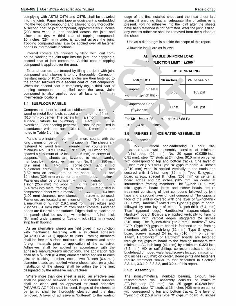
Allowable loads are as follows:
ALLOWABLE UNIFORM LOAD
AT DEFLECTION LIMIT = L/360 1
PRODUCT
JOIST SPACING
16 inches o.c. 24 inches o.c.
Compressed Sheet II
(½- and 5/8-inch thick)190 psf 105 psf
Compressed Sheet II
(3/4-inch thick) 300 psf 145 psf
For SI: 1 inch = 25.4 mm, 1 psf = 47.88 Pa
L = length of span (inches)
3.5 FIRE-RESISTANCE RATED ASSEMBLIES
3.5.1 Assembly 1
The nonsymmetrical nonloadbearing, 1 hour, fire-resistance-rated wall assembly consists of minimum 35/8-inch-deep (92 mm), No. 20 gage (0.0359-inch, 0.91 mm), steel “C” studs at 24 inches (610 mm) on center with corresponding top and bottom tracks. One layer of 5/8-inch-thick (15.9 mm) Type “X” gypsum board, 48 inches (1219 mm) wide, is applied vertically to the studs and secured with 11/4-inch-long (32 mm), Type S, gypsum board screws, spaced 8 inches (203 mm) on center at board edges and 12 inches (305 mm) on center at intermediate framing members. The 5/8-inch (15.9 mm) thick gypsum board joints and screw heads require treatment consisting of joint compound followed by joint tape and a second layer of joint compound. The opposite face of the wall is covered with one layer of 1/2-inch-thick (12.7 mm) Hardirock® Max “C”™(Type “X”) gypsum board, followed by one layer of either 1/4-inch-thick (6.4 mm) Titan® (tapered- edge), Hardibacker® (square-edge), or Harditex® board. Boards are applied vertically to framing members with vertical edges staggered 24 inches (610 mm). The 1/2-inch-thick (12.7 mm) Hardirock® Max “C”™ (Type “X”) gypsum board is fastened to the framing members with 11/4-inch-long (32 mm), Type S, gypsum board screws spaced 24 inches (610 mm) on center. Titan®, Hardibacker® or Harditex® boards are fastened through the gypsum board to the framing members with minimum 15/8-inch-long (41 mm) by minimum 0.323-inch (8.2 mm) HD or self-drilling, corrosion-resistant, ribbed buglehead or ribbed waferhead screws located a maximum of 8 inches (203 mm) on center. Board joints and fasteners require treatment similar to that described in Sections 3.3.1.1, 3.3.1.2, 3.3.2.2, and 3.2.4 of this report.
3.5.2 Assembly 2
The nonsymmetrical nonload bearing, 1-hour, fire-resistant-rated wall assembly consists of minimum 35/8-inch-deep (92 mm), No. 25 gage (0.0209-inch, 0.53 mm), steel “C” studs at 16 inches (406 mm) on center with corresponding top and bottom tracks. One layer of 5/8-inch-thick (15.9 mm) Type “X” gypsum board, 48 inches
LEGACY
REPO
RT
NER-405 | Most Widely Accepted and Trusted Page 7 of 35
(1219 mm) wide, is applied vertically to the studs and secured with minimum 1 inch-long (25.4 mm), Type S, gypsum board screws, spaced 8 inches (203 mm) on center at board edges and 12 inches (305 mm) on center at intermediate framing members. The 5/8-inch-thick (15.9 mm) Type “X” gypsum board joints and screw heads require treatment consisting of joint compound followed by joint tape and a second layer of joint compound. The stud cavities are insulated with minimum 3-inch-thick (76 mm), 3 pcf (48 kg/m3), unfaced, friction-fit, mineral fiber insulation complying with ASTM C665, Type I. The opposite face of the wall is covered with one layer of 7/16—inch-thick (11.1 mm) Hardibacker® (backerboard) or Titan® panel or Harditex® boards. The boards are applied vertically to framing members with vertical edges staggered 16 inches (406 mm). Hardibacker®, Titan® or Harditex® boards are fastened through to the framing members with minimum 1-inch-long (25.4 mm) No. 8 by 0.323-inch (8.2 mm) HD self-drilling, corrosion-resistant, ribbed buglehead (or equivalent) screws located a maximum of 6 inches (152 mm) on center. Board joints and fasteners require treatment similar to that described in Sections 3.3.1.1, 3.3.1.2 or 3.3.2.2 of this report, and using the glass fiber reinforcing tape.
3.5.3 Assembly 3
The nonsymmetrical limited loadbearing, 1 hour fire-resistant rated wall assembly consists of nominal 2 x 4 wood studs at 16 inches (406 mm) on center with two top plates and a single bottom plate. The lesser of 800 pounds per stud or 31 percent of full design load is permitted to be superimposed, provided structural consideration for axial, flexural and bearing perpendicular-to-grain stresses are resolved in accordance with Part III of the National Design Specification, 1997 edition, published by the American Forest & Paper Association. One layer of 5/8-inch-thick (15.9 mm) Type “X” gypsum board, 48 inches (1219 mm) wide, is applied vertically to the studs and secured with minimum 17/8-inch-long (22 mm) cup-head gypsum board nails, spaced 7 inches (178 mm) on center at board edges and intermediate framing members. The 5/8-inch-thick (15.9 mm) Type “X” gypsum board joints and nail heads require treatment consisting of joint compound followed by joint tape and a second layer of joint compound. The stud cavities are insulated with minimum 3-inch-thick (76 mm), 3 pcf, unfaced, friction-fit, mineral fiber insulation complying with ASTM C665, Type I. The opposite face of the wall is covered with one layer of 7/16-inch-thick (11.1 mm) Titan® panel or Hardibacker® backerboard. The fiber cement board is applied vertically to framing members with vertical edges staggered 16 inches (406 mm) from the gypsum board edges. Boards are fastened through to the framing members with minimum 11/2-inch-long (38 mm), corrosion-resistant roofing nails located a maximum of 6 inches (152 mm) on center. Board joints and fasteners require treatment similar to that described in Section 3.3.2.2 of this report. The side of the wall clad with fiber-cement board is covered with standard grade ceramic tile, nominal 1/4-inch thick . Tiles, any expansion or control joints, and grout are installed in accordance with ANSI A108.4 when Type I organic adhesive is used, or ANSI A108.5 if dry set, acrylic-modified or latex-modified portland cement mortar is used.
3.5.4 Assembly 4
The nonsymmetrical loadbearing 1 hour fire-resistant rated wall assembly consists of nominal 2 x 4 wood studs at 24 inches (610 mm) on center with two top plates and a single bottom plate. Full design loads are permitted to be superimposed, provided structural consideration for axial flexural and bearing perpendicular-to-grain stresses are resolved in accordance with Part III of the National Design Specification, 1997 Edition, published by the American Forest & Paper Association. One layer of 5/8-inch-thick
(15.9) Type "X" gypsum board, 48 inches (1219 mm) wide, is applied vertically to the studs and secured with minimum 13/4-inch-long (44 mm) cup-head gypsum board nails, spaced 7 inches (178 mm) on center at board edges and intermediate framing members. The 5/8-inch-thick (15.9 mm) Type “X” gypsum board joints and nail heads require treatment consisting of joint compound followed by joint tape and a second layer of joint compound. The stud cavities are either insulated or uninsulated. The opposite face of the wall is covered with one layer of 1/2-inch-thick (12.7 mm) Type "X" water-resistant core gypsum sheathing and one layer of maximum 12-inch-wide (305 mm) Hardi-plank® lap siding lapped a minimum of 11/4 inches (32 mm). The 1/2-inch-thick (12.7 mm) Type “X” water-resistant core gypsum sheathing is applied vertically to framing members with vertical edges staggered 24 inches (610 mm) from the joints on the opposite side. The 1/2-inch-thick (12.7 mm) Type "X" water-resistant core gypsum sheathing is fastened to the framing members with 13/4-inch-long (44 mm) roofing nails spaced 7 inches (178 mm) on center in the field and 4 inches (102 mm) on center along the perimeter of each board. An outer layer of 5/16-inch-thick (7.5 mm), 12-inch-wide (305 mm) Hardi-plank® lap siding is applied over the 1/2-inch-thick (12.7 mm) Type "X" water-resistant core gypsum sheathing by attaching a 11/2-inch-wide (38 mm) Hardiplank® starter strip attached through the gypsum sheathing into the bottom plate and 12-inch-wide (305 mm) Hardiplank® lap siding applied horizontally with a minimum nominal 11/4-inch headlap and fastened with a single 6d corrosion resistant common nail driven through the lapped planks at each stud.
3.5.5 Assembly 5
The symmetrical nonload bearing, 1-hour, fire-resistant-rated wall assembly consists of minimum 3 5/8-inch-deep (92 mm), No. 20 gage (0.0359 inch, 0.91 mm), steel “C” studs at 24 inches (610 mm) on center with corresponding top and bottom tracks. Both sides of the wall are covered with one layer of 1/2-inch-thick (12.7 mm) Hardirock® Max “C”™ (Type “X”) gypsum board, followed by one layer of either 1/4-inch-thick (6.4 mm) Titan® panel, Hardibacker® backerboard, or Harditex® baseboards. Boards are applied either perpendicular (horizontally) or parallel (vertically) to framing members. Base layer and face layer board joints of both wall sides are offset by 24 inches (610 mm). The 1/2-inch-thick (12.7 mm) Hardirock® Max “C”™ (Type “X”) gypsum board is fastened to the framing members with minimum 1-inch-long (25.4 mm), Type S, gypsum board screws spaced 24 inches (610 mm) on center. Titan®, Hardibacker® or Harditex® boards are fastened through the gypsum board to the framing members with minimum 15/8-inch-long (41 mm) by minimum 0.323-inch (8.2 mm) HD self-drilling, corrosion-resistant, ribbed buglehead or ribbed waferhead screws located a maximum of 8 inches (203 mm) on center. Board joints and fasteners require finish treatment similar to that described in Sections 3.3.1.1, 3.3.1.2, 3.3.2.2, or 3.2.4 and of this report.
3.5.6 Assembly 6
The symmetrical nonload bearing, 1-hour, fire-resistant-rated wall assembly consists of minimum 3 5/8-inch-deep (92 mm), No. 20 gage (0.0359 inch, 0.91 mm), steel “C” studs at 24 inches (610 mm) on center with corresponding top and bottom tracks. Both sides of the wall are covered with one layer of 5/8-inch-thick (15.9 mm) Titan®-FR panel. Boards are applied either perpendicular (horizontally) or parallel (vertically) to framing members. Panel joints are offset by 24 inches (610 mm). The 5/8-inch (15.9 mm) thick Titan®-FR panel is fastened to the framing members with minimum 1-inch-long (25.4 mm), Type S, gypsum board screws spaced 12 inches (305 mm) on center. Board joints and fasteners require finish treatment similar to that described in Sections 3.3.1.1 or 3.3.1.2 of this report.
LEGACY
REPO
RT
NER-405 | Most Widely Accepted and Trusted Page 8 of 35 4.0 INSTALLATION
Installation shall comply with this report and a copy of this report shall be available at all times on the job site during installation. Additional details are in the applicable manufacturer's product information sheets issued December 1993. Where non-editorial differences occur between the manufacturer's product information sheets and this report, this report shall be null and void.
5.0 IDENTIFICATION
James Hardie Building Products, Inc., Hardiflex®, Hardi-panel® Cempanel®, Hardisoffit® and Cemsoffit® boards; Harditex® baseboards; Titan®, Titan®-FR, Hardibacker®, Ultraboard® and Hardibacker 500® lining boards, backerboard and underlayment; Compressed Sheet subflooring; pallets of Hardiplank® and Cemplank® lap siding; and pallets of Hardishingle™ planks and panels shall bear a label identifying the manufacturer's name and telephone number, the product name, and this ICC-ES Legacy report number (NER-405) for field identification.
6.0 EVIDENCE SUBMITTED
6.1 The following test reports issued by the Building Research Association of New Zealand (BRANZ) in accordance with ASTM E72, Conducting Strength Test of Panels of Building Construction, Section 9, Transverse Load, and Section 14, Racking Load:
Report No. Date ASTM Standard
Section
S100
S101
S102
S103
S104
S105
S106
S109
S112
S113
STR122
STR123
STR127
STR128
STR131
STR132
June, 1984
June, 1984
June, 1984
June, 1984
June, 1984
June, 1984
June, 1984
July, 1984
August, 1984
August, 1984
April, 1985
April, 1985
April, 1985
May, 1985
May, 1985
May, 1985
9
9
9
9
9
14
14
9
14
9
9
14
9
14
9
14
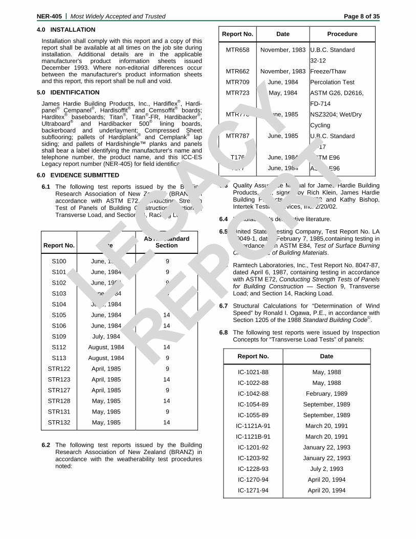
6.2 The following test reports issued by the Building Research Association of New Zealand (BRANZ) in accordance with the weatherability test procedures noted:
Report No. Date Procedure
MTR658
MTR662
MTR709
MTR723
MTR778
MTR787
T176
T177
November, 1983
November, 1983
June, 1984
May, 1984
June, 1985
June, 1985
June, 1984
June, 1984
U.B.C. Standard
32-12
Freeze/Thaw
Percolation Test
ASTM G26, D2616,
FD-714
NSZ3204; Wet/Dry
Cycling
U.B.C. Standard
47-17
ASTM E96
ASTM E96
6.3 Quality Assurance Manual for James Hardie Building Products, Inc., signed by Rich Klein, James Hardie Building Products, Inc. 2/18/02 and Kathy Bishop, Intertek Testing Services, Inc. 2/20/02.
6.4 Manufacturer's descriptive literature.
6.5 United States Testing Company, Test Report No. LA 50049-1, dated February 7, 1985,containing testing in accordance with ASTM E84, Test of Surface Burning Characteristic of Building Materials.
6.6 Ramtech Laboratories, Inc., Test Report No. 8047-87, dated April 6, 1987, containing testing in accordance with ASTM E72, Conducting Strength Tests of Panels for Building Construction — Section 9, Transverse Load; and Section 14, Racking Load.
6.7 Structural Calculations for “Determination of Wind Speed” by Ronald I. Ogawa, P.E., in accordance with Section 1205 of the 1988 Standard Building Code©.
6.8 The following test reports were issued by Inspection Concepts for “Transverse Load Tests” of panels:
Report No. Date
IC-1021-88
IC-1022-88
IC-1042-88
IC-1054-89
IC-1055-89
IC-1121A-91
IC-1121B-91
IC-1201-92
IC-1203-92
IC-1228-93
IC-1270-94
IC-1271-94
May, 1988
May, 1988
February, 1989
September, 1989
September, 1989
March 20, 1991
March 20, 1991
January 22, 1993
January 22, 1993
July 2, 1993
April 20, 1994
April 20, 1994
LEGACY
REPO
RT

NER-405 | Most Widely Accepted and Trusted Page 9 of 35
6.9 The following test reports were issued by Inspection Concepts for “Racking Tests” of panels:
Report No. Date
IC-1013-88
IC-1014-88
IC-1030-88
IC-1032-88
IC-1037-88
IC-1038-88
IC-1057-89
IC-1062-89
IC-1100-90
IC-1107-91
IC-1108-91
IC-1109-91
IC-1110-91
IC-1120A-91
IC-1120B-91
IC-1120C-91
IC-1120D-91
IC-1202-92
IC-1202-92
IC-1237-93
IC-1273-94
IC-1274-94
January, 1988
January, 1988
September, 1988
September, 1988
November, 1988
November, 1988
September, 1989
November ,1989
October 30, 1990
January 5, 1991
January 6, 1991
January 8, 1991
January 8, 1991
March 20, 1991
March 20, 1991
March 20, 1991
March 20, 1991
January 22, 1993
January 22, 1993
August 5, 1993
April 20, 1994
April 29, 1994
6.10 The following test reports were issued by Inspection Concepts for “Transverse Load Tests” of planks:
Report No. Date
IC-1020-88
IC-1011-88
IC-1034-88
IC-1035-88
May, 1988
January, 1988
October, 1988
October, 1988
6.11 The following test reports were issued by Southwest Research Institute for “1 hour Fire-resistant Assemblies”:
Report No. Date
01-2602-802
01-2602-803
March, 1989
March, 1989
6.12 Structural calculations verifying design values for Tables 2 and 3 of this report, prepared by Inspection Concepts dated March 7, 1990, signed and sealed by Ronald I. Ogawa, P.E.
6.13 Inspection Concepts, Test Report No. IC-1093A-90, dated October 18, 1990, in accordance with ASTM E136.
6.14 Smith-Emery Company, Test Report No. L-87-1732, dated October 8, 1987, in accordance with ANSI A118.9.
6.15 United States Testing Company, Inc., Test Report No. 176842, dated September 14, 1990, in accordance with ASTM D1037.
6.16 Truesdail Laboratories, Inc., Test Report No. 30240-1, dated March 1, 1989, revised March 28, 1991, in accordance with ASTM G21.
6.17 Truesdail Laboratories, Inc., Test Report No. 30240-2, dated March 1, 1989, revised March 28, 1991, in accordance with ASTM G22.
6.18 Inspection Concepts, Report No. IC-1131-91, dated May 8, 1991, in accordance with ASTM C947, C666 Procedure B, and ANSI 136-1.
6.19 ETL Testing Laboratories, Report No. 497742, dated March 5, 1990, in accordance with ASTM E84.
6.20 Inspection Concepts, Report No. IC-1039-89, dated January 6, 1989, revised May 11, 1990, containing comparative fastener pullout and pull-through testing results.
6.21 James Hardie Building Products, Inc. product information sheets issued October 1991.
6.22 Structural calculations verifying design values for Tables 2 and 3 of this report, prepared by Inspection Concepts dated October 20, 1993, signed by Ronald I. Ogawa, P.E.
6.23 Letter correcting structural calculations for BRANZ Reports S106 and STR128 prepared by Inspection Concepts dated February 14, 1993, signed and sealed by Ronald I. Ogawa, P.E.
6.24 Letter reviewing “Racking Tests” and “Transverse Load Tests” for Group III wood species verification for Tables 2 and 3 of this report, prepared by Inspection Concepts dated October 14, 1993, signed and sealed by Ronald I. Ogawa, P.E.
6.25 The following test reports were issued by Omega Point Laboratories for “1 hour Fire-resistant Assemblies”:
Report No. Date
11710-92783
11710-92851
11710-98414
11710-105198
11710-105199
February 13,1992
September 9,1992
May 1, 1995
August 2, 1999
August 3, 1999
6.26 Ramtech Laboratories, Inc., Test Report No. 8108A-87, dated May 20, 1987, in accordance with ASTM C725 for flexural strength tests conducted on 1/4-inch- and 3/4-inch-thick compressed sheet panels.
6.27 Ramtech Laboratories, Inc., Test Report No. 8108B-87, dated May 26, 1987, in accordance with ASTM E72, Section 18, concentrated load on 1/4--inch and 3/4-inch thick compressed sheet panels.
6.28 Ramtech Laboratories, Inc., Test Report No. 8108C-87, dated June 24, 1987, in accordance with ASTM E72, Section 9, transverse load on 1/4-inch and 3/4-inch thick compressed sheet panels.
LEGACY
REPO
RT
NER-405 | Most Widely Accepted and Trusted Page 10 of 35
6.29 Inspection Concepts, Test Report No. IC-1257-94, dated January 13, 1994, in accordance with ASTM E331 for water penetration of 1/4-inch-thick Hardi-panel® vertical siding.
6.30 Inspection Concepts, Test Report No. IC-1243-93, dated August 26, 1993, in accordance with ASTM E228 for linear-thermal expansion of 1/4-inch-thick James Hardie fiber cement products.
6.31 Ramtech Laboratories, Inc., Laboratory No. 9778-93, IC-1225-93, dated June 4, 1993,. The Hardibacker board was tested in accordance with ASTM C177 Test for Steady-State Thermal Transmission Properties by Means of the Guarded Hot Plate. The results are listed in Table 4 of this report.
6.32 Ramtech Laboratories, Inc., Test Report No. IC-1230-93, Laboratory No. 9778-93, dated June 1993. The Hardibacker® board materials were tested in accordance with ASTM E96-90 to determine the water vapor transmission properties. The average permeance (perms) of the panels are shown in Table 5 of this report.
6.33 Ramtech Laboratories, Inc. Laboratory No. 10367A-95/1363, dated September 18, 1995. The 71/4-inch- and 9 1/4-inch-wide Hardiplank® lap sidings were tested in accordance with ASTM E330 Transverse Load Test. The panels were installed on nominal 2 x 4 wood structural members spaced 16 inches on center (o.c.).
6.34 Structural Calculations verifying design values for Table 3 of this report, prepared by Inspection Concepts dated October 6, 1995, signed by Ronald I. Ogawa, P.E.
6.35 Wind analysis and calculations for Hardishingle and Hardislate roofing and Hardie® Shingleside® cladding installed with 8-, 7-, and 6-inch weather exposures. Analysis and calculations conducted by Ronald I. Ogawa, P.E. dated March 28, 1997; March 31, 1997; and April 2, 1997.
6.36 Structural calculations to determine design wind load on 8.25 Hardiplank®, dated October 24, 1996, signed and sealed by Ronald I. Ogawa, P.E. of Inspection Concepts Inc..
6.37 Structural calculations to determine design values for Tables 2a, 2b, and 3 of this report, prepared by Inspection Concepts dated July 16, 1997, July 19, 1997, and August 19, 1997, signed and sealed by Ronald I. Ogawa, P.E.
6.38 Ramtech Laboratories, Inc., Report Lab. No. 10868-97/1475, dated June 26, 1997. The report contains results of testing in accordance with ASTM E72 and ASTM E330 on 5/16-inch-thick Hardipanel.
6.39 Ramtech Laboratories, Inc., Report Lab. No. 10869-97/1482, dated July 14, 1997 containing results of transverse load testing in accordance with ASTM E72 on 9 1/4-inch-wide Hardiplank® lap siding.
6.40 Applied Research Laboratories, Lab No. 29278-UD1, dated September 1, 1994, containing reports of tensile pull-out testing of fasteners.
6.41 Structural calculations to determine the allowable fastener spacing based on a wind speed of 110 mph, Exposure Category C, prepared by Inspection Concepts, dated November 2, 1994, signed and sealed by Ronald I. Ogawa, P.E.
6.42 Ramtech Laboratories, Inc., Laboratory Number 10794-97/1458, dated March 13, 1997, containing results of an Uplift Resistance Test of 18-inch long by 12-inch-wide by 1/4-inch-thick Hardishingle™ roofing installed on 15/32-inch-thick, 4-ply, 3-layer CDX plywood.
6.43 Ramtech Laboratories, Inc., Laboratory Number 10794-97/1460, dated March 13, 1997, containing results of an Uplift Resistance Test of 18-inch-long by 12-inch-wide by 1/4-inch-thick Hardie® Shingleside® as siding roofing installed on 7/16-inch-thick Oriented Strand Board utilizing 2 siding nails per 12-inch wide panel.
6.44 Ramtech Laboratories, Inc., Laboratory Number 10794-97/1464, dated March 13, 1997, containing results of an Uplift Resistance Test of 18-inch long by 12-inch-wide by 1/4-inch-thick Hardie® Shingleside® as siding roofing installed on 7/16-inch-thick Oriented Strand Board utilizing 3 siding nails per 12-inch-wide panel.
6.45 Ramtech Laboratories, Inc., Laboratory Number 11149-98/1554, dated October 7, 1998, containing results of an ASTM E330 Transverse Load Test of 61/4-inch-wide Hardiplank® siding installed on 20-ga. metal framing members spaced at 16-inch and 24-inch centers and fastened with ET & F pin fasteners through the lap to each stud.
6.46 Ramtech Laboratories, Inc., Laboratory Number 11149-98/1554A, dated October 7, 1998, containing results of an ASTM E330 Transverse Load Test of 12-inch-wide Hardiplank® siding installed on 20-ga. metal framing members spaced at 16-inch and 24-inch centers and fastened with ET & F pin fasteners through the lap to each stud.
6.47 Ramtech Laboratories, Inc., Laboratory Number 11149-98/1554B, dated October 7, 1998, containing results of an ASTM E330 Transverse Load Test of 81/4-inch-wide Hardiplank® siding installed on 20-ga. metal framing members spaced at 16-inch and 24-inch centers and fastened with ET & F pin fasteners blind nailed to each stud.
6.48 Ramtech Laboratories, Inc., Laboratory Number 11284-99/1580, dated April 15, 1999, containing results of an ASTM E72 Racking Shear Test of 5/16-inch-thick x 48-inch-wide x 96-inch-long Hardipanel® siding installed on 20-ga. metal framing members spaced at 16-inch and 24-inch centers and fastened with ET & F pin fasteners spaced at 4 inches o.c. perimeter and 8 inches o.c. intermediate framing members.
6.49 Ramtech Laboratories, Inc., Laboratory Number 11149-98/1554D, dated September 14, 1998, containing results of an ASTM E330 Transverse Load Test of 5/16-inch-thick x 48-inch-wide x 96- inch-long Hardipanel® siding installed on 20-ga. metal framing members spaced at 16-inch and 24-inch centers and fastened with ET & F pin fasteners spaced at 4 inches o.c. perimeter and 8 inches o.c. intermediate framing members.
6.50 Wind analysis and calculations for Hardipanel® panels for exposure categories B, C, and D. Analysis and calculations signed and sealed by Ronald I. Ogawa, P.E., dated March 26, 2000.
6.51 Ramtech Laboratories, Inc., Laboratory Number 11552/1636, dated April 20, 2000, containing results
LEGACY
REPO
RT

NER-405 | Most Widely Accepted and Trusted Page 11 of 35
of an ASTM E330 Uplift Resistance Test of 1/4-inch-thick x 24-inch-wide vented Hardisoffit® panel installed on nominal 2 x 4 framing members spaced at 24 inch centers and fastened with 11/4-inch-long x 0.083-inch shank x 0.187-inch HD nails spaced at 8 inches o.c. perimeter and intermediate framing members.
6.52 Wind analysis and calculations for 24-inch-wide vented Hardisoffit® panel for exposure categories B, C, and D. Analysis and calculations signed and sealed by Ronald I. Ogawa, P.E., dated May 4, 2000.
6.53 Ramtech Laboratories, Inc., Laboratory Number 11436-99/1602, dated October 29, 1999, containing results of an ASTM E330 Transverse Load Test of 1/4-inch-thick x 19-inch-long x 48-inch-wide Heritage™ (half round) panel siding installed on 7/16-inch-thick APA rated Oriented Strand Board sheathing only with 11/4-inch-long x 0.083-inch shank x 0.187-inch HD nails spaced at 133/4-inch o.c.
6.54 Ramtech Laboratories, Inc., Laboratory Number 11436-99/1603, dated October 27, 1999, containing results of an ASTM E330 Transverse Load Test of 1/4-inch-thick x 19-inch-long x 48- inch-wide Heritage™ (half round) panel siding installed on nominal 2 x 4 framing members spaced at 16-inch centers and fastened with 11/4-inch-long x 0.083-inch shank x 0.187-inch HD nails to each framing member.
6.55 Ramtech Laboratories, Inc., Laboratory Number 11436-99/1604, dated October 28, 1999, containing results of an ASTM E330 Transverse Load Test of 1/4-inch-thick x 19-inch-long x 48-inch-wide Heritage™ (half round) panel siding installed on nominal 2 x 4 framing members spaced at 24-inch centers and fastened with 11/4-inch-long x 0.083-inch shank x 0.187-inch HD nails to each framing member.
6.56 Letter justifying horizontal application of panels in accordance with Table 3 of this report, based on Table 23-II-I-1 of the 1997 Uniform Building Code™ and similar tables in the BOCA® National Building Code/1999 and 1999 Standard Building Code©, prepared by Inspection Concepts Inc., dated October 20, 1999, and signed and sealed by Ronald I. Ogawa, P.E.
6.57 Wind analysis and calculations for Hardiplank® lap siding installed with ET & F pin fasteners for exposure categories B, C, and D. Analysis and calculations signed and sealed by Ronald I. Ogawa, P.E., dated December 14, 1998.
6.58 Wind analysis and calculations for Hardiplank® lap siding based on various test reports of installations with nail and screw fasteners. Analysis and calculations signed and sealed by Ronald I. Ogawa, P.E., dated July 7, 1998.
6.59 Underwriters Laboratories Inc. letter, dated May 29, 1997, recognizing James Hardie Gypsum’s 1/4-inch-thick Hardirock® Max “C”™ gypsum board as an alternative to Super Fire X gypsum board.
6.60 Underwriters Laboratories Inc. letter, dated February 23, 2000, recognizing James Hardie® Gypsum’s 1/4-inch-thick Hardirock® Max “C”™ gypsum board as an alternative to Super Fire X gypsum board.
6.61 Underwriters Laboratories, Inc., File R8701, Project 96NK16606, dated December 19, 1996, containing results of ANSI/UL 263 (ASTM E119, NFPA 251), Fire Tests of Building Construction and Materials, for
1/4-inch-thick x 8-feet-long x 4-feet-wide gypsum board installed on steel columns of 25 MSG steel studs spaced at 12- inch centers and fastened with 3-inch-long Type S self-drilling, self-tapping board screws spaced at 12-inch centers in a UL G512 assembly.
6.62 Underwriters Laboratories, Inc., File R8701, Project 96NK35820, dated July 23, 1997, containing results of ANSI/UL 263 (ASTM E119, NFPA 251), Fire Tests of Building Construction and Materials, for 5/8-inch-thick x 144-inch-long x 48-inch-wide gypsum board installed in a UL X515 floor-ceiling assembly.
6.63 Wind analysis and calculations for Shingleside® Heritage™ panels for exposure categories B, C, and D. Analysis and calculations signed and sealed by Ronald I. Ogawa, P.E., dated December 3, 1999.
6.64 Ramtech Laboratories, Inc., Laboratory Number 11436-99/1612, dated December 20, 1999, containing results of an ASTM E72 Racking Shear Test of 5/16-inch-thick x 48-inch-wide x 96- inch-long Hardipanel® Shiplap siding installed on nominal 2 x 4 wood framing members spaced at 16-inch centers and fastened with 0.092-inch shank by 0.225-inch HD by 2-inch-long nails spaced at 3 inches o.c. perimeter and 8 inches o.c. intermediate framing members.
6.65 Ramtech Laboratories, Inc., Laboratory Number 11436-99/1616, dated December 27, 1999, containing results of an ASTM E72 Racking Shear Test of 5/16-inch-thick x 48-inch-wide x 96- inch-long Hardipanel® Shiplap siding installed on nominal 2 x 4 wood framing members spaced at 16-inch centers and fastened with 0.092-inch shank by 0.225-inch HD by 2-inch long nails spaced at 8 inches o.c. perimeter and 8 inches o.c. intermediate framing members.
6.66 Wind analysis and calculations of Ramtech Laboratories, Inc., Test Reports Laboratory Number 11436-99/1612 and 11436/1616, prepared by Inspection Concepts dated January 14, 2000, signed and sealed by Ronald I. Ogawa, P.E.
6.67 Wind analysis and calculations for Hardipanel® installed on steel studs spaced 16 and 24 inches o.c. Analysis and calculations signed and sealed by Ronald I. Ogawa, P.E., dated June 15, 1999.
6.68 Ramtech Laboratories, Inc., Laboratory Number 11436-99/1619, dated January 19, 2000, containing results of a Uniform Negative Transverse Load Test of 5/16-inch thick x 48-inch wide x 96-inch long Hardi-panel® Shiplap Panel installed on nominal 2 x 4 wood framing members spaced at 16-inch centers and fastened with 0.092-inch shank by 0.225-inch HD by 2-inch long ring shank nails spaced at 3 inches and 8 inches o.c. perimeter and 8 inches o.c. field.
6.69 Wind analysis and calculations of Ramtech Laboratories, Inc., Test Report Laboratory Number 11436-99/1619, prepared by Inspection Concepts dated February 4, 2000, signed and sealed by Ronald I. Ogawa, P.E.
6.70 Ramtech Laboratories, Inc., Laboratory Number 11443/1613, dated February 10, 2000, containing results of testing, in accordance with ASTM C36, of 5/8-inch-thick x 48-inch-wide x 120-inch-long Titan®-FR panel consisting of 1/4-inch-thick Hardirock® Max “C”™ gypsum board and 3/32-inch-thick Hardie® fiber-cement board adhered with PVA adhesive.
LEGACY
REPO
RT
NER-405 | Most Widely Accepted and Trusted Page 12 of 35
6.71 Ramtech Laboratories, Inc., Laboratory Number 11443/1613, dated March 25, 2000, revision to report to additionally show compliance with ASTM C1278.
6.72 Ramtech Laboratories, Inc., Laboratory Number 11443/1629, dated March 22, 2000, containing testing of Hardibacker 500® in accordance with ASTM C1288, Standard Specification for Discrete Non-Asbestos Fiber-Cement Interior Substrate Sheets.
6.73 Omega Point Laboratories, Report Number 11710-106315, dated March 7, 2000, containing results of surface burning characteristic testing, indicating compliance with ASTM E84 for the Hardibacker 500® backerboard.
6.74 Ramtech Laboratories, Inc., Laboratory Number 11569/1647, dated June 2, 2000, containing results of water tightness testing performed in accordance with ASTM C1185 on Hardibacker 500®.
6.75 Ramtech Laboratories, Inc., Laboratory Number 11569B/1655, dated June 27, 2000, containing results of falling ball impact testing performed in accordance with ASTM D1037 on Hardibacker 500®.
6.76 Ramtech Laboratories, Inc. Laboratory Number 11569A/1654, dated July 10, 2000, containing results of flexural strength testing performed in accordance with ASTM C947, freeze thaw testing performed in accordance with ASTM C666, and bacteria resistance testing performed in accordance with ASTM G22 on the Hardibacker 500®.
6.77 Analysis of screw attachment to 20-gage metal studs and calculations by Ronald I. Ogawa, P.E., signed and sealed 10/10/01.
6.78 Analysis and wind load and wind speed by analysis of Ramtech Laboratories Report Lab No. IC-1035-88, analysis prepared by Inspection concepts, Inc., 15-Oct-01, signed and sealed by Ronald I. Ogawa, P.E, 10/16/01.
6.79 Test report on thermal conductivity under ASTM C177 for 13/32-inch-thick Hardibacker 500, Ramtech Laboratories, Inc., Lab No. 11670/1685, November 29, 2000, signed and sealed by Ronald I. Ogawa, P.E. and signed by David R. Macey.
6.80 Test report on moisture vapor transmission under ASTM E96 for 13/32-inch Hardibacker 500, Ramtech Laboratories, Inc., Lab No. 11639/1674, October 10, 2000, signed and sealed by Ronald I. Ogawa, P.E. and signed by David R. Macey.
6.81 Test report equivalency testing for 5/16-inch Hardipanel Cladding with 6-,4-,3- and 2-inch nail spacing on 16- and 24-inch o.c. wood 2x4 studs, Ramtech Laboratories, Inc., Lab No. 11992/1783, January 17, 2002, signed and sealed by Ronald I. Ogawa, P.E. 12/1/02, and David R. Macey, 12/1/02.
7.0 CONDITIONS OF USE
The ICC-ES Subcommittee for the National Evaluation Service finds that James Hardie Building Products, as described in this report, comply with or are suitable alternates to that specified in the 2000 International Building Code®, the BOCA® National Building Code/1999, the 1999 Standard Building Code©, the 1997 Uniform Building Code™, the 2000 International Residential Code®, the 2002 Accumulative Supplement to the International
Codes™, and the 1998 International One and Two Family Dwelling Code© subject to the following conditions:
7.1 James Hardie Building Products listed in this report shall be installed in accordance with this report. This Evaluation Report and the manufacturer’s published installation instructions, when required by the code official, shall be submitted at the time of permit application.
7.2 Hardiplank® lap siding and Hardishingle™ cladding shingle and panel sidings shall be installed on exterior walls braced in accordance with the applicable code:
7.2.1 Section 2305.7 of the BOCA® National Building Code.
7.2.2 Section 2308.2 of the Standard Building Code©.
7.2.3 Section 2320.11.3 and 2320.11.4 of the Uniform Building Code™.
7.2.4 Section 2308.9.3 of the International Building Code®.
7.2.5 Section R602.10.3 of the International Residential Code®.
7.2.6 Section 602.10 of the International One and Two Family Dwelling Code®.
7.3 Design Wind Loads applied to James Hardie Sidings listed in this report shall be determined in accordance with Chapter 16 of the applicable code and shall be less than those shown in the design tables in this report.
7.3.1 Design Tables 2a and 2b as shown in this report provides allowable capacity in MPH for transverse load conditions for James Hardie Sidings attached to studs. When using the International Building Code® the wind speeds must be converted to 3-second gust wind speed (mph) using Table 1609.3.1 of the IBC and the allowable wind speeds shown in Tables 2a and 2b for the column titled BOCA® National Building Code (See 7.3.5 below).
7.3.2 Design Table 3 as shown in this report provides allowable shear capacity in plf for James Hardie Sidings.
7.3.3 Design Tables 6A, 6B, 6C, 7A, 7B, 7C, 8A, 8B, 8C as shown in this report provides allowable capacity in MPH for transverse load conditions for James Hardie Sidings attached to sheathing. When using the International Building Code® the wind speeds must be converted to 3 second gust wind speed (mph) using Table 1609.3.1of the IBC and the allowable wind speeds shown in Tables 6A, 7A, and 8A for the BOCA® National Building Code (See 7.3.5 below).
7.3.4 Design Tables 9A, 9B, 9C as shown in this report provides allowable fastener spacing for James Hardiplank Lap Siding attached to CMUs in 110 MPH wind speed. When using the International Building Code® fastener spacings shown in Table 9B are applicable for a Wind Speed of 130 MPH.
LEGACY
REPO
RT
NER-405 | Most Widely Accepted and Trusted Page 13 of 35
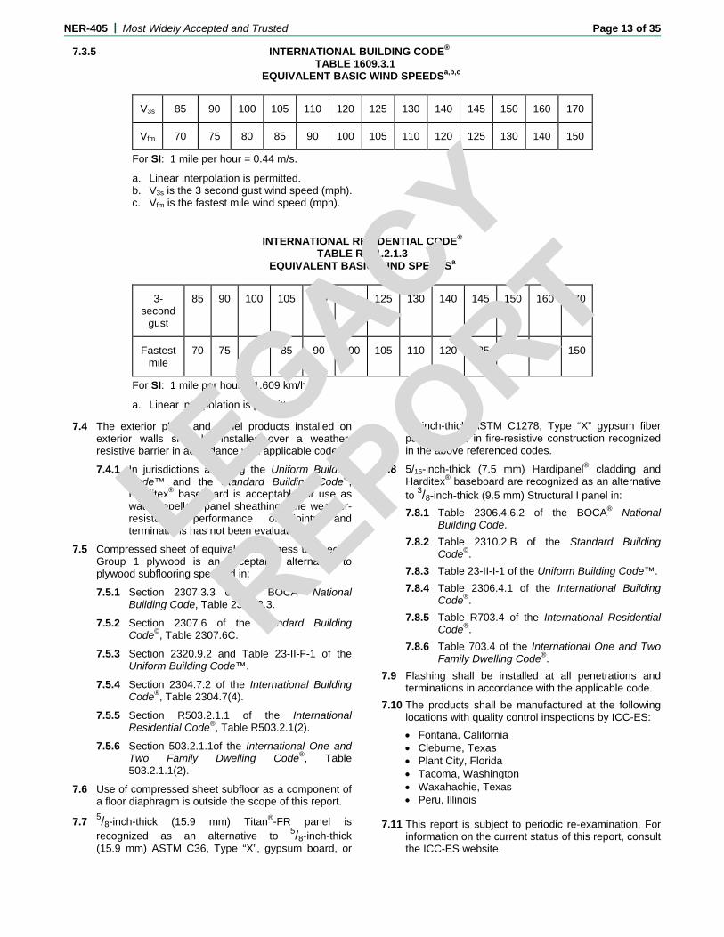
7.3.5 INTERNATIONAL BUILDING CODE® TABLE 1609.3.1 EQUIVALENT BASIC WIND SPEEDSa,b,c
V3s 85 90 100 105 110 120 125 130 140 145 150 160 170
Vfm 70 75 80 85 90 100 105 110 120 125 130 140 150
For SI: 1 mile per hour = 0.44 m/s.
a. Linear interpolation is permitted. b. V3s is the 3 second gust wind speed (mph). c. Vfm is the fastest mile wind speed (mph).
INTERNATIONAL RESIDENTIAL CODE® TABLE R301.2.1.3
EQUIVALENT BASIC WIND SPEEDSa
3-second
gust
85 90 100 105 110 120 125 130 140 145 150 160 170
Fastest mile
70 75 80 85 90 100 105 110 120 125 130 140 150
For SI: 1 mile per hour = 1.609 km/h.
a. Linear interpolation is permitted.
7.4 The exterior plank and panel products installed on exterior walls shall be installed over a weather-resistive barrier in accordance with applicable codes.
7.4.1 In jurisdictions adopting the Uniform Building Code™ and the Standard Building Code©, Harditex® baseboard is acceptable for use as water repellant panel sheathing. The weather-resistance performance of joints and terminations has not been evaluated.
7.5 Compressed sheet of equivalent thickness to Species Group 1 plywood is an acceptable alternative to plywood subflooring specified in:
7.5.1 Section 2307.3.3 of the BOCA® National Building Code, Table 2307.3.3.
7.5.2 Section 2307.6 of the Standard Building Code©, Table 2307.6C.
7.5.3 Section 2320.9.2 and Table 23-II-F-1 of the Uniform Building Code™.
7.5.4 Section 2304.7.2 of the International Building Code®, Table 2304.7(4).
7.5.5 Section R503.2.1.1 of the International Residential Code®, Table R503.2.1(2).
7.5.6 Section 503.2.1.1of the International One and Two Family Dwelling Code®, Table 503.2.1.1(2).
7.6 Use of compressed sheet subfloor as a component of a floor diaphragm is outside the scope of this report.
7.7 5/8-inch-thick (15.9 mm) Titan®-FR panel is recognized as an alternative to 5/8-inch-thick (15.9 mm) ASTM C36, Type “X”, gypsum board, or
5/8-inch-thick ASTM C1278, Type “X” gypsum fiber panel for use in fire-resistive construction recognized in the above referenced codes.
7.8 5/16-inch-thick (7.5 mm) Hardipanel® cladding and Harditex® baseboard are recognized as an alternative to 3/8-inch-thick (9.5 mm) Structural I panel in:
7.8.1 Table 2306.4.6.2 of the BOCA® National Building Code.
7.8.2 Table 2310.2.B of the Standard Building Code©.
7.8.3 Table 23-II-I-1 of the Uniform Building Code™.
7.8.4 Table 2306.4.1 of the International Building Code®.
7.8.5 Table R703.4 of the International Residential Code®.
7.8.6 Table 703.4 of the International One and Two Family Dwelling Code®.
7.9 Flashing shall be installed at all penetrations and terminations in accordance with the applicable code.
7.10 The products shall be manufactured at the following locations with quality control inspections by ICC-ES:
Fontana, California Cleburne, Texas Plant City, Florida Tacoma, Washington Waxahachie, Texas Peru, Illinois
7.11 This report is subject to periodic re-examination. For
information on the current status of this report, consult the ICC-ES website.
LEGACY
REPO
RT
NER-405 | Most Widely Accepted and Trusted Page 14 of 35
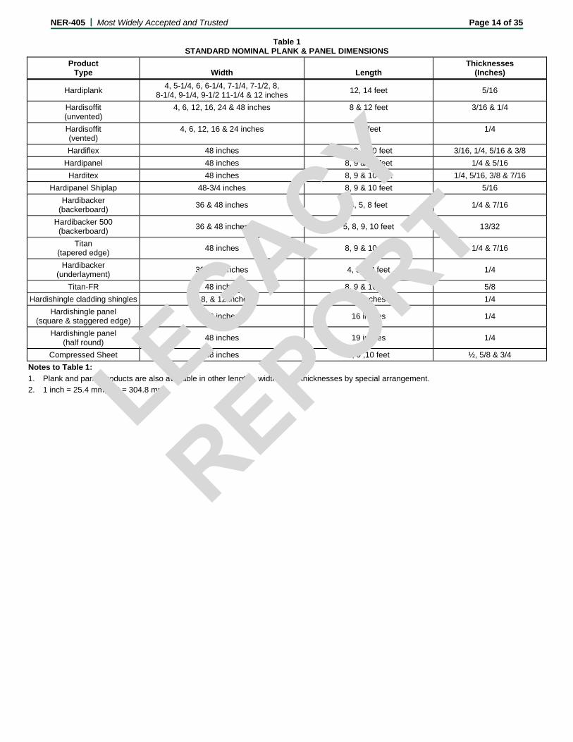
Table 1 STANDARD NOMINAL PLANK & PANEL DIMENSIONS
Product Type Width Length
Thicknesses (Inches)
Hardiplank 4, 5-1/4, 6, 6-1/4, 7-1/4, 7-1/2, 8,
8-1/4, 9-1/4, 9-1/2 11-1/4 & 12 inches 12, 14 feet 5/16
Hardisoffit (unvented)
4, 6, 12, 16, 24 & 48 inches 8 & 12 feet 3/16 & 1/4
Hardisoffit (vented)
4, 6, 12, 16 & 24 inches 12 feet 1/4
Hardiflex 48 inches 8, 9 & 10 feet 3/16, 1/4, 5/16 & 3/8
Hardipanel 48 inches 8, 9 & 10 feet 1/4 & 5/16
Harditex 48 inches 8, 9 & 10 feet 1/4, 5/16, 3/8 & 7/16
Hardipanel Shiplap 48-3/4 inches 8, 9 & 10 feet 5/16
Hardibacker (backerboard)
36 & 48 inches 4, 5, 8 feet 1/4 & 7/16
Hardibacker 500 (backerboard)
36 & 48 inches 5, 8, 9, 10 feet 13/32
Titan (tapered edge)
48 inches 8, 9 & 10 feet 1/4 & 7/16
Hardibacker (underlayment)
36 & 48 inches 4, 5 & 8 feet 1/4
Titan-FR 48 inches 8, 9 & 10 feet 5/8
Hardishingle cladding shingles 6, 8, & 12 inches 18 inches 1/4
Hardishingle panel (square & staggered edge)
48 inches 16 inches 1/4
Hardishingle panel (half round)
48 inches 19 inches 1/4
Compressed Sheet 48 inches 8, 9 ,10 feet ½, 5/8 & 3/4
Notes to Table 1:
1. Plank and panel products are also available in other lengths, widths, and thicknesses by special arrangement.
2. 1 inch = 25.4 mm, 1 ft = 304.8 mm
LEGACY
REPO
RT
NER-405 | Most Widely Accepted and Trusted Page 15 of 35
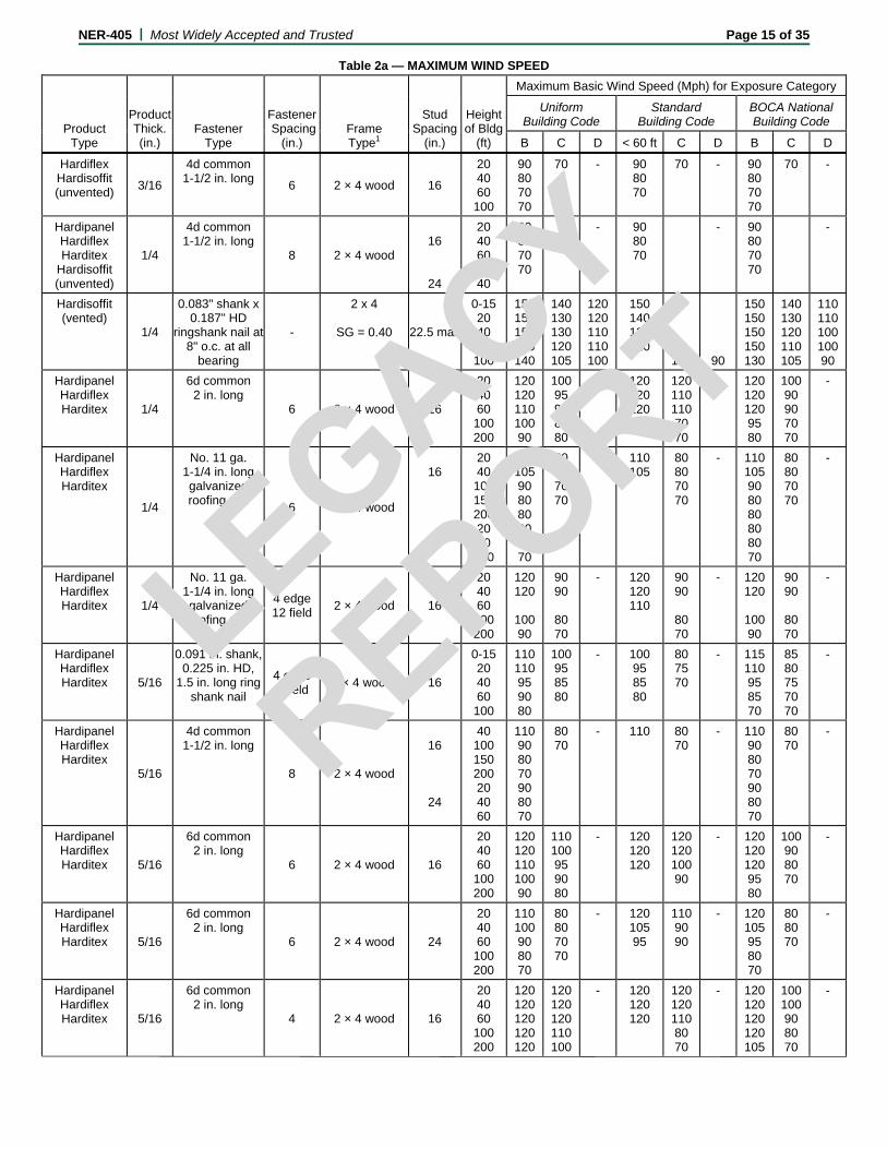
Table 2a — MAXIMUM WIND SPEED
Product Type
Product Thick. (in.)
Fastener Type
Fastener Spacing
(in.) Frame Type1
Stud Spacing
(in.)
Heightof Bldg
(ft)
Maximum Basic Wind Speed (Mph) for Exposure Category
Uniform Building Code
Standard Building Code
BOCA National Building Code
B C D < 60 ft C D B C D
Hardiflex Hardisoffit (unvented)
3/16
4d common 1-1/2 in. long
6 2 × 4 wood 16
20 40 60 100
90 80 70 70
70 - 90 80 70
70
- 90 80 70 70
70 -
Hardipanel Hardiflex Harditex
Hardisoffit (unvented)
1/4
4d common 1-1/2 in. long
8 2 × 4 wood
16
24
20 40 60 20 40
90 80 70 70
- 90 80 70
- 90 80 70 70
-
Hardisoffit (vented)
1/4
0.083" shank x 0.187" HD
ringshank nail at 8" o.c. at all
bearing
-
2 x 4
SG = 0.40 22.5 max
0-15 20 40 60 100
150 150 150 150 140
140 130 130 120 105
120 120 110 110 100
150 140 130 120
105
90
150 150 150 150 130
140 130 120 110 105
110 110 100 100 90
Hardipanel Hardiflex Harditex 1/4
6d common 2 in. long
6 2 × 4 wood 16
20 40 60 100 200
120 120 110 100 90
100 95 90 85 80
- 120 120 120
120 110 110 70 70
- 120 120 120 95 80
100 90 90 70 70
-
Hardipanel Hardiflex Harditex
1/4
No. 11 ga. 1-1/4 in. long galvanized roofing nail
6 2 × 4 wood
16
24
20 40 100 150 200 20 40 100
110 105 90 80 80 80 80 70
80 80 70 70
- 110 105
80 80 70 70
- 110 105 90 80 80 80 80 70
80 80 70 70
-
Hardipanel Hardiflex Harditex 1/4
No. 11 ga. 1-1/4 in. long galvanized roofing nail
4 edge 12 field
2 × 4 wood 16
20 40 60 100 200
120 120
100 90
90 90
80 70
- 120 120 110
90 90
80 70
- 120 120
100 90
90 90
80 70
-
Hardipanel Hardiflex Harditex 5/16
0.091 in. shank, 0.225 in. HD,
1.5 in. long ring shank nail
4 edge 8 field
2 × 4 wood2 16
0-15 20 40 60 100
110 110 95 90 80
100 95 85 80
- 100 95 85 80
80 75 70
- 115 110 95 85 70
85 80 75 70 70
-
Hardipanel Hardiflex Harditex
5/16
4d common 1-1/2 in. long
8 2 × 4 wood
16
24
40 100 150 200 20 40 60
110 90 80 70 90 80 70
80 70
- 110 80 70
- 110 90 80 70 90 80 70
80 70
-
Hardipanel Hardiflex Harditex 5/16
6d common 2 in. long
6 2 × 4 wood 16
20 40 60 100 200
120 120 110 100 90
110 100 95 90 80
- 120 120 120
120 120 100 90
- 120 120 120 95 80
100 90 80 70
-
Hardipanel Hardiflex Harditex 5/16
6d common 2 in. long
6 2 × 4 wood 24
20 40 60 100 200
110 100 90 80 70
80 80 70 70
- 120 105 95
110 90 90
- 120 105 95 80 70
80 80 70
-
Hardipanel Hardiflex Harditex 5/16
6d common 2 in. long
4 2 × 4 wood 16
20 40 60 100 200
120 120 120 120 120
120 120 120 110 100
- 120 120 120
120 120 110 80 70
- 120 120 120 120 105
100 100 90 80 70
-
LEGACY
REPO
RT

NER-405 | Most Widely Accepted and Trusted Page 16 of 35
Table 2a — MAXIMUM WIND SPEED
Product Type
Product Thick. (in.)
Fastener Type
Fastener Spacing
(in.) Frame Type1
Stud Spacing
(in.)
Heightof Bldg
(ft)
Maximum Basic Wind Speed (Mph) for Exposure Category
Uniform Building Code
Standard Building Code
BOCA National Building Code
B C D < 60 ft C D B C D
Hardipanel Hardiflex Harditex 5/16
6d common 2 in. long
4 2 × 4 wood 24
20 40 60 100 200
120 120 110 100 90
105 100 90 85 80
- 120 120 120
120 110 110 80 70
- 120 120 120 100 80
105 95 90 80 70
-
Hardipanel Hardiflex Harditex
5/16
6d common 2 in. long 6 edge
12 field 2 × 4 wood 16
40 60 100 200
120
100 90
90
80 70
- 120 110
90
80 70
- 120
100 90
90
80 70
-
Hardipanel Shiplap Panel 5/16
0.092" shank × 2" × 0.225" HD ringshank nail
3 edge 8 field
2 × 4
SG = 0.40 16
0-15 20 40 60 100
140 130 120 115 105
110 105 95 90 85
95 95 90 85 80
125 120 110 100
80
-
150 150 130 120 95
110 105 95 90 80
90 85 80 75 -
Hardipanel Shiplap Panel 5/16
0.092" shank × 2" × 0.225" HD ringshank nail
4 edge 8 field
2 × 4
SG = 0.40 16
0-15 20 40 60 100
130 130 115 110 100
100 100 95 90 80
90 90 85 80 75
120 115 100 95
75
-
150 140 125 115 90
105 100 90 85 75
85 80 75 75 -
Hardipanel Shiplap Panel 5/16
0.092" shank × 2" × 0.225" HD ringshank nail
5 edge 8 field
2 × 4
SG = 0.40 16
0-15 20 40 60 100
130 120 110 100 90
95 95 85 80 80
85 80 80 75 70
115 110 95 90
-
-
140 140 120 110 90
90 90 85 80 75
80 80 75 - -
Hardipanel Shiplap Panel 5/16
0.092" shank × 2" × 0.225" HD ringshank nail
6 edge 8 field
2 × 4
SG = 0.40 16
0-15 20 40 60 100
120 115 110 100 95
90 90 85 80 75
80 80 75 75 -
105 100 90 85
-
-
140 130 110 100 80
95 90 80 75 -
75 70 70 - -
Hardipanel Shiplap Panel 5/16
0.092" shank × 2" × 0.225" HD ringshank nail
7 edge 8 field
2 × 4
SG = 0.40 16
0-15 20 40 60 100
110 110 100 90 85
85 80 80 75 70
75 70 70 - -
100 95 85 80
-
-
130 120 100 90 75
90 85 80 70 -
70 70 - - -
Hardipanel Shiplap Panel 5/16
0.092" shank × 2" × 0.225" HD ringshank nail
8 edge 8 field
2 × 4
SG = 0.40 16
0-15 20 40 60 100
105 100 90 85 80
80 80 70 70 -
70 70 - - -
90 90 80 75
120 110 95 90 75
80 80 70 - -
70 - - - -
Hardiflex Harditex
7/16
No. 11 ga 1-3/4 in. long galvanized roofing nail
6 2 × 4 wood 16
20 40 60 100 200
120 120 120 110 110
120 110 110 110 100
- 120 120 120
120 110 100 90 80
- 120 120 120 110 100
120 110 100 90 80
-
Hardishingle Panel
Straight Installation
1/4
0.083" shank ×0.187" HD
ringshank nail into OSB only
13.75 -
0-15 20 40 60 100
100 90 85 80 70
70 70 70 - -
- - - - -
80 80 70 70
-
-
110 105 90 80 70
70 70 70 - -
- - - - -
Hardishingle Panel
Staggered Installation
1/4
0.083" shank ×0.187" HD
ringshank nail into OSB only
13.75 -
0-15 20 40 60 100
90 90 80 70 -
70 70 - - -
- - - - -
80 80 70 -
-
-
90 90 80 70 -
70 - - - -
- - - - -
Hardishingle Panel
1/4
0.083" shank × 0.187" HD
ringshank nail at each stud
- 2 × 4
SG = 0.40
16
0-15 20 40 60 100
150 150 140 130 120
120 120 110 105 100
110 100 100 95 90
150 150 130 120
90
80
150 150 150 140 110
120 120 110 100 90
100 100 90 90 80
LEGACY
REPO
RT

NER-405 | Most Widely Accepted and Trusted Page 17 of 35
Table 2a — MAXIMUM WIND SPEED
Product Type
Product Thick. (in.)
Fastener Type
Fastener Spacing
(in.) Frame Type1
Stud Spacing
(in.)
Heightof Bldg
(ft)
Maximum Basic Wind Speed (Mph) for Exposure Category
Uniform Building Code
Standard Building Code
BOCA National Building Code
B C D < 60 ft C D B C D
Hardishingle Panel
1/4
0.083" shank × 0.187" HD
ringshank nail at each stud
- 2 × 4
SG = 0.40
24
0-15 20 40 60 100
115 110 105 90 85
90 85 80 75 70
80 70 70 - -
100 100 90 85
-
-
130 120 110 100 80
90 85 80 75 -
70 70 - - -
Hardiflex Hardisoffit (unvented) 3/16
Min. No. 8 x 1 in. long × 0.323 in. HD ribbed
buglehead screws
6
Min. No. 20 ga. × 3-5/8 in.×1-
3/8 in. metal C-stud
16
20 40 60 100
80 80 70 70
70 - 80 80 70
70 - 80 80 70 70
70 -
Hardipanel Hardiflex Harditex
1/4
Min. No. 8 x 1 in. long × 0.323 in. HD ribbed
buglehead screws 6
Min. No. 20 ga. × 3-5/8 in.×1-
3/8 in. metal C-stud
16
24
20 40 60 100 150 200 20 40 100
120 110 100 90 90 80 90 80 70
90 90 80 80 70 70 70
N/A 120 110 100
90 80
90 90 80 80 70 70 70
N/A 120 110 100 90 90 80 90 80 70
90 90 80 80 70 70 70
N/A
Hardipanel
5/16
ET & F 0.100 × 1.5" ×
25" HD ES 4144
4 edge 8 field
Min. No. 20 ga. × 3.62" ×
1.375" Metal C-stud
16
0-15 20 40 60 100
150 140 130 120 110
115 110 105 100 95
100 100 90 90 85
130 130 120 110
75
-
150 150 140 130 105
120 110 100 100 85
100 90 90 80 70
Hardipanel
5/16
ET & F 0.100 × 1.5" ×
25" HD ES 4144
4 edge 8 field
Min. No. 20 ga. × 3.62" ×
1.375" Metal C-stud
24
0-15 20 40 60 100
120 110 100 95 85
90 85 80 75 70
80 75 70 70 -
105 100 90 85
-
-
135 130 110 100 80
90 90 80 75 -
75 70 70 70 -
Hardiflex Harditex
7/16
Min. No. 8 x 1 in. long × 0.311 in. HD ribbed
buglehead screws
6
Min. No. 20 ga. × 3-5/8 in.×1-
3/8 in. metal C-stud
16
20 40 60 100 200
120 120 120 120 110
120 120 110 110 110
- 120 120 120
120 120 120 90 80
- 120 120 120 120 100
120 120 110 90 80
-
Notes to Table 2a: 1. Values are for species of wood having a specific gravity of 0.42 or greater, unless otherwise noted. 2. Values are for species of wood having a specific gravity of 0.36 or greater.
LEGACY
REPO
RT

NER-405 | Most Widely Accepted and Trusted Page 18 of 35
Table 2b — MAXIMUM WIND SPEED
Product Type
Fastener Type
Fastener Spacing
(in.) Frame Type1
Stud Spacing
(in.)
Heightof Bldg
(ft)
Maximum Basic Wind Speed (Mph) for Exposure Category
Product (in.)
Uniform Building Code
Standard Building Code
BOCA NationalBuilding Code
Thick. Width B C D < 60 ft C D B C D
Hardiplank 5/16 4.00 ET & F pin 0.100 × 1.5" × 0.25" HD
Through Overlap
Min. No. 20 ga. × 3.62" × 1.375" Metal C-stud
16 0-15 20 40 60 100
150150150150150
150150150150150
150 150 150 150 150
150 150 150 150
140
120
150150150150150
150150150150140
150150150140120
Hardiplank 5/16 6.00 ET & F pin 0.100 × 1.5" × 0.25" HD
Through Overlap
Min. No. 20 ga. × 3.62" × 1.375" Metal C-stud
16 0-15 20 40 60 100
150150150150150
150150140130130
140 140 130 120 120
150 150 150 150
110 100
150150150150140
150150140130110
130130120110100
Hardiplank 5/16 6.25 ET & F pin 0.100 × 1.5" × 0.25" HD
Through Overlap
Min. No. 20 ga. × 3.62" × 1.375" Metal C-stud
16 0-15 20 40 60 100
150150150140130
150150140130130
140 130 130 120 120
150 150 150 150
110 100
150150150150130
150150140130110
130120120110100
Hardiplank 5/16 7.50 ET & F pin 0.100 × 1.5" × 0.25" HD
Through Overlap
Min. No. 20 ga. × 3.62" × 1.375" Metal C-stud
16 0-15 20 40 60 100
150150150140130
140130120120110
120 120 110 110 100
150 150 130 130
100 80
150150150150120
140130120110100
11011010511080
Hardiplank 5/16 8.00 ET & F pin 0.100 × 1.5" × 0.25" HD
Through Overlap
Min. No. 20 ga. × 3.62" × 1.375" Metal C-stud
16 0-15 20 40 60 100
150150150130130
130130120110110
110 110 110 105 100
150 150 130 12
95 90
150150150150120
13013012011095
11011010090 85
Hardiplank 5/16 8.25 ET & F pin 0.100 × 1.5" × 0.25" HD
Through Overlap
Min. No. 20 ga. × 3.62" × 1.375" Metal C-stud
16 0-15 20 40 60 100
150150140130120
130130110110105
110 110 100 100 100
150 140 130 120
90 80
150150150140120
13013011511090
11010010090 80
Hardiplank 5/16 9.50 ET & F pin 0.100 × 1.5" × 0.25" HD
Through Overlap
Min. No. 20 ga. × 3.62" × 1.375" Metal C-stud
16 0-15 20 40 60 100
150150140120120
120120110105100
105 100 100 90 90
140 130 120 110
80 75
150150140130110
12012011010080
10010090 90 75
Hardiplank 5/16 12.00 ET & F pin 0.100 × 1.5" × 0.25" HD
Through Overlap
Min. No. 20 ga. × 3.62" × 1.375" Metal C-stud
16 0-15 20 40 60 100
140140120110105
11010510095 90
90 90 90 85 80
120 120 110 100
75 70
150150130120100
11011010090 75
90 90 80 80 70
Hardiplank 5/16 4.00 ET & F pin 0.100 × 1.5" × 0.25" HD
Through Overlap
Min. No. 20 ga. × 3.62" × 1.375" Metal C-stud
24 0-15 20 40 60 100
150150150150140
140140130125120
130 125 120 115 100
150 150 150 140
100 90
150150150150130
150140135125100
12012011010590
Hardiplank 5/16 6.00 ET & F pin 0.100 × 1.5" × 0.25" HD
Through Overlap
Min. No. 20 ga. × 3.62" × 1.375" Metal C-stud
24 0-15 20 40 60 100
150150130125115
120115110100100
100 100 95 90 90
140 135 120 110
80 70
150150140130110
12012010510080
10010090 85 75
Hardiplank 5/16 6.25 ET & F pin 0.100 × 1.5" × 0.25" HD
Through Overlap
Min. No. 20 ga. × 3.62" × 1.375" Metal C-stud
24 0-15 20 40 60 100
150150130120110
12011010510095
100 100 95 90 90
135 130 120 110
80 70
15015013012090
12011010510090
10095 90 80 70
Hardiplank 5/16 7.50 ET & F pin 0.100 × 1.5" × 0.25" HD
Through Overlap
Min. No. 20 ga. × 3.62" × 1.375" Metal C-stud
24 0-15 20 40 60 100
130125115110100
10010090 85 80
90 85 80 80 75
120 110 100 95
75 -
15014012011090
10010090 80 70
85 80 75 75 -
LEGACY
REPO
RT

NER-405 | Most Widely Accepted and Trusted Page 19 of 35
Table 2b — MAXIMUM WIND SPEED
Product Type
Fastener Type
Fastener Spacing
(in.) Frame Type1
Stud Spacing
(in.)
Heightof Bldg
(ft)
Maximum Basic Wind Speed (Mph) for Exposure Category
Product (in.)
Uniform Building Code
Standard Building Code
BOCA NationalBuilding Code
Thick. Width B C D < 60 ft C D B C D
Hardiplank 5/16 8.00 ET & F pin 0.100 × 1.5" × 0.25" HD
Through Overlap
Min. No. 20 ga. × 3.62" × 1.375" Metal C-stud
24 0-15 20 40 60 100
13012011010595
10095 90 85 80
85 80 80 75 70
115 110 100 95
70 -
15014012011090
10010090 80 70
80 80 75 70 -
Hardiplank 5/16 8.25 ET & F pin 0.100 × 1.5" × 0.25" HD
Through Overlap
Min. No. 20 ga. × 3.62" × 1.375" Metal C-stud
24 0-15 20 40 60 100
12512011010090
95 90 85 80 80
85 80 80 75 70
110 105 95 90
70 -
14014012011090
10090 85 80 70
80 80 70 70 -
Hardiplank 5/16 9.50 ET & F pin 0.100 × 1.5" × 0.25" HD
Through Overlap
Min. No. 20 ga. × 3.62" × 1.375" Metal C-stud
24 0-15 20 40 60 100
12011010090 85
90 90 80 80 70
80 75 70 70 -
100 100 90 85
- -
13013011011080
90 90 80 80 -
70 70 70 - -
Hardiplank 5/16 12.00 ET & F pin 0.100 × 1.5" × 0.25" HD
Through Overlap
Min. No. 20 ga. × 3.62" × 1.375" Metal C-stud
24 0-15 20 40 60 100
10010090 85 80
80 80 70 70 -
- - - - -
90 90 80 75
- -
12011090 90 70
80 80 70 - -
- - - - -
Hardiplank 5/16 4.00 ET & F Panelfast
0.100 × 1.5" × 0.313" HD
Through top edge of plank
Min. No. 20 ga. × 3.62" × 1.375" Metal C-stud
16 0-15 20 40 60 100
150150150150150
150150150150150
150 150 150 150 150
150 150 150 150
150 150
150150150150150
150150150150150
150150150150140
Hardiplank 5/16 6.00 ET & F Panelfast
0.100 × 1.5" × 0.313" HD
Through top edge of plank
Min. No. 20 ga. × 3.62" × 1.375" Metal C-stud
16 0-15 20 40 60 100
150150130120110
11011010010090
100 100 90 90 80
130 140 120 110
75 -
14014013012095
11010595 90 75
90 85 80 80 -
Hardiplank 5/16 6.25 ET & F Panelfast
0.100 × 1.5" × 0.313" HD
Through top edge of plank
Min. No. 20 ga. × 3.62" × 1.375" Metal C-stud
16 0-15 20 40 60 100
140140120120110
11011010095 90
100 90 90 85 80
130 120 115 105
70 -
15014012011090
10010090 85 70
85 80 75 70 -
Hardiplank 5/16 7.50 ET & F Panelfast
0.100 × 1.5" × 0.313" HD
Through top edge of plank
Min. No. 20 ga. × 3.62" × 1.375" Metal C-stud
16 0-15 20 40 60 100
12012011010090
90 90 80 80 75
80 80 75 70 70
110 100 95 90
- -
13012010595 75
90 85 75 70 -
70 70 - - -
Hardiplank 5/16 8.00 ET & F Panelfast
0.100 × 1.5" × 0.313" HD
Through top edge of plank
Min. No. 20 ga. × 3.62" × 1.375" Metal C-stud
16 0-15 20 40 60 100
11011010090 80
90 85 80 70 70
80 70 70 70 -
100 100 90 80
- -
12011010090 70
80 80 70 70 -
70 - - - -
Hardiplank 5/16 8.25 ET & F Panelfast
0.100 × 1.5" × 0.313" HD
Through top edge of plank
Min. No. 20 ga. × 3.62" × 1.375" Metal C-stud
16 0-15 20 40 60 100
11011010090 80
90 80 80 70 70
70 70 70 - -
100 95 85 70
- -
12011010090 70
80 80 70 - -
- - - - -
Hardiplank 5/16 4.00 ET & F Panelfast
0.100 × 1.5" × 0.313" HD
Through top edge of plank
Min. No. 20 ga. × 3.62" × 1.375" Metal C-stud
24 0-15 20 40 60 100
150150150150150
150150150
150150
150 150 150 150 150
150 150 150 150
130 110
150150150150150
150150150150130
150150140130110
Hardiplank 5/16 6.00 ET & F Panelfast
0.100 × 1.5" × 0.313" HD
Through top edge of plank
Min. No. 20 ga. × 3.62" × 1.375" Metal C-stud
24 0-15 20 40 60 100
130120110110100
10010090 85 80
90 85 85 80 70
110 110 100 90
- -
14013011010580
95 90 80 80 -
80 70 70 - -
LEGACY
REPO
RT

NER-405 | Most Widely Accepted and Trusted Page 20 of 35
Table 2b — MAXIMUM WIND SPEED
Product Type
Fastener Type
Fastener Spacing
(in.) Frame Type1
Stud Spacing
(in.)
Heightof Bldg
(ft)
Maximum Basic Wind Speed (Mph) for Exposure Category
Product (in.)
Uniform Building Code
Standard Building Code
BOCA NationalBuilding Code
Thick. Width B C D < 60 ft C D B C D
Hardiplank 5/16 6.25 ET & F Panelfast
0.100 × 1.5" × 0.313" HD
Through top edge of plank
Min. No. 20 ga. × 3.62" × 1.375" Metal C-stud
24 0-15 20 40 60 100
12012011010090
95 90 85 80 70
80 80 70 70 70
110 100 90 80
- -
13012011090 70
90 85 80 75 -
70 70 - - -
Hardiplank 5/16 7.50 ET & F Panelfast
0.100 × 1.5" × 0.313" HD
Through top edge of plank
Min. No. 20 ga. × 3.62" × 1.375" Metal C-stud
24 0-15 20 40 60 100
11011010090 85
90 85 80 75 70
70 70 70 70 -
100 100 90 80
- -
12011010090 70
80 80 70 70 -
70 - - - -
Hardiplank 5/16 8.00 ET & F Panelfast
0.100 × 1.5" × 0.313" HD
Through top edge of plank
Min. No. 20 ga. × 3.62" × 1.375" Metal C-stud
24 0-15 20 40 60 100
10010090 80 75
80 75 70 - -
70 70 - - -
90 90 80 75
- -
11010085 80 -
70 70 - - -
- - - - -
Hardiplank 5/16 8.25 ET & F Panelfast
0.100 × 1.5" × 0.313" HD
Through top edge of plank
Min. No. 20 ga. × 3.62" × 1.375" Metal C-stud
24 0-15 20 40 60 100
90 90 80 75 70
70 70 - - -
- - - - -
80 80 70 70
- -
10090 80 70 -
- - - - -
- - - - -
Hardiplank 5/16 4.00 6d common 2" long
Through Overlap
2 × 4 16 0-15 20 40 60 100
150150150150150
150150150150150
150 150 150 150 140
150 150 150 150
130 120
150150150150150
150150150150130
150150150130120
Hardiplank 5/16 6.00 6d common 2" long
Through Overlap
2 × 4 16 0-15 20 40 60 100
150150150150150
150150150150150
135 130 120 120 120
150 150 150 150
110 100
150150150150140
150150140130110
130130120115100
Hardiplank 5/16 6.25 6d common 2" long
Through Overlap
2 × 4 16 0-15 20 40 60 100
150150150150150
150150150130130
120 120 120 120 110
150 150 150 150
110 100
150150150150150
1501501
40 130110
130120120115100
Hardiplank 5/16 7.50 6d common 2" long
Through Overlap
2 × 4 16 0-15 20 40 60 100
150150 150150130
150150130120110
120 120 110 110 110
150 150 140 130
110 90
150150150150140
140140120120100
12012012011590
Hardiplank 5/16 8.00 6d common 2" long
Through Overlap
2 × 4 16 0-15 20 40 60 100
150150150140130
130130120120110
120 115 110 105 100
150 150 130 130
95 85
150150150150120
14014012011595
11011010010085
Hardiplank 5/16 8.25 6d common 2" long
Through Overlap
2 × 4 16 0-15 20 40 60 100
150150150140130
130130120115110
115 110 110 105 100
150 150 130 120
95 80
150150150150130
14013012011095
11010010010080
Hardiplank 5/16 9.50 6d common 2" long
Through Overlap
2 × 4 16 0-15 20 40 60 100
150150140130120
120120110105100
110 110 100 100 95
140 140 120 120
90 80
150150140120115
13012012012090
10510095 90 80
Hardiplank 5/16 12.00 6d common 2" long
Through Overlap
2 × 4 16 0-15 20 40 60 100
140140120115110
11010510095 90
95 95 90 85 80
130 120 110 105
80 70
150150140120100
11011010095 80
95 90 85 80 70
LEGACY
REPO
RT
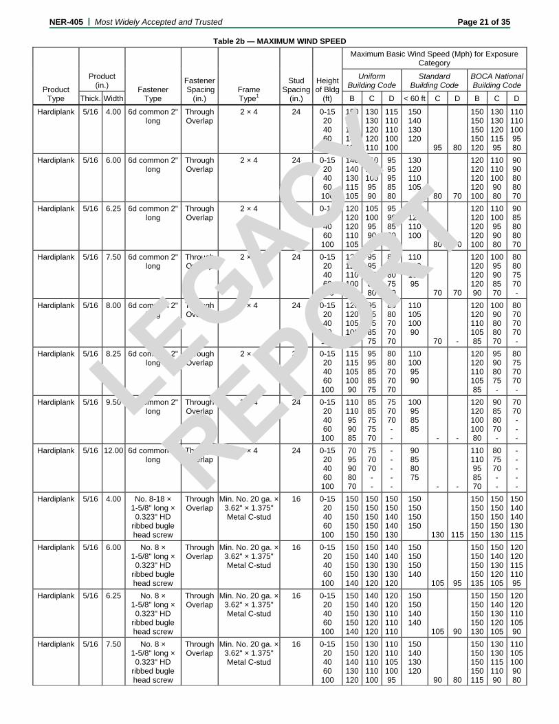
NER-405 | Most Widely Accepted and Trusted Page 21 of 35
Table 2b — MAXIMUM WIND SPEED
Product Type
Fastener Type
Fastener Spacing
(in.) Frame Type1
Stud Spacing
(in.)
Heightof Bldg
(ft)
Maximum Basic Wind Speed (Mph) for Exposure Category
Product (in.)
Uniform Building Code
Standard Building Code
BOCA NationalBuilding Code
Thick. Width B C D < 60 ft C D B C D
Hardiplank 5/16 4.00 6d common 2" long
Through Overlap
2 × 4 24 0-15 20 40 60 100
150150150140130
130130120120110
115 110 110 100 100
150 140 130 120
95 80
150150150150120
13013012011595
11011010095 80
Hardiplank 5/16 6.00 6d common 2" long
Through Overlap
2 × 4 24 0-15 20 40 60 100
140140130115105
11010010095 90
95 95 95 85 80
130 120 110 105
80 70
120120120120100
11011010090 80
90 90 80 80 70
Hardiplank 5/16 6.25 6d common 2" long
Through Overlap
2 × 4 24 0-15 20 40 60 100
120120120110105
10510095 90 85
95 90 85 80 80
120 120 110 100
80 70
120120120120100
11010095 90 80
90 85 80 80 70
Hardiplank 5/16 7.50 6d common 2" long
Through Overlap
2 × 4 24 0-15 20 40 60 100
12012011010095
95 95 85 85 80
85 85 80 75 70
110 110 100 95
70 70
12012012012090
10095 90 85 70
80 80 75 70 -
Hardiplank 5/16 8.00 6d common 2" long
Through Overlap
2 × 4 24 0-15 20 40 60 100
12012010510090
95 95 85 85 75
80 80 70 70 70
110 105 100 90
70 -
12012011010585
10090 80 80 70
80 70 70 70 -
Hardiplank 5/16 8.25 6d common 2" long
Through Overlap
2 × 4 24 0-15 20 40 60 100
11511510510090
95 95 85 85 75
80 80 70 70 70
110 100 95 90
12012011010585
95 90 80 75 -
80 75 70 70 -
Hardiplank 5/16 9.50 6d common 2" long
Through Overlap
2 × 4 24 0-15 20 40 60 100
11011095 90 85
85 85 75 75 70
75 70 70 - -
100 95 85 85
- -
12012010010080
90 85 80 70 -
70 70 - - -
Hardiplank 5/16 12.00 6d common 2" long
Through Overlap
2 × 4 24 0-15 20 40 60 100
70 95 90 80 70
75 70 70 - -
- - - - -
90 85 80 75
- -
11011095 85 70
80 75 70 - -
- - - - -
Hardiplank 5/16 4.00 No. 8-18 × 1-5/8" long × 0.323" HD
ribbed bugle head screw
Through Overlap
Min. No. 20 ga. × 3.62" × 1.375" Metal C-stud
16 0-15 20 40 60 100
150150150150150
150150150150150
150 150 140 140 130
150 150 150 150
130 115
150150150150150
150150150150130
150140140130115
Hardiplank 5/16 6.00 No. 8 × 1-5/8" long × 0.323" HD
ribbed bugle head screw
Through Overlap
Min. No. 20 ga. × 3.62" × 1.375" Metal C-stud
16 0-15 20 40 60 100
150150150150140
150140130130120
140 140 130 130 120
150 150 150 140
105 95
150150150150135
150140130120105
12012011511095
Hardiplank 5/16 6.25 No. 8 × 1-5/8" long × 0.323" HD
ribbed bugle head screw
Through Overlap
Min. No. 20 ga. × 3.62" × 1.375" Metal C-stud
16 0-15 20 40 60 100
150150150150140
140140130120120
120 120 110 110 110
150 150 140 140
105 90
150150150150130
150140130120105
12012011010590
Hardiplank 5/16 7.50 No. 8 × 1-5/8" long × 0.323" HD
ribbed bugle head screw
Through Overlap
Min. No. 20 ga. × 3.62" × 1.375" Metal C-stud
16 0-15 20 40 60 100
150150140130120
130120110110100
110 110 105 100 95
150 140 130 120
90 80
150150150150115
13013011511090
11010510090 80
LEGACY
REPO
RT

NER-405 | Most Widely Accepted and Trusted Page 22 of 35
Table 2b — MAXIMUM WIND SPEED
Product Type
Fastener Type
Fastener Spacing
(in.) Frame Type1
Stud Spacing
(in.)
Heightof Bldg
(ft)
Maximum Basic Wind Speed (Mph) for Exposure Category
Product (in.)
Uniform Building Code
Standard Building Code
BOCA NationalBuilding Code
Thick. Width B C D < 60 ft C D B C D
Hardiplank 5/16 8.00 No. 8 × 1-5/8" long × 0.323" HD
ribbed bugle head screw
Through Overlap
Min. No. 20 ga. × 3.62" × 1.375" Metal C-stud
16 0-15 20 40 60 100
150150150150130
130120110110100
110 110 105 100 95
150 140 130 120
90 80
150150150140115
13013011511090
11010510090 80
Hardiplank 5/16 8.25 No. 8 × 1-5/8" long × 0.323" HD
ribbed bugle head screw
Through Overlap
Min. No. 20 ga. × 3.62" × 1.375" Metal C-stud
16 0-15 20 40 60 100
150150140120120
120120110110100
110 110 105 100 95
140 140 120 120
90 80
150150150140115
13012011510590
11010510090 80
Hardiplank 5/16 9.50 No. 8 × 1-5/8" long × 0.323" HD
ribbed bugle head screw
Through Overlap
Min. No. 20 ga. × 3.62" × 1.375" Metal C-stud
16 0-15 20 40 60 100
150150130120115
11511011011095
100 100 95 90 85
130 130 120 110
85 75
150150140130110
12011510510085
10095 90 85 75
Hardiplank 5/16 12.00 No. 8 × 1-5/8" long × 0.323" HD
ribbed bugle head screw
Through Overlap
Min. No. 20 ga. × 3.62" × 1.375" Metal C-stud
16 0-15 20 40 60 100
130130120110100
10010090 90 85
90 90 80 80 80
120 120 100 100
75 -
15015012012095
11010595 90 75
90 80 80 75 -
Hardiplank 5/16 4.00 No. 8 × 1-5/8" long × 0.323" HD
ribbed bugle head screw
Through Overlap
Min. No. 20 ga. × 3.62" × 1.375" Metal C-stud
24 0-15 20 40 60 100
150150150150140
150140130130110
130 130 120 110 110
150 150 150 140
105 90
150150150150135
150140130120105
12012011011090
Hardiplank 5/16 6.00 No. 8 × 1-5/8" long × 0.323" HD
ribbed bugle head screw
Through Overlap
Min. No. 20 ga. × 3.62" × 1.375" Metal C-stud
24 0-15 20 40 60 100
150150150140130
130130110105100
105 100 100 90 90
140 130 120 115
85 75
150150140130110
12012011010085
10010095 90 75
Hardiplank 5/16 6.25 No. 8 × 1-5/8" long × 0.323" HD
ribbed bugle head screw
Through Overlap
Min. No. 20 ga. × 3.62" × 1.375" Metal C-stud
24 0-15 20 40 60 100
150150130120110
12011010510095
100 100 90 90 90
135 130 120 110
85 70
150150140130110
15014013012085
10095 90 85 75
Hardiplank 5/16 7.50 No. 8 × 1-5/8" long × 0.323" HD
ribbed bugle head screw
Through Overlap
Min. No. 20 ga. × 3.62" × 1.375" Metal C-stud
24 0-15 20 40 60 100
140130120110100
11010095 90 90
90 90 85 80 80
120 120 110 100
80 70
150150130120115
11010595 90 80
90 90 80 80 70
Hardiplank 5/16 8.00 No. 8 × 1-5/8" long × 0.323" HD
ribbed bugle head screw
Through Overlap
Min. No. 20 ga. × 3.62" × 1.375" Metal C-stud
24 0-15 20 40 60 100
130130120110100
10510095 90 85
90 90 80 80 80
120 115 105 100
75 -
15015013012095
11010595 90 75
90 85 80 75 -
Hardiplank 5/16 8.25 No. 8 × 1-5/8" long × 0.323" HD
ribbed bugle head screw
Through Overlap
Min. No. 20 ga. × 3.62" × 1.375" Metal C-stud
24 0-15 20 40 60 100
130130120110100
10010090 90 85
90 90 80 80 75
120 115 105 100
75 -
15015012011595
10510590 85 75
90 85 80 75 -
Hardiplank 5/16 9.50 No. 8 × 1-5/8" long × 0.323" HD
ribbed bugle head screw
Through Overlap
Min. No. 20 ga. × 3.62" × 1.375" Metal C-stud
24 0-15 20 40 60 100
12012011010090
95 90 85 80 80
80 80 75 70 70
110 105 95 90
70 -
14014012011090
10095 85 80 70
80 80 75 70 -
Hardiplank 5/16 12.00 No. 8 × 1-5/8" long × 0.323" HD
ribbed bugle head screw
Through Overlap
Min. No. 20 ga. × 3.62" × 1.375" Metal C-stud
24 0-15 20 40 60 100
11511095 90 80
80 80 75 70 70
70 70 70 - -
100 95 85 80
- -
13012010095 80
90 85 75 70 -
70 70 - - -
LEGACY
REPO
RT

NER-405 | Most Widely Accepted and Trusted Page 23 of 35
Table 2b — MAXIMUM WIND SPEED
Product Type
Fastener Type
Fastener Spacing
(in.) Frame Type1
Stud Spacing
(in.)
Heightof Bldg
(ft)
Maximum Basic Wind Speed (Mph) for Exposure Category
Product (in.)
Uniform Building Code
Standard Building Code
BOCA NationalBuilding Code
Thick. Width B C D < 60 ft C D B C D
Hardiplank 5/16 4.00 No. 11 ga. 1-1/4" long
Galv. roofing nail
Through top edge of plank
2 × 4 wood
16 0-15 20 40 60 100
150150150150150
150150150150150
150 150 150 150 150
150 150 150 150
140 120
150150150150150
150150150150140
150150150150120
Hardiplank 5/16 6.00 No. 11 ga. 1-1/4" long
galv. roofing nail
Through top edge of plank
2 × 4 wood
16 0-15 20 40 60 100
150150150150150
150150140130120
130 130 120 120 110
150 150 150 140
110 95
150150150150140
150150130130110
13012011511095
Hardiplank 5/16 6.25 No. 11 ga. 1-1/4" long
galv. roofing nail
Through top edge of plank
2 × 4 wood
16 0-15 20 40 60 100
150150150150140
150140130130120
130 120 120 110 110
150 150 150 140
100 95
150150150150135
150140130120100
12012011011095
Hardiplank 5/16 7.50 No. 11 ga. 1-1/4" long
galv. roofing nail
Through top edge of plank
2 × 4 wood
16 0-15 20 40 60 100
150150150140130
130130120115110
115 110 110 105 100
150 140 135 125
95 85
150150150150120
13013012011095
11011010095 85
Hardiplank 5/16 8.00 No. 11 ga. 1-1/4" long
galv. roofing nail
Through top edge of plank
2 × 4 wood
16 0-15 20 40 60 100
150150140130120
130120115110110
110 110 100 100 95
150 140 130 120
90 80
150150150140115
13012011511090
10510095 95 80
Hardiplank 5/16 8.25 No. 11 ga. 1-1/4" long
galv. roofing nail
Through top edge of plank
2 × 4 wood
16 0-15 20 40 60 100
150150140130120
120120110110100
110 105 100 100 95
140 140 125 120
90 80
150150150140115
13012011010590
10510595 90 80
Hardiplank 5/16 9.50 No. 11 ga. 1-1/4" long
galv. roofing nail
Through top edge of plank
2 × 4 wood
16 0-15 20 40 60 100
150140130120110
11011010010095
100 100 90 90 80
130 130 115 110
80 70
150150140130105
12011510010080
10095 90 85 70
Hardiplank 5/16 12.00 No. 11 ga. 1-1/4" long
galv. roofing nail
Through top edge of plank
2 × 4 wood
16 0-15 20 40 60 100
130120110110100
10010090 80 80
90 80 80 80 75
115 110 100 95
75 -
15014012011090
10510095 85 75
85 80 75 75 -
Hardiplank 5/16 4.00 No. 11 ga. 1-1/4" long
galv. roofing nail
Through top edge of plank
2 × 4 wood
24 0-15 20 40 60 100
150150150150150
150150150140130
140 140 130 130 120
150 150 150 150
115 105
150150150150150
150150140140115
130130120120105
Hardiplank 5/16 6.00 No. 11 ga. 1-1/4" long
galv. roofing nail
Through top edge of plank
2 × 4 wood
24 0-15 20 40 60 100
150150140130120
120120110110100
110 105 100 100 100
140 140 125 115
90 80
150150150140110
13012011010590
10510595 90 80
Hardiplank 5/16 6.25 No. 11 ga. 1-1/4" long
galv. roofing nail
Through top edge of plank
2 × 4 wood
24 0-15 20 40 60 100
150150130120120
120120110110100
110 100 100 95 90
140 130 120 110
85 80
150150150130110
12512011010585
10010095 90 80
Hardiplank 5/16 7.50 No. 11 ga. 1-1/4" long
galv. roofing nail
Through top edge of plank
2 × 4 wood
24 0-15 20 40 60 100
140140120120110
11010510095 90
95 90 90 85 70
120 120 110 100
80 70
150150130120100
11511010095 80
90 90 80 80 70
LEGACY
REPO
RT
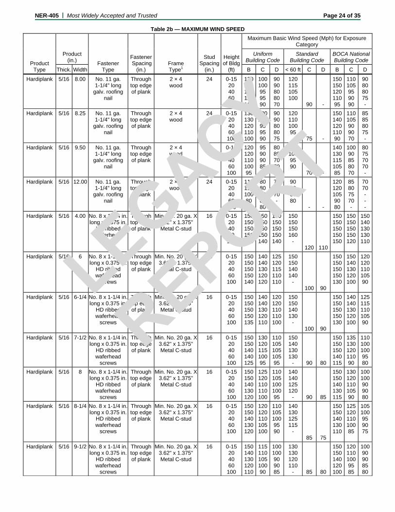
NER-405 | Most Widely Accepted and Trusted Page 24 of 35
Table 2b — MAXIMUM WIND SPEED
Product Type
Fastener Type
Fastener Spacing
(in.) Frame Type1
Stud Spacing
(in.)
Heightof Bldg
(ft)
Maximum Basic Wind Speed (Mph) for Exposure Category
Product (in.)
Uniform Building Code
Standard Building Code
BOCA NationalBuilding Code
Thick. Width B C D < 60 ft C D B C D
Hardiplank 5/16 8.00 No. 11 ga. 1-1/4" long
galv. roofing nail
Through top edge of plank
2 × 4 wood
24 0-15 20 40 60 100
130130120120110
10010095 95 90
90 90 80 80 70
120 115 105 100
90 -
15015012011095
11010595 90 90
90 80 80 75 -
Hardiplank 5/16 8.25 No. 11 ga. 1-1/4" long
galv. roofing nail
Through top edge of plank
2 × 4 wood
24 0-15 20 40 60 100
130130120110100
10010095 95 90
90 90 80 80 75
120 110 100 95
75 -
15014012011090
11010590 90 70
85 85 80 75 -
Hardiplank 5/16 9.50 No. 11 ga. 1-1/4" long
galv. roofing nail
Through top edge of plank
2 × 4 wood
24 0-15 20 40 60 100
12012011010095
95 90 90 85 75
80 80 70 70 70
110 105 95 90
70 -
14013011510585
10090 85 80 70
80 75 70 70 -
Hardiplank 5/16 12.00 No. 11 ga. 1-1/4" long
galv. roofing nail
Through top edge of plank
2 × 4 wood
24 0-15 20 40 60 100
11011010080 80
80 80 80 80 80
70 70 70 - -
90 90 80 80
- -
12012010590 80
85 80 75 70 -
70 70 - - -
Hardiplank 5/16 4.00 No. 8 x 1-1/4 in. long x 0.375 in.
HD ribbed waferhead
screws
Through top edge of plank
Min. No. 20 ga. X 3.62" x 1.375" Metal C-stud
16 0-15 20 40 60 100
150150150150150
150150150150140
150 150 150 150 140
150 150 150 160
- 120 110
150150150150150
150150150150120
150140130130110
Hardiplank 5/16 6 No. 8 x 1-1/4 in. long x 0.375 in.
HD ribbed waferhead
screws
Through top edge of plank
Min. No. 20 ga. X 3.62" x 1.375" Metal C-stud
16 0-15 20 40 60 100
150150150150140
140140130120120
125 120 115 110 110
150 150 140 140
- 100 90
150150150150130
150140130120100
12012011010590
Hardiplank 5/16 6-1/4 No. 8 x 1-1/4 in. long x 0.375 in.
HD ribbed waferhead
screws
Through top edge of plank
Min. No. 20 ga. X 3.62" x 1.375" Metal C-stud
16 0-15 20 40 60 100
150150150150135
140140130120110
120 120 110 110 100
150 150 140 130
- 100 90
150150150150130
140140130120100
12511511010590
Hardiplank 5/16 7-1/2 No. 8 x 1-1/4 in. long x 0.375 in.
HD ribbed waferhead
screws
Through top edge of plank
Min. No. 20 ga. X 3.62" x 1.375" Metal C-stud
16 0-15 20 40 60 100
150150140140125
13012011510095
110 105 105 105 95
150 140 130 130
- 90 80
150150150140115
13513012011090
11010010095 80
Hardiplank 5/16 8 No. 8 x 1-1/4 in. long x 0.375 in.
HD ribbed waferhead
screws
Through top edge of plank
Min. No. 20 ga. X 3.62" x 1.375" Metal C-stud
16 0-15 20 40 60 100
150150140130120
125120110110100
110 105 100 100 95
140 140 125 120
- 90 85
150150140130115
13012011010590
10010090 90 80
Hardiplank 5/16 8-1/4 No. 8 x 1-1/4 in. long x 0.375 in.
HD ribbed waferhead
screws
Through top edge of plank
Min. No. 20 ga. X 3.62" x 1.375" Metal C-stud
16 0-15 20 40 60 100
150150140130120
120120110105100
110 105 100 95 90
140 130 125 115
- 85 75
150150140130110
12512011010085
10510095 90 75
Hardiplank 5/16 9-1/2 No. 8 x 1-1/4 in. long x 0.375 in.
HD ribbed waferhead
screws
Through top edge of plank
Min. No. 20 ga. X 3.62" x 1.375" Metal C-stud
16 0-15 20 40 60 100
150140130120110
11511010510090
100 100 90 90 85
130 130 120 110
- 85 80
150150140120100
12011010095 85
10090 90 85 80
LEGACY
REPO
RT

NER-405 | Most Widely Accepted and Trusted Page 25 of 35
Table 2b — MAXIMUM WIND SPEED
Product Type
Fastener Type
Fastener Spacing
(in.) Frame Type1
Stud Spacing
(in.)
Heightof Bldg
(ft)
Maximum Basic Wind Speed (Mph) for Exposure Category
Product (in.)
Uniform Building Code
Standard Building Code
BOCA NationalBuilding Code
Thick. Width B C D < 60 ft C D B C D
Hardiplank 5/16 4 No. 8 x 1-1/4 in. long x 0.375 in.
HD ribbed waferhead
screws
Through top edge of plank
Min. No. 20 ga. X 3.62" x 1.375" Metal C-stud
24 0-15 20 40 60 100
150150150150140
140140130120120
125 120 115 110 110
150 150 140 140
- 100 90
150150150150130
150140130120100
12012011010590
Hardiplank 5/16 6 No. 8 x 1-1/4 in. long x 0.375 in.
HD ribbed waferhead
screws
Through top edge of plank
Min. No. 20 ga. X 3.62" x 1.375" Metal C-stud
24 0-15 20 40 60 100
150150130120110
12011010510095
100 100 90 90 90
130 130 120 110
- 85 75
150150135130105
12011510510085
10095 90 85 75
Hardiplank 5/16 6-1/4 No. 8 x 1-1/4 in. long x 0.375 in.
HD ribbed waferhead
screws
Through top edge of plank
Min. No. 20 ga. X 3.62" x 1.375" Metal C-stud
24 0-15 20 40 60 100
150140130120110
11511010510095
100 100 95 90 85
130 130 115 110
- 85 70
150150140130105
12011510510085
10090 90 85 70
Hardiplank 5/16 7-1/2 No. 8 x 1-1/4 in. long x 0.375 in.
HD ribbed waferhead
screws
Through top edge of plank
Min. No. 20 ga. X 3.62" x 1.375" Metal C-stud
24 0-15 20 40 60 100
140130120110100
10510095 90 85
90 90 85 80 70
120 115 105 100
- NA NA
15015013012090
11010090 75 NA
90 85 75 75 NA
Hardiplank 5/16 8 No. 8 x 1-1/4 in. long x 0.375 in.
HD ribbed waferhead
screws
Through top edge of plank
Min. No. 20 ga. X 3.62" x 1.375" Metal C-stud
24 0-15 20 40 60 100
13013012010 100
10010090 85 80
90 85 80 80 75
120 115 100 95 - 75 NA
15014012511590
10510090 85 75
85 85 75 75 NA
Hardiplank 5/16 8-1/4 No. 8 x 1-1/4 in. long x 0.375 in.
HD ribbed waferhead
screws
Through top edge of plank
Min. No. 20 ga. X 3.62" x 1.375" Metal C-stud
24 0-15 20 40 60 100
130125115105100
10010090 85 80
90 85 80 80 75
110 110 100 95 - 75 NA
15014012511090
10510090 85 75
85 85 75 75 NA
Hardiplank 5/16 9-1/2 No. 8 x 1-1/4 in. long x 0.375 in.
HD ribbed waferhead
screws
Through top edge of plank
Min. No. 20 ga. X 3.62" x 1.375" Metal C-stud
24 0-15 20 40 60 100
12012010510090
90 90 85 80 75
80 80 75 75 NA
110 105 95 90 - NA NA
14013011510585
10090 80 75 NA
80 75 70 70 NA
Hardiplank 5/16 4.00 0.089" shank × 0.221"
HD × 2" long galv. siding nail
Through overlap
2 × 4 16 0-15 20 40 60 100
150140130120110
11511010510090
100 95 90 90 85
130 125 115 110
80 70
150150140130105
12011010095 80
95 95 90 85 70
Hardiplank 5/16 6.00 0.089" shank × 0.221"
HD × 2" long galv. siding nail
Through overlap
2 × 4 16 0-15 20 40 60 100
12012010510090
90 90 80 80 75
85 80 75 70 70
110 100 90 90
- -
14013011010590
95 90 85 80 -
80 70 70 70 -
Hardiplank 5/16 6.25 0.089" shank × 0.221"
HD × 2" long galv. siding nail
Through overlap
2 × 4 16 0-15 20 40 60 100
12010510595 90
90 90 85 80 75
80 80 70 70
100 100 90 85
- -
14013011010590
95 90 80 75 -
70 70 70 - -
Hardiplank 5/16 7.50 0.089" shank × 0.221"
HD × 2" long galv. siding nail
Through overlap
2 × 4 16 0-15 20 40 60 100
11010090 85 80
80 80 75 70 70
70 70 - - -
90 90 80 80
- -
12012010095 75
85 80 75 70 -
70 70 - - -
Hardiplank 5/16 8.00 0.089" shank × 0.221"
HD × 2" long galv. siding nail
Through overlap
2 × 4 16 0-15 20 40 60 100
10010090 80 75
80 80 70 70 -
70 70 - - -
90 90 80 75
- -
12011510090 70
80 80 70 70 -
70 - - - -
LEGACY
REPO
RT

NER-405 | Most Widely Accepted and Trusted Page 26 of 35
Table 2b — MAXIMUM WIND SPEED
Product Type
Fastener Type
Fastener Spacing
(in.) Frame Type1
Stud Spacing
(in.)
Heightof Bldg
(ft)
Maximum Basic Wind Speed (Mph) for Exposure Category
Product (in.)
Uniform Building Code
Standard Building Code
BOCA NationalBuilding Code
Thick. Width B C D < 60 ft C D B C D
Hardiplank 5/16 8.25 0.089" shank × 0.221"
HD × 2" long galv. siding nail
Through overlap
2 × 4 16 0-15 20 40 60 100
10010090 80 75
80 80 70 70 -
70 70 - - -
90 90 80 75
- -
12011010090 70
80 80 70 70 -
- - - - -
Hardiplank 5/16 9.50 0.089" shank × 0.221"
HD × 2" long galv. siding nail
Through overlap
2 × 4 16 0-15 20 40 60 100
10090 80 80 70
70 70 - - -
- - - - -
80 80 75 70
- -
11010590 85
75 70 - - -
- - - - -
Hardiplank 5/16 12.00 0.089" shank × 0.221"
HD × 2" long galv. siding nail
Through overlap
2 × 4 16 0-15 20 40 60 100
90 80 70 70 -
- - - - -
- - - - -
70 70 - -
- -
10090 80 70 -
70 - - - -
- - - - -
Hardiplank 5/16 4.00 0.089" shank × 0.221"
HD × 2" long galv. siding nail
Through overlap
2 × 4 24 0-15 20 40 60 100
12012010510090
90 90 85 80 75
80 80 75 70 -
110 105 90 90
- -
14013011010590
95 90 85 80 -
80 75 70 70 -
Hardiplank 5/16 6.00 0.089" shank × 0.221"
HD × 2" long galv. siding nail
Through overlap
2 × 4 24 0-15 20 40 60 100
10090 85 80 70
70 70 70 - -
- - - - -
90 85 75 70
- -
11511590 85 70
80 75 70 - -
- - - - -
Hardiplank 5/16 6.25 0.089" shank × 0.221"
HD × 2" long galv. siding nail
Through overlap
2 × 4 24 0-15 20 40 60 100
10090 85 80 70
70 70 - - -
- - - - -
85 80 75 70
- -
11010590 80 70
75 70 - - -
- - - - -
Hardiplank 5/16 7.50 0.089" shank × 0.221"
HD × 2" long galv. siding nail
Through overlap
2 × 4 24 0-15 20 40 60 100
90 85 80 70 70
70 70 - - -
- - - - -
80 75 70 -
- -
10510085 80 -
70 70 - - -
- - - - -
Hardiplank 5/16 8.00 0.089" shank × 0.221"
HD × 2" long galv. siding nail
Through overlap
2 × 4 24 0-15 20 40 60 100
80 80 75 70 -
- - - - -
- - - - -
70 70 - -
- -
10090 80 70 -
- - - - -
- - - - -
Hardiplank 5/16 8.25 0.089" shank × 0.221"
HD × 2" long galv. siding nail
Through overlap
2 × 4 24 0-15 20 40 60 100
80 80 75 70 -
- - - - -
- - - - -
70 70 - -
- -
10090 80 70 -
- - - - -
- - - - -
Hardiplank 5/16 9.50 0.089" shank × 0.221"
HD × 2" long galv. siding nail
Through overlap
2 × 4 24 0-15 20 40 60 100
80 70 - - -
- - - - -
- - - - -
70 - - -
- -
90 80 70 70 -
- - - - -
- - - - -
Hardiplank 5/16 12.00 0.089" shank × 0.221"
HD × 2" long galv. siding nail
Through overlap
2 × 4 24 0-15 20 40 60 100
70 - - - -
- - - - -
- - - - -
- - - -
- -
80 80 - - -
- - - - -
- - - - -
Hardiplank 5/16 4.00 0.093" shank × 0.222"
HD × 2" long galv. siding nail
Through top edge of plank
2 × 4 16 0-15 20 40 60 100
150150140140125
130120115110100
110 110 100 100 95
150 140 130 120
90 80
150150150140110
13013011511090
11010510095 80
LEGACY
REPO
RT
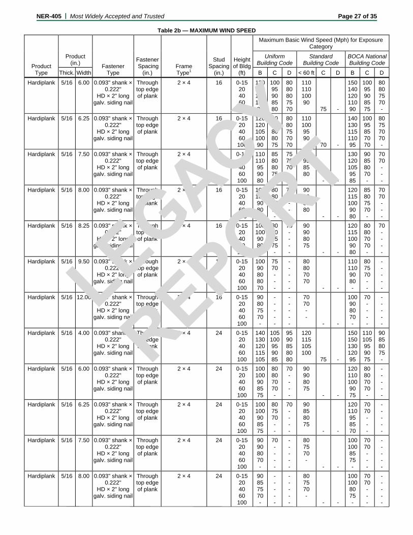
NER-405 | Most Widely Accepted and Trusted Page 27 of 35
Table 2b — MAXIMUM WIND SPEED
Product Type
Fastener Type
Fastener Spacing
(in.) Frame Type1
Stud Spacing
(in.)
Heightof Bldg
(ft)
Maximum Basic Wind Speed (Mph) for Exposure Category
Product (in.)
Uniform Building Code
Standard Building Code
BOCA NationalBuilding Code
Thick. Width B C D < 60 ft C D B C D
Hardiplank 5/16 6.00 0.093" shank × 0.222"
HD × 2" long galv. siding nail
Through top edge of plank
2 × 4 16 0-15 20 40 60 100
13012011010095
10095 90 85 80
80 80 80 75 70
110 110 100 90
75 -
15014012011090
10095 90 85 75
80 80 75 70 -
Hardiplank 5/16 6.25 0.093" shank × 0.222"
HD × 2" long galv. siding nail
Through top edge of plank
2 × 4 16 0-15 20 40 60 100
12012010510090
90 90 80 80 75
80 80 75 70 70
110 100 95 90
70 -
14013011511095
10095 85 70 70
80 75 70 70 -
Hardiplank 5/16 7.50 0.093" shank × 0.222"
HD × 2" long galv. siding nail
Through top edge of plank
2 × 4 16 0-15 20 40 60 100
11011095 90 80
85 80 80 75 70
75 70 70 - -
100 95 85 80
- -
13012010595 85
90 85 80 70 -
70 70 - - -
Hardiplank 5/16 8.00 0.093" shank × 0.222"
HD × 2" long galv. siding nail
Through top edge of plank
2 × 4 16 0-15 20 40 60 100
10010090 80 80
80 80 75 70 -
70 70 - - -
90 90 80 80
- -
12011510090 80
85 80 75 70 -
70 70 - - -
Hardiplank 5/16 8.25 0.093" shank × 0.222"
HD × 2" long galv. siding nail
Through top edge of plank
2 × 4 16 0-15 20 40 60 100
10010090 80 75
80 80 75 75 -
70 - - - -
90 90 80 75
- -
12011510090 80
80 80 70 70 -
70 - - - -
Hardiplank 5/16 9.50 0.093" shank × 0.222"
HD × 2" long galv. siding nail
Through top edge of plank
2 × 4 16 0-15 20 40 60 100
10090 80 80 70
75 70 - - -
- - - - -
80 80 70 70
- -
11011090 80 -
80 75 70 - -
- - - - -
Hardiplank 5/16 12.00 0.093" shank × 0.222"
HD × 2" long galv. siding nail
Through top edge of plank
2 × 4 16 0-15 20 40 60 100
90 80 75 70 -
- - - - -
- - - - -
70 70 - -
- -
10090 80 70 -
70 - - - -
- - - - -
Hardiplank 5/16 4.00 0.093" shank × 0.222"
HD × 2" long galv. siding nail
Through top edge of plank
2 × 4 24 0-15 20 40 60 100
140130120115105
10510095 90 85
95 90 85 80 80
120 115 105 100
75 -
15015013012095
11010595 90 75
90 85 80 75 -
Hardiplank 5/16 6.00 0.093" shank × 0.222"
HD × 2" long galv. siding nail
Through top edge of plank
2 × 4 24 0-15 20 40 60 100
10010090 85 75
80 80 70 70 -
70 - - - -
90 90 80 75
- -
12011010090 75
80 80 70 70 -
- - - - -
Hardiplank 5/16 6.25 0.093" shank × 0.222"
HD × 2" long galv. siding nail
Through top edge of plank
2 × 4 24 0-15 20 40 60 100
10010090 85 75
80 75 70 - -
70 - - - -
90 85 80 75
- -
12011095 85 70
70 70 - - -
- - - - -
Hardiplank 5/16 7.50 0.093" shank × 0.222"
HD × 2" long galv. siding nail
Through top edge of plank
2 × 4 24 0-15 20 40 60 100
90 90 80 70 -
70 - - - -
- - - - -
80 75 70 -
- -
10010085 75 -
70 70 - - -
- - - - -
Hardiplank 5/16 8.00 0.093" shank × 0.222"
HD × 2" long galv. siding nail
Through top edge of plank
2 × 4 24 0-15 20 40 60 100
90 85 75 70 -
- - - - -
- - - - -
80 75 70 -
- -
10010080 75 -
70 70 - - -
- - - - -
LEGACY
REPO
RT

NER-405 | Most Widely Accepted and Trusted Page 28 of 35
Table 2b — MAXIMUM WIND SPEED
Product Type
Fastener Type
Fastener Spacing
(in.) Frame Type1
Stud Spacing
(in.)
Heightof Bldg
(ft)
Maximum Basic Wind Speed (Mph) for Exposure Category
Product (in.)
Uniform Building Code
Standard Building Code
BOCA NationalBuilding Code
Thick. Width B C D < 60 ft C D B C D
Hardiplank 5/16 8.25 0.093" shank × 0.222"
HD × 2" long galv. siding nail
Through top edge of plank
2 × 4 24 0-15 20 40 60 100
85 85 70 70 -
- - - - -
- - - - -
70 70 - -
- -
10095 85 75 -
70 - - - -
- - - - -
Hardiplank 5/16 9.50 0.093" shank × 0.222"
HD × 2" long galv. siding nail
Through top edge of plank
2 × 4 24 0-15 20 40 60 100
80 80 70 - -
- - - - -
- - - - -
70 70 - - - - -
90 90 75 70 -
- - - - -
- - - - -
Hardiplank 5/16 12.00 0.093" shank × 0.222"
HD × 2" long galv. siding nail
Through top edge of plank
2 × 4 24 0-15 20 40 60 100
70 - - - -
- - - - -
- - - - -
- - - - - -
70 80 - - -
- - - - -
- - - - -
Hardiplank 5/16 9.50 0.091" shank, 0.221" HD, 1.5" long corrosion resistant nail
Face nailed
through the
overlap @ 12" o.c.
7/16" thick APA rated OSB
sheathing or equivalent solid
sheathing
- 0-15 20 40 60 100
10095 85 80 70
80 75 70 - -
- - - - -
90 85 80 75 -
- - - - - -
11511090 85 70
80 75 70 - -
- - - -
Notes to Table 2b:
1. Values are for species of wood having a specific gravity of 0.42 or greater, unless otherwise noted.
LEGACY
REPO
RT

NER-405 | Most Widely Accepted and Trusted Page 29 of 35
Table 3 — SHEAR VALUES ALLOWABLE LOADS IN POUNDS PER LINEAL FOOT FOR PANEL SHEAR WALLS1,2
Product Type
Product Thickness
(inch) Fastener
Type
Fastener Spacing
(inch) Frame Types
Stud Spacing
(inch)
Shear Value (plf)
Hardiflex Hardisoffit
3/16 4d common 1-1/2 in. long 6 2 × 4 wood 5 16 145
Hardipanel Hardiflex
Hardisoffit
1/4 4d common 1-1/2 in. long 8 2 × 4 wood 5 16 & 24 120
Hardibacker Titan
1/4 0.086 in. × 1-3/8 in. long gypsum wall board nail
6 2 × 4 wood 5 16 & 24 140
Hardipanel Hardiflex
1/4 6d common 2 in. long 6 2 × 4 wood 5 16 190
Hardipanel Hardiflex Harditex
Hardibacker Titan
1/4 No. 11 ga. 1-1/4 in. long galvanized roofing nail
6 2 × 4 wood 5 16 & 24 180
Hardipanel Hardiflex Harditex
Hardibacker Titan
1/4 No. 11 ga. 1-1/4 in. long galvanized roofing nail
4 edge 12 field
2 × 4 wood 5 16 & 24 265
Hardipanel Hardiflex Harditex
Hardibacker Titan
1/4 No. 11 ga. 1-1/4 in. long galvanized roofing nail
3 edge 6 field
2 × 4 wood 5 w/48 in.
mid-height block
16 & 24 295
Shiplap 5/16 0.092 in. shank, 0.225 in. HD, 2 in. long ring shank nail
3 edge 8 field
2 × 4 wood 4 16 268
Shiplap 5/16 0.092 in. shank, 0.225 in. HD, 2 in. long ring shank nail
4 edge 8 field
2 × 4 wood 4 16 238
Shiplap 5/16 0.092 in. shank, 0.225 in. HD, 2 in. long ring shank nail
5 edge 8 field
2 × 4 wood 4 16 208
Shiplap 5/16 0.092 in. shank, 0.225 in. HD, 2 in. long ring shank nail
6 edge 8 field
2 × 4 wood 4 16 179
Shiplap 5/16 0.092 in. shank, 0.225 in. HD, 2 in. long ring shank nail
7 edge 8 field
2 × 4 wood 4 16 149
Shiplap 5/16 0.092 in. shank, 0.225 in. HD, 2 in. long ring shank nail
8 edge 8 field
2 × 4 wood 4 16 119
Hardipanel Hardiflex
5/16 0.091 in. shank, 0.225 in. HD, 1.5 in. long ring shank nail
4 edge 8 field
2 × 4 wood 3 16 198
Hardipanel Hardiflex
5/16 4d common 1-1/2 in. long 8 2 × 4 wood 5 16 & 24 120
Hardipanel Hardiflex
5/16 6d common 2 in. long 6 2 × 4 wood 5 16 200
Hardipanel Hardiflex
5/16 6d common 2 in. long 6 2 × 4 wood 5 24 153
Hardipanel Hardiflex
5/16 6d common 2 in. long 4 2 × 4 wood 5 16 233
Hardipanel Hardiflex
5/16 6d common 2 in. long 4 2 × 4 wood 5 24 212
Hardipanel Hardiflex
5/16 6d common 2 in. long 6 edge 12 field
2 × 4 wood 5 16 157
Hardipanel Hardiflex
5/16 6d common 2 in. long 6 edge 12 field
2 × 4 wood 5 24 145
Hardipanel Hardiflex Harditex
Hardibacker
5/16 No. 11 ga. 1-1/2 in. long galvanized roofing nail
6 2 × 4 wood 5 16 200
Hardipanel Hardiflex Harditex
Hardibacker
5/16 No. 11 ga. 1-1/2 in. long galvanized roofing nail
4 edge 12 field
2 × 4 wood 5 16 280
LEGACY
REPO
RT

NER-405 | Most Widely Accepted and Trusted Page 30 of 35
Table 3 — SHEAR VALUES ALLOWABLE LOADS IN POUNDS PER LINEAL FOOT FOR PANEL SHEAR WALLS1,2
Product Type
Product Thickness
(inch) Fastener
Type
Fastener Spacing
(inch) Frame Types
Stud Spacing
(inch)
Shear Value (plf)
Hardipanel Hardiflex Harditex
Hardibacker
5/16 No. 11 ga. 1-1/2 in. long galvanized roofing nail
3 edge 6 field
2 × 4 wood 5 w/48 in.
mid-height block
16 340
Hardiflex Hardipanel
Harditex Hardibacker
Titan
7/16 No. 11 ga. 1-3/4 in. long galvanized roofing nail
6 2 × 4 wood 5 16 280
Hardiflex Hardisoffit
3/16 Min. No. 8 x 1 in. long × 0.323 in. HD ribbed buglehead screws
6 Min. No. 20 ga. × 3-5/8 in.
× 1-3/8 in. metal C-stud
16 1406
Hardipanel Hardiflex Harditex
Hardibacker Titan
1/4 Min. No. 8 x 1 in. long × 0.323 in. HD ribbed buglehead screws
6 Min. No. 20 ga. × 3-5/8 in.
× 1-3/8 in. metal C-stud
16 & 24 1256
Hardipanel Hardiflex Harditex
Hardibacker
5/16 Min. No. 8 x 1 in. long × 0.323 in. HD ribbed buglehead screws
6 Min. No. 20 ga. × 3-5/8 in.
× 1-3/8 in. metal C-stud
16 1606
Hardipanel Hardiflex Harditex
Hardibacker Titan
7/16 Min. No. 8 x 1 in. long × 0.311 in. HD ribbed buglehead screws
6 Min. No. 20 ga. × 3-5/8 in.
×1-3/8 in. metal C-stud
16 1626
Hardipanel Hardiflex Harditex
5/16 ET & F 1-1/2 in. long × 0.10" knurled shank × 0.25" HD pin fastener
(AKN100-0150NA)
4 edge 8 field
Min. No. 20 ga. × 3-5/8 in. × 1-3/8 in. metal
C-stud
16 154
Hardipanel Hardiflex Harditex
5/16 ET & F 1-1/2 in. long × 0.10" knurled shank × 0.25" HD pin fastener
(AKN100-0150NA)
4 edge 8 field
Min. No. 20 ga. × 3-5/8 in. × 1-3/8 in. metal
C-stud
24 133
1. All board edges shall be supported by framing. Panels shall be applied with the long dimension either parallel or perpendicular to studs. 2. The maximum height-to-length ratio for construction in this Table is 2:1. 3. Values are for species of wood having a specific gravity of 0.36 or greater. 4. Values are for species of wood having a specific gravity of 0.40 or greater. 5. Values are for species of wood having a specific gravity of 0.42 or greater, unless otherwise noted. 6. Under the Uniform Building Code™, these steel-framed assemblies are limited to wind load resistance only. 7. 1 inch = 25.4 mm, 1plf = 14.59 N/m
Table 4 — “K” and “R” VALUES FOR FIBER-CEMENT PRODUCTS
Product Thickness3
(inch)
Thermal Conductivity1
Keff = Btu/hr-ft2-F
Thermal Resistance1
R = 1/Keff
Actual Thermal Conductivity2
(Keff)
Actual Thermal Resistance2
®)
1/4 1.95 0.51 7.80 0.13
5/16 2.07 0.48 6.62 0.15
3/8 2.18 0.46 5.81 0.17
13/32 8.39 0.12 20.07 0.05
7/16 2.30 0.44 5.26 0.19
Notes to Table 4: 1. Based on 1 inch of panel thickness. 2. Actual value for panel thickness shown. 3. SI units conversion: 1 inch = 25.4 mm, 1 Btu/h-ft2-F = 5.678 W/m2-K
LEGACY
REPO
RT
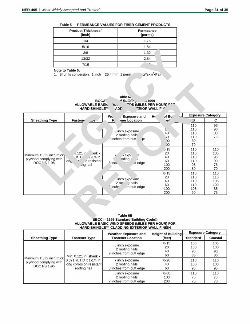
NER-405 | Most Widely Accepted and Trusted Page 31 of 35
Table 5 — PERMEANCE VALUES FOR FIBER-CEMENT PRODUCTS
Product Thickness1 (inch)
Permeance (perms)
1/4 1.75
5/16 1.54
3/8 1.32
13/32 2.84
7/16 1.10
Note to Table 5: 1. SI units conversion: 1 inch = 25.4 mm, 1 perm = 57 mg/(s•m2•Pa)
Table 6A BOCA® National Building Code/1999
ALLOWABLE BASIC WIND SPEEDS (MILES PER HOUR) FOR HARDISHINGLE™ CLADDING EXTERIOR WALL FINISH
Sheathing Type Fastener Type
Weather Exposure and Fastener Location
Height of Building (feet)
Exposure Category
B C
Minimum 15/32 inch thick plywood complying with
DOC PS 1-95
Min. 0.121 in. shank x 0.371 in. HD x 1-1/4 in. long corrosion resistant
roofing nail
8 inch exposure 2 roofing nails
9 inches from butt edge
0-15 20 40 60 100 200
110 110 110 110 80 70
95 90 80 75
7 inch exposure 2 roofing nails
8 inches from butt edge
0-15 20 40 60 100 200
110 110 110 110 95 80
110 105 95 90 75 70
6 inch exposure 2 roofing nails
7 inches from butt edge
0-15 20 40 60 100 200
110 110 110 110 105 90
110 110 105 100 85 75
Table 6B SBCCI - 1999 Standard Building Code©
ALLOWABLE BASIC WIND SPEEDS (MILES PER HOUR) FOR HARDISHINGLE™ CLADDING EXTERIOR WALL FINISH
Sheathing Type Fastener Type Weather Exposure and
Fastener Location Height of Building
(feet)
Exposure Category
Standard Coastal
Minimum 15/32 inch thick plywood complying with
DOC PS 1-95
Min. 0.121 in. shank x 0.371 in. HD x 1-1/4 in. long corrosion resistant
roofing nail
8 inch exposure 2 roofing nails
9 inches from butt edge
0-15 20 40 60
105 100 90 85
105 100 90 85
7 inch exposure 2 roofing nails
8 inches from butt edge
0-20 40 60
110 100 95
110 100 95
6 inch exposure 2 roofing nails
7 inches from butt edge
0-60 100 200
110 75 70
110 75 70
LEGACY
REPO
RT
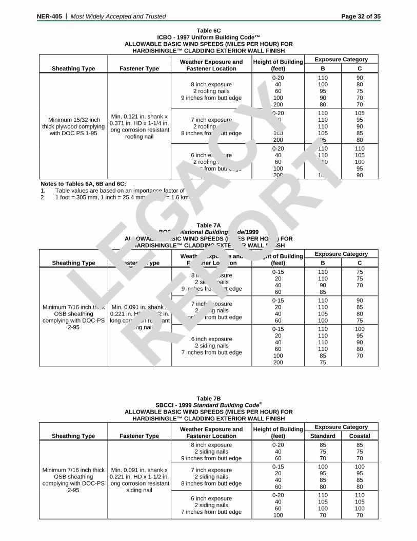
NER-405 | Most Widely Accepted and Trusted Page 32 of 35
Table 6C ICBO - 1997 Uniform Building Code™
ALLOWABLE BASIC WIND SPEEDS (MILES PER HOUR) FOR HARDISHINGLE™ CLADDING EXTERIOR WALL FINISH
Sheathing Type Fastener Type Weather Exposure and
Fastener Location Height of Building
(feet)
Exposure Category
B C
Minimum 15/32 inch thick plywood complying
with DOC PS 1-95
Min. 0.121 in. shank x 0.371 in. HD x 1-1/4 in. long corrosion resistant
roofing nail
8 inch exposure 2 roofing nails
9 inches from butt edge
0-20 40 60 100 200
110 100 95 90 80
90 80 75 70 70
7 inch exposure 2 roofing nails
8 inches from butt edge
0-20 40 60 100 200
110 110 110 105 95
105 95 90 85 80
6 inch exposure 2 roofing nails
7 inches from butt edge
0-20 40 60 100 200
110 110 110 110 100
110 105 100 95 90
Notes to Tables 6A, 6B and 6C: 1. Table values are based on an importance factor of 1.0 2. 1 foot = 305 mm, 1 inch = 25.4 mm, 1 mph = 1.6 km/h
Table 7A BOCA® National Building Code/1999
ALLOWABLE BASIC WIND SPEEDS (MILES PER HOUR) FOR HARDISHINGLE™ CLADDING EXTERIOR WALL FINISH
Sheathing Type Fastener Type Weather Exposure and
Fastener Location Height of Building
(feet)
Exposure Category
B C
Minimum 7/16 inch thick OSB sheathing
complying with DOC-PS 2-95
Min. 0.091 in. shank x 0.221 in. HD x 1-1/2 in. long corrosion resistant
siding nail
8 inch exposure 2 siding nails
9 inches from butt edge
0-15 20 40 60
110 110 90 85
75 75 70
7 inch exposure 2 siding nails
8 inches from butt edge
0-15 20 40 60
110 110 105 100
90 85 80 75
6 inch exposure 2 siding nails
7 inches from butt edge
0-15 20 40 60 100 200
110 110 110 110 85 75
100 95 90 80 70
Table 7B
SBCCI - 1999 Standard Building Code© ALLOWABLE BASIC WIND SPEEDS (MILES PER HOUR) FOR
HARDISHINGLE™ CLADDING EXTERIOR WALL FINISH
Sheathing Type Fastener Type Weather Exposure and
Fastener Location Height of Building
(feet)
Exposure Category
Standard Coastal
Minimum 7/16 inch thick OSB sheathing
complying with DOC-PS 2-95
Min. 0.091 in. shank x 0.221 in. HD x 1-1/2 in. long corrosion resistant
siding nail
8 inch exposure 2 siding nails
9 inches from butt edge
0-20 40 60
85 75 70
85 75 70
7 inch exposure 2 siding nails
8 inches from butt edge
0-15 20 40 60
100 95 85 80
100 95 85 80
6 inch exposure 2 siding nails
7 inches from butt edge
0-20 40 60 100
110 105 100 70
110 105 100 70
LEGACY
REPO
RT
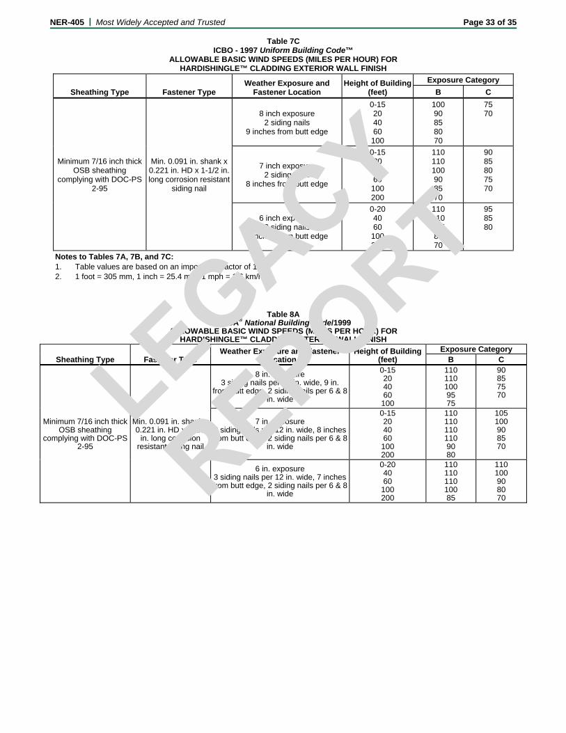
NER-405 | Most Widely Accepted and Trusted Page 33 of 35
Table 7C ICBO - 1997 Uniform Building Code™
ALLOWABLE BASIC WIND SPEEDS (MILES PER HOUR) FOR HARDISHINGLE™ CLADDING EXTERIOR WALL FINISH
Sheathing Type Fastener Type Weather Exposure and
Fastener Location Height of Building
(feet)
Exposure Category
B C
Minimum 7/16 inch thick OSB sheathing
complying with DOC-PS 2-95
Min. 0.091 in. shank x 0.221 in. HD x 1-1/2 in. long corrosion resistant
siding nail
8 inch exposure 2 siding nails
9 inches from butt edge
0-15 20 40 60 100
100 90 85 80 70
75 70
7 inch exposure 2 siding nails
8 inches from butt edge
0-15 20 40 60 100 200
110 110 100 90 85 70
90 85 80 75 70
6 inch exposure 2 siding nails
7 inches from butt edge
0-20 40 60 100 200
110 110 105 80 70
95 85 80
Notes to Tables 7A, 7B, and 7C: 1. Table values are based on an importance factor of 1.0 2. 1 foot = 305 mm, 1 inch = 25.4 mm, 1 mph = 1.6 km/h
Table 8ABOCA® National Building Code/1999
ALLOWABLE BASIC WIND SPEEDS (MILES PER HOUR) FOR HARDISHINGLE™ CLADDING EXTERIOR WALL FINISH
Sheathing Type Fastener Type Weather Exposure and Fastener
Location Height of Building
(feet) Exposure Category
B C
Minimum 7/16 inch thick OSB sheathing
complying with DOC-PS 2-95
Min. 0.091 in. shank x 0.221 in. HD x 1-1/2
in. long corrosion resistant siding nail
8 in. exposure 3 siding nails per 12 in. wide, 9 in.
from butt edge, 2 siding nails per 6 & 8 in. wide
0-15 20 40 60 100
110 110 100 95 75
90 85 75 70
7 in. exposure 3 siding nails per 12 in. wide, 8 inches from butt edge, 2 siding nails per 6 & 8
in. wide
0-15 20 40 60 100 200
110 110 110 110 90 80
105 100 90 85 70
6 in. exposure 3 siding nails per 12 in. wide, 7 inches from butt edge, 2 siding nails per 6 & 8
in. wide
0-20 40 60 100 200
110 110 110 100 85
110 100 90 80 70
LEGACY
REPO
RT

NER-405 | Most Widely Accepted and Trusted Page 34 of 35
Table 8B SBCCI - 1999 Standard Building Code©
ALLOWABLE BASIC WIND SPEEDS (MILES PER HOUR) FOR HARDISHINGLE™ CLADDING EXTERIOR WALL FINISH
Sheathing Type Fastener Type Weather Exposure and
Fastener Location Height of Building
(feet)
Exposure Category
Standard Coastal
Minimum 7/16 inch thick OSB sheathing complying
with DOC-PS 2-95
Min. 0.091 in. shank x 0.221 in. HD x 1-1/2 in. long corrosion resistant
siding nail
8 in. exposure 3 siding nails per 12 in. wide, 9 in. from butt edge, 2 siding nails
per 6 & 8 in. wide
0-15 20 40 60
100 95 85 80
100 95 85 80
7 in. exposure 3 siding nails per 12 in. wide, 8 inches from butt edge, 2 siding
nails per 6 & 8 in. wide
0-15 20 40 60
110 105 95 90
110 105 95 90
6 in. exposure 3 siding nails per 12 in. wide, 7 inches from butt edge, 2 siding
nails per 6 & 8 in. wide
0-15 20 40 60 100
110 110 110 105 70
110 110 110 105 70
Table 8C ICBO - 1997 Uniform Building Code™
ALLOWABLE BASIC WIND SPEEDS (MILES PER HOUR) FOR HARDISHINGLE™ CLADDING EXTERIOR WALL FINISH
Sheathing Type Fastener Type Weather Exposure and
Fastener Location Height of Building
(feet)
Exposure Category
B C
Minimum 7/16 inch thick OSB sheathing complying
with DOC-PS 2-95
Min. 0.091 in. shank x 0.221 in. HD x 1-1/2 in. long corrosion resistant
siding nail
8 in. exposure 3 siding nails per 12 in. wide, 9 in. from butt edge, 2 siding nails
per 6 & 8 in. wide
0-15 20 40 60 100 200
110 110 100 90 80 70
85 80 75 70 70
7 in. exposure 3 siding nails per 12 in. wide, 8 inches from butt edge, 2 siding
nails per 6 & 8 in. wide
0-15 20 40 60 100 200
110 110 110 110 100 90
110 105 100 95 80 75
6 in. exposure 3 siding nails per 12 in. wide, 7 inches from butt edge, 2 siding
nails per 6 & 8 in. wide
0-15 20 40 60 100 200
110 110 110 110 105 95
110 105 100 95 90 85
Notes to Tables 8A, 8B, and 8C: 1. Table values are based on an importance factor of 1.0 2. 1 foot = 305 mm, 1 inch = 25.4 mm, 1 mph = 1.6 km/h
Table 9A SBCCI - 1999 Standard Building Code©
Allowable Fastener Spacing (in.) Hardiplank Lap Siding fastened to ASTM C90 Concrete Wall
Height of Building
(feet) 6-1/4 and 6 inch wide
Hardiplank 7-1/2 inch wide Hardiplank8-1/4 and 8 inch wide
Hardiplank 9-1/2 inch wide Hardiplank
0-15 20 30 40 50 60
18.25 16.5 14.75 13.5 12.75 12.25
14.5 13.25 11.75 10.75 10.25 9.75
13.75 12.25
11 10.25
9.5 9
11.5 10.5 9.25 8.5 8
7.5
LEGACY
REPO
RT
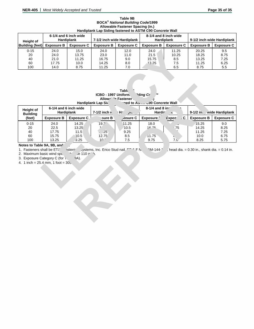
NER-405 | Most Widely Accepted and Trusted Page 35 of 35
Table 9B BOCA® National Building Code/1999
Allowable Fastener Spacing (in.) Hardiplank Lap Siding fastened to ASTM C90 Concrete Wall
Height of Building (feet)
6-1/4 and 6 inch wide Hardiplank 7-1/2 inch wide Hardiplank
8-1/4 and 8 inch wide Hardiplank 9-1/2 inch wide Hardiplank
Exposure B Exposure C Exposure B Exposure C Exposure B Exposure C Exposure B Exposure C
0-15 20 40 60 100
24.0 24.0 21.0 17.75 14.0
15.0 13.75 11.25 10.0 8.75
24.0 23.0 16.75 14.25 11.25
12.0 11.0 9.0 8.0 7.0
24.0 21.5 15.75 13.25 10.5
11.25 10.25
8.5 7.5 6.5
20.25 18.25 13.25 11.25 8.75
9.5 8.75 7.25 6.25 5.5
Table 9C ICBO - 1997 Uniform Building Code™
Allowable Fastener Spacing (in.) Hardiplank Lap Siding fastened to ASTM C90 Concrete Wall
Height of Building
(feet)
6-1/4 and 6 inch wide Hardiplank 7-1/2 inch wide Hardiplank
8-1/4 and 8 inch wide Hardiplank 9-1/2 inch wide Hardiplank
Exposure B Exposure C Exposure B Exposure C Exposure B Exposure C Exposure B Exposure C
0-15 20 40 60 100
24.0 22.5 17.75 15.75 13.25
14.25 13.25 11.5 10.5 9.25
19.25 18.0 14.25 12.75 10.5
11.25 10.5 9.25 8.5 7.5
18.0 16.75 13.5 11.75 9.75
10.5 9.75 8.5 8.0 7.0
15.25 14.25 11.25 10.0 8.25
9.0 8.25 7.25 6.75 5.75
Notes to Table 9A, 9B, and 9C: 1. Fasteners shall be ET&F Fastening Systems, Inc. Erico Stud nail, ET & F No. ASM-144-125, head dia. = 0.30 in., shank dia. = 0.14 in. 2. Maximum basic wind speed shall be 110 mph. 3. Exposure Category C (for Table 9A). 4. 1 inch = 25.4 mm, 1 foot = 305 mm.
LEGACY
REPO
RT