Embed Size (px)
Citation preview

ICC Evaluation Service, Inc. www.icc-es.org
Business/Regional Office ■ 5360 Workman Mill Road, Whittier, California 90601 ■ (562) 699-0543 Regional Office ■ 900 Montclair Road, Suite A, Birmingham, Alabama 35213 ■ (205) 599-9800 Regional Office ■ 4501 West Flossmoor Road, Country Club Hills, Illinois 60478 ■ (708) 799-2305
ESR-2322Issued November 1, 2007
This report is subject to re-examination in one year.
DIVISION: 5 – CONCRETE Section: 03151 – Concrete Anchoring REPORT HOLDER: HILTI, INC. 5400 SOUTH 122ND EAST AVENUE TULSA, OKLAHOMA 74146 (800) 879-8000 www.us.hilti.com [email protected]
EVALUATION SUBJECT:
HILTI HIT-RE 500-SD ADHESIVE ANCHORS IN CONCRETE
1.0 EVALUATION SCOPE
1.1 Compliance with the following codes:
• 2006 International Building Code® (2006 IBC) • 2006 International Residential Code® (2006 IRC) • 2003 International Building Code® (2003 IBC) • 2003 International Residential Code® (2003 IRC) • 2000 International Building Code® (2000 IBC) • 2000 International Residential Code® (2000 IRC) • 1997 Uniform Building Code™ (UBC)
1.2 Property evaluated:
Structural
2.0 USES Hilti HIT-RE 500-SD Adhesive Anchors are used to resist static, wind and seismic tension and shear loads in cracked and uncracked normal-weight concrete having a specified compressive strength, f'c, of 2,500 psi to 8,500 psi (17.2 MPa to 58.6 MPa). The anchor system is an alternative to cast-in-place anchors described in Sections 1911 and 1912 of the 2006 IBC, Sections 1912 and 1913 of the 2000 or 2003 IBC, and Section 1923 of the 1997 UBC. The anchor systems may also be used where an engineered design is submitted in accordance with Section R301.1.3 of the 2006 IRC, Section R301.1.3 of the 2003 IRC, or Section R301.1.2 of the 2000 IRC.
3.0 DESCRIPTION
3.1 General: The Hilti HIT-RE 500-SD Adhesive Anchor System is comprised of the following components:
• Hilti HIT-RE 500-SD adhesive packaged in foil packs • Adhesive mixing and dispensing equipment • Equipment for hole cleaning and adhesive injection
Hilti HIT-RE 500-SD adhesive may be used with continuously threaded rod, Hilti HIS-N and HIS-RN internally-threaded inserts or deformed steel reinforcing bars. The primary components of the Hilti Adhesive Anchor System, including the Hilti HIT-RE 500-SD Adhesive, HIT-RE-M static mixing nozzle and steelanchoring elements are shown in Figure 2 of this report.
Installation information and parameters, as included with each adhesive unit package, are replicated as Figure 5 of this report.
3.2 Materials: 3.2.1 Hilti HIT-RE 500-SD Adhesive: Hilti HIT-RE 500-SD Adhesive is an injectable two-component epoxy adhesive. The two components are separated by means of a dual-cylinder foil pack attached to a manifold. The two components combine and react when dispensed through a static mixing nozzle attached to the manifold. Hilti HIT-RE 500-SD is available in 11.1 oz. (330 ml), 16.9 oz. (500 ml), and 47.3 oz. (1400 ml) foil packs. The manifold attached to each foil pack is stamped with the adhesive expiration date. The shelf life, as indicated by the expiration date, corresponds to an unopened foil pack stored in a dry, dark environment.
3.2.2 Hole cleaning equipment: Hole cleaning equipment is must be in accordance with Figure 5 of this report. 3.2.3 Dispensers: Hilti HIT-RE 500-SD adhesive must be dispensed with manual dispensers, pneumatic dispensers, or electric dispensers provided by Hilti. 3.2.4 Anchor elements: 3.2.4.1 Threaded steel rods: Threaded steel rods must be clean, continuously threaded rods (all-thread) in diameters as described in Tables 7 and 11 and Figure 5 of this report. Specifications for grades of threaded rod and associated nuts included in the scope of the report are provided in TABLE 2 and TABLE 3. Carbon steel threaded rods must be furnished with a 5 μm thick zinc electroplated coating complying with ASTM B 633 SC 1 or must be hot-dipped galvanized in accordance with ASTM A 153, Class C or D. Threaded steel rods must be straight and free of indentations or other defects along their length. The ends may be stamped with identifying marks and the embedded end may be flat cut or cut on the bias (chisel point). 3.2.4.2 Steel reinforcing bars: Steel reinforcing bars are deformed bars (rebar). Tables 27 and 31 and Figure 5 summarize reinforcing bar size ranges. See Table 6 for specifications of permitted reinforcing bar types and grades. The embedded portions of reinforcing bars must be straight, and free of mill scale, rust and other coatings that impair the bond with the adhesive. Reinforcing bars must not be bent after installation.
Page 2 of 42
ESR-2322
3.2.4.3 HIS-N and HIS-RN inserts: Hilti HIS-N and HIS-RN inserts have a profile on the external surface and are internally threaded. Mechanical properties for HIS-N and HIS-RN inserts are provided in Table 4. The inserts are available in diameters and lengths as shown in Tables 15 and 19 and Figure 5. HIS-N Inserts are produced from carbon steel and furnished either with a 5 μm zinc electroplated coating complying with ASTM B 633 SC 1 or a hot dipped galvanized coating complying with ASTM A 153 Class C or D. The stainless steel HIS-RN inserts are fabricated from X5CrNiMo17122 K700 steel conforming to DIN 17440. Specifications for common bolt types that may be used in conjunction with HIS-N and HIS-RN inserts are provided in TABLE 5. Bolt grade and material type (carbon, stainless) must be matched to the insert. Strength reduction factors, φ, corresponding to brittle steel elements must be used for HIS-N and HIS-RN Inserts. 3.2.4.4 Ductility: In accordance with ACI 318-05 (ACI 318) Appendix D, in order for a steel element to be considered ductile, the tested elongation must be at least 14 percent and reduction of area must be at least 30 percent. Steel elements with a tested elongation less than 14 percent or a reduction of area less than 30 percent, or both, are considered brittle. Values for various common steel materials are provided in Tables 2, 3 and 5 of this report.
4.0 DESIGN AND INSTALLATION
4.1 Strength Design: 4.1.1 General: Design strengths must be determined in accordance with ACI 318-05 (ACI 318) Appendix D and this report. A design example is given in Figure 4. Design parameters including strength reduction factors,φ, corresponding to each limit state and anchor steel are provided in Table 7 through Table . Strength reduction factors, φ, as described in ACI 318 D.4.4 must be used for load combinations calculated in accordance with Section 1605.2 of the 2000, 2003 or 2006 IBC or Section 1612.2 of the UBC. Strength reduction factors φ as described in ACI 318 D.4.5 must be used for load combinations calculated in accordance with Section 1909.2 of the UBC.
This section provides amendments to ACI 318 Appendix D as required for the strength design of adhesive anchors. In conformance with ACI 318, all equations are expressed in inch-pound units.
Modify ACI 318 D.4.1.2 as follows:
D.4.1.2 – In Eq. (D-1) and (D-2), φNn and φVn are the lowest design strengths determined from all appropriate failure modes. φNn is the lowest design strength in tension of an anchor or group of anchors as determined from consideration of φNsa, either φNa or φNag and either φNcb or φNcbg. φVn is the lowest design strength in shear of an anchor or a group of anchors as determined from consideration of: φVsa, either φVcb or φVcbg, and either φVcp or φVcpg.
Add ACI 318 D.4.1.2 as follows:
D.4.1.4 – For adhesive anchors installed overhead and subjected to tension resulting from sustained loading, Eq. (D-1) shall also be satisfied taking φNn = 0.75φNa for single anchors and φNn = 0.75φNag for groups of anchors, whereby Nua is determined from the sustained load alone, e.g., the dead load and that portion of the live load acting
that may be considered as sustained. Where shear loads act concurrently with the sustained tension load, interaction of tension and shear shall be analyzed in accordance with D.4.1.3.
4.1.2 Static Steel Strength in Tension: The nominal strength of an anchor in tension as governed by the steel, Nsa, in accordance with ACI 318 D.5.1.2 is given in the tables outlined in Table 1 for the corresponding anchor steel.
4.1.3 Static Concrete Breakout Strength in Tension: The nominal concrete breakout strength in tension, Ncb or Ncbg, must be calculated in accordance with ACI 318 D.5.2 with the following addition:
D.5.2.9 – The limiting concrete strength of adhesive anchors in tension shall be calculated in accordance with D.5.2.1 to D.5.2.7 where the value of kc to be used in Eq. (D-7) shall be:
kc,cr where analysis indicates cracking at service load levels in the anchor vicinity (cracked concrete)
kc,uncr where analysis indicates no cracking at service load levels in the anchor vicinity (uncracked concrete)
Additional information for the determination of the nominal concrete breakout strength is given in the tables outlined in Table 1 for the corresponding anchor steel. 4.1.4 Static Pullout Strength in Tension: In lieu of determining the nominal pullout strength in accordance with ACI 318 D.5.3, nominal bond strength in tension must be calculated in accordance with the following sections added to ACI 318: D.5.3.7 – The nominal bond strength of an adhesive anchor Na or group of adhesive anchors Nag in tension shall not exceed
(a) For a single anchor
Naa p,Na a0
Na0
AN NA
ψ= ⋅ ⋅ (D-14a)
(b) For a group of anchors
a0Nap,Naec,Nag,Naed,Na0
Naag N
AAN ⋅⋅⋅⋅⋅= ψψψψ (D-14b)
where
Ana is the projected area of the failure surface for the single anchor or group of anchors that shall be approximated as the base of the rectilinear geometrical figure that results from projecting the failure surface outward a distance from the centerlines of the anchor, or in the case of a group of anchors, from a line through a row of adjacent anchors. Ana shall not exceed nAna0 where n is the number of anchors in tension in the group. In ACI 318 Figures RD.5.2.1a and RD.5.2.1b, the terms 1.5hef and 3.0hef shall be replaced with ccr,Na and scr,Na, respectively.
ANa0 is the projected area of the failure surface of a single anchor without the influence of proximate edges in

Page 3 of 42
ESR-2322
accordance with Eq. (D-14c):
( )2
Na0 cr,NaA = s (D-14c)
With
scr,Na = as given by Eq. (D-14h)
D.5.3.8 – The critical spacing and critical edge distance shall be calculated as follows:
τ= ⋅ ⋅ ≤ ⋅20 3
1 450k ,uncr
cr,Na efs d h,
(D-14h)
cr,Nacr,Na
sc =
2 (D-14i)
D.5.3.9 – The basic strength of a single adhesive anchor in tension in cracked concrete shall not exceed
a0 k,cr efN d hτ π= ⋅ ⋅ ⋅ (D-14j)
D.5.3.10 – The modification factor for the influence of the failure surface of a group of adhesive anchors is
( ) 0.11 0,
5.0
,0,, ≥
⎥⎥⎦
⎤
⎢⎢⎣
⎡−⋅⎟
⎟⎠
⎞⎜⎜⎝
⎛+= Nag
NacrNagNag s
s ψψψ (D-14k)
Where
( ) 0.115.1
max,,
,0, ≥
⎥⎥⎦
⎤
⎢⎢⎣
⎡
⎟⎟⎠
⎞⎜⎜⎝
⎛⋅−−=
crk
crkNag nn
ττ
ψ (D-14l)
Where
n = the number of tension-loaded adhesive anchors in a group.
cefcrc
crk fhd
k',
max,, ⋅⋅
=π
τ (D-14m)
D.5.3.11 – The modification factor for eccentrically loaded adhesive anchor groups is
ec,NaN
cr,Na
1 1.02e'1s
ψ = ≤+
(D-14n)
Eq. (D-14n) is valid for Nse'2
≤
If the loading on an anchor group is such that only certain anchors are in tension, only those anchors that are in tension shall be considered when determining the eccentricity e'N for use in Eq. (D-14n).
In the case where eccentric loading exists about two orthogonal axes, the modification factor ψec,Na shall be computed for each axis individually and the product of
these factors used as ψec,Na in Eq. (D-14b).
D.5.3.12 – The modification factor for the edge effects for single adhesive anchors or anchor groups loaded in tension is:
for ≥a,min cr,Nac c
0.1, =Naedψ (D-14o)
or for Nacrcc a ,min, <
0.13.07.0,
min,, ≤⎟
⎟⎠
⎞⎜⎜⎝
⎛⋅+=
Nacr
aNaed c
cψ
(D-14p)
D.5.3.13 – When an adhesive anchor or a group of adhesive anchors is located in a region of a concrete member where analysis indicates no cracking at service load levels, the nominal strength Na or Nag of a single adhesive anchor or a group of adhesive anchors shall be calculated according to Eq. (D-14a) and Eq. (D-14b) with τk,uncr substituted for τk,cr in the calculation of the basic strength in accordance with Eq. (D-14j). The factor ψg,Na0 shall be calculated in accordance with Eq. (D-14l) whereby the value of τk,max,uncr shall be calculated in accordance with Eq. (D-14q) and substituted for τk,max,cr in Eq. (D-14l).
τπ
= ⋅⋅
c ,uncrk ,max,uncr ef c
kh f '
d (D-14q)
D.5.3.14 – When an adhesive anchor or a group of adhesive anchors is located in a region of a concrete member where analysis indicates no cracking at service load levels, the modification factor shall be taken as
p,Na 1.0ψ = when a,min acc c≥ (D-14r)
ψ = a,min c r ,Nap,Na
cr
max c ;cc
when <a,min acc c (D-14s)
Additional information for the determination of nominal bond strength in tension is given in Section 4.1.8.
4.1.5 Static Steel Strength in Shear: The nominal static strength of an anchor in tension as governed by the steel, Vsa, in accordance with ACI 318 D.6.1.2 is given in the tables outlined in Table 1 for the corresponding anchor steel. 4.1.6 Static Concrete Breakout Strength in Shear: The nominal concrete breakout strength in shear, Vcb or Vcbg, must be calculated in accordance with ACI 318 D.6.2 based on information given in the tables outlined in Table 1 for the corresponding anchor steel. 4.1.7 Static Concrete Pryout Strength in Shear: In lieu of determining the nominal pryout strength in accordance with ACI 318 D.6.3.1, nominal pryout strength in shear must be calculated in accordance with the following sections added to ACI 318: D.6.3.2 – The nominal pryout strength of an adhesive anchor or group of adhesive anchors shall not exceed

Page 4 of 42
ESR-2322
(a) for a single adhesive anchor
cp cp a cp cbV min k N ;k N= ⋅ ⋅ (D-28a)
(b) for a group of adhesive anchors
cpg cp ag cp cbgV min k N ;k N= ⋅ ⋅ (D-28b)
where
kcp = 1.0 for hef < 2.5 in. (64 mm)
kcp = 2.0 for hef ≥ 2.5 in. (64 mm)
Na shall be calculated in accordance with Eq. (D-14a)
Nag shall be calculated in accordance with Eq. (D-14b)
Ncb, Ncbg are determined in accordance with D.5.2.8
4.1.8 Bond strength determination: Bond strength values are a function of concrete condition (cracked, uncracked), drilling method (hammer drill, core drill) and installation conditions (dry, water-saturated, etc.). Bond strength values must be modified with the factor κnn for cases where holes are drilled in water-saturated concrete (κws), where the holes are water-filled at the time of anchor installation (κwf), or where the anchor installation is conducted underwater (κuw) as follows:
conc
rete
Hol
e dr
illin
g m
etho
d permissible installation conditions
bond strength
Associated strength reduction
factor
dry concrete k,crτ φd
crac
ked
ham
mer
dr
illed
water-saturated k,cr wsτ κ⋅ φws
dry concrete k,uncrτ φd
water-saturated k,uncr wsτ κ⋅ φws
water-filled hole k,uncr wfτ κ⋅ φwf
ham
mer
dril
led
underwater application k,uncr uwτ κ⋅ φuw
dry concrete k,uncrτ φd
uncr
acke
d co
ncre
te
core
dr
illed
water-saturated k,uncr wsτ κ⋅ φws
Figure 3 presents a selection flow chart. Where applicable, the modified bond strength values must be used in lieu of τk,cr and τk,uncr in Equations (D-14d), (D-14f), (D-14j), (D-14m), and (D-14o). The resulting nominal bond strength must be multiplied by the associated strength reduction factor φnn.
4.1.9 Minimum member thickness hmin, anchor spacing smin and edge distance cmin: In lieu of ACI 318 D.8.3, values of cmin and smin described in this report must be observed for anchor design and installation. Likewise, in lieu of ACI 318 D.8.5, the minimum member thicknesses, hmin, described in this report must be observed for anchor design and installation. In determining minimum edge distance, cmin, the following section must be added to ACI 318: D.8.8 – For adhesive anchors that will remain untorqued, the minimum edge distance shall be based on minimum cover requirements for reinforcement in 7.7. For adhesive anchors that will be torqued, the minimum edge distance and spacing shall be taken as 6do and 5do, respectively.
4.1.10 Critical edge distance cac: In lieu of ACI 318 Section D.8.6, cac must be determined as follows:
for minh h= : ( )2
efac ef
3 hc +1.63h
32d=
for ( )3 4ef a,minh h 5 c≥ +
where
efh 8d≤ : ac efc 1.5h=
efh 8d> : ( )2ef
ac ef
hc +1.33h
48d=
for all otherminh h≥ : ac efc 2.5h=
4.1.11 Design strength in Seismic Design Categories C, D, E and F: In structures assigned to Seismic Design Categories C, D, E or F under the IBC or IRC, or Seismic Zones 2B, 3 or 4 under the UBC, the anchor strength must be adjusted in accordance with 2006 IBC Section 1908.1.16. For brittle steel elements, the anchor strength must be adjusted in accordance with 2006 IBC Section 1908.1.16 D.3.3.5. The nominal steel shear strength, Vsa, must be adjusted by αV,seis as given in the tables summarized in Table 1 for the corresponding anchor steel. The nominal bond strength τk,cr must be adjusted by αN,seis as given in the tables summarized in Table 1 for the corresponding anchor steel.
4.1.12 Interaction of Tensile and Shear Forces: For designs that include combined tension and shear, the interaction of tension and shear loads must be calculated in accordance with ACI D.7. 4.2 Allowable Stress Design: Design values for use with allowable stress design load combinations (working stress design) calculated in accordance with Section 1612.3 of the UBC or Section 1605.3 of the 2000, 2003 or 2006 IBC must be established as follows:
dallow,ASD
RR =α
(21)
where d kR Rφ= ⋅ represents the limiting design strength
Page 5 of 42
ESR-2322
in tension (nNφ ) or shear (
nVφ ) as calculated according to ACI 318 D.4.1.1 and D.4.1.2 and Section 4.1 of this report. Limits on edge distance, anchor spacing and member thickness described in this report must apply.
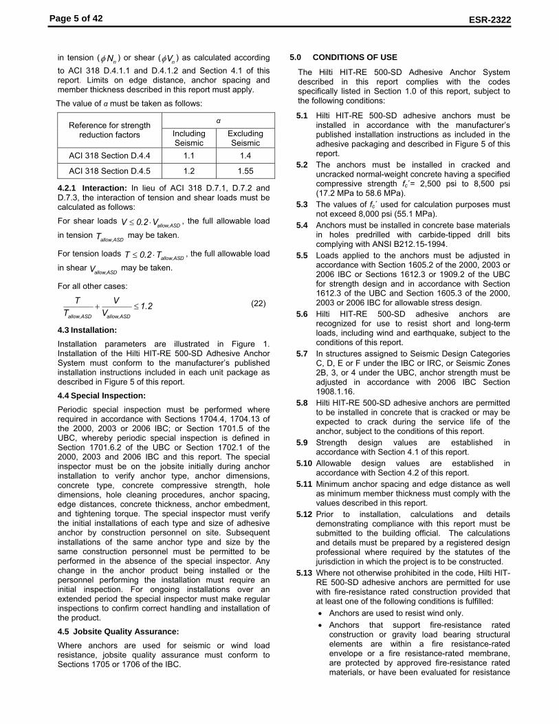
The value of α must be taken as follows:
α Reference for strength reduction factors Including
Seismic Excluding Seismic
ACI 318 Section D.4.4 1.1 1.4
ACI 318 Section D.4.5 1.2 1.55
4.2.1 Interaction: In lieu of ACI 318 D.7.1, D.7.2 and D.7.3, the interaction of tension and shear loads must be calculated as follows:
For shear loads allow,ASDV 0.2 V≤ ⋅ , the full allowable load
in tension allow,ASDT may be taken.
For tension loads allow,ASDT 0.2 T≤ ⋅ , the full allowable load
in shear allow,ASDV may be taken.
For all other cases:
allow,ASD allow,ASD
T V 1.2T V
+ ≤ (22)
4.3 Installation: Installation parameters are illustrated in Figure 1. Installation of the Hilti HIT-RE 500-SD Adhesive Anchor System must conform to the manufacturer’s published installation instructions included in each unit package as described in Figure 5 of this report.
4.4 Special Inspection: Periodic special inspection must be performed where required in accordance with Sections 1704.4, 1704.13 of the 2000, 2003 or 2006 IBC; or Section 1701.5 of the UBC, whereby periodic special inspection is defined in Section 1701.6.2 of the UBC or Section 1702.1 of the 2000, 2003 and 2006 IBC and this report. The special inspector must be on the jobsite initially during anchor installation to verify anchor type, anchor dimensions, concrete type, concrete compressive strength, hole dimensions, hole cleaning procedures, anchor spacing, edge distances, concrete thickness, anchor embedment, and tightening torque. The special inspector must verify the initial installations of each type and size of adhesive anchor by construction personnel on site. Subsequent installations of the same anchor type and size by the same construction personnel must be permitted to be performed in the absence of the special inspector. Any change in the anchor product being installed or the personnel performing the installation must require an initial inspection. For ongoing installations over an extended period the special inspector must make regular inspections to confirm correct handling and installation of the product.
4.5 Jobsite Quality Assurance: Where anchors are used for seismic or wind load resistance, jobsite quality assurance must conform to Sections 1705 or 1706 of the IBC.
5.0 CONDITIONS OF USE
The Hilti HIT-RE 500-SD Adhesive Anchor System described in this report complies with the codes specifically listed in Section 1.0 of this report, subject to the following conditions:
5.1 Hilti HIT-RE 500-SD adhesive anchors must be installed in accordance with the manufacturer’s published installation instructions as included in the adhesive packaging and described in Figure 5 of this report.
5.2 The anchors must be installed in cracked and uncracked normal-weight concrete having a specified compressive strength fc΄= 2,500 psi to 8,500 psi (17.2 MPa to 58.6 MPa).
5.3 The values of fc΄ used for calculation purposes must not exceed 8,000 psi (55.1 MPa).
5.4 Anchors must be installed in concrete base materials in holes predrilled with carbide-tipped drill bits complying with ANSI B212.15-1994.
5.5 Loads applied to the anchors must be adjusted in accordance with Section 1605.2 of the 2000, 2003 or 2006 IBC or Sections 1612.3 or 1909.2 of the UBC for strength design and in accordance with Section 1612.3 of the UBC and Section 1605.3 of the 2000, 2003 or 2006 IBC for allowable stress design.
5.6 Hilti HIT-RE 500-SD adhesive anchors are recognized for use to resist short and long-term loads, including wind and earthquake, subject to the conditions of this report.
5.7 In structures assigned to Seismic Design Categories C, D, E or F under the IBC or IRC, or Seismic Zones 2B, 3, or 4 under the UBC, anchor strength must be adjusted in accordance with 2006 IBC Section 1908.1.16.
5.8 Hilti HIT-RE 500-SD adhesive anchors are permitted to be installed in concrete that is cracked or may be expected to crack during the service life of the anchor, subject to the conditions of this report.
5.9 Strength design values are established in accordance with Section 4.1 of this report.
5.10 Allowable design values are established in accordance with Section 4.2 of this report.
5.11 Minimum anchor spacing and edge distance as well as minimum member thickness must comply with the values described in this report.
5.12 Prior to installation, calculations and details demonstrating compliance with this report must be submitted to the building official. The calculations and details must be prepared by a registered design professional where required by the statutes of the jurisdiction in which the project is to be constructed.
5.13 Where not otherwise prohibited in the code, Hilti HIT-RE 500-SD adhesive anchors are permitted for use with fire-resistance rated construction provided that at least one of the following conditions is fulfilled: • Anchors are used to resist wind only. • Anchors that support fire-resistance rated
construction or gravity load bearing structural elements are within a fire resistance-rated envelope or a fire resistance-rated membrane, are protected by approved fire-resistance rated materials, or have been evaluated for resistance
Page 6 of 42
ESR-2322
to fire exposure in accordance with recognized standards.
• Anchors are used to support nonstructural elements.
5.14 Since an ICC-ES acceptance criteria for evaluating data to determine the performance of adhesive anchors subjected to fatigue or shock loading is unavailable at this time, the use of these anchors under such conditions is beyond the scope of this report.
5.15 Use of zinc-plated carbon steel anchors is limited to dry, interior locations.
5.16 Special inspection and jobsite quality assurance must be provided in accordance with Sections 4.4 and 4.5, respectively.
5.17 Hilti HIT-RE 500-SD adhesive are manufactured by Hilti GmbH, Kaufering, Germany with quality control inspections by Underwriters Laboratories, Inc. (AA-637).
5.18 Hilti HIS-N and HIS-RN inserts are manufactured by Hilti (China) Ltd., Guangdong, China with quality control inspections by Underwriters Laboratories, Inc. (AA-637).
6.0 EVIDENCE SUBMITTED
6.1 Data in accordance with the ICC-ES Acceptance Criteria for Post-Installed Adhesive Anchors in Concrete (AC308), dated October 2007.
7.0 IDENTIFICATION
7.1 Hilti HIT-RE 500-SD adhesive is identified by packaging labeled with the manufacturer’s name (Hilti Corp.) and address, anchor name, evaluation report number (ICC-ES ESR-2322), and the name of the quality control agency, Underwriters Laboratories Inc.
7.2 HIS-N and HIS-RN inserts are identified by packaging labeled with the manufacturer’s name (Hilti Corp.) and address, anchor name, evaluation report number (ICC-ES ESR-2322), and the name of the quality control agency, Underwriters Laboratories Inc.
7.3 Threaded rods, nuts, washers, bolts, cap screws, and deformed reinforcing bars are standard elements and must conform to applicable national or international specifications.
This report is subject to re-examination in one year.

Page 7 of 42
ESR-2322
THREADED ROD/REINFORCING BAR HIS AND HIS-R INSERTS FIGURE 1 – INSTALLATION PARAMETERS
TABLE 1 – DESIGN TABLE INDEX
Threaded rod Hilti HIS internally threaded insert Deformed reinforcement
Design strength1 fractional metric fractional metric Fractional metric Canadian
Steel Nsa, Vsa TABLE Table Table 15 Table 19 Table 23 Table 27 Table 31
Concrete Npn, Nsb, Nsbg, Ncb, Ncbg, Vcb, Vcbg, Vcp, Vcpg
Table 8 Table 12 Table 16 Table 20 Table 24 Table 28 Table 32
hammer-drilled holes Table 9 Table 13 Table 17 Table 21 Table 25 Table 29 Table 33
Bond2 Na, Nag diamond cored holes Table 10 Table 14 Table 18 Table 22 Table 26 Table 30 Table 34
1 Ref. ACI 318-05 D.4.1.2
2 See Section 4.1 of this evaluation report
BOLT OR STUD
HILTI HIS/HIS-R INTERNALLY THREADED INSERT
Tmax
hs
hef
h d
dbit
ALL-THREAD OR REBAR
dbit
hef
h
c
d
Tmax
s
c
Page 8 of 42
ESR-2322
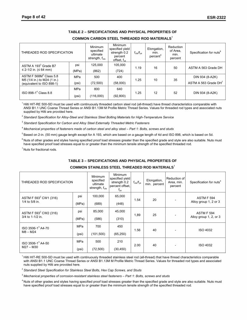
TABLE 2 – SPECIFICATIONS AND PHYSICAL PROPERTIES OF
COMMON CARBON STEEL THREADED ROD MATERIALS1
THREADED ROD SPECIFICATION
Minimum specified ultimate
strength, futa
Minimum specified yield strength 0.2
percent offset, fya
futa/fya
Elongation, min.
percent5
Reduction of Area,
min. percent
Specification for nuts6
psi 125,000 105,000 ASTM A 1932 Grade B7 ≤ 2-1/2 in. (≤ 64 mm) (MPa) (862) (724)
1.19 16 50 ASTM A 563 Grade DH
MPa 500 400 DIN 934 (8-A2K) ASTM F 568M3 Class 5.8 M5 (1/4 in.) to M24 (1 in.) (equivalent to ISO 898-1) (psi) (72,500) (58,000)
1.25 10 35 ASTM A 563 Grade DH7
MPa 800 640 ISO 898-14 Class 8.8
(psi) (116,000) (92,800) 1.25 12 52 DIN 934 (8-A2K)
1 Hilti HIT-RE 500-SD must be used with continuously threaded carbon steel rod (all-thread) have thread characteristics comparable with ANSI B1.1 UNC Coarse Thread Series or ANSI B1.13M M Profile Metric Thread Series. Values for threaded rod types and associated nuts supplied by Hilti are provided here.
2 Standard Specification for Alloy-Steel and Stainless Steel Bolting Materials for High-Temperature Service 3 Standard Specification for Carbon and Alloy Steel Externally Threaded Metric Fasteners 4 Mechanical properties of fasteners made of carbon steel and alloy steel – Part 1: Bolts, screws and studs 5 Based on 2-in. (50 mm) gauge length except for A 193, which are based on a gauge length of 4d and ISO 898, which is based on 5d.
6 Nuts of other grades and styles having specified proof load stresses greater than the specified grade and style are also suitable. Nuts must have specified proof load stresses equal to or greater than the minimum tensile strength of the specified threaded rod.
7 Nuts for fractional rods.
TABLE 3 – SPECIFICATIONS AND PHYSICAL PROPERTIES OF
COMMON STAINLESS STEEL THREADED ROD MATERIALS1
THREADED ROD SPECIFICATION
Minimum specified ultimate
strength, futa
Minimum specified yield strength 0.2
percent offset,fya
futa/fya Elongation,
min. percent
Reduction of Area, min.
percent Specification for nuts4
psi 100,000 65,000 ASTM F 5932 CW1 (316) 1/4 to 5/8 in. (MPa) (689) (448)
1.54 20 - ASTM F 594 Alloy group 1, 2 or 3
psi 85,000 45,000 ASTM F 5932 CW2 (316) 3/4 to 1-1/2 in. (MPa) (586) (310)
1,89 25 - ASTM F 594 Alloy group 1, 2, or 3
MPa 700 450 ISO 3506-13 A4-70 M8 – M24 (psi) (101,500) (65,250)
1.56 40 - ISO 4032
MPa 500 210 ISO 3506-13 A4-50 M27 – M30 (psi) (72,500) (30,450)
2.00 40 - ISO 4032
1 Hilti HIT-RE 500-SD must be used with continuously threaded stainless steel rod (all-thread) that have thread characteristics comparable with ANSI B1.1 UNC Coarse Thread Series or ANSI B1.13M M Profile Metric Thread Series. Values for threaded rod types and associated nuts supplied by Hilti are provided here.
2 Standard Steel Specification for Stainless Steel Bolts, Hex Cap Screws, and Studs 3 Mechanical properties of corrosion-resistant stainless steel fasteners – Part 1: Bolts, screws and studs 4 Nuts of other grades and styles having specified proof load stresses greater than the specified grade and style are also suitable. Nuts must have specified proof load stresses equal to or greater than the minimum tensile strength of the specified threaded rod.
Page 9 of 42
ESR-2322
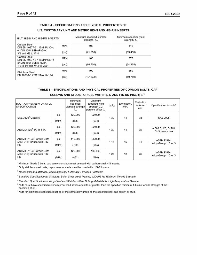
TABLE 4 – SPECIFICATIONS AND PHYSICAL PROPERTIES OF
U.S. CUSTOMARY UNIT AND METRIC HIS-N AND HIS-RN INSERTS
HILTI HIS-N AND HIS-RN INSERTS Minimum specified ultimate strength, futa
Minimum specified yield strength, fya
MPa 490 410 Carbon Steel DIN EN 10277-3 11SMnPb30+c or DIN 1561 9SMnPb28K 3/8 and M8 to M10 (psi) (71,050) (59,450)
MPa 460 375 Carbon Steel DIN EN 10277-3 11SMnPb30+c or DIN 1561 9SMnPb28K 1/2 to 3/4 and M12 to M20 (psi) (66,700) (54,375)
MPa 700 350 Stainless Steel EN 10088-3 X5CrNiMo 17-12-2 (psi) (101,500) (50,750)
TABLE 5 – SPECIFICATIONS AND PHYSICAL PROPERTIES OF COMMON BOLTS, CAP
SCREWS AND STUDS FOR USE WITH HIS-N AND HIS-RN INSERTS1,2
BOLT, CAP SCREW OR STUD SPECIFICATION
Minimum specified
ultimate strength futa
Minimum specified yield strength 0.2
percent offset fya
futa/fya Elongation,
min.
Reduction of Area,
min. Specification for nuts6
psi 120,000 92,000 SAE J4293 Grade 5
(MPa) (828) (634) 1.30 14 35 SAE J995
psi 120,000 92,000 ASTM A 3254 1/2 to 1-in.
(MPa) (828) (634) 1.30 14 35 A 563 C, C3, D, DH,
DH3 Heavy Hex
psi 110,000 95,000 ASTM F A1935 Grade B8M (AISI 316) for use with HIS-RN (MPa) (759) (655)
1.16 15 45 ASTM F 5947
Alloy Group 1, 2 or 3
psi 125,000 100,000 ASTM F A1935 Grade B8M (AISI 316) for use with HIS-RN (MPa) (862) (690)
1.25 12 35 ASTM F 5947
Alloy Group 1, 2 or 3
1 Minimum Grade 5 bolts, cap screws or studs must be used with carbon steel HIS inserts. 2 Only stainless steel bolts, cap screws or studs must be used with HIS-R inserts. 3 Mechanical and Material Requirements for Externally Threaded Fasteners 4 Standard Specification for Structural Bolts, Steel, Heat Treated, 120/105 ksi Minimum Tensile Strength 5 Standard Specification for Alloy-Steel and Stainless Steel Bolting Materials for High-Temperature Service 6 Nuts must have specified minimum proof load stress equal to or greater than the specified minimum full-size tensile strength of the specified stud.
7 Nuts for stainless steel studs must be of the same alloy group as the specified bolt, cap screw, or stud.
Page 10 of 42
ESR-2322
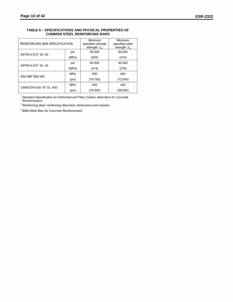
TABLE 6 – SPECIFICATIONS AND PHYSICAL PROPERTIES OF COMMON STEEL REINFORCING BARS
REINFORCING BAR SPECIFICATION Minimum
specified ultimate strength, futa
Minimum specified yield
strength, fya psi 90,000 60,000
ASTM A 6151 Gr. 60 (MPa) (620) (414)
psi 60,000 40,000 ASTM A 6151 Gr. 40
(MPa) (414) (276)
MPa 550 500 DIN 4882 BSt 500
(psi) (79,750) (72,500)
MPa 540 400 CAN/CSA-G30.183 Gr. 400
(psi) (78,300) (58,000)
1 Standard Specification for Deformed and Plain Carbon Steel Bars for Concrete Reinforcement
2 Reinforcing steel; reinforcing steel bars; dimensions and masses 3 Billet-Steel Bars for Concrete Reinforcement
Page 11 of 42
ESR-2322
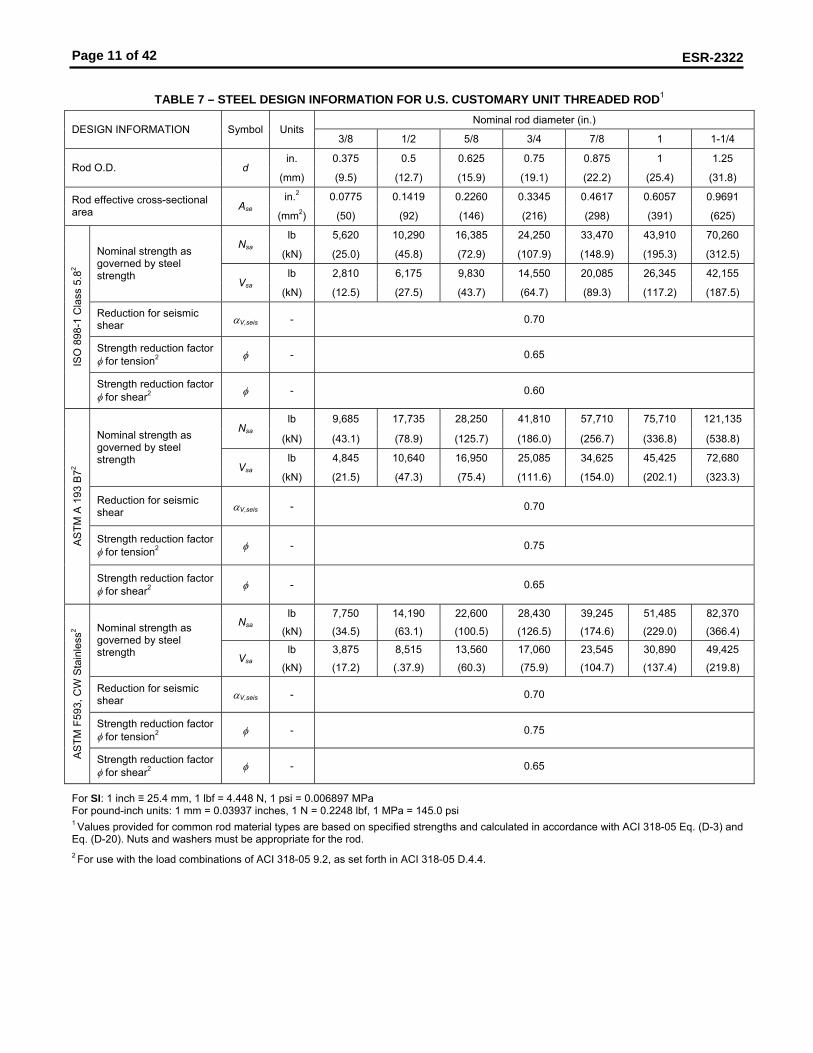
TABLE 7 – STEEL DESIGN INFORMATION FOR U.S. CUSTOMARY UNIT THREADED ROD1
Nominal rod diameter (in.) DESIGN INFORMATION Symbol Units
3/8 1/2 5/8 3/4 7/8 1 1-1/4
in. 0.375 0.5 0.625 0.75 0.875 1 1.25 Rod O.D. d
(mm) (9.5) (12.7) (15.9) (19.1) (22.2) (25.4) (31.8)
in.2 0.0775 0.1419 0.2260 0.3345 0.4617 0.6057 0.9691 Rod effective cross-sectional area Ase
(mm2) (50) (92) (146) (216) (298) (391) (625)
lb 5,620 10,290 16,385 24,250 33,470 43,910 70,260 Nsa
(kN) (25.0) (45.8) (72.9) (107.9) (148.9) (195.3) (312.5)
lb 2,810 6,175 9,830 14,550 20,085 26,345 42,155
Nominal strength as governed by steel strength Vsa
(kN) (12.5) (27.5) (43.7) (64.7) (89.3) (117.2) (187.5)
Reduction for seismic shear αV,seis - 0.70
Strength reduction factor φ for tension2 φ - 0.65
ISO
898
-1 C
lass
5.8
2
Strength reduction factor φ for shear2 φ - 0.60
lb 9,685 17,735 28,250 41,810 57,710 75,710 121,135 Nsa
(kN) (43.1) (78.9) (125.7) (186.0) (256.7) (336.8) (538.8)
lb 4,845 10,640 16,950 25,085 34,625 45,425 72,680
Nominal strength as governed by steel strength
Vsa (kN) (21.5) (47.3) (75.4) (111.6) (154.0) (202.1) (323.3)
Reduction for seismic shear αV,seis - 0.70
Strength reduction factor φ for tension2 φ - 0.75 A
STM
A 1
93 B
72
Strength reduction factor φ for shear2 φ - 0.65
lb 7,750 14,190 22,600 28,430 39,245 51,485 82,370 Nsa
(kN) (34.5) (63.1) (100.5) (126.5) (174.6) (229.0) (366.4)
lb 3,875 8,515 13,560 17,060 23,545 30,890 49,425
Nominal strength as governed by steel strength Vsa
(kN) (17.2) (.37.9) (60.3) (75.9) (104.7) (137.4) (219.8)
Reduction for seismic shear αV,seis - 0.70
Strength reduction factor φ for tension2 φ - 0.75
AS
TM F
593,
CW
Sta
inle
ss2
Strength reduction factor φ for shear2 φ - 0.65
For SI: 1 inch ≡ 25.4 mm, 1 lbf = 4.448 N, 1 psi = 0.006897 MPa For pound-inch units: 1 mm = 0.03937 inches, 1 N = 0.2248 lbf, 1 MPa = 145.0 psi 1 Values provided for common rod material types are based on specified strengths and calculated in accordance with ACI 318-05 Eq. (D-3) and Eq. (D-20). Nuts and washers must be appropriate for the rod. 2 For use with the load combinations of ACI 318-05 9.2, as set forth in ACI 318-05 D.4.4.

Page 12 of 42
ESR-2322
Table 8 - CONCRETE BREAKOUT DESIGN INFORMATION FOR U.S. CUSTOMARY UNIT THREADED ROD IN HOLES
DRILLED WITH A HAMMER DRILL AND CARBIDE BIT1 Nominal rod diameter (in.)
DESIGN INFORMATION Symbol Units 3/8 1/2 5/8 3/4 7/8 1 1-1/4
in-lb 17 Effectiveness factor for cracked concrete kc,cr
(SI) (7.1)
in-lb 24 Effectiveness factor for uncracked concrete kc,uncr
(SI) (10)
in. 1-7/8 2-1/2 3-1/8 3-3/4 4-3/8 5 6-1/4 Min. anchor spacing smin
(mm) (48) (64) (79) (95) (111) (127) (159)
in. 1-7/8 2-1/2 3-1/8 3-3/4 4-3/8 5 6-1/4 Min. edge distance cmin
(mm) (48) (64) (79) (95) (111) (127) (159)
in. hef + 1-1/4 Minimum member thickness hmin
(mm) (hef + 30) hef + 2d0
Critical edge distance – splitting (for uncracked concrete)
cac - See Section 4.1.10 of this report.
Strength reduction factor for tension, concrete failure modes, Condition B2
φ - 0.65
Strength reduction factor for shear, concrete failure modes, Condition B2
φ - 0.70
For SI: 1 inch ≡ 25.4 mm, 1 lbf = 4.448 N, 1 psi = 0.006897 MPa For pound-inch units: 1 mm = 0.03937 inches, 1 N = 0.2248 lbf, 1 MPa = 145.0 psi 1Additional setting information is described in Figure 5, installation instructions.
2 Values provided for post-installed anchors under Condition B without supplementary reinforcement as defined in ACI 318 Section D.4.4.

Page 13 of 42
ESR-2322
Table 9 – BOND STRENGTH DESIGN INFORMATION FOR U.S. CUSTOMARY UNIT THREADED ROD IN HOLES
DRILLED WITH A HAMMER DRILL AND CARBIDE BIT1,4 Nominal rod diameter (in.)
DESIGN INFORMATION Symbol Units 3/8 1/2 5/8 3/4 7/8 1 1-1/4
psi 1,090 1,075 1,045 1,000 920 850 730 τk,cr
(N/mm2) (7.5) (7.4) (7.2) (6.9) (6.3) (5.9) (5.0)
in. 2.43 2.81 3.14 3.44 3.71 4.0 5.0
Characteristic bond strength and minimum anchor embedment in cracked concrete hef,min
(mm) (62) (71) (80) (87) (94) (102) (127)
psi 2,285 2,235 2,140 2,065 2,000 1,945 1,860 τk,uncr
(N/mm2) (15.7) (15.4) (14.8) (14.3) (13.8) (13.4) (12.8)
in. 2.43 2.81 3.14 3.44 3.71 4.0 5.0 Tem
pera
ture
rang
e A
3
Characteristic bond strength and minimum anchor embedment in uncracked concrete hef,min
(mm) (62) (71) (80) (87) (94) (102) (127)
psi 445 430 380 345 315 295 260 τk,cr
(N/mm2) (3.1) (3.0) (2.6) (2.4) (2.2) (2.0) (1.8)
in. 1.73 2.20 3.61 3.01 3.50 4.0 5.0
Characteristic bond strength and minimum anchor embedment in cracked concrete2 hef,min
(mm) (44) (56) (66) (76) (89) (102) (127)
psi 790 770 740 715 690 670 645 τk,uncr
(N/mm2) (5.4) (5.3) (5.1) (4.9) (4.8) (4.6) (4.4)
in. 1.73 2.20 3.61 3.01 3.50 4.0 5.0 Tem
pera
ture
rang
e B
3
Characteristic bond strength and minimum anchor embedment in uncracked concrete2 hef,min
(mm) (44) (56) (66) (76) (89) (102) (127)
Dry concrete φd - 0.65 0.65 0.65 0.65 0.55 0.55 0.55
φws - 0.55 0.55 0.45 0.45 0.45 0.45 0.45 Water-saturated concrete
κws - 1.0 1.0 1.0 1.0 1.0 0.99 0.94
φwf - 0.45 0.45 0.45 0.45 0.45 0.45 0.45 Water-filled hole
κwf - 1.00 1.00 0.96 0.91 0.87 0.84 0.79
φuw - 0.45 0.45 0.45 0.45 0.45 0.45 0.45
Per
mis
sibl
e in
stal
latio
n co
nditi
ons
Underwater application
κuw - 0.95 0.94 0.94 0.93 0.92 0.92 0.91
For SI: 1 inch ≡ 25.4 mm, 1 lbf = 4.448 N, 1 psi = 0.006897 MPa For pound-inch units: 1 mm = 0.03937 inches, 1 N = 0.2248 lbf, 1 MPa = 145.0 psi 1 Bond strength values correspond to concrete compressive strength in the range 2,500 psi ≤ f’c ≤ 4,500 psi. For the range 4,500 psi < f’c ≤ 6,500 psi, tabulated characteristic bond strengths may be increased by 6 percent. For the range 6,500 psi < f’c ≤ 8,000 psi, tabulated characteristic bond strengths may be increased by 10 percent.
2 Bond strength values are for sustained loads including dead and live loads. For load combinations consisting of short-term loads only such as wind and seismic, bond strengths may be increased 40 percent.
3 Temperature range A: Maximum short term temperature = 110°F (43°C), maximum long term temperature = 80°F (26°C). Temperature range B: Maximum short term temperature = 162°F (72°C), maximum long term temperature = 110°F (43°C). Short term elevated concrete temperatures are those that occur over brief intervals, e.g., as a result of diurnal cycling. Long term concrete temperatures are roughly constant over significant periods of time.
4 For structures assigned to Seismic Design Categories C, D, E or F, bond strength values must be multiplied by αN,seis = 0.65.
Page 14 of 42
ESR-2322
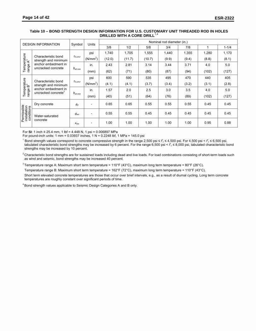
Table 10 – BOND STRENGTH DESIGN INFORMATION FOR U.S. CUSTOMARY UNIT THREADED ROD IN HOLES
DRILLED WITH A CORE DRILL1,4 Nominal rod diameter (in.)
DESIGN INFORMATION Symbol Units 3/8 1/2 5/8 3/4 7/8 1 1-1/4
psi 1,740 1,705 1,555 1,440 1,355 1,280 1,170 τk,uncr
(N/mm2) (12.0) (11.7) (10.7) (9.9) (9.4) (8.8) (8.1)
in. 2.43 2.81 3.14 3.44 3.71 4.0 5.0
Tem
pera
ture
ra
nge
A3 Characteristic bond
strength and minimum anchor embedment in uncracked concrete hef,min
(mm) (62) (71) (80) (87) (94) (102) (127)
psi 600 590 535 495 470 440 405 τk,uncr
(N/mm2) (4.1) (4.1) (3.7) (3.4) (3.2) (3.1) (2.8)
in. 1.57 2.0 2.5 3.0 3.5 4.0 5.0
Tem
pera
ture
ra
nge
B3 Characteristic bond
strength and minimum anchor embedment in uncracked concrete2 hef,min
(mm) (40) (51) (64) (76) (89) (102) (127)
Dry concrete φd - 0.65 0.65 0.55 0.55 0.55 0.45 0.45
φws - 0.55 0.55 0.45 0.45 0.45 0.45 0.45
Per
mis
sibl
e in
stal
latio
n co
nditi
ons
Water-saturated concrete
κws - 1.00 1.00 1.00 1.00 1.00 0.95 0.88
For SI: 1 inch ≡ 25.4 mm, 1 lbf = 4.448 N, 1 psi = 0.006897 MPa For pound-inch units: 1 mm = 0.03937 inches, 1 N = 0.2248 lbf, 1 MPa = 145.0 psi 1 Bond strength values correspond to concrete compressive strength in the range 2,500 psi ≤ f’c ≤ 4,500 psi. For 4,500 psi < f’c ≤ 6,500 psi, tabulated characteristic bond strengths may be increased by 6 percent. For the range 6,500 psi < f’c ≤ 8,000 psi, tabulated characteristic bond strengths may be increased by 10 percent.
2 Characteristic bond strengths are for sustained loads including dead and live loads. For load combinations consisting of short-term loads such as wind and seismic, bond strengths may be increased 40 percent.
3 Temperature range A: Maximum short term temperature = 110°F (43°C), maximum long term temperature = 80°F (26°C). Temperature range B: Maximum short term temperature = 162°F (72°C), maximum long term temperature = 110°F (43°C). Short term elevated concrete temperatures are those that occur over brief intervals, e.g., as a result of diurnal cycling. Long term concrete temperatures are roughly constant over significant periods of time.
4 Bond strength values applicable to Seismic Design Categories A and B only.
Page 15 of 42
ESR-2322
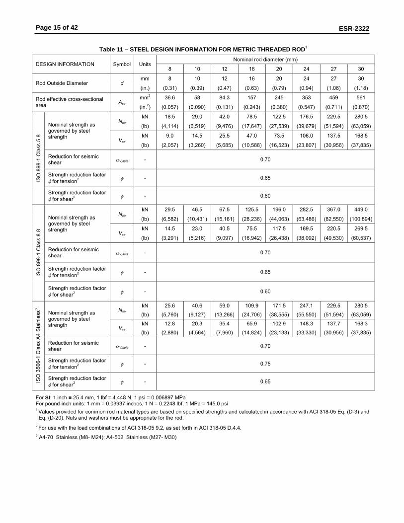
Table 11 – STEEL DESIGN INFORMATION FOR METRIC THREADED ROD1
Nominal rod diameter (mm) DESIGN INFORMATION Symbol Units
8 10 12 16 20 24 27 30
mm 8 10 12 16 20 24 27 30 Rod Outside Diameter d
(in.) (0.31) (0.39) (0.47) (0.63) (0.79) (0.94) (1.06) (1.18)
mm2 36.6 58 84.3 157 245 353 459 561 Rod effective cross-sectional area Ase
(in.2) (0.057) (0.090) (0.131) (0.243) (0.380) (0.547) (0.711) (0.870)
kN 18.5 29.0 42.0 78.5 122.5 176.5 229.5 280.5 Nsa
(lb) (4,114) (6,519) (9,476) (17,647) (27,539) (39,679) (51,594) (63,059)
kN 9.0 14.5 25.5 47.0 73.5 106.0 137.5 168.5
Nominal strength as governed by steel strength Vsa
(lb) (2,057) (3,260) (5,685) (10,588) (16,523) (23,807) (30,956) (37,835)
Reduction for seismic shear αV,seis - 0.70
Strength reduction factor φ for tension2 φ - 0.65 IS
O 8
98-1
Cla
ss 5
.8
Strength reduction factor φ for shear2 φ - 0.60
kN 29.5 46.5 67.5 125.5 196.0 282.5 367.0 449.0 Nsa
(lb) (6,582) (10,431) (15,161) (28,236) (44,063) (63,486) (82,550) (100,894)
kN 14.5 23.0 40.5 75.5 117.5 169.5 220.5 269.5
Nominal strength as governed by steel strength Vsa
(lb) (3,291) (5,216) (9,097) (16,942) (26,438) (38,092) (49,530) (60,537)
Reduction for seismic shear αV,seis - 0.70
Strength reduction factor φ for tension2 φ - 0.65 IS
O 8
98-1
Cla
ss 8
.8
Strength reduction factor φ for shear2 φ - 0.60
kN 25.6 40.6 59.0 109.9 171.5 247.1 229.5 280.5 Nsa
(lb) (5,760) (9,127) (13,266) (24,706) (38,555) (55,550) (51,594) (63,059)
kN 12.8 20.3 35.4 65.9 102.9 148.3 137.7 168.3
Nominal strength as governed by steel strength Vsa
(lb) (2,880) (4,564) (7,960) (14,824) (23,133) (33,330) (30,956) (37,835)
Reduction for seismic shear αV,seis - 0.70
Strength reduction factor φ for tension2 φ - 0.75
ISO
350
6-1
Cla
ss A
4 S
tain
less
3
Strength reduction factor φ for shear2 φ - 0.65
For SI: 1 inch ≡ 25.4 mm, 1 lbf = 4.448 N, 1 psi = 0.006897 MPa For pound-inch units: 1 mm = 0.03937 inches, 1 N = 0.2248 lbf, 1 MPa = 145.0 psi 1 Values provided for common rod material types are based on specified strengths and calculated in accordance with ACI 318-05 Eq. (D-3) and
Eq. (D-20). Nuts and washers must be appropriate for the rod. 2 For use with the load combinations of ACI 318-05 9.2, as set forth in ACI 318-05 D.4.4. 3 A4-70 Stainless (M8- M24); A4-502 Stainless (M27- M30)

Page 16 of 42
ESR-2322
Table 12 - CONCRETE BREAKOUT DESIGN INFORMATION FOR METRIC THREADED ROD IN HOLES DRILLED WITH A
HAMMER DRILL AND CARBIDE BIT1 Nominal rod diameter (mm)
DESIGN INFORMATION Symbol Units 8 10 12 16 20 24 27 30
SI 7.1 Effectiveness factor for cracked concrete kc,cr
(in-lb) (17)
SI 10 Effectiveness factor for uncracked concrete kc,uncr
(in-lb) (24)
mm 40 50 60 80 100 120 135 150 Min. anchor spacing smin
(in.) (1.6) (2.0) (2.4) (3.2) (3.9) (4.7) (5.3) (5.9)
mm 40 50 60 80 100 120 135 150 Min. edge distance cmin
(in.) (1.6) (2.0) (2.4) (3.2) (3.9) (4.7) (5.3) (5.9)
mm hef + 30 Minimum member thickness hmin
(in.) (hef + 1-1/4) hef + 2d
Critical edge distance – splitting (for uncracked concrete)
cac - See Section 4.1.10 of this report.
Strength reduction factor for tension, concrete failure modes, Condition B2
φ - 0.65
Strength reduction factor for shear, concrete failure modes, Condition B2
φ - 0.70
For SI: 1 inch ≡ 25.4 mm, 1 lbf = 4.448 N, 1 psi = 0.006897 MPa For pound-inch units: 1 mm = 0.03937 inches, 1 N = 0.2248 lbf, 1 MPa = 145.0 psi 1Additional setting information is described in Figure 5, installation instructions.
2 Values provided for post-installed anchors installed under Condition B without supplementary reinforcement.
Page 17 of 42
ESR-2322
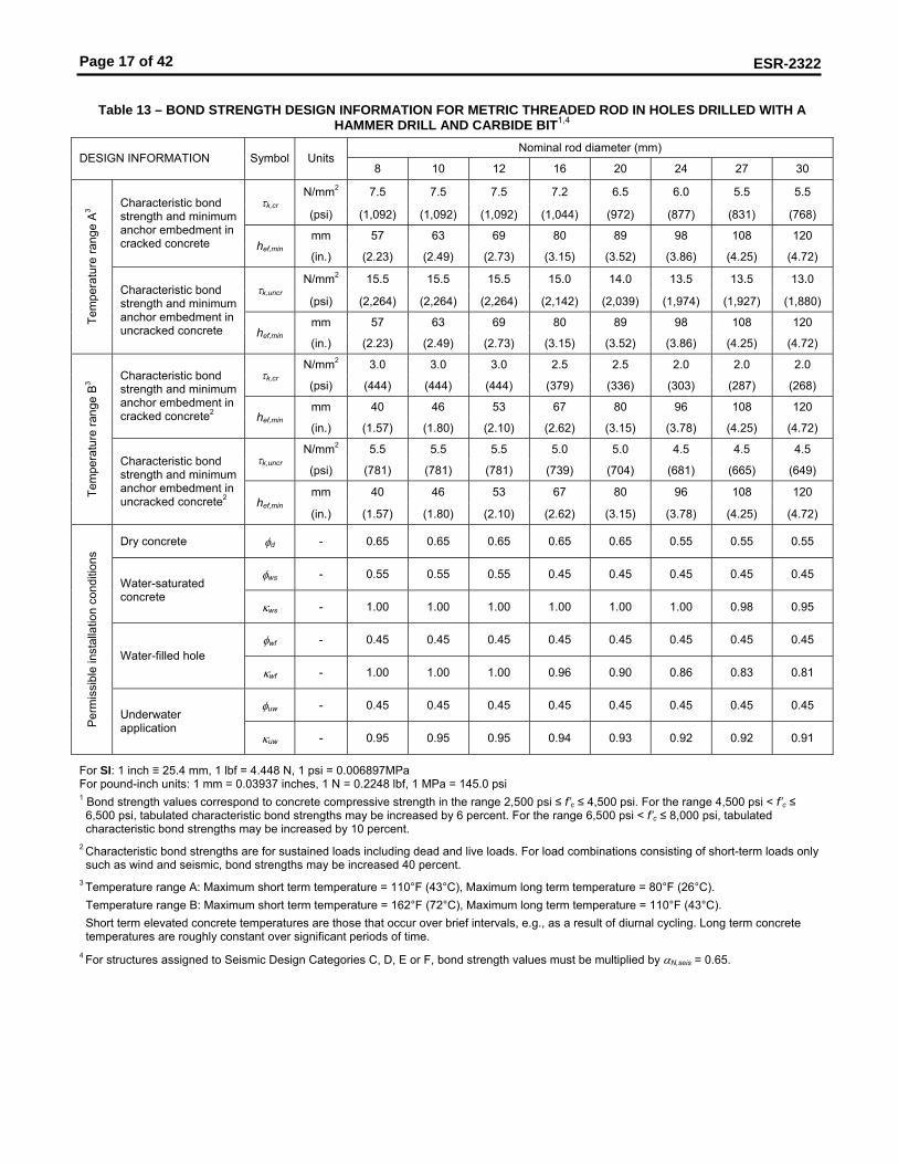
Table 13 – BOND STRENGTH DESIGN INFORMATION FOR METRIC THREADED ROD IN HOLES DRILLED WITH A
HAMMER DRILL AND CARBIDE BIT1,4 Nominal rod diameter (mm)
DESIGN INFORMATION Symbol Units 8 10 12 16 20 24 27 30
N/mm2 7.5 7.5 7.5 7.2 6.5 6.0 5.5 5.5 τk,cr
(psi) (1,092) (1,092) (1,092) (1,044) (972) (877) (831) (768)
mm 57 63 69 80 89 98 108 120
Characteristic bond strength and minimum anchor embedment in cracked concrete hef,min
(in.) (2.23) (2.49) (2.73) (3.15) (3.52) (3.86) (4.25) (4.72)
N/mm2 15.5 15.5 15.5 15.0 14.0 13.5 13.5 13.0 τk,uncr
(psi) (2,264) (2,264) (2,264) (2,142) (2,039) (1,974) (1,927) (1,880)
mm 57 63 69 80 89 98 108 120 Tem
pera
ture
rang
e A
3
Characteristic bond strength and minimum anchor embedment in uncracked concrete hef,min
(in.) (2.23) (2.49) (2.73) (3.15) (3.52) (3.86) (4.25) (4.72)
N/mm2 3.0 3.0 3.0 2.5 2.5 2.0 2.0 2.0 τk,cr
(psi) (444) (444) (444) (379) (336) (303) (287) (268)
mm 40 46 53 67 80 96 108 120
Characteristic bond strength and minimum anchor embedment in cracked concrete2 hef,min
(in.) (1.57) (1.80) (2.10) (2.62) (3.15) (3.78) (4.25) (4.72)
N/mm2 5.5 5.5 5.5 5.0 5.0 4.5 4.5 4.5 τk,uncr
(psi) (781) (781) (781) (739) (704) (681) (665) (649)
mm 40 46 53 67 80 96 108 120 Tem
pera
ture
rang
e B
3
Characteristic bond strength and minimum anchor embedment in uncracked concrete2 hef,min
(in.) (1.57) (1.80) (2.10) (2.62) (3.15) (3.78) (4.25) (4.72)
Dry concrete φd - 0.65 0.65 0.65 0.65 0.65 0.55 0.55 0.55
φws - 0.55 0.55 0.55 0.45 0.45 0.45 0.45 0.45 Water-saturated concrete
κws - 1.00 1.00 1.00 1.00 1.00 1.00 0.98 0.95
φwf - 0.45 0.45 0.45 0.45 0.45 0.45 0.45 0.45 Water-filled hole
κwf - 1.00 1.00 1.00 0.96 0.90 0.86 0.83 0.81
φuw - 0.45 0.45 0.45 0.45 0.45 0.45 0.45 0.45
Per
mis
sibl
e in
stal
latio
n co
nditi
ons
Underwater application
κuw - 0.95 0.95 0.95 0.94 0.93 0.92 0.92 0.91
For SI: 1 inch ≡ 25.4 mm, 1 lbf = 4.448 N, 1 psi = 0.006897MPa For pound-inch units: 1 mm = 0.03937 inches, 1 N = 0.2248 lbf, 1 MPa = 145.0 psi 1 Bond strength values correspond to concrete compressive strength in the range 2,500 psi ≤ f’c ≤ 4,500 psi. For the range 4,500 psi < f’c ≤ 6,500 psi, tabulated characteristic bond strengths may be increased by 6 percent. For the range 6,500 psi < f’c ≤ 8,000 psi, tabulated characteristic bond strengths may be increased by 10 percent.
2 Characteristic bond strengths are for sustained loads including dead and live loads. For load combinations consisting of short-term loads only such as wind and seismic, bond strengths may be increased 40 percent.
3 Temperature range A: Maximum short term temperature = 110°F (43°C), Maximum long term temperature = 80°F (26°C). Temperature range B: Maximum short term temperature = 162°F (72°C), Maximum long term temperature = 110°F (43°C). Short term elevated concrete temperatures are those that occur over brief intervals, e.g., as a result of diurnal cycling. Long term concrete temperatures are roughly constant over significant periods of time.
4 For structures assigned to Seismic Design Categories C, D, E or F, bond strength values must be multiplied by αN,seis = 0.65.

Page 18 of 42
ESR-2322
Table 14 – BOND STRENGTH DESIGN INFORMATION FOR METRIC THREADED ROD IN HOLES DRILLED WITH A
CORE DRILL1,4 Nominal rod diameter (mm)
DESIGN INFORMATION Symbol Units 8 10 12 16 20 24 27 30
N/mm2 12.0 12.0 12.0 10.5 9.5 9.0 8.5 8.5 τk,uncr
(psi) (1,740) (1,740) (1,740) (1,553) (1,413) (1,310) (1,254) (1,197)
mm 56 63 69 80 89 98 108 120
Tem
pera
ture
ra
nge
A3 Characteristic bond
strength and minimum anchor embedment in uncracked concrete hef,min
(in.) (2.19) (2.49) (2.73) (3.15) (3.52) (3.86) (4.25) (4.72)
N/mm2 4.0 4.0 4.0 3.5 3.5 3.0 3.0 3.0 τk,uncr
(psi) (601) (601) (601) (536) (488) (452) (433) (413)
mm 40 41 48 64 80 96 108 120
Tem
pera
ture
ra
nge
B3 Characteristic bond
strength and minimum anchor embedment in uncracked concrete2 hef,min
(in.) (1.57) (1.61) (1.89) (2.52) (3.15) (3.78) (4.25) (4.72)
Dry concrete φd - 0.65 0.65 0.65 0.55 0.55 0.55 0.45 0.45
φws - 0.55 0.55 0.55 0.45 0.45 0.45 0.45 0.45
Per
mis
sibl
e in
stal
latio
n co
nditi
ons
Water-saturated concrete
κws - 1.00 1.00 1.00 1.00 1.00 0.97 0.93 0.90
For SI: 1 inch ≡ 25.4 mm, 1 lbf = 4.448 N, 1 psi = 0.006897MPa For pound-inch units: 1 mm = 0.03937 inches, 1 N = 0.2248 lbf, 1 MPa = 145.0 psi 1 Bond strength values correspond to concrete compressive strength in the range 2,500 psi ≤ f’c ≤ 4,500 psi. For the range 4,500 psi < f’c ≤ 6,500 psi, tabulated characteristic bond strengths may be increased by 6 percent. For the range 6,500 psi < f’c ≤ 8,000 psi, tabulated characteristic bond strengths may be increased by 10 percent.
2 Characteristic bond strengths are for sustained loads including dead and live loads. For short-term loads including wind and seismic, bond strengths may be increased 40 percent.
3 Temperature range A: Maximum short term temperature = 110°F (43°C), Maximum long term temperature = 80°F (26°C). Temperature range B: Maximum short term temperature = 162°F (72°C), Maximum long term temperature = 110°F (43°C). Short term elevated concrete temperatures are those that occur over brief intervals, e.g., as a result of diurnal cycling. Long term concrete temperatures are roughly constant over significant periods of time.
4 Bond strength values applicable to Seismic Design Categories A and B only.

Page 19 of 42
ESR-2322
Table 15 – STEEL DESIGN INFORMATION FOR U.S. CUSTOMARY UNIT HILTI HIS-N AND HIS-RN INSERTS1
Nominal bolt/cap screw diameter (in.) DESIGN INFORMATION Symbol Units
3/8 1/2 5/8 3/4
in. 0.65 0.81 1 1.09 HIS insert O.D. d
(mm) (16.5) (20.5) (25.4) (27.6)
HIS insert length l
in. mm)
4.33 (110)
4.92 (125)
6.69 (170)
8.07 (205)
(mm) 0.0775 0.1419 0.2260 0.3345 Bolt effective cross-sectional area Ase
(mm2) (50) (92) (146) (216)
in.2 0.178 0.243 0.404 0.410 HIS insert effective cross-sectional area Ainsert
(mm2) (115) (157) (260) (265)
lb 9,295 17,020 27,110 40,120 Nsa
(kN) (41.3) (75.7) (120.6) (178.5)
lb 5,575 10,210 16,265 24,075
Nominal strength as governed by steel strength – A 193 B7 bolt/cap screw Vsa
(kN) (24,8) (45.4) (72.3) (107.1)
lb 12,650 16,195 26,925 27,360 Nominal strength as governed by steel strength – HIS-N insert
Nsa (kN) (56.3) (72.0) (119.8) (121.7)
Reduction for seismic shear αV,seis - 0.70
Strength reduction factor φ for tension2 φ - 0.75
AS
TM A
193
B7
Strength reduction factor φ for shear2 φ - 0.65
lb 7,750 14,190 22,600 28,430 Nsa
(kN) (34.5) (63.1) (100.5) (126.5)
lb 4,650 8,515 13,560 17,060
Nominal strength as governed by steel strength – ASTM F A193 Grade B8M SS bolt/cap screw Vsa
(kN) (20.7) (37.9) (60.3) (75.9)
lb 18,070 24,645 40,975 41,640 Nominal strength as governed by steel strength – HIS-RN insert
Nsa (kN) (80.4) (109.6) (182.3) (185.2)
Reduction for seismic shear αV,seis - 0.70
Strength reduction factor φ for tension2 φ - 0.65
AS
TM F
A19
3 G
rade
B8M
SS
Strength reduction factor φ for shear2 φ - 0.60
For SI: 1 inch ≡ 25.4 mm, 1 lbf = 4.448 N, 1 psi = 0.006897MPa For pound-inch units: 1 mm = 0.03937 inches, 1 N = 0.2248 lbf, 1 MPa = 145.0 psi 1 Values provided for common rod material types based on specified strengths and calculated in accordance with ACI 318-05 Eq. (D-3) and Eq. (D-20). Nuts and washers must be appropriate for the rod. 2 For use with the load combinations of ACI 318-05 9.2, as set forth in ACI 318-05 D.4.4. Values correspond to a ductile steel element.
Page 20 of 42
ESR-2322
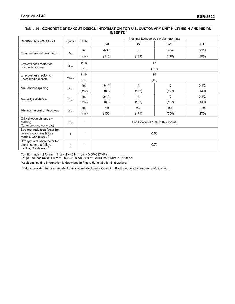
Table 16 - CONCRETE BREAKOUT DESIGN INFORMATION FOR U.S. CUSTOMARY UNIT HILTI HIS-N AND HIS-RN
INSERTS 1 Nominal bolt/cap screw diameter (in.)
DESIGN INFORMATION Symbol Units 3/8 1/2 5/8 3/4
in. 4-3/8 5 6-3/4 8-1/8 Effective embedment depth hef
(mm) (110) (125) (170) (205)
in-lb 17 Effectiveness factor for cracked concrete kc,cr
(SI) (7.1)
in-lb 24 Effectiveness factor for uncracked concrete kc,uncr
(SI) (10)
in. 3-1/4 4 5 5-1/2 Min. anchor spacing smin
(mm) (83) (102) (127) (140)
in. 3-1/4 4 5 5-1/2 Min. edge distance cmin
(mm) (83) (102) (127) (140)
in. 5.9 6.7 9.1 10.6 Minimum member thickness hmin
(mm) (150) (170) (230) (270) Critical edge distance – splitting (for uncracked concrete)
cac - See Section 4.1.10 of this report.
Strength reduction factor for tension, concrete failure modes, Condition B2
φ - 0.65
Strength reduction factor for shear, concrete failure modes, Condition B2
φ - 0.70
For SI: 1 inch ≡ 25.4 mm, 1 lbf = 4.448 N, 1 psi = 0.006897MPa For pound-inch units: 1 mm = 0.03937 inches, 1 N = 0.2248 lbf, 1 MPa = 145.0 psi 1Additional setting information is described in Figure 5, installation instructions.
2 Values provided for post-installed anchors installed under Condition B without supplementary reinforcement.

Page 21 of 42
ESR-2322
Table 17– BOND STRENGTH DESIGN INFORMATION FOR U.S. CUSTOMARY UNIT HILTI HIS-N AND HIS-RN INSERTS
IN HOLES DRILLED WITH A HAMMER DRILL AND CARBIDE BIT 1,4 Nominal bolt/cap screw diameter (in.)
DESIGN INFORMATION Symbol Units 3/8 1/2 5/8 3/4
in. 4-3/8 5 6-3/4 8-1/8 Effective embedment depth hef
(mm) (110) (125) (170) (205)
in. 0.65 0.81 1 1.09 HIS insert O.D. d
(mm) (16.5) (20.5) (25.4) (27.6)
psi 1040 955 845 805 Characteristic bond strength in cracked concrete
τk,cr (N/mm2) (7.2) (6.6) (5.8) (5.6)
psi 2125 2030 1945 1910
Tem
pera
ture
ra
nge
A3
Characteristic bond strength in uncracked concrete
τk,uncr (N/mm2) (14.6) (14.0) (13.4) (13.2)
psi 375 330 290 280 Characteristic bond strength in cracked concrete2
τk,cr (N/mm2) (2.6) (2.3) (2.0) (1.9)
psi 735 700 670 660
Tem
pera
ture
ra
nge
B3
Characteristic bond strength in uncracked concrete2
τk,uncr (N/mm2) (5.1) (4.8) (4.6) (4.5)
Dry concrete φd - 0.65 0.65 0.55 0.55
φws - 0.45 0.45 0.45 0.45 Water-saturated concrete
κws - 1.00 1.00 0.99 0.97
φwf - 0.45 0.45 0.45 0.45 Water-filled hole
κwf - 0.95 0.89 0.84 0.82
φuw - 0.45 0.45 0.45 0.45
Per
mis
sibl
e in
stal
latio
n co
nditi
ons
Underwater application
κuw - 0.93 0.93 0.92 0.92
For SI: 1 inch ≡ 25.4 mm, 1 lbf = 4.448 N, 1 psi = 0.006897MPa For pound-inch units: 1 mm = 0.03937 inches, 1 N = 0.2248 lbf, 1 MPa = 145.0 psi 1 Bond strength values correspond to concrete compressive strength in the range 2,500 psi ≤ f’c ≤ 4,500 psi. For the range 4,500 psi < f’c ≤ 6,500 psi, tabulated characteristic bond strengths may be increased by 6 percent. For the range 6,500 psi < f’c ≤ 8,000 psi, tabulated characteristic bond strengths may be increased by 10 percent.
2 Characteristic bond strengths are for sustained loads including dead and live loads. For load combinations consisting of short-term loads only such as wind and seismic, bond strengths may be increased 40 percent.
3 Temperature range A: Maximum short term temperature = 110°F (43°C), Maximum long term temperature = 80°F (26°C). Temperature range B: Maximum short term temperature = 162°F (72°C), Maximum long term temperature = 110°F (43°C). Short term elevated concrete temperatures are those that occur over brief intervals, e.g., as a result of diurnal cycling. Long term concrete temperatures are roughly constant over significant periods of time.
4 For structures assigned to Seismic Design Categories C, D, E or F, bond strength values must be multiplied by αN,seis = 0.65.

Page 22 of 42
ESR-2322
Table 18 – BOND STRENGTH DESIGN INFORMATION FOR U.S. CUSTOMARY UNIT HILTI HIS-N AND HIS-RN INSERTS
IN HOLES DRILLED WITH A CORE DRILL1,4 Nominal bolt/cap screw diameter (in.)
DESIGN INFORMATION Symbol Units 3/8 1/2 5/8 3/4
in. 4-3/8 5 6-3/4 8-1/8 Effective embedment depth hef
(mm) (110) (125) (170) (205)
in. 0.65 0.81 1 1.09 HIS insert O.D. d
(mm) (16.5) (20.5) (25.4) (27.6)
psi 1,535 1,405 1,280 1,235
Tem
pera
ture
ra
nge
A3
Characteristic bond strength in uncracked concrete
τk,uncr
(N/mm2) (10.6) (9.7) (8.8) (8.5)
psi 530 485 440 425
Tem
pera
ture
ra
nge
B3
Characteristic bond strength in uncracked concrete2
τk,uncr
(N/mm2) (3.7) (3.3) (3.1) (2.9)
Dry concrete φd - 0.55 0.55 0.45 0.45
φws - 0.45 0.45 0.45 0.45
Per
mis
sibl
e in
stal
latio
n co
nditi
ons
Water-saturated concrete
κws - 1.00 1.00 0.95 0.92
For SI: 1 inch ≡ 25.4 mm, 1 lbf = 4.448 N, 1 psi = 0.006897MPa For pound-inch units: 1 mm = 0.03937 inches, 1 N = 0.2248 lbf, 1 MPa = 145.0 psi 1 Bond strength values correspond to concrete compressive strength in the range 2,500 psi ≤ f’c ≤ 4,500 psi. For the range 4,500 psi < f’c ≤ 6,500 psi, tabulated characteristic bond strengths may be increased by 6 percent. For the range 6,500 psi < f’c ≤ 8,000 psi, tabulated characteristic bond strengths may be increased by 10 percent.
2 Characteristic bond strengths are for sustained loads including dead and live loads. For load combinations consisting of short-term loads only such as wind and seismic, bond strengths may be increased 40 percent.
3 Temperature range A: Maximum short term temperature = 110°F (43°C), Maximum long term temperature = 80°F (26°C). Temperature range B: Maximum short term temperature = 162°F (72°C), Maximum long term temperature = 110°F (43°C). Short term elevated concrete temperatures are those that occur over brief intervals, e.g., as a result of diurnal cycling. Long term concrete temperatures are roughly constant over significant periods of time.
4 Bond strength values applicable to Seismic Design Categories A and B only.

Page 23 of 42
ESR-2322
Table 19 – STEEL DESIGN INFORMATION FOR METRIC HILTI HIS-N AND HIS-RN INSERTS1
Nominal bolt/cap screw diameter (mm) DESIGN INFORMATION Symbol Units
8 10 12 16 20
mm 12.5 16.5 20.5 25.4 27.6 HIS insert O.D. d
(in.) (0.49) (0.65) (0.81) (1.00) (1.09)
HIS insert length l mm (in.)
90 (3.54)
110 (4.33)
125 (4.92)
170 (6.69)
205 (8.07)
mm2 36.6 58 84.3 157 245 Bolt effective cross-sectional area Ase
(in.2) (0.057) (0.090) (0.131) (0.243) (0.380)
mm2 51.5 108 169.1 256.1 237.6 HIS insert effective cross-sectional area Ainsert
(in.2) (0.080) (0.167) (0.262) (0.397) (0.368)
kN 29.5 46.5 67.5 125.5 196.0 Nsa
(lb) (6,582) (10,431) (15,161) (28,236) (44,063)
kN 17.5 28.0 40.5 75.5 117.5
Nominal strength as governed by steel strength – ISO 898-1 Class 8.8 bolt/cap screw Vsa
(lb) (3,949) (6,259) (9,097) (16,942) (26,438)
kN 25.0 53.0 78.0 118.0 110.0 Nominal strength as governed by steel strength – HIS-N insert
Nsa (lb) (5,669) (11,894) (17,488) (26,483) (24,573)
Reduction for seismic shear αV,seis - 0.70
Strength reduction factor φ for tension2 φ - 0.65
ISO
898
-1 C
lass
8.8
Strength reduction factor φ for shear2 φ - 0.60
kN 25.5 40.5 59.0 110.0 171.5 Nsa
(lb) (5,760) (9,127) (13,266) (24,706) (38,555)
kN 15.5 24.5 35.5 66.0 103.0
Nominal strength as governed by steel strength – ISO 3506-1 Class A4-70 Stainless bolt/cap screw Vsa
(lb) (3,456) (5,476) (7,960) (14,824) (23,133)
kN 36.0 75.5 118.5 179.5 166.5 Nominal strength as governed by steel strength – HIS-RN insert
Nsa (lb) (8,099) (16,991) (26,612) (40,300) (37,394)
Reduction for seismic shear αV,seis - 0.70
Strength reduction factor φ for tension2 φ - 0.75
ISO
350
6-1
Cla
ss A
4-70
Sta
inle
ss
Strength reduction factor φ for shear2 φ - 0.65
For SI: 1 inch ≡ 25.4 mm, 1 lbf = 4.448 N, 1 psi = 0.006897MPa For pound-inch units: 1 mm = 0.03937 inches, 1 N = 0.2248 lbf, 1 MPa = 145.0 psi 1 Values provided for common rod material types based on specified strengths and calculated in accordance with ACI 318-05 Eq. (D-3) and Eq. (D-20). Nuts and washers must be appropriate for the rod. 2 For use with the load combinations of ACI 318-05 9.2 as set forth in ACI 318-05 D.4.4. Values correspond to a ductile steel element.

Page 24 of 42
ESR-2322
Table 20 - CONCRETE BREAKOUT DESIGN INFORMATION FOR METRIC HILTI HIS-N AND HIS-RN INSERTS 1
Nominal bolt/cap screw diameter (in.) DESIGN INFORMATION Symbol Units
8 10 12 16 20
mm 90 110 125 170 205 Effective embedment depth hef
(in.) (3.5) (4.3) (4.9) (6.7) (8.1)
SI 7.1 Effectiveness factor for cracked concrete kc,cr
(in-lb) (17)
SI 10 Effectiveness factor for uncracked concrete kc,uncr
(in-lb) (24)
mm 63 83 102 127 140 Min. anchor spacing smin
(in.) (2.5) (3.25) (4.0) (5.0) (5.5)
mm 63 83 102 127 140 Min. edge distance cmin
(in.) (2.5) (3.25) (4.0) (5.0) (5.5)
mm 120 150 170 230 270 Minimum member thickness hmin
(in.) (4.7) (5.9) (6.7) (9.1) (10.6) Critical edge distance – splitting (for uncracked concrete)
cac - See Section 4.1.10 of this report.
Strength reduction factor for tension, concrete failure modes, Condition B2
φ - 0.65
Strength reduction factor for shear, concrete failure modes, Condition B2
φ - 0.70
For SI: 1 inch ≡ 25.4 mm, 1 lbf = 4.448 N, 1 psi = 0.006897MPa For pound-inch units: 1 mm = 0.03937 inches, 1 N = 0.2248 lbf, 1 MPa = 145.0 psi 1Additional setting information is described in Figure 5, installation instructions.
2 Values provided for post-installed anchors installed under Condition B without supplementary reinforcement.

Page 25 of 42
ESR-2322
Table 21 – BOND STRENGTH DESIGN INFORMATION FOR METRIC HILTI HIS-N AND HIS-RN INSERTS IN HOLES
DRILLED WITH A HAMMER DRILL AND CARBIDE BIT 1,4 Nominal bolt/cap screw diameter (in.)
DESIGN INFORMATION Symbol Units 8 10 12 16 20
mm 90 110 125 170 205 Effective embedment depth hef
(in.) (3.5) (4.3) (4.9) (6.7) (8.1)
mm 12.5 16.5 20.5 25.5 27.5 HIS insert O.D. d
(in.) (0.49) (0.65) (0.81) (1.00) (1.09)
N/mm2 7.5 7.0 6.5 6.0 5.5 Characteristic bond strength in cracked concrete
τk,cr (psi) (1,080) (1,040) (957) (845) (806)
N/mm2 15.5 14.5 14.0 13.5 13.0
Tem
pera
ture
ra
nge
A3
Characteristic bond strength in uncracked concrete
τk,uncr (psi) (2,245) (2,124) (2,030) (1,946) (1,908)
N/mm2 3.0 2.5 2.5 2.0 2.0 Characteristic bond strength in cracked concrete2
τk,cr (psi) (433) (374) (330) (292) (278)
N/mm2 5.5 5.0 5.0 4.5 4.5
Tem
pera
ture
ra
nge
B3
Characteristic bond strength in uncracked concrete2
τk,uncr (psi) (775) (733) (701) (672) (659)
Dry concrete φd - 0.65 0.65 0.65 0.55 0.55
φws - 0.55 0.45 0.45 0.45 0.45 Water-saturated concrete
κws - 1.00 1.00 1.00 0.99 0.97
φwf - 0.45 0.45 0.45 0.45 0.45 Water-filled hole
κwf - 1.00 0.95 0.89 0.84 0.82
φuw - 0.45 0.45 0.45 0.45 0.45
Per
mis
sibl
e in
stal
latio
n co
nditi
ons
Underwater application
κuw - 0.94 0.93 0.93 0.92 0.92
For SI: 1 inch ≡ 25.4 mm, 1 lbf = 4.448 N, 1 psi = 0.006897MPa For pound-inch units: 1 mm = 0.03937 inches, 1 N = 0.2248 lbf, 1 MPa = 145.0 psi 1 Bond strength values correspond to concrete compressive strength in the range 2,500 psi ≤ f’c ≤ 4,500 psi. For the range 4,500 psi < f’c ≤ 6,500 psi, tabulated characteristic bond strengths may be increased by 6 percent. For the range 6,500 psi < f’c ≤ 8,000 psi, tabulated characteristic bond strengths may be increased by 10 percent.
2 Characteristic bond strengths are for sustained loads including dead and live loads. For load combinations consisting of short-term loads only such as wind and seismic, bond strengths may be increased 40 percent.
3 Temperature range A: Maximum short term temperature = 110°F (43°C), Maximum long term temperature = 80°F (26°C). Temperature range B: Maximum short term temperature = 162°F (72°C), Maximum long term temperature = 110°F (43°C). Short term elevated concrete temperatures are those that occur over brief intervals, e.g., as a result of diurnal cycling. Long term concrete temperatures are roughly constant over significant periods of time.
4 For structures assigned to Seismic Design Categories C, D, E or F, bond strength values must be multiplied by αN,seis = 0.65.

Page 26 of 42
ESR-2322
Table 22 – BOND STRENGTH DESIGN INFORMATION FOR METRIC HILTI HIS-N AND HIS-RN INSERTS IN HOLES
DRILLED WITH A CORE DRILL 1,4 Nominal bolt/cap screw diameter (in.)
DESIGN INFORMATION Symbol Units 8 10 12 16 20
mm 90 110 125 170 205 Effective embedment depth hef
(in.) (3.5) (4.3) (4.9) (6.7) (8.1)
mm 12.5 16.5 20.5 25.5 27.5 HIS insert O.D. d
(in.) (0.49) (0.65) (0.81) (1.00) (1.09)
N/mm2 12.0 10.5 9.5 9.0 8.5
Tem
pera
ture
ra
nge
A3
Characteristic bond strength in uncracked concrete
τk,cr
(psi) (1,712) (1,534) (1,403) (1,282) (1,235)
N/mm2 4.0 3.5 3.5 3.0 3.0
Tem
pera
ture
ra
nge
B3
Characteristic bond strength in uncracked concrete2
τk,cr
(psi) (591) (530) (484) (442) (426)
Dry concrete φd - 0.65 0.55 0.45 0.45 0.45
φws - 0.55 0.45 0.45 0.45 0.45
Per
mis
sibl
e in
stal
latio
n co
nditi
ons
Water-saturated concrete
κws - 1.0 1.0 1.0 0.95 0.92
For SI: 1 inch ≡ 25.4 mm, 1 lbf = 4.448 N, 1 psi = 0.006897MPa For pound-inch units: 1 mm = 0.03937 inches, 1 N = 0.2248 lbf, 1 MPa = 145.0 psi 1 Bond strength values correspond to concrete compressive strength in the range 2,500 psi ≤ f’c ≤ 4,500 psi. For the range 4,500 psi < f’c ≤ 6,500 psi, tabulated characteristic bond strengths may be increased by 6 percent. For the range 6,500 psi < f’c ≤ 8,000 psi, tabulated characteristic bond strengths may be increased by 10 percent.
2 Characteristic bond strengths are for sustained loads including dead and live loads. For load combinations consisting of short-term loads only such as wind and seismic, bond strengths may be increased 40 percent.
3 Temperature range A: Maximum short term temperature = 110°F (43°C), Maximum long term temperature = 80°F (26°C). Temperature range B: Maximum short term temperature = 162°F (72°C), Maximum long term temperature = 110°F (43°C). Short term elevated concrete temperatures are those that occur over brief intervals, e.g., as a result of diurnal cycling. Long term concrete temperatures are roughly constant over significant periods of time.
4 For structures assigned to Seismic Design Categories C, D, E or F, bond strength values must be multiplied by αN,seis = 0.65.
Page 27 of 42
ESR-2322
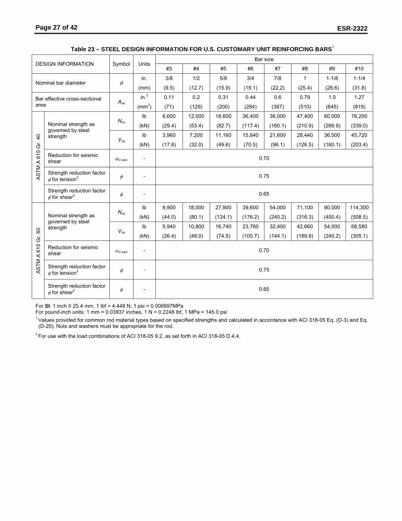
Table 23 – STEEL DESIGN INFORMATION FOR U.S. CUSTOMARY UNIT REINFORCING BARS1
Bar size DESIGN INFORMATION Symbol Units
#3 #4 #5 #6 #7 #8 #9 #10
in. 3/8 1/2 5/8 3/4 7/8 1 1-1/8 1-1/4 Nominal bar diameter d
(mm) (9.5) (12.7) (15.9) (19.1) (22.2) (25.4) (28.6) (31.8)
in.2 0.11 0.2 0.31 0.44 0.6 0.79 1.0 1.27 Bar effective cross-sectional area Ase
(mm2) (71) (129) (200) (284) (387) (510) (645) (819)
lb 6,600 12,000 18,600 26,400 36,000 47,400 60,000 76,200 Nsa
(kN) (29.4) (53.4) (82.7) (117.4) (160.1) (210.9) (266.9) (339.0)
lb 3,960 7,200 11,160 15,840 21,600 28,440 36,000 45,720
Nominal strength as governed by steel strength Vsa
(kN) (17.6) (32.0) (49.6) (70.5) (96.1) (126.5) (160.1) (203.4)
Reduction for seismic shear αV,seis - 0.70
Strength reduction factor φ for tension2 φ - 0.75 A
STM
A 6
15 G
r. 40
Strength reduction factor φ for shear2 φ - 0.65
lb 9,900 18,000 27,900 39,600 54,000 71,100 90,000 114,300 Nsa
(kN) (44.0) (80.1) (124.1) (176.2) (240.2) (316.3) (400.4) (508.5)
lb 5,940 10,800 16,740 23,760 32,400 42,660 54,000 68,580
Nominal strength as governed by steel strength Vsa
(kN) (26.4) (48.0) (74.5) (105.7) (144.1) (189.8) (240.2) (305.1)
Reduction for seismic shear αV,seis - 0.70
Strength reduction factor φ for tension2 φ - 0.75 A
STM
A 6
15 G
r. 60
Strength reduction factor φ for shear2 φ - 0.65
For SI: 1 inch ≡ 25.4 mm, 1 lbf = 4.448 N, 1 psi = 0.006897MPa For pound-inch units: 1 mm = 0.03937 inches, 1 N = 0.2248 lbf, 1 MPa = 145.0 psi 1 Values provided for common rod material types based on specified strengths and calculated in accordance with ACI 318-05 Eq. (D-3) and Eq.
(D-20). Nuts and washers must be appropriate for the rod. 2 For use with the load combinations of ACI 318-05 9.2, as set forth in ACI 318-05 D.4.4.
Page 28 of 42
ESR-2322
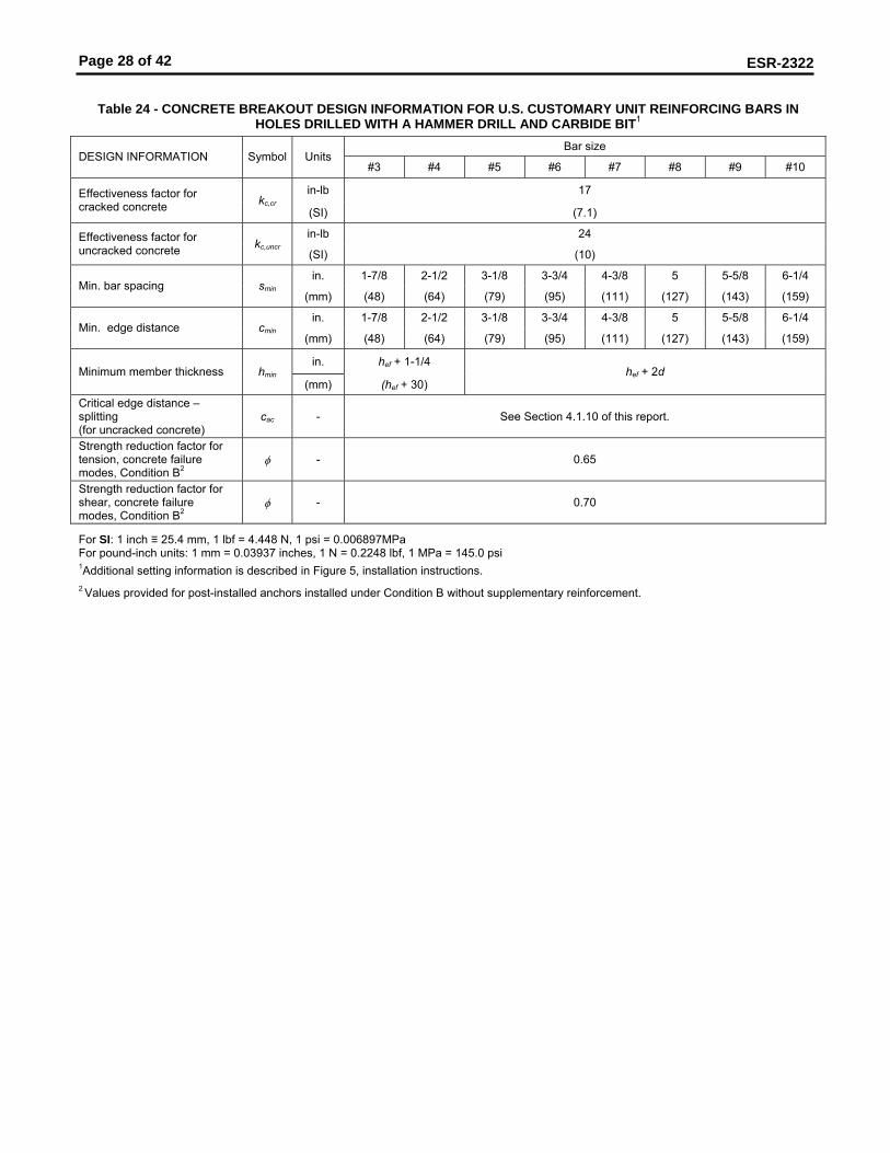
Table 24 - CONCRETE BREAKOUT DESIGN INFORMATION FOR U.S. CUSTOMARY UNIT REINFORCING BARS IN
HOLES DRILLED WITH A HAMMER DRILL AND CARBIDE BIT1 Bar size
DESIGN INFORMATION Symbol Units #3 #4 #5 #6 #7 #8 #9 #10
in-lb 17 Effectiveness factor for cracked concrete kc,cr
(SI) (7.1)
in-lb 24 Effectiveness factor for uncracked concrete kc,uncr
(SI) (10)
in. 1-7/8 2-1/2 3-1/8 3-3/4 4-3/8 5 5-5/8 6-1/4 Min. bar spacing smin
(mm) (48) (64) (79) (95) (111) (127) (143) (159)
in. 1-7/8 2-1/2 3-1/8 3-3/4 4-3/8 5 5-5/8 6-1/4 Min. edge distance cmin
(mm) (48) (64) (79) (95) (111) (127) (143) (159)
in. hef + 1-1/4 Minimum member thickness hmin
(mm) (hef + 30) hef + 2d
Critical edge distance – splitting (for uncracked concrete)
cac - See Section 4.1.10 of this report.
Strength reduction factor for tension, concrete failure modes, Condition B2
φ - 0.65
Strength reduction factor for shear, concrete failure modes, Condition B2
φ - 0.70
For SI: 1 inch ≡ 25.4 mm, 1 lbf = 4.448 N, 1 psi = 0.006897MPa For pound-inch units: 1 mm = 0.03937 inches, 1 N = 0.2248 lbf, 1 MPa = 145.0 psi 1Additional setting information is described in Figure 5, installation instructions.
2 Values provided for post-installed anchors installed under Condition B without supplementary reinforcement.

Page 29 of 42
ESR-2322
Table 25 – BOND STRENGTH DESIGN INFORMATION FOR U.S. CUSTOMARY UNIT REINFORCING BARS IN HOLES
DRILLED WITH A HAMMER DRILL AND CARBIDE BIT1,4 Bar size
DESIGN INFORMATION Symbol Units #3 #4 #5 #6 #7 #8 #9 #10
psi 1,090 1,075 1,045 1,000 915 855 800 730 τk,cr
(N/mm2) (7.5) (7.4) (7.2) (6.9) (6.3) (5.9) (5.5) (5.0)
in. 2.43 2.81 3.14 3.44 3.71 4.00 4.50 5.00
Characteristic bond strength and minimum anchor embedment in cracked concrete hef,min
(mm) (62) (71) (80) (87) (94) (102) (114) (127)
psi 2,265 2,235 2,145 2,065 2,000 1,945 1,900 1,860 τk,uncr
(N/mm2) (15.6) (15.4) (14.8) (14.3) (13.8) (13.4) (13.1) (12.8)
in. 2.43 2.81 3.14 3.44 3.71 4.00 4.50 5.00 Tem
pera
ture
rang
e A
3
Characteristic bond strength and minimum anchor embedment in uncracked concrete hef,min
(mm) (62) (71) (80) (87) (94) (102) (114) (127)
psi 444 431 379 345 316 294 276 260 τk,cr
(N/mm2) (3.1) (3.0) (2.6) (2.4) (2.2) (2.0) (1.9) (1.8)
in. 1.73 2.20 2.61 3.00 3.50 4.00 4.50 5.00
Characteristic bond strength and minimum anchor embedment in cracked concrete2 hef,min
(mm) (44) (56) (66) (76) (89) (102) (114) (127)
psi 781 772 739 714 691 672 656 643 τk,uncr
(N/mm2) (5.4) (5.3) (5.1) (4.9) (4.8) (4.6) (4.5) (4.4)
in. 1.73 2.20 2.61 3.00 3.50 4.00 4.50 5.00 Tem
pera
ture
rang
e B
3
Characteristic bond strength and minimum anchor embedment in uncracked concrete2 hef,min
(mm) (44) (56) (66) (76) (89) (102) (114) (127)
Dry concrete φd - 0.65 0.65 0.65 0.65 0.55 0.55 0.55 0.55
φws - 0.55 0.55 0.45 0.45 0.45 0.45 0.45 0.45 Water-saturated concrete
κws - 1.00 1.00 1.00 1.00 1.00 0.99 0.97 0.94
φwf - 0.45 0.45 0.45 0.45 0.45 0.45 0.45 0.45 Water-filled hole
κwf - 1.00 1.00 0.96 0.91 0.87 0.84 0.82 0.79
φuw - 0.45 0.45 0.45 0.45 0.45 0.45 0.45 0.45
Per
mis
sibl
e in
stal
latio
n co
nditi
ons
Underwater application
κuw - 0.95 0.94 0.94 0.93 0.92 0.92 0.92 0.91
For SI: 1 inch ≡ 25.4 mm, 1 lbf = 4.448 N, 1 psi = 0.006897MPa For pound-inch units: 1 mm = 0.03937 inches, 1 N = 0.2248 lbf, 1 MPa = 145.0 psi 1 Bond strength values correspond to concrete compressive strength in the range 2,500 psi ≤ f’c ≤ 4,500 psi. For the range 4,500 psi < f’c ≤ 6,500 psi, tabulated characteristic bond strengths may be increased by 6 percent. For the range 6,500 psi < f’c ≤ 8,000 psi, tabulated characteristic bond strengths may be increased by 10 percent.
2 Characteristic bond strengths are for sustained loads including dead and live loads. For load combinations consisting of short-term loads only such as wind and seismic, bond strengths may be increased 40 percent.
3 Temperature range A: Maximum short term temperature = 110°F (43°C), Maximum long term temperature = 80°F (26°C). Temperature range B: Maximum short term temperature = 162°F (72°C), Maximum long term temperature = 110°F (43°C). Short term elevated concrete temperatures are those that occur over brief intervals, e.g., as a result of diurnal cycling. Long term concrete temperatures are roughly constant over significant periods of time.
4 For structures assigned to Seismic Design Categories C, D, E or F, bond strength values must be multiplied by αN,seis = 0.65.
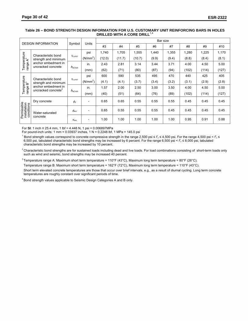
Page 30 of 42
ESR-2322
Table 26 – BOND STRENGTH DESIGN INFORMATION FOR U.S. CUSTOMARY UNIT REINFORCING BARS IN HOLES
DRILLED WITH A CORE DRILL1,4 Bar size
DESIGN INFORMATION Symbol Units #3 #4 #5 #6 #7 #8 #9 #10
psi 1,740 1,705 1,555 1,440 1,355 1,280 1,225 1,170 τk,uncr
(N/mm2) (12.0) (11.7) (10.7) (9.9) (9.4) (8.8) (8.4) (8.1)
in. 2.43 2.81 3.14 3.44 3.71 4.00 4.50 5.00
Tem
pera
ture
ra
nge
A3 Characteristic bond
strength and minimum anchor embedment in uncracked concrete hef,min
(mm) (62) (71) (80) (87) (94) (102) (114) (127)
psi 600 590 535 495 470 440 425 405 τk,uncr
(N/mm2) (4.1) (4.1) (3.7) (3.4) (3.2) (3.1) (2.9) (2.8)
in. 1.57 2.00 2.50 3.00 3.50 4.00 4.50 5.00
Tem
pera
ture
ra
nge
B3 Characteristic bond
strength and minimum anchor embedment in uncracked concrete2 hef,min
(mm) (40) (51) (64) (76) (89) (102) (114) (127)
Dry concrete φd - 0.65 0.65 0.55 0.55 0.55 0.45 0.45 0.45
φws - 0.65 0.55 0.55 0.55 0.45 0.45 0.45 0.45
Per
mis
sibl
e in
stal
latio
n co
nditi
ons
Water-saturated concrete
κws - 1.00 1.00 1.00 1.00 1.00 0.95 0.91 0.88
For SI: 1 inch ≡ 25.4 mm, 1 lbf = 4.448 N, 1 psi = 0.006897MPa For pound-inch units: 1 mm = 0.03937 inches, 1 N = 0.2248 lbf, 1 MPa = 145.0 psi 1 Bond strength values correspond to concrete compressive strength in the range 2,500 psi ≤ f’c ≤ 4,500 psi. For the range 4,500 psi < f’c ≤ 6,500 psi, tabulated characteristic bond strengths may be increased by 6 percent. For the range 6,500 psi < f’c ≤ 8,000 psi, tabulated characteristic bond strengths may be increased by 10 percent.
2 Characteristic bond strengths are for sustained loads including dead and live loads. For load combinations consisting of short-term loads only such as wind and seismic, bond strengths may be increased 40 percent.
3 Temperature range A: Maximum short term temperature = 110°F (43°C), Maximum long term temperature = 80°F (26°C). Temperature range B: Maximum short term temperature = 162°F (72°C), Maximum long term temperature = 110°F (43°C). Short term elevated concrete temperatures are those that occur over brief intervals, e.g., as a result of diurnal cycling. Long term concrete temperatures are roughly constant over significant periods of time.
4 Bond strength values applicable to Seismic Design Categories A and B only.

Page 31 of 42
ESR-2322
Table 27 – STEEL DESIGN INFORMATION FOR EU METRIC REINFORCING BARS1
Bar size DESIGN INFORMATION Symbol Units
8 10 12 14 16 20 25 28 32
mm 8.0 10.0 12.0 14.0 16.0 20.0 25.0 28.0 32.0 Nominal bar diameter d
(in.) (0.315) (0.394) (0.472) (0.551) (0.630) (0.787) (0.984) (1.102) (1.260)
mm2 50.3 78.5 113.1 153.9 201.1 314.2 490.9 615.8 804.2 Bar effective cross-sectional area Ase
(in.2) (0.078) (0.122) (0.175) (0.239) (0.312) (0.487) (0.761) (0.954) (1.247)
kN 27.5 43.0 62.0 84.5 110.5 173.0 270.0 338.5 442.5 Nsa
(lb) (6,215) (9,711) (13,984) (19,034) (24,860) (38,844) (60,694) (76,135) (99,441)
kN 16.5 26.0 37.5 51.0 66.5 103.0 162.0 203.0 265.5
Nominal strength as governed by steel strength Vsa
(lb) (3,729) (5,827) (8,390) (11,420) (14,916) (23,307) (36,416) (45,681) (59,665)
Reduction for seismic shear αV,seis - 0.70
Strength reduction factor φ for tension2 φ - 0.65
DIN
488
BS
t 550
/500
Strength reduction factor φ for shear2 φ - 0.60
For SI: 1 inch ≡ 25.4 mm, 1 lbf = 4.448 N, 1 psi = 0.006897MPa For pound-inch units: 1 mm = 0.03937 inches, 1 N = 0.2248 lbf, 1 MPa = 145.0 psi 1 Values provided for common rod material types based on specified strengths and calculated in accordance with ACI 318-05 Eq. (D-3) and Eq.
(D-20). Other material specifications are admissible. Nuts and washers must be appropriate for the rod. 2 For use with the load combinations of ACI 318-05 9.2, as set forth in ACI 318-05 D.4.4.
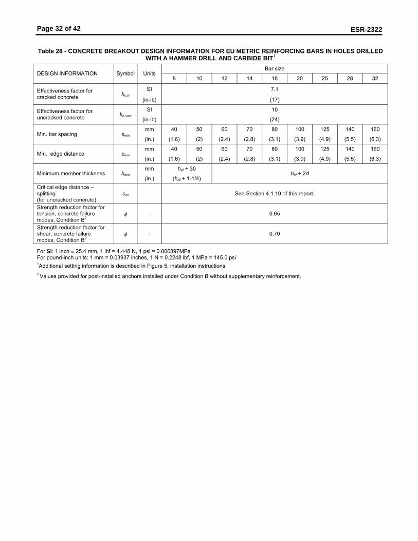
Page 32 of 42
ESR-2322
Table 28 - CONCRETE BREAKOUT DESIGN INFORMATION FOR EU METRIC REINFORCING BARS IN HOLES DRILLED
WITH A HAMMER DRILL AND CARBIDE BIT1 Bar size
DESIGN INFORMATION Symbol Units 8 10 12 14 16 20 25 28 32
SI 7.1 Effectiveness factor for cracked concrete kc,cr
(in-lb) (17)
SI 10 Effectiveness factor for uncracked concrete kc,uncr
(in-lb) (24)
mm 40 50 60 70 80 100 125 140 160 Min. bar spacing smin
(in.) (1.6) (2) (2.4) (2.8) (3.1) (3.9) (4.9) (5.5) (6.3)
mm 40 50 60 70 80 100 125 140 160 Min. edge distance cmin
(in.) (1.6) (2) (2.4) (2.8) (3.1) (3.9) (4.9) (5.5) (6.3)
mm hef + 30 Minimum member thickness hmin
(in.) (hef + 1-1/4) hef + 2d
Critical edge distance – splitting (for uncracked concrete)
cac - See Section 4.1.10 of this report.
Strength reduction factor for tension, concrete failure modes, Condition B2
φ - 0.65
Strength reduction factor for shear, concrete failure modes, Condition B2
φ - 0.70
For SI: 1 inch ≡ 25.4 mm, 1 lbf = 4.448 N, 1 psi = 0.006897MPa For pound-inch units: 1 mm = 0.03937 inches, 1 N = 0.2248 lbf, 1 MPa = 145.0 psi 1Additional setting information is described in Figure 5, installation instructions.
2 Values provided for post-installed anchors installed under Condition B without supplementary reinforcement.
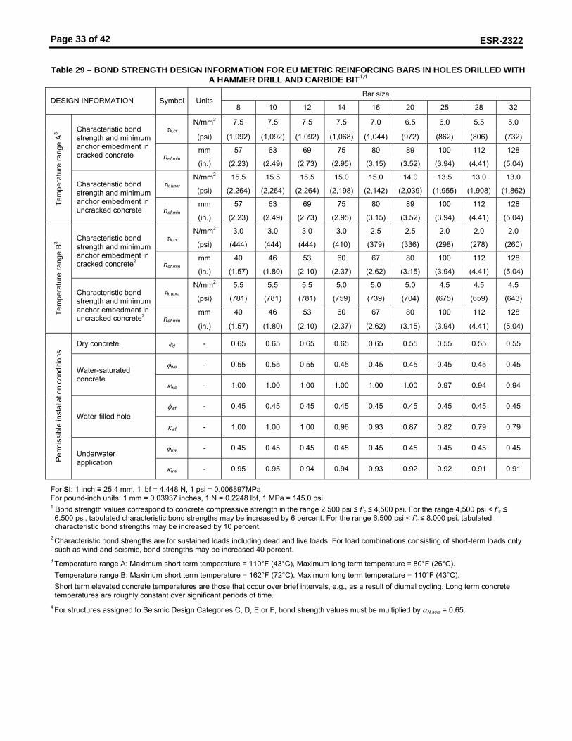
Page 33 of 42
ESR-2322
Table 29 – BOND STRENGTH DESIGN INFORMATION FOR EU METRIC REINFORCING BARS IN HOLES DRILLED WITH
A HAMMER DRILL AND CARBIDE BIT1,4 Bar size
DESIGN INFORMATION Symbol Units 8 10 12 14 16 20 25 28 32
N/mm2 7.5 7.5 7.5 7.5 7.0 6.5 6.0 5.5 5.0 τk,cr
(psi) (1,092) (1,092) (1,092) (1,068) (1,044) (972) (862) (806) (732)
mm 57 63 69 75 80 89 100 112 128
Characteristic bond strength and minimum anchor embedment in cracked concrete hef,min
(in.) (2.23) (2.49) (2.73) (2.95) (3.15) (3.52) (3.94) (4.41) (5.04)
N/mm2 15.5 15.5 15.5 15.0 15.0 14.0 13.5 13.0 13.0 τk,uncr
(psi) (2,264) (2,264) (2,264) (2,198) (2,142) (2,039) (1,955) (1,908) (1,862)
mm 57 63 69 75 80 89 100 112 128 Tem
pera
ture
rang
e A
3
Characteristic bond strength and minimum anchor embedment in uncracked concrete hef,min
(in.) (2.23) (2.49) (2.73) (2.95) (3.15) (3.52) (3.94) (4.41) (5.04)
N/mm2 3.0 3.0 3.0 3.0 2.5 2.5 2.0 2.0 2.0 τk,cr
(psi) (444) (444) (444) (410) (379) (336) (298) (278) (260)
mm 40 46 53 60 67 80 100 112 128
Characteristic bond strength and minimum anchor embedment in cracked concrete2 hef,min
(in.) (1.57) (1.80) (2.10) (2.37) (2.62) (3.15) (3.94) (4.41) (5.04)
N/mm2 5.5 5.5 5.5 5.0 5.0 5.0 4.5 4.5 4.5 τk,uncr
(psi) (781) (781) (781) (759) (739) (704) (675) (659) (643)
mm 40 46 53 60 67 80 100 112 128 Tem
pera
ture
rang
e B
3
Characteristic bond strength and minimum anchor embedment in uncracked concrete2 hef,min
(in.) (1.57) (1.80) (2.10) (2.37) (2.62) (3.15) (3.94) (4.41) (5.04)
Dry concrete φd - 0.65 0.65 0.65 0.65 0.65 0.55 0.55 0.55 0.55
φws - 0.55 0.55 0.55 0.45 0.45 0.45 0.45 0.45 0.45 Water-saturated concrete
κws - 1.00 1.00 1.00 1.00 1.00 1.00 0.97 0.94 0.94
φwf - 0.45 0.45 0.45 0.45 0.45 0.45 0.45 0.45 0.45 Water-filled hole
κwf - 1.00 1.00 1.00 0.96 0.93 0.87 0.82 0.79 0.79
φuw - 0.45 0.45 0.45 0.45 0.45 0.45 0.45 0.45 0.45
Per
mis
sibl
e in
stal
latio
n co
nditi
ons
Underwater application
κuw - 0.95 0.95 0.94 0.94 0.93 0.92 0.92 0.91 0.91
For SI: 1 inch ≡ 25.4 mm, 1 lbf = 4.448 N, 1 psi = 0.006897MPa For pound-inch units: 1 mm = 0.03937 inches, 1 N = 0.2248 lbf, 1 MPa = 145.0 psi 1 Bond strength values correspond to concrete compressive strength in the range 2,500 psi ≤ f’c ≤ 4,500 psi. For the range 4,500 psi < f’c ≤ 6,500 psi, tabulated characteristic bond strengths may be increased by 6 percent. For the range 6,500 psi < f’c ≤ 8,000 psi, tabulated characteristic bond strengths may be increased by 10 percent.
2 Characteristic bond strengths are for sustained loads including dead and live loads. For load combinations consisting of short-term loads only such as wind and seismic, bond strengths may be increased 40 percent.
3 Temperature range A: Maximum short term temperature = 110°F (43°C), Maximum long term temperature = 80°F (26°C). Temperature range B: Maximum short term temperature = 162°F (72°C), Maximum long term temperature = 110°F (43°C). Short term elevated concrete temperatures are those that occur over brief intervals, e.g., as a result of diurnal cycling. Long term concrete temperatures are roughly constant over significant periods of time.
4 For structures assigned to Seismic Design Categories C, D, E or F, bond strength values must be multiplied by αN,seis = 0.65.

Page 34 of 42
ESR-2322
Table 30 – BOND STRENGTH DESIGN INFORMATION FOR EU METRIC REINFORCING BARS IN HOLES DRILLED WITH
A CORE DRILL1,4 Bar size
DESIGN INFORMATION Symbol Units 8 10 12 14 16 20 25 28 32
N/mm2 12.0 12.0 12.0 11.5 10.5 9.5 9.0 8.5 8.0 τk,uncr
(psi) (1,740) (1,740) (1,740) (1,637) (1,553) (1,413) (1,291) (1,235) (1,169)
mm 56 63 69 75 80 89 100 110 130
Tem
pera
ture
ra
nge
A3 Characteristic bond
strength and minimum anchor embedment in uncracked concrete hef,min
(in.) (2.19) (2.49) (2.73) (2.95) (3.15) (3.52) (3.94) (4.41) (5.04)
N/mm2 4.0 4.0 4.0 4.0 3.5 3.5 3.0 3.0 3.0 τk,uncr
(psi) (601) (601) (601) (565) (536) (488) (446) (426) (404)
mm 40 41 48 56 64 80 100 112 128
Tem
pera
ture
ra
nge
B3 Characteristic bond
strength and minimum anchor embedment in uncracked concrete2 hef,min
(in.) (1.57) (1.61) (1.89) (2.20) (2.52) (3.15) (3.94) (4.41) (5.04)
Dry concrete φd - 0.65 0.65 0.65 0.55 0.55 0.55 0.45 0.45 0.45
φws - 0.55 0.55 0.55 0.45 0.45 0.45 0.45 0.45 0.45
Per
mis
sibl
e in
stal
latio
n co
nditi
ons
Water-saturated concrete
κws - 1.0 1.0 1.0 1.0 1.0 1.0 0.92 0.88 0.88
For SI: 1 inch ≡ 25.4 mm, 1 lbf = 4.448 N, 1 psi = 0.006897MPa For pound-inch units: 1 mm = 0.03937 inches, 1 N = 0.2248 lbf, 1 MPa = 145.0 psi 1 Bond strength values correspond to concrete compressive strength in the range 2,500 psi ≤ f’c ≤ 4,500 psi. For the range 4,500 psi < f’c ≤ 6,500 psi, tabulated characteristic bond strengths may be increased by 6 percent. For the range 6,500 psi < f’c ≤ 8,000 psi, tabulated characteristic bond strengths may be increased by 10 percent.
2 Characteristic bond strengths are for sustained loads including dead and live loads. For load combinations consisting of short-term loads only such as wind and seismic, bond strengths may be increased 40 percent.
3 Temperature range A: Maximum short term temperature = 110°F (43°C), Maximum long term temperature = 80°F (26°C). Temperature range B: Maximum short term temperature = 162°F (72°C), Maximum long term temperature = 110°F (43°C). Short term elevated concrete temperatures are those that occur over brief intervals, e.g., as a result of diurnal cycling. Long term concrete temperatures are roughly constant over significant periods of time.
4 Bond strength values applicable to Seismic Design Categories A and B only.

Page 35 of 42
ESR-2322
Table 31 – STEEL DESIGN INFORMATION FOR CANADIAN METRIC REINFORCING BARS1
Bar size DESIGN INFORMATION Symbol Units
10 M 15 M 20 M 25 M 30 M
mm 11.3 16.0 19.5 25.2 29.9 Nominal bar diameter d
(in.) (0.445) (0.630) (0.768) (0.992) (1.177)
mm2 100.3 201.1 298.6 498.8 702.2 Bar effective cross-sectional area Ase
(in.2) (0.155) (0.312) (0.463) (0.773) (1.088)
kN 54.0 108.5 161.5 270.0 380.0 Nsa
(lb) (12,175) (24,408) (36,255) (60,548) (85,239)
kN 32.5 65.0 97.0 161.5 227.5
Nominal strength as governed by steel strength Vsa
(lb) (7,305) (14,645) (21,753) (36,329) (51,144)
Reduction for seismic shear αV,seis - 0.70
Strength reduction factor φ for tension2 φ - 0.65
CS
A G
30
Strength reduction factor φ for shear2 φ - 0.60
For SI: 1 inch ≡ 25.4 mm, 1 lbf = 4.448 N, 1 psi = 0.006897MPa For pound-inch units: 1 mm = 0.03937 inches, 1 N = 0.2248 lbf, 1 MPa = 145.0 psi 1 Values provided for common rod material types based on specified strengths and calculated in accordance with ACI 318-05 Eq. (D-3) and Eq.
(D-20). Other material specifications are admissible. Use nuts and washers appropriate for the rod strength. 2 For use with the load combinations of ACI 318-05 9.2, as set forth in ACI 318-05 D.4.4.

Page 36 of 42
ESR-2322
Table 32 - CONCRETE BREAKOUT DESIGN INFORMATION FOR CANADIAN METRIC REINFORCING BARS IN HOLES
DRILLED WITH A HAMMER DRILL AND CARBIDE BIT1 Bar size
DESIGN INFORMATION Symbol Units 10 M 15 M 20 M 25 M 30 M
SI 7.1 Effectiveness factor for cracked concrete kc,cr
(in-lb) (17)
SI 10 Effectiveness factor for uncracked concrete kc,uncr
(in-lb) (24)
mm 57 80 98 126 150 Min. bar spacing smin
(in.) (2.2) (3.1) (3.8) (5.0) (5.9)
mm 57 80 98 126 150 Min. edge distance cmin
(in.) (2.2) (3.1) (3.8) (5.0) (5.9)
mm hef + 30 Minimum member thickness hmin
(in.) (hef + 1-1/4) hef + 2d
Critical edge distance – splitting (for uncracked concrete)
cac - See Section 4.1.10 of this report.
Strength reduction factor for tension, concrete failure modes, Condition B2
φ - 0.65
Strength reduction factor for shear, concrete failure modes, Condition B2
φ - 0.70
For SI: 1 inch ≡ 25.4 mm, 1 lbf = 4.448 N, 1 psi = 0.006897MPa For pound-inch units: 1 mm = 0.03937 inches, 1 N = 0.2248 lbf, 1 MPa = 145.0 psi 1Additional setting information is described in Figure 5, installation instructions. 2 Values provided for post-installed anchors installed under Condition B without supplementary reinforcement.

Page 37 of 42
ESR-2322
Table 33 – BOND STRENGTH DESIGN INFORMATION FOR CANADIAN METRIC REINFORCING BARS IN HOLES
DRILLED WITH A HAMMER DRILL AND CARBIDE BIT1,4 Bar size
DESIGN INFORMATION Symbol Units 10 M 15 M 20 M 25 M 30 M
N/mm2 7.5 7.0 7.0 6.0 5.5 τk,cr
(psi) (1,092) (1,044) (991) (852) (777)
mm 67 80 88 101 120
Characteristic bond strength and minimum anchor embedment in cracked concrete hef,min
(in.) (2.65) (3.15) (3.48) (3.97) (4.71)
N/mm2 15.5 15.0 14.0 13.5 13.0 τk,uncr
(psi) (2,264) (2,142) (2,058) (1,955) (1,880)
mm 67 80 88 101 120 Tem
pera
ture
rang
e A
3
Characteristic bond strength and minimum anchor embedment in uncracked concrete hef,min
(in.) (2.65) (3.15) (3.48) (3.97) (4.71)
N/mm2 3.0 2.5 2.5 2.0 2.0 τk,cr
(psi) (444) (379) (342) (294) (271)
mm 51 67 78 101 120
Characteristic bond strength and minimum anchor embedment in cracked concrete2 hef,min
(in.) (2.00) (2.62) (3.07) (3.97) (4.71)
N/mm2 5.5 5.0 5.0 4.5 4.5 τk,uncr
(psi) (781) (739) (710) (675) (649)
mm 51 67 78 101 120 Tem
pera
ture
rang
e B
3
Characteristic bond strength and minimum anchor embedment in uncracked concrete2 hef,min
(in.) (2.00) (2.62) (3.07) (3.97) (4.71)
Dry concrete φd - 0.65 0.65 0.65 0.55 0.55
φws - 0.55 0.45 0.45 0.45 0.45 Water-saturated concrete
κws - 1.0 1.0 1.0 1.0 0.96
φwf - 0.45 0.45 0.45 0.45 0.45 Water-filled hole
κwf - 1.00 0.96 0.91 0.85 0.81
φuw - 0.45 0.45 0.45 0.45 0.45
Per
mis
sibl
e in
stal
latio
n co
nditi
ons
Underwater application
κuw - 0.95 0.94 0.93 0.92 0.92
For SI: 1 inch ≡ 25.4 mm, 1 lbf = 4.448 N, 1 psi = 0.006897MPa For pound-inch units: 1 mm = 0.03937 inches, 1 N = 0.2248 lbf, 1 MPa = 145.0 psi 1 Bond strength values correspond to concrete compressive strength in the range 2,500 psi ≤ f’c ≤ 4,500 psi. For the range 4,500 psi < f’c ≤ 6,500 psi, tabulated characteristic bond strengths may be increased by 6 percent. For the range 6,500 psi < f’c ≤ 8,000 psi, tabulated characteristic bond strengths may be increased by 10 percent.
2 Characteristic bond strengths are for sustained loads including dead and live loads. For load combinations consisting of short-term loads only such as wind and seismic, bond strengths may be increased 40 percent.
3 Temperature range A: Maximum short term temperature = 110°F (43°C), Maximum long term temperature = 80°F (26°C). Temperature range B: Maximum short term temperature = 162°F (72°C), Maximum long term temperature = 110°F (43°C). Short term elevated concrete temperatures are those that occur over brief intervals, e.g., as a result of diurnal cycling. Long term concrete temperatures are roughly constant over significant periods of time.
4 For structures assigned to Seismic Design Categories C, D, E or F, bond strength values must be multiplied by αN,seis = 0.65.
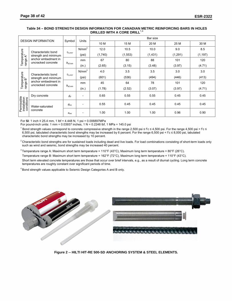
Page 38 of 42
ESR-2322
Table 34 – BOND STRENGTH DESIGN INFORMATION FOR CANADIAN METRIC REINFORCING BARS IN HOLES
DRILLED WITH A CORE DRILL1,4 Bar size
DESIGN INFORMATION Symbol Units 10 M 15 M 20 M 25 M 30 M
N/mm2 12.0 10.5 10.0 9.0 8.5 τk,uncr
(psi) (1,740) (1,553) (1,431) (1,291) (1,197)
mm 67 80 88 101 120
Tem
pera
ture
ra
nge
A3 Characteristic bond
strength and minimum anchor embedment in uncracked concrete hef,min
(in.) (2.65) (3.15) (3.48) (3.97) (4.71)
N/mm2 4.0 3.5 3.5 3.0 3.0 τk,uncr
(psi) (601) (536) (494) (446) (413)
mm 45 64 78 101 120
Tem
pera
ture
ra
nge
B3 Characteristic bond
strength and minimum anchor embedment in uncracked concrete hef,min
(in.) (1.78) (2.52) (3.07) (3.97) (4.71)
Dry concrete φd - 0.65 0.55 0.55 0.45 0.45
φws - 0.55 0.45 0.45 0.45 0.45
Per
mis
sibl
e in
stal
latio
n co
nditi
ons
Water-saturated concrete
κws - 1.00 1.00 1.00 0.96 0.90
For SI: 1 inch ≡ 25.4 mm, 1 lbf = 4.448 N, 1 psi = 0.006897MPa For pound-inch units: 1 mm = 0.03937 inches, 1 N = 0.2248 lbf, 1 MPa = 145.0 psi 1 Bond strength values correspond to concrete compressive strength in the range 2,500 psi ≤ f’c ≤ 4,500 psi. For the range 4,500 psi < f’c ≤ 6,500 psi, tabulated characteristic bond strengths may be increased by 6 percent. For the range 6,500 psi < f’c ≤ 8,000 psi, tabulated characteristic bond strengths may be increased by 10 percent.
2 Characteristic bond strengths are for sustained loads including dead and live loads. For load combinations consisting of short-term loads only such as wind and seismic, bond strengths may be increased 40 percent.
3 Temperature range A: Maximum short term temperature = 110°F (43°C), Maximum long term temperature = 80°F (26°C). Temperature range B: Maximum short term temperature = 162°F (72°C), Maximum long term temperature = 110°F (43°C). Short term elevated concrete temperatures are those that occur over brief intervals, e.g., as a result of diurnal cycling. Long term concrete temperatures are roughly constant over significant periods of time.
4 Bond strength values applicable to Seismic Design Categories A and B only.
Figure 2 -- HILTI HIT-RE 500-SD ANCHORING SYSTEM & STEEL ELEMENTS.

Page 39 of 42
ESR-2322
FIGURE 3 –FLOW CHART FOR THE ESTABLISHMENT OF DESIGN BOND STRENGTH
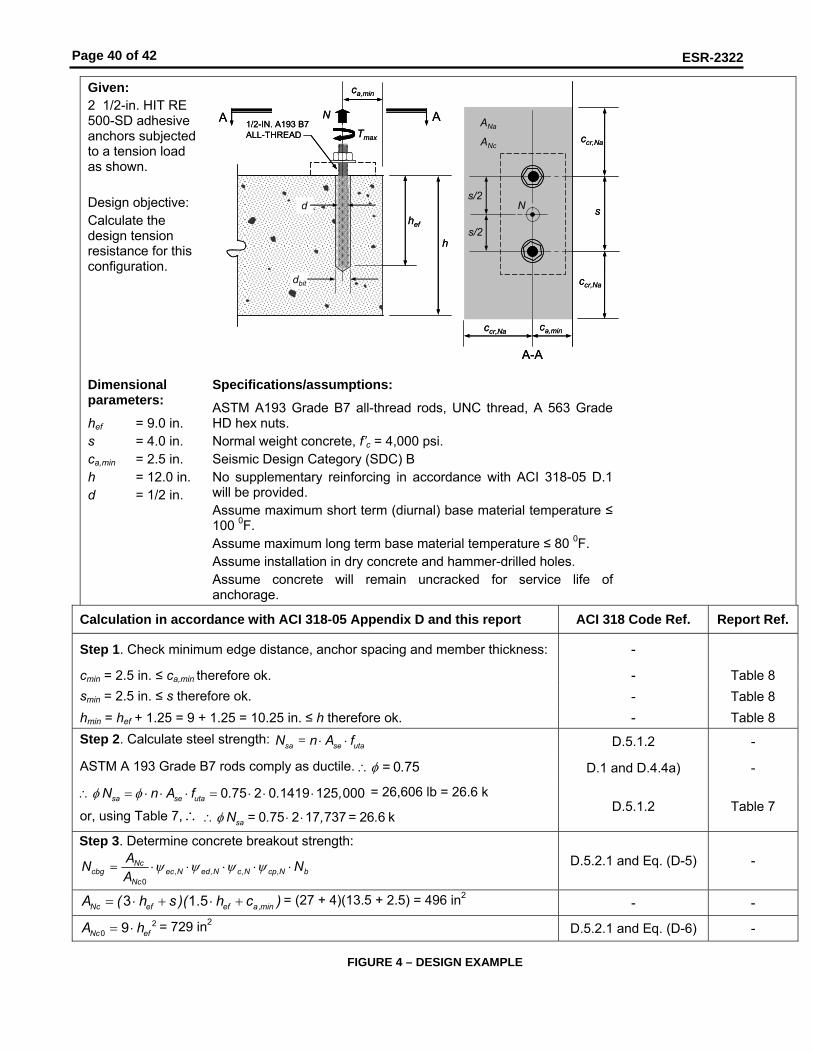
Page 40 of 42
ESR-2322
Given: 2 1/2-in. HIT RE 500-SD adhesive anchors subjected to a tension load as shown. Design objective: Calculate the design tension resistance for this configuration.
h
1/2-IN. A193 B7 ALL-THREAD
hef
ca,min
Tmax
dbit
d
A A
ca,min
s
ccr,Na
ccr,Na
ccr,Na
ANa
ANc
A-A
N
N
s/2
s/2
h
1/2-IN. A193 B7 ALL-THREAD
hef
ca,min
Tmax
dbit
d
A A
ca,min
s
ccr,Na
ccr,Na
ccr,Na
ANa
ANc
A-A
N
N
s/2
s/2
Dimensional parameters:
hef = 9.0 in. s = 4.0 in. ca,min = 2.5 in. h = 12.0 in. d = 1/2 in.
Specifications/assumptions:
ASTM A193 Grade B7 all-thread rods, UNC thread, A 563 Grade HD hex nuts. Normal weight concrete, f’c = 4,000 psi. Seismic Design Category (SDC) B No supplementary reinforcing in accordance with ACI 318-05 D.1 will be provided. Assume maximum short term (diurnal) base material temperature ≤ 100 0F. Assume maximum long term base material temperature ≤ 80 0F. Assume installation in dry concrete and hammer-drilled holes. Assume concrete will remain uncracked for service life of anchorage.
Calculation in accordance with ACI 318-05 Appendix D and this report ACI 318 Code Ref. Report Ref.
Step 1. Check minimum edge distance, anchor spacing and member thickness: -
cmin = 2.5 in. ≤ ca,min therefore ok. - Table 8 smin = 2.5 in. ≤ s therefore ok. - Table 8 hmin = hef + 1.25 = 9 + 1.25 = 10.25 in. ≤ h therefore ok. - Table 8 Step 2. Calculate steel strength: =sa se utaN n A f⋅ ⋅ D.5.1.2 -
ASTM A 193 Grade B7 rods comply as ductile. .φ∴ = 0 75 D.1 and D.4.4a) -
sa se utaN n A f . . ,φ φ∴ = ⋅ ⋅ ⋅ = ⋅ ⋅ ⋅0 75 2 0 1419 125 000 = 26,606 lb = 26.6 k
or, using Table 7, ∴ saN = . , = .φ∴ ⋅ ⋅0 75 2 17 737 26 6 k D.5.1.2 Table 7
Step 3. Determine concrete breakout strength:
bNcpNcNedNecNc
Nccbg N
AAN ⋅⋅⋅⋅⋅= ,,,,
0
ψψψψ D.5.2.1 and Eq. (D-5) -
3 1.5Nc ef ef a,minA ( h s )( h c )= ⋅ + ⋅ + = (27 + 4)(13.5 + 2.5) = 496 in2 - -
Nc efA h 20 9= ⋅ = 729 in2 D.5.2.1 and Eq. (D-6) -
FIGURE 4 – DESIGN EXAMPLE

Page 41 of 42
ESR-2322
Calculation in accordance with ACI 318-05 Appendix D and this report ACI 318 Code Ref. Report Ref.
Nec,ψ = 1.0 no eccentricity of tension load with respect to tension-loaded anchors
D.5.2.4
0 7 0 31 5
a,mined ,N
ef
c. .
. hψ = + ⋅ for 1.5a,min efc h≤ D.5.2.5 and Eq. (D-11) -
2.5 1.5 4.5a,minc = < ⋅ - -
ed,N2.50.7 0.3 0.76
1.5 9ψ∴ = + ⋅ =
⋅ - -
Nc,ψ = 1.0 uncracked concrete assumed (kc,uncr = 24) D.5.2.6 Table 8 Determine cac:
( ) ( ) .ef a,min ac efh c . . . c h
0.75 0 755 9 0 5 2 5 18 9 in. 12.0 in. 2.5+ = + = > ∴ = ⋅
( )acc 2.5 9.0 in. 22.5 in.= = D.5.2.7 Section
4.1.3
For ca,min < cac a,min efcp,N
ac
max c ; . h max . ..c .
1 5 2 5 ;1 5 90 6022 5ψ
⋅ ⋅= = = D.5.2.7 and Eq. (D-13) -
( ) ..b c ,uncr c efN k f ' h , . ,1 51 5 24 4 000 9 0 40 983 lb= ⋅ = ⋅ = D.5.2.2 and Eq. (D-7) -
cbgN 496 1.0 0.76 1.0 0.60 40,983 12,715 lb729
= ⋅ ⋅ ⋅ ⋅ ⋅ = - -
cbgN . , ,0 65 12 715 8 265 lb 8.3 kφ = ⋅ = = D.4.4c) -
Step 4. Determine bond strength: a0Nap,Naec,Nag,Naed,Na0
Naag N
AA
N ⋅⋅⋅⋅⋅= ψψψψ - Section 4.1 Eq. (D-14b)
k,uncrcr,Na efs min d h 2,23620 ; 3 20 0.5 12.4 in.
1,450 1,450τ⎛ ⎞
= ⋅ ⋅ = ⋅ ⋅ =⎜ ⎟⎜ ⎟⎝ ⎠
ef cr ,Na3 h s27 in. 12.4 in. 12.4 in.⋅ = ≥ ∴ = - Section 4.1
Table 9
cr .Nacr,Na
sc 6.2 in.2
= = - Section 4.1 Eq. (D-14i)
( ) ( )Na cr ,Na cr ,Na a,minA 2c s c c 2143.0 in= + + = - Section 4.1 D.5.3.7
( )2Na0 cr ,NaA s 2154.2 in= = - Section 4.1
D.5.3.7
For a,min cr.Nac c< : a,min
cr,Na
cced,Na 0.7 0.3ψ
⎛ ⎞= + ⋅⎜ ⎟⎜ ⎟
⎝ ⎠ - Section 4.1
ed,Na2.50.7 0.3 0.826.2
ψ ⎛ ⎞= + ⋅ =⎜ ⎟⎝ ⎠
- Section 4.1
c,uncrk,max,uncr ef c
kh f'
d24 9.0 4,000 2,899 psi0.5
τπ π
= ⋅ = ⋅ =⋅ ⋅
- Section 4.1 Table 8
( ) ( )k,uncrg,Na0
k,max,uncr
n n1.5 1.52,2361 2 2 1 1.13
2,899τ
ψτ
⎡ ⎤ ⎡ ⎤⎛ ⎞ ⎛ ⎞⎢ ⎥= − − ⋅ = − − ⋅ =⎢ ⎥⎜ ⎟ ⎜ ⎟⎜ ⎟⎢ ⎥ ⎝ ⎠⎢ ⎥⎝ ⎠ ⎣ ⎦⎣ ⎦
- Section 4.1 Table 9
FIGURE 4 – DESIGN EXAMPLE (CONTINUED)

Page 42 of 42
ESR-2322
Calculation in accordance with ACI 318-05 Appendix D and this report ACI 318 Code Ref. Report Ref.
( ) ( )g,Na g,Na0 g,Na0cr,Na
ss
0.5 0.54.01 1.13 1 1.13 1.0612.4
ψ ψ ψ⎡ ⎤ ⎡ ⎤⎛ ⎞ ⎛ ⎞⎢ ⎥= + ⋅ − = + ⋅ − =⎢ ⎥⎜ ⎟ ⎜ ⎟⎜ ⎟⎢ ⎥ ⎝ ⎠⎢ ⎥⎝ ⎠ ⎣ ⎦⎣ ⎦
- Section 4.1
=Naec,ψ 1.0 no eccentricity - loading is concentric - -
a,min cr,Na
ac
max c c maxcp,Na
; 2.5 ; 6.20.2822.5ψ = = = - -
a0 k,uncr efN d h 2,236 0.5 9.0 31,610 lbτ π π= ⋅ ⋅ ⋅ = ⋅ ⋅ ⋅ = - Section 4.1 Eq. (D-14j)
a0Nap,Naec,Nag,Naed,Na0
Naag N
AA
N ⋅⋅⋅⋅⋅= ψψψψ
agN 143.0 0.82 1.06 1.0 0.28 31,610 7,134 lb154.2
= ⋅ ⋅ ⋅ ⋅ ⋅ = - Section 4.1
Eq. (D-14b)
0.65φ = - Table 9
agN 0.65 7,134 4,637 lb 4.6 kφ∴ = ⋅ = = - Step 5. Determine controlling strength: D.4.1.2 -
Steel strength φ Nsa = 26.6 k Concrete breakout strength φ Ncbg = 8.3 k
Bond strength φ Nag = 4.6 k controls Step 6. Convert strength to ASD using factor provided in Section 4.2:
d nallow,ASD
N NN 4.6 3.3 k1.4
φα α
= = = = Section 4.2
FIGURE 4 – SAMPLE CALCULATION
Made in GermanyFabriqué en AllemagneHecho en Alemaniawww.us.hilti.comHilti = registered trademark of Hilti Corporation, Schaan, LI 39
1163
/C 0
9.20
07
Hilti, Inc.5400 South 122nd East Ave.Tulsa, OK 74146 USATel.: +1-800-879 8000www.us.hilti.com
Hilti (Canada) Corp.6790 Century Avenue, Suite 300CDN-Mississauga, Ontario L5N 2V8Tel.: +1-800-363 4458www.ca.hilti.com
Hilti Latin America Ltd.5400 South 122nd East Ave.Tulsa, OK 74146 USATel.: +1-918/252 6595www.hilti.com
Hilti HIT-RE 500-SD
Instructions for use
Mode d'emploi
Instrucciones de uso
en
fr
es
Hilti HIT-RE 500-SDSee the Material Safety Data Sheet for this product before handling.For Industrial Use Only. Keep out of the reach of children! Danger: Corrosive. Harmful if inhaled or swallowed. Can cause eye and skin burns. Risk of serious damage to eyes. Can cause sensitization with some individuals. Contains: quartz sand.Precautions: Wear suitable protection clothing, eye protection and gloves. Do not get in eyes. Avoid contact with the skin. Avoid inhalation of vapors. Avoid inhalation of dusts during demolition/removal.First Aid: For eye contact, flush with water for 15 minutes while holding the eyelids apart. Seek medical attention immediately. For skin contact, wash immediately with soap and water. If ingested, drink two glasses of water and seek medical attention immediately.
Hilti HIT-RE 500-SDSe reporter á la Fiche de données de sécurité du produit déjà l’usage.Pour usage industriel seulement. Tenir hors de la portée des enfants!Danger: Corrosif. Nocif si respiré ou avalé. Peut brûler les yeux et la peau. Risque de lésions oculaires graves. Peut entraîner la sensibilisation chez certains individus. Contient du: sable quartzeux.Précautions: Pour travailler, porter des vêtements, des gants et une protection pour les yeux. Eviter tout contact avec les yeux. Eviter tout contact avec la peau. Eviter d’inhaler les vapeurs. Eviter d’inhaler les poussières lors de la démolition ou du retrait.Premiers soins: En cas de contact avec les yeux, rincer à grande eau pendant 15 minutes en tenant les paupières ouvertes. Faire immédiatement appel à un médecin. En cas de contact avec la peau, se laver immédiatement avec de l’eau et du savon. En cas d’ingestion, boire deux verres d’eau et faire immédiatement appel à un médecin.
Hilti HIT-RE 500-SDConsulte con las Hoja de datos de seguridad para este producto antes de usarlo.Sólo Para Uso Industrial. Mantener alejado del alcance de los niños. Peligro: Corrosivo. Nocivo en caso de ser inhalado o ingerido. Puede causar quemadura de la piel y de los ojos. Riesgo de lesiones oculares graves. Puede causar sensibilización en algunas personas.Contiene: arena de Cuarzo.Precaución: Utilice indumentaria y guantes adecuados y protección para los ojos/la cara. Evite contacto con los ojos y la piel. Evite inhalación de los vapores. Evite inhalación polvo durante la remoción o la demolición.Primeros auxilios: Para contacto con los ojos, enjuague con agua por 15 minutos mientras aguante los párpados abiertos. Acudir atención medica. Para contacto con la piel, enjuague inmediatemente con agua y jabón. De ser ingerido, tome dos vasos de agua y acudir inmediatamente a un medico.
Hilti, Inc. Tulsa, OK 74146 / Hilti Canada Corp. / Hilti Latin America Ltd., Tulsa, OK
In Case of Emergency, call Chem-Trec: 1-800-424-9300 (USA, P.R., Virgin Islands, Canada)En cas d’urgence, téléphoner Chem-Trec: 1-800-424-9300 (USA, P.R., Virgin Islands, Canada)En Caso de Emergencia, Ilame Chem-Trec: 001-703-527-3887 (other countries/autres pays/otros países)
ICC-ES ESR - 2322
HIT RE 500 SD USA:HIT RE 500 SD v1 20.09.2007 17:13 Uhr Seite 7
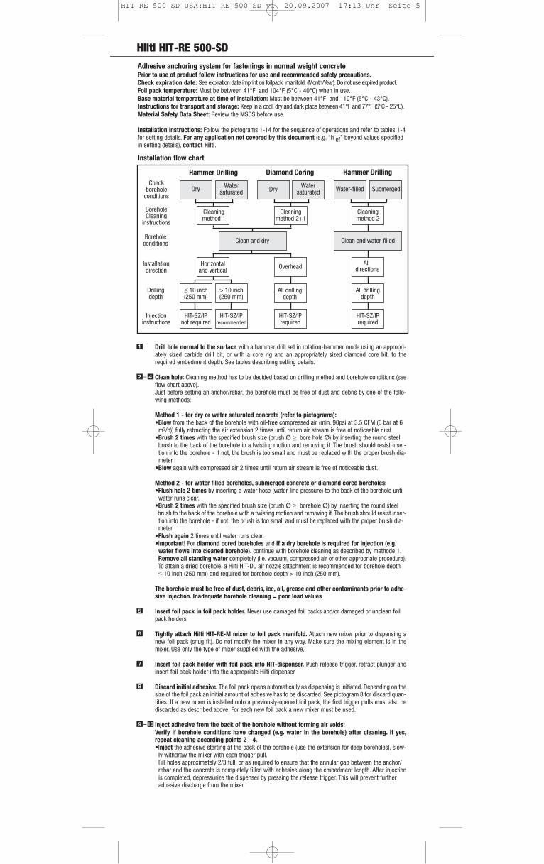
Hilti HIT-RE 500-SD
Adhesive anchoring system for fastenings in normal weight concrete Prior to use of product follow instructions for use and recommended safety precautions.Check expiration date: See expiration date imprint on foilpack manifold. (Month/Year). Do not use expired product.Foil pack temperature: Must be between 41°F and 104°F (5°C - 40°C) when in use.Base material temperature at time of installation: Must be between 41°F and 110°F (5°C - 43°C).Instructions for transport and storage: Keep in a cool, dry and dark place between 41°F and 77°F (5°C - 25°C).Material Safety Data Sheet: Review the MSDS before use.
Installation instructions: Follow the pictograms 1-14 for the sequence of operations and refer to tables 1-4for setting details. For any application not covered by this document (e.g. “h ef” beyond values specifiedin setting details), contact Hilti.
Drill hole normal to the surface with a hammer drill set in rotation-hammer mode using an appropri-ately sized carbide drill bit, or with a core rig and an appropriately sized diamond core bit, to therequired embedment depth. See tables describing setting details.
Clean hole: Cleaning method has to be decided based on drilling method and borehole conditions (seeflow chart above). Just before setting an anchor/rebar, the borehole must be free of dust and debris by one of the follo-wing methods:
Method 1 - for dry or water saturated concrete (refer to pictograms):•Blow from the back of the borehole with oil-free compressed air (min. 90psi at 3.5 CFM (6 bar at 6
m3/h)) fully retracting the air extension 2 times until return air stream is free of noticeable dust. •Brush 2 times with the specified brush size (brush Ø ≥ bore hole Ø) by inserting the round steel
brush to the back of the borehole in a twisting motion and removing it. The brush should resist inser-tion into the borehole - if not, the brush is too small and must be replaced with the proper brush dia-meter.
•Blow again with compressed air 2 times until return air stream is free of noticeable dust.
Method 2 - for water filled boreholes, submerged concrete or diamond cored boreholes:•Flush hole 2 times by inserting a water hose (water-line pressure) to the back of the borehole until
water runs clear. •Brush 2 times with the specified brush size (brush Ø ≥ borehole Ø) by inserting the round steel brush to the back of the borehole with a twisting motion and removing it. The brush should resist inser-tion into the borehole - if not, the brush is too small and must be replaced with the proper brush dia-meter.
•Flush again 2 times until water runs clear.•Important! For diamond cored boreholes and if a dry borehole is required for injection (e.g.
water flows into cleaned borehole), continue with borehole cleaning as described by methode 1.Remove all standing water completely (i.e. vacuum, compressed air or other appropriate procedure).To attain a dried borehole, a Hilti HIT-DL air nozzle attachment is recommended for borehole depth ≤ 10 inch (250 mm) and required for borehole depth > 10 inch (250 mm).
The borehole must be free of dust, debris, ice, oil, grease and other contaminants prior to adhe-sive injection. Inadequate borehole cleaning = poor load values
Insert foil pack in foil pack holder. Never use damaged foil packs and/or damaged or unclean foil pack holders.
Tightly attach Hilti HIT-RE-M mixer to foil pack manifold. Attach new mixer prior to dispensing anew foil pack (snug fit). Do not modify the mixer in any way. Make sure the mixing element is in themixer. Use only the type of mixer supplied with the adhesive.
Insert foil pack holder with foil pack into HIT-dispenser. Push release trigger, retract plunger andinsert foil pack holder into the appropriate Hilti dispenser.
Discard initial adhesive. The foil pack opens automatically as dispensing is initiated. Depending on thesize of the foil pack an initial amount of adhesive has to be discarded. See pictogram 8 for discard quan-tities. If a new mixer is installed onto a previously-opened foil pack, the first trigger pulls must also bediscarded as described above. For each new foil pack a new mixer must be used.
Inject adhesive from the back of the borehole without forming air voids:Verify if borehole conditions have changed (e.g. water in the borehole) after cleaning. If yes,repeat cleaning according points 2 - 4.•Inject the adhesive starting at the back of the borehole (use the extension for deep boreholes), slow-
ly withdraw the mixer with each trigger pull. Fill holes approximately 2/3 full, or as required to ensure that the annular gap between the anchor/ rebar and the concrete is completely filled with adhesive along the embedment length. After injection is completed, depressurize the dispenser by pressing the release trigger. This will prevent further adhesive discharge from the mixer.
�
�–�
�
�
�
�
– �
Hammer Drilling Diamond Coring Hammer DrillingCheck
boreholeconditions
BoreholeCleaning
instructions
Boreholeconditions
Installationdirection
Drillingdepth
Injectioninstructions
Dry Watersaturated Dry Water
saturated Water-filled Submerged
Cleaningmethod 1
Cleaningmethod 2+1
Cleaningmethod 2
Clean and dry Clean and water-filled
Horizontaland vertical Overhead All
directions
≤ 10 inch(250 mm)
> 10 inch(250 mm)
All drillingdepth
All drillingdepth
HIT-SZ/IPnot required
HIT-SZ/IPrecommended
HIT-SZ/IPrequired
HIT-SZ/IPrequired
Installation flow chart
HIT RE 500 SD USA:HIT RE 500 SD v1 20.09.2007 17:13 Uhr Seite 5
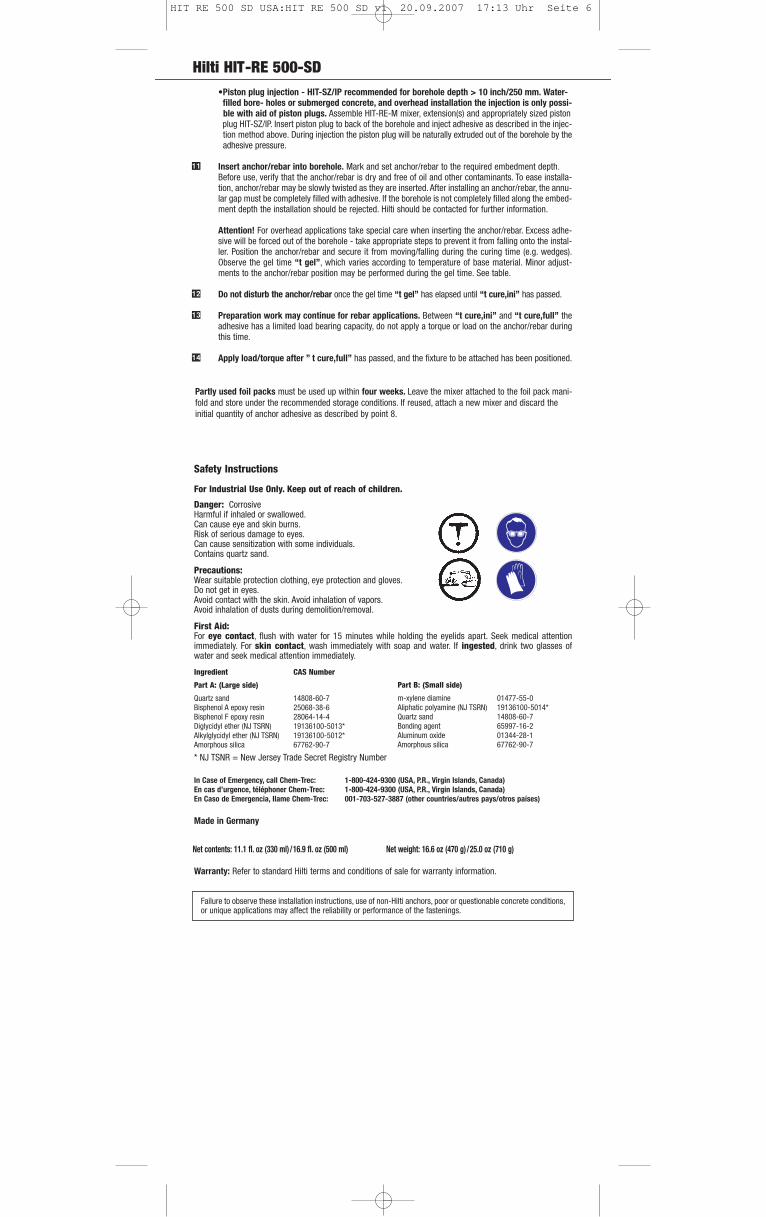
Hilti HIT-RE 500-SD
Safety Instructions
For Industrial Use Only. Keep out of reach of children.
Danger: CorrosiveHarmful if inhaled or swallowed.Can cause eye and skin burns.Risk of serious damage to eyes.Can cause sensitization with some individuals.Contains quartz sand.
Precautions: Wear suitable protection clothing, eye protection and gloves. Do not get in eyes.Avoid contact with the skin. Avoid inhalation of vapors.Avoid inhalation of dusts during demolition/removal.
First Aid: For eye contact, flush with water for 15 minutes while holding the eyelids apart. Seek medical attentionimmediately. For skin contact, wash immediately with soap and water. If ingested, drink two glasses ofwater and seek medical attention immediately.
Ingredient CAS Number
Part A: (Large side)
Quartz sand 14808-60-7Bisphenol A epoxy resin 25068-38-6Bisphenol F epoxy resin 28064-14-4Diglycidyl ether (NJ TSRN) 19136100-5013*Alkylglycidyl ether (NJ TSRN) 19136100-5012*Amorphous silica 67762-90-7
* NJ TSNR = New Jersey Trade Secret Registry Number
In Case of Emergency, call Chem-Trec: 1-800-424-9300 (USA, P.R., Virgin Islands, Canada)En cas d’urgence, téléphoner Chem-Trec: 1-800-424-9300 (USA, P.R., Virgin Islands, Canada)En Caso de Emergencia, Ilame Chem-Trec: 001-703-527-3887 (other countries/autres pays/otros países)
Made in Germany
Warranty: Refer to standard Hilti terms and conditions of sale for warranty information.
Failure to observe these installation instructions, use of non-Hilti anchors, poor or questionable concrete conditions,or unique applications may affect the reliability or performance of the fastenings.
Net contents: 11.1 fl. oz (330 ml)/16.9 fl. oz (500 ml) Net weight: 16.6 oz (470 g)/25.0 oz (710 g)
Part B: (Small side)
m-xylene diamine 01477-55-0Aliphatic polyamine (NJ TSRN) 19136100-5014*Quartz sand 14808-60-7Bonding agent 65997-16-2Aluminum oxide 01344-28-1Amorphous silica 67762-90-7
Partly used foil packs must be used up within four weeks. Leave the mixer attached to the foil pack mani-fold and store under the recommended storage conditions. If reused, attach a new mixer and discard theinitial quantity of anchor adhesive as described by point 8.
•Piston plug injection - HIT-SZ/IP recommended for borehole depth > 10 inch/250 mm. Water- filled bore- holes or submerged concrete, and overhead installation the injection is only possi- ble with aid of piston plugs. Assemble HIT-RE-M mixer, extension(s) and appropriately sized piston plug HIT-SZ/IP. Insert piston plug to back of the borehole and inject adhesive as described in the injec-tion method above. During injection the piston plug will be naturally extruded out of the borehole by the adhesive pressure.
Insert anchor/rebar into borehole. Mark and set anchor/rebar to the required embedment depth. Before use, verify that the anchor/rebar is dry and free of oil and other contaminants. To ease installa-tion, anchor/rebar may be slowly twisted as they are inserted. After installing an anchor/rebar, the annu-lar gap must be completely filled with adhesive. If the borehole is not completely filled along the embed-ment depth the installation should be rejected. Hilti should be contacted for further information.
Attention! For overhead applications take special care when inserting the anchor/rebar. Excess adhe-sive will be forced out of the borehole - take appropriate steps to prevent it from falling onto the instal-ler. Position the anchor/rebar and secure it from moving/falling during the curing time (e.g. wedges).Observe the gel time “t gel”, which varies according to temperature of base material. Minor adjust-ments to the anchor/rebar position may be performed during the gel time. See table.
Do not disturb the anchor/rebar once the gel time “t gel” has elapsed until “t cure,ini” has passed.
Preparation work may continue for rebar applications. Between “t cure,ini” and “t cure,full” theadhesive has a limited load bearing capacity, do not apply a torque or load on the anchor/rebar duringthis time.
Apply load/torque after ” t cure,full” has passed, and the fixture to be attached has been positioned.
�
�
�
HIT RE 500 SD USA:HIT RE 500 SD v1 20.09.2007 17:13 Uhr Seite 6

Hilti HIT-RE 500-SD
0
1
5˚C 41˚F
10˚C 50˚F
15˚C 59˚F
20˚C 68˚F
30˚C 86˚F
40˚C 104˚F
2 1/2 2
1 1/2
18
12
8
0
1
2x
0
22x
0
3
0
10
0
8
330ml = 3x500ml = 4x
0
5
0
9
0
2x 4
or /ou /
o
or / ou/ o
0
6
1
23
0
7
0
9
0
10
0
tgel
0
11tcure, ini
0
12
0
1
+*
*) Please refer to technical literature (approvals, setting instructions) for detail*) Voir littérature technique (agréments, manuels d`utilisation produits) pour plus de détail*) Por favor vease la referencia técnica (normativa y manuales de uso) para mas detalle
*
• Linear interpolation for intermediate temperatures is possible.• Une interpolation linéaire des données est possible pour les températures intermédiaires.• Interpolación linear para temperaturas intermedios es posible.
tgel
0
11
0
12tcure, ini
HIT RE 500 SD USA:HIT RE 500 SD v1 20.09.2007 17:12 Uhr Seite 1
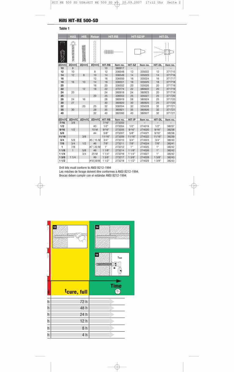
Hilti HIT-RE 500-SD
48
0
0
13
0
14
0
Tinst14
HAS HIS Rebar HIT-RB HIT-SZ/IP HIT-DL
Ø [mm] Ø [mm] Ø [mm] Ø [mm] Item no. Item no. Item no.10 8 10 380917 – – – –12 10 8 12 336548 12 335022 12 37171514 12 8 10 14 336549 14 335023 14 37171616 12 16 336550 16 335024 16 37171718 16 10 14 18 336551 18 335025 18 37171820 16 20 336552 20 335026 20 37171922 12 18 22 370774 22 380922 20 37171924 20 24 380918 24 380923 20 37171925 20 25 336553 25 335027 25 37172028 24 16 28 380919 28 380924 25 37172030 27 30 380920 30 380925 25 37172032 20 25 32 336554 32 335028 32 37172135 30 28 35 380921 35 380926 32 37172140 32 40 382260 40 32 371721
Ø [inch] Ø [inch] Ø [inch] Ø [inch] Item no. Item no. Item no.7/16 3/8 7/16" 273203 – – –1/2 #3 1/2" 273204 1/2" 274019 1/2" 38237
9/16 1/2 9/16" 273205 9/16" 274020 9/16" 382385/8 #4 5/8" 273207 5/8" 274021 9/16" 38238
11/16 3/8 11/16" 273209 11/16" 274022 11/16" 382393/4 5/8 #5 | 15 M 3/4" 273210 3/4" 274023 3/4" 382407/8 3/4 1/2 #6 7/8" 273211 7/8" 274024 7/8" 382411 7/8 #7 | 20 M 1" 273212 1" 274025 1" 38242
1 1/8 1 5/8 #8 1 1/8" 273214 1 1/8" 274026 1" 382421 1/4 3/4 1 1/4" 273216 1 1/4" 274027 1" 382421 3/8 1 1/4 #9 1 3/8" 273217 1 3/8" 274028 1 3/8" 382431 1/2 #10 | 30 M 1 1/2" 273218 1 1/2" 274029 1 3/8" 38243
HIT-RB
HIT-RB
HIT-SZ
HIT-IP HIT-DL
HIT-DL
10 M
380927
25 M
0
Table 1
Drill bits must conform to ANSI B212-1994Les mèches de forage doivent être conformes à ANSI B212-1994.Brocas deben cumplir con el estándar ANSI B212-1994.
HIT RE 500 SD USA:HIT RE 500 SD v1 20.09.2007 17:12 Uhr Seite 2

Hilti HIT-RE 500-SD
d d0 hef Tinst df hmin
[inch] [mm] [inch] [inch] [mm] [ft-lb] [Nm] [inch] [inch] [mm] 3/8 9.5 11/16 4 3/8 110 15 20 7/16 5 3/4 1501/2 12.7 7/8 5 125 30 41 9/16 6 3/4 1705/8 15.9 1 1/8 6 3/4 170 60 81 11/16 9 2303/4 19.1 1 1/4 8 1/8 205 100 136 13/16 10 3/4 270
[mm] [mm] [Nm] [mm] [mm] M8 14 90 10 9 120M10 18 110 20 12 150M12 22 125 40 14 170M16 28 170 80 18 230M20 32 205 150 22 270
[mm]
Setting Details of Hilti HIT-RE 500-SD with HIS-N and HIS-RN Inserts
hef = h0
hmin
hs df
d0
d
df
hef
d0
Tinst
hmin
= h0 ≤ 20 d
d
d d0hef
min-maxTinst df hmin
[inch] [mm] [inch] [inch] [mm] [ft-lb] [Nm] [inch] [inch] 3/8 9.5 7/16 1 1/2 - 7 1/2 40 - 191 15 20 7/16 hef + 1 1/4 (30 mm)1/2 12.7 9/16 2 - 10 51 - 254 30 41 9/165/8 15.9 3/4 2 1/2 - 12 1/2 64 - 318 60 81 11/16
hef + 2 d0
3/4 19.1 7/8 3 - 15 76 - 381 100 136 13/167/8 22.2 1 3 1/2 - 17 1/2 89 - 445 125 169 15/161 25.4 1 1/8 4 - 20 102 - 508 150 203 1 1/8
1 1/4 31.8 1 3/8 5 - 25 127 - 635 200 271 1 3/8
[mm] [mm] [Nm] [mm] [mm] M8 10 40 - 160 10 9
hef + 30M10 12 41 - 200 20 12M12 14 48 - 240 40 14M16 18 64 - 320 80 18
hef + 2 d0M20 24 80 - 400 150 22M24 28 96 - 480 200 26M27 30 108 - 540 270 30M30 35 120 - 600 300 33
[mm]
Setting Details of Hilti HIT-RE 500-SD with threaded rod
Table 2: HAS
Table 3: HIS-(R)N
HIT RE 500 SD USA:HIT RE 500 SD v1 20.09.2007 17:12 Uhr Seite 3
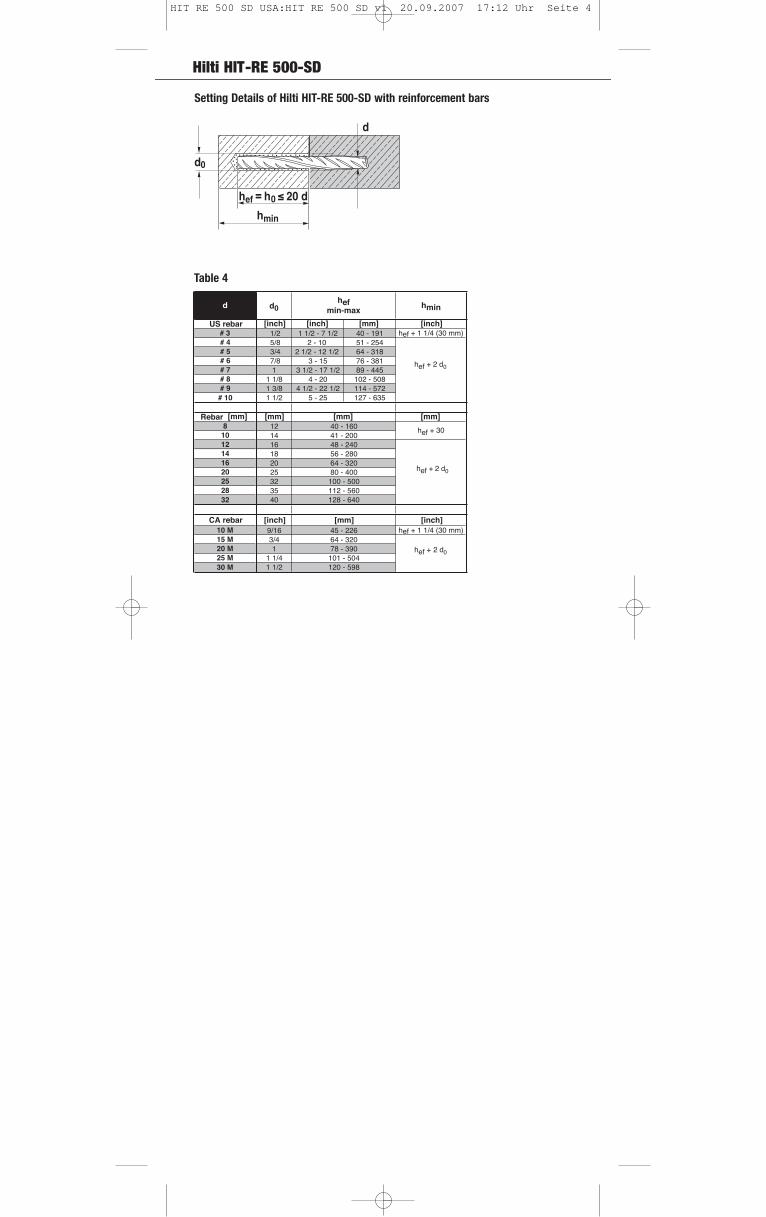
Hilti HIT-RE 500-SD
d0
d
hef = h0
hmin
≤ 20 d
d d0hef
min-maxhmin
US rebar [inch] [inch] [mm] [inch]# 3 1/2 1 1/2 - 7 1/2 40 - 191 hef + 1 1/4 (30 mm)# 4 5/8 2 - 10 51 - 254
hef + 2 d0
# 5 3/4 2 1/2 - 12 1/2 64 - 318# 6 7/8 3 - 15 76 - 381# 7 1 3 1/2 - 17 1/2 89 - 445# 8 1 1/8 4 - 20 102 - 508# 9 1 3/8 4 1/2 - 22 1/2 114 - 572# 10 1 1/2 5 - 25 127 - 635
Rebar [mm] [mm] [mm]8 12 40 - 160 hef + 3010 14 41 - 20012 16 48 - 240
hef + 2 d0
14 18 56 - 28016 20 64 - 32020 25 80 - 40025 32 100 - 50028 35 112 - 56032 40 128 - 640
CA rebar [inch] [mm] [inch]10 M 9/16 45 - 226 hef + 1 1/4 (30 mm)15 M 3/4 64 - 320
hef + 2 d020 M 1 78 - 39025 M 1 1/4 101 - 50430 M 1 1/2 120 - 598
[mm]
Setting Details of Hilti HIT-RE 500-SD with reinforcement bars
Table 4
HIT RE 500 SD USA:HIT RE 500 SD v1 20.09.2007 17:12 Uhr Seite 4
Hilti HIT-RE 500-SD
HIT RE 500 SD USA:HIT RE 500 SD v1 20.09.2007 17:13 Uhr Seite 8
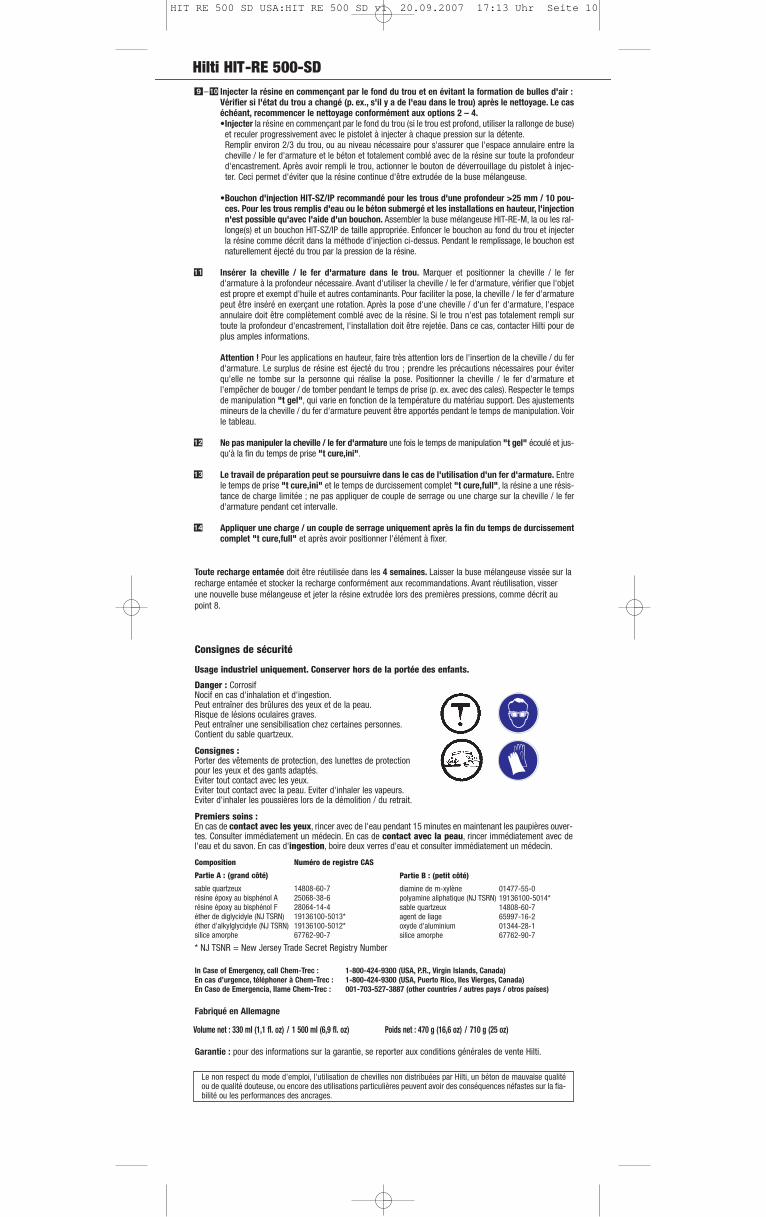
Hilti HIT-RE 500-SD
Consignes de sécurité
Usage industriel uniquement. Conserver hors de la portée des enfants.
Danger : CorrosifNocif en cas d'inhalation et d'ingestion.Peut entraîner des brûlures des yeux et de la peau.Risque de lésions oculaires graves.Peut entraîner une sensibilisation chez certaines personnes.Contient du sable quartzeux.
Consignes :Porter des vêtements de protection, des lunettes de protection pour les yeux et des gants adaptés.Eviter tout contact avec les yeux.Eviter tout contact avec la peau. Eviter d'inhaler les vapeurs.Eviter d'inhaler les poussières lors de la démolition / du retrait.
Premiers soins : En cas de contact avec les yeux, rincer avec de l'eau pendant 15 minutes en maintenant les paupières ouver-tes. Consulter immédiatement un médecin. En cas de contact avec la peau, rincer immédiatement avec del'eau et du savon. En cas d'ingestion, boire deux verres d'eau et consulter immédiatement un médecin.
Composition Numéro de registre CAS
Partie A : (grand côté)
sable quartzeux 14808-60-7résine époxy au bisphénol A 25068-38-6résine époxy au bisphénol F 28064-14-4éther de diglycidyle (NJ TSRN) 19136100-5013*éther d'alkylglycidyle (NJ TSRN) 19136100-5012*silice amorphe 67762-90-7
* NJ TSNR = New Jersey Trade Secret Registry Number
In Case of Emergency, call Chem-Trec : 1-800-424-9300 (USA, P.R., Virgin Islands, Canada)En cas d’urgence, téléphoner à Chem-Trec : 1-800-424-9300 (USA, Puerto Rico, Iles Vierges, Canada)En Caso de Emergencia, Ilame Chem-Trec : 001-703-527-3887 (other countries / autres pays / otros países)
Fabriqué en Allemagne
Garantie : pour des informations sur la garantie, se reporter aux conditions générales de vente Hilti.
Le non respect du mode d'emploi, l'utilisation de chevilles non distribuées par Hilti, un béton de mauvaise qualitéou de qualité douteuse, ou encore des utilisations particulières peuvent avoir des conséquences néfastes sur la fia-bilité ou les performances des ancrages.
Volume net : 330 ml (1,1 fl. oz) / 1 500 ml (6,9 fl. oz) Poids net : 470 g (16,6 oz) / 710 g (25 oz)
Partie B : (petit côté)
diamine de m-xylène 01477-55-0polyamine aliphatique (NJ TSRN) 19136100-5014*sable quartzeux 14808-60-7agent de liage 65997-16-2oxyde d'aluminium 01344-28-1silice amorphe 67762-90-7
Toute recharge entamée doit être réutilisée dans les 4 semaines. Laisser la buse mélangeuse vissée sur larecharge entamée et stocker la recharge conformément aux recommandations. Avant réutilisation, visserune nouvelle buse mélangeuse et jeter la résine extrudée lors des premières pressions, comme décrit aupoint 8.
Injecter la résine en commençant par le fond du trou et en évitant la formation de bulles d'air :Vérifier si l'état du trou a changé (p. ex., s'il y a de l'eau dans le trou) après le nettoyage. Le caséchéant, recommencer le nettoyage conformément aux options 2 – 4.•Injecter la résine en commençant par le fond du trou (si le trou est profond, utiliser la rallonge de buse)
et reculer progressivement avec le pistolet à injecter à chaque pression sur la détente.Remplir environ 2/3 du trou, ou au niveau nécessaire pour s'assurer que l'espace annulaire entre lacheville / le fer d'armature et le béton et totalement comblé avec de la résine sur toute la profondeurd'encastrement. Après avoir rempli le trou, actionner le bouton de déverrouillage du pistolet à injec-ter. Ceci permet d'éviter que la résine continue d'être extrudée de la buse mélangeuse.
•Bouchon d'injection HIT-SZ/IP recommandé pour les trous d'une profondeur >25 mm / 10 pou-ces. Pour les trous remplis d'eau ou le béton submergé et les installations en hauteur, l'injectionn'est possible qu'avec l'aide d'un bouchon. Assembler la buse mélangeuse HIT-RE-M, la ou les ral-longe(s) et un bouchon HIT-SZ/IP de taille appropriée. Enfoncer le bouchon au fond du trou et injecterla résine comme décrit dans la méthode d'injection ci-dessus. Pendant le remplissage, le bouchon estnaturellement éjecté du trou par la pression de la résine.
Insérer la cheville / le fer d'armature dans le trou. Marquer et positionner la cheville / le ferd'armature à la profondeur nécessaire. Avant d'utiliser la cheville / le fer d'armature, vérifier que l'objetest propre et exempt d'huile et autres contaminants. Pour faciliter la pose, la cheville / le fer d'armaturepeut être inséré en exerçant une rotation. Après la pose d'une cheville / d'un fer d'armature, l'espaceannulaire doit être complètement comblé avec de la résine. Si le trou n'est pas totalement rempli surtoute la profondeur d'encastrement, l'installation doit être rejetée. Dans ce cas, contacter Hilti pour deplus amples informations.
Attention ! Pour les applications en hauteur, faire très attention lors de l'insertion de la cheville / du ferd'armature. Le surplus de résine est éjecté du trou ; prendre les précautions nécessaires pour éviterqu'elle ne tombe sur la personne qui réalise la pose. Positionner la cheville / le fer d'armature etl'empêcher de bouger / de tomber pendant le temps de prise (p. ex. avec des cales). Respecter le tempsde manipulation "t gel", qui varie en fonction de la température du matériau support. Des ajustementsmineurs de la cheville / du fer d'armature peuvent être apportés pendant le temps de manipulation. Voirle tableau.
Ne pas manipuler la cheville / le fer d'armature une fois le temps de manipulation "t gel" écoulé et jus-qu'à la fin du temps de prise "t cure,ini".
Le travail de préparation peut se poursuivre dans le cas de l'utilisation d'un fer d'armature. Entrele temps de prise "t cure,ini" et le temps de durcissement complet "t cure,full", la résine a une résis-tance de charge limitée ; ne pas appliquer de couple de serrage ou une charge sur la cheville / le ferd'armature pendant cet intervalle.
Appliquer une charge / un couple de serrage uniquement après la fin du temps de durcissementcomplet "t cure,full" et après avoir positionner l'élément à fixer.
– �
�
�
�
HIT RE 500 SD USA:HIT RE 500 SD v1 20.09.2007 17:13 Uhr Seite 10

Hilti HIT-RE 500-SDSistema de anclaje con adhesivo para fijaciones en hormigón de peso normalAntes de utilizar el producto, lea estas instrucciones de uso y las indicaciones de seguridad.Verifique la fecha de caducidad: Véase la etiqueta que figura en el colector del cartucho (Mes/año). No utilice elproducto una vez expirada la fecha de caducidad.Temperatura del cartucho: Debe estar entre 5 °C y 40 °C (41 °F y 104 °F) en el momento de la aplicación.Temperatura del material base al momento de la instalación: Debe estar entre 5 °C y 43 °C (41 °F y 110 °F) en el momento de la aplicación.Instrucciones de transporte y almacenamiento: Mantener en un lugar fresco, seco y oscuro a una temperatura deentre 5 °C y 25 °C (41 °F y 77 °F).Hoja de datos de seguridad de los materiales: Véase la MSDS del material antes de utilizarlo.
Instrucciones de montaje: Secuencia de operaciones: véanse los pictogramas 1 a 14. Detalles de fijación:véanse las tablas 1 a 4. Para cualquier otra aplicación no incluida en este documento (por ejemplo, "h ef" fuera de los valores especificados en los detalles de fijación), póngase en contacto con Hilti.
Realice el taladro en perpendicular a la superficie con una perforadora de percusión fijada en modode martillo perforador y emplee una broca de carburo del tamaño adecuado, o una perforadora con unacorona de diamante del tamaño adecuado, según la profundidad de empotramiento necesario. Véanselas tablas en las que se describen los detalles de ajuste.
Limpieza del taladro: El método de limpieza debe seleccionarse en función del método de perforacióny las condiciones del taladro (véase el diagrama de flujo anterior).Antes de proceder a la colocación del corrugado o anclaje, limpie el taladro para eliminar el polvillo ola suciedad que pudiese tener. Para ello, utilice uno de los siguientes métodos:
Método 1: para hormigón seco o saturado de agua (véanse los pictogramas):•Aplique soplado a presión desde la parte de atrás del taladro con aire comprimido libre de aceite
(mínimo 90 psi a 3,5 CFM (6 bares a 6 m3/h)) y retire la boquilla de aire 2 veces hasta que la corrien-te de aire de retorno no contenga polvo visible.
•Cepille 2 veces con un cepillo del tamaño especificado (Ø de cepillo ≥ Ø de taladro). Para ello, inserte el cepillo metálico redondo en la parte trasera del taladro con un movimiento giratorio y sáque-lo. El cepillo debe presentar resistencia al ser introducido en el taladro. Si no es el caso, el cepillo esdemasiado pequeño y deberá reemplazarse por otro cepillo que tenga el diámetro adecuado.
•Vuelva a aplicar soplado a presión con aire comprimido 2 veces hasta que la corriente de aire deretorno no contenga polvo visible.
Método 2: para taladros llenos de agua, de hormigón sumergido o taladros realizados con coro-na de diamante:•Lave el taladro 2 veces insertando una manguera con agua (con presión normal de la línea de agua)
en la parte trasera del taladro hasta que el agua salga limpia. •Cepille 2 veces con un cepillo del tamaño especificado (Ø de cepillo ≥ Ø de taladro). Para ello,
inserte el cepillo metálico redondo en la parte trasera del taladro con un movimiento giratorio y sáque-lo. El cepillo debe presentar resistencia al ser introducido en el taladro. Si no es el caso, el cepillo esdemasiado pequeño y deberá reemplazarse por otro cepillo que tenga el diámetro adecuado.
•Vuelva a lavarlo 2 veces hasta que el agua salga limpia.•Importante: En el caso de los taladros realizados con coronas de diamante y si se necesita un
taladro seco para inyección (es decir, el agua fluye dentro del taladro limpio), prosiga con la lim-pieza del taladro tal y como se describe en el método 1.Elimine completamente el agua retenida (por ejemplo, mediante vacío, aire comprimido u otro pro-cedimiento adecuado).Para conseguir un taladro seco, se recomienda emplear una boquilla para aire HIT-DL de Hilti en tala-dros de ≤250 mm (10 pulg.) de profundidad; su uso es obligatorio en taladros de profundidad>250 mm (10 pulg.).
El taladro debe estar exento de polvo, suciedad, hielo, aceite, grasa o cualquier otro agente con-taminante antes de proceder a la inyección del adhesivo. Limpieza insuficiente del taladro =valores de carga inadecuados.
Inserte el cartucho en el portacartuchos. No utilice cartuchos en mal estado o portacartuchos dete-riorados o sucios.
Fije fuertemente el mezclador Hilti HIT-RE-M al colector del cartucho. Antes de utilizar un nuevocartucho, coloque primero el nuevo mezclador (bien ajustado). No modifique el mezclador en ningúncaso. Verifique que el elemento de mezcla se encuentre en el mezclador. Emplee únicamente el tipo demezclador provisto con el adhesivo.
Inserte el portacartuchos con el cartucho en el aplicador HIT. Pulse el gatillo de bloqueo, retraigael émbolo e inserte el cartucho en el aplicador Hilti que corresponda.
No utilice el adhesivo inicial. El cartucho se abre automáticamente al comenzar con la aplicación. Enfunción del tamaño del cartucho, deberá desecharse una cantidad del adhesivo inicial. El pictograma 8le muestra la cantidad correspondiente que se debe desechar. Si se instala un nuevo mezclador sobreun cartucho abierto con anterioridad, se debe desechar una cierta cantidad del adhesivo inicial, talcomo se describió antes. Se debe utilizar un nuevo mezclador para cada cartucho nuevo.
�
�–�
�
�
�
�
Perforadora de percusión Corona de diamante Perforadora de percusiónVerifique lascondicionesdel taladro
Instruccionespara limpiarlos taladros
Condicionesdel taladro
Sentido dela instalación
Profundidadde perforación
Instruccionesde inyección
Seco Saturadode agua Seco Saturado
de aguaLleno de
agua Sumergido
Método delimpieza 1
Método delimpieza 2+1
Método delimpieza 2
Limpio y seco Limpio y lleno de agua
Horizontaly vertical Suspendida Todas las
direcciones
≤250 mm(10 pulg.)
>250 mm(10 pulg.)
Prof. de per-foración total
Prof. de per-foración total
HIT-SZ/IP noes necesario
HIT-SZ/IPrecomendado
HIT-SZ/IPobligatorio
HIT-SZ/IPobligatorio
Diagrama de flujo de instalación
HIT RE 500 SD USA:HIT RE 500 SD v1 20.09.2007 17:13 Uhr Seite 11
Hilti HIT-RE 500-SD
Instrucciones de seguridad
Sólo para uso industrial. Mantener alejado del alcance de los niños.
Peligro: CorrosivoPeligroso si se inhala o ingiere.Puede provocar quemaduras en los ojos y la piel.Puede dañar seriamente los ojos.Puede provocar sensibilización en algunas personas.Contiene arena de cuarzo.
Precauciones:Utilice indumentaria y guantes adecuados, y protección para los ojos.Evite el contacto con los ojos.Evite el contacto con la piel. Evite la inhalación de vapores.Evite la inhalación de polvos durante su destrucción o extracción.
Primeros auxilios: En caso de contacto con los ojos, enjuague con agua durante 15 minutos, manteniendo los párpados abier-tos. Busque atención médica de inmediato. En caso de contacto con la piel, lave inmediatamente con aguay jabón. En caso de ingestión, beba dos vasos de agua y busque atención médica de inmediato.
Componente Número CAS
Parte A: (Lado grande)
Arena de cuarzo 14808-60-7Resina epoxy Bisfenol A 25068-38-6Resina epoxy Bisfenol F 28064-14-4Éter diglicidílico (NJ TSRN) 19136100-5013*Éter alquil glicidílico (NJ TSRN) 19136100-5012*Sílice amorfo 67762-90-7
* NJ TSNR = Número de Registro de Secreto Comercial de Nueva Jersey
In Case of Emergency, call Chem-Trec: 1-800-424-9300 (USA, P.R., Virgin Islands, Canada)En cas d’urgence, téléphoner Chem-Trec: 1-800-424-9300 (USA, P.R., Virgin Islands, Canada)En caso de emergencia, llame a Chem-Trec: 001-703-527-3887 (other countries/autres pays/otros países)
Hecho en Alemania
Garantía: Consulte los términos y condiciones estándar de venta de Hilti para obtener más datos sobre lagarantía.
El incumplimiento de las instrucciones de uso y datos de fijación, el uso de anclajes no fabricados por Hilti, el esta-do deficiente o cuestionable del hormigón, o ciertas aplicaciones pueden afectar la fiabilidad o el rendimiento dela fijación.
Contenido neto: 330 ml (11,1 oz. fl.) /500 ml (16,9 oz. fl.) Peso neto: 470 g (16,6 oz.)/710 g (25,0 oz.)
Parte B: (Lado pequeño)
m-xilenodiamina 01477-55-0Poliamina alifática (NJ TSRN) 19136100-5014*Arena de cuarzo 14808-60-7Aglutinante 65997-16-2Óxido de aluminio 01344-28-1Sílice amorfo 67762-90-7
Los cartuchos no agotados por completo deberán utilizarse antes de cuatro semanas. Para ello, se losdeberá guardar con el mezclador roscado al colector del cartucho en las condiciones de almacenamientorecomendadas. Antes de volver a utilizarlo, fije un nuevo mezclador y deseche el adhesivo de anclaje inicial,tal como se describe en el punto 8.
Inyecte el adhesivo desde la parte trasera del taladro sin que se formen burbujas de aire:Verifique si se han modificado las condiciones del taladro (por ejemplo, si contiene agua) después de la limpieza. De ser así, vuelva a limpiarlo según lo detallado en los puntos 2 a 4.•Inyecte el adhesivo comenzando por la parte de atrás del taladro (emplee la extensión para los tala-
dros más profundos). Lentamente, retire el mezclador después de cada aplicación.Rellene alrededor de 2/3 del taladro, o hasta donde sea necesario para asegurar que el espacio anu-lar entre el corrugado o anclaje y el hormigón esté totalmente lleno con adhesivo todo a lo largo delempotramiento. Una vez finalizada la inyección, despresurice el aplicador pulsando el gatillo de blo-queo. Esto evitará que siga saliendo adhesivo del mezclador.
•Inyección con tapón pistón: HIT-SZ/IP recomendado para taladros con una profundidad>250 mm/10 pulg. En casos de taladros llenos de agua o en hormigón sumergido e instalacio-nes suspendidas, sólo se puede inyectar el adhesivo utilizando un tapón pistón. Ensamble elmezclador HIT-RE-M, las extensiones necesarias y un tapón HIT-SZ/IP de tamaño adecuado. Inserte eltapón pistón en la parte trasera del taladro e inyecte el adhesivo tal como se describió antes en elmétodo de inyección. Durante la inyección, el tapón pistón será naturalmente extruido del taladro por lapresión del adhesivo.
Inserte el corrugado o anclaje en el taladro. Marque y fije el corrugado o anclaje a la profundidaddeseada del empotramiento. Antes de usarlo, verifique que el corrugado o anclaje esté seco y no con-tenga aceite ni otros agentes contaminantes. Para facilitar la instalación, gire lentamente el corrugadoo anclaje a medida que lo va insertando. Después de haber instalado un corrugado o anclaje, debe lle-nar por completo el espacio anular con adhesivo. Si el taladro no está totalmente lleno a lo largo de laprofundidad del empotramiento, se debería rechazar la instalación. Comuníquese con Hilti para obtenermás información al respecto.
Atención: En el caso de aplicaciones suspendidas, tenga especial cuidado al insertar el corrugado oanclaje. El exceso de adhesivo saldrá del taladro. Tome las medidas necesarias para evitar que pudie-se caer encima del instalador. Coloque el corrugado o anclaje en su sitio y asegúrelo para evitar quepueda moverse o caer durante el tiempo de fraguado (por ejemplo, utilizando cuñas). Respete el tiem-po de aplicación "t gel", el cual varía según la temperatura del material base. Durante ese período, sepueden realizar ajustes menores al corrugado o anclaje. Véase la tabla.
No toque el corrugado o anclaje una vez finalizado el tiempo "t gel" y hasta que haya transcurrido eltiempo "t cure,ini".
Puede continuar con el trabajo de preparación para las aplicaciones de corrugado. Entre las eta-pas de "t cure,ini" y "t cure,full", el adhesivo tiene limitada capacidad de soportar cargas. Por ello,no someta el corrugado o anclaje a torsión o carga durante ese tiempo.
Aplique carga o torsión sólo después de que el punto "t cure,full" haya transcurrido y el acceso-rio que se instalará esté situado en su lugar.
– �
�
�
�
HIT RE 500 SD USA:HIT RE 500 SD v1 20.09.2007 17:13 Uhr Seite 12


![Wi Tricity[2]](https://img.pdfslide.net/doc/110x75/55a446e41a28abf32b8b47d3/wi-tricity2-55a5185dd7d07.jpg)