Embed Size (px)
Citation preview
ICD-GPS-060
Revision B
GPS USER EQUIPMENT (PHASE III)
INTERFACE CONTROL DOCUMENT
FOR THE
PRECISE TIME AND TIME INTERVAL
(PTTI) INTERFACE
12 February 2002 CAGE Code 3D619
DISTRIBUTION A - Approved for public release; distribution unlimited.


DOC. NO. ICD-GPS-060 REV. B DATE 12 February 2002
THIS PAGE INTENTIONALLY LEFT BLANK
ii
DOC. NO. ICD-GPS-060 REV. B DATE 12 February 2002
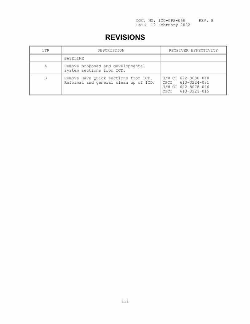
REVISIONS
LTR DESCRIPTION RECEIVER EFFECTIVITY
BASELINE
A Remove proposed and developmental system sections from ICD.
B Remove Have Quick sections from ICD. Reformat and general clean up of ICD.
H/W CI 622-8080-040 CPCI 613-3224-031 H/W CI 622-8078-046 CPCI 613-3223-015
iii

DOC. NO. ICD-GPS-060 REV. B DATE 12 February 2002
THIS PAGE INTENTIONALLY LEFT BLANK
iv
DOC. NO. ICD-GPS-060 REV. B DATE 12 February 2002
GPS USER EQUIPMENT (PHASE III)
INTERFACE CONTROL DOCUMENT
FOR THE
PRECISE TIME AND TIME INTERVAL
(PTTI) INTERFACE
12 February 2002
DISTRIBUTION A - Approved for public release; distribution unlimited.
v
DOC. NO. ICD-GPS-060 REV. B DATE 12 February 2002
THIS PAGE INTENTIONALLY LEFT BLANK
vi
DOC. NO. ICD-GPS-060 REV. B DATE 12 February 2002 TABLE OF CONTENTS SECTION PAGE 1. INTRODUCTION .............................................. 1-1 1.1 Purpose ................................................... 1-1 1.2 Scope .................................................... 1-1 1.3 GPS Time Standard ......................................... 1-1 1.4 U.S. Naval Observatory (USNO) ............................. 1-1 1.5 Agencies and Contractors ................................. 1-1 1.5.1 GPS Joint Program Office (JPO) ............................ 1-1 1.5.2 Interface Control Contractor (ICC) ........................ 1-1 2. APPLICABLE DOCUMENTS ...................................... 2-1 3. DESCRIPTION ............................................... 3-1 3.1 GPS User Equipment ........................................ 3-1 3.2 General Characteristics ................................... 3-1 3.3 Signal Inputs to PTTI Port ................................ 3-1 3.3.1 Time Rollover Pulse (1 PPS) ............................... 3-1 3.3.1.1 Functional Description .................................... 3-2 3.3.1.2 Signal Characteristics .................................... 3-2 3.3.1.3 Electrical Characteristics ................................ 3-2 3.3.2 BCD Time Code ............................................. 3-2 3.3.2.1 Functional Description .................................... 3-2 3.3.2.2 Signal Characteristics .................................... 3-2 3.3.2.3 Electrical Characteristics ................................ 3-2 3.3.2.4 Deviations from the 40-Bit Time Code ...................... 3-2 3.3.3 Timing Fault Discrete ..................................... 3-2 3.3.3.1 Functional Description .................................... 3-2 3.3.3.2 Signal Characteristics .................................... 3-2 3.3.3.3 Electrical Characteristics ................................ 3-5 3.3.4 Configuration Inputs ...................................... 3-5 3.4 Signal Outputs from the PTTI Port ......................... 3-5 3.4.1 Time Rollover Pulse (1 PPS) ............................... 3-5 3.4.1.1 Functional Description .................................... 3-5 3.4.1.2 Signal Characteristics .................................... 3-5 3.4.1.3 Electrical Characteristics ................................ 3-5 3.4.2 Time Synchronizing Signal (1 PPM) ......................... 3-5 3.4.2.1 Functional Description .................................... 3-5 3.4.2.2 Signal Characteristics .................................... 3-5 3.4.2.3 Electrical Characteristics ................................ 3-5 3.4.3 BCD Time Code ............................................. 3-5 3.4.3.1 Functional Description .................................... 3-5 3.4.3.2 Signal Characteristics .................................... 3-5 3.4.3.3 Electrical Characteristics ................................ 3-7 3.4.4 Timing Fault Discrete ..................................... 3-7 3.4.4.1 Functional Description .................................... 3-7 3.4.4.2 Signal Characteristics .................................... 3-7 3.4.4.3 Electrical Characteristics ................................ 3-7 3.5 Short Circuit Protection .................................. 3-7 3.6 TFOM ...................................................... 3-7
vii

DOC. NO. ICD-GPS-060 REV. B DATE 12 February 2002
TABLE OF CONTENTS (continued)
LIST OF FIGURES FIGURE PAGE 3-1. PTTI Interfaces ........................................... 3-1 3-2. Input Time Rollover Pulse (1 PPS) Signal
Characteristics ........................................... 3-3 3-3. Signal Characteristics of BCD Time Code ................... 3-4 3-4. Output Time Rollover Pulse (1 PPS) and Time
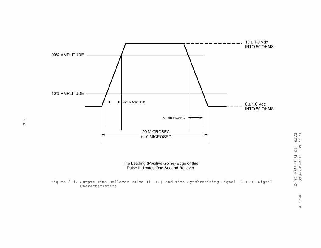
Synchronizing Signal (1 PPM) Signal Characteristics ....... 3-6
LIST OF TABLES TABLE PAGE 3-1. Time Figure of Merit ...................................... 3-8
APPENDICES APPENDIX PAGE A ACRONYMS AND ABBREVIATIONS ................................ A-1
viii

DOC. NO. ICD-GPS-060 REV. B DATE 12 February 2002
PREFACE Changes to this Interface Control Document (ICD) must be coordinated with the Global Positioning System (GPS) Joint Program Office (JPO), the Interface Control Contractor (ICC), and the GPS contractors as required. The previous revision of this ICD is superseded. The description of the Have Quick Time of Day (TOD) interface contained therein should not be used. Organizations requiring a description of the Have Quick TOD interface applicable to a particular system must contact the activity responsible for controlling the Have Quick radio incorporated in that system.
ix

DOC. NO. ICD-GPS-060 REV. B DATE 12 February 2002
THIS PAGE INTENTIONALLY LEFT BLANK
x
DOC. NO. ICD-GPS-060 REV. B DATE 12 February 2002 1. INTRODUCTION 1.1 Purpose. This document describes the Global Positioning System (GPS) production version (Phase III), Precise Time and Time Interval (PTTI) Interface port. 1.2 Scope. This document defines the fundamental electrical, functional, electromagnetic compatibility, and database requirements that must be met by the GPS UE Military Standard PTTI Interface for use in DoD applications. 1.3 GPS Time Standard. The Master Control Station monitors the SV time standards daily, with reference to GPS system time, and generates clock correction parameters for transmission to the SVs where they are retransmitted to users with the navigational signals and used to determine the precise magnitude of the clock offsets. Refer to ICD-GPS-200 for a definition of the GPS navigation signals. GPS system time necessarily differs from Coordinated Universal Time (UTC), which must be adjusted for leap seconds at periodic intervals. The difference between GPS system time and UTC is transmitted by the space vehicles. 1.4 U.S. Naval Observatory (USNO). The mission of USNO includes maintenance and dissemination of the U.S. version of UTC and of earth orientation data. In support of this, it also monitors the GPS dissemination of UTC estimates. 1.5 Agencies and Contractors. This document is controlled in accordance with the provisions of the GPS Interface Control Working Group (ICWG) charter by the following agencies. 1.5.1 GPS Joint Program Office (JPO). The GPS JPO in the Space and Missile Systems Center (SMC) is responsible for the development, configuration control, and life-cycle support of the GPS UE. The point of contact for the GPS UE Interface Control Working Group (ICWG) is:
SMC/CZER 2420 Vela Way, Suite 1467 Los Angeles AFB El Segundo, CA 90245-4659 Phone (310) 363-0834 DSN 833-0834 FAX (310) 363-6387
1.5.2 Interface Control Contractor (ICC). ARINC Incorporated is designated the ICC by direction of the GPS JPO and the point of contact for maintaining the technical validity of this ICD.
ARINC Incorporated 4055 Hancock Street, Suite 100 San Diego, CA 92110-5152 Phone (619) 222-7447 FAX (619) 225-1750
1-1

DOC. NO. ICD-GPS-060 REV. B DATE 12 February 2002
THIS PAGE INTENTIONALLY LEFT BLANK
1-2
DOC. NO. ICD-GPS-060 REV. B DATE 12 February 2002 2. APPLICABLE DOCUMENTS The following documents form a part of the GPS UE standards as specified herein. ICD-GPS-200 Revision C 10 October 1993 IRN001 13 October 1995 IRN002 25 September 1997 IRN003 11 October 1999 IRN004 12 April 2000
Navstar GPS Space Segment/Navigation User Interfaces
2-1
DOC. NO. ICD-GPS-060 REV. B DATE 12 February 2002
THIS PAGE INTENTIONALLY LEFT BLANK
2-2
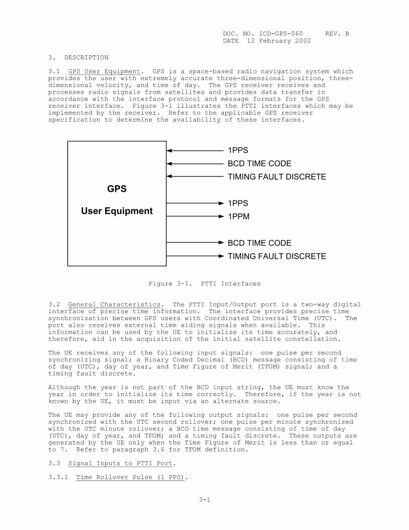
DOC. NO. ICD-GPS-060 REV. B DATE 12 February 2002 3. DESCRIPTION 3.1 GPS User Equipment. GPS is a space-based radio navigation system which provides the user with extremely accurate three-dimensional position, three-dimensional velocity, and time of day. The GPS receiver receives and processes radio signals from satellites and provides data transfer in accordance with the interface protocol and message formats for the GPS receiver interface. Figure 3-1 illustrates the PTTI interfaces which may be implemented by the receiver. Refer to the applicable GPS receiver specification to determine the availability of these interfaces.
GPS
User Equipment
Figure 3-1. PTTI I 3.2 General Characteristics. The PTTI Inpuinterface of precise time information. The synchronization between GPS users with Coordport also receives external time aiding signinformation can be used by the UE to initialtherefore, aid in the acquisition of the ini The UE receives any of the following input ssynchronizing signal; a Binary Coded Decimalof day (UTC), day of year, and Time Figure otiming fault discrete. Although the year is not part of the BCD inpyear in order to initialize its time correctknown by the UE, it must be input via an alt The UE may provide any of the following outpsynchronized with the UTC second rollover; owith the UTC minute rollover; a BCD time mes(UTC), day of year, and TFOM; and a timing fgenerated by the UE only when the Time Figurto 7. Refer to paragraph 3.6 for TFOM defin 3.3 Signal Inputs to PTTI Port. 3.3.1 Time Rollover Pulse (1 PPS).
3-1
1PPS BCD TIME CODE TIMING FAULT DISCRETE 1PPS 1PPM BCD TIME CODE TIMING FAULT DISCRETE
nterfaces
t/Output port is a two-way digital interface provides precise time inated Universal Time (UTC). The als when available. This ize its time accurately, and tial satellite constellation.
ignals: one pulse per second (BCD) message consisting of time f Merit (TFOM) signal; and a
ut string, the UE must know the ly. Therefore, if the year is not ernate source.
ut signals: one pulse per second ne pulse per minute synchronized sage consisting of time of day ault discrete. These outputs are e of Merit is less than or equal ition.

DOC. NO. ICD-GPS-060 REV. B DATE 12 February 2002 3.3.1.1 Functional Description. The leading edge of this pulse indicates the occurrence of time rollover. 3.3.1.2 Signal Characteristics. The time rollover signal is a one pulse per second (1 PPS) signal, synchronized to an external source representing the UTC second rollover. 3.3.1.3 Electrical Characteristics. The electrical characteristics are shown in Figure 3-2. If required for testing purposes, the pulse width at the 50% level may be determined by extrapolation. 3.3.2 BCD Time Code. 3.3.2.1 Functional Description. The PTTI port receives a BCD code that is used in conjunction with the 1 PPS signal to identify the time of the current one second time rollover. 3.3.2.2 Signal Characteristics. The code is a forty (40) bit serial 8421 BCD code defining UTC time of day, day of year, and Time Figure of Merit (TFOM) transmitted at a 50 bps rate. Formats of the data are outlined in Figure 3-3. Bits 41 through 50 are set at a mark (logical one). The first bit is the most significant bit of the hours. The 40th bit is the least significant bit of the TFOM. The data contained represents previous 1 PPS rollover. The TFOM is defined in paragraph 3.6. In the event that the source of the signal cannot provide TFOM, or TFOM and day of year, the signal is modified as indicated in paragraph 3.3.2.4. 3.3.2.3 Electrical Characteristics. The BCD time code input is a two-wire balanced low level digital interface. A logical one state (mark) is denoted by 0.10 to 6.0 Vdc line A with respect to line B. A logical zero state (space) is denoted by -0.10 to -6.0 Vdc line A with respect to line B. The DC input impedance of a single BCD time code input is equal to or greater than 5000 ohms. Input reactance, if any, is capacitive. Multiple BCD time code inputs may be connected in parallel. For parallel connections the total load to the BCD time code signal must be equal to or greater than 500 ohms measured between line A and line B, including cable impedance. 3.3.2.4 Deviation from the 40-Bit Time Code. In the event that the external BCD signal does not include TFOM, or TFOM and day of year, the 8421 BCD slots for these parameters will be set at a mark (logical one state) by the interfacing equipment. The UE recognizes these BCD data slots, when all set at a mark, to represent no data available. Under these conditions, the UE accepts an alternate source of data for the day of year. 3.3.3 Timing Fault Discrete. 3.3.3.1 Functional Description. The interfacing equipment which supplies the 1 PPS and BCD data provides a timing fault discrete which informs the UE if the transmitting equipment is functioning properly. In the event that the BCD time code information is provided to the GPS UE receiver without a Timing Fault Discrete signal (hard wire), the UE receiver recognizes this condition and assumes the Timing Fault Discrete signal line to be set high, thus accepting any data that is input to the GPS receiver via the PTTI port. 3.3.3.2 Signal Characteristics. The signal is a voltage level in a logical one or zero state. A logical one state indicates normal operation and valid time information. A logical zero state indicates a fault within the external equipment and implies that the UE must not use the data.
3-2
3-3
DOC. NO. ICD-GPS-060
REV.
DATE 12 February 2002
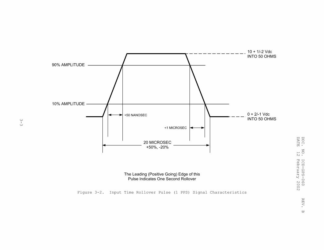
10 + 1/-2 Vdc INTO 50 OHMS
10% AMPLITUDE
90% AMPLITUDE
<50 NANOSEC
<1 MICROSEC
20 MICROSEC+50%, -20%
0 + 2/-1 Vdc INTO 50 OHMS
The Leading (Positive Going) Edge of this Pulse Indicates One Second Rollover
Figure 3-2. Input Time Rollover Pulse (1 PPS) Signal Characteristics
B
DOC. NO. ICD-GPS-060
REV.
DATE 12 February 2002
3-4
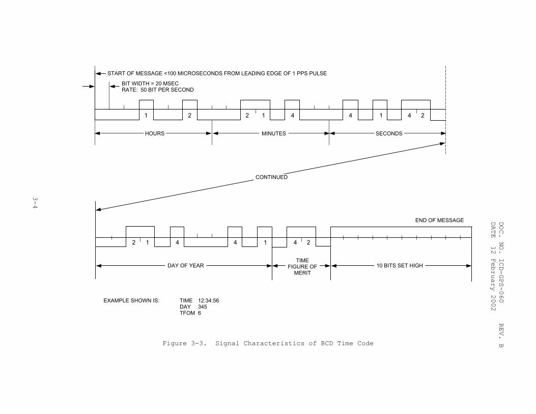
1 2
END OF MESSAGE
CONTINUED
241442 1
10 BITS SET HIGHTIME
FIGURE OF MERIT
DAY OF YEAR
4 144221
BIT WIDTH = 20 MSEC RATE: 50 BIT PER SECOND
START OF MESSAGE <100 MICROSECONDS FROM LEADING EDGE OF 1 PPS PULSE
SECONDSMINUTESHOURS
EXAMPLE SHOWN IS: TIME 12:34:56 DAY 345 TFOM 6
B Figure 3-3. Signal Characteristics of BCD Time Code
DOC. NO. ICD-GPS-060 REV. B DATE 12 February 2002 3.3.3.3 Electrical Characteristics. A logical one state is defined as +3 to +5.5 Volts dc (Vdc). A logical zero state is defined as 0 Vdc to +0.5 Vdc, when loaded with a UE input circuit of 5000 ohms connected to +5 Vdc (standard transistor logic load). 3.3.4 Configuration Inputs. The UE receiver provides configuration inputs defining Host Vehicle utilization of various PTTI interface functions. Details of these configuration inputs are defined in the applicable receiver specification. 3.4 Signal Outputs from the PTTI Port. 3.4.1 Time Rollover Pulse (1 PPS). 3.4.1.1 Functional Description. The leading edge of this pulse indicates the occurrence of time rollover. 3.4.1.2 Signal Characteristics. The Time Rollover signal is a one pulse per second (1 PPS) signal synchronized to the UTC second rollover. 3.4.1.3 Electrical Characteristics. The electrical characteristics are shown in Figure 3-4. If required for testing purposes, the pulse width at the 50% level may be determined by extrapolation. 3.4.2 Time Synchronizing Signal (1 PPM). 3.4.2.1 Functional Description. The leading edge of this pulse indicates the occurrence of time rollover. 3.4.2.2 Signal Characteristics. The Time Synchronizing Signal is a one pulse per minute (1 PPM) signal synchronized to the UTC minute rollover. 3.4.2.3 Electrical Characteristics. The electrical characteristics are shown in Figure 3-4. If required for testing purposes, the pulse width at the 50% level may be determined by extrapolation. 3.4.3 BCD Time Code. 3.4.3.1 Functional Description. The PTTI port outputs a BCD code which is used by the interfacing equipment in conjunction with the 1 PPS signal to identify current one second time rollover. 3.4.3.2 Signal Characteristics. The BCD Time Code is a 50-bit message. The first 40 bits are a serial 8421 BCD code, defining UTC time of day, day of year, and TFOM, transmitted at a 50 bps rate. The data contained represents previous 1 PPS rollover. Formats of the data are outlined in Figure 3-3. Bits 41 through 50 are set at a mark (logical one). The first bit is the most significant bit of the hour. The 40th bit is the least significant bit of the TFOM. The TFOM is defined in paragraph 3.6.
3-5
3-6
DOC. NO. ICD-GPS-060
REV.
DATE 12 February 2002
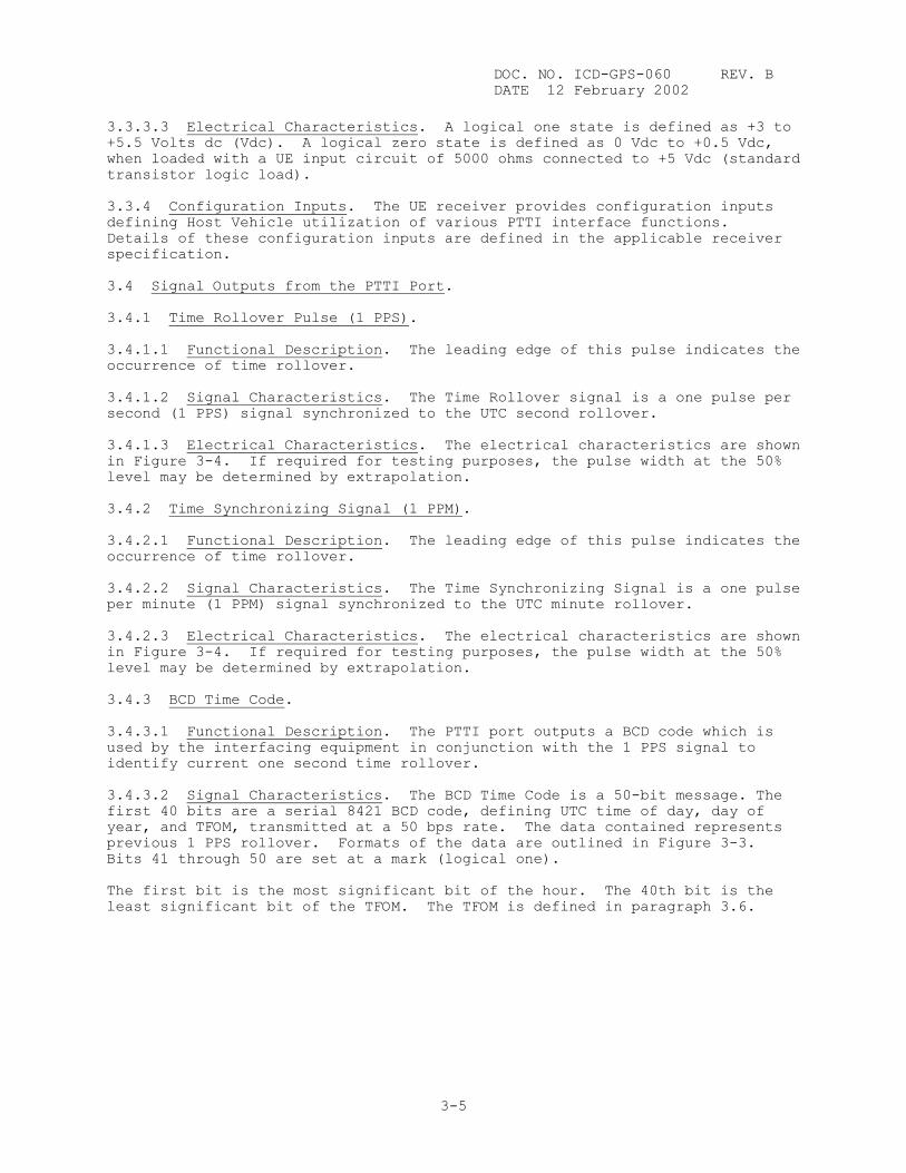
10 ± 1.0 Vdc INTO 50 OHMS
10% AMPLITUDE
90% AMPLITUDE
<20 NANOSEC
<1 MICROSEC
20 MICROSEC±1.0 MICROSEC
0 ± 1.0 Vdc INTO 50 OHMS
The Leading (Positive Going) Edge of this Pulse Indicates One Second Rollover
Figure 3-4. Output Time Rollover Pulse (1 PPS) and Time Synchronizing Signal (1 PPM) Signal Characteristics
B
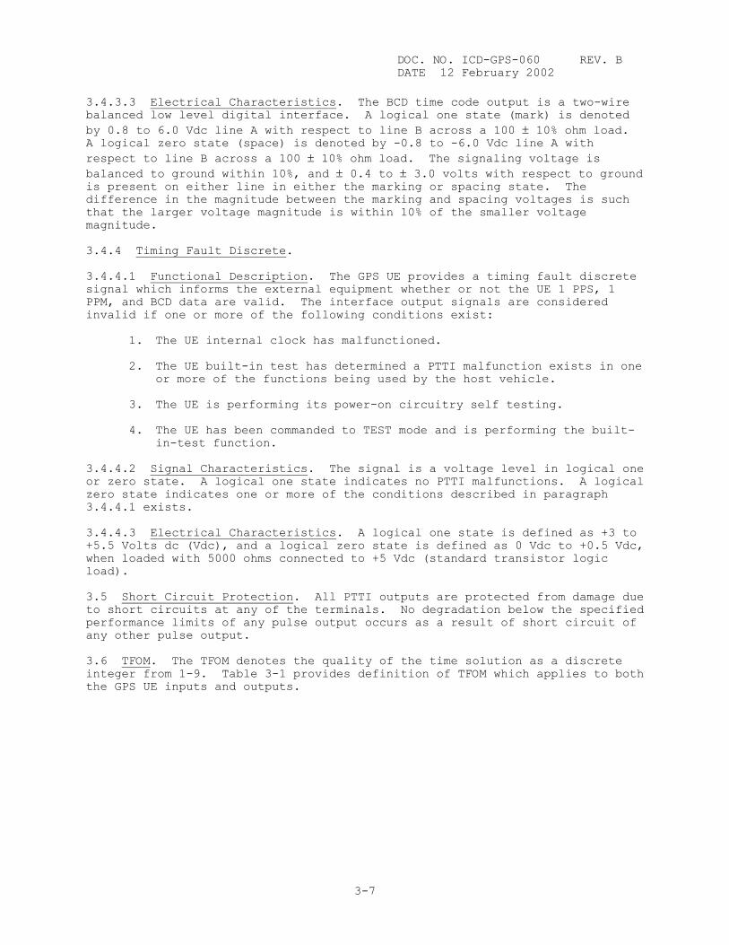
DOC. NO. ICD-GPS-060 REV. B DATE 12 February 2002 3.4.3.3 Electrical Characteristics. The BCD time code output is a two-wire balanced low level digital interface. A logical one state (mark) is denoted by 0.8 to 6.0 Vdc line A with respect to line B across a 100 ± 10% ohm load. A logical zero state (space) is denoted by -0.8 to -6.0 Vdc line A with respect to line B across a 100 ± 10% ohm load. The signaling voltage is balanced to ground within 10%, and ± 0.4 to ± 3.0 volts with respect to ground is present on either line in either the marking or spacing state. The difference in the magnitude between the marking and spacing voltages is such that the larger voltage magnitude is within 10% of the smaller voltage magnitude. 3.4.4 Timing Fault Discrete. 3.4.4.1 Functional Description. The GPS UE provides a timing fault discrete signal which informs the external equipment whether or not the UE 1 PPS, 1 PPM, and BCD data are valid. The interface output signals are considered invalid if one or more of the following conditions exist:
1. The UE internal clock has malfunctioned.
2. The UE built-in test has determined a PTTI malfunction exists in one or more of the functions being used by the host vehicle.
3. The UE is performing its power-on circuitry self testing.
4. The UE has been commanded to TEST mode and is performing the built-
in-test function. 3.4.4.2 Signal Characteristics. The signal is a voltage level in logical one or zero state. A logical one state indicates no PTTI malfunctions. A logical zero state indicates one or more of the conditions described in paragraph 3.4.4.1 exists. 3.4.4.3 Electrical Characteristics. A logical one state is defined as +3 to +5.5 Volts dc (Vdc), and a logical zero state is defined as 0 Vdc to +0.5 Vdc, when loaded with 5000 ohms connected to +5 Vdc (standard transistor logic load). 3.5 Short Circuit Protection. All PTTI outputs are protected from damage due to short circuits at any of the terminals. No degradation below the specified performance limits of any pulse output occurs as a result of short circuit of any other pulse output. 3.6 TFOM. The TFOM denotes the quality of the time solution as a discrete integer from 1-9. Table 3-1 provides definition of TFOM which applies to both the GPS UE inputs and outputs.
3-7
DOC. NO. ICD-GPS-060 REV. B DATE 12 February 2002
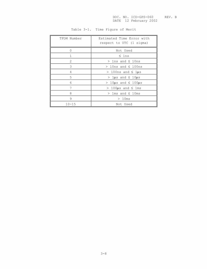
Table 3-1. Time Figure of Merit
TFOM Number Estimated Time Error with respect to UTC (1 sigma)
0 Not Used
1 ≤ 1ns
2 > 1ns and ≤ 10ns
3 > 10ns and ≤ 100ns
4 > 100ns and ≤ 1µs
5 > 1µs and ≤ 10µs
6 > 10µs and ≤ 100µs
7 > 100µs and ≤ 1ms
8 > 1ms and ≤ 10ms
9 > 10ms
10-15 Not Used
3-8
DOC. NO. ICD-GPS-060 REV. B DATE 12 February 2002
APPENDIX A
ACRONYMS AND ABBREVIATIONS
A-1
DOC. NO. ICD-GPS-060 REV. B DATE 12 February 2002
THIS PAGE INTENTIONALLY LEFT BLANK
A-2
DOC. NO. ICD-GPS-060 REV. B DATE 12 February 2002
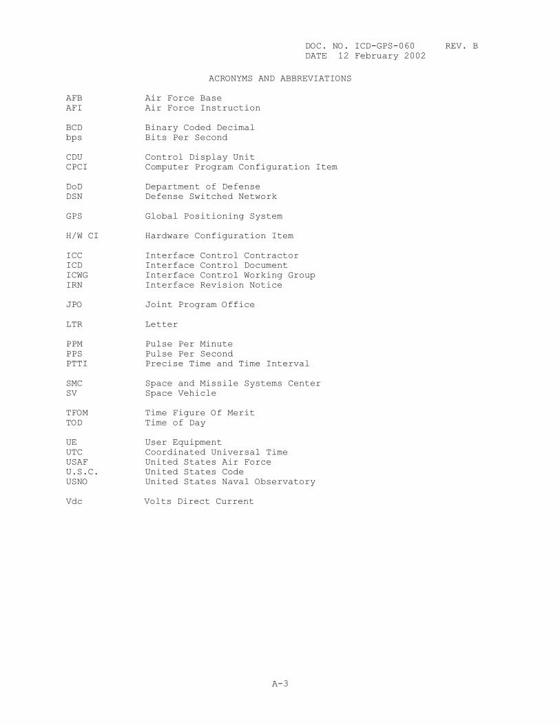
ACRONYMS AND ABBREVIATIONS AFB Air Force Base AFI Air Force Instruction BCD Binary Coded Decimal bps Bits Per Second CDU Control Display Unit CPCI Computer Program Configuration Item DoD Department of Defense DSN Defense Switched Network GPS Global Positioning System H/W CI Hardware Configuration Item ICC Interface Control Contractor ICD Interface Control Document ICWG Interface Control Working Group IRN Interface Revision Notice JPO Joint Program Office LTR Letter PPM Pulse Per Minute PPS Pulse Per Second PTTI Precise Time and Time Interval SMC Space and Missile Systems Center SV Space Vehicle TFOM Time Figure Of Merit TOD Time of Day UE User Equipment UTC Coordinated Universal Time USAF United States Air Force U.S.C. United States Code USNO United States Naval Observatory Vdc Volts Direct Current
A-3

DOC. NO. ICD-GPS-060 REV. B DATE 12 February 2002
THIS PAGE INTENTIONALLY LEFT BLANK
A-4