Embed Size (px)
Citation preview

ICF Homes & Thermal Mass
Capitalizing on the Thermal Mass Properties of
Concrete, Radiant Systems, & Passive Solar
Radiation to Reduce Heating & Cooling Loads

Thermal Mass
• Thermal mass refers to a material's capacity to store heat,
e.g., heat capacity. Concrete, cultured stone, and (adobe)
bricks have high thermal mass, which can act like a battery
for storing thermal energy.
• The classical use of thermal mass is in desert climates
(including Boise, ID), where outside temperatures swing
above inside temperatures during the day and below at
night.
Thermal Mass cont.
• High mass building shells can store the heat from the
outside during the day and release that heat to the inside at
night - keeping the inside comfortable (using almost no
additional energy).
• In temperate climates, thermal mass is best used in
combination with the principles of passive solar design,
e.g., allowing the sun to heat high thermal mass (concrete)
floors and connected structures through strategically
placed windows during cool seasons.

Thermal Mass & Building Design
• Thermal mass is a concept in building design that describes how the mass of the building provides "inertia" against temperature fluctuations, sometimes known as the thermal flywheel effect.
• For example, when outside temperatures are fluctuating throughout the day, a large thermal mass within the insulated portion of a house can serve to "flatten out" the daily temperature fluctuations, since the thermal mass will absorb thermal energy when the surroundings are higher in temperature than the mass, and give thermal energy back when the surroundings are cooler, without reaching thermal equilibrium.

Thermal Mass
• Is distinct from a material's insulative value, which reduces a
building's thermal conductivity, allowing it to be heated or
cooled relatively separate from the outside, or even just retain
the occupants' thermal energy longer.
• Scientifically, thermal mass is equivalent to thermal
capacitance or heat capacity, the ability of a body to store
thermal energy.

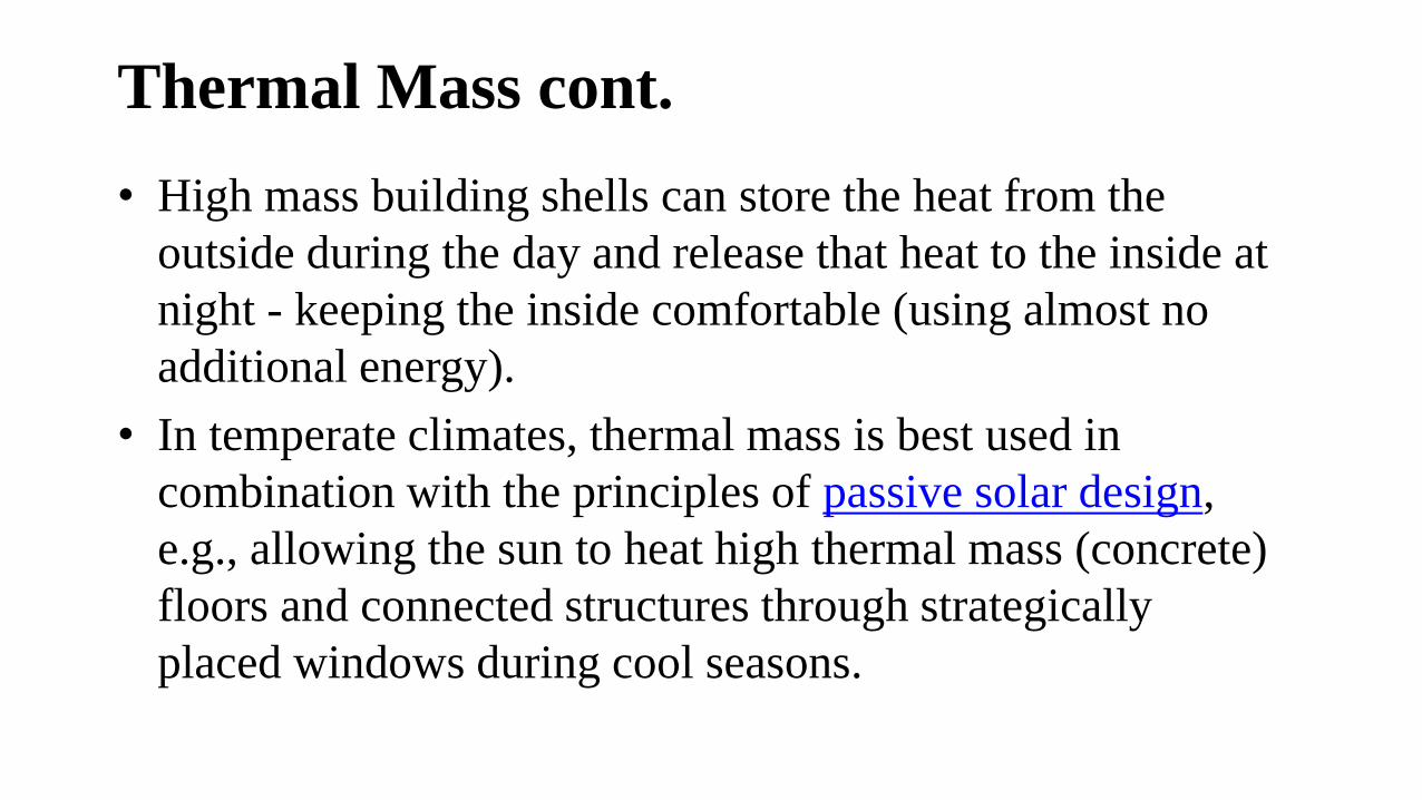
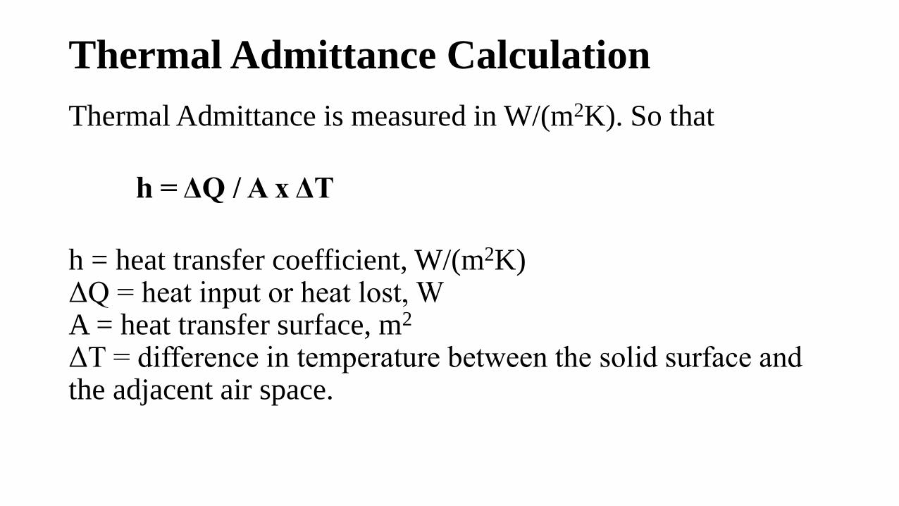
Understanding the Properties of Thermal Mass
• Though thermal mass has always been an aspect of buildings,
only in recent years has it evolved as a tool to be deployed in
the conservation of energy.
• Understanding the properties of thermal mass and its use,
particularly in context, is critical to realizing both benefits and
potential pitfalls.
• This understanding begins with the concept of thermal
admittance.

Thermal Admittance
• Thermal admittance (aka heat transfer coefficient) quantifies a
material's ability to absorb and release heat from a space as the
indoor temperature changes through a period of time.
• Admittance values can be a useful tool in the early stages of
designing a building or structure when assessing heat flows into
and out of thermal storage.
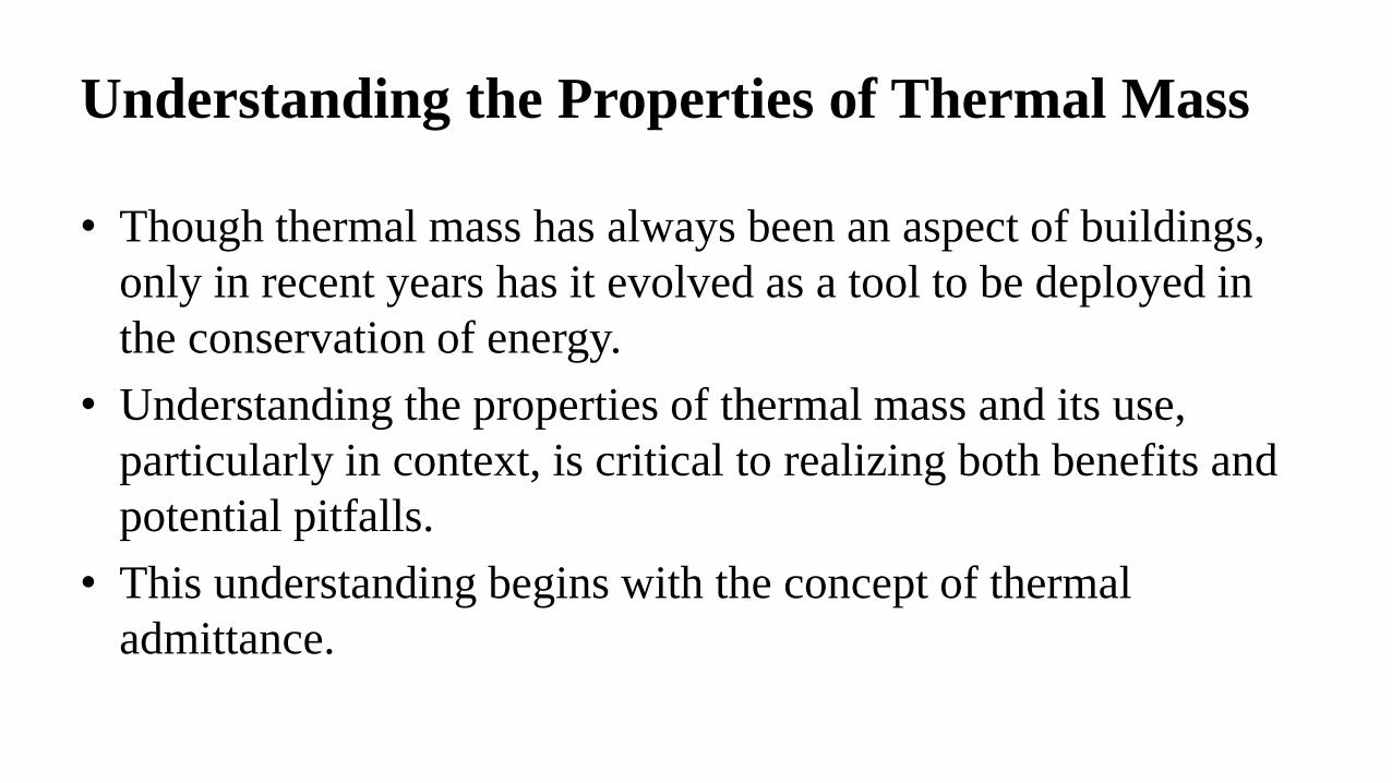
Thermal Admittance Calculation
Thermal Admittance is measured in W/(m2K). So that
h = ΔQ / A x ΔT
h = heat transfer coefficient, W/(m2K) ΔQ = heat input or heat lost, WA = heat transfer surface, m2
ΔT = difference in temperature between the solid surface and the adjacent air space.
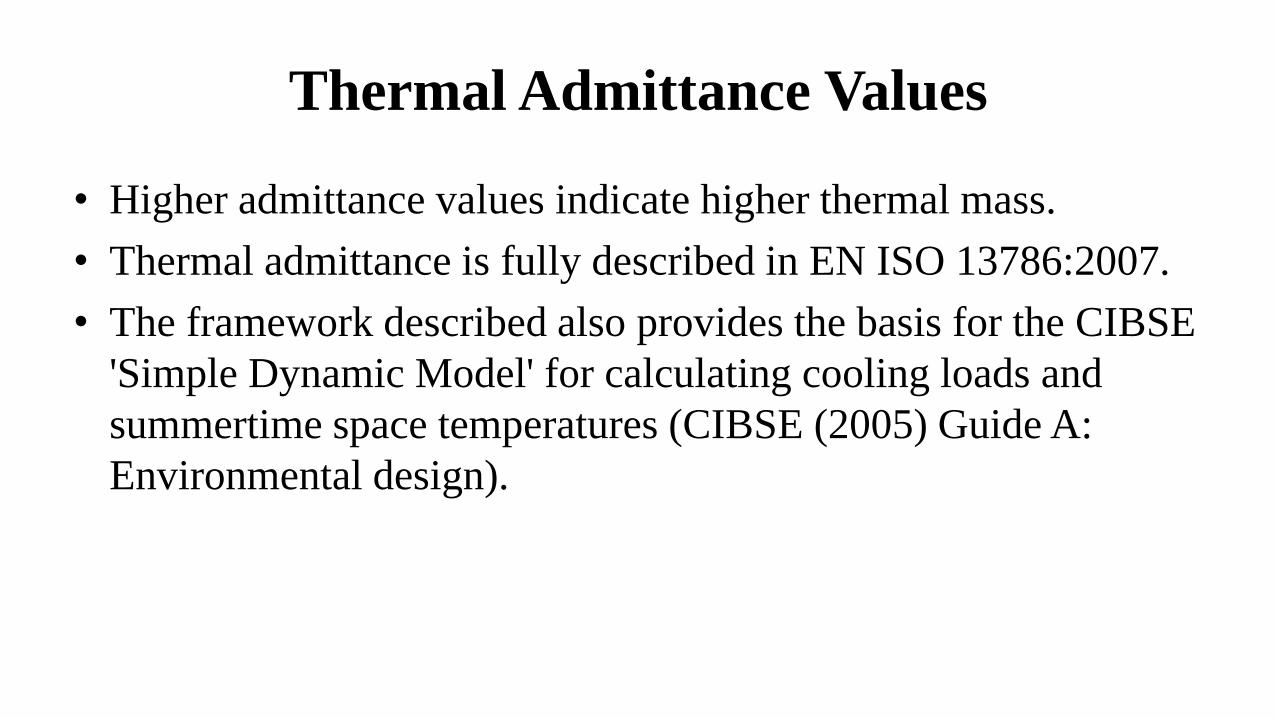
Thermal Admittance Values
• Higher admittance values indicate higher thermal mass.
• Thermal admittance is fully described in EN ISO 13786:2007.
• The framework described also provides the basis for the CIBSE
'Simple Dynamic Model' for calculating cooling loads and
summertime space temperatures (CIBSE (2005) Guide A:
Environmental design).

Admittance Values for Typical External Wall
Elements (based on a 24 hr. cycle)
External wall Internal finish Admittance value
Timber frame (brick outer leaf)
Plasterboard1.0
Wet plaster
Masonry cavity wall (100 mm
aircrete block)
Plasterboard 1.85
Wet plaster2.65
Masonry cavity wall (100 mm
dense aggregate block)
Plasterboard 2.65
Wet plaster 5.04
Source: The Concrete Centre (calculated according to EN ISO 13786:2007)

Factors that Determine Thermal Mass
• Specific Heat Capacity
• Density
• Thermal Conductivity
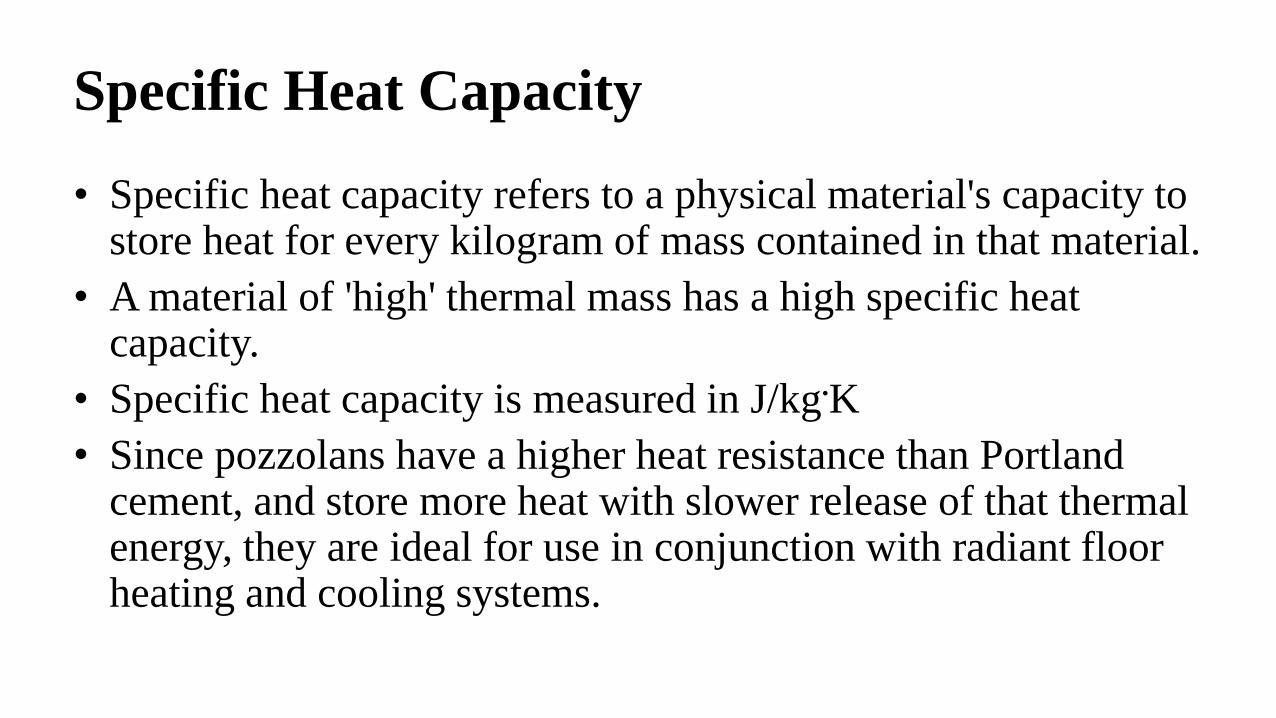
Specific Heat Capacity
• Specific heat capacity refers to a physical material's capacity to store heat for every kilogram of mass contained in that material.
• A material of 'high' thermal mass has a high specific heat capacity.
• Specific heat capacity is measured in J/kg.K
• Since pozzolans have a higher heat resistance than Portland cement, and store more heat with slower release of that thermal energy, they are ideal for use in conjunction with radiant floor heating and cooling systems.

Density
• The density refers to the mass (or 'weight') per unit volume of a
material and is measured in kg/m3.
• A high density material maximizes the overall weight and is a
characteristic aspect of 'high' thermal mass.
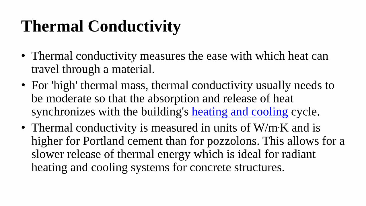
Thermal Conductivity
• Thermal conductivity measures the ease with which heat can travel through a material.
• For 'high' thermal mass, thermal conductivity usually needs to be moderate so that the absorption and release of heat synchronizes with the building's heating and cooling cycle.
• Thermal conductivity is measured in units of W/m.K and is higher for Portland cement than for pozzolons. This allows for a slower release of thermal energy which is ideal for radiant heating and cooling systems for concrete structures.

Heat Capacity & Thermal Conductivity
• Since pozzolans (fly ash, slag, etc.) have higher heat capacities and decreased thermal conductivity, they offer the following advantages over ordinary Portland cement concrete:– Increased resistance to heat/fire
– Increased ability to store thermal energy
– Slower release of that thermal energy for heating structures which enhances energy efficiency
• This makes pozzolanic and Portland cement concrete blends strategically appealing for use with concrete structures, particularly in conjunction with hydronic-radiant heating and cooling systems, allowing for conservation of up to 40% of the energy required for heating and cooling a concrete structure.

Effectiveness of Thermal Mass for Common
Building Materials
MaterialSpecific heat capacity
(J/kg K)
Thermal conductivity
[W / (m · K)] Density
(J/kg K)Effectiveness
water 4200 0.60 1000 high
stone 1000 1.8 2300 high
brick 800 0.73 1700 high
concrete 1000 1.13 2000 high
unfired clay bricks 1000 0.21 700 high
dense concrete block 1000 1.63 2300 high
gypsum plaster 1000 0.5 1300 high
aircrete block 1000 0.15 600 medium
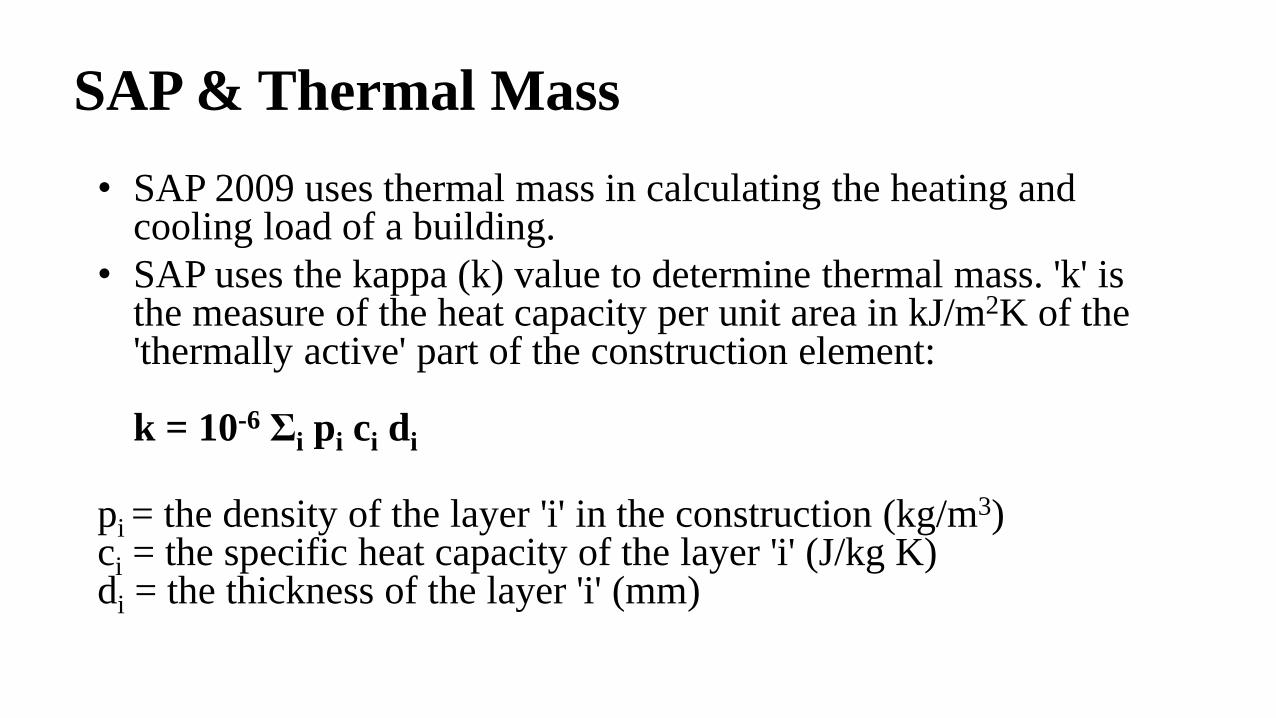
SAP & Thermal Mass
• SAP 2009 uses thermal mass in calculating the heating and cooling load of a building.
• SAP uses the kappa (k) value to determine thermal mass. 'k' is the measure of the heat capacity per unit area in kJ/m2K of the 'thermally active' part of the construction element:
k = 10-6 Σi pi ci di
pi = the density of the layer 'i' in the construction (kg/m3)ci = the specific heat capacity of the layer 'i' (J/kg K)di = the thickness of the layer 'i' (mm)
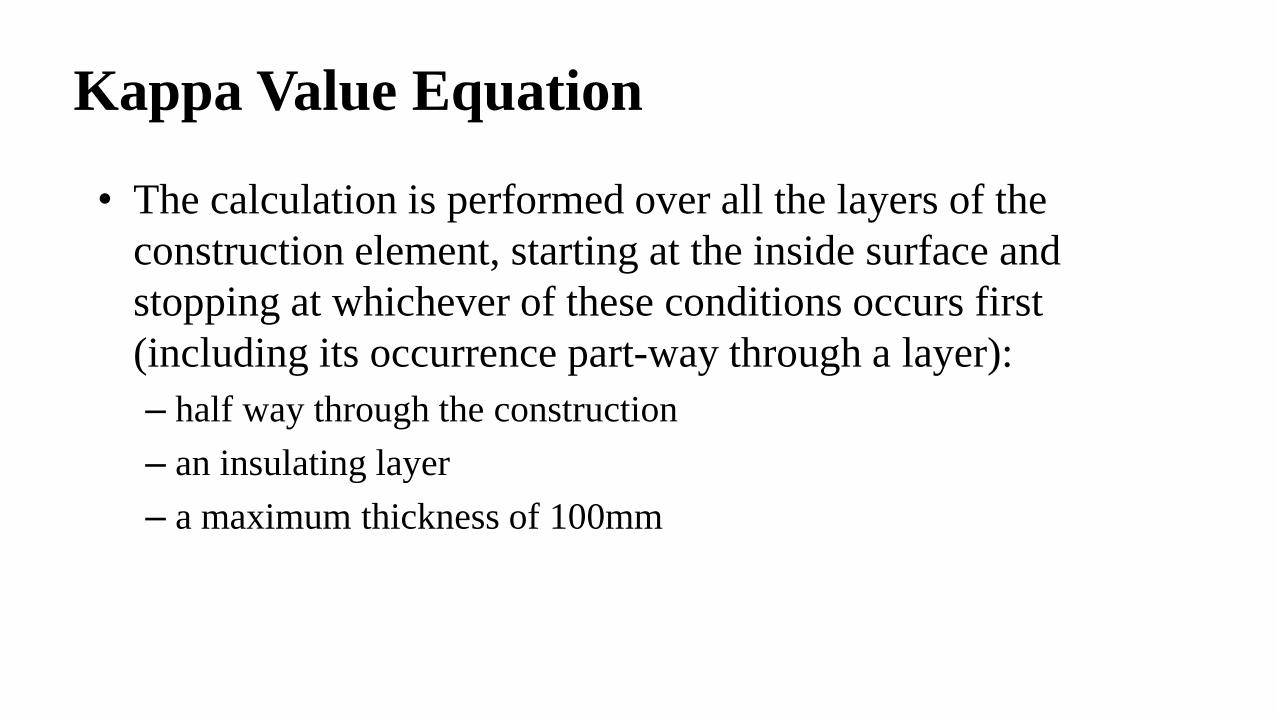
Kappa Value Equation
• The calculation is performed over all the layers of the
construction element, starting at the inside surface and
stopping at whichever of these conditions occurs first
(including its occurrence part-way through a layer):
– half way through the construction
– an insulating layer
– a maximum thickness of 100mm
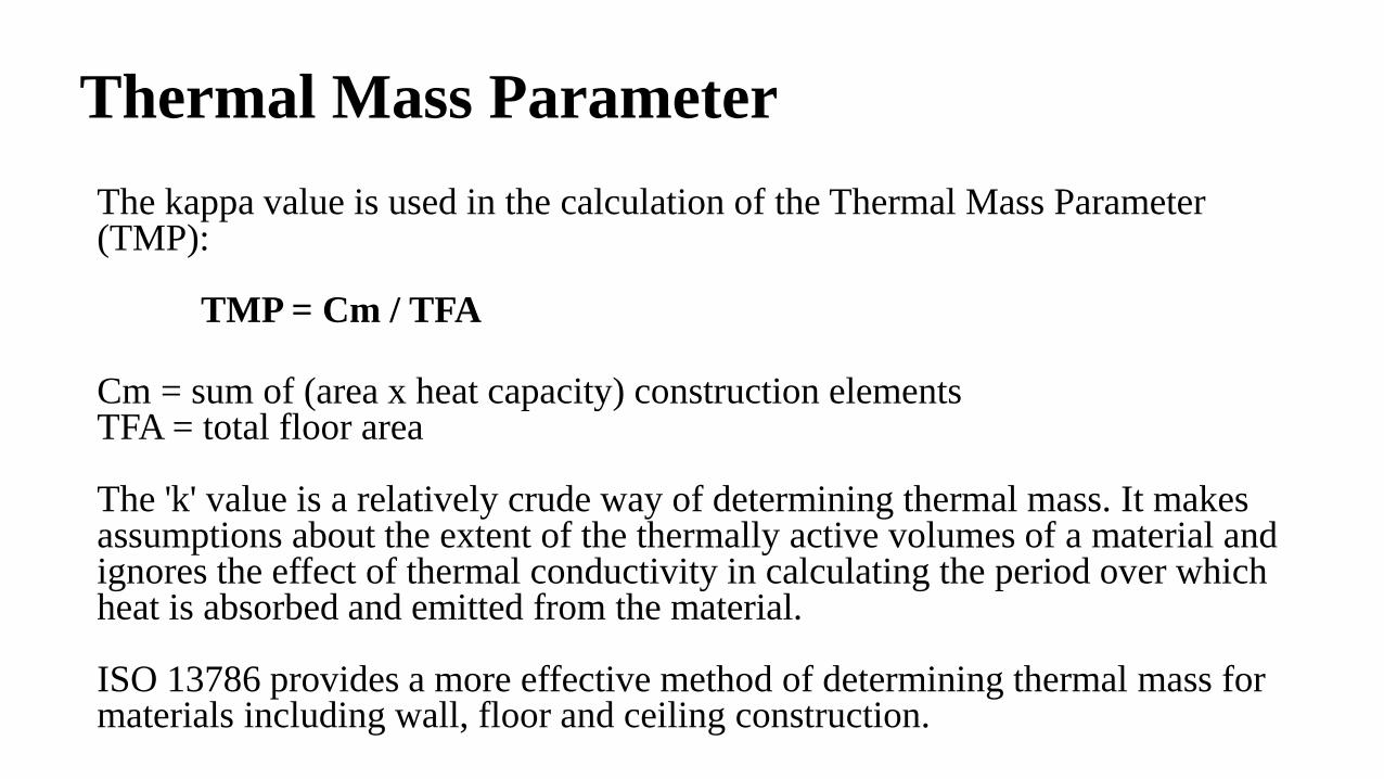
Thermal Mass Parameter
The kappa value is used in the calculation of the Thermal Mass Parameter (TMP):
TMP = Cm / TFA
Cm = sum of (area x heat capacity) construction elementsTFA = total floor area
The 'k' value is a relatively crude way of determining thermal mass. It makes assumptions about the extent of the thermally active volumes of a material and ignores the effect of thermal conductivity in calculating the period over which heat is absorbed and emitted from the material.
ISO 13786 provides a more effective method of determining thermal mass for materials including wall, floor and ceiling construction.

How Thermal Mass Works
• By alternately storing and releasing heat, high thermal mass
'smooths out' the extremes in daytime temperatures.
• In warm/hot climates where there is significant temperature
variation between day and night ('diurnal' variation), heat is
absorbed during the day and then released in the evening
when the excess can be either 'flushed out' through natural
ventilation or it can be used to heat the space as the outside
temperature drops.
• The entire process can then be repeated the next day.

Thermal Mass of Concrete vs. Wood
• Wood frame buildings have almost no thermal mass - unless
the exterior walls are finished with concrete products, brick
or other masonry product.
• In contrast, concrete has a relatively high ability to store and
release thermal energy.
• This makes concrete an ideal building material for use in
passive house design, particularly for passive solar
radiation.

Thermal Mass of Concrete Structures
• Even temperature: Concrete is a material of high thermal mass. That means it changes temperature only slowly. ICF walls, in fact, have about 3-5 times the thermal mass of a conventional wood frame wall. The result is that the temperature of the building tends to be very stable, instead of overheating and getting cold when the furnace (or AC cycles on and off every half hour.
• Fewer drafts: An ICF wall consists of two layers of a fairly air-tight material (foam or cementitious composite) sealed in the center with concrete. This contrasts with wood frame, which is assembled of many rigid pieces to leave thousands of tiny air gaps. Recent studies of new wood homes show air changes per hour of an average of 0.5. But ICF houses have consistently been measured at much lower change rates (down to .11), for many fewer drafts.

Radiant Heating & Cooling - Continuous
Concrete Structures - Temperature Differential
• Fewer hot and cold spots: Most ICF structures have two layers of insulation that are completely uninterrupted. The uninsulated portions of wood frame walls usually add up to about 25% of total area. The result is that ICF structures have virtually none of the cold spots or hot spots one feels when walking along frame walls in winter or summer.
• Consistent floor-to-ceiling temperature via integration of ICF structures and radiant heating & cooling: Since ICFs have consistent thermal mass and insulation at the floor level and up and down the walls and in vaulted ceilings, measurements have shown an air temperature differential in super-insulated air-tight ICF houses from floor level to ceiling level of only a few degrees. The difference can be 4-5 times this in conventional stick-frame houses.
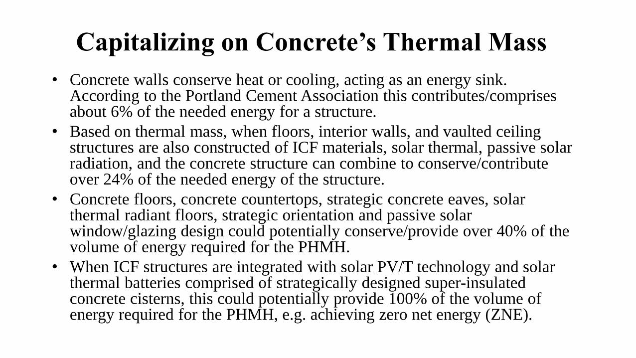
Capitalizing on Concrete’s Thermal Mass
• Concrete walls conserve heat or cooling, acting as an energy sink. According to the Portland Cement Association this contributes/comprises about 6% of the needed energy for a structure.
• Based on thermal mass, when floors, interior walls, and vaulted ceiling structures are also constructed of ICF materials, solar thermal, passive solar radiation, and the concrete structure can combine to conserve/contribute over 24% of the needed energy of the structure.
• Concrete floors, concrete countertops, strategic concrete eaves, solar thermal radiant floors, strategic orientation and passive solar window/glazing design could potentially conserve/provide over 40% of the volume of energy required for the PHMH.
• When ICF structures are integrated with solar PV/T technology and solar thermal batteries comprised of strategically designed super-insulated concrete cisterns, this could potentially provide 100% of the volume of energy required for the PHMH, e.g. achieving zero net energy (ZNE).

ICF Exterior Wall System

Hybrid Thermal Storage System
• As portrayed above, passive thermal storage is incorporated into buildings to smooth out temperature swings, delay heat entry (such as concrete and solar thermal collectors that absorb solar heat and conduct it into a structure over the course of several hours), absorb energy surpluses such as solar heat or heat from computers or other appliances, or to store heat as part of a passive solar heating system.
• Though the above illustration is based on a specific product for a particular ICF manufacturer, similar though varied results would be obtained from different products with lower or higher thermal mass (volume of concrete used in walls, floors/ceiling and roof structures, etc., as a component of a thermal battery storage system).
• For an all ICF/concrete structure the volume of thermal mass and ability to stabilize thermal temperature within that structure would be dramatically enhanced via an integrated solar thermal HVAC system.
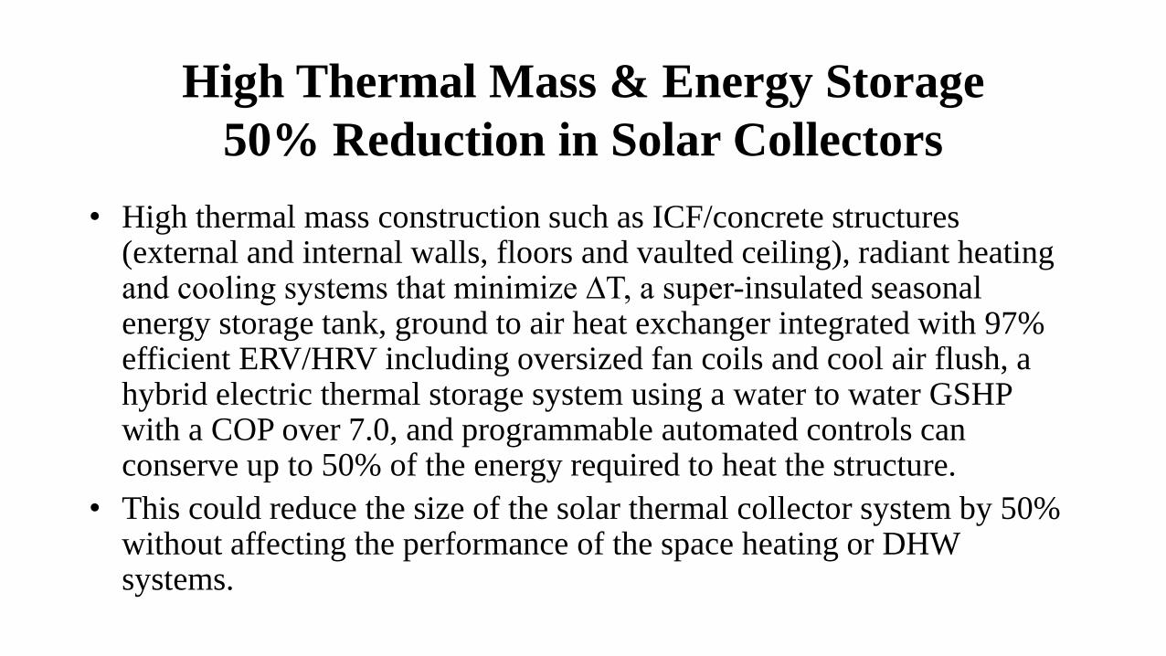
High Thermal Mass & Energy Storage
50% Reduction in Solar Collectors
• High thermal mass construction such as ICF/concrete structures (external and internal walls, floors and vaulted ceiling), radiant heating and cooling systems that minimize ∆T, a super-insulated seasonal energy storage tank, ground to air heat exchanger integrated with 97% efficient ERV/HRV including oversized fan coils and cool air flush, a hybrid electric thermal storage system using a water to water GSHP with a COP over 7.0, and programmable automated controls can conserve up to 50% of the energy required to heat the structure.
• This could reduce the size of the solar thermal collector system by 50% without affecting the performance of the space heating or DHW systems.
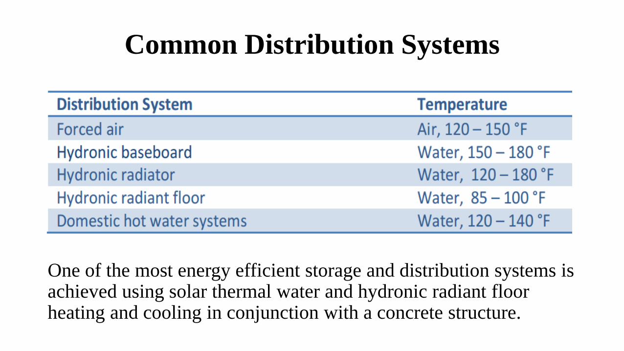
Common Distribution Systems
One of the most energy efficient storage and distribution systems is achieved using solar thermal water and hydronic radiant floor heating and cooling in conjunction with a concrete structure.

High Heat Capacity & Moderate Conductivity
• ICF exterior walls and connected floors have a high storage capacity with moderate thermal conductivity. Thus, it provides the most useful level of thermal mass sandwiched between EPS foam layers. This helps to stabilize the internal temperature from day to night temperature fluctuations.
• Increasing thermal mass by constructing interior walls, floors, ceilings/roofs with ICF and concrete slabs could substantially increase energy conservation.
• This is particularly true if a thermal battery, such as a super-insulated concrete cistern can be economically utilized to store solar thermal energy. Such an integrated system which may include a water to water GSHP and Desuperheater is used to bridge passive and active thermal storage technologies for development of an innovative hybrid thermal energy storage system.

Drain Back Solar Thermal Collector Systems
• Drain back systems provide an 18% increase in energy efficiency compared to closed systems using glycol.
• Life cycle is increased by 33% vs. a glycol system.
• System is substantially simplified vs. a closed pressurized system:– No expansion tank required
– No pressurized tank required
– No check valve required
– No air valve required
– No pressure release valve required
– No heat exchanger required
– No heat dump equipment required
• Labor and materials for installation of a drain back system are less expensive.
• Stainless steel or brass circulators must be utilized in the solar loop since air can cause oxidation and lead to rusting of cast iron circulators for open systems.
ICF Thermal Mass
• High mass construction built into ICF walls & floors can
significantly reduce the requirements for active heating and
cooling systems in many climates.
• This translates into on-going energy savings from using
smaller sized HVAC equipment.
• Most current residential HVAC sizing software programs
do not factor in the effects of thermal mass.
Concrete Thermal Mass
• Concrete “thermal mass” provides the ability to smooth out
large temperature swings.
• It keeps the walls warmer when the outdoor temperature
reaches its coldest extreme and cooler when the outdoor
temperature is hottest.

Concrete Homes Save Energy
• According to the Portland Cement Association, building a
concrete home with ICFs saves energy and money.
• The greater insulation, tighter construction and temperature-
moderating mass of the walls conserve heating and cooling
energy much better than conventional wood-frame walls.
• This reduces monthly fuel bills. It also allows use of smaller
heating and cooling equipment, saving money in construction.

Concrete Homes Save Energy cont.
• Houses built with ICF exterior walls require an estimated 44% less energy to heat and 32% less energy to cool than comparable frame houses. A typical 2,000 square foot home in the center of the U.S. will save approximately $200 in heating costs each year and $65 in air conditioning each year.
• The bigger the house, the bigger the savings. In colder areas of the U.S. and Canada, heating savings will be more and cooling savings less. In hotter areas, heating savings will be less and cooling savings more.
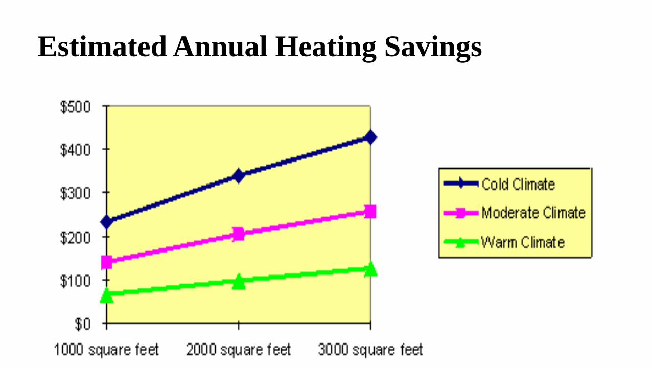
Estimated Annual Heating Savings

Estimated Annual Cooling Savings
Energy Savings Estimates
• The above energy savings estimates are from a study of 58
single-family houses across the US and Canada.
• Half had exterior walls constructed with concrete using ICFs
made of expanded polystyrene (EPS) or extruded
polystyrene (XPS) foam.
• The other half were neighboring houses with wood-frame
walls. All houses were less than 6 years old.
Reducing Energy Consumption
• Researchers compared the energy bill of each concrete house to
its frame counterpart, carefully correcting for important
differences to get an “apples-to-apples” comparison.
• Estimates of equipment savings are actual numbers reported by
contractors who build ICF houses.
• Insulating values for ICF walls using polystyrene foam are R-17
to R-26, compared to wood frame’s R-9 to R-15. ICF walls are
expected to cut conduction losses through foundation and
above-grade walls in half. And ICF walls are tighter. In tests,
they averaged about half as much infiltration (air leakage) as
wood-frame homes.

PHMH Construction
• Since the PHMH will have ICF exterior walls, interior walls, slab floors, and roof, it will have nearly double the insulation [e.g., R-51 in walls and R-80 (R-16 Quad-Deck panel plus R-65 (16” Foam-Control EPS including ¾” OSB coverboard] in the roof, the increase in energy conservation will be over double that of the ICF houses in the above study.
• In addition, conduction will be virtually eliminated through an air-tight ICF envelope. Thus, the volume of savings for the PHMH will be substantially enhanced in relation to the above comparisons.

Benefits of Interior ICF Walls
• Sound attenuation
• Mold and mildew free environment
• Structural support for ceiling, floors, roof and exterior walls
• Fire resistance (fire protection rating up to 4 hr. via steel reinforced concrete and a non-toxic fire retardant EPS foam)
• Ease of installation and construction including plumbing, electrical, and HVAC, etc.
• Green building & longevity
• Increase in thermal mass
Net-Zero PHMH
• By virtually eliminating energy losses due to convection and
using super-insulated ICF, the primary objective of the PHMH
is to decrease the energy load by over 90%. This will reduce
HVAC sizing proportionately.
• Structure orientation, strategic glazing, and passive solar
radiation will then be utilized in conjunction with solar/PV
power systems to achieve a Net-Zero PHMH.

Smaller Energy/HVAC Loads
• Since the energy needed is less, HVAC requirements are also
less. And the more the energy savings, the greater the possible
reduction in equipment size —and cost.
• Estimating the size of heating and cooling equipment for
concrete homes is complicated because the effect of thermal
mass must be simulated in a computer program.
• The Building Energy Optimizer modeling software, Energy
Plus Simulation Software (developed by NREL) and WrightSoft
HVAC software simplify manual J & D calculations by entering
information about the house including location, house size and
wall, floor, and roof construction, etc.

HVAC Sizing Software
• BEopt and Wrightsoft’s sophisticated HVAC design software
use Dept. of Energy 2.1E calculations to estimate the
required heating and cooling system capacity (Manual J) for
single-family concrete homes.
• Calculations are based on a user-defined thermostat set point,
house dimensions, construction materials, and geographical
location.
Summary of ICF vs. Wood Frame
• The R-value of one component alone does not reveal how a building will perform. The Building Code is only a MINIMUM standard, and there are many factors that influence energy performance.
• ICF buildings far outperform framed buildings despite similar stated R-values.
• The secret lies in the combination of reduced conduction & convection, and high thermal mass.
• The result is ICF buildings have lower appetites for energy and more consistent and comfortable temperatures inside the building.