Embed Size (px)
Citation preview
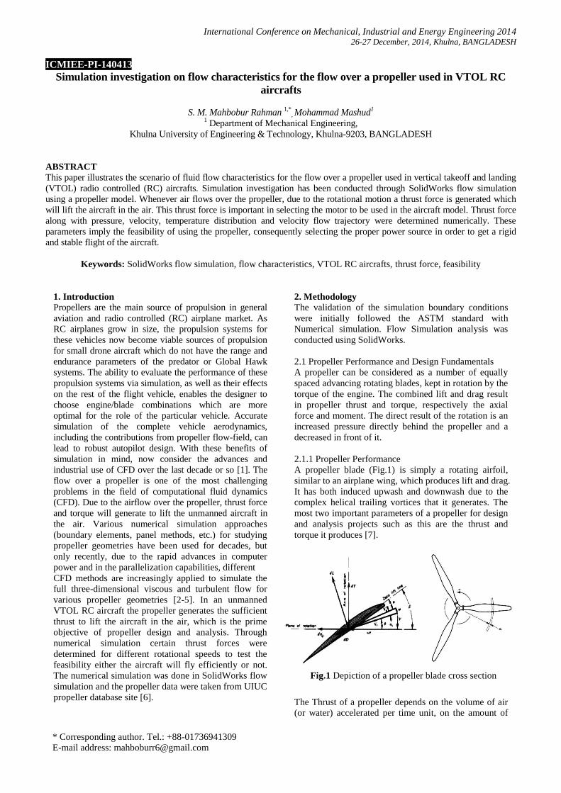
International Conference on Mechanical, Industrial and Energy Engineering 2014
26-27 December, 2014, Khulna, BANGLADESH
* Corresponding author. Tel.: +88-01736941309
E-mail address: [email protected]
ICMIEE-PI-140413
Simulation investigation on flow characteristics for the flow over a propeller used in VTOL RC
aircrafts
S. M. Mahbobur Rahman 1,*
, Mohammad Mashud1
1 Department of Mechanical Engineering,
Khulna University of Engineering & Technology, Khulna-9203, BANGLADESH
ABSTRACT
This paper illustrates the scenario of fluid flow characteristics for the flow over a propeller used in vertical takeoff and landing
(VTOL) radio controlled (RC) aircrafts. Simulation investigation has been conducted through SolidWorks flow simulation
using a propeller model. Whenever air flows over the propeller, due to the rotational motion a thrust force is generated which
will lift the aircraft in the air. This thrust force is important in selecting the motor to be used in the aircraft model. Thrust force
along with pressure, velocity, temperature distribution and velocity flow trajectory were determined numerically. These
parameters imply the feasibility of using the propeller, consequently selecting the proper power source in order to get a rigid
and stable flight of the aircraft.
Keywords: SolidWorks flow simulation, flow characteristics, VTOL RC aircrafts, thrust force, feasibility
1. Introduction
Propellers are the main source of propulsion in general
aviation and radio controlled (RC) airplane market. As
RC airplanes grow in size, the propulsion systems for
these vehicles now become viable sources of propulsion
for small drone aircraft which do not have the range and
endurance parameters of the predator or Global Hawk
systems. The ability to evaluate the performance of these
propulsion systems via simulation, as well as their effects
on the rest of the flight vehicle, enables the designer to
choose engine/blade combinations which are more
optimal for the role of the particular vehicle. Accurate
simulation of the complete vehicle aerodynamics,
including the contributions from propeller flow-field, can
lead to robust autopilot design. With these benefits of
simulation in mind, now consider the advances and
industrial use of CFD over the last decade or so [1]. The
flow over a propeller is one of the most challenging
problems in the field of computational fluid dynamics
(CFD). Due to the airflow over the propeller, thrust force
and torque will generate to lift the unmanned aircraft in
the air. Various numerical simulation approaches
(boundary elements, panel methods, etc.) for studying
propeller geometries have been used for decades, but
only recently, due to the rapid advances in computer
power and in the parallelization capabilities, different
CFD methods are increasingly applied to simulate the
full three-dimensional viscous and turbulent flow for
various propeller geometries [2-5]. In an unmanned
VTOL RC aircraft the propeller generates the sufficient
thrust to lift the aircraft in the air, which is the prime
objective of propeller design and analysis. Through
numerical simulation certain thrust forces were
determined for different rotational speeds to test the
feasibility either the aircraft will fly efficiently or not.
The numerical simulation was done in SolidWorks flow
simulation and the propeller data were taken from UIUC
propeller database site [6].
2. Methodology
The validation of the simulation boundary conditions
were initially followed the ASTM standard with
Numerical simulation. Flow Simulation analysis was
conducted using SolidWorks.
2.1 Propeller Performance and Design Fundamentals
A propeller can be considered as a number of equally
spaced advancing rotating blades, kept in rotation by the
torque of the engine. The combined lift and drag result
in propeller thrust and torque, respectively the axial
force and moment. The direct result of the rotation is an
increased pressure directly behind the propeller and a
decreased in front of it.
2.1.1 Propeller Performance
A propeller blade (Fig.1) is simply a rotating airfoil,
similar to an airplane wing, which produces lift and drag.
It has both induced upwash and downwash due to the
complex helical trailing vortices that it generates. The
most two important parameters of a propeller for design
and analysis projects such as this are the thrust and
torque it produces [7].
Fig.1 Depiction of a propeller blade cross section
The Thrust of a propeller depends on the volume of air
(or water) accelerated per time unit, on the amount of
ICMIEE-PI-140413- 2
the acceleration, and on the density of the medium.
Based on momentum considerations, it can be expressed
by the following formula:
where:
T thrust [N]
D propeller diameter [m]
v velocity of incoming flow [m/s]
additional velocity,
acceleration by propeller [m/s]
ρ density of fluid [kg/m³]
(air: ρ= 1.225 kg/m³, water: ρ = 1000
kg/m³)
2.1.2 Propeller Modeling and Selection
In the field of RC aerial vehicles, selection of proper
propeller is an important scenario. Depending upon the
required flight phenomena, appropriate propeller should
be modeled and selected. For this simulation
investigation 10*4.7 propeller model was selected
because of its appreciable flexibility and light weight
(13g approx.). 10*4.7 indicates that the propeller has a
diameter of 10 in and pitch of 4.7 in per revolution.
Fig.2 represents the design flow-chart for the selected
propeller.
Fig.2 Propeller Design and Analysis Flow-Chart
Fig.3 Sketch for loft feature in SolidWorks
Using the data from the UIUC database site [6], the
points through x-y-z were generated and then by
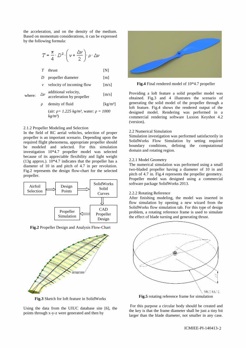
Fig.4 Final rendered model of 10*4.7 propeller
Providing a loft feature a solid propeller model was
obtained. Fig.3 and 4 illustrates the scenario of
generating the solid model of the propeller through a
loft feature. Fig.4 shows the rendered output of the
designed model. Rendering was performed in a
commercial rendering software Luxion Keyshot 4.2
(version).
2.2 Numerical Simulation
Simulation investigation was performed satisfactorily in
SolidWorks Flow Simulation by setting required
boundary conditions, defining the computational
domain and rotating region.
2.2.1 Model Geometry
The numerical simulation was performed using a small
two-bladed propeller having a diameter of 10 in and
pitch of 4.7 in. Fig.4 represents the propeller geometry.
Propeller model was designed using a commercial
software package SolidWorks 2013.
2.2.2 Rotating Reference
After finishing modeling, the model was inserted in
flow simulation by opening a new wizard from the
SolidWorks flow simulation tab. For this type of design
problem, a rotating reference frame is used to simulate
the effect of blade turning and generating thrust.
Fig.5 rotating reference frame for simulation
For this purpose a circular body should be created and
the key is that the frame diameter shall be just a tiny bit
larger than the blade diameter, not smaller in any case.
Airfoil
Selection
Design
Points
SolidWorks
Solid
Curves
CAD
Propeller
Design
Propeller
Simulation
ICMIEE-PI-140413- 3
Axis of rotation was set about Y-axis. This illustrates
that air will flow along Y-axis, when the propeller starts
to rotate in order to provide a thrust force beneath. Fig.5
shows the optimum rotating frame (dimensions are in
inch) used during investigation.
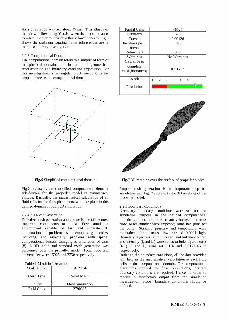
2.2.3 Computational Domain
The computational domain refers to a simplified form of
the physical domain both in terms of geometrical
representation and boundary condition imposition. For
this investigation, a rectangular block surrounding the
propeller acts as the computational domain.
Fig.6 Simplified computational domain
Fig.6 represents the simplified computational domain,
sub-domain for the propeller model in symmetrical
attitude. Basically, the mathematical calculation of all
fluid cells for the flow phenomena will take place in this
defined domain through 3D simulation.
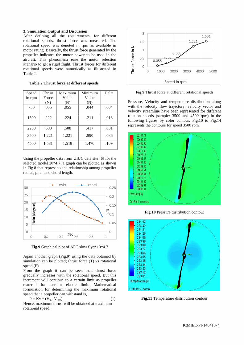
2.2.4 3D Mesh Generation
Effective mesh generation and update is one of the most
important components of a 3D flow simulation
environment capable of fast and accurate 3D
computation of problems with complex geometries,
including, and especially, problems with spatial
computational domain changing as a function of time
[8]. A 3D, solid and standard mesh generation was
performed over the propeller model. Total node and
element size were 15925 and 7750 respectively.
Table 1 Mesh Information
Study Name 3D Mesh
Mesh Type Solid Mesh
Solver Flow Simulation
Fluid Cells 2790315
Partial Cells 48527
Iterations 326
Travels 2.00126
Iterations per 1
travel
163
Refinement 326
Warnings No Warnings
CPU time to
complete
mesh(hh:mm:ss)
02:06:24
Result
Resolution
Fig.7 3D meshing over the surface of propeller blades
Proper mesh generation is an important step for
simulation and Fig. 7 represents the 3D meshing of the
propeller model.
2.2.5 Boundary Conditions
Necessary boundary conditions were set for the
simulation purpose in the defined computational
domain- at inlet, inlet free stream velocity, inlet mass
flow, Mach number were imposed; same had gone for
the outlet. Standard pressure and temperature were
maintained for a mass flow rate of 0.0001 kg/s.
Boundary layer was set to turbulent and turbulent length
and intensity (It and Lt) were set as turbulent parameters
(I-L). It and Lt were set 0.1% and 0.0177165 in
respectively.
Initiating the boundary conditions, all the data provided
will help in the mathematical calculation at each fluid
cells in the computational domain. For computational
algorithms applied to flow simulations, discrete
boundary conditions are required. Hence, in order to
receive a satisfactory output from the simulation
investigation, proper boundary conditions should be
defined.
ICMIEE-PI-140413- 4
Speed
in rpm
Thrust
Force
(N)
Maximum
Value
(N)
Minimum
Value
(N)
Delta
750 .055 .055 .044 .004
1500 .222 .224 .211 .013
2250 .508 .508 .417 .031
3500 1.221 1.221 .990 .086
4500 1.531 1.518 1.476 .109
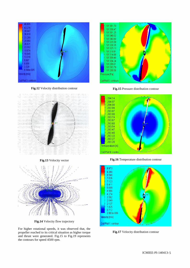
3. Simulation Output and Discussion
After defining all the requirements, for different
rotational speeds, thrust force was measured. The
rotational speed was denoted in rpm as available in
motor rating. Basically, the thrust force generated by the
propeller indicates the motor power to be used in the
aircraft. This phenomena ease the motor selection
scenario to get a rigid flight. Thrust forces for different
rotational speeds were numerically as illustrated in
Table 2.
Table 2 Thrust force at different speeds
Using the propeller data from UIUC data site [6] for the
selected model 10*4.7, a graph can be plotted as shown
in Fig.8 that represents the relationship among propeller
radius, pitch and chord length.
Fig.9 Graphical plot of APC slow flyer 10*4.7
Again another graph (Fig.9) using the data obtained by
simulation can be plotted; thrust force (T) vs rotational
speed (P).
From the graph it can be seen that, thrust force
gradually increases with the rotational speed. But this
increment will continue to a certain limit as propeller
material has certain elastic limit. Mathematical
formulation for determining the maximum rotational
speed that a propeller can withstand is,
P = Kv * (Vin- Vloss) (1)
Hence, maximum thrust will be obtained at maximum
rotational speed.
Fig.9 Thrust force at different rotational speeds
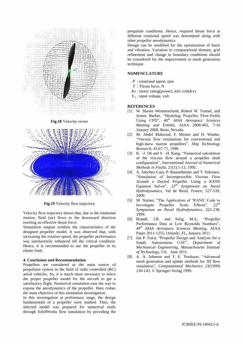
Pressure, Velocity and temperature distribution along
with the velocity flow trajectory, velocity vector and
velocity streamline have been represented for different
rotation speeds (sample: 3500 and 4500 rpm) in the
following figures by color contour. Fig.10 to Fig.14
represents the contours for speed 3500 rpm.
Fig.10 Pressure distribution contour
Fig.11 Temperature distribution contour
ICMIEE-PI-140413- 5
Fig.12 Velocity distribution contour
Fig.13 Velocity vector
Fig.14 Velocity flow trajectory
For higher rotational speeds, it was observed that, the
propeller reached to its critical situation as higher torque
and thrust were generated. Fig.15 to Fig.19 represents
the contours for speed 4500 rpm.
Fig.15 Pressure distribution contour
Fig.16 Temperature distribution contour
Fig.17 Velocity distribution contour
ICMIEE-PI-140413- 6
P
T
Kv
Vin
: rotational speed, rpm
: Thrust force, N
: motor rating(power), kilo volt(Kv)
: input voltage, volt
Fig.18 Velocity vector
Fig.19 Velocity flow trajectory
Velocity flow trajectory shows that, due to the rotational
motion, fluid (air) flows to the downward direction
exerting an effective thrust force.
Simulation outputs exhibits the characteristics of the
designed propeller model. It was observed that, with
increasing the rotation speed, the propeller performance
was satisfactorily enhanced till the critical condition.
Hence, it is recommended to use the propeller in its
elastic limit.
4. Conclusion and Recommendation
Propellers are considered as the main source of
propulsion system in the field of radio controlled (RC)
aerial vehicles. So, it is much more necessary to select
the proper propeller model for the aircraft to get a
satisfactory flight. Numerical simulation ease the way to
expose the aerodynamics of the propeller. Here comes
the main objective of this simulation investigation.
In this investigation at preliminary stage, the design
fundamentals of a propeller were studied. Then, the
selected model was prepared for numerical study
through SolidWorks flow simulation by providing the
perquisite conditions. Hence, required thrust force at
different rotational speed was determined along with
other propeller aerodynamics.
Design can be modified for the optimization of burrs
and vibration. Variation in computational domain, grid
refinement and change in boundary conditions should
be considered for the improvement in mesh generation
technique.
NOMENCLATURE
REFERENCES
[1] W. Shawn Westmoreland, Robert W. Tramel, and
Jennie Barber, “Modeling Propeller Flow-Fields
Using CFD”, 46th
AIAA Aerospace Sciences
Meeting and Exhibit, AIAA 2008-402, 7-10
January 2008, Reno, Nevada.
[2] M. Abdel Maksoud, F. Menter and H. Wuttke,
“Viscous flow simulations for conventional and
high-skew marine propellers”, Ship Technology
Research, 45:67-71, 1998.
[3] K. –J. Oh and S. –H. Kang, “Numerical calculation
of the viscous flow around a propeller shaft
configuration”, International Journal of Numerical
Methods in Fluids, 21(1):1-13, 1995.
[4] A. Sánchez-Caja, P. Rautanhiemo and T. Siikonen,
“Simulation of Incompressible Viscous Flow
Around a Ducted Propeller Using a RANS
Equation Solver”, 23rd
Symposium on Naval
Hydrodynamics, Val de Reuil, France, 527-539,
2000.
[5] M. Stainer, “The Application of „RANS‟ Code to
Investigate Propeller Scale Effects”, 22nd
Symposium on Naval Hydrodynamics, 222-238,
1999.
[6] Brandt, J.B. and Selig, M.S., “Propeller
Performance Data at Low Reynolds Numbers”,
49th
AIAA Aerospace Sciences Meeting, AIAA
Paper 2011-1255, Orlando, FL, January 2011.
[7] Ian P. Tracy, “Propeller Design and Analysis for a
Small, Autonomous UAV”, Department of
Mechanical Engineering, Massachusetts Institute
of Technology, 5-6, June 2011.
[8] A. A. Johnson and T. E. Tezduyar, “Advanced
mesh generation and update methods for 3D flow
simulation”, Computational Mechanics 23(1999)
130-143, © Springer-Verlag 1999.


![ICMIEE-PI-140413 Simulation investigation on flow ... · Sketch for loft feature in SolidWorks site [6], the points through x-y-z were generated and then by Fig.4 Final rendered model](https://img.pdfslide.net/doc/110x75/5be258d909d3f284098c05b8/icmiee-pi-140413-simulation-investigation-on-flow-sketch-for-loft-feature.jpg)