Embed Size (px)
Citation preview
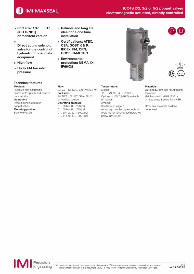
ICO4S 2/2, 3/2 or 5/2 poppet valves electromagnetic actuated, directly controlled
12/15en 5.7.550.01
Our policy is one of continued research and development. We therefore reserve the right to amend, without notice, the specifications given in this document. (2012 - 5198c) © IMI Precision Engineering, Thompson Valves Ltd.
Medium:Hydraulic and pneumatic – customer to specify and confirm compatibilityOperation:Direct solenoid operated poppet valvesMounting position:Solenoid vertical
Flow:0,8 Cv (11,5 Kv) ... 6,0 Cv (86,2 Kv)Port size:1/4 NPT, 1/2 NPT, G1/4, G1/2 or manifold versionOperating pressure:0 ... 20 bar (0 ... 290 psi) 0 ... 50 bar (0 ... 725 psi) 0 ... 207 bar (0 ... 3002 psi) 0 ... 414 bar (0 ... 6004 psi)
Temperature:Media:-20 ... +90°C (-4 ... +194°F)Options to -60°C (-76°F) available on requestAmbient:See table on page 2Air supply must be dry enough to avoid ice formation at temperatures below +2°C (+35°F).
Materials:Valve body, trim, coil housing and top cover: stainless steel 1.4404 (316 L) O-rings seats & seals: high NBR Other seal materials available on request
Technical features
> Port size: 1/4” ... 3/4” (ISO G/NPT) or manifold version
> Direct acting solenoid valve for the control of hydraulic or pneumatic equipment
> High flow
> Up to 414 bar inlet pressure
> Reliable and long life, ideal for a one time installation
> Certifications: ATEX, CSA, GOST K & R, IECEx, FM, CRN, CCOE IN-METRO
> Environmental protection; NEMA 4X, IP66/X8
ICO4S 2/2, 3/2 or 5/2 poppet valves electromagnetic actuated, directly controlled
en 5.7.550.02
12/15Our policy is one of continued research and development. We therefore reserve the right to amend, without
notice, the specifications given in this document. (2012 - 5198c) © IMI Precision Engineering, Thompson Valves Ltd.
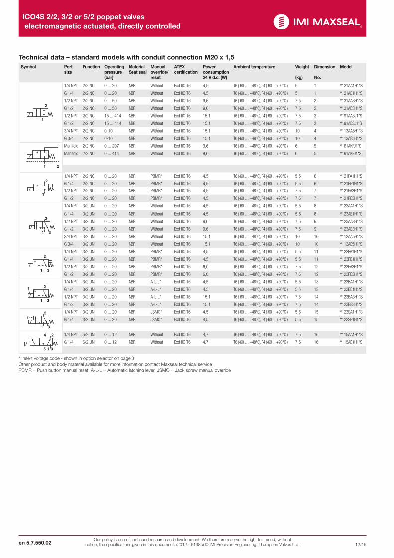
Technical data – standard models with conduit connection M20 x 1,5Symbol Port
sizeFunction Operating
pressure (bar)
Material Seat seal
Manual override/ reset
ATEXcertification
Power consumption 24 V d.c. (W)
Ambient temperature Weight
(kg)
Dimension
No.
Model
2
1
2
1
2
1
2
1
V-22C-E-F
V-22C-EH-F
V-22C-ER-F
1/4 NPT 2/2 NC 0 ... 20 NBR Without Exd IIC T6 4,5 T6 (-60 … +48°C), T4 (-60 ... +90°C ) 5 1 Y121AA1H1*S
G 1/4 2/2 NC 0 ... 20 NBR Without Exd IIC T6 4,5 T6 (-60 … +48°C), T4 (-60 ... +90°C ) 5 1 Y121AE1H1*S
1/2 NPT 2/2 NC 0 ... 50 NBR Without Exd IIC T6 9,6 T6 (-60 … +48°C), T4 (-60 ... +90°C ) 7,5 2 Y131AA3H1*S
G 1/2 2/2 NC 0 ... 50 NBR Without Exd IIC T6 9,6 T6 (-60 … +48°C), T4 (-60 ... +90°C ) 7,5 2 Y131AE3H1*S
1/2 NPT 2/2 NC 15 ... 414 NBR Without Exd IIC T6 15,1 T6 (-60 … +48°C), T4 (-60 ... +90°C ) 7,5 3 Y191AA3J1*S
G 1/2 2/2 NC 15 ... 414 NBR Without Exd IIC T6 15,1 T6 (-60 … +48°C), T4 (-60 ... +90°C ) 7,5 3 Y191AE3J1*S
3/4 NPT 2/2 NC 0-10 NBR Without Exd IIC T6 15,1 T6 (-60 … +48°C), T4 (-60 ... +90°C ) 10 4 Y113AA5H1*S
G 3/4 2/2 NC 0-10 NBR Without Exd IIC T6 15,1 T6 (-60 … +48°C), T4 (-60 ... +90°C ) 10 4 Y113AE5H1*S
21
Manifold 2/2 NC 0 ... 207 NBR Without Exd IIC T6 9,6 T6 (-60 … +48°C), T4 (-60 ... +90°C ) 6 5 Y161AKFJ1*S
Manifold 2/2 NC 0 ... 414 NBR Without Exd IIC T6 9,6 T6 (-60 … +48°C), T4 (-60 ... +90°C ) 6 5 Y191AKFJ1*S
2
1
1/4 NPT 2/2 NC 0 ... 20 NBR PBMR* Exd IIC T6 4,5 T6 (-60 … +48°C), T4 (-60 ... +90°C ) 5,5 6 Y121PA1H1*S
G 1/4 2/2 NC 0 ... 20 NBR PBMR* Exd IIC T6 4,5 T6 (-60 … +48°C), T4 (-60 ... +90°C ) 5,5 6 Y121PE1H1*S
1/2 NPT 2/2 NC 0 ... 20 NBR PBMR* Exd IIC T6 4,5 T6 (-60 … +48°C), T4 (-60 ... +90°C ) 7,5 7 Y121PA3H1*S
G 1/2 2/2 NC 0 ... 20 NBR PBMR* Exd IIC T6 4,5 T6 (-60 … +48°C), T4 (-60 ... +90°C ) 7,5 7 Y121PE3H1*S
3
2
1 3
2
1 3
2
1 3
V-32C-E-F
V-32C-EH-F
V-32C-ER-F
1/4 NPT 3/2 UNI 0 ... 20 NBR Without Exd IIC T6 4,5 T6 (-60 … +48°C), T4 (-60 ... +90°C ) 5,5 8 Y123AA1H1*S
G 1/4 3/2 UNI 0 ... 20 NBR Without Exd IIC T6 4,5 T6 (-60 … +48°C), T4 (-60 ... +90°C ) 5,5 8 Y123AE1H1*S
1/2 NPT 3/2 UNI 0 ... 20 NBR Without Exd IIC T6 9,6 T6 (-60 … +48°C), T4 (-60 ... +90°C ) 7,5 9 Y123AA3H1*S
G 1/2 3/2 UNI 0 ... 20 NBR Without Exd IIC T6 9,6 T6 (-60 … +48°C), T4 (-60 ... +90°C ) 7,5 9 Y123AE3H1*S
3/4 NPT 3/2 UNI 0 ... 20 NBR Without Exd IIC T6 15,1 T6 (-60 … +48°C), T4 (-60 ... +90°C ) 10 10 Y113AA5H1*S
G 3/4 3/2 UNI 0 ... 20 NBR Without Exd IIC T6 15,1 T6 (-60 … +48°C), T4 (-60 ... +90°C ) 10 10 Y113AE5H1*S
2
1 3
1/4 NPT 3/2 UNI 0 ... 20 NBR PBMR* Exd IIC T6 4,5 T6 (-60 … +48°C), T4 (-60 ... +90°C ) 5,5 11 Y123PA1H1*S
G 1/4 3/2 UNI 0 ... 20 NBR PBMR* Exd IIC T6 4,5 T6 (-60 … +48°C), T4 (-60 ... +90°C ) 5,5 11 Y123PE1H1*S
1/2 NPT 3/2 UNI 0 ... 20 NBR PBMR* Exd IIC T6 6,0 T6 (-60 … +48°C), T4 (-60 ... +90°C ) 7,5 12 Y123PA3H1*S
G 1/2 3/2 UNI 0 ... 20 NBR PBMR* Exd IIC T6 6,0 T6 (-60 … +48°C), T4 (-60 ... +90°C ) 7,5 12 Y123PE3H1*S
3
2
1 3
1/4 NPT 3/2 UNI 0 ... 20 NBR A-L-L* Exd IIC T6 4,5 T6 (-60 … +48°C), T4 (-60 ... +90°C ) 5,5 13 Y123BA1H1*S
G 1/4 3/2 UNI 0 ... 20 NBR A-L-L* Exd IIC T6 4,5 T6 (-60 … +48°C), T4 (-60 ... +90°C ) 5,5 13 Y123BE1H1*S
1/2 NPT 3/2 UNI 0 ... 20 NBR A-L-L* Exd IIC T6 15,1 T6 (-60 … +48°C), T4 (-60 ... +90°C ) 7,5 14 Y123BA3H1*S
G 1/2 3/2 UNI 0 ... 20 NBR A-L-L* Exd IIC T6 15,1 T6 (-60 … +48°C), T4 (-60 ... +90°C ) 7,5 14 Y123BE3H1*S
2
1 3
1/4 NPT 3/2 UNI 0 ... 20 NBR JSMO* Exd IIC T6 4,5 T6 (-60 … +48°C), T4 (-60 ... +90°C ) 5,5 15 Y123SA1H1*S
G 1/4 3/2 UNI 0 ... 20 NBR JSMO* Exd IIC T6 4,5 T6 (-60 … +48°C), T4 (-60 ... +90°C ) 5,5 15 Y123SE1H1*S
24
15 3
24
15 3
24
15 3
V-52-E-F
V-52-EH-F
V-52-EH-F
1/4 NPT 5/2 UNI 0 ... 12 NBR Without Exd IIC T6 4,7 T6 (-60 … +48°C), T4 (-60 ... +90°C ) 7,5 16 Y115AA1H1*S
G 1/4 5/2 UNI 0 ... 12 NBR Without Exd IIC T6 4,7 T6 (-60 … +48°C), T4 (-60 ... +90°C ) 7,5 16 Y115AE1H1*S
* Insert voltage code - shown in option selector on page 3 Other product and body material available for more information contact Maxseal technical service PBMR = Push button manual reset, A-L-L = Automatic latching lever, JSMO = Jack screw manual override
ICO4S 2/2, 3/2 or 5/2 poppet valves electromagnetic actuated, directly controlled
en 5.7.550.0312/15Our policy is one of continued research and development. We therefore reserve the right to amend, without
notice, the specifications given in this document. (2012 - 5198c) © IMI Precision Engineering, Thompson Valves Ltd.
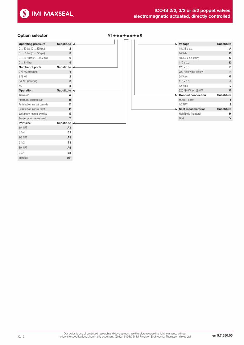
Y1˙˙˙˙˙˙˙˙SOption selector
Operating pressure Substitute
0 ... 20 bar (0 ... 290 psi) 2
0 ... 50 bar (0 ... 725 psi) 3
0 ... 207 bar (0 ... 3002 psi) 6
0 ... 414 bar 9
Number of ports Substitute
2 /2 NC (standard) 1
2 /2 NO 2
3/2 NC (universal) 3
5/2 5
Operation Substitute
Automatic A
Automatic latching lever B
Push button manual override C
Push button manual reset P
Jack screw manual override S
Tamper proof manual reset T
Port size Substitute
1/4 NPT A1
G 1/4 E1
1/2 NPT A3
G 1/2 E3
3/4 NPT A5
G 3/4 E5
Manifold KF
Voltage Substitute
18 /33 V d.c. A
24 V d.c. B
48 /50 V d.c. (50 V) C
110 V d.c. D
125 V d.c. E
220 /240 V d.c. (240 V) F
24 V a.c. G
110 V a.c. J
12 V d.c. L
220 /240 V a.c. (240 V) M
Conduit connection Substitute
M20 x 1.5 mm 1
1/2 NPT 2
Seat /seal material Substitute
High Nitrile (standard) H
FKM V
ICO4S 2/2, 3/2 or 5/2 poppet valves electromagnetic actuated, directly controlled
en 5.7.550.04
12/15Our policy is one of continued research and development. We therefore reserve the right to amend, without
notice, the specifications given in this document. (2012 - 5198c) © IMI Precision Engineering, Thompson Valves Ltd.
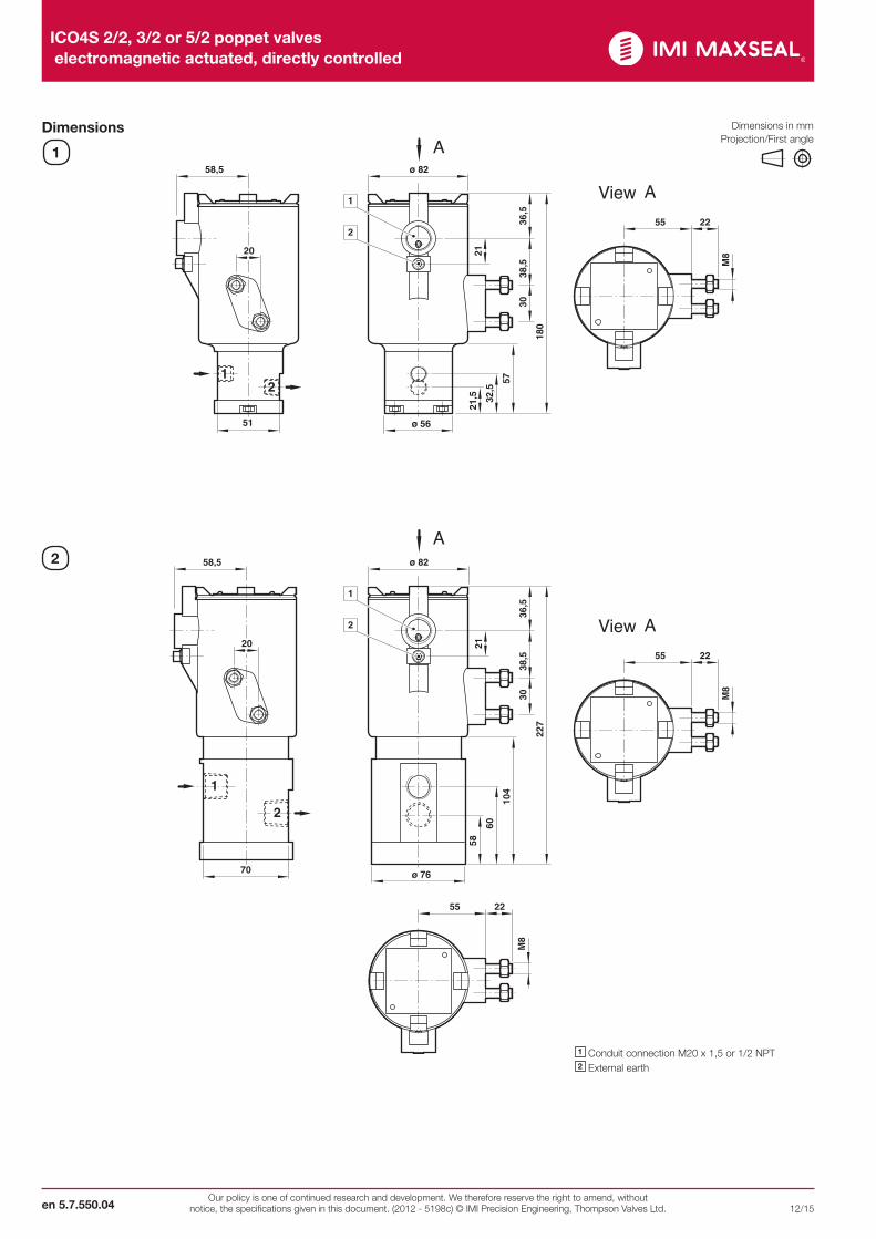
Dimensions
1
2
57
30
21
38,5
36,5
180
21,5 32
,5
51 ø 56
55 22
20
58,5 ø 82
1
2
12
M8
View
A
A
104
30
21
38,5
36,5
227
58
60
70 ø 76
55 22
20
58,5 ø 82
1
2
2
1
M8
55 22
M8
View A
A
1 Conduit connection M20 x 1,5 or 1/2 NPT2 External earth
Dimensions in mm Projection/First angle
ICO4S 2/2, 3/2 or 5/2 poppet valves electromagnetic actuated, directly controlled
en 5.7.550.0512/15Our policy is one of continued research and development. We therefore reserve the right to amend, without
notice, the specifications given in this document. (2012 - 5198c) © IMI Precision Engineering, Thompson Valves Ltd.
3
4
30
21
38,5
36,5
303
ø 35 ø76
20
58,5 ø 82
68
1
2
1
2
127
85
62
55 22
M8
View A
A
105
30
21
38,5
36,5
26
235
39
1
3
2
20
58,5 ø 82
57
60
74
30,5
70
1
2
55 22
M8
View A
A
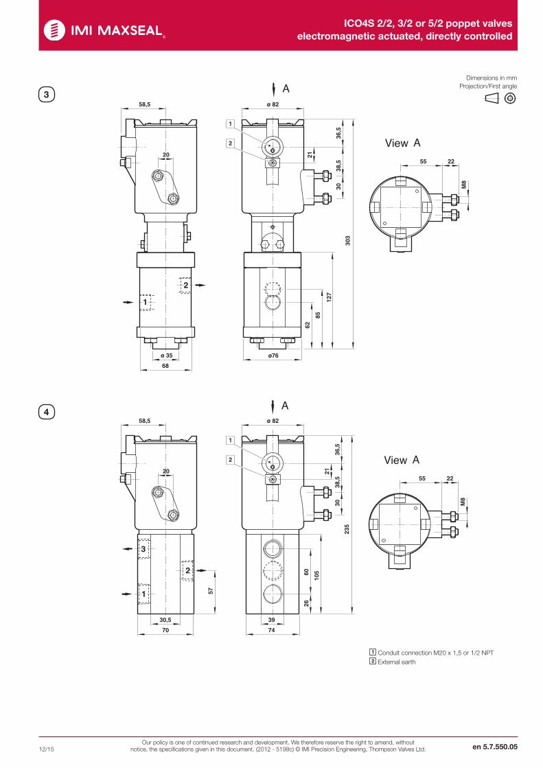
1 Conduit connection M20 x 1,5 or 1/2 NPT2 External earth
Dimensions in mm Projection/First angle
ICO4S 2/2, 3/2 or 5/2 poppet valves electromagnetic actuated, directly controlled
en 5.7.550.06
12/15Our policy is one of continued research and development. We therefore reserve the right to amend, without
notice, the specifications given in this document. (2012 - 5198c) © IMI Precision Engineering, Thompson Valves Ltd.
63
30
21
38,5
36,5
192
37
6,8
51
20
58,5 ø 82
17
51
38
1
2
55 22
M8
View A
A
1127
21
3
7730
21
38,5
36,5
200
1442 53
51
12
ø 57
20
58,5 ø 82
1
2
6
55 22M
8
View A
A
5
6
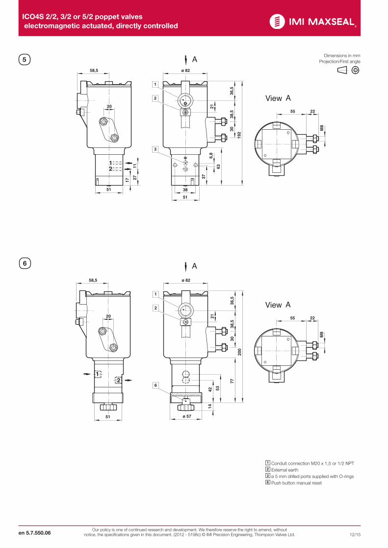
Dimensions in mm Projection/First angle
1 Conduit connection M20 x 1,5 or 1/2 NPT2 External earth3 ø 5 mm drilled ports supplied with O-rings6 Push button manual reset
ICO4S 2/2, 3/2 or 5/2 poppet valves electromagnetic actuated, directly controlled
en 5.7.550.0712/15Our policy is one of continued research and development. We therefore reserve the right to amend, without
notice, the specifications given in this document. (2012 - 5198c) © IMI Precision Engineering, Thompson Valves Ltd.
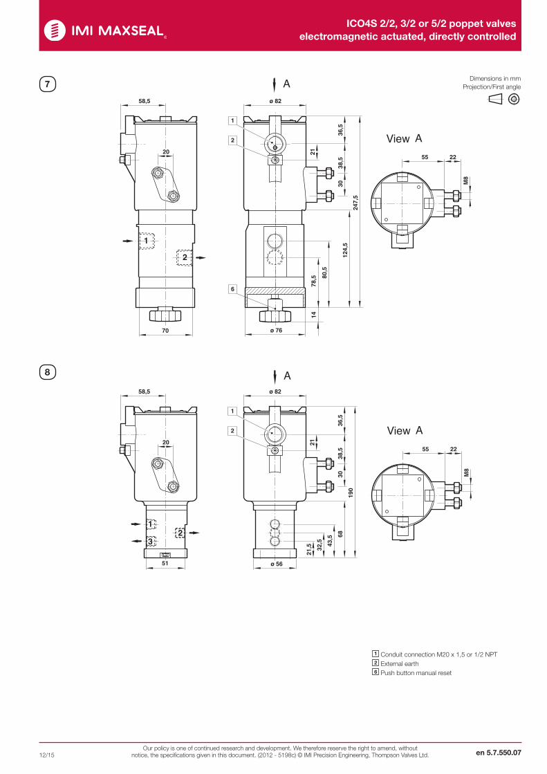
6830
21
38,5
36,5
190
21,5 32
,5 43,5
51
3
12
ø 56
20
58,5 ø 82
1
2
55 22
M8
View A
A
124,
530
21
38,5
36,5
247,
5
78,5 80
,570
1
2
ø 76
20
58,5 ø 82
14
1
2
6
55 22
M8
View A
A7
8
1 Conduit connection M20 x 1,5 or 1/2 NPT2 External earth6 Push button manual reset
Dimensions in mm Projection/First angle
ICO4S 2/2, 3/2 or 5/2 poppet valves electromagnetic actuated, directly controlled
en 5.7.550.08
12/15Our policy is one of continued research and development. We therefore reserve the right to amend, without
notice, the specifications given in this document. (2012 - 5198c) © IMI Precision Engineering, Thompson Valves Ltd.
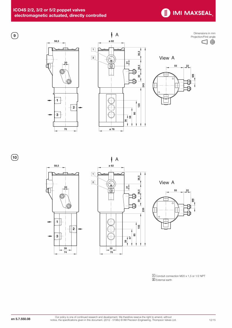
120
30
21
38,5
36,5
243
58
80
70
1
3
2
ø 76
20
58,5 ø 82
36
1
2
55 22
M8
View A
A
105
30
21
38,5
36,5
235
57
85
74
1
3
2
70
20
58,5 ø 82
26
39 30
1
2
55 22M
8
View A
A
9
10
1 Conduit connection M20 x 1,5 or 1/2 NPT2 External earth
Dimensions in mm Projection/First angle
ICO4S 2/2, 3/2 or 5/2 poppet valves electromagnetic actuated, directly controlled
en 5.7.550.0912/15Our policy is one of continued research and development. We therefore reserve the right to amend, without
notice, the specifications given in this document. (2012 - 5198c) © IMI Precision Engineering, Thompson Valves Ltd.
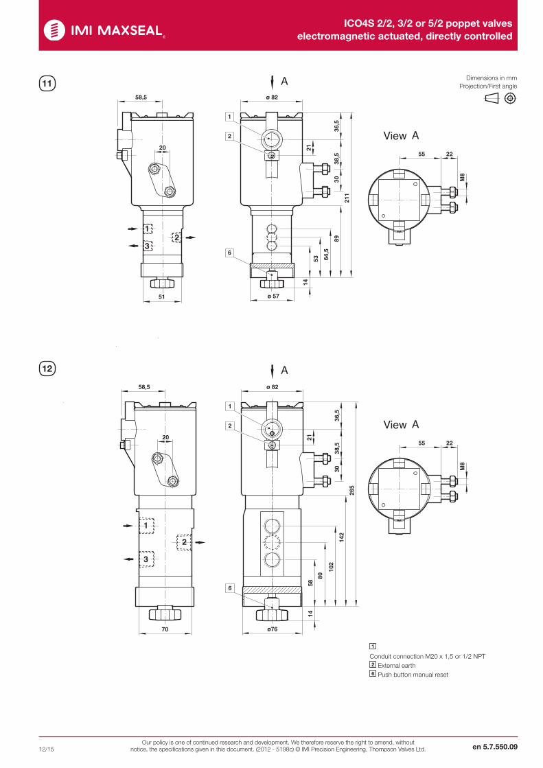
8930
21
38,5
36,5
211
14
53 64,5
51
3
12
ø 57
20
58,5 ø 82
1
2
6
55 22
M8
View A
A
142
30
21
38,5
36,5
265
80
102
70
1
3
2
ø76
20
58,5 ø 82
1458
1
2
6
55 22
M8
View A
A
11
12
1 Conduit connection M20 x 1,5 or 1/2 NPT2 External earth6 Push button manual reset
Dimensions in mm Projection/First angle
ICO4S 2/2, 3/2 or 5/2 poppet valves electromagnetic actuated, directly controlled
en 5.7.550.10
12/15Our policy is one of continued research and development. We therefore reserve the right to amend, without
notice, the specifications given in this document. (2012 - 5198c) © IMI Precision Engineering, Thompson Valves Ltd.
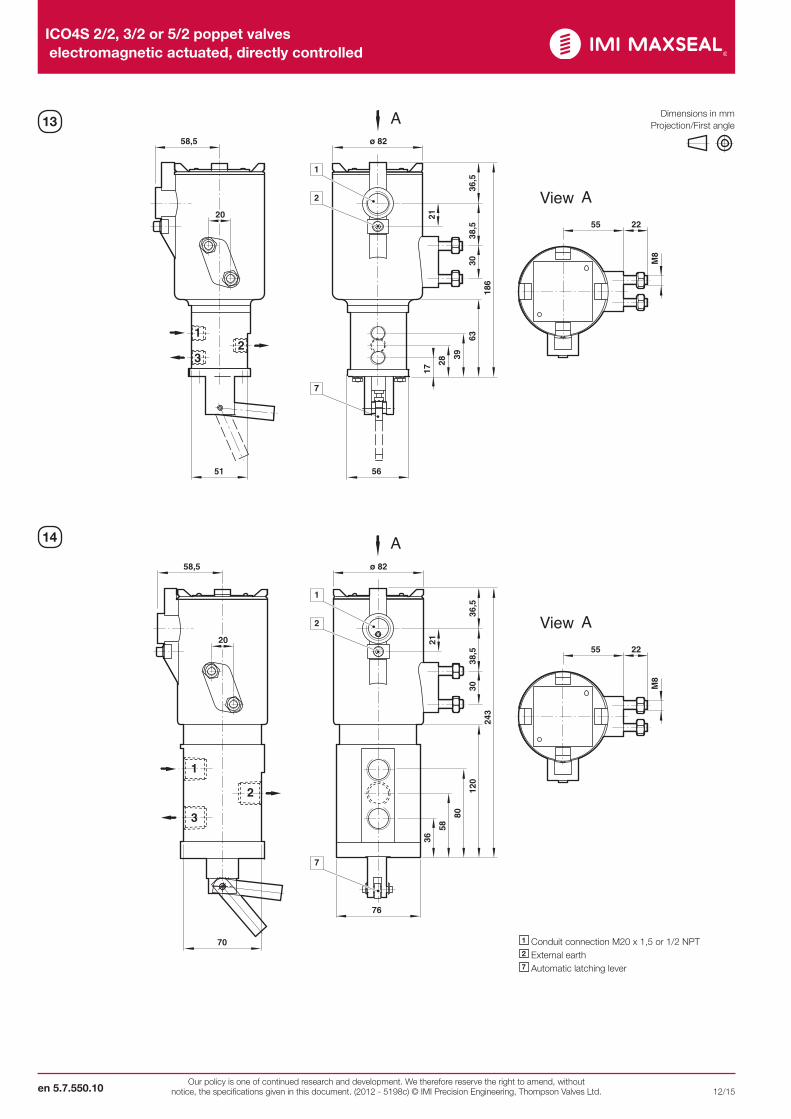
6330
21
38,5
36,5
186
17
28
393
12
5651
20
58,5 ø 82
1
2
7
55 22
M8
View A
A
120
30
21
38,5
36,5
243
58
80
70
1
3
2
76
20
58,5 ø 82
36
1
2
7
55 22M
8
View A
A
13
14
1 Conduit connection M20 x 1,5 or 1/2 NPT2 External earth7 Automatic latching lever
Dimensions in mm Projection/First angle

ICO4S 2/2, 3/2 or 5/2 poppet valves electromagnetic actuated, directly controlled
en 5.7.550.1112/15Our policy is one of continued research and development. We therefore reserve the right to amend, without
notice, the specifications given in this document. (2012 - 5198c) © IMI Precision Engineering, Thompson Valves Ltd.
8930
21
38,5
36,5
211
42 53 64,5
51
3
12
ø 57
20
58,5 ø 82
1
2
5
55 22
M8
View A
A
??
30
21
38,5
36,5
264
48
44
1
4
2
3
5
28,5
20
58,5 ø 82
4817
48
41
63,5
1
2
55 22
M8
View A
A
15
16
1 Conduit connection M20 x 1,5 or 1/2 NPT2 External earth5 Jack screw manual override
Dimensions in mm Projection/First angle
ICO4S 2/2, 3/2 or 5/2 poppet valves electromagnetic actuated, directly controlled
en 5.7.550.12
12/15Our policy is one of continued research and development. We therefore reserve the right to amend, without
notice, the specifications given in this document. (2012 - 5198c) © IMI Precision Engineering, Thompson Valves Ltd.
WarningThese products are intended for use in industrial compressed air systems only. Do not use these products where pressures and temperatures can exceed those listed under »Technical features/data«.Before using these products with fluids other than those specified, for non-industrial applications, life-support systems or other applications not within published specifications, consult IMI Precision Engineering, Thompson Valves Ltd.Through misuse, age, or malfunction, components used in fluid power systems can fail in various modes.
The system designer is warned to consider the failure modes of all component parts used in fluid power systems and to provide adequate safeguards to prevent personal injury or damage to equipment in the event of such failure.System designers must provide a warning to end users in the system instructional manual if protection against a failure mode cannot be adequately provided.System designers and end users are cautioned to review specificwarnings found in instruction sheets packed and shipped with these products. For further information please see Functional Safety Manual MI0560.