Embed Size (px)
Citation preview

Part of the MONIER GROUPCE ICS80/250 LIT DOC/CP3/58 July 2013
ICSINSTALLATION INSTRUCTIONS80 - 250mm Internal Diameter Twin Wall Insulated Chimney Systemfor gas, oil, wood and multi-fuel applications
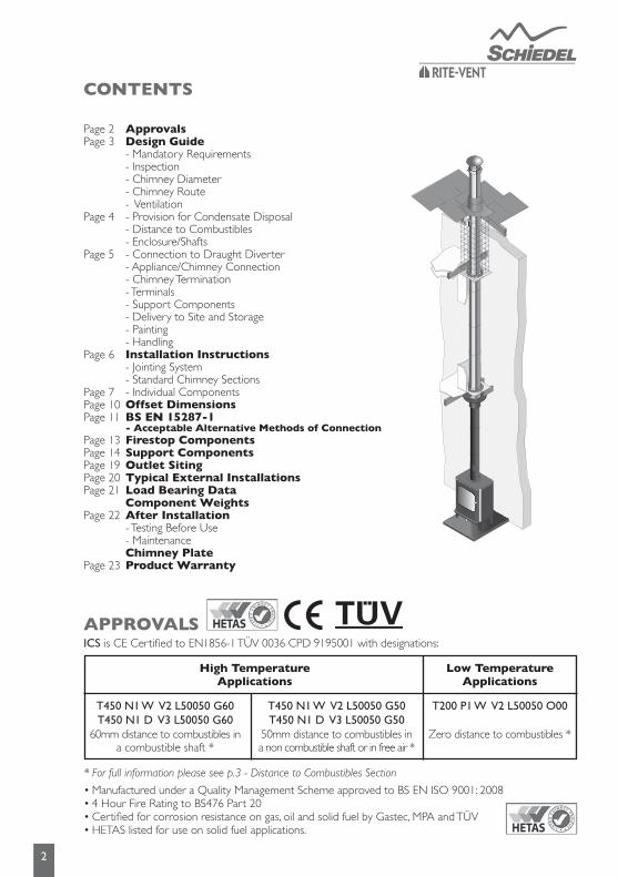
CONTENTS
APPROVALS
2
ICS is CE Certified to EN1856-1 TÜV 0036 CPD 9195001 with designations:
High Temperature Applications
Low Temperature Applications
T450 N1 W V2 L50050 G60T450 N1 D V3 L50050 G60
60mm distance to combustibles ina combustible shaft *
T450 N1 W V2 L50050 G50T450 N1 D V3 L50050 G50
50mm distance to combustibles ina non combustible shaft or in free air *
T200 P1 W V2 L50050 O00
Zero distance to combustibles *
* For full information please see p.3 - Distance to Combustibles Section
• Manufactured under a Quality Management Scheme approved to BS EN ISO 9001: 2008• 4 Hour Fire Rating to BS476 Part 20• Certified for corrosion resistance on gas, oil and solid fuel by Gastec, MPA and TÜV• HETAS listed for use on solid fuel applications.
ApprovalsDesign Guide- Mandatory Requirements- Inspection- Chimney Diameter- Chimney Route- Ventilation- Provision for Condensate Disposal- Distance to Combustibles- Enclosure/Shafts- Connection to Draught Diverter- Appliance/Chimney Connection- Chimney Termination- Terminals- Support Components- Delivery to Site and Storage- Painting- HandlingInstallation Instructions- Jointing System- Standard Chimney Sections- Individual ComponentsOffset DimensionsBS EN 15287-1 - Acceptable Alternative Methods of ConnectionFirestop ComponentsSupport ComponentsOutlet SitingTypical External InstallationsLoad Bearing DataComponent WeightsAfter Installation- Testing Before Use- MaintenanceChimney PlateProduct Warranty
Page 2Page 3
Page 4
Page 5
Page 6
Page 7Page 10Page 11
Page 13Page 14Page 19Page 20Page 21
Page 22
Page 23
DESIGN GUIDE
3
Mandatory RequirementsConnection to an appliance which is not connected to the fuel supply, may be carried out by a competent person. However, connection to an appliance that is connected to the fuel supply must be carried out by a GAS SAFE (gas) or OFTEC (oil) registered installer. We recommend the use of HETAS approved installers for solid fuel applications.
The design guide must be read in conjunction with the detailed component installation instructions. For full design and installation details the key referral documents are:
•BSEN1856-1: Chimneys - System Chimney Products•BSEN1859: Metal Chimneys - Testing Methods•BSEN1443: Chimneys - General Requirements•BSEN15287-1: Chimneys. Design, installation and commissioning of chimneys. Chimneys for non-room sealed heating appliances.•BS5440-1: Fluing and ventilation for gas appliances of rated input not exceeding 70kW net (1st, 2nd and 3rd family gases). Specification for installation of gas appliances to chimneys and for maintenance of chimneys.•ApprovedDocumentJ: - Combustion appliances and fuel storage systems (England & Wales)•DFPTechnicalBookletL: - Combustion appliances and fuel storage systems (NI)•TechnicalHandbook(Domestic&NonDomestic),Section3 - Environment (Scotland)•BSEN14241-1: Chimneys - Seals in flue liners.•ApplianceInstallationInstructions and related standards. Other standards covering specific applications will also be relevant and must be adhered to.
Planning permission for a System Chimney may be required, and reference should be made to the local Building Control Department.
InspectionTo conform to Building Regulations, provisions should be made to enable a chimney to be inspected and cleaned. An inspection length or an insulated 90˚ or 135˚ Tee can form a suitable inspection point (unless cleaning/inspection can be done through the appliance). To aid cleaning, sufficient distance should be left between changes of direction to permit the safe passage of cleaning brushes within the system. This is particularly important on solid fuel applications. It is recommended that chimneys serving solid fuel appliances be swept as frequently as necessary, but at least twice a year
Chimney DiameterThe chimney size should be as recommended by the appliance manufacturer. Where there is a requirement for a flue diameter smaller than the appliance spigot, then the operational requirements of the appliance and the configuration of the flue must satisfy the flue sizing requirements of EN13384-1 for single appliances, and EN13384-2 for multi appliances
Chimney RouteThe chimney should remain as straight as possible through its vertical run to assist flow. Should it be necessary to offset a chimney run then the following guidelines should be adhered to:
It is recommended that a vertical run of at least 600mm should be allowed immediately above the appliance prior to any change of direction. Within a system, on all fuels, there should be no more than 4 changes of direction of maximum 45˚. 90˚ Factory made bends or tees within the system may be treated as being equal to two 45˚ bends (as per Document J of the Building Regulations issued October 2010)
VentilationIt is very important that sufficient air for combustion and ventilation is provided to the room containing the appliance, to enable correct and efficient working of the appliance and chimney system. Reference should be made to the appliance manufacturer’s instructions and recommendations are also given in the Building Regulations Document J, CIBSE guidance notes and BS 5440.
Provision for Condensate Disposal (subject to appliance manufacturer recommendations)Condensing appliances need provision for drainage. Choose appropriate flue drainage components, normally fittedat the base of the stack and close to the appliance outlet. A 3° slope on horizontal runs must be maintained, usingthe appropriate 87° bend and 93° tee.
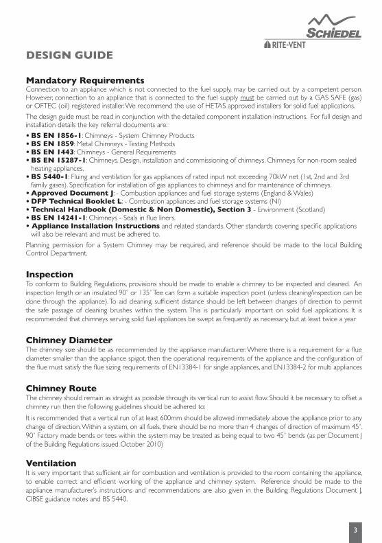
Distance to CombustiblesIn accordance with building regulations, it is essential that the correct distance to combustible material is maintained. On solid fuel applications, where there is a risk of soot fire, a distance of 60mmtocombustibles must be maintained within a combustiblefloor and within a combustible shaft (see Fig.1). There is no need toline the area within the floor cavity with plasterboard; however the ventilatedfirestopplate and ventilated support plate must be used.
On gas and oil applications, a distance of 50mmtocombustibles must be maintained within a combustible floor and within a combustible shaft. The ventilatedfirestopplate and ventilated support plate must be used.
Where the chimney penetrates a non combustible floor and where a non combustible shaft is used, a distance of 50mmtotheshaft is sufficient. In this case, nonventilatedfirestopplatesandsupportplates may be used with a ventilatedfirestop being used where the chimney penetrates into the roof space.
On bungalow applications where the chimney runs through either a combustible or non-combustible ceiling, an unventilated bungalow fire stop plate kit can be used. Please note that an unventilated support plate can not be used above the ceiling in this case. The weight of the chimney should be supported using the roof support (see p.12). Distance to combustibles must be respected within the ceiling space (see Fig. 2) and mesh frameshould be used within the loft space, which must be ventilated (see Fig. 2).
4
Enclosure/ShaftsWith the exception of the room containing the appliance, where the chimney passes through any part of the building, where there is a risk of accidental human contact, i.e a bedroom etc., or where there is a risk of contact with combustible materials stored in a cupboard or in the roof-space, the chimney must be enclosed in an appropriate way to meet Building Regulations. This can be achieved by boxing in the chimney in habitable rooms, or by the use of a protective wire mesh frame in roof spaces etc. In all cases the minimum distance to any combustible material, including loft insulation, must be respected according to the table on p.1, and any enclosure should be ventilated using the appropriate ventilated fire stops (see p.8).
Fig. 1Internal HouseCombustible Floors
Fig. 2InternalBungalow(VentilatedLoftSpace)Combustible and Non-Combustible Floors
RoofSupport

5
Connection to Draught DiverterWhere the appliance features a draught diverter the connection should rise vertically from it for at least 600mm before any change of direction (unless otherwise specified by the appliance manufacturer). This is in accordance with the recommendations contained in BS 5440 Part 1 section 4.1.5.
Appliance/Chimney ConnectionThis must be done by using the appropriate appliance connector. When a single wall connecting flue pipe is used to connect an appliance to the chimney, the lower end of the chimney section must extend a minimum of 425mm below the ceiling. When connecting the appliance to the flue pipe all joints between the flue pipes/appliance outlet must be securely caulked and sealed with non asbestos rope (or suitable alternative) and fire cement on solid fuel appliances and using the appropriate lip seal gasket in the case of condensing appliances.
Any flue pipe connection to the chimney MUST be made in the same room as the appliance.
Chimney Termination (refer to page14)Flue termination for solid fuel and oil are subject to EN15287-1.
Flue terminations for gas appliances up to 70kW are governed by BS5440-1 Section 4.2. The illustrations on page 14 give recommendations for the most common siting situations encountered. Adjacent taller structures may require increased height.
TerminalsAll terminals must be secured with the use of a locking band. On solid fuel appliances, an open termination is normally recommended. However in certain conditions, rain caps or anti-downdraught terminals may be used.
Rain caps and anti-downdraught terminals are available in two versions, with anti bird mesh and without mesh. Where a terminal with mesh is used, there is a risk of soot build up, and therefore regular cleaning is required to avoid blockage, particularly when using oil or solid fuel.
Support ComponentsThe weight of a chimney system is considerable and requires independent support. Minimal weight should be borne by the appliance. The weight of the chimney can be supported from floor level by using a base support plate, or floor support; from the wall by using wall support top plates together with side plates or cantilever brackets; or from first floor level by using a support plate and clamp fixed to the floor/ceiling joists.
Wall brackets are non load bearing and provide lateral support only. Refer to the load bearing tables on page 16for full details of maximum loadings.
Where the flue is freestanding above the roof and its height exceeds 1.5m above the last support or above the roof, a guy wire bracket must be used and every 1.5m thereafter in conjunction with guy wires or rigid stays (provided by others). Alternatively a height of up to 3m can be achieved unsupported using extended lockingbands at the joint immediately below the last support and on every joint above it.
Delivery to Site and StorageComponents should be carefully transported and off loaded. They should be inspected to ensure they have not been damaged, and should be stored off the ground and under cover so that they are protected from accidental damage and the adverse effects of weather.
PaintingIf painting of any external sections is required, it is important to de-grease, dry and prime the exterior surface prior to the application of appropriate heat resistant paint.
Schiedel Chimney Systems can provide to special order, chimney sections and accessories painted to an extensive range of British Standard RAL colours – details on application.
HandlingIt is advised that suitable PPE should be used when handling the products.
6
INSTALLATION INSTRUCTIONS
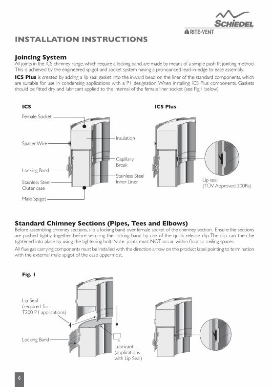
JointingSystem All joints in the ICS chimney range, which require a locking band, are made by means of a simple push fit jointing method. This is achieved by the engineered spigot and socket system having a pronounced lead-in-edge to ease assembly.
ICS Plus is created by adding a lip seal gasket into the inward bead on the liner of the standard components, which are suitable for use in condensing applications with a P1 designation. When installing ICS Plus components, Gaskets should be fitted dry and lubricant applied to the internal of the female liner socket (see Fig.1 below)
StandardChimneySections(Pipes,TeesandElbows)Before assembling chimney sections, slip a locking band over female socket of the chimney section. Ensure the sections are pushed tightly together, before securing the locking band by use of the quick release clip. The clip can then be tightened into place by using the tightening bolt. Note:-joints must NOT occur within floor or ceiling spaces.
All flue gas carrying components must be installed with the direction arrow on the product label pointing to termination with the external male spigot of the case uppermost.
ICS
Locking Band
Male Spigot
Stainless SteelOuter case
Spacer Wire
Female Socket
Insulation
CapillaryBreak
Stainless SteelInner Liner Lip seal
(TÜV Approved 200Pa)
ICS Plus
Fig. 1
Locking Band
Lip Seal (required for T200 P1 applications)
Lubricant(applications with Lip Seal)
7
LockingBand(supplied with each component with a female socket on the case)A locking band must be fitted to every joint in the system. The band is of stainless steel construction and is fitted with a quick release clip and a stainless steel tightening bolt.The bolt can be adjusted to ensure the joint is firmly secured.
StructuralLockingBandThe structural locking band, which is purchased separately, is used instead of a standard locking band in a situation where extra structural support is required, for instance where the chimney height is >1.5m above the last support or above the roof. It is also used to provide extra support in long horizontal runs. A maximum of 3m unsupported height can be achieved by fitting the structural locking band on the joint immediately below and on every joint above the last support. Please see diagram on page 16.
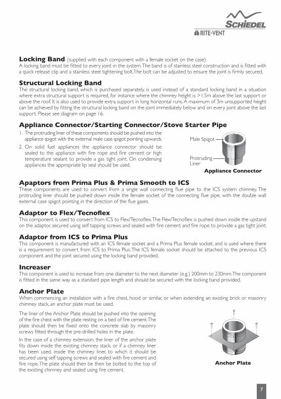
Appliance Connector/Starting Connector/Stove Starter Pipe
ApaptorsfromPrimaPlus&PrimaSmoothtoICSThese components are used to convert from a single wall connecting flue pipe to the ICS system chimney. The protruding liner should be pushed down inside the female socket of the connecting flue pipe, with the double wall external case spigot pointing in the direction of the flue gases.
AdaptortoFlex/TecnoflexThis component is used to convert from ICS to Flex/Tecnoflex. The Flex/Tecnoflex is pushed down inside the upstand on the adaptor, secured using self tapping screws and sealed with fire cement and fire rope to provide a gas tight joint.
Adaptor from ICS to Prima PlusThis component is manufactured with an ICS female socket and a Prima Plus female socket, and is used where there is a requirement to convert from ICS to Prima Plus. The ICS female socket should be attached to the previous ICS component and the joint secured using the locking band provided.
IncreaserThis component is used to increase from one diameter to the next diameter (e.g.) 200mm to 230mm. The componentis fitted in the same way as a standard pipe length and should be secured with the locking band provided.
Anchor PlateWhen commencing an installation with a fire chest, hood or similar, or when extending an existing brick or masonry chimney stack, an anchor plate must be used.
1.
2.
The protruding liner of these components should be pushed into the appliance spigot with the external male case spigot pointing upwards.
On solid fuel appliances the appliance connector should be sealed to the appliance with fire rope and fire cement or high temperature sealant to provide a gas tight joint. On condensing appliances the appropriate lip seal should be used.
The liner of the Anchor Plate should be pushed into the openingof the fire chest with the plate resting on a bed of fire cement. The plate should then be fixed onto the concrete slab by masonry screws fitted through the pre-drilled holes in the plate.
In the case of a chimney extension, the liner of the anchor plate fits down inside the existing chimney stack, or if a chimney liner has been used, inside the chimney liner, to which it should be secured using self tapping screws and sealed with fire cement and fire rope. The plate should then be then be bolted to the top of the existing chimney and sealed using fire cement.
Appliance Connector
Male Spigot
ProtrudingLiner
Anchor Plate

8
Adjustable PipeThe adjustable pipes are delivered as two pre-assembled sections with a joint band and locking band (see Fig.1).They are used with standard components to achieve an exact length on site and avoid on-site cutting of components.
1. Calculate the length required. Loosen the joint band and remove the top section of the adjustable pipe.
2. Remove insulation as required to achieve the correct length.
3. Re-assemble the pipe and cover the joint with the joint band.
4. Fix the adjusted section to standard components using the locking band provided.
Please note that the adjustable pipe is non load bearing.
InspectionLength(DrySystems)The inspection length is a component providing the facility for flue inspection and cleaning. It is installed as per a standard pipe section.
InspectionLength(CondensingSystems)The inspection length is a component providing the facility for flue inspection and cleaning on condensing or high efficiency appliances with a maximum flue gas temperature of 250°C, and a positive pressure rating of up to 200 Pa. It is installed as per a standard pipe section.
Inspection PipeThe Inspection pipe is a component which provides the facility to inspect the flue. It is installed as per a standard pipe section.
Measure PipeThe measure pipe is a component which provides access to the flue for draught testing or for flue gas analysis. It is installed as per a standard pipe section.
Vertical Drain PipeThis component is used on condensing systems and provides the facility to collect and drain off condensate from the chimney. It is installed in the same way as a standard pipe. It is provided as standard with a 3/4” BSP fitting.
Inspection Length(DrySystems)
Inspection Length(CondensingSystems)
Inspection Pipe
Fig. 1
Lip Seal x 2 ( T200 P1 applications only)
Insulation
Joint Band
Adjustable Pipe
JointBand
9
Elbowsand90˚InspectionElbowsFor offset information on standard elbows, please refer to p.9
Please note that 90° Inspection bends may be incorporated into a connecting flue pipe arrangement on all fuels, please refer to National Annex of BS EN 15387-1 for specific guidance re use on solid fuel applications, the diagrams on p.10-11 give guidance, and should be read in conjunction with the approved.
In cases of top mounted stoves, a minimum vertical height of 600mm from the appliance must be respected prior to any change of direction in the flue pipe.
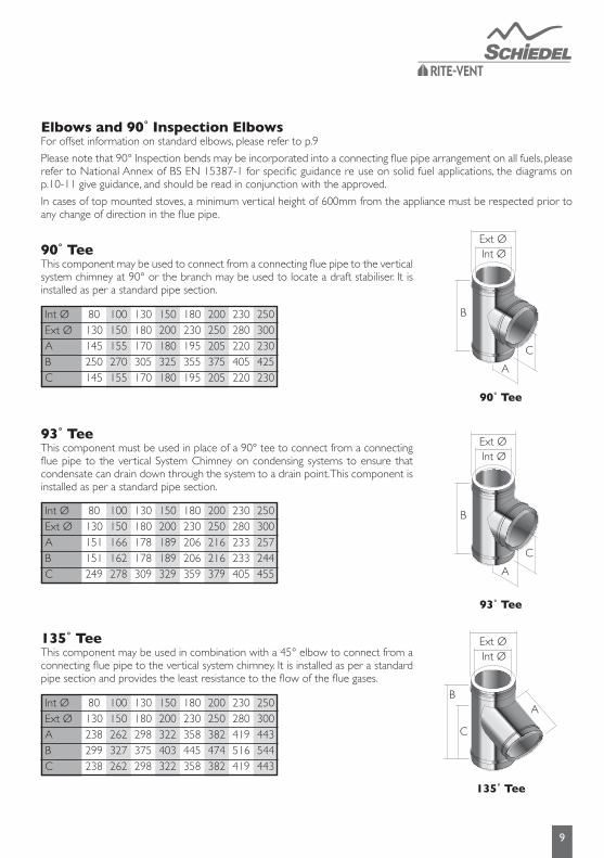
90˚TeeThis component may be used to connect from a connecting flue pipe to the vertical system chimney at 90° or the branch may be used to locate a draft stabiliser. It is installed as per a standard pipe section.
93˚TeeThis component must be used in place of a 90° tee to connect from a connecting flue pipe to the vertical System Chimney on condensing systems to ensure that condensate can drain down through the system to a drain point. This component is installed as per a standard pipe section.
135˚TeeThis component may be used in combination with a 45° elbow to connect from a connecting flue pipe to the vertical system chimney. It is installed as per a standard pipe section and provides the least resistance to the flow of the flue gases.
90˚Tee
93˚Tee
135˚Tee
Int ØExt ØABC
80130145250145
180230195355195
100150155270155
200250205375205
130180170305170
230280220405220
150200180325180
250300230425230
Int ØExt ØABC
80130151151249
180230206206359
100150166162278
200250216216379
130180178178309
230280233233405
150200189189329
250300257244455
Int ØExt ØABC
80130238299238
180230358445358
100150262327262
200250382474382
130180298375298
230280419516419
150200322403322
250300443544443
Ext Ø
B
C
A
Int Ø
Ext Ø
B
C
A
Int Ø
Ext Ø
B
C
A
Int Ø

10
OFFSET DIMENSIONS(made by assembling 2 bends)
Int ØAB
8029539
18031541
10029539
20031541
13029539
23031541
15029539
25033444
OffsetsforDouble15˚Bend
Int ØAB
8028075
18035595
10029980
200373100
13032788
230373100
15033690
250392105
OffsetsforDouble30˚Bend
Int ØAB
80307127
180376156
100324134
200393163
130341141
230427177
150358148
250427177
OffsetsforDouble45˚Bend
Int ØAB
80300300
180396396
100316316
200420420
130348348
230452452
150366366
250468468
OffsetsforDouble90˚Bend
Int ØAB
80343305
180452415
100370324
200496473
130437404
230523475
150445406
250537499
OffsetsforDoubleTee˚Bend&45˚Bend
B
A
BB
A A
Int Ø Int Ø Int Ø
BB
Eff Pipe
Eff Pi
peA
A
Int Ø
Int Ø mm
955 Eff APipe B455 Eff APipe B205 Eff APipe B150 Eff APipe B
8012182867351574939244579
18012382887551595139446581
10012182867351574939244579
20012382887551595139446581
13012182867351574939244579
23012382887551595139446581
15012182867351574939244579
25012572917741625329748484
Double15˚BendC/WPipeLength
Int Ø mm
955 Eff APipe B455 Eff APipe B205 Eff APipe B150 Eff APipe B
801107553674303458178414153
1801182573765323533198489173
1001126558693308477183433158
2001200578765328551203507178
1301154566721316505191461166
2301200578784328551203507178
1501163568709318514193470168
2501219583784333570208526183
Double30˚BendC/WPipeLength
Int Ø mm
955 Eff APipe B455 Eff APipe B205 Eff APipe B150 Eff APipe B
80982802629449452272417237
1801051831698478521301486266
100999809646456469279434244
2001068838715485538308503273
1301016816663463486286451251
2301102852749499572322537287
1501033823680470503293468258
2501102852749499572322537287
Double45˚BendC/WPipeLength
Int Ø mm
955 Eff APipe B455 Eff APipe B205 Eff APipe B150 Eff APipe B
80296
1251296751296501296446
180415
1370415870415620415565
100315
1270315770315520315466
200414
1369414869414619414564
130345
1300345800345550345495
230445
1400445900445650445595
150366
1321366821366571366516
250464
1419464919464669464614
Double90˚BendC/WPipeLength
11
BS EN 15287-1ACCEPTABLE ALTERNATIVE METHODS OF CONNECTION
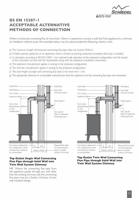
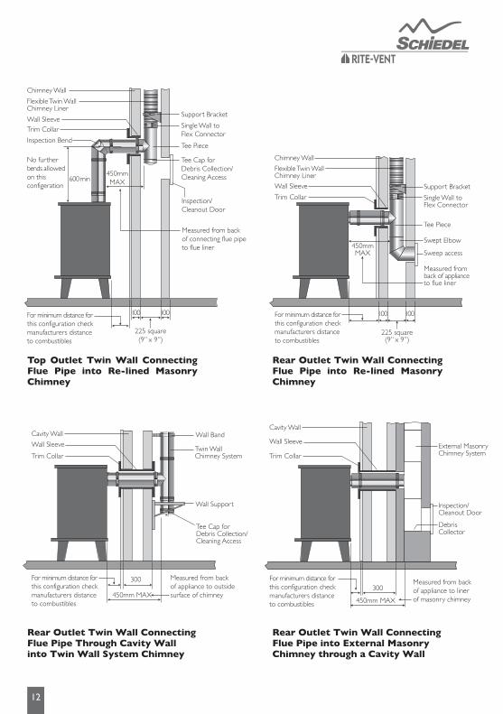
Where a horizontal connecting flue of more than 150mm is required to connect a solid fuel fired appliance to a chimney, an installation method as per the examples below may be used provided the following criteria is met:-
a)Themaximumlengthofhorizontalconnectingfluepipedoesnotexceed450mm;b)ADefraexemptapplianceoranappliance,whichislimitedtoburningauthorisedsmokelessfuelonly,isinstalled;c)AcalculationaccordingtoBSEN13384-1hasindicatedsafeoperationoftheproposedconfiguration,andtheresults ofthecalculationareleftwiththehouseholderalongwiththeapplianceinstallationinstructions;d)Theappliancemanufactureragreesinwritingtotheproposedconfiguration;e)Thechimneymanufactureragreesinwritingtotheproposedconfiguration;f) Thetotallengthofsinglewallconnectingfluepipeisnotmorethan1.5m;g)Theappropriatedistancestocombustiblematerialsfromboththeapplianceandtheconnectingfluepipearemaintained.
Top Outlet Single Wall Connecting Flue Pipe through Solid Wall into Twin Wall System Chimney
NB Where the connecting flue pipe from the appliance passes through any wall other than the existing chimney wall, the connecting flue pipe must be a System Chimney of twin wall insulated design.
Top Outlet Twin Wall Connecting Flue Pipe through Solid Wall into Twin Wall System Chimney
For minimum distance for this configuration check manufacturers distanceto combustibles
Measured from back of appliance to outside surface of chimney
Measured from back of appliance to liner of masonry chimney
Twin Wall Chimney System
300
Wall Support
Tee Cap forDebris Collection/Cleaning Access
Wall Sleeve
Trim Collar
Cavity Wall Wall Band
450mm MAX300
450mm MAX
External Masonry Chimney System
Inspection/Cleanout Door
Cavity Wall
Wall Sleeve
Trim Collar
DebrisCollector
Wall Sleeve
Trim Collar
100100
225 square(9” x 9”)
Flexible Twin Wall Chimney Liner
Chimney Wall
Support Bracket
Swept Elbow
Sweep access
Tee Piece
Single Wall to Flex Connector
450mmMAX
Measured from back of appliance to flue liner
Wall Support
Measured from back of connecting flue pipe to outside surface of chimney
Tee Cap forDebris Collection/Cleaning Access
Twin Wall Chimney System
Solid Wall
Inspection Bend
Wall Sleeve
Trim Collar
600 min
225For minimum distance for this configuration check manufacturers distanceto combustibles
No further bends allowed on this configeration
Wall Band
450mm MAX
Measured from back of connecting flue pipe to outside surface of chimney
Tee Cap forDebris Collection/Cleaning Access
Twin Wall Chimney System
Solid Wall
Inspection Bend
Wall Sleeve
Trim Collar
225
Wall Support
Wall Band
450mm MAX
600 min
For minimum distance for this configuration check manufacturers distanceto combustibles
No further bends allowed on this configeration
Flexible Twin Wall Chimney Liner
Inspection/Cleanout Door
Inspection Bend
Wall SleeveTrim Collar
Chimney Wall
Support Bracket
Tee Piece
Tee Cap forDebris Collection/Cleaning Access
Single Wall to Flex Connector
225 square(9” x 9”)
450mmMAX
For minimum distance for this configuration check manufacturers distanceto combustibles
For minimum distance for this configuration check manufacturers distanceto combustibles
For minimum distance for this configuration check manufacturers distanceto combustibles
Measured from back of connecting flue pipe to flue liner
No further bends allowed on this configeration
600 min
100100
12
Top Outlet Twin Wall Connecting Flue Pipe into Re-lined Masonry Chimney
Rear Outlet Twin Wall Connecting Flue Pipe Through Cavity Wall into Twin Wall System Chimney
Rear Outlet Twin Wall Connecting Flue Pipe into Re-lined Masonry Chimney
Rear Outlet Twin Wall Connecting Flue Pipe into External Masonry Chimney through a Cavity Wall
For minimum distance for this configuration check manufacturers distanceto combustibles
Measured from back of appliance to outside surface of chimney
Measured from back of appliance to liner of masonry chimney
Twin Wall Chimney System
300
Wall Support
Tee Cap forDebris Collection/Cleaning Access
Wall Sleeve
Trim Collar
Cavity Wall Wall Band
450mm MAX300
450mm MAX
External Masonry Chimney System
Inspection/Cleanout Door
Cavity Wall
Wall Sleeve
Trim Collar
DebrisCollector
Wall Sleeve
Trim Collar
100100
225 square(9” x 9”)
Flexible Twin Wall Chimney Liner
Chimney Wall
Support Bracket
Swept Elbow
Sweep access
Tee Piece
Single Wall to Flex Connector
450mmMAX
Measured from back of appliance to flue liner
Wall Support
Measured from back of connecting flue pipe to outside surface of chimney
Tee Cap forDebris Collection/Cleaning Access
Twin Wall Chimney System
Solid Wall
Inspection Bend
Wall Sleeve
Trim Collar
600 min
225For minimum distance for this configuration check manufacturers distanceto combustibles
No further bends allowed on this configeration
Wall Band
450mm MAX
Measured from back of connecting flue pipe to outside surface of chimney
Tee Cap forDebris Collection/Cleaning Access
Twin Wall Chimney System
Solid Wall
Inspection Bend
Wall Sleeve
Trim Collar
225
Wall Support
Wall Band
450mm MAX
600 min
For minimum distance for this configuration check manufacturers distanceto combustibles
No further bends allowed on this configeration
Flexible Twin Wall Chimney Liner
Inspection/Cleanout Door
Inspection Bend
Wall SleeveTrim Collar
Chimney Wall
Support Bracket
Tee Piece
Tee Cap forDebris Collection/Cleaning Access
Single Wall to Flex Connector
225 square(9” x 9”)
450mmMAX
For minimum distance for this configuration check manufacturers distanceto combustibles
For minimum distance for this configuration check manufacturers distanceto combustibles
For minimum distance for this configuration check manufacturers distanceto combustibles
Measured from back of connecting flue pipe to flue liner
No further bends allowed on this configeration
600 min
100100
For minimum distance for this configuration check manufacturers distanceto combustibles
Measured from back of appliance to outside surface of chimney
Measured from back of appliance to liner of masonry chimney
Twin Wall Chimney System
300
Wall Support
Tee Cap forDebris Collection/Cleaning Access
Wall Sleeve
Trim Collar
Cavity Wall Wall Band
450mm MAX300
450mm MAX
External Masonry Chimney System
Inspection/Cleanout Door
Cavity Wall
Wall Sleeve
Trim Collar
DebrisCollector
Wall Sleeve
Trim Collar
100100
225 square(9” x 9”)
Flexible Twin Wall Chimney Liner
Chimney Wall
Support Bracket
Swept Elbow
Sweep access
Tee Piece
Single Wall to Flex Connector
450mmMAX
Measured from back of appliance to flue liner
Wall Support
Measured from back of connecting flue pipe to outside surface of chimney
Tee Cap forDebris Collection/Cleaning Access
Twin Wall Chimney System
Solid Wall
Inspection Bend
Wall Sleeve
Trim Collar
600 min
225For minimum distance for this configuration check manufacturers distanceto combustibles
No further bends allowed on this configeration
Wall Band
450mm MAX
Measured from back of connecting flue pipe to outside surface of chimney
Tee Cap forDebris Collection/Cleaning Access
Twin Wall Chimney System
Solid Wall
Inspection Bend
Wall Sleeve
Trim Collar
225
Wall Support
Wall Band
450mm MAX
600 min
For minimum distance for this configuration check manufacturers distanceto combustibles
No further bends allowed on this configeration
Flexible Twin Wall Chimney Liner
Inspection/Cleanout Door
Inspection Bend
Wall SleeveTrim Collar
Chimney Wall
Support Bracket
Tee Piece
Tee Cap forDebris Collection/Cleaning Access
Single Wall to Flex Connector
225 square(9” x 9”)
450mmMAX
For minimum distance for this configuration check manufacturers distanceto combustibles
For minimum distance for this configuration check manufacturers distanceto combustibles
For minimum distance for this configuration check manufacturers distanceto combustibles
Measured from back of connecting flue pipe to flue liner
No further bends allowed on this configeration
600 min
100100

13
FIRESTOP COMPONENTS
Ventilated Support Plate (Galvanised with S/S Band)The support plate is used where the chimney passes through a combustible floor, and the weight of the chimney has to be taken at floor level. The support plate must be firmly fixed by using bolts or screws. For load bearing Data refer to tables 1 and 2 on page 14.
1. Frame a four sided level square opening within the joists using timber stringers where necessary to allow for the correct distance to combustibles from the outer wall of the chimney. This distance must be a minimum of 50mm on Gas and Oil applications and 60mm for solid fuel applications (see Fig. 3 below - distance x).
2. Lower the chimney section through the opening in the floor, and secure to the next section of pipe.
3. Locate the two halves of the support plates around the chimney section, and secure to the joists using screws or bolts.
4. Remove the screws which are fastened to the clamp band. Then fasten clamp band around the chimney section and position on top of the plate. Tighten using the nuts and bolts provided.
5. Using the holes in the clamp support ring drill 3mm holes in the outer casing of the chimney section (drill bit should be set for a depth no greater than 10mm to avoid damage to the liner).
6. Using the screws provided secure the clamp support ring to the outer casing of the chimney section.
Note:JointsmustNOToccurwithinthefloororceilingjoists.
VentilatedFirestop Plate
Non-VentilatedBungalow Firestop
Fig.3Fig. 2 Fig.4
Ventilated Firestop Plate (1 & 2-Piece Round and 2-Piece Rectangular)The ventilated fire stop plates are used in combination with standard ICS pipes where the chimney passes through a combustible floor or ceiling. The outermost circle of ventilation slots gives a distance to combustibles of 60mm. This measures the required distance for solid fuel applications. For gas and oil applications a minimum of 50mm is required, which should be measured on site. The fire stop plate should be positioned around the chimney and fastened to the pre-cut plasterboard or to the timber frame with nails or screws using the location holes provided (see Fig. 2 above).
Non-Ventilated Bungalow Firestop (1 & 2-Piece Round and 1-Piece Rectangular)Installed as per a ventilated firestop using the ventilation holes provided (see Fig.4 above). Distance to combustibles must be respected - see p.3 for further info.
Support Plate with S/S Clamp Band (Non Combustible Floor)The support plate is used where the chimney passes through a non combustible floor, and the weight of the chimney has to be taken at floor level. The support plate must be firmly fixed to the floor using bolts or screws provided by others. For load bearing Data refer to table on page 17.
Fire stop Plate (Non Combustible Floor)This fire stop plate is used exclusively where the chimney passes through a non combustible floor. The two halves of the plate are located around the chimney section and fastened to the floor using bolts or screws provided by others.
14
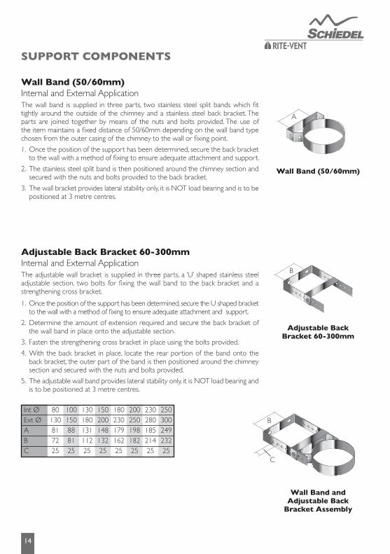
WallBand(50/60mm)Internal and External ApplicationThe wall band is supplied in three parts, two stainless steel split bands which fit tightly around the outside of the chimney and a stainless steel back bracket. The parts are joined together by means of the nuts and bolts provided. The use of the item maintains a fixed distance of 50/60mm depending on the wall band type chosen from the outer casing of the chimney to the wall or fixing point.
1. Once the position of the support has been determined, secure the back bracket to the wall with a method of fixing to ensure adequate attachment and support.
2. The stainless steel split band is then positioned around the chimney section and secured with the nuts and bolts provided to the back bracket.
3. The wall bracket provides lateral stability only, it is NOT load bearing and is to be positioned at 3 metre centres.
AdjustableBackBracket60-300mmInternal and External ApplicationThe adjustable wall bracket is supplied in three parts, a ‘U’ shaped stainless steel adjustable section, two bolts for fixing the wall band to the back bracket and a strengthening cross bracket.
WallBand(50/60mm)
AdjustableBackBracket60-300mm
Wall Band and AdjustableBackBracketAssembly
Once the position of the support has been determined, secure the U shaped bracket to the wall with a method of fixing to ensure adequate attachment and support.
Determine the amount of extension required and secure the back bracket of the wall band in place onto the adjustable section.
Fasten the strengthening cross bracket in place using the bolts provided.
With the back bracket in place, locate the rear portion of the band onto the back bracket, the outer part of the band is then positioned around the chimney section and secured with the nuts and bolts provided.
The adjustable wall band provides lateral stability only, it is NOT load bearing and is to be positioned at 3 metre centres.
1.
2.
3.
4.
5.
Int ØExt ØABC
80130817225
18023017916225
100150888125
20025019818225
13018013111225
23028018521425
15020014813225
25030024923225
B
A
B
C
SUPPORT COMPONENTS
15
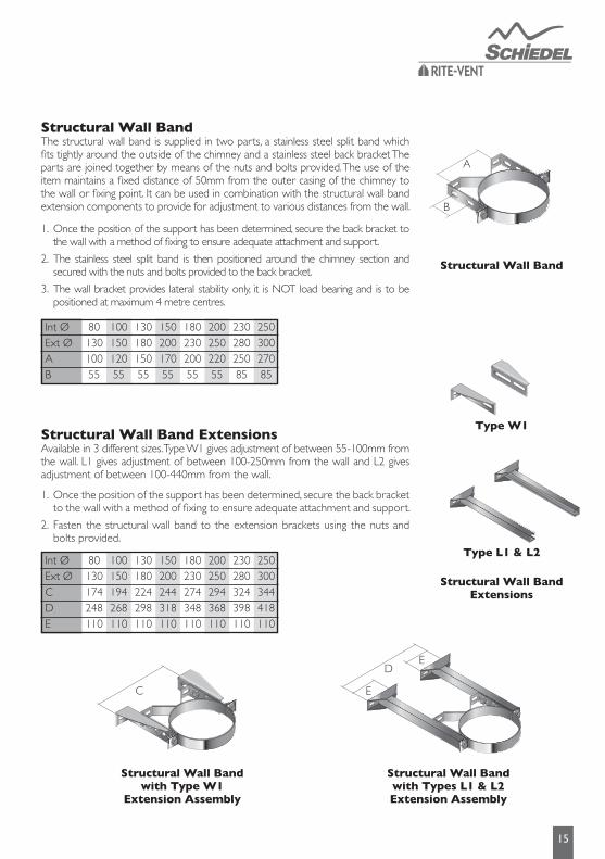
Structural Wall BandThe structural wall band is supplied in two parts, a stainless steel split band which fits tightly around the outside of the chimney and a stainless steel back bracket The parts are joined together by means of the nuts and bolts provided. The use of the item maintains a fixed distance of 50mm from the outer casing of the chimney to the wall or fixing point. It can be used in combination with the structural wall band extension components to provide for adjustment to various distances from the wall.
Structural Wall Band ExtensionsAvailable in 3 different sizes. Type W1 gives adjustment of between 55-100mm from the wall. L1 gives adjustment of between 100-250mm from the wall and L2 gives adjustment of between 100-440mm from the wall.
Once the position of the support has been determined, secure the back bracket to the wall with a method of fixing to ensure adequate attachment and support.
The stainless steel split band is then positioned around the chimney section and secured with the nuts and bolts provided to the back bracket.
The wall bracket provides lateral stability only, it is NOT load bearing and is to be positioned at maximum 4 metre centres.
1.
2.
3.
Once the position of the support has been determined, secure the back bracket to the wall with a method of fixing to ensure adequate attachment and support.
Fasten the structural wall band to the extension brackets using the nuts and bolts provided.
1.
2.
Int ØExt ØAB
8013010055
18023020055
10015012055
20025022055
13018015055
23028025085
15020017055
25030027085
Structural Wall Band
Structural Wall Band with Type W1
Extension Assembly
Structural Wall BandwithTypesL1&L2Extension Assembly
B
A
Type W1
TypeL1&L2
Structural Wall BandExtensions
C E
ED
Int ØExt ØCDE
80130174248110
180230274348110
100150194268110
200250294368110
130180224298110
230280324398110
150200244318110
250300344418110
16
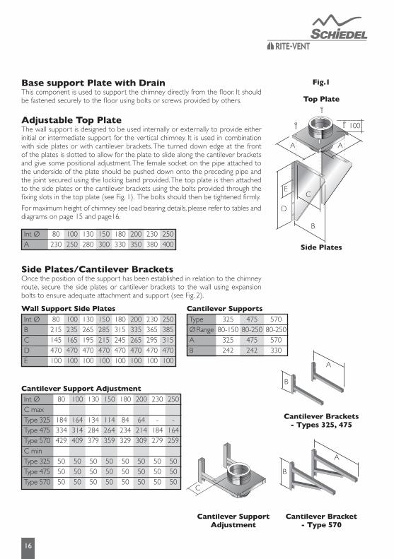
Base support Plate with DrainThis component is used to support the chimney directly from the floor. It should be fastened securely to the floor using bolts or screws provided by others.
Adjustable Top PlateThe wall support is designed to be used internally or externally to provide either initial or intermediate support for the vertical chimney. It is used in combination with side plates or with cantilever brackets. The turned down edge at the front of the plates is slotted to allow for the plate to slide along the cantilever brackets and give some positional adjustment. The female socket on the pipe attached to the underside of the plate should be pushed down onto the preceding pipe and the joint secured using the locking band provided. The top plate is then attached to the side plates or the cantilever brackets using the bolts provided through the fixing slots in the top plate (see Fig. 1). The bolts should then be tightened firmly.
For maximum height of chimney see load bearing details, please refer to tables and diagrams on page 15 and page16.
SidePlates/CantileverBracketsOnce the position of the support has been established in relation to the chimney route, secure the side plates or cantilever brackets to the wall using expansion bolts to ensure adequate attachment and support (see Fig. 2).
Fig.1
Top Plate
Side Plates
Int ØA
80230
180330
100250
200350
130280
230380
150300
250400
Wall Support Side PlatesInt ØBCDE
80215145470100
180315245470100
100235165470100
200335265470100
130265195470100
230365295470100
150285215470100
250385315470100
Cantilever Support AdjustmentInt ØC maxType 325Type 475Type 570C minType 325Type 475Type 570
80
184334429
505050
180
84234329
505050
100
164314409
505050
200
64214309
505050
130
134284379
505050
230
-184279
505050
150
114264359
505050
250
-164259
505050
Cantilever SupportsTypeØ RangeAB
32580-150
325242
47580-250
475242
57080-250
570330
CantileverBracket-Type570
Cantilever SupportAdjustment
CantileverBrackets- Types325,475
C
E
D
C
B
A A
100
A
B
A
B

17
Roof SupportThe roof support is supplied as a kit complete with two side plates for fixing to the roof trusses, a band to give lateral support to the chimney as it passes through the roof, and 3 self tapping screws, which are secured to the chimney through the band to give a load bearing capacity. When the plates are installed above the roof trusses as in Fig.1 the maximum number of pipes, which may be suspended from the roof support is 6 x 1m pipes. When the plates are attached below the trusses as in Fig.2 the maximum number of pipes, which may be suspended is 4 x 1m pipes.
The band should be lowered down over the top of the ICS pipe, and positioned so that the the side plates are resting on top of the roof trusses as in Fig.1 or below the roof trusses in the case of Fig. 2 . The recommended position is always as per Fig.1 where circumstances allow this solution.
The band should then be tightened using the nut and bolt provided.
Using the holes pre-drilled in the roof support band, drill 3mm holes in the outer case of the chimney section (drill bit should be set for a depth no greater than 10mm to avoid any damage to the liner of the chimney)
Use the self tapping screws provided to secure the clamp band to the outer casing of the chimney section.
1.
2.
3.
4.
Please note: It is the responsibility of the installer to ensure that the joist to which the roof support is being attached is load bearing and capable of withstanding the weight of the system being installed.
GuyWireBracketThis component should be used to secure unsupported chimney sections aboveroof level. Guy wires or preferably rigid stays (supplied by others) must be fixed to the bracket and secured to suitable anchorage points to ensure that the chimneysections are stable.
A maximum chimney height of 1.5 metres from the last support, or from the roof is permitted. Additional height requirements MUST be supported at 1.5 metre intervals using the guy wire bracket as specified above.
Ceiling HangerThis accessory is designed to support horizontal runs of the chimney from the roof or ceiling and offers adjustment from 130mm to 1115mm.
Once the position of the ceiling support has been determined, the section length of uni-rax channel must be securely fixed to the roof or the ceiling using a method of attachment to ensure adequate attachment and support.
All items are assembled as shown to attach the length of studding to the channel.
Attach the stud connector to the length of studding and connect the eye bolt to the connector.
Position the split band around the chimney section and secure to the eye bolt using the nut/bolt provided.
Maximum support spacing to be no more than 1.5 metres.
1.
2.
3.
4.
5.
GuyWireBracket
Ceiling Hanger
Guy Wire
Rigid Stay
Fig.1
Fig.2
1.5 metresmaximum
18
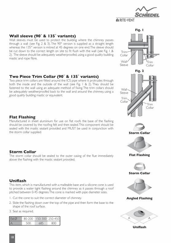
Wallsleeve(90˚&135˚variants)Wall sleeves must be used to protect the building where the chimney passes through a wall (see Fig. 2 & 3). The 90° version is supplied as a straight length whereas the 135° version is mitred at 45 degrees on one end. The sleeve should be cut down to the correct length on site to fit flush with the wall (see Fig. 1 & 2). The sleeve should be adequately weatherproofed, using a good quality building mastic and rope fibre.
TwoPieceTrimCollar(90˚&135˚variants)Two piece trim collars are fitted around the ICS pipe where it protrudes through both the inside and the outside of the wall (see Fig. 1 & 2). They should be fastened to the wall using an adequate method of fixing. The trim collars should be adequately weatherproofed back to the wall and around the chimney, using a good quality building mastic or equivalent.
Flat FlashingManufactured in sheet aluminium for use on flat roofs the base of the flashing should be covered by the roofing felt and then sealed. This component should be sealed with the mastic sealant provided and MUST be used in conjunction with the storm collar supplied.
Storm CollarThe storm collar should be sealed to the outer casing of the flue immediately above the flashing with the mastic sealant provided.
Uniflash
UniflashThis item, which is manufactured with a malleable base and a silicone cone is used to provide a water tight flashing around the chimney as it passes through a roof pitched between 0-45 degrees. The cone is marked with pipe diameter sizes.
Cut the cone to suit the correct diameter of chimney.
Slide the flashing down over the top of the pipe and then form the base to the shape of the roof surface.
Seal as required.
1.
2.
3.
Ext ØA
80-200500
150-300685
250-450800
A A
Flat Flashing
Storm Collar
Storm Collar
Angled Flashing
Fig. 1
Fig. 2
TrimCollar
WallSleeve
TrimCollar
TrimCollar
WallSleeve
TrimCollar

TerminalsTerminals are supplied complete with a locking band. Once the terminal has been pushed into place, the adjustment bolt on the locking band clip should be tightened to ensure that the terminal is properly secured to the previous pipe.
Flue terminations for solid fuel & oil are subject to EN15287-1 2007. Figures A and B illustrate recommendations for the most commonly encountered outlet terminations. Flue terminations for gas in domestic situations are governed by the BS5440-1 2008 Section 4.2. Figure C illustrates recommendations for the most common siting situations encountered. Adjacent taller structures may require increased height. The minimum flue projection through the roof is 600mm to the underside of the terminal.
Fig. AOutlet siting forOil Appliances(<45kW)
Fig. BOutlet siting forSolid Fuel Appliances(<50kW)
Fig. CBS 5440-1Outlet siting forGas Appliances(<70kW)
The weather surface is the building external surface, such as its roof, tiles or external walls.A flat roof has a pitch less than 10˚.The clearance for A or B, as appropriate, will also apply.A vertical flue fixed to an outside wall should be treated as equivalent to an inside flue emerging at the nearest edge of the roof.
1.
2.3.4.
TaperedTerminal
Raincap Anti Splash Terminal
Point where flue passes throughweather surface (Notes 1, 2) Clearance to flue outlet
At or within 600mm of the ridgeElsewhere on the roof(whether pitched or flat)
Below (on a pitched roof) or within 2300mm horizontally to an openable rooflight, dormer window or other opening (Note 3)Within 2300mm of an adjoining or adjacent building, whether or not beyond the boundary (Note 3)
At or within 600mm above the ridgeAt least 2300mm horizontally from the nearest point on the weather surface and:a) at least 1000mm above the highest point of intersection of the chimney and the weather surface; orb) at least as high as the ridgeAt least 1000mm above the top of the opening
At least 600mm above any part of the adjacent building within 2300mm
AB
C
D
OutletsitingforSolidFuelAppliances(<50kW)
OutletsitingforOilAppliances(<45kW)Locationof outlet
PressureJetBurner
VapourisingBurner
Above the highest point of an intersectionwith the roofFrom a structure to the side of the terminalAbove a vertical structure which is less than 750mm (pressure jet burner) or 2300mm (vapourising burner) horizontally from the side of the terminalFrom a ridge terminal to a vertical structure on the roof
600mm
750mm600mm
1500mm
1000mm
2300mm1000mm
Should not be used
M
NO
P
19
P
O
N
M
A
D
B C
A 600mmmin
600mmmin
less than600mm
1500
1500
600 min Chimney shouldnot penetrate within the shaded area
600
6002000
P
O
N
M
A
D
B C
A 600mmmin
600mmmin
less than600mm
1500
1500
600 min Chimney shouldnot penetrate within the shaded area
600
6002000
P
O
N
M
A
D
B C
A 600mmmin
600mmmin
less than600mm
1500
1500
600 min Chimney shouldnot penetrate within the shaded area
600
6002000
OUTLET SITING
20
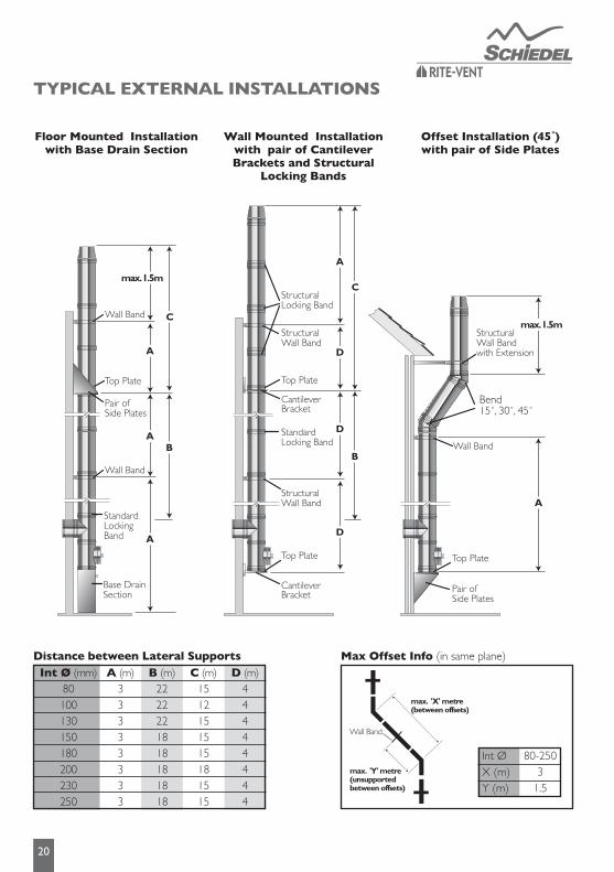
TYPICAL EXTERNAL INSTALLATIONS
Floor Mounted Installation with Base Drain Section
Wall Mounted Installation with pair of Cantilever BracketsandStructural
LockingBands
OffsetInstallation(45˚)with pair of Side Plates
Distance between Lateral SupportsInt Ø (mm)
80100130150180200230250
A (m)33333333
B (m)2222221818181818
C (m)1512151515181515
D (m)44444444
Max Offset Info (in same plane)
Int ØX (m)Y (m)
80-2503
1.5
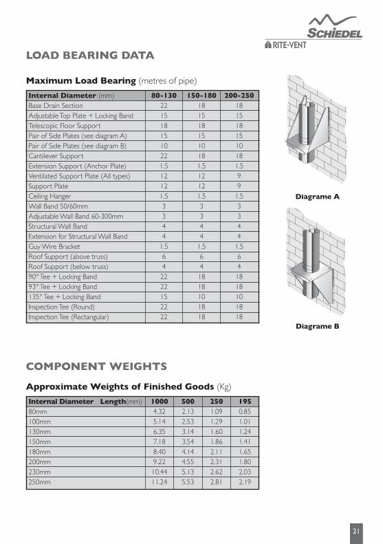
Maximum Load Bearing (metres of pipe)
21
LOAD BEARING DATA
COMPONENT WEIGHTS
Diagrame B
Diagrame A
Approximate Weights of Finished Goods (Kg)
Internal Diameter Length(mm)80mm100mm130mm150mm180mm200mm230mm250mm
10004.325.146.357.188.409.2210.4411.24
5002.132.533.143.544.144.555.135.53
2501.091.291.601.862.112.312.622.81
1950.851.011.241.411.651.802.032.19
Internal Diameter (mm)Base Drain SectionAdjustable Top Plate + Locking BandTelescopic Floor SupportPair of Side Plates (see diagram A)Pair of Side Plates (see diagram B)Cantilever SupportExtension Support (Anchor Plate)Ventilated Support Plate (All types)Support PlateCeiling HangerWall Band 50/60mmAdjustable Wall Band 60-300mmStructural Wall BandExtension for Structural Wall BandGuy Wire BracketRoof Support (above truss)Roof Support (below truss)90° Tee + Locking Band93° Tee + Locking Band135° Tee + Locking BandInspection Tee (Round)Inspection Tee (Rectangular)
80-1302215181510221.512121.53344
1.5642222152222
150-1801815181510181.512121.53344
1.5641818101818
200-2501815181510181.599
1.53344
1.5641818101818
22
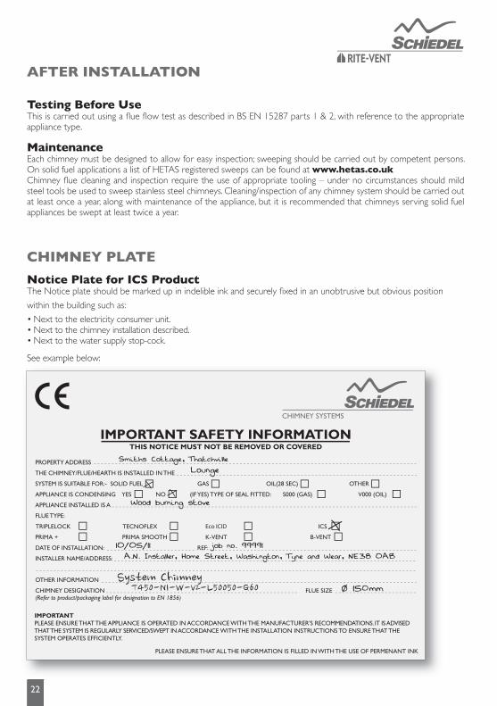
Testing Before UseThis is carried out using a fl ue fl ow test as described in BS EN 15287 parts 1 & 2, with reference to the appropriate appliance type.
MaintenanceEach chimney must be designed to allow for easy inspection; sweeping should be carried out by competent persons. On solid fuel applications a list of HETAS registered sweeps can be found at www.hetas.co.ukChimney fl ue cleaning and inspection require the use of appropriate tooling – under no circumstances should mild steel tools be used to sweep stainless steel chimneys. Cleaning/inspection of any chimney system should be carried out at least once a year, along with maintenance of the appliance, but it is recommended that chimneys serving solid fuel appliances be swept at least twice a year.
CHIMNEY PLATE
AFTER INSTALLATION
Notice Plate for ICS ProductThe Notice plate should be marked up in indelible ink and securely fi xed in an unobtrusive but obvious position
within the building such as:
• Next to the electricity consumer unit.• Next to the chimney installation described.• Next to the water supply stop-cock.
See example below:See example below:
System ChimneyT450-N1-W-V2-L50050-G60

PRODUCT WARRANTY
Under normal operating conditions and providing the system is installed correctly, it should last the lifetime of the appliance, which normally is 10 years. ICS carries a 10 year conditional warranty. The conditions are that the system is:-
• Correctly sized and installed in accordance with the manufacturer’s instructions, current Building Regulations and relevant British and European standards.• Maintained correctly by a qualified and competent person and maintenance records kept updated for both appliance and system chimney.• Used in combination with an appliance burning only approved fuels in accordance with Schiedel Chimney Systems and the appliance manufacturer’s instructions.
For recommended fuels listings, please refer to the HETAS Guide www.hetas.co.uk
In the event of a fault developing in the product due to defective materials or faulty manufacture Schiedel Chimney Systems undertake to replace the product only.
Schiedel Chimney Systems cannot accept liability nor take any responsibility for the installation, building or redecorating costs or any other consequential losses arising.
If any complaint is found to be a result of faulty installation, non-compliance with or abuse contrary to these conditions, the cost of site investigation is chargeable.
Product RegistrationThe installer/customer is required to fill in the details below and return the registration form to Schiedel Chimney Systems. Failure to register the installation may affect any claim made during the warranty period of the product.
Name & Address of Installer: Address of property where product installed:
Supplier/Stockist: Date of Purchase:
Occupier of Property: Date of Installation: Product Installed:
Appliance Type/Model:
Internal Flue Diameter: Fuel Type:
23

Schiedel Chimney SystemsCrowther EstateWashingtonTyne & Wear NE38 0AQTel. +44 (0)191 416 1150Fax. +44 (0)191 415 [email protected]/rite-vent
Complementary products and servicesfrom Schiedel Chimney Systems
HETAS TRAININGCourses H001-H006 available. See website for course prospectus and application form downloads or scan QR code below.
ECO ICID FLEXIBLE LINERS PRIMA SMOOTH


![•«vraOfd doo Bmr W Ttfc* ] .mail.maldegem.be/websitemaldegem/getrmaldegem/1915_10_12.pdf•«vraOfd doo Bmr W Ttfc* ] . 24 )Mr io, MM I< teifetioS * ii2 Kaap vo Harderwijkn e](https://img.pdfslide.net/doc/110x75/5ae89a007f8b9aee078fb9c5/vraofd-doo-bmr-w-ttfc-mail-vraofd-doo-bmr-w-ttfc-24-mr-io-mm-i.jpg)

![Washington Evening Times. (Washington, DC) 1902-12-13 [p 11].€¦ · CfJk and Unamwotfaji aaaa-twntat Jrontag 788 Ttfc at-daUM HELP WAKTKD MALB fc FKlfAI-MKDTbWjr aacn sad tea tediei](https://img.pdfslide.net/doc/110x75/5f7cb87c468d3932290e6745/washington-evening-times-washington-dc-1902-12-13-p-11-cfjk-and-unamwotfaji.jpg)