Embed Size (px)
Citation preview
ISU Structured Cable System Minimum Requirements
Idaho State University Networking & Telecommunications Structured Cabling Minimum Specifications
1.0 GENERAL This document is general in nature and not specific to a particular project. It is, however, the minimum standard by which all construction documents, particular to any telecommunications project, should be based. Any modifications to this document to fit a particular project must be approved by NetCom prior to being put in a construction document. NOTE: This specification may impact other trades. When there is a conflict in the construction document between trades, this General Structured Cabling Minimum Specification prevails. As an example, the construction document may instruct the electrical contractor to provide telecommunications grounding/bonding and conduit runs in the electrical section of the construction document. If there is a conflict between the electrical specification and the telecommunications specification, the telecommunications specification prevails. 1.1 STANDARDS A. Building structured wiring systems shall meet the cabling conventions of Idaho State University (ISU) Networking & Telecommunications Department (NetCom) to include adherence to the most currently available Building Industry Consulting Service International (BICSI) Telecommunications Distribution Methods Manual (TDMM 13th Edition), the most current ANSI/TIA/EIA Telecommunications Building Wiring Standards, National Electrical Manufacturer’s Asociation (NEMA) NEMA WC 26, and National Electrical Code 2017 NFPA 70 manuals as adopted by ISU. In projects involving new construction. Bidders shall be fully acquainted with the above referenced standards and be fully qualified, as outlined in the Telecommunications contractor qualifications, to bid on and perform work. Bidders shall have manufacturer authorization, qualifications and certifications to install and test a Category 5E (CAT 5E) Ortronics/Superior Essex nCompass 1G Channel Solution and 1000BaseTX/FX intra-building backbone. The network cabling infrastructure must be installed by manufacturer approved designers and certified contractors at the Certified Installer Plus-Enterprise Solutions Partner (CIP-ESP) tier or Certified Installer Plus (CIP) tier in accordance with manufacturer’s installation instructions and specifications. All station and riser cabling shall be tested and certified by successful bidder to support 1000BaseTX/FX technology. The successful bidder will be required to meet with and coordinate with a representative of ISU NetCom prior to work beginning, and a minimum of weekly, during the installation process to ensure work is meeting ISU conventions and standards. Meetings may include a site inspection to ensure compliance with the defined standards contained in this document. The successful electrical and telecommunications contractor(s) shall follow appropriate installation guidelines, as contained in the most currently available BICSI TDMM, ANSI/TIA/EIA, NEMA WC 26, and NFPA 70 manuals. Additionally, contractor will work with ISU NetCom to ensure proper placement and routing of cable and support hardware. The specified Structured Cable Wiring Standards are to be used as a minimum requirement.
ISU Structured Cable System Minimum Requirements
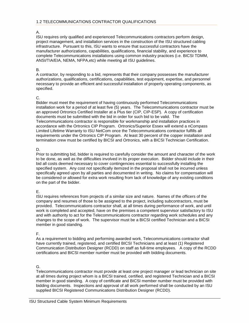
1.2 TELECOMMUNICATIONS CONTRACTOR QUALIFICATIONS A. ISU requires only qualified and experienced Telecommunications contractors perform design, project management, and installation services in the construction of the ISU structured cabling infrastructure. Pursuant to this, ISU wants to ensure that successful contractors have the manufacturer authorizations, capabilities, qualifications, financial stability, and experience to complete Telecommunications installations using common industry practices (i.e. BICSI TDMM, ANSI/TIA/EIA, NEMA, NFPA,etc) while meeting all ISU guidelines. B. A contractor, by responding to a bid, represents that their company possesses the manufacturer authorizations, qualifications, certifications, capabilities, test equipment, expertise, and personnel necessary to provide an efficient and successful installation of properly operating components, as specified. C. Bidder must meet the requirement of having continuously performed Telecommunications installation work for a period of at least five (5) years. The Telecommunications contractor must be an approved Ortronics Certified Installer at a Plus tier (CIP, CIP-ESP). A copy of certification documents must be submitted with the bid in order for such bid to be valid. The Telecommunications contractor is responsible for workmanship and installation practices in accordance with the Ortronics CIP Program. Ortronics/Superior Essex will extend a nCompass Limited Lifetime Warranty to ISU NetCom once the Telecommunications contractor fulfills all requirements under the Ortronics CIP Program. At least 30 percent of the copper installation and termination crew must be certified by BICSI and Ortronics, with a BICSI Technician Certification. D. Prior to submitting bid, bidder is required to carefully consider the amount and character of the work to be done, as well as the difficulties involved in its proper execution. Bidder should include in their bid all costs deemed necessary to cover contingencies essential to successfully installing the specified system. Any cost not specifically itemized in the proposal shall not be incurred unless specifically agreed upon by all parties and documented in writing. No claims for compensation will be considered or allowed for extra work resulting from lack of knowledge of any existing conditions on the part of the bidder. E. ISU requires references from projects of a similar size and nature. Names of the officers of the company and resumes of those to be assigned to the project, including subcontractors, must be provided. Telecommunications contractor shall, at all times during performance of work, and until work is completed and accepted, have on the premises a competent supervisor satisfactory to ISU and with authority to act for the Telecommunications contractor regarding work schedules and any changes to the scope of work. The supervisor must be a BICSI certified Technician and a BICSI member in good standing. F. As a requirement to bidding and performing awarded work, Telecommunications contractor shall have currently trained, registered, and certified BICSI Technicians and at least (1) Registered Communication Distribution Designer (RCDD) on staff as full-time employees. A copy of the RCDD certifications and BICSI member number must be provided with bidding documents. G. Telecommunications contractor must provide at least one project manager or lead technician on site at all times during project whom is a BICSI trained, certified, and registered Technician and a BICSI member in good standing. A copy of certificate and BICSI member number must be provided with bidding documents. Inspections and approval of all work performed shall be conducted by an ISU supplied BICSI Registered Communications Distribution Designer (RCDD).
ISU Structured Cable System Minimum Requirements
H. Telecommunication contractor must be skilled and proficient in both inside cable plant (copper and fiber optics) installation, as well as outside cable plant (copper and fiber optics) installation, termination, splicing, and testing. Telecommunications contractor must be certified by the manufacture of the structured cable system specified in this document. (See 1.5 Materials)
1.3 PROGRESS MEETINGS A. The successful bidder will be required to meet with and coordinate with a representative of ISU NetCom prior to work beginning, and a minimum of weekly, during the installation process. Meetings may include a site inspection to ensure compliance with established standards. The successful electrical and Telecommunications contractor(s) will follow appropriate installation guidelines, as contained in the most currently available BICSI TDMM, ANSI/TIA/EIA Wiring Standards, NEMA and NFPA 70 National Electrical Code manuals. Additionally, contractor will work with ISU NetCom to ensure proper placement, routing, labeling, and documentation of cable and support hardware. 1.4 DOCUMENTATION A. Prior to system acceptance, the successful bidder shall submit to the owner fully documented 8.5" x 11" scale drawings of the entire fiber optic and copper distribution system. Documentation shall be provided in both a hard copy binder and a digital copy capable of being viewed and edited in MS Visio. This will include building and floor layouts with appropriate labling and locations of workstation Telecommunications Outlet (TO), Equipment Room/Telecommunications Room (ER/TR), Main Cross Connect/Intermediate Cross Connect (MC/IC), cable routes, interconnect locations, riser locations, and all other information pertinent to the installation. B. Successful bidder will be responsible for accurately labeling and identifying all relevant components of the cabling system, including, but not limited to: Telecommunications Outlet (TO) face plate labeling; patch panel and block labeling and color-coding; backbone cable labeling at entrance to MC, BEF/IC/ER, and HC/TR; fiber optic patch panel labeling and color-coding, cables at each end, conduits at each end, and grounding system. Reference BICSI TDMM, 13th Edition, Telecommunications Administration. The successful bidder will consult with ISU NetCom’s representative in regard to labeling and identification. 1.5 MATERIALS Idaho State University has selected the Ortronics/Superior Essex nCompass Structured Cabling Solution for all campus cabling. ISU desires to protect it's investment in training, certifications, and inventory, therefore, all new construction and remodel projects shall include the Ortronics/Superior Esssex nCompass Cabling Solution products as specified. The Telecommunications contractor must be an approved Ortronics Certified Installer at a Plus tier (CIP, CIP-ESP). A copy of certification documents must be submitted with the bid in order for such bid to be valid. The Telecommunications contractor is responsible for workmanship and installation practices in accordance with the Ortronics CIP Program. Ortronics/Superior Essex will extend a nCompass Limited Lifetime Warranty to ISU NetCom once the Telecommunications contractor fulfills all requirements under the Ortronics CIP Program. At least 30 percent of the copper installation and termination crew must be certified by BICSI and Ortronics, with a BICSI Technician Certification. Bidder should expect to present quotes based on the following itemized manufacturer's products. The horizontal workstation structured cabling system shall be an Ortronics/Superior Essex nCompass
ISU Structured Cable System Minimum Requirements
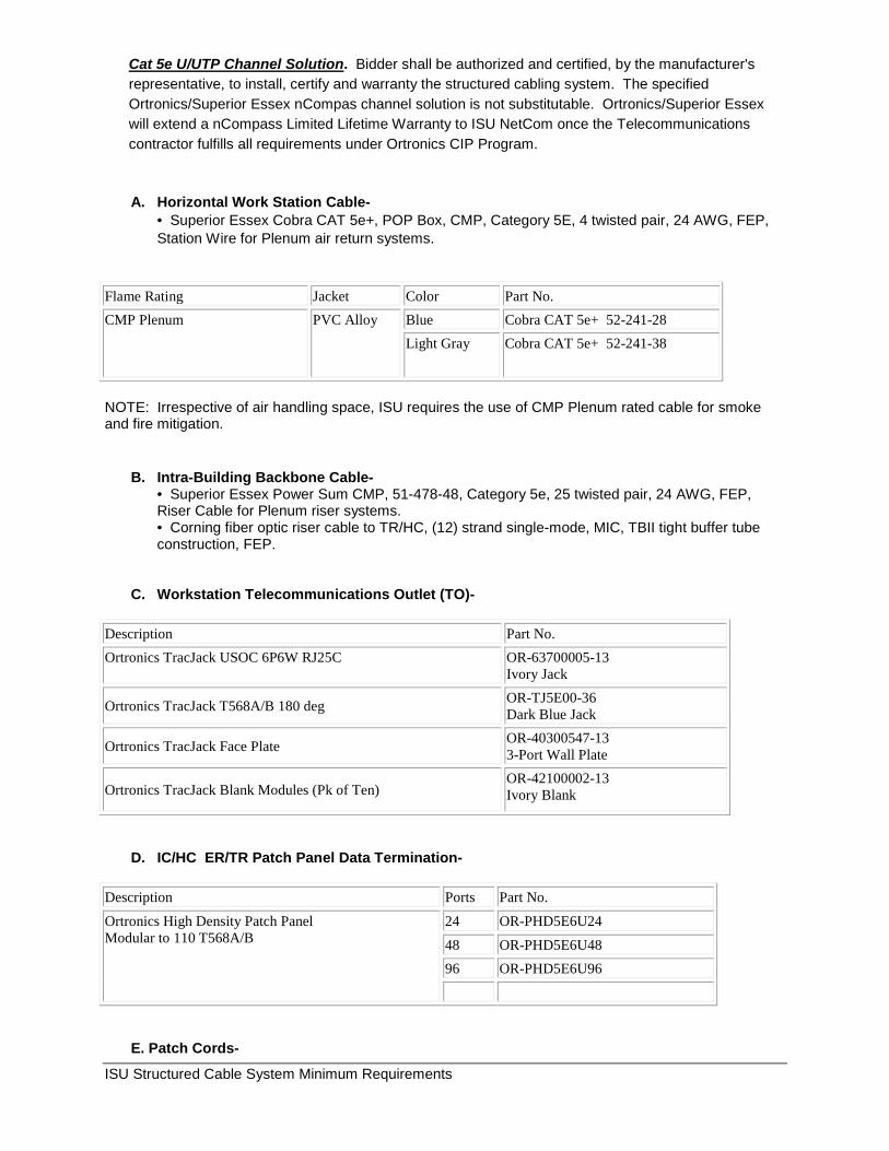
Cat 5e U/UTP Channel Solution. Bidder shall be authorized and certified, by the manufacturer's representative, to install, certify and warranty the structured cabling system. The specified Ortronics/Superior Essex nCompas channel solution is not substitutable. Ortronics/Superior Essex will extend a nCompass Limited Lifetime Warranty to ISU NetCom once the Telecommunications contractor fulfills all requirements under Ortronics CIP Program.
A. Horizontal Work Station Cable-
• Superior Essex Cobra CAT 5e+, POP Box, CMP, Category 5E, 4 twisted pair, 24 AWG, FEP, Station Wire for Plenum air return systems.
Flame Rating Jacket Color Part No. CMP Plenum PVC Alloy Blue Cobra CAT 5e+ 52-241-28
Light Gray Cobra CAT 5e+ 52-241-38
NOTE: Irrespective of air handling space, ISU requires the use of CMP Plenum rated cable for smoke and fire mitigation.
B. Intra-Building Backbone Cable- • Superior Essex Power Sum CMP, 51-478-48, Category 5e, 25 twisted pair, 24 AWG, FEP, Riser Cable for Plenum riser systems. • Corning fiber optic riser cable to TR/HC, (12) strand single-mode, MIC, TBII tight buffer tube construction, FEP.
C. Workstation Telecommunications Outlet (TO)-
Description Part No. Ortronics TracJack USOC 6P6W RJ25C OR-63700005-13
Ivory Jack
Ortronics TracJack T568A/B 180 deg OR-TJ5E00-36 Dark Blue Jack
Ortronics TracJack Face Plate OR-40300547-13 3-Port Wall Plate
Ortronics TracJack Blank Modules (Pk of Ten) OR-42100002-13 Ivory Blank
D. IC/HC ER/TR Patch Panel Data Termination-
Description Ports Part No. Ortronics High Density Patch Panel Modular to 110 T568A/B
24 OR-PHD5E6U24 48 OR-PHD5E6U48 96 OR-PHD5E6U96
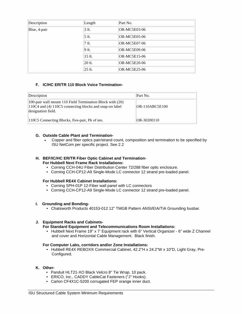
E. Patch Cords-
ISU Structured Cable System Minimum Requirements
Description Length Part No.
Blue, 4-pair 3 ft. OR-MC5E03-06
5 ft. OR-MC5E05-06
7 ft. OR-MC5E07-06 9 ft. OR-MC5E09-06
15 ft. OR-MC5E15-06 20 ft. OR-MC5E20-06
25 ft. OR-MC5E25-06
F. IC/HC ER/TR 110 Block Voice Termination-
Description Part No. 100-pair wall mount 110 Field Termination Block with (20) 110C4 and (4) 110C5 connecting blocks and snap-on label designation field. 110C5 Connecting Blocks, five-pair, Pk of ten.
OR-110ABC5E100 OR-30200110
G. Outside Cable Plant and Termination- • Copper and fiber optics pair/strand count, composition and termination to be specified by
ISU NetCom per specific project. See 2.2
H. BEF/IC/HC ER/TR Fiber Optic Cabinet and Termination- For Hubbell Next Frame Rack Installations:
• Corning CCH-04U Fiber Distribution Center 72/288 fiber optic enclosure. • Corning CCH-CP12-A9 Single-Mode LC connector 12 strand pre-loaded panel.
For Hubbell RE4X Cabinet Installations: • Corning SPH-01P 12-Fiber wall panel with LC connectors • Corning CCH-CP12-A9 Single-Mode LC connector 12 strand pre-loaded panel.
I. Grounding and Bonding-
• Chatsworth Products 40153-012 12” TMGB Pattern ANSI/EIA/TIA Grounding busbar.
J. Equipment Racks and Cabinets- For Standard Equipment and Telecommunications Room Installations:
• Hubbell Next Frame 19" x 7’ Equipment rack with 6" Vertical Organizer - 6" wide Z Channel and cover and Horizontal Cable Management. Black finish.
For Computer Labs, corridors and/or Zone Installations:
• Hubbell RE4X REBOX® Commercial Cabinet, 42.2"H x 24.2"W x 10"D, Light Gray, Pre-Configured.
K. Other- • Panduit HLT21-XO Black Velcro 8" Tie Wrap, 10 pack. • ERICO, Inc., CADDY CableCat Fasteners ("J" Hooks). • Carlon CF4X1C-5200 corrugated FEP orange inner duct.
ISU Structured Cable System Minimum Requirements
2.0 CABLE PLANT
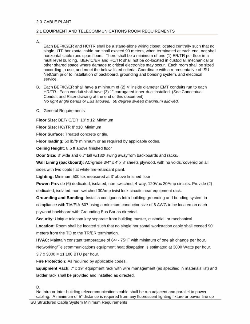
2.1 EQUIPMENT AND TELECOMMUNICATIONS ROOM REQUIREMENTS A.
Each BEF/IC/ER and HC/TR shall be a stand-alone wiring closet located centrally such that no single UTP horizontal cable run shall exceed 90 meters, when terminated at each end, nor shall horizontal cable runs span floors. There shall be a minimum of one (1) ER/TR per floor in a multi level building. BEF/IC/ER and HC/TR shall not be co-located in custodial, mechanical or other shared space where damage to critical electronics may occur. Each room shall be sized according to use, and meet the below listed criteria. Coordinate with a representative of ISU NetCom prior to installation of backboard, grounding and bonding system, and electrical service.
B. Each BEF/IC/ER shall have a minimum of (2) 4" inside diameter EMT conduits run to each HR/TR. Each conduit shall have (3) 1” corrugated inner-duct installed. (See Conceptual Conduit and Riser drawing at the end of this document) No right angle bends or LBs allowed. 60 degree sweep maximum allowed.
C. General Requirements Floor Size: BEF/IC/ER 10' x 12' Minimum
Floor Size: HC/TR 8' x10' Minimum
Floor Surface: Treated concrete or tile.
Floor loading: 50 lb/ft2 minimum or as required by applicable codes.
Ceiling Height: 8.5 ft above finished floor
Door Size: 3' wide and 6.7' tall w/1800 swing awayfrom backboards and racks.
Wall Lining (backboard): AC-grade 3/4" x 4' x 8' sheets plywood, with no voids, covered on all
sides with two coats flat white fire-retardant paint.
Lighting: Minimum 500 lux measured at 3' above finished floor
Power: Provide (6) dedicated, isolated, non-switched, 4-way, 120Vac 20Amp circuits. Provide (2)
dedicated, isolated, non-switched 30Amp twist lock circuits near equipment rack.
Grounding and Bonding: Install a contiguous Intra-building grounding and bonding system in
compliance with TIA/EIA-607 using a minimum conductor size of 6 AWG to be located on each
plywood backboard with Grounding Bus Bar as directed.
Security: Unique telecom key separate from building master, custodial, or mechanical.
Location: Room shall be located such that no single horizontal workstation cable shall exceed 90
meters from the TO to the TR/ER termination.
HVAC: Maintain constant temperature of 640 - 750 F with minimum of one air change per hour.
Networking/Telecommunications equipment heat disapation is estimated at 3000 Watts per hour.
3.7 x 3000 = 11,100 BTU per hour.
Fire Protection: As required by applicable codes.
Equipment Rack: 7' x 19" equipment rack with wire management (as specified in materials list) and
ladder rack shall be provided and installed as directed.
D. No Intra or Inter-building telecommunications cable shall be run adjacent and parallel to power cabling. A minimum of 5" distance is required from any fluorescent lighting fixture or power line up
ISU Structured Cable System Minimum Requirements
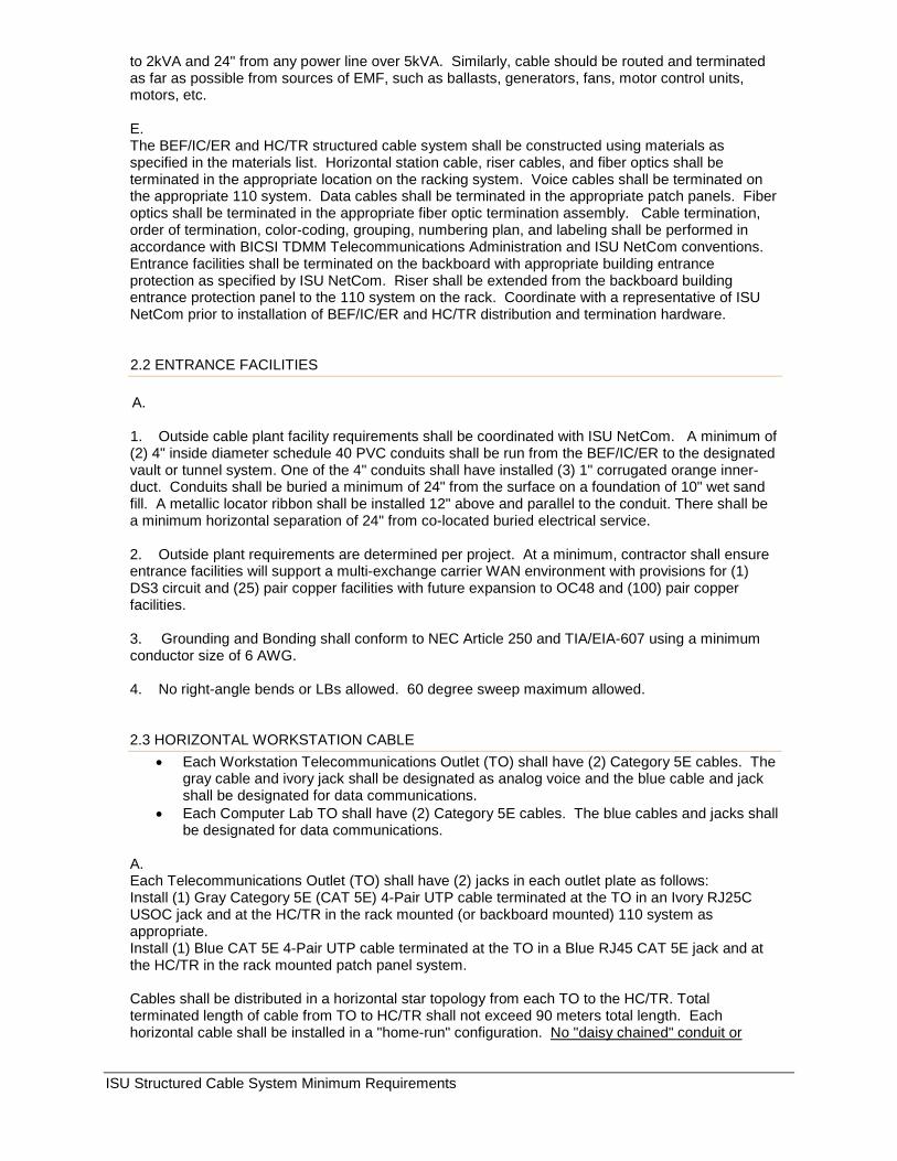
to 2kVA and 24" from any power line over 5kVA. Similarly, cable should be routed and terminated as far as possible from sources of EMF, such as ballasts, generators, fans, motor control units, motors, etc. E. The BEF/IC/ER and HC/TR structured cable system shall be constructed using materials as specified in the materials list. Horizontal station cable, riser cables, and fiber optics shall be terminated in the appropriate location on the racking system. Voice cables shall be terminated on the appropriate 110 system. Data cables shall be terminated in the appropriate patch panels. Fiber optics shall be terminated in the appropriate fiber optic termination assembly. Cable termination, order of termination, color-coding, grouping, numbering plan, and labeling shall be performed in accordance with BICSI TDMM Telecommunications Administration and ISU NetCom conventions. Entrance facilities shall be terminated on the backboard with appropriate building entrance protection as specified by ISU NetCom. Riser shall be extended from the backboard building entrance protection panel to the 110 system on the rack. Coordinate with a representative of ISU NetCom prior to installation of BEF/IC/ER and HC/TR distribution and termination hardware. 2.2 ENTRANCE FACILITIES A. 1. Outside cable plant facility requirements shall be coordinated with ISU NetCom. A minimum of (2) 4" inside diameter schedule 40 PVC conduits shall be run from the BEF/IC/ER to the designated vault or tunnel system. One of the 4" conduits shall have installed (3) 1" corrugated orange inner-duct. Conduits shall be buried a minimum of 24" from the surface on a foundation of 10" wet sand fill. A metallic locator ribbon shall be installed 12" above and parallel to the conduit. There shall be a minimum horizontal separation of 24" from co-located buried electrical service. 2. Outside plant requirements are determined per project. At a minimum, contractor shall ensure entrance facilities will support a multi-exchange carrier WAN environment with provisions for (1) DS3 circuit and (25) pair copper facilities with future expansion to OC48 and (100) pair copper facilities. 3. Grounding and Bonding shall conform to NEC Article 250 and TIA/EIA-607 using a minimum conductor size of 6 AWG. 4. No right-angle bends or LBs allowed. 60 degree sweep maximum allowed. 2.3 HORIZONTAL WORKSTATION CABLE
• Each Workstation Telecommunications Outlet (TO) shall have (2) Category 5E cables. The gray cable and ivory jack shall be designated as analog voice and the blue cable and jack shall be designated for data communications.
• Each Computer Lab TO shall have (2) Category 5E cables. The blue cables and jacks shall be designated for data communications.
A. Each Telecommunications Outlet (TO) shall have (2) jacks in each outlet plate as follows: Install (1) Gray Category 5E (CAT 5E) 4-Pair UTP cable terminated at the TO in an Ivory RJ25C USOC jack and at the HC/TR in the rack mounted (or backboard mounted) 110 system as appropriate. Install (1) Blue CAT 5E 4-Pair UTP cable terminated at the TO in a Blue RJ45 CAT 5E jack and at the HC/TR in the rack mounted patch panel system. Cables shall be distributed in a horizontal star topology from each TO to the HC/TR. Total terminated length of cable from TO to HC/TR shall not exceed 90 meters total length. Each horizontal cable shall be installed in a "home-run" configuration. No "daisy chained" conduit or
ISU Structured Cable System Minimum Requirements
cables shall be allowed. No horizontal cable run shall span between floors. A minimum 12” service loop shall be provided at each TO and 24” at each HC/TR. B. All cables shall be installed using conduit, cable tray, or "J" hooks. Where cables are not installed in conduit or cable tray, the cable shall not be pulled or installed directly across suspended ceiling tiles or fluorescent lights without proper suspension and consideration of possible electrical interference. If "J" hooks are used, avoid placing any pressure or creating stress points on the cable. Maximum spacing between "J" hooks shall not exceed five feet. Suspended ceiling support wires shall not be used to support cables or cable support system(s). C. At no time shall pulling tension exceed 25 lbs. on horizontal cables. Exceeding the maximum recommended pulling tension during installation of cables will compromise wire integrity. If wire integrity is compromised, the wire may not pass testing and certification standards required for a 1000BaseTX infrastructure. The installing contractor will be responsible for replacement of any cable system that does not pass required certification standards. A representative from ISU NetCom may randomly test cable installations during weekly coordination meetings. D. Traditional nylon synch style Tie Wraps shall not be used to bundle cables. Only Velcro Tie Wraps are acceptable to bundle cables. Cables shall be dressed in loose, neat bundles. E. No Intra-building telecommunications cable shall be run adjacent and parallel to power cabling. A minimum of 5" distance is required from any fluorescent lighting fixture or power line up to 2kVA and 24" from any power line over 5kVA. Similarly, cable should be routed and terminated as far as possible from sources of EMF, such as ballasts, generators, fans, motor control units, motors, etc. F. Horizontal UTP station cable shall be terminated at the HC/TR in a manner such that each workstation location will be numbered and terminated in sequential order. Voice (Gray) cable shall be terminated at the 19” x 7’ stand alone rack in rack mounted (or backboard mounted) 110 blocks as specified in materials list. Each 100 pair 110 block will support (24) 4-pair cables. Designator strips shall be blue in color. Data (Blue) cables shall be terminated in Ortronics High Density T568A/B wired Patch Panels as specified in materials list and shall be located in 19" x 7’ stand alone rack as specified in materials list. Horizontal and vertical fiber optic cable shall be terminated at BEF/IC/ER and HC/TR in Corning fiber optic distribution centers as specified in materials list. Coordinate with a representative of ISU NetCom prior to installation of BEF/IC/ER and HC/TR distribution and termination hardware. G. Each TO location shall use Ortronics TracJack hardware as specified in materials list. The gray CAT 5E cable shall be terminated USOC in an Ivory RJ25C jack. The Blue and CAT 5E cable(s) shall be terminated TIA/EIA T568A in (1) Blue RJ45 jacks. Striping of cable jacket, untwisting of conductor pairs and termination shall be done using TIA/EIA conventions. 12" of excess, jacketed, cable shall be coiled in the outlet box to accommodate future re-termination. Maintain UTP cable pair twists up to the point of termination (maximum of up to 1/4'' jacket removal allowed) at both the station/outlet end as well as patch panel/ block end for each horizontal cable. Take caution as to refrain from physically changing or damaging the shape or geometry of the cable during installation, i.e., do not cinch cable ties too tightly; avoid kinks and sharp bends in cable. Do not place bundles in such a way that the weight of large bundles is damaging the cables on the bottom of the bundle. Each TO wall plate shall be numbered sequentially, consistent with the HC/TR number layout using an acceptable labeling system. Coordinate with a representative of ISU NetCom prior to installation of TO termination hardware.
ISU Structured Cable System Minimum Requirements
H. Successful bidder shall test and certify that building wiring meets or exceeds all applicable TIA/EIA 568, 569, 606, 607, etc. conventions and standards. Successful bidder shall test and certify tha building wiring shall support 1000Base TX/FX (gigabit) Ethernet technologies. Ortronics/Superior Essex will extend a nCompass Limited Lifetime Warranty to ISU NeTel once the Telecommunications contractor fulfills all requirements under Ortronics CIP Program. All test results shall be supplied at completion of the project. 2.4 VERTICAL RISER CABLE A. Install a minimum of (2) 4" conduit paths between the BEF/IC/ER and each HC/TR. No right angle bends or LBs allowed. 60 degree sweep maximum allowed. Any conduit exceeding 100’ shall have a pull box every 100’. B. For each (12) telephone workstation locations there shall be a (25) pair copper riser from the HC/TR to the BEF/IC/ER. Copper riser cable shall be of a 25 Pair Category 5E FEP rated construction as specified in materials list. All riser cable shall be terminated using 110 wiring distribution systems as specified in materials list. Riser cable shall be terminated on a separate 100 pair block from horizontal station cable. Designator strips shall be gray in color. Coordinate with a representative of ISU NetCom prior to installation and termination of riser cable and termination hardware. C. Each TR/HC shall have a (12) strand single-mode, MIC, TBII tight buffer tube construction. Fiber optic cable shall be terminated in a Corning cabinet at the BEF/IC/ER and each HC/TR. See materials list. Coordinate with a representative of ISU NetCom prior to installation of fiber optic riser cable.
2.5 PATHWAY SUPPORT SYSTEM A.
All horizontal cable shall be installed using a home-run configuration. Conduit, cable tray or "J" hooks are acceptable in any combination to support the cable system. NOTE: In open ceiling environments, where cable is intentionally or unintentionally exposed to view, the cable shall not be painted,
• Cable should be protected from exposure to paint. • Paint products may deteriorate the cable sheath and compromise the integrity of cable
conductors. B. Conduits shall be dedicated, using no smaller than a 1" inside diameter per workstation outlet. There shall be no daisy-chain conduit runs. Each workstation location shall require one 1" conduit, which is a home run back to the appropriate HC/TR or appropriate tray/support system. Provide pull boxes in telecommunications conduit runs spaced not greater than 100 feet apart with no more than two right angle bends. If more than two bends are in any 100-foot section, increase the conduit by one trade size. See TIA/EIA-569-A Section 4.4. Place a “TELECOMMUNICATIONS” label on all pull and junction boxes. If a cable tray system is installed, the conduit shall be a home run from the workstation outlet jack to the tray. Conduit runs shall not exceed 40% fill capacity and bend design as specified in TIA/EIA-569-A documents. Conduits should be sized appropriately.
• Workstation conduits shall be dedicated 1:1 ratio of conduit to workstation outlet. • Workstation conduits shall not be daisy chained or shared between workstation outlets. • Conduit runs shall have no more than (2) right angle bends. • Conduit fill shall not exceed 40%.
ISU Structured Cable System Minimum Requirements
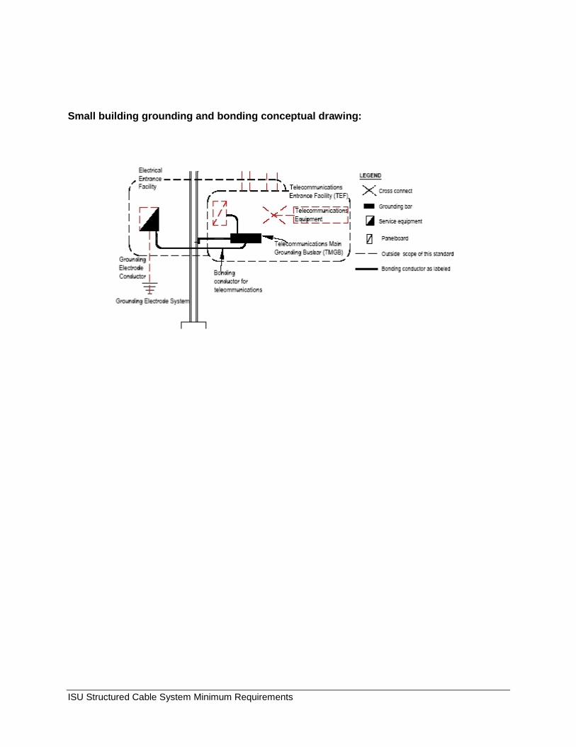
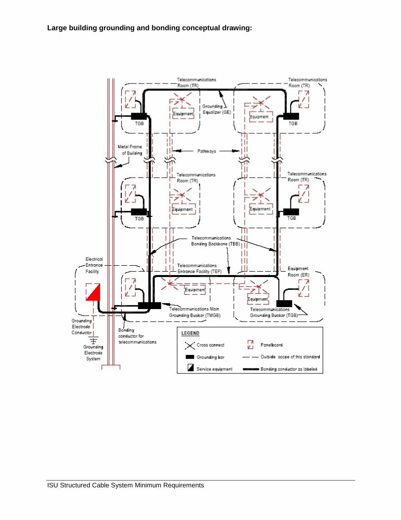
C. Traditional nylon synch style Tie Wraps shall not be used to bundle cables. Velcro style Tie Wraps are the only acceptable method to secure cable bundles. See materials list. At no time shall pulling tension exceed 25 lbs on horizontal cables. Exceeding the maximum recommended pulling tension on Category 5E cables will compromise cable integrity. If wire integrity is compromised, the wire may not pass testing and certification standards required for a 1000BaseTX infrastructure. The installing contractor will be responsible for replacement of any cable system that does not meet required standards. D. No intra/inter-building telecommunications cable shall be run adjacent and parallel to power cabling. A minimum of 5" distance is required from any fluorescent lighting fixture or power line up to 2kVA and 24" from any power line over 5kVA. Similarly, cable should be routed and terminated as far as possible from sources of EMF, such as generators, motors etc. 2.6 GROUNDING AND BONDING Telecommunications bonding and grounding are additional bonding and grounding installed specifically for telecommunications systems. From a safety code standpoint, the NEC and NFPA 780 already cover such bonding and grounding, however, these codes are established primarily for safety. There are many situations where these codes can be interpreted or implemented in different ways. Some of these ways may not be as suitable as others for equipment protection, reliability, and performance. Establishing a suitable telecommunications ground is critical in protecting and equalizing telecommunications equipment. A proper grounding and bonding infrastructure is essential for the reliable operation of today’s sensitive telecommunications equipment and systems. Telecommunications cabling and electrical power cabling must be effectively equalized. The grounding and bonding infrastructure is to originate at the service entrance (electrical power) ground and extend throughout the building to each telecommunications room. Building steel, neither water pipes, nor electrical service sub-panels are acceptable grounding points. Grounding and Bonding shall conform to NEC Article 250 and TIA/EIA-607-A using a minimum conductor size of 6 AWG.
• Install a contiguous Intra-building grounding and bonding system in compliance with NEC Article 250 and TIA/EIA-607-A.
• Use a minimum conductor size of 6 AWG • Install a grounding busbar on each plywood backboard in each telecommunications room
as directed. • The grounding and bonding system shall originate at the service entrance (electrical power)
ground and be a contiguous intra-building bus as shown in the example drawings. • Bond all telecommunications equipment racks, backboards, conduits, and cable trays as
specified in TIA/EIA-607 as shown in example drawings.
ISU Structured Cable System Minimum Requirements
Small building grounding and bonding conceptual drawing:
ISU Structured Cable System Minimum Requirements
Large building grounding and bonding conceptual drawing:
ISU Structured Cable System Minimum Requirements
3/4" Plywood Backboard
(2) 19" x 7' Racks
110 Vac Dedicated Power
D
D
D
D D
D
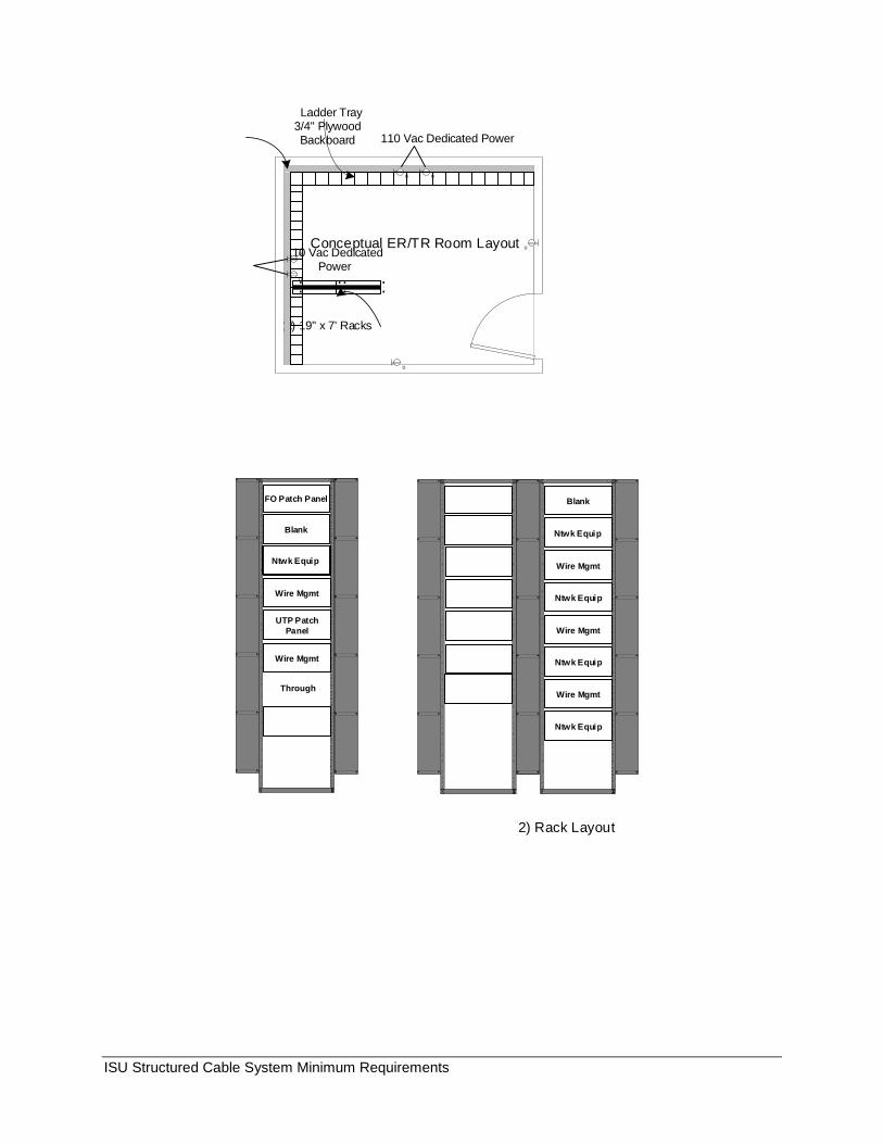
Ladder Tray
110 Vac Dedicated Power
...... ..
Conceptual ER/TR Room Layout
SD SD
(2) Rack Layout
Blank
Ntwk Equip
Ntwk Equip
Wire Mgmt
Wire Mgmt
Ntwk Equip
Ntwk Equip
Wire Mgmt
SD
FO Patch Panel
Blank
Through
Wire Mgmt
Ntwk Equip
UTP Patch Panel
Wire Mgmt
ISU Structured Cable System Minimum Requirements
Glossary: BDF Building Distribution Frame BEF Building Entrance Frame BET Building Entrance Termination BICSI Building Industry Consulting Service International ER Equipment Room HC Horizontal Cross Connect IC Intermediate Cross Connect IDF Intermediate Distribution Frame MC Main Cross Connect MDF Main Distribution Frame RCDD Registered Communications Distribution Designer TO Telecommunications Outlet TR Telecommunications Room UTP Unshielded Twisted Pair FO Fiber Optics
Last Updated: 05/20/2019 Submitted by: Christopher M Olsen, RCDD (201210R)


![Config Structural Authorizations[1]](https://img.pdfslide.net/doc/110x75/55027c794a7959362a8b4953/config-structural-authorizations1.jpg)