Embed Size (px)
Citation preview
Identification of main problem areas, and lacks in design principles, for stability design of multi-storey timber frame buildings
Thomas Orskaug
Avdelningen för Konstruktionsteknik Lunds Tekniska Högskola Lunds Universitet, 2003
Rapport TVBK - 5118

Avdelningen för Konstruktionsteknik Lunds Tekniska Högskola Box 118 221 00 LUND
Division of Structural Engineering Lund Institute of Technology Box 118 S-221 00 LUND Sweden
Inventering av konstruktiva problemoråden vid design av flervånings trähus
Identification of main problem areas, and lacks in design principles, for stability design of multi-storey timber frame buildings Thomas Orskaug 2003
Abstract Identification of areas of focus for future development of design principles and recommendations.

Report TVBK-5118 ISSN 0349-4969 ISRN: LUTVDG/TVBK-03/5118+90p Diploma Thesis Supervisor: Sverker Andreasson, Division of Structural Engineering, LTH March 2003

I
PREFACE The work presented in this diploma thesis has been carried out at the Division of Structural Engineering at Lund University in Sweden during winter 2002-2003 and was accepted at the Technical University of Karlsruhe in Germany. First, I would like to thank my supervisor, Sverker Andreasson, for his guidance during the project. I would also like to thank all the respondents for making this project possible by taking part in the interviews. Lund, March 2003. Thomas Orskaug

II
III
SUMMARY In most European countries, the use of wood as a structural material in multi-storey timber frame buildings has stagnated at a quite low level compared to other materials like concrete, steel and different kinds of masonry. There are many reasons for this, such as limited marketing activities, limited support by material suppliers to builders and conservatism in the building industry. One main reason, however, is probably the lack of a collected comprehensive and coherent knowledge source concerning the design of multi-storey timber frame structures. The documentation from pilots projects in different European countries for the last ten years is quite scattered and do not provide inexperienced engineers with sufficient knowledge about the performance of the structural system or tools that support an efficient stability design. The objective of this study is to describe the main problem areas in the current stability design of multi-storey timber frame buildings, to identify lacks in current design principles and to recommend in which areas the future development of design principles and guidelines should be focused in order to facilitate the design work and make stabilising systems more effective. In order to investigate lacks in current design principles and to identify the most areas in most need of further development, a literature study was performed on current design principles and design guidelines. Based on this information, a questionnaire was designed covering five main topics: distribution of load, design of diaphragms, design of shear walls, intercomponent connections, and lacks in current design principles and further development of design guidelines. A qualitative research (embedded multiple case study) was perfomed by interviewing structural engineers in Austria, Denmark, Finland, Germany, Norway, Sweden, Switzerland and the United Kingdom. Finally, the results from the interviews and the literature study were analysed and conclusions about the need of further development drawn. The results from the study show that there is lacks in design principles and design guidelines for, in particular, the design of diaphragms, shear walls with openings, intercomponent connections and disproportionate collapse. In order to improve the design principles for horizontal diaphragms, methods should be developed to determine the stiffness of diaphragms and to design diaphragms with openings. Concerning the design of shear walls, a simplified plastic method for partially anchored walls with openings ought to be developed and principles stated for the interaction between shear walls on different storeys. Furthermore, there is a need to define distinct principles for the use of adjacent transverse walls to reduce the uplift forces in shear walls. Finally, design guidelines for disproportionate collapse and robustness design of buildings should be developed, for example by defining the use of double spanned floor joists and rim beams.

IV

TABLE OF CONTENTS
1
Preface ................................................................................................................. 1 SUMMARY .......................................................................................................... III 1. INTRODUCTION.............................................................................................. 5
1.1 Background................................................................................................. 5 1.2 Objectives ................................................................................................... 6 1.3 Methods ...................................................................................................... 6 1.4 Limitations................................................................................................... 7 1.5 Outline of report .......................................................................................... 7
2.CURRENT DESIGN PRINCIPLES.................................................................... 9 2.1 Distribution of Load ................................................................................... 10 2.2 Design of diaphragms ............................................................................... 12 2.3 Design of shear walls................................................................................ 17
2.3.1 Racking load carrying capacity........................................................... 17 2.3.2 Horizontal anchorage (anchor bolts) .................................................. 21 2.3.3 Compression and tension in studs ..................................................... 22 2.3.4 Vertical anchorage (hold-downs)........................................................ 24 2.3.5 Buckling of wall studs ......................................................................... 24 2.3.6 Compression perpendicular to the grain............................................. 25 2.3.7 Shear in sheathing material................................................................ 26 2.3.8 Shear buckling of sheathing material ................................................. 27 2.3.9 Racking deflection .............................................................................. 27
2.4 Intercomponent connections..................................................................... 28 2.5 Disproportionate collapse ......................................................................... 28 2.6 Lacks in design principles ......................................................................... 34
3. METHODS ..................................................................................................... 35 3.1 Case study methodology .......................................................................... 35 3.2 Design of questionnaire ............................................................................ 36 3.3 Sample selection....................................................................................... 38 3.4 Analysis technique .................................................................................... 39 3.5 Reliability and validity................................................................................ 39
4.RESULTS FROM INTERVIEWS ..................................................................... 41 4.1 Distribution of Load ................................................................................... 41
4.1.1 Austria ................................................................................................ 41 4.1.2 Denmark............................................................................................. 42 4.1.3 Finland................................................................................................ 42 4.1.4 Germany............................................................................................. 43 4.1.5 Norway ............................................................................................... 44 4.1.6 Sweden .............................................................................................. 44 4.1.7 Switzerland......................................................................................... 45 4.1.8 The United Kingdom........................................................................... 45
4.2 Design of diaphragms ............................................................................... 46 4.2.1 Austria ................................................................................................ 46 4.2.2 Denmark............................................................................................. 47 4.2.3 Finland................................................................................................ 47 4.2.4 Germany............................................................................................. 48 4.2.5 Norway ............................................................................................... 49

TABLE OF CONTENTS
2
4.2.6 Sweden .............................................................................................. 49 4.2.7 Switzerland......................................................................................... 50 4.2.8 The United Kingdom........................................................................... 50
4.3 Design of shear walls................................................................................ 51 4.3.1 Austria ................................................................................................ 51 4.3.2 Denmark............................................................................................. 52 4.3.3 Finland................................................................................................ 53 4.3.4 Germany............................................................................................. 54 4.3.6 Sweden .............................................................................................. 56 4.3.7 Switzerland......................................................................................... 57 4.3.8 The United Kingdom........................................................................... 58
4.4 Intercomponent connections..................................................................... 59 4.4.1 Austria ................................................................................................ 59 4.4.2 Denmark............................................................................................. 59 4.4.3 Finland................................................................................................ 60 4.4.4 Germany............................................................................................. 60 4.4.5 Norway ............................................................................................... 60 4.4.6 Sweden .............................................................................................. 61 4.4.7 Switzerland......................................................................................... 61 4.4.8 The United Kingdom........................................................................... 61
4.5 Design for disproportionate collapse......................................................... 62 4.5.1 Austria ................................................................................................ 62 4.5.2 Denmark............................................................................................. 62 4.5.3 Finland................................................................................................ 62 4.5.4 Germany............................................................................................. 62 4.5.5 Norway ............................................................................................... 63 4.5.6 Sweden .............................................................................................. 63 4.5.7 Switzerland......................................................................................... 63 4.5.8 The United Kingdom........................................................................... 63
4.6 Lacks in design principles and development of design guidelines ............ 64 4.6.1 Austria ................................................................................................ 64 4.6.2 Denmark............................................................................................. 64 4.6.3 Finland................................................................................................ 65 4.6.4 Germany............................................................................................. 65 4.6.5 Norway ............................................................................................... 66 4.6.6 Sweden .............................................................................................. 66 4.6.7 Switzerland......................................................................................... 67 4.6.8 The United Kingdom........................................................................... 67
5. CONCLUSIONS AND DISCUSSION ............................................................. 69 5.1 Conclusions .............................................................................................. 69
5.1.1 Distribution of load.............................................................................. 69 5.1.2 Design of diaphragms ........................................................................ 70 5.1.3 Design of shear walls ......................................................................... 71 5.1.4 Intercomponent connections .............................................................. 71 5.1.5 Disproportionate collapse................................................................... 72
5.2 Discussion................................................................................................. 72

TABLE OF CONTENTS
3
5.3 Further work.............................................................................................. 73 6.REFERENCES................................................................................................ 75
Internet............................................................................................................ 77 Interviews........................................................................................................ 77
APPENDIX A: Questionnaire................................................................................ 79 APPENDIX B: European multi-storey timber frame building projects.................. 81 APPENDIX C: List of respondents ...................................................................... 85

4

5
1. INTRODUCTION
1.1 Background For the last ten years, the new possibilities with modern multi-storey timber frame building systems have been in focus in several European countries. Quite a large number of multi-storey timber frame buildings have been constructed in different European countries during this period. These buildings have very often served as pilot projects in the respective country. The intention with these projects has often been to support the timber frame industry, looking for opportunities to increase its market share in residential and non-residential buildings. The timber frame industry has made some progress in increasing the market share. Yet, the use of wood as a structural material has stagnated at a quite low level in most of the countries, compared to other materials like concrete, steel and different kinds of masonry. There are many reasons for this, such as limited marketing activities, limited support from material suppliers to builders and conservatism in the building industry. One main reason is, however, probably the lack of a collected comprehensive and coherent knowledge source concerning the design of multi-storey timber frame structures. Since the building technique in its modern form is quite new in Europe, there existed very few, if any, design guidelines for such structures when the first projects were realised. Most design principles were therefore derived from the design of low-rise buildings. However, the requirements are quite different for a single-family house and a block of flats. The simple design principles that are sufficient for small-scale buildings are in many cases incomplete or not practicable in the design of multi-storey buildings. During the work with these projects some development of new principles were accomplished, but since then, too little has been done to further develop and publish such design principles. Therefore, the engineers who were involved in the early pilot projects still represent the know-how in the design of multi-storey timber frame buildings in Europe, while inexperienced engineers who are confronted with such a design task have difficulties solving it because of the lack of design guidelines. One of the key areas in the design of multi-storey timber frame buildings that displays such a knowledge gap is the stability design. The documentation from the early pilot projects in Europe is, as mentioned previously, quite scattered and do not provide inexperienced engineers with sufficient knowledge about the performance of the structural system or tools that support an efficient stability design. One consequence of this is that simplified design principles, usually two-dimensional ones, are still used to design the stabilising structural system, although multi-storey timber frame buildings are highly indeterminate structural systems. This results in a quite conservative design and thus unnecessary costs. It has been shown by several researchers, e.g. Andreasson (2000), that the performance of multi-storey timber frame structural systems is underestimated if the three-dimensional interaction of the building elements in the system is not considered.

INTRODUCTION
6
This problem is now being addressed. Quite recently, a number of European wood organisations have started to develop new design guidelines in order to overcome some of these obstacles. For example, BRE (Building Research Establishment Ltd) in the UK published a design guide for multi-storey timber frame buildings in February 2003. This guide provides useful information regarding the design for disproportionate collapse, even though it contains less about the design of lateral stability. It concludes that the current design principles in the British standard BS 5268 concerning the design of racking resistance has to be clarified for the use on buildings exceeding four storeys. Work is also going on in several other European countries. It is, however, important that this work is focused in the areas where the gain will be the most. Consequently, there is a need to identify these target areas.
1.2 Objectives The objectives of this study are to describe the main problem areas in the current stability design of multi-storey timber frame buildings, to identify lacks in current design principles and to recommend in which areas the future development of design principles and guidelines should be focused, in order to facilitate the design work and make the stabilising systems more effective.
1.3 Methods In order to investigate lacks in current design principle and to identify the areas in most need of further development, a literature study was performed on current design principles and design guidelines. This study focused mainly on the codes in the different countries, but also on handbooks and other guidelines to some extent. Based on this information, a questionnaire was designed covering the main topics: distribution of load, design of diaphragms, design of shear walls, intercomponent connections, and lacks in current design principles and further development of design guidelines. A qualitative research (embedded multiple case studies) was performed by interviewing structural engineers in Austria, Denmark, Finland, Germany, Norway, Sweden, Switzerland and the United Kingdom. Finally, the result from the interviews and the literature study, were analysed and conclusions about the need of further development were drawn.

INTRODUCTION
7
1.4 Limitations Seismic load is not discussed in this study. Wind load and load due to tilting of wall diaphragms are the only lateral loads that have been considered to the study. The main focus is platform frame structural systems. Other building systems, e.g. solid wood structures, are not explicitly covered in the investigation. Furthermore, principles for calculation of wind load on buildings are not discussed.
1.5 Outline of report In Chapter 2 (Current design principles), an overview is given of the existing codes for stabilisation design of timber structures in the countries covered by the study, i.e. Austria, Denmark, Finland, Germany, Norway, Sweden, Switzerland and the United Kingdom. The sections in the chapter are divided according to different themes connected to the main problem areas in the stability design. The last section point out some areas that seem to lack clear design principles. The method used in the study in order to obtain information about which design principles that are used by designers in real situations in different countries is explained in chapter 3 (Methods). Chapter 4 (Results from interviews), shows the results from interviews with structural engineers, responsible for the stability design in one or several building projects. This chapter is divided after the themes stated in chapter 2 and subdivided after the different countries covered by the study, in alphabetical order. In chapter 5 (Conclusions and discussion), conclusions are drawn based on the results from the interviews and the study of the current design codes, major finding and uncertainties are discussed, and suggestions for the future development of design guidelines and design principles are given.

8

9
2.CURRENT DESIGN PRINCIPLES Over the last fifty years, many European countries have developed national codes. The UK code BS 5268 gives “permissible stresses”, which embody the total factor or safety against failure. Other codes are in “limit state” format, in which the total factor of safety is split between the material strengths and the applied forces. In 1994, the first Eurocode for design of timber structures was issued (in a limit state format), and although still a draft in 1998, it was accepted in some countries as an alternative to national codes. As the use of the unified European codes and standards increase, it will be easier for designs, and designers, to cross national boundaries. Current design methods for timber frame buildings in the European countries are mainly based on simplified analyses. The racking resistance of shear walls is for example determined by linear elastic or plastic models in form of equations or by tabulated empirical values based on results from full-scale tests. In most cases, two-dimensional analyses are used to design the structure for vertical and lateral loads. The building is controlled for lateral stability in each principal direction separately. In the following sections, the principal fields in the stability design are discussed, current design principles in each field are accounted for and different codes are explained.

CURRENT DESIGN PRINCIPLES
10
2.1 Distribution of Load Multi-storey timber frame buildings are subjected to lateral loads (wind load and load due to tilting of walls) and vertical loads (dead load, live load and snow load). These loads have to be transferred into the foundation by the wall and diaphragm elements in the building and the connections between those elements, see figure 2.1.1. The structural engineer has to ensure adequate load paths vertically and horizontally.
Figure 2.1.1: Principal force distribution in a simple-box structure (Source: CWC, 1996) The building is often designed for lateral loads by analysing each of the storeys separately. A single storey subjected to wind load is considered as a simple-box structure in which the walls perpendicular to the wind direction are assumed to be simply supported between the roof and the floor of that storey. The transverse walls thus transfer one half of the total wind load to the roof diaphragm and one half to the floor diaphragm. The roof diaphragm acts as a deep horizontal beam and transmits the load to the shear walls, which in turn transfer the load to the foundation. How much load a diaphragm distributes to the respective shear wall depends on the stiffness of the diaphragm and the shear walls. Usually one of the two following assumptions is made to find a reasonable distribution of the loads (see figure 2.1.2): the diaphragm is considered either very flexible or infinitely rigid.

CURRENT DESIGN PRINCIPLES
11
Figure 2.1.2: Load distribution through a diaphragm: flexible diaphragm (left), rigid diaphragm (right) (Source: Thelandersson et al., 2003) In case of a flexible diaphragm, the forces are distributed to the shear walls according to the position of the walls. In this case, the stiffness of the walls is not considered. If the diaphragm is assumed to be rigid, the relative stiffness of the shear walls has to be calculated. In this case, both translation and rotation of the diaphragm are considered in the calculations. A common simplification utilised in this case is to assume that the stiffness of a wall is proportional to its length. This is realistic when all the walls are built in the same manner and have the same height. Using the assumption that the diaphragm is rigid, the centre of rigidity of the shear walls has to be calculated. The torsional component of each shear wall is dependent on its stiffness and distance from the center of rigidity. The translational component is distributed according to the stiffness of each shear wall, see figure 2.1.3.
Figure 2.1.3: Load distribution with a rigid diaphragm (Source: Thelandersson et al., 2003) There are no guidelines given in the codes covering the distribution of horizontal loads. Some principles are given in different handbooks, e.g. Thelandersson et al (2003). However, there is a lack of distinct guidelines stating when a diaphragm should be considered to be rigid respective flexible concerning the distribution of lateral loads.

CURRENT DESIGN PRINCIPLES
12
Designing the vertical load path requires an understanding of the structural load path and load sharing. Multi-storey timber frame structures are highly indeterminate and the load path is often not known explicitly. European building codes have rules for decreasing favourable permanent actions (e.g. when counteracting uplift forces) by 10-20% and increasing unfavourable actions by 10-20%. But apart from these rules, there are no guidelines on how to distribute vertical loads in such building systems.
2.2 Design of diaphragms In the previous section, the distribution of load to different components in the stabilising system, such as walls and diaphragms, was discussed. In this section, the design principles for diaphragms in different codes will be presented. Floor and roof diaphragms are designed to transmit lateral loads from the transverse walls to the shear walls. A diaphragm is normally assumed to act as a simply supported deep I-beam, in which the sheathing is considered to represent the web and the chords are the flanges, see figure 2.2.1.
Figure 2.2.1: Principal behaviour of floor diaphragms (Source: Blaß et al., 1995)
CURRENT DESIGN PRINCIPLES
13
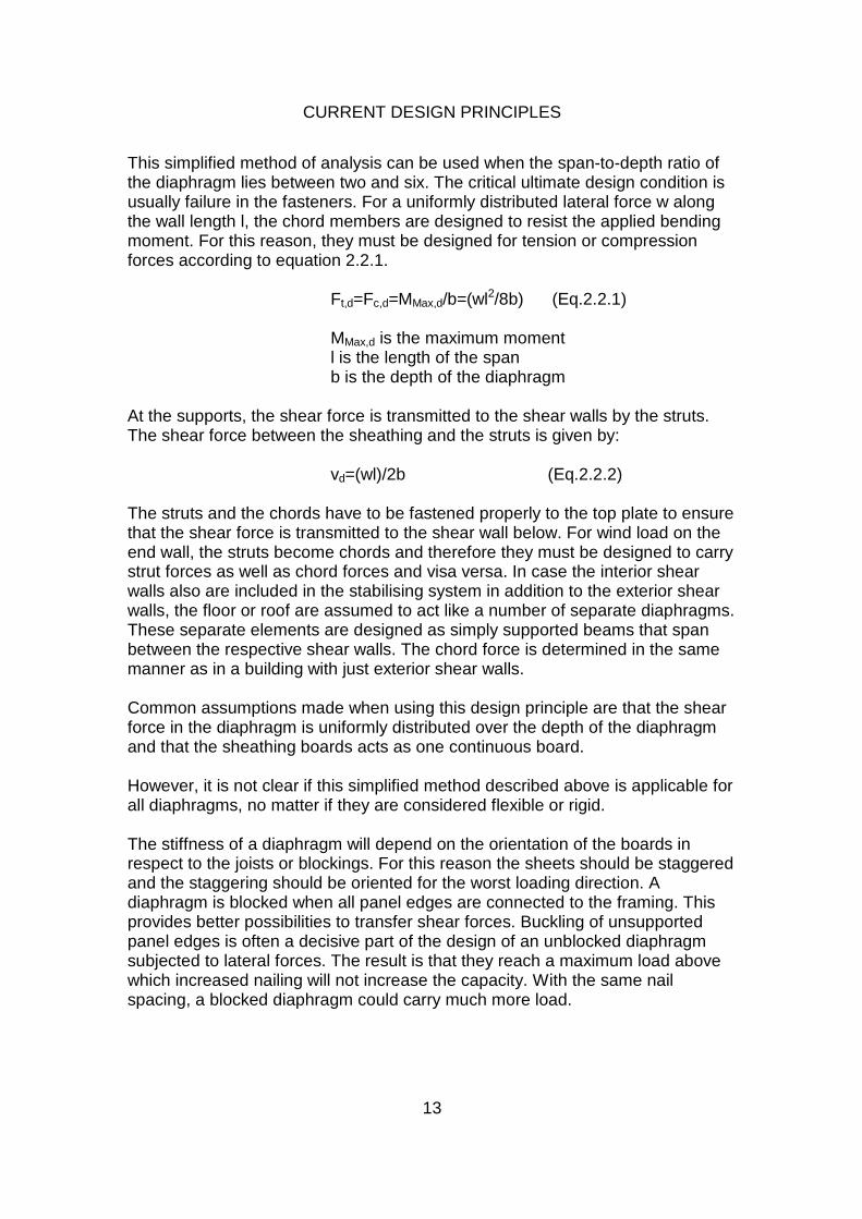
This simplified method of analysis can be used when the span-to-depth ratio of the diaphragm lies between two and six. The critical ultimate design condition is usually failure in the fasteners. For a uniformly distributed lateral force w along the wall length l, the chord members are designed to resist the applied bending moment. For this reason, they must be designed for tension or compression forces according to equation 2.2.1.
Ft,d=Fc,d=MMax,d/b=(wl2/8b) (Eq.2.2.1)
MMax,d is the maximum moment l is the length of the span
b is the depth of the diaphragm At the supports, the shear force is transmitted to the shear walls by the struts. The shear force between the sheathing and the struts is given by:
vd=(wl)/2b (Eq.2.2.2)
The struts and the chords have to be fastened properly to the top plate to ensure that the shear force is transmitted to the shear wall below. For wind load on the end wall, the struts become chords and therefore they must be designed to carry strut forces as well as chord forces and visa versa. In case the interior shear walls also are included in the stabilising system in addition to the exterior shear walls, the floor or roof are assumed to act like a number of separate diaphragms. These separate elements are designed as simply supported beams that span between the respective shear walls. The chord force is determined in the same manner as in a building with just exterior shear walls. Common assumptions made when using this design principle are that the shear force in the diaphragm is uniformly distributed over the depth of the diaphragm and that the sheathing boards acts as one continuous board. However, it is not clear if this simplified method described above is applicable for all diaphragms, no matter if they are considered flexible or rigid. The stiffness of a diaphragm will depend on the orientation of the boards in respect to the joists or blockings. For this reason the sheets should be staggered and the staggering should be oriented for the worst loading direction. A diaphragm is blocked when all panel edges are connected to the framing. This provides better possibilities to transfer shear forces. Buckling of unsupported panel edges is often a decisive part of the design of an unblocked diaphragm subjected to lateral forces. The result is that they reach a maximum load above which increased nailing will not increase the capacity. With the same nail spacing, a blocked diaphragm could carry much more load.

CURRENT DESIGN PRINCIPLES
14
Openings in diaphragms have to be reinforced, e.g. by using blockings and steel straps, to ensure that tension and compression forces are transmitted around the openings. The sheathing has to be fastened properly to the blockings and joists around the opening to assure a transfer of shear force, see figure 2.2.2.
Figure 2.2.2: Diaphragm framing around opening (Source: CWC, 1997) When struts and chords are functioning as header joists for the walls below, they have to be designed for a combination of vertical and horizontal load. In order to prevent lateral displacement of the compressive side of the beams or joists throughout their length, the diaphragm should be blocked and the beams or joists torsionally restrained at their supports. Today, design codes have rules for a simplified analysis of roof and floor diaphragms, but no specific principles are given for more advanced analyses. One reason to this lack might be that prefabricated elements very often are used. In this case, the producers provide the engineers with span tables and tables for shear resistance.

CURRENT DESIGN PRINCIPLES
15
Eurocode 5 (prEN 1995-1-1) provides design principles for a simplified analysis method for roof and floor diaphragms subjected to a uniformly distributed load, see figure 2.2.3.
Figure 2.2.3: Diaphragm loading and staggered panel arrangements (Source: Eurocode 5 prEN 1995-1-1:2003) The method of analysis in Eurocode 5 can be used provided that:
• The span l lies between 2b and 6b (b is the width of the diaphragm) • The critical ultimate design condition is failure in the fasteners (in the
panels) • The sheathing panels, which are not supported by joists or rafters, are
connected to each other with battens • The maximum spacing between the fasteners along the edges should be
150 mm, elsewhere 300 mm
According to EC 5, edge beams should be designed to resist a maximum bending moment in the diaphragm and the shear forces should be assumed as uniformly distributed over the width of the diaphragm. When the sheets are staggered (see figure2.2.3), the nail spacing along the discontinuous panel edges may be increased by a factor of 1.5 (up to maximum of 150 mm) without reduction of the load-carrying capacity. ÖN B 4100 (Austrian Standard) provides design principles for diaphragms based on the method presented in DIN 1052 (see below). DS 413 (Danish standard) provides design principles for diaphragms similar to those in the final draft of Eurocode 5 (prEN 1995-1-1).
CURRENT DESIGN PRINCIPLES
16
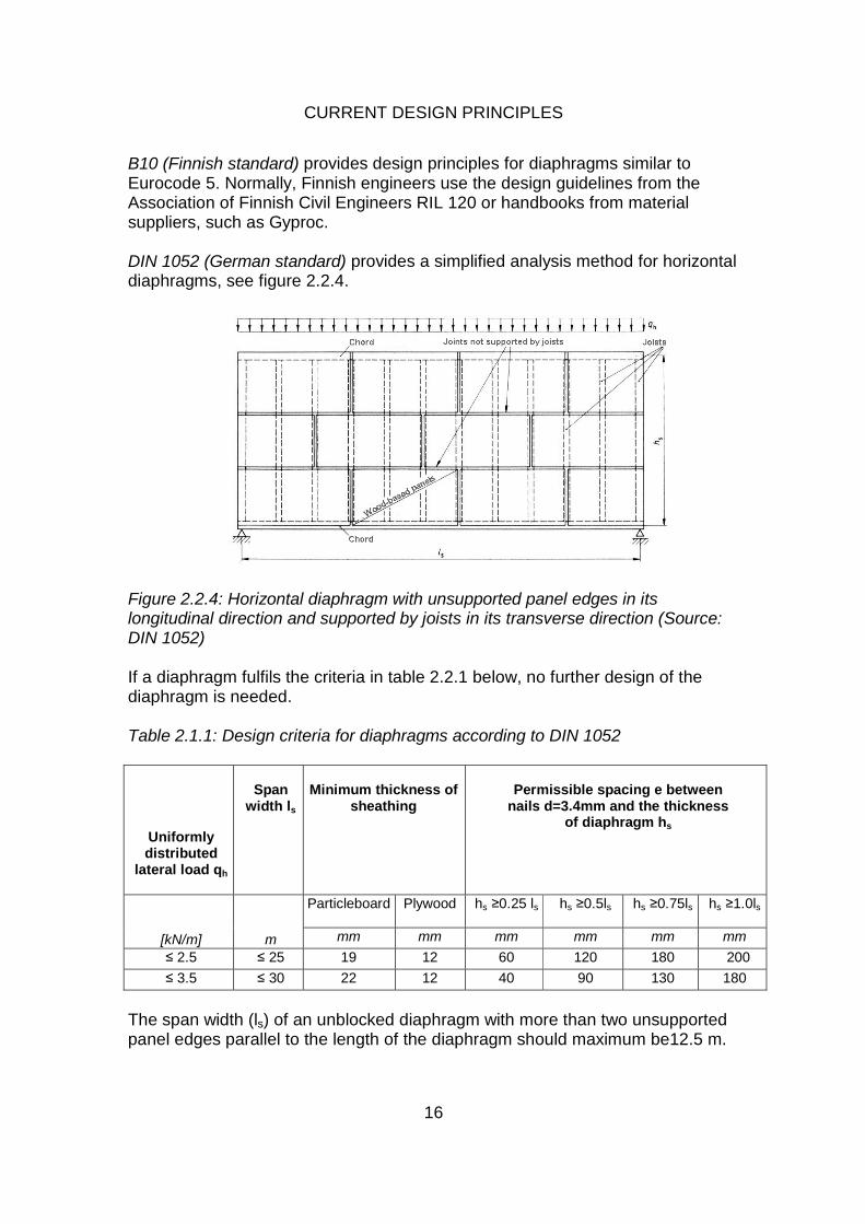
B10 (Finnish standard) provides design principles for diaphragms similar to Eurocode 5. Normally, Finnish engineers use the design guidelines from the Association of Finnish Civil Engineers RIL 120 or handbooks from material suppliers, such as Gyproc. DIN 1052 (German standard) provides a simplified analysis method for horizontal diaphragms, see figure 2.2.4.
Figure 2.2.4: Horizontal diaphragm with unsupported panel edges in its longitudinal direction and supported by joists in its transverse direction (Source: DIN 1052) If a diaphragm fulfils the criteria in table 2.2.1 below, no further design of the diaphragm is needed. Table 2.1.1: Design criteria for diaphragms according to DIN 1052
Uniformly distributed
lateral load qh
Span
width ls
Minimum thickness of
sheathing
Permissible spacing e between
nails d=3.4mm and the thickness of diaphragm hs
Particleboard
Plywood
hs ≥0.25 ls
hs ≥0.5ls
hs ≥0.75ls
hs ≥1.0ls
[kN/m] m mm mm mm mm mm mm
≤ 2.5 ≤ 25 19 12 60 120 180 200
≤ 3.5 ≤ 30 22 12 40 90 130 180
The span width (ls) of an unblocked diaphragm with more than two unsupported panel edges parallel to the length of the diaphragm should maximum be12.5 m.
CURRENT DESIGN PRINCIPLES
17
NS 3479 (Norwegian standard) provides design principles for diaphragms based on a method presented in a draft for Eurocode 5 prENV 1995-1-1:1993, which is the same as in the final draft of Eurocode 5 prEN 1995-1-1. BKR 99 (Swedish standard) provides no specific design principles for horizontal diaphragms. Many engineers in Sweden follow the design guidelines given in handbooks such as Gyproc (plasterboard producer) or “Dimensionering av Träkonstruktioner” (Carling et al., 1992) which are similar to the design principles in Eurocode 5. SIA 265 (Swiss standard) gives design principles for diaphragms based on a method presented in the final draft for Eurocode 5 prEN 1995-1-1. BS 5268 (British standard) gives no specific design principles for horizontal diaphragms.
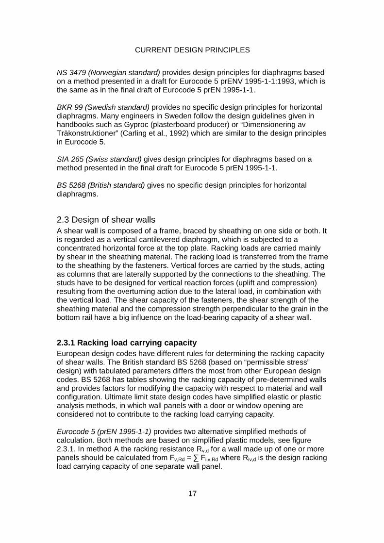
2.3 Design of shear walls A shear wall is composed of a frame, braced by sheathing on one side or both. It is regarded as a vertical cantilevered diaphragm, which is subjected to a concentrated horizontal force at the top plate. Racking loads are carried mainly by shear in the sheathing material. The racking load is transferred from the frame to the sheathing by the fasteners. Vertical forces are carried by the studs, acting as columns that are laterally supported by the connections to the sheathing. The studs have to be designed for vertical reaction forces (uplift and compression) resulting from the overturning action due to the lateral load, in combination with the vertical load. The shear capacity of the fasteners, the shear strength of the sheathing material and the compression strength perpendicular to the grain in the bottom rail have a big influence on the load-bearing capacity of a shear wall.
2.3.1 Racking load carrying capacity European design codes have different rules for determining the racking capacity of shear walls. The British standard BS 5268 (based on “permissible stress” design) with tabulated parameters differs the most from other European design codes. BS 5268 has tables showing the racking capacity of pre-determined walls and provides factors for modifying the capacity with respect to material and wall configuration. Ultimate limit state design codes have simplified elastic or plastic analysis methods, in which wall panels with a door or window opening are considered not to contribute to the racking load carrying capacity. Eurocode 5 (prEN 1995-1-1) provides two alternative simplified methods of calculation. Both methods are based on simplified plastic models, see figure 2.3.1. In method A the racking resistance Rv,d for a wall made up of one or more panels should be calculated from Fv,Rd = ∑ Fi,v,Rd where Riv,d is the design racking load carrying capacity of one separate wall panel.

CURRENT DESIGN PRINCIPLES
18
Figure 2.3.1: Forces acting on the wall panel, the framing and the sheet (Source: Eurocode 5 prEN 1995-1-1). Riv,d for one wall panel with a sheet fixed to one side of a timber frame is calculated according to equation 2.3.1 below.
Fi,v,Rd=(Ff,Rdbici)/s (Eq.2.3.1)
Ff,Rd is the design capacity of an individual fastener bi is the width of the wall panel s is the fastener spacing c is a geometry factor c=1 for bi ≥ b0 and c = bi/b0 for bi<b0, where b0=h/2
The fastener spacing has to be constant along the perimeter of every sheet and the width of each sheet has to be at least h/4. Wall panels with a door or window opening should not be considered to contribute to the racking resistance. For wall panels with sheets on both sides the racking capacity should be taken as the sum of the racking capacities of the individual sides. This rule applies if the sheets and fasteners on both sides are of the same type and dimension. If different types of sheets are used, 75% of the racking capacity of the weaker side may be taken into consideration if the fasteners have similar slip modulus. If not, maximum 50 % of the racking capacity should be taken into consideration.

CURRENT DESIGN PRINCIPLES
19
The design lateral load carrying capacity for fasteners along the edges of an individual sheet can be increased by a factor of 1.2 over the corresponding values given in section 8. According to Eurocode 5, method A should only be applied to wall diaphragms with a hold-down at the end, i.e. that the vertical member at the end is directly connected with the construction below. The second analysis model, method B, can be applied to wall diaphragms without hold-downs at the end. The spacing of fasteners has to be constant along the perimeter of every sheet and the width of each sheet has to be at least h/4. Wall panels with large openings are not considered to distribute to the racking resistance of the wall. In order to form a wall, the individual panels should be linked together on top of the walls by a member, or another construction, across the panel joints. The vertical connection between two panels should have a minimum design strength of 2.5 kN/m. The panels should be designed to resist overturning and sliding forces by either anchorage to the supporting structure or by the permanent actions applied to the wall, or a combination of both effects. The racking resistance of a wall assembly Fv,d should be calculated according to equation 2.3.2.
Fv,Rd=∑Fi,v,d (Eq.2.3.2)
Fi,v,d=((Ff,Rdbi)/s0)kdki,qkskn (Eq.2.3.3) Where kd is the dimension factor for the panel, ki,q is the uniformly distributed load factor for wall i, ks is the fastener spacing factor and kn is the sheathing material factor. These factors are all calculated according to equations in Eurocode 5 section 9.2.4.3.2 (4). Method A is the recommended procedure in Eurocode 5. National choice may be given in the National annex. ÖN B 4100 (Austrian Standard) provides design principles for shear walls based on the method presented in DIN 1052 (1981). DS 413 (Danish standard) provides design principles for shear walls similar to those in the final draft of Eurocode 5 (prEN 1995-1-1) Method A. B10 (Finnish standard) gives no specific design principles for shear walls. Finnish engineers use the design guidelines RIL 120 from the Association of Finnish Civil Engineers or handbooks such as Gyproc.

CURRENT DESIGN PRINCIPLES
20
DIN 1052 (German standard) provides a simplified linear elastic analysis of wall diaphragms. According to DIN 1052, the lateral force is transferred into compression and tensile forces in the studs, and a uniformly distributed shear force along the bottom rail. This decides the capacity of the wall element. NS 3479 (Norwegian standard) provides design principles for shear walls based on a method presented in a draft for Eurocode 5 prENV 1995-1-1:1993. The method from Eurocode 5 (prENV 1995-1-1:1993) calculates the racking load carrying capacity of a wall as:
Fv,Rd=∑Ff,Rd(bi/b1)
2b1/s (Eq.2.3.4)
Fv,Rd is the design racking load capacity Ff,Rd is the design capacity of an individual fastener
bi is the wall panel width b1 is the maximum panel width s is the fastener spacing The reduction factor (bi/b1), however, leads to too conservative results if a sheet with a high width to height ratio is combined with more normal sheet dimensions (bi=h/2). Consequently, b1 was replaced by the fixed value h/2 and the reduction factor (bi/b1) was set to be used only when bi < h/2. The result was the method that is given the final draft for Eurocode 5 prEN 1995-1-1. BKR 99 (Swedish standard) gives no specific design principles for shear walls. The Swedish engineers therefore use different handbooks such as Gyproc or “Dimensionering av Träkonstruktioner” (Carling et al., 1992). Both of them provide design principles based on a linear elastic design method.
SIA 265 (Swiss standard) provides design principles for shear walls based on method A presented in the final draft for Eurocode 5 prEN 1995-1-1. BS 5268 (British standard) refer to four different methods of determining the racking resistance of walls:
• Assessment method • Load testing • Load testing of full-sized walls • Detailed analytical methods outside the scope of British Standard
The assessment method implies a calculation of the racking resistance of a wall with the formula:
Rb x L x Km x Kw (Eq.2.3.7) Rb is the basic racking resistance given in table 2 in BS 5268, section 6.1.

CURRENT DESIGN PRINCIPLES
21
L is the wall length (in m). Km and Kw are material and wall modification factors. Km takes the variation in nail diameter, the variation in nail spacing and the variation in board thickness, into account. Kw considers the height of the wall panels, the length of the wall, window, door and other fully framed openings in walls, and variation in vertical load on the wall. Load testing results are based on tests of square panels (2.4m x 2.4m) according to EN 594. The basic test racking resistance of a particular combination of materials and construction is derived from the load testing and are substituted for the values given in table 2 in BS 5268 section 6.1 and modified by the wall modification factor KW. The racking resistance of a wall should be calculated from the formula:
Rb x L x KW (Eq.2.3.8)
In case the basic test racking resistance of the primary board material does not exceed 2.1 kN/m, the additional contribution values of a secondary layer (according to table 2 BS 5268, section 6.1) can be used. Load testing of full sized walls in accordance with EN 594 derives the permissible racking resistance for the wall. The modification factor for variation of the nail diameter and the modification factor for stiffening effect of the corners and the interaction of walls and floors through multiple fixings should not be used to modify the wall racking test data derived from the full scale load testing of walls. Detailed analytical methods outside the scope of BS 5268 should not apply the material modification factor Km or the wall modification factor Kw to designs carried out independently of BS 5268.
2.3.2 Horizontal anchorage (anchor bolts) Eurocode 5 (prEN 1995-1-1) gives design principles for designing the anchor bolts. The shear force is considered uniformly distributed over the length of the shear wall. B10 (Finnish standard) provides no specific design principles for the anchor bolts. According to DIN 1052 (German standard) the plate and the bottom rail have to be designed as continuous and the anchor bolts should be designed for the horizontal force FH. BS 5268 (British standard) provides no specific design principles for the anchor bolts.
CURRENT DESIGN PRINCIPLES
22
2.3.3 Compression and tension in studs Eurocode 5 (prEN 1995-1-1) provides design principles for determining the external forces:
Fi,c,Ed=Fi,t,Ed=(Fi,v,Edh)/bi (Eq.2.3.9)
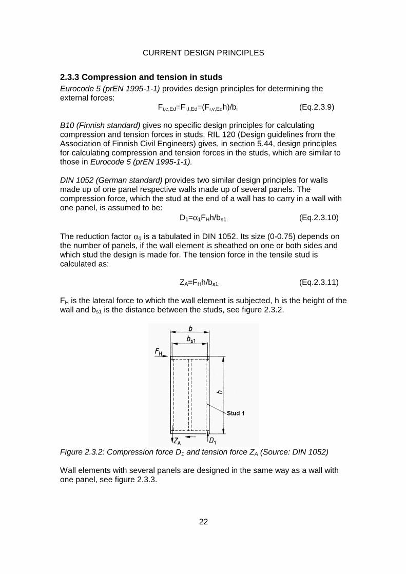
B10 (Finnish standard) gives no specific design principles for calculating compression and tension forces in studs. RIL 120 (Design guidelines from the Association of Finnish Civil Engineers) gives, in section 5.44, design principles for calculating compression and tension forces in the studs, which are similar to those in Eurocode 5 (prEN 1995-1-1). DIN 1052 (German standard) provides two similar design principles for walls made up of one panel respective walls made up of several panels. The compression force, which the stud at the end of a wall has to carry in a wall with one panel, is assumed to be:
D1=α1FHh/bs1. (Eq.2.3.10)
The reduction factor α1 is a tabulated in DIN 1052. Its size (0-0.75) depends on the number of panels, if the wall element is sheathed on one or both sides and which stud the design is made for. The tension force in the tensile stud is calculated as:
ZA=FHh/bs1. (Eq.2.3.11)
FH is the lateral force to which the wall element is subjected, h is the height of the wall and bs1 is the distance between the studs, see figure 2.3.2.
Figure 2.3.2: Compression force D1 and tension force ZA (Source: DIN 1052) Wall elements with several panels are designed in the same way as a wall with one panel, see figure 2.3.3.

CURRENT DESIGN PRINCIPLES
23
Figure 2.3.3: Vertical tension force ZA and compression force D1 (Source: DIN 1052)
The compression force in the studs is:
Di=αiFHh/bs. (Eq.2.3.12) The tensile force in the stud at the end of the wall element is:
ZA=FHh/bs. (Eq.2.3.13)
h is the height of the wall
bi is the width of the wall
The fasteners between single wall panels should be designed for a shear force equal to ZA. NS 3479 (Norwegian standard) provides design principles for the compression studs in shear walls based on a method presented in a draft for Eurocode 5 prENV 1995-1-1:1993:
Fi,c,Ed= 0.67 Fi,v,Ed h/bi (sheets on both sides of the wall panel) (Eq.2.3.5)
or
Fi,c,Ed= 0.75 Fi,v,Ed h/bi (sheets on one side of the wall panel) (Eq.2.3.6)
Fi,c,Ed is the vertical compression force Fi,v,Ed is the lateral design load on the wall diaphragm h is the height of the wall bi is the width of wall panel

CURRENT DESIGN PRINCIPLES
24
The factors 0.67 and 0.75 are in agreement with DIN 1052, where these values are used for wall panels built up with one or two wall units, and a linear elastic design method is used. In Eurocode prEN 1995-1-1, a plastic theory is given, why the vertical compression force is determined without the reduction factors 0.67 and 0.75 (see section 2.3.3, Eurocode 5 prEN 1995-1-1). BS 5268 (British standard) gives no specific design guidelines for the compression and tension in studs.
2.3.4 Vertical anchorage (hold-downs) Eurocode 5 (prEN 1995-1-1) provides design principles for determining the external forces Fi,c,Ed and Fi,t,Ed (see section 2.3.3). In case of tensile forces, the panel should be anchored by stiff fasteners. B10 (Finnish standard) gives no specific design principles for hold-downs. According to DIN 1052 (German standard) hold-downs on a single panel have to be designed for an uplift force (see figure 2.3.2):
ZA= FHh/bs1 (Eq.2.3.14)
And for a wall element made of more than one panel (see figure 2.3.3): ZA= FHh/bs (Eq.2.3.15)
BS 5268 (British standard) gives no specific design principles for hold-downs.
2.3.5 Buckling of wall studs Eurocode 5 (prEN 1995-1-1) provides design principles for buckling of wall studs in section 6.3.2 (Members subjected to compression and bending). B10 (Finnish standard) provides no specific design principles for buckling of wall studs. DIN 1052(German standard) does not give specific guidelines for buckling of shear wall studs. BS 5268 (British standard), Part 2, provides guidelines for the design of wall studs, subjected to compression and bending perpendicular to the plane of the wall. When considering buckling out of the plane of the wall, the slenderness ratio of a wall sheathed and fixed according to table 2 in BS 5268, section 6.1, should be calculated with an effective length of the studs 0.85 times the actual length. Studs with sheathing on one or both sides according to table 2 in BS 5268, section 6.1, are assumed fully restrained laterally in the plane of the wall.

CURRENT DESIGN PRINCIPLES
25
2.3.6 Compression perpendicular to the grain Eurocode 5 (prEN 1995-1-1) gives design principles for compression perpendicular to the grain in the horizontal members in section 6.1.5 (Compression perpendicular to the grain). B10 (Finnish standard) gives design principles for compression perpendicular to grain in section 5.2. DIN 1052 (German standard) has defined different rules for wall elements made of single panels or continuous panel systems, which are subjected to a vertical force or both a vertical and a horizontal force. The studs and the connection of the sheathing to the rail are considered to carry the vertical force FVi to the rail. The vertical design force Di for compression on the rail perpendicular to grain is determined by the relation of the permissible force Di and the total permissible vertical force, according to:
D=∑ (Di)+Dsheathing (Eq.2.3.16) Dsheathing is the capacity of the connectors between the sheathing and the rail. In continuous panels, which are connected to the same stud, the compression force from the stud and the corresponding compression area are divided by two. For shear walls, which are subjected to both a vertical force Fv and a horizontal force Fh, the compression force perpendicular to grain should be calculated as the result of both D1 (Eq.2.3.10) and D (Eq.2.3.16), for walls with one panel, and the result of Di (Eq.2.3.12) and D (Eq.2.3.16), for walls with several panels. BS 5268 (British standard) states that the permissible compression perpendicular to grain stress should be checked where studs bear on to rail or plate bear on to studs. The values for permissible compression perpendicular to grain stress are found in BS 5268 Part 2.

CURRENT DESIGN PRINCIPLES
26
2.3.7 Shear in sheathing material Eurocode 5 (prEN 1995-1-1) provides no specific design principles for analysis of shear in the sheathing material. B10 (Finnish standard) provides no specific design principles for analysis of shear in the sheathing material. RIL 120 (Design guideline from the Association of Finnish Civil Engineers) provides design principles for shear analysis of the sheathing in section 5.44. In this design, the buckling of the sheathing is taken into account.
DIN 1052 (German standard) contains no specific guidelines for analysis of shear in the sheathing. According to the code, no shear design is necessary for the sheathing and the fasteners in a shear wall that is ≥1.0 meter long and sheathed on both sides, if the maximum spacing between the fasteners along the edges of the panel is eR ≤ 80 mm, elsewhere eM ≤ 225 mm. In a wall with sheathing on one side, the lateral force FH is assumed to be transferred in the sheet by a diagonal tension force Z, see figure 2.3.5. For a diaphragm with a width b ≥1.2 m and a diagonal tension zone bZ=0.5 m, a design is not needed.
Figure 2.3.5: Wall panel with sheathing on one side. The transfer of the tension force Z in the sheathing (Source: DIN 1052) BS 5268 (British standard) gives no specific guidelines for shear in the sheathing material.

CURRENT DESIGN PRINCIPLES
27
2.3.8 Shear buckling of sheathing material Eurocode 5 (prEN 1995-1-1) provides no specific guidelines for shear buckling. According to EC 5, shear buckling of the sheet may be disregarded if the criterion in equation 2.3.17 is fulfilled.
bnet/t ≤100 (Eq.2.3.17) bnet is the clear distance between studs t is the thickness of the sheathing material
B10 (Finnish standard) provides no specific design principles for shear buckling of the sheathing material. RIL 120 (Design guideline from Association of Finnish Civil Engineers) gives no specific design principles for shear buckling, but it is taken into account (by a factor) when the shear capacity of the sheathing is calculated. DIN 1052 (German standard) does not provide rules for shear buckling design. BS 5268 (British standard) gives no specific guidelines for shear buckling of sheathing panels.
2.3.9 Racking deflection Eurocode 5 (prEN 1995-1-1) provides no specific design principles for racking deflection. Eurocode 5 states that the deflection should remain within appropriate serviceability limits (Eurocode 5, 9.2.4.1(6)). B10 (Finnish standard) gives no specific design principles for racking deflection. RIL 120 (section 5.44) provides a permissible racking deflection of maximum 1/500 x panel height. DIN 1052 (German standard) gives no methods for estimating the deflection. However, it provides rules for a permissible racking deflection of maximum 1/500 of the panel height. According to DIN 1052 deflection analysis is not needed if the height to width ratio of the panel is ≤ 3.0. BS 5268 (British standard) does not provide methods for estimating the deflection. However, the basic racking resistances given in table 2 in section 6.1 are based upon a maximum deflection of 0.003 times panel height.

CURRENT DESIGN PRINCIPLES
28
2.4 Intercomponent connections Intercomponent connections refer to the connections that join adjacent wall panels on the same storey, wall panels on different storeys or wall panels and diaphragms. None of the standards gives specific design principles for intercomponent connections, except the connections between a shear wall and the construction below (hold-downs and anchor bolts).
2.5 Disproportionate collapse Design principles for disproportionate collapse are implemented in few of the national codes. However, there is a new draft of Eurocode concerning this area. Eurocode 1 (draft prEN 1991-1-7, March 2003) gives specific design principles for accidental actions (e.g. explosions and impact) and localised failure. The draft prEN 1991-1-7 presents three strategies to ensure that a structure has sufficient robustness, see figure 2.5.1.
Figure 2.5.1: Accidental design situations (Source: Eurocode 1, prEN 1991-1-7) Sufficient robustness can be achieved by:
• Designing key components of the structure to sustain notional accidental action
• Designing the structural members to have sufficiently ductility to absorb much strain energy without breaking apart
• Incorporating sufficient redundancy in the structure to facilitate the transfer of accidental load to alternative load paths
This could minimize the potential damage to the structure due to a localised failure. Buildings are classified in different consequences classes depending on their type and occupancy. The Annex A in prEN 1991-1-7 recommends different

CURRENT DESIGN PRINCIPLES
29
strategies in order to provide structures in the different consequences classes with enough robustness to sustain localised failure without a disproportionate level of collapse. The different classes are presented in table 2.5.1. Table 2.5.1: Recommended categorisation of consequences classes (source: Eurocode 1, prEN 1991-1-7)

CURRENT DESIGN PRINCIPLES
30
The strategies for respective class are:
• Consequences class 1: Provided the stability design of the building was done according to EN 1992 to 1999, no further specific design regarding accidental action has to be done.
• Consequences class 2 (lower group): Horizontal ties, or effective
anchorage of suspended floors to walls should be provided. This should be done according to Annex A section 6.1 in prEN1991-1-7 for framed constructions and section 6.2 in prEN 1991-1-7 for load-bearing wall constructions.
• Consequences class 2 (upper group): Horizontal ties should be
implemented like in consequences class 2. In addition, vertical ties should be done according to Annex A section 7 in prEN 1991-1-7 and it should be ensured that the building remains stable by a notional removal of a supporting member.
• Consequences class 3: A systematic risk analysis of the building should
be done, taking into account all the normal hazards and abnormal hazards. The National Annex gives the hazards, which are to be taken into account. Annex B in prEN 1991-1-7 provides the guidance on the preparation of a risk analysis.
According to Annex A1 in prEN 1991-1-7, the local damage is limited to 15 % of the floor area in each of two adjacent storeys, see figure 2.5.2.
Figure 2.5.3: Recommended limit of admissible damage (Source: Eurocode 1, prEN 1991-1-7)

CURRENT DESIGN PRINCIPLES
31
DS 409 (Danish standard) provides simplified design principles for disproportionate collapse for buildings above four storeys. The rules are based on those in prEN1991-1-7. During next summer (2003) a new robustness design guideline, “Robust construction-Background and principle Guidance-2003”, will be approved be the Danish officials. In this guideline, the difference between the design for accidental loading and the design for robustness is stated more precisely than in the DS 409:1998 (second edition), “Code of practice for the safety of structures”. In DS 409:1998 (second edition), this difference was not made clear enough and could easily be misjudged. According to the DS/INF xxx (draft for code), both accidental action and robustness could be designed with load combination 3 “removal of supporting element” (DS 409:1998, second edition). An accidental action is a load, which is predefined or defined during the design of the building. The building can immediately be designed for this action based on the predefined values. However, robustness is a characteristic, which makes the structure less vulnerable for removal of support members. A structure, which is designed for an accidental action, is not guaranteed to be robust if this action has not been calculated in combination with the removal of supporting elements. Buildings, which have more than four storeys, should be designed for disproportionate collapse by checking the stability of the structure after removal of one support member. The area of structure at risk of collapse is limited to 15% of the area of two adjacent storeys, with maximum 240m2 in one storey and a total maximum of 360m2. BKR 98 (Swedish standard), section 2:113, provides no specific design principles for disproportionate collapse. It refers to Boverket’s handbook about vibrations, deflections and accidental actions, which gives design guidelines for multi-storey buildings concerning disproportionate collapse. According to these guidelines, a building with maximum four stories should be analysed for an overall stability after being damaged by an accidental action based on load combination 6 (1.0 Gk+0.25Qk). Furthermore, the load bearing walls, the supports of the diaphragms, the diaphragms and its joints should be designed in their own plane for a tensile force and a shear force, which act perpendicular to each other. These forces are based on the self-weight of the members and the imposed loads. For buildings with 5 to 16 stories, an additional analysis should be made to ensure that an alternative bearing could be provided to span over gaps formed by the removal of load bearing supports. According to British building regulations, the structural engineer should analyse the robustness of the building. BRE’s (Building Research Establishment Ltd) design guide for multi-storey timber frame buildings provides guidelines for timber frame design against disproportionate collapse. According to Enjily (2002), a notional removal of a support member, one member at a time in each storey in turn, should be considered to check if the rest of the structure would bridge over the resulting lack of support. Although, the structure would be in a substantially deformed condition or the risk of collapse of the remaining structure is limited to

CURRENT DESIGN PRINCIPLES
32
15% of the area of the storey, or 70 m2 within the storey or immediately adjacent storeys, whichever is less. If the structure cannot bridge over a missing member or limit the area at risk, the member should be designed for a load of 34 kN/m2 applied in any direction. The BRE design guide considers the method, by which the structure is checked against the notional removal of a defined length or specific member of the structure, as an appropriate route for platform timber frame structures. Furthermore, the BRE design guide defines the extent of a structure that should be considered under the robustness design, gives a clarification of structural elements used for robustness compliance and defines failure limits for the timber frame elements, see table 2.5.2 and 2.5.3. Table 2.5.2: Definitions of the extent of structure being considered under the robustness design (source: “the BRE design guide”)

CURRENT DESIGN PRINCIPLES
33
Table 2.5.3: Clarification of structural elements used for robustness compliance (source: “the BRE design guide”)
According to the BRE design guide, the following structural loads should be applied in the design for disproportionate collapse:
• Full dead load • 1/3 imposed floor load without floor reductions due to number of storeys • 1/3 imposed roof load • 1/3 wind load
The 1/3 wind load is not needed in timber frame design due to the method of racking resistance of walls. If a member is removed, it is unlikely that it would result in a loss in the racking resistance of more than one third.

CURRENT DESIGN PRINCIPLES
34
2.6 Lacks in design principles The study of current codes and handbooks shows that the respective European standards have lacks in several areas concerning stability design of multi-storey timber frame buildings. Some lacks that can be noted concern:
• Guidelines for the distribution of vertical loads along walls in different directions and the use of self weight of the building in order to counteract the uplift forces in the shear walls.
• Design guidelines stating when a diaphragm should be considered rigid
respective flexible concerning the distribution of lateral loads.
• Design principles for horizontal diaphragms, especially concerning the blocking of diaphragms and the continuity of the struts and chords in order to ensure a continuous load path.
• Design principles, which take the different diaphragm boundaries of roof
and floor diaphragms into account.
• Design guidelines for buckling of sheathing.
• Design principles for partially anchored shear walls with openings.
• Design principles for deflection of walls.
• Guidelines on how to ensure the transfer of forces between structural elements, e.g. adjacent walls in different storeys, adjacent walls in corners, horizontal diaphragms and the walls below.
• Design principles for multi-storey timber frame buildings against
disproportionate collapse concerning the design of robustness. However, the question is if these lacks constitute a problem for the structural engineers and if the simplified design principles used give conservative results. In order to investigate this, a number of engineers in Austria, Denmark, Finland, Germany, Norway, Sweden, Switzerland and the UK were interviewed. The interview method and the results from the investigation are presented in the following chapters.

35
3. METHODS In the previous chapter, an overview of the codes in different countries was given, and some problem areas where the codes provide indistinct or no guidance for the designers were pointed out. In order to investigate if these areas really are obstacles in the practical design situation, a field survey was performed. The survey was performed as a case study. A qualitative research was a natural approach for this study since the questions were of the type “how” and “why”, and since the investigator has little control over the events. Through a multiple case study the investigator could concentrate attention on the way particular groups of engineers confront specific problems. By comparing the cases, the investigator could strengthen the precision, the validity and the stability of the findings. In this chapter, the theory behind a case study is presented, as well as the design of this actual case study.
3.1 Case study methodology The survey was as, mentioned previously, conducted as embedded multiple case study, in which each of the engineers in the different countries represented a case. In figure 3.1, the initial steps in the design of a multiple case study are shown. First, a theory is developed, the cases are selected and a data collection protocol is designed. Each individual case study consists of one particular study, which is later compared with the other ones. The data collection protocol defines which data that are going to be measured and compared.

METHODS
36
Figure 3.1: Illustration of the phases in a multiple case study (after Yin, 1994). Secondly, multiple case studies are conducted and their individual reports are written. Finally, cross-case conclusions are drawn from the multiple-cases results and a cross-case report is written. The key concern of the investigator was to understand the problems that the engineers confront in the stability design of multi-storey timber frame buildings and how they solve these, from their perspectives. In order to obtain this information, the investigator chose to do semi structured person-to-person interviews and telephone interviews. Everything was recorded with a digital tape recorder.
3.2 Design of questionnaire The objective of the study was to identify lacks in design principles and design guidelines in the field of stability design in the Nordic countries, Germany, Switzerland, Austria and the UK. As mentioned previously, the investigation was performed by interviewing structural engineers in the different countries. A list of questions was thus designed and used as a guide. This allowed the investigator to respond to the situation at hand, to the emerging view of the respondent and to new ideas on the topic. Since the investigator was inexperienced in this kind of research, the list of questions was an important tool. It assured that the interview maintained a certain structure, i.e. that the respondents were asked the same questions, making it possible to compare the answers afterwards.

METHODS
37
During the literature studies and discussions with the tutor, the investigator designed a questionnaire covering a number of main topics in the field of stability design. Due to the differences in the national codes, the comparison was limited to five themes: 1. Load distribution 2. Design of diaphragms 3. Design of shear walls 4. Intercomponent connections 5. Lacks in design principles and development of design guidelines
Within each of these topics, a number of questions were designed to close in possible lacks in current codes and guidelines. Four different types of questions were used, se table 3.1. Table 3.1: Question categories (after Merriam,1998) and examples from questionnaire of present study. Type of question: Hypothetical Question: What the respondent might do or what it might be like in a particular situation; usually begins with “What if” or “suppose”. Ideal Position Question: Asks the respondent to describe an ideal situation Interpretive Question: Advances tentative interpretation of what the respondent have been saying and asks for a reaction. Yes-or-no:
Example: “Suppose you had a method to consider rigid beams over door openings, what influence do you think this would have on the racking resistance of a wall with large openings?” “If you had an ideal design method, which component do you think could profit at most of this method?” “What kind of simplification did you do?” “Do you think these simplification have any influence on the result?” “Did you design the building for progressive collapse?”
The first interview (with an engineer in Sweden) formed a pilot case study. The pilot case study revealed inadequacies in the initial questionnaire design, e.g. that some of the questions reoccurred several times under various themes. Due to this input, the structure of the interview was changed somewhat. The originally seven main topics were reduced to five. Also the number of questions was reduced. The questionnaire is presented in appendix A (Questionnaire).
METHODS
38
3.3 Sample selection In order to identify suitable structural engineers to interview, a list of recent multi-storey timber frame building projects was put together. For each project, the structural engineer responsible for the stability design was then identified. The selection criteria in the search for projects were that the buildings should be three stories or taller and built in the Nordic countries, Germany, Switzerland, Austria or the UK. In the search for multi-storey timber frame buildings meeting those criteria, the investigator got input from several sources, among others Professor Sven Thelandersson (Lund University), Mr Svein Gloslie in Norway and the Internet. The final list of building projects and corresponding structural engineer is presented in appendix B (European multi-storey timber frame building projects). Not all of the identified structural engineers could be interviewed since travelling and making interviews is very time-consuming. Due to the locations of the structural engineers, the travel expenses would also get very high if all of them were interviewed. Therefore the number of respondents was reduced and their locations chosen so that the costs could be kept low. The list of the engineers included in the case study is given in table 4.1 in chapter 4 (Results from interviews). The limitations of the sampling were thus: 1. Time 2. Money 3. Location 4. Availability of the respondents The final sampling was based on the criteria that both inexperienced and experienced engineers should be selected. This was done in order to get a divers picture of the situation. As an example, four engineers were interviewed in the UK; two of them have been designing multi-storey timber frame buildings for 1-1½ years and the two other engineers have been working in this field for over 10 years. The comparison of the results from those interviews was an important element in the case studies.

METHODS
39
3.4 Analysis technique The collection and analysis of data is a simultaneous process in qualitative research. A qualitative research is an emergent process. The investigator do not know ahead of every interview, all questions that might be asked or where to look next unless data are analysed as they are collected. Ideas, working hypotheses, and educated guesses direct the investigator’s attention to certain data and then to refining or verifying the investigator’s thoughts. This process is dynamic and is not finished when all the data has been collected. The analysis becomes more intensive as the study progresses, and once all the data are collected. In a multiple case study, there are two stages of analysis: the within-case analysis and the cross-case analyses (see figure 3.1). In the within-case analysis, each case is first treated as a comprehensive case in and of itself. In the present study this corresponds to the group of engineers in the Nordic countries, Germany, Switzerland, Austria and the UK. The investigator gathered data so that he could learn about the background variables that might have an influence on the case. Once the analysis of each case was completed, the cross-case analysis began. The investigator tried to build abstractions across the cases, keeping in mind that the countries have different building codes. The data were first compared between different cases in the same country. Finally, a cross-case analysis was made within each topic between the different countries.
3.5 Reliability and validity
According to Merriam (1998), reliability refers to the extent to which there is consistency in the findings. “In a research design reliability is based on the assumption that there is a single reality and that studying it repeatedly will give the same result. This is a central concept of traditional experimental research, which focuses on discovering fundamental relations among variables and uncovering laws to explain phenomena. Qualitative research however is not conducted so that the laws of human behavior can be isolated. Researchers seek to describe and explain the world as those in the world experience it. Since there are many interpretations of what is happening, there is no standard by which to take repeated measures and establish reliability in traditional sense” (Merriam 1998 p.205) Because information gathered, is a function of who gives it and how skilled the researcher is at getting it, and because the emergent design of a qualitative case study, achieving reliability in the traditional sense is impossible. The investigator could, in order to ensure that results are dependable, refer to the assumptions and theory behind the study, his position vis-à-vis the group of engineers being

METHODS
40
studied, and, the basis for selecting informants and the description of them (sample selection). Merriam (1998) also states that internal validity deals with the question of how research findings match reality. Because human beings are the primary instrument of data collection and analysis in qualitative research, interpretations of reality are accessed directly through their observations and interviews. An investigator relies on own instincts and abilities throughout most of this research effort. The question is the integrity of the investigator. According to Merriam (1998), an investigator could ask colleagues to comment on the findings as they emerged in order to estimate the internal validity. In the present study, the investigator asked his tutor to enhance the internal validity. The nature of interaction between the respondents and the investigator is determined by four variables (Merriam, 1998): • The investigators personality and skills • The attitudes and orientation of the respondent • How the respondent and the investigator defined the situation • The communicative skills of the respondent and the investigator These factors also determined the type of information obtained from an interview in the present study. In order to reduce the negative effect of these variables, the investigator tried to be non-judgemental, sensitive, and respectful of the respondent. At the beginning of the interviews, the respondent was asked which projects the respondent was involved in and general information about these projects. This laid the foundation for the succeeding structured interview.

41
4.RESULTS FROM INTERVIEWS In this chapter, the results from the interviews are presented briefly. The different sections are arranged after the main design topics, given by the questionnaire. Under each topic the respondents are presented country by country. The respondents and the building projects they have designed are presented in Appendix C (List of respondents).
4.1 Distribution of Load
4.1.1 Austria
Respondent A The respondent designed the building for the ultimate limit state with three different load combinations of dead load, snow load and wind load (similar to the three combinations in the German standard). The buildings were analysed for wind load in both principal directions. The most critical load combination was reduced dead load with wind load. Lateral loads were transferred from the diaphragm to the shear walls with the assumption that the stiffness of the walls was proportional to the length of each wall.
Respondent B The respondent designed the building for the ultimate limit state with three different load combinations of dead load, snow load and wind load (similar to the three combinations in the German standard). Additional lateral forces due to tilting of the shear wall elements were considered in the distribution of lateral loads. The buildings were analysed for wind load in both principal directions. The most critical load combination was reduced dead load with wind load. Lateral loads were transferred from the diaphragm to the shear walls with the assumption that the stiffness of the walls was proportional to the length of each wall.

RESULTS FROM INTERVIEWS
42
4.1.2 Denmark
Respondent C The respondent designed the building for the ultimate limit state with different load combinations of dead load, snow load and wind load. Additional lateral forces due to tilting (1.5% of vertical force) of the shear wall elements were considered in the distribution of lateral loads. The buildings were analysed for wind load in both principal directions. The most critical load combination was reduced dead load combined with wind load. Due to the rectangular and symmetrical shape of the buildings, he considered a detailed calculation of a section of the buildings to be sufficient for the overall stability design. Torsional effects were considered as a stability design problem, but because of the long building body and the continuous sub-floors, no essential torsional effects occurred. He considered the diaphragms to be rigid and distributed the lateral loads to the shear walls according to their relative stiffness.
Respondent D The respondent designed the building for the ultimate limit state with different load combinations of dead load, snow load and wind load. Additional lateral forces due to tilting (1.5%) of the shear wall elements were considered in the distribution of lateral loads. The building was analysed for wind load in both of its principal directions. The most critical load combination was reduced dead load combined with wind load on longitudinal walls. Due to the rectangular and symmetrical shape of the building, he considered a detailed calculation of a section of the building to be sufficient for the overall stability design. Torsional effects were generally not considered as a stability design problem (due to the shape of the building). He considered the diaphragms to be semi-rigid and distributed the lateral loads to the shear walls according to the length of each wall.
4.1.3 Finland
Respondent E The respondent designed the building for the ultimate limit state with different load combinations of dead load, snow load and wind load. The building was analysed for wind load in both of its principal directions. Reduced dead load combined with wind load was the most critical load combination. Torsional effects on the structure were not considered a problem due to the concrete lift wells and stairwells restraining the structure. The shear force was distributed to the shear walls according to the length of each wall.

RESULTS FROM INTERVIEWS
43
Respondent F The respondent designed the building for the ultimate limit state with different load combinations of dead load, snow load and wind load. The building was analysed for wind load in both of its principal directions. Reduced dead load (load factor 1.0) combined with wind load was the most critical load combination. He used a computer program to design the structure for torsional effects. The diaphragms were assumed to act like simply supported beams. The respondent assumed that roof diaphragms were not able to transfer as much force to the walls as floor diaphragms, due to the lack of connections between roof diaphragms and the walls. The shear force was distributed to the shear walls according to the length of each wall.
Respondent G The respondent designed the buildings for the ultimate limit state with different load combinations of dead load, snow load and wind load. The building was analysed for wind load in both of its principal directions. Additional lateral loads due to tilting of the shear walls were also considered in the distribution of load. Reduced dead load combined with wind load was the most critical load combination. The respondent simplified the design by using the maximum wind load parameter. He believes that this simplification had little influence on the result.
4.1.4 Germany
Respondent H The respondent designed the building for the ultimate limit state with three different load combinations of dead load, snow load and wind load. The building was analysed for wind load in both of its principal directions. Reduced dead load combined with wind load on gable walls was the most critical load combination. Diaphragms were considered to act like simply supported deep beams. Each of the two parts of the building was designed separately. The concrete structure, which connected these two parts, was considered to carry torsional forces. The respondent chose to overdimension the structure to simplify the analysis. The shear force was distributed from the diaphragm on the shear walls according to the length of each wall.
Respondent I The respondent designed the building for the ultimate limit state with three different load combinations of dead load, snow load and wind load. The building was analysed for wind load in both of its principal directions. Reduced dead load combined with wind load on gable walls was the most critical load combination. The hold-downs in the shear walls were the most crucial components in the design of the walls. Diaphragms were considered to act like simply supported beams. The shear force was distributed to the shear walls according to the length of each wall.
RESULTS FROM INTERVIEWS
44
Respondent J The respondent designed the building for the ultimate limit state with three different load combinations of dead load, snow load and wind load. He considered the building to have enough shear walls and racking capacity for wind load perpendicular to the longitudinal walls. Reduced dead load combined with wind load on gable walls was the most critical load combination. The wind load was distributed on the structure according to the flexible diaphragm method.
Respondent K The respondent designed the building for the ultimate limit state with three different load combinations of dead load, snow load and wind load. The building was analysed for wind load in both of its principal directions. Reduced dead load (factor 0.67) combined with wind load on gable walls was the most critical load combination.
4.1.5 Norway
Respondent L The respondent designed the building for the ultimate limit state with three different load combinations of dead load, snow load and wind load. The building was analysed for wind load in both of its principal directions, by which wind load on the gable was the most critical one. Reduced dead load and wind load was the most critical combination. A design for torisonal effects was performed with a computer program. Lateral loads were transferred from the diaphragm to the shear walls according to the relative stiffness of each wall.
Respondent M The respondent designed the building for the ultimate limit state with three different load combinations of dead load, snow load and wind load. The building was analysed for wind load in both of its principal directions, by which wind load on the gable was the most critical one. Reduced dead load and wind load was the most critical combination. A design for torisonal effects was performed with a computer program. Lateral loads were transferred from the diaphragm to the shear walls according to the relative stiffness of each wall.
4.1.6 Sweden
Respondent N The respondent designed the building for wind load in both of its principal directions. A load combination with reduced dead load and wind load was the most crucial one in the ultimate limit state. Due to the geometry of the building (L-shaped), the respondent chose to split the building in two separate parts in the structural design and to analyse each of the parts separately. This resulted in a more simplified design method in which the torsional effects were neglected. The two parts were considered to be too rigid to rotate. The respondent considered the diaphragms to be flexible and did not design them for torsional effects.

RESULTS FROM INTERVIEWS
45
Respondent O The respondent designed the building for wind load perpendicular to the longitudinal walls. He considered the building to have adequate racking load carrying capacity in its longitudinal direction and did not perform any design for this direction. Since the building is rectangular and symmetrical, the respondent considered it enough to analyse one section of the building.
Respondent P The respondent designed the building for the ultimate limit state with three different load combinations with dead load, snow load and wind load. The building was designed for wind load in both of its principal directions. Diaphragms were considered to act as simply supported deep beams. Reduced dead load and wind load was the most critical load combination. The stiffness of the walls was assumed to be proportional to the length of each wall and the shear force was distributed according to this.
4.1.7 Switzerland
Respondent Q The respondent designed the building in the ultimate limit state for three different load combinations with dead load, snow load and wind load. The building was designed for wind load in both of its principal directions. Reduced dead load and wind load was the most critical load combination. The building was designed for torsional effects.
Respondent R The respondent designed the building in the ultimate limit state for three different load combinations with dead load, snow load and wind load. The building was designed for wind load in both of its principal directions. Reduced dead load and wind load was the most critical load combination. A concrete structure in the building was designed to carry all torsional forces.
4.1.8 The United Kingdom
Respondent S The respondent designed the building for different load combinations with dead load, snow load and wind load. The building was designed for wind load in both of its principal directions. The wind load was distributed on the structure according to the flexible diaphragm method and an analysis was made for both directions of the building. The respondent made a design for torsional effects, by which he considered the whole structure.

RESULTS FROM INTERVIEWS
46
Respondent T The respondent designed the building for different load combinations with dead load, snow load and wind load. For the overall stability design, dead load combined with wind load was most critical combination. The wind load was distributed on the structure according to the tributary area method, and an analysis was made for both of the principal directions of the building. A design for torsional effects was done by considering the whole structure.
Respondent U The respondent did a permissible stress design according to BS 5268 and used load combinations with dead load, snow load and wind load. The wind load was distributed on the structure according to the tributary area method and an analysis was made for both of the directions of the building. For overall wind load, the whole structure was considered. For individual stability, parts (sections) of the building were analysed. The sections on the end of the building had to distribute 50% of the stiffness. By the design for rotational forces, the cooperation of different sections of the building is considered to contribute to the overall stiffness.
Respondent V The respondent designed the structure according to BS 5268. A permissible stress design with load combinations with dead load, snow load and wind load was performed. The wind load was distributed on the building according to the tributary area method and an analysis was made for both of the principal directions of the building. Different parts of the building was considered to cooperate and taken into account in the design for torsional effects.
4.2 Design of diaphragms
4.2.1 Austria
Respondent A The buildings were built as a platform frame system with bonded timber elements as diaphragms. The respondent considered the diaphragms to be rigid. Their anchor bolts were designed for a uniformly distributed shear force. Lateral torsional buckling was not considered to be a problem due to the structure of the bonded elements. A concrete structure, which restrained the timber frame building, was designed to carry the torsional forces of the multi-storey timber frame structure.

RESULTS FROM INTERVIEWS
47
Respondent B The buildings were built as platform frame systems with solid wood elements as diaphragms. These elements were assumed to act as deep beams and designed according to design principles similar to those in DIN 1052 (see 2.2.1). The diaphragms were considered to be rigid. Their anchor bolts were designed for a uniformly distributed horizontal shear force. Lateral torsional buckling was not considered as a problem due to the structure of the solid wood elements.
4.2.2 Denmark
Respondent C Floor elements were not designed for torsional effects. The sheathing and its fastening were designed for a uniformly distributed shear force. A platform frame system was used in the buildings. In order to reduce the effects of shrinkage, short pieces of wall studs were placed on both sides of the supports of the floor joists to minimize the amount of wood subjected to compression perpendicular to grain. The respondent did not design the floor joists for lateral torsional buckling because he considered the joists to be restrained at their compressive side by the sheathing and at their supports by blockings. In his opinion, roof and floor diaphragms can be designed in the same way if they are similar constructed and have the equal boundary solutions. He thinks eccentricity makes the difference for the design of a connection between a floor element and wall studs in a balloon frame system compared to a platform frame system.
Respondent D Floor elements were generally not designed for torsional effects (due to the shape of the building). The sheathing and its fastening were designed for a uniformly distributed shear force. The building was build with a platform frame system. In order to reduce the effects of shrinkage, short pieces of wall studs were placed on both sides of the supports of the floor joists to minimize the amount of wood subjected to compression perpendicular to grain. The respondent did not design the floor joists for lateral torsional buckling because he considered the joists restrained at their compressive side by the sheathing and at their supports by blockings. He thinks eccentricity makes the difference for the design of a connection between a floor element and wall studs in a balloon frame system compared to a platform frame system.
4.2.3 Finland
Respondent E The composite diaphragms were considered to be rigid. The building was built with a platform frame system.

RESULTS FROM INTERVIEWS
48
Respondent F The respondent considered the prefabricated diaphragms to be rigid. Floor elements were not, due to prefabrication, especially designed. The building was built with a platform frame system. The floor diaphragms were not especially designed for lateral torsional buckling, but blockings were used in order to restrain joists. Lateral torsional buckling of the joists was not considered to be a problem.
Respondent G The respondent considered the prefabricated diaphragms to be rigid. The diaphragms were designed for torsional effects by using a computer program. The floor elements were designed according to the handbooks of the producer for a uniformly distributed shear force. The building was built with a platform frame system. Floor joists were not designed for lateral torsional buckling. Blockings were used every 2-meter to restrain the beams. The shear force was distributed to the shear walls according to the length of each wall.
4.2.4 Germany
Respondent H The respondent assumed the diaphragms to be rigid. A design for torsional effects was not done. The sheathing and the fasteners were designed for a uniformly distributed shear force. A platform frame system was used, in which floor joist were designed as continuous beams. The respondent did not design the floor joist for lateral torsional buckling. He considered the joists to be torsional restrained at their compressive side by the sheathing.
Respondent I The solid wood diaphragms were considered to be rigid and designed for torsional effects. Its joints were designed for a uniformly distributed shear force. The building was built with a platform frame system. The respondent thought that floor diaphragms and roof diaphragms could be designed in the same way if the boundary conditions are the same.
Respondent J The respondent considered the diaphragms to be flexible and to act like simply supported deep beams. He designed them according to DIN 1052. The building was built with a platform frame system.
Respondent K The respondent considered the diaphragms to be rigid and analysed them according to DIN 1052. Wind bracing straps were used to make the diaphragms stiffer. The diaphragms were designed for torsional effects. This design was checked with a computer program. The building was built with a platform frame system. The floor joists were not designed for torsional buckling. Blockings were used to restrain the beams at their supports.

RESULTS FROM INTERVIEWS
49
4.2.5 Norway
Respondent L The prefabricated floor elements were considered to be rigid and were not specifically designed for shear force. A computer program was used to determine the torsional components of the shear walls. The building was built in a platform system and continuous beams were used in the diaphragms. The beams were analysed as continuous beams. They were not considered to be subjected to lateral torsional buckling. Still, they were torsional restrained at the supports by blockings. The respondent thinks that floor and roof diaphragms are designed in the same manner.
Respondent M The sheathing of the diaphragms was designed for a uniformly distributed shear force. The beams were not especially designed for lateral torsional buckling, but torsional restrained at the supports by blockings The respondent did not consider lateral torsional buckling as a stability problem since the compressive side of the joists was restrained by the sheathing and the beams were restrained at its supports by the blockings. He considered the design of a roof diaphragm to be different from a floor diaphragm analysis because the connections along the edges of the sheathing of a floor diaphragm are not continuous.
4.2.6 Sweden
Respondent N The building was built with a platform frame system. Floor joists were not designed for lateral torsional buckling. Joists were assumed restrained at the compressive side by the floor sheathing. Diaphragm elements were designed according to the Gyproc handbook. The sheathing was glued and nailed to the beams according to guidelines in handbooks from the plasterboard producer.
Respondent O The respondent considered the diaphragms to be rigid. He assumed the diaphragms to act as deep beams, which are simply supported. The stiffness of the walls was assumed to be proportional to the length of each wall. Floor diaphragms were prefabricated elements and considered by the respondent to have an overcapacity. Therefore, he chose not to design the floor elements. The joists in the diaphragms were not designed for lateral torsional buckling. Horizontal rotation of the building was neglected.

RESULTS FROM INTERVIEWS
50
Respondent P The respondent considered the prefabricated diaphragms to be rigid. The structure was not designed for torsional effects. The building was built with a platform frame system. Diaphragms were not designed for lateral torsional buckling since the joists were torsional restrained at their supports by blockings and the compressive side of joists was restrained by the sheathing. The respondent considers eccentricity at the connection between the joists and the continuous studs to be problem with the design of a balloon frame system compared with a platform frame system.
4.2.7 Switzerland
Respondent Q The respondent considered the composite diaphragms to be rigid. The diaphragms were analysed according to DIN 1052 and designed to transfer the torsional forces to the walls. The Sheathing and its fasteners were designed for a uniformly distributed shear force. Joists were designed for lateral torsional buckling and torsional restrained at their supports.
Respondent R The respondent considered the “Lignatur” elements to be rigid. A shear force design was made according to German Standard DIN 1052. The building was built with a platform frame system. Due to the structure of the “Lignatur” elements, the diaphragms were not designed for lateral torsional buckling.
4.2.8 The United Kingdom
Respondent S The respondent used prefabricated diaphragms, which were approved by a colleague, in a platform frame system. The respondent considered a balloon frame system to have two disadvantages compared to platform system:
• It is difficult to make suitable connection details in terms of both disproportionate collapse and normal loading
• It is unpractical for erection on the building site The respondent did not design the floor joists for lateral torsional buckling since they were assumed to be restrained at the compressive side by the floor decking. For disproportionate collapse, all prefabricated floor panels were double or triple span.

RESULTS FROM INTERVIEWS
51
Respondent T The respondent considered the diaphragm to be rigid, providing the depth to length ratio was less than 4/1, and did not design them. Greater length to depth ratios would require further consideration. The buildings were all built with a platform frame system. The respondent thinks the transfer of shear force from the diaphragm to the studs is the biggest difference, in terms of design, between a balloon frame system and a platform frame system, as far as design is concerned. Practicalities of erection and transport would differ between the two methods.
Respondent U The prefabricated diaphragms were considered to be rigid. The shear force was distributed to the shear walls according to the length of each wall. An ordinary torsional design (lever arm) was performed to design for torsional effects. The building was built with a platform frame system. The respondent believes that the transmission of shear force from the diaphragms to the studs is the biggest difference, in terms of design, between a balloon frame system and a platform frame system.
Respondent V The respondent considered the prefabricated diaphragms to be rigid. A standard torsional design was performed for the diaphragms. The building was built with a platform frame system.
4.3 Design of shear walls
4.3.1 Austria
Respondent A The shear walls were designed according to Austrian standard (similar to German standard DIN 1052). Wall panels, which contained large window or door openings, were considered not to contribute to the racking load carrying capacity of the shear walls. The anchor bolts (screws) were designed for a uniformly distributed shear force. These connections were the most critical part of the analysis of the walls. Uplift of shear wall studs was not a problem in the design of the buildings. The reduced dead load was enough to keep the structure stable. Compression perpendicular to grain between wall and diaphragm elements was not considered as a problem. The walls were not designed for deflection or displacement in their own plane.

RESULTS FROM INTERVIEWS
52
Respondent B The walls were designed according to Austrian standard (similar to German standard DIN 1052). Wall panels, which contained large window or door openings, were considered not to contribute to the racking load carrying capacity of the shear walls. The shear walls were fully anchored. Connector brackets and bolts were used as hold-downs. Screws and nails were used as anchor bolts. Compression perpendicular to grain and the design of the hold-downs at window and door openings were the two most difficult areas of the design of the shear walls. All layers of sheathing on both sides of the panel of inner shear walls were assumed to contribute to the racking capacity of the walls. Outer plasterboards on longitudinal walls or gable walls were, due to moisture, not considered to contribute to the racking capacity of the walls. Transverse walls were designed to reduce the uplift forces in the shear walls. The shear walls were not designed for deflection or displacement in their own plane.
4.3.2 Denmark
Respondent C The shear walls were designed according to Eurocode 5. This implies that wall panels with large openings were not considered to contribute to the racking load carrying capacity of the fully anchored walls. Slats fastened with nails were used as hold-downs. These were designed to carry just vertical forces. Screws were used as anchor bolts and designed to transmit just horizontal shear forces. Compression perpendicular to grain was a critical part of the design, which was solved by using short pieces of studs at the supports of the joists. The fastening of the sheathing was the most critical component in the shear wall design. Transverse walls were designed to reduce the uplift forces in the shear walls. This was done according to Andreasson (2000). Multi-storey shear wall structures were designed to stiffen the structure. The respondent utilised diaphragms to increase the stiffness of wall elements with large openings. The effect of the diaphragms in this perspective depends on the orientation of the floor joists and if they are supported on these wall elements. All layers of sheathing were considered to contribute to the racking capacity of the shear walls. However, plasterboards on outer walls were not used in the design, due to reduced stiffness if subjected to moisture. The shear walls were not designed for deflection or displacement in their own plane.

RESULTS FROM INTERVIEWS
53
Respondent D The shear walls were designed according to Eurocode 5. Wall panels with large openings were not considered to contribute to the racking capacity of the partial anchored walls. Slats fastened with nails were used as hold-downs. These were designed to carry just vertical forces. Screws were used as anchor bolts and designed to transmit just horizontal shear forces. Compression perpendicular to grain was a critical part of the design, which was solved by using short pieces of studs at the supports of the joists. The fastening of the sheathing was the most critical component in the shear wall design. Transverse walls were designed to reduce the uplift forces in the shear walls according to Andreasson (2000). The respondent assumed that the uplift forces could be reduced with 20% if the transverse walls were load-bearing walls. The respondent used single storey shear walls to stiffen the structure. The effect of multi-storey shear wall structures was not considered. Plasterboards on outer walls were not used in the design, due to reduced stiffness if subjected to moisture. The shear walls were not designed for deflection or displacement in their own plane.
4.3.3 Finland
Respondent E The respondent used concrete shear walls. Therefore, he was not asked questions from this topic.
Respondent F The shear walls were designed according to the Gyproc Handbook. Wall panels with large openings were not considered to contribute to the racking capacity of the partial anchored shear walls. The hold-downs (steel brackets with bolts) were designed to carry just uplift forces. Screws and nails were used as anchor bolts and designed to carry just horizontal shear forces. The hold-downs were the most critical components in the design of the shear walls. In case both plasterboards and plywood boards were used as sheathing, just the plywood boards were considered to contribute to the racking capacity. Transverse walls were used to reduce the uplift forces in the shear walls. Multi-storey shear wall structures were not considered to stiffen the structure. The shear walls were designed for deflection and displacement in their own plane.

RESULTS FROM INTERVIEWS
54
Respondent G The respondent has designed the diaphragms according to the Finnish standard and the Gyproc handbook. Wall panels with large openings were not considered to contribute to the racking capacity of the fully anchored walls. The fastening of the sheathing was the crucial component in the shear wall design. The respondent tried to keep a balance between the designs of the hold-downs, anchor bolts, sheathing fasteners and compression perpendicular to grain. The hold-downs (steel brackets) were designed to carry just uplift forces. Anchor bolts (screws) were designed to transmit just horizontal shear forces. Transverse walls were not designed to reduce uplift forces in the shear walls. Multi-storey shear wall structures were considered to stiffer the structure. The respondent assumed that just one layer (preferable wood-based boards) on both sides of a wall panel would contribute to the racking capacity of the shear wall. The shear walls were designed for displacements in their own plane.
4.3.4 Germany
Respondent H The respondent designed the shear walls according to DIN 1052, which means that he did not consider the wall panels with large openings to contribute to the racking capacity of the walls. Due to the height of the wall (3.75 m), the respondent had to do a special design of the wall (in conference with the test engineer). Steel brackets with screws were used as hold-downs and designed to carry just vertical forces. Glued-in bolts were used as anchor bolts to transmit horizontal shear forces. The fastening of the sheathing to the frame was the critical part of the design of the shear walls. All layers of sheathing were taken into account in the design of the racking capacity. Wall elements were fully anchored. Transverse walls were used to reduce the uplift forces in the shear walls. Multi-storey shear wall structures were not designed to stiffen the structure.
Respondent I The respondent designed the shear walls according to DIN 1052. Wall panels with large openings were considered not to contribute to the racking capacity of the walls. Steel brackets and bolts, which were used as hold-downs, were designed to transmit just uplift forces. The anchor bolts (nails) were analysed to carry just horizontal shear forces. The hold-downs were the most critical part in the design of the fully anchored shear walls. Transverse walls were not designed to reduce the uplift forces in shear walls. Multi-storey shear wall structures were not designed to stiffen the structure. All layers of sheathing, except for plasterboards on outer walls, were taken into account in the design of the racking capacity. A “Kerto” plate was used under the end of the studs to avoid problems with compression perpendicular to grain. The shear walls transmitting the highest lateral loads were designed for displacement in their own plane.

RESULTS FROM INTERVIEWS
55
Respondent J Shear wall were designed according to DIN 1052. Wall panels with large openings were not considered to contribute to the racking resistance of the walls. BMF/Simpson connectors were used as hold-downs and anchor bolts. The hold-downs were designed to carry just uplift forces and the anchor bolts were designed to carry horizontal shear forces. The respondent did not need to consider that transverse walls would reduce the uplift forces in the fully anchored shear walls. He chose not to design multi-storey shear wall structures to stiffen the structure since they were just two storeys tall. The shear walls were not designed for deflection or displacement in their own plane.
Respondent K The shear walls were designed according DIN 1052. Wall panels with large openings were not considered to contribute to the racking capacity of the fully anchored walls. Steel brackets with bolts were used as hold-downs. These were designed to carry just uplift forces. The anchor bolts (screws) were designed to carry just horizontal shear forces. The transverse walls were not designed to reduce the uplift forces in the shear walls. Due to the plan configuration there were no multi-storey shear wall structures, which could be used to stiffen the structure. The respondent considered all layers of sheathing on both sides of the wall panels to contribute to the racking load carrying capacity. The hold-downs were the critical component in the shear wall design. The shear walls were not designed for displacement and deflection in their own plane.
4.3.5 Norway
Respondent L Wall panels, which contained large window or door openings, were considered to contribute to the racking load carrying capacity of the shear walls. This was made by constructing a special frame for each element. A firm specialized in making trusses did the design of the frames. The shear walls were designed as partially anchored wall elements and the hold-downs (metal straps) were the most critical components in the shear wall design. Plywood board stripes, which were mechanically jointed to the modules, were used to transfer vertical shear force. Transverse walls were designed to reduce the uplift forces in the shear walls. The respondent assumed that all layers of sheathing on both sides of the panel would contribute to the racking capacity of the shear walls. According to the Norwegian Standard NS 3479, the design for compression perpendicular to grain should be done in the serviceability limit state and not the ultimate limit state. The respondent did not consider compression perpendicular to grain to be a problem in his project.
Respondent M Wall panels, which contained large door or window openings, were not considered to contribute to the racking capacity of the shear walls. The walls were designed to be fully anchored and metal straps were used as hold-downs.

RESULTS FROM INTERVIEWS
56
The hold-downs were the most critical components in the design of the shear walls. Due to the simplifications in the analysis (analysing the building for each of its principal directions separately and performing an elastic analysis of the shear walls) a large number of hold-downs at the large openings in the longitudinal walls were needed. Transverse walls were used in order to reduce the uplift forces in the shear walls. One layer of sheathing on each side of the wall panels was considered to contribute to the racking capacity. Compression perpendicular to grain was not considered as a problem. The shear walls were not designed for deflection in their own plane.
4.3.6 Sweden
Respondent N The respondent used guidelines from a plasterboard producer to design the shear walls. In this method, wall panels with large window or door openings are not considered to contribute to the racking load carrying capacity of the shear wall. The wall elements were fully anchored with steel brackets and bolts as hold-downs and screws as anchor bolts. Expansion bolts were used to fasten the rail to the foundation. Transverse walls were not considered to reduce uplift forces in shear walls. Compression perpendicular to grain and buckling of the wall studs were the two most critical parts of the design of the shear walls. The shear walls were not designed for deflection and displacement in their own plane. The respondent considered compression perpendicular to grain and moisture effects to be the two crucial points with a platform frame system.
Respondent O The respondent used a design method, which does not consider wall panels with large window or door openings to contribute to the racking load carrying capacity of a shear wall. Wall elements were designed as fully anchored walls. Steel brackets with bolts and screws were used as hold-downs and anchor bolts. The hold-downs and the anchor bolts were designed separately, i.e. the hold-downs are carrying only vertical forces and anchor bolts only horizontal forces. The design of these connections was the most critical part in the shear wall design. Transverse walls were designed to reduce uplift forces in shear walls. Because of the simplified analysis and a small wind load, dead load was enough to prevent walls from uplift.

RESULTS FROM INTERVIEWS
57
Respondent P The respondent used a handbook from a plasterboard producer as a design guideline. According to this guideline, wall panels with large window or door openings are not considered to contribute to the racking load carrying capacity of shear walls. Steel brackets with bolts and nails were used as hold-downs and anchor bolts. Hold-downs were separately designed to carry uplift forces and anchor bolts to carry horizontal forces. The hold-downs were the most critical part of the design of the shear walls, which were designed as fully anchored. The respondent considered all layers of sheathing (inclusive outer plasterboards) on both sides of the wall panels to contribute to the racking capacity. Transverse walls were not considered to reduce the uplift forces in shear walls. Multi-storey shear wall structures were not assumed to contribute to a stiffer structure. The wall elements were not designed for deflection or displacement in their own plane.
4.3.7 Switzerland
Respondent Q The shear forces were distributed uniformly to the shear walls according to the length of each wall. The shear walls were designed according to DIN 1052. Therefore, wall panels with large window or door openings were not considered to contribute to the racking load carrying capacity. Hold-downs (steel brackets and bolts) were designed to carry just uplift loads. Anchor bolts (screws) were designed to carry just uniformly horizontally distributed shear forces. The hold-downs were the critical component in the shear wall design. The respondent considered shear walls as fully anchored and used transverse walls to reduce the uplift forces in adjacent shear walls.
Respondent R The shear walls were fully anchored and designed according to German Standard DIN 1052. Wall panels with large window or door openings were not considered to contribute to the racking load carrying capacity of the shear walls. Steel brackets and bolts were used as hold-downs. These were designed to carry just uplift forces. The hold-downs were the critical component in the shear wall design for this load combination.

RESULTS FROM INTERVIEWS
58
4.3.8 The United Kingdom
Respondent S The respondent designed the shear walls according to BS 5268 Part 6.2 (Buildings other than dwellings not exceeding four storeys). Wall panels with large openings were considered to contribute to the racking resistance of the partial anchored walls in accordance with the British Standard. The hold-downs (metal straps) were designed to carry just uplift forces. The anchor bolts (nails) were designed to transmit just horizontal shear forces. Compression perpendicular to the grain was the most critical part in the design of the shear wall stud centres (no numerical effect to overall racking design). More studs were used in the lower parts of the building to carry the additional vertical loads. The respondent tried to find a balance between the design of the hold-downs, the sheathing joints and compression perpendicular to grain. Transverse walls were not considered to reduce the uplift forces in the shear walls. Multi-storey shear wall structures were not considered to stiffen the structure. The respondent used the capacity of just one board on each side of the wall. He preferred to use OSB. He did not design the shear walls and the diaphragms for deflections or displacements in their own plane.
Respondent T The shear walls were designed according to BS 5268 Part 6.1. Wall panels with large openings were used to contribute to the racking resistance of the fully anchored shear wall if needed. However, the respondent generally tries to use walls without openings. Hold-downs and anchor bolts were not designed. The respondent knows from experience how many hold-downs he needs, as standard one metal strap every 3.6 meters. Hold-downs are considered to carry just vertical forces and anchor bolts (nails) just horizontal shear forces. Compression perpendicular to grain was not considered as a problem. If he had problems with that, he used a higher grade of timber or just more studs. The fastening of the sheathing was the most crucial component in the wall. All layers of sheathing were considered, according to BS 5268, to contribute to the racking resistance of the walls. Transverse walls contribute to the resistance to overturning of the building and the dead load of the building is often sufficient to prevent overturning. Multi-storey shear wall structures were not considered to stiffen the structure. The effect of dead weight from walls is taken into account in the BS. These have a stiffening effect. The respondent did not calculate the shear walls for deflections or displacements in their own plane because it is already taken into account in the tables in British Standard.

RESULTS FROM INTERVIEWS
59
Respondent U The respondent designed the shear walls according to British Standard BS 5268. The racking resistance for walls with large openings was reduced according to BS 5268. Compression perpendicular to grain governs the stud design and, together with buckling of the studs, is the most critical part in the shear wall design. Hold-downs and anchor bolts were designed according to BS 5268. Hold-downs (metal straps) are carrying just uplift forces and anchor bolts (nails) are transmitting just horizontal shear forces. The use of hold-downs depended on the uplift forces. Some walls were designed with just anchor bolts. Transverse walls were not designed to reduce uplift forces in shear walls. Multi-storey shear wall structures were not considered to stiffen the structure. Only OSB boards were used in the design of the racking resistance.
Respondent V The shear walls were designed according to BS 5268. Walls with large window or door openings had their racking resistance reduced according to BS 5268. The respondent did a simplified design of the building. The racking resistance of the walls were calculated and compared with the lateral load. The shear forces were distributed to the shear walls according to the length of each wall. Reduced dead load combined with wind load was the most critical load combination for the shear wall design. Hold-downs were used when there were uplift forces. The anchor bolts were designed to carry just horizontal shear forces. Transverse walls were not designed to reduce uplift forces in shear walls. Multi-storey shear wall structures were not considered to stiffen the structure. Shear walls and diaphragms were not designed for deflection and displacements in their own plane.
4.4 Intercomponent connections
4.4.1 Austria
Respondent A Walls were connected to diaphragms in two different ways: with steel brackets and bolts or with screws. Screws were also use to connect walls to each other.
Respondent B The respondent was not asked questions about this topic.
4.4.2 Denmark
Respondent C The respondent was not asked questions about this topic.

RESULTS FROM INTERVIEWS
60
Respondent D The most critical intercomponent connectors in the stability design of the project were connectors between top plate and trusses respective connectors between sill plate and foundation.
4.4.3 Finland
Respondent E The respondent was not asked questions about this topic.
Respondent F Both metal connectors and wooden boards were used as intercomponent connections. Nail spacing were based on experience values. Between adjacent walls, the connections were done on site by the contractor.
Respondent G Screws were used to connect the walls to the diaphragms. These connections were designed for a uniformly distributed shear force. The wall elements were connected to each other with screws. The spacing value between the screws was chosen by the contractor in conference with the respondent.
4.4.4 Germany
Respondent H The respondent was not asked questions about this topic.
Respondent I The respondent was not asked questions about this topic.
Respondent J The respondent was not asked questions about this topic.
Respondent K The intercomponent connections, except for the hold-downs and anchor bolts, were not especially designed. Constructional solutions (nail joints) based on the experience of the contractor were used to connect adjacent walls.
4.4.5 Norway
Respondent L The respondent was not asked questions about this topic.
Respondent M The respondent was not asked questions about this topic.
RESULTS FROM INTERVIEWS
61
4.4.6 Sweden
Respondent N At the time of the interview, the intercomponent connections details were not yet designed by the respondent. Therefore, he was not asked questions about this topic.
Respondent O The shear force was assumed to be uniformly distributed and screws were, except for the hold-downs, used in every intercomponent connection. Connections between adjacent walls were developed by the contractor in conference with the respondent.
Respondent P The respondent designed just the hold-downs and anchor bolts.
4.4.7 Switzerland
Respondent Q The respondent was not asked questions about this topic.
Respondent R The respondent was not asked questions about this topic.
4.4.8 The United Kingdom
Respondent S The respondent was not asked questions about this topic.
Respondent T The respondent was not asked questions about this topic.
Respondent U The respondent was not asked questions about this topic.
Respondent V The respondent was not asked questions about this topic.

RESULTS FROM INTERVIEWS
62
4.5 Design for disproportionate collapse
4.5.1 Austria
Respondent A The respondent did not design the buildings for disproportionate collapse.
Respondent B The respondent did not design the buildings for disproportionate collapse.
4.5.2 Denmark
Respondent C The respondent did not design the building for disproportionate collapse. He considered the structure to be highly indeterminate and very resistant against such actions.
Respondent D The respondent did not design the building for disproportionate collapse.
4.5.3 Finland
Respondent E The respondent did not design the building for disproportionate collapse.
Respondent F The respondent did not design the building for disproportionate collapse. He does not consider disproportionate collapse to be a realistic action on the building.
Respondent G The respondent did not design the building for disproportionate collapse, but said that the ground floor of the building could carry the upper floors if they collapsed.
4.5.4 Germany
Respondent H The respondent did not design the building for disproportionate collapse.
Respondent I The respondent did not design the building for disproportionate collapse. There are no design principles for this in Germany.
Respondent J The respondent did not design the building for disproportionate collapse. There are no design principles for this in Germany.

RESULTS FROM INTERVIEWS
63
Respondent K The respondent did not design the building for disproportionate collapse.
4.5.5 Norway
Respondent L The respondent did not design the building for disproportionate collapse.
Respondent M The respondent did not design the building for disproportionate collapse. He knows there is some rules for this in Sweden, but he never use them himself. He would probably use these design principles if he had to design the structure for this kind of action.
4.5.6 Sweden
Respondent N The respondent did not design the building for disproportionate collapse.
Respondent O The respondent did not design the building for disproportionate collapse. If he should have done that, he would remove one module (one apartment) and then try to do a stability design of the structure.
Respondent P The respondent did not design the building for disproportionate collapse.
4.5.7 Switzerland
Respondent Q The respondent was not asked questions about this topic.
Respondent R The respondent was not asked questions about this topic.
4.5.8 The United Kingdom
Respondent S The respondent did a stability design by considering the notional removal of each load bearing support member, removed one at a time. All prefabricated double/triple span floor panels were designed to span increased distances or cantilever when an internal load-bearing wall was removed. Additional rim beams were also used.

RESULTS FROM INTERVIEWS
64
Respondent T The respondent assured that when various parts of the structure were removed, the building would remind stable. He removed one wall at time.
Respondent U The respondent used a rim beam on the diaphragm, which was supposed to carry the diaphragm if a load-bearing wall would fall out.
Respondent V The respondent designed the building for disproportionate collapse according to British Standard.
4.6 Lacks in design principles and development of design guidelines
4.6.1 Austria
Respondent A The respondent thinks the most difficult part of the stability design in his projects was to ensure an adequate load path and transmit the lateral forces to the ground. However, he does not think there are any lacks in the design principles. The respondent does not have ideas of how to improve the design guidelines.
Respondent B The respondent considers the wind bracing, compression perpendicular to grain and the design of solid wood elements with large window or door openings to be the most difficult parts of the stability design. He thinks the diaphragms could profit at most from an improved design method.
4.6.2 Denmark
Respondent C The respondent considers the design of the shear walls to be least realistic. The respondent believes the walls should be designed according to a non-linear method. He had problems finding data about the plasterboards that he used in his projects. The respondent thinks there are lacks in design principles for plasterboards subjected to long-term loads. He believes there could be done improvements in the design of the hold-downs and the anchor bolts connecting the rail to the foundation.
Respondent D The respondent would like to have more detailed design principles for shear walls with large openings.

RESULTS FROM INTERVIEWS
65
4.6.3 Finland
Respondent E The respondent believes the distribution of lateral load according to the tributary area method is realistic. In his opinion, the lacks of design guidelines for serviceability limit state (acoustics and vibration) are the biggest problem during the structural design. He would like to have more detail drawings with edge distances from the producers of the connectors.
Respondent F The respondent did not have any problems with the stability design. He thinks the shear walls could profit at most of an improved design method. A computer program for shear wall design should handle different kinds of boards and connections.
Respondent G The respondent thinks there are lacks in design guidelines for joint details. He would like to have handbooks showing more details of joints.
4.6.4 Germany
Respondent H The respondent considered the cooperation with the contractor and the development of structural details to be the most difficult part of the structural design. Different solutions were worked out but problems came up when the contractor was going to decide how to build them. He wishes there would be generally more design guidelines with tables and examples of detail solutions. He thinks that diaphragms would profit at most of an improved design method.
Respondent I The respondent thinks there are no lacks in design principles. He believes that design guidelines with tables and diagrams would probably make the job easier for the respondents. Most of the details could be used from the design guideline “Holzrahmenbau mehrgeschossig”, a book with information about materials, joints and constructions with design examples. Both the respondent and the contractor used this book. Consequently, the cooperation between respondent and contractor worked out well without any big problems.
Respondent J The respondent thinks there are general lacks in design principles and design guidelines for shear walls and diaphragms. There are big differences between the calculations and the actual deformation behaviour. In order to get a more accurate design of the structure, the engineer needs to know how the structure will be build. This would lead to a more precise picture of the deformation behaviour.

RESULTS FROM INTERVIEWS
66
Respondent K The respondent considered the design of the joints not to be realistic. They are not implemented according to the design made by the respondent. The respondent had problems finding adequate load paths for the lateral loads. He wished that mechanical timber joints producers would provide more design guidelines and detail plans for joints.
4.6.5 Norway
Respondent L The respondent thinks that the design of the stiffness of the walls is not realistic. They are considered to be much more flexible compared to what he thinks they are. He considers the design of the intercomponent connections to be the most difficult part. He thinks there is a lack in design principles of shear walls and that these could be improved at most together with the design of anchor bolts and hold-downs connections.
Respondent M The respondent considers the elastic design of shear walls to be insufficient. In his opinion, this results in to many anchor bolts and hold-downs. His biggest problem with the construction was to find a sufficient load path. He considers the lacks of design principles for serviceability limit state in the Norwegian Standard to be obstacles in the design of multi-storey timber frame buildings. There are no design principles for determining deformations and deflection. This results in problems designing for example a shear wall with plasterboard sheathing in the serviceability limit state. The respondent does not know if the plasterboards are going to crack or not. He thinks the shear walls with their anchor bolts and hold-downs and the roof diaphragms could profit at most from an improved design method.
4.6.6 Sweden
Respondent N The respondent did not have any problems designing the building. Though, he wishes there would be guidelines for the stability design of multi-storey timber frame buildings. For the time being, there are no design principles. He thinks a 3D Tool with a FE-unit could improve the stability design and give a more accurate design, which again, in his opinion would result in reduced uplift forces in the studs.

RESULTS FROM INTERVIEWS
67
Respondent O The respondent had problems with combining fire safety design, sound insulation design and stability design. He believes that the determination of the wind load on a multi-storey building today is done in a very simplified way. He thinks there are lacks in design guidelines and design principles, which makes the job difficult for structural engineers. Therefore, he suggests that more design guides and design check lists are developed to help structural engineers. The respondent thinks that wall panels with large door or window openings could profit at most from a more accurate design method.
Respondent P The respondent believes that the design methods of shear walls are not realistic. His opinion is that they result in too many hold-downs. He thinks there are general lacks in design principles and design guidelines for multi-storey timber frame buildings. Design handbooks would lead to a more efficient design of these structures. Especially the shear walls could profit from this.
4.6.7 Switzerland
Respondent Q Due to lacks in design principles for shear wall and diaphragm design in SIA 164 (revised 1986), the respondent used the design principles in German Standard DIN 1052. Since there are no design guidelines for multi-storey timber frame buildings in Switzerland, the engineers always have to use own judgment and find design principles in “Holzrahmenbau” IP Holz from SIA/Lignum or other Standards like the German Standard or Eurocode 5.
Respondent R The respondent was not asked questions about this topic.
4.6.8 The United Kingdom
Respondent S The respondent had problems with big loads in one part (hotel corridor) of the structure. He thinks there are general lacks of design principles for multi-storey timber frame buildings. This results in the use of appropriate engineering judgment. He believes the shear walls could profit at most of an improved design method.

RESULTS FROM INTERVIEWS
68
Respondent T The respondent believes BS 5268 racking capacity design method, which considers deflection, is a realistic design method as it is based on test results. The respondent thinks the capacity design of nails in the BS is too conservative for simple connections. This result in more nails than necessary. He does not think it is possible to significantly improve the economic design of multi-storey timber frame buildings, as many of the structural components are required to provide other functions such as framework for partitions, support for linings etc. The effect of short term loads in nailed connections should be examined further to ensure that design values used for wind loading are accurate. There is a greater need for research into compression/shrinkage of multi-storey buildings.
Respondent U The respondent thinks the design methods in BS 5268 are accurate. His biggest problem with the project was that the building was originally meant to be a concrete building. Then he had to design it with wood. The respondent thinks there are lacks in design principles in BS 5268 for disproportionate collapse. He thinks the new design guide from BRE (The Building Research Establishment Limited) will give the necessary help.
Respondent V The respondent believes there are lacks in design principles for disproportionate collapse. He thinks a software for stability design could solve many problems for structural engineers and get a more accurate design. He thinks the racking design of shear walls could profit at most from an improved design method.

69
5. CONCLUSIONS AND DISCUSSION In this chapter, the conclusions drawn from the results of the literature study and the embedded multiple case study are presented. Furthermore, some disagreements in the results are discussed.
5.1 Conclusions It is apparent that many structural engineers, due to lack of guidelines in codes and design manuals, have difficulties when designing multi-storey timber frame buildings for lateral loads and disproportional collapse. The results from the study show that the respondents believe that the design of shear walls with openings, the design of diaphragms, and the design for disproportionate collapse can be improved. If more comprehensive design tables and diagrams are developed together with clear and unambiguous guidelines for the use of different design principles, the structural design could be considerably facilitated. Detailed conclusions drawn from the study are presented below, structured in sections according to the structural context.
5.1.1 Distribution of load Currently, there are very few design guidelines covering the distribution of lateral and vertical loads on diaphragms and shear walls. The results from the study show that:
• There is a lack of distinct guidelines stating when a diaphragm should be
considered to be rigid respective flexible concerning the distribution of lateral loads.
• Most structural engineers consider diaphragms to be rigid and distribute
the shear forces to the walls according to the stiffness of each wall. In this case, a simplified method is often used, in which the stiffness of walls is assumed to be proportional to the length of each wall. This method is acceptable as long as the walls are built in the same manner and have the same height. Very often, this is not the case, why this assumption easily can lead to overestimated shear forces in internal walls. There is a need to investigate this effect and to develop guidelines for this calculation.
• Some structural engineers consider diaphragms to be flexible and
distribute the shear forces to the walls without considering the stiffness of the walls. In this case, only the position of the walls influences the load distribution. Depending on the actual wall configuration, this will probably give an overestimation or an underestimation of the shear force. There is a need to investigate this effect and to develop guidelines for this calculation.

CONCLUSIONS AND DISCUSSION
70
• Lateral loads due to tilting of load-bearing walls in multi-storey structures
are very seldom considered by the engineers. This is somewhat surprising since this can be a critical action, especially because of the long-term duration. More pronounced design principles are needed for this long-tem action on multi-storey timber frame structures.
• Most structural engineers utilise the self-weight of the building in order to
counteract the uplift forces in the shear walls. However, there is a lack of guidelines for the distribution of vertical loads along walls in different directions.
5.1.2 Design of diaphragms In most cases, the structural engineers consider the diaphragms to be rigid and their joists restrained against lateral torsional buckling by the sheathing. The results from the study show that:
• Prefabricated elements are frequently used. The design of the diaphragm elements is often limited since producers of prefabricated diaphragm elements or sheathing material provide the engineers with span tables and characteristic values.
• The codes give only simplified design methods for horizontal diaphragms.
Design principles and design guidelines ought to be developed and definitions on how to determine the stiffness of a diaphragm stated.
• The diaphragms are in most cases designed as a deep beam. This
seems to be a reasonable simplification if the diaphragms are considered to be flexible. However, there is a lack of guidelines covering how to apply the deep beam theory if the diaphragms are assumed to be rigid. For example, it is not apparent from the present rules how the diaphragm should be designed for compression and tension forces if the diaphragm is rigid.
• Unblocked diaphragms are often used. However, blocked diaphragms
can carry much more design load. The design principles for diaphragms and the effect of blockings ought to be made more distinct.
• The standards do not state the difference between the design of a roof
diaphragm and a floor diaphragm. The design principles should be improved in order to consider different diaphragm boundaries.

CONCLUSIONS AND DISCUSSION
71
5.1.3 Design of shear walls Current design principles for shear walls are based on simplified elastic or plastic analyses. None of these methods consider wall segments with window or door openings to contribute to the racking resistance. The results from the study show that:
• There is a need for simple design principles for shear walls with openings that take the wall parts over and under the opening into account. It is also desirable that partially anchored walls, or walls with different sheathing materials on respective side, can be analysed with such a method.
• A few codes give directions for the maximum allowable deflection of walls.
However, shear walls are seldom designed for deflections in their own plane. This might be due to the fact that no design principles for deflection of walls are given in the codes. Such principles ought to be developed.
• The design principles for reduction of the compression forces in shear
wall studs are not clear. Eurocode 5 (prEN 1995-1-1) does not allow any reduction, while other codes (e.g. DIN 1052, NS3479) allow reductions between 25 and 33 percent. An alignment between different codes is desirable.
• Interaction between walls in different storeys is not taken into account in
the stability design. There is a need to investigate this interaction and to define this effect in different situations.
5.1.4 Intercomponent connections Interaction between walls in different directions is to some extent considered in the design, e.g. in order to reduce uplift forces. The intercomponent connections, however, are seldom designed for interaction in three dimensions between structural elements. The results from the study show that:
• Intercomponent connections are seldom designed by the structural engineer. The connections are often chosen by the contractor, sometimes in consultation with the structural engineer.
• Adjacent transverse walls are often used to reduce the uplift forces in
shear walls. However, there are no design principles given for the transfer of forces between adjacent walls in corners in codes or handbooks. Furthermore, there are no guidelines that define how to ensure the transfer of forces between adjacent walls in different storeys or horizontal diaphragms with the walls below.

CONCLUSIONS AND DISCUSSION
72
• There is a general lack of detail drawings of connections in multi-storey timber frame buildings. The producers of connectors and boards ought to develop handbooks with detail drawings and tables showing capacity of connectors used in multi-storey timber frame structures.
5.1.5 Disproportionate collapse Recently, new design guidelines and principles for disproportional collapse have been developed in some countries and also been implemented in Eurocode. However, the results from the study show that:
• The design for disproportionate collapse is often neglected by the structural engineers since no principles and guidelines are provided in most of the national codes. Design guidelines ought to be developed in order to secure the robustness design.
• It is not clear whether timber frame structures are more resistant against
disproportionate collapse than other structural systems. However, this seems to be an assumption made by many engineers.
5.2 Discussion Even though, the calculation of wind loads was not included in the study, this issue was discussed in some interviews. The respondents thought that the wind load on multi-storey structures are determined in a very simplified way and that this could result in inaccurately lateral loads on the structures. Norway and the UK, have recently introduced new standards for wind loads. This resulted in a much more advanced and distinct design method. According to most of the respondents, however, this method is not profitable on multi-storey timber frame structures. In their opinion, these accurate design methods for wind loads are just applicable on more complicated structures like towers. Because of the extensive use of prefabricated diaphragms and the lack of design principles for horizontal diaphragms, many engineers do not design the diaphragms. However, those diaphragms that are used are very often unblocked, which is not an effective way of using the capacity of the diaphragm. The engineers have different opinions on which of the components in a shear wall that fails first. The reason for this may be that their projects have different wall structures, or that there are differences in design principles in the standards, or a combination of both. But since the failure of the hold-downs often occurs in a brittle manner, it should be ensured that the wall fails in shear along the fasteners of the sheathing before any of the hold-downs fail. This is not stated clearly in the standards. Many respondents were not asked about the topic “intercomponent connections”. The reason for this was that they already had given answers about this topic implicitly by answering comprehensively to the questions about design of

CONCLUSIONS AND DISCUSSION
73
diaphragms and shear walls. This resulted in few detailed comments in chapter 4.4 (Intercomponent connections). This was a little unfortunate since this design topic probably is one of the most in need of new guidelines if the stability design should be developed in order to take three-dimensional effects in the structural system into account. The British engineers were the only respondents who designed their buildings for disproportionate collapse. One of the reasons may be that British building regulation has defined distinct rules for this design and that they have been practiced for more than 20 years. The engineers from the other countries considered the structures highly indeterminate and very resistant against such actions and they do not have the same distinct rules to follow. The reason why the design for disproportionate collapse in the UK just applies for buildings exceeding four storeys is questionable. The respondents replied similar to the questions about lacks of design principles and development of design guidelines. They agreed that the design of shear walls with openings could gain most from an ideal design method. However, very few had ideas on how this could be done. Comprehensive answers were given by those who were involved in research projects about timber frame design. The other engineers replied by suggesting design aids like computer programs, design tables and design diagrams.
5.3 Further work As stated in the previous chapter, the results from the study show that design principles for multi-storey timber frame buildings can be improved and that there is a need for further development of existing design guidelines. In order to address this need, development work is suggested in the following areas:
• Development of a simplified plastic design method for partially anchored
shear walls with large openings. This could result in a computer-based software, design tables or diagrams, which would facilitate the design of shear walls with window and door openings.
• Development of a simplified design method for diaphragms, covering both
flexible and rigid horizontal diaphragms with openings. The result of this work could be design tables or diaphragms that can facilitate the structural design. It is also important to develop guidelines for when a diaphragm should be assumed to be flexible respective rigid.
• Investigation of the impact of the out of plane stiffness of floor diaphragms
on the distribution of vertical reaction forces due to horizontal loading. This could result in guidelines for the transfer of forces across openings in multi-storey timber frame shear wall structures.
CONCLUSIONS AND DISCUSSION
74
• Development of design guidelines for disproportionate collapse. This could result in distinct rules on when and how multi-storey timber frame buildings should be designed for disproportionate collapse.
• Development of design guidelines for intercomponenet connections to
ensure an improved interaction between walls and between walls and diaphragms.

75
6.REFERENCES American Plywood Association, (1999), Introduction to lateral design, Tacoma, USA. Andreasson Sverker, (2000), Three-Dimensional Interaction in Stabilisation of Multi-Storey Timber Frame Building Systems, Lund University, Sweden. B10, (2001), Timber structures, Ministry of environment, Helsinki, Finland. Bayerisches Staatsministerium des Inneren-Oberste Baubehörde, (2002), Wohnungen in Holzbauweise: Wohnmodelle Bayern Band 2, Callwey, Munich, Germany. BFS 1998:39, (1998), Timber structures, Swedish Board of Housing, Karlskrona, Sweden. BKR 94, (1994), Design against disproportionate collapse, Swedish Board of Housing, Karlskrona, Sweden. Blaß H. et al.,(1995), Timber Engineering STEP 1, 1st ed., Centrum Hout, Almere, the Netherlands. Blöchlinger H. et al., (2001), Mehrgeschossiger Holzbau, SAH, Zürich, Switzerland. Breyer Donald E., (1993), Design of Wood Structures, McGraw-Hill, Inc., New York, USA. BS 5268:Section 6.1, (1996), Structural use of timber: Code of practice for timber frame walls, Dwellings not exceeding four storeys, BSI, London, the United Kingdom. Budeanu A. and Nawrocka D., (2002), Structured and unstructured interview (RM course), Lund University, Sweden. Canadian Wood Council, (1990), Wood Design Manual: The complete reference for wood design in Canada, Canadian Wood Council, Ottawa, Canada. Carling O. et al., (1992), dimensionering av träkonstruktioner, Svensk byggtjänst, Göteborg, Sweden. DS 409, (1998), Code of practice for the safety of structures – Supplement to DS 409:1998, 2nd Ed., The Danish Standardization Association, Charlottenlund, Denmark.

REFERENCES
76
DS/INF XXX, (2003), Robust construction-Background and principle Guidance, The Danish Standardization Association, Charlottenlund, Denmark. Ehlbeck J. et al., (2002), Holzbau Kalender 2003, Bruderverlag, Karlsruhe, Germany. Enjily V., (2003), Multi-storey timber frame buildings: a design guide, BRE (Building Research Establishment Ltd.), London, the United Kingdom. Eurocode 1 prEN 1991-1-7, (2003), Part:1-7 General actions-Accidental actions, European Committee for Standardisation, Brussels, Belgium. Eurocode 5 prEN 1995-1-1, (2002), Design of timber structures: Part 1-1 General Rules, European Committee for Standardisation, Brussels, Belgium. Gyproc, (1992), Gyproc Handbook 1991:3, Skogs, Malmö, Sweden. Källsner B. et al., (2002), A simplified plastic model for design of partially anchored wood-framed shear walls, Trätek, Stockholm, Sweden. Källsner B. et al., (2002), A plastic design model for partially anchored wood-framed shear walls with openings, Trätek, Stockholm, Sweden. Lantz A., (1993), Intervjumetodik: den professionellt genomförda intervjun, Lund Studentlitteratur, Sweden. Merriam Sharan B., (1998), Qualitative research and case study applications in education, Jossey-Bass Inc., San Francisco, USA. NS 3479, (1999), Timber structures, Norwegian Council for Building Standardization, Oslo, Norway. Schober K.P., (2002), Mehrgeschossiger Holzbau in Österreich, proHolz Austria, Vienna, Austria. SIA 265, (2003), Timber structures, SIA, Zurich, Switzerland. Silverman David, (2000), Doing qualitative research: a practical handbook, Sage publications Ltd, London, the United Kingdom. Thelandersson S. et al., (2003), Timber Engineering, Wiley, New York, USA. Thelandersson S. et al., (1997), Flervånings trähus, Söderby tryckeri AB, Sweden.
REFERENCES
77
Yin Robert K., (1994), Case study research: design and methods, 2nd ed., Sage publications, Inc., Thousand Oaks, USA.
Internet www.apawood.org, October 2002-March 2003. www.bre.co.uk, November 2002-December 2003. www.infoholz.de, October 2002-December 2003. www.proholz.at, October 2002-March 2003. www.trainformation.se, October 2002-March 2003. www.tratek.se, October 2002-March 2003. www.trefokus.no, February 2003-March 2003. www.woodfocus.fi, 0ctober 2002-March 2003.
Interviews Aho Tapio, Magnus Malmber OY, Helsinki, Finland, 02/12/16. Allan Garry, W.A. Fairhurst & Partners, Aberdeen, the UK, 03/01/06. Bachofner Ralf, Conzett, Bronzini & Gartmann, Chur, Switzerland, 03/01/23. Bart Beat, Makiol+Wiederkehr, Beinwill am See, Switzerland, 03/01/23. Bengtsson Jesper, Scandiaconsult, Malmö, Sweden 02/12/04. Bowim Nils I., Consultec AB, Ås, Norway, 03/01/02 Carling Olle, Olle Carling Ingenjörsbyrå AB, Telephone 02/12/12: Collett Andy, Andy Collett Associates, Bridgnorth, the UK, 03/01/07. Eskola Jorma, Konstru OY, Espoo, Finland, 02/12/16. Estuelle Julian, Consultec AB, Ås, Norway, 03/01/02 Gehrer Ingo, Ingo Gehrer Statik, Höchst, Austria, 03/01/24. Kristensen Claus N., Cowi A/S, Lyngby, Denmark 02/12/11. Lewis Guy, Chiltern Clarkebond, Bristol, the UK, 03/01/07.

REFERENCES
78
Meier Ulrich, Bruderverlag Ingenieurbüro, Karlsruhe, Germany, 03/01/21. Merz Herr, Merz & Kaufmann, Dornbirn, Austira, 03/01/24. Rohde Herr, Rohde & Angnes Ingenieurbüro, Ingelheim, Germany, 03/01/22. Selander Pehr, Skanska Teknik AB, Malmö, Sweden, 03/01/15. Sirén Mikko, Narmaplan OY, Turku, Finland, 02/12/17. Taylor Robert, Wren & Bell, Edinburgh, the UK, 03/01/06. Zeitter Helmut, Wagner & Zeitter, Wiesbaden, Germany, 03/01/22. Zimmermann Herr, IBC Ingenieurbau-Consult GmbH, Mainz, Germany, 03/01/20.
APPENDIX A: Questionnaire
79
Questions regarding stability design of multi-storey timber frame buildings Respondent: Company: Time: Place: Projects: Topic 1: Distribution of load • Which directions of the building did you check? • Which load combinations did you design the building for? • Which load combination was the most critical one? • Which component failed first for respective load combination? • How did you distribute the vertical respective horizontal forces in the construction? • Did you design the building as one complete structure or different parts separately? • Did you take the co-operation of different building parts into account (e.g. in torsion)? • What kind of simplifications did you do and why did you do them? • Do you think those simplifications have any influence on the result? Topic 2: Design of Diaphragms • Did you assume the diaphragms to be very flexible or infinitely rigid? • If rigid, what kind of assumption did you make concerning the stiffness of the walls? • How did you design the diaphragms for torsional effects? • Did you design beams as continuous beams or discontinuous? • How did you design the diaphragm for shear forces (components and joints)? • Did you assume the beams to be hung on the side of the studs or to be supported on
the top plate (balloon framing or platform framing)? • Which differences, in terms of design, are there between platform framing and balloon
framing? • Did you verify the beams for lateral torsional buckling? • How did you prevent the beams from lateral torsional buckling? • What differences exist between your way of designing a floor diaphragm and a roof
diaphragm for lateral stability? • Did you design the diaphragms for deflections/displacements in their own plane? • What kind of simplifications did you do and why did you do them? • Do you think those simplifications have any influence on the result?
APPENDIX A: Questionnaire
80
Topic 3: Design of shear walls • How did you design the shear walls (which method)? • Did you take the wall parts over and under openings in the shear walls into account? • How did you design the anchor bolts and the hold-downs? • Did you design the anchor bolts to transmit vertical forces? • Did you design the hold-downs to transmit horizontal forces? • Did you check compression perpendicular to grain? • Which was the most critical part in the shear wall design? • Did you design the shear walls as partially or fully anchored? • Did you assume any interaction between shear walls and adjacent transverse walls? • Did you assume any interaction between shear walls on different storeys? • Did you assume any interaction between shear walls and diaphragms above door
openings? • Did you check the capacity of the sheathing in the shear force design? • Did you design the structure for progressive collapse? • If yes, how did you design for progressive collapse? • If no, why did you not design for progressive collapse? • Did you design the shear walls for deflections/displacements in their own plane? • What kind of simplifications did you do and why did you do them? • Do you think those simplifications have any influence on the result? Topic 4: Intercomponent connections • How did you design the connections between shear walls and diaphragms (horizontal
and vertical direction)? • How did you design the connections between shear walls and transverse walls? • How did you design the connections between shear walls on adjacent storeys? • What kind of simplifications did you do and why did you do them? • Do you think those simplifications have any influence on the result? Topic 5: Lacks in design principles and development of design guidelines • Which design principles do you think are the most realistic ones? • What kind of problems did you have designing the structure? • For which kind of analyses do you think there exists lacks in the design principles? • Which problems do these lacks cause structural engineers? • What kind of help do you need to solve these problems? • Which analyses (design controls) do you think are redundant? • If you had an ideal design method, which component do you think could profit the
most from this method (3D-effects to transfer self weight, interaction between shear walls on different storeys, connections between shear walls in the same storey in order to transfer forces between shear walls, influence of openings in shear walls)?

APPENDIX B: European Multi-Storey Timber Frame Building Projects
81
European multi-storey timber frame building projects
Country Project name Location Storeys Year Design II
Austria Bürogebäude Infracom Griffen 3,5 2000 DI Riebenbauer, Lignum Consulting
Austria BV Remschmidgasse Graz 3 1999 Ing.gem. Kaufmann&Kriebernegg, Graz
Austria Pflegeheim Pertlstein Pertlstein 3 1999 Bm Ing. E.Haider, Mürztal Austria BV Kindberg I Kindberg 3 2000 Franz Mitter-Mang,
Waldkraiburg Austria R.hausanlg.
Jagdgasse Innsbruck 3 1999 Ingo Gehrer, Höchst
Austria Wohnanl.Böhmerwald Reichental 3 2000 Ing.S.Kapl, Bad Leonfelden
Austria Holzwohnbau 2000 Telfs
Telfs 3 2000 Ing.E.Roth Holzbauwerke, Feldkirchen
Austria Öster.Bundesforste Purkersdorf 4 2002 DI.DR.Woschitz Austria Judenburg West Judenburg 3 2001 DI Riebenbauer, Lignum
Consulting Austria Judenburg Murdorf Judenburg 3 1998 Franz Mitter-Mang,
Waldkraigburg Austria Holzwohnbau
Trofaiach Trofaiach 3 1999 Franz Mitter-Mang,
Waldkraigburg Austria Wohnbau Schlichtling Telfs 2 and 3 1998 Franz Mitter-Mang,
Waldkraigburg Austria Siedlung Neudorfstr. Wolfurt 3 2000 Merz, Kaufmann Partner,
Dornbirn Austria HWB Glantreppelweg Salzburg 3 1998 Manfred Armstorfer Austria Trofaiach III Trofaiach 3 2002 Franz Mitter-Mang,
Waldkraigburg Austria Wohnbau Spöttelgasse Wien 4 2003 DI.DR.Woschitz/Johan
Ribenbauer Austria Telfs II Telfs 3 2003 Merz, Kaufmann Partner,
Dornbirn Austria BV Buchengasse Zeltweg 3 2002 DI Divora Austria BV Mödling Mödling 3 2003 DI Zehetgruber Austria Wohnanlage Ölzbündt Dornbirn 3 1997 Merz, Kaufmann Partner,
Dornbirn Denmark Marieparken Ålborg 2 and 3 1997 COWI, Hilmer Riberholt Denmark Apartment block Hörsholm 3 1998 Hilmer Riberholt COWI
Consult Denmark Apartment block Heming 3 1999 Hilmer Riberholt COWI
Consult Denmark Apartment block Odense 4 2000 Hilmer Riberholt COWI Finland Puukotka Uleåborg 3 1997 Uni.Uleåborg,
Div.Structural Eng. Finland Vik Helsinki 2 and 4 1997 Pertti Rautamäki Finland Tuusula Tuusula 4 1997 Pertti Rautamäki Finland Porvoo Helsinki 4 1997 YH Suomi

APPENDIX B: European Multi-Storey Timber Frame Building Projects
82
Finland Viikki Helsinki 3 1998 Rakentajain Oy,Espoo Finland Oulu Oulu 3 1997 Puustudio Oulun Yliopisto Finland Ylöjärvi Tammerfors 3 1996 M.Malmberg OY Finland Poppeli, Paavola Lahti 4 1998 Jorma Eskola, Konstru Finland Pinja, Paavola Lahti 4 1998 Pertti Rautamäki Finland Pyökki Lahti 3 2001 Mikko Siren, Narmaplan Finland Saalava Lahti 3 2003 Mikko Siren, Narmaplan Finland Jerenmäki Raisio 3,5 1997 Narmaplan, Turku Finland Jerenpiha Raisio 4 1997 Narmaplan, Turku Finland Apartment block Naantali 3 2000 Narmaplan, Turku Germany Prinzenviertel Ingolstadt 3 1998 C.A.Möbus Germany Nürnberg-Langwasser Nürnberg 3 1995 C.A.Möbus, Nürnberg Germany Wohngb.Blü.-Waibl. Waiblingen 3 1994 C.A.Möbus, Nürnberg Germany Bürohaus Ingelheim Ingelheim 3 2001 Ing. Roede & Angnes,
Ingelheim Germany Wohnanl. Schweinfurt Schweinfurt 3 1998 Franz Mitter-Mang,
Unterreit Germany Erlangen-Büchenbach Erlangen 2 and 3 1994 C.A.Möbus Germany Gymnasium Ramstein 3 2001 IBC Ing.-Consult GmbH,
Mainz Germany Mehrfamilienhäuser Cottbus 3 1999 Dr.P.Thieme, Cottbus
Brandenburg Germany Gästehaus Cottbus 3 1999 Prof. M. Pfeifer,
Darmstadt Germany Müsterhaus Bausyst. Donaueschingen 3 1995 switch-haus-Bau
Donaueschingen Germany Apartment block Bad N.ahr 3,5 1998 Ing.Büro Holzbau im
Bruderverlag Greenland Apartment block Capitol 4 2003 Hilmer Riberholt COWI
Consult Norway Solbakken Trondheim 4 1997 Nils Ivar Bovim Norway Moholt (Brösethveien) Trondheim 3 2003 Bård Terje Stenbro
(Stören Treindustri) Norway Apmnts for students Trondheim 4 2002 Nils Ivar Bovim Norway Apartment block Namsos 4 2002 Trönderplan Norway Apartment block Sandnes 3 2001 Multiconsult Oslo; Forsén Norway Landegode Bodö 4 2001 John Martin Berglund, BB
Eiendom Norway Börvasstind Bodö 5 2002 John Martin Berglund, BB
Eiendom Norway Hjertöya Bodö 4 2002 John Martin Berglund, BB
Eiendom Sweden Kvarngården Växjö 3 1994 Angel Byggkonsult AB,
Vetlanda Sweden Orgelbänken Linköping 4 1996 Skanska Teknik AB, Ulf
Persson Sweden Wälludden Växjö 4 and 5 1996 Skanska Teknik AB, Ulf
Persson Sweden Belstad Lund Wallentuna 3 2003 Skanska Teknik AB Sweden Apartmt Block Räven Bergshamra 4 1998 Ulf Persson Skanska
Teknik AB Sweden Trähus 2001 Malmö 4 2001 Ulf Persson Skanska
Teknik A Sweden Hagsetra Stockholm 5 2004 Thyréns,Stockholm

APPENDIX B: European Multi-Storey Timber Frame Building Projects
83
Sweden Students home Linköping 4 2003 Jesper Bengtsson Sweden Students home Uppsala 3 2002 Olle Carling Switzerland Försterschule Lyss Lyss 3 1996 Stefan Zöllig c/o Boss
Holzbau AG Switzerland MFH blumlinmattweg Thun 3 2001 Stefan Zöllig (timbatec) Switzerland Holzfachschule Biel Biel 3 1999 Conzett, Bronzini,
Gartmann AG Switzerland Office Building Ebikon 3 1998 Merz, Kaufmann Partner,
Dornbirn Switzerland Wohnhaus Rigistrasse Cham 3 2000 Odermatt Projektierungen,
Walchwil Switzerland Wohnhaus mit Atelier Langenthal 3 1999 W.Schär Holzbau AG,
Grossdietwil Switzerland Wbgen.Chemin Vert Carouge 5 2000 Charpente Concept
Thomas Büchi SA Switzerland W.haus Bois-Gentil La- Chaux-de-Fonds 3 2000 Baustysteme, Pratteln;
Thomas Leimer Switzerland Schule Schaffhausen Schaffhausen 3 1999 Makiol+Wiederkehr,
Beinwill am See Switzerland Wohnüberb.Espenwald St.Gallen 5 1997 Makiol+Wiederkehr,
Beinwill am See Switzerland MFH im oberen Boden Zürich 4 2001 Makiol+Wiederkehr,
Beinwill am See UK Apartment block London 6 2002 Chilton Clark Bond;Talk to
David Barber UK Apartment block Edinburgh 5 2000 Wren & Bell, Edinburgh UK Apartment block Edinburgh 4 + 1 trad III 2000 Wren & Bell, Edinburgh UK Commercial Nottingham 5 / 5+1 trad 2001 Wren & Bell, Edinburgh UK Apartment block Manchester 5 2002 Wren & Bell, Edinburgh UK Apartment block Aberdeen 5 + 1 trad 2002 W.A Fairhurst & Partners -
Aberdeen UK Apartment block Bristol 4 + 5 2002 W.A Fairhurst & Partners -
Aberdeen UK Commercial Liverpool 5 2002 W.A Fairhurst & Partners -
Aberdeen UK Manheim Key Swansea 5 1991 Andy Collett Associates Designations: I. Year of completion II. Designer of structural stability III. Ground floor constructed traditionally with masonry

84

APPENDIX C: List of respondents
85
List of respondents Respondent: Name: Country: Project:
A B C D E F G H I J K L M N O P Q R S T U V
Mr.Gehrer Mr.Merz Mr.Kristensen Mr.Riberholt Mr.Aho Mr.Eskola Mr.Sirén Mr.Zimmermann Mr.Meier Mr.Zeitter Mr.Rohde Mr.Estuelle Mr.Bowim Mr.Bengtsson Mr.Carling Mr.Selander Mr.Bart Mr.Bachofner Mr.Allan Mr.Taylor Mr.Lewis Mr.Collett
Austria Austria Denmark Denmark Finland Finland Finland Germany Germany Germany Germany Norway Norway Sweden Sweden Sweden Switzerland Switzerland The UK The UK The UK The UK
Jagdgasse Innsbruck Ölzbundt, Wolfurt, Telfs Nuuk (Greenland) Casa-Nova Ylöjärvi, Tampere Poppel Pyökki, Saalava Ramstein Bad Neuenahr-Ahrweiler IBZ Cottbus Ingelheim Trondheim Solbakken Linköping Uppsala Belstad Lund Höngg (Zurich) Holzfachschule Biel Liverpool Edinburgh London Swansea