Embed Size (px)
Citation preview
Page 1
Copyright: DEPAC Anstalt ©
I) DEVELOPMENT OF SINGLE-MECHANICAL SEALS It is important for all manufacturers of industrial products to have ongoing development programmes if they wish to be competitive.
With this in mind, we need to look at the past and analyse it. For DEPAC, as a manufacturer of mechanical seals, it was important not only to assess the seals
and their operation, but also to find out why there have been so few innovations in this field.
Market Analysis a) Original equipment market (OEM)
One important reason for stagnation in the technology of mechanical seals is that they are mostly used as component parts in pumps, agitators and similar equipment. The bulk of the turnover in such seals comes from sales to the OEM’s, some of whom buy thousands of seals each year to be installed in their own equipment. These seals are then passed on to their customers as functional components in their products. These OEM’s do of course need to provide their customers with competitive products. It has always been perfectly legitimate for them to select „buy-in“ components – whether motors, couplings or seals – in accordance with traditional principles of economic efficiency. No manufacturer could afford to use better technology at a higher price if the existing technology had proved its worth in lasting through the warranty periods and if new and more expensive technology would have reduced their own competitive edge. From an economic point of view, this was and still is perfectly understandable. On top of it we have seen in many cases that maintenance products, including mechanical seals, are excluded from warranties. Functional operability is largely dependent on the customer’s operation of his entire process system. This has been and still is the so-called original equipment (OEM) market for mechanical seals.
b) Maintenance market
The maintenance market of the end user is a very different from the original equipment. Here the end user is responsible. Seal manufacturers, such as DEPAC, whose product development largely concentrated on improving the service of maintenance products, were offering seals that were technologically more mature but also more expensive. However, the higher prices made it practically impossible for them to sell their seals to OEM manufacturers in large numbers as standard components. Manufacturers like DEPAC therefore had no option but to advertise the economical efficiency of their improved technology to the end user. Here, this technology was often used only to solve problems created by the existing “cheap” seals supplied in equipment by the OEM.

Page 2
Copyright: DEPAC Anstalt ©
Standardisation of these technical improvements in mechanical seals did not readily gain acceptance at large companies because the conventional seals were stored in their computerised stores as spare parts. Any innovation had to be justified by “thousands” of reasons. No individual engineer working in a big company wanted to face these organisational problems, and so everything often remained unchanged.
c) DIN-Specifications 24960 In addition, the German Industrial Standards (DIN) committees, which consisted of large users, OEM’s and established manufacturers of mechanical seals, had a common interest in maintaining DIN standard 24960. This basically described the so-called OEM seals in its original form, so that the old, conventional models of seals and/or the relevant housings would remain unchanged. Through their work on these committees they left very little room for new developments. As a result, the DIN specifications for standard mechanical seals and their housings remained at the same technical level for several decades. There was a tendency – especially in the “process” industry – to retrofit an increasing number of pumps with mechanical seals and to do this for more and more difficult applications. This meant that the so-called DIN 24960 standard and the seals manufactured to its specifications no longer had satisfactory service lives. In particular, this concerned especially the non pressure-balanced and dynamic seals with single, sinus and multiple springs located inside the pump medium, which had to be sealed.
d) Conclusion: DEPAC’s developments of NEW mechanical seals DEPAC was already aware of this fundamental problem in the eighties. It was the first company to market a totally new generation of fundamental seal improvements through the development of stationary seals. One of the major new DEPAC developments was in 1988 where DEPAC was able to develop a stationary sealing system, which could be fitted to the existing “very small” housings specified in DIN 24960 (LIKU). The resulting benefits can be seen in the following comparison of dynamic and stationary designs of mechanical seals.
A) Design of dynamic mechanical seals
In a dynamic design the spring elements are mounted in the dynamic (rotating) part of the seal system. The various parts of the seal and the pump have different tolerances, e.g. the retaining of the seal, the spring(s), the face of the stuffing box, the shaft, the seal gasket or the gland and their positions in relation to the shaft axis. We know that, due to the total sum of these different tolerances, the stationary face of the seal can never be at a right angle to the shaft axis (see Fig. 1).

Page 3
Copyright: DEPAC Anstalt ©
Fig. 1
In a dynamic design, where the spring elements rotate along with the shaft, they need to adjust the rotating face twice per revolution to suit the stationary face which is set at an angle. It follows that there is a to-and-fro axial movement within the seal. This is why mechanical seals were at one time also known as axial mechanical seals. The following calculations will illustrate the resulting problem: If a pump operates at 3,000 rpm for 24 hours, the seal components will have the following axial movements: 3,000 rpm × 2 axial movements per revolution × 60 min./hour × 24 hours/day =
8,640,000 axial movements per DAY
This causes enormous movements within a mechanical seal, which leads not only to considerable vibrations, thus reducing its service life considerably, but also to groove the shaft protection sleeve (fretting), speeding up the weakening of the spring(s) and more frequent opening of the seal faces. All these problems finally lead to the failure of the seal.

Page 4
Copyright: DEPAC Anstalt ©
B) Design of stationary mechanical seals
In a stationary design the spring elements are placed in the stationary part of a seal system. (Fig. 2)
DEPAC 190
Fig. 2 Even within this design, the above-mentioned inaccuracies and tolerances of the pump and the mechanical seal remain the same. The main difference is that the inaccuracies are compensated for by the spring element ONCE between the gland and the stationary seal face. After this one time adjustment, the seal stands still and runs without additional vibrations but with the same accuracy as the shaft itself. This contrasts sharply with the dynamic design in which there are 8,640,000 axial movements per DAY. Therefore it is understandable that mechanical seals with stationary design work more reliably. Admittedly of course, even this type of seal may “wobble” if working in a pump which has a bent shaft. However, compared with the dynamic design, its behaviour is far more consistent. The extremely small wobbling movement that remains is negligible, and in nearly all cases is compensated for within the stationary seal by the elastomer (O-ring no. 3). The success and reliability of this principle was proved long ago in other industries. It is used, for instance, in motorised vehicles, washing machines, aviation, ships, submarines, agitators, flue-gas desulphurisation pumps, high-speed pumps, etc. In all these areas stationary mechanical seals have been in use for many years and for virtually no other reason but their reliable performance.

Page 5
Copyright: DEPAC Anstalt ©
C) Assessment of mechanical seal components
To identify reasons for failure of a mechanical seal and also to improve the design through new developments, each component of a seal must be considered and evaluated separately. 1. SINGLE SPRING DESIGN (Fig. 3)
Fig. 3 The efficient operation of single springs depend on the direction of the shaft rotation and the stainless steel they are made of. The following weak points should be evaluated:
a) Cloride stress corrosion Stainless steel is attacked and weakened by chlorine or chlorides, if it is used in a stressed condition. Chlorides are present everywhere and will cause a so called „intercrystalline corrosion“. This corrosion that takes place under stressed conditions in stainless steel is called chloride stress corrosion. Even if this corrosion is minimal, a stainless steel spring, which is under stress, will suffer from early hysteresis (weakening) and will consequently lead to the failure of the seal.

Page 6
Copyright: DEPAC Anstalt ©
In the event of a failure the customer generally has a problem establishing the cause of the failure. For reasons of economy, the end user often puts the cause of the failure, the spring, together with new faces, back into the seal he is repairing. As a result, the service life gets shorter and shorter with each repetitive repair. The end user tend to get used to short service lives. They have come to regard the situation as normal and therefore do not even attempt to find out the reasons for the failure. This means they are not even aware that something needs to be done about it.
b) Inaccuracy of face load Single springs display extremely inaccurate loading of a mechanical seal face. This is because the ends of the single coil have extraordinary dimensional inaccuracies at the circumference. As an obvious result the seal, with the help of the spring, needs to compensate axially for its own inaccuracy twice with each shaft rotation, thus increasing the “wobbling” of the dynamic seal described in section I. Hysteresis and seal failure are therefore inevitable.
c) Installation of single springs - sources of human error Single springs that are dependent on the direction of rotation are frequently subject to human error. The majority of technicians who we have asked over the years were not aware whether a certain spring was designed for clockwise or anti-clockwise rotation. Neither did they know from which side the mechanical seal system was to be looked at and assessed. This meant that the ordering and the correct installation in the end user’s equipment was pure luck. Double-ended pumps are a good example. In most cases, technicians use only one type of seal on both ends, so that at least one of them will be wrongly installed. As a result, more maintenance is required to repair or replace the seals that fail.
d) Slurries
Due to the axial movement of dynamic seal designs, single spring seals cannot be recommended for purposes that involve solids in the pumping medium. Although a single spring is self cleaning due to the shaft rotation, the dynamic O-ring (wedge, etc.), needs to move axially, and thus eventually get stuck on the solid build up, resulting in seal hang up and ultimate failure.
e) Price Single springs are in fact even more expensive than a set of multiple small springs. It is only necessary to use larger retaining parts in which holes have to be drilled for multiple springs and this often increases the price of such a seal.
f) Waver or sinus springs
As, sinus or waver springs are only available with a relative steep spring curve or rate, so that – with the wear and tear on the seal face – the seal quickly loses the spring force it needs and therefore its potential service life is artificially reduced. If spot-welded double sinus / waver springs are used in order to achieve a better spring rate, then the inevitable axial movements (8.64 Mill. times per day), described above, leads to work hardening of the welding spots and this results eventually in breakage. (Fig. 4)

Page 7
Copyright: DEPAC Anstalt ©
Moreover, sinus / waver springs are always made of stainless steel and are therefore also subject to chloride stress corrosion.
Fig. 4
In case spiral-waver springs are used the spring portion, especially with Hastelloy C material, will be quite a bit more expensive than multiple small springs.
As an alternative, it is preferable to have a set of multiple springs, which are evenly distributed over the circumference. They are independent of the direction of shaft rotation and display none of the problems mentioned above. Nevertheless, the following specifications should be born in mind: 1. Small springs in a set must always be made of Hastelloy C, to avoid chloride stress corrosion. 2. Small springs in a set should always be located outside the pumped medium, to prevent any
clogging due to solids. (Fig. 5)
DEPAC 186
Fig. 5

Page 8
Copyright: DEPAC Anstalt ©
2. FRETTING CORROSION OF SHAFTS OR PROTECTIVE SLEEVES
Dynamic seal designs, as previously described, make it necessary to use a shaft protection sleeve. We need to remember that the dynamic secondary sealing element on the sleeve (O-ring, wedge, V-ring, etc.) has to move axially back and forward twice on the sleeve with each rotation in order to allow the seal faces to stay against one another and have a sealing effect (see Fig. 1). The sleeve, usually made of stainless steel with approximately 16 % chrome content, will form with chromium and the oxygen from the air, a protective passive chrome-oxide layer on the steel surface. The extreme axial movement of the secondary seal, however, polishes off this layer. As a result, the underlying chromium, which is in the stainless steel, again connects with the oxygen and forms a new chrome-oxide layer. This same process is obviously continually repeated. There is also the view that this extreme axial movement even prevents the chromium from forming any protective oxide layer at all, so that the stainless steel is subject to a continuous so called fretting corrosion. Whatever the case may be, the result is the same. Significant grooving will take place on the sleeve so that the secondary seal either develops a leak (thus resulting in seal failure), or gets stuck, so that the sealing faces open (which again, leads to seal failure). (Fig. 6)
Fig. 6
Please note that even if the seal may still be in perfect working condition, the customer is now forced to take the pump apart, in order to repair or renew the seal AND the sleeve. Please note that the seal has had a destructive effect on a pump component, which is more expensive than the seal itself!

Page 9
Copyright: DEPAC Anstalt ©
With a stationary seal design, such as DEPAC Type 190 (Fig. 2), there is no dynamic secondary seal on a shaft sleeve so that fretting corrosion can no longer occur. The existing sleeve will undoubtedly continue to be used by the end user, though only as a one-time anti-corrosion device for steel shafts and/or whenever a pump has been designed in such a way that the sleeve also serves as a positioning part for the impeller. In any event, the shaft protection sleeve will no longer be serving as a replacement part when using stationary mechanical seals. As a result, economic efficiency has improved considerably for the end user. He saves money on repairs and on the purchase of expensive sleeves.
3. HYDRAULICALLY UNBALANCED / BALANCED MECHANICAL SEALS
In the past it was common to recommend seals without hydraulic pressure balancing to the “process” industry, supposedly, for reasons of economic efficiency. It is difficult to follow this recommendation given by manufacturers and suppliers of such seals, because the parts that make up mechanical seals in balanced or unbalanced design are basically identical. The only difference is a small recess either on or behind the spring loaded face which, from the manufacturing point of view, has no effect on the price. (Fig. 7)
UNBALANCED BAL
ANCED
Fig. 7 To illustrate the point, it may be helpful to consider the following background: a) Unless a mechanical seal has hydraulic pressure balancing, it will always lead the full force of
the hydraulic pressure, present in the stuffing box, onto the sealing surfaces. This is in addition to the necessary spring force that is built within the seal already. Regardless of the stuffing box pressure at which the seal works, there will always be additional unnecessary load on the seal faces. This additional load increases friction, which results in heat and increased wear, thus shortening the service life of the seals. These facts have been known in the market for several decades, and therefore a number of industries, such as refineries, specified many years ago – in API 610 – that ALL mechanical seals must be pressure balanced.

Page 10
Copyright: DEPAC Anstalt ©
b) It was also argued that pressure balanced seals require a „stepped sleeve“, which would be
more expensive. Again, this is difficult to follow since for over 20 years the market has known that mechanical seals incorporated in their own design small stepped sleeves to warrant pressure balancing like DEPAC Style 185. (Fig. 5) The alternative STATIONARY sealing principle All the inconsistencies were eliminated in 1986, with the new stationary seal design of DEPAC the Style 190. (Fig. 2) Style 190, however, as all stationary seals, is pressure balanced as a standard. This results in less face load, less friction, less wear, and therefore a longer service life for the seal. The step behind the spring-loaded face was now arranged inside the stationary face (Fig. 2). No special sleeve was required and no artificial price increase was added. As pump sleeves are no longer required, stationary seals immediately became significantly cheaper than conventional seal systems. DIN 24960 DEPAC Type 190, however, could not be used for DIN 24960 with the LIKU dimensions, because it did not fit the dimensional requirements of the stationary housing or gland.
Therefore in 1988, DEPAC developed a modified seal, with the Style number 196, which fitted the existing DIN L1Ku dimensions without any design changes and which offered all the benefits of a stationary mechanical seal (Fig. 8).
DEPAC 196
Fig. 8

Page 11
Copyright: DEPAC Anstalt ©
4. SELECTION OF ELASTOMERS
When using mechanical seals, particularly in the chemical industry, there has been the increasing problem as to which elastomers can, or should, be used within mechanical seals. The most commonly used elastomer materials have been Viton and Ethylene-Propylene, which could reliably cater for virtually 90% of all seals in the form of O-rings. In certain areas of application where the temperature was above 180°C (350° F) and the seal could not be cooled, and/or the chemicals that had to be sealed attacked the above conventional elastomers, the operators had no choice but to use special materials such as Kalrez (DuPont) or similar products. However, these materials are extremely expensive. Again, the industry asked us as manufacturers of mechanical seals if we had any alternatives that would either minimise or avoid the use of Kalrez O-rings within mechanical seals. To come to a better understanding, we can point out that the O-rings shown (O-rings 1, 2 and 4 in Fig. 8) are stationary and do not need to have elastomeric characteristics and could be made of non-elastomer materials, such as solid PTFE (Fig. 9).
Fig. 9
O-ring no. 3 can be described as a dynamic O-ring, even in a stationary seal. If the pump shaft is bent, the O-ring also makes a continuous back and forward for axial movement, as it would in a dynamic design, but will roll or flex in itself elastically in order to compensate for this extremely small misalignment. Also, the surface underneath this O-ring No. 3 has to move with the help of the spring and the hydraulic pressure to compensate for the wear of the seal faces. If O-ring no. 3 was a non-elastomer, then these two requirements could not be met and the O-ring could not work reliably so that the overall operation would be unreliable. In the special cases discussed above, this O-ring No. 3 had to be selected in Kalrez or some similar material.
1 2 3 4

Page 12
Copyright: DEPAC Anstalt ©
The first alternative offered by DEPAC at the time was a stationary mechanical seal with welded metal bellows, DEPAC Style 211 (see Fig. 10). The dynamic O-ring mentioned above as well as the springs were replaced by welded bellows.
DEPAC 211
Fig. 10
This seal design avoids the use of very expensive special O-ring materials. However, it had two fundamental disadvantages that also had to be taken into account: 1. The mechanical seal could not be used for the conventional DIN 24960 specifications, as its
design was too long. 2. If the seal was used with a medium that contained solids, the solids would clog up the narrow
welded spaces of the bellows. The resulting movement of the bellows over the solids caused friction at the ends of welded wedges. As a result, either the seals failed or the bellows broke.

Page 13
Copyright: DEPAC Anstalt ©
5. SEAL FACE MATERIALS
The conventional materials used for faces in mechanical seals are usually carbon, ceramic, chrome casting, tungsten carbide (with nickel- or cobalt-binder), silicon carbide (SC) and silicon carbide without free silicon (SSIC). In a number of the new seal generations, DEPAC provides the possibility of standardisation by offering as a standard SC versus SC face materials, which is generally regarded as the best face material today. (Special face materials for special applications are also available, as alternatives.)
D)The latest generation of mechanical seals with stationary rolled bellows for DIN 24960 L1Ku (Fig. 11)
DEPAC 201
Bild 11
The material Hastelloy C or the newly available corrosion resistant material Incolloy 825 enabled DEPAC to design new rolled bellows for a mechanical seal that fitted the available space specified in DIN 24960 LIKU. The chemical resistance of the bellow material is extremely durable when used with strong or aggressive chemicals. By designing this new seal, Style 201 (Fig. 11) DEPAC achieved the goal set by the chemical industry to eliminate the use of Kalrez or similar O-ring materials. Now it is no longer necessary to use special and expensive elastomers with mechanical seals. O-rings (see above) can all be made of inexpensive solid PTFE or FEP-encapsulated materials. The rolled bellows, which provides spring pressure as well as sealing, accommodate the dynamic mobility of the stationary seal face where O-ring elastomers were used before. There is no longer any need for a dynamic O-ring.

Page 14
Copyright: DEPAC Anstalt ©
Please note that even if the pump medium contains solids, there is now no longer any need to fear seal failure. The bends of the rolled bellows are round and can be clogged up with solids completely without impairing the functioning of the seal. If wear occurs on the faces, the bellows open. Even in the event of a flexing movement, which might occur as a result of a bent shaft, the bellows are no longer working on solids that are wedged causing friction, but on free rounded surfaces, so that they no longer impair the operation of the seal. Although German patent law protects the new design, this new generation of mechanical seals can be purchased at very economical prices. The purchase price is not artificially increased, although the bellows involve a complex production process and thus higher production costs. This additional expense, however, will no doubt be less than the use of a seal with expensive special elastomer materials.

Page 15
Copyright: DEPAC Anstalt ©
II) DEVELOPMENT OF DOUBLE MECHANICAL SEALS
Due to the ever increasing safety regulations and the more and more difficult fluids to be sealed, double mechanical seals are used more frequently for sealing pumps, agitators, mixers, filters, etc. With this growing range of applications, the significance of the maintenance frequency and costs grows as well. The technological history must be analysed again and put into perspective with the present know-how to allow necessary improvements to be implemented.
A) Installation Arrangements In the past, two single seals were used as double seals in the space to be sealed. Every possible problem occurred due to the installation arrangement of these two seals. (The single seals selected should be assessed separately as described before.)
1. BACK TO BACK
Regardless of the type of single mechanical seal selected, the two single mechanical seals were, as the phrase implies, arranged in a back to back installation (see Fig. 13).
Fig. 13

Page 16
Copyright: DEPAC Anstalt ©
a) Problem definitions with back to back seals
• FAILURE OF THE BARRIER PRESSURE A liquid barrier medium must also be used to lubricate and cool the external
mechanical seal. In order to keep this „back to back“ arrangement operable, the barrier fluid pressure must be higher than the pressure of the fluid to be sealed. It is undisputed in the industry that the provision of the barrier fluid is not only connected with considerable effort and cost but also that this pressure may fail for the most diverse reasons.
But if the barrier fluid pressure fails, the entire sealing system automatically fails
at the same time. The seal becomes inoperable. The basic drawing (Fig. 13) shows that the fluid to be sealed becomes active if the
barrier pressure fails. The product pressure rises to the top of the internal stationary face behind the O-Ring (1). The resulting hydraulic force compresses the sealing package as far as allowed by the spring system.
It is quite possible that the internal stationary sealing face will tilt and will not
return to its intended location even if the barrier pressure is re-established after a short period of time.
Depending on the single seals design and stationary parts selected, the individual
failure criteria of the seals may change, but the basic problem of failure due to the installation arrangement continues to exist.

Page 17
Copyright: DEPAC Anstalt ©
• SOLIDS OR SLURRIES
Often this double seal arrangement was sold to seal pump fluids which contain solids. This was also not understandable, considering that the centrifugal forces of the rotating shaft directly pushes solids, which might be in the pumped fluid, between the sealing faces. (Fig. 14)
Fig. 14
Solid particals forced between sealing faces by centrifugal action.
It is realistic to assume that the barrier pressure is higher than the medium pressure and solids will be pushed back into the medium due to the pressure gradient between the sealing faces.
Even today this is unfortunately still incorrectly argued time and again. We must remember that the mechanical seal principle is based on the fact that a
liquid pressure acts across the cross-section of the seal face. A neutral point is located slightly above the bottom face edge at which the atmospheric pressure is present. (Fig. 15)
Fig. 15
Neutral pressure point slightly above the bottom edge of face.
By use of a double mechanical seal (back to back) there is no atmospheric pressure on the internal sealing faces but there is a pressure on the medium side and a pressure, which is 1 to 2 bar higher on the barrier pressure side.

Page 18
Copyright: DEPAC Anstalt ©
So we have on both sides of the internal seal face almost equal pressure and a pressure gradient develops on both sides of the seal face. The neutral pressure point is approximately in the centre of the sealing face. (Fig. 16)
Pump space
Fig. 16
Atmosphere This basic fact shows that a reliable seal for fluids containing solids is not
possible with this arrangement as the centrifugal forces push the solids directly into the pressure gradient on the product side and therefore destroy the faces.
To this is added the fact that the O-Ring in the internal dynamic sealing face has
to slide against the solids when the faces wear and will obviously become stuck. Thus the seal opens and fails.
• PRESSURE LOAD It must be pointed out that both mechanical seals are often not balanced. This may
not produce any problems for the internal seal as both pressure gradients also generate opening forces. But the barrier pressure must be completely reduced to atmospheric pressure in the external seal.
In other words, if the internal seal is not failing due to media with solids or failure
of the barrier pressure or O-Ring „hang-up“, the external mechanical seal will fail due to excessive wear.
• GENERAL WEAK POINTS All the weak points of single mechanical seals as described in the previous article
on single mechanical seals must also be considered here.
Page 19
Copyright: DEPAC Anstalt ©
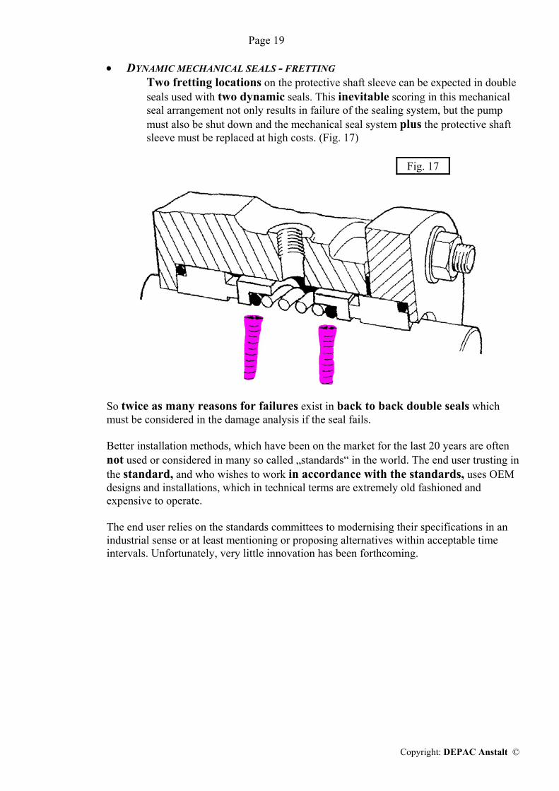
• DYNAMIC MECHANICAL SEALS - FRETTING Two fretting locations on the protective shaft sleeve can be expected in double
seals used with two dynamic seals. This inevitable scoring in this mechanical seal arrangement not only results in failure of the sealing system, but the pump must also be shut down and the mechanical seal system plus the protective shaft sleeve must be replaced at high costs. (Fig. 17)
Fig. 17
So twice as many reasons for failures exist in back to back double seals which must be considered in the damage analysis if the seal fails.
Better installation methods, which have been on the market for the last 20 years are often not used or considered in many so called „standards“ in the world. The end user trusting in the standard, and who wishes to work in accordance with the standards, uses OEM designs and installations, which in technical terms are extremely old fashioned and expensive to operate. The end user relies on the standards committees to modernising their specifications in an industrial sense or at least mentioning or proposing alternatives within acceptable time intervals. Unfortunately, very little innovation has been forthcoming.

Page 20
Copyright: DEPAC Anstalt ©
2. TANDEM
The tandem installation is the classic „proper“ arrangement of 2 single mechanical seals
used as a double seal. (Fig. 18)
Fig. 18
The major advantages of seals in Tadem are:
• OUTSIDE FACE CONTACT The liquid to be sealed is in contact with the outside diameter of the internal
seal. Any possible solids are thrown away from the seal face by the speed of the shaft and the centrifugal forces thus generated.
• VARIABLE BARRIER PRESSURE In a tandem installation, the barrier pressure may be higher than the pressure of
the medium to be sealed but not necessarily. If higher barrier pressure is used, it should be 1 to 2 bar (15 - 30 PSI) higher than the medium pressure.
It is, however, important to establish that the barrier pressure may also be
considerably lower than the medium pressure (up to atmospheric pressure).
The disadvantage of seals in Tadem is: The considerable disadvantages of dynamic seals also continue to exist in this
system. Moreover, there is a considerable space requirement and expensive glands are required for installation.

Page 21
Copyright: DEPAC Anstalt ©
3. FACE TO FACE All the weak points of „back to back“ and „tandem“ installations described previously
could already have been eliminated with the „face to face“ installation as a better alternative at the time. (Fig. 19)
Fig. 19 All that would have been necessary was to reverse the seals and let them run against one
common stationary face. In such a case the stationary part must be drilled to allow the passage of the barrier liquid into the space between the two seals.
The internal seal has tandem action. The liquid to be sealed is in contact with the outside
diameter of the internal seal. The barrier liquid may be operated at a pressure of 1 to maximum 2 bar (15 - 30 PSI) higher than the liquid to be sealed. Of course the liquid to be sealed can also have a higher pressure than the barrier liquid. The barrier pressure may even be at atmospheric pressure.
This installation method would also solve any space problems of the tandem system as
sufficient space was always available inside and also outside the pump stuffing box. Another positive aspect was that both seals could be standard seals. Only a special
stationary part and a special gland would be required. These special parts were unfortunately quite expensive and difficult to produce.

Page 22
Copyright: DEPAC Anstalt ©
4. STATIONARY DOUBLE SEAL With the new era of the „stationary mechanical seals“ the use of double seals was also
drastically changed. For this, reference must be made in part to the previous designs of the single mechanical
seal developments. These developments and facts are just repeated here in key-word form:
Stationary seals generally feature:
a) General pressure balancing b) Springs outside the medium to be sealed c) No scoring of the protective shaft sleeves d) No axial oscillating movements - No fretting
The „Tandem arrangement“ is also the only realistic installation method for the use of the stationary double seals: (Fig. 20)
Fig. 20
This arrangement allowed operation at lower barrier pressures than the pump pressure but was not suitable for applications in which higher barrier pressures were prescribed.
At a higher barrier pressure either:
a) the internal stationary sealing face holder was pushed from the gland or b) the O-Ring No. 3 was pushed from the sealing face holder or c) the seal opened as the internal pressure gradient perhaps represented a higher
opening force than the closing force.
Moreover, the installation with its many separate parts and double gland system was complicated and subject to faults.
The following further objectives were therefore defined:
a) the full pressure of the barrier fluid, like the full medium pressure, must be sealable either way
b) installation of the seal must be simpler and more reliable.
The use of two single stationary seals could not satisfy these requirements. This led to the need to consider whether this type of seal should be incorporated in some type of pre-assembled complete sealing system.

Page 23
Copyright: DEPAC Anstalt ©
E) F) G) H)
5. STATIONARY DOUBLE CARTRIDGE SEALS - DEPAC STYLE 322
The „stationary double cartridge seal“ (Fig. 21) was developed by DEPAC in 1984/85 with Style 320. This followed many years of research and development to improve efficiency.
Therefore it can be said today that all of the known weak points of single and double seals were automatically eliminated in the final and up to date system of Styles 322/323.
DEPAC 322
Fig. 21
a) DEPAC STYLE 322 DOUBLE BALANCED SEAL- ADVANTAGES
• PRE-ASSEMBLY Pre-assembly eliminates all the mounting problems for the many individual
parts of a double seal system. The cartridge is assembled in the factory or workshop and can be tested with barrier liquid before being fitted to the pump.
This ensures that a seal is not fitted into the pump with great effort only to find
that is leaks.
• TANDEM-ACTIVITY The stationary double seal cartridge has tandem activity. The liquid to be
sealed acts on the outside of the internal seal face. Solids are thrown away from the sealing faces.

Page 24
Copyright: DEPAC Anstalt ©
• SHOCK AND VIBRATION DAMPING Care should be taken that the dynamic rotating faces are installed in such a way that
the faces are not in direct contact with the retaining parts.
Fig. 22
WRONG
RIGHT
The slight misalignment resulting from machining or tightening of the sleeve or the retaining parts relative to the shaft must be compensated. This is easily accomplished if the faces are located on a shoulder with an O-Ring (elastomer) as a shock absorber.
The flexibility of the O-Ring (15 % of its cross-section) not only acts as
compensation for minor inaccuracies but acts basically as a shock and vibration damper for the pump and operation vibrations, which cannot be avoided.
The consequence is a high degree of „elastic“ running and reliable performance
by the seal.
• SAFETY The two seals in the cartridge can operate independently of each other as they
are mounted separately in the gland, though in reverse order.
• DOUBLE PRESSURE BALANCING The internal seal design can be selected so that the seal is closing under any
pressure conditions, but is at the same time pressure-balanced under any pressure condition to reduce the friction. This type of design is called „double pressure balancing“.
The object is to neutralise the unavoidable barrier pressure failures or any
pressure reversal, and still balance the seal to get the lowest friction possible at the faces. Lower face load results in less friction, less wear and therefore in longer seal life.

Page 25
Copyright: DEPAC Anstalt ©
„Double pressure balancing“ can easily be understood by the following
sketch of the internal faces. (Fig. 23)
Fig. 23
The external mechanical seal is of course only single pressure-balanced because atmospheric pressure can ever be applied to the outside of this seal.
It is the responsibility of the mechanical seal design engineer to establish the
maximum pressure at which a seal can operate and the balancing ratio at which he wishes to work. This should be reflected in the engineering data from the seal manufacturer. But it should be remembered that a seal always closes better if the closing force is less balanced (lower or no pressure-balancing) which thus reduces the service life of the mechanical seal due to increased friction on the faces.
The DEPAC Style 322 can operate, for example, both at 28 bar medium
pressure with atmospheric barrier pressure as well as at 28 bar barrier pressure against atmospheric medium pressure.
• TOLERANCE COMPENSATION By way of the two stationary seals and the special design of the various parts and
their location relative to each other, the DEPAC 322 stationary double cartridge seal system also offers the possibility of compensating approximately ± 0.5 mm axial and radial tolerances of the pump shaft without seal failures (problems due to hardening, sticking media, etc. are of course excluded).

Page 26
Copyright: DEPAC Anstalt ©
• BARRIER FLUID – CENTRIFUGAL PUMP
The barrier fluid will be thrown to the outer parts of the system through the centrifugal force, created by the rotating shaft/sleeve. Due to the tapered ID of the gland a pressure differential will be created from the inlet to the outlet part of the barrier fluid connections. Therefore, a measurable pumping action is created to improve the flow within a thermo syphon system.
• MODULAR SYSTEM The two independently arranged stationary seals also allow this system to be
considered as a modular system.
a) The cartridge can be used as a single seal with only the internal seal installed. b) The external seal can be retrofitted at any time.
Likewise the external mechanical seal can perform its function fully by itself after failure of the internal seal
b) COMPETITION - BE AWARE OF FALSE ADVERTISEMENTS
The user should analyse and compare the described sealing principles critically because these mechanical seal principles have until now not been understood or used by even well known established mechanical seal manufactures.
Non-critical consumers are often confused or misled by flippant superficial advertising statements. The well-known name of a manufacturer does not have to be synonymous with top technology or quality. An extract from a recent catalogue of a well-known manufacturer shows design drawings and descriptions for double pressure balance as an example. (Fig. 24)
„Double pressure balancing“ Advertisement
Fig. 24
2) If the medium pressure increases then O-Ring ③ slides towards the right-hand adapter collar and the seal is single pressure balanced. Where is the „double pressure balancing“ here??
The advertisement statements are not in accordance with the seal offered. The manufacturer has no idea what „double pressure balancing“ is! But he sells a lot of seals.
Please evaluate:
1) The barrier pressure is higher than the medium pressure. The O-Ring is located against the collar of the stationary seal face. The entire barrier pressure line is transferred above the sealing faces. The seal is NOT balanced.

Page 27
Copyright: DEPAC Anstalt ©
6. CARTRIDGE WITH FLOATING STATIONARY DOUBLE SEAL DEPAC STYLE 326 / 365
Another new technology can be evaluated if larger movement tolerances of the
equipment are to be expected. The special installation of the stationary sealing faces allows this seal to adjust to
larger shaft movements / tolerances without adversely affecting the relevant face load from the spring package. (Fig. 25)
DEPAC 365
Fig. 25
The tolerances to be compensated must be selected by the design engineers. DEPAC
offers various standard seals with adjustment possibility for different movement tolerances (series 326/365) allowing from 3 mm to 6 mm axial and radial movement tolerances.
All these seals are of course double pressure balanced.

Page 28
Copyright: DEPAC Anstalt ©
7. DIN 24960 C MECHANICAL SEAL CARTRIDGES
After companies like DEPAC, which generally cater for the end user, had successfully
sold double seals and particularly modular systems for many years, the German standards committees were also approached by the end users time and again about this subject.
Eventually the many years of success by stationary DEPAC cartridge seals could no
longer be kept quiet and became a subject for the standards committees. The objective was that, if the standards were to be changed or extended then
modification should be formulated in such a way that any German mechanical seal manufacturer, pump manufacturer and large-scale end user could also agree with it. But as every individual party wanted to protect its own interest, the changes took a long time and were only a compromise. They are now registered in
DIN 24960 C.
The standards recommendation required a really extravagant basic structure, which was associated with correspondingly high costs. It must also be noted on the positive side that the pump industry was advised at the same time to allow for larger housings for mechanical seals, which would benefit the performance and reliability of mechanical seals.
For 10 years DEPAC was the only manufacturer who could use its Style 320 seals,
directly within this standard. Only the adapter parts had to be matched accordingly to the new standard.
In other words, sealing technology for DIN 24960 C was written around the DEPAC
developments of stationary cartridge seals. Due to the many, not required detail specifications, the seals became quite expensive
and the customers were reluctant to pay these high prices. For this reason this DIN recommendation was withdrawn.

Page 29
Copyright: DEPAC Anstalt ©
B) Barrier fluid system for double mechanical seals
a) The easiest way of providing a barrier fluid to a double seal is to introduce to the barrier
space a product is compatible with the pump medium. Ideally, the barrier medium should be cooling, clean and lubricating. The pressure is selected in accordance with the requirements. The supply line should be at
a low point of the gland and the drain line at the high point of the gland. The flow requirement will depend on the pressure and temperature conditions. But in
general it can be said that the barrier flow must be high for unbalanced seals. The barrier flow can be relatively small for double pressure-balanced seals. 5 to 10 litres (½ - 2 ½ gallons) per hour is sufficient, depending on the size of the seal and the product conditions.
b) A Thermosyphon-system can be used if suitable liquid from the general process is not
available in the vicinity of the pump. This is a closed system in which the barrier fluid circulates by thermal forces.
A low viscosity, well lubricating, clean liquid with a high specific heat capacity and
compatible with the product should also be used here. Due to the piping resistance, the viscosity of the sealing medium should not be much
higher than that of water. On the next page we would like to point out a few important basic subjects, for a
thermosyphon system.

Page 30
Copyright: DEPAC Anstalt ©
Forced circulation The circulation can be supported by various
circulation systems if the above natural circulation is not sufficient.
This can be achieved by a screw conveyor or pump
ring or by a circulation pump mounted in the barrier circuit.
Natural circulation The circulation of the barrier fluid is
established according to the thermosyphon principal.
The barrier fluid is heated in the mechanical
seal reducing the fluid density making it lighter. The lighter barrier fluid rises up from the sealing area through the pipe into the vessel. The barrier fluid is then cooled in the vessel, the density increases and sinks down into the sealing space as a specifically heavier fluid.

Page 31
Copyright: DEPAC Anstalt ©
Pressurising If for safety reasons and / or technical product
reasons the barrier pressure at the mechanical seal must be higher than the medium pressure, an appropriate nitrogen buffer may be applied to pressurise the barrier system.
Cooling
A cooling system with cooling coils and cooling water connection is always recommended to ensure the best possible circulation.
Multiple connections A forced circulation system in the form of a pump
must always be chosen if two mechanical seals are to be supplied from the thermosyphon system.
Page 32
Copyright: DEPAC Anstalt ©
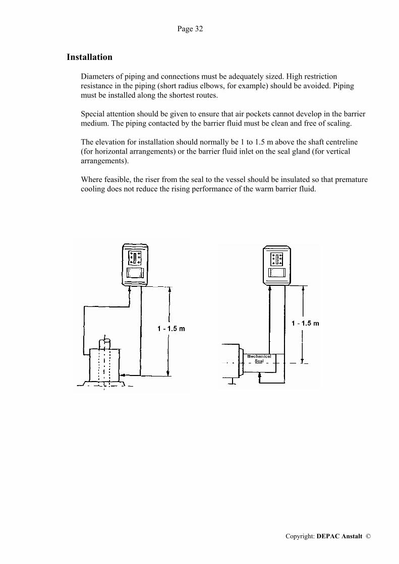
Installation Diameters of piping and connections must be adequately sized. High restriction
resistance in the piping (short radius elbows, for example) should be avoided. Piping must be installed along the shortest routes.
Special attention should be given to ensure that air pockets cannot develop in the barrier
medium. The piping contacted by the barrier fluid must be clean and free of scaling. The elevation for installation should normally be 1 to 1.5 m above the shaft centreline
(for horizontal arrangements) or the barrier fluid inlet on the seal gland (for vertical arrangements).
Where feasible, the riser from the seal to the vessel should be insulated so that premature
cooling does not reduce the rising performance of the warm barrier fluid.

Page 33
Copyright: DEPAC Anstalt ©
III) SELF-ALIGNING OR BETTER SELF-MISALIGNING STATIONARY FACE COMPONENTS
There are no self-aligning stationary parts. There are only self-aligning mechanical seals i. e. STATIONARY SEALS. For many years now, a mechanical seal manufacturer has been marketing a stationary face concept, which highlights „self-aligning“ performance. This concept should compensate the mistakes of dynamic seal designs. In technical terms the relevant advertisement statements are however, completely incomprehensible. In the interest of better assessment we would just like to look at the background:
1. PROBLEM DEFINITION In a dynamic seal design the spring elements are arranged in the dynamic (rotating) part of
the seal system. We know that due to the total of the various tolerances within the seal system and pump
parts, such as the retainer rings, the spring(s), the stuffing box face, the shaft, the gasket and the gland, the installed stationary seal face is never square to the shaft centreline. (Fig. 30)
Fig. 30
In the dynamic design the spring elements rotate along with the shaft and the rotating seal
face must therefore adjust now to the misaligned stationary face twice per revolution. So an oscillating axial movement must occur within the seal as described before.

Page 34
Copyright: DEPAC Anstalt ©
2. OBJECTIVE The substantial oscillating movement not only results in the premature failure of the seal,
but also scores (Fig. 31) the protective shaft sleeve. These both problems should be eliminated.
Fig. 31

Page 35
Copyright: DEPAC Anstalt ©
3. METHOD The basic idea was that a stationary seal face should be used in connection with a pressure
balanced dynamic seal to compensate for misalignments of the pump, the shaft and the mechanical seal components. For this purpose the spring force in the stationary part must be equal to the spring force of the dynamic unit. The spring rates of the two systems can of course be different.
But if the spring forces are equal the hydraulic forces must also be equal. For this, the
stationary part must also have the SAME hydraulic pressure balancing as the dynamic face. If this is observed and implemented accordingly, the centrifugal force from the rotating shaft
becomes active and positions the dynamic face square to the shaft centreline around which it is thrown. The stationary face adjusts to the dynamic square face and any axial movement is stopped. So the stationary face is automatically centred rectangular to the theoretical shaft centreline.
Fig. 32
Nothing can be said against the physical explanation of this principle. The principle is correct.

Page 36
Copyright: DEPAC Anstalt ©
4. REALITY Unfortunately, this really interesting „self aligning stationary“ principle does not work. The developers have overlooked the real world of mechanical seal installations.
• The internal seal sleeve (protective sleeve) must be pushed onto the shaft. For this purpose the inside diameter of this sleeve must be larger than the shaft or the pump sleeve. Otherwise this part will not fit.
As the inside diameter is naturally larger it must also be fixed to the shaft. This is normally achieved by tightening of set screws.
But when tightening these set screws the maintenance engineer has no way of controlling whether the sleeve is tightened slightly higher, lower or angular to the centre line (even the smallest amount will upset the system).
But as the diameter of the seal sleeve surface represents the pressure balancing line we must therefore accept that the pressure balancing line of the dynamic seal part cannot be controlled.
• The stationary seal face must be retained in a gland and screwed to the front of the
stuffing box.
The maintenance engineer will of course use certain shims to ensure that the stationary face part does not contact the shaft. Irrespective of the accuracy of the gland, he will not be able to install the stationary part 100 % concentric to the shaft centreline.
This part will also be installed slightly higher, lower or angular to the shaft centreline.
Pressure balancing must, however, also be realised in the stationary part and this must be 100 % equal in diameter to the dynamic pressure balancing line.
How can these two lines (in diameter) be 100 % aligned if the installation does not allow
us to control the dynamic balancing line or the stationary balancing line? THE SYSTEM DOES NOT WORK AS INTENDED!

Page 37
Copyright: DEPAC Anstalt ©
5. THE RESULT But how does the sealing system behave if equality of the pressure balancing lines
cannot be achieved? (Fig. 33)
Fig. 33 We illustrated only one of infinite possibilities in the drawing (Fig. 33). Due to the slightly
lower location of the stationary part, the hydraulic pressure balancing line of the stationary part is also slightly lower than the pressure balancing line of the dynamic face.
The hydraulic load at the stationary face is higher than the hydraulic load of the dynamic
face. The behaviour of the load system on the opposite underside is of course exactly reversed. But as the same spring load was chosen, there is no other load compensation and the
matching set of faces automatically adjust at an angle in accordance with the load distribution. How much the lines are separated from each other is irrelevant because the tiniest fraction of one millionth of a millimetre is enough for tilting fully, as other supporting or dampening loads are not longer available.
This is what we as engineers call Self-Misalignment

Page 38
Copyright: DEPAC Anstalt ©
A good basic idea, but one where the reality reverses the objective. Will this sealing system therefore fail immediately when used? NO, because until now any dynamic seal has been operable with axially oscillating
movements, so that is what this dynamic system will be doing as well. The service life will being better than that for normal dynamic seals and severe scoring will occur. For this result the customer has to pay a premium price!?
Can the customer check the effectiveness or non-effectiveness of the system after
installation? YES! If such a sealing system has been in operation for a long period, approximately 12 months,
and it arrives in the workshop after failure, the only thing to be checked is whether or not O-Ring No. 2 developed scoring on the sleeve.
The result to be expected is obvious. Scoring will be recognisable in all cases. Only the
depth of the scoring depends on the operating time.
If the system had in fact been self-aligning there would be no traces of scoring by the dynamic
O-Ring.

Page 39
Copyright: DEPAC Anstalt ©
6. A DIFFERENT VERSION One version that is offered to the market, but it operates and is advertised fundamentally on
the same principle as “the self aligning concept” differs in that the stationary part uses pins instead of stationary springs.
Two opposite pins supported by a retaining ring in turn support the stationary face part,
which itself is supported in the housing by two opposite pins. The second set of pins is staggered 90 ° from the first set. (Fig. 34)
Fig. 34 The pressure balancing line should again be equal at both face parts, which is
impossible based on the above installation tolerances. But when the pressure balancing line is not even equal due to the basic advertised design,
one could only wonder whether the manufacturer has any idea what he is doing. Due to the pressure balancing line which cannot be kept equal, the dynamic, rotating spring
unit will of course compensate this MIS-ALIGNMENT, generated by the design in turn by continuous, axial oscillations..

Page 40
Copyright: DEPAC Anstalt ©
The stationary face permanently supported by 4 pins staggered at 90° can of course move,
each time at one of 2 levels staggered at 90°. But a total existing inaccuracy (Fig. 34) must be continuously compensated for the axial
direction, i. e. for an indefinite division of one degree, distributed along the circumference (see dynamic mechanical seal, page 3). This is not possible because:
a) in case of 2 axes b) at all if the spring elements dynamically rotate with the shaft, also making the necessary
compensations for the tolerances in axial direction. But as with any other dynamic mechanical seal design, the spring element will always try to
keep the faces together by axial adjustment. The mechanical seal performs DESPITE misalignment. The question is, for how long and how reliably?
The confirmation of NON-PERFORMANCE is given in turn by the appearance of scoring
on the sleeve under the dynamic O-Ring No. 2. (Fig. 34) But the scoring becomes visible only after the mechanical seal has been in operation for at
least 12 months.
The attack by scoring on this sleeve, which actually contributes to the failure of the
mechanical seal, could be reduced if the surface on which O-Ring No. 2 acts was hard chromium plated. Such hard chromium plating would of course be more sensible than perhaps chromium plating a mechanical seal gland for „cosmetic“ reasons.
So why do manufacturers offer parts in this form? It is an interesting sales argument, which triggers an incentive to buy, by less
informed customers or users due to the “novelty effect”. A self-misaligning stationary part, however offered, cannot perform according to the
advertisement promises. The question is just how such suppliers intend to explain their incompetence in engineering
or confusing sales tactics to experts??? As mentioned at the beginning of section III), self-aligning, compensation is
achieved simply and only by using STATIONARY MECHANICAL SEALS.

Page 41
Copyright: DEPAC Anstalt ©
So why try to make technically obsolete dynamic mechanical seal designs with absurd self-
misaligning stationary parts equivalent to stationary mechanical seals? Why not manufacture and offer STATIONARY mechanical seals from the start?

Page 42
Copyright: DEPAC Anstalt ©
IV. CONSIDERATIONS FOR USING CARTRIDGE SEALS To be able to justify the use of cartridge mechanical seals, various hidden or often neglected
secondary costs must be considered.
A) Problem definitions of mechanical seals 1. INSTALLATION
• The installation of single component seals always was and still is a critical manual operation, which must be carried out with care and cleanliness.
• Single component seals must be installed with a specific overall length „L“. (Fig. 35)
Fig. 35
These dimensions must be derived from the technical data sheets supplied with the seals. This dimension is always measured from the stuffing box face to the back of the dynamic seal part. (Fig. 35)
Axial inaccuracies must be minimised as the expected service life also depends on that dimension.

Page 43
Copyright: DEPAC Anstalt ©
a) If the dynamic part is installed with an excessive face load (springs are compressed too much), friction and wear will be increased and the service life
is reduced. b) If the dynamic part is installed with an insufficient spring load, very soon after start-up the spring load becomes inadequate and the full working length of the
face will not wear. This also reduces service life.
For dynamic seals, pump manufacturers often provide a shoulder on the protective shaft sleeve at the point where the back of the mechanical seal should be seated. This is certainly a good idea for the pump manufacturer, because he installs new parts with the required dimensions.
But it looks completely different in the operator’s repair or maintenance department.
The reason is obviously that, in a pump repair, many pump parts can be repaired: bearings, shaft, sleeve, mechanical seal parts and even the stuffing box face. The most diverse reasons lead to the stuffing box face no longer being in the correct relationship to the shoulder on the protective sleeve. But the maintenance man will install his mechanical seal trusting in the correct shoulder distance, and thus installs the seal incorrectly.
Nobody will notice because the mechanical seal performs. But for how long? We have to remember the steps of the seal installation:
• Installation of mechanical seals will of course be carried out only when the pump
with the other necessary parts is repaired.
The „wet end“ of the pump should then be assembled without the seal. The position of the protective shaft sleeve should be fixed. The stuffing box face can now be marked on the protective shaft sleeve.
The „wet end“ of the pump is dismantled again and the seal can now be fitted.
• The gland with the stationary face is placed loosely on the shaft (with a protective
shaft sleeve).
The dynamic seal unit is mounted on the protective shaft sleeve and fixed to the sleeve with screws at the locating dimension „L“.
• The „wet end“ of the pump is assembled for the 2nd time. • The gland with the stationary face, loose on the shaft until now, is now tightened to
the stuffing box face. Only then do the sealing faces contact each other and can be spring pressure loaded.
• Now the whole pump can be installed.
Page 44
Copyright: DEPAC Anstalt ©
One of the main reasons that a pump sometimes already leaks during pressure testing after component seals are installed is that dirt particles got deposited on the open faces during installation.
But even if the pump does not leak during pressure testing any dirty particles on the face can nonetheless lead to increased wear of the faces which in turn leads to a shorter service life of the seal.
The time and care taken to install a component seal must not be underestimated.
The time taken simply to assemble the pump twice depends in part on the type of pump. It will add at least to 2 - 4 additional man hours.
This 2nd assembly is, however, often not performed for reasons of time. This will then involve the risk of installation errors by which the service life of the mechanical seal is reduced.
2. INEFFICIENCY
These days, when costs and cost cutting are discussed at EVERY industrial level, the
costs relating to the installation of component seals must also be analysed and assessed.
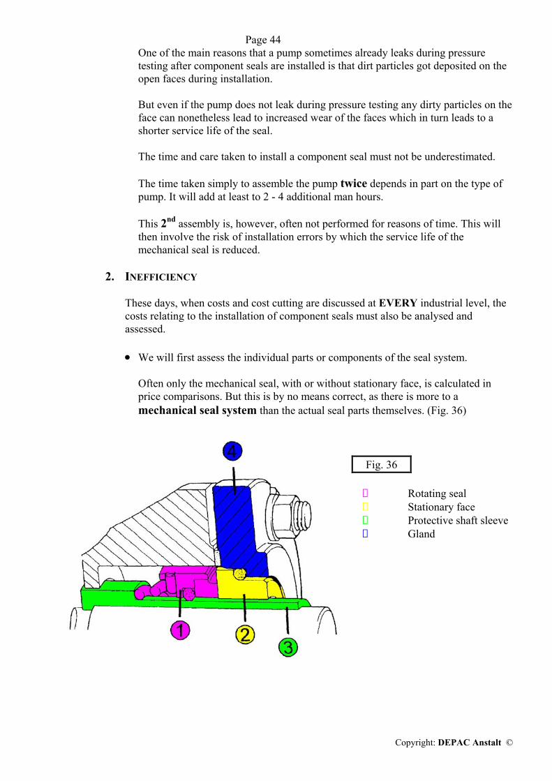
• We will first assess the individual parts or components of the seal system.
Often only the mechanical seal, with or without stationary face, is calculated in price comparisons. But this is by no means correct, as there is more to a mechanical seal system than the actual seal parts themselves. (Fig. 36)
Fig. 36 ➀ Rotating seal ➁ Stationary face ➂ Protective shaft sleeve ➃ Gland

Page 45
Copyright: DEPAC Anstalt ©
• The protective shaft sleeve is also required for corrosion protection purposes, but it must always be replaced with ALL dynamic mechanical seals, since fretting corrosion damages them. (See section C, 2, page 8)
Many end users have hardened the zone on the sleeve where fretting occurrs, at considerable cost. This has certainly contributed to an improved service life of the mechanical seal.
The solution here would be the use of STATIONARY mechanical seals. (See section B, page 4)
• If a pump was supplied with a seal by the pump manufacturer, a gland was
supplied or the pump was glandless. A seal in a glandless pump is installed inside in the stuffing box. The housing is closed to the atmosphere.
If a gland is supplied with the pump, the cost portion for the gland is included in the price of the pump.
• The work required for installation of the seal comprises of:
Assembly of the „wet end“ of the pump. Marking the stuffing box face on the sleeve. Dismantling the „wet end“ of the pump. Installation of the seal using the installation dimension „L“. Assembly of the pump. Pressure testing of the pump.
a) To calculate the overall costs for the installation of a component seal, several
assumptions have to be made which may differ from company to company and from seal to seal. Only values have to be modified accordingly to arrive at a specific cost assessment.

Page 46
Copyright: DEPAC Anstalt ©
Let us assume:
• The outside diameter of the sleeve is 40 mm. • A simple mechanical seal costs € 100,-- • The ceramic stationary face costs € 30,--
If a specific seal is supplied and charged
together with the stationary face, the price is combined accordingly.
• The sleeve in DIN 1.4571 (316 SS) in case of repair costs € 250,-- • Gland closts (€ 50,--) • Labour costs including social costs @ € 40,--/hr.
Manpower requirement for the installation of a component seal as described above for items , , ⑦ , ⑧ , is 3 additional hours @ € 40,--. € 120,-- -------------- The overall costs for the installation of a „cheap“ component seal system is: approx. € 550,-- (+/-) ========
Every additional repair will create the SAME costs.

Page 47
Copyright: DEPAC Anstalt ©
B)
B) Advantages of cartridge seals All individual parts required are included. (Fig. 37)
Fig. 37
DEPAC 270
➀ 1 Stationary seal ➁ 2 Rotating face ➂ 3 Mounting sleeve ➃ 4 Gland
A cartridge is pre-assembled in either the factory or the workshop. It can then be kept in
stock ready to be used at any time.
1. INSTALLATION The installation of a cartridge seal eliminates the need for the assembly and
dismantling of the „wet end“ of the pump for the 2nd time.
The cartridge is placed loosely on the shaft or sleeve and then assembly of the pump is completed.
The cartridge is placed against the stuffing box, the gland is bolted to the face of the stuffing box after which the set screws are tightened to the pump shaft or sleeve.
The centring clips are removed. THAT’S ALL!
2 1 3
4

Page 48
Copyright: DEPAC Anstalt ©
• No component parts need to be measured or handled in accordance with drawing
details. • Dirt no longer can come between the faces. • The existing sleeve NEVER has to be renewed if DEPAC cartridges are used. A
sleeve is still used, but only for corrosion protection of the shaft and for tightening the impeller to its correct dimension but it is never again replaced at high cost due to scoring by the dynamic component seal.
2. EFFICIENCY
The price for a new cartridge seal and the omission of installation steps , , ,
result in greater economy than using a component seal.
• PURCHASING NEW DEPAC 270-40 cartridge approximately
€ 450,--
If a cartridge has to be repaired only, the individual wearing parts must be replaced. • REPAIR The repair of the cartridge for the above seal includes replacement of the spare parts such as faces, O-Rings, set screws, springs, gasket at the cost of approximately € 225,-- = Every further repair will therefore also be € 225,--.
It is clear not only that today’s overall maintenance costs for mechanical seals can be reduced by better engineering, such as that of the STATIONARY principle, but that even the overall installation and repair costs can greatly be reduced by using CARTRIDGE seals.

Page 49
Copyright: DEPAC Anstalt ©
V) SELECTION OF MECHANICAL SEALS, MATERIALS AND APPLICATIONS AIDS
A) Problem definition These days there is seemingly a never-ending list of chemical fluids, which have to be
sealed by mechanical seals. A typical question from the end user to the seal manufacturer is which seal he recommends
for product „XYZ“. No seal manufacturer can possibly know all these chemicals. There are many seal manufacturers who want to impress customers with the fact that they publish lists of chemicals for which they have used specific types of seals with success. But this is completely misleading and / or irrelevant to the man in the field as a 10 % change in concentration or a temperature difference of 10°C can produce a completely new behavioural patterns of the fluid, which in turn can have an adverse effect on the performance of the seal.
The behavioural pattern of the basic chemical is also greatly changed by the innumerable
blending possibilities or additives. How can a seal manufacturer possibly give a general recommendation to the end user
without knowing the individual but critical factors of the liquid to be sealed. This is practically impossible! So how can the end user be helped for his own selection of the proper seals, environmental
controls or materials? Just like any other seal manufacturer, DEPAC has to recommend seals to the customers for
the most diverse applications. DEPAC, however, proceeded according to the general behavioural patterns of the
liquids to make such selections or recommendations easier.
DEPAC did not ask, which liquid do we have to seal?
But the question is, what does the liquid do to the mechanical seal?
Ideally a liquid should not be corrosive but cool, clean and lubricating. That unfortunately applies to very few fluids. We must therefore analyse what the most diverse liquids can do in the worst case to the seal and what can be done to prevent or inactivate those problems at the seal.
We can apply or use 4 ENVIRONMENTAL CONTROLS to achieve this:
a) FLUSHING INTO THE STUFFING BOX b) QUENCHING c) HEATING / COOLING OF THE STUFFING BOX d) DOUBLE MECHANICAL SEALS
These controls are explained in the following sample applications.
We will see basically 10 alternatives of chemical / fluid / pump applications and these 10 possibilities cover ALL general applications of seals in the world.

Page 50
Copyright: DEPAC Anstalt ©
1) SOLIDS IN THE MEDIUM
If a pump medium contains solids but is otherwise cool and lubricating it is irrelevant what the pump medium is called and what sort of solids are now in the medium. These may be materials such as
sand crystals product materials fibres, etc.
For the mechanical seal it is only important that these materials might come between the faces of the seal and could therefore destroy the faces. They could also get to the dynamic O-Rings and obstruct them.
For dynamic seals it also should be evaluated that springs (extremely small springs) should not in the pumped medium.
We therefore assume that we selected the correct stationary seal design with pressure balancing and springs outside the pumped medium, but now in addition we have to seal a liquid containing solids.
We can visualise that the seal faces are lapped on the surface to an accuracy of approximately 1 helium light-band and slide over each other under pressure. The clearance between these faces will be extremely small. Only solids smaller in size than the clearance width can penetrate into this gap. So we see that the seal will not be damaged by large solid particles but by the microscopic particles.
There are only 2 possibilities to help the seal in developing „service life“ under these conditions.
a) FLUSHING (Fig. 38) Fig. 38

Page 51
Copyright: DEPAC Anstalt ©
i) Flushing always means a supply line with clean, cool, lubricating liquid from
outside the pump into the stuffing box. Of course this can also be the pumped product itself if it can be withdrawn in a clean and cool condition from another point within the process.
ii) It can be an alien liquid as long as it is „compatible“ with the pumped medium since it will „dilute“ the pumped media.
But as a rule of thumb it can be said from experience that flushing at 3 - 10 litres (1-3 GAL) per HOUR would be adequate. In order to keep the amount of flushing small a base bushing should be installed in the stuffing box to reduce the clearance between the housing and the shaft sleeve as much as possible.
iii) If a clean, cool and lubricating liquid is available it should be to the stuffing box at a pressure which is 1 - 2 bar (15 - 30 PSI) higher than the stuffing box pressure of the pump (not the pressure at the pump discharge).
In the past, only dynamic and mostly unbalanced seals were used in the process industry. These seals required large amounts of liquid to cool the face, and for this reason they were often rejected.
Re-circulation flushing Another misleading application is the so called „re-circulation flushing“.
Fig. 39

Page 52
Copyright: DEPAC Anstalt ©
Unbalanced seals generate high friction forces and thus frictional heat on the faces. This
heat must be removed and a high amount of liquid flow through the stuffing box is required. „Re-circulation flushing“ was applied by connecting the pump discharge fluid at the highest possible pressure into the stuffing box in which an unbalanced seal was installed. By this excessive frictional heat was generated by the unbalanced seal was „flushed“, i. e. „cooled“.
This must be seen in the proper perspective!
• An unbalanced seal is selected.
• This generates excessive frictional heat and is therefore subject to a large degree of wear.
• Liquid at an even higher pressure is then supplied to the seal to remove that frictional heat!!??
You think nobody would do that? Oh yes, virtually the entire industry has used, or is still using this re-circulation
flushing in many pumps with unbalanced mechanical seals. „Re-circulation flushing“ only makes sense in applications where pumping is performed
in the vicinity of the boiling point of the liquid. Increasing the pressure in the stuffing box reduces the risk of evaporation at the seal.
In all other media, a re-circulation flushing line should NEVER be installed from the
pump discharge to the stuffing box. If, for any logical reason, a flow in the stuffing box should be achieved, a line can be
installed from the stuffing box to the suction side of the pump. Only this makes sense, since this gives both the required flow and a pressure reduction at the seal, which extends the service life of the seal.

Page 53
Copyright: DEPAC Anstalt ©
b) Double mechanical seal Double seals can be used as an alternative for fluids containing solids. The sealing
pressure must be higher than the pump stuffing box pressure. (Fig. 40)
DEPAC 322
Fig. 40
This recommendation is ONLY ALLOWED for double mechanical seals with
„tandem action“. The solids of the pumped fluid to be sealed may only appear on the OUTSIDE of the internal set of seal faces. This ensures that the solids will be thrown away from the seal by the centrifugal force and the faces operate in a liquid as cleanly as possible.
The higher sealing pressure ensures that the pressure gradient at the internal set of
faces is developed from the inside to the outside and that penetration of solids between the faces is reduced as much as technically possible.

Page 54
Copyright: DEPAC Anstalt ©
2. CRYSTALLISING MEDIA All crystallising liquids develop a certain harmful situation at the seal. IT IS COMPLETELY IRRELEVANT WHETHER THIS LIQUID IS CALLED sea water sugar water sodium chloride, or has any other name. It will be important to consider what causes crystallising, what effect it has on the
seal and what consideration we can apply to either to prevent crystallising or make it ineffective with regard to the seal.
We know that certain liquids crystallise either, because a) The concentration rises above the solubility limit of the liquid, or b) The temperature drops to the extend that the liquid can no longer keep the
crystals in solution at that temperature. We also know that a pressure gradient exists between the seal faces. (Fig. 41)
Fig. 41
We know that the temperature at the base of the pressure gradient will increase. The
solution is now over-saturated at that point and the slightest degree of product evaporation results in the development of crystals.
This reveals the problem to us.
• The actual separation point of the liquid and the atmosphere is slightly above the „atmospheric side“ of the sealing faces.

Page 55
Copyright: DEPAC Anstalt ©
• At this point, sealing faces run almost dry and therefore generate more frictional heat.
• In a liquid that tends to crystallise, evaporation at the seal faces will cause microscopic crystals to form.
The crystals now have two possibilities.
a) Either to deposit on the atmospheric side of the sealing faces. More and more crystals will develop and “grow” onto each other and gradually push the sealing faces apart until the seal starts leaking and thus has to be replaced. The crystals on the atmospheric side of the mechanical seal faces become clearly visible after dismantling. Typically, the product side of the mechanical seal will appear completely clean and often look like new.
b) Or the crystals may fall out as dry particles on the atmospheric side. The dry particles
will settle in all the gaps on the atmospheric side of the seal and therefore obstruct the performance of the O-Rings, particularly the dynamic O-Ring. The springs are also blocked and obstructed. Eventually performance will be reduced to such a degree that the seal starts leaking and must be replaced.
We will find the same behavioural and appearance patterns time and time again for ALL
crystallising liquids and can therefore give the same recommendations for all of those liquids.
Proposals A) FLUSHING The safest and simplest recommendation is always to flush the crystallising liquid from
the stuffing box where the mechanical seal is installed with a clean, cool, lubricating, non crystallising liquid.
This flushing as described above naturally enters the pump and must therefore be
compatible with the pump medium. The flushing quantity can be drastically reduced and regulated in a controlled way by a base bushing and a flow meter.

Page 56
Copyright: DEPAC Anstalt ©
B) HARD FACES The sealing faces must always be selected from the best possible wear resistant
materials. Today that would be silicon carbide (SC) on SC. The extremely hard wear resistant SC faces can partly grind crystals without being subjected to short-term wear.
C) QUENCHING If flushing cannot be applied, a small flow of warm and moist air in the form of low
pressure steam (creeping steam) should be supplied to the „back side“, i. e. the atmospheric side of the mechanical seal. This is called „quenching“. (Fig. 42)
Fig. 42
With quenching we achieve the following a) the steam supply prevents crystals forming on the sealing faces b) any crystals which do develop cannot settle on the sealing faces or on the
atmospheric side of the mechanical seal c) those crystals can be flushed out by the small steam flow. This small quantity quenching steam supply keeps the atmospheric side of the
mechanical seal clean and the mechanical seal can therefore operate as if it were running in a clean medium.
Liquids are never used for quenching as they can leak to the atmospheric side without
obstruction. Even a so-called throttling bushing, often used, is not a seal and allows heavy leakage.

Page 57
Copyright: DEPAC Anstalt ©
D) DOUBLE MECHANICAL SEALS If steam is not available, the same result can also be achieved by use of a double
mechanical seal. The double seal offers the possibility of keeping the backside of the product sealing seal clean by the barrier fluid. Once again it is important to note that a higher barrier pressure is not required for stationary and double pressure balanced seals.
But it should also be remembered that the sealing faces on the product side should be
SC-SC. 3. STICKING / HARDENING FLUIDS All sticking or hardening liquids develop a specific harmful situation at the seal. It is completely irrelevant whether this liquid is called Patex Glue Bitumen etc. Once again we have to establish when and why sticking or hardening occurs and
what we can do to prevent this behaviour from happening at the seal. The solution is similar to the crystallising media but two essential differences must be noted. a) A temperature change can have dramatic consequences. The liquid suddenly solidifies if
bitumen cools off, for example. Moving mechanical parts can be severely damaged. b) A pump is often heated to liquefy the medium before starting or stopping. Unfortunately these sensible measures hardly ever have the required effect BETWEEN
the sealing faces of a seal. Complete cleaning or liquefying of the medium between the sealing faces will almost never be possible. The gap between the faces is too narrow for this and the faces are spring loaded.
In other words, if the pump is switched on after shut-down, an extremely high
torsional force becomes active on the faces because the faces may be torn or the anti-rotation pins can be sheared off.
We have to establish whether we can prevent sticking / hardening at the seal. Sometimes it
is already achieved by heating or cooling the stuffing box.

Page 58
Copyright: DEPAC Anstalt ©
Several other methods could be evaluated a) Flushing Once again, flushing is basically the simplest and best measure to consider. b) Heating/Cooling jacket (Fig. 43)
Fig. 43 The heating / cooling jacket is normally supplied from the pump manufacturer. We
only have to make sure that it is used properly. Once again, the use of a base bushing in the stuffing box is recommended to insulate the liquid at the seal to maximise the heating / cooling action in the stuffing box as much as possible.
c) Quenching Quenching can only be seen as a measure to prevent cooling of the faces or to keep
air / oxygen away from the product. d) Double mechanical seals Choosing a double seal is the last solution as it is the most expensive. Ideally the
barrier fluid should be chosen in such a way that it is not only compatible with the pump medium but also has dissolving properties for the solidifying product.
The barrier fluid pressure should be higher than the stuffing box pressure in order
to develop the pressure gradient against the pumped medium. e) Fracture-proof faces TC-TC (Tungsten carbide) Due to the fact that the liquid between the faces is often not fully flushed or
softened during starting and stopping even by heating / cooling of the stuffing box and the faces, considerable shearing forces are imposed on the seal faces by the acceleration of the pump shaft. The retainer pins retaining theses faces can easily destroy brittle materials such as ceramics (CE) or silicon carbide (SC). At present only tungsten carbide (TC) is the most reliable face material available for these applications.

Page 59
Copyright: DEPAC Anstalt ©
Although tungsten carbide (TC) is also destructible it offers, a much higher
fracture resistance than other wear resistant materials. This applies to the internal seal faces of double seals. Standard faces may be used
on the atmospheric side. But nonetheless TC-TC is often also used on the outside seal for safety reasons.
4. EVAPORATING FLUIDS These not only include the light hydrocarbons but also hot water and fluids that are
pumped near the liquid vapour temperature and pressure. Dry running occurs if the liquid evaporates between faces due to its medium
temperature AND the frictional heat developed at the sealing faces. The faces are then subjected to an extremely high degree of wear especially at shaft speeds of 1500 - 3000 rpm. The service life of the seal is drastically reduced.
We have to add the fact that also the O-Rings in the seal can only tolerate a certain
temperature and may be destroyed, if the allowable temperature is exceeded. Once again, it is irrelevant what type of the fluid is in contact with the seal. All media
evaporating at the seal faces exhibit the same behaviour. We must therefore lower the temperature at the seal. The following alternatives are
available: A) FLUSHING There will be no other problems if we can exchange the liquid at the mechanical
seal by cool flushing. Also use a base bushing. B) QUENCHING 200°C water can often be properly cooled by 100°C low-pressure steam, for
example. A base bushing must always be used as a temperature barrier. C) RE-CIRCULATION FLUSHING In this case a re-circulation line may be installed from the pump discharge to the
seal in the stuffing box to increase the pressure. Care should be taken that the inlet is not directly above the sealing faces as this will result in unbalance and face erosion. The inlet should be positioned in tangential direction to the direction of the shaft rotation. Always use a base bushing.
D) DOUBLE MECHANICAL SEAL The barrier fluid can now be used for effective cooling. Always use a base
bushing in the stuffing box.

Page 60
Copyright: DEPAC Anstalt ©
5. EXTREME TEMPERATURES (HIGH OR LOW) A definition for the word extreme is normally used for temperatures beyond the
customary temperature limits for the O-Rings used. A) High temperatures may embrittle the O-Rings. Brittle O-Rings lead to cracking
and leakage of the seal, or the dynamic O-Ring in a sealing system will loose its elasticity, resulting in a seal failure.
So the use of cooling would be a logical measure. Cooling may be achieved again
by various methods already described above: a) FLUSHING with a cool product compatible with the pump medium b) QUENCHING (for example, 100°C steam may cool product of 250°C only) c) COOLING JACKET in the stuffing box d) DOUBLE MECHANICAL SEAL A pump ring could be used within the double seal to achieve a higher flow
rate of the barrier fluid.
DEPAC Style 323
Fig. 44
A base bushing should be installed in the stuffing box in all cases. Such a bushing
is usually made of simple carbon. Carbon has anti-friction properties if the shaft would be slightly misaligned and slide against the carbon. Carbon is also thermally stable and offers a good thermal barrier between the pump medium and the stuffing box.
B) For extremely low temperatures the same measures as described above are used
but the thermal loads are reversed.

Page 61
Copyright: DEPAC Anstalt ©
6. HAZARDOUS FLUIDS Companies and authorities set standards for the levels of hazard. Hazards for humans,
animals and the environment must be prevented in accordance with these standards. In many of these cases the end user uses a pump in which the impeller is driven
electro-magnetically through the casing wall. Mechanical seals are omitted and the release of a hazardous product into the environment due to seal failure is therefore impossible.
This pump development obviously also raises the question of why this type of pump is
not used generally in all cases so that maintenance-intensive seals no longer have to be used at all. In that context we indicate some reasons why the general use of these pumps have not asserted themselves yet.
Electromagnetic pumps are:
• very expensive to buy • extremely expensive to operate due to very high power consumption • cannot be used for higher solid concentrations in the pump medium • cannot be used for sticking / hardening media
For these reasons mechanical seals will certainly be used for sealing purposes in the
industry for a long time to come. A double mechanical seal will always be used if seals are used for media classified
as „moderately“ hazardous. It must also be ensured that the barrier fluid pressure is always higher than the pump
stuffing box pressure. Precisely because of the stringent safety requirements only stationary mechanical
seals should be used as their design characteristics offer a higher level of reliability.
7. HIGH SHAFT SPEEDS High shaft speeds are relative and we would like to discuss standard „rule of thumb“
values for which the practical user should consider taking precautionary measures.
• If stationary seals are used they can readily be used today at speeds up to 30 m/sec. and more. As the springs are in a stationary arrangement they do not have to overcome the centrifugal forces and oscillating movements as in dynamic seals.
• Moreover, stationary seals are pressure balanced and feature little friction on the
faces even at high speeds.

Page 62
Copyright: DEPAC Anstalt ©
• At higher speeds care should be taken that snap rings in seal designs such as shown in
the Fig. 45 cannot be released or opened by the increased centrifugal forces.
Fig. 45
wrong right
• Moreover, care must be taken with the selection of the face materials. Materials with the lowest coefficients of friction and the best thermal conductivity values are to be preferred. These may be special „dry running carbon“ and / or silicon carbide (SC) materials, for example.
Generally speaking it would be advisable to discuss special areas of application such
as these with a seal manufacturer in whom you have confidence (DEPAC). 8. EXTREME PRESSURE A) PRESSURE A standard stationary seal can seal pressures of up to 30 bar (450 PSI). For higher pressures the design of the seal must usually be changed. These changes
include the modification of the pressure balancing, the O-Ring arrangement, the O-Ring support, the hardness of the O-Rings and the general wall thicknesses of the components.
For large rotating shaft seals DEPAC has developed and successfully used
mechanical seals with shaft diameters of more than 300 mm (12 inch) and high pressures of up to 100 bar (1500 PSI), for example.

Page 63
Copyright: DEPAC Anstalt ©
B) VACUUM For a mechanical seal, vacuum means only that a maximum theoretical pressure
of 1 bar occurs from the „wrong“ side. This is normally no problem for seals. But what has to be taken into account are
the O-Rings. Elastomere O-Rings are made of „cellular material“ and the plastic constituents are highly loaded with air bubbles.
So if a high vacuum (more than 700 mm Hg) is present it will practically suck the
air from the O-Rings, resulting in considerable shrinkage. If they shrink the cross-section will become smaller and can no longer withstand the vacuum against the atmosphere. The seal will leak atmosphere into the vacuum.
Stationary rolled bellow mechanical seals should be used for higher vacuum. The
statically operating O-Rings may be made of PTFE (Teflon) (Fig. 46), which will not shrink in vacuum applications since PTFE is not an elastomere.
Fig. 46
DEPAC Style 321
9. LARGE SHAFT DIAMETERS Shaft diameters of up to 100 mm (4 inch) are usually seen as standard for pumps. Agitators, mixers, etc., have often much larger diameters and the seals with larger
diameters are also considered standard for these special areas of application. But most seal manufacturers distinguish the standard of 100 mm (4 inch) shaft
diameter for pumps and special design and manufacture are available for customisation.
DEPAC has manufactured and successfully used seals with shaft diameters up to
400 mm (16 inch).

Page 64
Copyright: DEPAC Anstalt ©
10. LARGE SHAFT MOVEMENTS
Pump shafts are normally supported by precision ball bearings and the shafts have extremely small movement tolerances in axial and radial directions. Radial movement of course occurs in end suction pumps, but even these shaft movements can normally be regarded as minor.
A standard „rule of thumb“ value for the radial tolerance is 0.01 mm per 10 mm shaft diameter while only 0.1 to 0.2 mm could usually be expected in axial direction. Any stationary seal (not necessarily by dynamic seals) can accept both tolerances.
But there are special areas of application in which these normal tolerances can be greatly exceeded, like in mixers, agitators, filters or other larger equipment.
DEPAC has a range of standard seals to compensate large shaft tolerances. DEPAC’s stationary seals offer the following tolerance compensations:
a) Single seals
STYLE 270 SERIES
radial axial
± 0.5 mm ± 0.8 mm.
b) Double seals
STYLE 320 SERIES radial axial
± 0.7 mm ± 0.8 mm
STYLE 326 SERIES radial axial
± 1.5 mm ± 1.5 mm
STYLE 365 SERIES radial axial
± 3 mm ± 3 mm
DEPAC Style 365
Fig. 47

Page 65
Copyright: DEPAC Anstalt ©
DEPAC has also already manufactured and successfully used seals for large shaft
diameters of 200 mm with large run-outs and shaft tolerances up to 10 mm in axial and 6 mm in radial direction for large size filters.
Contact DEPAC if the shaft tolerances exceed the above values. B) SUMMARY It will be difficult for any end user to find media or applications, which do not fit in
with this schedule of the 10 general applications. Sealing problems can now be identified with a combination of these 10 problem definitions. Combination of problem definitions does not create a new application as every point can be and should be separately dealt with for the individual criteria as described.
It is important to understand that the problems of ALL liquids and applications can be
reduced to 10 simple criteria. If these 10 criteria can be successfully sealed, a mixture of these can also be
successfully sealed. The correct mechanical seals and installation aids can be selected for ALL liquids and chemicals, and thus can also successfully seal the so called „most difficult“ media, whatever they may be called.

Page 66
Copyright: DEPAC Anstalt ©
MAJOR DEPAC MECHANICAL SEAL DEVELOPMENTS A large number of fundamental improvements in mechanical seals have been made available to the industry by DEPAC over a long period of time. 1984 DEPAC began to manufacture and market the first range of stationary
mechanical seals as cartridges in Europe (Style 290, 300 and 320, today styles 270, 301, 322).
1985 DEPAC produced the first range of stationary mechanical seals with welded metal bellows (Style 295 and 310).
1986 DEPAC developed the first single component stationary mechanical seals (Style 190 and 210, today 191 and 211).
1987 DEPAC manufactured the first stationary cartridge mechanical seal especially for agitators, with floating stationary seal faces for axial and radial shaft tolerances of 6 mm each (Style 360, today 365).
1988 DEPAC offered the first stationary safety seal range as cartridges (Style 292, 298, 305 and 315, today 270 P, 301 P, 309 P).
1988 DEPAC invented the first stationary mechanical seal for DIN 24960 (LIKU space) Style 195 (today 196).
1989 DEPAC invented the first stationary cartridge mechanical seal specially, with floating stationary faces for pumps with axial and radial shaft tolerances of up to 3 mm each (Style 325, today 326).
1996 DEPAC offered another future orientated innovation in form of the first stationary mechanical seal with rolled bellows for DIN 24960 (LIKU space) Style 201.
2002 DEPAC invented the centrifugal pumping system within cartridge double seals. (Style 322/323)
All DEPAC developments have been and still are aimed to provide the end user of mechanical seals with better, more reliable and more economical products. We are hopeful that the industry will generally be interested in using these technical innovations and improvements, as it will improve the sealing standards of these users and lead to greater economic efficiency.