Embed Size (px)
Citation preview
AD-A284 154
Ap lllnl
Lf' Chris J. FergusonMr. E. Scott Getson
Strike Aircraft Test DirectorateNaval Air Warfare Center
Aircraft Division
/I*DIIC .DTICELECTE
94-28616I~hhhhIIIE DMC QUALIT INSPCTE 1.
949 01 215• m mll • m mm /1i
Table of Contents
INMhODUCION ............................................................................... 2F-14A AIR-TO-GROUND HISTORY ............. ............................................ 4F-14A STORE CARRIAGE/SEPARATION IN THE 90'S .................................... 4F- i4D STORE CERTIFICATION MlETHODOLOGY ........................................... SPHOTOGRAMMETRY, A GENERAL DESCRIPTIN......................................... 9PHOTOGRAMM4ETRICS APPLIED) TO THE F-14D........................................... 15FLIGHT TEST.................................................................................. 19DATA REDUCTION AND PROCESSING ...................................................... 21FUTrE RECOMMAENDATIONSILESONS LEARNED...................................... 24CONCLUSION.................................................................................. 25
r)DIC TAB
bzma=nacuedJRt Vstaricatio
Byvallabil~ity Cods
A vi2-/ )
INTRODUCTION
Conceived in the 1960's as a replacement for the F-4 Phantom, the 'A'variant of the F-14 Tomcat was first deployed as an air superiority fighter inthe early 1970's. Designed as a follow-on to the F-14A, the F-14D was introducedto the U.S. Navy in 1990. Improvements were manifold and included addition ofthe A/N-AAS-429 Infrared Search and Track Set (IRSTS) to the 'chin' podlocated beneath the radome forward of the nose landing gear. This chin pod,which was smaller and housed only the A/N AXX-1 Television Camera Set (TCS)in the F-14A variant, was postulated to adversely affect air-to-air and air-to-ground weapon separation from the aircraft fuselage stations. This warrantedadditional testing to validate the separation envelope previously tested andauthorized on the F-14A.
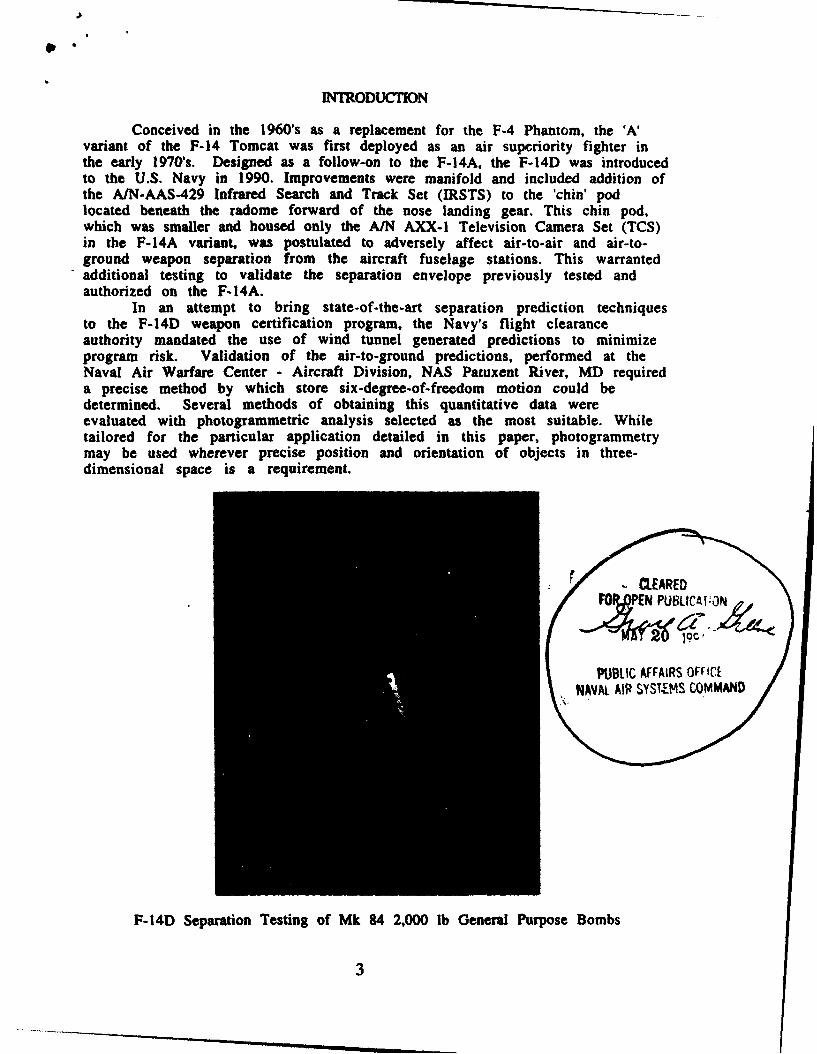
In an attempt to bring state-of-the-art separation prediction techniquesto the F-14D weapon certification program, the Navy's flight clearanceauthority mandated the use of wind tunnel generated predictions to minimizeprogram risk. Validation of the air-to-ground predictions, performed at theNaval Air Warfare Center - Aircraft Division, NAS Patuxent River, MD requireda precise method by which store six-degree-of-freedom motion could bedetermined. Several methods of obtaining this quantitative data wereevaluated with photogrammetric analysis selected as the most suitable. Whiletailored for the particular application detailed in this paper, photogrammetrymay be used wherever precise position and orientation of objects in three-dimensional space is a requirement.
r -. cEAREDJOY N PtBLICATI:C
PUBLIC AFFAIRS OFFICENAVAL AIR SYST.EMS COMMAND
F-14D Separation Testing of Mk 84 2,000 lb General Purpose Bombs
3
F-14A A IR-TOMGROUND HJSTORY
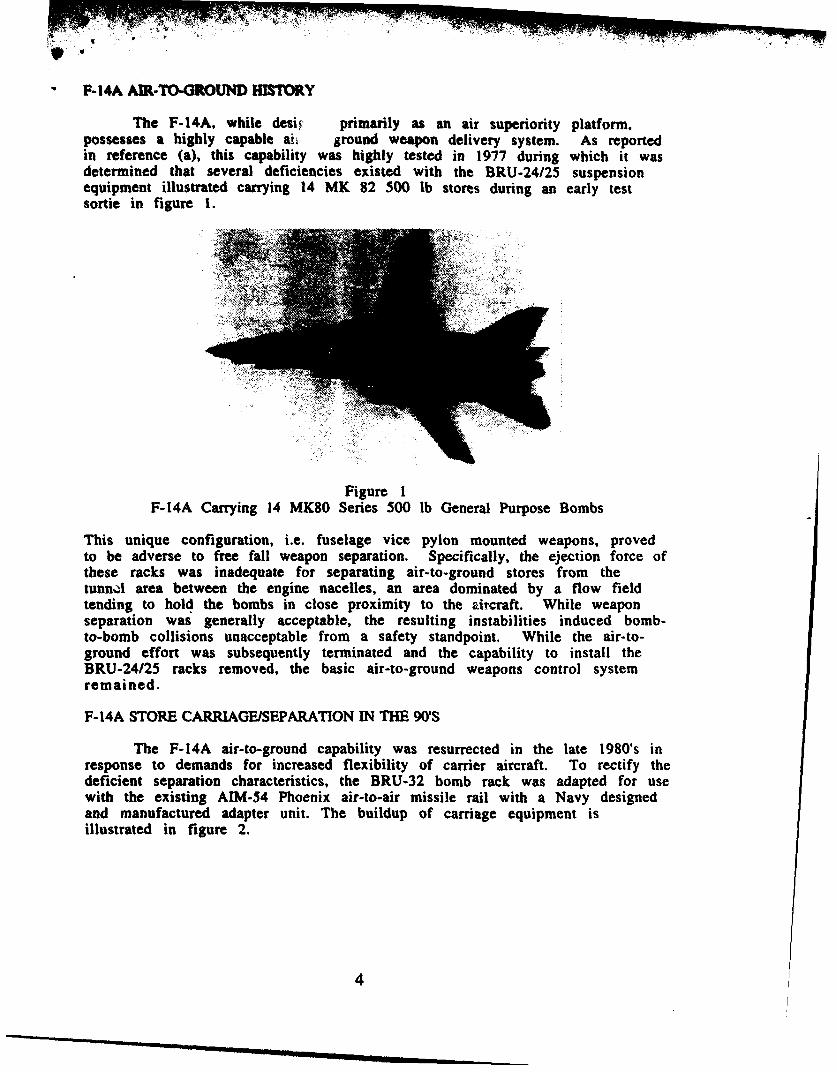
The F-14A, while desi primarily as an air superiority platform,possesses a highly capable ai, ground weapon delivery system. As reportedin reference (a), this capability was highly tested in 1977 during which it wasdetermined that several deficiencies existed with the BRU-24/25 suspensionequipment illustrated carrying 14 MK 82 500 lb stores during an early testsortie in figure 1.
Figure 1F-14A Carrying 14 MK80 Series 500 lb General Purpose Bombs
This unique configuration, i.e. fuselage vice pylon mounted weapons, provedto be adverse to free fall weapon separation. Specifically, the ejection force ofthese racks was inadequate for separating air-to-ground stores from thetunnl area between the engine nacelles, an area dominated by a flow fieldtending to hold the bombs in close proximity to the ircraft. While weaponseparation was generally acceptable, the resulting instabilities induced bomb-to-bomb collisions unacceptable from a safety standpoint. While the air-to-ground effort was subsequently terminated and the capability to install theBRU-24125 racks removed, the basic air-to-ground weapons control systemremained.
F-14A STORE CARRIAGE/SEPARATION IN THE 9('S
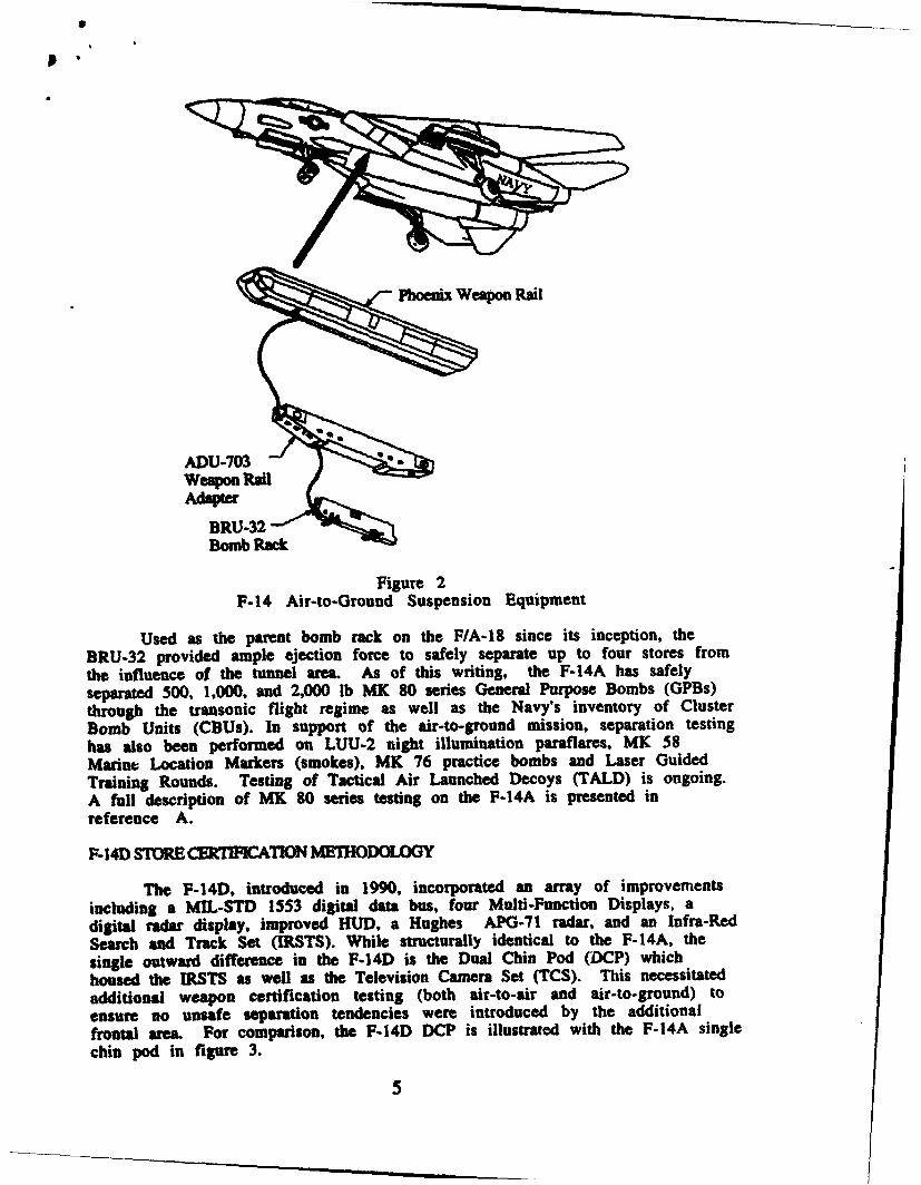
The F-14A air-to-ground capability was resurrected in the late 1980's inresponse to demands for increased flexibility of carrier aircraft. To rectify thedeficient separation characteristics, the BRU-32 bomb rack was adapted for usewith the existing AIM-54 Phoenix air-to-air missile rail with a Navy designedand manufactured adapter unit. The buildup of carriage equipment isillustrated in figure 2.
4
p •
F-1 Ai-t-GrundSPheniwaon EquipmnADU-703 -weapon Ran
BRU-32Bomb Rack
Figure 2F-14 Air-to-Ground Suspension Equipment
Used as the parent bomb rack on the F/A-18 since its inception, theBRU-32 provided ample ejection force to safely separate up to four stores fromthe influence of the tunnel area. As of this writing, the F-14A has safelyseparated 500, 1,000, and 2,000 lb MK 80 series General Purpose Bombs (GPBs)through the transonic flight regime as well as the Navy's inventory of ClusterBomb Units (CBUs). In support of the air-to-ground mission, separation testinghas also been performed on LUU-2 night illumination paraflares, MK 58Marine Location Markers (smokes), MK 76 practice bombs and Laser GuidedTraining Rounds. Testing of Tactical Air Launched Decoys (TALD) is ongoing.A full description of MK 80 series testing on the F-14A is presented inreference A.
F- 14D STORE CElfIqCATION M] HODOLOGY
The F-14D, introduced in 1990, incorporated an array of improvementsincluding a MIL-STD 1553 digital data bus, four Multi-Function Displays, adigital radar display, improved HUD, a Hughes APG-71 radar, and an Infra-RedSearch and Track Set (IRSTS). While structurally identical to the F-14A, thesingle outward difference in the F-14D is the Dual Chin Pod (DCP) whichhoused the IRSTS as well as the Television Camera Set (TCS). This necessitatedadditional weapon certification testing (both air-to-air and air-to-ground) toensure no unsafe separation tendencies were introduced by the additionalfrontal area For comparison, the F-14D DCP is illustrated with the F-14A singlechin pod in figure 3.
5
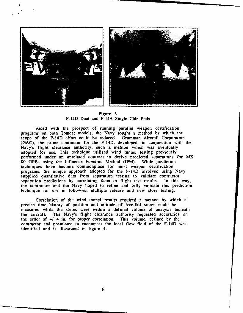
Figure 3F-14D Dual and F-14A Single Chin Pods
Faced with the prospect of running parallel weapon certificationprograms on both Tomcat models, the Navy sought a method by which thescope of the F-14D effort could be reduced. Grumman Aircraft Corporation(GAC), the prime contractor for the F-14D, developed, in conjunction with theNavy's flight clearance authority, such a method which was eventuallyadopted for use. This technique utilized wind tunnel testing previouslyperformed under an unrelated contract to derive predicted separations for MK80 GPBs using the Influence Function Method (IFM). While predictiontechniques have become commonplace for most weapon certificationprograms, the unique approach adopted for the F-14D involved using Navysupplied quantitative data from separation testing to validate contractorseparation predictions by correlating them to flight test results. In this way,the contractor and the Navy hoped to refine and fully validate this predictiontechnique for use in follow-on multiple release and new store testing.
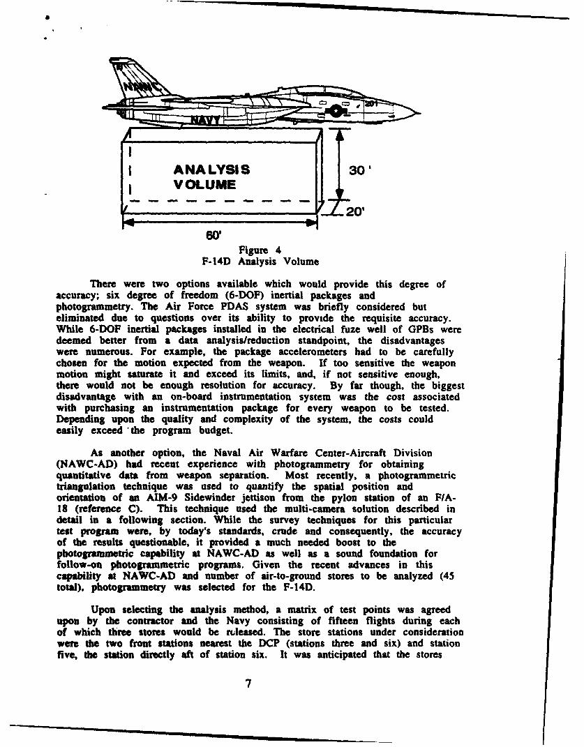
Correlation of the wind tunnel results required a method by which aprecise time history of position and attitude of free-fall stores could bemeasured while the stores were within a defined volume of analysis beneaththe aircraft. The Navy's flight clearance authority requested accuracies onthe order of +/ 4 in. for proper correlation. This volume, defined by thecontractor and postulated to encompass the local flow field of the F-14D wasidentified and is illustrated in figure 4.
6
I
I ANALYSISVOLUME
2'
Figure 4F-14D Analysis Volume
There were two options available which would provide this degree ofaccuracy; six degree of freedom (6-DOF) inertial packages andphotogrammetry. The Air Force PDAS system was briefly considered buteliminated due to questions over its ability to provide the requisite accuracy.While 6-DOF inertial packages installed in the electrical fuze well of GPBs weredeemed better from a data analysis/reduction standpoint, the disadvantageswere numerous. For example, the package accelerometers had to be carefullychosen for the motion expected from the weapon. If too sensitive the weaponmotion might saturate it and exceed its limits, and, if not sensitive enough,there would not be enough resolution for accuracy. By far though, the biggestdisadvantage with an on-board instrumentation system was the cost associatedwith purchasing an instrumentation package for every weapon to be tested.Depending upon the quality and complexity of the system, the costs couldeasily exceed *the program budget.
As another option, the Naval Air Warfare Center-Aircraft Division(NAWC-AD) had recent experience with photogrammetry for obtainingquantitative data from weapon separation. Most recently, a photogrammetrictriangulation technique was used to quantify the spatial position andorientation of an AIM-9 Sidewinder jettison from the pylon station of an F/A-18 (reference C). This technique used the multi-camera solution described indetail in a following section. While the survey techniques for this particulartest program were, by today's standards, crude and consequently, the accuracyof the results questionable, it provided a much needed boost to thephotogrammetric capability at NAWC-AD as well as a sound foundation forfollow-on photogrammetric programs. Given the recent advances in thiscapability at NAWC-AD and number of air-to-ground stores to be analyzed (45total). photogrammetry was selected for the F-14D.
Upon selecting the analysis method, a matrix of test points was agreedupon by the contractor and the Navy consisting of fifteen flights during eachof which three stores would be rleased. The store stations under considerationwere the two front stations nearest the DCP (stations three and six) and stationfive, the station directly aft of station six. It was anticipated that the stores
7
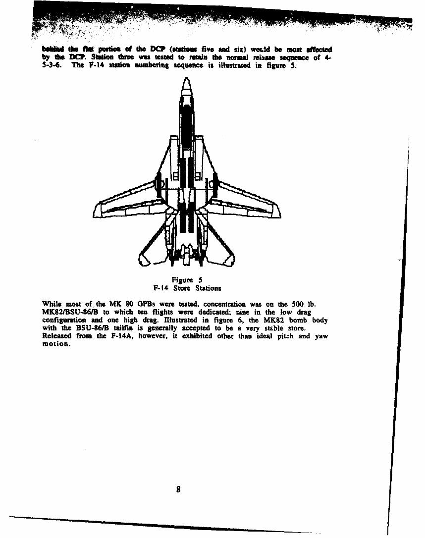
bhkd the i0s pqid. of doe DCP (stak.. five and six) would be am affecteby the DCP. Station three was tsted to retain the normal release sequoeae of 4-5-3-6. The P-14 stion sumberint Sequence is illustrated in figure 5.
Figure 5F-14 Store Stations
While most of. the MK 80 GPBs were tested, concentration was on the 500 lb.MK82IBSU-861B to which ten flights were dedicated; nine in the low dragconfiguration and one high drag. Illustrated in figure 6, the MK82 bomb bodywith the BSU-86/B tailfin is generally accepted to be a very stLble store.Released from the F-14A, however, it exhibited other than ideal pitch and yawmotion.
8
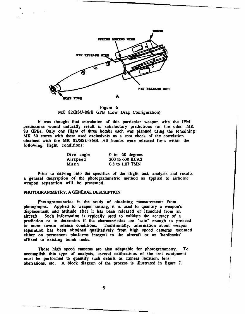
Figure 6MK 82/BSU-86/B GPB (Low Drag Configuration)
It was thought that correlation of this particular weapon with the IFMpredictions would naturally result in satisfactory predictions for the other MK80 GPBs. Only one flight of three bombs each was planned using the remainingMK 80 stores with these used exclusively as a spot check of the correlationobtained with the MK 82/BSU-861B. All bombs were released from within thefollowing flight conditions:
Dive angle 0 to -60 degreesAirspeed 500 to 600 KCASMach 0.8 to 1.07 TMN
Prior to delving into the specifics of the flight test, analysis and resultsa general description of the photogrammetric method as applied to airborneweapon separation will be presented.
PHOTOGRAMMETRY. A GENERAL DESCRIPTION
Photogrammetrics is the study of obtaining measurements fromphotographs. Applied to weapon testing, it is used to quantify a weapon'sdisplacement and attitude after it has been released or launched from anaircraft. Such information is typically used to validate the accuracy of aprediction or to determine if the characteristics are "safe" enough to proceedto more severe release conditions. Traditionally, information about weaponseparation has been obtained qualitatively from high speed cameras mountedeither on permanent platforms integral to the aircraft or on 'hardbacks'affixed to existing bomb racks.
These high speed cameras are also adaptable for photogrammetry. Toaccomplish this type of analysis, several calibrations of the test equipmentmust be performed to quantify such details as camera location, lensaberrations, etc. A block diagram of the process is illustrated in figure 7.
9

Conduct Test / Process Film
r~i
Post-TestI r c ssD t I II
Figure 7Photogrammetric Process Block Diagram
As shown, there are pre- and post-test operations. While most of thepre-test methodologies are common, the post-test requirements can varydepending upon the type of test or the camera solution chosen. Varioussolution techniques are available including single, dual, and multi-camera; theselection of which depends upon the accuracy of the data required and thecomplexity of the computer algorithm available to reduce the data. For thesetests, a multi-camera solution was apolied and the discussions presented in thispaper are limited to this method.
At the heart of the analysis lies the high speed cameras themselves. Forthis application motion was recorded on high quality ASA 400 16mm film usingPhotosonics Model IPL high speed cinematic cameras operating at 200 framesper second. Each camera accommodates up to 250 ft of film providing up to 45seconds of footage when operated at .005 seconds per frame. For weaponseparation photography, 5.9 mm lenses are typically installed. This sairi focallength is also aptly suited for photogrammetric analysis.
A first priority is calibration of the camera lenses. This simply maps outany distortion in the lens (ex: pin-cushion or barrel) and determines how theprojection of the object's image on the camera film frame (or film plane) isaffected. Lens calibrations are performed by aiming the camera at acalibrated target, usually a plane surface like a 4 ft X 8 ft ply-board withgraduated gridwork painted on it, and running several frames of film. Theresults of this calibration are entered into the algorithm so that distortions aretaken into consideration when reducing film data.
In addition to the lens calibration the objects, in this case the aircraftand weapons, have to be "targeted". Targets are easily identified points (either
10
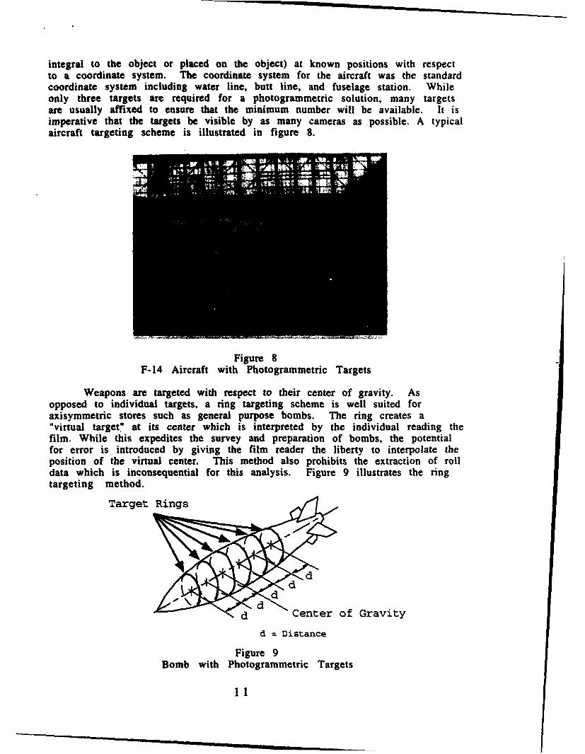
integral to the object or placed on the object) at known positions with respectto a coordinate system. The coordinate system for the aircraft was the standardcoordinate system including water line, butt line, and fuselage station. Whileonly three targets are required for a photogrammetric solution, many targetsare usually affixed to ensure that the minimum number will be available. It isimperative that the targets be visible by as many cameras as possible. A typicalaircraft targeting scheme is illustrated in figure 8.
Figure 8F-14 Aircraft with Photogrammetric Targets
Weapons are targeted with respect to their center of gravity. Asopposed to individual targets, a ring targeting scheme is well suited foraxisymmetric stores such as general purpose bombs. The ring creates a"virtual target" at its center which is interpreted by the individual reading thefilm. While this expedites the survey and preparation of bombs, the potentialfor error is introduced by giving the film reader the liberty to interpolate theposition of the virtual center. This method also prohibits the extraction of rolldata which is inconsequential for this analysis. Figure 9 illustrates the ringtargeting method.
Target Rings
d Center of Gravity
d = Distance
Figure 9Bomb with Photogrammetric Targets
-- umi ~mml lllm11~
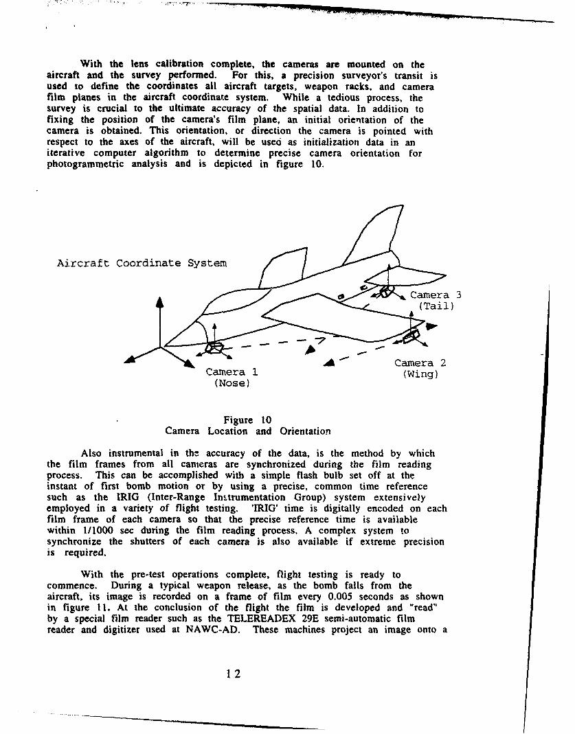
With the lens calibration complete, the cameras are mounted on theaircraft and the survey performed. For this, a precision surveyor's transit isused to define the coordinates all aircraft targets, weapon racks, and camerafilm planes in the aircraft coordinate system. While a tedious process, thesurvey is crucial to the ultimate accuracy of the spatial data. In addition tofixing the position of the camera's film plane, an initial orientation of thecamera is obtained. This orientation, or direction the camera is pointed withrespect to the axes of the aircraft, will be used as initialization data in aniterative computer algorithm to determine precise camera orientation forphotogrammetric analysis and is depicted in figure 10.
Aircraft Coordinate System
/ / Camera 3(Tail
A Camera 2Camera 1 (Wing)(Nose)
Figure 10Camera Location and Orientation
Also instrumental in the accuracy of the data, is the method by whichthe film frames from all cameras are synchronized during the film readingprocess. This can be accomplished with a simple flash bulb set off at theinstant of first bomb motion or by using a precise, common time referencesuch as the IRIG (Inter-Range Instrumentation Group) system extensivelyemployed in a variety of flight testing. 'IRIG' time is digitally encoded on eachfilm frame of each camera so that the precise reference time is availablewithin 1/1000 sec during the film reading process. A complex system tosynchronize the shutters of each camera is also available if extreme precisionis required.
With the pre-test operations complete, flight testing is ready tocommence. During a typical weapon release, as the bomb falls from theaircraft, its image is recorded on a frame of film every 0.005 seconds as shownin figure 11. At the conclusion of the flight the film is developed and "read"by a special film reader such as the TELEREADEX 29E semi-automatic filmreader and digitizer used at NAWC-AD. These machines project an image onto a
12
.- .L ..............
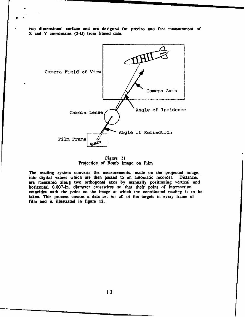
two dimensional surface and are designed for precise and fast measurement ofX and Y coordinates (2-D) from filmed data.
Camera Field of View
Camera Axis
Camera Lense Angle of Incidence
Angle of Refraction
Film Frame
Figure I 1Projection of Bomb Image on Film
The reading system converts the measurements, made on the projected image,into digital values which are then passed to an automatic recorder. Distancesare measured -along two orthogonal axes by manually positioning vertical andhorizontal 0.007-in. diameter crosswires so that their point of intersectioncoincides with the point on the image at which the coordinated readirg is to betaken. This process creates a data set for all of the targets in every frame offilm and is illustrated in figure 12.
13
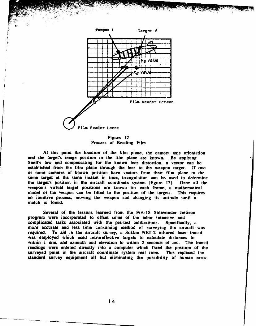
Target 1 Target 6
-- - ---- Y6 value
Film Reader Screen
Film Reader Lense
Figure 12Process of Reading Film
At this point the location of the film plane, the camera axis orientationand the target's image position in the film plane are known. By applyingSnell's law and compensating for the known lens distortion, a vector can beestablished from the film plane through the lens to the weapon target. If twoor more cameras of known position have vectors from their film plane to thesame target at the same instant in time, triangulation can be used to determinethe target's vosition in the aircraft coordinate system (figure 13). Once all theweapon's virtual target positions are known for each frame, a mathematicalmodel of the weapon can be fitted to the position of the targets. This requiresan iterative process, moving the weapon and changing its attitude until amatch is found.
Several of the lessons learned from the F/A-I8 Sidewinder Jettisonprogram were incorporated to offset some of the labor intensive andcomplicated tasks associated with the pre-test calibrations. Specifically, amore accurate and less time consuming method of surveying the aircraft wasrequired. To aid in the aircraft survey, a Sokkia NET-2 infrared laser transitwas employed which used retroreflective targets to calculate distances towithin I mm, and azimuth and elevation to within 2 seconds of arc. The transitreadings were entered directly into a computer which fixed the position of thesurveyed point in the aircraft coordinate system real time. This replaced thestandard survey equipment all but eliminating the possibility of human error.
14
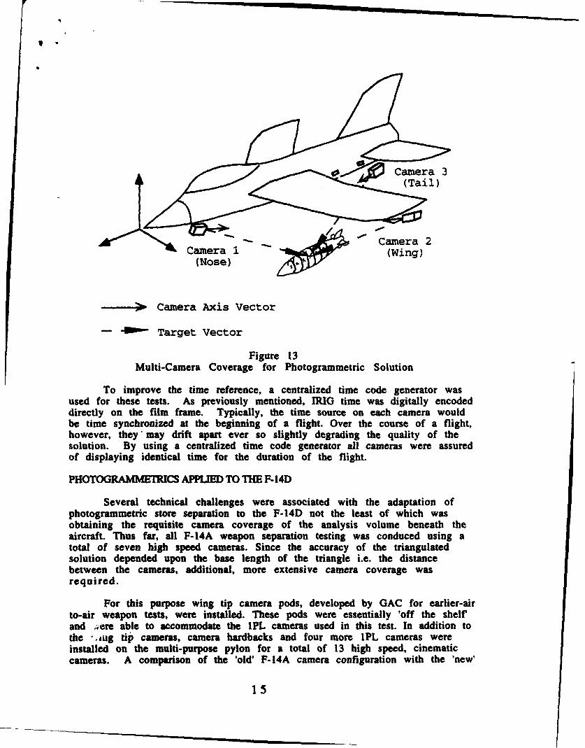
~ Camera 3
Camera 1 (Wing)(Nose)
,,, w Camera Axis Vector
-- O Target Vector
Figure 13Multi-Camera Coverage for Photogrammetric Solution
To improve the time reference, a centralized time code generator wasused for these tests. As previously mentioned, IRIG time was digitally encodeddirectly on the film frame. Typically, the time source on each camera wouldbe time synchronized at the beginning of a flight. Over the course of a flight,however, they'may drift apart ever so slightly degrading the quality of thesolution. By using a centralized time code generator all cameras were assuredof displaying identical time for the duration of the flight.
PHOTOGRAMMETRICS APPLIED TO THE F-14D
Several technical challenges were associated with the adaptation ofphotogrammetric store separation to the F-14D not the least of which wasobtaining the requisite camera coverage of the analysis volume beneath theaircraft. Thus far, all F-14A weapon separation testing was conduced using atotal of seven high speed cameras. Since the accuracy of the triangulatedsolution depended upon the base length of the triangle i.e. the distancebetween the cameras, additional, more extensive camera coverage wasrequired.
For this purpose wing tip camera pods, developed by GAC for earlier-airto-air weapon tests, were installed. These pods were essentially 'off the shelfand ;ere able to accommodate the IPL cameras used in this test. In addition tothe _sug tip cameras, camera hardbacks and four more IPL cameras wereinstalled on the multi-purpose pylon for a total of 13 high speed, cinematiccameras. A comparison of the 'old' F-14A camera configuration with the 'new'
15
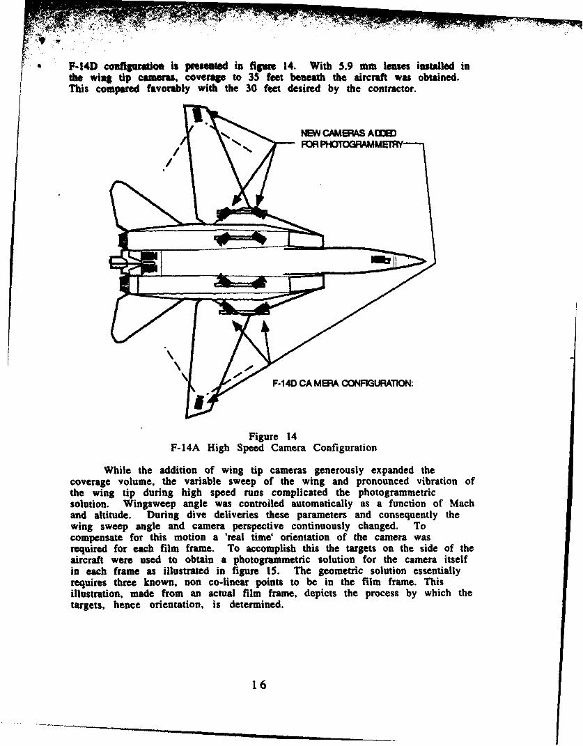
F-14D conflguratlon is presented in figure 14. With 5.9 mm lenses installed inthe wing tip camera, coverage to 35 feet beneath the aircraft was obtained.This compared favorably with the 30 feet desired by the contractor.
NEW CAMERAS ADDED
[F-14D CA MEPA CONFIGURATION:
Figure 14F-14A High Speed Camera Configuration
While the addition of wing tip cameras generously expanded thecoverage volume, the variable sweep of the wing and pronounced vibration ofthe wing tip during high speed runs complicated the photogrammetricsolution. Wingsweep angle was controlled automatically as a function of Machand altitude. During dive deliveries these parameters and consequently thewing sweep angle and camera perspective continuously changed. Tocompensate for this motion a 'real time' orientation of the camera wasrequired for each film frame. To accomplish this the targets on the side of theaircraft were used to obtain a photogrammetric solution for the camera itselfin each frame as illustrated in figure 15. The geometric solution essentiallyrequires three known, non co-linear points to be in the film frame. Thisillustration, made from an actual film frame, depicts the process by which thetargets, hence orientation, is determined.
16

Center of Film Frame
Film reader lens
Figure 15Wing tip camera triangulation
As mentioned, NAWC-AD used an iterative algorithm to determineprecise camera orientation using the field survey of the aircraft forinitialization data. This algorithm was able to fix the position and orientation(x, y, z, pitch, roll, yaw) of a camera provided enough surveyed targets on theaircraft were visible in the film frame. For each of the aircraft-mountedcameras x, y, and z position was held fixed because it was theorized that theseparameters would not vary much from those obtained from the field survey.Camera pitch, roll and yaw were allowed to vary in the iteration to preciselyfix the orientation. Two aircraft targets had to be in the film frame to completethis fuselage camera orientation.
For the wing tip cameras, x and y were fixed with z allowed to vary inaddition to pitch, roll and yaw. The z variable was allowed to vary tocompensate for the up and down movement of the wing tip due to airloads. Toconverge on a solution with this extra degree of freedom, an additionalfuselage target (total of three) had to be in the film frame. To fix the x and yvariables for these cameras the location of the film frame had to bedetermined as a function of wingsweep angle. This was achieved during theground aircraft survey when the wings were swept and surveyed in fivedegree increments. Wingsweep angle was an instrumented parameter so thisprovided the x and y position of the camera within +/- I in. While theorientation of the wing tip camera may have been determined without the useof the wingsweep instrumentation (i.e. allowing all six variables: x, y, z, pitch,roll, and yaw to vary) this expedited the iteration resulting in a quickersolution. Once the wing tip camera was precisely oriented it, in turn, could beused in combination with other cameras to precisely locate the weapons.
17
In addition to wing tip camera position another technical hurdle wassatisfactorily determining the accuracy of the photogrammetric solution. Theprecision of these solutions had been speculated since there existed severalsources of error and, during live weapon releases, there was no 'truth data' towhich the solution could be compared. Accuracy was dependent upon severalfactors and in many cases the errors were additive. For example, a fewmilliradian error in the aircraft survey may translate into a several incherror in the final product. Error sources included but were not limited to:
Angular survey measurementRange survey measurementFilm reading / virtual target interpretationLens calibrationPhase lock / film frame interpolationCamera motion
To isolate all but the camera motion error, a ground test was performedprior to the first flight. For this test the fully surveyed and targeted aircraftwas raised on aircraft jacks and the landing gear retracted. This provided themaximum availability of the analysis volume. A painted and targeted bomb wasthen moved to several locations under the aircraft to simulate the actual paththe store may follow as it separated. This ground test is depicted in figure 16.
Figure 16F-14D Photogrammetric Ground Test
In each position, the bomb was surveyed in the aircraft coordinated system toobtain truth data and the cameras were run for several frames. The film datawas then reduced and the photogrammetric accuracy compared to thesurveyed truth data. Results were encouraging with an accuracy of 3.28 incheswith the bombs is a simulated carriage position, improving to 2.8 inchesapproximately 2 ft below the aircraft and degrading linearly below that.
18
While camera vibration/motion was not able to be simulated in theground test (aside from sweeping the wings) a provision was made tocompensate for this condition should it occur. This will be discussed in thenext section. As an additional independent verification of the accuracy of thephotogrammetric solution, a 6-DOF inertial package was released in a MK 83bomb approximately mid way through the program. The results of this releaseare presented in a following section.
In addition to the technical challenges associated with this program,several logistical difficulties were anticipated as well. The effect upon thecamera survey of repeated touch and go landings, especially the Navy variety,was unknown. The same held true for the removal and re-installation of thecamera hardbacks. While the cameras were physically locked onto the cameramount and hardback, the effect of even a minor adjustment of a sway bracewhile the cameras were removed was unknown. For this reason, the aircraftwas put under a 'project flight only' status for the duration of the program.Since there were three days allocated for data reduction following a flight, theresulting aircraft utilization rate was poor.
Problems were also experienced during scheduled maintenance. Navyaircraft were on a 14 day wash schedule. While initially permitted to do 'drywashes' where the aircraft is cleaned with spray solvents, wet washed had tobe resumed mid way through the program for instruction compliance. Thisresulted in a lengthy process by which each camera was waterproofed prior toeach wash. Scheduled maintenance on the ejector racks which suspended thecamera hardbacks also presented a problem in that the sway bracing had to bemarked in position to prevent compromising the survey during removal.
FLIGHT TEST
Flight testing commenced 21 May 1993 and concluded 7 September 1993.During this period 17 flights for analysis were flown during which 49 singlebomb release- events occurred. Photogrammetric solutions for 47 of these 49releases were obtained. One of the bombs released contained an experimental6-DOF telemetry package. Forty-five of the 49 events had at least a threecamera solution.
While the program proceeded without any major difficulties someunanticipated problems did arise. First was the deflection of the forwardcameras on aircraft stations 2 and 7 camera hardbacks. The design of thecamera hardback sway braces and mounts positioned the cameras out on acantilevered and unsupported end of the hardback. At the high dynamicpressure test points the airloads on the camera induced a film plane deflectionof approximately 1/2 inch which compromised the photogrammetric data. Thestation 2/7 camera hardback is illustrated in figure 17.
19

Figure 17F-14D Station 2/7 camera hardback
To compensate for this deflection, a 'real time' orientation of theaffected cameras was performed just prior to weapon release. Recall that forprecise fuselage camera orientation, x, y and z were assumed to remain fixed inthe aircraft coordinate system. This deflection was akin to movement in the zdirection and had to be accounted for. As was described for the wing tipcameras, the z variable was allowed to vary in addition to pitch, roll and yawfor these affected fuselage cameras producing an accurate solution in theiteration. As opposed to performing orientation for each film frame, it wasdone once per bomb release with the assumption that the deflection remainedconstant while the bomb was within the field of view of the affected camera.
Additional difficulties experienced during the flight test, conductedduring an exceptionally humid summer, was limited visibility and bombobscuration by vapor trails. Even though, in most cases, the bombs were nomore that 30-40 feet from the camera, the condensation of moisture about theengine nacelles obstructed some targets from sight. Surface weatherobservations obtained for each flight date indicated that better film readingquality corresponded to lower temperatures, dew points, and humidity. Whilefilm quality deteriorated in August and September sortie rate remainedconsistent with that obtained in the late Spring with the impact to theprogram limited only to the quality of the photogrammetric data. Mostlyaffected by the vapor trails were the wing tip cameras.
Compounding the vapor trails was the paint scheme selected for theweapons. Completely unrelated to the photogrammetric effort but beingconducted concurrently, a ballistic analysis was being performed on thereleased stores. A paint scheme tailored for good visibility from the groundbased high speed cameras was desired and a bright orange was selected.Unfortunately, this color was not well suited for photogrammetric filmreading and accuracy was probably somewhat degraded. (The white tape on ablue bomb scheme, used when ballistic testing was not scheduled, performedsatisfactorily and was more desired than the green-on-orange used otherwise).
20
Bomb visibility was also highly dependent upon the time of day of the flight.Flights conducted later in the afternoon were susceptible to an intense glarefrom several of the cameras.
DATA REDUMM AND PROCESSING
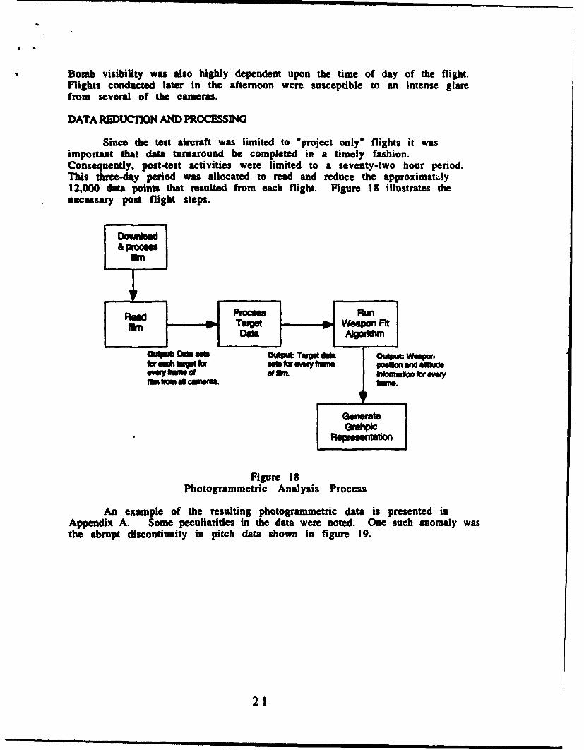
Since the test aircraft was limited to "project only" flights it wasimportant that data turnaround be completed in a timely fashion.Consequently. post-test activities were limited to a seventy-two hour period.This three-day period was allocated to read and reduce the approximatwly12,000 data points that resulted from each flight. Figure 18 illustrates thenecessary post flight steps.
Ra Prcl Run
fn T" Weapon cFp eit
Figure 18Photogrammetric Analysis Process
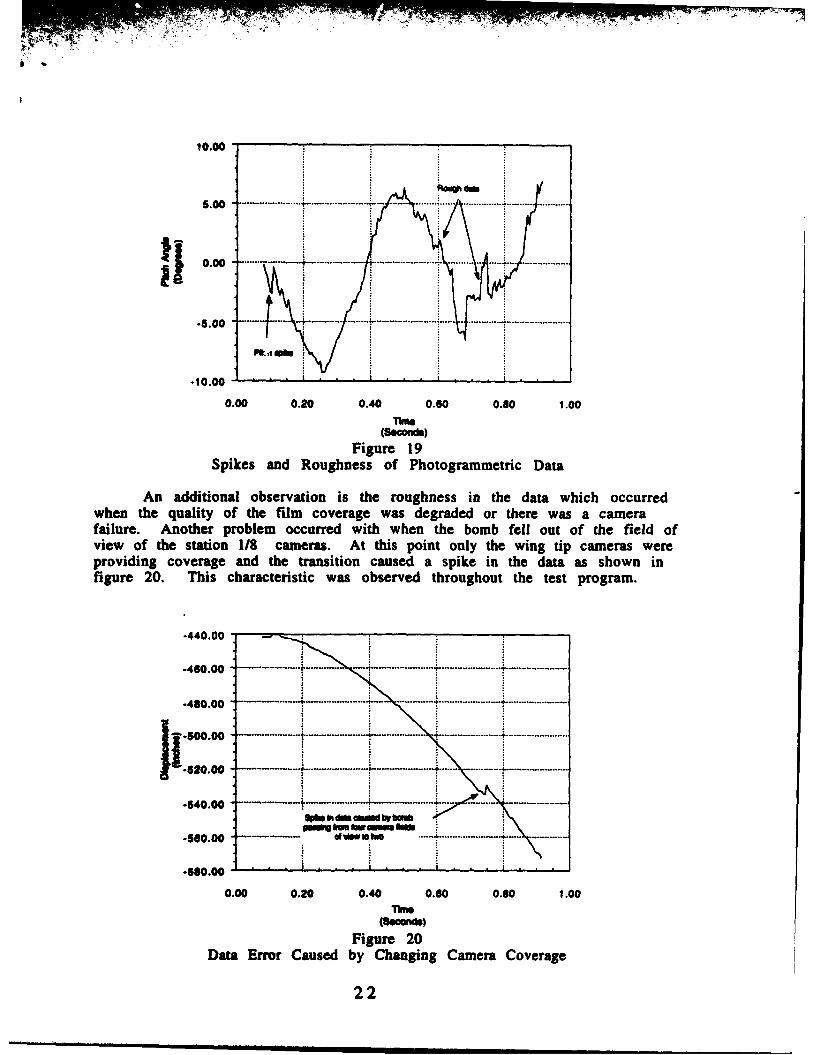
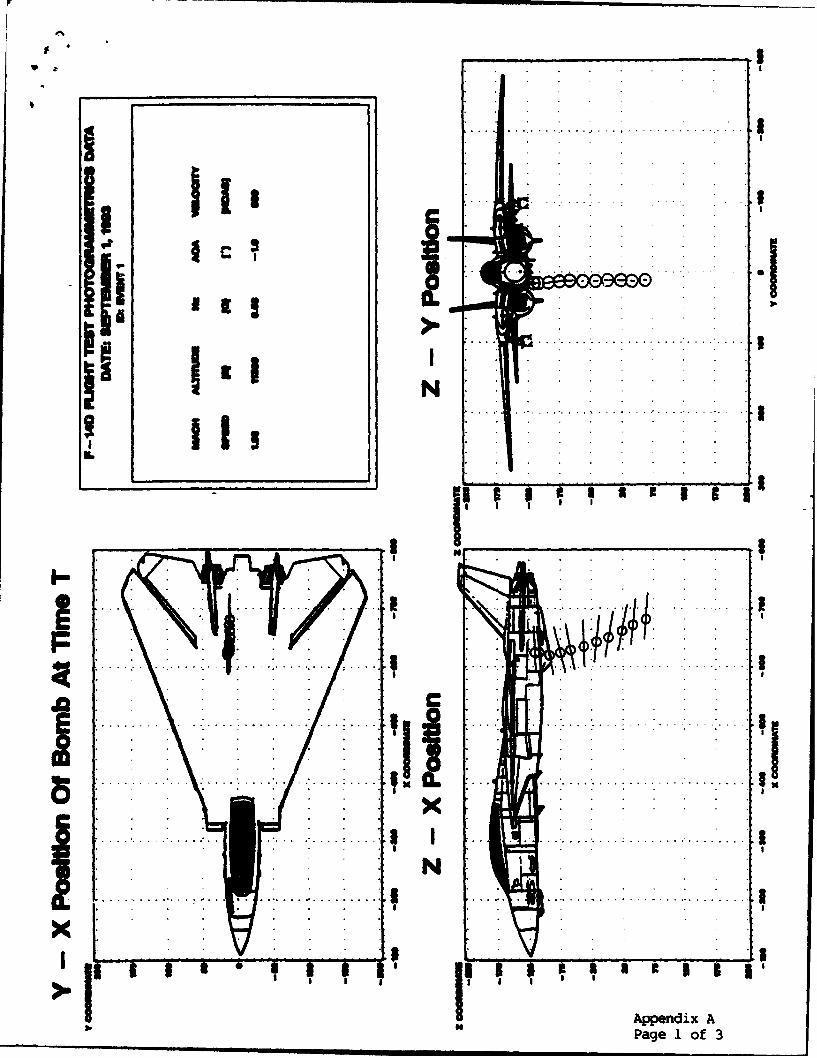
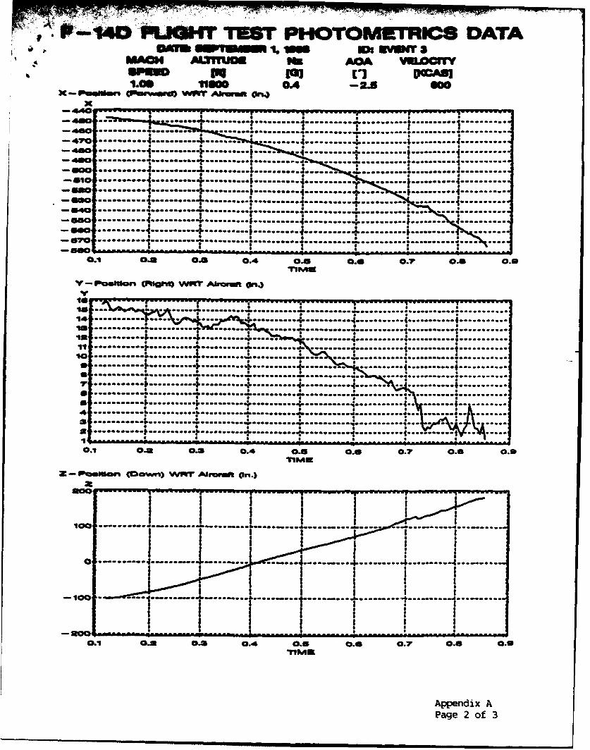
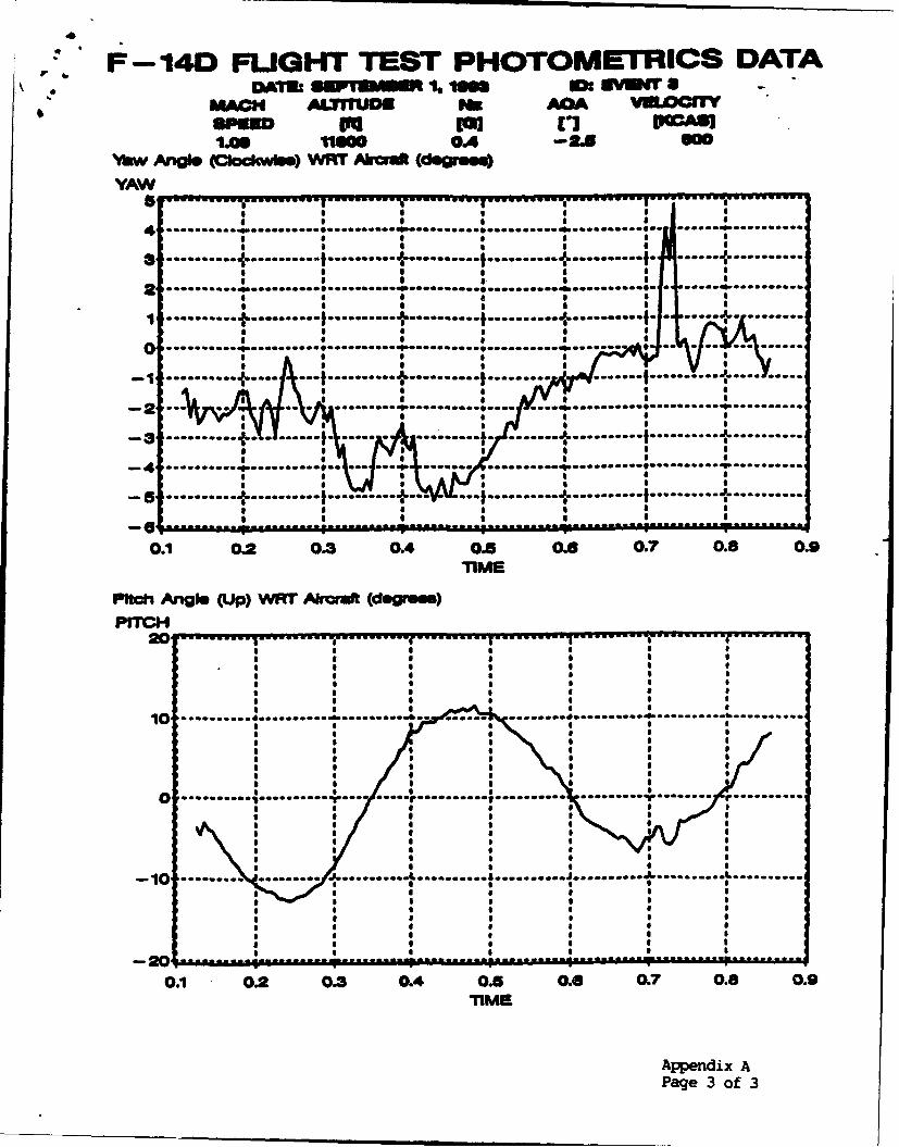
An example of the resulting photogrammetric data is presented inAppendix A. Some peculiarities in the data were noted. One such anomaly wasthe abrupt discontinuity in pitch data shown in figure 19.
21
y-;
10.00
1 0 00 ...... ... ............
-5.00
0.00 0.20 0.40 0.80 0.80 1 00The(Seconde)
Figure 19Spikes and Roughness of Photogrammetric Data
An additional observation is the roughness in the data which occurredwhen the quality of the film coverage was degraded or there was a camerafailure. Another problem occurred with when the bomb fell out of the field ofview of the station 1/8 cameras. At this point only the wing tip cameras wereproviding coverage and the transition caused a spike in the data as shown infigure 20. This characteristic was observed throughout the test program.
.440.00 --4(10.00 .. .. --- --.. ---- .. .............- .............. . ...... -. .......
-480.00 - .-.-.-.--.---- . .... . ......... - ------- ........ ....... -.......... .4 -. -----................-
4 W- 0O0 -- -...... . . .......... ... ................. 4 ........... ........... ........................
-540.00 .........
-540.00• i , , • • • , , , , , . . ,
0.00 0.20 0.40 0.60 0.60 1.00
Figure 20Data Error Caused by Changing Camera Coverage
22
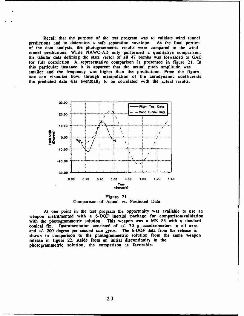
Recall that the purpose of the test program was to validate wind tunnelpredictions and to determine a safe separation envelope. As the final portionof the data analysis, the photogrammetric results were compared to the windtunnel predictions. While NAWC-AD only performed a qualitative comparison,the tabular data defining the state vector of all 47 bombs was forwarded to GACfor full correlction. A representative comparison is presented in figure 21. Inthis particular instance it is apparent that the actual pitch amplitude wassmaller and the frequency was higher than the predictioon. From the figureone can visualize how, through manipulation of the aerodynamic coefficients,the predicted data was eventually to be correlated with the actual results.
30.00- Flight Test Data
20.00 ./ . .. . Wind Tunnel Data10.00
Ii\// ...... / . .................
-20 .00 ................. ................ ................................... ...................................................... .
-30.00 ,
0.00 0.20 0.40 0.60 0.80 1.00 1.20 1.40
Tihe(Seconds)
Figure 21Comparison of Actual vs. Predicted Data
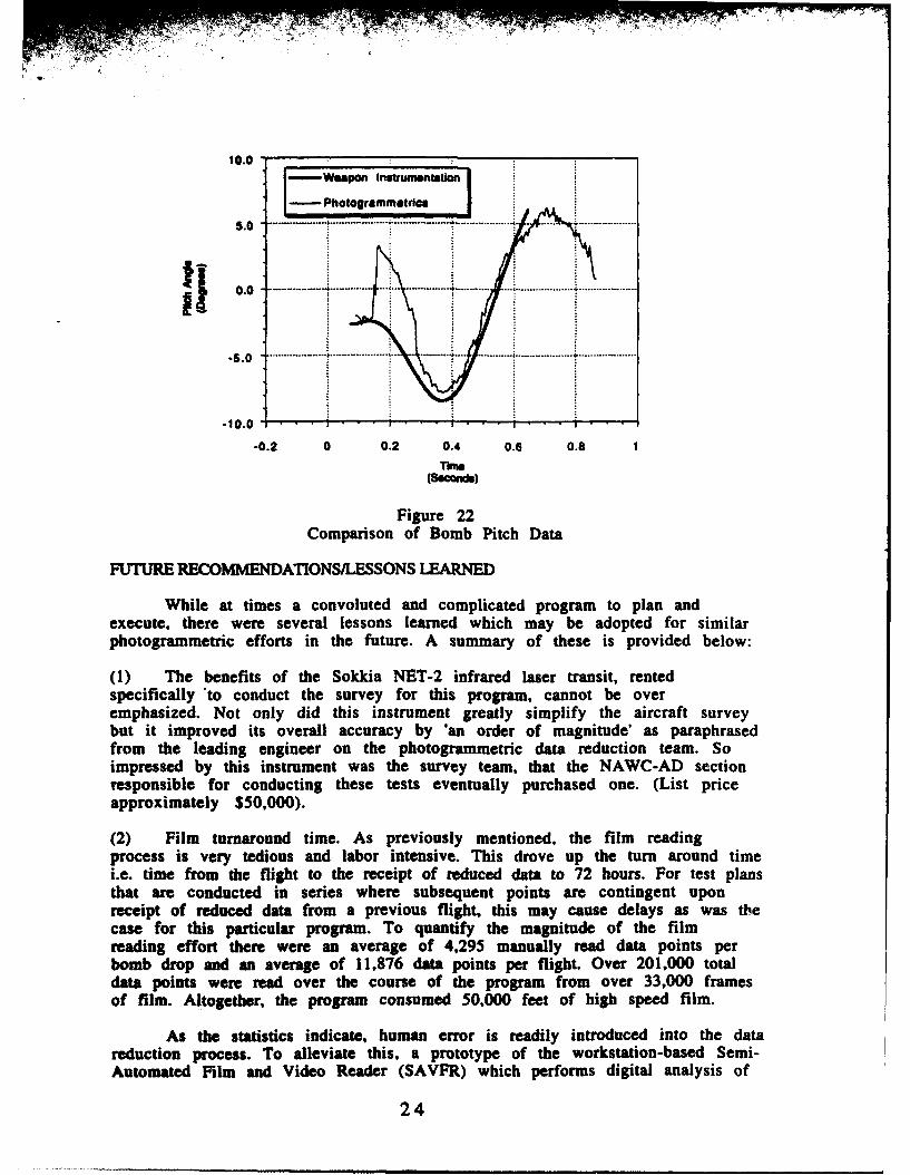
At one point in the test program the opportunity was available to use anweapon instrumented with a 6-DOF inertial package for comparison/validationwith the photogrammetric solution. This weapon was a MK 83 with a standardconical fin. Instrumentation consisted of +/- 30 g accelerometers in all axesand +/- 200 degree per second rate gyros. The 6-DOF data from the release isshown in comparison to the photogrammetric solution from the same weaponrelease in figure 22. Aside from an initial discontinuity in thephotogrammetric solution, the comparison is favorable.
23
10.0 , - i_--wupan Instumnw~ne im
I- Photogrammotic"5 .0 - . ..t... .......... .... ........ ...... . .. ... .. ...
0 .0 .. ....... .. ... .......... ....... .... .... .................... ............ ........
-S .0 ....... .... ' ...... ..............-- --- ------ -- -- -_- -----------
-0.2 0 0.2 0.4 0.6 0.8 1TOW(seconws)
Figure 22
Comparison of Bomb Pitch Data
FUTURE RECOMMENDATIONS/LESSONS LEARNED
While at times a convoluted and complicated program to plan andexecute, there were several lessons learned which may be adopted for similarphotogrammetric efforts in the future. A summary of these is provided below:
(1) The benefits of the Sokkia NET-2 infrared laser transit, rentedspecifically 'to conduct the survey for this program, cannot be overemphasized. Not only did this instrument greatly simplify the aircraft surveybut it improved its overall accuracy by 'an order of magnitude' as paraphrasedfrom the leading engineer on the photogrammetric data reduction team. Soimpressed by this instrument was the survey team, that the NAWC-AD sectionresponsible for conducting these tests eventually purchased one. (List priceapproximately $50,000).
(2) Film turnaround time. As previously mentioned, the film readingprocess is very tedious and labor intensive. This drove up the turn around timei.e. time from the flight to the receipt of reduced data to 72 hours. For test plansthat are conducted in series where subsequent points are contingent uponreceipt of reduced data from a previous flight, this may cause delays as was thecase for this particular program. To quantify the magnitude of the filmreading effort there were an average of 4,295 manually read data points perbomb drop and an average of 11,876 data points per flight. Over 201,000 totaldata points were read over the course of the program from over 33,000 framesof film. Altogether, the program consumed 50,000 feet of high speed film.
As the statistics indicate, human error is readily introduced into the datareduction process. To alleviate this, a prototype of the workstation-based Semi-Automated Film and Video Reader (SAVFR) which performs digital analysis of
24
16 mm film and video is currently being evaluated at NAWC-AD. SAVFR,tailored specifically for flight test and analysis applications, was designed tointroduce automation and artificial intelligence to increase the speed of thefilm reading process and improve the quality of tracking information.
(3) Although not addressed previously, the benefit of the widely spacedwing tip cameras was not realized. While one would believe that more cameracoverage is better, the distances involved and the wide angle lenses used to getthe requisite coverage degraded the accuracy of the solution. One can imaginehow difficult it was for the film readers to pinpoint the center of the targetrings when the target rings themselves became a blur on the film frame.
Along this same line, more in-depth planning to orient the cameras formaximum coverage would have been beneficial. While limited to specificaircraft locations, the cameras were moveable +/- 180 degrees in azimuth anddown to -75 degrees in elevation. During the planning process this particularissue was not given sufficient attention and maximum utility was not obtainedfrom each camera.
(5) Bomb preparation required an inordinate amount of time. As requestedby the photogrammetric analysis group, the bombs were all surveyed andtaped relative to the weapon center of gravity. While the mass properties oftest ordnance is typically obtained as a matter of course, taping in reference tothe c.g. was time consuming. A better technique would be to tape the bomb inreference to the weapon leading edge and measure the leading edge inreference to the c.g. For future applications NAWC-AD is evaluating thePIXSYS system developed for the U.S. Air Force, which uses near-infraredtechnology to produce accurate 3-D surveys of relatively small objects likestores. This should greatly reduce the survey and preparation time for stores.
Tape was used to form the rings on the bombs. While painting the ringsseemed like the logical choice, there were several drawbacks to this methodincluding the construction of a complicated painting jig. Unfortunately, thetape on the forward half of the bombs had a tendency to peel off. Althoughmore difficult, painting is the preferred method and ghould be considered inthe future.
Colorizing the bombs was also an issue. For ballistic visibility the bombswere painted orange. This, unfortunately, was not well distinguishable in thesummer haze. A better and easier method was to leave the bombs their factoryblue color and use white tape. The white-on-blue provided more contrast andenabled the acquisition of higher quality data.
(6) Finally, a more rigid hardback is recommended. This would makepractical sense in that higher quality data would be obtained but also makessense from a safety standpoint.
CONCLUSION
While adapted here to airborne weapon separation, photogrammetryhas far reaching applications. As an example, the National Geographic Societyand the Navigation Foundation recently teamed up to prove, viaphotogrammetric analysis of prints taken during his expedition, that ADM
25
Peary did indeed reach the North Pole*; a claim long since disputed by hiscritics. While this is quite an exotic application of the technology, thepossibilities for additional aviation applications such as mishapreconstruction, carrier suitability, range tracking and overhead impact arejust being realized. NAWC-AD continues to build upon its ability to rapidlyconfigure for and provide quantitative photogrammetric data reduction andanalysis. It can only be expected that the ease and accuracy of employing thistechnique will continue to advance.
* New Evidence Peary Reached The Pole; National Geographic; January, 1990;
p44.
26
Re fereniices
A. Navy Technical Evaluation of the F-14A Air-to-Ground WeaponsCowjji~dij1W Naval Air Test Center report SY-189R-77; 7 FEB 78.
B. ATM-9R/LAU- 127 Evaluation on EIA- 18 Aircraft; Naval Air WarfareCenter report SA-30R-92; 6 MAY 92.
C. Manual of Photogrammetry. Second Edition; American Society ofPhotograinmetry; George Banta; 1952.
27
........ . . . . . . . . . .
. . .
I . . .. . . . .
I. . . . ...
... .. .. ... . .. .. .
Pag IIof
71 17 -
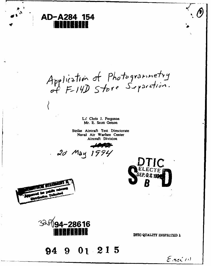
vawU W-4 uurT PHOTOMIETRICS DATADAMN Ew 1 it S "m SY1W 3
mAON AL1fm AXIIJD vuacnw
iiM an OkA -AgoX - P~wsmn (awawm wwr ^kwat On.)
X-440---------------------------------OU------e ---------- --- I------
-400~~~...... ..........0.0.I......1*00f......0 ....... 00...--............. ................................................
-470 ----- ........ .....~..0.. o~oa. . ... ........... ..........-- .......* a
e6 0 .......... .......... r ... ......---------...- -......
-60......n..... ........... ..... 4..... ...... ........... &.......... ..........*em ...... ................ ...... .... I& .......... ..........
-660 ............ .::.oI........S...~ ~ ...............
-49 ....... ..14.. ........... ............... ..........-6......604----------- 4---------------------------------------
0.1 0.3 0.3 0.4 OAS 0.0 0.7 0.5 0.6
v - plIo cPIaSgh Wif F Abrmet on.)v
................................. ........... .......... ........... ........... ...........
... I ... ....... ............... 4 ....................................... ........................... .............. ........... .......... ........... ...........-----------... ........ 4 ....... .................
......... .................... .... ......... .................. .......... .......... ........... ........
10 --------... ........a...... ...... ... ... ..... ...........-------- ........... .......... -................ .......... ........... ..........
............... ........... .......... ........... .......... . ..... ........... 0...........
...... ~............. ........... a....t.............1C........ ...........-- - - - - .. . .. . .. . .. . .. . . . . - -- - - -. . . .
.............. I . ......... 4... ........ 4... ........... ........... ..........----------.......... ........ 0............... . . ..
SR -----------.................. a...4 ... .... ... 9.................. ....... t.......
*. I a 0. .ai . . . .
Ic ....l...... a............
CLIO 0.2 0.3 0.4 0.5 0.6 0.7 0.6 0.9
Z - oe~o. ~0wn) WF Arae,"MR.
Apedi
300~~~ag - o-f 3 ~ vw~ -
a
F-14D FUGHT TEST PHOTOMETRICS DATA
MACH AIIIlUMN of AM VDC11.5IC OA -2.5I.QG "am0 0.4 -- .m '
Yaw Ango ( bksow) WRY A (degres
YAW4 ..
a ........... .- .......... .......... .. .......... ..........- I .......... - ------. ..........2 ........ .......... .... .......
..........------..-........------------------------ - ---------- ---. ....* a a a S o I Boa
0 ...... ....... ........... ,, ......... ,o ...... ',.......... ........ .. . .. ...., : : .......S....... ....
-2 ...... ... ............ --. ..... . .. ..........I ..................-3 ....... L .a........ .... . . .... . ..........
-4 . ... ............. *S *** *.*.* . ... b.............. .. .........
-5..... ----- -----........ ........ jr..........
, ,
0. 0. 0.3 0. O07 0. .
au a a lm oeI , oa , ai'beO qi,,oe u
-2 ... . .......... .. .- ............ ... ..........
- ...... ..... ..... .......... " .......... -.......... . ..... .. .. ..." - .. j ......b ...l ........ ...........
- ... a I a a a aI a
, -- ------------- - -------------0.1 0.2 0.3 0.4 0.5 0.6 0.7 0.8 0.9
TIMEPitch A.gle (Up) wR in" ra.=t (doene)
........ ...... 0"......... "............. ..... ............ . ......... b...........
age 3 f
10I
II a
I IS
* a$ a
-1 ...... -..... "J ...... " ...... ...... a ... . . -.......... .......* 5-a--* a SoI SI
0.1 0.2 0.3 0.4 0.5I 0.0 0.7 0.8 0.9T1MB
Page 3 of 3