Embed Size (px)
Citation preview
IDP Series
Administration Guide
Release
5.1rX
Published: 2013-12-19
Revision 03
Copyright © 2013, Juniper Networks, Inc.
Juniper Networks, Inc.1194 North Mathilda AvenueSunnyvale, California 94089USA408-745-2000www.juniper.net
Juniper Networks, Junos, Steel-Belted Radius, NetScreen, and ScreenOS are registered trademarks of Juniper Networks, Inc. in the UnitedStates and other countries. The Juniper Networks Logo, the Junos logo, and JunosE are trademarks of Juniper Networks, Inc. All othertrademarks, service marks, registered trademarks, or registered service marks are the property of their respective owners.
Juniper Networks assumes no responsibility for any inaccuracies in this document. Juniper Networks reserves the right to change, modify,transfer, or otherwise revise this publication without notice.
IDP Series Administration GuideCopyright © 2013, Juniper Networks, Inc.All rights reserved.
Revision HistoryNovember 2012—Revision 03
The information in this document is current as of the date on the title page.
YEAR 2000 NOTICE
Juniper Networks hardware and software products are Year 2000 compliant. Junos OS has no known time-related limitations through theyear 2038. However, the NTP application is known to have some difficulty in the year 2036.
ENDUSER LICENSE AGREEMENT
The Juniper Networks product that is the subject of this technical documentation consists of (or is intended for use with) Juniper Networkssoftware. Use of such software is subject to the terms and conditions of the End User License Agreement (“EULA”) posted athttp://www.juniper.net/support/eula.html. By downloading, installing or using such software, you agree to the terms and conditions ofthat EULA.
Copyright © 2013, Juniper Networks, Inc.ii
Table of Contents
Preface . . . . . . . . . . . . . . . . . . . . . . . . . . . . . . . . . . . . . . . . . . . . . . . . . . . . . . . . . . xvii
Objectives . . . . . . . . . . . . . . . . . . . . . . . . . . . . . . . . . . . . . . . . . . . . . . . . . . . . . xvii
Audience . . . . . . . . . . . . . . . . . . . . . . . . . . . . . . . . . . . . . . . . . . . . . . . . . . . . . xvii
Documentation Conventions . . . . . . . . . . . . . . . . . . . . . . . . . . . . . . . . . . . . . xvii
Related Documentation . . . . . . . . . . . . . . . . . . . . . . . . . . . . . . . . . . . . . . . . . . xix
Requesting Technical Support . . . . . . . . . . . . . . . . . . . . . . . . . . . . . . . . . . . . . xx
Self-Help Online Tools and Resources . . . . . . . . . . . . . . . . . . . . . . . . . . . xx
Opening a Case with JTAC . . . . . . . . . . . . . . . . . . . . . . . . . . . . . . . . . . . . . xxi
Part 1 Getting Started
Chapter 1 Using the Default Configuration . . . . . . . . . . . . . . . . . . . . . . . . . . . . . . . . . . . . . . 3
Getting Started with the Default Configuration . . . . . . . . . . . . . . . . . . . . . . . . . . . . 3
Part 2 Analyzing Your Network
Chapter 2 Using Simulation Mode . . . . . . . . . . . . . . . . . . . . . . . . . . . . . . . . . . . . . . . . . . . . . 7
Simulation Mode Task Summary . . . . . . . . . . . . . . . . . . . . . . . . . . . . . . . . . . . . . . . . 7
Enabling Simulation Mode . . . . . . . . . . . . . . . . . . . . . . . . . . . . . . . . . . . . . . . . . . . . . 7
Viewing Simulation Mode Logs . . . . . . . . . . . . . . . . . . . . . . . . . . . . . . . . . . . . . . . . . 9
Chapter 3 Using Profiler . . . . . . . . . . . . . . . . . . . . . . . . . . . . . . . . . . . . . . . . . . . . . . . . . . . . . . 11
Profiler Task Summary . . . . . . . . . . . . . . . . . . . . . . . . . . . . . . . . . . . . . . . . . . . . . . . . 11
Configuring Profiler Options (NSM Procedure) . . . . . . . . . . . . . . . . . . . . . . . . . . . . 12
Configuring General Settings . . . . . . . . . . . . . . . . . . . . . . . . . . . . . . . . . . . . . . . 12
Configuring Tracked Hosts . . . . . . . . . . . . . . . . . . . . . . . . . . . . . . . . . . . . . . . . 14
Configuring Context Targets . . . . . . . . . . . . . . . . . . . . . . . . . . . . . . . . . . . . . . . 16
Configuring Alert Options . . . . . . . . . . . . . . . . . . . . . . . . . . . . . . . . . . . . . . . . . 17
Starting and Stopping the Profiler (NSM Procedure) . . . . . . . . . . . . . . . . . . . . . . . 18
Using Profiler Viewer (NSM Procedure) . . . . . . . . . . . . . . . . . . . . . . . . . . . . . . . . . . 19
Application Profiler Tab . . . . . . . . . . . . . . . . . . . . . . . . . . . . . . . . . . . . . . . . . . . 19
Protocol Profiler Tab . . . . . . . . . . . . . . . . . . . . . . . . . . . . . . . . . . . . . . . . . . . . . 21
Network Profiler Tab . . . . . . . . . . . . . . . . . . . . . . . . . . . . . . . . . . . . . . . . . . . . . 22
Violation Viewer Tab . . . . . . . . . . . . . . . . . . . . . . . . . . . . . . . . . . . . . . . . . . . . . 24
Modifying Profiler Settings . . . . . . . . . . . . . . . . . . . . . . . . . . . . . . . . . . . . . . . . . . . . 25
Managing the Profiler Database (NSM Procedure) . . . . . . . . . . . . . . . . . . . . . . . . . 27
Displaying Profiler Database Information . . . . . . . . . . . . . . . . . . . . . . . . . . . . . 27
Querying the Profiler Database . . . . . . . . . . . . . . . . . . . . . . . . . . . . . . . . . . . . . 27
Purging the Profiler Database . . . . . . . . . . . . . . . . . . . . . . . . . . . . . . . . . . . . . . 28
Chapter 4 Using the NSM Security Explorer . . . . . . . . . . . . . . . . . . . . . . . . . . . . . . . . . . . . 29
Security Explorer Task Summary . . . . . . . . . . . . . . . . . . . . . . . . . . . . . . . . . . . . . . . 29
iiiCopyright © 2013, Juniper Networks, Inc.
Chapter 5 Using the NSM Topology Manager . . . . . . . . . . . . . . . . . . . . . . . . . . . . . . . . . . . 31
NSM Topology Manager Task Summary . . . . . . . . . . . . . . . . . . . . . . . . . . . . . . . . . 31
Part 3 Protecting Your Network
Chapter 6 Security Policies Overview . . . . . . . . . . . . . . . . . . . . . . . . . . . . . . . . . . . . . . . . . 35
Developing Security Policies Task Summary . . . . . . . . . . . . . . . . . . . . . . . . . . . . . 35
Using Predefined Security Policies . . . . . . . . . . . . . . . . . . . . . . . . . . . . . . . . . . . . . . 37
Using the New Policy Wizard (NSM Procedure) . . . . . . . . . . . . . . . . . . . . . . . . . . . 38
Chapter 7 Configuring the IDP Rulebase . . . . . . . . . . . . . . . . . . . . . . . . . . . . . . . . . . . . . . . 41
Modifying IDP Rulebase Rules (NSM Procedure) . . . . . . . . . . . . . . . . . . . . . . . . . . 41
Specifying Rule Match Conditions (NSM Procedure) . . . . . . . . . . . . . . . . . . . . . . . 43
Specifying IDP Rulebase Attack Objects (NSM Procedure) . . . . . . . . . . . . . . . . . . 45
Specifying Rule Session Action (NSM Procedure) . . . . . . . . . . . . . . . . . . . . . . . . . 46
Specifying IP Action (NSM Procedure) . . . . . . . . . . . . . . . . . . . . . . . . . . . . . . . . . . 48
Specifying Rule Notification Options (NSM Procedure) . . . . . . . . . . . . . . . . . . . . 49
Specifying Rule VLAN Matches (NSM Procedure) . . . . . . . . . . . . . . . . . . . . . . . . . 51
Specifying Rule Targets (NSM Procedure) . . . . . . . . . . . . . . . . . . . . . . . . . . . . . . . . 51
Specifying Rule Severity (NSM Procedure) . . . . . . . . . . . . . . . . . . . . . . . . . . . . . . . 52
Specifying Rule Comments (NSM Procedure) . . . . . . . . . . . . . . . . . . . . . . . . . . . . 53
Chapter 8 Configuring Additional Security Policy Rulebases . . . . . . . . . . . . . . . . . . . . . 55
Configuring Exempt Rulebase Rules (NSM Procedure) . . . . . . . . . . . . . . . . . . . . . 55
Configuring the APE Rulebase (NSM Procedure) . . . . . . . . . . . . . . . . . . . . . . . . . . 56
Configuring Backdoor Rulebase Rules (NSM Procedure) . . . . . . . . . . . . . . . . . . . . 61
Configuring SYN Protector Rulebase Rules (NSM Procedure) . . . . . . . . . . . . . . . . 63
Configuring Traffic Anomalies Rulebase Rules (NSM Procedure) . . . . . . . . . . . . . 65
Configuring Network Honeypot Rulebase Rules (NSM Procedure) . . . . . . . . . . . . 68
Chapter 9 Managing Security Policies . . . . . . . . . . . . . . . . . . . . . . . . . . . . . . . . . . . . . . . . . 71
Managing Security Policies Task Summary . . . . . . . . . . . . . . . . . . . . . . . . . . . . . . . 71
Assigning a Security Policy to a Device (NSM Procedure) . . . . . . . . . . . . . . . . . . . 72
Validating a Security Policy (NSM Procedure) . . . . . . . . . . . . . . . . . . . . . . . . . . . . 72
Troubleshooting Security Policy Validation Errors (NSM Procedure) . . . . . . . . . . . 72
Pushing Security Policy Updates to an IDP Series Device (NSM Procedure) . . . . . 73
Troubleshooting Configuration Push Errors (NSM Procedure) . . . . . . . . . . . . . . . . 75
Disabling Rules (NSM Procedure) . . . . . . . . . . . . . . . . . . . . . . . . . . . . . . . . . . . . . . 76
Exporting Security Policies (NSM Procedure) . . . . . . . . . . . . . . . . . . . . . . . . . . . . . 76
Chapter 10 Working with Attack Objects . . . . . . . . . . . . . . . . . . . . . . . . . . . . . . . . . . . . . . . 79
Attack Objects Task Summary . . . . . . . . . . . . . . . . . . . . . . . . . . . . . . . . . . . . . . . . 79
Viewing Predefined Attack Objects (NSM Procedure) . . . . . . . . . . . . . . . . . . . . . 80
Working with Attack Groups (NSM Procedure) . . . . . . . . . . . . . . . . . . . . . . . . . . . 83
Creating Dynamic Groups . . . . . . . . . . . . . . . . . . . . . . . . . . . . . . . . . . . . . . . . . 83
Creating Static Groups . . . . . . . . . . . . . . . . . . . . . . . . . . . . . . . . . . . . . . . . . . . 84
Creating a Signature Attack Object . . . . . . . . . . . . . . . . . . . . . . . . . . . . . . . . . . . . . 85
Creating a Compound Attack Object . . . . . . . . . . . . . . . . . . . . . . . . . . . . . . . . . . . 105
Copyright © 2013, Juniper Networks, Inc.iv
IDP Series Administration Guide
Chapter 11 Working With Application Objects . . . . . . . . . . . . . . . . . . . . . . . . . . . . . . . . . . . 111
Application Objects Task Summary . . . . . . . . . . . . . . . . . . . . . . . . . . . . . . . . . . . . . 111
Viewing Predefined Application Objects (NSM Procedure) . . . . . . . . . . . . . . . . . . 112
Viewing Predefined Extended Application Objects (NSM Procedure) . . . . . . . . . 115
Creating a Custom Application (NSM Procedure) . . . . . . . . . . . . . . . . . . . . . . . . . 117
Creating Application Groups (NSM Procedure) . . . . . . . . . . . . . . . . . . . . . . . . . . . 118
Part 4 Managing Your IDP Series Devices
Chapter 12 Understanding the Management Tools . . . . . . . . . . . . . . . . . . . . . . . . . . . . . . 123
Supported Tools for Management Tasks . . . . . . . . . . . . . . . . . . . . . . . . . . . . . . . . 123
Chapter 13 Using NSM to Manage the IDP Series Device Configuration . . . . . . . . . . . . 127
NSM Device Configuration Management Task Summary . . . . . . . . . . . . . . . . . . . 127
Adding IDP Series Devices to NSM Device Manager . . . . . . . . . . . . . . . . . . . . . . . 128
Adding a Reachable Device . . . . . . . . . . . . . . . . . . . . . . . . . . . . . . . . . . . . . . . 128
Adding an Unreachable Device . . . . . . . . . . . . . . . . . . . . . . . . . . . . . . . . . . . . 129
Modeling an IDP Series Device Configuration . . . . . . . . . . . . . . . . . . . . . . . . 130
Adding Device Clusters . . . . . . . . . . . . . . . . . . . . . . . . . . . . . . . . . . . . . . . . . . . 131
Activating Devices (NSM Procedure) . . . . . . . . . . . . . . . . . . . . . . . . . . . . . . . . . . . 132
Activating a Reachable IDP Series Device . . . . . . . . . . . . . . . . . . . . . . . . . . . . 132
Activating an Unreachable IDP Series Device . . . . . . . . . . . . . . . . . . . . . . . . . 133
Pulling or Pushing Configuration Updates . . . . . . . . . . . . . . . . . . . . . . . . . . . . . . . 134
Modifying the IDP Series Device Configuration . . . . . . . . . . . . . . . . . . . . . . . . . . . 135
Modifying NSM Informational Properties . . . . . . . . . . . . . . . . . . . . . . . . . . . . 136
Modifying Antispoof Settings . . . . . . . . . . . . . . . . . . . . . . . . . . . . . . . . . . . . . 137
Modifying Runtime Parameters . . . . . . . . . . . . . . . . . . . . . . . . . . . . . . . . . . . 139
Modifying Load-Time Parameters . . . . . . . . . . . . . . . . . . . . . . . . . . . . . . . . . 149
Modifying Protocol Anomaly Thresholds . . . . . . . . . . . . . . . . . . . . . . . . . . . . 151
Deleting an IDP Series Device Configuration from NSM Device Manager (NSM
Procedure) . . . . . . . . . . . . . . . . . . . . . . . . . . . . . . . . . . . . . . . . . . . . . . . . . . . . 166
Chapter 14 Enabling Advanced Features and Options with scio Commands . . . . . . . . 167
scio Configuration Commands Task Summary . . . . . . . . . . . . . . . . . . . . . . . . . . . 167
Using the SSL Private Server Key to Enable Inspection of SSL Traffic . . . . . . . . . 168
Using the SSL Forward Proxy Feature to Enable Inspection of HTTPS Traffic . . . 171
Exempting HTTPS Traffic from Inspection . . . . . . . . . . . . . . . . . . . . . . . . . . . . . . . 172
Enabling Inspection of GRE Traffic . . . . . . . . . . . . . . . . . . . . . . . . . . . . . . . . . . . . . 173
Enabling Inspection of GTP Traffic . . . . . . . . . . . . . . . . . . . . . . . . . . . . . . . . . . . . . 175
Enabling Inspection of IPsec VPN Traffic . . . . . . . . . . . . . . . . . . . . . . . . . . . . . . . . 177
Enabling Inspection of MPLS Traffic . . . . . . . . . . . . . . . . . . . . . . . . . . . . . . . . . . . 178
Enabling the Flow Bypass Feature . . . . . . . . . . . . . . . . . . . . . . . . . . . . . . . . . . . . . 179
Configuring Advanced Settings for the User-Role-Based Policy Feature . . . . . . . 181
Configuring a Default Rate Limit . . . . . . . . . . . . . . . . . . . . . . . . . . . . . . . . . . . . . . 182
Enabling Per-User Rate Limiting for User-Role-Based Rules . . . . . . . . . . . . . . . . 183
vCopyright © 2013, Juniper Networks, Inc.
Table of Contents
Chapter 15 Using ACM to Configure IDP Series Network Interfaces . . . . . . . . . . . . . . . . 185
ACM Task Summary . . . . . . . . . . . . . . . . . . . . . . . . . . . . . . . . . . . . . . . . . . . . . . . . 185
Configuring Virtual Routers (ACM Procedure) . . . . . . . . . . . . . . . . . . . . . . . . . . . 186
Configuring Interface Aliasing (ACM Procedure) . . . . . . . . . . . . . . . . . . . . . . . . . . 187
Installing an I/O Module . . . . . . . . . . . . . . . . . . . . . . . . . . . . . . . . . . . . . . . . . . . . . 188
Chapter 16 Updating IDP OS Software . . . . . . . . . . . . . . . . . . . . . . . . . . . . . . . . . . . . . . . . . 191
Updating IDP OS Software (NSM Procedure) . . . . . . . . . . . . . . . . . . . . . . . . . . . . 191
Upgrading Software (CLI Procedure) . . . . . . . . . . . . . . . . . . . . . . . . . . . . . . . . . . 193
Loading J-Security Center Updates (NSM Procedure) . . . . . . . . . . . . . . . . . . . . . 194
Chapter 17 Restarting the IDP Engine . . . . . . . . . . . . . . . . . . . . . . . . . . . . . . . . . . . . . . . . . 199
Restarting the IDP Engine . . . . . . . . . . . . . . . . . . . . . . . . . . . . . . . . . . . . . . . . . . . 199
Chapter 18 Rebooting and Shutting Down an IDP Series Appliance . . . . . . . . . . . . . . . 201
Rebooting and Shutting Down the IDP Series Appliance . . . . . . . . . . . . . . . . . . . 201
Part 5 Monitoring Attacks and Application Usage
Chapter 19 Monitoring Tools Overview . . . . . . . . . . . . . . . . . . . . . . . . . . . . . . . . . . . . . . . . 205
Supported Tools for Monitoring Tasks . . . . . . . . . . . . . . . . . . . . . . . . . . . . . . . . . 205
Chapter 20 Using NSM Logs and Reports . . . . . . . . . . . . . . . . . . . . . . . . . . . . . . . . . . . . . . 207
IDP Series Logs and Reports in NSM Task Summary . . . . . . . . . . . . . . . . . . . . . . 207
Viewing Device Status (NSM Procedure) . . . . . . . . . . . . . . . . . . . . . . . . . . . . . . . 208
Using NSM Logs . . . . . . . . . . . . . . . . . . . . . . . . . . . . . . . . . . . . . . . . . . . . . . . . . . . 213
NSM Logs Overview . . . . . . . . . . . . . . . . . . . . . . . . . . . . . . . . . . . . . . . . . . . . . 213
Using NSM Log Viewer (NSM Procedure) . . . . . . . . . . . . . . . . . . . . . . . . . . . . 214
Using NSM Log Investigator (NSM Procedure) . . . . . . . . . . . . . . . . . . . . . . . 219
Using NSM Audit Log Viewer (NSM Procedure) . . . . . . . . . . . . . . . . . . . . . . 220
Viewing NSM Predefined Reports (NSM Procedure) . . . . . . . . . . . . . . . . . . . . . . . 221
Creating NSM Custom Reports (NSM Procedure) . . . . . . . . . . . . . . . . . . . . . . . . 224
Configuring Log Storage Limits . . . . . . . . . . . . . . . . . . . . . . . . . . . . . . . . . . . . . . . 226
Configuring Log Suppression (NSM Procedure) . . . . . . . . . . . . . . . . . . . . . . . . . . 227
Configuring an SNMP Agent (NSM Procedure) . . . . . . . . . . . . . . . . . . . . . . . . . . 228
Configuring Syslog Collection (NSM Procedure) . . . . . . . . . . . . . . . . . . . . . . . . . 230
Enabling Collection of Packet Data in NSM Logs (NSM Procedure) . . . . . . . . . . 232
Chapter 21 Using IDP Reporter . . . . . . . . . . . . . . . . . . . . . . . . . . . . . . . . . . . . . . . . . . . . . . . 235
IDP Reporter Task Summary . . . . . . . . . . . . . . . . . . . . . . . . . . . . . . . . . . . . . . . . . 235
Chapter 22 Using SNMP to Monitor Device Health and Traffic Statistics . . . . . . . . . . . 237
SNMP Statistic Reporting and Traps Task Summary . . . . . . . . . . . . . . . . . . . . . . 237
Configuring SNMP Reporting for the Sensor Category of Statistics . . . . . . . . . . 238
Configuring SNMP Reporting for the Resource Category of Statistics . . . . . . . . . 242
Configuring SNMP Reporting for the Interface Category of Statistics . . . . . . . . . 247
Configuring SNMP Reporting for the Traffic Category of Statistics . . . . . . . . . . . 257
Configuring SNMP Reporting for the Rule Category of Statistics . . . . . . . . . . . . 264
Chapter 23 Monitoring NIC State with the bypassStatus Command . . . . . . . . . . . . . . 267
bypassStatus Utility Task Summary . . . . . . . . . . . . . . . . . . . . . . . . . . . . . . . . . . . 267
Copyright © 2013, Juniper Networks, Inc.vi
IDP Series Administration Guide
Chapter 24 Verifying Feature Implementation with scio Counters . . . . . . . . . . . . . . . . 269
scio Monitoring Commands Task Summary . . . . . . . . . . . . . . . . . . . . . . . . . . . . . 269
Verifying the APE Rulebase . . . . . . . . . . . . . . . . . . . . . . . . . . . . . . . . . . . . . . . . . . 269
Verifying Integration with an IC Series Unified Access Control Appliance . . . . . . 271
Verifying MPLS Decapsulation . . . . . . . . . . . . . . . . . . . . . . . . . . . . . . . . . . . . . . . . 272
Verifying the Flow Bypass Feature . . . . . . . . . . . . . . . . . . . . . . . . . . . . . . . . . . . . . 273
Chapter 25 Monitoring Session Flow with the sctop Command . . . . . . . . . . . . . . . . . . . 277
sctop Task Summary . . . . . . . . . . . . . . . . . . . . . . . . . . . . . . . . . . . . . . . . . . . . . . . 277
Using the sctop Utility (CLI Procedure) . . . . . . . . . . . . . . . . . . . . . . . . . . . . . . . . . 277
Understanding sctop Flow Table Reports . . . . . . . . . . . . . . . . . . . . . . . . . . . . . . 280
Chapter 26 Using Command-Line Utilities for Packet Capture . . . . . . . . . . . . . . . . . . . . 281
Using jnetTcpdump to Capture Packets . . . . . . . . . . . . . . . . . . . . . . . . . . . . . . . . 281
Using tcpdump to Capture Packets . . . . . . . . . . . . . . . . . . . . . . . . . . . . . . . . . . . 282
Part 6 Troubleshooting
Chapter 27 Troubleshooting . . . . . . . . . . . . . . . . . . . . . . . . . . . . . . . . . . . . . . . . . . . . . . . . . 285
Troubleshooting Tools Overview . . . . . . . . . . . . . . . . . . . . . . . . . . . . . . . . . . . . . . 285
IDP Processes Reference . . . . . . . . . . . . . . . . . . . . . . . . . . . . . . . . . . . . . . . . . . . . 287
Troubleshooting SNMP Statistic Reporting . . . . . . . . . . . . . . . . . . . . . . . . . . . . . 288
Tuning the JNET Driver Failure Count . . . . . . . . . . . . . . . . . . . . . . . . . . . . . . . . . . 290
Viewing Auto-Recovery Logs . . . . . . . . . . . . . . . . . . . . . . . . . . . . . . . . . . . . . . . . . 291
Disabling the Auto-Recovery Feature . . . . . . . . . . . . . . . . . . . . . . . . . . . . . . . . . . 292
Tuning the Auto-Recovery Policy Reload Setting . . . . . . . . . . . . . . . . . . . . . . . . . 293
Viewing CPU Utilization . . . . . . . . . . . . . . . . . . . . . . . . . . . . . . . . . . . . . . . . . . . . . 293
Troubleshooting High CPU Usage . . . . . . . . . . . . . . . . . . . . . . . . . . . . . . . . . . . . . 295
Troubleshooting Erroneous CPU Utilization Reports . . . . . . . . . . . . . . . . . . . . . . 297
Displaying Service Session Count . . . . . . . . . . . . . . . . . . . . . . . . . . . . . . . . . . . . . 299
Troubleshooting Application Identification . . . . . . . . . . . . . . . . . . . . . . . . . . . . . 300
Disabling the APE Rulebase . . . . . . . . . . . . . . . . . . . . . . . . . . . . . . . . . . . . . . . . . 303
Disabling the User Role-Based Policy Feature . . . . . . . . . . . . . . . . . . . . . . . . . . . 304
Disabling Support for Jumbo Frames . . . . . . . . . . . . . . . . . . . . . . . . . . . . . . . . . . 304
Troubleshooting SSL Inspection . . . . . . . . . . . . . . . . . . . . . . . . . . . . . . . . . . . . . . 305
Disabling SSL Inspection . . . . . . . . . . . . . . . . . . . . . . . . . . . . . . . . . . . . . . . . . . . . 305
Disabling MPLS Decapsulation . . . . . . . . . . . . . . . . . . . . . . . . . . . . . . . . . . . . . . . 306
Troubleshooting NSM Log Collection Issues . . . . . . . . . . . . . . . . . . . . . . . . . . . . . 307
Part 7 Appendixes
Appendix A Connecting to the Appliance Configuration Manager . . . . . . . . . . . . . . . . . . 311
Connecting to ACM . . . . . . . . . . . . . . . . . . . . . . . . . . . . . . . . . . . . . . . . . . . . . . . . . 311
Changing the Management Interface IP Address . . . . . . . . . . . . . . . . . . . . . . . . . . 311
Appendix B bypassStatus Commands . . . . . . . . . . . . . . . . . . . . . . . . . . . . . . . . . . . . . . . . . 315
Connecting to the Command-Line Interface (CLI Procedure) . . . . . . . . . . . . . . . 315
bypassStatus Command Reference . . . . . . . . . . . . . . . . . . . . . . . . . . . . . . . . . . . 316
viiCopyright © 2013, Juniper Networks, Inc.
Table of Contents
Appendix C idp.sh Commands . . . . . . . . . . . . . . . . . . . . . . . . . . . . . . . . . . . . . . . . . . . . . . . . 319
Connecting to the Command-Line Interface (CLI Procedure) . . . . . . . . . . . . . . . 319
idp.sh Command Reference . . . . . . . . . . . . . . . . . . . . . . . . . . . . . . . . . . . . . . . . . 320
Appendix D scio Commands . . . . . . . . . . . . . . . . . . . . . . . . . . . . . . . . . . . . . . . . . . . . . . . . . 323
Connecting to the Command-Line Interface (CLI Procedure) . . . . . . . . . . . . . . . 324
scio agentconfig . . . . . . . . . . . . . . . . . . . . . . . . . . . . . . . . . . . . . . . . . . . . . . . . . . . 325
scio app cache . . . . . . . . . . . . . . . . . . . . . . . . . . . . . . . . . . . . . . . . . . . . . . . . . . . . 327
scio app sig list . . . . . . . . . . . . . . . . . . . . . . . . . . . . . . . . . . . . . . . . . . . . . . . . . . . . 329
scio const . . . . . . . . . . . . . . . . . . . . . . . . . . . . . . . . . . . . . . . . . . . . . . . . . . . . . . . . 330
scio counter . . . . . . . . . . . . . . . . . . . . . . . . . . . . . . . . . . . . . . . . . . . . . . . . . . . . . . 347
scio getsystem . . . . . . . . . . . . . . . . . . . . . . . . . . . . . . . . . . . . . . . . . . . . . . . . . . . . 349
scio idp-cpu-utlization . . . . . . . . . . . . . . . . . . . . . . . . . . . . . . . . . . . . . . . . . . . . . 350
scio logview . . . . . . . . . . . . . . . . . . . . . . . . . . . . . . . . . . . . . . . . . . . . . . . . . . . . . . . 351
scio napp sig list . . . . . . . . . . . . . . . . . . . . . . . . . . . . . . . . . . . . . . . . . . . . . . . . . . . 352
scio nic . . . . . . . . . . . . . . . . . . . . . . . . . . . . . . . . . . . . . . . . . . . . . . . . . . . . . . . . . . 353
scio sri . . . . . . . . . . . . . . . . . . . . . . . . . . . . . . . . . . . . . . . . . . . . . . . . . . . . . . . . . . . 354
scio ssl . . . . . . . . . . . . . . . . . . . . . . . . . . . . . . . . . . . . . . . . . . . . . . . . . . . . . . . . . . 356
scio subs . . . . . . . . . . . . . . . . . . . . . . . . . . . . . . . . . . . . . . . . . . . . . . . . . . . . . . . . 360
scio sysconf . . . . . . . . . . . . . . . . . . . . . . . . . . . . . . . . . . . . . . . . . . . . . . . . . . . . . . 364
scio user . . . . . . . . . . . . . . . . . . . . . . . . . . . . . . . . . . . . . . . . . . . . . . . . . . . . . . . . . 369
scio var . . . . . . . . . . . . . . . . . . . . . . . . . . . . . . . . . . . . . . . . . . . . . . . . . . . . . . . . . . . 371
scio vc . . . . . . . . . . . . . . . . . . . . . . . . . . . . . . . . . . . . . . . . . . . . . . . . . . . . . . . . . . . 374
scio version . . . . . . . . . . . . . . . . . . . . . . . . . . . . . . . . . . . . . . . . . . . . . . . . . . . . . . . 375
scio vr . . . . . . . . . . . . . . . . . . . . . . . . . . . . . . . . . . . . . . . . . . . . . . . . . . . . . . . . . . . 376
Appendix E statview Commands . . . . . . . . . . . . . . . . . . . . . . . . . . . . . . . . . . . . . . . . . . . . . 379
statview view . . . . . . . . . . . . . . . . . . . . . . . . . . . . . . . . . . . . . . . . . . . . . . . . . . . . . 380
Appendix F jnetTcpdump . . . . . . . . . . . . . . . . . . . . . . . . . . . . . . . . . . . . . . . . . . . . . . . . . . . . 383
jnetTcpdump . . . . . . . . . . . . . . . . . . . . . . . . . . . . . . . . . . . . . . . . . . . . . . . . . . . . . 384
Appendix G IDP Series MIB Object ID Reference . . . . . . . . . . . . . . . . . . . . . . . . . . . . . . . . 387
IDP Series MIB Object ID Reference . . . . . . . . . . . . . . . . . . . . . . . . . . . . . . . . . . . . 387
Example: Querying the IDP Series Device MIB . . . . . . . . . . . . . . . . . . . . . . . . . . . 406
Part 8 Index
Index . . . . . . . . . . . . . . . . . . . . . . . . . . . . . . . . . . . . . . . . . . . . . . . . . . . . . . . . . . . . . 411
Copyright © 2013, Juniper Networks, Inc.viii
IDP Series Administration Guide
List of Figures
Part 2 Analyzing Your Network
Chapter 2 Using Simulation Mode . . . . . . . . . . . . . . . . . . . . . . . . . . . . . . . . . . . . . . . . . . . . . 7
Figure 1: NSM Log Viewer: Simulation Mode Logs . . . . . . . . . . . . . . . . . . . . . . . . . . . 9
Chapter 3 Using Profiler . . . . . . . . . . . . . . . . . . . . . . . . . . . . . . . . . . . . . . . . . . . . . . . . . . . . . . 11
Figure 2: Profiler Settings: Enable AVT . . . . . . . . . . . . . . . . . . . . . . . . . . . . . . . . . . . 12
Figure 3: NSM Profiler Tracked Hosts Tab . . . . . . . . . . . . . . . . . . . . . . . . . . . . . . . . 14
Figure 4: NSM Profiler Context to Profile Tab . . . . . . . . . . . . . . . . . . . . . . . . . . . . . . 16
Figure 5: Profiler Alert Tab . . . . . . . . . . . . . . . . . . . . . . . . . . . . . . . . . . . . . . . . . . . . . 17
Figure 6: Profiler Viewer: Application Profiler Tab . . . . . . . . . . . . . . . . . . . . . . . . . . 19
Figure 7: Profiler Viewer: Application Profiler Tab: Nested Applications . . . . . . . . . 19
Figure 8: Profiler Viewer: Protocol Profiler Tab . . . . . . . . . . . . . . . . . . . . . . . . . . . . . 21
Figure 9: Profiler Viewer: Network Profiler Tab . . . . . . . . . . . . . . . . . . . . . . . . . . . . 23
Figure 10: Profiler Viewer: Violation Viewer Tab . . . . . . . . . . . . . . . . . . . . . . . . . . . 25
Figure 11: New Preferences Dialog Box . . . . . . . . . . . . . . . . . . . . . . . . . . . . . . . . . . . 26
Part 3 Protecting Your Network
Chapter 7 Configuring the IDP Rulebase . . . . . . . . . . . . . . . . . . . . . . . . . . . . . . . . . . . . . . . 41
Figure 12: NSM Security Policy Editor: IDP Rulebase . . . . . . . . . . . . . . . . . . . . . . . . 42
Chapter 8 Configuring Additional Security Policy Rulebases . . . . . . . . . . . . . . . . . . . . . 55
Figure 13: NSM Security Policy Editor: Exempt Rulebase . . . . . . . . . . . . . . . . . . . . 55
Figure 14: NSM Security Policy Editor: APE Rulebase . . . . . . . . . . . . . . . . . . . . . . . 56
Figure 15: NSM Security Policy Editor: Backdoor Rulebase . . . . . . . . . . . . . . . . . . . 61
Figure 16: NSM Device Manager: Sensor Settings > Run-Time Parameters . . . . . 63
Figure 17: NSM Security Policy Editor: SYN Protector Rulebase . . . . . . . . . . . . . . . 64
Figure 18: NSM Device Manager: Sensor Settings > Run-Time Parameters . . . . . 65
Figure 19: NSM Security Policy Editor: Traffic Anomalies Rulebase . . . . . . . . . . . . 66
Figure 20: NSM Security Policy Editor: Network Honeypot Rulebase . . . . . . . . . . 68
Chapter 10 Working with Attack Objects . . . . . . . . . . . . . . . . . . . . . . . . . . . . . . . . . . . . . . . 79
Figure 21: NSM Object Manager: Predefined Attack Objects . . . . . . . . . . . . . . . . . 80
Figure 22: NSM Object Manager Predefined Attack Object Details . . . . . . . . . . . . 81
Figure 23: NSM Object Manager Predefined Attack Object Extended Details . . . . 82
Figure 24: Custom Attack Object: General Tab . . . . . . . . . . . . . . . . . . . . . . . . . . . . 86
Figure 25: Custom Attack Object: Extended Tab . . . . . . . . . . . . . . . . . . . . . . . . . . 87
Figure 26: Custom Attack: Target Platform and Type Page . . . . . . . . . . . . . . . . . . 89
Figure 27: Custom Attack - General Properties Page . . . . . . . . . . . . . . . . . . . . . . . . 91
Figure 28: Custom Attack – Attack Pattern Page . . . . . . . . . . . . . . . . . . . . . . . . . . 95
Figure 29: Custom Attack – IP Settings and Header Matches Page . . . . . . . . . . . 99
ixCopyright © 2013, Juniper Networks, Inc.
Figure 30: Custom Attack Object: TCP Packet Header Fields . . . . . . . . . . . . . . . . 101
Figure 31: Custom Attack Object: UDP Packet Header Fields . . . . . . . . . . . . . . . . 103
Figure 32: Custom Attack Object: ICMP Packet Header Fields . . . . . . . . . . . . . . . 104
Figure 33: Custom Attack – Compound Members . . . . . . . . . . . . . . . . . . . . . . . . 107
Chapter 11 Working With Application Objects . . . . . . . . . . . . . . . . . . . . . . . . . . . . . . . . . . . 111
Figure 34: NSM Object Manager: Predefined Application Objects . . . . . . . . . . . . 112
Figure 35: NSM Object Manager: Predefined Application: General Tab . . . . . . . . 113
Figure 36: NSM Object Manager: Predefined Application: Detector Tab . . . . . . . . 114
Figure 37: NSM Object Manager: Predefined Extended Application Objects . . . . 115
Figure 38: NSM Object Manager: Extended Application Details . . . . . . . . . . . . . . 116
Figure 39: NSM Object Manager: New Custom Application Dialog Box . . . . . . . . 117
Figure 40: NSM Object Manager: New Application Group . . . . . . . . . . . . . . . . . . . 119
Part 4 Managing Your IDP Series Devices
Chapter 13 Using NSM to Manage the IDP Series Device Configuration . . . . . . . . . . . . 127
Figure 41: NSM Device Configuration Editor: Info Page . . . . . . . . . . . . . . . . . . . . . 136
Figure 42: NSM Device Configuration Editor: Anti-Spoof Settings Page . . . . . . . 138
Figure 43: NSM Device Configuration Editor: Run-time Parameters Tab . . . . . . . 139
Figure 44: NSM Device Configuration Editor: Load Time Parameters Tab . . . . . . 150
Figure 45: NSM Device Configuration Editor: Protocol Thresholds and
Configuration Tab . . . . . . . . . . . . . . . . . . . . . . . . . . . . . . . . . . . . . . . . . . . . . . 152
Chapter 14 Enabling Advanced Features and Options with scio Commands . . . . . . . . 167
Figure 46: NSM Device Manager: SSL Decryption Setting . . . . . . . . . . . . . . . . . . 170
Figure 47: NSM Device Manager: GRE Support Setting . . . . . . . . . . . . . . . . . . . . . 174
Figure 48: NSM Device Manager: GTP Support Setting . . . . . . . . . . . . . . . . . . . . 176
Chapter 15 Using ACM to Configure IDP Series Network Interfaces . . . . . . . . . . . . . . . . 185
Figure 49: ACM Configure Virtual Routers Page . . . . . . . . . . . . . . . . . . . . . . . . . . 186
Figure 50: ACM Configure Network Interface Hardware Page . . . . . . . . . . . . . . . 187
Figure 51: I/O Module Blank . . . . . . . . . . . . . . . . . . . . . . . . . . . . . . . . . . . . . . . . . . 188
Figure 52: IDP-1GE-4COP-BYP . . . . . . . . . . . . . . . . . . . . . . . . . . . . . . . . . . . . . . . 188
Figure 53: IDP-1GE-4SFP* . . . . . . . . . . . . . . . . . . . . . . . . . . . . . . . . . . . . . . . . . . . 189
Figure 54: IDP-1GE-4SX-BYP . . . . . . . . . . . . . . . . . . . . . . . . . . . . . . . . . . . . . . . . . 189
Figure 55: IDP-10GE-2XFP* . . . . . . . . . . . . . . . . . . . . . . . . . . . . . . . . . . . . . . . . . . 189
Figure 56: IDP-10GE-2SR-BYP . . . . . . . . . . . . . . . . . . . . . . . . . . . . . . . . . . . . . . . 189
Figure 57: Replacing a Blank Tray with an I/O Module Tray . . . . . . . . . . . . . . . . . 190
Part 5 Monitoring Attacks and Application Usage
Chapter 20 Using NSM Logs and Reports . . . . . . . . . . . . . . . . . . . . . . . . . . . . . . . . . . . . . . 207
Figure 58: NSM Device Monitor . . . . . . . . . . . . . . . . . . . . . . . . . . . . . . . . . . . . . . . 208
Figure 59: NSM Device Detail . . . . . . . . . . . . . . . . . . . . . . . . . . . . . . . . . . . . . . . . . 210
Figure 60: NSM Device Monitor: Process Status Page . . . . . . . . . . . . . . . . . . . . . . 212
Figure 61: NSM Device Monitor: Device Statistics . . . . . . . . . . . . . . . . . . . . . . . . . 213
Figure 62: NSM Log Viewer . . . . . . . . . . . . . . . . . . . . . . . . . . . . . . . . . . . . . . . . . . . 214
Figure 63: NSM Packet Viewer . . . . . . . . . . . . . . . . . . . . . . . . . . . . . . . . . . . . . . . . 218
Figure 64: NSM Device Configuration Editor: Report Settings . . . . . . . . . . . . . . . 226
Figure 65: NSM Device Configuration Editor: Report Settings . . . . . . . . . . . . . . . 229
Copyright © 2013, Juniper Networks, Inc.x
IDP Series Administration Guide
Figure 66: NSM Device Configuration Editor: Report Settings . . . . . . . . . . . . . . . 231
Figure 67: NSM Device Configuration Editor: Report Settings . . . . . . . . . . . . . . . 233
Chapter 24 Verifying Feature Implementation with scio Counters . . . . . . . . . . . . . . . . 269
Figure 68: NSM Log Viewer: MPLS Label Information . . . . . . . . . . . . . . . . . . . . . 273
Part 6 Troubleshooting
Chapter 27 Troubleshooting . . . . . . . . . . . . . . . . . . . . . . . . . . . . . . . . . . . . . . . . . . . . . . . . . 285
Figure 69: SNMP Statistic Report Processes . . . . . . . . . . . . . . . . . . . . . . . . . . . . 289
xiCopyright © 2013, Juniper Networks, Inc.
List of Figures

Copyright © 2013, Juniper Networks, Inc.xii
IDP Series Administration Guide
List of Tables
Preface . . . . . . . . . . . . . . . . . . . . . . . . . . . . . . . . . . . . . . . . . . . . . . . . . . . . . . . . . . xvii
Table 1: Notice Icons . . . . . . . . . . . . . . . . . . . . . . . . . . . . . . . . . . . . . . . . . . . . . . . . xviii
Table 2: Text Conventions . . . . . . . . . . . . . . . . . . . . . . . . . . . . . . . . . . . . . . . . . . . xviii
Table 3: Syntax Conventions . . . . . . . . . . . . . . . . . . . . . . . . . . . . . . . . . . . . . . . . . . xix
Table 4: Related IDP Series Documentation . . . . . . . . . . . . . . . . . . . . . . . . . . . . . . xix
Part 2 Analyzing Your Network
Chapter 3 Using Profiler . . . . . . . . . . . . . . . . . . . . . . . . . . . . . . . . . . . . . . . . . . . . . . . . . . . . . . 11
Table 5: Profiler Settings: General Tab . . . . . . . . . . . . . . . . . . . . . . . . . . . . . . . . . . . 13
Table 6: Profiler Settings: Tracked Hosts or Exclude List . . . . . . . . . . . . . . . . . . . . . 15
Table 7: Profiler Alert Tab . . . . . . . . . . . . . . . . . . . . . . . . . . . . . . . . . . . . . . . . . . . . . 18
Table 8: Application Profiler Session Table . . . . . . . . . . . . . . . . . . . . . . . . . . . . . . . 20
Table 9: Protocol Profiler Data . . . . . . . . . . . . . . . . . . . . . . . . . . . . . . . . . . . . . . . . . 21
Table 10: Network Profiler Data . . . . . . . . . . . . . . . . . . . . . . . . . . . . . . . . . . . . . . . . 23
Table 11: Profiler Settings . . . . . . . . . . . . . . . . . . . . . . . . . . . . . . . . . . . . . . . . . . . . . 26
Part 3 Protecting Your Network
Chapter 6 Security Policies Overview . . . . . . . . . . . . . . . . . . . . . . . . . . . . . . . . . . . . . . . . . 35
Table 12: IDP Security Policy Rulebases . . . . . . . . . . . . . . . . . . . . . . . . . . . . . . . . . 36
Table 13: Recommended Security Policy Settings . . . . . . . . . . . . . . . . . . . . . . . . . . 37
Table 14: IDP Security Policy Templates . . . . . . . . . . . . . . . . . . . . . . . . . . . . . . . . . 38
Table 15: New Policy Wizard: Page One . . . . . . . . . . . . . . . . . . . . . . . . . . . . . . . . . . 39
Table 16: New Policy Wizard: Page Two . . . . . . . . . . . . . . . . . . . . . . . . . . . . . . . . . 39
Table 17: New Policy Wizard: Preconfiguration Options . . . . . . . . . . . . . . . . . . . . . 39
Chapter 7 Configuring the IDP Rulebase . . . . . . . . . . . . . . . . . . . . . . . . . . . . . . . . . . . . . . . 41
Table 18: IDP Rulebase Rule Properties . . . . . . . . . . . . . . . . . . . . . . . . . . . . . . . . . . 42
Table 19: IDP Rulebase Match Condition Settings . . . . . . . . . . . . . . . . . . . . . . . . . 43
Table 20: Attack Object Group Hierarchy . . . . . . . . . . . . . . . . . . . . . . . . . . . . . . . . 45
Table 21: IDP Rulebase Actions . . . . . . . . . . . . . . . . . . . . . . . . . . . . . . . . . . . . . . . . 46
Table 22: IDP Rulebase Actions: Recommended Actions by Severity . . . . . . . . . . 47
Table 23: IDP Rulebase IP Actions . . . . . . . . . . . . . . . . . . . . . . . . . . . . . . . . . . . . . . 49
Table 24: IDP Rulebase Notification Options . . . . . . . . . . . . . . . . . . . . . . . . . . . . . 50
Table 25: IDP Rulebase VLAN Tag Settings . . . . . . . . . . . . . . . . . . . . . . . . . . . . . . . 51
Table 26: IDP Rulebase Severity . . . . . . . . . . . . . . . . . . . . . . . . . . . . . . . . . . . . . . . 52
Chapter 8 Configuring Additional Security Policy Rulebases . . . . . . . . . . . . . . . . . . . . . 55
Table 27: Exempt Rulebase Rule Properties . . . . . . . . . . . . . . . . . . . . . . . . . . . . . . 56
Table 28: APE Rulebase Rule Properties . . . . . . . . . . . . . . . . . . . . . . . . . . . . . . . . . 57
Table 29: Backdoor Rulebase Rule Settings . . . . . . . . . . . . . . . . . . . . . . . . . . . . . . 62
xiiiCopyright © 2013, Juniper Networks, Inc.
Table 30: SYN Protector Rulebase Rule Properties . . . . . . . . . . . . . . . . . . . . . . . . 64
Table 31: Traffic Anomalies Rulebase Rule Properties . . . . . . . . . . . . . . . . . . . . . . 66
Table 32: Traffic Anomalies Rulebase Detection Settings . . . . . . . . . . . . . . . . . . . 67
Table 33: Network Honeypot Rulebase Rule Properties . . . . . . . . . . . . . . . . . . . . 68
Chapter 9 Managing Security Policies . . . . . . . . . . . . . . . . . . . . . . . . . . . . . . . . . . . . . . . . . 71
Table 34: Troubleshooting: Security Policy Validation Errors . . . . . . . . . . . . . . . . . 73
Table 35: Devices Update Job Options . . . . . . . . . . . . . . . . . . . . . . . . . . . . . . . . . . 74
Table 36: Device Update Job Options . . . . . . . . . . . . . . . . . . . . . . . . . . . . . . . . . . . 75
Table 37: Troubleshooting: Configuration Push Errors . . . . . . . . . . . . . . . . . . . . . . 75
Chapter 10 Working with Attack Objects . . . . . . . . . . . . . . . . . . . . . . . . . . . . . . . . . . . . . . . 79
Table 38: Dynamic Attack Group Filters . . . . . . . . . . . . . . . . . . . . . . . . . . . . . . . . . 84
Table 39: Custom Attack Dialog Box: General Tab Settings . . . . . . . . . . . . . . . . . 86
Table 40: Custom Attack Dialog Box: Extended Tab Settings . . . . . . . . . . . . . . . . 88
Table 41: Attack Object Types . . . . . . . . . . . . . . . . . . . . . . . . . . . . . . . . . . . . . . . . . 90
Table 42: Custom Attack – General Properties . . . . . . . . . . . . . . . . . . . . . . . . . . . . 91
Table 43: Custom Attack – Attack Pattern . . . . . . . . . . . . . . . . . . . . . . . . . . . . . . . 95
Table 44: Custom Attack – IP Settings and Header Matches Page . . . . . . . . . . . 100
Table 45: Custom Attack Object: TCP Packet Header Fields . . . . . . . . . . . . . . . . 101
Table 46: Custom Attack Object: UDP Header Fields . . . . . . . . . . . . . . . . . . . . . . 103
Table 47: Custom Attack Object: ICMP Packet Header Fields . . . . . . . . . . . . . . . 104
Table 48: Custom Attack – General Properties . . . . . . . . . . . . . . . . . . . . . . . . . . 106
Table 49: Compound Attack Parameters . . . . . . . . . . . . . . . . . . . . . . . . . . . . . . . 107
Chapter 11 Working With Application Objects . . . . . . . . . . . . . . . . . . . . . . . . . . . . . . . . . . . 111
Table 50: NSM Object Manager: Custom Application Objects . . . . . . . . . . . . . . . 118
Part 4 Managing Your IDP Series Devices
Chapter 12 Understanding the Management Tools . . . . . . . . . . . . . . . . . . . . . . . . . . . . . . 123
Table 51: Management Tools by Task . . . . . . . . . . . . . . . . . . . . . . . . . . . . . . . . . . . 123
Chapter 13 Using NSM to Manage the IDP Series Device Configuration . . . . . . . . . . . . 127
Table 52: Pulling and Pushing Configuration Updates . . . . . . . . . . . . . . . . . . . . . 134
Table 53: Device Update Job Options . . . . . . . . . . . . . . . . . . . . . . . . . . . . . . . . . . 135
Table 54: IDP Series Device Configuration: Info Settings . . . . . . . . . . . . . . . . . . . 136
Table 55: IDP Series Device Configuration: Antispoof Settings . . . . . . . . . . . . . . 138
Table 56: IDP Series Device Configuration: Runtime Parameters . . . . . . . . . . . . . 140
Table 57: IDP Series Device Configuration: Load Time Parameters . . . . . . . . . . . 150
Table 58: IDP Series Device Configuration: Protocol Thresholds and Configuration
Settings . . . . . . . . . . . . . . . . . . . . . . . . . . . . . . . . . . . . . . . . . . . . . . . . . . . . . . 153
Chapter 16 Updating IDP OS Software . . . . . . . . . . . . . . . . . . . . . . . . . . . . . . . . . . . . . . . . . 191
Table 59: IDP Detector Engine and NSM Attack Database Update
Procedures . . . . . . . . . . . . . . . . . . . . . . . . . . . . . . . . . . . . . . . . . . . . . . . . . . . . 195
Chapter 17 Restarting the IDP Engine . . . . . . . . . . . . . . . . . . . . . . . . . . . . . . . . . . . . . . . . . 199
Table 60: Operations Requiring Use of Particular IDP Series User Interfaces . . . 199
Chapter 18 Rebooting and Shutting Down an IDP Series Appliance . . . . . . . . . . . . . . . 201
Table 61: IDP Series Appliance Reboot and Shutdown Commands . . . . . . . . . . . 201
Copyright © 2013, Juniper Networks, Inc.xiv
IDP Series Administration Guide
Part 5 Monitoring Attacks and Application Usage
Chapter 19 Monitoring Tools Overview . . . . . . . . . . . . . . . . . . . . . . . . . . . . . . . . . . . . . . . . 205
Table 62: Supported Tools for Monitoring Tasks . . . . . . . . . . . . . . . . . . . . . . . . . 205
Chapter 20 Using NSM Logs and Reports . . . . . . . . . . . . . . . . . . . . . . . . . . . . . . . . . . . . . . 207
Table 63: NSM Device Monitor Status Data . . . . . . . . . . . . . . . . . . . . . . . . . . . . . 208
Table 64: NSM Device Monitor: Device Details Page . . . . . . . . . . . . . . . . . . . . . . . 211
Table 65: Log Viewing Options . . . . . . . . . . . . . . . . . . . . . . . . . . . . . . . . . . . . . . . . 213
Table 66: NSM Log Viewer: Log Columns . . . . . . . . . . . . . . . . . . . . . . . . . . . . . . . 214
Table 67: NSM Log Viewer: Predefined Views . . . . . . . . . . . . . . . . . . . . . . . . . . . . 219
Table 68: NSM Audit Log Viewer Table . . . . . . . . . . . . . . . . . . . . . . . . . . . . . . . . . 220
Table 69: NSM Audit Log Viewer: Target View Table . . . . . . . . . . . . . . . . . . . . . . 220
Table 70: NSM Audit Log Viewer: Device View Table . . . . . . . . . . . . . . . . . . . . . . . 221
Table 71: NSM DI/IDP Predefined Reports . . . . . . . . . . . . . . . . . . . . . . . . . . . . . . . 221
Table 72: NSM Profiler Predefined Reports . . . . . . . . . . . . . . . . . . . . . . . . . . . . . . 223
Table 73: NSM: Application Volume Tracking Reports . . . . . . . . . . . . . . . . . . . . . 223
Table 74: Custom Report Configuration Options . . . . . . . . . . . . . . . . . . . . . . . . . 225
Table 75: IDP Series Device Configuration: Log Storage Limit Settings . . . . . . . . 227
Table 76: IDP Series Device Configuration: Log Suppression Settings . . . . . . . . . 228
Table 77: IDP Series Device Configuration: SNMP Settings . . . . . . . . . . . . . . . . . 229
Chapter 22 Using SNMP to Monitor Device Health and Traffic Statistics . . . . . . . . . . . 237
Table 78: System Resource Instrumentation Categories . . . . . . . . . . . . . . . . . . . 237
Table 79: System Resource Instrumentation: Sensor SNMP Traps . . . . . . . . . . . 241
Table 80: System Resource Instrumentation: Resource SNMP Traps . . . . . . . . . 246
Table 81: System Resource Instrumentation: Network Interface Traps . . . . . . . . 254
Chapter 24 Verifying Feature Implementation with scio Counters . . . . . . . . . . . . . . . . 269
Table 82: APE-Related scio Commands . . . . . . . . . . . . . . . . . . . . . . . . . . . . . . . . 270
Table 83: scio counters Related to Flow Bypass . . . . . . . . . . . . . . . . . . . . . . . . . . 275
Chapter 25 Monitoring Session Flow with the sctop Command . . . . . . . . . . . . . . . . . . . 277
Table 84: Command Key Reference: sctop Utility . . . . . . . . . . . . . . . . . . . . . . . . . 278
Table 85: sctop Flow Table Report . . . . . . . . . . . . . . . . . . . . . . . . . . . . . . . . . . . . 280
Table 86: sctop Flow Table: Flag Column . . . . . . . . . . . . . . . . . . . . . . . . . . . . . . . 280
Part 6 Troubleshooting
Chapter 27 Troubleshooting . . . . . . . . . . . . . . . . . . . . . . . . . . . . . . . . . . . . . . . . . . . . . . . . . 285
Table 87: IDP Series Troubleshooting Tools . . . . . . . . . . . . . . . . . . . . . . . . . . . . . 286
Table 88: Troubleshooting: IDP Processes Reference . . . . . . . . . . . . . . . . . . . . . 287
Table 89: Diagnosing Problems with SNMP Reporting . . . . . . . . . . . . . . . . . . . . 289
Table 90: Auto-Recovery Logs . . . . . . . . . . . . . . . . . . . . . . . . . . . . . . . . . . . . . . . . 291
Table 91: CPU Monitoring Tools . . . . . . . . . . . . . . . . . . . . . . . . . . . . . . . . . . . . . . . 294
Part 7 Appendixes
Appendix B bypassStatus Commands . . . . . . . . . . . . . . . . . . . . . . . . . . . . . . . . . . . . . . . . . 315
Table 92: Command Reference: bypassStatus . . . . . . . . . . . . . . . . . . . . . . . . . . . 316
Appendix C idp.sh Commands . . . . . . . . . . . . . . . . . . . . . . . . . . . . . . . . . . . . . . . . . . . . . . . . 319
xvCopyright © 2013, Juniper Networks, Inc.
List of Tables
Table 93: Command Reference: idp.sh . . . . . . . . . . . . . . . . . . . . . . . . . . . . . . . . . 320
Appendix D scio Commands . . . . . . . . . . . . . . . . . . . . . . . . . . . . . . . . . . . . . . . . . . . . . . . . . 323
Table 94: Command Reference: scio agentconfig . . . . . . . . . . . . . . . . . . . . . . . . 325
Table 95: Command Reference: scio app cache . . . . . . . . . . . . . . . . . . . . . . . . . . 327
Table 96: Command Reference: scio const . . . . . . . . . . . . . . . . . . . . . . . . . . . . . 330
Table 97: scio const Arguments Related to the Application Identification
Feature . . . . . . . . . . . . . . . . . . . . . . . . . . . . . . . . . . . . . . . . . . . . . . . . . . . . . . 334
Table 98: scio const Arguments Related to the APE Rulebase . . . . . . . . . . . . . . 336
Table 99: scio const Arguments Related to the Application Volume Tracking
Feature . . . . . . . . . . . . . . . . . . . . . . . . . . . . . . . . . . . . . . . . . . . . . . . . . . . . . . . 337
Table 100: scio const Arguments Related to Flow Bypass . . . . . . . . . . . . . . . . . . 338
Table 101: scio const Arguments Related to Policy Load . . . . . . . . . . . . . . . . . . . 339
Table 102: scio const Arguments Related to GRE Decapsulation . . . . . . . . . . . . 340
Table 103: scio const Arguments Related to GTP Decapsulation . . . . . . . . . . . . 340
Table 104: scio const Arguments Related to IPsec ESP NULL Decapsulation . . . 342
Table 105: scio const Arguments Related to MPLS Decapsulation . . . . . . . . . . . 342
Table 106: scio const Arguments Related to SSL Inspection . . . . . . . . . . . . . . . . 343
Table 107: scio const Arguments Related to Maximum Frame Size . . . . . . . . . . . 344
Table 108: scio const Arguments Related to the SYN Protector Rulebase . . . . . 344
Table 109: scio const Arguments Related to the User Role-Based Policy
Feature . . . . . . . . . . . . . . . . . . . . . . . . . . . . . . . . . . . . . . . . . . . . . . . . . . . . . . 346
Table 110: Command Reference: scio var . . . . . . . . . . . . . . . . . . . . . . . . . . . . . . . 347
Table 111: Command Reference: scio idp–cpu-utilization . . . . . . . . . . . . . . . . . . 350
Table 112: Command Reference: scio nic . . . . . . . . . . . . . . . . . . . . . . . . . . . . . . . . 353
Table 113: Command Reference: scio sri . . . . . . . . . . . . . . . . . . . . . . . . . . . . . . . . 354
Table 114: Command Reference: scio ssl . . . . . . . . . . . . . . . . . . . . . . . . . . . . . . . . 356
Table 115: Command Reference: scio subs . . . . . . . . . . . . . . . . . . . . . . . . . . . . . . 360
Table 116: Command Reference: scio sysconf . . . . . . . . . . . . . . . . . . . . . . . . . . . 364
Table 117: Command Reference: scio ca . . . . . . . . . . . . . . . . . . . . . . . . . . . . . . . . 369
Table 118: Command Reference: scio var . . . . . . . . . . . . . . . . . . . . . . . . . . . . . . . . 372
Table 119: Command Reference: scio vc . . . . . . . . . . . . . . . . . . . . . . . . . . . . . . . . 374
Table 120: Command Reference: scio vr . . . . . . . . . . . . . . . . . . . . . . . . . . . . . . . . 376
Appendix E statview Commands . . . . . . . . . . . . . . . . . . . . . . . . . . . . . . . . . . . . . . . . . . . . . 379
Table 121: Command Reference: statview view . . . . . . . . . . . . . . . . . . . . . . . . . . 380
Table 122: Application Volume Tracking Data . . . . . . . . . . . . . . . . . . . . . . . . . . . . 381
Appendix F jnetTcpdump . . . . . . . . . . . . . . . . . . . . . . . . . . . . . . . . . . . . . . . . . . . . . . . . . . . . 383
Table 123: Command Reference: jnetTcpdump . . . . . . . . . . . . . . . . . . . . . . . . . . 384
Appendix G IDP Series MIB Object ID Reference . . . . . . . . . . . . . . . . . . . . . . . . . . . . . . . . 387
Table 124: snmpwalk Results by Name and by Number . . . . . . . . . . . . . . . . . . . . 387
Table 125: IDP Series MIB Objects . . . . . . . . . . . . . . . . . . . . . . . . . . . . . . . . . . . . . 393
Table 126: IDP Series Traps . . . . . . . . . . . . . . . . . . . . . . . . . . . . . . . . . . . . . . . . . . 401
Copyright © 2013, Juniper Networks, Inc.xvi
IDP Series Administration Guide
Preface
• Objectives on page xvii
• Audience on page xvii
• Documentation Conventions on page xvii
• Related Documentation on page xix
• Requesting Technical Support on page xx
Objectives
The purpose of this guide is to provide complete procedures for the administration tasks
related to the use of Juniper Networks IDP Series Intrusion Detection and Prevention
(IDP) appliances.
For descriptions of features, limitations, and examples, see the IDP Series Concepts and
Examples Guide.
For details on using Network and Security Manager centralized management and user
interface features, see the NSM documentation.
Audience
This guide is intended for network administrators who are familiar with TCP/IP networks
and network security issues.
Documentation Conventions
This section provides all the documentation conventions that are followed in this guide.
Table 1 on page xviii defines notice icons used in this guide.
xviiCopyright © 2013, Juniper Networks, Inc.
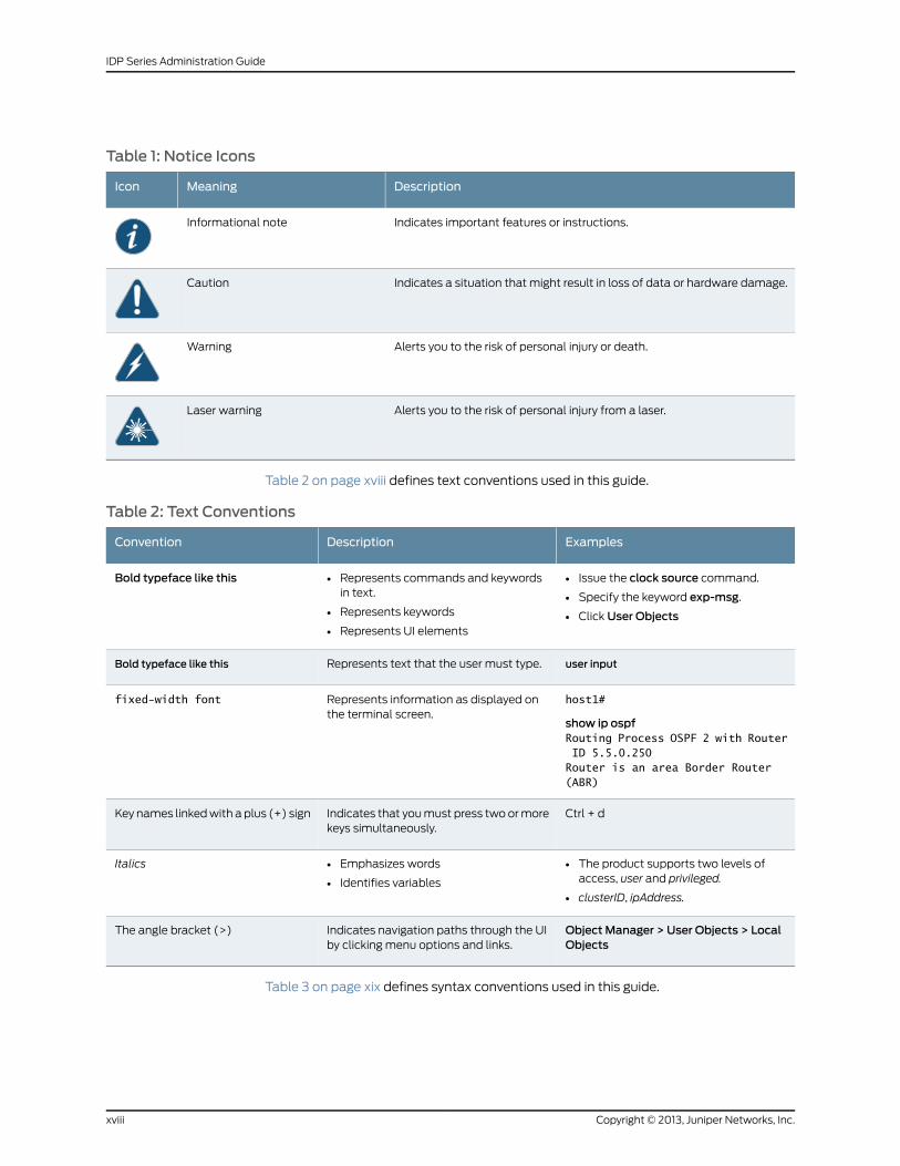
Table 1: Notice Icons
DescriptionMeaningIcon
Indicates important features or instructions.Informational note
Indicates a situation that might result in loss of data or hardware damage.Caution
Alerts you to the risk of personal injury or death.Warning
Alerts you to the risk of personal injury from a laser.Laser warning
Table 2 on page xviii defines text conventions used in this guide.
Table 2: Text Conventions
ExamplesDescriptionConvention
• Issue the clock source command.
• Specify the keyword exp-msg.
• Click User Objects
• Represents commands and keywordsin text.
• Represents keywords
• Represents UI elements
Bold typeface like this
user inputRepresents text that the user must type.Bold typeface like this
host1#
show ip ospfRouting Process OSPF 2 with Router ID 5.5.0.250Router is an area Border Router (ABR)
Represents information as displayed onthe terminal screen.
fixed-width font
Ctrl + dIndicates that you must press two or morekeys simultaneously.
Key names linked with a plus (+) sign
• The product supports two levels ofaccess, user and privileged.
• clusterID, ipAddress.
• Emphasizes words
• Identifies variables
Italics
Object Manager > User Objects > LocalObjects
Indicates navigation paths through the UIby clicking menu options and links.
The angle bracket (>)
Table 3 on page xix defines syntax conventions used in this guide.
Copyright © 2013, Juniper Networks, Inc.xviii
IDP Series Administration Guide
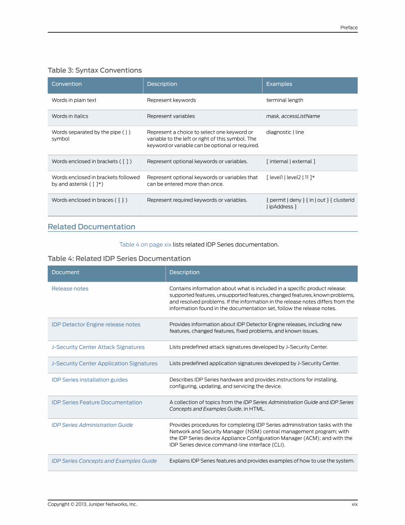
Table 3: Syntax Conventions
ExamplesDescriptionConvention
terminal lengthRepresent keywordsWords in plain text
mask, accessListNameRepresent variablesWords in italics
diagnostic | lineRepresent a choice to select one keyword orvariable to the left or right of this symbol. Thekeyword or variable can be optional or required.
Words separated by the pipe ( | )symbol
[ internal | external ]Represent optional keywords or variables.Words enclosed in brackets ( [ ] )
[ level1 | level2 | 11 ]*Represent optional keywords or variables thatcan be entered more than once.
Words enclosed in brackets followedby and asterisk ( [ ]*)
{ permit | deny } { in | out } { clusterId| ipAddress }
Represent required keywords or variables.Words enclosed in braces ( { } )
Related Documentation
Table 4 on page xix lists related IDP Series documentation.
Table 4: Related IDP Series Documentation
DescriptionDocument
Contains information about what is included in a specific product release:supported features, unsupported features, changed features, known problems,and resolved problems. If the information in the release notes differs from theinformation found in the documentation set, follow the release notes.
Release notes
Provides information about IDP Detector Engine releases, including newfeatures, changed features, fixed problems, and known issues.
IDP Detector Engine release notes
Lists predefined attack signatures developed by J-Security Center.J-Security Center Attack Signatures
Lists predefined application signatures developed by J-Security Center.J-Security Center Application Signatures
Describes IDP Series hardware and provides instructions for installing,configuring, updating, and servicing the device.
IDP Series installation guides
A collection of topics from the IDP Series Administration Guide and IDP SeriesConcepts and Examples Guide, in HTML.
IDP Series Feature Documentation
Provides procedures for completing IDP Series administration tasks with theNetwork and Security Manager (NSM) central management program; withthe IDP Series device Appliance Configuration Manager (ACM); and with theIDP Series device command-line interface (CLI).
IDP Series Administration Guide
Explains IDP Series features and provides examples of how to use the system.IDP Series Concepts and Examples Guide
xixCopyright © 2013, Juniper Networks, Inc.
Preface
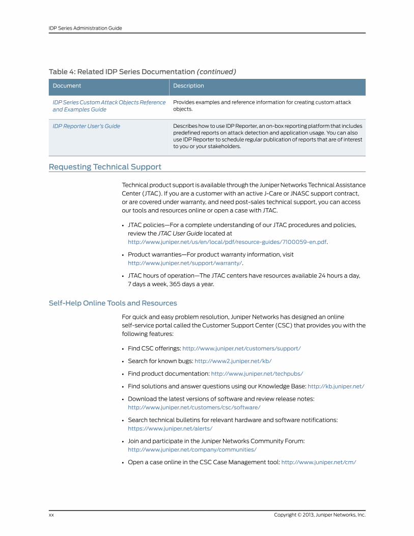
Table 4: Related IDP Series Documentation (continued)
DescriptionDocument
Provides examples and reference information for creating custom attackobjects.
IDPSeriesCustomAttackObjectsReferenceand Examples Guide
Describes how to use IDP Reporter, an on-box reporting platform that includespredefined reports on attack detection and application usage. You can alsouse IDP Reporter to schedule regular publication of reports that are of interestto you or your stakeholders.
IDP Reporter User’s Guide
Requesting Technical Support
Technical product support is available through the Juniper Networks Technical Assistance
Center (JTAC). If you are a customer with an active J-Care or JNASC support contract,
or are covered under warranty, and need post-sales technical support, you can access
our tools and resources online or open a case with JTAC.
• JTAC policies—For a complete understanding of our JTAC procedures and policies,
review the JTAC User Guide located at
http://www.juniper.net/us/en/local/pdf/resource-guides/7100059-en.pdf.
• Product warranties—For product warranty information, visit
http://www.juniper.net/support/warranty/.
• JTAC hours of operation—The JTAC centers have resources available 24 hours a day,
7 days a week, 365 days a year.
Self-Help Online Tools and Resources
For quick and easy problem resolution, Juniper Networks has designed an online
self-service portal called the Customer Support Center (CSC) that provides you with the
following features:
• Find CSC offerings: http://www.juniper.net/customers/support/
• Search for known bugs: http://www2.juniper.net/kb/
• Find product documentation: http://www.juniper.net/techpubs/
• Find solutions and answer questions using our Knowledge Base: http://kb.juniper.net/
• Download the latest versions of software and review release notes:
http://www.juniper.net/customers/csc/software/
• Search technical bulletins for relevant hardware and software notifications:
https://www.juniper.net/alerts/
• Join and participate in the Juniper Networks Community Forum:
http://www.juniper.net/company/communities/
• Open a case online in the CSC Case Management tool: http://www.juniper.net/cm/
Copyright © 2013, Juniper Networks, Inc.xx
IDP Series Administration Guide
To verify service entitlement by product serial number, use our Serial Number Entitlement
(SNE) Tool: https://tools.juniper.net/SerialNumberEntitlementSearch/
Opening a Casewith JTAC
You can open a case with JTAC on the Web or by telephone.
• Use the Case Management tool in the CSC at http://www.juniper.net/cm/.
• Call 1-888-314-JTAC (1-888-314-5822 toll-free in the USA, Canada, and Mexico).
For international or direct-dial options in countries without toll-free numbers, see
http://www.juniper.net/support/requesting-support.html.
xxiCopyright © 2013, Juniper Networks, Inc.
Preface

Copyright © 2013, Juniper Networks, Inc.xxii
IDP Series Administration Guide

PART 1
Getting Started
• Using the Default Configuration on page 3
1Copyright © 2013, Juniper Networks, Inc.

Copyright © 2013, Juniper Networks, Inc.2
IDP Series Administration Guide
CHAPTER 1
Using the Default Configuration
This chapter provides the basic steps you take to get started using IDP Series appliance
features. It contains the following topics:
• Getting Started with the Default Configuration on page 3
Getting Started with the Default Configuration
The purpose of this topic is to provide you with a workflow to get started using an IDP
Series appliance with the default configuration.
Follow these basic steps to get started:
1. Read the release notes for your release. The release notes contain important
release-related information about release-specific features, unsupported features,
changed features, fixed issues, and known issues. The information in the release notes
is more current than the information in this guide.
2. Install the IDP Series appliance, configure network settings and virtual routers, and
connect the device to your network.
For details, see the installation guide for your IDP Series appliance.
3. Add the device to the NSM Device Manager.
4. Upgrade IDP OS software to the latest version (if applicable).
5. Update the detector engine and NSM attack object database.
6. Become familiar with the default security policy (named Recommended).
7. Use the documentation to become familiar with the product features and user
interface:
• Use the IDPSeries Concepts andExamplesGuide to become familiar with the product
features.
• Use this guide, the IDP Series Administration Guide, to learn the steps to implement
the product features and monitor security events.
• Use the Appliance Configuration Manager (ACM) online Help for information about
using ACM.
3Copyright © 2013, Juniper Networks, Inc.
• Use CLI man pages for syntax and parameter hints for CLI commands.
• Use the NSM online Help for information about using the NSM user interface.
8. Run Profiler to discover the network hosts you want to protect.
9. Review logs to verify the initial deployment.
RelatedDocumentation
The following related topic is included in the IDP Series Administration Guide:
• Loading J-Security Center Updates (NSM Procedure) on page 194
• Updating IDP OS Software (NSM Procedure) on page 191
• Adding IDP Series Devices to NSM Device Manager on page 128
• Developing Security Policies Task Summary on page 35
• Profiler Task Summary on page 11
• IDP Series Logs and Reports in NSM Task Summary on page 207
The following additional related topic is included in the IDPSeriesConcepts andExamples
Guide:
• Example: Fine-Tuning a Security Policy
Copyright © 2013, Juniper Networks, Inc.4
IDP Series Administration Guide
PART 2
Analyzing Your Network
• Using Simulation Mode on page 7
• Using Profiler on page 11
• Using the NSM Security Explorer on page 29
• Using the NSM Topology Manager on page 31
5Copyright © 2013, Juniper Networks, Inc.

Copyright © 2013, Juniper Networks, Inc.6
IDP Series Administration Guide
CHAPTER 2
Using Simulation Mode
This chapter includes the following topics:
• Simulation Mode Task Summary on page 7
• Enabling Simulation Mode on page 7
• Viewing Simulation Mode Logs on page 9
SimulationMode Task Summary
Simulation mode is an operational mode in which the IDP Series device examines traffic
but only simulates security policy actions, generating simulation mode logs that indicate
the programmed action. Simulation mode is disabled by default.
Familiarize yourself with the following tasks related to using simulation mode:
• Enabling simulation mode
• Viewing simulation mode logs
RelatedDocumentation
The following related topics are included in the IDP Series Administration Guide:
Enabling Simulation Mode on page 7•
• Viewing Simulation Mode Logs on page 9
The following related topics are included in the IDP Series Concepts and Examples Guide:
• Simulation Mode Overview
• Example: Getting Started with Simulation Mode
• Example: Using Simulation Mode to Maximize Uptime
Enabling SimulationMode
Simulation mode is an operational mode in which the IDP Series device examines traffic
but only simulates security policy actions, generating simulation mode logs that indicate
the programmed action. Simulation mode is disabled by default.
7Copyright © 2013, Juniper Networks, Inc.
To enable simulation mode:
1. Log into the CLI as admin and enter su - to switch to root.
2. Run the following command to display the current setting for simulation mode:
[root@defaulthost conf]# scio const -s s0 get sc_simulation_modescio: sc_simulation_mode = 0x0
The value 0x0 indicates simulation mode is disabled.
3. Run the following command to enable simulation mode:
[root@defaulthost conf]# scio const -s s0 set sc_simulation_mode 1scio: setting sc_simulation_mode to 0x1
The value 0x1 indicates simulation mode is enabled.
You do not need to restart the IDP engine (idp.sh) or push a policy to initiate changes to
your simulation mode setting. Changes you make to kernel constants from the CLI do
not persist across restarts.
To make your change persistent:
1. Open the /usr/idp/device/bin/user_funcs file in a text editor, such as vi.
2. Add the simulation mode constant within the user_start_pre_policy() section:
user_start_pre_policy ()
{
# Disable ARP spoofing detection# -------------------------------# If you are running clusters with virtual MAC addresses, IDP will treat# these as spoofed ARP packets since the MAC addresses in the ethernet# framewill be different fromwhat is inside the ARP request/response. If# you havemultiple virtual routers, you need to perform this operation on# all defined virtual routers.## $SCIO const -v vr0 set sc_arp_spoof_detect 0# $SCIO const -s s0 set sc_mpls_decapsulation 1$SCIO const -s s0 set sc_simulation_mode 1return;
}
3. Save the file.
RelatedDocumentation
The following related topic is included in the IDP Series Administration Guide:
Viewing Simulation Mode Logs on page 9•
The following related topic is included in the IDP Series Concepts and Examples Guide:
• Simulation Mode Overview
Copyright © 2013, Juniper Networks, Inc.8
IDP Series Administration Guide
Viewing SimulationMode Logs
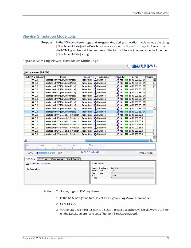
Purpose In the NSM Log Viewer, logs that are generated during simulation mode include the string
[Simulation Mode] in the Details column, as shown in Figure 1 on page 9. You can use
the NSM log and report filter feature to filter for (or filter out) columns that include the
[Simulation Mode] string.
Figure 1: NSM Log Viewer: SimulationMode Logs
Action To display logs in NSM Log Viewer:
1. In the NSM navigation tree, select Investigate > Log Viewer > Predefined.
2. Click IDP/DI.
3. (Optional) Click the filter icon to display the filter dialog box, which allows you to filter
on the Details column and set a filter for [Simulation Mode].
9Copyright © 2013, Juniper Networks, Inc.
Chapter 2: Using Simulation Mode

RelatedDocumentation
The following related topics are included in the IDP Series Administration Guide:
• Simulation Mode Task Summary on page 7
• IDP Series Logs and Reports in NSM Task Summary on page 207
The following related topic is included in the IDP Series Concepts and Examples Guide:
• Simulation Mode Overview
Copyright © 2013, Juniper Networks, Inc.10
IDP Series Administration Guide
CHAPTER 3
Using Profiler
This chapter provides instructions for using NSM Profiler. It contains the following topics:
• Profiler Task Summary on page 11
• Configuring Profiler Options (NSM Procedure) on page 12
• Starting and Stopping the Profiler (NSM Procedure) on page 18
• Using Profiler Viewer (NSM Procedure) on page 19
• Modifying Profiler Settings on page 25
• Managing the Profiler Database (NSM Procedure) on page 27
Profiler Task Summary
You use NSM Profiler to learn about your internal network so you can create effective
security policies and minimize unnecessary log records. The Profiler queries and correlates
attack logs and application usage logs from multiple IDP Series devices.
The Profiler feature is available only through Network and Security Manager (NSM).
IDP Series administration includes the following tasks related to the Profiler feature:
• Configuring Profiler options and preferences
• Starting and stopping the Profiler
• Viewing Profiler reports
• Managing the Profiler database
RelatedDocumentation
The following related topics are included in the IDP Series Administration Guide:
Configuring Profiler Options (NSM Procedure) on page 12•
• Modifying Profiler Settings on page 25
• Starting and Stopping the Profiler (NSM Procedure) on page 18
• Using Profiler Viewer (NSM Procedure) on page 19
• Managing the Profiler Database (NSM Procedure) on page 27
11Copyright © 2013, Juniper Networks, Inc.
The following related topic is included in the IDP Series Concepts and Examples Guide:
• Profiler Overview
Configuring Profiler Options (NSMProcedure)
You configure Profiler options to enable Profiler features, set network addresses and
applications subject to profiling, and set alerts.
The following topics describe how to configure Profiler options:
• Configuring General Settings on page 12
• Configuring Tracked Hosts on page 14
• Configuring Context Targets on page 16
• Configuring Alert Options on page 17
Configuring General Settings
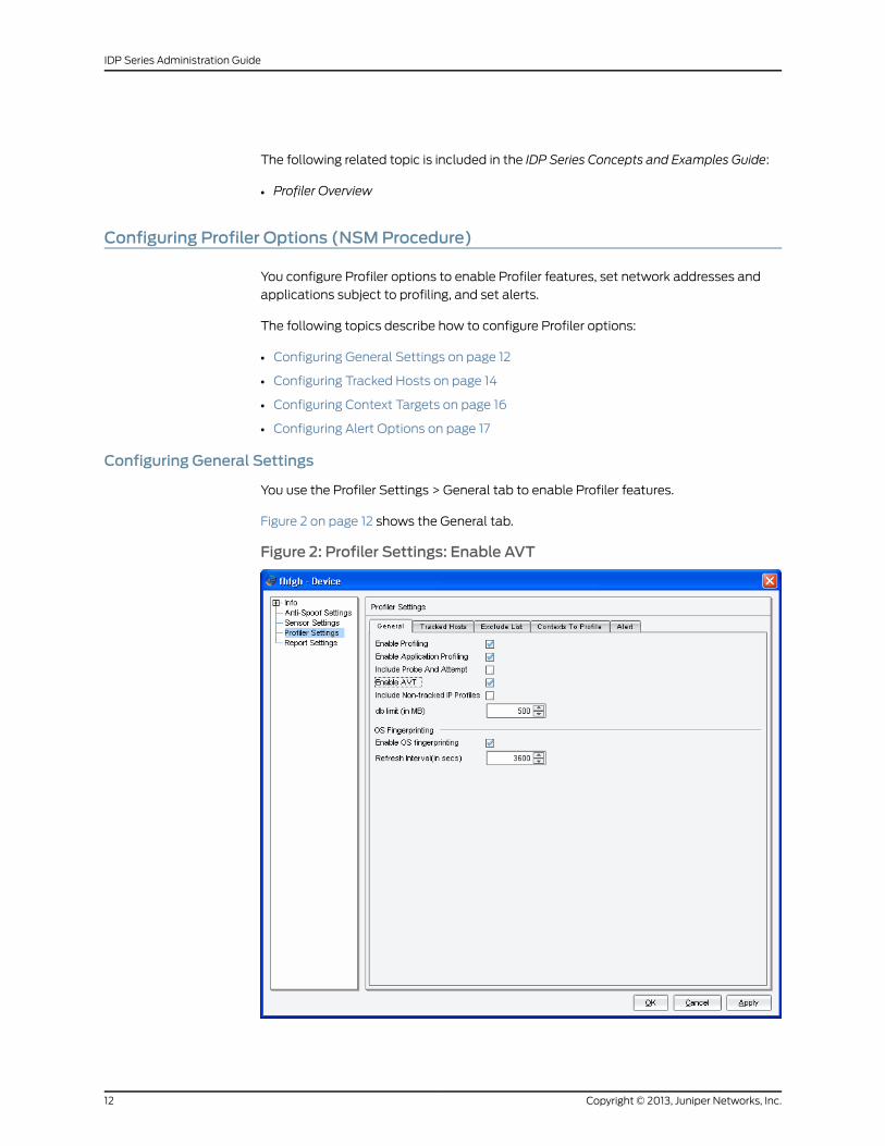
You use the Profiler Settings > General tab to enable Profiler features.
Figure 2 on page 12 shows the General tab.
Figure 2: Profiler Settings: Enable AVT
Copyright © 2013, Juniper Networks, Inc.12
IDP Series Administration Guide
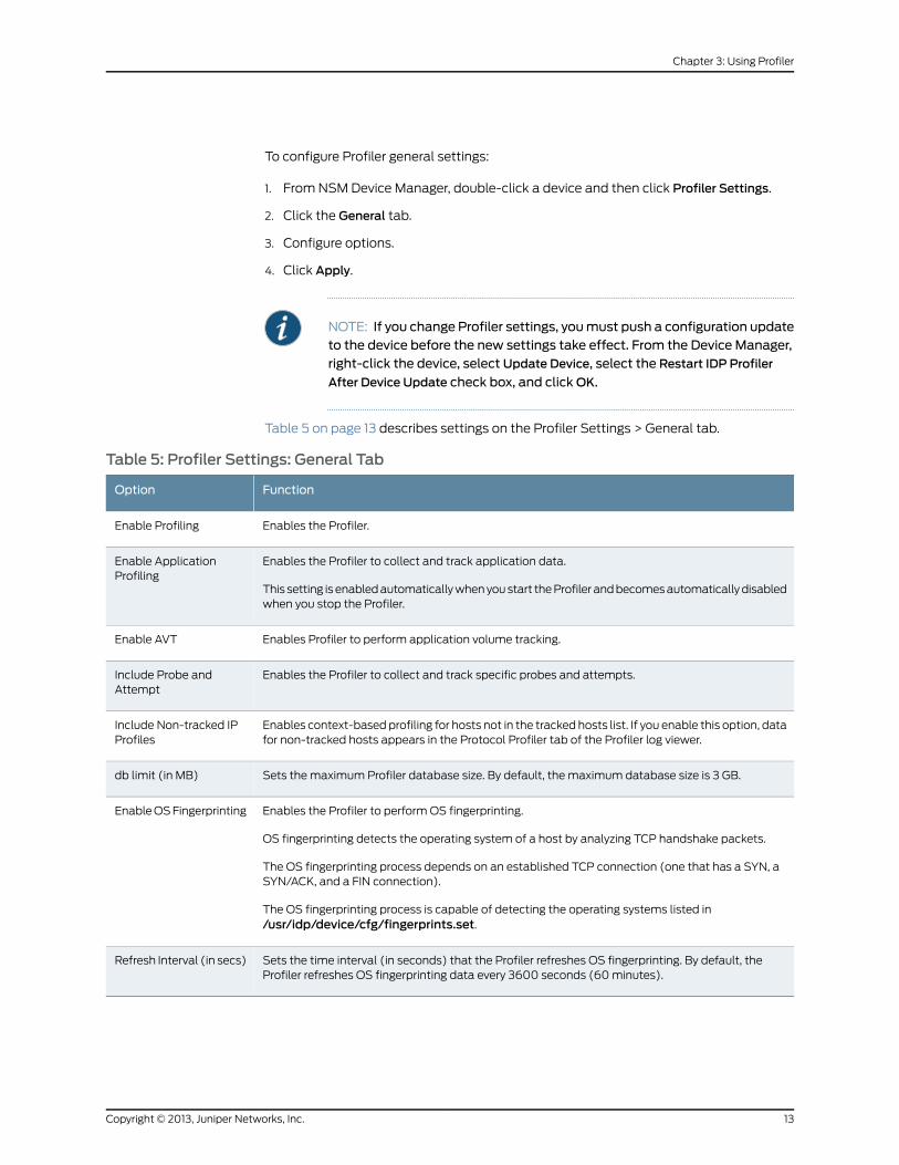
To configure Profiler general settings:
1. From NSM Device Manager, double-click a device and then click Profiler Settings.
2. Click the General tab.
3. Configure options.
4. Click Apply.
NOTE: If you change Profiler settings, youmust push a configuration updateto the device before the new settings take effect. From the Device Manager,right-click the device, select Update Device, select the Restart IDP Profiler
After Device Update check box, and clickOK.
Table 5 on page 13 describes settings on the Profiler Settings > General tab.
Table 5: Profiler Settings: General Tab
FunctionOption
Enables the Profiler.Enable Profiling
Enables the Profiler to collect and track application data.
This setting is enabled automatically when you start the Profiler and becomes automatically disabledwhen you stop the Profiler.
Enable ApplicationProfiling
Enables Profiler to perform application volume tracking.Enable AVT
Enables the Profiler to collect and track specific probes and attempts.Include Probe andAttempt
Enables context-based profiling for hosts not in the tracked hosts list. If you enable this option, datafor non-tracked hosts appears in the Protocol Profiler tab of the Profiler log viewer.
Include Non-tracked IPProfiles
Sets the maximum Profiler database size. By default, the maximum database size is 3 GB.db limit (in MB)
Enables the Profiler to perform OS fingerprinting.
OS fingerprinting detects the operating system of a host by analyzing TCP handshake packets.
The OS fingerprinting process depends on an established TCP connection (one that has a SYN, aSYN/ACK, and a FIN connection).
The OS fingerprinting process is capable of detecting the operating systems listed in/usr/idp/device/cfg/fingerprints.set.
Enable OS Fingerprinting
Sets the time interval (in seconds) that the Profiler refreshes OS fingerprinting. By default, theProfiler refreshes OS fingerprinting data every 3600 seconds (60 minutes).
Refresh Interval (in secs)
13Copyright © 2013, Juniper Networks, Inc.
Chapter 3: Using Profiler
Configuring Tracked Hosts
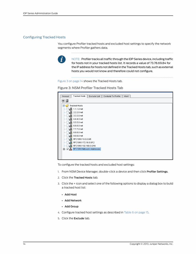
You configure Profiler tracked hosts and excluded host settings to specify the network
segments where Profiler gathers data.
NOTE: Profiler tracksall traffic through the IDPSeriesdevice, including trafficfor hosts not in your tracked hosts list. It records a value of 73.78.69.84 forthe IPaddress forhostsnotdefined in theTrackedHosts tab, suchasexternalhosts you would not know and therefore could not configure.
Figure 3 on page 14 shows the Tracked Hosts tab.
Figure 3: NSMProfiler Tracked Hosts Tab
To configure the tracked hosts and excluded host settings:
1. From NSM Device Manager, double-click a device and then click Profiler Settings.
2. Click the Tracked Hosts tab.
3. Click the + icon and select one of the following options to display a dialog box to build
a tracked host list:
• Add Host
• Add Network
• Add Group
4. Configure tracked host settings as described in Table 6 on page 15.
5. Click the Exclude tab.
Copyright © 2013, Juniper Networks, Inc.14
IDP Series Administration Guide
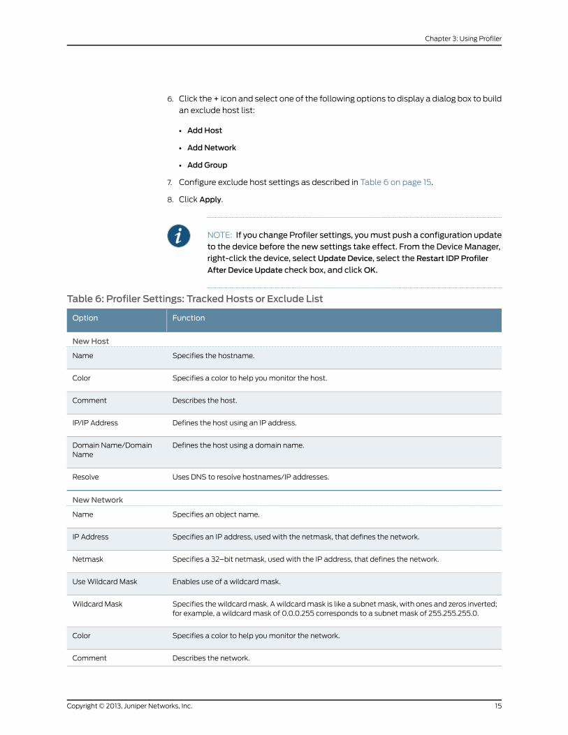
6. Click the + icon and select one of the following options to display a dialog box to build
an exclude host list:
• Add Host
• Add Network
• Add Group
7. Configure exclude host settings as described in Table 6 on page 15.
8. Click Apply.
NOTE: If you change Profiler settings, youmust push a configuration updateto the device before the new settings take effect. From the Device Manager,right-click the device, select Update Device, select the Restart IDP Profiler
After Device Update check box, and clickOK.
Table 6: Profiler Settings: Tracked Hosts or Exclude List
FunctionOption
NewHost
Specifies the hostname.Name
Specifies a color to help you monitor the host.Color
Describes the host.Comment
Defines the host using an IP address.IP/IP Address
Defines the host using a domain name.Domain Name/DomainName
Uses DNS to resolve hostnames/IP addresses.Resolve
NewNetwork
Specifies an object name.Name
Specifies an IP address, used with the netmask, that defines the network.IP Address
Specifies a 32–bit netmask, used with the IP address, that defines the network.Netmask
Enables use of a wildcard mask.Use Wildcard Mask
Specifies the wildcard mask. A wildcard mask is like a subnet mask, with ones and zeros inverted;for example, a wildcard mask of 0.0.0.255 corresponds to a subnet mask of 255.255.255.0.
Wildcard Mask
Specifies a color to help you monitor the network.Color
Describes the network.Comment
15Copyright © 2013, Juniper Networks, Inc.
Chapter 3: Using Profiler
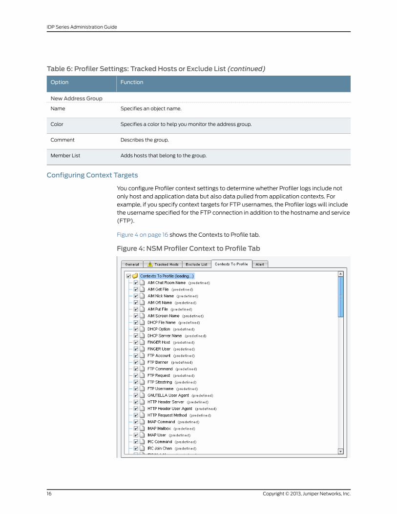
Table 6: Profiler Settings: Tracked Hosts or Exclude List (continued)
FunctionOption
NewAddress Group
Specifies an object name.Name
Specifies a color to help you monitor the address group.Color
Describes the group.Comment
Adds hosts that belong to the group.Member List
Configuring Context Targets
You configure Profiler context settings to determine whether Profiler logs include not
only host and application data but also data pulled from application contexts. For
example, if you specify context targets for FTP usernames, the Profiler logs will include
the username specified for the FTP connection in addition to the hostname and service
(FTP).
Figure 4 on page 16 shows the Contexts to Profile tab.
Figure 4: NSMProfiler Context to Profile Tab
Copyright © 2013, Juniper Networks, Inc.16
IDP Series Administration Guide
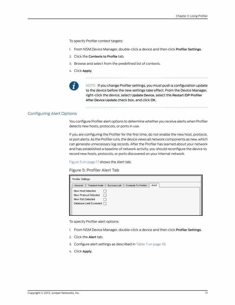
To specify Profiler context targets:
1. From NSM Device Manager, double-click a device and then click Profiler Settings.
2. Click the Contexts to Profile tab.
3. Browse and select from the predefined list of contexts.
4. Click Apply.
NOTE: If you change Profiler settings, youmust push a configuration updateto the device before the new settings take effect. From the Device Manager,right-click the device, select Update Device, select the Restart IDP Profiler
After Device Update check box, and clickOK.
Configuring Alert Options
You configure Profiler alert options to determine whether you receive alerts when Profiler
detects new hosts, protocols, or ports in use.
If you are configuring the Profiler for the first time, do not enable the new host, protocol,
or port alerts. As the Profiler runs, the device views all network components as new, which
can generate unnecessary log records. After the Profiler has learned about your network
and has established a baseline of network activity, you should reconfigure the device to
record new hosts, protocols, or ports discovered on your internal network.
Figure 5 on page 17 shows the Alert tab.
Figure 5: Profiler Alert Tab
To specify Profiler alert options:
1. From NSM Device Manager, double-click a device and then click Profiler Settings.
2. Click the Alert tab.
3. Configure alert settings as described in Table 7 on page 18.
4. Click Apply.
17Copyright © 2013, Juniper Networks, Inc.
Chapter 3: Using Profiler
NOTE: If you change Profiler settings, youmust push a configuration updateto the device before the new settings take effect. From the Device Manager,right-click the device, select Update Device, select the Restart IDP Profiler
After Device Update check box, and clickOK.
Table 7: Profiler Alert Tab
FunctionOption
Sends an alert when Profiler detects a new host.New Host Detected
Sends an alert when Profiler detects a new protocol.New Protocol Detected
Sends an alert when Profiler detects a new port.New Port Detected
Sends an alert to indicate the maximum database size has been reached. After a device reachesthis limit, it begins purging the database.
Database Limit Exceeded
RelatedDocumentation
The following related topic is included in the IDP Series Administration Guide:
Profiler Task Summary on page 11•
Starting and Stopping the Profiler (NSMProcedure)
You use Network and Security Manager (NSM) to start and stop the Profiler.
The Profiler is a service, located on the IDP Series device at /usr/idp/device/bin/profiler.sh.
To start the Profiler:
1. From the NSM main menu, select Devices > IDP Profiler > Start Profiler.
2. Select the devices on which you want to start the Profiler.
3. Click OK.
To stop the Profiler:
1. From the NSM main menu, select Devices > IDP Profiler > Stop Profiler.
2. Select the devices on which you want to stop the Profiler.
3. Click OK.
RelatedDocumentation
The following related topic is included in the IDP Series Administration Guide:
Profiler Task Summary on page 11•
Copyright © 2013, Juniper Networks, Inc.18
IDP Series Administration Guide
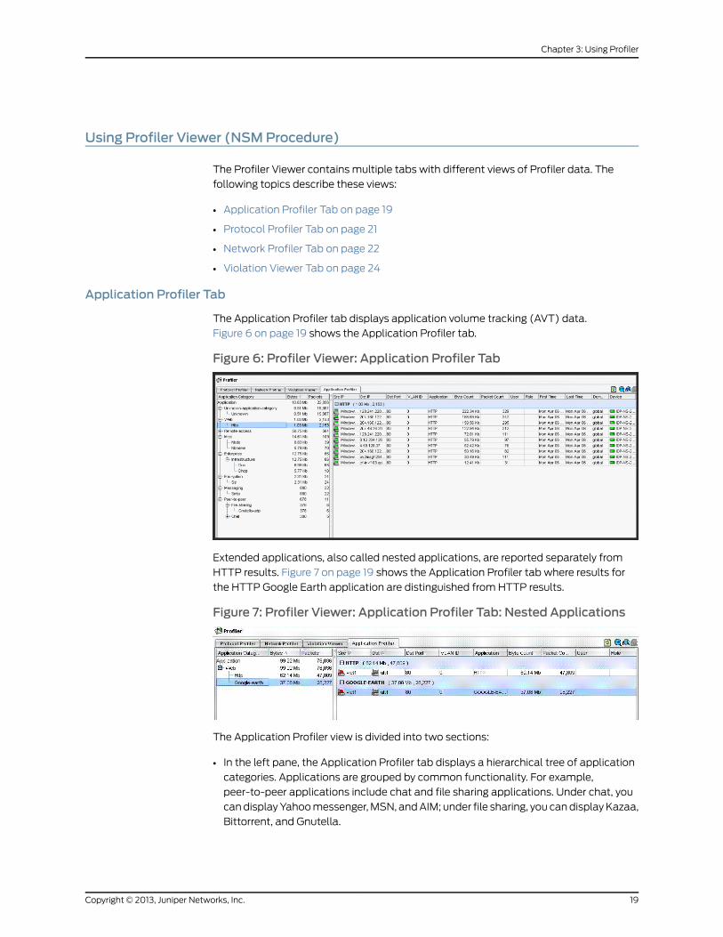
Using Profiler Viewer (NSMProcedure)
The Profiler Viewer contains multiple tabs with different views of Profiler data. The
following topics describe these views:
• Application Profiler Tab on page 19
• Protocol Profiler Tab on page 21
• Network Profiler Tab on page 22
• Violation Viewer Tab on page 24
Application Profiler Tab
The Application Profiler tab displays application volume tracking (AVT) data.
Figure 6 on page 19 shows the Application Profiler tab.
Figure 6: Profiler Viewer: Application Profiler Tab
Extended applications, also called nested applications, are reported separately from
HTTP results. Figure 7 on page 19 shows the Application Profiler tab where results for
the HTTP Google Earth application are distinguished from HTTP results.
Figure 7: Profiler Viewer: Application Profiler Tab: Nested Applications
The Application Profiler view is divided into two sections:
• In the left pane, the Application Profiler tab displays a hierarchical tree of application
categories. Applications are grouped by common functionality. For example,
peer-to-peer applications include chat and file sharing applications. Under chat, you
can display Yahoo messenger, MSN, and AIM; under file sharing, you can display Kazaa,
Bittorrent, and Gnutella.
19Copyright © 2013, Juniper Networks, Inc.
Chapter 3: Using Profiler
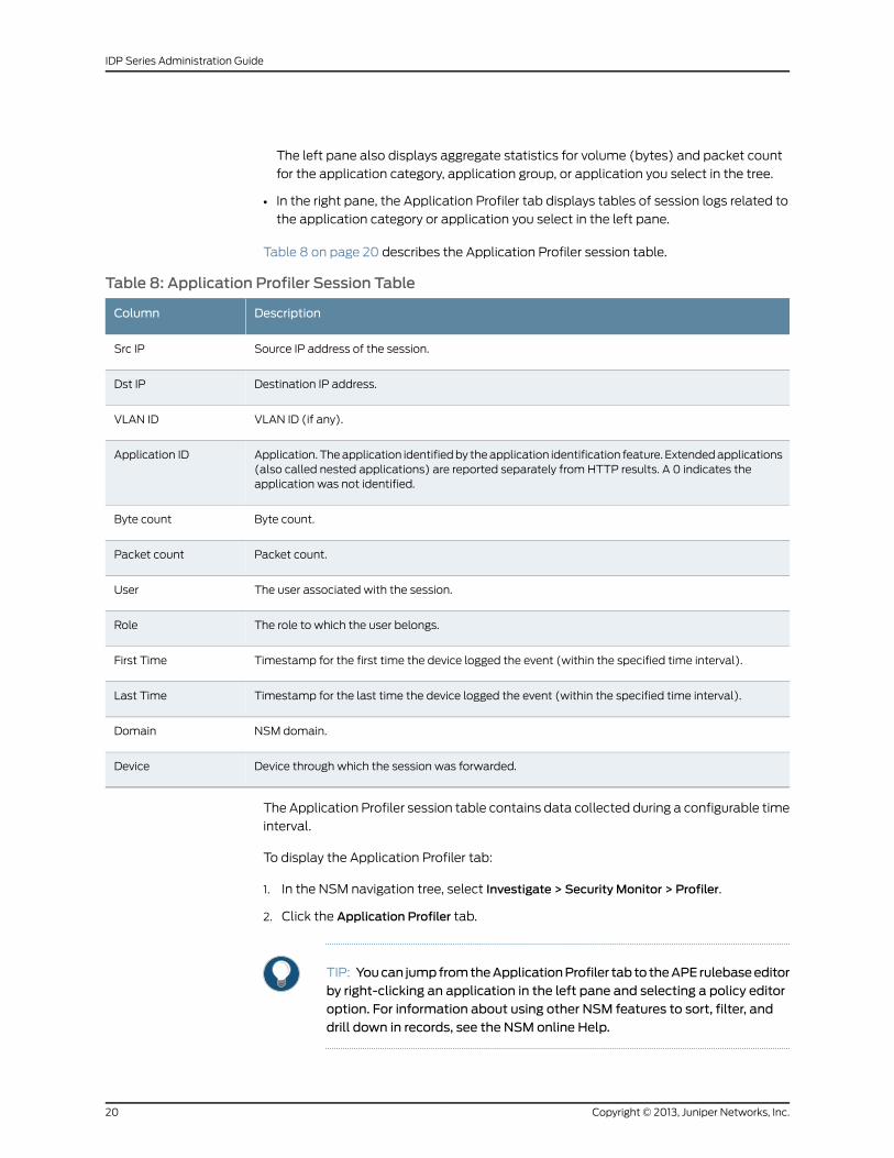
The left pane also displays aggregate statistics for volume (bytes) and packet count
for the application category, application group, or application you select in the tree.
• In the right pane, the Application Profiler tab displays tables of session logs related to
the application category or application you select in the left pane.
Table 8 on page 20 describes the Application Profiler session table.
Table 8: Application Profiler Session Table
DescriptionColumn
Source IP address of the session.Src IP
Destination IP address.Dst IP
VLAN ID (if any).VLAN ID
Application. The application identified by the application identification feature. Extended applications(also called nested applications) are reported separately from HTTP results. A 0 indicates theapplication was not identified.
Application ID
Byte count.Byte count
Packet count.Packet count
The user associated with the session.User
The role to which the user belongs.Role
Timestamp for the first time the device logged the event (within the specified time interval).First Time
Timestamp for the last time the device logged the event (within the specified time interval).Last Time
NSM domain.Domain
Device through which the session was forwarded.Device
The Application Profiler session table contains data collected during a configurable time
interval.
To display the Application Profiler tab:
1. In the NSM navigation tree, select Investigate > Security Monitor > Profiler.
2. Click the Application Profiler tab.
TIP: Youcan jumpfromtheApplicationProfiler tab to theAPE rulebaseeditorby right-clicking an application in the left pane and selecting a policy editoroption. For information about using other NSM features to sort, filter, anddrill down in records, see the NSM online Help.
Copyright © 2013, Juniper Networks, Inc.20
IDP Series Administration Guide
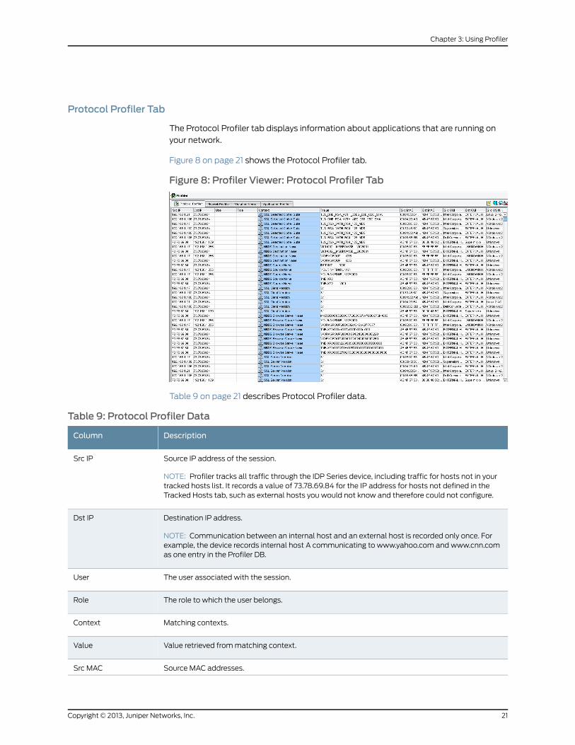
Protocol Profiler Tab
The Protocol Profiler tab displays information about applications that are running on
your network.
Figure 8 on page 21 shows the Protocol Profiler tab.
Figure 8: Profiler Viewer: Protocol Profiler Tab
Table 9 on page 21 describes Protocol Profiler data.
Table 9: Protocol Profiler Data
DescriptionColumn
Source IP address of the session.
NOTE: Profiler tracks all traffic through the IDP Series device, including traffic for hosts not in yourtracked hosts list. It records a value of 73.78.69.84 for the IP address for hosts not defined in theTracked Hosts tab, such as external hosts you would not know and therefore could not configure.
Src IP
Destination IP address.
NOTE: Communication between an internal host and an external host is recorded only once. Forexample, the device records internal host A communicating to www.yahoo.com and www.cnn.comas one entry in the Profiler DB.
Dst IP
The user associated with the session.User
The role to which the user belongs.Role
Matching contexts.Context
Value retrieved from matching context.Value
Source MAC addresses.Src MAC
21Copyright © 2013, Juniper Networks, Inc.
Chapter 3: Using Profiler
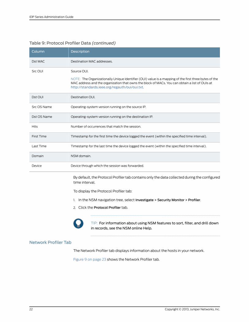
Table 9: Protocol Profiler Data (continued)
DescriptionColumn
Destination MAC addresses.Dst MAC
Source OUI.
NOTE: The Organizationally Unique Identifier (OUI) value is a mapping of the first three bytes of theMAC address and the organization that owns the block of MACs. You can obtain a list of OUIs athttp://standards.ieee.org/regauth/oui/oui.txt.
Src OUI
Destination OUI.Dst OUI
Operating-system version running on the source IP.Src OS Name
Operating-system version running on the destination IP.Dst OS Name
Number of occurrences that match the session.Hits
Timestamp for the first time the device logged the event (within the specified time interval).First Time
Timestamp for the last time the device logged the event (within the specified time interval).Last Time
NSM domain.Domain
Device through which the session was forwarded.Device
By default, the Protocol Profiler tab contains only the data collected during the configured
time interval.
To display the Protocol Profiler tab:
1. In the NSM navigation tree, select Investigate > Security Monitor > Profiler.
2. Click the Protocol Profiler tab.
TIP: For information about using NSM features to sort, filter, and drill downin records, see the NSM online Help.
Network Profiler Tab
The Network Profiler tab displays information about the hosts in your network.
Figure 9 on page 23 shows the Network Profiler tab.
Copyright © 2013, Juniper Networks, Inc.22
IDP Series Administration Guide
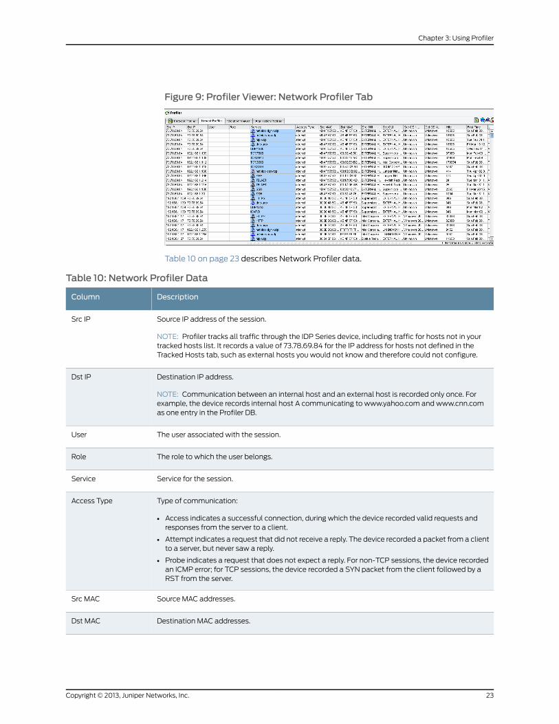
Figure 9: Profiler Viewer: Network Profiler Tab
Table 10 on page 23 describes Network Profiler data.
Table 10: Network Profiler Data
DescriptionColumn
Source IP address of the session.
NOTE: Profiler tracks all traffic through the IDP Series device, including traffic for hosts not in yourtracked hosts list. It records a value of 73.78.69.84 for the IP address for hosts not defined in theTracked Hosts tab, such as external hosts you would not know and therefore could not configure.
Src IP
Destination IP address.
NOTE: Communication between an internal host and an external host is recorded only once. Forexample, the device records internal host A communicating to www.yahoo.com and www.cnn.comas one entry in the Profiler DB.
Dst IP
The user associated with the session.User
The role to which the user belongs.Role
Service for the session.Service
Type of communication:
• Access indicates a successful connection, during which the device recorded valid requests andresponses from the server to a client.
• Attempt indicates a request that did not receive a reply. The device recorded a packet from a clientto a server, but never saw a reply.
• Probe indicates a request that does not expect a reply. For non-TCP sessions, the device recordedan ICMP error; for TCP sessions, the device recorded a SYN packet from the client followed by aRST from the server.
Access Type
Source MAC addresses.Src MAC
Destination MAC addresses.Dst MAC
23Copyright © 2013, Juniper Networks, Inc.
Chapter 3: Using Profiler
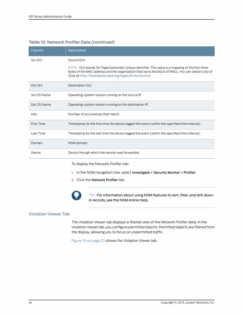
Table 10: Network Profiler Data (continued)
DescriptionColumn
Source OUI.
NOTE: OUI stands for Organizationally Unique Identifier. This value is a mapping of the first threebytes of the MAC address and the organization that owns the block of MACs. You can obtain a list ofOUIs at http://standards.ieee.org/regauth/oui/oui.txt.
Src OUI
Destination OUI.Dst OUI
Operating-system version running on the source IP.Src OS Name
Operating-system version running on the destination IP.Dst OS Name
Number of occurrences that match.Hits
Timestamp for the first time the device logged the event (within the specified time interval).First Time
Timestamp for the last time the device logged the event (within the specified time interval).Last Time
NSM domain.Domain
Device through which the session was forwarded.Device
To display the Network Profiler tab:
1. In the NSM navigation tree, select Investigate > Security Monitor > Profiler.
2. Click the Network Profiler tab.
TIP: For information about using NSM features to sort, filter, and drill downin records, see the NSM online Help.
Violation Viewer Tab
The Violation Viewer tab displays a filtered view of the Network Profiler data. In the
Violation Viewer tab, you configure permitted objects. Permitted objects are filtered from
the display, allowing you to focus on unpermitted traffic.
Figure 10 on page 25 shows the Violation Viewer tab.
Copyright © 2013, Juniper Networks, Inc.24
IDP Series Administration Guide
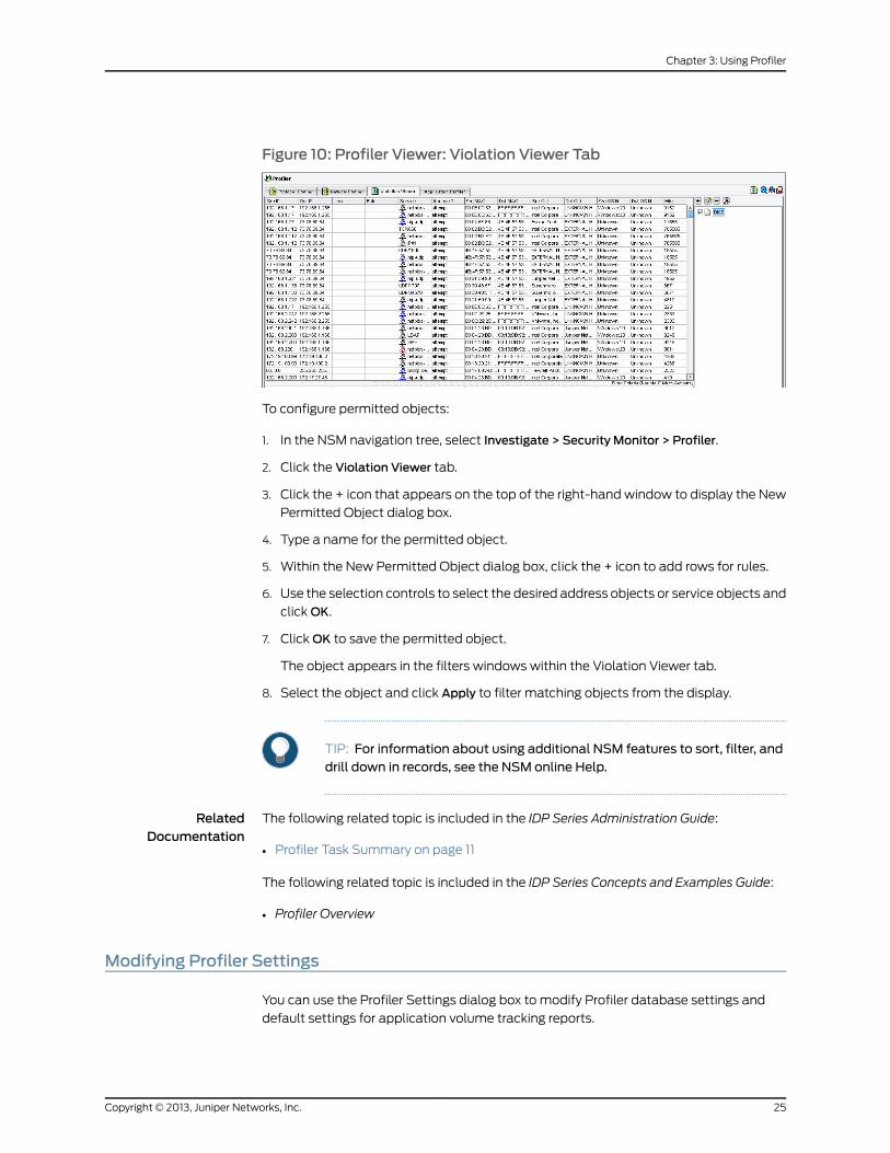
Figure 10: Profiler Viewer: Violation Viewer Tab
To configure permitted objects:
1. In the NSM navigation tree, select Investigate > Security Monitor > Profiler.
2. Click the Violation Viewer tab.
3. Click the + icon that appears on the top of the right-hand window to display the New
Permitted Object dialog box.
4. Type a name for the permitted object.
5. Within the New Permitted Object dialog box, click the + icon to add rows for rules.
6. Use the selection controls to select the desired address objects or service objects and
click OK.
7. Click OK to save the permitted object.
The object appears in the filters windows within the Violation Viewer tab.
8. Select the object and click Apply to filter matching objects from the display.
TIP: For information about using additional NSM features to sort, filter, anddrill down in records, see the NSM online Help.
RelatedDocumentation
The following related topic is included in the IDP Series Administration Guide:
Profiler Task Summary on page 11•
The following related topic is included in the IDP Series Concepts and Examples Guide:
• Profiler Overview
Modifying Profiler Settings
You can use the Profiler Settings dialog box to modify Profiler database settings and
default settings for application volume tracking reports.
25Copyright © 2013, Juniper Networks, Inc.
Chapter 3: Using Profiler
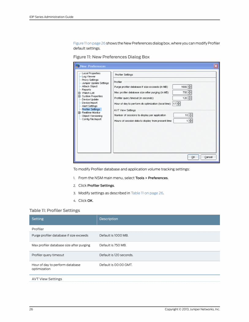
Figure 11 on page 26 shows the New Preferences dialog box, where you can modify Profiler
default settings.
Figure 11: New Preferences Dialog Box
To modify Profiler database and application volume tracking settings:
1. From the NSM main menu, select Tools > Preferences.
2. Click Profiler Settings.
3. Modify settings as described in Table 11 on page 26.
4. Click OK.
Table 11: Profiler Settings
DescriptionSetting
Profiler
Default is 1000 MB.Purge profiler database if size exceeds
Default is 750 MB.Max profiler database size after purging
Default is 120 seconds.Profiler query timeout
Default is 00:00 GMT.Hour of day to perform databaseoptimization
AVT View Settings
Copyright © 2013, Juniper Networks, Inc.26
IDP Series Administration Guide
Table 11: Profiler Settings (continued)
DescriptionSetting
Determines the number of sessions displayed in the Application Profiler applicationvolume tracking session tables.
Default is 10 sessions. You can specify from 5 to 10,000 sessions.
Number of sessions to display perapplication
Determines the hours of application volume tracking data displayed in theApplication Profiler tab session tables.
Default is 1 hour. You can specify from 1 to 24 hours.
This setting is also a data retention policy. By default, data older than 1 hour isdeleted. If you change to 12 hours, data older than 12 hours is deleted.
Hours of session data to display frompresent time
RelatedDocumentation
The following related topic is included in the IDP Series Administration Guide:
Profiler Task Summary on page 11•
The following related topic is included in the IDP Series Concepts and Examples Guide:
• Profiler Overview
Managing the Profiler Database (NSMProcedure)
The following topics provide procedures for managing the Profiler database:
• Displaying Profiler Database Information on page 27
• Querying the Profiler Database on page 27
• Purging the Profiler Database on page 28
Displaying Profiler Database Information
Purpose Data discovered by Profiler is stored in a database located on the NSM GUI server. Use
the steps in this procedure to display information about the Profiler database.
Action To display Profiler database information:
1. In the NSM navigation tree, select Investigate > Security Monitor > Profiler.
2. Click the ShowDB Information icon in the upper right corner to view specific details
about the Profiler database, including the database size.
Querying the Profiler Database
Purpose Data discovered by Profiler is stored in a database located on the NSM GUI server. Use
the steps in this procedure to query the Profiler database.
27Copyright © 2013, Juniper Networks, Inc.
Chapter 3: Using Profiler
Action To query records in the database:
1. Log into the NSM GUI server as the Postgres SQL user. By default, the Postgres SQL
user is netscreen.
2. Navigate to the directory where the Profiler DB is located: /usr/local/nsmpsql/bin.
3. Run any Postgres SQL command. For example, you can type the following command:
./psql -d profilerDb
Purging the Profiler Database
Data discovered by Profiler is stored in a database located on the NSM GUI server. When
the database reaches a maximum size (4 GB by default), it begins purging records (oldest
first) automatically. The Profiler stops purging records when it reaches a certain set
minimum size (3 GB by default).
Use the steps in this procedure to purge the Profiler database, if needed.
To change automatic purge settings, from the NSM main menu, selectTools>Preferences
and modify the Profiler database settings.
To purge the database immediately:
1. In the NSM navigation tree, select Investigate > Security Monitor > Profiler.
2. Click the Clear All DB icon in the upper right corner.
RelatedDocumentation
The following related topic is included in the IDP Series Administration Guide:
• Profiler Task Summary on page 11
The following related topic is included in the IDP Series Concepts and Examples Guide:
• Profiler Overview
Copyright © 2013, Juniper Networks, Inc.28
IDP Series Administration Guide
CHAPTER 4
Using the NSM Security Explorer
The purpose of this chapter is to make you aware of the Network and Security Manager
(NSM) Security Explorer. It contains the following topic:
• Security Explorer Task Summary on page 29
Security Explorer Task Summary
The NSM Security Explorer is a graphical tool that enables you to visualize and correlate
network behavior based on data collected in the Profiler, Log Viewer, and Report Manager.
You can use the Security Explorer to:
• Get a dynamic, interactive view of your network.
• Drill down on a particular host or server and view all the different attacks, open ports,
destination or peer IP addresses, and so on.
• Move between hosts and peers and trace a connection or attack.
• Toggle between different views or slices of the network, as well as explore the
contextual information (logs, reports, attacks, IP addresses, and so on) within the
Security Explorer panel.
For information on using Security Explorer, see the NSM documentation.
RelatedDocumentation
The following related topic is included in the IDP Series Administration Guide:
• IDP Series Logs and Reports in NSM Task Summary on page 207
29Copyright © 2013, Juniper Networks, Inc.

Copyright © 2013, Juniper Networks, Inc.30
IDP Series Administration Guide
CHAPTER 5
Using the NSM Topology Manager
The purpose of this chapter is to make you aware of the Network and Security Manager
(NSM) Topology Manager. It contains the following topic:
• NSM Topology Manager Task Summary on page 31
NSMTopologyManager Task Summary
You can use the NSM Topology Manager to discover and manage the physical topology
of a network of devices connected to a Juniper Networks EX-series switch. These include
networking devices such as the J Series, M Series, MX Series, and EX Series, as well as
ScreenOS and IDP Series devices, IP phones, desktops, printers, and servers. The NSM
Topology Manager also provides details about connections between a device and the
EX Series switch.
For information on using the NSM Topology Manager, see the NSM documentation.
31Copyright © 2013, Juniper Networks, Inc.

Copyright © 2013, Juniper Networks, Inc.32
IDP Series Administration Guide
PART 3
Protecting Your Network
• Security Policies Overview on page 35
• Configuring the IDP Rulebase on page 41
• Configuring Additional Security Policy Rulebases on page 55
• Managing Security Policies on page 71
• Working with Attack Objects on page 79
• Working With Application Objects on page 111
33Copyright © 2013, Juniper Networks, Inc.

Copyright © 2013, Juniper Networks, Inc.34
IDP Series Administration Guide
CHAPTER 6
Security Policies Overview
The purpose of this chapter is to familiarize you with the tasks involved in creating security
policies. It contains the following topics:
• Developing Security Policies Task Summary on page 35
• Using Predefined Security Policies on page 37
• Using the New Policy Wizard (NSM Procedure) on page 38
Developing Security Policies Task Summary
An IDP security policy allows you to use various attack detection and prevention
techniques on traffic that traverses your network.
To create an effective security policy, follow these basic steps:
1. Run the New Policy wizard to create a security policy object. The new security policy
can be based on a predefined template.
2. Use the Security Policy editor to add one or more rulebases. Table 12 on page 36
describes the IDP security policy rulebases. A security policy can contain only one
instance of any rulebase type.
A rulebase is an ordered set of rules that use a particular detection method to identify
and prevent attacks.
3. Within rulebases, configure rules.
Rules are instructions that provide context to detection methods. Rules specify:
• A source/destination/service match condition that determines which traffic to
inspect.
• Attack objects that determine what to look for (IDP rulebase and Exempt rulebase).
• Actions that determine what to do when an attack is detected or the application
rate limit is reached.
• Notification options, including logs, alerts, and packet captures.
Each rulebase can contain up to 40,000 rules.
4. Fine-tune your security policy as you learn more about your network and security
requirements and IDP Series capabilities.
35Copyright © 2013, Juniper Networks, Inc.
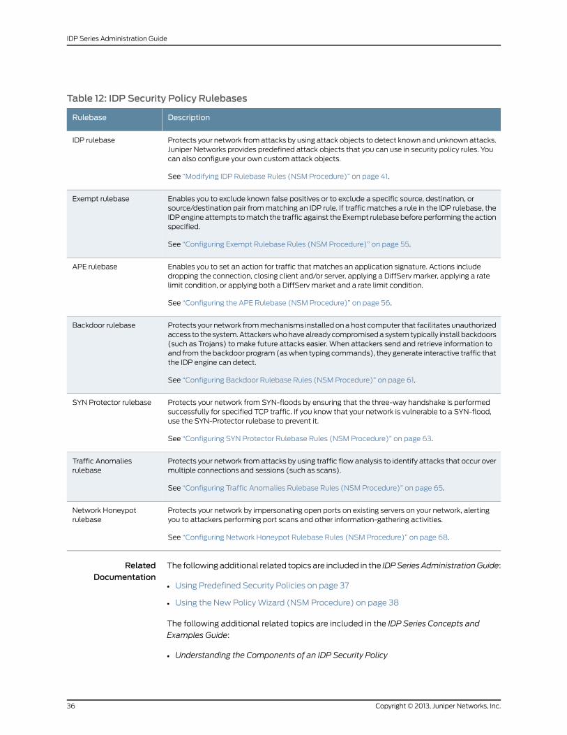
Table 12: IDP Security Policy Rulebases
DescriptionRulebase
Protects your network from attacks by using attack objects to detect known and unknown attacks.Juniper Networks provides predefined attack objects that you can use in security policy rules. Youcan also configure your own custom attack objects.
See “Modifying IDP Rulebase Rules (NSM Procedure)” on page 41.
IDP rulebase
Enables you to exclude known false positives or to exclude a specific source, destination, orsource/destination pair from matching an IDP rule. If traffic matches a rule in the IDP rulebase, theIDP engine attempts to match the traffic against the Exempt rulebase before performing the actionspecified.
See “Configuring Exempt Rulebase Rules (NSM Procedure)” on page 55.
Exempt rulebase
Enables you to set an action for traffic that matches an application signature. Actions includedropping the connection, closing client and/or server, applying a DiffServ marker, applying a ratelimit condition, or applying both a DiffServ market and a rate limit condition.
See “Configuring the APE Rulebase (NSM Procedure)” on page 56.
APE rulebase
Protects your network from mechanisms installed on a host computer that facilitates unauthorizedaccess to the system. Attackers who have already compromised a system typically install backdoors(such as Trojans) to make future attacks easier. When attackers send and retrieve information toand from the backdoor program (as when typing commands), they generate interactive traffic thatthe IDP engine can detect.
See “Configuring Backdoor Rulebase Rules (NSM Procedure)” on page 61.
Backdoor rulebase
Protects your network from SYN-floods by ensuring that the three-way handshake is performedsuccessfully for specified TCP traffic. If you know that your network is vulnerable to a SYN-flood,use the SYN-Protector rulebase to prevent it.
See “Configuring SYN Protector Rulebase Rules (NSM Procedure)” on page 63.
SYN Protector rulebase
Protects your network from attacks by using traffic flow analysis to identify attacks that occur overmultiple connections and sessions (such as scans).
See “Configuring Traffic Anomalies Rulebase Rules (NSM Procedure)” on page 65.
Traffic Anomaliesrulebase
Protects your network by impersonating open ports on existing servers on your network, alertingyou to attackers performing port scans and other information-gathering activities.
See “Configuring Network Honeypot Rulebase Rules (NSM Procedure)” on page 68.
Network Honeypotrulebase
RelatedDocumentation
The following additional related topics are included in the IDPSeriesAdministrationGuide:
Using Predefined Security Policies on page 37•
• Using the New Policy Wizard (NSM Procedure) on page 38
The following additional related topics are included in the IDP Series Concepts and
Examples Guide:
• Understanding the Components of an IDP Security Policy
Copyright © 2013, Juniper Networks, Inc.36
IDP Series Administration Guide
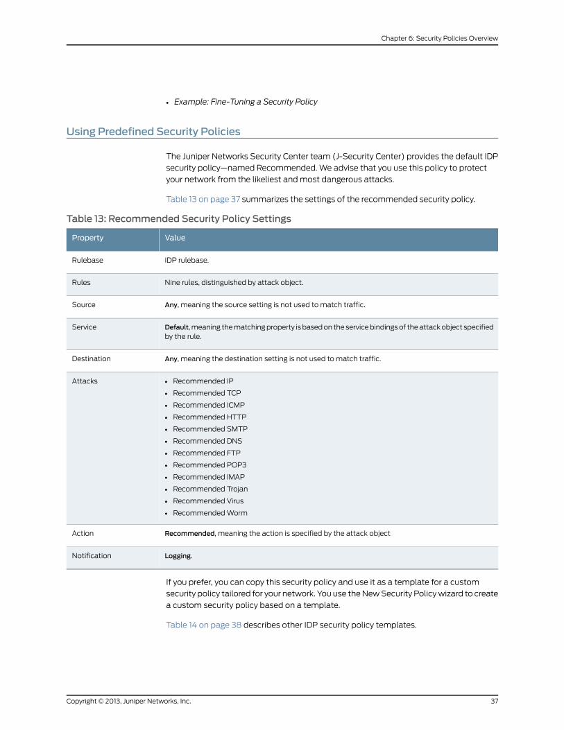
• Example: Fine-Tuning a Security Policy
Using Predefined Security Policies
The Juniper Networks Security Center team (J-Security Center) provides the default IDP
security policy—named Recommended. We advise that you use this policy to protect
your network from the likeliest and most dangerous attacks.
Table 13 on page 37 summarizes the settings of the recommended security policy.
Table 13: Recommended Security Policy Settings
ValueProperty
IDP rulebase.Rulebase
Nine rules, distinguished by attack object.Rules
Any, meaning the source setting is not used to match traffic.Source
Default, meaning the matching property is based on the service bindings of the attack object specifiedby the rule.
Service
Any, meaning the destination setting is not used to match traffic.Destination
• Recommended IP
• Recommended TCP
• Recommended ICMP
• Recommended HTTP
• Recommended SMTP
• Recommended DNS
• Recommended FTP
• Recommended POP3
• Recommended IMAP
• Recommended Trojan
• Recommended Virus
• Recommended Worm
Attacks
Recommended, meaning the action is specified by the attack objectAction
Logging.Notification
If you prefer, you can copy this security policy and use it as a template for a custom
security policy tailored for your network. You use the New Security Policy wizard to create
a custom security policy based on a template.
Table 14 on page 38 describes other IDP security policy templates.
37Copyright © 2013, Juniper Networks, Inc.
Chapter 6: Security Policies Overview
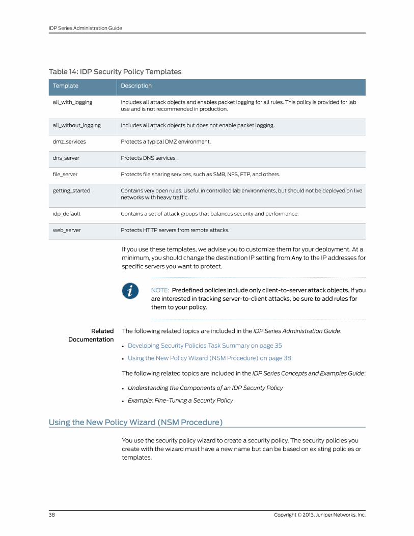
Table 14: IDP Security Policy Templates
DescriptionTemplate
Includes all attack objects and enables packet logging for all rules. This policy is provided for labuse and is not recommended in production.
all_with_logging
Includes all attack objects but does not enable packet logging.all_without_logging
Protects a typical DMZ environment.dmz_services
Protects DNS services.dns_server
Protects file sharing services, such as SMB, NFS, FTP, and others.file_server
Contains very open rules. Useful in controlled lab environments, but should not be deployed on livenetworks with heavy traffic.
getting_started
Contains a set of attack groups that balances security and performance.idp_default
Protects HTTP servers from remote attacks.web_server
If you use these templates, we advise you to customize them for your deployment. At a
minimum, you should change the destination IP setting from Any to the IP addresses for
specific servers you want to protect.
NOTE: Predefinedpolicies includeonly client-to-server attack objects. If youare interested in tracking server-to-client attacks, be sure to add rules forthem to your policy.
RelatedDocumentation
The following related topics are included in the IDP Series Administration Guide:
Developing Security Policies Task Summary on page 35•
• Using the New Policy Wizard (NSM Procedure) on page 38
The following related topics are included in the IDP Series Concepts and Examples Guide:
• Understanding the Components of an IDP Security Policy
• Example: Fine-Tuning a Security Policy
Using the NewPolicyWizard (NSMProcedure)
You use the security policy wizard to create a security policy. The security policies you
create with the wizard must have a new name but can be based on existing policies or
templates.
Copyright © 2013, Juniper Networks, Inc.38
IDP Series Administration Guide
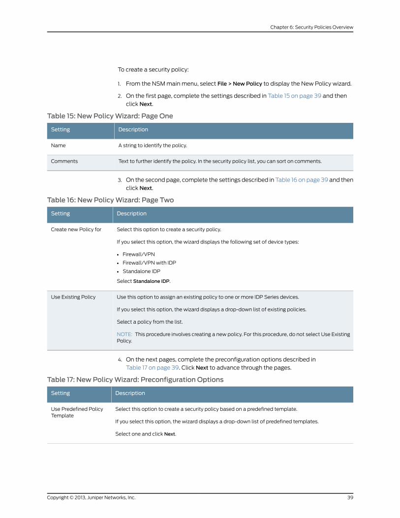
To create a security policy:
1. From the NSM main menu, select File > NewPolicy to display the New Policy wizard.
2. On the first page, complete the settings described in Table 15 on page 39 and then
click Next.
Table 15: New PolicyWizard: Page One
DescriptionSetting
A string to identify the policy.Name
Text to further identify the policy. In the security policy list, you can sort on comments.Comments
3. On the second page, complete the settings described in Table 16 on page 39 and then
click Next.
Table 16: New PolicyWizard: Page Two
DescriptionSetting
Select this option to create a security policy.
If you select this option, the wizard displays the following set of device types:
• Firewall/VPN
• Firewall/VPN with IDP
• Standalone IDP
Select Standalone IDP.
Create new Policy for
Use this option to assign an existing policy to one or more IDP Series devices.
If you select this option, the wizard displays a drop-down list of existing policies.
Select a policy from the list.
NOTE: This procedure involves creating a new policy. For this procedure, do not select Use ExistingPolicy.
Use Existing Policy
4. On the next pages, complete the preconfiguration options described in
Table 17 on page 39. Click Next to advance through the pages.
Table 17: New PolicyWizard: Preconfiguration Options
DescriptionSetting
Select this option to create a security policy based on a predefined template.
If you select this option, the wizard displays a drop-down list of predefined templates.
Select one and click Next.
Use Predefined PolicyTemplate
39Copyright © 2013, Juniper Networks, Inc.
Chapter 6: Security Policies Overview
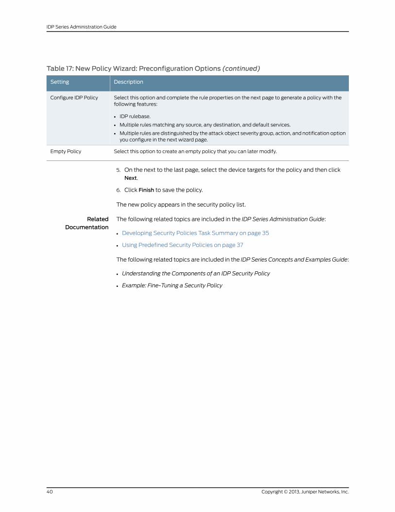
Table 17: New PolicyWizard: Preconfiguration Options (continued)
DescriptionSetting
Select this option and complete the rule properties on the next page to generate a policy with thefollowing features:
• IDP rulebase.
• Multiple rules matching any source, any destination, and default services.
• Multiple rules are distinguished by the attack object severity group, action, and notification optionyou configure in the next wizard page.
Configure IDP Policy
Select this option to create an empty policy that you can later modify.Empty Policy
5. On the next to the last page, select the device targets for the policy and then click
Next.
6. Click Finish to save the policy.
The new policy appears in the security policy list.
RelatedDocumentation
The following related topics are included in the IDP Series Administration Guide:
• Developing Security Policies Task Summary on page 35
• Using Predefined Security Policies on page 37
The following related topics are included in the IDP Series Concepts and Examples Guide:
• Understanding the Components of an IDP Security Policy
• Example: Fine-Tuning a Security Policy
Copyright © 2013, Juniper Networks, Inc.40
IDP Series Administration Guide
CHAPTER 7
Configuring the IDP Rulebase
The IDP rulebase is the primary rulebase that protects your network from attacks. The
IDP rulebase is included in an IDP security policy by default. This chapter contains the
following topics related to configuring IDP rulebase rules:
• Modifying IDP Rulebase Rules (NSM Procedure) on page 41
• Specifying Rule Match Conditions (NSM Procedure) on page 43
• Specifying IDP Rulebase Attack Objects (NSM Procedure) on page 45
• Specifying Rule Session Action (NSM Procedure) on page 46
• Specifying IP Action (NSM Procedure) on page 48
• Specifying Rule Notification Options (NSM Procedure) on page 49
• Specifying Rule VLAN Matches (NSM Procedure) on page 51
• Specifying Rule Targets (NSM Procedure) on page 51
• Specifying Rule Severity (NSM Procedure) on page 52
• Specifying Rule Comments (NSM Procedure) on page 53
Modifying IDP Rulebase Rules (NSMProcedure)
This procedure assumes you have used the New Policy wizard to create a basic policy
that you can modify.
The primary IDP security policy rulebase is the IDP rulebase. The IDP rulebase enables
the IDP engine to inspect matching traffic for attack signatures and protocol anomalies.
Figure 12 on page 42 shows the IDP rulebase in the NSM security policy editor, where you
can modify IDP rulebase rules. Table 18 on page 42 lists the rule properties you can modify
and provides references to documentation for these properties.
41Copyright © 2013, Juniper Networks, Inc.
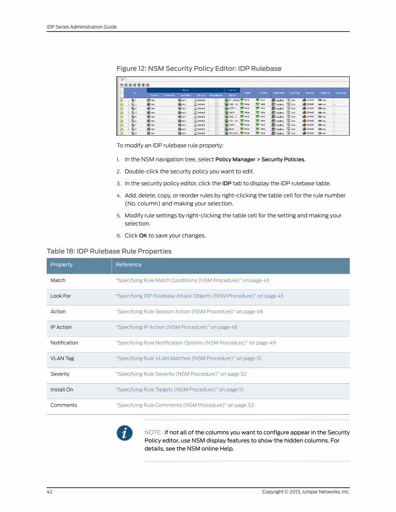
Figure 12: NSMSecurity Policy Editor: IDP Rulebase
To modify an IDP rulebase rule property:
1. In the NSM navigation tree, select Policy Manager > Security Policies.
2. Double-click the security policy you want to edit.
3. In the security policy editor, click the IDP tab to display the IDP rulebase table.
4. Add, delete, copy, or reorder rules by right-clicking the table cell for the rule number
(No. column) and making your selection.
5. Modify rule settings by right-clicking the table cell for the setting and making your
selection.
6. Click OK to save your changes.
Table 18: IDP Rulebase Rule Properties
ReferenceProperty
“Specifying Rule Match Conditions (NSM Procedure)” on page 43Match
“Specifying IDP Rulebase Attack Objects (NSM Procedure)” on page 45Look For
“Specifying Rule Session Action (NSM Procedure)” on page 46Action
“Specifying IP Action (NSM Procedure)” on page 48IP Action
“Specifying Rule Notification Options (NSM Procedure)” on page 49Notification
“Specifying Rule VLAN Matches (NSM Procedure)” on page 51VLAN Tag
“Specifying Rule Severity (NSM Procedure)” on page 52Severity
“Specifying Rule Targets (NSM Procedure)” on page 51Install On
“Specifying Rule Comments (NSM Procedure)” on page 53Comments
NOTE: If not all of the columns you want to configure appear in the SecurityPolicy editor, use NSM display features to show the hidden columns. Fordetails, see the NSM online Help.
Copyright © 2013, Juniper Networks, Inc.42
IDP Series Administration Guide
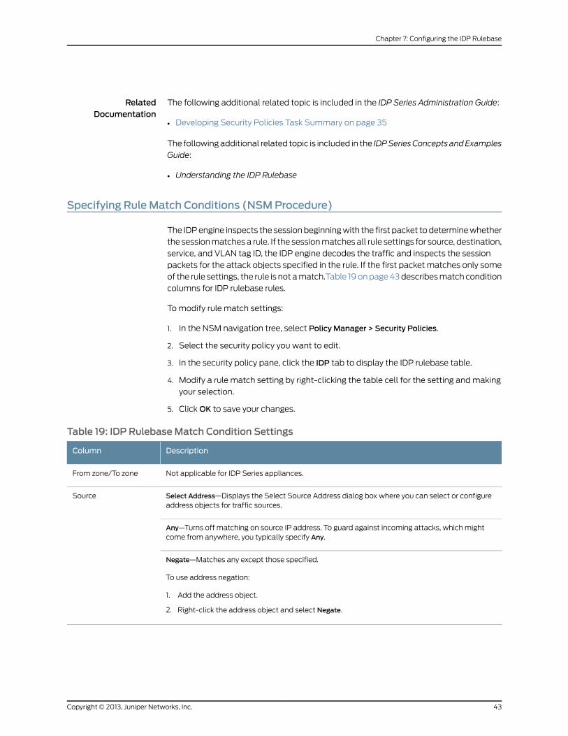
RelatedDocumentation
The following additional related topic is included in the IDP Series Administration Guide:
Developing Security Policies Task Summary on page 35•
The following additional related topic is included in the IDPSeriesConcepts andExamples
Guide:
• Understanding the IDP Rulebase
Specifying Rule Match Conditions (NSMProcedure)
The IDP engine inspects the session beginning with the first packet to determine whether
the session matches a rule. If the session matches all rule settings for source, destination,
service, and VLAN tag ID, the IDP engine decodes the traffic and inspects the session
packets for the attack objects specified in the rule. If the first packet matches only some
of the rule settings, the rule is not a match.Table 19 on page 43 describes match condition
columns for IDP rulebase rules.
To modify rule match settings:
1. In the NSM navigation tree, select Policy Manager > Security Policies.
2. Select the security policy you want to edit.
3. In the security policy pane, click the IDP tab to display the IDP rulebase table.
4. Modify a rule match setting by right-clicking the table cell for the setting and making
your selection.
5. Click OK to save your changes.
Table 19: IDP RulebaseMatch Condition Settings
DescriptionColumn
Not applicable for IDP Series appliances.From zone/To zone
Select Address—Displays the Select Source Address dialog box where you can select or configureaddress objects for traffic sources.
Source
Any—Turns off matching on source IP address. To guard against incoming attacks, which mightcome from anywhere, you typically specify Any.
Negate—Matches any except those specified.
To use address negation:
1. Add the address object.
2. Right-click the address object and select Negate.
43Copyright © 2013, Juniper Networks, Inc.
Chapter 7: Configuring the IDP Rulebase
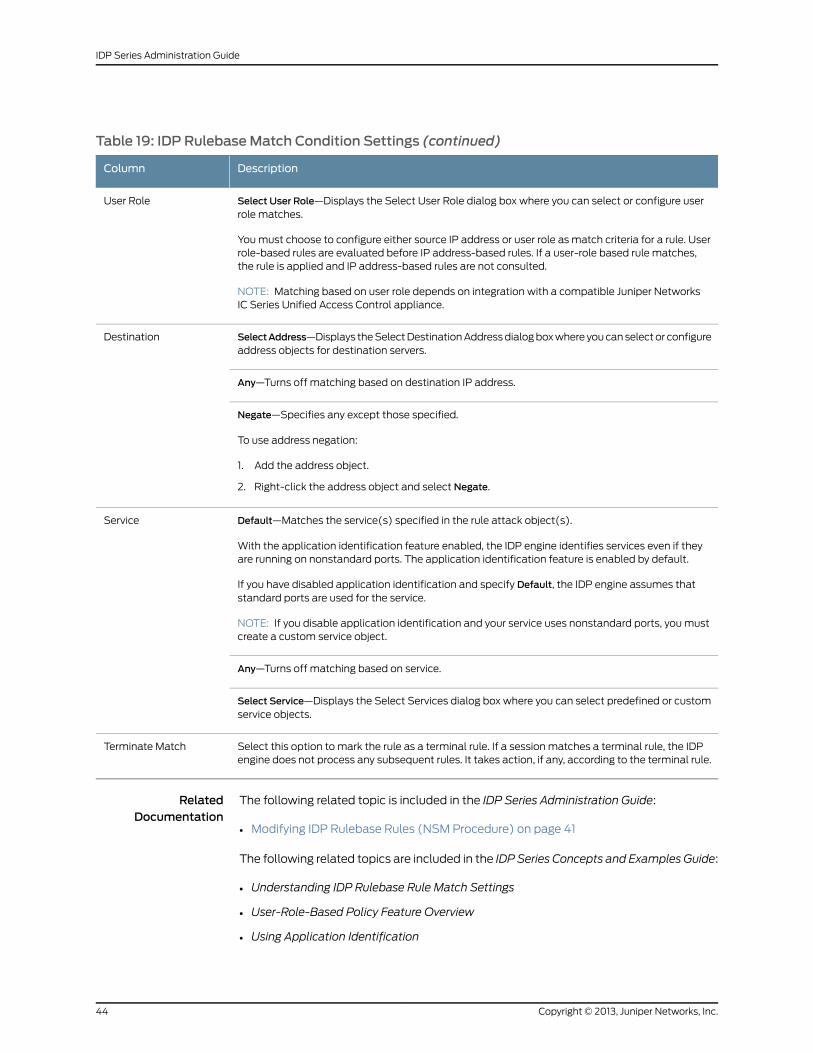
Table 19: IDP RulebaseMatch Condition Settings (continued)
DescriptionColumn
Select User Role—Displays the Select User Role dialog box where you can select or configure userrole matches.
You must choose to configure either source IP address or user role as match criteria for a rule. Userrole-based rules are evaluated before IP address-based rules. If a user-role based rule matches,the rule is applied and IP address-based rules are not consulted.
NOTE: Matching based on user role depends on integration with a compatible Juniper NetworksIC Series Unified Access Control appliance.
User Role
SelectAddress—Displays the Select Destination Address dialog box where you can select or configureaddress objects for destination servers.
Destination
Any—Turns off matching based on destination IP address.
Negate—Specifies any except those specified.
To use address negation:
1. Add the address object.
2. Right-click the address object and select Negate.
Default—Matches the service(s) specified in the rule attack object(s).
With the application identification feature enabled, the IDP engine identifies services even if theyare running on nonstandard ports. The application identification feature is enabled by default.
If you have disabled application identification and specify Default, the IDP engine assumes thatstandard ports are used for the service.
NOTE: If you disable application identification and your service uses nonstandard ports, you mustcreate a custom service object.
Service
Any—Turns off matching based on service.
Select Service—Displays the Select Services dialog box where you can select predefined or customservice objects.
Select this option to mark the rule as a terminal rule. If a session matches a terminal rule, the IDPengine does not process any subsequent rules. It takes action, if any, according to the terminal rule.
Terminate Match
RelatedDocumentation
The following related topic is included in the IDP Series Administration Guide:
Modifying IDP Rulebase Rules (NSM Procedure) on page 41•
The following related topics are included in the IDP Series Concepts and Examples Guide:
• Understanding IDP Rulebase Rule Match Settings
• User-Role-Based Policy Feature Overview
• Using Application Identification
Copyright © 2013, Juniper Networks, Inc.44
IDP Series Administration Guide
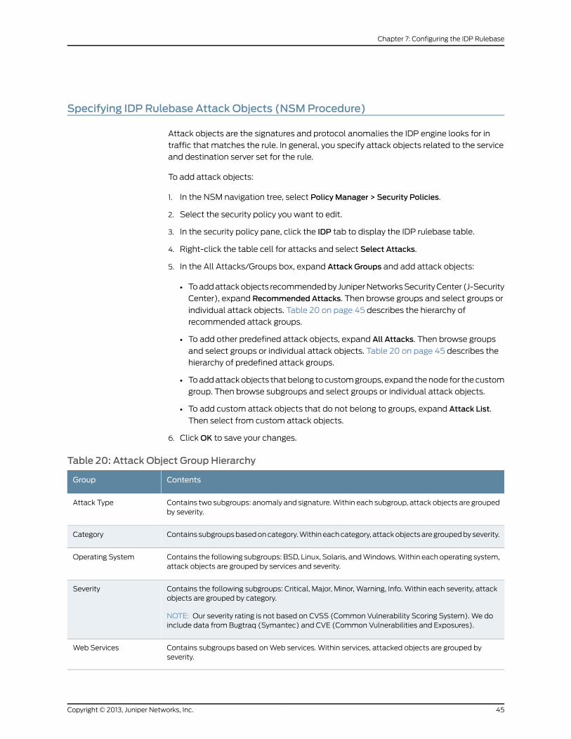
Specifying IDP Rulebase Attack Objects (NSMProcedure)
Attack objects are the signatures and protocol anomalies the IDP engine looks for in
traffic that matches the rule. In general, you specify attack objects related to the service
and destination server set for the rule.
To add attack objects:
1. In the NSM navigation tree, select Policy Manager > Security Policies.
2. Select the security policy you want to edit.
3. In the security policy pane, click the IDP tab to display the IDP rulebase table.
4. Right-click the table cell for attacks and select Select Attacks.
5. In the All Attacks/Groups box, expand Attack Groups and add attack objects:
• To add attack objects recommended by Juniper Networks Security Center (J-Security
Center), expand Recommended Attacks. Then browse groups and select groups or
individual attack objects. Table 20 on page 45 describes the hierarchy of
recommended attack groups.
• To add other predefined attack objects, expand All Attacks. Then browse groups
and select groups or individual attack objects. Table 20 on page 45 describes the
hierarchy of predefined attack groups.
• To add attack objects that belong to custom groups, expand the node for the custom
group. Then browse subgroups and select groups or individual attack objects.
• To add custom attack objects that do not belong to groups, expand Attack List.
Then select from custom attack objects.
6. Click OK to save your changes.
Table 20: Attack Object Group Hierarchy
ContentsGroup
Contains two subgroups: anomaly and signature. Within each subgroup, attack objects are groupedby severity.
Attack Type
Contains subgroups based on category. Within each category, attack objects are grouped by severity.Category
Contains the following subgroups: BSD, Linux, Solaris, and Windows. Within each operating system,attack objects are grouped by services and severity.
Operating System
Contains the following subgroups: Critical, Major, Minor, Warning, Info. Within each severity, attackobjects are grouped by category.
NOTE: Our severity rating is not based on CVSS (Common Vulnerability Scoring System). We doinclude data from Bugtraq (Symantec) and CVE (Common Vulnerabilities and Exposures).
Severity
Contains subgroups based on Web services. Within services, attacked objects are grouped byseverity.
Web Services
45Copyright © 2013, Juniper Networks, Inc.
Chapter 7: Configuring the IDP Rulebase
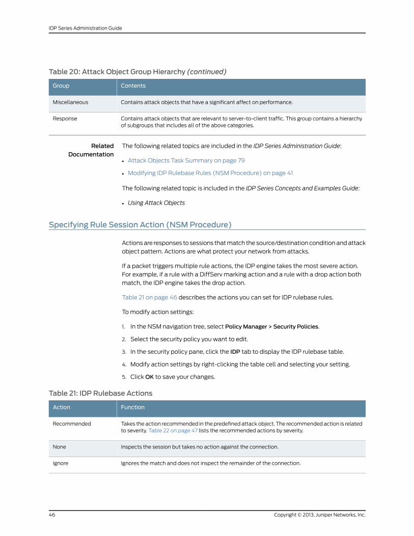
Table 20: Attack Object Group Hierarchy (continued)
ContentsGroup
Contains attack objects that have a significant affect on performance.Miscellaneous
Contains attack objects that are relevant to server-to-client traffic. This group contains a hierarchyof subgroups that includes all of the above categories.
Response
RelatedDocumentation
The following related topics are included in the IDP Series Administration Guide:
Attack Objects Task Summary on page 79•
• Modifying IDP Rulebase Rules (NSM Procedure) on page 41
The following related topic is included in the IDP Series Concepts and Examples Guide:
• Using Attack Objects
Specifying Rule Session Action (NSMProcedure)
Actions are responses to sessions that match the source/destination condition and attack
object pattern. Actions are what protect your network from attacks.
If a packet triggers multiple rule actions, the IDP engine takes the most severe action.
For example, if a rule with a DiffServ marking action and a rule with a drop action both
match, the IDP engine takes the drop action.
Table 21 on page 46 describes the actions you can set for IDP rulebase rules.
To modify action settings:
1. In the NSM navigation tree, select Policy Manager > Security Policies.
2. Select the security policy you want to edit.
3. In the security policy pane, click the IDP tab to display the IDP rulebase table.
4. Modify action settings by right-clicking the table cell and selecting your setting.
5. Click OK to save your changes.
Table 21: IDP Rulebase Actions
FunctionAction
Takes the action recommended in the predefined attack object. The recommended action is relatedto severity. Table 22 on page 47 lists the recommended actions by severity.
Recommended
Inspects the session but takes no action against the connection.None
Ignores the match and does not inspect the remainder of the connection.Ignore
Copyright © 2013, Juniper Networks, Inc.46
IDP Series Administration Guide
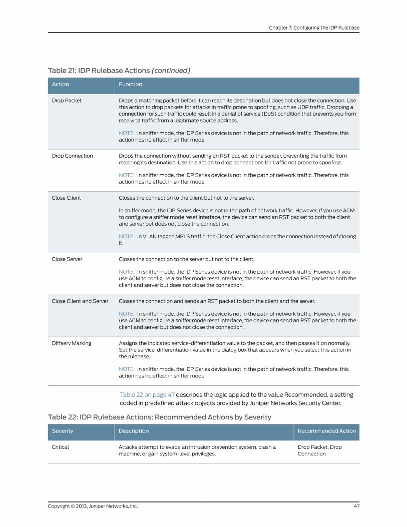
Table 21: IDP Rulebase Actions (continued)
FunctionAction
Drops a matching packet before it can reach its destination but does not close the connection. Usethis action to drop packets for attacks in traffic prone to spoofing, such as UDP traffic. Dropping aconnection for such traffic could result in a denial of service (DoS) condition that prevents you fromreceiving traffic from a legitimate source address.
NOTE: In sniffer mode, the IDP Series device is not in the path of network traffic. Therefore, thisaction has no effect in sniffer mode.
Drop Packet
Drops the connection without sending an RST packet to the sender, preventing the traffic fromreaching its destination. Use this action to drop connections for traffic not prone to spoofing.
NOTE: In sniffer mode, the IDP Series device is not in the path of network traffic. Therefore, thisaction has no effect in sniffer mode.
Drop Connection
Closes the connection to the client but not to the server.
In sniffer mode, the IDP Series device is not in the path of network traffic. However, if you use ACMto configure a sniffer mode reset interface, the device can send an RST packet to both the clientand server but does not close the connection.
NOTE: In VLAN tagged MPLS traffic, the Close Client action drops the connection instead of closingit.
Close Client
Closes the connection to the server but not to the client.
NOTE: In sniffer mode, the IDP Series device is not in the path of network traffic. However, if youuse ACM to configure a sniffer mode reset interface, the device can send an RST packet to both theclient and server but does not close the connection.
Close Server
Closes the connection and sends an RST packet to both the client and the server.
NOTE: In sniffer mode, the IDP Series device is not in the path of network traffic. However, if youuse ACM to configure a sniffer mode reset interface, the device can send an RST packet to both theclient and server but does not close the connection.
Close Client and Server
Assigns the indicated service-differentiation value to the packet, and then passes it on normally.Set the service-differentiation value in the dialog box that appears when you select this action inthe rulebase.
NOTE: In sniffer mode, the IDP Series device is not in the path of network traffic. Therefore, thisaction has no effect in sniffer mode.
Diffserv Marking
Table 22 on page 47 describes the logic applied to the value Recommended, a setting
coded in predefined attack objects provided by Juniper Networks Security Center.
Table 22: IDP Rulebase Actions: Recommended Actions by Severity
RecommendedActionDescriptionSeverity
Drop Packet, DropConnection
Attacks attempt to evade an intrusion prevention system, crash amachine, or gain system-level privileges.
Critical
47Copyright © 2013, Juniper Networks, Inc.
Chapter 7: Configuring the IDP Rulebase
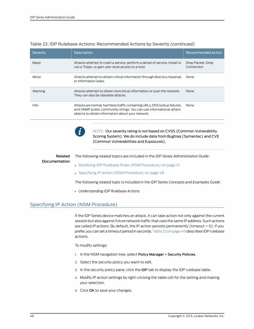
Table 22: IDP Rulebase Actions: Recommended Actions by Severity (continued)
RecommendedActionDescriptionSeverity
Drop Packet, DropConnection
Attacks attempt to crash a service, perform a denial of service, install oruse a Trojan, or gain user-level access to a host.
Major
NoneAttacks attempt to obtain critical information through directory traversalor information leaks.
Minor
NoneAttacks attempt to obtain noncritical information or scan the network.They can also be obsolete attacks.
Warning
NoneAttacks are normal, harmless traffic containing URLs, DNS lookup failures,and SNMP public community strings. You can use informational attackobjects to obtain information about your network.
Info
NOTE: Our severity rating is not based on CVSS (Common VulnerabilityScoring System). We do include data from Bugtraq (Symantec) and CVE(Common Vulnerabilities and Exposures).
RelatedDocumentation
The following related topics are included in the IDP Series Administration Guide:
Modifying IDP Rulebase Rules (NSM Procedure) on page 41•
• Specifying IP Action (NSM Procedure) on page 48
The following related topic is included in the IDP Series Concepts and Examples Guide:
• Understanding IDP Rulebase Actions
Specifying IP Action (NSMProcedure)
If the IDP Series device matches an attack, it can take action not only against the current
session but also against future network traffic that uses the same IP address. Such actions
are called IP actions. By default, the IP action persists permanently (timeout = 0). If you
prefer, you can set a timeout period in seconds. Table 23 on page 49 describes IDP rulebase
actions.
To modify settings:
1. In the NSM navigation tree, select Policy Manager > Security Policies.
2. Select the security policy you want to edit.
3. In the security policy pane, click the IDP tab to display the IDP rulebase table.
4. Modify IP action settings by right-clicking the table cell for the setting and making
your selection.
5. Click OK to save your changes.
Copyright © 2013, Juniper Networks, Inc.48
IDP Series Administration Guide
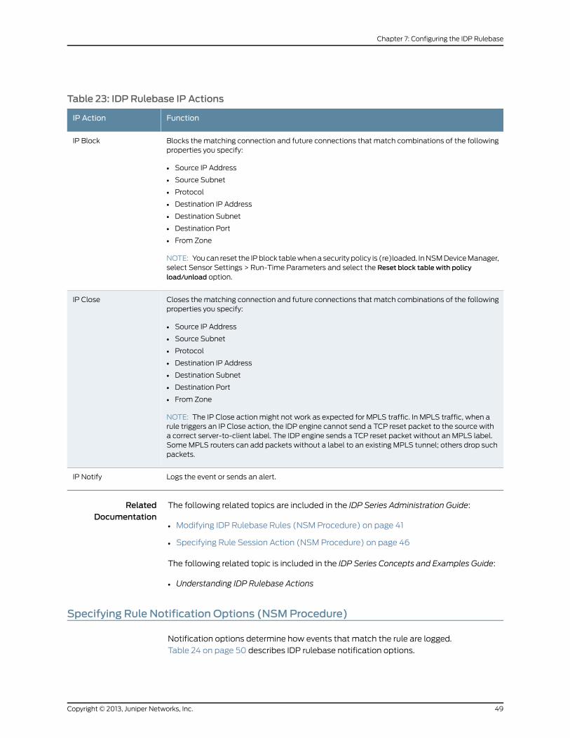
Table 23: IDP Rulebase IP Actions
FunctionIP Action
Blocks the matching connection and future connections that match combinations of the followingproperties you specify:
• Source IP Address
• Source Subnet
• Protocol
• Destination IP Address
• Destination Subnet
• Destination Port
• From Zone
NOTE: You can reset the IP block table when a security policy is (re)loaded. In NSM Device Manager,select Sensor Settings > Run-Time Parameters and select the Reset block table with policyload/unload option.
IP Block
Closes the matching connection and future connections that match combinations of the followingproperties you specify:
• Source IP Address
• Source Subnet
• Protocol
• Destination IP Address
• Destination Subnet
• Destination Port
• From Zone
NOTE: The IP Close action might not work as expected for MPLS traffic. In MPLS traffic, when arule triggers an IP Close action, the IDP engine cannot send a TCP reset packet to the source witha correct server-to-client label. The IDP engine sends a TCP reset packet without an MPLS label.Some MPLS routers can add packets without a label to an existing MPLS tunnel; others drop suchpackets.
IP Close
Logs the event or sends an alert.IP Notify
RelatedDocumentation
The following related topics are included in the IDP Series Administration Guide:
Modifying IDP Rulebase Rules (NSM Procedure) on page 41•
• Specifying Rule Session Action (NSM Procedure) on page 46
The following related topic is included in the IDP Series Concepts and Examples Guide:
• Understanding IDP Rulebase Actions
Specifying Rule Notification Options (NSMProcedure)
Notification options determine how events that match the rule are logged.
Table 24 on page 50 describes IDP rulebase notification options.
49Copyright © 2013, Juniper Networks, Inc.
Chapter 7: Configuring the IDP Rulebase
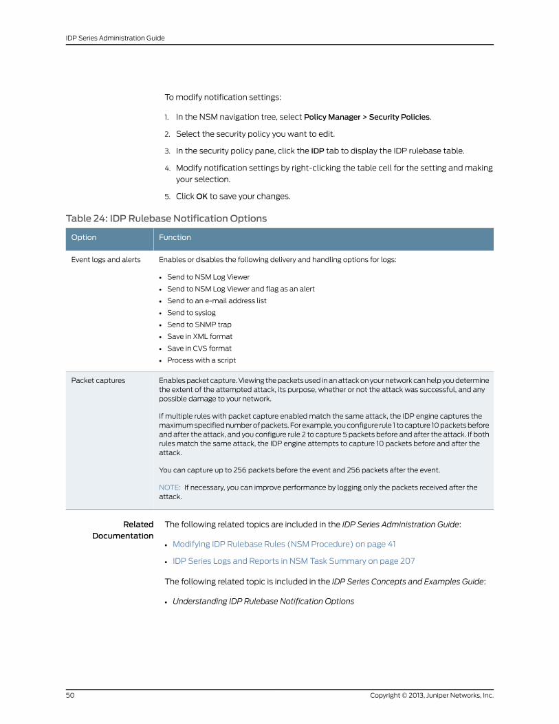
To modify notification settings:
1. In the NSM navigation tree, select Policy Manager > Security Policies.
2. Select the security policy you want to edit.
3. In the security policy pane, click the IDP tab to display the IDP rulebase table.
4. Modify notification settings by right-clicking the table cell for the setting and making
your selection.
5. Click OK to save your changes.
Table 24: IDP Rulebase Notification Options
FunctionOption
Enables or disables the following delivery and handling options for logs:
• Send to NSM Log Viewer
• Send to NSM Log Viewer and flag as an alert
• Send to an e-mail address list
• Send to syslog
• Send to SNMP trap
• Save in XML format
• Save in CVS format
• Process with a script
Event logs and alerts
Enables packet capture. Viewing the packets used in an attack on your network can help you determinethe extent of the attempted attack, its purpose, whether or not the attack was successful, and anypossible damage to your network.
If multiple rules with packet capture enabled match the same attack, the IDP engine captures themaximum specified number of packets. For example, you configure rule 1 to capture 10 packets beforeand after the attack, and you configure rule 2 to capture 5 packets before and after the attack. If bothrules match the same attack, the IDP engine attempts to capture 10 packets before and after theattack.
You can capture up to 256 packets before the event and 256 packets after the event.
NOTE: If necessary, you can improve performance by logging only the packets received after theattack.
Packet captures
RelatedDocumentation
The following related topics are included in the IDP Series Administration Guide:
Modifying IDP Rulebase Rules (NSM Procedure) on page 41•
• IDP Series Logs and Reports in NSM Task Summary on page 207
The following related topic is included in the IDP Series Concepts and Examples Guide:
• Understanding IDP Rulebase Notification Options
Copyright © 2013, Juniper Networks, Inc.50
IDP Series Administration Guide
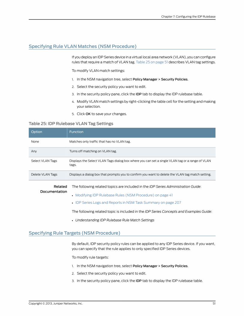
Specifying Rule VLANMatches (NSMProcedure)
If you deploy an IDP Series device in a virtual local area network (VLAN), you can configure
rules that require a match of VLAN tag. Table 25 on page 51 describes VLAN tag settings.
To modify VLAN match settings:
1. In the NSM navigation tree, select Policy Manager > Security Policies.
2. Select the security policy you want to edit.
3. In the security policy pane, click the IDP tab to display the IDP rulebase table.
4. Modify VLAN match settings by right-clicking the table cell for the setting and making
your selection.
5. Click OK to save your changes.
Table 25: IDP Rulebase VLAN Tag Settings
FunctionOption
Matches only traffic that has no VLAN tag.None
Turns off matching on VLAN tag.Any
Displays the Select VLAN Tags dialog box where you can set a single VLAN tag or a range of VLANtags.
Select VLAN Tags
Displays a dialog box that prompts you to confirm you want to delete the VLAN tag match setting.Delete VLAN Tags
RelatedDocumentation
The following related topics are included in the IDP Series Administration Guide:
Modifying IDP Rulebase Rules (NSM Procedure) on page 41•
• IDP Series Logs and Reports in NSM Task Summary on page 207
The following related topic is included in the IDP Series Concepts and Examples Guide:
• Understanding IDP Rulebase Rule Match Settings
Specifying Rule Targets (NSMProcedure)
By default, IDP security policy rules can be applied to any IDP Series device. If you want,
you can specify that the rule applies to only specified IDP Series devices.
To modify rule targets:
1. In the NSM navigation tree, select Policy Manager > Security Policies.
2. Select the security policy you want to edit.
3. In the security policy pane, click the IDP tab to display the IDP rulebase table.
51Copyright © 2013, Juniper Networks, Inc.
Chapter 7: Configuring the IDP Rulebase
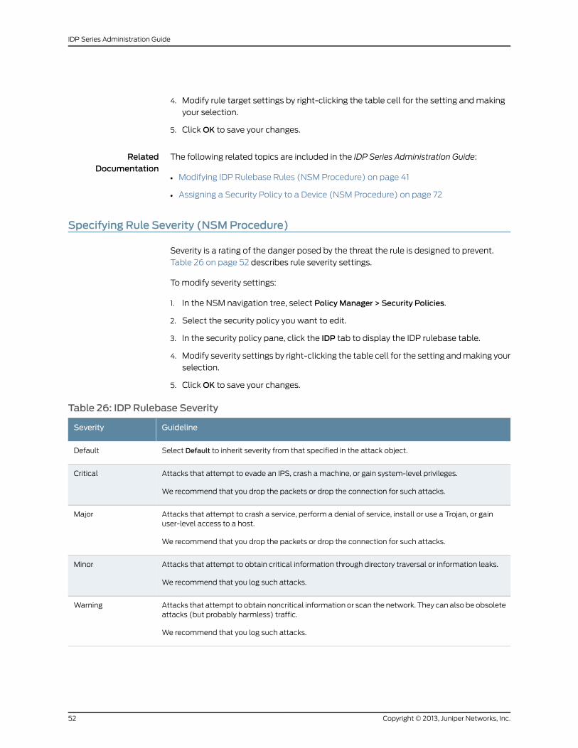
4. Modify rule target settings by right-clicking the table cell for the setting and making
your selection.
5. Click OK to save your changes.
RelatedDocumentation
The following related topics are included in the IDP Series Administration Guide:
Modifying IDP Rulebase Rules (NSM Procedure) on page 41•
• Assigning a Security Policy to a Device (NSM Procedure) on page 72
Specifying Rule Severity (NSMProcedure)
Severity is a rating of the danger posed by the threat the rule is designed to prevent.
Table 26 on page 52 describes rule severity settings.
To modify severity settings:
1. In the NSM navigation tree, select Policy Manager > Security Policies.
2. Select the security policy you want to edit.
3. In the security policy pane, click the IDP tab to display the IDP rulebase table.
4. Modify severity settings by right-clicking the table cell for the setting and making your
selection.
5. Click OK to save your changes.
Table 26: IDP Rulebase Severity
GuidelineSeverity
Select Default to inherit severity from that specified in the attack object.Default
Attacks that attempt to evade an IPS, crash a machine, or gain system-level privileges.
We recommend that you drop the packets or drop the connection for such attacks.
Critical
Attacks that attempt to crash a service, perform a denial of service, install or use a Trojan, or gainuser-level access to a host.
We recommend that you drop the packets or drop the connection for such attacks.
Major
Attacks that attempt to obtain critical information through directory traversal or information leaks.
We recommend that you log such attacks.
Minor
Attacks that attempt to obtain noncritical information or scan the network. They can also be obsoleteattacks (but probably harmless) traffic.
We recommend that you log such attacks.
Warning
Copyright © 2013, Juniper Networks, Inc.52
IDP Series Administration Guide
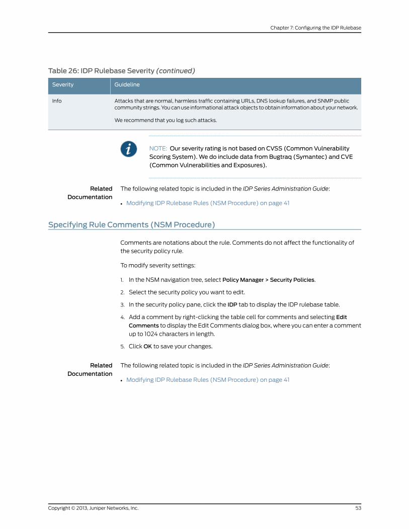
Table 26: IDP Rulebase Severity (continued)
GuidelineSeverity
Attacks that are normal, harmless traffic containing URLs, DNS lookup failures, and SNMP publiccommunity strings. You can use informational attack objects to obtain information about your network.
We recommend that you log such attacks.
Info
NOTE: Our severity rating is not based on CVSS (Common VulnerabilityScoring System). We do include data from Bugtraq (Symantec) and CVE(Common Vulnerabilities and Exposures).
RelatedDocumentation
The following related topic is included in the IDP Series Administration Guide:
Modifying IDP Rulebase Rules (NSM Procedure) on page 41•
Specifying Rule Comments (NSMProcedure)
Comments are notations about the rule. Comments do not affect the functionality of
the security policy rule.
To modify severity settings:
1. In the NSM navigation tree, select Policy Manager > Security Policies.
2. Select the security policy you want to edit.
3. In the security policy pane, click the IDP tab to display the IDP rulebase table.
4. Add a comment by right-clicking the table cell for comments and selecting Edit
Comments to display the Edit Comments dialog box, where you can enter a comment
up to 1024 characters in length.
5. Click OK to save your changes.
RelatedDocumentation
The following related topic is included in the IDP Series Administration Guide:
• Modifying IDP Rulebase Rules (NSM Procedure) on page 41
53Copyright © 2013, Juniper Networks, Inc.
Chapter 7: Configuring the IDP Rulebase

Copyright © 2013, Juniper Networks, Inc.54
IDP Series Administration Guide
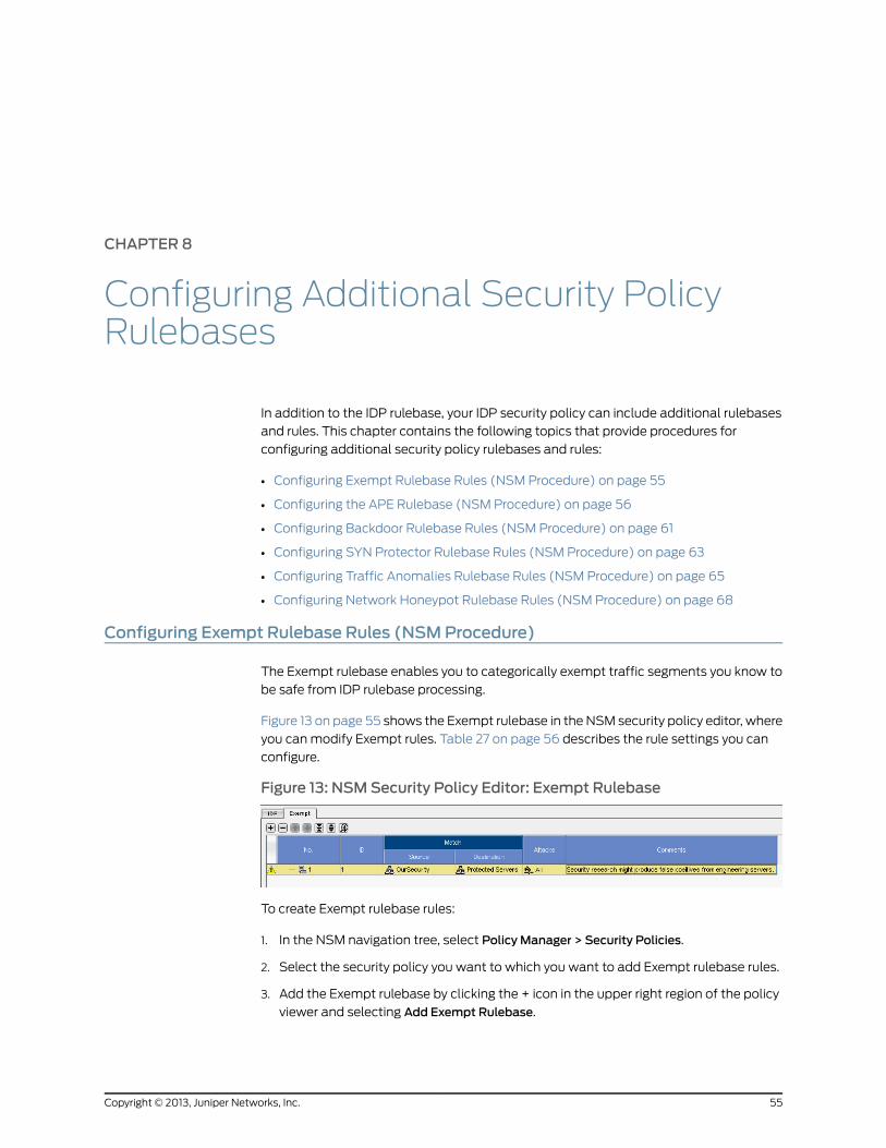
CHAPTER 8
Configuring Additional Security PolicyRulebases
In addition to the IDP rulebase, your IDP security policy can include additional rulebases
and rules. This chapter contains the following topics that provide procedures for
configuring additional security policy rulebases and rules:
• Configuring Exempt Rulebase Rules (NSM Procedure) on page 55
• Configuring the APE Rulebase (NSM Procedure) on page 56
• Configuring Backdoor Rulebase Rules (NSM Procedure) on page 61
• Configuring SYN Protector Rulebase Rules (NSM Procedure) on page 63
• Configuring Traffic Anomalies Rulebase Rules (NSM Procedure) on page 65
• Configuring Network Honeypot Rulebase Rules (NSM Procedure) on page 68
Configuring Exempt Rulebase Rules (NSMProcedure)
The Exempt rulebase enables you to categorically exempt traffic segments you know to
be safe from IDP rulebase processing.
Figure 13 on page 55 shows the Exempt rulebase in the NSM security policy editor, where
you can modify Exempt rules. Table 27 on page 56 describes the rule settings you can
configure.
Figure 13: NSMSecurity Policy Editor: Exempt Rulebase
To create Exempt rulebase rules:
1. In the NSM navigation tree, select Policy Manager > Security Policies.
2. Select the security policy you want to which you want to add Exempt rulebase rules.
3. Add the Exempt rulebase by clicking the + icon in the upper right region of the policy
viewer and selecting Add Exempt Rulebase.
55Copyright © 2013, Juniper Networks, Inc.
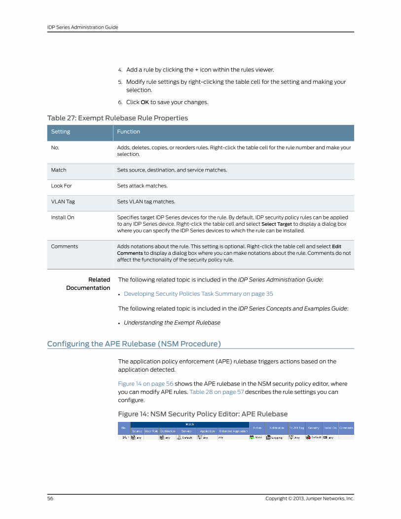
4. Add a rule by clicking the + icon within the rules viewer.
5. Modify rule settings by right-clicking the table cell for the setting and making your
selection.
6. Click OK to save your changes.
Table 27: Exempt Rulebase Rule Properties
FunctionSetting
Adds, deletes, copies, or reorders rules. Right-click the table cell for the rule number and make yourselection.
No.
Sets source, destination, and service matches.Match
Sets attack matches.Look For
Sets VLAN tag matches.VLAN Tag
Specifies target IDP Series devices for the rule. By default, IDP security policy rules can be appliedto any IDP Series device. Right-click the table cell and select Select Target to display a dialog boxwhere you can specify the IDP Series devices to which the rule can be installed.
Install On
Adds notations about the rule. This setting is optional. Right-click the table cell and select EditComments to display a dialog box where you can make notations about the rule. Comments do notaffect the functionality of the security policy rule.
Comments
RelatedDocumentation
The following related topic is included in the IDP Series Administration Guide:
Developing Security Policies Task Summary on page 35•
The following related topic is included in the IDP Series Concepts and Examples Guide:
• Understanding the Exempt Rulebase
Configuring the APE Rulebase (NSMProcedure)
The application policy enforcement (APE) rulebase triggers actions based on the
application detected.
Figure 14 on page 56 shows the APE rulebase in the NSM security policy editor, where
you can modify APE rules. Table 28 on page 57 describes the rule settings you can
configure.
Figure 14: NSMSecurity Policy Editor: APE Rulebase
Copyright © 2013, Juniper Networks, Inc.56
IDP Series Administration Guide
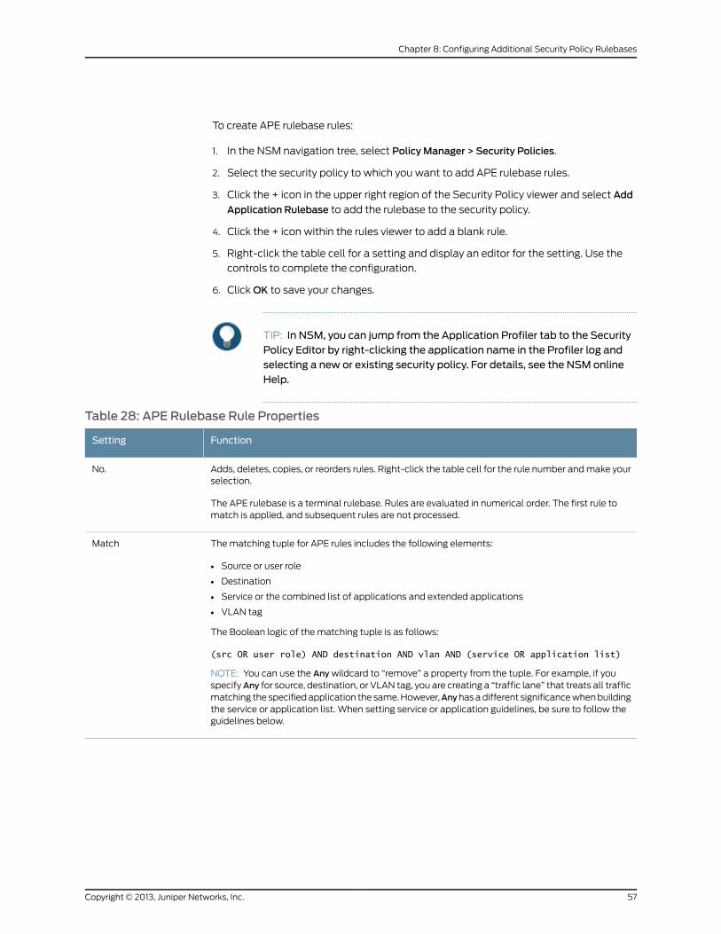
To create APE rulebase rules:
1. In the NSM navigation tree, select Policy Manager > Security Policies.
2. Select the security policy to which you want to add APE rulebase rules.
3. Click the + icon in the upper right region of the Security Policy viewer and select Add
Application Rulebase to add the rulebase to the security policy.
4. Click the + icon within the rules viewer to add a blank rule.
5. Right-click the table cell for a setting and display an editor for the setting. Use the
controls to complete the configuration.
6. Click OK to save your changes.
TIP: In NSM, you can jump from the Application Profiler tab to the SecurityPolicy Editor by right-clicking the application name in the Profiler log andselecting a new or existing security policy. For details, see the NSM onlineHelp.
Table 28: APE Rulebase Rule Properties
FunctionSetting
Adds, deletes, copies, or reorders rules. Right-click the table cell for the rule number and make yourselection.
The APE rulebase is a terminal rulebase. Rules are evaluated in numerical order. The first rule tomatch is applied, and subsequent rules are not processed.
No.
The matching tuple for APE rules includes the following elements:
• Source or user role
• Destination
• Service or the combined list of applications and extended applications
• VLAN tag
The Boolean logic of the matching tuple is as follows:
(src OR user role) AND destination AND vlan AND (service OR application list)
NOTE: You can use the Any wildcard to “remove” a property from the tuple. For example, if youspecifyAny for source, destination, or VLAN tag, you are creating a “traffic lane” that treats all trafficmatching the specified application the same. However,Anyhas a different significance when buildingthe service or application list. When setting service or application guidelines, be sure to follow theguidelines below.
Match
57Copyright © 2013, Juniper Networks, Inc.
Chapter 8: Configuring Additional Security Policy Rulebases
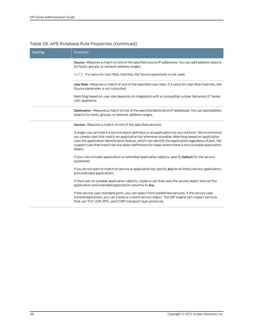
Table 28: APE Rulebase Rule Properties (continued)
FunctionSetting
Source—Requires a match of one of the specified source IP addresses. You can add address objectsfor hosts, groups, or network address ranges.
NOTE: If a value for User Role matches, the Source parameter is not used.
User Role—Requires a match of one of the specified user roles. If a value for User Role matches, theSource parameter is not consulted.
Matching based on user role depends on integration with a compatible Juniper Networks IC SeriesUAC appliance.
Destination—Requires a match of one of the specified destination IP addresses. You can add addressobjects for hosts, groups, or network address ranges.
Service—Requires a match of one of the specified services.
A single rule can match a service object definition or an application list, but not both. We recommendyou create rules that match an application list whenever possible. Matching based on applicationuses the application identification feature, which can identify the application regardless of port. Wesupport rules that match service object definitions for cases where there is not a suitable applicationobject.
If your rule includes application or extended application objects, specify Default for the serviceparameter.
If you do not want to match on service or application list, specifyAny for all three (service, application,and extended application).
If there are no suitable application objects, create a rule that uses the service object and set theapplication and extended application columns to Any.
If the service uses standard ports, you can select from predefined services. If the service usesnonstandard ports, you can create a custom service object. The IDP engine can inspect servicesthat use TCP, UDP, RPC, and ICMP transport layer protocols.
Copyright © 2013, Juniper Networks, Inc.58
IDP Series Administration Guide
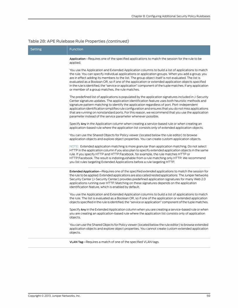
Table 28: APE Rulebase Rule Properties (continued)
FunctionSetting
Application—Requires one of the specified applications to match the session for the rule to beapplied.
You use the Application and Extended Application columns to build a list of applications to matchthe rule. You can specify individual applications or application groups. When you add a group, youare in effect adding its members to the list. The group object itself is not evaluated. The list isevaluated as a Boolean OR, so if one of the application or extended application objects specifiedin the rule is identified, the “service or application” component of the tuple matches. If any applicationor member of a group matches, the rule matches.
The predefined list of applications is populated by the application signatures included in J-SecurityCenter signature updates. The application identification feature uses both heuristic methods andsignature pattern matching to identify the application regardless of port. Port-independentapplication identification simplifies rule configuration and ensures that you do not miss applicationsthat are running on nonstandard ports. For this reason, we recommend that you use the applicationparameter instead of the service parameter whenever possible.
Specify Any in the Application column when creating a service-based rule or when creating anapplication-based rule where the application list consists only of extended application objects.
You can use the Shared Objects for Policy viewer (located below the rule editor) to browseapplication objects and explore object properties. You can create custom application objects.
NOTE: Extended application matching is more granular than application matching. Do not selectHTTP in the application column if you also plan to specify extended application objects in the samerule. If you specify HTTP and HTTP:Facebook, for example, the rule matches HTTP orHTTP:Facebook. The result is indistinguishable from a rule matching only HTTP. We recommendyou list rules targeting Extended Applications before a rule targeting HTTP.
ExtendedApplication—Requires one of the specified extended applications to match the session forthe rule to be applied. Extended applications are also callednestedapplications. The Juniper NetworksSecurity Center (J-Security Center) provides predefined application signatures for many Web 2.0applications running over HTTP. Matching on these signatures depends on the applicationidentification feature, which is enabled by default.
You use the Application and Extended Application columns to build a list of applications to matchthe rule. The list is evaluated as a Boolean OR, so if one of the application or extended applicationobjects specified in the rule is identified, the “service or application” component of the tuple matches.
SpecifyAny in the Extended Application column when you are creating a service-based rule or whenyou are creating an application-based rule where the application list consists only of applicationobjects.
You can use the Shared Objects for Policy viewer (located below the rule editor) to browse extendedapplication objects and explore object properties. You cannot create custom extended applicationobjects.
VLAN Tag—Requires a match of one of the specified VLAN tags.
59Copyright © 2013, Juniper Networks, Inc.
Chapter 8: Configuring Additional Security Policy Rulebases
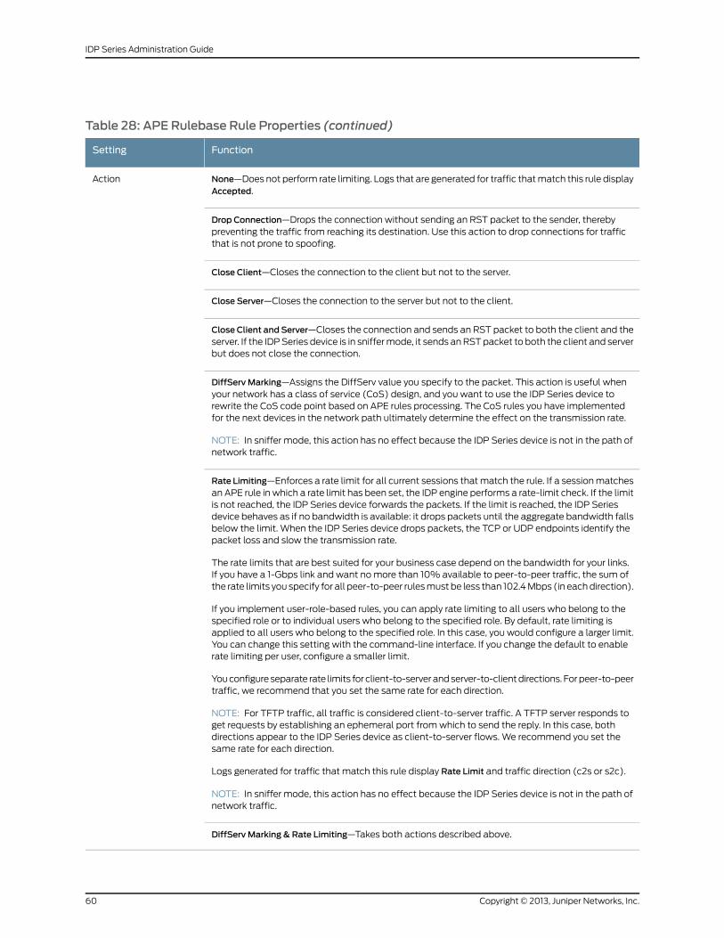
Table 28: APE Rulebase Rule Properties (continued)
FunctionSetting
None—Does not perform rate limiting. Logs that are generated for traffic that match this rule displayAccepted.
Action
Drop Connection—Drops the connection without sending an RST packet to the sender, therebypreventing the traffic from reaching its destination. Use this action to drop connections for trafficthat is not prone to spoofing.
Close Client—Closes the connection to the client but not to the server.
Close Server—Closes the connection to the server but not to the client.
Close Client and Server—Closes the connection and sends an RST packet to both the client and theserver. If the IDP Series device is in sniffer mode, it sends an RST packet to both the client and serverbut does not close the connection.
DiffServ Marking—Assigns the DiffServ value you specify to the packet. This action is useful whenyour network has a class of service (CoS) design, and you want to use the IDP Series device torewrite the CoS code point based on APE rules processing. The CoS rules you have implementedfor the next devices in the network path ultimately determine the effect on the transmission rate.
NOTE: In sniffer mode, this action has no effect because the IDP Series device is not in the path ofnetwork traffic.
Rate Limiting—Enforces a rate limit for all current sessions that match the rule. If a session matchesan APE rule in which a rate limit has been set, the IDP engine performs a rate-limit check. If the limitis not reached, the IDP Series device forwards the packets. If the limit is reached, the IDP Seriesdevice behaves as if no bandwidth is available: it drops packets until the aggregate bandwidth fallsbelow the limit. When the IDP Series device drops packets, the TCP or UDP endpoints identify thepacket loss and slow the transmission rate.
The rate limits that are best suited for your business case depend on the bandwidth for your links.If you have a 1-Gbps link and want no more than 10% available to peer-to-peer traffic, the sum ofthe rate limits you specify for all peer-to-peer rules must be less than 102.4 Mbps (in each direction).
If you implement user-role-based rules, you can apply rate limiting to all users who belong to thespecified role or to individual users who belong to the specified role. By default, rate limiting isapplied to all users who belong to the specified role. In this case, you would configure a larger limit.You can change this setting with the command-line interface. If you change the default to enablerate limiting per user, configure a smaller limit.
You configure separate rate limits for client-to-server and server-to-client directions. For peer-to-peertraffic, we recommend that you set the same rate for each direction.
NOTE: For TFTP traffic, all traffic is considered client-to-server traffic. A TFTP server responds toget requests by establishing an ephemeral port from which to send the reply. In this case, bothdirections appear to the IDP Series device as client-to-server flows. We recommend you set thesame rate for each direction.
Logs generated for traffic that match this rule display Rate Limit and traffic direction (c2s or s2c).
NOTE: In sniffer mode, this action has no effect because the IDP Series device is not in the path ofnetwork traffic.
DiffServ Marking & Rate Limiting—Takes both actions described above.
Copyright © 2013, Juniper Networks, Inc.60
IDP Series Administration Guide
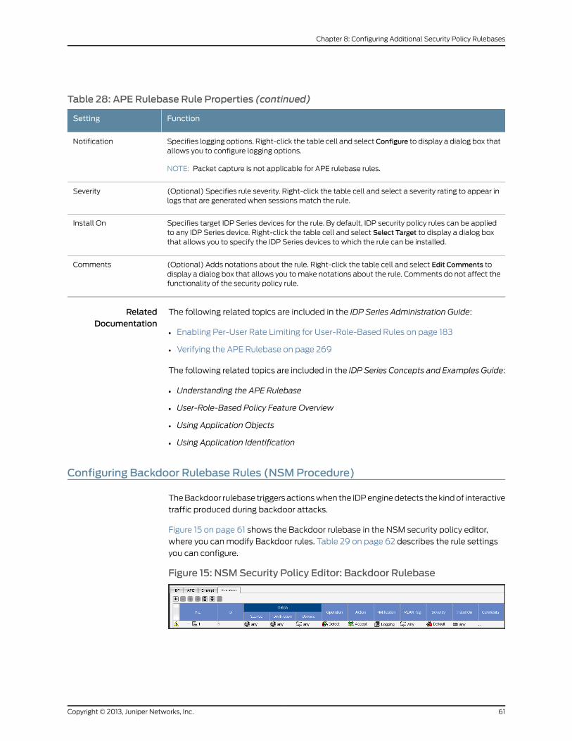
Table 28: APE Rulebase Rule Properties (continued)
FunctionSetting
Specifies logging options. Right-click the table cell and select Configure to display a dialog box thatallows you to configure logging options.
NOTE: Packet capture is not applicable for APE rulebase rules.
Notification
(Optional) Specifies rule severity. Right-click the table cell and select a severity rating to appear inlogs that are generated when sessions match the rule.
Severity
Specifies target IDP Series devices for the rule. By default, IDP security policy rules can be appliedto any IDP Series device. Right-click the table cell and select Select Target to display a dialog boxthat allows you to specify the IDP Series devices to which the rule can be installed.
Install On
(Optional) Adds notations about the rule. Right-click the table cell and select Edit Comments todisplay a dialog box that allows you to make notations about the rule. Comments do not affect thefunctionality of the security policy rule.
Comments
RelatedDocumentation
The following related topics are included in the IDP Series Administration Guide:
Enabling Per-User Rate Limiting for User-Role-Based Rules on page 183•
• Verifying the APE Rulebase on page 269
The following related topics are included in the IDP Series Concepts and Examples Guide:
• Understanding the APE Rulebase
• User-Role-Based Policy Feature Overview
• Using Application Objects
• Using Application Identification
Configuring Backdoor Rulebase Rules (NSMProcedure)
The Backdoor rulebase triggers actions when the IDP engine detects the kind of interactive
traffic produced during backdoor attacks.
Figure 15 on page 61 shows the Backdoor rulebase in the NSM security policy editor,
where you can modify Backdoor rules. Table 29 on page 62 describes the rule settings
you can configure.
Figure 15: NSMSecurity Policy Editor: Backdoor Rulebase
61Copyright © 2013, Juniper Networks, Inc.
Chapter 8: Configuring Additional Security Policy Rulebases
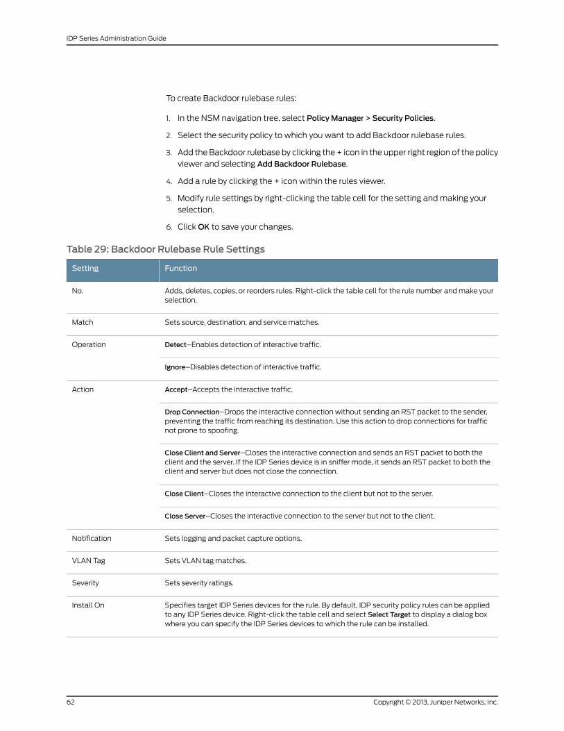
To create Backdoor rulebase rules:
1. In the NSM navigation tree, select Policy Manager > Security Policies.
2. Select the security policy to which you want to add Backdoor rulebase rules.
3. Add the Backdoor rulebase by clicking the + icon in the upper right region of the policy
viewer and selecting Add Backdoor Rulebase.
4. Add a rule by clicking the + icon within the rules viewer.
5. Modify rule settings by right-clicking the table cell for the setting and making your
selection.
6. Click OK to save your changes.
Table 29: Backdoor Rulebase Rule Settings
FunctionSetting
Adds, deletes, copies, or reorders rules. Right-click the table cell for the rule number and make yourselection.
No.
Sets source, destination, and service matches.Match
Detect–Enables detection of interactive traffic.Operation
Ignore–Disables detection of interactive traffic.
Accept–Accepts the interactive traffic.Action
Drop Connection–Drops the interactive connection without sending an RST packet to the sender,preventing the traffic from reaching its destination. Use this action to drop connections for trafficnot prone to spoofing.
Close Client and Server–Closes the interactive connection and sends an RST packet to both theclient and the server. If the IDP Series device is in sniffer mode, it sends an RST packet to both theclient and server but does not close the connection.
Close Client–Closes the interactive connection to the client but not to the server.
Close Server–Closes the interactive connection to the server but not to the client.
Sets logging and packet capture options.Notification
Sets VLAN tag matches.VLAN Tag
Sets severity ratings.Severity
Specifies target IDP Series devices for the rule. By default, IDP security policy rules can be appliedto any IDP Series device. Right-click the table cell and select Select Target to display a dialog boxwhere you can specify the IDP Series devices to which the rule can be installed.
Install On
Copyright © 2013, Juniper Networks, Inc.62
IDP Series Administration Guide
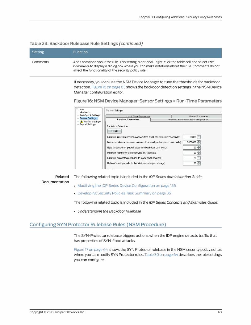
Table 29: Backdoor Rulebase Rule Settings (continued)
FunctionSetting
Adds notations about the rule. This setting is optional. Right-click the table cell and select EditComments to display a dialog box where you can make notations about the rule. Comments do notaffect the functionality of the security policy rule.
Comments
If necessary, you can use the NSM Device Manager to tune the thresholds for backdoor
detection. Figure 16 on page 63 shows the backdoor detection settings in the NSM Device
Manager configuration editor.
Figure 16:NSMDeviceManager: SensorSettings>Run-TimeParameters
RelatedDocumentation
The following related topic is included in the IDP Series Administration Guide:
Modifying the IDP Series Device Configuration on page 135•
• Developing Security Policies Task Summary on page 35
The following related topic is included in the IDP Series Concepts and Examples Guide:
• Understanding the Backdoor Rulebase
Configuring SYN Protector Rulebase Rules (NSMProcedure)
The SYN-Protector rulebase triggers actions when the IDP engine detects traffic that
has properties of SYN-flood attacks.
Figure 17 on page 64 shows the SYN Protector rulebase in the NSM security policy editor,
where you can modify SYN Protector rules. Table 30 on page 64 describes the rule settings
you can configure.
63Copyright © 2013, Juniper Networks, Inc.
Chapter 8: Configuring Additional Security Policy Rulebases
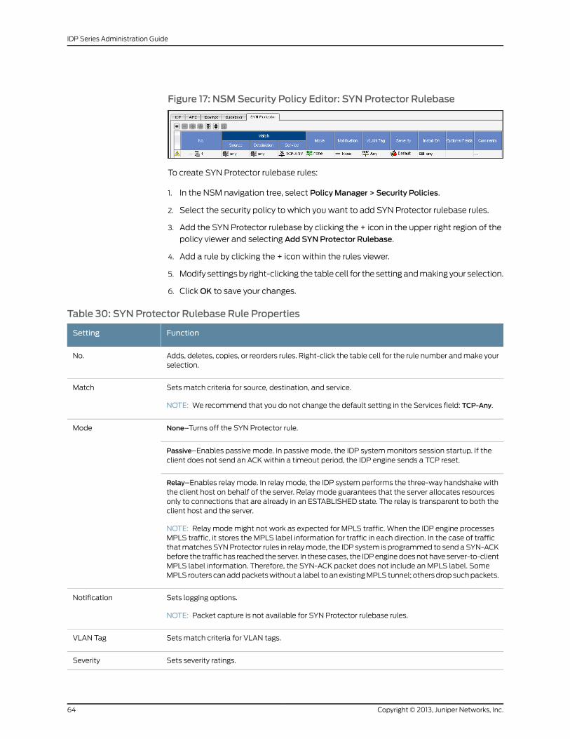
Figure 17: NSMSecurity Policy Editor: SYN Protector Rulebase
To create SYN Protector rulebase rules:
1. In the NSM navigation tree, select Policy Manager > Security Policies.
2. Select the security policy to which you want to add SYN Protector rulebase rules.
3. Add the SYN Protector rulebase by clicking the + icon in the upper right region of the
policy viewer and selecting Add SYN Protector Rulebase.
4. Add a rule by clicking the + icon within the rules viewer.
5. Modify settings by right-clicking the table cell for the setting and making your selection.
6. Click OK to save your changes.
Table 30: SYN Protector Rulebase Rule Properties
FunctionSetting
Adds, deletes, copies, or reorders rules. Right-click the table cell for the rule number and make yourselection.
No.
Sets match criteria for source, destination, and service.
NOTE: We recommend that you do not change the default setting in the Services field: TCP-Any.
Match
None–Turns off the SYN Protector rule.Mode
Passive–Enables passive mode. In passive mode, the IDP system monitors session startup. If theclient does not send an ACK within a timeout period, the IDP engine sends a TCP reset.
Relay–Enables relay mode. In relay mode, the IDP system performs the three-way handshake withthe client host on behalf of the server. Relay mode guarantees that the server allocates resourcesonly to connections that are already in an ESTABLISHED state. The relay is transparent to both theclient host and the server.
NOTE: Relay mode might not work as expected for MPLS traffic. When the IDP engine processesMPLS traffic, it stores the MPLS label information for traffic in each direction. In the case of trafficthat matches SYN Protector rules in relay mode, the IDP system is programmed to send a SYN-ACKbefore the traffic has reached the server. In these cases, the IDP engine does not have server-to-clientMPLS label information. Therefore, the SYN-ACK packet does not include an MPLS label. SomeMPLS routers can add packets without a label to an existing MPLS tunnel; others drop such packets.
Sets logging options.
NOTE: Packet capture is not available for SYN Protector rulebase rules.
Notification
Sets match criteria for VLAN tags.VLAN Tag
Sets severity ratings.Severity
Copyright © 2013, Juniper Networks, Inc.64
IDP Series Administration Guide
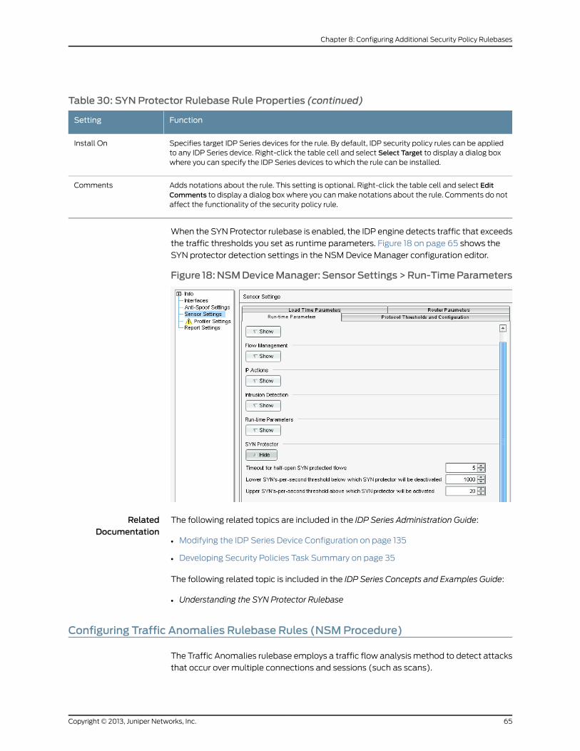
Table 30: SYN Protector Rulebase Rule Properties (continued)
FunctionSetting
Specifies target IDP Series devices for the rule. By default, IDP security policy rules can be appliedto any IDP Series device. Right-click the table cell and select Select Target to display a dialog boxwhere you can specify the IDP Series devices to which the rule can be installed.
Install On
Adds notations about the rule. This setting is optional. Right-click the table cell and select EditComments to display a dialog box where you can make notations about the rule. Comments do notaffect the functionality of the security policy rule.
Comments
When the SYN Protector rulebase is enabled, the IDP engine detects traffic that exceeds
the traffic thresholds you set as runtime parameters. Figure 18 on page 65 shows the
SYN protector detection settings in the NSM Device Manager configuration editor.
Figure 18:NSMDeviceManager: SensorSettings>Run-TimeParameters
RelatedDocumentation
The following related topics are included in the IDP Series Administration Guide:
Modifying the IDP Series Device Configuration on page 135•
• Developing Security Policies Task Summary on page 35
The following related topic is included in the IDP Series Concepts and Examples Guide:
• Understanding the SYN Protector Rulebase
Configuring Traffic Anomalies Rulebase Rules (NSMProcedure)
The Traffic Anomalies rulebase employs a traffic flow analysis method to detect attacks
that occur over multiple connections and sessions (such as scans).
65Copyright © 2013, Juniper Networks, Inc.
Chapter 8: Configuring Additional Security Policy Rulebases
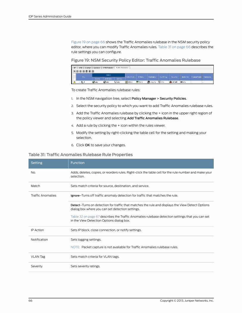
Figure 19 on page 66 shows the Traffic Anomalies rulebase in the NSM security policy
editor, where you can modify Traffic Anomalies rules. Table 31 on page 66 describes the
rule settings you can configure.
Figure 19: NSMSecurity Policy Editor: Traffic Anomalies Rulebase
To create Traffic Anomalies rulebase rules:
1. In the NSM navigation tree, select Policy Manager > Security Policies.
2. Select the security policy to which you want to add Traffic Anomalies rulebase rules.
3. Add the Traffic Anomalies rulebase by clicking the + icon in the upper right region of
the policy viewer and selecting Add Traffic Anomalies Rulebase.
4. Add a rule by clicking the + icon within the rules viewer.
5. Modify the setting by right-clicking the table cell for the setting and making your
selection.
6. Click OK to save your changes.
Table 31: Traffic Anomalies Rulebase Rule Properties
FunctionSetting
Adds, deletes, copies, or reorders rules. Right-click the table cell for the rule number and make yourselection.
No.
Sets match criteria for source, destination, and service.Match
Ignore–Turns off traffic anomaly detection for traffic that matches the rule.Traffic Anomalies
Detect–Turns on detection for traffic that matches the rule and displays the View Detect Optionsdialog box where you can set detection settings.
Table 32 on page 67 describes the Traffic Anomalies rulebase detection settings that you can setin the View Detection Options dialog box.
Sets IP block, close connection, or notify settings.IP Action
Sets logging settings.
NOTE: Packet capture is not available for Traffic Anomalies rulebase rules.
Notification
Sets match criteria for VLAN tags.VLAN Tag
Sets severity ratings.Severity
Copyright © 2013, Juniper Networks, Inc.66
IDP Series Administration Guide
Table 31: Traffic Anomalies Rulebase Rule Properties (continued)
FunctionSetting
Specifies target IDP Series devices for the rule. By default, IDP security policy rules can be appliedto any IDP Series device. Right-click the table cell and select Select Target to display a dialog boxwhere you can specify the IDP Series devices to which the rule can be installed.
Install On
Adds notations about the rule. This setting is optional. Right-click the table cell and select EditComments to display a dialog box where you can make notations about the rule. Comments do notaffect the functionality of the security policy rule.
Comments
Table 32 on page 67 describes Traffic Anomalies rulebase detection settings.
Table 32: Traffic Anomalies Rulebase Detection Settings
FunctionSetting
Sets a port count (number of ports scanned) and the time threshold (the time period that ports arecounted) in seconds.
The default port count is 20. The default time threshold is 120 seconds. The rule is matched if thesame source scans 20 TCP ports on your internal network within 120 seconds or if the same sourcescans 20 UDP ports on your internal network within 120 seconds.
TCP scans, UDP PortScans
A distributed port scan is an attack that uses multiple source IP addresses to scan ports.
Sets a port count (number of ports scanned) and the time threshold (the time period that ports arecounted) in seconds.
The default IP count is 50. The default time threshold is 120 seconds. The rule is matched if 50 IPaddresses attempt to scan ports on your internal network within 120 seconds.
Distributed Port Scan
An ICMP sweep is an attack where a single source IP pings multiple IP addresses.
Sets a port count (number of ports scanned) and the time threshold (the time period that ports arecounted) in seconds.
The default IP count is 50. The default time threshold is 120 seconds. The rule is matched if the samesource IP attempts to ping 50 IP addresses within 120 seconds.
ICMP Sweep
A network scan is an attack where a single source IP scans multiple IP addresses
Sets a port count (number of ports scanned) and the time threshold (the time period that ports arecounted) in seconds.
The default IP count is 50. The default time threshold is 120 seconds. The rule is matched if the samesource IP attempts to scan 50 IP addresses within 120 seconds.
Network Scan
Sets a threshold number of sessions allowed from a single host within a second. The default is 100sessions.
For example, assume your internal network typically has low volume traffic. To detect a suddenincrease in traffic from a specific host (which might indicate a worm), configure a rule that matchestraffic over your internal network and configure a limit of 200. To block traffic that exceeds thesession limit, set the rule IP Action to IP Block and set Blocking Options to Source, Protocol.
Session Limit
67Copyright © 2013, Juniper Networks, Inc.
Chapter 8: Configuring Additional Security Policy Rulebases
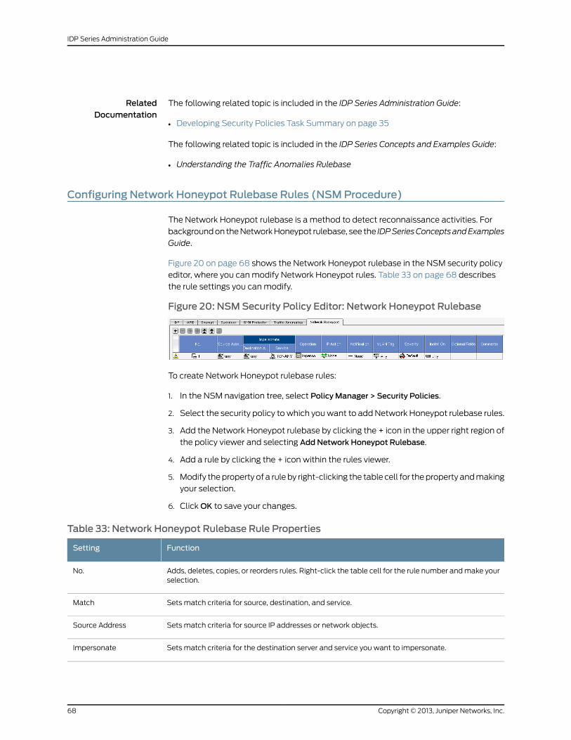
RelatedDocumentation
The following related topic is included in the IDP Series Administration Guide:
Developing Security Policies Task Summary on page 35•
The following related topic is included in the IDP Series Concepts and Examples Guide:
• Understanding the Traffic Anomalies Rulebase
Configuring Network Honeypot Rulebase Rules (NSMProcedure)
The Network Honeypot rulebase is a method to detect reconnaissance activities. For
background on the Network Honeypot rulebase, see the IDPSeriesConceptsandExamples
Guide.
Figure 20 on page 68 shows the Network Honeypot rulebase in the NSM security policy
editor, where you can modify Network Honeypot rules. Table 33 on page 68 describes
the rule settings you can modify.
Figure 20: NSMSecurity Policy Editor: Network Honeypot Rulebase
To create Network Honeypot rulebase rules:
1. In the NSM navigation tree, select Policy Manager > Security Policies.
2. Select the security policy to which you want to add Network Honeypot rulebase rules.
3. Add the Network Honeypot rulebase by clicking the + icon in the upper right region of
the policy viewer and selecting Add Network Honeypot Rulebase.
4. Add a rule by clicking the + icon within the rules viewer.
5. Modify the property of a rule by right-clicking the table cell for the property and making
your selection.
6. Click OK to save your changes.
Table 33: Network Honeypot Rulebase Rule Properties
FunctionSetting
Adds, deletes, copies, or reorders rules. Right-click the table cell for the rule number and make yourselection.
No.
Sets match criteria for source, destination, and service.Match
Sets match criteria for source IP addresses or network objects.Source Address
Sets match criteria for the destination server and service you want to impersonate.Impersonate
Copyright © 2013, Juniper Networks, Inc.68
IDP Series Administration Guide
Table 33: Network Honeypot Rulebase Rule Properties (continued)
FunctionSetting
Ignore–Turns off the network honeypot.Operation
Impersonate–Turns on the network honeypot. The IDP system sends a TCP SYN/ACK in responseto TCP requests.
Sets IP block, close, or notify actions.IP Action
Sets logging and packet capture settings.Notification
Sets match criteria for VLAN tags.VLAN Tag
Sets severity ratings.Severity
Specifies target IDP Series devices for the rule. By default, IDP security policy rules can be appliedto any IDP Series device. Right-click the table cell and select Select Target to display a dialog boxwhere you can specify the IDP Series devices to which the rule can be installed.
Install On
Adds notations about the rule. This setting is optional. Right-click the table cell and select EditComments to display a dialog box where you can make notations about the rule. Comments do notaffect the functionality of the security policy rule.
Comments
NOTE: The IDP Series device drops MPLS traffic that matches a NetworkHoneypot rule. When the IDP engine processes MPLS traffic, it stores theMPLS label information. It stores separate labels for client-to-server andserver-to-client communication. In the case of traffic thatmatches NetworkHoneypot rules, there is no genuine server-to-client communication, so theIDPenginedoesnothaveserver-to-clientMPLS label information.Therefore,the impersonation operation cannot be supported.
RelatedDocumentation
The following related topic is included in the IDP Series Administration Guide:
• Developing Security Policies Task Summary on page 35
The following related topic is included in the IDP Series Concepts and Examples Guide:
• Understanding the Network Honeypot Rulebase
69Copyright © 2013, Juniper Networks, Inc.
Chapter 8: Configuring Additional Security Policy Rulebases

Copyright © 2013, Juniper Networks, Inc.70
IDP Series Administration Guide
CHAPTER 9
Managing Security Policies
This chapter contains the following topics:
• Managing Security Policies Task Summary on page 71
• Assigning a Security Policy to a Device (NSM Procedure) on page 72
• Validating a Security Policy (NSM Procedure) on page 72
• Troubleshooting Security Policy Validation Errors (NSM Procedure) on page 72
• Pushing Security Policy Updates to an IDP Series Device (NSM Procedure) on page 73
• Troubleshooting Configuration Push Errors (NSM Procedure) on page 75
• Disabling Rules (NSM Procedure) on page 76
• Exporting Security Policies (NSM Procedure) on page 76
Managing Security Policies Task Summary
Routine administration can include the following tasks related to managing IDP security
policies:
• Assigning a security policy to a device if you have not done so already
• Validating a security policy
• Pushing a security policy update
• Exporting a security policy to a file
• Disabling rules that trigger false positives or degrade performance
RelatedDocumentation
The following related topics are included in the IDP Series Administration Guide:
Assigning a Security Policy to a Device (NSM Procedure) on page 72•
• Validating a Security Policy (NSM Procedure) on page 72
• Pushing Security Policy Updates to an IDP Series Device (NSM Procedure) on page 73
• Exporting Security Policies (NSM Procedure) on page 76
• Disabling Rules (NSM Procedure) on page 76
71Copyright © 2013, Juniper Networks, Inc.
Assigning a Security Policy to a Device (NSMProcedure)
When you create a security policy with the new security policy wizard, you can designate
an IDP Series device target. You can also specify IDP Series devices as targets for particular
rules. Follow this procedure if you did not complete the assignment when you created
the security policy, or if you want to change the assignment.
To assign a security policy to a device:
1. In the NSM navigation tree, select Policy Manager > Security Policies.
2. Right-click the security policy you want to assign and select Assign Policy to display
the Assign Policies to Devices dialog box, where you can select IDP Series devices to
which the policy should be assigned.
3. Click OK.
RelatedDocumentation
The following related topics are included in the IDP Series Administration Guide:
Using the New Policy Wizard (NSM Procedure) on page 38•
• Specifying Rule Targets (NSM Procedure) on page 51
• Managing Security Policies Task Summary on page 71
Validating a Security Policy (NSMProcedure)
We recommend you validate the integrity of a security policy before pushing the security
policy to a device.
To validate a security policy:
1. From the NSM main menu, select Devices > Policy > Validate IDP Policy to display the
Validate IDP Policy dialog box.
2. Select IDP Series devices to which the validation job applies.
3. Click OK.
RelatedDocumentation
The following related topics are included in the IDP Series Administration Guide:
Troubleshooting Security Policy Validation Errors (NSM Procedure) on page 72•
• Managing Security Policies Task Summary on page 71
Troubleshooting Security Policy Validation Errors (NSMProcedure)
Problem Table 34 on page 73 describes security policy validation errors and how to resolve them.
Copyright © 2013, Juniper Networks, Inc.72
IDP Series Administration Guide
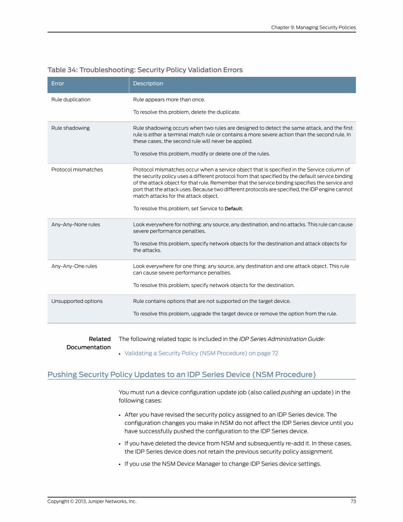
Table 34: Troubleshooting: Security Policy Validation Errors
DescriptionError
Rule appears more than once.
To resolve this problem, delete the duplicate.
Rule duplication
Rule shadowing occurs when two rules are designed to detect the same attack, and the firstrule is either a terminal match rule or contains a more severe action than the second rule. Inthese cases, the second rule will never be applied.
To resolve this problem, modify or delete one of the rules.
Rule shadowing
Protocol mismatches occur when a service object that is specified in the Service column ofthe security policy uses a different protocol from that specified by the default service bindingof the attack object for that rule. Remember that the service binding specifies the service andport that the attack uses. Because two different protocols are specified, the IDP engine cannotmatch attacks for the attack object.
To resolve this problem, set Service to Default.
Protocol mismatches
Look everywhere for nothing: any source, any destination, and no attacks. This rule can causesevere performance penalties.
To resolve this problem, specify network objects for the destination and attack objects forthe attacks.
Any-Any-None rules
Look everywhere for one thing: any source, any destination and one attack object. This rulecan cause severe performance penalties.
To resolve this problem, specify network objects for the destination.
Any-Any-One rules
Rule contains options that are not supported on the target device.
To resolve this problem, upgrade the target device or remove the option from the rule.
Unsupported options
RelatedDocumentation
The following related topic is included in the IDP Series Administration Guide:
Validating a Security Policy (NSM Procedure) on page 72•
Pushing Security Policy Updates to an IDP Series Device (NSMProcedure)
You must run a device configuration update job (also called pushing an update) in the
following cases:
• After you have revised the security policy assigned to an IDP Series device. The
configuration changes you make in NSM do not affect the IDP Series device until you
have successfully pushed the configuration to the IDP Series device.
• If you have deleted the device from NSM and subsequently re-add it. In these cases,
the IDP Series device does not retain the previous security policy assignment.
• If you use the NSM Device Manager to change IDP Series device settings.
73Copyright © 2013, Juniper Networks, Inc.
Chapter 9: Managing Security Policies
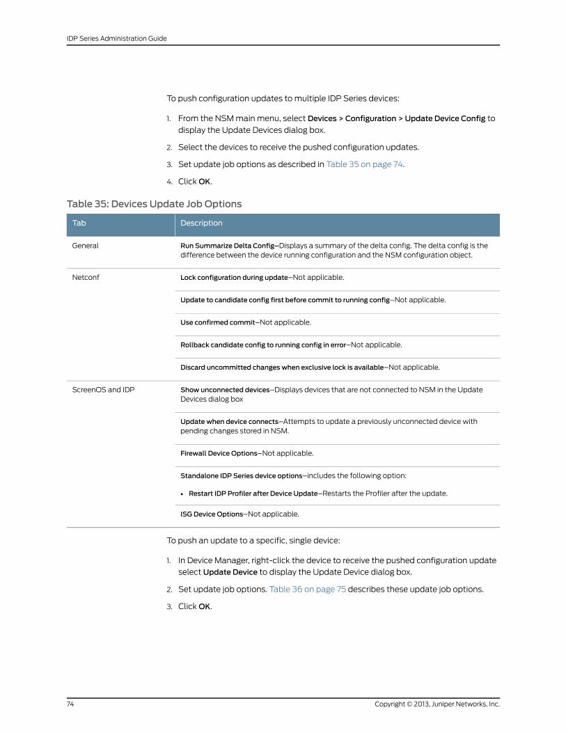
To push configuration updates to multiple IDP Series devices:
1. From the NSM main menu, select Devices > Configuration > Update Device Config to
display the Update Devices dialog box.
2. Select the devices to receive the pushed configuration updates.
3. Set update job options as described in Table 35 on page 74.
4. Click OK.
Table 35: Devices Update Job Options
DescriptionTab
Run Summarize Delta Config–Displays a summary of the delta config. The delta config is thedifference between the device running configuration and the NSM configuration object.
General
Lock configuration during update–Not applicable.Netconf
Update to candidate config first before commit to running config–Not applicable.
Use confirmed commit–Not applicable.
Rollback candidate config to running config in error–Not applicable.
Discard uncommitted changes when exclusive lock is available–Not applicable.
Show unconnected devices–Displays devices that are not connected to NSM in the UpdateDevices dialog box
ScreenOS and IDP
Update when device connects–Attempts to update a previously unconnected device withpending changes stored in NSM.
Firewall Device Options–Not applicable.
Standalone IDP Series device options–includes the following option:
• Restart IDP Profiler after Device Update–Restarts the Profiler after the update.
ISG Device Options–Not applicable.
To push an update to a specific, single device:
1. In Device Manager, right-click the device to receive the pushed configuration update
select Update Device to display the Update Device dialog box.
2. Set update job options. Table 36 on page 75 describes these update job options.
3. Click OK.
Copyright © 2013, Juniper Networks, Inc.74
IDP Series Administration Guide
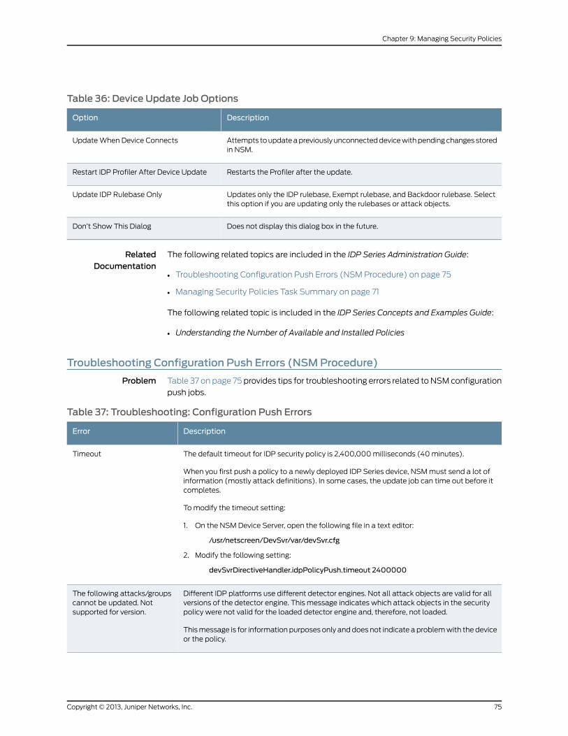
Table 36: Device Update Job Options
DescriptionOption
Attempts to update a previously unconnected device with pending changes storedin NSM.
Update When Device Connects
Restarts the Profiler after the update.Restart IDP Profiler After Device Update
Updates only the IDP rulebase, Exempt rulebase, and Backdoor rulebase. Selectthis option if you are updating only the rulebases or attack objects.
Update IDP Rulebase Only
Does not display this dialog box in the future.Don’t Show This Dialog
RelatedDocumentation
The following related topics are included in the IDP Series Administration Guide:
Troubleshooting Configuration Push Errors (NSM Procedure) on page 75•
• Managing Security Policies Task Summary on page 71
The following related topic is included in the IDP Series Concepts and Examples Guide:
• Understanding the Number of Available and Installed Policies
Troubleshooting Configuration Push Errors (NSMProcedure)
Problem Table 37 on page 75 provides tips for troubleshooting errors related to NSM configuration
push jobs.
Table 37: Troubleshooting: Configuration Push Errors
DescriptionError
The default timeout for IDP security policy is 2,400,000 milliseconds (40 minutes).
When you first push a policy to a newly deployed IDP Series device, NSM must send a lot ofinformation (mostly attack definitions). In some cases, the update job can time out before itcompletes.
To modify the timeout setting:
1. On the NSM Device Server, open the following file in a text editor:
/usr/netscreen/DevSvr/var/devSvr.cfg
2. Modify the following setting:
devSvrDirectiveHandler.idpPolicyPush.timeout 2400000
Timeout
Different IDP platforms use different detector engines. Not all attack objects are valid for allversions of the detector engine. This message indicates which attack objects in the securitypolicy were not valid for the loaded detector engine and, therefore, not loaded.
This message is for information purposes only and does not indicate a problem with the deviceor the policy.
The following attacks/groupscannot be updated. Notsupported for version.
75Copyright © 2013, Juniper Networks, Inc.
Chapter 9: Managing Security Policies
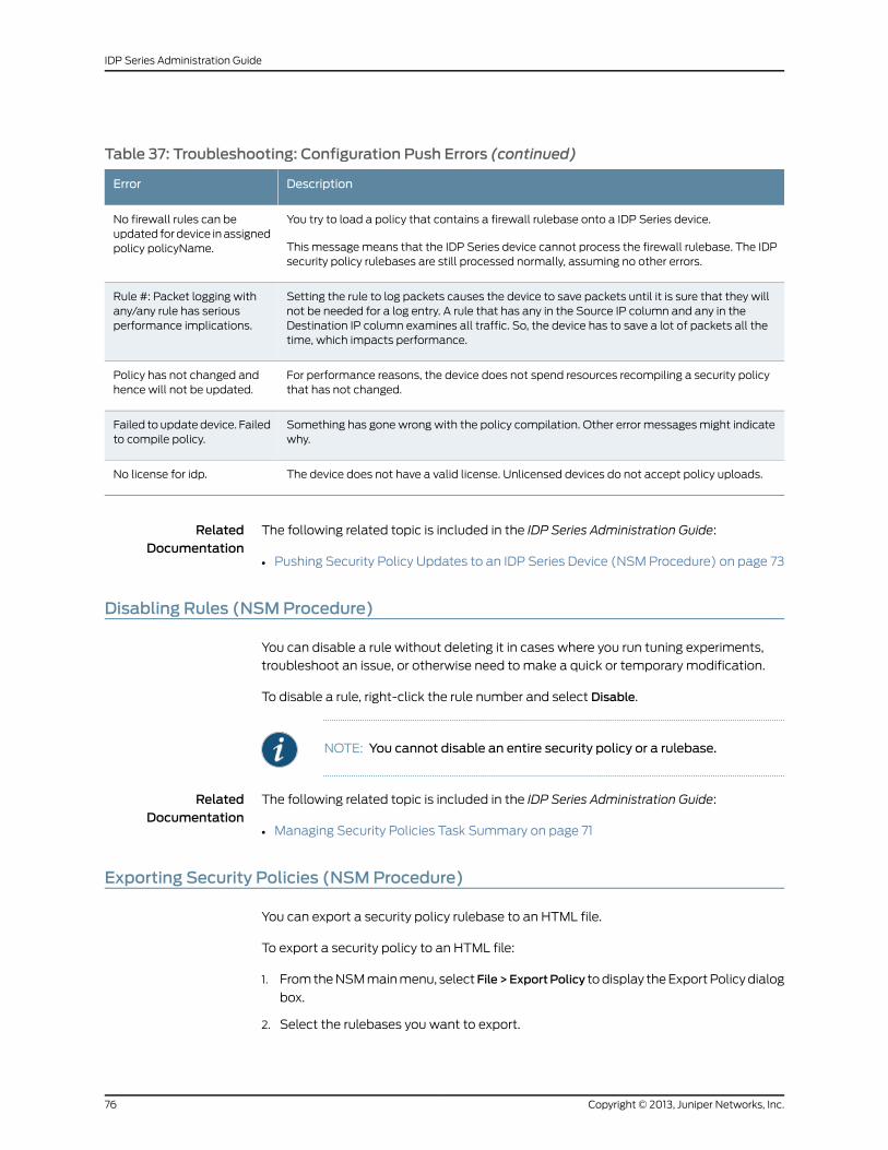
Table 37: Troubleshooting: Configuration Push Errors (continued)
DescriptionError
You try to load a policy that contains a firewall rulebase onto a IDP Series device.
This message means that the IDP Series device cannot process the firewall rulebase. The IDPsecurity policy rulebases are still processed normally, assuming no other errors.
No firewall rules can beupdated for device in assignedpolicy policyName.
Setting the rule to log packets causes the device to save packets until it is sure that they willnot be needed for a log entry. A rule that has any in the Source IP column and any in theDestination IP column examines all traffic. So, the device has to save a lot of packets all thetime, which impacts performance.
Rule #: Packet logging withany/any rule has seriousperformance implications.
For performance reasons, the device does not spend resources recompiling a security policythat has not changed.
Policy has not changed andhence will not be updated.
Something has gone wrong with the policy compilation. Other error messages might indicatewhy.
Failed to update device. Failedto compile policy.
The device does not have a valid license. Unlicensed devices do not accept policy uploads.No license for idp.
RelatedDocumentation
The following related topic is included in the IDP Series Administration Guide:
Pushing Security Policy Updates to an IDP Series Device (NSM Procedure) on page 73•
Disabling Rules (NSMProcedure)
You can disable a rule without deleting it in cases where you run tuning experiments,
troubleshoot an issue, or otherwise need to make a quick or temporary modification.
To disable a rule, right-click the rule number and select Disable.
NOTE: You cannot disable an entire security policy or a rulebase.
RelatedDocumentation
The following related topic is included in the IDP Series Administration Guide:
Managing Security Policies Task Summary on page 71•
Exporting Security Policies (NSMProcedure)
You can export a security policy rulebase to an HTML file.
To export a security policy to an HTML file:
1. From the NSM main menu, selectFile>ExportPolicy to display the Export Policy dialog
box.
2. Select the rulebases you want to export.
Copyright © 2013, Juniper Networks, Inc.76
IDP Series Administration Guide
3. Select a directory in which to save the exported file.
4. Click Export to complete the operation.
Each export creates a new directory. The default directory name is
policyname_YYMMDD_HHMMSS. The export process puts each rulebase in a separate
HTML file in that directory.
Use an HTML browser to view the exported file.
RelatedDocumentation
The following related topic is included in the IDP Series Administration Guide:
• Managing Security Policies Task Summary on page 71
77Copyright © 2013, Juniper Networks, Inc.
Chapter 9: Managing Security Policies

Copyright © 2013, Juniper Networks, Inc.78
IDP Series Administration Guide
CHAPTER 10
Working with Attack Objects
This chapter contains the following topics:
• Attack Objects Task Summary on page 79
• Viewing Predefined Attack Objects (NSM Procedure) on page 80
• Working with Attack Groups (NSM Procedure) on page 83
• Creating a Signature Attack Object on page 85
• Creating a Compound Attack Object on page 105
Attack Objects Task Summary
You use the NSM Object Manager to manage NSM administrative objects, including the
attack objects used in IDP security policies.
IDP Series administration can include the following tasks related to attack objects:
• Updating IDP detector engine and the NSM attack database
• Viewing predefined attack object definitions
• Working with attack object groups
• Creating custom attack objects
For details on how to use NSM Object Manager features to copy objects, find references
to objects, search for unused objects, or configure object versions, see the NSM online
Help.
RelatedDocumentation
The following related topics are included in the IDP Series Administration Guide:
Loading J-Security Center Updates (NSM Procedure) on page 194•
• Viewing Predefined Attack Objects (NSM Procedure) on page 80
• Working with Attack Groups (NSM Procedure) on page 83
• Creating a Signature Attack Object on page 85
• Creating a Compound Attack Object on page 105
79Copyright © 2013, Juniper Networks, Inc.
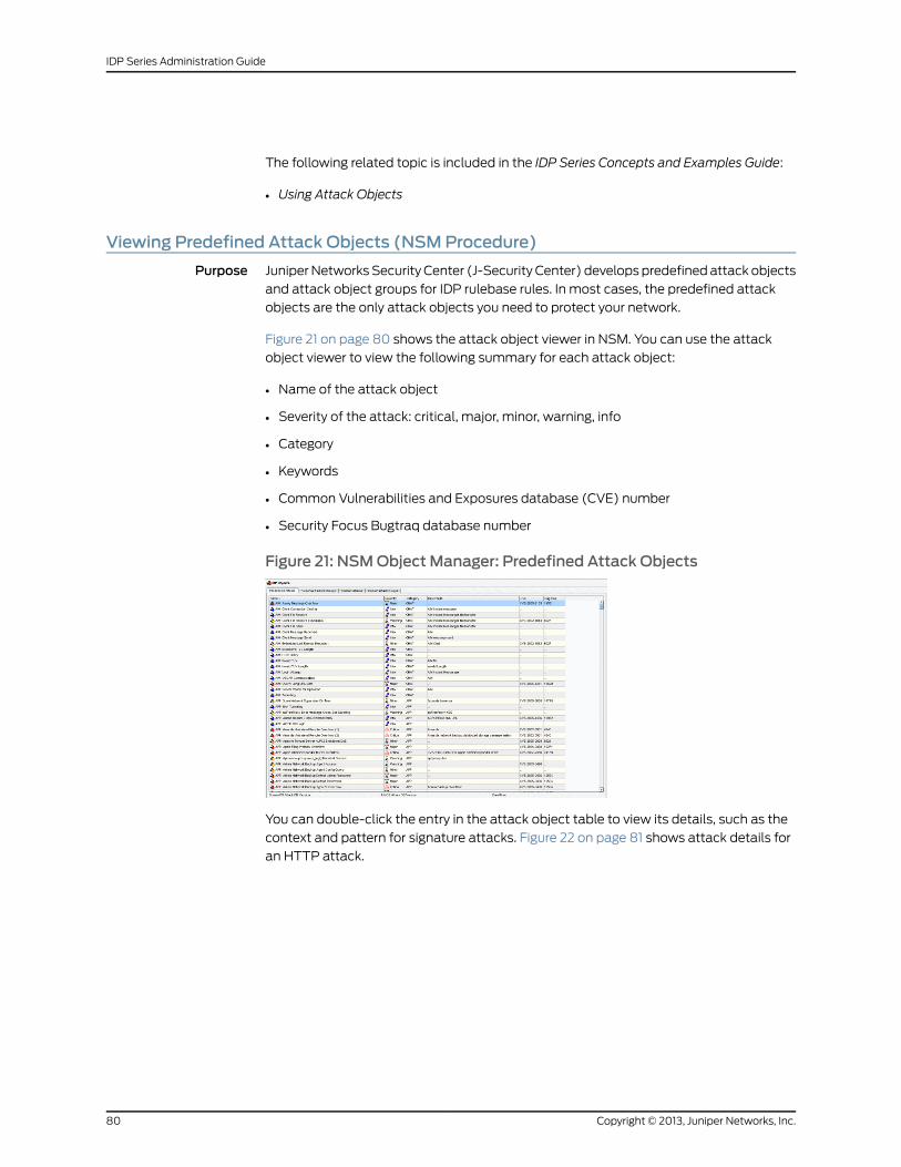
The following related topic is included in the IDP Series Concepts and Examples Guide:
• Using Attack Objects
Viewing Predefined Attack Objects (NSMProcedure)
Purpose Juniper Networks Security Center (J-Security Center) develops predefined attack objects
and attack object groups for IDP rulebase rules. In most cases, the predefined attack
objects are the only attack objects you need to protect your network.
Figure 21 on page 80 shows the attack object viewer in NSM. You can use the attack
object viewer to view the following summary for each attack object:
• Name of the attack object
• Severity of the attack: critical, major, minor, warning, info
• Category
• Keywords
• Common Vulnerabilities and Exposures database (CVE) number
• Security Focus Bugtraq database number
Figure 21: NSMObject Manager: Predefined Attack Objects
You can double-click the entry in the attack object table to view its details, such as the
context and pattern for signature attacks. Figure 22 on page 81 shows attack details for
an HTTP attack.
Copyright © 2013, Juniper Networks, Inc.80
IDP Series Administration Guide
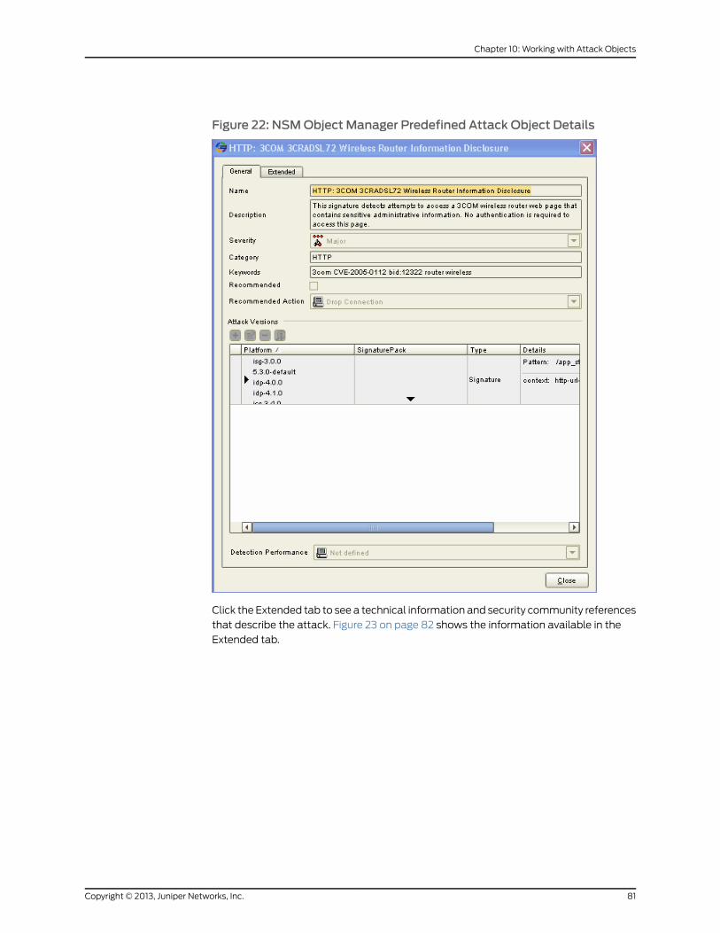
Figure 22: NSMObject Manager Predefined Attack Object Details
Click the Extended tab to see a technical information and security community references
that describe the attack. Figure 23 on page 82 shows the information available in the
Extended tab.
81Copyright © 2013, Juniper Networks, Inc.
Chapter 10: Working with Attack Objects
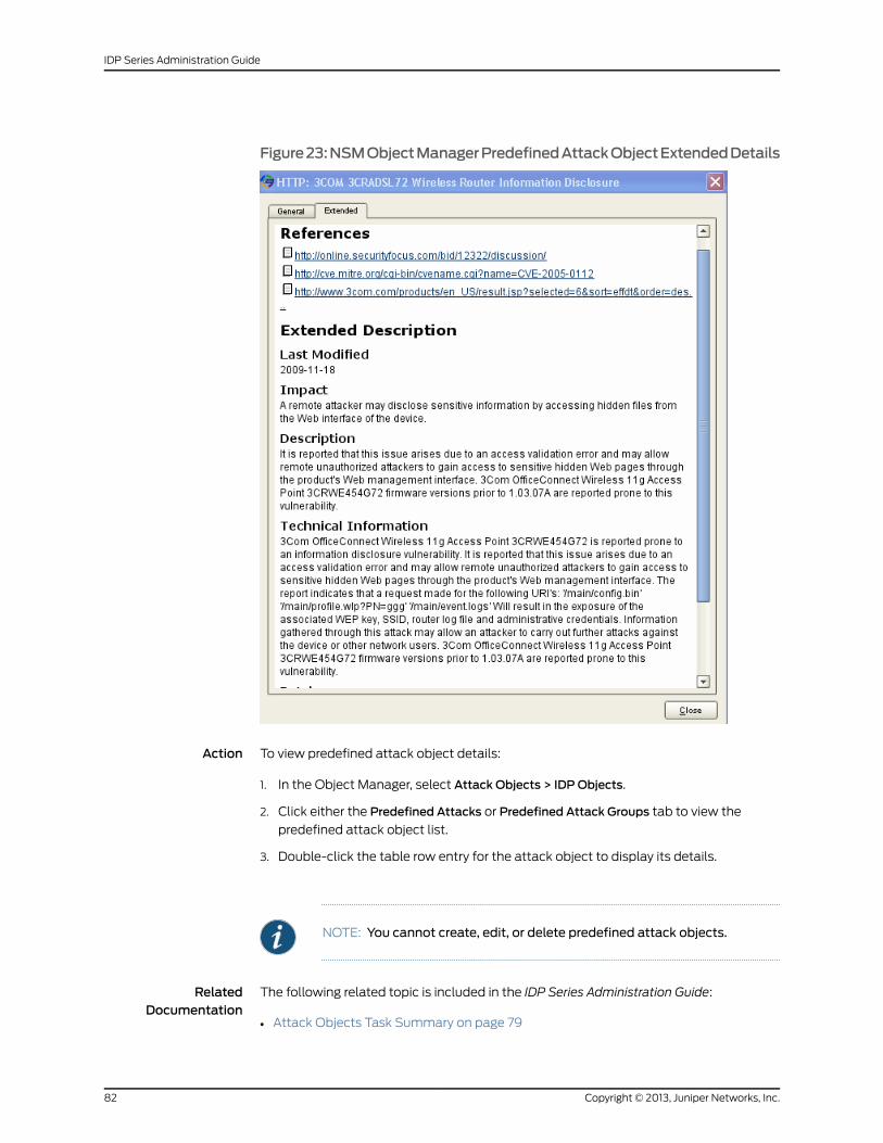
Figure23:NSMObjectManagerPredefinedAttackObjectExtendedDetails
Action To view predefined attack object details:
1. In the Object Manager, select Attack Objects > IDPObjects.
2. Click either the Predefined Attacks or Predefined Attack Groups tab to view the
predefined attack object list.
3. Double-click the table row entry for the attack object to display its details.
NOTE: You cannot create, edit, or delete predefined attack objects.
RelatedDocumentation
The following related topic is included in the IDP Series Administration Guide:
Attack Objects Task Summary on page 79•
Copyright © 2013, Juniper Networks, Inc.82
IDP Series Administration Guide
The following related topic is included in the IDP Series Concepts and Examples Guide:
• Using Attack Objects
Working with Attack Groups (NSMProcedure)
NSM groups are administrative objects that facilitate configuration and monitoring tasks.
You can add attack groups or individual attack objects to IDP rulebase rules and Exempt
rulebase rules.
This section includes the following topics:
• Creating Dynamic Groups on page 83
• Creating Static Groups on page 84
Creating Dynamic Groups
A dynamic group contains attack objects that are automatically added or deleted based
on specified criteria for the group. The NSM Object Manager includes predefined dynamic
groups that work with recommended attack objects, predefined attack objects, the
recommended security policy, and predefined policy templates.
When you run an NSM attack database update job, the process automatically performs
the following tasks:
• For all new attack objects, compares the predefined attributes of each attack object
to each dynamic group criteria and adds the attack objects that match.
• For all updated attack objects, determines if they meet dynamic group criteria and
adds or removes them, as appropriate.
• For all deleted attack objects, removes the attack objects from their dynamic groups.
Use of dynamic groups eliminates the need to review each new signature to determine
if you need to use it in your existing security policy.
A predefined or custom dynamic group can contain only attack objects and not attack
groups. Dynamic group members can be either predefined or custom attack objects.
To create a custom dynamic group:
1. In Object Manager, select Attack Objects > IDPObjects to display the IDP Objects
dialog box.
2. Click the CustomAttack Groups tab, then click the + icon and select Add Dynamic
Group to display the New Dynamic Group dialog box.
3. Enter a name and description for the static group. Select a color for the group icon.
4. In the Filters tab, click the + icon and add select filters as described in
Table 38 on page 84.
83Copyright © 2013, Juniper Networks, Inc.
Chapter 10: Working with Attack Objects
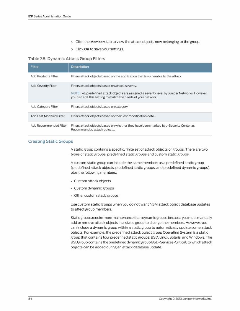
5. Click the Members tab to view the attack objects now belonging to the group.
6. Click OK to save your settings.
Table 38: Dynamic Attack Group Filters
DescriptionFilter
Filters attack objects based on the application that is vulnerable to the attack.Add Products Filter
Filters attack objects based on attack severity.
NOTE: All predefined attack objects are assigned a severity level by Juniper Networks. However,you can edit this setting to match the needs of your network.
Add Severity Filter
Filters attack objects based on category.Add Category Filter
Filters attack objects based on their last modification date.Add Last Modified Filter
Filters attack objects based on whether they have been marked by J-Security Center asRecommended attack objects.
Add Recommended Filter
Creating Static Groups
A static group contains a specific, finite set of attack objects or groups. There are two
types of static groups: predefined static groups and custom static groups.
A custom static group can include the same members as a predefined static group
(predefined attack objects, predefined static groups, and predefined dynamic groups),
plus the following members:
• Custom attack objects
• Custom dynamic groups
• Other custom static groups
Use custom static groups when you do not want NSM attack object database updates
to affect group members.
Static groups require more maintenance than dynamic groups because you must manually
add or remove attack objects in a static group to change the members. However, you
can include a dynamic group within a static group to automatically update some attack
objects. For example, the predefined attack object group Operating System is a static
group that contains four predefined static groups: BSD, Linux, Solaris, and Windows. The
BSD group contains the predefined dynamic group BSD-Services-Critical, to which attack
objects can be added during an attack database update.
Copyright © 2013, Juniper Networks, Inc.84
IDP Series Administration Guide
To create a custom static group:
1. In Object Manager, select Attack Objects > IDPObjects to display the IDP Objects
dialog box.
2. Click the CustomAttack Groups tab, then click the + icon and select Add Static Group
to display the New Static Group dialog box.
3. Enter a name and description for the static group.
4. Select a color for the group icon.
5. Select the attack or group from the Attacks/Group list and click Add .
6. Click OK.
RelatedDocumentation
The following related topic is included in the IDP Series Administration Guide:
Attack Objects Task Summary on page 79•
The following related topic is included in the IDP Series Concepts and Examples Guide:
• Using Attack Objects
Creating a Signature Attack Object
A signature attack object is a pattern you want the system to detect. You use a DFA
expression to represent the pattern. All of the other signature properties you can set
(such as service or protocol context, direction, and other constraints) are provided so
you can optimize performance of the system in detecting the pattern and eliminate false
positives. In general, you want to tune settings of a signature attack object so that the
system looks for it in every context where it might occur and in no other context.
To configure a signature attack object:
1. In the Object Manager, select Attack Objects > IDPObjects.
2. Click the CustomAttacks tab.
3. Click the + icon to display the Custom Attack dialog box.
4. Configure attack object settings. Figure 24 on page 86 shows the General tab.
Table 39 on page 86 provides guidelines for completing the settings.
85Copyright © 2013, Juniper Networks, Inc.
Chapter 10: Working with Attack Objects
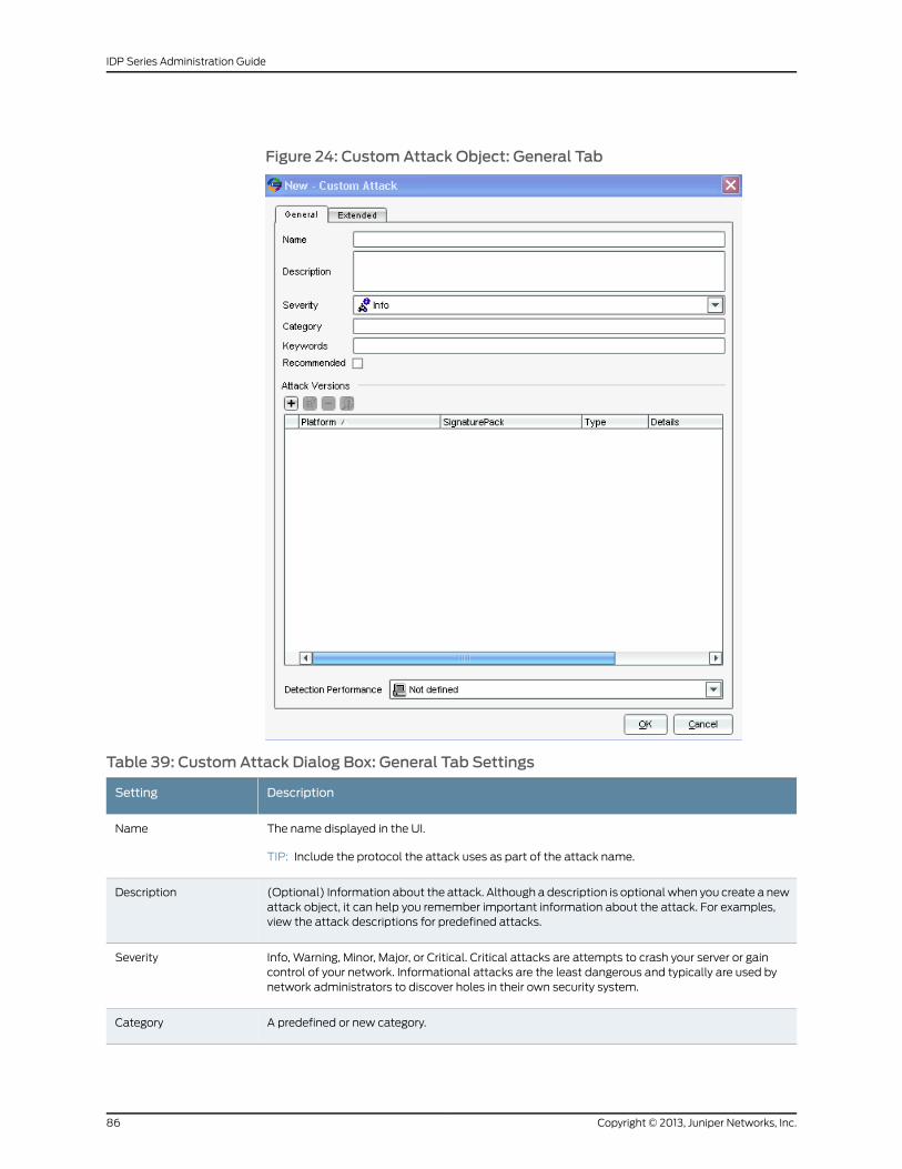
Figure 24: CustomAttack Object: General Tab
Table 39: CustomAttack Dialog Box: General Tab Settings
DescriptionSetting
The name displayed in the UI.
TIP: Include the protocol the attack uses as part of the attack name.
Name
(Optional) Information about the attack. Although a description is optional when you create a newattack object, it can help you remember important information about the attack. For examples,view the attack descriptions for predefined attacks.
Description
Info, Warning, Minor, Major, or Critical. Critical attacks are attempts to crash your server or gaincontrol of your network. Informational attacks are the least dangerous and typically are used bynetwork administrators to discover holes in their own security system.
Severity
A predefined or new category.Category
Copyright © 2013, Juniper Networks, Inc.86
IDP Series Administration Guide
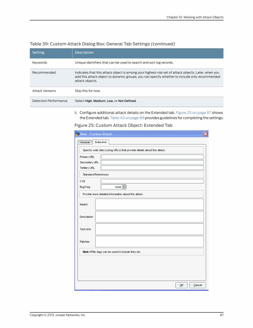
Table 39: CustomAttack Dialog Box: General Tab Settings (continued)
DescriptionSetting
Unique identifiers that can be used to search and sort log records.Keywords
Indicates that this attack object is among your highest-risk set of attack objects. Later, when youadd this attack object to dynamic groups, you can specify whether to include only recommendedattack objects.
Recommended
Skip this for now.Attack Versions
Select High, Medium, Low, or Not Defined.Detection Performance
5. Configure additional attack details on the Extended tab. Figure 25 on page 87 shows
the Extended tab. Table 40 on page 88 provides guidelines for completing the settings.
Figure 25: CustomAttack Object: Extended Tab
87Copyright © 2013, Juniper Networks, Inc.
Chapter 10: Working with Attack Objects
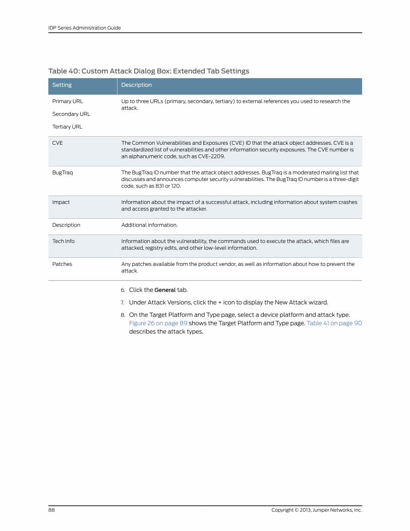
Table 40: CustomAttack Dialog Box: Extended Tab Settings
DescriptionSetting
Up to three URLs (primary, secondary, tertiary) to external references you used to research theattack.
Primary URL
Secondary URL
Tertiary URL
The Common Vulnerabilities and Exposures (CVE) ID that the attack object addresses. CVE is astandardized list of vulnerabilities and other information security exposures. The CVE number isan alphanumeric code, such as CVE-2209.
CVE
The BugTraq ID number that the attack object addresses. BugTraq is a moderated mailing list thatdiscusses and announces computer security vulnerabilities. The BugTraq ID number is a three-digitcode, such as 831 or 120.
BugTraq
Information about the impact of a successful attack, including information about system crashesand access granted to the attacker.
Impact
Additional information.Description
Information about the vulnerability, the commands used to execute the attack, which files areattacked, registry edits, and other low-level information.
Tech Info
Any patches available from the product vendor, as well as information about how to prevent theattack.
Patches
6. Click the General tab.
7. Under Attack Versions, click the + icon to display the New Attack wizard.
8. On the Target Platform and Type page, select a device platform and attack type.
Figure 26 on page 89 shows the Target Platform and Type page. Table 41 on page 90
describes the attack types.
Copyright © 2013, Juniper Networks, Inc.88
IDP Series Administration Guide
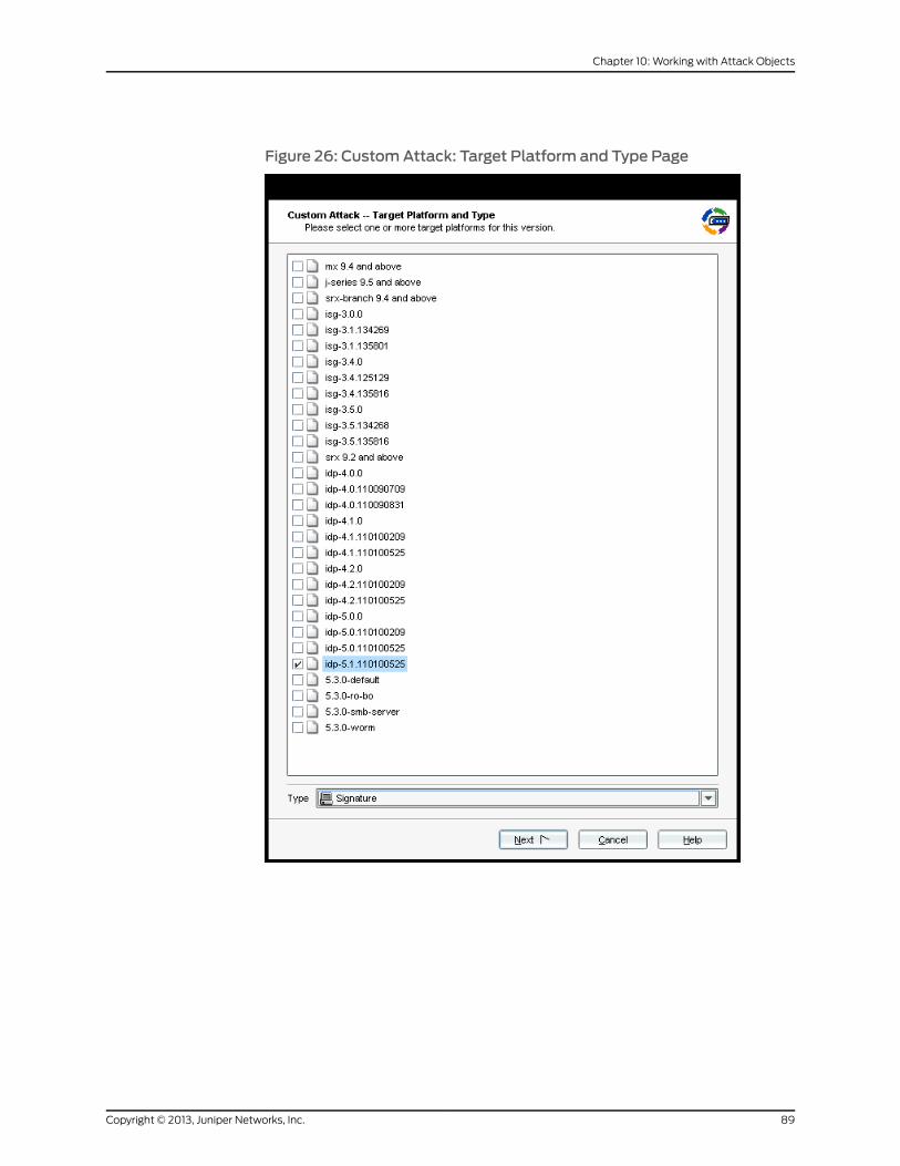
Figure 26: CustomAttack: Target Platform and Type Page
89Copyright © 2013, Juniper Networks, Inc.
Chapter 10: Working with Attack Objects
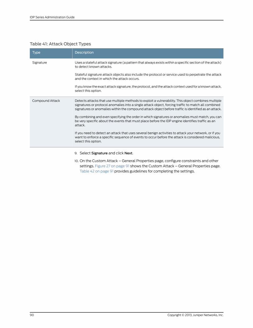
Table 41: Attack Object Types
DescriptionType
Uses a stateful attack signature (a pattern that always exists within a specific section of the attack)to detect known attacks.
Stateful signature attack objects also include the protocol or service used to perpetrate the attackand the context in which the attack occurs.
If you know the exact attack signature, the protocol, and the attack context used for a known attack,select this option.
Signature
Detects attacks that use multiple methods to exploit a vulnerability. This object combines multiplesignatures or protocol anomalies into a single attack object, forcing traffic to match all combinedsignatures or anomalies within the compound attack object before traffic is identified as an attack.
By combining and even specifying the order in which signatures or anomalies must match, you canbe very specific about the events that must place before the IDP engine identifies traffic as anattack.
If you need to detect an attack that uses several benign activities to attack your network, or if youwant to enforce a specific sequence of events to occur before the attack is considered malicious,select this option.
Compound Attack
9. Select Signature and click Next.
10. On the Custom Attack – General Properties page, configure constraints and other
settings. Figure 27 on page 91 shows the Custom Attack – General Properties page.
Table 42 on page 91 provides guidelines for completing the settings.
Copyright © 2013, Juniper Networks, Inc.90
IDP Series Administration Guide
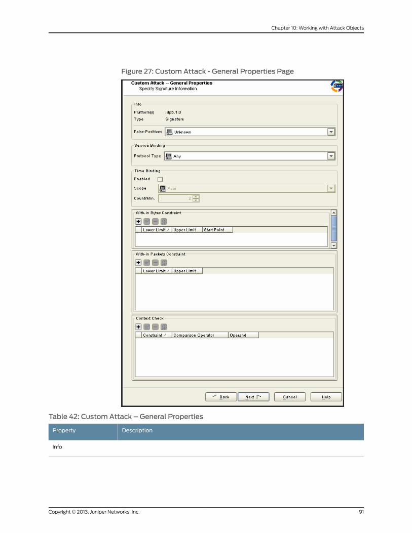
Figure 27: CustomAttack - General Properties Page
Table 42: CustomAttack – General Properties
DescriptionProperty
Info
91Copyright © 2013, Juniper Networks, Inc.
Chapter 10: Working with Attack Objects
Table 42: CustomAttack – General Properties (continued)
DescriptionProperty
Select the frequency that the attack object produces a false positive on your network: Unknown,Rarely, Occasionally, Frequently.
Typically, you do not initially know the frequency of false positives. You can update this setting asyour observations change.
False Positives
Service Binding
Service–If you were able to determine the service through your research, select Service. Later in thewizard, you can specify a service context.
Protocol Type
IP–If you are not sure of the service but you know IP details, select IP and specify a protocol typenumber.
TCP, UDP, or ICMP–If you do not know the service context but you know protocol details, selectthe protocol.
For TCP and UDP protocol types, specify the port ranges.
RPC–If you are detecting threats over remote procedure call (RPC) protocol, select this option andspecify the program ID.
RPC is used by distributed processing applications to handle interaction between processesremotely. When a client makes a remote procedure call to an RPC server, the server replies with aremote program. Each remote program uses a different program number.
IPv6 or ICMPv6–Do not select these options. IDP Series devices do not support inspection of IPv6.
Any–If you are unsure of the correct service, select Any to match the signature in all services.Matching any service essentially turns off service binding and has a significant performance impact.Specify Any when you know that attacks are using multiple services to attack your network.
NOTE: You must select a service binding other than Any if you want to select a context for theattack.
Copyright © 2013, Juniper Networks, Inc.92
IDP Series Administration Guide
Table 42: CustomAttack – General Properties (continued)
Time Binding
Time binding attributes track how many times a signature is repeated. By configuring the scopeand count of an attack, you can detect a sequence of the same attacks over a period of time (oneminute) across sessions. This method is useful for detecting brute force attacks that attempt toguess authentication credentials or overwhelm system capacity to handle data.
Enable
Select the scope within which the count occurs:
• Source–Detects the signature in traffic from the source IP address for the specified number oftimes, regardless of the destination IP address.
• Destination–Detects the signature in traffic from the destination IP address for the specifiednumber of times, regardless of the source IP address.
• Peer–Detects the signature in traffic between source and destination IP addresses of the sessionsfor the specified number of times.
Scope
Enter the number of times per minute that the signature must be detected within the specifiedscope before the device identifies the traffic as a match.
The minute timer starts when the signature first matches the event. If the signature matches thesame event for the specific count or higher within the next 60 seconds, the traffic is a match.
The system increments the count each time it detects the signature, either regardless of port(application identification) or according to your port binding settings. For example, when the systemdetects the signature on TCP/80 and then on TCP/8080, the count is 2.
Count/Min
93Copyright © 2013, Juniper Networks, Inc.
Chapter 10: Working with Attack Objects
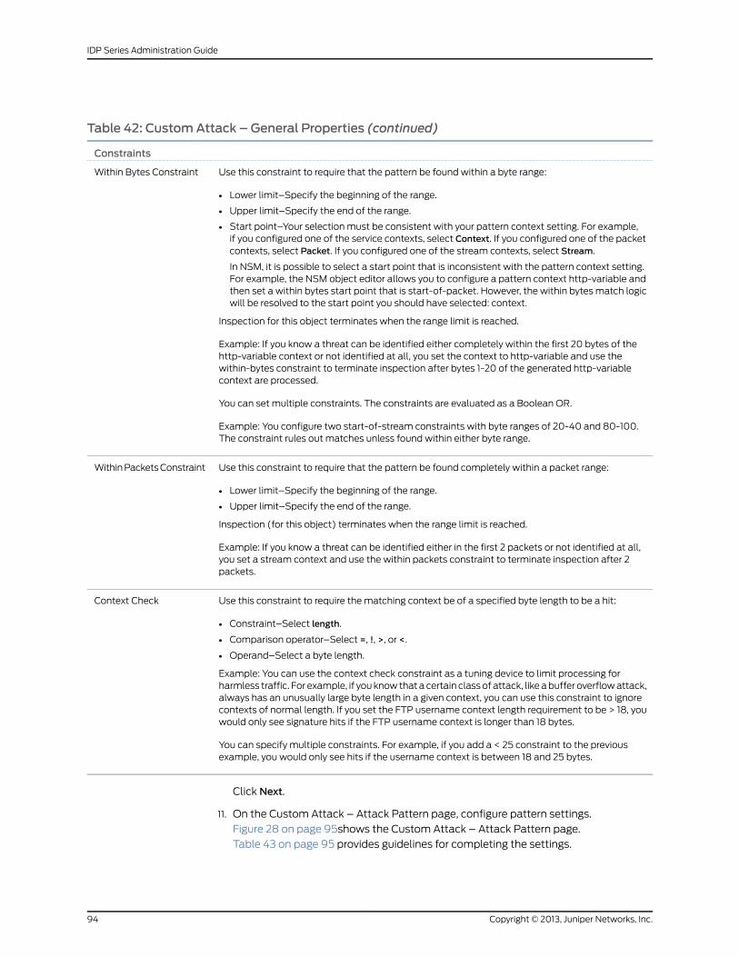
Table 42: CustomAttack – General Properties (continued)
Constraints
Use this constraint to require that the pattern be found within a byte range:
• Lower limit–Specify the beginning of the range.
• Upper limit–Specify the end of the range.
• Start point–Your selection must be consistent with your pattern context setting. For example,if you configured one of the service contexts, select Context. If you configured one of the packetcontexts, select Packet. If you configured one of the stream contexts, select Stream.
In NSM, it is possible to select a start point that is inconsistent with the pattern context setting.For example, the NSM object editor allows you to configure a pattern context http-variable andthen set a within bytes start point that is start-of-packet. However, the within bytes match logicwill be resolved to the start point you should have selected: context.
Inspection for this object terminates when the range limit is reached.
Example: If you know a threat can be identified either completely within the first 20 bytes of thehttp-variable context or not identified at all, you set the context to http-variable and use thewithin-bytes constraint to terminate inspection after bytes 1-20 of the generated http-variablecontext are processed.
You can set multiple constraints. The constraints are evaluated as a Boolean OR.
Example: You configure two start-of-stream constraints with byte ranges of 20-40 and 80-100.The constraint rules out matches unless found within either byte range.
Within Bytes Constraint
Use this constraint to require that the pattern be found completely within a packet range:
• Lower limit–Specify the beginning of the range.
• Upper limit–Specify the end of the range.
Inspection (for this object) terminates when the range limit is reached.
Example: If you know a threat can be identified either in the first 2 packets or not identified at all,you set a stream context and use the within packets constraint to terminate inspection after 2packets.
Within Packets Constraint
Use this constraint to require the matching context be of a specified byte length to be a hit:
• Constraint–Select length.
• Comparison operator–Select =, !, >, or <.
• Operand–Select a byte length.
Example: You can use the context check constraint as a tuning device to limit processing forharmless traffic. For example, if you know that a certain class of attack, like a buffer overflow attack,always has an unusually large byte length in a given context, you can use this constraint to ignorecontexts of normal length. If you set the FTP username context length requirement to be > 18, youwould only see signature hits if the FTP username context is longer than 18 bytes.
You can specify multiple constraints. For example, if you add a < 25 constraint to the previousexample, you would only see hits if the username context is between 18 and 25 bytes.
Context Check
Click Next.
11. On the Custom Attack – Attack Pattern page, configure pattern settings.
Figure 28 on page 95shows the Custom Attack – Attack Pattern page.
Table 43 on page 95 provides guidelines for completing the settings.
Copyright © 2013, Juniper Networks, Inc.94
IDP Series Administration Guide
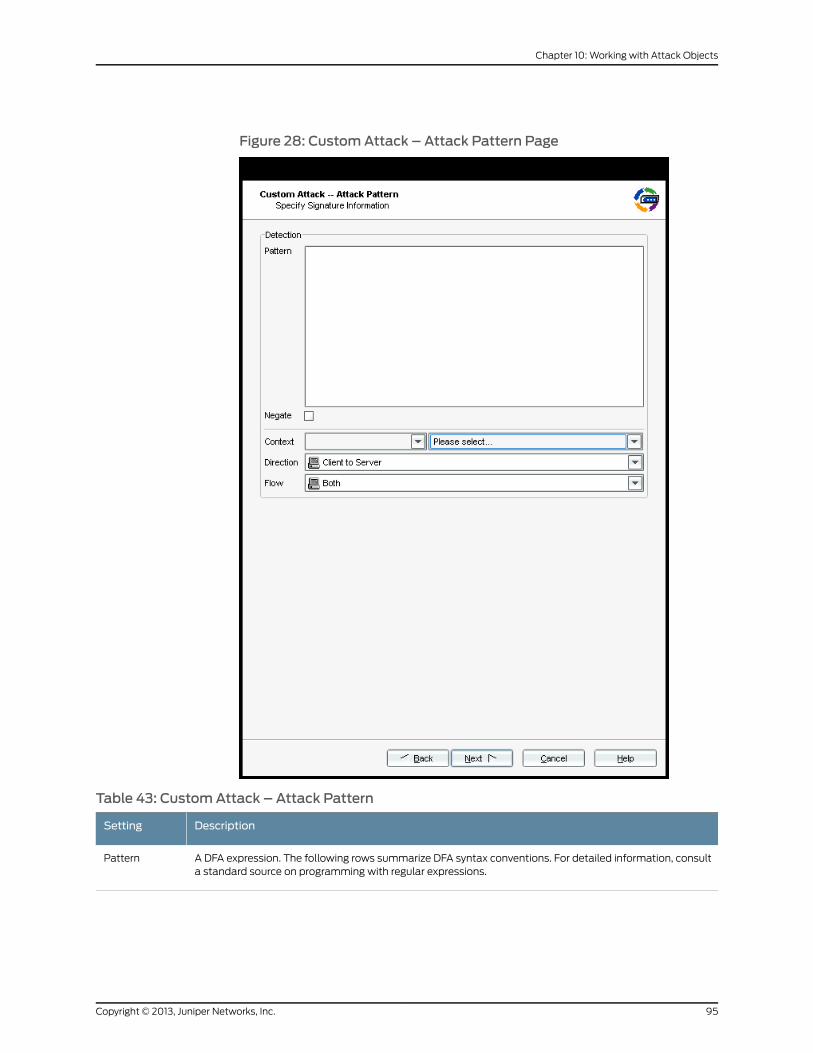
Figure 28: CustomAttack – Attack Pattern Page
Table 43: CustomAttack – Attack Pattern
DescriptionSetting
A DFA expression. The following rows summarize DFA syntax conventions. For detailed information, consulta standard source on programming with regular expressions.
Pattern
95Copyright © 2013, Juniper Networks, Inc.
Chapter 10: Working with Attack Objects
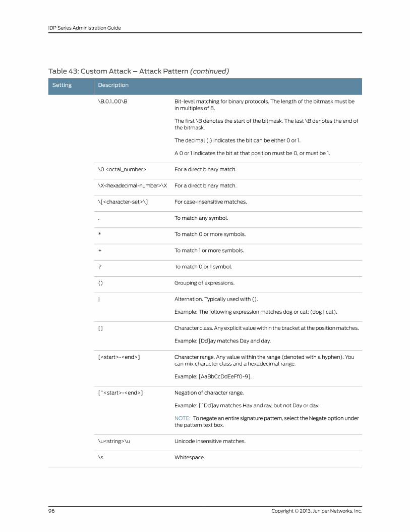
Table 43: CustomAttack – Attack Pattern (continued)
DescriptionSetting
Bit-level matching for binary protocols. The length of the bitmask must bein multiples of 8.
The first \B denotes the start of the bitmask. The last \B denotes the end ofthe bitmask.
The decimal (.) indicates the bit can be either 0 or 1.
A 0 or 1 indicates the bit at that position must be 0, or must be 1.
\B.0.1..00\B
For a direct binary match.\0 <octal_number>
For a direct binary match.\X<hexadecimal-number>\X
For case-insensitive matches.\[<character-set>\]
To match any symbol..
To match 0 or more symbols.*
To match 1 or more symbols.+
To match 0 or 1 symbol.?
Grouping of expressions.()
Alternation. Typically used with ().
Example: The following expression matches dog or cat: (dog | cat).
|
Character class. Any explicit value within the bracket at the position matches.
Example: [Dd]ay matches Day and day.
[]
Character range. Any value within the range (denoted with a hyphen). Youcan mix character class and a hexadecimal range.
Example: [AaBbCcDdEeFf0-9].
[<start>-<end>]
Negation of character range.
Example: [^Dd]ay matches Hay and ray, but not Day or day.
NOTE: To negate an entire signature pattern, select the Negate option underthe pattern text box.
[^<start>-<end>]
Unicode insensitive matches.\u<string>\u
Whitespace.\s
Copyright © 2013, Juniper Networks, Inc.96
IDP Series Administration Guide
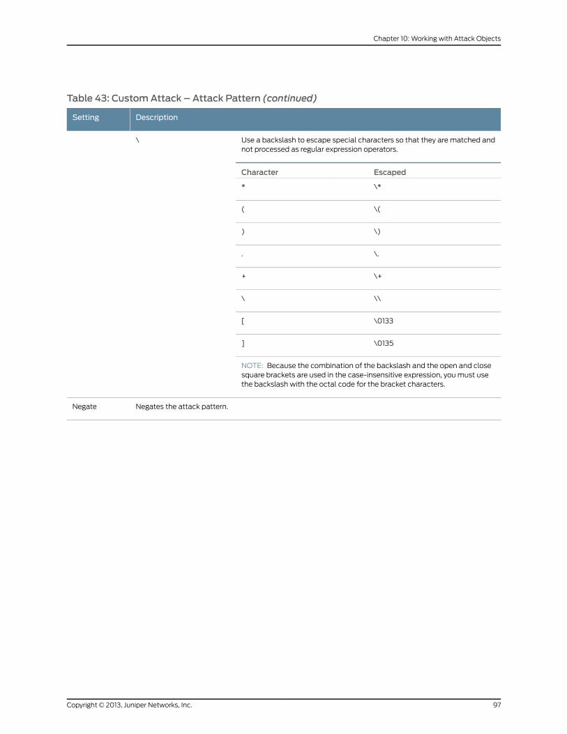
Table 43: CustomAttack – Attack Pattern (continued)
DescriptionSetting
Use a backslash to escape special characters so that they are matched andnot processed as regular expression operators.
\
EscapedCharacter
\**
\((
\))
\..
\++
\\\
\0133[
\0135]
NOTE: Because the combination of the backslash and the open and closesquare brackets are used in the case-insensitive expression, you must usethe backslash with the octal code for the bracket characters.
Negates the attack pattern.Negate
97Copyright © 2013, Juniper Networks, Inc.
Chapter 10: Working with Attack Objects
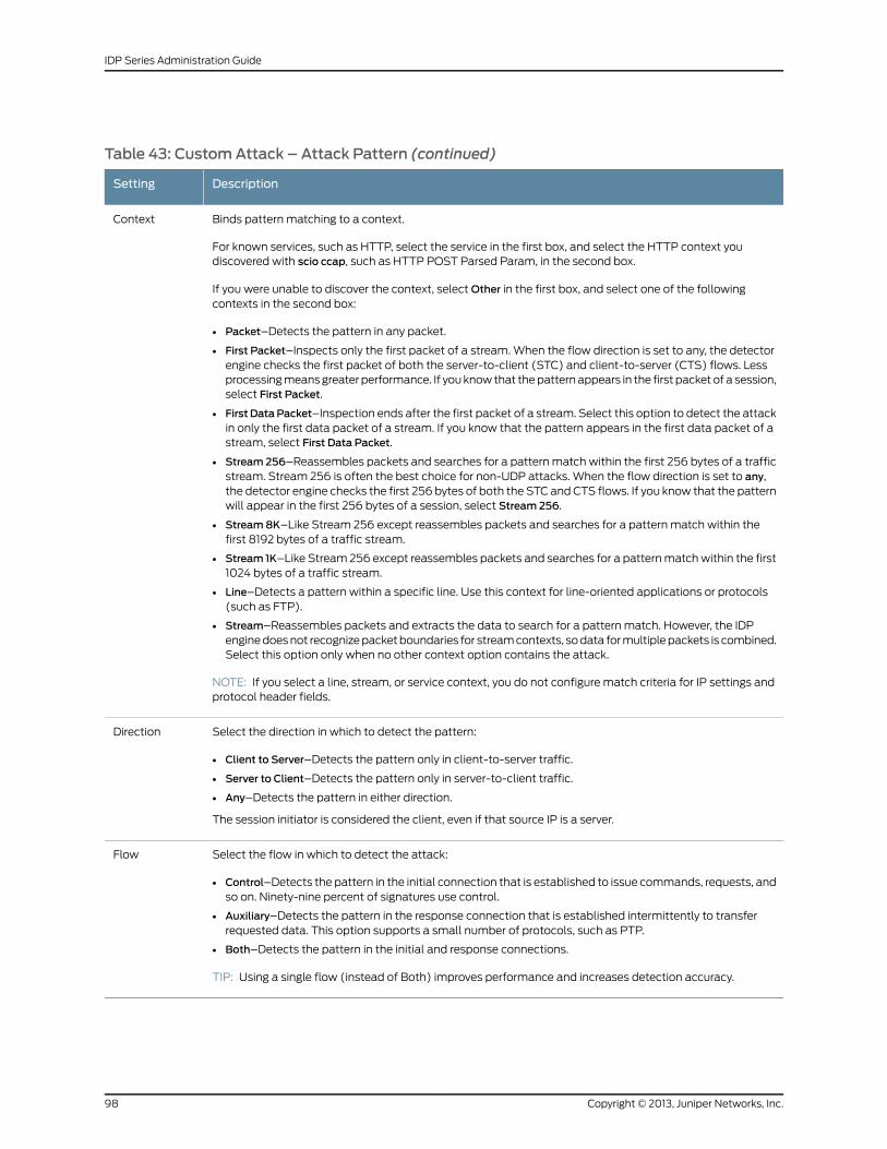
Table 43: CustomAttack – Attack Pattern (continued)
DescriptionSetting
Binds pattern matching to a context.
For known services, such as HTTP, select the service in the first box, and select the HTTP context youdiscovered with scio ccap, such as HTTP POST Parsed Param, in the second box.
If you were unable to discover the context, select Other in the first box, and select one of the followingcontexts in the second box:
• Packet–Detects the pattern in any packet.
• First Packet–Inspects only the first packet of a stream. When the flow direction is set to any, the detectorengine checks the first packet of both the server-to-client (STC) and client-to-server (CTS) flows. Lessprocessing means greater performance. If you know that the pattern appears in the first packet of a session,select First Packet.
• First DataPacket–Inspection ends after the first packet of a stream. Select this option to detect the attackin only the first data packet of a stream. If you know that the pattern appears in the first data packet of astream, select First Data Packet.
• Stream 256–Reassembles packets and searches for a pattern match within the first 256 bytes of a trafficstream. Stream 256 is often the best choice for non-UDP attacks. When the flow direction is set to any,the detector engine checks the first 256 bytes of both the STC and CTS flows. If you know that the patternwill appear in the first 256 bytes of a session, select Stream 256.
• Stream8K–Like Stream 256 except reassembles packets and searches for a pattern match within thefirst 8192 bytes of a traffic stream.
• Stream 1K–Like Stream 256 except reassembles packets and searches for a pattern match within the first1024 bytes of a traffic stream.
• Line–Detects a pattern within a specific line. Use this context for line-oriented applications or protocols(such as FTP).
• Stream–Reassembles packets and extracts the data to search for a pattern match. However, the IDPengine does not recognize packet boundaries for stream contexts, so data for multiple packets is combined.Select this option only when no other context option contains the attack.
NOTE: If you select a line, stream, or service context, you do not configure match criteria for IP settings andprotocol header fields.
Context
Select the direction in which to detect the pattern:
• Client to Server–Detects the pattern only in client-to-server traffic.
• Server to Client–Detects the pattern only in server-to-client traffic.
• Any–Detects the pattern in either direction.
The session initiator is considered the client, even if that source IP is a server.
Direction
Select the flow in which to detect the attack:
• Control–Detects the pattern in the initial connection that is established to issue commands, requests, andso on. Ninety-nine percent of signatures use control.
• Auxiliary–Detects the pattern in the response connection that is established intermittently to transferrequested data. This option supports a small number of protocols, such as PTP.
• Both–Detects the pattern in the initial and response connections.
TIP: Using a single flow (instead of Both) improves performance and increases detection accuracy.
Flow
Copyright © 2013, Juniper Networks, Inc.98
IDP Series Administration Guide
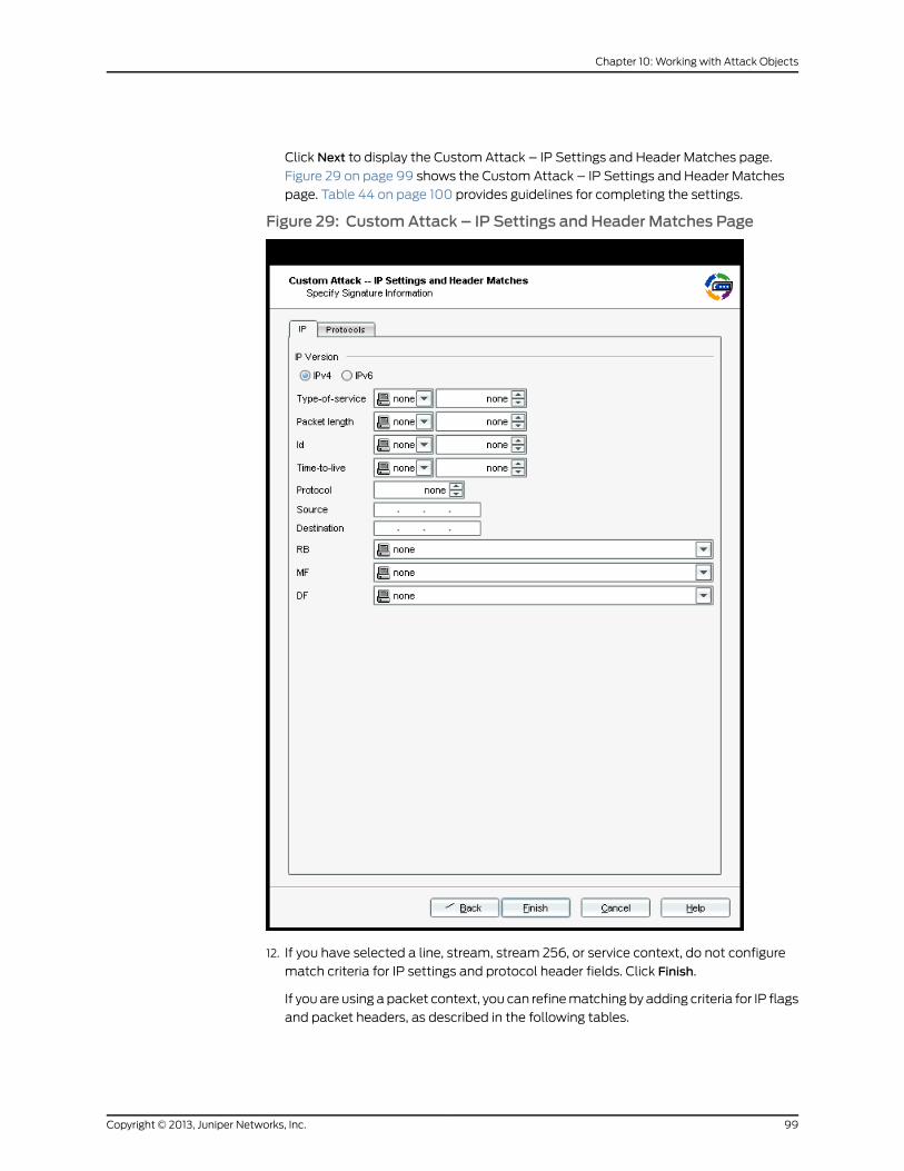
Click Next to display the Custom Attack – IP Settings and Header Matches page.
Figure 29 on page 99 shows the Custom Attack – IP Settings and Header Matches
page. Table 44 on page 100 provides guidelines for completing the settings.
Figure 29: CustomAttack – IP Settings and Header Matches Page
12. If you have selected a line, stream, stream 256, or service context, do not configure
match criteria for IP settings and protocol header fields. Click Finish.
If you are using a packet context, you can refine matching by adding criteria for IP flags
and packet headers, as described in the following tables.
99Copyright © 2013, Juniper Networks, Inc.
Chapter 10: Working with Attack Objects
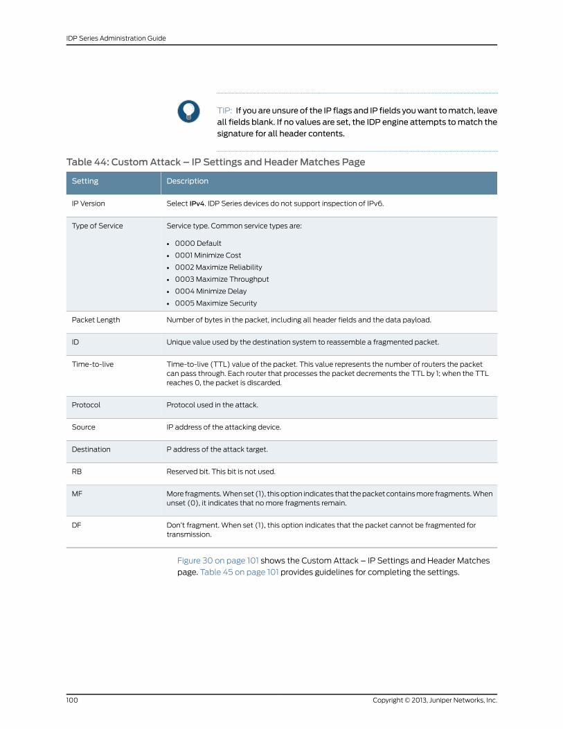
TIP: If you are unsure of the IP flags and IP fields youwant tomatch, leaveall fields blank. If no values are set, the IDP engine attempts tomatch thesignature for all header contents.
Table 44: CustomAttack – IP Settings and Header Matches Page
DescriptionSetting
Select IPv4. IDP Series devices do not support inspection of IPv6.IP Version
Service type. Common service types are:
• 0000 Default
• 0001 Minimize Cost
• 0002 Maximize Reliability
• 0003 Maximize Throughput
• 0004 Minimize Delay
• 0005 Maximize Security
Type of Service
Number of bytes in the packet, including all header fields and the data payload.Packet Length
Unique value used by the destination system to reassemble a fragmented packet.ID
Time-to-live (TTL) value of the packet. This value represents the number of routers the packetcan pass through. Each router that processes the packet decrements the TTL by 1; when the TTLreaches 0, the packet is discarded.
Time-to-live
Protocol used in the attack.Protocol
IP address of the attacking device.Source
P address of the attack target.Destination
Reserved bit. This bit is not used.RB
More fragments. When set (1), this option indicates that the packet contains more fragments. Whenunset (0), it indicates that no more fragments remain.
MF
Don’t fragment. When set (1), this option indicates that the packet cannot be fragmented fortransmission.
DF
Figure 30 on page 101 shows the Custom Attack – IP Settings and Header Matches
page. Table 45 on page 101 provides guidelines for completing the settings.
Copyright © 2013, Juniper Networks, Inc.100
IDP Series Administration Guide
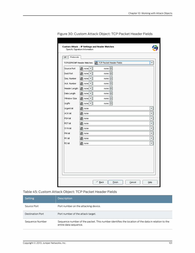
Figure 30: CustomAttack Object: TCP Packet Header Fields
Table 45: CustomAttack Object: TCP Packet Header Fields
DescriptionSetting
Port number on the attacking device.Source Port
Port number of the attack target.Destination Port
Sequence number of the packet. This number identifies the location of the data in relation to theentire data sequence.
Sequence Number
101Copyright © 2013, Juniper Networks, Inc.
Chapter 10: Working with Attack Objects
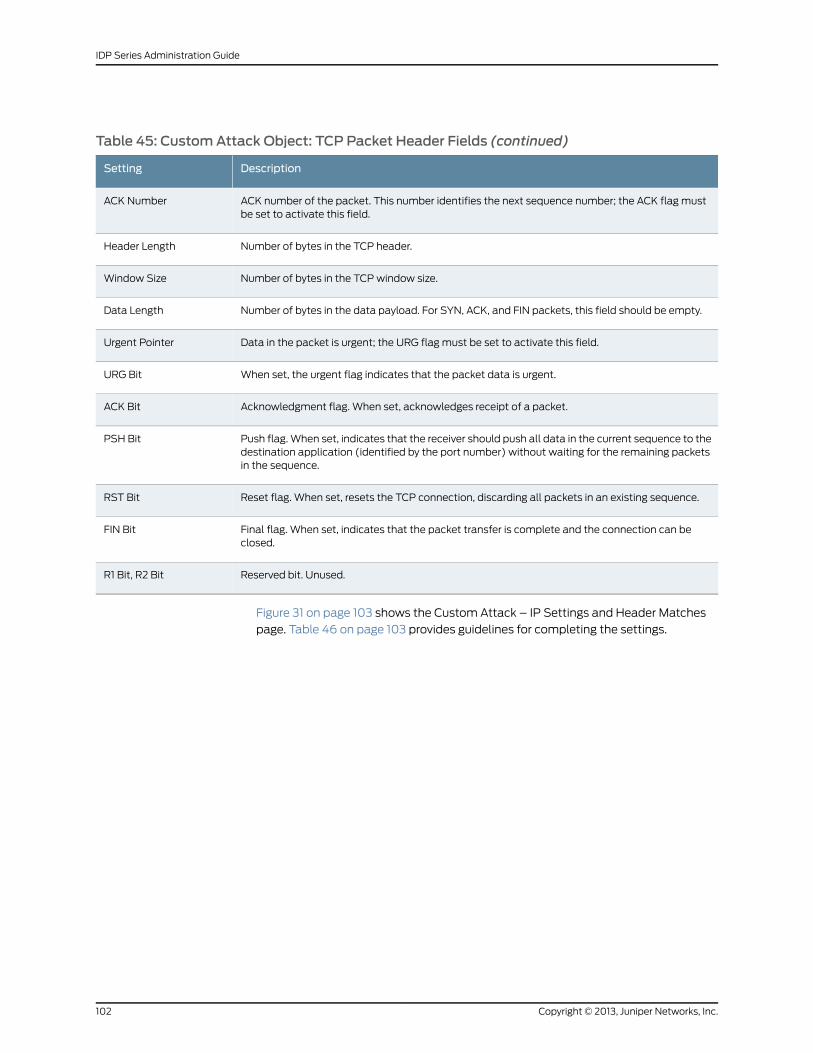
Table 45: CustomAttack Object: TCP Packet Header Fields (continued)
DescriptionSetting
ACK number of the packet. This number identifies the next sequence number; the ACK flag mustbe set to activate this field.
ACK Number
Number of bytes in the TCP header.Header Length
Number of bytes in the TCP window size.Window Size
Number of bytes in the data payload. For SYN, ACK, and FIN packets, this field should be empty.Data Length
Data in the packet is urgent; the URG flag must be set to activate this field.Urgent Pointer
When set, the urgent flag indicates that the packet data is urgent.URG Bit
Acknowledgment flag. When set, acknowledges receipt of a packet.ACK Bit
Push flag. When set, indicates that the receiver should push all data in the current sequence to thedestination application (identified by the port number) without waiting for the remaining packetsin the sequence.
PSH Bit
Reset flag. When set, resets the TCP connection, discarding all packets in an existing sequence.RST Bit
Final flag. When set, indicates that the packet transfer is complete and the connection can beclosed.
FIN Bit
Reserved bit. Unused.R1 Bit, R2 Bit
Figure 31 on page 103 shows the Custom Attack – IP Settings and Header Matches
page. Table 46 on page 103 provides guidelines for completing the settings.
Copyright © 2013, Juniper Networks, Inc.102
IDP Series Administration Guide

Figure 31: CustomAttack Object: UDP Packet Header Fields
Table 46: CustomAttack Object: UDPHeader Fields
DescriptionSetting
Port number on the attacking device.Source Port
Port number of the attack target.Destination Port
Number of bytes in the data payload.Data Length
103Copyright © 2013, Juniper Networks, Inc.
Chapter 10: Working with Attack Objects
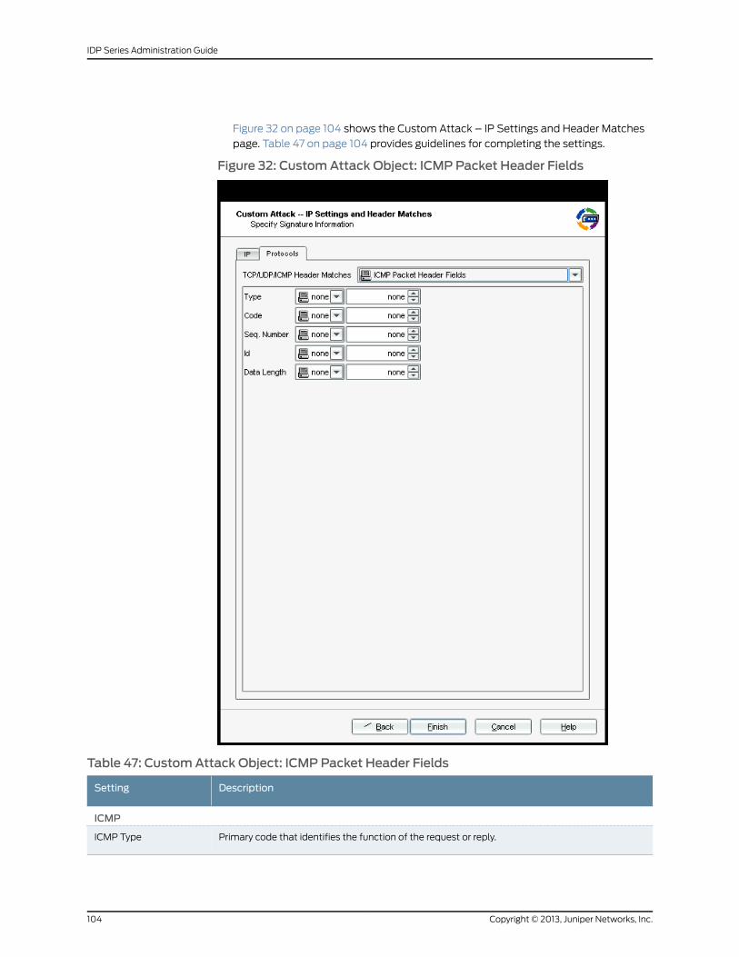
Figure 32 on page 104 shows the Custom Attack – IP Settings and Header Matches
page. Table 47 on page 104 provides guidelines for completing the settings.
Figure 32: CustomAttack Object: ICMP Packet Header Fields
Table 47: CustomAttack Object: ICMP Packet Header Fields
DescriptionSetting
ICMP
Primary code that identifies the function of the request or reply.ICMP Type
Copyright © 2013, Juniper Networks, Inc.104
IDP Series Administration Guide
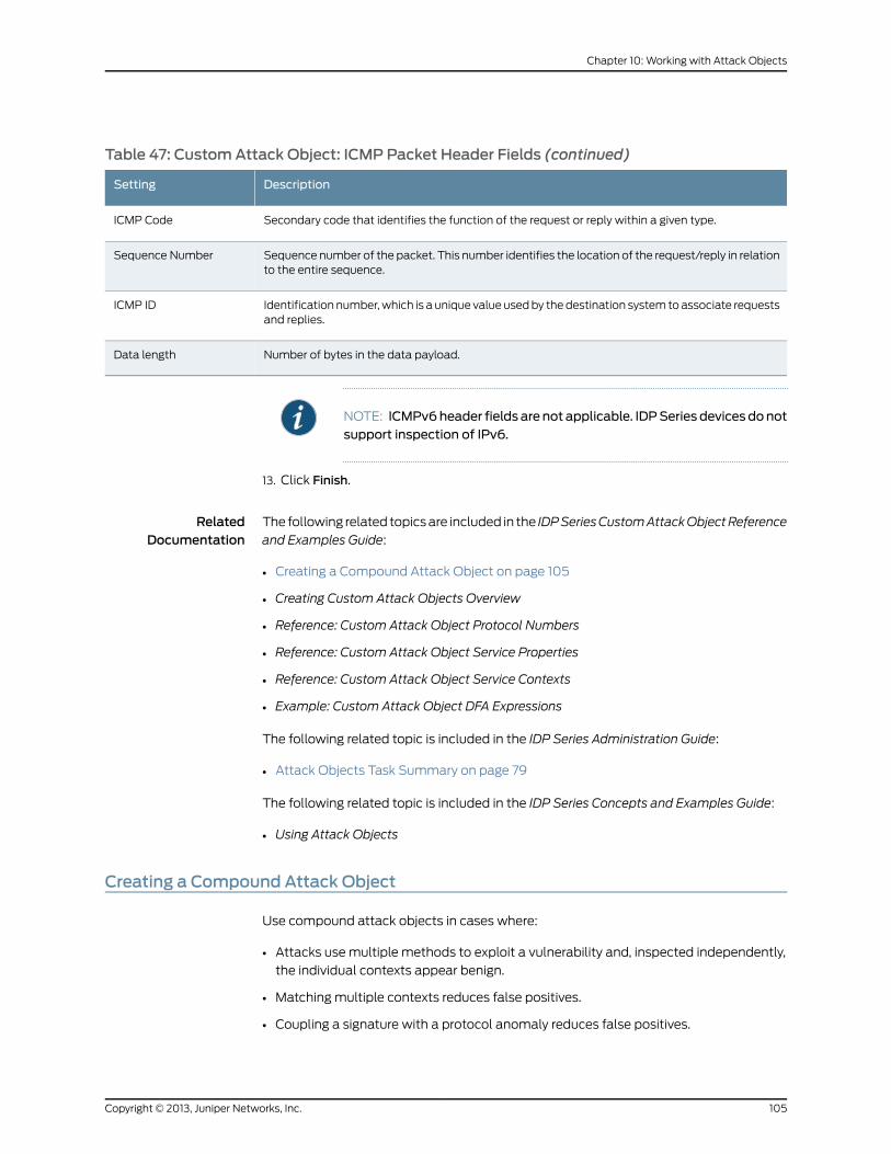
Table 47: CustomAttack Object: ICMP Packet Header Fields (continued)
DescriptionSetting
Secondary code that identifies the function of the request or reply within a given type.ICMP Code
Sequence number of the packet. This number identifies the location of the request/reply in relationto the entire sequence.
Sequence Number
Identification number, which is a unique value used by the destination system to associate requestsand replies.
ICMP ID
Number of bytes in the data payload.Data length
NOTE: ICMPv6header fields are not applicable. IDPSeries devicesdonotsupport inspection of IPv6.
13. Click Finish.
RelatedDocumentation
The following related topics are included in the IDPSeriesCustomAttackObjectReference
and Examples Guide:
• Creating a Compound Attack Object on page 105
• Creating Custom Attack Objects Overview
• Reference: Custom Attack Object Protocol Numbers
• Reference: Custom Attack Object Service Properties
• Reference: Custom Attack Object Service Contexts
• Example: Custom Attack Object DFA Expressions
The following related topic is included in the IDP Series Administration Guide:
• Attack Objects Task Summary on page 79
The following related topic is included in the IDP Series Concepts and Examples Guide:
• Using Attack Objects
Creating a Compound Attack Object
Use compound attack objects in cases where:
• Attacks use multiple methods to exploit a vulnerability and, inspected independently,
the individual contexts appear benign.
• Matching multiple contexts reduces false positives.
• Coupling a signature with a protocol anomaly reduces false positives.
105Copyright © 2013, Juniper Networks, Inc.
Chapter 10: Working with Attack Objects
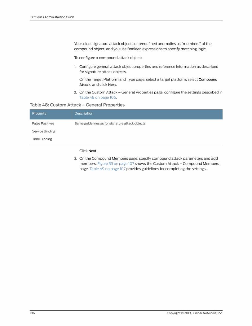
You select signature attack objects or predefined anomalies as “members” of the
compound object, and you use Boolean expressions to specify matching logic.
To configure a compound attack object:
1. Configure general attack object properties and reference information as described
for signature attack objects.
On the Target Platform and Type page, select a target platform, select Compound
Attack, and click Next.
2. On the Custom Attack – General Properties page, configure the settings described in
Table 48 on page 106.
Table 48: CustomAttack – General Properties
DescriptionProperty
Same guidelines as for signature attack objects.False Positives
Service Binding
Time Binding
Click Next.
3. On the Compound Members page, specify compound attack parameters and add
members. Figure 33 on page 107 shows the Custom Attack – Compound Members
page. Table 49 on page 107 provides guidelines for completing the settings.
Copyright © 2013, Juniper Networks, Inc.106
IDP Series Administration Guide
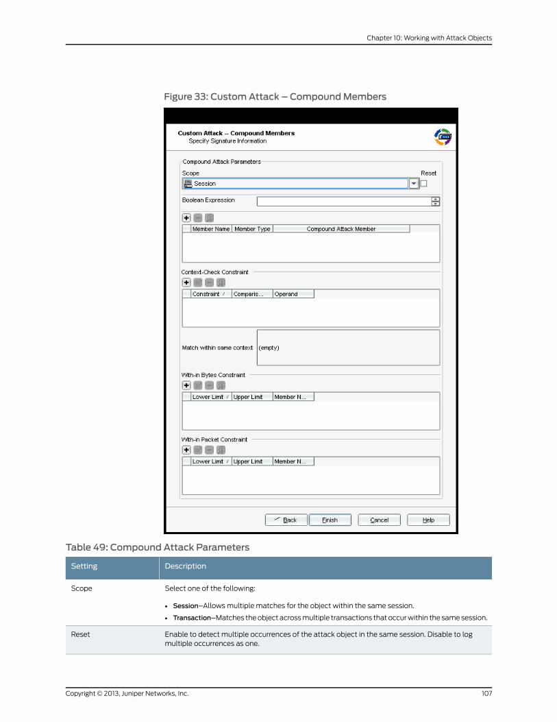
Figure 33: CustomAttack – CompoundMembers
Table 49: Compound Attack Parameters
DescriptionSetting
Select one of the following:
• Session–Allows multiple matches for the object within the same session.
• Transaction–Matches the object across multiple transactions that occur within the same session.
Scope
Enable to detect multiple occurrences of the attack object in the same session. Disable to logmultiple occurrences as one.
Reset
107Copyright © 2013, Juniper Networks, Inc.
Chapter 10: Working with Attack Objects
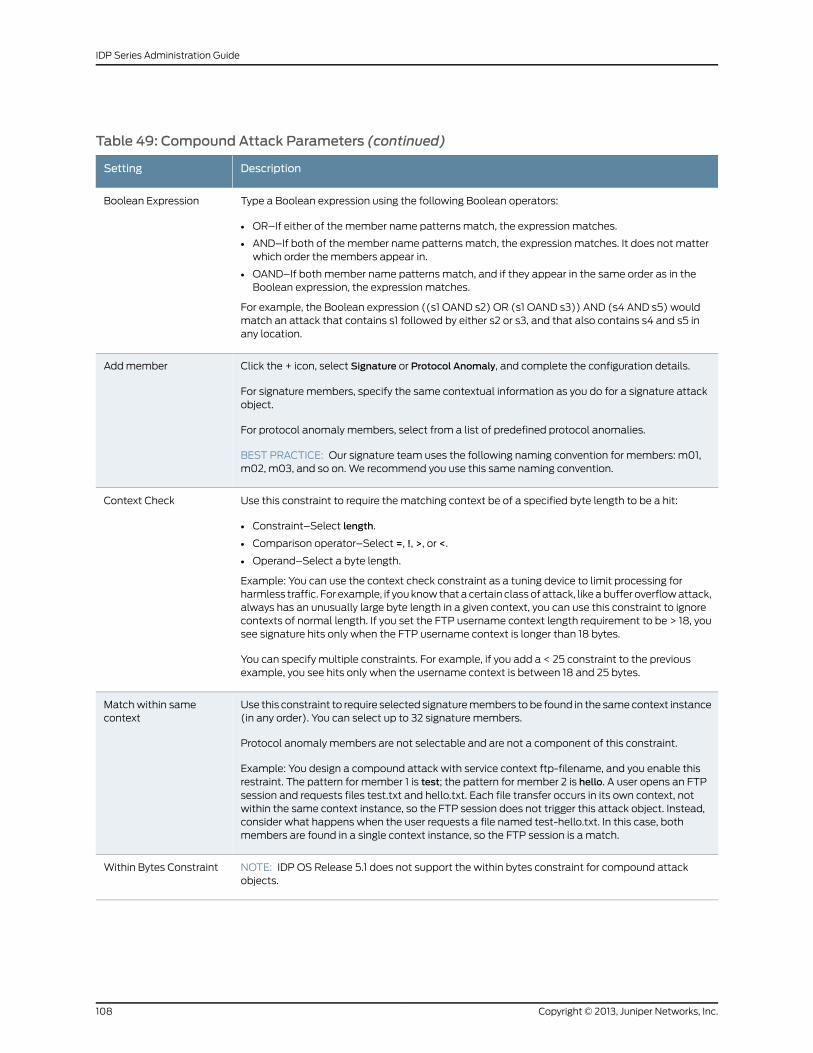
Table 49: Compound Attack Parameters (continued)
DescriptionSetting
Type a Boolean expression using the following Boolean operators:
• OR–If either of the member name patterns match, the expression matches.
• AND–If both of the member name patterns match, the expression matches. It does not matterwhich order the members appear in.
• OAND–If both member name patterns match, and if they appear in the same order as in theBoolean expression, the expression matches.
For example, the Boolean expression ((s1 OAND s2) OR (s1 OAND s3)) AND (s4 AND s5) wouldmatch an attack that contains s1 followed by either s2 or s3, and that also contains s4 and s5 inany location.
Boolean Expression
Click the + icon, select Signature or Protocol Anomaly, and complete the configuration details.
For signature members, specify the same contextual information as you do for a signature attackobject.
For protocol anomaly members, select from a list of predefined protocol anomalies.
BEST PRACTICE: Our signature team uses the following naming convention for members: m01,m02, m03, and so on. We recommend you use this same naming convention.
Add member
Use this constraint to require the matching context be of a specified byte length to be a hit:
• Constraint–Select length.
• Comparison operator–Select =, !, >, or <.
• Operand–Select a byte length.
Example: You can use the context check constraint as a tuning device to limit processing forharmless traffic. For example, if you know that a certain class of attack, like a buffer overflow attack,always has an unusually large byte length in a given context, you can use this constraint to ignorecontexts of normal length. If you set the FTP username context length requirement to be > 18, yousee signature hits only when the FTP username context is longer than 18 bytes.
You can specify multiple constraints. For example, if you add a < 25 constraint to the previousexample, you see hits only when the username context is between 18 and 25 bytes.
Context Check
Use this constraint to require selected signature members to be found in the same context instance(in any order). You can select up to 32 signature members.
Protocol anomaly members are not selectable and are not a component of this constraint.
Example: You design a compound attack with service context ftp-filename, and you enable thisrestraint. The pattern for member 1 is test; the pattern for member 2 is hello. A user opens an FTPsession and requests files test.txt and hello.txt. Each file transfer occurs in its own context, notwithin the same context instance, so the FTP session does not trigger this attack object. Instead,consider what happens when the user requests a file named test-hello.txt. In this case, bothmembers are found in a single context instance, so the FTP session is a match.
Match within samecontext
NOTE: IDP OS Release 5.1 does not support the within bytes constraint for compound attackobjects.
Within Bytes Constraint
Copyright © 2013, Juniper Networks, Inc.108
IDP Series Administration Guide
Table 49: Compound Attack Parameters (continued)
DescriptionSetting
Use this constraint to require that the pattern be found completely within a packet range of astream:
• Lower limit–Specify the beginning of the range.
• Upper limit–Specify the end of the range.
• Member–Select one or two members. You cannot configure a relationship for more than twomembers.
If you set a packet constraint for one member, the program logic counts packets beginning withthe start-of-stream. The member must be found completely within the packet range indicated.
If you select two members and apply a packet constraint to them, the program logic counts thefirst match as packet 0. If you specify a range of 1-2 with member 1 and member 2, the secondpattern must occur within one or two packets from the packet containing the first match.Specifying 0-1 requires the pattern to appear in the same packet or within one packet from thefirst match. Order does not matter unless you use an Boolean ordered AND to specify the orderin which the patterns must appear.
Inspection for this object terminates when the range limit has been reached.
Within Packets Constraint
4. Click Finish.
RelatedDocumentation
The following related topics are included in the IDPSeriesCustomAttackObjectReference
and Examples Guide:
• Creating a Signature Attack Object on page 85
• Creating Custom Attack Objects Overview
The following related topic is included in the IDP Series Administration Guide:
• Attack Objects Task Summary on page 79
The following related topic is included in the IDP Series Concepts and Examples Guide:
• Using Attack Objects
109Copyright © 2013, Juniper Networks, Inc.
Chapter 10: Working with Attack Objects

Copyright © 2013, Juniper Networks, Inc.110
IDP Series Administration Guide
CHAPTER 11
WorkingWith Application Objects
This chapter contains the following topics:
• Application Objects Task Summary on page 111
• Viewing Predefined Application Objects (NSM Procedure) on page 112
• Viewing Predefined Extended Application Objects (NSM Procedure) on page 115
• Creating a Custom Application (NSM Procedure) on page 117
• Creating Application Groups (NSM Procedure) on page 118
Application Objects Task Summary
Application objects are stored in the NSM database application signature table (also
referred to as the appsig table) and extended application signature table (also referred
to as the extappsig table). Juniper Networks Security Center (J-Security Center) develops
predefined application signatures and makes them available for download to NSM during
updates to the signature database. You use the NSM Object Manager to manage
application objects. When you push security policy updates, the application signatures
are pushed to the IDP Series device. During traffic inspection, the application identification
feature matches traffic to the application objects that are specified in APE rules.
IDP Series administration can include the following tasks related to application objects:
• Updating the application signature table
• Viewing predefined application object definitions
• Creating custom application objects
• Working with application object groups
For information about how to use NSM Object Manager search features, see the NSM
online Help.
RelatedDocumentation
The following related topics are included in the IDP Series Administration Guide:
Loading J-Security Center Updates (NSM Procedure) on page 194•
• Viewing Predefined Application Objects (NSM Procedure) on page 112
• Viewing Predefined Extended Application Objects (NSM Procedure) on page 115
111Copyright © 2013, Juniper Networks, Inc.
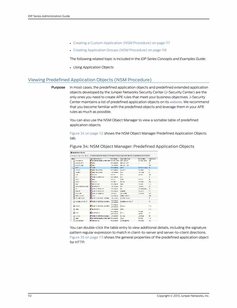
• Creating a Custom Application (NSM Procedure) on page 117
• Creating Application Groups (NSM Procedure) on page 118
The following related topic is included in the IDP Series Concepts and Examples Guide:
• Using Application Objects
Viewing Predefined Application Objects (NSMProcedure)
Purpose In most cases, the predefined application objects and predefined extended application
objects developed by the Juniper Networks Security Center (J-Security Center) are the
only ones you need to create APE rules that meet your business objectives. J-Security
Center maintains a list of predefined application objects on its website. We recommend
that you become familiar with the predefined objects and leverage them in your APE
rules as much as possible.
You can also use the NSM Object Manager to view a sortable table of predefined
application objects.
Figure 34 on page 112 shows the NSM Object Manager Predefined Application Objects
tab.
Figure 34: NSMObject Manager: Predefined Application Objects
You can double-click the table entry to view additional details, including the signature
pattern regular expression to match in client-to-server and server-to-client directions.
Figure 35 on page 113 shows the general properties of the predefined application object
for HTTP.
Copyright © 2013, Juniper Networks, Inc.112
IDP Series Administration Guide
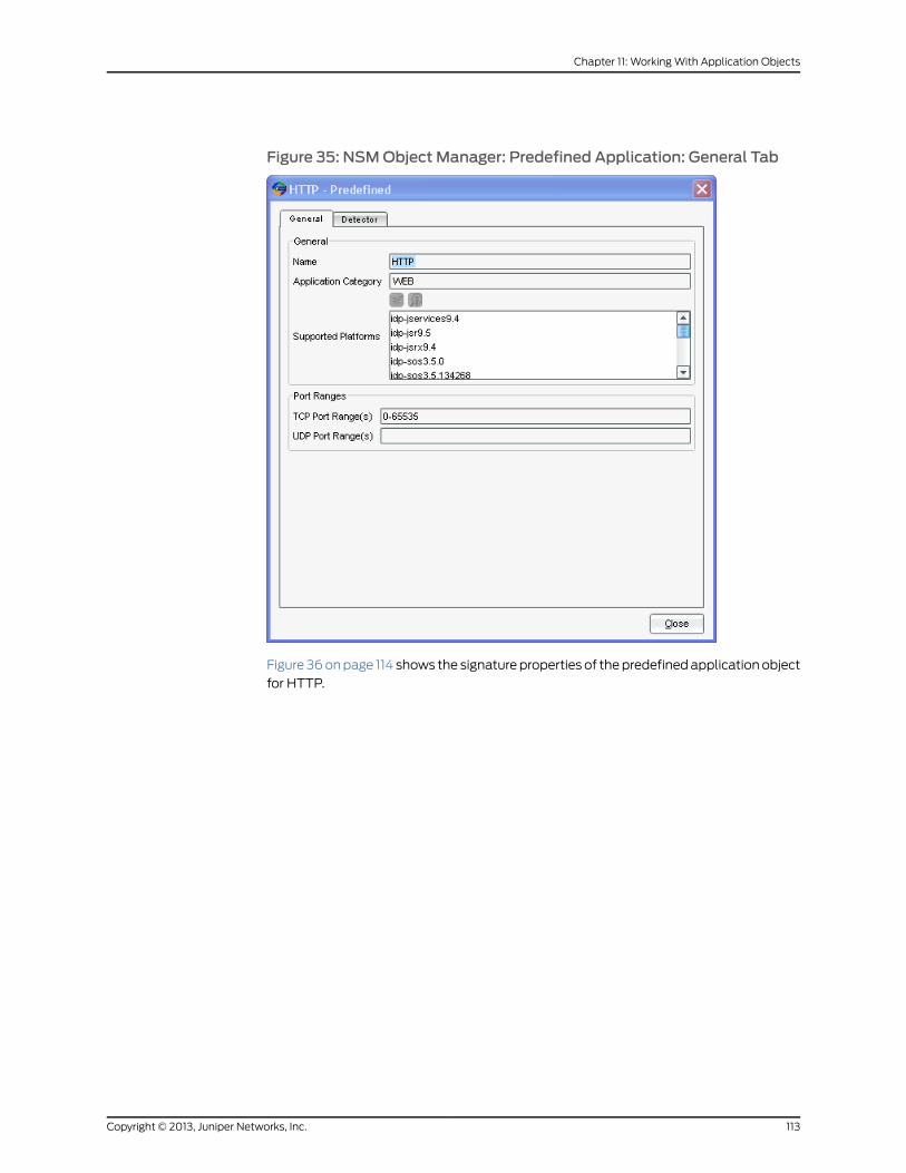
Figure 35: NSMObject Manager: Predefined Application: General Tab
Figure 36 on page 114 shows the signature properties of the predefined application object
for HTTP.
113Copyright © 2013, Juniper Networks, Inc.
Chapter 11: Working With Application Objects
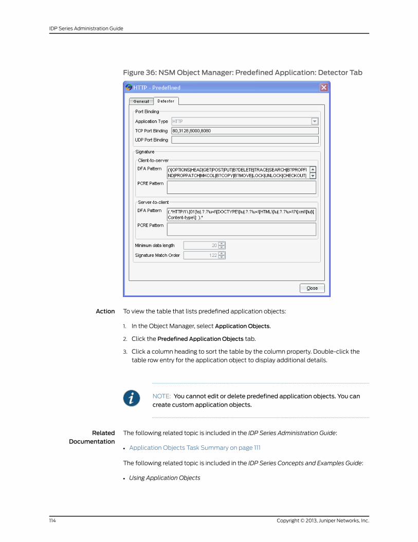
Figure 36: NSMObject Manager: Predefined Application: Detector Tab
Action To view the table that lists predefined application objects:
1. In the Object Manager, select Application Objects.
2. Click the Predefined Application Objects tab.
3. Click a column heading to sort the table by the column property. Double-click the
table row entry for the application object to display additional details.
NOTE: You cannot edit or delete predefined application objects. You cancreate custom application objects.
RelatedDocumentation
The following related topic is included in the IDP Series Administration Guide:
Application Objects Task Summary on page 111•
The following related topic is included in the IDP Series Concepts and Examples Guide:
• Using Application Objects
Copyright © 2013, Juniper Networks, Inc.114
IDP Series Administration Guide
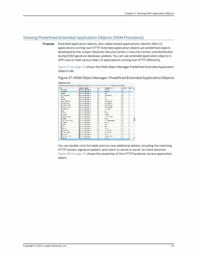
Viewing Predefined Extended Application Objects (NSMProcedure)
Purpose Extended application objects, also called nested applications, identify Web 2.0
applications running over HTTP. Extended application objects are predefined objects
developed by the Juniper Networks Security Center (J-Security Center) and distributed
during NSM signature database updates. You can use extended application objects in
APE rules to treat various Web 2.0 applications running over HTTP differently.
Figure 37 on page 115 shows the NSM Object Manager Predefined Extended Application
Objects tab.
Figure37:NSMObjectManager:PredefinedExtendedApplicationObjects
You can double-click the table entry to view additional details, including the matching
HTTP context, signature pattern, and client-to-server or server-to-client direction.
Figure 38 on page 116 shows the properties of the HTTP:Facebook-Access application
object.
115Copyright © 2013, Juniper Networks, Inc.
Chapter 11: Working With Application Objects
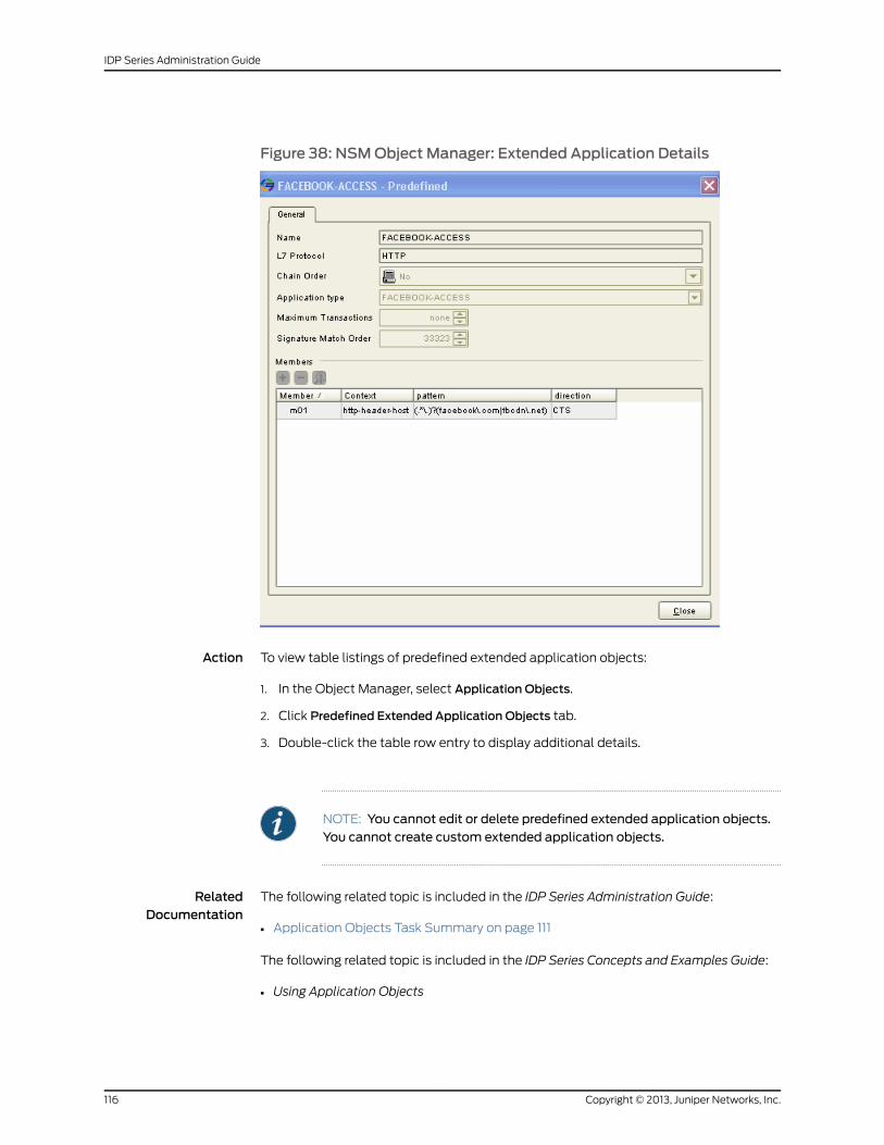
Figure 38: NSMObject Manager: Extended Application Details
Action To view table listings of predefined extended application objects:
1. In the Object Manager, select Application Objects.
2. Click Predefined Extended Application Objects tab.
3. Double-click the table row entry to display additional details.
NOTE: You cannot edit or delete predefined extended application objects.You cannot create custom extended application objects.
RelatedDocumentation
The following related topic is included in the IDP Series Administration Guide:
Application Objects Task Summary on page 111•
The following related topic is included in the IDP Series Concepts and Examples Guide:
• Using Application Objects
Copyright © 2013, Juniper Networks, Inc.116
IDP Series Administration Guide
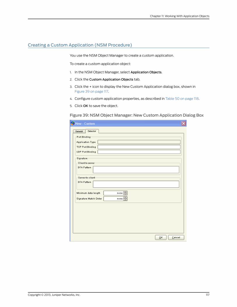
Creating a CustomApplication (NSMProcedure)
You use the NSM Object Manager to create a custom application.
To create a custom application object:
1. In the NSM Object Manager, select Application Objects.
2. Click the CustomApplication Objects tab.
3. Click the + icon to display the New Custom Application dialog box, shown in
Figure 39 on page 117.
4. Configure custom application properties, as described in Table 50 on page 118.
5. Click OK to save the object.
Figure 39: NSMObject Manager: New CustomApplication Dialog Box
117Copyright © 2013, Juniper Networks, Inc.
Chapter 11: Working With Application Objects
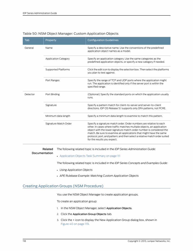
Table 50: NSMObject Manager: CustomApplication Objects
Configuration GuidelinesPropertyTab
Specify a descriptive name. Use the conventions of the predefinedapplication object names as a model.
NameGeneral
Specify an application category. Use the same categories as thepredefined application objects, or specify a new category if needed.
Application Category
Click the edit icon to display the selection box. Then select the platformsyou plan to test against.
Supported Platforms
Specify the range of TCP and UDP ports where the application mightrun. The application is identified only if the server port is within thespecified range.
Port Ranges
(Optional) Specify the standard ports on which the application usuallyruns.
Port BindingDetector
Specify a pattern match for client-to-server and server-to-clientdirections. IDP OS Release 5.1 supports only DFA patterns, not PCRE.
Signature
Specify a minimum data length to examine to match this pattern.Minimum data length
Specify a signature match order. Order numbers are relative to eachother. In cases where traffic matches multiple objects, an applicationobject with the lower signature match-order number is considered thematch. Be sure to examine all applications that might have the sameprotocol, port, and pattern; and then select a relative match order suitedfor the results you expect.
Signature Match Order
RelatedDocumentation
The following related topic is included in the IDP Series Administration Guide:
Application Objects Task Summary on page 111•
The following related topic is included in the IDP Series Concepts and Examples Guide:
• Using Application Objects
• APE Rulebase Example: Matching Custom Application Objects
Creating Application Groups (NSMProcedure)
You use the NSM Object Manager to create application groups.
To create an application group:
1. In the NSM Object Manager, select Application Objects.
2. Click the Application Group Objects tab.
3. Click the + icon to display the New Application Group dialog box, shown in
Figure 40 on page 119.
Copyright © 2013, Juniper Networks, Inc.118
IDP Series Administration Guide
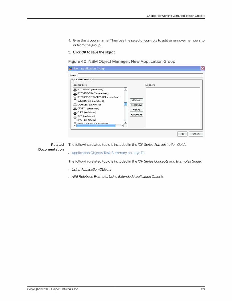
4. Give the group a name. Then use the selector controls to add or remove members to
or from the group.
5. Click OK to save the object.
Figure 40: NSMObject Manager: NewApplication Group
RelatedDocumentation
The following related topic is included in the IDP Series Administration Guide:
• Application Objects Task Summary on page 111
The following related topic is included in the IDP Series Concepts and Examples Guide:
• Using Application Objects
• APE Rulebase Example: Using Extended Application Objects
119Copyright © 2013, Juniper Networks, Inc.
Chapter 11: Working With Application Objects

Copyright © 2013, Juniper Networks, Inc.120
IDP Series Administration Guide
PART 4
Managing Your IDP Series Devices
• Understanding the Management Tools on page 123
• Using NSM to Manage the IDP Series Device Configuration on page 127
• Enabling Advanced Features and Options with scio Commands on page 167
• Using ACM to Configure IDP Series Network Interfaces on page 185
• Updating IDP OS Software on page 191
• Restarting the IDP Engine on page 199
• Rebooting and Shutting Down an IDP Series Appliance on page 201
121Copyright © 2013, Juniper Networks, Inc.

Copyright © 2013, Juniper Networks, Inc.122
IDP Series Administration Guide
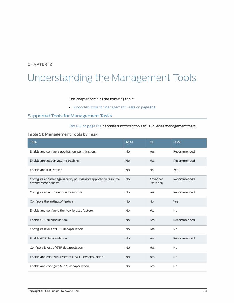
CHAPTER 12
Understanding the Management Tools
This chapter contains the following topic:
• Supported Tools for Management Tasks on page 123
Supported Tools for Management Tasks
Table 51 on page 123 identifies supported tools for IDP Series management tasks.
Table 51: Management Tools by Task
NSMCLIACMTask
RecommendedYesNoEnable and configure application identification.
RecommendedYesNoEnable application volume tracking.
YesNoNoEnable and run Profiler.
RecommendedAdvancedusers only
NoConfigure and manage security policies and application resourceenforcement policies.
RecommendedYesNoConfigure attack detection thresholds.
YesNoNoConfigure the antispoof feature.
NoYesNoEnable and configure the flow bypass feature.
RecommendedYesNoEnable GRE decapsulation.
NoYesNoConfigure levels of GRE decapsulation.
RecommendedYesNoEnable GTP decapsulation.
NoYesNoConfigure levels of GTP decapsulation.
NoYesNoEnable and configure IPsec ESP NULL decapsulation.
NoYesNoEnable and configure MPLS decapsulation.
123Copyright © 2013, Juniper Networks, Inc.
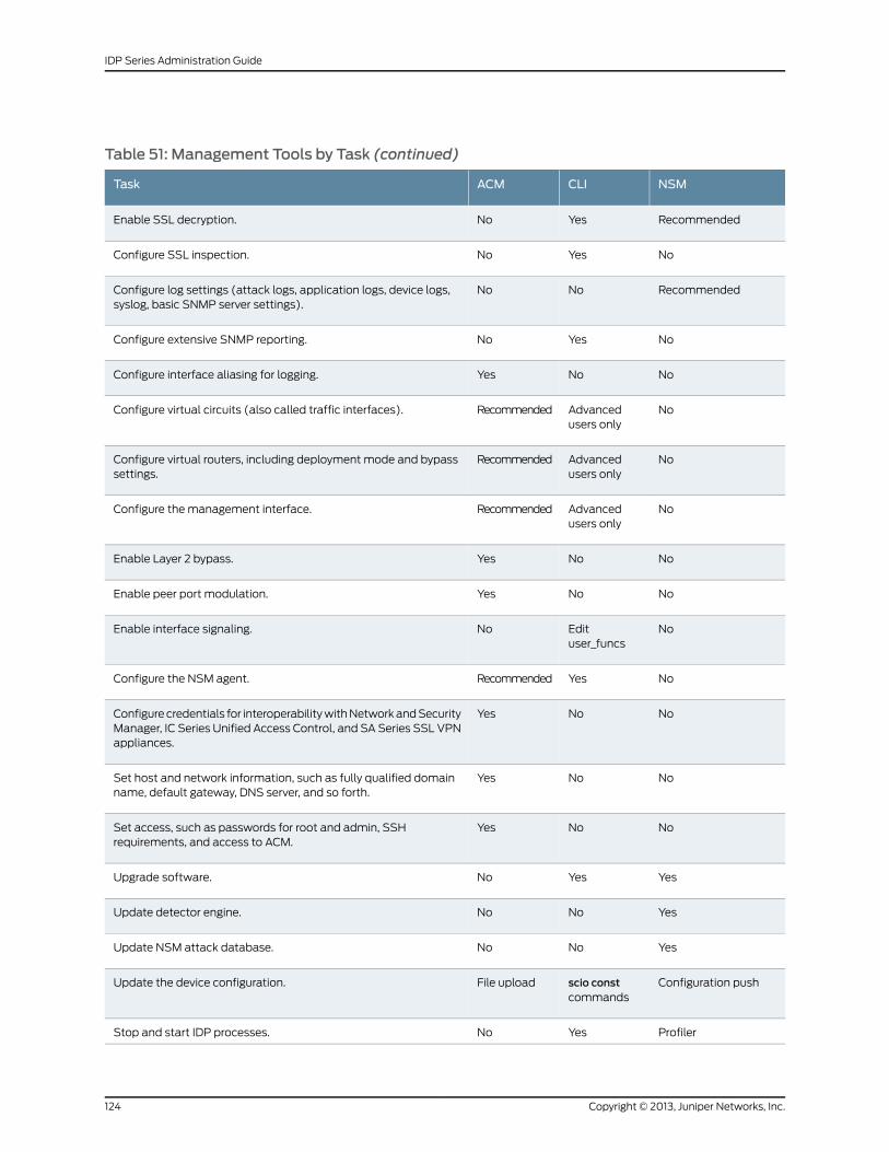
Table 51: Management Tools by Task (continued)
NSMCLIACMTask
RecommendedYesNoEnable SSL decryption.
NoYesNoConfigure SSL inspection.
RecommendedNoNoConfigure log settings (attack logs, application logs, device logs,syslog, basic SNMP server settings).
NoYesNoConfigure extensive SNMP reporting.
NoNoYesConfigure interface aliasing for logging.
NoAdvancedusers only
RecommendedConfigure virtual circuits (also called traffic interfaces).
NoAdvancedusers only
RecommendedConfigure virtual routers, including deployment mode and bypasssettings.
NoAdvancedusers only
RecommendedConfigure the management interface.
NoNoYesEnable Layer 2 bypass.
NoNoYesEnable peer port modulation.
NoEdituser_funcs
NoEnable interface signaling.
NoYesRecommendedConfigure the NSM agent.
NoNoYesConfigure credentials for interoperability with Network and SecurityManager, IC Series Unified Access Control, and SA Series SSL VPNappliances.
NoNoYesSet host and network information, such as fully qualified domainname, default gateway, DNS server, and so forth.
NoNoYesSet access, such as passwords for root and admin, SSHrequirements, and access to ACM.
YesYesNoUpgrade software.
YesNoNoUpdate detector engine.
YesNoNoUpdate NSM attack database.
Configuration pushscio constcommands
File uploadUpdate the device configuration.
ProfilerYesNoStop and start IDP processes.
Copyright © 2013, Juniper Networks, Inc.124
IDP Series Administration Guide
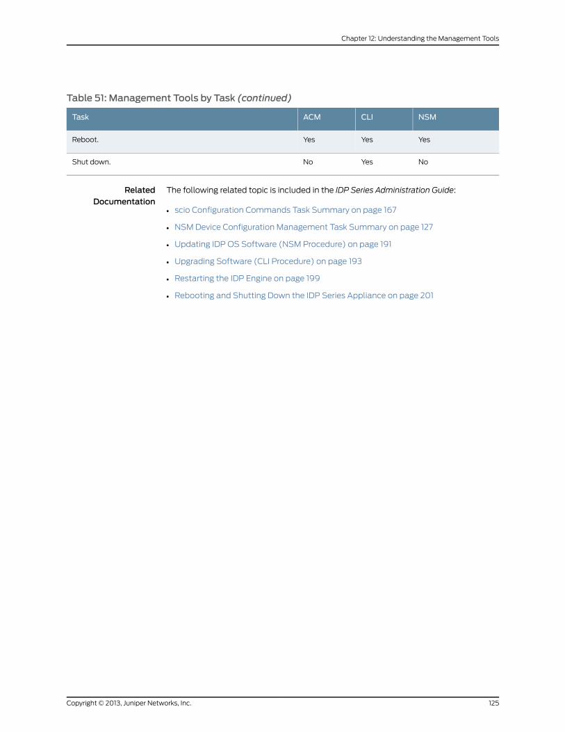
Table 51: Management Tools by Task (continued)
NSMCLIACMTask
YesYesYesReboot.
NoYesNoShut down.
RelatedDocumentation
The following related topic is included in the IDP Series Administration Guide:
• scio Configuration Commands Task Summary on page 167
• NSM Device Configuration Management Task Summary on page 127
• Updating IDP OS Software (NSM Procedure) on page 191
• Upgrading Software (CLI Procedure) on page 193
• Restarting the IDP Engine on page 199
• Rebooting and Shutting Down the IDP Series Appliance on page 201
125Copyright © 2013, Juniper Networks, Inc.
Chapter 12: Understanding the Management Tools

Copyright © 2013, Juniper Networks, Inc.126
IDP Series Administration Guide
CHAPTER 13
Using NSM to Manage the IDP SeriesDevice Configuration
This chapter contains the following topics:
• NSM Device Configuration Management Task Summary on page 127
• Adding IDP Series Devices to NSM Device Manager on page 128
• Activating Devices (NSM Procedure) on page 132
• Pulling or Pushing Configuration Updates on page 134
• Modifying the IDP Series Device Configuration on page 135
• Deleting an IDP Series Device Configuration from NSM Device Manager (NSM
Procedure) on page 166
NSMDevice ConfigurationManagement Task Summary
Juniper Networks Network and Security Manager (NSM) is a central management server
capable of managing hundreds of IDP Series devices and other Juniper Networks devices,
such as Juniper Networks ScreenOS firewalls, Juniper Networks SA Series SSL VPN
appliances, and Juniper Networks IC Series Unified Access Control appliances. You
typically deploy NSM in a management subnet accessible to NSM-managed devices.
You use NSM to perform the following tasks related to IDP Series device configuration
management:
• Adding the IDP Series device to the NSM Device Manager
• Pushing for pulling configuration updates
• Modifying the IDP Series device configuration
RelatedDocumentation
The following related topic is included in the IDP Series Administration Guide:
Adding IDP Series Devices to NSM Device Manager on page 128•
• Activating Devices (NSM Procedure) on page 132
• Pulling or Pushing Configuration Updates on page 134
• Modifying the IDP Series Device Configuration on page 135
127Copyright © 2013, Juniper Networks, Inc.
• Deleting an IDP Series Device Configuration from NSM Device Manager (NSM
Procedure) on page 166
Adding IDP Series Devices to NSMDeviceManager
Before you can use Network and Security Manager (NSM) to manage an IDP Series
device, you must add the IDP Series device to NSM Device Manager. Use one of the
following workflows to add the IDP Series device to the NSM Device Manager:
• Adding a Reachable Device on page 128
• Adding an Unreachable Device on page 129
• Modeling an IDP Series Device Configuration on page 130
• Adding Device Clusters on page 131
Adding a Reachable Device
A reachable device is a device you have installed and initialized, including configuring an
IP address for the management interface and connecting the management interface to
the network. You complete the reachable device workflow in cases where you set up the
IDP Series device first and the NSM device object second.
To import an IDP Series device with a known IP address:
1. In the NSM navigation tree, select DeviceManager > Devices.
2. Click the + icon and select Device to display the Add Device wizard. Configure the
following properties:
• Name–Specify a string to identify the IDP Series device. The string may contain
letters, numbers, spaces, dashes, and underscores.
• Color–Select a color. Some administrators use colors to distinguish devices by type,
region, software version, and so forth.
• Select Device Is Reachable (default).
3. Click Next.
4. In the Specify Connection Settings dialog box, enter the following connection
information:
• Enter the IP address of the IDP Series device.
• Enter the username of the device admin user.
• Enter the password for the device admin user.
• Enter the password for the device root user.
NOTE: In NSM, passwords are case-sensitive.
• Select SSHVersion 2 and port 22.
Copyright © 2013, Juniper Networks, Inc.128
IDP Series Administration Guide
Click Next.
5. On the Verify Device Authenticity page, use an out-of-band method to verify the RSA
key fingerprint information to prevent man-in-the-middle attacks.
Click Next.
In response, NSM connects to the IDP Series device to retrieve device information.
This process takes a moment.
6. Verify that the device type, OS version, device serial number, and device mode are
correct.
7. Click Next to add the device to NSM.
8. Click Next to import the configuration from the IDP Series device.
9. Click Finish.
For IDP OS Release 4.1 and later devices, NSM next runs a job to update the IDP Series
device with the Recommended IDP security policy. The Job Information dialog box
shows the status of the Update Device job.
10. After the job is complete, double-click the device in Device Manager to view the
imported configuration.
To check the device configuration status, mouse over the device and verify that the
device status displays Managed.
Adding an Unreachable Device
An unreachable device is a device that has not been set up and so does not have an IP
address for the management interface. You complete the unreachable device workflow
in cases where you set up the NSM device object first and the IDP Series device second.
To add an IDP Series device with an unknown IP address:
1. In the NSM navigation tree, select DeviceManager > Devices.
2. Click the + icon and select Device to display the Add Device wizard.
3. Configure the following properties:
• Name–Specify a string to identify the IDP Series device. The string may contain
letters, numbers, spaces, dashes, and underscores.
• Color–Select a color. Some administrators use colors to distinguish devices by type,
region, software version, and so forth.
• Select Device Is Not Reachable.
4. Click Next.
5. On the Specify One Time Password page:
• Make a note of the unique external ID for the device. The device administrator will
need it to connect the device to NSM. This ID number represents the device within
the management system. The wizard automatically provides this value.
129Copyright © 2013, Juniper Networks, Inc.
Chapter 13: Using NSM to Manage the IDP Series Device Configuration
• Specify the first connection one-time password (OTP) that authenticates the device.
• Click ShowDevice Commands to display the list of CLI commands that must be
executed on the device to connect to NSM. The commands enable management,
set the IP address for NSM, set the unique external ID, and set the device OTP.
Copy these commands to a text file.
Click Finish to complete the Add Device wizard and include the new device in the
Device Manager list.
6. Log into the CLI as admin and enter su - to switch to root.
7. Run the CLI commands you copied in Step 5.
8. In the NSM Device Manager, mouse over the device to track its configuration status.
The first status message is Waiting for 1st connect. After the connection has been
established, the status displays Import Needed.
9. Right-click the device and select Import Device.
The Job Information box displays the job type and status for the import; when the job
status displays successful completion, click Close.
For IDP OS Release 4.1 and later devices, NSM next runs a job to update the IDP Series
device with the Recommended IDP security policy. The Job Information dialog box
shows the status of the Update Device job.
10. After the job is complete, double-click the device in Device Manager to view the
imported configuration.
To check the device configuration status, mouse over the device and verify that the
device status displays Managed.
Modeling an IDP Series Device Configuration
You model an IDP Series device configuration when the device is not online, and you
intend to push the configuration to the device when it is ready to be put online and
configured.
To model an IDP Series device
1. In the NSM navigation tree, select DeviceManager > Devices.
2. Click the + icon and then select Device to display the Add Device wizard.
3. Configure the following properties:
• Name–Specify a string to identify the IDP Series device. The string may contain
letters, numbers, spaces, dashes, and underscores.
• Color–Select a color. Some administrators use colors to distinguish devices by type,
region, software version, and so forth.
• Select Model Device.
Copyright © 2013, Juniper Networks, Inc.130
IDP Series Administration Guide
4. In the Specify OS Name, Version, and Platform page, enter the following connection
information:
• In the OS Name list, select the device family that the modeled device belongs to.
• In the platform list, select the device platform name.
• In the OS version list, select the version of the operating system or firmware that
runs on the device.
5. Click Finish.
6. Double-click the device to display the device configuration editor.
7. When you have completed the model configuration, check the device configuration
status. Mouse over the device and verify that the device status displays Modeled.
Adding Device Clusters
In a high-availability (HA) deployment, an IDP Series device cluster is a set of two IDP
Series devices deployed for the same purpose—to provide intrusion detection and
prevention for a particular network segment. You use Appliance Configuration Manager
(ACM) to configure HA. You use Network and Security Manager (NSM) to create a cluster
object that will help you ensure the nodes (IDP Series devices) maintain the same feature
configuration, which is a requirement of HA deployments.
To configure clusters in NSM:
1. Add the cluster object.
2. Add cluster members to the cluster object.
To add a cluster object:
1. In the NSM navigation tree, select DeviceManager > Devices.
2. Click the + icon and then select Cluster to display the New Cluster wizard.
3. Configure the following properties:
• Cluster Name–Specify a string to identify the IDP Series device. The string may
contain letters, numbers, spaces, dashes, and underscores.
• Color–Select a color. Some administrators use colors to distinguish devices by type,
region, software version, and so forth.
• In the OS Name list, select ScreenOS/IDP.
• In the platform list, select the device model number.
• In the Managed OS version list, select the IDP OS version.
4. Click OK.
131Copyright © 2013, Juniper Networks, Inc.
Chapter 13: Using NSM to Manage the IDP Series Device Configuration
To add cluster members:
1. In the NSM navigation tree, select DeviceManager > Devices.
2. Right-click the cluster object and then select New> Cluster Member to display the
Add Cluster Member wizard.
3. Complete the wizard steps.
4. Repeat to add the second cluster member.
NOTE: An IDP Series cluster contains exactly twomembers.
RelatedDocumentation
The following related topic is included in the IDP Series Administration Guide:
NSM Device Configuration Management Task Summary on page 127•
Activating Devices (NSMProcedure)
This section includes the following topics:
• Activating a Reachable IDP Series Device on page 132
• Activating an Unreachable IDP Series Device on page 133
Activating a Reachable IDP Series Device
To activate a device:
1. In the NSM Device Manager, right-click the device and selectActivateDevice to display
the Activate Device wizard.
2. Select Device deployed and IP is reachable.
3. In the Specify Connection Settings dialog box, enter the following connection
information:
• Enter the IP address of the IDP Series device.
• Enter the username of the device admin user.
• Enter the password for the device admin user.
• Enter the password for the device root user.
NOTE: In NSM, passwords are case-sensitive.
• Select SSHVersion 2 as the connection method and port 22.
Click Next.
Copyright © 2013, Juniper Networks, Inc.132
IDP Series Administration Guide
4. On the Verify Device Authenticity page, use an out-of-band method to verify the RSA
key fingerprint information to prevent man-in-the-middle attacks. For example:
a. Log into the CLI as admin and enter su - to switch to root.
b. Enter cd /etc/ssh.
c. Enter ssh-keygen -l -f ssh_host_dsa_key.
d. After you have verified the key, click Next.
In response, NSM connects to the IDP Series device to retrieve device information.
This process takes a moment.
5. Verify that the device type, OS version, device serial number, and device mode are
correct.
6. Click Next to add the device to NSM.
7. Click Next to import the configuration from the IDP Series device.
8. Click Finish.
For IDP OS Release 4.1 and later devices, NSM next runs a job to update the device
with the Recommended IDP security policy. The Job Information dialog box shows
the status of the Update Device job.
9. After the job is complete, double-click the device in Device Manager to view the
imported configuration.
To check the device configuration status, mouse over the device and verify that the
device status displays Managed.
Activating an Unreachable IDP Series Device
To activate an unreachable device:
1. In the NSM Device Manager, right-click the device and select Activate Device to display
the Activate Device wizard.
2. Select Device deployed, but IP is not reachable.
3. On the Specify One Time Password page:
• Make a note of the unique external ID for the device. The device administrator will
need it to connect the device to NSM. This ID number represents the device within
the management system. The wizard automatically provides this value.
• Specify the first connection one-time password (OTP) that authenticates the device.
• Click ShowDevice Commands to display the list of CLI commands that must be
executed on the device to connect to NSM. The commands enable management,
set the unique external ID, set the management IP address to the device server IP
address, and set the device OTP.
Copy these commands to a text file.
133Copyright © 2013, Juniper Networks, Inc.
Chapter 13: Using NSM to Manage the IDP Series Device Configuration
Click Finish to complete the Add Device wizard and include the new device in the
Device Manager list.
4. Log into the CLI as admin and enter su - to switch to root.
5. Run the CLI commands you copied in Step 3.
6. In the NSM Device Manager, mouse over the device to track its configuration status.
The first status message is Waiting for 1st connect. After the connection has been
established, the status displays Import Needed.
7. Right-click the device and select Import Device.
The Job Information box displays the job type and status for the import; when the job
status displays successful completion, click Close.
For IDP OS Release 4.1 and later devices, NSM next runs a job to update the device
with the Recommended IDP security policy. The Job Information dialog box shows
the status of the Update Device job.
8. After the job is complete, double-click the device in Device Manager to view the
imported configuration.
To check the device configuration status, mouse over the device and verify that the
device status displays Managed.
RelatedDocumentation
The following related topic is included in the IDP Series Administration Guide:
NSM Device Configuration Management Task Summary on page 127•
Pulling or Pushing Configuration Updates
The IDP Series device configuration stored in NSM is not an active configuration. The
active configuration is the one running on the IDP Series device. In some cases, the two
configurations can be out of sync. To synchronize them, you can pull the running
configuration from the IDP Series device into NSM or push the NSM device configuration
onto the IDP Series device.
Table 52 on page 134 describes the cases when you pull and the cases where you push.
Table 52: Pulling and Pushing Configuration Updates
Push a ConfigurationPull a Configuration
• After you model an IDP Series device in NSM.
• After you update the IDP detector engine, NSM attack database, orsecurity policy.
• After you use the NSM device editor to enable features or changefeature settings.
• When you add an IDP Series device to NSM.
• After you use ACM to change the deploymentmode.
To import the IDP Series device configuration:
1. In the NSM Device Manager, right-click the device and select Import Device.
Copyright © 2013, Juniper Networks, Inc.134
IDP Series Administration Guide
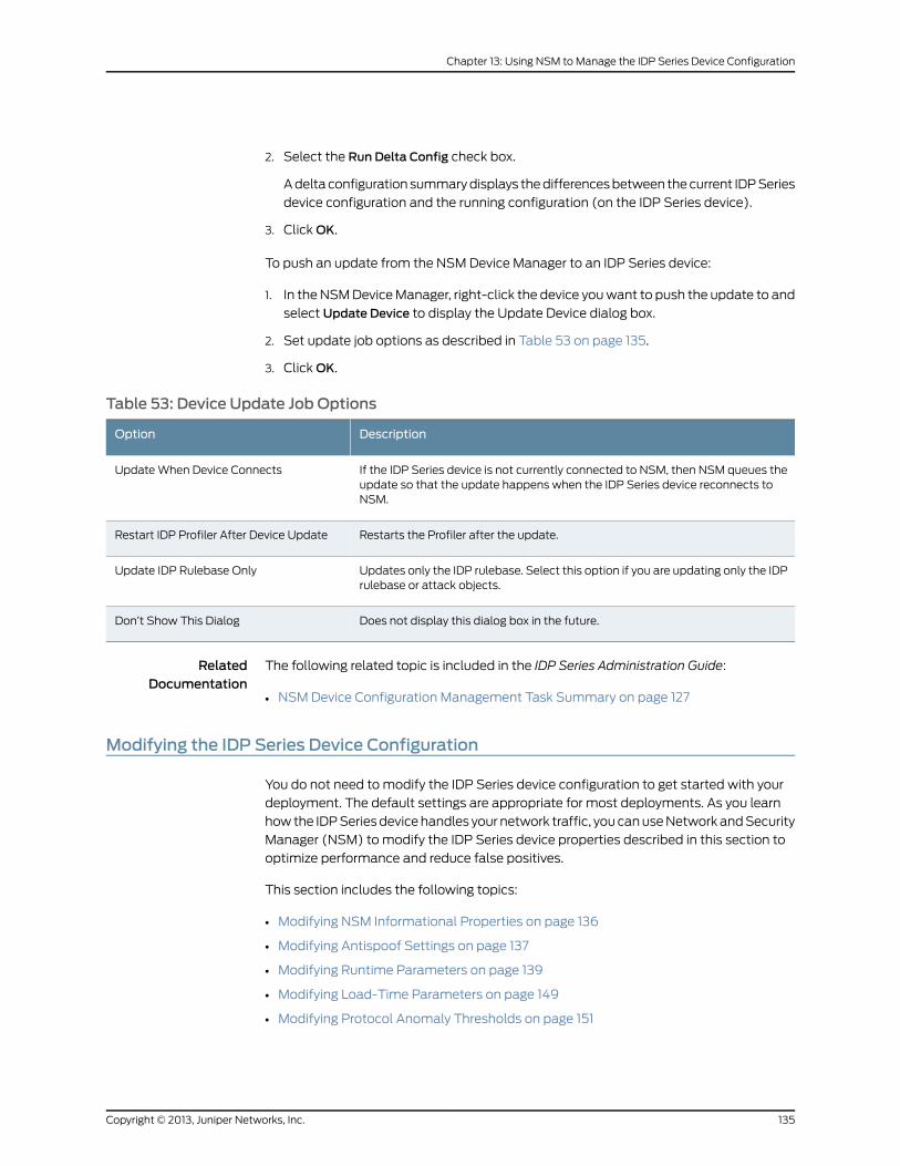
2. Select the Run Delta Config check box.
A delta configuration summary displays the differences between the current IDP Series
device configuration and the running configuration (on the IDP Series device).
3. Click OK.
To push an update from the NSM Device Manager to an IDP Series device:
1. In the NSM Device Manager, right-click the device you want to push the update to and
select Update Device to display the Update Device dialog box.
2. Set update job options as described in Table 53 on page 135.
3. Click OK.
Table 53: Device Update Job Options
DescriptionOption
If the IDP Series device is not currently connected to NSM, then NSM queues theupdate so that the update happens when the IDP Series device reconnects toNSM.
Update When Device Connects
Restarts the Profiler after the update.Restart IDP Profiler After Device Update
Updates only the IDP rulebase. Select this option if you are updating only the IDPrulebase or attack objects.
Update IDP Rulebase Only
Does not display this dialog box in the future.Don’t Show This Dialog
RelatedDocumentation
The following related topic is included in the IDP Series Administration Guide:
NSM Device Configuration Management Task Summary on page 127•
Modifying the IDP Series Device Configuration
You do not need to modify the IDP Series device configuration to get started with your
deployment. The default settings are appropriate for most deployments. As you learn
how the IDP Series device handles your network traffic, you can use Network and Security
Manager (NSM) to modify the IDP Series device properties described in this section to
optimize performance and reduce false positives.
This section includes the following topics:
• Modifying NSM Informational Properties on page 136
• Modifying Antispoof Settings on page 137
• Modifying Runtime Parameters on page 139
• Modifying Load-Time Parameters on page 149
• Modifying Protocol Anomaly Thresholds on page 151
135Copyright © 2013, Juniper Networks, Inc.
Chapter 13: Using NSM to Manage the IDP Series Device Configuration
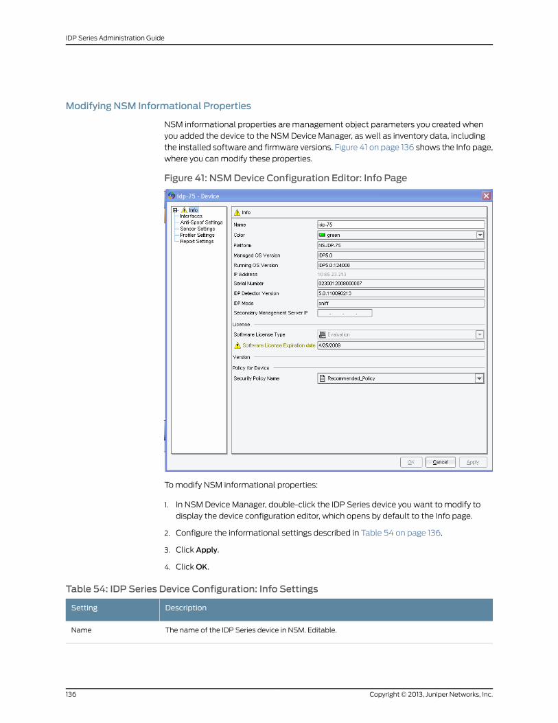
Modifying NSM Informational Properties
NSM informational properties are management object parameters you created when
you added the device to the NSM Device Manager, as well as inventory data, including
the installed software and firmware versions. Figure 41 on page 136 shows the Info page,
where you can modify these properties.
Figure 41: NSMDevice Configuration Editor: Info Page
To modify NSM informational properties:
1. In NSM Device Manager, double-click the IDP Series device you want to modify to
display the device configuration editor, which opens by default to the Info page.
2. Configure the informational settings described in Table 54 on page 136.
3. Click Apply.
4. Click OK.
Table 54: IDP Series Device Configuration: Info Settings
DescriptionSetting
The name of the IDP Series device in NSM. Editable.Name
Copyright © 2013, Juniper Networks, Inc.136
IDP Series Administration Guide
Table 54: IDP Series Device Configuration: Info Settings (continued)
DescriptionSetting
The color of the IDP Series device icon in NSM. Selectable.Color
The IDP Series device hardware model number.Platform
The major OS version.Managed OS Version
The precise OS version installed on the device.Running OS Version
The IDP Series device management port IP address.
NOTE: Can only be changed with ACM.
IP Address
The product serial number.Serial Number
The version of the IDP detector engine installed on the device.IDP Detector Version
Deployment mode: sniffer, transparent, mixed.
NOTE: Can only be changed with ACM.
IDP Mode
The IP address that the IDP Series device contacts if it cannot reach the current NSM server.Secondary ManagementServer IP
The type of license currently loaded on the IDP Series device. An evaluation license is good for oneyear.
Software License Type
The expiration date of the license currently loaded on the IDP Series device.Software LicenseExpiration Date
The security policy assigned to the device. Selectable.Security Police Name
Modifying Antispoof Settings
You detect attacks that attempt to spoof the addresses of hosts in your protected network
by associating IDP Series traffic interfaces with the addresses of hosts in your protected
network. The IDP Series appliance then detects an IP spoof attack if:
• An incoming packet uses an IP address that belongs to a network object on your internal
network.
• An outgoing packet uses an IP address that does not belong to a network object on
your internal network.
Figure 42 on page 138 shows the Anti-Spoof Settings page, where you can configure IP
spoof detection.
137Copyright © 2013, Juniper Networks, Inc.
Chapter 13: Using NSM to Manage the IDP Series Device Configuration
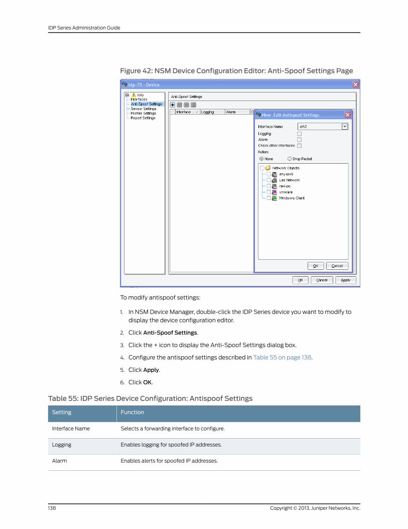
Figure 42: NSMDevice Configuration Editor: Anti-Spoof Settings Page
To modify antispoof settings:
1. In NSM Device Manager, double-click the IDP Series device you want to modify to
display the device configuration editor.
2. Click Anti-Spoof Settings.
3. Click the + icon to display the Anti-Spoof Settings dialog box.
4. Configure the antispoof settings described in Table 55 on page 138.
5. Click Apply.
6. Click OK.
Table 55: IDP Series Device Configuration: Antispoof Settings
FunctionSetting
Selects a forwarding interface to configure.Interface Name
Enables logging for spoofed IP addresses.Logging
Enables alerts for spoofed IP addresses.Alarm
Copyright © 2013, Juniper Networks, Inc.138
IDP Series Administration Guide
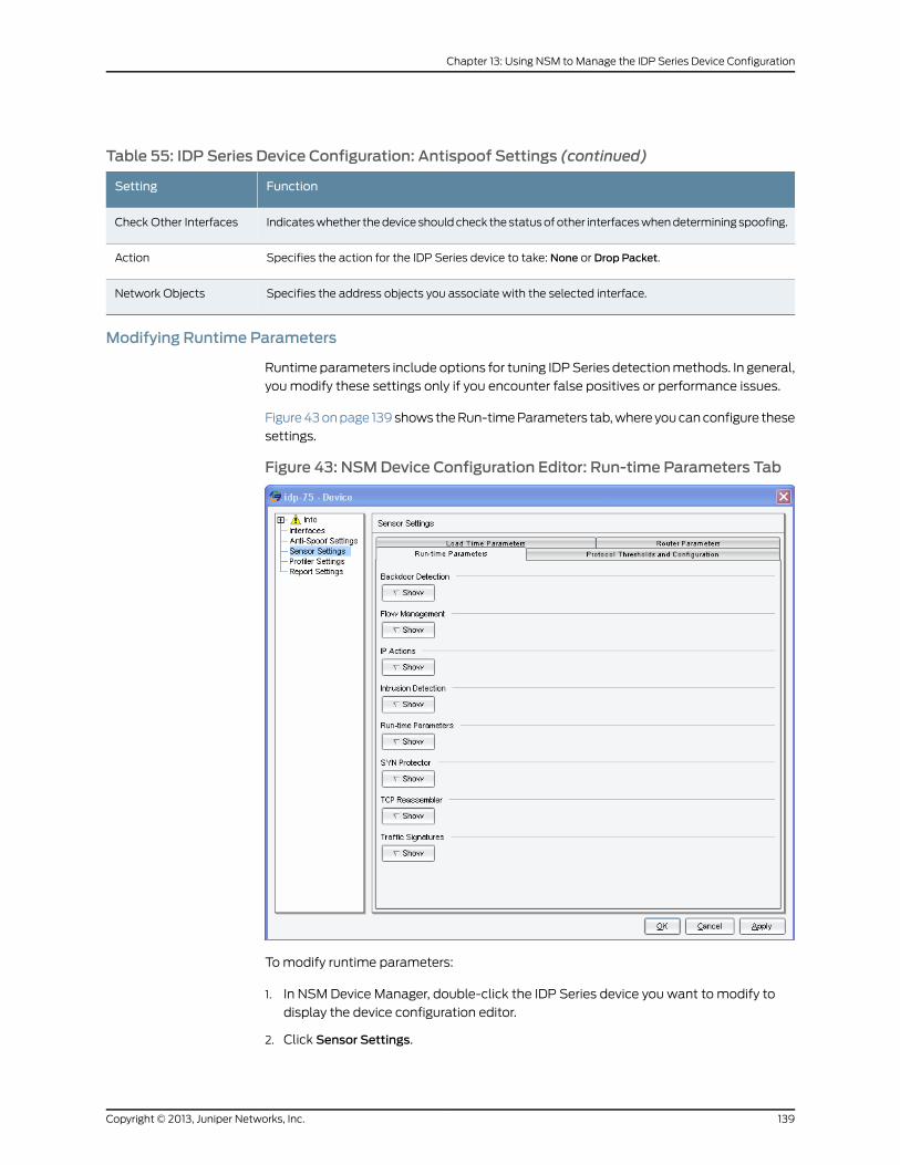
Table 55: IDP Series Device Configuration: Antispoof Settings (continued)
FunctionSetting
Indicates whether the device should check the status of other interfaces when determining spoofing.Check Other Interfaces
Specifies the action for the IDP Series device to take: None or Drop Packet.Action
Specifies the address objects you associate with the selected interface.Network Objects
Modifying Runtime Parameters
Runtime parameters include options for tuning IDP Series detection methods. In general,
you modify these settings only if you encounter false positives or performance issues.
Figure 43 on page 139 shows the Run-time Parameters tab, where you can configure these
settings.
Figure 43: NSMDevice Configuration Editor: Run-time Parameters Tab
To modify runtime parameters:
1. In NSM Device Manager, double-click the IDP Series device you want to modify to
display the device configuration editor.
2. Click Sensor Settings.
139Copyright © 2013, Juniper Networks, Inc.
Chapter 13: Using NSM to Manage the IDP Series Device Configuration
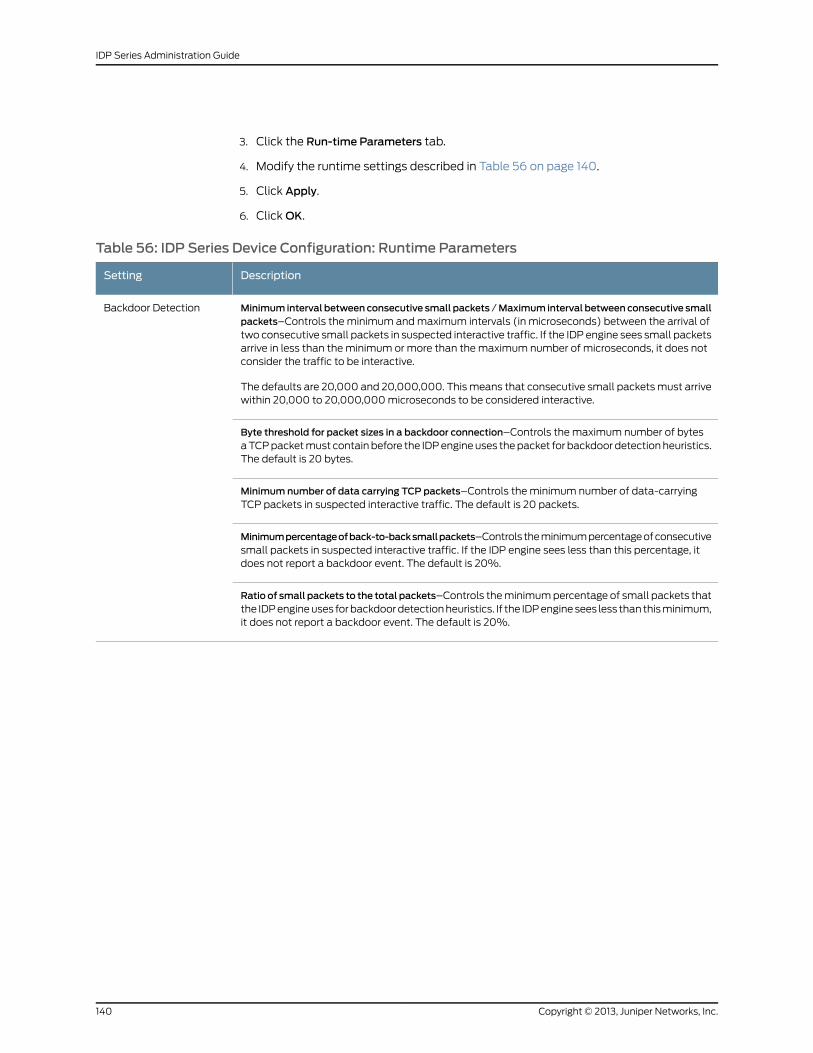
3. Click the Run-time Parameters tab.
4. Modify the runtime settings described in Table 56 on page 140.
5. Click Apply.
6. Click OK.
Table 56: IDP Series Device Configuration: Runtime Parameters
DescriptionSetting
Minimum interval betweenconsecutive small packets /Maximum interval betweenconsecutive smallpackets–Controls the minimum and maximum intervals (in microseconds) between the arrival oftwo consecutive small packets in suspected interactive traffic. If the IDP engine sees small packetsarrive in less than the minimum or more than the maximum number of microseconds, it does notconsider the traffic to be interactive.
The defaults are 20,000 and 20,000,000. This means that consecutive small packets must arrivewithin 20,000 to 20,000,000 microseconds to be considered interactive.
Backdoor Detection
Byte threshold for packet sizes in a backdoor connection–Controls the maximum number of bytesa TCP packet must contain before the IDP engine uses the packet for backdoor detection heuristics.The default is 20 bytes.
Minimum number of data carrying TCP packets–Controls the minimum number of data-carryingTCP packets in suspected interactive traffic. The default is 20 packets.
Minimumpercentageofback-to-backsmallpackets–Controls the minimum percentage of consecutivesmall packets in suspected interactive traffic. If the IDP engine sees less than this percentage, itdoes not report a backdoor event. The default is 20%.
Ratio of small packets to the total packets–Controls the minimum percentage of small packets thatthe IDP engine uses for backdoor detection heuristics. If the IDP engine sees less than this minimum,it does not report a backdoor event. The default is 20%.
Copyright © 2013, Juniper Networks, Inc.140
IDP Series Administration Guide
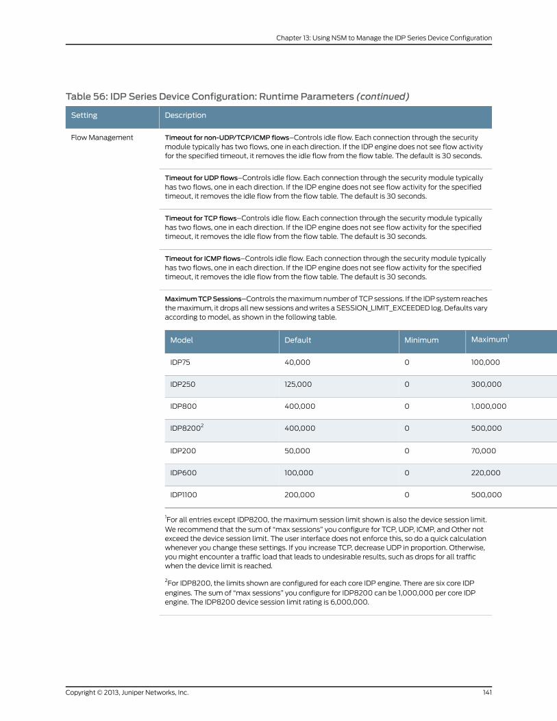
Table 56: IDP Series Device Configuration: Runtime Parameters (continued)
DescriptionSetting
Timeout for non-UDP/TCP/ICMP flows–Controls idle flow. Each connection through the securitymodule typically has two flows, one in each direction. If the IDP engine does not see flow activityfor the specified timeout, it removes the idle flow from the flow table. The default is 30 seconds.
Flow Management
Timeout for UDP flows–Controls idle flow. Each connection through the security module typicallyhas two flows, one in each direction. If the IDP engine does not see flow activity for the specifiedtimeout, it removes the idle flow from the flow table. The default is 30 seconds.
Timeout for TCP flows–Controls idle flow. Each connection through the security module typicallyhas two flows, one in each direction. If the IDP engine does not see flow activity for the specifiedtimeout, it removes the idle flow from the flow table. The default is 30 seconds.
Timeout for ICMP flows–Controls idle flow. Each connection through the security module typicallyhas two flows, one in each direction. If the IDP engine does not see flow activity for the specifiedtimeout, it removes the idle flow from the flow table. The default is 30 seconds.
MaximumTCPSessions–Controls the maximum number of TCP sessions. If the IDP system reachesthe maximum, it drops all new sessions and writes a SESSION_LIMIT_EXCEEDED log. Defaults varyaccording to model, as shown in the following table.
Maximum1MinimumDefaultModel
100,000040,000IDP75
300,0000125,000IDP250
1,000,0000400,000IDP800
500,0000400,000IDP82002
70,000050,000IDP200
220,0000100,000IDP600
500,0000200,000IDP1100
1For all entries except IDP8200, the maximum session limit shown is also the device session limit.We recommend that the sum of “max sessions” you configure for TCP, UDP, ICMP, and Other notexceed the device session limit. The user interface does not enforce this, so do a quick calculationwhenever you change these settings. If you increase TCP, decrease UDP in proportion. Otherwise,you might encounter a traffic load that leads to undesirable results, such as drops for all trafficwhen the device limit is reached.
2For IDP8200, the limits shown are configured for each core IDP engine. There are six core IDPengines. The sum of “max sessions” you configure for IDP8200 can be 1,000,000 per core IDPengine. The IDP8200 device session limit rating is 6,000,000.
141Copyright © 2013, Juniper Networks, Inc.
Chapter 13: Using NSM to Manage the IDP Series Device Configuration
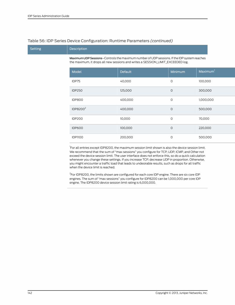
Table 56: IDP Series Device Configuration: Runtime Parameters (continued)
DescriptionSetting
MaximumUDPSessions–Controls the maximum number of UDP sessions. If the IDP system reachesthe maximum, it drops all new sessions and writes a SESSION_LIMIT_EXCEEDED log.
Maximum1MinimumDefaultModel
100,000040,000IDP75
300,0000125,000IDP250
1,000,0000400,000IDP800
500,0000400,000IDP82002
70,000010,000IDP200
220,0000100,000IDP600
500,0000200,000IDP1100
1For all entries except IDP8200, the maximum session limit shown is also the device session limit.We recommend that the sum of “max sessions” you configure for TCP, UDP, ICMP, and Other notexceed the device session limit. The user interface does not enforce this, so do a quick calculationwhenever you change these settings. If you increase TCP, decrease UDP in proportion. Otherwise,you might encounter a traffic load that leads to undesirable results, such as drops for all trafficwhen the device limit is reached.
2For IDP8200, the limits shown are configured for each core IDP engine. There are six core IDPengines. The sum of “max sessions” you configure for IDP8200 can be 1,000,000 per core IDPengine. The IDP8200 device session limit rating is 6,000,000.
Copyright © 2013, Juniper Networks, Inc.142
IDP Series Administration Guide
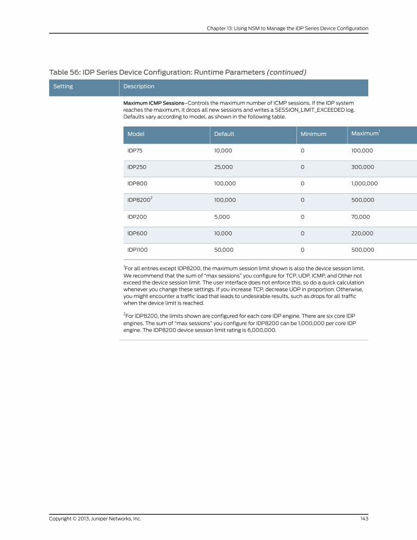
Table 56: IDP Series Device Configuration: Runtime Parameters (continued)
DescriptionSetting
Maximum ICMP Sessions–Controls the maximum number of ICMP sessions. If the IDP systemreaches the maximum, it drops all new sessions and writes a SESSION_LIMIT_EXCEEDED log.Defaults vary according to model, as shown in the following table.
Maximum1MinimumDefaultModel
100,000010,000IDP75
300,000025,000IDP250
1,000,0000100,000IDP800
500,0000100,000IDP82002
70,00005,000IDP200
220,000010,000IDP600
500,000050,000IDP1100
1For all entries except IDP8200, the maximum session limit shown is also the device session limit.We recommend that the sum of “max sessions” you configure for TCP, UDP, ICMP, and Other notexceed the device session limit. The user interface does not enforce this, so do a quick calculationwhenever you change these settings. If you increase TCP, decrease UDP in proportion. Otherwise,you might encounter a traffic load that leads to undesirable results, such as drops for all trafficwhen the device limit is reached.
2For IDP8200, the limits shown are configured for each core IDP engine. There are six core IDPengines. The sum of “max sessions” you configure for IDP8200 can be 1,000,000 per core IDPengine. The IDP8200 device session limit rating is 6,000,000.
143Copyright © 2013, Juniper Networks, Inc.
Chapter 13: Using NSM to Manage the IDP Series Device Configuration
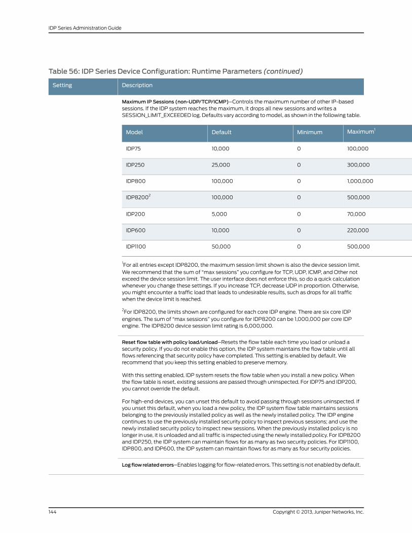
Table 56: IDP Series Device Configuration: Runtime Parameters (continued)
DescriptionSetting
Maximum IP Sessions (non-UDP/TCP/ICMP)–Controls the maximum number of other IP-basedsessions. If the IDP system reaches the maximum, it drops all new sessions and writes aSESSION_LIMIT_EXCEEDED log. Defaults vary according to model, as shown in the following table.
Maximum1MinimumDefaultModel
100,000010,000IDP75
300,000025,000IDP250
1,000,0000100,000IDP800
500,0000100,000IDP82002
70,00005,000IDP200
220,000010,000IDP600
500,000050,000IDP1100
1For all entries except IDP8200, the maximum session limit shown is also the device session limit.We recommend that the sum of “max sessions” you configure for TCP, UDP, ICMP, and Other notexceed the device session limit. The user interface does not enforce this, so do a quick calculationwhenever you change these settings. If you increase TCP, decrease UDP in proportion. Otherwise,you might encounter a traffic load that leads to undesirable results, such as drops for all trafficwhen the device limit is reached.
2For IDP8200, the limits shown are configured for each core IDP engine. There are six core IDPengines. The sum of “max sessions” you configure for IDP8200 can be 1,000,000 per core IDPengine. The IDP8200 device session limit rating is 6,000,000.
Reset flow table with policy load/unload–Resets the flow table each time you load or unload asecurity policy. If you do not enable this option, the IDP system maintains the flow table until allflows referencing that security policy have completed. This setting is enabled by default. Werecommend that you keep this setting enabled to preserve memory.
With this setting enabled, IDP system resets the flow table when you install a new policy. Whenthe flow table is reset, existing sessions are passed through uninspected. For IDP75 and IDP200,you cannot override the default.
For high-end devices, you can unset this default to avoid passing through sessions uninspected. Ifyou unset this default, when you load a new policy, the IDP system flow table maintains sessionsbelonging to the previously installed policy as well as the newly installed policy. The IDP enginecontinues to use the previously installed security policy to inspect previous sessions; and use thenewly installed security policy to inspect new sessions. When the previously installed policy is nolonger in use, it is unloaded and all traffic is inspected using the newly installed policy. For IDP8200and IDP250, the IDP system can maintain flows for as many as two security policies. For IDP1100,IDP800, and IDP600, the IDP system can maintain flows for as many as four security policies.
Log flowrelatederrors–Enables logging for flow-related errors. This setting is not enabled by default.
Copyright © 2013, Juniper Networks, Inc.144
IDP Series Administration Guide
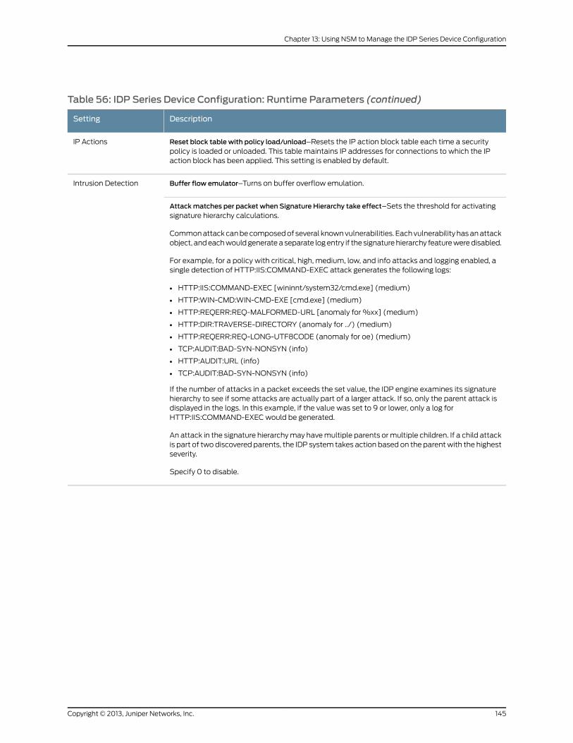
Table 56: IDP Series Device Configuration: Runtime Parameters (continued)
DescriptionSetting
Reset block table with policy load/unload–Resets the IP action block table each time a securitypolicy is loaded or unloaded. This table maintains IP addresses for connections to which the IPaction block has been applied. This setting is enabled by default.
IP Actions
Buffer flow emulator–Turns on buffer overflow emulation.Intrusion Detection
Attackmatches per packet when Signature Hierarchy take effect–Sets the threshold for activatingsignature hierarchy calculations.
Common attack can be composed of several known vulnerabilities. Each vulnerability has an attackobject, and each would generate a separate log entry if the signature hierarchy feature were disabled.
For example, for a policy with critical, high, medium, low, and info attacks and logging enabled, asingle detection of HTTP:IIS:COMMAND-EXEC attack generates the following logs:
• HTTP:IIS:COMMAND-EXEC [wininnt/system32/cmd.exe] (medium)
• HTTP:WIN-CMD:WIN-CMD-EXE [cmd.exe] (medium)
• HTTP:REQERR:REQ-MALFORMED-URL [anomaly for %xx] (medium)
• HTTP:DIR:TRAVERSE-DIRECTORY (anomaly for ../) (medium)
• HTTP:REQERR:REQ-LONG-UTF8CODE (anomaly for oe) (medium)
• TCP:AUDIT:BAD-SYN-NONSYN (info)
• HTTP:AUDIT:URL (info)
• TCP:AUDIT:BAD-SYN-NONSYN (info)
If the number of attacks in a packet exceeds the set value, the IDP engine examines its signaturehierarchy to see if some attacks are actually part of a larger attack. If so, only the parent attack isdisplayed in the logs. In this example, if the value was set to 9 or lower, only a log forHTTP:IIS:COMMAND-EXEC would be generated.
An attack in the signature hierarchy may have multiple parents or multiple children. If a child attackis part of two discovered parents, the IDP system takes action based on the parent with the highestseverity.
Specify 0 to disable.
145Copyright © 2013, Juniper Networks, Inc.
Chapter 13: Using NSM to Manage the IDP Series Device Configuration
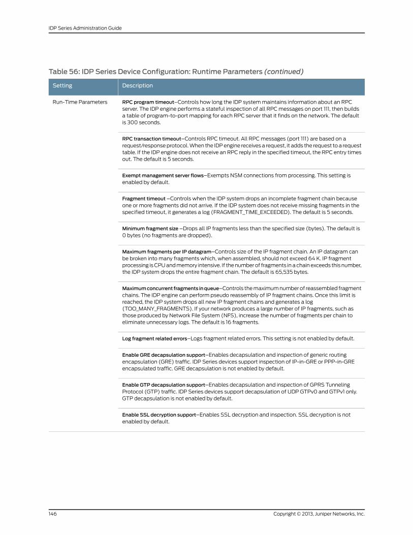
Table 56: IDP Series Device Configuration: Runtime Parameters (continued)
DescriptionSetting
RPC program timeout–Controls how long the IDP system maintains information about an RPCserver. The IDP engine performs a stateful inspection of all RPC messages on port 111, then buildsa table of program-to-port mapping for each RPC server that it finds on the network. The defaultis 300 seconds.
Run-Time Parameters
RPC transaction timeout–Controls RPC timeout. All RPC messages (port 111) are based on arequest/response protocol. When the IDP engine receives a request, it adds the request to a requesttable. If the IDP engine does not receive an RPC reply in the specified timeout, the RPC entry timesout. The default is 5 seconds.
Exemptmanagement server flows–Exempts NSM connections from processing. This setting isenabled by default.
Fragment timeout –Controls when the IDP system drops an incomplete fragment chain becauseone or more fragments did not arrive. If the IDP system does not receive missing fragments in thespecified timeout, it generates a log (FRAGMENT_TIME_EXCEEDED). The default is 5 seconds.
Minimum fragment size –Drops all IP fragments less than the specified size (bytes). The default is0 bytes (no fragments are dropped).
Maximum fragments per IP datagram–Controls size of the IP fragment chain. An IP datagram canbe broken into many fragments which, when assembled, should not exceed 64 K. IP fragmentprocessing is CPU and memory intensive. If the number of fragments in a chain exceeds this number,the IDP system drops the entire fragment chain. The default is 65,535 bytes.
Maximumconcurrent fragments inqueue–Controls the maximum number of reassembled fragmentchains. The IDP engine can perform pseudo reassembly of IP fragment chains. Once this limit isreached, the IDP system drops all new IP fragment chains and generates a log(TOO_MANY_FRAGMENTS). If your network produces a large number of IP fragments, such asthose produced by Network File System (NFS), increase the number of fragments per chain toeliminate unnecessary logs. The default is 16 fragments.
Log fragment related errors–Logs fragment related errors. This setting is not enabled by default.
Enable GRE decapsulation support–Enables decapsulation and inspection of generic routingencapsulation (GRE) traffic. IDP Series devices support inspection of IP-in-GRE or PPP-in-GREencapsulated traffic. GRE decapsulation is not enabled by default.
Enable GTP decapsulation support–Enables decapsulation and inspection of GPRS TunnelingProtocol (GTP) traffic. IDP Series devices support decapsulation of UDP GTPv0 and GTPv1 only.GTP decapsulation is not enabled by default.
Enable SSL decryption support–Enables SSL decryption and inspection. SSL decryption is notenabled by default.
Copyright © 2013, Juniper Networks, Inc.146
IDP Series Administration Guide
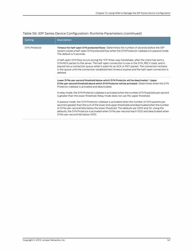
Table 56: IDP Series Device Configuration: Runtime Parameters (continued)
DescriptionSetting
Timeout for half-open SYN protected flows–Determines the number of seconds before the IDPsystem closes a half-open SYN protected flow when the SYN Protector rulebase is in passive mode.The default is 5 seconds.
A half-open SYN flow occurs during the TCP three-way handshake, after the client has sent aSYN/ACK packet to the server. The half-open connection is now in the SYN_RECV state, and isplaced into a connection queue while it waits for an ACK or RST packet. The connection remainsin the queue until the connection-establishment timeout expires and the half-open connection isdeleted.
SYN-Protector
Lower SYNs-per-second threshold belowwhich SYN Protector will be deactivated / UpperSYNs-per-second threshold abovewhichSYNProtectorwill be activated–Determines when the SYNProtector rulebase is activated and deactivated.
In relay mode, the SYN Protector rulebase is activated when the number of SYN packets per secondis greater than the lower threshold. Relay mode does not use the upper threshold.
In passive mode, the SYN Protector rulebase is activated when the number of SYN packets persecond is greater than the sum of the lower and upper thresholds and deactivated when the numberof SYNs-per-second falls below the lower threshold. The defaults are 1000 and 20. Using thedefaults, the SYN Protector is activated when SYNs-per-second reach 1020 and deactivated whenSYNs-per-second fall below 1000.
147Copyright © 2013, Juniper Networks, Inc.
Chapter 13: Using NSM to Manage the IDP Series Device Configuration
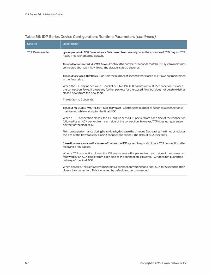
Table 56: IDP Series Device Configuration: Runtime Parameters (continued)
DescriptionSetting
Ignore packets in TCP flowswhere a SYN hasn't been seen–Ignores the absence of SYN flags in TCPflows. This is enabled by default.
TCP Reassembler
Timeoutforconnected, idleTCPflows–Controls the number of seconds that the IDP system maintainsconnected (but idle) TCP flows. The default is 3600 seconds.
Timeout forclosedTCPflows–Controls the number of seconds that closed TCP flows are maintainedin the flow table.
When the IDP engine sees a RST packet or FIN/FIN+ACK packets on a TCP connection, it closesthe connection flows. It drops any further packets for the closed flow, but does not delete existing,closed flows from the flow table.
The default is 5 seconds.
Timeout for CLOSE-WAIT/LAST-ACK TCP flows–Controls the number of seconds a connection ismaintained while waiting for the final ACK.
When a TCP connection closes, the IDP engine sees a FIN packet from each side of the connectionfollowed by an ACK packet from each side of the connection. However, TCP does not guaranteedelivery of the final ACK.
To improve performance during heavy loads, decrease the timeout. Decreasing the timeout reducesthe size of the flow table by closing connections sooner. The default is 120 seconds.
Close flows as soonas a FIN is seen–Enables the IDP system to quickly close a TCP connection afterreceiving a FIN packet.
When a TCP connection closes, the IDP engine sees a FIN packet from each side of the connectionfollowed by an ACK packet from each side of the connection. However, TCP does not guaranteedelivery of the final ACK.
When enabled, the IDP system maintains a connection waiting for a final ACK for 5 seconds, thencloses the connection. This is enabled by default and recommended.
Copyright © 2013, Juniper Networks, Inc.148
IDP Series Administration Guide
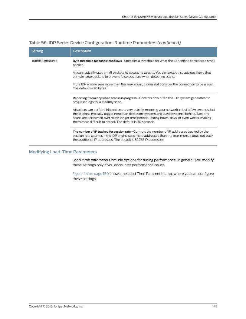
Table 56: IDP Series Device Configuration: Runtime Parameters (continued)
DescriptionSetting
Byte threshold for suspicious flows–Specifies a threshold for what the IDP engine considers a smallpacket.
A scan typically uses small packets to access its targets. You can exclude suspicious flows thatcontain large packets to prevent false positives when detecting scans.
If the IDP engine sees more than this maximum, it does not consider the connection to be a scan.The default is 20 bytes.
Traffic Signatures
Reporting frequency when scan is in progress –Controls how often the IDP system generates "inprogress" logs for a stealthy scan.
Attackers can perform blatant scans very quickly, mapping your network in just a few seconds, butthese scans typically trigger intrustion detection systems and leave evidence behind. Stealthyscans are performed over much longer time periods, lasting hours, days, or even weeks, makingthem more difficult to detect. The default is 30 seconds.
The number of IP tracked for session rate –Controls the number of IP addresses tracked by thesession rate counter. If the IDP engine sees more addresses than the maximum, it does not trackthe additional IP addresses. The default is 32,767 IP addresses.
Modifying Load-Time Parameters
Load-time parameters include options for tuning performance. In general, you modify
these settings only if you encounter performance issues.
Figure 44 on page 150 shows the Load Time Parameters tab, where you can configure
these settings.
149Copyright © 2013, Juniper Networks, Inc.
Chapter 13: Using NSM to Manage the IDP Series Device Configuration
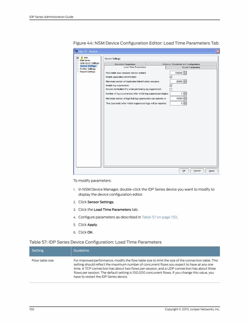
Figure 44: NSMDevice Configuration Editor: Load Time Parameters Tab
To modify parameters:
1. In NSM Device Manager, double-click the IDP Series device you want to modify to
display the device configuration editor.
2. Click Sensor Settings.
3. Click the Load Time Parameters tab.
4. Configure parameters as described in Table 57 on page 150.
5. Click Apply.
6. Click OK.
Table 57: IDP Series Device Configuration: Load Time Parameters
GuidelineSetting
For improved performance, modify the flow table size to limit the size of the connection table. Thissetting should reflect the maximum number of concurrent flows you expect to have at any onetime. A TCP connection has about two flows per session, and a UDP connection has about threeflows per session. The default setting is 100,000 concurrent flows. If you change this value, youhave to restart the IDP Series device.
Flow table size
Copyright © 2013, Juniper Networks, Inc.150
IDP Series Administration Guide
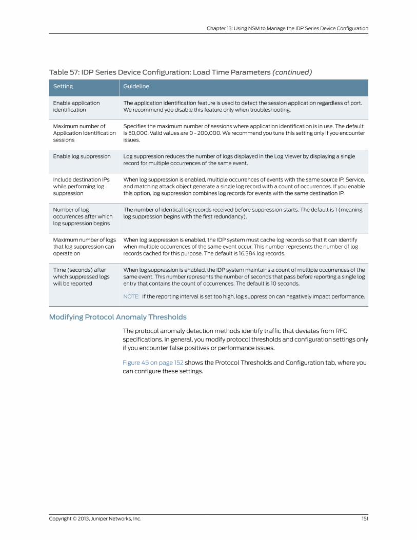
Table 57: IDP Series Device Configuration: Load Time Parameters (continued)
GuidelineSetting
The application identification feature is used to detect the session application regardless of port.We recommend you disable this feature only when troubleshooting.
Enable applicationidentification
Specifies the maximum number of sessions where application identification is in use. The defaultis 50,000. Valid values are 0 - 200,000. We recommend you tune this setting only if you encounterissues.
Maximum number ofApplication Identificationsessions
Log suppression reduces the number of logs displayed in the Log Viewer by displaying a singlerecord for multiple occurrences of the same event.
Enable log suppression
When log suppression is enabled, multiple occurrences of events with the same source IP, Service,and matching attack object generate a single log record with a count of occurrences. If you enablethis option, log suppression combines log records for events with the same destination IP.
Include destination IPswhile performing logsuppression
The number of identical log records received before suppression starts. The default is 1 (meaninglog suppression begins with the first redundancy).
Number of logoccurrences after whichlog suppression begins
When log suppression is enabled, the IDP system must cache log records so that it can identifywhen multiple occurrences of the same event occur. This number represents the number of logrecords cached for this purpose. The default is 16,384 log records.
Maximum number of logsthat log suppression canoperate on
When log suppression is enabled, the IDP system maintains a count of multiple occurrences of thesame event. This number represents the number of seconds that pass before reporting a single logentry that contains the count of occurrences. The default is 10 seconds.
NOTE: If the reporting interval is set too high, log suppression can negatively impact performance.
Time (seconds) afterwhich suppressed logswill be reported
Modifying Protocol Anomaly Thresholds
The protocol anomaly detection methods identify traffic that deviates from RFC
specifications. In general, you modify protocol thresholds and configuration settings only
if you encounter false positives or performance issues.
Figure 45 on page 152 shows the Protocol Thresholds and Configuration tab, where you
can configure these settings.
151Copyright © 2013, Juniper Networks, Inc.
Chapter 13: Using NSM to Manage the IDP Series Device Configuration
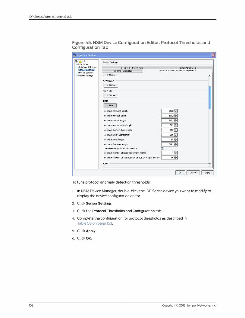
Figure 45: NSMDevice Configuration Editor: Protocol Thresholds andConfiguration Tab
To tune protocol anomaly detection thresholds:
1. In NSM Device Manager, double-click the IDP Series device you want to modify to
display the device configuration editor.
2. Click Sensor Settings.
3. Click the Protocol Thresholds and Configuration tab.
4. Complete the configuration for protocol thresholds as described in
Table 58 on page 153.
5. Click Apply.
6. Click OK.
Copyright © 2013, Juniper Networks, Inc.152
IDP Series Administration Guide
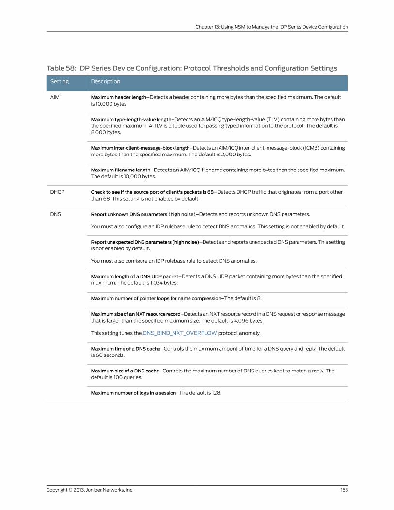
Table 58: IDP Series Device Configuration: Protocol Thresholds and Configuration Settings
DescriptionSetting
Maximum header length–Detects a header containing more bytes than the specified maximum. The defaultis 10,000 bytes.
AIM
Maximum type-length-value length–Detects an AIM/ICQ type-length-value (TLV) containing more bytes thanthe specified maximum. A TLV is a tuple used for passing typed information to the protocol. The default is8,000 bytes.
Maximuminter-client-message-block length–Detects an AIM/ICQ inter-client-message-block (ICMB) containingmore bytes than the specified maximum. The default is 2,000 bytes.
Maximum filename length–Detects an AIM/ICQ filename containing more bytes than the specified maximum.The default is 10,000 bytes.
Check to see if the source port of client's packets is 68–Detects DHCP traffic that originates from a port otherthan 68. This setting is not enabled by default.
DHCP
Report unknown DNS parameters (high noise)–Detects and reports unknown DNS parameters.
You must also configure an IDP rulebase rule to detect DNS anomalies. This setting is not enabled by default.
DNS
ReportunexpectedDNSparameters(highnoise)–Detects and reports unexpected DNS parameters. This settingis not enabled by default.
You must also configure an IDP rulebase rule to detect DNS anomalies.
Maximum length of a DNSUDP packet–Detects a DNS UDP packet containing more bytes than the specifiedmaximum. The default is 1,024 bytes.
Maximum number of pointer loops for name compression–The default is 8.
MaximumsizeofanNXTresource record–Detects an NXT resource record in a DNS request or response messagethat is larger than the specified maximum size. The default is 4,096 bytes.
This setting tunes the DNS_BIND_NXT_OVERFLOW protocol anomaly.
Maximum time of a DNS cache–Controls the maximum amount of time for a DNS query and reply. The defaultis 60 seconds.
Maximum size of a DNS cache–Controls the maximum number of DNS queries kept to match a reply. Thedefault is 100 queries.
Maximum number of logs in a session–The default is 128.
153Copyright © 2013, Juniper Networks, Inc.
Chapter 13: Using NSM to Manage the IDP Series Device Configuration
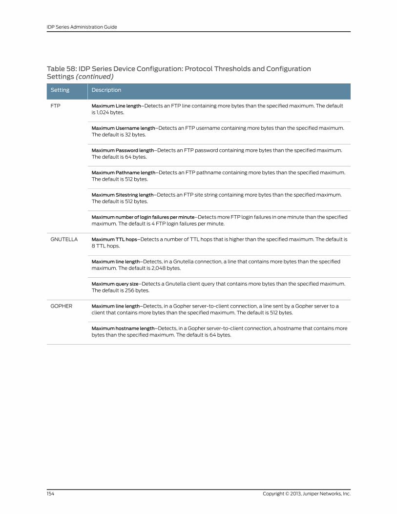
Table 58: IDP Series Device Configuration: Protocol Thresholds and ConfigurationSettings (continued)
DescriptionSetting
Maximum Line length–Detects an FTP line containing more bytes than the specified maximum. The defaultis 1,024 bytes.
FTP
MaximumUsername length–Detects an FTP username containing more bytes than the specified maximum.The default is 32 bytes.
MaximumPassword length–Detects an FTP password containing more bytes than the specified maximum.The default is 64 bytes.
MaximumPathname length–Detects an FTP pathname containing more bytes than the specified maximum.The default is 512 bytes.
MaximumSitestring length–Detects an FTP site string containing more bytes than the specified maximum.The default is 512 bytes.
Maximumnumber of login failures perminute–Detects more FTP login failures in one minute than the specifiedmaximum. The default is 4 FTP login failures per minute.
MaximumTTL hops–Detects a number of TTL hops that is higher than the specified maximum. The default is8 TTL hops.
GNUTELLA
Maximum line length–Detects, in a Gnutella connection, a line that contains more bytes than the specifiedmaximum. The default is 2,048 bytes.
Maximumquery size–Detects a Gnutella client query that contains more bytes than the specified maximum.The default is 256 bytes.
Maximum line length–Detects, in a Gopher server-to-client connection, a line sent by a Gopher server to aclient that contains more bytes than the specified maximum. The default is 512 bytes.
GOPHER
Maximumhostname length–Detects, in a Gopher server-to-client connection, a hostname that contains morebytes than the specified maximum. The default is 64 bytes.
Copyright © 2013, Juniper Networks, Inc.154
IDP Series Administration Guide
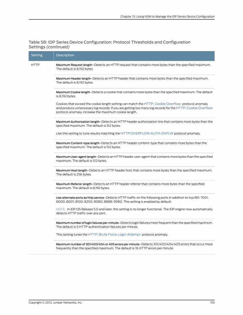
Table 58: IDP Series Device Configuration: Protocol Thresholds and ConfigurationSettings (continued)
DescriptionSetting
MaximumRequest length–Detects an HTTP request that contains more bytes than the specified maximum.The default is 8,192 bytes.
HTTP
MaximumHeader length–Detects an HTTP header that contains more bytes than the specified maximum.The default is 8,192 bytes.
MaximumCookie length–Detects a cookie that contains more bytes than the specified maximum. The defaultis 8,192 bytes.
Cookies that exceed the cookie length setting can match the HTTP: Cookie Overflow protocol anomalyand produce unnecessary log records. If you are getting too many log records for theHTTP: CookieOverflowprotocol anomaly, increase the maximum cookie length.
MaximumAuthorization length–Detects an HTTP header authorization line that contains more bytes than thespecified maximum. The default is 512 bytes.
Use this setting to tune results matching the HTTP:OVERFLOW:AUTH-OVFLW protocol anomaly.
MaximumContent-type length–Detects an HTTP header content-type that contains more bytes than thespecified maximum. The default is 512 bytes.
MaximumUser-agent length–Detects an HTTP header user-agent that contains more bytes than the specifiedmaximum. The default is 512 bytes.
MaximumHost length–Detects an HTTP header host that contains more bytes than the specified maximum.The default is 256 bytes.
MaximumReferrer length–Detects an HTTP header referrer that contains more bytes than the specifiedmaximum. The default is 8,192 bytes.
Use alternate ports as http service–Detects HTTP traffic on the following ports in addition to tcp/80: 7001;8000; 8001; 8100; 8200; 8080; 8888; 9080. This setting is enabled by default.
NOTE: In IDP OS Release 5.0 and later, this setting is no longer functional. The IDP engine now automaticallydetects HTTP traffic over any port.
Maximumnumberof login failuresper-minute–Detects login failures more frequent than the specified maximum.The default is 5 HTTP authentication failures per minute.
This setting tunes the HTTP: Brute Force Login Attempt protocol anomaly.
Maximumnumber of 301/403/404or 405 errors per-minute–Detects 301/403/404/405 errors that occur morefrequently than the specified maximum. The default is 16 HTTP errors per minute.
155Copyright © 2013, Juniper Networks, Inc.
Chapter 13: Using NSM to Manage the IDP Series Device Configuration
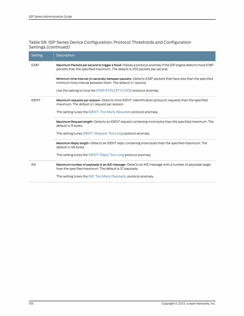
Table 58: IDP Series Device Configuration: Protocol Thresholds and ConfigurationSettings (continued)
DescriptionSetting
MaximumPacketsper second to trigger a flood–Raises a protocol anomaly if the IDP engine detects more ICMPpackets than the specified maximum. The default is 250 packets per second.
ICMP
Minimum time interval (in seconds) between packets–Detects ICMP packets that have less than the specifiedminimum time interval between them. The default is 1 second.
Use this setting to tune the ICMP:EXPLOIT:FLOOD protocol anomaly.
Maximum requests per session–Detects more IDENT (identification protocol) requests than the specifiedmaximum. The default is 1 request per session.
This setting tunes the IDENT: TooMany Requests protocol anomaly.
IDENT
MaximumRequest length–Detects an IDENT request containing more bytes than the specified maximum. Thedefault is 15 bytes.
This setting tunes IDENT: Request Too Long protocol anomaly.
MaximumReply length–Detects an IDENT reply containing more bytes than the specified maximum. Thedefault is 128 bytes.
This setting tunes the IDENT: Reply Too Long protocol anomaly.
Maximum number of payloads in an IKEmessage–Detects an IKE message with a number of payloads largerthan the specified maximum. The default is 57 payloads.
This setting tunes the IKE: TooMany Payloads protocol anomaly.
IKE
Copyright © 2013, Juniper Networks, Inc.156
IDP Series Administration Guide
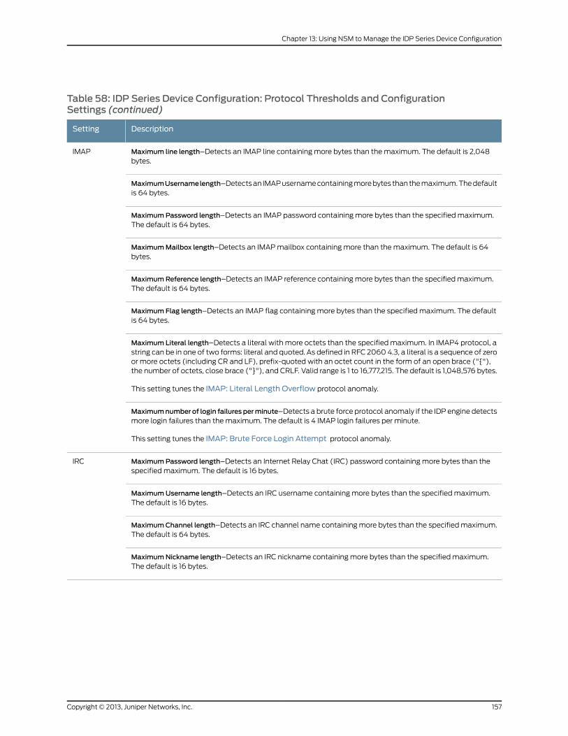
Table 58: IDP Series Device Configuration: Protocol Thresholds and ConfigurationSettings (continued)
DescriptionSetting
Maximum line length–Detects an IMAP line containing more bytes than the maximum. The default is 2,048bytes.
IMAP
MaximumUsernamelength–Detects an IMAP username containing more bytes than the maximum. The defaultis 64 bytes.
MaximumPassword length–Detects an IMAP password containing more bytes than the specified maximum.The default is 64 bytes.
MaximumMailbox length–Detects an IMAP mailbox containing more than the maximum. The default is 64bytes.
MaximumReference length–Detects an IMAP reference containing more bytes than the specified maximum.The default is 64 bytes.
Maximum Flag length–Detects an IMAP flag containing more bytes than the specified maximum. The defaultis 64 bytes.
Maximum Literal length–Detects a literal with more octets than the specified maximum. In IMAP4 protocol, astring can be in one of two forms: literal and quoted. As defined in RFC 2060 4.3, a literal is a sequence of zeroor more octets (including CR and LF), prefix-quoted with an octet count in the form of an open brace ("{"),the number of octets, close brace ("}"), and CRLF. Valid range is 1 to 16,777,215. The default is 1,048,576 bytes.
This setting tunes the IMAP: Literal Length Overflow protocol anomaly.
Maximumnumber of login failures perminute–Detects a brute force protocol anomaly if the IDP engine detectsmore login failures than the maximum. The default is 4 IMAP login failures per minute.
This setting tunes the IMAP: Brute Force Login Attempt protocol anomaly.
MaximumPassword length–Detects an Internet Relay Chat (IRC) password containing more bytes than thespecified maximum. The default is 16 bytes.
IRC
MaximumUsername length–Detects an IRC username containing more bytes than the specified maximum.The default is 16 bytes.
MaximumChannel length–Detects an IRC channel name containing more bytes than the specified maximum.The default is 64 bytes.
MaximumNickname length–Detects an IRC nickname containing more bytes than the specified maximum.The default is 16 bytes.
157Copyright © 2013, Juniper Networks, Inc.
Chapter 13: Using NSM to Manage the IDP Series Device Configuration
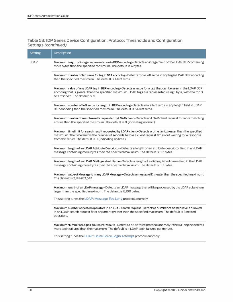
Table 58: IDP Series Device Configuration: Protocol Thresholds and ConfigurationSettings (continued)
DescriptionSetting
Maximum lengthof integer representation inBERencoding–Detects an integer field of the LDAP BER containingmore bytes than the specified maximum. The default is 4 bytes.
LDAP
Maximumnumberof left zeros for tag inBERencoding–Detects more left zeros in any tag in LDAP BER encodingthan the specified maximum. The default is 4 left zeros.
Maximum value of any LDAP tag in BER encoding–Detects a value for a tag that can be seen in the LDAP BERencoding that is greater than the specified maximum. LDAP tags are represented using 1 byte, with the top 3bits reserved. The default is 31.
Maximum number of left zeros for length in BER encoding–Detects more left zeros in any length field in LDAPBER encoding than the specified maximum. The default is 64 left zeros.
Maximumnumberofsearch results requestedbyLDAPclient–Detects an LDAP client request for more matchingentries than the specified maximum. The default is 0 (indicating no limit).
Maximum timelimit for search result requested by LDAP client–Detects a time limit greater than the specifiedmaximum. The time limit is the number of seconds before a client request times out waiting for a responsefrom the server. The default is 0 (indicating no limit).
Maximum length of an LDAP Attribute Descriptor–Detects a length of an attribute descriptor field in an LDAPmessage containing more bytes than the specified maximum. The default is 512 bytes.
Maximum length of an LDAP Distinguished Name–Detects a length of a distinguished name field in the LDAPmessage containing more bytes than the specified maximum. The default is 512 bytes.
MaximumvalueofMessage id inanyLDAPMessage–Detects a message ID greater than the specified maximum.The default is 2,147,483,647.
MaximumlengthofanLDAPmessage–Detects an LDAP message that will be processed by the LDAP subsystemlarger than the specified maximum. The default is 8,100 bytes.
This setting tunes the LDAP: Message Too Long protocol anomaly.
Maximum number of nested operators in an LDAP search request–Detects a number of nested levels allowedin an LDAP search request filter argument greater than the specified maximum. The default is 8 nestedoperators.
MaximumNumberofLoginFailuresPerMinute–Detects a brute force protocol anomaly if the IDP engine detectsmore login failures than the maximum. The default is 4 LDAP login failures per minute.
This setting tunes the LDAP: Brute Force Login Attempt protocol anomaly.
Copyright © 2013, Juniper Networks, Inc.158
IDP Series Administration Guide
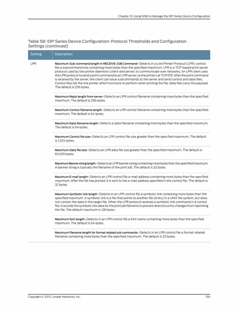
Table 58: IDP Series Device Configuration: Protocol Thresholds and ConfigurationSettings (continued)
DescriptionSetting
MaximumSub-command length in RECEIVE-JOB Command–Detects in a Line Printer Protocol (LPR) controlfile a subcommand line containing more bytes than the specified maximum. LPR is a TCP-based print serverprotocol used by line printer daemons (client and server) to communicate over networks. An LPR client usesthe LPR protocol to send a print command to an LPR server (a line printer) at TCP/515. After the print commandis received by the server, the client can issue subcommands to the server and send control and data files.Control files tell the line printer which functions to perform when printing the file; data files carry the payload.The default is 256 bytes.
LPR
MaximumReply length from server–Detects an LPR control filename containing more bytes than the specifiedmaximum. The default is 256 bytes.
MaximumControl filename length–Detects an LPR control filename containing more bytes than the specifiedmaximum. The default is 64 bytes.
MaximumData filename length–Detects a data filename containing more bytes than the specified maximum.The default is 64 bytes.
MaximumControl file size–Detects an LPR control file size greater than the specified maximum. The defaultis 1,024 bytes.
MaximumData file size–Detects an LPR data file size greater than the specified maximum. The default is65,535 bytes.
MaximumBannerstringlength–Detects an LPR banner string containing more bytes than the specified maximum.A banner string is typically the filename of the print job. The default is 32 bytes.
MaximumE-mail length–Detects an LPR control file e-mail address containing more bytes than the specifiedmaximum. After the file has printed, it is sent to the e-mail address specified in the control file. The default is32 bytes.
MaximumSymbolic link length–Detects in an LPR control file a symbolic link containing more bytes than thespecified maximum. A symbolic link is a file that points to another file (entry) in a UNIX file system, but doesnot contain the data in the target file. When the LPR protocol receives a symbolic link command in a controlfile, it records the symbolic link data for the print job filename to prevent directory entry changes from reprintingthe file. The default maximum is 128 bytes.
Maximum font length–Detects in an LPR control file a font name containing more bytes than the specifiedmaximum. The default is 64 bytes.
Maximum filename length for format related sub commands–Detects in an LPR control file a format-relatedfilename containing more bytes than the specified maximum. The default is 32 bytes.
159Copyright © 2013, Juniper Networks, Inc.
Chapter 13: Using NSM to Manage the IDP Series Device Configuration
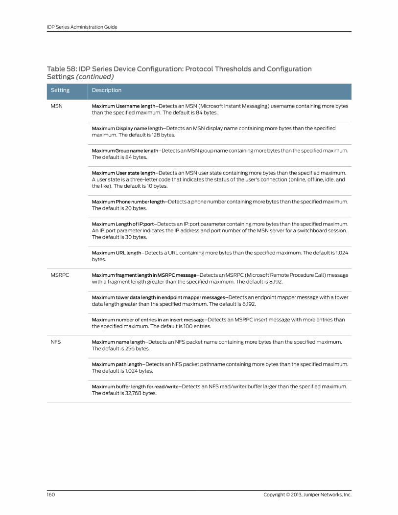
Table 58: IDP Series Device Configuration: Protocol Thresholds and ConfigurationSettings (continued)
DescriptionSetting
MaximumUsername length–Detects an MSN (Microsoft Instant Messaging) username containing more bytesthan the specified maximum. The default is 84 bytes.
MSN
MaximumDisplay name length–Detects an MSN display name containing more bytes than the specifiedmaximum. The default is 128 bytes.
MaximumGroupnamelength–Detects an MSN group name containing more bytes than the specified maximum.The default is 84 bytes.
MaximumUser state length–Detects an MSN user state containing more bytes than the specified maximum.A user state is a three-letter code that indicates the status of the user's connection (online, offline, idle, andthe like). The default is 10 bytes.
MaximumPhonenumber length–Detects a phone number containing more bytes than the specified maximum.The default is 20 bytes.
MaximumLengthof IP:port–Detects an IP:port parameter containing more bytes than the specified maximum.An IP:port parameter indicates the IP address and port number of the MSN server for a switchboard session.The default is 30 bytes.
MaximumURL length–Detects a URL containing more bytes than the specified maximum. The default is 1,024bytes.
Maximumfragment length inMSRPCmessage–Detects an MSRPC (Microsoft Remote Procedure Call) messagewith a fragment length greater than the specified maximum. The default is 8,192.
MSRPC
Maximumtowerdata length in endpointmappermessages–Detects an endpoint mapper message with a towerdata length greater than the specified maximum. The default is 8,192.
Maximum number of entries in an insert message–Detects an MSRPC insert message with more entries thanthe specified maximum. The default is 100 entries.
Maximum name length–Detects an NFS packet name containing more bytes than the specified maximum.The default is 256 bytes.
NFS
Maximumpath length–Detects an NFS packet pathname containing more bytes than the specified maximum.The default is 1,024 bytes.
Maximumbuffer length for read/write–Detects an NFS read/writer buffer larger than the specified maximum.The default is 32,768 bytes.
Copyright © 2013, Juniper Networks, Inc.160
IDP Series Administration Guide
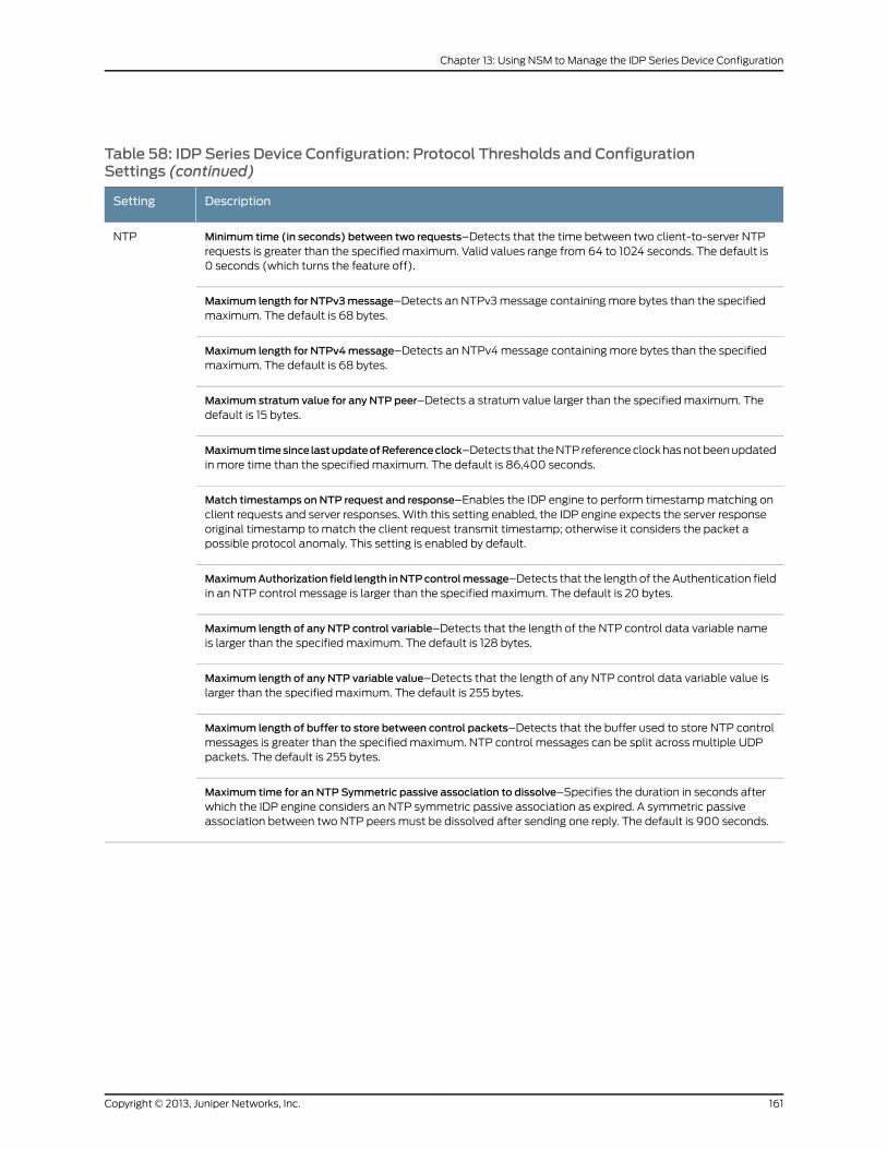
Table 58: IDP Series Device Configuration: Protocol Thresholds and ConfigurationSettings (continued)
DescriptionSetting
Minimum time (in seconds) between two requests–Detects that the time between two client-to-server NTPrequests is greater than the specified maximum. Valid values range from 64 to 1024 seconds. The default is0 seconds (which turns the feature off).
NTP
Maximum length for NTPv3message–Detects an NTPv3 message containing more bytes than the specifiedmaximum. The default is 68 bytes.
Maximum length for NTPv4message–Detects an NTPv4 message containing more bytes than the specifiedmaximum. The default is 68 bytes.
Maximum stratum value for any NTP peer–Detects a stratum value larger than the specified maximum. Thedefault is 15 bytes.
Maximumtimesince lastupdateofReferenceclock–Detects that the NTP reference clock has not been updatedin more time than the specified maximum. The default is 86,400 seconds.
Match timestamps on NTP request and response–Enables the IDP engine to perform timestamp matching onclient requests and server responses. With this setting enabled, the IDP engine expects the server responseoriginal timestamp to match the client request transmit timestamp; otherwise it considers the packet apossible protocol anomaly. This setting is enabled by default.
MaximumAuthorization field length inNTPcontrolmessage–Detects that the length of the Authentication fieldin an NTP control message is larger than the specified maximum. The default is 20 bytes.
Maximum length of any NTP control variable–Detects that the length of the NTP control data variable nameis larger than the specified maximum. The default is 128 bytes.
Maximum length of any NTP variable value–Detects that the length of any NTP control data variable value islarger than the specified maximum. The default is 255 bytes.
Maximum length of buffer to store between control packets–Detects that the buffer used to store NTP controlmessages is greater than the specified maximum. NTP control messages can be split across multiple UDPpackets. The default is 255 bytes.
Maximum time for an NTP Symmetric passive association to dissolve–Specifies the duration in seconds afterwhich the IDP engine considers an NTP symmetric passive association as expired. A symmetric passiveassociation between two NTP peers must be dissolved after sending one reply. The default is 900 seconds.
161Copyright © 2013, Juniper Networks, Inc.
Chapter 13: Using NSM to Manage the IDP Series Device Configuration
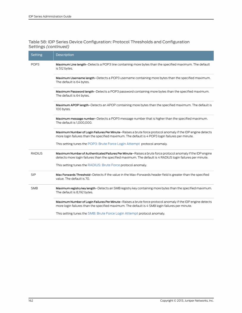
Table 58: IDP Series Device Configuration: Protocol Thresholds and ConfigurationSettings (continued)
DescriptionSetting
Maximum Line length–Detects a POP3 line containing more bytes than the specified maximum. The defaultis 512 bytes.
POP3
MaximumUsername length–Detects a POP3 username containing more bytes than the specified maximum.The default is 64 bytes.
MaximumPassword length–Detects a POP3 password containing more bytes than the specified maximum.The default is 64 bytes.
MaximumAPOP length–Detects an APOP containing more bytes than the specified maximum. The default is100 bytes.
Maximummessage number–Detects a POP3 message number that is higher than the specified maximum.The default is 1,000,000.
MaximumNumber of Login FailuresPerMinute–Raises a brute force protocol anomaly if the IDP engine detectsmore login failures than the specified maximum. The default is 4 POP3 login failures per minute.
This setting tunes the POP3: Brute Force Login Attempt protocol anomaly.
MaximumNumberofAuthenticatedFailuresPerMinute–Raises a brute force protocol anomaly if the IDP enginedetects more login failures than the specified maximum. The default is 4 RADIUS login failures per minute.
This setting tunes the RADIUS: Brute Force protocol anomaly.
RADIUS
Max Forwards Threshold–Detects if the value in the Max-Forwards header field is greater than the specifiedvalue. The default is 70.
SIP
Maximumregistry key length–Detects an SMB registry key containing more bytes than the specified maximum.The default is 8,192 bytes.
SMB
MaximumNumber of Login FailuresPerMinute–Raises a brute force protocol anomaly if the IDP engine detectsmore login failures than the specified maximum. The default is 4 SMB login failures per minute.
This setting tunes the SMB: Brute Force Login Attempt protocol anomaly.
Copyright © 2013, Juniper Networks, Inc.162
IDP Series Administration Guide
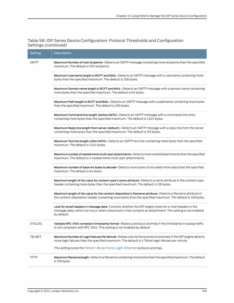
Table 58: IDP Series Device Configuration: Protocol Thresholds and ConfigurationSettings (continued)
DescriptionSetting
MaximumNumber ofmail recipients–Detects an SMTP message containing more recipients than the specifiedmaximum. The default is 100 recipients.
SMTP
MaximumUsername length in RCPT andMAIL–Detects an SMTP message with a username containing morebytes than the specified maximum. The default is 256 bytes.
MaximumDomain name length in RCPT andMAIL–Detects an SMTP message with a domain name containingmore bytes than the specified maximum. The default is 64 bytes.
MaximumPath length in RCPT andMAIL–Detects an SMTP message with a pathname containing more bytesthan the specified maximum. The default is 256 bytes.
MaximumCommand line length (before DATA)–Detects an SMTP message with a command-line entrycontaining more bytes than the specified maximum. The default is 1,024 bytes.
MaximumReply line length from server (default)–Detects an SMTP message with a reply line from the servercontaining more bytes than the specified maximum. The default is 512 bytes.
MaximumText line length (after DATA)–Detects an SMTP text line containing more bytes than the specifiedmaximum. The default is 1,024 bytes.
Maximumnumberofnestedmimemulti-partattachments–Detects more nested attachments than the specifiedmaximum. The default is 4 nested mime multi-part attachments.
Maximum number of base-64 bytes to decode–Detects more bytes of encoded mime data than the specifiedmaximum. The default is 64 bytes.
Maximum length of the value for content-type's name attribute–Detects a name attribute in the content-typeheader containing more bytes than the specified maximum. The default is 128 bytes.
Maximum length of the value for the content-disposition's filename attribute–Detects a filename attribute inthe content-disposition header containing more bytes than the specified maximum. The default is 128 bytes.
Look for email headers inmessage data–Controls whether the IDP engine looks for e-mail headers in themessage data, which can occur when a bounced e-mail contains an attachment. This setting is not enabledby default.
Validate RFC-3164 compliant timestamp format–Raises a protocol anomaly if the timestamp in syslog trafficis not compliant with RFC 3164. This setting is not enabled by default.
SYSLOG
MaximumNumber of Login FailuresPerMinute–Raises a brute force protocol anomaly if the IDP engine detectsmore login failures than the specified maximum. The default is 4 Telnet login failures per minute.
This setting tunes the Telnet:: Brute Force Login Attempt protocol anomaly.
TELNET
Maximumfilenamelength–Detects a filename containing more bytes than the specified maximum. The defaultis 128 bytes.
TFTP
163Copyright © 2013, Juniper Networks, Inc.
Chapter 13: Using NSM to Manage the IDP Series Device Configuration
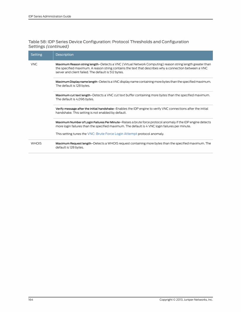
Table 58: IDP Series Device Configuration: Protocol Thresholds and ConfigurationSettings (continued)
DescriptionSetting
MaximumReason string length–Detects a VNC (Virtual Network Computing) reason string length greater thanthe specified maximum. A reason string contains the text that describes why a connection between a VNCserver and client failed. The default is 512 bytes.
VNC
MaximumDisplaynamelength–Detects a VNC display name containing more bytes than the specified maximum.The default is 128 bytes.
Maximum cut text length–Detects a VNC cut text buffer containing more bytes than the specified maximum.The default is 4,096 bytes.
Verify message after the initial handshake–Enables the IDP engine to verify VNC connections after the initialhandshake. This setting is not enabled by default.
MaximumNumber of Login FailuresPerMinute–Raises a brute force protocol anomaly if the IDP engine detectsmore login failures than the specified maximum. The default is 4 VNC login failures per minute.
This setting tunes the VNC: Brute Force Login Attempt protocol anomaly.
MaximumRequest length–Detects a WHOIS request containing more bytes than the specified maximum. Thedefault is 128 bytes.
WHOIS
Copyright © 2013, Juniper Networks, Inc.164
IDP Series Administration Guide
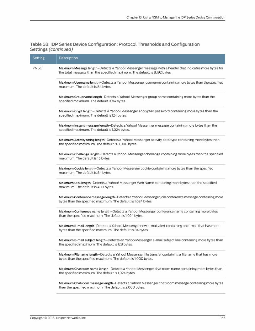
Table 58: IDP Series Device Configuration: Protocol Thresholds and ConfigurationSettings (continued)
DescriptionSetting
MaximumMessage length–Detects a Yahoo! Messenger message with a header that indicates more bytes forthe total message than the specified maximum. The default is 8,192 bytes.
YMSG
MaximumUsername length–Detects a Yahoo! Messenger username containing more bytes than the specifiedmaximum. The default is 84 bytes.
MaximumGroupname length–Detects a Yahoo! Messenger group name containing more bytes than thespecified maximum. The default is 84 bytes.
MaximumCrypt length–Detects a Yahoo! Messenger encrypted password containing more bytes than thespecified maximum. The default is 124 bytes.
Maximum Instantmessage length–Detects a Yahoo! Messenger message containing more bytes than thespecified maximum. The default is 1,024 bytes.
MaximumActivity string length–Detects a Yahoo! Messenger activity data type containing more bytes thanthe specified maximum. The default is 8,000 bytes.
MaximumChallenge length–Detects a Yahoo! Messenger challenge containing more bytes than the specifiedmaximum. The default is 15 bytes.
MaximumCookie length–Detects a Yahoo! Messenger cookie containing more bytes than the specifiedmaximum. The default is 84 bytes.
MaximumURL length–Detects a Yahoo! Messenger Web Name containing more bytes than the specifiedmaximum. The default is 400 bytes.
MaximumConferencemessage length–Detects a Yahoo! Messenger join conference message containing morebytes than the specified maximum. The default is 1,024 bytes.
MaximumConference name length–Detects a Yahoo! Messenger conference name containing more bytesthan the specified maximum. The default is 1,024 bytes.
MaximumE-mail length–Detects a Yahoo! Messenger new e-mail alert containing an e-mail that has morebytes than the specified maximum. The default is 84 bytes.
MaximumE-mail subject length–Detects an Yahoo Messenger e-mail subject line containing more bytes thanthe specified maximum. The default is 128 bytes.
Maximum Filename length–Detects a Yahoo! Messenger file transfer containing a filename that has morebytes than the specified maximum. The default is 1,000 bytes.
MaximumChatroom name length–Detects a Yahoo! Messenger chat room name containing more bytes thanthe specified maximum. The default is 1,024 bytes.
MaximumChatroommessage length–Detects a Yahoo! Messenger chat room message containing more bytesthan the specified maximum. The default is 2,000 bytes.
165Copyright © 2013, Juniper Networks, Inc.
Chapter 13: Using NSM to Manage the IDP Series Device Configuration
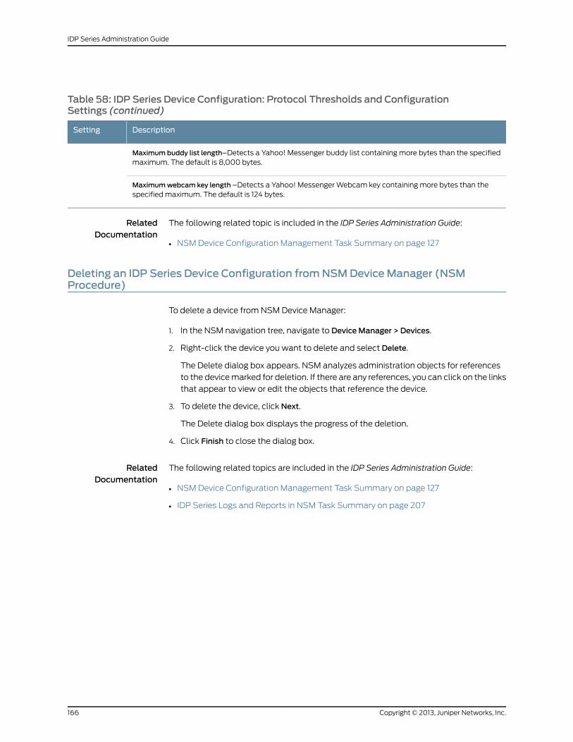
Table 58: IDP Series Device Configuration: Protocol Thresholds and ConfigurationSettings (continued)
DescriptionSetting
Maximumbuddy list length–Detects a Yahoo! Messenger buddy list containing more bytes than the specifiedmaximum. The default is 8,000 bytes.
Maximumwebcam key length –Detects a Yahoo! Messenger Webcam key containing more bytes than thespecified maximum. The default is 124 bytes.
RelatedDocumentation
The following related topic is included in the IDP Series Administration Guide:
NSM Device Configuration Management Task Summary on page 127•
Deleting an IDP Series Device Configuration fromNSMDeviceManager (NSMProcedure)
To delete a device from NSM Device Manager:
1. In the NSM navigation tree, navigate to DeviceManager > Devices.
2. Right-click the device you want to delete and select Delete.
The Delete dialog box appears. NSM analyzes administration objects for references
to the device marked for deletion. If there are any references, you can click on the links
that appear to view or edit the objects that reference the device.
3. To delete the device, click Next.
The Delete dialog box displays the progress of the deletion.
4. Click Finish to close the dialog box.
RelatedDocumentation
The following related topics are included in the IDP Series Administration Guide:
• NSM Device Configuration Management Task Summary on page 127
• IDP Series Logs and Reports in NSM Task Summary on page 207
Copyright © 2013, Juniper Networks, Inc.166
IDP Series Administration Guide
CHAPTER 14
Enabling Advanced Features andOptionswith scio Commands
This chapter contains the following topics:
• scio Configuration Commands Task Summary on page 167
• Using the SSL Private Server Key to Enable Inspection of SSL Traffic on page 168
• Using the SSL Forward Proxy Feature to Enable Inspection of HTTPS Traffic on page 171
• Exempting HTTPS Traffic from Inspection on page 172
• Enabling Inspection of GRE Traffic on page 173
• Enabling Inspection of GTP Traffic on page 175
• Enabling Inspection of IPsec VPN Traffic on page 177
• Enabling Inspection of MPLS Traffic on page 178
• Enabling the Flow Bypass Feature on page 179
• Configuring Advanced Settings for the User-Role-Based Policy Feature on page 181
• Configuring a Default Rate Limit on page 182
• Enabling Per-User Rate Limiting for User-Role-Based Rules on page 183
scio Configuration Commands Task Summary
You can use the scio configuration commands to enable advanced features, such as:
• Inspection of encrypted or encapsulated traffic
• Flow bypass when the IDP engine is under heavy stress
• Advanced settings for the APE rulebase
• Advanced settings for the user-role-based feature
RelatedDocumentation
The following related topics are included in the IDP Series Administration Guide:
scio const on page 330•
• Using the SSL Private Server Key to Enable Inspection of SSL Traffic on page 168
• Using the SSL Forward Proxy Feature to Enable Inspection of HTTPS Traffic on page 171
167Copyright © 2013, Juniper Networks, Inc.
• Exempting HTTPS Traffic from Inspection on page 172
• Enabling Inspection of GRE Traffic on page 173
• Enabling Inspection of GTP Traffic on page 175
• Enabling Inspection of IPsec VPN Traffic on page 177
• Enabling Inspection of MPLS Traffic on page 178
• Enabling the Flow Bypass Feature on page 179
Using the SSL Private Server Key to Enable Inspection of SSL Traffic
To inspect the HTTP payload of HTTPS traffic, the IDP Series device must first decrypt
the session. Your security policy can examine both the SSL session and the HTTP payload.
The IDP Series solution supports SSL inspection in two ways:
• Using server private keys. Use this method when inspecting traffic to internal servers
where you have access to the server private key.
• Using the SSL forward proxy feature. Use this method when the server private key
method is not practical (for example, for traffic to servers on the WWW).
NOTE: If you enable bothmethods, the IDP Series device performs SSLinspection using the SSL forward proxymethod and does not use the serverprivate keys.
The following procedure provides the basic steps you take to implement inspection using
the SSL server private keys.
To use the SSL private server key to enable inspection of SSL traffic:
1. Log into the CLI as admin and enter su - to switch to root.
Copyright © 2013, Juniper Networks, Inc.168
IDP Series Administration Guide
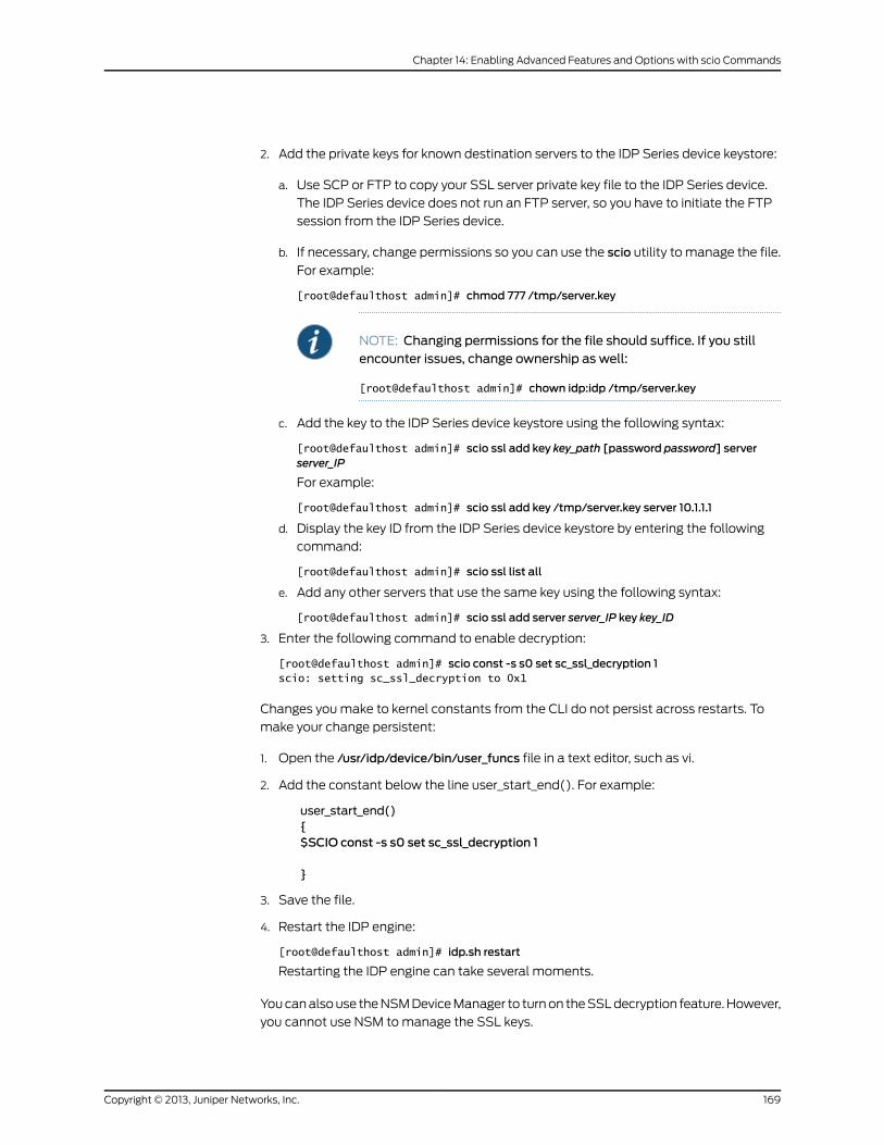
2. Add the private keys for known destination servers to the IDP Series device keystore:
a. Use SCP or FTP to copy your SSL server private key file to the IDP Series device.
The IDP Series device does not run an FTP server, so you have to initiate the FTP
session from the IDP Series device.
b. If necessary, change permissions so you can use the scio utility to manage the file.
For example:
[root@defaulthost admin]# chmod 777 /tmp/server.key
NOTE: Changing permissions for the file should suffice. If you stillencounter issues, change ownership as well:
[root@defaulthost admin]# chown idp:idp /tmp/server.key
c. Add the key to the IDP Series device keystore using the following syntax:
[root@defaulthost admin]# scio ssl add key key_path [password password] serverserver_IP
For example:
[root@defaulthost admin]# scio ssl add key /tmp/server.key server 10.1.1.1
d. Display the key ID from the IDP Series device keystore by entering the following
command:
[root@defaulthost admin]# scio ssl list all
e. Add any other servers that use the same key using the following syntax:
[root@defaulthost admin]# scio ssl add server server_IP key key_ID
3. Enter the following command to enable decryption:
[root@defaulthost admin]# scio const -s s0 set sc_ssl_decryption 1scio: setting sc_ssl_decryption to 0x1
Changes you make to kernel constants from the CLI do not persist across restarts. To
make your change persistent:
1. Open the /usr/idp/device/bin/user_funcs file in a text editor, such as vi.
2. Add the constant below the line user_start_end(). For example:
user_start_end(){$SCIO const -s s0 set sc_ssl_decryption 1
}
3. Save the file.
4. Restart the IDP engine:
[root@defaulthost admin]# idp.sh restart
Restarting the IDP engine can take several moments.
You can also use the NSM Device Manager to turn on the SSL decryption feature. However,
you cannot use NSM to manage the SSL keys.
169Copyright © 2013, Juniper Networks, Inc.
Chapter 14: Enabling Advanced Features and Options with scio Commands
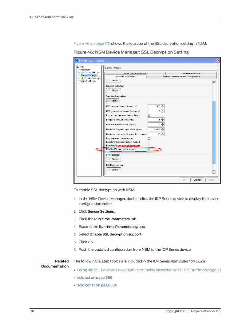
Figure 46 on page 170 shows the location of the SSL decryption setting in NSM.
Figure 46: NSMDeviceManager: SSL Decryption Setting
To enable SSL decryption with NSM:
1. In the NSM Device Manager, double-click the IDP Series device to display the device
configuration editor.
2. Click Sensor Settings.
3. Click the Run-time Parameters tab.
4. Expand the Run-time Parameters group.
5. Select Enable SSL decryption support.
6. Click OK.
7. Push the updated configuration from NSM to the IDP Series device.
RelatedDocumentation
The following related topics are included in the IDP Series Administration Guide:
Using the SSL Forward Proxy Feature to Enable Inspection of HTTPS Traffic on page 171•
• scio ssl on page 356
• scio const on page 330
Copyright © 2013, Juniper Networks, Inc.170
IDP Series Administration Guide
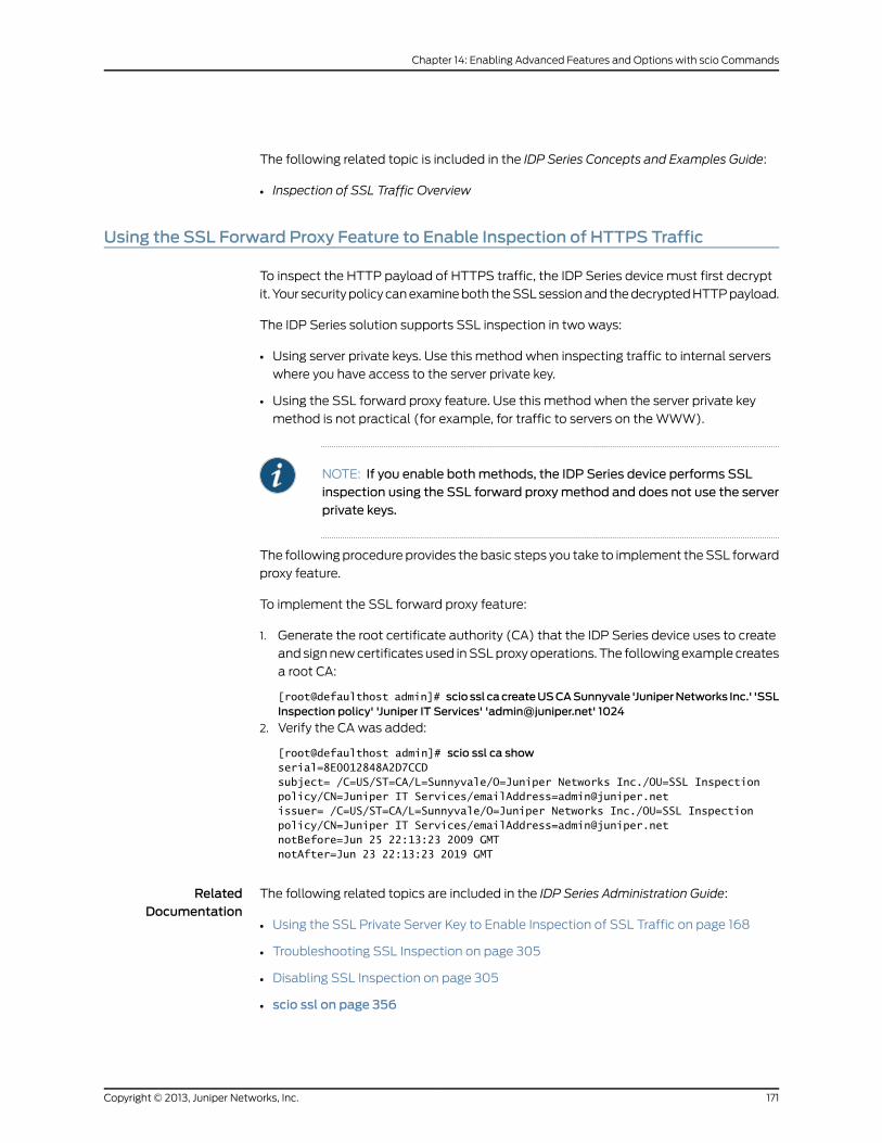
The following related topic is included in the IDP Series Concepts and Examples Guide:
• Inspection of SSL Traffic Overview
Using the SSL Forward Proxy Feature to Enable Inspection of HTTPS Traffic
To inspect the HTTP payload of HTTPS traffic, the IDP Series device must first decrypt
it. Your security policy can examine both the SSL session and the decrypted HTTP payload.
The IDP Series solution supports SSL inspection in two ways:
• Using server private keys. Use this method when inspecting traffic to internal servers
where you have access to the server private key.
• Using the SSL forward proxy feature. Use this method when the server private key
method is not practical (for example, for traffic to servers on the WWW).
NOTE: If you enable bothmethods, the IDP Series device performs SSLinspection using the SSL forward proxymethod and does not use the serverprivate keys.
The following procedure provides the basic steps you take to implement the SSL forward
proxy feature.
To implement the SSL forward proxy feature:
1. Generate the root certificate authority (CA) that the IDP Series device uses to create
and sign new certificates used in SSL proxy operations. The following example creates
a root CA:
[root@defaulthost admin]# scio ssl cacreateUSCASunnyvale 'JuniperNetworks Inc.' 'SSLInspection policy' 'Juniper IT Services' '[email protected]' 1024
2. Verify the CA was added:
[root@defaulthost admin]# scio ssl ca showserial=8E0012848A2D7CCDsubject= /C=US/ST=CA/L=Sunnyvale/O=Juniper Networks Inc./OU=SSL Inspectionpolicy/CN=Juniper IT Services/[email protected]= /C=US/ST=CA/L=Sunnyvale/O=Juniper Networks Inc./OU=SSL Inspectionpolicy/CN=Juniper IT Services/[email protected]=Jun 25 22:13:23 2009 GMTnotAfter=Jun 23 22:13:23 2019 GMT
RelatedDocumentation
The following related topics are included in the IDP Series Administration Guide:
Using the SSL Private Server Key to Enable Inspection of SSL Traffic on page 168•
• Troubleshooting SSL Inspection on page 305
• Disabling SSL Inspection on page 305
• scio ssl on page 356
171Copyright © 2013, Juniper Networks, Inc.
Chapter 14: Enabling Advanced Features and Options with scio Commands
• scio const on page 330
The following related topics are included in the IDP Series Concepts and Examples Guide:
• Example: Implementing Inspection of Outbound SSL Traffic
• Inspection of SSL Traffic Overview
Exempting HTTPS Traffic from Inspection
You can use a whitelist to exempt from inspection traffic to specified HTTPS servers. If
traffic matches a whitelist entry, it is passed through (not decrypted or inspected).
NOTE: The whitelist applies only to traffic processing based on the SSLforward proxy feature. You would not use a whitelist to exclude inspectionof traffic to internal destination servers. If desired, you can use a securitypolicy rule to exempt such traffic from inspection.
The whitelist is a text file you import into the IDP Series device, using the CLI. The following
example shows the format of a whitelist file:
10.0.0.11.0.0.0/870.34.21.82trustedsite.comlanding.trustedsearch.com
Each line in the whitelist file specifies the IP address or domain name for a destination
server. To whitelist multiple sites with one entry, you can use an IP prefix to match address
blocks and a domain suffix to include all subdomains.
The domain name in your whitelist should match the common name entry in the certificate
presented by the destination server. For example, suppose the certificate for the E-Trade
HTTPS server contains the following subject:
C=US, ST=Georgia, L=Alpharetta, O=ETRADE FINANCIAL CORPORATION, OU=Global
Information Security, CN=us.etrade.com
You can whitelist this site by adding the string us.etrade.com or the string etrade.comto your whitelist file.
To create a whitelist:
1. Log into the CLI as admin and enter su - to switch to root.
2. Use an editor like vi to create a whitelist file. For example:
[root@defaulthost admin]# vi /tmp/whitelist.txt10.0.0.11.0.0.0/870.34.21.82
Copyright © 2013, Juniper Networks, Inc.172
IDP Series Administration Guide
etrade.combankofamerica.com
3. Run the following command to import the whitelist entries:
[root@defaulthost admin]# scio ssl whitelist import /tmp/whitelist.txt
NOTE: The whitelist setting takes effect on sessions that are initiated afteryour change.
NOTE: To update the active whitelist, import an updated whitelist file. Toclear the whitelist, import a file that contains only one empty line.
RelatedDocumentation
The following related topic is included in the IDP Series Administration Guide:
scio ssl on page 356•
The following related topics are included in the IDP Series Concepts and Examples Guide:
• Example: Exempting Outbound SSL Traffic from Inspection
• Inspection of SSL Traffic Overview
Enabling Inspection of GRE Traffic
You can use the command-line interface (CLI) or Network and Security Manager (NSM)
to enable inspection of generic routing encapsulation (GRE) encapsulated traffic. To
enable inspection of encapsulated traffic, the IDP engine must first decapsulate it.
To enable and configure decapsulation from the CLI:
1. Log into the CLI as admin and enter su - to switch to root.
2. Enter the following command to enable decapsulation:
[root@defaulthost admin]# scio const -s s0 set sc_gre_decapsulation 1scio: setting sc_gre_decapsulation to 0x1
By default, the IDP engine decapsulates one layer.
3. Optional. Change the maximum decapsulation to two layers by entering the following
command:
[root@defaulthost admin]# scio const -s s0 set sc_max_decapsulation 2scio: setting sc_max_decapsulation to 0x2
Changes you make to kernel constants from the CLI do not persist across restarts. To
make your change persistent:
1. Open the /usr/idp/device/bin/user_funcs file in a text editor, such as vi.
2. Add the constant below the line user_start_end(). For example:
173Copyright © 2013, Juniper Networks, Inc.
Chapter 14: Enabling Advanced Features and Options with scio Commands
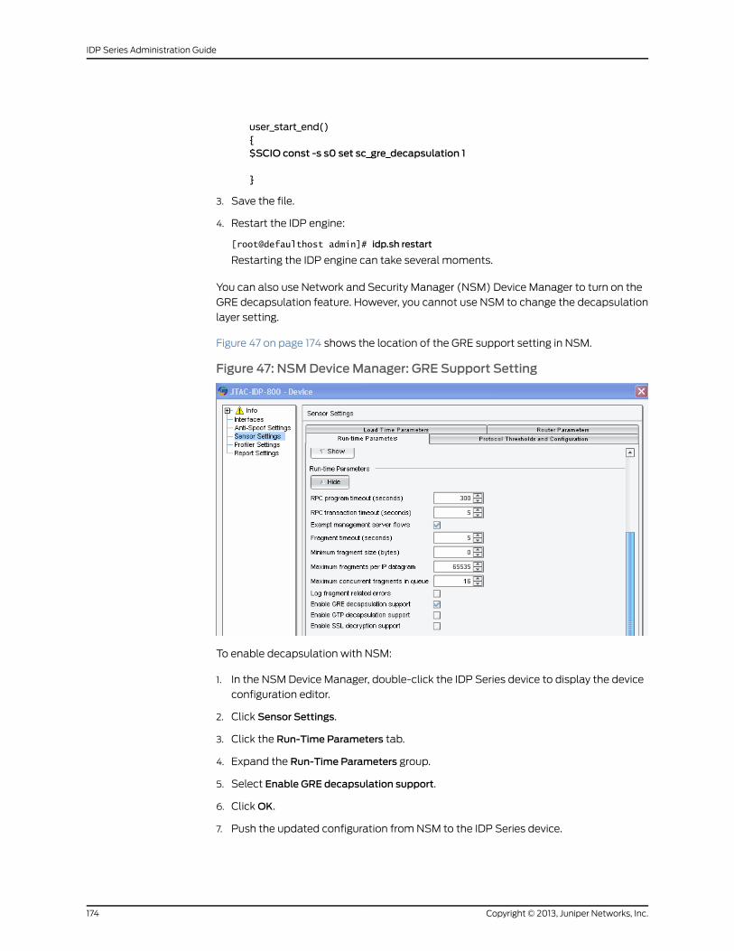
user_start_end(){$SCIO const -s s0 set sc_gre_decapsulation 1
}
3. Save the file.
4. Restart the IDP engine:
[root@defaulthost admin]# idp.sh restart
Restarting the IDP engine can take several moments.
You can also use Network and Security Manager (NSM) Device Manager to turn on the
GRE decapsulation feature. However, you cannot use NSM to change the decapsulation
layer setting.
Figure 47 on page 174 shows the location of the GRE support setting in NSM.
Figure 47: NSMDeviceManager: GRE Support Setting
To enable decapsulation with NSM:
1. In the NSM Device Manager, double-click the IDP Series device to display the device
configuration editor.
2. Click Sensor Settings.
3. Click the Run-Time Parameters tab.
4. Expand the Run-Time Parameters group.
5. Select Enable GRE decapsulation support.
6. Click OK.
7. Push the updated configuration from NSM to the IDP Series device.
Copyright © 2013, Juniper Networks, Inc.174
IDP Series Administration Guide
RelatedDocumentation
The following related topic is included in the IDP Series Administration Guide:
scio const on page 330•
The following related topic is included in the IDP Series Concepts and Examples Guide:
• Inspection of GRE Traffic Overview
Enabling Inspection of GTP Traffic
You can use the command-line interface (CLI) or Network and Security Manager (NSM)
to enable inspection of GPRS tunnelling protocol (GTP) encapsulated traffic. To enable
inspection of encapsulated traffic, the IDP engine must first decapsulate it.
To enable and configure decapsulation from the CLI:
1. Log into the CLI as admin and enter su - to switch to root.
2. Enter the following command to enable decapsulation:
[root@defaulthost admin]# scio const -s s0 set sc_gtp_decapsulation 1scio: setting sc_gtp_decapsulation to 0x1
By default, the IDP engine decapsulates one layer.
3. Optional. Change the maximum decapsulation to two layers by entering the following
command:
[root@defaulthost admin]# scio const -s s0 set sc_max_decapsulation 2scio: setting sc_max_decapsulation to 0x2
You can also use the scioconst command to change defaults for the timeout at which
the IDP engine closes the GTP tunnel and for the maximum number of concurrent
GTP tunnels the IDP engine can handle.
Changes you make to kernel constants from the CLI do not persist across restarts. To
make your change persistent:
1. Open the /usr/idp/device/bin/user_funcs file in a text editor, such as vi.
2. Add the constant below the line user_start_end(). For example:
user_start_end(){$SCIO const -s s0 set sc_gtp_decapsulation 1
}
3. Save the file.
4. Restart the IDP engine:
[root@defaulthost admin]# idp.sh restart
Restarting the IDP engine can take several moments.
175Copyright © 2013, Juniper Networks, Inc.
Chapter 14: Enabling Advanced Features and Options with scio Commands
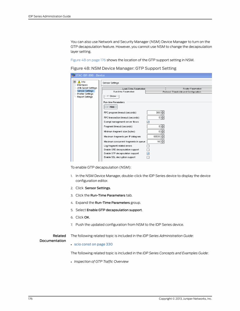
You can also use Network and Security Manager (NSM) Device Manager to turn on the
GTP decapsulation feature. However, you cannot use NSM to change the decapsulation
layer setting.
Figure 48 on page 176 shows the location of the GTP support setting in NSM.
Figure 48: NSMDeviceManager: GTP Support Setting
To enable GTP decapsulation (NSM):
1. In the NSM Device Manager, double-click the IDP Series device to display the device
configuration editor.
2. Click Sensor Settings.
3. Click the Run-Time Parameters tab.
4. Expand the Run-Time Parameters group.
5. Select Enable GTP decapsulation support.
6. Click OK.
7. Push the updated configuration from NSM to the IDP Series device.
RelatedDocumentation
The following related topic is included in the IDP Series Administration Guide:
scio const on page 330•
The following related topic is included in the IDP Series Concepts and Examples Guide:
• Inspection of GTP Traffic Overview
Copyright © 2013, Juniper Networks, Inc.176
IDP Series Administration Guide
Enabling Inspection of IPsec VPN Traffic
Internet Protocol Security (IPsec) virtual private networks (VPNs) use the Encapsulating
Security Payload (ESP) protocol and the NULL encryption algorithm to ensure the
authenticity, integrity, and confidentiality of IP packets. You can use the command-line
interface (CLI) to enable decapsulation of IPsec ESP NULL traffic so that the IDP engine
can inspect it. You can configure decapsulation for one or two layers.
To enable and configure decapsulation:
1. Log into the CLI as admin and enter su - to switch to root.
2. Enter the following command to enable decapsulation:
[root@defaulthost admin]# scio const -s s0 set sc_null_esp_decapsulation 1scio: setting sc_null_esp_decapsulation to 0x1
By default, the IDP engine decapsulates one layer.
3. Optional. Change the maximum decapsulation to two layers by entering the following
commands:
[root@defaulthost admin]# scio const -s s0 set sc_max_decapsulation 2scio: setting sc_max_decapsulation to 0x2
Changes you make to kernel constants from the CLI do not persist across restarts. To
make your change persistent:
1. Open the /usr/idp/device/bin/user_funcs file in a text editor, such as vi.
2. Add the constant below the line user_start_end(). For example:
user_start_end(){$SCIO const -s s0 set sc_null_esp_decapsulation 1
}
3. Save the file.
4. Restart the IDP engine:
[root@defaulthost admin]# idp.sh restart
Restarting the IDP engine can take several moments.
RelatedDocumentation
The following related topics are included in the IDP Series Administration Guide:
scio const on page 330•
The following related topic is included in the IDP Series Concepts and Examples Guide:
• Inspection of IPsec VPN Traffic Overview
177Copyright © 2013, Juniper Networks, Inc.
Chapter 14: Enabling Advanced Features and Options with scio Commands
Enabling Inspection of MPLS Traffic
Before the IDP engine can inspect the payload of Multiprotocol Label Switching (MPLS)
traffic, it must decapsulate it. You can use the command-line interface to enable MPLS
decapsulation.
For an overview of MPLS decapsulation support and limitations, see the IDP Series
Concepts and Examples Guide.
To enable MPLS decapsulation:
1. Log into the CLI as admin and enter su - to switch to root.
2. Enter the following command to enable decapsulation:
[root@defaulthost admin]# scio const -s s0 set sc_mpls_decapsulation 1scio: sc_mpls_decapsulation = 0x1
The value 0x1 indicates MPLS support is enabled.
Changes you make to kernel constants from the CLI do not persist across restarts. To
make your change persistent:
1. Open the /usr/idp/device/bin/user_funcs file in a text editor, such as vi.
2. Locate the MPLS constant below the line user_start_pre_policy():
user_start_pre_policy ()
{
# Disable ARP spoofing detection# -------------------------------# If you are running clusters with virtual MAC addresses, IDP will treat# these as spoofed ARP packets since the MAC addresses in the ethernet# framewill be different fromwhat is inside the ARP request/response. If# you havemultiple virtual routers, you need to perform this operation on# all defined virtual routers.## $SCIO const -v vr0 set sc_arp_spoof_detect 0# $SCIO const -s s0 set sc_mpls_decapsulation 1return;
}
3. Uncomment the $SCIO const -s s0 set sc_mpls_decapsulation 1 line. For example:
user_start_pre_policy ()
{
# Disable ARP spoofing detection# -------------------------------# If you are running clusters with virtual MAC addresses, IDP will treat# these as spoofed ARP packets since the MAC addresses in the ethernet# framewill be different fromwhat is inside the ARP request/response. If
Copyright © 2013, Juniper Networks, Inc.178
IDP Series Administration Guide
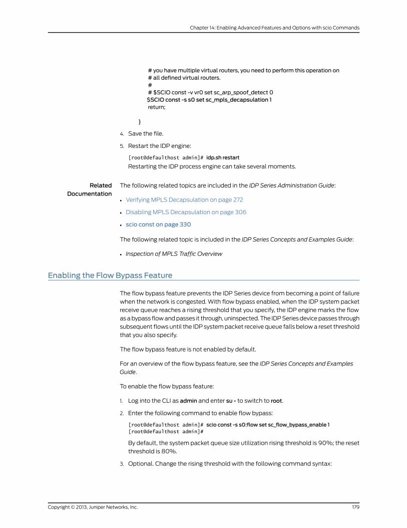
# you havemultiple virtual routers, you need to perform this operation on# all defined virtual routers.## $SCIO const -v vr0 set sc_arp_spoof_detect 0$SCIO const -s s0 set sc_mpls_decapsulation 1return;
}
4. Save the file.
5. Restart the IDP engine:
[root@defaulthost admin]# idp.sh restart
Restarting the IDP process engine can take several moments.
RelatedDocumentation
The following related topics are included in the IDP Series Administration Guide:
Verifying MPLS Decapsulation on page 272•
• Disabling MPLS Decapsulation on page 306
• scio const on page 330
The following related topic is included in the IDP Series Concepts and Examples Guide:
• Inspection of MPLS Traffic Overview
Enabling the Flow Bypass Feature
The flow bypass feature prevents the IDP Series device from becoming a point of failure
when the network is congested. With flow bypass enabled, when the IDP system packet
receive queue reaches a rising threshold that you specify, the IDP engine marks the flow
as a bypass flow and passes it through, uninspected. The IDP Series device passes through
subsequent flows until the IDP system packet receive queue falls below a reset threshold
that you also specify.
The flow bypass feature is not enabled by default.
For an overview of the flow bypass feature, see the IDP Series Concepts and Examples
Guide.
To enable the flow bypass feature:
1. Log into the CLI as admin and enter su - to switch to root.
2. Enter the following command to enable flow bypass:
[root@defaulthost admin]# scio const -s s0:flow set sc_flow_bypass_enable 1[root@defaulthost admin]#
By default, the system packet queue size utilization rising threshold is 90%; the reset
threshold is 80%.
3. Optional. Change the rising threshold with the following command syntax:
179Copyright © 2013, Juniper Networks, Inc.
Chapter 14: Enabling Advanced Features and Options with scio Commands
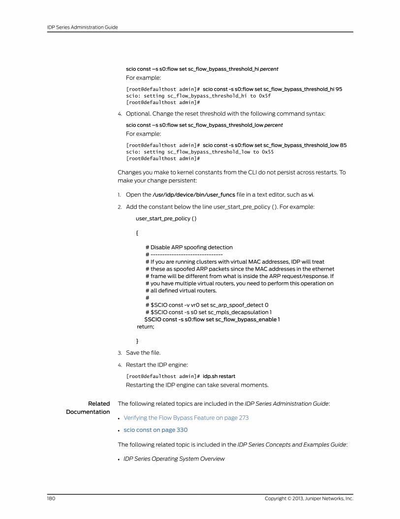
scio const –s s0:flow set sc_flow_bypass_threshold_hi percent
For example:
[root@defaulthost admin]# scio const -s s0:flow set sc_flow_bypass_threshold_hi 95scio: setting sc_flow_bypass_threshold_hi to 0x5f[root@defaulthost admin]#
4. Optional. Change the reset threshold with the following command syntax:
scio const –s s0:flow set sc_flow_bypass_threshold_low percent
For example:
[root@defaulthost admin]# scio const -s s0:flow set sc_flow_bypass_threshold_low 85scio: setting sc_flow_bypass_threshold_low to 0x55[root@defaulthost admin]#
Changes you make to kernel constants from the CLI do not persist across restarts. To
make your change persistent:
1. Open the /usr/idp/device/bin/user_funcs file in a text editor, such as vi.
2. Add the constant below the line user_start_pre_policy (). For example:
user_start_pre_policy ()
{
# Disable ARP spoofing detection# -------------------------------# If you are running clusters with virtual MAC addresses, IDP will treat# these as spoofed ARP packets since the MAC addresses in the ethernet# framewill be different fromwhat is inside the ARP request/response. If# you havemultiple virtual routers, you need to perform this operation on# all defined virtual routers.## $SCIO const -v vr0 set sc_arp_spoof_detect 0# $SCIO const -s s0 set sc_mpls_decapsulation 1$SCIO const -s s0:flow set sc_flow_bypass_enable 1
return;
}
3. Save the file.
4. Restart the IDP engine:
[root@defaulthost admin]# idp.sh restart
Restarting the IDP engine can take several moments.
RelatedDocumentation
The following related topics are included in the IDP Series Administration Guide:
Verifying the Flow Bypass Feature on page 273•
• scio const on page 330
The following related topic is included in the IDP Series Concepts and Examples Guide:
• IDP Series Operating System Overview
Copyright © 2013, Juniper Networks, Inc.180
IDP Series Administration Guide
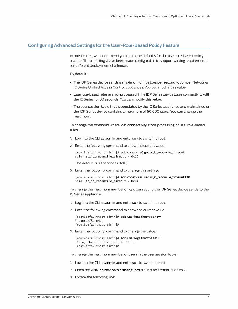
Configuring Advanced Settings for the User-Role-Based Policy Feature
In most cases, we recommend you retain the defaults for the user role-based policy
feature. These settings have been made configurable to support varying requirements
for different deployment challenges.
By default:
• The IDP Series device sends a maximum of five logs per second to Juniper Networks
IC Series Unified Access Control appliances. You can modify this value.
• User role-based rules are not processed if the IDP Series device loses connectivity with
the IC Series for 30 seconds. You can modify this value.
• The user session table that is populated by the IC Series appliance and maintained on
the IDP Series device contains a maximum of 50,000 users. You can change the
maximum.
To change the threshold where lost connectivity stops processing of user role-based
rules:
1. Log into the CLI as admin and enter su - to switch to root.
2. Enter the following command to show the current value:
[root@defaulthost admin]# scio const -s s0 get sc_ic_reconcile_timeoutscio: sc_ic_reconcile_timeout = 0x1E
The default is 30 seconds (0x1E).
3. Enter the following command to change this setting:
[root@defaulthost admin]# scio const -s s0 set sc_ic_reconcile_timeout 180scio: sc_ic_reconcile_timeout = 0xB4
To change the maximum number of logs per second the IDP Series device sends to the
IC Series appliance:
1. Log into the CLI as admin and enter su - to switch to root.
2. Enter the following command to show the current value:
[root@defaulthost admin]# scio user logs throttle show5 Log(s)/Second.[root@defaulthost admin]#
3. Enter the following command to change the value:
[root@defaulthost admin]# scio user logs throttle set 10IC-Log Throttle limit set to '10'.[root@defaulthost admin]#
To change the maximum number of users in the user session table:
1. Log into the CLI as admin and enter su - to switch to root.
2. Open the /usr/idp/device/bin/user_funcs file in a text editor, such as vi.
3. Locate the following line:
181Copyright © 2013, Juniper Networks, Inc.
Chapter 14: Enabling Advanced Features and Options with scio Commands
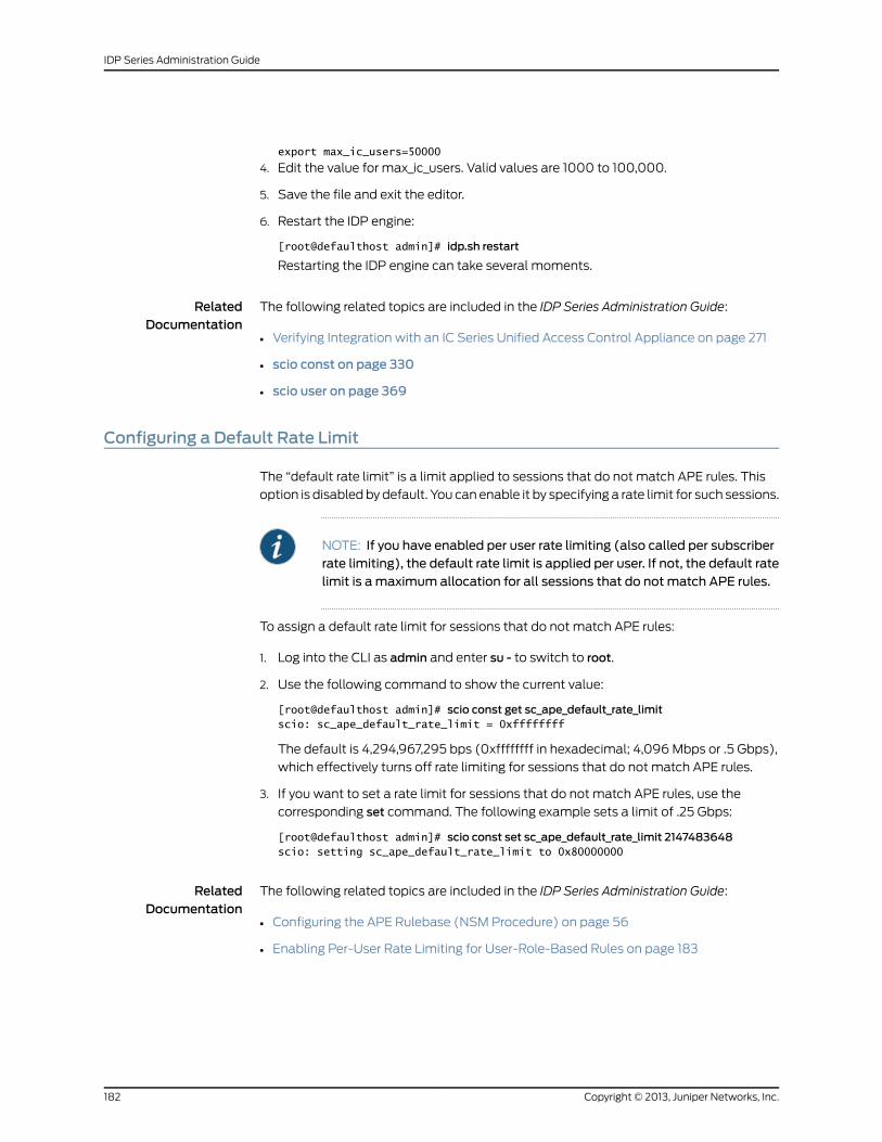
export max_ic_users=50000
4. Edit the value for max_ic_users. Valid values are 1000 to 100,000.
5. Save the file and exit the editor.
6. Restart the IDP engine:
[root@defaulthost admin]# idp.sh restart
Restarting the IDP engine can take several moments.
RelatedDocumentation
The following related topics are included in the IDP Series Administration Guide:
Verifying Integration with an IC Series Unified Access Control Appliance on page 271•
• scio const on page 330
• scio user on page 369
Configuring a Default Rate Limit
The “default rate limit” is a limit applied to sessions that do not match APE rules. This
option is disabled by default. You can enable it by specifying a rate limit for such sessions.
NOTE: If you have enabled per user rate limiting (also called per subscriberrate limiting), the default rate limit is applied per user. If not, the default ratelimit is amaximum allocation for all sessions that do not match APE rules.
To assign a default rate limit for sessions that do not match APE rules:
1. Log into the CLI as admin and enter su - to switch to root.
2. Use the following command to show the current value:
[root@defaulthost admin]# scio const get sc_ape_default_rate_limitscio: sc_ape_default_rate_limit = 0xffffffff
The default is 4,294,967,295 bps (0xffffffff in hexadecimal; 4,096 Mbps or .5 Gbps),
which effectively turns off rate limiting for sessions that do not match APE rules.
3. If you want to set a rate limit for sessions that do not match APE rules, use the
corresponding set command. The following example sets a limit of .25 Gbps:
[root@defaulthost admin]# scio const set sc_ape_default_rate_limit 2147483648scio: setting sc_ape_default_rate_limit to 0x80000000
RelatedDocumentation
The following related topics are included in the IDP Series Administration Guide:
Configuring the APE Rulebase (NSM Procedure) on page 56•
• Enabling Per-User Rate Limiting for User-Role-Based Rules on page 183
Copyright © 2013, Juniper Networks, Inc.182
IDP Series Administration Guide
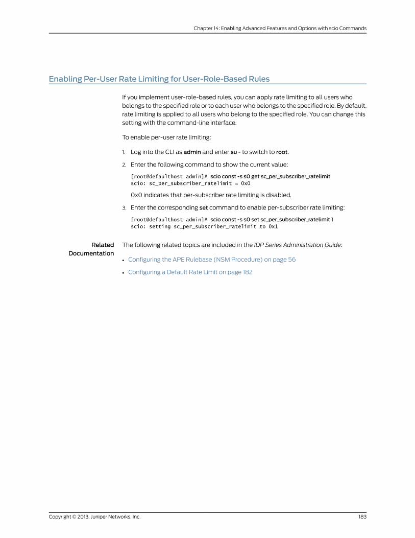
Enabling Per-User Rate Limiting for User-Role-Based Rules
If you implement user-role-based rules, you can apply rate limiting to all users who
belongs to the specified role or to each user who belongs to the specified role. By default,
rate limiting is applied to all users who belong to the specified role. You can change this
setting with the command-line interface.
To enable per-user rate limiting:
1. Log into the CLI as admin and enter su - to switch to root.
2. Enter the following command to show the current value:
[root@defaulthost admin]# scio const -s s0 get sc_per_subscriber_ratelimitscio: sc_per_subscriber_ratelimit = 0x0
0x0 indicates that per-subscriber rate limiting is disabled.
3. Enter the corresponding set command to enable per-subscriber rate limiting:
[root@defaulthost admin]# scio const -s s0 set sc_per_subscriber_ratelimit 1scio: setting sc_per_subscriber_ratelimit to 0x1
RelatedDocumentation
The following related topics are included in the IDP Series Administration Guide:
• Configuring the APE Rulebase (NSM Procedure) on page 56
• Configuring a Default Rate Limit on page 182
183Copyright © 2013, Juniper Networks, Inc.
Chapter 14: Enabling Advanced Features and Options with scio Commands

Copyright © 2013, Juniper Networks, Inc.184
IDP Series Administration Guide
CHAPTER 15
Using ACM to Configure IDP SeriesNetwork Interfaces
This chapter contains the following topics:
• ACM Task Summary on page 185
• Configuring Virtual Routers (ACM Procedure) on page 186
• Configuring Interface Aliasing (ACM Procedure) on page 187
• Installing an I/O Module on page 188
ACMTask Summary
Appliance Configuration Manager (ACM) is a Web-based configuration editor that has
been preinstalled on IDP Series devices.
You use ACM to perform the following tasks:
• Set host and network information, such as fully qualified domain name, default gateway,
DNS server, and so forth.
• Set IP addresses for the management interface.
• Configure speed/duplex for traffic interfaces.
• Configure interface aliasing, if you want a string you specify to appear in logs instead
of the defaults (defaults are eth0, eth1, eth2 and so forth).
• Configure virtual routers, including deployment mode and bypass settings.
• Enable peer port modulation.
• Enable Layer 2 processing.
• Set access, such as passwords for root and admin users, SSH requirements, Radius
access, and ACM access restrictions.
• Configure credentials for interoperability with Network and Security Manager, IC Series
Unified Access Control appliances, and SA Series SSL VPN appliances.
• Save the running configuration to a file.
• Upload a configuration file and activate it.
185Copyright © 2013, Juniper Networks, Inc.
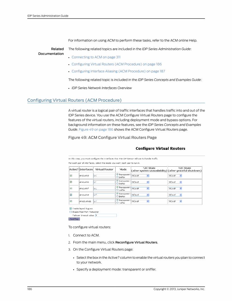
For information on using ACM to perform these tasks, refer to the ACM online Help.
RelatedDocumentation
The following related topics are included in the IDP Series Administration Guide:
Connecting to ACM on page 311•
• Configuring Virtual Routers (ACM Procedure) on page 186
• Configuring Interface Aliasing (ACM Procedure) on page 187
The following related topic is included in the IDP Series Concepts and Examples Guide:
• IDP Series Network Interfaces Overview
Configuring Virtual Routers (ACMProcedure)
A virtual router is a logical pair of traffic interfaces that handles traffic into and out of the
IDP Series device. You use the ACM Configure Virtual Routers page to configure the
features of the virtual routers, including deployment mode and bypass options. For
background information on these features, see the IDP Series Concepts and Examples
Guide. Figure 49 on page 186 shows the ACM Configure Virtual Routers page.
Figure 49: ACMConfigure Virtual Routers Page
To configure virtual routers:
1. Connect to ACM.
2. From the main menu, click Reconfigure Virtual Routers.
3. On the Configure Virtual Routers page:
• Select the box in the Active? column to enable the virtual routers you plan to connect
to your network.
• Specify a deployment mode: transparent or sniffer.
Copyright © 2013, Juniper Networks, Inc.186
IDP Series Administration Guide
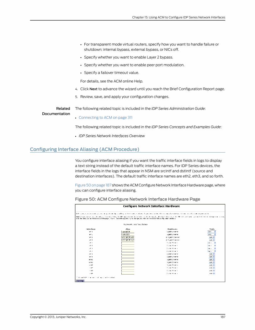
• For transparent mode virtual routers, specify how you want to handle failure or
shutdown: internal bypass, external bypass, or NICs off.
• Specify whether you want to enable Layer 2 bypass.
• Specify whether you want to enable peer port modulation.
• Specify a failover timeout value.
For details, see the ACM online Help.
4. Click Next to advance the wizard until you reach the Brief Configuration Report page.
5. Review, save, and apply your configuration changes.
RelatedDocumentation
The following related topic is included in the IDP Series Administration Guide:
Connecting to ACM on page 311•
The following related topic is included in the IDP Series Concepts and Examples Guide:
• IDP Series Network Interfaces Overview
Configuring Interface Aliasing (ACMProcedure)
You configure interface aliasing if you want the traffic interface fields in logs to display
a text string instead of the default traffic interface names. For IDP Series devices, the
interface fields in the logs that appear in NSM are srcIntf and dstIntf (source and
destination interfaces). The default traffic interface names are eth2, eth3, and so forth.
Figure 50 on page 187 shows the ACM Configure Network Interface Hardware page, where
you can configure interface aliasing.
Figure 50: ACMConfigure Network Interface Hardware Page
187Copyright © 2013, Juniper Networks, Inc.
Chapter 15: Using ACM to Configure IDP Series Network Interfaces
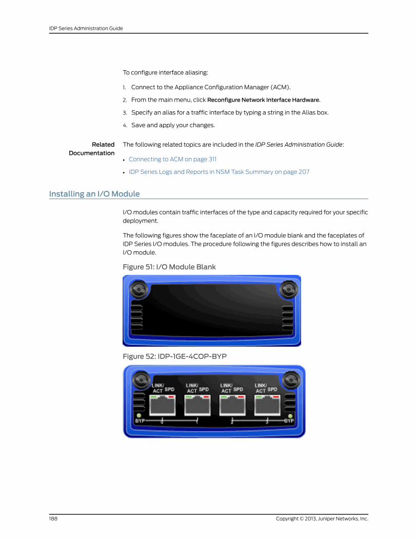
To configure interface aliasing:
1. Connect to the Appliance Configuration Manager (ACM).
2. From the main menu, click Reconfigure Network Interface Hardware.
3. Specify an alias for a traffic interface by typing a string in the Alias box.
4. Save and apply your changes.
RelatedDocumentation
The following related topics are included in the IDP Series Administration Guide:
Connecting to ACM on page 311•
• IDP Series Logs and Reports in NSM Task Summary on page 207
Installing an I/OModule
I/O modules contain traffic interfaces of the type and capacity required for your specific
deployment.
The following figures show the faceplate of an I/O module blank and the faceplates of
IDP Series I/O modules. The procedure following the figures describes how to install an
I/O module.
Figure 51: I/OModule Blank
Figure 52: IDP-1GE-4COP-BYP
Copyright © 2013, Juniper Networks, Inc.188
IDP Series Administration Guide
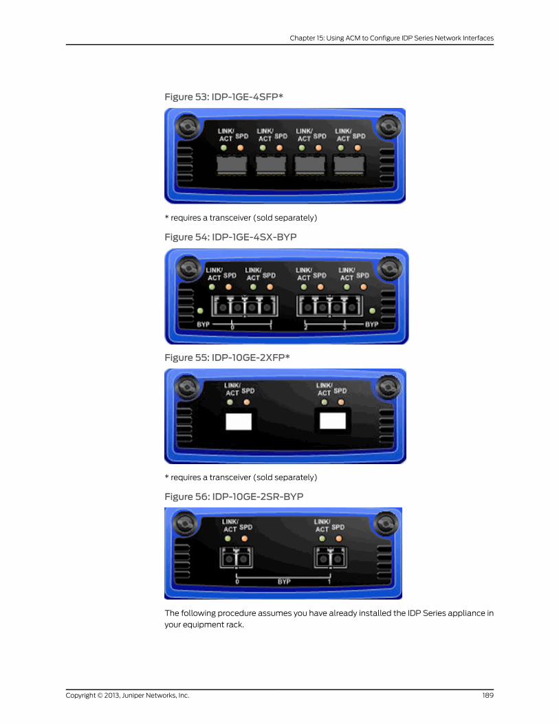
Figure 53: IDP-1GE-4SFP*
* requires a transceiver (sold separately)
Figure 54: IDP-1GE-4SX-BYP
Figure 55: IDP-10GE-2XFP*
* requires a transceiver (sold separately)
Figure 56: IDP-10GE-2SR-BYP
The following procedure assumes you have already installed the IDP Series appliance in
your equipment rack.
189Copyright © 2013, Juniper Networks, Inc.
Chapter 15: Using ACM to Configure IDP Series Network Interfaces
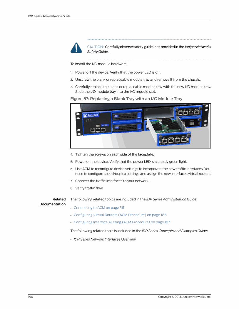
CAUTION: Carefullyobservesafetyguidelinesprovided in the JuniperNetworksSafety Guide.
To install the I/O module hardware:
1. Power off the device. Verify that the power LED is off.
2. Unscrew the blank or replaceable module tray and remove it from the chassis.
3. Carefully replace the blank or replaceable module tray with the new I/O module tray.
Slide the I/O module tray into the I/O module slot.
Figure 57: Replacing a Blank Tray with an I/OModule Tray
4. Tighten the screws on each side of the faceplate.
5. Power on the device. Verify that the power LED is a steady green light.
6. Use ACM to reconfigure device settings to incorporate the new traffic interfaces. You
need to configure speed/duplex settings and assign the new interfaces virtual routers.
7. Connect the traffic interfaces to your network.
8. Verify traffic flow.
RelatedDocumentation
The following related topics are included in the IDP Series Administration Guide:
• Connecting to ACM on page 311
• Configuring Virtual Routers (ACM Procedure) on page 186
• Configuring Interface Aliasing (ACM Procedure) on page 187
The following related topic is included in the IDP Series Concepts and Examples Guide:
• IDP Series Network Interfaces Overview
Copyright © 2013, Juniper Networks, Inc.190
IDP Series Administration Guide
CHAPTER 16
Updating IDP OS Software
This chapter describes how to use NSM to update IDP OS software, the IDP detector
engine, and the NSM attack database. It includes the following topics:
• Updating IDP OS Software (NSM Procedure) on page 191
• Upgrading Software (CLI Procedure) on page 193
• Loading J-Security Center Updates (NSM Procedure) on page 194
Updating IDPOS Software (NSMProcedure)
This topic provides the basic procedure for upgrading IDP OS software. Check the release
notes to see the exact procedure tested for a particular release.
To update IDP OS software:
1. Add the IDP OS software to the NSM GUI server.
2. Push the IDP OS software from the NSM GUI server to one or more IDP Series devices.
To add an IDP OS software image to the NSM GUI server:
1. Download the software image:
a. Go to https://www.juniper.net/customers/csc/software/ and log in with your
customer username and password.
b. Enter the IDP Series device serial number to display a view of applicable software
releases available for download.
c. Click the applicable link to display the software download page.
d. Download the software to a location you can access from your NSM client.
2. From the NSM main menu, select Tools > SoftwareManager to display the Software
Manager dialog box.
3. Click the + button to display the Open dialog box.
4. Select the IDP OS software image you just downloaded and click Open to add the
software image to the NSM GUI server.
5. Click OK.
191Copyright © 2013, Juniper Networks, Inc.
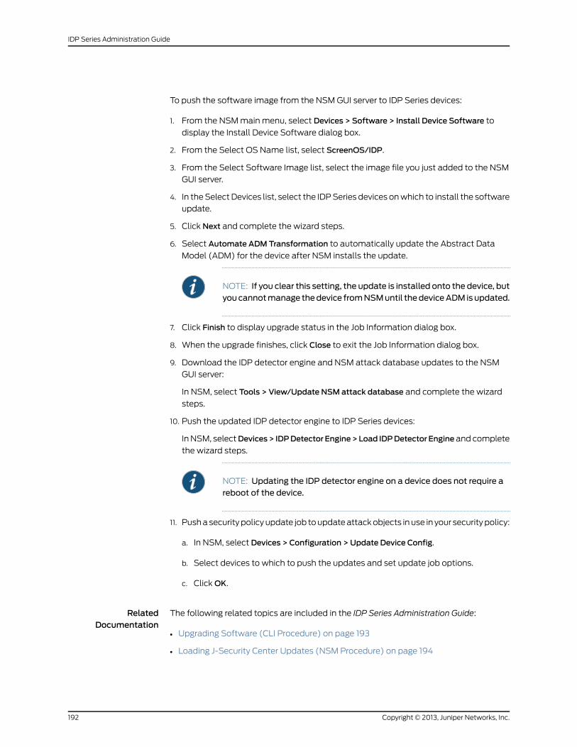
To push the software image from the NSM GUI server to IDP Series devices:
1. From the NSM main menu, select Devices > Software > Install Device Software to
display the Install Device Software dialog box.
2. From the Select OS Name list, select ScreenOS/IDP.
3. From the Select Software Image list, select the image file you just added to the NSM
GUI server.
4. In the Select Devices list, select the IDP Series devices on which to install the software
update.
5. Click Next and complete the wizard steps.
6. Select Automate ADMTransformation to automatically update the Abstract Data
Model (ADM) for the device after NSM installs the update.
NOTE: If you clear this setting, the update is installed onto the device, butyoucannotmanage thedevice fromNSMuntil thedeviceADM isupdated.
7. Click Finish to display upgrade status in the Job Information dialog box.
8. When the upgrade finishes, click Close to exit the Job Information dialog box.
9. Download the IDP detector engine and NSM attack database updates to the NSM
GUI server:
In NSM, select Tools > View/Update NSM attack database and complete the wizard
steps.
10. Push the updated IDP detector engine to IDP Series devices:
In NSM, selectDevices> IDPDetector Engine>Load IDPDetector Engine and complete
the wizard steps.
NOTE: Updating the IDP detector engine on a device does not require areboot of the device.
11. Push a security policy update job to update attack objects in use in your security policy:
a. In NSM, select Devices > Configuration > Update Device Config.
b. Select devices to which to push the updates and set update job options.
c. Click OK.
RelatedDocumentation
The following related topics are included in the IDP Series Administration Guide:
Upgrading Software (CLI Procedure) on page 193•
• Loading J-Security Center Updates (NSM Procedure) on page 194
Copyright © 2013, Juniper Networks, Inc.192
IDP Series Administration Guide
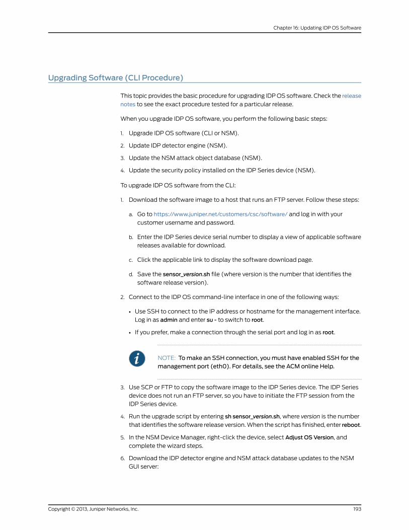
Upgrading Software (CLI Procedure)
This topic provides the basic procedure for upgrading IDP OS software. Check the release
notes to see the exact procedure tested for a particular release.
When you upgrade IDP OS software, you perform the following basic steps:
1. Upgrade IDP OS software (CLI or NSM).
2. Update IDP detector engine (NSM).
3. Update the NSM attack object database (NSM).
4. Update the security policy installed on the IDP Series device (NSM).
To upgrade IDP OS software from the CLI:
1. Download the software image to a host that runs an FTP server. Follow these steps:
a. Go to https://www.juniper.net/customers/csc/software/ and log in with your
customer username and password.
b. Enter the IDP Series device serial number to display a view of applicable software
releases available for download.
c. Click the applicable link to display the software download page.
d. Save the sensor_version.sh file (where version is the number that identifies the
software release version).
2. Connect to the IDP OS command-line interface in one of the following ways:
• Use SSH to connect to the IP address or hostname for the management interface.
Log in as admin and enter su - to switch to root.
• If you prefer, make a connection through the serial port and log in as root.
NOTE: Tomake an SSH connection, youmust have enabled SSH for themanagement port (eth0). For details, see the ACM online Help.
3. Use SCP or FTP to copy the software image to the IDP Series device. The IDP Series
device does not run an FTP server, so you have to initiate the FTP session from the
IDP Series device.
4. Run the upgrade script by entering sh sensor_version.sh, where version is the number
that identifies the software release version. When the script has finished, enter reboot.
5. In the NSM Device Manager, right-click the device, select Adjust OS Version, and
complete the wizard steps.
6. Download the IDP detector engine and NSM attack database updates to the NSM
GUI server:
193Copyright © 2013, Juniper Networks, Inc.
Chapter 16: Updating IDP OS Software
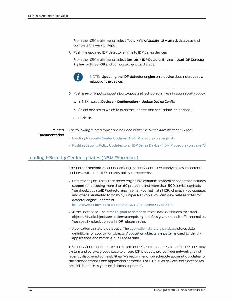
From the NSM main menu, select Tools > View/Update NSM attack database and
complete the wizard steps.
7. Push the updated IDP detector engine to IDP Series devices:
From the NSM main menu, select Devices > IDP Detector Engine > Load IDP Detector
Engine for ScreenOS and complete the wizard steps.
NOTE: Updating the IDP detector engine on a device does not require areboot of the device.
8. Push a security policy update job to update attack objects in use in your security policy:
a. In NSM, select Devices > Configuration > Update Device Config.
b. Select devices to which to push the updates and set update job options.
c. Click OK.
RelatedDocumentation
The following related topics are included in the IDP Series Administration Guide:
Loading J-Security Center Updates (NSM Procedure) on page 194•
• Pushing Security Policy Updates to an IDP Series Device (NSM Procedure) on page 73
Loading J-Security Center Updates (NSMProcedure)
The Juniper Networks Security Center (J-Security Center) routinely makes important
updates available to IDP security policy components:
• Detector engine. The IDP detector engine is a dynamic protocol decoder that includes
support for decoding more than 60 protocols and more than 500 service contexts.
You should update IDP detector engine when you first install IDP, whenever you upgrade,
and whenever alerted to do so by Juniper Networks. You can view release notes for
detector engine updates at
http://www.juniper.net/techpubs/software/management/idp/de/.
• Attack database. The attack signature database stores data definitions for attack
objects. Attack objects are patterns comprising stateful signatures and traffic anomalies.
You specify attack objects in IDP rulebase rules.
• Application signature database. The application signature database stores data
definitions for application objects. Application objects are patterns used to identify
applications and match APE rulebase rules.
J-Security Center updates are packaged and released separately from the IDP operating
system and software code base to ensure IDP products protect your network against
recently discovered vulnerabilities. We recommend you schedule automatic updates for
the attack database and application database. For IDP Series devices, both databases
are distributed in “signature database updates”.
Copyright © 2013, Juniper Networks, Inc.194
IDP Series Administration Guide
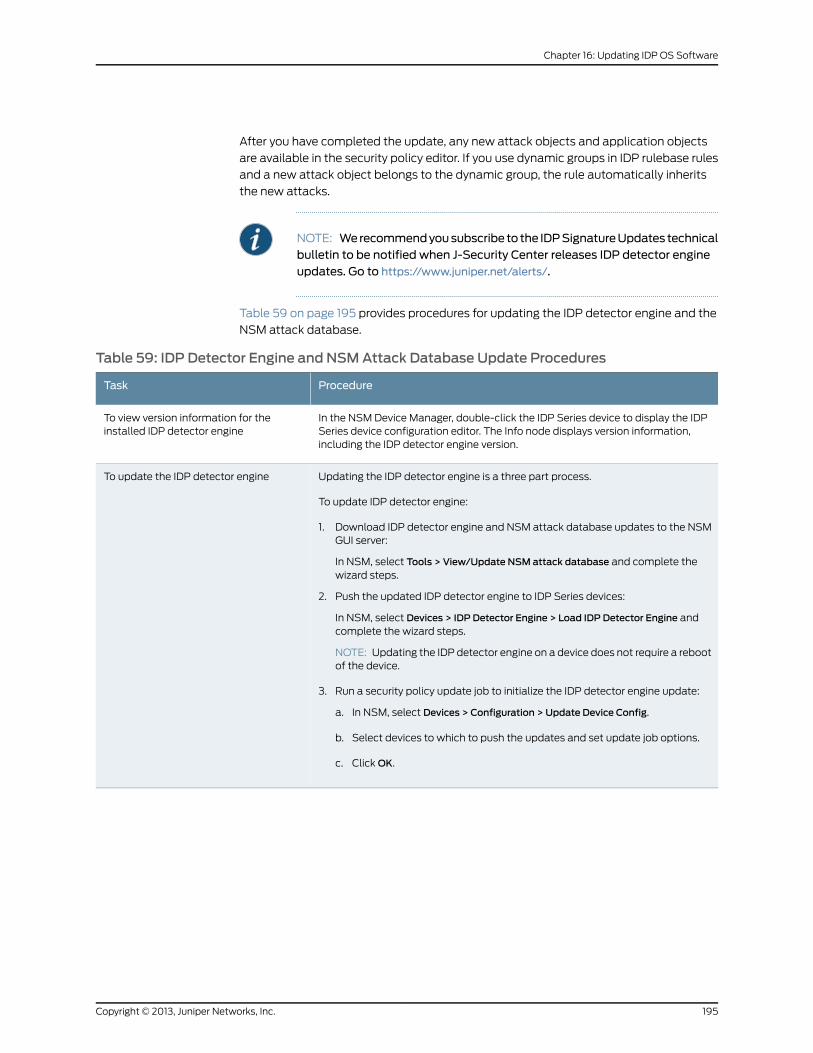
After you have completed the update, any new attack objects and application objects
are available in the security policy editor. If you use dynamic groups in IDP rulebase rules
and a new attack object belongs to the dynamic group, the rule automatically inherits
the new attacks.
NOTE: Werecommendyousubscribe to the IDPSignatureUpdates technicalbulletin to be notified when J-Security Center releases IDP detector engineupdates. Go to https://www.juniper.net/alerts/.
Table 59 on page 195 provides procedures for updating the IDP detector engine and the
NSM attack database.
Table 59: IDP Detector Engine and NSMAttack Database Update Procedures
ProcedureTask
In the NSM Device Manager, double-click the IDP Series device to display the IDPSeries device configuration editor. The Info node displays version information,including the IDP detector engine version.
To view version information for theinstalled IDP detector engine
Updating the IDP detector engine is a three part process.
To update IDP detector engine:
1. Download IDP detector engine and NSM attack database updates to the NSMGUI server:
In NSM, select Tools > View/Update NSM attack database and complete thewizard steps.
2. Push the updated IDP detector engine to IDP Series devices:
In NSM, select Devices > IDP Detector Engine > Load IDP Detector Engine andcomplete the wizard steps.
NOTE: Updating the IDP detector engine on a device does not require a rebootof the device.
3. Run a security policy update job to initialize the IDP detector engine update:
a. In NSM, select Devices > Configuration > Update Device Config.
b. Select devices to which to push the updates and set update job options.
c. Click OK.
To update the IDP detector engine
195Copyright © 2013, Juniper Networks, Inc.
Chapter 16: Updating IDP OS Software
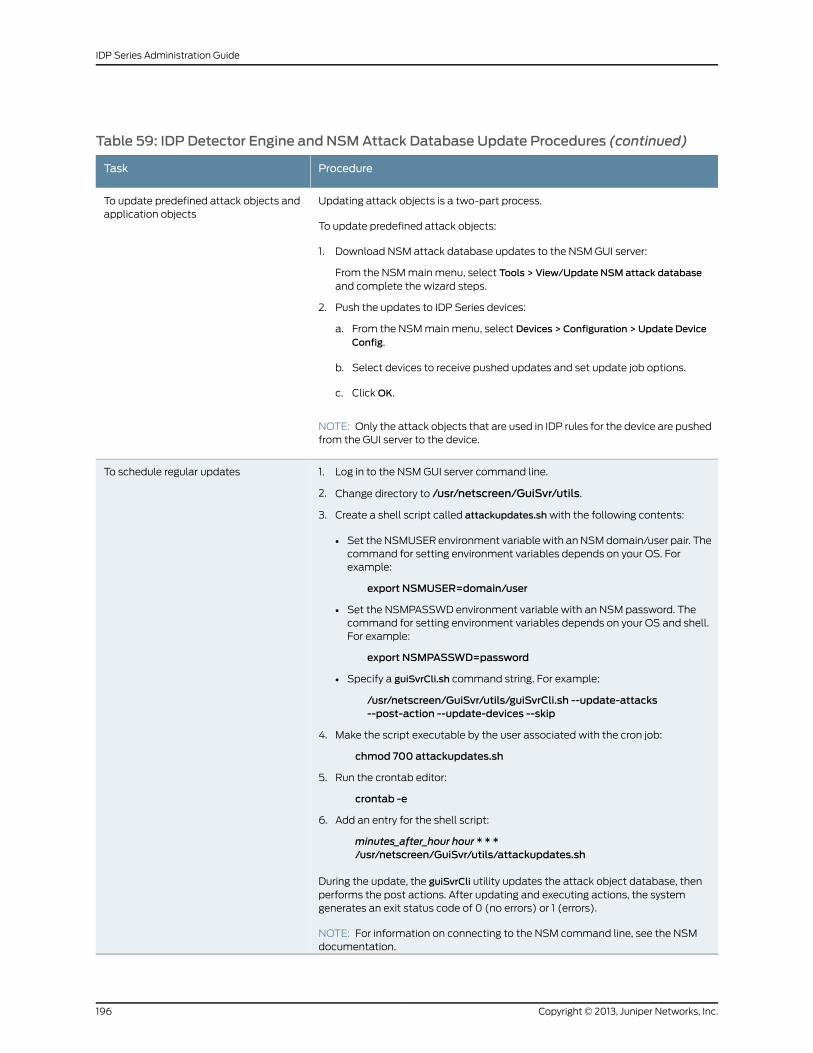
Table 59: IDP Detector Engine and NSMAttack Database Update Procedures (continued)
ProcedureTask
Updating attack objects is a two-part process.
To update predefined attack objects:
1. Download NSM attack database updates to the NSM GUI server:
From the NSM main menu, select Tools > View/Update NSM attack databaseand complete the wizard steps.
2. Push the updates to IDP Series devices:
a. From the NSM main menu, select Devices > Configuration > Update DeviceConfig.
b. Select devices to receive pushed updates and set update job options.
c. Click OK.
NOTE: Only the attack objects that are used in IDP rules for the device are pushedfrom the GUI server to the device.
To update predefined attack objects andapplication objects
1. Log in to the NSM GUI server command line.
2. Change directory to /usr/netscreen/GuiSvr/utils.
3. Create a shell script called attackupdates.sh with the following contents:
• Set the NSMUSER environment variable with an NSM domain/user pair. Thecommand for setting environment variables depends on your OS. Forexample:
export NSMUSER=domain/user
• Set the NSMPASSWD environment variable with an NSM password. Thecommand for setting environment variables depends on your OS and shell.For example:
export NSMPASSWD=password
• Specify a guiSvrCli.sh command string. For example:
/usr/netscreen/GuiSvr/utils/guiSvrCli.sh --update-attacks--post-action --update-devices --skip
4. Make the script executable by the user associated with the cron job:
chmod 700 attackupdates.sh
5. Run the crontab editor:
crontab -e
6. Add an entry for the shell script:
minutes_after_hour hour * * */usr/netscreen/GuiSvr/utils/attackupdates.sh
During the update, the guiSvrCli utility updates the attack object database, thenperforms the post actions. After updating and executing actions, the systemgenerates an exit status code of 0 (no errors) or 1 (errors).
NOTE: For information on connecting to the NSM command line, see the NSMdocumentation.
To schedule regular updates
Copyright © 2013, Juniper Networks, Inc.196
IDP Series Administration Guide
RelatedDocumentation
The following related topics are included in the IDP Series Administration Guide:
• Attack Objects Task Summary on page 79
• Application Objects Task Summary on page 111
• Pushing Security Policy Updates to an IDP Series Device (NSM Procedure) on page 73
The following related topic is included in the IDP Series Concepts and Examples Guide:
• Using Attack Objects
• Using Application Objects
197Copyright © 2013, Juniper Networks, Inc.
Chapter 16: Updating IDP OS Software

Copyright © 2013, Juniper Networks, Inc.198
IDP Series Administration Guide
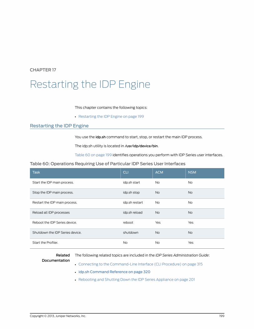
CHAPTER 17
Restarting the IDP Engine
This chapter contains the following topics:
• Restarting the IDP Engine on page 199
Restarting the IDP Engine
You use the idp.sh command to start, stop, or restart the main IDP process.
The idp.sh utility is located in /usr/idp/device/bin.
Table 60 on page 199 identifies operations you perform with IDP Series user interfaces.
Table 60: Operations Requiring Use of Particular IDP Series User Interfaces
NSMACMCLITask
NoNoidp.sh startStart the IDP main process.
NoNoidp.sh stopStop the IDP main process.
NoNoidp.sh restartRestart the IDP main process.
NoNoidp.sh reloadReload all IDP processes
YesYesrebootReboot the IDP Series device.
NoNoshutdownShutdown the IDP Series device.
YesNoNoStart the Profiler.
RelatedDocumentation
The following related topics are included in the IDP Series Administration Guide:
• Connecting to the Command-Line Interface (CLI Procedure) on page 315
• idp.sh Command Reference on page 320
• Rebooting and Shutting Down the IDP Series Appliance on page 201
199Copyright © 2013, Juniper Networks, Inc.

Copyright © 2013, Juniper Networks, Inc.200
IDP Series Administration Guide
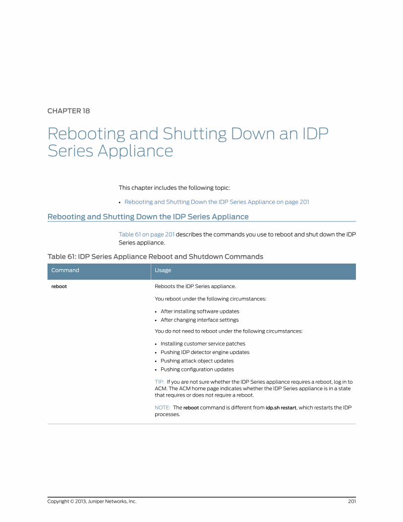
CHAPTER 18
Rebooting and Shutting Down an IDPSeries Appliance
This chapter includes the following topic:
• Rebooting and Shutting Down the IDP Series Appliance on page 201
Rebooting and Shutting Down the IDP Series Appliance
Table 61 on page 201 describes the commands you use to reboot and shut down the IDP
Series appliance.
Table 61: IDP Series Appliance Reboot and Shutdown Commands
UsageCommand
Reboots the IDP Series appliance.
You reboot under the following circumstances:
• After installing software updates
• After changing interface settings
You do not need to reboot under the following circumstances:
• Installing customer service patches
• Pushing IDP detector engine updates
• Pushing attack object updates
• Pushing configuration updates
TIP: If you are not sure whether the IDP Series appliance requires a reboot, log in toACM. The ACM home page indicates whether the IDP Series appliance is in a statethat requires or does not require a reboot.
NOTE: The reboot command is different from idp.sh restart, which restarts the IDPprocesses.
reboot
201Copyright © 2013, Juniper Networks, Inc.
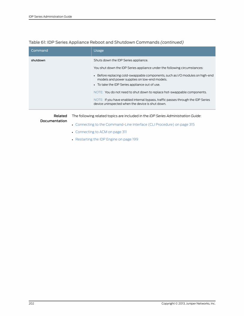
Table 61: IDP Series Appliance Reboot and Shutdown Commands (continued)
UsageCommand
Shuts down the IDP Series appliance.
You shut down the IDP Series appliance under the following circumstances:
• Before replacing cold-swappable components, such as I/O modules on high-endmodels and power supplies on low-end models.
• To take the IDP Series appliance out of use.
NOTE: You do not need to shut down to replace hot-swappable components.
NOTE: If you have enabled internal bypass, traffic passes through the IDP Seriesdevice uninspected when the device is shut down.
shutdown
RelatedDocumentation
The following related topics are included in the IDP Series Administration Guide:
• Connecting to the Command-Line Interface (CLI Procedure) on page 315
• Connecting to ACM on page 311
• Restarting the IDP Engine on page 199
Copyright © 2013, Juniper Networks, Inc.202
IDP Series Administration Guide
PART 5
MonitoringAttacksandApplicationUsage
• Monitoring Tools Overview on page 205
• Using NSM Logs and Reports on page 207
• Using IDP Reporter on page 235
• Using SNMP to Monitor Device Health and Traffic Statistics on page 237
• Monitoring NIC State with the bypassStatus Command on page 267
• Verifying Feature Implementation with scio Counters on page 269
• Monitoring Session Flow with the sctop Command on page 277
• Using Command-Line Utilities for Packet Capture on page 281
203Copyright © 2013, Juniper Networks, Inc.

Copyright © 2013, Juniper Networks, Inc.204
IDP Series Administration Guide
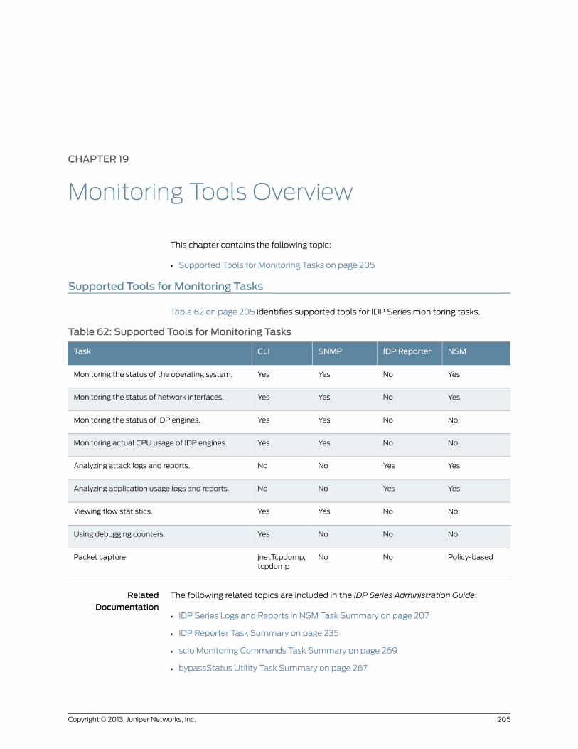
CHAPTER 19
Monitoring Tools Overview
This chapter contains the following topic:
• Supported Tools for Monitoring Tasks on page 205
Supported Tools for Monitoring Tasks
Table 62 on page 205 identifies supported tools for IDP Series monitoring tasks.
Table 62: Supported Tools for Monitoring Tasks
NSMIDP ReporterSNMPCLITask
YesNoYesYesMonitoring the status of the operating system.
YesNoYesYesMonitoring the status of network interfaces.
NoNoYesYesMonitoring the status of IDP engines.
NoNoYesYesMonitoring actual CPU usage of IDP engines.
YesYesNoNoAnalyzing attack logs and reports.
YesYesNoNoAnalyzing application usage logs and reports.
NoNoYesYesViewing flow statistics.
NoNoNoYesUsing debugging counters.
Policy-basedNoNojnetTcpdump,tcpdump
Packet capture
RelatedDocumentation
The following related topics are included in the IDP Series Administration Guide:
• IDP Series Logs and Reports in NSM Task Summary on page 207
• IDP Reporter Task Summary on page 235
• scio Monitoring Commands Task Summary on page 269
• bypassStatus Utility Task Summary on page 267
205Copyright © 2013, Juniper Networks, Inc.

• sctop Task Summary on page 277
Copyright © 2013, Juniper Networks, Inc.206
IDP Series Administration Guide
CHAPTER 20
Using NSM Logs and Reports
This chapter contains the following topics:
• IDP Series Logs and Reports in NSM Task Summary on page 207
• Viewing Device Status (NSM Procedure) on page 208
• Using NSM Logs on page 213
• Viewing NSM Predefined Reports (NSM Procedure) on page 221
• Creating NSM Custom Reports (NSM Procedure) on page 224
• Configuring Log Storage Limits on page 226
• Configuring Log Suppression (NSM Procedure) on page 227
• Configuring an SNMP Agent (NSM Procedure) on page 228
• Configuring Syslog Collection (NSM Procedure) on page 230
• Enabling Collection of Packet Data in NSM Logs (NSM Procedure) on page 232
IDP Series Logs and Reports in NSMTask Summary
IDP Series devices generate logs about device status based on built-in criteria and about
security events based on the security policy notification settings. These logs are
automatically sent to the NSM GUI server and can be viewed in the NSM log viewer.
IDP Series administration includes the following log-related tasks:
• Viewing device status, logs, and reports.
• Viewing attack logs and reports.
• Viewing application usage logs and reports.
• Configuring interface aliasing, if you want to identify IDP Series traffic interfaces by
name in logs and reports.
• Configuring log suppression, if you want to reduce the number of identical log files.
• Configuring communication with an SNMP or syslog server, if you use external log
programs to view alerts or analyze or archive log data.
• Ensuring collection of packet data in NSM logs is enabled, if you want to drill into packet
data from NSM logs.
207Copyright © 2013, Juniper Networks, Inc.
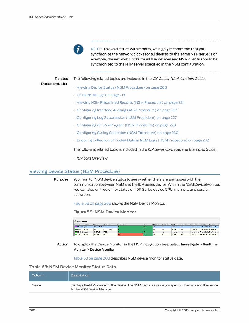
NOTE: To avoid issues with reports, we highly recommend that yousynchronize the network clocks for all devices to the same NTP server. Forexample, the network clocks for all IDP devices and NSM clients should besynchronized to the NTP server specified in the NSM configuration.
RelatedDocumentation
The following related topics are included in the IDP Series Administration Guide:
Viewing Device Status (NSM Procedure) on page 208•
• Using NSM Logs on page 213
• Viewing NSM Predefined Reports (NSM Procedure) on page 221
• Configuring Interface Aliasing (ACM Procedure) on page 187
• Configuring Log Suppression (NSM Procedure) on page 227
• Configuring an SNMP Agent (NSM Procedure) on page 228
• Configuring Syslog Collection (NSM Procedure) on page 230
• Enabling Collection of Packet Data in NSM Logs (NSM Procedure) on page 232
The following related topic is included in the IDP Series Concepts and Examples Guide:
• IDP Logs Overview
Viewing Device Status (NSMProcedure)
Purpose You monitor NSM device status to see whether there are any issues with the
communication between NSM and the IDP Series device. Within the NSM Device Monitor,
you can also drill-down for status on IDP Series device CPU, memory, and session
utilization.
Figure 58 on page 208 shows the NSM Device Monitor.
Figure 58: NSMDeviceMonitor
Action To display the Device Monitor, in the NSM navigation tree, select Investigate > Realtime
Monitor > DeviceMonitor.
Table 63 on page 208 describes NSM device monitor status data.
Table 63: NSMDeviceMonitor Status Data
DescriptionColumn
Displays the NSM name for the device. The NSM name is a value you specify when you add the deviceto the NSM Device Manager.
Name
Copyright © 2013, Juniper Networks, Inc.208
IDP Series Administration Guide
Table 63: NSMDeviceMonitor Status Data (continued)
DescriptionColumn
Displays the NSM domain to which the device is a member.Domain
Displays the device model number.Platform
Displays the operating system version.OS version
Displays the status of the connection between the device and NSM:
• Up
• Down
• Never Connected
Connection status
Displays the most severe alarm for the device (if applicable). Double-click an alarm to view the AlarmDetails dialog box, which lists all alarms and their polling time for that device.
Alarm
Displays the status of hardware inventory data:
• In Sync–The NSM device configuration data matches the IDP Series device running configurationdata.
• Reconciliation needed–The NSM device configuration data does not match the IDP Series devicerunning configuration data.
• Unknown–Inventory information is unknown (the device might not be deployed yet).
• N/A–Inventory information is not available.
Hardware inventorystatus
Displays the status of software inventory data:
• In Sync–The NSM device configuration data matches the IDP Series device running configurationdata.
• Reconciliation needed–The NSM device configuration data does not match the IDP Series devicerunning configuration data.
• Unknown–Inventory information is unknown (the device might not be deployed yet).
• N/A–Inventory information is not available.
Software inventorystatus
Displays the status of the NSM device configuration compared to the IDP Series device runningconfiguration:
• Managed–Indicates that the device is managed by NSM.
• Modeled–Indicates that the security device exists in NSM but has not been pushed to the IDP Seriesdevice.
• RMA–Indicates a device that has been reverted to a modeled state.
• Waiting for 1st connect–Indicates that NSM is waiting for the device to connect.
• Import Needed–Indicates the running configuration has changed and you should import theconfiguration from the IDP Series device to synchronize the NSM device configuration.
• Update Needed–Indicates a change to the NSM device configuration that needs to be pushed tothe IDP Series device.
• OSVersion Adjustment Needed–Indicates that the firmware version detected on the device isdifferent from what was previously detected by NSM.
Configuration state
209Copyright © 2013, Juniper Networks, Inc.
Chapter 20: Using NSM Logs and Reports
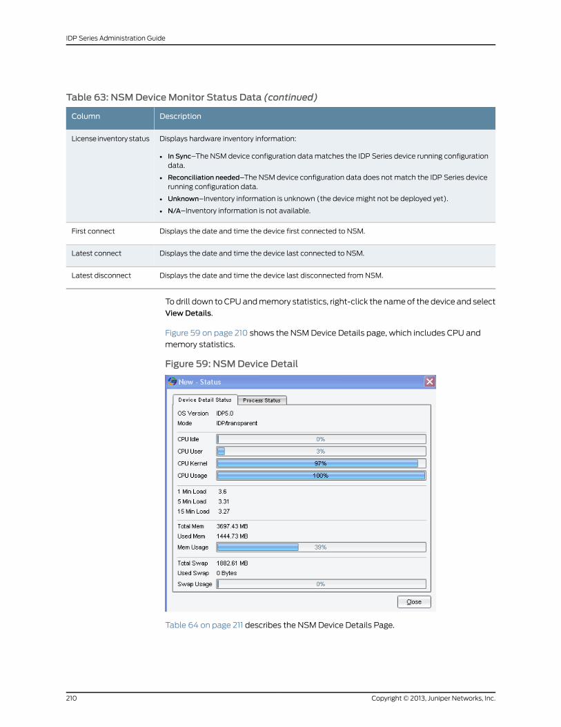
Table 63: NSMDeviceMonitor Status Data (continued)
DescriptionColumn
Displays hardware inventory information:
• In Sync–The NSM device configuration data matches the IDP Series device running configurationdata.
• Reconciliation needed–The NSM device configuration data does not match the IDP Series devicerunning configuration data.
• Unknown–Inventory information is unknown (the device might not be deployed yet).
• N/A–Inventory information is not available.
License inventory status
Displays the date and time the device first connected to NSM.First connect
Displays the date and time the device last connected to NSM.Latest connect
Displays the date and time the device last disconnected from NSM.Latest disconnect
To drill down to CPU and memory statistics, right-click the name of the device and select
View Details.
Figure 59 on page 210 shows the NSM Device Details page, which includes CPU and
memory statistics.
Figure 59: NSMDevice Detail
Table 64 on page 211 describes the NSM Device Details Page.
Copyright © 2013, Juniper Networks, Inc.210
IDP Series Administration Guide
Table 64: NSMDeviceMonitor: Device Details Page
DescriptionColumn
The IDP operating system version.OS Version
Current operation mode of the device.Mode
Percentage of the time the CPU was idle.CPU Idle
Percentage of CPU utilization for user processes.CPU User
Percentage of CPU utilization for kernel processes.CPU Kernel
Combined CPU utilization for user and kernel processes.
NOTE: This CPU statistic shown here is the value returned from the Linux top command for CPU0.On IDP8200, only control plane processes run on CPU0. On IDP1100, IDP800, and IDP250, controlplane processes and JNET driver processes run on CPU0. On IDP600 and IDP75, all processes runon CPU0.
CPU Usage
One-minute load average.1 Min Load
Five-minute load average.5 Min Load
Fifteen-minute load average.15 Min Load
Total amount (in megabytes) of memory.Total Mem
Amount (in megabytes) of used memory.Used Mem
Percentage of used memory.Mem Usage
Total amount (in megabytes) of swap space.Total Swap
Amount (in megabytes) of used swap space.Used Swap
Percentage of used swap space.Swap Usage
To drill down to process status:
1. Right–click a row in the Device Monitor report and select View Device Details.
2. Click the Process Status tab.
Figure 60 on page 212 shows Process Status page, which gives details on memory and
CPU usage per IDP process.
211Copyright © 2013, Juniper Networks, Inc.
Chapter 20: Using NSM Logs and Reports
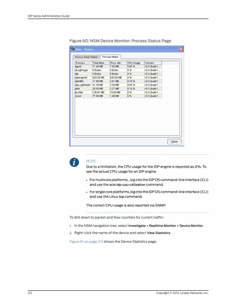
Figure 60: NSMDeviceMonitor: Process Status Page
NOTE:
Due to a limitation, the CPU usage for the IDP engine is reported as 0%. Tosee the actual CPU usage for an IDP engine
• Formulticoreplatforms, , log into the IDPOScommand-line interface (CLI)and use the scio idp-cpu-utilization command.
• Forsinglecoreplatforms, log into the IDPOScommand-line interface(CLI)and use the Linux top command.
The correct CPU usage is also reported via SNMP.
To drill down to packet and flow counters for current traffic:
1. In the NSM navigation tree, select Investigate > RealtimeMonitor > DeviceMonitor.
2. Right-click the name of the device and select View Statistics.
Figure 61 on page 213 shows the Device Statistics page.
Copyright © 2013, Juniper Networks, Inc.212
IDP Series Administration Guide
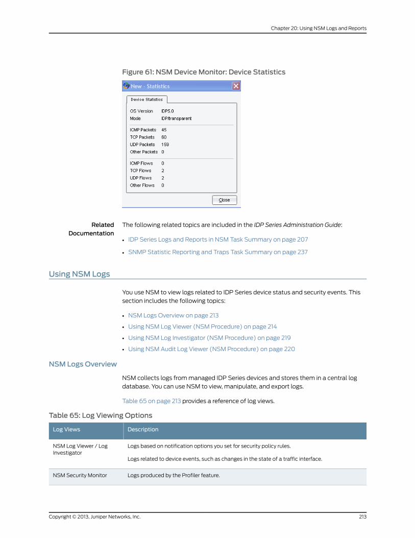
Figure 61: NSMDeviceMonitor: Device Statistics
RelatedDocumentation
The following related topics are included in the IDP Series Administration Guide:
IDP Series Logs and Reports in NSM Task Summary on page 207•
• SNMP Statistic Reporting and Traps Task Summary on page 237
Using NSM Logs
You use NSM to view logs related to IDP Series device status and security events. This
section includes the following topics:
• NSM Logs Overview on page 213
• Using NSM Log Viewer (NSM Procedure) on page 214
• Using NSM Log Investigator (NSM Procedure) on page 219
• Using NSM Audit Log Viewer (NSM Procedure) on page 220
NSM Logs Overview
NSM collects logs from managed IDP Series devices and stores them in a central log
database. You can use NSM to view, manipulate, and export logs.
Table 65 on page 213 provides a reference of log views.
Table 65: Log Viewing Options
DescriptionLog Views
Logs based on notification options you set for security policy rules.
Logs related to device events, such as changes in the state of a traffic interface.
NSM Log Viewer / LogInvestigator
Logs produced by the Profiler feature.NSM Security Monitor
213Copyright © 2013, Juniper Networks, Inc.
Chapter 20: Using NSM Logs and Reports
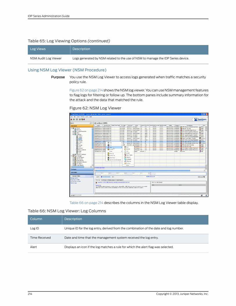
Table 65: Log Viewing Options (continued)
DescriptionLog Views
Logs generated by NSM related to the use of NSM to manage the IDP Series device.NSM Audit Log Viewer
Using NSM Log Viewer (NSMProcedure)
Purpose You use the NSM Log Viewer to access logs generated when traffic matches a security
policy rule.
Figure 62 on page 214 shows the NSM log viewer. You can use NSM management features
to flag logs for filtering or follow up. The bottom panes include summary information for
the attack and the data that matched the rule.
Figure 62: NSM Log Viewer
Table 66 on page 214 describes the columns in the NSM Log Viewer table display.
Table 66: NSM Log Viewer: Log Columns
DescriptionColumn
Unique ID for the log entry, derived from the combination of the date and log number.Log ID
Date and time that the management system received the log entry.Time Received
Displays an icon if the log matches a rule for which the alert flag was selected.Alert
Copyright © 2013, Juniper Networks, Inc.214
IDP Series Administration Guide
Table 66: NSM Log Viewer: Log Columns (continued)
DescriptionColumn
To set a flag, right-click the log row, select Flag, and then select one of the following flags:
• High
• Medium
• Low
• Closed
• False Positive
• Assigned
• Investigate
• Follow-up
• Pending
User Flag
Source IP address of the packet that generated the log entry.Src Addr
Destination IP address of the packet that generated the log entry.Dst Addr
Action the security device performed on the packet/connection that generated this log entry:
• Accepted—The device did not block the packet.
• Closed Client—The device closed the connection and sent a RST packet to the client, but did neitherto the server.
• Closed Server—The device closed the connection and sent a RST packet to the server, but did neitherto the client.
• Closed—The device closed the connection and sent a RST packet to both the client and the server.
• Dropped—The device dropped the connection without sending a RST packet to the sender, preventingthe traffic from reaching its destination.
• Dropped Packet—The device dropped a matching packet before it could reach its destination butdid not close the connection.
• Ignored–Matched the attack, did not take action, and ignored the remainder of the connection.
NOTE: IDP logs show the action that was set in the rule, not necessarily the actual action taken. ForTCP events, these are the same. For UDP and ICMP events, the IDP logs show close client, close server,and close client and server actions, even when the actual action taken was a drop (close actions arenot possible for UDP or ICMP packets).
Action
Protocol that the packet that generated the log entry used.Protocol
Destination port of the packet that generated the log entry.Dst Port
The rule in a policy rulebase (in a specific version of a domain) that generated the log entry.Rule #
The NAT source address of the packet that generated the log entry.Nat Src Addr
The NAT destination address of the packet that generated the log entry.Nat Dst Addr
Miscellaneous string associated with log entry.Details
215Copyright © 2013, Juniper Networks, Inc.
Chapter 20: Using NSM Logs and Reports
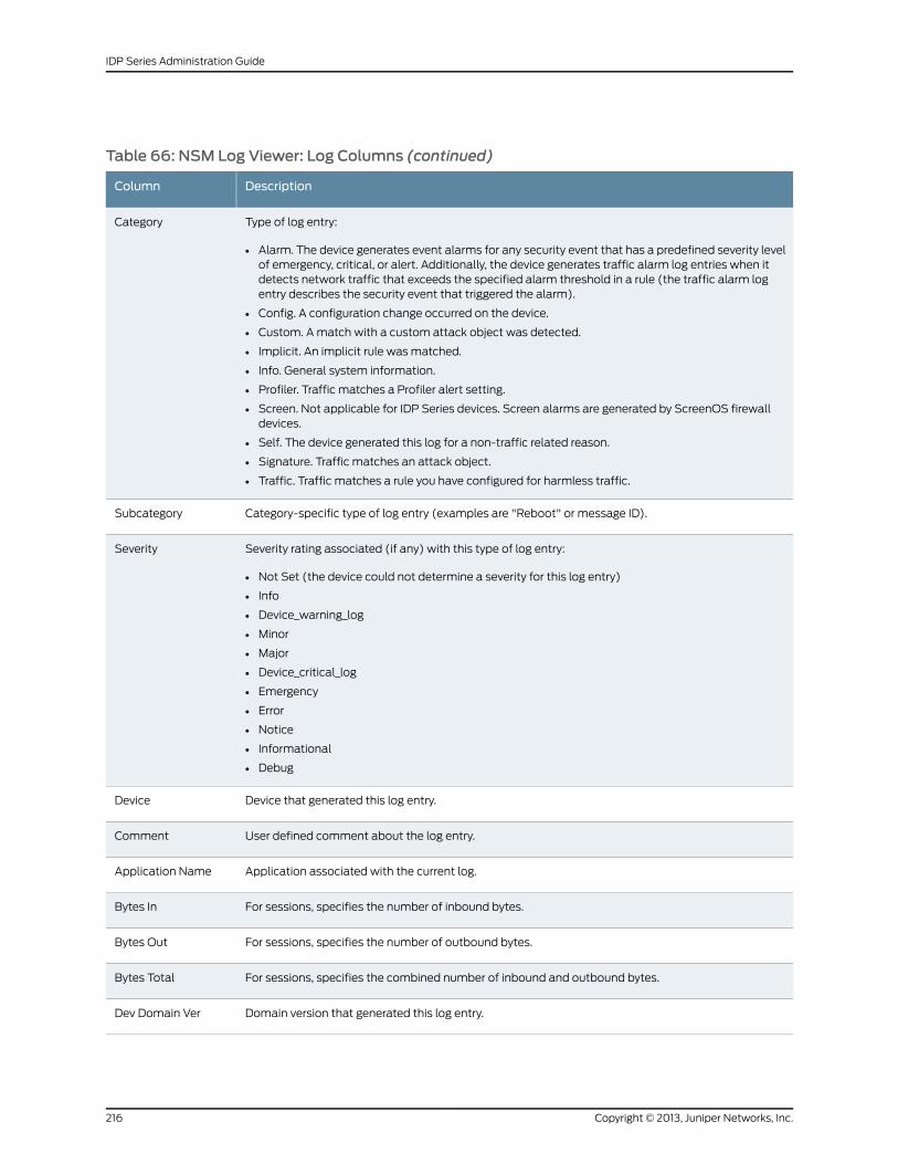
Table 66: NSM Log Viewer: Log Columns (continued)
DescriptionColumn
Type of log entry:
• Alarm. The device generates event alarms for any security event that has a predefined severity levelof emergency, critical, or alert. Additionally, the device generates traffic alarm log entries when itdetects network traffic that exceeds the specified alarm threshold in a rule (the traffic alarm logentry describes the security event that triggered the alarm).
• Config. A configuration change occurred on the device.
• Custom. A match with a custom attack object was detected.
• Implicit. An implicit rule was matched.
• Info. General system information.
• Profiler. Traffic matches a Profiler alert setting.
• Screen. Not applicable for IDP Series devices. Screen alarms are generated by ScreenOS firewalldevices.
• Self. The device generated this log for a non-traffic related reason.
• Signature. Traffic matches an attack object.
• Traffic. Traffic matches a rule you have configured for harmless traffic.
Category
Category-specific type of log entry (examples are "Reboot" or message ID).Subcategory
Severity rating associated (if any) with this type of log entry:
• Not Set (the device could not determine a severity for this log entry)
• Info
• Device_warning_log
• Minor
• Major
• Device_critical_log
• Emergency
• Error
• Notice
• Informational
• Debug
Severity
Device that generated this log entry.Device
User defined comment about the log entry.Comment
Application associated with the current log.Application Name
For sessions, specifies the number of inbound bytes.Bytes In
For sessions, specifies the number of outbound bytes.Bytes Out
For sessions, specifies the combined number of inbound and outbound bytes.Bytes Total
Domain version that generated this log entry.Dev Domain Ver
Copyright © 2013, Juniper Networks, Inc.216
IDP Series Administration Guide
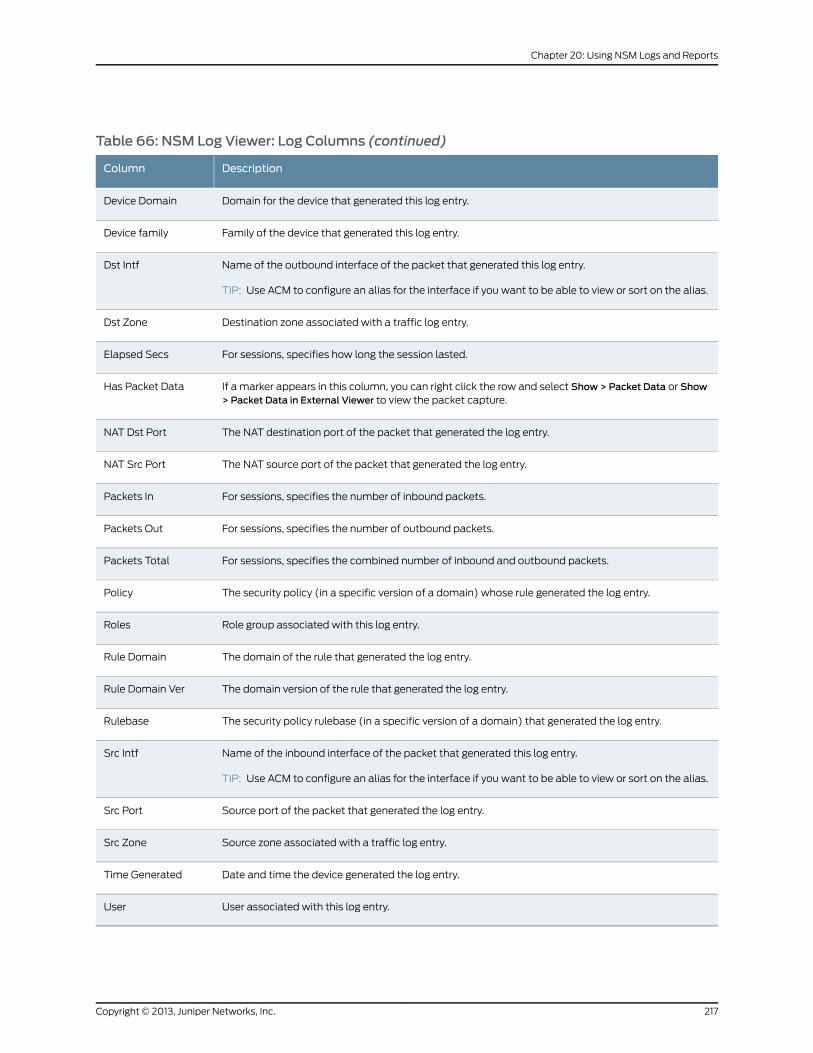
Table 66: NSM Log Viewer: Log Columns (continued)
DescriptionColumn
Domain for the device that generated this log entry.Device Domain
Family of the device that generated this log entry.Device family
Name of the outbound interface of the packet that generated this log entry.
TIP: Use ACM to configure an alias for the interface if you want to be able to view or sort on the alias.
Dst Intf
Destination zone associated with a traffic log entry.Dst Zone
For sessions, specifies how long the session lasted.Elapsed Secs
If a marker appears in this column, you can right click the row and select Show > Packet Data or Show> Packet Data in External Viewer to view the packet capture.
Has Packet Data
The NAT destination port of the packet that generated the log entry.NAT Dst Port
The NAT source port of the packet that generated the log entry.NAT Src Port
For sessions, specifies the number of inbound packets.Packets In
For sessions, specifies the number of outbound packets.Packets Out
For sessions, specifies the combined number of inbound and outbound packets.Packets Total
The security policy (in a specific version of a domain) whose rule generated the log entry.Policy
Role group associated with this log entry.Roles
The domain of the rule that generated the log entry.Rule Domain
The domain version of the rule that generated the log entry.Rule Domain Ver
The security policy rulebase (in a specific version of a domain) that generated the log entry.Rulebase
Name of the inbound interface of the packet that generated this log entry.
TIP: Use ACM to configure an alias for the interface if you want to be able to view or sort on the alias.
Src Intf
Source port of the packet that generated the log entry.Src Port
Source zone associated with a traffic log entry.Src Zone
Date and time the device generated the log entry.Time Generated
User associated with this log entry.User
217Copyright © 2013, Juniper Networks, Inc.
Chapter 20: Using NSM Logs and Reports
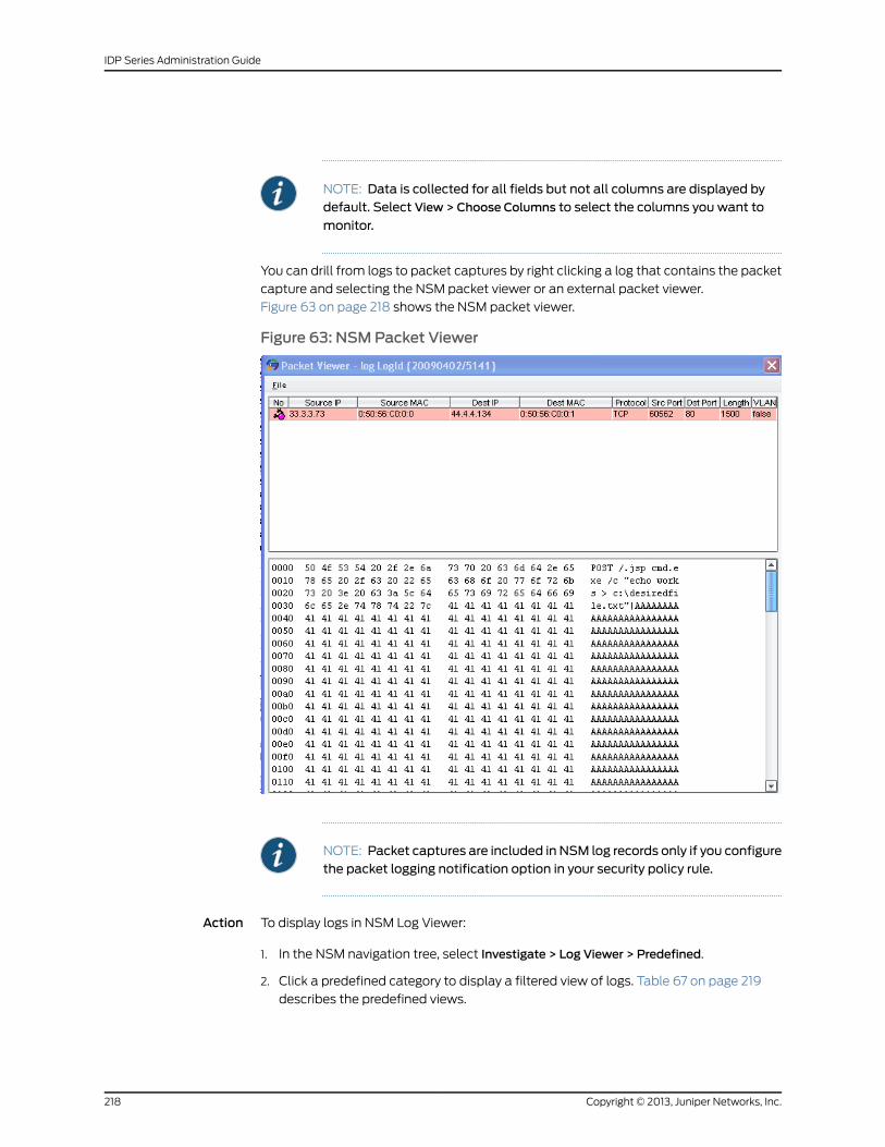
NOTE: Data is collected for all fields but not all columns are displayed bydefault. Select View > Choose Columns to select the columns you want to
monitor.
You can drill from logs to packet captures by right clicking a log that contains the packet
capture and selecting the NSM packet viewer or an external packet viewer.
Figure 63 on page 218 shows the NSM packet viewer.
Figure 63: NSMPacket Viewer
NOTE: Packet captures are included in NSM log records only if you configurethe packet logging notification option in your security policy rule.
Action To display logs in NSM Log Viewer:
1. In the NSM navigation tree, select Investigate > Log Viewer > Predefined.
2. Click a predefined category to display a filtered view of logs. Table 67 on page 219
describes the predefined views.
Copyright © 2013, Juniper Networks, Inc.218
IDP Series Administration Guide
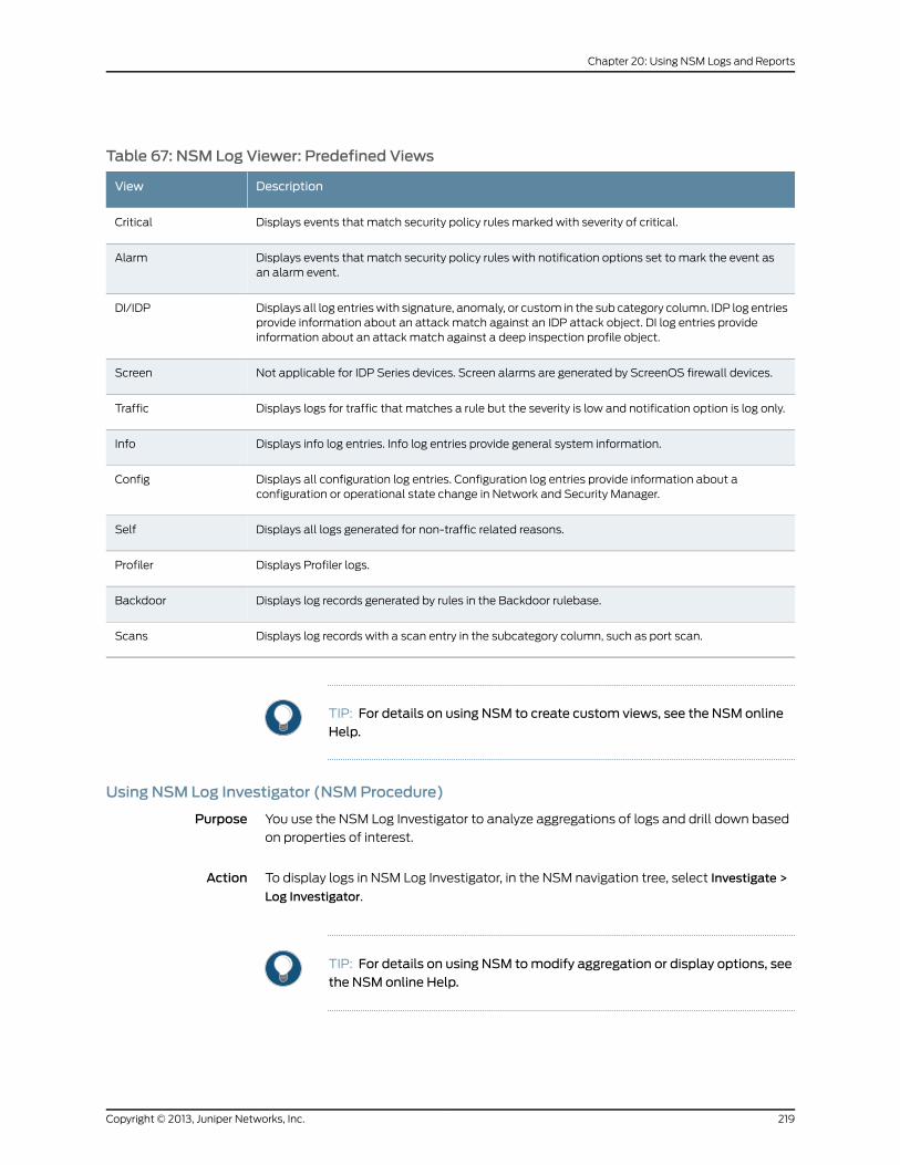
Table 67: NSM Log Viewer: Predefined Views
DescriptionView
Displays events that match security policy rules marked with severity of critical.Critical
Displays events that match security policy rules with notification options set to mark the event asan alarm event.
Alarm
Displays all log entries with signature, anomaly, or custom in the sub category column. IDP log entriesprovide information about an attack match against an IDP attack object. DI log entries provideinformation about an attack match against a deep inspection profile object.
DI/IDP
Not applicable for IDP Series devices. Screen alarms are generated by ScreenOS firewall devices.Screen
Displays logs for traffic that matches a rule but the severity is low and notification option is log only.Traffic
Displays info log entries. Info log entries provide general system information.Info
Displays all configuration log entries. Configuration log entries provide information about aconfiguration or operational state change in Network and Security Manager.
Config
Displays all logs generated for non-traffic related reasons.Self
Displays Profiler logs.Profiler
Displays log records generated by rules in the Backdoor rulebase.Backdoor
Displays log records with a scan entry in the subcategory column, such as port scan.Scans
TIP: For details on using NSM to create custom views, see the NSM onlineHelp.
Using NSM Log Investigator (NSMProcedure)
Purpose You use the NSM Log Investigator to analyze aggregations of logs and drill down based
on properties of interest.
Action To display logs in NSM Log Investigator, in the NSM navigation tree, select Investigate >
Log Investigator.
TIP: For details on using NSM tomodify aggregation or display options, seethe NSM online Help.
219Copyright © 2013, Juniper Networks, Inc.
Chapter 20: Using NSM Logs and Reports
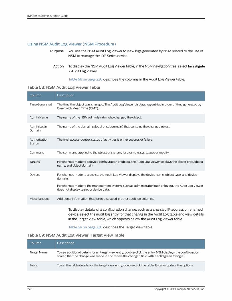
Using NSMAudit Log Viewer (NSMProcedure)
Purpose You use the NSM Audit Log Viewer to view logs generated by NSM related to the use of
NSM to manage the IDP Series device.
Action To display the NSM Audit Log Viewer table, in the NSM navigation tree, select Investigate
> Audit Log Viewer.
Table 68 on page 220 describes the columns in the Audit Log Viewer table.
Table 68: NSMAudit Log Viewer Table
DescriptionColumn
The time the object was changed. The Audit Log Viewer displays log entries in order of time generated byGreenwich Mean Time (GMT).
Time Generated
The name of the NSM administrator who changed the object.Admin Name
The name of the domain (global or subdomain) that contains the changed object.Admin LoginDomain
The final access-control status of activities is either success or failure.AuthorizationStatus
The command applied to the object or system, for example, sys_logout or modify.Command
For changes made to a device configuration or object, the Audit Log Viewer displays the object type, objectname, and object domain.
Targets
For changes made to a device, the Audit Log Viewer displays the device name, object type, and devicedomain.
For changes made to the management system, such as administrator login or logout, the Audit Log Viewerdoes not display target or device data.
Devices
Additional information that is not displayed in other audit log columns.Miscellaneous
To display details of a configuration change, such as a changed IP address or renamed
device, select the audit log entry for that change in the Audit Log table and view details
in the Target View table, which appears below the Audit Log Viewer table.
Table 69 on page 220 describes the Target View table.
Table 69: NSMAudit Log Viewer: Target View Table
DescriptionColumn
To see additional details for an target view entry, double-click the entry. NSM displays the configurationscreen that the change was made in and marks the changed field with a solid green triangle.
Target Name
To set the table details for the target view entry, double-click the table. Enter or update the options.Table
Copyright © 2013, Juniper Networks, Inc.220
IDP Series Administration Guide
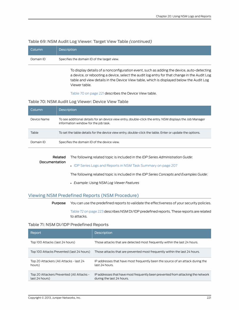
Table 69: NSMAudit Log Viewer: Target View Table (continued)
DescriptionColumn
Specifies the domain ID of the target view.Domain ID
To display details of a nonconfiguration event, such as adding the device, auto-detecting
a device, or rebooting a device, select the audit log entry for that change in the Audit Log
table and view details in the Device View table, which is displayed below the Audit Log
Viewer table.
Table 70 on page 221 describes the Device View table.
Table 70: NSMAudit Log Viewer: Device View Table
DescriptionColumn
To see additional details for an device view entry, double-click the entry. NSM displays the Job Managerinformation window for the job task.
Device Name
To set the table details for the device view entry, double-click the table. Enter or update the options.Table
Specifies the domain ID of the device view.Domain ID
RelatedDocumentation
The following related topic is included in the IDP Series Administration Guide:
IDP Series Logs and Reports in NSM Task Summary on page 207•
The following related topic is included in the IDP Series Concepts and Examples Guide:
• Example: Using NSM Log Viewer Features
Viewing NSMPredefined Reports (NSMProcedure)
Purpose You can use the predefined reports to validate the effectiveness of your security policies.
Table 72 on page 223 describes NSM DI/IDP predefined reports. These reports are related
to attacks.
Table 71: NSMDI/IDP Predefined Reports
DescriptionReport
Those attacks that are detected most frequently within the last 24 hours.Top 100 Attacks (last 24 hours)
Those attacks that are prevented most frequently within the last 24 hours.Top 100 Attacks Prevented (last 24 hours)
IP addresses that have most frequently been the source of an attack during thelast 24 hours.
Top 20 Attackers (All Attacks - last 24hours)
IP addresses that have most frequently been prevented from attacking the networkduring the last 24 hours.
Top 20 Attackers Prevented (All Attacks -last 24 hours)
221Copyright © 2013, Juniper Networks, Inc.
Chapter 20: Using NSM Logs and Reports
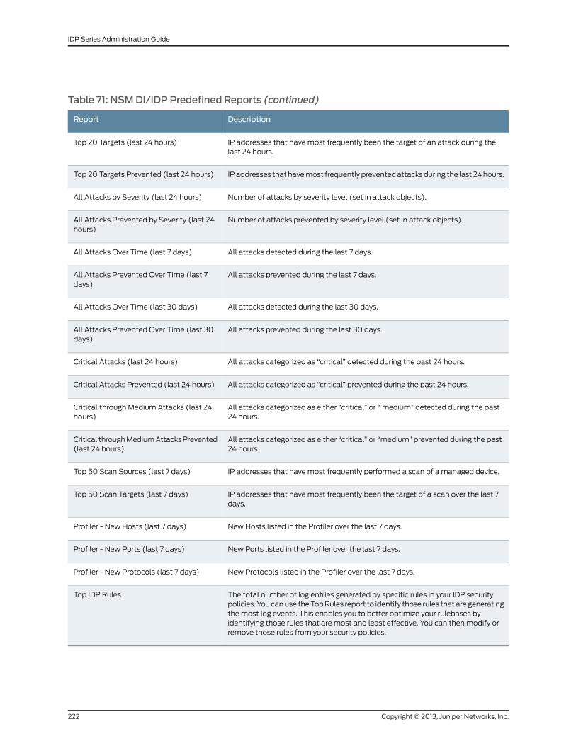
Table 71: NSMDI/IDP Predefined Reports (continued)
DescriptionReport
IP addresses that have most frequently been the target of an attack during thelast 24 hours.
Top 20 Targets (last 24 hours)
IP addresses that have most frequently prevented attacks during the last 24 hours.Top 20 Targets Prevented (last 24 hours)
Number of attacks by severity level (set in attack objects).All Attacks by Severity (last 24 hours)
Number of attacks prevented by severity level (set in attack objects).All Attacks Prevented by Severity (last 24hours)
All attacks detected during the last 7 days.All Attacks Over Time (last 7 days)
All attacks prevented during the last 7 days.All Attacks Prevented Over Time (last 7days)
All attacks detected during the last 30 days.All Attacks Over Time (last 30 days)
All attacks prevented during the last 30 days.All Attacks Prevented Over Time (last 30days)
All attacks categorized as “critical” detected during the past 24 hours.Critical Attacks (last 24 hours)
All attacks categorized as “critical” prevented during the past 24 hours.Critical Attacks Prevented (last 24 hours)
All attacks categorized as either “critical” or “ medium” detected during the past24 hours.
Critical through Medium Attacks (last 24hours)
All attacks categorized as either “critical” or “medium” prevented during the past24 hours.
Critical through Medium Attacks Prevented(last 24 hours)
IP addresses that have most frequently performed a scan of a managed device.Top 50 Scan Sources (last 7 days)
IP addresses that have most frequently been the target of a scan over the last 7days.
Top 50 Scan Targets (last 7 days)
New Hosts listed in the Profiler over the last 7 days.Profiler - New Hosts (last 7 days)
New Ports listed in the Profiler over the last 7 days.Profiler - New Ports (last 7 days)
New Protocols listed in the Profiler over the last 7 days.Profiler - New Protocols (last 7 days)
The total number of log entries generated by specific rules in your IDP securitypolicies. You can use the Top Rules report to identify those rules that are generatingthe most log events. This enables you to better optimize your rulebases byidentifying those rules that are most and least effective. You can then modify orremove those rules from your security policies.
Top IDP Rules
Copyright © 2013, Juniper Networks, Inc.222
IDP Series Administration Guide
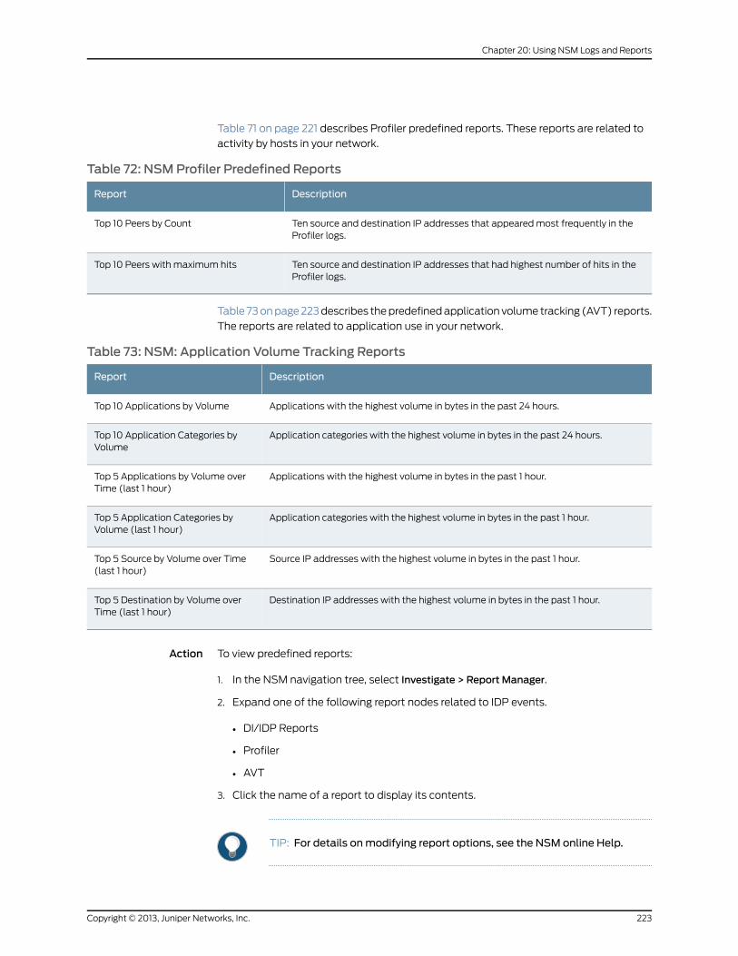
Table 71 on page 221 describes Profiler predefined reports. These reports are related to
activity by hosts in your network.
Table 72: NSMProfiler Predefined Reports
DescriptionReport
Ten source and destination IP addresses that appeared most frequently in theProfiler logs.
Top 10 Peers by Count
Ten source and destination IP addresses that had highest number of hits in theProfiler logs.
Top 10 Peers with maximum hits
Table 73 on page 223 describes the predefined application volume tracking (AVT) reports.
The reports are related to application use in your network.
Table 73: NSM: Application Volume Tracking Reports
DescriptionReport
Applications with the highest volume in bytes in the past 24 hours.Top 10 Applications by Volume
Application categories with the highest volume in bytes in the past 24 hours.Top 10 Application Categories byVolume
Applications with the highest volume in bytes in the past 1 hour.Top 5 Applications by Volume overTime (last 1 hour)
Application categories with the highest volume in bytes in the past 1 hour.Top 5 Application Categories byVolume (last 1 hour)
Source IP addresses with the highest volume in bytes in the past 1 hour.Top 5 Source by Volume over Time(last 1 hour)
Destination IP addresses with the highest volume in bytes in the past 1 hour.Top 5 Destination by Volume overTime (last 1 hour)
Action To view predefined reports:
1. In the NSM navigation tree, select Investigate > Report Manager.
2. Expand one of the following report nodes related to IDP events.
• DI/IDP Reports
• Profiler
• AVT
3. Click the name of a report to display its contents.
TIP: For details onmodifying report options, see the NSM online Help.
223Copyright © 2013, Juniper Networks, Inc.
Chapter 20: Using NSM Logs and Reports
RelatedDocumentation
The following related topic is included in the IDP Series Administration Guide:
IDP Series Logs and Reports in NSM Task Summary on page 207•
Creating NSMCustomReports (NSMProcedure)
Purpose You use custom reports if you require a view of data not covered by predefined reports.
Action To create a custom report:
1. In the NSM navigation tree, select Investigate > Report Manager.
2. Select a predefined report with data similar to what you ultimately want to save.
3. Select File > Save As.
4. Use the predefined report as a template and example. Complete the configuration
options described in Table 74 on page 225.
5. Click OK.
Copyright © 2013, Juniper Networks, Inc.224
IDP Series Administration Guide
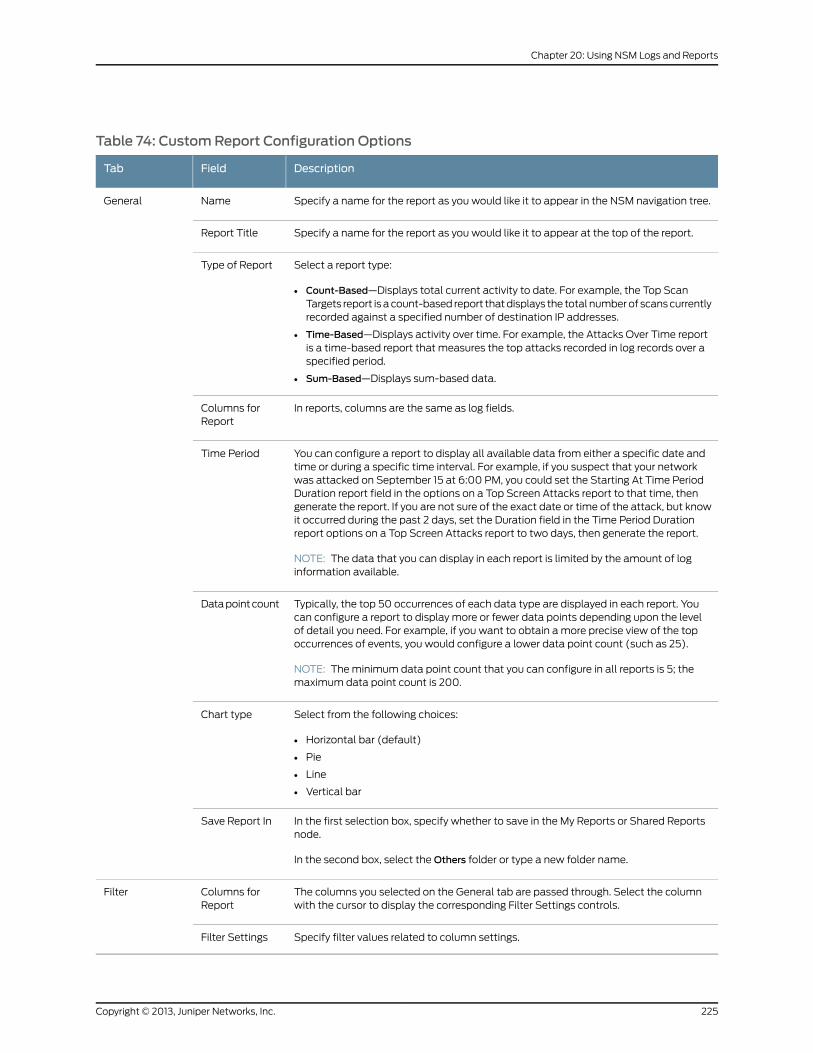
Table 74: CustomReport Configuration Options
DescriptionFieldTab
Specify a name for the report as you would like it to appear in the NSM navigation tree.NameGeneral
Specify a name for the report as you would like it to appear at the top of the report.Report Title
Select a report type:
• Count-Based—Displays total current activity to date. For example, the Top ScanTargets report is a count-based report that displays the total number of scans currentlyrecorded against a specified number of destination IP addresses.
• Time-Based—Displays activity over time. For example, the Attacks Over Time reportis a time-based report that measures the top attacks recorded in log records over aspecified period.
• Sum-Based—Displays sum-based data.
Type of Report
In reports, columns are the same as log fields.Columns forReport
You can configure a report to display all available data from either a specific date andtime or during a specific time interval. For example, if you suspect that your networkwas attacked on September 15 at 6:00 PM, you could set the Starting At Time PeriodDuration report field in the options on a Top Screen Attacks report to that time, thengenerate the report. If you are not sure of the exact date or time of the attack, but knowit occurred during the past 2 days, set the Duration field in the Time Period Durationreport options on a Top Screen Attacks report to two days, then generate the report.
NOTE: The data that you can display in each report is limited by the amount of loginformation available.
Time Period
Typically, the top 50 occurrences of each data type are displayed in each report. Youcan configure a report to display more or fewer data points depending upon the levelof detail you need. For example, if you want to obtain a more precise view of the topoccurrences of events, you would configure a lower data point count (such as 25).
NOTE: The minimum data point count that you can configure in all reports is 5; themaximum data point count is 200.
Data point count
Select from the following choices:
• Horizontal bar (default)
• Pie
• Line
• Vertical bar
Chart type
In the first selection box, specify whether to save in the My Reports or Shared Reportsnode.
In the second box, select the Others folder or type a new folder name.
Save Report In
The columns you selected on the General tab are passed through. Select the columnwith the cursor to display the corresponding Filter Settings controls.
Columns forReport
Filter
Specify filter values related to column settings.Filter Settings
225Copyright © 2013, Juniper Networks, Inc.
Chapter 20: Using NSM Logs and Reports
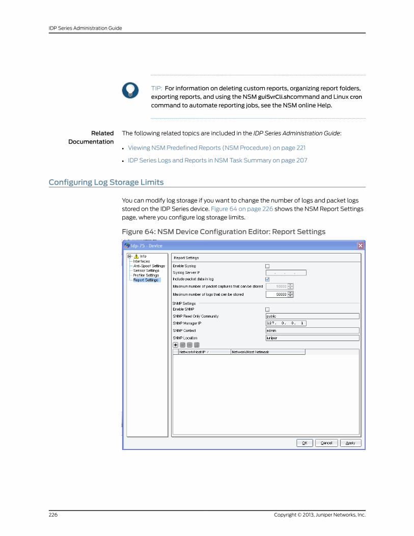
TIP: For information on deleting custom reports, organizing report folders,exporting reports, and using the NSM guiSvrCli.shcommand and Linux cron
command to automate reporting jobs, see the NSM online Help.
RelatedDocumentation
The following related topics are included in the IDP Series Administration Guide:
Viewing NSM Predefined Reports (NSM Procedure) on page 221•
• IDP Series Logs and Reports in NSM Task Summary on page 207
Configuring Log Storage Limits
You can modify log storage if you want to change the number of logs and packet logs
stored on the IDP Series device. Figure 64 on page 226 shows the NSM Report Settings
page, where you configure log storage limits.
Figure 64: NSMDevice Configuration Editor: Report Settings
Copyright © 2013, Juniper Networks, Inc.226
IDP Series Administration Guide
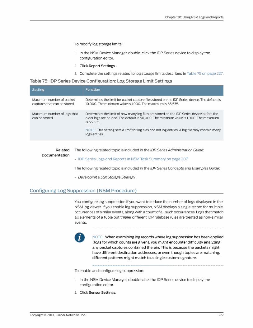
To modify log storage limits:
1. In the NSM Device Manager, double-click the IDP Series device to display the
configuration editor.
2. Click Report Settings.
3. Complete the settings related to log storage limits described in Table 75 on page 227.
Table 75: IDP Series Device Configuration: Log Storage Limit Settings
FunctionSetting
Determines the limit for packet capture files stored on the IDP Series device. The default is10,000. The minimum value is 1,000. The maximum is 65,535.
Maximum number of packetcaptures that can be stored
Determines the limit of how many log files are stored on the IDP Series device before theolder logs are pruned. The default is 50,000. The minimum value is 1,000. The maximumis 65,535.
NOTE: This setting sets a limit for log files and not log entries. A log file may contain manylogs entries.
Maximum number of logs thatcan be stored
RelatedDocumentation
The following related topic is included in the IDP Series Administration Guide:
IDP Series Logs and Reports in NSM Task Summary on page 207•
The following related topic is included in the IDP Series Concepts and Examples Guide:
• Developing a Log Storage Strategy
Configuring Log Suppression (NSMProcedure)
You configure log suppression if you want to reduce the number of logs displayed in the
NSM log viewer. If you enable log suppression, NSM displays a single record for multiple
occurrences of similar events, along with a count of all such occurrences. Logs that match
all elements of a tuple but trigger different IDP rulebase rules are treated as non-similar
events.
NOTE: When examining log recordswhere log suppression has been applied(logs for which counts are given), youmight encounter difficulty analyzingany packet captures contained therein. This is because the packets mighthave different destination addresses, or even though tuples arematching,different patternsmight match to a single custom signature.
To enable and configure log suppression:
1. In the NSM Device Manager, double-click the IDP Series device to display the
configuration editor.
2. Click Sensor Settings.
227Copyright © 2013, Juniper Networks, Inc.
Chapter 20: Using NSM Logs and Reports
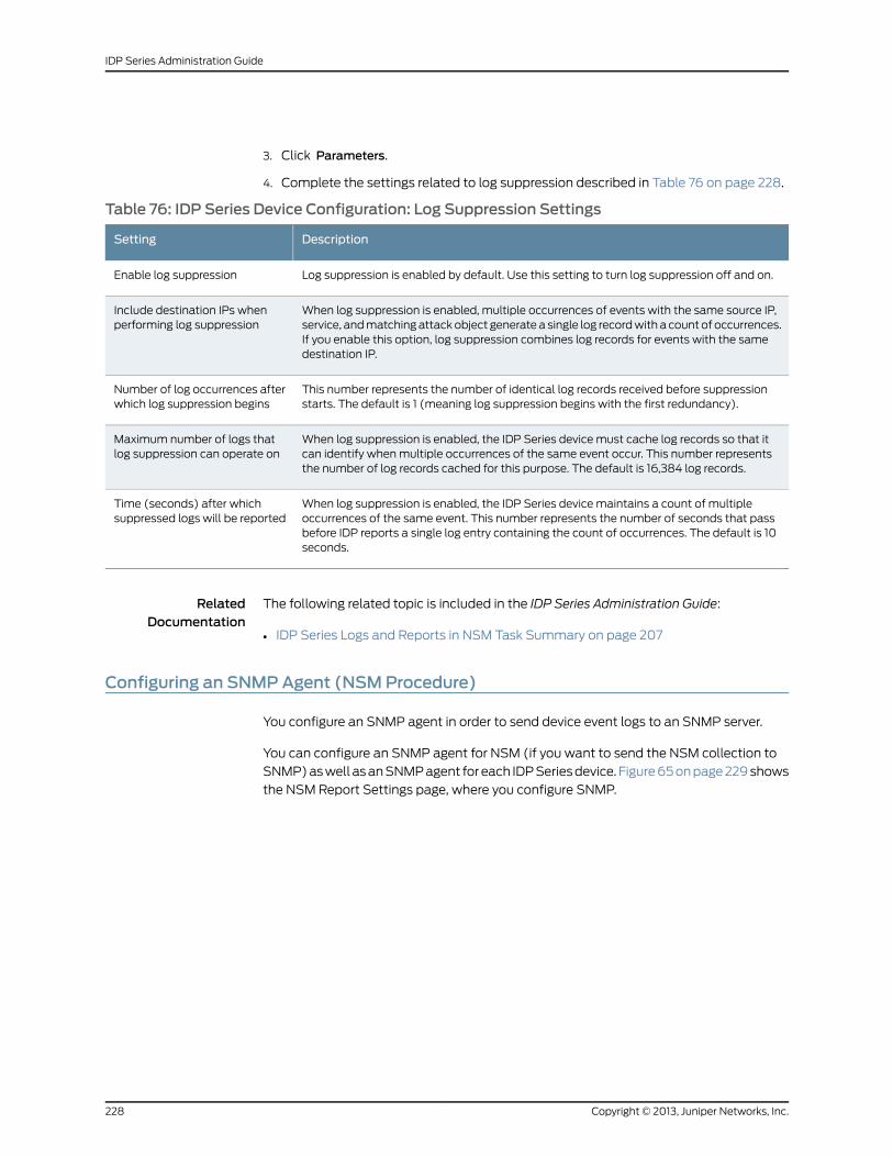
3. Click Parameters.
4. Complete the settings related to log suppression described in Table 76 on page 228.
Table 76: IDP Series Device Configuration: Log Suppression Settings
DescriptionSetting
Log suppression is enabled by default. Use this setting to turn log suppression off and on.Enable log suppression
When log suppression is enabled, multiple occurrences of events with the same source IP,service, and matching attack object generate a single log record with a count of occurrences.If you enable this option, log suppression combines log records for events with the samedestination IP.
Include destination IPs whenperforming log suppression
This number represents the number of identical log records received before suppressionstarts. The default is 1 (meaning log suppression begins with the first redundancy).
Number of log occurrences afterwhich log suppression begins
When log suppression is enabled, the IDP Series device must cache log records so that itcan identify when multiple occurrences of the same event occur. This number representsthe number of log records cached for this purpose. The default is 16,384 log records.
Maximum number of logs thatlog suppression can operate on
When log suppression is enabled, the IDP Series device maintains a count of multipleoccurrences of the same event. This number represents the number of seconds that passbefore IDP reports a single log entry containing the count of occurrences. The default is 10seconds.
Time (seconds) after whichsuppressed logs will be reported
RelatedDocumentation
The following related topic is included in the IDP Series Administration Guide:
IDP Series Logs and Reports in NSM Task Summary on page 207•
Configuring an SNMPAgent (NSMProcedure)
You configure an SNMP agent in order to send device event logs to an SNMP server.
You can configure an SNMP agent for NSM (if you want to send the NSM collection to
SNMP) as well as an SNMP agent for each IDP Series device. Figure 65 on page 229 shows
the NSM Report Settings page, where you configure SNMP.
Copyright © 2013, Juniper Networks, Inc.228
IDP Series Administration Guide
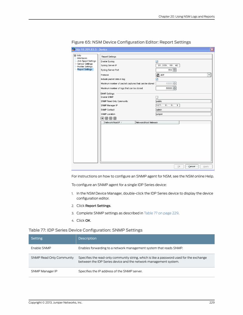
Figure 65: NSMDevice Configuration Editor: Report Settings
For instructions on how to configure an SNMP agent for NSM, see the NSM online Help.
To configure an SNMP agent for a single IDP Series device:
1. In the NSM Device Manager, double-click the IDP Series device to display the device
configuration editor.
2. Click Report Settings.
3. Complete SNMP settings as described in Table 77 on page 229.
4. Click OK.
Table 77: IDP Series Device Configuration: SNMP Settings
DescriptionSetting
Enables forwarding to a network management system that reads SNMP.Enable SNMP
Specifies the read-only community string, which is like a password used for the exchangebetween the IDP Series device and the network management system.
SNMP Read Only Community
Specifies the IP address of the SNMP server.SNMP Manager IP
229Copyright © 2013, Juniper Networks, Inc.
Chapter 20: Using NSM Logs and Reports
Table 77: IDP Series Device Configuration: SNMP Settings (continued)
DescriptionSetting
Specifies an e-mail address for the IDP administrator contact. The contact is included in SNMPcommunications. If the network management system encounters a problem with the SNMPcommunication, an administrator can use the contact information to follow up.
SNMP Contact
Specifies the location of the IDP Series device. Location is included in SNMP communications.SNMP Location
RelatedDocumentation
The following related topics are included in the IDP Series Administration Guide:
SNMP Statistic Reporting and Traps Task Summary on page 237•
• IDP Series Logs and Reports in NSM Task Summary on page 207
Configuring Syslog Collection (NSMProcedure)
You configure syslog settings if you want to forward a copy of IDP Series device logs to
a syslog server.
You have the option of configuring NSM to forward a copy of its log collection to a syslog
server or configuring syslog settings for each IDP Series device.Figure 66 on page 231
shows the NSM Report Settings page, where you configure syslog settings.
Copyright © 2013, Juniper Networks, Inc.230
IDP Series Administration Guide
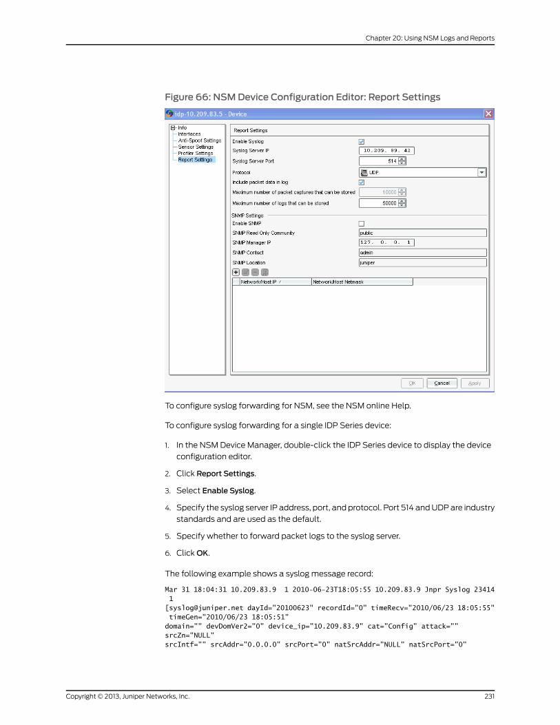
Figure 66: NSMDevice Configuration Editor: Report Settings
To configure syslog forwarding for NSM, see the NSM online Help.
To configure syslog forwarding for a single IDP Series device:
1. In the NSM Device Manager, double-click the IDP Series device to display the device
configuration editor.
2. Click Report Settings.
3. Select Enable Syslog.
4. Specify the syslog server IP address, port, and protocol. Port 514 and UDP are industry
standards and are used as the default.
5. Specify whether to forward packet logs to the syslog server.
6. Click OK.
The following example shows a syslog message record:
Mar 31 18:04:31 10.209.83.9 1 2010-06-23T18:05:55 10.209.83.9 Jnpr Syslog 23414 1 [[email protected] dayId="20100623" recordId="0" timeRecv="2010/06/23 18:05:55" timeGen="2010/06/23 18:05:51" domain="" devDomVer2="0" device_ip="10.209.83.9" cat="Config" attack="" srcZn="NULL" srcIntf="" srcAddr="0.0.0.0" srcPort="0" natSrcAddr="NULL" natSrcPort="0"
231Copyright © 2013, Juniper Networks, Inc.
Chapter 20: Using NSM Logs and Reports
dstZn="NULL" dstIntf="NULL" dstAddr="0.0.0.0" dstPort="0" natDstAddr="NULL" natDstPort="0" protocol="IP" ruleDomain="" ruleVer="0" policy="" rulebase="NONE" ruleNo="0" action="NONE" severity="INFO" alert="no" elaspedTime="0" inbytes="0" outbytes="0" totBytes="0" inPak="0" outPak="0" totPak="0" repCount="0" packetData="no" varEnum="0" misc="Interaface eth2,eth3 is in Normal State" user="NULL" app="NULL" uri="NULL"]
RelatedDocumentation
The following related topic is included in the IDP Series Administration Guide:
IDP Series Logs and Reports in NSM Task Summary on page 207•
Enabling Collection of Packet Data in NSM Logs (NSMProcedure)
When you configure security policy rule notification options, you have the option of logging
the packets surrounding the security event.
Packet capture logs are stored locally on the IDP Series device in numbered directories:
/usr/idp/device/var/pktlogs/0/, /usr/idp/device/var/pktlogs/1/,
/usr/idp/device/var/pktlogs/2/, and so forth. Each directory stores 100,000 logs. The
total number of directories is determined by the value set in NSM for Maximum number
of packet captures that can be stored. For example, if you retain the default (10,000), all
packet logs are stored in /usr/idp/device/var/pktlogs/0/. If you set the maximum to
200,000, packet logs are stored two directories: /usr/idp/device/var/pktlogs/0/ and
/usr/idp/device/var/pktlogs/1/.
The first 100,000 packet capture logs are stored in /usr/idp/device/var/pktlogs/0/. Files
are named 1.pcap, 2.pcap, ..., 100000.pcap. The next 100,000 logs are stored in
/usr/idp/device/var/pktlogs/1/. Files are named 1.cap, 2.pcap, ... 100000.pcap. The log
agent continues to create directories and files in this manner until the user-specified limit
is reached or the disk usage for the partition reaches 90% capacity.
When the user-specified maximum is reached, the log agent begins overwriting packet
log files, beginning with /usr/idp/device/var/pklogs/0/1.pcap.
If the packet capture repository reaches the disk limit before the user-specified limit:
1. The log agent deletes all 100,000 logs in the first directory,
/usr/idp/device/var/pktlogs/0/, in order to reuse the directory and disk space.
2. The next logs are written to /usr/idp/device/var/pktlogs/0/ and the files are named
1.pcap, 2.pcap, ..., 100000.pcap.
3. When the limit is reached again, the log agent deletes all of the logs in the next
directory, /usr/idp/device/var/pktlogs/1/. It continues writing in the current directory
until if reaches 100000.pcap.
4. Then, it begins writing in the next directory, which had been emptied in the previous
step.
Copyright © 2013, Juniper Networks, Inc.232
IDP Series Administration Guide
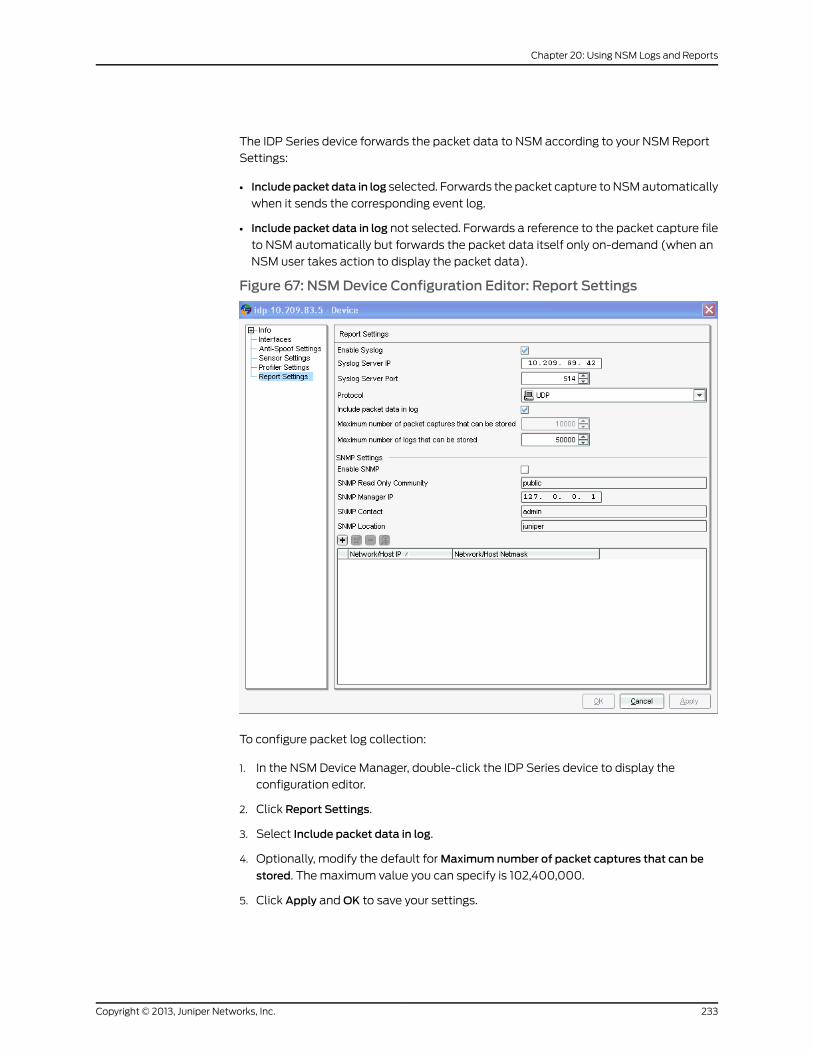
The IDP Series device forwards the packet data to NSM according to your NSM Report
Settings:
• Includepacket data in log selected. Forwards the packet capture to NSM automatically
when it sends the corresponding event log.
• Include packet data in log not selected. Forwards a reference to the packet capture file
to NSM automatically but forwards the packet data itself only on-demand (when an
NSM user takes action to display the packet data).
Figure 67: NSMDevice Configuration Editor: Report Settings
To configure packet log collection:
1. In the NSM Device Manager, double-click the IDP Series device to display the
configuration editor.
2. Click Report Settings.
3. Select Include packet data in log.
4. Optionally, modify the default for Maximum number of packet captures that can be
stored. The maximum value you can specify is 102,400,000.
5. Click Apply and OK to save your settings.
233Copyright © 2013, Juniper Networks, Inc.
Chapter 20: Using NSM Logs and Reports
NOTE: Becarefulwhenmodifying themaximumpacket captures limit. If youfirst configurea large limit and later configureasmaller limit, youmightdeletedirectoriesof logs. For example, supposeyou first set amaximum1,000,000.The log agent begins storing logs in up to 10 log directories. Later, you changethemaximumto 100,000.The logagentcleansup thepreviousconfiguration,deletingunnecessarydirectories 1-9.Before youchange thesetting toa lowervalue, be sure you have copied all the logs you want saved to a remotelocation.
NOTE: Youmight encounter unexpected behavior if the followingcircumstances apply:
• You change themaximum to a lower value–from 200,000 to 100,000, forexample.
• At the same time, the agent process is handling requests fromNSM forlogs from /usr/idp/device/var/pktlogs/ subdirectories.
In the typical case, we expect the agent tomark unnecessary subdirectoriesfordeletionandcleanthemupafter thenewmaximumisapplied. If theagenthas locked a subdirectory marked for deletion in order to retrieve files forNSM, it will not delete the subdirectory.
RelatedDocumentation
The following related topic is included in the IDP Series Administration Guide:
• IDP Series Logs and Reports in NSM Task Summary on page 207
The following related topic is included in the IDP Series Concepts and Examples Guide:
• Example: Packet LoggingWorkflow
Copyright © 2013, Juniper Networks, Inc.234
IDP Series Administration Guide
CHAPTER 21
Using IDP Reporter
This chapter contains the following topics:
• IDP Reporter Task Summary on page 235
IDP Reporter Task Summary
IDP Reporter collects logs related to attacks and application volume tracking, parses
them, and presents them as reports in HTML, PDF, or text formats.
You can use IDP Reporter to perform the following tasks:
• View predefined reports for attacks.
• View predefined reports for application usage.
• Generate reports based on criteria you specify.
• Create jobs that regularly generate predefined or custom reports and e-mail them to
customers or other interested parties.
For information about using IDP Reporter, see the IDP Reporter User’s Guide.
RelatedDocumentation
The following related topics are included in the IDP Series Concepts and Examples Guide:
• IDP Logs Overview
• Application Volume Tracking Overview
235Copyright © 2013, Juniper Networks, Inc.

Copyright © 2013, Juniper Networks, Inc.236
IDP Series Administration Guide
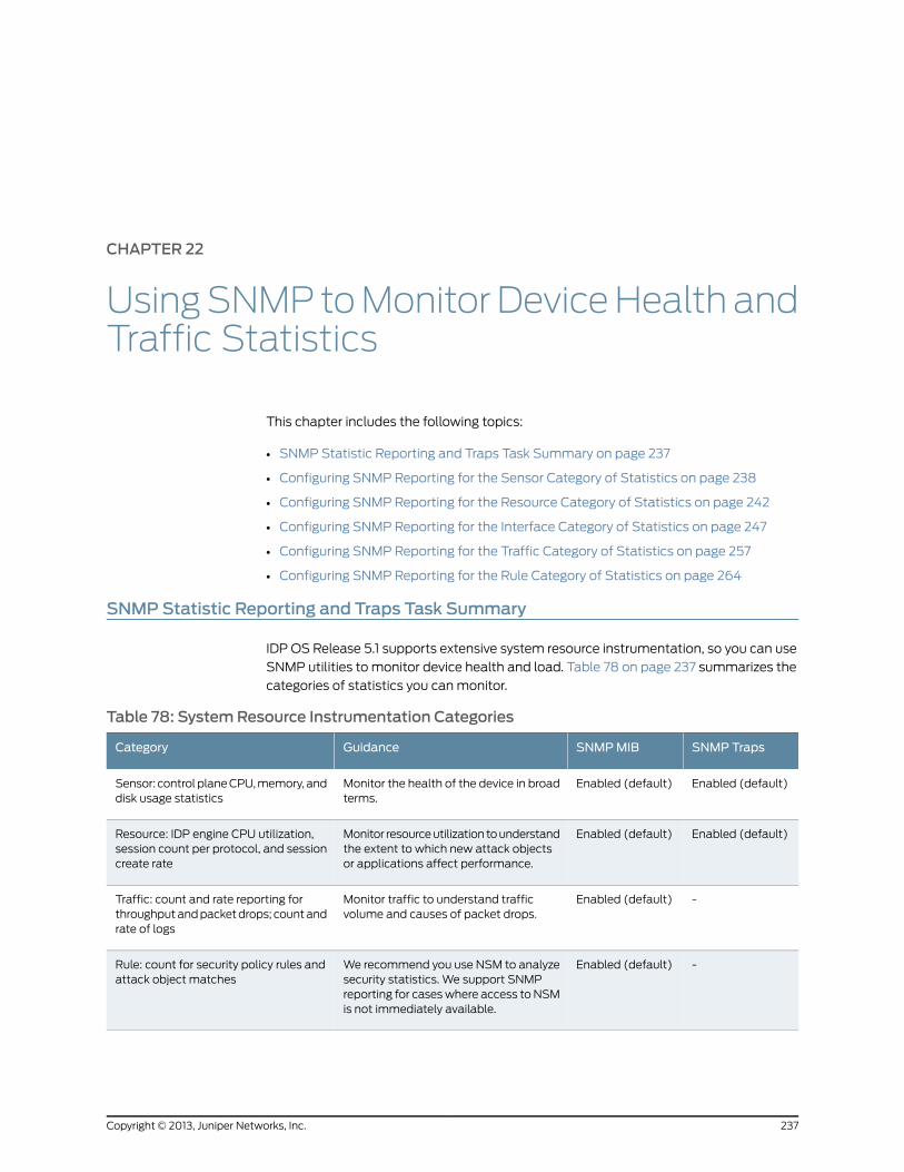
CHAPTER 22
UsingSNMPtoMonitorDeviceHealthandTraffic Statistics
This chapter includes the following topics:
• SNMP Statistic Reporting and Traps Task Summary on page 237
• Configuring SNMP Reporting for the Sensor Category of Statistics on page 238
• Configuring SNMP Reporting for the Resource Category of Statistics on page 242
• Configuring SNMP Reporting for the Interface Category of Statistics on page 247
• Configuring SNMP Reporting for the Traffic Category of Statistics on page 257
• Configuring SNMP Reporting for the Rule Category of Statistics on page 264
SNMPStatistic Reporting and Traps Task Summary
IDP OS Release 5.1 supports extensive system resource instrumentation, so you can use
SNMP utilities to monitor device health and load. Table 78 on page 237 summarizes the
categories of statistics you can monitor.
Table 78: SystemResource Instrumentation Categories
SNMP TrapsSNMPMIBGuidanceCategory
Enabled (default)Enabled (default)Monitor the health of the device in broadterms.
Sensor: control plane CPU, memory, anddisk usage statistics
Enabled (default)Enabled (default)Monitor resource utilization to understandthe extent to which new attack objectsor applications affect performance.
Resource: IDP engine CPU utilization,session count per protocol, and sessioncreate rate
-Enabled (default)Monitor traffic to understand trafficvolume and causes of packet drops.
Traffic: count and rate reporting forthroughput and packet drops; count andrate of logs
-Enabled (default)We recommend you use NSM to analyzesecurity statistics. We support SNMPreporting for cases where access to NSMis not immediately available.
Rule: count for security policy rules andattack object matches
237Copyright © 2013, Juniper Networks, Inc.
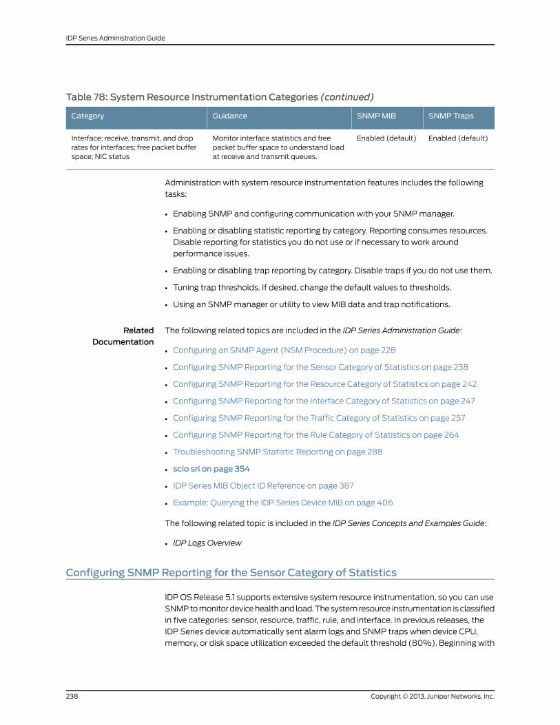
Table 78: SystemResource Instrumentation Categories (continued)
SNMP TrapsSNMPMIBGuidanceCategory
Enabled (default)Enabled (default)Monitor interface statistics and freepacket buffer space to understand loadat receive and transmit queues.
Interface: receive, transmit, and droprates for interfaces; free packet bufferspace; NIC status
Administration with system resource instrumentation features includes the following
tasks:
• Enabling SNMP and configuring communication with your SNMP manager.
• Enabling or disabling statistic reporting by category. Reporting consumes resources.
Disable reporting for statistics you do not use or if necessary to work around
performance issues.
• Enabling or disabling trap reporting by category. Disable traps if you do not use them.
• Tuning trap thresholds. If desired, change the default values to thresholds.
• Using an SNMP manager or utility to view MIB data and trap notifications.
RelatedDocumentation
The following related topics are included in the IDP Series Administration Guide:
Configuring an SNMP Agent (NSM Procedure) on page 228•
• Configuring SNMP Reporting for the Sensor Category of Statistics on page 238
• Configuring SNMP Reporting for the Resource Category of Statistics on page 242
• Configuring SNMP Reporting for the Interface Category of Statistics on page 247
• Configuring SNMP Reporting for the Traffic Category of Statistics on page 257
• Configuring SNMP Reporting for the Rule Category of Statistics on page 264
• Troubleshooting SNMP Statistic Reporting on page 288
• scio sri on page 354
• IDP Series MIB Object ID Reference on page 387
• Example: Querying the IDP Series Device MIB on page 406
The following related topic is included in the IDP Series Concepts and Examples Guide:
• IDP Logs Overview
Configuring SNMPReporting for the Sensor Category of Statistics
IDP OS Release 5.1 supports extensive system resource instrumentation, so you can use
SNMP to monitor device health and load. The system resource instrumentation is classified
in five categories: sensor, resource, traffic, rule, and interface. In previous releases, the
IDP Series device automatically sent alarm logs and SNMP traps when device CPU,
memory, or disk space utilization exceeded the default threshold (80%). Beginning with
Copyright © 2013, Juniper Networks, Inc.238
IDP Series Administration Guide
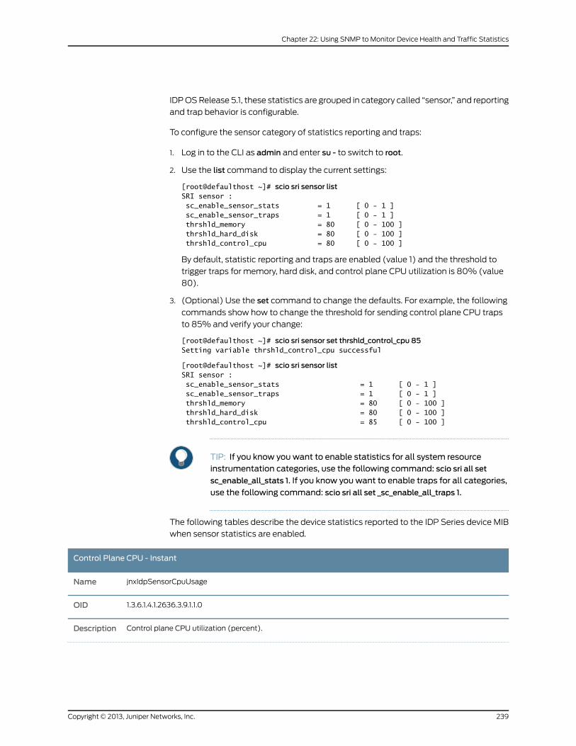
IDP OS Release 5.1, these statistics are grouped in category called “sensor,” and reporting
and trap behavior is configurable.
To configure the sensor category of statistics reporting and traps:
1. Log in to the CLI as admin and enter su - to switch to root.
2. Use the list command to display the current settings:
[root@defaulthost ~]# scio sri sensor listSRI sensor : sc_enable_sensor_stats = 1 [ 0 - 1 ] sc_enable_sensor_traps = 1 [ 0 - 1 ] thrshld_memory = 80 [ 0 - 100 ] thrshld_hard_disk = 80 [ 0 - 100 ] thrshld_control_cpu = 80 [ 0 - 100 ]
By default, statistic reporting and traps are enabled (value 1) and the threshold to
trigger traps for memory, hard disk, and control plane CPU utilization is 80% (value
80).
3. (Optional) Use the set command to change the defaults. For example, the following
commands show how to change the threshold for sending control plane CPU traps
to 85% and verify your change:
[root@defaulthost ~]# scio sri sensor set thrshld_control_cpu 85Setting variable thrshld_control_cpu successful
[root@defaulthost ~]# scio sri sensor listSRI sensor : sc_enable_sensor_stats = 1 [ 0 - 1 ] sc_enable_sensor_traps = 1 [ 0 - 1 ] thrshld_memory = 80 [ 0 - 100 ] thrshld_hard_disk = 80 [ 0 - 100 ] thrshld_control_cpu = 85 [ 0 - 100 ]
TIP: If you know you want to enable statistics for all system resourceinstrumentation categories, use the following command: scio sri all set
sc_enable_all_stats 1. If you know you want to enable traps for all categories,
use the following command: scio sri all set _sc_enable_all_traps 1.
The following tables describe the device statistics reported to the IDP Series device MIB
when sensor statistics are enabled.
Control Plane CPU - Instant
jnxIdpSensorCpuUsageName
1.3.6.1.4.1.2636.3.9.1.1.0OID
Control plane CPU utilization (percent).Description
239Copyright © 2013, Juniper Networks, Inc.
Chapter 22: Using SNMP to Monitor Device Health and Traffic Statistics
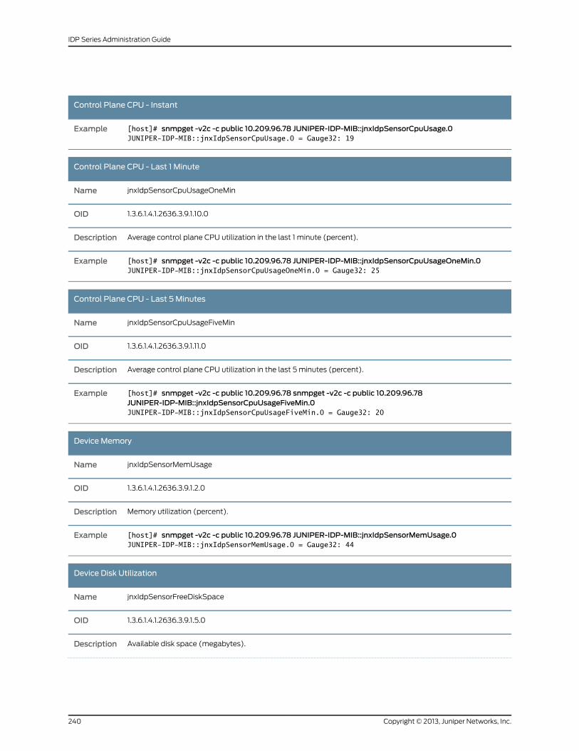
Control Plane CPU - Instant
[host]# snmpget -v2c -c public 10.209.96.78 JUNIPER-IDP-MIB::jnxIdpSensorCpuUsage.0JUNIPER-IDP-MIB::jnxIdpSensorCpuUsage.0 = Gauge32: 19
Example
Control Plane CPU - Last 1 Minute
jnxIdpSensorCpuUsageOneMinName
1.3.6.1.4.1.2636.3.9.1.10.0OID
Average control plane CPU utilization in the last 1 minute (percent).Description
[host]# snmpget -v2c -c public 10.209.96.78 JUNIPER-IDP-MIB::jnxIdpSensorCpuUsageOneMin.0JUNIPER-IDP-MIB::jnxIdpSensorCpuUsageOneMin.0 = Gauge32: 25
Example
Control Plane CPU - Last 5 Minutes
jnxIdpSensorCpuUsageFiveMinName
1.3.6.1.4.1.2636.3.9.1.11.0OID
Average control plane CPU utilization in the last 5 minutes (percent).Description
[host]# snmpget -v2c -c public 10.209.96.78 snmpget -v2c -c public 10.209.96.78JUNIPER-IDP-MIB::jnxIdpSensorCpuUsageFiveMin.0JUNIPER-IDP-MIB::jnxIdpSensorCpuUsageFiveMin.0 = Gauge32: 20
Example
Device Memory
jnxIdpSensorMemUsageName
1.3.6.1.4.1.2636.3.9.1.2.0OID
Memory utilization (percent).Description
[host]# snmpget -v2c -c public 10.209.96.78 JUNIPER-IDP-MIB::jnxIdpSensorMemUsage.0JUNIPER-IDP-MIB::jnxIdpSensorMemUsage.0 = Gauge32: 44
Example
Device Disk Utilization
jnxIdpSensorFreeDiskSpaceName
1.3.6.1.4.1.2636.3.9.1.5.0OID
Available disk space (megabytes).Description
Copyright © 2013, Juniper Networks, Inc.240
IDP Series Administration Guide
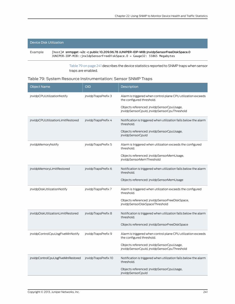
Device Disk Utilization
[host]# snmpget -v2c -c public 10.209.96.78 JUNIPER-IDP-MIB::jnxIdpSensorFreeDiskSpace.0JUNIPER-IDP-MIB::jnxIdpSensorFreeDiskSpace.0 = Gauge32: 55865 Megabytes
Example
Table 79 on page 241 describes the device statistics reported to SNMP traps when sensor
traps are enabled.
Table 79: SystemResource Instrumentation: Sensor SNMP Traps
DescriptionOIDObject Name
Alarm is triggered when control plane CPU utilization exceedsthe configured threshold.
Objects referenced: jnxIdpSensorCpuUsage,jnxIdpSensorCpuId, jnxIdpSensorCpuThreshold
jnxIdpTrapsPrefix 3jnxIdpCPUUtilizationNotify
Notification is triggered when utilization falls below the alarmthreshold.
Objects referenced: jnxIdpSensorCpuUsage,jnxIdpSensorCpuId
jnxIdpTrapsPrefix 4jnxIdpCPUUtilizationLimitRestored
Alarm is triggered when utilization exceeds the configuredthreshold.
Objects referenced: jnxIdpSensorMemUsage,jnxIdpSensorMemThreshold
jnxIdpTrapsPrefix 5jnxIdpMemoryNotify
Notification is triggered when utilization falls below the alarmthreshold.
Objects referenced: jnxIdpSensorMemUsage
jnxIdpTrapsPrefix 6jnxIdpMemoryLimitRestored
Alarm is triggered when utilization exceeds the configuredthreshold.
Objects referenced: jnxIdpSensorFreeDiskSpace,jnxIdpSensorDiskSpaceThreshold
jnxIdpTrapsPrefix 7jnxIdpDiskUtilizationNotify
Notification is triggered when utilization falls below the alarmthreshold.
Objects referenced: jnxIdpSensorFreeDiskSpace
jnxIdpTrapsPrefix 8jnxIdpDiskUtilizationLimitRestored
Alarm is triggered when control plane CPU utilization exceedsthe configured threshold.
Objects referenced: jnxIdpSensorCpuUsage,jnxIdpSensorCpuId, jnxIdpSensorCpuThreshold
jnxIdpTrapsPrefix 9jnxIdpControlCpuUsgFiveMinNotify
Notification is triggered when utilization falls below the alarmthreshold.
Objects referenced: jnxIdpSensorCpuUsage,jnxIdpSensorCpuId
jnxIdpTrapsPrefix 10jnxIdpControlCpuUsgFiveMinRestored
241Copyright © 2013, Juniper Networks, Inc.
Chapter 22: Using SNMP to Monitor Device Health and Traffic Statistics
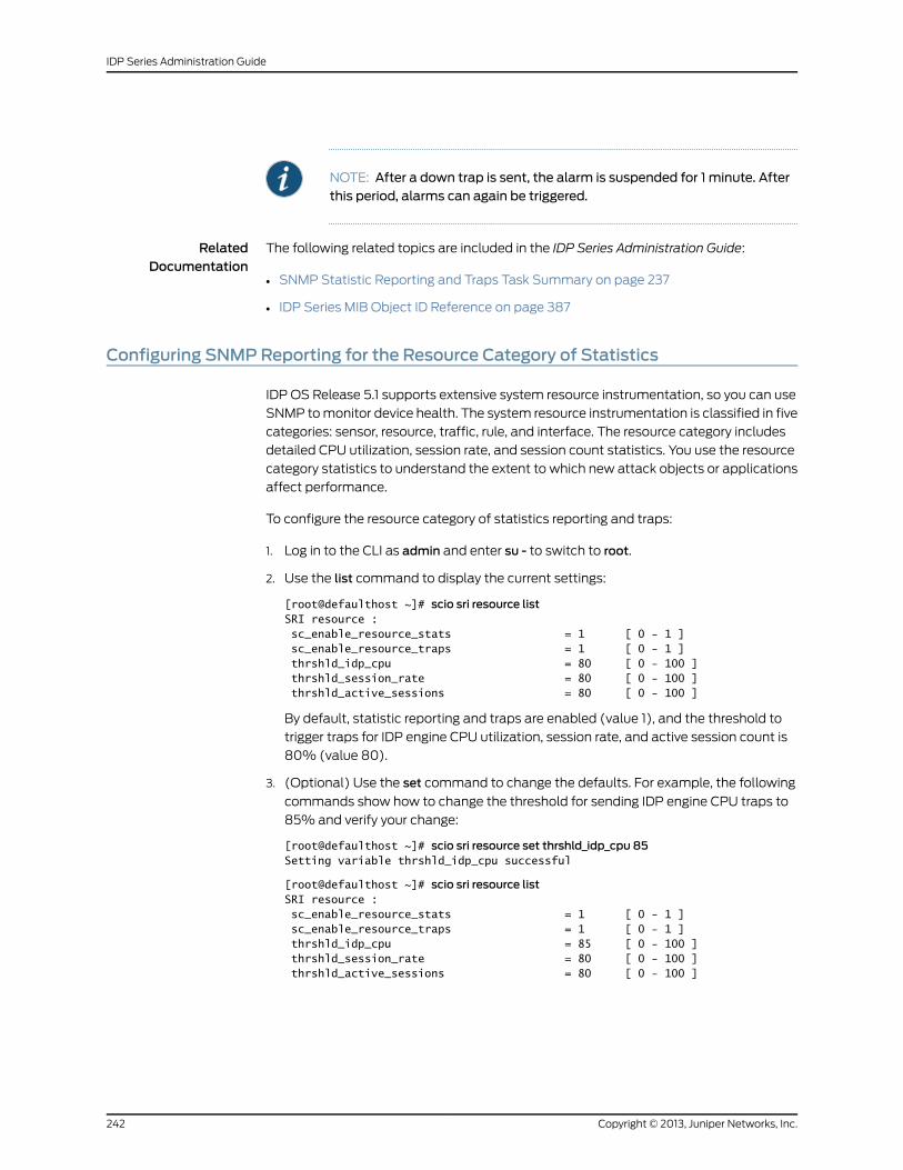
NOTE: After a down trap is sent, the alarm is suspended for 1 minute. Afterthis period, alarms can again be triggered.
RelatedDocumentation
The following related topics are included in the IDP Series Administration Guide:
SNMP Statistic Reporting and Traps Task Summary on page 237•
• IDP Series MIB Object ID Reference on page 387
Configuring SNMPReporting for the Resource Category of Statistics
IDP OS Release 5.1 supports extensive system resource instrumentation, so you can use
SNMP to monitor device health. The system resource instrumentation is classified in five
categories: sensor, resource, traffic, rule, and interface. The resource category includes
detailed CPU utilization, session rate, and session count statistics. You use the resource
category statistics to understand the extent to which new attack objects or applications
affect performance.
To configure the resource category of statistics reporting and traps:
1. Log in to the CLI as admin and enter su - to switch to root.
2. Use the list command to display the current settings:
[root@defaulthost ~]# scio sri resource listSRI resource : sc_enable_resource_stats = 1 [ 0 - 1 ] sc_enable_resource_traps = 1 [ 0 - 1 ] thrshld_idp_cpu = 80 [ 0 - 100 ] thrshld_session_rate = 80 [ 0 - 100 ] thrshld_active_sessions = 80 [ 0 - 100 ]
By default, statistic reporting and traps are enabled (value 1), and the threshold to
trigger traps for IDP engine CPU utilization, session rate, and active session count is
80% (value 80).
3. (Optional) Use the set command to change the defaults. For example, the following
commands show how to change the threshold for sending IDP engine CPU traps to
85% and verify your change:
[root@defaulthost ~]# scio sri resource set thrshld_idp_cpu 85Setting variable thrshld_idp_cpu successful
[root@defaulthost ~]# scio sri resource listSRI resource : sc_enable_resource_stats = 1 [ 0 - 1 ] sc_enable_resource_traps = 1 [ 0 - 1 ] thrshld_idp_cpu = 85 [ 0 - 100 ] thrshld_session_rate = 80 [ 0 - 100 ] thrshld_active_sessions = 80 [ 0 - 100 ]
Copyright © 2013, Juniper Networks, Inc.242
IDP Series Administration Guide
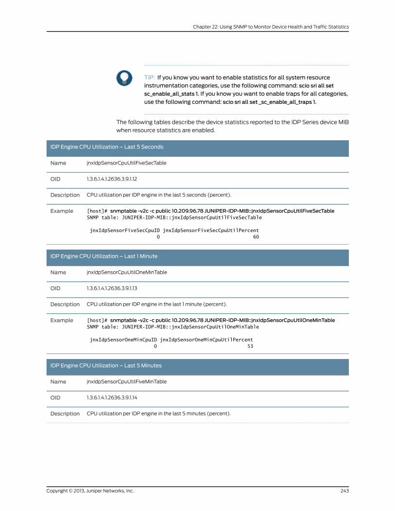
TIP: If you know you want to enable statistics for all system resourceinstrumentation categories, use the following command: scio sri all set
sc_enable_all_stats 1. If you know you want to enable traps for all categories,
use the following command: scio sri all set _sc_enable_all_traps 1.
The following tables describe the device statistics reported to the IDP Series device MIB
when resource statistics are enabled.
IDP Engine CPU Utilization – Last 5 Seconds
jnxIdpSensorCpuUtilFiveSecTableName
1.3.6.1.4.1.2636.3.9.1.12OID
CPU utilization per IDP engine in the last 5 seconds (percent).Description
[host]# snmptable -v2c -c public 10.209.96.78 JUNIPER-IDP-MIB::jnxIdpSensorCpuUtilFiveSecTableSNMP table: JUNIPER-IDP-MIB::jnxIdpSensorCpuUtilFiveSecTable
jnxIdpSensorFiveSecCpuID jnxIdpSensorFiveSecCpuUtilPercent 0 60
Example
IDP Engine CPU Utilization – Last 1 Minute
jnxIdpSensorCpuUtilOneMinTableName
1.3.6.1.4.1.2636.3.9.1.13OID
CPU utilization per IDP engine in the last 1 minute (percent).Description
[host]# snmptable -v2c -c public 10.209.96.78 JUNIPER-IDP-MIB::jnxIdpSensorCpuUtilOneMinTableSNMP table: JUNIPER-IDP-MIB::jnxIdpSensorCpuUtilOneMinTable
jnxIdpSensorOneMinCpuID jnxIdpSensorOneMinCpuUtilPercent 0 53
Example
IDP Engine CPU Utilization – Last 5 Minutes
jnxIdpSensorCpuUtilFiveMinTableName
1.3.6.1.4.1.2636.3.9.1.14OID
CPU utilization per IDP engine in the last 5 minutes (percent).Description
243Copyright © 2013, Juniper Networks, Inc.
Chapter 22: Using SNMP to Monitor Device Health and Traffic Statistics
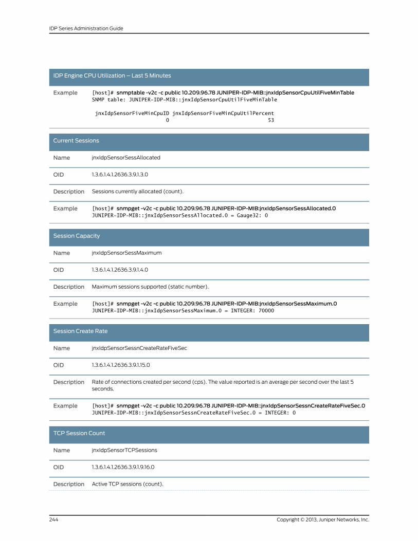
IDP Engine CPU Utilization – Last 5 Minutes
[host]# snmptable -v2c -c public 10.209.96.78 JUNIPER-IDP-MIB::jnxIdpSensorCpuUtilFiveMinTableSNMP table: JUNIPER-IDP-MIB::jnxIdpSensorCpuUtilFiveMinTable
jnxIdpSensorFiveMinCpuID jnxIdpSensorFiveMinCpuUtilPercent 0 53
Example
Current Sessions
jnxIdpSensorSessAllocatedName
1.3.6.1.4.1.2636.3.9.1.3.0OID
Sessions currently allocated (count).Description
[host]# snmpget -v2c -c public 10.209.96.78 JUNIPER-IDP-MIB:jnxIdpSensorSessAllocated.0JUNIPER-IDP-MIB::jnxIdpSensorSessAllocated.0 = Gauge32: 0
Example
Session Capacity
jnxIdpSensorSessMaximumName
1.3.6.1.4.1.2636.3.9.1.4.0OID
Maximum sessions supported (static number).Description
[host]# snmpget -v2c -c public 10.209.96.78 JUNIPER-IDP-MIB:jnxIdpSensorSessMaximum.0JUNIPER-IDP-MIB::jnxIdpSensorSessMaximum.0 = INTEGER: 70000
Example
Session Create Rate
jnxIdpSensorSessnCreateRateFiveSecName
1.3.6.1.4.1.2636.3.9.1.15.0OID
Rate of connections created per second (cps). The value reported is an average per second over the last 5seconds.
Description
[host]# snmpget -v2c -c public 10.209.96.78 JUNIPER-IDP-MIB::jnxIdpSensorSessnCreateRateFiveSec.0JUNIPER-IDP-MIB::jnxIdpSensorSessnCreateRateFiveSec.0 = INTEGER: 0
Example
TCP Session Count
jnxIdpSensorTCPSessionsName
1.3.6.1.4.1.2636.3.9.1.9.16.0OID
Active TCP sessions (count).Description
Copyright © 2013, Juniper Networks, Inc.244
IDP Series Administration Guide
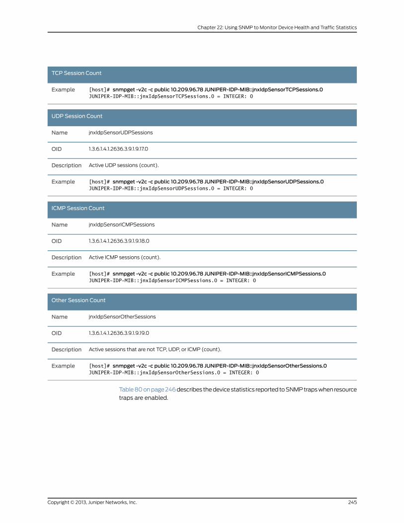
TCP Session Count
[host]# snmpget -v2c -c public 10.209.96.78 JUNIPER-IDP-MIB::jnxIdpSensorTCPSessions.0JUNIPER-IDP-MIB::jnxIdpSensorTCPSessions.0 = INTEGER: 0
Example
UDP Session Count
jnxIdpSensorUDPSessionsName
1.3.6.1.4.1.2636.3.9.1.9.17.0OID
Active UDP sessions (count).Description
[host]# snmpget -v2c -c public 10.209.96.78 JUNIPER-IDP-MIB::jnxIdpSensorUDPSessions.0JUNIPER-IDP-MIB::jnxIdpSensorUDPSessions.0 = INTEGER: 0
Example
ICMP Session Count
jnxIdpSensorICMPSessionsName
1.3.6.1.4.1.2636.3.9.1.9.18.0OID
Active ICMP sessions (count).Description
[host]# snmpget -v2c -c public 10.209.96.78 JUNIPER-IDP-MIB::jnxIdpSensorICMPSessions.0JUNIPER-IDP-MIB::jnxIdpSensorICMPSessions.0 = INTEGER: 0
Example
Other Session Count
jnxIdpSensorOtherSessionsName
1.3.6.1.4.1.2636.3.9.1.9.19.0OID
Active sessions that are not TCP, UDP, or ICMP (count).Description
[host]# snmpget -v2c -c public 10.209.96.78 JUNIPER-IDP-MIB::jnxIdpSensorOtherSessions.0JUNIPER-IDP-MIB::jnxIdpSensorOtherSessions.0 = INTEGER: 0
Example
Table 80 on page 246 describes the device statistics reported to SNMP traps when resource
traps are enabled.
245Copyright © 2013, Juniper Networks, Inc.
Chapter 22: Using SNMP to Monitor Device Health and Traffic Statistics
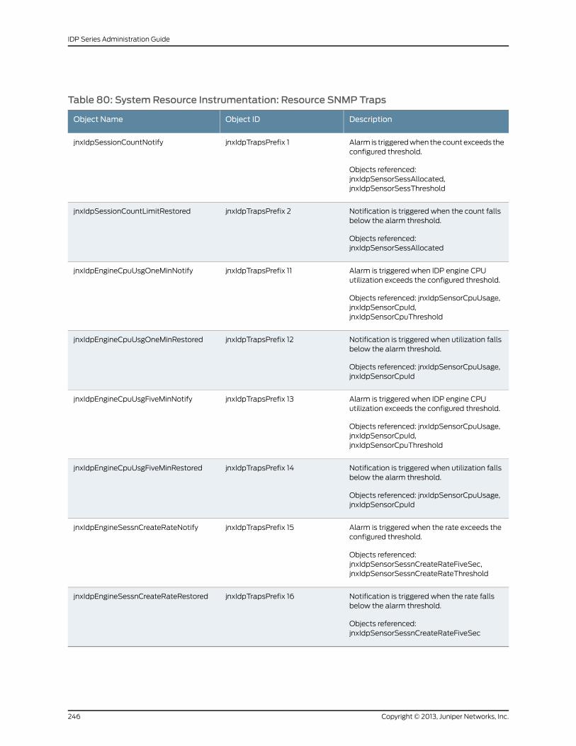
Table 80: SystemResource Instrumentation: Resource SNMP Traps
DescriptionObject IDObject Name
Alarm is triggered when the count exceeds theconfigured threshold.
Objects referenced:jnxIdpSensorSessAllocated,jnxIdpSensorSessThreshold
jnxIdpTrapsPrefix 1jnxIdpSessionCountNotify
Notification is triggered when the count fallsbelow the alarm threshold.
Objects referenced:jnxIdpSensorSessAllocated
jnxIdpTrapsPrefix 2jnxIdpSessionCountLimitRestored
Alarm is triggered when IDP engine CPUutilization exceeds the configured threshold.
Objects referenced: jnxIdpSensorCpuUsage,jnxIdpSensorCpuId,jnxIdpSensorCpuThreshold
jnxIdpTrapsPrefix 11jnxIdpEngineCpuUsgOneMinNotify
Notification is triggered when utilization fallsbelow the alarm threshold.
Objects referenced: jnxIdpSensorCpuUsage,jnxIdpSensorCpuId
jnxIdpTrapsPrefix 12jnxIdpEngineCpuUsgOneMinRestored
Alarm is triggered when IDP engine CPUutilization exceeds the configured threshold.
Objects referenced: jnxIdpSensorCpuUsage,jnxIdpSensorCpuId,jnxIdpSensorCpuThreshold
jnxIdpTrapsPrefix 13jnxIdpEngineCpuUsgFiveMinNotify
Notification is triggered when utilization fallsbelow the alarm threshold.
Objects referenced: jnxIdpSensorCpuUsage,jnxIdpSensorCpuId
jnxIdpTrapsPrefix 14jnxIdpEngineCpuUsgFiveMinRestored
Alarm is triggered when the rate exceeds theconfigured threshold.
Objects referenced:jnxIdpSensorSessnCreateRateFiveSec,jnxIdpSensorSessnCreateRateThreshold
jnxIdpTrapsPrefix 15jnxIdpEngineSessnCreateRateNotify
Notification is triggered when the rate fallsbelow the alarm threshold.
Objects referenced:jnxIdpSensorSessnCreateRateFiveSec
jnxIdpTrapsPrefix 16jnxIdpEngineSessnCreateRateRestored
Copyright © 2013, Juniper Networks, Inc.246
IDP Series Administration Guide
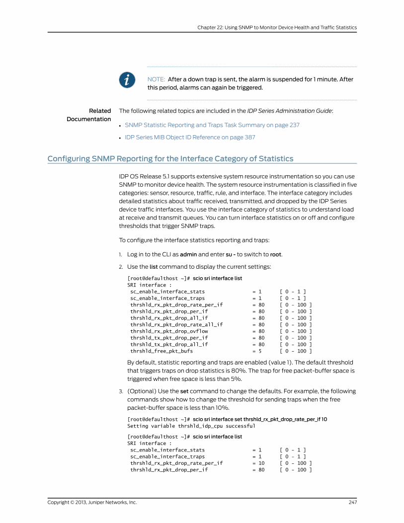
NOTE: After a down trap is sent, the alarm is suspended for 1 minute. Afterthis period, alarms can again be triggered.
RelatedDocumentation
The following related topics are included in the IDP Series Administration Guide:
SNMP Statistic Reporting and Traps Task Summary on page 237•
• IDP Series MIB Object ID Reference on page 387
Configuring SNMPReporting for the Interface Category of Statistics
IDP OS Release 5.1 supports extensive system resource instrumentation so you can use
SNMP to monitor device health. The system resource instrumentation is classified in five
categories: sensor, resource, traffic, rule, and interface. The interface category includes
detailed statistics about traffic received, transmitted, and dropped by the IDP Series
device traffic interfaces. You use the interface category of statistics to understand load
at receive and transmit queues. You can turn interface statistics on or off and configure
thresholds that trigger SNMP traps.
To configure the interface statistics reporting and traps:
1. Log in to the CLI as admin and enter su - to switch to root.
2. Use the list command to display the current settings:
[root@defaulthost ~]# scio sri interface listSRI interface : sc_enable_interface_stats = 1 [ 0 - 1 ] sc_enable_interface_traps = 1 [ 0 - 1 ] thrshld_rx_pkt_drop_rate_per_if = 80 [ 0 - 100 ] thrshld_rx_pkt_drop_per_if = 80 [ 0 - 100 ] thrshld_rx_pkt_drop_all_if = 80 [ 0 - 100 ] thrshld_rx_pkt_drop_rate_all_if = 80 [ 0 - 100 ] thrshld_rx_pkt_drop_ovflow = 80 [ 0 - 100 ] thrshld_tx_pkt_drop_per_if = 80 [ 0 - 100 ] thrshld_tx_pkt_drop_all_if = 80 [ 0 - 100 ] thrshld_free_pkt_bufs = 5 [ 0 - 100 ]
By default, statistic reporting and traps are enabled (value 1). The default threshold
that triggers traps on drop statistics is 80%. The trap for free packet-buffer space is
triggered when free space is less than 5%.
3. (Optional) Use the set command to change the defaults. For example, the following
commands show how to change the threshold for sending traps when the free
packet-buffer space is less than 10%.
[root@defaulthost ~]# scio sri interface set thrshld_rx_pkt_drop_rate_per_if 10Setting variable thrshld_idp_cpu successful
[root@defaulthost ~]# scio sri interface listSRI interface : sc_enable_interface_stats = 1 [ 0 - 1 ] sc_enable_interface_traps = 1 [ 0 - 1 ] thrshld_rx_pkt_drop_rate_per_if = 10 [ 0 - 100 ] thrshld_rx_pkt_drop_per_if = 80 [ 0 - 100 ]
247Copyright © 2013, Juniper Networks, Inc.
Chapter 22: Using SNMP to Monitor Device Health and Traffic Statistics
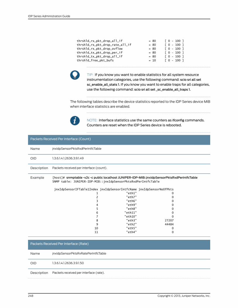
thrshld_rx_pkt_drop_all_if = 80 [ 0 - 100 ] thrshld_rx_pkt_drop_rate_all_if = 80 [ 0 - 100 ] thrshld_rx_pkt_drop_ovflow = 80 [ 0 - 100 ] thrshld_tx_pkt_drop_per_if = 80 [ 0 - 100 ] thrshld_tx_pkt_drop_all_if = 80 [ 0 - 100 ] thrshld_free_pkt_bufs = 10 [ 0 - 100 ]
TIP: If you know you want to enable statistics for all system resourceinstrumentation categories, use the following command: scio sri all set
sc_enable_all_stats 1. If you know you want to enable traps for all categories,
use the following command: scio sri all set _sc_enable_all_traps 1.
The following tables describe the device statistics reported to the IDP Series device MIB
when interface statistics are enabled.
NOTE: Interface statistics use the same counters as ifconfig commands.
Counters are reset when the IDP Series device is rebooted.
Packets Received Per Interface (Count)
jnxIdpSensorPktsRxdPerIntfcTableName
1.3.6.1.4.1.2636.3.9.1.49OID
Packets received per interface (count).Description
[host]# snmptable -v2c -c public localhost JUNIPER-IDP-MIB::jnxIdpSensorPktsRxdPerIntfcTableSNMP table: JUNIPER-IDP-MIB::jnxIdpSensorPktsRxdPerIntfcTable
jnxIdpSensorIFTable1Index jnxIdpSensorIntfcName jnxIdpSensorNoOfPkts 1 "eth1" 0 2 "eth7" 0 3 "eth6" 0 4 "eth9" 0 5 "eth8" 0 6 "eth11" 0 7 "eth10" 0 8 "eth3" 27207 9 "eth2" 44484 10 "eth5" 0 11 "eth4" 0
Example
Packets Received Per Interface (Rate)
jnxIdpSensorPktsRxRatePerIntfcTableName
1.3.6.1.4.1.2636.3.9.1.50OID
Packets received per interface (rate).Description
Copyright © 2013, Juniper Networks, Inc.248
IDP Series Administration Guide
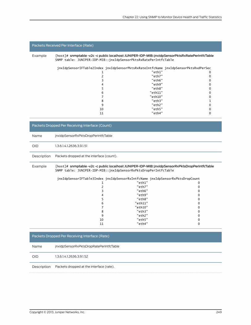
Packets Received Per Interface (Rate)
[host]# snmptable -v2c -c public localhost JUNIPER-IDP-MIB::jnxIdpSensorPktsRxRatePerIntfcTableSNMP table: JUNIPER-IDP-MIB::jnxIdpSensorPktsRxRatePerIntfcTable
jnxIdpSensorIFTable2Index jnxIdpSensorPktsRxRateIntfcName jnxIdpSensorPktsRxdPerSec 1 "eth1" 0 2 "eth7" 0 3 "eth6" 0 4 "eth9" 0 5 "eth8" 0 6 "eth11" 0 7 "eth10" 0 8 "eth3" 1 9 "eth2" 0 10 "eth5" 0 11 "eth4" 0
Example
Packets Dropped Per Receiving Interface (Count)
jnxIdpSensorRxPktsDropPerIntfcTableName
1.3.6.1.4.1.2636.3.9.1.51OID
Packets dropped at the interface (count).Description
[host]# snmptable -v2c -c public localhost JUNIPER-IDP-MIB::jnxIdpSensorRxPktsDropPerIntfcTableSNMP table: JUNIPER-IDP-MIB::jnxIdpSensorRxPktsDropPerIntfcTable
jnxIdpSensorIFTable3Index jnxIdpSensorRxIntfcName jnxIdpSensorRxPktsDropCount 1 "eth1" 0 2 "eth7" 0 3 "eth6" 0 4 "eth9" 0 5 "eth8" 0 6 "eth11" 0 7 "eth10" 0 8 "eth3" 0 9 "eth2" 0 10 "eth5" 0 11 "eth4" 0
Example
Packets Dropped Per Receiving Interface (Rate)
jnxIdpSensorRxPktsDropRatePerIntfcTableName
1.3.6.1.4.1.2636.3.9.1.52OID
Packets dropped at the interface (rate).Description
249Copyright © 2013, Juniper Networks, Inc.
Chapter 22: Using SNMP to Monitor Device Health and Traffic Statistics
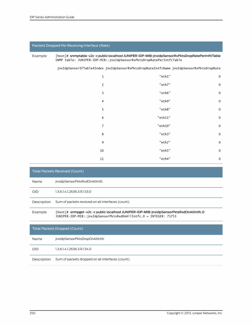
Packets Dropped Per Receiving Interface (Rate)
[host]# snmptable-v2c-cpublic localhost JUNIPER-IDP-MIB::jnxIdpSensorRxPktsDropRatePerIntfcTableSNMP table: JUNIPER-IDP-MIB::jnxIdpSensorRxPktsDropRatePerIntfcTable
jnxIdpSensorIFTable4Index jnxIdpSensorRxPktsDropRateIntfcName jnxIdpSensorRxPktsDropRate
1 "eth1" 0
2 "eth7" 0
3 "eth6" 0
4 "eth9" 0
5 "eth8" 0
6 "eth11" 0
7 "eth10" 0
8 "eth3" 0
9 "eth2" 0
10 "eth5" 0
11 "eth4" 0
Example
Total Packets Received (Count)
jnxIdpSensorPktsRxdOnAllIntfcName
1.3.6.1.4.1.2636.3.9.1.53.0OID
Sum of packets received on all interfaces (count).Description
[host]# snmpget -v2c -c public localhost JUNIPER-IDP-MIB::jnxIdpSensorPktsRxdOnAllIntfc.0JUNIPER-IDP-MIB::jnxIdpSensorPktsRxdOnAllIntfc.0 = INTEGER: 71753
Example
Total Packets Dropped (Count)
jnxIdpSensorPktsDropOnAllIntfcName
1.3.6.1.4.1.2636.3.9.1.54.0OID
Sum of packets dropped on all interfaces (count).Description
Copyright © 2013, Juniper Networks, Inc.250
IDP Series Administration Guide
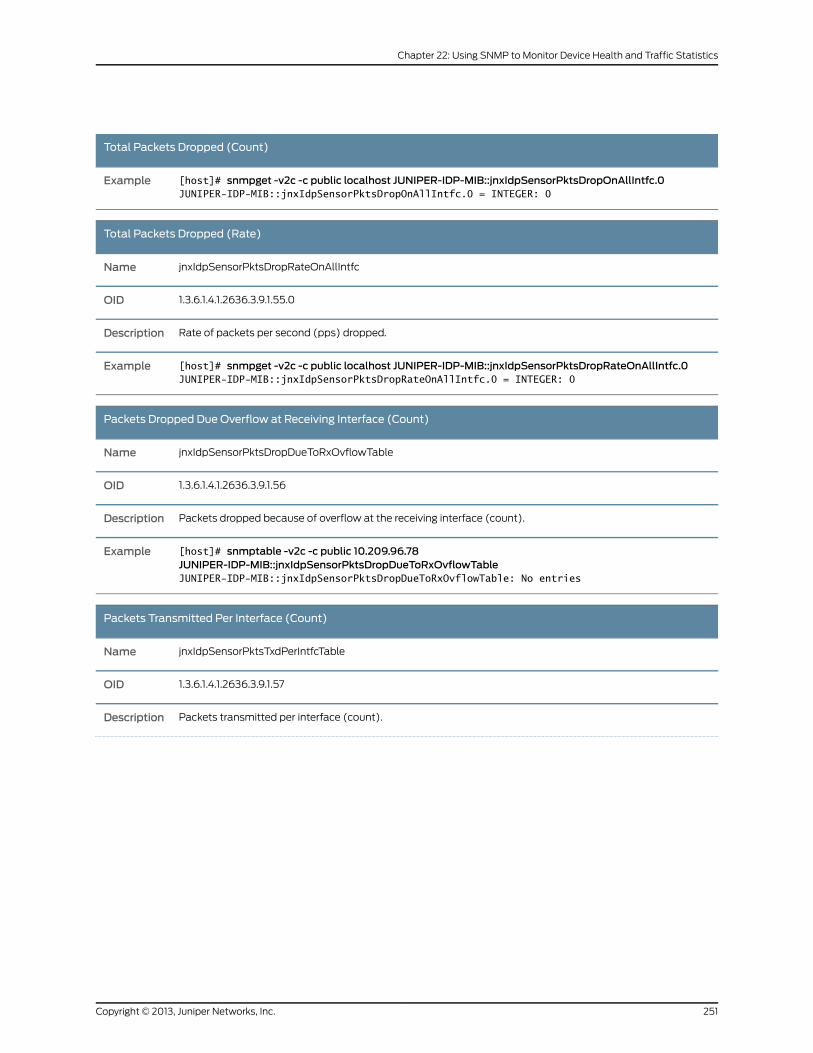
Total Packets Dropped (Count)
[host]# snmpget -v2c -c public localhost JUNIPER-IDP-MIB::jnxIdpSensorPktsDropOnAllIntfc.0JUNIPER-IDP-MIB::jnxIdpSensorPktsDropOnAllIntfc.0 = INTEGER: 0
Example
Total Packets Dropped (Rate)
jnxIdpSensorPktsDropRateOnAllIntfcName
1.3.6.1.4.1.2636.3.9.1.55.0OID
Rate of packets per second (pps) dropped.Description
[host]# snmpget -v2c -c public localhost JUNIPER-IDP-MIB::jnxIdpSensorPktsDropRateOnAllIntfc.0JUNIPER-IDP-MIB::jnxIdpSensorPktsDropRateOnAllIntfc.0 = INTEGER: 0
Example
Packets Dropped Due Overflow at Receiving Interface (Count)
jnxIdpSensorPktsDropDueToRxOvflowTableName
1.3.6.1.4.1.2636.3.9.1.56OID
Packets dropped because of overflow at the receiving interface (count).Description
[host]# snmptable -v2c -c public 10.209.96.78JUNIPER-IDP-MIB::jnxIdpSensorPktsDropDueToRxOvflowTableJUNIPER-IDP-MIB::jnxIdpSensorPktsDropDueToRxOvflowTable: No entries
Example
Packets Transmitted Per Interface (Count)
jnxIdpSensorPktsTxdPerIntfcTableName
1.3.6.1.4.1.2636.3.9.1.57OID
Packets transmitted per interface (count).Description
251Copyright © 2013, Juniper Networks, Inc.
Chapter 22: Using SNMP to Monitor Device Health and Traffic Statistics
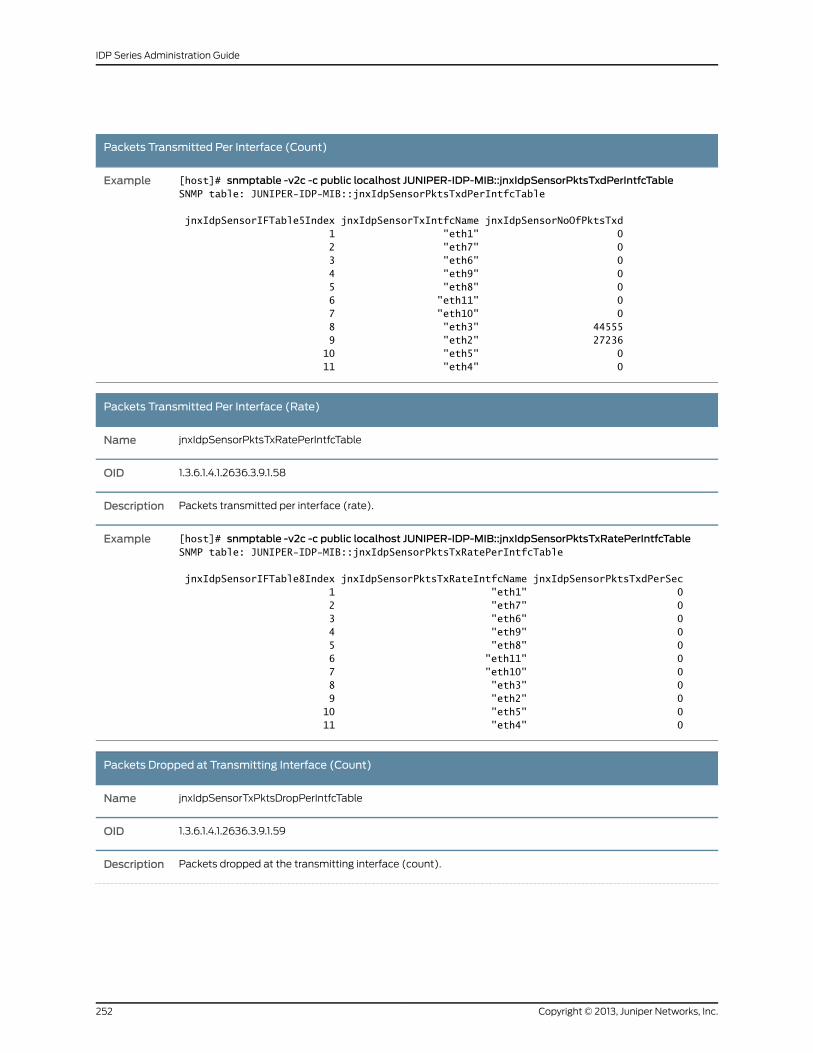
Packets Transmitted Per Interface (Count)
[host]# snmptable -v2c -c public localhost JUNIPER-IDP-MIB::jnxIdpSensorPktsTxdPerIntfcTableSNMP table: JUNIPER-IDP-MIB::jnxIdpSensorPktsTxdPerIntfcTable
jnxIdpSensorIFTable5Index jnxIdpSensorTxIntfcName jnxIdpSensorNoOfPktsTxd 1 "eth1" 0 2 "eth7" 0 3 "eth6" 0 4 "eth9" 0 5 "eth8" 0 6 "eth11" 0 7 "eth10" 0 8 "eth3" 44555 9 "eth2" 27236 10 "eth5" 0 11 "eth4" 0
Example
Packets Transmitted Per Interface (Rate)
jnxIdpSensorPktsTxRatePerIntfcTableName
1.3.6.1.4.1.2636.3.9.1.58OID
Packets transmitted per interface (rate).Description
[host]# snmptable -v2c -c public localhost JUNIPER-IDP-MIB::jnxIdpSensorPktsTxRatePerIntfcTableSNMP table: JUNIPER-IDP-MIB::jnxIdpSensorPktsTxRatePerIntfcTable
jnxIdpSensorIFTable8Index jnxIdpSensorPktsTxRateIntfcName jnxIdpSensorPktsTxdPerSec 1 "eth1" 0 2 "eth7" 0 3 "eth6" 0 4 "eth9" 0 5 "eth8" 0 6 "eth11" 0 7 "eth10" 0 8 "eth3" 0 9 "eth2" 0 10 "eth5" 0 11 "eth4" 0
Example
Packets Dropped at Transmitting Interface (Count)
jnxIdpSensorTxPktsDropPerIntfcTableName
1.3.6.1.4.1.2636.3.9.1.59OID
Packets dropped at the transmitting interface (count).Description
Copyright © 2013, Juniper Networks, Inc.252
IDP Series Administration Guide
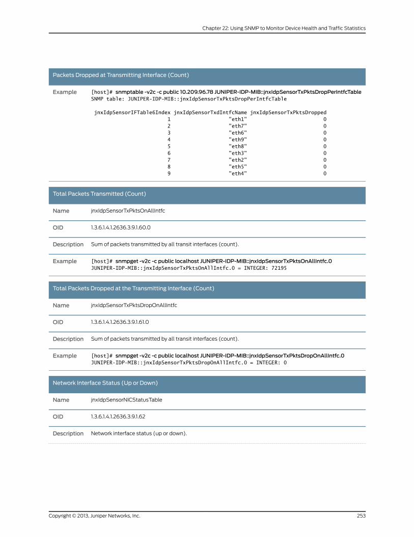
Packets Dropped at Transmitting Interface (Count)
[host]# snmptable -v2c -c public 10.209.96.78 JUNIPER-IDP-MIB::jnxIdpSensorTxPktsDropPerIntfcTableSNMP table: JUNIPER-IDP-MIB::jnxIdpSensorTxPktsDropPerIntfcTable
jnxIdpSensorIFTable6Index jnxIdpSensorTxdIntfcName jnxIdpSensorTxPktsDropped 1 "eth1" 0 2 "eth7" 0 3 "eth6" 0 4 "eth9" 0 5 "eth8" 0 6 "eth3" 0 7 "eth2" 0 8 "eth5" 0 9 "eth4" 0
Example
Total Packets Transmitted (Count)
jnxIdpSensorTxPktsOnAllIntfcName
1.3.6.1.4.1.2636.3.9.1.60.0OID
Sum of packets transmitted by all transit interfaces (count).Description
[host]# snmpget -v2c -c public localhost JUNIPER-IDP-MIB::jnxIdpSensorTxPktsOnAllIntfc.0JUNIPER-IDP-MIB::jnxIdpSensorTxPktsOnAllIntfc.0 = INTEGER: 72195
Example
Total Packets Dropped at the Transmitting Interface (Count)
jnxIdpSensorTxPktsDropOnAllIntfcName
1.3.6.1.4.1.2636.3.9.1.61.0OID
Sum of packets transmitted by all transit interfaces (count).Description
[host]# snmpget -v2c -c public localhost JUNIPER-IDP-MIB::jnxIdpSensorTxPktsDropOnAllIntfc.0JUNIPER-IDP-MIB::jnxIdpSensorTxPktsDropOnAllIntfc.0 = INTEGER: 0
Example
Network Interface Status (Up or Down)
jnxIdpSensorNICStatusTableName
1.3.6.1.4.1.2636.3.9.1.62OID
Network interface status (up or down).Description
253Copyright © 2013, Juniper Networks, Inc.
Chapter 22: Using SNMP to Monitor Device Health and Traffic Statistics
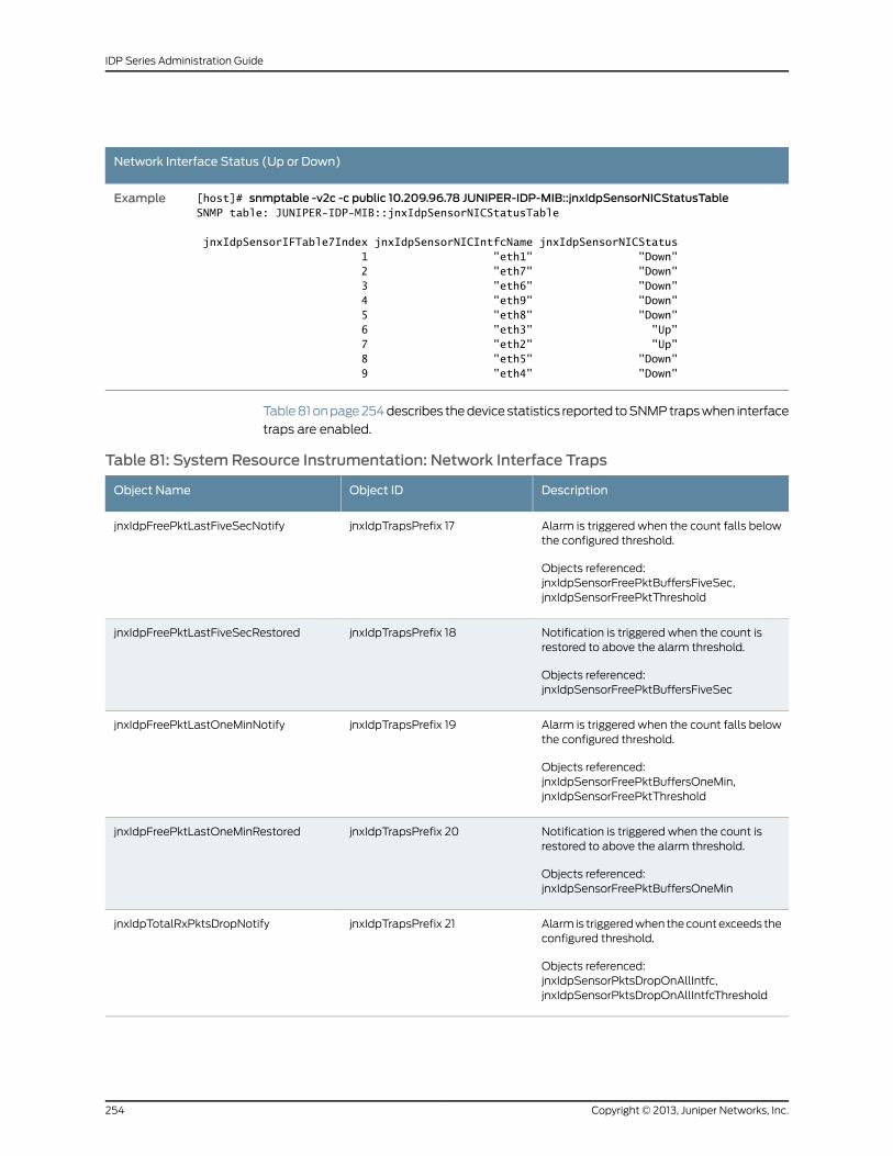
Network Interface Status (Up or Down)
[host]# snmptable -v2c -c public 10.209.96.78 JUNIPER-IDP-MIB::jnxIdpSensorNICStatusTableSNMP table: JUNIPER-IDP-MIB::jnxIdpSensorNICStatusTable
jnxIdpSensorIFTable7Index jnxIdpSensorNICIntfcName jnxIdpSensorNICStatus 1 "eth1" "Down" 2 "eth7" "Down" 3 "eth6" "Down" 4 "eth9" "Down" 5 "eth8" "Down" 6 "eth3" "Up" 7 "eth2" "Up" 8 "eth5" "Down" 9 "eth4" "Down"
Example
Table 81 on page 254 describes the device statistics reported to SNMP traps when interface
traps are enabled.
Table 81: SystemResource Instrumentation: Network Interface Traps
DescriptionObject IDObject Name
Alarm is triggered when the count falls belowthe configured threshold.
Objects referenced:jnxIdpSensorFreePktBuffersFiveSec,jnxIdpSensorFreePktThreshold
jnxIdpTrapsPrefix 17jnxIdpFreePktLastFiveSecNotify
Notification is triggered when the count isrestored to above the alarm threshold.
Objects referenced:jnxIdpSensorFreePktBuffersFiveSec
jnxIdpTrapsPrefix 18jnxIdpFreePktLastFiveSecRestored
Alarm is triggered when the count falls belowthe configured threshold.
Objects referenced:jnxIdpSensorFreePktBuffersOneMin,jnxIdpSensorFreePktThreshold
jnxIdpTrapsPrefix 19jnxIdpFreePktLastOneMinNotify
Notification is triggered when the count isrestored to above the alarm threshold.
Objects referenced:jnxIdpSensorFreePktBuffersOneMin
jnxIdpTrapsPrefix 20jnxIdpFreePktLastOneMinRestored
Alarm is triggered when the count exceeds theconfigured threshold.
Objects referenced:jnxIdpSensorPktsDropOnAllIntfc,jnxIdpSensorPktsDropOnAllIntfcThreshold
jnxIdpTrapsPrefix 21jnxIdpTotalRxPktsDropNotify
Copyright © 2013, Juniper Networks, Inc.254
IDP Series Administration Guide
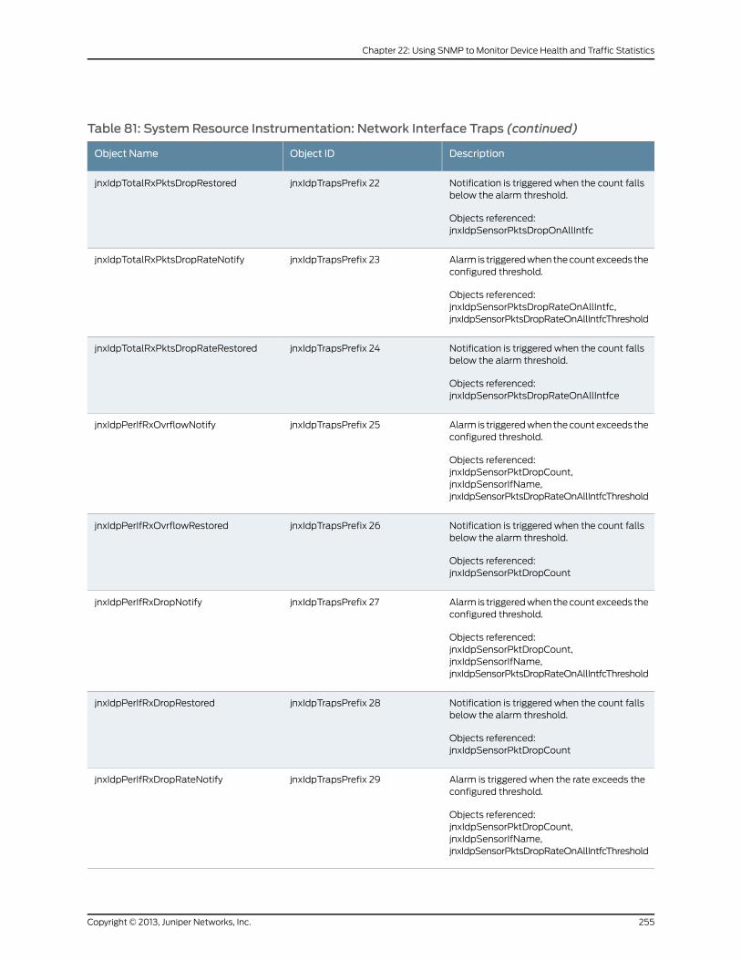
Table 81: SystemResource Instrumentation: Network Interface Traps (continued)
DescriptionObject IDObject Name
Notification is triggered when the count fallsbelow the alarm threshold.
Objects referenced:jnxIdpSensorPktsDropOnAllIntfc
jnxIdpTrapsPrefix 22jnxIdpTotalRxPktsDropRestored
Alarm is triggered when the count exceeds theconfigured threshold.
Objects referenced:jnxIdpSensorPktsDropRateOnAllIntfc,jnxIdpSensorPktsDropRateOnAllIntfcThreshold
jnxIdpTrapsPrefix 23jnxIdpTotalRxPktsDropRateNotify
Notification is triggered when the count fallsbelow the alarm threshold.
Objects referenced:jnxIdpSensorPktsDropRateOnAllIntfce
jnxIdpTrapsPrefix 24jnxIdpTotalRxPktsDropRateRestored
Alarm is triggered when the count exceeds theconfigured threshold.
Objects referenced:jnxIdpSensorPktDropCount,jnxIdpSensorIfName,jnxIdpSensorPktsDropRateOnAllIntfcThreshold
jnxIdpTrapsPrefix 25jnxIdpPerIfRxOvrflowNotify
Notification is triggered when the count fallsbelow the alarm threshold.
Objects referenced:jnxIdpSensorPktDropCount
jnxIdpTrapsPrefix 26jnxIdpPerIfRxOvrflowRestored
Alarm is triggered when the count exceeds theconfigured threshold.
Objects referenced:jnxIdpSensorPktDropCount,jnxIdpSensorIfName,jnxIdpSensorPktsDropRateOnAllIntfcThreshold
jnxIdpTrapsPrefix 27jnxIdpPerIfRxDropNotify
Notification is triggered when the count fallsbelow the alarm threshold.
Objects referenced:jnxIdpSensorPktDropCount
jnxIdpTrapsPrefix 28jnxIdpPerIfRxDropRestored
Alarm is triggered when the rate exceeds theconfigured threshold.
Objects referenced:jnxIdpSensorPktDropCount,jnxIdpSensorIfName,jnxIdpSensorPktsDropRateOnAllIntfcThreshold
jnxIdpTrapsPrefix 29jnxIdpPerIfRxDropRateNotify
255Copyright © 2013, Juniper Networks, Inc.
Chapter 22: Using SNMP to Monitor Device Health and Traffic Statistics
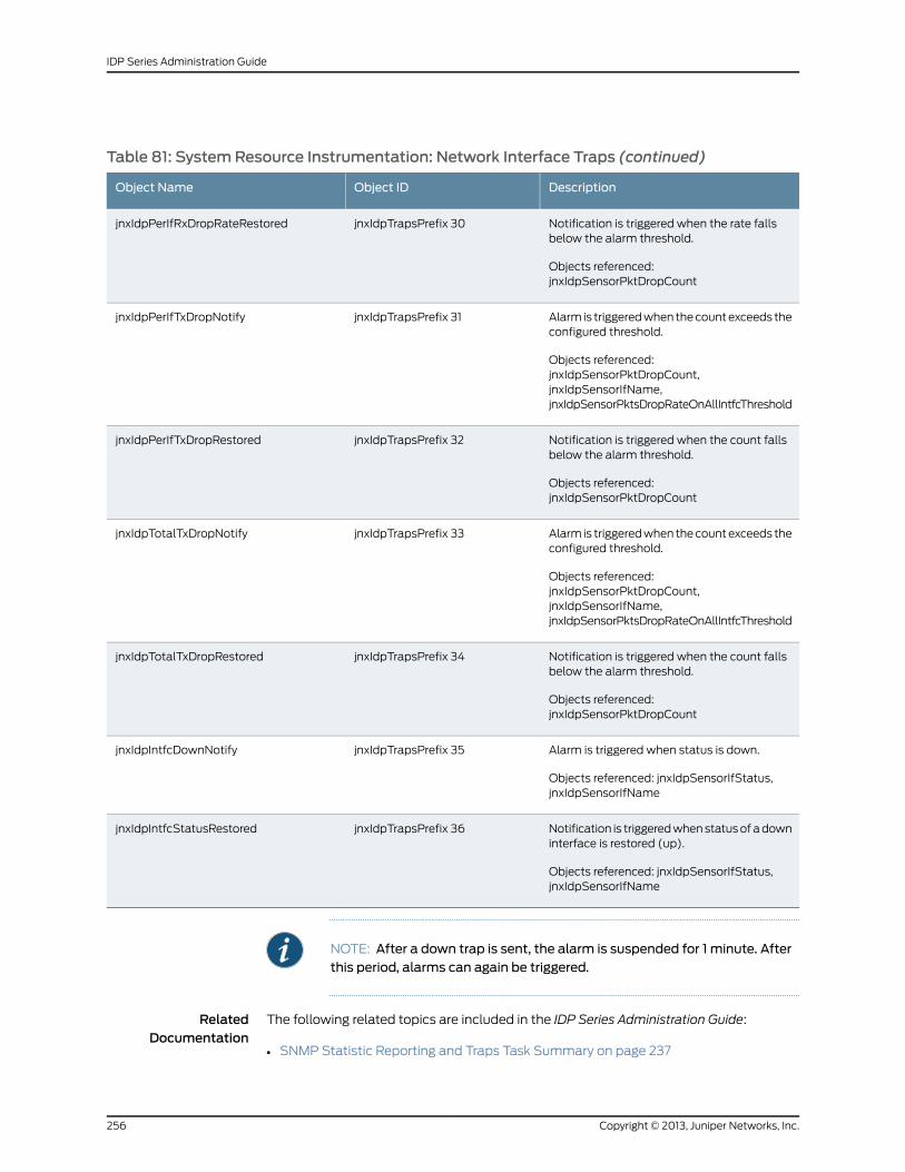
Table 81: SystemResource Instrumentation: Network Interface Traps (continued)
DescriptionObject IDObject Name
Notification is triggered when the rate fallsbelow the alarm threshold.
Objects referenced:jnxIdpSensorPktDropCount
jnxIdpTrapsPrefix 30jnxIdpPerIfRxDropRateRestored
Alarm is triggered when the count exceeds theconfigured threshold.
Objects referenced:jnxIdpSensorPktDropCount,jnxIdpSensorIfName,jnxIdpSensorPktsDropRateOnAllIntfcThreshold
jnxIdpTrapsPrefix 31jnxIdpPerIfTxDropNotify
Notification is triggered when the count fallsbelow the alarm threshold.
Objects referenced:jnxIdpSensorPktDropCount
jnxIdpTrapsPrefix 32jnxIdpPerIfTxDropRestored
Alarm is triggered when the count exceeds theconfigured threshold.
Objects referenced:jnxIdpSensorPktDropCount,jnxIdpSensorIfName,jnxIdpSensorPktsDropRateOnAllIntfcThreshold
jnxIdpTrapsPrefix 33jnxIdpTotalTxDropNotify
Notification is triggered when the count fallsbelow the alarm threshold.
Objects referenced:jnxIdpSensorPktDropCount
jnxIdpTrapsPrefix 34jnxIdpTotalTxDropRestored
Alarm is triggered when status is down.
Objects referenced: jnxIdpSensorIfStatus,jnxIdpSensorIfName
jnxIdpTrapsPrefix 35jnxIdpIntfcDownNotify
Notification is triggered when status of a downinterface is restored (up).
Objects referenced: jnxIdpSensorIfStatus,jnxIdpSensorIfName
jnxIdpTrapsPrefix 36jnxIdpIntfcStatusRestored
NOTE: After a down trap is sent, the alarm is suspended for 1 minute. Afterthis period, alarms can again be triggered.
RelatedDocumentation
The following related topics are included in the IDP Series Administration Guide:
SNMP Statistic Reporting and Traps Task Summary on page 237•
Copyright © 2013, Juniper Networks, Inc.256
IDP Series Administration Guide
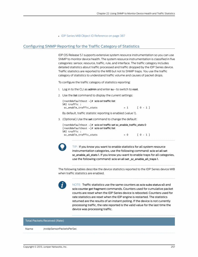
• IDP Series MIB Object ID Reference on page 387
Configuring SNMPReporting for the Traffic Category of Statistics
IDP OS Release 5.1 supports extensive system resource instrumentation so you can use
SNMP to monitor device health. The system resource instrumentation is classified in five
categories: sensor, resource, traffic, rule, and interface. The traffic category includes
detailed statistics about traffic processed and traffic dropped by the IDP Series device.
Traffic statistics are reported to the MIB but not to SNMP traps. You use the traffic
category of statistics to understand traffic volume and causes of packet drops.
To configure the traffic category of statistics reporting:
1. Log in to the CLI as admin and enter su - to switch to root.
2. Use the list command to display the current settings:
[root@defaulthost ~]# scio sri traffic listSRI traffic : sc_enable_traffic_stats = 1 [ 0 - 1 ]
By default, traffic statistic reporting is enabled (value 1).
3. (Optional) Use the set command to change the default:
[root@defaulthost ~]# scio sri traffic set sc_enable_traffic_stats 0[root@defaulthost ~]# scio sri traffic listSRI traffic : sc_enable_traffic_stats = 0 [ 0 - 1 ]
TIP: If you know you want to enable statistics for all system resourceinstrumentation categories, use the following command: scio sri all set
sc_enable_all_stats 1. If you know you want to enable traps for all categories,
use the following command: scio sri all set _sc_enable_all_traps 1.
The following tables describe the device statistics reported to the IDP Series device MIB
when traffic statistics are enabled.
NOTE: Traffic statistics use the same counters as scio subs status s0 and
scio counter get fragment commands. Counters used for cumulative packet
counts are reset when the IDP Series device is rebooted. Counters used forrate statistics are reset when the IDP engine is restarted. The statisticsreturned are the results of an instant polling. If the device is not currentlyprocessing traffic, the rate reported is the valid value for the last time thedevice was processing traffic.
Total Packets Received (Rate)
jnxIdpSensorPacketsPerSecName
257Copyright © 2013, Juniper Networks, Inc.
Chapter 22: Using SNMP to Monitor Device Health and Traffic Statistics
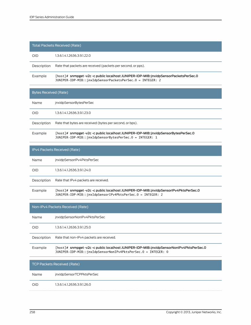
Total Packets Received (Rate)
1.3.6.1.4.1.2636.3.9.1.22.0OID
Rate that packets are received (packets per second, or pps).Description
[host]# snmpget -v2c -c public localhost JUNIPER-IDP-MIB::jnxIdpSensorPacketsPerSec.0JUNIPER-IDP-MIB::jnxIdpSensorPacketsPerSec.0 = INTEGER: 2
Example
Bytes Received (Rate)
jnxIdpSensorBytesPerSecName
1.3.6.1.4.1.2636.3.9.1.23.0OID
Rate that bytes are received (bytes per second, or bps).Description
[host]# snmpget -v2c -c public localhost JUNIPER-IDP-MIB::jnxIdpSensorBytesPerSec.0JUNIPER-IDP-MIB::jnxIdpSensorBytesPerSec.0 = INTEGER: 1
Example
IPv4 Packets Received (Rate)
jnxIdpSensorIPv4PktsPerSecName
1.3.6.1.4.1.2636.3.9.1.24.0OID
Rate that IPv4 packets are received.Description
[host]# snmpget -v2c -c public localhost JUNIPER-IDP-MIB::jnxIdpSensorIPv4PktsPerSec.0JUNIPER-IDP-MIB::jnxIdpSensorIPv4PktsPerSec.0 = INTEGER: 2
Example
Non-IPv4 Packets Received (Rate)
jnxIdpSensorNonIPv4PktsPerSecName
1.3.6.1.4.1.2636.3.9.1.25.0OID
Rate that non-IPv4 packets are received.Description
[host]# snmpget -v2c -c public localhost JUNIPER-IDP-MIB::jnxIdpSensorNonIPv4PktsPerSec.0JUNIPER-IDP-MIB::jnxIdpSensorNonIPv4PktsPerSec.0 = INTEGER: 0
Example
TCP Packets Received (Rate)
jnxIdpSensorTCPPktsPerSecName
1.3.6.1.4.1.2636.3.9.1.26.0OID
Copyright © 2013, Juniper Networks, Inc.258
IDP Series Administration Guide
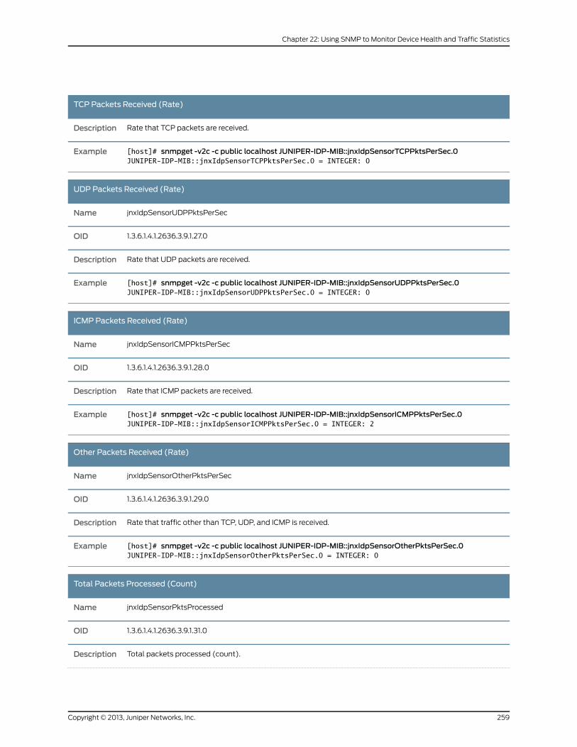
TCP Packets Received (Rate)
Rate that TCP packets are received.Description
[host]# snmpget -v2c -c public localhost JUNIPER-IDP-MIB::jnxIdpSensorTCPPktsPerSec.0JUNIPER-IDP-MIB::jnxIdpSensorTCPPktsPerSec.0 = INTEGER: 0
Example
UDP Packets Received (Rate)
jnxIdpSensorUDPPktsPerSecName
1.3.6.1.4.1.2636.3.9.1.27.0OID
Rate that UDP packets are received.Description
[host]# snmpget -v2c -c public localhost JUNIPER-IDP-MIB::jnxIdpSensorUDPPktsPerSec.0JUNIPER-IDP-MIB::jnxIdpSensorUDPPktsPerSec.0 = INTEGER: 0
Example
ICMP Packets Received (Rate)
jnxIdpSensorICMPPktsPerSecName
1.3.6.1.4.1.2636.3.9.1.28.0OID
Rate that ICMP packets are received.Description
[host]# snmpget -v2c -c public localhost JUNIPER-IDP-MIB::jnxIdpSensorICMPPktsPerSec.0JUNIPER-IDP-MIB::jnxIdpSensorICMPPktsPerSec.0 = INTEGER: 2
Example
Other Packets Received (Rate)
jnxIdpSensorOtherPktsPerSecName
1.3.6.1.4.1.2636.3.9.1.29.0OID
Rate that traffic other than TCP, UDP, and ICMP is received.Description
[host]# snmpget -v2c -c public localhost JUNIPER-IDP-MIB::jnxIdpSensorOtherPktsPerSec.0JUNIPER-IDP-MIB::jnxIdpSensorOtherPktsPerSec.0 = INTEGER: 0
Example
Total Packets Processed (Count)
jnxIdpSensorPktsProcessedName
1.3.6.1.4.1.2636.3.9.1.31.0OID
Total packets processed (count).Description
259Copyright © 2013, Juniper Networks, Inc.
Chapter 22: Using SNMP to Monitor Device Health and Traffic Statistics
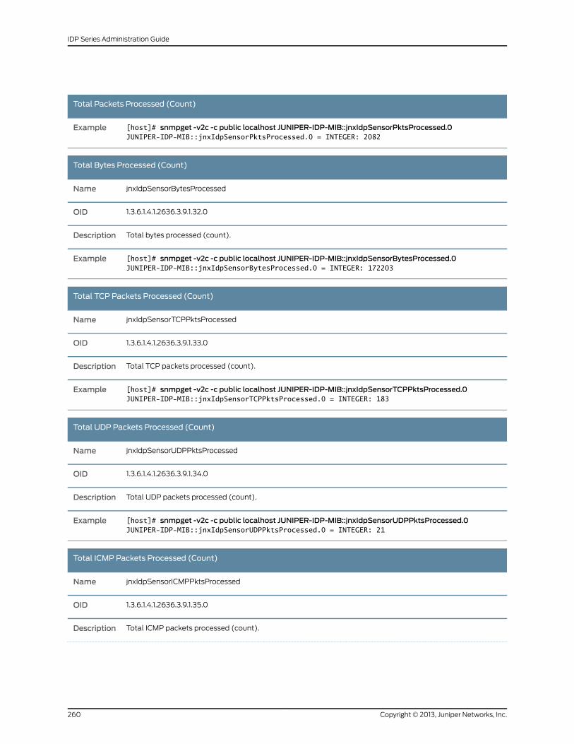
Total Packets Processed (Count)
[host]# snmpget -v2c -c public localhost JUNIPER-IDP-MIB::jnxIdpSensorPktsProcessed.0JUNIPER-IDP-MIB::jnxIdpSensorPktsProcessed.0 = INTEGER: 2082
Example
Total Bytes Processed (Count)
jnxIdpSensorBytesProcessedName
1.3.6.1.4.1.2636.3.9.1.32.0OID
Total bytes processed (count).Description
[host]# snmpget -v2c -c public localhost JUNIPER-IDP-MIB::jnxIdpSensorBytesProcessed.0JUNIPER-IDP-MIB::jnxIdpSensorBytesProcessed.0 = INTEGER: 172203
Example
Total TCP Packets Processed (Count)
jnxIdpSensorTCPPktsProcessedName
1.3.6.1.4.1.2636.3.9.1.33.0OID
Total TCP packets processed (count).Description
[host]# snmpget -v2c -c public localhost JUNIPER-IDP-MIB::jnxIdpSensorTCPPktsProcessed.0JUNIPER-IDP-MIB::jnxIdpSensorTCPPktsProcessed.0 = INTEGER: 183
Example
Total UDP Packets Processed (Count)
jnxIdpSensorUDPPktsProcessedName
1.3.6.1.4.1.2636.3.9.1.34.0OID
Total UDP packets processed (count).Description
[host]# snmpget -v2c -c public localhost JUNIPER-IDP-MIB::jnxIdpSensorUDPPktsProcessed.0JUNIPER-IDP-MIB::jnxIdpSensorUDPPktsProcessed.0 = INTEGER: 21
Example
Total ICMP Packets Processed (Count)
jnxIdpSensorICMPPktsProcessedName
1.3.6.1.4.1.2636.3.9.1.35.0OID
Total ICMP packets processed (count).Description
Copyright © 2013, Juniper Networks, Inc.260
IDP Series Administration Guide
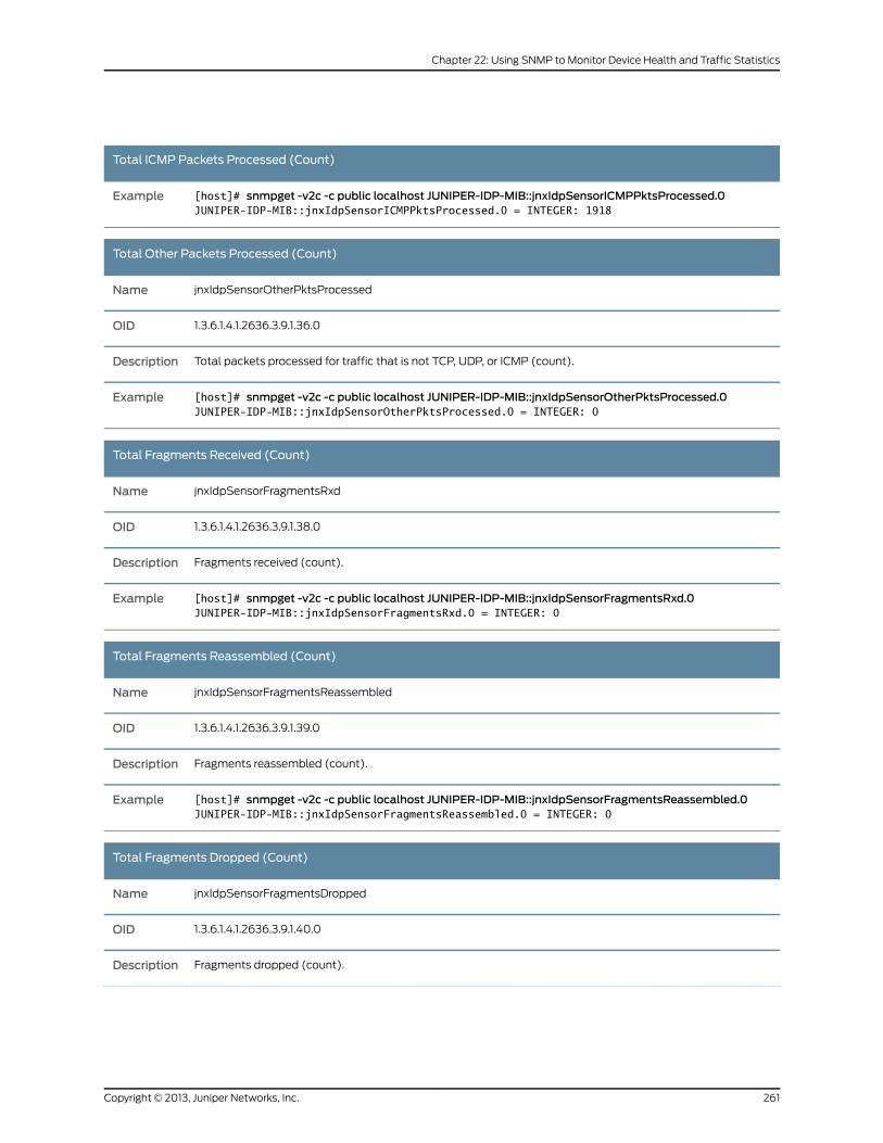
Total ICMP Packets Processed (Count)
[host]# snmpget -v2c -c public localhost JUNIPER-IDP-MIB::jnxIdpSensorICMPPktsProcessed.0JUNIPER-IDP-MIB::jnxIdpSensorICMPPktsProcessed.0 = INTEGER: 1918
Example
Total Other Packets Processed (Count)
jnxIdpSensorOtherPktsProcessedName
1.3.6.1.4.1.2636.3.9.1.36.0OID
Total packets processed for traffic that is not TCP, UDP, or ICMP (count).Description
[host]# snmpget -v2c -c public localhost JUNIPER-IDP-MIB::jnxIdpSensorOtherPktsProcessed.0JUNIPER-IDP-MIB::jnxIdpSensorOtherPktsProcessed.0 = INTEGER: 0
Example
Total Fragments Received (Count)
jnxIdpSensorFragmentsRxdName
1.3.6.1.4.1.2636.3.9.1.38.0OID
Fragments received (count).Description
[host]# snmpget -v2c -c public localhost JUNIPER-IDP-MIB::jnxIdpSensorFragmentsRxd.0JUNIPER-IDP-MIB::jnxIdpSensorFragmentsRxd.0 = INTEGER: 0
Example
Total Fragments Reassembled (Count)
jnxIdpSensorFragmentsReassembledName
1.3.6.1.4.1.2636.3.9.1.39.0OID
Fragments reassembled (count).Description
[host]# snmpget -v2c -c public localhost JUNIPER-IDP-MIB::jnxIdpSensorFragmentsReassembled.0JUNIPER-IDP-MIB::jnxIdpSensorFragmentsReassembled.0 = INTEGER: 0
Example
Total Fragments Dropped (Count)
jnxIdpSensorFragmentsDroppedName
1.3.6.1.4.1.2636.3.9.1.40.0OID
Fragments dropped (count).Description
261Copyright © 2013, Juniper Networks, Inc.
Chapter 22: Using SNMP to Monitor Device Health and Traffic Statistics
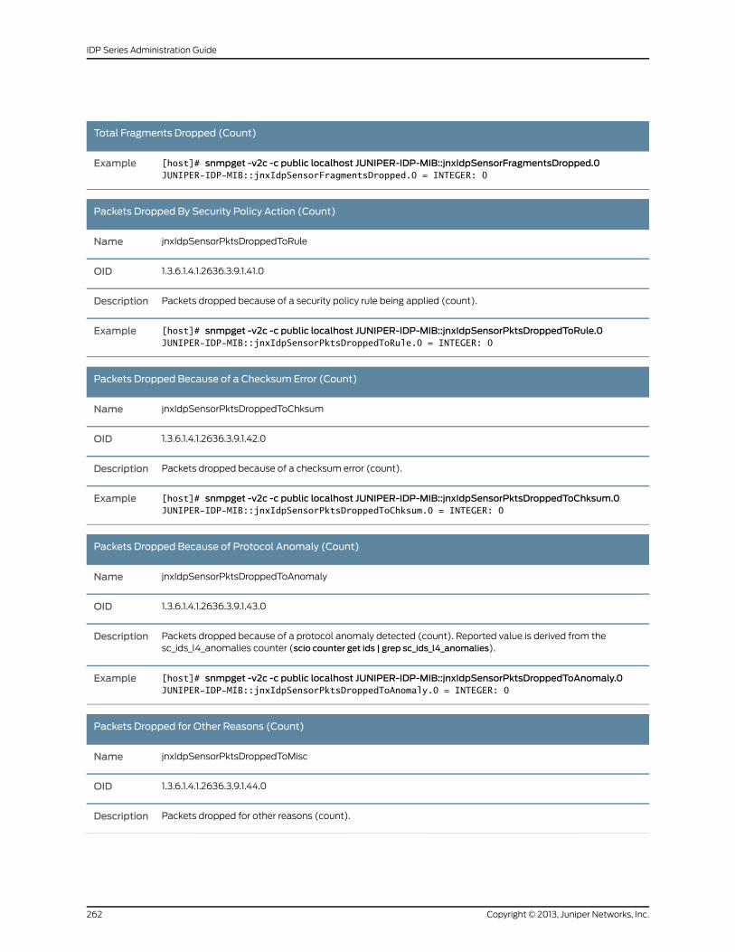
Total Fragments Dropped (Count)
[host]# snmpget -v2c -c public localhost JUNIPER-IDP-MIB::jnxIdpSensorFragmentsDropped.0JUNIPER-IDP-MIB::jnxIdpSensorFragmentsDropped.0 = INTEGER: 0
Example
Packets Dropped By Security Policy Action (Count)
jnxIdpSensorPktsDroppedToRuleName
1.3.6.1.4.1.2636.3.9.1.41.0OID
Packets dropped because of a security policy rule being applied (count).Description
[host]# snmpget -v2c -c public localhost JUNIPER-IDP-MIB::jnxIdpSensorPktsDroppedToRule.0JUNIPER-IDP-MIB::jnxIdpSensorPktsDroppedToRule.0 = INTEGER: 0
Example
Packets Dropped Because of a Checksum Error (Count)
jnxIdpSensorPktsDroppedToChksumName
1.3.6.1.4.1.2636.3.9.1.42.0OID
Packets dropped because of a checksum error (count).Description
[host]# snmpget -v2c -c public localhost JUNIPER-IDP-MIB::jnxIdpSensorPktsDroppedToChksum.0JUNIPER-IDP-MIB::jnxIdpSensorPktsDroppedToChksum.0 = INTEGER: 0
Example
Packets Dropped Because of Protocol Anomaly (Count)
jnxIdpSensorPktsDroppedToAnomalyName
1.3.6.1.4.1.2636.3.9.1.43.0OID
Packets dropped because of a protocol anomaly detected (count). Reported value is derived from thesc_ids_l4_anomalies counter (scio counter get ids | grep sc_ids_l4_anomalies).
Description
[host]# snmpget -v2c -c public localhost JUNIPER-IDP-MIB::jnxIdpSensorPktsDroppedToAnomaly.0JUNIPER-IDP-MIB::jnxIdpSensorPktsDroppedToAnomaly.0 = INTEGER: 0
Example
Packets Dropped for Other Reasons (Count)
jnxIdpSensorPktsDroppedToMiscName
1.3.6.1.4.1.2636.3.9.1.44.0OID
Packets dropped for other reasons (count).Description
Copyright © 2013, Juniper Networks, Inc.262
IDP Series Administration Guide
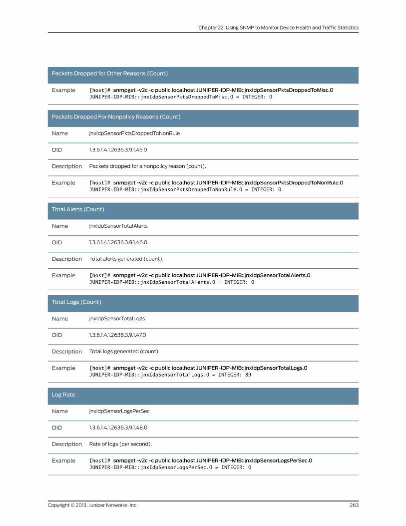
Packets Dropped for Other Reasons (Count)
[host]# snmpget -v2c -c public localhost JUNIPER-IDP-MIB::jnxIdpSensorPktsDroppedToMisc.0JUNIPER-IDP-MIB::jnxIdpSensorPktsDroppedToMisc.0 = INTEGER: 0
Example
Packets Dropped For Nonpolicy Reasons (Count)
jnxIdpSensorPktsDroppedToNonRuleName
1.3.6.1.4.1.2636.3.9.1.45.0OID
Packets dropped for a nonpolicy reason (count).Description
[host]# snmpget -v2c -c public localhost JUNIPER-IDP-MIB::jnxIdpSensorPktsDroppedToNonRule.0JUNIPER-IDP-MIB::jnxIdpSensorPktsDroppedToNonRule.0 = INTEGER: 0
Example
Total Alerts (Count)
jnxIdpSensorTotalAlertsName
1.3.6.1.4.1.2636.3.9.1.46.0OID
Total alerts generated (count).Description
[host]# snmpget -v2c -c public localhost JUNIPER-IDP-MIB::jnxIdpSensorTotalAlerts.0JUNIPER-IDP-MIB::jnxIdpSensorTotalAlerts.0 = INTEGER: 0
Example
Total Logs (Count)
jnxIdpSensorTotalLogsName
1.3.6.1.4.1.2636.3.9.1.47.0OID
Total logs generated (count).Description
[host]# snmpget -v2c -c public localhost JUNIPER-IDP-MIB::jnxIdpSensorTotalLogs.0JUNIPER-IDP-MIB::jnxIdpSensorTotalLogs.0 = INTEGER: 89
Example
Log Rate
jnxIdpSensorLogsPerSecName
1.3.6.1.4.1.2636.3.9.1.48.0OID
Rate of logs (per second).Description
[host]# snmpget -v2c -c public localhost JUNIPER-IDP-MIB::jnxIdpSensorLogsPerSec.0JUNIPER-IDP-MIB::jnxIdpSensorLogsPerSec.0 = INTEGER: 0
Example
263Copyright © 2013, Juniper Networks, Inc.
Chapter 22: Using SNMP to Monitor Device Health and Traffic Statistics
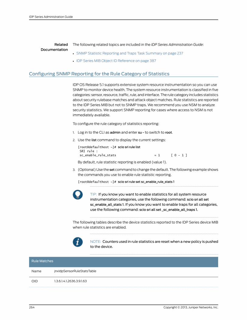
RelatedDocumentation
The following related topics are included in the IDP Series Administration Guide:
SNMP Statistic Reporting and Traps Task Summary on page 237•
• IDP Series MIB Object ID Reference on page 387
Configuring SNMPReporting for the Rule Category of Statistics
IDP OS Release 5.1 supports extensive system resource instrumentation so you can use
SNMP to monitor device health. The system resource instrumentation is classified in five
categories: sensor, resource, traffic, rule, and interface. The rule category includes statistics
about security rulebase matches and attack object matches. Rule statistics are reported
to the IDP Series MIB but not to SNMP traps. We recommend you use NSM to analyze
security statistics. We support SNMP reporting for cases where access to NSM is not
immediately available.
To configure the rule category of statistics reporting:
1. Log in to the CLI as admin and enter su - to switch to root.
2. Use the list command to display the current settings:
[root@defaulthost ~]# scio sri rule list SRI rule : sc_enable_rule_stats = 1 [ 0 - 1 ]
By default, rule statistic reporting is enabled (value 1).
3. (Optional) Use the setcommand to change the default. The following example shows
the commands you use to enable rule statistic reporting.
[root@defaulthost ~]# scio sri rule set sc_enable_rule_stats 1
TIP: If you know you want to enable statistics for all system resourceinstrumentation categories, use the following command: scio sri all set
sc_enable_all_stats 1. If you know you want to enable traps for all categories,
use the following command: scio sri all set _sc_enable_all_traps 1.
The following tables describe the device statistics reported to the IDP Series device MIB
when rule statistics are enabled.
NOTE: Counters used in rule statistics are resetwhen a newpolicy is pushedto the device.
Rule Matches
jnxIdpSensorRuleStatsTableName
1.3.6.1.4.1.2636.3.9.1.63OID
Copyright © 2013, Juniper Networks, Inc.264
IDP Series Administration Guide
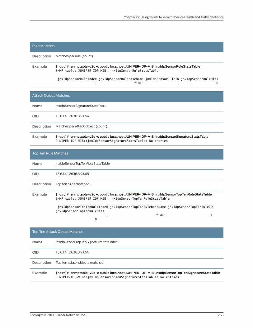
Rule Matches
Matches per rule (count).Description
[host]# snmptable -v2c -c public localhost JUNIPER-IDP-MIB::jnxIdpSensorRuleStatsTableSNMP table: JUNIPER-IDP-MIB::jnxIdpSensorRuleStatsTable
jnxIdpSensorRuleIndex jnxIdpSensorRulebaseName jnxIdpSensorRuleID jnxIdpSensorRuleHits 1 "ids" 1 0
Example
Attack Object Matches
jnxIdpSensorSignatureStatsTableName
1.3.6.1.4.1.2636.3.9.1.64OID
Matches per attack object (count).Description
[host]# snmptable -v2c -c public localhost JUNIPER-IDP-MIB::jnxIdpSensorSignatureStatsTableJUNIPER-IDP-MIB::jnxIdpSensorSignatureStatsTable: No entries
Example
Top Ten Rule Matches
jnxIdpSensorTopTenRuleStatsTableName
1.3.6.1.4.1.2636.3.9.1.65OID
Top ten rules matched.Description
[host]# snmptable -v2c -c public localhost JUNIPER-IDP-MIB::jnxIdpSensorTopTenRuleStatsTableSNMP table: JUNIPER-IDP-MIB::jnxIdpSensorTopTenRuleStatsTable
jnxIdpSensorTopTenRuleIndex jnxIdpSensorTopTenRulebaseName jnxIdpSensorTopTenRuleID jnxIdpSensorTopTenRuleHits 1 "ids" 1 0
Example
Top Ten Attack Object Matches
jnxIdpSensorTopTenSignatureStatsTableName
1.3.6.1.4.1.2636.3.9.1.66OID
Top ten attack objects matched.Description
[host]# snmptable -v2c -c public localhost JUNIPER-IDP-MIB::jnxIdpSensorTopTenSignatureStatsTableJUNIPER-IDP-MIB::jnxIdpSensorTopTenSignatureStatsTable: No entries
Example
265Copyright © 2013, Juniper Networks, Inc.
Chapter 22: Using SNMP to Monitor Device Health and Traffic Statistics

RelatedDocumentation
The following related topics are included in the IDP Series Administration Guide:
• SNMP Statistic Reporting and Traps Task Summary on page 237
• IDP Series MIB Object ID Reference on page 387
Copyright © 2013, Juniper Networks, Inc.266
IDP Series Administration Guide
CHAPTER 23
Monitoring NIC State with thebypassStatus Command
This chapter contains the following topics:
• bypassStatus Utility Task Summary on page 267
bypassStatus Utility Task Summary
You use the bypassStatus command to monitor the NIC state for traffic interfaces. The
bypassStatus command displays the state of the bypass daemon, the watchdog timer
setting, the watchdog timer reset interval, and the state of each interface pair.
The bypassStatus utility is located in the /usr/idp/device/utils/ directory.
RelatedDocumentation
• bypassStatus Command Reference on page 316
267Copyright © 2013, Juniper Networks, Inc.

Copyright © 2013, Juniper Networks, Inc.268
IDP Series Administration Guide
CHAPTER 24
Verifying Feature Implementation withscio Counters
This chapter contains the following topics:
• scio Monitoring Commands Task Summary on page 269
• Verifying the APE Rulebase on page 269
• Verifying Integration with an IC Series Unified Access Control Appliance on page 271
• Verifying MPLS Decapsulation on page 272
• Verifying the Flow Bypass Feature on page 273
scio Monitoring Commands Task Summary
You can use scio monitoring commands to verify implementation of IDP Series features.
These commands display counters that increment when the feature is in use. In general,
you do not need to use these commands to monitor normal operations.
RelatedDocumentation
The following related topics are included in the IDP Series Administration Guide:
Verifying the APE Rulebase on page 269•
• Verifying Integration with an IC Series Unified Access Control Appliance on page 271
• Verifying MPLS Decapsulation on page 272
• Verifying the Flow Bypass Feature on page 273
Verifying the APE Rulebase
Purpose When you are initially verifying APE rulebase functionality in your lab, you can use the
scio utility to view APE-related process statistics. The counters should increase or
decrement in accordance with your test load.
Action To view APE-related statistics in the CLI:
1. Log into the CLI as admin and enter su - to switch to root.
2. Use the commands described in the following table to verify APE rulebase functionality.
269Copyright © 2013, Juniper Networks, Inc.
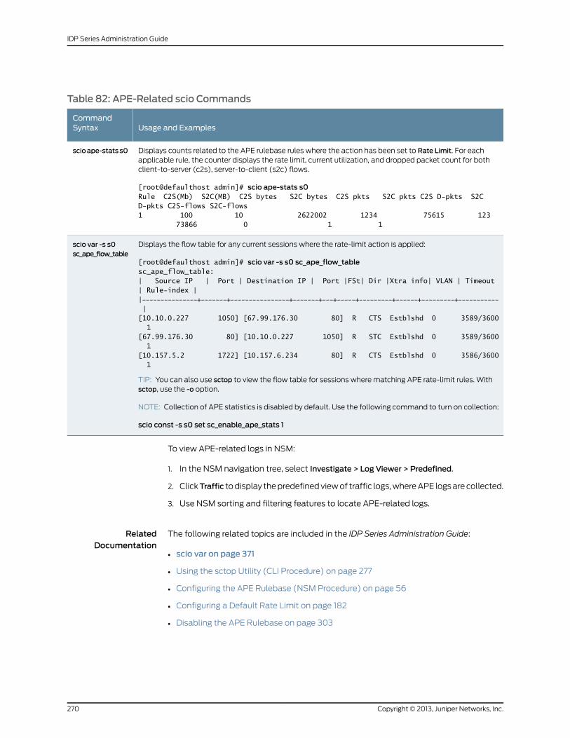
Table 82: APE-Related scio Commands
Usage and ExamplesCommandSyntax
Displays counts related to the APE rulebase rules where the action has been set to Rate Limit. For eachapplicable rule, the counter displays the rate limit, current utilization, and dropped packet count for bothclient-to-server (c2s), server-to-client (s2c) flows.
[root@defaulthost admin]# scio ape-stats s0Rule C2S(Mb) S2C(MB) C2S bytes S2C bytes C2S pkts S2C pkts C2S D-pkts S2C D-pkts C2S-flows S2C-flows1 100 10 2622002 1234 75615 123 73866 0 1 1
scioape-statss0
Displays the flow table for any current sessions where the rate-limit action is applied:
[root@defaulthost admin]# scio var -s s0 sc_ape_flow_tablesc_ape_flow_table:| Source IP | Port | Destination IP | Port |FSt| Dir |Xtra info| VLAN | Timeout | Rule-index ||---------------+-------+----------------+-------+---+-----+---------+------+---------+----------- |[10.10.0.227 1050] [67.99.176.30 80] R CTS Estblshd 0 3589/3600 1[67.99.176.30 80] [10.10.0.227 1050] R STC Estblshd 0 3589/3600 1[10.157.5.2 1722] [10.157.6.234 80] R CTS Estblshd 0 3586/3600 1
TIP: You can also use sctop to view the flow table for sessions where matching APE rate-limit rules. Withsctop, use the -o option.
NOTE: Collection of APE statistics is disabled by default. Use the following command to turn on collection:
scio const -s s0 set sc_enable_ape_stats 1
scio var -s s0sc_ape_flow_table
To view APE-related logs in NSM:
1. In the NSM navigation tree, select Investigate > Log Viewer > Predefined.
2. ClickTraffic to display the predefined view of traffic logs, where APE logs are collected.
3. Use NSM sorting and filtering features to locate APE-related logs.
RelatedDocumentation
The following related topics are included in the IDP Series Administration Guide:
scio var on page 371•
• Using the sctop Utility (CLI Procedure) on page 277
• Configuring the APE Rulebase (NSM Procedure) on page 56
• Configuring a Default Rate Limit on page 182
• Disabling the APE Rulebase on page 303
Copyright © 2013, Juniper Networks, Inc.270
IDP Series Administration Guide
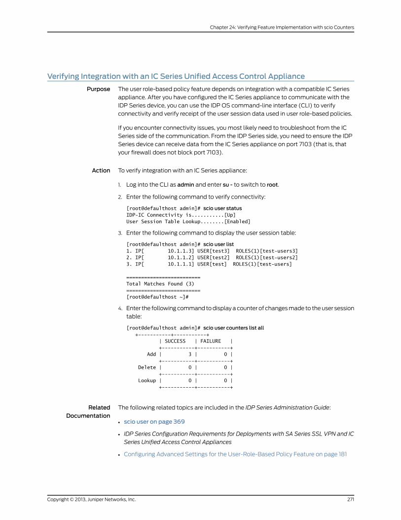
Verifying Integration with an IC Series Unified Access Control Appliance
Purpose The user role-based policy feature depends on integration with a compatible IC Series
appliance. After you have configured the IC Series appliance to communicate with the
IDP Series device, you can use the IDP OS command-line interface (CLI) to verify
connectivity and verify receipt of the user session data used in user role-based policies.
If you encounter connectivity issues, you most likely need to troubleshoot from the IC
Series side of the communication. From the IDP Series side, you need to ensure the IDP
Series device can receive data from the IC Series appliance on port 7103 (that is, that
your firewall does not block port 7103).
Action To verify integration with an IC Series appliance:
1. Log into the CLI as admin and enter su - to switch to root.
2. Enter the following command to verify connectivity:
[root@defaulthost admin]# scio user statusIDP-IC Connectivity is...........[Up]User Session Table Lookup........[Enabled]
3. Enter the following command to display the user session table:
[root@defaulthost admin]# scio user list1. IP[ 10.1.1.3] USER[test3] ROLES(1)[test-users3]2. IP[ 10.1.1.2] USER[test2] ROLES(1)[test-users2]3. IP[ 10.1.1.1] USER[test] ROLES(1)[test-users]
=========================Total Matches Found (3)=========================[root@defaulthost ~]#
4. Enter the following command to display a counter of changes made to the user session
table:
[root@defaulthost admin]# scio user counters list all +-----------+-----------+ | SUCCESS | FAILURE | +-----------+-----------+ Add | 3 | 0 | +-----------+-----------+ Delete | 0 | 0 | +-----------+-----------+ Lookup | 0 | 0 | +-----------+-----------+
RelatedDocumentation
The following related topics are included in the IDP Series Administration Guide:
scio user on page 369•
• IDP Series Configuration Requirements for Deployments with SA Series SSL VPN and IC
Series Unified Access Control Appliances
• Configuring Advanced Settings for the User-Role-Based Policy Feature on page 181
271Copyright © 2013, Juniper Networks, Inc.
Chapter 24: Verifying Feature Implementation with scio Counters
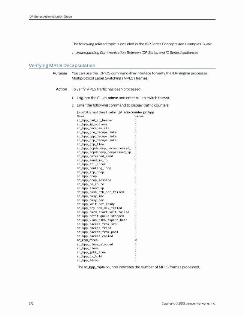
The following related topic is included in the IDP Series Concepts and Examples Guide:
• Understanding Communication Between IDP Series and IC Series Appliances
VerifyingMPLS Decapsulation
Purpose You can use the IDP OS command-line interface to verify the IDP engine processes
Multiprotocol Label Switching (MPLS) frames.
Action To verify MPLS traffic has been processed:
1. Log into the CLI as admin and enter su - to switch to root.
2. Enter the following command to display traffic counters:
[root@defaulthost admin]# scio counter get kppName Valuesc_kpp_bad_ip_header 0sc_kpp_ip_options 0sc_kpp_decapsulate 0sc_kpp_gre_decapsulate 0sc_kpp_ppp_decapsulate 0sc_kpp_gtp_decapsulate 0sc_kpp_gtp_flow 0sc_kpp_tcpdecomp_uncompressed_i 0sc_kpp_tcpdecomp_compressed_ip 0sc_kpp_deferred_send 0sc_kpp_send_in_ip 0sc_kpp_ttl_error 0sc_kpp_routing_loop 0sc_kpp_stp_drop 0sc_kpp_drop 0sc_kpp_drop_session 0sc_kpp_no_route 0sc_kpp_flood_ip 0sc_kpp_push_eth_hdr_failed 0sc_kpp_busy_inc 0sc_kpp_busy_dec 0sc_kpp_xmit_not_ready 0sc_kpp_trylock_dev_failed 0sc_kpp_hard_start_xmit_failed 0sc_kpp_netif_queue_stopped 0sc_kpp_vlan_pskb_expand_head 0sc_kpp_packet_from_szp 0sc_kpp_packet_freed 6sc_kpp_packet_from_pool 6sc_kpp_packet_copied 0sc_kpp_mpls 0sc_kpp_clone_stopped 0sc_kpp_clone 0sc_kpp_jpkt_free 6sc_kpp_tx_hold 0sc_kpp_fdrop 0
The sc_kpp_mpls counter indicates the number of MPLS frames processed.
Copyright © 2013, Juniper Networks, Inc.272
IDP Series Administration Guide
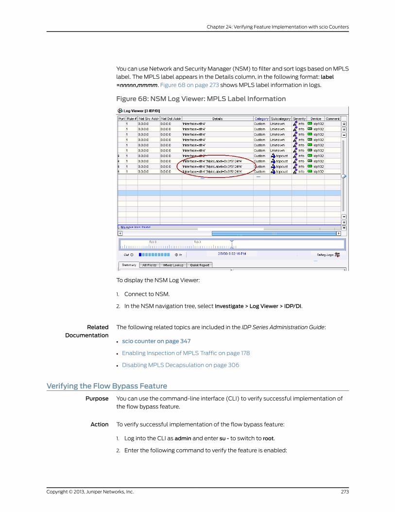
You can use Network and Security Manager (NSM) to filter and sort logs based on MPLS
label. The MPLS label appears in the Details column, in the following format: label
=nnnnn,mmmm. Figure 68 on page 273 shows MPLS label information in logs.
Figure 68: NSM Log Viewer: MPLS Label Information
To display the NSM Log Viewer:
1. Connect to NSM.
2. In the NSM navigation tree, select Investigate > Log Viewer > IDP/DI.
RelatedDocumentation
The following related topics are included in the IDP Series Administration Guide:
scio counter on page 347•
• Enabling Inspection of MPLS Traffic on page 178
• Disabling MPLS Decapsulation on page 306
Verifying the Flow Bypass Feature
Purpose You can use the command-line interface (CLI) to verify successful implementation of
the flow bypass feature.
Action To verify successful implementation of the flow bypass feature:
1. Log into the CLI as admin and enter su - to switch to root.
2. Enter the following command to verify the feature is enabled:
273Copyright © 2013, Juniper Networks, Inc.
Chapter 24: Verifying Feature Implementation with scio Counters
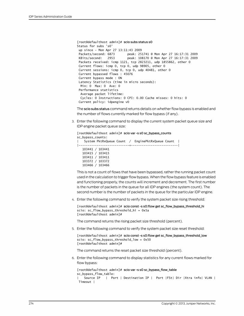
[root@defaulthost admin]# scio subs status s0Status for subs 's0' up since - Mon Apr 27 13:11:43 2009 Packets/second: 6873 peak: 251741 @ Mon Apr 27 16:17:31 2009 KBits/second: 2953 peak: 108170 @ Mon Apr 27 16:17:31 2009 Packets received: icmp 1121, tcp 2823211, udp 1855862, other 0 Current flows: icmp 0, tcp 0, udp 98905, other 0 Current sessions: icmp 0, tcp 0, udp 40481, other 0 Current bypassed flows : 45076 Current bypass mode : ON Latency Statistics (time in micro seconds): Min: 0 Max: 0 Ave: 0 Performance statistics Average packet lifetime: Cycles: 0 Instructions: 0 CPI: 0.00 Cache misses: 0 hits: 0 Current policy: idpengine v0
The scio subs status command returns details on whether flow bypass is enabled and
the number of flows currently marked for flow bypass (if any).
3. Enter the following command to display the current system packet queue size and
IDP engine packet queue size:
[root@defaulthost admin]# scio var -s s0 sc_bypass_countssc_bypass_counts:| System PktRxQueue Count / EnginePktRxQueue Count ||----------------------------+--------------------------| 103441 / 103441 103415 / 103415 103411 / 103411 103372 / 103372 103466 / 103466
This is not a count of flows that have been bypassed, rather the running packet count
used in the calculation to trigger flow bypass. When the flow bypass feature is enabled
and functioning properly, the counts will increment and decrement. The first number
is the number of packets in the queue for all IDP engines (the system count). The
second number is the number of packets in the queue for the particular IDP engine.
4. Enter the following command to verify the system packet size rising threshold:
[root@defaulthost admin]# scio const -s s0:flow get sc_flow_bypass_threshold_hiscio: sc_flow_bypass_threshold_hi = 0x5a[root@defaulthost admin]#
The command returns the rising packet size threshold (percent).
5. Enter the following command to verify the system packet size reset threshold:
[root@defaulthost admin]# scio const -s s0:flow get sc_flow_bypass_threshold_lowscio: sc_flow_bypass_threshold_low = 0x50[root@defaulthost admin]#
The command returns the reset packet size threshold (percent).
6. Enter the following command to display statistics for any current flows marked for
flow bypass:
[root@defaulthost admin]# scio var -s s0 sc_bypass_flow_tablesc_bypass_flow_table:| Source IP | Port | Destination IP | Port |FSt| Dir |Xtra info| VLAN | Timeout |
Copyright © 2013, Juniper Networks, Inc.274
IDP Series Administration Guide
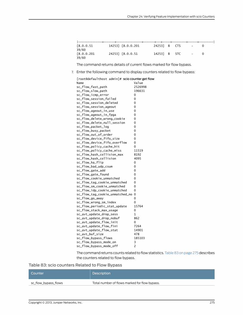
|---------------+-------+----------------+-------+---+-----+---------+------+---------|[8.0.0.51 14253] [8.0.0.201 24253] B CTS - 0 39/60[8.0.0.201 24253] [8.0.0.51 14253] B STC - 0 39/60
The command returns details of current flows marked for flow bypass.
7. Enter the following command to display counters related to flow bypass:
[root@defaulthost admin]# scio counter get flowName Valuesc_flow_fast_path 2526998sc_flow_slow_path 196631sc_flow_icmp_error 0sc_flow_session_failed 0sc_flow_session_deleted 0sc_flow_session_ageout 0sc_flow_ageout_in_use 0sc_flow_ageout_in_fpga 0sc_flow_delete_wrong_cookie 0sc_flow_delete_null_session 0sc_flow_packet_log 0sc_flow_busy_packet 0sc_flow_out_of_order 0sc_flow_device_fifo_size 0sc_flow_device_fifo_overflow 0sc_flow_policy_cache_hit 0sc_flow_policy_cache_miss 11519sc_flow_hash_collision_max 8192sc_flow_hash_collision 4095sc_flow_ha_flip 0sc_flow_bad_udp_csum 0sc_flow_gate_add 0sc_flow_gate_found 0sc_flow_cookie_unmatched 0sc_flow_tag_cookie_unmatched 0sc_flow_sm_cookie_unmatched 0sc_flow_idp_cookie_unmatched 0sc_flow_tag_cookie_unmatched_no 0sc_flow_go_away 0sc_flow_wrong_sm_index 0sc_flow_periodic_stat_update 15764sc_flow_stack_max_usage 0sc_avt_update_drop_sess 1sc_avt_update_drop_nobuf 862sc_avt_update_flow_init 0sc_avt_update_flow_fini 7264sc_avt_update_flow_stat 14901sc_avt_buf_size 478sc_flow_bypass_flows 185103sc_flow_bypass_mode_on 3sc_flow_bypass_mode_off 2
The command returns counts related to flow statistics. Table 83 on page 275 describes
the counters related to flow bypass.
Table 83: scio counters Related to Flow Bypass
DescriptionCounter
Total number of flows marked for flow bypass.sc_flow_bypass_flows
275Copyright © 2013, Juniper Networks, Inc.
Chapter 24: Verifying Feature Implementation with scio Counters
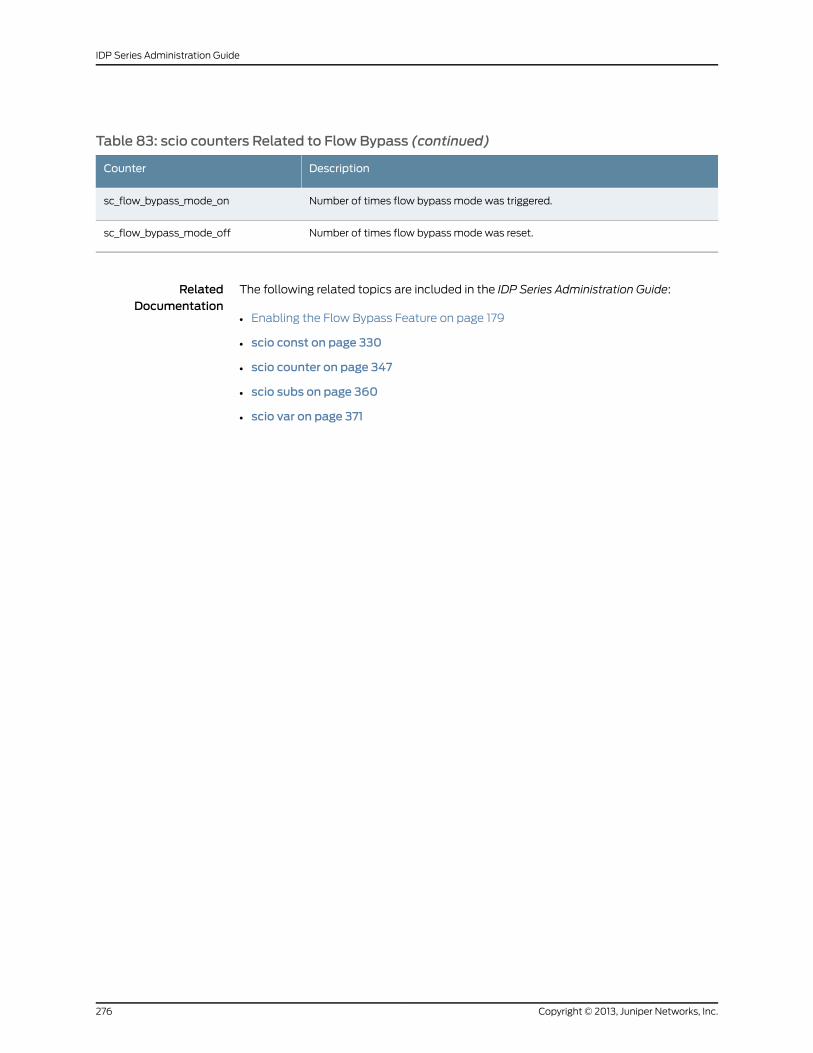
Table 83: scio counters Related to Flow Bypass (continued)
DescriptionCounter
Number of times flow bypass mode was triggered.sc_flow_bypass_mode_on
Number of times flow bypass mode was reset.sc_flow_bypass_mode_off
RelatedDocumentation
The following related topics are included in the IDP Series Administration Guide:
• Enabling the Flow Bypass Feature on page 179
• scio const on page 330
• scio counter on page 347
• scio subs on page 360
• scio var on page 371
Copyright © 2013, Juniper Networks, Inc.276
IDP Series Administration Guide
CHAPTER 25
Monitoring Session Flow with the sctopCommand
This chapter contains the following topics:
• sctop Task Summary on page 277
• Using the sctop Utility (CLI Procedure) on page 277
• Understanding sctop Flow Table Reports on page 280
sctop Task Summary
You use the sctop command to monitor the IDP system connection tables and view IDP
system status.
The sctop utility is located in the /usr/bin directory.
You use the sctop utility to perform the following tasks:
• Display the ARP and MAC tables.
• Display the IP, ICMP, TCP, and UDP flow tables.
• Display STP information.
• Display RPC information.
• Display performance statistics for traffic, IDP security policies, and IDP processors.
RelatedDocumentation
The following related topic is included in the IDP Series Administration Guide:
Using the sctop Utility (CLI Procedure) on page 277•
Using the sctop Utility (CLI Procedure)
Purpose You use the sctop command to monitor session information.
Action To connect to the command-line interface and use the sctop utility:
1. Use SSH to connect to the IP address or hostname for the management interface.
2. Log into the CLI as admin and enter su - to switch to root.
277Copyright © 2013, Juniper Networks, Inc.
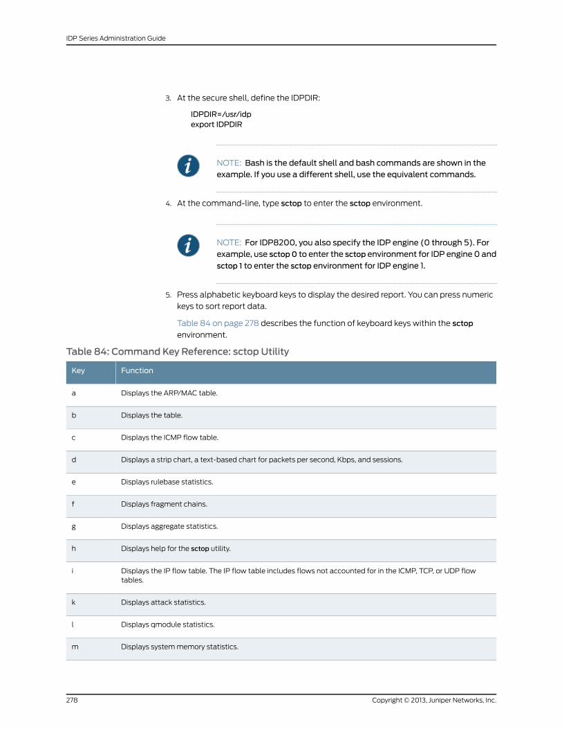
3. At the secure shell, define the IDPDIR:
IDPDIR=/usr/idpexport IDPDIR
NOTE: Bash is the default shell and bash commands are shown in theexample. If you use a different shell, use the equivalent commands.
4. At the command-line, type sctop to enter the sctop environment.
NOTE: For IDP8200, you also specify the IDP engine (0 through 5). Forexample, use sctop0 to enter the sctop environment for IDP engine 0 and
sctop 1 to enter the sctop environment for IDP engine 1.
5. Press alphabetic keyboard keys to display the desired report. You can press numeric
keys to sort report data.
Table 84 on page 278 describes the function of keyboard keys within the sctop
environment.
Table 84: Command Key Reference: sctop Utility
FunctionKey
Displays the ARP/MAC table.a
Displays the table.b
Displays the ICMP flow table.c
Displays a strip chart, a text-based chart for packets per second, Kbps, and sessions.d
Displays rulebase statistics.e
Displays fragment chains.f
Displays aggregate statistics.g
Displays help for the sctop utility.h
Displays the IP flow table. The IP flow table includes flows not accounted for in the ICMP, TCP, or UDP flowtables.
i
Displays attack statistics.k
Displays qmodule statistics.l
Displays system memory statistics.m
Copyright © 2013, Juniper Networks, Inc.278
IDP Series Administration Guide
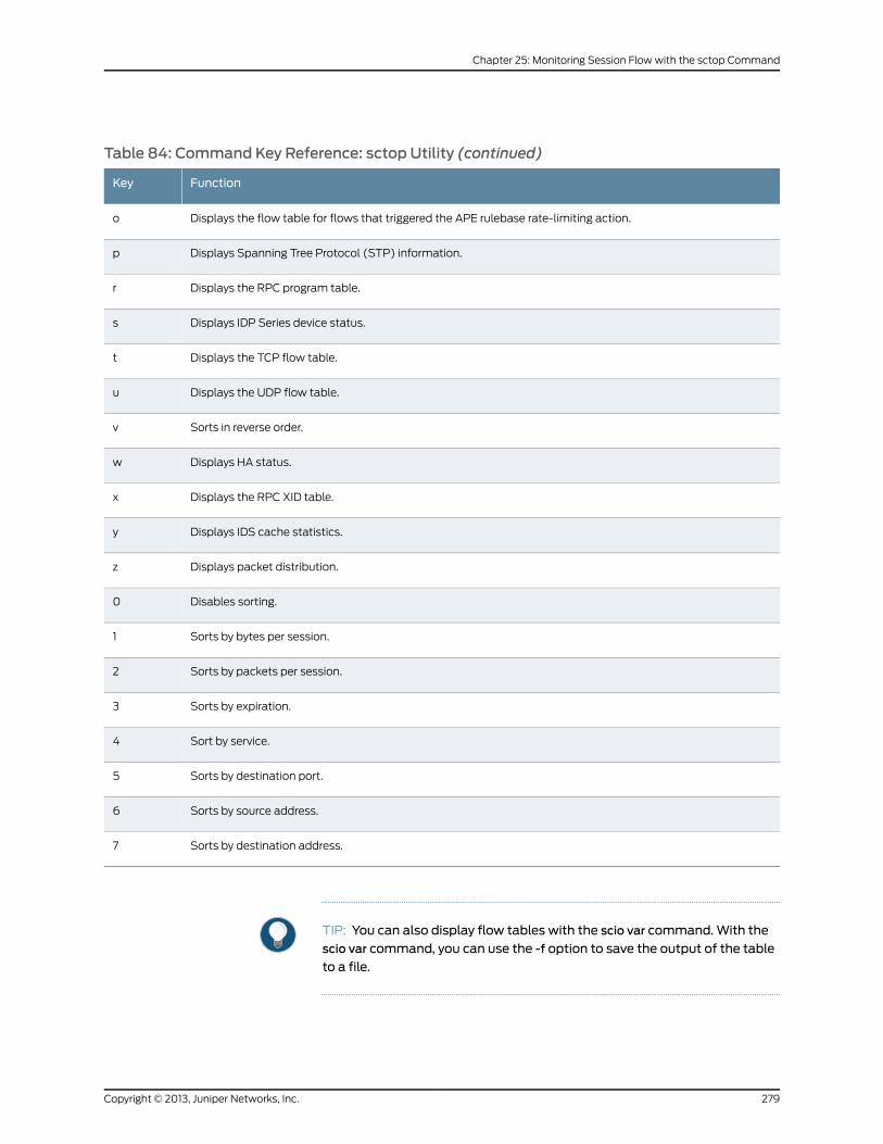
Table 84: Command Key Reference: sctop Utility (continued)
FunctionKey
Displays the flow table for flows that triggered the APE rulebase rate-limiting action.o
Displays Spanning Tree Protocol (STP) information.p
Displays the RPC program table.r
Displays IDP Series device status.s
Displays the TCP flow table.t
Displays the UDP flow table.u
Sorts in reverse order.v
Displays HA status.w
Displays the RPC XID table.x
Displays IDS cache statistics.y
Displays packet distribution.z
Disables sorting.0
Sorts by bytes per session.1
Sorts by packets per session.2
Sorts by expiration.3
Sort by service.4
Sorts by destination port.5
Sorts by source address.6
Sorts by destination address.7
TIP: You can also display flow tables with the scio var command.With the
scio var command, you can use the -f option to save the output of the table
to a file.
279Copyright © 2013, Juniper Networks, Inc.
Chapter 25: Monitoring Session Flow with the sctop Command
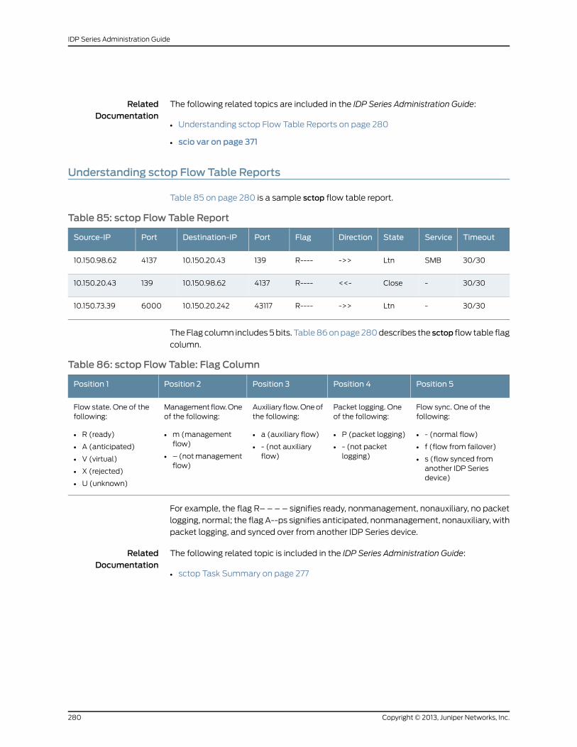
RelatedDocumentation
The following related topics are included in the IDP Series Administration Guide:
Understanding sctop Flow Table Reports on page 280•
• scio var on page 371
Understanding sctop Flow Table Reports
Table 85 on page 280 is a sample sctop flow table report.
Table 85: sctop Flow Table Report
TimeoutServiceStateDirectionFlagPortDestination-IPPortSource-IP
30/30SMBLtn->>R----13910.150.20.43413710.150.98.62
30/30-Close<<-R----413710.150.98.6213910.150.20.43
30/30-Ltn->>R----4311710.150.20.242600010.150.73.39
The Flag column includes 5 bits. Table 86 on page 280 describes the sctop flow table flag
column.
Table 86: sctop Flow Table: Flag Column
Position 5Position 4Position 3Position 2Position 1
Flow sync. One of thefollowing:
• - (normal flow)
• f (flow from failover)
• s (flow synced fromanother IDP Seriesdevice)
Packet logging. Oneof the following:
• P (packet logging)
• - (not packetlogging)
Auxiliary flow. One ofthe following:
• a (auxiliary flow)
• - (not auxiliaryflow)
Management flow. Oneof the following:
• m (managementflow)
• – (not managementflow)
Flow state. One of thefollowing:
• R (ready)
• A (anticipated)
• V (virtual)
• X (rejected)
• U (unknown)
For example, the flag R– – – – signifies ready, nonmanagement, nonauxiliary, no packet
logging, normal; the flag A--ps signifies anticipated, nonmanagement, nonauxiliary, with
packet logging, and synced over from another IDP Series device.
RelatedDocumentation
The following related topic is included in the IDP Series Administration Guide:
• sctop Task Summary on page 277
Copyright © 2013, Juniper Networks, Inc.280
IDP Series Administration Guide
CHAPTER 26
Using Command-Line Utilities for PacketCapture
This chapter contains the following topics:
• Using jnetTcpdump to Capture Packets on page 281
• Using tcpdump to Capture Packets on page 282
Using jnetTcpdump to Capture Packets
Typically, when you want to capture the packet data surrounding a security event, you
configure the packet logging option in security policy rules. In the course of monitoring
your network, you might encounter suspicious traffic where you have not set up rule-based
packet capture. In these cases, you can use the jnetTcpdump utility or the Linux-based
tcpdump utility to capture the traffic.
The jnetTcpdump utility copies packets from the JNET driver packet queuing module.
This allows it to capture packets as they are received (Rx packets) or as they are
transmitted (Tx packets). In contrast, on the IDP Series device, the tcpdump utility can
capture only Rx packets. The command options for the jnetTcpdump utility are similar
to the standard tcpdump utility options (though there are fewer options).
The following example starts listening on interface eth4 for packets with a destination
IP address of 4.0.0.4:
[root@localhost ~]# jnetTcpdump -i eth4 -f 4.0.0.4 dstjnetPassiveAttach donejnet tcpdump Started on eth4 for both Receive & Transmit sideFilter enabled - Host:4.0.0.4 as dst0 50 56 a4 21 6c 0 50 56 a4 d 9 8 0 45 0 0 54 0 0 40 0 40 1 32 a3 4 0 0 3 4 0 0 4 8 0 55 8e 8e 4f 0 0ba 9f 3e 4d 21 32 f 0 8 9 a b c d e f 10 11 12 13 14 150 50 56 a4 21 6c 0 50 56 a4 d 9 8 0 45 0 0 54 0 0 40 0 40 1 32 a3 4 0 0 3 4 0 0 4 8 0 97 88 8e 4f 0 1bb 9f 3e 4d de 36 f 0 8 9 a b c d e f 10 11 12 13 14 15Done...No of Packet Captured is 2No of Packets filtered-out 2
Type Ctrl-C to stop the capture.
To view captured traffic, you can use tcpdumpdata display options or use a packet viewer,
such as Wireshark.
281Copyright © 2013, Juniper Networks, Inc.
RelatedDocumentation
The following related topics are included in the IDP Series Administration Guide:
jnetTcpdump on page 384•
• Using tcpdump to Capture Packets on page 282
• Connecting to the Command-Line Interface (CLI Procedure) on page 315
The following related topic is included in the IDP Series Concepts and Examples Guide:
• Example: Packet LoggingWorkflow
Using tcpdump to Capture Packets
The IDP OS includes a Linux version of the commonly used tcpdump utility. On IDP Series
devices, the tcpdump utility can capture only received packets (Rx packets). If you need
to capture transmitted packets (Tx packets), use the jnetTcpdump utility.
To display a reference of tcpdump options and Berkeley Packet Filter (BFT) primitive
expressions, enter man tcpdump.
The following example shows the syntax for capturing SMTP traffic on port 25. Here,
tcpdump starts listening on the eth1 interface for traffic matching the expression tcp port
25.
[root@localhost ~]# tcpdump -i eth1 -s 0 -w /tmp/smtp.pcap tcp port 25
The following example shows the syntax for capturing all traffic except your SSH session
to the IDP Series device:
[root@localhost ~]# tcpdump -s 0 -I eth2 -w eth2-all-but-ssh.pcap not tcp port 22
If you later decide you want to extract only HTTP traffic from the “all-but” pcap, you can
use the following syntax to filter the previously collected file:
[root@localhost ~]# tcpdump -r eth2-all-but-ssh.pcap -w http.pcap tcp port 80
To view captured traffic, you can use tcpdumpdata display options or use a packet viewer,
such as Wireshark.
RelatedDocumentation
The following related topics are included in the IDP Series Administration Guide:
• Using jnetTcpdump to Capture Packets on page 281
• Connecting to the Command-Line Interface (CLI Procedure) on page 315
The following related topic is included in the IDP Series Concepts and Examples Guide:
• Example: Packet LoggingWorkflow
Copyright © 2013, Juniper Networks, Inc.282
IDP Series Administration Guide
PART 6
Troubleshooting
• Troubleshooting on page 285
283Copyright © 2013, Juniper Networks, Inc.

Copyright © 2013, Juniper Networks, Inc.284
IDP Series Administration Guide
CHAPTER 27
Troubleshooting
This chapter contains the following topics:
• Troubleshooting Tools Overview on page 285
• IDP Processes Reference on page 287
• Troubleshooting SNMP Statistic Reporting on page 288
• Tuning the JNET Driver Failure Count on page 290
• Viewing Auto-Recovery Logs on page 291
• Disabling the Auto-Recovery Feature on page 292
• Tuning the Auto-Recovery Policy Reload Setting on page 293
• Viewing CPU Utilization on page 293
• Troubleshooting High CPU Usage on page 295
• Troubleshooting Erroneous CPU Utilization Reports on page 297
• Displaying Service Session Count on page 299
• Troubleshooting Application Identification on page 300
• Disabling the APE Rulebase on page 303
• Disabling the User Role-Based Policy Feature on page 304
• Disabling Support for Jumbo Frames on page 304
• Troubleshooting SSL Inspection on page 305
• Disabling SSL Inspection on page 305
• Disabling MPLS Decapsulation on page 306
• Troubleshooting NSM Log Collection Issues on page 307
Troubleshooting Tools Overview
The best troubleshooting tips and troubleshooting workflows are published in the Juniper
Networks Technical Assistance Center (JTAC) knowledge base at http://kb.juniper.net.
For example, http://kb.juniper.net/index?page=content&id=KB9777 provides a workflow
for diagnosing dropped traffic.
Table 87 on page 286 provides a summary of IDP Series troubleshooting tools.
285Copyright © 2013, Juniper Networks, Inc.
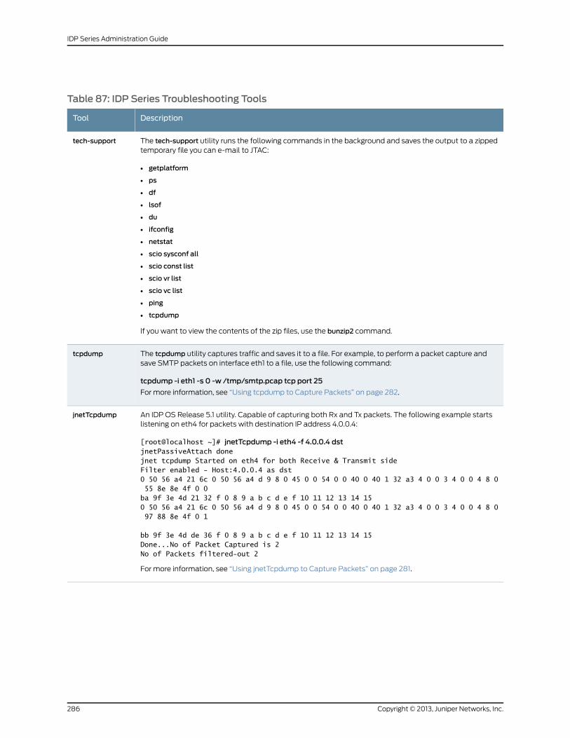
Table 87: IDP Series Troubleshooting Tools
DescriptionTool
The tech-support utility runs the following commands in the background and saves the output to a zippedtemporary file you can e-mail to JTAC:
• getplatform
• ps
• df
• lsof
• du
• ifconfig
• netstat
• scio sysconf all
• scio const list
• scio vr list
• scio vc list
• ping
• tcpdump
If you want to view the contents of the zip files, use the bunzip2 command.
tech-support
The tcpdump utility captures traffic and saves it to a file. For example, to perform a packet capture andsave SMTP packets on interface eth1 to a file, use the following command:
tcpdump -i eth1 -s 0 -w /tmp/smtp.pcap tcp port 25
For more information, see “Using tcpdump to Capture Packets” on page 282.
tcpdump
An IDP OS Release 5.1 utility. Capable of capturing both Rx and Tx packets. The following example startslistening on eth4 for packets with destination IP address 4.0.0.4:
[root@localhost ~]# jnetTcpdump -i eth4 -f 4.0.0.4 dstjnetPassiveAttach donejnet tcpdump Started on eth4 for both Receive & Transmit sideFilter enabled - Host:4.0.0.4 as dst0 50 56 a4 21 6c 0 50 56 a4 d 9 8 0 45 0 0 54 0 0 40 0 40 1 32 a3 4 0 0 3 4 0 0 4 8 0 55 8e 8e 4f 0 0ba 9f 3e 4d 21 32 f 0 8 9 a b c d e f 10 11 12 13 14 150 50 56 a4 21 6c 0 50 56 a4 d 9 8 0 45 0 0 54 0 0 40 0 40 1 32 a3 4 0 0 3 4 0 0 4 8 0 97 88 8e 4f 0 1
bb 9f 3e 4d de 36 f 0 8 9 a b c d e f 10 11 12 13 14 15Done...No of Packet Captured is 2No of Packets filtered-out 2
For more information, see “Using jnetTcpdump to Capture Packets” on page 281.
jnetTcpdump
Copyright © 2013, Juniper Networks, Inc.286
IDP Series Administration Guide
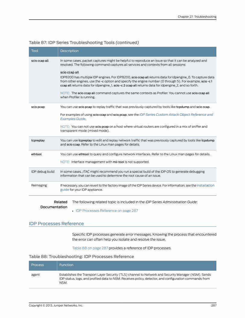
Table 87: IDP Series Troubleshooting Tools (continued)
DescriptionTool
In some cases, packet captures might be helpful to reproduce an issue so that it can be analyzed andresolved. The following command captures all services and contexts from all sessions:
scio ccap all
IDP8200 has multiple IDP engines. For IDP8200, scio ccap all returns data for idpengine_0. To capture datafrom other engines, use the -c option and specify the engine number (0 through 5). For example, scio -c 1ccap all returns data for idpengine_1, scio -c 2 ccap all returns data for idpengine_2, and so forth.
NOTE: The scio ccap all command captures the same contexts as Profiler. You cannot use scio ccap allwhen Profiler is running.
scio ccap all
You can use scio pcap to replay traffic that was previously captured by tools like tcpdump and scio ccap.
For examples of using scio ccap and scio pcap, see the IDP Series Custom Attack Object Reference andExamples Guide.
NOTE: You can not use scio pcap on a host where virtual routers are configured in a mix of sniffer andtransparent mode (mixed mode).
scio pcap
You can use tcpreplay to edit and replay network traffic that was previously captured by tools like tcpdumpand scio ccap. Refer to the Linux man pages for details.
tcpreplay
You can use ethtool to query and configure network interfaces. Refer to the Linux man pages for details.
NOTE: Interface management with mii-tool is not supported.
ethtool
In some cases, JTAC might recommend you run a special build of the IDP OS to generate debugginginformation that can be used to determine the root cause of an issue.
IDP debug build
If necessary, you can revert to the factory image of the IDP Series device. For information, see the installationguide for your IDP appliance.
Reimaging
RelatedDocumentation
The following related topic is included in the IDP Series Administration Guide:
IDP Processes Reference on page 287•
IDP Processes Reference
Specific IDP processes generate error messages. Knowing the process that encountered
the error can often help you isolate and resolve the issue.
Table 88 on page 287 provides a reference of IDP processes.
Table 88: Troubleshooting: IDP Processes Reference
FunctionProcess
Establishes the Transport Layer Security (TLS) channel to Network and Security Manager (NSM). SendsIDP status, logs, and profiled data to NSM. Receives policy, detector, and configuration commands fromNSM.
agent
287Copyright © 2013, Juniper Networks, Inc.
Chapter 27: Troubleshooting
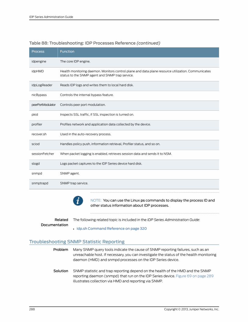
Table 88: Troubleshooting: IDP Processes Reference (continued)
FunctionProcess
The core IDP engine.idpengine
Health monitoring daemon. Monitors control plane and data plane resource utilization. Communicatesstatus to the SNMP agent and SNMP trap service.
idpHMD
Reads IDP logs and writes them to local hard disk.idpLogReader
Controls the internal bypass feature.nicBypass
Controls peer port modulation.peerPortModulator
Inspects SSL traffic, if SSL inspection is turned on.pkid
Profiles network and application data collected by the device.profiler
Used in the auto-recovery process.recover.sh
Handles policy push, information retrieval, Profiler status, and so on.sciod
When packet logging is enabled, retrieves session data and sends it to NSM.sessionFetcher
Logs packet captures to the IDP Series device hard disk.slogd
SNMP agent.snmpd
SNMP trap service.snmptrapd
NOTE: You can use the Linux ps commands to display the process ID andother status information about IDP processes.
RelatedDocumentation
The following related topic is included in the IDP Series Administration Guide:
idp.sh Command Reference on page 320•
Troubleshooting SNMPStatistic Reporting
Problem Many SNMP query tools indicate the cause of SNMP reporting failures, such as an
unreachable host. If necessary, you can investigate the status of the health monitoring
daemon (HMD) and snmpd processes on the IDP Series device.
Solution SNMP statistic and trap reporting depend on the health of the HMD and the SNMP
reporting daemon (snmpd) that run on the IDP Series device. Figure 69 on page 289
illustrates collection via HMD and reporting via SNMP.
Copyright © 2013, Juniper Networks, Inc.288
IDP Series Administration Guide
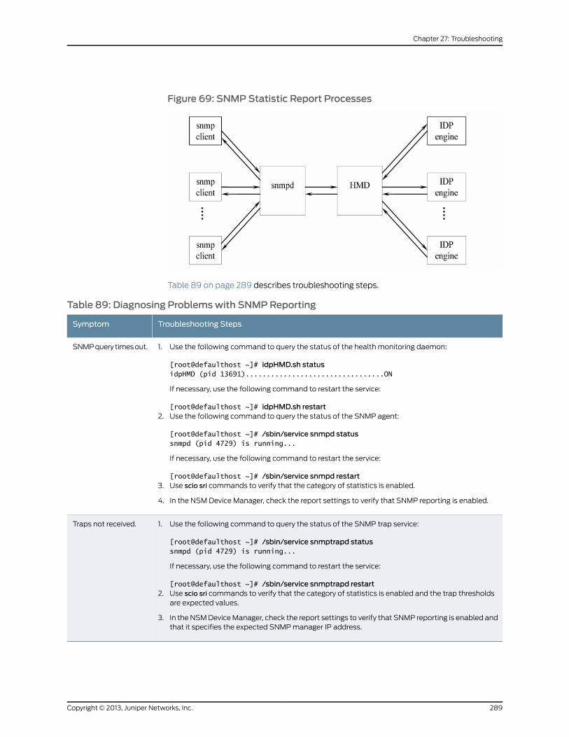
Figure 69: SNMPStatistic Report Processes
Table 89 on page 289 describes troubleshooting steps.
Table 89: Diagnosing Problemswith SNMPReporting
Troubleshooting StepsSymptom
1. Use the following command to query the status of the health monitoring daemon:
[root@defaulthost ~]# idpHMD.sh statusidpHMD (pid 13691).................................ON
If necessary, use the following command to restart the service:
[root@defaulthost ~]# idpHMD.sh restart2. Use the following command to query the status of the SNMP agent:
[root@defaulthost ~]# /sbin/service snmpd statussnmpd (pid 4729) is running...
If necessary, use the following command to restart the service:
[root@defaulthost ~]# /sbin/service snmpd restart3. Use scio sri commands to verify that the category of statistics is enabled.
4. In the NSM Device Manager, check the report settings to verify that SNMP reporting is enabled.
SNMP query times out.
1. Use the following command to query the status of the SNMP trap service:
[root@defaulthost ~]# /sbin/service snmptrapd statussnmpd (pid 4729) is running...
If necessary, use the following command to restart the service:
[root@defaulthost ~]# /sbin/service snmptrapd restart2. Use scio sri commands to verify that the category of statistics is enabled and the trap thresholds
are expected values.
3. In the NSM Device Manager, check the report settings to verify that SNMP reporting is enabled andthat it specifies the expected SNMP manager IP address.
Traps not received.
289Copyright © 2013, Juniper Networks, Inc.
Chapter 27: Troubleshooting
RelatedDocumentation
The following related topic is included in the IDP Series Administration Guide:
SNMP Statistic Reporting and Traps Task Summary on page 237•
Tuning the JNET Driver Failure Count
Problem If you configure internal bypass for virtual routers, traffic will bypass processing if the IDP
engine is unavailable or JNET driver fails to transmit packets as expected.
In the latter case, internal bypass is triggered when the JNET driver receive queue failure
count reaches 18 (about three minutes). After you have analyzed and resolved the cause
of the JNET driver failure, you can return the interfaces to normal state by restarting the
IDP engine.
We have provided a tunable setting in case you prefer the IDP Series device to enter
bypass sooner (decrease the count). If you want to give the JNET driver more time to
self-correct, you can increase the failure count.
To tune the default, modify the max_intf_recv_failed_cnt_nicbypass value in theuser_funcs
file. You must run idp.sh restart to restart the IDP engine and initialize any changes.
Solution To tune the JNET driver failure count:
1. Log into the CLI as admin and enter su - to switch to root.
2. Open the /usr/idp/device/bin/user_funcs file in a text editor, such as vi.
3. Locate the following line in the Variables section of the file:
#########################################################################
VARIABLES#########################################################################...# 'max_intf_recv_failed_cnt_nicbypass' - Themaximum count value for any# data interface indicating the number of times the packet could not# be received by that interface. If the count for any interface reaches# this value nicBypass gets triggered.# **WARNING**: Changing the value would require running 'idp.sh restart'.
export max_intf_recv_failed_cnt_nicbypass=18
NOTE: If your upgrade path was from 5.0r1 to 5.0r2, your user_funcs files
does not include the excerpt shown above. If this line is not present, thedefault isused. If youwant tochange thedefault, addtheexport statementshown to the Variables section of the user_funcs file.
4. Modify the default value (18) as you prefer. The value 18 is approximately equivalent
to 180 seconds. A value of 6 would be approximately 60 seconds.
Copyright © 2013, Juniper Networks, Inc.290
IDP Series Administration Guide
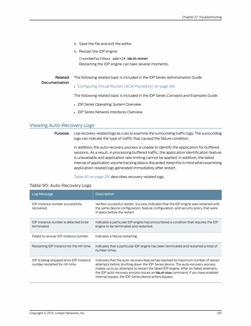
5. Save the file and exit the editor.
6. Restart the IDP engine:
[root@defaulthost admin]# idp.sh restart
Restarting the IDP engine can take several moments.
RelatedDocumentation
The following related topic is included in the IDP Series Administration Guide:
Configuring Virtual Routers (ACM Procedure) on page 186•
The following related topic is included in the IDP Series Concepts and Examples Guide:
• IDP Series Operating System Overview
• IDP Series Network Interfaces Overview
Viewing Auto-Recovery Logs
Purpose Use recovery-related logs as cues to examine the surrounding traffic logs. The surrounding
logs can indicate the type of traffic that caused the failure condition.
In addition, the auto-recovery process is unable to identify the application for buffered
sessions. As a result, in processing buffered traffic, the application identification feature
is unavailable and application rate limiting cannot be applied. In addition, the latest
interval of application volume tracking data is discarded. Keep this in mind when examining
application-related logs generated immediately after restart.
Table 90 on page 291 describes recovery-related logs.
Table 90: Auto-Recovery Logs
DescriptionLogMessage
Verifies successful restart. Success indicates that the IDP engine was restarted withthe same device configuration, feature configuration, and security policy that werein place before the restart.
IDP instance number successfullyrecovered.
Indicates a particular IDP engine has encountered a condition that requires the IDPengine to be terminated and restarted.
IDP instance number is detected to beterminated.
Indicates a failure restarting.Failed to recover IDP instance number.
Indicates that a particular IDP engine has been terminated and restarted a total ofnumber times.
Restarting IDP instance for the nth time.
Indicates that the auto-recovery feature has reached its maximum number of restartattempts before shutting down the IDP Series device. The auto-recovery processmakes up to six attempts to restart the failed IDP engine. After six failed attempts,the IDP auto-recovery process issues an idp.sh stop command. If you have enabledinternal bypass, the IDP Series device enters bypass.
IDP is being stopped since IDP instancenumber restarted for nth time.
291Copyright © 2013, Juniper Networks, Inc.
Chapter 27: Troubleshooting
Action Use the NSM Log Viewer filtering features to identify auto-recovery events and examine
the surrounding traffic. Auto-recovery logs belong to category Alarm and subcategory
Others.
You can also find auto-recovery logs on the IDP Series device in
/var/idp/device/sysinfo/logs/idpinit.date.
RelatedDocumentation
The following related topics are included in the IDP Series Administration Guide:
IDP Series Logs and Reports in NSM Task Summary on page 207•
• Tuning the Auto-Recovery Bypass Setting
• Tuning the Auto-Recovery Policy Reload Setting on page 293
• Disabling the Auto-Recovery Feature on page 292
• idp.sh Command Reference on page 320
The following related topic is included in the IDP Series Concepts and Examples Guide:
• IDP Series Operating System Overview
Disabling the Auto-Recovery Feature
Problem If you encounter a problem with the auto-recovery feature, you can disable it.
Solution To disable the auto-recovery feature:
1. Log into the CLI as admin and enter su - to switch to root.
2. Stop the IDP engine:
[root@defaulthost admin]# idp.sh stop
Restarting the IDP engine can take several moments.
3. Open the /usr/idp/device/bin/user_funcs file in a text editor, such as vi.
4. Locate the following line:
export autorecovery_state=1
5. Change the value to 0 to disable the feature.
6. Save the file and exit the editor.
7. Restart the IDP engine:
[root@defaulthost admin]# idp.sh start
Starting the IDP engine can take several moments.
RelatedDocumentation
The following related topics are included in the IDP Series Administration Guide:
Viewing Auto-Recovery Logs on page 291•
• Tuning the Auto-Recovery Bypass Setting
Copyright © 2013, Juniper Networks, Inc.292
IDP Series Administration Guide
• Tuning the Auto-Recovery Policy Reload Setting on page 293
Tuning the Auto-Recovery Policy Reload Setting
Problem The auto-recovery feature detects failure of an IDP engine and buffers packets while it
attempts to restart the IDP engine. The auto-recovery process reloads the device
configuration, including the security policy. The larger the security policy, the longer it
takes to complete the auto-recovery process. By default, packet processing resumes
only after the security policy has been reloaded. If your deployment requires faster
resumption of traffic flow, you can change this setting so that the IDP engine begins
processing traffic before the security policy has been loaded. However, the packets that
are processed before the security policy has been loaded are uninspected.
Solution To set packet processing to resume before the security policy has been loaded:
1. Log into the CLI as admin and enter su - to switch to root.
2. Open the /usr/idp/device/bin/user_funcs file in a text editor, such as vi.
3. Locate the following line:
export pktprocess_afterpolicyload=1
4. Change the value to 0 so that packet processing resumes before the security policy
has been loaded.
5. Save the file and exit the editor.
6. Restart the IDP engine:
[root@defaulthost admin]# idp.sh restart
Restarting the IDP engine can take several moments.
RelatedDocumentation
The following related topics are included in the IDP Series Administration Guide:
Viewing Auto-Recovery Logs on page 291•
• Tuning the Auto-Recovery Bypass Setting
• Disabling the Auto-Recovery Feature on page 292
Viewing CPUUtilization
Problem In earlier releases of the IDP OS, the CPU utilization reported for the system was simply
the results from the Linux top command. This has not changed for single core platforms
(IDP75, IDP200, IDP600): the reported CPU utilization continues to be the results of top.
For multicore platforms (IDP250, IDP800, IDP1100, IDP8200), the results of the Linux
top command are not helpful. Because of JNET driver polling behavior on multicore
platforms, the top command shows constant 100% utilization. To address this issue, we
developed the scio idp-cpu-utilization utility for multicore platforms. We do not claim
that the CPU utilization reported by the scio idp-cpu-utilization utility to be as precise as
the Linux top command, but the results are helpful in tracking changes in CPU utilization
293Copyright © 2013, Juniper Networks, Inc.
Chapter 27: Troubleshooting
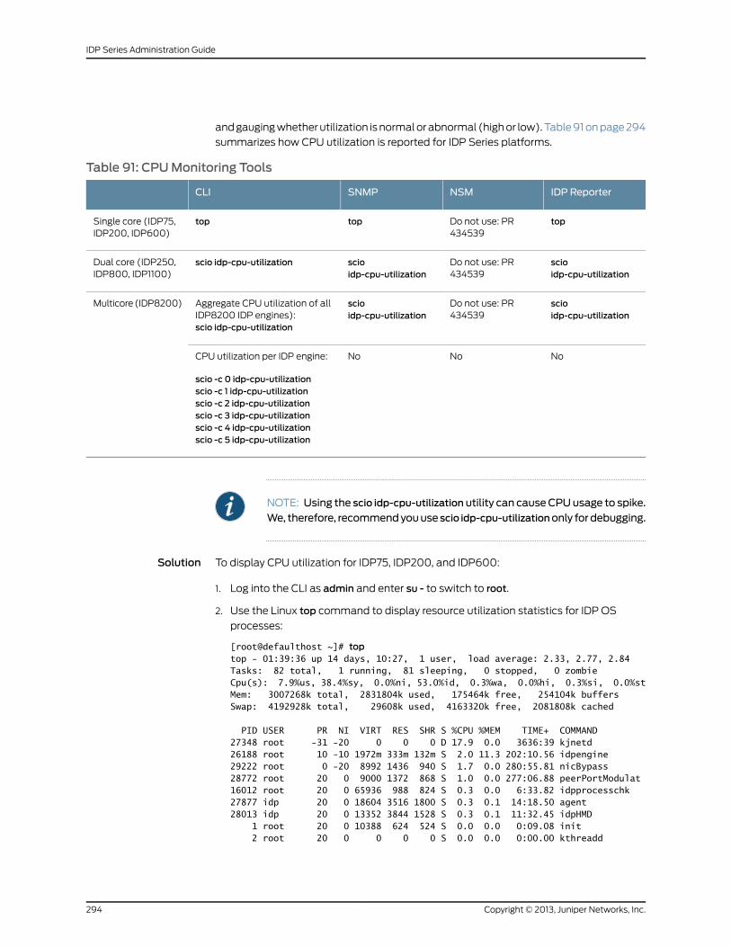
and gauging whether utilization is normal or abnormal (high or low). Table 91 on page 294
summarizes how CPU utilization is reported for IDP Series platforms.
Table 91: CPUMonitoring Tools
IDP ReporterNSMSNMPCLI
topDo not use: PR434539
toptopSingle core (IDP75,IDP200, IDP600)
scioidp-cpu-utilization
Do not use: PR434539
scioidp-cpu-utilization
scio idp-cpu-utilizationDual core (IDP250,IDP800, IDP1100)
scioidp-cpu-utilization
Do not use: PR434539
scioidp-cpu-utilization
Aggregate CPU utilization of allIDP8200 IDP engines):scio idp-cpu-utilization
Multicore (IDP8200)
NoNoNoCPU utilization per IDP engine:
scio -c 0 idp-cpu-utilizationscio -c 1 idp-cpu-utilizationscio -c 2 idp-cpu-utilizationscio -c 3 idp-cpu-utilizationscio -c 4 idp-cpu-utilizationscio -c 5 idp-cpu-utilization
NOTE: Using the scio idp-cpu-utilization utility can causeCPUusage to spike.
We, therefore, recommendyouuse scio idp-cpu-utilizationonly fordebugging.
Solution To display CPU utilization for IDP75, IDP200, and IDP600:
1. Log into the CLI as admin and enter su - to switch to root.
2. Use the Linux top command to display resource utilization statistics for IDP OS
processes:
[root@defaulthost ~]# toptop - 01:39:36 up 14 days, 10:27, 1 user, load average: 2.33, 2.77, 2.84Tasks: 82 total, 1 running, 81 sleeping, 0 stopped, 0 zombieCpu(s): 7.9%us, 38.4%sy, 0.0%ni, 53.0%id, 0.3%wa, 0.0%hi, 0.3%si, 0.0%stMem: 3007268k total, 2831804k used, 175464k free, 254104k buffersSwap: 4192928k total, 29608k used, 4163320k free, 2081808k cached
PID USER PR NI VIRT RES SHR S %CPU %MEM TIME+ COMMAND27348 root -31 -20 0 0 0 D 17.9 0.0 3636:39 kjnetd26188 root 10 -10 1972m 333m 132m S 2.0 11.3 202:10.56 idpengine29222 root 0 -20 8992 1436 940 S 1.7 0.0 280:55.81 nicBypass28772 root 20 0 9000 1372 868 S 1.0 0.0 277:06.88 peerPortModulat16012 root 20 0 65936 988 824 S 0.3 0.0 6:33.82 idpprocesschk27877 idp 20 0 18604 3516 1800 S 0.3 0.1 14:18.50 agent28013 idp 20 0 13352 3844 1528 S 0.3 0.1 11:32.45 idpHMD 1 root 20 0 10388 624 524 S 0.0 0.0 0:09.08 init 2 root 20 0 0 0 0 S 0.0 0.0 0:00.00 kthreadd
Copyright © 2013, Juniper Networks, Inc.294
IDP Series Administration Guide
3 root 20 0 0 0 0 S 0.0 0.0 10:25.39 ksoftirqd/0 4 root 20 0 0 0 0 S 0.0 0.0 0:00.00 kworker/0:0
To display CPU utilization for IDP250, IDP800, IDP1100, and IDP8200:
1. Log into the CLI as admin and enter su - to switch to root.
2. Use the following command to display CPU usage for the CPU core running the IDP
engine:
[root@defaulthost admin]# scio idp-cpu-utilizationCurrent actual cpu utilization: 0
The IDP8200 has multiple IDP engines. Specify the -c idp-engine option to display
CPU usage for a particular CPU core (0–5):
[root@defaulthost admin]# scio -c 0 idp-cpu-utilizationCurrent actual cpu utilization: 0
RelatedDocumentation
The following related topics are included in the IDP Series Administration Guide:
Configuring SNMP Reporting for the Sensor Category of Statistics on page 238•
• Troubleshooting High CPU Usage on page 295
• Troubleshooting Erroneous CPU Utilization Reports on page 297
• scio idp-cpu-utlization on page 350
The following related topic is included in the IDP Series Concepts and Examples Guide:
• IDP Series Operating System Overview
Troubleshooting High CPUUsage
Problem Security policy rules processing has an impact on CPU usage. You can use scio signature
statistic tool to understand the CPU utilization used to match particular attack objects
or attack groups. You can then take a better informed approach to tuning your security
policy.
NOTE: There is a slight performance impact to using this feature. Enable thisfeature while you are investigating high CPU; otherwise, disable it.
To use the scio signature statistic tool:
1. Log into the CLI as admin and enter su - to switch to root.
2. Enter the following command to enable the signature statistic tool:
[root@defaulthost ~]# scio const -s s0 set sc_enable_sigstat 1
295Copyright © 2013, Juniper Networks, Inc.
Chapter 27: Troubleshooting
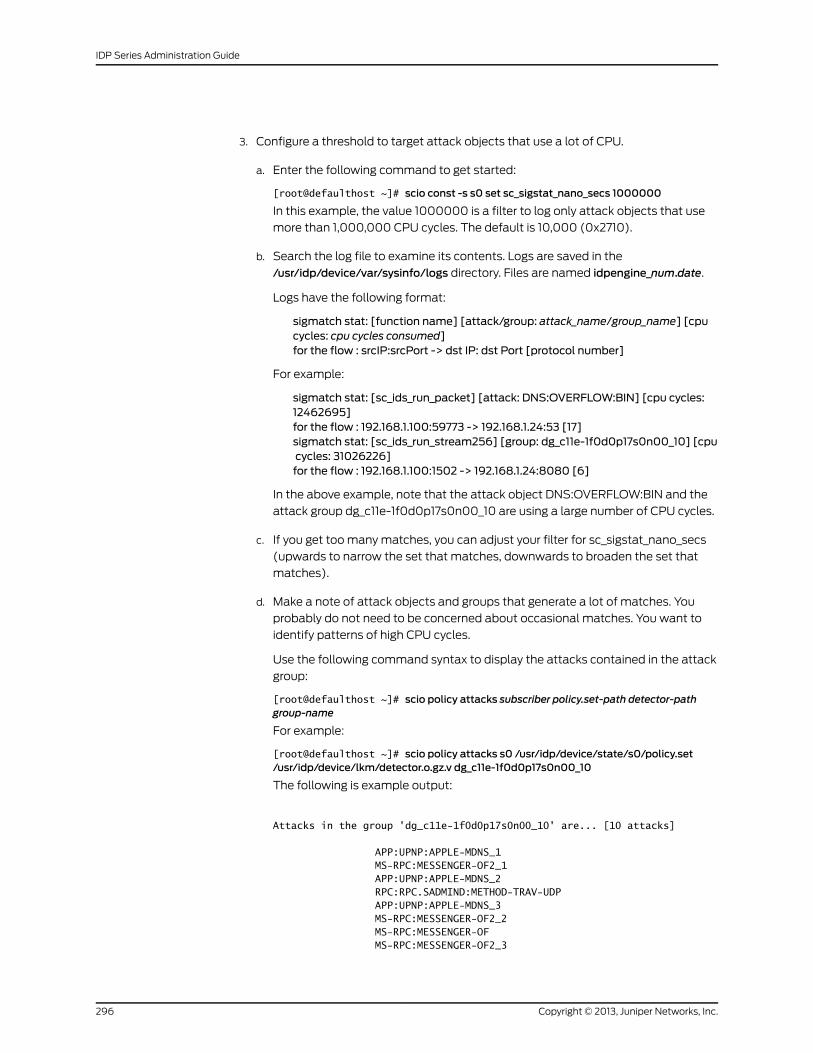
3. Configure a threshold to target attack objects that use a lot of CPU.
a. Enter the following command to get started:
[root@defaulthost ~]# scio const -s s0 set sc_sigstat_nano_secs 1000000
In this example, the value 1000000 is a filter to log only attack objects that use
more than 1,000,000 CPU cycles. The default is 10,000 (0x2710).
b. Search the log file to examine its contents. Logs are saved in the
/usr/idp/device/var/sysinfo/logs directory. Files are named idpengine_num.date.
Logs have the following format:
sigmatch stat: [function name] [attack/group: attack_name/group_name] [cpucycles: cpu cycles consumed]for the flow : srcIP:srcPort -> dst IP: dst Port [protocol number]
For example:
sigmatch stat: [sc_ids_run_packet] [attack: DNS:OVERFLOW:BIN] [cpu cycles:12462695]for the flow : 192.168.1.100:59773 -> 192.168.1.24:53 [17]sigmatch stat: [sc_ids_run_stream256] [group: dg_c11e-1f0d0p17s0n00_10] [cpucycles: 31026226]for the flow : 192.168.1.100:1502 -> 192.168.1.24:8080 [6]
In the above example, note that the attack object DNS:OVERFLOW:BIN and the
attack group dg_c11e-1f0d0p17s0n00_10 are using a large number of CPU cycles.
c. If you get too many matches, you can adjust your filter for sc_sigstat_nano_secs
(upwards to narrow the set that matches, downwards to broaden the set that
matches).
d. Make a note of attack objects and groups that generate a lot of matches. You
probably do not need to be concerned about occasional matches. You want to
identify patterns of high CPU cycles.
Use the following command syntax to display the attacks contained in the attack
group:
[root@defaulthost ~]# scio policy attacks subscriber policy.set-path detector-pathgroup-name
For example:
[root@defaulthost ~]# scio policy attacks s0 /usr/idp/device/state/s0/policy.set/usr/idp/device/lkm/detector.o.gz.v dg_c11e-1f0d0p17s0n00_10
The following is example output:
Attacks in the group 'dg_c11e-1f0d0p17s0n00_10' are... [10 attacks]
APP:UPNP:APPLE-MDNS_1 MS-RPC:MESSENGER-OF2_1 APP:UPNP:APPLE-MDNS_2 RPC:RPC.SADMIND:METHOD-TRAV-UDP APP:UPNP:APPLE-MDNS_3 MS-RPC:MESSENGER-OF2_2 MS-RPC:MESSENGER-OF MS-RPC:MESSENGER-OF2_3
Copyright © 2013, Juniper Networks, Inc.296
IDP Series Administration Guide
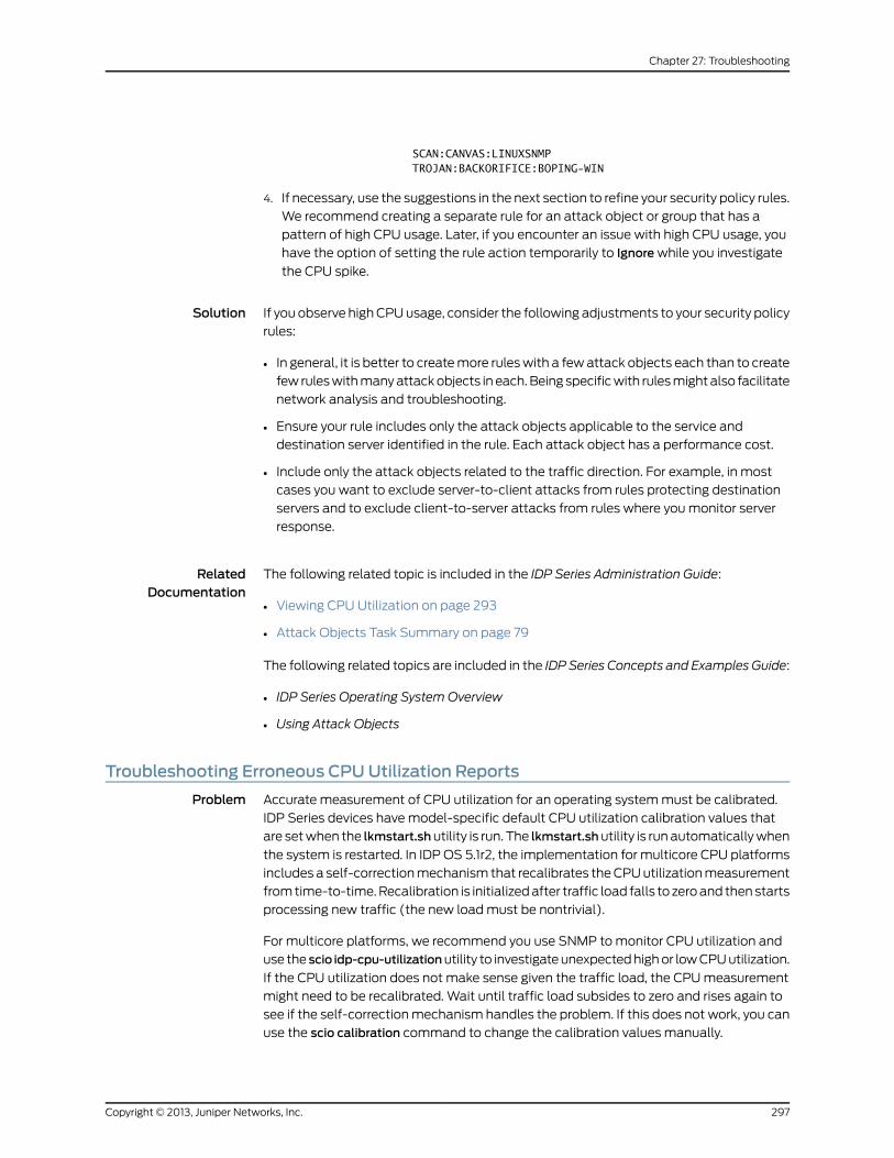
SCAN:CANVAS:LINUXSNMP TROJAN:BACKORIFICE:BOPING-WIN
4. If necessary, use the suggestions in the next section to refine your security policy rules.
We recommend creating a separate rule for an attack object or group that has a
pattern of high CPU usage. Later, if you encounter an issue with high CPU usage, you
have the option of setting the rule action temporarily to Ignore while you investigate
the CPU spike.
Solution If you observe high CPU usage, consider the following adjustments to your security policy
rules:
• In general, it is better to create more rules with a few attack objects each than to create
few rules with many attack objects in each. Being specific with rules might also facilitate
network analysis and troubleshooting.
• Ensure your rule includes only the attack objects applicable to the service and
destination server identified in the rule. Each attack object has a performance cost.
• Include only the attack objects related to the traffic direction. For example, in most
cases you want to exclude server-to-client attacks from rules protecting destination
servers and to exclude client-to-server attacks from rules where you monitor server
response.
RelatedDocumentation
The following related topic is included in the IDP Series Administration Guide:
Viewing CPU Utilization on page 293•
• Attack Objects Task Summary on page 79
The following related topics are included in the IDP Series Concepts and Examples Guide:
• IDP Series Operating System Overview
• Using Attack Objects
Troubleshooting Erroneous CPUUtilization Reports
Problem Accurate measurement of CPU utilization for an operating system must be calibrated.
IDP Series devices have model-specific default CPU utilization calibration values that
are set when the lkmstart.shutility is run. The lkmstart.shutility is run automatically when
the system is restarted. In IDP OS 5.1r2, the implementation for multicore CPU platforms
includes a self-correction mechanism that recalibrates the CPU utilization measurement
from time-to-time. Recalibration is initialized after traffic load falls to zero and then starts
processing new traffic (the new load must be nontrivial).
For multicore platforms, we recommend you use SNMP to monitor CPU utilization and
use the scio idp-cpu-utilizationutility to investigate unexpected high or low CPU utilization.
If the CPU utilization does not make sense given the traffic load, the CPU measurement
might need to be recalibrated. Wait until traffic load subsides to zero and rises again to
see if the self-correction mechanism handles the problem. If this does not work, you can
use the scio calibration command to change the calibration values manually.
297Copyright © 2013, Juniper Networks, Inc.
Chapter 27: Troubleshooting
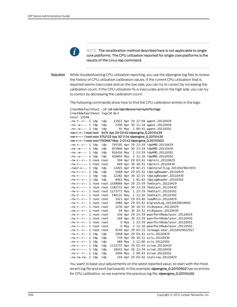
NOTE: The recalibrationmethod described here is not applicable to singlecore platforms. The CPU utilization reported for single core platforms is theresults of the Linux top command.
Solution While troubleshooting CPU utilization reporting, you use the idpengine log files to review
the history of CPU utilization calibration values. If the current CPU utilization that is
reported seems inaccurate and on the low side, you can try to correct by increasing the
calibration count. If the CPU utilization % is inaccurate and on the high side, you can try
to correct by decreasing the calibration count.
The following commands show how to find the CPU calibration entries in the logs:
[root@defaulthost ~]# cd /usr/idp/device/var/sysinfo/logs[root@defaulthost logs]# ls -ltotal 13548-rw-r--r-- 1 idp idp 13922 Apr 29 17:04 agent.20110429-rw--w---- 1 idp idp 2700 Apr 30 11:34 agent.20110430-rw--w---- 1 idp idp 91 May 2 00:41 agent.20110502-rw-r--r-- 1 root root 3474 Apr 29 03:40 idpengine_0.20110429-rw-r----- 1 root root 3752123 Apr 30 11:34 idpengine_0.20110430-rw-r--r-- 1 root root 1750667May 2 01:42 idpengine_0.20110502-rw-r--r-- 1 idp idp 795595 Apr 29 23:59 idpHMD.20110429-rw--w---- 1 idp idp 925840 Apr 30 23:59 idpHMD.20110430-rw--w---- 1 idp idp 916416 May 1 23:59 idpHMD.20110501-rw--w---- 1 idp idp 426893 May 2 11:10 idpHMD.20110502-rw-r--r-- 1 root root 504 Apr 29 03:41 idpinit.20110429-rw-r----- 1 root root 649 Apr 30 10:51 idpinit.20110430-rwxr-x--- 1 idp idp 12405 Apr 29 02:21 idpInstallLog.20110429021955-rw-r--r-- 1 idp idp 5668 Apr 29 03:42 idpLogReader.20110429-rw-r----- 1 idp idp 12282 Apr 30 12:25 idpLogReader.20110430-rw-r--r-- 1 idp idp 4063 May 2 01:42 idpLogReader.20110502-rw-r--r-- 1 root root 1038066 Apr 29 23:59 lkmStart.20110429-rw-r----- 1 root root 1182731 Apr 30 23:59 lkmStart.20110430-rw-r--r-- 1 root root 1173772 May 1 23:59 lkmStart.20110501-rw-r--r-- 1 root root 546132 May 2 11:10 lkmStart.20110502-rw-r--r-- 1 root root 1421 Apr 29 03:40 loadNics.20110429-rw-r--r-- 1 root root 2986 Apr 29 03:42 migrateLog.20110430034003-rw-r--r-- 1 root root 1230 Apr 30 10:51 nicBypass.20110429-rw-r--r-- 1 root root 44 Apr 30 10:52 nicBypass.20110430-rw-r--r-- 1 root root 156 Apr 29 23:59 peerPortModulator.20110429-rw-r--r-- 1 root root 104 Apr 30 23:59 peerPortModulator.20110430-rw-r--r-- 1 root root 0 May 1 23:59 peerPortModulator.20110501-rw-r--r-- 1 root root 0 May 2 11:10 peerPortModulator.20110502-rw-r--r-- 1 root root 6740 Apr 29 03:31 reimage-shar.20110429032917-rw-r--r-- 1 idp idp 1048 Apr 29 03:41 scio.20110429-rw-r--r-- 1 idp idp 739 Apr 30 10:51 scio.20110430-rw-r--r-- 1 idp idp 489 May 2 11:00 scio.20110502-rw-r--r-- 1 idp idp 1133737 Apr 29 03:43 sciod.20110429-rw-r----- 1 idp idp 18243 Apr 30 11:34 sciod.20110430-rw-r--r-- 1 idp idp 2094 May 2 00:43 sciod.20110502-rw-rw-rw- 1 idp idp 144 Apr 29 03:42 statview.20110429
You want to base your adjustments on the latest reported value, so start with the most
recent log file and work backwards. In this example, idpengine_0.20110502 has no entries
for CPU calibration, so we examine the previous log file, idpengine_0.20110430.
Copyright © 2013, Juniper Networks, Inc.298
IDP Series Administration Guide
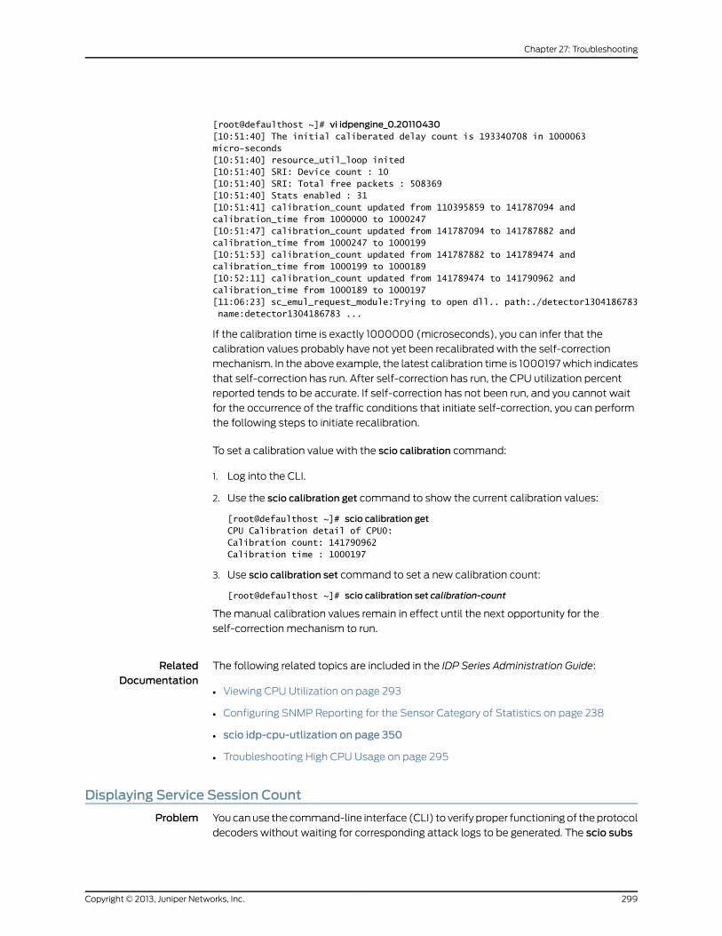
[root@defaulthost ~]# vi idpengine_0.20110430[10:51:40] The initial caliberated delay count is 193340708 in 1000063 micro-seconds[10:51:40] resource_util_loop inited[10:51:40] SRI: Device count : 10[10:51:40] SRI: Total free packets : 508369[10:51:40] Stats enabled : 31[10:51:41] calibration_count updated from 110395859 to 141787094 and calibration_time from 1000000 to 1000247[10:51:47] calibration_count updated from 141787094 to 141787882 and calibration_time from 1000247 to 1000199[10:51:53] calibration_count updated from 141787882 to 141789474 and calibration_time from 1000199 to 1000189[10:52:11] calibration_count updated from 141789474 to 141790962 and calibration_time from 1000189 to 1000197[11:06:23] sc_emul_request_module:Trying to open dll.. path:./detector1304186783 name:detector1304186783 ...
If the calibration time is exactly 1000000 (microseconds), you can infer that the
calibration values probably have not yet been recalibrated with the self-correction
mechanism. In the above example, the latest calibration time is 1000197 which indicates
that self-correction has run. After self-correction has run, the CPU utilization percent
reported tends to be accurate. If self-correction has not been run, and you cannot wait
for the occurrence of the traffic conditions that initiate self-correction, you can perform
the following steps to initiate recalibration.
To set a calibration value with the scio calibration command:
1. Log into the CLI.
2. Use the scio calibration get command to show the current calibration values:
[root@defaulthost ~]# scio calibration getCPU Calibration detail of CPU0:Calibration count: 141790962Calibration time : 1000197
3. Use scio calibration set command to set a new calibration count:
[root@defaulthost ~]# scio calibration set calibration-count
The manual calibration values remain in effect until the next opportunity for the
self-correction mechanism to run.
RelatedDocumentation
The following related topics are included in the IDP Series Administration Guide:
Viewing CPU Utilization on page 293•
• Configuring SNMP Reporting for the Sensor Category of Statistics on page 238
• scio idp-cpu-utlization on page 350
• Troubleshooting High CPU Usage on page 295
Displaying Service Session Count
Problem You can use the command-line interface (CLI) to verify proper functioning of the protocol
decoders without waiting for corresponding attack logs to be generated. The scio subs
299Copyright © 2013, Juniper Networks, Inc.
Chapter 27: Troubleshooting
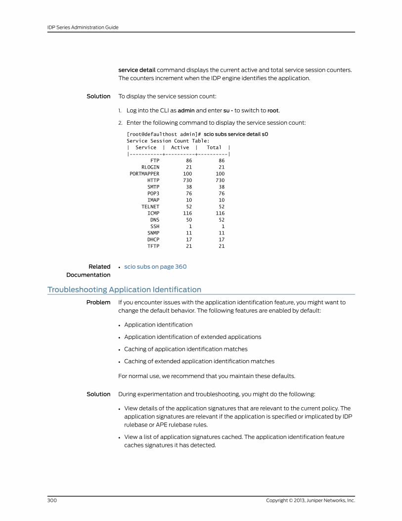
service detail command displays the current active and total service session counters.
The counters increment when the IDP engine identifies the application.
Solution To display the service session count:
1. Log into the CLI as admin and enter su - to switch to root.
2. Enter the following command to display the service session count:
[root@defaulthost admin]# scio subs service detail s0Service Session Count Table:| Service | Active | Total ||-----------+----------+----------| FTP 86 86 RLOGIN 21 21 PORTMAPPER 100 100 HTTP 730 730 SMTP 38 38 POP3 76 76 IMAP 10 10 TELNET 52 52 ICMP 116 116 DNS 50 52 SSH 1 1 SNMP 11 11 DHCP 17 17 TFTP 21 21
RelatedDocumentation
scio subs on page 360•
Troubleshooting Application Identification
Problem If you encounter issues with the application identification feature, you might want to
change the default behavior. The following features are enabled by default:
• Application identification
• Application identification of extended applications
• Caching of application identification matches
• Caching of extended application identification matches
For normal use, we recommend that you maintain these defaults.
Solution During experimentation and troubleshooting, you might do the following:
• View details of the application signatures that are relevant to the current policy. The
application signatures are relevant if the application is specified or implicated by IDP
rulebase or APE rulebase rules.
• View a list of application signatures cached. The application identification feature
caches signatures it has detected.
Copyright © 2013, Juniper Networks, Inc.300
IDP Series Administration Guide
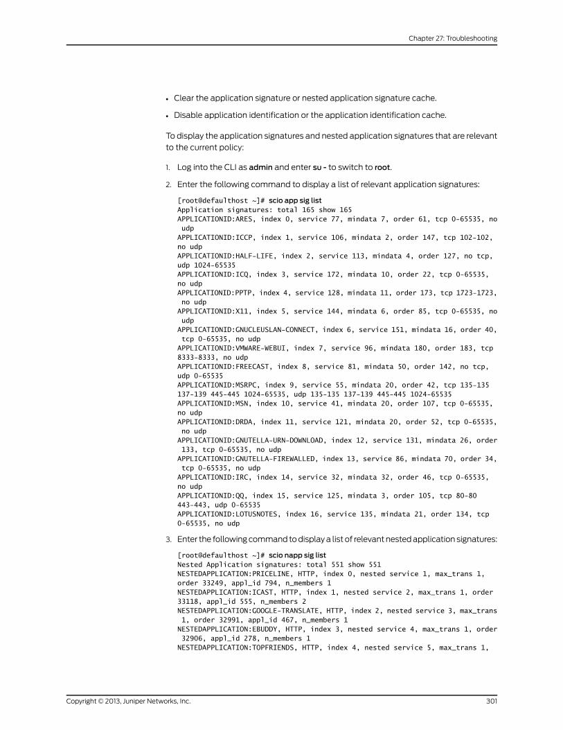
• Clear the application signature or nested application signature cache.
• Disable application identification or the application identification cache.
To display the application signatures and nested application signatures that are relevant
to the current policy:
1. Log into the CLI as admin and enter su - to switch to root.
2. Enter the following command to display a list of relevant application signatures:
[root@defaulthost ~]# scio app sig listApplication signatures: total 165 show 165APPLICATIONID:ARES, index 0, service 77, mindata 7, order 61, tcp 0-65535, no udpAPPLICATIONID:ICCP, index 1, service 106, mindata 2, order 147, tcp 102-102, no udpAPPLICATIONID:HALF-LIFE, index 2, service 113, mindata 4, order 127, no tcp, udp 1024-65535APPLICATIONID:ICQ, index 3, service 172, mindata 10, order 22, tcp 0-65535, no udpAPPLICATIONID:PPTP, index 4, service 128, mindata 11, order 173, tcp 1723-1723, no udpAPPLICATIONID:X11, index 5, service 144, mindata 6, order 85, tcp 0-65535, no udpAPPLICATIONID:GNUCLEUSLAN-CONNECT, index 6, service 151, mindata 16, order 40, tcp 0-65535, no udpAPPLICATIONID:VMWARE-WEBUI, index 7, service 96, mindata 180, order 183, tcp 8333-8333, no udpAPPLICATIONID:FREECAST, index 8, service 81, mindata 50, order 142, no tcp, udp 0-65535APPLICATIONID:MSRPC, index 9, service 55, mindata 20, order 42, tcp 135-135 137-139 445-445 1024-65535, udp 135-135 137-139 445-445 1024-65535APPLICATIONID:MSN, index 10, service 41, mindata 20, order 107, tcp 0-65535, no udpAPPLICATIONID:DRDA, index 11, service 121, mindata 20, order 52, tcp 0-65535, no udpAPPLICATIONID:GNUTELLA-URN-DOWNLOAD, index 12, service 131, mindata 26, order 133, tcp 0-65535, no udpAPPLICATIONID:GNUTELLA-FIREWALLED, index 13, service 86, mindata 70, order 34, tcp 0-65535, no udpAPPLICATIONID:IRC, index 14, service 32, mindata 32, order 46, tcp 0-65535, no udpAPPLICATIONID:QQ, index 15, service 125, mindata 3, order 105, tcp 80-80 443-443, udp 0-65535APPLICATIONID:LOTUSNOTES, index 16, service 135, mindata 21, order 134, tcp 0-65535, no udp
3. Enter the following command to display a list of relevant nested application signatures:
[root@defaulthost ~]# scio napp sig listNested Application signatures: total 551 show 551NESTEDAPPLICATION:PRICELINE, HTTP, index 0, nested service 1, max_trans 1, order 33249, appl_id 794, n_members 1NESTEDAPPLICATION:ICAST, HTTP, index 1, nested service 2, max_trans 1, order 33118, appl_id 555, n_members 2NESTEDAPPLICATION:GOOGLE-TRANSLATE, HTTP, index 2, nested service 3, max_trans 1, order 32991, appl_id 467, n_members 1NESTEDAPPLICATION:EBUDDY, HTTP, index 3, nested service 4, max_trans 1, order 32906, appl_id 278, n_members 1NESTEDAPPLICATION:TOPFRIENDS, HTTP, index 4, nested service 5, max_trans 1,
301Copyright © 2013, Juniper Networks, Inc.
Chapter 27: Troubleshooting
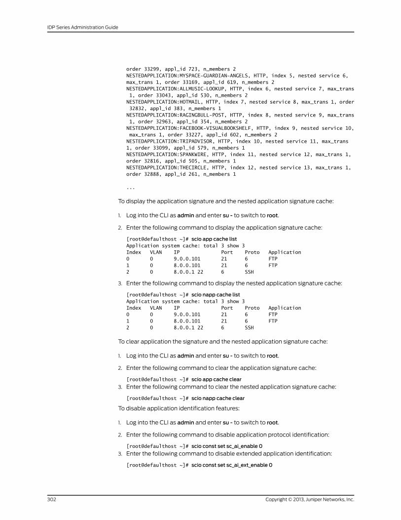
order 33299, appl_id 723, n_members 2NESTEDAPPLICATION:MYSPACE-GUARDIAN-ANGELS, HTTP, index 5, nested service 6, max_trans 1, order 33169, appl_id 619, n_members 2NESTEDAPPLICATION:ALLMUSIC-LOOKUP, HTTP, index 6, nested service 7, max_trans 1, order 33043, appl_id 530, n_members 2NESTEDAPPLICATION:HOTMAIL, HTTP, index 7, nested service 8, max_trans 1, order 32832, appl_id 383, n_members 1NESTEDAPPLICATION:RAGINGBULL-POST, HTTP, index 8, nested service 9, max_trans 1, order 32963, appl_id 354, n_members 2NESTEDAPPLICATION:FACEBOOK-VISUALBOOKSHELF, HTTP, index 9, nested service 10, max_trans 1, order 33227, appl_id 602, n_members 2NESTEDAPPLICATION:TRIPADVISOR, HTTP, index 10, nested service 11, max_trans 1, order 33099, appl_id 579, n_members 1NESTEDAPPLICATION:SPANKWIRE, HTTP, index 11, nested service 12, max_trans 1, order 32816, appl_id 505, n_members 1NESTEDAPPLICATION:THECIRCLE, HTTP, index 12, nested service 13, max_trans 1, order 32888, appl_id 261, n_members 1
...
To display the application signature and the nested application signature cache:
1. Log into the CLI as admin and enter su - to switch to root.
2. Enter the following command to display the application signature cache:
[root@defaulthost ~]# scio app cache listApplication system cache: total 3 show 3Index VLAN IP Port Proto Application0 0 9.0.0.101 21 6 FTP1 0 8.0.0.101 21 6 FTP2 0 8.0.0.1 22 6 SSH
3. Enter the following command to display the nested application signature cache:
[root@defaulthost ~]# scio napp cache listApplication system cache: total 3 show 3Index VLAN IP Port Proto Application0 0 9.0.0.101 21 6 FTP1 0 8.0.0.101 21 6 FTP2 0 8.0.0.1 22 6 SSH
To clear application the signature and the nested application signature cache:
1. Log into the CLI as admin and enter su - to switch to root.
2. Enter the following command to clear the application signature cache:
[root@defaulthost ~]# scio app cache clear
3. Enter the following command to clear the nested application signature cache:
[root@defaulthost ~]# scio napp cache clear
To disable application identification features:
1. Log into the CLI as admin and enter su - to switch to root.
2. Enter the following command to disable application protocol identification:
[root@defaulthost ~]# scio const set sc_ai_enable 0
3. Enter the following command to disable extended application identification:
[root@defaulthost ~]# scio const set sc_ai_ext_enable 0
Copyright © 2013, Juniper Networks, Inc.302
IDP Series Administration Guide
4. Enter the following command to disable caching of application protocol identification
results:
[root@defaulthost ~]# scio const set sc_asc_enable 0
5. Enter the following command to disable caching of extended application protocol
identification results:
[root@defaulthost ~]# scio const set sc_ext_asc_enable 0
Changes take effect immediately, but the settings do not persist across restarts and
policy pushes.
RelatedDocumentation
The following related topics are included in the IDP Series Administration Guide:
scio app sig list on page 329•
• scio napp sig list on page 352
• scio app cache on page 327
• scio const on page 330
• Application Objects Task Summary on page 111
The following related topic is included in the IDP Series Concepts and Examples Guide:
• Using Application Objects
Disabling the APE Rulebase
Problem If the APE rulebase does not behave as expected, you can use the IDP OS CLI to disable
it.
Solution To disable the APE rulebase:
1. Log into the CLI as admin and enter su - to switch to root.
2. Use the following command to show the current value:
[root@defaulthost admin]# scio const get sc_ape_enablescio: sc_ape_enable = 0x1
A 1 (0x1) indicates the APE is enabled; a 0 (0x0) indicates the APE rulebase is disabled.
3. Change this setting with the corresponding set command. The following example
disables the APE rulebase:
[root@defaulthost admin]# scio const set sc_ape_enable 0scio: setting sc_ape_enable to 0x0
RelatedDocumentation
The following related topics are included in the IDP Series Administration Guide:
Configuring the APE Rulebase (NSM Procedure) on page 56•
• Verifying the APE Rulebase on page 269
303Copyright © 2013, Juniper Networks, Inc.
Chapter 27: Troubleshooting
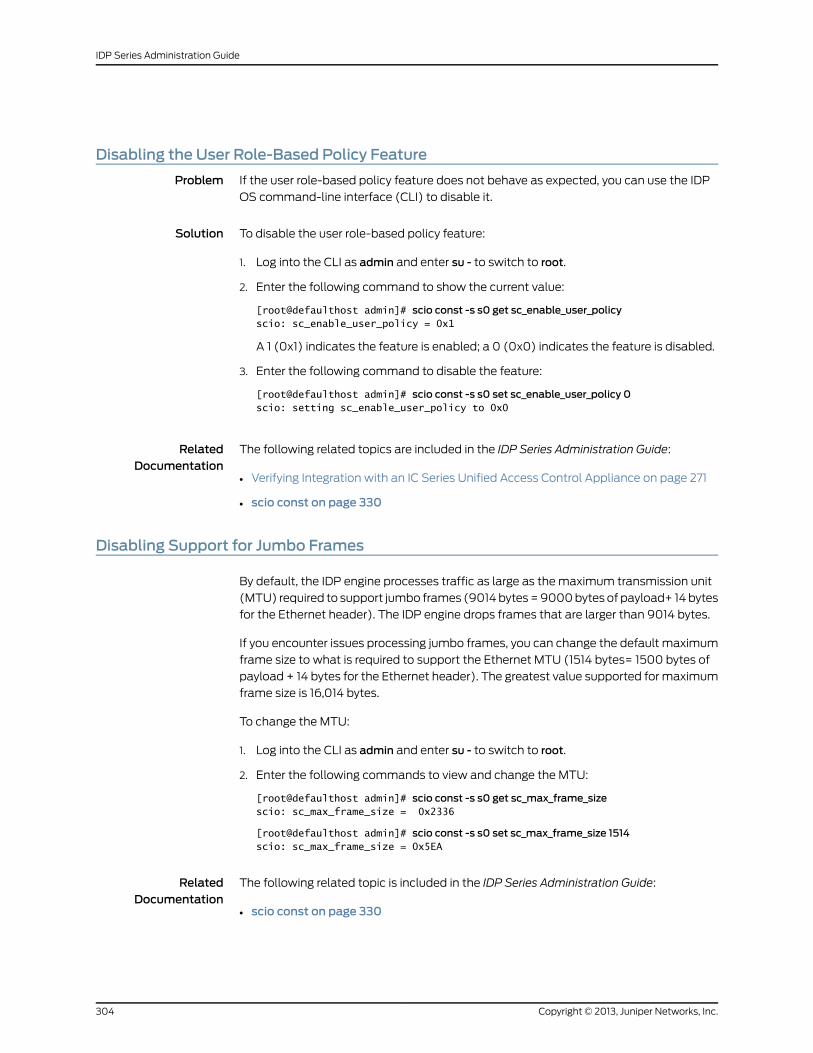
Disabling the User Role-Based Policy Feature
Problem If the user role-based policy feature does not behave as expected, you can use the IDP
OS command-line interface (CLI) to disable it.
Solution To disable the user role-based policy feature:
1. Log into the CLI as admin and enter su - to switch to root.
2. Enter the following command to show the current value:
[root@defaulthost admin]# scio const -s s0 get sc_enable_user_policyscio: sc_enable_user_policy = 0x1
A 1 (0x1) indicates the feature is enabled; a 0 (0x0) indicates the feature is disabled.
3. Enter the following command to disable the feature:
[root@defaulthost admin]# scio const -s s0 set sc_enable_user_policy 0scio: setting sc_enable_user_policy to 0x0
RelatedDocumentation
The following related topics are included in the IDP Series Administration Guide:
Verifying Integration with an IC Series Unified Access Control Appliance on page 271•
• scio const on page 330
Disabling Support for Jumbo Frames
By default, the IDP engine processes traffic as large as the maximum transmission unit
(MTU) required to support jumbo frames (9014 bytes = 9000 bytes of payload+ 14 bytes
for the Ethernet header). The IDP engine drops frames that are larger than 9014 bytes.
If you encounter issues processing jumbo frames, you can change the default maximum
frame size to what is required to support the Ethernet MTU (1514 bytes= 1500 bytes of
payload + 14 bytes for the Ethernet header). The greatest value supported for maximum
frame size is 16,014 bytes.
To change the MTU:
1. Log into the CLI as admin and enter su - to switch to root.
2. Enter the following commands to view and change the MTU:
[root@defaulthost admin]# scio const -s s0 get sc_max_frame_sizescio: sc_max_frame_size = 0x2336
[root@defaulthost admin]# scio const -s s0 set sc_max_frame_size 1514scio: sc_max_frame_size = 0x5EA
RelatedDocumentation
The following related topic is included in the IDP Series Administration Guide:
scio const on page 330•
Copyright © 2013, Juniper Networks, Inc.304
IDP Series Administration Guide
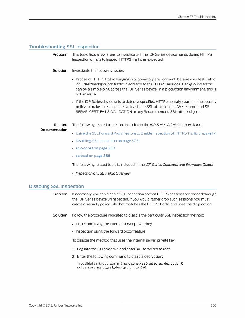
Troubleshooting SSL Inspection
Problem This topic lists a few areas to investigate if the IDP Series device hangs during HTTPS
inspection or fails to inspect HTTPS traffic as expected.
Solution Investigate the following issues:
• In case of HTTPS traffic hanging in a laboratory environment, be sure your test traffic
includes “background” traffic in addition to the HTTPS sessions. Background traffic
can be a simple ping across the IDP Series device. In a production environment, this is
not an issue.
• If the IDP Series device fails to detect a specified HTTP anomaly, examine the security
policy to make sure it includes at least one SSL attack object. We recommend SSL:
SERVR-CERT-FAILS-VALIDATION or any Recommended SSL attack object.
RelatedDocumentation
The following related topics are included in the IDP Series Administration Guide:
Using the SSL Forward Proxy Feature to Enable Inspection of HTTPS Traffic on page 171•
• Disabling SSL Inspection on page 305
• scio const on page 330
• scio ssl on page 356
The following related topic is included in the IDP Series Concepts and Examples Guide:
• Inspection of SSL Traffic Overview
Disabling SSL Inspection
Problem If necessary, you can disable SSL inspection so that HTTPS sessions are passed through
the IDP Series device uninspected. If you would rather drop such sessions, you must
create a security policy rule that matches the HTTPS traffic and uses the drop action.
Solution Follow the procedure indicated to disable the particular SSL inspection method:
• Inspection using the internal server private key
• Inspection using the forward proxy feature
To disable the method that uses the internal server private key:
1. Log into the CLI as admin and enter su - to switch to root.
2. Enter the following command to disable decryption:
[root@defaulthost admin]# scio const -s s0 set sc_ssl_decryption 0scio: setting sc_ssl_decryption to 0x0
305Copyright © 2013, Juniper Networks, Inc.
Chapter 27: Troubleshooting
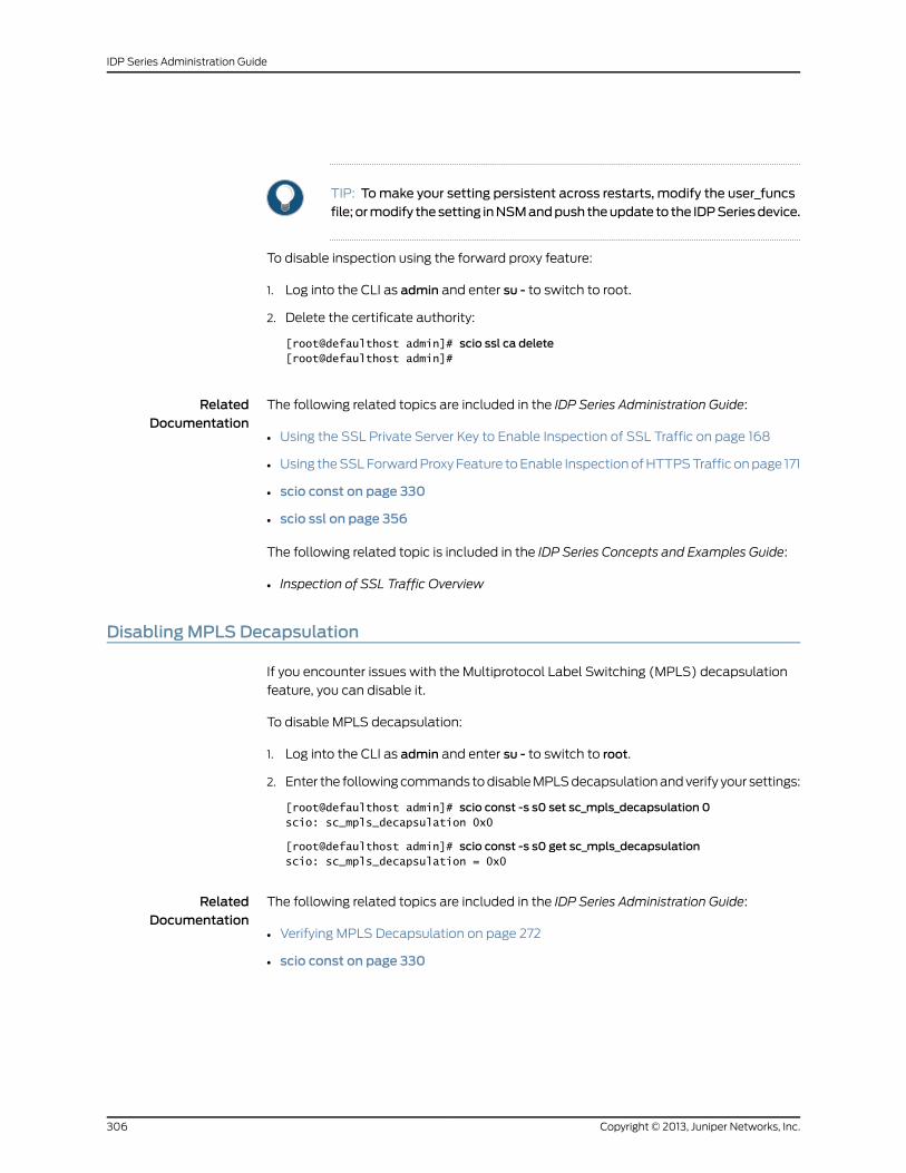
TIP: Tomake your setting persistent across restarts, modify the user_funcsfile; ormodify thesetting inNSMandpush theupdate to the IDPSeriesdevice.
To disable inspection using the forward proxy feature:
1. Log into the CLI as admin and enter su - to switch to root.
2. Delete the certificate authority:
[root@defaulthost admin]# scio ssl ca delete[root@defaulthost admin]#
RelatedDocumentation
The following related topics are included in the IDP Series Administration Guide:
Using the SSL Private Server Key to Enable Inspection of SSL Traffic on page 168•
• Using the SSL Forward Proxy Feature to Enable Inspection of HTTPS Traffic on page 171
• scio const on page 330
• scio ssl on page 356
The following related topic is included in the IDP Series Concepts and Examples Guide:
• Inspection of SSL Traffic Overview
DisablingMPLS Decapsulation
If you encounter issues with the Multiprotocol Label Switching (MPLS) decapsulation
feature, you can disable it.
To disable MPLS decapsulation:
1. Log into the CLI as admin and enter su - to switch to root.
2. Enter the following commands to disable MPLS decapsulation and verify your settings:
[root@defaulthost admin]# scio const -s s0 set sc_mpls_decapsulation 0scio: sc_mpls_decapsulation 0x0
[root@defaulthost admin]# scio const -s s0 get sc_mpls_decapsulationscio: sc_mpls_decapsulation = 0x0
RelatedDocumentation
The following related topics are included in the IDP Series Administration Guide:
Verifying MPLS Decapsulation on page 272•
• scio const on page 330
Copyright © 2013, Juniper Networks, Inc.306
IDP Series Administration Guide
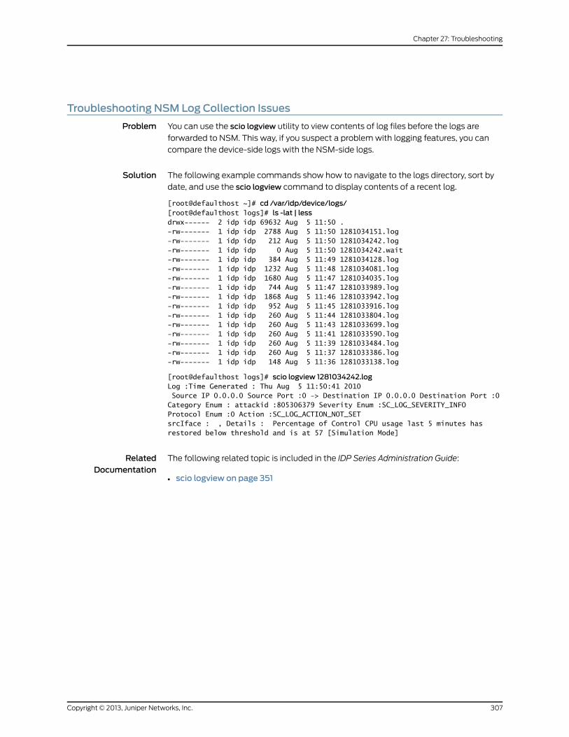
Troubleshooting NSM Log Collection Issues
Problem You can use the scio logview utility to view contents of log files before the logs are
forwarded to NSM. This way, if you suspect a problem with logging features, you can
compare the device-side logs with the NSM-side logs.
Solution The following example commands show how to navigate to the logs directory, sort by
date, and use the scio logview command to display contents of a recent log.
[root@defaulthost ~]# cd /var/idp/device/logs/[root@defaulthost logs]# ls -lat | lessdrwx------ 2 idp idp 69632 Aug 5 11:50 .-rw------- 1 idp idp 2788 Aug 5 11:50 1281034151.log-rw------- 1 idp idp 212 Aug 5 11:50 1281034242.log-rw------- 1 idp idp 0 Aug 5 11:50 1281034242.wait-rw------- 1 idp idp 384 Aug 5 11:49 1281034128.log-rw------- 1 idp idp 1232 Aug 5 11:48 1281034081.log-rw------- 1 idp idp 1680 Aug 5 11:47 1281034035.log-rw------- 1 idp idp 744 Aug 5 11:47 1281033989.log-rw------- 1 idp idp 1868 Aug 5 11:46 1281033942.log-rw------- 1 idp idp 952 Aug 5 11:45 1281033916.log-rw------- 1 idp idp 260 Aug 5 11:44 1281033804.log-rw------- 1 idp idp 260 Aug 5 11:43 1281033699.log-rw------- 1 idp idp 260 Aug 5 11:41 1281033590.log-rw------- 1 idp idp 260 Aug 5 11:39 1281033484.log-rw------- 1 idp idp 260 Aug 5 11:37 1281033386.log-rw------- 1 idp idp 148 Aug 5 11:36 1281033138.log
[root@defaulthost logs]# scio logview 1281034242.logLog :Time Generated : Thu Aug 5 11:50:41 2010 Source IP 0.0.0.0 Source Port :0 -> Destination IP 0.0.0.0 Destination Port :0Category Enum : attackid :805306379 Severity Enum :SC_LOG_SEVERITY_INFOProtocol Enum :0 Action :SC_LOG_ACTION_NOT_SETsrcIface : , Details : Percentage of Control CPU usage last 5 minutes has restored below threshold and is at 57 [Simulation Mode]
RelatedDocumentation
The following related topic is included in the IDP Series Administration Guide:
• scio logview on page 351
307Copyright © 2013, Juniper Networks, Inc.
Chapter 27: Troubleshooting

Copyright © 2013, Juniper Networks, Inc.308
IDP Series Administration Guide
PART 7
Appendixes
• Connecting to the Appliance Configuration Manager on page 311
• bypassStatus Commands on page 315
• idp.sh Commands on page 319
• scio Commands on page 323
• statview Commands on page 379
• jnetTcpdump on page 383
• IDP Series MIB Object ID Reference on page 387
309Copyright © 2013, Juniper Networks, Inc.

Copyright © 2013, Juniper Networks, Inc.310
IDP Series Administration Guide
APPENDIX A
Connecting to theApplianceConfigurationManager
This appendix provides the following reference information:
• Connecting to ACM on page 311
• Changing the Management Interface IP Address on page 311
Connecting to ACM
You use the Appliance Configuration Manager to configure IDP Series device network
settings.
To connect to ACM:
1. In the Address or Location box of your Web browser, enter https://IP, where IP is the
IP address you assigned to the management interface. For example, if you configured
the IP address 10.100.200.1, enter https://10.100.200.1.
NOTE: ACM access uses SSL, so youmust type https:// and not http://.
2. Log in as root. If you do not know the root password, contact the administrator who
ran the initial setup for the IDP Series device.
For information on using ACM to configure network communication, see the ACM online
Help.
TIP: ACM logs are located in /var/log/httpd/error_log. You can use these logs
to troubleshoot errors connecting to ACM.
Changing theManagement Interface IP Address
The IDP system uses the management interface (eth0) to communicate with Network
and Security Manager (NSM) (all deployments), SNMP managers (if applicable), and
311Copyright © 2013, Juniper Networks, Inc.
Juniper IVE devices (Access Control Service or Secure Access Service in coordinated
threat control deployments).
The management interface IP address is the only IP address for the IDP Series device. It
is the IP address used to make ssh connections to the command-line interface (CLI) and
to make browser-based connections to the Appliance Configuration Manager (ACM).
You configure the management interface IP address when you install and deploy the
device, as described in the installation documentation for your IDP Series device. If your
network IP address space changes, and you are required to reassign the IP address for
management interface, you can use ACM to change it.
Before you begin, prepare for the impact that changing the management interface IP
address has on any systems that might be configured to listen to or communicate with
the IDP Series device through the IDP Service device management interface IP address,
such as:
• NSM
• SNMP
• Juniper IVE systems
NOTE: The IP address change operation restarts the IDP engine. Be sure touse the same precautions you use when upgrading software, such ashigh-availability (HA) features, NIC bypass features, and choosing anopportune time to perform the operation (for example, a periodwhen trafficis light).
TIP: Be sure to inform others whomight act as administrators for the devicethat the IP address has changed. Administrators use the IP address whenconnecting to the device through ssh or ACM.
Copyright © 2013, Juniper Networks, Inc.312
IDP Series Administration Guide
To change the management interface IP address:
1. Reconfigure the IDP Series device using ACM:
a. Log into ACM.
b. Use the Configure Management Interface page to configure settings for the
management interface. The IP address must be reachable from the NSM Device
Server.
After the management IP address is changed:
• The ACM Web server is rebooted. You can access ACM again using the new IP
address.
• The IDP engine is restarted, and traffic flow is processed according to NIC bypass
settings during the restart cycle.
• The device reconnects to NSM and logs are forwarded to NSM without disruption.
• In NSM Device Monitor, the status displayed in the Connection Status column goes
down and comes up. There are no changes to the Configuration Status column.
• In NSM Log Viewer, NSM displays the same IDP device name with the previous IP
address.
2. Update the NSM configuration for the IDP Series device:
a. In NSM Device Manager, right-click the IDP Series device and select RMA to change
the device status to RMA.
b. Right-click the device and select Activate Device to display the Activate Device
dialog box.
c. Select the Device deployed and IP is reachable option, and complete the
configuration by specifying the IDP Series device IP address, admin username and
password, and root password.
After the device has been reactivated:
• In NSM Device Monitor, you might see the connection status go down and up again
as the connection is re-established.
• In NSM Log Viewer, the logs collected before the RMA/Activate Device operation
show the same device name but the changed IP address.
RelatedDocumentation
• IDP Series Network Interfaces Overview
• Connecting to ACM on page 311
• Activating Devices (NSM Procedure) on page 132
• Supported Tools for Management Tasks on page 123
313Copyright © 2013, Juniper Networks, Inc.
Appendix A: Connecting to the Appliance Configuration Manager

Copyright © 2013, Juniper Networks, Inc.314
IDP Series Administration Guide
APPENDIX B
bypassStatus Commands
This appendix provides the following reference information:
• Connecting to the Command-Line Interface (CLI Procedure) on page 315
• bypassStatus Command Reference
Connecting to the Command-Line Interface (CLI Procedure)
You use the command-line interface (CLI) to use CLI utilities, such as bypassStatus, scio,
sctop, idp.sh; or Linux diagnostic commands, such as ethtool.
To connect to the command-line interface:
1. Use SSH to connect to the IP address or hostname for the management interface.
2. Log in as admin and enter su - to switch to root.
3. At the secure shell, define IDPDIR as follows:
IDPDIR=/usr/idpexport IDPDIR
NOTE: Bash is the default shell and bash commands are shown in theexample. If you use a different shell, use the equivalent commands.
NOTE: If you automatemanagement or monitoring tasks with cron jobsor daemons that run CLI commands, remember to define the shellenvironment at the topof your script file. For example, if you create aBashscript to runasacron job, include the following lineat the topof your scriptfile:
export IDPDIR=/usr/idp
315Copyright © 2013, Juniper Networks, Inc.
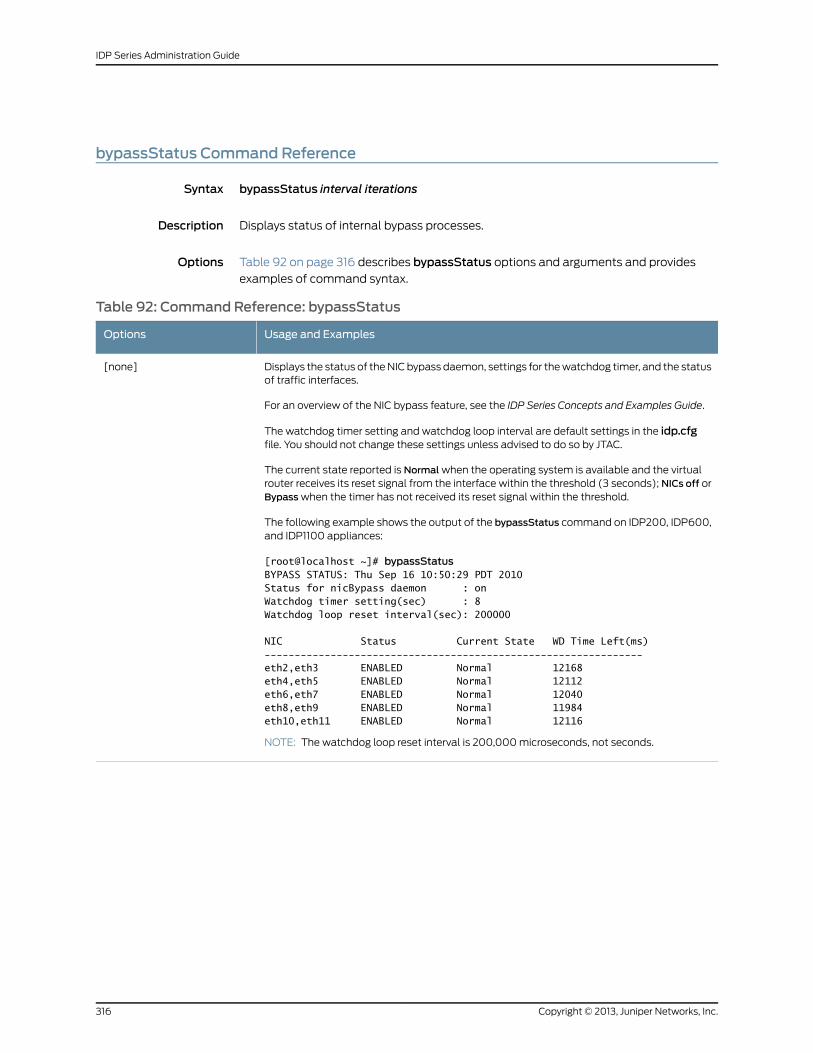
bypassStatus Command Reference
Syntax bypassStatus interval iterations
Description Displays status of internal bypass processes.
Options Table 92 on page 316 describes bypassStatus options and arguments and provides
examples of command syntax.
Table 92: Command Reference: bypassStatus
Usage and ExamplesOptions
Displays the status of the NIC bypass daemon, settings for the watchdog timer, and the statusof traffic interfaces.
For an overview of the NIC bypass feature, see the IDP Series Concepts and Examples Guide.
The watchdog timer setting and watchdog loop interval are default settings in the idp.cfgfile. You should not change these settings unless advised to do so by JTAC.
The current state reported is Normal when the operating system is available and the virtualrouter receives its reset signal from the interface within the threshold (3 seconds); NICs off orBypass when the timer has not received its reset signal within the threshold.
The following example shows the output of the bypassStatus command on IDP200, IDP600,and IDP1100 appliances:
[root@localhost ~]# bypassStatusBYPASS STATUS: Thu Sep 16 10:50:29 PDT 2010Status for nicBypass daemon : onWatchdog timer setting(sec) : 8Watchdog loop reset interval(sec): 200000
NIC Status Current State WD Time Left(ms)---------------------------------------------------------------eth2,eth3 ENABLED Normal 12168eth4,eth5 ENABLED Normal 12112eth6,eth7 ENABLED Normal 12040eth8,eth9 ENABLED Normal 11984eth10,eth11 ENABLED Normal 12116
NOTE: The watchdog loop reset interval is 200,000 microseconds, not seconds.
[none]
Copyright © 2013, Juniper Networks, Inc.316
IDP Series Administration Guide
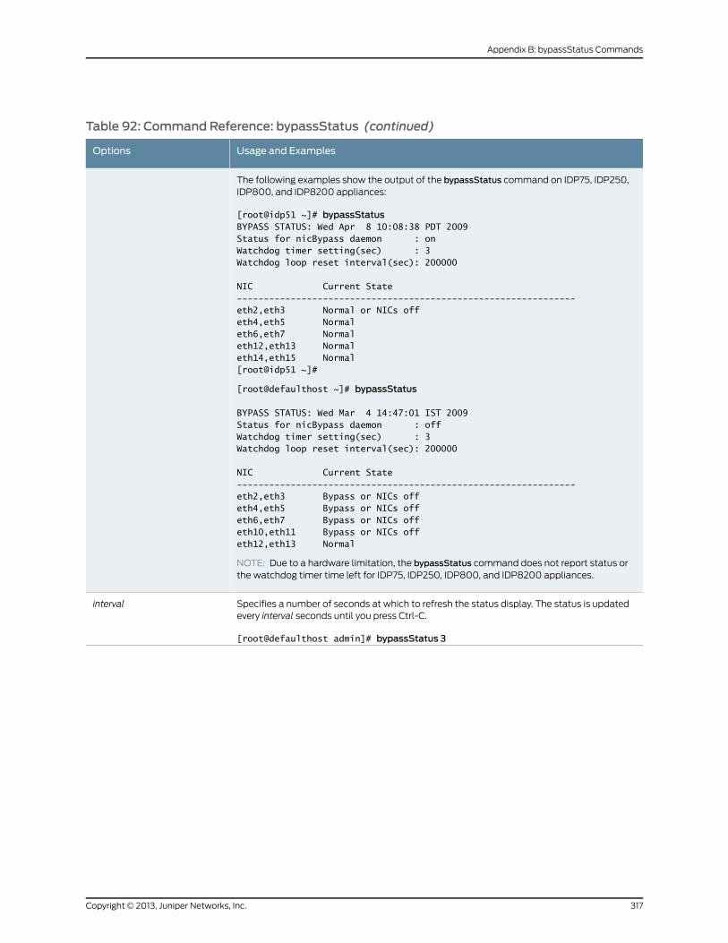
Table 92: Command Reference: bypassStatus (continued)
Usage and ExamplesOptions
The following examples show the output of the bypassStatus command on IDP75, IDP250,IDP800, and IDP8200 appliances:
[root@idp51 ~]# bypassStatusBYPASS STATUS: Wed Apr 8 10:08:38 PDT 2009Status for nicBypass daemon : onWatchdog timer setting(sec) : 3Watchdog loop reset interval(sec): 200000
NIC Current State---------------------------------------------------------------eth2,eth3 Normal or NICs offeth4,eth5 Normaleth6,eth7 Normaleth12,eth13 Normaleth14,eth15 Normal[root@idp51 ~]#
[root@defaulthost ~]# bypassStatus
BYPASS STATUS: Wed Mar 4 14:47:01 IST 2009Status for nicBypass daemon : offWatchdog timer setting(sec) : 3Watchdog loop reset interval(sec): 200000
NIC Current State---------------------------------------------------------------eth2,eth3 Bypass or NICs offeth4,eth5 Bypass or NICs offeth6,eth7 Bypass or NICs offeth10,eth11 Bypass or NICs offeth12,eth13 Normal
NOTE: Due to a hardware limitation, the bypassStatus command does not report status orthe watchdog timer time left for IDP75, IDP250, IDP800, and IDP8200 appliances.
Specifies a number of seconds at which to refresh the status display. The status is updatedevery interval seconds until you press Ctrl-C.
[root@defaulthost admin]# bypassStatus 3
interval
317Copyright © 2013, Juniper Networks, Inc.
Appendix B: bypassStatus Commands
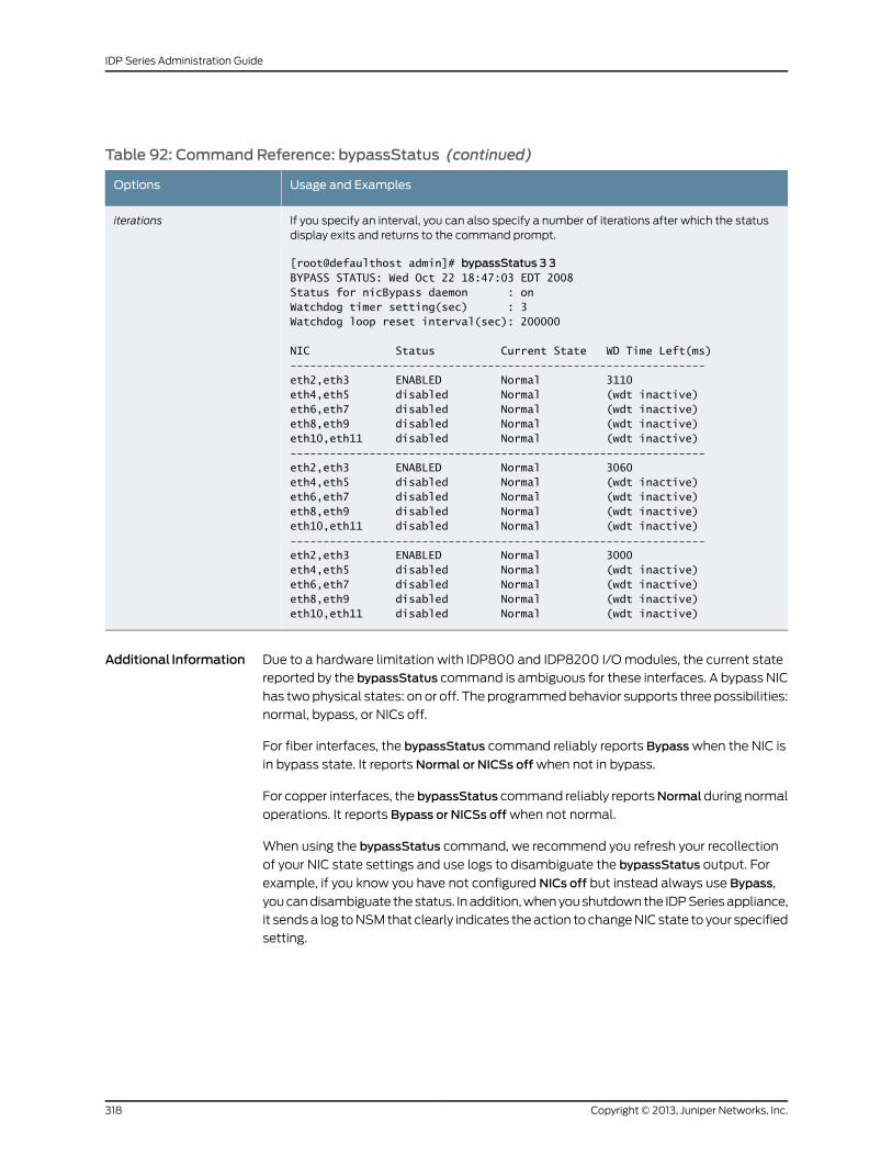
Table 92: Command Reference: bypassStatus (continued)
Usage and ExamplesOptions
If you specify an interval, you can also specify a number of iterations after which the statusdisplay exits and returns to the command prompt.
[root@defaulthost admin]# bypassStatus 3 3BYPASS STATUS: Wed Oct 22 18:47:03 EDT 2008Status for nicBypass daemon : onWatchdog timer setting(sec) : 3Watchdog loop reset interval(sec): 200000
NIC Status Current State WD Time Left(ms)---------------------------------------------------------------eth2,eth3 ENABLED Normal 3110eth4,eth5 disabled Normal (wdt inactive)eth6,eth7 disabled Normal (wdt inactive)eth8,eth9 disabled Normal (wdt inactive)eth10,eth11 disabled Normal (wdt inactive)---------------------------------------------------------------eth2,eth3 ENABLED Normal 3060eth4,eth5 disabled Normal (wdt inactive)eth6,eth7 disabled Normal (wdt inactive)eth8,eth9 disabled Normal (wdt inactive)eth10,eth11 disabled Normal (wdt inactive)---------------------------------------------------------------eth2,eth3 ENABLED Normal 3000eth4,eth5 disabled Normal (wdt inactive)eth6,eth7 disabled Normal (wdt inactive)eth8,eth9 disabled Normal (wdt inactive)eth10,eth11 disabled Normal (wdt inactive)
iterations
Additional Information Due to a hardware limitation with IDP800 and IDP8200 I/O modules, the current state
reported by the bypassStatus command is ambiguous for these interfaces. A bypass NIC
has two physical states: on or off. The programmed behavior supports three possibilities:
normal, bypass, or NICs off.
For fiber interfaces, the bypassStatus command reliably reports Bypass when the NIC is
in bypass state. It reports Normal or NICSs off when not in bypass.
For copper interfaces, the bypassStatus command reliably reportsNormalduring normal
operations. It reports Bypass or NICSs off when not normal.
When using the bypassStatus command, we recommend you refresh your recollection
of your NIC state settings and use logs to disambiguate the bypassStatus output. For
example, if you know you have not configured NICs off but instead always use Bypass,
you can disambiguate the status. In addition, when you shutdown the IDP Series appliance,
it sends a log to NSM that clearly indicates the action to change NIC state to your specified
setting.
Copyright © 2013, Juniper Networks, Inc.318
IDP Series Administration Guide
APPENDIX C
idp.sh Commands
This appendix provides the following reference information:
• Connecting to the Command-Line Interface (CLI Procedure) on page 319
• idp.sh Command Reference
• idp.sh Command Reference
Connecting to the Command-Line Interface (CLI Procedure)
You use the command-line interface (CLI) to use CLI utilities, such as bypassStatus, scio,
sctop, idp.sh; or Linux diagnostic commands, such as ethtool.
To connect to the command-line interface:
1. Use SSH to connect to the IP address or hostname for the management interface.
2. Log in as admin and enter su - to switch to root.
3. At the secure shell, define IDPDIR as follows:
IDPDIR=/usr/idpexport IDPDIR
NOTE: Bash is the default shell and bash commands are shown in theexample. If you use a different shell, use the equivalent commands.
NOTE: If you automatemanagement or monitoring tasks with cron jobsor daemons that run CLI commands, remember to define the shellenvironment at the topof your script file. For example, if you create aBashscript to runasacron job, include the following lineat the topof your scriptfile:
export IDPDIR=/usr/idp
319Copyright © 2013, Juniper Networks, Inc.
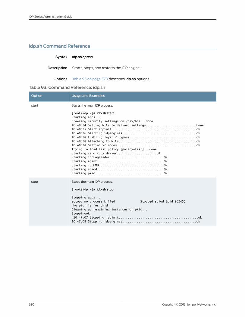
idp.sh Command Reference
Syntax idp.sh option
Description Starts, stops, and restarts the IDP engine.
Options Table 93 on page 320 describes idp.sh options.
Table 93: Command Reference: idp.sh
Usage and ExamplesOption
Starts the main IDP process.
[root@idp ~]# idp.sh startStarting apps...Freezing security settings on /dev/hda...Done10:48:24 Setting NICs to defined settings............................Done10:48:25 Start idpinit...............................................ok10:48:26 Starting idpengines.........................................ok10:48:28 Enabling layer 2 bypass.....................................ok10:48:28 Attaching to NICs...........................................ok10:48:28 Setting vr modes............................................okTrying to load last policy [policy-test]...doneStarting zero copy driver......................OKStarting idpLogReader..............................OKStarting agent.....................................OKStarting idpHMD....................................OKStarting sciod.....................................OKStarting pkid......................................OK
start
Stops the main IDP process.
[root@idp ~]# idp.sh stop
Stopping apps...sctop: no process killed Stopped sciod (pid 26245) No pidfile for pkidCleaning up remaining instances of pkid...Stoppingok 10:47:07 Stopping idpinit............................................ok10:47:09 Stopping idpengines.........................................ok
stop
Copyright © 2013, Juniper Networks, Inc.320
IDP Series Administration Guide
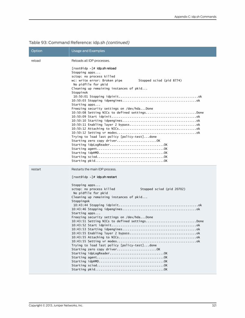
Table 93: Command Reference: idp.sh (continued)
Usage and ExamplesOption
Reloads all IDP processes.
[root@idp ~]# idp.sh reloadStopping apps...sctop: no process killedwc: write error: Broken pipe Stopped sciod (pid 8774) No pidfile for pkidCleaning up remaining instances of pkid...Stoppinok 10:50:01 Stopping idpinit............................................ok10:50:03 Stopping idpengines.........................................okStarting apps...Freezing security settings on /dev/hda...Done10:50:08 Setting NICs to defined settings............................Done10:50:09 Start idpinit...............................................ok10:50:10 Starting idpengines.........................................ok10:50:11 Enabling layer 2 bypass.....................................ok10:50:12 Attaching to NICs...........................................ok10:50:12 Setting vr modes............................................okTrying to load last policy [policy-test]...doneStarting zero copy driver......................OKStarting idpLogReader..............................OKStarting agent.....................................OKStarting idpHMD....................................OKStarting sciod.....................................OKStarting pkid......................................OK
reload
Restarts the main IDP process.
[root@idp ~]# idp.sh restart
Stopping apps...sctop: no process killed Stopped sciod (pid 20702) No pidfile for pkidCleaning up remaining instances of pkid...Stoppingok 10:43:44 Stopping idpinit............................................ok10:43:46 Stopping idpengines.........................................okStarting apps...Freezing security settings on /dev/hda...Done10:43:51 Setting NICs to defined settings............................Done10:43:52 Start idpinit...............................................ok10:43:53 Starting idpengines.........................................ok10:43:55 Enabling layer 2 bypass.....................................ok10:43:55 Attaching to NICs...........................................ok10:43:55 Setting vr modes............................................okTrying to load last policy [policy-test]...doneStarting zero copy driver......................OKStarting idpLogReader..............................OKStarting agent.....................................OKStarting idpHMD....................................OKStarting sciod.....................................OKStarting pkid......................................OK
restart
321Copyright © 2013, Juniper Networks, Inc.
Appendix C: idp.sh Commands
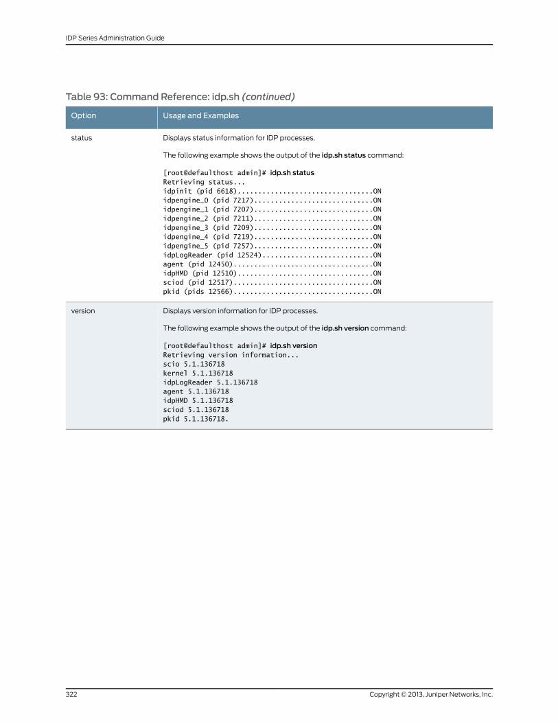
Table 93: Command Reference: idp.sh (continued)
Usage and ExamplesOption
Displays status information for IDP processes.
The following example shows the output of the idp.sh status command:
[root@defaulthost admin]# idp.sh statusRetrieving status...idpinit (pid 6618).................................ONidpengine_0 (pid 7217).............................ONidpengine_1 (pid 7207).............................ONidpengine_2 (pid 7211).............................ONidpengine_3 (pid 7209).............................ONidpengine_4 (pid 7219).............................ONidpengine_5 (pid 7257).............................ONidpLogReader (pid 12524)...........................ONagent (pid 12450)..................................ONidpHMD (pid 12510).................................ONsciod (pid 12517)..................................ONpkid (pids 12566)..................................ON
status
Displays version information for IDP processes.
The following example shows the output of the idp.sh version command:
[root@defaulthost admin]# idp.sh versionRetrieving version information...scio 5.1.136718kernel 5.1.136718idpLogReader 5.1.136718agent 5.1.136718idpHMD 5.1.136718sciod 5.1.136718pkid 5.1.136718.
version
Copyright © 2013, Juniper Networks, Inc.322
IDP Series Administration Guide
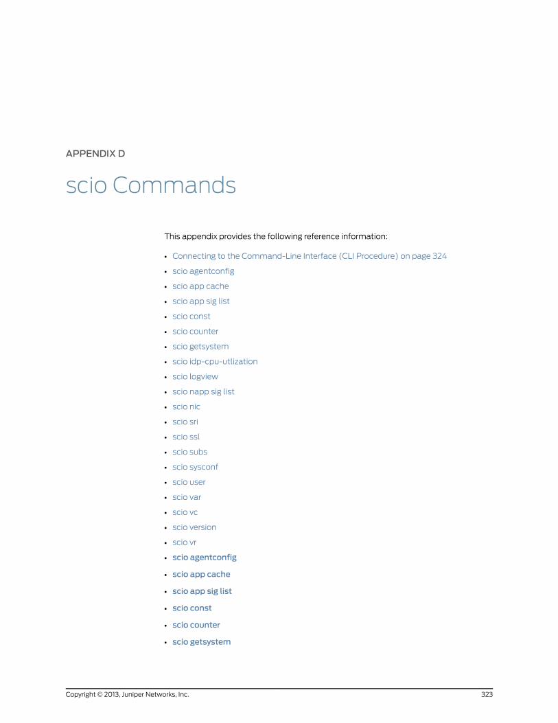
APPENDIX D
scio Commands
This appendix provides the following reference information:
• Connecting to the Command-Line Interface (CLI Procedure) on page 324
• scio agentconfig
• scio app cache
• scio app sig list
• scio const
• scio counter
• scio getsystem
• scio idp-cpu-utlization
• scio logview
• scio napp sig list
• scio nic
• scio sri
• scio ssl
• scio subs
• scio sysconf
• scio user
• scio var
• scio vc
• scio version
• scio vr
• scio agentconfig
• scio app cache
• scio app sig list
• scio const
• scio counter
• scio getsystem
323Copyright © 2013, Juniper Networks, Inc.
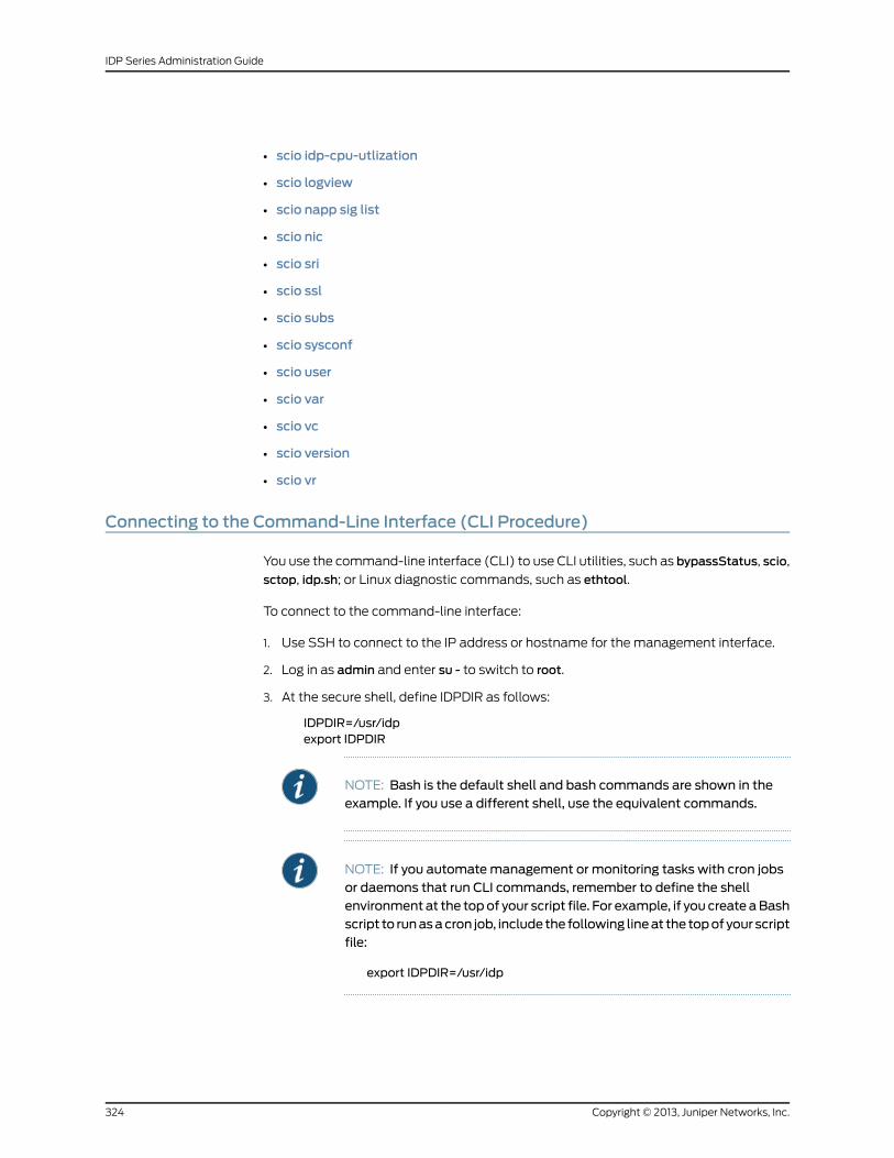
• scio idp-cpu-utlization
• scio logview
• scio napp sig list
• scio nic
• scio sri
• scio ssl
• scio subs
• scio sysconf
• scio user
• scio var
• scio vc
• scio version
• scio vr
Connecting to the Command-Line Interface (CLI Procedure)
You use the command-line interface (CLI) to use CLI utilities, such as bypassStatus, scio,
sctop, idp.sh; or Linux diagnostic commands, such as ethtool.
To connect to the command-line interface:
1. Use SSH to connect to the IP address or hostname for the management interface.
2. Log in as admin and enter su - to switch to root.
3. At the secure shell, define IDPDIR as follows:
IDPDIR=/usr/idpexport IDPDIR
NOTE: Bash is the default shell and bash commands are shown in theexample. If you use a different shell, use the equivalent commands.
NOTE: If you automatemanagement or monitoring tasks with cron jobsor daemons that run CLI commands, remember to define the shellenvironment at the topof your script file. For example, if you create aBashscript to runasacron job, include the following lineat the topof your scriptfile:
export IDPDIR=/usr/idp
Copyright © 2013, Juniper Networks, Inc.324
IDP Series Administration Guide
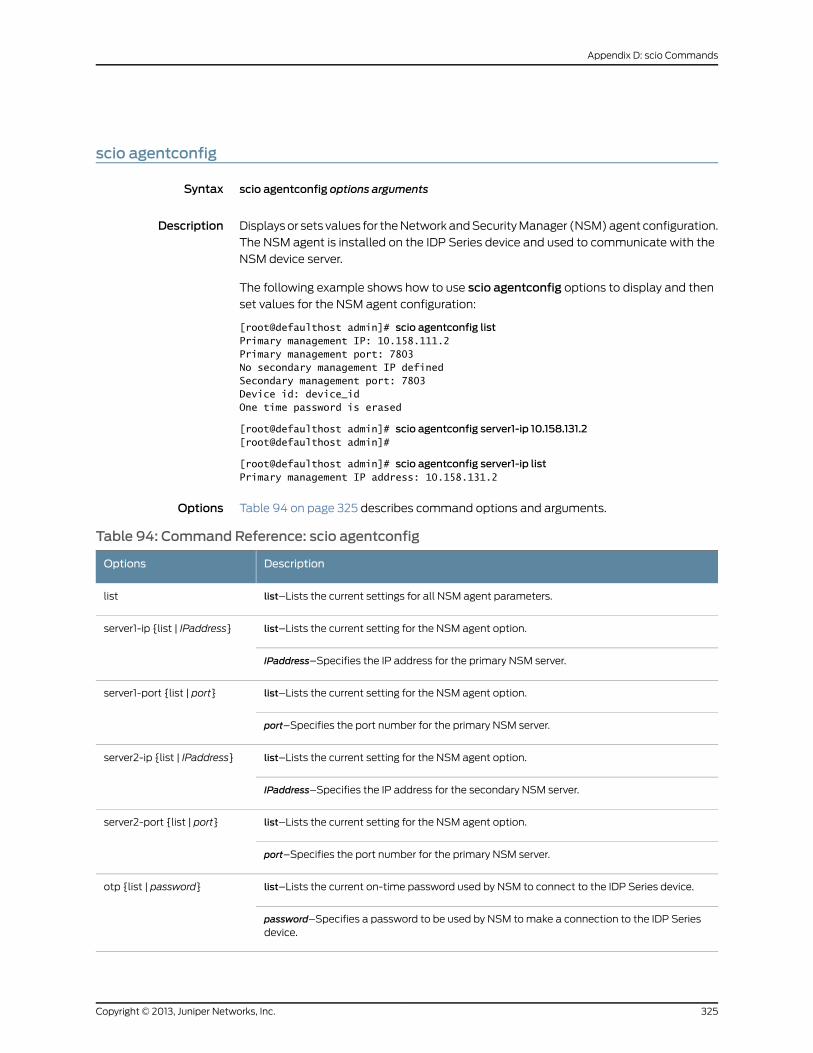
scio agentconfig
Syntax scio agentconfig options arguments
Description Displays or sets values for the Network and Security Manager (NSM) agent configuration.
The NSM agent is installed on the IDP Series device and used to communicate with the
NSM device server.
The following example shows how to use scio agentconfig options to display and then
set values for the NSM agent configuration:
[root@defaulthost admin]# scio agentconfig listPrimary management IP: 10.158.111.2Primary management port: 7803No secondary management IP definedSecondary management port: 7803Device id: device_idOne time password is erased
[root@defaulthost admin]# scio agentconfig server1-ip 10.158.131.2[root@defaulthost admin]#
[root@defaulthost admin]# scio agentconfig server1-ip listPrimary management IP address: 10.158.131.2
Options Table 94 on page 325 describes command options and arguments.
Table 94: Command Reference: scio agentconfig
DescriptionOptions
list–Lists the current settings for all NSM agent parameters.list
list–Lists the current setting for the NSM agent option.server1-ip {list | IPaddress}
IPaddress–Specifies the IP address for the primary NSM server.
list–Lists the current setting for the NSM agent option.server1-port {list | port}
port–Specifies the port number for the primary NSM server.
list–Lists the current setting for the NSM agent option.server2-ip {list | IPaddress}
IPaddress–Specifies the IP address for the secondary NSM server.
list–Lists the current setting for the NSM agent option.server2-port {list | port}
port–Specifies the port number for the primary NSM server.
list–Lists the current on-time password used by NSM to connect to the IDP Series device.otp {list | password}
password–Specifies a password to be used by NSM to make a connection to the IDP Seriesdevice.
325Copyright © 2013, Juniper Networks, Inc.
Appendix D: scio Commands
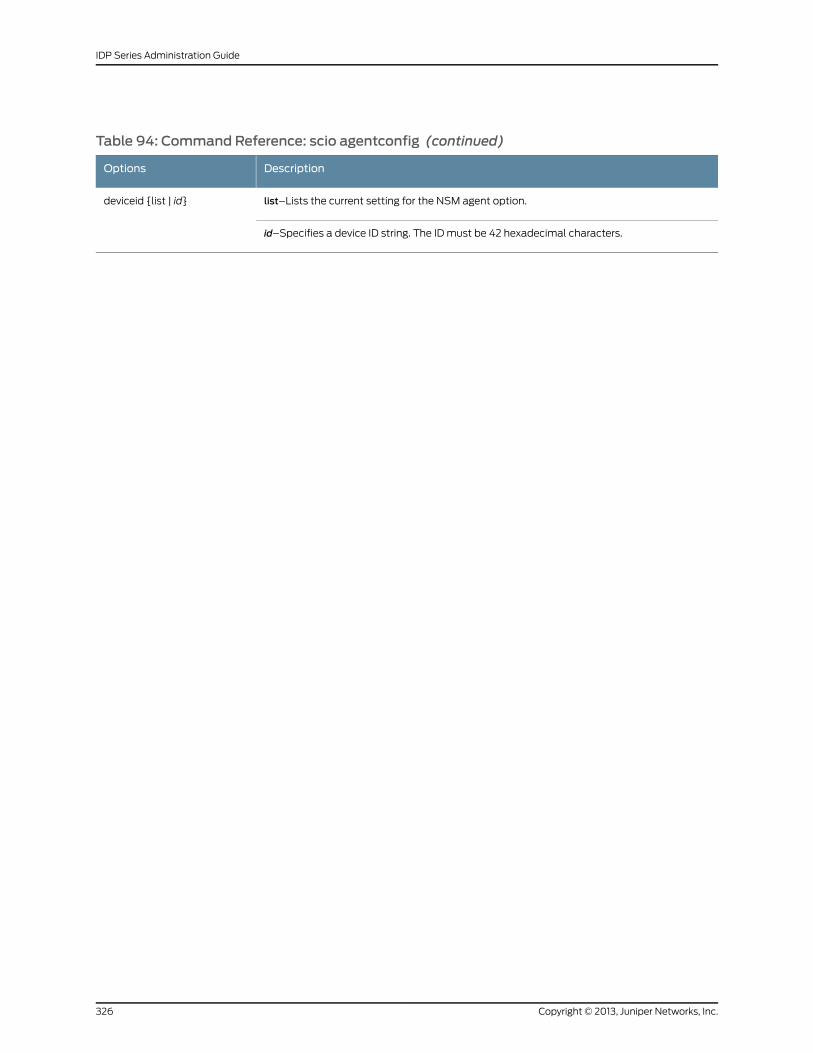
Table 94: Command Reference: scio agentconfig (continued)
DescriptionOptions
list–Lists the current setting for the NSM agent option.deviceid {list | id}
id–Specifies a device ID string. The ID must be 42 hexadecimal characters.
Copyright © 2013, Juniper Networks, Inc.326
IDP Series Administration Guide
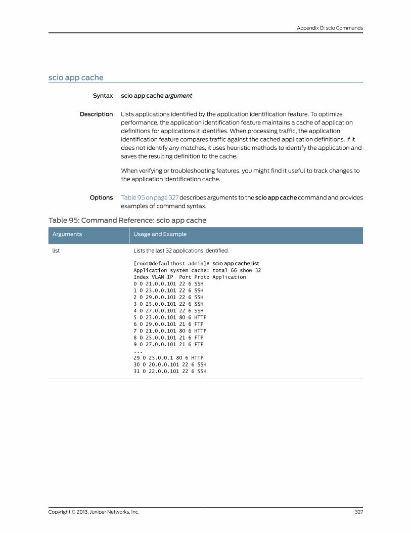
scio app cache
Syntax scio app cache argument
Description Lists applications identified by the application identification feature. To optimize
performance, the application identification feature maintains a cache of application
definitions for applications it identifies. When processing traffic, the application
identification feature compares traffic against the cached application definitions. If it
does not identify any matches, it uses heuristic methods to identify the application and
saves the resulting definition to the cache.
When verifying or troubleshooting features, you might find it useful to track changes to
the application identification cache.
Options Table 95 on page 327 describes arguments to thescioappcachecommand and provides
examples of command syntax.
Table 95: Command Reference: scio app cache
Usage and ExampleArguments
Lists the last 32 applications identified.
[root@defaulthost admin]# scio app cache listApplication system cache: total 66 show 32Index VLAN IP Port Proto Application0 0 21.0.0.101 22 6 SSH1 0 23.0.0.101 22 6 SSH2 0 29.0.0.101 22 6 SSH3 0 25.0.0.101 22 6 SSH4 0 27.0.0.101 22 6 SSH5 0 23.0.0.101 80 6 HTTP6 0 29.0.0.101 21 6 FTP7 0 21.0.0.101 80 6 HTTP8 0 25.0.0.101 21 6 FTP9 0 27.0.0.101 21 6 FTP...29 0 25.0.0.1 80 6 HTTP30 0 20.0.0.101 22 6 SSH31 0 22.0.0.101 22 6 SSH
list
327Copyright © 2013, Juniper Networks, Inc.
Appendix D: scio Commands
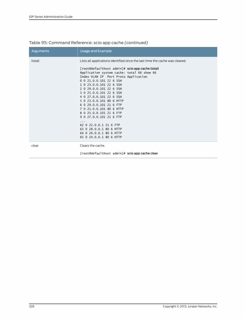
Table 95: Command Reference: scio app cache (continued)
Usage and ExampleArguments
Lists all applications identified since the last time the cache was cleared.
[root@defaulthost admin]# scio app cache listallApplication system cache: total 66 show 66Index VLAN IP Port Proto Application0 0 21.0.0.101 22 6 SSH1 0 23.0.0.101 22 6 SSH2 0 29.0.0.101 22 6 SSH3 0 25.0.0.101 22 6 SSH4 0 27.0.0.101 22 6 SSH5 0 23.0.0.101 80 6 HTTP6 0 29.0.0.101 21 6 FTP7 0 21.0.0.101 80 6 HTTP8 0 25.0.0.101 21 6 FTP9 0 27.0.0.101 21 6 FTP...62 0 22.0.0.1 21 6 FTP63 0 28.0.0.1 80 6 HTTP64 0 26.0.0.1 80 6 HTTP65 0 24.0.0.1 80 6 HTTP
listall
Clears the cache.
[root@defaulthost admin]# scio app cache clear
clear
Copyright © 2013, Juniper Networks, Inc.328
IDP Series Administration Guide
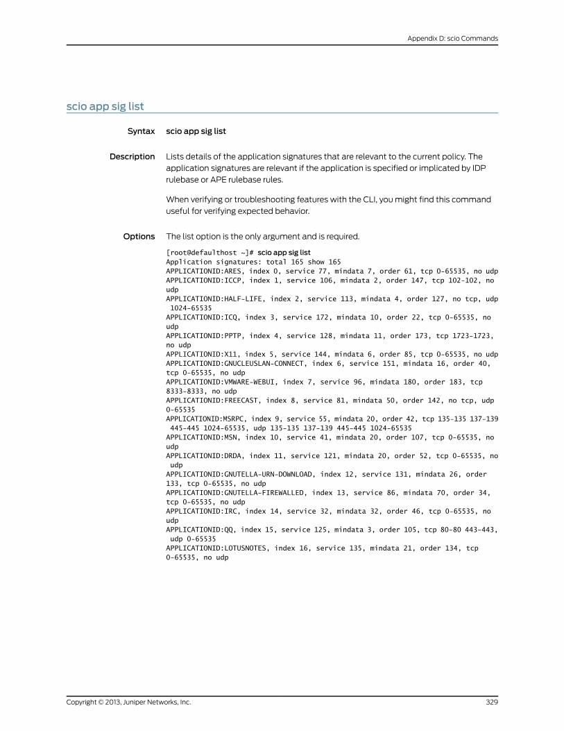
scio app sig list
Syntax scio app sig list
Description Lists details of the application signatures that are relevant to the current policy. The
application signatures are relevant if the application is specified or implicated by IDP
rulebase or APE rulebase rules.
When verifying or troubleshooting features with the CLI, you might find this command
useful for verifying expected behavior.
Options The list option is the only argument and is required.
[root@defaulthost ~]# scio app sig listApplication signatures: total 165 show 165APPLICATIONID:ARES, index 0, service 77, mindata 7, order 61, tcp 0-65535, no udpAPPLICATIONID:ICCP, index 1, service 106, mindata 2, order 147, tcp 102-102, no udpAPPLICATIONID:HALF-LIFE, index 2, service 113, mindata 4, order 127, no tcp, udp 1024-65535APPLICATIONID:ICQ, index 3, service 172, mindata 10, order 22, tcp 0-65535, no udpAPPLICATIONID:PPTP, index 4, service 128, mindata 11, order 173, tcp 1723-1723, no udpAPPLICATIONID:X11, index 5, service 144, mindata 6, order 85, tcp 0-65535, no udpAPPLICATIONID:GNUCLEUSLAN-CONNECT, index 6, service 151, mindata 16, order 40, tcp 0-65535, no udpAPPLICATIONID:VMWARE-WEBUI, index 7, service 96, mindata 180, order 183, tcp 8333-8333, no udpAPPLICATIONID:FREECAST, index 8, service 81, mindata 50, order 142, no tcp, udp 0-65535APPLICATIONID:MSRPC, index 9, service 55, mindata 20, order 42, tcp 135-135 137-139 445-445 1024-65535, udp 135-135 137-139 445-445 1024-65535APPLICATIONID:MSN, index 10, service 41, mindata 20, order 107, tcp 0-65535, no udpAPPLICATIONID:DRDA, index 11, service 121, mindata 20, order 52, tcp 0-65535, no udpAPPLICATIONID:GNUTELLA-URN-DOWNLOAD, index 12, service 131, mindata 26, order 133, tcp 0-65535, no udpAPPLICATIONID:GNUTELLA-FIREWALLED, index 13, service 86, mindata 70, order 34, tcp 0-65535, no udpAPPLICATIONID:IRC, index 14, service 32, mindata 32, order 46, tcp 0-65535, no udpAPPLICATIONID:QQ, index 15, service 125, mindata 3, order 105, tcp 80-80 443-443, udp 0-65535APPLICATIONID:LOTUSNOTES, index 16, service 135, mindata 21, order 134, tcp 0-65535, no udp
329Copyright © 2013, Juniper Networks, Inc.
Appendix D: scio Commands
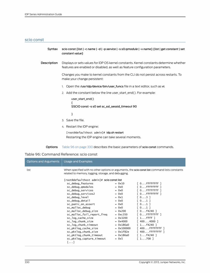
scio const
Syntax scio const {list | -c name | -d | -p service | -s s0:qmodule | -v name} {list | get constant | set
constant value}
Description Displays or sets values for IDP OS kernel constants. Kernel constants determine whether
features are enabled or disabled, as well as feature configuration parameters.
Changes you make to kernel constants from the CLI do not persist across restarts. To
make your change persistent:
1. Open the /usr/idp/device/bin/user_funcs file in a text editor, such as vi.
2. Add the constant below the line user_start_end(). For example:
user_start_end(){$SCIO const -s s0 set sc_ssl_sessid_timeout 90
}
3. Save the file.
4. Restart the IDP engine:
[root@defaulthost admin]# idp.sh restart
Restarting the IDP engine can take several moments.
Options Table 96 on page 330 describes the basic parameters of scio const commands.
Table 96: Command Reference: scio const
Usage and ExamplesOptions and Arguments
When specified with no other options or arguments, the scio const list command lists constantsrelated to memory, logging, storage, and debugging.
[root@defaulthost admin]# scio const list sc_debug_features = 0x10 [ 0...ffffffff ] sc_debug_qmodules = 0x0 [ 0...ffffffff ] sc_debug_services = 0x0 [ 0...ffffffff ] sc_debug_services2 = 0x0 [ 0...ffffffff ] sc_debug_level = 0x1 [ 0...3 ] sc_debug_detail = 0x0 [ 0...1 ] sc_panic_on_assert = 0x0 [ 0...1 ] sc_malloc_debug = 0x0 [ 0...1 ] sc_malloc_debug_size = 0x200 [ 0...f4240 ] sc_malloc_fail_report_freq = 0xc350 [ 0...ffffffff ] sc_log_cache_size = 0x3200 [ 1...ffff ] sc_log_chunk_size = 0x4000 [ 400...4000 ] sc_log_chunk_timeout = 0x186a0 [ 1...f4240 ] sc_pktlog_cache_size = 0x100000 [ 400...ffffffff ] sc_pktlog_chunk_size = 0x1f82e [ 400...ffffffff ] sc_pktlog_chunk_timeout = 0x186a0 [ 1...f4240 ] sc_pktlog_capture_timeout = 0x5 [ 1...708 ] [...]
list
Copyright © 2013, Juniper Networks, Inc.330
IDP Series Administration Guide
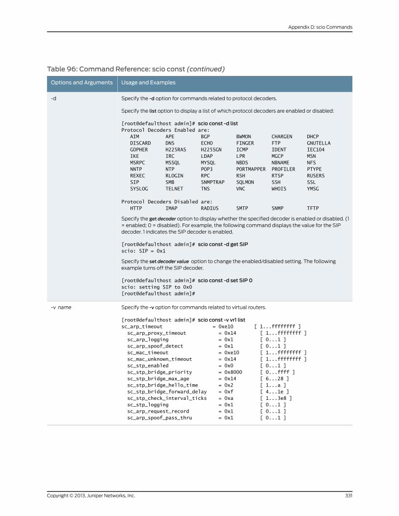
Table 96: Command Reference: scio const (continued)
Usage and ExamplesOptions and Arguments
Specify the -d option for commands related to protocol decoders.
Specify the list option to display a list of which protocol decoders are enabled or disabled:
[root@defaulthost admin]# scio const -d listProtocol Decoders Enabled are: AIM APE BGP BWMON CHARGEN DHCP DISCARD DNS ECHO FINGER FTP GNUTELLA GOPHER H225RAS H225SGN ICMP IDENT IEC104 IKE IRC LDAP LPR MGCP MSN MSRPC MSSQL MYSQL NBDS NBNAME NFS NNTP NTP POP3 PORTMAPPER PROFILER PTYPE REXEC RLOGIN RPC RSH RTSP RUSERS SIP SMB SNMPTRAP SQLMON SSH SSL SYSLOG TELNET TNS VNC WHOIS YMSG
Protocol Decoders Disabled are: HTTP IMAP RADIUS SMTP SNMP TFTP
Specify the get decoder option to display whether the specified decoder is enabled or disabled. (1= enabled; 0 = disabled). For example, the following command displays the value for the SIPdecoder. 1 indicates the SIP decoder is enabled.
[root@defaulthost admin]# scio const -d get SIPscio: SIP = 0x1
Specify the set decoder value option to change the enabled/disabled setting. The followingexample turns off the SIP decoder.
[root@defaulthost admin]# scio const -d set SIP 0scio: setting SIP to 0x0[root@defaulthost admin]#
-d
Specify the -v option for commands related to virtual routers.
[root@defaulthost admin]# scio const -v vr1 listsc_arp_timeout = 0xe10 [ 1...ffffffff ] sc_arp_proxy_timeout = 0x14 [ 1...ffffffff ] sc_arp_logging = 0x1 [ 0...1 ] sc_arp_spoof_detect = 0x1 [ 0...1 ] sc_mac_timeout = 0xe10 [ 1...ffffffff ] sc_mac_unknown_timeout = 0x14 [ 1...ffffffff ] sc_stp_enabled = 0x0 [ 0...1 ] sc_stp_bridge_priority = 0x8000 [ 0...ffff ] sc_stp_bridge_max_age = 0x14 [ 6...28 ] sc_stp_bridge_hello_time = 0x2 [ 1...a ] sc_stp_bridge_forward_delay = 0xf [ 4...1e ] sc_stp_check_interval_ticks = 0xa [ 1...3e8 ] sc_stp_logging = 0x1 [ 0...1 ] sc_arp_request_record = 0x1 [ 0...1 ] sc_arp_spoof_pass_thru = 0x1 [ 0...1 ]
-v name
331Copyright © 2013, Juniper Networks, Inc.
Appendix D: scio Commands
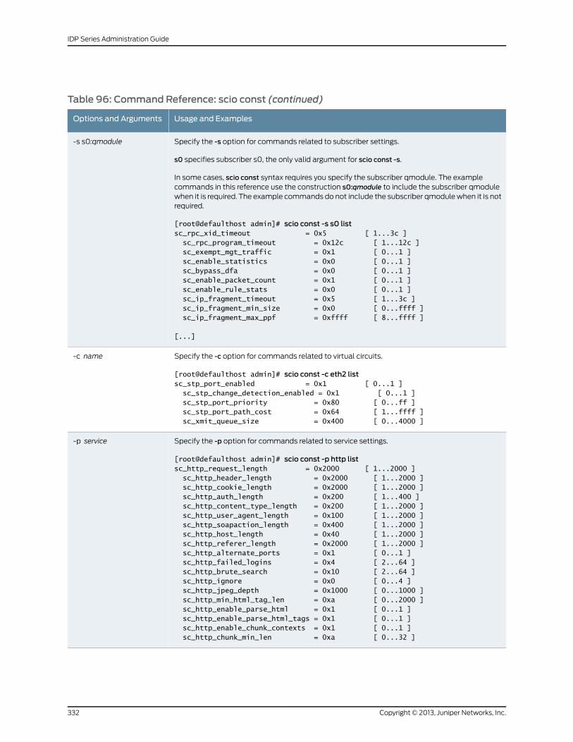
Table 96: Command Reference: scio const (continued)
Usage and ExamplesOptions and Arguments
Specify the -s option for commands related to subscriber settings.
s0 specifies subscriber s0, the only valid argument for scio const -s.
In some cases, scio const syntax requires you specify the subscriber qmodule. The examplecommands in this reference use the construction s0:qmodule to include the subscriber qmodulewhen it is required. The example commands do not include the subscriber qmodule when it is notrequired.
[root@defaulthost admin]# scio const -s s0 listsc_rpc_xid_timeout = 0x5 [ 1...3c ] sc_rpc_program_timeout = 0x12c [ 1...12c ] sc_exempt_mgt_traffic = 0x1 [ 0...1 ] sc_enable_statistics = 0x0 [ 0...1 ] sc_bypass_dfa = 0x0 [ 0...1 ] sc_enable_packet_count = 0x1 [ 0...1 ] sc_enable_rule_stats = 0x0 [ 0...1 ] sc_ip_fragment_timeout = 0x5 [ 1...3c ] sc_ip_fragment_min_size = 0x0 [ 0...ffff ] sc_ip_fragment_max_ppf = 0xffff [ 8...ffff ]
[...]
-s s0:qmodule
Specify the -c option for commands related to virtual circuits.
[root@defaulthost admin]# scio const -c eth2 listsc_stp_port_enabled = 0x1 [ 0...1 ] sc_stp_change_detection_enabled = 0x1 [ 0...1 ] sc_stp_port_priority = 0x80 [ 0...ff ] sc_stp_port_path_cost = 0x64 [ 1...ffff ] sc_xmit_queue_size = 0x400 [ 0...4000 ]
-c name
Specify the -p option for commands related to service settings.
[root@defaulthost admin]# scio const -p http listsc_http_request_length = 0x2000 [ 1...2000 ] sc_http_header_length = 0x2000 [ 1...2000 ] sc_http_cookie_length = 0x2000 [ 1...2000 ] sc_http_auth_length = 0x200 [ 1...400 ] sc_http_content_type_length = 0x200 [ 1...2000 ] sc_http_user_agent_length = 0x100 [ 1...2000 ] sc_http_soapaction_length = 0x400 [ 1...2000 ] sc_http_host_length = 0x40 [ 1...2000 ] sc_http_referer_length = 0x2000 [ 1...2000 ] sc_http_alternate_ports = 0x1 [ 0...1 ] sc_http_failed_logins = 0x4 [ 2...64 ] sc_http_brute_search = 0x10 [ 2...64 ] sc_http_ignore = 0x0 [ 0...4 ] sc_http_jpeg_depth = 0x1000 [ 0...1000 ] sc_http_min_html_tag_len = 0xa [ 0...2000 ] sc_http_enable_parse_html = 0x1 [ 0...1 ] sc_http_enable_parse_html_tags = 0x1 [ 0...1 ] sc_http_enable_chunk_contexts = 0x1 [ 0...1 ] sc_http_chunk_min_len = 0xa [ 0...32 ]
-p service
Copyright © 2013, Juniper Networks, Inc.332
IDP Series Administration Guide
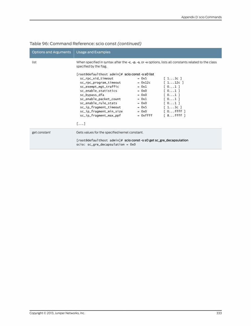
Table 96: Command Reference: scio const (continued)
Usage and ExamplesOptions and Arguments
When specified in syntax after the -c, -p, -s, or -v options, lists all constants related to the classspecified by the flag.
[root@defaulthost admin]# scio const -s s0 list sc_rpc_xid_timeout = 0x5 [ 1...3c ] sc_rpc_program_timeout = 0x12c [ 1...12c ] sc_exempt_mgt_traffic = 0x1 [ 0...1 ] sc_enable_statistics = 0x0 [ 0...1 ] sc_bypass_dfa = 0x0 [ 0...1 ] sc_enable_packet_count = 0x1 [ 0...1 ] sc_enable_rule_stats = 0x0 [ 0...1 ] sc_ip_fragment_timeout = 0x5 [ 1...3c ] sc_ip_fragment_min_size = 0x0 [ 0...ffff ] sc_ip_fragment_max_ppf = 0xffff [ 8...ffff ]
[...]
list
Gets values for the specified kernel constant.
[root@defaulthost admin]# scio const -s s0 get sc_gre_decapsulationscio: sc_gre_decapsulation = 0x0
get constant
333Copyright © 2013, Juniper Networks, Inc.
Appendix D: scio Commands
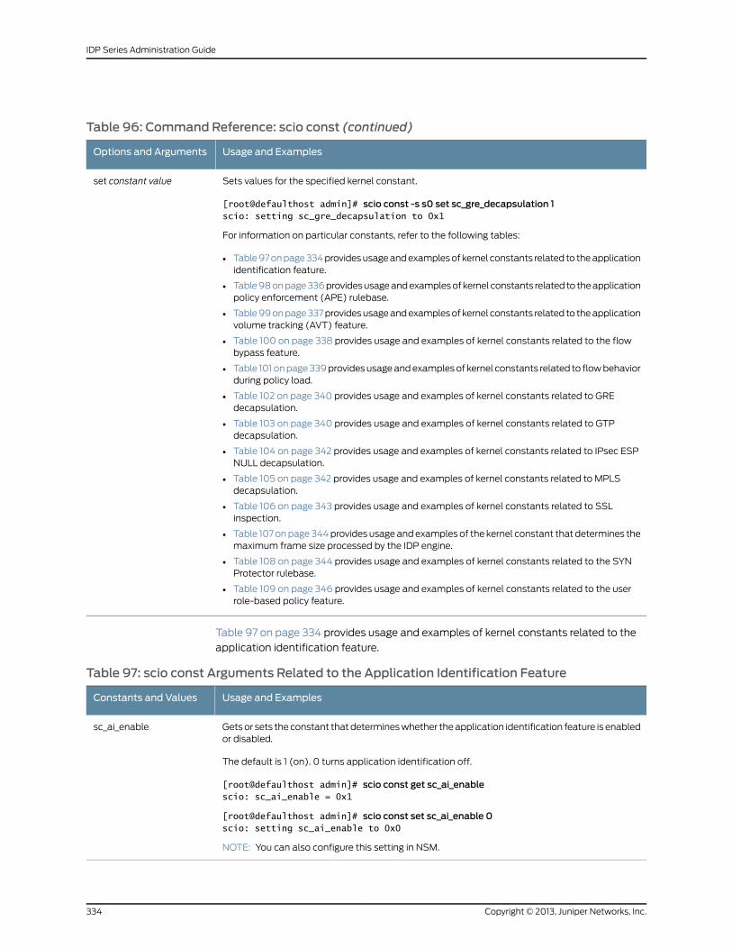
Table 96: Command Reference: scio const (continued)
Usage and ExamplesOptions and Arguments
Sets values for the specified kernel constant.
[root@defaulthost admin]# scio const -s s0 set sc_gre_decapsulation 1scio: setting sc_gre_decapsulation to 0x1
For information on particular constants, refer to the following tables:
• Table 97 on page 334 provides usage and examples of kernel constants related to the applicationidentification feature.
• Table 98 on page 336 provides usage and examples of kernel constants related to the applicationpolicy enforcement (APE) rulebase.
• Table 99 on page 337 provides usage and examples of kernel constants related to the applicationvolume tracking (AVT) feature.
• Table 100 on page 338 provides usage and examples of kernel constants related to the flowbypass feature.
• Table 101 on page 339 provides usage and examples of kernel constants related to flow behaviorduring policy load.
• Table 102 on page 340 provides usage and examples of kernel constants related to GREdecapsulation.
• Table 103 on page 340 provides usage and examples of kernel constants related to GTPdecapsulation.
• Table 104 on page 342 provides usage and examples of kernel constants related to IPsec ESPNULL decapsulation.
• Table 105 on page 342 provides usage and examples of kernel constants related to MPLSdecapsulation.
• Table 106 on page 343 provides usage and examples of kernel constants related to SSLinspection.
• Table 107 on page 344 provides usage and examples of the kernel constant that determines themaximum frame size processed by the IDP engine.
• Table 108 on page 344 provides usage and examples of kernel constants related to the SYNProtector rulebase.
• Table 109 on page 346 provides usage and examples of kernel constants related to the userrole-based policy feature.
set constant value
Table 97 on page 334 provides usage and examples of kernel constants related to the
application identification feature.
Table 97: scio const Arguments Related to the Application Identification Feature
Usage and ExamplesConstants and Values
Gets or sets the constant that determines whether the application identification feature is enabledor disabled.
The default is 1 (on). 0 turns application identification off.
[root@defaulthost admin]# scio const get sc_ai_enablescio: sc_ai_enable = 0x1
[root@defaulthost admin]# scio const set sc_ai_enable 0scio: setting sc_ai_enable to 0x0
NOTE: You can also configure this setting in NSM.
sc_ai_enable
Copyright © 2013, Juniper Networks, Inc.334
IDP Series Administration Guide
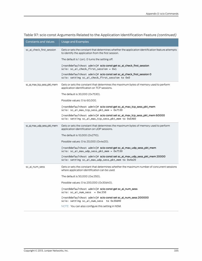
Table 97: scio const Arguments Related to the Application Identification Feature (continued)
Usage and ExamplesConstants and Values
Gets or sets the constant that determines whether the application identification feature attemptsto identify the application from the first session.
The default is 1 (on). 0 turns the setting off.
[root@defaulthost admin]# scio const get sc_ai_check_first_sessionscio: sc_ai_check_first_session = 0x1
[root@defaulthost admin]# scio const set sc_ai_check_first_session 0scio: setting sc_ai_check_first_session to 0x0
sc_ai_check_first_session
Gets or sets the constant that determines the maximum bytes of memory used to performapplication identification on TCP sessions.
The default is 30,000 (0x7530).
Possible values: 0 to 60,000.
[root@defaulthost admin]# scio const get sc_ai_max_tcp_sess_pkt_memscio: sc_ai_max_tcp_sess_pkt_mem = 0x7530
[root@defaulthost admin]# scio const set sc_ai_max_tcp_sess_pkt_mem60000scio: setting sc_ai_max_tcp_sess_pkt_mem to 0xEA60
sc_ai_max_tcp_sess_pkt_mem
Gets or sets the constant that determines the maximum bytes of memory used to performapplication identification on UDP sessions.
The default is 10,000 (0x2710).
Possible values: 0 to 20,000 (0x4e20).
[root@defaulthost admin]# scio const get sc_ai_max_udp_sess_pkt_memscio: sc_ai_max_udp_sess_pkt_mem = 0x7530
[root@defaulthost admin]# scio const set sc_ai_max_udp_sess_pkt_mem 20000scio: setting sc_ai_max_udp_sess_pkt_mem to 0x4e20
sc_ai_max_udp_sess_pkt_mem
Gets or sets the constant that determines whether the maximum number of concurrent sessionswhere application identification can be used.
The default is 50,000 (0xc350).
Possible values: 0 to 200,000 (0x30d40).
[root@defaulthost admin]# scio const get sc_ai_num_sessscio: sc_ai_num_sess = 0xc350
[root@defaulthost admin]# scio const set sc_ai_num_sess 200000scio: setting sc_ai_num_sess to 0x30d40
NOTE: You can also configure this setting in NSM.
sc_ai_num_sess
335Copyright © 2013, Juniper Networks, Inc.
Appendix D: scio Commands
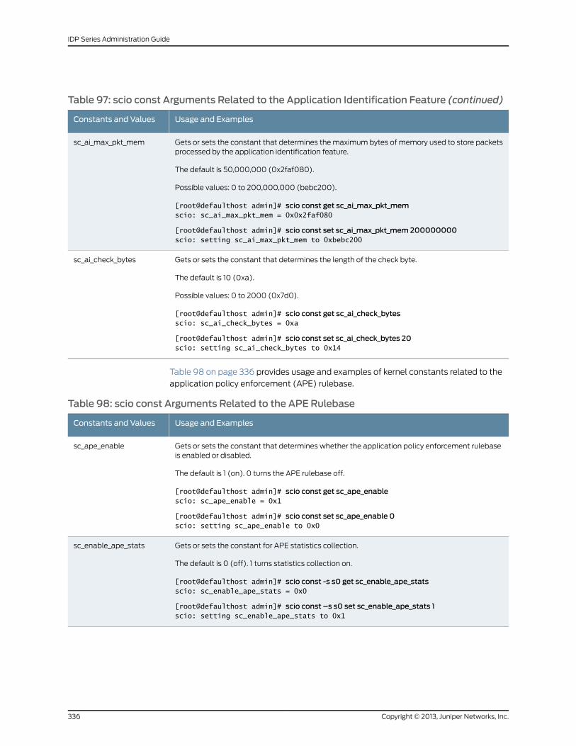
Table 97: scio const Arguments Related to the Application Identification Feature (continued)
Usage and ExamplesConstants and Values
Gets or sets the constant that determines the maximum bytes of memory used to store packetsprocessed by the application identification feature.
The default is 50,000,000 (0x2faf080).
Possible values: 0 to 200,000,000 (bebc200).
[root@defaulthost admin]# scio const get sc_ai_max_pkt_memscio: sc_ai_max_pkt_mem = 0x0x2faf080
[root@defaulthost admin]# scio const set sc_ai_max_pkt_mem 200000000scio: setting sc_ai_max_pkt_mem to 0xbebc200
sc_ai_max_pkt_mem
Gets or sets the constant that determines the length of the check byte.
The default is 10 (0xa).
Possible values: 0 to 2000 (0x7d0).
[root@defaulthost admin]# scio const get sc_ai_check_bytesscio: sc_ai_check_bytes = 0xa
[root@defaulthost admin]# scio const set sc_ai_check_bytes 20scio: setting sc_ai_check_bytes to 0x14
sc_ai_check_bytes
Table 98 on page 336 provides usage and examples of kernel constants related to the
application policy enforcement (APE) rulebase.
Table 98: scio const Arguments Related to the APE Rulebase
Usage and ExamplesConstants and Values
Gets or sets the constant that determines whether the application policy enforcement rulebaseis enabled or disabled.
The default is 1 (on). 0 turns the APE rulebase off.
[root@defaulthost admin]# scio const get sc_ape_enablescio: sc_ape_enable = 0x1
[root@defaulthost admin]# scio const set sc_ape_enable 0scio: setting sc_ape_enable to 0x0
sc_ape_enable
Gets or sets the constant for APE statistics collection.
The default is 0 (off). 1 turns statistics collection on.
[root@defaulthost admin]# scio const -s s0 get sc_enable_ape_statsscio: sc_enable_ape_stats = 0x0
[root@defaulthost admin]# scio const –s s0 set sc_enable_ape_stats 1scio: setting sc_enable_ape_stats to 0x1
sc_enable_ape_stats
Copyright © 2013, Juniper Networks, Inc.336
IDP Series Administration Guide
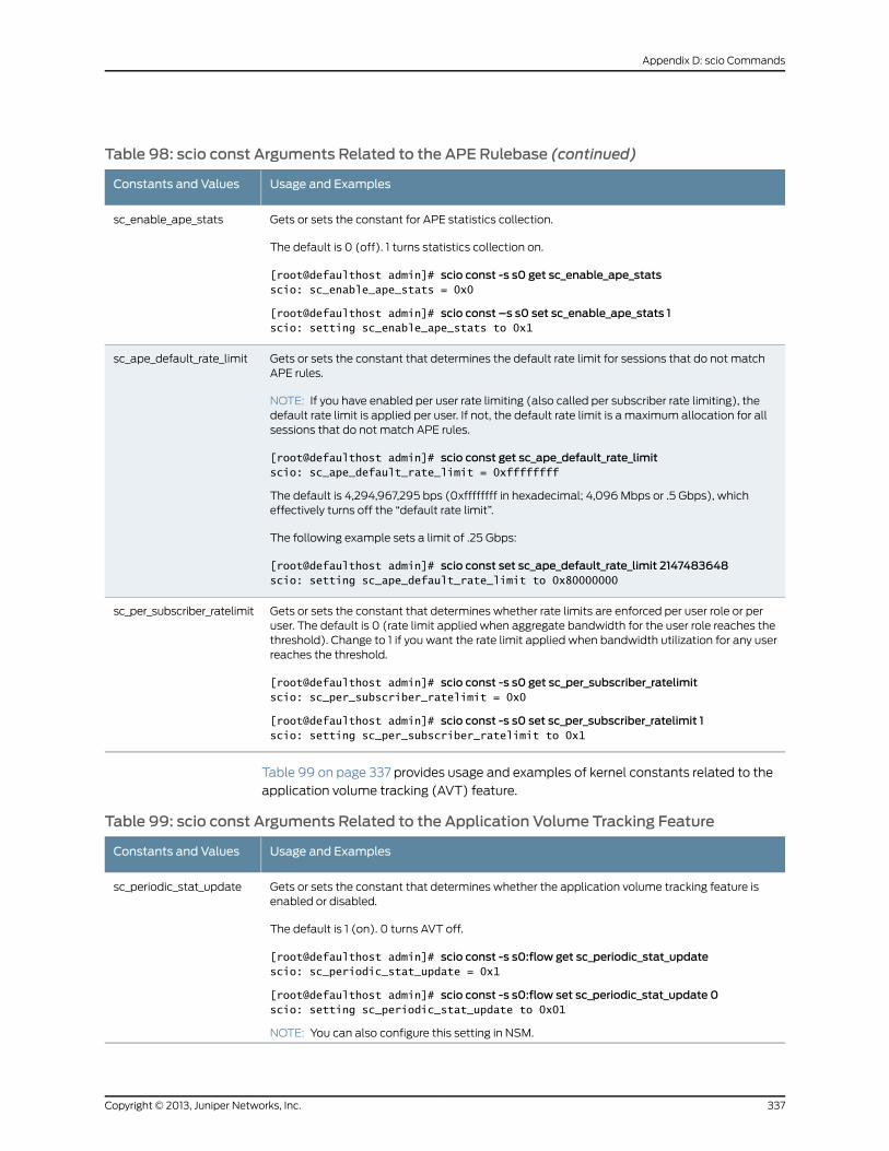
Table 98: scio const Arguments Related to the APE Rulebase (continued)
Usage and ExamplesConstants and Values
Gets or sets the constant for APE statistics collection.
The default is 0 (off). 1 turns statistics collection on.
[root@defaulthost admin]# scio const -s s0 get sc_enable_ape_statsscio: sc_enable_ape_stats = 0x0
[root@defaulthost admin]# scio const –s s0 set sc_enable_ape_stats 1scio: setting sc_enable_ape_stats to 0x1
sc_enable_ape_stats
Gets or sets the constant that determines the default rate limit for sessions that do not matchAPE rules.
NOTE: If you have enabled per user rate limiting (also called per subscriber rate limiting), thedefault rate limit is applied per user. If not, the default rate limit is a maximum allocation for allsessions that do not match APE rules.
[root@defaulthost admin]# scio const get sc_ape_default_rate_limitscio: sc_ape_default_rate_limit = 0xffffffff
The default is 4,294,967,295 bps (0xffffffff in hexadecimal; 4,096 Mbps or .5 Gbps), whicheffectively turns off the “default rate limit”.
The following example sets a limit of .25 Gbps:
[root@defaulthost admin]# scio const set sc_ape_default_rate_limit 2147483648scio: setting sc_ape_default_rate_limit to 0x80000000
sc_ape_default_rate_limit
Gets or sets the constant that determines whether rate limits are enforced per user role or peruser. The default is 0 (rate limit applied when aggregate bandwidth for the user role reaches thethreshold). Change to 1 if you want the rate limit applied when bandwidth utilization for any userreaches the threshold.
[root@defaulthost admin]# scio const -s s0 get sc_per_subscriber_ratelimitscio: sc_per_subscriber_ratelimit = 0x0
[root@defaulthost admin]# scio const -s s0 set sc_per_subscriber_ratelimit 1scio: setting sc_per_subscriber_ratelimit to 0x1
sc_per_subscriber_ratelimit
Table 99 on page 337 provides usage and examples of kernel constants related to the
application volume tracking (AVT) feature.
Table 99: scio const Arguments Related to the Application Volume Tracking Feature
Usage and ExamplesConstants and Values
Gets or sets the constant that determines whether the application volume tracking feature isenabled or disabled.
The default is 1 (on). 0 turns AVT off.
[root@defaulthost admin]# scio const -s s0:flow get sc_periodic_stat_updatescio: sc_periodic_stat_update = 0x1
[root@defaulthost admin]# scio const -s s0:flow set sc_periodic_stat_update 0scio: setting sc_periodic_stat_update to 0x01
NOTE: You can also configure this setting in NSM.
sc_periodic_stat_update
337Copyright © 2013, Juniper Networks, Inc.
Appendix D: scio Commands
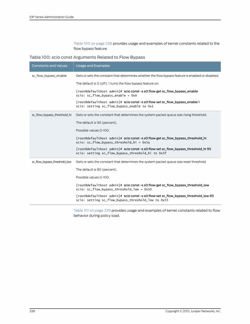
Table 100 on page 338 provides usage and examples of kernel constants related to the
flow bypass feature.
Table 100: scio const Arguments Related to Flow Bypass
Usage and ExamplesConstants and Values
Gets or sets the constant that determines whether the flow bypass feature is enabled or disabled.
The default is 0 (off). 1 turns the flow bypass feature on.
[root@defaulthost admin]# scio const -s s0:flow get sc_flow_bypass_enablescio: sc_flow_bypass_enable = 0x0
[root@defaulthost admin]# scio const -s s0:flow set sc_flow_bypass_enable 1scio: setting sc_flow_bypass_enable to 0x1
sc_flow_bypass_enable
Gets or sets the constant that determines the system packet queue size rising threshold.
The default is 90 (percent).
Possible values 0-100.
[root@defaulthost admin]# scio const -s s0:flow get sc_flow_bypass_threshold_hiscio: sc_flow_bypass_threshold_hi = 0x5a
[root@defaulthost admin]# scio const -s s0:flow set sc_flow_bypass_threshold_hi 95scio: setting sc_flow_bypass_threshold_hi to 0x5f
sc_flow_bypass_threshold_hi
Gets or sets the constant that determines the system packet queue size reset threshold.
The default is 80 (percent).
Possible values 0-100.
[root@defaulthost admin]# scio const -s s0:flow get sc_flow_bypass_threshold_lowscio: sc_flow_bypass_threshold_low = 0x50
[root@defaulthost admin]# scio const -s s0:flow set sc_flow_bypass_threshold_low 85scio: setting sc_flow_bypass_threshold_low to 0x55
sc_flow_bypass_threshold_low
Table 101 on page 339 provides usage and examples of kernel constants related to flow
behavior during policy load.
Copyright © 2013, Juniper Networks, Inc.338
IDP Series Administration Guide
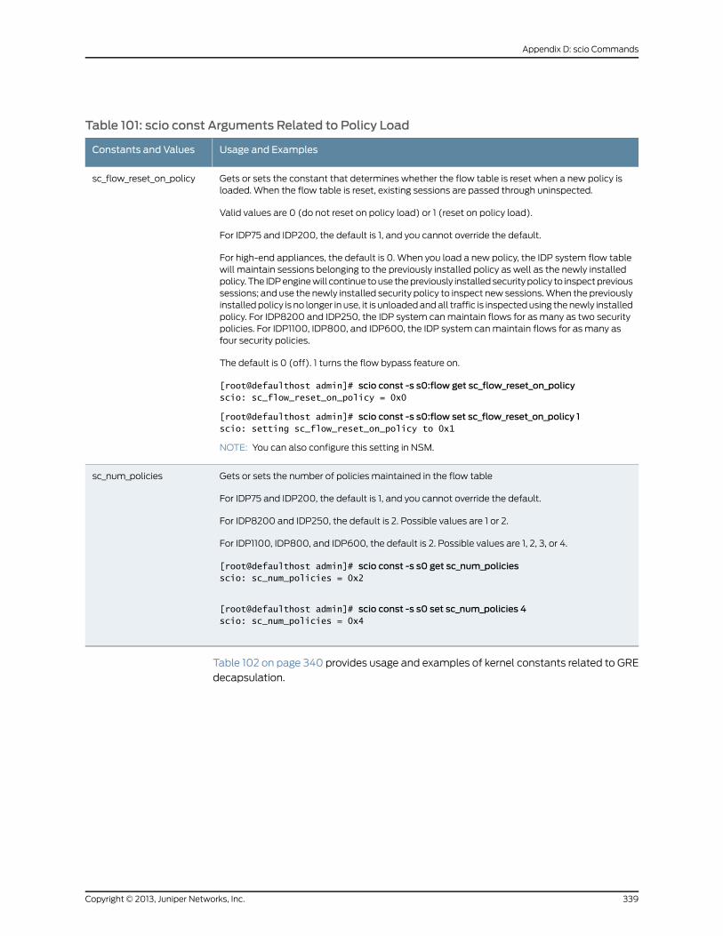
Table 101: scio const Arguments Related to Policy Load
Usage and ExamplesConstants and Values
Gets or sets the constant that determines whether the flow table is reset when a new policy isloaded. When the flow table is reset, existing sessions are passed through uninspected.
Valid values are 0 (do not reset on policy load) or 1 (reset on policy load).
For IDP75 and IDP200, the default is 1, and you cannot override the default.
For high-end appliances, the default is 0. When you load a new policy, the IDP system flow tablewill maintain sessions belonging to the previously installed policy as well as the newly installedpolicy. The IDP engine will continue to use the previously installed security policy to inspect previoussessions; and use the newly installed security policy to inspect new sessions. When the previouslyinstalled policy is no longer in use, it is unloaded and all traffic is inspected using the newly installedpolicy. For IDP8200 and IDP250, the IDP system can maintain flows for as many as two securitypolicies. For IDP1100, IDP800, and IDP600, the IDP system can maintain flows for as many asfour security policies.
The default is 0 (off). 1 turns the flow bypass feature on.
[root@defaulthost admin]# scio const -s s0:flow get sc_flow_reset_on_policyscio: sc_flow_reset_on_policy = 0x0
[root@defaulthost admin]# scio const -s s0:flow set sc_flow_reset_on_policy 1scio: setting sc_flow_reset_on_policy to 0x1
NOTE: You can also configure this setting in NSM.
sc_flow_reset_on_policy
Gets or sets the number of policies maintained in the flow table
For IDP75 and IDP200, the default is 1, and you cannot override the default.
For IDP8200 and IDP250, the default is 2. Possible values are 1 or 2.
For IDP1100, IDP800, and IDP600, the default is 2. Possible values are 1, 2, 3, or 4.
[root@defaulthost admin]# scio const -s s0 get sc_num_policiesscio: sc_num_policies = 0x2
[root@defaulthost admin]# scio const -s s0 set sc_num_policies 4scio: sc_num_policies = 0x4
sc_num_policies
Table 102 on page 340 provides usage and examples of kernel constants related to GRE
decapsulation.
339Copyright © 2013, Juniper Networks, Inc.
Appendix D: scio Commands
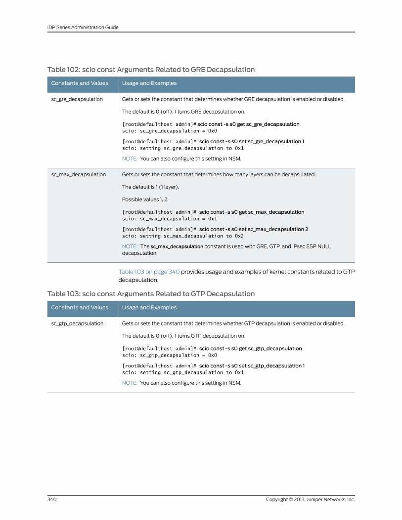
Table 102: scio const Arguments Related to GRE Decapsulation
Usage and ExamplesConstants and Values
Gets or sets the constant that determines whether GRE decapsulation is enabled or disabled.
The default is 0 (off). 1 turns GRE decapsulation on.
[root@defaulthost admin]# scio const -s s0 get sc_gre_decapsulationscio: sc_gre_decapsulation = 0x0
[root@defaulthost admin]# scio const -s s0 set sc_gre_decapsulation 1scio: setting sc_gre_decapsulation to 0x1
NOTE: You can also configure this setting in NSM.
sc_gre_decapsulation
Gets or sets the constant that determines how many layers can be decapsulated.
The default is 1 (1 layer).
Possible values 1, 2.
[root@defaulthost admin]# scio const -s s0 get sc_max_decapsulationscio: sc_max_decapsulation = 0x1
[root@defaulthost admin]# scio const -s s0 set sc_max_decapsulation 2scio: setting sc_max_decapsulation to 0x2
NOTE: The sc_max_decapsulation constant is used with GRE, GTP, and IPsec ESP NULLdecapsulation.
sc_max_decapsulation
Table 103 on page 340 provides usage and examples of kernel constants related to GTP
decapsulation.
Table 103: scio const Arguments Related to GTP Decapsulation
Usage and ExamplesConstants and Values
Gets or sets the constant that determines whether GTP decapsulation is enabled or disabled.
The default is 0 (off). 1 turns GTP decapsulation on.
[root@defaulthost admin]# scio const -s s0 get sc_gtp_decapsulationscio: sc_gtp_decapsulation = 0x0
[root@defaulthost admin]# scio const -s s0 set sc_gtp_decapsulation 1scio: setting sc_gtp_decapsulation to 0x1
NOTE: You can also configure this setting in NSM.
sc_gtp_decapsulation
Copyright © 2013, Juniper Networks, Inc.340
IDP Series Administration Guide
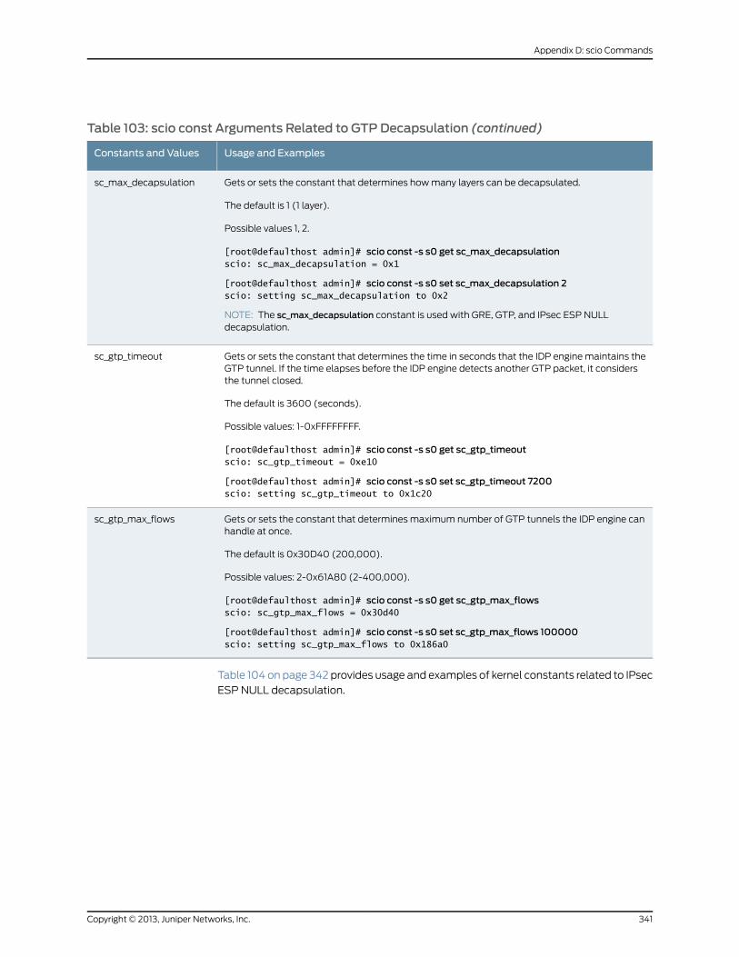
Table 103: scio const Arguments Related to GTP Decapsulation (continued)
Usage and ExamplesConstants and Values
Gets or sets the constant that determines how many layers can be decapsulated.
The default is 1 (1 layer).
Possible values 1, 2.
[root@defaulthost admin]# scio const -s s0 get sc_max_decapsulationscio: sc_max_decapsulation = 0x1
[root@defaulthost admin]# scio const -s s0 set sc_max_decapsulation 2scio: setting sc_max_decapsulation to 0x2
NOTE: The sc_max_decapsulation constant is used with GRE, GTP, and IPsec ESP NULLdecapsulation.
sc_max_decapsulation
Gets or sets the constant that determines the time in seconds that the IDP engine maintains theGTP tunnel. If the time elapses before the IDP engine detects another GTP packet, it considersthe tunnel closed.
The default is 3600 (seconds).
Possible values: 1-0xFFFFFFFF.
[root@defaulthost admin]# scio const -s s0 get sc_gtp_timeoutscio: sc_gtp_timeout = 0xe10
[root@defaulthost admin]# scio const -s s0 set sc_gtp_timeout 7200scio: setting sc_gtp_timeout to 0x1c20
sc_gtp_timeout
Gets or sets the constant that determines maximum number of GTP tunnels the IDP engine canhandle at once.
The default is 0x30D40 (200,000).
Possible values: 2-0x61A80 (2-400,000).
[root@defaulthost admin]# scio const -s s0 get sc_gtp_max_flowsscio: sc_gtp_max_flows = 0x30d40
[root@defaulthost admin]# scio const -s s0 set sc_gtp_max_flows 100000scio: setting sc_gtp_max_flows to 0x186a0
sc_gtp_max_flows
Table 104 on page 342 provides usage and examples of kernel constants related to IPsec
ESP NULL decapsulation.
341Copyright © 2013, Juniper Networks, Inc.
Appendix D: scio Commands
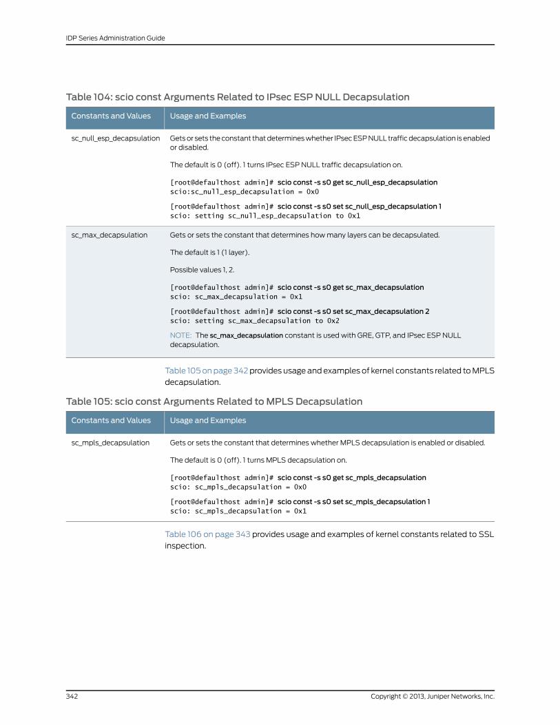
Table 104: scio const Arguments Related to IPsec ESPNULL Decapsulation
Usage and ExamplesConstants and Values
Gets or sets the constant that determines whether IPsec ESP NULL traffic decapsulation is enabledor disabled.
The default is 0 (off). 1 turns IPsec ESP NULL traffic decapsulation on.
[root@defaulthost admin]# scio const -s s0 get sc_null_esp_decapsulationscio:sc_null_esp_decapsulation = 0x0
[root@defaulthost admin]# scio const -s s0 set sc_null_esp_decapsulation 1scio: setting sc_null_esp_decapsulation to 0x1
sc_null_esp_decapsulation
Gets or sets the constant that determines how many layers can be decapsulated.
The default is 1 (1 layer).
Possible values 1, 2.
[root@defaulthost admin]# scio const -s s0 get sc_max_decapsulationscio: sc_max_decapsulation = 0x1
[root@defaulthost admin]# scio const -s s0 set sc_max_decapsulation 2scio: setting sc_max_decapsulation to 0x2
NOTE: The sc_max_decapsulation constant is used with GRE, GTP, and IPsec ESP NULLdecapsulation.
sc_max_decapsulation
Table 105 on page 342 provides usage and examples of kernel constants related to MPLS
decapsulation.
Table 105: scio const Arguments Related toMPLS Decapsulation
Usage and ExamplesConstants and Values
Gets or sets the constant that determines whether MPLS decapsulation is enabled or disabled.
The default is 0 (off). 1 turns MPLS decapsulation on.
[root@defaulthost admin]# scio const -s s0 get sc_mpls_decapsulationscio: sc_mpls_decapsulation = 0x0
[root@defaulthost admin]# scio const -s s0 set sc_mpls_decapsulation 1scio: sc_mpls_decapsulation = 0x1
sc_mpls_decapsulation
Table 106 on page 343 provides usage and examples of kernel constants related to SSL
inspection.
Copyright © 2013, Juniper Networks, Inc.342
IDP Series Administration Guide
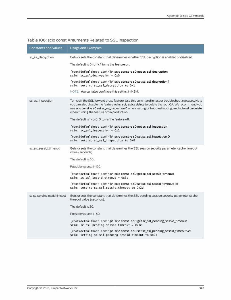
Table 106: scio const Arguments Related to SSL Inspection
Usage and ExamplesConstants and Values
Gets or sets the constant that determines whether SSL decryption is enabled or disabled.
The default is 0 (off). 1 turns the feature on.
[root@defaulthost admin]# scio const -s s0 get sc_ssl_decryptionscio: sc_ssl_decryption = 0x0
[root@defaulthost admin]# scio const -s s0 set sc_ssl_decryption 1scio: setting sc_ssl_decryption to 0x1
NOTE: You can also configure this setting in NSM.
sc_ssl_decryption
Turns off the SSL forward proxy feature. Use this command in test or troubleshooting cases. Noteyou can also disable the feature using scio ssl ca delete to delete the root CA. We recommend youuse scio const -s s0 set sc_ssl_inspection 0 when testing or troubleshooting; and scio ssl ca deletewhen turning the feature off in production.
The default is 1 (on). 0 turns the feature off.
[root@defaulthost admin]# scio const -s s0 get sc_ssl_inspectionscio: sc_ssl_inspection = 0x1
[root@defaulthost admin]# scio const -s s0 set sc_ssl_inspection 0scio: setting sc_ssl_inspection to 0x0
sc_ssl_inspection
Gets or sets the constant that determines the SSL session security parameter cache timeoutvalue (seconds).
The default is 60.
Possible values: 1–120.
[root@defaulthost admin]# scio const -s s0 get sc_ssl_sessid_timeoutscio: sc_ssl_sessid_timeout = 0x3c
[root@defaulthost admin]# scio const -s s0 set sc_ssl_sessid_timeout 45scio: setting sc_ssl_sessid_timeout to 0x2d
sc_ssl_sessid_timeout
Gets or sets the constant that determines the SSL pending session security parameter cachetimeout value (seconds).
The default is 30.
Possible values: 1–60.
[root@defaulthost admin]# scio const -s s0 get sc_ssl_pending_sessid_timeoutscio: sc_ssl_pending_sessid_timeout = 0x1e
[root@defaulthost admin]# scio const -s s0 set sc_ssl_pending_sessid_timeout 45scio: setting sc_ssl_pending_sessid_timeout to 0x2d
sc_ssl_pending_sessid_timeout
343Copyright © 2013, Juniper Networks, Inc.
Appendix D: scio Commands
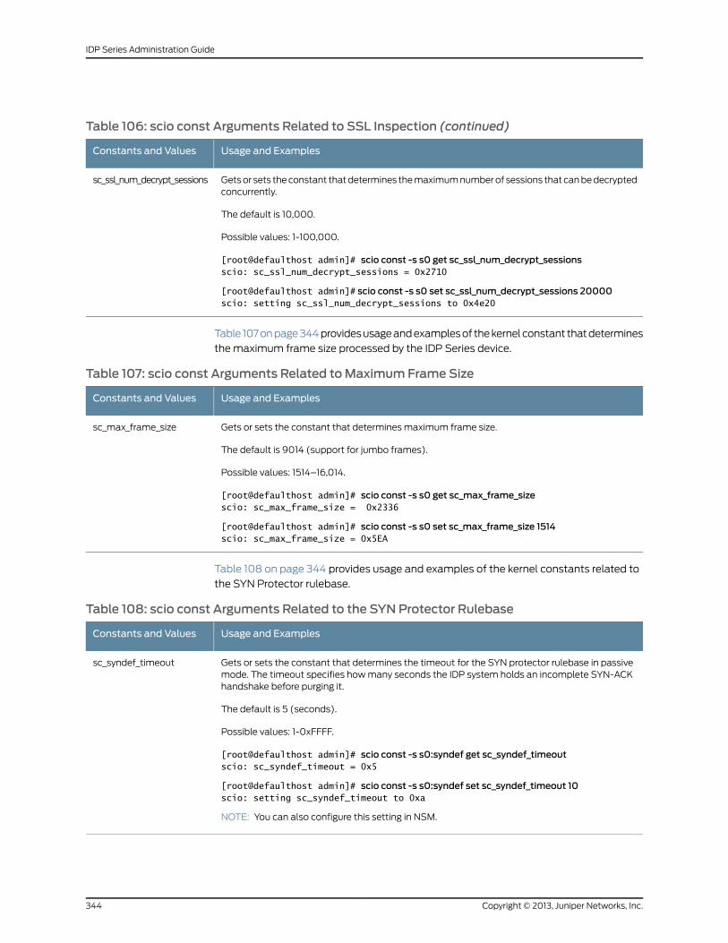
Table 106: scio const Arguments Related to SSL Inspection (continued)
Usage and ExamplesConstants and Values
Gets or sets the constant that determines the maximum number of sessions that can be decryptedconcurrently.
The default is 10,000.
Possible values: 1-100,000.
[root@defaulthost admin]# scio const -s s0 get sc_ssl_num_decrypt_sessionsscio: sc_ssl_num_decrypt_sessions = 0x2710
[root@defaulthost admin]# scio const -s s0 set sc_ssl_num_decrypt_sessions 20000scio: setting sc_ssl_num_decrypt_sessions to 0x4e20
sc_ssl_num_decrypt_sessions
Table 107 on page 344 provides usage and examples of the kernel constant that determines
the maximum frame size processed by the IDP Series device.
Table 107: scio const Arguments Related toMaximum Frame Size
Usage and ExamplesConstants and Values
Gets or sets the constant that determines maximum frame size.
The default is 9014 (support for jumbo frames).
Possible values: 1514–16,014.
[root@defaulthost admin]# scio const -s s0 get sc_max_frame_sizescio: sc_max_frame_size = 0x2336
[root@defaulthost admin]# scio const -s s0 set sc_max_frame_size 1514scio: sc_max_frame_size = 0x5EA
sc_max_frame_size
Table 108 on page 344 provides usage and examples of the kernel constants related to
the SYN Protector rulebase.
Table 108: scio const Arguments Related to the SYN Protector Rulebase
Usage and ExamplesConstants and Values
Gets or sets the constant that determines the timeout for the SYN protector rulebase in passivemode. The timeout specifies how many seconds the IDP system holds an incomplete SYN-ACKhandshake before purging it.
The default is 5 (seconds).
Possible values: 1-0xFFFF.
[root@defaulthost admin]# scio const -s s0:syndef get sc_syndef_timeoutscio: sc_syndef_timeout = 0x5
[root@defaulthost admin]# scio const -s s0:syndef set sc_syndef_timeout 10scio: setting sc_syndef_timeout to 0xa
NOTE: You can also configure this setting in NSM.
sc_syndef_timeout
Copyright © 2013, Juniper Networks, Inc.344
IDP Series Administration Guide
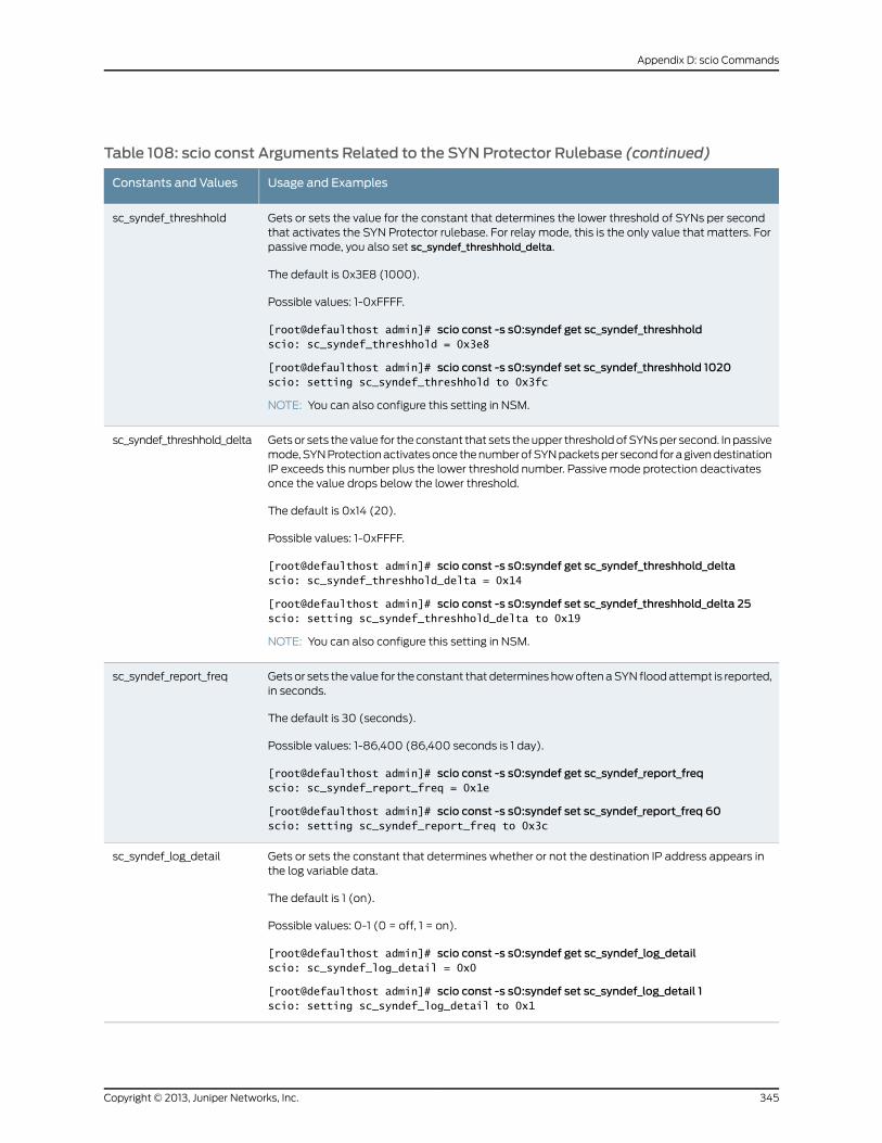
Table 108: scio const Arguments Related to the SYN Protector Rulebase (continued)
Usage and ExamplesConstants and Values
Gets or sets the value for the constant that determines the lower threshold of SYNs per secondthat activates the SYN Protector rulebase. For relay mode, this is the only value that matters. Forpassive mode, you also set sc_syndef_threshhold_delta.
The default is 0x3E8 (1000).
Possible values: 1-0xFFFF.
[root@defaulthost admin]# scio const -s s0:syndef get sc_syndef_threshholdscio: sc_syndef_threshhold = 0x3e8
[root@defaulthost admin]# scio const -s s0:syndef set sc_syndef_threshhold 1020scio: setting sc_syndef_threshhold to 0x3fc
NOTE: You can also configure this setting in NSM.
sc_syndef_threshhold
Gets or sets the value for the constant that sets the upper threshold of SYNs per second. In passivemode, SYN Protection activates once the number of SYN packets per second for a given destinationIP exceeds this number plus the lower threshold number. Passive mode protection deactivatesonce the value drops below the lower threshold.
The default is 0x14 (20).
Possible values: 1-0xFFFF.
[root@defaulthost admin]# scio const -s s0:syndef get sc_syndef_threshhold_deltascio: sc_syndef_threshhold_delta = 0x14
[root@defaulthost admin]# scio const -s s0:syndef set sc_syndef_threshhold_delta 25scio: setting sc_syndef_threshhold_delta to 0x19
NOTE: You can also configure this setting in NSM.
sc_syndef_threshhold_delta
Gets or sets the value for the constant that determines how often a SYN flood attempt is reported,in seconds.
The default is 30 (seconds).
Possible values: 1-86,400 (86,400 seconds is 1 day).
[root@defaulthost admin]# scio const -s s0:syndef get sc_syndef_report_freqscio: sc_syndef_report_freq = 0x1e
[root@defaulthost admin]# scio const -s s0:syndef set sc_syndef_report_freq 60scio: setting sc_syndef_report_freq to 0x3c
sc_syndef_report_freq
Gets or sets the constant that determines whether or not the destination IP address appears inthe log variable data.
The default is 1 (on).
Possible values: 0-1 (0 = off, 1 = on).
[root@defaulthost admin]# scio const -s s0:syndef get sc_syndef_log_detailscio: sc_syndef_log_detail = 0x0
[root@defaulthost admin]# scio const -s s0:syndef set sc_syndef_log_detail 1scio: setting sc_syndef_log_detail to 0x1
sc_syndef_log_detail
345Copyright © 2013, Juniper Networks, Inc.
Appendix D: scio Commands
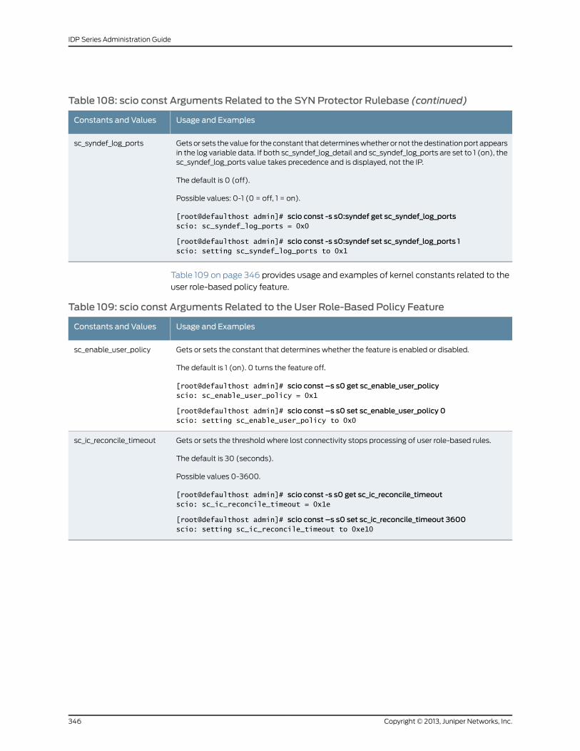
Table 108: scio const Arguments Related to the SYN Protector Rulebase (continued)
Usage and ExamplesConstants and Values
Gets or sets the value for the constant that determines whether or not the destination port appearsin the log variable data. If both sc_syndef_log_detail and sc_syndef_log_ports are set to 1 (on), thesc_syndef_log_ports value takes precedence and is displayed, not the IP.
The default is 0 (off).
Possible values: 0-1 (0 = off, 1 = on).
[root@defaulthost admin]# scio const -s s0:syndef get sc_syndef_log_portsscio: sc_syndef_log_ports = 0x0
[root@defaulthost admin]# scio const -s s0:syndef set sc_syndef_log_ports 1scio: setting sc_syndef_log_ports to 0x1
sc_syndef_log_ports
Table 109 on page 346 provides usage and examples of kernel constants related to the
user role-based policy feature.
Table 109: scio const Arguments Related to the User Role-Based Policy Feature
Usage and ExamplesConstants and Values
Gets or sets the constant that determines whether the feature is enabled or disabled.
The default is 1 (on). 0 turns the feature off.
[root@defaulthost admin]# scio const –s s0 get sc_enable_user_policyscio: sc_enable_user_policy = 0x1
[root@defaulthost admin]# scio const –s s0 set sc_enable_user_policy 0scio: setting sc_enable_user_policy to 0x0
sc_enable_user_policy
Gets or sets the threshold where lost connectivity stops processing of user role-based rules.
The default is 30 (seconds).
Possible values 0-3600.
[root@defaulthost admin]# scio const -s s0 get sc_ic_reconcile_timeoutscio: sc_ic_reconcile_timeout = 0x1e
[root@defaulthost admin]# scio const –s s0 set sc_ic_reconcile_timeout 3600scio: setting sc_ic_reconcile_timeout to 0xe10
sc_ic_reconcile_timeout
Copyright © 2013, Juniper Networks, Inc.346
IDP Series Administration Guide
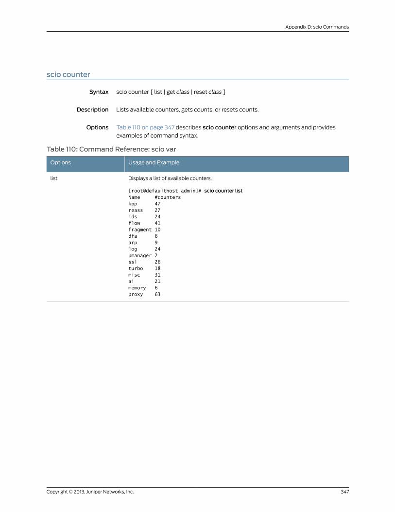
scio counter
Syntax scio counter { list | get class | reset class }
Description Lists available counters, gets counts, or resets counts.
Options Table 110 on page 347 describes scio counter options and arguments and provides
examples of command syntax.
Table 110: Command Reference: scio var
Usage and ExampleOptions
Displays a list of available counters.
[root@defaulthost admin]# scio counter listName #counterskpp 47reass 27ids 24flow 41fragment 10dfa 6arp 9log 24pmanager 2ssl 26turbo 18misc 31ai 21memory 6proxy 63
list
347Copyright © 2013, Juniper Networks, Inc.
Appendix D: scio Commands
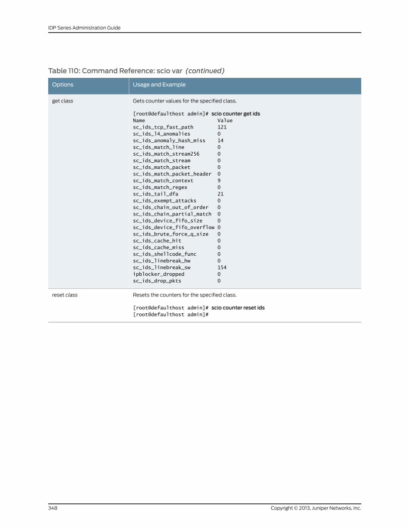
Table 110: Command Reference: scio var (continued)
Usage and ExampleOptions
Gets counter values for the specified class.
[root@defaulthost admin]# scio counter get idsName Valuesc_ids_tcp_fast_path 121sc_ids_l4_anomalies 0sc_ids_anomaly_hash_miss 14sc_ids_match_line 0sc_ids_match_stream256 0sc_ids_match_stream 0sc_ids_match_packet 0sc_ids_match_packet_header 0sc_ids_match_context 9sc_ids_match_regex 0sc_ids_tail_dfa 21sc_ids_exempt_attacks 0sc_ids_chain_out_of_order 0sc_ids_chain_partial_match 0sc_ids_device_fifo_size 0sc_ids_device_fifo_overflow 0sc_ids_brute_force_q_size 0sc_ids_cache_hit 0sc_ids_cache_miss 0sc_ids_shellcode_func 0sc_ids_linebreak_hw 0sc_ids_linebreak_sw 154ipblocker_dropped 0sc_ids_drop_pkts 0
get class
Resets the counters for the specified class.
[root@defaulthost admin]# scio counter reset ids[root@defaulthost admin]#
reset class
Copyright © 2013, Juniper Networks, Inc.348
IDP Series Administration Guide
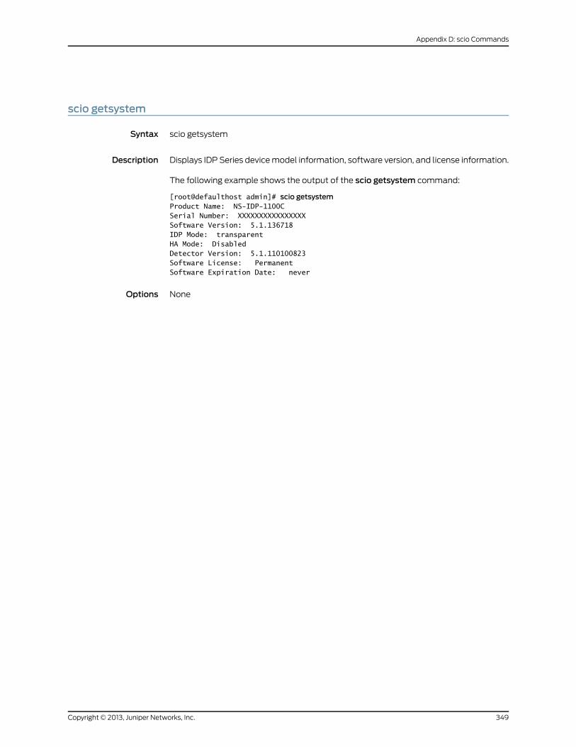
scio getsystem
Syntax scio getsystem
Description Displays IDP Series device model information, software version, and license information.
The following example shows the output of the scio getsystem command:
[root@defaulthost admin]# scio getsystemProduct Name: NS-IDP-1100CSerial Number: XXXXXXXXXXXXXXXXSoftware Version: 5.1.136718IDP Mode: transparentHA Mode: DisabledDetector Version: 5.1.110100823Software License: PermanentSoftware Expiration Date: never
Options None
349Copyright © 2013, Juniper Networks, Inc.
Appendix D: scio Commands
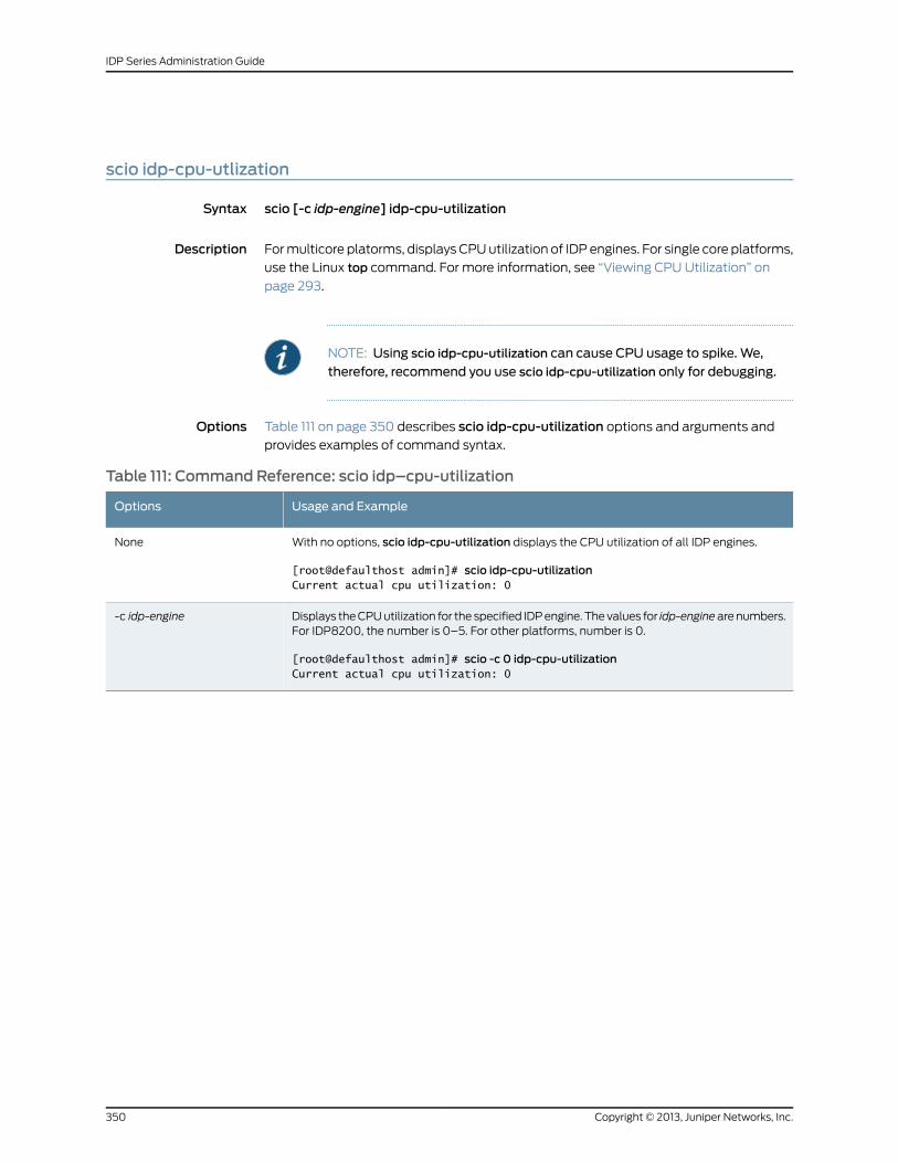
scio idp-cpu-utlization
Syntax scio [-c idp-engine] idp-cpu-utilization
Description For multicore platorms, displays CPU utilization of IDP engines. For single core platforms,
use the Linux top command. For more information, see “Viewing CPU Utilization” on
page 293.
NOTE: Using scio idp-cpu-utilization can cause CPU usage to spike. We,
therefore, recommend you use scio idp-cpu-utilization only for debugging.
Options Table 111 on page 350 describes scio idp-cpu-utilization options and arguments and
provides examples of command syntax.
Table 111: Command Reference: scio idp–cpu-utilization
Usage and ExampleOptions
With no options, scio idp-cpu-utilization displays the CPU utilization of all IDP engines.
[root@defaulthost admin]# scio idp-cpu-utilizationCurrent actual cpu utilization: 0
None
Displays the CPU utilization for the specified IDP engine. The values for idp-engineare numbers.For IDP8200, the number is 0–5. For other platforms, number is 0.
[root@defaulthost admin]# scio -c 0 idp-cpu-utilizationCurrent actual cpu utilization: 0
-c idp-engine
Copyright © 2013, Juniper Networks, Inc.350
IDP Series Administration Guide
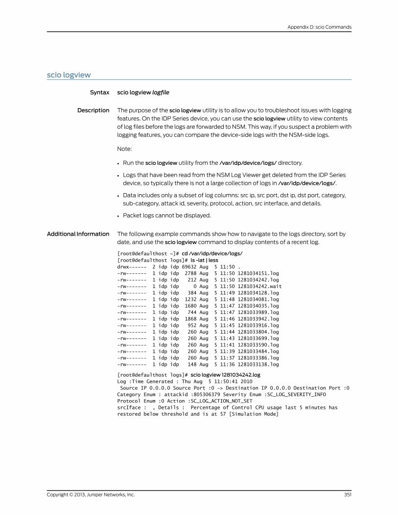
scio logview
Syntax scio logview logfile
Description The purpose of the scio logview utility is to allow you to troubleshoot issues with logging
features. On the IDP Series device, you can use the scio logview utility to view contents
of log files before the logs are forwarded to NSM. This way, if you suspect a problem with
logging features, you can compare the device-side logs with the NSM-side logs.
Note:
• Run the scio logview utility from the /var/idp/device/logs/ directory.
• Logs that have been read from the NSM Log Viewer get deleted from the IDP Series
device, so typically there is not a large collection of logs in /var/idp/device/logs/.
• Data includes only a subset of log columns: src ip, src port, dst ip, dst port, category,
sub-category, attack id, severity, protocol, action, src interface, and details.
• Packet logs cannot be displayed.
Additional Information The following example commands show how to navigate to the logs directory, sort by
date, and use the scio logview command to display contents of a recent log.
[root@defaulthost ~]# cd /var/idp/device/logs/[root@defaulthost logs]# ls -lat | lessdrwx------ 2 idp idp 69632 Aug 5 11:50 .-rw------- 1 idp idp 2788 Aug 5 11:50 1281034151.log-rw------- 1 idp idp 212 Aug 5 11:50 1281034242.log-rw------- 1 idp idp 0 Aug 5 11:50 1281034242.wait-rw------- 1 idp idp 384 Aug 5 11:49 1281034128.log-rw------- 1 idp idp 1232 Aug 5 11:48 1281034081.log-rw------- 1 idp idp 1680 Aug 5 11:47 1281034035.log-rw------- 1 idp idp 744 Aug 5 11:47 1281033989.log-rw------- 1 idp idp 1868 Aug 5 11:46 1281033942.log-rw------- 1 idp idp 952 Aug 5 11:45 1281033916.log-rw------- 1 idp idp 260 Aug 5 11:44 1281033804.log-rw------- 1 idp idp 260 Aug 5 11:43 1281033699.log-rw------- 1 idp idp 260 Aug 5 11:41 1281033590.log-rw------- 1 idp idp 260 Aug 5 11:39 1281033484.log-rw------- 1 idp idp 260 Aug 5 11:37 1281033386.log-rw------- 1 idp idp 148 Aug 5 11:36 1281033138.log
[root@defaulthost logs]# scio logview 1281034242.logLog :Time Generated : Thu Aug 5 11:50:41 2010 Source IP 0.0.0.0 Source Port :0 -> Destination IP 0.0.0.0 Destination Port :0Category Enum : attackid :805306379 Severity Enum :SC_LOG_SEVERITY_INFOProtocol Enum :0 Action :SC_LOG_ACTION_NOT_SETsrcIface : , Details : Percentage of Control CPU usage last 5 minutes has restored below threshold and is at 57 [Simulation Mode]
351Copyright © 2013, Juniper Networks, Inc.
Appendix D: scio Commands
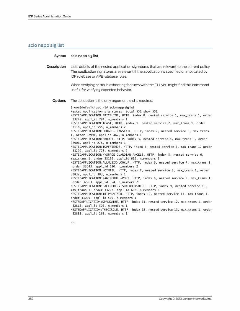
scio napp sig list
Syntax scio napp sig list
Description Lists details of the nested application signatures that are relevant to the current policy.
The application signatures are relevant if the application is specified or implicated by
IDP rulebase or APE rulebase rules.
When verifying or troubleshooting features with the CLI, you might find this command
useful for verifying expected behavior.
Options The list option is the only argument and is required.
[root@defaulthost ~]# scio napp sig listNested Application signatures: total 551 show 551NESTEDAPPLICATION:PRICELINE, HTTP, index 0, nested service 1, max_trans 1, order 33249, appl_id 794, n_members 1NESTEDAPPLICATION:ICAST, HTTP, index 1, nested service 2, max_trans 1, order 33118, appl_id 555, n_members 2NESTEDAPPLICATION:GOOGLE-TRANSLATE, HTTP, index 2, nested service 3, max_trans 1, order 32991, appl_id 467, n_members 1NESTEDAPPLICATION:EBUDDY, HTTP, index 3, nested service 4, max_trans 1, order 32906, appl_id 278, n_members 1NESTEDAPPLICATION:TOPFRIENDS, HTTP, index 4, nested service 5, max_trans 1, order 33299, appl_id 723, n_members 2NESTEDAPPLICATION:MYSPACE-GUARDIAN-ANGELS, HTTP, index 5, nested service 6, max_trans 1, order 33169, appl_id 619, n_members 2NESTEDAPPLICATION:ALLMUSIC-LOOKUP, HTTP, index 6, nested service 7, max_trans 1, order 33043, appl_id 530, n_members 2NESTEDAPPLICATION:HOTMAIL, HTTP, index 7, nested service 8, max_trans 1, order 32832, appl_id 383, n_members 1NESTEDAPPLICATION:RAGINGBULL-POST, HTTP, index 8, nested service 9, max_trans 1, order 32963, appl_id 354, n_members 2NESTEDAPPLICATION:FACEBOOK-VISUALBOOKSHELF, HTTP, index 9, nested service 10, max_trans 1, order 33227, appl_id 602, n_members 2NESTEDAPPLICATION:TRIPADVISOR, HTTP, index 10, nested service 11, max_trans 1, order 33099, appl_id 579, n_members 1NESTEDAPPLICATION:SPANKWIRE, HTTP, index 11, nested service 12, max_trans 1, order 32816, appl_id 505, n_members 1NESTEDAPPLICATION:THECIRCLE, HTTP, index 12, nested service 13, max_trans 1, order 32888, appl_id 261, n_members 1
...
Copyright © 2013, Juniper Networks, Inc.352
IDP Series Administration Guide
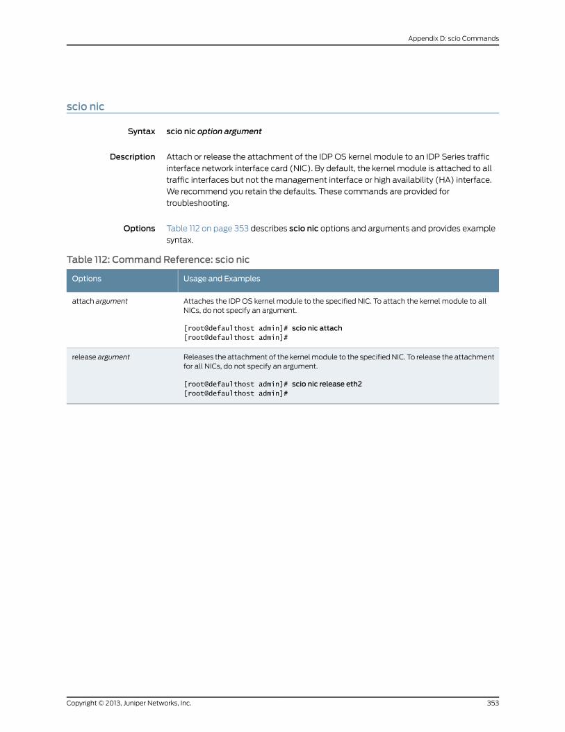
scio nic
Syntax scio nic option argument
Description Attach or release the attachment of the IDP OS kernel module to an IDP Series traffic
interface network interface card (NIC). By default, the kernel module is attached to all
traffic interfaces but not the management interface or high availability (HA) interface.
We recommend you retain the defaults. These commands are provided for
troubleshooting.
Options Table 112 on page 353 describes scio nic options and arguments and provides example
syntax.
Table 112: Command Reference: scio nic
Usage and ExamplesOptions
Attaches the IDP OS kernel module to the specified NIC. To attach the kernel module to allNICs, do not specify an argument.
[root@defaulthost admin]# scio nic attach[root@defaulthost admin]#
attach argument
Releases the attachment of the kernel module to the specified NIC. To release the attachmentfor all NICs, do not specify an argument.
[root@defaulthost admin]# scio nic release eth2[root@defaulthost admin]#
release argument
353Copyright © 2013, Juniper Networks, Inc.
Appendix D: scio Commands
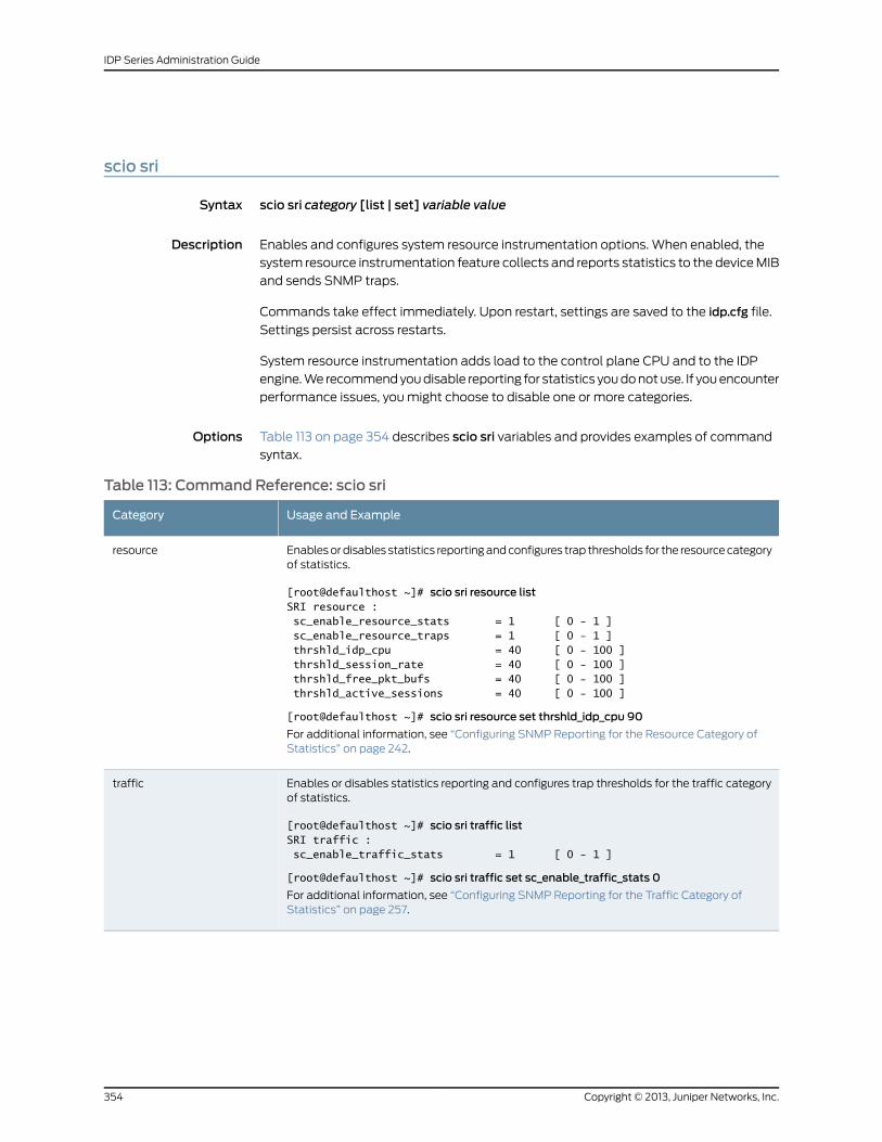
scio sri
Syntax scio sri category [list | set] variable value
Description Enables and configures system resource instrumentation options. When enabled, the
system resource instrumentation feature collects and reports statistics to the device MIB
and sends SNMP traps.
Commands take effect immediately. Upon restart, settings are saved to the idp.cfg file.
Settings persist across restarts.
System resource instrumentation adds load to the control plane CPU and to the IDP
engine. We recommend you disable reporting for statistics you do not use. If you encounter
performance issues, you might choose to disable one or more categories.
Options Table 113 on page 354 describes scio sri variables and provides examples of command
syntax.
Table 113: Command Reference: scio sri
Usage and ExampleCategory
Enables or disables statistics reporting and configures trap thresholds for the resource categoryof statistics.
[root@defaulthost ~]# scio sri resource listSRI resource : sc_enable_resource_stats = 1 [ 0 - 1 ] sc_enable_resource_traps = 1 [ 0 - 1 ] thrshld_idp_cpu = 40 [ 0 - 100 ] thrshld_session_rate = 40 [ 0 - 100 ] thrshld_free_pkt_bufs = 40 [ 0 - 100 ] thrshld_active_sessions = 40 [ 0 - 100 ]
[root@defaulthost ~]# scio sri resource set thrshld_idp_cpu 90
For additional information, see “Configuring SNMP Reporting for the Resource Category ofStatistics” on page 242.
resource
Enables or disables statistics reporting and configures trap thresholds for the traffic categoryof statistics.
[root@defaulthost ~]# scio sri traffic listSRI traffic : sc_enable_traffic_stats = 1 [ 0 - 1 ]
[root@defaulthost ~]# scio sri traffic set sc_enable_traffic_stats 0
For additional information, see “Configuring SNMP Reporting for the Traffic Category ofStatistics” on page 257.
traffic
Copyright © 2013, Juniper Networks, Inc.354
IDP Series Administration Guide
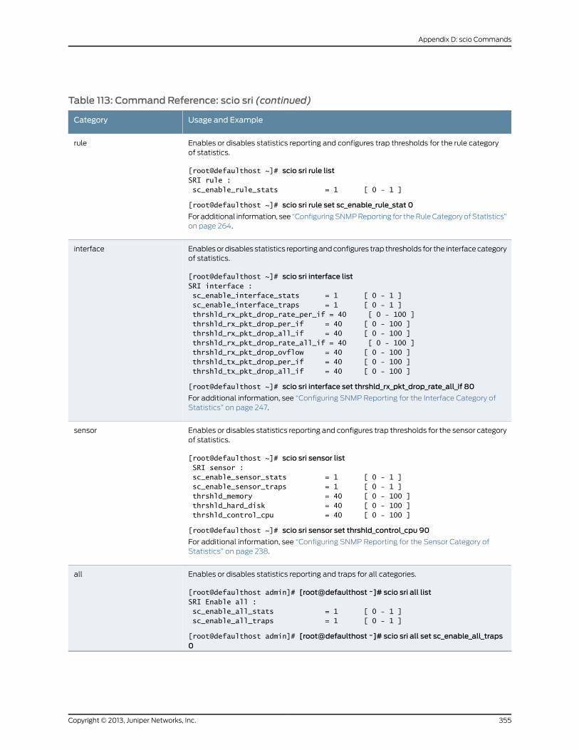
Table 113: Command Reference: scio sri (continued)
Usage and ExampleCategory
Enables or disables statistics reporting and configures trap thresholds for the rule categoryof statistics.
[root@defaulthost ~]# scio sri rule listSRI rule : sc_enable_rule_stats = 1 [ 0 - 1 ]
[root@defaulthost ~]# scio sri rule set sc_enable_rule_stat 0
For additional information, see “Configuring SNMP Reporting for the Rule Category of Statistics”on page 264.
rule
Enables or disables statistics reporting and configures trap thresholds for the interface categoryof statistics.
[root@defaulthost ~]# scio sri interface listSRI interface : sc_enable_interface_stats = 1 [ 0 - 1 ] sc_enable_interface_traps = 1 [ 0 - 1 ] thrshld_rx_pkt_drop_rate_per_if = 40 [ 0 - 100 ] thrshld_rx_pkt_drop_per_if = 40 [ 0 - 100 ] thrshld_rx_pkt_drop_all_if = 40 [ 0 - 100 ] thrshld_rx_pkt_drop_rate_all_if = 40 [ 0 - 100 ] thrshld_rx_pkt_drop_ovflow = 40 [ 0 - 100 ] thrshld_tx_pkt_drop_per_if = 40 [ 0 - 100 ] thrshld_tx_pkt_drop_all_if = 40 [ 0 - 100 ]
[root@defaulthost ~]# scio sri interface set thrshld_rx_pkt_drop_rate_all_if 80
For additional information, see “Configuring SNMP Reporting for the Interface Category ofStatistics” on page 247.
interface
Enables or disables statistics reporting and configures trap thresholds for the sensor categoryof statistics.
[root@defaulthost ~]# scio sri sensor list SRI sensor : sc_enable_sensor_stats = 1 [ 0 - 1 ] sc_enable_sensor_traps = 1 [ 0 - 1 ] thrshld_memory = 40 [ 0 - 100 ] thrshld_hard_disk = 40 [ 0 - 100 ] thrshld_control_cpu = 40 [ 0 - 100 ]
[root@defaulthost ~]# scio sri sensor set thrshld_control_cpu 90
For additional information, see “Configuring SNMP Reporting for the Sensor Category ofStatistics” on page 238.
sensor
Enables or disables statistics reporting and traps for all categories.
[root@defaulthost admin]# [root@defaulthost ~]# scio sri all listSRI Enable all : sc_enable_all_stats = 1 [ 0 - 1 ] sc_enable_all_traps = 1 [ 0 - 1 ]
[root@defaulthost admin]# [root@defaulthost ~]# scio sri all set sc_enable_all_traps0
all
355Copyright © 2013, Juniper Networks, Inc.
Appendix D: scio Commands
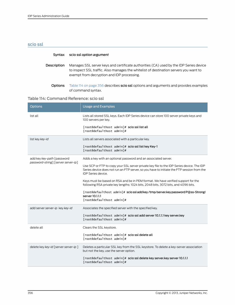
scio ssl
Syntax scio ssl option argument
Description Manages SSL server keys and certificate authorities (CA) used by the IDP Series device
to inspect SSL traffic. Also manages the whitelist of destination servers you want to
exempt from decryption and IDP processing.
Options Table 114 on page 356 describes scio ssl options and arguments and provides examples
of command syntax.
Table 114: Command Reference: scio ssl
Usage and ExamplesOptions
Lists all stored SSL keys. Each IDP Series device can store 100 server private keys and100 servers per key.
[root@defaulthost admin]# scio ssl list all[root@defaulthost admin]#
list all
Lists all servers associated with a particular key.
[root@defaulthost admin]# scio ssl list key Key-1[root@defaulthost admin]#
list key key-id
Adds a key with an optional password and an associated server.
Use SCP or FTP to copy your SSL server private key file to the IDP Series device. The IDPSeries device does not run an FTP server, so you have to initiate the FTP session from theIDP Series device.
Keys must be based on RSA and be in PEM format. We have verified support for thefollowing RSA private key lengths: 1024 bits, 2048 bits, 3072 bits, and 4096 bits.
[root@defaulthost admin]# sciossladdkey/tmp/server.keypasswordP@ss-Strong!server 10.1.1.1[root@defaulthost admin]#
add key key-path [passwordpassword-string] [server server-ip]
Associates the specified server with the specified key.
[root@defaulthost admin]# scio ssl add server 10.1.1.1 key server.key[root@defaulthost admin]#
add server server-ip key key-id
Clears the SSL keystore.
[root@defaulthost admin]# scio ssl delete all[root@defaulthost admin]#
delete all
Deletes a particular SSL key from the SSL keystore. To delete a key-server associationbut not the key, use the server option.
[root@defaulthost admin]# scio ssl delete key server.key server 10.1.1.1[root@defaulthost admin]#
delete key key-id [server server-ip ]
Copyright © 2013, Juniper Networks, Inc.356
IDP Series Administration Guide
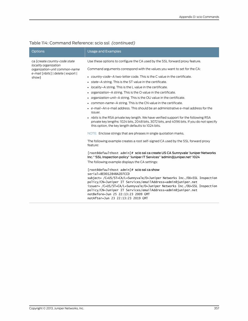
Table 114: Command Reference: scio ssl (continued)
Usage and ExamplesOptions
Use these options to configure the CA used by the SSL forward proxy feature.
Command arguments correspond with the values you want to set for the CA:
• country-code–A two-letter code. This is the C value in the certificate.
• state–A string. This is the ST value in the certificate.
• locality–A string. This is the L value in the certificate.
• organization–A string. This is the O value in the certificate.
• organization-unit–A string. This is the OU value in the certificate.
• common-name–A string. This is the CN value in the certificate.
• e-mail–An e-mail address. This should be an administrative e-mail address for theissuer.
• nbits is the RSA private key length. We have verified support for the following RSAprivate key lengths: 1024 bits, 2048 bits, 3072 bits, and 4096 bits. If you do not specifythis option, the key length defaults to 1024 bits.
NOTE: Enclose strings that are phrases in single quotation marks.
The following example creates a root self-signed CA used by the SSL forward proxyfeature:
[root@defaulthost admin]# scio ssl ca create US CA Sunnyvale 'Juniper NetworksInc.' 'SSL Inspection policy' 'Juniper IT Services' '[email protected]' 1024
The following example displays the CA settings:
[root@defaulthost admin]# scio ssl ca showserial=8E0012848A2D7CCDsubject= /C=US/ST=CA/L=Sunnyvale/O=Juniper Networks Inc./OU=SSL Inspectionpolicy/CN=Juniper IT Services/[email protected]= /C=US/ST=CA/L=Sunnyvale/O=Juniper Networks Inc./OU=SSL Inspectionpolicy/CN=Juniper IT Services/[email protected]=Jun 25 22:13:23 2009 GMTnotAfter=Jun 23 22:13:23 2019 GMT
ca {create country-code statelocality organizationorganization-unit common-namee-mail [nbits] | delete | export |show}
357Copyright © 2013, Juniper Networks, Inc.
Appendix D: scio Commands
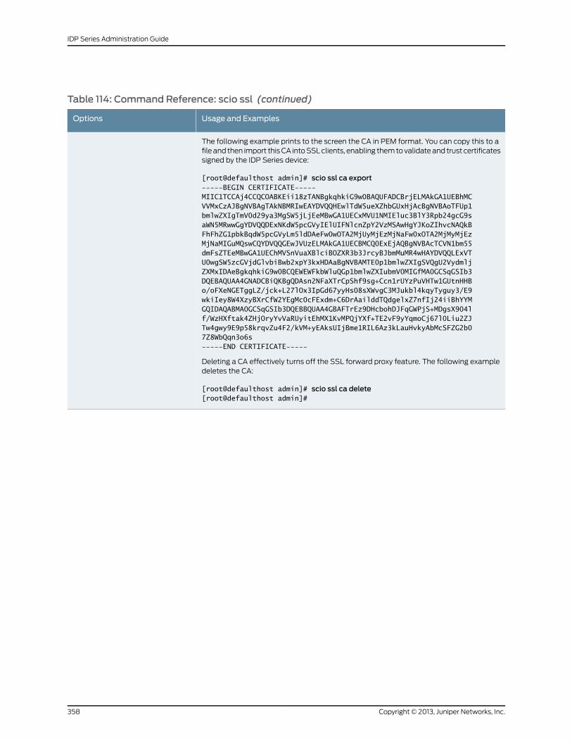
Table 114: Command Reference: scio ssl (continued)
Usage and ExamplesOptions
The following example prints to the screen the CA in PEM format. You can copy this to afile and then import this CA into SSL clients, enabling them to validate and trust certificatessigned by the IDP Series device:
[root@defaulthost admin]# scio ssl ca export-----BEGIN CERTIFICATE-----MIIC1TCCAj4CCQCOABKEii18zTANBgkqhkiG9w0BAQUFADCBrjELMAkGA1UEBhMCVVMxCzAJBgNVBAgTAkNBMRIwEAYDVQQHEwlTdW5ueXZhbGUxHjAcBgNVBAoTFUp1bmlwZXIgTmV0d29ya3MgSW5jLjEeMBwGA1UECxMVU1NMIEluc3BlY3Rpb24gcG9saWN5MRwwGgYDVQQDExNKdW5pcGVyIElUIFNlcnZpY2VzMSAwHgYJKoZIhvcNAQkBFhFhZG1pbkBqdW5pcGVyLm5ldDAeFw0wOTA2MjUyMjEzMjNaFw0xOTA2MjMyMjEzMjNaMIGuMQswCQYDVQQGEwJVUzELMAkGA1UECBMCQ0ExEjAQBgNVBAcTCVN1bm55dmFsZTEeMBwGA1UEChMVSnVuaXBlciBOZXR3b3JrcyBJbmMuMR4wHAYDVQQLExVTU0wgSW5zcGVjdGlvbiBwb2xpY3kxHDAaBgNVBAMTE0p1bmlwZXIgSVQgU2VydmljZXMxIDAeBgkqhkiG9w0BCQEWEWFkbWluQGp1bmlwZXIubmV0MIGfMA0GCSqGSIb3DQEBAQUAA4GNADCBiQKBgQDAsn2NFaXTrCpShf9sg+Ccn1rUYzPuVHTw1GUtnHHBo/oFXeNGETggLZ/jck+L27lOx3IpGd67yyHs08sXWvgC3MJukbl4kqyTyguy3/E9wkiIey8W4XzyBXrCfW2YEgMc0cFExdm+C6DrAailddTQdgelxZ7nfIj24iiBhYYMGQIDAQABMA0GCSqGSIb3DQEBBQUAA4GBAFTrEz9DHcbohDJFqGWPjS+MDgsX904lf/WzHXftak4ZHjOryYvVaRUyitEhMX1KvMPQjYXf+TE2vF9yYqmoCj67l0Liu2ZJTw4gwy9E9p58krqvZu4F2/kVM+yEAksUIjBme1RIL6Az3kLauHvkyAbMcSFZG2b07Z8WbQqn3o6s-----END CERTIFICATE-----
Deleting a CA effectively turns off the SSL forward proxy feature. The following exampledeletes the CA:
[root@defaulthost admin]# scio ssl ca delete[root@defaulthost admin]#
Copyright © 2013, Juniper Networks, Inc.358
IDP Series Administration Guide
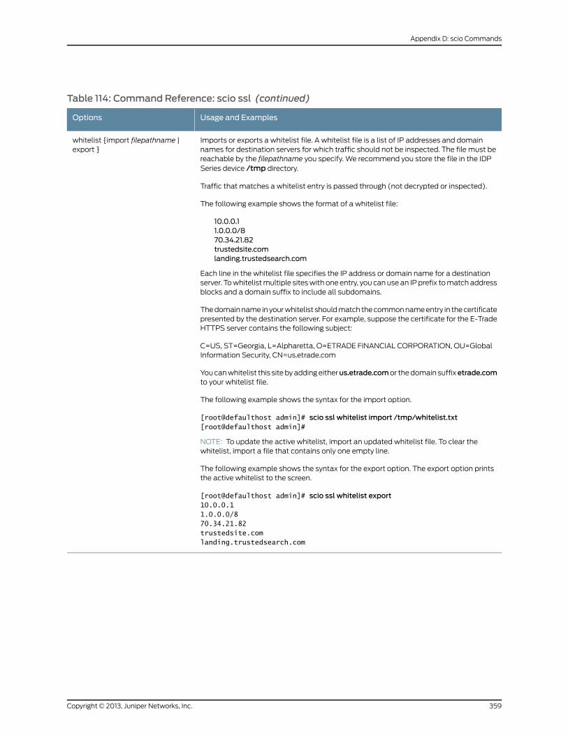
Table 114: Command Reference: scio ssl (continued)
Usage and ExamplesOptions
Imports or exports a whitelist file. A whitelist file is a list of IP addresses and domainnames for destination servers for which traffic should not be inspected. The file must bereachable by the filepathname you specify. We recommend you store the file in the IDPSeries device /tmp directory.
Traffic that matches a whitelist entry is passed through (not decrypted or inspected).
The following example shows the format of a whitelist file:
10.0.0.11.0.0.0/870.34.21.82trustedsite.comlanding.trustedsearch.com
Each line in the whitelist file specifies the IP address or domain name for a destinationserver. To whitelist multiple sites with one entry, you can use an IP prefix to match addressblocks and a domain suffix to include all subdomains.
The domain name in your whitelist should match the common name entry in the certificatepresented by the destination server. For example, suppose the certificate for the E-TradeHTTPS server contains the following subject:
C=US, ST=Georgia, L=Alpharetta, O=ETRADE FINANCIAL CORPORATION, OU=GlobalInformation Security, CN=us.etrade.com
You can whitelist this site by adding eitherus.etrade.comor the domain suffixetrade.comto your whitelist file.
The following example shows the syntax for the import option.
[root@defaulthost admin]# scio ssl whitelist import /tmp/whitelist.txt[root@defaulthost admin]#
NOTE: To update the active whitelist, import an updated whitelist file. To clear thewhitelist, import a file that contains only one empty line.
The following example shows the syntax for the export option. The export option printsthe active whitelist to the screen.
[root@defaulthost admin]# scio ssl whitelist export10.0.0.11.0.0.0/870.34.21.82trustedsite.comlanding.trustedsearch.com
whitelist {import filepathname |export }
359Copyright © 2013, Juniper Networks, Inc.
Appendix D: scio Commands
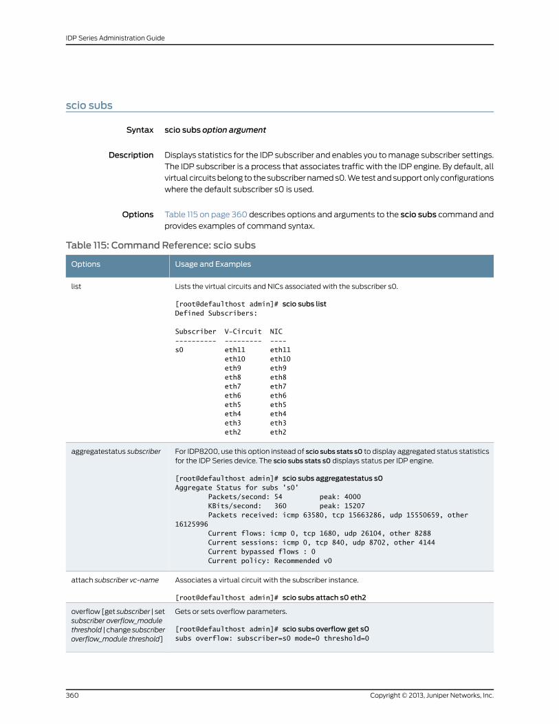
scio subs
Syntax scio subs option argument
Description Displays statistics for the IDP subscriber and enables you to manage subscriber settings.
The IDP subscriber is a process that associates traffic with the IDP engine. By default, all
virtual circuits belong to the subscriber named s0. We test and support only configurations
where the default subscriber s0 is used.
Options Table 115 on page 360 describes options and arguments to the scio subs command and
provides examples of command syntax.
Table 115: Command Reference: scio subs
Usage and ExamplesOptions
Lists the virtual circuits and NICs associated with the subscriber s0.
[root@defaulthost admin]# scio subs listDefined Subscribers:
Subscriber V-Circuit NIC---------- --------- ----s0 eth11 eth11 eth10 eth10 eth9 eth9 eth8 eth8 eth7 eth7 eth6 eth6 eth5 eth5 eth4 eth4 eth3 eth3 eth2 eth2
list
For IDP8200, use this option instead of scio subs stats s0 to display aggregated status statisticsfor the IDP Series device. The scio subs stats s0 displays status per IDP engine.
[root@defaulthost admin]# scio subs aggregatestatus s0Aggregate Status for subs 's0' Packets/second: 54 peak: 4000 KBits/second: 360 peak: 15207 Packets received: icmp 63580, tcp 15663286, udp 15550659, other 16125996 Current flows: icmp 0, tcp 1680, udp 26104, other 8288 Current sessions: icmp 0, tcp 840, udp 8702, other 4144 Current bypassed flows : 0 Current policy: Recommended v0
aggregatestatus subscriber
Associates a virtual circuit with the subscriber instance.
[root@defaulthost admin]# scio subs attach s0 eth2
attach subscriber vc-name
Gets or sets overflow parameters.
[root@defaulthost admin]# scio subs overflow get s0subs overflow: subscriber=s0 mode=0 threshold=0
overflow [get subscriber | setsubscriber overflow_modulethreshold | change subscriberoverflow_module threshold]
Copyright © 2013, Juniper Networks, Inc.360
IDP Series Administration Guide
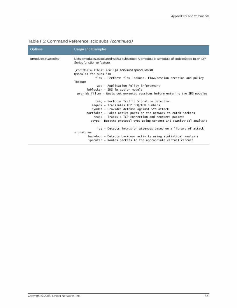
Table 115: Command Reference: scio subs (continued)
Usage and ExamplesOptions
Lists qmodules associated with a subscriber. A qmodule is a module of code related to an IDPSeries function or feature.
[root@defaulthost admin]# scio subs qmodules s0Qmodules for subs 's0' flow - Performs flow lookups, flow/session creation and policy lookups ape - Application Policy Enforcement ipblocker - IDS ip action module pre-ids filter - Weeds out unwanted sessions before entering the IDS modules
tsig - Performs Traffic Signature detection seqack - Translates TCP SEQ/ACK numbers syndef - Provides defense against SYN attack portfaker - Fakes active ports on the network to catch hackers reass - Tracks a TCP connection and reorders packets ptype - Detects protocol type using content and statistical analysis
ids - Detects intrusion attempts based on a library of attack signatures backdoor - Detects backdoor activity using statistical analysis iprouter - Routes packets to the appropriate virtual circuit
qmodules subscriber
361Copyright © 2013, Juniper Networks, Inc.
Appendix D: scio Commands
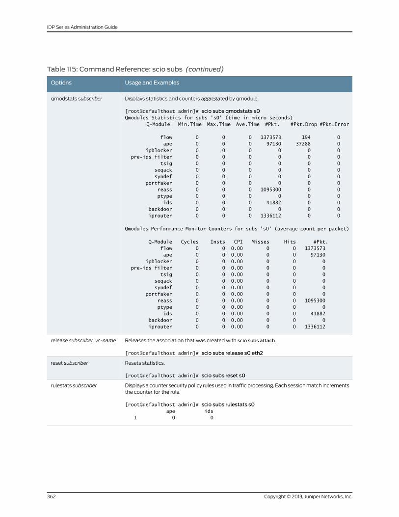
Table 115: Command Reference: scio subs (continued)
Usage and ExamplesOptions
Displays statistics and counters aggregated by qmodule.
[root@defaulthost admin]# scio subs qmodstats s0Qmodules Statistics for subs 's0' (time in micro seconds) Q-Module Min.Time Max.Time Ave.Time #Pkt. #Pkt.Drop #Pkt.Error
flow 0 0 0 1373573 194 0 ape 0 0 0 97130 37288 0 ipblocker 0 0 0 0 0 0 pre-ids filter 0 0 0 0 0 0 tsig 0 0 0 0 0 0 seqack 0 0 0 0 0 0 syndef 0 0 0 0 0 0 portfaker 0 0 0 0 0 0 reass 0 0 0 1095300 0 0 ptype 0 0 0 0 0 0 ids 0 0 0 41882 0 0 backdoor 0 0 0 0 0 0 iprouter 0 0 0 1336112 0 0
Qmodules Performance Monitor Counters for subs 's0' (average count per packet)
Q-Module Cycles Insts CPI Misses Hits #Pkt. flow 0 0 0.00 0 0 1373573 ape 0 0 0.00 0 0 97130 ipblocker 0 0 0.00 0 0 0 pre-ids filter 0 0 0.00 0 0 0 tsig 0 0 0.00 0 0 0 seqack 0 0 0.00 0 0 0 syndef 0 0 0.00 0 0 0 portfaker 0 0 0.00 0 0 0 reass 0 0 0.00 0 0 1095300 ptype 0 0 0.00 0 0 0 ids 0 0 0.00 0 0 41882 backdoor 0 0 0.00 0 0 0 iprouter 0 0 0.00 0 0 1336112
qmodstats subscriber
Releases the association that was created with scio subs attach.
[root@defaulthost admin]# scio subs release s0 eth2
release subscriber vc-name
Resets statistics.
[root@defaulthost admin]# scio subs reset s0
reset subscriber
Displays a counter security policy rules used in traffic processing. Each session match incrementsthe counter for the rule.
[root@defaulthost admin]# scio subs rulestats s0 ape ids 1 0 0
rulestats subscriber
Copyright © 2013, Juniper Networks, Inc.362
IDP Series Administration Guide
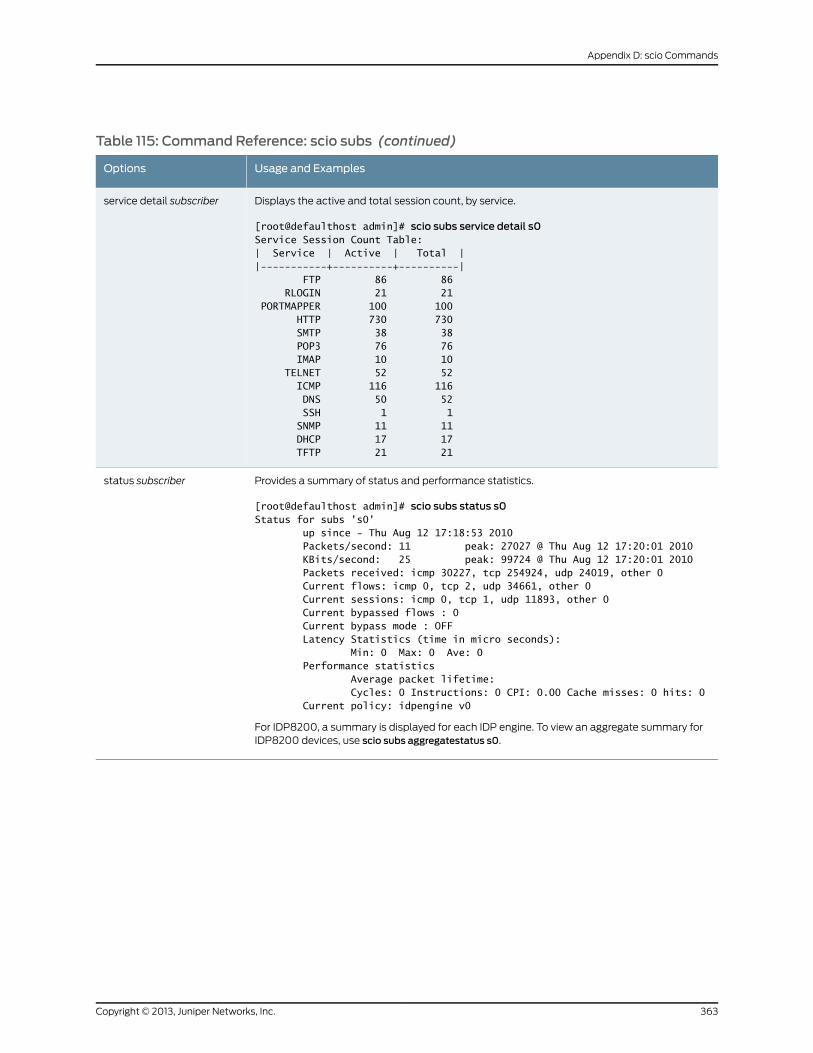
Table 115: Command Reference: scio subs (continued)
Usage and ExamplesOptions
Displays the active and total session count, by service.
[root@defaulthost admin]# scio subs service detail s0Service Session Count Table:| Service | Active | Total ||-----------+----------+----------| FTP 86 86 RLOGIN 21 21 PORTMAPPER 100 100 HTTP 730 730 SMTP 38 38 POP3 76 76 IMAP 10 10 TELNET 52 52 ICMP 116 116 DNS 50 52 SSH 1 1 SNMP 11 11 DHCP 17 17 TFTP 21 21
service detail subscriber
Provides a summary of status and performance statistics.
[root@defaulthost admin]# scio subs status s0Status for subs 's0' up since - Thu Aug 12 17:18:53 2010 Packets/second: 11 peak: 27027 @ Thu Aug 12 17:20:01 2010 KBits/second: 25 peak: 99724 @ Thu Aug 12 17:20:01 2010 Packets received: icmp 30227, tcp 254924, udp 24019, other 0 Current flows: icmp 0, tcp 2, udp 34661, other 0 Current sessions: icmp 0, tcp 1, udp 11893, other 0 Current bypassed flows : 0 Current bypass mode : OFF Latency Statistics (time in micro seconds): Min: 0 Max: 0 Ave: 0 Performance statistics Average packet lifetime: Cycles: 0 Instructions: 0 CPI: 0.00 Cache misses: 0 hits: 0 Current policy: idpengine v0
For IDP8200, a summary is displayed for each IDP engine. To view an aggregate summary forIDP8200 devices, use scio subs aggregatestatus s0.
status subscriber
363Copyright © 2013, Juniper Networks, Inc.
Appendix D: scio Commands
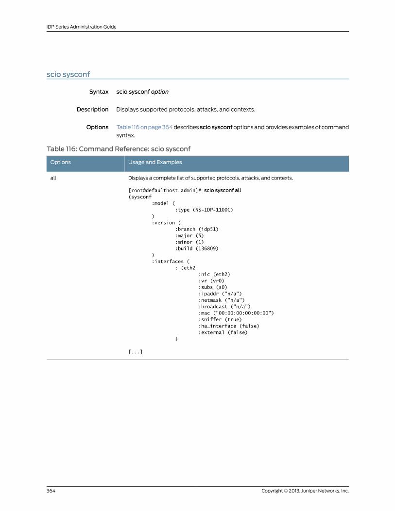
scio sysconf
Syntax scio sysconf option
Description Displays supported protocols, attacks, and contexts.
Options Table 116 on page 364 describessciosysconfoptions and provides examples of command
syntax.
Table 116: Command Reference: scio sysconf
Usage and ExamplesOptions
Displays a complete list of supported protocols, attacks, and contexts.
[root@defaulthost admin]# scio sysconf all(sysconf :model ( :type (NS-IDP-1100C) ) :version ( :branch (idp51) :major (5) :minor (1) :build (136809) ) :interfaces ( : (eth2 :nic (eth2) :vr (vr0) :subs (s0) :ipaddr ("n/a") :netmask ("n/a") :broadcast ("n/a") :mac ("00:00:00:00:00:00") :sniffer (true) :ha_interface (false) :external (false) )
[...]
all
Copyright © 2013, Juniper Networks, Inc.364
IDP Series Administration Guide

Table 116: Command Reference: scio sysconf (continued)
Usage and ExamplesOptions
protocols
365Copyright © 2013, Juniper Networks, Inc.
Appendix D: scio Commands
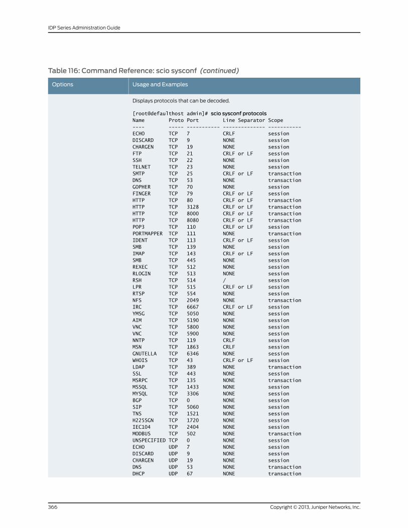
Table 116: Command Reference: scio sysconf (continued)
Usage and ExamplesOptions
Displays protocols that can be decoded.
[root@defaulthost admin]# scio sysconf protocolsName Proto Port Line Separator Scope---- ----- ----------- -------------- -----------ECHO TCP 7 CRLF sessionDISCARD TCP 9 NONE sessionCHARGEN TCP 19 NONE sessionFTP TCP 21 CRLF or LF sessionSSH TCP 22 NONE sessionTELNET TCP 23 NONE sessionSMTP TCP 25 CRLF or LF transactionDNS TCP 53 NONE transactionGOPHER TCP 70 NONE sessionFINGER TCP 79 CRLF or LF sessionHTTP TCP 80 CRLF or LF transactionHTTP TCP 3128 CRLF or LF transactionHTTP TCP 8000 CRLF or LF transactionHTTP TCP 8080 CRLF or LF transactionPOP3 TCP 110 CRLF or LF sessionPORTMAPPER TCP 111 NONE transactionIDENT TCP 113 CRLF or LF sessionSMB TCP 139 NONE sessionIMAP TCP 143 CRLF or LF sessionSMB TCP 445 NONE sessionREXEC TCP 512 NONE sessionRLOGIN TCP 513 NONE sessionRSH TCP 514 / sessionLPR TCP 515 CRLF or LF sessionRTSP TCP 554 NONE sessionNFS TCP 2049 NONE transactionIRC TCP 6667 CRLF or LF sessionYMSG TCP 5050 NONE sessionAIM TCP 5190 NONE sessionVNC TCP 5800 NONE sessionVNC TCP 5900 NONE sessionNNTP TCP 119 CRLF sessionMSN TCP 1863 CRLF sessionGNUTELLA TCP 6346 NONE sessionWHOIS TCP 43 CRLF or LF sessionLDAP TCP 389 NONE transactionSSL TCP 443 NONE sessionMSRPC TCP 135 NONE transactionMSSQL TCP 1433 NONE sessionMYSQL TCP 3306 NONE sessionBGP TCP 0 NONE sessionSIP TCP 5060 NONE sessionTNS TCP 1521 NONE sessionH225SGN TCP 1720 NONE sessionIEC104 TCP 2404 NONE sessionMODBUS TCP 502 NONE transactionUNSPECIFIED TCP 0 NONE sessionECHO UDP 7 NONE sessionDISCARD UDP 9 NONE sessionCHARGEN UDP 19 NONE sessionDNS UDP 53 NONE transactionDHCP UDP 67 NONE transaction
Copyright © 2013, Juniper Networks, Inc.366
IDP Series Administration Guide
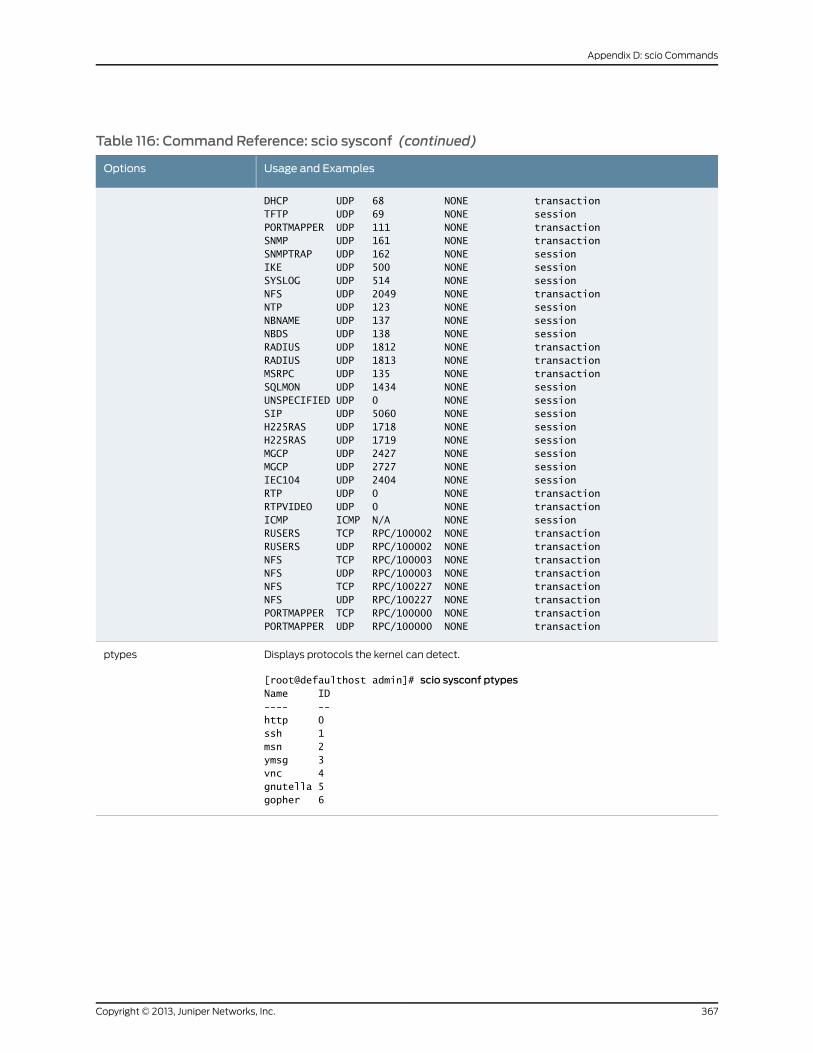
Table 116: Command Reference: scio sysconf (continued)
Usage and ExamplesOptions
DHCP UDP 68 NONE transactionTFTP UDP 69 NONE sessionPORTMAPPER UDP 111 NONE transactionSNMP UDP 161 NONE transactionSNMPTRAP UDP 162 NONE sessionIKE UDP 500 NONE sessionSYSLOG UDP 514 NONE sessionNFS UDP 2049 NONE transactionNTP UDP 123 NONE sessionNBNAME UDP 137 NONE sessionNBDS UDP 138 NONE sessionRADIUS UDP 1812 NONE transactionRADIUS UDP 1813 NONE transactionMSRPC UDP 135 NONE transactionSQLMON UDP 1434 NONE sessionUNSPECIFIED UDP 0 NONE sessionSIP UDP 5060 NONE sessionH225RAS UDP 1718 NONE sessionH225RAS UDP 1719 NONE sessionMGCP UDP 2427 NONE sessionMGCP UDP 2727 NONE sessionIEC104 UDP 2404 NONE sessionRTP UDP 0 NONE transactionRTPVIDEO UDP 0 NONE transactionICMP ICMP N/A NONE sessionRUSERS TCP RPC/100002 NONE transactionRUSERS UDP RPC/100002 NONE transactionNFS TCP RPC/100003 NONE transactionNFS UDP RPC/100003 NONE transactionNFS TCP RPC/100227 NONE transactionNFS UDP RPC/100227 NONE transactionPORTMAPPER TCP RPC/100000 NONE transactionPORTMAPPER UDP RPC/100000 NONE transaction
Displays protocols the kernel can detect.
[root@defaulthost admin]# scio sysconf ptypesName ID---- --http 0ssh 1msn 2ymsg 3vnc 4gnutella 5gopher 6
ptypes
367Copyright © 2013, Juniper Networks, Inc.
Appendix D: scio Commands
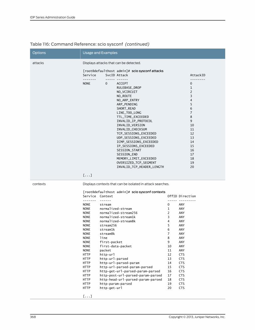
Table 116: Command Reference: scio sysconf (continued)
Usage and ExamplesOptions
Displays attacks that can be detected.
[root@defaulthost admin]# scio sysconf attacksService SvcID Attack AttackID------- ----- ------ --------NONE 0 ACCEPT 0 RULEBASE_DROP 1 NO_VCIRCUIT 2 NO_ROUTE 3 NO_ARP_ENTRY 4 ARP_PENDING 5 SHORT_READ 6 LINE_TOO_LONG 7 TTL_TIME_EXCEEDED 8 INVALID_IP_PROTOCOL 9 INVALID_VERSION 10 INVALID_CHECKSUM 11 TCP_SESSIONS_EXCEEDED 12 UDP_SESSIONS_EXCEEDED 13 ICMP_SESSIONS_EXCEEDED 14 IP_SESSIONS_EXCEEDED 15 SESSION_START 16 SESSION_END 17 MEMORY_LIMIT_EXCEEDED 18 OVERSIZED_TCP_SEGMENT 19 INVALID_TCP_HEADER_LENGTH 20
[...]
attacks
Displays contexts that can be isolated in attack searches.
[root@defaulthost admin]# scio sysconf contextsService Context OffID Direction------- ------ ----- ---------NONE stream 0 ANYNONE normalized-stream 1 ANYNONE normalized-stream256 2 ANYNONE normalized-stream1k 3 ANYNONE normalized-stream8k 4 ANYNONE stream256 5 ANYNONE stream1k 6 ANYNONE stream8k 7 ANYNONE line 8 ANYNONE first-packet 9 ANYNONE first-data-packet 10 ANYNONE packet 11 ANYHTTP http-url 12 CTSHTTP http-url-parsed 13 CTSHTTP http-url-parsed-param 14 CTSHTTP http-url-parsed-param-parsed 15 CTSHTTP http-get-url-parsed-param-parsed 16 CTSHTTP http-post-url-parsed-param-parsed 17 CTSHTTP http-head-url-parsed-param-parsed 18 CTSHTTP http-param-parsed 19 CTSHTTP http-get-url 20 CTS
[...]
contexts
Copyright © 2013, Juniper Networks, Inc.368
IDP Series Administration Guide
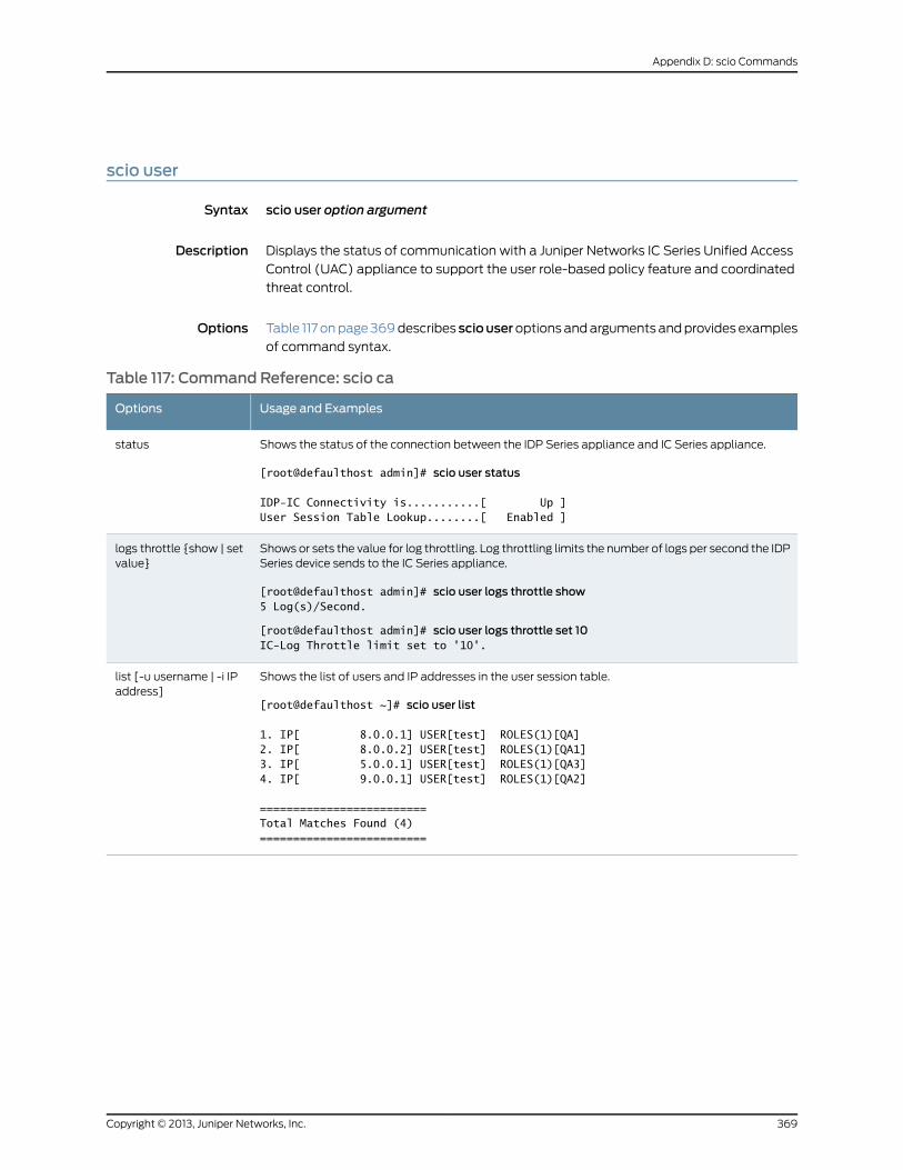
scio user
Syntax scio user option argument
Description Displays the status of communication with a Juniper Networks IC Series Unified Access
Control (UAC) appliance to support the user role-based policy feature and coordinated
threat control.
Options Table 117 on page 369 describes sciouseroptions and arguments and provides examples
of command syntax.
Table 117: Command Reference: scio ca
Usage and ExamplesOptions
Shows the status of the connection between the IDP Series appliance and IC Series appliance.
[root@defaulthost admin]# scio user status
IDP-IC Connectivity is...........[ Up ]User Session Table Lookup........[ Enabled ]
status
Shows or sets the value for log throttling. Log throttling limits the number of logs per second the IDPSeries device sends to the IC Series appliance.
[root@defaulthost admin]# scio user logs throttle show5 Log(s)/Second.
[root@defaulthost admin]# scio user logs throttle set 10IC-Log Throttle limit set to '10'.
logs throttle {show | setvalue}
Shows the list of users and IP addresses in the user session table.
[root@defaulthost ~]# scio user list
1. IP[ 8.0.0.1] USER[test] ROLES(1)[QA]2. IP[ 8.0.0.2] USER[test] ROLES(1)[QA1]3. IP[ 5.0.0.1] USER[test] ROLES(1)[QA3]4. IP[ 9.0.0.1] USER[test] ROLES(1)[QA2]
=========================Total Matches Found (4)=========================
list [-u username | -i IPaddress]
369Copyright © 2013, Juniper Networks, Inc.
Appendix D: scio Commands
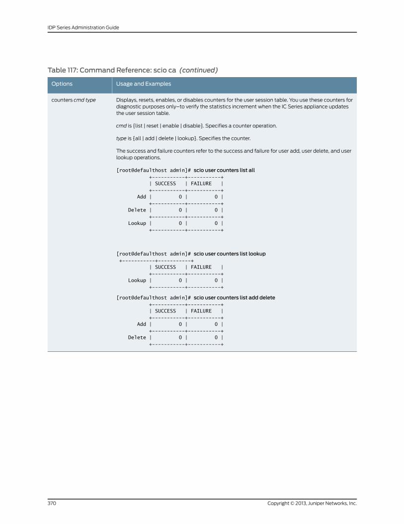
Table 117: Command Reference: scio ca (continued)
Usage and ExamplesOptions
Displays, resets, enables, or disables counters for the user session table. You use these counters fordiagnostic purposes only–to verify the statistics increment when the IC Series appliance updatesthe user session table.
cmd is {list | reset | enable | disable}. Specifies a counter operation.
type is {all | add | delete | lookup}. Specifies the counter.
The success and failure counters refer to the success and failure for user add, user delete, and userlookup operations.
[root@defaulthost admin]# scio user counters list all +-----------+-----------+ | SUCCESS | FAILURE | +-----------+-----------+ Add | 0 | 0 | +-----------+-----------+ Delete | 0 | 0 | +-----------+-----------+ Lookup | 0 | 0 | +-----------+-----------+
[root@defaulthost admin]# scio user counters list lookup +-----------+-----------+ | SUCCESS | FAILURE | +-----------+-----------+ Lookup | 0 | 0 | +-----------+-----------+
[root@defaulthost admin]# scio user counters list add delete +-----------+-----------+ | SUCCESS | FAILURE | +-----------+-----------+ Add | 0 | 0 | +-----------+-----------+ Delete | 0 | 0 | +-----------+-----------+
counters cmd type
Copyright © 2013, Juniper Networks, Inc.370
IDP Series Administration Guide
scio var
Syntax scio var {-s subscriber | -v virtual router} [-f file][varname]
Description Displays variables related to a subscriber or a virtual router.
Options Table 118 on page 372 describes options and arguments to the scio var command and
provides examples of command syntax.
371Copyright © 2013, Juniper Networks, Inc.
Appendix D: scio Commands
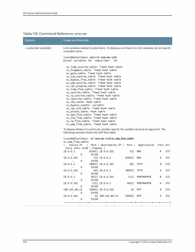
Table 118: Command Reference: scio var
Usage and ExampleOptions
Lists variables related to subscribers. To display a summary list of all variables, do not specifya variable name.
[root@defaulthost admin]# scio var -s s0Kernel variables for 'subscriber' 's0'
sc_icmp_session_table: Timed hash table sc_fragment_table: Timed hash table sc_gate_table: Timed hash table sc_tcp_session_table: Timed hash table sc_bypass_flow_table: Timed hash table sc_udp_session_table: Timed hash table sc_rpc_program_table: Timed hash table sc_icmp_flow_table: Timed hash table sc_session_table: Timed hash table sc_ip_session_table: Timed hash table sc_ipaction_table: Timed hash table sc_ids_cache: Hash table sc_bypass_counts: variable sc_rpc_xid_table: Timed hash table sc_attack_table: Hash table sc_ape_flow_table: Timed hash table sc_tcp_flow_table: Timed hash table sc_ip_flow_table: Timed hash table sc_udp_flow_table: Timed hash table
To display details of a particular variable, specify the variable name as an argument. Thefollowing example shows the UDP flow table:
[root@defaulthost ~]# scio var -s s0 sc_udp_flow_tablesc_udp_flow_table:| Source IP | Port | Destination IP | Port | Application |FSt| Dir |Xtra info| VLAN | Timeout |[8.0.0.1 62091] [8.0.0.101 53] DNS R CTS - 0 59/60[8.0.0.101 53] [8.0.0.1 62091] DNS A STC - 0 59/60[8.0.0.1 58007] [8.0.0.101 69] TFTP R CTS - 0 59/60[8.0.0.101 69] [8.0.0.1 58007] TFTP A STC - 0 59/60[8.0.0.1 3812] [8.0.0.101 111] PORTMAPPER R CTS - 0 59/60[8.0.0.101 111] [8.0.0.1 3812] PORTMAPPER A STC - 0 59/60[88.143.88.25 59092] [8.0.0.101 0] RTP R CTS - 0 59/60[8.0.0.101 0] [88.143.88.25 59092] RTP A STC - 0 59/60---------------+-------+----------------+-------+---------------+---+-----+---------+------+---------|
-s subscriber [variable]
Copyright © 2013, Juniper Networks, Inc.372
IDP Series Administration Guide
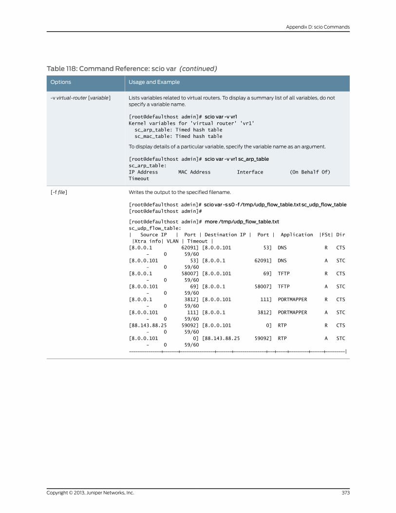
Table 118: Command Reference: scio var (continued)
Usage and ExampleOptions
Lists variables related to virtual routers. To display a summary list of all variables, do notspecify a variable name.
[root@defaulthost admin]# scio var -v vr1Kernel variables for 'virtual router' 'vr1' sc_arp_table: Timed hash table sc_mac_table: Timed hash table
To display details of a particular variable, specify the variable name as an argument.
[root@defaulthost admin]# scio var -v vr1 sc_arp_tablesc_arp_table:IP Address MAC Address Interface (On Behalf Of) Timeout
-v virtual-router [variable]
Writes the output to the specified filename.
[root@defaulthost admin]# sciovar -ss0-f/tmp/udp_flow_table.txtsc_udp_flow_table[root@defaulthost admin]#
[root@defaulthost admin]# more /tmp/udp_flow_table.txtsc_udp_flow_table:| Source IP | Port | Destination IP | Port | Application |FSt| Dir |Xtra info| VLAN | Timeout |[8.0.0.1 62091] [8.0.0.101 53] DNS R CTS - 0 59/60[8.0.0.101 53] [8.0.0.1 62091] DNS A STC - 0 59/60[8.0.0.1 58007] [8.0.0.101 69] TFTP R CTS - 0 59/60[8.0.0.101 69] [8.0.0.1 58007] TFTP A STC - 0 59/60[8.0.0.1 3812] [8.0.0.101 111] PORTMAPPER R CTS - 0 59/60[8.0.0.101 111] [8.0.0.1 3812] PORTMAPPER A STC - 0 59/60[88.143.88.25 59092] [8.0.0.101 0] RTP R CTS - 0 59/60[8.0.0.101 0] [88.143.88.25 59092] RTP A STC - 0 59/60---------------+-------+----------------+-------+---------------+---+-----+---------+------+---------|
[-f file]
373Copyright © 2013, Juniper Networks, Inc.
Appendix D: scio Commands
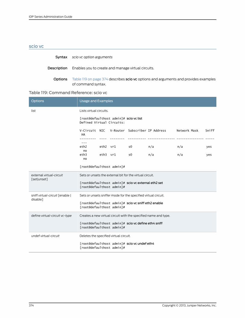
scio vc
Syntax scio vc option arguments
Description Enables you to create and manage virtual circuits.
Options Table 119 on page 374 describes scio vc options and arguments and provides examples
of command syntax.
Table 119: Command Reference: scio vc
Usage and ExamplesOptions
Lists virtual circuits.
[root@defaulthost admin]# scio vc listDefined Virtual Circuits:
V-Circuit NIC V-Router Subscriber IP Address Network Mask Sniff HA--------- ---- -------- ---------- --------------- --------------- ----- ---eth2 eth2 vr1 s0 n/a n/a yes noeth3 eth3 vr1 s0 n/a n/a yes no
[root@defaulthost admin]#
list
Sets or unsets the external bit for the virtual circuit.
[root@defaulthost admin]# scio vc external eth2 set[root@defaulthost admin]#
external virtual-circuit[set|unset]
Sets or unsets sniffer mode for the specified virtual circuit.
[root@defaulthost admin]# scio vc sniff eth2 enable[root@defaulthost admin]#
sniff virtual-circuit [enable |disable]
Creates a new virtual circuit with the specified name and type.
[root@defaulthost admin]# scio vc define eth4 sniff[root@defaulthost admin]#
define virtual-circuit vc-type
Deletes the specified virtual circuit.
[root@defaulthost admin]# scio vc undef eth4[root@defaulthost admin]#
undef virtual-circuit
Copyright © 2013, Juniper Networks, Inc.374
IDP Series Administration Guide
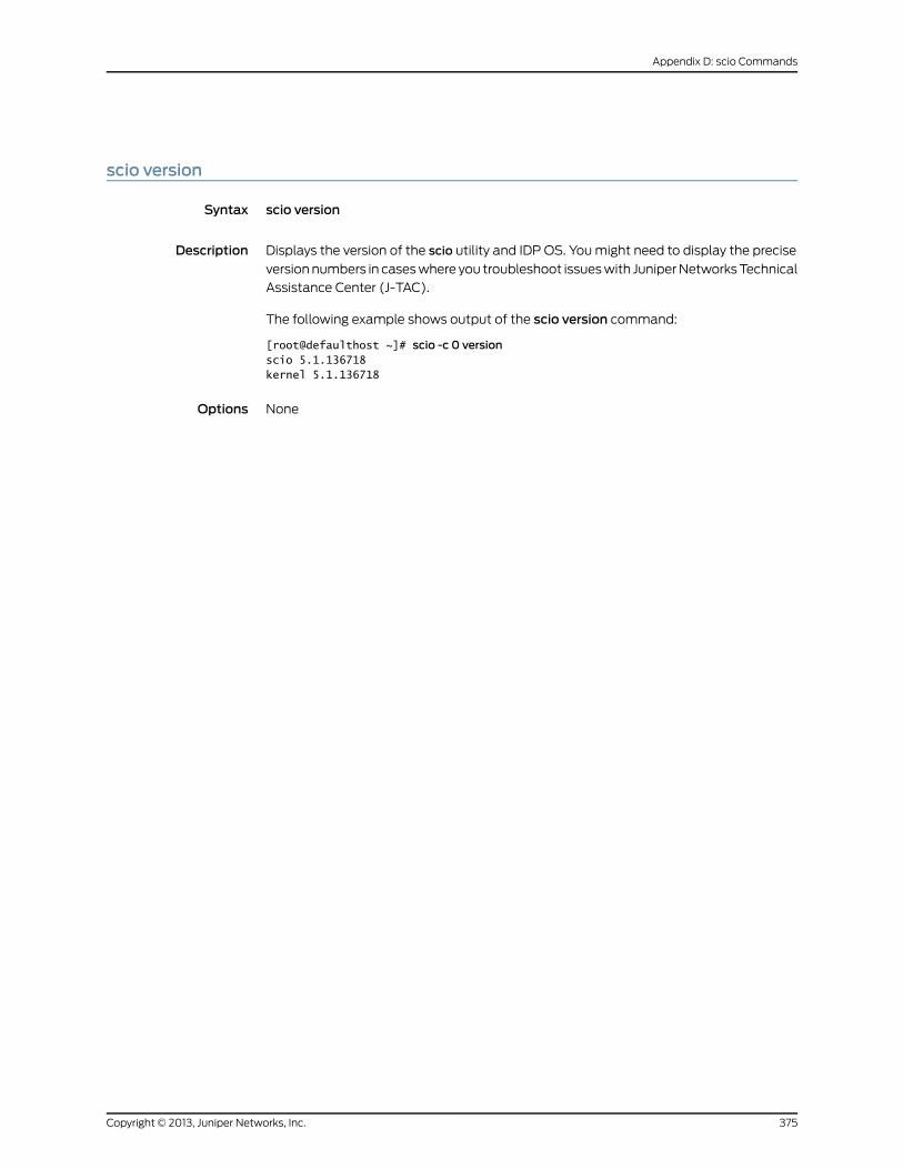
scio version
Syntax scio version
Description Displays the version of the scio utility and IDP OS. You might need to display the precise
version numbers in cases where you troubleshoot issues with Juniper Networks Technical
Assistance Center (J-TAC).
The following example shows output of the scio version command:
[root@defaulthost ~]# scio -c 0 versionscio 5.1.136718kernel 5.1.136718
Options None
375Copyright © 2013, Juniper Networks, Inc.
Appendix D: scio Commands
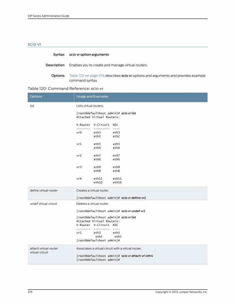
scio vr
Syntax scio vr option arguments
Description Enables you to create and manage virtual routers.
Options Table 120 on page 376 describes scio vr options and arguments and provides example
command syntax.
Table 120: Command Reference: scio vr
Usage and ExamplesOptions
Lists virtual routers.
[root@defaulthost admin]# scio vr listAttached Virtual Routers:
V-Router V-Circuit NIC-------- --------- ----vr0 eth3 eth3 eth2 eth2
vr1 eth5 eth5 eth4 eth4
vr2 eth7 eth7 eth6 eth6
vr3 eth9 eth9 eth8 eth8
vr4 eth11 eth11 eth10 eth10
list
Creates a virtual router.
[root@defaulthost admin]# scio vr define vr2
define virtual-router
Deletes a virtual router.
[root@defaulthost admin]# scio vr undef vr2
[root@defaulthost admin]# scio vr listAttached Virtual Routers:V-Router V-Circuit NIC-------- --------- ----vr1 eth3 eth3 eth2 eth2[root@defaulthost admin]#
undef virtual-circuit
Associates a virtual circuit with a virtual router..
[root@defaulthost admin]# scio vr attach vr1 eth4[root@defaulthost admin]#
attach virtual-routervirtual-circuit
Copyright © 2013, Juniper Networks, Inc.376
IDP Series Administration Guide
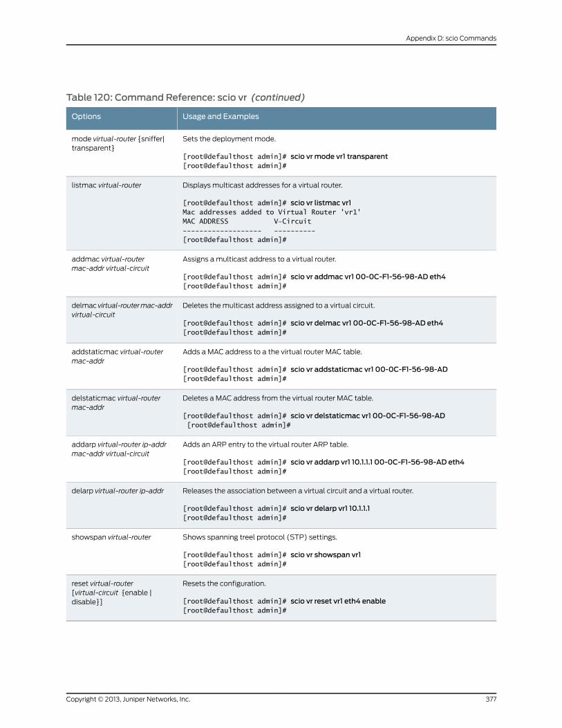
Table 120: Command Reference: scio vr (continued)
Usage and ExamplesOptions
Sets the deployment mode.
[root@defaulthost admin]# scio vr mode vr1 transparent[root@defaulthost admin]#
mode virtual-router {sniffer|transparent}
Displays multicast addresses for a virtual router.
[root@defaulthost admin]# scio vr listmac vr1Mac addresses added to Virtual Router 'vr1'MAC ADDRESS V-Circuit------------------- ----------[root@defaulthost admin]#
listmac virtual-router
Assigns a multicast address to a virtual router.
[root@defaulthost admin]# scio vr addmac vr1 00-0C-F1-56-98-AD eth4[root@defaulthost admin]#
addmac virtual-routermac-addr virtual-circuit
Deletes the multicast address assigned to a virtual circuit.
[root@defaulthost admin]# scio vr delmac vr1 00-0C-F1-56-98-AD eth4[root@defaulthost admin]#
delmacvirtual-routermac-addrvirtual-circuit
Adds a MAC address to a the virtual router MAC table.
[root@defaulthost admin]# scio vr addstaticmac vr1 00-0C-F1-56-98-AD[root@defaulthost admin]#
addstaticmac virtual-routermac-addr
Deletes a MAC address from the virtual router MAC table.
[root@defaulthost admin]# scio vr delstaticmac vr1 00-0C-F1-56-98-AD [root@defaulthost admin]#
delstaticmac virtual-routermac-addr
Adds an ARP entry to the virtual router ARP table.
[root@defaulthost admin]# scio vr addarp vr1 10.1.1.1 00-0C-F1-56-98-AD eth4[root@defaulthost admin]#
addarp virtual-router ip-addrmac-addr virtual-circuit
Releases the association between a virtual circuit and a virtual router.
[root@defaulthost admin]# scio vr delarp vr1 10.1.1.1[root@defaulthost admin]#
delarp virtual-router ip-addr
Shows spanning treel protocol (STP) settings.
[root@defaulthost admin]# scio vr showspan vr1[root@defaulthost admin]#
showspan virtual-router
Resets the configuration.
[root@defaulthost admin]# scio vr reset vr1 eth4 enable[root@defaulthost admin]#
reset virtual-router[virtual-circuit {enable |disable}]
377Copyright © 2013, Juniper Networks, Inc.
Appendix D: scio Commands

Copyright © 2013, Juniper Networks, Inc.378
IDP Series Administration Guide
APPENDIX E
statview Commands
• statview view
379Copyright © 2013, Juniper Networks, Inc.
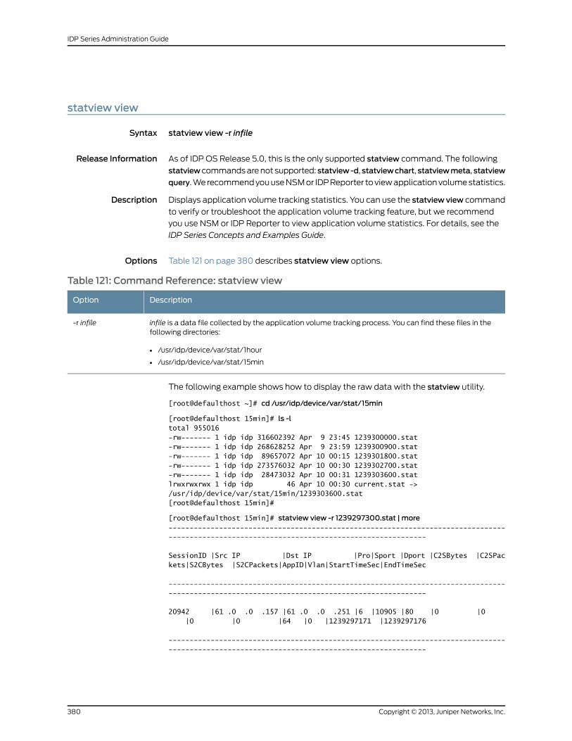
statview view
Syntax statview view -r infile
Release Information As of IDP OS Release 5.0, this is the only supported statview command. The following
statviewcommands are not supported: statview-d, statviewchart, statviewmeta, statview
query. We recommend you use NSM or IDP Reporter to view application volume statistics.
Description Displays application volume tracking statistics. You can use the statview view command
to verify or troubleshoot the application volume tracking feature, but we recommend
you use NSM or IDP Reporter to view application volume statistics. For details, see the
IDP Series Concepts and Examples Guide.
Options Table 121 on page 380 describes statview view options.
Table 121: Command Reference: statview view
DescriptionOption
infile is a data file collected by the application volume tracking process. You can find these files in thefollowing directories:
• /usr/idp/device/var/stat/1hour
• /usr/idp/device/var/stat/15min
-r infile
The following example shows how to display the raw data with the statview utility.
[root@defaulthost ~]# cd /usr/idp/device/var/stat/15min
[root@defaulthost 15min]# ls -ltotal 955016-rw------- 1 idp idp 316602392 Apr 9 23:45 1239300000.stat-rw------- 1 idp idp 268628252 Apr 9 23:59 1239300900.stat-rw------- 1 idp idp 89657072 Apr 10 00:15 1239301800.stat-rw------- 1 idp idp 273576032 Apr 10 00:30 1239302700.stat-rw------- 1 idp idp 28473032 Apr 10 00:31 1239303600.statlrwxrwxrwx 1 idp idp 46 Apr 10 00:30 current.stat -> /usr/idp/device/var/stat/15min/1239303600.stat[root@defaulthost 15min]#
[root@defaulthost 15min]# statview view -r 1239297300.stat | more---------------------------------------------------------------------------------------------------------------------------------------------
SessionID |Src IP |Dst IP |Pro|Sport |Dport |C2SBytes |C2SPackets|S2CBytes |S2CPackets|AppID|Vlan|StartTimeSec|EndTimeSec
---------------------------------------------------------------------------------------------------------------------------------------------
20942 |61 .0 .0 .157 |61 .0 .0 .251 |6 |10905 |80 |0 |0 |0 |0 |64 |0 |1239297171 |1239297176
---------------------------------------------------------------------------------------------------------------------------------------------
Copyright © 2013, Juniper Networks, Inc.380
IDP Series Administration Guide
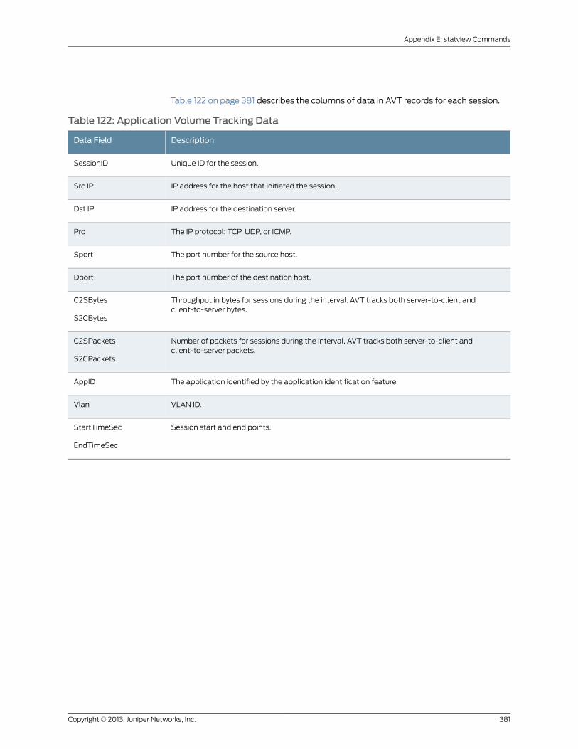
Table 122 on page 381 describes the columns of data in AVT records for each session.
Table 122: Application Volume Tracking Data
DescriptionData Field
Unique ID for the session.SessionID
IP address for the host that initiated the session.Src IP
IP address for the destination server.Dst IP
The IP protocol: TCP, UDP, or ICMP.Pro
The port number for the source host.Sport
The port number of the destination host.Dport
Throughput in bytes for sessions during the interval. AVT tracks both server-to-client andclient-to-server bytes.
C2SBytes
S2CBytes
Number of packets for sessions during the interval. AVT tracks both server-to-client andclient-to-server packets.
C2SPackets
S2CPackets
The application identified by the application identification feature.AppID
VLAN ID.Vlan
Session start and end points.StartTimeSec
EndTimeSec
381Copyright © 2013, Juniper Networks, Inc.
Appendix E: statview Commands

Copyright © 2013, Juniper Networks, Inc.382
IDP Series Administration Guide
APPENDIX F
jnetTcpdump
• jnetTcpdump
383Copyright © 2013, Juniper Networks, Inc.
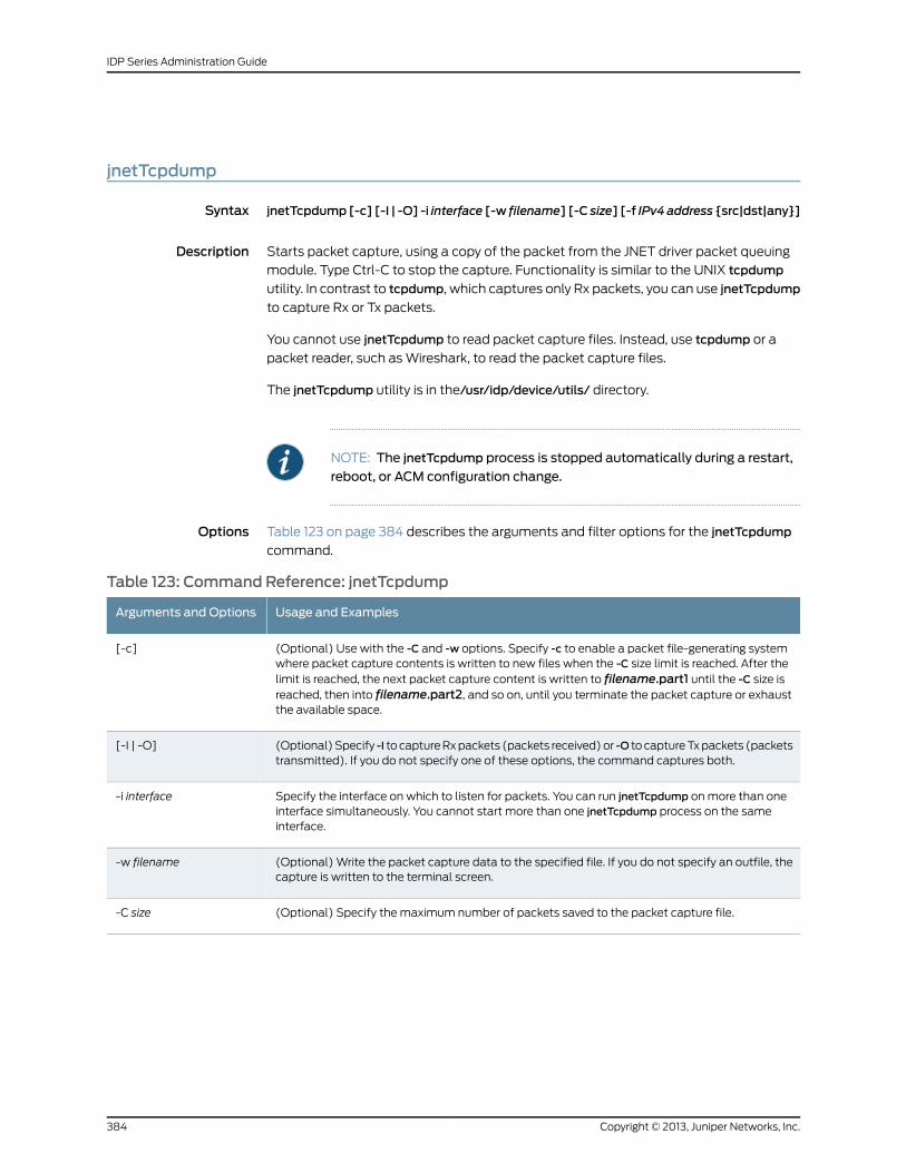
jnetTcpdump
Syntax jnetTcpdump[-c] [-I | -O] -i interface [-w filename] [-C size] [-f IPv4address {src|dst|any}]
Description Starts packet capture, using a copy of the packet from the JNET driver packet queuing
module. Type Ctrl-C to stop the capture. Functionality is similar to the UNIX tcpdump
utility. In contrast to tcpdump, which captures only Rx packets, you can use jnetTcpdump
to capture Rx or Tx packets.
You cannot use jnetTcpdump to read packet capture files. Instead, use tcpdump or a
packet reader, such as Wireshark, to read the packet capture files.
The jnetTcpdump utility is in the/usr/idp/device/utils/ directory.
NOTE: The jnetTcpdump process is stopped automatically during a restart,
reboot, or ACM configuration change.
Options Table 123 on page 384 describes the arguments and filter options for the jnetTcpdump
command.
Table 123: Command Reference: jnetTcpdump
Usage and ExamplesArguments and Options
(Optional) Use with the -C and -w options. Specify -c to enable a packet file-generating systemwhere packet capture contents is written to new files when the -C size limit is reached. After thelimit is reached, the next packet capture content is written to filename.part1 until the -C size isreached, then into filename.part2, and so on, until you terminate the packet capture or exhaustthe available space.
[-c]
(Optional) Specify -I to capture Rx packets (packets received) or -O to capture Tx packets (packetstransmitted). If you do not specify one of these options, the command captures both.
[-I | -O]
Specify the interface on which to listen for packets. You can run jnetTcpdump on more than oneinterface simultaneously. You cannot start more than one jnetTcpdump process on the sameinterface.
-i interface
(Optional) Write the packet capture data to the specified file. If you do not specify an outfile, thecapture is written to the terminal screen.
-w filename
(Optional) Specify the maximum number of packets saved to the packet capture file.-C size
Copyright © 2013, Juniper Networks, Inc.384
IDP Series Administration Guide
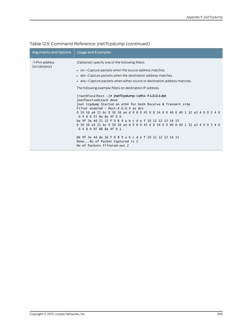
Table 123: Command Reference: jnetTcpdump (continued)
Usage and ExamplesArguments and Options
(Optional) specify one of the following filters:
• src—Capture packets when the source address matches.
• dst—Capture packets when the destination address matches.
• any—Capture packets when either source or destination address matches.
The following example filters on destination IP address.
[root@localhost ~]# jnetTcpdump -i eth4 -f 4.0.0.4 dstjnetPassiveAttach donejnet tcpdump Started on eth4 for both Receive & Transmit sideFilter enabled - Host:4.0.0.4 as dst0 50 56 a4 21 6c 0 50 56 a4 d 9 8 0 45 0 0 54 0 0 40 0 40 1 32 a3 4 0 0 3 4 0 0 4 8 0 55 8e 8e 4f 0 0ba 9f 3e 4d 21 32 f 0 8 9 a b c d e f 10 11 12 13 14 150 50 56 a4 21 6c 0 50 56 a4 d 9 8 0 45 0 0 54 0 0 40 0 40 1 32 a3 4 0 0 3 4 0 0 4 8 0 97 88 8e 4f 0 1
bb 9f 3e 4d de 36 f 0 8 9 a b c d e f 10 11 12 13 14 15Done...No of Packet Captured is 2No of Packets filtered-out 2
-f IPv4 address{src|dst|any}
385Copyright © 2013, Juniper Networks, Inc.
Appendix F: jnetTcpdump

Copyright © 2013, Juniper Networks, Inc.386
IDP Series Administration Guide
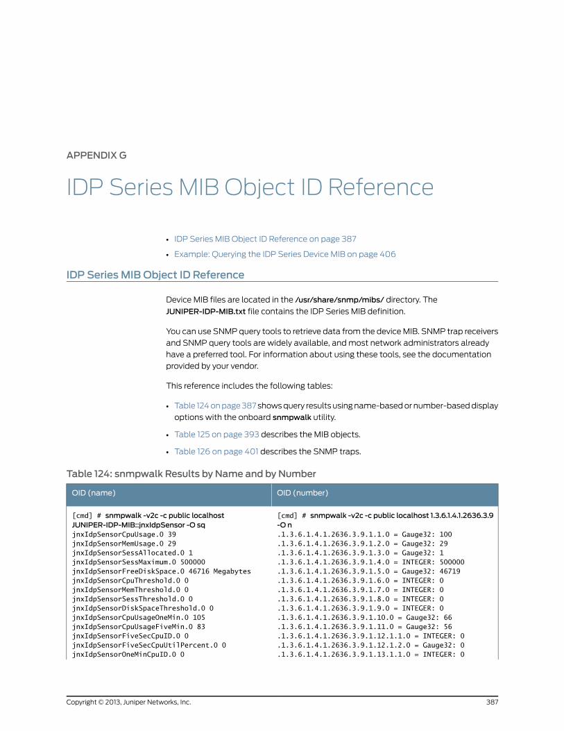
APPENDIX G
IDP Series MIB Object ID Reference
• IDP Series MIB Object ID Reference on page 387
• Example: Querying the IDP Series Device MIB on page 406
IDP Series MIB Object ID Reference
Device MIB files are located in the /usr/share/snmp/mibs/ directory. The
JUNIPER-IDP-MIB.txt file contains the IDP Series MIB definition.
You can use SNMP query tools to retrieve data from the device MIB. SNMP trap receivers
and SNMP query tools are widely available, and most network administrators already
have a preferred tool. For information about using these tools, see the documentation
provided by your vendor.
This reference includes the following tables:
• Table 124 on page 387 shows query results using name-based or number-based display
options with the onboard snmpwalk utility.
• Table 125 on page 393 describes the MIB objects.
• Table 126 on page 401 describes the SNMP traps.
Table 124: snmpwalk Results by Name and by Number
OID (number)OID (name)
[cmd] # snmpwalk -v2c -c public localhost 1.3.6.1.4.1.2636.3.9-O n
[cmd] # snmpwalk -v2c -c public localhostJUNIPER-IDP-MIB::jnxIdpSensor -O sq
.1.3.6.1.4.1.2636.3.9.1.1.0 = Gauge32: 100
.1.3.6.1.4.1.2636.3.9.1.2.0 = Gauge32: 29jnxIdpSensorCpuUsage.0 39jnxIdpSensorMemUsage.0 29
.1.3.6.1.4.1.2636.3.9.1.3.0 = Gauge32: 1jnxIdpSensorSessAllocated.0 1
.1.3.6.1.4.1.2636.3.9.1.4.0 = INTEGER: 500000jnxIdpSensorSessMaximum.0 500000
.1.3.6.1.4.1.2636.3.9.1.5.0 = Gauge32: 46719jnxIdpSensorFreeDiskSpace.0 46716 Megabytes
.1.3.6.1.4.1.2636.3.9.1.6.0 = INTEGER: 0jnxIdpSensorCpuThreshold.0 0
.1.3.6.1.4.1.2636.3.9.1.7.0 = INTEGER: 0jnxIdpSensorMemThreshold.0 0
.1.3.6.1.4.1.2636.3.9.1.8.0 = INTEGER: 0jnxIdpSensorSessThreshold.0 0
.1.3.6.1.4.1.2636.3.9.1.9.0 = INTEGER: 0jnxIdpSensorDiskSpaceThreshold.0 0
.1.3.6.1.4.1.2636.3.9.1.10.0 = Gauge32: 66jnxIdpSensorCpuUsageOneMin.0 105
.1.3.6.1.4.1.2636.3.9.1.11.0 = Gauge32: 56jnxIdpSensorCpuUsageFiveMin.0 83
.1.3.6.1.4.1.2636.3.9.1.12.1.1.0 = INTEGER: 0jnxIdpSensorFiveSecCpuID.0 0
.1.3.6.1.4.1.2636.3.9.1.12.1.2.0 = Gauge32: 0jnxIdpSensorFiveSecCpuUtilPercent.0 0
.1.3.6.1.4.1.2636.3.9.1.13.1.1.0 = INTEGER: 0jnxIdpSensorOneMinCpuID.0 0
387Copyright © 2013, Juniper Networks, Inc.
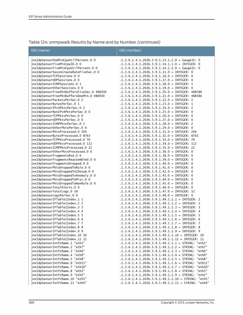
Table 124: snmpwalk Results by Name and by Number (continued)
OID (number)OID (name)
jnxIdpSensorOneMinCpuUtilPercent.0 0jnxIdpSensorFiveMinCpuID.0 0
.1.3.6.1.4.1.2636.3.9.1.13.1.2.0 = Gauge32: 0
.1.3.6.1.4.1.2636.3.9.1.14.1.1.0 = INTEGER: 0jnxIdpSensorFiveMinCpuUtilPercent.0 0 .1.3.6.1.4.1.2636.3.9.1.14.1.2.0 = Gauge32: 0jnxIdpSensorSessnCreateRateFiveSec.0 0 .1.3.6.1.4.1.2636.3.9.1.15.0 = INTEGER: 0jnxIdpSensorTCPSessions.0 0 .1.3.6.1.4.1.2636.3.9.1.16.0 = INTEGER: 0jnxIdpSensorUDPSessions.0 0 .1.3.6.1.4.1.2636.3.9.1.17.0 = INTEGER: 0jnxIdpSensorICMPSessions.0 1 .1.3.6.1.4.1.2636.3.9.1.18.0 = INTEGER: 1jnxIdpSensorOtherSessions.0 0 .1.3.6.1.4.1.2636.3.9.1.19.0 = INTEGER: 0jnxIdpSensorFreePktBuffersFiveSec.0 486930 .1.3.6.1.4.1.2636.3.9.1.20.0 = INTEGER: 488586jnxIdpSensorFreePktBuffersOneMin.0 486930 .1.3.6.1.4.1.2636.3.9.1.21.0 = INTEGER: 488586jnxIdpSensorPacketsPerSec.0 2 .1.3.6.1.4.1.2636.3.9.1.22.0 = INTEGER: 2jnxIdpSensorBytesPerSec.0 1 .1.3.6.1.4.1.2636.3.9.1.23.0 = INTEGER: 1jnxIdpSensorIPv4PktsPerSec.0 2 .1.3.6.1.4.1.2636.3.9.1.24.0 = INTEGER: 2jnxIdpSensorNonIPv4PktsPerSec.0 0 .1.3.6.1.4.1.2636.3.9.1.25.0 = INTEGER: 0jnxIdpSensorTCPPktsPerSec.0 0 .1.3.6.1.4.1.2636.3.9.1.26.0 = INTEGER: 0jnxIdpSensorUDPPktsPerSec.0 0 .1.3.6.1.4.1.2636.3.9.1.27.0 = INTEGER: 0jnxIdpSensorICMPPktsPerSec.0 2 .1.3.6.1.4.1.2636.3.9.1.28.0 = INTEGER: 2jnxIdpSensorOtherPktsPerSec.0 0 .1.3.6.1.4.1.2636.3.9.1.29.0 = INTEGER: 0jnxIdpSensorPktsProcessed.0 204 .1.3.6.1.4.1.2636.3.9.1.31.0 = INTEGER: 204jnxIdpSensorBytesProcessed.0 8763 .1.3.6.1.4.1.2636.3.9.1.32.0 = INTEGER: 8763jnxIdpSensorTCPPktsProcessed.0 70 .1.3.6.1.4.1.2636.3.9.1.33.0 = INTEGER: 70jnxIdpSensorUDPPktsProcessed.0 112 .1.3.6.1.4.1.2636.3.9.1.34.0 = INTEGER: 112jnxIdpSensorICMPPktsProcessed.0 22 .1.3.6.1.4.1.2636.3.9.1.35.0 = INTEGER: 22jnxIdpSensorOtherPktsProcessed.0 0 .1.3.6.1.4.1.2636.3.9.1.36.0 = INTEGER: 0jnxIdpSensorFragmentsRxd.0 0 .1.3.6.1.4.1.2636.3.9.1.38.0 = INTEGER: 0jnxIdpSensorFragmentsReassembled.0 0 .1.3.6.1.4.1.2636.3.9.1.39.0 = INTEGER: 0jnxIdpSensorFragmentsDropped.0 0 .1.3.6.1.4.1.2636.3.9.1.40.0 = INTEGER: 0jnxIdpSensorPktsDroppedToRule.0 0 .1.3.6.1.4.1.2636.3.9.1.41.0 = INTEGER: 0jnxIdpSensorPktsDroppedToChksum.0 0 .1.3.6.1.4.1.2636.3.9.1.42.0 = INTEGER: 0jnxIdpSensorPktsDroppedToAnomaly.0 0 .1.3.6.1.4.1.2636.3.9.1.43.0 = INTEGER: 0jnxIdpSensorPktsDroppedToMisc.0 0 .1.3.6.1.4.1.2636.3.9.1.44.0 = INTEGER: 0jnxIdpSensorPktsDroppedToNonRule.0 0 .1.3.6.1.4.1.2636.3.9.1.45.0 = INTEGER: 0jnxIdpSensorTotalAlerts.0 0 .1.3.6.1.4.1.2636.3.9.1.46.0 = INTEGER: 0jnxIdpSensorTotalLogs.0 58 .1.3.6.1.4.1.2636.3.9.1.47.0 = INTEGER: 52jnxIdpSensorLogsPerSec.0 0 .1.3.6.1.4.1.2636.3.9.1.48.0 = INTEGER: 0jnxIdpSensorIFTable1Index.1 1 .1.3.6.1.4.1.2636.3.9.1.49.1.1.1 = INTEGER: 1jnxIdpSensorIFTable1Index.2 2 .1.3.6.1.4.1.2636.3.9.1.49.1.1.2 = INTEGER: 2jnxIdpSensorIFTable1Index.3 3 .1.3.6.1.4.1.2636.3.9.1.49.1.1.3 = INTEGER: 3jnxIdpSensorIFTable1Index.4 4 .1.3.6.1.4.1.2636.3.9.1.49.1.1.4 = INTEGER: 4jnxIdpSensorIFTable1Index.5 5 .1.3.6.1.4.1.2636.3.9.1.49.1.1.5 = INTEGER: 5jnxIdpSensorIFTable1Index.6 6 .1.3.6.1.4.1.2636.3.9.1.49.1.1.6 = INTEGER: 6jnxIdpSensorIFTable1Index.7 7 .1.3.6.1.4.1.2636.3.9.1.49.1.1.7 = INTEGER: 7jnxIdpSensorIFTable1Index.8 8 .1.3.6.1.4.1.2636.3.9.1.49.1.1.8 = INTEGER: 8jnxIdpSensorIFTable1Index.9 9 .1.3.6.1.4.1.2636.3.9.1.49.1.1.9 = INTEGER: 9jnxIdpSensorIFTable1Index.10 10 .1.3.6.1.4.1.2636.3.9.1.49.1.1.10 = INTEGER: 10jnxIdpSensorIFTable1Index.11 11 .1.3.6.1.4.1.2636.3.9.1.49.1.1.11 = INTEGER: 11jnxIdpSensorIntfcName.1 "eth1" .1.3.6.1.4.1.2636.3.9.1.49.1.2.1 = STRING: "eth1"jnxIdpSensorIntfcName.2 "eth7" .1.3.6.1.4.1.2636.3.9.1.49.1.2.2 = STRING: "eth7"jnxIdpSensorIntfcName.3 "eth6" .1.3.6.1.4.1.2636.3.9.1.49.1.2.3 = STRING: "eth6"jnxIdpSensorIntfcName.4 "eth9" .1.3.6.1.4.1.2636.3.9.1.49.1.2.4 = STRING: "eth9"jnxIdpSensorIntfcName.5 "eth8" .1.3.6.1.4.1.2636.3.9.1.49.1.2.5 = STRING: "eth8"jnxIdpSensorIntfcName.6 "eth11" .1.3.6.1.4.1.2636.3.9.1.49.1.2.6 = STRING: "eth11"jnxIdpSensorIntfcName.7 "eth10" .1.3.6.1.4.1.2636.3.9.1.49.1.2.7 = STRING: "eth10"jnxIdpSensorIntfcName.8 "eth3" .1.3.6.1.4.1.2636.3.9.1.49.1.2.8 = STRING: "eth3"jnxIdpSensorIntfcName.9 "eth2" .1.3.6.1.4.1.2636.3.9.1.49.1.2.9 = STRING: "eth2"jnxIdpSensorIntfcName.10 "eth5" .1.3.6.1.4.1.2636.3.9.1.49.1.2.10 = STRING: "eth5"jnxIdpSensorIntfcName.11 "eth4" .1.3.6.1.4.1.2636.3.9.1.49.1.2.11 = STRING: "eth4"
Copyright © 2013, Juniper Networks, Inc.388
IDP Series Administration Guide
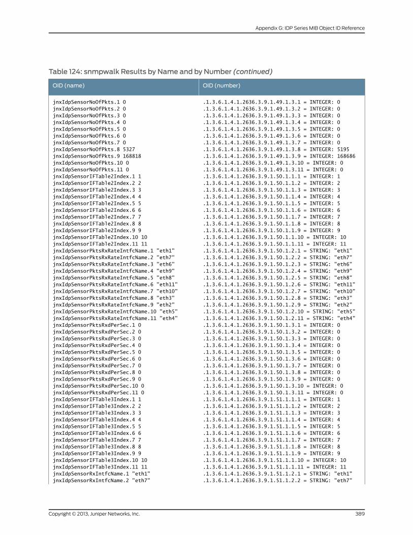
Table 124: snmpwalk Results by Name and by Number (continued)
OID (number)OID (name)
.1.3.6.1.4.1.2636.3.9.1.49.1.3.1 = INTEGER: 0
.1.3.6.1.4.1.2636.3.9.1.49.1.3.2 = INTEGER: 0jnxIdpSensorNoOfPkts.1 0jnxIdpSensorNoOfPkts.2 0
.1.3.6.1.4.1.2636.3.9.1.49.1.3.3 = INTEGER: 0jnxIdpSensorNoOfPkts.3 0
.1.3.6.1.4.1.2636.3.9.1.49.1.3.4 = INTEGER: 0jnxIdpSensorNoOfPkts.4 0
.1.3.6.1.4.1.2636.3.9.1.49.1.3.5 = INTEGER: 0jnxIdpSensorNoOfPkts.5 0
.1.3.6.1.4.1.2636.3.9.1.49.1.3.6 = INTEGER: 0jnxIdpSensorNoOfPkts.6 0
.1.3.6.1.4.1.2636.3.9.1.49.1.3.7 = INTEGER: 0jnxIdpSensorNoOfPkts.7 0
.1.3.6.1.4.1.2636.3.9.1.49.1.3.8 = INTEGER: 5195jnxIdpSensorNoOfPkts.8 5327
.1.3.6.1.4.1.2636.3.9.1.49.1.3.9 = INTEGER: 168686jnxIdpSensorNoOfPkts.9 168818
.1.3.6.1.4.1.2636.3.9.1.49.1.3.10 = INTEGER: 0jnxIdpSensorNoOfPkts.10 0
.1.3.6.1.4.1.2636.3.9.1.49.1.3.11 = INTEGER: 0jnxIdpSensorNoOfPkts.11 0
.1.3.6.1.4.1.2636.3.9.1.50.1.1.1 = INTEGER: 1jnxIdpSensorIFTable2Index.1 1
.1.3.6.1.4.1.2636.3.9.1.50.1.1.2 = INTEGER: 2jnxIdpSensorIFTable2Index.2 2
.1.3.6.1.4.1.2636.3.9.1.50.1.1.3 = INTEGER: 3jnxIdpSensorIFTable2Index.3 3
.1.3.6.1.4.1.2636.3.9.1.50.1.1.4 = INTEGER: 4jnxIdpSensorIFTable2Index.4 4
.1.3.6.1.4.1.2636.3.9.1.50.1.1.5 = INTEGER: 5jnxIdpSensorIFTable2Index.5 5
.1.3.6.1.4.1.2636.3.9.1.50.1.1.6 = INTEGER: 6jnxIdpSensorIFTable2Index.6 6
.1.3.6.1.4.1.2636.3.9.1.50.1.1.7 = INTEGER: 7jnxIdpSensorIFTable2Index.7 7
.1.3.6.1.4.1.2636.3.9.1.50.1.1.8 = INTEGER: 8jnxIdpSensorIFTable2Index.8 8
.1.3.6.1.4.1.2636.3.9.1.50.1.1.9 = INTEGER: 9jnxIdpSensorIFTable2Index.9 9
.1.3.6.1.4.1.2636.3.9.1.50.1.1.10 = INTEGER: 10jnxIdpSensorIFTable2Index.10 10
.1.3.6.1.4.1.2636.3.9.1.50.1.1.11 = INTEGER: 11jnxIdpSensorIFTable2Index.11 11
.1.3.6.1.4.1.2636.3.9.1.50.1.2.1 = STRING: "eth1"jnxIdpSensorPktsRxRateIntfcName.1 "eth1"
.1.3.6.1.4.1.2636.3.9.1.50.1.2.2 = STRING: "eth7"jnxIdpSensorPktsRxRateIntfcName.2 "eth7"
.1.3.6.1.4.1.2636.3.9.1.50.1.2.3 = STRING: "eth6"jnxIdpSensorPktsRxRateIntfcName.3 "eth6"
.1.3.6.1.4.1.2636.3.9.1.50.1.2.4 = STRING: "eth9"jnxIdpSensorPktsRxRateIntfcName.4 "eth9"
.1.3.6.1.4.1.2636.3.9.1.50.1.2.5 = STRING: "eth8"jnxIdpSensorPktsRxRateIntfcName.5 "eth8"
.1.3.6.1.4.1.2636.3.9.1.50.1.2.6 = STRING: "eth11"jnxIdpSensorPktsRxRateIntfcName.6 "eth11"
.1.3.6.1.4.1.2636.3.9.1.50.1.2.7 = STRING: "eth10"jnxIdpSensorPktsRxRateIntfcName.7 "eth10"
.1.3.6.1.4.1.2636.3.9.1.50.1.2.8 = STRING: "eth3"jnxIdpSensorPktsRxRateIntfcName.8 "eth3"
.1.3.6.1.4.1.2636.3.9.1.50.1.2.9 = STRING: "eth2"jnxIdpSensorPktsRxRateIntfcName.9 "eth2"
.1.3.6.1.4.1.2636.3.9.1.50.1.2.10 = STRING: "eth5"jnxIdpSensorPktsRxRateIntfcName.10 "eth5"
.1.3.6.1.4.1.2636.3.9.1.50.1.2.11 = STRING: "eth4"jnxIdpSensorPktsRxRateIntfcName.11 "eth4"
.1.3.6.1.4.1.2636.3.9.1.50.1.3.1 = INTEGER: 0jnxIdpSensorPktsRxdPerSec.1 0
.1.3.6.1.4.1.2636.3.9.1.50.1.3.2 = INTEGER: 0jnxIdpSensorPktsRxdPerSec.2 0
.1.3.6.1.4.1.2636.3.9.1.50.1.3.3 = INTEGER: 0jnxIdpSensorPktsRxdPerSec.3 0
.1.3.6.1.4.1.2636.3.9.1.50.1.3.4 = INTEGER: 0jnxIdpSensorPktsRxdPerSec.4 0
.1.3.6.1.4.1.2636.3.9.1.50.1.3.5 = INTEGER: 0jnxIdpSensorPktsRxdPerSec.5 0
.1.3.6.1.4.1.2636.3.9.1.50.1.3.6 = INTEGER: 0jnxIdpSensorPktsRxdPerSec.6 0
.1.3.6.1.4.1.2636.3.9.1.50.1.3.7 = INTEGER: 0jnxIdpSensorPktsRxdPerSec.7 0
.1.3.6.1.4.1.2636.3.9.1.50.1.3.8 = INTEGER: 0jnxIdpSensorPktsRxdPerSec.8 0
.1.3.6.1.4.1.2636.3.9.1.50.1.3.9 = INTEGER: 0jnxIdpSensorPktsRxdPerSec.9 0
.1.3.6.1.4.1.2636.3.9.1.50.1.3.10 = INTEGER: 0jnxIdpSensorPktsRxdPerSec.10 0
.1.3.6.1.4.1.2636.3.9.1.50.1.3.11 = INTEGER: 0jnxIdpSensorPktsRxdPerSec.11 0
.1.3.6.1.4.1.2636.3.9.1.51.1.1.1 = INTEGER: 1jnxIdpSensorIFTable3Index.1 1
.1.3.6.1.4.1.2636.3.9.1.51.1.1.2 = INTEGER: 2jnxIdpSensorIFTable3Index.2 2
.1.3.6.1.4.1.2636.3.9.1.51.1.1.3 = INTEGER: 3jnxIdpSensorIFTable3Index.3 3
.1.3.6.1.4.1.2636.3.9.1.51.1.1.4 = INTEGER: 4jnxIdpSensorIFTable3Index.4 4
.1.3.6.1.4.1.2636.3.9.1.51.1.1.5 = INTEGER: 5jnxIdpSensorIFTable3Index.5 5
.1.3.6.1.4.1.2636.3.9.1.51.1.1.6 = INTEGER: 6jnxIdpSensorIFTable3Index.6 6
.1.3.6.1.4.1.2636.3.9.1.51.1.1.7 = INTEGER: 7jnxIdpSensorIFTable3Index.7 7
.1.3.6.1.4.1.2636.3.9.1.51.1.1.8 = INTEGER: 8jnxIdpSensorIFTable3Index.8 8
.1.3.6.1.4.1.2636.3.9.1.51.1.1.9 = INTEGER: 9jnxIdpSensorIFTable3Index.9 9
.1.3.6.1.4.1.2636.3.9.1.51.1.1.10 = INTEGER: 10jnxIdpSensorIFTable3Index.10 10
.1.3.6.1.4.1.2636.3.9.1.51.1.1.11 = INTEGER: 11jnxIdpSensorIFTable3Index.11 11
.1.3.6.1.4.1.2636.3.9.1.51.1.2.1 = STRING: "eth1"jnxIdpSensorRxIntfcName.1 "eth1"
.1.3.6.1.4.1.2636.3.9.1.51.1.2.2 = STRING: "eth7"jnxIdpSensorRxIntfcName.2 "eth7"
389Copyright © 2013, Juniper Networks, Inc.
Appendix G: IDP Series MIB Object ID Reference
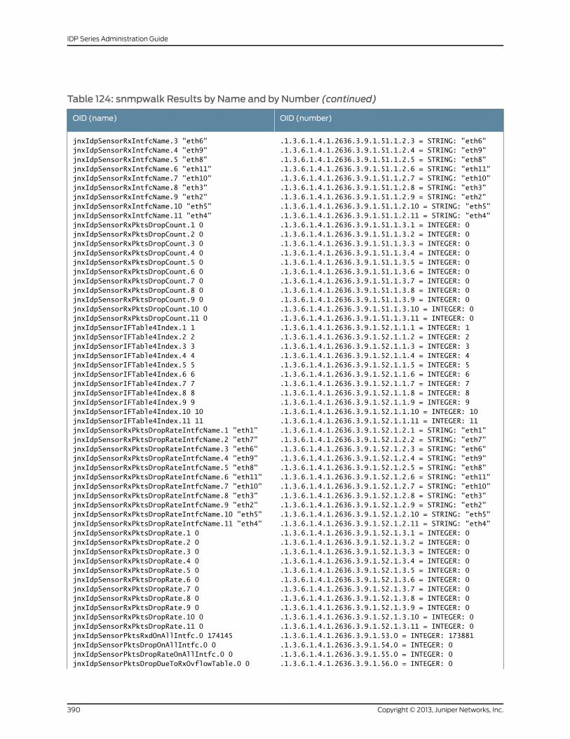
Table 124: snmpwalk Results by Name and by Number (continued)
OID (number)OID (name)
jnxIdpSensorRxIntfcName.3 "eth6"jnxIdpSensorRxIntfcName.4 "eth9"
.1.3.6.1.4.1.2636.3.9.1.51.1.2.3 = STRING: "eth6"
.1.3.6.1.4.1.2636.3.9.1.51.1.2.4 = STRING: "eth9"jnxIdpSensorRxIntfcName.5 "eth8" .1.3.6.1.4.1.2636.3.9.1.51.1.2.5 = STRING: "eth8"jnxIdpSensorRxIntfcName.6 "eth11" .1.3.6.1.4.1.2636.3.9.1.51.1.2.6 = STRING: "eth11"jnxIdpSensorRxIntfcName.7 "eth10" .1.3.6.1.4.1.2636.3.9.1.51.1.2.7 = STRING: "eth10"jnxIdpSensorRxIntfcName.8 "eth3" .1.3.6.1.4.1.2636.3.9.1.51.1.2.8 = STRING: "eth3"jnxIdpSensorRxIntfcName.9 "eth2" .1.3.6.1.4.1.2636.3.9.1.51.1.2.9 = STRING: "eth2"jnxIdpSensorRxIntfcName.10 "eth5" .1.3.6.1.4.1.2636.3.9.1.51.1.2.10 = STRING: "eth5"jnxIdpSensorRxIntfcName.11 "eth4" .1.3.6.1.4.1.2636.3.9.1.51.1.2.11 = STRING: "eth4"jnxIdpSensorRxPktsDropCount.1 0 .1.3.6.1.4.1.2636.3.9.1.51.1.3.1 = INTEGER: 0jnxIdpSensorRxPktsDropCount.2 0 .1.3.6.1.4.1.2636.3.9.1.51.1.3.2 = INTEGER: 0jnxIdpSensorRxPktsDropCount.3 0 .1.3.6.1.4.1.2636.3.9.1.51.1.3.3 = INTEGER: 0jnxIdpSensorRxPktsDropCount.4 0 .1.3.6.1.4.1.2636.3.9.1.51.1.3.4 = INTEGER: 0jnxIdpSensorRxPktsDropCount.5 0 .1.3.6.1.4.1.2636.3.9.1.51.1.3.5 = INTEGER: 0jnxIdpSensorRxPktsDropCount.6 0 .1.3.6.1.4.1.2636.3.9.1.51.1.3.6 = INTEGER: 0jnxIdpSensorRxPktsDropCount.7 0 .1.3.6.1.4.1.2636.3.9.1.51.1.3.7 = INTEGER: 0jnxIdpSensorRxPktsDropCount.8 0 .1.3.6.1.4.1.2636.3.9.1.51.1.3.8 = INTEGER: 0jnxIdpSensorRxPktsDropCount.9 0 .1.3.6.1.4.1.2636.3.9.1.51.1.3.9 = INTEGER: 0jnxIdpSensorRxPktsDropCount.10 0 .1.3.6.1.4.1.2636.3.9.1.51.1.3.10 = INTEGER: 0jnxIdpSensorRxPktsDropCount.11 0 .1.3.6.1.4.1.2636.3.9.1.51.1.3.11 = INTEGER: 0jnxIdpSensorIFTable4Index.1 1 .1.3.6.1.4.1.2636.3.9.1.52.1.1.1 = INTEGER: 1jnxIdpSensorIFTable4Index.2 2 .1.3.6.1.4.1.2636.3.9.1.52.1.1.2 = INTEGER: 2jnxIdpSensorIFTable4Index.3 3 .1.3.6.1.4.1.2636.3.9.1.52.1.1.3 = INTEGER: 3jnxIdpSensorIFTable4Index.4 4 .1.3.6.1.4.1.2636.3.9.1.52.1.1.4 = INTEGER: 4jnxIdpSensorIFTable4Index.5 5 .1.3.6.1.4.1.2636.3.9.1.52.1.1.5 = INTEGER: 5jnxIdpSensorIFTable4Index.6 6 .1.3.6.1.4.1.2636.3.9.1.52.1.1.6 = INTEGER: 6jnxIdpSensorIFTable4Index.7 7 .1.3.6.1.4.1.2636.3.9.1.52.1.1.7 = INTEGER: 7jnxIdpSensorIFTable4Index.8 8 .1.3.6.1.4.1.2636.3.9.1.52.1.1.8 = INTEGER: 8jnxIdpSensorIFTable4Index.9 9 .1.3.6.1.4.1.2636.3.9.1.52.1.1.9 = INTEGER: 9jnxIdpSensorIFTable4Index.10 10 .1.3.6.1.4.1.2636.3.9.1.52.1.1.10 = INTEGER: 10jnxIdpSensorIFTable4Index.11 11 .1.3.6.1.4.1.2636.3.9.1.52.1.1.11 = INTEGER: 11jnxIdpSensorRxPktsDropRateIntfcName.1 "eth1" .1.3.6.1.4.1.2636.3.9.1.52.1.2.1 = STRING: "eth1"jnxIdpSensorRxPktsDropRateIntfcName.2 "eth7" .1.3.6.1.4.1.2636.3.9.1.52.1.2.2 = STRING: "eth7"jnxIdpSensorRxPktsDropRateIntfcName.3 "eth6" .1.3.6.1.4.1.2636.3.9.1.52.1.2.3 = STRING: "eth6"jnxIdpSensorRxPktsDropRateIntfcName.4 "eth9" .1.3.6.1.4.1.2636.3.9.1.52.1.2.4 = STRING: "eth9"jnxIdpSensorRxPktsDropRateIntfcName.5 "eth8" .1.3.6.1.4.1.2636.3.9.1.52.1.2.5 = STRING: "eth8"jnxIdpSensorRxPktsDropRateIntfcName.6 "eth11" .1.3.6.1.4.1.2636.3.9.1.52.1.2.6 = STRING: "eth11"jnxIdpSensorRxPktsDropRateIntfcName.7 "eth10" .1.3.6.1.4.1.2636.3.9.1.52.1.2.7 = STRING: "eth10"jnxIdpSensorRxPktsDropRateIntfcName.8 "eth3" .1.3.6.1.4.1.2636.3.9.1.52.1.2.8 = STRING: "eth3"jnxIdpSensorRxPktsDropRateIntfcName.9 "eth2" .1.3.6.1.4.1.2636.3.9.1.52.1.2.9 = STRING: "eth2"jnxIdpSensorRxPktsDropRateIntfcName.10 "eth5" .1.3.6.1.4.1.2636.3.9.1.52.1.2.10 = STRING: "eth5"jnxIdpSensorRxPktsDropRateIntfcName.11 "eth4" .1.3.6.1.4.1.2636.3.9.1.52.1.2.11 = STRING: "eth4"jnxIdpSensorRxPktsDropRate.1 0 .1.3.6.1.4.1.2636.3.9.1.52.1.3.1 = INTEGER: 0jnxIdpSensorRxPktsDropRate.2 0 .1.3.6.1.4.1.2636.3.9.1.52.1.3.2 = INTEGER: 0jnxIdpSensorRxPktsDropRate.3 0 .1.3.6.1.4.1.2636.3.9.1.52.1.3.3 = INTEGER: 0jnxIdpSensorRxPktsDropRate.4 0 .1.3.6.1.4.1.2636.3.9.1.52.1.3.4 = INTEGER: 0jnxIdpSensorRxPktsDropRate.5 0 .1.3.6.1.4.1.2636.3.9.1.52.1.3.5 = INTEGER: 0jnxIdpSensorRxPktsDropRate.6 0 .1.3.6.1.4.1.2636.3.9.1.52.1.3.6 = INTEGER: 0jnxIdpSensorRxPktsDropRate.7 0 .1.3.6.1.4.1.2636.3.9.1.52.1.3.7 = INTEGER: 0jnxIdpSensorRxPktsDropRate.8 0 .1.3.6.1.4.1.2636.3.9.1.52.1.3.8 = INTEGER: 0jnxIdpSensorRxPktsDropRate.9 0 .1.3.6.1.4.1.2636.3.9.1.52.1.3.9 = INTEGER: 0jnxIdpSensorRxPktsDropRate.10 0 .1.3.6.1.4.1.2636.3.9.1.52.1.3.10 = INTEGER: 0jnxIdpSensorRxPktsDropRate.11 0 .1.3.6.1.4.1.2636.3.9.1.52.1.3.11 = INTEGER: 0jnxIdpSensorPktsRxdOnAllIntfc.0 174145 .1.3.6.1.4.1.2636.3.9.1.53.0 = INTEGER: 173881jnxIdpSensorPktsDropOnAllIntfc.0 0 .1.3.6.1.4.1.2636.3.9.1.54.0 = INTEGER: 0jnxIdpSensorPktsDropRateOnAllIntfc.0 0 .1.3.6.1.4.1.2636.3.9.1.55.0 = INTEGER: 0jnxIdpSensorPktsDropDueToRxOvflowTable.0 0 .1.3.6.1.4.1.2636.3.9.1.56.0 = INTEGER: 0
Copyright © 2013, Juniper Networks, Inc.390
IDP Series Administration Guide
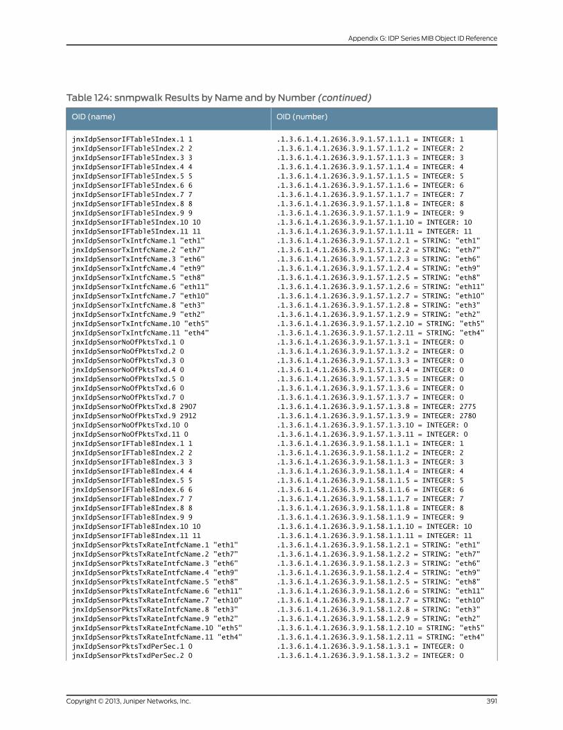
Table 124: snmpwalk Results by Name and by Number (continued)
OID (number)OID (name)
.1.3.6.1.4.1.2636.3.9.1.57.1.1.1 = INTEGER: 1
.1.3.6.1.4.1.2636.3.9.1.57.1.1.2 = INTEGER: 2jnxIdpSensorIFTable5Index.1 1jnxIdpSensorIFTable5Index.2 2
.1.3.6.1.4.1.2636.3.9.1.57.1.1.3 = INTEGER: 3jnxIdpSensorIFTable5Index.3 3
.1.3.6.1.4.1.2636.3.9.1.57.1.1.4 = INTEGER: 4jnxIdpSensorIFTable5Index.4 4
.1.3.6.1.4.1.2636.3.9.1.57.1.1.5 = INTEGER: 5jnxIdpSensorIFTable5Index.5 5
.1.3.6.1.4.1.2636.3.9.1.57.1.1.6 = INTEGER: 6jnxIdpSensorIFTable5Index.6 6
.1.3.6.1.4.1.2636.3.9.1.57.1.1.7 = INTEGER: 7jnxIdpSensorIFTable5Index.7 7
.1.3.6.1.4.1.2636.3.9.1.57.1.1.8 = INTEGER: 8jnxIdpSensorIFTable5Index.8 8
.1.3.6.1.4.1.2636.3.9.1.57.1.1.9 = INTEGER: 9jnxIdpSensorIFTable5Index.9 9
.1.3.6.1.4.1.2636.3.9.1.57.1.1.10 = INTEGER: 10jnxIdpSensorIFTable5Index.10 10
.1.3.6.1.4.1.2636.3.9.1.57.1.1.11 = INTEGER: 11jnxIdpSensorIFTable5Index.11 11
.1.3.6.1.4.1.2636.3.9.1.57.1.2.1 = STRING: "eth1"jnxIdpSensorTxIntfcName.1 "eth1"
.1.3.6.1.4.1.2636.3.9.1.57.1.2.2 = STRING: "eth7"jnxIdpSensorTxIntfcName.2 "eth7"
.1.3.6.1.4.1.2636.3.9.1.57.1.2.3 = STRING: "eth6"jnxIdpSensorTxIntfcName.3 "eth6"
.1.3.6.1.4.1.2636.3.9.1.57.1.2.4 = STRING: "eth9"jnxIdpSensorTxIntfcName.4 "eth9"
.1.3.6.1.4.1.2636.3.9.1.57.1.2.5 = STRING: "eth8"jnxIdpSensorTxIntfcName.5 "eth8"
.1.3.6.1.4.1.2636.3.9.1.57.1.2.6 = STRING: "eth11"jnxIdpSensorTxIntfcName.6 "eth11"
.1.3.6.1.4.1.2636.3.9.1.57.1.2.7 = STRING: "eth10"jnxIdpSensorTxIntfcName.7 "eth10"
.1.3.6.1.4.1.2636.3.9.1.57.1.2.8 = STRING: "eth3"jnxIdpSensorTxIntfcName.8 "eth3"
.1.3.6.1.4.1.2636.3.9.1.57.1.2.9 = STRING: "eth2"jnxIdpSensorTxIntfcName.9 "eth2"
.1.3.6.1.4.1.2636.3.9.1.57.1.2.10 = STRING: "eth5"jnxIdpSensorTxIntfcName.10 "eth5"
.1.3.6.1.4.1.2636.3.9.1.57.1.2.11 = STRING: "eth4"jnxIdpSensorTxIntfcName.11 "eth4"
.1.3.6.1.4.1.2636.3.9.1.57.1.3.1 = INTEGER: 0jnxIdpSensorNoOfPktsTxd.1 0
.1.3.6.1.4.1.2636.3.9.1.57.1.3.2 = INTEGER: 0jnxIdpSensorNoOfPktsTxd.2 0
.1.3.6.1.4.1.2636.3.9.1.57.1.3.3 = INTEGER: 0jnxIdpSensorNoOfPktsTxd.3 0
.1.3.6.1.4.1.2636.3.9.1.57.1.3.4 = INTEGER: 0jnxIdpSensorNoOfPktsTxd.4 0
.1.3.6.1.4.1.2636.3.9.1.57.1.3.5 = INTEGER: 0jnxIdpSensorNoOfPktsTxd.5 0
.1.3.6.1.4.1.2636.3.9.1.57.1.3.6 = INTEGER: 0jnxIdpSensorNoOfPktsTxd.6 0
.1.3.6.1.4.1.2636.3.9.1.57.1.3.7 = INTEGER: 0jnxIdpSensorNoOfPktsTxd.7 0
.1.3.6.1.4.1.2636.3.9.1.57.1.3.8 = INTEGER: 2775jnxIdpSensorNoOfPktsTxd.8 2907
.1.3.6.1.4.1.2636.3.9.1.57.1.3.9 = INTEGER: 2780jnxIdpSensorNoOfPktsTxd.9 2912
.1.3.6.1.4.1.2636.3.9.1.57.1.3.10 = INTEGER: 0jnxIdpSensorNoOfPktsTxd.10 0
.1.3.6.1.4.1.2636.3.9.1.57.1.3.11 = INTEGER: 0jnxIdpSensorNoOfPktsTxd.11 0
.1.3.6.1.4.1.2636.3.9.1.58.1.1.1 = INTEGER: 1jnxIdpSensorIFTable8Index.1 1
.1.3.6.1.4.1.2636.3.9.1.58.1.1.2 = INTEGER: 2jnxIdpSensorIFTable8Index.2 2
.1.3.6.1.4.1.2636.3.9.1.58.1.1.3 = INTEGER: 3jnxIdpSensorIFTable8Index.3 3
.1.3.6.1.4.1.2636.3.9.1.58.1.1.4 = INTEGER: 4jnxIdpSensorIFTable8Index.4 4
.1.3.6.1.4.1.2636.3.9.1.58.1.1.5 = INTEGER: 5jnxIdpSensorIFTable8Index.5 5
.1.3.6.1.4.1.2636.3.9.1.58.1.1.6 = INTEGER: 6jnxIdpSensorIFTable8Index.6 6
.1.3.6.1.4.1.2636.3.9.1.58.1.1.7 = INTEGER: 7jnxIdpSensorIFTable8Index.7 7
.1.3.6.1.4.1.2636.3.9.1.58.1.1.8 = INTEGER: 8jnxIdpSensorIFTable8Index.8 8
.1.3.6.1.4.1.2636.3.9.1.58.1.1.9 = INTEGER: 9jnxIdpSensorIFTable8Index.9 9
.1.3.6.1.4.1.2636.3.9.1.58.1.1.10 = INTEGER: 10jnxIdpSensorIFTable8Index.10 10
.1.3.6.1.4.1.2636.3.9.1.58.1.1.11 = INTEGER: 11jnxIdpSensorIFTable8Index.11 11
.1.3.6.1.4.1.2636.3.9.1.58.1.2.1 = STRING: "eth1"jnxIdpSensorPktsTxRateIntfcName.1 "eth1"
.1.3.6.1.4.1.2636.3.9.1.58.1.2.2 = STRING: "eth7"jnxIdpSensorPktsTxRateIntfcName.2 "eth7"
.1.3.6.1.4.1.2636.3.9.1.58.1.2.3 = STRING: "eth6"jnxIdpSensorPktsTxRateIntfcName.3 "eth6"
.1.3.6.1.4.1.2636.3.9.1.58.1.2.4 = STRING: "eth9"jnxIdpSensorPktsTxRateIntfcName.4 "eth9"
.1.3.6.1.4.1.2636.3.9.1.58.1.2.5 = STRING: "eth8"jnxIdpSensorPktsTxRateIntfcName.5 "eth8"
.1.3.6.1.4.1.2636.3.9.1.58.1.2.6 = STRING: "eth11"jnxIdpSensorPktsTxRateIntfcName.6 "eth11"
.1.3.6.1.4.1.2636.3.9.1.58.1.2.7 = STRING: "eth10"jnxIdpSensorPktsTxRateIntfcName.7 "eth10"
.1.3.6.1.4.1.2636.3.9.1.58.1.2.8 = STRING: "eth3"jnxIdpSensorPktsTxRateIntfcName.8 "eth3"
.1.3.6.1.4.1.2636.3.9.1.58.1.2.9 = STRING: "eth2"jnxIdpSensorPktsTxRateIntfcName.9 "eth2"
.1.3.6.1.4.1.2636.3.9.1.58.1.2.10 = STRING: "eth5"jnxIdpSensorPktsTxRateIntfcName.10 "eth5"
.1.3.6.1.4.1.2636.3.9.1.58.1.2.11 = STRING: "eth4"jnxIdpSensorPktsTxRateIntfcName.11 "eth4"
.1.3.6.1.4.1.2636.3.9.1.58.1.3.1 = INTEGER: 0jnxIdpSensorPktsTxdPerSec.1 0
.1.3.6.1.4.1.2636.3.9.1.58.1.3.2 = INTEGER: 0jnxIdpSensorPktsTxdPerSec.2 0
391Copyright © 2013, Juniper Networks, Inc.
Appendix G: IDP Series MIB Object ID Reference
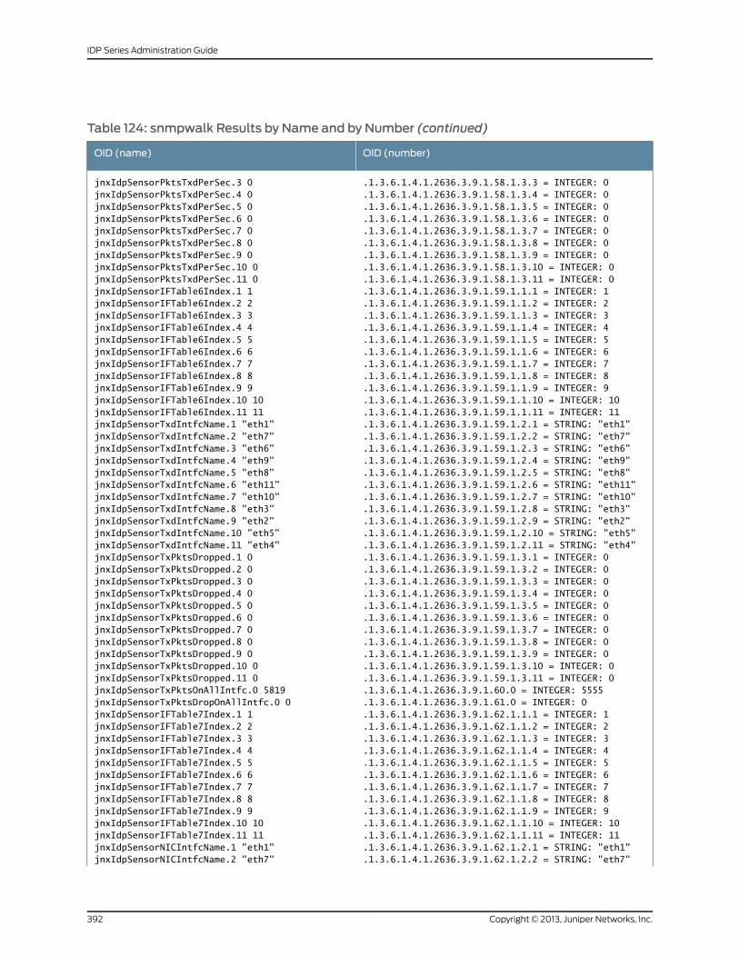
Table 124: snmpwalk Results by Name and by Number (continued)
OID (number)OID (name)
jnxIdpSensorPktsTxdPerSec.3 0jnxIdpSensorPktsTxdPerSec.4 0
.1.3.6.1.4.1.2636.3.9.1.58.1.3.3 = INTEGER: 0
.1.3.6.1.4.1.2636.3.9.1.58.1.3.4 = INTEGER: 0jnxIdpSensorPktsTxdPerSec.5 0 .1.3.6.1.4.1.2636.3.9.1.58.1.3.5 = INTEGER: 0jnxIdpSensorPktsTxdPerSec.6 0 .1.3.6.1.4.1.2636.3.9.1.58.1.3.6 = INTEGER: 0jnxIdpSensorPktsTxdPerSec.7 0 .1.3.6.1.4.1.2636.3.9.1.58.1.3.7 = INTEGER: 0jnxIdpSensorPktsTxdPerSec.8 0 .1.3.6.1.4.1.2636.3.9.1.58.1.3.8 = INTEGER: 0jnxIdpSensorPktsTxdPerSec.9 0 .1.3.6.1.4.1.2636.3.9.1.58.1.3.9 = INTEGER: 0jnxIdpSensorPktsTxdPerSec.10 0 .1.3.6.1.4.1.2636.3.9.1.58.1.3.10 = INTEGER: 0jnxIdpSensorPktsTxdPerSec.11 0 .1.3.6.1.4.1.2636.3.9.1.58.1.3.11 = INTEGER: 0jnxIdpSensorIFTable6Index.1 1 .1.3.6.1.4.1.2636.3.9.1.59.1.1.1 = INTEGER: 1jnxIdpSensorIFTable6Index.2 2 .1.3.6.1.4.1.2636.3.9.1.59.1.1.2 = INTEGER: 2jnxIdpSensorIFTable6Index.3 3 .1.3.6.1.4.1.2636.3.9.1.59.1.1.3 = INTEGER: 3jnxIdpSensorIFTable6Index.4 4 .1.3.6.1.4.1.2636.3.9.1.59.1.1.4 = INTEGER: 4jnxIdpSensorIFTable6Index.5 5 .1.3.6.1.4.1.2636.3.9.1.59.1.1.5 = INTEGER: 5jnxIdpSensorIFTable6Index.6 6 .1.3.6.1.4.1.2636.3.9.1.59.1.1.6 = INTEGER: 6jnxIdpSensorIFTable6Index.7 7 .1.3.6.1.4.1.2636.3.9.1.59.1.1.7 = INTEGER: 7jnxIdpSensorIFTable6Index.8 8 .1.3.6.1.4.1.2636.3.9.1.59.1.1.8 = INTEGER: 8jnxIdpSensorIFTable6Index.9 9 .1.3.6.1.4.1.2636.3.9.1.59.1.1.9 = INTEGER: 9jnxIdpSensorIFTable6Index.10 10 .1.3.6.1.4.1.2636.3.9.1.59.1.1.10 = INTEGER: 10jnxIdpSensorIFTable6Index.11 11 .1.3.6.1.4.1.2636.3.9.1.59.1.1.11 = INTEGER: 11jnxIdpSensorTxdIntfcName.1 "eth1" .1.3.6.1.4.1.2636.3.9.1.59.1.2.1 = STRING: "eth1"jnxIdpSensorTxdIntfcName.2 "eth7" .1.3.6.1.4.1.2636.3.9.1.59.1.2.2 = STRING: "eth7"jnxIdpSensorTxdIntfcName.3 "eth6" .1.3.6.1.4.1.2636.3.9.1.59.1.2.3 = STRING: "eth6"jnxIdpSensorTxdIntfcName.4 "eth9" .1.3.6.1.4.1.2636.3.9.1.59.1.2.4 = STRING: "eth9"jnxIdpSensorTxdIntfcName.5 "eth8" .1.3.6.1.4.1.2636.3.9.1.59.1.2.5 = STRING: "eth8"jnxIdpSensorTxdIntfcName.6 "eth11" .1.3.6.1.4.1.2636.3.9.1.59.1.2.6 = STRING: "eth11"jnxIdpSensorTxdIntfcName.7 "eth10" .1.3.6.1.4.1.2636.3.9.1.59.1.2.7 = STRING: "eth10"jnxIdpSensorTxdIntfcName.8 "eth3" .1.3.6.1.4.1.2636.3.9.1.59.1.2.8 = STRING: "eth3"jnxIdpSensorTxdIntfcName.9 "eth2" .1.3.6.1.4.1.2636.3.9.1.59.1.2.9 = STRING: "eth2"jnxIdpSensorTxdIntfcName.10 "eth5" .1.3.6.1.4.1.2636.3.9.1.59.1.2.10 = STRING: "eth5"jnxIdpSensorTxdIntfcName.11 "eth4" .1.3.6.1.4.1.2636.3.9.1.59.1.2.11 = STRING: "eth4"jnxIdpSensorTxPktsDropped.1 0 .1.3.6.1.4.1.2636.3.9.1.59.1.3.1 = INTEGER: 0jnxIdpSensorTxPktsDropped.2 0 .1.3.6.1.4.1.2636.3.9.1.59.1.3.2 = INTEGER: 0jnxIdpSensorTxPktsDropped.3 0 .1.3.6.1.4.1.2636.3.9.1.59.1.3.3 = INTEGER: 0jnxIdpSensorTxPktsDropped.4 0 .1.3.6.1.4.1.2636.3.9.1.59.1.3.4 = INTEGER: 0jnxIdpSensorTxPktsDropped.5 0 .1.3.6.1.4.1.2636.3.9.1.59.1.3.5 = INTEGER: 0jnxIdpSensorTxPktsDropped.6 0 .1.3.6.1.4.1.2636.3.9.1.59.1.3.6 = INTEGER: 0jnxIdpSensorTxPktsDropped.7 0 .1.3.6.1.4.1.2636.3.9.1.59.1.3.7 = INTEGER: 0jnxIdpSensorTxPktsDropped.8 0 .1.3.6.1.4.1.2636.3.9.1.59.1.3.8 = INTEGER: 0jnxIdpSensorTxPktsDropped.9 0 .1.3.6.1.4.1.2636.3.9.1.59.1.3.9 = INTEGER: 0jnxIdpSensorTxPktsDropped.10 0 .1.3.6.1.4.1.2636.3.9.1.59.1.3.10 = INTEGER: 0jnxIdpSensorTxPktsDropped.11 0 .1.3.6.1.4.1.2636.3.9.1.59.1.3.11 = INTEGER: 0jnxIdpSensorTxPktsOnAllIntfc.0 5819 .1.3.6.1.4.1.2636.3.9.1.60.0 = INTEGER: 5555jnxIdpSensorTxPktsDropOnAllIntfc.0 0 .1.3.6.1.4.1.2636.3.9.1.61.0 = INTEGER: 0jnxIdpSensorIFTable7Index.1 1 .1.3.6.1.4.1.2636.3.9.1.62.1.1.1 = INTEGER: 1jnxIdpSensorIFTable7Index.2 2 .1.3.6.1.4.1.2636.3.9.1.62.1.1.2 = INTEGER: 2jnxIdpSensorIFTable7Index.3 3 .1.3.6.1.4.1.2636.3.9.1.62.1.1.3 = INTEGER: 3jnxIdpSensorIFTable7Index.4 4 .1.3.6.1.4.1.2636.3.9.1.62.1.1.4 = INTEGER: 4jnxIdpSensorIFTable7Index.5 5 .1.3.6.1.4.1.2636.3.9.1.62.1.1.5 = INTEGER: 5jnxIdpSensorIFTable7Index.6 6 .1.3.6.1.4.1.2636.3.9.1.62.1.1.6 = INTEGER: 6jnxIdpSensorIFTable7Index.7 7 .1.3.6.1.4.1.2636.3.9.1.62.1.1.7 = INTEGER: 7jnxIdpSensorIFTable7Index.8 8 .1.3.6.1.4.1.2636.3.9.1.62.1.1.8 = INTEGER: 8jnxIdpSensorIFTable7Index.9 9 .1.3.6.1.4.1.2636.3.9.1.62.1.1.9 = INTEGER: 9jnxIdpSensorIFTable7Index.10 10 .1.3.6.1.4.1.2636.3.9.1.62.1.1.10 = INTEGER: 10jnxIdpSensorIFTable7Index.11 11 .1.3.6.1.4.1.2636.3.9.1.62.1.1.11 = INTEGER: 11jnxIdpSensorNICIntfcName.1 "eth1" .1.3.6.1.4.1.2636.3.9.1.62.1.2.1 = STRING: "eth1"jnxIdpSensorNICIntfcName.2 "eth7" .1.3.6.1.4.1.2636.3.9.1.62.1.2.2 = STRING: "eth7"
Copyright © 2013, Juniper Networks, Inc.392
IDP Series Administration Guide
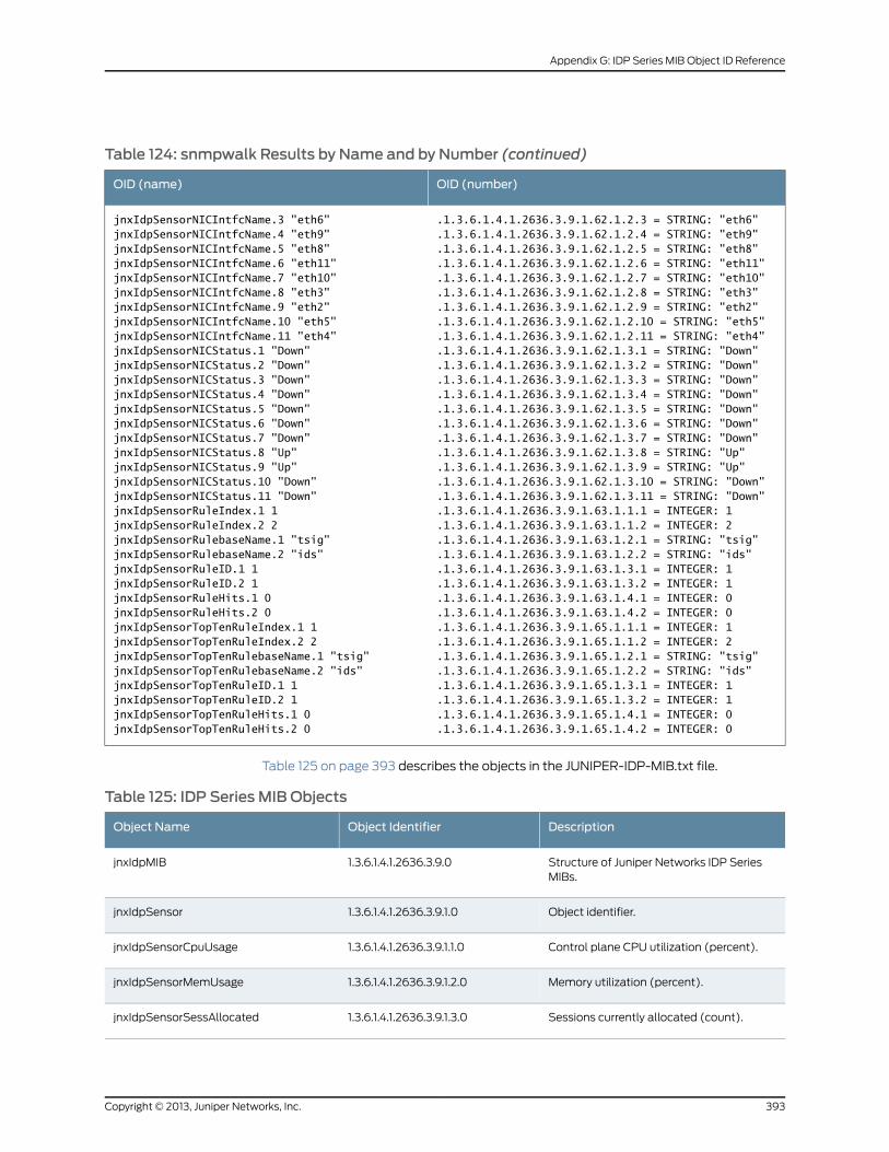
Table 124: snmpwalk Results by Name and by Number (continued)
OID (number)OID (name)
.1.3.6.1.4.1.2636.3.9.1.62.1.2.3 = STRING: "eth6"
.1.3.6.1.4.1.2636.3.9.1.62.1.2.4 = STRING: "eth9"jnxIdpSensorNICIntfcName.3 "eth6"jnxIdpSensorNICIntfcName.4 "eth9"
.1.3.6.1.4.1.2636.3.9.1.62.1.2.5 = STRING: "eth8"jnxIdpSensorNICIntfcName.5 "eth8"
.1.3.6.1.4.1.2636.3.9.1.62.1.2.6 = STRING: "eth11"jnxIdpSensorNICIntfcName.6 "eth11"
.1.3.6.1.4.1.2636.3.9.1.62.1.2.7 = STRING: "eth10"jnxIdpSensorNICIntfcName.7 "eth10"
.1.3.6.1.4.1.2636.3.9.1.62.1.2.8 = STRING: "eth3"jnxIdpSensorNICIntfcName.8 "eth3"
.1.3.6.1.4.1.2636.3.9.1.62.1.2.9 = STRING: "eth2"jnxIdpSensorNICIntfcName.9 "eth2"
.1.3.6.1.4.1.2636.3.9.1.62.1.2.10 = STRING: "eth5"jnxIdpSensorNICIntfcName.10 "eth5"
.1.3.6.1.4.1.2636.3.9.1.62.1.2.11 = STRING: "eth4"jnxIdpSensorNICIntfcName.11 "eth4"
.1.3.6.1.4.1.2636.3.9.1.62.1.3.1 = STRING: "Down"jnxIdpSensorNICStatus.1 "Down"
.1.3.6.1.4.1.2636.3.9.1.62.1.3.2 = STRING: "Down"jnxIdpSensorNICStatus.2 "Down"
.1.3.6.1.4.1.2636.3.9.1.62.1.3.3 = STRING: "Down"jnxIdpSensorNICStatus.3 "Down"
.1.3.6.1.4.1.2636.3.9.1.62.1.3.4 = STRING: "Down"jnxIdpSensorNICStatus.4 "Down"
.1.3.6.1.4.1.2636.3.9.1.62.1.3.5 = STRING: "Down"jnxIdpSensorNICStatus.5 "Down"
.1.3.6.1.4.1.2636.3.9.1.62.1.3.6 = STRING: "Down"jnxIdpSensorNICStatus.6 "Down"
.1.3.6.1.4.1.2636.3.9.1.62.1.3.7 = STRING: "Down"jnxIdpSensorNICStatus.7 "Down"
.1.3.6.1.4.1.2636.3.9.1.62.1.3.8 = STRING: "Up"jnxIdpSensorNICStatus.8 "Up"
.1.3.6.1.4.1.2636.3.9.1.62.1.3.9 = STRING: "Up"jnxIdpSensorNICStatus.9 "Up"
.1.3.6.1.4.1.2636.3.9.1.62.1.3.10 = STRING: "Down"jnxIdpSensorNICStatus.10 "Down"
.1.3.6.1.4.1.2636.3.9.1.62.1.3.11 = STRING: "Down"jnxIdpSensorNICStatus.11 "Down"
.1.3.6.1.4.1.2636.3.9.1.63.1.1.1 = INTEGER: 1jnxIdpSensorRuleIndex.1 1
.1.3.6.1.4.1.2636.3.9.1.63.1.1.2 = INTEGER: 2jnxIdpSensorRuleIndex.2 2
.1.3.6.1.4.1.2636.3.9.1.63.1.2.1 = STRING: "tsig"jnxIdpSensorRulebaseName.1 "tsig"
.1.3.6.1.4.1.2636.3.9.1.63.1.2.2 = STRING: "ids"jnxIdpSensorRulebaseName.2 "ids"
.1.3.6.1.4.1.2636.3.9.1.63.1.3.1 = INTEGER: 1jnxIdpSensorRuleID.1 1
.1.3.6.1.4.1.2636.3.9.1.63.1.3.2 = INTEGER: 1jnxIdpSensorRuleID.2 1
.1.3.6.1.4.1.2636.3.9.1.63.1.4.1 = INTEGER: 0jnxIdpSensorRuleHits.1 0
.1.3.6.1.4.1.2636.3.9.1.63.1.4.2 = INTEGER: 0jnxIdpSensorRuleHits.2 0
.1.3.6.1.4.1.2636.3.9.1.65.1.1.1 = INTEGER: 1jnxIdpSensorTopTenRuleIndex.1 1
.1.3.6.1.4.1.2636.3.9.1.65.1.1.2 = INTEGER: 2jnxIdpSensorTopTenRuleIndex.2 2
.1.3.6.1.4.1.2636.3.9.1.65.1.2.1 = STRING: "tsig"jnxIdpSensorTopTenRulebaseName.1 "tsig"
.1.3.6.1.4.1.2636.3.9.1.65.1.2.2 = STRING: "ids"jnxIdpSensorTopTenRulebaseName.2 "ids"
.1.3.6.1.4.1.2636.3.9.1.65.1.3.1 = INTEGER: 1jnxIdpSensorTopTenRuleID.1 1
.1.3.6.1.4.1.2636.3.9.1.65.1.3.2 = INTEGER: 1jnxIdpSensorTopTenRuleID.2 1
.1.3.6.1.4.1.2636.3.9.1.65.1.4.1 = INTEGER: 0
.1.3.6.1.4.1.2636.3.9.1.65.1.4.2 = INTEGER: 0jnxIdpSensorTopTenRuleHits.1 0jnxIdpSensorTopTenRuleHits.2 0
Table 125 on page 393 describes the objects in the JUNIPER-IDP-MIB.txt file.
Table 125: IDP Series MIB Objects
DescriptionObject IdentifierObject Name
Structure of Juniper Networks IDP SeriesMIBs.
1.3.6.1.4.1.2636.3.9.0jnxIdpMIB
Object identifier.1.3.6.1.4.1.2636.3.9.1.0jnxIdpSensor
Control plane CPU utilization (percent).1.3.6.1.4.1.2636.3.9.1.1.0jnxIdpSensorCpuUsage
Memory utilization (percent).1.3.6.1.4.1.2636.3.9.1.2.0jnxIdpSensorMemUsage
Sessions currently allocated (count).1.3.6.1.4.1.2636.3.9.1.3.0jnxIdpSensorSessAllocated
393Copyright © 2013, Juniper Networks, Inc.
Appendix G: IDP Series MIB Object ID Reference
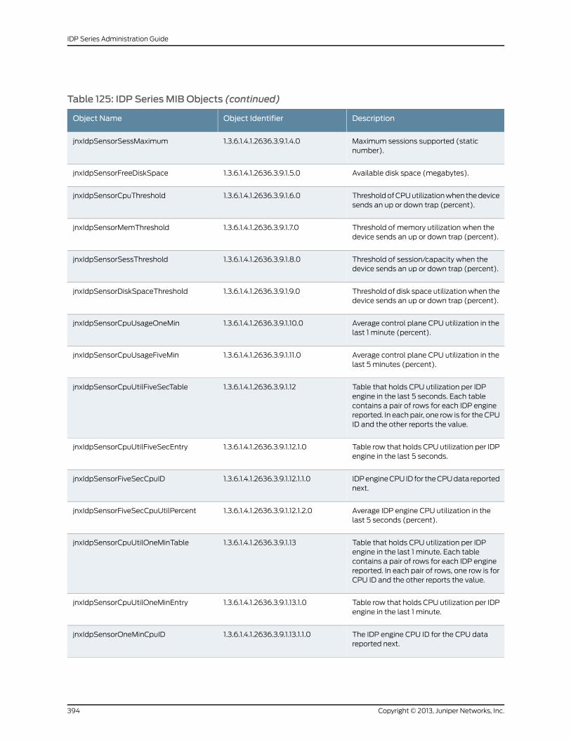
Table 125: IDP Series MIB Objects (continued)
DescriptionObject IdentifierObject Name
Maximum sessions supported (staticnumber).
1.3.6.1.4.1.2636.3.9.1.4.0jnxIdpSensorSessMaximum
Available disk space (megabytes).1.3.6.1.4.1.2636.3.9.1.5.0jnxIdpSensorFreeDiskSpace
Threshold of CPU utilization when the devicesends an up or down trap (percent).
1.3.6.1.4.1.2636.3.9.1.6.0jnxIdpSensorCpuThreshold
Threshold of memory utilization when thedevice sends an up or down trap (percent).
1.3.6.1.4.1.2636.3.9.1.7.0jnxIdpSensorMemThreshold
Threshold of session/capacity when thedevice sends an up or down trap (percent).
1.3.6.1.4.1.2636.3.9.1.8.0jnxIdpSensorSessThreshold
Threshold of disk space utilization when thedevice sends an up or down trap (percent).
1.3.6.1.4.1.2636.3.9.1.9.0jnxIdpSensorDiskSpaceThreshold
Average control plane CPU utilization in thelast 1 minute (percent).
1.3.6.1.4.1.2636.3.9.1.10.0jnxIdpSensorCpuUsageOneMin
Average control plane CPU utilization in thelast 5 minutes (percent).
1.3.6.1.4.1.2636.3.9.1.11.0jnxIdpSensorCpuUsageFiveMin
Table that holds CPU utilization per IDPengine in the last 5 seconds. Each tablecontains a pair of rows for each IDP enginereported. In each pair, one row is for the CPUID and the other reports the value.
1.3.6.1.4.1.2636.3.9.1.12jnxIdpSensorCpuUtilFiveSecTable
Table row that holds CPU utilization per IDPengine in the last 5 seconds.
1.3.6.1.4.1.2636.3.9.1.12.1.0jnxIdpSensorCpuUtilFiveSecEntry
IDP engine CPU ID for the CPU data reportednext.
1.3.6.1.4.1.2636.3.9.1.12.1.1.0jnxIdpSensorFiveSecCpuID
Average IDP engine CPU utilization in thelast 5 seconds (percent).
1.3.6.1.4.1.2636.3.9.1.12.1.2.0jnxIdpSensorFiveSecCpuUtilPercent
Table that holds CPU utilization per IDPengine in the last 1 minute. Each tablecontains a pair of rows for each IDP enginereported. In each pair of rows, one row is forCPU ID and the other reports the value.
1.3.6.1.4.1.2636.3.9.1.13jnxIdpSensorCpuUtilOneMinTable
Table row that holds CPU utilization per IDPengine in the last 1 minute.
1.3.6.1.4.1.2636.3.9.1.13.1.0jnxIdpSensorCpuUtilOneMinEntry
The IDP engine CPU ID for the CPU datareported next.
1.3.6.1.4.1.2636.3.9.1.13.1.1.0jnxIdpSensorOneMinCpuID
Copyright © 2013, Juniper Networks, Inc.394
IDP Series Administration Guide
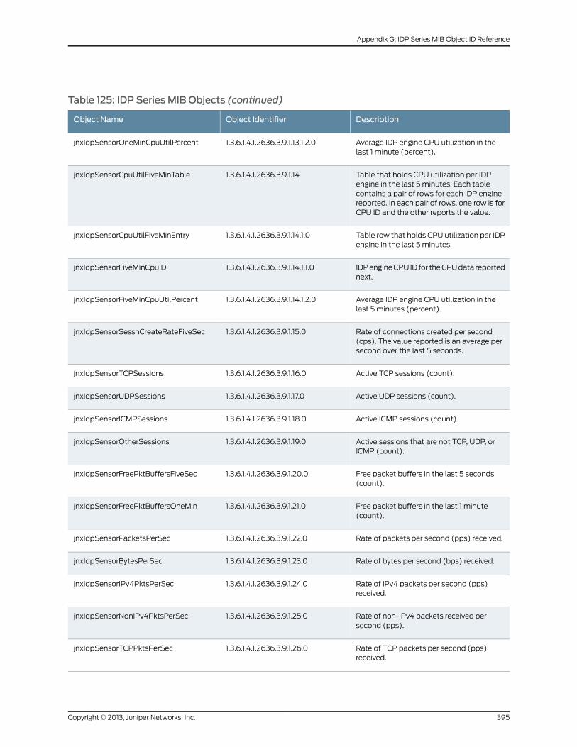
Table 125: IDP Series MIB Objects (continued)
DescriptionObject IdentifierObject Name
Average IDP engine CPU utilization in thelast 1 minute (percent).
1.3.6.1.4.1.2636.3.9.1.13.1.2.0jnxIdpSensorOneMinCpuUtilPercent
Table that holds CPU utilization per IDPengine in the last 5 minutes. Each tablecontains a pair of rows for each IDP enginereported. In each pair of rows, one row is forCPU ID and the other reports the value.
1.3.6.1.4.1.2636.3.9.1.14jnxIdpSensorCpuUtilFiveMinTable
Table row that holds CPU utilization per IDPengine in the last 5 minutes.
1.3.6.1.4.1.2636.3.9.1.14.1.0jnxIdpSensorCpuUtilFiveMinEntry
IDP engine CPU ID for the CPU data reportednext.
1.3.6.1.4.1.2636.3.9.1.14.1.1.0jnxIdpSensorFiveMinCpuID
Average IDP engine CPU utilization in thelast 5 minutes (percent).
1.3.6.1.4.1.2636.3.9.1.14.1.2.0jnxIdpSensorFiveMinCpuUtilPercent
Rate of connections created per second(cps). The value reported is an average persecond over the last 5 seconds.
1.3.6.1.4.1.2636.3.9.1.15.0jnxIdpSensorSessnCreateRateFiveSec
Active TCP sessions (count).1.3.6.1.4.1.2636.3.9.1.16.0jnxIdpSensorTCPSessions
Active UDP sessions (count).1.3.6.1.4.1.2636.3.9.1.17.0jnxIdpSensorUDPSessions
Active ICMP sessions (count).1.3.6.1.4.1.2636.3.9.1.18.0jnxIdpSensorICMPSessions
Active sessions that are not TCP, UDP, orICMP (count).
1.3.6.1.4.1.2636.3.9.1.19.0jnxIdpSensorOtherSessions
Free packet buffers in the last 5 seconds(count).
1.3.6.1.4.1.2636.3.9.1.20.0jnxIdpSensorFreePktBuffersFiveSec
Free packet buffers in the last 1 minute(count).
1.3.6.1.4.1.2636.3.9.1.21.0jnxIdpSensorFreePktBuffersOneMin
Rate of packets per second (pps) received.1.3.6.1.4.1.2636.3.9.1.22.0jnxIdpSensorPacketsPerSec
Rate of bytes per second (bps) received.1.3.6.1.4.1.2636.3.9.1.23.0jnxIdpSensorBytesPerSec
Rate of IPv4 packets per second (pps)received.
1.3.6.1.4.1.2636.3.9.1.24.0jnxIdpSensorIPv4PktsPerSec
Rate of non-IPv4 packets received persecond (pps).
1.3.6.1.4.1.2636.3.9.1.25.0jnxIdpSensorNonIPv4PktsPerSec
Rate of TCP packets per second (pps)received.
1.3.6.1.4.1.2636.3.9.1.26.0jnxIdpSensorTCPPktsPerSec
395Copyright © 2013, Juniper Networks, Inc.
Appendix G: IDP Series MIB Object ID Reference
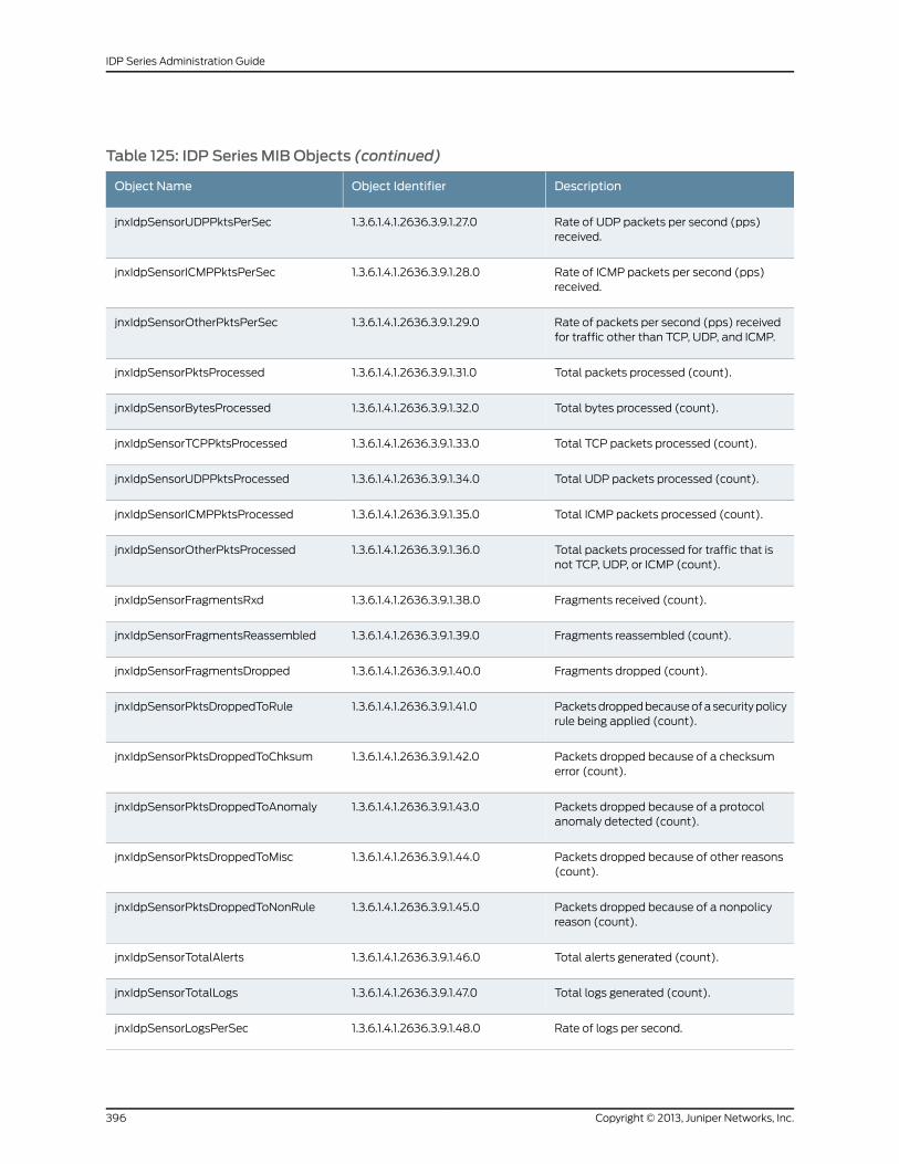
Table 125: IDP Series MIB Objects (continued)
DescriptionObject IdentifierObject Name
Rate of UDP packets per second (pps)received.
1.3.6.1.4.1.2636.3.9.1.27.0jnxIdpSensorUDPPktsPerSec
Rate of ICMP packets per second (pps)received.
1.3.6.1.4.1.2636.3.9.1.28.0jnxIdpSensorICMPPktsPerSec
Rate of packets per second (pps) receivedfor traffic other than TCP, UDP, and ICMP.
1.3.6.1.4.1.2636.3.9.1.29.0jnxIdpSensorOtherPktsPerSec
Total packets processed (count).1.3.6.1.4.1.2636.3.9.1.31.0jnxIdpSensorPktsProcessed
Total bytes processed (count).1.3.6.1.4.1.2636.3.9.1.32.0jnxIdpSensorBytesProcessed
Total TCP packets processed (count).1.3.6.1.4.1.2636.3.9.1.33.0jnxIdpSensorTCPPktsProcessed
Total UDP packets processed (count).1.3.6.1.4.1.2636.3.9.1.34.0jnxIdpSensorUDPPktsProcessed
Total ICMP packets processed (count).1.3.6.1.4.1.2636.3.9.1.35.0jnxIdpSensorICMPPktsProcessed
Total packets processed for traffic that isnot TCP, UDP, or ICMP (count).
1.3.6.1.4.1.2636.3.9.1.36.0jnxIdpSensorOtherPktsProcessed
Fragments received (count).1.3.6.1.4.1.2636.3.9.1.38.0jnxIdpSensorFragmentsRxd
Fragments reassembled (count).1.3.6.1.4.1.2636.3.9.1.39.0jnxIdpSensorFragmentsReassembled
Fragments dropped (count).1.3.6.1.4.1.2636.3.9.1.40.0jnxIdpSensorFragmentsDropped
Packets dropped because of a security policyrule being applied (count).
1.3.6.1.4.1.2636.3.9.1.41.0jnxIdpSensorPktsDroppedToRule
Packets dropped because of a checksumerror (count).
1.3.6.1.4.1.2636.3.9.1.42.0jnxIdpSensorPktsDroppedToChksum
Packets dropped because of a protocolanomaly detected (count).
1.3.6.1.4.1.2636.3.9.1.43.0jnxIdpSensorPktsDroppedToAnomaly
Packets dropped because of other reasons(count).
1.3.6.1.4.1.2636.3.9.1.44.0jnxIdpSensorPktsDroppedToMisc
Packets dropped because of a nonpolicyreason (count).
1.3.6.1.4.1.2636.3.9.1.45.0jnxIdpSensorPktsDroppedToNonRule
Total alerts generated (count).1.3.6.1.4.1.2636.3.9.1.46.0jnxIdpSensorTotalAlerts
Total logs generated (count).1.3.6.1.4.1.2636.3.9.1.47.0jnxIdpSensorTotalLogs
Rate of logs per second.1.3.6.1.4.1.2636.3.9.1.48.0jnxIdpSensorLogsPerSec
Copyright © 2013, Juniper Networks, Inc.396
IDP Series Administration Guide
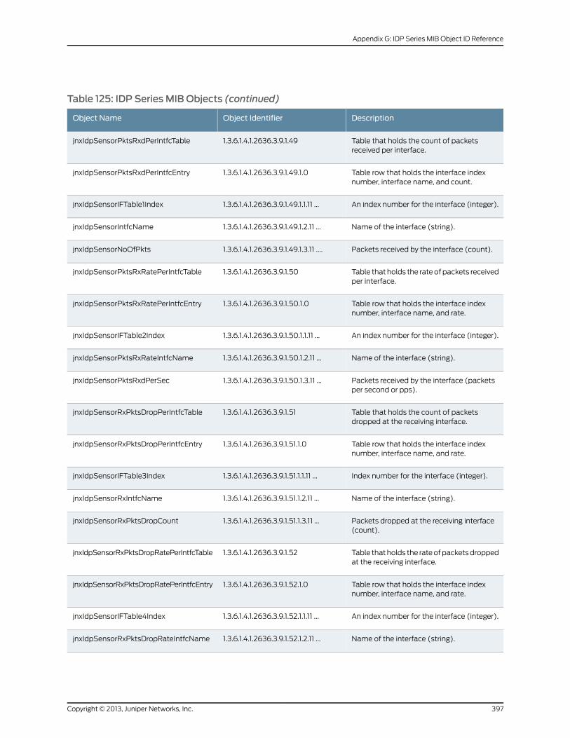
Table 125: IDP Series MIB Objects (continued)
DescriptionObject IdentifierObject Name
Table that holds the count of packetsreceived per interface.
1.3.6.1.4.1.2636.3.9.1.49jnxIdpSensorPktsRxdPerIntfcTable
Table row that holds the interface indexnumber, interface name, and count.
1.3.6.1.4.1.2636.3.9.1.49.1.0jnxIdpSensorPktsRxdPerIntfcEntry
An index number for the interface (integer).1.3.6.1.4.1.2636.3.9.1.49.1.1.11 ...jnxIdpSensorIFTable1Index
Name of the interface (string).1.3.6.1.4.1.2636.3.9.1.49.1.2.11 ...jnxIdpSensorIntfcName
Packets received by the interface (count).1.3.6.1.4.1.2636.3.9.1.49.1.3.11 ....jnxIdpSensorNoOfPkts
Table that holds the rate of packets receivedper interface.
1.3.6.1.4.1.2636.3.9.1.50jnxIdpSensorPktsRxRatePerIntfcTable
Table row that holds the interface indexnumber, interface name, and rate.
1.3.6.1.4.1.2636.3.9.1.50.1.0jnxIdpSensorPktsRxRatePerIntfcEntry
An index number for the interface (integer).1.3.6.1.4.1.2636.3.9.1.50.1.1.11 ...jnxIdpSensorIFTable2Index
Name of the interface (string).1.3.6.1.4.1.2636.3.9.1.50.1.2.11 ...jnxIdpSensorPktsRxRateIntfcName
Packets received by the interface (packetsper second or pps).
1.3.6.1.4.1.2636.3.9.1.50.1.3.11 ...jnxIdpSensorPktsRxdPerSec
Table that holds the count of packetsdropped at the receiving interface.
1.3.6.1.4.1.2636.3.9.1.51jnxIdpSensorRxPktsDropPerIntfcTable
Table row that holds the interface indexnumber, interface name, and rate.
1.3.6.1.4.1.2636.3.9.1.51.1.0jnxIdpSensorRxPktsDropPerIntfcEntry
Index number for the interface (integer).1.3.6.1.4.1.2636.3.9.1.51.1.1.11 ...jnxIdpSensorIFTable3Index
Name of the interface (string).1.3.6.1.4.1.2636.3.9.1.51.1.2.11 ...jnxIdpSensorRxIntfcName
Packets dropped at the receiving interface(count).
1.3.6.1.4.1.2636.3.9.1.51.1.3.11 ...jnxIdpSensorRxPktsDropCount
Table that holds the rate of packets droppedat the receiving interface.
1.3.6.1.4.1.2636.3.9.1.52jnxIdpSensorRxPktsDropRatePerIntfcTable
Table row that holds the interface indexnumber, interface name, and rate.
1.3.6.1.4.1.2636.3.9.1.52.1.0jnxIdpSensorRxPktsDropRatePerIntfcEntry
An index number for the interface (integer).1.3.6.1.4.1.2636.3.9.1.52.1.1.11 ...jnxIdpSensorIFTable4Index
Name of the interface (string).1.3.6.1.4.1.2636.3.9.1.52.1.2.11 ...jnxIdpSensorRxPktsDropRateIntfcName
397Copyright © 2013, Juniper Networks, Inc.
Appendix G: IDP Series MIB Object ID Reference
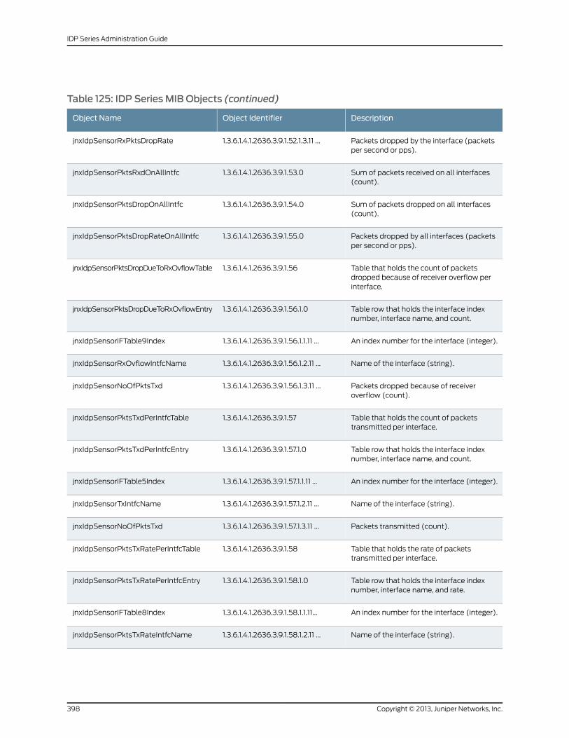
Table 125: IDP Series MIB Objects (continued)
DescriptionObject IdentifierObject Name
Packets dropped by the interface (packetsper second or pps).
1.3.6.1.4.1.2636.3.9.1.52.1.3.11 ...jnxIdpSensorRxPktsDropRate
Sum of packets received on all interfaces(count).
1.3.6.1.4.1.2636.3.9.1.53.0jnxIdpSensorPktsRxdOnAllIntfc
Sum of packets dropped on all interfaces(count).
1.3.6.1.4.1.2636.3.9.1.54.0jnxIdpSensorPktsDropOnAllIntfc
Packets dropped by all interfaces (packetsper second or pps).
1.3.6.1.4.1.2636.3.9.1.55.0jnxIdpSensorPktsDropRateOnAllIntfc
Table that holds the count of packetsdropped because of receiver overflow perinterface.
1.3.6.1.4.1.2636.3.9.1.56jnxIdpSensorPktsDropDueToRxOvflowTable
Table row that holds the interface indexnumber, interface name, and count.
1.3.6.1.4.1.2636.3.9.1.56.1.0jnxIdpSensorPktsDropDueToRxOvflowEntry
An index number for the interface (integer).1.3.6.1.4.1.2636.3.9.1.56.1.1.11 ...jnxIdpSensorIFTable9Index
Name of the interface (string).1.3.6.1.4.1.2636.3.9.1.56.1.2.11 ...jnxIdpSensorRxOvflowIntfcName
Packets dropped because of receiveroverflow (count).
1.3.6.1.4.1.2636.3.9.1.56.1.3.11 ...jnxIdpSensorNoOfPktsTxd
Table that holds the count of packetstransmitted per interface.
1.3.6.1.4.1.2636.3.9.1.57jnxIdpSensorPktsTxdPerIntfcTable
Table row that holds the interface indexnumber, interface name, and count.
1.3.6.1.4.1.2636.3.9.1.57.1.0jnxIdpSensorPktsTxdPerIntfcEntry
An index number for the interface (integer).1.3.6.1.4.1.2636.3.9.1.57.1.1.11 ...jnxIdpSensorIFTable5Index
Name of the interface (string).1.3.6.1.4.1.2636.3.9.1.57.1.2.11 ...jnxIdpSensorTxIntfcName
Packets transmitted (count).1.3.6.1.4.1.2636.3.9.1.57.1.3.11 ...jnxIdpSensorNoOfPktsTxd
Table that holds the rate of packetstransmitted per interface.
1.3.6.1.4.1.2636.3.9.1.58jnxIdpSensorPktsTxRatePerIntfcTable
Table row that holds the interface indexnumber, interface name, and rate.
1.3.6.1.4.1.2636.3.9.1.58.1.0jnxIdpSensorPktsTxRatePerIntfcEntry
An index number for the interface (integer).1.3.6.1.4.1.2636.3.9.1.58.1.1.11...jnxIdpSensorIFTable8Index
Name of the interface (string).1.3.6.1.4.1.2636.3.9.1.58.1.2.11 ...jnxIdpSensorPktsTxRateIntfcName
Copyright © 2013, Juniper Networks, Inc.398
IDP Series Administration Guide
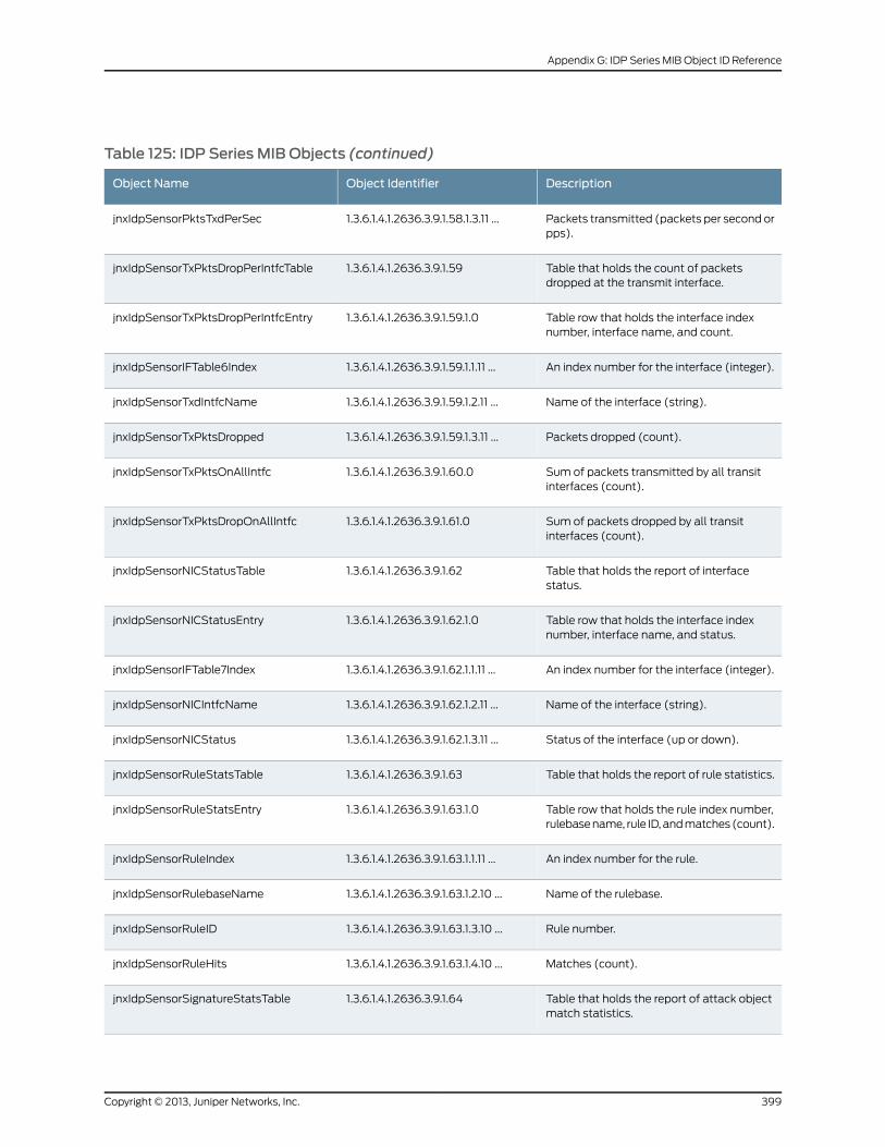
Table 125: IDP Series MIB Objects (continued)
DescriptionObject IdentifierObject Name
Packets transmitted (packets per second orpps).
1.3.6.1.4.1.2636.3.9.1.58.1.3.11 ...jnxIdpSensorPktsTxdPerSec
Table that holds the count of packetsdropped at the transmit interface.
1.3.6.1.4.1.2636.3.9.1.59jnxIdpSensorTxPktsDropPerIntfcTable
Table row that holds the interface indexnumber, interface name, and count.
1.3.6.1.4.1.2636.3.9.1.59.1.0jnxIdpSensorTxPktsDropPerIntfcEntry
An index number for the interface (integer).1.3.6.1.4.1.2636.3.9.1.59.1.1.11 ...jnxIdpSensorIFTable6Index
Name of the interface (string).1.3.6.1.4.1.2636.3.9.1.59.1.2.11 ...jnxIdpSensorTxdIntfcName
Packets dropped (count).1.3.6.1.4.1.2636.3.9.1.59.1.3.11 ...jnxIdpSensorTxPktsDropped
Sum of packets transmitted by all transitinterfaces (count).
1.3.6.1.4.1.2636.3.9.1.60.0jnxIdpSensorTxPktsOnAllIntfc
Sum of packets dropped by all transitinterfaces (count).
1.3.6.1.4.1.2636.3.9.1.61.0jnxIdpSensorTxPktsDropOnAllIntfc
Table that holds the report of interfacestatus.
1.3.6.1.4.1.2636.3.9.1.62jnxIdpSensorNICStatusTable
Table row that holds the interface indexnumber, interface name, and status.
1.3.6.1.4.1.2636.3.9.1.62.1.0jnxIdpSensorNICStatusEntry
An index number for the interface (integer).1.3.6.1.4.1.2636.3.9.1.62.1.1.11 ...jnxIdpSensorIFTable7Index
Name of the interface (string).1.3.6.1.4.1.2636.3.9.1.62.1.2.11 ...jnxIdpSensorNICIntfcName
Status of the interface (up or down).1.3.6.1.4.1.2636.3.9.1.62.1.3.11 ...jnxIdpSensorNICStatus
Table that holds the report of rule statistics.1.3.6.1.4.1.2636.3.9.1.63jnxIdpSensorRuleStatsTable
Table row that holds the rule index number,rulebase name, rule ID, and matches (count).
1.3.6.1.4.1.2636.3.9.1.63.1.0jnxIdpSensorRuleStatsEntry
An index number for the rule.1.3.6.1.4.1.2636.3.9.1.63.1.1.11 ...jnxIdpSensorRuleIndex
Name of the rulebase.1.3.6.1.4.1.2636.3.9.1.63.1.2.10 ...jnxIdpSensorRulebaseName
Rule number.1.3.6.1.4.1.2636.3.9.1.63.1.3.10 ...jnxIdpSensorRuleID
Matches (count).1.3.6.1.4.1.2636.3.9.1.63.1.4.10 ...jnxIdpSensorRuleHits
Table that holds the report of attack objectmatch statistics.
1.3.6.1.4.1.2636.3.9.1.64jnxIdpSensorSignatureStatsTable
399Copyright © 2013, Juniper Networks, Inc.
Appendix G: IDP Series MIB Object ID Reference
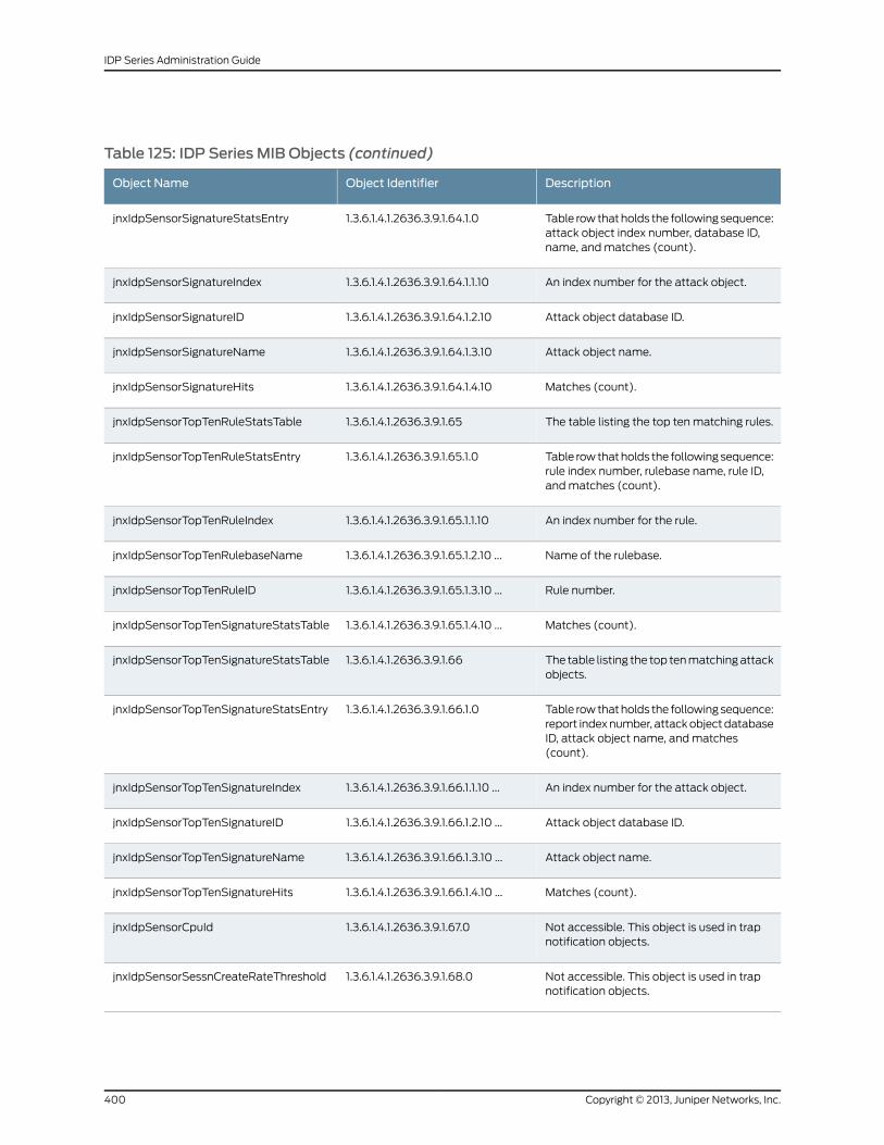
Table 125: IDP Series MIB Objects (continued)
DescriptionObject IdentifierObject Name
Table row that holds the following sequence:attack object index number, database ID,name, and matches (count).
1.3.6.1.4.1.2636.3.9.1.64.1.0jnxIdpSensorSignatureStatsEntry
An index number for the attack object.1.3.6.1.4.1.2636.3.9.1.64.1.1.10jnxIdpSensorSignatureIndex
Attack object database ID.1.3.6.1.4.1.2636.3.9.1.64.1.2.10jnxIdpSensorSignatureID
Attack object name.1.3.6.1.4.1.2636.3.9.1.64.1.3.10jnxIdpSensorSignatureName
Matches (count).1.3.6.1.4.1.2636.3.9.1.64.1.4.10jnxIdpSensorSignatureHits
The table listing the top ten matching rules.1.3.6.1.4.1.2636.3.9.1.65jnxIdpSensorTopTenRuleStatsTable
Table row that holds the following sequence:rule index number, rulebase name, rule ID,and matches (count).
1.3.6.1.4.1.2636.3.9.1.65.1.0jnxIdpSensorTopTenRuleStatsEntry
An index number for the rule.1.3.6.1.4.1.2636.3.9.1.65.1.1.10jnxIdpSensorTopTenRuleIndex
Name of the rulebase.1.3.6.1.4.1.2636.3.9.1.65.1.2.10 ...jnxIdpSensorTopTenRulebaseName
Rule number.1.3.6.1.4.1.2636.3.9.1.65.1.3.10 ...jnxIdpSensorTopTenRuleID
Matches (count).1.3.6.1.4.1.2636.3.9.1.65.1.4.10 ...jnxIdpSensorTopTenSignatureStatsTable
The table listing the top ten matching attackobjects.
1.3.6.1.4.1.2636.3.9.1.66jnxIdpSensorTopTenSignatureStatsTable
Table row that holds the following sequence:report index number, attack object databaseID, attack object name, and matches(count).
1.3.6.1.4.1.2636.3.9.1.66.1.0jnxIdpSensorTopTenSignatureStatsEntry
An index number for the attack object.1.3.6.1.4.1.2636.3.9.1.66.1.1.10 ...jnxIdpSensorTopTenSignatureIndex
Attack object database ID.1.3.6.1.4.1.2636.3.9.1.66.1.2.10 ...jnxIdpSensorTopTenSignatureID
Attack object name.1.3.6.1.4.1.2636.3.9.1.66.1.3.10 ...jnxIdpSensorTopTenSignatureName
Matches (count).1.3.6.1.4.1.2636.3.9.1.66.1.4.10 ...jnxIdpSensorTopTenSignatureHits
Not accessible. This object is used in trapnotification objects.
1.3.6.1.4.1.2636.3.9.1.67.0jnxIdpSensorCpuId
Not accessible. This object is used in trapnotification objects.
1.3.6.1.4.1.2636.3.9.1.68.0jnxIdpSensorSessnCreateRateThreshold
Copyright © 2013, Juniper Networks, Inc.400
IDP Series Administration Guide
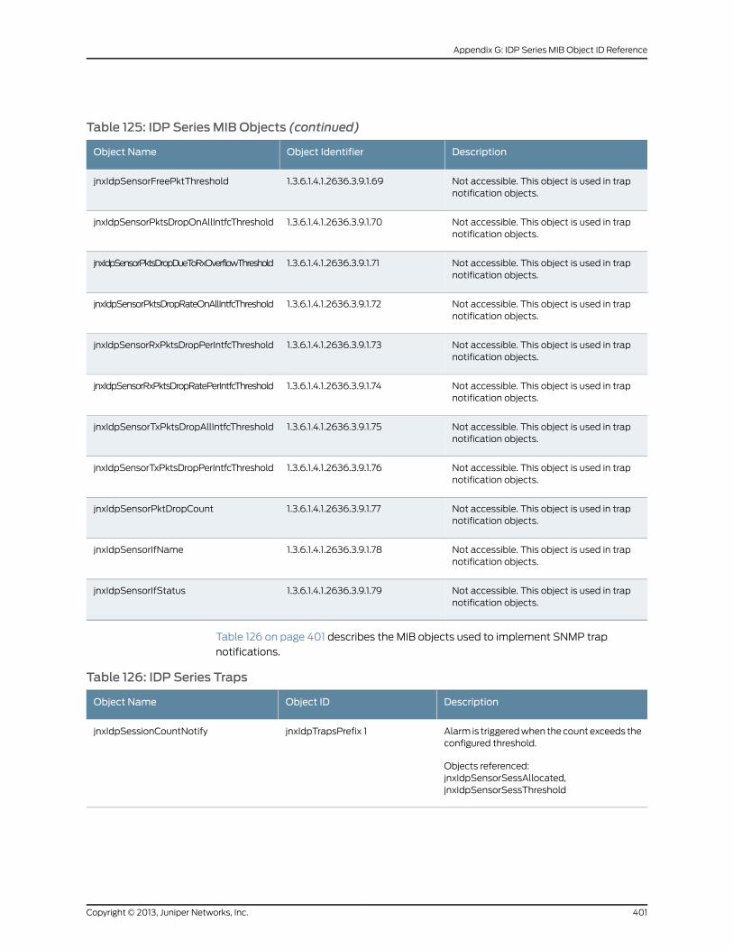
Table 125: IDP Series MIB Objects (continued)
DescriptionObject IdentifierObject Name
Not accessible. This object is used in trapnotification objects.
1.3.6.1.4.1.2636.3.9.1.69jnxIdpSensorFreePktThreshold
Not accessible. This object is used in trapnotification objects.
1.3.6.1.4.1.2636.3.9.1.70jnxIdpSensorPktsDropOnAllIntfcThreshold
Not accessible. This object is used in trapnotification objects.
1.3.6.1.4.1.2636.3.9.1.71jnxIdpSensorPktsDropDueToRxOverflowThreshold
Not accessible. This object is used in trapnotification objects.
1.3.6.1.4.1.2636.3.9.1.72jnxIdpSensorPktsDropRateOnAllIntfcThreshold
Not accessible. This object is used in trapnotification objects.
1.3.6.1.4.1.2636.3.9.1.73jnxIdpSensorRxPktsDropPerIntfcThreshold
Not accessible. This object is used in trapnotification objects.
1.3.6.1.4.1.2636.3.9.1.74jnxIdpSensorRxPktsDropRatePerIntfcThreshold
Not accessible. This object is used in trapnotification objects.
1.3.6.1.4.1.2636.3.9.1.75jnxIdpSensorTxPktsDropAllIntfcThreshold
Not accessible. This object is used in trapnotification objects.
1.3.6.1.4.1.2636.3.9.1.76jnxIdpSensorTxPktsDropPerIntfcThreshold
Not accessible. This object is used in trapnotification objects.
1.3.6.1.4.1.2636.3.9.1.77jnxIdpSensorPktDropCount
Not accessible. This object is used in trapnotification objects.
1.3.6.1.4.1.2636.3.9.1.78jnxIdpSensorIfName
Not accessible. This object is used in trapnotification objects.
1.3.6.1.4.1.2636.3.9.1.79jnxIdpSensorIfStatus
Table 126 on page 401 describes the MIB objects used to implement SNMP trap
notifications.
Table 126: IDP Series Traps
DescriptionObject IDObject Name
Alarm is triggered when the count exceeds theconfigured threshold.
Objects referenced:jnxIdpSensorSessAllocated,jnxIdpSensorSessThreshold
jnxIdpTrapsPrefix 1jnxIdpSessionCountNotify
401Copyright © 2013, Juniper Networks, Inc.
Appendix G: IDP Series MIB Object ID Reference
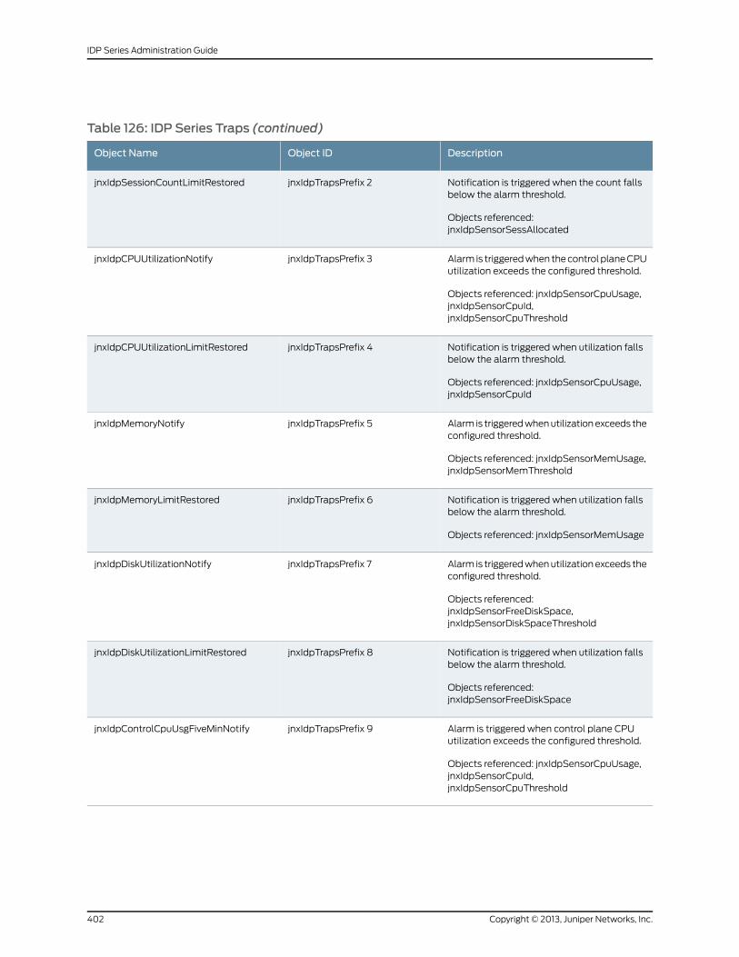
Table 126: IDP Series Traps (continued)
DescriptionObject IDObject Name
Notification is triggered when the count fallsbelow the alarm threshold.
Objects referenced:jnxIdpSensorSessAllocated
jnxIdpTrapsPrefix 2jnxIdpSessionCountLimitRestored
Alarm is triggered when the control plane CPUutilization exceeds the configured threshold.
Objects referenced: jnxIdpSensorCpuUsage,jnxIdpSensorCpuId,jnxIdpSensorCpuThreshold
jnxIdpTrapsPrefix 3jnxIdpCPUUtilizationNotify
Notification is triggered when utilization fallsbelow the alarm threshold.
Objects referenced: jnxIdpSensorCpuUsage,jnxIdpSensorCpuId
jnxIdpTrapsPrefix 4jnxIdpCPUUtilizationLimitRestored
Alarm is triggered when utilization exceeds theconfigured threshold.
Objects referenced: jnxIdpSensorMemUsage,jnxIdpSensorMemThreshold
jnxIdpTrapsPrefix 5jnxIdpMemoryNotify
Notification is triggered when utilization fallsbelow the alarm threshold.
Objects referenced: jnxIdpSensorMemUsage
jnxIdpTrapsPrefix 6jnxIdpMemoryLimitRestored
Alarm is triggered when utilization exceeds theconfigured threshold.
Objects referenced:jnxIdpSensorFreeDiskSpace,jnxIdpSensorDiskSpaceThreshold
jnxIdpTrapsPrefix 7jnxIdpDiskUtilizationNotify
Notification is triggered when utilization fallsbelow the alarm threshold.
Objects referenced:jnxIdpSensorFreeDiskSpace
jnxIdpTrapsPrefix 8jnxIdpDiskUtilizationLimitRestored
Alarm is triggered when control plane CPUutilization exceeds the configured threshold.
Objects referenced: jnxIdpSensorCpuUsage,jnxIdpSensorCpuId,jnxIdpSensorCpuThreshold
jnxIdpTrapsPrefix 9jnxIdpControlCpuUsgFiveMinNotify
Copyright © 2013, Juniper Networks, Inc.402
IDP Series Administration Guide
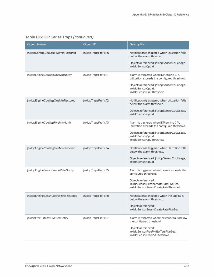
Table 126: IDP Series Traps (continued)
DescriptionObject IDObject Name
Notification is triggered when utilization fallsbelow the alarm threshold.
Objects referenced: jnxIdpSensorCpuUsage,jnxIdpSensorCpuId
jnxIdpTrapsPrefix 10jnxIdpControlCpuUsgFiveMinRestored
Alarm is triggered when IDP engine CPUutilization exceeds the configured threshold.
Objects referenced: jnxIdpSensorCpuUsage,jnxIdpSensorCpuId,jnxIdpSensorCpuThreshold
jnxIdpTrapsPrefix 11jnxIdpEngineCpuUsgOneMinNotify
Notification is triggered when utilization fallsbelow the alarm threshold.
Objects referenced: jnxIdpSensorCpuUsage,jnxIdpSensorCpuId
jnxIdpTrapsPrefix 12jnxIdpEngineCpuUsgOneMinRestored
Alarm is triggered when IDP engine CPUutilization exceeds the configured threshold.
Objects referenced: jnxIdpSensorCpuUsage,jnxIdpSensorCpuId,jnxIdpSensorCpuThreshold
jnxIdpTrapsPrefix 13jnxIdpEngineCpuUsgFiveMinNotify
Notification is triggered when utilization fallsbelow the alarm threshold.
Objects referenced: jnxIdpSensorCpuUsage,jnxIdpSensorCpuId
jnxIdpTrapsPrefix 14jnxIdpEngineCpuUsgFiveMinRestored
Alarm is triggered when the rate exceeds theconfigured threshold.
Objects referenced:jnxIdpSensorSessnCreateRateFiveSec,jnxIdpSensorSessnCreateRateThreshold
jnxIdpTrapsPrefix 15jnxIdpEngineSessnCreateRateNotify
Notification is triggered when the rate fallsbelow the alarm threshold.
Objects referenced:jnxIdpSensorSessnCreateRateFiveSec
jnxIdpTrapsPrefix 16jnxIdpEngineSessnCreateRateRestored
Alarm is triggered when the count falls belowthe configured threshold.
Objects referenced:jnxIdpSensorFreePktBuffersFiveSec,jnxIdpSensorFreePktThreshold
jnxIdpTrapsPrefix 17jnxIdpFreePktLastFiveSecNotify
403Copyright © 2013, Juniper Networks, Inc.
Appendix G: IDP Series MIB Object ID Reference
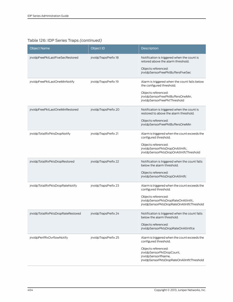
Table 126: IDP Series Traps (continued)
DescriptionObject IDObject Name
Notification is triggered when the count isretored above the alarm threshold.
Objects referenced:jnxIdpSensorFreePktBuffersFiveSec
jnxIdpTrapsPrefix 18jnxIdpFreePktLastFiveSecRestored
Alarm is triggered when the count falls belowthe configured threshold.
Objects referenced:jnxIdpSensorFreePktBuffersOneMin,jnxIdpSensorFreePktThreshold
jnxIdpTrapsPrefix 19jnxIdpFreePktLastOneMinNotify
Notification is triggered when the count isrestored to above the alarm threshold.
Objects referenced:jnxIdpSensorFreePktBuffersOneMin
jnxIdpTrapsPrefix 20jnxIdpFreePktLastOneMinRestored
Alarm is triggered when the count exceeds theconfigured threshold.
Objects referenced:jnxIdpSensorPktsDropOnAllIntfc,jnxIdpSensorPktsDropOnAllIntfcThreshold
jnxIdpTrapsPrefix 21jnxIdpTotalRxPktsDropNotify
Notification is triggered when the count fallsbelow the alarm threshold.
Objects referenced:jnxIdpSensorPktsDropOnAllIntfc
jnxIdpTrapsPrefix 22jnxIdpTotalRxPktsDropRestored
Alarm is triggered when the count exceeds theconfigured threshold.
Objects referenced:jnxIdpSensorPktsDropRateOnAllIntfc,jnxIdpSensorPktsDropRateOnAllIntfcThreshold
jnxIdpTrapsPrefix 23jnxIdpTotalRxPktsDropRateNotify
Notification is triggered when the count fallsbelow the alarm threshold.
Objects referenced:jnxIdpSensorPktsDropRateOnAllIntfce
jnxIdpTrapsPrefix 24jnxIdpTotalRxPktsDropRateRestored
Alarm is triggered when the count exceeds theconfigured threshold.
Objects referenced:jnxIdpSensorPktDropCount,jnxIdpSensorIfName,jnxIdpSensorPktsDropRateOnAllIntfcThreshold
jnxIdpTrapsPrefix 25jnxIdpPerIfRxOvrflowNotify
Copyright © 2013, Juniper Networks, Inc.404
IDP Series Administration Guide
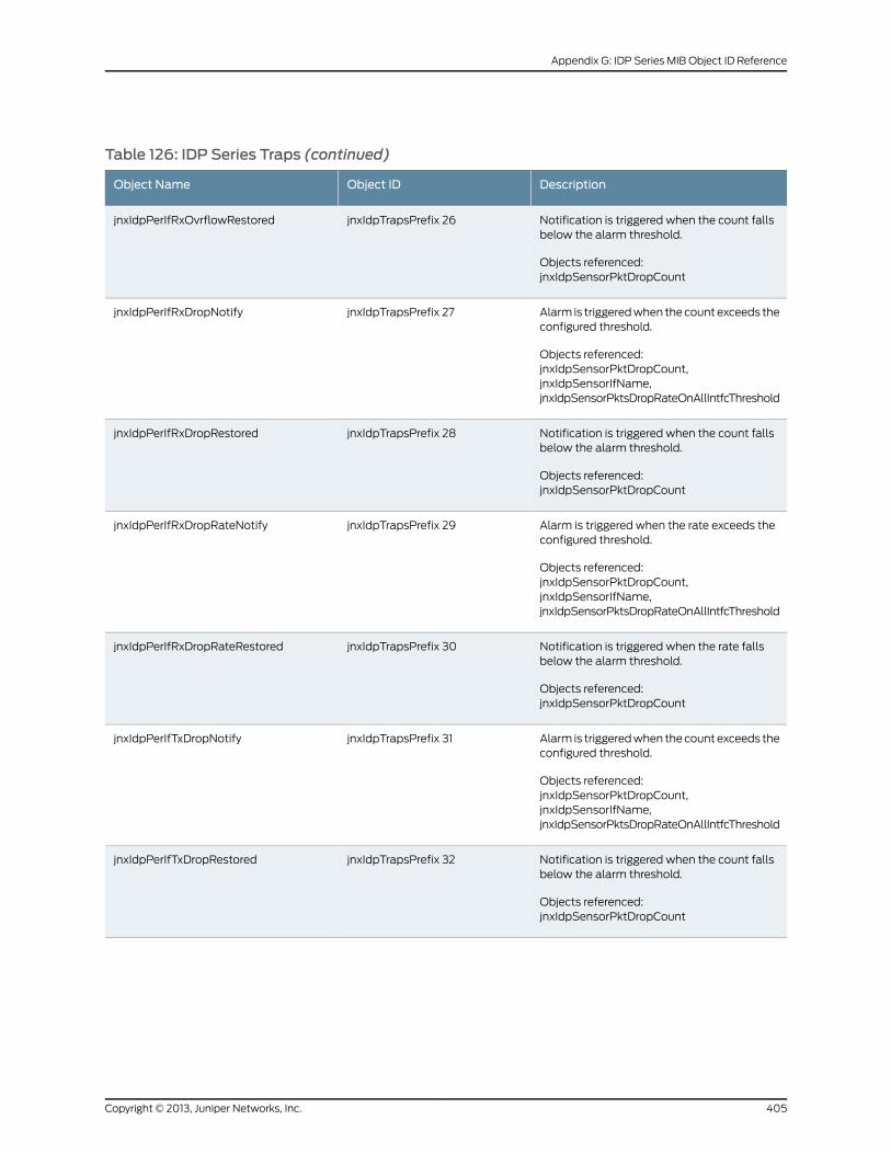
Table 126: IDP Series Traps (continued)
DescriptionObject IDObject Name
Notification is triggered when the count fallsbelow the alarm threshold.
Objects referenced:jnxIdpSensorPktDropCount
jnxIdpTrapsPrefix 26jnxIdpPerIfRxOvrflowRestored
Alarm is triggered when the count exceeds theconfigured threshold.
Objects referenced:jnxIdpSensorPktDropCount,jnxIdpSensorIfName,jnxIdpSensorPktsDropRateOnAllIntfcThreshold
jnxIdpTrapsPrefix 27jnxIdpPerIfRxDropNotify
Notification is triggered when the count fallsbelow the alarm threshold.
Objects referenced:jnxIdpSensorPktDropCount
jnxIdpTrapsPrefix 28jnxIdpPerIfRxDropRestored
Alarm is triggered when the rate exceeds theconfigured threshold.
Objects referenced:jnxIdpSensorPktDropCount,jnxIdpSensorIfName,jnxIdpSensorPktsDropRateOnAllIntfcThreshold
jnxIdpTrapsPrefix 29jnxIdpPerIfRxDropRateNotify
Notification is triggered when the rate fallsbelow the alarm threshold.
Objects referenced:jnxIdpSensorPktDropCount
jnxIdpTrapsPrefix 30jnxIdpPerIfRxDropRateRestored
Alarm is triggered when the count exceeds theconfigured threshold.
Objects referenced:jnxIdpSensorPktDropCount,jnxIdpSensorIfName,jnxIdpSensorPktsDropRateOnAllIntfcThreshold
jnxIdpTrapsPrefix 31jnxIdpPerIfTxDropNotify
Notification is triggered when the count fallsbelow the alarm threshold.
Objects referenced:jnxIdpSensorPktDropCount
jnxIdpTrapsPrefix 32jnxIdpPerIfTxDropRestored
405Copyright © 2013, Juniper Networks, Inc.
Appendix G: IDP Series MIB Object ID Reference
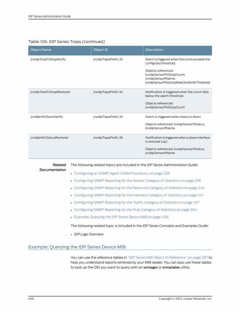
Table 126: IDP Series Traps (continued)
DescriptionObject IDObject Name
Alarm is triggered when the count exceeds theconfigured threshold.
Objects referenced:jnxIdpSensorPktDropCount,jnxIdpSensorIfName,jnxIdpSensorPktsDropRateOnAllIntfcThreshold
jnxIdpTrapsPrefix 33jnxIdpTotalTxDropNotify
Notification is triggered when the count fallsbelow the alarm threshold.
Objects referenced:jnxIdpSensorPktDropCount
jnxIdpTrapsPrefix 34jnxIdpTotalTxDropRestored
Alarm is triggered when status is down.
Objects referenced: jnxIdpSensorIfStatus,jnxIdpSensorIfName
jnxIdpTrapsPrefix 35jnxIdpIntfcDownNotify
Notification is triggered when a down interfaceis restored (up).
Objects referenced: jnxIdpSensorIfStatus,jnxIdpSensorIfName
jnxIdpTrapsPrefix 36jnxIdpIntfcStatusRestored
RelatedDocumentation
The following related topics are included in the IDP Series Administration Guide:
Configuring an SNMP Agent (NSM Procedure) on page 228•
• Configuring SNMP Reporting for the Sensor Category of Statistics on page 238
• Configuring SNMP Reporting for the Resource Category of Statistics on page 242
• Configuring SNMP Reporting for the Interface Category of Statistics on page 247
• Configuring SNMP Reporting for the Traffic Category of Statistics on page 257
• Configuring SNMP Reporting for the Rule Category of Statistics on page 264
• Example: Querying the IDP Series Device MIB on page 406
The following related topic is included in the IDP Series Concepts and Examples Guide:
• IDP Logs Overview
Example: Querying the IDP Series DeviceMIB
You can use the reference tables in “IDP Series MIB Object ID Reference” on page 387 to
help you understand reports retrieved by your MIB reader. You can also use these tables
to look up the OID you want to query with an snmpget or snmptable utility.
Copyright © 2013, Juniper Networks, Inc.406
IDP Series Administration Guide
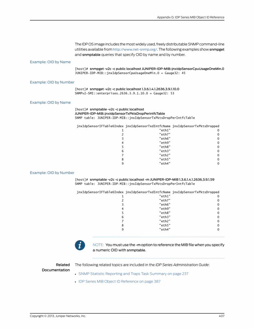
The IDP OS image includes the most widely used, freely distributable SNMP command-line
utilities available fromhttp://www.net-snmp.org/. The following examples show snmpget
and snmptable queries that specify OID by name and by number.
Example: OID by Name
[host]# snmpget -v2c -c public localhost JUNIPER-IDP-MIB::jnxIdpSensorCpuUsageOneMin.0JUNIPER-IDP-MIB::jnxIdpSensorCpuUsageOneMin.0 = Gauge32: 45
Example: OID by Number
[host]# snmpget -v2c -c public localhost 1.3.6.1.4.1.2636.3.9.1.10.0SNMPv2-SMI::enterprises.2636.3.9.1.10.0 = Gauge32: 53
Example: OID by Name
[host]# snmptable -v2c -c public localhostJUNIPER-IDP-MIB::jnxIdpSensorTxPktsDropPerIntfcTableSNMP table: JUNIPER-IDP-MIB::jnxIdpSensorTxPktsDropPerIntfcTable
jnxIdpSensorIFTable6Index jnxIdpSensorTxdIntfcName jnxIdpSensorTxPktsDropped 1 "eth1" 0 2 "eth7" 0 3 "eth6" 0 4 "eth9" 0 5 "eth8" 0 6 "eth3" 0 7 "eth2" 0 8 "eth5" 0 9 "eth4" 0
Example: OID by Number
[host]# snmptable -v2c -c public localhost -m JUNIPER-IDP-MIB 1.3.6.1.4.1.2636.3.9.1.59SNMP table: JUNIPER-IDP-MIB::jnxIdpSensorTxPktsDropPerIntfcTable
jnxIdpSensorIFTable6Index jnxIdpSensorTxdIntfcName jnxIdpSensorTxPktsDropped 1 "eth1" 0 2 "eth7" 0 3 "eth6" 0 4 "eth9" 0 5 "eth8" 0 6 "eth3" 0 7 "eth2" 0 8 "eth5" 0 9 "eth4" 0
NOTE: Youmust use the -moption to reference theMIB filewhen you specify
a numeric OID with snmptable.
RelatedDocumentation
The following related topics are included in the IDP Series Administration Guide:
• SNMP Statistic Reporting and Traps Task Summary on page 237
• IDP Series MIB Object ID Reference on page 387
407Copyright © 2013, Juniper Networks, Inc.
Appendix G: IDP Series MIB Object ID Reference

Copyright © 2013, Juniper Networks, Inc.408
IDP Series Administration Guide

PART 8
Index
• Index on page 411
409Copyright © 2013, Juniper Networks, Inc.

Copyright © 2013, Juniper Networks, Inc.410
IDP Series Administration Guide
Index
AACM...................................................................................123, 185
ACM reference.........................................................................311
actions
IDP rulebase.....................................................................46
IP actions..........................................................................48
Recommended................................................................47
activating devices in NSM..................................................132
adding a device to NSM......................................................128
antispoof settings..................................................................137
APE rulebase............................................................................56
troubleshooting...........................................................303
verifying implementation of....................................269
Appliance Configuration Manager. See ACM.
application groups
viewing ......................................................................117, 118
application objects
task list................................................................................111
viewing predefined........................................................112
application volume tracking
enabling in NSM...............................................................13
preference settings........................................................25
reports..............................................................................223
viewing logs in Profiler Viewer....................................19
attack logs, viewing..............................................................214
attack objects
creating compound.....................................................105
creating signature..........................................................85
groups................................................................................83
specifying in Exempt rulebase..................................56
specifying in IDP rulebase rules................................45
task list...............................................................................79
updating predefined...................................................194
viewing predefined.......................................................80
attack reports..........................................................................221
Audit Log Viewer...................................................................220
autorecovery
disabling..........................................................................292
autorecovery logs..................................................................291
Bbackdoor rulebase...................................................................61
bandwidth rate limiting........................................................56
Boolean expressions in compound attack
objects..................................................................................108
bypassStatus reference......................................................316
bypassStatus utility.............................................................267
CCLI...................................................................123, 167, 205, 269
clusters, adding to NSM.......................................................131
compound attack objects
Boolean expressions..................................................108
creating...................................................................105, 106
protocol anomalies.....................................................108
compound attack objects, creating.....................105, 106
configuration updates.........................................................134
context check constraint.....................................................94
context, specifying.................................................................98
CPU usage...............................................................................293
custom application objects
viewing.......................................................................117, 118
customer support....................................................................xx
contacting JTAC...............................................................xx
Ddefault configuration................................................................3
detector engine, updating..................................................194
device status.........................................................................208
DFA expressions
syntax.................................................................................95
direction
specifying..........................................................................98
disabling rules...........................................................................76
documentation........................................................................xix
dynamic groups.......................................................................83
EExempt rulebase.....................................................................55
extended application objects
viewing ..............................................................................115
viewing predefined................................................117, 118
external bypass, setting.....................................................186
Fflow bypass
enabling............................................................................179
verifying implementation of.....................................273
411Copyright © 2013, Juniper Networks, Inc.
flow table
resetting...........................................................................144
viewing..............................................................................277
flow, specifying........................................................................98
fragment handling................................................................146
GGRE inspection.......................................................................173
GTP inspection.......................................................................175
guiSvrCli.sh..............................................................................196
HHTTPS inspection.........................................................168, 171
II/O modules............................................................................188
IC Series Appliance
verifying integration with............................................271
ICMP packet header matching..........................................99
IDP detector engine, updating.........................................194
IDP Reporter.................................................................205, 235
IDP rulebase...............................................................................41
idp.sh.........................................................................................320
idp.sh reference.....................................................................320
interface aliasing....................................................................187
internal bypass, setting......................................................186
IP Action
resetting the block table............................................145
IP actions...................................................................................48
IP packet header matching.................................................99
IPsec VPN inspecdtion.........................................................177
JJ-Security Center...................................................................194
jnetTcpdump...........................................................................281
jumbo frames, disabling....................................................304
LLayer 2 processing, enabling.............................................185
Log Investigator......................................................................219
log storage limts...................................................................226
log suppression......................................................................227
logs.............................................................................................207
MMIB.............................................................................................387
mixed deployment mode, setting..................................186
MPLS inspection
disabling.........................................................................306
enabling............................................................................178
verifying implementation of.....................................272
NNetwork Honeypot rulebase..............................................68
NIC cards..................................................................................188
notification options................................................................49
NSM..................................................................................123, 205
custom reports.............................................................224
managing device configuration with ....................127
modifying device configuration with.....................135
updating IDP detector engine with........................194
updating predefined attack objects with............194
updating software with...............................................191
viewing logs and reports with.................................207
viewing logs with...........................................................213
viewing reports with....................................................221
NSM Audit Log Viewer........................................................220
NSM Log Investigator...........................................................219
NSM Log Viewer.....................................................................214
NSM reports.............................................................................221
NSM security explorer, about.............................................29
NSM topology manager, about..........................................31
OOS fingerprinting
enabling..............................................................................13
Ppacket header matching......................................................99
packet logging
enabling collection in NSM logs.............................232
enabling in IDP rulebase rules...................................49
log storage limits.........................................................226
using jnetTcpdump......................................................281
using tcpdump.............................................................282
parameters..............................................................................149
peer port modulation, setting..........................................186
Profiler
alerts.....................................................................................17
Application Profiler tab.................................................19
database settings..........................................................25
managing the database...............................................27
Network Profiler tab......................................................22
options................................................................................12
Protocol Profiler tab.......................................................21
reports..............................................................................223
Copyright © 2013, Juniper Networks, Inc.412
IDP Series Administration Guide
starting and stopping....................................................18
using......................................................................................11
Violation Viewer tab......................................................24
protocol anomalies in compound attack
objects..................................................................................108
protocol decoders................................................................299
protocol handling parameters...........................................151
pulling configuration updates..........................................134
pushing configuration updates........................................134
Rreboot command..................................................................201
Recommended action...........................................................47
Recommended attack objects..................................45, 84
Recommended security policy...........................................37
reports.......................................................................................207
rule match conditions...........................................................43
rule severity...............................................................................52
rule target....................................................................................51
runtime parameters.............................................................139
Sscio
agentconfig....................................................................325
ca.......................................................................................369
const................................................................................330
getsystem.......................................................................349
nic......................................................................................353
ssl......................................................................................356
subs..................................................................................360
sysconf............................................................................364
vc........................................................................................374
version..............................................................................375
vr.........................................................................................376
scio reference.........................................................................323
scio utility........................................................................167, 269
sctop..........................................................................................277
security policies
assigning............................................................................72
creating..............................................................................35
exporting............................................................................76
pushing to IDP Series devices....................................73
validating...........................................................................72
service binding.........................................................................92
severity, rule...............................................................................52
shutdown command..........................................................202
signature attack objects
creating..............................................................................85
signature attack objects, creating....................................85
sniffer mode, setting............................................................186
SNMP..............................................................................205, 228
SSL inspection................................................................168, 171
static groups.............................................................................84
support, technical See technical support
SYN Protector rulebase........................................................63
configurable threshholds...................................65, 147
syslog........................................................................................230
TTCP packet header matching............................................99
tcpdump..................................................................................282
tech-support script.............................................................286
technical support
contacting JTAC...............................................................xx
tech-support script....................................................286
templates, security policy....................................................37
terminal match........................................................................43
time binding..............................................................................93
Traffic Anomalies rulebase.................................................65
traffic interfaces
I/O modules...................................................................188
transparent mode, setting.................................................186
troubleshooting utilities.....................................................285
UUDP packet header matching...........................................99
updating software
CLI procedure.................................................................193
NSM procedure..............................................................191
updating the configuration................................................134
user-role-based policy
advanced features........................................................181
troubleshooting...........................................................304
verifying implementation of......................................271
Vvirtual routers, configuring.................................................186
VLAN
match in security policy rules.....................................51
Wwithin bytes constraint.........................................................94
within packets constraint....................................................94
413Copyright © 2013, Juniper Networks, Inc.
Index

Copyright © 2013, Juniper Networks, Inc.414
IDP Series Administration Guide