Embed Size (px)
Citation preview
IE3 three-phase AC motors m200
Mains operation 5.5 ... 45 kW
www.lenze.nt-rt.ru

По вопросам продаж и поддержки обращайтесь:Астана +7(7172)727-132, Волгоград (844)278-03-48, Воронеж (473)204-51-73, Екатеринбург (343)384-55-89,
Казань (843)206-01-48, Краснодар (861)203-40-90, Красноярск (391)204-63-61, Москва (495)268-04-70, Нижний Новгород (831)429-08-12, Новосибирск (383)227-86-73, Ростов-на-Дону (863)308-18-15, Самара (846)206-03-16,
Санкт-Петербург (812)309-46-40, Саратов (845)249-38-78, Уфа (347)229-48-12 [email protected] || www.lenze.nt-rt.ru
IE3 three-phase AC motors m200General information
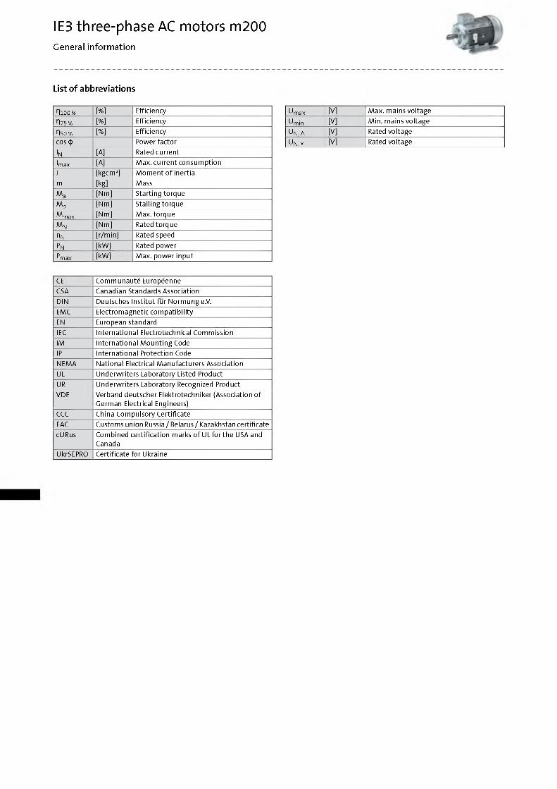
List of abbreviations
Hioo% [%] Efficiency
П75% [%] Efficiency
П50 % [%] Efficiencycos ф Power factor
IN [A] Rated current
Imax [A] M ax. current consum ptionJ [kgcm 2] M om ent o f inertiam [kg] Mass
Ma [Nm] Starting torque
Mb [Nm] Stalling torque
M max [Nm] M ax. torque
M N [Nm] Rated torque
nN [r/min] Rated speed
Pn [kW] Rated powerPr max [kW] M ax. power input
U max [V] M ax. mains voltage
U min [V] M in. mains voltage
U N, Д [V] Rated voltage
U N,Y [V] Rated voltage
CE Com m unaute EuropeenneCSA Canadian Standards AssociationDIN Deutsches Institu t fur N orm ung e.V.EMC Electrom agnetic com patib ilityEN European standardIEC International Electrotechnical CommissionIM International M ounting CodeIP International Protection CodeNEM A National Electrical M anufacturers AssociationUL Underw riters Laboratory Listed ProductUR Underw riters Laboratory Recognized ProductVDE Verband deutscher Elektrotechniker (Association o f
Germ an Electrical Engineers)CCC China Com pulsory CertificateEAC Customs union Russia/ Belarus/ Kazakhstan certificatecURus Com bined certification marks o f UL for the USA and
CanadaUkrSEPRO Certificate for Ukraine
IE3 three-phase AC motors m200General information
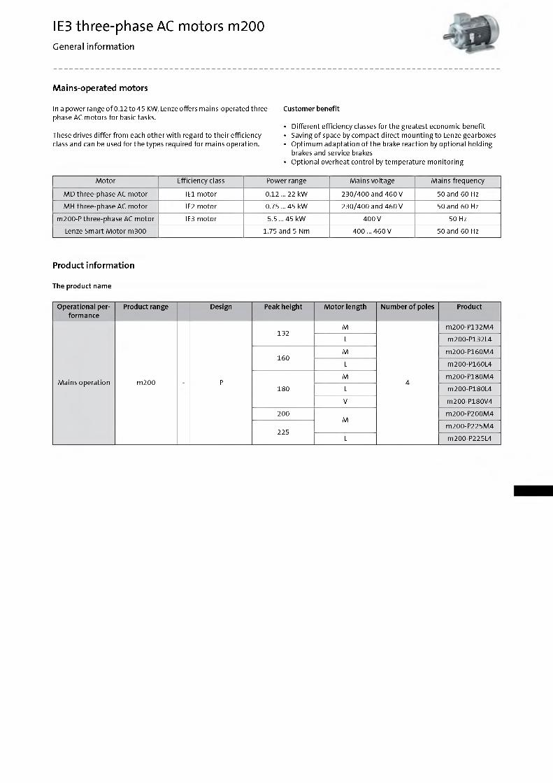
Mains-operated motors
Custom er benefit
• Different efficiency classes fo r the greatest economic benefit• Saving o f space by com pact direct m ounting to Lenze gearboxes• O ptim um adaptation o f the brake reaction by optional holding
brakes and service brakes• Optional overheat control by tem perature m onitoring
M otor Efficiency class Power range Mains voltage Mains frequency
M D three-phase AC m otor IE1 m otor 0.12 ... 22 kW 230/400 and 460 V 50 and 60 Hz
MH three-phase AC m otor IE2 m otor 0.75 ... 45 kW 230/400 and 460 V 50 and 60 Hz
m200-P three-phase AC m otor IE3 m otor 5.5 ... 45 kW 400 V 50 Hz
Lenze Smart M otor m300 1.75 and 5 Nm 400... 460 V 50 and 60 Hz
Product information
The product name
Operational perform ance
Product range Design Peak height M oto r length Num ber o f poles Product
132M m200-P132M4
L m200-P132L4
160M m200-P160M4
L m200-P160L4
Mains operation m200 PM
4m200-P180M4
180 L m200-P180L4
V m200-P180V4
200M
m200-P200M4
225m200-P225M4
L m200-P225L4
In a power range o f 0.12 to 45 KW, Lenze offers m ains-operated three- phase AC m otors for basic tasks.
These drives differ from each o ther w ith regard to the ir efficiency class and can be used for the types required for mains operation.
IE3 three-phase AC motors m200General information
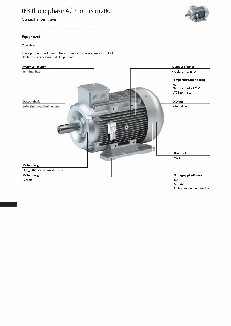
Equipment
O verv iew
The equipm ent includes all the options available as standard and all the bu ilt-on accessories o f the product.
M otor connection
M oto r design
Flange (B5)with through holes
M otor design
Num ber o f poles
4-pole, 5.5 ... 45 kW
Tem perature m onitoring
NoThermal contact TKO pTC therm istor
Cooling______________
Integral fan
Feedback
W itho u t
Spring-applied brake
Foot (B3) NoStandardO ption manual release lever
IE3 three-phase AC motors m200General information
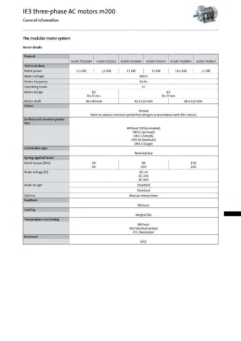
The modular motor system
M o to r details
Product
m200-P132M4 m200-P132L4 m200-P160M4 m200-P160L4 m200-P180M4 m200-P180L4Technical data
Rated power 5.5 kW 7,5 kW 11 kW 15 kW 18.5 kW 22 kW
Mains voltage 400 V
Mains frequency 50 Hz
O perating mode S1
M otor design B3B5-FF265
B3B5-FF300
M otor shaft 38 x 80 mm 42 x 110 mm 48 x 110 mmColour
PrimedPaint in various corrosion-protection designs in accordance w ith RAL colours
Surface and corrosion protection
W ith o u t OKS(uncoated) OKS-G (prim ed) OKS-S (Small);
OKS-M (m edium ) OKS-L (large)
Connection type
Terminal boxSpring-applied brake
Rated torque [Nm] 6080
80150
150260
Brake voltage [V] DC 24 AC 230 AC 400
Brake design Standard
Standard
Options M anual release leverFeedback
W ith o u tCooling
Integral fanTem perature m on itoring
W ith o u t TKO therm al contact
PTC therm istorEnclosure
IP55
IE3 three-phase AC motors m200General information
The modular motor system
M o to r details
Product
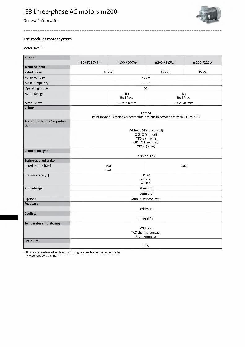
m200-P180V41) m200-P200M4 m200-P225M4 m200-P225L4Technical data
Rated power 30 kW 37 kW 45 kW
Mains voltage 400 V
Mains frequency 50 Hz
O perating mode S1
M otor design B3B5-FF350
B3B5-FF400
M otor shaft 55 x1 1 0 mm 60 x 140 mmColour
PrimedPaint in various corrosion-protection designs in accordance w ith RAL colours
Surface and corrosion protection
W ith o u t OKS(uncoated) OKS-G (prim ed) OKS-S (Small);
OKS-M (m edium ) OKS-L (large)
Connection type
Terminal boxSpring-applied brake
Rated torque [Nm] 150260
400
Brake voltage [V] DC 24 AC 230 AC 400
Brake design Standard
Standard
Options M anual release leverFeedback
W ith o u tCooling
Integral fanTem perature m on itoring
W ith o u t TKO therm al contact
PTC therm istorEnclosure
IP55
1)This motor is intended for direct mounting to a gearboxand is not available in motor design B3 or B5.
IE3 three-phase AC motors m200General information
The modular motor system
M o to r details
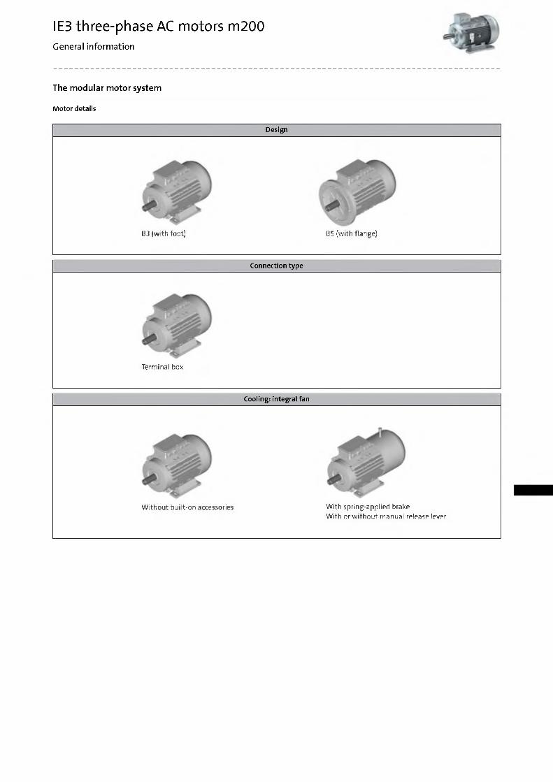
Design
B3 (w ith foot) B5 (w ith flange)
Connection type
Term inal box
Cooling: integral fan
W ith o u t bu ilt-on accessories W ith spring-applied brakeW ith or w ith o u t m anual release lever
IE3 three-phase AC motors m200Technical data
Standards and operating conditions
O verv iew
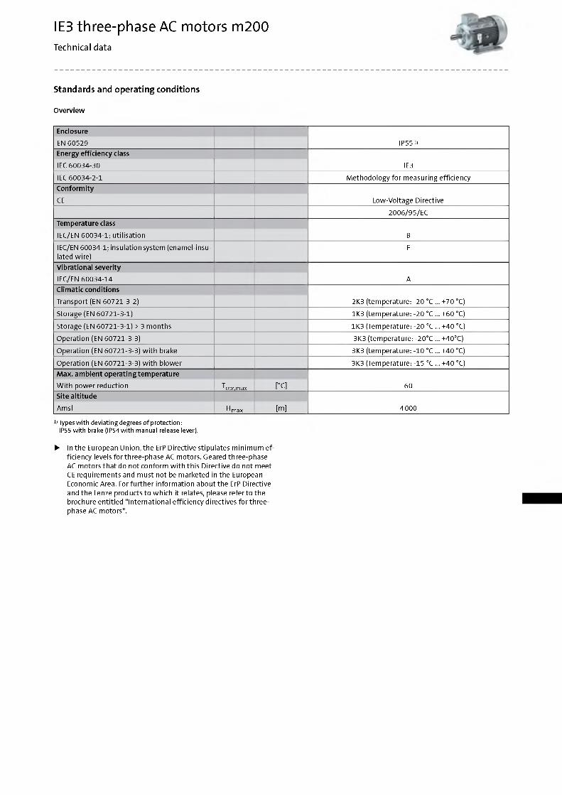
Enclosure
EN 60529 IP55 1)Energy effic iency class
IEC 60034-30 IE3
IEC 60034-2-1 M ethodo logy fo r measuring efficiency
C onform ity
CE Low -Voltage Directive
2006/95/EC
Tem perature class
IEC/EN 60034-1; utilisation B
IEC/EN 60034-1; insulation system (enam el-insulated w ire)
F
Vibrational severity
IEC/EN 60034-14 AClim atic conditions
Transport (EN 60721-3-2) 2K3 (tem perature: -20 °C ... +70 °C)
Storage (EN 60721-3-1) 1K3 (tem perature: -20 °C ... +60 °C)
Storage (EN 60721-3-1) > 3 m onths 1K3 (Temperature: -20 °C ... +40 °C)
Operation (EN 60721-3-3) 3K3 (tem perature: -20°C ... +40°C)
Operation (EN 60721-3-3) w ith brake 3K3 (tem perature: -10 °C ... +40 °C)
Operation (EN 60721-3-3) w ith blower 3K3 (Temperature: -15 °C ... +40 °C)
M ax. am bient operatingtem peratu re
W ith power reduction Topr,max [°C] 60Site a ltitude
Am sl H max [m] 4000
1 Types w ith deviating degrees of protection:IP55 w ith brake (IP54with manual release lever).
► In the European Union, the ErP Directive stipulates m inim um efficiency levels fo rth ree-phase AC m otors. Geared three-phase AC m otors th a t do not conform w ith th is Directive do not meet CE requirem ents and m ust not be marketed in the European Economic Area. For fu rth er inform ation about the ErP Directive and the Lenze products to which it relates, please re ferto the brochure entitled "International efficiency directives fo rth re e - phase AC m otors".
IE3 three-phase AC motors m200Technical data
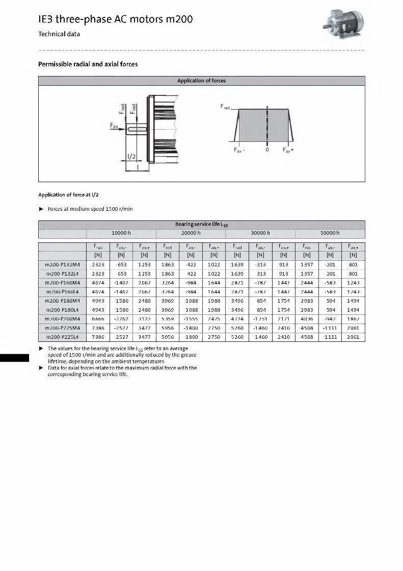
Permissible radial and axial forces
App lication o f force at l/2
► Forces at m edium speed 1500 r/min
Bearing service life L10
10000 h 20000 h 30000 h 50000 h
Frad Fax,- Fax,+ Frad Fax,- Fax,+ Frad Fax,- Fax,+ Frad Fax,- Fax,+
[N] [N] [N] [N] [N] [N] [N] [N] [N] [N] [N] [N]
m200-P132M4 2323 -653 1253 1863 -422 1022 1639 -313 913 1357 -201 801
m200-P132L4 2323 -653 1253 1863 -422 1022 1639 -313 913 1357 -201 801
m200-P160M4 4074 -1407 2067 3264 -984 1644 2871 -787 1447 2444 -583 1243
m200-P160L4 4074 -1407 2067 3264 -984 1644 2871 -787 1447 2444 -583 1243
m200-P180M4 4943 -1580 2480 3969 -1088 1988 3496 -854 1754 2983 -594 1494
m200-P180L4 4943 -1580 2480 3969 -1088 1988 3496 -854 1754 2983 -594 1494
m200-P200M4 6666 -2202 3122 5359 -1555 2475 4724 -1251 2171 4036 -942 1862
m200-P225M4 7 386 -2527 3477 5956 -1800 2750 5260 -1460 2410 4508 -1111 2061
m200-P225L4 7 386 -2527 3477 5956 -1800 2750 5260 -1460 2410 4508 -1111 2061
► The values for the bearing service life L10 refer to an average speed o f 1500 r/min and are add itiona lly reduced by the grease lifetim e, depending on the am bienttem peratures.
► Data for axial forces relate to the m axim um radial force w ith the corresponding bearing service life.
IE3 three-phase AC motors m200Technical data
Permissible radial and axial forces
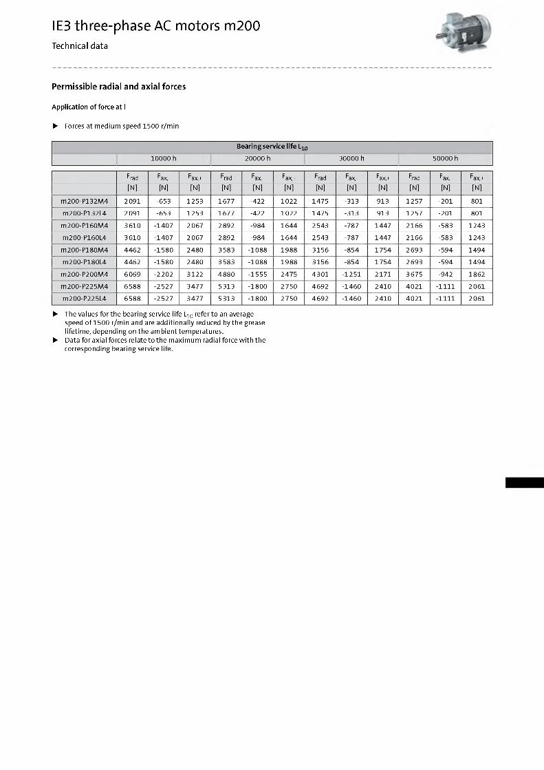
App lication o f force at l
► Forces at m edium speed 1500 r/min
Bearing service life L10
10000 h 20000 h 30000 h 50000 h
Frad Fax,- Fax,+ Frad Fax,- Fax,+ Frad Fax,- Fax,+ Frad Fax,- Fax,+
[N] [N] [N] [N] [N] [N] [N] [N] [N] [N] [N] [N]
m200-P132M4 2091 -653 1253 1677 -422 1022 1475 -313 913 1257 -201 801
m200-P132L4 2091 -653 1253 1677 -422 1022 1475 -313 913 1257 -201 801
m200-P160M4 3610 -1407 2067 2892 -984 1644 2 543 -787 1447 2166 -583 1243
m200-P160L4 3610 -1407 2067 2892 -984 1644 2 543 -787 1447 2166 -583 1243
m200-P180M4 4462 -1580 2480 3583 -1088 1988 3156 -854 1754 2693 -594 1494
m200-P180L4 4462 -1580 2480 3583 -1088 1988 3156 -854 1754 2693 -594 1494
m200-P200M4 6069 -2202 3122 4880 -1555 2475 4301 -1251 2171 3675 -942 1862
m200-P225M4 6588 -2527 3477 5313 -1800 2750 4692 -1460 2410 4021 -1111 2061
m200-P225L4 6588 -2527 3477 5313 -1800 2750 4692 -1460 2410 4021 -1111 2061
► The values for the bearing service life L10 refer to an average speed o f 1500 r/min and are add itiona lly reduced by the grease lifetim e, depending on the am bienttem peratures.
► Data for axial forces relate to the m axim um radial force w ith the corresponding bearing service life.
IE3 three-phase AC motors m200Technical data
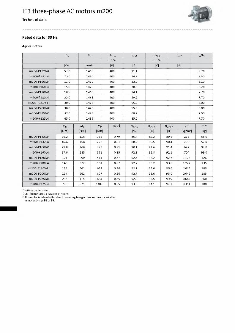
Rated data for 50 Hz
4-pole m otors
Pn nN U N, Д IN, Д U N,Y IN,Y Ia/IN± 5 % ± 5 %
[kW] [r/min] [V] [A] [V] [A]
m200-P132M4 5.50 1465 400 11.1 8.70
m200-P132L4 7.50 1460 400 14.8 9.50
m200-P160M4 11.0 1470 400 22.0 8.10
m200-P160L4 15.0 1470 400 28.6 8.20
m200-P180M4 18.5 1460 400 34.1 7.70
m200-P180L4 22.0 1465 400 39.9 7.70
m200-P180V43) 30.0 1475 400 55.3 8.00
m200-P200M4 30.0 1475 400 55.3 8.00
m200-P225M4 37.0 1485 400 68.9 7.50
m200-P225L4 45.0 1485 400 83.0 7.70
M N Ma Mb cos ф n50 % П75% П100% J1) m 1)
[Nm] [Nm] [Nm] [%] [%] [%] [kgcm2] [kg]
m200-P132M4 36.2 116 156 0.79 86.9 89.2 89.6 276 55.0
m200-P132L4 49.4 158 222 0.81 88.9 90.5 90.4 298 57.0
m200-P160M4 71.8 208 273 0.81 90.1 91.6 91.4 692 92.0
m200-P160L4 97.6 283 371 0.83 92.8 92.8 92.1 704 99.0
m200-P180M4 121 290 411 0.87 92.8 93.2 92.6 1122 126
m200-P180L4 143 372 501 0.87 92.7 93.2 93.0 1277 135
m200-P180V43) 194 561 697 0.86 92.7 93.6 93.6 2 645 183
m200-P200M4 194 561 697 0.86 92.7 93.6 93.6 2 645 183
m200-P225M4 238 715 834 0.85 92.0 93.5 93.9 3 643 260
m200-P225L4 290 871 1016 0.85 93.0 94.1 94.2 4351 280
1) W ithout accessories2) Star/delta start-up possible at 400 V.3) This motor is intended for direct mounting to a gearbox and is not available
in motor design B3 or B5.
IE3 three-phase AC motors m200Technical data
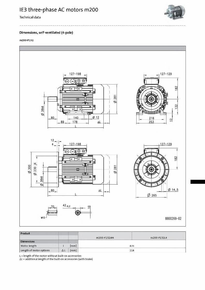
Dimensions, self-ventilated (4-pole)
m200-P132
Product
m200-P132M4 m200-P132L4Dimensions
M otor length L [mm] 476
Length o f m otor options A L [mm] 118
L = length of the motor without built-on accessoriesA L = additional length o f the built-on accessories (with brake)
IE3 three-phase AC motors m200Technical data
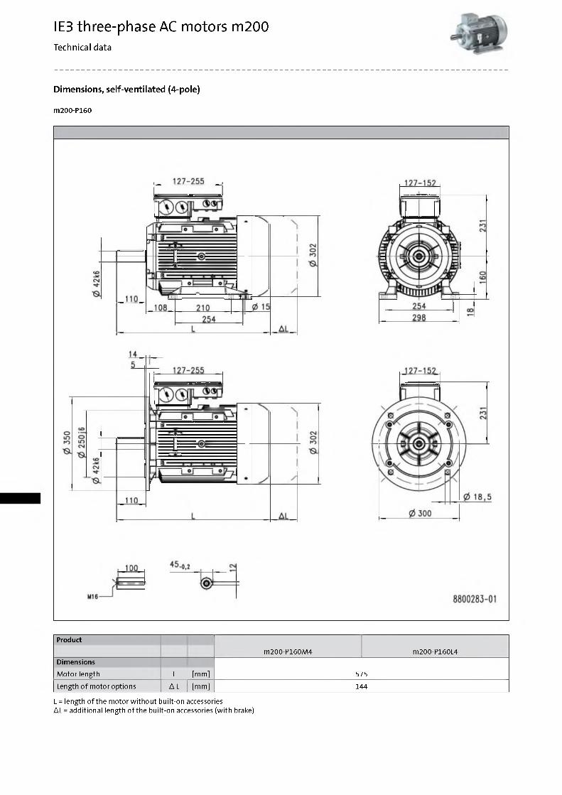
Dimensions, self-ventilated (4-pole)
m200-P160
Product
m200-P160M4 m200-P160L4Dimensions
M otor length L [mm] 575
Length o f m otor options A L [mm] 144
L = length of the motor without built-on accessoriesA L = additional length o f the built-on accessories (with brake)
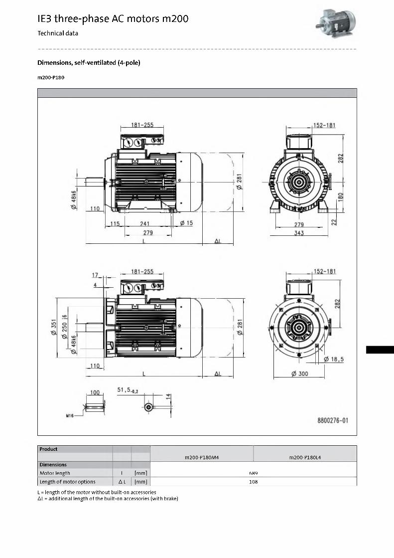
IE3 three-phase AC motors m200Technical data
Dimensions, self-ventilated (4-pole)
m200-P180
Product
m200-P180M4 m200-P180L4Dimensions
M otor length L [mm] 689
Length o f m otor options Д L [mm] 108
L = length of the motor without built-on accessoriesДL = additional length o f the built-on accessories (with brake)
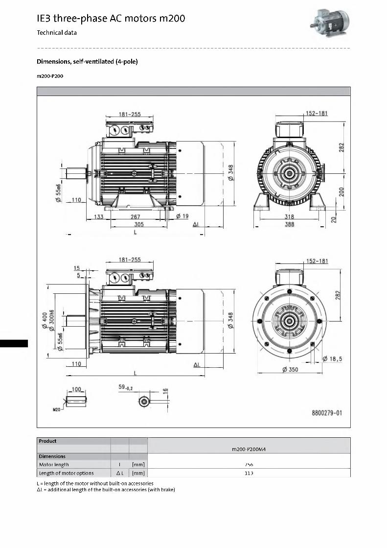
IE3 three-phase AC motors m200Technical data
Dimensions, self-ventilated (4-pole)
m200-P200
Product
m200-P200M4Dimensions
M otor length L [mm] 756
Length o f m otor options A L [mm] 113
L = length of the motor without built-on accessoriesA L = additional length o f the built-on accessories (with brake)
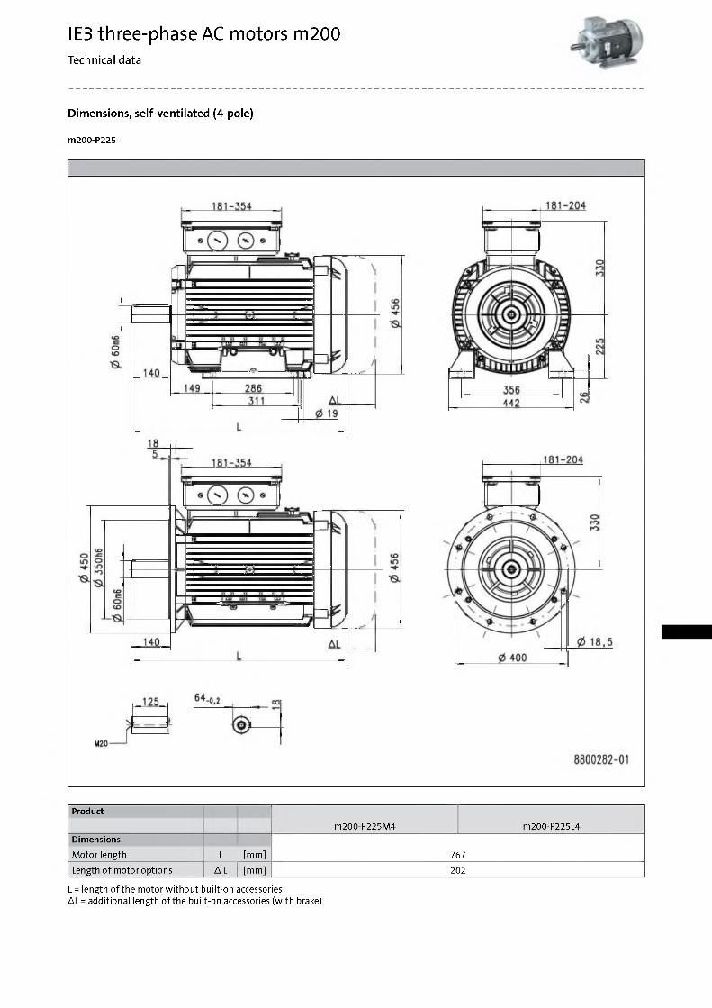
IE3 three-phase AC motors m200Technical data
Dimensions, self-ventilated (4-pole)
m200-P225
Product
m200-P225M4 m200-P225L4Dimensions
M otor length L [mm] 767
Length o f m otor options A L [mm] 202
L = length of the motor without built-on accessoriesA L = additional length o f the built-on accessories (with brake)
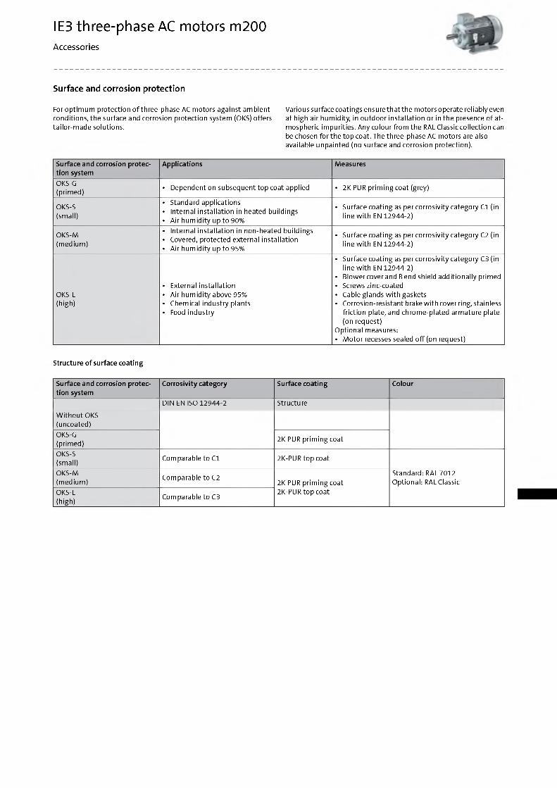
IE3 three-phase AC motors m200Accessories
Surface and corrosion protection
Various surface coatings ensure that the motors operate reliably even at high air hum idity, in outdoor installation or in the presence o f atmospheric im purities. A n y colour from the RAL Classic collection can be chosen for the top coat. The three-phase AC m otors are also available unpainted (no surface and corrosion protection).
Surface and corrosion protection system
Applications Measures
OKS-G(prim ed)
• Dependent on subsequent top coat applied • 2K PUR prim ing coat (grey)
OKS-S(small)
• Standard applications• Internal installation in heated buildings• A ir hum id ity up to 90%
• Surface coating as per corrosivity category C1 (in line w ith EN 12944-2)
OKS-M(m edium )
• Internal installation in non-heated buildings• Covered, protected external installation• A ir hum id ity up to 95%
• Surface coating as per corrosivity category C2 (in line w ith EN 12944-2)
OKS-L(high)
• External installation• A ir hum id ity above 95%• Chemical industry plants• Food industry
• Surface coating as per corrosivity category C3 (in line w ith EN 12944-2)
• Blower cover and Bend shield add itionally primed• Screws zinc-coated• Cable glands w ith gaskets• Corrosion-resistant brake w ith cover ring, stainless
friction plate, and chrom e-plated arm ature plate (on request)
Optional measures:• M oto r recesses sealed o ff (on request)
Structure o f surface coating
Surface and corrosion protection system
C orros iv ity category Surface coating Colour
DIN EN ISO 12944-2 Structure
W ith o u t OKS (uncoated)OKS-G(prim ed)
2K PUR prim ing coat
OKS-S(small)
Comparable to C1 2K-PUR top coat
Standard: RAL 7012 Optional: RAL Classic
OKS-M(m edium )
Comparable to C22K PUR prim ing coat 2K-PUR top coatOKS-L
(high)Comparable to C3
For optim um protection o f three-phase AC m otors against am bient conditions, the surface and corrosion protection system (OKS) offers ta ilo r-m ade solutions.
IE3 three-phase AC motors m200Accessories
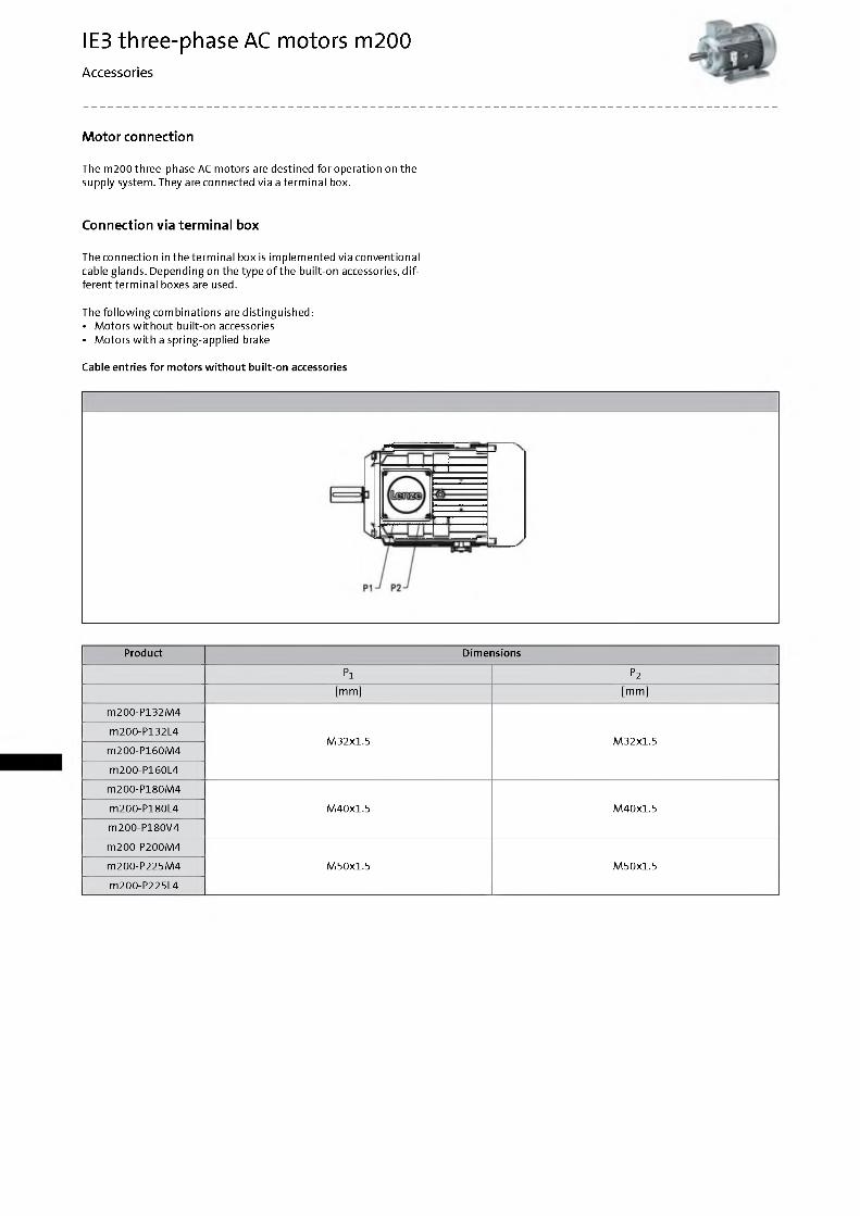
Motor connection
The m200 three-phase AC m otors are destined fo r operation on the supply system. They are connected via a term inal box.
Connection via terminal box
The connection in the term inal box is im plem ented via conventional cable glands. Depending on the type o f the built-on accessories, d ifferent term inal boxes are used.
The fo llo w in g com binations are distinguished:• M otors w ith o u t bu ilt-on accessories• M otors w ith a spring-applied brake
Cable entries fo r m otors w ith o u t bu ilt-on accessories
Product Dimensions
P1 P2[mm] [m m ]
m200-P132M4
M32X1.5 M32X1.5m200-P132L4
m200-P160M4
m200-P160L4
m200-P180M4
M40X1.5 M40X1.5m200-P180L4
m200-P180V4
m200-P200M4
M50X1.5 M50X1.5m200-P225M4
m200-P225L4
IE3 three-phase AC motors m200Accessories
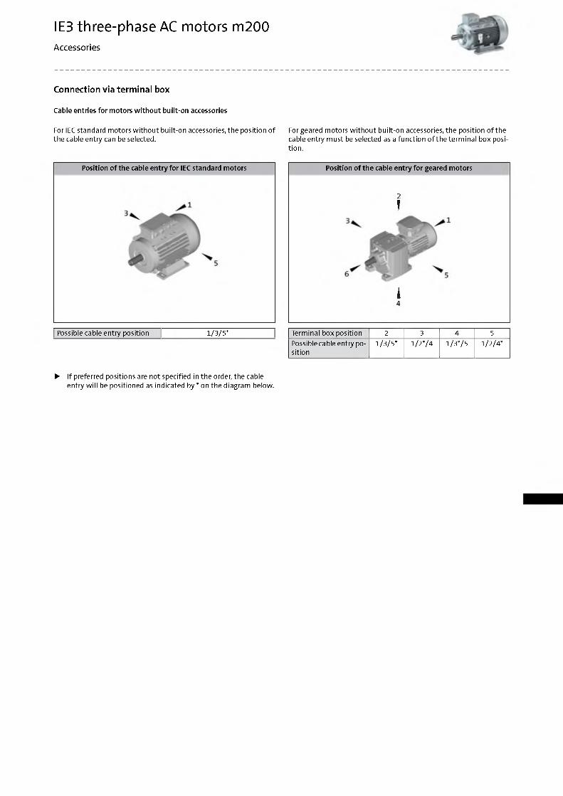
Connection via terminal box
Cable entries fo r m otors w ith o u t bu ilt-on accessories
For IEC standard m otors w ith o u t bu ilt-on accessories, the position o f For geared m otors w ith o u t bu ilt-on accessories, the position o f the the cable entry can be selected. cable entry m ust be selected as a function o f the term inal box posi
tion.
Position o f the cable e n try fo r IEC standard m otors
Possible cable entry position 1/3/5*
Position o f the cable e n try fo r geared m otors
2
T
i4
Term inal box position 2 3 4 5Possible cable entry position
1/3/5* 1/2*/4 1/3*/5 1/2/4*
► If preferred positions are not specified in the order, the cable entry w ill be positioned as indicated by * on the diagram below.
IE3 three-phase AC motors m200Accessories
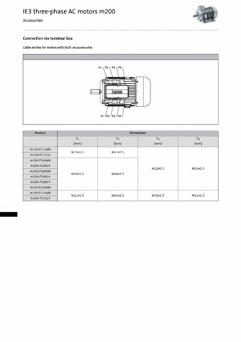
Connection via terminal box
Cable entries fo r m otors w ith bu ilt-on accessories
Product Dimensions
P1 P2 P3 P4
[m m ] [mm] [mm] [mm]
m200-P132M4M25x1.5 M32x1.5
M20x1.5 M16x1.5
m200-P132L4
m200-P160M4
M50x1.5 M40x1.5
m200-P160L4
m200-P180M4
m200-P180L4
m200-P180V4
m200-P200M4
m200-P225M4M12x1.5 M63x1.5 M50x1.5 M12x1.5
m200-P225L4
IE3 three-phase AC motors m200Accessories
Spring-applied brake
The three-phase AC m otors can be equipped w ith a spring-applied brake which is active when the supply voltage has been switched o ff (closed-circuit principle). In the deenergised state, the brake is applied. This prevents possible m ovem ent o f the m otor shaft w ith regard to the load after sw itch -o ff or in the event o f a power failure. Foroptim um adaptation o fth e brake m o to rto th e application, several brake sizes and control variants are provided for each motor.
Types• Standard
-1 x 10⁶ repeating sw itch ing cycles -1 x 1 0 6 reversing sw itch ing cycles
Control• DC supply• AC supply via rectifiers in the term inal box
Enclosure• W ith o u t manual release IP55• W ith manual release IP54
Friction lin ing• Asbestos-free, low -w ear
Options• M anual release
Braking torques
In addition to the standard braking torque, depending on the brake size, the possibility o f choosing between a reduced and an increased braking torque is provided.• W hen the braking torque is reduced, great w ear reserves can be
attained. This is enabled by a reduction o fth e spring rate.• In order to obtain a greater braking torque, the spring rate is in
creased. This is practical, fo r instance, for hoists, since here the gravity acts as an additional acceleration in the negative direction.
M anual release
By actuating the manual release lever, the brake can be released m anually during operation at zero current. M anual release facilitates positioning and m aintenance work.
IE3 three-phase AC motors m200Accessories
Spring-applied brake
Direct connection w ith o u t rectifier
If the brake is activated d irectly w ith o u t a rectifier, a freew heeling diode or a spark suppressor is required for protection against induction peaks.• Supply voltages
DC 24 V
Connection via mains vo ltage w ith brake rectifier
If the brake is not d irectly supplied w ith DC voltage, a rectifier is required. This is included in the scope o f supply and is located in the term inal box o f the m otor. The rectifier converts the AC voltage o f the connection into DC voltage. The fo llo w in g rectifiers are available:
H alf-w ave rectifier, 6-pole• Supply voltage / brake coil vo ltage ratio = 2.22• Supply voltages
AC 400 V
Bridge rectifier, 6 -pole• Ratio o f supply voltage to brake coil vo ltage = 1.11• Supply voltage
AC 230 V
IE3 three-phase AC motors m200Accessories
Spring-applied brake
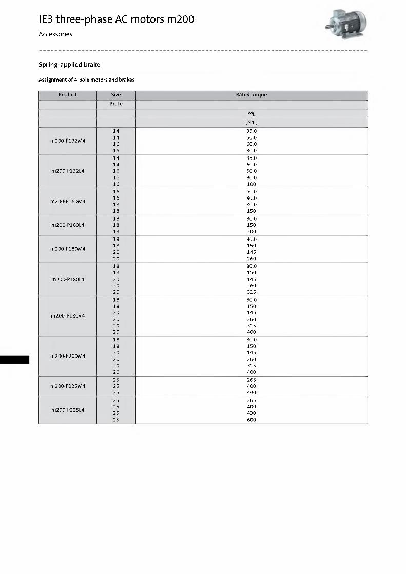
Assignm ent o f 4 -pole m otors and brakes
Product Size Rated torque
Brake
M k
[Nm]
14 35.014 60.0
m200-P132M416 60.016 80.014 35.014 60.0
m200-P132L4 16 60.016 80.016 10016 60.016 80.0
m200-P160M418 80.018 15018 80.0
m200-P160L4 18 15018 20018 80.018 150
m200-P180M420 14520 26018 80.018 150
m200-P180L4 20 14520 26020 31518 80.018 15020 145
m200-P180V420 26020 31520 40018 80.018 15020 145
m200-P200M420 26020 31520 40025 265
m200-P225M4 25 40025 49025 26525 400
m200-P225L425 49025 600
IE3 three-phase AC motors m200Accessories
Spring-applied brake
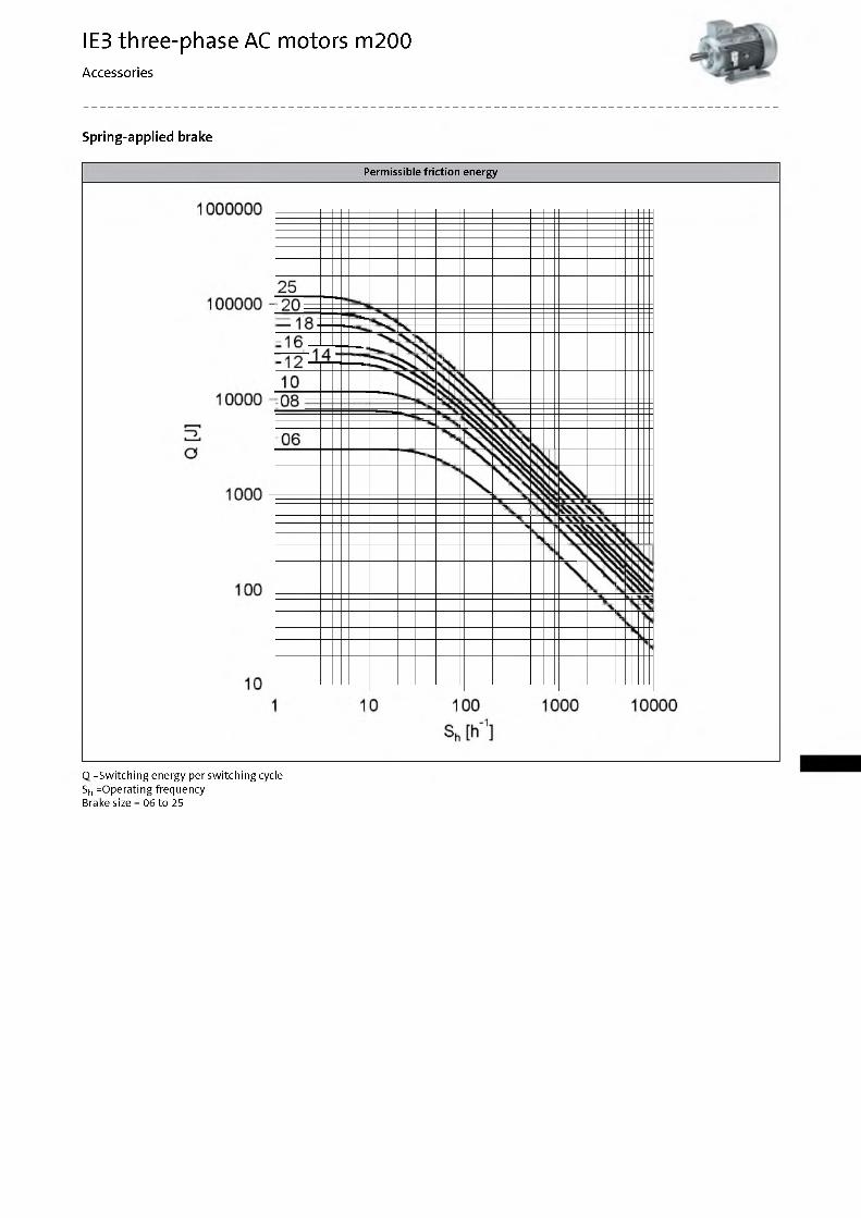
Permissible friction energy
О =Switching energy per sw itch ing cycle Sh =Operating frequency Brake size = 06 to 25

IE3 three-phase AC motors m200Accessories
Spring-applied brake
Rated data w ith reduced brak ing torque
► Please enquire for braking torques and m axim um sw itch ing w ork values not listed here.
Size
06 08 10 12 14 16 18 20 25Power input
Pin [kW] 0.020 0.025 0.030 0.040 0.050 0.055 0.085 0.10 0.11Braking torque
100 M b [Nm] 2.50 3.50 7.00 14.0 35.0 60.0 80.0 145 265
1000 M b [Nm] 2.30 3.10 6.10 12.0 30.0 50.0 65.0 115 203
1200 M b [Nm] 2.30 3.10 6.00 12.0 29.0 48.0 63.0 112 199
1500 M b [Nm] 2.20 3.00 5.80 11.0 28.0 47.0 61.0 109 1) 1931)
1800 M b [Nm] 2.10 2.90 5.70 11.0 28.0 46.0 60.01)
3000 M b [Nm] 2.00 2.80 5.30 10.0 26.01) 43.01)
3600 M b [Nm] 2.00 2.70 5.20 10.01)M axim um sw itch ing energy
100 Q e [KJ] 3.00 7.50 12.0 24.0 30.0 36.0 60.0 80.0 120
1000 Q e [KJ] 3.00 7.50 12.0 24.0 30.0 36.0 60.0 80.0 120
1200 Q e [KJ] 3.00 7.50 12.0 24.0 30.0 36.0 60.0 80.0 120
1500 Q e [KJ] 3.00 7.50 12.0 24.0 30.0 36.0 60.0 24.01) 36.01)
1800 Q e [KJ] 3.00 7.50 12.0 24.0 30.0 36.0 36.01)
3000 Q e [KJ] 3.00 7.50 12.0 24.0 18.01) 11.0 4
3600 Q e [KJ] 3.00 7.50 12.0 7.001)
Transition operating frequency
Shu [1/h] 79.0 50.0 40.0 30.0 28.0 27.0 20.0 19.0 15.0M om ent o f inertia
J [kgcm 2] 0.015 0.061 0.20 0.45 0.63 1.50 2.90 7.30 20.0Mass
m [kg] 0.90 1.50 2.60 4.20 5.80 8.70 12.6 19.5 31.0
1) In the region o fthe load lim it the value for friction energy 0 BW can be reduced to 40 %.

IE3 three-phase AC motors m200Accessories
Spring-applied brake
Rated data w ith reduced brak ing torque
► Activation via half-wave or bridge rectifier
Size
06 08 10 12 14 16 18 20 25Friction energy
Q BW [MJ] 113 210 264 706 761 966 1542 2322 3 522Delay tim e
Engaging t n [ms] 11.0 14.0 20.0 21.0 37.0 53.0 32.0 47.0 264Rise tim e
Braking torque t 12 [ms] 13.0 10.0 17.0 19.0 22.0 30.0 20.0 100 120Engagem ent tim e
t1 [ms] 24.0 37.0 40.0 59.0 83.0 52.0 147 384
Disengagem ent tim e
t2 [ms] 35.0 37.0 57.0 65.0 148 169 230 207 269
► The brake response and application tim es are guide values. The engagem ent tim e is 10tim es longer w ith AC-side sw itching. W ith the m axim um air gap the disengagem ent tim e t 2-d e p e n d ing on the brake and control - is up to 4 tim es longer than the disengagem ent tim e w ith the rated air gap.
IE3 three-phase AC motors m200Accessories
Spring-applied brake
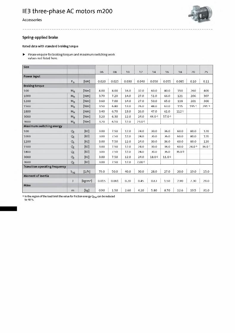
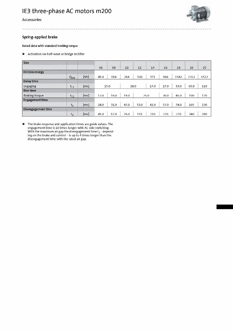
Rated data w ith standard braking torque
► Please enquire for braking torques and m axim um sw itch ing w ork values not listed here.
Size
06 08 10 12 14 16 18 20 25Power input
Pin [kW] 0.020 0.025 0.030 0.040 0.050 0.055 0.085 0.10 0.11Braking torque
100 M b [Nm] 4.00 8.00 16.0 32.0 60.0 80.0 150 260 400
1000 M b [Nm] 3.70 7.20 14.0 27.0 51.0 66.0 121 206 307
1200 M b [Nm] 3.60 7.00 14.0 27.0 50.0 65.0 118 201 300
1500 M b [Nm] 3.50 6.80 13.0 26.0 48.0 63.0 115 1951) 2911)
1800 M b [Nm] 3.40 6.70 13.0 26.0 47.0 61.0 1121)
3000 M b [Nm] 3.20 6.30 12.0 24.0 44.01) 57.01)
3600 M b [Nm] 3.20 6.10 12.0 23.01)M axim um sw itch ing energy
100 Q e [KJ] 3.00 7.50 12.0 24.0 30.0 36.0 60.0 80.0 120
1000 Q e [KJ] 3.00 7.50 12.0 24.0 30.0 36.0 60.0 80.0 120
1200 Q e [KJ] 3.00 7.50 12.0 24.0 30.0 36.0 60.0 80.0 120
1500 Q e [KJ] 3.00 7.50 12.0 24.0 30.0 36.0 60.0 24.01) 36.01)
1800 Q e [KJ] 3.00 7.50 12.0 24.0 30.0 36.0 36.01)
3000 Q e [KJ] 3.00 7.50 12.0 24.0 18.01) 11.0 4
3600 Q e [KJ] 3.00 7.50 12.0 7.001)
Transition operating frequency
Shu [1/h] 79.0 50.0 40.0 30.0 28.0 27.0 20.0 19.0 15.0M om ent o f inertia
J [kgcm 2] 0.015 0.061 0.20 0.45 0.63 1.50 2.90 7.30 20.0Mass
m [kg] 0.90 1.50 2.60 4.20 5.80 8.70 12.6 19.5 31.0
1) In the region o f the load lim it the value for friction energy Q bw can be reduced to 40 %.
IE3 three-phase AC motors m200Accessories
Spring-applied brake
Rated data w ith standard braking torque
► Activation via half-wave or bridge rectifier
Size
06 08 10 12 14 16 18 20 25Friction energy
Q bw [MJ] 85.0 158 264 530 571 966 1542 2322 3 522Delay tim e
Engaging t n [ms] 15.0 28.0 17.0 27.0 33.0 65.0 110Rise tim e
Braking torque t 12 [ms] 13.0 16.0 19.0 25.0 30.0 45.0 100 120Engagem ent tim e
t1 [ms] 28.0 31.0 47.0 53.0 42.0 57.0 78.0 165 230
Disengagem ent tim e
t2 [ms] 45.0 57.0 76.0 115 210 220 270 340 390
► The brake response and application tim es are guide values. The engagem ent tim e is 10tim es longer w ith AC-side sw itching. W ith the m axim um air gap the disengagem ent tim e t 2-d e p e n d ing on the brake and control - is up to 4 tim es longer than the disengagem ent tim e w ith the rated air gap.
IE3 three-phase AC motors m200Accessories
Spring-applied brake
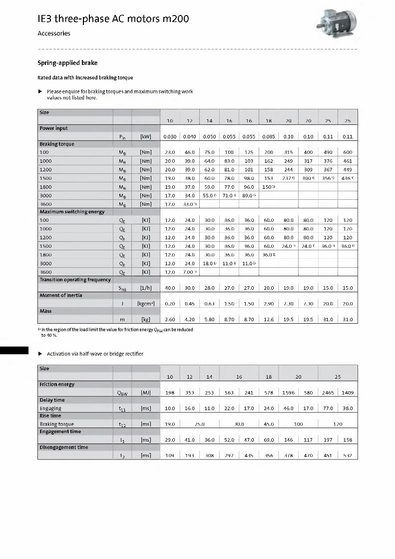
Rated data w ith increased braking torque
► Please enquire for braking torques and m axim um sw itch ing w ork values not listed here.
Size
10 12 14 16 16 18 20 20 25 25Power input
Pin [kW] 0.030 0.040 0.050 0.055 0.055 0.085 0.10 0.10 0.11 0.11Braking torque
100 M b [Nm] 23.0 46.0 75.0 100 125 200 315 400 490 600
1000 M b [Nm] 20.0 39.0 64.0 83.0 103 162 249 317 376 461
1200 M b [Nm] 20.0 39.0 62.0 81.0 101 158 244 309 367 449
1500 M b [Nm] 19.0 38.0 60.0 78.0 98.0 153 2371) 3001) 3561) 4361)
1800 M b [Nm] 19.0 37.0 59.0 77.0 96.0 1501)
3000 M b [Nm] 17.0 34.0 55.01) 71.01) 89.01)
3600 M b [Nm] 17.0 33.01)M axim um sw itch ing energy
100 Q e [KJ] 12.0 24.0 30.0 36.0 36.0 60.0 80.0 80.0 120 120
1000 Q e [KJ] 12.0 24.0 30.0 36.0 36.0 60.0 80.0 80.0 120 120
1200 Q e [KJ] 12.0 24.0 30.0 36.0 36.0 60.0 80.0 80.0 120 120
1500 Q e [KJ] 12.0 24.0 30.0 36.0 36.0 60.0 24.01) 24.01) 36.01) 36.01)
1800 Q e [KJ] 12.0 24.0 30.0 36.0 36.0 36.01)
3000 Q e [KJ] 12.0 24.0 18.01) 11.0 4 11.0 4
3600 Q e [KJ] 12.0 7.001)
Transition operating frequency
Shu [1/h] 40.0 30.0 28.0 27.0 27.0 20.0 19.0 19.0 15.0 15.0M om ent o f inertia
J [kgcm 2] 0.20 0.45 0.63 1.50 1.50 2.90 7.30 7.30 20.0 20.0Mass
m [kg] 2.60 4.20 5.80 8.70 8.70 12.6 19.5 19.5 31.0 31.0
1) In the region o f the load lim it the value for friction energy Q bw can be reduced to 40 %.
► Activation via half-wave or bridge rectifier
Size
10 12 14 16 18 20 25Friction energy
Q bw [MJ] 198 353 253 563 241 578 1596 580 2465 1409Delay tim e
Engaging t n [ms] 10.0 16.0 11.0 22.0 17.0 24.0 46.0 17.0 77.0 38.0Rise tim e
Braking torque t 12 [ms] 19.0 25.0 30.0 45.0 100 120Engagem ent tim e
t1 [ms] 29.0 41.0 36.0 52.0 47.0 69.0 146 117 197 158Disengagem ent tim e
t2 [ms] 109 193 308 297 435 356 378 470 451 532
IE3 three-phase AC motors m200Accessories
Spring-applied brake
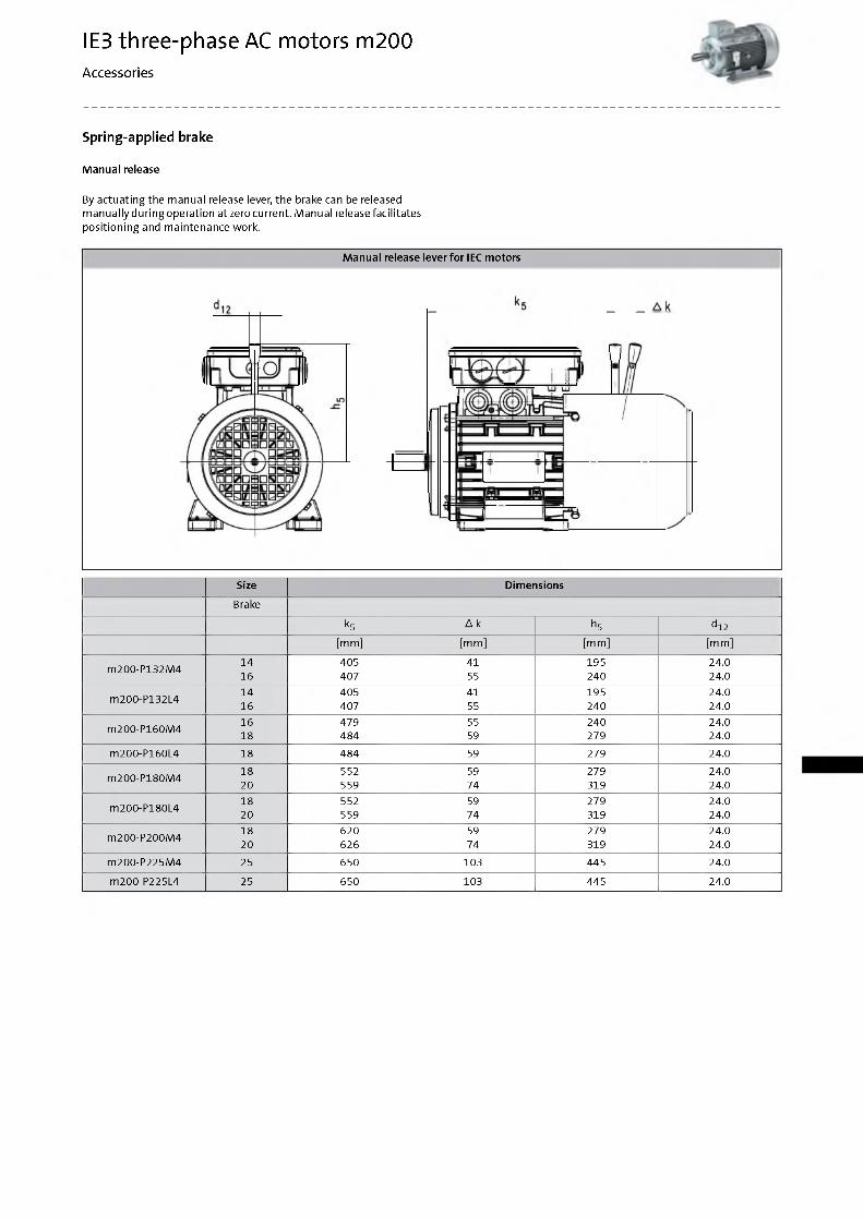
M anual release
By actuating the manual release lever, the brake can be released m anually during operation at zero current. M anual release facilitates positioning and m aintenance work.
M anual release lever fo r IEC m otors
Size Dimensions
Brake
k5 A k h5 d12[mm] [m m ] [mm] [m m ]
m200-P132M414 405 41 195 24.016 407 55 240 24.0
m200-P132L414 405 41 195 24.016 407 55 240 24.0
m200-P160M416 479 55 240 24.018 484 59 279 24.0
m200-P160L4 18 484 59 279 24.0
m200-P180M418 552 59 279 24.020 559 74 319 24.0
m200-P180L418 552 59 279 24.020 559 74 319 24.0
m200-P200M418 620 59 279 24.020 626 74 319 24.0
m200-P225M4 25 650 103 445 24.0
m200-P225L4 25 650 103 445 24.0
IE3 three-phase AC motors m200Accessories
Spring-applied brake
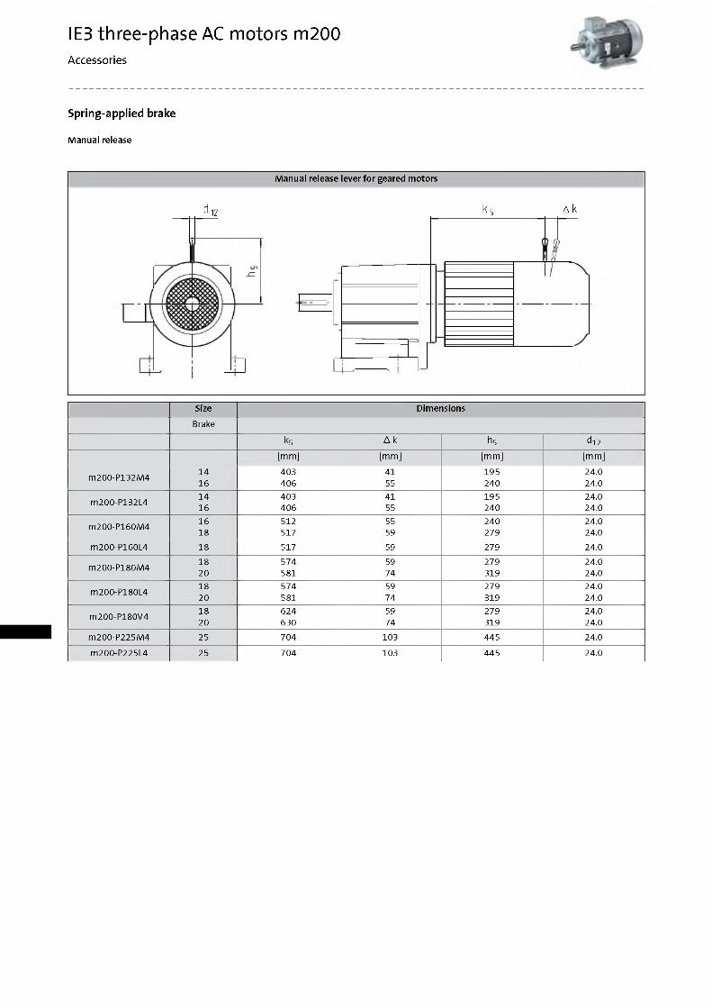
M anual release
M anual release lever fo r geared m otors
d 12 к 5 д к
Size Dimensions
Brake
k5 A k h5 d12
[mm] [m m ] [mm] [m m ]
m200-P132M414 403 41 195 24.016 406 55 240 24.0
m200-P132L414 403 41 195 24.016 406 55 240 24.0
m200-P160M416 512 55 240 24.018 517 59 279 24.0
m200-P160L4 18 517 59 279 24.0
m200-P180M418 574 59 279 24.020 581 74 319 24.0
m200-P180L418 574 59 279 24.020 581 74 319 24.0
m200-P180V418 624 59 279 24.020 630 74 319 24.0
m200-P225M4 25 704 103 445 24.0
m200-P225L4 25 704 103 445 24.0
IE3 three-phase AC motors m200Accessories
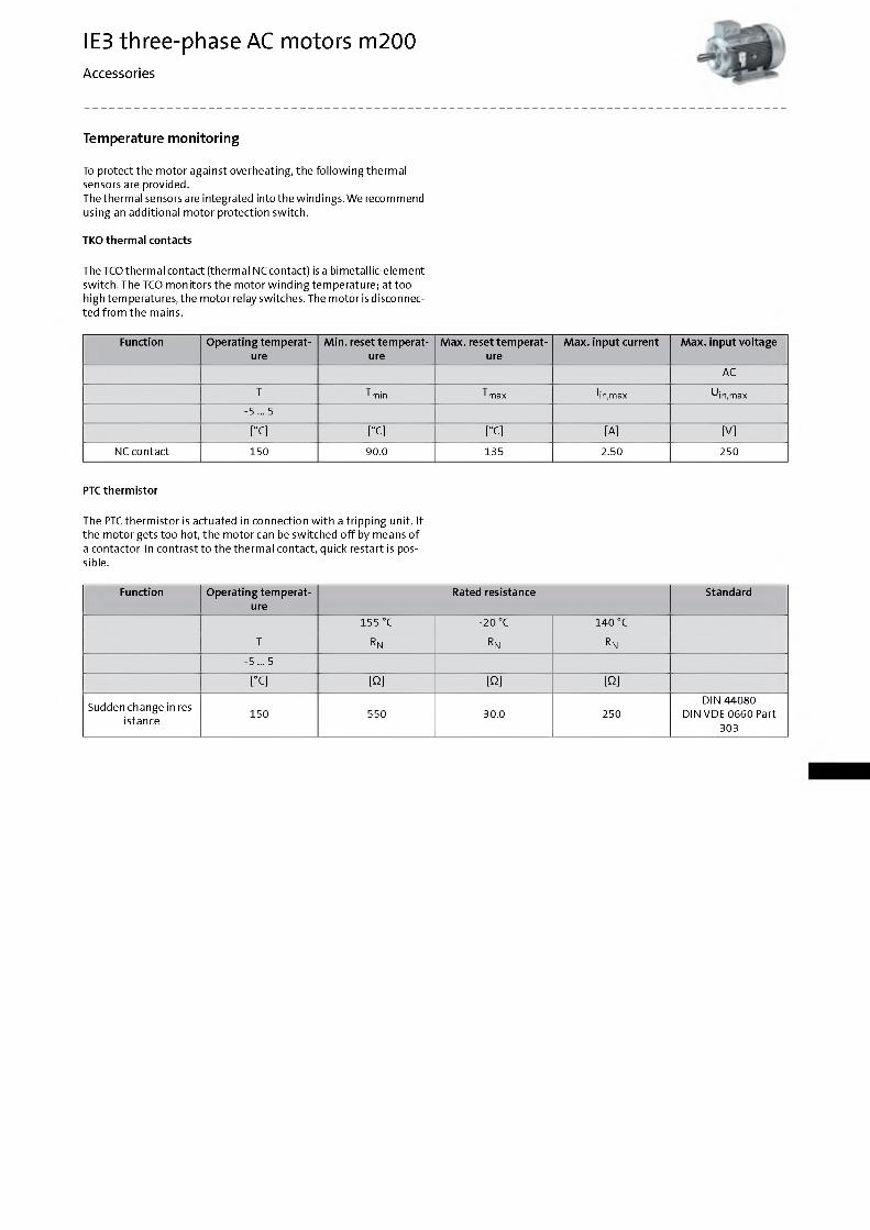
Temperature monitoring
To protect the m otor against overheating, the fo llo w in g therm al sensors are provided.The therm al sensors are integrated into the w indings. W e recommend using an additional m otor protection switch.
TKO therm al contacts
The TCO therm al contact (therm al NCcontact) is a bim etallic-elem ent sw itch. The TCO m onitors the m otor w in d ing tem perature; at too high tem peratures, the m otor relay switches. The m otor isdisconnec- ted from the mains.
Function O perating tem perature
M in. reset tem perature
M ax. reset tem perature
M ax. input current M ax. input vo ltage
AC
T T min T max Iin,max U in,max
-5 ... 5
[°C] [°C] [°C] [A] [V]
NC contact 150 90.0 135 2.50 250
PTC therm istor
The PTC therm istor is actuated in connection w ith a tripp ing unit. If the m otor gets too hot, the m otor can be switched o ff by means o f a contactor. In contrast to the therm al contact, quick restart is possible.
Function O perating tem perature
Rated resistance Standard
155 °C -20 °C 140 °C
T r n rn r n
-5 ... 5
[°C] [0] [0 ] [0 ]
Sudden change in resistance
150 550 30.0 250DIN 44080
D IN VD E 0660 Part 303

По вопросам продаж и поддержки обращайтесь:Астана +7(7172)727-132, Волгоград (844)278-03-48, Воронеж (473)204-51-73, Екатеринбург (343)384-55-89,
Казань (843)206-01-48, Краснодар (861)203-40-90, Красноярск (391)204-63-61, Москва (495)268-04-70, Нижний Новгород (831)429-08-12, Новосибирск (383)227-86-73, Ростов-на-Дону (863)308-18-15, Самара (846)206-03-16,
Санкт-Петербург (812)309-46-40, Саратов (845)249-38-78, Уфа (347)229-48-12 [email protected] || www.lenze.nt-rt.ru
![IS 1885-34 (1972): Electrotechnical vocabulary, Part 34: Cinematography · Cinematography [ETD 1: Basic Electrotechnical Standards] ‘is:.m~~ (&tXXXIV)-1972 Indian Standard ELECTROTECHNICAL](https://img.pdfslide.net/doc/110x75/5fe030e6cbc55d4a9b147853/is-1885-34-1972-electrotechnical-vocabulary-part-34-cinematography-cinematography.jpg)