Embed Size (px)
Citation preview
Power and productivity
for a better world™
System 800xAIEC 61850Operation Library for Substation Equipment
System Version 6.0

System 800xAIEC 61850
Operation Library for Substation Equipment
System Version 6.0
NOTICEThis document contains information about one or more ABB products and may include adescription of or a reference to one or more standards that may be generally relevant tothe ABB products. The presence of any such description of a standard or reference to astandard is not a representation that all of the ABB products referenced in this documentsupport all of the features of the described or referenced standard. In order to determinethe specific features supported by a particular ABB product, the reader should consult theproduct specifications for the particular ABB product.
ABB may have one or more patents or pending patent applications protecting the intel-lectual property in the ABB products described in this document.
The information in this document is subject to change without notice and should not beconstrued as a commitment by ABB. ABB assumes no responsibility for any errors thatmay appear in this document.
In no event shall ABB be liable for direct, indirect, special, incidental or consequentialdamages of any nature or kind arising from the use of this document, nor shall ABB beliable for incidental or consequential damages arising from use of any software or hard-ware described in this document.
This document and parts thereof must not be reproduced or copied without written per-mission from ABB, and the contents thereof must not be imparted to a third party nor usedfor any unauthorized purpose.
The software or hardware described in this document is furnished under a license andmay be used, copied, or disclosed only in accordance with the terms of such license. Thisproduct meets the requirements specified in EMC Directive 2004/108/EC and in Low Volt-age Directive 2006/95/EC.
TRADEMARKSAll rights to copyrights, registered trademarks, and trademarks reside with their respec-tive owners.
Copyright © 2013 - 2014 by ABB. All rights reserved.
Release: August 2014Document number: 2PAA108626-600
2PAA108626-600 5
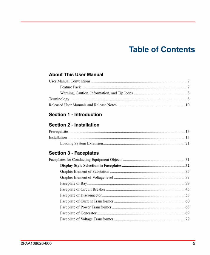
Table of Contents
About This User ManualUser Manual Conventions .................................................................................................7
Feature Pack ...........................................................................................................7
Warning, Caution, Information, and Tip Icons ......................................................8
Terminology.......................................................................................................................8
Released User Manuals and Release Notes.....................................................................10
Section 1 - Introduction
Section 2 - InstallationPrerequisite ......................................................................................................................13
Installation .......................................................................................................................13
Loading System Extension...................................................................................21
Section 3 - FaceplatesFaceplates for Conducting Equipment Objects ...............................................................31
Display Style Selection in Faceplates ................................................................32
Graphic Element of Substation ............................................................................35
Graphic Element of Voltage level ........................................................................37
Faceplate of Bay...................................................................................................39
Faceplate of Circuit Breaker ................................................................................45
Faceplate of Disconnector....................................................................................53
Faceplate of Current Transformer ........................................................................60
Faceplate of Power Transformer ..........................................................................63
Faceplate of Generator .........................................................................................69
Faceplate of Voltage Transformer ........................................................................72
Table of Contents
6 2PAA108626-600
Control Connection Aspect ............................................................................................. 75
Faceplates Localization ................................................................................................... 78
Section 4 - Re ConfigurationCreate New version of Base Library IEC61850 Object Types........................................ 81
Addition and Modification of Graphic Elements ............................................................ 82
Faceplates and Graphic Elements Containing IEC 61850 Data .......................... 82
Faceplates and Graphic Elements Containing Data from Other Connectivity .... 85
Configuring the Control Connection Aspect of Functional Objects.................... 85
Example ...................................................................................... 86
Customize Faceplates........................................................................................... 88
Index
2PAA108626-600 7
About This User Manual
This user manual describes the IEC61850 Operations Library for Substation Equipment in 800xA System.
User Manual ConventionsMicrosoft Windows conventions are normally used for the standard presentation of material when entering text, key sequences, prompts, messages, menu items, screen elements, etc.
Feature Pack
The Feature Pack content (including text, tables, and figures) included in this User Manual is distinguished from the existing content using the following two separators:
Feature Pack Functionality______________________________________________________________________
<Feature Pack Content>
___________________________________________________________________________________________
Any security measures described in this User Manual, for example, for user access, password security, network security, firewalls, virus protection, etc., represent possible steps that a user of an 800xA System may want to consider based on a risk assessment for a particular application and installation. This risk assessment, as well as the proper implementation, configuration, installation, operation, administration, and maintenance of all relevant security related equipment, software, and procedures, are the responsibility of the user of the 800xA System.
Warning, Caution, Information, and Tip Icons About This User Manual
8 2PAA108626-600
Feature Pack functionality included in an existing table is indicated using a table footnote (*):*Feature Pack Functionality
Unless noted, all other information in this User Manual applies to 800xA Systems with or without a Feature Pack installed.
Warning, Caution, Information, and Tip Icons
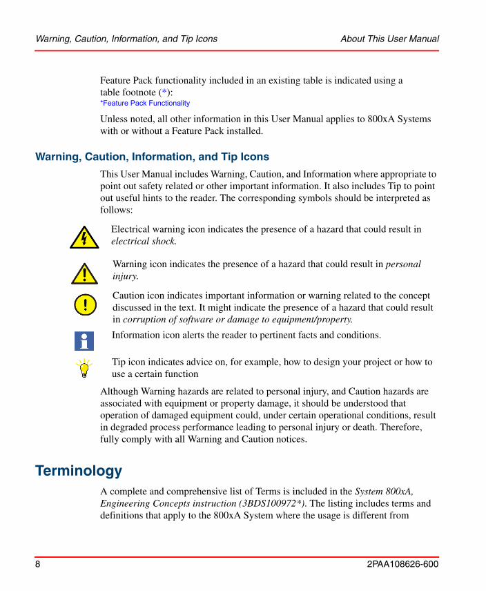
This User Manual includes Warning, Caution, and Information where appropriate to point out safety related or other important information. It also includes Tip to point out useful hints to the reader. The corresponding symbols should be interpreted as follows:
Although Warning hazards are related to personal injury, and Caution hazards are associated with equipment or property damage, it should be understood that operation of damaged equipment could, under certain operational conditions, result in degraded process performance leading to personal injury or death. Therefore, fully comply with all Warning and Caution notices.
TerminologyA complete and comprehensive list of Terms is included in the System 800xA, Engineering Concepts instruction (3BDS100972*). The listing includes terms and definitions that apply to the 800xA System where the usage is different from
Electrical warning icon indicates the presence of a hazard that could result in electrical shock.
Warning icon indicates the presence of a hazard that could result in personal injury.
Caution icon indicates important information or warning related to the concept discussed in the text. It might indicate the presence of a hazard that could result in corruption of software or damage to equipment/property.
Information icon alerts the reader to pertinent facts and conditions.
Tip icon indicates advice on, for example, how to design your project or how to use a certain function
About This User Manual Terminology
2PAA108626-600 9
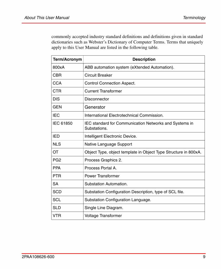
commonly accepted industry standard definitions and definitions given in standard dictionaries such as Webster’s Dictionary of Computer Terms. Terms that uniquely apply to this User Manual are listed in the following table.
Term/Acronym Description
800xA ABB automation system (eXtended Automation).
CBR Circuit Breaker
CCA Control Connection Aspect.
CTR Current Transformer
DIS Disconnector
GEN Generator
IEC International Electrotechnical Commission.
IEC 61850 IEC standard for Communication Networks and Systems in Substations.
IED Intelligent Electronic Device.
NLS Native Language Support
OT Object Type, object template in Object Type Structure in 800xA.
PG2 Process Graphics 2.
PPA Process Portal A.
PTR Power Transformer
SA Substation Automation.
SCD Substation Configuration Description, type of SCL file.
SCL Substation Configuration Language.
SLD Single Line Diagram.
VTR Voltage Transformer
Released User Manuals and Release Notes About This User Manual
10 2PAA108626-600
Released User Manuals and Release NotesA complete list of all User Manuals and Release Notes applicable to System 800xA is provided in System 800xA Released User Manuals and Release Notes (3BUA000263*).
System 800xA Released User Manuals and Release Notes (3BUA000263*) is updated each time a document is updated or a new document is released. It is in PDF format and is provided in the following ways:
• Included on the documentation media provided with the system and published to ABB SolutionsBank when released as part of a major or minor release, Service Pack, Feature Pack, or System Revision.
• Published to ABB SolutionsBank when a User Manual or Release Note is updated in between any of the release cycles listed in the first bullet.
A product bulletin is published each time System 800xA Released User Manuals and Release Notes (3BUA000263*) is updated and published to ABB SolutionsBank.
2PAA108626-600 11
Section 1 Introduction
IEC61850 Operation Library for Substation Equipment is delivered together with the 800xA IEC 61850 Connect package and can be installed and used as an optional software.
IEC61850 Operation Library for Substation Equipment allows Visualization, Monitoring, and Control of Bays and Primary Equipment from 800xA Graphics displays through Faceplates.
The Library should be used when no ABB market specific libraries with their specific Faceplate design are used in 800xA System with IEC61850 Base connect package
The Operation library software package contains the following contents:
• Faceplates for Objects:
– Bay, CBR, DIS, PTR, GEN, VTR, and CTR.
• Graphic Elements of ANSI and IEC types for objects:
– Substation and Voltage Level in addition to Bay, CBR, DIS, PTR, GEN, VTR, and CTR.
• Control Connection Aspect with Predefined properties used in Faceplate and Faceplate Elements dynamic points.
• General Properties Aspect Operation Display Selection for selecting the representation styles in Faceplates as required in project.
• NLS Aspects for configuring Faceplate text strings to additional language locales as required in Project.
Section 1 Introduction
12 2PAA108626-600
2PAA108626-600 13
Section 2 Installation
PrerequisiteFollowing are the pre-requisites before installing IEC 61850 Operation Library for Substation:
• ABB 800xA IEC61850 Connect is installed.
• ABB IEC 61850 Operation Library for Substation Equipment License is available.
InstallationIEC 61850 Operation Library for Substation Equipment is licensed and installed as a separate package.
Perform the following steps to install the Operation Library for Substation Equipment manually:
Screen shot in this manual is used for illustration purpose only, the version number varies according to the latest software version packaged with System Version release.
Installation Section 2 Installation
14 2PAA108626-600
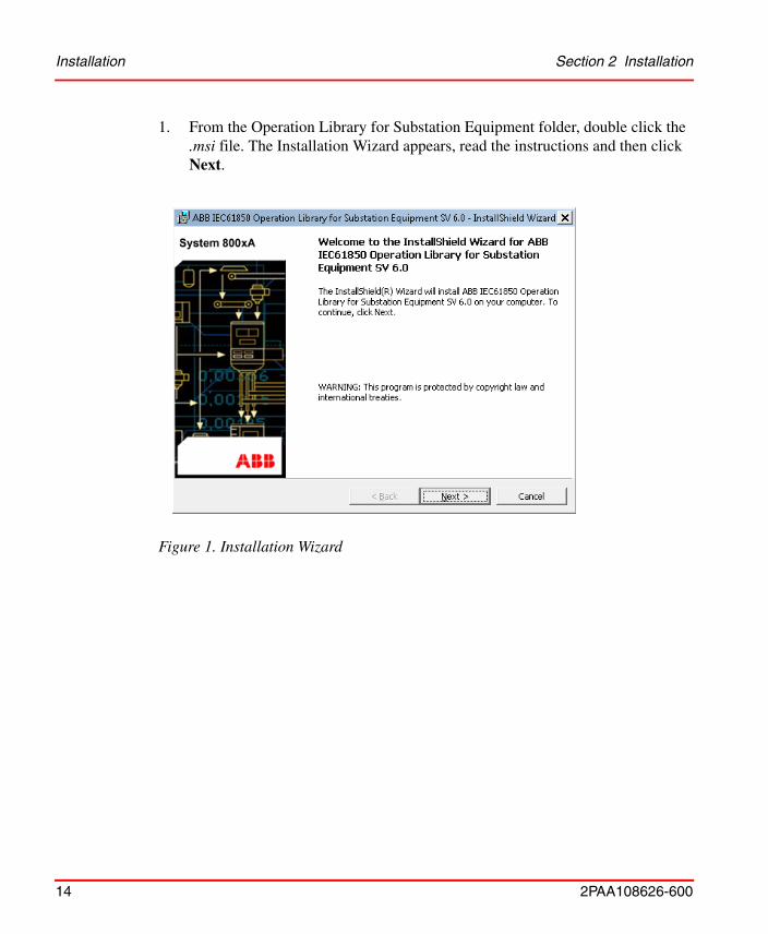
1. From the Operation Library for Substation Equipment folder, double click the .msi file. The Installation Wizard appears, read the instructions and then click Next.
Figure 1. Installation Wizard
Section 2 Installation Installation
2PAA108626-600 15
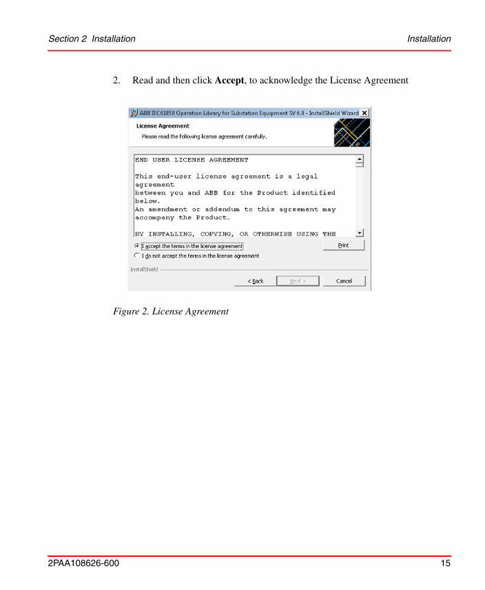
2. Read and then click Accept, to acknowledge the License Agreement
Figure 2. License Agreement
Installation Section 2 Installation
16 2PAA108626-600
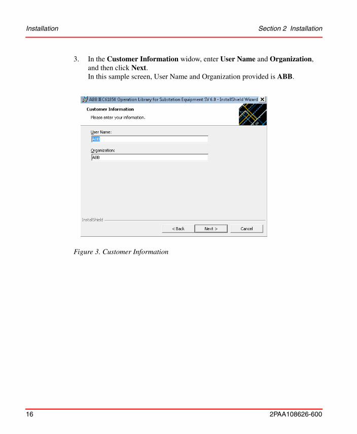
3. In the Customer Information widow, enter User Name and Organization, and then click Next.In this sample screen, User Name and Organization provided is ABB.
Figure 3. Customer Information
Section 2 Installation Installation
2PAA108626-600 17
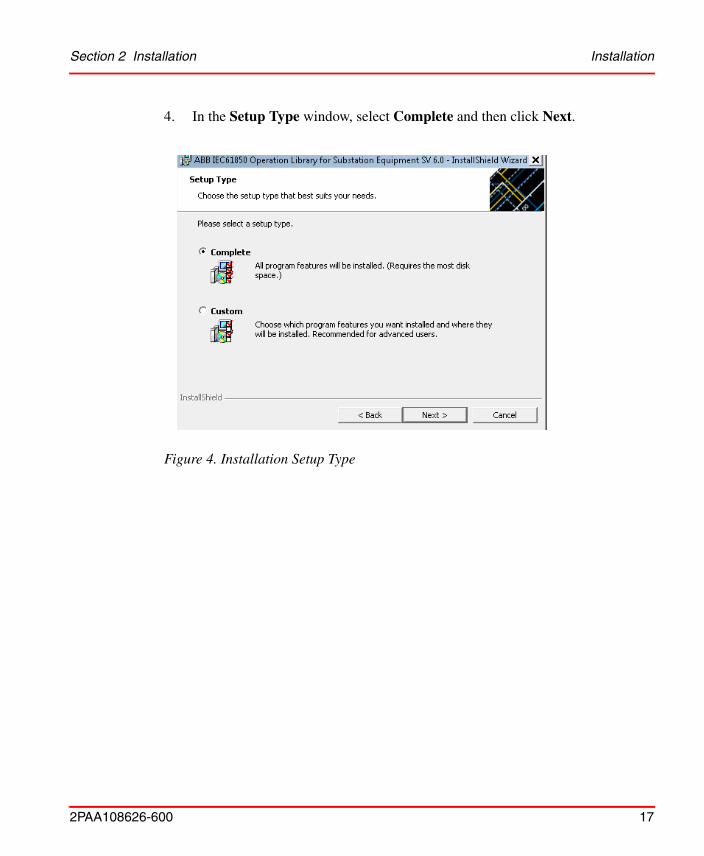
4. In the Setup Type window, select Complete and then click Next.
Figure 4. Installation Setup Type
Installation Section 2 Installation
18 2PAA108626-600
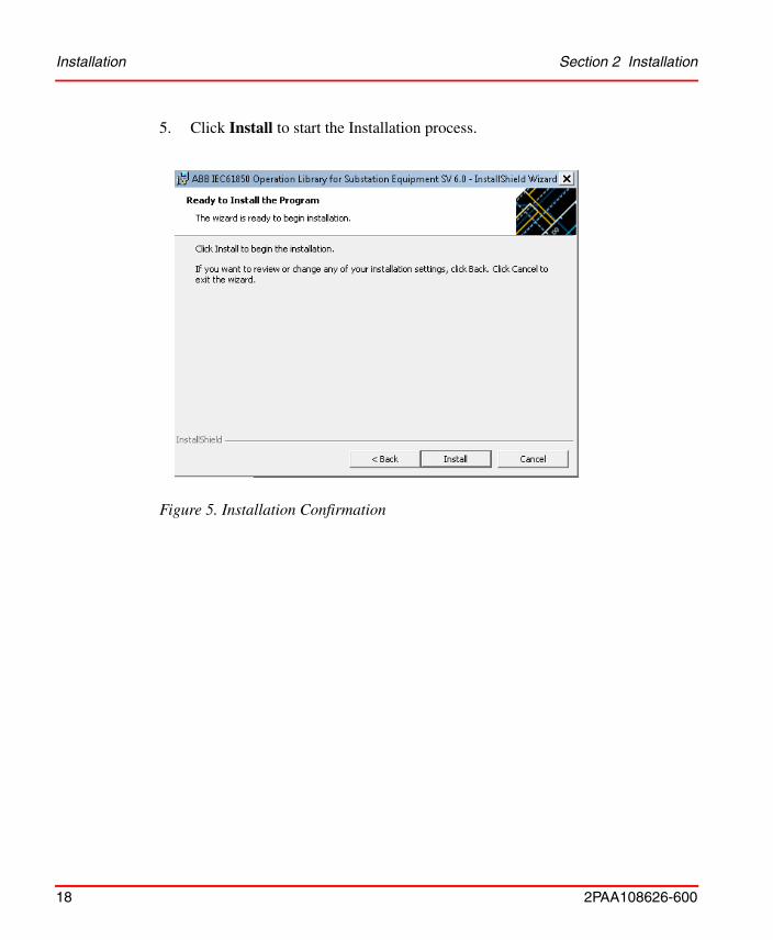
5. Click Install to start the Installation process.
Figure 5. Installation Confirmation
Section 2 Installation Installation
2PAA108626-600 19
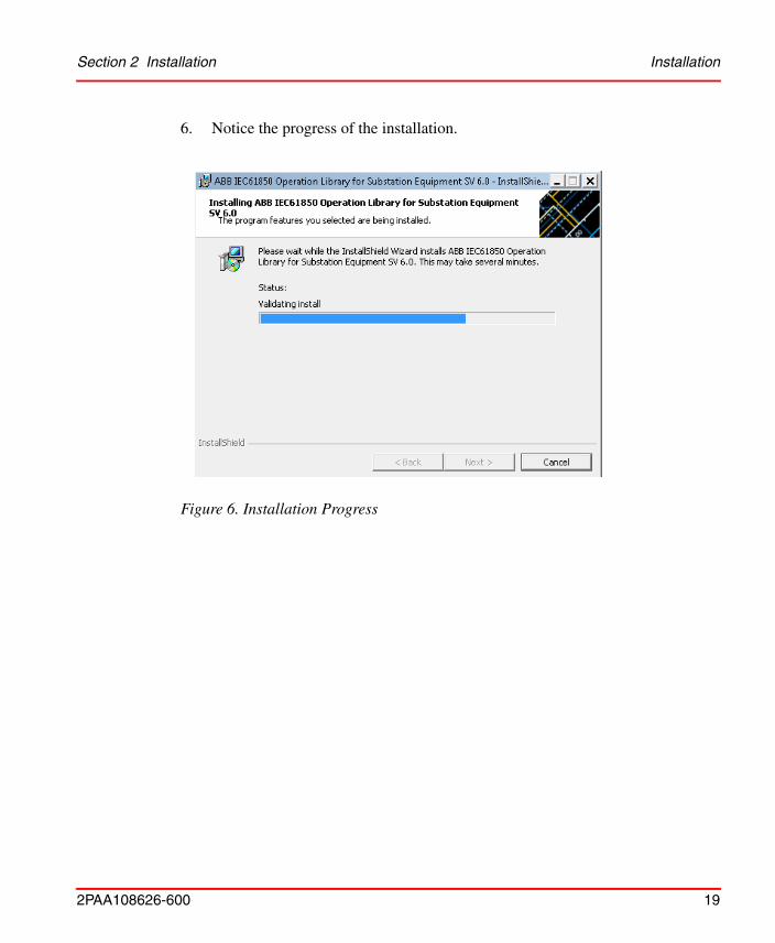
6. Notice the progress of the installation.
Figure 6. Installation Progress
Installation Section 2 Installation
20 2PAA108626-600
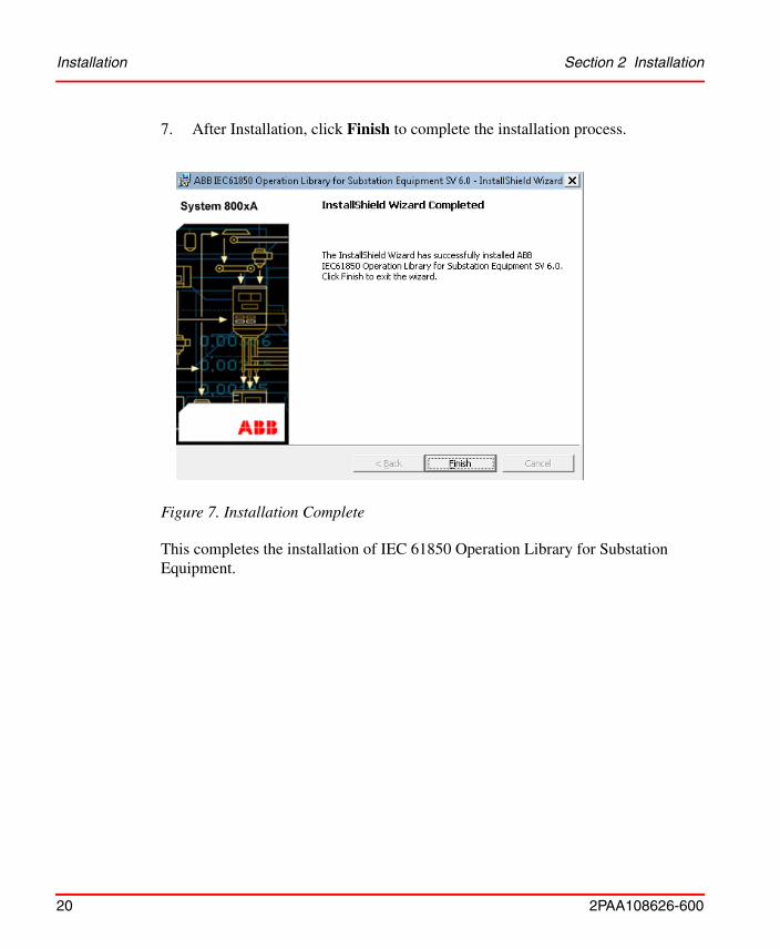
7. After Installation, click Finish to complete the installation process.
This completes the installation of IEC 61850 Operation Library for Substation Equipment.
Figure 7. Installation Complete
Section 2 Installation Loading System Extension
2PAA108626-600 21
Loading System Extension
Perform the following steps to load the System extensions:
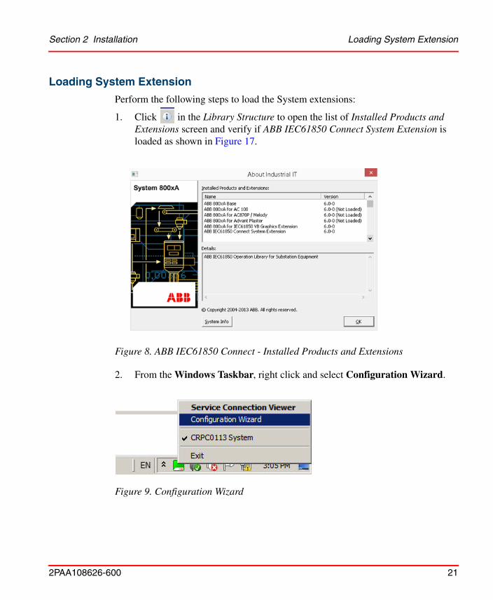
1. Click in the Library Structure to open the list of Installed Products and Extensions screen and verify if ABB IEC61850 Connect System Extension is loaded as shown in Figure 17.
2. From the Windows Taskbar, right click and select Configuration Wizard.
Figure 8. ABB IEC61850 Connect - Installed Products and Extensions
Figure 9. Configuration Wizard
Loading System Extension Section 2 Installation
22 2PAA108626-600
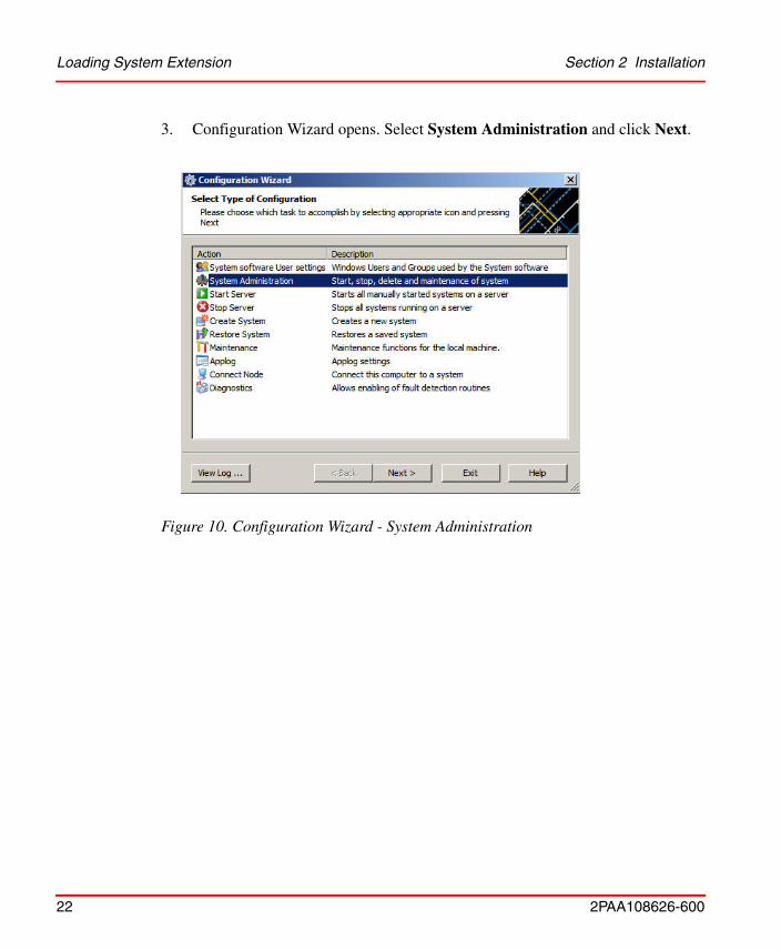
3. Configuration Wizard opens. Select System Administration and click Next.
Figure 10. Configuration Wizard - System Administration
Section 2 Installation Loading System Extension
2PAA108626-600 23
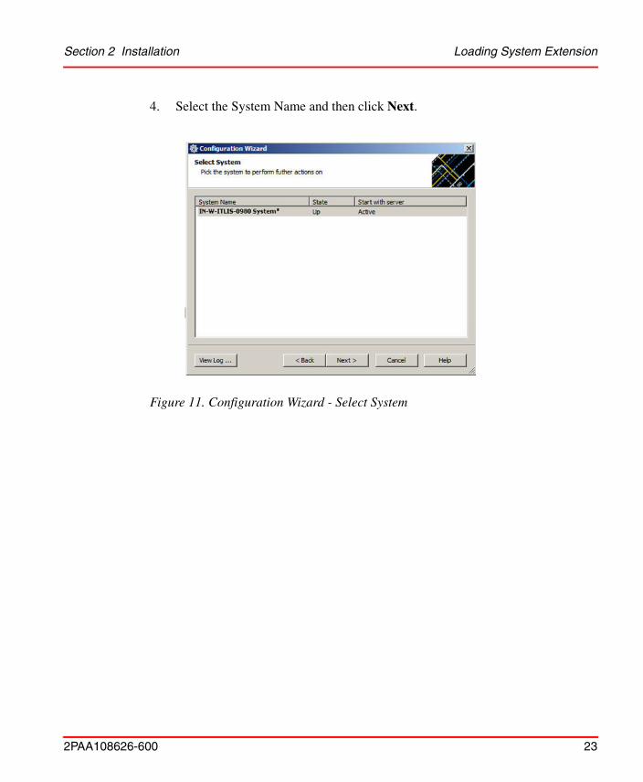
4. Select the System Name and then click Next.
Figure 11. Configuration Wizard - Select System
Loading System Extension Section 2 Installation
24 2PAA108626-600
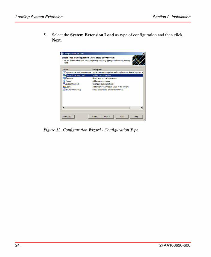
5. Select the System Extension Load as type of configuration and then click Next.
Figure 12. Configuration Wizard - Configuration Type
Section 2 Installation Loading System Extension
2PAA108626-600 25
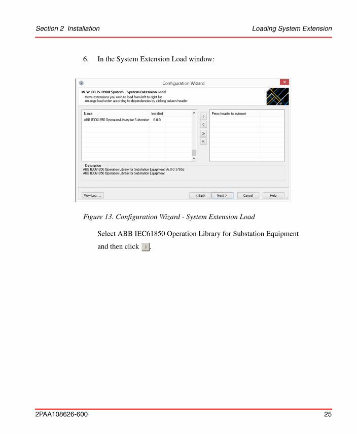
6. In the System Extension Load window:
Select ABB IEC61850 Operation Library for Substation Equipment
and then click .
Figure 13. Configuration Wizard - System Extension Load
Loading System Extension Section 2 Installation
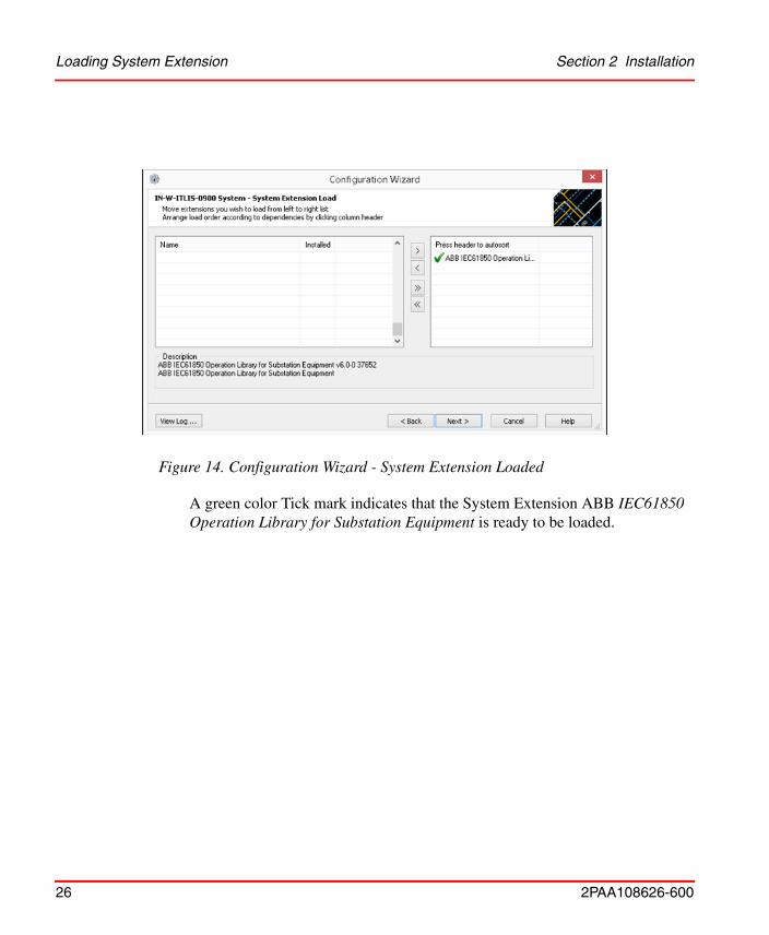
26 2PAA108626-600
A green color Tick mark indicates that the System Extension ABB IEC61850 Operation Library for Substation Equipment is ready to be loaded.
Figure 14. Configuration Wizard - System Extension Loaded
Section 2 Installation Loading System Extension
2PAA108626-600 27
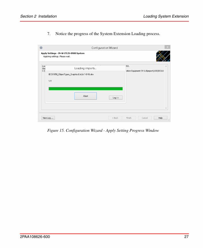
7. Notice the progress of the System Extension Loading process.
Figure 15. Configuration Wizard - Apply Setting Progress Window
Loading System Extension Section 2 Installation
28 2PAA108626-600
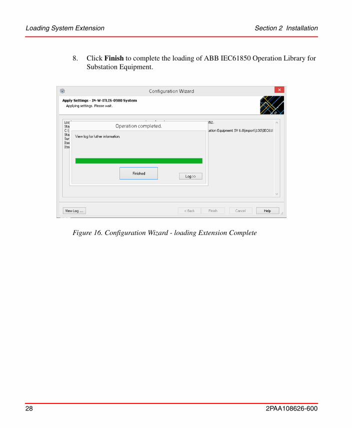
8. Click Finish to complete the loading of ABB IEC61850 Operation Library for Substation Equipment.
Figure 16. Configuration Wizard - loading Extension Complete
Section 2 Installation Loading System Extension
2PAA108626-600 29
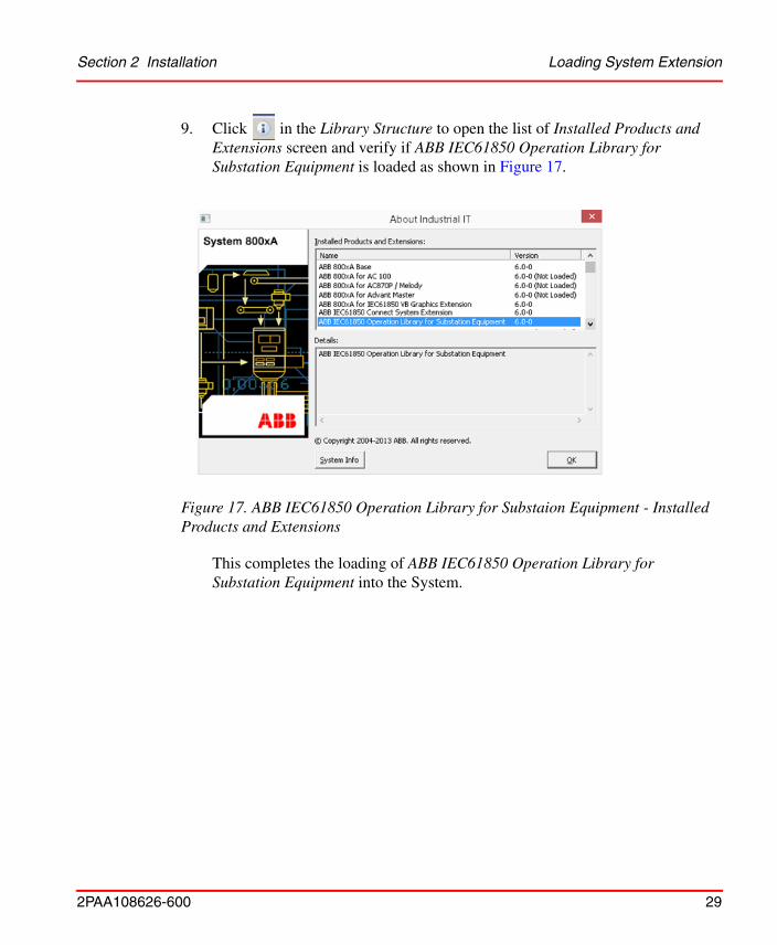
9. Click in the Library Structure to open the list of Installed Products and Extensions screen and verify if ABB IEC61850 Operation Library for Substation Equipment is loaded as shown in Figure 17.
This completes the loading of ABB IEC61850 Operation Library for Substation Equipment into the System.
Figure 17. ABB IEC61850 Operation Library for Substaion Equipment - Installed Products and Extensions
Loading System Extension Section 2 Installation
30 2PAA108626-600
2PAA108626-600 31
Section 3 Faceplates
IEC 61850 Operation Library for Substation Equipment contains Faceplates and Graphic Elements to monitor and control Bay and Conducting equipments in a Substation.
The operating elements required for Bay and Conducting equipment operation are provided in the faceplate, depending on the function. The Graphic Elements can be used directly in Graphics displays to visualize the entire Substation in 800xA.
Faceplates available for each type of Conducting Equipment and Bay is explained in the following topic.
Faceplates for Conducting Equipment ObjectsFaceplates are available for following Conducting Equipment: • Bay• Circuit Breaker• Disconnector• Current Transformer• Power Transformer• Generator• Voltage Transformer
Display Style Selection in Faceplates Section 3 Faceplates
32 2PAA108626-600
Display Style Selection in Faceplates
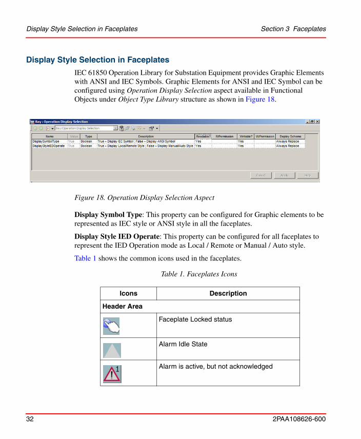
IEC 61850 Operation Library for Substation Equipment provides Graphic Elements with ANSI and IEC Symbols. Graphic Elements for ANSI and IEC Symbol can be configured using Operation Display Selection aspect available in Functional Objects under Object Type Library structure as shown in Figure 18.
Display Symbol Type: This property can be configured for Graphic elements to be represented as IEC style or ANSI style in all the faceplates.
Display Style IED Operate: This property can be configured for all faceplates to represent the IED Operation mode as Local / Remote or Manual / Auto style.
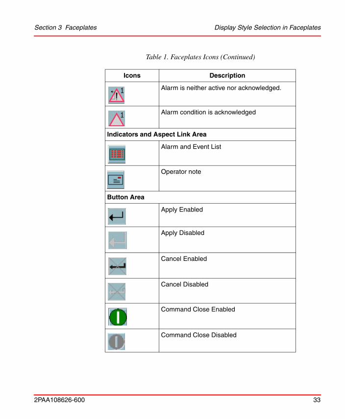
Table 1 shows the common icons used in the faceplates.
Figure 18. Operation Display Selection Aspect
Table 1. Faceplates Icons
Icons Description
Header Area
Faceplate Locked status
Alarm Idle State
Alarm is active, but not acknowledged
Section 3 Faceplates Display Style Selection in Faceplates
2PAA108626-600 33
Alarm is neither active nor acknowledged.
Alarm condition is acknowledged
Indicators and Aspect Link Area
Alarm and Event List
Operator note
Button Area
Apply Enabled
Apply Disabled
Cancel Enabled
Cancel Disabled
Command Close Enabled
Command Close Disabled
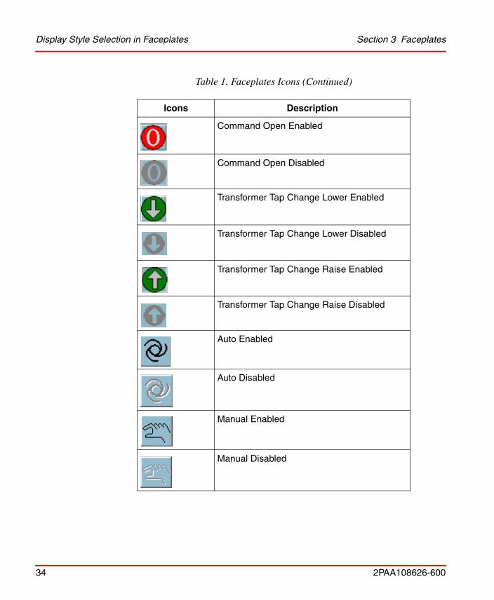
Table 1. Faceplates Icons (Continued)
Icons Description
Display Style Selection in Faceplates Section 3 Faceplates
34 2PAA108626-600
Command Open Enabled
Command Open Disabled
Transformer Tap Change Lower Enabled
Transformer Tap Change Lower Disabled
Transformer Tap Change Raise Enabled
Transformer Tap Change Raise Disabled
Auto Enabled
Auto Disabled
Manual Enabled
Manual Disabled
Table 1. Faceplates Icons (Continued)
Icons Description
Section 3 Faceplates Graphic Element of Substation
2PAA108626-600 35
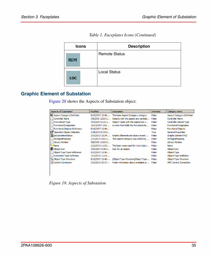
Graphic Element of Substation
Figure 20 shows the Aspects of Substation object.
Remote Status
Local Status
Figure 19. Aspects of Substation
Table 1. Faceplates Icons (Continued)
Icons Description
Graphic Element of Substation Section 3 Faceplates
36 2PAA108626-600
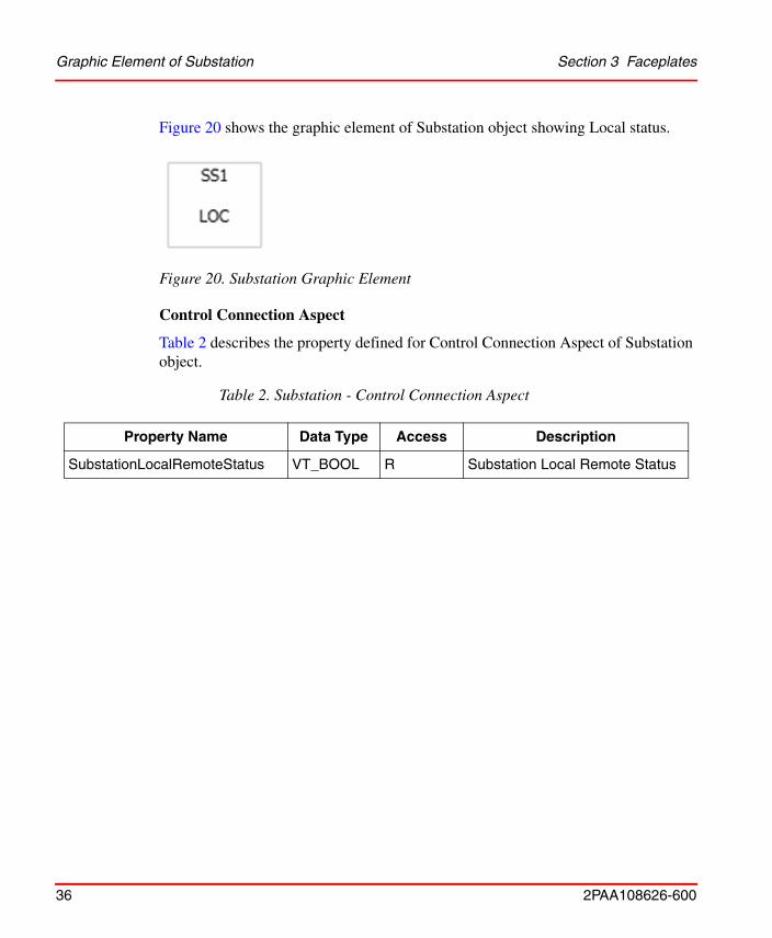
Figure 20 shows the graphic element of Substation object showing Local status.
Control Connection Aspect
Table 2 describes the property defined for Control Connection Aspect of Substation object.
Figure 20. Substation Graphic Element
Table 2. Substation - Control Connection Aspect
Property Name Data Type Access Description
SubstationLocalRemoteStatus VT_BOOL R Substation Local Remote Status
Section 3 Faceplates Graphic Element of Voltage level
2PAA108626-600 37
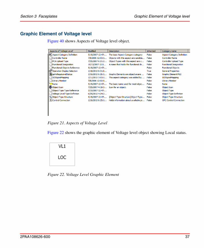
Graphic Element of Voltage level
Figure 40 shows Aspects of Voltage level object.
Figure 22 shows the graphic element of Voltage level object showing Local status.
Figure 21. Aspects of Voltage Level
Figure 22. Voltage Level Graphic Element
Graphic Element of Voltage level Section 3 Faceplates
38 2PAA108626-600
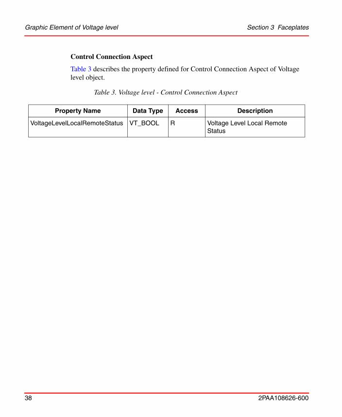
Control Connection Aspect
Table 3 describes the property defined for Control Connection Aspect of Voltage level object.
Table 3. Voltage level - Control Connection Aspect
Property Name Data Type Access Description
VoltageLevelLocalRemoteStatus VT_BOOL R Voltage Level Local Remote Status
Section 3 Faceplates Faceplate of Bay
2PAA108626-600 39
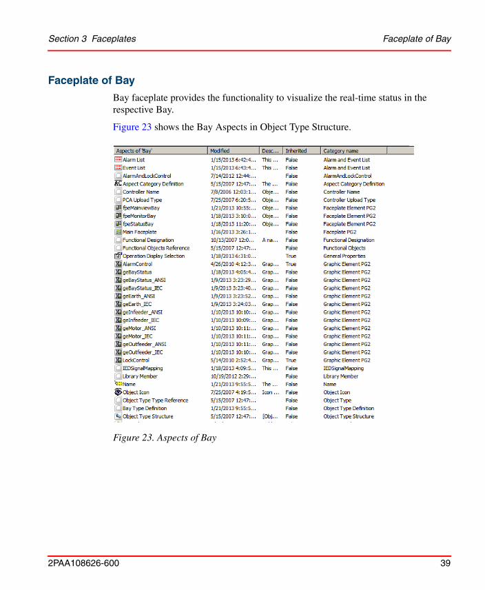
Faceplate of Bay
Bay faceplate provides the functionality to visualize the real-time status in the respective Bay.
Figure 23 shows the Bay Aspects in Object Type Structure.
Figure 23. Aspects of Bay
Faceplate of Bay Section 3 Faceplates
40 2PAA108626-600
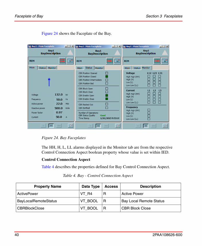
Figure 24 shows the Faceplate of the Bay.
The HH, H, L, LL alarms displayed in the Monitor tab are from the respective Control Connection Aspect boolean property whose value is set within IED.
Control Connection Aspect
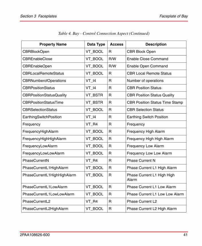
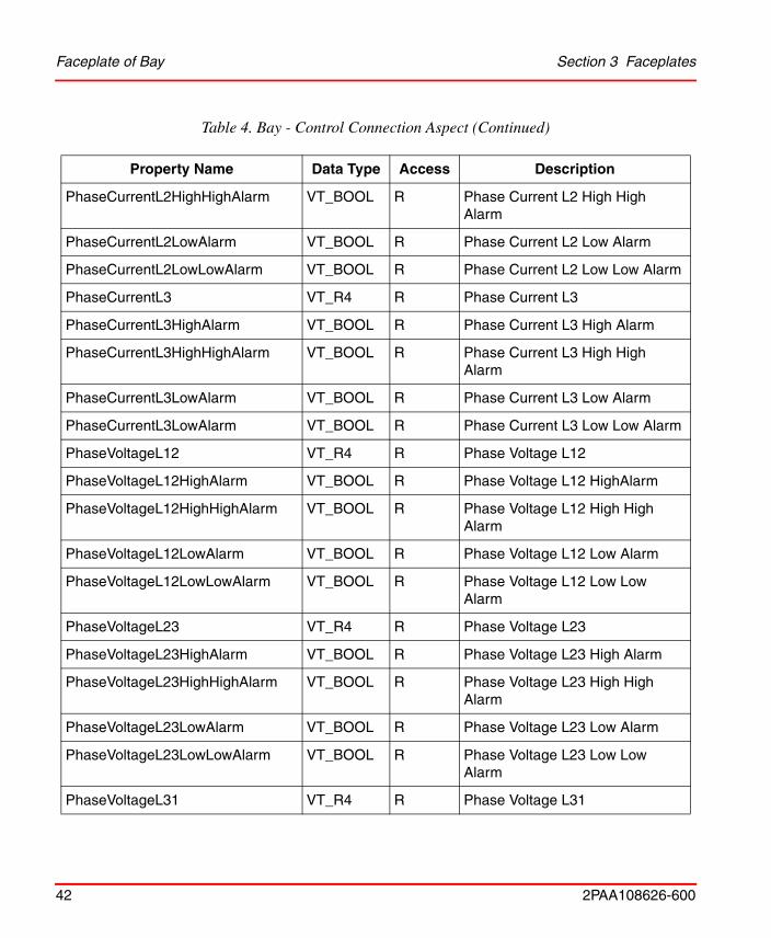
Table 4 describes the properties defined for Bay Control Connection Aspect.
Figure 24. Bay Faceplates
Table 4. Bay - Control Connection Aspect
Property Name Data Type Access Description
ActivePower VT_R4 R Active Power
BayLocalRemoteStatus VT_BOOL R Bay Local Remote Status
CBRBlockClose VT_BOOL R CBR Block Close
Section 3 Faceplates Faceplate of Bay
2PAA108626-600 41
CBRBlockOpen VT_BOOL R CBR Block Open
CBREnableClose VT_BOOL R/W Enable Close Command
CBREnableOpen VT_BOOL R/W Enable Open Command
CBRLocalRemoteStatus VT_BOOL R CBR Local Remote Status
CBRNumberofOperations VT_I4 R Number of operations
CBRPositionStatus VT_I4 R CBR Position Status
CBRPositionStatusQuality VT_BSTR R CBR Position Status Quality
CBRPositionStatusTime VT_BSTR R CBR Position Status Time Stamp
CBRSelectionStatus VT_BOOL R CBR Selection Status
EarthingSwitchPosition VT_I4 R Earthing Switch Position
Frequency VT_R4 R Frequency
FrequencyHighAlarm VT_BOOL R Frequency High Alarm
FrequencyHighHighAlarm VT_BOOL R Frequency High High Alarm
FrequencyLowAlarm VT_BOOL R Frequency Low Alarm
FrequencyLowLowAlarm VT_BOOL R Frequency Low Low Alarm
PhaseCurrentN VT_R4 R Phase Current N
PhaseCurrentL1HighAlarm VT_BOOL R Phase Current L1 High Alarm
PhaseCurrentL1HighHighAlarm VT_BOOL R Phase Current L1 High High Alarm
PhaseCurrentL1LowAlarm VT_BOOL R Phase Current L1 Low Alarm
PhaseCurrentL1LowLowAlarm VT_BOOL R Phase Current L1 Low Low Alarm
PhaseCurrentL2 VT_R4 R Phase Current L2
PhaseCurrentL2HighAlarm VT_BOOL R Phase Current L2 High Alarm
Table 4. Bay - Control Connection Aspect (Continued)
Property Name Data Type Access Description
Faceplate of Bay Section 3 Faceplates
42 2PAA108626-600
PhaseCurrentL2HighHighAlarm VT_BOOL R Phase Current L2 High High Alarm
PhaseCurrentL2LowAlarm VT_BOOL R Phase Current L2 Low Alarm
PhaseCurrentL2LowLowAlarm VT_BOOL R Phase Current L2 Low Low Alarm
PhaseCurrentL3 VT_R4 R Phase Current L3
PhaseCurrentL3HighAlarm VT_BOOL R Phase Current L3 High Alarm
PhaseCurrentL3HighHighAlarm VT_BOOL R Phase Current L3 High High Alarm
PhaseCurrentL3LowAlarm VT_BOOL R Phase Current L3 Low Alarm
PhaseCurrentL3LowAlarm VT_BOOL R Phase Current L3 Low Low Alarm
PhaseVoltageL12 VT_R4 R Phase Voltage L12
PhaseVoltageL12HighAlarm VT_BOOL R Phase Voltage L12 HighAlarm
PhaseVoltageL12HighHighAlarm VT_BOOL R Phase Voltage L12 High High Alarm
PhaseVoltageL12LowAlarm VT_BOOL R Phase Voltage L12 Low Alarm
PhaseVoltageL12LowLowAlarm VT_BOOL R Phase Voltage L12 Low Low Alarm
PhaseVoltageL23 VT_R4 R Phase Voltage L23
PhaseVoltageL23HighAlarm VT_BOOL R Phase Voltage L23 High Alarm
PhaseVoltageL23HighHighAlarm VT_BOOL R Phase Voltage L23 High High Alarm
PhaseVoltageL23LowAlarm VT_BOOL R Phase Voltage L23 Low Alarm
PhaseVoltageL23LowLowAlarm VT_BOOL R Phase Voltage L23 Low Low Alarm
PhaseVoltageL31 VT_R4 R Phase Voltage L31
Table 4. Bay - Control Connection Aspect (Continued)
Property Name Data Type Access Description
Section 3 Faceplates Faceplate of Bay
2PAA108626-600 43
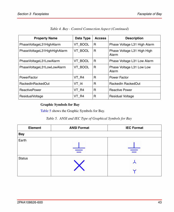
Graphic Symbols for Bay
Table 5 shows the Graphic Symbols for Bay.
PhaseVoltageL31HighAlarm VT_BOOL R Phase Voltage L31 High Alarm
PhaseVoltageL31HighHighAlarm VT_BOOL R Phase Voltage L31 High High Alarm
PhaseVoltageL31LowAlarm VT_BOOL R Phase Voltage L31 Low Alarm
PhaseVoltageL31LowLowAlarm VT_BOOL R Phase Voltage L31 Low Low Alarm
PowerFactor VT_R4 R Power Factor
RackedInRackedOut VT_I4 R RackedIn RackedOut
ReactivePower VT_R4 R Reactive Power
ResidualVoltage VT_R4 R Residual Voltage
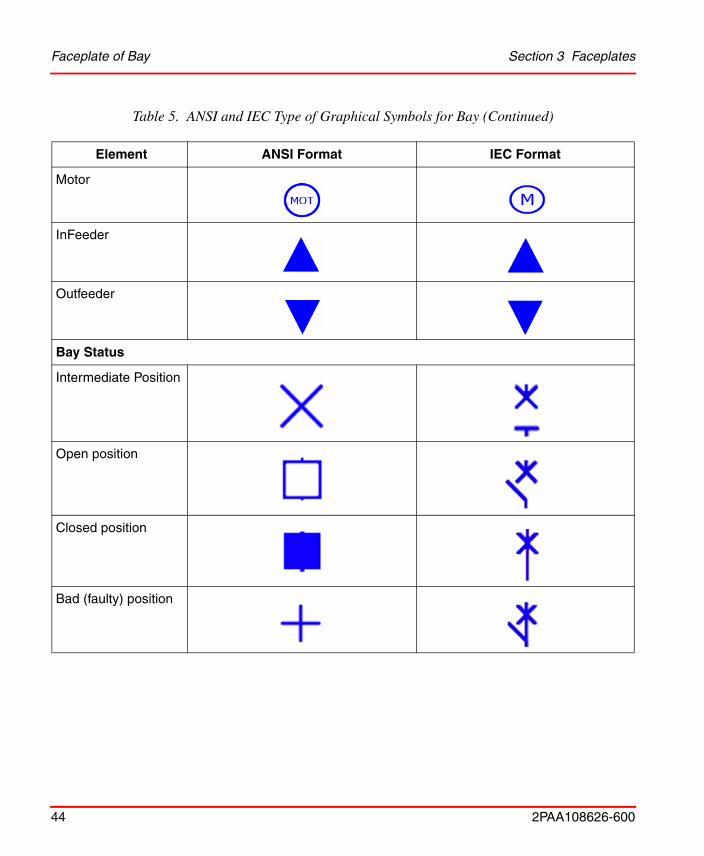
Table 5. ANSI and IEC Type of Graphical Symbols for Bay
Element ANSI Format IEC Format
Bay
Earth
Status
Table 4. Bay - Control Connection Aspect (Continued)
Property Name Data Type Access Description
Faceplate of Bay Section 3 Faceplates
44 2PAA108626-600
Motor
InFeeder
Outfeeder
Bay Status
Intermediate Position
Open position
Closed position
Bad (faulty) position
Table 5. ANSI and IEC Type of Graphical Symbols for Bay (Continued)
Element ANSI Format IEC Format
Section 3 Faceplates Faceplate of Circuit Breaker
2PAA108626-600 45
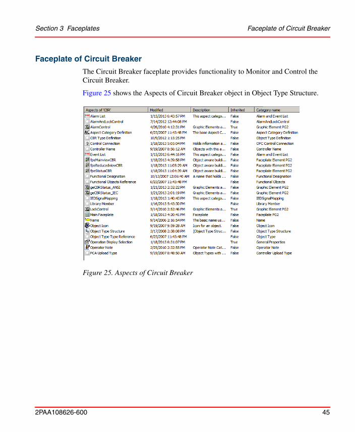
Faceplate of Circuit Breaker
The Circuit Breaker faceplate provides functionality to Monitor and Control the Circuit Breaker.
Figure 25 shows the Aspects of Circuit Breaker object in Object Type Structure.
Figure 25. Aspects of Circuit Breaker
Faceplate of Circuit Breaker Section 3 Faceplates
46 2PAA108626-600
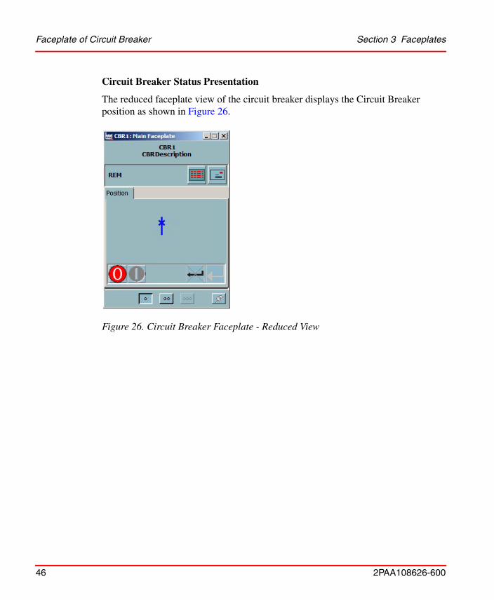
Circuit Breaker Status Presentation
The reduced faceplate view of the circuit breaker displays the Circuit Breaker position as shown in Figure 26.
Figure 26. Circuit Breaker Faceplate - Reduced View
Section 3 Faceplates Faceplate of Circuit Breaker
2PAA108626-600 47
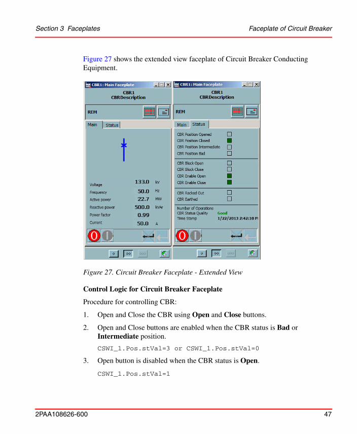
Figure 27 shows the extended view faceplate of Circuit Breaker Conducting Equipment.
Control Logic for Circuit Breaker Faceplate
Procedure for controlling CBR:
1. Open and Close the CBR using Open and Close buttons.
2. Open and Close buttons are enabled when the CBR status is Bad or Intermediate position.
CSWI_1.Pos.stVal=3 or CSWI_1.Pos.stVal=0
3. Open button is disabled when the CBR status is Open.
CSWI_1.Pos.stVal=1
Figure 27. Circuit Breaker Faceplate - Extended View
Faceplate of Circuit Breaker Section 3 Faceplates
48 2PAA108626-600
4. Close button is disabled when the CBR status is Close.
CSWI_1.Pos.stVal=1
5. To close the CBR, Select Close and Apply button.
6. To open the CBR, Select Open and Apply button.
7. The apply button will be enabled only if,
Open Command = 1 (CSWI_1.Pos.ctlSelOn = 1) and Selected Feedback = True (CSWI_1.Pos.stSeld = True),
OR
Close Command = 1 (CSWI_1.Pos.ctlSelOff = 1) and Selected Feedback = True (CSWI_1.Pos.stSeld = True).
8. The Cancel button is used to clear the open and close requests.
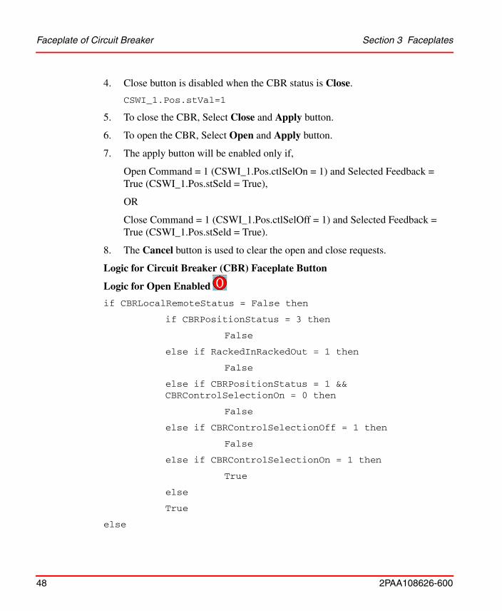
Logic for Circuit Breaker (CBR) Faceplate Button
Logic for Open Enabled
if CBRLocalRemoteStatus = False then
if CBRPositionStatus = 3 then
False
else if RackedInRackedOut = 1 then
False
else if CBRPositionStatus = 1 && CBRControlSelectionOn = 0 then
False
else if CBRControlSelectionOff = 1 then
False
else if CBRControlSelectionOn = 1 then
True
else
True
else
Section 3 Faceplates Faceplate of Circuit Breaker
2PAA108626-600 49
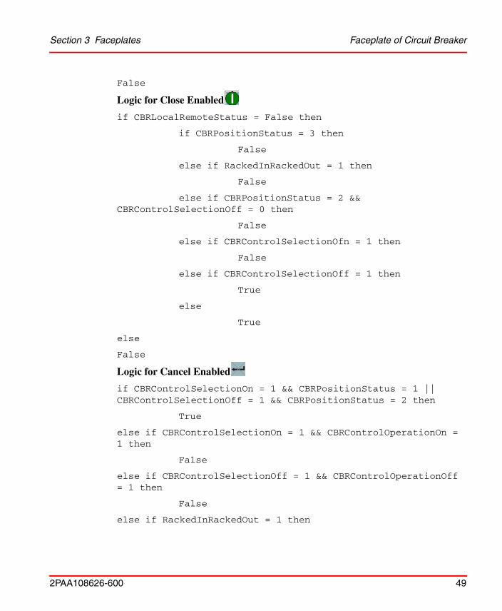
False
Logic for Close Enabled
if CBRLocalRemoteStatus = False then
if CBRPositionStatus = 3 then
False
else if RackedInRackedOut = 1 then
False
else if CBRPositionStatus = 2 && CBRControlSelectionOff = 0 then
False
else if CBRControlSelectionOfn = 1 then
False
else if CBRControlSelectionOff = 1 then
True
else
True
else
False
Logic for Cancel Enabled
if CBRControlSelectionOn = 1 && CBRPositionStatus = 1 || CBRControlSelectionOff = 1 && CBRPositionStatus = 2 then
True
else if CBRControlSelectionOn = 1 && CBRControlOperationOn = 1 then
False
else if CBRControlSelectionOff = 1 && CBRControlOperationOff = 1 then
False
else if RackedInRackedOut = 1 then
Faceplate of Circuit Breaker Section 3 Faceplates
50 2PAA108626-600
False
else
False
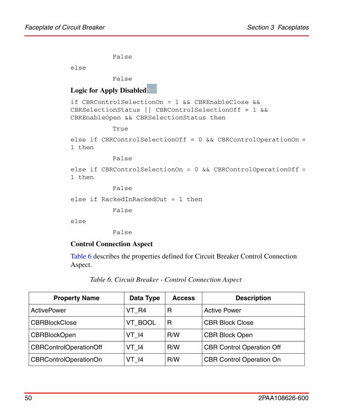
Logic for Apply Disabled
if CBRControlSelectionOn = 1 && CBREnableClose && CBRSelectionStatus || CBRControlSelectionOff = 1 && CBREnableOpen && CBRSelectionStatus then
True
else if CBRControlSelectionOff = 0 && CBRControlOperationOn = 1 then
False
else if CBRControlSelectionOn = 0 && CBRControlOperationOff = 1 then
False
else if RackedInRackedOut = 1 then
False
else
False
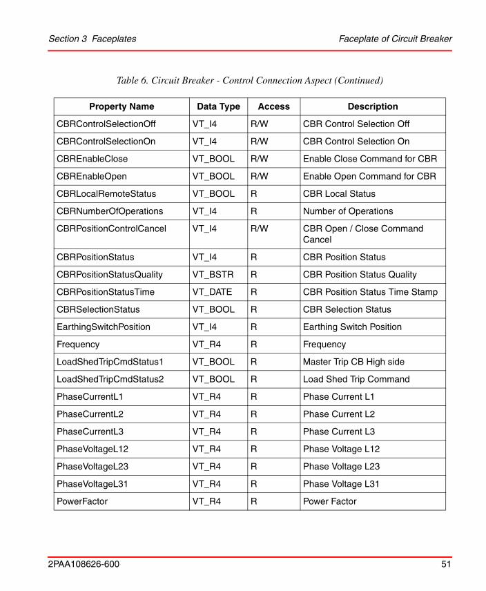
Control Connection Aspect
Table 6 describes the properties defined for Circuit Breaker Control Connection Aspect.
Table 6. Circuit Breaker - Control Connection Aspect
Property Name Data Type Access Description
ActivePower VT_R4 R Active Power
CBRBlockClose VT_BOOL R CBR Block Close
CBRBlockOpen VT_I4 R/W CBR Block Open
CBRControlOperationOff VT_I4 R/W CBR Control Operation Off
CBRControlOperationOn VT_I4 R/W CBR Control Operation On
Section 3 Faceplates Faceplate of Circuit Breaker
2PAA108626-600 51
CBRControlSelectionOff VT_I4 R/W CBR Control Selection Off
CBRControlSelectionOn VT_I4 R/W CBR Control Selection On
CBREnableClose VT_BOOL R/W Enable Close Command for CBR
CBREnableOpen VT_BOOL R/W Enable Open Command for CBR
CBRLocalRemoteStatus VT_BOOL R CBR Local Status
CBRNumberOfOperations VT_I4 R Number of Operations
CBRPositionControlCancel VT_I4 R/W CBR Open / Close Command Cancel
CBRPositionStatus VT_I4 R CBR Position Status
CBRPositionStatusQuality VT_BSTR R CBR Position Status Quality
CBRPositionStatusTime VT_DATE R CBR Position Status Time Stamp
CBRSelectionStatus VT_BOOL R CBR Selection Status
EarthingSwitchPosition VT_I4 R Earthing Switch Position
Frequency VT_R4 R Frequency
LoadShedTripCmdStatus1 VT_BOOL R Master Trip CB High side
LoadShedTripCmdStatus2 VT_BOOL R Load Shed Trip Command
PhaseCurrentL1 VT_R4 R Phase Current L1
PhaseCurrentL2 VT_R4 R Phase Current L2
PhaseCurrentL3 VT_R4 R Phase Current L3
PhaseVoltageL12 VT_R4 R Phase Voltage L12
PhaseVoltageL23 VT_R4 R Phase Voltage L23
PhaseVoltageL31 VT_R4 R Phase Voltage L31
PowerFactor VT_R4 R Power Factor
Table 6. Circuit Breaker - Control Connection Aspect (Continued)
Property Name Data Type Access Description
Faceplate of Circuit Breaker Section 3 Faceplates
52 2PAA108626-600
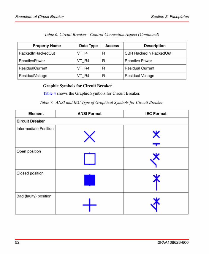
Graphic Symbols for Circuit Breaker
Table 4 shows the Graphic Symbols for Circuit Breaker.
RackedInRackedOut VT_I4 R CBR RackedIn RackedOut
ReactivePower VT_R4 R Reactive Power
ResidualCurrent VT_R4 R Residual Current
ResidualVoltage VT_R4 R Residual Voltage
Table 7. ANSI and IEC Type of Graphical Symbols for Circuit Breaker
Element ANSI Format IEC Format
Circuit Breaker
Intermediate Position
Open position
Closed position
Bad (faulty) position
Table 6. Circuit Breaker - Control Connection Aspect (Continued)
Property Name Data Type Access Description
Section 3 Faceplates Faceplate of Disconnector
2PAA108626-600 53
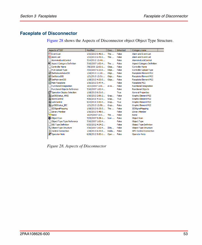
Faceplate of Disconnector
Figure 28 shows the Aspects of Disconnector object Object Type Structure.
Figure 28. Aspects of Disconnector
Faceplate of Disconnector Section 3 Faceplates
54 2PAA108626-600
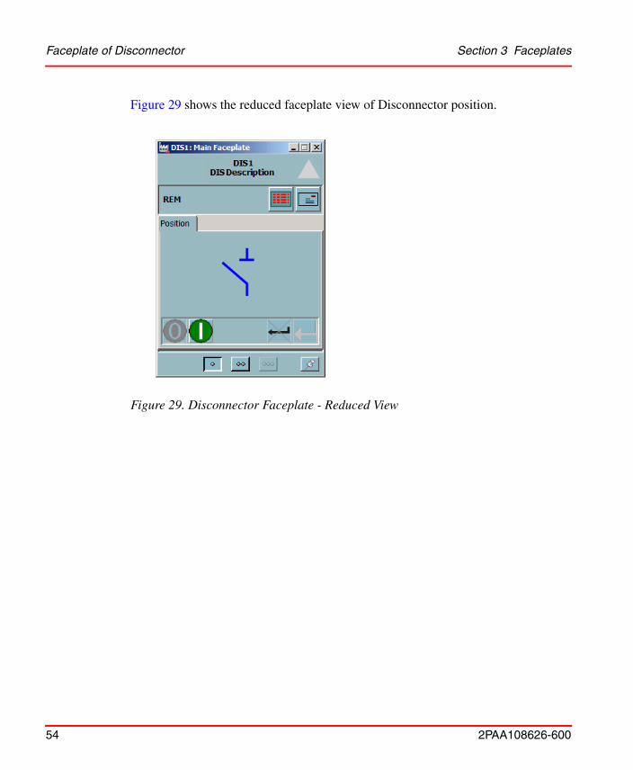
Figure 29 shows the reduced faceplate view of Disconnector position.
Figure 29. Disconnector Faceplate - Reduced View
Section 3 Faceplates Faceplate of Disconnector
2PAA108626-600 55
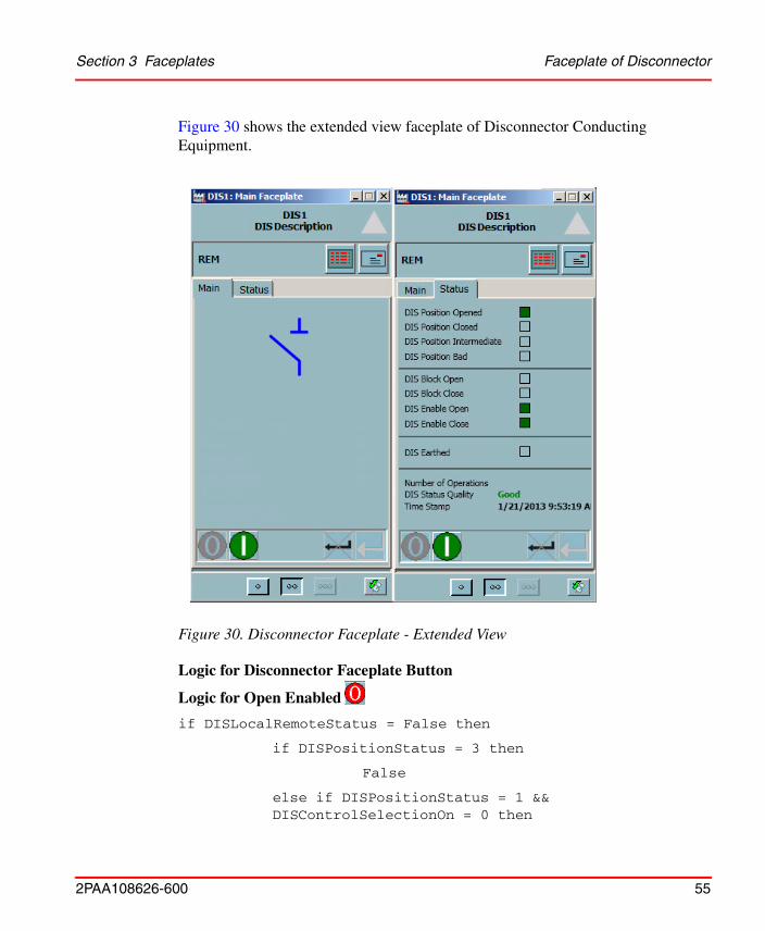
Figure 30 shows the extended view faceplate of Disconnector Conducting Equipment.
Logic for Disconnector Faceplate Button
Logic for Open Enabled
if DISLocalRemoteStatus = False then
if DISPositionStatus = 3 then
False
else if DISPositionStatus = 1 &&DISControlSelectionOn = 0 then
Figure 30. Disconnector Faceplate - Extended View
Faceplate of Disconnector Section 3 Faceplates
56 2PAA108626-600
False
else if DISControlSelectionOff = 1 then
False
else if DISControlSelectionOn = 1 then
True
else
True
else
False
Logic for Close Enabled
if DISLocalRemoteStatus = False then
if DISPositionStatus = 3 then
False
else if DISPositionStatus = 2 && DISControlSelectionOff = 0 then
False
else if DISControlSelectionOn = 1 then
False
else if DISControlSelectionOff = 1 then
True
else
True
else
False
Logic for Cancel Enabled
if DISControlSelectionOn = 1 && DISPositionStatus = 1 || DISControlSelectionOff = 1 && DISPositionStatus = 2 then
True
Section 3 Faceplates Faceplate of Disconnector
2PAA108626-600 57
else if DISControlSelectionOn = 1 && DISControlOperationOn = 1 then
False
else if DISControlSelectionOff = 1 && DISControlOperationOff = 1 then
False
else
False
Logic for Apply Disabled
if DISControlSelectionOn = 1 && DISEnableClose && DISSelectionStatus || DISControlSelectionOff = 1 && DISEnableOpen && DISSelectionStatus then
True
else if DISControlSelectionOff = 0 && DISControlOperationOn = 1 then
False
else if DISControlSelectionOn = 0 && DISControlOperationOff = 1 then
False
else
False
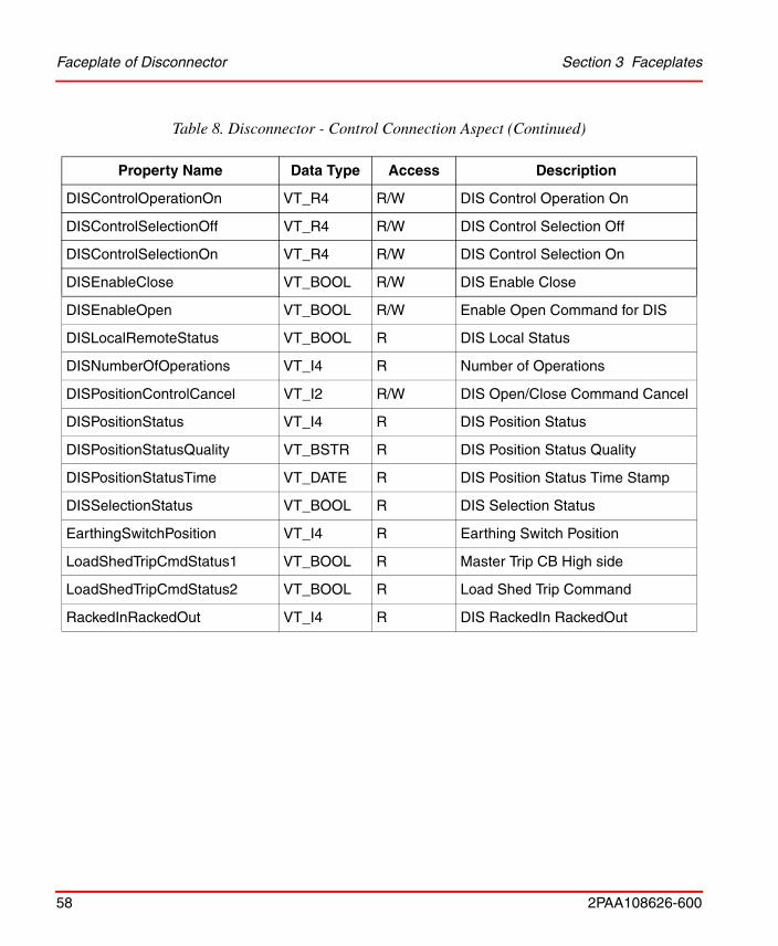
Control Connection Aspect
Table 8 describes the properties defined for Disconnector Control Connection Aspect.
Table 8. Disconnector - Control Connection Aspect
Property Name Data Type Access Description
DISBlockClose VT_BOOL R DIS Block Close
DISBlockOpen VT_BOOL R DIS Block Open
DISControlOperationOff VT_R4 R/W DIS Control Operation Off
Faceplate of Disconnector Section 3 Faceplates
58 2PAA108626-600
DISControlOperationOn VT_R4 R/W DIS Control Operation On
DISControlSelectionOff VT_R4 R/W DIS Control Selection Off
DISControlSelectionOn VT_R4 R/W DIS Control Selection On
DISEnableClose VT_BOOL R/W DIS Enable Close
DISEnableOpen VT_BOOL R/W Enable Open Command for DIS
DISLocalRemoteStatus VT_BOOL R DIS Local Status
DISNumberOfOperations VT_I4 R Number of Operations
DISPositionControlCancel VT_I2 R/W DIS Open/Close Command Cancel
DISPositionStatus VT_I4 R DIS Position Status
DISPositionStatusQuality VT_BSTR R DIS Position Status Quality
DISPositionStatusTime VT_DATE R DIS Position Status Time Stamp
DISSelectionStatus VT_BOOL R DIS Selection Status
EarthingSwitchPosition VT_I4 R Earthing Switch Position
LoadShedTripCmdStatus1 VT_BOOL R Master Trip CB High side
LoadShedTripCmdStatus2 VT_BOOL R Load Shed Trip Command
RackedInRackedOut VT_I4 R DIS RackedIn RackedOut
Table 8. Disconnector - Control Connection Aspect (Continued)
Property Name Data Type Access Description
Section 3 Faceplates Faceplate of Disconnector
2PAA108626-600 59
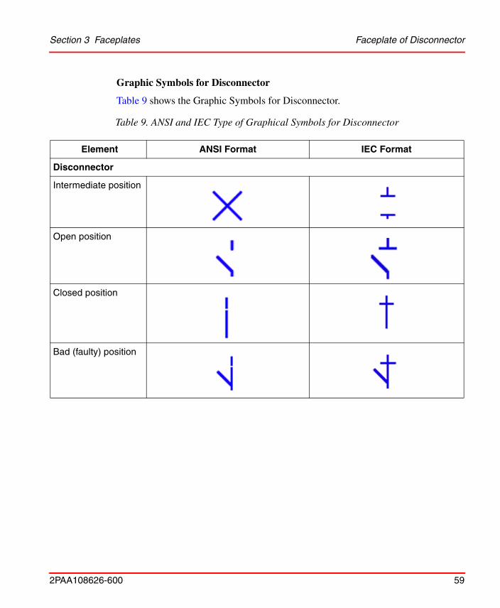
Graphic Symbols for Disconnector
Table 9 shows the Graphic Symbols for Disconnector.
Table 9. ANSI and IEC Type of Graphical Symbols for Disconnector
Element ANSI Format IEC Format
Disconnector
Intermediate position
Open position
Closed position
Bad (faulty) position
Faceplate of Current Transformer Section 3 Faceplates
60 2PAA108626-600
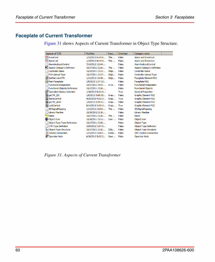
Faceplate of Current Transformer
Figure 31 shows Aspects of Current Transformer in Object Type Structure.
Figure 31. Aspects of Current Transformer
Section 3 Faceplates Faceplate of Current Transformer
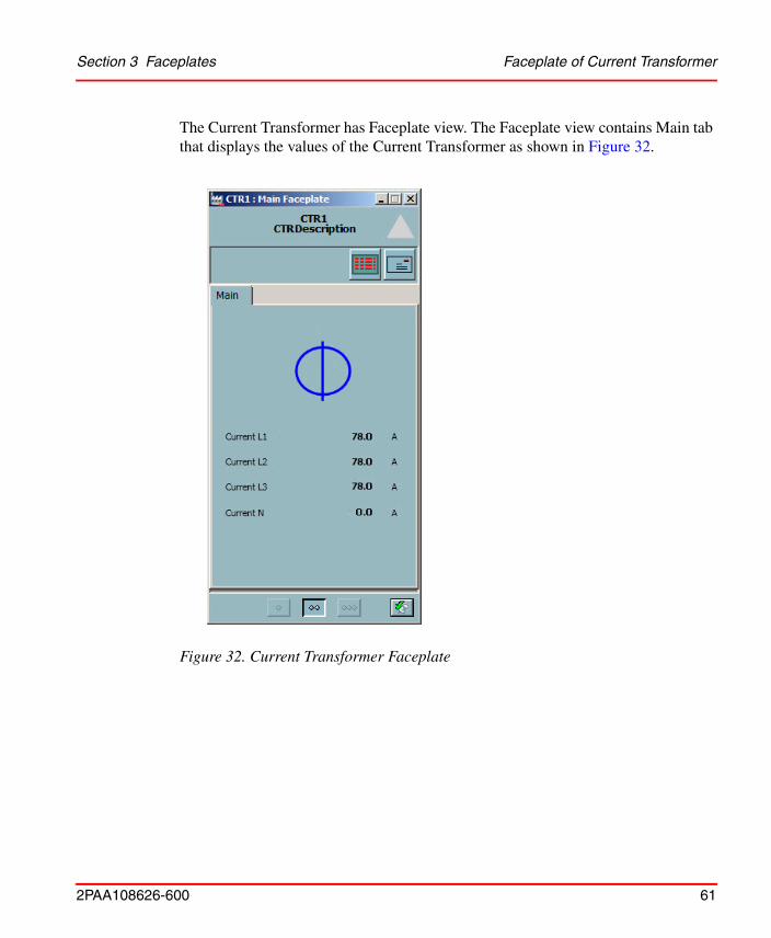
2PAA108626-600 61
The Current Transformer has Faceplate view. The Faceplate view contains Main tab that displays the values of the Current Transformer as shown in Figure 32.
Figure 32. Current Transformer Faceplate
Faceplate of Current Transformer Section 3 Faceplates
62 2PAA108626-600
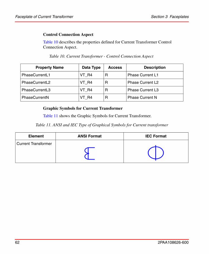
Control Connection Aspect
Table 10 describes the properties defined for Current Transformer Control Connection Aspect.
Graphic Symbols for Current Transformer
Table 11 shows the Graphic Symbols for Current Transformer.
Table 10. Current Transformer - Control Connection Aspect
Property Name Data Type Access Description
PhaseCurrentL1 VT_R4 R Phase Current L1
PhaseCurrentL2 VT_R4 R Phase Current L2
PhaseCurrentL3 VT_R4 R Phase Current L3
PhaseCurrentN VT_R4 R Phase Current N
Table 11. ANSI and IEC Type of Graphical Symbols for Current transformer
Element ANSI Format IEC Format
Current Transformer
Section 3 Faceplates Faceplate of Power Transformer
2PAA108626-600 63
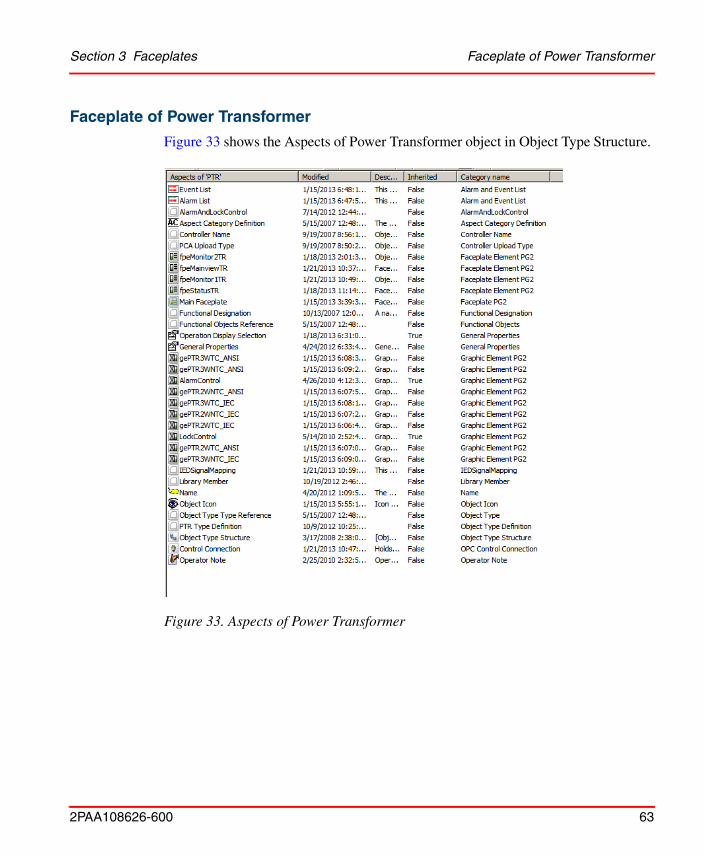
Faceplate of Power Transformer
Figure 33 shows the Aspects of Power Transformer object in Object Type Structure.
Figure 33. Aspects of Power Transformer
Faceplate of Power Transformer Section 3 Faceplates
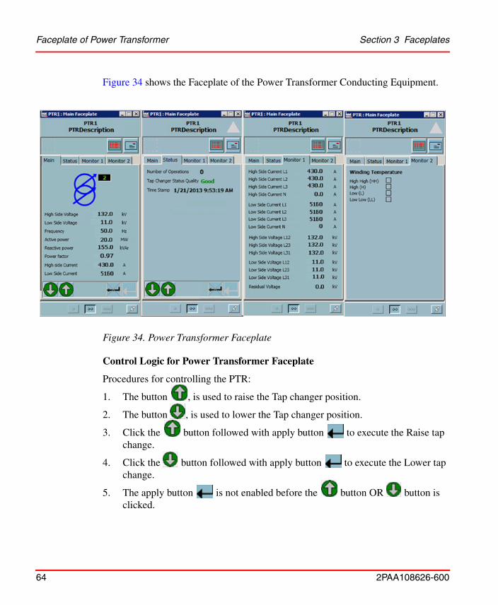
64 2PAA108626-600
Figure 34 shows the Faceplate of the Power Transformer Conducting Equipment.
Control Logic for Power Transformer Faceplate
Procedures for controlling the PTR:
1. The button , is used to raise the Tap changer position.
2. The button , is used to lower the Tap changer position.
3. Click the button followed with apply button to execute the Raise tap change.
4. Click the button followed with apply button to execute the Lower tap change.
5. The apply button is not enabled before the button OR button is clicked.
Figure 34. Power Transformer Faceplate
Section 3 Faceplates Faceplate of Power Transformer
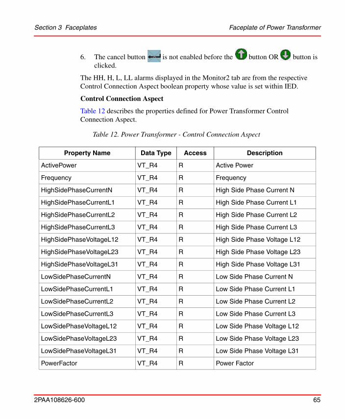
2PAA108626-600 65
6. The cancel button is not enabled before the button OR button is clicked.
The HH, H, L, LL alarms displayed in the Monitor2 tab are from the respective Control Connection Aspect boolean property whose value is set within IED.
Control Connection Aspect
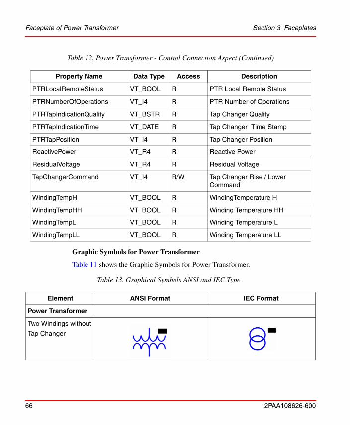
Table 12 describes the properties defined for Power Transformer Control Connection Aspect.
Table 12. Power Transformer - Control Connection Aspect
Property Name Data Type Access Description
ActivePower VT_R4 R Active Power
Frequency VT_R4 R Frequency
HighSidePhaseCurrentN VT_R4 R High Side Phase Current N
HighSidePhaseCurrentL1 VT_R4 R High Side Phase Current L1
HighSidePhaseCurrentL2 VT_R4 R High Side Phase Current L2
HighSidePhaseCurrentL3 VT_R4 R High Side Phase Current L3
HighSidePhaseVoltageL12 VT_R4 R High Side Phase Voltage L12
HighSidePhaseVoltageL23 VT_R4 R High Side Phase Voltage L23
HighSidePhaseVoltageL31 VT_R4 R High Side Phase Voltage L31
LowSidePhaseCurrentN VT_R4 R Low Side Phase Current N
LowSidePhaseCurrentL1 VT_R4 R Low Side Phase Current L1
LowSidePhaseCurrentL2 VT_R4 R Low Side Phase Current L2
LowSidePhaseCurrentL3 VT_R4 R Low Side Phase Current L3
LowSidePhaseVoltageL12 VT_R4 R Low Side Phase Voltage L12
LowSidePhaseVoltageL23 VT_R4 R Low Side Phase Voltage L23
LowSidePhaseVoltageL31 VT_R4 R Low Side Phase Voltage L31
PowerFactor VT_R4 R Power Factor
Faceplate of Power Transformer Section 3 Faceplates
66 2PAA108626-600
Graphic Symbols for Power Transformer
Table 11 shows the Graphic Symbols for Power Transformer.
PTRLocalRemoteStatus VT_BOOL R PTR Local Remote Status
PTRNumberOfOperations VT_I4 R PTR Number of Operations
PTRTapIndicationQuality VT_BSTR R Tap Changer Quality
PTRTapIndicationTime VT_DATE R Tap Changer Time Stamp
PTRTapPosition VT_I4 R Tap Changer Position
ReactivePower VT_R4 R Reactive Power
ResidualVoltage VT_R4 R Residual Voltage
TapChangerCommand VT_I4 R/W Tap Changer Rise / Lower Command
WindingTempH VT_BOOL R WindingTemperature H
WindingTempHH VT_BOOL R Winding Temperature HH
WindingTempL VT_BOOL R Winding Temperature L
WindingTempLL VT_BOOL R Winding Temperature LL
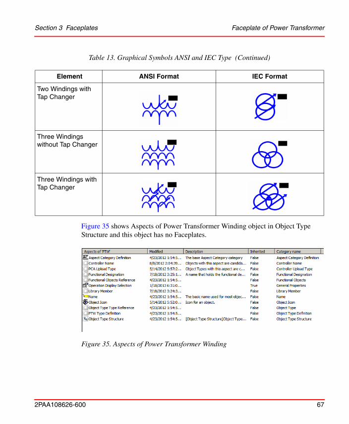
Table 13. Graphical Symbols ANSI and IEC Type
Element ANSI Format IEC Format
Power Transformer
Two Windings without
Tap Changer
Table 12. Power Transformer - Control Connection Aspect (Continued)
Property Name Data Type Access Description
Section 3 Faceplates Faceplate of Power Transformer
2PAA108626-600 67
Figure 35 shows Aspects of Power Transformer Winding object in Object Type Structure and this object has no Faceplates.
Two Windings with Tap Changer
Three Windings without Tap Changer
Three Windings with Tap Changer
Figure 35. Aspects of Power Transformer Winding
Table 13. Graphical Symbols ANSI and IEC Type (Continued)
Element ANSI Format IEC Format
Faceplate of Power Transformer Section 3 Faceplates
68 2PAA108626-600
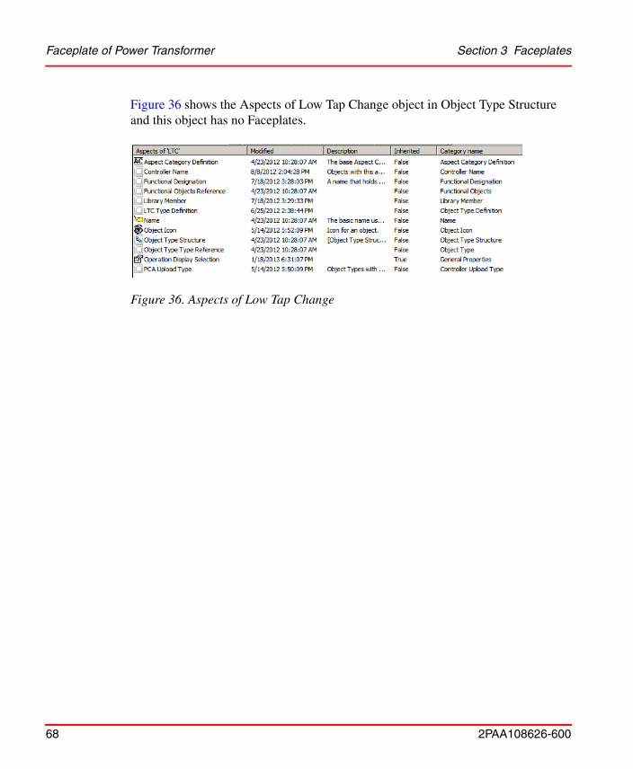
Figure 36 shows the Aspects of Low Tap Change object in Object Type Structure and this object has no Faceplates.
Figure 36. Aspects of Low Tap Change
Section 3 Faceplates Faceplate of Generator
2PAA108626-600 69
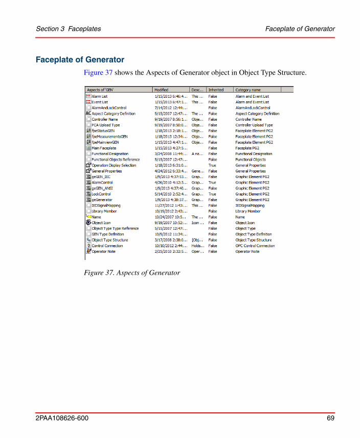
Faceplate of Generator
Figure 37 shows the Aspects of Generator object in Object Type Structure.
Figure 37. Aspects of Generator
Faceplate of Generator Section 3 Faceplates
70 2PAA108626-600
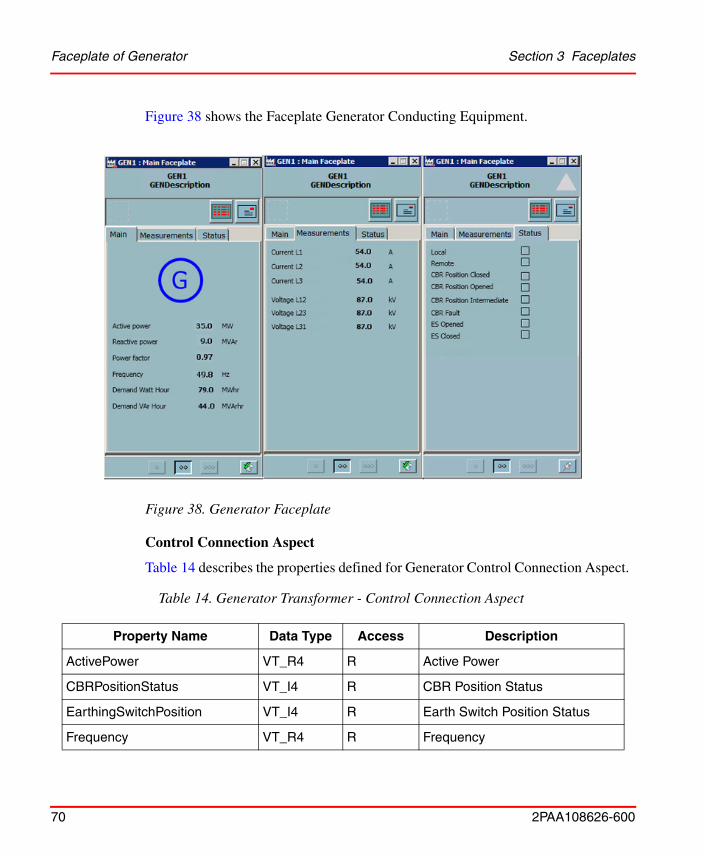
Figure 38 shows the Faceplate Generator Conducting Equipment.
Control Connection Aspect
Table 14 describes the properties defined for Generator Control Connection Aspect.
Figure 38. Generator Faceplate
Table 14. Generator Transformer - Control Connection Aspect
Property Name Data Type Access Description
ActivePower VT_R4 R Active Power
CBRPositionStatus VT_I4 R CBR Position Status
EarthingSwitchPosition VT_I4 R Earth Switch Position Status
Frequency VT_R4 R Frequency
Section 3 Faceplates Faceplate of Generator
2PAA108626-600 71
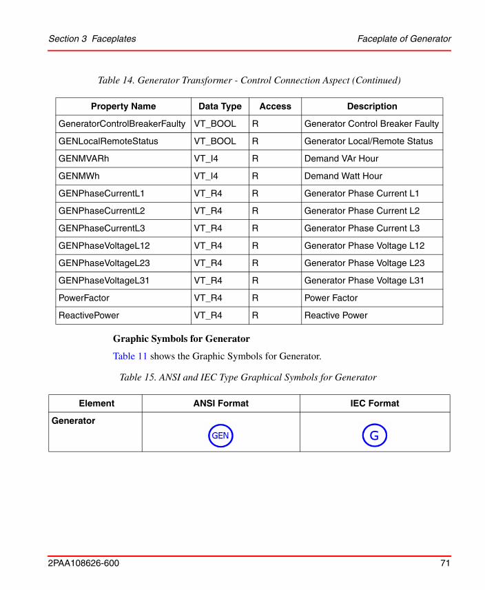
Graphic Symbols for Generator
Table 11 shows the Graphic Symbols for Generator.
GeneratorControlBreakerFaulty VT_BOOL R Generator Control Breaker Faulty
GENLocalRemoteStatus VT_BOOL R Generator Local/Remote Status
GENMVARh VT_I4 R Demand VAr Hour
GENMWh VT_I4 R Demand Watt Hour
GENPhaseCurrentL1 VT_R4 R Generator Phase Current L1
GENPhaseCurrentL2 VT_R4 R Generator Phase Current L2
GENPhaseCurrentL3 VT_R4 R Generator Phase Current L3
GENPhaseVoltageL12 VT_R4 R Generator Phase Voltage L12
GENPhaseVoltageL23 VT_R4 R Generator Phase Voltage L23
GENPhaseVoltageL31 VT_R4 R Generator Phase Voltage L31
PowerFactor VT_R4 R Power Factor
ReactivePower VT_R4 R Reactive Power
Table 15. ANSI and IEC Type Graphical Symbols for Generator
Element ANSI Format IEC Format
Generator
Table 14. Generator Transformer - Control Connection Aspect (Continued)
Property Name Data Type Access Description
Faceplate of Voltage Transformer Section 3 Faceplates
72 2PAA108626-600
Faceplate of Voltage Transformer
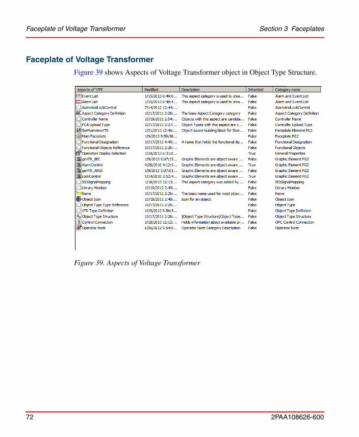
Figure 39 shows Aspects of Voltage Transformer object in Object Type Structure.
Figure 39. Aspects of Voltage Transformer
Section 3 Faceplates Faceplate of Voltage Transformer
2PAA108626-600 73
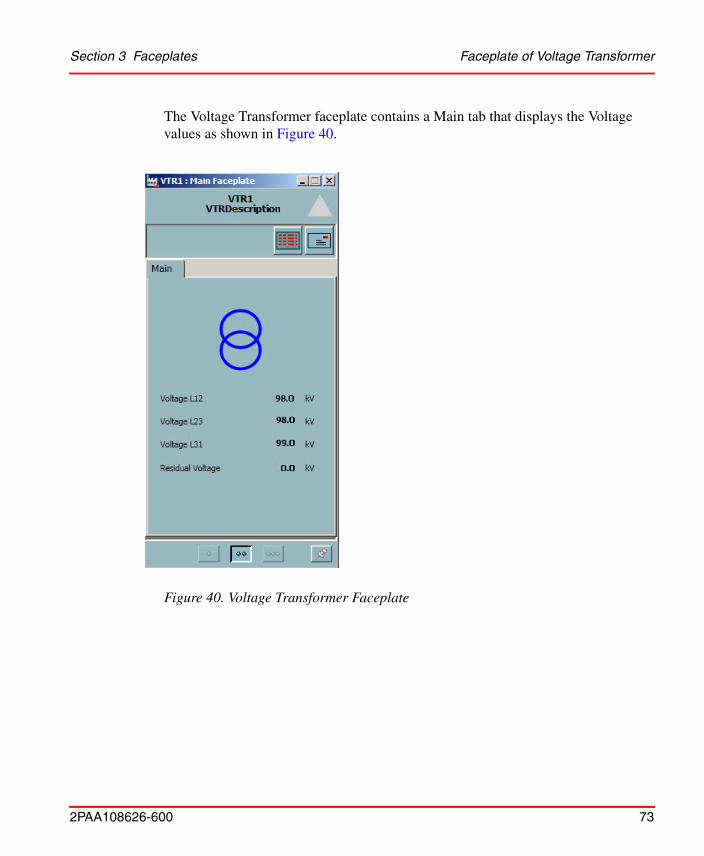
The Voltage Transformer faceplate contains a Main tab that displays the Voltage values as shown in Figure 40.
Figure 40. Voltage Transformer Faceplate
Faceplate of Voltage Transformer Section 3 Faceplates
74 2PAA108626-600
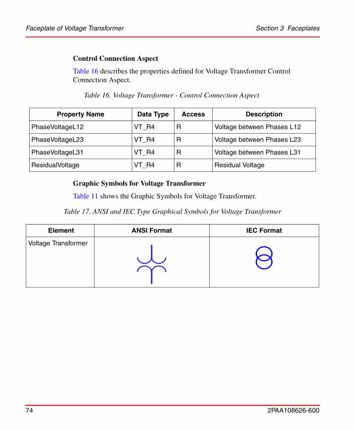
Control Connection Aspect
Table 16 describes the properties defined for Voltage Transformer Control Connection Aspect.
Graphic Symbols for Voltage Transformer
Table 11 shows the Graphic Symbols for Voltage Transformer.
Table 16. Voltage Transformer - Control Connection Aspect
Property Name Data Type Access Description
PhaseVoltageL12 VT_R4 R Voltage between Phases L12
PhaseVoltageL23 VT_R4 R Voltage between Phases L23
PhaseVoltageL31 VT_R4 R Voltage between Phases L31
ResidualVoltage VT_R4 R Residual Voltage
Table 17. ANSI and IEC Type Graphical Symbols for Voltage Transformer
Element ANSI Format IEC Format
Voltage Transformer
Section 3 Faceplates Control Connection Aspect
2PAA108626-600 75
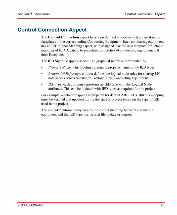
Control Connection Aspect The Control Connection aspect have a predefined properties that are used in the faceplates of the corresponding Conducting Equipment. Each conducting equipment has an IED Signal Mapping aspect, with assigned .csv file as a template for default mapping of IED Attribute to predefined properties of conducting equipment and their Faceplate.
The IED Signal Mapping aspect, is a graphical interface represented by,
• Property Name, which defines a generic property name of the IED types
• Remote LN Reference, column defines the logical node rules for sharing LN data access across Substation, Voltage, Bay, Conducting Equipment
• IED type, each columns represents an IED type with the Logical Node attributes. This can be updated with IED types as required for the project.
For example, a default mapping is prepared for default ABB IEDs. But this mapping must be verified and updated during the start of project based on the type of IED used in the project.
The uploader automatically creates the correct mapping between conducting equipment and the IED type during .scd file update or import.
Control Connection Aspect Section 3 Faceplates
76 2PAA108626-600
For more details on IED Signal Mapping and Uploader functionality, refer to System 800xA IEC 61850 Connect Configuration (9ARD171387*) Manual.
Figure 41. IED Signal Mapping Aspect
Section 3 Faceplates Control Connection Aspect
2PAA108626-600 77
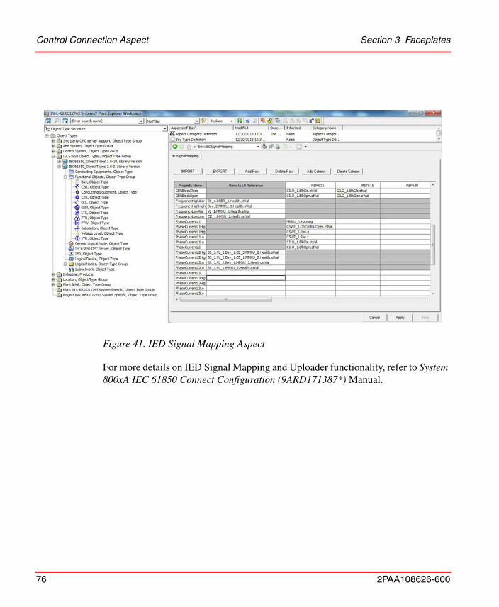
Figure 42 shows Control Connection Aspect - OPC Tab of the Bay Conducting Equipment object.
Figure 42. Control Structure - Bay Control Connection Aspect
Faceplates Localization Section 3 Faceplates
78 2PAA108626-600
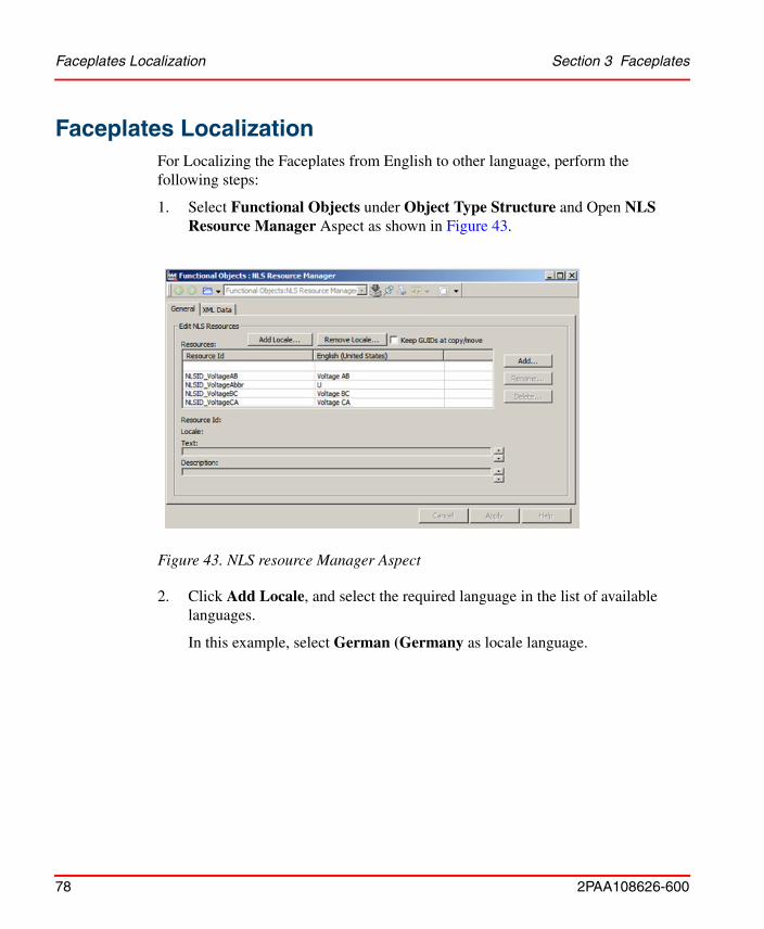
Faceplates LocalizationFor Localizing the Faceplates from English to other language, perform the following steps:
1. Select Functional Objects under Object Type Structure and Open NLS Resource Manager Aspect as shown in Figure 43.
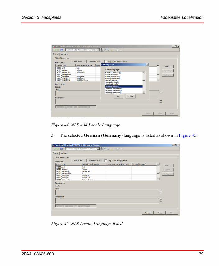
2. Click Add Locale, and select the required language in the list of available languages.
In this example, select German (Germany as locale language.
Figure 43. NLS resource Manager Aspect
Section 3 Faceplates Faceplates Localization
2PAA108626-600 79
3. The selected German (Germany) language is listed as shown in Figure 45.
Figure 44. NLS Add Locale Language
Figure 45. NLS Locale Language listed
Faceplates Localization Section 3 Faceplates
80 2PAA108626-600
4. The new column created for the language needs to be filled up with respective translated text for all NLS IDs to display those translated text in Faceplates instead of English language.
For changing the Windows Regional Settings, refer to Section 4 Regional Setting, Installation Guide (2PAA102031*).
English (United States) is added by default.
2PAA108626-600 81
Section 4 Re Configuration
This topic explains the re-configuration of Faceplates when additional changes are required by the Project. The steps are as follows:
• Create Child Library of IEC61850 Base Library
• Addition and Modification of Graphic Elements
• Customize faceplates as per requirement
• Configure NLS Resource manager to include new NLS IDs
Create New version of Base Library IEC61850 Object Types
Create a new version of all the Object Types of IEC61850 base Library and extension libraries and link these new extension libraries to the newly created base library version.
For more details, refer to System 800xA IEC 61850 Connect Configuration (9ARD171387*) Manual.
It is mandatory that the version number of instantiated IEC 61850 Object Type Library is not higher than the Feature version number specified in the License (*.sla) file for Feature IEC61850_FP_LIB.
Addition and Modification of Graphic Elements Section 4 Re Configuration
82 2PAA108626-600
Addition and Modification of Graphic ElementsThis section describes how to create and modify user defined faceplates and graphic elements containing only IEC 61850 data along with other connectivity data.
Faceplates and Graphic Elements Containing IEC 61850 Data
While creating faceplates or graphic elements for an object of existing default set of object types. Perform the following steps to create the faceplate/faceplate element/graphic element in the chosen object type:
While creating a faceplate for an object type that is not part of the default set of object types, create a new object type under the ‘Functional Objects’ folder. The new object type name and type name in SCD file must be the same.
Perform the following steps, to create/edit a faceplate for an object type:
1. Open the Plant Explorer.
2. Navigate to Library Structure > Libraries, Library Collection > IEC61850_ObjectTypes_GraphicsExtLib, Extension Library >
Only the users with application engineer rights can create faceplates and graphic elements.
Graphic elements and faceplates must be created only for Functional Structure object types.
Section 4 Re Configuration Faceplates and Graphic Elements Containing IEC 61850 Data
2PAA108626-600 83
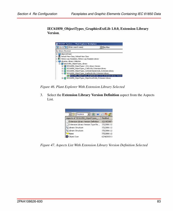
IEC61850_ObjectTypes_GraphicsExtLib 1.0.0, Extension Library Version.
3. Select the Extension Library Version Definition aspect from the Aspects List.
Figure 46. Plant Explorer With Extension Library Selected
Figure 47. Aspects List With Extension Library Version Definition Selected
Faceplates and Graphic Elements Containing IEC 61850 Data Section 4 Re Configuration
84 2PAA108626-600
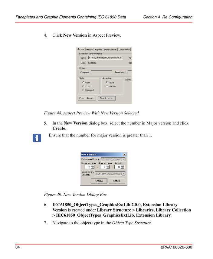
4. Click New Version in Aspect Preview.
5. In the New Version dialog box, select the number in Major version and click Create.
6. IEC61850_ObjectTypes_GraphicsExtLib 2.0-0, Extension Library Version is created under Library Structure > Libraries, Library Collection > IEC61850_ObjectTypes_GraphicsExtLib, Extension Library.
7. Navigate to the object type in the Object Type Structure.
Figure 48. Aspect Preview With New Version Selected
Ensure that the number for major version is greater than 1.
Figure 49. New Version Dialog Box
Section 4 Re Configuration Faceplates and Graphic Elements Containing Data from Other
2PAA108626-600 85
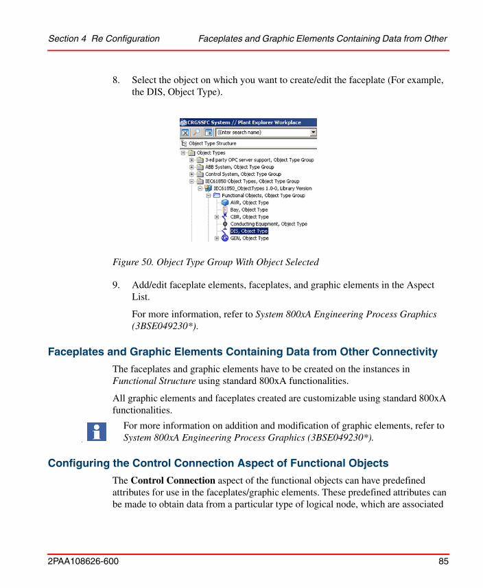
8. Select the object on which you want to create/edit the faceplate (For example, the DIS, Object Type).
9. Add/edit faceplate elements, faceplates, and graphic elements in the Aspect List.
For more information, refer to System 800xA Engineering Process Graphics (3BSE049230*).
Faceplates and Graphic Elements Containing Data from Other Connectivity
The faceplates and graphic elements have to be created on the instances in Functional Structure using standard 800xA functionalities.
All graphic elements and faceplates created are customizable using standard 800xA functionalities.
Configuring the Control Connection Aspect of Functional Objects
The Control Connection aspect of the functional objects can have predefined attributes for use in the faceplates/graphic elements. These predefined attributes can be made to obtain data from a particular type of logical node, which are associated
Figure 50. Object Type Group With Object Selected
F
For more information on addition and modification of graphic elements, refer to System 800xA Engineering Process Graphics (3BSE049230*).
Configuring the Control Connection Aspect of Functional Objects Section 4 Re Configuration
86 2PAA108626-600
with a functional object. For example, a functional object CBR can be associated with LNs XCBR and CILO. The predefined attribute in the CBR object can be configured to get data from XCBR logical node. This can be achieved by providing a name syntax for the predefined attribute of the functional object (CBR in the above example). The following is the syntax:
<LN name>_<instance number>.<attribute of the LN>.
Example
A predefined attribute in the Control Connection aspect of CBR Object Type can contain an attribute like ‘XCBR_1.BlkOpn.stVal’.
This means that the attribute ‘XCBR_1.BlkOpn.stVal’, refers to ‘Blkopn.stVal’ attribute of the first instance of the XCBR Logical Node (first instance under the functional object CBR).
During upload, the Uploader parses this syntax and puts the appropriate OPC Item ID for this attribute.
Use the above syntax to predefine the Control Connection aspect of the functional objects and use this predefined attribute in the faceplate element/graphic element.
Section 4 Re Configuration Configuring the Control Connection Aspect of Functional Objects
2PAA108626-600 87
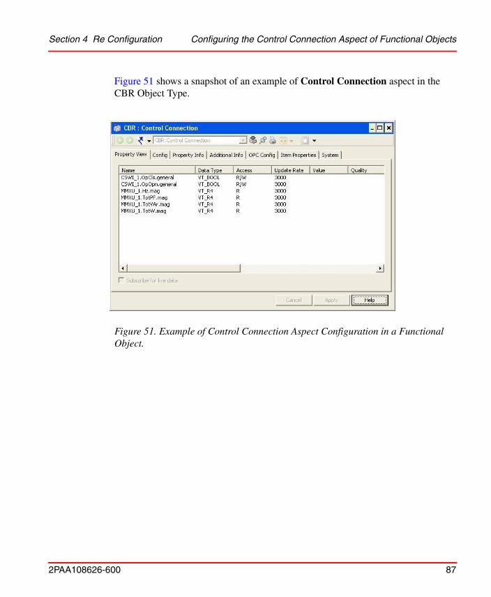
Figure 51 shows a snapshot of an example of Control Connection aspect in the CBR Object Type.
Figure 51. Example of Control Connection Aspect Configuration in a Functional Object.
Customize Faceplates Section 4 Re Configuration
88 2PAA108626-600
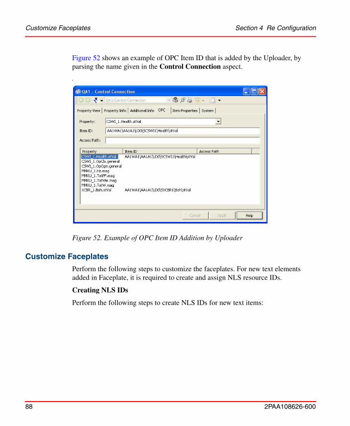
Figure 52 shows an example of OPC Item ID that is added by the Uploader, by parsing the name given in the Control Connection aspect.
Customize Faceplates
Perform the following steps to customize the faceplates. For new text elements added in Faceplate, it is required to create and assign NLS resource IDs.
Creating NLS IDs
Perform the following steps to create NLS IDs for new text items:
s
Figure 52. Example of OPC Item ID Addition by Uploader
Section 4 Re Configuration Customize Faceplates
2PAA108626-600 89
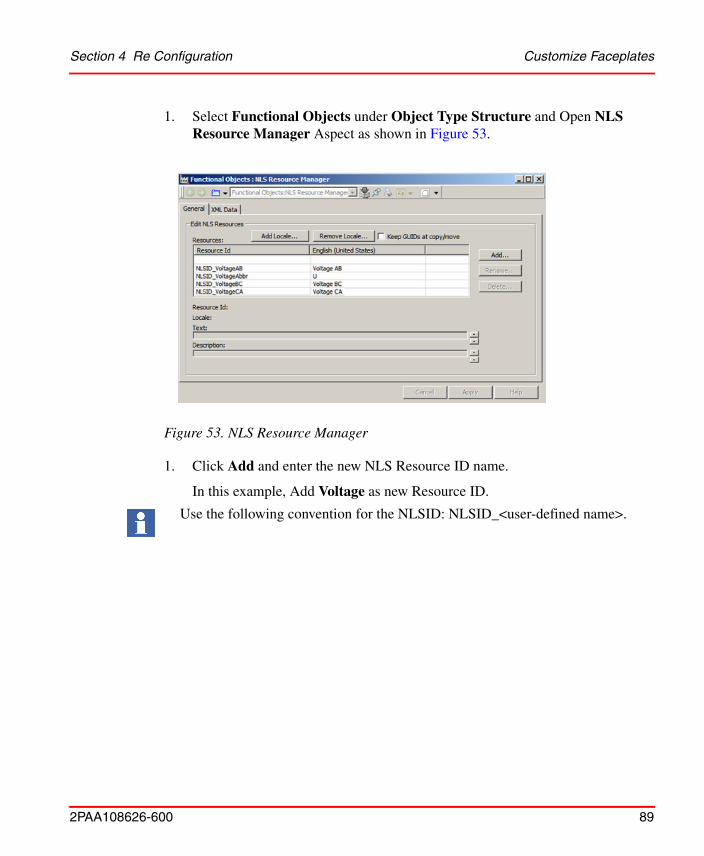
1. Select Functional Objects under Object Type Structure and Open NLS Resource Manager Aspect as shown in Figure 53.
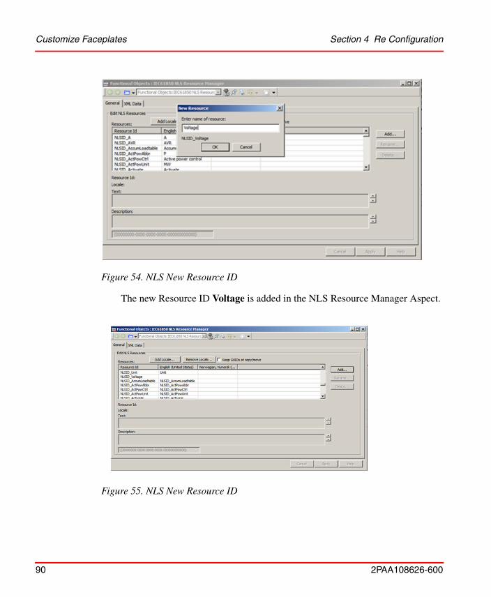
1. Click Add and enter the new NLS Resource ID name.
In this example, Add Voltage as new Resource ID.
Figure 53. NLS Resource Manager
Use the following convention for the NLSID: NLSID_<user-defined name>.
Customize Faceplates Section 4 Re Configuration
90 2PAA108626-600
The new Resource ID Voltage is added in the NLS Resource Manager Aspect.
Figure 54. NLS New Resource ID
Figure 55. NLS New Resource ID
Section 4 Re Configuration Customize Faceplates
2PAA108626-600 91
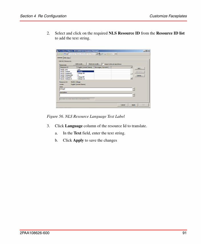
2. Select and click on the required NLS Resource ID from the Resource ID list to add the text string.
3. Click Language column of the resource Id to translate.
a. In the Text field, enter the text string.
b. Click Apply to save the changes
Figure 56. NLS Resource Language Text Label
Customize Faceplates Section 4 Re Configuration
92 2PAA108626-600
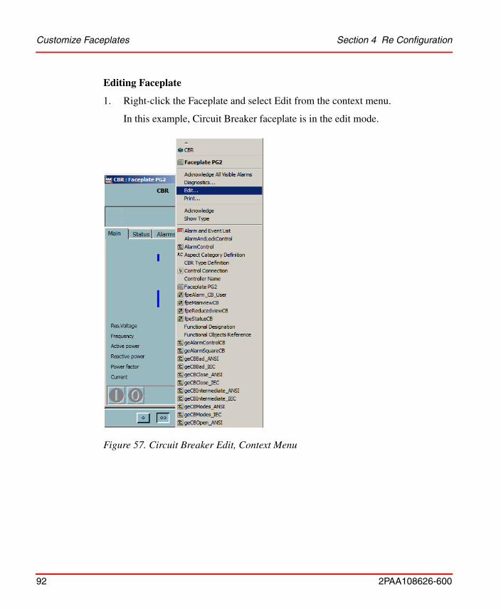
Editing Faceplate
1. Right-click the Faceplate and select Edit from the context menu.
In this example, Circuit Breaker faceplate is in the edit mode.
Figure 57. Circuit Breaker Edit, Context Menu
Section 4 Re Configuration Customize Faceplates
2PAA108626-600 93
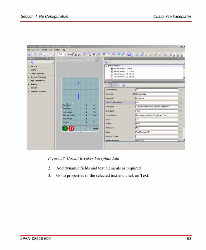
2. Add dynamic fields and text elements as required
3. Go to properties of the selected text and click on Text.
Figure 58. Circuit Breaker Faceplate Edit
Customize Faceplates Section 4 Re Configuration
94 2PAA108626-600
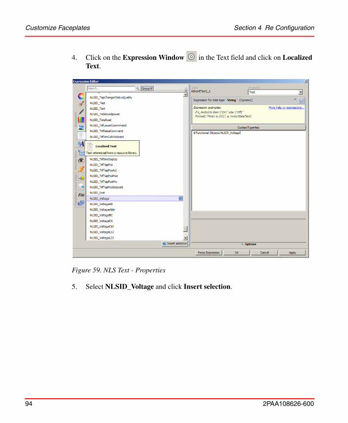
4. Click on the Expression Window in the Text field and click on Localized Text.
5. Select NLSID_Voltage and click Insert selection.
Figure 59. NLS Text - Properties
Section 4 Re Configuration Customize Faceplates
2PAA108626-600 95
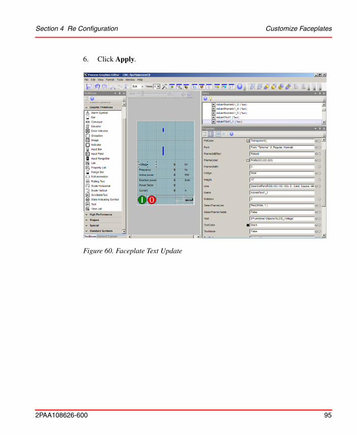
6. Click Apply.
Figure 60. Faceplate Text Update
Customize Faceplates Section 4 Re Configuration
96 2PAA108626-600
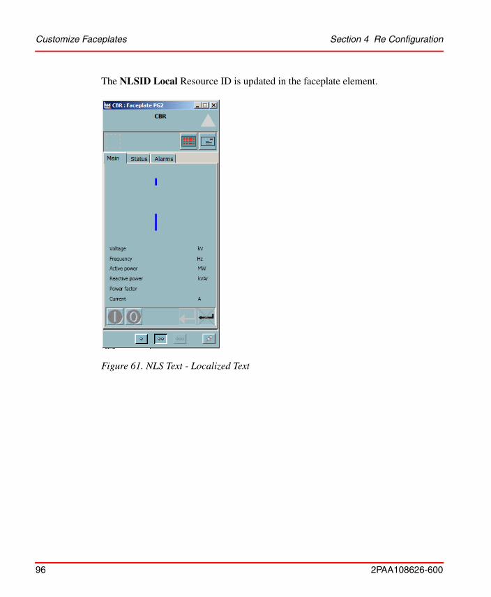
The NLSID Local Resource ID is updated in the faceplate element.
Figure 61. NLS Text - Localized Text
2PAA108626-600 97
BBay
Aspects 39Control Connection Aspect 40Faceplate 40Graphic Symbols 43
CCircuit Breaker
Aspects 45Control Connection Aspect 50Control Logic for Faceplate 47Faceplate 46Faceplate Button Logic
Apply Disabled 50Cancel Enabled 49Close Enabled 49Open Enabled 48
Graphic Symbols 52Configuring NLS Resource Manager Aspect 78Configuring the Control Connection Aspect 85Control Connection Aspect 75Current Transformer
Aspects 60Control Connection Aspect 62Faceplate 61Graphic Symbols 62
DDisconnector
Aspects 53Control Connection Aspect 57Faceplate 54Faceplate Button Logic
Apply Disabled 57
Cancel Enabled 56Close Enabled 56Open Enabled 55
Graphic Symbols 59
FFaceplate Icons 32Faceplates and Graphic Elements Containing Data
from Other Connectivity 85Faceplates and Graphic Elements Containing IEC
61850 Data 82
GGenerator
Aspects 69Control Connection Aspect 70Faceplate 70Graphic Symbols 71
IIED Signal Mapping
IED type 75Property Name 75Remote LN Reference 75
LLow Tap Change
Aspects 68
PPower Transformer
Aspects 63Control Connection Aspect 65Control Logic 64
Index
Index
2PAA108626-600 98
Faceplate 64Graphic Symbols 66
Power Transformer WindingAspects 67
Procedure for controlling CBR 47
SSubstation
Aspects 35Control Connection Aspect 36
VVoltage Level
Aspects 37Control Connection Aspect 38Graphic Element 37
Voltage TransformerAspects 72Control Connection Aspect 74Faceplate 73Graphic Symbols 74

Power and productivityfor a better worldTM
Contact us
Copyright© 2014 ABB.All rights reserved.
2PA
A10
8626
-600www.abb.com/800xA
www.abb.com/controlsystems