Embed Size (px)
Citation preview
FORM FDIS (IEC)/FORMULAIRE FDIS (CEI) 2007-08-09
17A/961/FDISFINAL DRAFT INTERNATIONAL STANDARD
PROJET FINAL DE NORME INTERNATIONALEProject number Numéro de projet
62271-103 Ed 1.0
IEC/TC or SC CEI/CE ou SC SC 17A
Secretariat / Secrétariat Sweden
Submitted for parallel voting in CENELEC Soumis au vote parallèle au CENELEC
Distributed on / Diffusé le 2011-02-18
Voting terminates on / Vote clos le 2011-04-22
Also of interest to the following committees Intéresse également les comités suivants
Supersedes document Remplace le document 17A/913A/CDV, 17A/944/RVC and item 6.2 of 17A/945/RM
Functions concerned Fonctions concernées
Safety Sécurité
EMC CEM
Environment Environnement
Quality assurance Assurance de la qualité
CE DOCUMENT EST UN PROJET DIFFUSÉ POUR APPROBATION. IL NE PEUT ÊTRE CITÉ COMME NORME INTERNATIONALE AVANT SA PUBLICATION EN TANT QUE TELLE.
OUTRE LE FAIT D'ÊTRE EXAMINÉS POUR ÉTABLIR S'ILS SONT ACCEPTABLES À DES FINS INDUSTRIELLES, TECHNOLOGIQUES ET COMMERCIALES, AINSI QUE DU POINT DE VUE DES UTILISATEURS, LES PROJETS FINAUX DE NORMES INTERNATIONALES DOIVENT PARFOIS ÊTRE EXAMINÉS EN VUE DE LEUR POSSIBILITÉ DE DEVENIR DES NORMES POUVANT SERVIR DE RÉFÉRENCE DANS LES RÈGLEMENTATIONS NATIONALES.
LES RÉCIPIENDAIRES DU PRÉSENT DOCUMENT SONT INVITÉS À PRÉSENTER, AVEC LEURS OBSERVATIONS, LA NOTIFICATION DES DROITS DE PROPRIÉTÉ DONT ILS AURAIENT ÉVENTUELLEMENT CONNAISSANCE ET À FOURNIR UNE DOCUMENTATION EXPLICATIVE.
THIS DOCUMENT IS A DRAFT DISTRIBUTED FOR APPROVAL. IT MAY NOT BE REFERRED TO AS AN INTERNATIONAL STANDARD UNTIL PUBLISHED AS SUCH.
IN ADDITION TO THEIR EVALUATION AS BEING ACCEPTABLE FOR INDUSTRIAL, TECHNOLOGICAL, COMMERCIAL AND USER PURPOSES, FINAL DRAFT INTERNATIONAL STANDARDS MAY ON OCCASION HAVE TO BE CONSIDERED IN THE LIGHT OF THEIR POTENTIAL TO BECOME STANDARDS TO WHICH REFERENCE MAY BE MADE IN NATIONAL REGULATIONS.
RECIPIENTS OF THIS DOCUMENT ARE INVITED TO SUBMIT, WITH THEIR COMMENTS, NOTIFICATION OF ANY RELEVANT PATENT RIGHTS OF WHICH THEY ARE AWARE AND TO PROVIDE SUPPORTING DOCUMENTATION.
Titre Appareillage à haute tension - Partie 103: Interrupteurs pour tensions assignées supérieures à 1 kV et inférieures ou égales à 52 kV
Title High-voltage switchgear and controlgear - Part 103: Switches for rated voltages above 1 kV up to and including 52 kV
ATTENTION VOTE PARALLÈLE
CEI – CENELEC L’attention des Comités nationaux de la CEI, membres du
CENELEC, est attirée sur le fait que ce projet finale de Norme internationale est soumis au vote parallèle.
Les membres du CENELEC sont invités à voter via le système de vote en ligne du CENELEC.
ATTENTION IEC – CENELEC
PARALLEL VOTING The attention of IEC National Committees, members of CENELEC, is drawn to the fact that this final draft International Standard (DIS)
is submitted for parallel voting. The CENELEC members are invited to vote through the
CENELEC online voting system.
Copyright © 2011 International Electrotechnical Commission, IEC. All rights reserved. It is permitted to download this electronic file, to make a copy and to print out the content for the sole purpose of preparing National Committee positions. You may not copy or "mirror" the file or printed version of the document, or any part of it, for any other purpose without permission in writing from IEC.
– 2 – 62271-103/FDIS IEC
CONTENTS
FOREWORD .................................................................................................................. 6 1 General ................................................................................................................... 8
1.1 Scope ............................................................................................................. 8 1.2 Normative references ....................................................................................... 8
2 Normal and special service conditions ........................................................................ 9 3 Terms and definitions ................................................................................................ 9
3.1 General terms .................................................................................................. 9 3.2 Assemblies of switchgear and controlgear .......................................................... 9 3.3 Parts of assemblies .......................................................................................... 9 3.4 Switching devices ............................................................................................ 9 3.5 Parts of switchgear and controlgear ................................................................. 11 3.6 Operation ...................................................................................................... 11 3.7 Characteristic quantities ................................................................................. 11 3.8 Index of definitions ......................................................................................... 13
4 Ratings .................................................................................................................. 14 4.1 Rated voltage (Ur) .......................................................................................... 14 4.2 Rated insulation level ..................................................................................... 15 4.3 Rated frequency (fr) ....................................................................................... 15 4.4 Rated normal current and temperature rise ....................................................... 15 4.5 Rated short-time withstand current (Ik) ............................................................. 15 4.6 Rated peak withstand current (Ip) .................................................................... 15 4.7 Rated duration of short-circuit (tk) .................................................................... 15 4.8 Rated supply voltage of closing and opening devices and of auxiliary and
control circuits (Ua) ........................................................................................ 15 4.9 Rated supply frequency of closing and opening devices and of auxiliary
circuits .......................................................................................................... 15 4.10 Rated pressure of compressed gas supply for controlled pressure systems .......... 15 4.11 Rated filling levels for insulation and/or operation .............................................. 15 4.101 Rated mainly active load-breaking current (Iload) .............................................. 15 4.102 Rated closed-loop breaking current (Iloop and Ipptr) ......................................... 16 4.103 Rated cable-charging breaking current (Icc) ...................................................... 16 4.104 Rated line-charging breaking current (Ilc) ......................................................... 16 4.105 Rated single capacitor bank breaking current for special purpose switches
(Isb) ............................................................................................................. 16 4.106 Rated back-to-back capacitor bank breaking current for special purpose
switches (Ibb) ................................................................................................ 16 4.107 Rated back-to-back capacitor bank inrush making current for special purpose
switches (Iin) ................................................................................................. 16 4.108 Rated earth fault breaking current (Ief1) ........................................................... 16 4.109 Rated cable- and line-charging breaking current under earth fault conditions
(Ief2) ............................................................................................................ 17 4.110 Rated motor breaking current for special purpose switches (Imot) ....................... 17 4.111 Rated short-circuit making current (Ima) ........................................................... 17 4.112 Rated breaking and making currents for a general purpose switch ...................... 17 4.113 Ratings for limited purpose switches ................................................................ 18 4.114 Ratings for special purpose switches................................................................ 18 4.115 Ratings for switches backed by fuses ............................................................... 18
62271-103/FDIS IEC – 3 –
4.116 Type and classes for general purpose, limited purpose and special purpose switches ........................................................................................................ 18
5 Design and construction .......................................................................................... 19 5.1 Requirements for liquids in switchgear and controlgear ...................................... 19 5.2 Requirements for gases in switchgear and controlgear ....................................... 19 5.3 Earthing of switchgear and controlgear ............................................................. 19 5.4 Auxiliary and control equipment ....................................................................... 19 5.5 Dependent power operation ............................................................................ 19 5.6 Stored energy operation ................................................................................. 19 5.7 Independent manual or power operation (independent unlatched operation) ......... 19 5.8 Operation of releases ..................................................................................... 19 5.9 Low- and high-pressure interlocking and monitoring devices ............................... 19 5.10 Nameplates ................................................................................................... 19 5.11 Interlocking devices ........................................................................................ 21 5.12 Position indication .......................................................................................... 21 5.13 Degrees of protection provided by enclosures ................................................... 21 5.14 Creepage distances for outdoor insulators ........................................................ 21 5.15 Gas and vacuum tightness .............................................................................. 21 5.16 Liquid tightness.............................................................................................. 21 5.17 Fire hazard (flammability) ............................................................................... 22 5.18 Electromagnetic compatibility (EMC) ................................................................ 22 5.19 X-ray emission ............................................................................................... 22 5.20 Corrosion ...................................................................................................... 22 5.101 Making and breaking operations ...................................................................... 22 5.102 Requirements for switch-disconnectors ............................................................ 22 5.103 Mechanical strength ....................................................................................... 22 5.104 Securing the position ...................................................................................... 22 5.105 Auxiliary contacts for signalling ....................................................................... 22 5.106 No-load transformer breaking .......................................................................... 23
6 Type tests .............................................................................................................. 23 6.1 General ......................................................................................................... 23
6.1.1 Grouping of tests ................................................................................ 23 6.1.2 Information for identification of specimens ............................................. 24 6.1.3 Information to be included in the type-test reports .................................. 24
6.2 Dielectric tests ............................................................................................... 24 6.3 Radio interference voltage (r.i.v.) test............................................................... 24 6.4 Measurement of the resistance of circuits ......................................................... 24 6.5 Temperature-rise tests.................................................................................... 24 6.6 Short-time withstand current and peak withstand current tests ............................ 24 6.7 Verification of the protection ............................................................................ 25 6.8 Tightness tests .............................................................................................. 25 6.9 Electromagnetic compatibility (EMC) tests ........................................................ 25 6.10 Additional tests on auxiliary and control circuits ................................................ 25
6.10.1 General .............................................................................................. 25 6.10.2 Functional tests .................................................................................. 25 6.10.3 Electrical continuity of earthed metallic parts test ................................... 25 6.10.4 Verification of the operational characteristics of auxiliary contacts ............ 25 6.10.5 Environmental tests ............................................................................. 25 6.10.6 Dielectric test...................................................................................... 25
– 4 – 62271-103/FDIS IEC
6.11 X-radiation test procedure for vacuum interrupters ............................................ 25 6.101 Making and breaking tests .............................................................................. 26
6.101.1 Test duties for general purpose switches ............................................... 26 6.101.2 Test duties for limited purpose switches ................................................ 28 6.101.3 Test duties for special purpose switches ................................................ 28 6.101.4 Arrangement of the switch for tests ....................................................... 30 6.101.5 Earthing of test circuit and switch.......................................................... 30 6.101.6 Test parameters .................................................................................. 31 6.101.7 Test circuits ........................................................................................ 33 6.101.8 Behaviour of switch during breaking tests .............................................. 46 6.101.9 Condition of switch after breaking tests and short-circuit making tests ...... 47 6.101.10 Type-test reports ................................................................... 48
6.102 Mechanical and environmental tests ................................................................. 49 6.102.1 Miscellaneous provisions for mechanical and environmental tests ............ 49 6.102.2 Mechanical operation test at ambient air temperature ............................. 51 6.102.3 Low and high temperature tests ............................................................ 52 6.102.5 Operation under severe ice conditions ................................................... 58 6.102.6 Tests to verify the proper functioning of the position indicating device ...... 58
7 Routine tests .......................................................................................................... 59 7.101 Mechanical operating tests .............................................................................. 59
8 Guide to the selection of switchgear and controlgear .................................................. 60 8.101 General ......................................................................................................... 60 8.102 Conditions affecting application ....................................................................... 60 8.103 Insulation coordination .................................................................................... 60 8.104 Selection of class of switch ............................................................................. 60
8.104.1 General purpose switch ....................................................................... 60 8.104.2 Limited purpose switch ........................................................................ 61 8.104.3 Special purpose switch ........................................................................ 61
8.105 Tests for special applications .......................................................................... 61 9 Information to be given with inquiries, tenders and orders ........................................... 61
9.1 Information to be given with inquiries and orders ............................................... 61 9.2 Information to be given with tenders ................................................................. 62
10 Transport, storage, installation, operation and maintenance ........................................ 63 11 Safety ................................................................................................................... 63 12 Influence of the product on the environment .............................................................. 63 Annex A (normative) Tolerances on test quantities for type tests ...................................... 64 Bibliography ................................................................................................................. 66 Figure 1 – Three-phase test circuit for mainly active load current switching for test duty TDload ................................................................................................................. 34 Figure 2 – Single-phase test circuit for mainly active load current switching for test duty TDload ................................................................................................................. 35 Figure 3 – Three-phase test circuit for distribution line closed-loop and parallel transformer current switching test for test duties TDloop and TDpptr .................................. 37 Figure 4 – Single-phase test circuit for distribution line closed-loop and parallel transformer current switching test, for test duties TDloop and TDpptr ................................. 38 Figure 5 – General test circuit for three- and single-phase capacitive switching tests........... 42 Figure 6 – Prospective TRV parameter limits for capacitor bank current breaking tests ........ 44
62271-103/FDIS IEC – 5 –
Figure 7 – Three-phase test circuit for earth fault breaking current tests, for test duty TDef1 .......................................................................................................................... 45 Figure 8 – Three-phase test circuit for cable-charging breaking current tests under earth fault conditions, for test duty TDef2 ........................................................................ 45 Figure 9 – Three-phase test circuit for short-circuit making current test for test duty TDma .......................................................................................................................... 46 Figure 10 – Single-phase test circuit for short-circuit making current test for test duty TDma .......................................................................................................................... 46 Figure 11 – Test sequences for low and high temperature tests......................................... 53 Figure 12 – Humidity test .............................................................................................. 57 Table 1 – Preferred values of rated line- and cable-charging breaking currents for general purpose switch ................................................................................................. 17 Table 2 – Product information ........................................................................................ 20 Table 3 – Test duties for general purpose switches – Test duties for three-phase tests on three-pole operated, switches................................................................................... 26 Table 4 – Test duties for general purpose switches – Single phase tests on three-pole switches operated pole-after-pole and single-pole switches applied on three-phase systems ....................................................................................................................... 27 Table 5 – Test duties for special purpose switches – Three-phase tests on three-pole operated, switches........................................................................................................ 29 Table 6 – Test duties for special purpose switches – Single phase tests on three-pole switches operated pole-after-pole and single-pole switches applied on three-phase systems ....................................................................................................................... 29 Table 7 – Supply circuit TRV parameters for mainly active load current breaking testsa ....... 36 Table 8 – TRV parameters for distribution line closed loop breaking tests........................... 38 Table 9 – TRV parameters for parallel power transformer current breaking tests ................. 39 Table 10 – Prospective recovery voltage parameter limits for capacitor bank current breaking tests .............................................................................................................. 43 Table A.1 – Tolerances on test quantities for type tests .................................................... 64
– 6 – 62271-103/FDIS IEC
INTERNATIONAL ELECTROTECHNICAL COMMISSION ____________
HIGH-VOLTAGE SWITCHGEAR AND CONTROLGEAR –
Part 103: Switches for rated voltages above 1 kV
up to and including 52 kV
FOREWORD
1) The International Electrotechnical Commission (IEC) is a worldwide organization for standardization comprising all national electrotechnical committees (IEC National Committees). The object of IEC is to promote international co-operation on all questions concerning standardization in the electrical and electronic f ields. To this end and in addition to other activities, IEC publishes International Standards, Technical Specif ications, Technical Reports, Publicly Available Specif ications (PAS) and Guides (hereafter referred to as “IEC Publication(s)”). Their preparation is entrusted to technical committees; any IEC National Committee interested in the subject dealt with may participate in this preparatory work. International, governmental and non-governmental organizations liaising with the IEC also participate in this preparation. IEC collaborates closely with the International Organization for Standardization (ISO) in accordance with conditions determined by agreement between the two organizations.
2) The formal decisions or agreements of IEC on technical matters express, as nearly as possible, an international consensus of opinion on the relevant subjects since each technical committee has representation from all interested IEC National Committees.
3) IEC Publications have the form of recommendations for international use and are accepted by IEC National Committees in that sense. W hile all reasonable efforts are made to ensure that the technical content of IEC Publications is accurate, IEC cannot be held responsible for the way in which they are used or for any misinterpretation by any end user.
4) In order to promote international uniformity, IEC National Committees undertake to apply IEC Publications transparently to the maximum extent possible in their national and regional publications. Any divergence between any IEC Publication and the corresponding national or regional publication shall be clearly indicated in the latter.
5) IEC itself does not provide any attestation of conformity. Independent certif ication bodies provide conformity assessment services and, in some areas, access to IEC marks of conformity. IEC is not responsible for any services carried out by independent certif ication bodies.
6) All users should ensure that they have the latest edition of this publication.
7) No liabil ity shall attach to IEC or its directors, employees, servants or agents including individual experts and members of its technical committees and IEC National Committees for any personal injury, property damage or other damage of any nature whatsoever, whether direct or indirect, or for costs (including legal fees) and expenses arising out of the publication, use of, or reliance upon, this IEC Publication or any other IEC Publications.
8) Attention is drawn to the Normative references cited in this publication. Use of the referenced publications is indispensable for the correct application of this publication.
9) Attention is drawn to the possibility that some of the elements of this IEC Publication may be the subject of patent rights. IEC shall not be held responsible for identifying any or all such patent rights.
International Standard IEC 62271-103 has been prepared by subcommittee 17A: High-voltage switchgear and controlgear, of IEC technical committee 17: Switchgear and controlgear.
This standard cancels and replaces the third edition of IEC 60265-1, published in 1998. It constitutes a technical revision.
This edition includes the following significant technical changes with respect to IEC 60265-1:1998:
– the rated voltage of 52 kV is now included; – the document is aligned with IEC 62271-1 and IEC 62271-100; – addition of a test procedure for short-circuit making tests; – introduction of notion of NSDD (non-sustained disruptive discharge) as defined in
IEC 62271-1 and restrikes; – new classes C1 and C2 for capacitive switching;
62271-103/FDIS IEC – 7 –
– new Annex A defining tolerances.
The text of this standard is based on the following documents:
FDIS Report on voting
17A/XX/FDIS 17A/XX/RVD
Full information on the voting for the approval of this standard can be found in the report on voting indicated in the above table.
This publication has been drafted in accordance with the ISO/IEC Directives, Part 2.
This standard is to be read in conjunction with IEC 62271-1:2007, to which it refers and which is applicable unless otherwise specified in this standard. In order to simplify the indication of corresponding requirements, the same numbering of clauses and subclauses is used as in IEC 62271-1. Amendments to these clauses and subclauses are given under the same references whilst additional subclauses are numbered from 101.
The list of all parts of the IEC 62271 series under the general title, High-voltage switchgear and controlgear, can be found on the IEC website.
The committee has decided that the contents of this publication will remain unchanged until the stability date indicated on the IEC web site under "http://webstore.iec.ch" in the data related to the specific publication. At this date, the publication will be
• reconfirmed, • withdrawn, • replaced by a revised edition, or • amended.
The National Committees are requested to note that for this publication the stability date is 2016.
THIS TEXT IS INCLUDED FOR THE INFORMATION OF THE NATIONAL COMMITTEES AND WILL BE DELETED AT THE PUBLICATION STAGE.
– 8 – 62271-103/FDIS IEC
HIGH-VOLTAGE SWITCHGEAR AND CONTROLGEAR –
Part 103: Switches for rated voltages above 1 kV up to and including 52 kV
1 General
1.1 Scope
This part of IEC 62271 is applicable to three-phase, alternating current switches and switch-disconnectors for their switching function, having making and breaking current ratings, for indoor and outdoor installations, for rated voltages above 1 kV up to and including 52 kV and for rated frequencies from 162/3 Hz up to and including 60 Hz. This standard is also applicable to single-pole switches used on three phase systems.
This standard is also applicable to the operating devices of these switches and to their auxiliary equipment.
Switch-disconnectors are also covered by IEC 62271-102 for their disconnecting function.
Devices that require a dependent manual closing operation are not covered by this standard.
General principles and provisions of this standard may also be applicable to single pole switches intended for application in single-phase systems. The requirements for dielectric tests and making and breaking tests should be in accordance with the requirements of the specific application.
This standard establishes requirements for general, limited and special purpose switches used in distribution systems.
It is assumed that opening and closing operations are performed according to the manufacturer's instructions. A making operation may immediately follow a breaking operation but a breaking operation should not immediately follow a making operation since the current to be broken may then exceed the rated breaking current of the switch.
NOTE 1 Except where special clarif ication is required, the term “switch” is used to refer to all kinds of switches and switch-disconnectors within the scope of this standard.
NOTE 2 Earthing switches are not covered by this standard. Earthing switches forming an integral part of a switch are covered by IEC 62271-102.
NOTE 3 This standard is not applicable to switching devices attached as an accessory to a high-voltage fuse assembly or its mounting and operated by opening and closing the fuse assembly.
1.2 Normative references
The following referenced documents are indispensable for the application of this document. For dated references, only the edition cited applies. For undated references, the latest edition of the referenced document (including any amendments) applies.
IEC 60050-441:1984, International Electrotechnical Vocabulary (IEV) – Chapter 441: Switchgear, controlgear and fuses
IEC 60529:1989, Degrees of protection provided by enclosures (IP Code)
IEC 62271-1:2007, High-voltage switchgear and controlgear – Part 1: Common specifications
62271-103/FDIS IEC – 9 –
IEC 62271-100:2008, High-voltage switchgear and controlgear – Part 100: Alternating-current circuit-breakers
IEC 62271-102:2001, High-voltage switchgear and controlgear – Part 102: Alternating current disconnectors and earthing switches
IEC 62271-110:2009, High-voltage switchgear and controlgear – Part 110: Inductive load switching
2 Normal and special service conditions
Clause 2 of IEC 62271-1 is applicable.
3 Terms and definitions
For the purposes of this document, the terms and definitions given in IEC 60050-441 and IEC 62271-1, as well as the following apply.
NOTE 1 Some terms and definitions are recalled hereunder for easier use or for the necessity of some precision or adaptation for the interpretation of this standard.
NOTE 2 The terms and definitions given below are classif ied in accordance with IEC 60050-441. The additional terms and definitions are classif ied so as to be aligned with the classif ication used in IEC 60050-441.
3.1 General terms
Subclause 3.1 of IEC 62271-1 is applicable with the following additions.
3.1.101 effectively earthed neutral system system earthed through a sufficiently low impedance such that for all system conditions the ratio of the zero-sequence reactance to the positive-sequence reactance (X0/X1) is positive and less than 3, and the ratio of the zero-sequence resistance to the positive-sequence reactance (R0/X1) is positive and less than 1. Normally such systems are solidly earthed (neutral) systems or low impedance earthed (neutral) systems
NOTE For the correct assessment of the earthing conditions not only the physical earthing conditions around the relevant location but the total system is to be considered.
3.1.102 non-effectively earthed neutral system system other than effectively earthed neutral system, not meeting the conditions given in 3.1.101. Normally such systems are isolated neutral systems, high impedance earthed (neutral) systems or resonant earthed (neutral) systems
NOTE For the correct assessment of the earthing conditions not only the physical earthing conditions around the relevant location but the total system is to be considered.
3.2 Assemblies of switchgear and controlgear
Subclause 3.2 of IEC 62271-1 applies.
3.3 Parts of assemblies
Subclause 3.3 of IEC 62271-1 applies.
3.4 Switching devices
Subclause 3.4 of IEC 62271-1 applies with the following addition.
– 10 – 62271-103/FDIS IEC
3.4.101 switch switching device capable of making, carrying and breaking currents under normal circuit conditions, which may include specified operating overload conditions and also carrying for a specified time currents under specified abnormal circuit conditions, such as those of a short-circuit
[IEC 60050-441:1984, 441-14-10, modified]
3.4.102 switch-disconnector switch which, in the open position, satisfies the isolating requirements specified for a disconnector
[IEC 60050-441:1984, 441-14-12]
3.4.103 general purpose switch switch capable of performing, with currents up to its rated breaking currents, all making and breaking operations which may normally occur in distribution systems. The switch is also capable of carrying and making short-circuit currents
3.4.103.1 class E1 general purpose switch general purpose switch capable of performing a basic electrical endurance of load breaking currents and short-circuit makings
NOTE This class is typically adequate for applications where infrequent switching operations are performed or where appropriate inspection and replacement of switching parts is permissible.
3.4.103.2 class E2 general purpose switch general purpose switch capable of performing a medium electrical endurance of lo ad breaking currents and short-circuit makings
NOTE This class is typically adequate for applications where infrequent switching operations are performed but where inspection and replacement of switching parts is not permissible or possible.
3.4.103.3 class E3 general purpose switch general purpose switch capable of performing a high electrical endurance of load breaking currents and short-circuit makings
NOTE This class is typically adequate for applications where frequent switching operations are performed and inspection and replacement of switching parts is not permissible or possible.
3.4.103.4 class M1 switch switch suitable for applications requiring a mechanical endurance of 1 000 operations
3.4.103.5 class M2 switch switch suitable for special service applications and for frequent operation having an extended mechanical endurance of 5 000 operations
3.4.103.6 class C1 switch switch with capability of capacitive current breaking as demonstrated by specific type tests (test duties Icc, Ilc, Isb and Ibb)
3.4.103.7 class C2 switch switch with very low probability of restrike during capacitive current breaking as demonstrated by specific type tests (test duties Icc, Ilc, Isb and Ibb)
62271-103/FDIS IEC – 11 –
3.4.104 limited purpose switch switch which has a rated normal current, a rated short-time withstand current, and one or more but not all switching capabilities of a general purpose switch
3.4.105 special purpose switch general purpose switch or limited purpose switch suitable for one or more of the following applications:
– switching single capacitor banks; – switching back-to-back capacitor banks; – switching of closed-loop circuits consisting of large power transformers in parallel; – switching of motors under steady-state and stalled conditions 3.4.105.1 single capacitor bank switch special purpose switch intended for switching of a single capacitor bank with charging currents up to its rated single capacitor bank breaking current
3.4.105.2 back-to-back capacitor bank switch special purpose switch intended for breaking capacitor bank charging currents with one or more capacitor banks connected to the supply side of the switch up to its rated back-to-back capacitor bank breaking current. The switch is capable of making the associated inrush current up to its rated capacitor bank inrush making current
3.4.105.3 motor switch special purpose switch intended for switching of motors under steady-state and stalled conditions
3.4.105.4 parallel power transformer closed-loop switch special purpose switch intended for switching a closed-loop circuit consisting of large power transformers in parallel
NOTE The switch is typically applied as a medium voltage tie switch on the transformer secondary circuit such that the breaking current is high and the transient recovery voltage (TRV) conditions are severe
3.5 Parts of switchgear and controlgear
Subclause 3.5 of IEC 62271-1 applies.
3.6 Operation
Subclause 3.6 of IEC 62271-1 applies.
3.7 Characteristic quantities
Subclause 3.7 of IEC 62271-1 applies with the following addition.
3.7.101 breaking capacity value of prospective current that a switching device or a fuse is capable of breaking at a stated voltage under prescribed conditions of use and behaviour
NOTE 1 The voltage to be stated and the conditions to be prescribed are dealt with in the relevant publications.
NOTE 2 For switching devices, the breaking capacity may be termed according to the kind of current included in the prescribed conditions, e.g. line-charging breaking capacity, cable charging breaking capacity, single capacitor bank breaking capacity, etc.
– 12 – 62271-103/FDIS IEC
[IEC 60050-441:1984, 441-17-08, modified]
3.7.102 mainly active load-breaking capacity breaking capacity when opening a mainly active load circuit, the power factor of which is at least 0,75, in which the load can be represented by resistors and reactors in parallel
3.7.103 no-load transformer breaking capacity breaking capacity when opening a transformer circuit under no-load conditions
3.7.104 closed-loop breaking capacity breaking capacity when opening a closed-loop distribution line circuit, or a power transformer in parallel with one or more power transformers, i.e., a circuit in which both sides of the switch remain energized after breaking
3.7.105 cable-charging breaking capacity breaking capacity when opening a cable circuit under no-load conditions
3.7.106 line-charging breaking capacity breaking capacity when opening an overhead line circuit under no-load conditions
3.7.107 single capacitor bank breaking capacity breaking capacity when opening a single capacitor bank circuit connected to a supply that does not include another capacitor bank adjacent to the bank being switched
3.7.108 back-to-back capacitor bank breaking capacity breaking capacity when opening a capacitor bank circuit connected to a supply that includes one or more capacitor banks adjacent to the bank being switched
3.7.109 back-to-back capacitor bank inrush making current high-frequency and high-magnitude current occurring when closing a capacitor bank circuit onto a supply including one or more capacitor banks adjacent to the bank being switched
3.7.110 motor breaking capacity breaking capacity when opening a motor under steady-state and stalled conditions
3.7.111 earth fault breaking capacity breaking capacity in the faulty phase of a non-effectively earthed neutral system when clearing an earth fault on an unloaded cable or overhead line on the load side of the switch
3.7.112 cable- and line-charging breaking capacity under earth fault conditions breaking capacity in the sound phases of a non-effectively earthed neutral system when switching off an unloaded cable or overhead line, with an earth fault on the supply side of the switch
62271-103/FDIS IEC – 13 –
3.7.113 breaking current current in a pole of a switching device or in a fuse at the instant of initiation of the arc during a breaking process
[IEC 60050-441:1984, 441-17-07]
3.7.114 (peak) making current peak value of the first major loop of the current in a pole of a switch during the transient period following the initiation of current during a making operation
NOTE 1 Peak value may differ from one pole to another and from one operation to another as it depends on the instant of current initiation relative to the wave of the applied voltage.
NOTE 2 Where, for a three-phase circuit, a single value of (peak) making current is referred to, it is, unless otherwise stated, the highest value in any phase.
3.7.115 short-circuit making capacity making capacity for which the prescribed conditions include a short circuit at the terminals of the switching device
[IEC 60050-441:1984, 441-17-10]
3.7.116 restrike performance expected probability of restrike during capacitive current interruption as demonstrated by specified type tests
NOTE Specif ic numeric probabilities cannot be applied throughout a switch service life.
3.7.117 re-ignition (of an a.c. mechanical switching device) resumption of current between the contacts of a mechanical switching device during a breaking operation with an interval of zero current of less than a quarter cycle of power frequency
[IEC 60050-441:1984, 441-17-45]
3.7.118 restrike (of an a.c. mechanical switching device) resumption of power frequency current, or in the case of capacitive current interruption a resumption of current in the main load circuit, between the contacts of a mechanical switching device during a breaking operation with an interval of zero current of a quarter cycle of power frequency or longer
[IEC 60050-441:1984, 441-17-46, modified]
3.8 Index of definitions
B Back-to-back capacitor bank breaking capacity 3.7.108 Back-to-back capacitor bank inrush making current 3.7.109 Back-to-back capacitor bank switch 3.4.105.2 Breaking capacity 3.7.101 Breaking current 3.7.113
C Cable- and line-charging breaking capacity under earth fault conditions 3.7.112
– 14 – 62271-103/FDIS IEC
Cable-charging breaking capacity 3.7.105 Class C1 switch 3.4.103.6 Class C2 switch 3.4.103.7 Class E1 general purpose switch 3.4.103.1 Class E2 general purpose switch 3.4.103.2 Class E3 general purpose switch 3.4.103.3 Class M1 switch 3.4.103.4 Class M2 switch 3.4.103.5 Closed-loop breaking capacity 3.7.104
E Earth fault breaking capacity 3.7.111 Effectively earthed neutral system 3.1.101
G General purpose switch 3.4.103
L Limited purpose switch 3.4.104 Line-charging breaking capacity 3.7.106
M Mainly active load-breaking capacity 3.7.102 Motor breaking capacity 3.7.110 Motor switch 3.4.105.3
N No-load transformer breaking capacity 3.7.103 Non-effectively earthed neutral system 3.1.102
P Parallel power transformer closed-loop switch 3.4.105.4 (Peak) making current 3.7.114
R Re-ignition (of an a.c. mechanical switching device) 3.7.117 Restrike (of an a.c. mechanical switching device) 3.7.118 Restrike performance 3.7.116
S Short-circuit making capacity 3.7.115 Single capacitor bank breaking capacity 3.7.107 Single capacitor bank switch 3.4.105.1 Special purpose switch 3.4.105 Switch 3.4.101 Switch-disconnector 3.4.102
4 Ratings
Clause 4 of IEC 62271-1 is applicable with the additions and exceptions indicated below.
4.1 Rated voltage (Ur)
Subclause 4.1 of IEC 62271-1 is applicable.
62271-103/FDIS IEC – 15 –
4.2 Rated insulation level
Subclause 4.2 of IEC 62271-1 is applicable.
4.3 Rated frequency (fr)
Subclause 4.3 of IEC 62271-1 is applicable.
4.4 Rated normal current and temperature rise
Subclause 4.4 of IEC 62271-1 is applicable.
4.5 Rated short-time withstand current (Ik)
Subclause 4.5 of IEC 62271-1 is applicable.
4.6 Rated peak withstand current (Ip)
Subclause 4.6 of IEC 62271-1 is applicable.
4.7 Rated duration of short-circuit (tk)
Subclause 4.7 of IEC 62271-1 is applicable.
4.8 Rated supply voltage of closing and opening devices and of auxiliary and control circuits (Ua)
Subclause 4.8 of IEC 62271-1 is applicable.
4.9 Rated supply frequency of closing and opening devices and of auxiliary circuits
Subclause 4.9 of IEC 62271-1 is applicable.
4.10 Rated pressure of compressed gas supply for controlled pressure systems
Subclause 4.10 of IEC 62271-1 is applicable with the following addition.
This rating applies only to power sources of operating devices.
NOTE Controlled pressure systems for insulation or switching are no longer manufactured up to 52 kV level. Therefore only gas supply for operating devices is considered.
4.11 Rated filling levels for insulation and/or operation
Subclause 4.11 of IEC 62271-1 is applicable with the following additions.
4.11.101 Rated filling levels for insulation and/or switching
This rating applies for any kind of liquid or gas used for insulation or switching.
4.11.102 Rated filling levels for operation
This rating applies for any kind of liquid or gas used as power source for the operating device.
4.101 Rated mainly active load-breaking current (Iload)
The rated mainly active load-breaking current is the maximum mainly active load current that the switch shall be capable of breaking at its rated voltage. Its value shall be equal to the rated normal current if no other value is indicated on the nameplate.
– 16 – 62271-103/FDIS IEC
4.102 Rated closed-loop breaking current (Iloop and Ipptr)
The rated closed-loop breaking current is the maximum closed-loop current the switch shall be capable of breaking. Separate ratings for distribution line loop breaking current and parallel power transformer breaking current may be assigned.
4.103 Rated cable-charging breaking current (Icc)
The rated cable-charging breaking current is the maximum cable-charging current that the switch shall be capable of breaking at its rated voltage.
4.104 Rated line-charging breaking current (Ilc)
The rated line-charging breaking current is the maximum line-charging current that the switch shall be capable of breaking at its rated voltage.
4.105 Rated single capacitor bank breaking current for special purpose switches (Isb)
The rated single capacitor bank breaking current is the maximum capacitor bank current that a special purpose switch shall be capable of breaking at its rated voltage with no capacitor bank connected to the supply side of the switch adjacent to the bank being switched.
4.106 Rated back-to-back capacitor bank breaking current for special purpose switches (Ibb)
The rated back-to-back capacitor bank breaking current is the maximum capacitor bank current that a special purpose switch shall be capable of breaking at its rated voltage with one or more capacitor banks connected on the supply side of the switch adjacent to the bank being switched.
4.107 Rated back-to-back capacitor bank inrush making current for special purpose switches (Iin)
The rated back-to-back capacitor bank inrush making current is the peak value of the current that a special purpose switch shall be capable of making at its rated voltage and with a frequency of the inrush current appropriate to the service conditions.
The assignment of a rated back-to-back capacitor bank inrush making current is mandatory for switches that have a rated back-to-back capacitor bank breaking current.
NOTE The frequency of the inrush current for back-to-back capacitor banks may be in the range of 2 kHz to 30 kHz. The frequency and magnitude of the inrush current are dependent upon the size and configuration of the capacitor bank being switched, the capacitor bank already connected to the supply side of the switch and the inclusion of limiting impedances, if any.
The switch is not necessarily rated to break the inrush making current produced by the back-to-back capacitor bank installation.
4.108 Rated earth fault breaking current (Ief1)
The rated earth fault breaking current is the maximum earth fault current in the faulted phase that the switch shall be capable of breaking at its rated voltage, when used on a non-effectively earthed neutral system.
NOTE The maximum earth fault breaking current is 3 times the cable- and line-charging current occurring in normal conditions. This covers the most severe case, which occurs with individually screened cables.
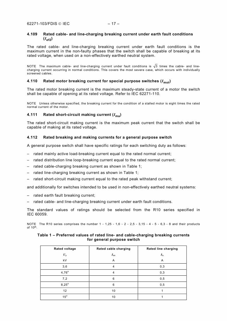
62271-103/FDIS IEC – 17 –
4.109 Rated cable- and line-charging breaking current under earth fault conditions (Ief2)
The rated cable- and line-charging breaking current under earth fault conditions is the maximum current in the non-faulty phases that the switch shall be capable of breaking at its rated voltage, when used on a non-effectively earthed neutral system.
NOTE The maximum cable- and line-charging current under fault conditions is 3 times the cable- and line-charging current occurring in normal conditions. This covers the most severe case, which occurs with individually screened cables.
4.110 Rated motor breaking current for special purpose switches (Imot)
The rated motor breaking current is the maximum steady-state current of a motor the switch shall be capable of opening at its rated voltage. Refer to IEC 62271-110.
NOTE Unless otherwise specif ied, the breaking current for the condition of a stalled motor is eight times the rated normal current of the motor.
4.111 Rated short-circuit making current (Ima)
The rated short-circuit making current is the maximum peak current that the switch shall be capable of making at its rated voltage.
4.112 Rated breaking and making currents for a general purpose switch
A general purpose switch shall have specific ratings for each switching duty as follows:
– rated mainly active load-breaking current equal to the rated normal current; – rated distribution line loop-breaking current equal to the rated normal current; – rated cable-charging breaking current as shown in Table 1; – rated line-charging breaking current as shown in Table 1; – rated short-circuit making current equal to the rated peak withstand current;
and additionally for switches intended to be used in non-effectively earthed neutral systems:
– rated earth fault breaking current; – rated cable- and line-charging breaking current under earth fault conditions.
The standard values of ratings should be selected from the R10 series specified in IEC 60059.
NOTE The R10 series comprises the number 1 - 1,25 - 1,6 - 2 - 2,5 - 3,15 - 4 - 5 - 6,3 - 8 and their products of 10n.
Table 1 – Preferred values of rated line- and cable-charging breaking currents for general purpose switch
Rated voltage
Ur
kV
Rated cable charging
Icc
A
Rated line charging
I lc
A
3,6 4 0,3
4,76a 4 0,3
7,2 6 0,5
8,25a 6 0,5
12 10 1
15a 10 1
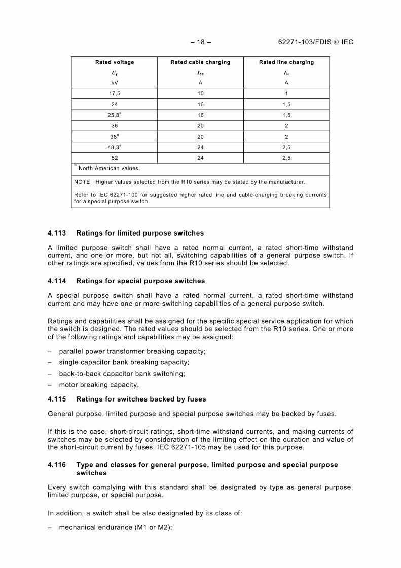
– 18 – 62271-103/FDIS IEC
Rated voltage
Ur
kV
Rated cable charging
Icc
A
Rated line charging
I lc
A
17,5 10 1
24 16 1,5
25,8a 16 1,5
36 20 2
38a 20 2
48,3a 24 2,5
52 24 2,5 a North American values.
NOTE Higher values selected from the R10 series may be stated by the manufacturer.
Refer to IEC 62271-100 for suggested higher rated line and cable-charging breaking currents for a special purpose switch.
4.113 Ratings for limited purpose switches
A limited purpose switch shall have a rated normal current, a rated short-time withstand current, and one or more, but not all, switching capabilities of a general purpose switch. If other ratings are specified, values from the R10 series should be selected.
4.114 Ratings for special purpose switches
A special purpose switch shall have a rated normal current, a rated short-time withstand current and may have one or more switching capabilities of a general purpose switch.
Ratings and capabilities shall be assigned for the specific special service application for which the switch is designed. The rated values should be selected from the R10 series. One or more of the following ratings and capabilities may be assigned:
– parallel power transformer breaking capacity; – single capacitor bank breaking capacity; – back-to-back capacitor bank switching; – motor breaking capacity.
4.115 Ratings for switches backed by fuses
General purpose, limited purpose and special purpose switches may be backed by fuses.
If this is the case, short-circuit ratings, short-time withstand currents, and making currents of switches may be selected by consideration of the limiting effect on the duration and value of the short-circuit current by fuses. IEC 62271-105 may be used for this purpose.
4.116 Type and classes for general purpose, limited purpose and special purpose switches
Every switch complying with this standard shall be designated by type as general purpose, limited purpose, or special purpose.
In addition, a switch shall be also designated by its class of:
– mechanical endurance (M1 or M2);
62271-103/FDIS IEC – 19 –
– electrical endurance (E1, E2 or E3) for general purpose switch; – capacitive switching (C1 or C2).
5 Design and construction
Clause 5 of IEC 62271-1 is applicable, with the additions and exceptions indicated below.
5.1 Requirements for liquids in switchgear and controlgear
Subclause 5.1 of IEC 62271-1 is applicable.
5.2 Requirements for gases in switchgear and controlgear
Subclause 5.2 of IEC 62271-1 is applicable.
5.3 Earthing of switchgear and controlgear
Subclause 5.3 of IEC 62271-1 is applicable.
5.4 Auxiliary and control equipment
Subclause 5.4 of IEC 62271-1 is applicable.
5.5 Dependent power operation
Subclause 5.5 of IEC 62271-1 is applicable.
5.6 Stored energy operation
Subclause 5.6 of IEC 62271-1 is applicable.
5.7 Independent manual or power operation (independent unlatched operation)
Subclause 5.7 of IEC 62271-1 is applicable.
5.8 Operation of releases
Subclause 5.8 of IEC 62271-1 is applicable.
5.9 Low- and high-pressure interlocking and monitoring devices
Subclause 5.9 of IEC 62271-1 is applicable.
5.10 Nameplates
Subclause 5.10 of IEC 62271-1 is applicable with the following modifications.
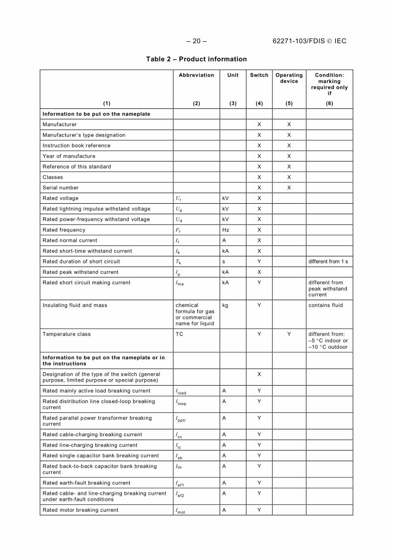
Switches and their operating devices, that are designed to be used as stand alone or to be integrated by third parties as components for switchgear, shall be provided with nameplates which contain information in accordance with Table 2.
Switches and their operating devices that are designed to be integrated in a particular family of switchgears shall integrate the information in the nameplate(s) and/or in the manufacturer instructions manual of the switchgear, as indicated in Table 2.
– 20 – 62271-103/FDIS IEC
Table 2 – Product information
Abbreviation Unit Switch Operating device
Condition: marking
required only if
(1) (2) (3) (4) (5) (6)
Information to be put on the nameplate
Manufacturer X X
Manufacturer’s type designation X X
Instruction book reference X X
Year of manufacture X X
Reference of this standard X X
Classes X X
Serial number X X
Rated voltage Ur kV X
Rated lightning impulse withstand voltage Up kV X
Rated power-frequency withstand voltage Ud kV X
Rated frequency Fr Hz X
Rated normal current Ir A X
Rated short-time withstand current Ik kA X
Rated duration of short circuit Tk s Y different from 1 s
Rated peak withstand current Ip kA X
Rated short circuit making current Ima kA Y different from peak withstand current
Insulating f luid and mass chemical formula for gas or commercial name for liquid
kg Y contains f luid
Temperature class TC Y Y different from: –5 C indoor or –10 C outdoor
Information to be put on the nameplate or in the instructions
Designation of the type of the switch (general purpose, limited purpose or special purpose)
X
Rated mainly active load breaking current I load A Y
Rated distribution line closed-loop breaking current
I loop A Y
Rated parallel power transformer breaking current
Ipptr A Y
Rated cable-charging breaking current Icc A Y
Rated line-charging breaking current I lc A Y
Rated single capacitor bank breaking current Isb A Y
Rated back-to-back capacitor bank breaking current
Ibb A Y
Rated earth-fault breaking current Ief1 A Y
Rated cable- and l ine-charging breaking current under earth-fault conditions
Ief2 A Y
Rated motor breaking current Imot A Y
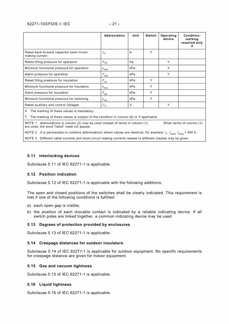
62271-103/FDIS IEC – 21 –
Abbreviation Unit Switch Operating device
Condition: marking
required only if
Rated back-to-back capacitor bank inrush making current
I in A Y
Rated f illing pressure for operation Prm Pa Y
Minimum functional pressure for operation pmm kPa Y
Alarm pressure for operation Pam kPa Y
Rated f illing pressure for insulation Pre kPa Y
Minimum functional pressure for insulation pme kPa Y
Alarm pressure for insulation Pae kPa Y
Minimum functional pressure for switching psw kPa Y
Rated auxiliary and control voltages Ua V Y
X The marking of these values is mandatory.
Y The marking of these values is subject to the condition in column (6) or if applicable.
NOTE 1 Abbreviations in column (2) may be used instead of terms in column (1). When terms of column (1) are used, the word "rated" need not appear.
NOTE 2 It is permissible to combine abbreviations where values are identical, for example: Ir, I load, Iloop = 400 A.
NOTE 3 Different rated currents and short-circuit making currents related to different classes may be given.
5.11 Interlocking devices
Subclause 5.11 of IEC 62271-1 is applicable.
5.12 Position indication
Subclause 5.12 of IEC 62271-1 is applicable with the following additions.
The open and closed positions of the switches shall be clearly indicated. This requirement is met if one of the following conditions is fulfilled:
a) each open gap is visible; b) the position of each movable contact is indicated by a reliable indicating device. If all
switch poles are linked together, a common indicating device may be used.
5.13 Degrees of protection provided by enclosures
Subclause 5.13 of IEC 62271-1 is applicable.
5.14 Creepage distances for outdoor insulators
Subclause 5.14 of IEC 62271-1 is applicable for outdoor equipment. No specific requirements for creepage distance are given for indoor equipment.
5.15 Gas and vacuum tightness
Subclause 5.15 of IEC 62271-1 is applicable.
5.16 Liquid tightness
Subclause 5.16 of IEC 62271-1 is applicable.
– 22 – 62271-103/FDIS IEC
5.17 Fire hazard (flammability)
Subclause 5.17 of IEC 62271-1 is applicable.
5.18 Electromagnetic compatibility (EMC)
Subclause 5.18 of IEC 62271-1 is applicable.
5.19 X-ray emission
Subclause 5.19 of IEC 62271-1 is applicable.
5.20 Corrosion
Subclause 5.20 of IEC 62271-1 is applicable.
5.101 Making and breaking operations
All switches shall be designed so as to be capable of making the circuits to which their rated making current apply.
All switches shall be designed so as to be capable of breaking at the assigned recovery voltage any current up to and including their rated breaking currents.
5.102 Requirements for switch-disconnectors
Switch-disconnectors shall, in addition, comply with the requirements specified for disconnectors in IEC 62271-102 for their disconnecting function.
5.103 Mechanical strength
Switches shall be capable of bearing mechanical terminal loads as specified by the manufacturer, when installed according to the manufacturer's instructions, as well as electromagnetic forces, without reduction of their reliability or current-carrying capacity.
5.104 Securing the position
Switches, including their operating devices, shall be so constructed that they cannot come out of their open or closed positions by forces arising from gravity, vibration, reasonable shocks or accidental touching of the connecting rods of their operating devices, or by electromagnetic forces.
Switches or their operating devices shall be designed to allow the application of means to prevent unauthorized operation.
5.105 Auxiliary contacts for signalling
Signalling of the closed position shall not take place until it is certain that the movable contacts will reach a position in which the rated normal current, peak withstand current and short-time withstand current can be carried safely.
Signalling of the open position shall not take place until the movable contacts have reached a position such that the corresponding open gap is at least 80 % of the total open gap, or until it is certain that the movable contacts will reach their fully open position.
62271-103/FDIS IEC – 23 –
5.106 No-load transformer breaking
All switches shall be designed so as to be capable of breaking no-load transformer breaking currents. Generally, the stress associated with this duty is negligible and is easily performed for a switch capable of switching active load.
Because of the variety of transformers and associated circuits, it is not possible to define a rated no-load transformer breaking current. Due to the non-linearity of the transformer core, it is not possible to correctly model the switching of transformer magnetizing current using linear components in a test laboratory. Tests conducted using an available transformer will only be valid for the tested transformer and cannot be representative for other transformers. If a special test is necessary, test circuits and test procedures have to be agreed between customer and manufacturer.
6 Type tests
Clause 6 of IEC 62271-1 is applicable, with the additions and exceptions indicated below.
All tolerances are defined in Annex A.
6.1 General
The purpose of type tests is to prove the characteristics of high-voltage switches, their operating devices and their auxiliary equipment.
Type tests include:
a) normal type tests: – dielectric tests including lightning impulse withstand tests, power-frequency voltage
withstand tests, and power-frequency voltage withstand tests on auxiliary and control circuits;
– temperature-rise tests; – measurement of the resistance of the main circuit; – short-time withstand current and peak withstand current tests; – tests to prove the ability of the switch to make and break the specified currents; – tests to prove satisfactory mechanical operation and endurance; – verification of the protection; – tightness tests; – electromagnetic compatibility (EMC) tests; – additional tests on auxiliary and control circuits – X-radiation test procedure for vacuum interrupters.
All of the above tests, except other indication is given in each respective clause, shall be made on complete high-voltage switches (filled with the specified types and quantities of liquid or gas at specified density or reduced density, as required), and on their operating devices and auxiliary equipment.
b) special tests upon special request of the user: – tests to prove satisfactory operation under severe ice conditions as defined in 6.102.5; – tests to prove the integrity of the external insulation under conditions of air pollution as
defined in IEC 60507 for ceramic and glass insulators.
6.1.1 Grouping of tests
Subclause 6.1.1 of IEC 62271-1 is applicable with the following additions:
– 24 – 62271-103/FDIS IEC
Short-circuit making test may be performed on an additional specimen.
Additional test samples may be used for additional special type tests.
6.1.2 Information for identification of specimens
Subclause 6.1.2 of IEC 62271-1 is applicable.
6.1.3 Information to be included in the type-test reports
Subclause 6.1.3 of IEC 62271-1 is applicable.
6.1.101 Reference no-load test
At the beginning of the type tests, the mechanical characteristics of the switch shall be established, for example, by recording no-load travel curves. The mechanical characteristics will serve as the reference for the purpose of characterising the mechanical behaviour of the switch. Furthermore, the mechanical characteristics shall not significantly differ in the different test samples used during the mechanical, making, breaking and switching type tests, according to the manufacturer tolerances as defined in 6.102.1.1. The test in which this reference is gained is referred to as reference no-load test and the curves or other parameters resulting from it as reference mechanical characteristics. Reference mechanical characteristics shall be established according to 6.102.1.1.
6.2 Dielectric tests
Subclause 6.2 of IEC 62271-1 is applicable with the following exception:
6.2.8 Artificial pollution tests for outdoor insulators
Subclause 6.2.8 of IEC 62271-1 is applicable for outdoor equipment. No tests are required for indoor equipment.
6.2.9 Partial discharge tests
Subclause 6.2.9 of IEC 62271-1 is replaced by the following:
No partial discharge tests are required to be performed on the complete high voltage switch. However, switch components shall comply in this respect with their relevant IEC publications.
6.3 Radio interference voltage (r.i.v.) test
RIV tests are not required.
6.4 Measurement of the resistance of circuits
Subclause 6.4 of IEC 62271-1 is applicable.
6.5 Temperature-rise tests
Subclause 6.5 of IEC 62271-1 is applicable.
6.6 Short-time withstand current and peak withstand current tests
Subclause 6.6 of IEC 62271-1 is applicable with the following additions.
Short time withstand current and peak withstand current tests performed at 50 Hz or 60 Hz, using a peak factor of 2,6, covers both frequencies for d.c. time constant network of 45 ms or smaller.
62271-103/FDIS IEC – 25 –
Short time withstand current and peak withstand current tests performed at 50 Hz or 60 Hz, using a peak factor of 2,7, covers both frequencies for networks with d.c. time constants higher than 45 ms.
6.7 Verification of the protection
Subclause 6.7 of IEC 62271-1 is applicable.
6.8 Tightness tests
Subclause 6.8 of IEC 62271-1 is applicable with the following addition.
A tightness test before the mechanical operation test is not mandatory.
6.9 Electromagnetic compatibility (EMC) tests
Subclause 6.9 of IEC 62271-1 is applicable.
6.10 Additional tests on auxiliary and control circuits
6.10.1 General
Subclause 6.10.1 of IEC 62271-1 is applicable.
6.10.2 Functional tests
Subclause 6.10.2 of IEC 62271-1 is applicable with the following addition:
If the mechanical operation test at ambient air temperature in accordance with 6.102.2 is performed on the complete switch equipped with its entire control unit, the functional tests according to 6.10.2 of IEC 62271-1 shall be regarded as covered and additional tests are not required.
6.10.3 Electrical continuity of earthed metallic parts test
Subclause 6.10.3 of IEC 62271-1 is applicable.
6.10.4 Verification of the operational characteristics of auxiliary contacts
Subclause 6.10.4 of IEC 62271-1 is applicable.
6.10.5 Environmental tests
Subclause 6.10.5 of IEC 62271-1 is applicable with the following addition:
If the mechanical operation test at ambient air temperature in accordance with 6.102.2, the low and high temperature tests in accordance with 6.102.3 and, if applicable, the humidity test in accordance with 6.102.4 are performed on the complete switch equipped with its entire control unit or in the case of the humidity test on the control equipment respectively, the environmental tests according to subclause 6.10.5 of IEC 62271-1 shall be regarded as covered and additional tests are not required.
6.10.6 Dielectric test
Subclause 6.10.6 of IEC 62271-1 is applicable.
6.11 X-radiation test procedure for vacuum interrupters
Subclause 6.11 of IEC 62271-1 is applicable.
– 26 – 62271-103/FDIS IEC
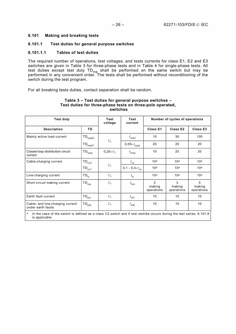
6.101 Making and breaking tests
6.101.1 Test duties for general purpose switches
6.101.1.1 Tables of test duties
The required number of operations, test voltages, and tests currents for class E1, E2 and E3 switches are given in Table 3 for three-phase tests and in Table 4 for single-phase tests. All test duties except test duty TDma shall be performed on the same switch but may be performed in any convenient order. The tests shall be performed without reconditioning of the switch during the test program.
For all breaking tests duties, contact separation shall be random.
Table 3 – Test duties for general purpose switches – Test duties for three-phase tests on three-pole operated,
switches
Test duty Test voltage
Test current
Number of cycles of operations
Description TD Class E1 Class E2 Class E3
Mainly active load current TDload2 Ur
I load 10 30 100
TDload1 0,05 I load 20 20 20
Closed-loop distribution circuit current
TDloop 0,20 Ur I loop 10 20 20
Cable-charging current TDcc2 Ur
Icc 10a 10a 10a
TDcc1 0,1 - 0,4 Icc 10a 10a 10a
Line-charging current TDlc Ur I lc 10a 10a 10a
Short-circuit making current TDma Ur Ima 2 making
operations
3 making
operations
5 making
operations
Earth fault current TDef1 Ur Ief1 10 10 10
Cable- and line-charging current under earth faults
TDef2 Ur Ief2 10 10 10
a In the case of the switch is defined as a class C2 switch and if one restrike occurs during the test series, 6.101.8 is applicable
62271-103/FDIS IEC – 27 –
Table 4 – Test duties for general purpose switches – Single phase tests on three-pole switches operated pole-after-pole and single-pole switches
applied on three-phase systems
Test duty Test voltage
Test current
Number of cycles of operations
Description TD Class E1 Class E2 Class E3
Mainly active load current TDload2 1,5 Ur/ 3 I load 5 15 50
TDload2 Urb 0,87 I load a 5 15 50
TDload1 Urb 0,05 I load 20 20 20
Closed-loop distribution circuit current
TDloop 0,20 Urb I loop 10 20 20
Cable-charging current TDcc2 c Icc 12d 12d 12d
TDcc1 c 0,1 - 0,4 Icc 12d 12d 12d
Line-charging current TDlc c I lc 12d 12d 12d
Short-circuit making current TDma Ur Ima 2 making
operations
3 making
operations
5 making
operations
Earth fault current TDef1 Ur/ 3 Ief1 10 10 10
Cable- and line-charging current under earth faults
TDef2 Ur Ief2 10 10 10
a Alternatively, one test series may be performed at rated voltage Ur and rated current I load, provided 10 operations are performed for class E1, 30 operations for class E2, and 100 operations for class E3 switches.
b The peak TRV values shall be 3/1,5 times the values shown in Tables 7 and 8.
c The manufacturer shall select the test circuit to be representative of the intended application. The test voltage shall equal the product of Ur/ 3 and one of the following factors:
1) 1,0 for effectively earthed neutral systems for switching of screened cables;
2) 1,2 for effectively earthed neutral systems for switching of belted cables;
3) 1,3 for effectively earthed neutral systems for switching of line;
4) 1,75 for non-effectively earthed neutral systems for switching of line and cable.
d In the case of the switch is defined as a class C2 switch and if one restrike occurs during the test series, 6.101.8 is applicable
6.101.1.2 Test duties for short-circuit making tests
Short-circuit making tests shall be performed on a switch which has been subjected to at least 10 make-break operating cycles at 100 % mainly active load as required for test duty TD load. If making and breaking are done by separate contacts or separate contacts areas, test duty TDma may be performed on a new switch.
The tests shall be performed with a sequence of two C operations with a no-load O in between, i.e. C – O (no-load) – C.
For class E2 switches, the test sequence is 2C – x – 1C, where x represents arbitrary switching tests, or even no-load tests.
For class E3 switches, the test sequence is 2C – x – 1C – y – 2C, where x and y represent arbitrary switching tests, or even no-load tests.
For class E2 and E3 switches, the 2C operations consist of C – O (no-load) – C.
– 28 – 62271-103/FDIS IEC
The switch shall be able to make the current with pre-arcing occurring at any point on the voltage wave. Two extreme cases are specified as follows:
a) making at the peak of the voltage wave, leading to a symmetrical short-circuit current and the longest pre-arcing time. The making shall occur within -30/+15 degrees of peak voltage;
b) closing at the zero of the voltage wave, without pre-arcing, leading to a fully asymmetrical short-circuit current.
During the short-circuit making tests series, both requirements a) and b) shall be met once for class E1 switches, once for class E2 switches and twice for class E3 switches.
If due to long pre-arcing times, it is not possible to achieve the required rated short-circuit making current at rated voltage, it may be necessary to carry out tests at reduced voltage in order to obtain the fully asymmetrical short-circuit current.
6.101.1.3 Test duties for make-break tests
Make-break operating cycles shall be carried out for test duties TDload, TDloop, TDcc, TDlc, TDef1 and TDef2. The opening operation shall follow the closing operation with a time delay between the two operations at least sufficient for any transient currents to subside. The opening and closing operations can be separated when design features of the switch or limitations of the test plant require it. For convenience, open-close operations may also be performed. The breaking currents shall be in accordance with 6.101.6.3.
If the TRV parameters achieved in test duty TDload2 are equal to or more severe than TRV parameters required for test duty TDloop, then test duty TDloop need not be performed provided 10 additional operations for class E1 switches or 20 for class E2 and E3 switches are performed for test duty TDload2, with the consent of the manufacturer.
The TRV of test duty TDload2 has the same peak and a higher rate of rise, if:
– either the source side impedance is equal or greater than 20 % of the total impedance,
– or the TRV is adjusted with an increased amplitude factor, for example (20/15) 1,5 in the case of the source impedance is 15 %.
6.101.2 Test duties for limited purpose switches
The tests specified for general purpose switches shall be used, deleting those test-duties for which the switch is not rated or by reducing the test values according to the limited ratings.
6.101.3 Test duties for special purpose switches
Special purpose switches shall be tested according to at least one of the tests defined in Table 5 for three-phase tests and in Table 6 for single-phase tests. Special purpose switches shall also be tested in accordance with the tests specified for general purpose switches deleting the test duties for which the switch is not rated.
Make-break operating cycles shall be carried out for all test duties. The opening operation shall follow the closing operation with a time delay between the two operations at least sufficient for any transient currents to subside. The opening and closing operations can be separated when design features of the switch or limitations of the test plant require it. The time interval between closing and opening shall not normally exceed 3 min. For convenience, open-close operations may also be performed. The breaking currents shall be in accordance with 6.101.6.3.
For all breaking tests duties, contact separation shall be random.
62271-103/FDIS IEC – 29 –
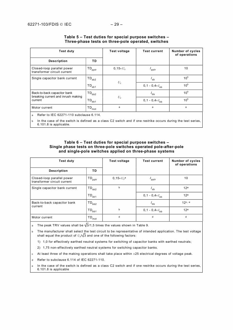
Table 5 – Test duties for special purpose switches – Three-phase tests on three-pole operated, switches
Test duty Test voltage Test current Number of cycles of operations
Description TD
Closed-loop parallel power transformer circuit current
TDpptr 0,15 Ur Ipptr 10
Single capacitor bank current TDsb2 Ur
Isb 10b
TDsb1 0,1 - 0,4 Isb 10b
Back-to-back capacitor bank breaking current and inrush making current
TDbb2 Ur
Ibb 10b
TDbb1 0,1 - 0,4 Ibb 10b
Motor current TDmot a a a
a Refer to IEC 62271-110 subclause 6.114.
b In the case of the switch is defined as a class C2 switch and if one restrike occurs during the test series, 6.101.8 is applicable.
Table 6 – Test duties for special purpose switches – Single phase tests on three-pole switches operated pole-after-pole
and single-pole switches applied on three-phase systems
Test duty Test voltage Test current Number of cycles of operations
Description TD
Closed-loop parallel power transformer circuit current
TDpptr 0,15 Ura Ipptr 10
Single capacitor bank current TDsb2 b Isb 12e
TDsb1 0,1 - 0,4 Isb 12e
Back-to-back capacitor bank current
TDbb2 Ibb 12c, e
TDbb1 b 0,1 - 0,4 Ibb 12e
Motor current TDmot d d d
a The peak TRV values shall be 3/1,5 times the values shown in Table 9.
b The manufacturer shall select the test circuit to be representative of intended application. The test voltage shall equal the product of Ur/ 3 and one of the following factors:
1) 1,0 for effectively earthed neutral systems for switching of capacitor banks with earthed neutrals;
2) 1,75 non-effectively earthed neutral systems for switching capacitor banks.
c At least three of the making operations shall take place within 25 electrical degrees of voltage peak.
d Refer to subclause 6.114 of IEC 62271-110.
e In the case of the switch is defined as a class C2 switch and if one restrike occurs during the test series, 6.101.8 is applicable
– 30 – 62271-103/FDIS IEC
6.101.4 Arrangement of the switch for tests
The switch under test shall be completely mounted on its own support, or on an equivalent support. Its operating device shall be operated in the manner prescribed and in particular, if it is electrically or pneumatically operated, it shall be operated at the minimum supply voltage or pressure for operation, respectively.
Before commencing making and breaking tests, no-load operations shall be made, and details of the operating characteristics of the switch such as speed of travel, closing time and opening time shall be recorded.
If applicable, tests shall be performed at the minimum functional pressure for insulation and/or switching.
Switches with independent manual operation may be operated by an arrangement provided for the purpose of making remote control possible.
Consideration shall be given to the effects of energization of either terminal of the switch.
The switch shall be supplied or energized as in service.
When the switch in service can be supplied or energized on both sides, the following applies,
for TDload2, if the physical arrangement of one side of the switch differs from that of the other side, 50 % of the total number of close-open operations of the test duty shall be carried out with supply side of the test circuit connected to one side of the switch and the remaining 50 % of the test duty shall be made with the supply connected to the other side. If the contact arrangement is symmetrical on both sides of the switch, then TDload2 may be performed using only one side;
for other make-break tests and for TDma, the switch shall be supplied from the same side, at laboratory convenience.
Making and breaking tests on three-pole operated switches shall be made three-phase except as noted for capacitive current switching tests. Making and breaking tests on three-pole switches operated pole-after-pole, or single-pole switches applied on three-phase systems, may be performed single-phase when they have single-phase enclosures or are open-air type switches.
Short-circuit making tests shall be performed three-phase in all the cases.
For switches normally installed within a metal enclosure, and having the characteristic of the emission of flame or metallic particles during breaking or making, the following procedure is required. The tests shall be made with the switch mounted within the metal enclosure or with metallic screens placed in the vicinity of the live parts, and separated from them by a clearance which the manufacturer shall specify. The screens, frame and other normally earthed parts shall be insulated and then connected to earth through a current indicating device. The current indicating device can be a fuse consisting of a copper wire of 0,1 mm diameter and 5 cm in length, or a link to earth across a sensor to measure the current. The fuse wire may also be connected to the secondary side of a 1:1 ratio current transformer. The terminals of the current transformer should be protected by a spark gap or surge arrester. No significant leakage is assumed to have occurred if this wire is intact after the test or if the Joule integral of the leakage current is less than 5 A2s from arc establishing up to 100 ms.
6.101.5 Earthing of test circuit and switch
Making and breaking tests, with the exception of capacitive current switching tests, conducted on three-pole operated switches, shall be performed using a three-phase test circuit with
62271-103/FDIS IEC – 31 –
either the neutral point of the supply earthed, or the neutral point of the load earthed. In either case, the test circuit and the frame of the switch shall be earthed.
For single-phase breaking tests on three-pole switches operated pole-after-pole, or for tests on single-pole switches applied on three-phase systems, tests shall be performed with one terminal of the pole to be tested connected to the supply, and the other terminal connected to the load. The common-side connection of the load and supply may be earthed, as shown in Figure 2 and Figure 4, for example. For capacitive tests circuits, refer to 6.101.7.3.4 and 6.101.7.3.5.
The connections used in all tests shall be indicated in the test report.
6.101.6 Test parameters
6.101.6.1 Test frequency
Switches shall be tested at rated frequency, with a tolerance as stated in Annex A. Where it is possible, test conditions to cover both 50 Hz and 60 Hz frequencies are explained in each type test clause.
6.101.6.2 Test voltage for breaking tests
The power-frequency test voltage for breaking tests are as shown in Tables 3 to 6.
The test voltage shall be measured immediately after interruption, with the exception of capacitive loads, where the voltage is measured immediately prior to opening of the contacts. The voltage shall be measured as closely as possible to the terminals of the switch, i.e. without appreciable impedance between the measuring point and the terminals. For three-phase tests, the test voltage shall be expressed as the average of the phase-to-phase test voltages. The test voltage tolerance between any two phases is given in Annex A. The power-frequency test voltage shall be maintained for at least 0,3 s after arc extinction.
6.101.6.3 Breaking current
The current for breaking tests are as shown in Tables 3 to 6.
The current to be interrupted shall be symmetrical with negligible decrement. The contacts of the switch shall not be separated until transient currents due to closing of the circuit have subsided.
NOTE The value of the d.c.-component of the breaking current is considered negligible when the d.c.-component is equal to or less than 20 %.
The difference between the average current and the values obtained in each pole shall not exceed the value as given in Annex A.
The breaking currents for single-phase tests shall be as shown in Table 6.
The waveform of the test current for capacitive current switching tests should be sinusoidal. This requirement is satisfied if the ratio of the r.m.s. value of the total current to the r.m.s. value of the fundamental component does not exceed 1,2. The test current shall not go through zero more than once per half cycle of power frequency.
The breaking capacity shall be stated in terms of:
a) the test voltage; b) the breaking current; c) the circuit power factor;
– 32 – 62271-103/FDIS IEC
d) the test circuit; e) the transient recovery voltage parameters; f) the number of close-open operating cycles.
6.101.6.4 Test voltage for short-circuit making tests
6.101.6.4.1 General
The power-frequency test voltage for short-circuit making tests are as shown in Table 3 and Table 4. The test voltage tolerance between any two phases is given in Annex A.
6.101.6.4.2 Alternative synthetic tests
Laboratory limitations of power may be such as to make direct tests at rated voltage and rated current difficult. A synthetic making circuit may be used under these circumstances so as to produce the required test voltage from one supply and the rated making current from a second supply.
6.101.6.4.3 Alternative tests at reduced voltage
As another alternative direct tests may be performed at reduced test voltage, by using means which ensure that the pre-arcing period at test voltage is not shorter than at the proper rated voltage.
Depending on the technology of the switch, different means for short-circuit making tests at reduced voltage may be applicable:
– when possible, the pre-arcing may be initiated by a fuse wire. A thin and rigid wire shall be fastened at the contacts (of all poles in case of three-phase tests);
– for switches breaking under gas, the short-circuit making tests may be performed under air or with gas, at reduced pressure. The test voltage shall be reduced by the same ratio as the difference of the flashover distance of air or the insulating gas at rated minimum pressure. The mechanical characteristics shall be in the limits of the manufacturer tolerances as defined in 6.102.1.1.
Prior to short-circuit making test at reduced voltage, the average pre-arcing time at rated voltage and its standard deviation have to be known.
These values can be calculated from 10 makings performed within 15° on the peak voltage, taken from other test duties with the same type of switch, or if not available, from extra making tests, performed at reduced current in a range of 1 A to 50 A, not to cause essential contact erosion.
During short-circuit making tests at reduced voltage, the pre-arcing times shall not be less than the above calculated average pre-arcing time plus two times its standard deviation, to fulfil the requirement a) described in clause 6.101.1.2
6.101.6.5 Short-circuit making current
The short-circuit making current shall be expressed in terms of peak making current and the r.m.s. symmetrical making current. For general purpose switches, the symmetrical r.m.s. value of current in each pole at 0,2 s shall be at least 80 % of the rated short-time withstand current. The duration of the short-circuit current shall be at least 0,2 s.
A general purpose switch shall be able to operate at voltages below its rated voltage at which it may actually make with a fully asymmetrical current. The lower limit of voltage, if any, shall be stated by the manufacturer.
The short-circuit making current performance shall be stated in terms of:
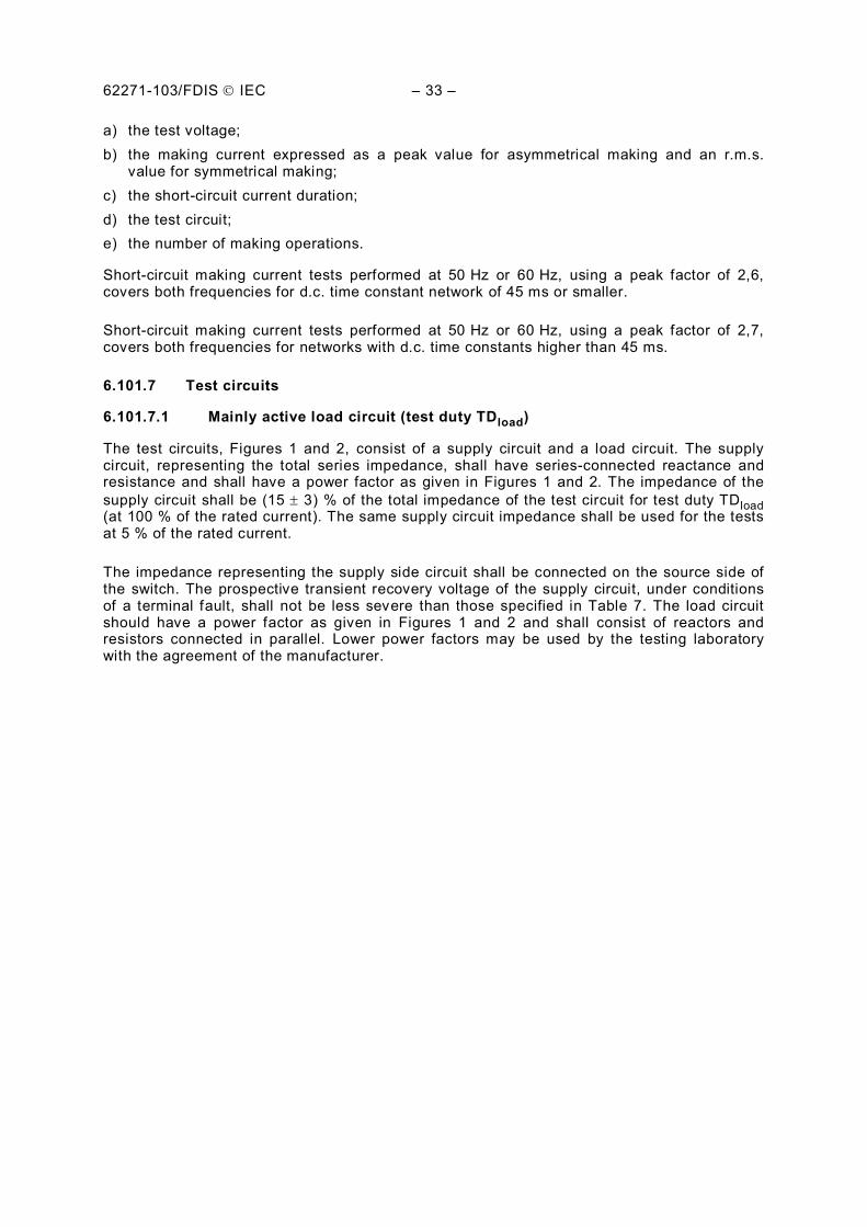
62271-103/FDIS IEC – 33 –
a) the test voltage; b) the making current expressed as a peak value for asymmetrical making and an r.m.s.
value for symmetrical making; c) the short-circuit current duration; d) the test circuit; e) the number of making operations.
Short-circuit making current tests performed at 50 Hz or 60 Hz, using a peak factor of 2,6, covers both frequencies for d.c. time constant network of 45 ms or smaller.
Short-circuit making current tests performed at 50 Hz or 60 Hz, using a peak factor of 2,7, covers both frequencies for networks with d.c. time constants higher than 45 ms.
6.101.7 Test circuits
6.101.7.1 Mainly active load circuit (test duty TDload)
The test circuits, Figures 1 and 2, consist of a supply circuit and a load circuit. The supply circuit, representing the total series impedance, shall have series-connected reactance and resistance and shall have a power factor as given in Figures 1 and 2. The impedance of the supply circuit shall be (15 3) % of the total impedance of the test circuit for test duty TDload (at 100 % of the rated current). The same supply circuit impedance shall be used for the tests at 5 % of the rated current.
The impedance representing the supply side circuit shall be connected on the source side of the switch. The prospective transient recovery voltage of the supply circuit, under conditions of a terminal fault, shall not be less severe than those specified in Table 7. The load circuit should have a power factor as given in Figures 1 and 2 and shall consist of reactors and resistors connected in parallel. Lower power factors may be used by the testing laboratory with the agreement of the manufacturer.
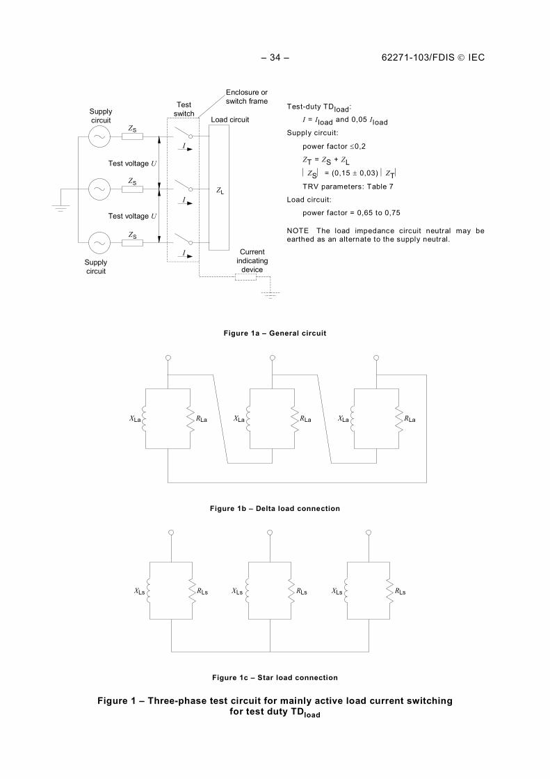
– 34 – 62271-103/FDIS IEC
Test-duty TDload:
I = Iload and 0,05 Iload Supply circuit:
power factor 0,2
ZT = ZS + ZL
ZS = (0,15 0,03) ZT
TRV parameters: Table 7
Load circuit:
power factor = 0,65 to 0,75
NOTE The load impedance circuit neutral may be earthed as an alternate to the supply neutral.
Figure 1a – General circuit
XLa XLa XLa RLa RLa RLa
Figure 1b – Delta load connection
XLs XLs XLs RLs RLs RLs
Figure 1c – Star load connection
Figure 1 – Three-phase test circuit for mainly active load current switching for test duty TDload
Z S
Z S
Z S
Z L
Supply circuit
Test switch
Load circuit
I
Current indicating
device
Test voltage U
Test voltage U
I
I
Enclosure or switch frame
Supply circuit
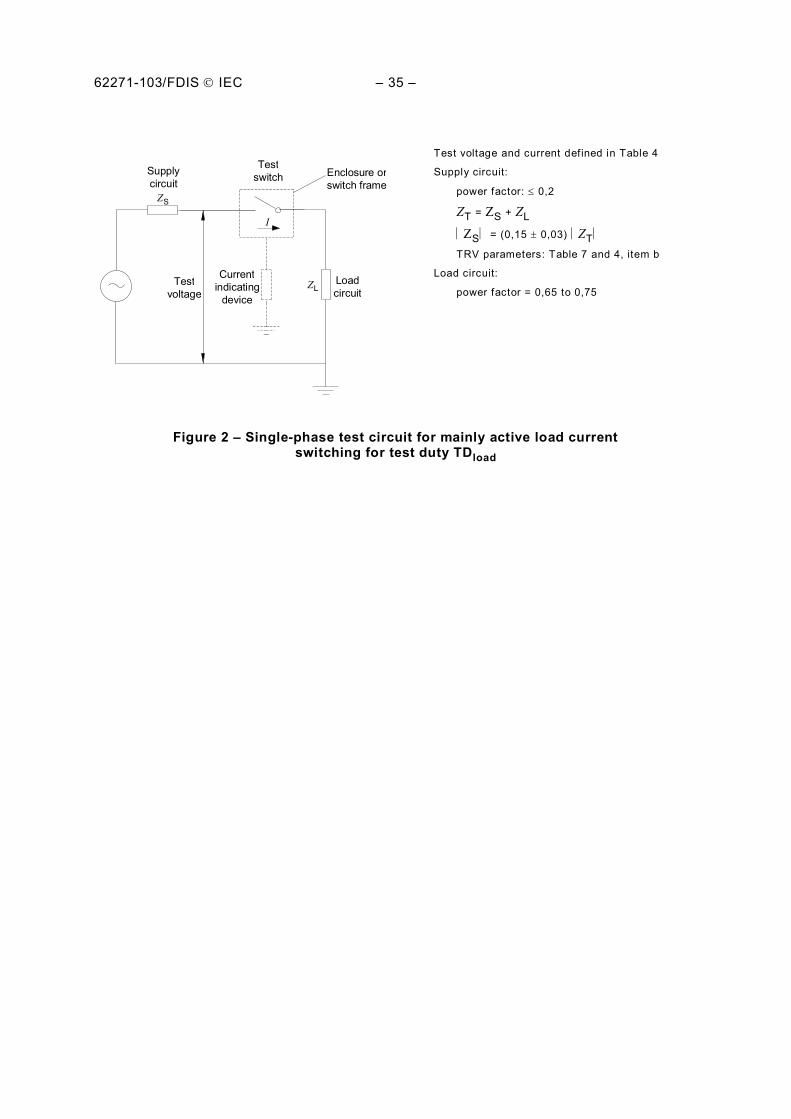
62271-103/FDIS IEC – 35 –
Z S
Supplycircuit
Testswitch
Loadcircuit
Currentindicating
device
I
Z LTestvoltage
Enclosure orswitch frame
Test voltage and current defined in Table 4
Supply circuit:
power factor: 0,2
ZT = ZS + ZL
ZS = (0,15 0,03) ZT
TRV parameters: Table 7 and 4, item b
Load circuit:
power factor = 0,65 to 0,75
Figure 2 – Single-phase test circuit for mainly active load current switching for test duty TDload
– 36 – 62271-103/FDIS IEC
Table 7 – Supply circuit TRV parameters for mainly active load current breaking testsa
Supply TRV parameters
Rated voltage Peak voltageb Time coordinateb
Ur Uc t3
kV kV s
3,6 6,2 40
4,76c 8,2 40
7,2 12,3 52
8,25c 14,1 52
12 20,6 60
15c 25,7 72
17,5 30 72
24 41 88
25,8c 44,2 88
36 62 108
38c 65,1 108
48,3c 82,8 132
52 89,2 138
a Supply circuit TRV parameters under conditions of a terminal fault.
b Users are cautioned that if current-limiting reactors are used, the supply circuit TRV may exceed the values specif ied.
c North American values.
NOTE 1 The switch supply and load transient components are illustrated below. The peak value of the supply component, u 'c as illustrated, will be approximately 15 % of uc at an approximate time t3. The actual u 'c and time to peak will be dependent upon the load circuit power factor and series impedance of the supply circuit.
Supply transient
Switc
h re
cove
ry v
olta
ge
volta
ge
Current interruption
Time
t3
u c
Time
Load transient
Current interruption
Supply voltage
u 'c = peak of supply circuit component of switch transient recovery voltage.
62271-103/FDIS IEC – 37 –
NOTE 2 The series supply impedance is (15 3) % of the total impedance with a power factor of 0,2 or less. The load consists of parallel resistance and reactance. The TRV from the load is an exponentially decaying voltage whose peak is determined by the power factor of the load. Thus, the load side TRV is completely determined by the load circuit and need not be specif ied.
NOTE 3 The series supply impedance is a combination of distributed transformer impedance and remote supply impedance. The f irst pole-to-clear factor kpp is 1,5. The amplitude factor is assumed to be 1,4.
1,4 1,5 32r
cUu
6.101.7.2 Closed-loop circuits
6.101.7.2.1 Test circuit for distribution line and parallel transformer
The test circuits for distribution line and parallel transformer are defined in Figures 3 and 4.
Z T
Z T
Z T
Supplycircuit
Testswitch
I
Currentindicating
device
Test voltage
I
I
Enclosure orswitch frame
Test voltage
Alternate earthpoint if supplyis not earthed
ZT = ZS + ZL
Test duty TDloop – Line circuit:
test voltage = 0,20 Ur
test current = Iloop
power factor 0,3
TRV parameters: Table 8
Test duty TDpptr – Parallel-power transformer circuit:
test voltage = 0,15 Ur
test current = Ipptr
power factor 0,2
TRV parameters: Table 9
NOTE The common switch connection may be earthed as an alternative to the supply neutral.
Figure 3 – Three-phase test circuit for distribution line closed-loop and parallel transformer current switching test for test duties TDloop and TDpptr
– 38 – 62271-103/FDIS IEC
Z S
Supplycircuit
Testswitch
Loadcircuit
Currentindicating
device
I
Z LTestvoltage
Enclosure orswitch frame
ZT = ZS + ZL
Test duty TDloop – Line circuit:
test voltage and current defined in Table 4
power factor 0,3
TRV parameters: Table 4, item b
Test duty TDpptr – Parallel-power transformer circuit:
test voltage and current defined in Table 6
power factor 0,2
TRV parameters: Table 6, item a
Figure 4 – Single-phase test circuit for distribution line closed-loop and parallel transformer current switching test, for test duties TDloop and TDpptr
6.101.7.2.2 Distribution line circuit (test duty TDloop)
The tests circuits, Figures 3 and 4, shall have series-connected reactors and resistors and a power factor as shown in Figures 3 and 4. The load impedance (ZL) may be on the supply side of the switch, the load side or divided. If the load impedance is on the load side, the supply side impedance (ZS) shall be as low as possible, but not such that the short-circuit current exceeds the making current of the switch. The prospective transient recovery voltages shall be not less severe than those specified in Table 8.
The open circuit, phase-to-phase, test voltage for three-phase tests is as noted in Table 3. Test voltages for single-phase tests on three-pole operated switches operated pole-after-pole, or single-pole switches applied on a three-phase system, are shown in Table 4.
Table 8 – TRV parameters for distribution line closed loop breaking tests
Rated voltage Peak voltage Time coordinate
Ur Uc t3
kV kV µs
3,6 1,2 110
4,76a 1,7 110
7,2 2,4 110
8,25a 2,9 110
12 4,1 150
15a 5,1 200
17,5 6,0 200
24 8,3 250
25,8a 8,9 250
36 12,3 310
38a 13,1 310
48,3a 16,5 350
52 17,8 370
a North American values.
62271-103/FDIS IEC – 39 –
NOTE 1 The specif ied transient recovery voltage across the switch is of the (1-cos) form. A typical transient is illustrated below.
Current interruption
Time
t3
uc (1-cos) TRV
Tran
sien
t rec
over
y vo
ltage
NOTE 2 Steady-state, phase-to-phase, open-circuit test voltage is 20 % of rated voltage. uc is based on a system having a f irst pole-to-clear factor kpp of 1,5 and an amplitude factor equal to 1,4.
4,1 5,1 3
2)20,0( rc Uu
6.101.7.2.3 Parallel power transformer circuit (test duty TDpptr)
The test circuits, Figures 3 and 4, shall have series-connected reactors and resistors and a power factor as shown in Figures 3 and 4. The prospective transient recovery voltages shall be not less severe than those specified in Table 9.
The open-circuit, phase-to-phase, test voltage for three-phase tests on three-pole switches is as noted in Table 5. Test voltages for single-phase tests on three-pole operated switches operated pole-after-pole, or single-pole switches applied on a three-pole phase system, are shown in Table 6.
Table 9 – TRV parameters for parallel power transformer current breaking tests
Rated voltage Peak voltage Time coordinate t3a
Ur uc K factor
kV kV
3,6 0,6 0,25
4,76b 0,7 0,28
7,2 1,1 0,35
8,25b 1,3 0,38
12 1,9 0,45
15b 2,3 0,50
17,5 2,7 0,55
24 3,7 0,63
25,8b 4,0 0,67
36 5,6 0,78
38b 5,9 0,80
48,3b 7,5 0,90
52 8,1 0,93
– 40 – 62271-103/FDIS IEC
a The time coordinate is calculated as I
IKt 7,6
600 480 13
, where t3 is in microseconds and I is the test
current in kA. The K factor and the equation for t3 were derived from published transient recovery voltage frequencies obtained by low-voltage current injection of transformers. The frequency is typical of power transformers having a current rating close to the test current and an impedance of 15 % at the forced cooled rating.
b North American values.
NOTE 1 The transient recovery voltage across the switch is of the (1-cos) form and the values are for the first-pole-to-clear.
NOTE 2 The f irst pole-to-clear factor kpp is 1,5. The amplitude factor is assumed to be 1,7 in accordance with IEC 62271-100 for short-circuit test duty T10. It is assumed that two power transformers are in parallel with one transformer being switched. The TRV is mainly from the transformer being switched. This implies that the transient recovery voltage is based only on half of the steady-state recovery voltage.
2
0,151,71,5
3
2rc
Uu
6.101.7.3 Capacitive circuits (test duties TDcc, TDlc, TDsb, TDbb)
6.101.7.3.1 General
Tests are normally carried out in a laboratory. However, field tests may also be performed. For field tests, the actual lines, cables and capacitor banks shall be used.
For laboratory tests, the lines or cables may be partly or fully replaced by artificial circuits with lumped elements consisting of capacitors, reactors or resistors.
Tests at 60 Hz are valid to demonstrate the breaking performance at 50 Hz.
Tests at 50 Hz are valid to prove the characteristics at 60 Hz provided that the voltage across the switch is not less during the first 8,3 ms than it would be during a test at 60 Hz with the specified voltage. If restrikes occur after 8,3 ms, due to instantaneous voltage being higher than it would be during a test at 60 Hz with the specified voltage, and the switch has a very low expected probability of restrike, the test duty shall be done at 60 Hz with a test voltage as prescribed for the 60 Hz test. If no restrikes occur, the switch shall be considered to have passed the test.
NOTE The laboratory test circuits representing lines and cables and capacitor banks are not applicable for determining the magnitude of possible overvoltages when restrikes occur. They are adapted to demonstrate the switching performance only.
Three-phase tests should be performed. However, single-phase laboratory tests on three-pole operated switches, are permitted for capacitive current switching tests.
6.101.7.3.2 Test voltages
The power-frequency test voltages for three-phase tests are given in Table 3 or 5.
Test voltage for single-phase tests on three-pole operated switches shall be equal to the product of Ur/ 3 and one of the following factors. These factors are for switches having a pole non-simultaneity equal to or less than 1/6 cycle:
– 1,0 for effectively earthed neutral system for switching of capacitor banks with earthed neutrals and for switching of screened cables;
– 1,1 for effectively earthed neutral systems for switching of belted cables; – 1,2 for effectively earthed neutral systems for switching of overhead distribution lines;
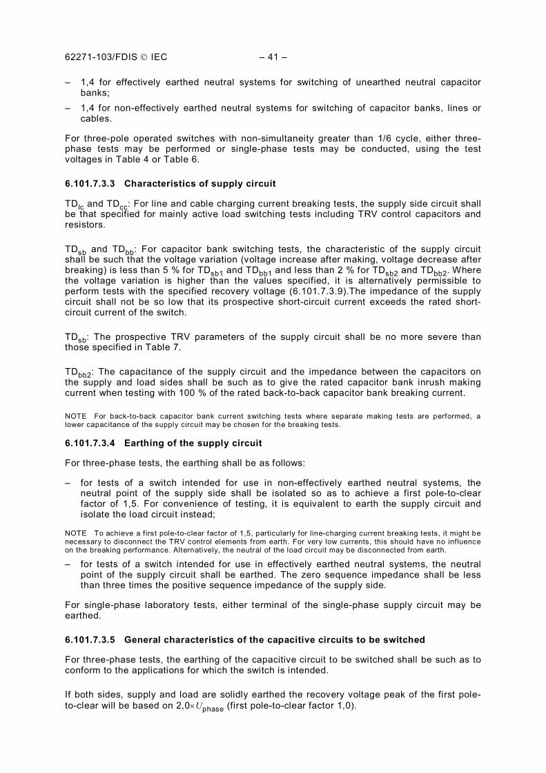
62271-103/FDIS IEC – 41 –
– 1,4 for effectively earthed neutral systems for switching of unearthed neutral capacitor banks;
– 1,4 for non-effectively earthed neutral systems for switching of capacitor banks, lines or cables.
For three-pole operated switches with non-simultaneity greater than 1/6 cycle, either three-phase tests may be performed or single-phase tests may be conducted, using the test voltages in Table 4 or Table 6.
6.101.7.3.3 Characteristics of supply circuit
TDlc and TDcc: For line and cable charging current breaking tests, the supply side circuit shall be that specified for mainly active load switching tests including TRV control capacitors and resistors.
TDsb and TDbb: For capacitor bank switching tests, the characteristic of the supply circuit shall be such that the voltage variation (voltage increase after making, voltage decrease after breaking) is less than 5 % for TDsb1 and TDbb1 and less than 2 % for TDsb2 and TDbb2. Where the voltage variation is higher than the values specified, it is alternatively permissible to perform tests with the specified recovery voltage (6.101.7.3.9).The impedance of the supply circuit shall not be so low that its prospective short-circuit current exceeds the rated short-circuit current of the switch.
TDsb: The prospective TRV parameters of the supply circuit shall be no more severe than those specified in Table 7.
TDbb2: The capacitance of the supply circuit and the impedance between the capacitors on the supply and load sides shall be such as to give the rated capacitor bank inrush making current when testing with 100 % of the rated back-to-back capacitor bank breaking current.
NOTE For back-to-back capacitor bank current switching tests where separate making tests are performed, a lower capacitance of the supply circuit may be chosen for the breaking tests.
6.101.7.3.4 Earthing of the supply circuit
For three-phase tests, the earthing shall be as follows:
– for tests of a switch intended for use in non-effectively earthed neutral systems, the neutral point of the supply side shall be isolated so as to achieve a first pole-to-clear factor of 1,5. For convenience of testing, it is equivalent to earth the supply circuit and isolate the load circuit instead;
NOTE To achieve a f irst pole-to-clear factor of 1,5, particularly for line-charging current breaking tests, it might be necessary to disconnect the TRV control elements from earth. For very low currents, this should have no influence on the breaking performance. Alternatively, the neutral of the load circuit may be disconnected from earth.
– for tests of a switch intended for use in effectively earthed neutral systems, the neutral point of the supply circuit shall be earthed. The zero sequence impedance shall be less than three times the positive sequence impedance of the supply side.
For single-phase laboratory tests, either terminal of the single-phase supply circuit may be earthed.
6.101.7.3.5 General characteristics of the capacitive circuits to be switched
For three-phase tests, the earthing of the capacitive circuit to be switched shall be such as to conform to the applications for which the switch is intended.
If both sides, supply and load are solidly earthed the recovery voltage peak of the first pole-to-clear will be based on 2,0 Uphase (first pole-to-clear factor 1,0).
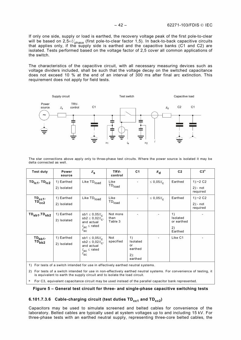
– 42 – 62271-103/FDIS IEC
If only one side, supply or load is earthed, the recovery voltage peak of the first pole-to-clear will be based on 2,5 Uphase (first pole-to-clear factor 1,5). In back-to-back capacitive circuits that applies only, if the supply side is earthed and the capacitive banks (C1 and C2) are isolated. Tests performed based on the voltage factor of 2,5 cover all common applications of the switch.
The characteristics of the capacitive circuit, with all necessary measuring devices such as voltage dividers included, shall be such that the voltage decay on the switched capacitance does not exceed 10 % at the end of an interval of 300 ms after final arc extinction. This requirement does not apply for field tests.
Supply circuit
Power source
TRV- control
Test switch Capacitive load
Zs C1 C2 C1 Rd
u1 ie ie u2 i
The star connections above apply only to three-phase test circuits. W here the power source is isolated it may be delta connected as well.
Test duty Power source
Zs TRV-control
C1 Rd C2 C3a
TDlc1, TDlc2 1) Earthed
2) Isolated
Like TDload Like TDload
- 0,05Xc Earthed 1):~2 C2
2):- not required
TDcc1, TDcc2
1) Earthed
2) Isolated
Like TDload Like TDload
- 0,05Xc Earthed 1):~2 C2
2):- not required
TDsb1,TDsb2 1) Earthed
2) Isolated
sb1 0,05Xc sb2 0,02Xc, and actual Isc rated Isc
Not more than Table 3
- - 1) Isolated or earthed
2) Earthed
-
TDbb1, TDbb2
1) Earthed
2) Isolated
sb1 0,05Xc sb2 0,02Xc, and actual Isc rated Isc
Not specif ied
1) Isolated or earthed
2): earthed
- Like C1 -
1) For tests of a switch intended for use in effectively earthed neutral systems.
2) For tests of a switch intended for use in non-effectively earthed neutral systems. For convenience of testing, it is equivalent to earth the supply circuit and to isolate the load circuit.
a For C3, equivalent capacitance circuit may be used instead of the parallel capacitor bank represented.
Figure 5 – General test circuit for three- and single-phase capacitive switching tests
6.101.7.3.6 Cable-charging circuit (test duties TDcc1 and TDcc2)
Capacitors may be used to simulate screened and belted cables for convenience of the laboratory. Belted cables are typically used at system voltages up to and including 15 kV. For three-phase tests with an earthed neutral supply, representing three-core belted cables, the
62271-103/FDIS IEC – 43 –
positive sequence capacitance of the capacitance circuit shall be approximately equal to three times the zero sequence capacitance. For an unearthed supply neutral, this requirement is not necessary.
When capacitors are used to simulate cables, a non-inductive resistance, not exceeding 5 % of the capacitive impedance, may be inserted in series with the capacitors. Higher values may unduly influence the recovery voltage.
6.101.7.3.7 Line-charging circuit (test duty TDlc)
Capacitors may be used to simulate lines for convenience of the laboratory. For three-phase tests, with an earthed neutral supply, the positive sequence capacitance of the capacitive circuit shall be approximately three times the zero sequence capacitance. For an unearthed neutral supply, this requirement is not necessary.
When capacitors are used to simulate overhead lines, a non-inductive resistance, not exceeding 5 % of the capacitive impedance, may be inserted in series with the capacitors. Higher values may unduly influence the recovery voltage.
6.101.7.3.8 Capacitor bank circuits (test duties TDsb1, TDsb2, TDbb1 and TDbb2)
For three-phase tests, the neutral of the capacitor bank shall be isolated or earthed, depending upon the application of the switch and the earthing of the neutral of the supply circuit.
In a three-phase back-to-back capacitor bank circuit both banks, C1 and C2, shall likewise either be earthed or isolated. A first pole-to-clear factor of 1,5 only occurs, if the C1 and C2 are isolated and the power supply is earthed.
6.101.7.3.9 Tests with specified TRV
If it is not possible to fulfil the requirements of 6.101.7.3.3, switching tests may be performed in circuits which fulfil the following requirements for the prospective recovery voltage as specified in Table 10 and identified in Figure 6.
Table 10 – Prospective recovery voltage parameter limits for capacitor bank current breaking tests
Test duties Recovery voltagea,b Time coordinatesa
uce uad tad t2e ms
50 Hz 60 Hz
1 1,98 0,028 t3c
2 1,95 0,070 t3c 8,7 7,3
a Refer to Figure 6.
b Values are per unit with respect to the peak value of the test voltage. c t3 in Table 7.
d The peak value u 'a of the initial part of the prospective TRV shall be less than ua and the time to peak t'a shall be greater than ta as shown in Figure 6.
e The prospective peak recovery voltage u 'c shall be greater than uc and the time to peak t'2 shall be less than t2 as shown in Figure 6.
– 44 – 62271-103/FDIS IEC
t 2 Time
Volta
ge
Mainly a (1- cos) form
u c uc
u a ua
t2
t a ta
The prospective TRV (u'a, t'a, u'c, t'2) shall be as follows:
u'a ua u'c uc t'a ta t'2 t2 ua, ta, uc and t2 are defined in Table 10.
Figure 6 – Prospective TRV parameter limits for capacitor bank current breaking tests
6.101.7.4 Test circuits for earth fault tests (test duties TDef1 and TDef2)
Test circuits according to Figures 7 and 8 shall be used with the impedance Zs equal to the impedance of the supply side for test duty TDload for general purpose switches. The supply side circuit shall be that specified for mainly active load switching tests including TRV control capacitors and resistors.
Non-inductive resistors R having a resistance not exceeding 5 % of the capacitive impedance may be inserted in series with the capacitors.
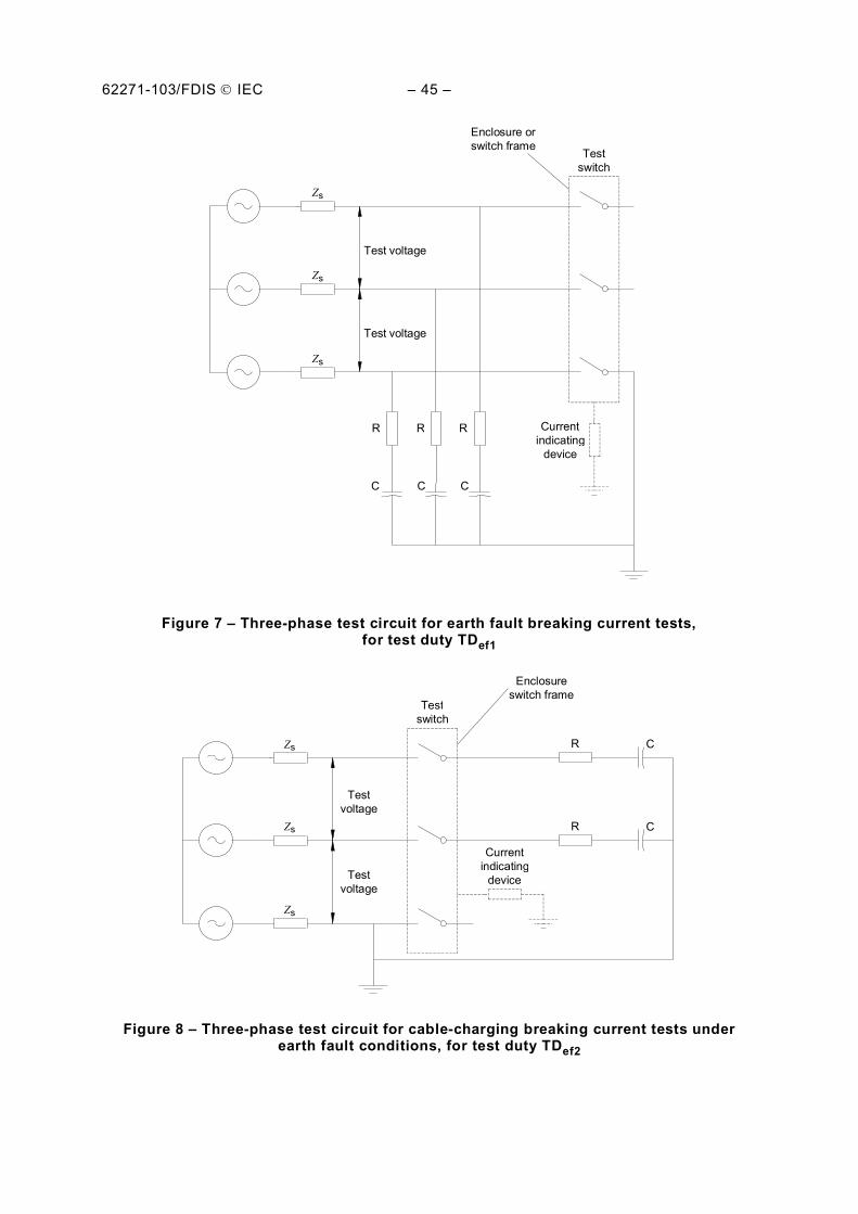
62271-103/FDIS IEC – 45 –
Zs
Testswitch
Currentindicating
device
Test voltage
Enclosure orswitch frame
R R R
C C C
Test voltage
Zs
Zs
Figure 7 – Three-phase test circuit for earth fault breaking current tests, for test duty TDef1
Zs
Enclosureswitch frame
R C
Testvoltage
Testvoltage
Testswitch
Currentindicating
device
R CZs
Zs
Figure 8 – Three-phase test circuit for cable-charging breaking current tests under earth fault conditions, for test duty TDef2
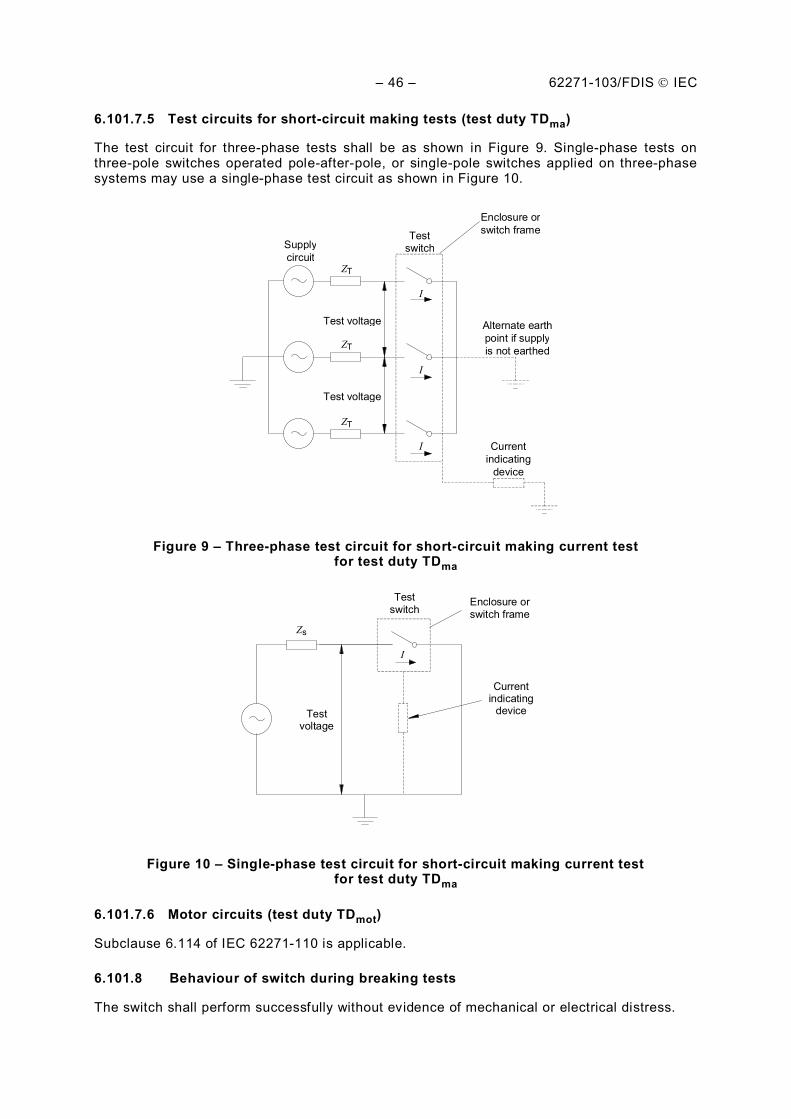
– 46 – 62271-103/FDIS IEC
6.101.7.5 Test circuits for short-circuit making tests (test duty TDma)
The test circuit for three-phase tests shall be as shown in Figure 9. Single-phase tests on three-pole switches operated pole-after-pole, or single-pole switches applied on three-phase systems may use a single-phase test circuit as shown in Figure 10.
ZT Supplycircuit
Testswitch
I
Current indicating
device
Test voltage
Enclosure orswitch frame
Test voltage
Alternate earthpoint if supplyis not earthedZT
ZT
I
I
Figure 9 – Three-phase test circuit for short-circuit making current test for test duty TDma
I
Test switch
Enclosure or switch frame
Current indicating
device Test voltage
Zs
Figure 10 – Single-phase test circuit for short-circuit making current test for test duty TDma
6.101.7.6 Motor circuits (test duty TDmot)
Subclause 6.114 of IEC 62271-110 is applicable.
6.101.8 Behaviour of switch during breaking tests
The switch shall perform successfully without evidence of mechanical or electrical distress.
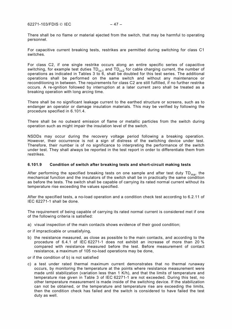
62271-103/FDIS IEC – 47 –
There shall be no flame or material ejected from the switch, that may be harmful to operating personnel.
For capacitive current breaking tests, restrikes are permitted during switching for class C1 switches.
For class C2, if one single restrike occurs along an entire specific series of capacitive switching, for example test duties TDcc1 and TDcc2 for cable charging current, the number of operations as indicated in Tables 3 to 6, shall be doubled for this test series. The additional operations shall be performed on the same switch and without any maintenance or reconditioning in between. The requirements for class C2 are still fulfilled, if no further restrike occurs. A re-ignition followed by interruption at a later current zero shall be treated as a breaking operation with long arcing time.
There shall be no significant leakage current to the earthed structure or screens, such as to endanger an operator or damage insulation materials. This may be verified by following the procedure specified in 6.101.4.
There shall be no outward emission of flame or metallic particles from the switch during operation such as might impair the insulation level of the switch.
NSDDs may occur during the recovery voltage period following a breaking operation. However, their occurrence is not a sign of distress of the switching device under test. Therefore, their number is of no significance to interpreting the performance of the switch under test. They shall always be reported in the test report in order to differentiate them from restrikes.
6.101.9 Condition of switch after breaking tests and short-circuit making tests
After performing the specified breaking tests on one sample and after test duty TDma, the mechanical function and the insulators of the switch shall be in practically the same condition as before the tests. The switch shall be capable of carrying its rated normal current without its temperature rise exceeding the values specified.
After the specified tests, a no-load operation and a condition check test according to 6.2.11 of IEC 62271-1 shall be done.
The requirement of being capable of carrying its rated normal current is considered met if one of the following criteria is satisfied:
a) visual inspection of the main contacts shows evidence of their good condition; or if impracticable or unsatisfying, b) the resistance measured, as close as possible to the main contacts, and according to the
procedure of 6.4.1 of IEC 62271-1 does not exhibit an increase of more than 20 % compared with resistance measured before the test. Before measurement of contact resistance, a maximum of 105 no-load operations may be done,
or if the condition of b) is not satisfied c) a test under rated thermal maximum current demonstrates that no thermal runaway
occurs, by monitoring the temperature at the points where resistance measurement were made until stabilization (variation less than 1 K/h), and that the limits of temperature and temperature rise given in Table 3 of IEC 62271-1 are not exceeded. During this test, no other temperature measurement is made inside of the switching device. If the stabilization can not be obtained, or the temperature and temperature rise are exceeding the limits, then the condition check has failed and the switch is considered to have failed the test duty as well.
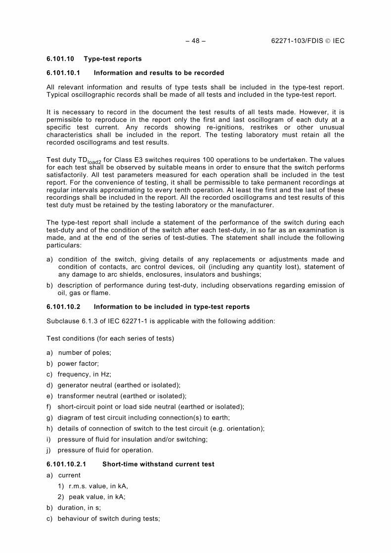
– 48 – 62271-103/FDIS IEC
6.101.10 Type-test reports
6.101.10.1 Information and results to be recorded
All relevant information and results of type tests shall be included in the type-test report. Typical oscillographic records shall be made of all tests and included in the type-test report.
It is necessary to record in the document the test results of all tests made. However, it is permissible to reproduce in the report only the first and last oscillogram of each duty at a specific test current. Any records showing re-ignitions, restrikes or other unusual characteristics shall be included in the report. The testing laboratory must retain all the recorded oscillograms and test results.
Test duty TDload2 for Class E3 switches requires 100 operations to be undertaken. The values for each test shall be observed by suitable means in order to ensure that the switch performs satisfactorily. All test parameters measured for each operation shall be included in the test report. For the convenience of testing, it shall be permissible to take permanent recordings at regular intervals approximating to every tenth operation. At least the first and the last of these recordings shall be included in the report. All the recorded oscillograms and test results of this test duty must be retained by the testing laboratory or the manufacturer.
The type-test report shall include a statement of the performance of the switch during each test-duty and of the condition of the switch after each test-duty, in so far as an examination is made, and at the end of the series of test-duties. The statement shall include the following particulars:
a) condition of the switch, giving details of any replacements or adjustments made and condition of contacts, arc control devices, oil (including any quantity lost), statement of any damage to arc shields, enclosures, insulators and bushings;
b) description of performance during test-duty, including observations regarding emission of oil, gas or flame.
6.101.10.2 Information to be included in type-test reports
Subclause 6.1.3 of IEC 62271-1 is applicable with the following addition:
Test conditions (for each series of tests)
a) number of poles; b) power factor; c) frequency, in Hz; d) generator neutral (earthed or isolated); e) transformer neutral (earthed or isolated); f) short-circuit point or load side neutral (earthed or isolated); g) diagram of test circuit including connection(s) to earth; h) details of connection of switch to the test circuit (e.g. orientation); i) pressure of fluid for insulation and/or switching; j) pressure of fluid for operation.
6.101.10.2.1 Short-time withstand current test a) current
1) r.m.s. value, in kA, 2) peak value, in kA;
b) duration, in s; c) behaviour of switch during tests;
62271-103/FDIS IEC – 49 –
d) condition after tests;
e) resistance of the main circuit before and after tests, in .
6.101.10.2.2 Making and breaking tests a) applied voltage, in kV; b) making current (peak value), in kA; (in case of short-circuit making tests); c) breaking current r.m.s. value of a.c. component in A for each phase and average; d) power frequency recovery voltage, in kV; e) prospective transient recovery voltage; f) arcing time, in ms; g) opening time, in ms (if applicable); h) break time, in ms (if applicable); i) make time, in ms (if applicable); j) behaviour of switch during tests, including, where applicable, emission of flame, gas, oil or
occurrence of NSDDs, etc; k) condition after tests; l) parts renewed or reconditioned during the tests.
6.101.10.2.3 Capacitive current switching tests a) test voltage, in kV; b) breaking current in each phase, in A; c) peak values of the voltage between phase and earth, in kV after interruption
1) supply side of the switch, 2) load side of the switch;
d) number of restrikes (if any); e) opening time, in ms (if applicable); f) break time, in ms (if applicable); g) make time, in ms (if applicable); h) behaviour of switch during tests; i) condition after tests.
6.102 Mechanical and environmental tests
6.102.1 Miscellaneous provisions for mechanical and environmental tests
6.102.1.1 Mechanical characteristics
At the beginning of the type tests, the mechanical characteristics of the switch shall be established, for example, by recording no-load travel curves.
The mechanical characteristics shall be produced during a no-load test made with one single C operation and one single O operation and, if applicable at rated supply voltage of operating devices and of auxiliary and control circuits, rated functional pressure for operation and, at the rated functional pressure for interruption.
The opening and the closing characteristics recorded in the reference no-load test shall be used as reference closing and reference opening characteristics. The allowable deviations from these reference characteristics correspond to the tolerances given by the manufacturer when performed under the same conditions as used for the procedure to produce the reference mechanical characteristics.
– 50 – 62271-103/FDIS IEC
6.102.1.2 Arrangement of the switch for tests
The switch should be mounted on its own support and its operating mechanism shall be operated in the specified manner.
Unless otherwise specified, the tests may be made at any convenient ambient air temperature.
If applicable, the supply voltage of the operating device shall be measured at the terminals of the closing and tripping coils during operation of the switch. Auxiliary equipment forming part of the operating device shall be included. Impedance shall not be added between the supply and the terminals of the device for regulation of the applied voltage.
For manually operated switches, the handle may, for convenience of testing, be replaced by an external power device where the operating force is equivalent to that for operation with a manual handle.
At the beginning of each test, the switch shall be at its rated functional pressure for interruption, if applicable.
A switch design may be fitted with several variants of auxiliary equipment (shunt releases and motors) in order to accommodate the various rated control voltages and frequencies as stated in 4.8 and 4.9. These variants do not need to be tested if they are of similar designs and if the resulting no-load mechanical characteristics are within the tolerance given in 6.102.1.1.
6.102.1.3 Evaluation of the operating characteristics before and after mechanical and environmental tests
For evaluation of the operating characteristics, the following operations shall be performed:
– five close-open operating cycles at the rated supply voltage and/or pressure (if any); – five close-open operating cycles at the minimum supply voltage and/or pressure (if any); – five close-open operating cycles at the maximum supply voltage and/or pressure (if any); – five close-open manual operations if the switch can only be operated manually or, if a
power-operated switch also allows manual operation.
The operating characteristics shall be recorded, if applicable, such as operating times, consumption of the control circuit, maximum forces for manual operation; satisfactory operation of control and auxiliary contacts, and position-indicating devices (if any) shall be verified. It is not necessary to include all the oscillograms recorded in the type-test report.
6.102.1.4 Condition of switch during and after mechanical operation tests
The switch shall be in such a condition that it is capable of operating normally, making, carrying and breaking its rated normal current.
Satisfactory operation of operating devices, of control and auxiliary contacts, and of position-indicating devices (if any), shall be verified during the test.
For switches having gas as a switching and/or insulating medium, a tightness test shall be performed after the mechanical operation test.
Some maintenance operations in accordance with the manufacturer’s instructions are permissible during the mechanical endurance tests for class M1 and class M2 switches and, shall be recorded:
– lubrication is permissible during the test;
62271-103/FDIS IEC – 51 –
– some mechanical adjustments are allowed after each set of 1 000 CO operations, but change of contacts is not permitted.
Before the visual inspection, a condition check test according to 6.2.11 of IEC 62271-1 shall be done.
The requirement of being capable of carrying its rated normal current is considered met if one of the following criteria is satisfied:
a) visual inspection of the main contacts shows evidence of their good condition; or if impracticable or unsatisfying, b) the resistance measured, as close as possible to the main contacts, and according to the
procedure of 6.4.1 of IEC 62271-1 does not exhibit an increase of more than 20 % compared with resistance measured before the test.
or if the condition of b) is not satisfied c) a test under rated thermal maximum current demonstrates that no thermal runaway
occurs, by monitoring the temperature at the points where resistance measurement were made until stabilization (variation less than 1 K per hour), and that the limits of temperature and temperature rise given in Table 3 of IEC 62271-1 are not exceeded. During this test, no other temperature measurement is made inside of the switching device. If the stabilization can not be obtained, or the temperature and temperature rise are exceeding the limits, then the condition check shall have failed and the switch is considered to have failed the test duty as well.
Vacuum switches are excluded from the tightness verification tests. The integrity of the vacuum will be verified by a power frequency voltage test after the mechanical and after the environmental tests. However, if the vacuum switch is used in an enclosure filled with an insulating gas, for example SF6, the tightness verification tests shall be performed on this enclosure.
6.102.2 Mechanical operation test at ambient air temperature
6.102.2.1 Mechanical endurance test for class M1 switches
The mechanical operation tests shall consist of 1 000 operating cycles without voltage on, or current in, the main circuit. If a capability beyond 1 000 operating cycles is required for all classes of switches, extended mechanical endurance tests should be conducted in accordance with 6.102.4.
A switch having a power-operating device shall be subjected to the following tests:
– 900 operating cycles at rated supply voltage and/or rated pressure of compressed gas supply;
– 50 operating cycles at the specified minimum supply voltage and/or minimum pressure of compressed gas supply;
– 50 operating cycles at the specified maximum supply voltage and/or maximum pressure of compressed gas supply.
The operating cycles can be performed in any convenient order.
A manually operated switch shall be subjected to the following test: 1 000 operating cycles using a range of operating forces typical of that to be expected in service.
No specific time intervals between operating cycles or between closing and opening operations are required. These tests shall be made, however, at a rate such that the temperature rises of the energized electrical control components do not exceed the specified values. External cooling may be applied during the test.
– 52 – 62271-103/FDIS IEC
6.102.2.2 Mechanical endurance tests for class M2 switches
These endurance tests only apply to power-operated switches.
Mechanical endurance tests shall be carried out as follows.
The tests shall be made according to 6.102.2 with the following addition: 5 000 operating cycles shall be performed comprising five times the number of operating cycles specified in the 6.102.2.
The program of maintenance during the tests shall be defined by the manufacturer before the test and recorded in the test report.
6.102.3 Low and high temperature tests
6.102.3.1 General
The two tests need not be performed in succession, and the order in which they are made is arbitrary. For class –5 °C indoor switches and for class –10 °C outdoor switches, no low temperature test is required.
For single enclosure switches or multi-enclosure switches with a common operating device, three-pole tests shall be made.
If heat sources are required, they shall be in operation.
No maintenance, replacement of parts, lubrication or readjustment of the switch is permissible during the tests.
6.102.3.2 Measurement of ambient air temperature
The ambient air temperature of the immediate test environment shall be measured at half the height of the switch and at a distance of 1 m from the switch.
The maximum temperature deviation over the height of the switch shall not exceed 5 K.
6.102.3.3 Low temperature test
The diagram of the test sequences and identification of the application points for the tests specified are given in Figure 11a.
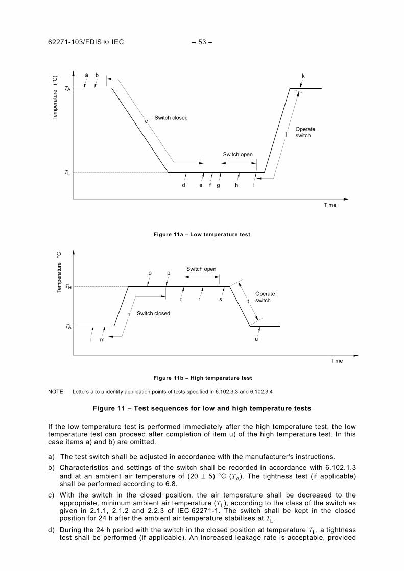
62271-103/FDIS IEC – 53 –
Tem
pera
ture
(°
C) a b
d e f g h i
j
c
k
Switch closed
Operate switch
Switch open
TA
TL
Time
Figure 11a – Low temperature test
o p
m
q r s t
u
n
l
TH
TA
Tem
pera
ture
°C
Time
Operate switch
Switch open
Switch closed
Figure 11b – High temperature test NOTE Letters a to u identify application points of tests specified in 6.102.3.3 and 6.102.3.4
Figure 11 – Test sequences for low and high temperature tests
If the low temperature test is performed immediately after the high temperature test, the low temperature test can proceed after completion of item u) of the high temperature test. In this case items a) and b) are omitted.
a) The test switch shall be adjusted in accordance with the manufacturer's instructions. b) Characteristics and settings of the switch shall be recorded in accordance with 6.102.1.3
and at an ambient air temperature of (20 5) °C (TA). The tightness test (if applicable) shall be performed according to 6.8.
c) With the switch in the closed position, the air temperature shall be decreased to the appropriate, minimum ambient air temperature (TL), according to the class of the switch as given in 2.1.1, 2.1.2 and 2.2.3 of IEC 62271-1. The switch shall be kept in the closed position for 24 h after the ambient air temperature stabilises at TL.
d) During the 24 h period with the switch in the closed position at temperature TL, a tightness test shall be performed (if applicable). An increased leakage rate is acceptable, provided
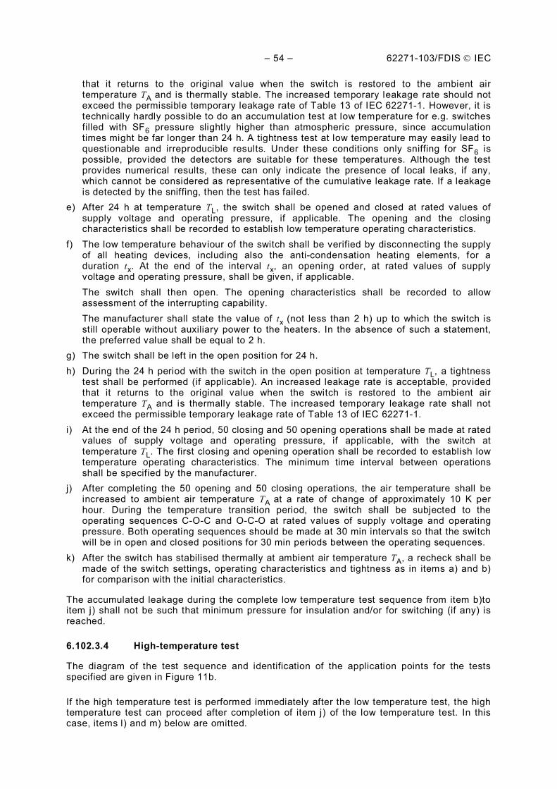
– 54 – 62271-103/FDIS IEC
that it returns to the original value when the switch is restored to the ambient air temperature TA and is thermally stable. The increased temporary leakage rate should not exceed the permissible temporary leakage rate of Table 13 of IEC 62271-1. However, it is technically hardly possible to do an accumulation test at low temperature for e.g. switches filled with SF6 pressure slightly higher than atmospheric pressure, since accumulation times might be far longer than 24 h. A tightness test at low temperature may easily lead to questionable and irreproducible results. Under these conditions only sniffing for SF6 is possible, provided the detectors are suitable for these temperatures. Although the test provides numerical results, these can only indicate the presence of local leaks, if any, which cannot be considered as representative of the cumulative leakage rate. If a leakage is detected by the sniffing, then the test has failed.
e) After 24 h at temperature TL, the switch shall be opened and closed at rated values of supply voltage and operating pressure, if applicable. The opening and the closing characteristics shall be recorded to establish low temperature operating characteristics.
f) The low temperature behaviour of the switch shall be verified by disconnecting the supply of all heating devices, including also the anti-condensation heating elements, for a duration tx. At the end of the interval tx, an opening order, at rated values of supply voltage and operating pressure, shall be given, if applicable.
The switch shall then open. The opening characteristics shall be recorded to allow assessment of the interrupting capability.
The manufacturer shall state the value of tx (not less than 2 h) up to which the switch is still operable without auxiliary power to the heaters. In the absence of such a statement, the preferred value shall be equal to 2 h.
g) The switch shall be left in the open position for 24 h. h) During the 24 h period with the switch in the open position at temperature TL, a tightness
test shall be performed (if applicable). An increased leakage rate is acceptable, provided that it returns to the original value when the switch is restored to the ambient air temperature TA and is thermally stable. The increased temporary leakage rate shall not exceed the permissible temporary leakage rate of Table 13 of IEC 62271-1.
i) At the end of the 24 h period, 50 closing and 50 opening operations shall be made at rated values of supply voltage and operating pressure, if applicable, with the switch at temperature TL. The first closing and opening operation shall be recorded to establish low temperature operating characteristics. The minimum time interval between operations shall be specified by the manufacturer.
j) After completing the 50 opening and 50 closing operations, the air temperature shall be increased to ambient air temperature TA at a rate of change of approximately 10 K per hour. During the temperature transition period, the switch shall be subjected to the operating sequences C-O-C and O-C-O at rated values of supply voltage and operating pressure. Both operating sequences should be made at 30 min intervals so that the switch will be in open and closed positions for 30 min periods between the operating sequences.
k) After the switch has stabilised thermally at ambient air temperature TA, a recheck shall be made of the switch settings, operating characteristics and tightness as in items a) and b) for comparison with the initial characteristics.
The accumulated leakage during the complete low temperature test sequence from item b)to item j) shall not be such that minimum pressure for insulation and/or for switching (if any) is reached.
6.102.3.4 High-temperature test
The diagram of the test sequence and identification of the application points for the tests specified are given in Figure 11b.
If the high temperature test is performed immediately after the low temperature test, the high temperature test can proceed after completion of item j) of the low temperature test. In this case, items l) and m) below are omitted.
62271-103/FDIS IEC – 55 –
l) The test switch shall be adjusted in accordance with the manufacturer's instructions. m) Characteristics and settings of the switch shall be recorded in accordance with 6.102.1.3
and at an ambient air temperature of (20 5) C (TA). The tightness test (if applicable) shall be performed according to 6.8.
n) With the switch in the closed position, the air temperature shall be increased to the appropriate, maximum ambient air temperature (TH), according to the upper limit of ambient air temperature as given in 2.1.1, 2.1.2 and 2.2.3 of IEC 62271-1. The switch shall be kept in the closed position for 24 h after the ambient air temperature stabilises at TH.
NOTE The influence of solar radiation is not considered.
o) During the 24 h period with the switch in the closed position at the temperature TH, a tightness test shall be performed (if applicable). An increased leakage rate is acceptable, provided that it returns to the original value when the switch is restored to the ambient air temperature TA and is thermally stable. The increased temporary leakage rate shall not exceed the permissible temporary leakage rate of Table 13 of IEC 62271-1.
p) After 24 h at the temperature TH, the switch shall be opened and closed at rated values of supply voltage and operating pressure. The opening and the closing characteristics shall be recorded to establish high temperature operating characteristics.
q) The switch shall be opened and left open for 24 h at the temperature TH.
r) During the 24 h period with the switch in the open position at the temperature TH, a tightness test shall be performed (if applicable). An increased leakage rate is acceptable, provided that it returns to the original value when the switch is restored to the ambient air temperature TA and is thermally stable. The increased temporary leakage rate should not exceed the permissible temporary leakage rate of Table 13 of IEC 62271-1. However, it is technically hardly possible to do an accumulation test at high temperature for e.g. switches filled with SF6 pressure slightly higher than atmospheric pressure, since accumulation times might be far longer than 24 h. A tightness test at high temperature may easily lead to questionable and irreproducible results. Under these conditions only sniffing for SF6 is possible, provided the detectors are suitable for these temperatures. Although the test provides numerical results, these can only indicate the presence of local leaks, if any, which cannot be considered as representative of the cumulative leakage rate. If a leakage is detected by the sniffing, then the test has failed.
s) At the end of the 24 h period, 50 closing and 50 opening operations shall be made at rated values of supply voltage and operating pressure with the switch at the temperature TH. The first closing and opening operation shall be recorded to establish high temperature operating characteristics. The minimum time interval between operations shall be specified by the manufacturer.
t) After completing the 50 opening and 50 closing operations, the air temperature shall be decreased to ambient air temperature TA, at a rate of change of approximately 10 K/h. During the temperature transition period the switch shall be subjected to the operating sequences C-O-C and O-C-O at rated values of supply voltage and operating pressure. Both operating sequences should be made at 30 min intervals so that the switch will be in open and closed positions for 30 min periods between the operating sequences.
u) After the switch has stabilised thermally at ambient air temperature TA, a recheck shall be made of the switch settings, operating characteristics and tightness as in items l) and m) for comparison with the initial characteristics.
The accumulated leakage during the complete high temperature test sequence from item l) to item t) shall not be such that minimum pressure for insulation and/or for switching (if any) is reached.
6.102.4 Humidity test on auxiliary and control circuits
6.102.4.1 General
The humidity test does not apply to equipment which is designed to be directly exposed to precipitation, for example primary parts of outdoor switches. The test shall be performed on
– 56 – 62271-103/FDIS IEC
switches or switch components, where due to sudden changes of the temperature condensation may occur on insulating surfaces which are continuously stressed by voltage. This is mainly the insulation of the auxiliary and control circuits of indoor installed switches. The test is not necessary if the switch is used within a switchgear for which tests on auxiliary and control circuits include environmental tests. It is also not necessary where effective means against condensation are provided, for example control cubicles with anti-condensation heaters.
Applying the test procedure described in 6.102.4.2, the withstand of the test object, primarily switch components, to humidity effects, which may produce condensation on the surface of the test specimen, is determined in an accelerated manner.
6.102.4.2 Test procedure
The test object shall be arranged in a test chamber containing circulating air and in which the temperature and humidity shall follow the cycle given below:
During about half of the cycle the surfaces of the test object shall be wet, and dry during the other half. To obtain this result the test cycle consists of a period t4 with low air temperature (Tmin = 25 °C 3 °C) and a period t2 with high air temperature (Tmax = 40 °C 2 °C) inside the test chamber. Both periods shall be equal in time. The generation of fog shall be maintained for that half of the cycle (see Figure 12) in which the low air temperature is applied.
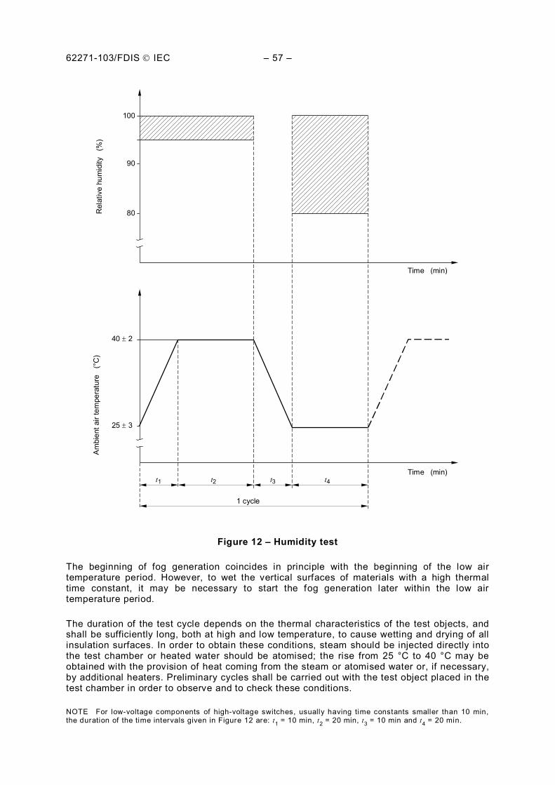
62271-103/FDIS IEC – 57 –
R
elat
ive
hum
idity
(%
)
100
90
80
Time (min)
Am
bien
t air
tem
pera
ture
(°
C)
40 2
25 3
Time (min)
1 cycle
t1 t2 t3 t4
Figure 12 – Humidity test
The beginning of fog generation coincides in principle with the beginning of the low air temperature period. However, to wet the vertical surfaces of materials with a high thermal time constant, it may be necessary to start the fog generation later within the low air temperature period.
The duration of the test cycle depends on the thermal characteristics of the test objects, and shall be sufficiently long, both at high and low temperature, to cause wetting and drying of all insulation surfaces. In order to obtain these conditions, steam should be injected directly into the test chamber or heated water should be atomised; the rise from 25 °C to 40 °C may be obtained with the provision of heat coming from the steam or atomised water or, if necessary, by additional heaters. Preliminary cycles shall be carried out with the test object placed in the test chamber in order to observe and to check these conditions.
NOTE For low-voltage components of high-voltage switches, usually having time constants smaller than 10 min, the duration of the time intervals given in Figure 12 are: t1 = 10 min, t2 = 20 min, t3 = 10 min and t4 = 20 min.
– 58 – 62271-103/FDIS IEC
The fog is obtained by the continuous or periodical atomisation of 0,2 l to 0,4 l of water (with the resistivity characteristics given below) per hour and per cubic metre of test chamber volume. The diameter of the droplets shall be less than 10 m; such a fog may be obtained by mechanical atomisers. The direction of the spraying shall be such that the surfaces of the test object are not directly sprayed. No water shall drop from the ceiling upon the test object.
During the fog generation the test chamber shall be closed and no additional forced air circulation is permitted.
The water used to create the humidity shall be such that the water collected in the test chamber has a resistivity equal to or greater than 100 m and contains neither salt (NaCl) nor any corrosive element.
The temperature and the relative humidity of the air in the test chamber shall be measured in the immediate vicinity of the test object and shall be recorded for the whole duration of the test. No value of relative humidity is specified during the drop in temperature; however, the humidity shall be above 80 % during the period when the temperature is maintained at 25 °C.
The air shall be circulated in order to obtain uniform distribution of the humidity in the test chamber.
The number of cycles shall be 350.
During and after the test, the operating characteristics of the test objects shall not be affected. The auxiliary and control circuits shall withstand a power frequency voltage of 1 500 V for 1 min. The degree of corrosion, if any, should be indicated in the test report.
6.102.5 Operation under severe ice conditions
If required, tests shall be performed in accordance with 6.103 of IEC 62271-102, with the following exception:
Switches having stored energy or dependent power-operating mechanisms shall operate successfully on the first attempt to operate.
6.102.6 Tests to verify the proper functioning of the position indicating device
Subclause 6.105 of IEC 62271-102 is applicable with the following addition.
The position indicating device is specified in Annex A of IEC 62271-102, and shall be verified as defined for disconnectors.
However, for switches not having any isolating capability and actuated by independent driving mechanism, the position indicating device shall be verified as follows.
Besides the mechanical type tests specified in Clause 6, during which the correct functioning of the indicating device shall be verified, the equipment shall pass the following test in order to verify both the sufficient strength of the power kinematic chain and the reliability of the position-indicating kinematic chain.
Five trials to open the switch shall be performed after blocking in closed position (with suitable means) the farthest moving contact of the switch measured from the point of transmission of the energy from the driving mechanism. No measurement of forces/torques is required during these trials.
62271-103/FDIS IEC – 59 –
The five trials shall be performed with its own driving mechanism for each one of the different manners of being operated i.e. at normal forces (if manually operated up to 250 N) and at rated voltage or pressure (if power operated or if release operated).
When the position-indicating device is marked directly on a mechanical part of the power kinematic chain no more test is required.
If, during service operations, the part of the position-indicating kinematic chain between the power kinematic chain and the position-indicating device is inside an enclosure providing a minimum degree of protection equivalent to IP2XC of IEC 60529 as defined in Clause 4, and which has passed a mechanical impact test according to 6.7.2 of IEC 62271-1 with an energy of 2 J, no supplementary tests are required but the following remarks shall be considered.
The blows shall be applied to the points of the enclosure that are likely to be the weakest in relation to the protection of the indicating kinematic chain and the indicating device.
In all other cases, a test for each operating manner shall be carried out blocking the position-indicating device instead of the moving contact, and applying normal forces (if manually operated up to 250 N) and at rated voltage or pressure (if power operated or if release operated).
Each test is passed if
– after each test the three moving contacts remain in the close position and the position-indicating device indicates correctly the position of the moving contacts;
– there is no permanent distortion on the position-indicating kinematic chain.
7 Routine tests
Clause 7 of IEC 62271-1 is applicable with the following addition.
7.101 Mechanical operating tests
Operating tests are made to ensure that switches comply with the prescribed performance within the specified limits.
During these tests, which are performed without voltage or current in the main circuit, it shall be verified, in particular, that the switches open and close correctly when their operating devices are energized or under pressure. It shall also be verified that operation will not cause any damage to the switches.
The arrangement of the switch shall comply with specifications for the mechanical operation type tests, refer to 6.102.1.
A switch having a power-operating device shall be subjected to the following tests:
– at specified maximum supply voltage and/or maximum pressure of compressed gas supply: five operating cycles;
– at specified minimum supply voltage and/or minimum pressure of compressed gas supply: five operating cycles;
– if a switch can be manually operated besides its normal electric or pneumatic operating device: five manual operating cycles.
A manually operated switch shall be subjected to the following test: 10 operating cycles.
– 60 – 62271-103/FDIS IEC
During these tests, no adjustment shall be made and the operation shall be faultless. It shall be verified that the position indication is operating correctly when the switches open and close.
8 Guide to the selection of switchgear and controlgear
8.101 General
This guide presents suggestions on application as an aid to obtaining satisfactory performance of high-voltage switches rated up to and including 52 kV.
It is offered in recognition of the continuing need for general guidelines to supplement, but not replace, the manufacturer's detailed instructions.
Refer to 2.1 of IEC 62271-1 for normal service condition requirements.
8.102 Conditions affecting application
Where unusual conditions exist, they should be brought to the attention of the manufacturer for his recommendations. Examples of such conditions are:
a) contamination such as damaging fumes or vapour, excessive or abrasive dust, explosive mixtures of dust or gases, salt spray, excessive moisture or dripping water, etc.;
b) abnormal vibration, shocks, tilting, or seismic activity; c) excessively high or low ambient temperatures; d) unusual transportation or storage conditions; e) unusual space limitations; f) mounting positions other than those recommended by the manufacturer; g) high altitude; h) wind velocity in excess of normal service conditions; i) unusual operating duty, frequency of operation, difficulty of maintenance, unbalanced
voltages, special insulation requirements, etc.; j) for use at other than rated frequency, such as harmonics associated with capacitor banks,
and rectifier circuits. The normal current rating of the switch should be such as to adequately carry the power-frequency current and the harmonic currents.
Refer to 2.2 of IEC 62271-1 for special service conditions.
8.103 Insulation coordination
The rated insulation level of a switch should be selected according to 4.2 of IEC 62271-1.
Refer to IEC 60071-1 for a general discussion and recommendations on insulation coordination.
8.104 Selection of class of switch
8.104.1 General purpose switch
Refer to 3.4.103 for purpose and application of class E1, E2, E3, M1, M2, C1 and C2 general purpose switches.
62271-103/FDIS IEC – 61 –
8.104.2 Limited purpose switch
Refer to 3.4.104 for definitions of the capabilities of a limited purpose switch and application of class M1, M2, C1 and C2.
8.104.3 Special purpose switch
Refer to 3.4.105 for definition of the capabilities and application of a special purpose switch and its classes E1, E2, E3, M1, M2, C1 and C2.
8.105 Tests for special applications
For special applications, tests may be defined on agreement between customer and manufacturer:
– tests to prove the ability of the switch to make or break currents that are specified by the user or are beyond the scope of the normal type tests;
– tests to verify that switches installed in systems where cable is connected to the switch can withstand the d.c. test voltages normally applied for the dielectric testing of cables. The a.c. voltage on the supply side of the switch should be considered when determining test voltages.
9 Information to be given with inquiries, tenders and orders
9.1 Information to be given with inquiries and orders
Subclause 9.1 of IEC 62271-1 is not applicable. It is modified as follows.
When inquiring for or ordering a switch, the following particulars should be supplied by the inquirer:
a) particulars of system: i.e., nominal and highest voltages, frequency, number of phases, and details of neutral earthing. Unusual characteristics of the system in which the switch is to be applied should be noted (harmonic currents, resonance conditions, number of operations required);
b) service conditions including minimum and maximum ambient air temperatures, if beyond the normal values; altitude, if over 1 000 m; and any special conditions likely to exist or arise, e.g. unusual exposure to steam or vapour, moisture, fumes, explosive gases, excessive dust, or salt air (see 2.1, 2.2 and 6.2.8 of IEC 62271-1 and 8.2 of this standard);
c) characteristics of the switch The following information should be given:
1) number of poles; 2) type and class of switch as defined in Clause 3; 3) indoor or outdoor installation; 4) rated voltage (4.1 of IEC 62271-1); 5) rated insulation level where a choice exists between different insulation levels
corresponding to a given rated voltage or, if other than standard, desired insulation level (4.2 of IEC 62271-1);
6) rated frequency (4.3 of IEC 62271-1); 7) rated normal current (4.4 of IEC 62271-1); 8) rated breaking currents; 9) rated short-circuit making current; 10) if other than standard, desired duration of short-circuit current (4.7 of IEC 62271-1); 11) the type tests required on special request;
– 62 – 62271-103/FDIS IEC
d) characteristics of the operating mechanism of switch and associated equipment, in particular: 1) method of operation, whether manual or power; 2) number and type of spare auxiliary switches; 3) rated supply voltage and rated supply frequency;
e) requirements concerning the use of compressed air and requirements for design and test of pressure vessels.
9.2 Information to be given with tenders
Subclause 9.2 of IEC 62271-1 is not applicable. It is modified as follows.
When the inquirer requests technical particulars of a switch, the following information, where applicable, should be given by the manufacturer, with any explanatory text and drawings:
a) rated values and characteristics: 1) number of poles, 2) type and class of switch as defined in Clause 3, 3) indoor or outdoor application, 4) rated voltage (4.1 of IEC 62271-1), 5) rated insulation level (4.2 of IEC 62271-1), 6) rated frequency (4.3 of IEC 62271-1), 7) rated normal current (4.4 of IEC 62271-1), 8) rated breaking currents as defined in Clause 3 and 4, if applicable, 9) rated short-circuit making current as defined in 3.7.115 and 4.112 if applicable, 10) rated duration short-circuit current (4.7 of IEC 62271-1);
b) type tests list of certificates or reports on request, including the special tests requested by the
inquirer; c) constructional features:
1) mass of complete switch, 2) gas pressure and limits of gas pressure within which the switch will operate correctly
for air blast switches and gas switches (4.10 of IEC 62271-1), 3) minimum clearances in air:
– between poles; – to earth.
d) operating mechanism of switch and associated equipment: 1) type of operating mechanism, 2) rated supply voltage of closing and opening devices (4.8 of IEC 62271-1), 3) rated supply frequency (4.9 of IEC 62271-1), 4) rated pressure of compressed gas supply for operation, 5) current required at rated supply voltage to close and open the switch, 6) quantity of free air required to close and open the switch at rated supply pressure, 7) rated supply voltage of shunt opening release, 8) current required at rated supply voltage for shunt opening release, 9) number and type of spare auxiliary switch contacts, 10) current required at rated supply voltage by other auxiliaries,
62271-103/FDIS IEC – 63 –
e) overall dimensions and other information. The manufacturer should give the necessary information regarding overall dimensions of
the switch and details necessary for installation. General information regarding maintenance should also be given.
10 Transport, storage, installation, operation and maintenance
Clause 10 of IEC 62271-1 is applicable with the following additional information.
Instructions shall also include every other rated value that is not in the mandatory list of the nameplate defined in Table 2.
11 Safety
Clause 11 of IEC 62271-1 is applicable.
12 Influence of the product on the environment
Clause 12 of IEC 62271-1 is applicable.
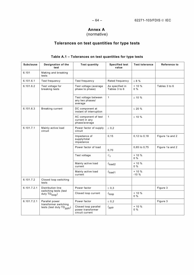
– 64 – 62271-103/FDIS IEC
Annex A (normative)
Tolerances on test quantities for type tests
Table A.1 – Tolerances on test quantities for type tests
Subclause Designation of the test
Test quantity Specified test value
Test tolerance Reference to
6.101 Making and breaking tests
6.101.6.1 Test frequency Test frequency Rated frequency 8 %
6.101.6.2 Test voltage for breaking tests
Test voltage (average phase to phase)
As specif ied in Tables 3 to 6
+ 10 % 0 %
Tables 3 to 6
Test voltage between any two phases/ average
1 10 %
6.101.6.3 Breaking current DC component at instant of interruption
20 %
AC component of test current in any phase/average
1 10 %
6.101.7.1 Mainly active load circuit
Power factor of supply circuit
0,2
Impedance of supply/total impedance
0,15 0,12 to 0,18 Figure 1a and 2
Power factor of load 0,70
0,65 to 0,75 Figure 1a and 2
Test voltage Ur + 10 % 0 %
Mainly active load current
Iload2 + 10 % 0 %
Mainly active load current
Iload1 + 10 % -10 %
6.101.7.2 Closed loop switching tests
6.101.7.2.1 Distribution line switching tests (test duty TDloop)
Power factor 0,3 Figure 3
Closed loop current Iloop + 10 % 0 %
6.101.7.2.1 Parallel power transformer switching tests (test duty TDpptr)
Power factor 0,2 Figure 3
Closed loop parallel power transformer circuit current
Ipptr + 10 % 0 %
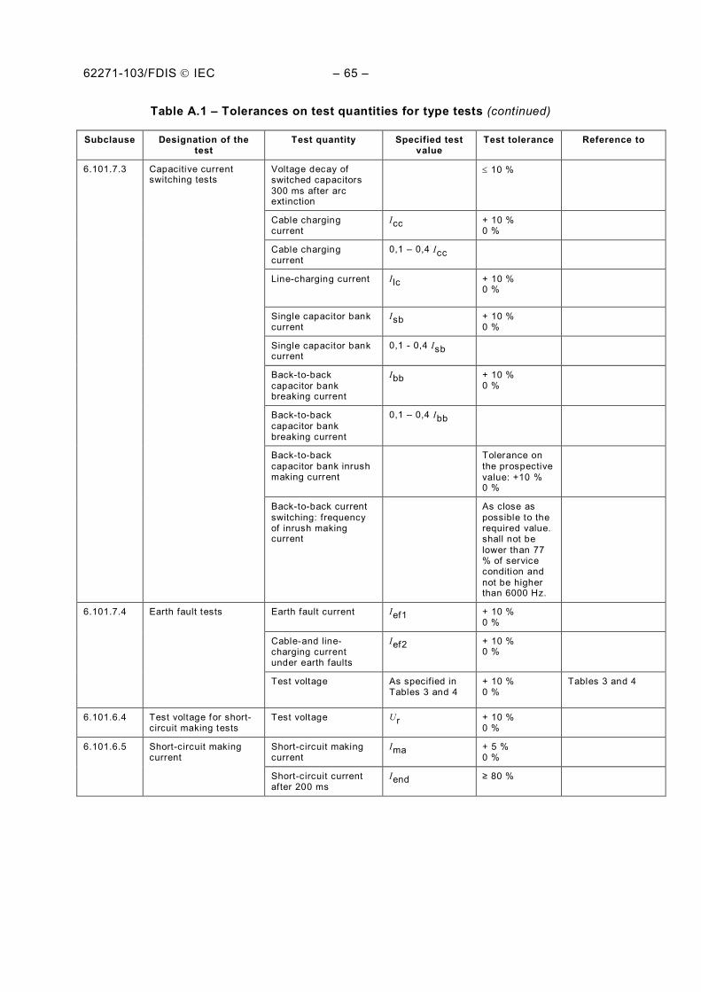
62271-103/FDIS IEC – 65 –
Table A.1 – Tolerances on test quantities for type tests (continued)
Subclause Designation of the test
Test quantity Specified test value
Test tolerance Reference to
6.101.7.3 Capacitive current switching tests
Voltage decay of switched capacitors 300 ms after arc extinction
10 %
Cable charging current
Icc + 10 % 0 %
Cable charging current
0,1 – 0,4 Icc
Line-charging current Ilc + 10 % 0 %
Single capacitor bank current
Isb + 10 % 0 %
Single capacitor bank current
0,1 - 0,4 Isb
Back-to-back capacitor bank breaking current
Ibb + 10 % 0 %
Back-to-back capacitor bank breaking current
0,1 – 0,4 Ibb
Back-to-back capacitor bank inrush making current
Tolerance on the prospective value: +10 % 0 %
Back-to-back current switching: frequency of inrush making current
As close as possible to the required value. shall not be lower than 77 % of service condition and not be higher than 6000 Hz.
6.101.7.4 Earth fault tests Earth fault current Ief1 + 10 % 0 %
Cable-and line-charging current under earth faults
Ief2 + 10 % 0 %
Test voltage As specif ied in Tables 3 and 4
+ 10 % 0 %
Tables 3 and 4
6.101.6.4 Test voltage for short-circuit making tests
Test voltage Ur + 10 % 0 %
6.101.6.5 Short-circuit making current
Short-circuit making current
Ima + 5 % 0 %
Short-circuit current after 200 ms
Iend 80 %
– 66 – 62271-103/FDIS IEC
Bibliography
[1] IEC 60059, IEC standard current ratings
[2] IEC 60071-1:2006, Insulation co-ordination – Part 1: Definitions, principles and rules
[3] IEC 62271-105, High-voltage switchgear and controlgear – Part 105: Alternating current switch-fuse combinations
[4] IEC 60507, Artificial pollution tests on high-voltage insulators to be used on a.c. systems
___________