Embed Size (px)
Citation preview

—
—
IEEE 1584 2.0 Changes Highlights

—
More analytical complexity,
more effort,
more decisions,
more inputs required �
more opportunities for mistakes…
IEEE 1584 2.0 model is more complex than the 2002 model
30/03/2019 Slide 2

—
Current Model (2002):
Contains approximately 3 pages of math
New Model:
• IEEE 1584 2.0 contains 17 pages of formulas, coefficients
and exponents.
• Also, more variables for a more representative model of
actual conditions… but more representative does not
mean “exact”
IEEE 1584 2.0 model is more complex than the 2002 model
30/03/2019 Slide 3

—
IEEE-2002 vs. IEEE 1584 2.0
30/03/2019 Slide 4
Current (2002) calculation variables:
• Gap (G) (equipment type driven)
• Working distance (D)
• Operating voltage (Voc)
• Available short circuit current (Ibf)
• Grounding (yes/no) (not new model)
• Box (yes/no)
What is the difference?
New model (2019) will add:
• Electrode orientation
• Electrode environment (barriers?)
• Box size considerations
• More variable gap considerations
• Results may vary significantly
• Arcing Current (Ia)
• Incident Energy (Ei)
• Approach Boundary
—
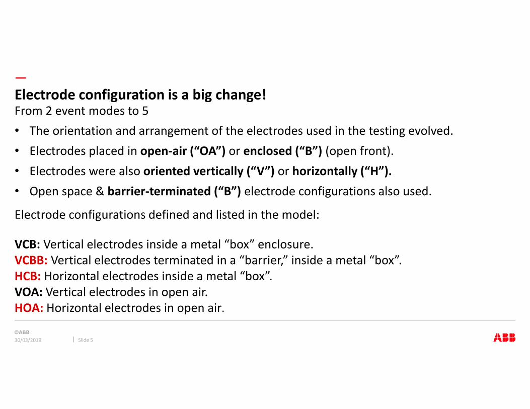
• The orientation and arrangement of the electrodes used in the testing evolved.
• Electrodes placed in open-air (“OA”) or enclosed (“B”) (open front).
• Electrodes were also oriented vertically (“V”) or horizontally (“H”).
• Open space & barrier-terminated (“B”) electrode configurations also used.
Electrode configurations defined and listed in the model:
VCB: Vertical electrodes inside a metal “box” enclosure.
VCBB: Vertical electrodes terminated in a “barrier,” inside a metal “box”.
HCB: Horizontal electrodes inside a metal “box”.
VOA: Vertical electrodes in open air.
HOA: Horizontal electrodes in open air.
Electrode configuration is a big change!
30/03/2019 Slide 5
From 2 event modes to 5

—
Horizontal electrodes aim plasma at
the worker!
Common sense � more dangerous…
“plasma rail”
aiming at worker!
The data confirms it!
Biggest difference is electrode direction
30/03/2019 Slide 6
Horizontal versus vertical makes a big difference.
Heat & plasma bounce around the
box & get pushed out via radiation
& pressure
Lorentz force pushes arc (plasma)
away from “end” of electrodes
Heat & plasma focused on worker
OLD MODEL
Additional in NEW
MODEL

—
Vertical electrodes inside metal
box enclosure.
Illustration of VCB
30/03/2019 Slide 7
Worker is mostly parallel to the
direct plasma stream

—
Vertical electrodes terminated in a barrier inside a metal box
Reduced space “under” the circuit breaker
Illustration of VCBB
30/03/2019 Slide 8

—
Horizontal electrodes inside a metal box
Best examples are probably the runbacks on any switchgear
Illustration of HCB
30/03/2019 Slide 9
Worker is mostly perpendicular to
the direct plasma stream

—
Vertical electrodes in open air
Frequently an outdoor issue
Illustration of VOA
30/03/2019 Slide 10
The electrodes are vertical.. But
where is the worker?
—
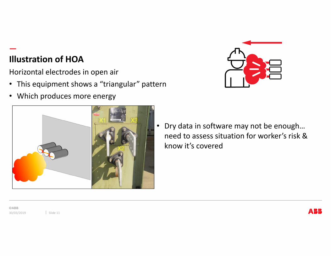
Horizontal electrodes in open air
• This equipment shows a “triangular” pattern
• Which produces more energy
Illustration of HOA
30/03/2019 Slide 11
• Dry data in software may not be enough…
need to assess situation for worker’s risk &
know it’s covered

—
Two methods
• Model for 600 ≤ Voc ≤ 15000 Volts
• Model for 208 ≤ Voc < 600 Volts
But no discontinuity in arcing current or energy function like old model at 1000V
Two-step process
1. Intermediate values of average arc current, incident energy and arc-flash boundary are
interpolated, or extrapolated to determine final values
2. Correction factors for enclosure (box) size and arc current variation are applied to adjust
results.
Similar to 2002 regarding current variation, box size variation is a new twist!
2 step process continuous over voltage range
30/03/2019 Slide 12

—
Three equations, one at each of the three Voc (600, 2700 & 14300 V)
must be solved with 10 different coefficients each
600 V - 14.3 kV, Intermediate Arcing Current Value
30/03/2019 Slide 13

—
600 V - 14.3 kV, Intermediate Arcing Current Value
30/03/2019 Slide 14
Example of coefficient tables (1 of 6)
k1 k2 k3 k4 k5 k6 k7 k8 k9 k10
600V -0.04287 1.035 -0.083 0 0 -4.78E-09 1.96E-06 -0.000229 0.003141 1.092
2700V 0.0065 1.001 -0.024 -1.56E-12 4.56E-10 -4.19E-08 8.35E-07 5.48E-05 -0.003191 0.9729
14300V 0.005795 1.015 -0.011 -1.56E-12 4.56E-10 -4.19E-08 8.35E-07 5.48E-05 -0.003191 0.9729
600V -0.017432 0.98 -0.05 0 0 -5.77E-09 2.52E-06 -0.00034 0.01187 1.013
2700V 0.002823 0.995 -0.0125 0 -9.20E-11 2.90E-08 -3.26E-06 0.0001569 -0.004003 0.9825
14300V 0.014827 1.01 -0.01 0 -9.20E-11 2.90E-08 -3.26E-06 0.0001569 -0.004003 0.9825
600V 0.054922 0.988 -0.11 0 0 -5.38E-09 2.32E-06 -0.000302 0.0091 0.9725
2700V 0.001011 1.003 -0.0249 0 0 4.86E-10 -1.81E-07 -9.13E-06 -0.0007 0.9881
14300V 0.008693 0.999 -0.02 0 -5.04E-11 2.23E-08 -3.05E-06 0.000116 -0.001145 0.9839
600V 0.043785 1.04 -0.18 0 0 -4.78E-09 1.96E-06 -0.000229 0.003141 1.092
2700V -0.02395 1.006 -0.0188 -1.56E-12 4.56E-10 -4.19E-08 8.35E-07 5.48E-05 -0.003191 0.9729
14300V 0.005371 1.0102 -0.029 -1.56E-12 4.56E-10 -4.19E-08 8.35E-07 5.48E-05 -0.003191 0.9729
600V 0.111147 1.008 -0.24 0 0 -3.90E-09 1.64E-06 -0.000197 0.002615 1.1
2700V 0.000435 1.006 -0.038 0 0 7.86E-10 -1.91E-07 -9.13E-06 -0.0007 0.9981
14300V 0.000904 0.999 -0.02 0 0 7.86E-10 -1.91E-07 -9.13E-06 -0.0007 0.9981
VOA
Table 1, Coefficients Iavg, V 2.6.2
HOA
VCB
VCBB
HCB

—
Values calculated at 3 voltages, 600,
2700 & 14300V… then interpolated
to actual Voc
Intermediate values of energy
30/03/2019 Slide 15

—
Box Correction Factor
30/03/2019 Slide 16
Logic rules select formulas for CF from normalized data… not intuitive

—
• Single phase method: use single phase current & 3 phase formulas!
TOO conservative? Can probably divide energy by 3.
• DC arc research starting now!
Single phase and DC
30/03/2019 Slide 17

—
Working distance, important
for energy, no effect on Iarc
36” for hot stick work
18” for manual work
24” for deep cubicles
Working distance
30/03/2019 Slide 18

—
Same:
Ibf (rms, 50/60Hz):
208–600V: 500A-106 kA
601V– 15kV: 200A- 65 kA
Sustainable arcs are possible but are less likely in 240V 3-phase systems with Ibf < 2kA
Different:
Conductor Gap
208– 600V: 6.4mm (0.25in) - 76mm (3in)
601V – 15kV: 19mm (0.75in) - 254mm (10in)
Different:
Working distances:
minimum 305mm (12”),
LV tests to 47”, MV to 36”
Different:
Fault Clearing Time:
2 S. rule still in but its only guidance!
Model Range
30/03/2019 Slide 19

—
If the total protective device clearing time is longer than 2 seconds; consider how long a
person is likely to remain in the location of the arc-flash. It is likely that a person exposed to
an arc flash will move away quickly if it is physically possible, and two seconds usually is a
reasonable assumption for the arc duration to determine the incident energy. However, this
also depends on the specific task. A worker in a bucket truck, or inside an equipment
enclosure, could need more time to move away. Use engineering judgement when applying
any maximum arc duration time for incident energy exposure calculations, since there may
be circumstances where a person’s egress may be blocked.
Also in 70E-2018, D.2.4 (2) ! Part of the risk assessment portion of the analysis
2 second rule
30/03/2019 Slide 20
In 6.9.1 General

—
The more absolute the more secure
The more automatic the more secure
The less it depends on actions by the person becoming safer, the better
Humans make mistakes!
Do not forget - Hierarchy of Hazard Controls
30/03/2019 Slide 21
1. Elimination of the hazard
2. Substitution of less hazardous
equipment or materials
3. Engineering control to reduce
exposure or severity
4. Warnings, signs, and other
communications
5. Administrative control, including
safe work practices
6. Personal Protective equipment
Secured & verified de-energization
Smaller transformers, lower voltage,
insulated bus bars, internal barriers
Faster over-current protection,
energy shunting devices
Signage, training, indicating lights
Maintenance switch, specific work
practices
PPE per applicable standards,
temporary barriers
Hierarchy of Hazard Control
Measures (ANSI Z10)
Examples of Arc Flash Incident
Energy Control Measures
In order of most (1) to least (6) effective

—
Summary
30/03/2019 Slide 22
More complex, more data, decisions, judgement, knowledge, i.e.… more risk required for the new accuracy
• Inputs � wide variance in Iarc & Ei
• 2002 based study: possibly, wrong vs. new model
• NFPA 70E: update model with new information?
• Horizontal vs. vertical seems obvious
• Small vs large box seems obvious
• But model reflects a laboratory test protocol… regardless how accurate, it may not be a perfect replica of reality
• How to account for possible error ? Understand the effect of variance & take it into account!


—
—
NFPA 70E 2018 EDITION CHANGE HIGHLIGHTS

—
• OHSA is the law
• NFPA 70E outlines how to comply with OSHA’s electrical safety requirements
• OSHA is “What”
• NFPA 70E is “How”
Relation Between OSHA’s Standards & NFPA 70E
30/03/2019 Slide 25

—
• New Annex Q has been added
• Risk Assessment Procedure requires you to address human error
• Negative consequences of human on people
Human Error
30/03/2019 Slide 26

—
• The hierarchy moved into standard’s mandatory text
• First priority must be the elimination of the hazard
• Each method is considered less effective than the one before
Hierarchy of Risk Control Methods
30/03/2019 Slide 27

—
• Article 120 includes a restructured procedure to help how to set a program
Establishing an Electrically Safe Work Condition
30/03/2019 Slide 28

—
• Table 130.5C is used for arc flash assessment
• Table now applies to the incident energy analysis
Estimate of the Likelihood of an Occurrence of an Arc Flash
30/03/2019 Slide 29

—
• Use incident energy analysis method
• Table 130.5G moved into standard mandatory text
• Table revised to select gear when using incident energy analysis method
Selection of Arc-Rated Clothing
30/03/2019 Slide 30
—
• Employers are required to establish ESP for employees to follow
• This includes training to perform task safely
• NFPA 70E is about preventing the worker from being injured
Electrical Safety Program (ESP)
30/03/2019 Slide 31


![The Impact of the New IEEE 1584-2018 Standard on Arc Flash … · 2021. 1. 26. · IEEE Std C37.010-1999 […]. The calculations omit all motors of less than 50 hp each." • IEEE](https://img.pdfslide.net/doc/110x75/60dcb5a8b6708869213f7518/the-impact-of-the-new-ieee-1584-2018-standard-on-arc-flash-2021-1-26-ieee-std.jpg)


![NOVEL APPROACH to ARC FLASH MITIGATION for LOW VOLTAGE ... · NOVEL APPROACH to ARC FLASH MITIGATION for LOW ... Senior Member, IEEE Member, ... on IEEE 1584-2002 [3]](https://img.pdfslide.net/doc/110x75/5acc241f7f8b9ad13e8c7b75/novel-approach-to-arc-flash-mitigation-for-low-voltage-approach-to-arc-flash.jpg)

![Arc-Flash Hazard Analysis€¢ Arc Current Equations (empirically derived from IEEE 1584) Log(I arc) ... IEEE Guide for Performing Arc-Flash Hazard Calculations, IEEE 1584-2002. [2]](https://img.pdfslide.net/doc/110x75/5acc0bf77f8b9aa1518bd727/arc-flash-hazard-arc-current-equations-empirically-derived-from-ieee-1584-logi.jpg)