Embed Size (px)
Citation preview
IEEE 1801 Assisted Custom IP Development and Low Power Checks Using Cadence Virtuoso
Power Manager
Matthias Steffen, Infineon Technologies
Amit Chopra, Cadence Design Systems Inc.
Sonal Singh, Cadence Design Systems (I) Pvt. Ltd.
2
Agenda
• Introduction
• Supply concept and domains – Concept Level vs IP Level
• Objectives and Benefit
• Brief Overview about IEEE 1801 Format
• Importing Power Intent via UPF
• Verifying power intent against design using IEEE 1801 Export
• Conclusion
Introduction
• Complex mixed-signal IPs can have multiple internal power domains powered by internal voltage regulators.
– Supply concept and domains may be defined top-down at conceptual level
– The designer needs to implement them in sub-blocks with corresponding power supply architecture.
– Power domains in mixed-signal IPs lead to higher complexity in the implementation.
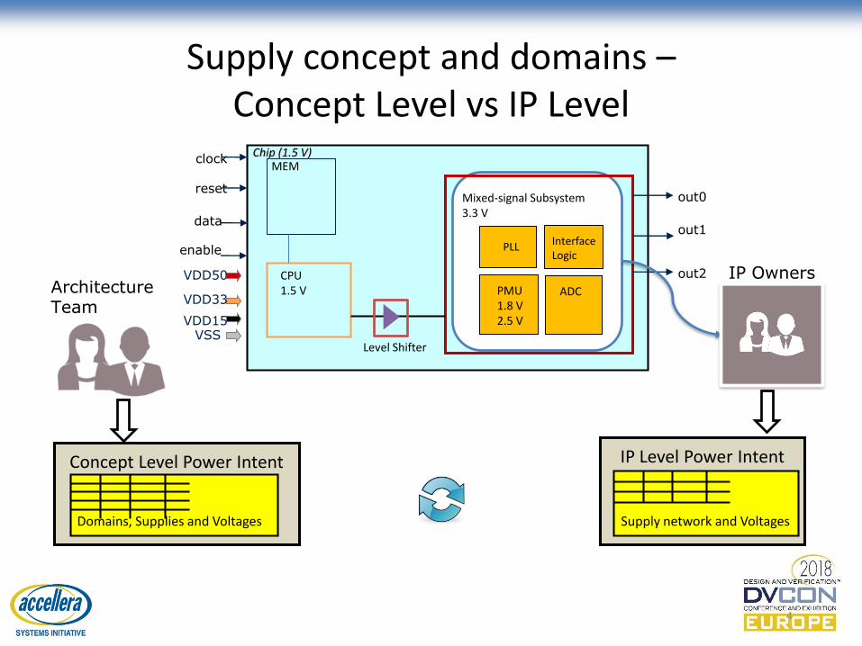
Supply concept and domains –Concept Level vs IP Level
4
Architecture Team
Concept Level Power Intent
Domains, Supplies and Voltages
IP Owners
IP Level Power Intent
Supply network and Voltages
CPU1.5 V
Chip (1.5 V)MEM
Mixed-signal Subsystem3.3 V
VDD33
VDD15VSS
VDD50
Level Shifter
PMU1.8 V2.5 V
clock
resetout0
out1
out2
data
enable
ADC
Interface Logic
PLL
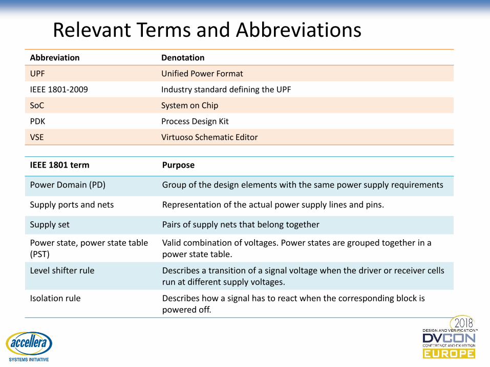
Relevant Terms and Abbreviations
IEEE 1801 term Purpose
Power Domain (PD) Group of the design elements with the same power supply requirements
Supply ports and nets Representation of the actual power supply lines and pins.
Supply set Pairs of supply nets that belong together
Power state, power state table (PST)
Valid combination of voltages. Power states are grouped together in a power state table.
Level shifter rule Describes a transition of a signal voltage when the driver or receiver cells run at different supply voltages.
Isolation rule Describes how a signal has to react when the corresponding block is powered off.
Abbreviation Denotation
UPF Unified Power Format
IEEE 1801-2009 Industry standard defining the UPF
SoC System on Chip
PDK Process Design Kit
VSE Virtuoso Schematic Editor
Objectives
1. Propose a new methodology for creation of supply connectivityin schematic designs
2. Describe how the existing static low-power checks can be extended to cope with mixed-signal IPs
– Based on IEEE 1801 format
Copyright © Infineon Technologies AG 2018. All rights reserved.
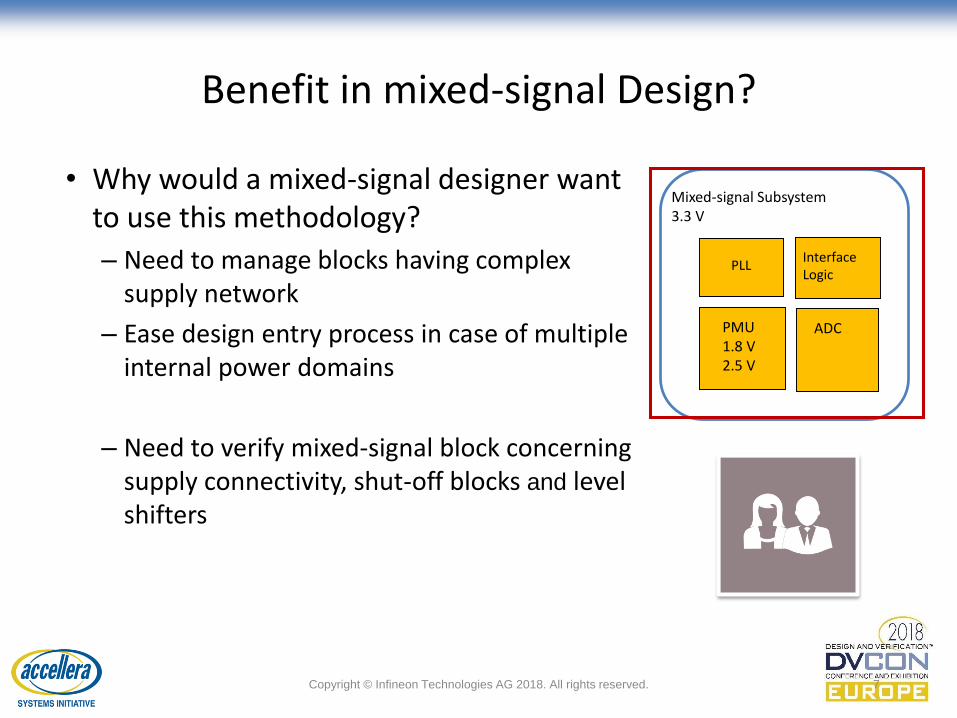
Benefit in mixed-signal Design?
7
• Why would a mixed-signal designer want to use this methodology?
– Need to manage blocks having complex supply network
– Ease design entry process in case of multiple internal power domains
– Need to verify mixed-signal block concerning supply connectivity, shut-off blocks and level shifters
Mixed-signal Subsystem3.3 V
PMU1.8 V2.5 V
ADC
Interface Logic
PLL
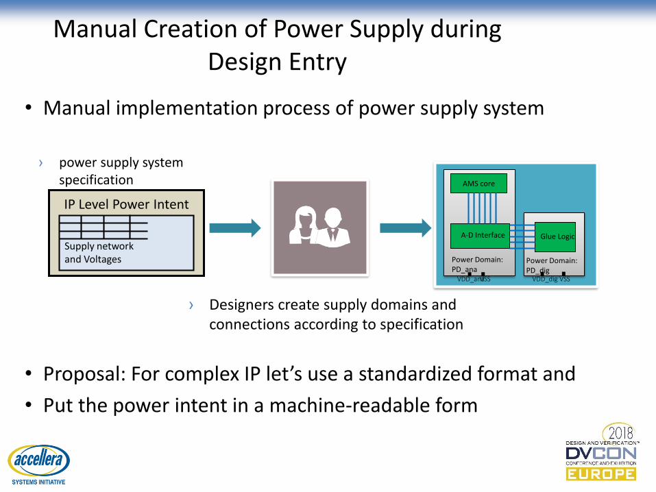
Manual Creation of Power Supply during Design Entry
• Manual implementation process of power supply system
Glue Logic
Power Domain: PD_dig
AMS core
A-D Interface
Power Domain: PD_anaVDD_anaVSS VDD_dig VSS
› power supply system specification
› Designers create supply domains and connections according to specification
IP Level Power Intent
Supply network and Voltages
• Proposal: For complex IP let’s use a standardized format and
• Put the power intent in a machine-readable form
Brief Overview about IEEE 1801-2009 – aka UPF 2.0
• IEEE 1801 format
– brings a unified way to describe the structure of the power supply system as well as low power requirements in the design process
• EDA tools can cope with IEEE 1801 (UPF)
• Hence the power specification can be passed through the EDA tool chain
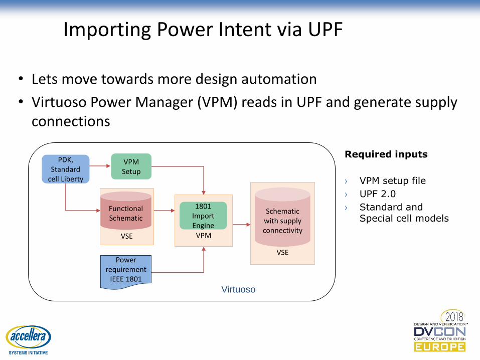
Importing Power Intent via UPF
• Lets move towards more design automation
• Virtuoso Power Manager (VPM) reads in UPF and generate supply connections
Required inputs
› VPM setup file
› UPF 2.0
› Standard and Special cell models
PDK, Standard
cell Liberty
VPM Setup
Power requirement
IEEE 1801
VPM
1801 Import Engine
VSE
Functional Schematic
VS
VSE
Schematic with supply connectivity
Virtuoso
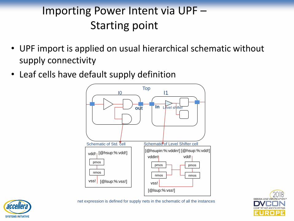
Importing Power Intent via UPF –Starting point
• UPF import is applied on usual hierarchical schematic without supply connectivity
• Leaf cells have default supply definition
Top I0 I1
Inout Level shifter
pmos
[@hsup:%:vdd!]
[@lsup:%:vss!]
vdd!
vss!
nmos
pmos
[@hsupin:%:vddin!]
[@lsup:%:vss!]
vddin!
vss!
nmos
pmos
[@hsup:%:vdd!]
vdd!
nmos
net expression is defined for supply nets in the schematic of all the instances
Schematic of Std. cell Schematic of Level Shifter cell
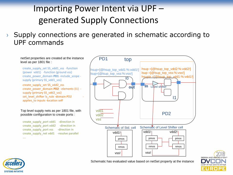
top
I0
out
PD2
PD1
hsup =[@hsup_top_vdd2:%:vdd2!]
lsup =[@lsup_top_vss:%:vss!]
hsupin =[@hsup_top_vdd1:%:vdd1!]
create_supply_port vdd1 -direction increate_supply_port vdd2 -direction increate_supply_port vss -direction increate_supply_net vdd1 -resolve parallel….
create_supply_set SS_vdd2_vss create_power_domain PD2 - elements {I1} -supply {primary SS_vdd2_vss} set_level_shifter ls_rule -domain PD2 -applies_to inputs -location self
vdd1
vdd2
vss
Schematic has evaluated value based on netSet property at the instance
Schematic of Std. cell Schematic of Level Shifter cell
pmos
vdd1!
vss!
nmos
pmos
vdd1!
vss!
nmos
pmos
vdd2!
nmos
netSet properties are created at the instance
level as per 1801 file :
Top level supply nets as per 1801 file, with
possible configuration to create ports :
I1
In Level shifter
create_supply_set SS_vdd1_vss -function {power vdd1} -function {ground vss} create_power_domain PD1 -include_scope -supply {primary SS_vdd1_vss}
hsup=[@hsup_top_vdd1:%:vdd1!]
lsup=[@lsup_top_vss:%:vss!]
Importing Power Intent via UPF –generated Supply Connections
› Supply connections are generated in schematic according to UPF commands
13
VERIFYING POWER INTENT AGAINST DESIGN USING IEEE 1801 EXPORT
Check the design against power intent
• Check complete design against the power intent is essential to detect errors
• In digital designs these checks are used for many years as part of the digital verification
– Checks stop at boundaries of analog blocks
– normally black-box models are used
Extend checks to mixed-signal designs
• Lets extend this verification method to mixed-signal designs
• Types of errors we are looking for
– Missing isolation cells in shut-off sub blocks
– Wrong supply connections
– Missing level shifters
– Enable signals wrongly driven by shut-off block
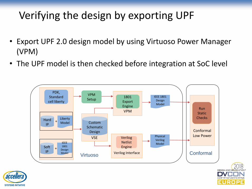
Verifying the design by exporting UPF
• Export UPF 2.0 design model by using Virtuoso Power Manager (VPM)
• The UPF model is then checked before integration at SoC level
PDK, Standard
cell liberty
+Hard IP
Liberty Model
+Soft IP
IEEE1801
Design Model
IEEE 1801 Design Model
Physical Verilog Model
VPM
1801 Export Engine
VPM Setup
VSE
Custom Schematic
Design
Verilog Interface
Verilog Netlist Engine
Virtuoso
Conformal Low Power
Run Static
Checks
Conformal
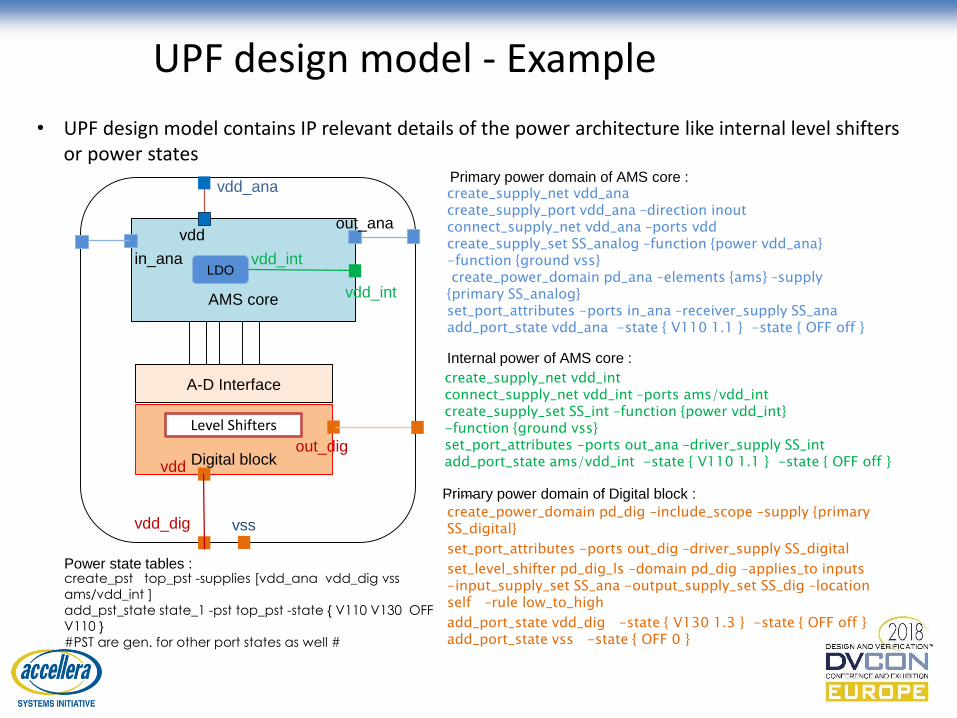
UPF design model - Example
• UPF design model contains IP relevant details of the power architecture like internal level shifters or power states
……
create_power_domain pd_dig –include_scope –supply {primary SS_digital}
set_port_attributes -ports out_dig –driver_supply SS_digital
set_level_shifter pd_dig_ls –domain pd_dig –applies_to inputs -input_supply_set SS_ana -output_supply_set SS_dig –location self –rule low_to_high
add_port_state vdd_dig -state { V130 1.3 } -state { OFF off } add_port_state vss -state { OFF 0 }
AMS core
A-D Interface
Digital block
Level Shifters
vdd_ana
vss
in_ana
out_dig
out_anavdd
LDOvdd_int
vdd
vdd_dig
vdd_int
create_pst top_pst -supplies [vdd_ana vdd_dig vss
ams/vdd_int ]
add_pst_state state_1 -pst top_pst -state { V110 V130 OFF
V110 }
#PST are gen. for other port states as well #
Power state tables :
create_supply_net vdd_ana create_supply_port vdd_ana –direction inoutconnect_supply_net vdd_ana –ports vddcreate_supply_set SS_analog –function {power vdd_ana} -function {ground vss}create_power_domain pd_ana –elements {ams} –supply
{primary SS_analog}set_port_attributes -ports in_ana –receiver_supply SS_anaadd_port_state vdd_ana -state { V110 1.1 } -state { OFF off }
Primary power domain of AMS core :
create_supply_net vdd_intconnect_supply_net vdd_int –ports ams/vdd_intcreate_supply_set SS_int –function {power vdd_int} -function {ground vss}set_port_attributes -ports out_ana –driver_supply SS_intadd_port_state ams/vdd_int -state { V110 1.1 } -state { OFF off }
Internal power of AMS core :
Primary power domain of Digital block :
Conclusion
• We have applied two design methodologies for IEEE 1801 (UPF 2.0)
1) power supply implementation
• VPM IEEE 1801 import automates the creation of power supply connectivity in a design
2) static low power checking on mixed-signal IP blocks
• VPM IEEE 1801 export capability enables the extraction of power relevant data from our schematic designs and export as UPF 2.0 design model
• The exported model enables a thorough low power checking using Conformal Low Power
Acknowledgment
• Infineon Technologies
– Steffen Rost
– Jürgen Karmann
– Gernot Zessar
– Ibrahim Khan
– Werner Grollitsch
– Gregor Kowalczyk
– Thomas Cemernek
• Cadence Design Systems
– Madhur Sharma
– Steffen Lorenz
20
THANK YOU
2018-09-07