Embed Size (px)
Citation preview
IEEE COMMUNICATIONS SURVEYS & TUTORIALS, VOL. 12, NO. 3, THIRD QUARTER 2010 357
A Survey of PCN-Based Admission Control andFlow Termination
Michael Menth, Frank Lehrieder, Bob Briscoe, Philip Eardley, Toby Moncaster, Jozef Babiarz, Anna Charny,Xinyang (Joy) Zhang, Tom Taylor, Kwok-Ho Chan, Daisuke Satoh, Ruediger Geib, and Georgios Karagiannis
Abstract—Pre-congestion notification (PCN) provides feedbackabout load conditions in a network to its boundary nodes. ThePCN working group of the IETF discusses the use of PCN toimplement admission control (AC) and flow termination (FT)for prioritized realtime traffic in a DiffServ domain. Admissioncontrol (AC) is a well-known flow control function that blocksadmission requests of new flows when they need to be carriedover a link whose admitted PCN rate already exceeds anadmissible rate. Flow termination (FT) is a new flow controlfunction that terminates some already admitted flows when theyare carried over a link whose admitted PCN rate exceeds asupportable rate. The latter condition can occur in spite of AC,e.g., when traffic is rerouted due to network failures.This survey gives an introduction to PCN and is a primer for
this new technology. It presents and discusses the multitude ofarchitectural design options in an early stage of the standard-ization process in a comprehensive and streamlined way beforeonly a subset of them is standardized by the IETF. It bringsPCN from the IETF to the research community and serves ashistorical record.
Index Terms—Quality of service, admission control, flow ter-mination, congestion notification, token bucket.
I. INTRODUCTION
IP NETWORKS were initially designed to perform packetforwarding without priorities. To achieve quality of ser-
vice (QoS), the differentiated services (DS, DiffServ) conceptintroduced various service classes called per-hop behaviors(PHBs) [10]. To avoid congestion for premium traffic in anetwork, admission control (AC) limits the number of high-priority flows. It is a well-established flow control functionfor packet-switched communication networks supporting high-quality realtime applications such as voice and video. It is
Manuscript received 14 October 2008; revised 3 April 2009. This work isfunded by Deutsche Forschungsgemeinschaft (DFG) under grant TR257/18-2;by Trilogy, a research project supported by the European Community under itsSeventh Framework Programme; and by the National Institute of Informationand Communications Technology (NICT), Tokyo, Japan. It reflects only theviews of the author.Michael Menth and Frank Lehrieder are with the University of Würzburg,
Inst. of Computer Science, Germany (e-mail: [email protected]).Bob Briscoe, Philip Eardley, and Toby Moncaster are with BT Research,
UK.Jozef Babiarz is with Nortel Networks, Ottawa, Canada.Anna Charny and Xinyang (Joy) Zhang are with Cisco Systems, Boxbor-
ough, MA.Tom Taylor and Kwok-Ho Chan are with Huawei Technologies,
Canada/USA.Daisuke Satoh is with NTT Advanced Technology Corporation, Japan.Ruediger Geib is with Deutsche Telekom Netzproduktion GmbH, Germany.Georgios Karagiannis is with the University of Twente/CTIT, The Nether-
lands.Digital Object Identifier 10.1109/SURV.2010.040710.00078
useful when capacity overprovisioning is difficult, too costly,or just not possible. The resource reservation protocol RSVP[11] supports admission control with per-flow reservations ineach RSVP-aware node. This is a rather heavy burden fortransit routers that need to keep per-flow states just to performcorrect AC decisions.
AC is not enough to keep the traffic load in a DiffServdomain low. When links or nodes fail, traffic is rerouted whichpossibly leads to congestion on backup paths. This degradesthe QoS for all flows on the congested links. In such a case,the traffic load should be quickly reduced by terminating someof the admitted flows. This is achieved by a new flow controlfunction which is called flow termination (FT). It complementsAC and is useful not only in failure cases but also in othercases of overload which might be caused, e.g., by flash crowds[4], [20], [33] or unexpected rate increases of admitted flows.
The Internet Engineering Task Force (IETF) currently stan-dardizes simple, robust, and scalable AC and FT mechanismsfor DiffServ domains based on pre-congestion notification(PCN) [24]. A new prioritized traffic class for admittedPCN traffic is defined. The rate of aggregate PCN traffic ismetered on all links of a DiffServ domain and packets areappropriately marked when certain rate thresholds (admissiblerate, supportable rate) are exceeded. Thereby, the PCN egressnodes are notified about load conditions inside the networkbefore congestion occurs. This information is used to performthe AC and FT decisions.
For the time being, several partly incompatible and compet-ing proposals for PCN-based AC and FT exist. However, theobjective of the standardization process is to define only oneor two mechanisms to achieve compatibility among vendors.This paper develops an integrated overview of methods formetering and marking, PCN encoding, AC, and FT thathave been presented in different proposals. To that end, aunifying nomenclature is developed. This presentation on thelevel of individual concepts and features instead of packageddeployment scenarios facilitates an objective discussion ofpros and cons and deepens the understanding of PCN and itsassociated algorithms. Thereby, it is a step forward concerningthe standardization of a future PCN architecture. Moreover, thepaper preserves the wealth of diverse ideas for PCN-based ACand FT beyond standardization.
The paper is structured as follows. Sect. II reviews thehistoric roots of PCN and related work. Sect. III introducesdifferent types of pre-congestion, explains the basic idea ofPCN, and illustrates its use in the Internet. Sect. IV presents
1553-877X/10/$25.00 c© 2010 IEEE
358 IEEE COMMUNICATIONS SURVEYS & TUTORIALS, VOL. 12, NO. 3, THIRD QUARTER 2010
metering and marking algorithms and Sect. V discusses howPCN marks can be encoded into the current IPv4 header.Sect. VI and Sect. VII review various AC and FT methods.Existing proposals are reviewed by Sect. VIII. Finally, Sect. IXsummarizes this work.
II. HISTORIC ROOTS OF PCN AND RELATED WORK
We review related work regarding random early detection(RED), explicit congestion notification (ECN), and statelesscore concepts for AC as they can be viewed as historic rootsof PCN.
A. Random Early Detection (RED)
RED was originally presented in [27], and in [12] it wasrecommended for deployment in the Internet. It was intendedto detect incipient congestion on a link and to throttle onlysome TCP flows early to avoid severe congestion and toimprove the TCP throughput. RED measures the averagebuffer occupation avg in routers and packets are dropped ormarked with a probability that increases linearly with theaverage queue length avg. Thus, a few packets are droppedbefore buffer overflow occurs which possibly leads to earlyrate reduction of some TCP flows prior to severe overload.An overview of RED and related mechanisms can be foundin [62].
B. Explicit Congestion Notification
Explicit congestion notification (ECN) is built on the idea ofRED to signal incipient congestion to TCP senders in orderto reduce their sending window [60]. Packets of non-ECN-capable flows can be differentiated by a “not-ECN-capabletransport” codepoint (not-ECT, ‘00’) from packets of an ECN-capable flow which have an “ECN-capable transport” code-point (ECT). In case of incipient congestion, RED gatewayspossibly drop not-ECT packets while they just switch thecodepoint of ECT packets to “congestion experienced” (CE,‘11’) instead of discarding them. This improves the TCPthroughput since packet retransmission is no longer neededin this case. Both the ECN encoding in the packet headerand the behavior of ECN-capable senders and receivers afterthe reception of a marked packet is defined in [60]. ECNcomes with two different codepoints for ECT: ECT(0) (‘10’)and ECT(1) (‘01’). They serve as nonces to detect cheatingnetwork equipment or receivers [68] that do not conform tothe ECN semantics. The four codepoints are encoded in the(“currently unused”) bits of the DS field in the IP header whichis a redefinition of the type of service octet [56]. The ECNbits can be redefined by other protocols and [26] providesguidelines for that. They are likely to be reused for encodingof PCN marks.
C. Admission Control
Recent surveys and classifications of AC methods can befound in [1], [39], [41], [66], [72]. We explain the problemwith per-flow reservations, reservation aggregation to mitigatethat problem, and show which problems still remain. Webriefly review some specific AC methods that can be seen
as forerunners of the PCN principle. They measure the rate ofadmitted traffic on each link of a network and give feedbackto the network boundary if that rate exceeds a pre-configuredadmissible rate threshold. Thereby, no per-flow reservationsneed to be kept for a link and the network core remainsstateless. This is a key property of PCN-based AC.1) Aggregation of Per-Flow Reservations: Admission con-
trol can be performed in the Internet using the resourcereservation protocol RSVP [11]. It sets up per-flow states inany node along the path which leads to a large number of stateson links carrying many flows. The setup and maintenance ofthese states is a large burden for routers and makes themmore complex. RSVP aggregation [7] improves this scalabilityconcern by setting up tunnels so that individual flows need tobe handled only at the edge nodes of the network. However, ann2 scalability problem of aggregated tunnels still remains whenn boundary nodes set up overlay reservations for premiumcommunication. Forecasts predict that the average numberof flows of typical edge-to-edge premium service tunnelsis very low and their distribution is long-tailed [23]. As aconsequence, the majority of aggregated reservations do notcarry traffic most of the time but need to be supported bycore nodes. Thus, other simple solutions for AC with betterscaling properties in core routers are needed. PCN requiresneither per-flow nor per-tunnel information in transit nodes.2) Admission Control Based on Reservation Tickets: To
keep a reservation for a flow across a network alive, ingressrouters send reservation tickets in regular intervals to theegress routers. Intermediate routers measure the rate of theobserved tickets and can thereby estimate the expected loadof reserved traffic. In case of a new reservation request, theingress router sends probe tickets, intermediate routers forwardthem to the egress router if they have still enough capacityto support the new flow, and the egress router bounces themback to the ingress router to indicate a successful reservation.If intermediate routers do not have enough resources to carryanother flow, they discard the probe tickets, the ingress routerdoes not receive a positive response, and the reservationrequest is blocked. The tickets can also be encoded by a packetstate. Several stateless core mechanisms work according to thisidea [2], [69], [70].3) Admission Control Based on Packet Marking: Gibbens
and Kelly [29], [30], [36] theoretically investigated AC basedon the feedback of marked packets whereby packets aremarked by routers based on a virtual queue with configurablebandwidth. This core idea is adopted by PCN. The importantdifference to RED-like packet marking is that marking de-cisions are based on a virtual instead of a physical queue.This allows to limit the utilization of the link bandwidthby premium traffic to arbitrary values between 0 and 100%.Karsten and Schmitt [34], [35] integrated these ideas into theIntServ framework and implemented a prototype. They pointout that the marking can also be based on the CPU usage ofthe routers instead of the link utilization if this turns out to bethe limiting resource for packet forwarding. An early versionof PCN-based AC has been reported in [67].4) Resilient Admission Control: In resilient networks,
rerouting or protection switching deviates traffic in case ofa failure to backup paths. Overviews of such techniques can
MENTH et al.: A SURVEY OF PCN-BASED ADMISSION CONTROL AND FLOW TERMINATION 359
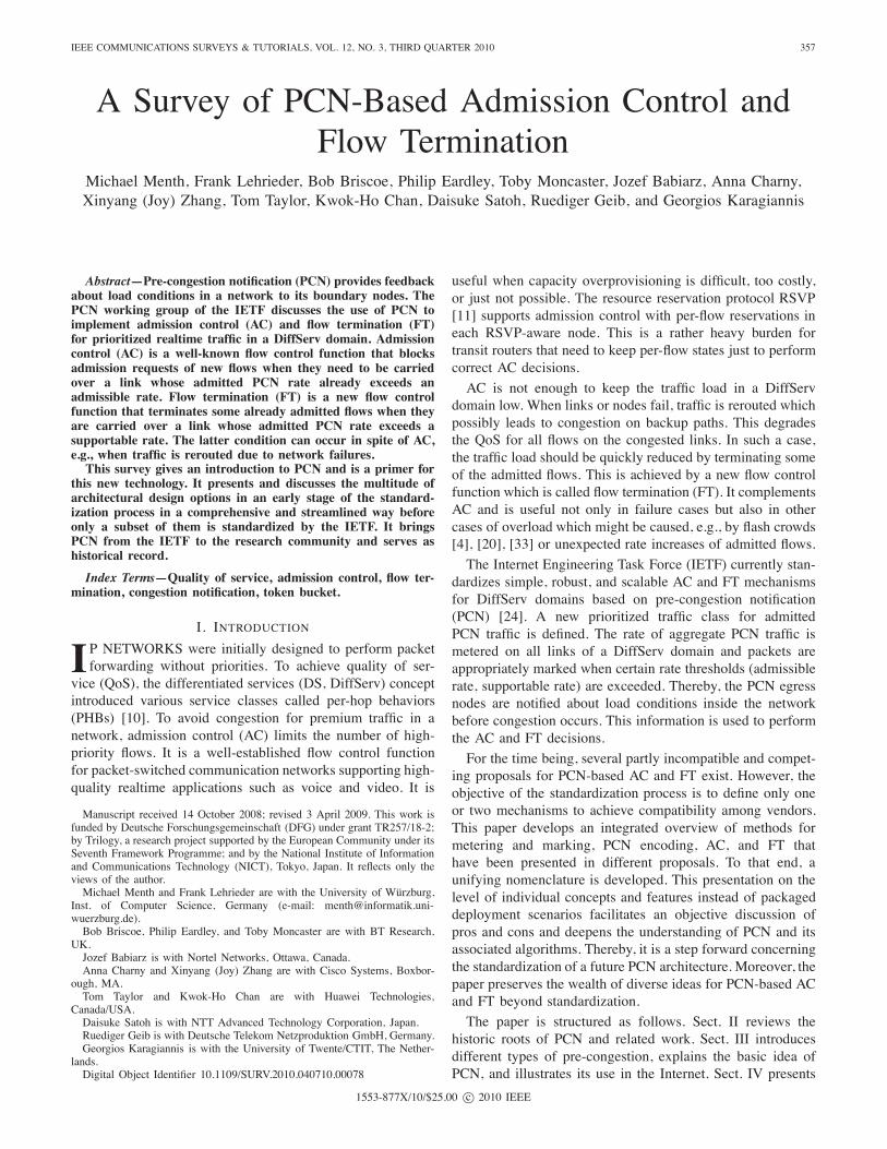
Fig. 1. The admissible and the supportable rate (AR(l),SR(l)) define threetypes of pre-congestion.
be found in [58] and [21]. The objective of resilient ACis to work properly even in case of failures and to avoidtermination of already admitted traffic. Transit nodes of anetwork without reservation states seem to be a prerequisitefor resilient AC. In case of a failure, traffic just needs to bererouted but reservation states do not need to be recovered.Resilient AC admits only so much traffic that it can still becarried after rerouting in a protected failure scenario [46], [53].It is necessary since overload occurs in wide area networksmostly due to link failures and not due to increased useractivity [31]. It can be implemented with PCN by settingthe admissible rate thresholds low enough so that admittedtraffic is not lost due to rerouting in likely failure scenarios.In particular, the PCN traffic rate on a link after reroutingmust be low enough so that flow termination is not triggered.Algorithms to configure PCN-based AC and FT for resilientAC are presented in [45]. It also optimizes IP routing tomaximize the rate of admissible traffic for resilient AC.
III. PCN-BASED FLOW CONTROL
This section explains the basic idea of PCN-based admis-sion control (AC) and flow termination (FT) and discusses itsapplication in an edge-to-edge and end-to-end context in theInternet.
A. Pre-Congestion Notification (PCN)
PCN defines a new traffic class that receives preferredtreatment by PCN nodes similar to the expedited forwardingper-hop-behavior (EF PHB) in DiffServ [32]. It provides infor-mation to support admission control (AC) and flow termination(FT) for this traffic type. PCN introduces an admissible and asupportable rate threshold (AR(l), SR(l)) for each link l of thenetwork which imply three different load regimes as illustratedin Fig. 1. If the PCN traffic rate r(l) is below AR(l), thereis no pre-congestion and further flows may be admitted. Ifthe PCN traffic rate r(l) is above AR(l), the link is AR-pre-congested and the rate above AR(l) is AR-overload. In thisstate, no further flows should be admitted. If the PCN trafficrate r(l) is above SR(l), the link is SR-pre-congested and therate above SR(l) is SR-overload. In this state, some alreadyadmitted flows should be terminated to reduce the PCN rate
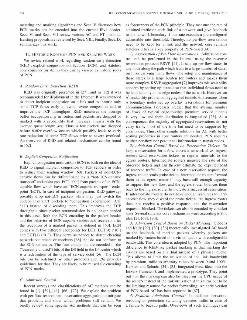
Fig. 2. Packet metering and marking is performed on all interfaces of a PCNdomain; the markings are evaluated at the network edges to support AC andFT.
r(l) below SR(l). A path is AR-pre-congested if at least oneof its links is AR-pre-congested and it is SR-pre-congested ifat least one of its links is SR-pre-congested; otherwise it isnot pre-congested.
B. A Two-Level Architecture for PCN-Based AC and FT
PCN-based AC and FT can be described as a two-levelarchitecture which is illustrated in Fig. 2. PCN nodes monitorthe PCN rate on their links and mark packets depending onthe type of pre-congestion. These mechanisms constitute thepacket marking layer (PML). Different proposals exist for thePML, but within a single PCN domain, the same methodsneed to be implemented in all PCN nodes. PCN egress nodesor PCN endpoints evaluate the packet markings and theiressence is reported to the AC and FT entities. Based onthis notification, further flows are admitted or blocked andalready admitted flows are terminated if necessary. The ACand FT algorithms constitute the admission control and flowtermination layer (ACL, FTL). Different implementations ofthe ACL and FTL may be deployed within a single PCNdomain as long as they coexist in a fair way, i.e. block orterminate traffic at the same PCN traffic rate.
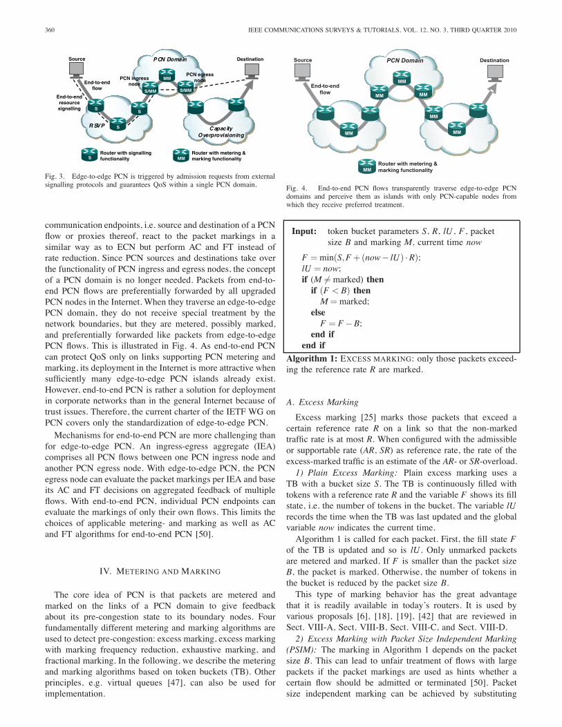
C. Edge-to-Edge PCN
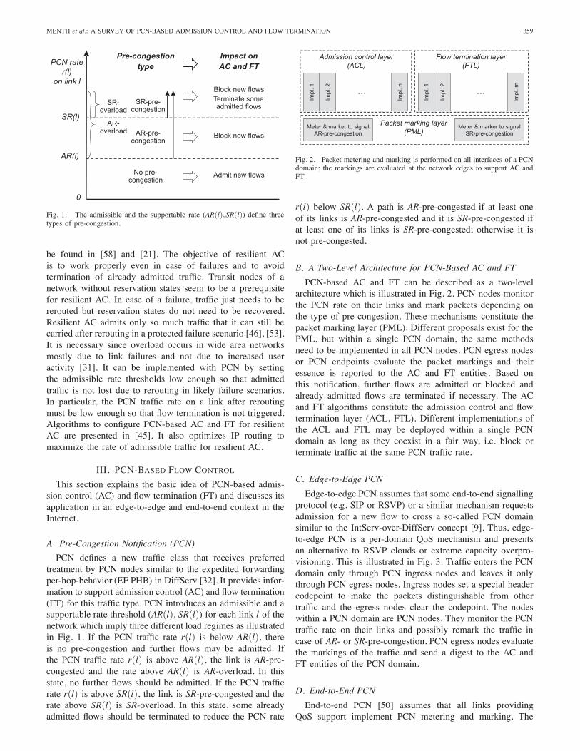
Edge-to-edge PCN assumes that some end-to-end signallingprotocol (e.g. SIP or RSVP) or a similar mechanism requestsadmission for a new flow to cross a so-called PCN domainsimilar to the IntServ-over-DiffServ concept [9]. Thus, edge-to-edge PCN is a per-domain QoS mechanism and presentsan alternative to RSVP clouds or extreme capacity overpro-visioning. This is illustrated in Fig. 3. Traffic enters the PCNdomain only through PCN ingress nodes and leaves it onlythrough PCN egress nodes. Ingress nodes set a special headercodepoint to make the packets distinguishable from othertraffic and the egress nodes clear the codepoint. The nodeswithin a PCN domain are PCN nodes. They monitor the PCNtraffic rate on their links and possibly remark the traffic incase of AR- or SR-pre-congestion. PCN egress nodes evaluatethe markings of the traffic and send a digest to the AC andFT entities of the PCN domain.
D. End-to-End PCN
End-to-end PCN [50] assumes that all links providingQoS support implement PCN metering and marking. The
360 IEEE COMMUNICATIONS SURVEYS & TUTORIALS, VOL. 12, NO. 3, THIRD QUARTER 2010
PCN Domain
R SVP C apacityOverprovisioning
Source Destination
End-to-endflow
PCN ingressnode
PCN egressnode
Router with signallingfunctionality
Router with metering &marking functionalityMMS
S/MM
MM
S
End-to-endresourcesignalling
S/MM
S
S
Fig. 3. Edge-to-edge PCN is triggered by admission requests from externalsignalling protocols and guarantees QoS within a single PCN domain.
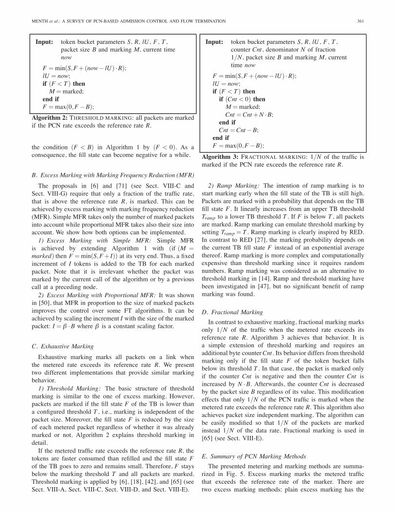
communication endpoints, i.e. source and destination of a PCNflow or proxies thereof, react to the packet markings in asimilar way as to ECN but perform AC and FT instead ofrate reduction. Since PCN sources and destinations take overthe functionality of PCN ingress and egress nodes, the conceptof a PCN domain is no longer needed. Packets from end-to-end PCN flows are preferentially forwarded by all upgradedPCN nodes in the Internet. When they traverse an edge-to-edgePCN domain, they do not receive special treatment by thenetwork boundaries, but they are metered, possibly marked,and preferentially forwarded like packets from edge-to-edgePCN flows. This is illustrated in Fig. 4. As end-to-end PCNcan protect QoS only on links supporting PCN metering andmarking, its deployment in the Internet is more attractive whensufficiently many edge-to-edge PCN islands already exist.However, end-to-end PCN is rather a solution for deploymentin corporate networks than in the general Internet because oftrust issues. Therefore, the current charter of the IETF WG onPCN covers only the standardization of edge-to-edge PCN.Mechanisms for end-to-end PCN are more challenging than
for edge-to-edge PCN. An ingress-egress aggregate (IEA)comprises all PCN flows between one PCN ingress node andanother PCN egress node. With edge-to-edge PCN, the PCNegress node can evaluate the packet markings per IEA and baseits AC and FT decisions on aggregated feedback of multipleflows. With end-to-end PCN, individual PCN endpoints canevaluate the markings of only their own flows. This limits thechoices of applicable metering- and marking as well as ACand FT algorithms for end-to-end PCN [50].
IV. METERING AND MARKING
The core idea of PCN is that packets are metered andmarked on the links of a PCN domain to give feedbackabout its pre-congestion state to its boundary nodes. Fourfundamentally different metering and marking algorithms areused to detect pre-congestion: excess marking, excess markingwith marking frequency reduction, exhaustive marking, andfractional marking. In the following, we describe the meteringand marking algorithms based on token buckets (TB). Otherprinciples, e.g. virtual queues [47], can also be used forimplementation.
Fig. 4. End-to-end PCN flows transparently traverse edge-to-edge PCNdomains and perceive them as islands with only PCN-capable nodes fromwhich they receive preferred treatment.
Input: token bucket parameters S, R, lU , F , packetsize B and marking M, current time now
F =min(S,F+(now− lU) ·R);lU = now;if (M �=marked) thenif (F < B) thenM =marked;
elseF = F−B;
end ifend if
Algorithm 1: EXCESS MARKING: only those packets exceed-ing the reference rate R are marked.
A. Excess Marking
Excess marking [25] marks those packets that exceed acertain reference rate R on a link so that the non-markedtraffic rate is at most R. When configured with the admissibleor supportable rate (AR, SR) as reference rate, the rate of theexcess-marked traffic is an estimate of the AR- or SR-overload.1) Plain Excess Marking: Plain excess marking uses a
TB with a bucket size S. The TB is continuously filled withtokens with a reference rate R and the variable F shows its fillstate, i.e. the number of tokens in the bucket. The variable lUrecords the time when the TB was last updated and the globalvariable now indicates the current time.Algorithm 1 is called for each packet. First, the fill state F
of the TB is updated and so is lU . Only unmarked packetsare metered and marked. If F is smaller than the packet sizeB, the packet is marked. Otherwise, the number of tokens inthe bucket is reduced by the packet size B.This type of marking behavior has the great advantage
that it is readily available in today’s routers. It is used byvarious proposals [6], [18], [19], [42] that are reviewed inSect. VIII-A, Sect. VIII-B, Sect. VIII-C, and Sect. VIII-D.2) Excess Marking with Packet Size Independent Marking
(PSIM): The marking in Algorithm 1 depends on the packetsize B. This can lead to unfair treatment of flows with largepackets if the packet markings are used as hints whether acertain flow should be admitted or terminated [50]. Packetsize independent marking can be achieved by substituting
MENTH et al.: A SURVEY OF PCN-BASED ADMISSION CONTROL AND FLOW TERMINATION 361
Input: token bucket parameters S, R, lU , F , T ,packet size B and marking M, current timenow
F =min(S,F+(now− lU) ·R);lU = now;if (F < T ) thenM =marked;
end ifF =max(0,F−B);
Algorithm 2: THRESHOLD MARKING: all packets are markedif the PCN rate exceeds the reference rate R.
the condition (F < B) in Algorithm 1 by (F < 0). As aconsequence, the fill state can become negative for a while.
B. Excess Marking with Marking Frequency Reduction (MFR)
The proposals in [6] and [71] (see Sect. VIII-C andSect. VIII-G) require that only a fraction of the traffic rate,that is above the reference rate R, is marked. This can beachieved by excess marking with marking frequency reduction(MFR). Simple MFR takes only the number of marked packetsinto account while proportional MFR takes also their size intoaccount. We show how both options can be implemented.1) Excess Marking with Simple MFR: Simple MFR
is achieved by extending Algorithm 1 with (if (M =marked) then F =min(S,F+ I)) at its very end. Thus, a fixedincrement of I tokens is added to the TB for each markedpacket. Note that it is irrelevant whether the packet wasmarked by the current call of the algorithm or by a previouscall at a preceding node.2) Excess Marking with Proportional MFR: It was shown
in [50], that MFR in proportion to the size of marked packetsimproves the control over some FT algorithms. It can beachieved by scaling the increment I with the size of the markedpacket: I = β ·B where β is a constant scaling factor.
C. Exhaustive Marking
Exhaustive marking marks all packets on a link whenthe metered rate exceeds its reference rate R. We presenttwo different implementations that provide similar markingbehavior.1) Threshold Marking: The basic structure of threshold
marking is similar to the one of excess marking. However,packets are marked if the fill state F of the TB is lower thana configured threshold T , i.e., marking is independent of thepacket size. Moreover, the fill state F is reduced by the sizeof each metered packet regardless of whether it was alreadymarked or not. Algorithm 2 explains threshold marking indetail.If the metered traffic rate exceeds the reference rate R, the
tokens are faster consumed than refilled and the fill state Fof the TB goes to zero and remains small. Therefore, F staysbelow the marking threshold T and all packets are marked.Threshold marking is applied by [6], [18], [42], and [65] (seeSect. VIII-A, Sect. VIII-C, Sect. VIII-D, and Sect. VIII-E).
Input: token bucket parameters S, R, lU , F , T ,counter Cnt, denominator N of fraction1/N, packet size B and marking M, currenttime now
F =min(S,F+(now− lU) ·R);lU = now;if (F < T ) thenif (Cnt < 0) thenM =marked;Cnt =Cnt+N ·B;
end ifCnt =Cnt−B;
end ifF =max(0,F−B);
Algorithm 3: FRACTIONAL MARKING: 1/N of the traffic ismarked if the PCN rate exceeds the reference rate R.
2) Ramp Marking: The intention of ramp marking is tostart marking early when the fill state of the TB is still high.Packets are marked with a probability that depends on the TBfill state F . It linearly increases from an upper TB thresholdTramp to a lower TB threshold T . If F is below T , all packetsare marked. Ramp marking can emulate threshold marking bysetting Tramp = T . Ramp marking is clearly inspired by RED.In contrast to RED [27], the marking probability depends onthe current TB fill state F instead of an exponential averagethereof. Ramp marking is more complex and computationallyexpensive than threshold marking since it requires randomnumbers. Ramp marking was considered as an alternative tothreshold marking in [14]. Ramp and threshold marking havebeen investigated in [47], but no significant benefit of rampmarking was found.
D. Fractional Marking
In contrast to exhaustive marking, fractional marking marksonly 1/N of the traffic when the metered rate exceeds itsreference rate R. Algorithm 3 achieves that behavior. It isa simple extension of threshold marking and requires anadditional byte counterCnt. Its behavior differs from thresholdmarking only if the fill state F of the token bucket fallsbelow its threshold T . In that case, the packet is marked onlyif the counter Cnt is negative and then the counter Cnt isincreased by N ·B. Afterwards, the counter Cnt is decreasedby the packet size B regardless of its value. This modificationeffects that only 1/N of the PCN traffic is marked when themetered rate exceeds the reference rate R. This algorithm alsoachieves packet size independent marking. The algorithm canbe easily modified so that 1/N of the packets are markedinstead 1/N of the data rate. Fractional marking is used in[65] (see Sect. VIII-E).
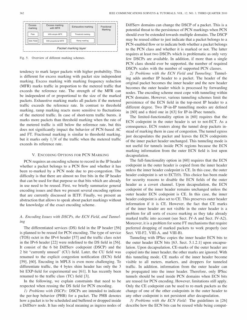
E. Summary of PCN Marking Methods
The presented metering and marking methods are summa-rized in Fig. 5. Excess marking marks the metered trafficthat exceeds the reference rate of the marker. There aretwo excess marking methods: plain excess marking has the
362 IEEE COMMUNICATIONS SURVEYS & TUTORIALS, VOL. 12, NO. 3, THIRD QUARTER 2010
Excess markingwith MFR
Excessmarking
Exhaustive marking FractionalMarking
With PSIM
Packet marking layer
Plain With simple MFR
With propotional MFR
Threshold marking
Ramp marking
Fig. 5. Overview of different marking schemes.
tendency to mark larger packets with higher probability. Thisis different for excess marking with packet size independentmarking. Excess marking with marking frequency reduction(MFR) marks traffic in proportion to the metered traffic thatexceeds the reference rate. The strength of the MFR canbe independent of or proportional to the size of the markedpackets. Exhaustive marking marks all packets if the meteredtraffic exceeds the reference rate. In contrast to thresholdmarking, ramp marking reacts more sensitive to fluctuationsof the metered traffic. In case of short-term traffic bursts, itmarks more packets than threshold marking when the rate ofthe metered traffic is still below the reference rate, but thisdoes not significantly impact the behavior of PCN-based ACand FT. Fractional marking is similar to threshold marking,but it marks only 1/N of the traffic when the metered trafficexceeds its reference rate.
V. ENCODING OPTIONS FOR PCN MARKING
PCN requires an encoding scheme to record in the IP headerwhether a packet belongs to a PCN flow and whether it hasbeen re-marked by a PCN node due to pre-congestion. Thedifficulty is that there are almost no free bits in the IP headerthat can be used for that purpose so that bits which are alreadyin use need to be reused. First, we briefly summarize generalencoding issues and then we present several encoding optionsthat are currently discussed in IETF. Finally, we present anabstraction that allows to speak about packet markings withoutthe knowledge of the exact encoding scheme.
A. Encoding Issues with DSCPs, the ECN Field, and Tunnel-ing
The differentiated services (DS) field in the IP header [56]is planned to be reused for PCN encoding. The type of service(TOS) octet in the IPv4 header [57] and the traffic class octetin the IPv6 header [22] were redefined to the DS field in [56].It consist of the 6 bit DiffServ codepoint (DSCP) and the2 bit “currently unused” (CU) field. Later, the CU field wasrenamed to the explicit congestion notification (ECN) field[59], [60]. Encoding in MPLS is even more challenging. Todifferentiate traffic, the 4 bytes shim header has only the 3bit EXP-field for experimental use [61]. It has recently beenrenamed to the traffic class (TC) field [3].In the following, we explain constraints that need to be
respected when reusing the DS field for PCN encoding.1) Problems with DSCPs: DSCPs are intended to indicate
the per-hop behavior (PHB) for a packet. The PHB denoteshow a packet is to be scheduled and buffered or dropped insidea DiffServ node. It has only local meaning as ingress nodes of
DiffServ domains can change the DSCP of a packet. This is apotential threat to the persistence of PCN markings when PCNshould ever be extended towards multiple domains. The DSCPmay be reused either to just indicate that a packet belongs to aPCN-enabled flow or to indicate both whether a packet belongsto the PCN class and whether it is marked or not. The latterrequires at least two DSCPs which is problematic as only veryfew DSCPs are available. In addition, if more than a singlePCN class should ever be supported, the number of requiredDSCPs scales with the number of supported PCN classes.2) Problems with the ECN Field and Tunneling: Tunnel-
ing adds another IP header to a packet. The header of theoriginal packet becomes the inner header and the new headerbecomes the outer header which is processed by forwardingnodes. The encoding scheme must cope with tunneling withinPCN domains. However, various tunneling schemes limit thepersistence of the ECN field in the top-most IP header to adifferent degree. Two IP-in-IP tunnelling modes are definedin [60] and a third one in [63] for IP-in-IPsec tunnels.The limited-functionality option in [60] requires that the
ECN codepoint in the outer header is set to not-ECT. As aconsequence, ECN routers along the tunnel drop packets in-stead of marking them in case of congestion. The tunnel egressjust decapsulates the packet and leaves the ECN codepointsof the inner packet header unchanged. This tunneling mode isnot useful for tunnels inside PCN regions because the ECNmarking information from the outer ECN field is lost upondecapsulation.The full-functionality option in [60] requires that the ECN
codepoint in the outer header is copied from the inner headerunless the inner header codepoint is CE. In this case, the outerheader codepoint is set to ECT(0). This choice has been madefor security reasons to disable the ECN fields of the outerheader as a covert channel. Upon decapsulation, the ECNcodepoint of the inner header remains unchanged unless theouter header ECN codepoint is CE. In this case, the innerheader codepoint is also set to CE. This preserves outer headerinformation if it is CE. However, the fact that CE marksof the inner header are not visible in the outer header is aproblem for all sorts of excess marking as they take alreadymarked traffic into account (see Sect. IV-A and Sect. IV-A2).Moreover, it is a problem for some FT mechanisms that requirepreferred dropping of marked packets to work properly (seeSect. VII-F2, VIII-A, and VIII-B).Tunneling with IPSec copies the inner header ECN bits to
the outer header ECN bits [63, Sect. 5.1.2.1] upon encapsu-lation. Upon decapsulation, CE-marks of the outer header arecopied into the inner header, the other marks are ignored. Withthis tunneling mode, CE marks of the inner header becomevisible to all meters, markers, and droppers for tunneledtraffic. In addition, information from the outer header canbe propagated into the inner header. Therefore, only IPSectunnels should be used inside PCN domains when ECN bitsare reused for PCN encoding. However, limitations still apply.Only the CE codepoint can be used to re-mark packets as thechange of one of the other codepoints in the outer header toany other codepoint is not persistent after decapsulation.3) Problems with the ECN Field: The guidelines in [26]
describe how the ECN bits can be reused while being compat-
MENTH et al.: A SURVEY OF PCN-BASED ADMISSION CONTROL AND FLOW TERMINATION 363
ible with [60]. A CE mark of a packet must never be changedto another ECN codepoint. Furthermore, a not-ECT mark ofa packet must never be changed to one of the ECN-capablecodepoints ECT(0), ECT(1), or CE. When the ECN field isreused for PCN marking, care must be taken that this rule isenforced when PCN packets leave the PCN domain. There aretwo basic options to handle ECN flows when the ECN fieldis reused for PCN marking in a DiffServ domain.
a) Disabling ECN: The PCN ingress node sets theappropriate ECN mark in incoming packets to indicate thatthey are initially unmarked. The PCN egress node resets theirECN field to not-ECT to make sure that previous not-ECTmarks are not changed to any other ECN marks through thePCN domain. This disables ECN for PCN flows so that theycannot profit from both ECN and PCN. As it is prohibitiveto change CE marks to not-ECT, CE-marked packets must bedropped by PCN ingress nodes.
b) Tunneling ECN Marks: Another option is tunnelingECT- or CE-marked packets through the PCN domain usingthe limited-functionality mode. This preserves the originalECN field so that PCN egress nodes receive PCN feedbackand end systems receive ECN feedback which is not modifiedby the PCN domain. Moreover, CE-marked packets do notneed to be dropped by the PCN ingress node.
B. Encoding Options
Different proposals for PCN-based AC and FT require adifferent number of codepoints to mark packets. Therefore,many encoding options have been presented and discussed inIETF [16]. However, we review only those that use a DSCP toindicate PCN traffic, use the ECN field to indicate the marking,and conform with the limitations due to tunneling.Most encoding schemes require a single DSCP, designated
as DSCP m, others need two different DSCPs, designated asDSCP m and DSCP n. These DSCPs should be usable bothfor non-PCN and for PCN traffic. Therefore, a general rule isthat not-ECT indicates non-PCN traffic while the codepointsECT(0), ECT(1), and CE may be reused for the encoding ofPCN marks. A candidate DSCP for being reused as DSCPm is the VOICE-ADMIT DSCP which is currently about tobe standardized to indicate EF-PHB for AC-controlled flows[8]. As a consequence, VOICE-ADMIT flows cannot profitfrom ECN unless their packets are tunneled through the PCNdomain and PCN marking is then applied only to the outerheader as described in Sect. V-A3.1) Baseline Encoding: Baseline encoding has been pre-
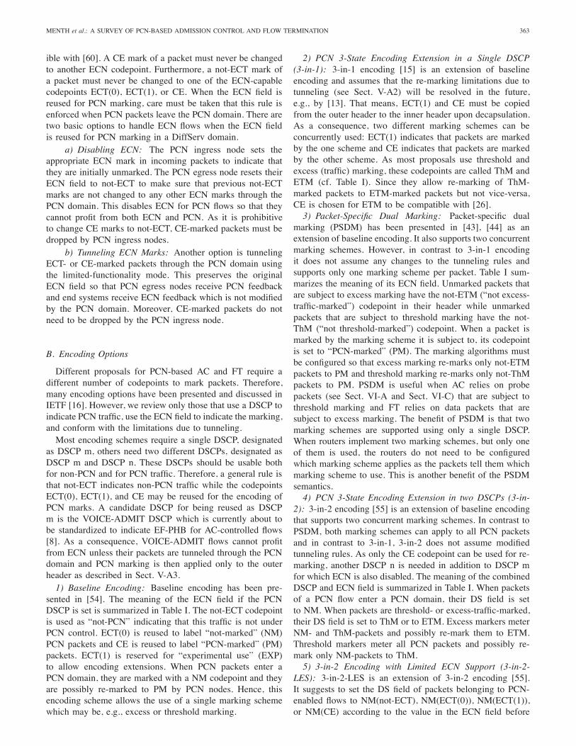
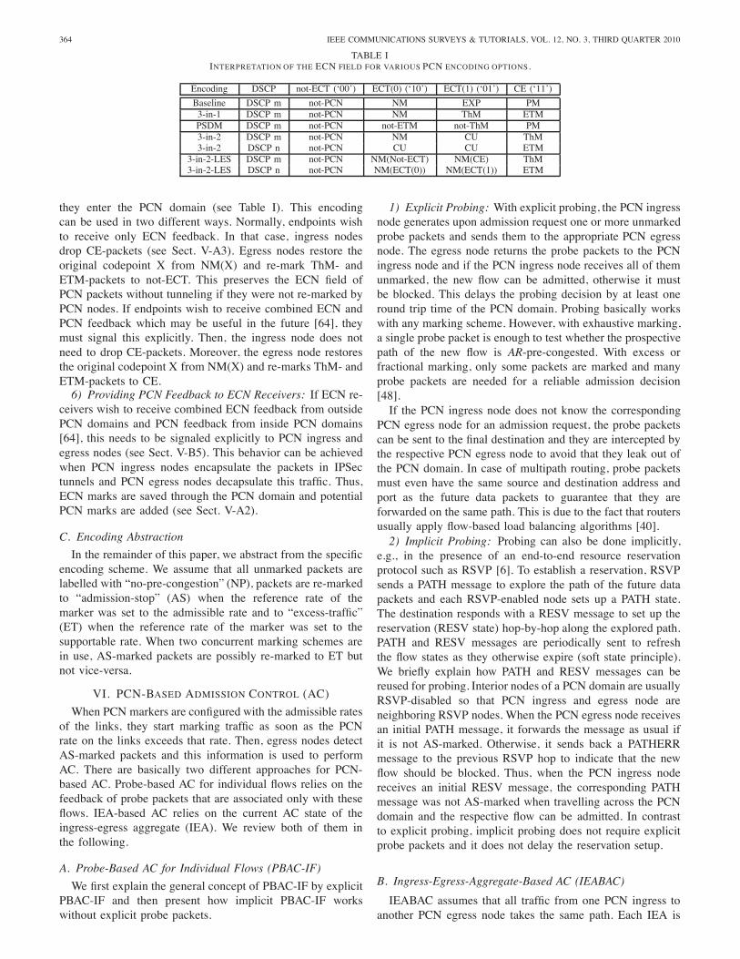
sented in [54]. The meaning of the ECN field if the PCNDSCP is set is summarized in Table I. The not-ECT codepointis used as “not-PCN” indicating that this traffic is not underPCN control. ECT(0) is reused to label “not-marked” (NM)PCN packets and CE is reused to label “PCN-marked” (PM)packets. ECT(1) is reserved for “experimental use” (EXP)to allow encoding extensions. When PCN packets enter aPCN domain, they are marked with a NM codepoint and theyare possibly re-marked to PM by PCN nodes. Hence, thisencoding scheme allows the use of a single marking schemewhich may be, e.g., excess or threshold marking.
2) PCN 3-State Encoding Extension in a Single DSCP(3-in-1): 3-in-1 encoding [15] is an extension of baselineencoding and assumes that the re-marking limitations due totunneling (see Sect. V-A2) will be resolved in the future,e.g., by [13]. That means, ECT(1) and CE must be copiedfrom the outer header to the inner header upon decapsulation.As a consequence, two different marking schemes can beconcurrently used: ECT(1) indicates that packets are markedby the one scheme and CE indicates that packets are markedby the other scheme. As most proposals use threshold andexcess (traffic) marking, these codepoints are called ThM andETM (cf. Table I). Since they allow re-marking of ThM-marked packets to ETM-marked packets but not vice-versa,CE is chosen for ETM to be compatible with [26].3) Packet-Specific Dual Marking: Packet-specific dual
marking (PSDM) has been presented in [43], [44] as anextension of baseline encoding. It also supports two concurrentmarking schemes. However, in contrast to 3-in-1 encodingit does not assume any changes to the tunneling rules andsupports only one marking scheme per packet. Table I sum-marizes the meaning of its ECN field. Unmarked packets thatare subject to excess marking have the not-ETM (“not excess-traffic-marked”) codepoint in their header while unmarkedpackets that are subject to threshold marking have the not-ThM (“not threshold-marked”) codepoint. When a packet ismarked by the marking scheme it is subject to, its codepointis set to “PCN-marked” (PM). The marking algorithms mustbe configured so that excess marking re-marks only not-ETMpackets to PM and threshold marking re-marks only not-ThMpackets to PM. PSDM is useful when AC relies on probepackets (see Sect. VI-A and Sect. VI-C) that are subject tothreshold marking and FT relies on data packets that aresubject to excess marking. The benefit of PSDM is that twomarking schemes are supported using only a single DSCP.When routers implement two marking schemes, but only oneof them is used, the routers do not need to be configuredwhich marking scheme applies as the packets tell them whichmarking scheme to use. This is another benefit of the PSDMsemantics.4) PCN 3-State Encoding Extension in two DSCPs (3-in-
2): 3-in-2 encoding [55] is an extension of baseline encodingthat supports two concurrent marking schemes. In contrast toPSDM, both marking schemes can apply to all PCN packetsand in contrast to 3-in-1, 3-in-2 does not assume modifiedtunneling rules. As only the CE codepoint can be used for re-marking, another DSCP n is needed in addition to DSCP mfor which ECN is also disabled. The meaning of the combinedDSCP and ECN field is summarized in Table I. When packetsof a PCN flow enter a PCN domain, their DS field is setto NM. When packets are threshold- or excess-traffic-marked,their DS field is set to ThM or to ETM. Excess markers meterNM- and ThM-packets and possibly re-mark them to ETM.Threshold markers meter all PCN packets and possibly re-mark only NM-packets to ThM.5) 3-in-2 Encoding with Limited ECN Support (3-in-2-
LES): 3-in-2-LES is an extension of 3-in-2 encoding [55].It suggests to set the DS field of packets belonging to PCN-enabled flows to NM(not-ECT), NM(ECT(0)), NM(ECT(1)),or NM(CE) according to the value in the ECN field before
364 IEEE COMMUNICATIONS SURVEYS & TUTORIALS, VOL. 12, NO. 3, THIRD QUARTER 2010
TABLE IINTERPRETATION OF THE ECN FIELD FOR VARIOUS PCN ENCODING OPTIONS.
Encoding DSCP not-ECT (‘00’) ECT(0) (‘10’) ECT(1) (‘01’) CE (‘11’)
Baseline DSCP m not-PCN NM EXP PM3-in-1 DSCP m not-PCN NM ThM ETMPSDM DSCP m not-PCN not-ETM not-ThM PM3-in-2 DSCP m not-PCN NM CU ThM3-in-2 DSCP n not-PCN CU CU ETM
3-in-2-LES DSCP m not-PCN NM(Not-ECT) NM(CE) ThM3-in-2-LES DSCP n not-PCN NM(ECT(0)) NM(ECT(1)) ETM
they enter the PCN domain (see Table I). This encodingcan be used in two different ways. Normally, endpoints wishto receive only ECN feedback. In that case, ingress nodesdrop CE-packets (see Sect. V-A3). Egress nodes restore theoriginal codepoint X from NM(X) and re-mark ThM- andETM-packets to not-ECT. This preserves the ECN field ofPCN packets without tunneling if they were not re-marked byPCN nodes. If endpoints wish to receive combined ECN andPCN feedback which may be useful in the future [64], theymust signal this explicitly. Then, the ingress node does notneed to drop CE-packets. Moreover, the egress node restoresthe original codepoint X from NM(X) and re-marks ThM- andETM-packets to CE.6) Providing PCN Feedback to ECN Receivers: If ECN re-
ceivers wish to receive combined ECN feedback from outsidePCN domains and PCN feedback from inside PCN domains[64], this needs to be signaled explicitly to PCN ingress andegress nodes (see Sect. V-B5). This behavior can be achievedwhen PCN ingress nodes encapsulate the packets in IPSectunnels and PCN egress nodes decapsulate this traffic. Thus,ECN marks are saved through the PCN domain and potentialPCN marks are added (see Sect. V-A2).
C. Encoding Abstraction
In the remainder of this paper, we abstract from the specificencoding scheme. We assume that all unmarked packets arelabelled with “no-pre-congestion” (NP), packets are re-markedto “admission-stop” (AS) when the reference rate of themarker was set to the admissible rate and to “excess-traffic”(ET) when the reference rate of the marker was set to thesupportable rate. When two concurrent marking schemes arein use, AS-marked packets are possibly re-marked to ET butnot vice-versa.
VI. PCN-BASED ADMISSION CONTROL (AC)
When PCN markers are configured with the admissible ratesof the links, they start marking traffic as soon as the PCNrate on the links exceeds that rate. Then, egress nodes detectAS-marked packets and this information is used to performAC. There are basically two different approaches for PCN-based AC. Probe-based AC for individual flows relies on thefeedback of probe packets that are associated only with theseflows. IEA-based AC relies on the current AC state of theingress-egress aggregate (IEA). We review both of them inthe following.
A. Probe-Based AC for Individual Flows (PBAC-IF)
We first explain the general concept of PBAC-IF by explicitPBAC-IF and then present how implicit PBAC-IF workswithout explicit probe packets.
1) Explicit Probing: With explicit probing, the PCN ingressnode generates upon admission request one or more unmarkedprobe packets and sends them to the appropriate PCN egressnode. The egress node returns the probe packets to the PCNingress node and if the PCN ingress node receives all of themunmarked, the new flow can be admitted, otherwise it mustbe blocked. This delays the probing decision by at least oneround trip time of the PCN domain. Probing basically workswith any marking scheme. However, with exhaustive marking,a single probe packet is enough to test whether the prospectivepath of the new flow is AR-pre-congested. With excess orfractional marking, only some packets are marked and manyprobe packets are needed for a reliable admission decision[48].If the PCN ingress node does not know the corresponding
PCN egress node for an admission request, the probe packetscan be sent to the final destination and they are intercepted bythe respective PCN egress node to avoid that they leak out ofthe PCN domain. In case of multipath routing, probe packetsmust even have the same source and destination address andport as the future data packets to guarantee that they areforwarded on the same path. This is due to the fact that routersusually apply flow-based load balancing algorithms [40].2) Implicit Probing: Probing can also be done implicitly,
e.g., in the presence of an end-to-end resource reservationprotocol such as RSVP [6]. To establish a reservation, RSVPsends a PATH message to explore the path of the future datapackets and each RSVP-enabled node sets up a PATH state.The destination responds with a RESV message to set up thereservation (RESV state) hop-by-hop along the explored path.PATH and RESV messages are periodically sent to refreshthe flow states as they otherwise expire (soft state principle).We briefly explain how PATH and RESV messages can bereused for probing. Interior nodes of a PCN domain are usuallyRSVP-disabled so that PCN ingress and egress node areneighboring RSVP nodes. When the PCN egress node receivesan initial PATH message, it forwards the message as usual ifit is not AS-marked. Otherwise, it sends back a PATHERRmessage to the previous RSVP hop to indicate that the newflow should be blocked. Thus, when the PCN ingress nodereceives an initial RESV message, the corresponding PATHmessage was not AS-marked when travelling across the PCNdomain and the respective flow can be admitted. In contrastto explicit probing, implicit probing does not require explicitprobe packets and it does not delay the reservation setup.
B. Ingress-Egress-Aggregate-Based AC (IEABAC)
IEABAC assumes that all traffic from one PCN ingress toanother PCN egress node takes the same path. Each IEA is
MENTH et al.: A SURVEY OF PCN-BASED ADMISSION CONTROL AND FLOW TERMINATION 365
Excess marking
IEABAC
CLEBAC
OBAC
PBAC-IEA
PBAC-IF
Explicit
Exhaustive marking
IEABAC
CLEBAC
OBAC
PBAC-IEA
PBAC-IF
Implicit
Explicit
Admission control layer
Packet marking layer
Fractional marking
IEABAC
CLEBAC
OBAC
PBAC-IEA
PBAC-IF
Explicit
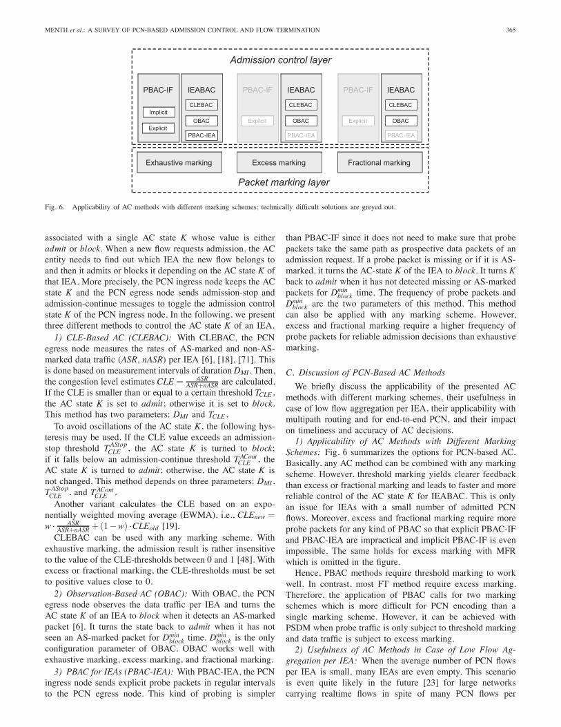
Fig. 6. Applicability of AC methods with different marking schemes; technically difficult solutions are greyed out.
associated with a single AC state K whose value is eitheradmit or block. When a new flow requests admission, the ACentity needs to find out which IEA the new flow belongs toand then it admits or blocks it depending on the AC state K ofthat IEA. More precisely, the PCN ingress node keeps the ACstate K and the PCN egress node sends admission-stop andadmission-continue messages to toggle the admission controlstate K of the PCN ingress node. In the following, we presentthree different methods to control the AC state K of an IEA.1) CLE-Based AC (CLEBAC): With CLEBAC, the PCN
egress node measures the rates of AS-marked and non-AS-marked data traffic (ASR, nASR) per IEA [6], [18], [71]. Thisis done based on measurement intervals of durationDMI . Then,the congestion level estimates CLE = ASR
ASR+nASR are calculated.If the CLE is smaller than or equal to a certain threshold TCLE ,the AC state K is set to admit; otherwise it is set to block.This method has two parameters: DMI and TCLE .To avoid oscillations of the AC state K, the following hys-
teresis may be used. If the CLE value exceeds an admission-stop threshold TAStopCLE , the AC state K is turned to block;if it falls below an admission-continue threshold TAContCLE , theAC state K is turned to admit; otherwise, the AC state K isnot changed. This method depends on three parameters: DMI ,TAStopCLE , and TAContCLE .Another variant calculates the CLE based on an expo-
nentially weighted moving average (EWMA), i.e., CLEnew =w · ASR
ASR+nASR +(1−w) ·CLEold [19].CLEBAC can be used with any marking scheme. With
exhaustive marking, the admission result is rather insensitiveto the value of the CLE-thresholds between 0 and 1 [48]. Withexcess or fractional marking, the CLE-thresholds must be setto positive values close to 0.2) Observation-Based AC (OBAC): With OBAC, the PCN
egress node observes the data traffic per IEA and turns theAC state K of an IEA to block when it detects an AS-markedpacket [6]. It turns the state back to admit when it has notseen an AS-marked packet for Dmin
block time. Dminblock is the only
configuration parameter of OBAC. OBAC works well withexhaustive marking, excess marking, and fractional marking.3) PBAC for IEAs (PBAC-IEA): With PBAC-IEA, the PCN
ingress node sends explicit probe packets in regular intervalsto the PCN egress node. This kind of probing is simpler
than PBAC-IF since it does not need to make sure that probepackets take the same path as prospective data packets of anadmission request. If a probe packet is missing or if it is AS-marked, it turns the AC-state K of the IEA to block. It turns Kback to admit when it has not detected missing or AS-markedpackets for Dmin
block time. The frequency of probe packets andDminblock are the two parameters of this method. This method
can also be applied with any marking scheme. However,excess and fractional marking require a higher frequency ofprobe packets for reliable admission decisions than exhaustivemarking.
C. Discussion of PCN-Based AC Methods
We briefly discuss the applicability of the presented ACmethods with different marking schemes, their usefulness incase of low flow aggregation per IEA, their applicability withmultipath routing and for end-to-end PCN, and their impacton timeliness and accuracy of AC decisions.1) Applicability of AC Methods with Different Marking
Schemes: Fig. 6 summarizes the options for PCN-based AC.Basically, any AC method can be combined with any markingscheme. However, threshold marking yields clearer feedbackthan excess or fractional marking and leads to faster and morereliable control of the AC state K for IEABAC. This is onlyan issue for IEAs with a small number of admitted PCNflows. Moreover, excess and fractional marking require moreprobe packets for any kind of PBAC so that explicit PBAC-IFand PBAC-IEA are impractical and implicit PBAC-IF is evenimpossible. The same holds for excess marking with MFRwhich is omitted in the figure.Hence, PBAC methods require threshold marking to work
well. In contrast, most FT method require excess marking.Therefore, the application of PBAC calls for two markingschemes which is more difficult for PCN encoding than asingle marking scheme. However, it can be achieved withPSDM when probe traffic is only subject to threshold markingand data traffic is subject to excess marking.2) Usefulness of AC Methods in Case of Low Flow Ag-
gregation per IEA: When the average number of PCN flowsper IEA is small, many IEAs are even empty. This scenariois even quite likely in the future [23] for large networkscarrying realtime flows in spite of many PCN flows per
366 IEEE COMMUNICATIONS SURVEYS & TUTORIALS, VOL. 12, NO. 3, THIRD QUARTER 2010
link. Empty IEAs are problematic for CLEBAC and OBACbecause they cannot block new admission requests. As a result,overadmission can easily occur [49]. This cannot happen withall PBAC methods including PBAC-IEA.3) Applicability of AC Methods with Multipath Routing:
All IEABAC method including PBAC-IEA cannot cope withmultipath routing as the admission of a new request is takenindependently of the prospective path of the associated flow.Therefore, flows are possibly admitted although their pathsare already AR-pre-congested and they are possibly blockedalthough their paths are not AR-pre-congested. This cannothappen with implicit or explicit per-flow probing when probepackets take the same path as future data packets of the flow.4) Applicability of AC Methods for End-to-End PCN: In
case of end-to-end PCN, IEAs do not exist as end systemsare the control entities of PCN flows. Therefore, all IEABACmethods are not applicable in this context and only PBAC-IFmethods remain for this application scenario.5) Impact of AC Methods on Timeliness and Accuracy of
Admission Decisions: Implicit PBAC-IF is based on recentPCN feedback and does not delay admission decision. ExplicitPBAC-IF is also based on recent PCN feedback and delaysadmission decisions by at least one round trip time of the PCNdomain which is quite short. IEABAC methods do not delayadmission decisions as they are performed based on the localAC state K. However, the AC state K may have been set awhile ago and does not reflect the current pre-congestion stateof the associated path. The parameters to control that delay areDMI for CLEBAC, Dmin
block for OBAC and PBAC-IEA, as wellas the frequency of probe packets for PBAC-IEA. Moreover,the use of excess or fractional marking for AC also leads todelayed control of the AC state K as only a few packets aremarked in case of AR-pre-congestion.
VII. PCN-BASED FLOW TERMINATION (FT)
FT methods use PCN feedback to detect SR-pre-congestionand terminate already admitted flows if necessary. There arebasically three different approaches: measured-rate based flowtermination (MRT), geometric flow termination (GFT), andmarked-packet based flow termination (MPT).We provide some general remarks about flow termination,
present the different mechanisms in detail, point out generalproblems with some FT methods, and finally discuss andsummarize the shown mechanisms.
A. General Remarks about Flow Termination
We briefly discuss basic termination strategies, the impact ofmultipath routing, show some motivation for and implicationsof single marking schemes, and explain what we understandby over- and undertermination.1) Basic Termination Strategies: We assume that a FT
entity can terminate already admitted PCN flows if neces-sary. Termination implies sending a teardown message, e.g.RESVTEAR in RSVP, and modifying packet filters in the PCNingress nodes to exclude terminated flows from prioritizedforwarding. Basically, the FT entity can be collocated withPCN ingress nodes, PCN egress nodes, or it may be locatedin a central node.
PCN ingress and egress nodes can inform the FT entity toremove admitted PCN traffic in three different ways. They maysignal the IDs of explicit flows that need to be terminated, theysignal the PCN rate that should be terminated (termination rateTR), or they signal the PCN rate that should not be terminated(edge-to-edge supportable rate ESR). While the flows to beterminated are already determined in the first case, the twoother options allow the FT entity to choose the flows to beterminated from a larger set of flows, e.g. all flows of a specificIEA. This allows to support termination policies such as lowor high termination priorities which can be a useful feature tosupport emergency calls.To work properly, the FT entity must know reliable rate
information about admitted flows, e.g., through measurementresults or traffic descriptors that are possibly also appliedin ingress policers. Traffic descriptors usually overestimatethe flow rates. As a result, too little traffic is terminatedwhen tearing down flows with an overall rate equal to thetermination rate TR; this requires additional termination steps.Likewise, too much traffic is terminated when tearing downall flows except for a set of flows with an overall rate equal tothe edge-to-edge supportable rate ESR; this immediately leadsto overtermination.2) Impact of Multipath Routing: If multipath routing is
used in a network, flows of a single IEA may take differentpaths [40]. Some of these paths may be SR-pre-congested,others not. Depending on the configuration of marking al-gorithms, a marked packet denotes that the correspondingflow is carried over an AR- or SR-pre-congested path. Wecall such a flow also marked. Therefore, marked flows aregood candidates for termination while non-marked flows ofthe same IEA may be carried over non-pre-congested paths.Thus, termination of only marked flows is important for afast reduction of SR-overload and the persistence of flowson non-pre-congested paths [51]. The PCN egress node canrecord recently marked flows and the FT entity may chooseonly marked flows for termination. In that case, packet sizeindependent marking (see Sect. IV-A2) should be used toachieve termination fairness among flows with small and largepackets. Moreover, this idea requires that the FT entity iscollocated with the PCN egress node or the PCN egress nodesneed to communicate the information about marked flows tothe FT entity.3) AC and FT with Only Two Codepoints: The intuitive
approach for PCN marking is dual marking which requiresthree codepoints (NM, AS, ET). A threshold marker with thereference rate set to the admissible rate re-marks all NM-marked packets to AS in case of AR-pre-congestion and anexcess marker with the reference rate set to the supportablerate re-marks all NM- or AS-marked traffic above the sup-portable rate to ET. Therefore, with dual marking it is easyto detect AR-pre-congestion and to determine the amount ofSR-overload.However, three PCN codepoints are more difficult to claim
than only two codepoints due to the unavailability of freecodepoints in the IP header (see Sect. V). Therefore, conceptssupporting both AC and FT methods with only two differentcodepoints are attractive. This can be achieved by using dif-ferent fractions of marked PCN traffic to differentiate between
MENTH et al.: A SURVEY OF PCN-BASED ADMISSION CONTROL AND FLOW TERMINATION 367
AR- and SR-pre-congestion. We review two approaches in thefollowing.
a) Fractional and Threshold Marking: The proposal in[65] proposes to use fractional marking with the referencerate set to the admissible rate and threshold marking with thereference rate set to the supportable rate. As a consequence,in case of AR-pre-congestion only a fraction of the PCNtraffic is marked and in case of SR-pre-congestion all PCNtraffic is marked. However, the amount of marked PCN trafficgives no information about the quantity of the SR-overload.In Sect. VII-C we present a termination method which workswith this two-codepoint marking scheme.
b) Single Marking: Single marking [17], [19] uses ex-cess marking with the reference rate set to the admissiblerate as a single marking scheme. As a consequence, as soonas packets are marked, AR-pre-congestion can be detectedwhich is required for AC. Furthermore, the admissible andsupportable rate on all links are connected by
SR= u ·AR (1)
using a domain-wide constant u. And as soon as the proportionof marked packets is larger than u
u+1 , SR-pre-congestion canbe detected which is required for FT. This approach has theadditional advantage that only a single marking scheme isneeded and that excess marking already exists. Both lead tosimpler and cheaper hardware. In Sect. VII-B and Sect. VII-Dwe show how FT methods can use marked AR-overload fortheir termination decisions.4) Over- and Undertermination: A FT method is expected
to terminate only so much traffic that the PCN rate on a SR-pre-congested link is reduced to its supportable rate. If moretraffic is terminated, we talk about overtermination. If lesstraffic is terminated, we talk about undertermination. Inaccu-rate PCN feedback due to statistical variation or wrong PCNfeedback due to multipath routing can cause overtermination.Undertermination can occur in combination with multipathrouting and single marking schemes (see Sect. VII-E1).
B. Measured-Rate Based Flow Termination (MRT)
MRT requires excess marking in PCN nodes. All operationsare performed per IEA. PCN egress nodes classify the receivedPCN traffic into IEAs and measure the rate of marked orunmarked traffic based on measurement intervals of durationDMI . Flow termination is possibly triggered at the end of suchmeasurement intervals.1) MRT with Directly Measured Termination Rates (MRT-
DTR): MRT-DTR calculates a direct estimate of the termina-tion rate TR and signals it to the FT entity which terminatesan appropriate set of flows from the IEA. To avoid overter-mination, TR should not be overestimated and a minimuminter-termination time Dinter
term between consecutive terminationactions is required to make sure that the new measurementresults for that IEA already reflect the last termination action.
a) MRT-DTR with Marked SR-Overload: When the ref-erence rate of the excess marker is set to the supportablerate, SR-overload is marked. The PCN egress node takesthe measured rates of ET-marked traffic per IEA as a directestimate of the termination rate TR. In case of packet loss, the
termination rate TR is underestimated and several terminationsteps are needed. Preferential dropping of unmarked packetsmitigates this problem.
b) MRT-DTR with Marked AR-Overload: When the ref-erence rate of the excess marker is set to the admissible rate,AR-overload is marked. The PCN egress node measures therates of AS-marked and non-AS-marked traffic (ASR,nASR)and calculates the termination rate by TR = nASR+ASR−u · nASR = ASR− (u− 1) · nASR. In case of packet loss, thetermination rate TR is underestimated if marked and unmarkedpackets are lost with the same probability. Preferential drop-ping of marked packets leads to a stronger underestimation ofTR while preferential dropping of unmarked packets leads tooverestimation of TR.
2) MRT with Edge-to-Edge Supportable Rates (MRT-ESR):MRT-ESR calculates an estimate of the edge-to-edge support-able rate ESR and signals it to the FT entity. It terminates anappropriate set of flows from the IEA so that the overall rateof the remaining flows is ESR. Traffic must be terminated onlyif the PCN egress node has detected SR-pre-congestion whichneeds to be signalled explicitly. To avoid overtermination, ESRshould not be underestimated. A minimum inter-terminationtime between consecutive termination actions is not required.The advantage of MRT-ESR compared to MRT-DTR is thata single termination step suffices to remove overload even incase of severe packet loss.
a) MRT-ESR with Marked SR-Overload: The PCNegress node takes the measured rates of non-ET-marked trafficper IEA as a direct estimate of the edge-to-edge supportablerate ESR. Termination is required only if ET-marked packetshave been observed. To avoid overtermination in case ofpacket loss, preferential dropping of marked packets is needed.
b) MRT-ESR with Marked AR-Overload: The PCNegress node measures the rates of AS-marked and non-AS-marked traffic (ASR,nASR) and calculates the edge-to-edgesupportable rate by ESR= u ·nASR. Traffic must be terminatedonly if nASR+ASR> u ·nASR holds. To avoid overterminationin case of packet loss, preferential dropping of marked packetsis needed.
3) MRT with Indirectly Measured Termination Rates (MRT-ITR): With MRT-ITR, the PCN egress node provides anestimate of the edge-to-edge supportable rate ESR and thePCN ingress node provides an estimate of the ingress rate IRper IEA. The termination rate is calculated as TR= IR−ESR.Appropriate signalling is required to convey the informationfrom the PCN ingress and the PCN egress node to theFT entity together with an indication whether termination isrequired at all. MRT-ITR works with both marked SR-overloadand marked AR-overload. The edge-to-edge supportable rateESR as well as the indication of SR-pre-congestion are derivedas in Sect. VII-B2a and Sect. VII-B2b, respectively. To avoidovertermination in case of packet loss, preferential droppingof marked packets is required to make sure that edge-to-edgesupportable rates ESR are correctly measured.Like MRT-ESR, MRT-ITR accounts for lost PCN traffic. Its
disadvantage is that measurement of IR is also required andthat the rates IR and ESR must be timely correlated to avoidover- or underestimated termination rates [51].
368 IEEE COMMUNICATIONS SURVEYS & TUTORIALS, VOL. 12, NO. 3, THIRD QUARTER 2010
C. Geometric Flow Termination (GFT)
GFT assumes that the reference rate of threshold markingis set to the supportable rate. Furthermore, fractional mark-ing based on the admissible rate is assumed for AC (seeSect. VIII-E). Thus, in case of AR-pre-congestion, a smallfraction of the packets is marked while in case of SR-pre-congestion, all packets are marked. As the marking is donewith the same codepoint, the PCN egress node computes theCLE (see Sect. VI-B1) for a specific IEA to differentiateboth cases. Hence, when the CLE value is larger than acertain threshold, SR-pre-congestion is signalled to the FTentity which terminates a fixed percentage x of the flowsof the corresponding IEA. Possibly several and sufficientlyspaced termination steps are required to remove the entire SR-overload. The PCN rate decreases like (1−x)k where k is thenumber of termination steps. This geometric decrease leads tothe name GFT. If the termination percentage x is small, thetermination process takes long. If x is large, overterminationlikely occurs.
D. Marked-Packet Based Flow Termination (MPT)
With MPT, individual marked packets trigger the termi-nation of single flows. As a result, MPT terminates flowssuccessively and the SR-overload is gradually reduced whichmay still be fast. This is different to MRT and GFT whichterminate several flows in one shot. MPT terminates onlyrecently marked flows by communicating their flow ID to theFT entity which may be collocated with the PCN egress node.This is an important feature in networks with multipath routing(see Sect. VII-A2).We first present three MPT mechanisms that require the
reference rates of the marker to be set to the supportable rates[50]. Then, we present a conversion algorithms that convertsmarked AR-overload into marked SR-overload which makestwo of the three presented MPT methods applicable in a singlemarking context.1) MPT Based on Excess Marking with Marking Frequency
Reduction (MPT-MFR): MPT-MFR requires excess markingwith MFR and the reference rate of the marker must beset to the supportable rate of the link. A flow is terminatedas soon as one of its packets is ET-marked [6]. If everypacket exceeding the supportable rate is ET-marked, manyflows are terminated within short time so that overterminationoccurs. Therefore, MPT-MFR requires that packets are ET-marked less frequently, i.e., the PCN nodes should applypacket size independent excess marking (see Sect. IV-A2) withproportional MFR (see Sect. IV-B2). Then, only one packetis ET-marked for σb bytes that exceed the supportable rateon a link. The parameter σb controls the termination speedof MPT-MFR and its proper choice prevents overtermination[50].2) MPT Based on Plain Excess Marking for Individual
Flows (MPT-IF): With MPT-IF, PCN packets are meteredand marked by plain excess marking and the reference rateof the marker is set to the supportable rate. Also here, packetsize independent marking (see Sect. IV-A2) is important toachieve termination fairness among flows with small and large
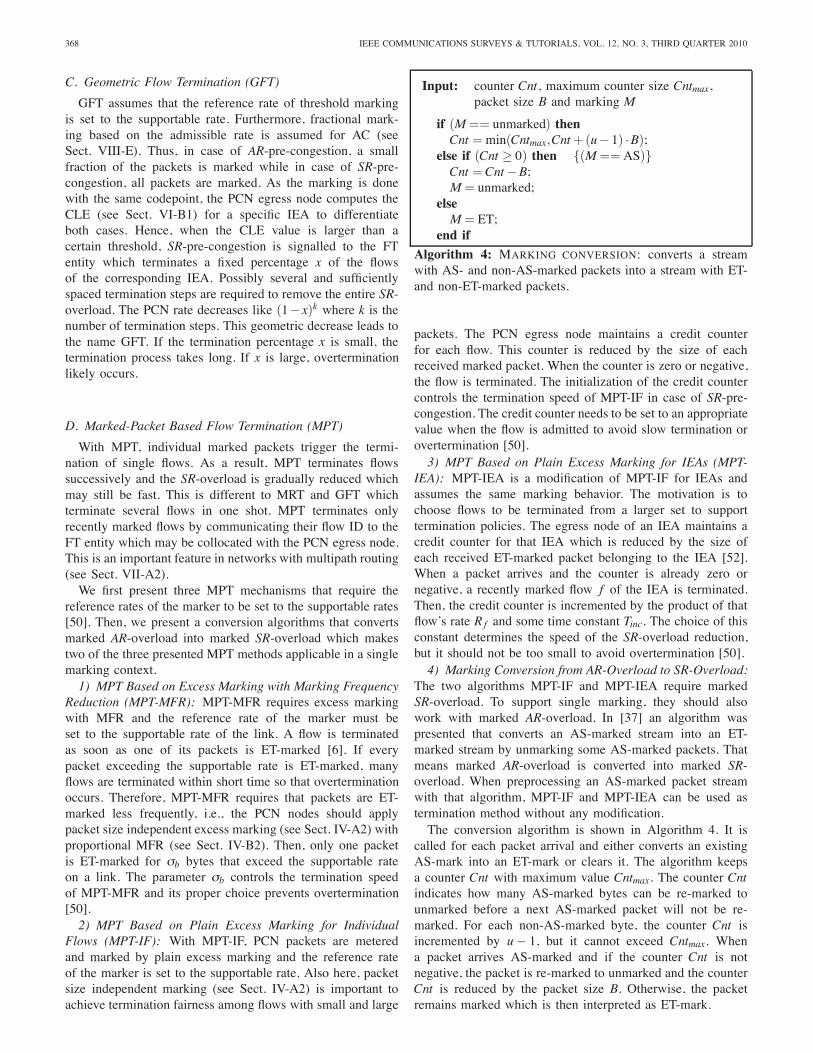
Input: counter Cnt, maximum counter size Cntmax,packet size B and marking M
if (M == unmarked) thenCnt =min(Cntmax,Cnt+(u−1) ·B);
else if (Cnt ≥ 0) then {(M == AS)}Cnt =Cnt−B;M = unmarked;
elseM = ET;
end if
Algorithm 4: MARKING CONVERSION: converts a streamwith AS- and non-AS-marked packets into a stream with ET-and non-ET-marked packets.
packets. The PCN egress node maintains a credit counterfor each flow. This counter is reduced by the size of eachreceived marked packet. When the counter is zero or negative,the flow is terminated. The initialization of the credit countercontrols the termination speed of MPT-IF in case of SR-pre-congestion. The credit counter needs to be set to an appropriatevalue when the flow is admitted to avoid slow termination orovertermination [50].3) MPT Based on Plain Excess Marking for IEAs (MPT-
IEA): MPT-IEA is a modification of MPT-IF for IEAs andassumes the same marking behavior. The motivation is tochoose flows to be terminated from a larger set to supporttermination policies. The egress node of an IEA maintains acredit counter for that IEA which is reduced by the size ofeach received ET-marked packet belonging to the IEA [52].When a packet arrives and the counter is already zero ornegative, a recently marked flow f of the IEA is terminated.Then, the credit counter is incremented by the product of thatflow’s rate Rf and some time constant Tinc. The choice of thisconstant determines the speed of the SR-overload reduction,but it should not be too small to avoid overtermination [50].4) Marking Conversion from AR-Overload to SR-Overload:
The two algorithms MPT-IF and MPT-IEA require markedSR-overload. To support single marking, they should alsowork with marked AR-overload. In [37] an algorithm waspresented that converts an AS-marked stream into an ET-marked stream by unmarking some AS-marked packets. Thatmeans marked AR-overload is converted into marked SR-overload. When preprocessing an AS-marked packet streamwith that algorithm, MPT-IF and MPT-IEA can be used astermination method without any modification.The conversion algorithm is shown in Algorithm 4. It is
called for each packet arrival and either converts an existingAS-mark into an ET-mark or clears it. The algorithm keepsa counter Cnt with maximum value Cntmax. The counter Cntindicates how many AS-marked bytes can be re-marked tounmarked before a next AS-marked packet will not be re-marked. For each non-AS-marked byte, the counter Cnt isincremented by u− 1, but it cannot exceed Cntmax. Whena packet arrives AS-marked and if the counter Cnt is notnegative, the packet is re-marked to unmarked and the counterCnt is reduced by the packet size B. Otherwise, the packetremains marked which is then interpreted as ET-mark.
MENTH et al.: A SURVEY OF PCN-BASED ADMISSION CONTROL AND FLOW TERMINATION 369
The conversion algorithm implements packet size indepen-dent re-marking as the re-marking decisions are taken indepen-dently of the packet size. A sufficiently large maximumCntmaxfor the counter is needed to tolerate short-term variations ofpacket markings, i.e. a burst of S AS-marked bytes should notbe ET-marked. However, this tolerance also delays initial re-marking. The authors of [37] studied the performance of MPTbased on AR-overload using marking conversion and showedthat it can lead to significant overtermination.
E. General Problems of FT Methods
Like overtermination expresses the fact that more trafficthan needed is terminated, undertermination means that lesstraffic is removed than necessary. In case of multipath routing,over- and undertermination possibly occur for IEA-based FTmethods (MRT and MPT-IEA). In scenarios with multiplebottlenecks, overtermination occurs for all FT methods. Webriefly illustrate these two fundamental problems in the fol-lowing.1) Over- and Undertermination due to Multipath Routing:
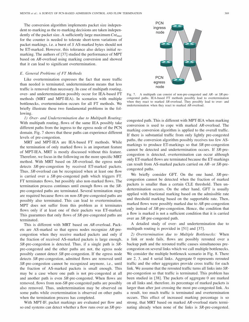
With multipath routing, flows of the same IEA possibly takedifferent paths from the ingress to the egress node of the PCNdomain. Fig. 7 shows that these paths can experience differentlevels of pre-congestion.MRT and MPT-IEA are IEA-based FT methods. While
the termination of only marked flows is an important featureof MPT-IEA, MRT is mostly discussed without this feature.Therefore, we focus in the following on the more specific MRTmethod. With MRT based on SR-overload, the egress nodedetects SR-pre-congestion by received ET-marked packets.Thus, SR-overload can be recognized when at least one flowis carried over a SR-pre-congested path which triggers FT.FT terminates flows, but possibly also non-marked flows. Thetermination process continues until enough flows on the SR-pre-congested paths are terminated. Several termination stepsare required because flows on non-SR-pre-congested paths arepossibly also terminated. This can lead to overtermination.MPT does not suffer from this problem as it terminatesflows only if at least one of their packets was ET-marked.This guarantees that only flows of SR-pre-congested paths areterminated.This is different with MRT based on AR-overload. Pack-
ets are AS-marked so that egress nodes recognize AR-pre-congestion when they receive marked packets and only ifthe fraction of received AS-marked packets is large enough,SR-pre-congestion is detected. Thus, if a single path is SR-pre-congested and the other paths are not, the egress nodepossibly cannot detect SR-pre-congestion. If the egress nodedetects SR-pre-congestion, admitted flows are removed untilSR-pre-congestion cannot be recognized anymore, i.e., untilthe fraction of AS-marked packets is small enough. Thismay be a case where one path is not pre-congested at alland another path is even SR-pre-congested. When flows areremoved, flows from non-SR-pre-congested paths are possiblyalso removed. Thus, undertermination may be observed onsome paths while overtermination is observed on other pathswhen the termination process has completed.With MPT-IF, packet markings are evaluated per flow and
so end systems can detect whether a flow runs over an SR-pre-
Fig. 7. A multipath can consist of non-pre-congested and AR- or SR-pre-congested paths. IEA-based FT methods possibly lead to overterminationwhen they react to marked SR-overload. They possibly lead to over- andundertermination when they react to marked AR-overload.
congested path. This is different with MPT-IEA when markingconversion is used to cope with marked AR-overload. Themarking conversion algorithm is applied to the overall traffic.If there is substantial traffic from only lightly pre-congestedpaths, the conversion algorithm possibly receives too few AS-markings to produce ET-markings so that SR-pre-congestioncannot be detected and undertermination occurs. If SR-pre-congestion is detected, overtermination can occur althoughonly ET-marked flows are terminated because the ET-markingscan result from AS-marked packets carried on AR- or SR-pre-congested paths.We briefly consider GFT. On the one hand, SR-pre-
congestion cannot be detected when the fraction of markedpackets is smaller than a certain CLE threshold. Then un-dertermination occurs. On the other hand, GFT is usuallyapplied with fractional marking based on the admissible rateand threshold marking based on the supportable rate. Then,marked flows were possibly marked due to AR-pre-congestiononly instead of SR-pre-congestion. Hence, the condition thata flow is marked is not a sufficient condition that it is carriedover an SR-pre-congested path.A detailed study of over- and undertermination due to
multipath routing is provided in [51] and [37].
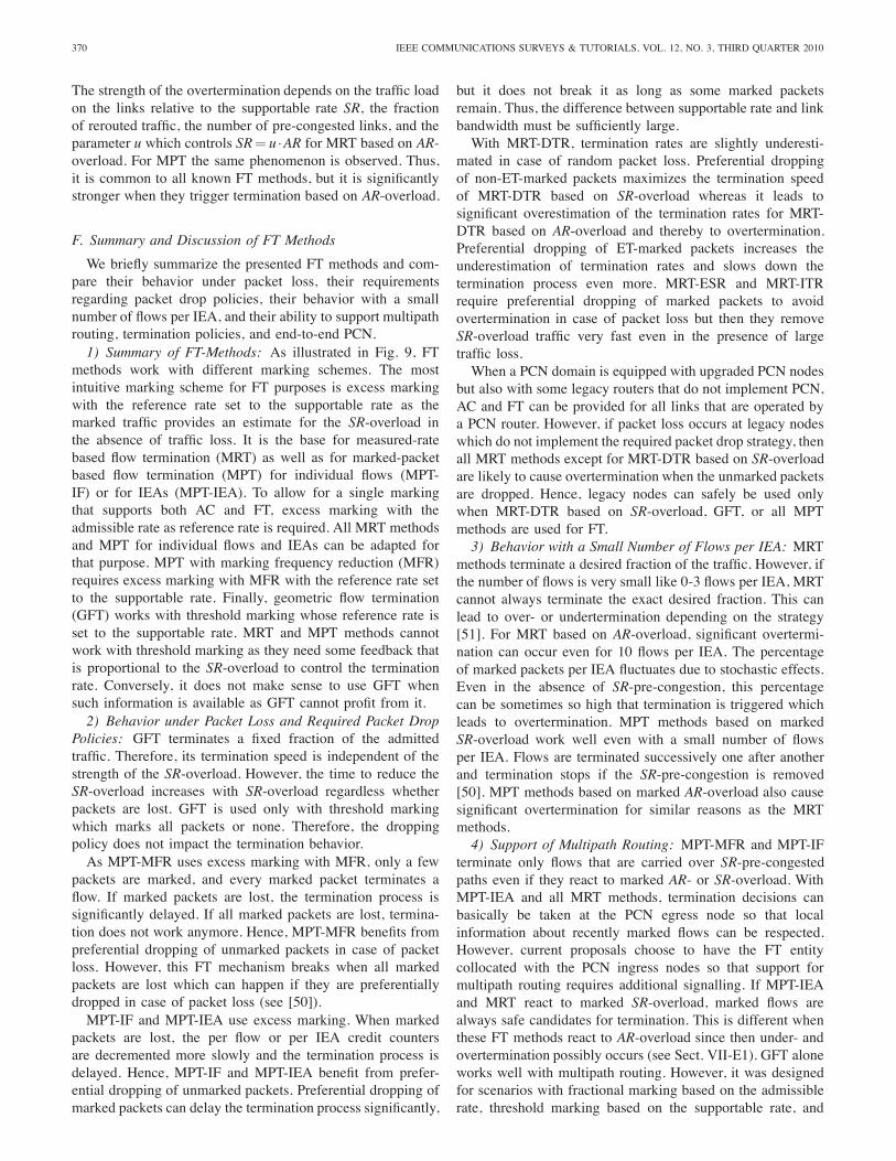
2) Overtermination due to Multiple Bottlenecks: Whena link or node fails, flows are possibly rerouted over abackup path and the rerouted traffic causes simultaneous pre-congestion on several links which we call multiple bottlenecks.We consider the multiple bottleneck scenario in Fig. 8. Thereare 2, 3, and 4 serial links. Aggregate 0 represents reroutedtraffic and the other aggregates provide cross traffic for eachlink. We assume that the rerouted traffic turns all links into SR-pre-congestion so that traffic is terminated. This problem hasbeen studied in [38]. The packets of aggregate 0 are markedon all links and, therefore, its percentage of marked packets islarger than after just crossing the most pre-congested link. Asa result, too much traffic is terminated and overterminationoccurs. This effect of increased marking percentage is sostrong, that MRT based on marked AR-overload starts termi-nating already when none of the links is SR-pre-congested.
370 IEEE COMMUNICATIONS SURVEYS & TUTORIALS, VOL. 12, NO. 3, THIRD QUARTER 2010
The strength of the overtermination depends on the traffic loadon the links relative to the supportable rate SR, the fractionof rerouted traffic, the number of pre-congested links, and theparameter u which controls SR= u ·AR for MRT based on AR-overload. For MPT the same phenomenon is observed. Thus,it is common to all known FT methods, but it is significantlystronger when they trigger termination based on AR-overload.
F. Summary and Discussion of FT Methods
We briefly summarize the presented FT methods and com-pare their behavior under packet loss, their requirementsregarding packet drop policies, their behavior with a smallnumber of flows per IEA, and their ability to support multipathrouting, termination policies, and end-to-end PCN.1) Summary of FT-Methods: As illustrated in Fig. 9, FT
methods work with different marking schemes. The mostintuitive marking scheme for FT purposes is excess markingwith the reference rate set to the supportable rate as themarked traffic provides an estimate for the SR-overload inthe absence of traffic loss. It is the base for measured-ratebased flow termination (MRT) as well as for marked-packetbased flow termination (MPT) for individual flows (MPT-IF) or for IEAs (MPT-IEA). To allow for a single markingthat supports both AC and FT, excess marking with theadmissible rate as reference rate is required. All MRT methodsand MPT for individual flows and IEAs can be adapted forthat purpose. MPT with marking frequency reduction (MFR)requires excess marking with MFR with the reference rate setto the supportable rate. Finally, geometric flow termination(GFT) works with threshold marking whose reference rate isset to the supportable rate. MRT and MPT methods cannotwork with threshold marking as they need some feedback thatis proportional to the SR-overload to control the terminationrate. Conversely, it does not make sense to use GFT whensuch information is available as GFT cannot profit from it.2) Behavior under Packet Loss and Required Packet Drop
Policies: GFT terminates a fixed fraction of the admittedtraffic. Therefore, its termination speed is independent of thestrength of the SR-overload. However, the time to reduce theSR-overload increases with SR-overload regardless whetherpackets are lost. GFT is used only with threshold markingwhich marks all packets or none. Therefore, the droppingpolicy does not impact the termination behavior.As MPT-MFR uses excess marking with MFR, only a few
packets are marked, and every marked packet terminates aflow. If marked packets are lost, the termination process issignificantly delayed. If all marked packets are lost, termina-tion does not work anymore. Hence, MPT-MFR benefits frompreferential dropping of unmarked packets in case of packetloss. However, this FT mechanism breaks when all markedpackets are lost which can happen if they are preferentiallydropped in case of packet loss (see [50]).MPT-IF and MPT-IEA use excess marking. When marked
packets are lost, the per flow or per IEA credit countersare decremented more slowly and the termination process isdelayed. Hence, MPT-IF and MPT-IEA benefit from prefer-ential dropping of unmarked packets. Preferential dropping ofmarked packets can delay the termination process significantly,
but it does not break it as long as some marked packetsremain. Thus, the difference between supportable rate and linkbandwidth must be sufficiently large.With MRT-DTR, termination rates are slightly underesti-
mated in case of random packet loss. Preferential droppingof non-ET-marked packets maximizes the termination speedof MRT-DTR based on SR-overload whereas it leads tosignificant overestimation of the termination rates for MRT-DTR based on AR-overload and thereby to overtermination.Preferential dropping of ET-marked packets increases theunderestimation of termination rates and slows down thetermination process even more. MRT-ESR and MRT-ITRrequire preferential dropping of marked packets to avoidovertermination in case of packet loss but then they removeSR-overload traffic very fast even in the presence of largetraffic loss.When a PCN domain is equipped with upgraded PCN nodes
but also with some legacy routers that do not implement PCN,AC and FT can be provided for all links that are operated bya PCN router. However, if packet loss occurs at legacy nodeswhich do not implement the required packet drop strategy, thenall MRT methods except for MRT-DTR based on SR-overloadare likely to cause overtermination when the unmarked packetsare dropped. Hence, legacy nodes can safely be used onlywhen MRT-DTR based on SR-overload, GFT, or all MPTmethods are used for FT.3) Behavior with a Small Number of Flows per IEA: MRT
methods terminate a desired fraction of the traffic. However, ifthe number of flows is very small like 0-3 flows per IEA, MRTcannot always terminate the exact desired fraction. This canlead to over- or undertermination depending on the strategy[51]. For MRT based on AR-overload, significant overtermi-nation can occur even for 10 flows per IEA. The percentageof marked packets per IEA fluctuates due to stochastic effects.Even in the absence of SR-pre-congestion, this percentagecan be sometimes so high that termination is triggered whichleads to overtermination. MPT methods based on markedSR-overload work well even with a small number of flowsper IEA. Flows are terminated successively one after anotherand termination stops if the SR-pre-congestion is removed[50]. MPT methods based on marked AR-overload also causesignificant overtermination for similar reasons as the MRTmethods.4) Support of Multipath Routing: MPT-MFR and MPT-IF
terminate only flows that are carried over SR-pre-congestedpaths even if they react to marked AR- or SR-overload. WithMPT-IEA and all MRT methods, termination decisions canbasically be taken at the PCN egress node so that localinformation about recently marked flows can be respected.However, current proposals choose to have the FT entitycollocated with the PCN ingress nodes so that support formultipath routing requires additional signalling. If MPT-IEAand MRT react to marked SR-overload, marked flows arealways safe candidates for termination. This is different whenthese FT methods react to AR-overload since then under- andovertermination possibly occurs (see Sect. VII-E1). GFT aloneworks well with multipath routing. However, it was designedfor scenarios with fractional marking based on the admissiblerate, threshold marking based on the supportable rate, and
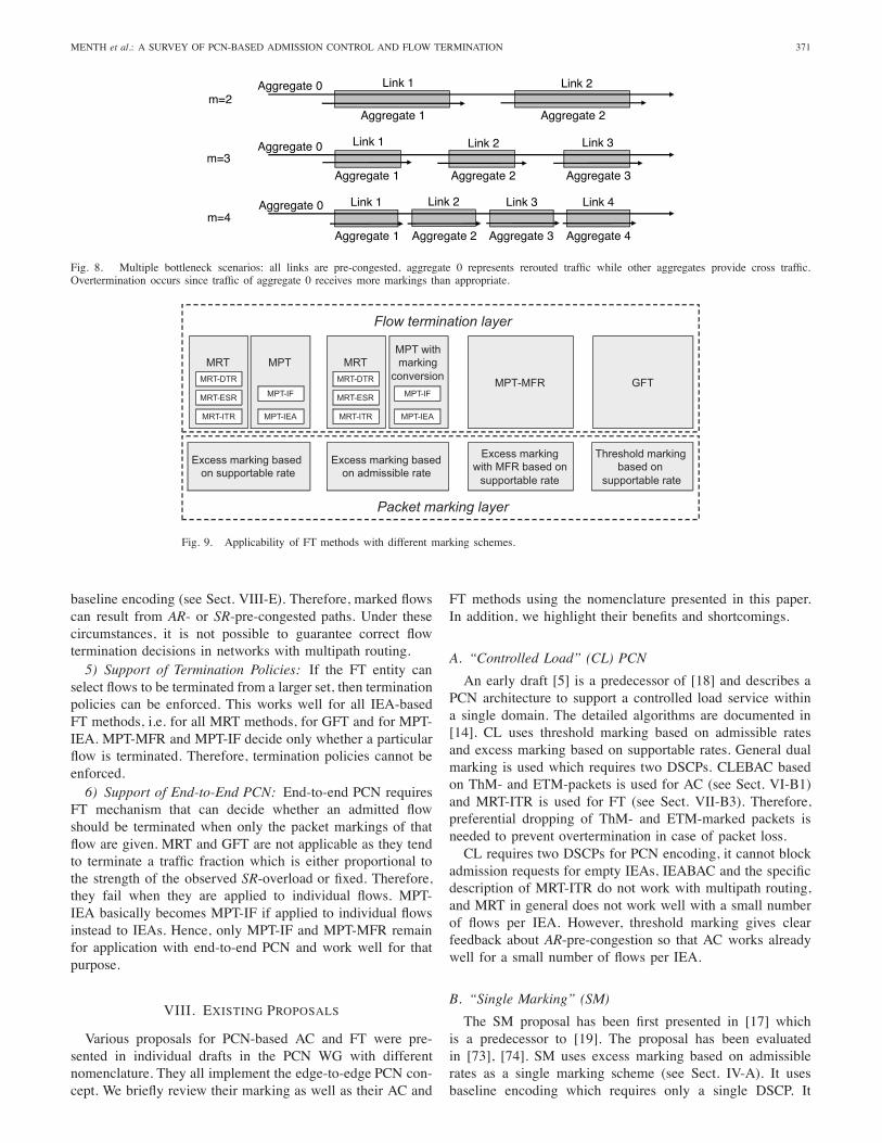
MENTH et al.: A SURVEY OF PCN-BASED ADMISSION CONTROL AND FLOW TERMINATION 371
Link 1 Link 2Aggregate 0
Link 1 Link 3Aggregate 0
Link 1Aggregate 0
Link 2
Link 2 Link 3 Link 4
Aggregate 1 Aggregate 2m=2
m=3
m=4
Aggregate 3Aggregate 2Aggregate 1
Aggregate 3 Aggregate 4Aggregate 2Aggregate 1
Fig. 8. Multiple bottleneck scenarios: all links are pre-congested, aggregate 0 represents rerouted traffic while other aggregates provide cross traffic.Overtermination occurs since traffic of aggregate 0 receives more markings than appropriate.
Excess markingwith MFR based onsupportable rate
MPT-MFR
Threshold markingbased on
supportable rate
GFT
Flow termination layer
Packet marking layer
MPT
MPT-IF
MPT-IEA
MRT
MRT-ESR
MRT-ITR
Excess marking basedon supportable rate
Excess marking basedon admissible rate
MPT withmarkingconversion
MPT-IF
MPT-IEA
MRT
MRT-ESR
MRT-ITR
MRT-DTR MRT-DTR
Fig. 9. Applicability of FT methods with different marking schemes.
baseline encoding (see Sect. VIII-E). Therefore, marked flowscan result from AR- or SR-pre-congested paths. Under thesecircumstances, it is not possible to guarantee correct flowtermination decisions in networks with multipath routing.5) Support of Termination Policies: If the FT entity can
select flows to be terminated from a larger set, then terminationpolicies can be enforced. This works well for all IEA-basedFT methods, i.e. for all MRT methods, for GFT and for MPT-IEA. MPT-MFR and MPT-IF decide only whether a particularflow is terminated. Therefore, termination policies cannot beenforced.6) Support of End-to-End PCN: End-to-end PCN requires
FT mechanism that can decide whether an admitted flowshould be terminated when only the packet markings of thatflow are given. MRT and GFT are not applicable as they tendto terminate a traffic fraction which is either proportional tothe strength of the observed SR-overload or fixed. Therefore,they fail when they are applied to individual flows. MPT-IEA basically becomes MPT-IF if applied to individual flowsinstead to IEAs. Hence, only MPT-IF and MPT-MFR remainfor application with end-to-end PCN and work well for thatpurpose.
VIII. EXISTING PROPOSALS
Various proposals for PCN-based AC and FT were pre-sented in individual drafts in the PCN WG with differentnomenclature. They all implement the edge-to-edge PCN con-cept. We briefly review their marking as well as their AC and
FT methods using the nomenclature presented in this paper.In addition, we highlight their benefits and shortcomings.
A. “Controlled Load” (CL) PCN
An early draft [5] is a predecessor of [18] and describes aPCN architecture to support a controlled load service withina single domain. The detailed algorithms are documented in[14]. CL uses threshold marking based on admissible ratesand excess marking based on supportable rates. General dualmarking is used which requires two DSCPs. CLEBAC basedon ThM- and ETM-packets is used for AC (see Sect. VI-B1)and MRT-ITR is used for FT (see Sect. VII-B3). Therefore,preferential dropping of ThM- and ETM-marked packets isneeded to prevent overtermination in case of packet loss.CL requires two DSCPs for PCN encoding, it cannot block
admission requests for empty IEAs, IEABAC and the specificdescription of MRT-ITR do not work with multipath routing,and MRT in general does not work well with a small numberof flows per IEA. However, threshold marking gives clearfeedback about AR-pre-congestion so that AC works alreadywell for a small number of flows per IEA.
B. “Single Marking” (SM)
The SM proposal has been first presented in [17] whichis a predecessor to [19]. The proposal has been evaluatedin [73], [74]. SM uses excess marking based on admissiblerates as a single marking scheme (see Sect. IV-A). It usesbaseline encoding which requires only a single DSCP. It
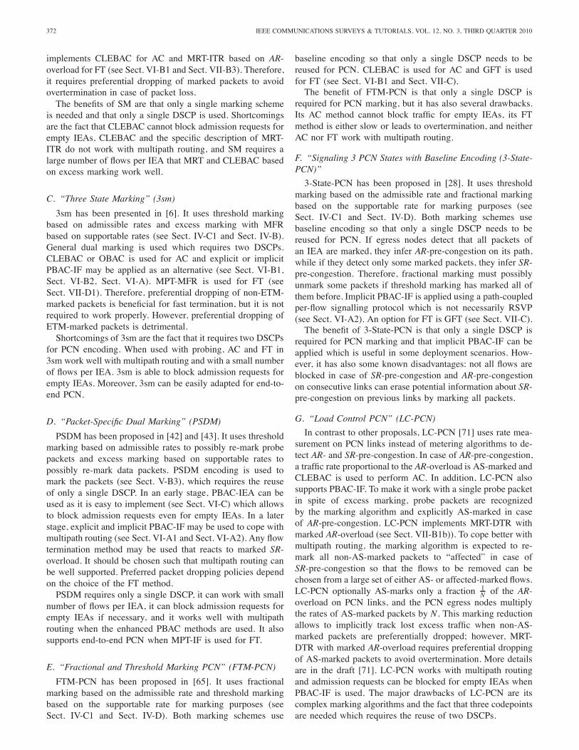
372 IEEE COMMUNICATIONS SURVEYS & TUTORIALS, VOL. 12, NO. 3, THIRD QUARTER 2010
implements CLEBAC for AC and MRT-ITR based on AR-overload for FT (see Sect. VI-B1 and Sect. VII-B3). Therefore,it requires preferential dropping of marked packets to avoidovertermination in case of packet loss.The benefits of SM are that only a single marking scheme
is needed and that only a single DSCP is used. Shortcomingsare the fact that CLEBAC cannot block admission requests forempty IEAs, CLEBAC and the specific description of MRT-ITR do not work with multipath routing, and SM requires alarge number of flows per IEA that MRT and CLEBAC basedon excess marking work well.
C. “Three State Marking” (3sm)
3sm has been presented in [6]. It uses threshold markingbased on admissible rates and excess marking with MFRbased on supportable rates (see Sect. IV-C1 and Sect. IV-B).General dual marking is used which requires two DSCPs.CLEBAC or OBAC is used for AC and explicit or implicitPBAC-IF may be applied as an alternative (see Sect. VI-B1,Sect. VI-B2, Sect. VI-A). MPT-MFR is used for FT (seeSect. VII-D1). Therefore, preferential dropping of non-ETM-marked packets is beneficial for fast termination, but it is notrequired to work properly. However, preferential dropping ofETM-marked packets is detrimental.Shortcomings of 3sm are the fact that it requires two DSCPs
for PCN encoding. When used with probing, AC and FT in3sm work well with multipath routing and with a small numberof flows per IEA. 3sm is able to block admission requests forempty IEAs. Moreover, 3sm can be easily adapted for end-to-end PCN.
D. “Packet-Specific Dual Marking” (PSDM)
PSDM has been proposed in [42] and [43]. It uses thresholdmarking based on admissible rates to possibly re-mark probepackets and excess marking based on supportable rates topossibly re-mark data packets. PSDM encoding is used tomark the packets (see Sect. V-B3), which requires the reuseof only a single DSCP. In an early stage, PBAC-IEA can beused as it is easy to implement (see Sect. VI-C) which allowsto block admission requests even for empty IEAs. In a laterstage, explicit and implicit PBAC-IF may be used to cope withmultipath routing (see Sect. VI-A1 and Sect. VI-A2). Any flowtermination method may be used that reacts to marked SR-overload. It should be chosen such that multipath routing canbe well supported. Preferred packet dropping policies dependon the choice of the FT method.PSDM requires only a single DSCP, it can work with small
number of flows per IEA, it can block admission requests forempty IEAs if necessary, and it works well with multipathrouting when the enhanced PBAC methods are used. It alsosupports end-to-end PCN when MPT-IF is used for FT.
E. “Fractional and Threshold Marking PCN” (FTM-PCN)
FTM-PCN has been proposed in [65]. It uses fractionalmarking based on the admissible rate and threshold markingbased on the supportable rate for marking purposes (seeSect. IV-C1 and Sect. IV-D). Both marking schemes use
baseline encoding so that only a single DSCP needs to bereused for PCN. CLEBAC is used for AC and GFT is usedfor FT (see Sect. VI-B1 and Sect. VII-C).The benefit of FTM-PCN is that only a single DSCP is
required for PCN marking, but it has also several drawbacks.Its AC method cannot block traffic for empty IEAs, its FTmethod is either slow or leads to overtermination, and neitherAC nor FT work with multipath routing.
F. “Signaling 3 PCN States with Baseline Encoding (3-State-PCN)”
3-State-PCN has been proposed in [28]. It uses thresholdmarking based on the admissible rate and fractional markingbased on the supportable rate for marking purposes (seeSect. IV-C1 and Sect. IV-D). Both marking schemes usebaseline encoding so that only a single DSCP needs to bereused for PCN. If egress nodes detect that all packets ofan IEA are marked, they infer AR-pre-congestion on its path,while if they detect only some marked packets, they infer SR-pre-congestion. Therefore, fractional marking must possiblyunmark some packets if threshold marking has marked all ofthem before. Implicit PBAC-IF is applied using a path-coupledper-flow signalling protocol which is not necessarily RSVP(see Sect. VI-A2). An option for FT is GFT (see Sect. VII-C).The benefit of 3-State-PCN is that only a single DSCP is
required for PCN marking and that implicit PBAC-IF can beapplied which is useful in some deployment scenarios. How-ever, it has also some known disadvantages: not all flows areblocked in case of SR-pre-congestion and AR-pre-congestionon consecutive links can erase potential information about SR-pre-congestion on previous links by marking all packets.
G. “Load Control PCN” (LC-PCN)
In contrast to other proposals, LC-PCN [71] uses rate mea-surement on PCN links instead of metering algorithms to de-tect AR- and SR-pre-congestion. In case of AR-pre-congestion,a traffic rate proportional to the AR-overload is AS-marked andCLEBAC is used to perform AC. In addition, LC-PCN alsosupports PBAC-IF. To make it work with a single probe packetin spite of excess marking, probe packets are recognizedby the marking algorithm and explicitly AS-marked in caseof AR-pre-congestion. LC-PCN implements MRT-DTR withmarked AR-overload (see Sect. VII-B1b)). To cope better withmultipath routing, the marking algorithm is expected to re-mark all non-AS-marked packets to “affected” in case ofSR-pre-congestion so that the flows to be removed can bechosen from a large set of either AS- or affected-marked flows.LC-PCN optionally AS-marks only a fraction 1
N of the AR-overload on PCN links, and the PCN egress nodes multiplythe rates of AS-marked packets by N. This marking reductionallows to implicitly track lost excess traffic when non-AS-marked packets are preferentially dropped; however, MRT-DTR with marked AR-overload requires preferential droppingof AS-marked packets to avoid overtermination. More detailsare in the draft [71]. LC-PCN works with multipath routingand admission requests can be blocked for empty IEAs whenPBAC-IF is used. The major drawbacks of LC-PCN are itscomplex marking algorithms and the fact that three codepointsare needed which requires the reuse of two DSCPs.
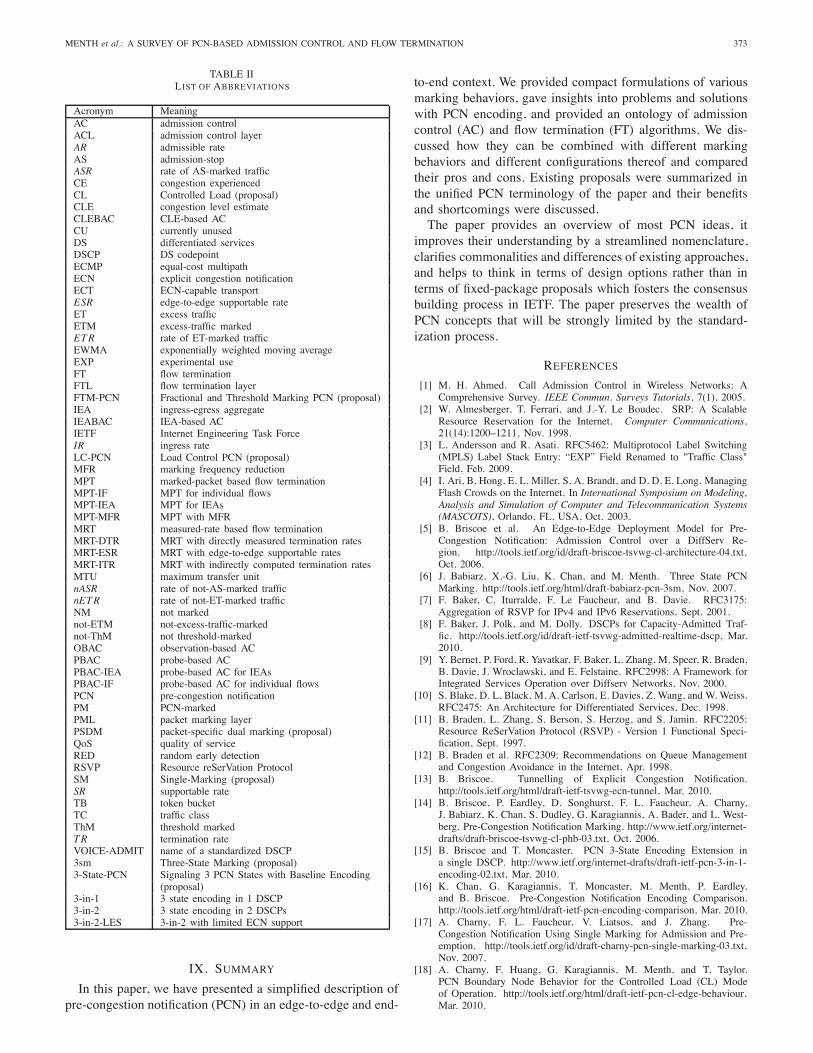
MENTH et al.: A SURVEY OF PCN-BASED ADMISSION CONTROL AND FLOW TERMINATION 373
TABLE IILIST OF ABBREVIATIONS
Acronym MeaningAC admission controlACL admission control layerAR admissible rateAS admission-stopASR rate of AS-marked trafficCE congestion experiencedCL Controlled Load (proposal)CLE congestion level estimateCLEBAC CLE-based ACCU currently unusedDS differentiated servicesDSCP DS codepointECMP equal-cost multipathECN explicit congestion notificationECT ECN-capable transportESR edge-to-edge supportable rateET excess trafficETM excess-traffic markedETR rate of ET-marked trafficEWMA exponentially weighted moving averageEXP experimental useFT flow terminationFTL flow termination layerFTM-PCN Fractional and Threshold Marking PCN (proposal)IEA ingress-egress aggregateIEABAC IEA-based ACIETF Internet Engineering Task ForceIR ingress rateLC-PCN Load Control PCN (proposal)MFR marking frequency reductionMPT marked-packet based flow terminationMPT-IF MPT for individual flowsMPT-IEA MPT for IEAsMPT-MFR MPT with MFRMRT measured-rate based flow terminationMRT-DTR MRT with directly measured termination ratesMRT-ESR MRT with edge-to-edge supportable ratesMRT-ITR MRT with indirectly computed termination ratesMTU maximum transfer unitnASR rate of not-AS-marked trafficnETR rate of not-ET-marked trafficNM not markednot-ETM not-excess-traffic-markednot-ThM not threshold-markedOBAC observation-based ACPBAC probe-based ACPBAC-IEA probe-based AC for IEAsPBAC-IF probe-based AC for individual flowsPCN pre-congestion notificationPM PCN-markedPML packet marking layerPSDM packet-specific dual marking (proposal)QoS quality of serviceRED random early detectionRSVP Resource reSerVation ProtocolSM Single-Marking (proposal)SR supportable rateTB token bucketTC traffic classThM threshold markedTR termination rateVOICE-ADMIT name of a standardized DSCP3sm Three-State Marking (proposal)3-State-PCN Signaling 3 PCN States with Baseline Encoding
(proposal)3-in-1 3 state encoding in 1 DSCP3-in-2 3 state encoding in 2 DSCPs3-in-2-LES 3-in-2 with limited ECN support
IX. SUMMARY
In this paper, we have presented a simplified description ofpre-congestion notification (PCN) in an edge-to-edge and end-
to-end context. We provided compact formulations of variousmarking behaviors, gave insights into problems and solutionswith PCN encoding, and provided an ontology of admissioncontrol (AC) and flow termination (FT) algorithms. We dis-cussed how they can be combined with different markingbehaviors and different configurations thereof and comparedtheir pros and cons. Existing proposals were summarized inthe unified PCN terminology of the paper and their benefitsand shortcomings were discussed.The paper provides an overview of most PCN ideas, it
improves their understanding by a streamlined nomenclature,clarifies commonalities and differences of existing approaches,and helps to think in terms of design options rather than interms of fixed-package proposals which fosters the consensusbuilding process in IETF. The paper preserves the wealth ofPCN concepts that will be strongly limited by the standard-ization process.
REFERENCES
[1] M. H. Ahmed. Call Admission Control in Wireless Networks: AComprehensive Survey. IEEE Commun. Surveys Tutorials, 7(1), 2005.
[2] W. Almesberger, T. Ferrari, and J.-Y. Le Boudec. SRP: A ScalableResource Reservation for the Internet. Computer Communications,21(14):1200–1211, Nov. 1998.
[3] L. Andersson and R. Asati. RFC5462: Multiprotocol Label Switching(MPLS) Label Stack Entry: “EXP” Field Renamed to "Traffic Class"Field, Feb. 2009.
[4] I. Ari, B. Hong, E. L. Miller, S. A. Brandt, and D. D. E. Long. ManagingFlash Crowds on the Internet. In International Symposium on Modeling,Analysis and Simulation of Computer and Telecommunication Systems(MASCOTS), Orlando, FL, USA, Oct. 2003.
[5] B. Briscoe et al. An Edge-to-Edge Deployment Model for Pre-Congestion Notification: Admission Control over a DiffServ Re-gion. http://tools.ietf.org/id/draft-briscoe-tsvwg-cl-architecture-04.txt,Oct. 2006.
[6] J. Babiarz, X.-G. Liu, K. Chan, and M. Menth. Three State PCNMarking. http://tools.ietf.org/html/draft-babiarz-pcn-3sm, Nov. 2007.
[7] F. Baker, C. Iturralde, F. Le Faucheur, and B. Davie. RFC3175:Aggregation of RSVP for IPv4 and IPv6 Reservations, Sept. 2001.
[8] F. Baker, J. Polk, and M. Dolly. DSCPs for Capacity-Admitted Traf-fic. http://tools.ietf.org/id/draft-ietf-tsvwg-admitted-realtime-dscp, Mar.2010.
[9] Y. Bernet, P. Ford, R. Yavatkar, F. Baker, L. Zhang, M. Speer, R. Braden,B. Davie, J. Wroclawski, and E. Felstaine. RFC2998: A Framework forIntegrated Services Operation over Diffserv Networks, Nov. 2000.
[10] S. Blake, D. L. Black, M. A. Carlson, E. Davies, Z. Wang, and W. Weiss.RFC2475: An Architecture for Differentiated Services, Dec. 1998.
[11] B. Braden, L. Zhang, S. Berson, S. Herzog, and S. Jamin. RFC2205:Resource ReSerVation Protocol (RSVP) - Version 1 Functional Speci-fication, Sept. 1997.
[12] B. Braden et al. RFC2309: Recommendations on Queue Managementand Congestion Avoidance in the Internet, Apr. 1998.
[13] B. Briscoe. Tunnelling of Explicit Congestion Notification.http://tools.ietf.org/html/draft-ietf-tsvwg-ecn-tunnel, Mar. 2010.
[14] B. Briscoe, P. Eardley, D. Songhurst, F. L. Faucheur, A. Charny,J. Babiarz, K. Chan, S. Dudley, G. Karagiannis, A. Bader, and L. West-berg. Pre-Congestion Notification Marking. http://www.ietf.org/internet-drafts/draft-briscoe-tsvwg-cl-phb-03.txt, Oct. 2006.
[15] B. Briscoe and T. Moncaster. PCN 3-State Encoding Extension ina single DSCP. http://www.ietf.org/internet-drafts/draft-ietf-pcn-3-in-1-encoding-02.txt, Mar. 2010.
[16] K. Chan, G. Karagiannis, T. Moncaster, M. Menth, P. Eardley,and B. Briscoe. Pre-Congestion Notification Encoding Comparison.http://tools.ietf.org/html/draft-ietf-pcn-encoding-comparison, Mar. 2010.
[17] A. Charny, F. L. Faucheur, V. Liatsos, and J. Zhang. Pre-Congestion Notification Using Single Marking for Admission and Pre-emption. http://tools.ietf.org/id/draft-charny-pcn-single-marking-03.txt,Nov. 2007.
[18] A. Charny, F. Huang, G. Karagiannis, M. Menth, and T. Taylor.PCN Boundary Node Behavior for the Controlled Load (CL) Modeof Operation. http://tools.ietf.org/html/draft-ietf-pcn-cl-edge-behaviour,Mar. 2010.
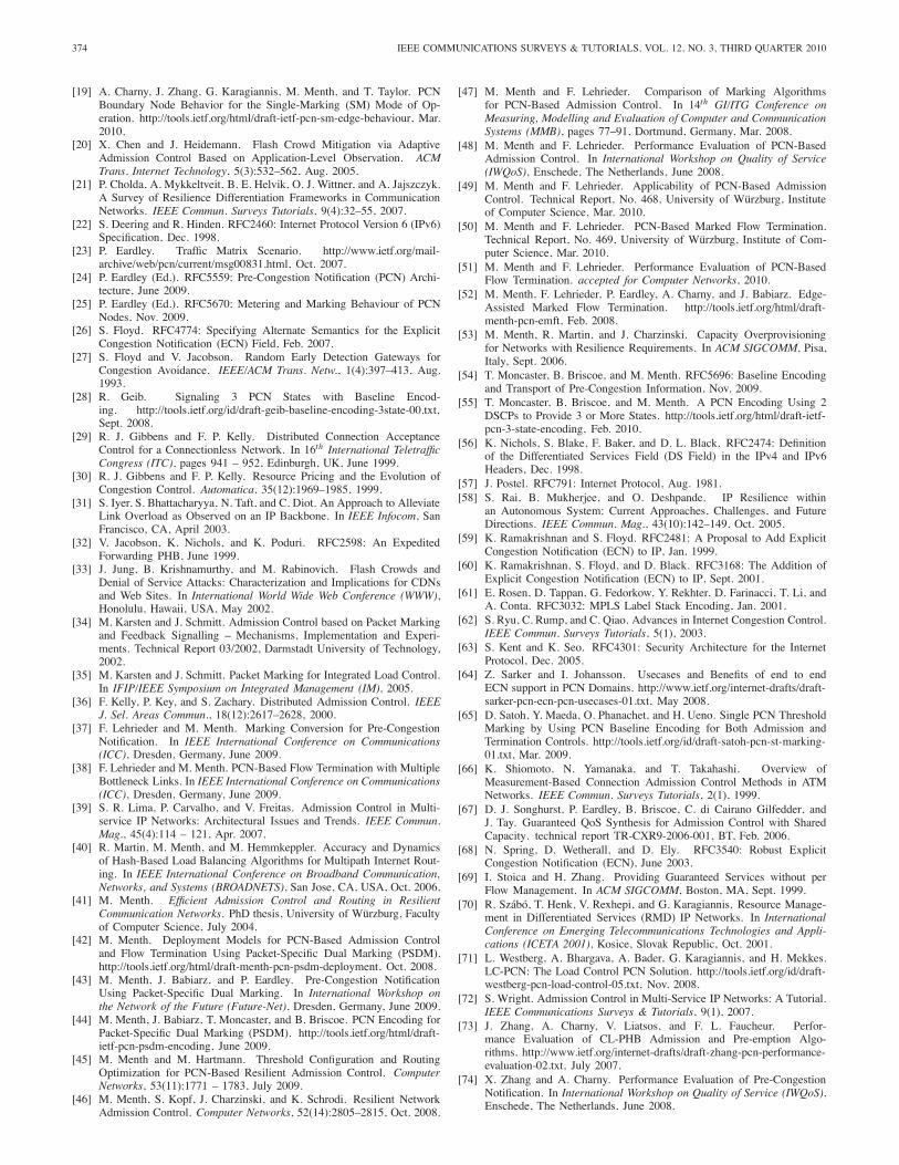
374 IEEE COMMUNICATIONS SURVEYS & TUTORIALS, VOL. 12, NO. 3, THIRD QUARTER 2010
[19] A. Charny, J. Zhang, G. Karagiannis, M. Menth, and T. Taylor. PCNBoundary Node Behavior for the Single-Marking (SM) Mode of Op-eration. http://tools.ietf.org/html/draft-ietf-pcn-sm-edge-behaviour, Mar.2010.
[20] X. Chen and J. Heidemann. Flash Crowd Mitigation via AdaptiveAdmission Control Based on Application-Level Observation. ACMTrans. Internet Technology, 5(3):532–562, Aug. 2005.
[21] P. Cholda, A. Mykkeltveit, B. E. Helvik, O. J. Wittner, and A. Jajszczyk.A Survey of Resilience Differentiation Frameworks in CommunicationNetworks. IEEE Commun. Surveys Tutorials, 9(4):32–55, 2007.
[22] S. Deering and R. Hinden. RFC2460: Internet Protocol Version 6 (IPv6)Specification, Dec. 1998.
[23] P. Eardley. Traffic Matrix Scenario. http://www.ietf.org/mail-archive/web/pcn/current/msg00831.html, Oct. 2007.
[24] P. Eardley (Ed.). RFC5559: Pre-Congestion Notification (PCN) Archi-tecture, June 2009.
[25] P. Eardley (Ed.). RFC5670: Metering and Marking Behaviour of PCNNodes, Nov. 2009.
[26] S. Floyd. RFC4774: Specifying Alternate Semantics for the ExplicitCongestion Notification (ECN) Field, Feb. 2007.
[27] S. Floyd and V. Jacobson. Random Early Detection Gateways forCongestion Avoidance. IEEE/ACM Trans. Netw., 1(4):397–413, Aug.1993.
[28] R. Geib. Signaling 3 PCN States with Baseline Encod-ing. http://tools.ietf.org/id/draft-geib-baseline-encoding-3state-00.txt,Sept. 2008.
[29] R. J. Gibbens and F. P. Kelly. Distributed Connection AcceptanceControl for a Connectionless Network. In 16th International TeletrafficCongress (ITC), pages 941 – 952, Edinburgh, UK, June 1999.
[30] R. J. Gibbens and F. P. Kelly. Resource Pricing and the Evolution ofCongestion Control. Automatica, 35(12):1969–1985, 1999.
[31] S. Iyer, S. Bhattacharyya, N. Taft, and C. Diot. An Approach to AlleviateLink Overload as Observed on an IP Backbone. In IEEE Infocom, SanFrancisco, CA, April 2003.
[32] V. Jacobson, K. Nichols, and K. Poduri. RFC2598: An ExpeditedForwarding PHB, June 1999.
[33] J. Jung, B. Krishnamurthy, and M. Rabinovich. Flash Crowds andDenial of Service Attacks: Characterization and Implications for CDNsand Web Sites. In International World Wide Web Conference (WWW),Honolulu, Hawaii, USA, May 2002.
[34] M. Karsten and J. Schmitt. Admission Control based on Packet Markingand Feedback Signalling – Mechanisms, Implementation and Experi-ments. Technical Report 03/2002, Darmstadt University of Technology,2002.
[35] M. Karsten and J. Schmitt. Packet Marking for Integrated Load Control.In IFIP/IEEE Symposium on Integrated Management (IM), 2005.
[36] F. Kelly, P. Key, and S. Zachary. Distributed Admission Control. IEEEJ. Sel. Areas Commun., 18(12):2617–2628, 2000.
[37] F. Lehrieder and M. Menth. Marking Conversion for Pre-CongestionNotification. In IEEE International Conference on Communications(ICC), Dresden, Germany, June 2009.
[38] F. Lehrieder and M. Menth. PCN-Based Flow Termination with MultipleBottleneck Links. In IEEE International Conference on Communications(ICC), Dresden, Germany, June 2009.
[39] S. R. Lima, P. Carvalho, and V. Freitas. Admission Control in Multi-service IP Networks: Architectural Issues and Trends. IEEE Commun.Mag., 45(4):114 – 121, Apr. 2007.
[40] R. Martin, M. Menth, and M. Hemmkeppler. Accuracy and Dynamicsof Hash-Based Load Balancing Algorithms for Multipath Internet Rout-ing. In IEEE International Conference on Broadband Communication,Networks, and Systems (BROADNETS), San Jose, CA, USA, Oct. 2006.
[41] M. Menth. Efficient Admission Control and Routing in ResilientCommunication Networks. PhD thesis, University of Würzburg, Facultyof Computer Science, July 2004.
[42] M. Menth. Deployment Models for PCN-Based Admission Controland Flow Termination Using Packet-Specific Dual Marking (PSDM).http://tools.ietf.org/html/draft-menth-pcn-psdm-deployment, Oct. 2008.
[43] M. Menth, J. Babiarz, and P. Eardley. Pre-Congestion NotificationUsing Packet-Specific Dual Marking. In International Workshop onthe Network of the Future (Future-Net), Dresden, Germany, June 2009.
[44] M. Menth, J. Babiarz, T. Moncaster, and B. Briscoe. PCN Encoding forPacket-Specific Dual Marking (PSDM). http://tools.ietf.org/html/draft-ietf-pcn-psdm-encoding, June 2009.
[45] M. Menth and M. Hartmann. Threshold Configuration and RoutingOptimization for PCN-Based Resilient Admission Control. ComputerNetworks, 53(11):1771 – 1783, July 2009.
[46] M. Menth, S. Kopf, J. Charzinski, and K. Schrodi. Resilient NetworkAdmission Control. Computer Networks, 52(14):2805–2815, Oct. 2008.
[47] M. Menth and F. Lehrieder. Comparison of Marking Algorithmsfor PCN-Based Admission Control. In 14th GI/ITG Conference onMeasuring, Modelling and Evaluation of Computer and CommunicationSystems (MMB), pages 77–91, Dortmund, Germany, Mar. 2008.
[48] M. Menth and F. Lehrieder. Performance Evaluation of PCN-BasedAdmission Control. In International Workshop on Quality of Service(IWQoS), Enschede, The Netherlands, June 2008.
[49] M. Menth and F. Lehrieder. Applicability of PCN-Based AdmissionControl. Technical Report, No. 468, University of Würzburg, Instituteof Computer Science, Mar. 2010.
[50] M. Menth and F. Lehrieder. PCN-Based Marked Flow Termination.Technical Report, No. 469, University of Würzburg, Institute of Com-puter Science, Mar. 2010.
[51] M. Menth and F. Lehrieder. Performance Evaluation of PCN-BasedFlow Termination. accepted for Computer Networks, 2010.
[52] M. Menth, F. Lehrieder, P. Eardley, A. Charny, and J. Babiarz. Edge-Assisted Marked Flow Termination. http://tools.ietf.org/html/draft-menth-pcn-emft, Feb. 2008.
[53] M. Menth, R. Martin, and J. Charzinski. Capacity Overprovisioningfor Networks with Resilience Requirements. In ACM SIGCOMM, Pisa,Italy, Sept. 2006.
[54] T. Moncaster, B. Briscoe, and M. Menth. RFC5696: Baseline Encodingand Transport of Pre-Congestion Information, Nov. 2009.
[55] T. Moncaster, B. Briscoe, and M. Menth. A PCN Encoding Using 2DSCPs to Provide 3 or More States. http://tools.ietf.org/html/draft-ietf-pcn-3-state-encoding, Feb. 2010.
[56] K. Nichols, S. Blake, F. Baker, and D. L. Black. RFC2474: Definitionof the Differentiated Services Field (DS Field) in the IPv4 and IPv6Headers, Dec. 1998.
[57] J. Postel. RFC791: Internet Protocol, Aug. 1981.[58] S. Rai, B. Mukherjee, and O. Deshpande. IP Resilience within
an Autonomous System: Current Approaches, Challenges, and FutureDirections. IEEE Commun. Mag., 43(10):142–149, Oct. 2005.
[59] K. Ramakrishnan and S. Floyd. RFC2481: A Proposal to Add ExplicitCongestion Notification (ECN) to IP, Jan. 1999.
[60] K. Ramakrishnan, S. Floyd, and D. Black. RFC3168: The Addition ofExplicit Congestion Notification (ECN) to IP, Sept. 2001.
[61] E. Rosen, D. Tappan, G. Fedorkow, Y. Rekhter, D. Farinacci, T. Li, andA. Conta. RFC3032: MPLS Label Stack Encoding, Jan. 2001.
[62] S. Ryu, C. Rump, and C. Qiao. Advances in Internet Congestion Control.IEEE Commun. Surveys Tutorials, 5(1), 2003.
[63] S. Kent and K. Seo. RFC4301: Security Architecture for the InternetProtocol, Dec. 2005.
[64] Z. Sarker and I. Johansson. Usecases and Benefits of end to endECN support in PCN Domains. http://www.ietf.org/internet-drafts/draft-sarker-pcn-ecn-pcn-usecases-01.txt, May 2008.
[65] D. Satoh, Y. Maeda, O. Phanachet, and H. Ueno. Single PCN ThresholdMarking by Using PCN Baseline Encoding for Both Admission andTermination Controls. http://tools.ietf.org/id/draft-satoh-pcn-st-marking-01.txt, Mar. 2009.
[66] K. Shiomoto, N. Yamanaka, and T. Takahashi. Overview ofMeasurement-Based Connection Admission Control Methods in ATMNetworks. IEEE Commun. Surveys Tutorials, 2(1), 1999.
[67] D. J. Songhurst, P. Eardley, B. Briscoe, C. di Cairano Gilfedder, andJ. Tay. Guaranteed QoS Synthesis for Admission Control with SharedCapacity. technical report TR-CXR9-2006-001, BT, Feb. 2006.
[68] N. Spring, D. Wetherall, and D. Ely. RFC3540: Robust ExplicitCongestion Notification (ECN), June 2003.
[69] I. Stoica and H. Zhang. Providing Guaranteed Services without perFlow Management. In ACM SIGCOMM, Boston, MA, Sept. 1999.
[70] R. Szábó, T. Henk, V. Rexhepi, and G. Karagiannis. Resource Manage-ment in Differentiated Services (RMD) IP Networks. In InternationalConference on Emerging Telecommunications Technologies and Appli-cations (ICETA 2001), Kosice, Slovak Republic, Oct. 2001.
[71] L. Westberg, A. Bhargava, A. Bader, G. Karagiannis, and H. Mekkes.LC-PCN: The Load Control PCN Solution. http://tools.ietf.org/id/draft-westberg-pcn-load-control-05.txt, Nov. 2008.
[72] S. Wright. Admission Control in Multi-Service IP Networks: A Tutorial.IEEE Communications Surveys & Tutorials, 9(1), 2007.
[73] J. Zhang, A. Charny, V. Liatsos, and F. L. Faucheur. Perfor-mance Evaluation of CL-PHB Admission and Pre-emption Algo-rithms. http://www.ietf.org/internet-drafts/draft-zhang-pcn-performance-evaluation-02.txt, July 2007.
[74] X. Zhang and A. Charny. Performance Evaluation of Pre-CongestionNotification. In International Workshop on Quality of Service (IWQoS),Enschede, The Netherlands, June 2008.
MENTH et al.: A SURVEY OF PCN-BASED ADMISSION CONTROL AND FLOW TERMINATION 375
Michael Menth studied computer science and mathematics at the Universityof Wuerzburg/Germany and Austin/Texas. He worked at the University ofUlm/Germany and Wuerzburg and obtained his Ph.D. in 2004. Since then hehas been assistant professor and heading the research group “Next GenerationNetworks” at the Institute of Computer Science in Wuerzburg. His specialinterests are performance analysis, optimization of communication networks,resource management, resilience issues, and future Internet. Dr. Menth holdsnumerous patents and patent applications and received various scientificawards for innovative work.
Frank Lehrieder studied computer science and business administration atthe Universities of Wuerzburg/Germany and Madrid/Spain and received hisdiploma degree in computer science in 2008. Since then, he has been aresearcher at the Institute of Computer Science in Wuerzburg and pursuinghis Ph.D. His special interests are performance evaluation and resourcemanagement for future Internet infrastructures.
Bob Briscoe is chief researcher in BT’s Networks Research Centre and leadsBT’s Future Communications Architecture programme, using expertise inengineering, economic and social control of computing networks. In the late-1980s, he managed the transition to IP of many of BT’s R&D networks andsystems. In 2000, he set-up and led the Market Managed Multi-service Internet(M3I) consortium. He also helped incubate Qariba, an on-demand bandwidthstart-up that BT re-absorbed to create its Internet QoS products. In 2003, heinitiated the Communications Research Network (CRN) to remove blockagesto the future health of the industry. He is heavily involved in re-defining theInternet architecture, particularly through IETF standardisation.
Philip Eardley works in BT’s Networks Research Centre. He is technicalmanager of the European collaborative Trilogy project, trilogy-project.org,and also active at the IETF, particularly in the PCN working group. Hisresearch interests include future Internet architecture, resource control andaccountability, inter-domain routing, and the impact on these technical topicsof commercial and social control. Previous research interests include IP mo-bility, free space optical communications, and erbium doped fibre amplifiers.
Toby Moncaster is a researcher in the Networks Research Centre of BTInnovate. Most of his work is in the field of network and transport protocoldesign and simulation. He is particularly interested in the field of networkaccountability. He is an active participant in the IETF, particularly in thePCN and Transport Area working groups. He received his M.Eng. degree inElectronics and Telecommunications from the University of Essex.
Jozef Babiarz graduated with honors in electronics engineering technologyat Mohawk College in 1979. He is responsible for advanced technology de-velopment at Nortel. His current focus is on technologies enabling ubiquitouswireless access within the campus using IEEE 802.11. Prior to this, Jozefperformed research and development of measurement-based admission controlin IP networks. He has over 25 years experience in the development of varioustechnologies for networking and telecommunication markets.
Anna Charny obtained a B.Sc. in applied mathematics from the Instituteof Physics and Technology in Moscow, Russia, and a M.Sc. in mathematicsfrom the State University in Tver, Russia. She holds a M.Sc. and a Ph.D. incomputer science from the Massachusetts Institute of Technology (Cambridge,MA). She worked as a research associate at Moscow State University inRussia from 1986-1987 and was a visiting professor at the Imperial Collegeof London from 2004-2006. She was principal engineer at Digital EquipmentCorporation in Littleton, MA, from 1994-1998 and at Cabletron Systems inAndover, MA, from 1998-1999. Since 1999 she is technical leader at CiscoSytems in Boxborough, MA. Dr. Charny holds multiple US patents and patentapplications. Her special interests are network algorithms and performanceevaluation with emphasis on quality of service, scheduling algorithms, trafficmanagement, traffic engineering and optimization.
Xinyang (Joy) Zhang studied computer science and statistics at CornellUniversity and obtained her Ph.D. in 2009. Her research interests are per-formance evaluation, quality of service, and Internet routing. She is currentlya researcher at Cisco Systems.
Tom Taylor obtained a M.Sc. in Mathematics in 1963. After spending tenyears as an operations research analyst in industry, government, and academiahe joined Bell-Northern Research, subsequently merged into its parent NortelNetworks, in 1973. He retired from Nortel in 2007 and has since been aconsultant to that company and to Huawei Technologies. Tom has been activein IP-related standards for the last twelve years, particularly as they relate toVoIP and multimedia services. He is currently co-Chair of the IETF AudioVideo Transport Working Group and Rapporteur, Security Coordination, inITU-T Study Group 11.
Kwok Ho Chan received a B.Sc. from Columbia University in New YorkCity, USA. He has been working for over 25 years as an architect, researcher,and implementor of IP technologies for Nortel, Bay Networks, and WellfleetCommunications and works now for Huawei Technologies in the USA. Hisfocus is on QoS and network resource management for transport networks.He has been participating in IETF for more than 10 years.
Daisuke Satoh graduated from Waseda University with the B.E. and M.E.degrees in electronics and communication engineering in 1992 and 1994,respectively, and received a Ph.D. in information and computer science in2002. He joined NTT in 1994. Currently he is working as a senior engineeron teletraffic issues in NTT Advanced Technology Corp. His research interestsinclude teletraffic issues, software reliability and theory, and application offinite difference. Dr. Satoh is a member of IEICE, JSIAM, and the OperationsResearch Society of Japan.
Ruediger Geib is a senior R&D engineeer of Deutsche Telekom NetworkProduction’s center for technical engineering and works on Internet backboneQoS architecture. He started to investigate measurement-based admissioncontrol for network sections operating DiffServ-based QoS in 2003 and isa founding member of IETF’s PCN working group. He is active on manynetwork-centric end-to-end IP QoS topics ranging from data forwarding,control plane to service validation, and data provisioning for accounting andnetwork planning.
Georgios Karagiannis holds a M.Sc. degree (1993) and a Ph.D. degree (2002)in electrical engineering from the University of Twente, the Netherlands.From 1994 to 1998 he was working as a researcher and since 2003 as anassistant professor at the Design and Analysis of Communication Systems(DACS) group at the same university. In between he was working inthe Wireless Multimedia Research unit of Ericsson Eurolab in Enschede,the Netherlands. His research interests are in the fields of fixed, mobileand wireless (inter)networking, end-to-end QoS signaling and provisioning,mobility and routing in vehicular communication networks, and performanceevaluation.


![IEEE COMMUNICATIONS SURVEYS AND TUTORIALS, · PDF filearXiv:1509.00940v2 [cs.NI] 14 Nov 2015 IEEE COMMUNICATIONS SURVEYS AND TUTORIALS, TO APPEAR 1 Wireless Charging Technologies:](https://img.pdfslide.net/doc/110x75/5aaa4cff7f8b9a8b188df10f/ieee-communications-surveys-and-tutorials-150900940v2-csni-14-nov-2015.jpg)