Embed Size (px)
Citation preview

P802®-REV/D1.7
(Revision of IEEE Std 802™-2001, incorporating IEEE Std 802a™-2003, and IEEE Std 802b™-2004)
IEEE Draft Standard for Local and Metropolitan Area Networks: Overview and Architecture
Prepared by the
Interworking Task Group of IEEE 802.1 LAN/MAN Standards Committee of the IEEE Computer Society
Copyright © 2013 by the IEEE.
Three Park Avenue
New York, New York 10016-5997, USA
All rights reserved.
This document is an unapproved draft of a proposed IEEE Standard. As such, this document is subject to change. USE AT YOUR OWN RISK! Because this is an unapproved draft, this document must not be utilized for any conformance/compliance purposes. Permission is hereby granted for IEEE Standards Committee participants to reproduce this document for purposes of international standardization consideration. Prior to adoption of this document, in whole or in part, by another standards development organization permission must first be obtained from the IEEE Standards Activities Department ([email protected]). Other entities seeking permission to reproduce this document, in whole or in part, must also obtain permission from the IEEE Standards Activities Department.
IEEE Standards Activities Department
445 Hoes Lane
Piscataway, NJ 08854, USA

The Institute of Electrical and Electronics Engineers, Inc.3 Park Avenue, New York, NY 10016-5997, USA
Copyright © 2011 by the Institute of Electrical and Electronics Engineers, Inc.All rights reserved. Published xx Month 20XX. Printed in the United States of America.
IEEE and 802 are registered trademarks in the U.S. Patent & Trademark Office, owned by the Institute of Electrical and Electronics Engineers, Incorporated.
PDF: ISBN XXX-XXXXX-XXXX-XSTDXXXXXPrint: ISBN XXX-XXXXX-XXXX-X STDPDXXXXX
No part of this publication may be reproduced in any form, in an electronic retrieval system or otherwise, without the prior written permission of the publisher.
Abstract: IEEE Std 802-2001, IEEE Standard for Local and Metropolitan Area Networks: Overview and Architecture, provides an overview to the family of IEEE 802 standards. It describes the relationship of IEEE 802 standards to the Open Systems Interconnection Basic Reference Model (ISO/IEC 7498-1:1994) and explains the relationship of these standards to the higher layer protocols; it provides a standard for the structure of LAN MAC addresses; it provides a standard for identification of public, private, prototype, and standard protocols; and it specifies an object identifier hierarchy used within IEEE 802 for uniform allocation of object identifiers used in IEEE 802 standards.
Keywords: EtherTypes, IEEE 802, IEEE 802 standards compliance, LAN/MAN architecture, LAN/MAN reference model, local area networks (LANs), metropolitan area networks (MANs), object identifiers, personal area networks (PANs), regional area networks (RANs), body area networks (BANs), protocol development, protocol types.

Overview and Architecture P802-REV/D1.7Octber 2013
Introduction
<Editor’s note: Introduction that describes the history of the standard to be added prior to publication>
This standard contains state-of-the-art material. The area covered by this standard is undergoing evolution. Revisions are anticipated within the next few years to clarify existing material, to correct possible errors, and to incorporate new related material. Information on the current revision state of this and other IEEE 802 standards may be obtained from
Secretary, IEEE-SA Standards Board 445 Hoes Lane P.O. Box 1331 Piscataway, NJ 08855-4141 USA
This introduction is not part of IEEE P802-REV/D1.7, IEEE Draft Standard for Local and metropolitan area net-works: Overview and Architecture.
iiiCopyright © 2011 IEEE. All rights reserved.
This is an unapproved IEEE Standards draft, subject to change.

P802-REV/D1.7 LOCAL AND METROPOLITAN AREA NETWORKSOctber 2013
Notice to users
Laws and regulations
Users of these documents should consult all applicable laws and regulations. Compliance with the provisions of this standard does not imply compliance to any applicable regulatory requirements. Implementers of the standard are responsible for observing or referring to the applicable regulatory requirements. IEEE does not, by the publication of its standards, intend to urge action that is not in compliance with applicable laws, and these documents may not be construed as doing so.
Copyrights
This document is copyrighted by the IEEE. It is made available for a wide variety of both public and private uses. These include both use, by reference, in laws and regulations, and use in private self-regulation, standardization, and the promotion of engineering practices and methods. By making this document available for use and adoption by public authorities and private users, the IEEE does not waive any rights in copyright to this document.
Updating of IEEE documents
Users of IEEE standards should be aware that these documents may be superseded at any time by the issuance of new editions or may be amended from time to time through the issuance of amendments, corrigenda, or errata. An official IEEE document at any point in time consists of the current edition of the document together with any amendments, corrigenda, or errata then in effect. In order to determine whether a given document is the current edition and whether it has been amended through the issuance of amendments, corrigenda, or errata, visit the IEEE Standards Association website at http://ieeexplore.ieee.org/xpl/standards.jsp, or contact the IEEE at the address listed previously.
For more information about the IEEE Standards Association or the IEEE standards development process, visit the IEEE-SA website at http://standards.ieee.org.
Errata
Errata, if any, for this and all other standards can be accessed at the following URL: http://standards.ieee.org/findstds/errata/index.html. Users are encouraged to check this URL for errata periodically.
Interpretations
Current interpretations can be accessed at the following URL: http://standards.ieee.org/findstds/interps/index.html.
Patents
Attention is called to the possibility that implementation of this standard may require use of subject matter covered by patent rights. By publication of this standard, no position is taken by the IEEE with respect to the existence or validity of any patent rights in connection therewith. If a patent holder or patent applicant has filed a statement of assurance via an Accepted Letter of Assurance, then the statement is listed on the IEEE-SA website http://standards.ieee.org/about/sasb/patcom/patents.html. Letters of Assurance may indicate whether the Submitter is willing or unwilling to grant licenses under patent rights without compensation or
ivCopyright © 2011 IEEE. All rights reserved.
This is an unapproved IEEE Standards draft, subject to change.

Overview and Architecture P802-REV/D1.7Octber 2013
under reasonable rates, with reasonable terms and conditions that are demonstrably free of any unfair discrimination to applicants desiring to obtain such licenses.
Essential Patent Claims may exist for which a Letter of Assurance has not been received. The IEEE is not responsible for identifying Essential Patent Claims for which a license may be required, for conducting inquiries into the legal validity or scope of Patents Claims, or determining whether any licensing terms or conditions provided in connection with submission of a Letter of Assurance, if any, or in any licensing agreements are reasonable or nondiscriminatory. Users of this standard are expressly advised that determination of the validity of any patent rights, and the risk of infringement of such rights, is entirely their own responsibility. Further information may be obtained from the IEEE Standards Association.
Participants
When the IEEE 802.1 Working Group approved P802-REV, it had the following membership:
Tony Jeffree, Chair and EditorPaul Congdon, Vice Chair
James P. K. “Trainwreck” Gilb, Task Force Chair and Technical Editor
In addition to the members if IEEE 802.1 working group, contributions were received from the following individuals w:
David Bagby Subir Das James P. K. Gilb Marek Hajduczenia Bruce Kraemer Mark Hamilton Roger B. Marks Apurva Mody Paul Nikolich Ivan Reede Geoffrey O. Thompson Juan Carlos Zuniga
CoThis is an un
vpyright © 2011 IEEE. All rights reserved.approved IEEE Standards draft, subject to
change.
P802-REV/D1.7 LOCAL AND METROPOLITAN AREA NETWORKSOctber 2013
The following members of the individual balloting committee voted on this standard. Balloters may have voted for approval, disapproval, or abstention.
When the IEEE-SA Standards Board approved this standard on XX Month 20XX, it had the following membership:
Name, Chair
Name, Vice Chair
Name, Past Chair
Name, Secretary
*Member Emeritus
Also included are the following nonvoting IEEE-SA Standards Board liaisons:
Name, TABRepresentative
Name, NIST Representative
Name, NRC Representative
Name
IEEE Standards Program Manager, Document Development
Name
IEEE Standards Program Manager, Technical Program Development
SBMember1SBMember2SBMember3SBMember4SBMember5SBMember6SBMember7SBMember8
SBMember9SBMember10SBMember11SBMember12SBMember13SBMember14SBMember15SBMember16
SBMember17SBMember18SBMember19SBMember20SBMember21SBMember22SBMember23
CoThis is an un
vipyright © 2011 IEEE. All rights reserved.approved IEEE Standards draft, subject to
change.
Overview and Architecture P802-REV/D1.7Octber 2013
Historical participants
When the IEEE Std 802-1990 was approved on 31 May, 1990, the IEEE 802.1 Working Group officers were:
William P. Lidinsky, Chair
When the IEEE Std 802-2001 was approved on 6 December 2001, the IEEE 802.1 Working Group officers were:
William P. Lidinsky, ChairTony Jeffree, Vice Chair and Editor
Alan Chambers, Tony Jeffree, Editors
When the IEEE Std 802a-2003 was approved on 12 June 2003, the IEEE 802a Working Group officers were:
Tony Jeffree, Chair and EditorNeil Jarvis, Vice Chair
When the IEEE Std 802b-2004 was approved on 25 March 2004, the IEEE 802a Working Group officers were:
Tony Jeffree, Chair and EditorNeil Jarvis, Vice Chair
The following individuals participated in the IEEE 802.1 working group during various stages of the stan-dard’s development. Since the initial publication, many IEEE standards have added functionality or pro-
viiCopyright © 2011 IEEE. All rights reserved.
This is an unapproved IEEE Standards draft, subject to change.

P802-REV/D1.7 LOCAL AND METROPOLITAN AREA NETWORKSOctber 2013
vided updates to material included in this standard. To follow is a historical list of participants who have dedicated their valuable time, energy, and knowledge to the creation of this standard:
Steve Adams Fumio Akashi Paul D. Amer Charles Arnold Floyd Backes Ann Ballard Richard Bantel John Bartlett Sy Bederman Les Bell Amatzia Ben-Artzi Michael Berger James S. Binder Robert Bledsoe Kwame Boakye Paul Bottorff Laura Bridge Juan Bulnes Bill Bunch Fred Burg Jim Burns Peter Carbone Paul Carroll Jeffrey Catlin Dirceu Cavendish Alan Chambers David W. Chang Ken Chapman Alice Chen Jade Chien Hon Wah Chin Chris Christ Paul Congdon Glenn Connery Jim Corrigan Paul Cowell David Cullerot Ted Davies Peter Dawe Stan Degen Fred Deignan David Delaney Ron Dhondy Jeffrey Dietz Eiji Doi Barbara J. Don Carlos Peter Ecclesine J. J. Ekstrom Hesham Elbakoury Walder Eldon
Norman W. Finn David Frattura Lars Henrik Frederiksen Eldon D. Feist Len Fishler Kevin Flanagan Anoop Ghanwani Pat Gonia Gerard Goubert Richard Graham Michael A. Gravel Steve Haddock Sharam Hakimi Mogens Hansen Harold Harrington John Hart Mike Harvey Richard Hausman David Head Deepak Hegde Ariel Hendel Bob Herbst Steve Horowitz Robert W. Hott Jack R. Hung Altaf Hussain Thomas Hytry Ran Ish-Shalom Jay Israel Vipin K. Jain Neil Jarvis Tony Jeffree Shyam Kaluve Toyoyuki Kato Hal Keen Kevin Ketchum Alan Kirby Kimberly Kirkpatrick Keith Klamm Steve Kleiman Bruce Kling Dan Krent James Kristof H. Eugene Latham Bing Liao William P. Lidinsky George Lin Paul Lachapelle Bill Lane Paul Langille
Roger Lapuh Loren Larsen Johann Lindmeyr Andy Luque Philip Magnuson Bruce McClure Tom McGowan Milan Merhar Margaret A. Merrick John Messenger Colin Mick Dinesh Mohan John Montrose Bob Moskowitz Yaron Nachman Krishna Narayanaswamy Lawrence Ng Henry Ngai Satoshi Obara Don O’Connor Jerry O’Keefe Toshio Ooka Jorg Ottensmeyer Richard Patti Luc Pariseau Glenn Parsons Roger Pfister Thomas L. Phinney John Pickens Dinel Pitt Ron L. G. Prince Steve Ramberg Nigel Ramsden Shlomo Reches Frank Reichstein Trudy Reusser James Richmond Anil Rijsinghani Eduoard Rocher John Roese Allyn Romanow Dan Romascanu Paul Rosenblum Dolors Sala John Salter Alan Sarsby Ayman Sayed Susan Schannning
CoThis is an un
viiipyright © 2011 IEEE. All rights reserved.approved IEEE Standards draft, subject to c
hange.
Overview and Architecture P802-REV/D1.7Octber 2013
Susan Schannning Mick Seaman Gerry Segal Rich Seifert Lee Sendelbach Himanshu Shah Howard Sherry Wu-Shi Shung Phil Simmons Curtis Simonson Paramjeet Singh Rosemary V. Slager Alexander Smith Andrew Smith M. Soha Larry Stefani Dan Stokesberry Stuart Soloway
Sundar Subramaniam Lennart Swartz Kazuo Takagi Kenta Takumi Robin Tasker Angus Telfer Pat Thaler Dave Thompson Geoffrey O. Thompson Michel Thorsen Nathan Tobol Wendell Turner Steve Van Seters Dono van-Mierop Paul Videcrantz Dennis Volpano Paul Wainright John Wakerly
Peter Wang Y. C. Wang Trevor Warwick Scott Wasson Daniel Watts Karl Weber Alan Weissberger Deborah Wilbert Keith Willette Michael Witkowski Edward Wong Michael D. Wright Michele Wright Allen Yu Wayne Zakowski Igor Zhovnirovosky Carolyn Zimmer Nick Zucchero
CoThis is an un
ixpyright © 2011 IEEE. All rights reserved.approved IEEE Standards draft, subject to c
hange.
P802-REV/D1.7 LOCAL AND METROPOLITAN AREA NETWORKSOctber 2013
1 2 3 4 5 6 7 8 9 10 11 12 13 14 15 16 17 18 19 20 21 22 23 24 25 26 27 28 29 30 31 32 33 34 35 36 37 38 39 40 41 42 43 44 45 46 47 48 49 50 51 52 53 54
Contents
1. Overview.............................................................................................................................................. 1
1.1 Scope............................................................................................................................................ 11.2 Purpose......................................................................................................................................... 1
2. Normative references ........................................................................................................................... 2
3. Definitions, acronyms and abbreviations............................................................................................. 3
3.1 Definitions ................................................................................................................................... 33.2 Acronyms and abbreviations ....................................................................................................... 4
4. Family of IEEE 802 standards ............................................................................................................. 7
4.1 Key concepts ................................................................................................................................ 74.2 Application and support............................................................................................................... 84.3 An international family of standards ........................................................................................... 94.4 Organization of IEEE 802 standards ........................................................................................... 9
5. Reference models (RMs) ................................................................................................................... 11
5.1 Introduction................................................................................................................................ 115.2 RM description for end stations ............................................................................................. 1312
5.2.1 SAPs............................................................................................................................... 135.2.2 LLC sublayer ................................................................................................................. 135.2.3 MAC sublayer................................................................................................................ 145.2.4 PHY ............................................................................................................................... 155.2.5 Layer and sublayer management ................................................................................... 15
5.3 Interconnection and interworking .............................................................................................. 155.3.1 PHY interconnection: Repeaters and hubs ................................................................ 16155.3.2 MAC-sublayer interconnection: Bridges ....................................................................... 165.3.3 Network-layer interconnection: Routers........................................................................ 18
6. General requirements for an IEEE 802 network................................................................................ 19
6.1 Services supported ..................................................................................................................... 196.2 Size and extentError ratios......................................................................................................... 196.3 Error ratiosTransient service interruption.................................................................................. 196.4 Transient service interruptionRegulatory requirements ............................................................ 19
67.5 ................................Safety, lightning and galvanic protectionIEEE 802 network management20
67.61Regulatory requirementsGeneral .............................................................................................. 207.2 General-purpose IEEE 802 network management................................................................. 2120
7.2.1 GeneralManagement functions .................................................................................. 21207.2.2 General-purpose IEEE 802 network managementManagement architecture............ 21207.2.13 Management functionsManaged object definitions ....................................................... 217.2.2 Management architecture............................................................................................... 217.2.3 Managed object definitions............................................................................................ 22
7.3 Special-purpose IEEE 802 network management standards ................................................. 2221
8. EUI-48s, EUI-64s and protocol identifiersExtended unique identifiers (EUIs) ............................ 2322
x Copyright © 2013 IEEE. All rights reserved.This is an unapproved IEEE Standards Draft, subject to change.

Overview and Architecture P802-REV/D1.7Octber 2013
1 2 3 4 5 6 7 8 9 10 11 12 13 14 15 16 17 18 19 20 21 22 23 24 25 26 27 28 29 30 31 32 33 34 35 36 37 38 39 40 41 42 43 44 45 46 47 48 49 50 51 52 53 54
8.1 GeneralOverview and history ................................................................................................ 23228.2 OUINotational conventions ................................................................................................... 23228.3 Universal addressesOUI ........................................................................................................ 24238.3.14ConceptUniversal addresses ................................................................................................ 2423
8.34.21Assignment by organizationsConcept ....................................................................... 26238.4.2 Interworking with EUI-48 and EUI-64.......................................................................... 248.34.3 Uniqueness of address assignmentAssignment by organizations.............................. 26258.4.4 Local addressesUniqueness of address assignment ................................................... 2625
8.5 SNAP identifiers ........................................................................................................................ 278.65 OUI and OUI-36 as protocol identifiersLocal addresses ....................................................... 27268.76 Standardized EUI-48 and EUI-64 group addresses ............................................................... 28268.87 Bit-ordering and different MACs .......................................................................................... 2826
8.87.1 General considerations............................................................................................... 28268.87.2 Recommendation ....................................................................................................... 2927
9. EtherTypes and SNAP Protocol identifiers ................................................................................... 3028
9.1 Introduction............................................................................................................................ 30289.2 Basic conceptsEtherTypes ..................................................................................................... 3028
9.2.1 Coexistence of multiple protocolsFormat, function, and administration................... 30289.2.2 Multiple protocols above the LLC sublayerEtherTypes for prototype and vendor-specific
protocol development30299.2.3 Multiple protocols above the alternative sublayer ......................................................... 309.2.3 Local Experimental EtherTypes ................................................................................ 30299.32.14Format, function, and administrationOUI Extended EtherType.................................... 30
9.3 OUI and OUI-36 as protocol identifiers .................................................................................... 319.3.24EtherTypes for prototype and vendor-specific protocol developmentEncapsulation of Ethernet
frames with LPD31329.3.3 Local Experimental EtherTypes .................................................................................... 31
9.45 Encapsulation of Ethernet frames over LLCSNAP ............................................................... 34339.5.1 SNAP identifiersidentifier ......................................................................................... 34339.5.12 SNAP address ............................................................................................................ 34339.5.23 SNAP data unit format............................................................................................... 3534
10. Allocation of object identifier (OID) values in IEEE 802 standards ............................................. 3635
10.1 General................................................................................................................................... 363510.2 OIDs and ISO standards ........................................................................................................ 363510.3 The OID hierarchy for IEEE 802 standards........................................................................... 373610.4 The OID hierarchy under iso(1) std(0) iso8802(8802) .......................................................... 383710.5 Migration from previous OID allocations ............................................................................. 3837
Annex A Bibliography.............................................................................................................................. 3938
Bibliography 39
Annex B Reference models (RMs) for IEEE 802 Standards......................................................................... 39
AB.1General IEEE 802 standardsStd 802.3 RMs ............................................................................. 39A.2 Other standards developing organizations ................................................................................. 41
Annex B ....................................................................................................................................................... 42
Reference models (RMs) for IEEE 802 Standards 42
Copyright © 2013 IEEE. All rights reserved. xiThis is an unapproved IEEE Standards Draft, subject to change.
P802-REV/D1.7 LOCAL AND METROPOLITAN AREA NETWORKSOctber 2013
1 2 3 4 5 6 7 8 9 10 11 12 13 14 15 16 17 18 19 20 21 22 23 24 25 26 27 28 29 30 31 32 33 34 35 36 37 38 39 40 41 42 43 44 45 46 47 48 49 50 51 52 53 54
B.12IEEE Std 802.3 RMs11 RM ...................................................................................................... 42B.23IEEE Std 802.11 RM15 RMs ................................................................................................ 4543
B.3.1 IEEE Std 802.15.15 RMs3™ RM ............................................................................. 4643B.3.12 IEEE Std 802.15.3™ 4 RM ...................................................................................... 4644B.3.23 IEEE Std 802.15.4 6™ RM ...................................................................................... 4745B.3.34 IEEE Std 802.15.7™ RM ......................................................................................... 4845
B.4 IEEE Std 802.16 RM ............................................................................................................. 4946B.4.1 Protocol RM .............................................................................................................. 4946B.4.2 Network reference model .......................................................................................... 4946
B.5 IEEE Std 802.21 RM ............................................................................................................. 5047B.6 IEEE Std 802.22 RM ............................................................................................................. 5148
B.6.1 Data plane ................................................................................................................. 5148B.6.2 Management/control plane ....................................................................................... 5148B.6.3 Cognitive plane ......................................................................................................... 5249
Annex C ....................................................................................................................................................... 56
Annex C Examples of bit ordering for addresses 56addresses ...................................................................... 52
C.1 General................................................................................................................................... 5652C.2 Illustrative examples .............................................................................................................. 5652
Annex D List of IEEE 802 standards............................................................................................................. 55
xii Copyright © 2013 IEEE. All rights reserved.This is an unapproved IEEE Standards Draft, subject to change.
Overview and Architecture P802-REV/D1.7Octber 2013
Copyright © 2013 IEEE. All rights reserved. 1This is an unapproved IEEE Standards Draft, subject to change.
1 2 3 4 5 6 7 8 9 10 11 12 13 14 15 16 17 18 19 20 21 22 23 24 25 26 27 28 29 30 31 32 33 34 35 36 37 38 39 40 41 42 43 44 45 46 47 48 49 50 51 52 53 54
IEEE Draft Standard for Local and Metropolitan Area Networks: Overview and Architecture
1. Overview
1.1 Scope
This standard contains descriptions of the IEEE 802 standards published by the IEEE for local area frame-based data networks (LANs), metropolitan area networks (MANs), personal area networks (PANs), and regional area networks (RANs), as well as a reference model (RM) for protocol standards. Compliance with the family of IEEE 802 standards architecture is defined, and a standard for the identification of public, private, and standard protocols is included.
1.2 Purpose
This standard serves as the foundation for the family of IEEE 802 standards published by IEEE for LANs, MANs, PANs, and RANs.

P802-REV/D1.7 LOCAL AND METROPOLITAN AREA NETWORKSOctber 2013
2 Copyright © 2013 IEEE. All rights reserved.This is an unapproved IEEE Standards Draft, subject to change.
1 2 3 4 5 6 7 8 9 10 11 12 13 14 15 16 17 18 19 20 21 22 23 24 25 26 27 28 29 30 31 32 33 34 35 36 37 38 39 40 41 42 43 44 45 46 47 48 49 50 51 52 53 54
2. Normative references
The following publications contain provisions which, through reference in this text, constitute provisions of this standard. At the time of publication, the editions indicated were valid. All standards are subject to revision, and parties to agreements based on this standard are encouraged to investigate the possibility of applying the most recent editions of the standards listed below.
IEEE Std 802.1D™, Standard for Local and Metropolitan Area Networks: Media Access Control (MAC) Bridges.1,2
IEEE Std 802.1Q™, Standard for Local and Metropolitan Area Networks: Virtual Bridged Local Area Networks.
IEEE P802Std 802.1AC™, Standard for Media Access Control (MAC) Service Definition.3
ISO/IEC 7498-1:1994, Information technology—Open Systems Interconnection—Basic Reference Model: The Basic Model.4
ISO/IEC 8802-2:1998, Standard for Information technology—Telecommunications and information exchange between systems—Local and metropolitan area networks—Specific requirements—Part 2: Logical link control.5
ITU-T Recommendation X.660, Information technology – Procedures for the operation of object identifier registration authorities: General procedures and top arcs of the international object identifier tree.6
IETF RFC 2578, Structure of Management Information Version 2 (SMIv2).7
1The IEEE standards referred to in Clause 2 are trademarks owned by the Institute of Electrical and Electronics Engineers, Incorporated.2IEEE publications are available from the Institute of Electrical and Electronics Engineers, 445 Hoes Lane, Piscataway, NJ 08854-4141, USA Engineers (http://standards.ieee.org/).3Numbers preceded by P are IEEE authorized standards projects that were not approved by the IEEE-SA Standards Board at the time this publication went to press. For information about obtaining drafts, contact the IEEE.4ISO/IEC publications are at http://shop.ieee.org.5ISO/IEC publications are available from the International Organization for Standardization (http://www.iso.ch/) and the International Electrotechnical Commission (http://www.iec.ch/). ISO/IEC publications are also available in the United States from the American National Standards Institute (http://www.ansi.org/).6ITU-T publications are available from the International Telecommunications Union (http://www.itu.int/).7IETF documents (i.e., RFCs) are available for download at http://www.rfc-archive.org/.

Overview and Architecture P802-REV/D1.7Octber 2013
1 2 3 4 5 6 7 8 9 10 11 12 13 14 15 16 17 18 19 20 21 22 23 24 25 26 27 28 29 30 31 32 33 34 35 36 37 38 39 40 41 42 43 44 45 46 47 48 49 50 51 52 53 54
3. Definitions, acronyms and abbreviations
3.1 Definitions
For the purposes of this standarddocument, the following terms and definitions apply. The IEEE Standards Dictionary: Glossary of Terms & Definitions Dictionary Online should be consulted for terms not defined in this clause.6
access domain: A set of stations in an IEEE 802 network together with interconnecting data transmission media and related equipment (e.g., connectors, repeaters), in which the stations use the same MAC protocol without the use of a bridge.
bit-reversed representation: The representation of a sequence of octet values in which the values of the individual octets are displayed in order from left to right, with each octet value represented as a two-digit hexadecimal numeral, and with the resulting pairs of hexadecimal digits separated by colons. The order of the hexadecimal digits in each pair, and the mapping between the hexadecimal digits and the bits of the octet value, are derived by reversing the order of the bits in the octet value and interpreting the resulting bit sequence as a binary numeral using the normal mathematical rules for digit significance.
NOTE—The bit-reversed representation is of historical interest only and is no longer applicable to any active IEEE 802 standard. See Figure 9 for a comparative example of bit-reversed and hexadecimal representation.7
bridge, MAC bridge: A functional unit that interconnects two or more IEEE 802 networks that use the same data link layer protocols above the MAC sublayer, but can use different MAC protocols. A bridge uses layer 2 information for forwarding Forwarding and filtering data among decisions are made on the IEEE 802 networksbasis of layer 2 information.
canonical format: The format of a MAC data frame in which the octets of any 48-bit extended unique iden-tifiers (EUI-48s) or 64-bit extended unique identifiers (EUI-64s) conveyed in the MAC user data field have the same bit ordering as in the hexadecimal representation.
end station: A functional unit attached to an IEEE 802 network that acts as a source of, and/or destination for, link layer data traffic carried on the network.
Ethernet: A communication protocol defined specified by IEEE Std 802.3™.
EtherType: A two octet value that indicates the nature of the MAC client protocol. Type values are value, assigned by the IEEE Registration Authority, that provides context for interpretation of the data field of a frame (protocol identification).
handover: The process by which a mobile node obtains facilities and preserves traffic flows when traffic is switched from one link to another. Different types of handover are defined specified based on the way facil-ities for supporting traffic flows are preserved.
hexadecimal representation: The representation of a sequence of octet values in which the values of the individual octets are displayed in order from left to right, with each octet value represented as a two-digit hexadecimal numeral, and with the resulting pairs of hexadecimal digits separated by hyphens. The order of the hexadecimal digits in each pair, and the mapping between the hexadecimal digits and the bits of the octet
6The IEEE Standards Dictionary: Glossary of Terms & Definitions Dictionary Online subscription is available at at: http://shop-www.ieee.org/portal/innovate/products/standard/standards_dictionary.html.7Notes in text, tables, and figures of a standard are given for information only and do not contain requirements needed to implementthis standard.
Copyright © 2013 IEEE. All rights reserved. 3This is an unapproved IEEE Standards Draft, subject to change.

P802-REV/D1.7 LOCAL AND METROPOLITAN AREA NETWORKSOctber 2013
1 2 3 4 5 6 7 8 9 10 11 12 13 14 15 16 17 18 19 20 21 22 23 24 25 26 27 28 29 30 31 32 33 34 35 36 37 38 39 40 41 42 43 44 45 46 47 48 49 50 51 52 53 54
value, are derived by interpreting the bits of the octet value as a binary numeral using the normal mathematical rules for digit significance.
NOTE—See Figure 9 for a comparative example of bit-reversed and hexadecimal representation.
IEEE 802 network: A network consisting of one or more interconnected networks each using a MAC pro-tocol specified in an IEEE 802 standard.
NOTE—IEEE 802 networks include both wired and wireless forms of local area networks (LANs), metropolitan area networks (MANs), personal area networks (PANs), and regional area networks (RANs).
interconnection: The provision of A data communication paths path between stations in an IEEE 802 net-work.
interworking: The use of interconnected stations in an IEEE 802 network for the exchange of data, by means of protocols operating over the underlying data transmission paths.
local area network: A networknetwork of devices, whether indoors or outdoors, covering a limited geo-graphic area, e.g., a building or campus.
medium access control (MAC) control frame: A data structure consisting of fields in accordance with a MAC protocol, for the communication of control information, only, in a network.
medium access control (MAC) data frame: A data structure consisting of fields in accordance with a MAC protocol, for the communication of user data and control information in a network; one of the fields contains a sequence of octets of user data.
medium access control protocol: The protocol that governs access to the transmission medium in a net-work, to enable the exchange of data between stations in a network.
media independent control function: A parallel control plane that provides control functions for different MAC and PHY sublayers and provides a media independent abstraction to higher layer protocols.
media independent handover function: A function that provides the ability to relocate traffic flows between different medium access technologies and associated physical media.
metropolitan area network: A computer networknetwork of devices, extending over a large geographical area such as an urban area, often providing integrated communication services such as data, voice, and video.
noncanonical format: The format of a medium access control (MAC) data frame in which the octets of 48-bit extended unique identifiers (EUI-48s) or 64-bit extended unique identifiers (EUI-64s) conveyed in the MAC user data field have the same bit ordering as in the bit-reversed representation.
octet: A sequence of eight bits, the ends of the sequence being identified as the most significant bit (MSB) and the least significant bit (LSB).
NOTE—This identification of the ends of the sequence defines an unambiguous mapping from octet values, via binary numerals, to the integers 0–255, and hence a mapping also from octet values to the expressions of those integers as numerals in hexadecimal notation. See: hexadecimal representation.
personal area network: A computer network of devices extending over a very limited geographical area, used to convey information among a private-intimate group of participant stations.
private protocol: A protocol whose use and specification are controlled by a private organization.
4 Copyright © 2013 IEEE. All rights reserved.This is an unapproved IEEE Standards Draft, subject to change.

Overview and Architecture P802-REV/D1.7Octber 2013
1 2 3 4 5 6 7 8 9 10 11 12 13 14 15 16 17 18 19 20 21 22 23 24 25 26 27 28 29 30 31 32 33 34 35 36 37 38 39 40 41 42 43 44 45 46 47 48 49 50 51 52 53 54
public protocol: A protocol whose specification is published and known to the public, but controlled by an organization other than a formal standards body.
regional area network: A computer network of devices that generally covers a service area that is larger than metropolitan area networks, typically in sparsely populated areas.
standard protocol: A protocol whose specification is published and known to the public and is controlled by a standards body.
station: An end station or bridge. See also: bridge; end station.
3.2 Acronyms and abbreviations
AN auto negotiation
BS base station
CGMII 100 Gb/s media independent interface
CPE customer-premises equipment
CPS common part sublayer
CS convergence sublayer
CSMA/CD carrier sense multiple access with collision detection
DLL data link layer
EFM Ethernet in the first mile
EPD EtherType protocol discrimination
EUI-48™ 48-bit extended unique identifier
EUI-64™ 64-bit extended unique identifier
FEC forward error correction
IETF Internet Engineering Task Force
IM implementation model
I/G individual/group
ISO/IEC JTC 1 Joint Technical Committee 1, Information Technology, of the International Organization for Standardization and the International Electrotechnical Commission
ITU-T International Telecommunication Union Telecommunication Standardization Sector
ITU-R International Telecommunication Union Radiocommunications Radiocommunication Sector
LAN local area network
LLC logical link control
LLDP link layer discovery protocolLink Layer Discovery Protocol
LMSC local area networksLocal Area Networks/metropolitan area networks standards commit-teeMetropolitan Area Networks Standards Committee
LPD LLC protocol discrimination
LSAP link service access point
LSB least significant bit
MAC medium access control, media access control8
MAN metropolitan area network
MCSAP medium access control control service access point
MDI medium dependent interface
8Both forms are used, with the same meaning. This standard uses medium.
Copyright © 2013 IEEE. All rights reserved. 5This is an unapproved IEEE Standards Draft, subject to change.
P802-REV/D1.7 LOCAL AND METROPOLITAN AREA NETWORKSOctber 2013
1 2 3 4 5 6 7 8 9 10 11 12 13 14 15 16 17 18 19 20 21 22 23 24 25 26 27 28 29 30 31 32 33 34 35 36 37 38 39 40 41 42 43 44 45 46 47 48 49 50 51 52 53 54
MIB management information base
MICLSAP media independent control link service access point
MICPSAP media independent control physical service access point
MICSAP media independent control service access point
MIH media independent handover
MIHF media independent handover function
MLME medium access control sublayer management entity
MOCS managed object conformance statement
MSAP medium access control service access point
MSB most significant bit
MSTP multiple spanning tree protocol
OAM operations, administration, and maintenance
OID object identifier
OSI open systems interconnectionOpen Systems Interconnection
OSAP operations, administration, and maintenance service access point
OUI organizationally unique identifier
PAN personal area network
PCS physical coding sublayer
PDUPDE protocol data unitdiscrimination entity
PDU protocol data unit
PHY physical layer (open systems interconnection reference model and IEEE 802 reference model)
PHY physical layer device or entity (IEEE Std 802.3 reference model)
PIB personal area network information base
PICS protocol implementation conformance statement
PLME physical layer management entity
PMA physical medium attachment
PMD physical medium dependent
PSAP physical service access point
PHY physical layer (open systems interconnection reference model and IEEE 802 reference model)
PHY physical layer device or entity (IEEE Std 802.3 reference model)
PICS protocol implementation conformance statement
RAN regional area network
RM reference model
RS reconciliation sublayer
RSTP rapid spanning tree protocol
SAP service access point
SDO standards development organization
SNAP subnetwork access protocol
SNMP simple network management protocolSimple Network Management Protocol
SPB shortest path bridging
TV television
U/L universally or locally administered
VLAN virtual local area network
WAN wide area network
WLAN wireless local area network
6 Copyright © 2013 IEEE. All rights reserved.This is an unapproved IEEE Standards Draft, subject to change.

Overview and Architecture P802-REV/D1.7Octber 2013
1 2 3 4 5 6 7 8 9 10 11 12 13 14 15 16 17 18 19 20 21 22 23 24 25 26 27 28 29 30 31 32 33 34 35 36 37 38 39 40 41 42 43 44 45 46 47 48 49 50 51 52 53 54
WMAN wireless metropolitan area network
WPAN wireless personal area network
WRAN wireless regional area network
Copyright © 2013 IEEE. All rights reserved. 7This is an unapproved IEEE Standards Draft, subject to change.

Overview and Architecture P802-REV/D1.7Octber 2013
1 2 3 4 5 6 7 8 9 10 11 12 13 14 15 16 17 18 19 20 21 22 23 24 25 26 27 28 29 30 31 32 33 34 35 36 37 38 39 40 41 42 43 44 45 46 47 48 49 50 51 52 53 54
4. Family of IEEE 802 standards
4.1 Key concepts
IEEE 802 networks use frame-based links over a variety of media to connect various digital apparatus regardless of computer technology and data type. However, the scope of IEEE 802 standards is not limited to the physical and data link layers.
The basic communications capabilities provided by all IEEE 802 standards are frame based with source and destination addressing, as opposed to either cell based or isochronous. In a frame-based system, the communication format is a variable-length sequence of data octets. By contrast, cell-based communication transmits data in shorter, fixed-length units while isochronous communication transmits data as a steady stream of octets, or groups of octets, at equal time intervals.
User and management data flowing within IEEE 802 networks are be optionally secured by a variety of authentication, secure key exchange, and encryption mechanisms that are described in the various IEEE 802 MAC/PHY standards. In addition, IEEE 802 standards specify mechanisms by which a station is able to discover neighboring networks information that may include IEEE 802 and non-IEEE 802 technologies. IEEE 802 standards also specify mechanisms to achieve service discovery (e.g., support for Internet or VPN service) and session continuity (e.g., a voice over IP or multimedia session) in a heterogeneous networking environment when stations have a choice of connecting to multiple access networks, either in stationary condition or while in motion.
The early IEEE 802 LAN wired technologies used shared-medium communication, with information broadcast for all stations to receive. That approach utilized by early wired IEEE 802 technologies has been varied and augmented subsequently, but in ways that preserve the appearance of simple peer-to-peer communications behavior for end stations. In particular, the use of bridges, as described in 5.3.2, for interconnecting IEEE 802 networks is now widespread. These bridges allow the construction of networks with much larger numbers of end stations, and much higher aggregate throughput, than would be achievable with a single shared-medium. End stations attached to such a bridged IEEE 802 network can communicate with each other just as though they were attached to a single shared-medium; however, the ability to communicate with other stations can be limited by use of management facilities in the bridges, particularly where broadcast or multicast transmissions are involved. A further stage in this evolution has led to the use of point-to-point full duplex communication in LANs, either between an end station and a bridge or between a pair of bridges.
Other IEEE 802 technologies, in particular wireless-based technologies, are inherently shared-medium communication systems. They too have been augmented over time. Many wireless LANs (WLANs) support mobile node mobility and hence dynamic topologies. These additional facilities may, depending on the IEEE 802 technology in use, restrict bridged LAN interconnects to the static topology nodes within the wireless portion of a heterogeneous technology LAN.
LANs are distinguished from other types of data networks in that they are optimized for a moderate-sized geographic area, such as a single office building, a warehouse, or a campus. An IEEE 802 LAN is a peer-to-peer communication network that enables stations to communicate directly on a point-to-point, or point-to-multipoint, basis without requiring them to communicate with any intermediate switching nodes. LAN communication takes place at moderate-to-high data rates, and with short transit delays, on the order of a few milliseconds or less.
A LAN is generally owned, used, and operated by a single organization. This is in contrast to wide area networks (WANs) that interconnect communication facilities in different parts of a country or are used as a public utility. LANs are useful for deployment on a variety of scales, whether indoors or outdoors, capable of covering a scale up to a large building or campus environment.
Copyright © 2013 IEEE. All rights reserved. 7This is an unapproved IEEE Standards Draft, subject to change.

P802-REV/D1.7 LOCAL AND METROPOLITAN AREA NETWORKSOctber 2013
1 2 3 4 5 6 7 8 9 10 11 12 13 14 15 16 17 18 19 20 21 22 23 24 25 26 27 28 29 30 31 32 33 34 35 36 37 38 39 40 41 42 43 44 45 46 47 48 49 50 51 52 53 54
A MAN is optimized for a larger geographical area than is a LAN, ranging from several blocks of buildings to entire cities. As with local networks, MANs can also depend on communications channels of moderate-to-high data rates. A MAN might be owned and operated by a single organization, but it is usually used by many individuals and organizations. MANs might also be owned and operated as public utilities. They often provide means for internetworking of local networks.
Personal area networks (PANs) are used to convey information over short distances among a private-intimate small group of participant stations. Unlike a LAN, a connection made through a PAN typically involves little or no infrastructure or direct connectivity to the world outside the link. This allows small, power-efficient, inexpensive solutions to be implemented for a wide range of devices. In the context of the family of IEEE 802 standards, PANs are implemented with wireless technology and so are sometimes referred to as wireless PANs (WPANs).
Regional area networks (RANs) generally cover a service area that is larger than the MANs. A RAN is similar to a MAN in that it is typically owned and operated by a single organization, but it is usually used by many individuals and organizations. In the case of wireless regional area networks (WRANs), the unique propagation characteristics of the frequency bands in which they operate, typically from 30 MHz to 1 GHz, require a specialized design of the physical layer (PHY) and the medium access control (MAC) that can absorb long channel impulse responses and large propagation delays. In some cases, operation in these bands is subject to coordination with existing users, e.g., television (TV) broadcast.
IEEE 802 networks can also be used to perform the task of an access network, i.e., to connect end stations to a larger, heterogeneous network, e.g., the Internet.
The early IEEE 802 standards for LAN and MAN technologies were all based on the use of copper or optical fiber cables as the physical transmission medium. However, in addition to the use of cable-based media, today’s IEEE 802 standards include technologies, radio and optical, that use free space as the physical transmission medium. IEEE 802 standards for wireless networks include wireless LANs, MANs, RANs and PANs. These technologies also target usage scenarios for both fixed and mobile wireless. These IEEE 802 network solutions address challenges of mobility, higher error rates, and potentials for signal loss and interference that are inherent to using wireless medium.
The scope of IEEE 802 standards is not limited to MAC and PHY standards.
The early IEEE 802 LAN wired technologies used shared-medium communication, with information broadcast for all stations to receive. That approach utilized by early wired IEEE 802 technologies has been varied and augmented subsequently, but in ways that preserve the appearance of simple peer-to-peer communications behavior for end stations. In particular, the use of bridges, as described in 5.3.2, for interconnecting IEEE 802 networks is now widespread. These bridges allow the construction of networks with much larger numbers of end stations, and much higher aggregate throughput, than would be achievable with a single shared-medium. End stations attached to such a bridged IEEE 802 network can communicate with each other just as though they were attached to a single shared-medium (however, the ability to communicate with other stations can be limited by use of management facilities in the bridges, particularly where broadcast or multicast transmissions are involved). A further stage in this evolution has led to the use of point-to-point full duplex communication in LANs, either between an end station and a bridge or between a pair of bridges.
Other IEEE 802 technologies, in particular wireless-based technologies, are inherently shared-medium communication systems. They too have been augmented over time. Many wireless LANs (WLANs) support mobile node mobility and hence dynamic topologies. These additional facilities may, depending on the IEEE 802 technology in use, restrict bridged LAN interconnects to the static topology nodes within the wireless portion of a heterogeneous technology LAN. In addition, IEEE 802 standards specify mechanisms by which a station is able to discover neighboring networks information that may include IEEE 802 and non-IEEE 802 technologies. IEEE 802 standards also specify mechanisms to achieve service and session
8 Copyright © 2013 IEEE. All rights reserved.This is an unapproved IEEE Standards Draft, subject to change.

Overview and Architecture P802-REV/D1.7Octber 2013
1 2 3 4 5 6 7 8 9 10 11 12 13 14 15 16 17 18 19 20 21 22 23 24 25 26 27 28 29 30 31 32 33 34 35 36 37 38 39 40 41 42 43 44 45 46 47 48 49 50 51 52 53 54
continuity in a heterogeneous networking environment when stations have a choice of connecting multiple access networks, either in stationary condition or while in movement.
IEEE 802 networks use frame-based links over a variety of media to connect various digital apparatus in an operating system, data type and computer technology independent manner.
The basic communications capabilities provided by all IEEE 802 standards are frame based with source and destination addressing, as opposed to either cell based or isochronous. In a frame-based system, the basic unit of transmission is a sequence of data octets that can be of any length within a range that is dependent on the type of network. By contrast, cell-based communication transmits data in shorter, fixed-length units while isochronous communication transmits data as a steady stream of octets, or groups of octets, at equal time intervals.
4.2 Application and support
IEEE 802 networks are intended to have wide applicability in many environments. The primary aim is to provide for low-cost devices and networks, suitable for consumer, commercial, educational, governmental, and industrial applications. The following lists are intended to show some applications and devices and, as such, are not intended to be exhaustive, nor do they constitute a set of required items:
— Client/server applications
— Database access
— Desktop publishing
— Electronic mail
— File transfer
— Graphics
— Handover services
— Multimedia
— Office automation
— Process control
— Robotics
— Telecommunication
— Text processing
— Transaction processing
IEEE 802 networks are intended to support various data devices, such as the following:
— Bridges, routers, and gateways
— Computers
— Image and video monitors
— Mass storage devices
— Monitoring and control equipment
— Photocopiers and facsimile machines
— Printers and plotters
— Terminals
— Wireless terminals
Copyright © 2013 IEEE. All rights reserved. 9This is an unapproved IEEE Standards Draft, subject to change.
P802-REV/D1.7 LOCAL AND METROPOLITAN AREA NETWORKSOctber 2013
1 2 3 4 5 6 7 8 9 10 11 12 13 14 15 16 17 18 19 20 21 22 23 24 25 26 27 28 29 30 31 32 33 34 35 36 37 38 39 40 41 42 43 44 45 46 47 48 49 50 51 52 53 54
4.3 An international family of standards
The terms LAN, MAN, PAN, and RAN encompass a number of data communications technologies and applications of these technologies. So it is with the IEEE 802 standards. In order to provide a balance between the proliferation proliferation of a very large number of different and incompatible local and metropolitan networks, on the one hand, and the need to accommodate rapidly changing technology and to satisfy certain applications or cost goals, on the other hand, several types of medium access technologies are currently defined specified in the family family of IEEE 802 standards. In turn, these MAC standards are defined specified for a variety variety of physical media. A logical link control (LLC) standard, a secure data exchange standard, and MAC bridging standards are intended to be used in conjunction with the MAC standards. An architecture Architecture and protocols for the management management of IEEE 802 networks are also definedspecified.
The IEEE 802 standards have been developed and applied in the context of a global data communications industry. IEEE 802 standards are recognized to be international standards in their own right. In addition, some IEEE 802 standards have progressed progressed to become standards within Joint Technical Committee 1, Information Technology, 1 of the International Organization for Standardization and the International Electrotechnical Electrotechnical Commission (ISO/IEC JTC 1), International Telecommunications Union Standardization sector Sector (ITU-T), International Telecommunications Union Radiocommunications sector Sector (ITU-R), and a wide variety of national body standards development organizations (SDOs).
4.4 Organization of IEEE 802 standards
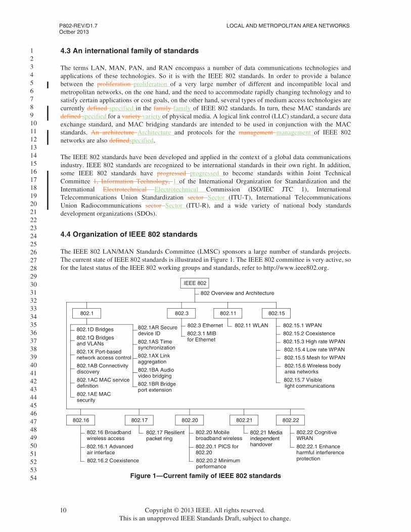
The IEEE 802 LAN/MAN Standards Committee (LMSC) sponsors a large number of standards projects. The current state of IEEE 802 standards is illustrated in Figure 1. The IEEE 802 committee is very active, so for the latest status of the IEEE 802 working groups and standards, refer to http://www.ieee802.org.
Figure 1—Current family of IEEE 802 standards
802.11
802.1D Bridges
802.1
IEEE 802
802.15
802.17 802.20 802.22
802.1Q Bridgesand VLANs
802.1X Port-basednetwork access control
802.1AB Connectivitydiscovery
802.1AC MAC servicedefinition
802.1AR Securedevice ID
802.1AS Timesynchronization
802.1AX Linkaggregation
802.1BA Audiovideo bridging
802.3 Ethernet
802.3.1 MIBfor Ethernet
802.11 WLAN 802.15.1 WPAN
802.15.2 Coexistence
802.15.3 High rate WPAN
802.15.4 Low rate WPAN
802.15.5 Mesh for WPAN
802.15.7 Visible light communications
802.17 Resilientpacket ring
802.16
802.16 Broadband
802.16.2 Coexistence
wireless access
802.16.1 Advancedair interface
802.20 Mobile
802.20.2 Minimum
broadband wireless
802.20.1 PICS for802.20
performance
802.21
802.21 Mediaindependenthandover
802.22 CognitiveWRAN
802.22.1 Enhanceharmful interferenceprotection
802.3
802 Overview and Architecture
802.15.6 Wireless bodyarea networks
802.1BR Bridgeport extension
802.1AE MACsecurity
10 Copyright © 2013 IEEE. All rights reserved.This is an unapproved IEEE Standards Draft, subject to change.
Overview and Architecture P802-REV/D1.7Octber 2013
1 2 3 4 5 6 7 8 9 10 11 12 13 14 15 16 17 18 19 20 21 22 23 24 25 26 27 28 29 30 31 32 33 34 35 36 37 38 39 40 41 42 43 44 45 46 47 48 49 50 51 52 53 54
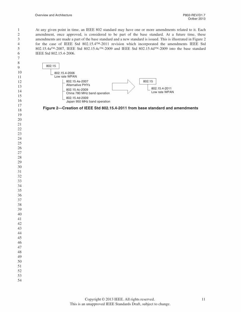
At any given point in time, an IEEE 802 standard may have one or more amendments related to it. Each amendment, once approved, is considered to be part of the base standard. At a future time, these amendments are made a part of the base standard and a new standard is issued. This is illustrated in Figure 2for the case of IEEE Std 802.15.4™-2011 revision which incorporated the amendments IEEE Std 802.15.4a™-2007, IEEE Std 802.15.4c™-2009 and IEEE Std 802.15.4d™-2009 into the base standard IEEE Std 802.15.4-2006.
Figure 2—Creation of IEEE Std 802.15.4-2011 from base standard and amendments
802.15
802.15.4a-2007Alternative PHYs
802.15.4c-2009China 780 MHz band operation
802.15.4d-2009Japan 950 MHz band operation
802.15.4-2006Low rate WPAN
802.15
802.15.4-2011Low rate WPAN
Copyright © 2013 IEEE. All rights reserved. 11This is an unapproved IEEE Standards Draft, subject to change.

Overview and Architecture P802-REV/D1.7Octber 2013
1 2 3 4 5 6 7 8 9 10 11 12 13 14 15 16 17 18 19 20 21 22 23 24 25 26 27 28 29 30 31 32 33 34 35 36 37 38 39 40 41 42 43 44 45 46 47 48 49 50 51 52 53 54
5. Reference models (RMs)
5.1 Introduction
This clause defines the IEEE 802 RM. The intent of presenting this model is as follows:
a) To provide an overview of the standard
b) To serve as a guide to reading other IEEE 802 standards
The IEEE 802 RM is patterned after derived from the open systems interconnection Open Systems Interconnection (OSI) basic reference model RM (OSI/RM), ISO/IEC 7498-11 [B7]. It is assumed that the reader has some familiarity with the OSI/RM and its terminology. The IEEE 802 standards encompass emphasize the functionality of the lowest two layers of the OSI/RM, i.e., physical layer (PHY) and data link layer (DLL), and the higher layers as they relate to network management. The IEEE 802 RM is similar to the OSI/RM in terms of its layers and the placement of its service boundaries. Figure 3 shows the architectural view of IEEE 802 RM for end stations and its relation to the OSI/RM. A variation of the model applies within bridges, as described in 5.3.2.
For the mandatory packet services supported by all IEEE 802 networks, the DLL is structured as two sublayers, with the LLC sublayer operating over a MAC sublayer. In addition, some IEEE 802 technologies provide direct support by the MAC sublayer for an alternative sublayer operating at the same place in the architecture as does the LLC sublayer, that multiplexes based on the EtherType field. For the other IEEE 802 technologies, the equivalent multiplexing functionality is provided by encapsulation of the EtherType within LLC protocol data units (PDUs), using the subnetwork access protocol (SNAP) specified in Clause 9of this standard.
For the mandatory data services supported by all IEEE 802 networks, the DLL is structured as two sublayers, with the LLC sublayer, described in 5.2.2, operating over a MAC sublayer, described in 5.2.3.
Each IEEE 802 standard has RMs that are more detailed in order to describe the structure for that specific standard. The RMs for the IEEE 802 standards are given in Annex B.
LLC
Figure 3—IEEE 802 RM for end stations
MAC medium access control sublayer MSAP MAC service access point
LSAP link service access point PSAP PHY service access point
Medium
Presentation
Physical
Data link
Network
Transport
Application
Medium
Physical
MAC and options
Upper layerprotocols
LLC
Physical
MAC and options
Upper layerprotocols
OptionalPSAPs
PSAPs
OptionalMSAPs
MSAPs
LSAPs
Session
Copyright © 2013 IEEE. All rights reserved. 11This is an unapproved IEEE Standards Draft, subject to change.

P802-REV/D1.7 LOCAL AND METROPOLITAN AREA NETWORKSOctber 2013
1 2 3 4 5 6 7 8 9 10 11 12 13 14 15 16 17 18 19 20 21 22 23 24 25 26 27 28 29 30 31 32 33 34 35 36 37 38 39 40 41 42 43 44 45 46 47 48 49 50 51 52 53 54
The IEEE 802 implementation models (IEEE 802 IMs) are more specific than the IEEE 802 RMs, allowing differentiation between implementation approaches (e.g., different MAC protocols and PHY layers).Figure 4 illustrates an IEEE Std 802.3 IM and its relation to the IEEE 802 RM.
Considerations of management, security, and media-independent handover (MIH) in IEEE 802 networks are also covered by IEEE 802 standards; these optional features lead to an elaboration of the RM, as illustrated in Figure 5. IEEE 802 network management provides a DLL management protocol, e.g., link layer discovery protocol (LLDP), and IEEE Std 802.3 PAUSE, protocols for exchange of management information between stations; managed objects are defined for all IEEE 802 standards. The media independent control function (MICF) is a parallel control plane that provides control functions for different MAC and PHY sublayers. Some examples of this MICF are the IEEE Std 802.21™ media independent handover function (MIHF), the control functions proposed in IEEE 802.19.1 Task Group and IEEE Std 802.22™. IEEE Std 802.1X™-2010 forms part of the LLC sublayer and provides a secure, connectionless service immediately above the MAC sublayer.
LLC
Figure 4—IEEE 802 RM for end stations
MAC medium access control sublayer MSAP MAC service access point
LSAP link service access point PSAP PHY service access point
Medium
Presentation
Physical
Data link
Network
Transport
Application
Medium
Physical
MAC and options
Upper layerprotocols
LLC
Physical
MAC and options
Upper layerprotocols
OptionalPSAPs
PSAPs
OptionalMSAPs
MSAPs
LSAPs
Session
Figure 5—IEEE 802 RM and an example of an end-station IM
Medium
LLC logical link control sublayer MAC medium access control sublayer PHY physical layer device RS reconciliation sublayer CGMII 100 Gb/s media independent interface PCS physical coding sublayer FEC forward error correction PMA physical medium attachment PMD physical medium dependent AN auto negotiation MDI medium dependent interface
802.3 IM (100 Gb/s)
Physical
IEEE 802 RM
LLC
MAC
LLC
MAC
RS
CGMII
PCS
FEC (optional)
PMA
PMD
AN (conditional)
MDI
Medium
PHY
12 Copyright © 2013 IEEE. All rights reserved.This is an unapproved IEEE Standards Draft, subject to change.

Overview and Architecture P802-REV/D1.7Octber 2013
1 2 3 4 5 6 7 8 9 10 11 12 13 14 15 16 17 18 19 20 21 22 23 24 25 26 27 28 29 30 31 32 33 34 35 36 37 38 39 40 41 42 43 44 45 46 47 48 49 50 51 52 53 54
5.2 RM description for end stations
The IEEE 802 RM maps to the OSI/RM as shown in Figure 3. The applicable part of the OSI/RM consists of the lowest two layers: the DLL and the PHY. These map onto the same two layers in the IEEE 802 RM. The MAC sublayer of the IEEE 802 RM exists between the PHY layer and the LLC sublayer to provide a common service for the LLC sublayer (certain MAC types provide additional MAC service features that can be used by LLC, in addition to the common core features). Service access points (SAPs) for connecting the layers and sublayers are shown in Figure 3.
Figure 6—IEEE 802 RM and an example of an end-station IM (100 Gb/s)
Medium
LLC logical link control sublayer MAC medium access control sublayer PHY physical layer device RS reconciliation sublayer CGMII 100 Gb/s media independent interface PCS physical coding sublayer FEC forward error correction PMA physical medium attachment PMD physical medium dependent AN auto negotiation MDI medium dependent interface
802.3 IM (100 Gb/s)
Physical
IEEE 802 RM
LLC
CGMII
FEC (conditional)
MDI
Medium
PHY PMA
PMD
AN (conditional)
PCS
RS
MAC
LLC
MAC
Figure 7—IEEE 802 RM with end-station management, security and MIH
Medium
PHY
Data link layer
Higher layers
Medium
PHY
LLC
Higher layers
802M
802.1X
MAC
Managementinformation
(Managedobjects)
IEEE 802 network
MSAP
PSAP
MIC
LSA
PM
ICP
SA
PM
ICS
AP
MICF
management
LSAP
Copyright © 2013 IEEE. All rights reserved. 13This is an unapproved IEEE Standards Draft, subject to change.

P802-REV/D1.7 LOCAL AND METROPOLITAN AREA NETWORKSOctber 2013
1 2 3 4 5 6 7 8 9 10 11 12 13 14 15 16 17 18 19 20 21 22 23 24 25 26 27 28 29 30 31 32 33 34 35 36 37 38 39 40 41 42 43 44 45 46 47 48 49 50 51 52 53 54
5.2.1 SAPs
One or more link service access points (LSAPs) provide interface ports to support one or more higher layer users above the LLC sublayer.
In addition, the end station optionally provides one or more media-independent control service access points (MICSAPs) that interface between one or more higher layers and the control and management planes enabling higher layer information to pass to the MICF and vice versa.
The MAC sublayer provides one or more MAC service access points (MSAPs) as interface ports to the LLC sublayer in an end station. In general, the MSAP is identified (for transmission and reception) by a single individual 48-bit extended unique identifiers identifier (EUI-48s48) or 64-bit extended unique identifiers identifier (EUI-64s64) and (for reception) by the network-wide broadcast EUI-48 or EUI-64; it can also be identified (for reception) by one or more group EUI-48s or EUI-64s. Clause 8 provides details of how these EUI-48s or EUI-64s are constructed and used. The MAC sublayer optionally provides a media independent control link service access point (MICLSAP) which is used to provide an interface port to support control of the MAC by the medium independent control function (MICF).
A user of LLC is identified by, at a minimum, the logical concatenation of the MAC Address field (containing an EUI-48 or EUI-64) and the LLC Address field in a frame. See ISO/IEC 8802-2 for a description of LLC addresses.
The PHY provides a physical layer service access point (PSAP). In addition, the PHY layer optionally provides a media independent control physical layer service access point (MICPSAP) which is used to provide an interface port to control of the PHY by the MICF.
5.2.2 LLC sublayer
The LLC sublayer contains a variety of entities, as illustrated in Figure 6.
Figure 8—IEEE 802 RM with end-station management, security and MIH
Medium
PHY
Data link layer
Higher layers
Medium
PHY
LLC
Higher layers
802 management
802.1X
MAC
Managementinformation
(Managedobjects)
IEEE 802 network
MSAP
PSAP
MIC
LSA
PM
ICP
SA
PM
ICS
AP
MICF
management
LSAP
protocols
14 Copyright © 2013 IEEE. All rights reserved.This is an unapproved IEEE Standards Draft, subject to change.

Overview and Architecture P802-REV/D1.7Octber 2013
1 2 3 4 5 6 7 8 9 10 11 12 13 14 15 16 17 18 19 20 21 22 23 24 25 26 27 28 29 30 31 32 33 34 35 36 37 38 39 40 41 42 43 44 45 46 47 48 49 50 51 52 53 54
The protocol discrimination entity (PDE) is used by the LLC sublayer to determine the higher layer protocol to which to deliver an LLC PDU. Two methods may be used in the PDE. The two methods are:
1) EtherType protoocol discrimination (EPD) which uses the EtherType value provided at the MSAP, and
2) LLC protocol discrimination (LPD), which uses the protocols defined in ISO/IEC 8802-2.
The LLC sublayer standardEPD provides a connectionless service for protocol discrimination. LPD, ISO/IEC 8802-2however, describes provides three types of operation for data communication between peer LLC entities: unacknowledged connectionless-mode (LLC Type 1)mode, connection-mode (LLC Type 2)mode, and acknowledged connectionless-mode (LLC Type 3)mode.
With LLC Type 1 operation, information frames are exchanged between LLC entities without the need for the prior establishment of a logical link between peers. The LLC sublayer does not provide any acknowledgments for these LLC frames, nor does it provide any flow control or error recovery procedures.
LLC Type 1 also provides a TEST function and an Exchange Identification (XID) function. The capability to act as responder for each of these functions is mandatory: this allows a station that chooses to support initiation of these functions to check the functioning of the communication path between itself and any other station, to discover the existence of other stations, and to find out the LLC capabilities of other stations.
With LLC Type 2 operation, a logical link is established between pairs of LLC entities prior to any exchange of information frames. In the data transfer phase of operation, information frames are transmitted and delivered in sequence. Error recovery and flow control are provided, within the LLC sublayer.
With LLC Type 3 operation, information frames are exchanged between LLC entities without the need for the prior establishment of a logical link between peers. However, the frames are acknowledged to allow error recovery and proper ordering. Further, LLC Type 3 operation allows one station to poll another for data.
NOTE—ISO/IEC 8802-2 defines four classes of LLC, each of which groups together support for a different combination of LLC types. All classes include mandatory support of LLC Type 1.
The IEEE 802 architecture allows an alternate LLC sublayer that supports protocol discrimination using an EtherType. For example, IEEE Std 802.3 is capable of natively representing the EtherType within its MAC frame format and so a connectionless LLC service can be provided via use of the EtherType without the use of the protocols defined in ISO/IEC 8802-2,which is used to support EPD. IEEE Std 802.3 also natively supports ISO/IEC 8802-2 LLC (over a limited range of packet frame sizes). In other IEEE 802 networks, such as IEEE Std 802.11™, that do not represent EtherTypes in the MAC frame format, protocol
Figure 9—LLC sublayer in 802 RM
Protocol discrimination entity (PDE)
LSAP
Higher layerprotocol 1
LSAP
Higher layerprotocol n
Higher layerprotocol 2
LSAP
Higher layerprotocol 2
LSAP
802.1X 802.1AE 802.1AX
MSAP
Copyright © 2013 IEEE. All rights reserved. 15This is an unapproved IEEE Standards Draft, subject to change.

P802-REV/D1.7 LOCAL AND METROPOLITAN AREA NETWORKSOctber 2013
1 2 3 4 5 6 7 8 9 10 11 12 13 14 15 16 17 18 19 20 21 22 23 24 25 26 27 28 29 30 31 32 33 34 35 36 37 38 39 40 41 42 43 44 45 46 47 48 49 50 51 52 53 54
identification via the use of an EtherType EPD can be achieved by means of the SNAP, as described in Clause 9. In either of these techniques, the EtherType is effectively being used as a means of identifying an LSAP that provides LLC service to the protocol concerned. New IEEE 802 standards shall support protocol discrimination in the LLC sublayer using EtherTypesEPD.
IEEE Std 802.1AE™ MAC security provides connectionless user data confidentiality, frame data integrity, and data origin authenticity by media access independent protocols and entities that operate transparently to MAC clients.
IEEE Std 802.1AX™ provides the ability to aggregate two or more links together to form a single logical link at a higher data rate.
IEEE Std 802.1X™ 1X provides authentication, authorization, and cryptographic key agreement mechanisms to support secure communication between end stations connected by IEEE 802 networks.
5.2.3 MAC sublayer
The MAC sublayer performs the functions necessary to provide packetframe-based, connectionless-mode (datagram style) data transfer between stations in support of the next higher sublayer, as described in 5.1, for networks that support it. The term MAC frame, or simply frame, is used to describe the packets datagrams transferred within the MAC sublayer. In some MAC types, some MAC frames are used in support of the MAC sublayer functionality itself, rather than for transfer of data from the next higher sublayer.
The principal functions of the MAC sublayer comprise the following:
— Frame delimiting and recognition— Addressing of destination stations (both as individual stations and as groups of stations)— Conveyance of source-station addressing information— Transparent data transfer of PDUs from the next higher sublayer— Protection against errors, generally by means of generating and checking frame check sequences— Control of access to the physical transmission medium
Other functions of the MAC sublayer—applicable particularly when the supporting implementation includes interconnection devices such as bridges—include flow control between an end station and an interconnection device, as described in 5.3, and filtering of frames according to their destination addresses to reduce the extent of propagation of frames in parts of an IEEE 802 network that do not contain communication paths leading to the intended destination end station(s).
The functions listed are those of the MAC sublayer as a whole. Responsibility for performing them is distributed across the transmitting and receiving end stations, and any interconnection devices such as bridges. Devices with different roles therefore can behave differently in support of a given function. For example, the basic transmission of a MAC frame by a bridge is very similar to transmission by an end station, but not identical. Principally, the handling of source-station addressing is different.
The various MAC specifications all specify MAC frame formats in terms of a serial transmission model for the service provided by the supporting PHY. This model supports concepts such as “first bit (e.g., of a particular octet) to be transmitted,” and a strict order of octet transmission, in a uniform manner. However, the ways in which the model has been applied in different MAC specifications are not completely uniform with respect to bit-ordering within octets (see Clause 8, and particularly 8.7, for examples and explanation).
The serial transmission model does not preclude current or future MAC specifications from using partly or wholly octet-oriented specifications of frame formats or of the interface to the PHY.
16 Copyright © 2013 IEEE. All rights reserved.This is an unapproved IEEE Standards Draft, subject to change.

Overview and Architecture P802-REV/D1.7Octber 2013
1 2 3 4 5 6 7 8 9 10 11 12 13 14 15 16 17 18 19 20 21 22 23 24 25 26 27 28 29 30 31 32 33 34 35 36 37 38 39 40 41 42 43 44 45 46 47 48 49 50 51 52 53 54
5.2.4 PHY
The PHY provides the capability of transmitting and receiving bits between PHY entities. A pair of PHY entities identifies the peer-to-peer unit exchange of bits between two MAC users.
The PHY provides the capability of transmitting and receiving modulated signals assigned to specific frequency channels, in the case of broadband or wireless, or to a single-channel band, in the case of baseband.
Note that, whereas the service offered to the MAC sublayer is expressed as the transfer of bits (in sequences representing MAC frames), the actual symbols that are encoded for transmission do not always represent individual bits. Particularly at speeds of 100 Mb/s and above, or for wireless transmission, the PHY layer can map blocks of several bits (e.g., 4, 5, or 8 bits) to different multi-element symbols. In some PHY encodings, these symbols are subject to further transformation before transmission, and in some cases, the transmission is spread over multiple physical data paths.
5.2.5 Layer and sublayer management
The LLC, MAC, and PHY standards also include a management component that specifies managed objects and aspects of the protocol machine that provides the management view of these resources. See Clause 7 for further information.
5.3 Interconnection and interworking
In some cases, the end stations in an IEEE 802 network have no need to communicate with end stations on other networks. However, this is not expected to be the norm; there are many cases in which end stations on an IEEE 802 network need to communicate with end stations on other networks and so devices that interconnect the IEEE 802 network with other kinds of networks are required. In addition, several standard methods have been developed that permit a variety of interconnection devices to operate transparently to end stations on a network in order to extend the capabilities available to end stations, particularly in terms of the geographical extent and/or total number of end stations that can be supported.
Standard methods of interworking fall into the following three general categories, depending on the layer at which the corresponding interconnection devices operate:
— PHY interconnection, using devices usually termed repeaters or hubs, as described in 5.3.1.
— MAC interconnection, using devices termed bridges, as described in 5.3.2.
— Network-layer interconnection, using devices usually termed routers, as described in 5.3.3.
5.3.1 PHY interconnection: Repeaters and hubs
The original IEEE 802 standards were for end stations attached to a shared communication medium. This basic configuration is referred to as a single access domain; the domain consists of the set of stations such that, at most, only one can transmit at a given time, with all other stations acting as (potential) receivers. In this situation the function of handling the “one-at-a-time” access arbitration is performed by the set of MACs on a shared medium.
A repeater is a device used to interconnect segments of the physical communications media, for example, to extend the range of a network when the physical specifications of the technology would otherwise be exceeded, while providing a single access domain for the attached stations. Repeaters used in support of multiple end stations attached by star-wired network topologies are frequently referred to as hubs.
Copyright © 2013 IEEE. All rights reserved. 17This is an unapproved IEEE Standards Draft, subject to change.

P802-REV/D1.7 LOCAL AND METROPOLITAN AREA NETWORKSOctber 2013
1 2 3 4 5 6 7 8 9 10 11 12 13 14 15 16 17 18 19 20 21 22 23 24 25 26 27 28 29 30 31 32 33 34 35 36 37 38 39 40 41 42 43 44 45 46 47 48 49 50 51 52 53 54
5.3.2 MAC-sublayer interconnection: Bridges
5.3.2.1 Bridges and bridged IEEE 802 networks
Bridges are stations that interconnect multiple access domains. IEEE Std 802.1D provides the basic specification for bridge interworking among IEEE 802 networks. A bridged IEEE 802 network consists of one or more bridges together with the complete set of access domains that they interconnect. A bridged IEEE 802 network provides end stations belonging to any of its access domains with the connectivity of a network that contains the whole set of attached end stations. IEEE Std 802.1Q adds additional capabilities to the bridge specification in IEEE Std 802.1D including virtual bridged networks (VLANs), priorities, and provider bridging, as defined described in 5.3.2.5.
A bridged network can provide for the following:
— Communication between stations attached to IEEE 802 networks of different MAC types
— Communication between stations attached to networks of different MAC types that conform to the Internal Sublayer Service as specified in IEEE Std 802.1AC.
— An increase in the total throughput of a network over that of a purely shared media network
— An increase in the physical extent of, or number of permissible attachments to, a network
— Partitioning of the physical network for administrative or maintenance reasons
The term switch is often used to refer to some classes of bridge. However, there is no consistent meaning applied to the distinction between the terms bridge and switch, and IEEE Std 802.1D does not make any such distinction. Hence, this standard only uses the term bridge.
5.3.2.2 Relaying and filtering by bridges
A bridge processes protocols in the MAC sublayer and is functionally transparent to LLC and higher layer protocols. MAC frames are forwarded between access domains, or filtered (i.e., not forwarded to certain access domains), on the basis primarily of EUI-48 addressing information. Figure 7 shows the position of the bridging functions within the MAC sublayer; note particularly that the relaying and filtering functions are considered to belong entirely within the MAC sublayer.
Filtering by bridges tends to confine traffic to only those parts of the bridged network that lie between transmitting end stations and the intended receivers. This permits a bridged network to support several transmitting end stations at any given time (up to the total number of access domains present).
Figure 10—Internal organization of the MAC sublayer with bridging
LAN
} MAC sublayer
LLC
MAC
End station
Relay
MAC MAC
Bridge
LAN
LLC
MAC
End station
Physical layer
Media
MAC serviceprovider
MAC serviceuser
18 Copyright © 2013 IEEE. All rights reserved.This is an unapproved IEEE Standards Draft, subject to change.
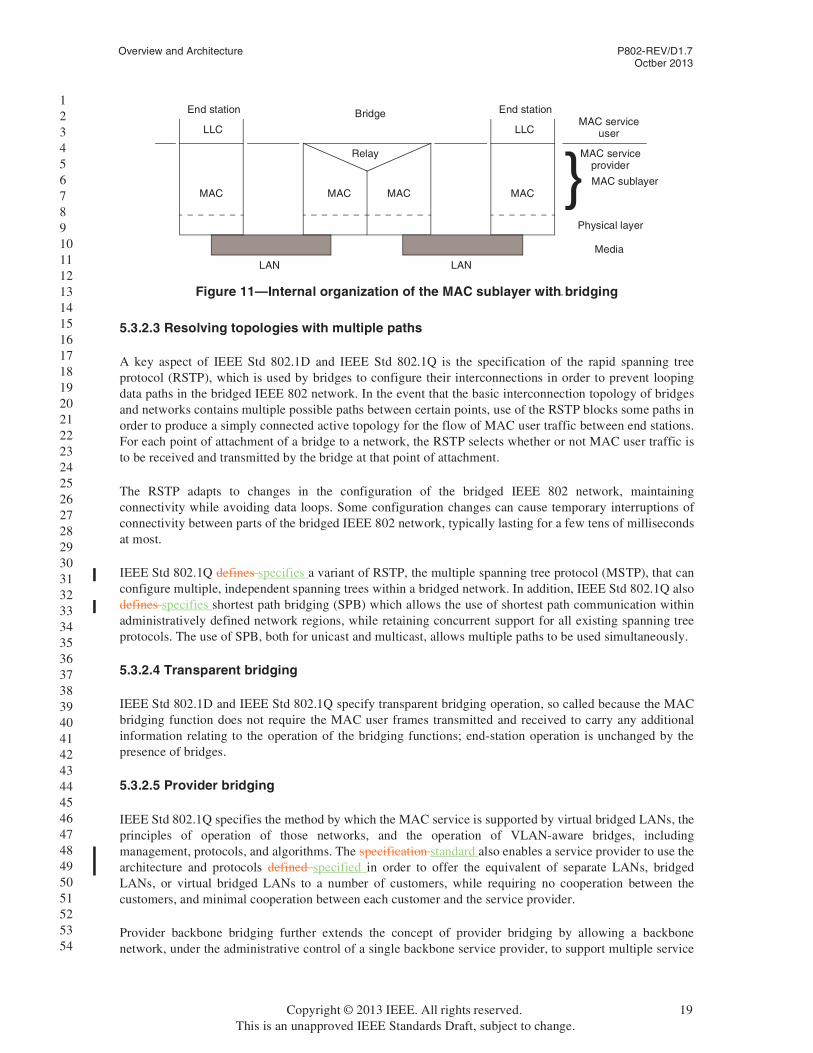
Overview and Architecture P802-REV/D1.7Octber 2013
1 2 3 4 5 6 7 8 9 10 11 12 13 14 15 16 17 18 19 20 21 22 23 24 25 26 27 28 29 30 31 32 33 34 35 36 37 38 39 40 41 42 43 44 45 46 47 48 49 50 51 52 53 54
5.3.2.3 Resolving topologies with multiple paths
A key aspect of IEEE Std 802.1D and IEEE Std 802.1Q is the specification of the rapid spanning tree protocol (RSTP), which is used by bridges to configure their interconnections in order to prevent looping data paths in the bridged IEEE 802 network. In the event that the basic interconnection topology of bridges and networks contains multiple possible paths between certain points, use of the RSTP blocks some paths in order to produce a simply connected active topology for the flow of MAC user traffic between end stations. For each point of attachment of a bridge to a network, the RSTP selects whether or not MAC user traffic is to be received and transmitted by the bridge at that point of attachment.
The RSTP adapts to changes in the configuration of the bridged IEEE 802 network, maintaining connectivity while avoiding data loops. Some configuration changes can cause temporary interruptions of connectivity between parts of the bridged IEEE 802 network, typically lasting for a few tens of milliseconds at most.
IEEE Std 802.1Q defines specifies a variant of RSTP, the multiple spanning tree protocol (MSTP), that can configure multiple, independent spanning trees within a bridged network. In addition, IEEE Std 802.1Q also defines specifies shortest path bridging (SPB) which allows the use of shortest path communication within administratively defined network regions, while retaining concurrent support for all existing spanning tree protocols. The use of SPB, both for unicast and multicast, allows multiple paths to be used simultaneously.
5.3.2.4 Transparent bridging
IEEE Std 802.1D and IEEE Std 802.1Q specify transparent bridging operation, so called because the MAC bridging function does not require the MAC user frames transmitted and received to carry any additional information relating to the operation of the bridging functions; end-station operation is unchanged by the presence of bridges.
5.3.2.5 Provider bridging
IEEE Std 802.1Q specifies the method by which the MAC service is supported by virtual bridged LANs, the principles of operation of those networks, and the operation of VLAN-aware bridges, including management, protocols, and algorithms. The specification standard also enables a service provider to use the architecture and protocols defined specified in order to offer the equivalent of separate LANs, bridged LANs, or virtual bridged LANs to a number of customers, while requiring no cooperation between the customers, and minimal cooperation between each customer and the service provider.
Provider backbone bridging further extends the concept of provider bridging by allowing a backbone network, under the administrative control of a single backbone service provider, to support multiple service
Figure 11—Internal organization of the MAC sublayer with bridging
LAN
} MAC sublayer
LLC
MAC
End station
Relay
MAC MAC
Bridge
LAN
LLC
MAC
End station
Physical layer
Media
MAC serviceprovider
MAC serviceuser
Copyright © 2013 IEEE. All rights reserved. 19This is an unapproved IEEE Standards Draft, subject to change.

Overview and Architecture P802-REV/D1.7Octber 2013
1 2 3 4 5 6 7 8 9 10 11 12 13 14 15 16 17 18 19 20 21 22 23 24 25 26 27 28 29 30 31 32 33 34 35 36 37 38 39 40 41 42 43 44 45 46 47 48 49 50 51 52 53 54
providers, each administering their own distinct provider bridged network to support distinct sets of customers.
5.3.2.6 Bridging example
Some bridges are used to interconnect access domains that each contain a very small number of end stations (often, a single end station). Others interconnect multiple access domains that contain principally other bridges, thus, forming a backbone for the bridged IEEE 802 networks. Bridged IEEE 802 network configurations that involve these kinds of interconnection have become widespread as the technologies have developed. These configurations allow the construction of networks with much larger numbers of end stations and much higher aggregate throughput than was previously achievable.
Figure 8 illustrates the kind of bridged IEEE 802 network that can be configured with bridge-style interconnection. The bridges A and B, and the IEEE Std 802.3 LAN configurations to which they attach, are typical of the older style of bridged IEEE 802 network in which a bridge interconnects a small number of access domains each containing many end stations, as is similar with K and L and their IEEE Std 802.17™ ring. The IEEE Std 802.17 ring and the IEEE Std 802.3 links between S and T and S and U form backbone networks. On the other hand, the bridges S, T, and U function as bridge bridges that combines IEEE Std 802.17, IEEE Std 802.3 and IEEE Std 802.16™ networks. S is a backbone bridge, handling a number of network attachments. T and U are bridges that support multiple end stations, with connection to the backbonea backbone network. B and K also provide access to the backbonea backbone network. The end station shown connected to S by a point-to-point link could be a server system.
5.3.3 Network-layer interconnection: Routers
The third category of interconnection uses network-layer interconnection devices, generally known as routers, that operate as IEEE 802 end stations. These process network layer protocols that operate directly above the LLC sublayer or equivalent, with forwarding decisions based on network layer addresses. Details
802.3802.17
End station
Bridge
IEEE 802 network link
B
S
L
802.3 802.3
T U
... ...... ...
A...
802.3
... ...
802.3
K
802.16
802.11... ...
802.15.1
Figure 12—A bridged IEEE 802 network
Copyright © 2013 IEEE. All rights reserved. 20This is an unapproved IEEE Standards Draft, subject to change.

Overview and Architecture P802-REV/D1.7Octber 2013
1 2 3 4 5 6 7 8 9 10 11 12 13 14 15 16 17 18 19 20 21 22 23 24 25 26 27 28 29 30 31 32 33 34 35 36 37 38 39 40 41 42 43 44 45 46 47 48 49 50 51 52 53 54
of this kind of interconnection lie outside of the scope of IEEE 802 standards, but the various standard and proprietary network-layer protocols involved represent a very substantial part of the user traffic on many IEEE 802 networks. In particular, IEEE 802 networks are often interconnected by routers for the Internet Protocol (IP) and its related routing and management protocols, either directly to other IEEE 802 networks or by means of WAN links.
802.3802.17
End station
Bridge
IEEE 802 network link
B
S
L
802.3 802.3
T U
... ...... ...
A...
802.3
... ...
802.3
K
802.16
802.11... ...
802.15.1
Figure 13—A bridged IEEE 802 network
Copyright © 2013 IEEE. All rights reserved. 21This is an unapproved IEEE Standards Draft, subject to change.

Overview and Architecture P802-REV/D1.7Octber 2013
1 2 3 4 5 6 7 8 9 10 11 12 13 14 15 16 17 18 19 20 21 22 23 24 25 26 27 28 29 30 31 32 33 34 35 36 37 38 39 40 41 42 43 44 45 46 47 48 49 50 51 52 53 54
6. General requirements for an IEEE 802 network
6.1 Services supported
With the descriptions in Clause 5 as a basis, an IEEE 802 network can be characterized as a communication resource that provides sufficient capabilities to support the MAC service defined specified in IEEE Std 802.1AC, between two or more MSAPs. In particular, this requires the ability to convey LLC data from one MSAP to n other MSAPs, where n can be any number from 1 to all of the other MSAPs on the network. An IEEE 802 network is required, at a minimum, to support the MAC Internal Sublayer Service defined specified in IEEE Std 802.1D and IEEE Std 802.1Q1AC, and support the use of EtherTypes for protocol identification at the LLC sublayer.
6.2 Size and extent
The initial IEEE 802 network technologies were designed to be capable of supporting access domains containing at least 200 end stations and with geographical extent of at least 2 km for IEEE 802 LANs (using PHY repeaters if necessary) and 50 km for metropolitan area networks (MANs). For some IEEE 802 networks, subsequent developments in technology and performance have been accompanied by a reduction in the size and extent required in individual access domains, recognizing that these can readily and cost-effectively be interconnected in bridged IEEE 802 networks that are capable of offering at least the original minimum size and extent, with increased overall bandwidth and performance. In other cases, IEEE 802 networks have been defined for larger areas, e.g., RANs, using wireless technology. Size and extent requirements for future IEEE 802 network technologies are, similarly, expected to be determined by application needs and opportunities.
6.3 Error ratios
Error performance of IEEE 802 networks is required to shall be as follows
a) For wired or optical fiber physical media: Within a single access domain, the probability that a transmitted MAC frame (excluding any preamble) is not reported correctly at the PHY service inter-face of an intended receiving peer MAC entity, due only to operation of the PHY, shall be less than 8 × 10⁻⁸ per octet of MAC frame length.
NOTE—For some applications and data rates, better performance than this may be required.
b) For wired or optical fiber physical media with frames shorter than 2048 octets: The probability that an MSDU delivered at an MSAP contains an undetected error, due to operation of the MAC service provider, shall be less than 5 × 10-14 per octet of MSDU length.
NOTE—For example, the worst-case probability of losing a maximum-length IEEE Std 802.3 frame at the PHY is to be less than 1.21 × 10⁻⁴, or approximately 1 in 8250. The worst-case probability that a similar frame, which contains an MSDU of 1500 octets, is delivered with an undetected error is to be less than 7.5 × 10⁻¹¹, or approximately 1 in 13 300 000 000.
c) For wireless physical media: The error performance within a single access domain is variable over time and no guarantee of service can be given.
6.4 Transient service interruption
Insertion of a station into, or removal of a station from, an IEEE 802 network shall cause at most a transient loss of availability of the access domain(s) to which the station attaches, lasting not more than 1 s. Failure of a station, including loss of power, shall not cause more than at most a transient fault for the access domain(s)
Copyright © 2013 IEEE. All rights reserved. 19This is an unapproved IEEE Standards Draft, subject to change.

Overview and Architecture P802-REV/D1.7Octber 2013
1 2 3 4 5 6 7 8 9 10 11 12 13 14 15 16 17 18 19 20 21 22 23 24 25 26 27 28 29 30 31 32 33 34 35 36 37 38 39 40 41 42 43 44 45 46 47 48 49 50 51 52 53 54
to which it was attached, with duration of order 1 s. The preceding requirements assume that the new configuration of the network without the lost station is valid.
6.5 Safety, lightning and galvanic protection
Equipment implementing IEEE 802 standards is typically subject to guidance and requirements relating to safety and to protection of the equipment and its users from lightning and galvanic effects. Such guidance and requirements are outside of the scope of IEEE 802 standardization; they are typically specified by other organizations with different legal, geographical, and industrial scope. However, the general underlying concerns can have an influence on the PHY aspects of IEEE 802 standards.
6.6 Regulatory requirements
Equipment implementing IEEE 802 standards can be subject to regulations imposed within particular geographical and political domains. For example, the deployment of equipment implementing IEEE 802 wireless standards are subject to local regulations that pertain to the use of radio-frequency transmission. Such regulations are typically outside of the scope of IEEE 802 standardization; they are typically specified by other organizations with different legal, geographical, and industrial scope. However, the general underlying concerns can have an influence on the MAC and PHY aspects of IEEE 802 standards.
While regulatory compliance is out of scope of IEEE 802 standards, the need to comply with regulations can influence the design of IEEE 802 standards.
Copyright © 2013 IEEE. All rights reserved. 20This is an unapproved IEEE Standards Draft, subject to change.

P802-REV/D1.7 LOCAL AND METROPOLITAN AREA NETWORKSOctber 2013
1 2 3 4 5 6 7 8 9 10 11 12 13 14 15 16 17 18 19 20 21 22 23 24 25 26 27 28 29 30 31 32 33 34 35 36 37 38 39 40 41 42 43 44 45 46 47 48 49 50 51 52 53 54
7. IEEE 802 network management
7.1 General
The provision of an adequate means of remote management is an important factor in the design of today's network equipment. Such management mechanisms fall into two broad categories: those that provide general-purpose management capability, allowing control and monitoring for a wide variety of purposes, and those that provide specific capabilities aimed at a particular aspect of management. These aspects of management are discussed in 7.2 and 7.3, respectively.
7.2 General-purpose IEEE 802 network management
This subclause introduces the functions of management to assist in the identification of the requirements placed on IEEE 802 network equipment for support of management facilities, and it identifies general-purpose management standards that may be used as the basis of developing management specifications for such equipment.
7.2.1 Management functions
Management functions relate to users’ needs for facilities that support the planning, organization, supervision, control, protection and security of communications resources, and account for their use. These facilities may be categorized as supporting the functional areas of configuration, fault, performance, security, and accounting management. These can be summarized as follows.
— Configuration management provides for the identification of communications resources, initialization, reset and closeshut-down, the supply of operational parameters, and the establishment and discovery of the relationships between resources.
— Fault management provides for fault prevention, detection, diagnosis, and correction.
— Performance management provides for evaluation of the behavior of communications resources and of the effectiveness of communication activities.
— Security management provides for the protection of resources.
— Accounting management provides for the identification and distribution of costs and the setting of charges.
Management facilities in IEEE 802 network equipment address some or all of these areas, as appropriate to the needs of that equipment and the environment in which it is to be operated.
7.2.2 Management architecture
The management facilities defined specified in IEEE 802 standards are based on the concept of managed objects, which model the semantics of management operations. Operations on a managed object supply information concerning, or facilitate control over the managed object and thereby, indirectly, the process or entity associated with that object.
Operations on a managed object can be initiated by mechanisms local to the equipment being managed (e.g., via a control panel built into the equipment), or can be initiated from a remote management system by means of a general-purpose management protocol carried using the data services provided by the IEEE 802 network to which the equipment being managed is connected. The entity that does both the network communication of the management protocol and the interaction to and from the managed objects is called the agent.
20 Copyright © 2013 IEEE. All rights reserved.This is an unapproved IEEE Standards Draft, subject to change.

Overview and Architecture P802-REV/D1.7Octber 2013
1 2 3 4 5 6 7 8 9 10 11 12 13 14 15 16 17 18 19 20 21 22 23 24 25 26 27 28 29 30 31 32 33 34 35 36 37 38 39 40 41 42 43 44 45 46 47 48 49 50 51 52 53 54
The simple network management protocol Simple Network Management Protocol (SNMP), as described in RFC 3411 [B5]8, provides a general-purpose management protocol that is relevant to can be used for the management of IEEE 802 network equipment.
7.2.3 Managed object definitions
In order for an IEEE 802 standard to specify management facilities, it is necessary for it to define specify managed objects that model the operations that can be performed on the communications resources specified in the standard. The components of a managed object definition are:
a) A definition of the functionality provided by the managed object, and the relationship between this functionality and the resource to which it relates.
b) A definition of the syntax that is used to convey management operations, and their arguments and results, in a management protocol.
c) An address that allows the management protocol to specifically communicate with the managed object in question. In IEEE 802 this is done with an object identifier (OID), as described in Clause 10.
The functionality of a managed object can be described in a manner that is independent of the protocol that is used; this abstract definition can then be used in conjunction with a definition of the syntactic elements required in order to produce a complete definition of the object for use with specific management protocols.
The SNMP protocol is used in many cases together with the structure of management information known as SMIv2, IETF RFC 2578 [B33]2578, RFC 2579 [B3], and RFC 2580 [B4], which uses a set of macros based on a subset of ASN.1 for defining managed objects.
The choice of notational tools for defining managed objects depensd depends on which of the available management protocols the standard supports.
7.3 Special-purpose IEEE 802 network management standards
Special-purpose protocols relating to the management functionality of IEEE 802 stations can be developed where the use of a general-purpose management protocol is inappropriate. Examples of special-purpose management protocols that can be found in the family of IEEE 802 standards include the connectivity fault management protocol defined specified in IEEE Std 802.1Q, the operations, administration, and maintenance (OAM) protocol defined specified in IEEE Std 802.3, and LLDP in IEEE Std 802.1AB™.
8The numbers in brackets correspond to those of the bibliography in Annex A.
Copyright © 2013 IEEE. All rights reserved. 21This is an unapproved IEEE Standards Draft, subject to change.

P802-REV/D1.7 LOCAL AND METROPOLITAN AREA NETWORKSOctber 2013
1 2 3 4 5 6 7 8 9 10 11 12 13 14 15 16 17 18 19 20 21 22 23 24 25 26 27 28 29 30 31 32 33 34 35 36 37 38 39 40 41 42 43 44 45 46 47 48 49 50 51 52 53 54
8. EUI-48s, EUI-64s and protocol identifiers
8.1 General
9. Extended unique identifiers (EUIs)
9.1 Overview and history
The IEEE makes it possible for organizations to employ unique individual EUI-48s, EUI-64s, group addresses, and protocol identifiers. A universal address is an EUI-48 or EUI-64 that is globally unique. In addition, the IEEE has set aside a group of EUI-48s and EUI-64s that are locally administered. EUI-48 addressing is required if interoperability through bridges is required for an IEEE 802 a standard. New standards that only require routed connectivity should use EUI-64 addressing.
The IEEE enables globally unique addresses, referred to as universal addresses, by assigning organizationally unique identifiers (OUIs), which are three octets (24 bits) in length. Because the assignment of the OUI in effect reserves a block of each derivative identifier (i.e., blocks of individual EUI-48s, EUI-64s, group addresses, and protocol identifiers), the address space of the OUI is chosen to be large. Although the OUIs are 24 bits in length, as shown in Figure 9, but their true address space is 22 bits. The LSB of the first octet may be set to one or zero depending on the application. The next-to-LSB of the first octet is zero, for all universal addresses. The remaining 22 bitsbits of the OUI are assigned by the RAC; when used in a field of an IEEE 802 standard, which the organization field of the OUI shall not be changed contain the value assigned by the assignee, result in 222 (approximately 4 million) identifiers; see Figure 8RAC.
The universal administration of EUI-48s began with the Xerox Corporation administering Block Identifiers (Block IDs) for Ethernet addresses. Block IDs, referred to as OUI by the IEEE, were assigned by the Ethernet Administration Office and were 24 bits in length. An organization developed addresses by assigning the remaining 24 bits. For example, the address as represented by the six octets P-Q-R-S-T-U comprises the Block ID, P-Q-R, and the locally assigned octets S-T-U.
The IEEE, because of the work in IEEE 802 on standardizing networking technologies, has assumed the responsibility of defining and carrying out procedures for the universal administration of these addresses. The IEEE has also been designated by ISO/IEC to act as a registration authority for ISO/IEC 8802 series of standards. In carrying out the procedures, the IEEE acts as the registration authority for OUIs.9 The
9Interested applicants should contact the IEEE Registration Authority, http://standards.ieee.org/develop/regauth/oui
Figure 9—Structure of an OUI
0Octet 0Octet 1Octet 2
Application dependent: e.g.,I/G address bit, M bit in protocol IDs
Figure 10—Structure of an OUI
Octet 0Octet 1Octet 2
Application dependent: e.g.,I/G bit in addresses, M bit in protocol IDs
Application dependent: e.g.,U/L bit in addresses, X bit in protocol IDs
22 Copyright © 2013 IEEE. All rights reserved.This is an unapproved IEEE Standards Draft, subject to change.

Overview and Architecture P802-REV/D1.7Octber 2013
1 2 3 4 5 6 7 8 9 10 11 12 13 14 15 16 17 18 19 20 21 22 23 24 25 26 27 28 29 30 31 32 33 34 35 36 37 38 39 40 41 42 43 44 45 46 47 48 49 50 51 52 53 54
responsibility for defining the procedures is discharged by the IEEE Registration Authority Committee (RAC), which is chartered by the IEEE Standards Association Board of Governors. In IEEE 802 networks, the term MAC address refers to an EUI-48. In some IEEE 802 standards, the term extended address refers to EUI-64.
9.2 Notational conventions
Hexadecimal representation is a sequence of octet values in which the values of the individual octets are displayed in order from left to right, with each octet value represented as a two-digit hexadecimal numeral, and with the resulting pairs of hexadecimal digits separated by hyphens. The order of the hexadecimal digits in each pair, and the mapping between the hexadecimal digits and the bits of the octet value, are derived by interpreting the bits of the octet value as a binary numeral using the normal mathematical rules for digit significance.
Bit-reversed representation is a sequence of octet values in which the values of the individual octets are displayed in order from left to right, with each octet value represented as a two-digit hexadecimal numeral, and with the resulting pairs of hexadecimal digits separated by colons. The order of the hexadecimal digits in each pair, and the mapping between the hexadecimal digits and the bits of the octet value, are derived by reversing the order of the bits in the octet value and interpreting the resulting bit sequence as a binary numeral using the normal mathematical rules for digit significance.
NOTE—The bit-reversed representation is of historical interest only and is no longer applicable to any active IEEE 802 standard.
Figure 10 provides a comparative example of bit-reversed and hexadecimal representation.
9.3 OUI
OUIs allow a general means of assuring unique identifiers for a number of purposes. OUIs are a 22-bit field assigned from a 24-bit space. The IEEE Registration Authority assigns OUI values. The IEEE Registration Authority also has additional products that use the OUI assignment as its base, e.g. OUI-36, but which do not include the assignment of an OUI10.
NOTE—The acronym OUI without modification is only used to refer to the 24-bit field assigned by the Registration Authority. The acronym Acronym OUI-36 is used refers to refer to the 36a product that allows assignment of 4096 glo-bally unique EUI-bit field assigned by the Registration Authority48 addresses. However, while not appropriate, the acro-nym OUI has been used to refer to generally to all Registration Authority assignments. As a result, the use of OUI is not always consistent within all IEEE standards.
The standard representation of the OUI is as a string of three octets, using the hexadecimal representation.
9.4 Universal addresses
9.4.1 Concept
The concept of universal addressing is based on the idea that all potential members of a network need to have a unique identifier (if they are going to coexist in the network)identifier. The advantage of a universal address is that a station with such an address can be attached to any IEEE 802 network in the world with an assurance that the address is unique, if all stations adhere to the rules and that the security of the network prevents malicious spoofing of addresses. Two different lengths of the universal address have been definedspecified, 48 bit (EUI-48) and 64 bit (EUI-64).
10More information on OUIs can be found on the IEEE Registration Authority web site, http://standards.ieee.org/develop/regauth/
Copyright © 2013 IEEE. All rights reserved. 23This is an unapproved IEEE Standards Draft, subject to change.

P802-REV/D1.7 LOCAL AND METROPOLITAN AREA NETWORKSOctber 2013
1 2 3 4 5 6 7 8 9 10 11 12 13 14 15 16 17 18 19 20 21 22 23 24 25 26 27 28 29 30 31 32 33 34 35 36 37 38 39 40 41 42 43 44 45 46 47 48 49 50 51 52 53 54
EUI-64s were introduced when it seemed that the EUI-48 space would be exhausted in the near future. Initially, new IEEE standards projects that did not require backward compatibility with EUI-48 were requested to use the new EUI-64. This led to some IEEE 802 standards adopting EUI-64, which cannot be bridged onto IEEE 802 networks that use EUI-48. The reason is that the bridging function in IEEE Std 802.1D and IEEE Std 802.1Q assume that addresses are unique among all the connected networks. Truncating an EUI-64 into an EUI-48 field can lead to two stations having the same EUI-48 value. Instead, traffic between EUI-64 and EUI-48 addressed networks needs to be routed at a layer above the DLL.
Universal addresses are created from the OUI. The universally or locally administered (U/L) address bit is the bit of octet 0 adjacent to the I/G address bit. This bit indicates whether the address has been assigned by a local or universal administrator. Universally administered addresses have the U/L bit set to 0. If the U/L bit is set to 1, the remaining 46 bits (i.e. all bits except the I/G and U/L bits) have been are locally administered and have no relationship should not be expected to meet the uniqueness requirement of the IEEE-assigned values (as described herein).
A universal address consists of two parts: one the leading bits are assigned by the IEEE Registration Authority and one assigned the remaining bits by the that assignee. The IEEE Registration Authority offers several products (e.g., OUI, OUI-36, IAB-12). They vary in the number of universal addresses the assignee can create. In the case where the IEEE assigns an OUI, the first 24 bits correspond to the OUI as assigned by the IEEE, except that the assignee may set the LSB of the first octet to one for group addresses or set it to zero for individual addresses. The second part, comprising the remaining 24 bits for an EUI-48 or the remaining 40 bits for an EUI-64, is administered by the assignee. In the EUI-48, an example of which is shown in Figure 10, the OUI is contained in octets 0, 1, 2, and the value assigned by the assignee is contained in octets 3, 4, 5. This address, including its OUI, is used throughout this document as the basis for examples of EUI-48s and protocol identifiers. In the case where the IEEE assigns an OUI-36, the first 36 bits correspond to the OUI-36 as assigned by the IEEE, except that the assignee may set the LSB of the first octet to one for group addresses or set it to zero for individual addresses. The second part, comprising the remaining 12 bits for an EUI-48 or the remaining 28 bits for an EUI-64, is administered by the assignee. In the EUI-48, an example of which is shown in Figure 9, the OUI is contained in octets 0, 1, 2, 3 and the LSB least significant nibble of octet 4, and the value assigned by the assignee is contained in the MSB most significant nibble of octet 4 and octet 5.
Figure 11—Example EUI-48
Hexadecimal representation: AC-DE-48-00-00-80
Bit-reversed representation: 35:7B:12:00:00:01
Octet:
0011 0101 0111 1011 0001 0010 0000 0000 0000 0000 0000 0001
LSB MSB LSB MSB
0 1 2 3 4 5
U/L address bitI/G address bit
OUI
1 0 1 0 1 1 0 0
0 0 0 0 0 0 0 0
1 1 0 1 1 1 1 0Octet 0
0 0 0 0 0 0 0 01 0 0 0 0 0 0 0
0 1 0 0 1 0 0 0 Octet 2Octet 3
Octet 1
Octet 4Octet 5
U/L address bit
I/G address bit
OUI-36
24 Copyright © 2013 IEEE. All rights reserved.This is an unapproved IEEE Standards Draft, subject to change.

Overview and Architecture P802-REV/D1.7Octber 2013
1 2 3 4 5 6 7 8 9 10 11 12 13 14 15 16 17 18 19 20 21 22 23 24 25 26 27 28 29 30 31 32 33 34 35 36 37 38 39 40 41 42 43 44 45 46 47 48 49 50 51 52 53 54
NOTE—The octet string AC-DE-48 is used because it is clear when a bit pattern is reversed. This OUI could be in use and is not a reserved value.
An IEEE 802 network with EUI-48s is not able to bridge to an IEEE 802 network with EUI-64s. Bridging for an IEEE 802 network with EUI-64 addresses is not currently defined.
An example of an EUI-64 is illustrated in Figure 11.
The standard representation of an EUI-48 is as a string of six octets, using the hexadecimal representation. See 8.7 for further specification relating to use of the bit-reversed representation.
NOTE—The upper, bit-stream representation of the EUI-48 in Figure 10 and the EUI-64 in Figure 11 shows the LSB of each octet first; this corresponds to the data-communications convention for representing bit-serial transmission in left-to-right order, applied to the model for transmission of EUI-48 fields (see 5.2.3) and EUI-6 64 fields. See also 8.7 for further discussion of bit-ordering issues. The lower, octet-sequence representation shows the bits within each octet in the usual order for binary numerals; the order of octet transmission is from the top downward.
The individual/group (I/G) address bit, least significant bit (LSB) of octet 0, is used to identify the destination address as an individual address or a group address. If the I/G address bit is 0, it indicates that the address field contains an individual address. If this bit is 1, the address field contains a group address that identifies one or more (or all) stations connected to the IEEE 802 network. The all-stations broadcast address is a special, predefined group address of all 1’s.
9.4.2 Interworking with EUI-48 and EUI-64
EUI-64s were introduced in response to concerns that the EUI-48 space could be exhausted by the breadth of products using OUIs to generate unique identifiers. Initially, new IEEE standards projects that did not require backward compatibility with EUI-48 were requested to use the new EUI-64. This led to some IEEE 802 standards adopting EUI-64, which cannot be bridged onto IEEE 802 networks that use EUI-48. The reason is that the bridging function in IEEE Std 802.1D and IEEE Std 802.1Q assume that addresses are unique among all the connected networks. Truncating an EUI-64 into an EUI-48 field can lead to two stations having the same EUI-48 value. Instead, traffic between EUI-64 and EUI-48 addressed networks needs to be routed at a layer above the DLL.
Figure 12—Example EUI-64
Hexadecimal representation: AC-DE-48-00-00-80-53-84
Bit-reversed representation: 35:7B:12:00:00:01:CA:21
Octet:
0011 0101 0111 1011 0001 0010 0000 0000 0000 0000 0000 0001 1100 1010 0010 0001
LSB MSB LSB MSB
0 1 2 3 4 5 6 7
U/L address bitI/G address bit
OUI
1 0 1 0 1 1 0 0
0 0 0 0 0 0 0 0
1 1 0 1 1 1 1 0Octet 0
0 0 0 0 0 0 0 01 0 0 0 0 0 0 0
0 1 0 0 1 0 0 0
0 1 0 1 0 0 1 11 0 0 0 0 1 0 0
Octet 2Octet 3
Octet 1
Octet 4
Octet 6Octet 7
Octet 5
U/L address bit
I/G address bit
OUI-36
Copyright © 2013 IEEE. All rights reserved. 25This is an unapproved IEEE Standards Draft, subject to change.

P802-REV/D1.7 LOCAL AND METROPOLITAN AREA NETWORKSOctber 2013
1 2 3 4 5 6 7 8 9 10 11 12 13 14 15 16 17 18 19 20 21 22 23 24 25 26 27 28 29 30 31 32 33 34 35 36 37 38 39 40 41 42 43 44 45 46 47 48 49 50 51 52 53 54
Bridging for an IEEE 802 network with EUI-64 addresses is not currently specified.
9.4.3 Assignment by organizations
The IEEE intends not to assign additional OUIs or OUI-36s to any organization unless the organization has exhausted this address block.
Varying the last 24 bits in the block of EUI-48s for a given OUI allows the OUI assignee approximately 16 million unique individual addresses and 16 million unique group addresses It is important to note that no other organization may assign (i.e., universally unique). Similarly, varying the last 8 bits in the block of EUI-48s for a given OUI-36 allows the OUI-36 assignee 4096 unique individual addresses and 4096 unique group addresses. The IEEE intends not to assign additional created from OUIs or OUI-36s to any organization unless the organization has exhausted this address block. Therefore, it is important for the IEEE to maintain a single point of contact with each assignee to avoid complicating the assignment process. It is important to note that in no way should these addresses not be used for purposes that would lead to skipping large numbers of them (for example, as product identifiers for the purpose of aiding company inventory procedures). The IEEE asks that organizations not misuse the assignments of the last 24 24 bits and thereby unnecessarily exhaust the block. There are sufficient identifiers to satisfy most needs for a long time, even in volume production; however, no address space is infinite.
The method that an assignee uses to ensure that no two of its stations carry the same address depends on the assignment or manufacturing process, the nature of the organization, and the organization’s philosophy. However, the users of networks worldwide expect to have unique addresses. The ultimate responsibility for assuring that user expectations and requirements are met, therefore, lies with the organization offering such stations.
9.4.4 Uniqueness of address assignment
An issue to be considered is the nature of the station to which uniqueness of address assignment applies.
The recommended approach is for each station associated with a distinct point of attachment to an IEEE 802 network to have its own unique EUI-48 or EUI-64. Typically, therefore, an IEEE 802 network adapter card (or, e.g., an equivalent chip or set of chips on a motherboard) should have one unique EUI-48 or EUI-64 for each IEEE 802 network attachment that it can support at a given time.
NOTE—It is recognized that an alternative approach has gained currency in some implementations, in which the station is interpreted as a complete computer system, which can have multiple attachments to different networks. Under this interpretation, a single EUI-48 or EUI-64 is used to identify all of the system’s points of attachment to the networks in question. This approach, unlike the recommended one, does not automatically meet the requirements of IEEE Std 802.1D MAC bridging.
9.5 Local addresses
Local addresses are EUI-48s or EUI-64s for which there is no guarantee that the address is unique in all IEEE 802 networks. Local addresses may be assigned any value that has the U/L bit set to indicate a local addresses and an I/G bit value that indicates whether the address is individual or group. Local addresses need to be unique on a LAN or bridged LAN unless the bridges support VLANs with independent learning.
The I/G bit is set as described in 8.4.1.
NOTE—OUI assignments do not apply to local addresses
26 Copyright © 2013 IEEE. All rights reserved.This is an unapproved IEEE Standards Draft, subject to change.

Overview and Architecture P802-REV/D1.7Octber 2013
1 2 3 4 5 6 7 8 9 10 11 12 13 14 15 16 17 18 19 20 21 22 23 24 25 26 27 28 29 30 31 32 33 34 35 36 37 38 39 40 41 42 43 44 45 46 47 48 49 50 51 52 53 54
9.6 SNAP identifiers
Clause 9 specifies the SNAP, which permits multiplexing and demultiplexing of private and public protocols, as described in 9.1, among multiple users of a data link. An organization that has an OUI assigned to it may use its OUI to assign universally unique protocol identifiers to its own protocols, for use in the protocol identification field of SNAP data units, as described in 9.5.
The protocol identifier is five octets in length and follows the LLC header in a frame. The first three octets of the protocol identifier consist of the OUI in exactly the same fashion as in EUI-48. The remaining two octets are administered by the assignee. In the protocol identifier, an example of which is shown in Figure 11, the OUI is contained in octets 0, 1, 2 with octets 3, 4 being assigned by the assignee of the OUI.
The standard representation of a protocol identifier is as a string of five octets using the hexadecimal representation.
The LSB of the first octet of a protocol identifier is referred to as the M bit. All identifiers derived from OUIs assigned by the IEEE shall have the M bit set to zero. Values with the M bit set to one are reserved.
Protocol identifiers may be assigned universally or locally. The X bit of a protocol identifier is the bit of the first octet adjacent to the M bit. All identifiers derived from OUIs assigned by the IEEE have the X bit set to zero and are universally assigned. Values with the X bit set to one are locally assigned and have no relationship to the IEEE-assigned values. They may be used, but there is no assurance of uniqueness.
9.7 OUI and OUI-36 as protocol identifiers
An organization that has an OUI or OUI-36 assigned to it may use its OUI or OUI-36 to assign universally unique protocol identifiers to its own protocols, for use with various protocols described in IEEE 802 standards, potentially with additional octets as part of the identifier.
The LSB of the first octet of a OUI, as shown in Figure 12, or OUI-36, as shown in Figure 13, used as as protocol identifier is referred to as the M bit. All OUI & OUI-36 identifiers assigned by the IEEE shall have the M bit set to zero. Values with the M bit set to one are reserved.
The X bit of a protocol identifier is the bit of the first octet adjacent to the M bit. All OUI and OUI-36 identifiers assigned by the IEEE with the X bit set to zero may also be used to create EUI-48 and EUI-64
Figure 13—Protocol identifier
Hexadecimal representation: AC-DE-48-00-80
Octet:
0011 0101 0111 1011 0001 0010 0000 0000 0000 0001
LSB MSB LSB MSB
0 1 2 3 4
X bitM bit
OUI
1 0 1 0 1 1 0 0
0 0 0 0 0 0 0 0
1 1 0 1 1 1 1 0Octet 0
1 0 0 0 0 0 0 0
0 1 0 0 1 0 0 0 Octet 2Octet 3
Octet 1
Octet 4
X bit
M bit
Copyright © 2013 IEEE. All rights reserved. 27This is an unapproved IEEE Standards Draft, subject to change.

Overview and Architecture P802-REV/D1.7Octber 2013
1 2 3 4 5 6 7 8 9 10 11 12 13 14 15 16 17 18 19 20 21 22 23 24 25 26 27 28 29 30 31 32 33 34 35 36 37 38 39 40 41 42 43 44 45 46 47 48 49 50 51 52 53 54
addresses. Values with the X bit set to one indicates that this shall only be used as a OUI or OUI-36 identifier. Any EUI-48 or EUI-64 addresses created with these OUI or OUI-36 have no relationship to the IEEE-assigned values; they may be used, but there is no assurance of uniqueness.
9.8 Standardized EUI-48 and EUI-64 group addresses11
The previous subclauses described the assignment of individual and group EUI-48s and EUI-64s, and protocol identifiers for public or private use by private organizations. There is also a need for standardized EUI-48 and EUI-64 group addresses to be used with standard protocols. The administration of these standardized EUI-48 and EUI-64 group addresses, including the procedure for application and a list of currently assigned values, is described on the web pages for the IEEE Registration Authority12. These standardized EUI-48 and EUI-64 group addressess come from a block of universally administered EUI-48s and EUI-64s derived from an OUI that has been assigned by the IEEE for this purpose.
9.9 Bit-ordering and different MACs
Throughout this subclause, considerations relating to the order of bit and/or octet transmission refer to the basic bit-serial model of transmission that applies to the representation of MAC frames at the boundary between the MAC and the PHY, as described in 5.2.3.
9.9.1 General considerations
The transmission of data on IEEE Std 802.3 networks is represented, as described in 5.2.3, as occurring LSB first within each octet. This is true for the entire frame: MAC Address fields (source and destination EUI-48’s), MAC-specific fields (e.g., length Length/Type field), and the MAC Information field.
On some other network types, each octet of the MAC Information field is represented as being transmitted most significant bit (MSB) first. The MAC Address fields (source and destination EUI-48), however, are represented as being transmitted with the LSB of each octet first. Thus, the first bit transmitted is the I/G
11These were previously referred to as standard group MAC addresses.12http://standards.ieee.org/develop/regauth/grpmac
Figure 14—Format of an OUI used as protocol identifier
Hexadecimal representation: AC-DE-48
Octet:
0011 0101 0111 1011 0001 0010
LSB MSB LSB MSB
0 1 2
X bitM bit
1 0 1 0 1 1 0 01 1 0 1 1 1 1 0
Octet 0
0 1 0 0 1 0 0 0 Octet 2Octet 1
X bit
M bit
Figure 15—Format of an OUI-36 used as a protocol identifier
Hexadecimal representation: AC-DE-48-00-8
Octet:
0011 0101 0111 1011 0001 0010 0000 0000 1000
LSB MSB LSB MSB
0 1 2 3 4
X bitM bit
1 0 1 0 1 1 0 01 1 0 1 1 1 1 0
Octet 0
0 1 0 0 1 0 0 0 Octet 2Octet 3
Octet 1
X bit
M bit
Octet 4 1 0 0 0 0 0 0 0 0 0 0 0
Copyright © 2013 IEEE. All rights reserved. 28This is an unapproved IEEE Standards Draft, subject to change.

Overview and Architecture P802-REV/D1.7Octber 2013
1 2 3 4 5 6 7 8 9 10 11 12 13 14 15 16 17 18 19 20 21 22 23 24 25 26 27 28 29 30 31 32 33 34 35 36 37 38 39 40 41 42 43 44 45 46 47 48 49 50 51 52 53 54
address bit, as in IEEE Std 802.3 networks. For frames that originate within the MAC (e.g., MAC-embedded management frames), the ordering of bits within the MAC Information field is defined specified by the MAC specification.standard
For most purposes, the difference in the bit ordering used to represent transmission of the octets of the MAC Information field is of no consequence, whether considered within a given MAC type, or across different MAC types. Each octet of user data is mapped to and from the appropriate ordering, symmetrically by the transmitting and receiving MAC entities. An unfortunate exception has occurred, however, where the octets concerned are those of an EUI-48 that is embedded, as user data, in the MAC Information field.
9.9.2 Recommendation
Designers of protocols that operate above the DLL are strongly recommended to avoid specifying new protocols that result in frames of noncanonical format.
Copyright © 2013 IEEE. All rights reserved. 29This is an unapproved IEEE Standards Draft, subject to change.

P802-REV/D1.7 LOCAL AND METROPOLITAN AREA NETWORKSOctber 2013
1 2 3 4 5 6 7 8 9 10 11 12 13 14 15 16 17 18 19 20 21 22 23 24 25 26 27 28 29 30 31 32 33 34 35 36 37 38 39 40 41 42 43 44 45 46 47 48 49 50 51 52 53 54
9. EtherTypes and SNAP Protocol identifiers
9.1 Introduction
This clause defines a method describes methods that allows multiple network layer protocols to coexist in an IEEE 802 network. This protocol provides for the coexistence of multiple network layer protocols, the migration of existing networks to future standard protocols, and allows future higher layer protocols to be accommodated.These methods provide for
EtherType shall be supported for protocol identification at the LLC sublayer in new IEEE 802 standard.
9.2 Basic concepts
— Coexistence the coexistence of multiple network layer protocols,
— the migration of existing networks to future standard protocols, and
— the accomodation of future higher layer protocols.
Within a given layer, entities can exchange data by a mutually agreed upon protocol mechanism. A pair of entities that do not support a common protocol cannot communicate with each other. For multiple protocols to coexist within a layer, it is necessary to determine which protocol is to be invoked to process a service data unit delivered by the lower layer.
9.2.1 Multiple protocols above the LLC sublayer
Various network and higher layer protocols have been assigned reserved LLC addressesaddresses or EtherTypes, as recorded by the IEEE Registration Authority13. These addresses permit multiple network layer protocols to coexist at a single MAC station. One half of the LLC address space is reserved for such assignment.
Other protocols are accommodated in two ways. One way is by local assignment of LSAPs, for which the other half of the LLC address space is available. Thus, users can agree to use locally assigned LSAPs for either an instance of communication or a type of communication.
The second way is through the use of a particular reserved LLC address value that has been assigned for use in conjunction with the SNAP identifiers, as described in 9.5, which provides for multiplexing and demultiplexing of public and private protocols among multiple users of a data link.
9.2.2 Multiple protocols above the alternative sublayer
The Ethernet MAC frame format includes a 16-bit type value, whose function is to identify the particular protocol pertaining to the user data contained in the frame. See 9.3 for further details.
This clause describes the protocol identifiers used for the LPD and EPD methods as well as a protocol identifier based on OUI-36.
The EPD method shall be the primary specified means for protocol identification at the LLC sublayer in IEEE 802 standards developed after January 201114, excluding amendements to existing standards.
13More information can be found at http://standards.ieee.org/develop/regauth/llc14IEEE Std 802.2™-1989 (reaffirmed 2003) was administratively withdrawn as an IEEE standard on 11 January 2011.
28 Copyright © 2013 IEEE. All rights reserved.This is an unapproved IEEE Standards Draft, subject to change.

Overview and Architecture P802-REV/D1.7Octber 2013
1 2 3 4 5 6 7 8 9 10 11 12 13 14 15 16 17 18 19 20 21 22 23 24 25 26 27 28 29 30 31 32 33 34 35 36 37 38 39 40 41 42 43 44 45 46 47 48 49 50 51 52 53 54
9.3 EtherTypes
9.3.1 Format, function, and administration
Protocol discrimination performed by the EPD method is based on parsing EtherType informationEtherTypes. The For example, the value of the Type/Length field in the IEEE Std 802.3 MAC frame format directs the protocol parser into the LLC space if the value is less than 1536. This allows frames of both formats to be freely intermixed on a given IEEE 802 network and at a given station.
The administration of the registration of EtherType values was originally undertaken by the Xerox Corporation under the name “Type Value”. The operation of the EtherType registration authority along with full recognition of all assignments of EtherTypes made by the predecessor administration is now the responsibility of the IEEE Registration Authority.
EtherTypes protocol identification values are assigned by the IEEE Registration Authority15 and are used to identify the protocol that is to be invoked to process the user data in the frame. An EtherType is a sequence of two octets, interpreted as a 16-bit numeric value with the first octet containing the most significant 8 bits and the second octet containing the least significant 8 bits. Values in the range 0–1535 are not available for use in order to retain legacy compatibility with Length field based protocols.
Examples of EtherTypes are 0x0800 and 0x8DD, which are used to identify IPV4 and IPV6, respectively.
It is strongly recommended when designing new protocols to be identified by an EtherType, that fields be assigned to provide for sub-typing. The format used for subtyping in a protocol described in 9.2.3 is preferredrecommended.
9.3.2 EtherTypes for prototype and vendor-specific protocol development
The existing EtherType identifier space is a finite resource. In order to develop protocols that use an EtherType value as a protocol identifier, it has historically been necessary for vendors to apply for type values from this limited identifier space, both for development purposes and for assignment to the final protocol. This can lead to waste of the identifier space for no useful purpose, as some of these protocol developments do not result in viable or usable protocols. The mechanisms identified in this clause allow prototype and experimental protocols to be developed without consuming type values, and also provides a means whereby protocol developers can assign permanent protocol identifier values without consuming type values from this limited resource.
The EtherType identifier space is a finite resource. The vendor specific protocol identifier is a means whereby protocol developers may assign permanent protocol identifier values without consuming type values from this limited resource. This can be useful for prototype, experimental and private/proprietary protocols to be developed without impacting the global EtherType namespace.
These objectives are supported by following EtherType assignments, and associated rules for their use:
a) Two EtherType values, known as the Local Experimental EtherTypes, as defined specified in 9.2.3, assigned, as the name implies, for experimental use within a local area; and
b) A single EtherType value, known as the OUI Extended EtherType, as defined specified in 9.2.4, assigned for the identification of vendor-specific protocols.
15More information on EtherTypes can be found on the IEEE Registration Authority web site, http://standards.ieee.org/develop/regauth/ethertype/
Copyright © 2013 IEEE. All rights reserved. 29This is an unapproved IEEE Standards Draft, subject to change.

P802-REV/D1.7 LOCAL AND METROPOLITAN AREA NETWORKSOctber 2013
1 2 3 4 5 6 7 8 9 10 11 12 13 14 15 16 17 18 19 20 21 22 23 24 25 26 27 28 29 30 31 32 33 34 35 36 37 38 39 40 41 42 43 44 45 46 47 48 49 50 51 52 53 54
The values of the Local Experimental EtherTypes and the OUI Extended EtherType are defined listed in Table 1.
9.3.3 Local Experimental EtherTypes
The Local Experimental EtherTypes are intended for use in conjunction with experimental protocol development within a privately administered development network; for example within an experimental network that has no wide area connectivity. Within that network, a local administrator is free to use a Local Experimental EtherType and to assign subtypes for protocol development purposes. However, by virtue of the way these EtherTypes are intended to be used, the following practical and administrative constraints apply to their use:
a) Since the format for protocols using the Local Experimental EtherTypes does not contain a means to identify the administrative domain, it may not be possible to identify the protocol of a frame if pro-tocols developed within different administrative domains using Local Experimental EtherTypes are used in the same network. Hence, the use of these EtherTypes to identify protocols can only be achieved reliably if all uses of the EtherTypes are within the control of a single administrative domain. Therefore, these EtherTypes shall not be used in protocols or products that are to be released for use in the wider networking community, as freeware, shareware, or as any part of a company’s commercial product offering. Products shall be transitioned to a product EtherType before it is deployed in an environment outside the developing organization’s administrative con-trol; for example, when deployed with a customer or any other connected environments for testing.
b) Any request by any individual or organization to have the value of a Local Experimental EtherType shall not be permanently assigned for use with a given protocol or protocols will be summarily refusedprotocols.
c) It is recommended that end End stations that bound any administrative domain should be configured to prevent frames containing a Local Experimental EtherType from passing either into or out of a domain in which its contents can be misinterpreted. For example, the default configuration of any firewall should be to not pass this EtherType.
A Local Experimental EtherType is used in the normal way, as a value that is placed in the Type/Length field of an Ethernet frame, or as described in 9.4 for encapsulation of Ethernet frames over LLC using SNAP identifiers, as described in 9.5.
A Local Experimental EtherType is processed by the PDE in the same manner as other Ethertype values.
In order to allow for different experimental protocols, sub-protocols, and versions, to coexist within the same experimental network, a protocol subtype and a protocol version identifier shall be used in conjunction with the Local Experimental EtherType value. This is illustrated in Figure 12, which shows the format of an Ethernet IEEE Std 802.3 frame carrying a Local Experimental EtherType. The lengths of the protocol subtype and the protocol version identifier fields, and their order of appearance within the frame, are not constrained by this standard.
Table 1—Assigned EtherType values
Name Value
Local Experimental EtherType 1 88-B5
Local Experimental EtherType 2 88-B6
OUI Extended EtherType 88-B7
30 Copyright © 2013 IEEE. All rights reserved.This is an unapproved IEEE Standards Draft, subject to change.

Overview and Architecture P802-REV/D1.7Octber 2013
1 2 3 4 5 6 7 8 9 10 11 12 13 14 15 16 17 18 19 20 21 22 23 24 25 26 27 28 29 30 31 32 33 34 35 36 37 38 39 40 41 42 43 44 45 46 47 48 49 50 51 52 53 54
Two Local Experimental EtherType values are provided, to allow protocols that need more than one distinct EtherType value, or two distinct protocols, to be developed within a single administrative domain. In particular, the provision of two Local Experimental EtherTypes allows for cases where it is necessary to be able to distinguish protocols or sub-protocols at the EtherType level, in order to facilitate the use of filtering actions in bridges.
The combination of the Local Experimental EtherType value, the protocol subtype, and the protocol version, provide the protocol identifier for the experimental protocol. The values assigned to the protocol subtype and protocol version are locally administered; their meaning cannot therefore be correctly interpreted outside of the administrative domain within which the value was allocated.
NOTE—The use of this format provides for a simple migration path to the use of a distinct EtherType permanently assigned to the protocol. The routine examination of proposals made to the IEEE Registration Authority for the alloca-tion of EtherTypes includes a check that the proposed protocol format has sufficient subtype capability to withstand enhancement by the originator without the need for the assignment of a further EtherType in the future, and inclusion of the subtype and version values could be deemed to meet this requirement. While the existence of such a mechanism in the protocol specification is not in itself sufficient to ensure that an application for an EtherType succeeds, its existence is a necessary element of an acceptable protocol design. The subtyping mechanism defined described here offers one way that this requirement may be met.
9.3.4 OUI Extended EtherType
The OUI Extended EtherType provides a means of protocol identification similar to that offered by the SNAP identifier described in 9.59.5.1. Like the SNAP identifier, the OUI Extended EtherType allows an organization to use protocol identifiers, as described in 9.5. An organization allocates protocol identifiers to its own protocols, in a manner that ensures that the protocol identifier is globally unique.
NOTE—The requirement for global uniqueness of protocol identifiers means that if protocol identifier X has been allo-cated for use by an organization’s protocol, then that protocol identifier can be used with either the SNAP identifier or the OUI Extended EtherType to identify that protocol. Conversely, it means that protocol identifier X cannot be used to identify any other protocol.
The OUI Extended EtherType is used in processed by the normal way, as a value that is placed PDE in the Type/Length field of an Ethernet frame, or same manner as described in 9.4 for encapsulation of Ethernet frames over LLCother Ethertype values. Immediately following the EtherType value is a protocol identifier, as described in 9.5, consisting of a three-octet OUI value followed by two octets administered by the OUI assignee. The OUI value provides an administrative context within which the assignee can allocate values to a 16-bit protocol subtype. This approach is closely similar to the LLCLPD-based SNAP identifier mechanism defined specified in Clause 99.5; however, the OUI Extended EtherType is used in place of the LLC header.
NOTE—The two octets of the protocol identifier that are administered by the OUI assignee can be used in any way that the assignee chooses; however, as OUIs are a finite resource, it is advisable not to choose an allocation approach that is wasteful, as would be the case, for example, if the assignee chose to use these two octets to encode a length value.
Figure 13 shows the format of an IEEE Std 802.3 frame carrying the OUI Extended EtherType in the Length/Type field. The value used for the OUI component of the protocol identifier is an OUI value
Figure 12—Example of an IEEE Std 802.3 frame carrying the Local Experimental EtherType
DestinationMAC address
SourceMAC address
Local experimentalEtherType (2 octets)
Protocol subtype Protocol version Protocol data(N octets)
FCS
IEEE Std 802.3 MAC header MAC information
Protocol identification field Protocol data field
Copyright © 2013 IEEE. All rights reserved. 31This is an unapproved IEEE Standards Draft, subject to change.

P802-REV/D1.7 LOCAL AND METROPOLITAN AREA NETWORKSOctber 2013
1 2 3 4 5 6 7 8 9 10 11 12 13 14 15 16 17 18 19 20 21 22 23 24 25 26 27 28 29 30 31 32 33 34 35 36 37 38 39 40 41 42 43 44 45 46 47 48 49 50 51 52 53 54
assigned to the organization that has developed the vendor-specific protocol. The combination of the OUI Extended EtherType, the OUI value, and the 16-bit value administered by the OUI assignee provide a unique protocol identifier for the vendor-specific protocol. The 16-bit values are administered by the organization to which the OUI has been assigned; their meaning can therefore only be correctly interpreted by reference to the organization that owns the OUI concerned.
NOTE—As the protocol designer is free to define specify the structure of the Protocol Data field, pad octets can be included in the definition of this field, for example, for the purposes of alignment with 4-octet or 8-octet boundaries.
As discussed in 9.2.3, it is good protocol development practice to use a protocol subtype, along with a protocol version identifier in order to avoid having to allocate a new protocol identifier when a protocol is revised or enhanced. Users of the OUI Extended EtherType are therefore encouraged to include protocol subtype and version information in the specification of the protocol data for their protocols.
It is the intention that this method of protocol identification be used in products or protocols that are planned to be released into multi-vendor environments outside of the control of the administration that assigns the protocol identifier. The use of this mechanism allows such protocols to be developed and distributed without the need for a specific EtherType to be assigned for the use of each protocol.
As the OUI Extended EtherType is a normal EtherType value, it is possible to use the encoding described in 9.4 to carry its value within an LLC PDU, using a SNAP identifier with the RFC 1042 OUI. Figure 14 shows the format of an IEEE Std 802.3 frame carrying the OUI Extended EtherType encoded in this way. In this case, it would be more appropriate to use SNAP identifier directly (i.e., omit the RFC 1042 OUI and OUI Extended EtherType fields shown in Figure 14); however, this is a valid encoding of the OUI Extended EtherType that can result from the application of the encapsulation described in 9.4.
9.4 OUI and OUI-36 as protocol identifiers
An organization that has an OUI or OUI-36 assigned to it may use its OUI or OUI-36 to assign universally unique protocol identifiers to its own protocols, for use with various protocols described in IEEE 802 standards, potentially with additional octets as part of the identifier.
The LSB of the first octet of a OUI, as shown in Figure 15, or OUI-36, as shown in Figure 16, used as a protocol identifier is referred to as the M bit. All OUI & OUI-36 identifiers assigned by the IEEE have the M bit set to zero. Values with the M bit set to one are reserved.
The X bit of a protocol identifier is the bit of the first octet adjacent to the M bit. All OUI and OUI-36 identifiers assigned by the IEEE with the X bit set to zero may also be used to create EUI-48 and EUI-64
Figure 13—IEEE Std 802.3 frame with the OUI Extended EtherType encoded in the Length/Type field
DestinationMAC address
SourceMAC address
OUI extendedEtherType (2 octets)
Protocol identifier Protocol data(N octets)
FCS
IEEE Std 802.3 MAC header MAC information
Protocol identification field Protocol data field
(5 octets)
Figure 14—IEEE Std 802.3 frame with the OUI Extended EtherType encoded in an LLC PDU
DestinationMAC address
SourceMAC address
OUI extendedEtherType
Protocol Protocol data FCS
IEEE Std 802.3 MAC header SNAP data fieldl
SNAP identifier field Protocol data
identifierLength SNAP
“AA”SNAP“AA”
UI“03”
RFC 1042OUI 00-00-00
field
LLC PDU header and SNAPidentification field
32 Copyright © 2013 IEEE. All rights reserved.This is an unapproved IEEE Standards Draft, subject to change.

Overview and Architecture P802-REV/D1.7Octber 2013
1 2 3 4 5 6 7 8 9 10 11 12 13 14 15 16 17 18 19 20 21 22 23 24 25 26 27 28 29 30 31 32 33 34 35 36 37 38 39 40 41 42 43 44 45 46 47 48 49 50 51 52 53 54
addresses. An OUI or OUI-36 identifier assigned by the IEEE with the X bit set one shall only be used as an OUI or OUI-36 protocol identifier, respectively. Any EUI-48 or EUI-64 addresses created with these OUI or OUI-36 have no relationship to the IEEE-assigned values; they may be used, but there is no assurance of uniqueness.
9.5 Encapsulation of Ethernet frames over LLCwith LPD
This subclause specifies the standard method for conveying Ethernet frames across IEEE 802 networks that offer only the LLC sublayer, LPD function and not the alternative sublayer, directly above EPD function in the MAC LLC sublayer.
An Ethernet frame conveyed on an LLCLPD-only IEEE 802 network shall be encapsulated in a SNAP data unit contained in an LLC PDU of type UI, as follows:
a) The Protocol Identification field of the SNAP data unit shall contain a SNAP identifier in which
1) The three OUI octets each take the value zero.2) The two remaining octets take the values, in the same order, of the two octets of the Ethernet
frame’s EtherType.
b) The Protocol Data field of the SNAP data unit shall contain the user data octets, in order, of the Ethernet frame.
c) The values of the Destination MAC Address field and Source MAC Address field of the Ethernet frame shall be used in the Destination MAC Address field and Source MAC Address field, respec-tively, of the MAC frame in which the SNAP data unit is conveyed.
NOTE—This encapsulation was originally specified in RFC 1042 [B1], which contains recommendations relating to its use. Further recommendations are contained in RFC 1390 [B2].
9.6 SNAP identifiersSNAP
SNAP provides a method for multiplexing and demultiplexing of private and public protocols among multiple users of a data link. An organization that has an OUI assigned to it may use its OUI to assign universally unique protocol identifiers to its own protocols, for use in the protocol identification field of SNAP data units.
Figure 15—Format of an OUI used as protocol identifier
Hexadecimal representation: AC-DE-48
Octet:
0011 0101 0111 1011 0001 0010
LSB MSB LSB MSB
0 1 2
X bitM bit
1 0 1 0 1 1 0 01 1 0 1 1 1 1 0
Octet 0
0 1 0 0 1 0 0 0 Octet 2Octet 1
X bit
M bit
Figure 16—Format of an OUI-36 used as a protocol identifier
Hexadecimal representation: AC-DE-48-00-8
Octet:
0011 0101 0111 1011 0001 0010 0000 0000 1000
LSB MSB LSB MSB
0 1 2 3 4
X bitM bit
1 0 1 0 1 1 0 01 1 0 1 1 1 1 0
Octet 0
0 1 0 0 1 0 0 0 Octet 2Octet 3
Octet 1
X bit
M bit
Octet 4 1 0 0 0 0 0 0 0 0 0 0 0
Copyright © 2013 IEEE. All rights reserved. 33This is an unapproved IEEE Standards Draft, subject to change.

P802-REV/D1.7 LOCAL AND METROPOLITAN AREA NETWORKSOctber 2013
1 2 3 4 5 6 7 8 9 10 11 12 13 14 15 16 17 18 19 20 21 22 23 24 25 26 27 28 29 30 31 32 33 34 35 36 37 38 39 40 41 42 43 44 45 46 47 48 49 50 51 52 53 54
9.6.1 SNAP identifier
The protocol identifier is five octets in length and follows the LLC header in a frame. The first three octets of the protocol identifier consist of the OUI in exactly the same fashion as in EUI-48. The remaining two octets are administered by the assignee. In the protocol identifier, an example of which is shown in Figure 17, the OUI is contained in octets 0, 1, 2 with octets 3, 4 being assigned by the assignee of the OUI.
The standard representation of a protocol identifier is as a string of five octets using the hexadecimal representation.
The LSB of the first octet of a protocol identifier is referred to as the M bit. All identifiers derived from OUIs assigned by the IEEE shall have the M bit set to zero. Values with the M bit set to one are reserved.
Protocol identifiers may be assigned universally or locally. The X bit of a protocol identifier is the bit of the first octet adjacent to the M bit. All identifiers derived from OUIs assigned by the IEEE have the X bit set to zero and are universally assigned. Values with the X bit set to one are locally assigned and have no relationship to the IEEE-assigned values. They may be used, but there is no assurance of uniqueness.
9.6.2 SNAP address
The reserved LLC address for use with SNAP is called the SNAP address. It is defined specified to be the bit pattern (starting with the LSB) Z1010101, in which the symbol Z indicates that either value 0 or 1 can occur, depending on the context in which the address appears (as specified in ISO/IEC 8802-2). The two possible values have hexadecimal representation AA and AB.
The SNAP address identifies, at each MSAP, a single LSAP for standard, public, and private protocol usage. To permit multiple public and private network layer protocols to coexist at one MSAP, each public or private protocol using SNAP must shall employ a protocol identifier that enables SNAP to discriminate among these protocols.
9.6.3 SNAP data unit format
Each SNAP data unit shall conform to the format shown in Figure 18 and shall form the entire content of the LLC information field.
Figure 17—Protocol identifier
Hexadecimal representation: AC-DE-48-00-80
Octet:
0011 0101 0111 1011 0001 0010 0000 0000 0000 0001
LSB MSB LSB MSB
0 1 2 3 4
X bitM bit
OUI
1 0 1 0 1 1 0 0
0 0 0 0 0 0 0 0
1 1 0 1 1 1 1 0Octet 0
1 0 0 0 0 0 0 0
0 1 0 0 1 0 0 0 Octet 2Octet 3
Octet 1
Octet 4
X bit
M bit
34 Copyright © 2013 IEEE. All rights reserved.This is an unapproved IEEE Standards Draft, subject to change.

Overview and Architecture P802-REV/D1.7Octber 2013
1 2 3 4 5 6 7 8 9 10 11 12 13 14 15 16 17 18 19 20 21 22 23 24 25 26 27 28 29 30 31 32 33 34 35 36 37 38 39 40 41 42 43 44 45 46 47 48 49 50 51 52 53 54
In Figure 18, the Protocol Identification field is a five-octet field containing a protocol identifier whose format and administration are as described in 8.59.5.1. The Protocol Data field is a field whose length, format, and content are defined specified by a public or private protocol specification. Each public or private protocol begins its PDU format with the Protocol Identification field, which shall contain the protocol identifier assigned to the protocol.
Figure 19 illustrates how a SNAP data unit appears in a complete MAC frame (the IEEE Std 802.3 MAC format is used for the example). The LLC control field (CTL) is shown for PDU type UI, Unnumbered Information, which is the most commonly used PDU type in this context; however, other information-carrying LLC PDU types may also be used with SNAP identifiers.
Figure 18—SNAP data unit format
SNAP identifier
4 (N+4)
Protocol data
5Octet: 0
Figure 19—SNAP data unit in IEEE Std 802.3 MAC frame
DestinationMAC address
SourceMAC address
LengthN+8
SNAP SNAP identifier Protocol data(N octets)
FCS
IEEE Std 802.3 MAC header MAC information = LLC PDU
Protocol
“AA”SNAP“AA”
UI“03”
DSAP SSAP CTL
LLC PDU header
identification fieldProtocol data field
SNAP data unit
Copyright © 2013 IEEE. All rights reserved. 35This is an unapproved IEEE Standards Draft, subject to change.

Overview and Architecture P802-REV/D1.7Octber 2013
1 2 3 4 5 6 7 8 9 10 11 12 13 14 15 16 17 18 19 20 21 22 23 24 25 26 27 28 29 30 31 32 33 34 35 36 37 38 39 40 41 42 43 44 45 46 47 48 49 50 51 52 53 54
10. Allocation of object identifier (OID) values in IEEE 802 standards
10.1 General
From time to time, various IEEE 802 standards have a requirement to allocate OID values—the most common example being for the purpose of defining management information base (MIB) objects for SNMP, but other examples exist. MIB modules describe the structure of the management data of a device subsystem and use a hierarchical name space based on OIDs to identify variables. This clause defines specifies a simple and consistent OID hierarchy, based on the use of the OID value that has been assigned by ISO to identify the IEEE 802 series of standards. This hierarchy should be used by all current and future IEEE 802 Working Groups, and can be used flexibly to meet the needs of the standards defined developed by those working groups. This establishes a consistent practice within IEEE 802 for the development and allocation of OIDs. Consistency of OID allocation facilitates implementation and operation of IEEE 802 compliant equipment.
10.2 OIDs and ISO standards
An OID is an ASN.1 data type, defined specified in ITU-T Recommendation X.660, that is used as a means of defining unique identifiers for objects. Values of the OID data type can then be used to name the objects to which they relate.
The OID data type consists of a sequence of one or more non-negative integers, often referred to as arcs, that define specify a hierarchy, or tree, of OID values. The first arc in the sequence identifies the registration authority responsible for allocating the values of the second and subsequent arcs. For example:
iso (1)
indicates that an initial arc value of 1 identifies ISO as the registration authority. Subsequent arcs in the sequence aredetermined are determined by ISO, or are allocated by registration authorities subordinate to ISO.
Under the iso arc, a second arc has been allocated to identify organizations recognized by ISO, such as the IEEE; hence, the two-integer sequence
iso (1) iso-identified-organization (3)
Under the iso-identified-organization arc, a subsequent arc has been allocated to identify the IEEE; hence, the three-integer sequence
iso (1) iso-identified-organization (3) ieee (111)
indicates that the fourth integer identifies a particular registry within the IEEE, and that the allocation of the fourth and subsequent arcs is the responsibility of the IEEE. Under the ieee arc, the IEEE Registration Authority has defined specified an arc for the numbered series of IEEE standards; hence, the four-integer sequence
iso (1) iso-identified-organization (3) ieee (111) standards-association-numbered-series-standards (2)
indicates that the fifth integer is used to identify a particular IEEE numbered series standard. The actual number corresponding to the numbered series standard is used in the fifth arc; hence the following identifies the IEEE 802 series of standards:
Copyright © 2013 IEEE. All rights reserved. 35This is an unapproved IEEE Standards Draft, subject to change.

P802-REV/D1.7 LOCAL AND METROPOLITAN AREA NETWORKSOctber 2013
1 2 3 4 5 6 7 8 9 10 11 12 13 14 15 16 17 18 19 20 21 22 23 24 25 26 27 28 29 30 31 32 33 34 35 36 37 38 39 40 41 42 43 44 45 46 47 48 49 50 51 52 53 54
iso (1) iso-identified-organization (3) ieee (111) standards-association-numbered-series-standards (2) ieee-802 (802)
The responsibility for allocating the subsequent arcs under iso (1) iso-identified-organization (3) ieee (111) standards-association-numbered-series-standards (2) ieee-802 (802) lies with IEEE 802.
As the standard number 802 is used to identify the member of the family of IEEE 802 standards, this particular sequence of integer values can form the basis of an OID hierarchy for use by the individual standards in the IEEE 802 family. The act of assigning a number to a standard has the effect of automatically assigning an OID arc to that standard, and therefore no further administrative effort is needed before that standard can allocate OID values under that point in the tree, using the subsequent arcs.
10.3 The OID hierarchy for IEEE 802 standards
The OID value assigned to the family of IEEE 802 standards is:
iso (1) iso-identified-organization (3) ieee (111) standards-association-numbered-series-standards (2) ieee-802 (802)
The next arc under iso (1) iso-identified-organization (3) ieee (111) standards-association-numbered-series-standards (2) ieee-802 (802) shall be is used to differentiate between members of the family of IEEE 802 standards, by using it as a working group designator, as follows:
iso (1) iso-identified-organization (3) ieee (111) standards-association-numbered-series-standards (2) ieee-802 (802) ieee802dotX (X)
where X is the working group number of the IEEE 802 Working Group responsible for that standard. These arcs are assigned for use in all current and future IEEE 802.X standards.
For example, under this hierarchy, the value used within the for standards defined developed by the IEEE 802.3 Working Group is:
iso (1) iso-identified-organization (3) ieee (111) standards-association-numbered-series-standards (2) ieee-802 (802) ieee802dot3 (3)
and the value used within the for IEEE 802.11 standards is:
iso (1) iso-identified-organization (3) ieee (111) standards-association-numbered-series-standards (2) ieee-802 (802) ieee802dot11 (11)
The working group concerned is free to decide how further arcs are allocated within their standards, in a manner that makes sense for their particular needs.
It is the responsibility of each working group to ensure that any values that are allocated to the fifth and subsequent arcs are documented, in a manner that ensures that the same OID value cannot be assigned to two different objects. In the IEEE 802.1 Working Group, this has been achieved in the past by placing tables of OID allocations in an annex within the standard concerned16; in the IEEE 802.3 Working Group, a master spreadsheet of allocated OID values is maintained by the Chair and posted on their website. For future allocations, adopting a master spreadsheet approach is appropriate.
16More information on IEEE 802.1 OIDs can be found on the working group web site, http://www.ieee802.org/1/pages/OIDS.html
36 Copyright © 2013 IEEE. All rights reserved.This is an unapproved IEEE Standards Draft, subject to change.
Overview and Architecture P802-REV/D1.7Octber 2013
1 2 3 4 5 6 7 8 9 10 11 12 13 14 15 16 17 18 19 20 21 22 23 24 25 26 27 28 29 30 31 32 33 34 35 36 37 38 39 40 41 42 43 44 45 46 47 48 49 50 51 52 53 54
It is important that the allocation scheme for the fifth and subsequent arcs is constructed in a manner that leaves appropriate “escapes” for uses that cannot be foreseen. The simple expedient of allocating a “type of allocation” value as the fifth arc is sufficient to ensure that such an escape is always available.
10.4 The OID hierarchy under iso(1) std(0) iso8802(8802)
The 2001 revision of this standard documented the use of iso(1) std(0) iso8802(8802) as the root arc under which IEEE 802 Standards standards would develop their OID hierarchies. The use of this root arc is deprecated.
10.5 Migration from previous OID allocations
The OID hierarchy described in this clause need not have any effect upon existing IEEE 802 standards that have already solved this problem by using a specific allocation obtained elsewhere (for example, from ANSI). The primary aims of documenting this procedure are:.
a) To ensure that OIDs can be allocated under iso(1) std(0) iso8802(8802) in a manner that ensures that they are unique, and
b) To avoid the need for any further administrative overhead (such as applying for the use of an OID arc) for any future uses of OIDs in IEEE 802 standards.
With the hierarchy as defined specified in this clause, as new working groups are created in IEEE 802, their base OID arc is also created automatically, so no administrative effort is required on the part of the working group, other than to determine how the fifth and subsequent arcs are used in their standards.
For those working groups that have already made use of other allocation schemes (e.g., IEEE Std 802.3 and IEEE Std 802.1), it may be considered appropriate to migrate existing allocations to the hierarchy defined specified in this clause. In considering this, the following should be borne in mind:
— While it might be perceived as “tidy” to have all IEEE 802 OIDs allocated under a single arc of the OID tree, this is not a requirement for any other reason; one OID value is no better or no worse than any other from a technical point of view (with the possible exception that the encoded length can vary with the number of arcs to be encoded), as long as any given OID identifies a single object.
— If migration is desired, there is no requirement to remove the old OID values17. Indeed, this is not permitted for objects defined in SNMP MIB modules that are not obsolete, as specified in IETF RFC 2578, nor is it permitted to associate such objects with more than one OID value. Instead, new defi-nitions are required to be created and registered under the desired OID tree18.
17There is no general requirement that an object should only have a single identifier; if it has more than one, then it can be “reached” by following more than one set of branches of the naming tree, just as a map can provide more than one path to a destination.18This appears to contradict the earlier statement and footnote that indicate that it doesn’t matter if multiple object identifiers point at the same object; however, this is a specific requirement imposed on MIB objects for SNMP by the relevant Internet Engineering Task Force (IETF) standards, and not a general rule.
Copyright © 2013 IEEE. All rights reserved. 37This is an unapproved IEEE Standards Draft, subject to change.

P802-REV/D1.7 LOCAL AND METROPOLITAN AREA NETWORKSOctber 2013
1 2 3 4 5 6 7 8 9 10 11 12 13 14 15 16 17 18 19 20 21 22 23 24 25 26 27 28 29 30 31 32 33 34 35 36 37 38 39 40 41 42 43 44 45 46 47 48 49 50 51 52 53 54
Annex A
(informative)
Bibliography
Bibliographic references are resources that provide additional or helpful material but do not need to be understood or used to implement this standard. Reference to these resources is made for informational use only.
A.1 General IEEE 802 standards
[B1] IEEE Std 802.1AB™, IEEE Standard for Local and Metropolitan Area Networks—Station and Medium Access Control Connectivity Discovery.19
[B2] IEEE Std 802.1AC™, IEEE Standard for Local and Metropolitan Area Networks—Media Access Con-trol (MAC) Service definition.
[B3] IEEE Std 802.1AE™, IEEE Standard for Local and Metropolitan Area Networks: Media Access Con-trol (MAC) Security.
[B4] IEEE Std 802.1AR™, IEEE Standard for Local and Metropolitan Area Networks—Secure Device Identity.
[B5] IEEE Std 802.1AS™, IEEE Standard for Local and Metropolitan Area Networks—Timing and Syn-chronization for Time-Sensitive Applications in Bridged Local Area Networks.
[B6] IEEE Std 802.1AX™, IEEE Standard for Local and Metropolitan Area Networks—Link Aggregation.
[B7] IEEE Std 802.1BA™, IEEE Standard for Local and Metropolitan Area Networks—Audio Video Bridging (AVB) Systems.
[B8] IEEE Std 802.1BR™, IEEE Standard for Local and Metropolitan Area Networks—Virtual Bridged Local Area Networks – Bridge Port Extension
[B9] IEEE Std 802.1D™, IEEE Standard for Local and Metropolitan Area Networks: Media Access Control (MAC) Bridges.
[B10] IEEE Std 802.1Q™, IEEE Standard for Local and Metropolitan Area Networks—Media Access Con-trol (MAC) Bridges and Virtual Bridged Local Area Networks.
[B11] IEEE Std 802.1X™, IEEE Standard for Local and Metropolitan Area Networks—Port-Based Net-work Access Control.
[B12] IEEE Std 802.3™, IEEE Standard for Ethernet.
[B13] IEEE Std 802.3.1™, IEEE Standard for Management Information Base (MIB) Definitions for Ether-net
19The IEEE standards and products referred to in Annex A are trademarks owned by the Institute of Electrical and Electronics Engineers, Incorporated.
38 Copyright © 2013 IEEE. All rights reserved.This is an unapproved IEEE Standards Draft, subject to change.

Overview and Architecture P802-REV/D1.7Octber 2013
1 2 3 4 5 6 7 8 9 10 11 12 13 14 15 16 17 18 19 20 21 22 23 24 25 26 27 28 29 30 31 32 33 34 35 36 37 38 39 40 41 42 43 44 45 46 47 48 49 50 51 52 53 54
[B14] IEEE Std 802.11™, IEEE Standard for Information technology—Telecommunications and Informa-tion Exchange Between Systems—Local and Metropolitan Area Networks—Specific Requirements—Part 11: Wireless LAN Medium Access Control (MAC) and Physical Layer (PHY) Specifications.
[B15] IEEE Std 802.15.1™, IEEE Standard for Information technology—Telecommunications and infor-mation exchange between systems—Local and Metropolitan Area Networks—Specific requirements—Part 15.1: Wireless LAN medium access control (MAC) and physical layer (PHY) specifications for wireless personal area networks (WPANs).
[B16] IEEE Std 802.15.2™, IEEE Recommended Practice for Information technology—Telecommunica-tions and Information Exchange Between Systems—Local and Metropolitan Area Networks—Specific Requirements—Part 15.2: Coexistence of Wireless Personal Area Networks with Other Wireless Devices Operating in Unlicensed Frequency Bands.
[B17] IEEE Std 802.15.3™, IEEE Standard for Information technology—Telecommunications and Infor-mation Exchange Between Systems—Local and Metropolitan Area Networks—Specific Requirements—Part 15.3: Wireless Medium Access Control (MAC) and Physical Layer (PHY) Specifications for High Rate Wireless Personal Area Networks (WPANs).
[B18] IEEE Std 802.15.4™, IEEE Standard for Local and Metropolitan Area Networks—Part 15.4: Low-Rate Wireless Personal Area Networks (LR-WPANs).
[B19] IEEE Std 802.15.5™, IEEE Recommended Practice for Information technology—Telecommunica-tions and information exchange between systems—Local and metropolitan area networks—Specific requirements—Part 15.5: Mesh Topology Capability in Wireless Personal Area Networks (WPANs).
[B20] IEEE Std 802.15.7™, IEEE Standard for Local and Metropolitan Area Networks—Part 15.7: Short-Range Wireless Optical Communication Using Visible Light.
[B21] IEEE Std 802.16™, IEEE Standard for Air Interface for Broadband Wireless Access Systems.
[B22] IEEE Std 802.16.1™, IEEE Standard for WirelessMAN-Advanced Air Interface for Broadband Wire-less Access Systems.
[B23] IEEE Std 802.16.2™, IEEE Recommended Practice for Local and Metropolitan Area Networks -Coexistence of Fixed Broadband Wireless Access Systems.
[B24] IEEE Std 802.17™, IEEE Standard for Information technology—Telecommunications and informa-tion exchange between systems—Local and Metropolitan Area Networks—Specific requirements—Part 17: Resilient packet ring (RPR) access method and physical layer.
[B25] IEEE Std 802.20™, IEEE Standard for Local and Metropolitan Area Networks—Part 20: Air Inter-face for Mobile Broadband Wireless Access Systems Supporting Vehicular Mobility—Physical and Media Access Control Layer Specification.
[B26] IEEE Std 802.20.2™, IEEE Standard for Conformance to IEEE 802.20 Systems—Protocol Imple-mentation Conformance Statement (PICS) Proforma.
[B27] IEEE Std 802.20.3™, IEEE Standard for Minimum Performance Characteristics of IEEE 802.20 Ter-minals and Base Stations/Access Nodes
[B28] IEEE Std 802.21™, IEEE Standard for Local and Metropolitan Area Networks—Media Independent Handover Services.
Copyright © 2013 IEEE. All rights reserved. 39This is an unapproved IEEE Standards Draft, subject to change.

Overview and Architecture P802-REV/D1.7Octber 2013
1 2 3 4 5 6 7 8 9 10 11 12 13 14 15 16 17 18 19 20 21 22 23 24 25 26 27 28 29 30 31 32 33 34 35 36 37 38 39 40 41 42 43 44 45 46 47 48 49 50 51 52 53 54
[B29] IEEE Std 802.22™, IEEE Standard for Information Technology—Telecommunications and informa-tion exchange between systems Wireless Regional Area Networks (WRAN)—Specific requirements Part 22: Cognitive Wireless RAN Medium Access Control (MAC) and Physical Layer (PHY) Specifications: Policies and Procedures for Operation in the TV Bands
[B30] IEEE Std 802.22.1™, IEEE Standard for Information Technology—Telecommunications and infor-mation exchange between systems—Local and Metropolitan Area Networks—Specific requirements Part 22.1: Standard to Enhance Harmful Interference Protection for Low-Power Licensed Devices Operating in TV Broadcast Bands
A.2 Other standards developing organizations
[B31] IETF RFC 1042, A Standard for the Transmission of IP Datagrams over IEEE 802 Networks. Postel, J., and Reynolds, J., February 1988.20
[B32] IETF RFC 1390, Transmission of IP and ARP over FDDI Networks. Katz, D., January 1993.
[B33] IETF RFC 2578, STD 58, Structure of Management Information Version 2 (SMIv2), McCloghrie, K., Perkins, D., Schoenwaelder, J., Case, J., Rose, M. and S. Waldbusser, April 1999.
[B34] IETF RFC 2579, STD 58, Textual Conventions for SMIv2, McCloghrie, K., Perkins, D., Schoen-waelder, J., Case, J., Rose, M. and S. Waldbusser, April 1999.
[B35] IETF RFC 2580, STD 58, Conformance Statements for SMIv2, McCloghrie, K., Perkins, D., Schoen-waelder, J., Case, J., Rose, M. and S. Waldbusser, April 1999.
[B36] IETF RFC 3411, STD 62, An Architecture for Describing Simple Network Management Protocol (SNMP) Management Frameworks.
[B37] IETF RFC 5677, IEEE 802.21 Mobility Services Framework Design (MSFD). Melia, T., Bajko, G., Das, S., Golmie, N., and Zuniga, JCJ. C., December 2009.
[B38]
[B39] ISO/IEC 7498-1:1994, Information technology—Open Systems Interconnection—Basic Reference Model: The Basic Model.
20Internet RFCs are available from the IETF at http://tools.ietf.org/index.
Copyright © 2013 IEEE. All rights reserved. 40This is an unapproved IEEE Standards Draft, subject to change.

Overview and Architecture P802-REV/D1.7Octber 2013
1 2 3 4 5 6 7 8 9 10 11 12 13 14 15 16 17 18 19 20 21 22 23 24 25 26 27 28 29 30 31 32 33 34 35 36 37 38 39 40 41 42 43 44 45 46 47 48 49 50 51 52 53 54
Annex B
(informative)
Reference models (RMs) for IEEE 802 Standards
B.1 IEEE Std 802.3 RMs
IEEE Std 802.3 offers multiple options, each of which has a different RM.
The basic RM for IEEE Std 802.3 stations without optional sublayers is illustrated in Figure B.1.
Figure B.1—Basic RM for IEEE Std 802.3 stations
OAM operations, administration and maintenance sublayer
RS reconciliation sublayer LSAP link service access point
MSAP MAC service access point OSAP OAM service access point MCSAP MAC control service access point PSAP PHY service access point
Medium
Physical
Data link
Network
Medium
PHY
MAC PSAP
RS
MAC Client
LSAP
IEEE Std 802.3Scope
PSAP
MSAP
Copyright © 2013 IEEE. All rights reserved. 39This is an unapproved IEEE Standards Draft, subject to change.
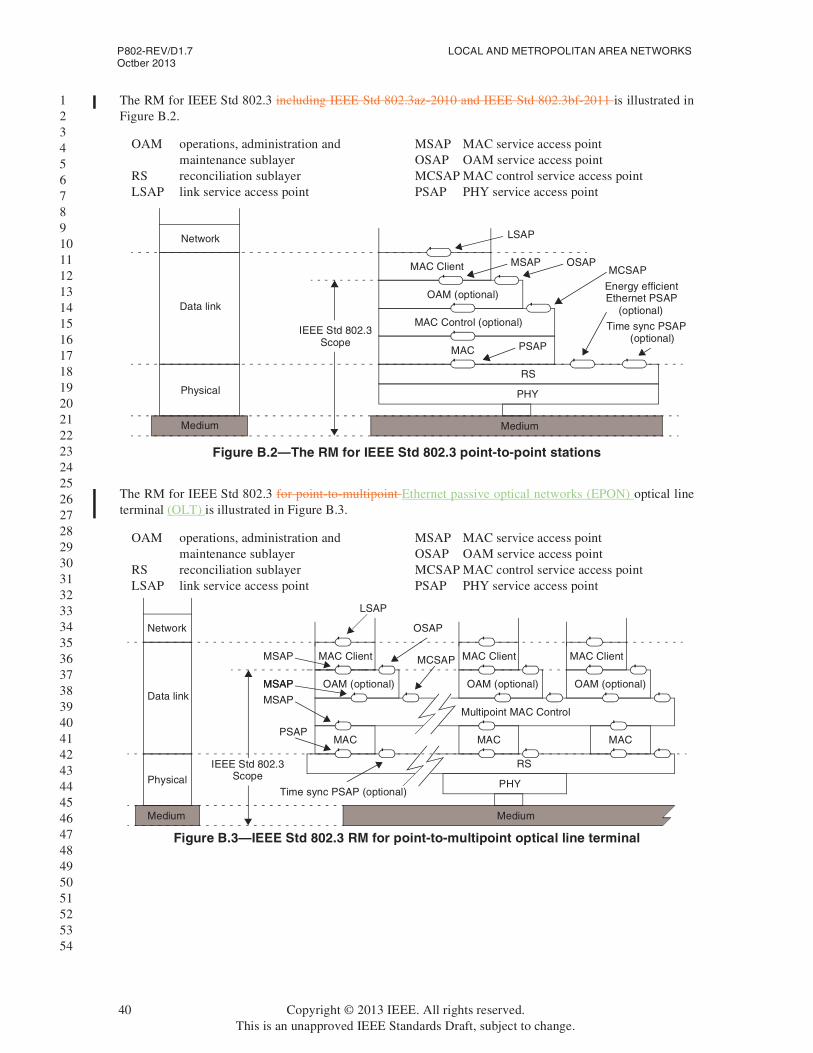
P802-REV/D1.7 LOCAL AND METROPOLITAN AREA NETWORKSOctber 2013
1 2 3 4 5 6 7 8 9 10 11 12 13 14 15 16 17 18 19 20 21 22 23 24 25 26 27 28 29 30 31 32 33 34 35 36 37 38 39 40 41 42 43 44 45 46 47 48 49 50 51 52 53 54
The RM for IEEE Std 802.3 including IEEE Std 802.3az-2010 and IEEE Std 802.3bf-2011 is illustrated in Figure B.2.
The RM for IEEE Std 802.3 for point-to-multipoint Ethernet passive optical networks (EPON) optical line terminal (OLT) is illustrated in Figure B.3.
Figure B.2—The RM for IEEE Std 802.3 point-to-point stations
OAM operations, administration and maintenance sublayer
RS reconciliation sublayer LSAP link service access point
MSAP MAC service access point OSAP OAM service access point MCSAP MAC control service access point PSAP PHY service access point
Medium
Physical
Data link
Network
Medium
PHY
MAC PSAP
OAM (optional)
MSAPMCSAP
RS
MAC Control (optional)
MAC Client
LSAP
OSAP
IEEE Std 802.3Scope
Time sync PSAP
Energy efficientEthernet PSAP
(optional)
(optional)
Figure B.3—IEEE Std 802.3 RM for point-to-multipoint optical line terminal
OAM operations, administration and maintenance sublayer
RS reconciliation sublayer LSAP link service access point
MSAP MAC service access point OSAP OAM service access point MCSAP MAC control service access point PSAP PHY service access point
Medium
Physical
Data link
Network
Medium
PHY
OAM (optional)
MSAP
MCSAP
RS
Multipoint MAC Control
MAC Client
LSAP
OSAP
IEEE Std 802.3Scope
OAM (optional)
MACMACMAC
MAC Client
OAM (optional)
MAC Client
Time sync PSAP (optional)
PSAP
MSAPMSAP
MSAP
40 Copyright © 2013 IEEE. All rights reserved.This is an unapproved IEEE Standards Draft, subject to change.

Overview and Architecture P802-REV/D1.7Octber 2013
1 2 3 4 5 6 7 8 9 10 11 12 13 14 15 16 17 18 19 20 21 22 23 24 25 26 27 28 29 30 31 32 33 34 35 36 37 38 39 40 41 42 43 44 45 46 47 48 49 50 51 52 53 54
The RM for IEEE Std 802.3 Ethernet passive optical networks (EPON) optical network unit (ONU) is illustrated in Figure B.4.
IEEE Std 802.3ah™-2004 and IEEE Std 802.3av-2009 introduced the concept of subscriber access network. The purpose of Ethernet in the first mile (EFM) and its distinction from traditional Ethernet networks, is that it specifies functionality required for the subscriber access network, i.e., public network access. Network design considerations for public access that may differ from traditional Ethernet LANs include the operations, administration and management (OAM) function, and the regulatory requirements.
Figure B.4—The RM for IEEE Std 802.3 point-to-multipoint ONU
OAM operations, administration and maintenance sublayer
RS reconciliation sublayer LSAP link service access point
MSAP MAC service access point OSAP OAM service access point MCSAP MAC control service access point PSAP PHY service access point
Medium
Physical
Data link
Network
Medium
PHY
MAC PSAP
OAM (optional)
MSAP
MCSAP
RS
Multipoint MAC Control
MAC Client
LSAP
OSAP
IEEE Std 802.3Scope
MSAPTime sync PSAP
(optional)
Copyright © 2013 IEEE. All rights reserved. 41This is an unapproved IEEE Standards Draft, subject to change.

P802-REV/D1.7 LOCAL AND METROPOLITAN AREA NETWORKSOctber 2013
1 2 3 4 5 6 7 8 9 10 11 12 13 14 15 16 17 18 19 20 21 22 23 24 25 26 27 28 29 30 31 32 33 34 35 36 37 38 39 40 41 42 43 44 45 46 47 48 49 50 51 52 53 54
B.2 IEEE Std 802.11 RM
The IEEE Std 802.11 11-2012 RM is based on the general station (STA) model, as shown in Figure B.5.
The interconnections between IEEE Std 802.11 11-2012 STAs follow two general models.
Several types of peer-to-peer, direct, pair-wise communication between STAs are definedprovided, each applicable in differing use scenarios. In these direct communications, the pair STAs are symmetrical, with each STA generally matching the simple STA model, although they may take on different behavioral roles for the purpose of establishing and maintaining the interconnection link.
The other interconnection model model, the infrastructure model, supports multiple STAs, collected into one or more wireless access domains. These access domains are interconnected via the distribution system, and can interwork with other IEEE 802 networks via one or more portals.
Each access domain in the infrastructure model is established by an access point (AP), which extends the basic STA model to include repeating and bridging forwarding functions that allow communications between non-AP STAs that do not directly interconnect. The AP acts as a repeater to enable communications between non-AP STAs within the access domaindomain (intra-BSS relay). The AP acts as performs a bridgeforwarding function, via the distribution systemDistribution System, to enable communications between non-AP STAs in different IEEE Std 802.11 wireless access domainsdomains (inter-BSS relay). Finally, via portalsPortals, APs support communications between IEEE Std 802.11 STAs and stations attached to other IEEE 802 networks.
Figure B.5—IEEE Std 802.11-2012 STA RM
IEEE Std 802.1X Port
MAC_SAP
MAC Sublayer
PHY_SAP
MAC SublayerManagement
Entity
MLME-PLME_SAP
Data LinkLayer
MAC State GenericConvergence Function
MSGCF_SAP
MSGCF_SME_SAP
IEEE Std 802.1XAuthenticator/Supplicant
RSNA KeyManagement
StationManagement
EntityPHY LayerManagement
Entity
PLME_SAP
MLME_SAP
PhysicalLayer
PLCP Sublayer
PMD_SAP
PMD Sublayer
Filtering (Optional)
42 Copyright © 2013 IEEE. All rights reserved.This is an unapproved IEEE Standards Draft, subject to change.

Overview and Architecture P802-REV/D1.7Octber 2013
1 2 3 4 5 6 7 8 9 10 11 12 13 14 15 16 17 18 19 20 21 22 23 24 25 26 27 28 29 30 31 32 33 34 35 36 37 38 39 40 41 42 43 44 45 46 47 48 49 50 51 52 53 54
Figure B.6 illustrates the Reference Model for an AP, and its relationship to the distribution system and portals.
Figure B.6—IEEE Std 802.11 AP RM
IEEE Std 802.1X
MAC_SAP
MAC sublayer
PHY_SAP
MAC SublayerManagement
Entity
MLME-PLME_SAP
Data LinkLayer
MAC State GenericConvergence Function
MSGCF_SAP
MSGCF_SME_SAP
IEEE Std 802.1XAuthenticator/Supplicant
RSNA KeyManagement
StationManagement
Entity
PHY LayerManagement
Entity
PLME_SAP
MLME_SAP
PhysicalLayer
PLCP sublayer
PMD_SAP
PMD Sublayer
port filtering
portal
IEEE Std
DistributionSystem
TXRXExample data flows
(optional)
802.1X Filter
Copyright © 2013 IEEE. All rights reserved. 43This is an unapproved IEEE Standards Draft, subject to change.

P802-REV/D1.7 LOCAL AND METROPOLITAN AREA NETWORKSOctber 2013
1 2 3 4 5 6 7 8 9 10 11 12 13 14 15 16 17 18 19 20 21 22 23 24 25 26 27 28 29 30 31 32 33 34 35 36 37 38 39 40 41 42 43 44 45 46 47 48 49 50 51 52 53 54
Figure B.6 illustrates the infrastructure model for APs, The Distribution System and Portals. The arrows indicate the intra-BSS and inter-BSS relay functions for MSDUs as well as interconnection to other 802 networks.
B.3 IEEE 802.15 RMs
B.3.1 IEEE Std 802.15.3™ RM
Data Link Layer
Physical Layer
Non-AP STA Non-AP
STA
Non-AP STA
Distribution System
MAC Sublayer
802.1X Port Filtering (Optional)
MAC Sublayer
802.1X Port Filtering (Optional)
PortalPortal
Integration
Other 802 network
PHY PHY
APs
Figure B.7—IEEE Std 802.11 infrastructure model
44 Copyright © 2013 IEEE. All rights reserved.This is an unapproved IEEE Standards Draft, subject to change.

Overview and Architecture P802-REV/D1.7Octber 2013
1 2 3 4 5 6 7 8 9 10 11 12 13 14 15 16 17 18 19 20 21 22 23 24 25 26 27 28 29 30 31 32 33 34 35 36 37 38 39 40 41 42 43 44 45 46 47 48 49 50 51 52 53 54
The RM for IEEE Std 802.15.3 is illustrated in Figure B.7.
The PHY SAP and physical layer management entity (PLME) SAP are not defined specified in IEEE Std 802.15.3 as they are rarely, if ever, exposed in a typical implementation. The PHY management objects and attributes are accessed through the MAC sublayer management entity (MLME) SAP with the generic management primitives used to access the MAC management objects and attributes.
The MAC SAP and MLME SAP are defined specified as logical interfaces to access the services provided by IEEE Std 802.15.3 end stations.
The PLME and MLME are logical entities that control the PHY and MAC, respectively, based on request from the higher layers.
PAL
MAC SAP
PHY SAP
PHY layer
802.15.3 Media access control
sublayer (MAC)
MAC
PHY
MLME
PLME SAP
Frame convergence sublayer (FCSL)
andDevice management entity (DME)
PLME
MLME SAP
Figure B.8—IEEE Std 802.15.3 RM
Figure B.9—IEEE Std 802.15.3 RM
Medium acces control(MAC) sublayer MLME
PHY layer PLME
Frame convergence sublayer (FCSL) andDevice management entity (DME)PAL
MLME SAPMAC SAP
PHY SAP
MAC
PHY
PLME SAP
Copyright © 2013 IEEE. All rights reserved. 45This is an unapproved IEEE Standards Draft, subject to change.

P802-REV/D1.7 LOCAL AND METROPOLITAN AREA NETWORKSOctber 2013
1 2 3 4 5 6 7 8 9 10 11 12 13 14 15 16 17 18 19 20 21 22 23 24 25 26 27 28 29 30 31 32 33 34 35 36 37 38 39 40 41 42 43 44 45 46 47 48 49 50 51 52 53 54
The frame convergence sublayer (FCSL) is used to allow multiple protocols to simultaneously access the services of an IEEE Std 802.15.3 PAN. IEEE Std 802.15.3 defines specifies an FCSL for connection to the ISO/IEC 8802-2 LLC.
B.3.2 IEEE Std 802.15.4 RM
The RM for IEEE Std 802.15.4 is illustrated in Figure B.8.
The upper layers shown in Figure B.8 consist of a network layer, which provides network configuration, manipulation, and message routing, and an application layer, which provides the intended function of the device. The upper layers are not defined specified in IEEE Std 802.15.4.
B.3.3 IEEE Std 802.15.6™ RM
The RM for IEEE Std 802.15.6 hub or node are shown in Figure B.9.
B.3.4 IEEE Std 802.15.7™ RM
Figure B.10—IEEE Std 802.15.4 RM
Upper layers
MAC
MCPS SAP MLME SAP
PHY
PD SAP PLME SAP
Physical medium
Figure B.11—IEEE Std 802.15.6 RM
MAC-SAP
MAC sublayer
PHY-SAP
PHY layer
Node or hubmanagement
entity
46 Copyright © 2013 IEEE. All rights reserved.This is an unapproved IEEE Standards Draft, subject to change.

Overview and Architecture P802-REV/D1.7Octber 2013
1 2 3 4 5 6 7 8 9 10 11 12 13 14 15 16 17 18 19 20 21 22 23 24 25 26 27 28 29 30 31 32 33 34 35 36 37 38 39 40 41 42 43 44 45 46 47 48 49 50 51 52 53 54
The RM for IEEE Std 802.15.7 is shown in Figure B.10.
The MAC sublayer provides the following two services, accessed through two SAPs:
a) The MAC data service, accessed through the MAC common part sublayer (MCPS) data SAP (MCPS-SAP), and
b) The MAC management service, accessed through the MLME-SAP.
In addition to these external interfaces, an implicit interface also exists between the MLME and the MAC common part sublayer that allows the MLME to use the MAC data service.
The PHY provides two services, accessed through two SAPs: the PHY data service, accessed through the PHY data SAP (PD-SAP), and the PHY management service, accessed through the PLME’s SAP (PLME-SAP). The optical SAP (OPTICAL-SAP) provides an interface between the PHY layer and the optical channel and is not specified in the standard.
B.4 IEEE Std 802.16 RM
B.4.1 Protocol RM
Figure B.12—IEEE Std 802.15.7 RM
MCPS-SAP MLME-SAP
MAC commonpart sublayer MAC PIB
MLME
PD-SAP PLME-SAP
PHY layer
PLME
OPTICAL-SAP
PHY PIB
Copyright © 2013 IEEE. All rights reserved. 47This is an unapproved IEEE Standards Draft, subject to change.

P802-REV/D1.7 LOCAL AND METROPOLITAN AREA NETWORKSOctber 2013
1 2 3 4 5 6 7 8 9 10 11 12 13 14 15 16 17 18 19 20 21 22 23 24 25 26 27 28 29 30 31 32 33 34 35 36 37 38 39 40 41 42 43 44 45 46 47 48 49 50 51 52 53 54
Figure B.11 illustrates the protocol RM for IEEE Std 802.16.
The service-specific convergence sublayer (CS) provides any transformation or mapping of external network data, received through the CS service access point (SAP), into MAC service data units (SDUs) received by the MAC common part sublayer (CPS) through the MAC SAP. This includes classifying
Figure B.13—IEEE Std 802.16 protocol RM
Figure B.14—IEEE Std 802.16 protocol RM
MAC commompart sublayer
PHY layer
Service specificconvergence sublayer
M_S
AP
MAC_SAP
PHY_SAP
MA
CP
HY
C_S
AP
(CS)
CS_SAP
Security sublayer
Managementinformation base (MIB) N
etw
ork
cont
rol a
nd m
anag
emen
t sys
tem
Management/control plane
802.16 entity
Scope of 802.16 standard
Data plane
Coexistence protocol
Distributed radioresource management
(CXP)
Distributed coexistenceinformation database
Coexistence (CX)management part
Management plane
(PHY)
(MAC CPS)
48 Copyright © 2013 IEEE. All rights reserved.This is an unapproved IEEE Standards Draft, subject to change.

Overview and Architecture P802-REV/D1.7Octber 2013
1 2 3 4 5 6 7 8 9 10 11 12 13 14 15 16 17 18 19 20 21 22 23 24 25 26 27 28 29 30 31 32 33 34 35 36 37 38 39 40 41 42 43 44 45 46 47 48 49 50 51 52 53 54
external network SDUs and associating them to the proper MAC service flow identifier and connection identifier. Multiple CS specifications are provided for interfacing with various protocols.
The MAC CPS provides the core MAC functionality of system access, bandwidth allocation, connection establishment, and connection maintenance. Quality of service (QoS) is applied to the transmission and scheduling of data over the PHY.
The security sublayer in the MAC provides authentication, secure key exchange, and encryption.
Data, PHY control, and statistics are transferred between the MAC CPS and the PHY via the PHY SAP (which is implementation specific).
The PHY definition includes multiple specifications, each appropriate to a particular frequency range and application.
B.4.2 Network reference model
Figure B.12 describes a simplified network RM for IEEE Std 802.16.
The network control and management system (NCMS) abstraction allows the PHY/MAC layers specified in IEEE Std 802.16 to be independent of the network architecture, the transport network, and the protocols used at the backend and therefore allows greater flexibility.
NCMS logically exists at base station (BS) side and subscriber station/mobile subscriber station (SS/MS) side of the radio interface, termed NCMS(BS) and NCMS(SS/MS), respectively. Any necessary inter-BS coordination is handled through the NCMS(BS).
The control SAP (C-SAP) and management SAP (M-SAP) exposes the control plane and management plane functions to upper layers. The NCMS uses the C-SAP and M-SAP to interface with the IEEE Std 802.16 entity. In order to provide correct MAC operation, NCMS is present within each SS/MS. The NCMS is a layer independent entity that may be viewed as a management entity or control entity. General system management entities can perform functions through NCMS and standard management protocols can be implemented in the NCMS.
An IEEE Std 802.16 entity is defined as the logical entity in an SS/MS or BS that comprises the PHY and MAC layers of the data plane and the management/control plane. The IEEE Std 802.16 end stations can include SS, MS, or BS. Multiple SS or MS may be attached to a BS.
SS or MS communicate to the BS over the U interface using a primary management connection, a basic connection, or a secondary management connection.
Figure B.15—IEEE Std 802.16 network RM
Network control andmanagement system (NCMS)
(SS/MS side)
Network control andmanagement system (NCMS)
(BS side)
IEEE Std 802.16 entity (BS)
M-SAPC-SAP
IEEE Std 802.16 entity (SS/MS)
C-SAPM-SAP
U
Copyright © 2013 IEEE. All rights reserved. 49This is an unapproved IEEE Standards Draft, subject to change.

P802-REV/D1.7 LOCAL AND METROPOLITAN AREA NETWORKSOctber 2013
1 2 3 4 5 6 7 8 9 10 11 12 13 14 15 16 17 18 19 20 21 22 23 24 25 26 27 28 29 30 31 32 33 34 35 36 37 38 39 40 41 42 43 44 45 46 47 48 49 50 51 52 53 54
B.5 IEEE Std 802.21 RM
Figure B.13 shows an implementation view of a dual-mode IEEE Std 802.11/IEEE Std 802.16 station with IEEE Std 802.21 MIH functionality. The MIHF provides the required services to perform handovers between IEEE Std 802.11 and IEEE Std 802.16 access technologies. Also, the MIHF becomes a higher layer when it requires data transport services to communicate with an IEEE Std 802.21 MIH peer. In the case of layer 2 transport of MIH data, services are provided by the IEEE Std 802.16 CS_SAP, or the IEEE Std 802.11 LSAP. In case of layer 3 transport, services are provided as described in RFC 5677 [B6].
B.6 IEEE Std 802.22 RM
The RM of IEEE Std 802.22 is depicted in Figure B.14. A unique characteristic of this architecture is its cognitive components which is used to allow for dynamic frequency selection, and avoid interference to incumbents on a real-time basis.
B.6.1 Data plane
The service-specific convergence sublayer (CS) provides the transformation or mapping of external network data that is received through the CS SAP, into MAC SDUs and data that is received by the MAC CPS through the MAC SAP. Multiple CS specifications are provided for interfacing with various protocols.
The MAC CPS provides the core MAC functionality of system access, connection establishment, and connection maintenance. The data that the MAC layer receives from the various CSs through the MAC SAP is classified according to the particular MAC connections.
The security sublayer 1 provides mechanisms for authentication, secure key exchange, encryption, etc.
Data, PHY control, and radio statistics are transferred between the MAC CPS and the PHY via the PHY SAP.
B.6.2 Management/control plane
Managemententity
Service specific convergence sublayer
MAC common part sublayer
PHY
CS_SAP
MAC_SAP
PHY_SAP
M_S
APC_
SAP LLC
MAC
PLCPand PMD
LSAP
MAC_SAP
PHY_SAP
MSGCF_SAP
MLME
PLME
MLME_PLME_SAP SME
MSGCF_SME_SAP
MLME_SAP
PLME_SAP
MAC state generic convergence function
MIH User
MIHF
Security sublayer
IEEE 802.16 IEEE 802.11
MIH_SAP
Higher Layers
IEEE 802.21
Figure B.16—Example of dual-mode IEEE Std 802.11 and IEEE Std 802.16 endstation with IEEE Std 802.21 end-station RM
50 Copyright © 2013 IEEE. All rights reserved.This is an unapproved IEEE Standards Draft, subject to change.

Overview and Architecture P802-REV/D1.7Octber 2013
1 2 3 4 5 6 7 8 9 10 11 12 13 14 15 16 17 18 19 20 21 22 23 24 25 26 27 28 29 30 31 32 33 34 35 36 37 38 39 40 41 42 43 44 45 46 47 48 49 50 51 52 53 54
The management/control plane contains the management information base (MIB). SNMP is used to communicate with the MIB database and some of its primitives can be used to manage the network entities, e.g., base station (BS), customer-premises equipment (CPE), bridges, routers. The MIB at the CPE is a subset of MIB at the BS.
B.6.3 Cognitive plane
The SM maintains spectrum availability information, manages channel lists, manages quiet periods scheduling, implements self-coexistence mechanisms and processes requests from the MAC/PHY. The SM is the central point at the BS where all the information on the spectrum availability resulting from the database service and the SSF is gathered. Based on this combined information, local regulations, and predefined SM policies, the SM provides the necessary configuration information to the BS MAC, which then remotely configures all the registered CPEs. Connection B2 is used for configuration of the SM at the BS, transmission of the available TV channel list to the SM, as well as to report the RF environment information via the MIB objects. Connection B1 is used by the SM to initiate a channel move, to configure the SSA at the CPE (e.g., backup/candidate channel list, etc.) as well as to gather information from the CPEs (e.g., local sensing information, local geolocation information, etc.).
Figure B.17—IEEE Std 802.22 RM for the BS and CPE
CS convergence sublayer PHY SAPPHY service access point MAC SAPMAC sublayer service access point CS SAP convergence sublayer service
access point SM-SSF SAP:spectrum manager, spectrum
sensing function service access point
SM-GL SAP:spectrum manager, geolocation service access point
NCMS: network control and management system AAA authentication, authorization
and accounting M-SAP management service access point C-SAP control service access point
Copyright © 2013 IEEE. All rights reserved. 51This is an unapproved IEEE Standards Draft, subject to change.

Overview and Architecture P802-REV/D1.7Octber 2013
1 2 3 4 5 6 7 8 9 10 11 12 13 14 15 16 17 18 19 20 21 22 23 24 25 26 27 28 29 30 31 32 33 34 35 36 37 38 39 40 41 42 43 44 45 46 47 48 49 50 51 52 53 54
The spectrum sensing automaton (SSA), is present at the BS and at the CPEs and independently implements specific procedures for sensing the RF environment at initialization of the BS and before the registration of a CPE with the BS. The SSA at the CPE also includes features to allow proper operation when the CPE is not under the control of a BS. At any other time, the SSA at the CPE is under the control of the SM. The SSA at the BS is also active when the BS is not transmitting to conduct out-of-band sensing. The SSA located at the BS can also carry out sensing to clear channels when the base station is not transmitting.
The spectrum sensing function (SSF) implements spectrum sensing algorithms while the geolocation (GL) module provides the information to determine the location of the IEEE Std 802.22 end station (BS or CPE).
Figure B.18—IEEE Std 802.22 RM for the BS and CPE
AAA authentication, authorization and accounting
CS convergence sublayer C-SAP control service access point CS SAP convergence sublayer service access
point M-SAP management service access point NCMS network control and management system
MAC SAP MAC sublayer service access point
PHY SAP PHY service access point SM-SSF SAP spectrum manager, spectrum
sensing function service access point
SM-GL SAP spectrum manager, geolocation service access point
Copyright © 2013 IEEE. All rights reserved. 52This is an unapproved IEEE Standards Draft, subject to change.

Overview and Architecture P802-REV/D1.7Octber 2013
1 2 3 4 5 6 7 8 9 10 11 12 13 14 15 16 17 18 19 20 21 22 23 24 25 26 27 28 29 30 31 32 33 34 35 36 37 38 39 40 41 42 43 44 45 46 47 48 49 50 51 52 53 54
The role of the security sublayer 2 is to provide enhanced protection to the incumbents as well as necessary protection to the IEEE Std 802.22 stations.
Copyright © 2013 IEEE. All rights reserved. 53This is an unapproved IEEE Standards Draft, subject to change.

P802-REV/D1.7 LOCAL AND METROPOLITAN AREA NETWORKSOctber 2013
1 2 3 4 5 6 7 8 9 10 11 12 13 14 15 16 17 18 19 20 21 22 23 24 25 26 27 28 29 30 31 32 33 34 35 36 37 38 39 40 41 42 43 44 45 46 47 48 49 50 51 52 53 54
Annex C
(informative)
Examples of bit ordering for addresses
C.1 General
This Annex illustrates the various bit- and octet-transmission scenarios that can occur, and it is intended as a basis for clarifying the issue of bit-ordering for EUI-48s across different MACs. Throughout, the examples make use of the OUI value AC-DE-48, introduced in 8.4.1. This three-octet value is considered in its two possible roles: as the first part of a five-octet protocol identifier, and as the first part of a six-octet EUI-48. The consistent representations of the OUI in its role as part of a protocol identifier are contrasted with the sometimes variable representations that apply to its role as part of an EUI-48.
NOTE—Protocol identifiers always form part of the normal user data in a MAC Information field; hence, there is nothing special about OUI octets in their protocol identifier role.
C.2 Illustrative examples
For the examples, the bit significance of an OUI in general is defined to be as illustrated in Figure C.1.
When transmitted on a network with all data octets of the OUI transmitted LSB first, the OUI portions of a protocol identifier and of an EUI-48 appear as in Figure C.2. When transmitted on a network with the data octets of the OUI transmitted MSB first, the OUI portions of a protocol identifier, and of an EUI-48 contained in a MAC Address field, appear as in Figure C.3.
In some circumstances, it is necessary to convey EUI-48s as data within MAC Information fields, e.g., as part of a management protocol or a network layer routing protocol.
For network types in which Figure C.2 applies, such as IEEE Std 802.3, the bit-ordering within the octets of an EUI-48 conveyed as data is the same as both the ordering when the address appears in a MAC Address field and the ordering for octets of nonaddress information.
For network types in which Figure C.3 applies there appears to be a choice of representations for EUI-48s conveyed as data, as follows:
— Canonical format: The octets of the EUI-48 can be treated like any other data octets and transmitted with the bit-ordering of Figure C.3(a). The canonical format is illustrated in Figure C.4.
Figure C.1—Bit significance of an OUI
h g f e d c b aOctet 0
p o n m l k j iOctet 1x w v u t s r qOctet 2
MSB LSB
When used in an EUI-48:Bit “a” of the OUI = I/G address bit. Bit “b” of the OUI = U/L address bit.
When used in a protocol identifiers:Bit “a” of the OUI = M bit. Bit “b” of the OUI (always zero) = X bit.
52 Copyright © 2013 IEEE. All rights reserved.This is an unapproved IEEE Standards Draft, subject to change.
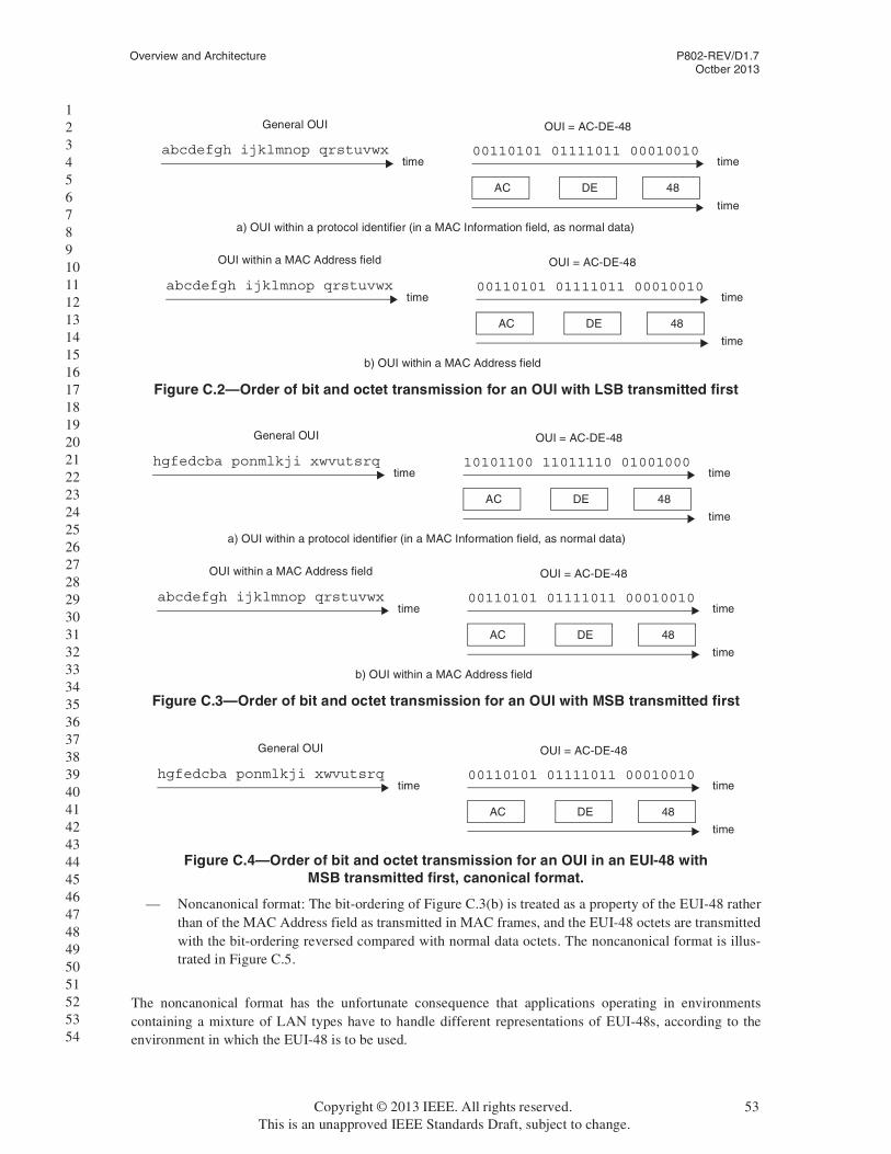
Overview and Architecture P802-REV/D1.7Octber 2013
1 2 3 4 5 6 7 8 9 10 11 12 13 14 15 16 17 18 19 20 21 22 23 24 25 26 27 28 29 30 31 32 33 34 35 36 37 38 39 40 41 42 43 44 45 46 47 48 49 50 51 52 53 54
— Noncanonical format: The bit-ordering of Figure C.3(b) is treated as a property of the EUI-48 rather than of the MAC Address field as transmitted in MAC frames, and the EUI-48 octets are transmitted with the bit-ordering reversed compared with normal data octets. The noncanonical format is illus-trated in Figure C.5.
The noncanonical format has the unfortunate consequence that applications operating in environments containing a mixture of LAN types have to handle different representations of EUI-48s, according to the environment in which the EUI-48 is to be used.
Figure C.2—Order of bit and octet transmission for an OUI with LSB transmitted first
00110101 01111011 00010010time
OUI = AC-DE-48
abcdefgh ijklmnop qrstuvwxtime
General OUI
time
AC DE 48
00110101 01111011 00010010time
OUI = AC-DE-48
abcdefgh ijklmnop qrstuvwxtime
OUI within a MAC Address field
time
AC DE 48
a) OUI within a protocol identifier (in a MAC Information field, as normal data)
b) OUI within a MAC Address field
Figure C.3—Order of bit and octet transmission for an OUI with MSB transmitted first
10101100 11011110 01001000time
OUI = AC-DE-48
hgfedcba ponmlkji xwvutsrqtime
General OUI
time
AC DE 48
00110101 01111011 00010010time
OUI = AC-DE-48
abcdefgh ijklmnop qrstuvwxtime
OUI within a MAC Address field
time
AC DE 48
a) OUI within a protocol identifier (in a MAC Information field, as normal data)
b) OUI within a MAC Address field
Figure C.4—Order of bit and octet transmission for an OUI in an EUI-48 withMSB transmitted first, canonical format.
00110101 01111011 00010010time
OUI = AC-DE-48
hgfedcba ponmlkji xwvutsrqtime
General OUI
time
AC DE 48
Copyright © 2013 IEEE. All rights reserved. 53This is an unapproved IEEE Standards Draft, subject to change.

P802-REV/D1.7 LOCAL AND METROPOLITAN AREA NETWORKSOctber 2013
1 2 3 4 5 6 7 8 9 10 11 12 13 14 15 16 17 18 19 20 21 22 23 24 25 26 27 28 29 30 31 32 33 34 35 36 37 38 39 40 41 42 43 44 45 46 47 48 49 50 51 52 53 54
In Figure C.2, Figure C.3, Figure C.4, and Figure C.5, it can be seen that the interpretation of OUI bits as octet values is consistent. This reversal of the bit order applies only to all six octets (not just the OUI) of anEUI-48 placed in the MAC Information field of a frame by a protocol that uses the bit-reversed view of the EUI-48s derived from Figure C.3(b). Frames containing, or possibly containing, such EUI-48s are described as having noncanonical format. Frames that cannot contain such EUI-48s are described as having canonical format.
Note that there is no way of knowing, from MAC layer information only, whether a particular frame is in canonical or noncanonical format. In general, this depends on which higher layer protocols are present in the frame.
Figure C.5—Order of bit and octet transmission for an OUI in an EUI-48with MSB transmitted first, noncanonical format.
00110101 01111011 00010010time
OUI = AC-DE-48
abcdefgh ijklmnop qrstuvwxtime
General OUI
time
35 7B 12
54 Copyright © 2013 IEEE. All rights reserved.This is an unapproved IEEE Standards Draft, subject to change.
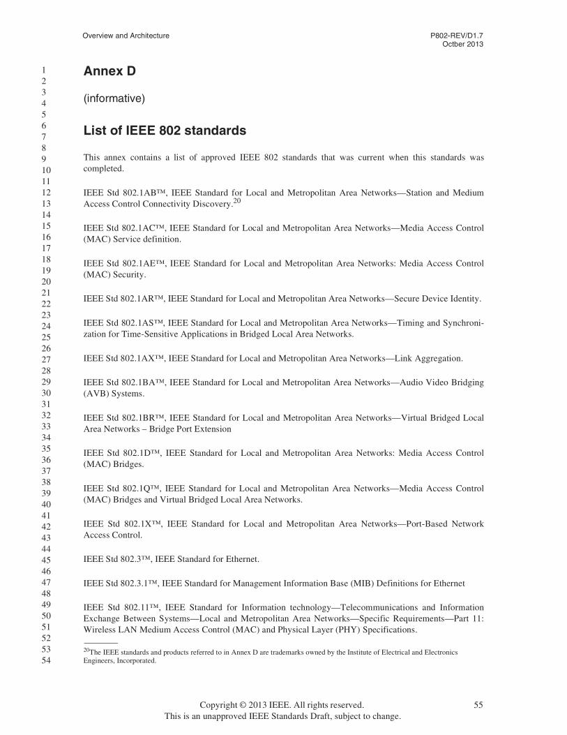
Overview and Architecture P802-REV/D1.7Octber 2013
1 2 3 4 5 6 7 8 9 10 11 12 13 14 15 16 17 18 19 20 21 22 23 24 25 26 27 28 29 30 31 32 33 34 35 36 37 38 39 40 41 42 43 44 45 46 47 48 49 50 51 52 53 54
Annex D
(informative)
List of IEEE 802 standards
This annex contains a list of approved IEEE 802 standards that was current when this standards was completed.
IEEE Std 802.1AB™, IEEE Standard for Local and Metropolitan Area Networks—Station and Medium Access Control Connectivity Discovery.20
IEEE Std 802.1AC™, IEEE Standard for Local and Metropolitan Area Networks—Media Access Control (MAC) Service definition.
IEEE Std 802.1AE™, IEEE Standard for Local and Metropolitan Area Networks: Media Access Control (MAC) Security.
IEEE Std 802.1AR™, IEEE Standard for Local and Metropolitan Area Networks—Secure Device Identity.
IEEE Std 802.1AS™, IEEE Standard for Local and Metropolitan Area Networks—Timing and Synchroni-zation for Time-Sensitive Applications in Bridged Local Area Networks.
IEEE Std 802.1AX™, IEEE Standard for Local and Metropolitan Area Networks—Link Aggregation.
IEEE Std 802.1BA™, IEEE Standard for Local and Metropolitan Area Networks—Audio Video Bridging (AVB) Systems.
IEEE Std 802.1BR™, IEEE Standard for Local and Metropolitan Area Networks—Virtual Bridged Local Area Networks – Bridge Port Extension
IEEE Std 802.1D™, IEEE Standard for Local and Metropolitan Area Networks: Media Access Control (MAC) Bridges.
IEEE Std 802.1Q™, IEEE Standard for Local and Metropolitan Area Networks—Media Access Control (MAC) Bridges and Virtual Bridged Local Area Networks.
IEEE Std 802.1X™, IEEE Standard for Local and Metropolitan Area Networks—Port-Based Network Access Control.
IEEE Std 802.3™, IEEE Standard for Ethernet.
IEEE Std 802.3.1™, IEEE Standard for Management Information Base (MIB) Definitions for Ethernet
IEEE Std 802.11™, IEEE Standard for Information technology—Telecommunications and Information Exchange Between Systems—Local and Metropolitan Area Networks—Specific Requirements—Part 11: Wireless LAN Medium Access Control (MAC) and Physical Layer (PHY) Specifications.
20The IEEE standards and products referred to in Annex D are trademarks owned by the Institute of Electrical and Electronics Engineers, Incorporated.
Copyright © 2013 IEEE. All rights reserved. 55This is an unapproved IEEE Standards Draft, subject to change.

P802-REV/D1.7 LOCAL AND METROPOLITAN AREA NETWORKSOctber 2013
1 2 3 4 5 6 7 8 9 10 11 12 13 14 15 16 17 18 19 20 21 22 23 24 25 26 27 28 29 30 31 32 33 34 35 36 37 38 39 40 41 42 43 44 45 46 47 48 49 50 51 52 53 54
IEEE Std 802.15.1™, IEEE Standard for Information technology—Telecommunications and information exchange between systems—Local and Metropolitan Area Networks—Specific requirements—Part 15.1: Wireless LAN medium access control (MAC) and physical layer (PHY) specifications for wireless personal area networks (WPANs).
IEEE Std 802.15.2™, IEEE Recommended Practice for Information technology—Telecommunications and Information Exchange Between Systems—Local and Metropolitan Area Networks—Specific Require-ments—Part 15.2: Coexistence of Wireless Personal Area Networks with Other Wireless Devices Operating in Unlicensed Frequency Bands.
IEEE Std 802.15.3™, IEEE Standard for Information technology—Telecommunications and Information Exchange Between Systems—Local and Metropolitan Area Networks—Specific Requirements—Part 15.3: Wireless Medium Access Control (MAC) and Physical Layer (PHY) Specifications for High Rate Wireless Personal Area Networks (WPANs).
IEEE Std 802.15.4™, IEEE Standard for Local and Metropolitan Area Networks—Part 15.4: Low-Rate Wireless Personal Area Networks (LR-WPANs).
IEEE Std 802.15.5™, IEEE Recommended Practice for Information technology—Telecommunications and information exchange between systems—Local and metropolitan area networks—Specific requirements—Part 15.5: Mesh Topology Capability in Wireless Personal Area Networks (WPANs).
IEEE Std 802.15.7™, IEEE Standard for Local and Metropolitan Area Networks—Part 15.7: Short-Range Wireless Optical Communication Using Visible Light.
IEEE Std 802.16™, IEEE Standard for Air Interface for Broadband Wireless Access Systems.
IEEE Std 802.16.1™, IEEE Standard for WirelessMAN-Advanced Air Interface for Broadband Wireless Access Systems.
IEEE Std 802.16.2™, IEEE Recommended Practice for Local and Metropolitan Area Networks -Coexist-ence of Fixed Broadband Wireless Access Systems.
IEEE Std 802.17™, IEEE Standard for Information technology—Telecommunications and information exchange between systems—Local and Metropolitan Area Networks—Specific requirements—Part 17: Resilient packet ring (RPR) access method and physical layer.
IEEE Std 802.20™, IEEE Standard for Local and Metropolitan Area Networks—Part 20: Air Interface for Mobile Broadband Wireless Access Systems Supporting Vehicular Mobility—Physical and Media Access Control Layer Specification.
IEEE Std 802.20.2™, IEEE Standard for Conformance to IEEE 802.20 Systems—Protocol Implementation Conformance Statement (PICS) Proforma.
IEEE Std 802.20.3™, IEEE Standard for Minimum Performance Characteristics of IEEE 802.20 Terminals and Base Stations/Access Nodes
IEEE Std 802.21™, IEEE Standard for Local and Metropolitan Area Networks—Media Independent Han-dover Services.
IEEE Std 802.22™, IEEE Standard for Information Technology—Telecommunications and information exchange between systems Wireless Regional Area Networks (WRAN)—Specific requirements Part 22: Cognitive Wireless RAN Medium Access Control (MAC) and Physical Layer (PHY) Specifications: Poli-cies and Procedures for Operation in the TV Bands
56 Copyright © 2013 IEEE. All rights reserved.This is an unapproved IEEE Standards Draft, subject to change.

Overview and Architecture P802-REV/D1.7Octber 2013
1 2 3 4 5 6 7 8 9 10 11 12 13 14 15 16 17 18 19 20 21 22 23 24 25 26 27 28 29 30 31 32 33 34 35 36 37 38 39 40 41 42 43 44 45 46 47 48 49 50 51 52 53 54
IEEE Std 802.22.1™, IEEE Standard for Information Technology—Telecommunications and information exchange between systems—Local and Metropolitan Area Networks—Specific requirements Part 22.1: Standard to Enhance Harmful Interference Protection for Low-Power Licensed Devices Operating in TV Broadcast Bands
Copyright © 2013 IEEE. All rights reserved. 57This is an unapproved IEEE Standards Draft, subject to change.