Embed Size (px)
Citation preview
IEEE JOURNAL OF EMERGING AND SELECTED TOPICS IN POWER ELECTRONICS, VOL. 03, NO. 2, JUNE 2015 371
Control Strategy for Improved DynamicPerformance of Variable-Speed Drives With
Modular Multilevel ConverterJae-Jung Jung, Student Member, IEEE, Hak-Jun Lee, Student Member, IEEE, and Seung-Ki Sul, Fellow, IEEE
Abstract— This paper presents a control scheme for the mod-ular multilevel converter (MMC) to drive a variable-speed acmachine, especially focusing on improving dynamic performance.Theoretically, the energy balance in the MMC cell capacitors isprone to be unstable at start-up and low-frequency operations.In addition, the MMC topology essentially requires advancedcontrol strategies to balance energy and suppress the voltagepulsation of each cell capacitor. This paper proposes a controlstrategy for the robust dynamic response of MMC even at zerooutput frequency employing leg offset voltage injection. The legoffset voltage for balancing the arm energy is produced by directcalculation without the circulating current control loop controller.Thanks to the highly dynamic leg offset voltage from directcalculation and not conventional circulating current controller,the dynamic performance of an MMC at low speeds has conspicu-ously improved. The ac machine has been driven from standstillto rated speed without excessive cell capacitor voltage ripplesutilizing this proposed strategy. The simulation and experimentalresults verify that stable operation is guaranteed down to <2%of the rated speed under 40% step load torque disturbance.
Index Terms— Arm energy balancing, dynamic performance,inner circulating current, modular multilevel converter (MMC),motor drive.
NOMENCLATURE
Superscript ‘∗’ Reference value.Superscript ‘∼’ Low-frequency component.Superscript ‘∧’ High-frequency component.x-phase Representation of one of the u, v,
or w phases.vxo Leg offset voltage of x-phase leg.vsn Common mode voltage.ixo Circulating current of x-phase leg.ωs Three-phase output frequency.R Resistance of arm inductor.L Inductance of arm inductor.Ccell Capacitance of dc capacitor in
a submodule cell.
Manuscript received September 1, 2013; revised December 18, 2013,February 19, 2014, and April 21, 2014; accepted April 22, 2014. Dateof publication May 14, 2014; date of current version April 30, 2015.Recommended for publication by Associate Editor Joseph O. Ojo.
J.-J. Jung and S.-K. Sul are with the School of Electric and Com-puter Engineering, Seoul National University, Seoul 151-742, Korea (e-mail:[email protected]).
H.-J. Lee is with the Corporate Technology Research and DevelopmentCenter, LSIS, Anyang-si 431-080, Korea (e-mail: [email protected]).
Color versions of one or more of the figures in this paper are availableonline at http://ieeexplore.ieee.org.
Digital Object Identifier 10.1109/JESTPE.2014.2323955
ExP Upper arm energy in x-phase leg.ExN Lower arm energy in x-phase leg.vC
xPi i th cell capacitor voltage inupper arm in x-phase.vC
xNi i th cell capacitor voltagein lower arm in x-phase.
I. INTRODUCTION
AMODULAR multilevel converter (MMC) with focus onhigh-power medium voltage ac motor drives is presented
[1]–[10]. The use of an MMC makes it possible to save bulkyreactive components in a medium-voltage motor drive appli-cation, such as a line-transformer, harmonic filter, and dc-linkreactor. Compared with conventional medium voltage sourceconverters, the MMC has a modular structure made up ofidentical converter cells. Because it can easily provide highernumber of voltage level for medium voltage applications, thequality of the output voltage waveform is better. In addition,because of the modular structure it has advantages, such aseasy maintenance and assembly.
Fig. 1 shows the circuit configuration of an MMC. Thistopology needs to be controlled by extra balancing strategies.As shown in Fig. 1, since the upper and lower arm currentsflow through cells in each arm, the corresponding arm currentscause fundamental periodic pulsations of cell capacitor volt-ages. The voltage pulsation of each cell’s capacitor is mostlyaffected by the output phase current and output frequency.Theoretically, the magnitude of the cell voltage fluctuation isproportional to magnitude of the output phase current andinversely proportional to operating frequency [6]. For thisreason, special effort is demanded to drive the ac machinethrough MMC, which requires considerable starting torqueand low-speed steady state operation. In recent studies of[7]–[9] and [16], the principles and algorithms for ac motordrives with the MMC have been introduced. However, theydid not address the actual control strategies, such as changingoutput frequency, including standstill and coveringload torquedisturbance.
The energy balancing control is one of the main issues ofan MMC system. In many literatures [6]–[10], the energybalancing controls of an MMC that uses circulating currentcontrol and modulation scheme have been introduced. Theleg offset voltage is used to regulate the circulating currentand has little effect on ac and dc terminal voltages. The con-ventional balancing controls need the circulating current con-troller that produces the leg offset voltage reference from theinput of circulating current references using the proportional
2168-6777 © 2014 IEEE. Personal use is permitted, but republication/redistribution requires IEEE permission.See http://www.ieee.org/publications_standards/publications/rights/index.html for more information.

372 IEEE JOURNAL OF EMERGING AND SELECTED TOPICS IN POWER ELECTRONICS, VOL. 03, NO. 2, JUNE 2015
Fig. 1. Circuit configuration of the MMC.
and integral (PI) or the proportional and resonant controller.The performance of the circulating current controller hasdetrimental effects on the dynamics and complexity of thebalancing control. Therefore, to improve the balancing perfor-mance by increasing bandwidth of the balancing controller,this paper proposes a balancing control method without thecirculating current controller. Therefore, in the view pointof capacitor voltage balancing, the leg offset voltage can bedirectly obtained with no phase delay due to the circulat-ing current controller. Therefore, the bandwidth of balancingcontroller based on the direct voltage injection method canbe extended more than that based on the circulating currentcontroller. In addition, the difference between the cell voltagescan be reduced faster. As a result, from the perspective ofthe control dynamics and control complexity, the proposedleg offset voltage injection method is better and simpler thanthe conventional circulating current injection method. Further-more, the injecting frequency of leg offset voltage injectionmethod can be increased more than that of current injectionmethod, because of the extended bandwidth of the proposedmethod. Therefore, owing to the high-frequency injection withthe proposed method, the fluctuation of cell capacitor voltagecan be minimized compared with circulating current injectionmethod.
The goal of this paper is to propose a control strategy ofthe entire frequency range operation including standstill forvariable speed ac motor drive. The proposed method reducesthe control performance degradation of the MMC when theload torque abruptlychanges. The control scheme introducestwo operation modes: 1) a low-frequency mode for start-upand low-speed operation and 2) a normal frequency modefrom medium to higher speed operation. The strategy in thelow-frequency mode exploits leg offset voltage and commonmode voltage with the high-frequency component to suppressthe cell capacitor voltage ripple. The square wave voltage isused as the leg offset voltage, which shows that the circulat-ing current peak is reduced when compared with sinusoidalwaveform of the voltage [7]. A switchover tactic between twooperation modes is described to drive the ac machine in theoverall speed region.
To prove the effectiveness of the proposed control strate-gies, a 12-kV 24-MVA MMC-based adjustable motor drivesystem was designed using the PSIM software. The simulationresults could offer the feasibility and advantage of the devisedmethod for high-power medium voltage drives with MMC.In addition, experiments for variable-speed ac motor drivesby a 10-kVA prototype MMC emulating fans, blowers, orpump drive system were performed to verify the feasibilityof the proposed balancing strategy. The experiments wereconducted for comparing features of the sinusoidal and squarewave leg offset voltage. The stable operation at 1 Hz, whichis <2% of the rated speed, is shown under an abrupt stepload torque disturbance from 0% to 40% to demonstrate thedynamic performance. The experimental results show that allcontrol strategies was well incorporated in the variable-speedac motor drive system with a load where the torque varies inproportional to the square of the speed, like fans, blowers, orpumps.
II. CONFIGURATION AND BASIC PRINCIPLE OF THE MMC
Fig. 1(a) shows the circuit configuration of the MMC.The three-phase MMC is composed of three legs and each leghas two arms and two arm inductors. Each arm has cascadedN-identical half-bridge circuit-based cells, and each cell con-sists of one dc capacitor and two active switching devices.The cascaded cell modules are shown in Fig. 1(b) in detail. InFig. 1(a), ixu and ixl are the upper and lower arm currents,respectively, and ixs is the output phase current where x’represents the u-, v-, or w-phase. The output phase current,ixs, and circulating current, ixo, are calculated from the upperand lower arm currents described in (1) and (2). Therefore,the arm currents can be deduced as (3) and (4), according tothe decoupled control scheme in [8] and [11]
ixs = ixu − ixl (1)
ixo = (ixu + ixl)
2(2)
ixu = 1
2ixs + ixo (3)
ixl = −1
2ixs + ixo. (4)
The leg offset voltage, vxo, produces a circulating currentdefined as (5), where R and L stand for the resistance andinductance of an arm inductor when all arm inductors in MMCare assumed to be identical. From the voltage relationshipsalong the x-phase loop, the upper, and lower arm voltagereferences are denoted as (6) and (7), respectively, where Vdcis the dc-link voltage, and vxP and vxN are the upper andlower arm voltages, respectively. The common mode voltage,vsn, is the voltage difference between nodes s’ and n’, and vxsis the phase voltage, which is vxs = Vmcos(ωs t). A detailedmathematical description of the relationships in an MMC isgiven in [10]
vxo =(
R + Ld
dt
)ixo (5)
v∗xP = Vdc
2− v∗
xs − v∗sn − v∗
xo (6)
v∗xN = Vdc
2+ v∗
xs + v∗sn − v∗
xo. (7)

JUNG et al.: CONTROL STRATEGY FOR IMPROVED DYNAMIC PERFORMANCE OF VARIABLE-SPEED DRIVES WITH MMC 373
The instantaneous power of each arm in the x-phase canbe deduced as (8) and (9). These two equations must beconsidered to understand of the proposed balancing control
PxP = v∗xPixu =
(Vdc
2− v∗
xs − v∗sn − v∗
xo
) (1
2ixs + ixo
)
(8)
PxN = v∗xNixl =
(Vdc
2+ v∗
xs + v∗sn − v∗
xo
) (−1
2ixs + ixo
).
(9)
In addition, the upper and lower arm energy can be calcu-lated by (10) and (11), respectively. Each arm energy is thesum of the cell capacitor energies in the corresponding arm atx-phase leg
ExP = 1
2Ccell
N∑i=1
(vC
xPi
)2(10)
ExN = 1
2Ccell
N∑i=1
(vC
xNi
)2. (11)
III. PROPOSED BALANCING CONTROL SCHEME
A. Start-Up and Low Frequency Mode
The capacitor power difference between the upper and lowerarm, which is derived as (12) from (8) and (9), affects thecell capacitor voltage balance of the arms. The first twoterms on the right-hand side in (12), 0.5Vdcixs−2v∗
xsixo, haveconsiderable dc or very low-frequency components. Thus,when the output frequency is dc or very low, the voltagedifference between the arms will diverge due to this low-frequency term
PxP − PxN = 0.5Vdcixs − 2v∗xsixo − 2v∗
snixo − v∗xoixs. (12)
To balance the power difference between arms, a controlstrategy exploiting the common mode voltage, vsn, was usedin this paper. The common mode voltage can be regardedas an additional degree of freedom for controllability sincethe common mode voltage does not affect the line-to-lineoutput voltage. It is natural to select the frequency of thecommon mode voltage as a high frequency to minimizethe cell capacitor voltage fluctuations. In addition, since thecirculating current, ixo, is also a controllable element thatdoes not affect the output phase current, a high-frequencycomponent can be superimposed on the circulating current.Hence, the third term on the right-hand side in (12), 2v∗
snixocan be used to balance the power of arms with the high-frequency components in vsn and ixo. For convenience, thelow- and high-frequency elements can be segregated from ixoand vsn as (13) and (14), where ~ and ^ refer to the low andhigh-frequency components, respectively
ixo = ixo + ixo (13)
vsn = vsn. (14)
The power difference between the upper and lower arms canbe rearranged from (12) to (14), and then, the low-frequency
power component can be extracted as in (15). Here, the powerdifference should be controlled as null
(PxP − PxN)|low freq.
≈ 0.5Vdcixs − 2v∗xsixo − 2v∗
sn i∗xo
∣∣∣low freq.
= 0. (15)
To nullify the low-frequency component as in (15), thelow-frequency component of 2v∗
sni∗xo should be controlled.
Thus, v∗sn and i∗
xo should be regulated as the same high-frequency, to make the power term of 2v∗
sni∗xo have dc or low-
frequency component.In the case of the sinusoidal leg offset voltage injection
method, v∗sn and v∗
xo can be defined as (16) and (17), and ωh
refers to the angular speed of the high-frequency component,Vsn for the effective value of common mode voltage, and Vxofor the magnitude of high-frequency leg offset voltage, whichmay have dc and several low-frequency components
v∗sn = √
2Vsncos(ωh t) (16)
v∗xo = Vxocos(ωh t + φ). (17)
The phase angle φ in (17) between the leg offset voltage andcirculating current is derived from (18) to make the circulatingcurrent synchronize with the common mode voltage
φ = arctan
(ωh L
R
). (18)
In general, ωh L is much larger than R, because the fre-quency of injecting voltage is quite high. However, if thefrequency is not high enough and the arm resistance cannotbe ignored, the arm impedance parameters would need tobe identified. For identification, at the system commissioningstage, the noninteracting leg offset voltage can be injected intothe arm, and the circulating current could befed back as in (5).Consequently, the phase angle between the leg offset voltageand the circulating current in (18) can be obtained. Underthe assumption of R�ωh L, φ is approximately π/2. From(5), (16) and (17), the low-frequency component of the powerassociated with the common mode voltage and the circulatingcurrent can be derived as (19) using the leg offset voltage,where p represents a differential operator
2vsnixo
∣∣∣low freq.
≈ 2vsnvxo
pL
∣∣∣∣low freq.
= 2√
2VsnVxo
ωhLcos (ωh t) sin
(ωh t + π
2
)∣∣∣∣∣low freq.
= 2√
2VsnVxo
ωhL
(1
2sin
(π
2
)+ 1
2sin
(2ωh t + π
2
))∣∣∣∣∣low freq.
=√
2VsnVxo
ωhL. (19)
And then, 2v∗sn i∗
xo in (15) can be substituted with (19).The magnitude of high-frequency leg offset voltage, Vxo, canbe calculated as√
2VsnVxo
ωhL≈ 1
2Vdcixs − 2v∗
xsixo
Vxo ≈ ωhL√2Vsn
(1
2Vdcixs − 2v∗
xsixo
). (20)
374 IEEE JOURNAL OF EMERGING AND SELECTED TOPICS IN POWER ELECTRONICS, VOL. 03, NO. 2, JUNE 2015
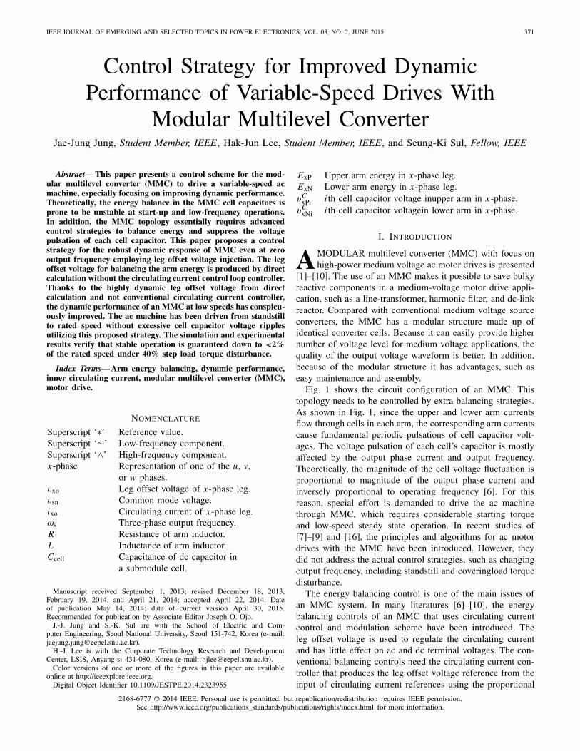
Fig. 2. Proposed control scheme for variable-speed drives. (a) Sinusoidal wave voltage injection method. (b) Square wave voltage injection method. αW isweighting factor for switchover, which is described in Section III-C.
In the case that the sinusoidal wave voltage is injectedto both the common mode and the leg offset voltage, thebalancing control strategy is shown as a block diagram inFig. 2(a). Eerr is the energy difference between the upperand lower arms as in (21). E∗
err is the reference of energydifference and should be set as null to keep the balance of thearm energies
Eerr = ExP − ExN = 1
2Ccell
{N∑
i=1
(vC
xPi
)2 −N∑
i=1
(vC
xNi
)2}
.
(21)
PVfferr in Fig. 2(a) can be derived as (22) by (20)
PV fferr = 1
2Vdcixs − 2v∗
xsixo. (22)
In the case of the square leg offset voltage injection, on theother hand, the square wave voltage can be injected to both thecommon mode and the leg offset voltage as shown in Fig. 2(b).In this case, v∗
sn can be defined by (23) and fh stands for thefrequency of the injected high-frequency voltage
v∗sn =
{−Vsn
(0 ≤ t < 1
2 fh
)Vsn
( 12 fh
≤ t < 1fh
).
(23)
Under the assumption that the arm resistance, R, is domi-nant during each given quasisteady half period, 1/(2 fh), v∗
xocan be approximated as (24) from (5), (15), and (23)
v∗xo ≈
{− R
2Vsn
( 12 Vdcixs − 2v∗
xsixo) (
0 ≤ t < 12 fh
)R
2Vsn
( 12 Vdcixs − 2v∗
xsixo) ( 1
2 fh≤ t < 1
fh
).
(24)
PVfferr in Fig. 2(b) can also be derived from (22) using (24)
similarly with the case of sinusoidal wave.
B. Normal Frequency Mode
Since the output frequency is high enough in the normalfrequency mode, the voltage fluctuation of the cell capacitoris tolerable. In this mode, the circulating current is controlledto have only dc component to minimize the conduction losscaused by the additional circulating current. As the operationfrequency increases, meanwhile, the margin of the commonmode voltage decreases. Hence, the common mode voltage isless available for balancing control.
Practical MMC systems may have an inherent unbalancedue to slight asymmetries in cells, structural errors, and other
Fig. 3. Relationship between operating frequency and weighting factor.
issues. In normal frequency mode, therefore, it should beperformed just to eliminate the inevitable small dc unbalances.The balancing can be achieved using the circulating currentas 2v∗
xsixo in (12). By regulating the leg offset voltage forcirculating current to have fundamental frequency component,this dc unbalance can be suppressed.
C. Switchover Between Two Modes
As mentioned previously, as the high-frequency componentsof the common mode and leg offset voltage are only injected inlow-operating frequency modes, the leg offset voltage refer-ence changes depending on the output frequency of MMC.A switchover tactic between the low- and high-frequencymodes shown in Fig. 3 is devised by the weighting factor,αW . In addition, this factor is applied to the switchover of thebalancing control scheme shown in Fig. 2. In addition, thetactic would have the hysteresis band to prevent chattering inthe vicinity of the switchover frequency, fcut.
IV. OVERALL CONTROL SCHEME FOR ENTIRE
FREQUENCY OPERATION
Fig. 4 shows the overall controller for the entire frequencyoperation from standstill to normal frequency mode. First,the averaging controller carries out regulating the leg power,which is the difference between dc-link input power andac output power. The leg power is calculated as (25) byadding (8) and (9)
PxP + PxN ≈ Vdcixo − 2v∗xoixo − v∗
xsixs − v∗snixs. (25)

JUNG et al.: CONTROL STRATEGY FOR IMPROVED DYNAMIC PERFORMANCE OF VARIABLE-SPEED DRIVES WITH MMC 375
Fig. 4. Proposed overall control scheme for variable-speed drives.
Because the low-frequency power component in (25) shouldbe nullified as in (26), the controller output has dc and second-order harmonic frequency components as described in (27)
PxP + PxN|low freq. ≈ Vdci∗xo − v∗
xsixs = 0 (26)
i∗xo = v∗
xsixs/Vdc. (27)
Eleg is the energy of the leg and it can be calculated as (28).E∗
leg is the reference energy of the leg as (29), where v∗c is
the reference value of cell capacitor voltage, Vdc/N
Eleg = ExP + ExN = 1
2Ccell
{N∑
i=1
(vC
xPi
)2 +N∑
i=1
(vC
xNi
)2}
(28)
E∗leg = 1
2
Ccell
2N4N2v∗2
c = NCcellv∗2c . (29)
The feed-forwarding power term, PV ffleg , can be derived as
v∗xsixs from (27). Therefore, the PI controller can simply be
adopted as the circulating current controller for the averag-ing control. The details about the averaging controller aredescribed in [10].
Meanwhile, the balancing controller can be chosen betweentwo schemes in Fig. 2 that are namely, the sinusoidal andthe square wave voltage injections. As shown in Fig. 4, thebalancing controller directly makes the leg offset voltage with-out the circulating current controller to eliminate the energydifference between upper and lower arms. By reason of thisfact, the balancing controller has a wider bandwidth, and canachieve a better transient response compared with the controlscheme based on the inner circulating current regulation loop.
Finally, the upper and lower arm voltage references aresynthesized as (6) and (7), which are composed of v∗
xs from theoutput of phase current controller, v∗
xo from the averaging andbalancing controller, and the injected common mode voltageof v∗
sn.
V. SIMULATION RESULTS
To verify the effectiveness of the proposed control strategy,an adjustable speed drive system based on 12-kV 24-MVA
TABLE I
CIRCUIT PARAMETERS OF THE SIMULATIONS
TABLE II
PMSM SPECIFICATION OF THE SIMULATIONS
MMC has been implemented using the time-domain simula-tion program, PSIM. The number of cells in each arm, N ,equals 20. Thus, the system with 120 cells was simulated. Eachcell capacitor voltage is controlled as 600 V, and the cell iscomposed of the half-bridge inverter and the cell capacitanceis 6000 μF. The nearest level modulation is applied to generatethe arm voltage references and reduce the switching loss ofMMC [15]. The cell voltage sorting algorithm is applied tothe cell voltage balancing [14]. The parameters used in thesimulation are listed in Table I.
It is assumed that the 21-level MMC system drives a 20 MW20-pole permanent magnet synchronous machine (PMSM)with adjustable mechanical load. The PMSM parameters aresummarized in Table II.
From the simulation results the devised method can beapplied to high-power medium voltage adjustable drive system
376 IEEE JOURNAL OF EMERGING AND SELECTED TOPICS IN POWER ELECTRONICS, VOL. 03, NO. 2, JUNE 2015
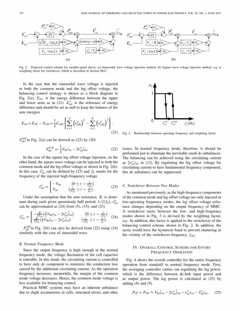
Fig. 5. Simulation waveform when applying the proposed leg offset voltage injection method with 6r/min speed and step load torque from 10% to 40% ofthe rated torque. (a) Sinusoidal waveform offset voltage injection. (b) Square waveform offset voltage injection.
based on MMC. From the dynamic comparison betweencirculating current injection with the inner current loop andthe proposed leg offset voltage injection method, it can beconcluded that the proposed method might be an acceptablesolution for high-power medium voltage drives based onMMC under requirements of considerable torque disturbanceand steady state operation down to a few percent of ratedfrequency.
Fig. 5 shows the low-frequency operation at 1 Hz (6 r/min,<2% of the rated frequency) with an abrupt step load torquefrom 50 kN · m (10%) to 200 kN · m (40%) at 4 s.Fig. 5(a) shows the simulation result of the sinusoidal wave legoffset voltage method, and Fig. 5(b) shows that of the squarewave leg offset voltage method. The high-frequency (100 Hz)voltage is used to balance the arm in low the frequency modein both sinusoidal and square wave cases. Before 4 s, thePMSM is controlled to be 6 r/min with 10% load torque. At thetime point 4 s, the 40% load torque is abruptly applied to thePMSM. Regardless of the impact of step load torque, MMCsystems with both sinusoidal and square wave cases havesuccessfully kept the stable operation. Meanwhile, comparingthe waveforms between Fig. 5(a) and (b), the square waveformmethod can save the magnitude of the circulating current. Inaddition, it has better balancing ability than the sinusoidalwaveform method, from the view of the u-phase upper andlower cell capacitor voltage fluctuations.
Meanwhile, in Fig. 6, the simulation results with the conven-tional circulating current injection method based on the innercurrent regulating loop is shown. All operating conditions areidentical to those in Fig. 5 except for the magnitude of thestep load torque. For fair comparison between the conventionalcurrent injection and proposed leg offset voltage injectionmethods, the bandwidth for the balancing controller of the
Fig. 6. Simulation waveform when applying the conventional circulatingcurrent injection method with 6 r/min speed and step load torque from 10%to 36% of the rated torque.
two methods is set as the same, and the frequency of theinjected component was also set as the same, 100 Hz. Themagnitude of the step load torque applied at the conventionalcurrent injection method is 36% of the rated torque, which

JUNG et al.: CONTROL STRATEGY FOR IMPROVED DYNAMIC PERFORMANCE OF VARIABLE-SPEED DRIVES WITH MMC 377
Fig. 7. Experimental setup with 300 V 10 kVA prototype MMC system.
TABLE III
CIRCUIT PARAMETERS OF THE EXPERIMENTS
TABLE IV
PMSM SPECIFICATION OF THE EXPERIMENTS
is less than the proposed method test in Fig. 5. As shown inFig. 6, the system based on the conventional method becomesunstable and stalls in a moment at the end. After the abruptstep load torque is applied at 4 s, the cell capacitor voltagefluctuations are larger than the fluctuations when using the legoffset voltage injection method in Fig. 5.
VI. EXPERIMENTAL RESULTS
The proposed control strategy is validated by the 300 V10 kVA reduced scale prototype MMC shown in Fig. 7. Thenumber of cells in each arm, N , is 6, so there are a total of36 cells used for the three-phase system. Each cell capacitorvoltage is controlled at 50 V and each cell includes twopower MOSFET switches, which have 100 V/120-A ratings.The level-shifted phase disposition pulsewidth modulationgenerates arm voltage references [12], [13], and the voltagebalancing of cell capacitors in each arm is achieved by sortingalgorithms [14]. The carrier frequency of each cell is set as
Fig. 8. Experimental waveform of the low frequency mode operation at 1 Hzoutput frequency with the sinusoidal leg offset voltage. (a) Negative energydifference. (b) Positive energy difference.
Fig. 9. Experimental waveform of the low frequency mode with 1 Hzoutput frequency when using the square leg offset voltage. (a) Negative energydifference. (b) Positive energy difference.
2 kHz and the dc link capacitance of each cell is 4400 μF.The parameters of the system under test are summarized inTable III.
The MMC is connected to drive 11-kW 8-pole PMSMcoupled to an induction machine (IM) for applying load torqueto PMSM, as shown in Fig. 7. The rated torque and speed ofthe PMSM are 60 N · m and 1750 r/min, respectively. ThePMSM specifications are summarized in Table IV.
A. Sinusoidal Leg Offset Voltage Injection
Fig. 8 shows the waveform in condition of thelow-frequency operation mode at 1-Hz output frequency with20% load torque. The injected leg offset voltage is the 100-Hzsinusoidal wave. Fig. 6 shows the upper and lower arm energyof the u-phase calculated from (10) to (11). The differencebetween the upper and lower arm is counter balanced by v∗
sni∗xo.
When the energy difference, EuP-EuN, is negative, the high-frequency circulating current and offset voltage are controlled180° out of phase, as shown in Fig. 8(a). In contrast, whenthe difference is positive, the circulating current and offsetvoltages are controlled to be in phase in Fig. 8(b).
378 IEEE JOURNAL OF EMERGING AND SELECTED TOPICS IN POWER ELECTRONICS, VOL. 03, NO. 2, JUNE 2015
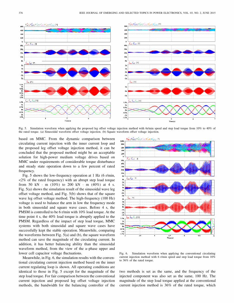
Fig. 10. Experimental waveform when applying the leg offset voltage injecionmethod with wrm = 15 r/min and 40% step load torque at t0.
B. Square Leg Offset Voltage Injection
Fig. 9 is the waveform of the low-frequency operation modeat 1-Hz output frequency with 20% load torque. The balancingcontrol is performed using the 100-Hz square wave leg offsetvoltage. Fig. 9 shows the energy of the upper and lower armin the u-phase leg. The energy difference is counter balancedby v∗
snixo as in the preceding sinusoidal wave case. In thisexperiment, the trapezoidal wave was used instead of squarewave, because the output voltage might have unwanted high-frequency distortion due to the nonlinearities of cells, suchas dead time. If the energy difference, EuP-EuN, is negative,the high-frequency circulating current and offset voltage arecontrolled to be 180° out of phase, as shown in Fig. 9(a).In contrast, when the difference is positive, the circulatingcurrent and offset voltages are controlled to be in phase, as inFig. 9(b).
As described in [7], the square wave can shave the peak ofcirculating current by 50%. However, because of trapezoidalwaveform in this experiment the peak value of circulatingcurrent (ixo) is smaller by 37% than that of the sinusoidalvoltage case.
C. Dynamic Comparison Between Circulating CurrentInjection and Leg Offset Voltage Injection
Fig. 10 shows the low-frequency operation at 1 Hz(15 r/min, <2% of the rated speed) when an abrupt stepload torque was applied from 0 to 24 N•m (40%) at t0. Thesquare wave leg offset voltage is injected in 100 Hz for thearm balancing at this experimental result. Before time point,t0, the PMSM was controlled to be 15 r/min without loadtorque. At the time point, t0, the 40% step load torque isapplied through torque control of the IM. After t0, the upperand lower arm energy fluctuations became larger because ofthe significant output phase current by the step load torque.Furthermore, the transient response in the circulating currentbecomes well regulated within 300 ms after the step variation
Fig. 11. Experimental waveform when applying the conventional circulatingcurrent injecion method with wrm = 15 r/min and 20% step load torque at t0.
in the torque. Regardless of the impact of load torque, PMSMhas successfully kept the speed showing reasonable low-speedperformance. This result confirms that the proposed controllerachieves a good transient response.
In contrast, the conventional circulating current injectionmethod with the inner current regulating loop has been appliedto balancing control, as shown in Fig. 11. For fair comparisonbetween the conventional current injection and the proposedleg offset voltage injection methods, the bandwidth for twomethods was set as the same, and the frequency of the injectedcomponent was also set as the same, 100 Hz. However, themagnitude of the step load torque applied at the conventionalcurrent injection method was half of the proposed method inFig. 10. As shown in Fig. 11, the system became unstable andstalled at the end despite the lower external load torque. Afterthe abrupt step load torque was applied at t0, the fluctuationsof the upper and lower arm energies were larger than that whenusing leg offset voltage injection method in Fig. 10. Finally,the balancing controller could not achieve system balance, andthe overvoltage trip of cell capacitor occurredand the systemstalled at the time point of t1.
And it can be concluded that the leg offset voltage injectionmethod has better disturbance load torque rejection perfor-mance.
D. Operation from Standstill to Normal Frequency Mode
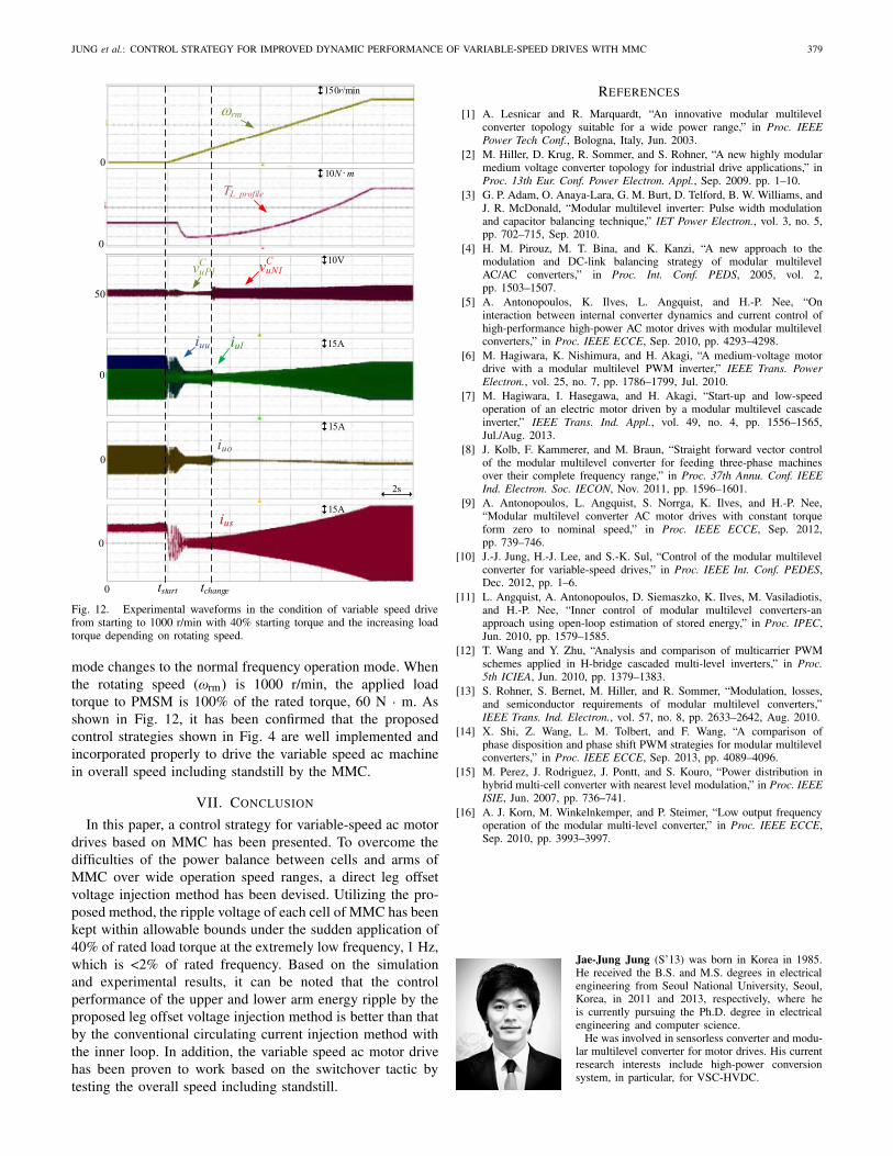
Finally, Fig. 12 shows the entire operation from standstillto the normal frequency mode, 1000 r/min. To conduct theswitchover operation in a practical application of variablespeed drive, such as fans, blowers, or pumps, the load torquewas emulated with IM in proportional to the square of thespeed. Furthermore, the start-up torque of 24 N · m (40%) isincluded in the torque profile (TL profile). In addition, the phasecurrent before tstart is regulated as the dc value. At the timepoint tchange, the switchover process starts, and the operating
JUNG et al.: CONTROL STRATEGY FOR IMPROVED DYNAMIC PERFORMANCE OF VARIABLE-SPEED DRIVES WITH MMC 379
Fig. 12. Experimental waveforms in the condition of variable speed drivefrom starting to 1000 r/min with 40% starting torque and the increasing loadtorque depending on rotating speed.
mode changes to the normal frequency operation mode. Whenthe rotating speed (ωrm) is 1000 r/min, the applied loadtorque to PMSM is 100% of the rated torque, 60 N · m. Asshown in Fig. 12, it has been confirmed that the proposedcontrol strategies shown in Fig. 4 are well implemented andincorporated properly to drive the variable speed ac machinein overall speed including standstill by the MMC.
VII. CONCLUSION
In this paper, a control strategy for variable-speed ac motordrives based on MMC has been presented. To overcome thedifficulties of the power balance between cells and arms ofMMC over wide operation speed ranges, a direct leg offsetvoltage injection method has been devised. Utilizing the pro-posed method, the ripple voltage of each cell of MMC has beenkept within allowable bounds under the sudden application of40% of rated load torque at the extremely low frequency, 1 Hz,which is <2% of rated frequency. Based on the simulationand experimental results, it can be noted that the controlperformance of the upper and lower arm energy ripple by theproposed leg offset voltage injection method is better than thatby the conventional circulating current injection method withthe inner loop. In addition, the variable speed ac motor drivehas been proven to work based on the switchover tactic bytesting the overall speed including standstill.
REFERENCES
[1] A. Lesnicar and R. Marquardt, “An innovative modular multilevelconverter topology suitable for a wide power range,” in Proc. IEEEPower Tech Conf., Bologna, Italy, Jun. 2003.
[2] M. Hiller, D. Krug, R. Sommer, and S. Rohner, “A new highly modularmedium voltage converter topology for industrial drive applications,” inProc. 13th Eur. Conf. Power Electron. Appl., Sep. 2009. pp. 1–10.
[3] G. P. Adam, O. Anaya-Lara, G. M. Burt, D. Telford, B. W. Williams, andJ. R. McDonald, “Modular multilevel inverter: Pulse width modulationand capacitor balancing technique,” IET Power Electron., vol. 3, no. 5,pp. 702–715, Sep. 2010.
[4] H. M. Pirouz, M. T. Bina, and K. Kanzi, “A new approach to themodulation and DC-link balancing strategy of modular multilevelAC/AC converters,” in Proc. Int. Conf. PEDS, 2005, vol. 2,pp. 1503–1507.
[5] A. Antonopoulos, K. Ilves, L. Angquist, and H.-P. Nee, “Oninteraction between internal converter dynamics and current control ofhigh-performance high-power AC motor drives with modular multilevelconverters,” in Proc. IEEE ECCE, Sep. 2010, pp. 4293–4298.
[6] M. Hagiwara, K. Nishimura, and H. Akagi, “A medium-voltage motordrive with a modular multilevel PWM inverter,” IEEE Trans. PowerElectron., vol. 25, no. 7, pp. 1786–1799, Jul. 2010.
[7] M. Hagiwara, I. Hasegawa, and H. Akagi, “Start-up and low-speedoperation of an electric motor driven by a modular multilevel cascadeinverter,” IEEE Trans. Ind. Appl., vol. 49, no. 4, pp. 1556–1565,Jul./Aug. 2013.
[8] J. Kolb, F. Kammerer, and M. Braun, “Straight forward vector controlof the modular multilevel converter for feeding three-phase machinesover their complete frequency range,” in Proc. 37th Annu. Conf. IEEEInd. Electron. Soc. IECON, Nov. 2011, pp. 1596–1601.
[9] A. Antonopoulos, L. Angquist, S. Norrga, K. Ilves, and H.-P. Nee,“Modular multilevel converter AC motor drives with constant torqueform zero to nominal speed,” in Proc. IEEE ECCE, Sep. 2012,pp. 739–746.
[10] J.-J. Jung, H.-J. Lee, and S.-K. Sul, “Control of the modular multilevelconverter for variable-speed drives,” in Proc. IEEE Int. Conf. PEDES,Dec. 2012, pp. 1–6.
[11] L. Angquist, A. Antonopoulos, D. Siemaszko, K. Ilves, M. Vasiladiotis,and H.-P. Nee, “Inner control of modular multilevel converters-anapproach using open-loop estimation of stored energy,” in Proc. IPEC,Jun. 2010, pp. 1579–1585.
[12] T. Wang and Y. Zhu, “Analysis and comparison of multicarrier PWMschemes applied in H-bridge cascaded multi-level inverters,” in Proc.5th ICIEA, Jun. 2010, pp. 1379–1383.
[13] S. Rohner, S. Bernet, M. Hiller, and R. Sommer, “Modulation, losses,and semiconductor requirements of modular multilevel converters,”IEEE Trans. Ind. Electron., vol. 57, no. 8, pp. 2633–2642, Aug. 2010.
[14] X. Shi, Z. Wang, L. M. Tolbert, and F. Wang, “A comparison ofphase disposition and phase shift PWM strategies for modular multilevelconverters,” in Proc. IEEE ECCE, Sep. 2013, pp. 4089–4096.
[15] M. Perez, J. Rodriguez, J. Pontt, and S. Kouro, “Power distribution inhybrid multi-cell converter with nearest level modulation,” in Proc. IEEEISIE, Jun. 2007, pp. 736–741.
[16] A. J. Korn, M. Winkelnkemper, and P. Steimer, “Low output frequencyoperation of the modular multi-level converter,” in Proc. IEEE ECCE,Sep. 2010, pp. 3993–3997.
Jae-Jung Jung (S’13) was born in Korea in 1985.He received the B.S. and M.S. degrees in electricalengineering from Seoul National University, Seoul,Korea, in 2011 and 2013, respectively, where heis currently pursuing the Ph.D. degree in electricalengineering and computer science.
He was involved in sensorless converter and modu-lar multilevel converter for motor drives. His currentresearch interests include high-power conversionsystem, in particular, for VSC-HVDC.
380 IEEE JOURNAL OF EMERGING AND SELECTED TOPICS IN POWER ELECTRONICS, VOL. 03, NO. 2, JUNE 2015
Hak-Jun Lee (S’11) was born in Korea in 1980. Hereceived the B.S., M.S., and Ph.D. degrees in elec-trical engineering from Seoul National University,Seoul, Korea, in 2007, 2009, and 2013, respectively.
He has been with the Research and DevelopmentCenter, LSIS Company, Ltd., Anyang, Korea, since2013, where he is currently involved in the electricmachine drive systems and the modular multilevelconverter for HVDC system. His current researchinterests include electric machine drive system, high-power converter, and multilevel converter.
Seung-Ki Sul (S’78–M’80–SM’98–F’00) receivedthe B.S., M.S., and Ph.D. degrees in electricalengineering from Seoul National University, Seoul,Korea, in 1980, 1983, and 1986, respectively.
He was an Associate Researcher with the Depart-ment of Electrical and Computer Engineering, Uni-versity of Wisconsin, Madison, WI, USA, from 1986to 1988. From 1988 to 1990, he was a PrincipalResearch Engineer with Gold-Star Industrial Sys-tems Company, Seoul. Since 1991, he has beena Faculty Member with the School of Electrical
Engineering, Seoul National University, where he is currently a Full Professor.From 2003 to 2004, he was a Research Director and an Acting Consultant withYaskawa Electric Corporation, Fukuoka, Japan. From 2005 to 2007, he wasthe Vice Dean of the Engineering College, Seoul National University. From2008 to 2011, he was the President of the Electrical Engineering ScienceResearch Institute funded by the Korean Government. He has authored over120 reviewed journal papers, in particular, the IEEE transactions. His currentresearch interests include power electronic control of electrical machines,electric/hybrid vehicle and ship drives, and power-converter circuits forrenewal energy sources.
Dr. Sul was a Technical Chair of the 2006 IEEE Power ElectronicsSpecialists Conference and the General Chair of the 2011 IEEE EnergyConversion Congress and Exposition-Asia. He is currently the Editor-in-Chiefof the Journal of Power Electronics, which is a SCIE registered journal,published by the Korean Power Electronics Institute, Seoul.


![IEEE Transactions on Consumer Electronics, Vol. 62, No. 1 ...kresttechnology.com/krest-academic-projects/krest... · [7]–[9]. Specifically, global time synchronization is necessary](https://img.pdfslide.net/doc/110x75/5fd4e3679912bc39a5014769/ieee-transactions-on-consumer-electronics-vol-62-no-1-7a9-specifically.jpg)