Embed Size (px)
Citation preview
IEEE JOURNAL ON EMERGING AND SELECTED TOPICS IN CIRCUITS AND SYSTEMS, VOL. 3, NO. 3, SEPTEMBER 2013 367
Measurement of Supercapacitor Fractional-OrderModel Parameters From Voltage-Excited
Step ResponseTodd J. Freeborn, Student Member, IEEE, Brent Maundy, Member, IEEE, and
Ahmed S. Elwakil, Senior Member, IEEE
Abstract—In this paper, we propose using a numerically solvedleast squares fitting process to estimate the impedance parametersof a fractional order model of supercapacitors from their voltageexcited step response, without requiring direct measurement of theimpedance or frequency response. Experimentally estimated pa-rameters from low capacity supercapacitors of 0.33, 1, and 1.5 F inthe time range 0.2–30 s and high capacity supercapacitors of 1500and 3000 F in the time range 0.2–90 s verify the proposed time do-main method showing less than 3% relative error between the sim-ulated response (using the extracted fractional parameters) and theexperimental step response in these time ranges. An application ofemploying supercapacitors in a multivibrator circuit is presentedto highlight their fractional time-domain behavior.
Index Terms—Fractional calculus, impedance, measurement,supercapacitors, time-domain analysis.
I. INTRODUCTION
S UPERCAPACITORS, also referred to as ultracapacitorsor electric double layer capacitors, are high energy storage
devices with many practical uses in energy storage for windturbines [1], photovoltaic systems [2], [3], energy harvesting[4], hybrid and electric vehicles [5], and biomedical sensors [6].Traditionally, these capacitors have been modelled using RCnetworks to describe their behavior over wide frequency bands,with larger frequency bands requiring a greater number of pa-rameters [7]. However, recent work has employed the conceptof fractional impedances to model and describe the behaviorof these components [8], [9]. These fractional models havebeen developed to describe the impedance in low and mediumfrequencies [10], [11], long-term transients [12], and stepresponse characteristics [13], [14] of supercapacitors; showingmuch better fit with experimental data over their integer ordercounterparts and requiring fewer model parameters. A very
Manuscript received January 25, 2013; revised March 27, 2013; acceptedJune 14, 2013. Date of publication July 10, 2013; date of current versionSeptember 09, 2013. The work of T. Freeborn was supported by Canada’sNational Sciences and Engineering Research Council (NSERC), Alberta Inno-vates—Technology Futures, and Alberta Advanced Education and Technologythrough their graduate student scholarships. This paper was recommended byGuest Editor A. Elwakil.T. J. Freeborn and B. Maundy are with the Department of Electrical and
Computer Engineering, University of Calgary, Calgary, AB, T2N 1N4 Canada(e-mail: [email protected]; [email protected]).A. S. Elwakil is with the Department of Electrical and Computer Engineering,
University of Sharjah, Sharjah, United Arab Emirates (e-mail: [email protected]).Digital Object Identifier 10.1109/JETCAS.2013.2271433
simple fractional-order supercapacitor model is composed ofa series resistor, , and constant phase element (CPE). TheCPE’s impedance is given as ; where isthe pseudo-capacitance with units F/s the order.These units were originally proposed in [15] where [s] is theunit of time not to be confused with , the Laplace transformoperator. The impedance of this fractional model is given by
(1)
This model is a simplification of the model derived from theporous electrode behavior of supercapacitors and represents thelow and high frequency behavior of the supercapacitors when
and , respectively [16]. This model has beenused in [10] to model the impedance in the frequency range from10 mHz to 1000 Hz and [11] in the frequency range 50–215mHz with and 450 mHz to 100 Hz with . Thismodel has been selected over other fractional models becauseof its simplicity and good fit with experimental data at low andhigh frequencies. Using this model, supercapacitors belong toa family of devices known as fractional capacitors, of whichtraditional capacitors are a small subset, possessing fractionalimpedances. Now, while all capacitors have been shown to pos-sess fractional characteristics [15] and should be modelled withan impedance , the value of is very near to1 for commercially available low-value capacitors. There hasbeen much work to realize low-value fractional capacitors usingphotolithographic manufacturing [17], [18] and electrolyte pro-cesses [9], [20] with applications in controls [21], oscillators[22], [23], power electronics [24], and analog filter design [25].Fractional order models are based on concepts imported fromfractional calculus, the branch of mathematics concerning dif-ferentiations and integrations to noninteger order. While thereare no physical analogies to these operations, like slope or areaunder a curve, their use has been steadily migrating from the the-oretical realms of mathematicians into many applied branchesof engineering [26]. A fractional derivative of order is givenby the Caputo derivative [27] as
(2)
where is the gamma function and .We use the Caputo definition, denoted in (2) with the super-script, of a fractional derivative over other approaches becausethe initial conditions for this definition take the same form as the
2156-3357 © 2013 IEEE
368 IEEE JOURNAL ON EMERGING AND SELECTED TOPICS IN CIRCUITS AND SYSTEMS, VOL. 3, NO. 3, SEPTEMBER 2013
more familiar integer-order differential equations. Applying theLaplace transform to the fractional derivative of (2) with lowerterminal yields
(3)
where is also referred to as the fractional Laplace transformoperator. The use of fractional-order elements in different fieldsof electrical engineering is steadily increasing including:• modelling RF inductors with a frequency dependent re-sistor that varies by [28];
• modelling the losses of coils using a fractional impedance[29];
• generalizing the Smith chart to the fractional domain forplotting and matching fractional impedances in the RF andmicrowave regime [30];
• expanding the freedom and versatility of electric circuitsby introducing fractional orders [31], [32];
• generalizing the integer-order cable model of the neuronsystem to the fractional domain [33].
Typically, the impedance parameters of capacitors are mea-sured using equipment such as LCR meters. However, thesepieces of equipment operate on the assumption that the circuitelement can be modelled using integer order impedances whichyields incorrect results when trying to measure fractional im-pedances. As a result, the determination of the fractional param-eters to describe supercapacitors has required direct measure-ment of the impedance [11] or frequency response [14] requiringeither an impedance or network analyzer. Therefore, there ex-ists a need for both equipment and techniques to measure thefractional characteristics of a circuit element directly.In this paper, we highlight the errors in using integer order
techniques to model and measure the fractional impedances ofsupercapacitors and more generally fractional capacitors. Wepropose an indirect measurement technique using a numericallysolved least squares fitting (NLSF) to extract the fractionalimpedance parameters that describe the transient behavior fromthe voltage excited step response of a quadripole implementedwith a supercapacitor. The focus is on the transient-time be-havior of supercapacitors since in general the transient-timebehavior of mathematical functions in a fractional-order spaceis significantly different from their behavior in an integer-orderspace [34]. Parameters estimated from MATLAB simulatednoisy step response datasets show less than 3% mean relativeerror compared to the ideal values. Experimentally estimatedparameters from low capacity supercapacitors of 0.33, 1, and1.5 F and high capacity supercapacitors of 1500 and 3000 Fshow less than 3% error compared to the collected step re-sponses from 0.2 to 30 s and 0.2 to 90 s, respectively. Anapplication of using a supercapacitor in a multivibrator circuitis presented to verify the fractional impedance of these compo-nents.
II. FRACTIONAL CAPACITORS
Traditional capacitors with order can be combined inparallel and series, as shown in Fig. 1(a) and (b), respectively.
Fig. 1. (a) Parallel and (b) series connection of fractional capacitors.
Fig. 2. Wien bridge circuit to determine the capacitance and series resistanceof a capacitor.
However when the capacitors have varying orders an equiva-lent impedance and not an equivalent capacitance must be usedwhen connecting these elements. The impedance of connectedfractional capacitors in parallel and series becomes
(4)
(5)
where and are the equivalent parallel and seriesimpedance, respectively. The order of each element has a sig-nificant effect on the impedance of each fractional capacitor andcannot be neglected when creating an equivalent impedance.Fractional capacitors with possess both a real and imag-inary impedance component, where an ideal capacitor has onlyan imaginary component. As a result, comparisons of the ca-pacity between integer and fractional models need to accountfor both the order and frequency as presented in [13]. With frac-tional capacitors requiring updated equations to determine theequivalent impedance of parallel and series elements it followsthat the techniques to measure these quantities also require up-dating to the fractional domain.
A. Measurement With a Wien Bridge
The Wien bridge, shown in Fig. 2, is a circuit to measure anunknown capacitance and series resistance by balancing themwith a branch of known impedance at a fixed frequency. To bal-ance this circuit at a fixed frequency, the components andare adjusted until the impedance of each branch is equal. When

FREEBORN et al.: MEASUREMENT OF SUPERCAPACITOR FRACTIONAL-ORDER MODEL PARAMETERS FROM VOLTAGE-EXCITED STEP RESPONSE 369
TABLE ITHEORETICAL EXTRACTIONS OF CAPACITANCE AND SERIES RESISTANCEOF A FRACTIONAL CAPACITOR IN A CLASSIC WIEN BRIDGE CIRCUIT
balanced, the unknown quantities, and can be found,when , by solving the equations
(6)
(7)
where is the frequency at which the impedances are balanced.However, these expressions are based on the assumption that
. If we generalize these balanced equations to the frac-tional domain they become
(8)
(9)
Now, if we measure a fractional capacitor with the Wienbridge, the calculated values using (6) and (7) will not be anaccurate representation of the element because the true orderis neglected. It will only provide an accurate account of theelement impedance at that frequency. For example, if fractionalcapacitors of orders , and 1 are balancedat rad/s when nF and k , thefractional capacitance and series resistance will be calculatedto be F and k using (6) and (7). However,solving (8) and (9) numerically when the order is known yieldsthe capacitances and series resistance given in Table I. Fromthese values it is clear that using the integer order Wien bridgeequations greatly underestimates the value of the fractionalcapacitor, with the true capacitance two orders of magnitudehigher than that calculated with (6) and (7) for orders lessthan 0.5. This difference is a natural result of the change inimpedance introduced by the order of the fractional capacitor.Therefore, it is not possible to use a traditional Wien bridgecircuit to measure the fractional impedance parameters thatdescribe fractional capacitors and new techniques are requiredfor their correct measurement.
III. CHARGING AND DISCHARGING OF SUPERCAPACITORS
Accurately using supercapacitors in circuits and systemsrequires both accurate impedance models and expressions fortheir charging and discharging characteristics. A simple circuitthat can be used to obtain the voltage excited step response ofa quadripole formed with a supercapacitor when modelled as afractional impedance is shown in Fig. 3(a). Using the Caputodefinition [27] of a fractional derivative it can be shown that the
Fig. 3. Circuits to (a) charge and (b) discharge the fractional model of a super-capacitor.
output voltage in the s-domain, , of Fig. 3 with an initialvoltage, , on the capacitor is
(10)
Applying the Laplace transform formula for the Mittag–Lefflerfunction [27] on (10) when is a step function of magni-tude , that is , yields
(11)
where is the time domain expression of the output voltageand is the two-term Mittag–Leffler function defined in[27] as
(12)
which when there are zero initial conditions ( V) be-comes
(13)
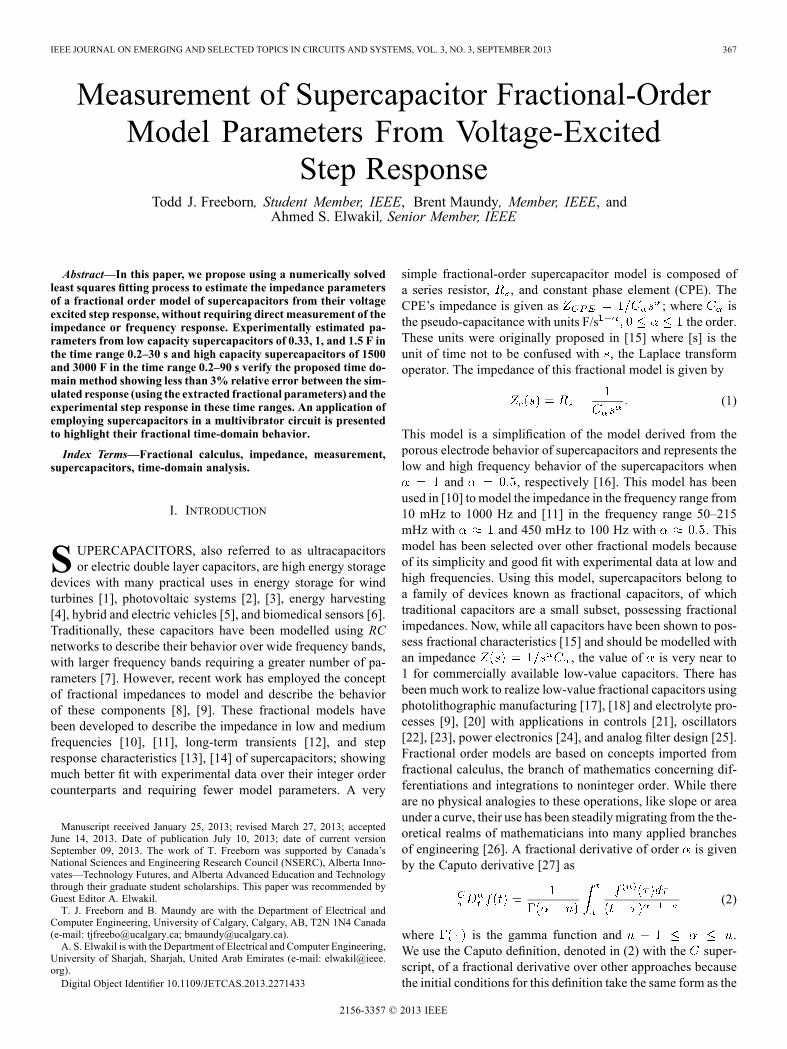
MATLAB simulations of (13) for , and 1 usingthe Mittag–Leffler function supplied by [35] to an accuracy of
for each datapoint when F/s, and V are given in Fig. 4. Note that
the value of has a significant impact on the charging of thequadripole, with lower values of reducing the rate at whichthe supercapacitor charges.Similarly, it can be shown that the time-domain expression
for the discharging of the quadripole with a supercapacitor inFig. 3(b) with initial voltage, , is given by
(14)
Using the fractional charging and discharging expressions forthe quadripole in Fig. 3(a) and (b) given by (13) and (14), re-
370 IEEE JOURNAL ON EMERGING AND SELECTED TOPICS IN CIRCUITS AND SYSTEMS, VOL. 3, NO. 3, SEPTEMBER 2013
Fig. 4. MATLAB simulated ideal step responses (solid lines) and simulatedresponses using estimated parameters with 60 dB SNR Gaussian white noise(circles) for , and 1 when F/s
V.
spectively, the transient behavior of the quadripole to a voltagestep input can be completely described.
IV. NUMERICALLY SOLVED LEAST SQUARES FITTING
Recently, fitting routines have been applied to extract frac-tional information from time-domain responses, having shownapplications in [36] for Cole impedance parameters, [37] forgeneral experimental data and [38], [39] for fractional behaviorof nested and ladder circuits. This method can also be applied toextract the fractional parameters from the transient responses ofa supercapacitor in the quadripole given in Fig. 3. In this case, anumerically solved least squares fitting is used to solve the con-strained optimization problem
(15)
where is the vector of impedance parametersis the time domain step response
(13) calculated using is the collected step response tofit to (13), and are the simulated response andcollected response at time , and is the total number of datapoints in the collected step response. This routine aims to findthe impedance parameters that would ideally reduce the leastsquares error to zero or realistically to the level of noise withinthe dataset. This fitting was implemented in MATLAB usingthe lsqcurvefit function to estimate the parametersusing the trust-region-reflective algorithm [40] that providesthe best fit of the experimental data to (13). The constraint isadded for this problem because negative values of andare not physically possible and a negative value of wouldindicate a fractional inductor not a fractional capacitor.
A. Simulated Datasets
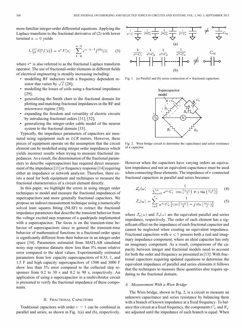
The impact of noise on the extractions was investigated byapplying the NLSF routine to 1000 MATLAB simulated stepresponses of (13) from to 30 s with 50 linearly spaceddatapoints for supercapacitors of orders , and 1when F/sV, and V. Randomly generated white Gaussian noise
Fig. 5. Average relative error of extracted parameters from 1000 MATLABsimulated step responses when F/s , and
, and 1 with 40–80 dB SNR Guassian white noise.
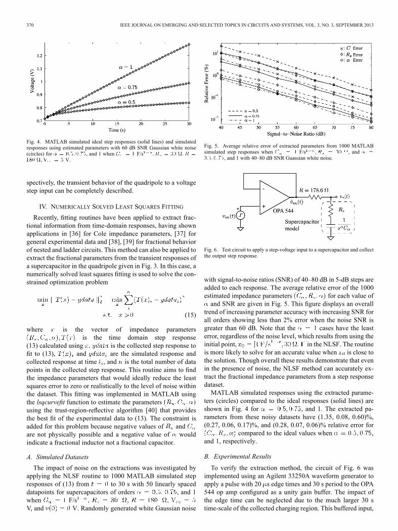
Fig. 6. Test circuit to apply a step-voltage input to a supercapacitor and collectthe output step response.
with signal-to-noise ratios (SNR) of 40–80 dB in 5-dB steps areadded to each response. The average relative error of the 1000estimated impedance parameters for each value ofand SNR are given in Fig. 5. This figure displays an overall
trend of increasing parameter accuracy with increasing SNR forall orders showing less than 2% error when the noise SNR isgreater than 60 dB. Note that the cases have the leasterror, regardless of the noise level, which results from using theinitial point, in the NLSF. The routineis more likely to solve for an accurate value when is close tothe solution. Though overall these results demonstrate that evenin the presence of noise, the NLSF method can accurately ex-tract the fractional impedance parameters from a step responsedataset.MATLAB simulated responses using the extracted parame-
ters (circles) compared to the ideal responses (solid lines) areshown in Fig. 4 for , and 1. The extracted pa-rameters from these noisy datasets have (1.35, 0.08, 0.60)%,(0.27, 0.06, 0.17)%, and (0.28, 0.07, 0.06)% relative error for
compared to the ideal values when ,and 1, respectively.
B. Experimental Results
To verify the extraction method, the circuit of Fig. 6 wasimplemented using an Agilent 33250A waveform generator toapply a pulse with 20 s edge times and 30 s period to the OPA544 op amp configured as a unity gain buffer. The impact ofthe edge time can be neglected due to the much larger 30 stime-scale of the collected charging region. This buffered input,

FREEBORN et al.: MEASUREMENT OF SUPERCAPACITOR FRACTIONAL-ORDER MODEL PARAMETERS FROM VOLTAGE-EXCITED STEP RESPONSE 371
Fig. 7. Buffered step input (solid) and 1 F supercapacitor charging/dis-charging (dashed) waveforms.
TABLE IIMANUFACTURER PART NUMBERS FOR 0.33, 1, AND 1.5 F RATED
SUPERCAPACIORS FROM PANASONIC, ELNA, AND COOPER–BUSSMANN
, was applied to a supercapacitor through a 178.6- re-sistor. The buffered step input and charging of a 1 F superca-pacitor, collected using a Tektronix 745D digital oscilloscopesampling at a rate of 5 S/s, shown in Fig. 7, confirms that the opamp is operating in its linear region. As the input step does notintroduce any high frequency artifacts the sampling rate is ade-quate to capture the charging and discharging characteristics forthe NLSF. Note the asymmetrical charging response of the 1 Fsupercapacitor in Fig. 7 supporting the results that charge anddischarge cycles vary due to irreversible processes and internalresistance [41]. The step responses of 0.33, 1, and 1.5 F super-capacitors, two each from Panasonic, Elna, and Cooper–Buss-mann (with all part numbers given in Table II) are shown inFig. 8(a), (b), and (c), respectively.Applying the NLSF to each of the collected responses in
Fig. 8 yields the parameters given in Table III. The pseudo-ca-pacitances extracted for the fractional model show a significantdeviation from the rated capacitances supplied by the manufac-turers because the manufacturer values represent the nominalcapacity where our extracted values are to represent the tran-sient behavior. Therefore, a direct comparison between theseparameters cannot be made as they are describing different be-haviors of the supercapacitors.Each of the three brands, for all three capacitances show
similar values to each other, even though each have potentiallydifferent manufacturing processes. Of significant note is thefractional order having mean values of , and0.53 for the 0.33, 1, and 1.5 F supercapacitors, respectively.Therefore, in the time scale from 0.2 to 30 s the high frequencysimplification of the porous supercapacitor model to (1) with
is a very good fit. The MATLAB simulation of (13)using the estimated parameters of the Panasonic(1) supercapac-itor in Table III compared to the experimentally collected stepresponse are shown in Fig. 9 as black circles and a solid line,
Fig. 8. Experimentally collected step responses of (a) 0.33, (b) 1, and (c) 1.5 FPanasonic, Elna, and Cooper–Bussmann brand supercapacitors.
respectively. The simulation using the estimated parametersshows a very good fit with the experimental data, with less than3% relative error over the entire response validating that theextracted fractional parameters do correctly describe the super-capacitor step response in this time scale. For comparison, theparameters from the step response were also extracted using theNLSF assuming which yields parametersF and , the simulated response using theseparameters are given in Fig. 9 as a dashed line. This responseshows a significant error compared to the experimental datareaching a maximum of 61% at 0.3316 s, confirming that thefractional model given by (1) provides a more accurate fit ofthe experimental data than its integer order counterpart.The relative errors of the simulated step responses using the
estimated parameters in Table III compared to the experimentalresults of Fig. 8 are given in Fig. 10. From these figures, it isclear that all simulated responses using the estimated parame-ters show very good agreement with the experimental resultswith maximum errors less than 3% for all responses of the 0.33,

372 IEEE JOURNAL ON EMERGING AND SELECTED TOPICS IN CIRCUITS AND SYSTEMS, VOL. 3, NO. 3, SEPTEMBER 2013
TABLE IIIFRACTIONAL PARAMETERS EXTRACTED USING NLSF METHOD FROM SUPERCAPACITORS WITH 0.33, 1, AND 1.5 F RATED CAPACITANCE
Fig. 9. Experimentally collected step response of the Panasonic(1) supercapac-itor (solid) and the MATLAB simulated response using the estimated fractional(black circles) and integer (dashed) parameters.
1, and 1.5 F supercapacitors. The majority of simulated data-points using the estimated parameters show less than 0.3% rel-ative error over the entire dataset with the maximum errors oc-curring at times less than 1 s.
C. 1 F Supercapacitor Comparison
The need for manufacturers to begin using and marketingtheir supercapacitors having fractional characteristics becomesmore apparent when comparing supercapacitors with the samerated capacitance but different part numbers from the samemanufacturer. For example, the step responses of three different1 F rated supercapacitors from Cooper–Bussmann having partnumbers KR-5R5V105-R [44], PM-5R0V105-R [45], andPB-5R0V105-R [46], collected from the circuit in Fig. 6 to aninput step of 5 V are given in Fig. 11. Previously, it was shownthat the KR-5R5V105-R supercapacitors possessed fractionalparameters of approximately F/s ,and . However, the NLSF extraction process appliedto the step responses of the PM and PB supercapacitors yieldsparameters F/s )and F/s , respectively. The PMand PB models possess parameters very close to those expectedby normal capacitors with an order very close to 1 and capaci-tance value within the expected tolerances. However, the orderof the KR model is only half as large as the PB andPM models . However, all three supercapacitor modelsare marketed with a 1 F rated capacitance even though the KRmodel has very different charging characteristics than both thePM and PB models. In this time scale, the transient behaviorof the PM and PB models are accurately represented with thelow-frequency simplification of the porous model while the KR
Fig. 10. Relative error of the (a) 0.33, (b) 1, and (c) 1.5 F simulated step re-sponses using the estimated parameters in Table III compared to the experi-mental results of Fig. 8.
model is accurately represented by the high-frequency simpli-fication. Therefore, it would be beneficial of manufacturers toadopt fractional models and report over which time-scales theyare accurate when describing supercapacitor specifications toreflect their transient characteristics.Regarding Fig. 11, the KR supercapacitors appear to have a
larger initial voltage than both PB and PM models even thoughall components were discharged for 15 min before testing. This

FREEBORN et al.: MEASUREMENT OF SUPERCAPACITOR FRACTIONAL-ORDER MODEL PARAMETERS FROM VOLTAGE-EXCITED STEP RESPONSE 373
Fig. 11. Step responses to a 5 V input collected from 1 F rated capacitors fromCooper–Bussmann with part numbers KR-5R5V105-R, PM-5R0V105-R, andPB-5R0V105-R as solid lines and circles, respectively.
Fig. 12. Experimental step responses collected from 0.33 F Panasonic superca-pacitor from initial voltages of –4V in 0.5 V-steps when V.
TABLE IVFRACTIONAL IMPEDANCE PARAMETERS EXTRACTED FROM 330 MF PANASONICSUPERCAPACITOR FROM INITIAL VOLTAGES OF 0.5–4 V IN 0.5-V STEPS
apparent initial voltage results from the large series resistanceof the KRmodel that forms a voltage divider, , andresults in the voltage jump when a step input is initially applied.
D. Voltage Dependence
The capacitance of supercapacitors has been shown in [41]to depend on the state of charge resulting from the nonlinearresponse of the molecules at the electrode-electrolyte interface.This behavior impacts the fractional impedance parameters ex-tracted from the step response of the supercapacitors. The stepresponses of a 330 mF Panasonic supercapacitor from initialvoltages of 0.5 V to 4 V in 0.5-V steps to an input ofV are given in Fig. 12. Applying the NLSF to each waveformyields the fractional parameters given in Table IV.From the extracted impedance parameters there is a trend
of decreasing and as the initial voltage increases. The
Fig. 13. Experimental (solid) and simulated (dashed) response to voltagepulses collected from 0.33 F Panasonic supercapacitor.
impact of the inaccuracies introduced in modelling the transientcharacteristics without accounting for the voltage depen-dence are highlighted in Fig. 13 with the experimental andsimulated waveforms of a 330 mF Panasonic supercapacitorshown as solid and dashed lines, respectively. The simu-lated charging and discharging regions use the fractionalparametersand , respectively, extractedfrom the initially collected charge and discharge responses inSection IV-B. The initial charging region from 0 to 10 s showsvery good agreement with the simulation, but major errors areintroduced between experimental and simulated waveforms inthe first discharging region from 10 to 15 s. This results fromthe discharging parameters having been extracted after thesupercapacitor was charged for 30 s before its discharge whichyielded a different initial voltage than that at 10 s in Fig. 13. Thisdifferent initial voltage requires modification of the parametersfor this region as a result of their voltage dependence. Withoutthis modification errors are introduced which propagate tosubsequent charging and discharging regions and results in thedeviations of the simulations from the experimental results.Therefore, to accurately model the transient characteristics inall charge situations, the fractional model must be expandedto account for the dependence of the fractional parameters onthe state of charge and voltage. The voltage dependency ofthe fractional impedance parameters that describe the transientbehavior of supercapacitors warrants future investigation, but isoutside the scope of the main argument presented in this work.
E. High Capacity Supercapacitors
Supercapacitors with very high capacities are availablewith rated capacitances upwards of a thousand farads.Two such components are the BCAP1500-P270-K05 andBCAP3000-P270-K05 supercapacitors from Maxwell Tech-nologies Inc. [47] with rated capacitances of 1500 and 3000 F,respectively. To extract the fractional parameters of these com-ponents a voltage step of 2.5 V was applied to each supercapac-itor using the circuit given in Fig. 3 when . In thistest-setup a HP3631A DC power supply was used to generatethe step-input with required output current. The relatively slowinput step of approximately 300 ms can be neglected due to themuch larger 90 s time-scale of the collected dataset. These col-lected responses are shown in Fig. 14 as solid lines. Applying

374 IEEE JOURNAL ON EMERGING AND SELECTED TOPICS IN CIRCUITS AND SYSTEMS, VOL. 3, NO. 3, SEPTEMBER 2013
Fig. 14. Experimental step responses collected from 1500 F (BCAP1500-P270-K05) and 3000 F (BCAP3000-P270-K05) rated capacitors from MaxwellTechnologies (solid) compared to MATLAB simulated responses using ex-tracted fractional parameters (black circles).
Fig. 15. Fractional multivibrator circuit implemented using a supercapacitoras the fractional element.
the NLSF extraction process on the BCAP1500-P270-K05and BCAP3000-P270-K05 datasets yields fractional param-eters ofand , respectively. TheMATLAB simulated step response using the extracted frac-tional parameters shows very good agreement with theexperimental results with less than 0.2% relative error over theentire collected dataset. These simulated responses are givenin Fig. 14 as black circles. These parameters are within thesame range as those extracted in [14] and confirm that thesesupercapacitors behave very closely to the traditional integerorder capacitor model and are accurately modelledusing the low-frequency simplification of the porous modelover this limited time scale.
V. MULTIVIBRATOR CIRCUIT WITH A SUPERCAPACITOR
A free-running multivibrator circuit has been previously in-vestigated in [23] examining the effect of using a fractionalorder capacitor in a single op amp circuit, demonstrating thatthe fractional order capacitor has the ability to increase the os-cillator frequency significantly while using reasonable time con-stants. However, the physical realization of this circuit in [23]required the use of an approximated fractional capacitor usinga RC ladder circuit. Having shown in the previous section thatsome supercapacitors exhibit fractional behavior in the time do-main with an order of approximately 0.5, we employ a superca-pacitor in the multivibrator circuit shown in Fig. 15 to confirm
Fig. 16. MATLAB simulated response of the multivibrator waveforms(solid) and (dashed) using the extracted fractional parameters of 1 F, Pana-sonic(2) supercapacitor when V.
its fractional-order transient time behavior. This circuit utilizesa single supply voltage because the supercapacitor can only ac-cept positive voltages, therefore this circuit will charge and dis-charge to and , respectively, at the invertingterminal of the op amp, , at which time the output,will toggle from to 0 or vice versa. To predict the oscil-lator frequency requires accurate modelling of based onthe charging and discharging of the supercapacitor. The expres-sions for these cycles are given by
(16)
(17)
where and are the charging and discharging expres-sions, respectively, and is the initial voltage stored on thesupercapacitor for that cycle. However, because of the series re-sistance, , of the supercapacitors the initial voltage is not thesame as the transition voltages, and , of typicalmultivibrators as a result of the voltage divider formed by and. Therefore, to correctly predict the oscillation frequency and
simulate this circuit requires the true voltage on the fractionalcapacitor for each charge and discharge cycle. The expressionsfor the voltage on the supercapacitor, shown as in Fig. 15,during the charge and discharge cycles are given as
(18)
(19)
where and are the voltages during the charging anddischarging cycles, respectively.MATLAB simulations of and using (16) and
(17), respectively, where the initial voltage for the charging/dis-charging cycle is determined by the previous discharge/chargecycle using (19) and (18) are given in Fig. 16 using the extractedfractional parameters of the 1 F, Panasonic(2) supercapacitor
FREEBORN et al.: MEASUREMENT OF SUPERCAPACITOR FRACTIONAL-ORDER MODEL PARAMETERS FROM VOLTAGE-EXCITED STEP RESPONSE 375
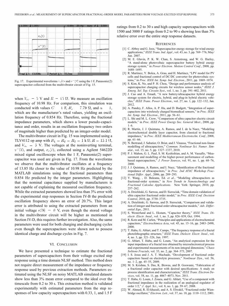
Fig. 17. Experimental waveforms and using the 1 F, Panasonic(2)supercapacitor collected from the multivibrator circuit of Fig. 15.
when V and . We measure an oscillationfrequency of 10.98 Hz. For comparison, this simulation wasconducted with values F, , and ,which are the manufacturer’s rated values, yielding an oscil-lation frequency of 0.854 Hz. Therefore, using the fractionalimpedance parameters, which shows a lower pseudo-capaci-tance and order, results in an oscillation frequency two ordersof magnitude higher than predicted by an integer-order model.The multivibrator circuit in Fig. 15 was implemented using a
TLV4112 op amp with k ,and V. The voltages at the noninverting terminal,
, and output, , collected using a Agilent 54622Dmixed signal oscilloscope when the 1 F, Panasonic(2) super-capacitor was used are given in Fig. 17. From the waveformswe observe that the multivibrator oscillates at a frequencyof 13.85 Hz closer to the value of 10.98 Hz predicted by theMATLAB simulations using the fractional parameters than0.854 Hz predicted by the integer parameters. Highlightingthat the nominal capacitance supplied by manufacturers isnot capable of explaining the measured oscillation frequency.While the extracted parameters showed less than 3% error withthe experimental step responses in Section IV-B the predictedoscillation frequency shows an error of 20.7%. This largererror is attributed to using the extracted parameters from aninitial voltage V, even though the stored voltagein the multivibrator circuit will be higher as mentioned inSection IV-D, this requires further investigation. Also, the sameparameters were used for both charging and discharging cycleseven though the supercapacitors were shown not to possessidentical charge and discharge cycles in Fig. 7.
VI. CONCLUSION
We have presented a technique to estimate the fractionalparameters of supercapacitors from their voltage excited stepresponse using a time domain NLSF method. This method doesnot require direct measurement of the impedance or frequencyresponse used by previous extraction methods. Parameters es-timated using the NLSF on noisy MATLAB simulated datasetsshow less than 3% mean error compared to the ideal over thetimescale from 0.2 to 30 s. This extraction method is validatedexperimentally with estimated parameters from the step re-sponses of low capacity supercapacitors with 0.33, 1, and 1.5 F
ratings from 0.2 to 30 s and high capacity supercapacitors with1500 and 3000 F ratings from 0.2 to 90 s showing less than 3%relative error over the entire step response datasets.
REFERENCES[1] C. Abbey and G. Joos, “Supercapacitor energy storage for wind energy
applications,” IEEE Trans. Ind. Appl., vol. 43, no. 3, pp. 769–776,May/Jun. 2007.
[2] M. E. Glavin, P. K. W. Chan, S. Armstrong, and W. G. Hurley,“A stand-alone photovoltaic supercapacitor battery hybrid energystorage system,” in Power Electron. Motion Control Conf., 2008, pp.1688–1695.
[3] R. Martinez, Y. Bolea, A. Grau, and H. Martinez, “LPV model for PVcells and fractional control of DC/DC converter for photovoltaic sys-tems,” in Proc. IEEE Int. Symp. Ind. Electron., 2011, pp. 1069–1074.
[4] S. Kim, K. No, and P. H. Chou, “Design and performance analysis ofsupercapacitor charging circuits for wireless sensor nodes,” IEEE J.Emerg. Sel. Top. Circuits Syst., vol. 1, no. 3, pp. 391–402, 2011.
[5] J. Cao and A. Emadi, “A new battery/ultracapacitor hybrid energystorage system for electric, hybrid, and plug-in hybrid electric vehi-cles,” IEEE Trans. Power Electron., vol. 27, no. 1, pp. 122–132, Jan.2012.
[6] A. Pandey, F. Allos, A. P. Hu, and D. Budgett, “Integration of super-capacitors into wirelessly charged biomedical sensors,” in Proc. IEEEInt. Symp. Ind. Electron., 2011, pp. 56–61.
[7] L. Shi and M. L. Crow, “Comparison of ultra capacitor electric circuitmodels,” in Proc. IEEE Power Energy Soc. General Meet., 2008, pp.1–6.
[8] R. Martin, J. J. Quintana, A. Ramos, and I. de la Nuez, “Modelingelectrochemical double layer capacitor, from classical to fractionalimpedance,” in Proc. IEEE Mediterranean Electrotechn. Conf., 2008,pp. 61–66.
[9] N. Bertrand, J. Sabatier, O. Briat, and J. Vinassa, “Fractional non-linearmodelling of ultracapacitors,” Commun. Nonlinear Sci. Numer. Sim-ulat., vol. 15, no. 5, pp. 1327–1337, 2010.
[10] P. J. Mahon, G. L. Paul, S. M. Keshishian, and A. M. Vassallo, “Mea-surement and modelling of the higher-power performance of carbon-based supercapacitors,” J. Power Sources, vol. 91, no. 1, pp. 68–76,2000.
[11] J. J. Quintana, A. Ramos, and I. Nuez, “Identification of the fractionalimpedance of ultracapacitors,” in Proc. 2nd AFAC Workshop Frac-tional Differ. Appl., 2006, pp. 289–293.
[12] Y. Wang, , D. Baleanu, Ed. et al., “Modeling ultracapacitors asfractional-order systems,” in New Trends in Nanotechnology andFractional Calculus Applications. New York: Springer, 2010, pp.257–262.
[13] A. Dzieliński, G. Sarwas, andD. Sierociuk, “Time domain validation ofultra capacitor fractional order model,” in Proc. IEEE Conf. DecisionControl, 2010, pp. 3730–3735.
[14] A. Dzieliński, G. Sarwas, and D. Sierociuk, “Comparison and valida-tion of integer and fractional order ultracapacitor models,” Adv. Differ-ential Equ., 2011.
[15] S. Westerlund and L. Ekstam, “Capacitor theory,” IEEE Trans. Di-electr. Electr. Insul., vol. 1, no. 5, pp. 826–839, Oct. 1994.
[16] R. Kotz andM. Carlen, “Principles and applications of electrochemicalcapacitors,” Electrochimica Acta, vol. 45, no. 15–16, pp. 2483–2498,2000.
[17] T. Haba, G. Ablart, and T. Camps, “The frequency response of a fractalphotolithographic structure,” IEEE Trans. Dielectr. Electr. Insul., vol.4, no. 3, pp. 321–326, Jun. 1997.
[18] G. Ablart, T. Haba, and G. Loum, “An analytical expression for theinput impedance of a fractal tree obtained by microelectronical processand experimental measurements of its non-integral dimension,” ChaosSolitons Fractals, vol. 33, no. 2, pp. 364–373, 2007.
[19] I. S. Jesus and J. A. T. Machado, “Development of fractional ordercapacitors based on electrolyte processes,” Nonlinear Dyn., vol. 56,no. 1–2, pp. 45–55, 2009.
[20] M. S. Krishna, S. Das, K. Biswas, and B. Goswami, “Fabrication ofa fractional order capacitor with desired specifications: A study onprocess identification and characterization,” IEEE Trans. Electron De-vices, vol. 58, no. 11, pp. 4067–4073, Nov. 2011.
[21] T. Haba, G. Loum, J. Zoueu, and G. Ablart, “Use of a component withfractional impedance in the realization of an analogical regulator oforder 1/2,” J. Appl. Sci., vol. 8, no. 1, pp. 59–67, 2008.
[22] W. Ahmed, R. El-khazali, and A. S. Elwakil, “Fractional-order Wien-bridge oscillator,” Electron. Lett., vol. 37, no. 18, pp. 1110–1112, 2001.
376 IEEE JOURNAL ON EMERGING AND SELECTED TOPICS IN CIRCUITS AND SYSTEMS, VOL. 3, NO. 3, SEPTEMBER 2013
[23] B. Maundy, A. Elwakil, and S. Gift, “On a multivibrator that employs afractional capacitor,” Analog Integr. Circuits Signal Process., vol. 62,no. 1, pp. 99–103, 2010.
[24] D. Baleanu, Z. B. Guvenc, and J. A. T. Machado, “Analysis of the frac-tional dynamics of an ultracapacitor and its application to a buck-boostconverter,” in New Trends Nanotechnology and Fractional CalculusApplications. New York: Springer, 2010, pp. 97–105.
[25] T. J. Freeborn, B. Maundy, and A. S. Elwakil, “Fractional-stepTow-Thomas biquad filters,” Nonlinear Theory Appl., vol. 3, no. 3,pp. 357–374, 2012.
[26] A. S. Elwakil, “Fractional-order circuits and systems: An emerging in-terdisciplinary research area,” IEEE Circuits Syst. Mag., vol. 10, no. 4,pp. 40–50, 2010.
[27] I. Podlubny, Fractional Differential Equations. San Diego, CA: Aca-demic, 1999.
[28] Modeling Coilcraft RF Inductors—Document 158-1 [Online]. Avail-able: http://www.coilcraft.com Coilcraft
[29] I. Schafer and K. Kruger, “Modelling of lossy coils using fractionalderivatives,” J. Phys. D: Appl. Phys., vol. 41, 2008.
[30] A. Shamim, A. G. Radwan, and K. N. Salama, “Fractional smith charttheory,” IEEE Microw. Wireless Compon. Lett., vol. 21, no. 3, pp.117–119, Mar. 2011.
[31] A. G. Radwan, A. M. Soliman, and A. S. Elwakil, “Fractional-ordersinusoidal oscillators: Design procedure and practical examples,” IEEETrans. Circuits Syst. I Reg. Papers, vol. 55, no. 7, pp. 2051–2063, Aug.2008.
[32] A. G. Radwan and K. N. Salama, “Fractional-order RC and RL cir-cuits,” Circuits Syst. Signal Process., vol. 31, no. 6, pp. 1901–1915,2012.
[33] K. Moaddy, A. G. Radwan, K. N. Salama, S. Momani, and I. Hashim,“The fractional-order modelling and synchronization of electricallycoupled neuron systems,” Comput. Math. Appl., vol. 64, no. 10, pp.3329–3339, 2012.
[34] A. G. Radwan and A. S. Elwakil, “Transient-time fractional-spacetrigonometry and application,” in Springer Lecture Notes in ComputerScience, T. Huang, Ed. Heidelberg, Germany: Springer, 2012, vol.7663, pp. 40–47.
[35] I. Podlubny, “Mittag-Leffler function,” Matlab Central File Exchange,Submission #8738 vol. 17, Oct. 2005.
[36] T. J. Freeborn, B. Maundy, and A. S. Elwakil, “Least squares estima-tion technique of Cole-Cole parameters from step response,” Electron.Lett., vol. 38, no. 13, pp. 752–754, 2012.
[37] I. Podlubny, I. Petras, and T. Skovranek, “Fitting of experimental datausing Mittag-Leffler function,” in Proc. 13th Int. Carpathian ControlConf., 2012, pp. 578–581.
[38] I. Petras, D. Sierociuk, and I. Podlubny, “Identification of parametersof a half-order system,” IEEE Trans. Signal Process., vol. 60, no. 10,pp. 5561–5566, Oct. 2012.
[39] D. Sierociuk, I. Podlubny, and I. Petras, “Experimental evidence ofvariable-order behaviour of ladders and nested ladders,” IEEE Trans.Control Syst. Technol., vol. 21, no. 2, pp. 459–466, Mar. 2013.
[40] T. Coleman and Y. Li, “An interior, trust region approach for nonlinearminimization subject to bounds,” SIAM J. Opt., vol. 6, pp. 418–445,1996.
[41] P. Kurzweil, M. Chwistek, and R. Galley, “Electrochemical and spec-troscopic studies on rated capacitance and aging mechanisms of super-capacitors,” in Proc. 2nd Eur. Symp. Supercapacitors Appl., 2006.
[42] Electric double layer capacitor (gold capacitor)/SD-EEC-4 Panasonic,Nov. 2012 [Online]. Available: http://industrial.panasonic.com
[43] Electric double layer capacitors ‘dynacap’ Elna, 2013 [Online]. Avail-able: http://www.elna.co.jp
[44] PowerStor coin cell supercapacitors KR series—Data sheet 4327Cooper–Bussmann [Online]. Available: http://www.cooperindus-tries.com
[45] PowerStor supercapacitors PMseries—Data sheet 4308 Cooper–Buss-mann [Online]. Available: http://www.cooperindustries.com
[46] PowerStor supercapacitors PB Series—Data sheet 4393 Cooper–Buss-mann [Online]. Available: http://www.cooperindustries.com
[47] K2 Series Ultra capacitors—Document number 1015370.3 MaxwellTechnol. [Online]. Available: http://www.maxwell.com
Todd J. Freeborn (S’12) received the B.Sc. andM.Sc. degrees, in 2008 and 2010, respectively, fromthe University of Calgary, Calgary, AB, Canada,where he is currently working toward the Ph.D.degree in electrical engineering.His research interests include the investigation of
fractional-order circuits and systems, specifically infractional-step analog filters for signal processing andthe indirect measurement of fractional impedances.
Brent Maundy (M’97) received the B.Sc. degreein electrical engineering and the M.Sc. degree inelectronics and instrumentation, in 1983 and 1986,respectively, from the University of the West Indies,Trinidad, and the Ph.D. degree in electrical engi-neering from Dalhousie University, Halifax, NS,Canada, in 1992.He completed a one-year postdoctoral fellow at
Dalhousie University, Halifax, NS, Canada, wherehe was actively involved in its analog microelec-tronics group. Subsequent to that he taught at the
University of the West Indies, and was a visiting Professor at the University ofLouisville for seven months. He later worked in the defence industry for twoyears on mixed signal projects. In 1997 he joined the Department of Electricaland Computer Engineering at the University of Calgary where he is currentlya Professor. His current research is in the design of linear circuit elementdesign, high-speed amplifier design, fractional circuits and systems, activeanalog filters, and CMOS circuits for signal processing and communicationapplications.Dr. Maundy is a past Associate Editor for the IEEE TRANSACTIONS ON
CIRCUITS AND SYSTEMS I.
Ahmed Elwakil (SM’05) was born in Cairo, Egypt.He received the B.Sc. andM.Sc. degrees from theDe-partment of Electronics and Communications fromCairo University, Cairo, Egypt, and the Ph.D. degreefrom the Department of Electrical and Electronic En-gineering at the National University of Ireland, Uni-versity College Dublin.Since September 2000, He has been with the De-
partment of Electrical and Computer Engineering,Sharjah University, United Arab Emirates, wherehe is currently an Associate Professor. His research
interests are primarily in the areas of circuit theory, nonlinear dynamics, chaostheory, and fractional-order circuits where he has authored and coauthoredover 90 publications in these areas. He has served as a reviewer and reviewcommittee member for many journals and numerous international conferences.He serves on the Editorial Boards of the International Journal of Circuit Theoryand Applications and the Journal of Electrical and Computer Engineering. Hecurrently also serves as an Associate Editor for the Dynamics of Continuous,Discrete and Impulsive Systems: Series-B and the newly launched IEICENonlinear Theory and its Applications.Dr. Elwakil is an Associate Member of the Centre for Chaos Control and
Synchronization at the City University of Hong Kong. He has also served asan instructor for a number of courses on basic VLSI design organized by theUnited Nations University (UNU) and the International Centre for TheoreticalPhysics (ICTP), where he is also an associate member. He is a member of theUAE Society of Engineers Advisory Committee and was awarded the EgyptianGovernment first-class medal for achievements in Engineering Sciences in 2003and 2009.