Embed Size (px)
Citation preview
IEEE JOURNAL ON SELECTED AREAS IN COMMUNICATIONS, VOL. 23, NO. 1, JANUARY 2005 51
Synchronization and Packet Separation in WirelessAd Hoc Networks by Known Modulus Algorithms
Relja Djapic, Alle-Jan van der Veen, Senior Member, IEEE, and Lang Tong, Senior Member, IEEE
Abstract—In mobile asynchronous ad hoc networks, multipleusers may transmit packets at the same time. If a collision occurs,then in current systems both packets are lost and need to be re-transmitted, reducing the overall throughput. To mitigate this, weconsider to extend the receiver with a small antenna array, so thatit can suppress interfering signals. To characterize the signal ofinterest, we propose to modulate it at the symbol rate by a knownamplitude variation. This allows the corresponding multichannelreceiver to estimate the beamformer weights that will suppress theinterfering sources. We introduce “known modulus algorithms”to achieve this. We also derive synchronization algorithms toestimate the offset of the desired packet in an observation window,among interfering data packets. The algorithms are illustrated viasimulations.
Index Terms—Ad hoc networks, blind source separation, knownmodulus algorithm (KMA), packet offset estimation, synchroniza-tion.
I. INTRODUCTION
AKEY limiting factor on the throughput of wirelessnetworks is packet collisions among uncoordinated
transmitters. Conventionally, medium access control (MAC)protocols are used to schedule transmissions either in a deter-ministic fashion [e.g., time-division multiple access (TDMA),frequency-division multiple access (FDMA), or code-divisionmultiple access (CDMA)] or by random access protocols suchas Aloha and carrier sense multiple access (CSMA). For ad hocnetworks, however, the absence of base stations and the neces-sity of distributed MAC requires some form of random access,and avoiding collisions is difficult. Even more challenging isthe so-called hidden/exposed terminal problem that severelylimits the effectiveness of techniques based on carrier sensing.Although the use of clear-to-send–ready-to-send (CTS-RTS)exchange along with busy tone [3] can eliminate collisions[4], such protocols are vulnerable to interference from otherservices.
Recent advances in antenna array processing and space–timecoding challenge the fundamental premise of the classical ap-proach to MAC that prohibits the simultaneous transmission ofdifferent users. Specifically, various algorithms have been de-veloped in the past decade that allow the separation of multiple
Manuscript received October 22, 2003; revised August 10, 2004. This workwas supported in part by the Dutch Ministry of Economic Affairs/Mininistryof Education Freeband-Impulse under Project DTC.5961 Airlink and in part byNWO-STW under the VICI Program DTC.5893.
R. Djapic and A. J. van der Veen are with the Department of Electrical En-gineering, Delft University of Technology, 2628 CD Delft, The Netherlands(e-mail: [email protected]; [email protected]).
L. Tong is with the Department of Electrical Engineering, Cornell University,Ithaca, NY 14853 USA (e-mail: [email protected]).
Digital Object Identifier 10.1109/JSAC.2004.837367
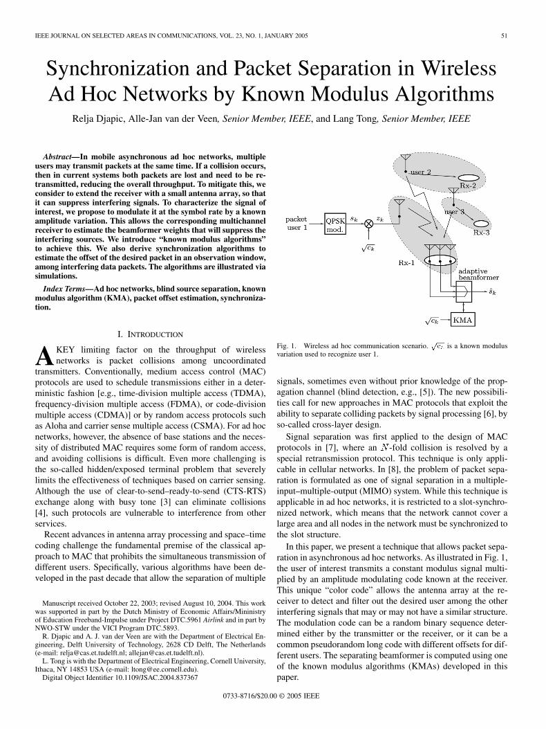
Fig. 1. Wireless ad hoc communication scenario.pc is a known modulus
variation used to recognize user 1.
signals, sometimes even without prior knowledge of the prop-agation channel (blind detection, e.g., [5]). The new possibili-ties call for new approaches in MAC protocols that exploit theability to separate colliding packets by signal processing [6], byso-called cross-layer design.
Signal separation was first applied to the design of MACprotocols in [7], where an -fold collision is resolved by aspecial retransmission protocol. This technique is only appli-cable in cellular networks. In [8], the problem of packet sepa-ration is formulated as one of signal separation in a multiple-input–multiple-output (MIMO) system. While this technique isapplicable in ad hoc networks, it is restricted to a slot-synchro-nized network, which means that the network cannot cover alarge area and all nodes in the network must be synchronized tothe slot structure.
In this paper, we present a technique that allows packet sepa-ration in asynchronous ad hoc networks. As illustrated in Fig. 1,the user of interest transmits a constant modulus signal multi-plied by an amplitude modulating code known at the receiver.This unique “color code” allows the antenna array at the re-ceiver to detect and filter out the desired user among the otherinterfering signals that may or may not have a similar structure.The modulation code can be a random binary sequence deter-mined either by the transmitter or the receiver, or it can be acommon pseudorandom long code with different offsets for dif-ferent users. The separating beamformer is computed using oneof the known modulus algorithms (KMAs) developed in thispaper.
0733-8716/$20.00 © 2005 IEEE
52 IEEE JOURNAL ON SELECTED AREAS IN COMMUNICATIONS, VOL. 23, NO. 1, JANUARY 2005
The idea of modulus variations to assist capture of the desireduser goes back to Treichler and Larimore [9], who also derivedthe first (iterative) KMA. More recently, the idea was picked upagain in [10] and [11] for the purpose of multiuser interferencecancellation, and, independently, by us in [1] and [2] for theseparation of finite duration packets.
In general, KMA requires neither slot synchronization norany coordination among transmitters, which makes its appli-cation in an uncontrolled environment such as wireless localarea network (WLAN) or mobile ad hoc networks (MANETs)particularly attractive. In the context of WLANs, it is inter-esting to note that the required amplitude modulations can beso small that they are not perceived by legacy receivers, makingthe system upward compatible.
From a source separation point of view, amplitude modu-lation is just one way to mark users of interest, and severalother techniques could play a role. Spread-spectrum techniquessuch as CDMA would be possible but reduce the data rates.User-specific training sequences have disadvantages in asyn-chronous systems. For instantaneous channels, general blindtechniques such as iterative least-squares with projection (ILSP)[12] and ACMA [13] are applicable, but not efficient since weare interested in only one user. Several modulation approacheshave been proposed in the literature. Stochastic techniques suchas “transmitter induced cyclostationarity,” initially derived forsingle user blind equalization [14]–[16] have recently been ex-tended to multiuser convolutive channels [17] and orthogonalfrequency-division multiplexing (OFDM) [18]. A deterministicversion of such a technique, using phase modulation codes, wasproposed for source separation in MANETs [19] (this paper re-lates to several ideas proposed in [1] and also offers a throughputanalysis which, therefore, we omit here). Another example of adeterministic source separation technique is [20], but it needsmultiple transmit antennas per source (spatial redundancy).
Our objective here is to derive a system that is simpler thanACMA and other blind techniques, does not reduce the capacity,and only finds the desired user. We consider a scenario whereusers can transmit packages at arbitrary moments, and assumethat the receiver knows the modulation code and packet lengthof the user of interest. We collect a block of data from an obser-vation window, and aim to detect the presence of a packet fromthe user of interest, estimate its offset within the window, andestimate the beamformer by which this packet can be receivedwhile suppressing the interfering packets. Some of these resultswere presented by us at conferences [1], [2]; the present paperoffers a more in-depth discussion.
The structure of the paper is as follows. In Section II, we in-troduce the communication scenario and resulting data model.Section III derives the basic KMA algorithm, assuming syn-chronization is available, and corresponding simulations. Sub-sequently, in Section IV, we present algorithms for estimatingthe packet offset, and corresponding simulations.
II. DATA MODEL
We assume the situation in Fig. 1 where several users occupya common wireless channel. For simplicity, the channel is as-sumed to be narrowband. The potential number of users is un-limited, but the offered network load is fixed. User 1 is the de-
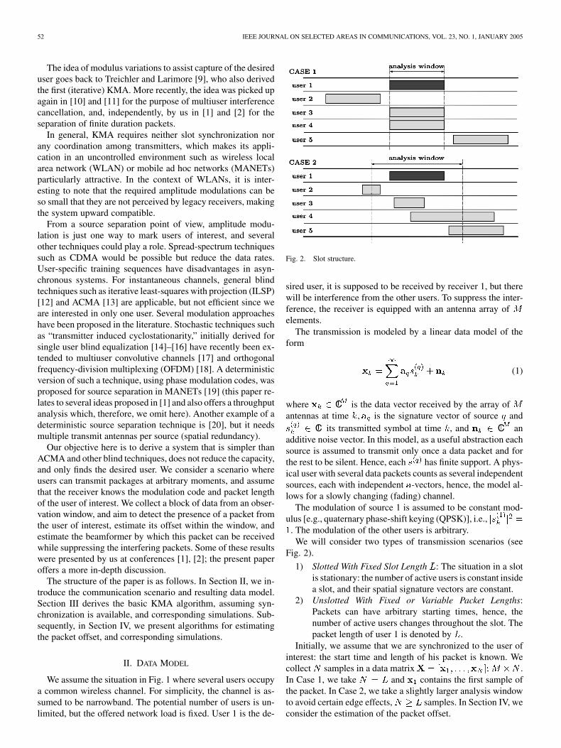
Fig. 2. Slot structure.
sired user, it is supposed to be received by receiver 1, but therewill be interference from the other users. To suppress the inter-ference, the receiver is equipped with an antenna array ofelements.
The transmission is modeled by a linear data model of theform
(1)
where C is the data vector received by the array ofantennas at time is the signature vector of source and
C its transmitted symbol at time , and C anadditive noise vector. In this model, as a useful abstraction eachsource is assumed to transmit only once a data packet and forthe rest to be silent. Hence, each has finite support. A phys-ical user with several data packets counts as several independentsources, each with independent -vectors, hence, the model al-lows for a slowly changing (fading) channel.
The modulation of source 1 is assumed to be constant mod-ulus [e.g., quaternary phase-shift keying (QPSK)], i.e.,
. The modulation of the other users is arbitrary.We will consider two types of transmission scenarios (see
Fig. 2).
1) Slotted With Fixed Slot Length : The situation in a slotis stationary: the number of active users is constant insidea slot, and their spatial signature vectors are constant.
2) Unslotted With Fixed or Variable Packet Lengths:Packets can have arbitrary starting times, hence, thenumber of active users changes throughout the slot. Thepacket length of user 1 is denoted by .
Initially, we assume that we are synchronized to the user ofinterest: the start time and length of his packet is known. Wecollect samples in a data matrix .In Case 1, we take and contains the first sample ofthe packet. In Case 2, we take a slightly larger analysis windowto avoid certain edge effects, samples. In Section IV, weconsider the estimation of the packet offset.
DJAPIC et al.: SYNCHRONIZATION AND PACKET SEPARATION IN WIRELESS AD HOC NETWORKS BY KMAs 53
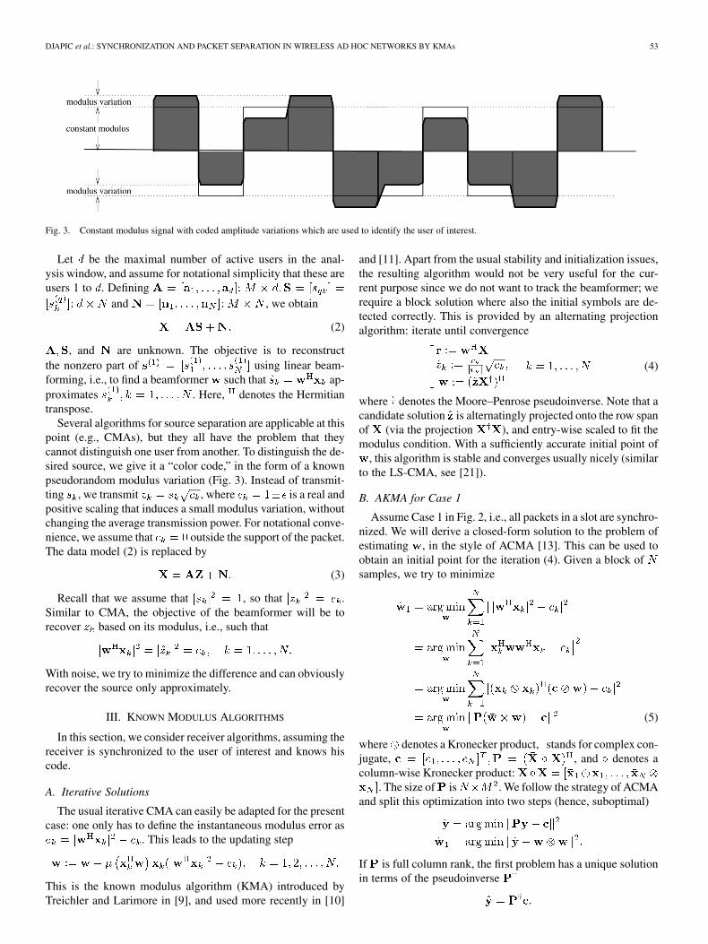
Fig. 3. Constant modulus signal with coded amplitude variations which are used to identify the user of interest.
Let be the maximal number of active users in the anal-ysis window, and assume for notational simplicity that these areusers 1 to . Defining
and , we obtain
(2)
, and are unknown. The objective is to reconstructthe nonzero part of using linear beam-forming, i.e., to find a beamformer such that ap-proximates . Here, denotes the Hermitiantranspose.
Several algorithms for source separation are applicable at thispoint (e.g., CMAs), but they all have the problem that theycannot distinguish one user from another. To distinguish the de-sired source, we give it a “color code,” in the form of a knownpseudorandom modulus variation (Fig. 3). Instead of transmit-ting , we transmit , where is a real andpositive scaling that induces a small modulus variation, withoutchanging the average transmission power. For notational conve-nience, we assume that outside the support of the packet.The data model (2) is replaced by
(3)
Recall that we assume that , so that .Similar to CMA, the objective of the beamformer will be torecover based on its modulus, i.e., such that
With noise, we try to minimize the difference and can obviouslyrecover the source only approximately.
III. KNOWN MODULUS ALGORITHMS
In this section, we consider receiver algorithms, assuming thereceiver is synchronized to the user of interest and knows hiscode.
A. Iterative Solutions
The usual iterative CMA can easily be adapted for the presentcase: one only has to define the instantaneous modulus error as
. This leads to the updating step
This is the known modulus algorithm (KMA) introduced byTreichler and Larimore in [9], and used more recently in [10]
and [11]. Apart from the usual stability and initialization issues,the resulting algorithm would not be very useful for the cur-rent purpose since we do not want to track the beamformer; werequire a block solution where also the initial symbols are de-tected correctly. This is provided by an alternating projectionalgorithm: iterate until convergence
(4)
where denotes the Moore–Penrose pseudoinverse. Note that acandidate solution is alternatingly projected onto the row spanof (via the projection ), and entry-wise scaled to fit themodulus condition. With a sufficiently accurate initial point of
, this algorithm is stable and converges usually nicely (similarto the LS-CMA, see [21]).
B. AKMA for Case 1
Assume Case 1 in Fig. 2, i.e., all packets in a slot are synchro-nized. We will derive a closed-form solution to the problem ofestimating , in the style of ACMA [13]. This can be used toobtain an initial point for the iteration (4). Given a block ofsamples, we try to minimize
(5)
where denotes a Kronecker product, stands for complex con-jugate, , and denotes acolumn-wise Kronecker product:
. The size of is . We follow the strategy of ACMAand split this optimization into two steps (hence, suboptimal)
If is full column rank, the first problem has a unique solutionin terms of the pseudoinverse

54 IEEE JOURNAL ON SELECTED AREAS IN COMMUNICATIONS, VOL. 23, NO. 1, JANUARY 2005
With this solution and setting , where “unvec”denotes an unstacking of a vector into a square matrix, we cansolve the second problem as
the solution of which is given in terms of the dominant eigen-vector of , scaled by the square root of the correspondingeigenvalue.
We see that, if is full rank, the algorithm becomes partic-ularly simple, and in the noise-free case will produce the exactseparating beamformer to recover the desired packet. If is notof full column rank, then there will exist additional solutions
to (where is an all-zero vector), which will addto the desired solution , producing a result thatcannot be factored. We, thus, need to study the rank propertiesof . This is done in Section III-D.
C. AKMA for Case 2 (Known Offset)
In Case 2 in Fig. 2, users are not slotted. We first assumefor simplicity that the base station is synchronized to user 1.Estimation of the offset is done in Section IV.
If the analysis window length is chosen to be the sameas the packet length , then the algorithm is the same as inSection III-B. If is larger than , the packet has leading and/ortrailing zeros. This can be modeled by defining
where the total number of zeros is and the offset of thecode matches the offset of the packet in the analysis window.After this, the algorithm is as in Section III-B.
D. Rank of for Case 1
We consider the rank of for Case 1 (all users synchronized)in the noise-free case, where . To recover usinglinear beamforming, we need to be tall and fullrank. In this case, has rank . has size , and
, where has size andis full rank, and has size . The rank of is equalto the rank of , therefore, it cannot exceed . A necessarycondition for to have rank is .
If and , then can be full rank. If ,then is not full rank, but can be made full rank by a prefilteringstep (cf. [13] and [22]). Compute the singular value decomposi-tion (SVD) of , i.e., , where is unitary,
is positive diagonal, and is unitary, then wecan replace by
which has rows and is of full rank. Note that due to theprewhitening, satisfies a model , where isand asymptotically unitary (for large ). From now on, weassume that the prewhitening has been performed and that,therefore, (we omit the underscore from the notation).
Even after the prefiltering, there are cases where is singular,namely, when at least two other sources are constant modulus(or equal-modulus). Indeed, if and
are constant-modulus, then ,and
Here, is a vector with all entries equal to “1.” To avoid thisnullspace solution, all sources (except perhaps one) should haveamplitude modulations. In Case 1, this level of cooperation isreasonable to assume.
We can show that if the sources are statistically indepen-dent constant modulus sources, all modulated by binary randompower modulations , then as becomes large,converges to its expected value
(6)
where
where is the identity matrix. For the proof, see the Appendix.The eigenvalues of are
(7)
For the proof, see again the Appendix. These are also theeigenvalues of since is asymptotically unitary afterprewhitening. Thus, the singular values of converge to
(8)
The smallest singular value of is raised by the modulationfrom 0 to . If is not too small, will be left invertible,so that will lead to the correct solution. It can also beverified that these singular values carry important information:truncating them to zero leads to the wrong result.
E. Rank of for Case 2
In Case 2, there are additional situations, where becomessingular, namely, when two sources are nonoverlapping in time.Indeed, suppose are such that
. Then, , hence
Thus, solutions to can be written as
for arbitrary scalars , and an arbitrary selected fromthe solution space cannot be factored into . We see twosolutions for this problem. First, we can writeas
DJAPIC et al.: SYNCHRONIZATION AND PACKET SEPARATION IN WIRELESS AD HOC NETWORKS BY KMAs 55
Fig. 4. Summary of AKMA and the complexity of the algorithm. L is thepacket length.
where is a permutation of . Similarly, if we take a basisof the null space of , it can be written as
where are diagonal matrices (with their first entry equalto 0). The problem boils down to a joint diagonalization of un-symmetric matrices, or a joint Schur decomposition, which canbe solved using Jacobi iterations [13].
Alternatively, we try to avoid the joint diagonalization step.If we have sufficiently large and do prewhitening, then isapproximately unitary, and the are approximately orthogonalto each other. Hence, the desired solution is orthogonalto the null space of . In this case, we can simply set
With noise, will not be exactly singular, and we will have toset a threshold on the pseudoinverse: compute the SVD ofas , let be the submatrix containing thesingular values of larger than a threshold, and let bethe corresponding left and right singular vectors. The solutionto which is orthogonal to the (approximate) null spaceof is then given by . As is clear from (8),the threshold on the singular values of should be smaller than
.In Case 2, it may also happen that only a few samples of
the desired packet are disturbed by the head or tail of anothersource, but with insufficient samples present to estimate thatsource reliably. A convenient solution that avoids this problem isto increase the analysis window to be larger than the packetlength , with the desired packet located in the center of theanalysis window. In that case, if a disturbing source overlapsthe desired packet, it will have at least samples inthe analysis window, sufficient to detect it.
Fig. 4 lists the algorithm as used in the simulations.
F. Simulations-Known Timing
We test the algorithm on simulated data. In these simulations,the receiver knows the code of the desired user, and it knows thetiming of this user.
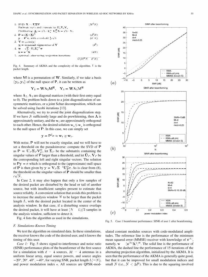
Case 1: Fig. 5 shows signal-to-interference and noise ratio(SINR) performance plots of the beamformer of the first sourcefor a simulation with sources, antennas in auniform linear array, equal source powers, and source angles
, for varying SNR, packet length ,and power modulation index . All sources are QPSK-mod-
Fig. 5. Case 1 beamformer performance: SINR of user 1 after beamforming.
ulated constant modulus sources with code-modulated ampli-tudes. The reference line is the performance of the minimummean squared error (MMSE) receiver with knowledge of ,namely, . The solid line is the performance ofAKMA, the dashed line the performance of 15 iterations of thealternating projection algorithm, initialized by the AKMA. It isseen that the performance of the AKMA is generally quite good,but that it can be improved for small modulation indices andsmall (i.e., ). This is due to the squaring involved
56 IEEE JOURNAL ON SELECTED AREAS IN COMMUNICATIONS, VOL. 23, NO. 1, JANUARY 2005
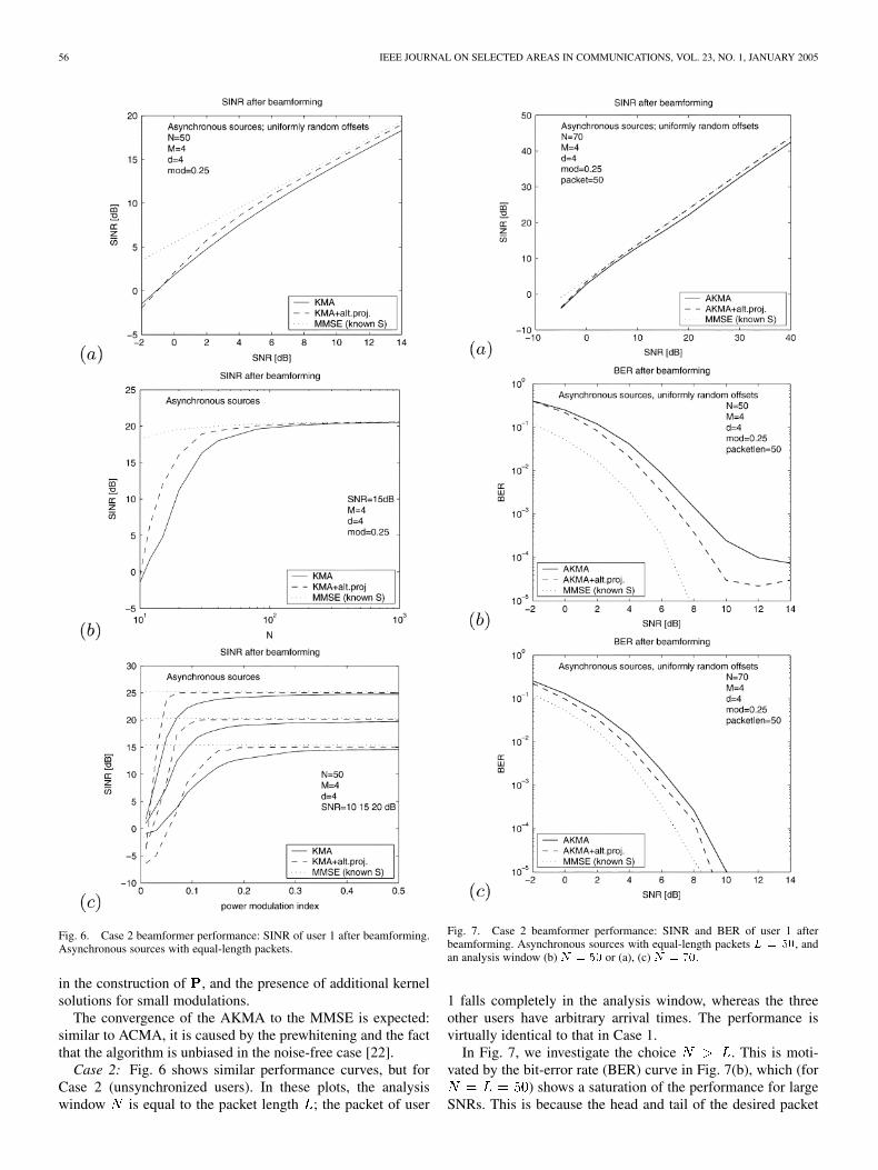
Fig. 6. Case 2 beamformer performance: SINR of user 1 after beamforming.Asynchronous sources with equal-length packets.
in the construction of , and the presence of additional kernelsolutions for small modulations.
The convergence of the AKMA to the MMSE is expected:similar to ACMA, it is caused by the prewhitening and the factthat the algorithm is unbiased in the noise-free case [22].
Case 2: Fig. 6 shows similar performance curves, but forCase 2 (unsynchronized users). In these plots, the analysiswindow is equal to the packet length ; the packet of user
Fig. 7. Case 2 beamformer performance: SINR and BER of user 1 afterbeamforming. Asynchronous sources with equal-length packets L = 50, andan analysis window (b) N = 50 or (a), (c) N = 70.
1 falls completely in the analysis window, whereas the threeother users have arbitrary arrival times. The performance isvirtually identical to that in Case 1.
In Fig. 7, we investigate the choice . This is moti-vated by the bit-error rate (BER) curve in Fig. 7(b), which (for
) shows a saturation of the performance for largeSNRs. This is because the head and tail of the desired packet
DJAPIC et al.: SYNCHRONIZATION AND PACKET SEPARATION IN WIRELESS AD HOC NETWORKS BY KMAs 57
can be disturbed by the tail of another source, but with insuffi-cient samples present to estimate that source reliably. Fig. 7(c)shows that increasing the analysis window to im-proves the BER for large SNRs. Fig. 7(a) shows the SINR per-formance for , which can be compared with Fig. 6(a),where .
IV. JOINT OFFSET AND BEAMFORMER ESTIMATION
In the previous section, we assumed that the receiver was syn-chronized to the user of interest. Now, we consider the situationwhere the receiver is not synchronized, e.g., the users transmitpackets at random moments. We assume that the receiver col-lects a batch of samples, where , and introduce analgorithm to estimate the offset of the packet of the desired userwithin this analysis window, as well as a beamformer to cancelthe interference. Introduce as the unknown packet offset. Sim-ilar to (5), we now have to compute a beamformer and offset
such that
(9)
For simplicity, we first assume that is an integer, and derivecorresponding algorithms in Section IV-A. In Section IV-D, weextend this to arbitrary noninteger delays, which can be esti-mated if oversampling is considered.
A. Integer Offset Estimation
Let user 1 with code be the user of in-terest. We consider the case where the packet falls completelywithin the analysis window, , and the packet offset isan integer. Our aim is to compute
Here
is a vector of length , and the matrix is constructed from thereceived data in the same way as in Section III-B. As before, wecontinue with a two-step optimization problem
and solve the first problem, which asks for joint estimation ofand . Similar to the derivation of the SI-JADE algorithm [23],we exploit the fact that a delay in time domain corresponds to aphase progression in frequency domain. This can be expressedas
where is the discrete Fourier transform (DFT) matrix,represents an entrywise multiplication (Schur–Hadamard
product)
and . The vector is the unshifted code vectorfollowed by zeros. Our objective will be to estimatebased on the shift-invariance structure exhibited by the vector
. This then immediately determines the offset . A similar ap-proach was considered in the SI-JADE algorithm [23] for jointangle-delay estimation.
Thus, apply to the equation to obtain
(10)
where and . Dividing the rows of withthe corresponding entries of the vector , we arrive at
(11)
where is known and the vector is aknown function of the unknown delay . Here, “diag” maps avector into a diagonal matrix. The above pointwise division putsa design constraint on the code: it should be chosen such that(after zero padding to length ) it does not contain small valuesin the DFT domain.
Equation (11) can be treated in several different ways. Es-sentially, we have to search for a vector in the column span of
that has the structure exhibited by , i.e., a shift invariancestructure. Obviously, a MUSIC-type search is applicable: ifis a basis for the dominant column span of , then
(12)
The optimum is found by searching over a coarse grid, selectingthe best interval, and subsequently refining if a higher resolu-tion is required. For integer values of , the rows are actuallyrows of the inverse fast Fourier transform (FFT) matrix and,hence, we can implement the coarse search over integer valuesof by applying an inverse FFT to . Hence, we simply haveto find the row of with maximal norm. Essentially, thealgorithm has at this point performed a deconvolution with thedesired code, implemented in frequency domain. The MUSIC-type algorithm shows good performance in simulations. Besidesthe processing steps described in Fig. 4, the additional com-plexity due to the synchronization step is given by the FFT ofand inverse fast Fourier transform (IFFT) of ,division by the user’s code , and computation of the normof the first rows . The complexity of the synchroniza-tion part is, therefore, of order .
B. Estimation of Signal Parameters Via Rotational InvarianceTechnique (ESPRIT)-Like Algorithms
To avoid the search, we can also implement an ESPRIT-likealgorithm, where the difference is that, here, we expect only asingle column in the column span of with shift-invariancestructure, whereas in ESPRIT all columns have such a structure.

58 IEEE JOURNAL ON SELECTED AREAS IN COMMUNICATIONS, VOL. 23, NO. 1, JANUARY 2005
To this end, split into two matrices and by takingits first and last rows, respectively. We, thus, obtain
(13)
This can also be written as
(14)
which (because and are tall) is recognized as a ma-trix pencil problem. To solve it, we must first find the commoncolumn span of and . Equivalently, we can look at thenull space of .
Algorithm 1: The simplest technique to intersect the columnspan of and that of is to compute the SVD of .Indeed, from (13), we see that
(15)
Now, it is clear that after an “economy size” SVD is performedof , at least one singular value will be zero. The cor-responding basis for the null space specifies a set of candidatesolutions to (14). If and each have full column rank, thenwe can simplify immediately, since we expect only a single so-lution in the null space, which then will have the form
(16)
After finding , we can estimate the phaseshift as, which directly specifies a delay estimate . The es-
timate can be improved by performing a MUSIC-type search(12) in the vicinity of this estimate. This will be referred to as“Algorithm 1” in the simulations.
At the same time, we can set , and since ,we can estimate the separating beamformer as indicated be-fore: set , and let be the dominant eigenvectorof , scaled by the square root of the corresponding eigenvalue.This is the estimated beamformer for user 1.
The above algorithm assumed that and are full rank.Alternatively, we can work with a basis of these subspaces, ob-tained, e.g., after the “economy-size” SVDs
(17)
where we drop the small singular values and corresponding vec-tors. Similar to (15), we find
(18)
We can compute the vector ( say) in the null space of, which will have the following structure:
(19)
The vector can be computed as , and followsfrom .
Algorithm 2: Another algorithm for subspace intersection ismentioned in [24]: the common vector in the column span ofand is given by the largest left singular vector of ,the one corresponding to a singular value . Interestingly, thisvector should have the structure .By computing the vector in the intersection and matching it tothis shift-invariance structure, we have another way to compute
and, hence, the offset delay.
Let be the largest left singular vector of . Undernoise-free conditions, we have .We can estimate as in ESPRIT, by constructing andconsisting of the first and last elements of , respectively,so that . It is possible to obtain a better estimate of
by the additional limited MUSIC search using the completeknown structure of .
In each of the algorithms, the estimated beamformer can beimproved by a few iterations of an alternating projection algo-rithm as already proposed in Section III-A.
C. Simulations-Integer Timing Estimation
In the following simulations, we consider users andantennas in a uniform linear array with half-wave-
length spacing. Signals are arriving at the array with angleswith respect to the array broadside, and
with delays samples. The packet length is, while the analysis window size is . All sources
are transmitting unit amplitude constant modulus signals modu-lated by a power modulation with index . The amplitudecodes are Gold sequences in order to minimize the cross corre-lation between the codes of different users. One thousand MonteCarlo runs for each value of the input SNR were performed.
The power of the th user is defined in the region wherethe signal exists, i.e., . isthe power of user 1, the user of interest. In the simulationspresented in Fig. 8(a)–(c), all users have the same trans-mitting power, whereas in Fig. 8(d), the power of the userof interest is varied with respect to the power of the in-terfering sources. The input SNR in decibels is defined as
, where is the power of theadditive white Gaussian noise (AWGN) per receiving antenna.The SINR after beamforming is computed as
with,
where is the first column of the array manifold .
Fig. 8(a) presents the root mean square error (RMSE) of theestimated delay for user 1 for each of the proposed algorithms.Similarly, Fig. 8(b) shows the percentage of cases where thedelay offset was not estimated correctly. An estimate is labeledas failure if its rounded value is not equal to the true (integer)delay offset.
From Fig. 8(a) and (b), we see that the MUSIC search per-forms very reliable, and much better than the closed-form ES-PRIT-type algorithms. These algorithms perhaps can be used to

DJAPIC et al.: SYNCHRONIZATION AND PACKET SEPARATION IN WIRELESS AD HOC NETWORKS BY KMAs 59
Fig. 8. Case 2 (asynchronous sources). (a) RMSE of the delay estimate. (b) Percentage of incorrectly estimated delays � . (c) Output SINR of user 1 afterbeamforming (cases without failure), all users having equal power. (d) Output SINR of user 1, where its power is varied with respect to the total power of theinterfering users.
obtain coarse estimates of the delays, which can subsequentlybe refined using a MUSIC-type search over a limited interval.(At the same time, the complexity of the MUSIC-search, whenimplemented via an inverse FFT, is lower than that of the ES-PRIT-type algorithms.)
The “jump” in the performance for low SNR is typical forsubspace algorithms. These involve a nonlinear step, namely,the selection of a subspace which, for low SNR, may excludethe vector of interest.
For the cases without failure, Fig. 8(c) presents the SINR atthe output, i.e., after beamforming. The dotted line is a theo-retical reference line showing the performance of the MMSEbeamformer assuming the transmitted signals, codes and offsetsof all users are known. The statistics are computed only overthe cases without failure. The performance of the algorithmsfollows that of the MMSE estimator closely, and can be fur-ther improved with a few iterations of the alternating projectionalgorithm.
Fig. 8(d) presents the SINR after beamforming as afunction of the input signal to interference ratio
. All interfering sources have fixed unitpower, while the power of the user of interest is changed inorder to simulate a near/far scenario. The interference to noise
ratio is defined as dB,where are the total interfering and noise power,respectively. The INR is kept constant for all the SIR values inthe simulation.
D. Noninteger Offset Estimation
There are two cases where the DFT property of mapping adelay to a phase progression is accurate. The delay is a mul-tiple of the sampling period, or the signal is sampled at or aboveNyquist rate. If the signal was sampled below the Nyquist rate,aliasing occurs which destroys the shift invariance property (cf.[24]). Up to this point in the paper, we considered sampling atthe symbol rate. Since delays are, in general, noninteger, thisleads to inaccuracies when realistic data is considered. There-fore, we now consider a Case 2 scenario with noninteger delays
, and where we sample at a rate of times the symbol rate,assuming that this is above Nyquist. Since there is no need tosample much faster than Nyquist, typically, is sufficient.
The signal is an analog constant modulus signal,e.g., a phase modulated data sequence. The amplitude codesequence is an analog function , and we assume that
is sampled above Nyquist, hence, is
60 IEEE JOURNAL ON SELECTED AREAS IN COMMUNICATIONS, VOL. 23, NO. 1, JANUARY 2005
sufficiently smooth. Under these conditions, we are still in con-text of the proposed KMAs, hence, the joint delay-beamformerestimation algorithms proposed in Section IV-A are applicable.
Because of oversampling, the spectrum of the “zero delaycode” vector introduced in Section IV has most ofthe power concentrated around the zero frequency, and the spec-trum decays fast for higher frequencies. Only the samplescentered around the zero frequency are expected to have signif-icant amplitude. In the computation of , we avoid divisions bysmall values by taking only the central rows of corre-sponding to the significant part of the vector and discardingthe other rows.
The estimated delay will be a rational number. For improvedaccuracy, we propose not to round it to the nearest sample in-stant, but rather to resample the signal after shifting it over .Using Shannon’s resampling theorem, we can obtain new sam-ples at exactly , where is thesymbol period, namely
where . These samples are used for detection.
E. Simulations-Noninteger Timing Estimation
In the following simulations, we used phase-modulatedsources that employ minimum shift keying (MSK) modulation.Even if phase modulation is a nonlinear operation in general,an MSK-modulated signal can also be represented as a linearlymodulated signal1
(20)
where the symbols satisfy for evenfor odd , and the pulse shape is
otherwise
Known modulus variations (the code) are inserted over thesignal as
We consider equal-power users transmitting data packetsof equal size symbols. The receiver has antennasand employs times oversampling. The analysis windowis samples or 128 symbol periods. The delays of thetwo sources were set at .
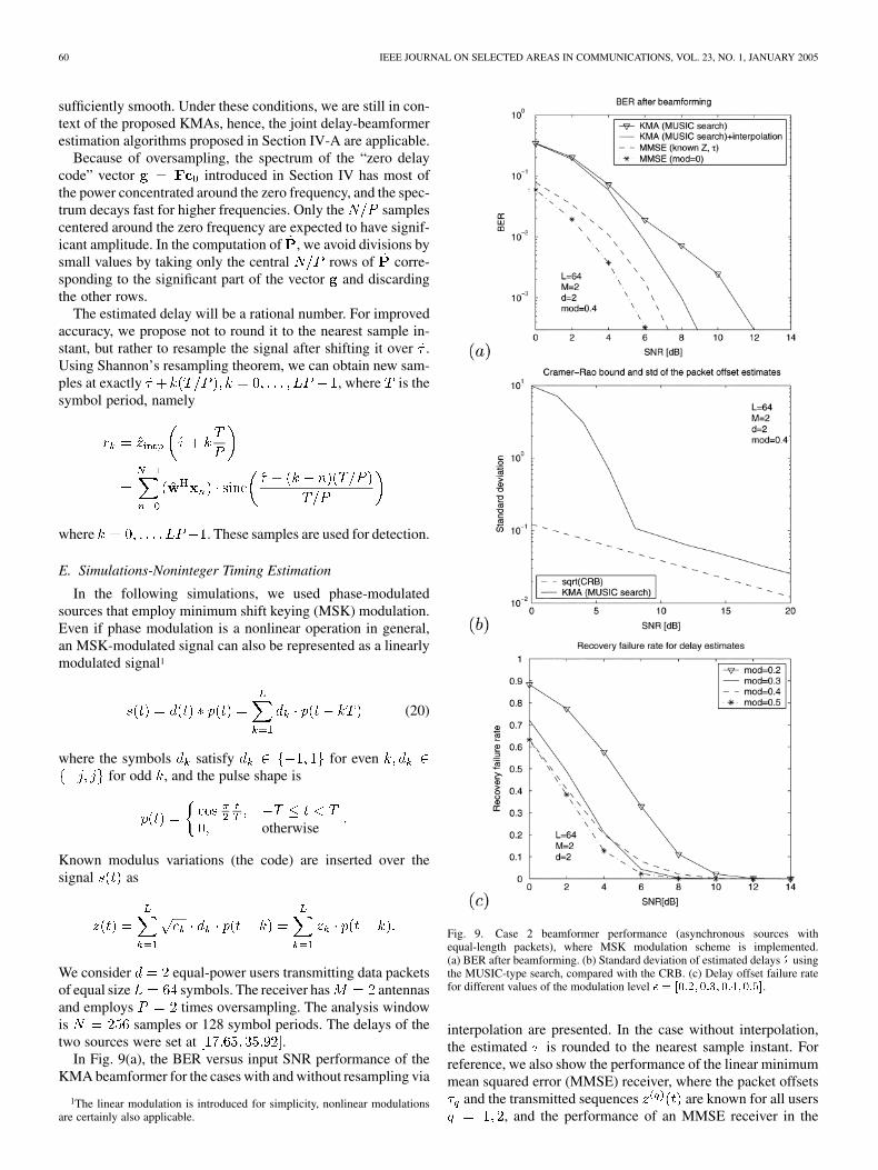
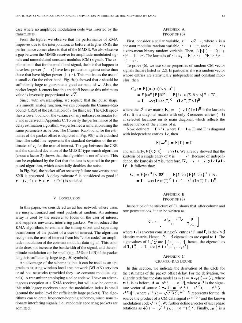
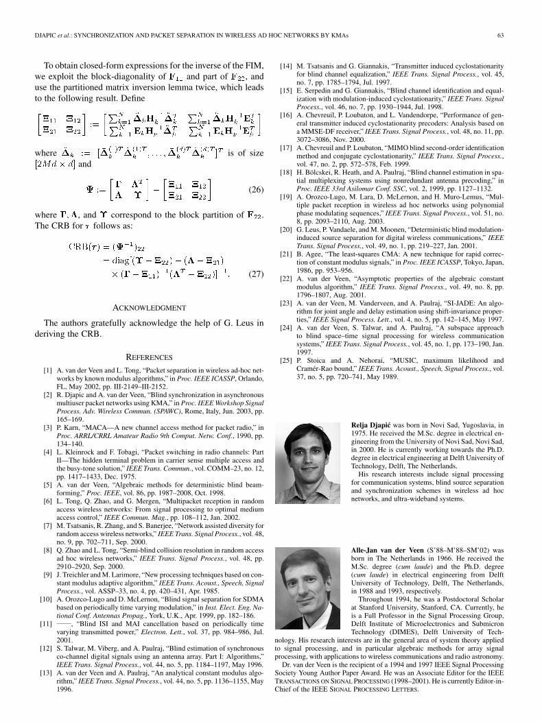
In Fig. 9(a), the BER versus input SNR performance of theKMA beamformer for the cases with and without resampling via
1The linear modulation is introduced for simplicity, nonlinear modulationsare certainly also applicable.
Fig. 9. Case 2 beamformer performance (asynchronous sources withequal-length packets), where MSK modulation scheme is implemented.(a) BER after beamforming. (b) Standard deviation of estimated delays � usingthe MUSIC-type search, compared with the CRB. (c) Delay offset failure ratefor different values of the modulation level � = [0:2; 0:3; 0:4; 0:5].
interpolation are presented. In the case without interpolation,the estimated is rounded to the nearest sample instant. Forreference, we also show the performance of the linear minimummean squared error (MMSE) receiver, where the packet offsets
and the transmitted sequences are known for all users, and the performance of an MMSE receiver in the
DJAPIC et al.: SYNCHRONIZATION AND PACKET SEPARATION IN WIRELESS AD HOC NETWORKS BY KMAs 61
case where no amplitude modulation code was inserted by thetransmitters.
From the figure, we observe that the performance of KMAimproves due to the interpolation; as before, at higher SNRs theperformance comes close to that of the MMSE. We also observea gap between the MMSE receiver for amplitude-modulated sig-nals and unmodulated constant modulus (CM) signals. The ex-planation is that for the modulated signal, the bits that happen tohave less power have less protection against noise thanthose that have higher power . This motivates the use ofa small . On the other hand, Fig. 5(c) showed that should besufficiently large to guarantee a good estimate of . Also, thepacket length enters into this tradeoff because this minimumvalue is inversely proportional to .
Since, with oversampling, we require that the pulse shapeis a smooth analog function, we can compute the Cramer–Raobound (CRB) of the estimation of for this case. The CRB spec-ifies a lower bound on the variance of any unbiased estimator for
and is derived in Appendix C. To verify the performance of thedelay estimation algorithm, we performed a simulation using thesame parameters as before. The Cramer–Rao bound for the esti-mates of the packet offset is depicted in Fig. 9(b) with a dashedline. The solid line represents the standard deviation of the es-timates of for the user of interest. The gap between the CRBand the standard deviation of the MUSIC-type search algorithm(about a factor 2) shows that the algorithm is not efficient. Thiscan be explained by the fact that the data is squared in the pro-posed algorithm, which essentially doubles the noise.
In Fig. 9(c), the packet offset recovery failure rate versus inputSNR is presented. A delay estimate is considered as good if
is satisfied.
V. CONCLUSION
In this paper, we considered an ad hoc network where usersare unsynchronized and send packets at random. An antennaarray is used by the receiver to focus on the user of interestand suppress unwanted interfering packets. We introduced theKMA algorithms to estimate the timing offset and separatingbeamformer of the packet of a user of interest. The algorithmrecognizes the user of interest from his “color code,” an ampli-tude modulation of the constant modulus data signal. This colorcode does not increase the bandwidth of the signal, and the am-plitude modulation can be small (e.g., 25% or 1 dB) if the packetlength is sufficiently large (e.g., 50 symbols).
An advantage of the scheme is that it can be used as an up-grade to existing wireless local area network (WLAN) servicesor ad hoc networks (provided they use constant modulus sig-nals). A transmitter employing a color code will have an advan-tageous reception at a KMA receiver, but will also be compat-ible with legacy receivers since the modulation index is small(around the noise level for sufficiently large packets). The algo-rithms can tolerate frequency-hopping schemes, since nonsta-tionary interfering signals, i.e., randomly appearing packets areadmitted.
APPENDIX APROOF OF (6)
First, consider a scalar variable, , where is aconstant modulus random variable, , and isa zero-mean binary random variable. Then,
. The kurtosis of is.
To prove (6), we use some properties of random CM vectorsignals that are listed in [22]. In particular, if is a random vectorwhose entries are statistically independent and constant mod-ulus, then
where the matrix is the kurtosisof . It is a diagonal matrix with only nonzero entriesat selected locations on its main diagonal, which reflects theindependence of the entries of .
Now, define , where and is diagonalwith independent entries , then
and similarly, . We already showed that thekurtosis of a single entry of is . Because of indepen-dence, the kurtosis of is, therefore,
. It follows that:
APPENDIX BPROOF OF (8)
Inspection of the structure of shows that, after column androw permutations, it can be written as
where is a vector consisting of entries ‘1’, and is theidentity matrix. Hence, eigenvalues are equal to 1. Theeigenvalues of are , hence, the eigenvaluesof are .
APPENDIX CCRAMER–RAO BOUND
In this section, we indicate the derivation of the CRB forthe estimates of the packet offset delay. For the derivation, weslightly redefine the data model as , where
is as before, , where is the signa-ture vector of source .
, where represents for the thsource the product of a CM data signal and the knownmodulation code . We further define a vector of user phaserotations as . Finally, is a

62 IEEE JOURNAL ON SELECTED AREAS IN COMMUNICATIONS, VOL. 23, NO. 1, JANUARY 2005
column vector of size and is assumed to be circularly sym-metric zero-mean white Gaussian noise with covariance matrix
, where is the noise variance as received on asingle antenna. As usual, the noise variance can be estimatedseparately from the other parameters and, therefore, we can as-sume it is known in the derivation of the CRB.
The unknown parameters are considered to be deterministicconstants rather than stochastic variables. After sampling withperiod , the model becomes
where , and . Note that is a func-tion of but this is not indicated in the notation for reasons ofsimplicity.
With little loss of generality, we assume , i.e., no over-sampling. In the case of oversampling, the obtained bound willbe slightly pessimistic because the model assumes independentphases, whereas in the observed data they are dependent.
Based on the model and assuming received sample vectorscollected in a matrix , we can derive the likelihood functionas
(21)
where
(22)
and
(23)
Here, , while .Let . After omitting con-
stants we obtain the log-likelihood function
(24)
The derivation of the CRB from the log-likelihood functionfollows along standard lines [25]. Indeed, the CRB is given bythe main diagonal of the inverse of the Fisher information matrix(FIM), given by
where is a vector which collects all parameters
To specify the entries in closed form, we partition the FIM as
(25)
where the partitioning follows the partitioning of into fol-lowed by . Then
. . .
......
. . ....
. . ....
where and the submatrices can be derived as
(superscript indicates complex conjugate), and matrix isconstructed as
The derivation is straightforward but tedious and, therefore,omitted.
DJAPIC et al.: SYNCHRONIZATION AND PACKET SEPARATION IN WIRELESS AD HOC NETWORKS BY KMAs 63
To obtain closed-form expressions for the inverse of the FIM,we exploit the block-diagonality of and part of , anduse the partitioned matrix inversion lemma twice, which leadsto the following result. Define
where is of sizeand
(26)
where , and correspond to the block partition of .The CRB for follows as:
(27)
ACKNOWLEDGMENT
The authors gratefully acknowledge the help of G. Leus inderiving the CRB.
REFERENCES
[1] A. van der Veen and L. Tong, “Packet separation in wireless ad-hoc net-works by known modulus algorithms,” in Proc. IEEE ICASSP, Orlando,FL, May 2002, pp. III-2149–III-2152.
[2] R. Djapic and A. van der Veen, “Blind synchronization in asynchronousmultiuser packet networks using KMA,” in Proc. IEEE Workshop SignalProcess. Adv. Wireless Commun. (SPAWC), Rome, Italy, Jun. 2003, pp.165–169.
[3] P. Karn, “MACA—A new channel access method for packet radio,” inProc. ARRL/CRRL Amateur Radio 9th Comput. Netw. Conf., 1990, pp.134–140.
[4] L. Kleinrock and F. Tobagi, “Packet switching in radio channels: PartII—The hidden terminal problem in carrier sense multiple access andthe busy-tone solution,” IEEE Trans. Commun., vol. COMM–23, no. 12,pp. 1417–1433, Dec. 1975.
[5] A. van der Veen, “Algebraic methods for deterministic blind beam-forming,” Proc. IEEE, vol. 86, pp. 1987–2008, Oct. 1998.
[6] L. Tong, Q. Zhao, and G. Mergen, “Multipacket reception in randomaccess wireless networks: From signal processing to optimal mediumaccess control,” IEEE Commun. Mag., pp. 108–112, Jan. 2002.
[7] M. Tsatsanis, R. Zhang, and S. Banerjee, “Network assisted diversity forrandom access wireless networks,” IEEE Trans. Signal Process., vol. 48,no. 9, pp. 702–711, Sep. 2000.
[8] Q. Zhao and L. Tong, “Semi-blind collision resolution in random accessad hoc wireless networks,” IEEE Trans. Signal Process., vol. 48, pp.2910–2920, Sep. 2000.
[9] J. Treichler and M. Larimore, “New processing techniques based on con-stant modulus adaptive algorithm,” IEEE Trans. Acoust., Speech, SignalProcess., vol. ASSP–33, no. 4, pp. 420–431, Apr. 1985.
[10] A. Orozco-Lugo and D. McLernon, “Blind signal separation for SDMAbased on periodically time varying modulation,” in Inst. Elect. Eng. Na-tional Conf. Antennas Propag., York, U.K., Apr. 1999, pp. 182–186.
[11] , “Blind ISI and MAI cancellation based on periodically timevarying transmitted power,” Electron. Lett., vol. 37, pp. 984–986, Jul.2001.
[12] S. Talwar, M. Viberg, and A. Paulraj, “Blind estimation of synchronousco-channel digital signals using an antenna array. Part I: Algorithms,”IEEE Trans. Signal Process., vol. 44, no. 5, pp. 1184–1197, May 1996.
[13] A. van der Veen and A. Paulraj, “An analytical constant modulus algo-rithm,” IEEE Trans. Signal Process., vol. 44, no. 5, pp. 1136–1155, May1996.
[14] M. Tsatsanis and G. Giannakis, “Transmitter induced cyclostationarityfor blind channel equalization,” IEEE Trans. Signal Process., vol. 45,no. 7, pp. 1785–1794, Jul. 1997.
[15] E. Serpedin and G. Giannakis, “Blind channel identification and equal-ization with modulation-induced cyclostationarity,” IEEE Trans. SignalProcess., vol. 46, no. 7, pp. 1930–1944, Jul. 1998.
[16] A. Chevreuil, P. Loubaton, and L. Vandendorpe, “Performance of gen-eral transmitter induced cyclostationarity precoders: Analysis based ona MMSE-DF receiver,” IEEE Trans. Signal Process., vol. 48, no. 11, pp.3072–3086, Nov. 2000.
[17] A. Chevreuil and P. Loubaton, “MIMO blind second-order identificationmethod and conjugate cyclostationarity,” IEEE Trans. Signal Process.,vol. 47, no. 2, pp. 572–578, Feb. 1999.
[18] H. Bölcskei, R. Heath, and A. Paulraj, “Blind channel estimation in spa-tial multiplexing systems using nonredundant antenna precoding,” inProc. IEEE 33rd Asilomar Conf. SSC, vol. 2, 1999, pp. 1127–1132.
[19] A. Orozco-Lugo, M. Lara, D. McLernon, and H. Muro-Lemus, “Mul-tiple packet reception in wireless ad hoc networks using polynomialphase modulating sequences,” IEEE Trans. Signal Process., vol. 51, no.8, pp. 2093–2110, Aug. 2003.
[20] G. Leus, P. Vandaele, and M. Moonen, “Deterministic blind modulation-induced source separation for digital wireless communications,” IEEETrans. Signal Process., vol. 49, no. 1, pp. 219–227, Jan. 2001.
[21] B. Agee, “The least-squares CMA: A new technique for rapid correc-tion of constant modulus signals,” in Proc. IEEE ICASSP, Tokyo, Japan,1986, pp. 953–956.
[22] A. van der Veen, “Asymptotic properties of the algebraic constantmodulus algorithm,” IEEE Trans. Signal Process., vol. 49, no. 8, pp.1796–1807, Aug. 2001.
[23] A. van der Veen, M. Vanderveen, and A. Paulraj, “SI-JADE: An algo-rithm for joint angle and delay estimation using shift-invariance proper-ties,” IEEE Signal Process. Lett., vol. 4, no. 5, pp. 142–145, May 1997.
[24] A. van der Veen, S. Talwar, and A. Paulraj, “A subspace approachto blind space–time signal processing for wireless communicationsystems,” IEEE Trans. Signal Process., vol. 45, no. 1, pp. 173–190, Jan.1997.
[25] P. Stoica and A. Nehorai, “MUSIC, maximum likelihood andCramér-Rao bound,” IEEE Trans. Acoust., Speech, Signal Process., vol.37, no. 5, pp. 720–741, May 1989.
Relja Djapic was born in Novi Sad, Yugoslavia, in1975. He received the M.Sc. degree in electrical en-gineering from the University of Novi Sad, Novi Sad,in 2000. He is currently working towards the Ph.D.degree in electrical engineering at Delft University ofTechnology, Delft, The Netherlands.
His research interests include signal processingfor communication systems, blind source separationand synchronization schemes in wireless ad hocnetworks, and ultra-wideband systems.
Alle-Jan van der Veen (S’88–M’88–SM’02) wasborn in The Netherlands in 1966. He received theM.Sc. degree (cum laude) and the Ph.D. degree(cum laude) in electrical engineering from DelftUniversity of Technology, Delft, The Netherlands,in 1988 and 1993, respectively.
Throughout 1994, he was a Postdoctoral Scholarat Stanford University, Stanford, CA. Currently, heis a Full Professor in the Signal Processing Group,Delft Institute of Microelectronics and SubmicronTechnology (DIMES), Delft University of Tech-
nology. His research interests are in the general area of system theory appliedto signal processing, and in particular algebraic methods for array signalprocessing, with applications to wireless communications and radio astronomy.
Dr. van der Veen is the recipient of a 1994 and 1997 IEEE Signal ProcessingSociety Young Author Paper Award. He was an Associate Editor for the IEEETRANSACTIONS ON SIGNAL PROCESSING (1998–2001). He is currently Editor-in-Chief of the IEEE SIGNAL PROCESSING LETTERS.
64 IEEE JOURNAL ON SELECTED AREAS IN COMMUNICATIONS, VOL. 23, NO. 1, JANUARY 2005
Lang Tong (S’87–M’91–SM’01) received the B.E.degree from Tsinghua University, Beijing, China, in1985, and the M.S. and Ph.D. degrees in electrical en-gineering from the University of Notre Dame, NotreDame, IN, in 1987 and 1990, respectively.
He is a Professor in the School of Electricaland Computer Engineering, Cornell University,Ithaca, NY. He was a Postdoctoral Research Affiliateat the Information Systems Laboratory, StanfordUniversity, Stanford, CA, in 1991. He was also the2001 Cor Wit Visiting Professor at Delft University
of Technology, Delft, The Netherlands. His areas of interest include statisticalsignal processing, wireless communications, communication and sensornetworks, and information theory.
Dr. Tong received the Young Investigator Award from the Office of NavalResearch in 1996 and the Outstanding Young Author Award from the IEEECircuits and Systems Society.


![arXiv:1906.00855v2 [cs.LG] 4 Jun 2019 · Thinking Fast and Slow Di Chen Cornell University Ithaca, NY 14853 di@cs.cornell.edu Yiwei Bai Cornell University Ithaca, NY 14853 bywbilly@cs.cornell.edu](https://img.pdfslide.net/doc/110x75/5f5334eab076db3cdc3d5f2e/arxiv190600855v2-cslg-4-jun-2019-thinking-fast-and-slow-di-chen-cornell-university.jpg)


![Corne]] University, Ithaca, New York 14853-7801](https://img.pdfslide.net/doc/110x75/61fb8c022e268c58cd5f76ad/corne-university-ithaca-new-york-14853-7801.jpg)