Embed Size (px)
DESCRIPTION
WSN
Citation preview

This article has been accepted for inclusion in a future issue of this journal. Content is final as presented, with the exception of pagination.
IEEE TRANSACTIONS ON INSTRUMENTATION AND MEASUREMENT 1
Delay-Aware Medium Access Schemes forWSN-Based Partial Discharge Measurement
Irfan Al-Anbagi, Member, IEEE, Melike Erol-Kantarci, Member, IEEE, and Hussein T. Mouftah, Fellow, IEEE
Abstract— Wireless sensor networks (WSNs) are widelypreferred measurement and monitoring tools for a large varietyof industrial and environmental applications thanks to theirlow-cost, energy-efficiency, flexibility, and ease of deployment.However, the use of WSNs for measuring and monitoringindustrial applications generating data at high rates, such asonline monitoring of partial discharge activities in high voltageequipment in the power grid, presents a significant challengefor the system operators. In such applications, packet arrivalrates could increase rapidly due to the occurrence of cascadedfaults in the monitored environment. The WSNs with multihoptopologies could experience excessive delays and an increase inpacket drop of vital data due to the overwhelming increase inthe packet arrival rates. Therefore, there should be an optimumoperating point of the network where high packet arrival ratesand low latency can be maintained at the same time. Thus, thereis an immediate need for carefully designed quality of service(QoS) differentiation schemes that can guarantee the delivery ofcritical data with minimum latency and least loss. In this paper,we present a QoS differentiation scheme for high priority data inmultihop WSNs based on an optimization scheme. Analytical andsimulation results show that our proposed scheme significantlyreduces the delay while maintaining high data delivery ratios andenergy efficiency of the network.
Index Terms— Condition monitoring, IEEE 802.15.4, partialdischarge (PD) measurement, smart grid, smart protocol, wirelesssensor networks (WSNs).
I. INTRODUCTION
MOST industrial condition monitoring applications, suchas monitoring partial discharge (PD) activity in high
voltage (HV) equipment, are based on onsite diagnoses ofsuspected equipment. However, the available online conditionmonitoring systems are based on systems with infrastruc-tures [1] that are in most cases costly and require constantmaintenance. Furthermore, some online monitoring systemsare based on radio frequency (RF) transmission [2]. TheseRF-based systems can wirelessly provide measurement toa base station. However, these systems have limited cover-age and cannot provide information on multiple networkedsystems, which is considered vital in studying the correla-tion between incidences in multiple devices. On the otherhand, wireless sensor networks (WSNs) are expected to be
Manuscript received July 28, 2013; revised April 13, 2014; acceptedApril 16, 2014. The Associate Editor coordinating the review process wasDr. Edoardo Fiorucci.
The authors are with the School of Electrical Engineering andComputer Science, University of Ottawa, Ottawa, ON K1N 6N5,Canada (e-mail: [email protected]; [email protected];[email protected]).
Color versions of one or more of the figures in this paper are availableonline at http://ieeexplore.ieee.org.
Digital Object Identifier 10.1109/TIM.2014.2323142
excellent candidates to replace manual diagnoses and otherinfrastructure-based online monitoring systems. WSNs-basedmonitoring systems are favored due to their unique featuresand advantages, such as enhanced fault tolerance, low powerconsumption, self-configuration, rapid deployment, and lowcost. In addition to that, in environments where HVs are inuse, WSN can also provide necessary insulation. However,WSNs suffer from low transmission bandwidth and they alsocannot provide hard quality of service (QoS) guarantees tocritical condition monitoring and measurement applications.Therefore, in order to use WSNs for such delay and reliabilitycritical monitoring applications, proper design and optimiza-tion techniques should be put in place to solve these two issues.
The PD signals are rich of information and can provideextensive overview on the health of the monitored HV equip-ment [3]. Therefore, a power grid operator needs to get asmuch information as possible from these PD signals. The PDsignals are known to be very fast and may appear successively.Consequently, in order for the WSN system to meet therequirements of a successful monitoring application, PD signalprocessing and filtering should be performed to minimize thetransmitted data. Even though filtering and signal process-ing are performed, the amount of data captured is expectedto be very high for the ZigBee-based bandwidth limitedWSNs [4], [5].
Most industrial condition monitoring applications arelocated in remote and wide spread locations [6], [7]. Hence,the use of WSNs with multihop topologies is essential toovercome the coverage problem and to prevent any losses dueto multipath reflections or path losses due to the nature of theenvironment [8], [9]. However, the use of multihop topologiespresent an additional delay problem since sensor nodes insuch topologies have to forward traffic from other branchesin addition to their own traffic [10]. In all WSN systems,there is a direct tradeoff between the reliability (defined asthe probability of successful packet transmission [11]) and thelatency in packet delivery [12], [13]. Hence, on one hand, wewant a WSN that can transmit all of the monitored data andon the other hand, we require this data to be delivered withinspecific deadline. As a result, this tradeoff requires the solutionof an optimization problem to minimize the delay and transmitas much data as possible in addition to providing firm QoSguarantees to critical monitoring data. We define critical dataas a data that requires a near real-time attention.
In this paper, we present a QoS scheme for multihop WSNsbased on an optimization model implemented in cluster-heads(CHs) of a cluster-tree and in full function devices (FFDs)of a mesh topologies. The presented QoS scheme can find
0018-9456 © 2014 IEEE. Personal use is permitted, but republication/redistribution requires IEEE permission.See http://www.ieee.org/publications_standards/publications/rights/index.html for more information.
This article has been accepted for inclusion in a future issue of this journal. Content is final as presented, with the exception of pagination.
2 IEEE TRANSACTIONS ON INSTRUMENTATION AND MEASUREMENT
optimum delays for specific reliability values. In addition tothat, our adaptive inter-CH delay control (AIDC) [14] schemefor cluster-tree topologies and the adaptive time slot allocation(ATSA) scheme for mesh topologies (which was preliminarilyproposed in [15]) can reduce the end-to-end delay of criticaldata in condition monitoring and control scenarios. Comparedwith [14] and [15], we show more details about the schemes,present comprehensive performance evaluation and propose acase study for PD measurement system using ZigBee-basedWSNs. Furthermore, in this paper, we show the advantages anddisadvantages of using either cluster-tree or mesh topologiesfor WSN-based monitoring applications. Both the AIDC andthe ATSA schemes build on the mathematical model of [12]and [13]. However, they present major improvements to [12]and [13] by presenting an optimization model for WSNs withmultihop topologies and by solving the issue of excessivelatency by adaptively providing QoS guarantees to delaycritical applications.
A. Main Contributions
The main contributions of this paper are:
1) propose QoS schemes based on an optimization modelthat meet the needs of PD measurement and monitoringapplications;
2) present an adaptive scheme to solve the latency problemsin cluster-tree and mesh topologies due to super-frame(SF) scheduling;
3) achieve minimum delay in multihop WSNs for hightraffic intensity condition monitoring applications;
4) present a comprehensive performance evaluation ofthe presented schemes in different network and trafficconditions in a smart grid environment.
B. Organization of Paper
The remainder of this paper is organized as follows.In Section II, we present the related work. In Section III,we present throughput and delay requirements in thesmart grid. In Section IV, we describe the system model.In Section V, we describe the AIDC and ATSA schemes.In Section VI, we present the delay optimization scheme. InSection VII, we present the simulation and the analysis andfinally, in Section VIII we conclude this paper.
II. RELATED WORK
There are many publications that discuss the use of WSNsin general condition monitoring applications [7], [8]. However,the use of WSNs for high traffic intensity applications such asPD has not been widely considered [5], this is mainly due tothe limited resources of these tiny sensor nodes. Furthermore,providing QoS provisioning for monitoring applications hasbeen studied in [16], they have proposed to add the QoSinto the IEEE 802.15.4 protocol by providing differentiatedservice for traffic of different priority at the MAC layer.Al-Anbagi et al. [17] have proposed modifying the clearchannel assessment (CCA) duration performed by a sensornode to provide service differentiation to high priority traffic.
In this paper, there are numerous papers that discuss thetiming and scheduling of cluster-tree WSNs topologies [10],[18]–[20]. Most of this paper assume that all sensor nodes inthe network use scheduling or timing between CHs and enddevices. Furthermore, some papers discuss the optimization ofsome operating conditions in a cluster tree topology [21]–[24].Most of these papers discuss the optimization of routing [18],network life time [22], and optimum sensors positions in thenetwork [22], [23].
Hoang et al. [21] have proposed a technique to sched-ule the SFs of cluster-tree IEEE 802.15.4 networks overmultiple channels to avoid beacon frame collisions as wellas guaranteed time slots (GTSs) collisions between multipleclusters. In our scheme, we have proposed that the com-munication within a cluster take place using carrier sensemultiple access with collision avoidance (CSMA/CA) based ona packet arrival rate control by the CH. Furthermore, we havesuggested that the communication between CHs take placeusing mutual scheduling of interfering CHs, which requiresminimal changes to the hardware as well as the communicationprotocol.
Alam et al. [25] have proposed an energy-aware,multiconstrained, and multipath QoS provisioning mechanismfor WSNs based on optimization approach. They have pro-posed an algorithm to achieve the desired QoS guarantee whilekeeping the energy consumption minimum. In this paper, wealso provide a QoS-based optimization model but our modeltends to solve a specific issue of excessive delay due to SFscheduling while maintaining high reliability.
Vuran and Akyildiz [24] have introduced a cross-layer solu-tion for packet size optimization in WSN to capture the effectsof multihop routing, the broadcast nature of the physicalwireless channel, and the effects of error control techniques.They have shown that longer packets reduce the collisionprobability in WSNs. They have formalized an optimizationsolution using three different objective functions. Furthermore,they have also investigated the effects of end-to-end delayand reliability constraints required by a particular application.In this paper, we have followed an entirely different approachto derive the optimization model that optimizes the end-to-enddelay in a cluster-tree WSN. We have assumed that WSN usesCSMA/CA, whereas they used RTS-CTS-Data-ACK, (whichis not used by the IEEE 802.15.4 MAC) this makes ouroptimization model more accurate. In addition to that, we haveproposed a technique to reduce the delay by allowing CHs tochoose the optimum packet arrival rates.
III. THROUGHPUT AND DELAY REQUIREMENTS
OF POWER GRID MEASUREMENTS
A. Throughput Requirements
To characterize the amount of data, a sensor node wouldexpect from a certain smart grid monitoring application wepresent a data rate analysis of PD signals in a HV equipment.We base our analysis on signals presented in [26] and [27].The data rate estimation presented in this section is notan exact forecast of the expected data rate; nevertheless,it is an approximate assessment of the general throughput

This article has been accepted for inclusion in a future issue of this journal. Content is final as presented, with the exception of pagination.
AL-ANBAGI et al.: DELAY-AWARE MEDIUM ACCESS SCHEMES FOR WSN-BASED PD MEASUREMENT 3
requirements in WSNs for such applications. We use thesethroughput values in our mathematical model, simulations,optimization model, and QoS algorithm in order to create ascenario as realistic as possible.
Before we begin our analysis, we make certain assumptionsbased on the available PD signals presented in [27]. Firstof all, we assume that the PD signal is being denoisedand preprocessed using common signal processing techniques,such as wavelet algorithm [27]. Continuous sampling at highfrequency may provide more details about the PD signal.However, if continuous sampling at a certain sampling rateis considered (taking Nyquist sampling rate into account)for such limited networks, the amount of data arriving atthe sensor node would cause buffer overflow and extensivetransmission delays. Therefore, we consider that each sensornode uses an electronic peak detect and hold circuit [28].This peak detector circuit searches for positive and negativepeaks, holds them for a certain duration and then triggersdigital signal conversion to take place. Once the analog-to-digital converter (ADC) receives the trigger signal from thepeak detector circuit, it converts the PD voltage and its timeof occurrence.
Different ADCs have different resolutions (up to 24-bitADCs) depending on the type of the microcontrollerused. In our simulations, we follow the specifications ofEFM32 [29], which is an ultralow power microcontroller with12-bit ADC resolution suitable for the low power ZigBeeapplications. Based on the PD signals measured in [27], the12-bit ADC resolution is sufficient to reconstruct the peaks.This means that peaks of voltages between (Vmax and Vmin)will have 4069 different levels to represent them.
Based on the previous information, and by referring to [3],[26], and [27], we consider that there are 100 pulses in a 50-Hzcycle (on average). In addition to that, for every detected PDpeak the system also captures the time for which the peak hasoccurred (i.e., the detected peak time stamp) with referenceto the 50-Hz cycle. The time stamps are synchronized withthe 50-Hz cycle’s zero crossing points to identify the eventsin time [30]. If the ADC has a 12-bit resolution, then the totalamount of data captured in one cycle is ∼2400 bits (neglectingthe three zero-crossover synchronization points of the 50-Hzsignal in one cycle). Therefore, the amount of data arriving tothe sensor node’s buffer is expected to be ∼120 kb/s.
This analysis is essential for designing and optimizing aWSN for such application since the data arrival rate affectsvery much the overall performance of the network. In additionto that, if no proper network optimization algorithm is inplace, the entire monitoring activity may be jeopardized. Suchdata arrival rates provide a clear indication of how muchdata is arriving into the sensor node buffer and at which ratethe ZigBee-based sensor node is expected to transmit. Thememory required for storing the captured data can easily beestimated from the previous analysis. However, the amountof data successfully transmitted from a node (i.e., goodput)is difficult to predict since it depends on several other factorssuch as the number of nodes contending to transmit at the sametime, the location of the node in the network, and whetherother nodes also experience similar PD incidents.
TABLE I
LATENCY REQUIREMENTS FOR SMART GRID APPLICATIONS [31]
In Section III-B, we present the delay requirements ofsome common monitoring applications in the smart grid, andthen we design our QoS schemes based on these two criticalrequirements.
B. Delay Requirements
WSN requirements associated with smart grid applicationsplay a considerable role in determining how to implementthe WSN technology into the power grid infrastructure. QoSrequirements vary depending on the criticality of the monitoredpower grid component. These requirements can be one or acombination of the following requirements: latency, reliability,availability, security, and spectrum availability [31]. In thispaper, we focus on the latency and the reliability requirements.In general, utilities require low latency communications, espe-cially for critical data applications, such as teleprotectionsystems, emergency power restoration, and substation mon-itoring and control. Therefore, latency requirements in smartgrid monitoring applications may vary from several secondsfor smart metering to<10 ms for protection operations. Table Ishows some typical latency regiments of some common smartgrid monitoring applications [31].
The reliability in the context of power grid monitoring isdefined as the amount of information a communication systemcan successfully deliver. In the smart grid, certain applicationssuch as gathering data for accumulation and records purposescan accept some flexibility in the latency and reliability values,whereas some critical applications that affect the operationof the power grid such as PD monitoring of HV equipmentrequire very tight deadline and reliability values.
Based on the delay values presented in Table I, we seethat achieving these requirements with the conventional IEEE802.15.4-based WSNs presents a hefty challenge, especially inlarge-scale networks with several hops from the source nodeto the sink. These WSNs are mostly designed for low datarate applications with no service guarantees. However, we aimto address this issue and present a QoS scheme design forWSNs with mesh topologies. Our proposed scheme intendsto minimize the latency of critical event monitoring whilemaintaining high reliability values, and at the same time, weintend not to significantly affect other noncritical data in thenetwork.
IV. SYSTEM MODEL
A. Cluster-Tree Topology WSN Model
In this paper, we use the IEEE 802.15.4-PHY and MACbased WSNs with multihop topologies, since they aremore suitable for smart grid condition monitoring applica-tions where sensor nodes are generally distributed in wide-spread locations. Furthermore, we overcome the issues with

This article has been accepted for inclusion in a future issue of this journal. Content is final as presented, with the exception of pagination.
4 IEEE TRANSACTIONS ON INSTRUMENTATION AND MEASUREMENT
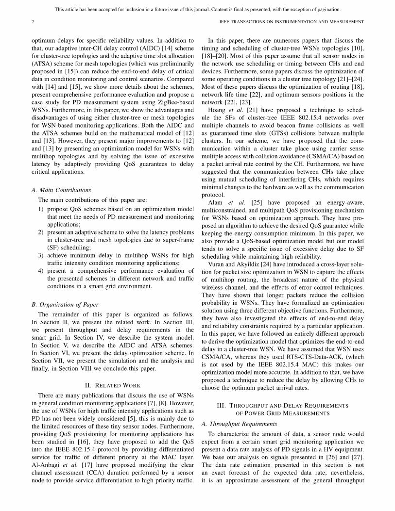
Fig. 1. Proposed cluster-tree topology.
multipath propagations arising from the nature of the moni-tored environment.
In a WSN with cluster-tree topology, the network comprisesof multiple coordinators, also known as CHs connecting sensornodes at different levels to the sink node through multihoprouting. Due to the nature of the monitored environment, theseCHs are located far apart and in some situations they cannothear each other. To avoid collision of packets exchangedbetween these CHs, they generate periodic beacon frames tosynchronize with their end nodes and with higher or lowerlevel CHs during the contention free period (CFP) of theSF duration. Fig. 1 shows a typical WSN with cluster-treetopology, in this topology CH1 is the parent of CH2 andCH4, while being child of the sink node. In this scenarioand in similar cluster-tree scenarios if the transmission of thebeacon frames from CHs are not properly scheduled using theGTS of the CFP, beacon frames could collide either with otherbeacon frames from different CHs or with data frames fromdifferent clusters. Collision of beacon frames leads to loss ofsynchronization between communicating CHs, which leads toloss of packets. According to the IEEE 802.15.4 standard [11]the CHs can allocate a maximum of seven GTSs in a singleSF duration. Therefore, we considered this limitation whendesigning our network.
The 15.4b Task Group [32] proposed two general methodsto avoid beacon frame collisions. These methods are the timedivision approach and the beacon-only period approach. In thetime-division approach, each CH schedules its SF during theinactive period of the other coordinators. This is achieved bysetting an offset in time for the beacon frame transmissionin each CH. This approach requires minor modification tothe current IEEE 802.15.4 MAC protocol. There are severallimitations associated with this approach. These limitations canbe summarized as follows: 1) the constrains in the duty-cycles,since duty cycle is dependent on the number of interfering CHs(i.e., interfering CHs must operate in different time windows)and 2) the direct communication between sibling CHs (CHsconnected to the same parent) is not possible, because eachof these CHs operates in a time window different from itsadjacent clusters. In the beacon-only period approach, the SFstructure is modified by introducing a period at the beginningof each SF, during this period CHs transmit their beaconframes [10]. Each CH should select a proper time slot so thatits beacon frame does not collide with the ones from adjacentCHs. This approach allows multiple clusters to share the activeperiod, so it is more scalable than the time division approach.
The main disadvantage of this approach is that the beacon-only period depends on the size of network and the parent-child relationship. Most importantly, in this approach, the GTSmechanism cannot be implemented, since transmission fromnodes belonging to different clusters may collide [11].
In this model, we adhere to the following assumptions.1) We assume that each CH communicates with its end
nodes using the CSMA-CA mechanism.2) Each CH forwards the data from the end devices to upper
level CHs using scheduling during the CFP.3) We only consider data transmissions from the sensors to
the sink. Traffic in the opposite direction is mostly forcontrol signaling and acknowledgement transmission.
4) We assume that end nodes belonging to a certain clusterare placed in such a way that they do not suffer fromcochannel interference from the transmissions in neigh-boring clusters.
5) To avoid beacon frame collisions between neighboringCHs, we use the beacon frame collision avoidancetechnique [10] (i.e., the time division approach withoutmodifications).
6) To prevent packet overflow, we assume that each CHmaintains a buffer to store the received packets, whicheither can be from its own end devices or forwardedfrom the lower level CHs and that these buffers canaccommodate all the incoming traffic.
7) We assume that packets arrive at the MAC sublayer atan arrival rate of [λ packets per second (pkts/s)]. Thetraffic received by a CH in an upper level (h+1) is equalto the aggregate of traffic from CHs at lower levels (h).
8) All CHs have M/G/1/L queues.9) We model the behavior of each cluster with the Markov
chain model described in [12].In contention-based WSN with constant number of nodes,
the number of packets arriving to the CH is dependent onthe reliability R (i.e., on the number of packets successfullyreceived from each node). When a CH receives high numberof packets from its end devices then it cannot serve all of theincoming packets and forward them to an upper level CH inthe same SF duration. Consequently, these remaining packetswould experience an additional delay because they have towait for the next SF. In this scenario, there is an obvioustradeoff between the required reliability (number of packetsreceived) and the desired delay. In a WSN, there are a numberof factors that affect the reliability of packet transmission suchas the number of nodes N in the PAN, the packet arrivalrate λ, MAC parameters, and so on [11]. To solve this tradeoffissue and find an optimum delay while maintaining acceptablereliability values, we formulate and solve an optimizationproblem. To simplify the problem, we assume that the numberof nodes in each cluster is constant. Furthermore, for themoment, we make other MAC parameters constant as well.
B. Mesh Topology WSN Model
In WSNs with mesh topology, such as the topology pro-posed in Fig. 2, the use of the AIDC scheme is somehowdifferent. This is due to the existence of multiple routes from

This article has been accepted for inclusion in a future issue of this journal. Content is final as presented, with the exception of pagination.
AL-ANBAGI et al.: DELAY-AWARE MEDIUM ACCESS SCHEMES FOR WSN-BASED PD MEASUREMENT 5
Fig. 2. Proposed mesh topology.
one or more FFDs to the sink and that needs to be taken intoconsideration in the QoS scheme.
We classify sensor nodes into three categories, namely,reduced function devices (RFDs), FFDs, and a sink. An RFDcollects data from equipment and can only communicate withan FFD (i.e., its parent FFD), an RFD cannot perform routing.Therefore, its main role is to collect data and forward it to theFFD. An FFD on the other hand, can communicate with itsown RFDs and can perform routing through neighboring FFDswithin its transmission range. The FFDs are known as relayor intermediate nodes. The sink node is the final destinationof the collected data. We group a number of RFDs dependingon their location and functionality into a single subpersonalarea network (SPAN).
In the ATSA scheme, we follow the WSN with multihopmesh topology described in Fig. 2. In smart grid monitoringscenarios, we consider that a certain FFD can receive highpriority data from associated RFDs within its SPAN or fromone or more neighboring FFDs. In the ATSA scheme, weadhere to the following additional assumptions.
1) FFDs use directed diffusion routing described in [33] toroute the packets through multihop routes to the sinknode.
2) Each FFD is at least connected to two other FFDs(i.e., there is a secondary path to route the packets to thesink). If a secondary path is not available an intermediatenode should be able to buffer the data until the nextround of communication.
3) All of the FFDs perform the optimization schemedescribed previously to minimize DFFD.
4) Priority of data is determined by the application layer ofeach RFD and is identified by a flag in the data packet.
5) High priority packets should be delivered to the sinkwith minimum delay and maximum reliability.
6) We refer to an RFD generating high priority data as thetagged RFD and to an FFD associated with a taggedRFD as a parent FFD (p-FFD).
V. AIDC AND ATSA SCHEMES
Before we describe the AIDC and ATSA schemes, webriefly discuss the derivation of the reliability R. R relatedto the probability of successful packet transmission from anend node to the sink. The value of R depends on the MACparameters and on the probability of collision and does notdepend on the channel condition since this parameter is very
difficult to predict. We follow [34] and [12] to derive thereliability. Table II shows the summary of frequently usednotations, other notations are described within the text.
In slotted CSMA/CA packets are dropped due two reasons;the first is the node declares channel access failure (Fca) andthe second is when the node exceeds its retry limits (Frt) [11].Fca takes place when the node fails to acquire channel accesswhen it tries the first and second (CCAs) within the allowednumber of backoffs. Frt takes place when a transmission failsdue to repeated packet collisions within the allowed number ofpacket retransmissions. We followed the Markov chain modelderived in [34] and modified in [12] to obtain the probability ofFca (Pca) and the probability of Crt (Prt). Hence, the reliabilityis given by the following relation:
R = 1− (Pac + Prt). (1)
Therefore, the value of the reliability depends on α, β, and Pc.The value of Pc is equal to the probability that at least onenode of the N−1 nodes transmit at the same time slot is givenby the following equation:
Pc = 1− (1− τ N−1). (2)
The derivation of τ is given in [34] and its modification isgiven in [12].
Park et al. [34] derived one exact and one approximatemodel for the reliability. Due to space limitations, we do notshow the derivations of the exact and approximate modelsof [34] and their modifications presented in [12]. We showthe final approximated model for the reliability which we usein our optimization model. The equation for the reliability isgiven below
R ≈ 1− x (m+1)(1+ y)− yn+1 (3)
where τ is the approximated version of τ and is given by thefollowing equation:
τ = (1+ x)(1+ y)b0,0,0 (4)
where
x = α + (1− α)β (5)
and
y = (1− (1− τ N−1)(1− x) (6)
and b0,0,0 is the modified and approximated version of thestationary distribution of the Markov chain and is given in [12].By carefully tracing these variables, we can see that theirvalues depend on the MAC parameters, the number of nodes,as well as the packet arrival rates.
A. AIDC Scheme
In the AIDC scheme, all end nodes in each cluster estimatethe expected reliability E[R] of successful packet transmissionto their CH using (3). Sensor nodes then transmit the reliabilityestimation results and their packet arrival rates λ to the CHduring the beacon exchange phase. If the CH is located inan intermediate level in the cluster tree then it receives theexpected packets from lower level CHs ε, then it uses these

This article has been accepted for inclusion in a future issue of this journal. Content is final as presented, with the exception of pagination.
6 IEEE TRANSACTIONS ON INSTRUMENTATION AND MEASUREMENT
TABLE II
SUMMARY OF FREQUENTLY USED NOTATIONS
values to estimate the number of full SF a packet can waitbefore being forwarded to the next CH and then run theoptimization algorithm. The CH then broadcasts the optimuminter-CH delay (σ ) and the corresponding value of the MACpacket generation rate (λopt) to all end nodes in its cluster.
When sensor nodes in cluster receive σ and λopt, theyrun the weighted moving average (WMA) algorithm [35]to further reduce the fluctuations in the read data and thenreduce the sampling rate by a factor of [� = �(λ/λopt)�]to achieve λopt. We implement the WMA algorithm sincethe simple moving average is not suitable for sensor networkapplications in general. Furthermore, if we lower λ then thesampling rates should be drastically lowered compared withthe WMA algorithm. Therefore, if a sensor node sharplylowers its sampling rate then it takes too long for a changeto appear in the moving average and it may miss importantevents. In addition to that, when a node continues samplingat a high rate, it fails to achieve λopt. To perform WMA, thenode also collects confidence data based on the location of themeasured sample. We use the following relation to computethe WMA:
a = wt−kat−k + · · · +wt at
wt−k + · · · +wt(7)
where wt is the weight of the read value at at time stamp t ,wt is assigned by the node to data point depending on itsconfidence value (if the confidence value is not available thenit is assigned a value of 1). k is a given window size. Sensornode uses k and � to achieve λopt. If the value of k = 0 and� = 1, then basically there is no averaging done by the nodeand the packets are forwarded down to the MAC sublayer atrate of λ. Therefore, the node increase k and � until λopt isreached.
In most condition monitoring applications, it is assumedthat the data read has no significant difference when theinfrastructure being monitored registers no failure. Therefore,using WMA will not affect the integrity of the monitoringprocess. Alternatively, when a sensor node senses a gradientin the measured data (i.e., the appearance of a faulty data orhigh priority data) it sets k = 0 and � = 1. This is done to
allow the node to sample at a maximum allowable samplingrate, because some applications require precise measurement,for example, PD analysis; the operator is interested in all peakvalues as well as the rise and fall times of these peaks [3].
In cluster tree networks, when a CH uses the CFP totransmit its packets to a higher level CH it can accommodateonly a finite number of packets in the CFP, packets that do notget a chance to be transmitted in the current SF should wait forthe next SF to be served and that poses an additional problem.To overcome this problem, we implement the algorithmdescribed in [36] where nodes with high priority traffic requesttwo time the GTS from their CHs. Therefore, when a failureis detected, the application layer of the corresponding nodeinserts a high priority flag (ON) in its packets to alert its CHso that it can double its GTS duration to accommodate theincrease of the incoming traffic and transmit these packets inthe same SF duration.
To increase the probability of the node generating the alarmin accessing the channel and transmitting prior to other nodes,the node starts performing linear backoff period [i.e., Randomdelay← random_int (2BE − 1)] [37] with lower values of BEcompared with other nodes. In addition to that the tagged nodestarts to perform CCA in half of the normal CCA duration,which is performed by other nodes [17]. In doing these steps,the node with an alarm (we shall refer to it as a tagged node)exits from its backoff state sooner than other nodes whichuse exponential backoff with double the BE and sense thechannel for a shorter duration. Hence, the tagged node is givenhigher priority to transmit its delay sensitive data. When thehigh priority data ends at the tagged node, its application layerinserts high priority flag (OFF), then the CH changes its GTSperiod to normal.
B. ATSA Scheme
In the ATSA scheme, we follow four case s which areexplained below.Case 1: (ATSA1) is when no high priority traffic is generated
in the entire network. In this case FFDs use thedefault IEEE 802.15.4 settings.

This article has been accepted for inclusion in a future issue of this journal. Content is final as presented, with the exception of pagination.
AL-ANBAGI et al.: DELAY-AWARE MEDIUM ACCESS SCHEMES FOR WSN-BASED PD MEASUREMENT 7
Algorithm 1 AIDC Algorithm//Initialize the MAC variable//N B ← 0, CW ← 2, B E ← macMinB EN ← Number of nodes, λ← Traffic arrival rateE[R] //Run the reliability estimation algorithm////Transmit R and λ////receive σ and λopt from CH////high priority data present at the application layer//if High priority flag = ON then
Priori ty_ f lag← ON //transmitted to CH//B E ← B E∗ //Run BE with linear BO//CC A← CC A/2
else// Run WMA Algorithm with lower sampling rate //k = 0� = 1a = wt−k at−k+···+wt at
wt−k+···+wtif λ �= λopt then
k = k + 1� = �+ 1
elseλ← λopt
end ifend if(IEEE 802.15.4 CSMA-CA Algorithm)
Case 2: (ATSA2) is when one or more RFDs generate highpriority traffic. In this case, tagged RFDs requesttheir p-FFD to increase the CAP to allow all of theincoming packets to be transmitted in the current SF.In addition to that, all of the associated FFDs alongthe path to the sink allocate their entire CFPs to thisp-FFD. Normal traffic generated from other FFDs iseither forced to request time slots from alternativeFFDs that are not in the route of this high prioritytraffic or buffer their traffic until the current highpriority traffic passes through.
Case 3: (ATSA3) is when a neighboring FFD generates highpriority traffic. In this case, the i-FFD uses the tuningfactor" (θ ) to control the allocation of the time slotsbetween the CAP and CFP. In ATSA, the p-FFD usesθ as follows.
We define (θ = (CAP/CFP)). When θ < 1, thep-FFD allocates the neighboring FFDs more timeslots to transmit their packets. Therefore, in ATSA3,the p-FFD and all of forwarding i-FFDs reduce θand do not grant any GTS to other FFDs that arenot generating high priority traffic.
Case 4: (ATSA4) is when the p-FFD receives high prioritydata from an RFD and one or more FFDs. In thiscase, the p-FFD uses the wakeup factor (ω) to controlits SF duration (refer to Fig. 3). The value of � isequal to the ratio of the SF to the BI. (ω = (SD/BI)),In ATSA4, an FFD increase the value of ω and usesθ to control CFP and CAP based on the sourceof the high priority traffic. In this situation, normal
Fig. 3. ATSA SF scheduling.
Algorithm 2 ATSA Algorithm at the FFD//Receive λ, R and priority status from RFDs//if RFD high priority flag = on then
if Number of RFD high priority flags >1 then//Request more CAP time slots from p-FFD//(CAP = CAP + 1)
end if//Acquire μ, υ and ψ////Run the optimization algorithm////Transmit σ and λopt to all RFDs//if neighbor-FFD high priority flag = on thenω = ω + 1 & θ = θ + 1if Number of high priority flags of neighbor-FFD >1thenω = ω + 2 & θ = θ + 1
end ifelse if neighbor-FFD high priority flag = OFF thenθ = θ + 1
end ifend if//Beacon frame collision avoidance Algorithm//
traffic generated from other FFDs is either forcedto request time slots from alternative FFDs thatare not in the route of this high priority traffic orbuffer the traffic until the high priority traffic passesthrough. Algorithm 2 describes the ATSA schemeimplemented in FFDs.
VI. DELAY OPTIMIZATION
We formulate optimization problem to minimize the onehop inter-CH and the inter-FFD delays (D). Hence, we onlyfocus on deriving an optimization problem for an individualCH or an FFD at a specific level other devices run the sameoptimization problem. The overall end-to-end delay from theend node to the sink can be minimized by combining theseoptimization problems. The value of D (in time slots) is givenby the following equation:
D = δDSF + μ. (8)

This article has been accepted for inclusion in a future issue of this journal. Content is final as presented, with the exception of pagination.
8 IEEE TRANSACTIONS ON INSTRUMENTATION AND MEASUREMENT
The value of δ depends on the number of packets arriving fromlower level CHs and on the number of packets arriving fromthe local cluster. δ is also dependent on the number of packetsthat can be fitted in a single DSF and that is dependent on thepacket length and other MAC parameters that control the DSFsuch as the SF order (SO) and the BaseSFDuration [11]. Thevalue of δ is given by the following equation:
δ =⌈ϕ
μ
⌉− 1 (9)
where ϕ is equal to the total packet arriving to the CH, its valueis given by the following relation:
ϕ = η + ε. (10)
The value of η is given by the following relation:η = R × λ (11)
where λ depends on the actual PD analysis performed inSection III. The value of λ can be found by knowing bothγ and l. We previously have calculated the bit arrival rateand assume that the packet size is equal to 120 B [11].In Section VII, we vary the value of λ to study its effectson the performance of the WSN. Furthermore, we show thatthe value of λ is a pivotal factor for the optimization problem.The value of ε depends on the depth of the tagged node in thenetwork and the number branches connected to the tagged CH(in case of a cluster tree topology) or the tagged FFD (in caseof a mesh topology).
Based on the above assumptions and equations, the objectivefunction is to minimize the inter-CH delays (Di ) form the localCH to the sink as a function of λ. The objective function andthe constraints are described below
minimizeλ
D(λ)
subject to μ+ ε = ψκ ≥ μ ≥ 0
υ ≥ ε ≥ 0
λmin ≥ λ ≥ λmax.
In addition to the latency and throughput requirementspreviously discussed in this paper, smart grid monitoringapplications require certain reliability values to be achieved.For example, monitoring HV transformer require that thereliability be between (98% and 99%) [38], other applicationsaccept lower reliability values. in this application, the mini-mum reliability Rmin is normally specified by the smart gridoperator who is monitoring PD activities. We use (5) to solvethe optimization problem derived earlier.
The value of μ is bounded by the maximum number ofpackets that can be transmitted from an end node in a localcluster. If we assume that there are no collisions between CHs,then the maximum number of packets the CH expects fromits own cluster is bounded by (κ). The value of κ depends onthe length of the packet (l), the BaseSlotDuration and the SO.Since individual CHs communicate among themselves usingscheduling during the CFP, then the value of ε depends on theGTS period of the intermediate level CH and all the received
packets should be accommodated in this period. The maximumvalue of ε is bounded by υ. The value of υ depends on thelength of the packet l, the BaseSlotDuration and the SO. In asingle DSF, the intermediate level CH should be forced not toreceive more than the combined values of ε and μ.
VII. SIMULATION AND ANALYSIS
A. Performance Metrics
The analytical model presented in [12], take into consid-eration actual traffic arrival rates rather than a predeterminedidle state duration [34] in representing various WSN para-meters, such as the end-to-end delay, reliability, and powerconsumption. In [12], three metrics (namely, end-to-end delay,reliability, and power consumption) were derived based on[34] to study the performance of a general WSN with startopology. We do not describe the analytical model we use inthe AIDC scheme. However, we briefly show the extensions ofthe three metrics to make the model implementable in WSNswith cluster-tree topology.
1) Power Consumption: Even though we propose to deploythe WSN in an electrical substation with an abundance ofpower, we assume that tapping into the substation for a fewmilliwatts is not feasible. Furthermore, both the AIDC andthe ATSA schemes can be implemented in environments wherepower may not be available. Therefore, the evaluation of powerconsumption is as important as other performance metrics.
In a single cluster, we find the average power consumedin transmitting a packet from an end node to a CH or to aFFD (ETOT) by summing the average power consumed duringbackoff (EBO), channel sensing (ESC), packet transmission(ET ), idle state (EQ), buffering (EB), and wake-up (EW ).We assume that the end node consumes no power in packetreception since we assume one way traffic flow. The totalpower consumption is given by the following equation:
ETOT = EBO + ESC + ET + EQ + EB + EW . (12)
We compute each term in (6) by finding the probability of anode in being at a certain state (i.e., backoff, channel sensing,packet transmission, idle state, buffering, and wake-up) andthe amount of average power consumed at that state. In boththe cluster-tree and mesh topologies, we assume that thereare no packet collisions between intermediate nodes due tothe existence of a synchronization scheme. Therefore, therewill be no power consumed in backoff, channel sensing, andretransmissions. Assuming that EB and EW are equal to EQ
and that the power consumed in receiving a packet is equal tothe power consumed in transmitting a packet. The total powerconsumed in transmitting a packet from an end node at thelth to the sink is given by the following relation:
E′tot = ETOT +
h−1∑
i=0
(2ET + EQ) (13)
where h represents the depth of the tagged node in themultihop network.

This article has been accepted for inclusion in a future issue of this journal. Content is final as presented, with the exception of pagination.
AL-ANBAGI et al.: DELAY-AWARE MEDIUM ACCESS SCHEMES FOR WSN-BASED PD MEASUREMENT 9
2) Reliability: The reliability R is given by (3). In bothtopologies, we assume that there are no packets lost in thetransmission between CHs or FFDs due to the employedsynchronization and beacon collision avoidance mechanisms.Hence, the reliability from the low level CHs or an FFD tothe parent CH or FFD is 100% (i.e., the total reliability of thecluster-tree and mesh network is equal to R).
3) End-to-End Delay: We consider the end-to-end delay intransmitting a packet from an end node to a CH or an FFD(T ) to be resulting from the time spent in backoff (Dbo), thetime wasted in experiencing j collisions ( j Tc), and the timeneeded to successfully transmit a packet (Ts) and is given bythe following relation:
T = Ts + j Tc + Dbo = (1+ j)TL + Dbo. (14)
To simplify the model, we assume that TL = Ts = Tc.We assume that the total end-to-end delay in transmitting apacket in the cluster-tree topology is equal to the sum ofthe end-to-end delays along the path from the source nodeto the sink. The total end-to-end delay in a multihop topology(DMH) depends on the number of nodes, λ in each level andthe number of levels (h) in the network, DMH value is givenby the following equation:
DMH = T +h−1∑
i=0
D′i (15)
where D′i is the inter-CH or the inter-FFD delay from the sink
to a second node and is given by
D′i = δDSF + ρ (16)
and
ρ = π − δμi . (17)
To find D′i , we use (16) for the first level nodes and (8) for
all other nodes at different levels.
B. Numerical Results
To support the analytical results of the AIDC and theATSA algorithms, we simulate the WSN topology shown inFig. 3 using QualNet [39] network simulator. We set all ofthe simulation parameters similar to the parameters of theanalytical model. We assume the all the nodes in the networkare operating in the 2.4-GHz band with a maximum bit rateof 250 kb/s. To reduce the coexistence issues between theZigBee devices and other wireless devices that may exist inthe transmission range and operate in the same frequencyband, we choose channel 26 for the ZigBee devices whichis proven to have less coexistence issues [40]. We assume thatall nodes in a single cluster can hear each other. We activatethe acknowledgement mechanism in the network in both thesimulation and the analytical model to improve the reliabilityof the system. We assume that the power consumed duringthe buffering state as well as the backoff state is equal to thepower consumed during the idle state. We set the rest of theparameters according to the IEEE 802.15.4 standard document[11] and the actual specification document of MicaZ platform.
TABLE III
INITIAL SIMULATION PARAMETERS
Fig. 4. Optimum value of inter-CH delay for different reliability values.
Fig. 5. Optimum value of inter-CH delay for different SF orders.
Table III shows initial simulation parameters that we adopt inour simulations. We run each simulation for 300 s and repeateach simulation 10 times. In our simulations, we consider idealclocks, compensation of clock drift in sensor devices is out ofthe scope of this paper.
In a general wireless environment, there exist three types ofpath loss models, which are, empirical models that are basedon data measurement, deterministic models which dependon the geometry of the site and finally semideterministicmodels, which are based on empirical models in addition todeterministic models. In this paper and similar to [17], we runour simulations of AIDC and ATSA in a deterministic pathloss model to account for the architecture of the monitoredenvironment.
Electrical substations are known for their harsh environmentin terms of noise and interference. The noise levels of substa-tion equipment can be obtained from the manufacturer datasheets or test documents [41]. The location of the substationmay have an impact on the noise level as well, for example,noise level measurement of an underground substation is foundto be around 90 dBm while it was found to be around 105 dBmin an outdoor environment [40]. These noise and interferencelevels from substation equipment may deteriorate the channelquality and hence may affect the quality of the receivedsignal. To mitigate the effects of noise and interference in the2.4-GHz frequency band, we configure all ZigBee devices

This article has been accepted for inclusion in a future issue of this journal. Content is final as presented, with the exception of pagination.
10 IEEE TRANSACTIONS ON INSTRUMENTATION AND MEASUREMENT
Fig. 6. Performance analysis of the AIDC scheme. (a) End-to-end delay. (b) Energy efficiency. (c) End-to-end reliability.
Fig. 7. End-to-end delay for different cluster sizes.
to use the direct sequence spread spectrum encoding schemewhich is shown to reduce the effects of noise and interferencethrough field measurements in electrical substation environ-ment [40].
We solve the optimization problem using LINGO optimiza-tion tool [42] to find the minimum value of Di for differentλ values (Figs. 4 and 5). Fig. 4 shows the minimum values ofthe inter-CH delay from a certain CH to the next CH at thei th level against λ. We show the results for different R valuesto illustrate the effect of the desired reliability on the optimumvalue of the inter-CH delay. In Fig. 4 if the desired reliabilityis 95% and λ is 30 pkts/s then the optimum inter-CH delayis ∼128 ms. However, the optimum inter-CH delay drops to110 ms if the desired probability drops to 75%. This happensbecause as the value of reliability is higher, there would behigher number of packets arriving to the CH, and hence theCH cannot serve all the incoming packets in the current SF.Therefore, we see an additional delay equivalent to one SFduration or higher depending on the location of the CH in thetree and the value of λ.
Fig. 5 shows the optimum value of inter-CH delay fordifferent SO. We show that as the value of SO increase theoptimum value of the inter-CH delay increases. This takesplace because as the SO increases the value of DSF increasesand that leads to higher packet accumulation at the CH leadingto higher inter-CH delay.
Fig. 6(a) shows the end-to-end delay of packet transmissionfrom a tagged node to the sink when a node is implementingthe AIDC scheme and the default IEEE 802.15.4 MAC for twodifferent network scenarios. We assume that there are 20 nodesin each cluster. Scenario (1) is when the node generatinghigh priority traffic is located in cluster 2. Scenario (2) iswhen the node generating high priority traffic is located incluster 3. For both scenario (1) and (2), we show that the AIDCscheme performs the optimization of the inter-CH delay and
Fig. 8. Energy consumed per useful bit.
Fig. 9. End-to-end delay in a large network.
significantly reduces the delay especially at high traffic arrivalrates. We show that the simulation results of scenario (1) agreewith analytical results.
Fig. 6(b) shows the energy efficiency of transmitting apacket from a node in cluster 2 to the sink. We define theenergy efficiency as the ratio of the energy consumed intransmitting an actual packet through a cluster-tree networkto the total energy consumed in the transmission, backoff,and retransmissions due to collisions. We show that thereis slight improvement in the energy efficiency when a nodeimplements the AIDC scheme and the default IEEE 802.15.4setting. We show that even when the tagged node implementsthe delay reduction at high λ values, the energy efficiencyis maintained at acceptable values compared with the IEEE802.15.4 protocol.
Fig. 6(c) shows the end-to-end reliability of transmitting apacket from a node located in cluster 2 to the sink. We showthat the reliability of a node implementing the AIDC schemeis maintained very close to the default IEEE 802.15.4 MACsetting. For high packet arrival rates, there is only a slightdifference between the two schemes.
Fig. 7 shows the end-to-end delay of packet transmissionfrom a node in cluster 2 to the sink (the topology in Fig. 1)as a function of the packet arrival rate and the number of

This article has been accepted for inclusion in a future issue of this journal. Content is final as presented, with the exception of pagination.
AL-ANBAGI et al.: DELAY-AWARE MEDIUM ACCESS SCHEMES FOR WSN-BASED PD MEASUREMENT 11
Fig. 10. Performance analysis of the ATSA scheme. (a) End-to-end delay. (b) Total power consumed. (c) Reliability.
nodes in cluster 2. We show that for high number of nodesand low λ (the left corner of the plot) the end-to-end delay ishighest in both the AIDC and the default IEEE 802.15.4 MACsetting. This behavior is expected in a cluster-tree networktopology since low λ and high number of nodes means morenodes get a chance to transmit and hence more packets beingaccumulated at the CH leading to excessive delays. However,this delay drops as λ increases, since higher collisions takeplace in CH5. We show that the AIDC significantly reducesthe end-to-end delay for all number of nodes and all λ values.In fact, we show that AIDC has almost a flat performance(i.e., the end-to-end delay does not change much) comparedwith the default IEEE 802.15.4 MAC setting.
Fig. 8 shows the energy consumed per useful bits from anode in cluster 2 to the sink (the topology in Fig. 1) versusthe packet size and the data arrival rate in kb/s. We showthat as the amount of arriving bits per second increases theenergy consumed per useful bit slightly increase. However,when the bit rate continues to increase, nodes in the clusterexperience extensive contention, which leads to less numberof transmissions and hence less power consumed.
To test the scalability of the AIDC scheme in large cluster-tree WSNs, we run a simulation where the tagged node islocated six hops away from the sink and assume that thereare six CHs experiencing high priority traffic and are in thepath of tagged packet to the sink. Fig. 9 shows the end-to-end delay of transmitting a packet from the tagged node(six hops away from the sink) to the sink. We show that thereis a significant reduction in the delay when we implementthe AIDC scheme and that this reduction becomes obvious athigher packet generation rates.
Fig. 10(a) shows the end-to-end delay of packet trans-mission from a tagged RFD to the sink when a node isimplementing the ATSA scheme and the IEEE802.15.4 MACprotocol. We simulate three different scenarios; Scenario (1)is when the tagged RFD is associated with FFD(4) and thatFFD(4) is receiving high priority traffic from FFD(3) andFFD(7) at the same time. Scenario (2) is when the taggedRFD is associated with FFD(1) and that FFD(1) is receivinghigh priority traffic from FFD(5) at the same time. We showthat in both scenarios (1) and (2) the end-to-end delay dropssharply when we implement ATSA scheme. In scenario (1),traffic generated from FFD(4) is either forwarded throughFFD(1) or FFD(8) depending on the availability of GTSs fromeither one of these FFDs. Other noncritical traffic arrivingat either FFD(1) or FFD(8) is not allowed access through
these FFDs. Hence, nonhigh priority traffic either seeks GTSsfrom alternative FFDs or is buffered in the FFD.
Fig. 10(b) shows the total power consumed in transmittinga packet from a tagged RFD to the sink in scenarios (1)–(3).We show that the power consumption is slightly higher inscenario (3)-OPT2, this is expected as packet transmissiongoes through multiple hops to reach the sink. We also showthat there is a good agreement between the analytical andsimulation results of scenario (2).
Fig. 10(c) shows the end-to-end reliability of transmitting apacket from a tagged RFD associated with FFD(4) and the sinkfor the ATSA scheme and the IEEE 802.15.4 MAC protocol.We show that the reliability drops slightly when we implementthe ATSA scheme. This is because the tagged RFD implementslinear backoff to reduce the end-to-end delay and that causesa slight increase in collision among other nodes sharing thesame SPAN. Note that at low packet arrival rates the reliabilityis close to 100%. Also note that since FFDs are using theCFP to communicate and we assume that there is an accuratescheduling mechanism in place, then there are no packets lostin transmission between FFDs. Therefore, we expect that thereis no difference in the reliability values in scenarios (1)–(3) ifthe number of FFDs and other MAC parameters are the sameover all SPANs.
VIII. CONCLUSION
The use of WSNs as an online PD measurement tool offersa great deal of advantages and facilitation to the conditionmonitoring and the instrumentation process. However, WSNssuffer from low bandwidth and high latency in data deliverydue to their low power nature. Therefore, the use of the defaultWSN communication protocols is considered to be unsuitablefor high data rate monitoring applications.
In this paper, we presented a QoS scheme based on anoptimization model to provide QoS differentiation and sig-nificantly reduce the end-to-end delay of high priority data.The presented scheme could adaptively change the MACparameters to achieve the delay reduction and can invert backto normal IEEE 802.15.4 MAC setting when there is no highpriority data. Simulation and analytical results showed that theAIDC scheme and the extended ATSA scheme could reducethe end-to-end delay by more than 50% while maintainingacceptable reliability and energy efficiency values.
As a future work, we intend to implement the optimizationmodel on the sink node and test the effectiveness of suchoperation on the performance of the entire network.
This article has been accepted for inclusion in a future issue of this journal. Content is final as presented, with the exception of pagination.
12 IEEE TRANSACTIONS ON INSTRUMENTATION AND MEASUREMENT
REFERENCES
[1] H. Wang et al., “On-line partial discharge monitoring system anddata processing using WTST-NST filter for high voltage power cable,”WSEAS Trans. Circuits Syst., vol. 8, no. 7, pp. 609–619, 2009.
[2] C. Yonghong et al., “Study of on-line monitoring method ofpartial discharge for power transformers based on RFCT and microstripantenna,” in Proc. Electr. Insul. Conf. Electr. Manuf. Expo, Oct. 2005,pp. 103–107.
[3] International Electrotechnical Commission, High-Voltage TestTechniques–Partial Discharge Measurements, IEC Standard 60270,2000.
[4] M. D. Judd, L. Yang, and I. B. Hunter, “Partial discharge monitoringof power transformers using UHF sensors. Part I: Sensors and signalinterpretation,” IEEE Electr. Insul. Mag., vol. 21, no. 2, pp. 5–14,Mar./Apr. 2005.
[5] I. S. Hammoodi, B. G. Stewart, A. Kocian, S. G. McMeekin, andA. Nesbit, “Wireless sensor networks for partial discharge conditionmonitoring,” in Proc. 44th IEEE UPEC, Sep. 2009, pp. 1–5.
[6] H. Denkilkian et al., “Wireless sensor for continuous real-time oilspill thickness and location measurement,” IEEE Trans. Instrum. Meas.,vol. 58, no. 12, pp. 4001–4011, Dec. 2009.
[7] A. Araujo et al., “Wireless measurement system for structural healthmonitoring with high time-synchronization accuracy,” IEEE Trans.Instrum. Meas., vol. 61, no. 3, pp. 801–810, Mar. 2012.
[8] M. Bertocco, G. Gamba, A. Sona, and S. Vitturi, “Experimentalcharacterization of wireless sensor networks for industrial applications,”IEEE Trans. Instrum. Meas., vol. 57, no. 8, pp. 1537–1546, Aug. 2008.
[9] Y. Kim, R. G. Evans, and W. M. Iversen, “Remote sensing and control ofan irrigation system using a distributed wireless sensor network,” IEEETrans. Instrum. Meas., vol. 57, no. 7, pp. 1379–1387, Jul. 2008.
[10] A. Koubaa, A. Cunha, and M. Alves, “A time division beaconscheduling mechanism for IEEE 802.15.4/ZigBee cluster-tree wirelesssensor networks,” in Proc. 19th ECRTS, Jul. 2007, pp. 125–135.
[11] IEEE Standard for Information Technology–Local andMetropolitan Area Networks–Specific Requirements–Part 15.4: WirelessMedium Access Control (MAC) and Physical Layer (PHY) Specificationsfor Low Rate Wireless Personal Area Networks (WPANs), IEEE Standard802.15.4-2006.
[12] I. Al-Anbagi, M. Erol-Kantarci, and H. T. Mouftah, “A reliable IEEE802.15.4 model for cyber physical power grid monitoring systems,”IEEE Trans. Emerg. Topics Comput., vol. 1, no. 2, pp. 258–272,Dec. 2013.
[13] I. Al-Anbagi, M. Khanafer, and H. T. Mouftah, “MAC finite bufferimpact on the performance of multi-hop WSNs,” in Proc. IEEE ICC,Jun. 2013.
[14] I. Al-Anbagi, M. Erol-Kantarci, and H. T. Mouftah, “A traffic adaptiveinter-cluster head delay control scheme in WSNs,” in Proc. 18th IEEEISCC, Jul. 2013, pp. 000910–000915.
[15] I. Al-Anbagi, M. Erol-Kantarci, and H. Mouftah, “Time slot allocationin WSNs for differentiated smart grid traffic,” in Proc. IEEE EPEC,Aug. 2013.
[16] W. Sun, X. Yuan, J. Wang, D. Han, and C. Zhang, “Quality of servicenetworking for smart grid distribution monitoring,” in Proc. 1st IEEEInt. Conf. Smart Grid Commun., Oct. 2010, pp. 373–378.
[17] I. Al-Anbagi, M. Erol-Kantarci, and H. T. Mouftah, “Priority- anddelay-aware medium access for wireless sensor networks in the smartgrid,” IEEE Syst. J., Doi:10.1109/JSYST.2013.2260939.
[18] S. Takagawa, M. N. Shirazi, B. Zhang, J. Cheng, and R. Miura,“A reliable and energy-efficient MAC protocol for cluster-treewireless sensor networks,” in Proc. Int. Conf. Comput., Netw. Commun.,Jan./Feb. 2012, pp. 159–163.
[19] S. Busanelli, M. Martalò, and G. Ferrari, “Markov chain-basedoptimization of multihop IEEE 802.15.4 wireless sensor networks,” inProc. 4th Int. ICST Conf. Perform. Eval. Methodol. Tools, 2009, p. 78.
[20] W. Liu, D. Zhao, and G. Zhu, “End-to-end delay and packet drop rateperformance for a wireless sensor network with a cluster-tree topology,”Wireless Commun. Mobile Comput. J., vol. 14, no. 7, pp. 729–744, May2014.
[21] D. C. Hoang, R. Kumar, and S. K. Panda, “Optimal data aggregation treein wireless sensor networks based on intelligent water drops algorithm,”IET Wireless Sensor Syst. J., vol. 2, no. 3, pp. 282–292, Sep. 2012.
[22] X. Gao, Y. Vanq, and D. Zhou, “Coverage of communication-basedsensor nodes deployed location and energy efficient clustering algorithmin WSN,” J. Syst. Eng. Electron., vol. 21, no. 4, pp. 698–704, Aug. 2010.
[23] W. Liu, D. Zhao, and G. Zhu, “Association schemes in a wireless sensornetwork with a cluster tree topology,” in Proc. IEEE 72nd VTC Fall,Sep. 2010, pp. 1–5.
[24] M. C. Vuran and I. F. Akyildiz, “Cross-layer packet size optimizationfor wireless terrestrial, underwater, and underground sensor net-works,” in Proc. IEEE 27th Conf. Comput. Commun., Apr. 2008,pp. 226–230.
[25] M. M. Alam, M. A. Razzaque, M. Mamun-Or-Rashid, and C. S. Hong,“Energy-aware QoS provisioning for wireless sensor networks: Analy-sis and protocol,” J. Commun. Netw., vol. 11, no. 4, pp. 390–405,Aug. 2009.
[26] J. Posada-Roman, J. A. Garcia-Souto, and J. Rubio-Serrano, “Fiberoptic sensor for acoustic detection of partial discharges in oil-paperinsulated electrical systems,” Sensors J., vol. 12, no. 4, pp. 4793–4802,2012.
[27] H. D. O. Mota, L. C. D. D. Rocha, T. C. D. M. Salles, andF. H. Vasconcelos, “Partial discharge signal denoising with spatiallyadaptive wavelet thresholding and support vector machines,” Electr.Power Syst. Res., vol. 81, no. 2, pp. 644–659, 2011.
[28] G. Capponi and R. Schifani, “Measurement of partial discharge in soliddielectrics with a microprocessor-based system,” IEEE Trans. Electr.Insul., vol. 27, no. 1, pp. 106–113, Feb. 1992.
[29] (2014, Jan.). Energy Microcontrollers [Online]. Available: http://www.energymicro.com/products/efm32-gecko-microcontroller-family
[30] S. Biswas, C. Koley, B. Chatterjee, and S. Chakravorti, “A methodologyfor identification and localization of partial discharge sources usingoptical sensors,” IEEE Trans. Dielectr. Electr. Insul., vol. 19, no. 1,pp. 18–28, Feb. 2012.
[31] J. Deshpande, A. Locke, and M. Madden, “Smart choices for the smartgrid: Using wireless broadband for power grid network transformation,”Alcatel-Lucent, Paris, France, Tech. Rep., 2010.
[32] (2014, Jan.). IEEE 802.15 WPAN Task Group 4b (TG4b) [Online].Available: http://www.ieee802.org/15/pub/TG4b.html
[33] C. Intanagonwiwat, R. Govindan, D. Estrin, J. Heidemann, and F. Silva,“Directed diffusion for wireless sensor networking,” IEEE/ACM Trans.Netw., vol. 11, no. 1, pp. 2–16, Feb. 2003.
[34] P. Park, P. Di Marco, P. Soldati, C. Fischione, and K. H. Johansson,“A generalized Markov chain model for effective analysis of slottedIEEE 802.15.4,” in Proc. IEEE 6th Int. Conf. MASS, Oct. 2009,pp. 130–139.
[35] Y. Zhuang, L. Chen, X. S. Wang, and J. Lian, “A weighted movingaverage-based approach for cleaning sensor data,” in Proc. 27th ICDCS,Jun. 2007, p. 38.
[36] I. Al-Anbagi, M. Erol-Kantarci, and H. T. Mouftah, “An adaptive QoSscheme for WSN-based smart grid monitoring,” in Proc. 3rd IEEE ICCWorkshops, Jun. 2013, pp. 1046–1051.
[37] I. Al-Anbagi, M. Erol-Kantarci, and H. T. Mouftah, “A delay mitigationscheme for WSN-based smart grid substation monitoring,” in Proc. 9thIEEE IWCMC, Jul. 2013, pp. 1470–1475.
[38] R. Zurawski, Embedded Systems Handbook: Networked EmbeddedSystems. Boca Raton, FL, USA: CRC Press, 2009.
[39] (2014, Jan.). Qualnet Network Simulator [Online]. Available:http://www.scalable-networks.com
[40] V. C. Gungor, B. Lu, and G. P. Hancke, “Opportunities and challengesof wireless sensor networks in smart grid,” IEEE Trans. Ind. Electron.,vol. 57, no. 10, pp. 3557–3564, Oct. 2010.
[41] J. D. McDonald, Electric Power Substations Engineering. Boca Raton,FL, USA: CRC Press, 2012.
[42] (2014, Jan.). LINGO Optimization Modeling Software [Online]. Avail-able: http://www.lindo.com
Irfan Al-Anbagi (M’03) received the Ph.D. degree in electrical and computerengineering from the University of Ottawa, Ottawa, ON, Canada.
He was a Senior Lecturer with the College of Engineering, CaledonianUniversity, Lanarkshire, U.K., from 2003 to 2010. He is currently a Post-Doctoral Fellow with the School of Electrical Engineering and ComputerScience, University of Ottawa. His current research interests include designand development of WSNs MAC protocols, development of QoS schemes forWSNs, and smart grid communication systems.

This article has been accepted for inclusion in a future issue of this journal. Content is final as presented, with the exception of pagination.
AL-ANBAGI et al.: DELAY-AWARE MEDIUM ACCESS SCHEMES FOR WSN-BASED PD MEASUREMENT 13
Melike Erol-Kantarci (M’08) received the M.Sc. and Ph.D. degrees from theDepartment of Computer Engineering, Istanbul Technical University, Istanbul,Turkey, in 2004 and 2009, respectively.
She was a Fulbright Visiting Researcher with the Department of ComputerScience, University of California at Los Angeles, Los Angeles, CA, USA. Sheis currently a Post-Doctoral Fellow with the School of Electrical Engineeringand Computer Science, University of Ottawa, Ottawa, ON, Canada. Shehas authored more than 60 refereed journal articles and conference papers.Her current research interests include wireless sensor networks, smart gridcommunications, cyber-physical systems, and underwater sensor networks.
Dr. Erol-Kantarci has served as a TPC Member for a number of IEEEconferences, including the TPC of the 2013 Global Communications Confer-ence, the 2014 International Conference on Communication and Computing,the 2013 IEEE International Conference on Smart Grid Communications, andthe 2013 IEEE Conference on Local Computer Networks.
Hussein T. Mouftah (F’90) was with the Department of Electrical andComputer Engineering, Queens University, from 1979 to 2002, and Bell-Northern Research, Ottawa, ON, Canada, from 1977 to 1979. He has beenwith the School of Electrical Engineering and Computer Science, Universityof Ottawa, Ottawa, since 2002, as a Senior Canada Research Chair andDistinguished University Professor. He has authored and co-authored eightbooks, 59 book chapters, and more than 1200 technical papers, and holds 12patents in this area.
Dr. Mouftah is a fellow of the Canadian Academy of Engineering, theEngineering Institute of Canada, and the Royal Society of Canada: TheAcademy of Science.