Embed Size (px)
Citation preview

IEEEPower Engineering Society
Series Capacitor Bank ProtectionTutorial
IEEE
98 TP 126-0

Series Capacitor Bank Protection
IEEE Power System Relaying CommitteeWGK13
IEEE Special Publication
Members of the Working Group
Chair
Vice-Chair:
A. F. Elneweihi
F. P. Plumptre
J. L. Batho G. Fenner R.V. Rebbaprgada
H. Bilodeau P. Lindberg s. D. Rowe
S.R.Chana G. L. Michel S. Weiss
S. P. Conrad K. K. Mustaphi B. Wikstrom
L. L. Dvorak M. Nagpal

Series Capacitor Bank Protection
Abstracting is permitted with credit to the source. For other copying, reprint, or republication permission,write to the IEEE Copyright Manager, IEEE Operations Center, 445 Hoes Lane, Piscataway, NJ 08855-1331. All rights reserved. Copyright © 1998 by The Institute of Electrical and Electronics Engineers, Inc.
IEEE Catalog Number: 98TP126-0
Additional copies of this publication are available from
IEEE Operations CenterP. O. Box 1331445 Hoes LanePiscataway, NJ 08855-1331 USA
1-800-678-IEEE (IndividuallMember Orders)1-800-701- IEEE (Institutional Orders)1-732-981-00601-732-981-9667 (FAX)email: customer.serviceOieee.org
IEEE Power System Relaying CommitteeWG K13
Series Capacitor Bank ProtectionIEEE Special Publication
1.0 - IN'TRODUCTION 12.0 - MAIN PROTECTIVE SCHEMES 1
2.1 - Introduction 12.2 - Gap Schemes 12.3 - MOV Protection Schemes 3
2.3.1 - MOV Gap Schemes 42.3.2 - MOV Gapless Schemes 4
2.4 - DischargeCurrent Limiting Device 53.0 - SYSTEM STUDIES AND DUTY CyCLE 6
3.1 - Introduction 63.2 - DutyCycle 63.3 - System Studies 7
4.0 - PROTECTION AND CONTROL PHILOSOPHY 94.1 - Introduction 94.2 - Protection and Control Functions 94.3 - Redundancy 10
5.0 - MOV PROTECTION 105.1 - Introduction 105.2 - MOV Energy Calculations 105.3 - MOV Protective Functions 11
5.3.1 - MOV Energy 115.3.2 - MOV High Current 125.3.3 - MOV Temperature Overload 125.3.4 - MOV Failure 13
6.0 - PROTECTION OF THE BYPASS GAP 146.1 - Introduction 146.2 - Gap Only Scheme 146.3 - MOV Scheme 14
7.0 - OTHER SERIES CAPACITOR BANK PROTECTION 147.1 - Introduction 147.2 - Capacitor Unit Failure Protection 15
7.2.1 - Externally Fused Capacitors (current limiting-expulsion type).. 157.2.2 - Internally fused capacitors 15
7.3 - Platform Fault Protection 157.4 - Capacitor Unbalance Protection 157.5 - Capacitor Overload Protection 177.7 - Bypass Switch Failure Protection and Phase Disagreement Protection 197.8 - Lockout Protection 197.9 - Key Interlock 197.10 - Summary of Alarms/Indications/Control Actions 20
WG K13 SPECIAL PUBLICAnON 21 Nov 97 @ 13:42
8.0 - ME1HODS OF PROVIDING PLATFORM POWER AND SIGNALTR.ANSMISSION 20
8.1 - Introduction 208.2 - Current Transformer Supply 208.3 - OpticallyPowered Supply 218.4- CCVT Supply 218.5 - Battery Supply 218.6 - Power SuppliesSpecific to Spark Gap Firing Circuits 218.7 - Ground Mounted Supplies 218.8 - Platform Information Transmission Methods 21
9.0 - CAPACITORBANK RELAYING ISSUES 229.1 - Introduction 229.2 - Environment 229.3 - InsulationConsiderations 229.4 - Electromagnetic Interference Considerations 239.5 - Bypass Gap Firing Circuits 23
10.0 TESTING BEFOREAND AFfER INSTALLATION 2310.1 - Introduction 2310.2- Manufacturer's Tests 23
10.2.1 - Design Tests 2310.2.2 - Routine Production Tests 25
10.3 - Field Tests 2510.3.1 - Pre-energization Tests 2510.3.2- OperationalTests 25
10.4- Fault Tests 2511.0 - MULTI-SEGMENT SERIES CAPACITOR BANKS 2612.0 - SUMMARY 26References: 27Appendix I - 29SupportingCalculations For MOV Protection Functions 29Appendix II _Summary of SuggestedAlarms/Indications/Control Action 32Appendix III 33A Brief Summary of Line Relaying Considerations 33
111.1 - Introduction 33111.2 - Basic Issues 33
III.2.1 Voltage Inversion 33111.2.2 Current Inversion 34
III.3 - Transient Aspects 34
WG K13 SPECIAL PUBLICATION ii 21 Nov 97 @ 13:42

IEEE Power System RelayingCommittee
WG K13Series Capacitor Bank Protection
IEEE Special Publication
1.0 • INTRODUCTION
The protection of a transnusston seriescapacitor bank is a topic which has notreceived much attention in previous PSRCpublications. The application of thisprotection requires a thorough understandingof the interrelationship of the utility systemrequirements, the equipment design, and theinstallation of the equipment. This specialpublication provides the protection engineerwith a comprehensive overview of thisinterrelationship and the special protectionissues associated with series capacitor banks.It will assist in the selection of protectionschemes that adequately protect the seriescapacitor bank.
Series compensation for the positive sequencereactance of transmission lines provides aneconomical means of maximizing powertransfer and improving transmission efficiencyover long distances. This publicationencompasses the protection and controlphilosophies of capacitor banks used on seriescompensated transmission lines. Theprotection and control of distribution systemseries capacitors as well as variable seriescapacitors are not covered in this publication.
This special publication includes discussions ofthe following topics and issues:
• main protectiveschemes• protection of series capacitor major
components• philosophies and differences between
gap and varistor protection• bypass switch failure and phase
disagreement protection
• capacitor bank duty cycles• system studies for series capacitors• methods of providing platform power• application of instrument transformers• testing and general control
philosophies• impact of the series capacitor on the
associated line protection
All references in the paper are to a singlesegment per phase capacitor bank. Specialconsiderations for multi-segment, multi-switching step banks are covered in Section11.0 "Multi-Segment Series Capacitors".
2.0· MAIN PROTECTIVE SCHEMES
2.1 • Introduction
A fault on the series compensated line(internal fault), or external to the seriescompensated line (external fault) can causeovervoltages across the capacitor bank for theduration of the fault. This is because faultcurrents can be several times the rated bankcurrent. This is especially true since thepresence of the series capacitor impedancetends to increase through-fault currents.Though of lesser impact, decaying dc orsubharmonic components of the fault current,if present, can add to the overvoltage acrossthe capacitor bank. It is not economicallyfeasible to design the series capacitors towithstand the transient overvoltages causedby all line faults. Instead, protection isprovided to limit the capacitor overvoltage.
Before 1980, series capacitor banks wereprotected by bypass spark gaps which flashover when the voltage across the capacitorreaches an unacceptable limit. Most newinstallations now use metal oxide varistor(MOV) based schemes. The sections belowprovide a brief description of both schemes.
2.2 - Gap Schemes
Figure 1 shows a simplified schematicdiagram of capacitor bank protected with asingle gap. The main element of this
WG K13 SPECIAL PUBLICAnON 1 21 Nov 97 @ 13:42

protection is a bypass gap (G1) which is self-triggered. A bypass switch, (SI) isconnected across the gap to bypass the bank,A discharge current limiting device isconnected in series with the gap and thebypass switch. The discharge current limitingdevice consists of a low reactance currentlimiting reactor which may be paralleled witha resistance (see Section 2.4 on dischargecurrent limiting devices).
SEAlES CAPACITOR
OISCHARGECURRENT
LIMITING DEVICE
SPARK GAP(G1)
BYPASS SWITCH(51)
Figure 1 - Single Gap Scheme For ProtectingSeries Capacitor
The gap setting is coordinated to naturallyspark over and effectively bypass the capacitorbank for transient overvoltages above theshort-time rating for the bank. The dischargecurrent limiting device limits the capacitordischarge current when the gap sparks over.The bypass gap arc is extinguished by eitheropening the line circuit breaker (CB) orclosing of the bypass switch. After the faultclears, and if the bypass switch is closed, theprotection and control scheme must reinsertthe capacitor into the line by opening thebypass switch. However, the inherenttendency for the bypass gap current toextinguish ncar a line current zero leads totransient ovcrvoltages across the capacitorduring the reinsertion. If an attempt forreinsertion is made too soon, it is likely tocause re-ignition of the ionized gap, especiallywhen the line current is high. A deionizationtime (typicalJy 200-400 ms) is generallynecessary and is dependent on the severityandduration of the gap arc current. When reliable
Vr'G K13 SPECIAL PtfBLICAllON 2
high-speed reinsertion is required for systemstability, the gap setting must be high enoughto withstand reinsertion transients. In someapplications, this may require a bank ratingmuch higher than would be necessary foroverload current considerations.
The triggering level is often set by a separatetrigger circuit. The advantage of using aseparate trigger circuit is to achieve thedesired accuracy, and as well, have the abilityto change the trigger level in small increments.Operation of the triggering circuit causes thepower gap to operate. It is important that thegap is triggered at the correct level but notspuriously triggered.
Dual gap schemes have been used primarily toincrease the reliability of the reinsertion of thebank without the re-ignition of the gap. In thisscheme, a low-set gap (G2) in series with anisolation switch (S2) is provided in parallelwith the high-set gap (G1), as shown inFigure 2. Switch S2 is normally closed.When the capacitor bank experiences anovervoltage, the low-set gap, G2, sparks over.When the line fault is cleared by the line circuitbreakers, switch 52 opens, thus inserting thecapacitor bank in a few cycles (detection +switch opening time) after fault clearing.Switch S2 must not open during the fault,otherwise the high-set gap may also operate.The high-set gap G1 remains in service toprotect the bank during and for a shortduration after reinsertion. Switch "52" isclosed after some time delay to allow forsystem transients to subside.
SEAlES CAPACITOR
DlSCHARGECURRENT
mAlTING DEVICf
HIGH·SET GAP(GI)
SWITCH (521
N.C lOW-SET GAP (G21
B'fPASSSWtTCH(SII
Figure 2 - Dual Gap Scheme For ProtectingSeries Capacitors
21 Nov 97 @ 13:42

The important advantage of a dual gap schemeis that the low set gap voltage settings forfault current bypass can be low, say 1.5 pu(but high enough to ensure no spark-overtakes place for normal line overloadconditions such as loss of a parallel line).During reinsertion, when the voltage typicallyexceeds 2.0 pu, only the high set, de-ionizedgap G1 will be in the circuit, thus providingreduced reinsertion time. Equipmentwithstand levels must be coordinated with thehigh-set gap sparkoversetting.
2.3 - MOV Protection Schemes
In the mid-seventies, a new, highly non-linearresistive material based upon zinc-oxide, withsmall amounts of other metal oxides added,was made available for power systemapplications [1]. The characteristics (seeFigure 3) of the metal oxide material is suchthat at normal operating voltage it acts as avery high impedance and only leakage currentflows through it. As the voltage appliedincreases above the normal voltage, thematerial begins to conduct an increasingamount of current, while keeping the voltagenearly constant. As the applied voltagedecreases back to normal levels, the metaloxide ceases conduction at nearly the samevoltage at which it began to conduct. Theexceptional non-linear V-I characteristic of theMOV allows it to provide direct overvoltageprotection of the series capacitor duringsystem line faults [2,3]. The instantaneousand automatic reinsertion and restorationafforded by the MOV can considerablyincrease power system transient stability.Additional benefits of MOY protection includeoptimized capacitor designs, increasedreliability, predictability of performance, andreduced maintenance.
WG K13 SPECIAL PUBLICATION 3
Protective Level----.
overload
continuous
Maximum Varistor--... ·Current
PEAK CURRENTFigure 3 - MOV V-I Characteristic
The MOV protective level voltage, VpI is themaximum instantaneous voltage appearingacross the capacitor at a specified currentthrough the varistor [4,5]. This current, whichis normally equal to the maximum specifiedfault current, is sometimes called the varistorco-ordinating current.
The protective level of the MOV is normallyexpressed in per unit (pu) of the ratedcapacitor voltage. The protective level istypically 2.0 to 2.5 pu.
The protective level voltage is normallycalculated as follows:
VpI = .fi * Ie * Xc * PL
where Vpl = protective level voltageIe = rated continuous current rmsXc = rated reactanceof the bankPL = protective level Cpu)
In capacitor bank protection application, theMOY must be capable of absorbing significantamounts of energy during system faults. Thisenergy capability is achieved by the parallelconnection of many matched columns of themetal oxide. The determination of this energyrating is a function of the power systemparameters, the protective level and reactanceof the bank, and the user's philosophy as to
21 Nov 97 @ 13:42
the preferred protection scheme (MOY gapscheme or MOV gapless scheme [5]. Thetechniques for establishing this rating arediscussed in Section3.0.
2.3.1 • MOV Gap Schemes
For many systems it is not economical todesign a MOV with energy absorptioncapability for worst-case intemalline sectionfaults. In general, the most economicalapproach for the protection system is todesign the MOV with the energy absorptionfor the worst external fault scenario. Thus,for external faults, the MOV conductsproviding overvoltage protection duringfaults and instantaneous re-insertion of thecapacitor upon fault clearing. For internal(on the line associated with the seriescapacitor) faults, the MOY acts to protectthe capacitor, but the MOY protection andcontrol system would trigger a parallelbypass gap to limit the energy absorbed bythe MOV to a value below its design limit.
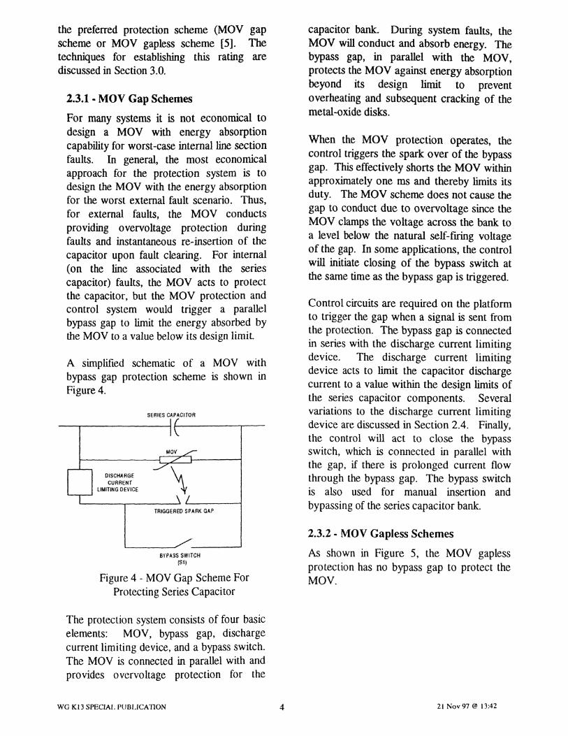
A simplified schematic of a MOV withbypass gap protection scheme is shown inFigure4.
SERIES CAPACITOR
MOV
OISCHARGE \CURRENT
LIMITING DEVICE
TRIGGERED SPARK GAP
BYPASS SWITCH(51)
Figure 4 - MOVGap SchemeForProtecting Series Capacitor
The protection system consists of four basicelements: MOV, bypass gap, dischargecurrent limiting device, and a bypass switch.The MOY is connected in parallel with andprovides overvoltage protection for the
WG Kl3 SPECIAL PUBLICAnON 4
capacitor bank. During system faults, theMOV will conduct and absorb energy. Thebypass gap, in parallel with the MOV,protects the MOV against energy absorptionbeyond its design limit to preventoverheating and subsequent cracking of themetal-oxide disks.
When the MOV protection operates, thecontrol triggers the spark over of the bypassgap. This effectively shorts the MOV withinapproximately one ms and thereby limits itsduty, The MOV scheme does not cause thegap to conduct due to overvoltage since theMOV clamps the voltage across the bank toa level below the natural self-firing voltageof the gap. In some applications, the controlwill initiate closing of the bypass switch atthe same timeas the bypass gap is triggered.
Control circuits are required on the platformto trigger the gap when a signal is sent fromthe protection. The bypass gap is connectedin series with the discharge current limitingdevice. The discharge current limitingdevice acts to limit the capacitor dischargecurrent to a value within the design limits ofthe series capacitor components. Severalvariations to the discharge current limitingdevice are discussed in Section 2.4. Finally,the control will act to close the bypassswitch, which is connected in parallel withthe gap, if there is prolonged current flowthrough the bypass gap. The bypass switchis also used for manual insertion andbypassing of the series capacitor bank.
2.3.2 - MOV Gapless Schemes
As shown in Figure 5, the MOV gaplessprotection has no bypass gap to protect theMOV.
21 Nov 97 @ 13:42

SEAlES CAPACITOR
Figure5 - MOV Gapless Scheme ForProtecting Series Capacitor
Protection of the MOV is provided byclosure of the bypass switch (typical closingtime of 50 ms) and/or by the opening of theline breakers. The MOV will, therefore, besubjected to much higher duty than in a gapscheme. The MOV in the gapless schememust have the capability to withstand theduty imposed by the worst case, internalfault current for a period of timeequal to theclosing of the bypass switch or the openingof the line breakers (whichever occurs first).The discharge current limiting device andbypass switch functions in the gaplessscheme are similar to their functions outlinedabove for the MOV gap schemes.
DISCHARGECURRENT
LIMITING DEVICE
MOV
\BYPASS SWITCH
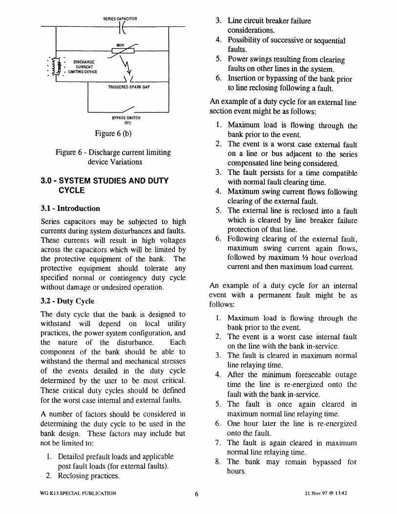
The discharge current limiting device usuallyconsists of an air core reactor. If additionaldamping is required, a resistor is connected inparallel with the reactor. The dischargedamping resistor, if used, reduces the 12 tstresses on the capacitor fuses. The use of adamping resistor can also prevent certainsystem problems related to standing waves inthe transmission system [7]. However,sufficient damping of the capacitor dischargeoscillations often can be achieved by the highfrequency losses of the reactor
To prevent undue steady state losses in thedischarge current limiting resistor when thecapacitor bank is bypassed, the resistor isequipped with either a spark gap (Figure 6 a)or a MOY (Figure 6 b) in series. When thebypass switch is closed, line current will onlyflow in the reactor. During a capacitordischarge, the resistor will be connected toeffectively dampen the capacitor dischargeoscillation.
SERIES CAPACITOR
The economic choice between the MOVgapless and MOV gap schemes is basedupon the cost of the additional MOVcapability versus the cost of the bypass gap.Other factors that influence this decision aregap maintenance concerns and systemoperation strategies [6].
OISCHARGE• CURRENT• LIMITING OEVICE
MOV
\TRIGGERED SPARK GAP
2.4 - Discharge Current Limiting Device
When the gap sparks over or when the bypassswitch is closed, a high amplitude, highfrequency current oscillation will occur due tothe local discharge of the capacitor throughthe closed loop formed by the operationof thebypass elements. In order to restrict thedischarge current to the rating of the seriescapacitor equipment (i.e., capacitor units,bypass switch, and gaps), a current limitingdevice is needed in the discharge circuit, asshown in previous figures.
WG K13 SPECIAL PUBLICAnON 5
BYPASS SWITCH(51)
Figure 6 (a)
21 Nov 97 @ 13:42
SERIES CAPACtTOR
Figure 6 (b)
Figure 6 - Discharge current limitingdevice Variations
3. Line circuit breaker failureconsiderations.
4. Possibility of successive or sequentialfaults.
5. Power swings resulting from clearingfaults on other lines in the system.
6. Insertion or bypassing of the bank priorto line reclosing following a fault.
An example of a duty cycle for an external linesection event might be as follows:
1. Maximum load is flowing through thebank prior to the event.
2. The event is a worst case external faulton a line or bus adjacent to the seriescompensated line being considered.
3. The fault persists for a time compatiblewith normal fault clearing time.
4. Maximum swing current flows followingclearing of the external fault.
5. The extemalline is reclosed into a faultwhich is cleared by line breaker failureprotection of that line.
6. Following clearing of the external fault,maximum swing current again flows,followed by maximum Y2 hour overloadcurrent and then maximum load current.
An example of a duty cycle for an internalevent with a permanent fault might be asfollows:
1. Maximum load is flowing through thebank prior to tile event.
2. The event is a worst case internal faulton the line with the bank in-service.
3. The fault is cleared in maximum normalline relaying time.
4. After the minimum foreseeable outagetime the line is re-energized onto thefault with the bank in-service.
5. The fault is once again cleared inmaximum normal line relaying time.
6. One hour later the line is re-energizedonto the fault.
7. The fault is again cleared in maximumnormal line relaying time.
8. The bank may remain bypassed forhours.
\MOV
BYPASS SWITCH(S1)
TRIGGERED SPARK GAP
, DISCHARGECURRENT
• LIMITING DEVICE
3.0 • SYSTEM STUDIES AND DUTYCYCLE
3.1 - Introduction
Series capacitors may be subjected to highcurrents during system disturbances and faults.These currents will result in high voltagesacross the capacitors which will be limited bythe protective equipment of the bank. Theprotective equipment should tolerate anyspecified normal or contingency duty cyclewithout damage or undesired operation.
3.2 - Duty Cycle
The duty cycle that the bank is designed towithstand will depend on local utilitypractices, the power system configuration, andthe nature of the disturbance. Eachcomponent of the bank should be able towithstand the thermal and mechanical stressesof the events detailed in the duty cycledetermined by the user to be most criticaLThese critical duty cycles should be defmedfor the worst case internal and external faults.
A number of factors should be considered indetermining the duty cycle to be used in thebank design. These factors may include butnot be limited to:
1. Detailed prefault loads and applicablepost fault loads (for external faults).
2. Reclosing practices.
WG K13 SPECIAL PUBLICATION 6 21 Nov 97 @ 13:42

An example of a duty cycle event for aninternal temporary fault might be as follows:
1. Maximum load is flowing through thebank prior to the event.
2. The event is a worst case internal faulton the line with the bank-in-service.
3. The fault is cleared in maximum normalline relaying time.
4. After the minimum outage time, the lineis successfully reclosed with the bank-in-service.
5. Maximum load is re-established throughthe bank.
Duty cycles would normally be adjusteddepending upon local practices and concerns.Typically, the external fault will defme therating of the MOY when a triggered gap isused in parallel. The internal fault usuallydefmes the rating of the MOV in a gaplessscheme.
The number of event duty cycles which theprotective equipment must withstand (for bothinternal and external faults) before bypassingthe bank for an extended period (hours), mustalso be specified.
3.3 - System Studies
While the duty cycle is being determined,studies must also be conducted in order toselect an appropriate location for the capacitorbank on the line and to issue generalcharacteristics to allow the manufacturer toappropriately design the equipment, mainly thecapacitor bank and the varistors.
The voltage proftle, MOY energy rating, costsof land and its development, constructioncosts and operating requirements are some ofthe items to review when selecting the site forthe series capacitor bank. The site selectionmust be determined before the [mal design canbegin since the location determines the faultcurrent.
The second aspect of system studies is toinvestigate the system performance for internaland external fault sequences. While the mainpurpose of the control and protectionequipment is to protect the bank and avoidequipment damage, it is also important that noaspect of the duty cycle is compromised.
Studies should be run with a reasonablyaccurate MOY model representation. In somecases, system studies are run with differentMOV models. The relationship betweenvoltage and current in the model used for thestudies could be expressed as a table of V-Ipoints or according to an exponential formula
such as: V =k x I ~. The factor k dependsupon the desired protective level which in tumdictates the number of series elements. Thefactor a. is related to the manufacturingprocess of the metal-oxide materiaL The V-Icharacteristic for a typical MOV installation isdepicted in Figure 7.
300
290~
~ 280o,
~ 270
Figure 7 - MOV V-I Characteristic
240 J I
10 A 100 A 1000 A 10000 AAmperes, At PEAK
The series capacitor bank could either belocated along the transmission line or at theline end terminals, Location along thetransmission line normally gives a better linevoltage profile and a lower fault current at theseries capacitor location compared with a lineend location. The lower fault current dutywould be significant for establishing the ~10Venergy rating.
"0 260>
250
-- Varistor Characteristic
••••• Constant Exponent. k = 238,(X =40 tor the examplecurveshown
WG K13 SPECIAL PUBLICATION 7 21 Nov 97 @ 13:42

As shown in the characteristic, a singleexponent model may not precisely representthe MOV V-I characteristic, over the entirecurrent range. It should be used with cautionand always compared with the [mal MOV V-Icharacteristic. In some cases, a multi-exponential, a polynomial or a look up tablemodel is more appropriate to use. Thus, theuse of a single exponential model should beused with caution and always compared withthe final MOY V-I characteristic.
There may be differences between theappropriate curve used for system studies asopposed to the curve used for the controlequipment model. In practice, however, thesedifferences will be small. More significantfactors which cause variations in the energycalculations are the specifics of the duty cycle,in particular the time duration of each faultevent.
Since the V-I characteristic varies accordingto the waveform injected into the MOV, thesystem engineer is sometimes presented withdifferent curves. In order to match varistorcolumns in a way to achieve a specific design,it is normal practice for manufacturers toinject a discharge current of 10 kA, with awave shape of 8/20 us, and to collect the dataas a reference point. This waveform producesa higher discharge voltage (typically 3% )than a slower, fundamental frequencywaveform. Utilities tend to use fundamentalfrequency waveforms to determinecharacteristics. Hence, when utilities considerthe design aspect of MOV in series capacitorinstallations, one must consider the slowerwaveform.
Different contingencies of external faults withvarious types of faults and duration's areconsidered in order to evaluate the stress onthe varistors. The utility may choose tospecify varistors having sufficient energyabsorption capacity for external faults in orderto prevent any bypass gap operation underthese conditions. The most severe internalfaults normally occur near the capacitor bank
WG K13 SPECIAL PUBLICArtox 8
itself. The studies must then evaluate thehighest varistor current and the maximumshort time energy level These parameters areessential to evaluate if any additional energycapacity is required by the varistors. This isan important consideration with respect tosizing MOYs and for spark gap only schemes,where capacitor bank reinsertion and gap arcextinction must be considered.
After the MOY characteristics have beenfmalized with the supplier (dimensioning,protective voltage level, coordinating current,V-I characteristic, etc.), the system studies areoften rerun, particularly those studiespertaining to MOY energy absorption duringthe duty cycle and during system swings. Forsome utilities, an additional purpose forrerunning the studies is also to generateaccurate electromagnetic transient program(EMTP) based studies for short circuitevaluation of the actual control andprotection system, particularly the MOVprotection.
The varistor model for MOY protection istypically based on MOV current as depicted inFigure 8. The simplified formula in Figure 9(b) for the varistor characteristic can be usedto calculate energy based on a varistor currentonly measurement and can be compared withthe EMTP studies.
Figure 8 - Current Based, Varistor Model
21 Nov 97 @ 13:42

4.0· PROTECTION AND CONTROLPHILOSOPHY
4.1- Introduction
A review of existing series capacitorinstallations shows that the basic functionsincorporated in the protection and controlsystems are similar. The details of thesesystems, however, can be very different.These details are influenced by the operationalphilosophy of the utility specifying theequipment. The elements which influence thisphilosophy are power system operationalrequirements, the redundancy philosophy ofthe utility and ultimately, the evaluation of thecost of the system when compared to thebenefits derived from the system. This sectionaddresses similarities and variations inprotection and control philosophies amongutilities.
4.2 • Protection and Control Functions
The series capacitor protection and controlsystem can be divided into four basic groups:
1. A group that provides protection of theseries capacitor components againstoverstress from system conditions: Thisgroup includes:
• Capacitor overvoltage protection• MOY overload protection• Bypass gap protection
Capacitor overvoltage protection consistsof two primary elements, transientprotection and overload protection. Thetransient protection is needed to protectthe capacitor from over voltages caused byhigh magnitude through current. Thesehigh currents would flow during powersystem faults and the reinsertion of thecapacitor following the fault (see Figure15). The protection for this condition isprovided by bypass gaps or a metal oxidevaristor (MOV) based scheme as detailedin section 2.0.
WG K13 SPECIAL PUBLICATION 9
Capacitor overload protection is a functionof the specified overload requirements forthe bank and utility practice. A fewutilities may not specify this protection ifthey believe that when an overload occurs,the power system is in serious trouble andbypassing of the series capacitor will nothelp the system to survive. When applied,the determining factor for the overloadprotection is the permissible capacitorovercurrent for the required systemoverload time.
Most modem series capacitors utilizeMOV protection to control transientovervoltages. Section 3.0 provided anoverview of the duty cycle considerationsand system studies needed to establish theenergy rating of the MOV. The protectionof the MOY for duties which exceed itsrating as described above is carried out byfunctions that measure MOV energy,MOV current, and MOV temperature, asdescribed in section 5.0.
Bypass gap protection typically includesdetection of prolonged gap conduction.
2. A group that provides protection to limitdamage to the series capacitor followingcomponent failure. This group includes.
• Capacitor fuses• Capacitorunbalance• Platform fault protection• Bypass gap failure• MOV failure• Bypass switch failure• Pole disagreementprotection• Protection & control system failure
All these protections are necessary toprotect the series capacitor againstadditional damage due to internalequipmentfailures.
3. A group that provides the series capacitorcontrol functions for bypassing, insertion
21 Nov 97 @ 13:42
(automatic or manual), and reinsertion ofthe capacitor bank.
The control functions vary widely amongdifferent utilities depending on the utility'soperational strategy and practice. Someutilities use automatic insertion functionsto insert the series capacitor prior to orafter line energization. Some automaticallybypass the seriescapacitorwhen the line isde-energized. Others use a manual (bysystem operators) insertion and bypassing.Some utilities use a complicated keyinterlocking system between the variouscomponents (disconnect switches andbypass switches) while others do not usean interlocking system at all.
4. A group that provides protection toprotect the power system againstpotentially harmful conditions caused bythe series capacitor.
This group includes subharmonic andsubsynchronous protection. See section7.6 for a discussion on this subject.
4.3 - Redundancy
Most of the installed series capacitors havebeen designed and are operating with a non-redundant protection and control system.During the 90's a number of utilities specifiedredundant systems. The reason for this is theutilities increased emphasis on availability ofthe series capacitors. With a redundantprotection system, the series capacitor canremain in service while the other system isundergoing maintenance.
Non-redundant systems are still being usedespecially when cost is a major concern.Because of the fewer components in the non-redundant system, the risk of unwantedprotection and control operation is minimized,increasing security.
To achieve the increased availability of aredundant system, it is important to duplicate
WG K13SPEC~ PUBLICA110N 10
all protection functions including all auxiliaryequipment such as station batteries and bypassswitch operating coils. The redundant systemsshould physically be located in separate panels.The additional cost of a redundant systemshould be weighed against the benefit ofincreased availability.
Technology now allows the protection andcontrol system to be ground mounted. Thisreduces the cost of maintaining the dualsystem, and allows for maintenance andtesting of one system while the bank is inservice protected by the redundantsystem.
If a redundant protection and control system isused, an alarm should be given for loss ofredundancy. In addition, on loss of animportant function in both systems, the seriescapacitor may be bypassed.
5.0 - MOV PROTECTION
5.1 - Introduction
The MOY must be protected against thermalstresses caused by fault and overloadconditions. Typically, MOY protectionconsists of the following:
• MOYEnergy
• MOV High Current
• MOY Temperature Overload
• MOY Failure
5.2 - MOV Energy Calculations
There are two approaches used by protectionsystems to determine the energy absorbed bythe varistors.
Integral of Power - It is a function of themeasured current in the varistor column andthe voltage across the varistor. The voltagecan either be estimated from the V-Icharacteristic of the varistors or calculatedfrom the current, using exponential orpolynomial relationships. Figure 9 shows a
21 Nov 97 @ 13:42

simplified mathematical approach for thismethod.
Duty cycle philosophy, accuracy, and delay ofoperation are also important factors in thedetermination of MOV energyrequirements.
(1 + 1/a )
P=V-I= k-I
(b.)
Figure 9 - MOV Energy Calculations
Integral of the Current (Coulombs) - Theenergy is calculated by integrating thecurrent over time, assuming a constantvoltage. The voltage is selected from thevoltage given for a specific varistor current(I). This method will yield calculated energywhich is lower than the actual for faults withcurrents higher than (I) and higher than theactual for faults with currents lower than (I).It is therefore appropriate to select thisvoltage according to the application.
1---+
1-<
p = V -I
E = V -I -t
v= k.1 1/0:
(1 + 1/0:)
E = k - I t
v ---.,..
Energy expressed interms of voltage,current and time
(a.)
Energy expressedin terms of k factor,current, and time
a. Duty Cycle Philosophy - The powersystem analysis that establishes thesystem requirements for the MOYsometimes includes a stated margin butmore often includes worst case faultscenarios that create margin in therequirements.
b. Delay of Operation - Includes the delaysin measurement, detection, andexecution of the control signal sent toinitiate gap conduction or circuitbreaker closing.
c. Accuracy - Accuracy can vary as afunction of fault current. Accuracydepends on the measurement equipment,energy model, and signal transmissionsystem. Accuracy could be increased byhaving two separate measurementsystems, one dedicated to high currentmeasurement and the other dedicated tolow current measurement.
5.3 - MOV Protective Functions
5.3.1 - MOV Energy
This protection prevents a high energyabsorption over a short time period whichmay cause cracking of the metal oxide disks.This protection complements the MOY highcurrent protection for internal faults. It alsoprovides protection against high energyabsorption due to external faults exceedingthose specified in the dutycycles.
The threshold is set based upon the shorttime energy rating of the MOV. When thisenergy level is reached, the gap is triggeredor the bypass switch is closed. In manycases, reinsertion is temporarily blocked forat least one minute to allow temperatureequilibrium in the varistor disks. Thethreshold will be set differently depending on
WG K13 SPECIAL PUBLICATION II 21 Nov 97 @ 13:42

the specified duty cycles. For a gaplessscheme, the most severe internal fault tendsto be the criteria for setting the threshold.For a gap scheme, the most severe externalfault is usually the criteria. Normally, thisprotection will not operateona swing.
The accuracy of the energy monitor is afactor which must be considered whenadjusting the threshold. For instance, whenthe short time energy threshold is set abovethe level for an external fault, the thresholdmust be set taking the negative toleranceinto consideration. On the other hand, whenthe threshold is set below the varistorinstalled capacity for an internal fault, thepositive tolerance of the energy monitormust be taken into consideration. However,in practice, this tolerance is not a significantfactor for internal faults since the highcurrent protection is expected to initiatebypass switch closure before the short timeenergythreshold is reached. See Appendix Ifor moredetails.
The time period for the energy integration aswell as the cooldown time are importantfactors and must be consistent with thereturn to temperature equilibrium within theMOY disks. As a result, the energiesassociated with two faults, approximately0.5 seconds apart is additive whereas theenergies associated with two faults a minuteapart is not. Note that the one minute timeis consistent with the one minute blockingtime for reinsertion discussed earlier in thissection.
Thus the accuracy of, energy measurement,speed of response, and maximum energy areall important factors in ensuring properprotection of the MOV. The design criteriamust also take into consideration currentsharing and additional margins. Verificationis sometimes made during a simulation test(worstcase fault) or field tests.
WG K13 SPECIAL PUBLICATION 12
5.3.2· MOV High Current
The purpose of the MOV high currentprotection is to reduce unnecessary energyabsorption for heavy internal faults. Thethreshold should be above the maximumexternal fault current. Triggering of thespark gap or initiation of closure of thebypass switch is instantaneous based uponcurrent magnitude only. Reinsertion of thefaulted phases follows a short time later(could be made within the dead time of thereclose cycle or after successful reclose,dependingon the utility practice).
5.3.3 - MOV Temperature Overload
The purpose of MOY temperature overloadprotection is to prevent damage to the MOVdiscs due to overheating. Depending uponthe construction and the quantity of MOVinstalled, the manufacturer establishes aconstant temperature rise for each degree ofMJ energy accumulated, as depicted in theexample shown on Figure 10.
200
180
160
140o
°120t)
~100«i~ 80
E60 .7 Co rise/MJ~
.- 40
20 ~ .'" Starting temperature
40 Co ambient
20 40 60 80 100 120 140 160 180 200 220
MJ
Figure 10 - Example EnergylHeatingCharacteristic
The maximum design temperature could bereached during a period of successiveexternal line section faults or long termoverload conditions following a systemdisturbance.
The thermal model for the protection mayinclude ambient temperature which can be
21 Nov 97 @ 13:42

used in the simulation of the overheating aswell as the cooling process. Steady stateload current on the series capacitor line andthe resulting voltage across the MOV isanother input which may be included withthe model.
When the temperature reaches the maximumlimit, the bypass gap is triggered and/or thebypass switch is closed. The coolingcharacteristics of the MOV is part of thethermal model for the protection.Reinsertion is permitted only when theMOV can safely withstand a critical faultimmediately after the reinsertion has takenplace. Some philosophies maintain that theMOVs must cool down sufficiently so that afull duty cycle is again possible. An exampleof a cool-downcurve is shown in Figure 11.
180
160
140
1200
0100
I)~
:J&; 80~
I)Q. 60EG)
t- 40
20
t 2 3 4 S 6 7 8 9 10
time, hours
Figure 11 - Example MOV Cool-downCharacteristic
5.3.4 - MOV Failure
MOV failure protection is applied to detectthe failure of a MOV column. Most varistorfailures will be evident only at the time of asystem fault which causes the varistor toconduct. Therefore, the main objective ofthis protection is to detect varistor failuresprior to: 1) system fault clearing, 2) gapoperation, or 3) bypassswitch closing. Notethat gap operation and/or bypass switch
closing could be initiated by other protectivefunctions, e.g., MOV high current.However, in some cases it is possible that avaristor failure cannot be detected if thefailure coincides with the clearing of asystem fault. In addition, due to the varistorfailure, the gap might not have sufficientvoltage to operate. It is desirable to havethe MOV failure protection close the bypassswitch directly, rather than trigger the sparkgap. Note that if there is insufficient voltageto operate the bypass gap, an alarmindicating failure of the gap to operate mayresult.
Different techniques can be used for thisprotective function. For MOVs configuredin two branches, as shown in Figure 12 a),the current in each branch (or the absorbedenergy) ·is compared with the other branch inorder to detect an MOV failure. Sincefailure of a column results in a short circuitin that branch, high accuracy is not requiredin the measurement. This differentialtechnique provides high speed detection(could be less than 2 milliseconds) of afaulty branch.
(a)
CT1
CT2
(b)
Figure 12 - MOV UnbalanceProtection- ct Arrangements
For a MOV configured as a single branch asshown in Figure 12 b) the varistor current(CT2) is compared to the line current (CTl).
WG K13 SPECw... PUBLICATION 13 21 Nov 97 @ 13:42
In case of varistor failure, the MOV currentwill be approximately the same as the linecurrent. One should note that this methodof comparing the varistor current to the linecurrent could also be used for the two-branch MOY configuration. This linecomparison technique detects a varistorfailure after a minimum of one half period ofthe power frequency so as to avoid falseindication of varistor failure.
The action for this protection is bypassswitch closureand lockout.
6.0 - PROTECTION OF THE BYPASSGAP
6.1- Introduction
This protection is only included for systemsequipped with bypass spark gaps. Theprotection operates differently for a gap onlyschemecompared witha MOV scheme.
6.2 - Gap Only Scheme
The gaps will conduct any time there is amomentary overvoltage across the bank:exceeding the set level of the bypass gap (dueto a line fault). Upon gap conduction, gapprotection orders the bypass switch to closeand thereby extinguish the gap arcing. Thisaction will also cause the protected capacitorsegment to be temporarily bypassed. The gapprotection will allow reinsertion of the seriescapacitor segment after a time delay sufficientfor the gap to regain the required voltagewithstand to allow emergency or normal loadflow through the bank.
Bypass switch operation can be on a singlephase basis or on a three phase basis,depending upon the bank design and systemrequirements. For example, if the gapsconduct on only one phase for an external linesection fault, then it would be appropriate toonly order closure (and subsequent opening)of the associated phase of the bypass switch.For an internal line section fault where the line
WG K13 SPECIAL PUBLICATION 14
is switched three pole, it may be appropriatefor the bypass switch operation to be on athree phase basis. Gap protection wouldinitiate closure of the bypass switch associatedwith the faulted phase, with line voltage andlinecurrent logic initiating closure of the othertwo bypass switch phases. For some gap onlyschemes, opening of the line breakers oninternalfaults is the means for arc extinction.
The gaps are only designed to withstand gapconduction for limited time. In the case ofprolonged gap conduction, the gap protectionwill initiate a bypass switch closure andlockout.
6.3 - MOV Scheme
The gaps will conduct when triggered fromthe MOY protection. In some applications, aclose command to the bypass switch is sentfrom the MOY protection at the same time thegaps are triggered. In other applications, thearc is extinguished by relying on line breakersopening (for internal faults). In case ofprolonged gap conduction, a bypass switchclosure and lockout will be initiated. A bypassswitch closure and lockout will also beinitiated in case of gap misfire (conductionwithout being triggered) or failure of the gapto conduct when triggered. Separate alarmswill also be given for all theseconditions.
7.0 - OTHER SERIES CAPACITORBANK PROTECTION
7.1 - Introduction
The protective functions discussed in thissection are those provided to protect thecapacitor elements and units against abnormalsystem conditions and against equipmentfailure related to the capacitor units theplatform insulation, and the associatedswitching equipment.
21 Nov 97 @ 13:42

7.2· Capacitor Unit Failure Protection
Fuses, either external or internal, provide theprimary protection for the series capacitorunits or elements. The fuse protection appliedmust be coordinated with the unbalanceprotection (described in section 7.4)
7.2.1 • Externally Fused Capacitors(current limiting-expulsion type)
In this scheme, external fuses capacitorsprovide protection for dielectric failure, leadfailures, internal bushing failures, andbushing flashovers. A failure within thecapacitorelements results in fuse operation,removing the entire unit from service. Theexpulsion fuse provides visual indication offuse operation which provides fastermaintenance procedures.
A capacitor unit failure could result in ashort circuit across a parallel connectedgroup of healthy capacitor units. The fusemust be selected to interrupt the fault andminimize the possibility of case rupture. Theremoval of the faulted capacitor unit fromthe series capacitor bank, upon external fuseoperation, causes an overvoltage on theremaining capacitor units in that groupwhich can be detected by unbalanceprotection.
7.2.2 - Internally fused capacitors
In this scheme, internally fused capacitorelements offer the possibility of allowingseveral failures of internal capacitorelementswithout affecting the overall expected life ofthe capacitors. The removal from service ofthe remaining capacitor elements would notthen be necessary. Typically, the failure of10 to 20 percent of the elements will requirethe replacement of the complete unit. Thisarrangement also offers lower parallelenergy discharge in the case of capacitorelement faults and provides compact cansize.
WG Kl3 SPECIAL PUBLICATION 15
However, internally fused capacitors onlyprovide protection for capacitor elementswithin the capacitor sections. Connectionsbetween the elements and the bushings arenot protected. Furthermore, lack of visualindication of fuse operation may result inlonger maintenance. This, however may notresult in less availability when comparedwith externally fused capacitors for thereasonoutlined in the first paragraph.
Faults external to the protected capacitorsections, e.g. bushing flashovers, will causeunbalance protection operation resulting inthe deenergization of the whole seriescapacitor bank.
7.3· Platform Fault Protection
Each platform has a protection system todetect an insulation failure to platform. Oncesuch an event is detected, the bypass switchwill automatically close and lockout. Analarm at the control house will indicate aplatform fault has occurred and the affectedphase.
7.4 • Capacitor Unbalance Protection
Series capacitors are configured in a certainnumber of series and parallel connections toform two or more balanced parallel strings.Different capacitor bank configurations can beemployed. One configuration is a bridge or"H" in which current unbalance detection isachieved in the balance branch. Othercapacitor bank installations are arranged byparalleling two capacitor branches andunbalance detection is achieved using acurrent differential principle for the twobranches. The two configurations are shown inFigure 13.
21 Nov 97 @ 13:42

Figure 13 - Capacitor Bank UnbalanceProtection Arrangements
Protection schemes differ depending on thecapacitor arrangement and the method usedfor fusing (internal and external). The mainprotectionobjectivesare listed below:
• Detect blown capacitor fuses.
• Detect short-circuits caused byflashovers across the bushings ofcapacitor units .
• Detect defective capacitor elements inthe capacitor units and racks.
• Protect the remaining capacitor elementsor units from high overvoltages when anumber of fuse elements (internally fused)or units (externally fused) have blown, sothat the overvoltage on the remaininghealthy capacitor units or elements remainsbelow a certain level at nominalcurrent.
Conventional relays or integrated logiccircuitry are provided to measure thefundamental frequency current for thedetection of the electrical asymmetries in thecapacitor arrangement. Since the magnitudeof the capacitor unbalance current will varywith the magnitude of the total capacitorcurrent, the threshold for operation of thisprotection is adjusted depending on thecapacitorcurrent as shown in Figure 14.
(a) 'H' or bridge (b) parallel branch
Three different functions are typically achievedby the protection:
1) A time delayed low set level to initiate analarm in case a number of fuse elements orunits have failed (Curve #1 in Figure 14).Normally a minimum level is required toassure that there will be no false alarms atlow line load. Natural unbalance shouldbe considered when planning this setting.The time delay is necessary to providetime to allow the external fuse to blow.Often, this level is set for an asymmetrythat results in the detection of the desiredminimum allowable elements lost at ratedload.
2) A time delayed level set to initiate a bypassand lockout operation if additional fuseelements or units blow in a string (Curve#2 in Figure 14). The time delay should beset longer than the normal line faultclearing and system swings duration toavoid unnecessary bypassing of the bank.The concern is that there may be excessivedamage to the bank: if a rack flashes overand the clearing time is set very slow. Anoptional solution is to add a second triplevel (see 3a and 3b below).
Often this level is set for an asymmetrythat results in the maximum permissibleovervoltage on the highest stressedcapacitor units.
3) a) An optional high set level to initiate afast bypass should a flashover or short-circuit occur is shown in Figure 14curve #3a. The setting should be setto detect a shorted group due to abushing or a rack flashover. Theprotection will initiate a bypass and abank lockout. The disadvantage ofthis scheme is that the unbalancecurrent can be very high near the limitswhere the MOV begins to conduct.
b) A second option is to set the fast highset level above the maximum overloadlevel expected from curve #2. Thisscheme is armed when the line current
WG KI3 SPECIAL PUBLICATION 16 2l Nov 97 @ 13:42

is above a muumum setting forsecurity. The fast bypass level isshown in Figure 14 curve #3b and isindependent of load current. Linecurrent compensation is not requiredfor this fast tripping function. Theprotection will initiate a bypass and abank lockout.
AICapacitorUnbalanceCurrent
RATED LOAD MAXIMUM PERMISSIBLEOVERLOAD
IL Capacitor Bank load Current
Figure 14 - Typical Capacitor UnbalanceProtection Characteristic
7.S - Capacitor Overload Protection
The life expectancy of capacitors dependsmainly on characteristics related to thedielectric material, on the voltage gradientapplied to the dielectric, and on its hot-spottemperature. Therefore, the main protectionobjective is to protect the capacitor units fromexcessive short-time and sustainedovervoltages associated with overloads. Theprotection must be coordinated with thespecified overvoltage cycle imposed by thenetwork (Figure 15) and the short time-current characteristic of the varistor designedto protect the capacitor bank.
The major concern for the oldercapacitor typeusing paper or paper-fill dielectric typematerials is the thermal overheating which mayresult from high level current and highambient temperatures. Arcing and gassing ofthe paper are also phenomena that should be
WG K13 SPECIAL PUBLICATION 17
considered since it may increase theprobability of case rupture. One must bear inmind that arcing is not eliminated until the unithas completely failed.
The advantages of the newer all-ftlmcapacitors in comparison to the older types arerelated to its characteristics such as highpartial-discharge inception voltage (PDIV),better heat-dissipation characteristics (lowlosses), and reduced potential for case rupture.Only small amounts of gas are produced incase of internal arcing but are eliminated byshorting the section foils. Ionization in theform of partial discharges in the dielectric isthe most important phenomenon whichdeteriorates the dielectric strength and thusreduces the overvoltage capability of thecapacitors. Consequently, in high voltageapplications, capacitors are designed towithstand high temporary overvoltages withrespect to an overvoltagecycle imposed by thenetwork and specified by the utility.However, deterioration of the dielectricstrength by thermal stress or by voltage levelsbelow the PDIV is very unlikely in all-ftlmcapacitors.
The overload detection is provided from acapacitor current or a line current ct.Harmonics in the line current will have limitedimpact on the voltage across the capacitors(lower impedance at higher harmonics), whenthe bypass switch is open. The capacitoroverload protection must respond properly tovarying current levels in addition to a singleoverload level. Since partial discharges willbe persisting in the presence of high peakvoltages, the protective function requires anintegrating characteristic which will limit theoperation as a function of the energydeveloped in the dielectric. A recovery timedepending on the energy level reached shouldbe also implemented.
The protective action will result in bypassswitch operation, temporary blocking, and insome cases automatic capacitor reinsertion
21 Nov 97 @ 13:42
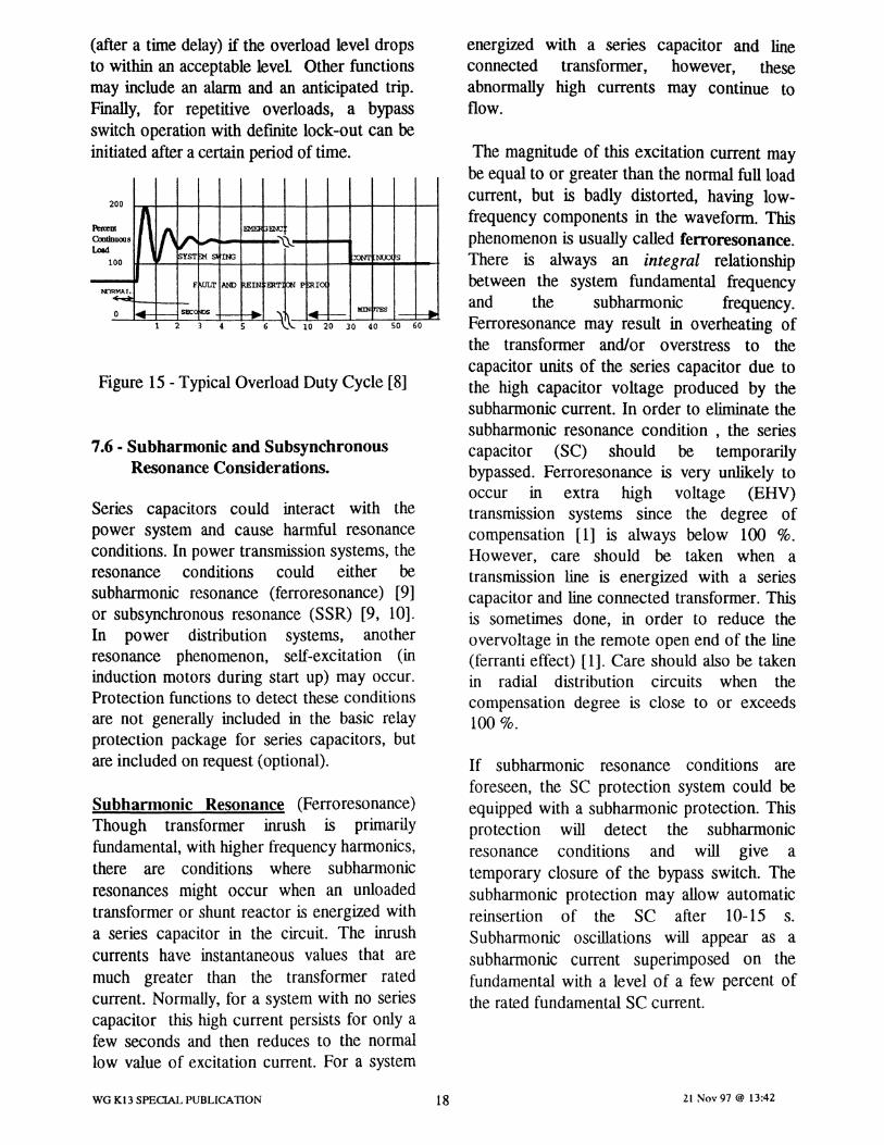
(after a time delay) if the overload level dropsto within an acceptable level Other functionsmay include an alarm and an anticipated trip.Finally, for repetitive overloads, a bypassswitch operation with defmite lock-out can beinitiated after a certainperiodof time.
Figure 15 - Typical Overload Duty Cycle [8]
7.6· Subharmonic and SubsynchronousResonance Considerations.
Series capacitors could interact with thepower system and cause harmful resonanceconditions. In power transmission systems, theresonance conditions could either besubharmonic resonance (ferroresonance) [9]or subsynchronous resonance (SSR) [9, 10].In power distribution systems, anotherresonance phenomenon, self-excitation (ininduction motors during start up) may occur.Protection functions to detect these conditionsare not generally included in the basic relayprotection package for series capacitors, butare included on request (optional).
Subhannonic Resonance (Ferroresonance)Though transformer inrush is primarilyfundamental, with higher frequency harmonics,there are conditions where subharmonicresonances might occur when an unloadedtransformer or shunt reactor is energized witha series capacitor in the circuit. The inrushcurrents have instantaneous values that aremuch greater than the transformer ratedcurrent. Normally, for a system with no seriescapacitor this high current persists for only afew seconds and then reduces to the normallow value of excitation current. For a system
energized with a series capacitor and lineconnected transformer, however, theseabnormally high currents may continue toflow.
The magnitude of this excitation current maybe equal to or greater than the normal full loadcurrent, but is badly distorted, having low-frequency components in the waveform. Thisphenomenon is usually called ferroresonance.There is always an integral relationshipbetween the system fundamental frequencyand the subharmonic frequency.Ferroresonance may result in overheating ofthe transformer and/or overstress to thecapacitor units of the series capacitor due tothe high capacitor voltage produced by thesubharmonic current. In order to eliminate thesubharmonic resonance condition , the seriescapacitor (SC) should be temporarilybypassed. Ferroresonance is very unlikely tooccur in extra high voltage (EHV)transmission systems since the degree ofcompensation [1] is always below 100 %.However, care should be taken when atransmission line is energized with a seriescapacitor and line connected transformer. Thisis sometimes done, in order to reduce theovervoltage in the remote open end of the line(ferranti effect) [1]. Care should also be takenin radial distribution circuits when thecompensation degree is close to or exceeds100%.
If subharmonic resonance conditions areforeseen, the SC protection system could beequipped with a subharmonic protection. Thisprotection will detect the subharmonicresonance conditions and will give atemporary closure of the bypass switch. Thesubharmonic protection may allow automaticreinsertion of the SC after 10-15 s.Subharmonic oscillations will appear as asubharmonic current superimposed on thefundamental with a level of a few percent ofthe rated fundamental SC current.
WG K13 SPECIAL PUBLICATION 18 21 Nov 97 @ 13:42
Subsynchronoos Resonance (SSR)SSR is a far more significant problem whichmight occur when the series capacitorinteracts with thermal turbine generator (TG)sets. This may cause damage to the shaft ofthe TO unit. This phenomenon is referred toas subsynchronous resonance (SSR) because itis a result of a resonant condition, which has aresonant frequency below the fundamentalfrequency of thepower system [9, 10].
There were two SSR incidents in the early1970's; since then SSR study techniques havebeen developed and widely applied and nonew problems have occurred. Ifsubsynchronous resonance conditions aresuspected for a series compensated system,these should be investigated as part of theinitial system studies.
SSR is difficult to detect at the seriescapacitor location.. Generally all new SCinstallations are designed with a degree ofcompensation that will not cause SSR tooccur. If SSR can not be avoided by a properselection of the degree of compensation, SSRmust be controlled by different SSRcountermeasures [9]. Historically, thesemeasures included static blocking filters at theTO-unit, a static Var compensator (SVC)located near the TG-unit, coordinated seriescapacitor control with loading and backupSSR relays at the TG-unit. A newcountermeasures which is effective involvesthe installation of a Thyristor ControlledSeries Capacitor (TCSC) designed for SSRmitigation [ 11,12,13,14].
7.7 - Bypass Switch Failure Protection andPhase Disagreement Protection
The purpose of this protection is to detect: 1)failure of the bypass switch to respond to aclose initiation within the expected time, and2) prolonged disagreement between bypassswitch phases.
If a bypass switch fails to respond to a closecommand initiated by a bank protection
WG K13 SPECIAL PUBLICATION 19
function, a backup action is required. Thebackup action could be tripping the line, orclosing an alternate bypass disconnect switchat the series capacitor station. It should berecognized, however, that the closing speed ofthe disconnectswitchwill likely be slow.
If the bypass switch phases are in differentpositions for a prolonged period of time, thebypass switches in all phases of the module areto be closed.
7.8 a Lockout Protection
Lockout protection will block all automaticand manual bypass switch opening operationsfollowing a closing operation initiated by theprotection functions as indicated above. Thelockout feature usually requires local manualreset. Refer to the summary table 'Summaryof Suggested AlarmslIndications/ControlAction' in Appendix II for further information.
7.9 - Key Interlock
For safety reasons, utilities generally usedocumented procedures or an interlockingsystem to prevent inadvertent opening/closingof disconnects and the bypass switchassociated with the series capacitor bank.
An interlocking system, for example, wouldprevent closing of the bypass disconnects ofthe bank unless the bypass switch was closedfirst. If the bypass disconnects wereinadvertently closed first, the capacitor bank:and the bypass disconnects would be subjectedto the full undamped discharge of thecapacitor bank which is not desirable. Aninterlocking systemcan also prevent personnelfrom inadvertently accessing the capacitorplatforms.
The design of an interlocking scheme must becoordinated with the supplier of the seriescapacitor equipment. In many instances, thecapacitor equipment, including the bypassswitch is provided by the series capacitorsupplier, whereas the isolating disconnects,
21 Nov 97 @ 13:42
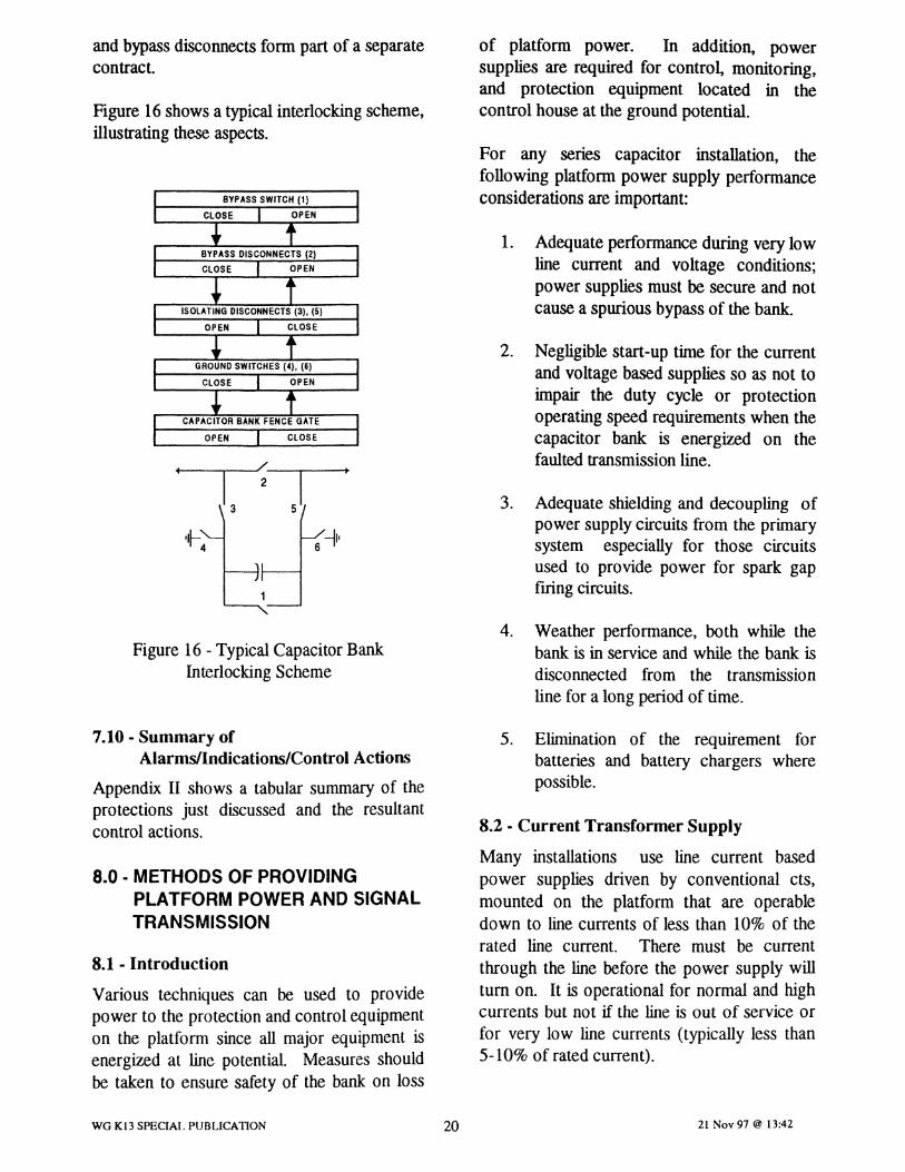
and bypass disconnects form part of a separatecontract.
Figure 16showsa typical interlocking scheme,illustrating these aspects.
1. Adequate performance during very lowline current and voltage conditions;power supplies must be secure and notcause a spurious bypassof the bank.
2. Negligible start-up time for the currentand voltage based suppliesso as not toimpair the duty cycle or protectionoperatingspeed requirements when thecapacitor bank is energized on thefaulted transmission line.
3. Adequate shielding and decoupling ofpower supplycircuits from the primarysystem especially for those circuitsused to provide power for spark gapfiring circuits.
For any series capacitor installation, thefollowing platform power supply performanceconsiderations are important:
of platform power. In addition, powersupplies are required for control, monitoring,and protection equipment located in thecontrol house at the ground potential.
~I'6"~4
Figure 16 - Typical CapacitorBankInterlocking Scheme
4. Weather performance, both while thebank is in service and while the bank isdisconnected from the transmissionline for a long periodof time.
7.10 - Summary ofAlarms/lndications/Control Actions
Appendix II shows a tabular summary of theprotections just discussed and the resultantcontrol actions.
8.0 • METHODS OF PROVIDINGPLATFORM POWER AND SIGNALTRANSMISSION
8.1 - Introduction
Various techniques can be used to providepower to the protectionand control equipmenton the platform since all major equipment isenergized at line potential. Measures shouldbe taken to ensure safety of the bank on loss
5. Elimination of the requirement forbatteries and battery chargers wherepossible.
8.2 • Current Transformer Supply
Many installations use line current basedpower supplies driven by conventional cts,mounted on the platform that are operabledown to line currents of less than 10% of therated line current. There must be currentthrough the line before the power supply willtum on. It is operational for normal and highcurrents but not if the line is out of service orfor very low line currents (typically less than5-10% of rated current).
WG K13 SPECIAL PUBLICATION 20 21 Nov 97 @ 13:42
A current transformer supplyuses a smallcorect, with a thyristor crowbar to short thesecondary when the power supply capacitor ischarged to a suitable level. The ct mustoperate over a wide range of currents. Thethyristor must be capable of handling themaximum ringdown currentfor a bank fault
8.3 • Optically Powered Supply
The optically powered supply utilizes a laserdiode which is housed in the ground basedcontrol building feeding an optical powerconverter through an optic link. The electricalenergy which is available through zero linecurrents as well as during line fault conditionsis sufficient and reliable to power a data linkor to optically trigger a spark gap over theexpected ambient temperature range.
8.4 • CCVT Supply
A ccvt supply provides a voltage with the lineenergized, independent of line current. It issometimes referred to as an inverted ccvtsupply since the base unit is mounted at theplatform level. Some installations include aground mounted base unit as a voltage signalfor protection and control purposes. Thedisadvantage of this scheme is that the ccvtoutput voltage will collapse for a severe close-in fault.
8.5 • Battery Supply
To maintain power when the line currentdrops below the power supply threshold orwhen the capacitor bank is isolated for anextended period of time, platform batterieshave been used. Batteries are charged fromthe ct/ccvt supplies discussed above.
The battery is sized considering cold weatherperformance, and desired performance for thespecified outage interval.
8.6 • Power Supplies Specific to Spark GapFiring Circuits
Two broad options may beconsidered:
WG K13 SPECIAL PUBLICAnON 21
a. schemes which work on the voltagedivider principle, utilizing the voltageacross the capacitor units
b. schemes which operate from a powerct or ccvt base unit mounted on theplatform
8.7 • Ground Mounted Supplies
The ground mounted supplies would be thesameas requiredin a substation.
8.8 • Platform Information TransmissionMethods
The information from the platform or linepotential can be sent to ground level byvarious methods. The currents can beobtained using iron core cts, but the cost ishigh for high power system voltages; hencethe information is sent to ground potential viafibre optics.
Signals from low-voltage class cts mounted onthe platform can. be multiplexed and/or sent,individually via optical fibres, down to groundlevel using various methods of modulation ordigital transmission protocol.
Other direct measuring methods areavailable. Some cts use fibre optics to theplatform and from ground level send a laserpulse up to the platform to provide energy tothe electronics coding the current level andsend it back down via the same fibre. At theplatform, an ironcore ct can be used, since theinsulation requirement is not a problem in thiscase. A second method of getting the currentinformation down to ground level would be touse the Faraday effect in a glass ct. Thisrequires two fibres per ct. A polarized lightsignal is sent up to platform and the magneticfield shifts the light. The angular shift of thelight is a measure of the instantaneous current
There may be nonpower system informationthat must be sent to or from the platform, e.g.,the signal to trigger the bypass gap. Somedesigns do this on the platform while others
24 Nov 97 @ 13:43

perform the calculations at ground level todetermine when the firing level has beenreached.
Most installations use fibre optics to sendinformation from the platform to ground levelfor high voltage banks because of economicsand reliability. There is also a trend to havethe protection system at ground level tosimplify maintenance and trouble shooting.However, some installations have allprotection and control equipment mounted onthe platform and only status informationnecessary for operating the equipment is sentdown to groundlevel.
9.0 - CAPACITOR BANK RELAYINGISSUES
9.1 - Introduction
The technology of the protection and controlequipment used on series capacitor banks hasevolved over the years. Older equipmentmade extensive use of electromechanicalprotection and control (P&C) equipment (thisterm will be used to describe all protection andcontrol equipment) which are located on theplatform. Recent equipment have minimizedthe use of P&C equipment or electronics onthe platform due to advancements in fibreoptic communications technology. Therelocation of P&C equipment from theplatformto the ground level has minimized thelevel of exposure to electrical environmentalproblems. However, some electronicequipment will continue to exist on theplatform and must perform properly. In thefuture, true fibre optic current transformerswill likely reduce all platform electronicsfurther.
9.2 - Environment
The presence of P&C equipment on theplatform requires careful consideration of theelectrical environment in which it exists. The
WG K13 SPECIAL PUBLICATION 22
issueswhich have to be addressed in designingseries capacitor banks are similar to thosefaced by the designer of a substation.However, close proximity to spark gap ftringcircuits and the resultant high dischargecurrents makes these problems morepronounced. Furthermore, the difficulties inproviding monitoring equipment for these highdischarge paths, makes these problemsdifficult to resolve.
The series capacitor equipment is exposed to awide range of current levels, both in amplitudeand frequency. These include: 1) the highmagnitude of power frequency currents(ranging from DC to fundamental frequency)which can occur due to system faults and areamplified by the presence of the seriescapacitors in the system, 2) the high frequency(typically 400 to 1000 Hz), high amplitude(typically 50 to loo-kA) ring-down of thecapacitor discharge current through thedischarge current limiting device, and 3) theextra high frequencies (over 100 kHz) whichoccur during the opening and closing of thebank disconnect swit.ches. The flow of thehigh frequency currents can give rise to veryhigh voltages due to the L*di/dt rise on theplatform buswork.
9.3 - Insulation Considerations
The devices used to measure these currentsmust be properly insulated for the applicationin which they are applied. This requires thatan evaluation of the insulation coordinationbe performed to establish the necessaryvoltage class and BIL level of the measuringdevices. If these devices are not properlyinsulated, their failure could result in the P&Cequipment (if platform located) being exposedto power system fault currents. Platformlocated P&C equipment is typically atplatform potential at or near the point wherethe platform is connected to the power circuit.This connection provides a reference point forinsulation coordination and is monitored toprovide indication of a platform fault.
21 Nov 97 @ 13:42
9.4 - Electromagnetic InterferenceConsiderations
The potential for electromagnetic interference(EMI) issues to arise on series capacitor banksis much higher than that of normal substationP&C equipment due to the relativecompactness of the equipment on theplatform. The high field levels associated withcurrent flow though the current limiting devicegive rise to circulating currents in the platformand may cause EMI problems if the cts,secondarycircuits, and the P&C equipment (ifplatform located) are not properly isolated.The secondary leads from the cts to the P&Cequipment must be properly shielded andgrounded at a single point. This ground pointshould be made at the protection cabinetwhich is at platform potential. This reducesthe risk of exposure to the flow of powercurrents on the platform since the platformdoes not normally carry current. The platformcan be subjected to induced current flow fromthe current limiting device as well as thebuswork. The control cabinet location shouldbe selected to minimize this exposure.
9.5 - Bypass Gap Firing Circuits
The bypass gap on MOV protected seriescapacitors requires a triggering circuit. Thiscircuit provides the connection from the lowpower measurement circuits to the initiation ofthe high energy impulse necessary to triggerthe gap. As with the other P &C equipmenton the platform, these circuits must bedesigned to survive the high energyenvironment of the bypass gap.
As with any protective relay scheme, secureand dependable operation is a paramountconsideration. The need for reliable gap firingto protect the MOV has usually dictated theuse of redundant gap frring circuits.Experience has shown that these circuits havebeen dependable. The other concern raised isthat these circuits may fife spuriously. Thisissue arises if the circuit has not been properlyshielded from EMI or if the fundamentalfrequency algorithm used to protect the MOY
WG K13 SPECIAL PUBLICATION 23
does not properly reflect the MOVcharacteristics. Proper design practices shouldaddress these concerns. Experience withmodern equipment is satisfactory in thisregard.
10.0 TESTING BEFORE AND AFTERINSTALLATION
10.1 - Introduction
It is important to test and prove the P&Csystem by conducting appropriate design tests,production tests, and field tests of the installedsystem. Typically, testing requirements arespecified by the utility during the specificationstage and/or by the manufacturer during theproposal stage. Test plans are developed bythe manufacturer detailing the ability of thespecific system to meet the specificationrequirements.
The full compliment of tests will generallyfollow the following sequence:
• Manufacturers tests - which typicallyconsist of designand routine productiontests
• Field tests - performed on site by thesupplier or user as a verification of theequipment after it is installedon site
• Fault tests - applied by some Purchaserson site to more fully verify thefunctionality of the protective systemand the series capacitorequipment
10.2 • Manufacturer's Tests
The tests performed by the manufacturerconsist basically of design tests and routineproduction tests.
10.2.1 • Design Tests
Design tests are those tests performed onthe P&C system in order to verify thedesign. These tests are grouped into threecategories: L) functional, ii.) environmental,
21 Nov 97 @ 13:42

iii.) electrical, surge,and electromagneticinterference.
in Figure 17 illustrating the unusualcharacteristics.
0.100.02 0.04 0.06 0.08
tlme._
-'.00T---+----+----+---+--_~0.00
Figure 17- Typical MOYCurrentCharacteristics
-3.00
4.00
13.00
~ 2.00
~ 1.00
:I 0.00o
-1.00
-2.00
7.00
&.00
5.00
Design tests may not be required if themanufacturer has previously conductedthese tests on similarequipment
i.) Functional tests - The objective is toverify the design of the protection and theproper functionality of the logic asimplemented in hardware and software.Some design parameters of controlequipment cannot easily be tested in the fieldsince all system operations cannot be easilyreproduced. These parameters, such asspeed of response, accuracy, and the logicfunctions are validated by these tests.
Tests by current injection using appropriatewave forms to simulate the systemconditions are recommended. This isimportant due to the wide frequency rangeof the currents experienced by seriescapacitor equipment such as the MOV. Inaddition, modern control equipment 'and itsdata transmission system are equipped withftlter circuits which are also frequencydependent. Furthermore, speed of responseand precision of the energy protection aresome of the important characteristics whichmust be evaluated since the performance canbe heavily influenced by the wave forminjected into the controlequipment.
Two approaches may be used to provideanadequate signal.
1. Current wave forms may be derived fromthe results of a digital program simulationsuch as EMTP, and stored in a ftle. Thefile can then be played back in the P & Csystem through digital to analogueconverters. These tests can easily beperformed by the manufacturer. Alimitation of this method is that theinteraction between various functionscannot be verified. A current trace of atypical MOV current waveform is shown
2. Testing can also be accomplished using atransient network analyzer (TNA) or areal time EMPT with digital to analogueconverters. Both facilities operate in realtime with the actions of the protectionand control acting on the modelled powersystem in real time. These methodsprovide a means to verify the interactionbetween various functions following theoperation of the bypass switch or gap
As well as transient tests involving fullfrequency spectrum signals as describedabove, it is worthwhile to performfundamental frequency tests. These testscan serve as bench marks for future routinetests performed by the power utilitycompany.
ii.) Environmental tests - The objective ofthese tests is to verify the performance ofthe control equipment under the range ofenvironmental conditions specified.Temperature influences on accuracy,operation delays, and the speed of responseof the equipment is validated.
iii.) Electrical, surge, and electromagneticinterference tests - The P & C panels shouldbe tested in accordance with the ANSI/IEEE
WG K13 SPECIAL PUBLICATION 24 21 Nov 97 @ 13:42
standards for protective relays (C37.90,C37.90.1,and C37.90.2).
Experience has shown that the testing ofP&C in accordance with ANSIIIEEEstandards is sufficient to assure properperformance of the systems. However, someutilities may chose to perform special teststo simulate conditions not included in thetests specified in these standards. Note thatspecial tests duplicating the malfunctioningof the spark gap are not defmed nor are theylikely to be easilyreproduced.
10.2.2 - Routine Production Tests
The main purpose of routine productiontests is to verify the manufacturing qualityofall components and of the completeassembly. Separate testing for platform andground controlequipment is acceptable.
The procedure consists of injecting steadystate power frequency signals into eachcontrol input to confirm signal flow. Eachanalogue and each event channel is observedduring these tests. The proper performanceof the software logic is verified during thesetests so as to demonstrate that the designhas been properly implemented. Theverification of the proper performance ofeach input and output to the system is alsoverified during these tests.
10.3 - Field Tests
Field tests are performed as a fmalverification of the equipment after itsinstallation. These tests fall into twocategories 1) pre-energization and 2)operational testing.
and the functioning of the overall system,including protectionsystem logic.
In case of software based systems, the P &C system may be tested by softwareverification techniques as well as theinjection of power frequency currents.Typically, the procedures used in these testsform the basis of future maintenance tests ofthe P & C system
10.3.2 - Operational Tests
Upon successful completion of the pre-energization tests, the bank is operationallytestedby the user. These tests consist of theprogressive application of system voltageand currents to verify the proper operationof the bank and to verify the functionalperformance of the control and protectionsystem. During these tests, the protectionalarms should be closely monitored.Operational tests would includeenergization, de-energization , operation ofthe bypass switch, loading of the bank:, andisolation procedures. Other switches in thesubstation may be operated to verify that theP&C is not influenced by any strayelectromagnetic fields.
10.4 • Fault Tests
The primary focus of fault testing the seriescapacitor installation is to fully verify theproper functioning of the P & C system asopposed to conftrming the rating of theMOVs. This testing accomplishes thefollowing:
1. Verifies the automatic controlsequenceduring fault conditions.
10.3.1 - Pre-energization Tests
These tests are performed by the supplier orthe user and include the verification ofcurrent transformer ratios, control circuitwiring, verification of all inputs and outputs,protection system calibration and settings,
WG K13 SPECIAL PUBLICATION 25
2.
3.
Verities the energy measurements(accuracy) of the MOV protection.
Verities the bypass gap firing/bypassswitch closing when the MOVprotection operates and the speed ofoperation.
21 Nov 97 @ 13:42

4. Confirms transient immunity of theP&C circuits during fault application,gap ftring, and other switchingoperations.
5. ConftrrnS the correct sequence ofevent recorder and digital faultrecorderoperations.
During fault testing, it may be worthwhile totemporarily install a separate referencecurrent transformer (measuring MOVcurrent) and a reference voltage divider(measuring voltage across the MOVs) tocorrelate MOV energy protection operatetimes and energy measurements. Stage faulttesting is also of benefit to confirm thevalidity of EMTPstudies.
It is desirable to test the rating capability ofthe MOVs. In many instances this would beimpractical to do since a rapid succession ofsevere faults wouldhave to be applied.
Due to high costs and the requirement forsystem outages, fault tests may be consideredoptional.
11.0 - MULTI-SEGMENT SERIESCAPACITOR BANKS
The capacitor bank equipment may consist ofmore than one series segment per phase, asnoted in the IEEE standard 824. Generally, allthe major components of a series capacitorbank are repeated on each capacitor segment.Hence, the protection described in thispublication must be duplicated on a persegmentbasis.
For flexibility, a dedicated bypass switch isusually applied for each segment. Each threephase set of segments is then referred to as aswitching step. For this situation, the P&Cassociated with each segment (switching step)controls the associated bypass switch.
WG K13 SPECIAL PUBLICATION 26
In some installations, the multiple seriessegments will beswitched with a single bypassswitch. For this situation the P&C for eachsegment will control the single bypass switch.
For multi-switching step banks there may be aconcern inserting segments when othersegments have just been inserted. Theconcern is that there may be a de trappedcharge on the in-service segments. Switchingin a new segment may introduce a trappedcharge of opposite polarity of the segmentbeing switched in. For a gap only scheme (i.e,with no MOVs) , the result may be unwantedbypass gap firing. If this problem is a concern,the P&C logic must be arranged to insert allsegments simultaneously. This is not aproblem for schemes using MOVs (with orwithout a gap).
12.0 - SUMMARY
This special publication has discussed the needfor capacitor bank transient over voltageprotection for various equipmentconfigurations as well as the impact thatsystem studies will have on the appliedprotection.
Application of protection to protect metal-oxide varistors against thermaVrnechanicalstresses caused by fault current and overloadconditions is important and requires a clearunderstanding of metal-oxide varistorcharacteristics. A major section of this specialpublication has been accordingly devoted tothis topic.
There are significant environmental and powersupply issues which arise due to the need forplatform mounted protection equipmentand/or measurement devices. These issueshave been explored as has the issue ofcommunicating with platform mountedprotection.
The section on testing emphasized the testingof individual protection components as well as
21 Nov 97 @ 13:42
the benefits of staged fault tests with acomplete installed system to confirmperformance.
Appendix III includes a summary section online relaying considerations to alert the readerto the protection impacts that a seriescapacitor installation can introduce to thepowersystem.
References:
[1] E.C. Sakshaug, J.S. Kresge, and S.A. Miske, Jr."A new concept in station arrester design", IEEETrans. Power Apparatus andSystems, vol. 96,00.2, March/April 1977, pp.647-656.
[2] A.L. Courts, N.G. Hingorani, and G.E. Stemler,"A new series capacitor protection scheme usingnonlinear resistors", IEEE Trans. PowerApparatus andSystems, vol. 97, no.4, July/August1978,pp.l042-1052.
[3] J.R. Hamann, S.A. Miske, Jr., LB. Johnson, andA.L. Courts,"A zinc oxide varistor protectivesystem for series capacitors", IEEETrans. PowerApparatus andSystems, vol. 100, no.3, March1981,pp.929-937.
[4] D.L. Goldsworthy, "A linearizedmodel for MOV-protectedseries capacitors", IEEE Trans. PowerSystems", vol. 2, no.4, November 1987,pp.953-958.
[5] J.M. Cutler and M. Sublich, "Parametric study ofvaristorenergy requirements for 500 kV seriescapacitors", IEEETrans. Power Delivery, vol. 3,no.4, October 1988, pp.1642-1649.
[6] G.E. Lee and D.L. Goldsworthy, "BPA's Pacificac intertic series capacitors: experience,equipmentand protection", IEEE Trans. PowerDelivery, vol. 11, no.I, January 1996, pp.253-259.
[7] V. Madzarevic, F.K. Tseng, D.H. Woo, W.O.Niebuhr, and R.G. Rocamora, "OvervoltagesonEHV transmission lines due to faults andsubsequentbypassing of series capacitors", IEEETrans. Power Apparatus and Systems, vol. 96,no.6, November/December 1977, pp.1847-1855.
[8] IEEE Standard/orSeries Capacitors in PowerSystems, ANSUIEEE 824-1994. 38pp.
WG K13 SPECIAL PUBLICAnON 27
[9] Anderson, P. M. and Farmer, R.,G.: "SeriesCompensation of Power Systems". PBLSHI Inc.,Encinitas, CA, 1996.
[10] Anderson, P. M., Agrawal, B. L. and Van Ness, J.E.: "Subsynchronous Resonance in PowerSystems". IEEE Press, New York, 1990.
[11]Cigre Working Group 14.18, "ThyristorControlled Series Compensation"
[12]L. Elits, R. Hedin, D. Torgersson, S. Weiss, "SSRCharacteristics of Alternative SeriesCompensation". IEEE Trans. On Power Systems,Vol. 10, No.2, May, 1995, pp.845-852.
[13]L. Angquist, G. Ingestrom, H.A. Jonsson,"Dynamic Performance of TCSC Schemes".ClORE' 1996, paper 14-302
[14]R.G. Farmer and B.L. Agrawal, "Guidelines forthe selection of subsynchronousresonancecountermeasures", Symposium onCountermeasures for Subsynchronous Resonance,IEEE Special Publication 81THOO86-9-PWR,1981, pp.81-85.
[15] P. Lacasse, P.-J. Lagace, and J. Mahseredjian,"Study tools for series compensatednetworks",Electricity '95: Conference Proceedings of theEngineering and Operating Division oftheCanadian Electricity Association, Vancouver,March 1995, paper 95-SP-48.
[16]G.E. Alexander, J.G. Andrichak, S.D. Rowe, andS.B. Wilkinson, Series Compensated LineProtection: Evaluation & Solutions. Publishedby General Electric, GER-3736.
[17] A Newbould, "Series compensatedlines issuesrelevant to the application of distance protection",Transactions ofthe Engineering and OperatingDivision of the Canadian Electrical Association,vol. 26, Vancouver, March 1987, paper 87-SP-171. 19pp.
[18] IEEE Power System RelayingCommittee,Working Group Report, "EHV protectionproblems", IEEETrans. Power Apparatus andSystems, vol. 100, no.S, May 1981, pp.2399-2406.
[19]Series Capacitors for Power Systems: Part2:Protective Equipment for Series Capacitor Banks,IEe Standard 143-2. Geneva: InternationalElectrotechnical Commission, 1994. 101 pp.
21 Nov 97 @ 13:42

[20] IEEE Standard/or Shunt Power Capacitors,ANSUIEEE 18-1992. 25 pp.
[21]/EEE Standard/or Metal-Oxide Surge Arrestersfor Alternating Current Power Circuits,ANSUIEEE C62.11-1993. 64pp.
[22] IEEE Standard Dictionary ofElectrical andElectronics Terms, IEEE 100-1996.
WG K13 SPECIAL PUBLICAnON 28 21 Nov 97 @ 13:42

Appendix 1-
Supporting Calculations For MOVProtection Functions
The two major functions of the MOVprotection are basedon high current and highvaristorenergyabsorption. The highcurrentprotective deviceis set to prevent unnecessaryenergyabsorption. The high energyabsorption monitoring device may be set at thevaristors' nominal energylevel, or at a levelcorresponding to the worst external fault. Inthe latter philosophy, the bypass gap must notfire for any externalfault
The tolerance of the energy monitoring deviceis an important factor to consider whenadjusting this energy threshold.Understanding the influence of the toleranceon the design is essential. If the tolerance isfound to be different from the specified value,the threshold of the monitoring device must bereadjusted accordingly. The maximum energythat could he reached after an internal fault
must be re-evaluated. This will insure thatthere willbe enough margin below the varistorinstalled energy characteristics. Themethodology developed below does not takeinto consideration the sharing factor or anyadditional factors which are used also in thedesign.
If the bypass gap is not to fife during anyexternal faults, the threshold level must be set
at least to En, where EB =[1 _~H l In this
case, we consider EN as the specified nominalenergy corresponding to the worst case ofexternal faults (refer to Figure 1.1). TOL is thetolerance in the accuracy of the MOYmonitoring device in per unit and is defmed asTOL=(Eestimated-Eactual)lEactual• TOL(-) and TOL(+)
are the negative and positive tolerances,respectively. The negative tolerance isconsideredin this case.
Enerzv
,.. E B
EXTERNAL FAULTS
•••••#••••••••••••••••••••••••••••••••••••••••••••••••••••••••••••••••••••••••••••••••J----_ I
••••• ; •••• til ••••••••••••••••••••••••••••••••••••••••••••••••••••••••••• ..-------' -----I
1 varistor cycle
o
WG K13 SPECIAL PUBLICATION
Time in Cvcles
29
2 3Figure 1.1
21 Nov 91 @ 13:42
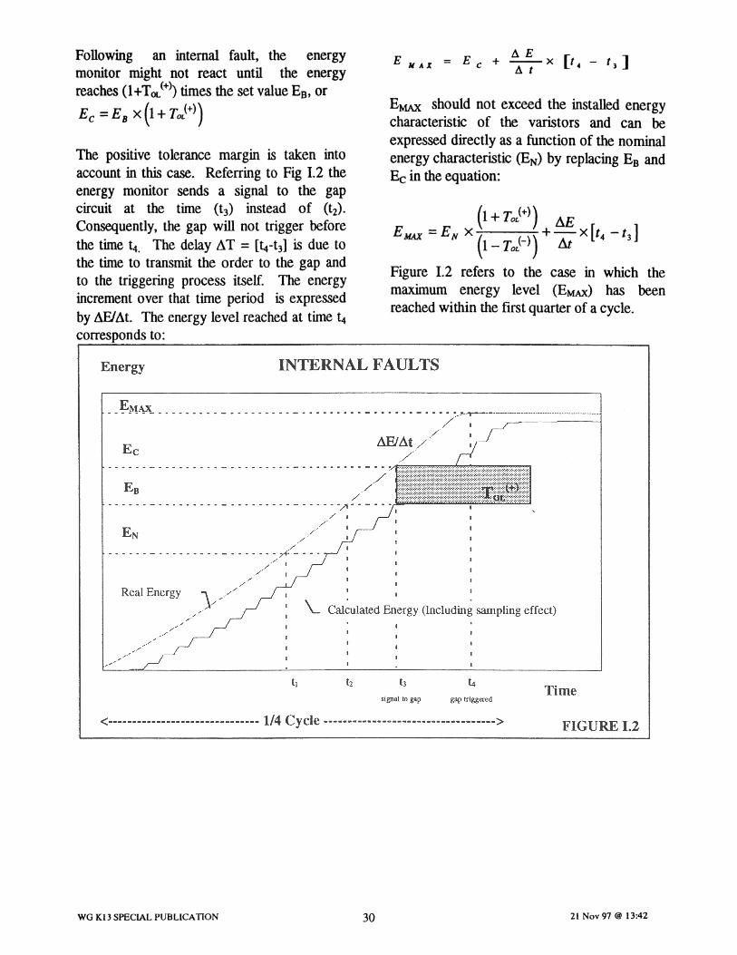
Following an internal fault, the energymonitor might not react until the energyreaches (1+TOL(+») times the set value EB, or
z; =EB X(l+ToL(+))
The positive tolerance margin is taken intoaccount in this case. Referring to Fig 1.2 theenergy monitor sends a signal to the gapcircuit at the time (t3) instead of (t2) .
Consequently, the gap will not trigger beforethe time t4. The delay AT = [~-t3] is due tothe time to transmit the order to the gap andto the triggering process itself. The energyincrement over that time period is expressedby AFlAt. The energy level reached at time t4corresponds to:
!!.EE = E + -- x [I. - t)]MAX C ilt •
EMAX should not exceed the installed energycharacteristic of the varistors and can beexpressed directly as a function of the nominalenergy characteristic (EN) by replacing EB andEc in the equation:
(1 + TOL(+)) AEEMAJ( =EN X ( (_)) +-x[t4 -t3 ]
1- TOL At
Figure 1.2 refers to the case in which themaximum energy level (EMAX) has beenreached within the first quarter of a cycle.
Energy INTERNAL FAULTS
Ec
· .~M~_ _ _ _ .... •• _ . .•. ~." ""' '__' """ ' _
. / I/
M!)At // .
·..~~ .- - - ' .~ ~> 7 ilill!li!I:I!II:I!I!lllll!llllllllllllll!I!!I!lll;!111Illlllllillllllll~f~illlll!1• •••• • - •• ••• - • - • - •• ••• • ••• - ••• •• ~)\ ' • - ••• I
./ I
/./
./-:. .. . .. _ _ ~_ .
./ / I
./ 1
Real Energy
//
I
\.. Cal~ulatedEnergy (Includin~ sampli ng effect)
signal to gap gap triggeredTime
<------------------------------- 1/4 Cycle -----------------------------------> FIGURE 1.2
WG K13 SPECIAL PUBLICAnON 30 21 Nov 97 @ 13:42
21.74(1+.08)+lOMJ/msec x 1msec=33.47 MJ
which is above the installed energy rating(see first paragraph under "Example").
Consequently for the worst case ofinternal fault, the energy could reachthen:
However , if the tolerance happened tochange overtime or if after site testmeasurement the tolerance is found to be
higher than expected, for example :t. 8%,the threshold should be modified to 21.74MJ in order to prevent gap firing.
~OMJ21.74x(1-.08) =20M]
Example:
The following example is not a typicalcase, but is presented to illustrate themathematics shown above. The examplebelow shows the effect of the tolerances ofthe energy monitor on the level of energyreached after a fault. It should beremembered, however, that in the case of asevere internal fault, as is shown in theexample, the protective device wouldnormally operate on high current in orderto limit the energy absorption on thevaristors. This operation will be almostinstantaneous, limiting the energyabsorption to much lower levels (10 MJ)than is shown in theexample.
• Nominal energy EN =20 MJoules(considered as the maximum energyleve1fo r an external fault)
• Installed energy E1Nsr = 33 MJoules (not considering sharing factor or anyadditional margins)
• Tolerance +5%,-3%• Maximum energy rate of increase L1E/L1
t = 10 MJ/msec
• Total delay L1T=l msec.
The energy monitoring device should beset at 20.61 MJ in order to prevent gapfiring for energy absorption below thenominal energy rating.
20.61 x (1-.03) = 20 MJ 220M]
Consequently for the worst case ofinternal[au It, the energy could reach:
20.61(1+.05J+IOMJ/msec x Imsec=31.64MJ
which is below the installed energycharacteristic.
WG K13 SPECIAL PUBLICATION 31 21 Nov 97 @ 13:42
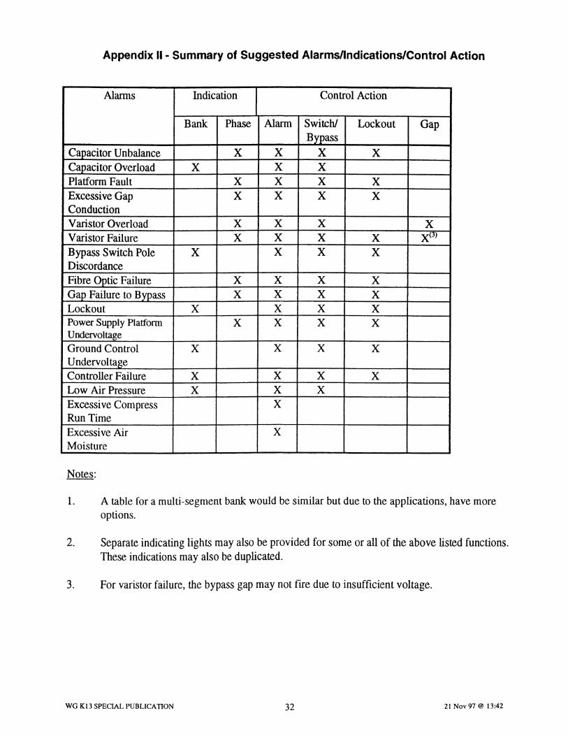
Appendix II - Summary of Suggested Alarms/Indications/Control Action
Alarms Indication Control Action
Bank Phase Alarm Switch! Lockout GapBypass
Capacitor Unbalance X X X XCapacitor Overload X X XPlatform Fault X X X XExcessive Gap X X X XConductionVaristor Overload X X X XVaristor Failure X X X X X(3)
Bypass Switch Pole X X X XDiscordanceFibre Optic Failure X X X XGap Failure to Bypass X X X XLockout X X X XPower Supply Platform X X X XUndervoltageGround Control X X X XUndervoltageController Failure X X X XLow Air Pressure X X XExcessive Compress XRunTimeExcessive Air XMoisture
Notes:
1. A table for a multi-segment bank would be similar but due to the applications, have moreoptions.
2. Separate indicating lights may also be provided for some or all of the above listed functions.These indications may also be duplicated.
3. For varistor failure, the bypass gapmay not fire due to insufficient voltage.
WG K13 SPECIAL PUBLICATION 32 21 Nov 97 @ 13:42

Appendix III
A Brief Summary of Line RelayingConsiderations
HI.t- Introduction
Application of series capacitors on HV andEHV transmission lines introduces manychallenges to protection engineers who haveto selecta reliable protection scheme for theselines. Transmission line protection schemes,such as directional comparison and phasecomparison, are generally designed forinductive sources and lines. Depending on thesize and location of the series capacitor andthe parameters of the network and t~~ line,this basic design assumption may not be valid.Moreover, protection of the capacitor bankitself includes gaps, MOYs, and bypassswitches. Operation of these devicesintroduces transients and unbalances that mustbe considered to ensure that the integrity ofthe protection scheme will not be adverselyaffected.
The following sections introduce the mainconsiderations whenselecting a line protectionscheme. This is not to suggest that the issuesoutlined are insolvable. In fact, there arenumerous relaying schemes that aresuccessfully applied on series compensatedlines. But, details of the schemes that wereintroduced to solve the problems explainedbelow are beyond the scope of thispublication.
For the purpose of the following analysis,series-compensated line protection problemsare grouped under two categories: basicproblems and transient problems. While bothphase and ground faults must be considered,the following analysis deals only with phasefaults. To simplify the following analysis,equipment resistance is neglected, even thoughthe MOV introduces a resistive component.More in-depth steady state analysis shouldinclude the MOY resistance [4,16, 17].
WG Kl3 SPECIAL PUBLICATION 33
lli.2 • Basic Issues
Transmission systems are predominantlyinductive. For an internal phase fault in aninductive system, the phase currents flowingfrom the terminal into the line lag the terminalvoltage bysome angle (Figure 111.1). This is abasic assumption in conventional distance(directional) protection schemes. Currentdifferential and phase comparison schemesassume that the current from the two terminalsinto the line are in phase for an internal faultand out of phase for an external fault. Theintroduction of capacitive elements, speciallyat or close to a line terminal, can change thesebasic relationships for some fault locations.This change is usually referred to as"inversion" as explained below. Thecombination of a mid-line location and 50% orless compensation reduces the possibilities ofcurrent and voltage inversion during faults.Voltage and current "inversion" phenomenacould affect the dependability and the securityof the conventional protectionschemes.
m.2.! Voltage Inversion
The impedance value of a series capacitorusually varies between 25 to 75% of the lineimpedance. The capacitor can be located atthe end of the line or at the middle of theline. Sometimes it is split up in two andplaced at both ends of the line. By placingthe capacitor at the end of the line (in thesubstation), cost of installation andmaintenance is reduced.
Figure III.2 shows a one line diagram of asystem similar to that in Figure 111.1, but fora series capacitor located at terminal (L)with the capacitor impedance, XC, less thanthe source impedance at "L". Vectordiagrams showing the voltage-currentrelationships at the two sources as well as atterminals L and R are shown for a threephase fault at the capacitor bank terminal(F). Since the impedance from F to terminalL is capacitive, IL leads VL. As can beseen, voltage VL has "inverted" from itsposition shown in Figure 111.1, while IL did
21 Nov 97 @ 13:42

not. A distance relay connected to apotential source at L would see this fault asa fault behind terminal L and would notoperate. Faults on the line (XL) can reliablybe detected by a distance relay if the relay'spotential source is located on the line (i.e.,F). However, similar analysis would showthat for a fault just behind terminal L, apotential source at F would cause thedistance relay at "L" to undesirably operatesince the relay current now lags VL.
Special care must be taken in setting zonedistance relays since the protected lineimpedance is modified by the inserted seriescapacitor but unmodified when the capacitorbank is bypassed.
Voltage-independent protection schemes,e.g. current differential and phasecomparison, will work properly but maysuffer from long line application problems.Since the series compensated lines. may belong and heavily loaded, the phaserelationship of currents between two endsshould be evaluated very carefully in orderto determine the settings. Charging currentmay reduce the sensitivity of the relay.
m.2.2 Current Inversion
As shown on Figure 111.3, current inversionoccurs when the fault current flowing intothe line for an internal fault is capacitive,rather than inductive. This occurs when theimpedance from the fault point to andincluding the source impedance is netcapacitive (XC > XSL). The current-voltage relationship at terminal L is that of afault behind that terminal for an inductivesystem. For terminal R, the current-voltagerelationship is that of an internal fault. Aconventional distance-based directionalcomparison scheme would not operate forthis internal fault as relay at terminal Lwould detect a reverse fault. This schemewould work correctly for internal faults ifthe potential source for relaying is locatedon the line side of the capacitor bank. On
WG K13 SPECIAL PUBLICATION 34
the other hand, the same scheme would alsooperate for faults just behind (left) ofterminal L.
Phase comparison schemes that use currentonly will also not operate for this internalfault unless they are modified to obtainreliable operation. Current differentialschemes mayor may not operate for thefault in Figure 111.3, depending on thecurrent magnitudes at both line terminals.
Current inversion is a rare occurrence andcan be avoided by locating the seriescapacitor away from a source with lowinductive impedance.
m.3 -Transient Aspects
The presence of series capacitors createstransient problems. These include bypass gapflashing transients, system subharmonics andunequal impedances between the phases whenthe bank: is bypassed on one phase. This willhave to be taken into consideration during thesteady state fault studies. The relay settingswill be considered using the fault values priorand after the gap firing, Similarly, settings ofrelays in the nearby system should beevaluated.
Steady state fault calculations become difficultwhen an MOV is used for capacitorprotection. Typical characteristic of a MOV,based upon expected fault current, can be usedto run steady state fault studies. This will bean approximation in determining the relaysettings. More accurate fault calculationsshould be done using an EMTP program.Final evaluation of settings can be done byapplying EMTP generated waveforms to therelays through digitally controlled dynamictest sets (simulators). Typically, various faultsat different locations on the system will beapplied in order to enable more thoroughevaluation of the relaying system before it isput in service.
21 Nov 97 @ 13:42

EVR
E
LIL
VL
LIRLIL LIRV XL
VRXSL*IL IR~XSR
& F~1
L R
Figure III. 1 Current Lags Voltage at Each Terminal for An Inductive System
E EVR
IL ~IL L I IRR
VLVL
XC XL ±XSRF( 1 ~
IL IRxc < XS L
Figure III.2 Voltage Inversion At Terminal L
E \ VRE
ILJ ILLIR IR
V XL VXSLr-jjXC :b XSRF
1G)-1 ( ~"IL IR"
XC> XSL
Figure 111.3 Current Inversion at Terminal L
WG K13 SPECIAL PUBLICATION 35 21 Nov 97 @ 13:42