Embed Size (px)
Citation preview
IEEE 1547 and Small Photovoltaic‐Based Generation Case Studies
Gerald Johns, P.E.
TVA Kentucky Comprehensive Services
IEEE 1547IEEE 1547
• IEEE Standard for Interconnecting Distributed Sta da d o te co ect g st butedResources with Electric Systems
• Applicable to any and all distributed resources pp ywith aggregate capacity of 10 MVA and less.
• Primarily targets radial primary and secondary distribution systems.
• “It provides requirements relevant to the f ti t ti f tperformance, operation, testing, safety
considerations, and maintenance of the interconnection ”1interconnection.
21. IEEE Std. 1547‐2003
IEEE 1547 and UL 1741 Testing and C liCompliance
• To comply with IEEE 1547 the interconnection system must: Exhibit a fixed 5 minute time delay or adjustable delay of 5 minutes or less on– Exhibit a fixed 5‐minute time delay or adjustable delay of 5 minutes or less on startup/restart
– Respond to abnormal system conditions (voltage/frequency excursions) per IEEE 1547.Not exceed steady state harmonic and DC current content limits– Not exceed steady‐state harmonic and DC current content limits.
– Not produce objectionable flicker.– Detect and cease energization of the grid during unintentional islanding within
2 seconds.h i i d i i i i ( d– Pass synchronization and interconnect integrity testing (EMI and surge
withstand). • UL 1741 listing indicates compliance with IEEE 1547 as far as
manufacturer’s design and production testing is concerned.• UL 1741 listing has no bearing on the installed interconnection
evaluation, commissioning test and periodic interconnection tests required by IEEE 1547.
3
Basis for Commissioning Test from IEEE 1547Basis for Commissioning Test from IEEE 1547
• IEEE 1547 requires a visual inspection to verify grounding coordination compliance and presence of isolation device (when required by utility).
• Commissioning tests to include:Commissioning tests to include:– Isolation device operability.– Cease to energize functionality test on each phase individually (refrain from unintentional islanding)individually (refrain from unintentional islanding). Verification of maximum response time and specified time delay before reconnect.
– Any of the design and/or production tests not alreadyAny of the design and/or production tests not already performed on the subject interconnection equipment (e.g. synchronization, response to abnormal voltage/frequency conditions, etc. when discrete relaying is used).y g )
4
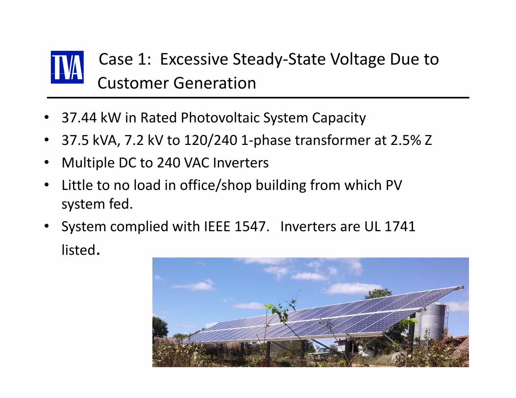
Case 1: Excessive Steady‐State Voltage Due to Customer Generation
• 37.44 kW in Rated Photovoltaic System Capacityy p y
• 37.5 kVA, 7.2 kV to 120/240 1‐phase transformer at 2.5% Z
• Multiple DC to 240 VAC Inverters
• Little to no load in office/shop building from which PV system fed.
• System complied with IEEE 1547 Inverters are UL 1741• System complied with IEEE 1547. Inverters are UL 1741
listed.
5
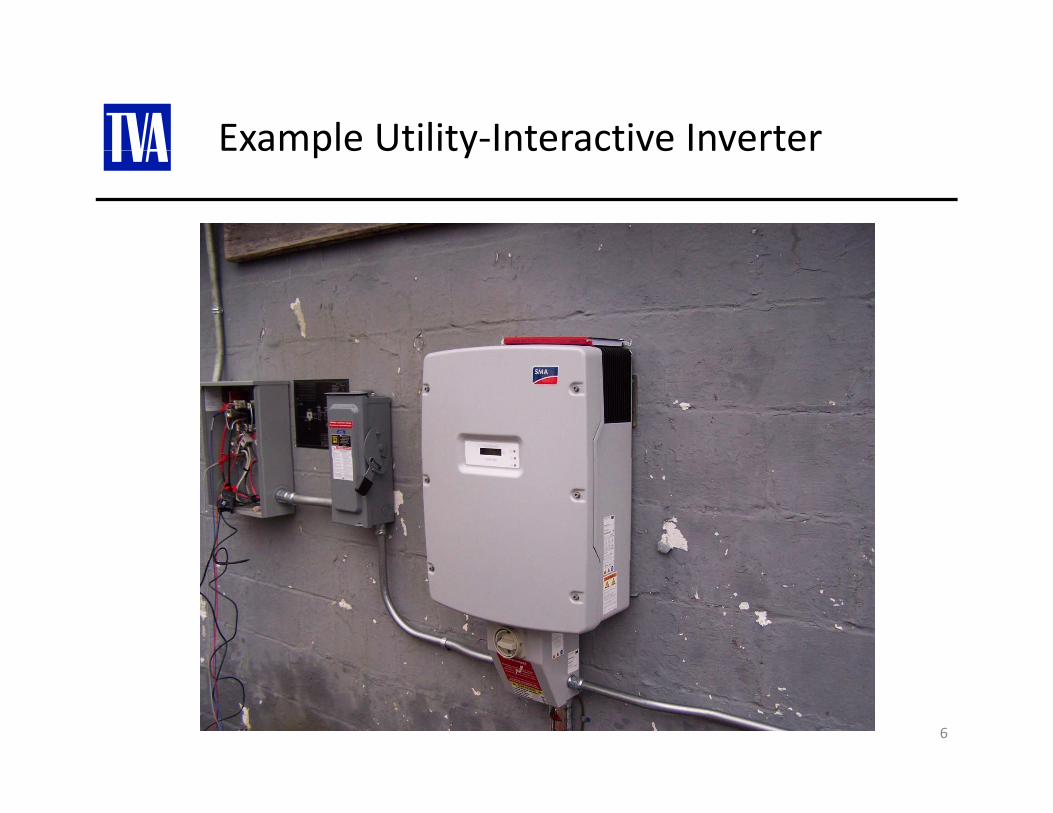
Example Utility‐Interactive InverterExample Utility Interactive Inverter
6
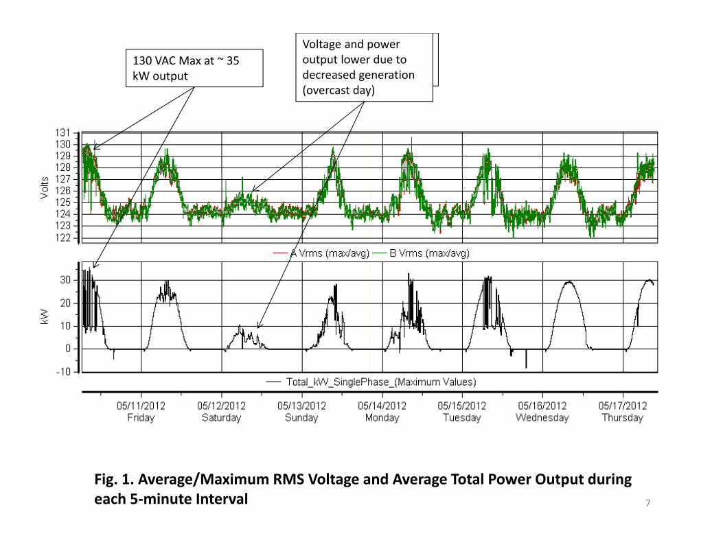
Voltage lower due to decreased generation (overcast day)
Voltage and power output lower due to decreased generation (overcast day)
130 VAC Max at ~ 35 kW output
Fig. 1. Average/Maximum RMS Voltage and Average Total Power Output during each 5‐minute Interval 7

Fig. 2. Maximum/Average RMS Voltage during each 5‐minute Interval at Other Customer Site Just Upstream on Distribution Circuit
8
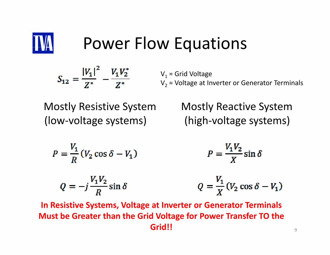
Power Flow EquationsPower Flow Equations
V1 = Grid Voltage
Mostly Reactive System Mostly Resistive System
V2 = Voltage at Inverter or Generator Terminals
y y(high‐voltage systems)
y y(low‐voltage systems)
In Resistive Systems, Voltage at Inverter or Generator Terminals
9
y , gMust be Greater than the Grid Voltage for Power Transfer TO the
Grid!!
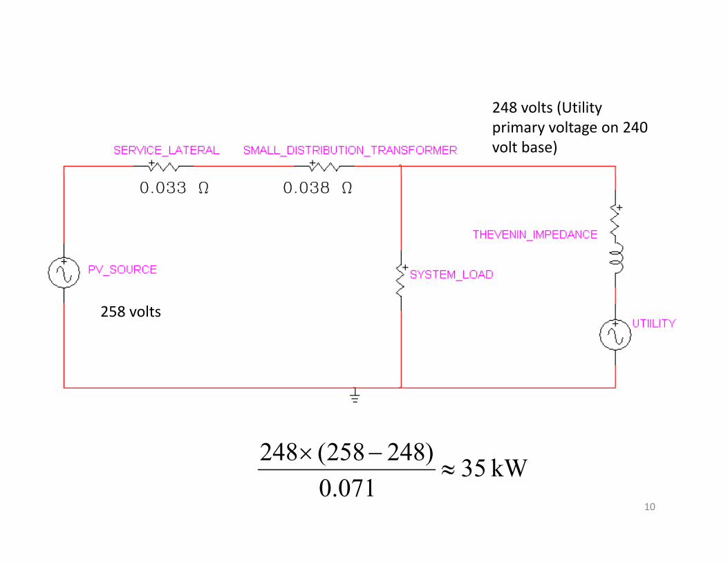
248 lt (Utilit248 volts (Utility primary voltage on 240 volt base)
0.033 W 0.038 W
258 volts258 volts
)248258(248 −× kW35071.0
)248258(248≈
×
10
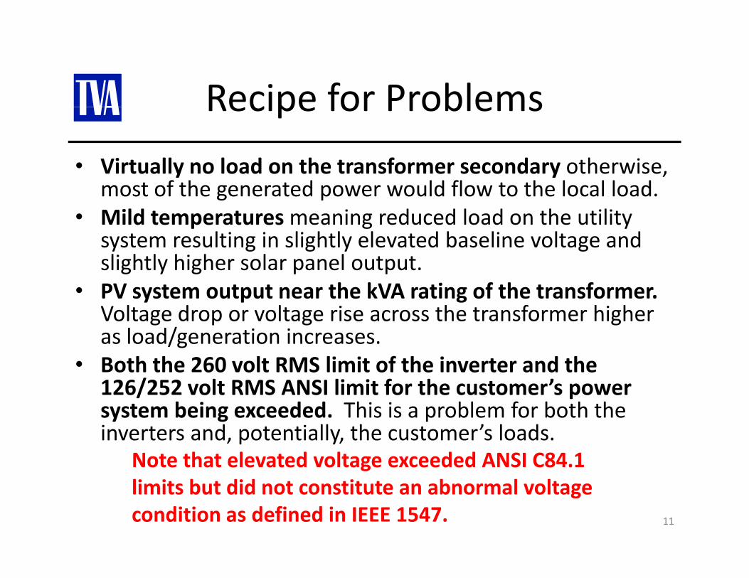
Recipe for ProblemsRecipe for Problems
• Virtually no load on the transformer secondary otherwise, most of the generated power would flow to the local load.
• Mild temperatures meaning reduced load on the utility system resulting in slightly elevated baseline voltage and slightly higher solar panel output.
• PV system output near the kVA rating of the transformer. Voltage drop or voltage rise across the transformer higher as load/generation increases.
• Both the 260 volt RMS limit of the inverter and the 126/252 volt RMS ANSI limit for the customer’s power psystem being exceeded. This is a problem for both the inverters and, potentially, the customer’s loads.
Note that elevated voltage exceeded ANSI C84.1
11
limits but did not constitute an abnormal voltage condition as defined in IEEE 1547.
Case 1 ‐ The FixCase 1 The Fix
• Replaced transformer that had no taps with• Replaced transformer that had no taps with transformer with taps.
• Adjusted tap to lower secondary voltageAdjusted tap to lower secondary voltage.
• Everybody happy (except for whoever had to pay for the replacement transformer).the replacement transformer).
12
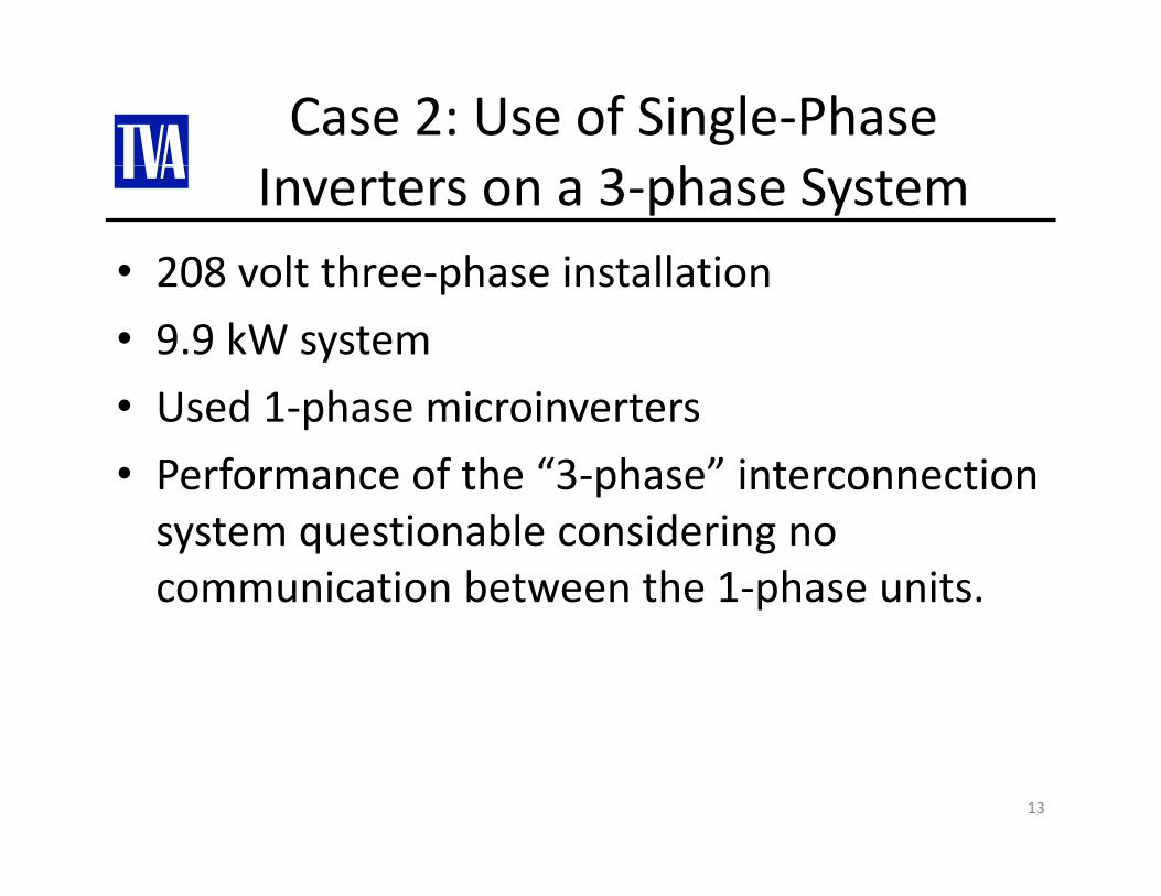
Case 2: Use of Single‐Phase hInverters on a 3‐phase System
• 208 volt three‐phase installation208 volt three phase installation
• 9.9 kW system
d h i i• Used 1‐phase microinverters
• Performance of the “3‐phase” interconnection system questionable considering no communication between the 1‐phase units.
13
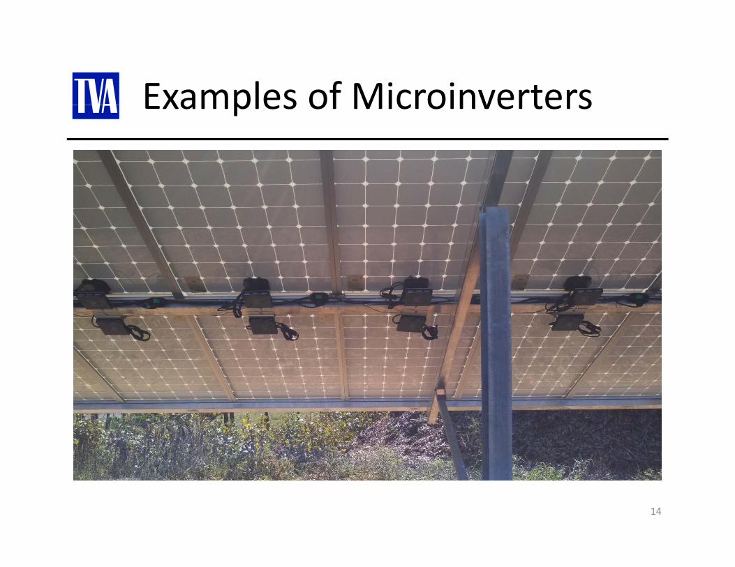
Examples of MicroinvertersExamples of Microinverters
14
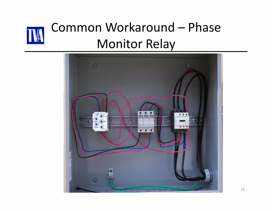
Common Workaround – Phase lMonitor Relay
15
Concerns with Using Phase Monitor Relay as al iSolution
• Only open phase and simultaneous disconnect of all three phases can be tested in typical commissioning test.
• Interconnection system includes components that have not been tested per IEEE 1547/UL 1741 in the factory, so commissioning test is to include testing response of the system to abnormal voltage/frequency conditions as well as other design/production tests.
• Design and production tests per IEEE 1547 require equipment under test to be connected to a simulated utility or signal injection test.
• Phase monitor relay performance may not satisfy IEEE 1547 requirements.
16
Other SolutionsOther Solutions
• When inverters are installed using all threeWhen inverters are installed using all three phases, a 3‐phase inverter is the best solution.
• Some manufacturers make accessories to link• Some manufacturers make accessories to link individual 1‐phase inverters together when installed separately on 3 phase systemsinstalled separately on 3‐phase systems. These accessories should have been factory tested per IEEE 1547 and UL 1741 listedtested per IEEE 1547 and UL 1741 listed.
17


![Parametric PV Grid-Support Function Characterization for ... · Parametric PV Grid-Support Function Characterization for Simulation Environments ... IEEE Std. 1547 [5], ... inverter](https://img.pdfslide.net/doc/110x75/5b2e17687f8b9af0648c8740/parametric-pv-grid-support-function-characterization-for-parametric-pv-grid-support.jpg)