Embed Size (px)
Citation preview
IEEE Std 446-1995
(Revision of IEEE Std 446-1987)
IEEE Recommended Practice for Emergency and Standby Power Systems for Industrial and Commercial Applications
Sponsor
Power Systems Engineering Committeeof theIndustrial and Commercial Power Systems Departmentof theIEEE Industry Applications Society
Approved 12 December 1995Reaffirmed 20 June 2000
IEEE Standards Board
Abstract:
This Recommended Practice addresses the uses, power sources, design, and main-tenance of emergency and standby power systems. Chapter 3 is a general discussion of needsfor and the configuration of emergency and standby systems. Chapter 9 lists the power needsfor specific industries. Chapters 4 and 5 deal with selection of power sources. Chapter 6 pro-vides recommendations for protecting both power sources and switching equipment duringfault conditions. Chapter 7 provides recommendations for design of system grounding, andChapter 10 provides recommendations for designing to reliability objectives. Chapter 8 pro-vides recommended maintenance practices.
Keywords:
batteries, emergency generators, emergency power, emergency system,emergency system design, engine generators, standby power, standby system, stored energysystems, transfer switch, uninterruptible power supplies, UPS, UPS batteries

Grateful acknowledgment is made to the following organizations for having granted permission to reprintillustrations in this document as listed below:
The Electrical Generating Systems Marketing Association (EGSA), 10251 W. Sample Rd., Ste. B, CoralSprings, FL 33065-3939, for
Table 3-1
from EGSA 109C-1994,
Table 1, copyright 1994 by EGSA.
The National Fire Protection Association (NFPA), Quincy, MA 02269, for
Figure 3-5
from NFPA 70-1996, National Electrical Code®, Figure 517-30(b), copyright 1995 by NFPA.
The Automatic Switch Company (ASCO), Florham Park, NJ 07932, for
Figure 4-10
.
First PrintingJuly 1996SH94381
The Institute of Electrical and Electronics Engineers, Inc.345 East 47th Street, New York, NY 10017-2394, USA
Copyright © 1996 by the Institute of Electrical and Electronics Engineers, Inc.All rights reserved. Published 1996. Printed in the United States of America
ISBN 1-55937-598-1
No part of this publication may be reproduced in any form, in an electronic retrieval system or otherwise, without the prior written permission of the publisher.
IEEE Standards
documents are developed within the Technical Committees of the IEEE Societies andthe Standards Coordinating Committees of the IEEE Standards Board. Members of the committeesserve voluntarily and without compensation. They are not necessarily members of the Institute. Thestandards developed within IEEE represent a consensus of the broad expertise on the subject within theInstitute as well as those activities outside of IEEE that have expressed an interest in participating in thedevelopment of the standard.
Use of an IEEE Standard is wholly voluntary. The existence of an IEEE Standard does not imply thatthere are no other ways to produce, test, measure, purchase, market, or provide other goods and servicesrelated to the scope of the IEEE Standard. Furthermore, the viewpoint expressed at the time a standardis approved and issued is subject to change brought about through developments in the state of the artand comments received from users of the standard. Every IEEE Standard is subjected to review at leastevery five years for revision or reaffirmation. When a document is more than five years old and has notbeen reaffirmed, it is reasonable to conclude that its contents, although still of some value, do notwholly reflect the present state of the art. Users are cautioned to check to determine that they have thelatest edition of any IEEE Standard.
Comments for revision of IEEE Standards are welcome from any interested party, regardless of mem-bership affiliation with IEEE. Suggestions for changes in documents should be in the form of a pro-posed change of text, together with appropriate supporting comments.
Interpretations: Occasionally questions may arise regarding the meaning of portions of standards asthey relate to specific applications. When the need for interpretations is brought to the attention ofIEEE, the Institute will initiate action to prepare appropriate responses. Since IEEE Standards representa consensus of all concerned interests, it is important to ensure that any interpretation has also receivedthe concurrence of a balance of interests. For this reason IEEE and the members of its technical com-mittees are not able to provide an instant response to interpretation requests except in those cases wherethe matter has previously received formal consideration.
Comments on standards and requests for interpretations should be addressed to:
Secretary, IEEE Standards Board445 Hoes LaneP.O. Box 1331Piscataway, NJ 08855-1331USA
Authorization to photocopy portions of any individual standard for internal or personal use is granted bythe Institute of Electrical and Electronics Engineers, Inc., provided that the appropriate fee is paid toCopyright Clearance Center. To arrange for payment of licensing fee, please contact Copyright Clear-ance Center, Customer Service, 222 Rosewood Drive, Danvers, MA 01923 USA; (508) 750-8400. Per-mission to photocopy portions of any individual standard for educational classroom use can also beobtained through the Copyright Clearance Center.
Note: Attention is called to the possibility that implementation of this standard may require useof subject matter covered by patent rights. By publication of this standard, no position is takenwith respect to the existence or validity of any patent rights in connection therewith. The IEEEshall not be responsible for identifying all patents for which a license may be required by anIEEE standard or for conducting inquiries into the legal validity or scope of those patents thatare brought to its attention.

iv
Introduction
(This introduction is not a part of IEEE Std 446-1995, IEEE Recommended Practice for Emergency andStandby Power Systems for Industrial and Commercial Applications.)
In 1968 the Industrial and Commercial Power Systems Committee within the Industry andGeneral Applications Group of the Institute of Electrical and Electronics Engineers recog-nized that a need existed for a publication that would provide guidance to industrial users andsuppliers of emergency and standby power systems.
The nature of electric power failures, interruptions, and their duration covers a range in timefrom microseconds to days. Voltage excursions occur within a range from 20 times normal(or more) to a complete absence of voltage. Frequency excursions can vary as widely in manyforms, from harmonics to direct current. These variables occur due to a multitude of condi-tions both in the power system ahead of the user’s service entrance and following the serviceentrance within the user’s area of distribution.
Such elements as lightning, automobiles striking power poles, ice storms, tornadoes, switch-ing to alternate lines, and equipment failure are but a few of the causes of interruptions in theelectric power supply ahead of the service entrance.
Within the user’s area of distribution are such elements as short and open circuits, undersizedfeeders, equipment failures, operator errors, temporary overloads, single-phasing unbalancedfeeders, fire, switching, and many other causes of power interruption or failure.
In the past the demand for reliable electric power was less critical. If power was completelyinterrupted too often, another source was found. If voltage varied enough to cause a problem,a regulator or a larger conductor was installed. As processes, controls, and instrumentationbecame more sophisticated and interlocked, the demand developed to shorten the length ofoutages. Increased safety standards for people required emergency and exit lighting. Manyfactories added medical facilities that needed reliable electric power.
With the advent of solid-state electronics and computers, the need for continuous, reliable,high-quality electric power became critical. Many installations required uninterruptiblepower, virtually free of frequency excursions and voltage dips, surges, and transients.
In 1969 a working group was established under the Industrial Plants Power Systems Subcom-mittee of the Industrial and Commercial Power Systems Committee to collect data and pro-duce a publication entitled “Emergency Power Systems for Industrial Plants.” Later that yearthe scope of the work was enlarged to include standby power since, in meeting various needs,the two systems were often found to be intertwined, or one system served multiple purposes.
As the work progressed, it became apparent that industrial and commercial needs containedmore similarities than differences. Systems available to supply the required power to industrywere found applicable to both fields. Once again the scope of the work was expanded toinclude commercial requirements. The existing working group was changed to the status of asubcommittee under the Industrial and Commercial Power Systems Committee to have direct
v
responsibility, not only for the Orange Book Working Group, but for other matters concern-ing emergency and standby power. The proposed publication was redirected toward establish-ing recommended practices. As a result of subsequent organizational changes, thisEmergency and Standby Power Systems Subcommittee is now under the Power SystemsEngineering Committee of the Industrial and Commercial Power Systems Department.
This third revision of the IEEE Orange Book contains updating and expansion of existingmaterial. In addition, a new chapter has been added that addresses design criteria for achiev-ing reliability objectives.
This IEEE Recommended Practice continues to serve as a companion publication to the fol-lowing other Recommended Practices prepared by the IEEE Industrial and CommercialPower Systems Department:
— IEEE Std 141-1993, IEEE Recommended Practice for Electric Power Distribution forIndustrial Plants (IEEE Red Book).
— IEEE Std 142-1991, IEEE Recommended Practice for Grounding of Industrial andCommercial Power Systems (IEEE Green Book).
— IEEE Std 241-1990, IEEE Recommended Practice for Electric Power Systems inCommercial Buildings (IEEE Gray Book).
— IEEE Std 242-1986, IEEE Recommended Practice for Protection and Coordination ofIndustrial and Commercial Power Systems (IEEE Buff Book).
— IEEE Std 399-1990, IEEE Recommended Practice for Industrial and CommercialPower Systems Analysis (IEEE Brown Book).
— IEEE Std 493-1990, IEEE Recommended Practice for the Design of Reliable Indus-trial and Commercial Power Systems (IEEE Gold Book).
— IEEE Std 602-1996, IEEE Recommended Practice for Electric Systems in HealthCare Facilities (IEEE White Book).
— IEEE Std 739-1995, IEEE Recommended Practice for Energy Management in Indus-trial and Commercial Facilities (IEEE Bronze Book).
— IEEE Std 1100-1992, IEEE Recommended Practice for Powering and GroundingSensitive Electronic Equipment (IEEE Emerald Book).

vi
The Orange Book Working Group for the 1995 edition had the following membership:
Neil Nichols
,
Chair
Chapter 1: Scope—
Neil Nichols
,
Chair
Chapter 2: Definitions—
Neil Nichols
,
Chair;
Marco W. Migliaro;
Joseph S. Dudor
Chapter 3: General need guidelines—
Gordon S. Johnson
,
Chair
Chapter 4: Generator and electric utility systems—
Farrokh Shokooh,
Chair;
Charles D. Hughes
Chapter 5: Stored energy systems—
Marco W. Migliaro
,
Chair;
J. H. Bellack; G. J. Davis; P. J. Demar; Joseph S. Dudor; Murray Leonard; Robert Soileau; Swagata Som
Chapter 6: Protection—
Pat O’Donnell
,
Chair;
René Castenschiold; Marco W. Migliaro; Neil Nichols; Charles D. Potts; Farrokh Shokooh; George Stromme
Chapter 7: Grounding—
René Castenschiold
,
Chair;
Norman Fowler; Daniel L. Goldberg; Gordon S. Johnson; Neil Nichols; Donald W. Zipse
Chapter 8: Maintenance—
Charles D. Potts
,
Chair;
René Castenschiold; Joseph S. Dudor; Norman Fowler; R. Gerald Irvine; Marco W. Migliaro; Gary Tupper
Chapter 9: Specific industry applications—
Eli Yagor
,
Chair
Chapter 10: Design and operation considerations for improving the reliability of emergency power systems—
Gary Tupper
,
Chair;
Norman Fowler; Neil Nichols; Charles D. Potts; Max Don Trumble
The following persons were on the balloting committee:
James Beall Charles D. Hughes Daleep MohlaCarl Becker R. Gerald Irvine Neil NicholsRené Castenschiold Gordon S. Johnson Pat O’DonnellJames M. Daly Douglas Kanitz Charles D. PottsJoseph S. Dudor C. Grant Keough Milton D. RobinsonJerry M. Frank Thomas S. Key Vincent SaporitaDaniel L. Goldberg Don Koval Stephen SchafferJames M. Harvey Marco W. Migliaro Farrokh ShokoohErling Hesla Donald W. Zipse

vii
When the IEEE Standards Board approved this recommended practice on 12 December 1995,it had the following membership:
E. G. “Al” Kiener,
Chair
Donald C. Loughry,
Vice Chair
Andrew G. Salem,
Secretary
*Member Emeritus
Also included are the following nonvoting IEEE Standards Board liaisons:
Satish K. AggarwalSteve Sharkey
Robert E. HebnerChester C. Taylor
Paula M. Kelty
IEEE Standards Project Editor
National Electrical Code and NEC are both registered trademarks of the National Fire Protection Association, Inc.
Gilles A. BarilClyde R. CampJoseph A. CannatelliStephen L. DiamondHarold E. EpsteinDonald C. FleckensteinJay Forster*Donald N. HeirmanRichard J. Holleman
Jim IsaakBen C. JohnsonSonny KasturiLorraine C. KevraIvor N. KnightJoseph L. Koepfinger*D. N. “Jim” LogothetisL. Bruce McClung
Marco W. MigliaroMary Lou PadgettJohn W. PopeArthur K. ReillyGary S. RobinsonIngo RuschChee Kiow TanLeonard L. TrippHoward L. Wolfman

viii
Contents
Chapter 1Scope........................................................................................................................................ 1
Chapter 2Definitions................................................................................................................................ 3
2.1 Introduction ................................................................................................................. 32.2 Terms .......................................................................................................................... 32.3 Bibliography................................................................................................................ 6
Chapter 3General need guidelines........................................................................................................... 7
3.1 Introduction ................................................................................................................. 73.2 Lighting..................................................................................................................... 293.3 Startup power ............................................................................................................ 313.4 Transportation ........................................................................................................... 333.5 Mechanical utility systems........................................................................................ 363.6 Heating ...................................................................................................................... 373.7 Refrigeration ............................................................................................................. 393.8 Production ................................................................................................................. 403.9 Space conditioning.................................................................................................... 45
3.10 Fire protection ........................................................................................................... 473.11 Data processing ......................................................................................................... 493.12 Life safety and life support systems.......................................................................... 683.13 Communication systems ........................................................................................... 733.14 Signal circuits............................................................................................................ 743.15 References ................................................................................................................. 753.16 Bibliography.............................................................................................................. 77
Chapter 4Generator and electric utility systems.................................................................................... 79
4.1 Introduction ............................................................................................................... 794.2 Engine-driven generators .......................................................................................... 814.3 Multiple utility services ............................................................................................ 944.4 Turbine-driven generators....................................................................................... 1104.5 Mobile equipment ................................................................................................... 1144.6 References ............................................................................................................... 1194.7 Bibliography............................................................................................................ 120
Chapter 5Stored energy systems.......................................................................................................... 123
5.1 Introduction ............................................................................................................. 123

ix
5.2 Definitions............................................................................................................... 1255.3 Battery systems ....................................................................................................... 1255.4 Mechanical energy storage...................................................................................... 1455.5 Battery/inverter systems.......................................................................................... 1465.6 Motor-generators and rotating UPS systems .......................................................... 1625.7 References ............................................................................................................... 1715.8 Bibliography............................................................................................................ 172
Chapter 6Protection ............................................................................................................................. 175
6.1 Introduction ............................................................................................................. 1756.2 Short-circuit current considerations ........................................................................ 1756.3 Transfer devices ...................................................................................................... 1796.4 Generator protection ............................................................................................... 1896.5 Prime mover protection........................................................................................... 1996.6 Electric utility power supply ................................................................................... 2016.7 Uninterruptible power supply (UPS) system .......................................................... 2026.8 Equipment physical protection................................................................................ 2146.9 Grounding ............................................................................................................... 214
6.10 Conclusions ............................................................................................................. 2146.11 References ............................................................................................................... 2156.12 Bibliography............................................................................................................ 216
Chapter 7Grounding ............................................................................................................................ 219
7.1 Introduction ............................................................................................................. 2197.2 System and equipment grounding functions ........................................................... 2207.3 Supplemental equipment bonding........................................................................... 2237.4 Objectionable current through grounding conductors............................................. 2247.5 System grounding requirements.............................................................................. 2257.6 Types of equipment-grounding conductors ............................................................ 2267.7 Grounding for separately derived and service-supplied systems............................ 2277.8 Grounding arrangements for emergency and standby power systems.................... 2297.9 Systems with a grounded circuit conductor ............................................................ 229
7.10 Ground-fault alarm.................................................................................................. 2437.11 Systems without a grounded circuit conductor ....................................................... 2437.12 Mobile engine-generator sets .................................................................................. 2477.13 Uninterruptible power supply (UPS) systems......................................................... 2497.14 References ............................................................................................................... 2497.15 Bibliography............................................................................................................ 250
Chapter 8Maintenance......................................................................................................................... 253
8.1 Introduction ............................................................................................................. 253
x
8.2 Internal combustion engines ................................................................................... 2548.3 Gas turbine .............................................................................................................. 2568.4 Generators ............................................................................................................... 2578.5 Uninterruptible power supply (UPS) systems......................................................... 2608.6 Stationary batteries.................................................................................................. 2628.7 Automatic transfer switches.................................................................................... 2688.8 Conclusions ............................................................................................................. 2688.9 References ............................................................................................................... 268
8.10 Bibliography............................................................................................................ 269
Chapter 9Specific industry applications .............................................................................................. 271
9.1 General .................................................................................................................... 2719.2 References ............................................................................................................... 285
Chapter 10Design and operation considerations for improving the reliability of emergencypower systems...................................................................................................................... 287
10.1 Introduction ............................................................................................................. 28710.2 Applications ............................................................................................................ 28710.3 Environmental concerns.......................................................................................... 28910.4 Specification and acceptance testing....................................................................... 29010.5 Maintenance and training........................................................................................ 29210.6 Failure modes .......................................................................................................... 29410.7 Management awareness .......................................................................................... 29410.8 Conclusions ............................................................................................................. 29510.9 References ............................................................................................................... 295
10.10 Bibliography............................................................................................................ 296
Index .................................................................................................................................... 297
IEEE Recommended Practice for Emergency and Standby Power Systems for Industrial and Commercial Applications
Chapter 1Scope
This standard presents recommended engineering principles, practices, and guidelines for theselection, design, installation, application, operation, and maintenance of emergency andstandby power systems. This information is primarily presented from a user’s viewpoint;however, managing the effects of power system disturbances requires close cooperationbetween users, electric utilities, and equipment manufacturers.
This standard addresses the following questions:
— Is an emergency or standby power system (or both) needed, and what will it accom-plish?
— What types of systems are available, and which can best meet the users’ needs?— How should the most suitable system be designed and applied to the existing power
system?— What are the maintenance and operating requirements for maintaining system reli-
ability?— Where can additional information be obtained?— What are the design considerations for maintaining system reliability?
Definitions to specialized technical terms used throughout this standard are provided inChapter 2. Emergency and standby power requirements of both industrial and commercialusers are outlined and discussed, including a distinction made between mandatory laws, reg-ulations, codes, and standards applicable to each. Knowledge of these requirements enableselectric utility companies to meet specific power supply needs and equipment manufacturersto design efficient, practical, and reliable equipment and systems. Recommendations aremade for various types of installations, based on technical and economic information onavailable hardware and systems provided by equipment manufacturers.
Technical guidelines for protecting and grounding emergency and standby power systems arepresented in Chapter 6 and Chapter 7, respectively. Guidelines for the maintenance of specifictypes of equipment are presented in Chapter 8. Chapter 9 provides information on applica-tions of emergency and standby power for specific industries. Chapter 10 presents design andoperation guidelines that will improve emergency and standby power system reliability.
The following industries and fields are considered specialized and beyond the scope of inclu-sion and direct address by this standard: transport, government, military, and utility.
1

IEEEStd 446-1995 CHAPTER 1
2

Chapter 2Definitions
2.1 Introduction
This chapter is intended to provide terms and definitions applicable to this standard for thepurpose of aiding in its overall understanding.
NOTE—The definitions of emergency power system and standby power system contained herein arebased on the general functions of the two systems. They may not agree entirely with definitions devel-oped by other bodies, which establish specific operating criteria or are used to establish regulatorycodes.
2.2 Terms
2.2.1 absorbed electrolyte cell: A valve-regulated lead-acid (VRLA) cell whose electrolytehas been immobilized in absorbent separator (normally, glass or polymeric fiber). Syn:starved electrolyte cell; absorbed glass mat (AGM) cell.
2.2.2 absorbed glass mat (AGM) cell: See: absorbed electrolyte cell.
2.2.3 automatic transfer switch: Self-acting equipment for transferring one or more loadconductor connections from one power source to another.
2.2.4 availability: The fraction of time within which a system is actually capable of perform-ing its mission.
2.2.5 battery: Two or more cells electrically connected for producing electric energy.
NOTE—Also commonly used to apply to a single cell used independently.
2.2.6 battery rack: A structure used to support a group of cells.
2.2.7 bypass/isolation switch: A manually operated device used in conjunction with an auto-matic transfer switch to provide a means of directly connecting load conductors to a powersource and of disconnecting the automatic transfer switch.
2.2.8 commercial power: Power furnished by an electric power utility company; when avail-able, it is usually the prime power source. However, when economically feasible, it some-times serves as an alternative or standby source.
2.2.9 current withstand rating: The maximum allowable current, either instantaneous or fora specified period of time, that a device can withstand without damage, or without exceedingthe criteria of an applicable safety or performance standard.
3
IEEEStd 446-1995 CHAPTER 2
2.2.10 dropout voltage (or current): The voltage (or current) at which a magnetically oper-ated device will release to its de-energized position. It is a level of voltage (or current) that isinsufficient to maintain the device in an energized state.
2.2.11 emergency power system: An independent reserve source of electric energy that,upon failure or outage of the normal source, automatically provides reliable electric powerwithin a specified time to critical devices and equipment whose failure to operate satisfacto-rily would jeopardize the health and safety of personnel or result in damage to property.
2.2.12 flooded cell: See: vented cell.
2.2.13 forced outage: A power outage that results from the failure of a system component,requiring that it be taken out of service immediately, either automatically or by manualswitching operations, or an outage caused by improper operation of equipment or humanerror. This type of power outage is not directly controllable and is usually unexpected.
2.2.14 frequency droop: The absolute change in frequency between steady-state no load andsteady-state full load.
2.2.15 frequency regulation: The percentage change in emergency or standby power fre-quency from steady-state no load to steady-state full load:
2.2.16 gel cell: See: gelled electrolyte cell.
2.2.17 gelled electrolyte cell: A valve-regulated lead-acid (VRLA) cell whose electrolyte hasbeen immobilized by the addition of a gelling agent. Syn: gel cell.
2.2.18 harmonic content: A measure of the presence of harmonics in a voltage or currentwave form expressed as a percentage of the amplitude of the fundamental frequency at eachharmonic frequency. The total harmonic content is expressed as the square root of the sum ofthe squares of each of the harmonic amplitudes (expressed as a percentage of the fundamen-tal).
2.2.19 immobilized electrolyte: Electrolyte in a cell that is retained by either using gelled orabsorbed electrolyte technology.
2.2.20 load shedding: The process of deliberately removing preselected loads from a powersystem in response to an abnormal condition in order to maintain the integrity of the system.
2.2.21 oxygen index: The minimum concentration of oxygen, expressed as volume percent,in a mixture of oxygen and nitrogen that will just support flaming combustion of a materialinitially at room temperature, referred to in battery manufacturers’ flammability designationsfor battery cases. Syn: limiting oxygen index (LOI).
%RFn1 F f 1–
Fn1----------------------- 100⋅=
4
IEEEDEFINITIONS Std 446-1995
2.2.22 limiting oxygen index (LOI): See: oxygen index.
2.2.23 power failure: Any variation in electric power supply that causes unacceptable perfor-mance of the user's equipment.
2.2.24 power outage: Complete absence of power at the point of use.
2.2.25 prime mover: The machine used to develop mechanical horsepower to drive an emer-gency or standby generator to produce electrical power.
2.2.26 prime power: The source of supply of electrical energy that is normally available andused continuously day and night, usually supplied by an electric utility company, but some-times supplied by base-loaded user-owned generation.
2.2.27 rated capacity (battery): The manufacturer’s statement of the number of ampere-hours or watt-hours that can be delivered by a fully charged battery at a specific dischargerate and electrolyte temperature, to a given end-of-discharge voltage.
2.2.28 redundancy: Duplication of elements in a system or installation for the purpose ofenhancing the reliability or continuity of operation of the system or installation.
2.2.29 scheduled outage: A power outage that results when a component is deliberatelytaken out of service at a selected time, usually for purposes of construction, preventive main-tenance, or repair. This type of outage is directly controllable and usually predictable.
2.2.30 separate excitation: A source of generator field excitation power derived from asource independent of the generator output power.
2.2.31 shunt excitation: A source of generator field excitation power taken from the genera-tor output, normally through power potential transformers connected directly or indirectly tothe generator output terminals.
2.2.32 standby power system: An independent reserve source of electric energy that, uponfailure or outage of the normal source, provides electric power of acceptable quality so thatthe user's facilities may continue in satisfactory operation.
2.2.33 starved electrolyte cell: See: absorbed electrolyte cell.
2.2.34 transient: That part of the change in a variable, such as voltage, current, or speed,which may be initiated by a change in steady-state conditions or an outside influence, thatdecays and/or disappears following its appearance.
2.2.35 uninterruptible power supply (UPS): A system designed to provide power automat-ically, without delay or transients, during any period when the normal power supply is inca-pable of performing acceptably.
5
IEEEStd 446-1995 CHAPTER 2
2.2.36 valve-regulated lead-acid (VRLA) cell: A lead-acid cell that is sealed with theexception of a valve that opens to the atmosphere when the internal gas pressure in the cellexceeds atmospheric pressure by a pre-selected amount.
2.2.37 vented cell: A cell design that is characterized by an excess of free electrolyte, and inwhich the products of electrolysis and evaporation can freely exit the cell through a vent. Syn:flooded cell; wet cell.
2.2.38 wet cell: See: vented cell.
2.3 Bibliography
Additional information may be found in the following sources:
[B1] IEEE Std 100-1992, The New IEEE Standard Dictionary of Electrical and ElectronicsTerms (ANSI).1
[B2] Migliaro, M.W., and Alber, G., editors, “Glossary of Stationary Battery Terminology,”Alber Technologies, Inc., Boca Raton, FL, 1992.
1IEEE publications are available from the Institute of Electrical and Electronics Engineers, 445 Hoes Lane, P.O. Box1331, Piscataway, NJ 08855-1331, USA.
6
Chapter 3General need guidelines
3.1 Introduction
While all who use electric power desire perfect frequency, voltage stability, and reliability atall times, this cannot be realized in practice because of the many causes of power supply dis-turbances that are beyond the control of the utility. For example, power failures can be causedby automobiles hitting poles; animals climbing across insulators; lightning striking overheadlines; and high winds blowing tree branches and other debris into lines.
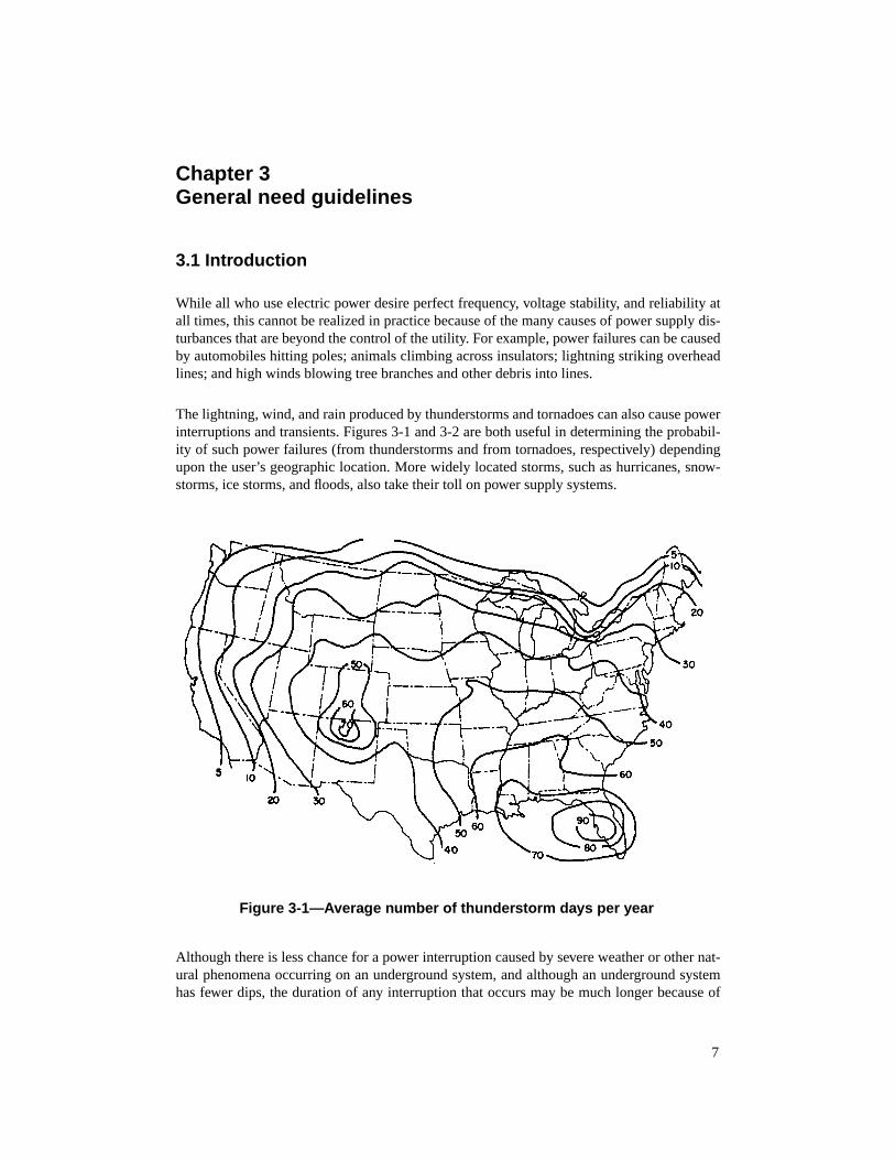
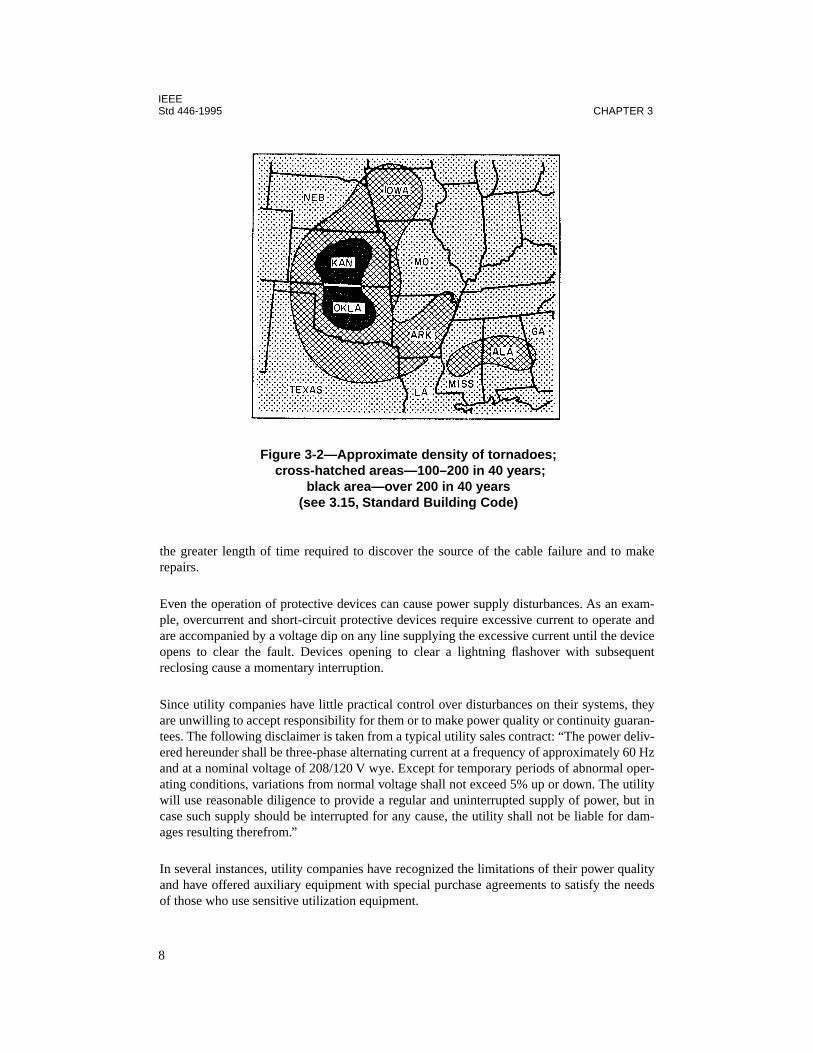
The lightning, wind, and rain produced by thunderstorms and tornadoes can also cause powerinterruptions and transients. Figures 3-1 and 3-2 are both useful in determining the probabil-ity of such power failures (from thunderstorms and from tornadoes, respectively) dependingupon the user’s geographic location. More widely located storms, such as hurricanes, snow-storms, ice storms, and floods, also take their toll on power supply systems.
Although there is less chance for a power interruption caused by severe weather or other nat-ural phenomena occurring on an underground system, and although an underground systemhas fewer dips, the duration of any interruption that occurs may be much longer because of
Figure 3-1—Average number of thunderstorm days per year
7
IEEEStd 446-1995 CHAPTER 3
the greater length of time required to discover the source of the cable failure and to makerepairs.
Even the operation of protective devices can cause power supply disturbances. As an exam-ple, overcurrent and short-circuit protective devices require excessive current to operate andare accompanied by a voltage dip on any line supplying the excessive current until the deviceopens to clear the fault. Devices opening to clear a lightning flashover with subsequentreclosing cause a momentary interruption.
Since utility companies have little practical control over disturbances on their systems, theyare unwilling to accept responsibility for them or to make power quality or continuity guaran-tees. The following disclaimer is taken from a typical utility sales contract: “The power deliv-ered hereunder shall be three-phase alternating current at a frequency of approximately 60 Hzand at a nominal voltage of 208/120 V wye. Except for temporary periods of abnormal oper-ating conditions, variations from normal voltage shall not exceed 5% up or down. The utilitywill use reasonable diligence to provide a regular and uninterrupted supply of power, but incase such supply should be interrupted for any cause, the utility shall not be liable for dam-ages resulting therefrom.”
In several instances, utility companies have recognized the limitations of their power qualityand have offered auxiliary equipment with special purchase agreements to satisfy the needsof those who use sensitive utilization equipment.
Figure 3-2—Approximate density of tornadoes; cross-hatched areas—100–200 in 40 years;
black area—over 200 in 40 years(see 3.15, Standard Building Code)
8
IEEEGENERAL NEED GUIDELINES Std 446-1995
Utility companies are by no means the only source of power system disturbances. Distur-bances and outages also occur in the plant system through the loss of power due to short cir-cuits in wiring and failures of local generation including emergency and standby equipment.Noise is generated in otherwise acceptable electric power by motors, welders, switches, semi-conductor-controlled rectifier (SCR) gating, dielectric heating, arcing short circuits, and amyriad of other sources.
Ordinary power meters and instrumentation cannot be used to measure power transients ordisturbances. Recording devices with extremely fast response must be used to detect, mea-sure, and record disturbance magnitudes and durations. Most disturbances will not only varywithin a given 24 h period, but depending on the geographical area, could be subject to sea-sonal variations.
Any meaningful data with regard to power quality, or lack of it, will become obvious onlyafter conducting a thorough and detailed measurement recording and analysis program. Sucha program would include the monitoring of an incoming power line over a representativeperiod of time. Since much of the instrumentation is costly (typically, $3000–$16 000) inrelation to its limited duration usage, rental arrangements are often a popular choice.
Without a good power disturbance monitor to measure and record disturbances continuously,there is a tendency to make judgments regarding disturbances in the power source in terms oftheir effects upon various electrical loads. When the lights go out and the electrical equipmentall stops working, this is usually a fairly reliable indication of a power interruption. However,if the lights merely flicker or the electronic equipment malfunctions, it is difficult to judgewhether or not there has been a severe change in voltage for a very short time or a very smallvoltage change for a much longer time. One cannot determine, without a disturbance monitor,whether or not the disturbance was unusually severe or the electronic equipment was unusu-ally susceptible to the disturbance. Without the necessary features in a disturbance monitor,one cannot tell if the source of the disturbance was external to the load equipment or was theload equipment itself.
The following list describes methods that can be used to reduce to acceptable limits, or eveneliminate, the effects of power supply disturbances:
— Modification of the design of utilization equipment so as to be impervious to powerdisturbances and discontinuities;
— Modification of the prime power distribution system to be compatible with utilizationequipment;
— Modification of both systems and equipment to meet a criterion that is realistic forboth;
— Interposing a continuous electric supply system between the prime source and the uti-lization equipment; this will function as a buffer to external sources of transients, butdepending on the design, could increase the magnitude of load-induced disturbances.
Almost any significant deviation from normal power parameters may be capable of causingproblems with some electronic equipment. Steady or slow deviations that exceed the productdesign range of line voltage or frequency can affect the shaft speed of motors, the force and
9

IEEEStd 446-1995 CHAPTER 3
speed of actuators, and the conversion of ac voltage into regulated dc voltage for electroniccircuit operation. As line voltage approaches product design limits, this often reduces theability of the product to sustain, without incident, a line voltage transient as described in thefollowing paragraph. Of course, some electronic circuits are more susceptible than others.This depends upon specific application and design.
Most frequent among excursions from normal line conditions are those classed as voltagetransients. These often contain an initially fast voltage rise or fall (sometimes oscillatory) fol-lowed by a slower voltage rise or fall. Thus one transient event may contain both fastimpulses and noise and a slower change in voltage.
Fast voltage impulses and noise generally have little direct effect upon the smooth, even flowof power to such devices as motors and ac to dc power conversion equipment. The flywheeleffect of motors and the energy storage in filters for reducing radio frequency interferenceand ripple in rectified dc output current of ac to dc converters keep the fast voltage changesfrom affecting their outputs directly. Excessively large impulses or noise bursts and inade-quate filtering may result in component voltage overstress or in the premature triggering ofcontrol circuit elements such as SCRs and TRIACs. Otherwise, very short-duration impulsesand high-frequency noise have little effect upon electronic circuits via power supply paths.More often these disturbances reach sensitive electronic circuits by more subtle paths throughcircuit grounds where power and signal ground circuit paths intersect. This dictates that carebe taken in the location of connections and routing of ground conductors in addition to themore obvious precautions taken to reduce the number and amplitude of transients.
For practical reasons and convenience, power disturbances should be defined in terms that arerelated to practical methods of measurement. When power disturbance limits are given in thespecifications for electrical and electronic equipment, use of the same terminology and mea-surements will make problem-solving easier and in some cases will help identify the sourceof the disturbances.
For purposes of later discussions, disturbances in ac power are classified as deviations in oneor more of the following areas:
a) Voltage1) Steady-state values (slow average), including unbalance2) Outages and interruptions3) Surges and sags4) Impulses and noise
NOTE—The term transients applies loosely to items 3) and 4).
b) Wave shapec) Frequencyd) Phase relationships
The steady-state value is measured with a true rms-actuated, rms-reading voltmeter or theequivalent. The instrument should be damped; otherwise the readings should be averagedover a 5–10 s averaging time so that a succession of readings will indicate the gradual, long-term changes in averaged rms voltage level. This is also known as slow-average rms voltage.
10
IEEEGENERAL NEED GUIDELINES Std 446-1995
Most deviations in steady-state voltage are caused by voltage drops in power lines, transform-ers, and feeders as load is increased. When step voltage corrections are made by such meansas transformer tap changing or by adding or removing capacitors, transients will be generatedat the time of the step change. In addition, the change that corrected an undervoltage condi-tion as the load increased will have to be reversed later when the load decreases. Otherwise,excessive overvoltage may result. Voltage is usually changed gradually in many small incre-mental steps. Occasional large step changes can occur.
The worst steady-state voltage deviations are likely to occur in areas where the total loadapproaches and even exceeds the capacity to generate or distribute power. In spite of short-time overload ratings, it becomes necessary to reduce load during periods of peak loading,such as during heat waves when air conditioning is added to all the other normal loads. Undersuch conditions, not only may there be an unusually large voltage drop between power sourceand load, but there may also be a planned voltage reduction to relieve utility system loading.This voltage reduction is known as a brownout. With reductions of 3%, 5%, or even 8% atpoints where voltage is regular, the voltage reduction at load points may be an additional 5–10%.
The most common protection against brownouts is some form of voltage regulation, prefera-bly one that has sufficiently low internal impedance and fast response time to avoid distur-bances created by load changes and by phase controlled load regulation (where used).
When a planned brownout fails to relieve the utility power system overload enough to supplyenergy at reduced voltage to all users, one remaining alternative is to shed loads in a rotatingsequence known as a rolling blackout. Under some emergency plans, certain noncritical loadswould be shed for the duration of the overload. A few known critical loads would not be dis-turbed. The remainder would be subjected to power interruptions lasting 10–20 min each on arotating basis among groups of subscribers, sufficient to relieve the overload by means of therolling blackout. Rolling blackouts in central Florida during the disastrous freeze of Decem-ber 1989 extended beyond the maximum 20 min and resulted in severe damage to crops andtropical fish hatcheries.
Unequal loading on polyphase lines or single-phase three-wire lines is often the cause of volt-age unbalance. Voltage control devices generally operate to regulate the average of the phasevoltages, or sometimes just one of the phase voltages, on the assumption that the other phaseswill be equal to it. The most common corrective measure is to balance the loading among thephases. However, power sources with high internal impedance are more critical in a require-ment to distribute loads evenly in order to avoid excessive voltage unbalance. Selection of adelta-connected primary with wye-connected secondary rather than a four-wire wye inputand output will help distribute unequal phase loading.
Large computer installations with an uninterruptible power supply (UPS) capable of supply-ing the computer’s power needs for 5–15 min would need supplementary standby power tooperate auxiliary building services, such as air conditioning, and to replenish the storage bat-tery energy in order that the computer system could continue to remain functional through anextended power outage. Diesel- or gas-turbine-driven generators fill this need.
11
IEEEStd 446-1995 CHAPTER 3
Nonpermanent departures from the normal line voltages and frequency can be classified asdisturbances. Disturbances include impulses, noise, transients, and even some changes in fre-quency or sudden phase shifts during synchronizing operations. Although the frequency andphase shift events may rarely be encountered when large loads are switched in power net-works, these may frequently be encountered in small independent power sources during syn-chronizing and switching of loads from one source to another.
3.1.1 Short-duration disturbances
Most disturbances on a power system are of short duration. Studies show that 90% are lessthan one second. Voltage disturbances of more than once cycle duration are usually expressedin rms value. Those of less than once cycle are expressed in terms of the fundamental peakvalue. Subclauses 3.1.1.1–3.1.1.3 group disturbances according to their duration, usualdescription, and possible causes.
3.1.1.1 Less than 1 cycle—transient
Transients result from disturbances of all kinds. The most severe subcycle disturbances arenatural lightning, electrostatic discharge, load switch, and short-duration faults.
3.1.1.2 Half cycle to a few seconds—swell or sag
Swells (increased voltage) or sags (decreased voltage) usually result from faults on the sys-tem with subsequent fuse or high-speed circuit breaker action and reclosing. On the loadedphases this results in a sag. On the unloaded phases the result may be a swell.
3.1.1.3 More than a few seconds—overvoltage or undervoltage
Overvoltage and undervoltage, usually attributed to severe faults accompanied by 50–100%voltage loss on one or more phases, often result in an outage in some circuit. Faults ofteninvolve all three phases and may be the result of a downed pole, a tree, or a crane on the line,a breaker lockout, or an in-line fuse blowing. If the critical load is on the cleared side of thefuse, the disturbance becomes an outage. If it is on the power source side of the fault clearingdevice, the normal voltage may be restored.
3.1.2 Frequency disturbances
In large power systems frequency changes are rare. However, with small engine generators,used for emergency supply, some frequency change is unavoidable when blocks of load areswitched. With a modern synchronous governor, these disturbances should be under 5% fre-quency change and less than 5 s duration, even for full load switching.
IEEE Std 1100-19921 contains additional information on short-duration disturbances.
1Information on references can be found in 3.15.
12

IEEEGENERAL NEED GUIDELINES Std 446-1995
3.1.3 Grounding
Grounding is an essential part of power systems and their connections to loads. Groundingensures safety for personnel, provides a low-impedance return path, and serves as a constantpotential signal reference. Chapter 7 contains the specific features of grounding emergencysystems.
3.1.4 Single-phasing
System designers need to be aware that some systems can fail to properly respond to failureof one phase on a three-phase system. Two conditions that may cause improper sensing arethree-phase motors that continue to run single-phase and ferroresonance.
Three-phase motors may continue to run when one phase of a three-phase system fails. Underthat condition, the motor will induce a voltage on the failed phase so that the transfer switchsensing circuit may not detect the phase loss. However, this may cause the motor to overheat.To avoid this problem, one approach is to use negative sequence sensors on the motor anddisconnect it. Another approach is to use close-differential voltage relays (approximately95% voltage pickup and 90% dropout) on all three phases in the transfer switch control.
Ferroresonance is a condition that can induce a flash voltage on a disconnected leg of a trans-former. This condition can cause improper recycling of emergency or standby system transferswitches. In a known case, the opening of a single utility supply fuse caused the transferswitch to recycle continuously. Since the transfer switch switched all the load to the emer-gency supply, the normal supply transformer was left with zero load. Ferroresonance pro-duced an rms voltage approximately equal to the normal voltage on the open leg of theunloaded transformer. Therefore, the transfer switch sensed that normal voltage had returned,and it switched back to normal.
The cause of ferroresonance is the magnetizing reactance of the transformer combined withopen line capacitance. The transformer was 225 kVA three-phase with grounded-wye pri-mary/grounded-wye secondary. The connection between the transformer and the fuses was25 kV #1 AWG cable of approximately 130 ft in length. Known practice indicates that theseparameters do not produce ferroresonance in the heavily saturated region with associateddamaging overvoltages. However, analysts have predicted distorted but nondamaging volt-ages on the open leg with 1.0–1.3 PU peak values (Smith, Swanson, and Borst 1975 [B18]).2
The distortion from a sine wave is due to nonlinear (saturated) magnetic circuits.
In the above case, permanent resistive load on the transformer of slightly more than 1% of therating, reduced voltages to well below the pickup point of the normal voltage-sensing relayson the transfer switch. Moving the transformer near the fuses (very short cable) also correctedthe problem.
2The numbers in brackets preceded by the letter B correspond to those of the bibliography in 3.16.
13
IEEEStd 446-1995 CHAPTER 3
Recommended practice for systems where single-phase switching, including fuse operation,can occur, is to maintain a small amount of untransfered load on the transformer secondary.Refer to IEEE Std 141-1993 for more information on industrial system connections.
3.1.5 Emergency power
Justification of the expenditure necessary to fulfill user needs for emergency and standbypower systems falls into three broad classifications:
a) Mandatory installations to meet federal, state, county, and municipal regulations;b) Maintenance of the safety of people during a power failure;c) Decreased economic losses due to fewer and shorter power failures.
Mandatory regulations for alternate power sources to ensure the safety of personnel and toprevent pollution of the environment continually increase. The National Electrical Code®(NEC®) (NFPA 70-1996) contains regulations for the safe installation of emergency andstandby power systems. NFPA 99-1996, ANSI/NFPA 110-1993, and ANSI/NFPA 111-1993contain testing, performance, and maintenance requirements. ANSI/NFPA 101-1994 listsoccupancies that require emergency power. Those requirements usually concern the safety ofoccupants. Government authorities may adopt building codes and other regulations that makesuch systems mandatory.
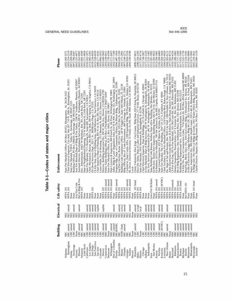
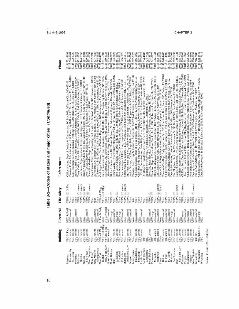
Table 3-1 is a guide to codes and enforcement agencies for states and major cities in the USA.The enforcement agencies for each project should be consulted before and during the designto make sure that current applicable regulations are complied with.
Table 3-2 lists the needs in thirteen general categories with some breakdown under each toindicate major requirements. Ranges under the columns “Maximum tolerance duration ofpower failure” and “Recommended minimum auxiliary supply time” are assigned based uponexperience. Written standards have been referenced where applicable.
In some cases, under the column “Type of auxiliary power system,” both emergency andstandby have been indicated as required. An emergency supply of limited time capacity maybe used at a low cost for immediate or uninterruptible power until a standby supply can bebrought on-line. An example would be the case in which battery lighting units come on untila standby generator can be started and transferred to the critical loads.
Following table 3-2, items from the “General need” column are presented in greater detailwith recommendations as to the type of equipment or system that should be used (see 3.2–3.14).
Users of this standard may wish to skip the detailed presentation of each “General need” andgo directly to Chapter 4. If so, care should be taken that all individual needs have been recog-nized and listed so that suitable power systems can be selected to meet all requirements.
14
IEEEGENERAL NEED GUIDELINES Std 446-1995
M
inne
apol
isU
BC
am
end
NE
C a
men
dN
one
Supv
r, I
nspe
ctio
ns D
iv, 3
00 P
ublic
Hea
lth C
ente
r, 2
50 S
4th
St,
Min
neap
olis
, MN
554
15(6
12)
673-
5845
Mis
siss
ippi
SBC
NE
CN
FPA
101
lim
tdSt
Bld
gs o
nly-
Dir
Off
ice
of B
ldgs
& G
rnds
, 150
1 W
alte
r Si
llers
Bld
g, J
acks
on, M
S 39
201
(601
) 35
9-36
21
Jack
son
SBC
NE
CN
one
Cha
rles
Dez
row
, Dep
uty
Dir
, Bld
g Pe
rmit
Div
, PO
Box
17,
Jac
kson
, MS
3920
5(6
01)
960-
1159
Tab
le 3
-1—
Co
des
of
stat
es a
nd
maj
or
citi
es
Bui
ldin
gE
lect
rica
lL
ife
safe
tyE
nfor
cem
ent
Pho
ne
Ala
bam
aSB
CN
EC
NFP
A 1
01St
ate
Fire
Mar
shal
's O
ffic
e.,P
O B
ox 3
0335
2, M
ontg
omer
y, A
L 3
6130
-335
2(2
05)
269
3575
B
irm
ingh
amSB
C a
men
dN
EC
am
end
NFP
A 1
01C
hief
Ele
ctri
cal I
nspe
ctor
, City
Hal
l, R
m 2
07, 7
10 N
. 20t
h St
., B
irm
ingh
am, A
L 3
5203
(205
) 25
4-22
19A
lask
aU
BC
am
end
NE
CN
one
Stat
e Fi
re M
arsh
al, 5
700
E. T
udor
St.,
Anc
hora
ge, A
K 9
9507
-122
5(9
07)
269-
5604
A
ncho
rage
UB
C a
men
dN
EC
am
end
Non
eB
uild
ing
Off
icia
l, PO
Box
196
650,
Anc
hora
ge, A
K 9
9519
-665
0(9
07)
786-
8307
Ari
zona
Non
eN
EC
Ari
z Fi
re C
ode
Ass
t Fir
e M
arsh
all,D
ept o
f B
ldg
& F
ire
Safe
ty, 1
540
W V
anB
uren
, Pho
enix
, AZ
850
07(6
02)
255-
4072
Ph
oeni
xU
BC
am
end
NE
C a
men
dR
ef in
Bld
g &
Fir
eA
ssis
tant
Dir
ecto
r, D
evel
opm
ent S
ervi
ces
Dep
t,200
W W
ashi
ngto
n, P
hoen
ix, A
Z 8
5003
(602
) 26
2-69
01A
rkan
sas
SBC
am
end
NE
CN
FPA
101
Ele
c. A
dmin
istr
ator
, 104
21 W
Mar
kham
, Rm
. 301
, Litt
le R
ock,
AR
722
05(5
01)
682-
4500
L
ittle
Roc
kSB
CN
EC
Non
eD
ept o
f N
eigh
borh
ood
Plan
ning
, 723
W M
arkh
am S
t, L
ittle
Roc
k, A
R 7
2201
(501
) 37
1-48
26C
alif
orni
aU
BC
am
end
NE
C a
men
dN
one
Stat
e Fi
re M
arsh
al, 7
171
Bow
ling
Dr,
Sui
te 6
00, S
acra
men
to, C
A 9
5823
(916
) 26
2-18
75
Los
Ang
eles
UB
C a
men
dN
EC
am
end
Non
eC
hief
, Mec
hani
cal.
Bur
eau,
Rm
485
City
Hal
l, 20
0 N
Spr
ing
St, L
os A
ngel
os, C
A 9
0012
(213
) 48
5-23
01
San
Die
goU
BC
am
end
NE
C a
men
dN
FPA
101
Dir
Dev
el.S
ervi
ces
Dep
t,, 2
02 C
St ,
MS9
B,S
an D
iego
, CA
921
01(6
19)
236-
6056
Sa
n Fr
anci
sco
UB
C a
men
dN
EC
am
end
Non
eC
h E
lec
Insp
, Dep
t of
Bui
ldin
g In
sp, 1
660
Mis
sion
St,,
San
Fra
ncis
co, C
A 9
4103
(415
) 55
8-60
30
San
Jose
UB
C a
men
dN
EC
sup
lmt
Non
eC
hief
Ins
pect
or D
ept o
f Pl
anni
ng, 8
01 N
1st
St,
Rm
200
, San
Jos
e, C
A 9
5110
(408
) 27
7-45
41C
olor
ado
UB
C
NE
C
Non
eL
este
r Fi
elds
, Div
of
Hou
sing
, 131
3 Sh
erm
an S
t, R
M 3
23, D
enve
r, C
O 8
0203
(303
) 86
6-20
33
Den
ver
UB
C a
men
dN
EC
sup
lmt
NFP
A 1
01
Dir
ecto
r, B
uild
ing
Insp
ectio
n D
iv, 2
00 W
14t
h A
ve, D
enve
r, C
O 8
0204
-270
0(3
03)
640-
5843
Con
nect
icut
NB
C a
men
dN
EC
NFP
A 1
01 a
men
dPu
blic
Saf
ety
Bui
ldin
g O
ffic
al, P
O B
ox 2
794,
Mid
dlet
own,
CT
064
57-9
294"
(203
) 23
8-60
11D
elaw
are
Non
eN
EC
NFP
A 1
01 a
men
dSt
ate
Fire
Mar
shal
's O
ffic
e, R
.D. 2
, Box
166
A, D
over
, DE
199
01"
(302
) 73
9-43
94
Wilm
ingt
onN
BC
am
end
NE
CN
FPA
101
am
end
Dep
t Lic
ence
s &
Ins
pect
ion,
800
Fre
nch
St, 5
th F
loor
, Wilm
ingt
on D
E 1
9801
(302
) 57
1-44
23D
ist o
f C
olum
bia
NB
C a
men
dN
EC
am
end
Non
eA
dmr,
Bld
g &
Lan
d R
egul
atio
n A
dm, 6
14 H
St N
W, R
oom
312
, Was
hing
ton,
DC
200
01(2
02)
727-
7340
Flor
ida
SBC
&SF
BC
NE
CN
FPA
101
am
end
Prog
ram
Mgr
, Dep
t of
Com
mun
ity A
ffai
rs,T
he R
hyne
Bld
g,, T
alla
hass
ee, F
L 3
2399
(904
) 48
7-18
24
Jack
sonv
ille
SBC
NE
C a
men
dN
FPA
101
Sup
Ele
ct S
ectio
n, R
oom
100
City
Hal
l, 22
0 E
Bay
St,
Jack
sonv
ille,
FL
322
02(9
04)
630-
1100
M
iam
iSF
BC
Dad
eN
EC
w/e
xcl
NFP
A 1
01B
uild
ing
Cod
e C
ompl
ianc
e O
ffic
e, 1
40 W
Fla
gler
St,
Suite
160
3 M
iam
i, FL
331
30(3
05)
375-
2901
O
rlan
doSB
C a
men
dN
EC
am
end
NFP
A 1
01B
ldg
Off
icia
l, B
ur o
f C
ode
Enf
orce
men
t., 4
00 S
Ora
nge
Av,
Orl
ando
, FL
328
01(4
07)
246-
2271
Geo
rgia
SBC
NE
CN
FPA
101
am
end
Com
mis
'nr,
Dep
t Com
m A
ffrs
, 120
0 E
quita
ble
Bld
g, 1
00 P
each
tree
St,
Atla
nta,
GA
303
03(4
04)
656-
5526
A
tlant
aSB
CN
EC
am
ned
NFP
A 1
01 a
men
dR
L D
over
, Ele
ctri
cal D
ivis
ion,
55
Tri
nity
Av,
SW, S
uite
390
0 A
tlant
a, G
A 3
0335
(404
) 33
0-61
80H
awai
iN
one
Non
eN
one
Loc
al H
onol
ulu
UB
C a
men
dN
EC
am
end
NFP
A 1
01 li
mtd
G
lenn
Yok
omic
hi, E
lect
Eng
r , C
ity/C
ount
y B
ldg
Dep
t, 65
0 S
Kin
g St
, Hon
olul
u, H
I 96
813
(808
) 52
7-60
11Id
aho
UB
CN
EC
w/s
upl
NFP
A 1
01E
lect
Div
Adm
r, D
ept o
f L
abor
and
Ind
ustr
ial S
ervi
ces,
277
N 6
th, B
oise
, ID
837
20(2
08)
334-
2183
Illin
ois
Non
eN
EC
loca
lN
FPA
101
Stat
e Fi
re M
arsh
al, 1
035
Stev
enso
n D
r, S
prin
gfie
ld, I
L 6
2706
(217
) 78
5-47
14
Chi
cago
CB
CC
EC
Non
eC
hief
Ele
ctri
cal I
nspe
ctor
, Dep
t of
Bui
ldin
gs, 1
21 N
LaS
alle
St,
Chi
cago
, IL
606
02(3
12)
744-
3457
Indi
ana
UB
C a
men
dN
EC
am
end
Non
eSt
Fir
e M
arsh
all,
Dep
t of
Bld
g Se
rvic
es, 4
02 W
Was
hing
ton
St, I
ndia
napo
lis, I
N 4
6204
(317
) 23
2-22
26
Indi
anap
olis
UB
C a
men
dN
EC
am
end
Non
eD
ir.T
ech.
Ser
vice
s an
d R
esea
rch
Div
,402
W W
ashi
ngto
n St
. Ind
iana
polis
, IN
462
04(3
17)
232-
1402
Iow
aU
BC
am
end
NE
C a
men
dIo
wa
Fire
M R
ules
Stat
e B
uild
ing
Cod
e B
urea
u, W
alla
ce S
tate
off
ice
Bui
ldin
g, D
es M
oine
s, I
A 5
0319
(515
) 28
1-39
92
Des
Moi
nes
UB
C a
men
dN
EC
am
end
Non
eE
d M
cAte
e, S
enio
r E
lect
Ins
pect
or, B
uild
ing
Dep
t, 60
2 E
1st
St,
Des
Moi
nes,
IA
503
09(5
15)
283-
4925
Kan
sas
UB
CN
EC
NFP
A 1
01 a
men
dE
d R
edm
on, K
S Fi
re M
arsh
all.,
700
SW
Jac
kson
St,
Ste
600,
Top
eka,
KS
6660
3-37
14(9
13)
296-
3401
W
ichi
taU
BC
am
end
NE
C a
men
dN
FPA
101
Supt
Cen
tral
Ins
pect
ion,
455
N M
ain
St, W
ichi
ta, K
S 67
202
(316
) 26
8-44
60K
entu
cky
NB
C (
KY
BC
)N
EC
am
end
NFP
A 1
01 (
KY
BC
)St
ate
Fire
Mar
shal
, The
127
Bui
ldin
g, 1
047
US
127
S, F
rank
fort
, KY
406
01(5
02)
564-
3626
Lou
isai
naSB
CN
EC
NFP
A 1
01C
hief
Arc
hite
ct, S
tate
Fir
e M
arsh
al's
Off
ice,
515
0 Fl
orid
a B
lvd,
Bat
on R
ouge
, LA
708
06(5
04)
925-
4920
N
ew O
rlea
nsSB
C a
men
dN
EC
am
end
NFP
A 1
01D
ir, D
ept o
f Sa
f an
d Pe
rmits
, Rm
7E
05 C
ity H
all,
1300
Per
dido
St,
New
Orl
eans
, LA
701
12(5
04)
565-
6111
Mai
neN
one
NE
CN
FPA
101
Adm
r E
lect
rici
an E
xam
Bd
Lic
enc
& E
nfor
ce, S
tate
Hou
se S
tatio
n #
35, A
ugus
ta M
E 0
4333
(207
) 58
2-87
23M
aryl
and
NB
CN
EC
NFP
A 1
01am
end
Ch
Fire
Pro
t Eng
, Off
St F
ire
Mar
shal
l, 10
1 O
ld C
ourt
Rd,
Ste
300
, Pik
esvi
lle, M
D 2
1032
(410
) 76
4-43
24
Bal
timor
eN
BC
am
end
NE
C a
men
dN
FPA
101
Den
nis
Cho
jnow
ski,
Perm
it E
nfor
c, 4
17 E
Fay
ette
St,
Rm
101
, Bal
timor
e, M
D 2
1202
(410
) 39
6-34
62M
assa
chus
etts
NB
C a
men
dN
EC
am
end
NFP
A 1
01 li
mtd
Bd
of B
ldg
Reg
ulat
ions
, One
Ash
burt
on P
lace
, Rm
130
1, B
osto
n, M
A 0
2108
(617
) 72
7-32
00
Bos
ton
NB
C a
men
dN
EC
am
end
NFP
A 1
01 li
mtd
Bui
ldin
gs a
nd I
nspe
ctio
nal S
erv,
101
0 M
assa
chus
etts
Av,
Bos
ton,
MA
022
15(6
17)
635-
5300
Mic
higa
nN
BC
am
end
NE
C a
men
dN
one
Ch
Ele
c D
iv, B
ur o
f C
onst
ruct
ion
Cod
es,
7150
Har
ris
Dr,
PO
Box
302
54, L
ansi
ng M
I 48
909
(517
) 32
2-17
39
Det
roit
NB
C a
men
dN
EC
am
end
Ref
NFP
A 1
01H
ead
Eng
r, M
ech.
Ele
ct. D
iv, 4
34 C
ity/C
ount
y B
ldg,
2 W
oodw
ard
Av,
Det
roit,
MI
4922
6(3
13)
224-
3181
Min
neso
taU
BC
am
end
NE
C a
men
dN
one
St B
d of
Ele
ctri
city
, Gri
ggs
Mid
way
Bld
g #S
-128
, 182
1 U
nive
rsity
Av,
St P
aul,
MN
551
04(6
12)
642-
0800
15
IEEEStd 446-1995 CHAPTER 3
Wis
cons
inSt
ate
BC
NE
C a
men
dN
one
Div
of
Safe
ty&
Bld
gs, P
O B
ox 7
969,
201
E W
ashi
ngto
n A
v, M
adis
on, W
I 53
707
(608
) 26
6-30
80
Milw
auke
eM
ilwau
kee
BC
NE
C s
uppl
Non
eC
omm
issi
oner
, Dep
t of
Bld
g In
sp, 8
41 N
Bro
adw
ay A
v, M
B 1
001,
Milw
auke
e, W
I 53
202
(414
) 27
8-25
42W
yom
ing
UB
CN
EC
Non
eD
ept F
ire
Prev
entio
n &
Ele
ctri
cal S
afet
y,1
W 2
5th
St, C
heye
nne,
WY
820
02(3
07)
777-
7119
Sour
ce: E
GSA
: 109
C-1
994
[B4]
Mis
sour
iN
BC
St F
acil
NE
C S
t Fac
ilN
FPA
101
St F
acO
ffic
e of
Adm
, Dep
t of
Des
ign
& C
onst
ruci
on, P
O B
ox 8
09, J
effe
rson
City
, MO
651
02(3
14)
751-
4191
K
ansa
s C
ityU
BC
am
end
NE
C a
men
dN
one
Dir
ecto
r C
odes
Adm
inis
trat
ion,
18t
h Fl
oor
City
Hal
l, 41
4 E
12t
h St
, Kan
sas
City
, MO
641
06(8
16)
274-
1464
St
. Loi
usN
BC
am
end
NE
CN
one
Supt
. Ele
ctri
cal S
ectio
n, B
uild
ing
Dep
t, R
m 4
25, 1
200
Mar
ket S
t, St
. Lou
is, M
O 6
3103
(314
) 62
2-33
26M
onta
naU
BC
am
end
NE
C a
men
dN
one
Bur
eau
Chi
ef B
ldg
Cod
es B
urea
u, D
ept o
f C
omm
erce
, PO
Box
200
517
Hel
ena,
MT
596
20(4
06)
444-
3933
Neb
rask
aU
BC
am
end
NE
CN
FPA
101
am
end
Ter
ry C
arls
on, E
xec
Dir
, Sta
te E
lect
rica
l Bd,
800
S 1
3th
St,,
RM
109
, Om
aha,
NB
681
02(4
02)
471-
3550
O
mah
aU
BC
am
end
NE
CN
FPA
101
am
end
John
Jes
se, S
uper
inte
nden
t, Pe
rmits
and
Ins
pect
ion,
181
9 Fa
rnam
St,
Om
aha,
NB
681
83(4
02)
444-
5350
Nev
ada
UB
C a
men
dN
EC
NFP
A 1
01 r
efr
Bru
ce N
ipp,
St P
ublic
Wor
ks B
d, C
apito
l Com
plex
505
E K
ing
St, C
arso
n C
ity, N
V 8
9710
(702
) 68
7-39
81
Las
Veg
asU
BC
am
end
NE
C a
men
dN
FPA
101
John
Tuc
ker,
Dir
ecto
r B
uild
ing
and
Safe
ty, 4
00 E
Ste
war
t Av,
Las
Veg
as, N
V 8
9101
(702
) 22
9-62
51N
ew H
amps
hire
NB
CN
EC
NFP
A 1
01 a
men
dSt
ate
Fire
Mar
shal
, Dep
t of
Safe
ty, 1
0 H
azen
Dr,
Con
cord
, NH
033
05(6
03)
271-
3294
New
Jer
sey
NB
CN
EC
Non
eD
ept C
omm
Aff
rs, D
iv o
f H
ousi
ng a
nd D
evel
, 101
S B
road
St,
CN
802
, Tre
nton
, NJ
0862
5(6
09)
292-
7899
New
Mex
ico
UB
C a
men
dN
EC
am
end
none
R. P
ache
co,a
ct. B
urea
u C
hief
, Ele
ctri
cal B
urea
u, 7
25 S
t. M
icha
el's
Dr,
San
ta F
e, N
M 8
7504
(505
) 82
7-70
36
Alb
uque
rque
UB
C a
men
dN
EC
am
end
Non
eD
Ste
ele,
Ch
Bld
g O
ffic
al, C
odes
Adm
inis
trat
ion,
600
2nd
St N
W, A
lbuq
uerq
ue, N
M 8
7102
(505
) 76
4-16
26N
ew Y
ork
U F
ire
& B
ldg
U F
ire
& B
ldg
U F
ire
& B
ldg
Car
l Sag
er, D
irec
tor,
Cod
es D
ivis
ion,
Dep
t of
Stat
e, 1
62 W
ashi
ngto
n A
V, A
lban
y, N
Y 1
2231
(518
) 47
4-40
73
Buf
falo
NY
Fir
e &
Bld
gN
EC
NY
Fir
e &
Bld
gD
avid
Pie
row
icz,
Ch
Ele
ct I
nspe
ctor
, City
Hal
l, R
m 6
01, 6
5 N
iaga
ra S
q, B
uffa
lo, N
Y 1
4202
(716
) 85
1-59
02
New
Yor
k C
ityN
Y C
ity B
ldg
NY
City
Ele
ctN
one
M K
ahm
e,PE
, Dir
, Bur
of
Ele
c C
ontr
, Rm
232
4 M
un B
ldg,
1 C
ente
r St
, New
Yor
k, N
Y 1
0007
(212
) 66
9-83
38N
orth
Car
olin
aSB
C a
men
dN
EC
am
end
Non
eA
lan
Bar
ring
er, C
h E
lect
Eng
r, D
ept o
f In
sura
nce,
410
N B
oyla
n A
v, R
alie
gh, N
C 2
7611
(919
) 73
3-39
01N
orth
Dak
ota
UB
CN
EC
sup
plN
FPA
101
Ric
hard
Ham
an, E
xec
Dir
Ele
ctri
cal B
oard
, 721
Mem
oria
l Hig
hway
, Bis
mar
k, N
D 5
8504
(701
) 32
8-28
22O
hio
NB
C a
men
dN
EC
am
end
Non
eE
lmer
Wal
tz, D
iv o
f Fa
ctor
y B
ldg
Insp
, 232
3 W
5th
Av,
PO
Box
825
, Col
umbu
s, O
H 4
3216
(614
) 64
4-26
22
Cin
cinn
ati
NB
C a
men
dN
EC
sup
plN
FPA
101
Bob
Lac
k, C
h E
lec
Insp
, Dep
t Bld
g &
Ins
p, C
ity H
all,
Rm
316
, Cin
cinn
ati,
OH
452
02(5
13)
381-
6080
C
leve
land
NB
C a
men
dN
EC
sup
plN
one
Ron
Jen
ning
s, C
h In
sp, D
iv o
f B
ldg
and
Hou
sing
, 601
Lak
esid
e A
v, C
leve
land
, OH
441
44(2
16)
664-
2618
C
olum
bus
NB
C a
men
dN
EC
am
end
NFP
A 1
01 a
men
dD
an B
enni
nger
, Ch
Ele
c II
nsp,
Reg
ulat
ion
Div
,125
0 Fa
irw
ood
Av,
Col
umbu
s, O
H 4
3206
(614
) 64
5-60
76O
klah
oma
NB
C
NE
CN
FPA
101
am
end
Off
ice
Stat
e Fi
re M
arsh
al, 4
545
N L
inco
ln B
lvd,
Sui
te 2
80, O
klah
oma
City
, OK
731
05(4
05)
524-
9610
O
klah
oma
City
NB
C a
men
dN
EC
am
end
NFP
A 1
01R
L H
ood,
Sup
t Ins
p Se
rv, P
ublic
Wor
ks D
ept 4
20 W
Mai
n 8t
hFl.
Okl
ahom
a C
ity, O
K 7
3109
(405
) 29
7-29
48O
rego
nU
BC
am
end
NE
C a
men
dN
one
Juni
or O
win
gs, C
h E
lect
Ins
p, B
ldg
Cod
es D
iv, 1
535
Edg
ewat
er S
t NW
, Sal
em, O
R 9
7310
(503
) 37
3-75
09Pe
nnsy
lvan
iaN
one
Non
eSt
ate
Dir
ecto
r, B
ur O
ccup
. & I
ndus
tria
l Saf
ety,
Rm
152
9 7t
h &
For
este
r St
, Har
risb
urg,
PA
171
20(7
17)
787-
3323
Ph
ilade
lphi
aN
BC
am
end
NE
C a
men
dN
one
Ch
Con
st S
ervi
ces,
Dep
t of
Lic
& I
nspe
c, 1
1th
Fl .
1401
JFK
Blv
d, P
hila
delp
hia,
PA
191
03(2
15)
686-
5160
Pi
ttsbu
rgh
NB
C a
men
dN
EC
Non
eC
hief
Bur
Bld
g In
spec
tion,
Dep
t of
Publ
ic S
afet
y, 2
00 R
oss
St, P
ittsb
urgh
, PA
152
20(4
12)
255-
2176
Rho
de I
slan
dN
BC
am
end
NE
C a
men
dN
one
J C
irill
o, C
omm
issi
oner
, Sta
te B
ldg
Com
m, 1
Cap
itol H
ill, 2
nd F
loor
, Pro
vide
nce,
RI
0290
8(4
01)
277-
3529
Sout
h C
arol
ina
SBC
NE
CN
one
Ass
tDep
Dir
, Bui
ldC
odes
&R
elat
ed S
ervi
cesl
, 360
0 Fo
rest
Dr,
Sui
te10
0, C
olum
bia,
SC
292
01(8
03)
734-
4182
C
harl
esto
nSB
CN
EC
Non
eB
uild
ing
& F
ireO
ffic
ial,
75C
alho
un S
t, D
ivis
on 3
20, C
harl
esto
n, S
C 2
9401
(803
) 72
4-74
31So
uth
Dak
ota
UB
C a
men
dN
EC
am
end
NFP
A 1
01E
xec
Dir
, Sta
te E
lect
rica
l Com
mis
sion
,302
S P
aune
e A
ve, P
ierr
e, S
D 5
7501
(605
) 77
3-35
73T
enne
ssee
SBC
NE
C s
uppl
NFP
A 1
01E
lect
Sec
, Dep
t of
Com
m&
Ins,
Vol
Pl,
3rd
Fl, 5
00 J
Rob
erts
on P
ky, N
ashv
ille,
TN
372
43(6
15)
741-
7170
M
emph
isSB
C a
men
dN
EC
am
end
Non
eB
ldg
Off
, Mem
phis
/She
lby
Cnt
y C
ode
Enf
or, 1
60 N
Mai
n St
, Rm
750
,Mem
phis
, TN
381
03(9
01)
576-
5341
N
ashv
ille
SBC
am
end
NE
C a
men
dN
FPA
101
am
end
Dir
, Dep
t of
Cod
es A
dm, M
etro
How
ard
Bld
g, 7
00 2
nd A
v S,
Nas
hvill
e, T
N 3
7210
(615
) 86
2-66
00T
exas
Non
eN
one
NFP
A 1
01 li
mtd
Dep
t of
Lic
& R
eg,P
olic
y &
Std
s D
iv B
ox 1
2157
, Cap
itol S
t, A
ustin
, TX
787
11(5
12)
463-
7356
D
alla
sU
BC
am
end
NE
C a
men
dN
one
Eco
nom
icD
evD
ept,
Bld
g In
spec
tion
Div
, 320
E J
effe
rson
Blv
d, R
oom
105
, Dal
las,
TX
752
03(2
14)
948-
4480
E
l Pas
oSB
C a
men
dN
EC
am
end
NFP
A 1
01
Ch
Ele
ctri
cal I
nspe
ctor
, Pub
lic I
nspe
ctio
n D
ept,
2 C
ivic
Cen
ter
Plaz
a, E
l Pas
o, T
X 7
9901
(915
) 54
1-49
00
Ft. W
orth
UB
C a
men
dN
EC
am
end
Non
eA
sst D
ir/B
ldg
Off
icia
l, C
ity D
ept o
f D
evel
, 100
0 T
hroc
kmor
ton
St, F
t. W
orth
, TX
761
02(8
17)
871-
8025
H
oust
onU
BC
am
end
NE
C s
uppl
Non
eD
ept P
ublic
Wor
ks,C
odes
& S
tand
ards
Gro
up, P
O B
ox 1
562,
Hou
ston
, TX
772
51(7
13)
754-
0004
Sa
n A
nton
io
UB
C a
men
dN
EC
am
end
NFP
A 1
01D
ir, B
ldg
Insp
Dep
t, 11
4 W
Com
mer
ce S
t. PO
Box
839
966,
San
Ant
onio
, TX
782
83(2
10)
287-
8232
Uta
hU
BC
am
end
NE
CN
FPA
101
lim
tdD
ept o
f C
omm
erce
, Div
of
Occ
up &
Pro
f L
icen
s, P
O B
ox 4
5805
, Sal
t Lak
e C
ity, U
T 8
4145
(801
) 53
0-67
31
Salt
Lak
e C
ityU
BC
am
end
NE
C
Non
eSr
Ele
ct I
nspe
ctor
, Bui
ldin
g &
Hou
sing
Ser
vice
s, 4
51 S
Sta
te S
t, Sa
lt L
ake
City
, UT
841
11(8
01)
535-
7752
Ver
mon
tN
BC
am
end
NE
C+
stat
eN
FPA
101
am
end
Ch
Ele
ctl I
nsp,
Dep
t of
Lab
or a
nd I
ndus
try,
Nat
iona
l Lif
e B
ldg,
Dw
r 20
Mon
tpel
ier,
VT
056
20(8
02)
828-
2106
Vir
gina
NB
C a
men
dN
EC
am
end
Non
eA
soc
Dir
, Cod
e E
nfor
c O
ffic
e, D
iv o
f B
ldg
Reg
ulat
ion,
501
N 2
nd S
t, R
ichm
ond,
VA
232
19(8
04)
371-
7160
Was
hing
ton
UB
C a
men
dN
EC
+st
ate
Non
eC
h E
lect
Ins
pect
or,D
iv o
f B
ldg
& C
onst
rSaf
ety
Serv
ices
, PO
Box
4446
0, O
lym
pia,
WA
985
04(3
60)
902-
5269
Sea
ttle
UB
C a
men
dN
EC
am
end
Non
ePr
in E
ngr,
Dep
t of
Con
stru
ctio
n &
Lan
d U
se, 7
10 2
nd A
v, S
uite
700
, Sea
ttle,
Wa
9810
4(2
06)
233-
3892
Wes
t Vir
gini
aN
BC
am
end
NE
C a
men
dN
FPA
101
am
end
Dep
uty
Stat
e Fi
re M
arsh
al, S
tate
Cap
itol,
2100
Was
hing
ton
St, C
harl
esto
n, W
V 2
5305
(304
) 55
8-21
91
Tab
le 3
-1—
Co
des
of
stat
es a
nd
maj
or
citi
es
(Co
nti
nued
)
Bui
ldin
gE
lect
rica
lL
ife
safe
tyE
nfor
cem
ent
Pho
ne
16

IEEEGENERAL NEED GUIDELINES Std 446-1995
Tab
le 3
-2—
Co
nd
ense
d g
ener
al c
rite
ria
for
pre
limin
ary
con
sid
erat
ion
Sect
ion
Gen
eral
nee
dSp
ecifi
c ne
ed
Max
imum
to
lera
nce
dura
tion
of
pow
er f
ailu
re
Rec
omm
ende
d m
inim
um
auxi
liary
su
pply
tim
e
Typ
e of
aux
iliar
y po
wer
sy
stem
Syst
em j
usti
ficat
ion
Em
erge
ncy
Stan
dby
3.2
Lig
htin
gE
vacu
atio
n of
pe
rson
nel
Up
to 1
0 s,
pr
efer
ably
not
m
ore
than
3 s
2 h
xPr
even
tion
of p
anic
, inj
ury,
loss
of
life
Com
plia
nce
with
bui
ldin
g co
des
and
loca
l, st
ate,
and
fed
eral
law
sL
ower
insu
ranc
e ra
tes
Prev
entio
n of
pro
pert
y da
mag
eL
esse
ning
of
loss
es d
ue to
lega
l sui
ts
Peri
met
er a
nd
secu
rity
10 s
10–1
2 h
duri
ng
all d
ark
hour
sx
xL
ower
loss
es fr
om th
eft a
nd p
rope
rty
dam
age
Low
er in
sura
nce
rate
sPr
even
tion
of in
jury
War
ning
From
10
s up
to
2 o
r 3
min
To r
etur
n to
pr
ime
pow
erx
Prev
entio
n or
red
uctio
n of
pro
pert
y lo
ssC
ompl
ianc
e w
ith b
uild
ing
code
s an
d lo
cal,
stat
e, a
nd f
eder
al la
ws
Prev
entio
n of
inju
ry a
nd lo
ss o
f lif
e
Res
tora
tion
of
norm
al p
ower
sy
stem
1 s
to in
defi-
nite
dep
end-
ing
on
avai
labl
e lig
ht
Unt
il re
pair
s co
mpl
eted
and
po
wer
res
tore
d
xx
Ris
k of
ext
ende
d po
wer
and
ligh
t ou
tage
due
to a
long
er r
epai
r tim
e
Gen
eral
lig
htin
gIn
defin
ite;
depe
nds
on
anal
ysis
and
ev
alua
tion
Inde
finite
; de
pend
s on
anal
ysis
and
ev
alua
tion
xPr
even
tion
of lo
ss o
f sa
les
Red
uctio
n of
pro
duct
ion
loss
esL
ower
ris
k of
thef
tL
ower
insu
ranc
e ra
tes
17
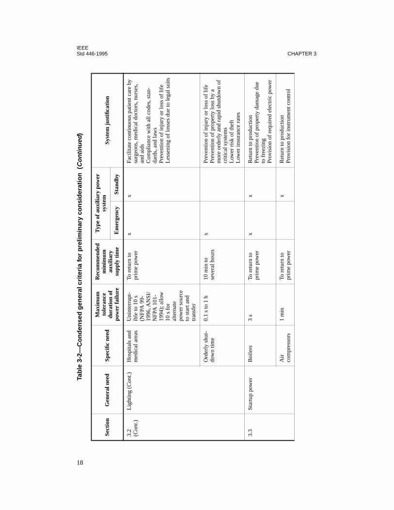
IEEEStd 446-1995 CHAPTER 3
3.2
( Con
t.)L
ight
ing
(Con
t.)H
ospi
tals
and
m
edic
al a
reas
Uni
nter
rupt
-ib
le to
10
s (N
FPA
99-
1996
, AN
SI/
NFP
A 1
01-
1994
); a
llow
10
s f
or
alte
rnat
e po
wer
sou
rce
to s
tart
and
tr
ansf
er
To r
etur
n to
pr
ime
pow
erx
xFa
cilit
ate
cont
inuo
us p
atie
nt c
are
by
surg
eons
, med
ical
doc
tors
, nur
ses,
an
d ai
dsC
ompl
ianc
e w
ith a
ll co
des,
sta
n-da
rds,
and
law
sPr
even
tion
of in
jury
or
loss
of
life
Les
seni
ng o
f lo
sses
due
to le
gal s
uits
Ord
erly
shu
t-do
wn
time
0.1
s to
1 h
10 m
in to
se
vera
l hou
rsx
Prev
entio
n of
inju
ry o
r lo
ss o
f lif
ePr
even
tion
of p
rope
rty
loss
by
a m
ore
orde
rly
and
rapi
d sh
utdo
wn
of
criti
cal s
yste
ms
Low
er r
isk
of th
eft
Low
er in
sura
nce
rate
s
3.3
Star
tup
pow
erB
oile
rs3
sTo
ret
urn
to
prim
e po
wer
xx
Ret
urn
to p
rodu
ctio
nPr
even
tion
of p
rope
rty
dam
age
due
to f
reez
ing
Prov
isio
n of
req
uire
d el
ectr
ic p
ower
Air
com
pres
sors
1 m
inTo
ret
urn
to
prim
e po
wer
xR
etur
n to
pro
duct
ion
Prov
isio
n fo
r in
stru
men
t con
trol
Tab
le 3
-2—
Co
nd
ense
d g
ener
al c
rite
ria
for
pre
limin
ary
con
sid
erat
ion
(C
on
tinu
ed)
Sect
ion
Gen
eral
nee
dSp
ecifi
c ne
ed
Max
imum
to
lera
nce
dura
tion
of
pow
er f
ailu
re
Rec
omm
ende
d m
inim
um
auxi
liary
su
pply
tim
e
Typ
e of
aux
iliar
y po
wer
sy
stem
Syst
em j
usti
ficat
ion
Em
erge
ncy
Stan
dby
18
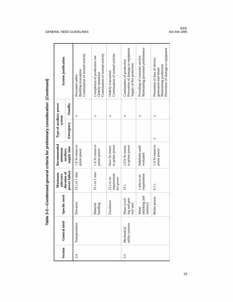
IEEEGENERAL NEED GUIDELINES Std 446-1995
3.4
Tra
nspo
rtat
ion
Ele
vato
rs15
s to
1 m
in1
h To
ret
urn
to
prim
e po
wer
xPe
rson
nel s
afet
yB
uild
ing
evac
uatio
nC
ontin
uatio
n of
nor
mal
act
ivity
Mat
eria
l ha
ndlin
g15
s to
1 m
in1
h To
ret
urn
to
prim
e po
wer
xC
ompl
etio
n of
pro
duct
ion
run
Ord
erly
shu
tdow
nC
ontin
uatio
n of
nor
mal
act
ivity
Esc
alat
ors
15 s
to n
o re
quir
emen
t fo
r po
wer
Zer
o To
ret
urn
to p
rim
e po
wer
xO
rder
ly e
vacu
atio
nC
ontin
uatio
n of
nor
mal
act
ivity
3.5
Mec
hani
cal
utili
ty s
yste
ms
Wat
er (
cool
-in
g an
d ge
n-er
al u
se)
15 s
1/2
h To
ret
urn
to p
rim
e po
wer
xC
ontin
uatio
n of
pro
duct
ion
Prev
entio
n of
dam
age
to e
quip
men
tSu
pply
of
fire
prot
ectio
n
Wat
er
(dri
nkin
g an
d sa
nita
ry)
1 m
in to
no
requ
irem
ent
Inde
finite
unt
il ev
alua
ted
xPr
ovid
ing
of c
usto
mer
ser
vice
Mai
ntai
ning
per
sonn
el p
erfo
rman
ce
Boi
ler
pow
er0.
1 s
1 h
To r
etur
n to
pr
ime
pow
erx
xPr
even
tion
of lo
ss o
f el
ectr
icge
nera
tion
and
stea
mM
aint
aini
ng p
rodu
ctio
nPr
even
tion
of d
amag
e to
equ
ipm
ent
Tab
le 3
-2—
Co
nd
ense
d g
ener
al c
rite
ria
for
pre
limin
ary
con
sid
erat
ion
(C
on
tinu
ed)
Sect
ion
Gen
eral
nee
dSp
ecifi
c ne
ed
Max
imum
to
lera
nce
dura
tion
of
pow
er f
ailu
re
Rec
omm
ende
d m
inim
um
auxi
liary
su
pply
tim
e
Typ
e of
aux
iliar
y po
wer
sy
stem
Syst
em j
usti
ficat
ion
Em
erge
ncy
Stan
dby
19

IEEEStd 446-1995 CHAPTER 3
3.5
( Con
t.)M
echa
nica
l ut
ility
sys
tem
s ( C
ont.)
Pum
ps f
or
wat
er,
sani
tatio
n,
and
prod
uc-
tion
fluid
s
10 s
to n
o re
quir
emen
tIn
defin
ite u
ntil
eval
uate
dx
Prev
entio
n of
floo
ding
Mai
ntai
ning
coo
ling
faci
litie
sPr
ovid
ing
sani
tary
nee
dsC
ontin
uatio
n of
pro
duct
ion
Mai
ntai
ning
boi
ler
oper
atio
n
Fans
and
bl
ower
s fo
r ve
ntila
tion
and
heat
ing
0.1
s to
ret
urn
of n
orm
al
pow
er
Inde
finite
unt
il ev
alua
ted
xx
Mai
ntai
ning
boi
ler
oper
atio
nPr
ovid
ing
for
gas-
fired
uni
t ven
ting
and
purg
ing
Mai
ntai
ning
coo
ling
and
heat
ing
func
tions
for
bui
ldin
gs a
nd
prod
uctio
n
3.6
Hea
ting
Food
pr
epar
atio
n5
min
To r
etur
n to
pr
ime
pow
erx
Prev
entio
n of
loss
of
sale
s an
d pr
ofit
Prev
entio
n of
spo
ilage
of
in-p
roce
ss
prep
arat
ion
Proc
ess
5 m
inIn
defin
ite u
ntil
eval
uate
d;
norm
ally
for
tim
e fo
r ord
erly
sh
utdo
wn,
or
To r
etur
n to
pr
ime
pow
er
xPr
even
tion
of in
-pro
cess
pro
duct
ion
dam
age
Prev
entio
n of
pro
pert
y da
mag
eC
ontin
ued
prod
uctio
nPr
even
tion
of p
aym
ent t
o w
orke
rs
duri
ng n
o pr
oduc
tion
Low
er in
sura
nce
rate
s
Tab
le 3
-2—
Co
nd
ense
d g
ener
al c
rite
ria
for
pre
limin
ary
con
sid
erat
ion
(C
on
tinu
ed)
Sect
ion
Gen
eral
nee
dSp
ecifi
c ne
ed
Max
imum
to
lera
nce
dura
tion
of
pow
er f
ailu
re
Rec
omm
ende
d m
inim
um
auxi
liary
su
pply
tim
e
Typ
e of
aux
iliar
y po
wer
sy
stem
Syst
em j
usti
ficat
ion
Em
erge
ncy
Stan
dby
20
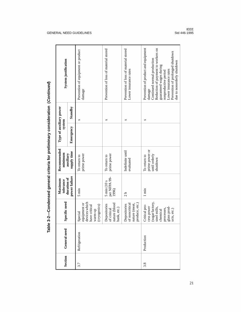
IEEEGENERAL NEED GUIDELINES Std 446-1995
3.7
Ref
rige
ratio
nSp
ecia
l eq
uipm
ent o
r de
vice
s whi
ch
have
cri
tical
w
arm
-up
(cry
ogen
ics)
5 m
inTo
ret
urn
to
prim
e po
wer
xPr
even
tion
of e
quip
men
t or
prod
uct
dam
age
Dep
osito
ries
of
cri
tical
na
ture
(bl
ood
bank
, etc
.)
5 m
in (
10 s
pe
r N
FPA
99-
1996
)
To r
etur
n to
pr
ime
pow
erx
Prev
entio
n of
loss
of
mat
eria
l sto
red
Dep
osito
ries
of
non
criti
cal
natu
re (
mea
t, pr
oduc
e, e
tc.)
2 h
Inde
finite
unt
il ev
alua
ted
xPr
even
tion
of lo
ss o
f m
ater
ial s
tore
dL
ower
insu
ranc
e ra
tes
3.8
Prod
uctio
nC
ritic
al p
ro-
cess
pow
er
(sug
ar fa
ctor
y,
stee
l mill
s,
chem
ical
pr
oces
ses,
gl
ass
prod
-uc
ts, e
tc.)
1 m
inTo
ret
urn
to
prim
e po
wer
or
until
ord
erly
sh
utdo
wn
xPr
even
tion
of p
rodu
ct a
nd e
quip
men
t da
mag
eC
ontin
ued
norm
al p
rodu
ctio
nR
educ
tion
of p
aym
ent t
o w
orke
rs o
n gu
aran
teed
wag
es d
urin
g no
npro
duct
ive
peri
odL
ower
insu
ranc
e ra
tes
Prev
entio
n of
pro
long
ed s
hutd
own
due
to n
onor
derl
y sh
utdo
wn
Tab
le 3
-2—
Co
nd
ense
d g
ener
al c
rite
ria
for
pre
limin
ary
con
sid
erat
ion
(C
on
tinu
ed)
Sect
ion
Gen
eral
nee
dSp
ecifi
c ne
ed
Max
imum
to
lera
nce
dura
tion
of
pow
er f
ailu
re
Rec
omm
ende
d m
inim
um
auxi
liary
su
pply
tim
e
Typ
e of
aux
iliar
y po
wer
sy
stem
Syst
em j
usti
ficat
ion
Em
erge
ncy
Stan
dby
21

IEEEStd 446-1995 CHAPTER 3
3.8
( Con
t.)Pr
oduc
tion
(Con
t.)Pr
oces
s co
ntro
l pow
erU
nint
erru
pt-
ible
to 1
min
To r
etur
n to
pr
ime
pow
erx
xPr
even
tion
of lo
ss o
f m
achi
ne a
nd
proc
ess
com
pute
r co
ntro
l pro
gram
Mai
ntai
ning
pro
duct
ion
Prev
entio
n of
saf
ety
haza
rds
from
de
velo
ping
Prev
entio
n of
out
-of-
tole
ranc
e pr
oduc
ts
3.9
Spac
e co
nditi
onin
gTe
mpe
ratu
re
(cri
tical
ap
plic
atio
n)
10 s
1 m
in T
o re
turn
to
pri
me
pow
erx
xPr
even
tion
of p
erso
nnel
haz
ards
Prev
entio
n of
pro
duct
or
prop
erty
da
mag
eL
ower
insu
ranc
e ra
tes
Con
tinua
tion
of n
orm
al a
ctiv
ities
Prev
entio
n of
loss
of
com
pute
r f
unct
ion
Pres
sure
(cri
tical
) po
s/ne
g at
mos
pher
e
1 m
in1
min
To
retu
rn
to p
rim
e po
wer
xx
Prev
entio
n of
per
sonn
el h
azar
dsC
ontin
uatio
n of
nor
mal
act
iviti
esPr
even
tion
of p
rodu
ct o
r pr
oper
ty
dam
age
Low
er in
sura
nce
rate
sC
ompl
ianc
e w
ith lo
cal,
stat
e, a
nd
fede
ral c
odes
, sta
ndar
ds, a
nd la
ws
Tab
le 3
-2—
Co
nd
ense
d g
ener
al c
rite
ria
for
pre
limin
ary
con
sid
erat
ion
(C
on
tinu
ed)
Sect
ion
Gen
eral
nee
dSp
ecifi
c ne
ed
Max
imum
to
lera
nce
dura
tion
of
pow
er f
ailu
re
Rec
omm
ende
d m
inim
um
auxi
liary
su
pply
tim
e
Typ
e of
aux
iliar
y po
wer
sy
stem
Syst
em j
usti
ficat
ion
Em
erge
ncy
Stan
dby
22

IEEEGENERAL NEED GUIDELINES Std 446-1995
3.9
( Con
t.)Sp
ace
cond
ition
ing
( Con
t.)
Hum
idity
(c
ritic
al)
1 m
inTo
ret
urn
to
prim
e po
wer
xPr
even
tion
of lo
ss o
f co
mpu
ter
fun
ctio
nsM
aint
enan
ce o
f no
rmal
ope
ratio
ns
and
test
sPr
even
tion
of e
xplo
sion
s or
oth
er
haza
rds
Stat
ic c
harg
e10
s o
r le
ssTo
ret
urn
to
prim
e po
wer
xx
Prev
entio
n of
sta
tic e
lect
ric
char
ge
and
asso
ciat
ed h
azar
dsC
ontin
uatio
n of
nor
mal
pro
duct
ion
(pri
ntin
g pr
ess
oper
atio
n, p
aint
ing
spra
y op
erat
ions
)
Bui
ldin
g he
atin
g an
d co
olin
g
30 m
inTo
ret
urn
to
prim
e po
wer
xPr
even
tion
of lo
ss d
ue to
fre
ezin
g M
aint
enan
ce o
f pe
rson
nel e
ffici
ency
Con
tinua
tion
of n
orm
al a
ctiv
ities
Ven
tilat
ion
(tox
ic f
umes
)15
sTo
ret
urn
to
prim
e po
wer
or
orde
rly
shut
-do
wn
xx
Red
uctio
n of
hea
lth h
azar
dsC
ompl
ianc
e w
ith lo
cal,
stat
e, a
nd
fede
ral c
odes
, sta
ndar
ds, a
nd la
ws
Red
uctio
n of
pol
lutio
n
Tab
le 3
-2—
Co
nd
ense
d g
ener
al c
rite
ria
for
pre
limin
ary
con
sid
erat
ion
(C
on
tinu
ed)
Sect
ion
Gen
eral
nee
dSp
ecifi
c ne
ed
Max
imum
to
lera
nce
dura
tion
of
pow
er f
ailu
re
Rec
omm
ende
d m
inim
um
auxi
liary
su
pply
tim
e
Typ
e of
aux
iliar
y po
wer
sy
stem
Syst
em j
usti
ficat
ion
Em
erge
ncy
Stan
dby
23
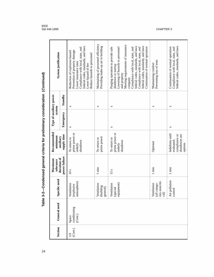
IEEEStd 446-1995 CHAPTER 3
com
plia
nce
or
shut
dow
ns a
re
optio
ns
fede
ral c
odes
, sta
ndar
ds, a
nd la
ws
3.9
( Con
t.)Sp
ace
cond
ition
ing
( Con
t.)
Ven
tilat
ion
(exp
losi
ve
atm
osph
ere)
10 s
To r
etur
n to
pr
ime
pow
er o
r or
derl
y sh
utdo
wn
xx
Red
uctio
n of
exp
losi
on h
azar
dPr
even
tion
of p
rope
rty
dam
age
Low
er in
sura
nce
rate
sC
ompl
ianc
e w
ith lo
cal,
stat
e, a
nd
fede
ral c
odes
, sta
ndar
ds, a
nd la
ws
Low
er h
azar
d of
fire
Red
uce
haza
rds
to p
erso
nnel
Ven
tilat
ion
(bui
ldin
g ge
nera
l)
1 m
inTo
ret
urn
to
prim
e po
wer
xM
aint
aini
ng o
f pe
rson
nel e
ffici
ency
Prov
idin
g m
ake-
up a
ir in
bui
ldin
g
Ven
tilat
ion
(spe
cial
eq
uipm
ent)
15 s
To r
etur
n to
pr
ime
pow
er o
r or
derl
y sh
utdo
wn
xx
Purg
ing
oper
atio
n to
pro
vide
saf
e sh
utdo
wn
or s
tart
upL
ower
ing
of h
azar
ds to
per
sonn
el
and
prop
erty
Mee
ting
requ
irem
ents
of
insu
ranc
e co
mpa
nyC
ompl
ianc
e w
ith lo
cal,
stat
e, a
nd
fede
ral c
odes
, sta
ndar
ds, a
nd la
ws
Com
plia
nce
with
loca
l, st
ate,
and
fe
dera
l cod
es, s
tand
ards
, and
law
sC
ontin
uatio
n of
nor
mal
ope
ratio
n
Ven
tilat
ion
(all
cate
go-
ries
non
criti
-ca
l)
1 m
inO
ptio
nal
xM
aint
aini
ng c
omfo
rt
Prev
entin
g lo
ss o
f te
sts
Air
pol
lutio
n co
ntro
l1
min
Inde
finite
unt
il ev
alua
ted;
x
xC
ontin
uatio
n of
nor
mal
ope
ratio
nC
ompl
ianc
e w
ith lo
cal,
stat
e, a
nd
Tab
le 3
-2—
Co
nd
ense
d g
ener
al c
rite
ria
for
pre
limin
ary
con
sid
erat
ion
(C
on
tinu
ed)
Sect
ion
Gen
eral
nee
dSp
ecifi
c ne
ed
Max
imum
to
lera
nce
dura
tion
of
pow
er f
ailu
re
Rec
omm
ende
d m
inim
um
auxi
liary
su
pply
tim
e
Typ
e of
aux
iliar
y po
wer
sy
stem
Syst
em j
usti
ficat
ion
Em
erge
ncy
Stan
dby
24

IEEEGENERAL NEED GUIDELINES Std 446-1995
3.10
Fire
pro
tect
ion
Ann
unci
ator
al
arm
s1
sTo
ret
urn
to
prim
e po
wer
xC
ompl
ianc
e w
ith lo
cal,
stat
e, a
nd
fede
ral c
odes
, sta
ndar
ds, a
nd la
ws
Low
er in
sura
nce
rate
sM
inim
izin
g lif
e an
d pr
oper
ty d
am-
age
Fire
pum
ps10
sTo
ret
urn
to
prim
e po
wer
xC
ompl
ianc
e w
ith lo
cal,
stat
e, a
nd
fede
ral c
odes
, sta
ndar
ds, a
nd la
ws
Low
er in
sura
nce
rate
sM
inim
izin
g lif
e an
d pr
oper
ty d
am-
age
Aux
iliar
y lig
htin
g10
s5
min
To
retu
rn
to p
rim
e po
wer
xx
Serv
icin
g of
fire
pum
p en
gine
sho
uld
it fa
il to
sta
rtPr
ovid
ing
visu
al g
uida
nce
for
fire-
fight
ing
pers
onne
l
3.11
Dat
a pr
oces
sing
CPU
mem
ory
tape
/dis
k st
orag
e,
peri
pher
als
1/2
cycl
eTo
ret
urn
to
prim
e po
wer
or
orde
rly
shut
dow
n
xx
Prev
entio
n of
pro
gram
loss
Mai
ntai
ning
nor
mal
ope
ratio
ns f
or
payr
oll,
proc
ess
cont
rol,
mac
hine
cont
rol,
war
ehou
sing
, res
erva
tions
, et
c.
Hum
idity
and
te
mpe
ratu
re
cont
rol
5–15
min
(1
min
for
w
ater
-coo
led
equi
pmen
t)
To r
etur
n to
pr
ime
pow
er o
r or
derl
y sh
utdo
wn
xM
aint
enan
ce o
f con
ditio
ns to
pre
vent
m
alfu
nctio
ns in
dat
a pr
oces
sing
sy
stem
Prev
entio
n of
dam
age
to e
quip
men
tC
ontin
uatio
n of
nor
mal
act
ivity
Tab
le 3
-2—
Co
nd
ense
d g
ener
al c
rite
ria
for
pre
limin
ary
con
sid
erat
ion
(C
on
tinu
ed)
Sect
ion
Gen
eral
nee
dSp
ecifi
c ne
ed
Max
imum
to
lera
nce
dura
tion
of
pow
er f
ailu
re
Rec
omm
ende
d m
inim
um
auxi
liary
su
pply
tim
e
Typ
e of
aux
iliar
y po
wer
sy
stem
Syst
em j
usti
ficat
ion
Em
erge
ncy
Stan
dby
25
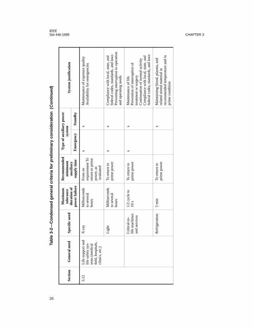
IEEEStd 446-1995 CHAPTER 3
3.12
Lif
e su
ppor
t and
lif
e sa
fety
sys
-te
ms
(med
ical
fie
ld, h
ospi
tals
, cl
inic
s, e
tc.)
X-r
ayM
illis
econ
ds
to s
ever
al
hour
s
From
no
requ
irem
ent T
o re
turn
to p
rim
e po
wer
, as
eva
luat
ed
xx
Mai
nten
ance
of
expo
sure
qua
lity
Ava
ilabi
lity
for
emer
genc
ies
Lig
htM
illis
econ
ds
to s
ever
al
hour
s
To r
etur
n to
pr
ime
pow
erx
xC
ompl
ianc
e w
ith lo
cal,
stat
e, a
nd
fede
ral c
odes
, sta
ndar
ds, a
nd la
ws
Prev
entin
g in
terr
uptio
n to
ope
ratio
n an
d op
erat
ing
need
s
Cri
tical
-to-
life
mac
hine
s an
d se
rvic
es
1/2
cycl
e to
10
sTo
ret
urn
to
prim
e po
wer
xx
Mai
nten
ance
of
life
Prev
entio
n of
inte
rrup
tion
of
trea
tmen
t or
surg
ery
Con
tinua
tion
of n
orm
al a
ctiv
ityC
ompl
ianc
e w
ith lo
cal,
stat
e, a
nd
fede
ral c
odes
, sta
ndar
ds, a
nd la
ws
Ref
rige
ratio
n5
min
To r
etur
n to
pr
ime
pow
erx
Mai
ntai
ning
blo
od, p
lasm
a, a
nd
rela
ted
stor
ed m
ater
ial a
t re
com
men
ded
tem
pera
ture
and
in
prim
e co
nditi
on
Tab
le 3
-2—
Co
nd
ense
d g
ener
al c
rite
ria
for
pre
limin
ary
con
sid
erat
ion
(C
on
tinu
ed)
Sect
ion
Gen
eral
nee
dSp
ecifi
c ne
ed
Max
imum
to
lera
nce
dura
tion
of
pow
er f
ailu
re
Rec
omm
ende
d m
inim
um
auxi
liary
su
pply
tim
e
Typ
e of
aux
iliar
y po
wer
sy
stem
Syst
em j
usti
ficat
ion
Em
erge
ncy
Stan
dby
26
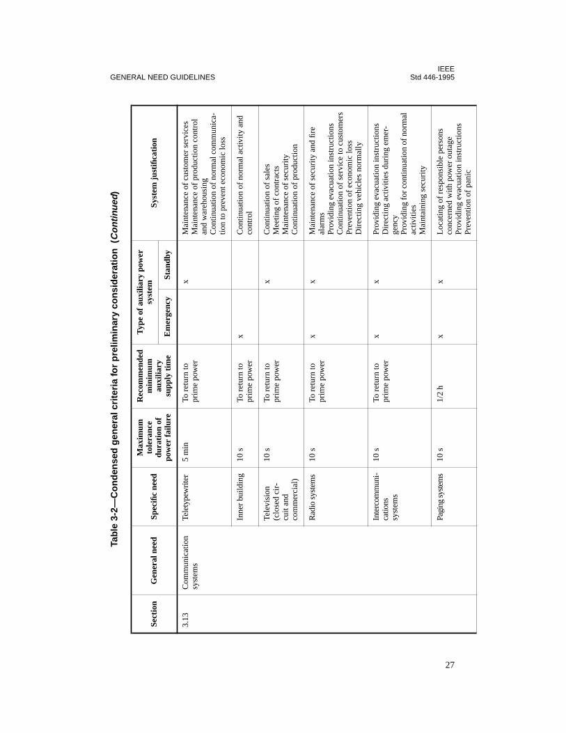
IEEEGENERAL NEED GUIDELINES Std 446-1995
Prev
entio
n of
pan
ic
3.13
Com
mun
icat
ion
syst
ems
Tele
type
wri
ter
5 m
inTo
ret
urn
to
prim
e po
wer
xM
aint
enan
ce o
f cu
stom
er s
ervi
ces
Mai
nten
ance
of
prod
uctio
n co
ntro
l an
d w
areh
ousi
ngC
ontin
uatio
n of
nor
mal
com
mun
ica-
tion
to p
reve
nt e
cono
mic
loss
Inne
r bu
ildin
g10
sTo
ret
urn
to
prim
e po
wer
xC
ontin
uatio
n of
nor
mal
act
ivity
and
co
ntro
l
Tele
visi
on
(clo
sed
cir-
cuit
and
com
mer
cial
)
10 s
To r
etur
n to
pr
ime
pow
erx
Con
tinua
tion
of s
ales
Mee
ting
of c
ontr
acts
Mai
nten
ance
of
secu
rity
Con
tinua
tion
of p
rodu
ctio
n
Rad
io s
yste
ms
10 s
To r
etur
n to
pr
ime
pow
erx
xM
aint
enan
ce o
f se
curi
ty a
nd fi
re
alar
ms
Prov
idin
g ev
acua
tion
inst
ruct
ions
Con
tinua
tion
of s
ervi
ce to
cus
tom
ers
Prev
entio
n of
eco
nom
ic lo
ssD
irec
ting
vehi
cles
nor
mal
ly
Inte
rcom
mun
i-ca
tions
syst
ems
10 s
To r
etur
n to
pr
ime
pow
erx
xPr
ovid
ing
evac
uatio
n in
stru
ctio
nsD
irec
ting
activ
ities
dur
ing
emer
-ge
ncy
Prov
idin
g fo
r con
tinua
tion
of n
orm
al
activ
ities
Mai
ntai
ning
sec
urity
Pagi
ng s
yste
ms
10 s
1/2
hx
xL
ocat
ing
of r
espo
nsib
le p
erso
ns
conc
erne
d w
ith p
ower
out
age
Prov
idin
g ev
acua
tion
inst
ruct
ions
Tab
le 3
-2—
Co
nd
ense
d g
ener
al c
rite
ria
for
pre
limin
ary
con
sid
erat
ion
(C
on
tinu
ed)
Sect
ion
Gen
eral
nee
dSp
ecifi
c ne
ed
Max
imum
to
lera
nce
dura
tion
of
pow
er f
ailu
re
Rec
omm
ende
d m
inim
um
auxi
liary
su
pply
tim
e
Typ
e of
aux
iliar
y po
wer
sy
stem
Syst
em j
usti
ficat
ion
Em
erge
ncy
Stan
dby
27
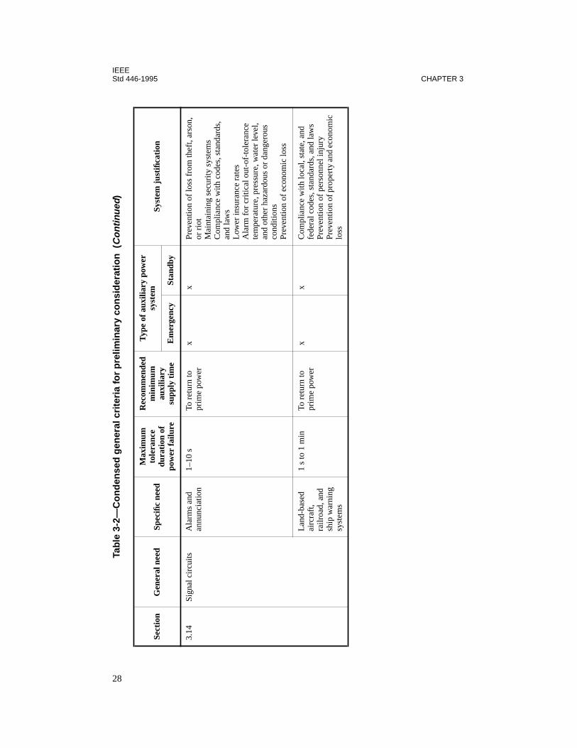
IEEEStd 446-1995 CHAPTER 3
3.14
Sign
al c
ircu
itsA
larm
s an
d an
nunc
iatio
n1–
10 s
To r
etur
n to
pr
ime
pow
erx
xPr
even
tion
of lo
ss f
rom
thef
t, ar
son,
or
rio
tM
aint
aini
ng s
ecur
ity s
yste
ms
Com
plia
nce
with
cod
es, s
tand
ards
, an
d la
ws
Low
er in
sura
nce
rate
sA
larm
for
cri
tical
out
-of-
tole
ranc
e te
mpe
ratu
re, p
ress
ure,
wat
er le
vel,
and
othe
r ha
zard
ous
or d
ange
rous
co
nditi
ons
Prev
entio
n of
eco
nom
ic lo
ss
Lan
d-ba
sed
airc
raft
, ra
ilroa
d, a
nd
ship
war
ning
sy
stem
s
1 s
to 1
min
To r
etur
n to
pr
ime
pow
erx
xC
ompl
ianc
e w
ith lo
cal,
stat
e, a
nd
fede
ral c
odes
, sta
ndar
ds, a
nd la
ws
Prev
entio
n of
per
sonn
el in
jury
Prev
entio
n of
pro
pert
y an
d ec
onom
ic
loss
Tab
le 3
-2—
Co
nd
ense
d g
ener
al c
rite
ria
for
pre
limin
ary
con
sid
erat
ion
(C
on
tinu
ed)
Sect
ion
Gen
eral
nee
dSp
ecifi
c ne
ed
Max
imum
to
lera
nce
dura
tion
of
pow
er f
ailu
re
Rec
omm
ende
d m
inim
um
auxi
liary
su
pply
tim
e
Typ
e of
aux
iliar
y po
wer
sy
stem
Syst
em j
usti
ficat
ion
Em
erge
ncy
Stan
dby
28
IEEEGENERAL NEED GUIDELINES Std 446-1995
Readers using this recommended practice may find that various combinations of generalneeds will require an in-depth system and cost analysis that will modify the recommendedequipment and systems to best meet the specific requirements.
Small commercial establishments and manufacturing plants will usually find their require-ments under two or three of the general need guidelines given in this chapter. Large manufac-turers and commercial facilities will find that portions or all of the need guidelines given inhere apply to their operations and justify or require emergency and backup standby electricpower.
3.2 Lighting
3.2.1 Introduction
Evaluation of the quality, quantity, type, and duration of emergency or standby power forlighting is necessary for each particular application. The different types of systems have vari-ous degrees of reliability that should be considered in the selection of the proper system.
3.2.2 Lighting for evacuation purposes
Interruption of power to a normal lighting system may cause injury or loss of life. Emergencylighting for evacuation purposes must energize automatically upon loss of normal lighting.Where legally required (ANSI/NFPA 101-1994) emergency systems are installed, lightingmust be maintained for at least 1.5 h if battery-powered unit equipment is used. Emergencylighting must provide enough illumination to allow easy and safe egress from the areainvolved. All exit lights, signs, and stairwell lights should be included in both the emergencylighting system and the normal lighting system. Design of the emergency lighting systemshould include consideration of the need for lighting to silhouette protruding machines orobjects in aisles.
3.2.3 Perimeter and security lighting
Emergency or standby power for perimeter and security lighting may be deemed necessary toreduce risk of injury, theft, or property damage. The power for perimeter lighting may not berequired until several minutes after failure of normal power. In order to maintain perimeterlighting throughout the dark hours, a system should be capable of supplying power for 10–12 h for every 24 h the normal power source is off. For this reason, the unit battery equipmentis not recommended for auxiliary perimeter lighting.
3.2.4 Warning lights
Emergency power should be available for all warning lights such as aircraft warning lights onhigh structures, ship warning lights on edges of waterways, and other warning lights that actto prevent injury or property damage. The power source selected should be capable of supply-ing emergency power throughout the duration of the longest anticipated power failure; there-fore, the unit battery type is normally not suited for this application.
29
IEEEStd 446-1995 CHAPTER 3
3.2.5 Health care facilities
Emergency lighting is of paramount importance in hospitals and similar institutions. Therequirements for these areas are included in 3.12.
3.2.6 Standby lighting for equipment repair
Standby power for lighting should be installed in areas where the most probable internalpower system failures may occur and in the main switchgear rooms. This requirement is jus-tified by the necessity of having enough light to repair the equipment that failed and causedthe loss of normal lighting.
3.2.7 Lighting for production
Interruption of power to a normal lighting system may cause serious curtailment or completeloss of production. Where there are no safety hazards or property damage associated with thisneed, the decision should be based on the economic evaluation of each particular application.Systems that provide power for emergency lighting may also provide high-level lighting toallow production to continue.
3.2.8 Lighting to reduce hazards to machine operators
A machine operator may be subjected to a high injury risk for the first few seconds after light-ing has failed. Many machines present a safety hazard if suddenly plunged into darkness.Instantaneous emergency lighting is required for protection against this type of injury.
3.2.9 Supplemental lighting for high-voltage discharge systems
If mercury or other types of high-voltage discharge lighting are used for the regular system,consideration should be given to adding auxiliary lamps, such as incandescent or fluorescent.Some high-voltage discharge lamps require a cooling period before they restrike the arc and awarm-up period before they attain full brilliance. The total time required for full illuminationafter a momentary power interruption can range from 1 min for high-pressure sodium to20 min for metal halide and mercury vapor.
3.2.10 Codes, rules, and regulations
Many states and municipalities have adopted their own specific codes regarding emergencylighting, in addition to those set down by the following organizations:
— The Occupational Safety and Health Act of 1970 (OSH Act) is charged with enforc-ing compliance and makes reference to the NEC and NFPA codes.
— NFPA 70-1996, the National Electric Code (NEC), Article 700, sets forth the stan-dard of practice for emergency lighting equipment with regard to installation, opera-tion, and maintenance.
30
IEEEGENERAL NEED GUIDELINES Std 446-1995
— ANSI/NFPA 101-1994, the Life Safety Code, concerns itself with the specification oflocations where emergency lighting is considered essential to life safety and specificson exit marking.
— Underwriter’s Laboratories, Inc., tests and approves equipment to uniform perfor-mance standards as established by ANSI/UL 924-1990.
3.2.11 Recommended systems
For short durations, primarily for personnel safety and evacuation purposes, battery units aresatisfactory. For applications requiring longer service and heavier loads, an engine- or tur-bine-driven generator, which starts automatically upon failure of the prime power source,may be more suitable. ANSI/NFPA 101-1994 requires that emergency lighting facilities pro-vide no less than an average of 10 lx ((1 fc) measured at any point along the path of egress atfloor level. The standard allows illumination to decline to 6 lx (0.6 fc) average and 0.6 lx (.06fc) minimum at the end of 1-1/2 h. The maximum top minimum illumination level may notexceed a a ration 40/1.
Table 3-3 summarizes the user’s needs for emergency and standby electric power for lightingby application and areas.
3.3 Startup power
3.3.1 Introduction
Assume a cold boiler and a dead plant without electrical power or steam. From this premise,several very important issues must be considered:
— How will the plant be protected from freezing in cold weather? Even with gas heat-ers, will there be sufficient heat without fans and without interlocked make-up airunits running?
— A steam turbine generator is on hand, but without forced draft, induced draft, boilerfeed water, flame detectors, or control power. How can it be started?
— A gas turbine generator has been installed, but how can this be started without bring-ing it up in speed with a small steam turbine, an electric motor, or other prime mover?Gas compressors may be necessary and also require prime movers of some type.
— Steam-driven and electrically driven fire pumps are out of service. There may be nomajor fire protection until electric power or steam is restored.
— An uninterruptible power supply (UPS) of sufficient capacity is probably not onhand; otherwise, steam and electric power would not be down.
These statements illustrate the fact that adequate startup power is one of the most importantconsiderations in the original design of any plant. Millions of dollars worth of equipmentcould be standing idle at a time of critical need if no allowance were made for starting themachines under expected conditions, such as a major power outage.
31

IEEEStd 446-1995 CHAPTER 3
3.3.2 Example of a system utilizing startup power
Starting major plant equipment without outside power is commonly referred to as a blackstart and is accomplished by using only the facilities available within the plant. One exampleof a system designed with black start capability, with a minimum electrical startup system,would be a large gas turbine driving a centrifugal compressor in the natural gas pipelineindustry, where the high-pressure gas from the pipeline is used to drive expansion turbinesand gas motors for cranking the turbine, operating pumps, and positioning valves. By utiliz-ing the high-pressure gas for the large horsepower requirements, a small engine-driven gener-ator, fueled by natural gas, is used to provide electric power for turbine accessories, batterycharging, lighting, and powering other critical loads. When the turbine is running, a shaft-driven generator provides larger quantities of electric power for all station requirements; thesmall generator is placed on standby.
Table 3-3—Typical emergency and standby lighting recommendations
Standbya Immediate, short-termb Immediate, long-termc
Security lightingOutdoor perimetersClosed circuit TVNight lightsGuard stationsEntrance gates
Evacuation lightingExit signsExit lightsStairwellsOpen areasTunnelsHalls
Hazardous areasLaboratoriesWarning lightsStorage areasProcess areas
Production lightingMachine areasRaw materials storagePackagingInspectionWarehousingOffices
MiscellaneousStandby generator areasHazardous machines
Warning lightsBeaconsHazardous areasTraffic signals
Commercial lightingDisplaysProduct shelvesSales countersOffices
Health care facilitiesOperating roomsDelivery roomsIntensive care areasEmergency treatment areas
MiscellaneousSwitchgear roomsLandscape lightingBoiler roomsComputer rooms
MiscellaneousSwitchgear roomsElevatorBoiler roomsControl rooms
a An example of a standby lighting system is an engine-driven generator.b An example of an immediate short-term lighting system is the common unit battery equipment.c An example of an immediate long-term lighting system is a central battery bank rated to handle the required lighting load only until a standby engine-driven generator is placed on-line.
32
IEEEGENERAL NEED GUIDELINES Std 446-1995
3.3.3 Lighting
In the design of the startup power system, first consideration should be given to installingbattery-operated lights in the vicinity of the standby power source and switchgear.
3.3.4 Engine-driven generators
The battery-cranking power for the engine may also be used for some lights. Cranking mayalso be accomplished by compressed air supplied to a tank by the plant compressed-air sys-tem and prevented from leaving the tank into the plant system by a check valve.
The engines may be sized for short-term operation if some type of continuous power genera-tion can be brought onto the line after startup. If no generation as a prime source of electricpower has been installed, the diesel or engine generator should be sized for supporting allelectrical needs for the generator auxiliaries, boilers, critical emergency lights, fire signals,exit lights, and other items listed in table 3-2.
3.3.5 Battery systems
Special consideration should be given to the design of the plant battery system or UPS, allow-ing for (1) adequate battery capacity to provide power for the necessary startup control sys-tems, following a programmed safe stop; and (2), when possible, special disconnectingdevices to automatically disconnect large power-consuming systems from the battery systemto conserve battery capacity for restart.
With capacity for these minimum facilities in operation, consideration may then be given toinstalling sufficient capacity at the same time to support additional justified needs.
3.3.6 Other systems
Mobile equipment may suffice if it can reasonably be assumed to be available when needed.(Who has the highest priority when all have the need?) An alternate standby public utility linemay also be available at a low cost from a separate source of supply. A neighboring plant withlive generation may assist in an emergency.
3.3.7 System justification
A definite workable plan with the proper equipment should be evaluated, and action taken asjustified, prior to the need.
3.4 Transportation
3.4.1 Introduction
This topic covers the moving of people and products by methods that depend upon electricpower. The importance of maintaining power for these methods ranges from desirable to crit-ical.
33

IEEEStd 446-1995 CHAPTER 3
3.4.2 Elevators
Where two or more elevators are in use in buildings three or more stories high, the elevatorsor banks of elevators should be connected to separate sources of power. There are situationswhere standby power is required for all elevators within 15 s. Savings may be made by sup-plying power during outages of the normal supply to one-half the elevators installed, provid-ing the traffic can be rerouted and the capacity of the elevators is adequate. Power must betransferred to the second bank of elevators within 1 min or so of the prime power loss to clearstalled elevators. Power may be left on this bank until normal power returns.
Where elevator service is critical for personnel and patients, it is desirable to have automaticpower transfer with manual supervision. Operators and maintenance men may not be avail-able in time, if the power failure occurs on a weekend or at night.
Where a single feeder supplies more than one elevator, selective coordination of the protec-tive devices may enhance elevator availability. This is a requirement of the 1996 edition of theNEC, Section 620-26.
— Typical elevator system. Figure 3-3 shows an elevator emergency power transfer sys-tem whereby one preferred elevator is fed from a vital load bus through an emergencyriser, while the rest of the elevators are fed from the normal service. By providing anautomatic transfer switch for each elevator and a remote selector station, it is possibleto select individual elevators, thus permitting complete evacuation in the event ofpower failure. The engine generator set and emergency riser need only be sized forone elevator, thus minimizing the installation cost. The controls for the remote selec-tor, automatic transfer switches, and engine starting are independent of the elevatorcontrols, thereby simplifying installation.
— Regenerated power. Regenerated power is a concern for motor generator-type eleva-tor applications. In some elevator applications, the motor is used as a brake when theelevator is descending and generates electricity. Electric power is then pumped backinto the power source. If the source is commercial utility power, it can easily beabsorbed. If the power source is an engine-driven generator, the regenerated powercan cause the generating set and the elevator to overspeed. To prevent overspeedingof the elevator, the maximum amount of power that can be pumped back into the gen-erating set must be known. The permissible amount of absorption is approximately20% of the generating set’s rating in kilowatts. If the amount pumped back is greaterthan 20%, other loads must be connected to the generating set, such as emergencylights or “dummy” load resistances. Emergency lighting should be permanently con-nected to the generating set for maximum safety. A dummy load can also be automat-ically switched on the line whenever the elevator is operating from an engine-drivengenerator.
3.4.3 Conveyors and escalators
Escalators and personnel conveyors may require emergency power since physically handi-capped persons ride up and would have great difficulty walking down, even though a normalperson would be able to do so were the power off.
34
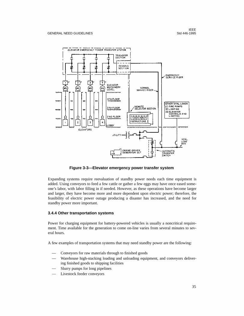
IEEEGENERAL NEED GUIDELINES Std 446-1995
35
Expanding systems require reevaluation of standby power needs each time equipment isadded. Using conveyors to feed a few cattle or gather a few eggs may have once eased some-one’s labor, with labor filling in if needed. However, as these operations have become largerand larger, they have become more and more dependent upon electric power; therefore, thefeasibility of electric power outage producing a disaster has increased, and the need forstandby power more important.
3.4.4 Other transportation systems
Power for charging equipment for battery-powered vehicles is usually a noncritical require-ment. Time available for the generation to come on-line varies from several minutes to sev-eral hours.
A few examples of transportation systems that may need standby power are the following:
— Conveyors for raw materials through to finished goods— Warehouse high-stacking loading and unloading equipment, and conveyors deliver-
ing finished goods to shipping facilities— Slurry pumps for long pipelines— Livestock feeder conveyors
Figure 3-3—Elevator emergency power transfer system

IEEEStd 446-1995 CHAPTER 3
36
3.5 Mechanical utility systems
3.5.1 Introduction
Often the need for mechanical utilities is as great as that for electric power utilities. These areinterdependent. We can speak of utility systems as a whole since, to most managers and cor-porate officials, these are all united in a group under the heading “utilities.”
3.5.2 Typical utility systems for which reliable power may be necessary
Mechanical utility systems comprise the following services for which reliable electric poweris usually required:
— Compressed air for pneumatic power— Cooling water (including return pumps, pressure pumps, tower fans)— Well water or other pumped sources for personnel use— Hydraulic systems— Sewer systems (sanitary, industrial, storm)— Gas systems (natural, propane, oxygen), including compressors— Fire pumps and associated water supplies— Steam systems (low and high pressures)— Ventilation (building and process)— Vacuum systems— Compressed air for instrumentation
Although this list is not exhaustive, it alerts a plant manager or engineer to the various needsand potential losses that may occur if electric power is not available.
Systems may be required for manufacturing and services to maintain other services. Forexample, electric power, water, and compressed air for boilers used to supply steam for thegeneration of electricity.
A 0.1–5 s power failure may cause plant operators to spend minutes or hours restarting equip-ment and making adjustments until all systems are again stable. Such disruptions to produc-tion should be prevented if economically justifiable.
3.5.3 Orderly shutdown of mechanical utility systems
An orderly shutdown of power to mechanical utility systems may be acceptable with a short-time smaller supply source of power provided for the following requirements:
— Maintaining temperature or pressure on vulcanizers until the product can be finished.— Maintaining hydraulic pressure until a batch process is completed, or until the pres-
sure can be released without loss.— Operating pumps for a time until all process water has been shut off or has drained
back into the sumps to prevent flooding. This becomes serious when the water is con-

IEEEGENERAL NEED GUIDELINES Std 446-1995
37
taminated with oil and other waste when flooding occurs and special handling may beneeded to comply with antipollution requirements.
— Maintaining ventilation to clear explosive atmospheres while a normal shutdown pro-ceeds. Purging air is critical to some oven-drying processes.
— Preventing sanitary sewers from overflowing before personnel evacuation takesplace.
— Running gas compressors for the finishing of a critical process.
This list is not exhaustive, but represents needs of various types, which should be sufficient toalert a plant engineer so that a plan may be prepared for an orderly shutdown. Managementmay then be justified to act on the plan and not be caught unprepared in an emergency situa-tion.
3.5.4 Alternates to orderly shutdown
An orderly shutdown may not be acceptable. Then an alternate may be selected, such as thefollowing:
—
Maintaining utilities without an interruption.
Full capacity standby power must beavailable as well as uninterruptible power for boiler controls, on-line computers, andessential relays and motor starters.
—
Accepting an outage but returning on standby power.
Full capacity power must beavailable. Startup of functions will be required since magnetic motor starters andrelays will have dropped out. Although power is off for 0.1–5 s, it will take 15–30 min or more for return to normal operation.
3.6 Heating
3.6.1 Maintaining steam production
Continuous-process plants require uninterrupted steam production. Minimum requirementsfor continuous steam production are sufficient combustion air, air to instruments and actua-tors, water and fuel supplies, plus a continuous power supply to most flame supervision sys-tems. The maximum interruption tolerable is that duration during which the inertia of the fansor pumping equipment will maintain flows and pressures above minimum limits. Table 3-4illustrates how this can be achieved.
3.6.2 Process heating
Process heating is defined as heat required to maintain certain process materials at therequired temperature. Noncritical heating processes, due to the inherent heat capacities ofsuch systems, can withstand a power interruption of considerable duration, i.e., 5 min to amaximum of several hours.

IEEEStd 446-1995 CHAPTER 3
Any of the following systems would be adequate for this application:
— Engine-driven generators, off-line— Multiple utility services, on-line and relayed, or off-line, switches, and transfers— Turbine (combustion, steam, water), off-line or on-line— Mechanical stored-energy system, with auxiliary motor generator sets off-line
Table 3-4—Systems for continued steam production
Components Allowable outage duration Systems
Flame supervision systems Nil Mechanical stored energy systemsMotor-generator set ride-throughUPS systems
Motor controls and instrumentation Nil Same as above
Boiler fans 1/2 to 2 s Multiple utility services, either on-line and relayed, or off-line, switched, and transferred
Air compressor To 30 min, depending on storage; nonessential air users should be automatically shut off
Multiple utility servicesTurbine- or engine-driven generator, off-lineTurbine (combustion, steam, water), off-line
Water pump To 5 min, depending on water drum capacity and upsets in steam production caused by power disturbance
Multiple utility services either on-line and relayed, or off-line, switched, and transferredTurbine (combustion, steam, water), off-line, automatic start
Oil pumps (for burners) To 15 cycles, more with flywheel
Multiple utility services, on-line and relayedTurbine (combustion, steam, water), on-line
Electric oil supply pumps Several minutes Turbine- or engine-driven generator, off-lineMultiple utility services, on- or off-line
38
IEEEGENERAL NEED GUIDELINES Std 446-1995
Other heating processes, such as cord and fabric treating and drying, are of such a criticalnature that loss of heat will cause an out-of-specification product within 10 s, but the gas oroil burners and flame detectors are sensitive to drops in voltage of about 40% for a second orless. In this case, an uninterruptible supply for the controls and an engine generator for a 10 smain power supply or an alternate feed system may be required.
Infrared drying of enamel on automobiles and appliances is a form of heating by electricenergy that must be maintained. A short interruption, perhaps 10 s, may be acceptable tobring on-line standby generation or perform automatic switching to an auxiliary powersource.
Losses may be substantial if power is lost during the heat treating of metals and when eitherdirect or indirect melting of metals is in process. Two evaluations must be made: one basedon not losing the flame on the fuels used, and the other based on accepting an interruption fora short period with a restart necessary. Uninterruptible power is several times more expensivethan switching or emergency power, but saves the product and prevents process interruption.Switching or emergency power is less expensive, but product or process losses may exceedthe initial savings in the chosen electric supply system.
Induction and dielectric heating are other forms of electrical heating that may or may notallow short interruptions to be tolerated. Most processes, whether in production or in otherfields, could tolerate an interruption of sufficient duration to come on-line with switchedsources or an engine- or turbine-driven generator.
3.6.3 Building heating
Buildings, even in the coldest regions, can usually be without heating for a minimum of30 min. The same systems listed for noncritical heating processes will be suitable for thisapplication.
3.7 Refrigeration
3.7.1 Requirements of selected refrigeration applications
Requirements for refrigeration are usually noncritical for short power interruptions of severalminutes to several hours. The need may become extremely critical as the length of time of theoutage increases. Consider these refrigeration needs:
— Production of ice cream or the freezing of foods may stop in the middle of the pro-cess. Not only will all production be lost during a power failure, but damage mayresult to the product in process.
— Material in storage may be in jeopardy as temperatures rise. Cafeterias, frozen foodlockers, meat cooling and storage facilities, dairies, and other food operations requirerefrigeration and will soon be in trouble as the length of the power outage increases.
— Scientific tests of long duration may require accurately maintained low temperatures.Short outages of electric power may destroy the tests and require repeating. An
39
IEEEStd 446-1995 CHAPTER 3
expensive and time-consuming process should be provided with a standby power sys-tem.
— Medical facilities require refrigeration for blood banks, antibiotics, and for long-range laboratory experiments and cultures that could be spoiled.
— As the state of the art of superconductivity develops, improves, and spreads to appli-cable fields, power for cryogenic refrigeration equipment operation will probablybecome critical.
Where present refrigeration units are electrically driven, when new units of moderate size areto be installed in permanent locations, and when other needs exist (as is usually the case) foremergency or standby power, a common engine-driven generator or alternate utility sourceshould be considered.
Because of the slow rise in temperature of cold-storage facilities, a savings may be made bythe use of a smaller than normal standby electric generator. By switching power to variousunits in turn, an acceptable storage temperature may be maintained until normal electricpower has been reestablished.
3.7.2 Refrigeration to reduce hazards
Certain chemical processes are exothermal and release heat during the chemical reaction.Loss of the cooling or refrigeration system may cause severe damage or even an explosion.
3.7.3 Typical system to maintain refrigeration
A manual starting of an engine-driven generator, turbine, or alternate utility supply will usu-ally suffice, providing a suitable alarm is installed to notify responsible persons of a loss ofrefrigeration.
3.8 Production
3.8.1 Justification for maintaining production in an industrial facility during apower failure
Production continuation in an industrial facility during a power failure is justified by the totalsum of many tangible and intangible savings. The following paragraphs discuss various con-siderations that can affect these savings.
Is there a guaranteed wage clause in the labor contract? If so, there will be a direct loss inwages paid for which no production is received. Where power requirements are low and theheavy-power-demanding machines are left shut down until normal power is returned, a smallelectric supply system can be justified to supply finishing areas, inspection areas, office areas,and other areas where most employees work.
Who is waiting for the product? There are periods when the products are being routed towarehouses and machines are not running at capacity previous to the outage. In this case, the
40

IEEEGENERAL NEED GUIDELINES Std 446-1995
cost of machine downtime is lower than it would be for a product that a customer will notreceive, or will receive late, if production is at full capacity and an outage occurs.
What is the cost of the product spoiled in process? In the rubber industry, material maybecome sealed in vulcanizers, extruders, or mixers at high temperatures and will be difficultand expensive to remove. Steam or water pressure may drop to zero and prevent proper cureswith losses due to poor or ruined products.
If all electric power is lost during certain processes in the making of sugar, glass, steel, phar-maceuticals, rubber, paper, chemicals, and some other materials, the product may have to bescrapped.
What is the cost of consequential damages? While the material ruined may be scrap, theremay be as many problems and costs associated with its removal as with the loss itself. Somematerial must be dug out or removed by hand, piece by piece, until lines are cleared or cham-bers are empty and clean so that an orderly startup can follow.
What is lost in reestablishing work efficiency? A 1/2 h electric power interruption disorga-nizes the workers. Experience indicates that, following the interruption, it will take men andwomen at least two or more hours to settle down, go to work, and reach the production levelat which they were operating just prior to the power failure. It may take days to reestablishnormal procedures in scheduling of incoming and outgoing materials and in telegrams, let-ters, notices, and calls explaining delays and changing promises.
A less tangible item lost is that of goodwill. For example, in the film processing industry, thecustomer may not consider the replacement of the exposed film with unexposed as adequatecompensation for “once in a lifetime” pictures that were spoiled due to a power failure.
Real and potential costs and losses must be calculated or estimated and added together to jus-tify an emergency and standby power system for industrial and commercial facilities.
A reasonable estimate of the costs associated with each past power failure should be calcu-lated and recorded in a journal with the date, duration, and conditions existing at the time. Astime goes on, this could be valuable factual backup information for budget requests.
3.8.2 Equations for determining cost of power interruptions
A rough estimate of the direct cost of a power failure from a cash flow viewpoint may be cal-culated as follows:
total cost of a power failure = E + H + I
where
E = cost of labor for employees affected (in dollars)H = scrap loss due to power failure (in dollars)I = cost of startup (in dollars)
41

IEEEStd 446-1995 CHAPTER 3
The value of E, H, and I may be calculated as follows:
E = AD (1.5 B = C) H = FG I = JK (B = C) = LG
where
A = number of productive employees affectedB = base hourly rate of employees affected (in dollars)C = fringe and overhead hourly cost per employee affected (in dollars)D = duration of power interruption (in hours)F = units of scrap material due to power failureG = cost per unit of scrap material due to power failure (in dollars)J = startup time (in hours)K = number of employees involved in startupL = units of scrap material due to startup
After the cost of downtime has been calculated, the savings in utilities should be subtracted toarrive at a total cost of downtime.
3.8.3 Commercial buildings
For commercial establishments, a similar example may be assembled based on the length ofthe power interruption, labor cost, loss of profit on sales, loss due to theft, and startup costs.
3.8.4 Additional losses due to power interruptions
In addition to losses relating to cash flow are those more difficult to calculate but whichshould be included when available and applicable, such as
— Prorated depreciation of capital costs— Depreciation in quality in process materials— “Cost” of money invested in unused materials or machines
Other losses may occur under special or unusual conditions. In an industrial plant operatingat 100% capacity, any loss in production results in the loss of the profit of the item or service.The prorated cost of fixed and variable overhead becomes a loss. Customers may switch tocompetitors. Expenditures for standby power have additional justification under this condi-tion.
3.8.5 Determining the likelihood of power failures
Next, the likelihood of a power failure must be determined by studying the record of the plantor utility company electrical supply, or by transmitting the service requirements to the localutility and obtaining their recommendations. Examples of recorded power failures are shownin table 3-5.
42
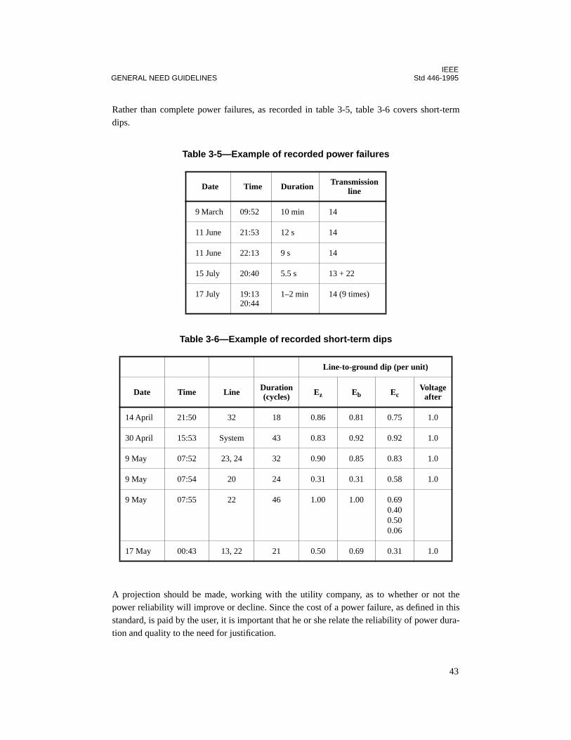
IEEEGENERAL NEED GUIDELINES Std 446-1995
Rather than complete power failures, as recorded in table 3-5, table 3-6 covers short-termdips.
A projection should be made, working with the utility company, as to whether or not thepower reliability will improve or decline. Since the cost of a power failure, as defined in thisstandard, is paid by the user, it is important that he or she relate the reliability of power dura-tion and quality to the need for justification.
Table 3-5—Example of recorded power failures
Date Time Duration Transmission line
9 March 09:52 10 min 14
11 June 21:53 12 s 14
11 June 22:13 9 s 14
15 July 20:40 5.5 s 13 + 22
17 July 19:1320:44
1–2 min 14 (9 times)
Table 3-6—Example of recorded short-term dips
Line-to-ground dip (per unit)
Date Time Line Duration (cycles) Ez Eb Ec
Voltage after
14 April 21:50 32 18 0.86 0.81 0.75 1.0
30 April 15:53 System 43 0.83 0.92 0.92 1.0
9 May 07:52 23, 24 32 0.90 0.85 0.83 1.0
9 May 07:54 20 24 0.31 0.31 0.58 1.0
9 May 07:55 22 46 1.00 1.00 0.690.400.500.06
17 May 00:43 13, 22 21 0.50 0.69 0.31 1.0
43
IEEEStd 446-1995 CHAPTER 3
3.8.6 Factors that increase the likelihood of power failures
As designed load is reached or exceeded, the probability of a power failure increases. A simi-lar probability exists as systems become more complex and as system equipment ages.
3.8.7 Power reserves
Power reserves in the user’s area should be investigated. Adequate reserve margins abovepeak load demands provide a guide to power reliability because the margin provides for somecontingencies.
3.8.8 Examples of standby power applications for production
The following typical examples were taken at random from users who found, after evaluation,purchase, and installation, that a standby power system was justified:
— A drug company installed a special engine generator backup system based on theneed for constant temperatures in manufacturing processes. The value of processessaved during blackouts soon exceeded the cost of the equipment installed by morethan 10 times.
— A photographic film processing company specified a 45 kW engine generator whenthe film processing machines were ordered. Film must continue to progress to eachstep of the process within 30 s or loss of quality will result.
— A 400 kW, 480 V, three-phase engine generator was installed in a highly automatedegg farm. Electric service continuity was mandatory for egg production and the wel-fare of the “machines” (chickens). During the first year, two electric service outagesoccurred and the automatic emergency generator reliability supplied power.
3.8.9 Types of systems to consider
An engine- or turbine-driven generator or an alternate independent utility source usually willfulfill the requirements for standby power. More than a standby system may be required forcritical loads. Motor starters, contactors, and relays held closed by a solenoid or electromag-net have no ride-through and are especially sensitive to short-time power outages or voltagedips. Their dropout characteristics vary with respect to voltage level and the length of dura-tion of the voltage dip. As a guide, a voltage dip to 60% or 70% of rated voltage for 0.5 s willde-energize many of the devices. The longer the duration of the voltage dip, the more deviceswill de-energize. Depending on the application of these devices, an emergency or UPS sys-tem may be justifiable, especially where boiler controls, critical chemical processes, safetydevices, and other critical systems are required to be maintained (Funk and Beatty 1987[B6]).
Devices much more likely to fail or malfunction due to voltage excursions are modern elec-tronic switching devices, which tolerate almost no time delay, and pressure, temperature, andflow transmitters and receivers of the electronic type. Automatic controllers for process con-trol, data reduction, and logging are in this same category (Gilbert 1960 [B7]).
44
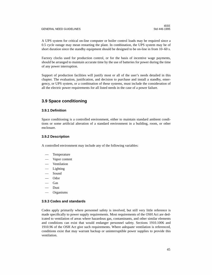
IEEEGENERAL NEED GUIDELINES Std 446-1995
A UPS system for critical on-line computer or boiler control loads may be required since a0.5 cycle outage may mean restarting the plant. In combination, the UPS system may be ofshort duration since the standby equipment should be designed to be on-line in from 10–60 s.
Factory clocks used for production control, or for the basis of incentive wage payments,should be arranged to maintain accurate time by the use of batteries for power during the timeof any power interruption.
Support of production facilities will justify most or all of the user’s needs detailed in thischapter. The evaluation, justification, and decision to purchase and install a standby, emer-gency, or UPS system, or a combination of these systems, must include the consideration ofall the electric power requirements for all listed needs in the case of a power failure.
3.9 Space conditioning
3.9.1 Definition
Space conditioning is a controlled environment, either to maintain standard ambient condi-tions or some artificial alteration of a standard environment in a building, room, or otherenclosure.
3.9.2 Description
A controlled environment may include any of the following variables:
— Temperature— Vapor content— Ventilation— Lighting— Sound— Odor— Gas— Dust— Organisms
3.9.3 Codes and standards
Codes apply primarily where personnel safety is involved, but still very little reference ismade specifically to power supply requirements. Most requirements of the OSH Act are ded-icated to ventilation of areas where hazardous gas, contaminants, and other similar elementsand conditions can exist that would endanger personnel safety. Sections 1910.1006 and1910.96 of the OSH Act give such requirements. Where adequate ventilation is referenced,conditions exist that may warrant backup or uninterruptible power supplies to provide thisventilation.
45

IEEEStd 446-1995 CHAPTER 3
3.9.4 Application considerations
Air-conditioning loads for personal comfort are not normally considered critical and are evenshed under overload conditions in some cases. Where equipment is sensitive to temperature,however, such as where solid-state electronic components exist, air conditioning can be criti-cal. Where continuous backup or standby power is not available, a self-contained emergencyor standby generator would apply. An UPS specifically for this purpose is not normally nec-essary since loss of power would cause no instantaneous temperature change. Likewise,where moisture and humidity cause serious equipment and operating problems, heatingmight require some type of backup power supply.
Table 3-2 shows examples of tolerable outage time for various applications. Ideally, testsshould be run by the designer or planner to determine the maximum transfer times tolerable.Amount of power needed, acceptable outage time, and economics will determine the applica-ble power supply. Often, economics dictate that power for space conditioning be incidental tototal power supply requirements, and the user must evaluate the ultimate consequences ofloss of power. An adequate alarm system might be a consideration in this case.
Alarm and signal circuits often require as much or more reliability than equipment providingcritical space conditioning. A UPS would be necessary where even a temporary loss of powerwould endanger personnel or cause severe equipment damage.
3.9.5 Examples of space conditioning where auxiliary power may be justified
Typical situations and facilities in which a comprehensive study of the need for supplementalelectric power is warranted are as follows:
— Commercial and laboratory botanical installations may require programmed cycliccontrol of temperature, humidity, and lights to develop the crop yield or desiredexperimental results. The loss of temperature or humidity control for 6–8 h can resultin total loss of a crop. A greenhouse must have maintained temperature in order toproduce.
— Tropical animal raising requires control of ventilation, temperature, humidity, andlighting. All are completely dependent on electric power. A loss of heat or coolingcan result in death or illness to all animals being raised. Lighting and temperaturechanges from the established cycle can induce unwanted breeding periods in manyexotic creatures. Egg production may be greatly curtailed by temperature changes orloss of light.
— Agricultural operations are often located in remote areas where long utility lines aresusceptible to damage.
— Final operations and packaging of materials susceptible to contamination are con-ducted in clean-room-type environments. A power interruption will shut down thetotal operation, and contamination may result as people exit, unless the room is keptunder positive pressure to prevent in-drafts from bringing in contaminants. Such con-taminants will necessitate a complete recleaning of the room before it can be usedagain.
46
IEEEGENERAL NEED GUIDELINES Std 446-1995
— In large processing plants, priorities may be established for essential loads. Nones-sential loads may be dropped automatically by load-shedding systems in the event ofa power failure, and other limited emergency sources must be relied upon. A reevalu-ation of these priorities should be undertaken. Critical temperature controls may havebeen placed in an air-conditioned space. These controls must function to achieve anorderly process shutdown, but can fail due to overheating caused by lack of ventila-tion or cooling.
— Windowless buildings or inside rooms may become unsafe for occupancy during anextended power interruption. Power supplies to keep these areas ventilated should beinstalled if evacuation of all personnel is not acceptable.
3.9.6 Typical auxiliary power systems
Needs may require any one or more types of emergency and standby power systems avail-able. An engine driven generator or combustion turbine should be considered for these appli-cations. Switching to a separate alternate electric utility line would involve a lower capitalcost, should such a line be readily available. In addition, a short-time UPS system may berequired for critical applications to supply power during engine startup or switching.
3.10 Fire protection
3.10.1 Codes, rules, and regulations
Various codes, standards, laws, rules, and regulations contain either advisory or mandatorystatements related to emergency and standby power systems for fire protection. See Califor-nia Administrative Code, Title 24, Part 3, Basic Electrical Regulations (Article E700, Emer-gency Systems); ANSI/NFPA 101-1994; pp. 19 and 20 of IEEE Committee Report 1974[B9]; and Katz 1968 [B12]. There appears to be more written on the subjects of wiring sys-tem reliability and needs than on the source of electric power supply or the checking andmaintenance of the complete installation. All three are vital.
Article 760 of the NEC lists some requirements for protecting circuitry in alarm and signalsystems. Article 230-94 of the NEC pertains more to the power supply by allowing a firealarm circuit to be connected to the supply side of a service overcurrent device if it has sepa-rate overcurrent protection.
The requirements of all local, state, and national standards and codes should be determined.The insurance company that will underwrite the insurance can provide valuable assistance inmaking sure that all requirements are met.
A common-sense approach to fire protection should be used even beyond the minimum stan-dard of meeting the letter of the law and insurance requirements. The primary goal is to avoida destructive fire, or, in the event that a fire has started, to limit it to a local area with mini-mum damage to property and no harm to personnel. In-depth knowledge of the industrialfacility and of processes by plant engineers and other responsible plant personnel should beutilized to reduce the likelihood of a fire or the extent of a fire’s damage, should one begin.
47
IEEEStd 446-1995 CHAPTER 3
3.10.2 Arson
Arson may be a source of a fire; power for plant security, lighting, signaling, and communica-tion covered in subsequent subclauses should be regarded as contributing to the reduction ofpossible loss by fire from this cause.
3.10.3 Typical needs
The user’s possible specific needs in combination with the general need of emergency andstandby power systems for fire protection include
— Power, usually batteries, to crank the engine on an engine-driven fire pump— Sprinkler-flow alarm systems— Communication power to notify the fire department and to assist in guiding their
activities— Lights for the firemen to work by in the buildings, around the outside area, and
mobile on company trucks— Power for the boilers that supply steam-driven fire pumps— Motors driving fire pumps, well pumps, and booster pumps— Air compressors associated with fire water tanks— Smoke and heat alarms— Deluge valves— Electrically operated plant gates, drawbridges, etc.— Communications, such as public address systems for directing evacuation of
personnel— Fire and hazardous gas detectors
3.10.4 Application considerations
A fire almost always warrants initiation of an emergency shutdown in a plant either by opera-tor-initiated devices or by automatic operation. The circuit required for shutdown is obvi-ously critical, as are all main circuits for the above-mentioned fire protection equipment.Uninterruptible power supplies should be first choice for these applications. Where automaticfire protection is employed, like sprinkler systems, CO2 discharge, etc., nuisance initiationsmust be prevented, a condition that lends itself to application of uninterruptible power sup-plies.
It is common practice in large plants to back up an electrically driven fire water pump with amechanically driven one such as a diesel drive. If all ac power is lost in an emergency shut-down operation, fire protection is maintained. In this case, the ac power supply to the motor-driven pump is not absolutely critical. If a mechanical drive pump is not available, the motor-driven pump would normally be supplied by an emergency generator.
Under emergency conditions, such as fire, communications are sometimes vital to personneland equipment safety. Under emergency conditions, communications should not be subjectedto an outage of any kind. Even momentary outages of a few cycles might cause erroneouscommunications, especially where remote supervisory control is employed.
48
IEEEGENERAL NEED GUIDELINES Std 446-1995
3.10.5 Feeder routing to fire protection equipment
Electric power distribution systems supplying fire equipment should be routed so as not to beburned out by a fire in the area they are protecting.
Protection of control circuitry, as well as main fire protection circuitry, can be enhanced byunderground conduits, separate conduit and wire from other circuits, and fire-resistant insu-lated cable such as type MI.
3.11 Data processing
3.11.1 Classification of systems
Most data processing installations can be grouped into two general classes of operation inaccordance with their usage. These classifications are off-line and on-line. These categorieswill be helpful in identifying a data processing system’s vulnerability to electrical power dis-turbances, since an off-line process will rarely require power buffering or backup sources orequipment. Conversely, it is common for an on-line system to warrant the additional expenseof buffering or backup equipment.
3.11.1.1 Off-line data processing systems
These systems are generally set up to perform one or more programs at a time in a sequentialor batch type. Usually such systems have a program operator for automatic processing ofcontrol cards for a given job run. Often, 24 h operation for a heavily loaded system may benecessary. In the off-line category, for the most part, are business, scientific, and computercenter applications. Systems of this type are particularly vulnerable when the programs arelengthy (several hours in duration). Thus the insertion of several natural breaks or check-points in the program for segmentation of long programs is highly desirable. Programmingcan be designed to save intermediate results at a checkpoint and to have the option of restart-ing at the last checkpoint that preceded the power interruption. Such a practice in programinterruption can be valuable in protecting against peripheral equipment failure. Many currentprograms are being designed without checkpoint techniques even though the practice hasbeen found to be feasible. Data-dependent programs have running times that vary in durationof the magnitude of input data and, accordingly, it is difficult to limit the run to much lessthan a 20 min period.
3.11.1.2 On-line data systems
On-line data systems, or as they are often called, real-time systems, are systems that are time-and event-oriented. They must respond to events that occur randomly in time, often coinci-dentally. An awareness of the system of events that occur that are external to the computerand beyond its influence is a requirement. In this category are such applications as industrialprocess monitoring and control systems, airline passenger reservations systems, vehiculartraffic control, certain specialized scheduling applications, international credit card and bankassociated credit/transaction systems, and many others. With these systems, the computer
49

IEEEStd 446-1995 CHAPTER 3
outage problem due to power interruption is usually more critical than in off-line applica-tions. Furthermore, there is generally no merit in segmenting programs. In most cases, anyoutage or power interruption will result in the loss of some data that were available only dur-ing the time period of the outage. The form of the input data is not conveniently available fora rerun, but may come from sensors such as thermocouples or pressure transducers that arescanned by a computer. When a computer controls a process, potential problems resultingfrom a power disturbance are generally serious enough in terms of product damage or equip-ment malfunctioning to warrant the use of a reserve or backup power source. Furthermore,any solution, to be adequate, must accomplish the necessary switching to the backup sourcewithout power interruption to the computer. It is obvious that the potential losses to severalhundred users, or input stations, to a time-shared computer system would warrant the provid-ing of a backup source that can practically guarantee uninterruptible power. In cases whereequipment or process monitoring must be made, as through data logging, protection fromdestruction of only the core memory content during a power interruption may be adequate.Automatic restart upon return of power is possible to minimize time that the equipment isdown and can often be utilized with the additional provision for a manual means of updatingthe system data or information not gathered or scanned during an interruption.
3.11.1.3 Single-phase versus three-phase
The foregoing discussion has categorized data processing equipment and resulting electricalloads by their respective functional usage, that is, whether they are off-line or on-line sys-tems. In most cases, large systems are involved. A further differentiation that can be made isby the magnitude of load. As with most power utilization equipment, smaller power consum-ing devices can generally be supplied from a single-phase source. The differentiation betweensingle-phase versus three-phase power consuming systems is often necessary since the meth-ods of protecting against input power disturbances and outages can be quite different for eachsystem. Some of the data processing systems that use single-phase power will employ micro-processors or minicomputers. Others may consist of multiple single-phase load units distrib-uted in their connection to three-phase power so as to achieve a reasonable load balance whenall units are operating. This may result in load unbalance when some of the units are turnedoff.
In general, computers and peripheral units that draw less than 1.5 kVA will often be singlephase. Those that draw more than 10 kVA often require three-phase power. In most cases, sin-gle-phase loads can be connected to three-phase sources provided load unbalance at maxi-mum load is not excessive, generally taken as 25% or less.
3.11.2 Needs of data processing equipment from a user’s viewpoint
In general, data are gathered in analog or digital form and converted to one or the other sys-tem. (Refer to definitions in the preceding paragraphs.) These data in electrical form are thenprocessed through one or several programs by an electronic computer, minicomputer, ormicroprocessor. The results are traced or printed out, or a signal is generated and fed back toform a closed-loop system that provides control to match preset conditions. Both types ofoutputs are commonly available and used.
50
IEEEGENERAL NEED GUIDELINES Std 446-1995
3.11.2.1 Real-time data processing
Both industrial and commercial users apply real-time data processing systems with a com-puter on-line. Failure of the data processing system often causes loss of valuable data or inter-ruption of a critical process, either of which may result in extensive financial losses andrequire hours, days, or even weeks to fully recover. Failure of computers providing controlmay also jeopardize the safety of personnel. These failures can occur as a result of an electricpower failure. Thus a reliable high-quality primary power supply is frequently justified tominimize loss of money and to prevent injury or loss of life.
3.11.2.2 Process or operational controls
A short list of control operations that frequently include data processing equipment, mini-computers, or microprocessors will suffice to alert users to the types of hazards and lossesthat may occur as a result of a power failure. Applications are categorized for both industrialand commercial classifications.
— Industrial applications. Materials handling; regulating control and status monitoringof pipelines, compressor, and pumping stations at remote locations; mixing com-pounds; grinding, drilling, machining; twisting textile fibers; steel mill processing;refining (oil); automatic testing and gauging; fabric processing; power flow and loaddispatching; safety and security monitoring; process control and data acquisition.
— Commercial applications. Controlling elevators; automated checkstand combinedwith inventory control; newspaper production machines; airline passenger reserva-tions; computer-aided emergency vehicle dispatching; environmental, life safety,security monitoring and control for buildings; typesetting; accounting; traffic con-trol—cars, rail, and airplane; stock exchanges and broker transactions; corporationcomputers for engineering, scientific, and business matters; hospital diagnosticequipment and individual intensive care systems; banking, financial, and credit trans-actions.
3.11.2.3 History of developing needs
With the advent of the electronic computer as a part of data processing and process control,an increased emphasis has been placed on the need for emergency and standby power sys-tems to assure a continuous flow of energy. Coupled with this need is a superimposed prob-lem, namely, the suppression of most short-time switching interruptions, voltage surges, dips,and frequency excursions. Often the suppression of transient disturbances and the need foremergency or standby power can be satisfied through a single installation of supplementaryor auxiliary equipment. These transient disturbances have been a part of the electric powersupply in the past, but caused few problems until electronic equipment came into extensiveuse. In some instances the solid-state power control equipment has caused problems, particu-larly on small, independent power systems.
51
IEEEStd 446-1995 CHAPTER 3
3.11.3 Power requirements for data processing equipment
By the proper selection of an electric supply system, the power needs associated with dataprocessing with a computer can be met, namely, a reliable source of noise-free electric powerat all times and of a much higher quality than previously demanded by most devices.
The problem is how to reconcile commercial short-duration power interruptions with rela-tively short time domains in electronic circuits. In early stages of data processing equipmentand computer equipment development, it was not unusual to experience problems with hard-ware and software when power disturbances of microseconds in duration were experienced.Most equipment built in that era was extremely vulnerable to such short-time disturbances.The goal of most manufacturers in today’s technology is to build from 4 ms to 1 cycle ofcarryover, or ride-through time, into their equipment.
Table 3-7 shows computer input power quality parameters for several manufacturers. Theuser should consider table 3-7 only as a source of some examples since computer designsvary with size of computers, their processing power, and the technology available when thedesign was created. They are continually changing and the parameters of power needs arechanging rapidly with the designs. Some of the paragraphs that follow expand on the individ-ual parameters that are presented in the table. Although there is a degree of variance amongcomputer manufacturers, the following represents the principle power parameters that areconsidered important by most major companies. While several of these parameters, such asfrequency variation, can be relatively insignificant when power is derived from a commercialpower source, they can become an important design consideration when supplemental orindependent power sources are applied as a means of power quality improvement.
3.11.3.1 Steady-state voltage
208Y/120 V single- and three-phase voltage is the most common electronic equipment utili-zation voltage with some single-phase 120, 120/240, or 240 V. Some equipment is reconnect-able for use at several voltages by use of an internal tapped transformer. Tolerance on the60 Hz voltage varies among manufacturers; however, limits as listed in ANSI C84.1-1989 are+6% and –13%.
A growing trend is to provide regulated low-voltage direct current for logic circuits by recti-fying the output from 400–40 000 Hz electronic inverters. These devices, though lackingride-through ability when installed without the addition of sizable banks of energy storagecapacitors, do offer a compact and convenient source of regulated low-voltage dc power. Withproper design and redundance, their reliability is at least equal to that of a central motor-gen-erator.
As discussed later, where 400 Hz or other special frequency power must be distributed tocomputer equipment from a location remote from the computer equipment, special consider-ations must be made for voltage drop (increases with higher frequency systems). Conductorsare ordinarily installed in nonferrous raceways.
52
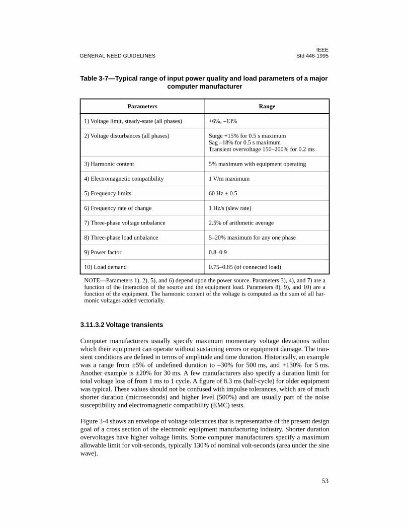
IEEEGENERAL NEED GUIDELINES Std 446-1995
3.11.3.2 Voltage transients
Computer manufacturers usually specify maximum momentary voltage deviations withinwhich their equipment can operate without sustaining errors or equipment damage. The tran-sient conditions are defined in terms of amplitude and time duration. Historically, an examplewas a range from ±5% of undefined duration to –30% for 500 ms, and +130% for 5 ms.Another example is ±20% for 30 ms. A few manufacturers also specify a duration limit fortotal voltage loss of from 1 ms to 1 cycle. A figure of 8.3 ms (half-cycle) for older equipmentwas typical. These values should not be confused with impulse tolerances, which are of muchshorter duration (microseconds) and higher level (500%) and are usually part of the noisesusceptibility and electromagnetic compatibility (EMC) tests.
Figure 3-4 shows an envelope of voltage tolerances that is representative of the present designgoal of a cross section of the electronic equipment manufacturing industry. Shorter durationovervoltages have higher voltage limits. Some computer manufacturers specify a maximumallowable limit for volt-seconds, typically 130% of nominal volt-seconds (area under the sinewave).
Table 3-7—Typical range of input power quality and load parameters of a major computer manufacturer
Parameters Range
1) Voltage limit, steady-state (all phases) +6%, –13%
2) Voltage disturbances (all phases) Surge +15% for 0.5 s maximumSag –18% for 0.5 s maximumTransient overvoltage 150–200% for 0.2 ms
3) Harmonic content 5% maximum with equipment operating
4) Electromagnetic compatibility 1 V/m maximum
5) Frequency limits 60 Hz ± 0.5
6) Frequency rate of change 1 Hz/s (slew rate)
7) Three-phase voltage unbalance 2.5% of arithmetic average
8) Three-phase load unbalance 5–20% maximum for any one phase
9) Power factor 0.8–0.9
10) Load demand 0.75–0.85 (of connected load)
NOTE—Parameters 1), 2), 5), and 6) depend upon the power source. Parameters 3), 4), and 7) are afunction of the interaction of the source and the equipment load. Parameters 8), 9), and 10) are afunction of the equipment. The harmonic content of the voltage is computed as the sum of all har-monic voltages added vectorially.
53
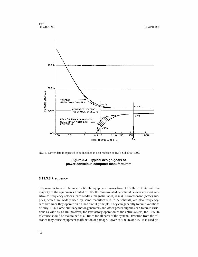
IEEEStd 446-1995 CHAPTER 3
3.11.3.3 Frequency
The manufacturer’s tolerance on 60 Hz equipment ranges from ±0.5 Hz to ±1%, with themajority of the equipments limited to ±0.5 Hz. Time-related peripheral devices are most sen-sitive to frequency (clocks, card readers, magnetic tapes, disks). Ferroresonant (ac/dc) sup-plies, which are widely used by some manufacturers in peripherals, are also frequency-sensitive since they operate on a tuned circuit principle. They can generally tolerate variationsof only ±1%. Some auxiliary motor-generators and other power supplies can tolerate varia-tions as wide as ±3 Hz; however, for satisfactory operation of the entire system, the ±0.5 Hztolerance should be maintained at all times for all parts of the system. Deviation from the tol-erance may cause equipment malfunction or damage. Power of 400 Hz or 415 Hz is used pri-
NOTE: Newer data is expected to be included in next revision of IEEE Std 1100-1992.
Figure 3-4—Typical design goals of power-conscious computer manufacturers
54
IEEEGENERAL NEED GUIDELINES Std 446-1995
marily in computer mainframes or in other areas where high-density power is needed. Thehigher frequency allows design of a smaller and more compact power supply and componentsthat result in reduced heating losses. The deriving of 400 Hz power does involve additionalcosts. Also, distribution of 400 Hz power presents some special problems. Thus, for many ofthe peripheral manufacturers, 60 Hz power is still preferred. Some equipment, such as largeCPUs, use both 400 Hz and 60 Hz power, with 60 Hz mainly for cooling fans and blowers.The current trend is to use 400 Hz power in the larger data processing systems, with 60 Hzlimited to the smaller systems and peripherals. Development and wider usage of 60–400 Hzor higher frequency static inverters to replace motor-generator sets and to be placed in indi-vidual equipments would reverse the trend back toward 60 Hz input in equipments. Severalmajor computer hardware manufacturers predict the use of frequencies considerably above400 Hz for future generation computer systems. Inverter frequencies of 20 kHz are com-monly used now, and some state-of-the-art inverters operate at 100 kHz and higher.
The voltage quality and characteristics of 400 Hz power are extremely critical, with fre-quency generally not as critical a parameter. Most manufacturers who consider the 400 Hzsource an integral part of the computer would prefer to furnish conversion equipment as partof the computer installation. Furthermore, because of the special problems associated withthe distribution of 400 Hz power, conversion equipment is generally located relatively closeto the utilization equipment.
In addition to being sensitive to the limits of ±0.5 Hz, some system peripherals are also sensi-tive to the rate of change within this band. Although extensive information is not available, avariation of 0.05 Hz/s has been cited by one manufacturer as a limit for some units of his sys-tem. A typical limit is 1.5 Hz/s, measured as rate of change in a 10 cycle running average.The limit is most significant when turbine or engine generators are applied where small loadstep applications may cause the rate to be exceeded.
3.11.3.4 Distortion
The maximum harmonic distortion permitted on input lines ranges from 3–5%, with themajority at +5%. The percentage is usually specified as total line-to-line distortion, with amaximum of 3% for any one harmonic.
Excessive harmonic content can cause heating in magnetic (iron) devices, such as transform-ers, motors, and chokes. The harmonic distortion will also appear as additional ripple in theoutput of some ac/dc power supplies and also cause threshold limits to vary in peak and aver-age sensing circuits. Either can contribute to data errors.
It should be noted that elements of the load may introduce considerable distortion or noiseinto the power source. This reflected noise, although not in the source, may require suppres-sion through filtering to avoid interference with other loads also connected to the system.
The voltage envelope should be sinusoidal, with a crest factor of 1.414 ± 0.1. Waveform devi-ation should be limited to ±10% line-to-neutral. The variation in the amplitude (in time) ofthe wave should not exceed ±0.5%.
55
IEEEStd 446-1995 CHAPTER 3
Excessive modulation of the voltage can produce pulsing and speed variations in motors andcan introduce additional ripple in the output of ac/dc power supplies.
Some computer units have half-wave rectifier units and SCRs (half-wave phase control).These are capable of creating a dc component of load current and greater current in the neu-tral than in the phase conductors. Power sources for such loads must be capable of handlingthem.
3.11.3.5 Phase angle displacement
Although some manufacturers build only single-phase equipment, the majority of equipment,particularly for larger systems, is three-phase. The maximum deviation from normal 120°spacing ranges from ±2.5° to ±6°. Unequal phase displacement, whether in the source or dueto unequal loading, can further contribute to phase voltage unbalance.
3.11.3.6 Voltage balance
Unequal distribution of single phase, as is frequently encountered in computer systems, willincrease the amount of voltage unbalance. Wherever possible, effort should be made to dis-tribute load evenly between the phases.
Excessive phase voltage unbalance can cause excessive heating to three-phase devices suchas motors. Similarly, relays and other electromechanical devices may be damaged due to con-tinuous operation at high (or low) voltage. In addition, high ripple may be observed in somethree-phase ac/dc power supplies if the voltage unbalance to the supply is high. Percent volt-age unbalance is defined by ANSI/NEMA MG 1-1993, Part 14.35.2, as
3.11.3.7 Environmental considerations
It is well known that electronic equipment is capable of reaching design performance levelsonly when proper cooling is introduced. The principal thrust of this discussion involves theelectrical power needs of data processing equipment. However, it must be recognized thatcooling of that equipment can be an overriding and sometimes limiting factor in the operationof data processing equipment, principally because most cooling and ventilating equipment iselectrically powered. In addition to comfort air conditioning for the computer room, the com-puter’s central processing unit (CPU) logic and chassis often have special cooling require-ments and many have overtemperature alarms or cutoffs. With larger systems and increasedcapabilities, computers have, for technical reasons, also grown more compact, leading toincreased power densities in terms of watts per cubic foot. The result has been a progressionin chassis cooling from natural convection, to forced air, to chilled water, and in some cases,to a refrigerant-cooled chassis. However, intermediate-sized computer installations are fre-quently cooled by forced air through ducts or under floor areas. Small computers and periph-erals may contain their own internal fans and draw cooling air from the room where they areinstalled.
percent voltage unbalance 100maximum voltage deviation from average voltage
average voltage-----------------------------------------------------------------------------------------------------------------------
×
=
56
IEEEGENERAL NEED GUIDELINES Std 446-1995
The methods of cooling of a computer system can also heavily influence how long a com-puter system can operate without electrical power to cooling apparatus. Assume that com-puter power could be maintained through the use of batteries, standby generators, or otherauxiliary equipment, which is described later. It then becomes important to consider thedesign/selection of computer system cooling systems and their need for auxiliary power sup-plies. Obviously, there is no need to provide battery ampere-hour capacity, which can extendcomputer operating time beyond the time that a computer system can operate before it mustshut down due to overheating.
Most manufacturers are reluctant to cite these times for their computer hardware since manyvariables within a facility can exist. For forced-air cooling, many claim up to 15 min canelapse before overheating and equipment shutdown occurs due to operation of overtempera-ture sensors. For those systems that use chilled-water cooling, approximately 2–3 min hasbeen given as the length of time that the chilled supply can be cut off. For refrigerant cooling,about 15 min is often considered the maximum.
Most larger systems shut down automatically when a high temperature is reached and manyprovide a warning alarm when approaching a high temperature.
3.11.3.8 Humidification
The need for, and extent of, introduction of humidification into a data processing equipmentroom will vary considerably with the geographic area. Humidity control is required to ensureorderly movement of papers, cards, and magnetic tapes in the operation of the computer andits peripherals. Low humidity allows the building up of static electrical charges, which in turncauses cards and tape to stick together, jam, etc. Extremely high humidity can result in con-densation of moisture on chilled chassis plates, resulting in rust and corrosion. Most data pro-cessing equipment manufacturers recommend that a humidity range of 40–60% bemaintained in equipment rooms. As with cooling apparatus, discussed in the preceding para-graph, humidity-generating equipment can be as important as cooling equipment. Anyreserve or standby equipment must be sized for not only the supply of electrical power to dataprocessing equipment, but also for the length of time the equipment can operate without sup-ple mental humidification or dehumidification and attendant problems.
3.11.4 Factors influencing data processing systems on incoming or supplementary independent power sources
Much of the foregoing discussion has been dedicated to the various influences that the sourceof electrical power has on data processing equipment and systems. It should be recognizedthat the same equipment and systems can, in various ways, interact with and influence thesource power system and other utilization equipment served by it. Some of these influencesbecome important if supplementary independent power sources are used as an enhancementof power source quality, particularly where emergency and standby power is applied.
57
IEEEStd 446-1995 CHAPTER 3
3.11.4.1 Load magnitude
The size of the electrical load of a data processing system depends on the makeup, complex-ity, and even on the function of the system. A typical small system may vary from 10–50 kVA, and larger systems, from 100–300 kVA. Some multiple systems may be as large as2000 kVA. As systems become larger, some manufacturers elect to power the mainframeswith 400 Hz power derived from the 60 Hz source, often through separate motor-generatorsets.
A principal computer manufacturer states that approximately 30–35 W/ft
2
per computer floorspace should be allowed in planning for ultimate computer electrical power consumption.This load density is exclusive of any attendant space conditioning, humidification, or dehu-midification loads that would be required.
3.11.4.2 Load growth
For an established system, most load growth will result from the incremental and often unpre-dictable addition or expansion of peripheral devices (tapes, disks, cardpunch, etc.). However,not all system growth results in electrical load growth. For example, the replacement of sev-eral smaller disks by a larger (in a computing sense) disk device may actually require lesspower. Major load growth occurs when an entire system performance capability is upgraded,which usually results in a new mainframe and some peripherals.
3.11.4.3 Power factor
The characteristic power factor of a computer system is relatively high. The power factor ofthe 60 Hz portion of the load generally ranges from 80–85%, and the power factor of the400 Hz (motor-generator set) load is generally around 90%. Depending on the amount of60 Hz load, and on whether or not a motor-generator set is used, the overall combined powerfactor is usually in the range of 80–90%. During initial powering up or startup, the power fac-tor may drop as low as 50% for short periods.
3.11.4.4 Load unbalance
Most equipment manufacturers attempt to balance their equipment load in the design of theequipment and in load connection in the planning phase. However, load unbalance may runfrom 5–30% (phase-to-phase) steady state and up to 100% dynamic, as in startup. The effectof load unbalance is to produce unbalanced phase voltages. See the discussion of voltage bal-ance in the preceding paragraphs.
3.11.4.5 Startup
The powering up of a computer system may place severe demands on the power source. Inthat regard, independent power sources are more vulnerable than a commercial power sourcefrom the utility company. Efforts are made by manufacturers to reduce inrush by variousmethods. Energizing of large loads is often sequenced in steps, manually or automatically.
58
IEEEGENERAL NEED GUIDELINES Std 446-1995
Special motor-starting techniques can be used to reduce inrush in the starting of large motors,disks, and motor-generator sets.
The user often can employ operational procedures designed to ease startup and step loading.As an example, large groups of peripherals may be started manually, in sequence, rather thansimultaneously. Large 400 Hz loads, such as mainframes powered by motor-generator sets,may be brought on-line slowly by controlled buildup of the generator output to give the logicload a cushioned start as well as reduced inrush.
Even with reduction methods, high inrush currents are common with many pieces of com-puter equipment. One manufacturer’s central processor whose steady-state load is 24 kVApresents a 1500% (of steady state) transient for approximately 100 ms, which decreases to600% in 300 rms. Another manufacturer, requiring 60 kVA steady state, presents a 400%transient. Still another manufacturer, requiring about 8 kVA steady state, presents a 1000%transient for a half-cycle, dropping to normal not later than the next cycle. The startup of a 40kVA motor-generator set can require up to 200% for 2–10 s, even with special starting meth-ods. High inrush puts an added requirement on the design of the power source, especially ondevices, such as ride-through motor-generator sets and static inverters. Current-limiting pro-tection for inverters is typically 125–175%. Voltage output will drop during current-limitingoutput.
3.11.4.6 Step or pulsing loads
Even when a system is on-line and drawing steady-state power, it may present severe loadtransients due to the operational demands of the computer. Step changes in load as high as200–300% may be possible when starting an additional unit. Frequently, step changes in loadcan be minimized within the equipment through judicious programming that avoids simulta-neous energizing or operation of several processes or pieces of equipment.
Pulsing loads can cause problems and occur when a number of devices that have powerpeaks, which are coincident and repetitive, are connected to the same power source. As anexample, the programming of multiple tape units to rewind simultaneously should beavoided. Line printers, whose steady-state load is small, may step 100–200% when striking afull line of print. The cumulative effect of a large number of printers in synchronism canplace a severe strain on the power system. If the power source includes a rotating device withspeed control, it is possible for the load to cause oscillations in the control and output.Although extremely rare, the problem should be considered if there could be a large numberof synchronized pulsing loads.
3.11.4.7 Load-generated harmonics and noise
Certain elements in the load, such as saturated magnetic circuits (transformers, motors), maycause distortion of the voltage waveform. Problems often result from the reflection into thesource of load-generated noise, such as switching spikes caused by turning devices on or offor by the firing of high-speed solid-state devices (SCRs, diodes) that are a part of the com-puter load. The spikes, of microsecond width, may run several hundred volts on the 120 V
59
IEEEStd 446-1995 CHAPTER 3
line. These disturbances may have to be eliminated by filtering to avoid interference withother parts of the load.
The load factor for an on-line system may approach 100% due to the continuous nature of itsoperation. Off-line systems will generally be lower, depending on their daily scheduling anduse.
Demand factor is the ratio of the actual steady-state running load to which a power systemwill be subjected to the total connected load.
Demand factor is important since connected kVA loads are generally available from theequipment manufacturer as nameplate ratings of individual components and can be taken asthe worst-case condition. Thus, an arithmetic total of the loads can be computed. However,some computer system manufacturers provide data on the actual running loads, as seen by thetotal system, when operating the individual components as a system.
Through experience and data obtained from several of the computer systems manufacturers,some of the larger computer systems having connected loads in the area of 300 kVA, experi-ence demand factors of between 75% and 85%. In other words, the running loads can be pre-dicted to run between 225 kVA and 255 kVA for such a system. Thus users should be awarethat nameplate ratings indicate power for a fully featured machine and actual loadings may besignificantly less for individual user’s systems.
Larger systems, consisting of many components, will probably have lower demand factorswhen compared with smaller systems with fewer components because of inherent diversityamong components.
3.11.4.8 Grounding
Most computer manufacturers have preferred methods of system and equipment groundingfor their hardware. Some systems require special grounded signal reference grids with single-point grounding and strict control of the paths through which equipment ground and powersystem ground are interconnected. These grounds are always connected one to the other to beelectrically safe and to conform with the codes. The paths may be separated up to some point.Also, since computers and office machines are accessible to people, particular attention mustbe given to the safety grounding of all equipment. If, for the sake of radio frequency noisereduction, the equipment grounding green wire is isolated from the building/raceways, itmust be run with power conductors and carried back to the service equipment grounding con-ductor. Furthermore, special semiconductive flooring may be employed for computer rooms,which enables draining off of static charges and minimizes the shock hazard to personnel.Some equipment manufacturers recommend grounding of equipment to the floor grid. Themanufacturers installation instructions are not always correct and may contribute to prob-lems. See Chapter 7 for grounding of emergency and standby power systems.
60
IEEEGENERAL NEED GUIDELINES Std 446-1995
3.11.5 Justification of supplemental power
Insurance companies provide loss of power and loss of production insurance that can give acost guideline on how much can be spent to improve the power supply.
The various units of a computer system are not equally sensitive to power supply distur-bances. Power requirements for equipment such as air conditioning, lights, and drive motorsare much less restrictive than for the logic, memory, control disk, and tape units. For eco-nomic reasons, the power loads should be separated into those requiring buffer or filter actionwith a UPS and those that require no buffering and can accept a 0.5 s–1 min power interrup-tion while switching to a standby source of electric power.
Assuming that such a separation of computer or data processing equipment, or both, is possi-ble, the next step would involve the selection of a system or equipment that would best solvethe user’s problems.
In summary, the following steps are intended to serve as a checklist toward problem-solvingwhere power problems are present. Care is required and computer manufacturer’s adviceshould be heeded in arranging and coordinating the ground references where more than onepower source supplies power to computer units in a common system.
a) Survey power quality requirements of all installed equipment to determine maximumdegree of sensitivity of the individual components. These data are often not availablefrom manufacturer’s published literature.
b) Check to see if the local utility company has operating records. If no records areavailable, the user may choose to install a power disturbance monitor to detect andrecord transient power deficiencies at the point of usage and obtain a profile of powertransients for a minimum two-week period. The results of such recordings should beused with the recognition that such seasonal conditions of lighting and other weather-related problems may not have been accounted for.
c) Review and analyze the monitor’s records to identify the magnitude, number, time,date, and characteristics of the recorded transients, interruptions, and prolonged out-ages.
d) Classify the transients according to their origin: from the utility; from the operationof electrical equipment in the computer’s vicinity; from the operation of computerunits and their accessories.
e) As appropriate, prepare engineering design and cost estimates of a power-bufferingsystem of required capacity (kVA). The chosen power-buffering system shouldaccommodate both future expansion and possible replacement with more recentlymarketed computer models.
f) Evaluate actual and intangible losses due to interruptions or malfunctions of the elec-tronic data processing equipment from all causes, including losses attributable topower supply deficiencies or failure.
g) Compare expected losses without power-buffering equipment to the cost of owningand operating various types of a power-buffering system as insurance against tran-sient-caused interruptions or malfunctions of computer equipment.
61
IEEEStd 446-1995 CHAPTER 3
h) If the previous step justifies an investment in a power-buffering system, proceed withthe project.
3.11.6 Power quality improvement techniques
Any attempts to categorize power improvement equipment should logically attempt also todefine the time duration effectiveness of the equipment. The simplest and least costly equip-ment is limited in effectiveness to extremely short-duration power disturbances. As the timespan for protection of disturbances increases to
outage
-type disruptions, the sophisticationand associated cost for related equipment, as a general rule, will also increase. The followinglist broadly classifies equipment from the very short duration to an indefinite time period. Abroader classification of equipment could be the distinction between passive and dynamicsystems.
Equipment systems:
— Power conditioners— Short time (up to 15 s, but typically 0.1 s) ride-through— Extended time (up to 30 min) ride-through— Indefinite time
The time interval for most of the equipment listed can usually be extended to an indefinitetime period through the use of a supplemental standby power source such as a second utilitycompany power feeder or on-site generation. To maintain power input to the load within tol-erance, the supplementary equipment must be capable of
riding through
the inherent sensingand transfer time switching associated with a second incoming feeder. With standby genera-tion systems, ride-through time must at least equal prime mover starting time, including syn-chronizing and transfer switching times for those systems.
Short-time ride-through can be accomplished with
mechanical stored energy systems
, whichare described in 5.4.
Extended ride-through time can be achieved through operation of the equipment in conjunc-tion with stored energy equipment, such as batteries.
In general,
power conditioning
equipment is limited to improvement of short-duration powerproblems. In installations where electrical noise and voltage are principal problems, an isola-tion transformer can be an effective solution in noise attenuation and voltage control.
Isolation transformers can simultaneously isolate and change voltage, for example, from480 V three-phase to 208Y/120 V, or can have a one-to-one transformation ratio. An ordinarytransformer with separate primary and secondary circuits will provide some isolation. How-ever, effectiveness is greatly improved if they are equipped with special shielding between theprimary and secondary windings. This special shielding will reduce the noise amplitude andinhibit the passage of noise through the transformer. Performance of three-phase transformerswill be greatly enhanced in handling harmonic currents and unbalanced load if the trans-former is connected delta-primary/wye-secondary on a three-legged core. Such transformers
62

IEEEGENERAL NEED GUIDELINES Std 446-1995
can be equipped with primary taps to adjust output voltage when input is constantly high orlow. A typical tap range is +5% to –5% in 2.5% steps.
Beyond the isolation transformer is a wide range of voltage correction or stabilizing equip-ment, each having distinct and unique operating characteristics. Commercially availableequipment that would fall into the power conditioner classification are listed in table 3-8.Typical reported response times are listed for each device. It is obvious, because of the rela-tively slow response times, that the use of several of the devices would be restricted to simplevoltage regulation and would have questionable value against short-term disturbances. Inaddition, some of the devices have inherently high internal impedance. Any sensed voltagedrop is ultimately corrected by its voltage-regulating capability. However, under stepped loadchange, the dynamic voltage change may be unacceptable for the time required for the regu-lator to respond. If multiple loads are to be supplied by one device and one of the loads isswitched, one must be assured that the magnitude of voltage change before the regulator canreact will be within acceptable limits.
Dynamic regulation and response time are the major considerations. It is stressed thatbecause of relatively slow response times some of the equipment is effective only for voltageadjustment or correction. Also, steady-state regulation is normally published, but dynamicregulation to step changes in voltage input and load current is often omitted. Without adetailed analysis of equipment operating characteristics, often from actual test data, a usercould mistakenly think that he is getting protection against short-duration line input voltagedisturbances and the effects of changing load. In general, equipment is available to acceptline voltage variations of a 15% overvoltage to a 20% undervoltage condition with output
Table 3-8—Performance of power conditioning equipment
Equipment type Response time
Typical internal
impedance (%)
Regulator, low impedance 11 ms 3–5
Transformer, constant voltage 25 ms
Reactor, electronic saturable 30 ms 20–30
Regulator, electronic magnetic 160 ms
Regulator, electromechanical 5+ s 3–5
Regulator, induction 5+ s 10
Tap changer, mechanical 60 s 3–5
63
IEEEStd 446-1995 CHAPTER 3
regulated to ±5% of rating. Such a regulated output is generally sufficient for electronic dataprocessing equipment. In a situation in which an ac line regulator appears to be needed, theapplication should be reviewed with the manufacturer of the data processing equipment.
3.11.7 Selection factors for supplemental power
The true nature of the data processing operation must be examined in combination with itsextent of usage. On-line systems generally require a higher degree of power protection thanoff-line systems. Certainly, a 24 h around-the-clock operation would be more vulnerable thana one-shift-a-day operation.
Whether on-line or off-line, the consequences of a power failure should be determined interms of cost, value of lost data, necessity of reruns, inconvenience to and loss of revenuefrom customers, possible equipment damage, repair cost, and general annoyance. It is some-times found, particularly in off-line operations, that the consequences of an outage do not jus-tify the often considerable expenditure for a protective system. The decision must be basedon how much a user should pay for insurance in light of the benefits to be derived.
To evaluate the effects of outages, an estimate of the number of outages and their durationpredicted over a period of at least one year should be obtained from the utility, based on theirpast operating experiences.
A comparison of what is predicted with what is acceptable in terms of power limits shouldindicate if supplemental protection is needed.
3.11.7.1 Protection time
Assuming that the predicted available power is not acceptable in terms of duration or fre-quency of disturbances or disruption, it must then be determined how much protection isappropriate and what solutions are available to the user.
Table 3-9 has been prepared to indicate what effect three types of power-line disturbanceswill have on data processing and computer equipments. Also shown for each type of distur-bance are several of the available solutions that can be applied for enhancement of the powerquality. Note that in this comparison the disturbance durations are for less than 1 cycle, from1 cycle–10 s, and for more than 10 s. Table 3-10 presents similar data in a slightly differentmanner and shows, for each of the categories of disturbances, how effective each of the avail-able solutions will be as a power quality improvement measure.
3.11.7.2 Reliability
An indication of reliability can be expressed in hours of mean time between failure (MTBF).Data for calculating the MTBF can be obtained from IEEE Std 500-1984. Equipment andreliability can be enhanced by redundant systems and components and provision for isolationor bypass of defective parts or subassemblies.
64
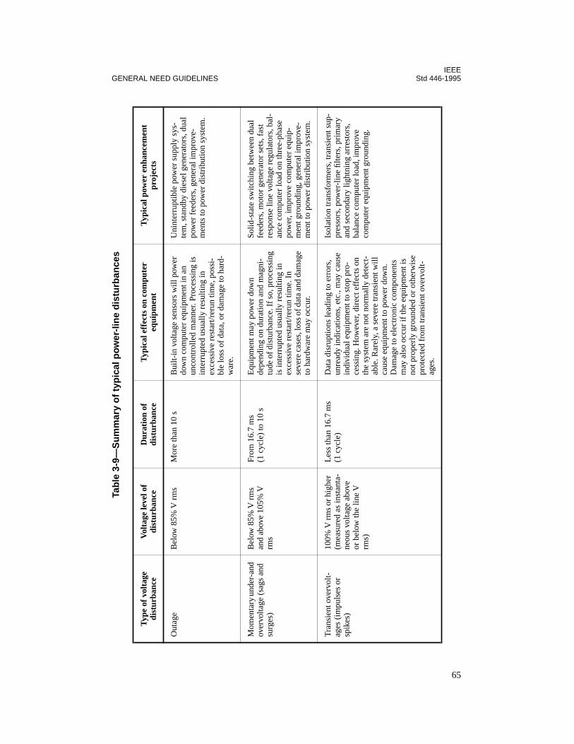
IEEEGENERAL NEED GUIDELINES Std 446-1995
Tab
le 3
-9—
Su
mm
ary
of
typ
ical
pow
er-l
ine
dis
turb
ance
s
Typ
e of
vol
tage
di
stur
banc
eV
olta
ge le
vel o
f di
stur
banc
e D
urat
ion
of
dist
urba
nce
Typ
ical
eff
ects
on
com
pute
r eq
uipm
ent
Typ
ical
pow
er e
nhan
cem
ent
proj
ects
Out
age
Bel
ow 8
5% V
rm
sM
ore
than
10
sB
uilt-
in v
olta
ge s
enso
rs w
ill p
ower
do
wn
com
pute
r eq
uipm
ent i
n an
un
cont
rolle
d m
anne
r. Pr
oces
sing
is
inte
rrup
ted
usua
lly r
esul
ting
in
exce
ssiv
e re
star
t/rer
un ti
me,
pos
si-
ble
loss
of
data
, or
dam
age
to h
ard-
war
e.
Uni
nter
rupt
ible
pow
er s
uppl
y sy
s-te
m, s
tand
by d
iese
l gen
erat
ors,
dua
l po
wer
fee
ders
, gen
eral
impr
ove-
men
ts to
pow
er d
istr
ibut
ion
syst
em.
Mom
enta
ry u
nder
-and
ov
ervo
ltage
(sa
gs a
nd
surg
es)
Bel
ow 8
5% V
rm
s an
d ab
ove
105%
V
rms
From
16.
7 m
s (1
cyc
le)
to 1
0 s
Equ
ipm
ent m
ay p
ower
dow
n de
pend
ing
on d
urat
ion
and
mag
ni-
tude
of
dist
urba
nce.
If
so, p
roce
ssin
g is
inte
rrup
ted
usua
lly r
esul
ting
in
exce
ssiv
e re
star
t/rer
un ti
me.
In
seve
re c
ases
, los
s of
dat
a an
d da
mag
e to
har
dwar
e m
ay o
ccur
.
Solid
-sta
te s
witc
hing
bet
wee
n du
al
feed
ers,
mot
or g
ener
ator
set
s, f
ast
resp
onse
line
vol
tage
reg
ulat
ors,
bal
-an
ce c
ompu
ter
load
on
thre
e-ph
ase
pow
er, i
mpr
ove
com
pute
r eq
uip-
men
t gro
undi
ng, g
ener
al im
prov
e-m
ent t
o po
wer
dis
trib
utio
n sy
stem
.
Tra
nsie
nt o
verv
olt-
ages
(im
puls
es o
r sp
ikes
)
100%
V rm
s or
hig
her
(mea
sure
d as
inst
anta
-ne
ous
volta
ge a
bove
or
bel
ow th
e lin
e V
rm
s)
Les
s th
an 1
6.7
ms
(1 c
ycle
)D
ata
disr
uptio
ns le
adin
g to
err
ors,
un
read
y in
dica
tions
, etc
., m
ay c
ause
in
divi
dual
equ
ipm
ent t
o st
op p
ro-
cess
ing.
How
ever
, dir
ect e
ffec
ts o
n th
e sy
stem
are
not
nor
mal
ly d
etec
t-ab
le. R
arel
y, a
sev
ere
tran
sien
t will
ca
use
equi
pmen
t to
pow
er d
own.
D
amag
e to
ele
ctro
nic
com
pone
nts
may
als
o oc
cur
if th
e eq
uipm
ent i
s no
t pro
perl
y gr
ound
ed o
r ot
herw
ise
prot
ecte
d fr
om tr
ansi
ent o
verv
olt-
ages
.
Isol
atio
n tr
ansf
orm
ers,
tran
sien
t sup
-pr
esso
rs, p
ower
-lin
e fil
ters
, pri
mar
y an
d se
cond
ary
light
ning
arr
esto
rs,
bala
nce
com
pute
r lo
ad, i
mpr
ove
com
pute
r eq
uipm
ent g
roun
ding
.
65

IEEEStd 446-1995 CHAPTER 3
Tab
le 3
-10—
Rel
ativ
e ef
fect
iven
ess
of
pow
er e
nh
ance
men
t p
roje
cts
in e
limin
atin
g o
r m
od
erat
ing
pow
er d
istu
rban
ces
(U.S
. Nav
y)
Dis
turb
ance
ty
pe
Uni
nter
rupt
ible
pow
er
supp
ly
(UP
S)
syst
em a
nd
stan
dby
dies
el
gene
rato
r
Uni
nter
rupt
ible
pow
er
supp
ly
(UP
S)
syst
em
Dua
l pow
er f
eede
rs
Mot
or-
gene
rato
r
Solid
-sta
te
line v
olta
ge
regu
lato
r
Spec
ialt
y sh
ield
ed
isol
atin
g tr
ansf
orm
er
Supp
ress
ors,
fil
ters
, and
lig
htni
ng
arre
ster
s
Bal
ance
co
mpu
ter
load
on
thre
e-ph
ase
supp
ly,
impr
ove
grou
ndin
g
Seco
ndar
y sp
ot
netw
ork
Seco
ndar
y se
lect
ivea
Tra
nsie
nt
and
osci
llato
ry
over
volta
ge
All
sour
ce-
caus
ed
tran
sien
ts
and
no lo
ad-
caus
ed
tran
sien
ts
All
sour
ce
tran
sien
ts
and
no lo
ad
tran
sien
ts
Non
eN
one
All
sour
ce
tran
sien
ts
and
no lo
ad
tran
sien
ts
Mos
t so
urce
tran
sien
ts
and
no lo
ad
tran
sien
ts
Mos
t sou
rce
tran
sien
ts
and
no lo
ad
tran
sien
ts
Mos
tSo
meb
Mom
enta
ry
unde
rvol
t-ag
e or
ov
ervo
ltage
All
All
Non
eM
ost
Mos
tSo
me
(dep
ends
on
resp
onse
tim
e)
Non
eN
one
Som
eb
Out
age
All
Onl
y ou
tage
s of
a
dura
tion
equa
l to
the
disc
harg
e tim
e of
the
batte
ry
Mos
tM
ost
Onl
y br
own-
out
Onl
y br
owno
utN
one
Non
eN
one
a Inc
lude
s sp
ecia
l app
licat
ion
of a
sol
id-s
tate
sw
itch
betw
een
two
inde
pend
ent s
ourc
es.
b The
se im
prov
emen
ts d
o no
t elim
inat
e or
mod
erat
e po
wer
-lin
e di
stur
banc
es, b
ut th
ey d
o m
ake
the
com
pute
r eq
uipm
ent s
igni
fican
tly le
ss s
usce
ptib
le to
und
er-
and
over
volta
ges.
Ass
ista
nce
of th
e co
mpu
ter
man
ufac
ture
r is
gen
eral
ly r
equi
red
to id
entif
y gr
ound
ing
prob
lem
s.
66
IEEEGENERAL NEED GUIDELINES Std 446-1995
A typical reliability prediction assumes that if the UPS system fails, there is to be a highprobability that the static switch will operate and that main power of suitable quality will beavailable to handle the load. The probability of simultaneous failures of the UPS and staticswitch or main power yields an exceptionally low failure rate corresponding to MTBFs of10 years or longer. However, the probability of switch failure is greater when it is called uponto operate than when quiescent. Also, the duration of the failure in a static switch may beextended due to an inability to detect failure.
As with reliability, data on equipment life expectancy are difficult to obtain. Often, becauseof the rapid advancement of data processing technology, the protected equipment obsoles-cence will generally occur before the life of the protecting equipment is exceeded.
Dynamic or rotating apparatus is capable of withstanding short time and sustained overloadsbetter than static equipment. Furthermore, most static assemblies are more vulnerable toshock or high-inrush loads than dynamic equipment. Dynamic or rotating equipment does notlend itself well to expansion through paralleling due to complex control problems. Con-versely, most static systems are easily expanded through the addition of parallel modules oradditional batteries.
Because some systems have inherent lower overall efficiencies, increased heat losses will beevident. The first cost of supplemental cooling and ventilating equipment, with ongoing oper-ating and maintenance costs, must be considered. Furthermore, the need of additional auxil-iary or standby power capability to drive the cooling and ventilating equipment, when normalpower curtailment occurs, must also be examined.
3.11.7.3 Other factors
Most equipment will occupy building interior space, which not only costs money but willrequire environmental treatment or tempering. Such space is often treated as leasable spacean, as such, its cost considered as an ongoing cost in any comparative analysis.
Delivery, setup, checkout, and debug time can often be an important and deciding factorwhen the dependence and prime emphasis is placed on having a data processing system orcomputer and its capabilities in service on an around-the-clock basis.
Some of the solutions for improvement of power quality will require the installation of anauxiliary power source with some form of prime mover. Other sections in this standard pro-vide detailed guidance toward a prime mover selection. The most popular choice is the dieselengine, with gas turbine usage increasing.
Often it is to the advantage of the user to provide for a separation of the source for the dataprocessing equipment or its power improvement equipment from the source for the facility’senvironmental equipment. Since the only objective of the auxiliary power source is to providean almost immediate source of power, reliability in starting is the most important characteris-tic. Usually, the unit is called on to start after a sustained period of idleness. The time periodfor starting could be important since the equipment could be called on to operate in conjunc-tion with a stored energy type of ride-through system. Often data processing equipment is
67
IEEEStd 446-1995 CHAPTER 3
installed in a relatively quiet atmosphere so that whichever choice of prime mover is made,some form of acoustic treatment will probably be required.
3.11.8 IEEE Std 1100 (the IEEE Emerald Book)
IEEE Std 1100-1992 contains a thorough treatment of the power requirements for sensitiveelectronic equipment. The book covers fundamentals, instrumentation, and recommendeddesign and installation practices.
3.12 Life safety and life support systems
3.12.1 Introduction
Emergency power for life safety systems is required in many different types of commercialand industrial facilities. For example, an alternative power source is needed to illuminateexits and to operate alarm systems in most public buildings. These needs generally relate tofire safety as set forth in ANSI/NFPA 101-1994.
In contrast, emergency power requirements for life support systems, such as a heart-lungmachine or medical diagnostic equipment, are generally limited to health care facilities.These requirements result from operational needs unique to the health care environment.
Emergency power for both life safety and life support equipment is addressed in this sub-clause primarily from the viewpoint of the user.
3.12.2 Health care facilities
Typical examples of both life safety and life support emergency power requirements arefound in large health care facilities. An appreciation for both of these needs can therefore beobtained by reviewing a hospital’s emergency power system.
Hospitals are increasingly dependent on electrical apparatus for patient life support and treat-ment as illustrated in the following paragraphs.
Electronic monitoring systems are being used to conduct therapy for critically ill patients. Inthe operating suite, during open-heart surgery, an electronic heart-lung machine maintainsextracorporeal circulation. In the intensive care unit, patients depend on ventilators poweredby electricity. Cardiac-assist devices augment a patient’s own circulation in the coronary careunit. Continuous lighting is needed to observe patients in primary care areas, and power isneeded to maintain refrigerated storage of vital supplies such as blood and tissue banks.
In addition to these examples of direct dependency on electric power in patient care, the sus-tained loss of electrical power can also result in an undesirable traumatic experience for someseriously ill patients.
68

IEEEGENERAL NEED GUIDELINES Std 446-1995
Hospitals also must have a highly reliable supply of emergency power for life safety systemsto ensure that the lives of sick or disabled persons are protected during emergencies.
Interruption of normal electrical services to hospitals may be caused by a variety of phenom-ena. These include storms, floods, fires, earthquakes, explosions, traffic accidents, electricalequipment failure, and human error. Several large area blackouts have been experienced inthe recent past with prolonged local outages. As a consequence of the “energy crisis” the inci-dence of such failures is thought by many authorities to be on the rise. Alternative sources ofpower for supplying vital life safety and life support systems must be provided to protectpatients relying on these systems.
3.12.2.1 Power continuity requirement
The acceptable duration for an interruption of normal power service to critical hospital loadsis the subject of many state codes and regulations. National standards often referenced by thestates and specifically addressing this issue are NFPA 99-1996 and the NEC, Article 517.
NFPA 99-1996 requires that all health care facilities maintain an alternate source of electricalpower. With few exceptions, this source must be an on-site generator capable of servicingboth essential major electrical equipment and emergency systems.
For hospitals, NFPA 99-1996 provides the following criteria with respect to the emergencysystem: “Those functions of patient care, depending on lighting or appliances that are permit-ted to be connected to the Emergency System are divided into two mandatory branches; theLife Safety and the Critical. The branches of the Emergency System shall be installed andconnected to the alternate power source . . . so that all functions specified . . . shall be auto-matically restored to operation within 10 seconds after interruption of the normal power.”
To meet the “10 second criteria” the emergency system must include independent distributioncircuits with automatic transfer to the alternate power source. Two-way bypass and isolationtransfer switches are recommended for the emergency branches. Figure 3-5 shows the emer-gency system wiring arrangement from a typical hospital. The hospital emergency systeminstallation must follow Articles 518 and 700 of the NEC.
The life safety branch of the emergency system, as described in NFPA 99-1996, includes illu-mination for means of egress and exit signs (ANSI/NFPA 101-1994 requirement), fire alarmsand systems, alarms for nonflammable medical gas systems, hospital communication sys-tems, and task illumination selected receptacles at the emergency generator set location.
NFPA 99-1996 contains a complete listing of circuits to be connected to the critical branchfeed areas and functions related to patient care. For most of these critical loads the “10 sec-ond criteria” is considered to be sufficient. However, an instantaneous restoration of minimaltask lighting, using battery systems, is recommended in operating, delivery, and radiologyrooms where the loss of lighting due to power failure might cause severe and immediate dan-ger to a patient undergoing surgery or an invasive radiographic procedure.
69
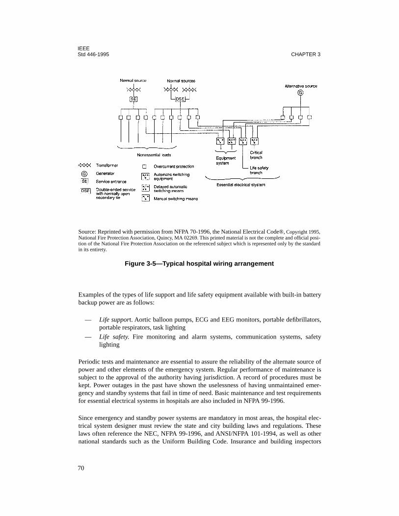
IEEEStd 446-1995 CHAPTER 3
Examples of the types of life support and life safety equipment available with built-in batterybackup power are as follows:
— Life support. Aortic balloon pumps, ECG and EEG monitors, portable defibrillators,portable respirators, task lighting
— Life safety. Fire monitoring and alarm systems, communication systems, safetylighting
Periodic tests and maintenance are essential to assure the reliability of the alternate source ofpower and other elements of the emergency system. Regular performance of maintenance issubject to the approval of the authority having jurisdiction. A record of procedures must bekept. Power outages in the past have shown the uselessness of having unmaintained emer-gency and standby systems that fail in time of need. Basic maintenance and test requirementsfor essential electrical systems in hospitals are also included in NFPA 99-1996.
Since emergency and standby power systems are mandatory in most areas, the hospital elec-trical system designer must review the state and city building laws and regulations. Theselaws often reference the NEC, NFPA 99-1996, and ANSI/NFPA 101-1994, as well as othernational standards such as the Uniform Building Code. Insurance and building inspectors
Source: Reprinted with permission from NFPA 70-1996, the National Electrical Code®, Copyright 1995,National Fire Protection Association, Quincy, MA 02269. This printed material is not the complete and official posi-tion of the National Fire Protection Association on the referenced subject which is represented only by the standardin its entirety.
Figure 3-5—Typical hospital wiring arrangement
70
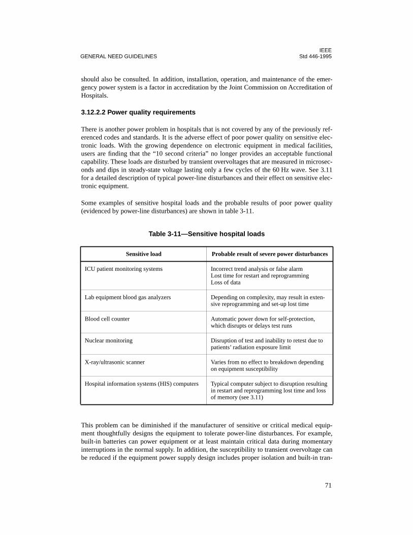
IEEEGENERAL NEED GUIDELINES Std 446-1995
should also be consulted. In addition, installation, operation, and maintenance of the emer-gency power system is a factor in accreditation by the Joint Commission on Accreditation ofHospitals.
3.12.2.2 Power quality requirements
There is another power problem in hospitals that is not covered by any of the previously ref-erenced codes and standards. It is the adverse effect of poor power quality on sensitive elec-tronic loads. With the growing dependence on electronic equipment in medical facilities,users are finding that the “10 second criteria” no longer provides an acceptable functionalcapability. These loads are disturbed by transient overvoltages that are measured in microsec-onds and dips in steady-state voltage lasting only a few cycles of the 60 Hz wave. See 3.11for a detailed description of typical power-line disturbances and their effect on sensitive elec-tronic equipment.
Some examples of sensitive hospital loads and the probable results of poor power quality(evidenced by power-line disturbances) are shown in table 3-11.
This problem can be diminished if the manufacturer of sensitive or critical medical equip-ment thoughtfully designs the equipment to tolerate power-line disturbances. For example,built-in batteries can power equipment or at least maintain critical data during momentaryinterruptions in the normal supply. In addition, the susceptibility to transient overvoltage canbe reduced if the equipment power supply design includes proper isolation and built-in tran-
Table 3-11—Sensitive hospital loads
Sensitive load Probable result of severe power disturbances
ICU patient monitoring systems Incorrect trend analysis or false alarmLost time for restart and reprogrammingLoss of data
Lab equipment blood gas analyzers Depending on complexity, may result in exten-sive reprogramming and set-up lost time
Blood cell counter Automatic power down for self-protection, which disrupts or delays test runs
Nuclear monitoring Disruption of test and inability to retest due to patients’ radiation exposure limit
X-ray/ultrasonic scanner Varies from no effect to breakdown depending on equipment susceptibility
Hospital information systems (HIS) computers Typical computer subject to disruption resulting in restart and reprogramming lost time and loss of memory (see 3.11)
71

IEEEStd 446-1995 CHAPTER 3
sient overvoltage protection. These preventive measures by the medical equipment manufac-turer are considered to be an efficient method of avoiding power quality-related problems.
Computer systems adapted to hospital applications typically do not have built-in protectionfrom power-line disturbances. Nevertheless, just as in the business sector, computer systemswill inevitably play a dominant role in hospitals. Organizations such as the Society for Com-puter Medicine provide a forum for identifying and putting into practice hospital computerapplications. These applications have been summarized as “patient care computing” andinclude patient monitoring, laboratory, radiology, diagnostic support, patient data base acqui-sition, patient scheduling, and so on.
With the increased dependence on computer systems in hospitals, more priority will certainlybe placed on supplying continuous and disturbance-free power in the future. For computersand other life safety and life support systems where it is impractical for the equipment manu-facturer to provide built-in solutions to power-quality problems, the user may find the needfor power interface systems in his facility. Power interface systems bridge the gap betweenequipment susceptibilities and power-line disturbances. For overvoltages or electrical noiseproblems, isolation transformers or transient suppressors may be an effective deterrent wheninstalled in the building power source. Required stored energy to ride-through low-voltageand momentary interruptions may be obtained from a power buffering motor-generator set or,when the need for power continuity warrants, an UPS (battery system). These interface sys-tems are addressed in Chapter 4 and stored energy systems in Chapter 5.
A large health-care facility involved in extensive life-support-related functions will probablyrequire a combination of both emergency power and power interface systems. In this case, acentral system approach to satisfy special power requirements may be more cost effectivethan one that addresses individual equipment separately.
It is strongly recommended that the user with an apparent power-quality problem consult andsecure the services of qualified engineers familiar with the unique power-quality require-ments of his facility.
3.12.3 Other critical life systems
Other critical life systems not necessarily unique to hospitals are subject to similar speciallaws and regulations regarding emergency power. Some examples follow:
— Controls for pressure vessels, such as boilers or ovens, where a failure may result in alife endangering explosion or fire
— Air supply systems for persons in a closed area— Fire pumps, alarms, and systems— Communications systems in hazardous areas— Industrial processes in which the interruption of power would create a hazard to life
To meet these or other specialized emergency power requirements, the assistance of an engi-neer who is experienced in the particular problem area should be obtained.
72

IEEEGENERAL NEED GUIDELINES Std 446-1995
3.13 Communication systems
3.13.1 Description
Communication systems are those facilities that require electric power for verbal, written, orfacsimile transmission and reception. Common systems of this type are
— Telephone— Facsimile— Teletypewriter— Paging— Radio— Television
Needs of one or all of the above communication systems during a power failure may well jus-tify the cost of one or more emergency and standby power systems, possibly in conjunctionwith any other critical loads.
3.13.2 Commonly used auxiliary power systems
Battery or battery and converter equipment are practical sources of power using a float-charg-ing system. Small engine generators are practical and economical. In the size ranges usuallyrequired from 1–5 kW, the installed cost ranges from about $1000/kW and up, dependingupon the quality of the equipment, battery life, gasoline storage problems, and amount ofautomatic equipment deemed to be necessary or convenient.
3.13.3 Evaluating the need for an auxiliary power system
The need of an emergency or standby power system for communications should include satis-factory answers to the following questions:
a) Will the communication equipment be required1) To issue orders for an orderly shutdown of processes and equipment?2) To announce instructions to personnel? A typical announcement might be to
wait by the machines or to check out for the duration of the shift.3) To call for help, issue warnings, and coordinate the work should there be a fire,
civil disturbance, vandalism, or other threat to personnel safety or plant secu-rity?
b) How will vital messages be received or sent for remote plants concerning production,inventory, or sales changes?
c) How will key personnel be found, or instructed; and how will these persons reportconditions to a central responsible source of control?
Many other questions may be asked, but the maintaining of communications under emer-gency conditions will save vital time and expedite the return to normal conditions withreduced confusion.
73
IEEEStd 446-1995 CHAPTER 3
For industrial plants, the telephone system is usually powered both regularly and on a standbyand emergency basis by the telephone company, normally by batteries or by standby genera-tion. In some plants there is a separate in-plant telephone system that may be powered by bat-teries under a float charge that will maintain the communication system for several hoursduring a prolonged power interruption. The user should check to see that his system willfunction for the required time with loss of normal power.
Usually various bells, horns, and other call devices connected to the telephone system arepowered by the lighting circuits and will stop functioning if there is a power interruption,even though the receiver and transmitter work. If required, these should be wired to thebackup power system.
Teletype equipment functions much the same as the telephone system so that the signal maybe present but the printout device will not operate without local power.
Paging systems in plants are frequently extensive, using many hundreds of watts of audiopower and several kilowatts of 120 V power. The need to use the system during a power inter-ruption should not be overlooked.
Radio systems are common in industrial plants. While the mobile units for personnel as wellas in-plant and out-of-plant car and truck units are generally self-powered by batteries, themain base station usually is connected to the nearest commercial power source. While mobileunits may or may not be able to speak to each other, the system as a whole usually stops func-tioning if the base station power fails. Consideration of emergency and standby power for thisbase station should not be overlooked.
In some plants and commercial buildings, paging or broadcasting is done by dialing throughthe telephone system. In this case, both the telephone and paging or radio systems should besupplied with emergency power.
3.14 Signal circuits
3.14.1 Description
A signal circuit supplies power to a device that gives a recognizable signal. Such devicesinclude bells, buzzers, code-calling equipment, lights, horns, sirens, and many other devices.
3.14.2 Signal circuits in health care facilities
Signal circuits in medical buildings that should be provided with continuous emergencypower within 10 s (ANSI/NFPA 101-1994) include the following:
a) Fire alarm systems:1) Manually initiated2) Automatic fire detection3) Water flow alarm devices used with sprinkler systems
74
IEEEGENERAL NEED GUIDELINES Std 446-1995
b) Alarms required for systems used for piping of nonflammable medical gasc) Paging systemd) Nurse’s station signaling system from patient arease) Alarm systems attached to equipment required to operate for the safety of major
apparatusf) Signaling equipment for elevators in buildings of more than four stories
3.14.3 Signal circuits in industrial and commercial buildings
Signal circuits for commercial buildings and industrial plants that may require continuousemergency power within 1 min include the following:
a) Fire alarm systemb) Watchman’s tour systemc) Elevator signal systemd) Door signals (into restricted areas such as boiler rooms and laboratories with electric
door locks)e) Liquid level, pressure, and temperature indications
3.14.4 Types of auxiliary power systems
The emergency supply for the signal circuits can be engine-driven generators, multiple utilityservices, or floating battery systems with auxiliary power. Most signal circuits operate downto 70% rated voltage and therefore require no special voltage-sensing relays on the transferdevice.
It is recommended that an emergency source of electric power be supplied for every part of afire alarm and security system. A local battery supply on float charge, close to the powerneed, in continuous service is very reliable. A usually acceptable substitute is an automatictransfer to a battery system when prime power fails.
Signal circuits are usually a small electrical burden and integral part of a total load that alsorequires an emergency source. Therefore, the selection of emergency system and hardwaregenerally depends upon the requirement of other related loads.
3.15 References
This chapter shall be used in conjunction with the following publications:
ANSI C84.1-1989, American National Standard Voltage Ratings for Electric Power Systemsand Equipment (60 Hz).3
ANSI/NEMA MG 1-1993, Motors and Generators.4
3ANSI publications are available from the Sales Department, American National Standards Institute, 11 West 42ndStreet, 13th Floor, New York, NY 10036, USA.4NEMA publications are available from the Sales Department, American National Standards Institute, 11 West 42ndStreet, 13th Floor, New York, NY 10036, USA.
75
IEEEStd 446-1995 CHAPTER 3
ANSI/NFPA 30-1993, Flammable and Combustible Liquids Code.5
ANSI/NFPA 101-1994, Code for Safety to Life from Fire in Buildings and Structures.
ANSI/NFPA 110-1993, Emergency and Standby Power Systems.
ANSI/NFPA 111-1993, Stored Electrical Energy Emergency and Standby Power Systems.
ANSI/UL 924-1990, Safety Standard for Emergency Lighting and Power Equipment.6
California Administrative Code, Title 24, Part 3, Basic Electrical Regulations, Article E700,Emergency Systems, Document Section, Sacramento, CA.7
EGSA 101G-1995, Electrical and Mechanical Terminology and Definitions.8
IEEE Std 100-1992, The New IEEE Standard Dictionary of Electrical and Electronics Terms(ANSI).9
IEEE Std 141-1993, IEEE Recommended Practice for Electric Power Distribution for Indus-trial Plants (IEEE Red Book) (ANSI).
IEEE Std 241-1990, IEEE Recommended Practice for Electric Power Systems in Commer-cial Buildings (IEEE Gray Book) (ANSI).
IEEE Std 493-1990, IEEE Recommended Practice for the Design of Reliable Industrial andCommercial Power Systems (IEEE Gold Book) (ANSI).
IEEE Std 500-1984 (Reaff 1991), IEEE Guide to the Collection and Presentation of Electri-cal, Electronic, Sensing Component, and Mechanical Equipment Reliability Data for NuclearPower Generating Stations (ANSI).
IEEE Std 1100-1992, IEEE Recommended Practice for Powering and Grounding SensitiveElectronic Equipment (The Emerald Book) (ANSI).
NFPA 70-1996, National Electrical Code®.
NFPA 99-1996, Health Care Facilities Code.
5NFPA publications are available from the Sales Department, American National Standards Institute, 11 West 42ndStreet, 13th Floor, New York, NY 10036, USA.6UL publications are available from Underwriters Laboratories, Inc., 333 Pfingsten Road, Northbrook, IL 60062-2096, USA.7This document can be obtained from the Department of General Services, P.O. Box 1015, North Highlands, CA95660, USA.8EGSA publications are available from the Electrical Generating Systems Association, 10251 W. Sample Rd., SuiteB, Coral Springs, FL 33065, USA.9IEEE publications are available from the Institute of Electrical and Electronics Engineers, 445 Hoes Lane, P.O. Box1331, Piscataway, NJ 08855-1331, USA.
76
IEEEGENERAL NEED GUIDELINES Std 446-1995
Occupational Safety and Health Act (OSH Act) of 1970 (29 USC 651 et seq.), Public LawNo. 91-596, Chapter XVII of Title 29 (Labor) of The Code of Federal Regulations, Parts1900-1999, established on April 13, 1970 (36 FR 7006) as amended by Public Law No. 101-552, Nov. 5, 1990. Amendments to Occupational Safety and Health Act of 1970, as publishedin the Federal Register, Washington, DC, Office of the Federal Register, National Archivesand Records Service, General Services Administration.10
Standard Building Code, Southern Building Code Congress International.11
Uniform Building Code, International Congress of Building Officials.12
3.16 Bibliography
Additional information may be found in the following sources:
[B1] Beeman, D. L., Ed., Industrial Power Systems Handbook. New York: McGraw-Hill,1955.
[B2] Burch, B. F., Jr., “Protection of Computers against Transients, Interruptions, and Out-ages,” Presented at the 1967 IEEE Industry and General Applications Group Annual Meeting,Pittsburgh, PA, Oct. 4, 1967.
[B3] Castenschiold, R., “Criteria for Rating and Application of Automatic TransferSwitches,” IEEE Conference Record of 1970 Industrial and Commercial Power Systems andElectric Space Heating and Air-Conditioning Joint Technical Conference, IEEE 70C8-1GA,pp. 11–16.
[B4] EGSA 109C-1994, Safety Codes Required by States and Major Cities.
[B5] Ferency, N., “Is a UPS Really Necessary?” Electronic Products Magazine, pp. 126–127,Apr. 17, 1972.
[B6] Fischer, E. I., “Emergency Power Facilities for a Research Laboratory,” ConferenceRecord of the 1966 IEEE Industry and General Applications Group Annual Meeting, IEEE34-C36, pp. 305–324.
[B7] Funk, D. G., and Beatty, J. M., Standard Handbook for Electrical Engineers, 12th ed.,New York: McGraw-Hill, 1987, Section 21.
10This publication is available from the Publications Dept., Occupational Safety and Health Administration (OSHA),200 Constitution Ave., NW, Washington, DC 20210.11This publication is available from the Southern Building Code Congress International, 900 Montclair Rd., Bir-mingham, AL 35213.12This publication is available from the International Conference of Building Officials, South Workman Mill Rd.,Whittier, CA 90601.
77
IEEEStd 446-1995 CHAPTER 3
[B8] Gilbert, M. M., “What the Chemical Industry Can Do to Minimize Effects from Electri-cal Disturbances,” Presented at the AIEE and ASME National Power Conference, Paper CP60-1161, Philadelphia, PA, Sept. 21–23, 1960.
[B9] Heising, C. R., and Dunki-Jacobs, J. R., “Application of Reliability Concepts to Indus-trial Power Systems,” Conference Record of the 1972 IEEE Industrial Applications SocietyAnnual Meeting, IEEE 72CH0685-81A, pp. 289–295.
[B10] IEEE Committee Report, “Protection Fundamentals for Low-Voltage Electrical Distri-bution Systems in Commercial Buildings,” IEEE JH 2112-1, 1974.
[B11] Jenkin, M. A., “Functions of Patient Care Computing,” Medical Instrumentation, vol.12, July–Aug. 1978.
[B12] Kaufman, J. E., Ed., IES Lighting Handbook. New York: Illuminating EngineeringSociety, 1972, Section 14, pp. 14-10 to 14-12.
[B13] Katz, E. G., “Evaluation of Hospital Essential Electrical Systems,” Fire Journal, vol.62, Nov. 1968.
[B14] Key, T. S., “Diagnosing Power Quality Related Computer Problems,” IEEE I-CPSConference Record, 78CH1302-91A, pp. 48–56, June 1978.
[B15] Knight, R. L., and Yuen, M. H., “The Uninterruptible Power Evolution—Are OurProblems Solved?” Conference Record of the 1973 IEEE Industry Applications SocietyAnnual Meeting, IEEE 73CH0763-31A, pp. 481–485.
[B16] Miller, N. A., “Noninterruptible Power Supplies for Essential Control Systems inPower Plants,” Presented at the IEEE IAS–IEC Group Meeting on Heating, Chicago Chapter,June 7, 1972.
[B17] Oliver, R. L., “Plant Engineering at RCA,” Plant Engineering, Apr. 1969.
[B18] Readers Digest Almanac. Pleasantville, NY: The Readers Digest Association, 1972,p. 790.
[B19] Smith, D. R., Swanson, S. R., and Borst, J. D., “Overvoltages with Remotely SwitchedCable-Fed Grounded Wye-Wye Transformers,” IEEE Conference Record, 1975 Winter PowerMeeting, New York, NY.
[B20] Tucker, R. Line Voltage Regulators, “Less Costly Alternative to UPS,” Electrical Con-sultant, Aug. 1974.
78
Chapter 4Generator and electric utility systems
4.1 Introduction
4.1.1 Overview
When an equipment problem is experienced, due to failure of the electric power supply, theoptions are to either tolerate the problem and do nothing, modify the equipment or system toperform satisfactorily during a power failure, or alter or supplement the power supply to pre-vent potential occurrences of failure. In many cases, the best decision is to modify the equip-ment or system, but this chapter does not examine these cases.
If the electric power user’s study has shown that the most beneficial approach is to alter orsupplement the power supply source, another study should be undertaken to determine theproper systems, configuration, and hardware that will meet the determined power require-ments for the lowest cost.
This chapter describes combinations of systems and hardware that have been proven reliablein preventing the following types of electric power failure:
— Long-time interruption (hours)— Medium-time interruption (minutes)— Short-time interruption (seconds)— Over- or undervoltage— Over- or underfrequency
4.1.2 Guidelines for use
Emergency power systems are of the following two basic types:
— An electric power source separate from the prime source of power, operating in paral-lel, that maintains power to the critical loads should the prime source fail
— An available reliable power source to which critical loads are rapidly switched auto-matically when the prime source of power fails
Standby power systems are made up of the following main components:
— An alternative reliable source of electric energy separate from the prime powersource
— Starting and regulating control if on-site standby generation is selected as the source— Controls that transfer loads from the prime or emergency power source to the standby
source
79
IEEEStd 446-1995 CHAPTER 4
For reasons of economy, the user would be prudent to establish, from the previous chapters ofthis recommended practice, specific needs for emergency and standby power before specify-ing and purchasing equipment, since equipment costs are proportional to the followingrequirements and specifications:
— Longer equipment life— Increased capacity— Closer frequency regulation— Closer voltage regulation— Freedom from voltage or frequency transients— Increased availability— Increased reliability— Increased temporary overload capability— Quiet operation— Safety from fuel hazards— Pollution-free operation— Freedom from harmonics— Close voltage and frequency regulation with wider-range rapid load changes
Consideration should be given to load growth. Future power requirements frequently need tobe connected to the emergency and standby system. It may be desirable to add additionalexisting power loads to the more reliable power bus as soon as the advantages are realized inpractice. If additional capacity cannot be justified initially, the equipment and system shouldbe selected and designed for future economic expansion compatible with the initial installa-tion.
Operating costs of the systems and hardware are usually secondary to the initial costs of pur-chasing equipments, but should be included as a factor in the selection. These include cost offuel, inspection frequency, ease of maintenance, frequency of testing, cost of parts, and taxes.
Installation quality should be high to prevent losing the reliability of electric power designedinto the system and purchased in the hardware (IEEE Committee Report 1974 [B6]).1 Oneshould guard against introducing voltage transients into the emergency and standby powerdistribution system. Satisfactory voltage levels should be maintained under all loading condi-tions.
For industrial plants, electric systems should conform to IEEE Std 141-1993.2 For commer-cial buildings, electric systems should conform to IEEE Std 241-1990. Grounding practicesshould follow the recommendations in IEEE Std 142-1991 and Chapter 7 of this book. Addi-tional shielding, bonding, grounding, and even filtering may be required to maintain the qual-ity of the emergency and standby power supply.
When energized sources of power are available for emergency use, a light should be includedin the system to show that the source is energized and an alarm, to signal loss of available
1The numbers in brackets preceded by the letter B correspond to those of the bibliography in 4.7.2Information on references can be found in 4.6.
80
IEEEGENERATOR AND ELECTRIC UTILITY SYSTEMS Std 446-1995
power. These should be located where responsible persons can take action, should an alarmsound. An alternate utility source (see 4.3) or battery system is typical of line sources nor-mally requiring these signals.
Users should take these additional steps to assure performance reliability:
— Establish regular inspections using a check sheet and recording exceptions;
— Perform regular preventive maintenance and repair items of exceptions found duringthe inspections;
— Set up a trial at regular intervals simulating a power failure but timed so as not toencounter hazards or losses should the system not operate as anticipated.
There are mathematical methods for quantitatively determining the reliability of an emer-gency or standby power system. Once the need is established, it may be advisable to calculatethe system reliability, especially for emergency systems involving possible injury or loss oflife. One such method is detailed in both Heising and Johnston 1972 [B5] and in Sawyer1972 [B10].
4.2 Engine-driven generators
4.2.1 Introduction
These units are “work horses” that fulfill the need for emergency and standby power. Theyare available from small 1 kVA units to those of several thousand kVA. When properly main-tained and kept warm, they dependably come on line within 8–15 s. In addition to providingemergency power, engine-driven generators are also used for handling peak loads and aresometimes used as the preferred source of power.
They fill the need of back-up power for uninterruptible power systems. Where well-regulatedsystems, free from voltage, frequency, or harmonic disturbances, are required, such as forcomputer operations, a buffer may be needed between the critical load and the engine-drivengenerators.
4.2.2 Diesel-engine generators
A typical diesel engine-driven generator rated 500 kW is shown in figure 4-1. Typical ratingsof engine-driven generator sets are given in table 4-1. Individual models by various compa-nies may be different. Lower speed units are heavier and more costly, but are more suitablefor continuous duty.
Diesel engines are somewhat more costly and heavier in smaller sizes, but are rugged anddependable. The fire and explosion hazard is considerably lower than for gasoline engines.Sizes vary from about 2.5 kW to several MW.
81
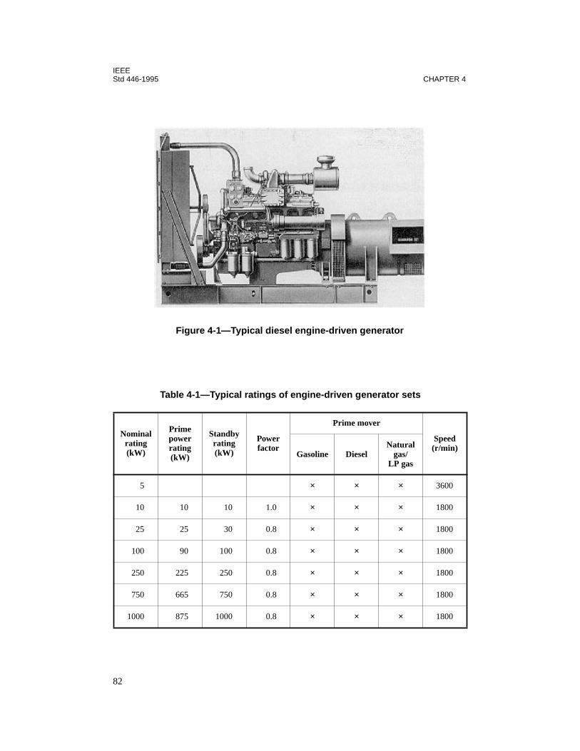
IEEEStd 446-1995 CHAPTER 4
Table 4-1—Typical ratings of engine-driven generator sets
Nominal rating(kW)
Prime power rating(kW)
Standby rating(kW)
Power factor
Prime mover
Speed(r/min)
Gasoline DieselNatural
gas/LP gas
5 × × × 3600
10 10 10 1.0 × × × 1800
25 25 30 0.8 × × × 1800
100 90 100 0.8 × × × 1800
250 225 250 0.8 × × × 1800
750 665 750 0.8 × × × 1800
1000 875 1000 0.8 × × × 1800
Figure 4-1—Typical diesel engine-driven generator
82

IEEEGENERATOR AND ELECTRIC UTILITY SYSTEMS Std 446-1995
4.2.3 Gasoline-engine generators
Gasoline engines may be furnished for installations up to about 100 kW output. They startrapidly and are low in initial cost as compared to diesel engines. Disadvantages include ahigher operating cost, a greater hazard due to the storing and handling of gasoline, short stor-age life of the fuel, and generally a lower mean-time between overhaul. The short fuel storagelife restricts gasoline engines’ use for emergency standby.
4.2.4 Gas-engine generators
Natural gas and liquid petroleum (LP) gas engines rank with gasoline engines in cost and areavailable up to about 600 kW and higher. They provide quick starting after long shutdownperiods because of the fresh fuel supply. Engine life is longer with reduced maintenancebecause of the clean burning of natural gas. However, consideration should be given to thepossibility of both the electric utility and the natural gas supply being concurrently unavail-able. Unless engine compression ratios are increased, engines lose approximately 15% inpower when operated on natural gas, compared to gasoline. Considerations in selecting natu-ral or LP gas-fueled engines are the availability and dependability of the fuel supply, espe-cially in an emergency situation. Reference should be made to the National Electrical Code(NEC) (NFPA 70-1996), Sections 700-12 and 700-11, to determine whether an on-site fuelsupply is required.
4.2.5 Derating requirements
As noted in figure 4-30 in 4.4.3, altitude will cause a serious derating of the prime mover todeliver the torque required for the full generator output. Oversizing of the engine is a must forhigher altitudes. The generators are less critical in output capacity if adequate cooling air issupplied to carry away the heat generated by the losses.
A general rule for derating engine power loss with altitude increase is to derate about 4% foreach 1000 ft increase in altitude. Turbo-charged engines usually do not need to be deratedbelow a specified minimum altitude, typically 2500–5000 ft above sea level. Also, an averagederating factor for high ambient temperature is 1% for each 10 °F above 60 °F. Temperaturederating is not considered as important as altitude derating.
4.2.6 Multiple engine-generator set systems
Automatic starting of multiple units and automatic synchronizing controls are available andpractical for multiple unit installations. Advantages of several smaller units over one largeunit should be considered since emergency and standby power can be available while one unitis being maintained or overhauled. Starting is usually reliable; especially if the units arewarm and maintained by regular exercising, the likelihood of all of the units not starting isextremely low as compared to a single unit.
Smaller units also allow the “building block” concept. As capital is made available and theneed of increased capacity grows, additional units of identical size and type may be added,thus simplifying the parts, maintenance, and training problems. The trend toward larger emer-
83
IEEEStd 446-1995 CHAPTER 4
gency power supplies also justifies the use of multiple sets to provide the additional power.Figures 4-2, 4-3, 4-4, and 4-5 illustrate typical multiple-set systems.
One very important consideration in the selection of smaller versus larger units is the serviceto which they will be subjected. Smaller units are nearly all higher speed (1800 r/min)engine-driven sets, and if these units are to be run continuously for long periods of time, theengine should be evaluated very thoroughly. Refer to table 4-1 for the comparison betweenprime power and standby ratings. Units may be operated at the standby rating for the durationof a power outage but should not be used at that rating for continuous operation. Generatorsfor standby use are frequently operated at higher output and temperature rise than are thosefor continuous use.
4.2.7 Construction and controls
The basic electrical components are the engine-generator set and associated meters, controls,and switchgear. Most installations include a single generator set designed to serve either allthe normal electrical needs of a building or a limited emergency circuit. Sometimes the sys-tem includes two or more generators of different types and sizes serving different types ofloads. Also, two or more generators may be operating in parallel to serve the same load.
4.2.8 Typical engine-generator systems
This information is designed to help in selecting the electrical components of a generatorinstallation. No attempt has been made to cover every situation that might arise.
The figures in this chapter show a circuit breaker at each generator set. The NEC, Article 445,permits a number of forms of generator protection, including inherent protection. Therefore,a circuit breaker or other form of overcurrent protection may or may not be used. For an in-depth discussion of generator protection, see Chapter 6.
In figures 4-2, 4-3, 4-4, 4-5, and 4-6, the following abbreviations are used:
— ATD = automatic transfer device (automatic transfer switch or electrically operatedcircuit breaker)
— CB = circuit breaker
— EG = engine-driven generator set
— LDC = load-dumping contactor, electrically operated, mechanically field
— PC = paralleling contactor
Figure 4-2 shows a standby power system in which, if power fails from the normal source,both engines automatically start. The first generator to reach operating voltage and frequencywill actuate load dumping circuits and cause the remaining load to transfer to this generator.When the second generator is in synchronism, it will be paralleled automatically with thefirst. After the generators are paralleled, all or part of the dumped load is reconnected if thestandby capacity is adequate.
84
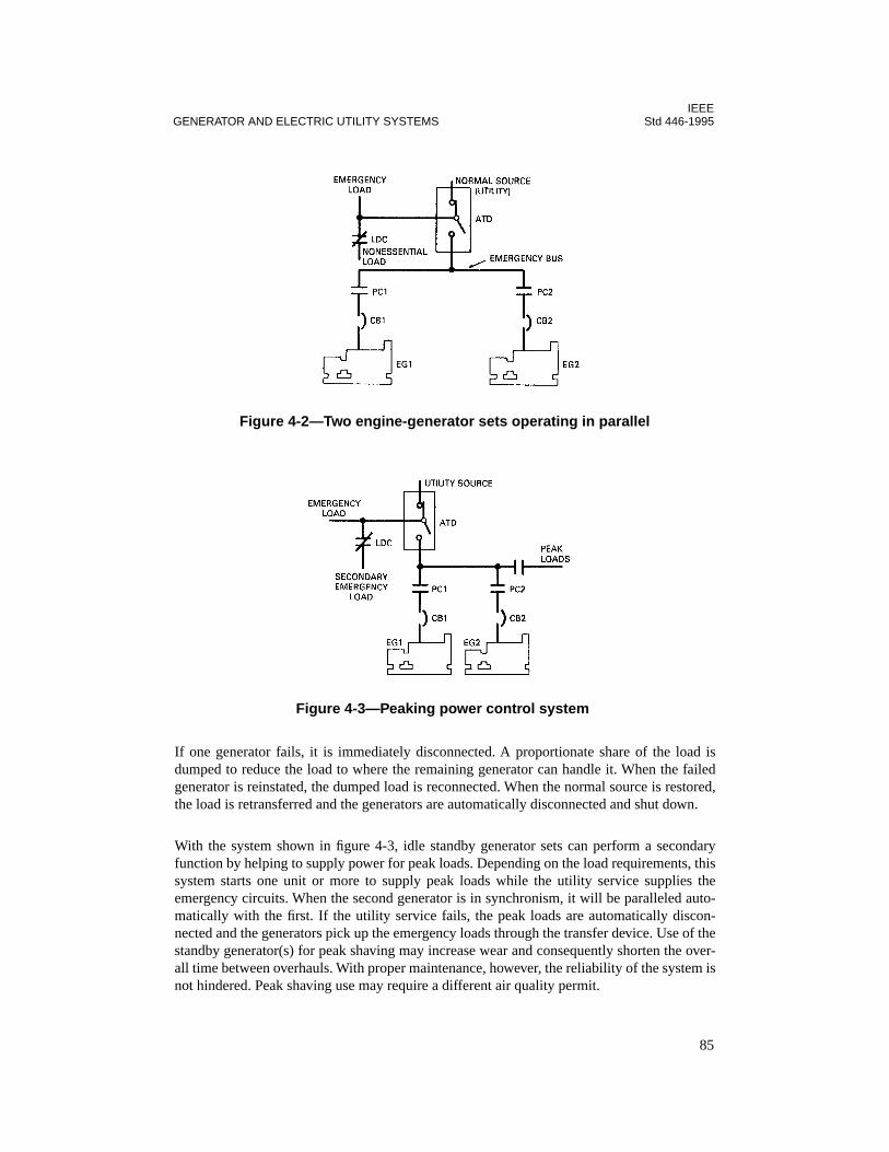
IEEEGENERATOR AND ELECTRIC UTILITY SYSTEMS Std 446-1995
If one generator fails, it is immediately disconnected. A proportionate share of the load isdumped to reduce the load to where the remaining generator can handle it. When the failedgenerator is reinstated, the dumped load is reconnected. When the normal source is restored,the load is retransferred and the generators are automatically disconnected and shut down.
With the system shown in figure 4-3, idle standby generator sets can perform a secondaryfunction by helping to supply power for peak loads. Depending on the load requirements, thissystem starts one unit or more to supply peak loads while the utility service supplies theemergency circuits. When the second generator is in synchronism, it will be paralleled auto-matically with the first. If the utility service fails, the peak loads are automatically discon-nected and the generators pick up the emergency loads through the transfer device. Use of thestandby generator(s) for peak shaving may increase wear and consequently shorten the over-all time between overhauls. With proper maintenance, however, the reliability of the system isnot hindered. Peak shaving use may require a different air quality permit.
Figure 4-2—Two engine-generator sets operating in parallel
Figure 4-3—Peaking power control system
85

IEEEStd 446-1995 CHAPTER 4
Figure 4-4 shows a standby power system where there is a split emergency load with one loadbeing more critical than the other.
When the prime source fails, both generators start. If Load 1 is the preferential load, the gen-erator that reaches operating speed first is put on the line by ATD3 to feed Load 1 throughATD1. When the other generator reaches operating speed, it then feeds Load 2. If the genera-
Figure 4-4—Three-source priority load selection system
Figure 4-5—Combination on-site power and emergency transfer system
86

IEEEGENERATOR AND ELECTRIC UTILITY SYSTEMS Std 446-1995
tor feeding Load 1 fails at any time, the other generator will be transferred from Load 2 andtake over Load 1. When the prime source is restored, both loads are retransferred to the nor-mal source and the generators shut down.
The system shown in figure 4-5 provides switching and control of utility and on-site power.Two on-site buses are provided: (1) an on-site power bus (preferred) supplies continuouspower for computer or other essential loads, and (2) an emergency bus (secondary) supplieson-site generator power to emergency loads through an automatic transfer device if the utilityservice fails.
In normal operation, one of the generators is selected to supply continuous power to the pre-ferred bus (in figure 4-5, EG1). Simplified semiautomatic synchronizing and paralleling con-trols permit any of the idle generators to be started and paralleled with the running generatorto change generators without load interruption. Anticipatory failure circuits for low oil pres-sure and high coolant temperature permit load transfer to a new generator without load inter-ruption. However, if the generator enters a critical failure mode, transfer to a new generator ismade automatically with load interruption.
Many loads, such as lighting, fire alarms, heating, and air-conditioning, are fed by the utilityservice through the transfer device. If the utility fails, idle generators are automaticallystarted and assume these loads through the automatic transfer device.
Figure 4-6 is similar to figure 4-3 wherein idle standby generator sets can perform a second-ary function by helping to supply power for peak loads. Depending on the load requirements,this system starts one or both generators to feed the peak load by switching ATD2 while theutility service continues to supply the emergency and prime loads. The second generator isparalleled automatically with the first.
If the utility service fails, the emergency and prime loads are automatically transferred to theemergency generators. Depending on generator capacity, the peaking load may be left on, orCB5 may be dropped for the emergency.
Figure 4-6—Dual engine-generator standby system
87

IEEEStd 446-1995 CHAPTER 4
4.2.9 Special considerations
Unusual conditions of altitude, ambient temperature, or ventilation may require either alarger generator to hold down winding temperatures or special insulation to withstand highertemperatures. Generators operating in the tropics are apt to encounter excessive moisture,high temperature, fungus, vermin, etc., and may require special tropical insulation and spaceheaters to keep the windings dry and the insulation from deteriorating.
4.2.10 Engine-generator set rating
For some buildings the maximum continuous generator load will be the total load when allequipment in the building is operating. For others, it may be more practical and economicalto set up an emergency circuit or circuits so that only certain essential lights and equipment,and perhaps just one elevator, can be operated when the load is on the standby generator. Ref-erence should be made to NEC, Sections 700-5 and 701-6, to determine whether an on-sitefuel supply is required.
4.2.11 Motor-starting considerations
The successful start of a motor on an engine-driven generator requires that the motor devel-ops enough torque for its driver’s load and the system voltages be maintained above criticallimits. Most motors behave as a constant impedance load during starting, which means thatstarting torque is proportional to the square of the terminal voltage. If the terminal voltage ofa motor during startup is 80% of its rated value, the starting torque is 64% of its rated locked-rotor torque. Therefore, the purpose of a motor-starting study is to find a maximum voltagedip that the system and the motor can withstand.
Since the starting power factor of motors is low (typically from 20% to 50%) and locked-rotor currents are high (typically from 500% to 700%), the starting power demand of motorsis mostly reactive and can be as high as ten times the full load reactive power demand of themotor. For example, a 100 hp motor with 600% LRC, 80% full-load PF and 20% starting PFwill require the following complex power (kW and kvar) from the system at full-load (FL)and starting (LR) conditions (assuming full-load kVA = hp, and the system impedance is neg-ligible):
SFL(kVA) = 100(0.8 + j 0.6 ) = 80 + j 60
SLR(kVA) = 600(0.2 + j 0.98 ) = 120 + j 588
kvarLR
kvarFL---------------- 588
60--------- 9.8= =
kWLR
kWFL-------------- 120
80--------- 1.5= =
88
IEEEGENERATOR AND ELECTRIC UTILITY SYSTEMS Std 446-1995
Depending on the size of the motor with respect to the engine generator, motor starting canrepresent a small or a large disturbance to the generator. In extreme cases, starting a verylarge motor can be almost as severe as a short-circuit condition for the generator. Under ashort-circuit condition, the generator reactance jumps down from its steady-state value (
Xd
)to subtransient value (
Xd
″
) and then changes to transient value (
Xd
′
) and gradually back to itssteady-state value (
Xd
). Therefore, to correctly model a motor acceleration on an engine gen-erator, the generator model should include its field and damper windings, so that both thesubtransient and transient behaviors are modeled. In additon to this, the rotor model used forthe motor should include the effect of speed on the rotor reactance and resistance. This meansthat a transient stability program, which can include the effect of generator excitor and gover-nor systems, should be used for motor acceleration studies.
For a snapshot study where the objective is to calculate the maximum voltage dip duringstarting, simple models for the generator and motor can be used. For this purpose, the genera-tor can be modeled as a constant voltage source behind its transient reactance and the startingmotor is modeled as a constant locked-rotor impedance.
Engines driving generators should be sized to handle the continuous kW load, plus motorstarting requirements and the generator losses. It is important to note in the example calcula-tion above that the initial starting kW exceeds the kW
FL
by 50%. During acceleration the kWrequirement may become twice the initial requirement when the motor reaches breakdownspeed, as determined by the breakdown torque rating. The generator engine must be capableof driving the starting kW requirements. In sizing the engine generators for motor starting,the locked-rotor kVA rating of the motors should be compared with the maximum motor-starting kVA capability of the generator. Manufacturers’ data can usually be obtained, givingthe maximum rating in kVA of the engine generator as well as its continuous rating. The max-imum starting kvar rating would be the maximum amount of the short-duration kVA availablefor motor-starting duty without exceeding a specified voltage dip.
Generator set manufacturers are usually willing to furnish a guide for calculating motor-start-ing effects. A rule of thumb of 0.5 hp/kW is frequently used; however, the final decisionshould be based upon the manufacturer’s data. When motor-starting kVA or continued kWexceed the rated values of the generator set, the effects of the resulting voltage and frequencydeviation on equipment other than the motor being started should be evaluated (that is, motorstarters, relays, computers, communication equipment, etc.).
Generators are usually sized for the maximum continuous kVA demand. Should there be unu-ally high inertia loads to start without benefit of reduced-voltage starting, or if voltage andfrequency regulation other than specified cannot be tolerated during the startup period, ahigher rated generator may be required.
4.2.12 Load transient considerations
A voltage regulator with sufficient response is required to minimize voltage sags or surgesafter load transients. The engine-generator set should be of sufficient capacity and designcapability to minimize the effect of load transients. Many industrial applications can toleratelarge voltage sags (usually down to 80%, but as low as 65% in special cases) as long as they
89
IEEEStd 446-1995 CHAPTER 4
are not so low as to cause motor contactors to drop out or automatic brakes to set. Solid-statecontrols and computers may be affected. The effect of non-linear loads on the generator setcontrols should be evaluated.
4.2.13 Manual systems
Manually controlled standby service is the simplest and lowest cost arrangement and may besatisfactory where an attendant is on duty at all times and where automatic starting and trans-fer of the load is not a critical requirement.
4.2.14 Automatic systems
In order for engine-driven generators to provide automatic emergency power, the systemshould also include automatic engine starting controls, automatic battery charger, and anautomatic transfer device. In most applications, the utility source is the normal source and theengine-generator set provides emergency power when utility power is interrupted or its char-acteristics are unsatisfactory. The utility power supply is monitored and engine starting isautomatically initiated once there is a failure or severe voltage or frequency reduction in thenormal supply. The load is automatically transferred as soon as the standby generator stabi-lizes at rated voltage and speed. Upon restoration of normal supply, the transfer device auto-matically retransfers the load and initiates engine shutdown. See 4.3.8 for specialconsideration in retransferring motor loads.
4.2.15 Automatic transfer devices
Transfer equipment for use with engine generator sets is similar to that used with multiple-utility systems, except for the addition of auxiliary contacts that close when the normalsource is interrupted. These auxiliary contacts initiate the starting and stopping of the engine-driven generator. The automatic transfer device may also include accessories for automaticexercising of the engine-generator set and a 5 min unloaded running time before shutdown.For additional information on automatic transfer devices, refer to 4.3.
4.2.16 Engine-generator set reliability
To keep the engine in good condition, whenever it starts it should run for a sufficiently longtime so that all parts reach their normal operating temperatures. In case emergency power iscalled for only briefly, it is desirable that the engine continue to run for about 15 min afternormal power has been restored. A programmed control should be added that starts theengine once a week and operates it for a set period of time under load.
Reliability and satisfaction of the standby power supply partially depends on the engine gen-erator installations. The following key points should be considered:
a) Systems dependent upon a municipal water supply are not dependable because thesupply can be interrupted in an emergency. A radiator cooling system or a heatexchanger cooled system with an independent cooling water supply should be speci-fied.
90
IEEEGENERATOR AND ELECTRIC UTILITY SYSTEMS Std 446-1995
b) Antifreeze protection may be required. A room heater, electric immersion heater, orsteam jacket improves starting reliability and solves the antifreeze problem at thesame time. A loss-of-heat alarm may be required.
c) A silencer on the intake and exhaust may be required by law and will reduce noiselevels.
d) Fuel supply systems must meet local laws, regulations, and insurance requirements.The capacity stored depends on available guaranteed quick delivery replacement,including Sundays and holidays and under all weather conditions.
e) Fuel supplies stored underground are desirable. Above ground, antifreeze protectionmay be required.
f) Gasoline and diesel fuels deteriorate if they stand unused for a period of severalmonths. Normal testing and running on line may be used to keep fuel fresh. Inhibitorsmay be added to the fuel. Fuel used for several purposes will tend to be fresh. A fueltest program should be established to ensure fuels are fresh and reliable.
g) Engine vibration transferred to the building should be dampened by rubber pads orsprings, and flexible couplings should be used on fuel, exhaust, water, and conduitlines.
h) Equipment mounting should conform to local seismic requirements.
i) Starting aids are of three types, of which item 3) is frequently preferred:
1) Air heated before it reaches the cylinders
2) Volatile starting fluid injected into the engine air
3) Engine block maintained warm
4.2.17 Air supply and exhaust
Exhaust piping inside the building should be covered with gas-tight insulation to protect per-sonnel and to reduce room temperature. The exhaust piping must be of sufficient diameter toavoid exhaust back pressure. Consideration should be given to dissipating the exhaust awayfrom air intakes and minimizing air pollution.
Some means of providing free flow of fresh air into the generator room is necessary to keepthe atmosphere comfortable for personnel and to make clean, cool air available to the engine.The most effective and lowest-cost method is usually to use a
pusher
-type fan on the radiatorand connect the radiator to the outside through a duct. The intake opening should be approxi-mately 25–50% larger than the duct.
4.2.18 Noise reduction
Vibration must frequently be isolated from structures to reduce noise. Noise-reducing muf-flers are rated according to their degree of silencing by such terms as
industrial
,
residential
,or
critical
, and are usually required to meet noise standards. An intake muffler is not usuallyinstalled since an engine normally is supplied with at least one intake air cleaner that alsoserves as an intake silencer.
91
IEEEStd 446-1995 CHAPTER 4
4.2.19 Fuel systems
To simplify the fuel supply system, the fuel tank should be as close to the engine as possible.When gasoline or LP fuel is used, it normally cannot be stored in the same room with theengine because there is a danger of fire or fumes. However, when diesel fuel is used, it cansometimes be stored in the same room as the engine. If a remote tank is used, a transfer tanklocated near the engine is recommended. The building code or fire insurance regulationsshould be checked to determine whether the fuel storage tank may be located beside the gen-erator set, in an adjacent room, outside, or underground.
An engine equipped to operate on gasoline, LP gas, or diesel fuel stored on-site is a self-con-tained system that does not depend on outside municipal or utility services. It is dependableand affords independent standby protection.
4.2.20 Governors and regulation
Governors work in droop or isochronous modes of operation. In a droop mode, the engine’sspeed decreases as the load increases, while in an isochronous mode the governor maintainsthe same stead speed at any load, up the the full load:
Typical speed droop setting for a droop-operated generator is 3–5%. Thus if speed and fre-quency at full load are 1800 r/min and 60 Hz, respectively, at no load they will be 1872 r/minand 62.4 Hz, with 4% droop.
When a generator is parallel with the system for maintenance periods, the governor is set ondroop mode, i.e., it is base-loaded. Under an isolated condition, it is desirable to operate thegovernor under an isochronous mode so that the system frequency is kept constant.
Under steady load, frequency tends to vary slightly above and below the normal frequencysetting of the governor. The extent of this variation is a measure of the stability of the gover-nor. An isochronous governor should maintain frequency regulation within ± 1/4%.
When load is added or removed, speed and frequency dip or rise momentarily, usually 1–3 s,before the governor causes the engine to settle at a steady speed at the new load. For genera-tors operating in parallel with a primary source of power, the governor may be arranged toautomatically switch from droop to isochronous mode upon loss of the primary source.
4.2.21 Starting methods
Most engine-generator sets utilize a battery-powered electric motor for starting the engine. Apneumatic or hydraulic system normally is used on large units where battery starting isimpracticable.
speed droopno-load r/min – full-load r/min
full-load r/min-------------------------------------------------------------------------- 100% ⋅
=
92
IEEEGENERATOR AND ELECTRIC UTILITY SYSTEMS Std 446-1995
4.2.22 Battery charging
In addition to the battery-charging generator on the set, a separate automatic battery chargeris recommended for maintaining battery charge when the generator is not running. Failure tokeep the battery properly maintained and charged is the greatest cause of emergency systemfailure.
4.2.23 Advantages and disadvantages of diesel-driven generators
In evaluating the merits of diesel engine versus gas turbine prime movers, the followingadvantages and disadvantages of each should be considered:
—
Fuel supply.
Gas turbines and diesel engines can generally burn the same fuels (kero-sene through #2 diesel).
—
Starting.
Where the application requires acceptance of 100% load in 10 s, diesel gen-erator sets can be provided that can meet this requirement. Most gas turbine genera-tors sets require more than 30 s.
—
Noise.
The gas turbine operates quieter and has less vibration than the diesel engine.
—
Ratings.
The gas turbine is not readily available in sizes less than 500 kW, while die-sel engine units range from 15 kW or lower.
—
Cooling.
Diesel engines in the larger sizes normally require water cooling, while gasturbines are normally air-cooled.
—
Installation.
Gas turbines are considerably lighter and smaller in size. Turbines alsorequire less total cooling and combustion air and produce minimal vibration. Installa-tion costs are normally less and rooftop applications are more feasible.
—
Cost.
First cost for diesel engines is lower than gas turbines, but overall installed costsometimes becomes comparable due to the lower installation costs of the gas tur-bines.
—
Exercising.
The cyclic operating requirements under load are more rigid for dieselunits than for gas turbines.
—
Maintenance.
The gas turbine is a more simple machine than a diesel engine. How-ever, repair service for a diesel engine is generally more readily available than for agas turbine.
—
Efficiency.
The diesel engine operates more efficiently than a gas turbine under fullload. However, the reduced exercising requirements for the gas turbine normallymake the turbine the lower fuel consumer in standby applications.
—
Frequency response.
The gas turbine generator is superior in full-load transient fre-quency response.
4.2.24 Additional information
Engine generator specifications are treated in greater detail in EGSA 101P-1995.
93
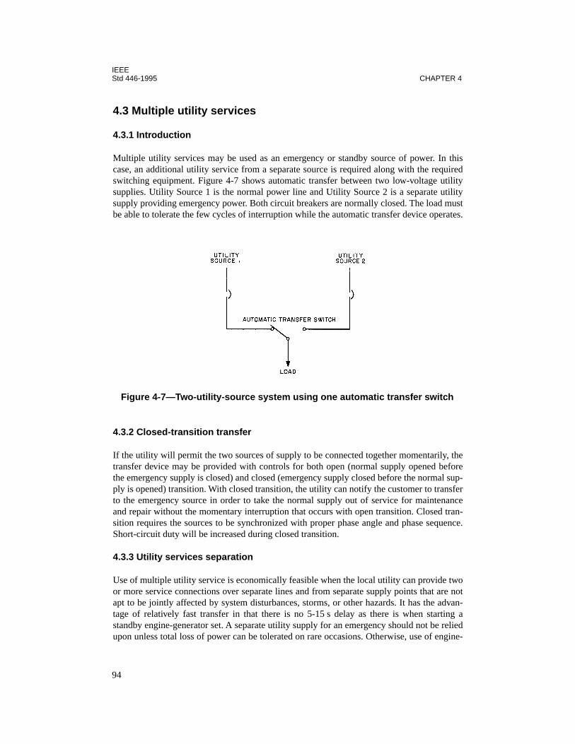
IEEEStd 446-1995 CHAPTER 4
4.3 Multiple utility services
4.3.1 Introduction
Multiple utility services may be used as an emergency or standby source of power. In thiscase, an additional utility service from a separate source is required along with the requiredswitching equipment. Figure 4-7 shows automatic transfer between two low-voltage utilitysupplies. Utility Source 1 is the normal power line and Utility Source 2 is a separate utilitysupply providing emergency power. Both circuit breakers are normally closed. The load mustbe able to tolerate the few cycles of interruption while the automatic transfer device operates.
4.3.2 Closed-transition transfer
If the utility will permit the two sources of supply to be connected together momentarily, thetransfer device may be provided with controls for both open (normal supply opened beforethe emergency supply is closed) and closed (emergency supply closed before the normal sup-ply is opened) transition. With closed transition, the utility can notify the customer to transferto the emergency source in order to take the normal supply out of service for maintenanceand repair without the momentary interruption that occurs with open transition. Closed tran-sition requires the sources to be synchronized with proper phase angle and phase sequence.Short-circuit duty will be increased during closed transition.
4.3.3 Utility services separation
Use of multiple utility service is economically feasible when the local utility can provide twoor more service connections over separate lines and from separate supply points that are notapt to be jointly affected by system disturbances, storms, or other hazards. It has the advan-tage of relatively fast transfer in that there is no 5-15 s delay as there is when starting astandby engine-generator set. A separate utility supply for an emergency should not be reliedupon unless total loss of power can be tolerated on rare occasions. Otherwise, use of engine-
Figure 4-7—Two-utility-source system using one automatic transfer switch
94
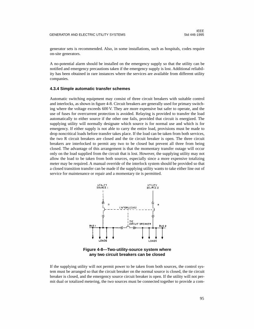
IEEEGENERATOR AND ELECTRIC UTILITY SYSTEMS Std 446-1995
generator sets is recommended. Also, in some installations, such as hospitals, codes requireon-site generators.
A no-potential alarm should be installed on the emergency supply so that the utility can benotified and emergency precautions taken if the emergency supply is lost. Additional reliabil-ity has been obtained in rare instances where the services are available from different utilitycompanies.
4.3.4 Simple automatic transfer schemes
Automatic switching equipment may consist of three circuit breakers with suitable controland interlocks, as shown in figure 4-8. Circuit breakers are generally used for primary switch-ing where the voltage exceeds 600 V. They are more expensive but safer to operate, and theuse of fuses for overcurrent protection is avoided. Relaying is provided to transfer the loadautomatically to either source if the other one fails, provided that circuit is energized. Thesupplying utility will normally designate which source is for normal use and which is foremergency. If either supply is not able to carry the entire load, provisions must be made todrop noncritical loads before transfer takes place. If the load can be taken from both services,the two R circuit breakers are closed and the tie circuit breaker is open. The three circuitbreakers are interlocked to permit any two to be closed but prevent all three from beingclosed. The advantage of this arrangement is that the momentary transfer outage will occuronly on the load supplied from the circuit that is lost. However, the supplying utility may notallow the load to be taken from both sources, especially since a more expensive totalizingmeter may be required. A manual override of the interlock system should be provided so thata closed transition transfer can be made if the supplying utility wants to take either line out ofservice for maintenance or repair and a momentary tie is permitted.
If the supplying utility will not permit power to be taken from both sources, the control sys-tem must be arranged so that the circuit breaker on the normal source is closed, the tie circuitbreaker is closed, and the emergency source circuit breaker is open. If the utility will not per-mit dual or totalized metering, the two sources must be connected together to provide a com-
Figure 4-8—Two-utility-source system where any two circuit breakers can be closed
95

IEEEStd 446-1995 CHAPTER 4
mon metering point and then connected to the distribution switchboard. In this case, the tiecircuit breaker can be eliminated and the two circuit breakers act as a transfer device. Underthese conditions, the cost of extra circuit breakers can rarely be justified.
The arrangement shown in figure 4-8 provides protection only against failure of the normalutility service. Continuity of power to critical loads can also be disrupted by either of the fol-lowing:
— An open circuit within the building (load side of the incoming service)— An overload or fault tripping out a circuit— Electrical or mechanical failure of the electric power distribution system within the
building
It may be desirable to locate transfer devices close to the load and have the operation of thetransfer devices independent of overcurrent protection. Multiple transfer devices of lowercurrent rating, each supplying a part of the load, may be used rather than one transfer devicefor the entire load.
Availability of multiple utility service systems can be improved by adding a standby engine-generator set capable of supplying the more critical load. Such an arrangement, using multi-ple automatic transfer switches, is shown in figure 4-9.
4.3.5 Overcurrent protection
Caution should be exercised to assure that transfer control and operation do not in any waydetract from overcurrent protection and vice versa. Furthermore, the transfer and overcurrentprotective devices should be so arranged that means for disconnecting incoming service isconventional and readily accessible. Chapter 6 provides a more in-depth analysis of overcur-rent protection.
4.3.6 Transfer device ratings and accessories
The required characteristics of transfer devices should include the capabilities of
— Closing against inrush currents without contact welding— Carrying full rated current continuously without overheating— Withstanding available short-circuit currents without contact separation— Properly interrupting the loads to avoid flashover between the two utility services
In addition to considering each of the above individually, it is also necessary to consider theeffect each has on the other. Particular consideration should be given to coordination betweenautomatic transfer switches and overcurrent protection. High fault currents create electro-magnet forces within the contact structure of circuit breakers, which help provide fast open-ing and therefore minimum clearing time; however, automatic transfer switches designed towithstand high fault currents utilize these electromagnetic forces in a reverse manner toassure that the transfer switch contacts remain closed unit the fault has been cleared. Contactseparation, while carrying fault level current, results in arcing, melting of contact surface, and
96
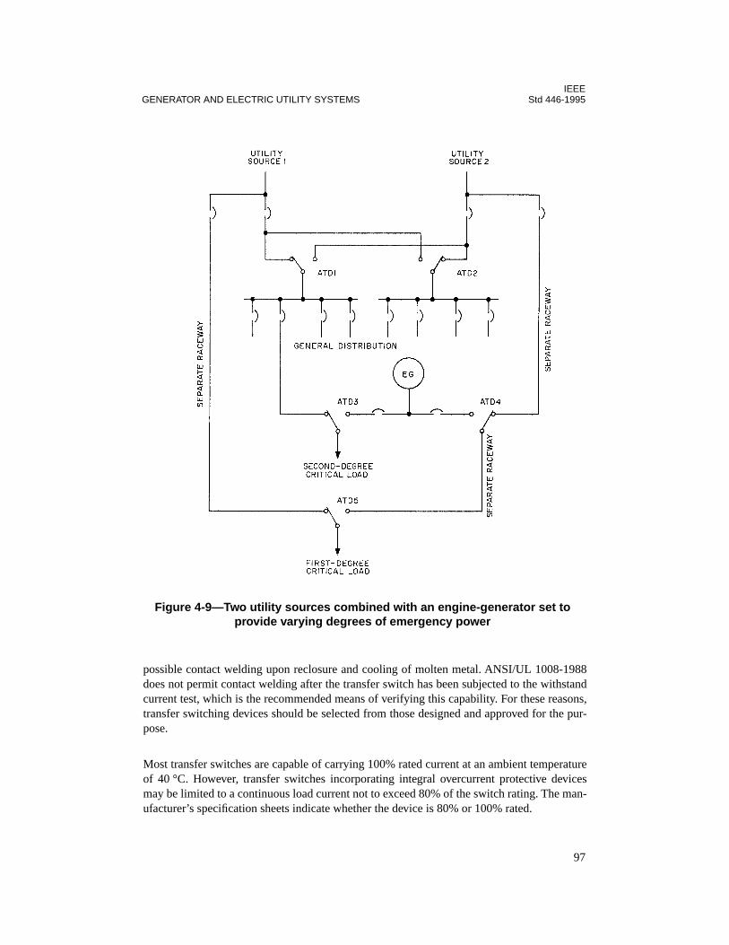
IEEEGENERATOR AND ELECTRIC UTILITY SYSTEMS Std 446-1995
possible contact welding upon reclosure and cooling of molten metal. ANSI/UL 1008-1988does not permit contact welding after the transfer switch has been subjected to the withstandcurrent test, which is the recommended means of verifying this capability. For these reasons,transfer switching devices should be selected from those designed and approved for the pur-pose.
Most transfer switches are capable of carrying 100% rated current at an ambient temperatureof 40 °C. However, transfer switches incorporating integral overcurrent protective devicesmay be limited to a continuous load current not to exceed 80% of the switch rating. The man-ufacturer’s specification sheets indicate whether the device is 80% or 100% rated.
Figure 4-9—Two utility sources combined with an engine-generator set to provide varying degrees of emergency power
97
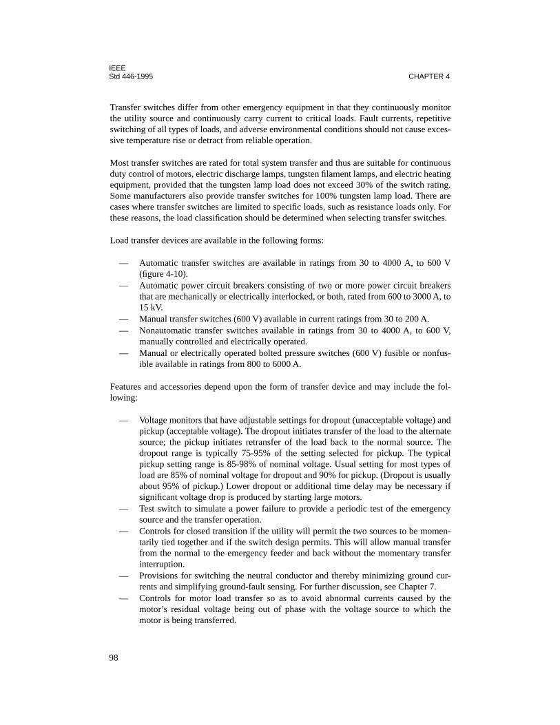
IEEEStd 446-1995 CHAPTER 4
Transfer switches differ from other emergency equipment in that they continuously monitorthe utility source and continuously carry current to critical loads. Fault currents, repetitiveswitching of all types of loads, and adverse environmental conditions should not cause exces-sive temperature rise or detract from reliable operation.
Most transfer switches are rated for total system transfer and thus are suitable for continuousduty control of motors, electric discharge lamps, tungsten filament lamps, and electric heatingequipment, provided that the tungsten lamp load does not exceed 30% of the switch rating.Some manufacturers also provide transfer switches for 100% tungsten lamp load. There arecases where transfer switches are limited to specific loads, such as resistance loads only. Forthese reasons, the load classification should be determined when selecting transfer switches.
Load transfer devices are available in the following forms:
— Automatic transfer switches are available in ratings from 30 to 4000 A, to 600 V(figure 4-10).
— Automatic power circuit breakers consisting of two or more power circuit breakersthat are mechanically or electrically interlocked, or both, rated from 600 to 3000 A, to15 kV.
— Manual transfer switches (600 V) available in current ratings from 30 to 200 A.— Nonautomatic transfer switches available in ratings from 30 to 4000 A, to 600 V,
manually controlled and electrically operated.— Manual or electrically operated bolted pressure switches (600 V) fusible or nonfus-
ible available in ratings from 800 to 6000 A.
Features and accessories depend upon the form of transfer device and may include the fol-lowing:
— Voltage monitors that have adjustable settings for dropout (unacceptable voltage) andpickup (acceptable voltage). The dropout initiates transfer of the load to the alternatesource; the pickup initiates retransfer of the load back to the normal source. Thedropout range is typically 75-95% of the setting selected for pickup. The typicalpickup setting range is 85-98% of nominal voltage. Usual setting for most types ofload are 85% of nominal voltage for dropout and 90% for pickup. (Dropout is usuallyabout 95% of pickup.) Lower dropout or additional time delay may be necessary ifsignificant voltage drop is produced by starting large motors.
— Test switch to simulate a power failure to provide a periodic test of the emergencysource and the transfer operation.
— Controls for closed transition if the utility will permit the two sources to be momen-tarily tied together and if the switch design permits. This will allow manual transferfrom the normal to the emergency feeder and back without the momentary transferinterruption.
— Provisions for switching the neutral conductor and thereby minimizing ground cur-rents and simplifying ground-fault sensing. For further discussion, see Chapter 7.
— Controls for motor load transfer so as to avoid abnormal currents caused by themotor’s residual voltage being out of phase with the voltage source to which themotor is being transferred.
98
IEEEGENERATOR AND ELECTRIC UTILITY SYSTEMS Std 446-1995
— Circuitry to initiate starting and stopping of the engine-generator set(s) dependingupon availability of the normal source of power.
— Time delays in the transfer switch to permit proper programming of transfer switchoperation. A time-delay relay, usually adjustable from 0–6 s, is used to provide over-ride of momentary interruptions and to initiate engine start and power transfer if theoutage or voltage reduction is sustained. This feature is necessary to minimize wearon the engine-starting motor, ring gear, and other system equipment and to preventunnecessary drain on the engine-cranking battery.This time delay is usually set at about 1 s, but can be set for longer if circumstanceswarrant. If delay settings are longer, care needs to be taken to ensure that sufficienttime remains to get the alternate power source on line within the time prescribed byapplicable codes if the system is a required system.After the engine has started and generator output is at proper voltage and frequency,another time-delay relay is activated to permit the generator output to stabilize underno load; this time delay is typically set for less than 1 min. Upon time-out, the load istransferred to the standby source.
Courtesy of Automatic Switch Company (ASCO)
Figure 4-10—Modular-type automatic transfer switch suitable for all classes of load
99
IEEEStd 446-1995 CHAPTER 4
Activation of another timer coincides with restoration of the normal source; this timeris typically adjustable from 0–30 min. The function of this time-delay relay is to pro-vide an established minimum running time for the engine-generator any time that theunit is activated and to maintain the transfer switch in the standby mode, even if thenormal source has been restored.
The purpose of this time delay is twofold. It is not uncommon for prolonged poweroutages to be preceded by a series of brief outages separated from each other by amatter of several seconds or a few minutes; the time delay prevents unnecessarycycling during such periods. It also ensures that the engine-generator will get a goodworkout under load, preserving it in good operating condition.
The transfer switch should be designed so that this feature is automatically nullified ifthe engine-generator set fails and power is available from the normal source.
A fourth timing function is recommended to permit the engine-generator to rununloaded for a while after transfer back to the normal source; an interval of 5 min orless is usually applied. This function permits the units to cool down properly and per-mits fan action to prevent excessive heat from building up in the generator. This fea-ture is especially recommended for diesel-driven units.
If the standby system comprises more than one automatic transfer switch, it is desir-able to sequence the transfer of loads from normal to standby source. This function,also performed by timers, can reduce the starting kVA requirements of the engine-generator set—an especially important consideration when the load is predominantlymotors.
4.3.7 Voltage tolerances
The basic standard for the voltage tolerance for utilization equipment is ANSI C84.1-1989.These limits are based on the T-frame motor with slightly reduced limits for equipment otherthan motors. In the case of special equipment, the manufacturer’s tolerance limits should beobtained. Care should be taken in determining the minimum voltage for transfer switch oper-ation to distinguish between equipment that is not damaged by low voltage, even thoughoperation is unsatisfactory, such as incandescent lamps and resistance heaters, and equipmentthat may be damaged by low voltage or that may cause damage or unsafe conditions at lowvoltage.
4.3.8 Transferring motor loads
Transferring motor loads between two sources requires special consideration. Although thetwo sources may be synchronized, the motor will tend to slow down upon loss of power andduring transfer, thus causing the residual voltage of the motor to be out of phase with theoncoming source. The speed of transfer, total inertia, and motor and system characteristicsare involved. On transfer, the vector difference and resulting high abnormal inrush currentcould cause serious damage to the motor, and the excessive current drawn by the motor maytrip the overcurrent protective device. Both motor loads with relatively low load inertia inrelation to torque requirements, such as pumps and compressors, and large inertia loads, suchas induced draft fans, etc., that keep turning near synchronous speed for a longer time afterloss of power, are subject to the hazard of out-of-phase switching. Automatic transfer
100
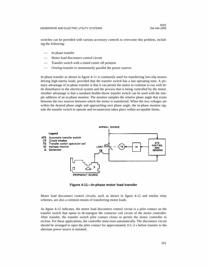
IEEEGENERATOR AND ELECTRIC UTILITY SYSTEMS Std 446-1995
switches can be provided with various accessory controls to overcome this problem, includ-ing the following:
— In-phase transfer
— Motor load disconnect control circuit
— Transfer switch with a timed center off position
— Overlap transfer to momentarily parallel the power sources
In-phase transfer as shown in figure 4-11 is commonly used for transferring low-slip motorsdriving high-inertia loads, provided that the transfer switch has a fast operating time. A pri-mary advantage of in-phase transfer is that it can permit the motor to continue to run with lit-tle disturbance to the electrical system and the process that is being controlled by the motor.Another advantage is that a standard double-throw transfer switch can be used with the sim-ple addition of an in-phase monitor. The monitor samples the relative phase angle that existsbetween the two sources between which the motor is transferred. When the two voltages arewithin the desired phase angle and approaching zero phase angle, the in-phase monitor sig-nals the transfer switch to operate and reconnection takes place within acceptable limits.
Motor load disconnect control circuits, such as shown in figure 4-12 and similar relayschemes, are also a common means of transferring motor loads.
As figure 4-12 indicates, the motor load disconnect control circuit is a pilot contact on thetransfer switch that opens to de-energize the contactor coil circuit of the motor controller.After transfer, the transfer switch pilot contact closes to permit the motor controller toreclose. For these applications, the controller must reset automatically. The disconnect circuitshould be arranged to open the pilot contact for approximately 0.5–3 s before transfer to thealternate power source is initiated.
Figure 4-11—In-phase motor load transfer
101
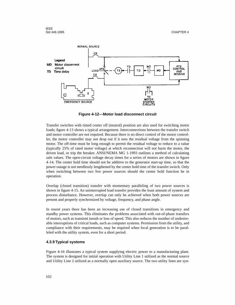
IEEEStd 446-1995 CHAPTER 4
Transfer switches with timed center off (neutral) position are also used for switching motorloads; figure 4-13 shows a typical arrangement. Interconnections between the transfer switchand motor controller are not required. Because there is no direct control of the motor control-ler, the motor controller may not drop out if it sees the residual voltage from the spinningmotor. The off-time must be long enough to permit the residual voltage to reduce to a value(typically 25% of rated motor voltage) at which reconnection will not harm the motor, thedriven load, or trip the breaker. ANSI/NEMA MG 1-1993 outlines a method of calculatingsafe values. The open-circuit voltage decay times for a series of motors are shown in figure4-14. The center hold time should not be additive to the generator start-up time, so that thepower outage is not needlessly lengthened by the center hold time of the transfer switch. Onlywhen switching between two live power sources should the center hold function be inoperation.
Overlap (closed transition) transfer with momentary paralleling of two power sources isshown in figure 4-15. An uninterrupted load transfer provides the least amount of system andprocess disturbance. However, overlap can only be achieved when both power sources arepresent and properly synchronized by voltage, frequency, and phase angle.
In resent years there has been an increasing use of closed transitions in emergency andstandby power systems. This eliminates the problems associated with out-of-phase transfersof motors, such as transient inrush or loss of speed. This also reduces the number of undesire-able interruptions of critical loads, such as computer systems. Permission from the utility, andcompliance with their requirements, may be required when local generation is to be paral-leled with the utility system, even for a short period.
4.3.9 Typical systems
Figure 4-16 illustrates a typical system supplying electric power to a manufacturing plant.The system is designed for initial operation with Utility Line 1 utilized as the normal sourceand Utility Line 2 utilized as a normally open auxiliary source. The two utility lines are syn-
Figure 4-12—Motor load disconnect circuit
102

IEEEGENERATOR AND ELECTRIC UTILITY SYSTEMS Std 446-1995
Figure 4-13—Neutral off position
Figure 4-14—Induction motor open-circuit voltage decay(based on constant speed)
103

IEEEStd 446-1995 CHAPTER 4
chronized with each other so that they can be paralleled, but are not normally operated in thismanner. However, unless the relaying is designed for it, the operation of the two incominglines in parallel should be kept to a minimum—that is, the switching time.
Utility Lines 1 and 2 enter the plant from a substation some distance away through under-ground conduits separated by about 1 ft and encased in the center of a 3
×
3 ft concrete enclo-sure 7 ft below the surface for protection.
Operation is as follows:
a) If voltage on the normal source (Line 1) drops appreciably for several cycles, theundervoltage relay will deactivate, trip the circuit breaker in Line 1, and close the cir-cuit breaker in Line 2 (if acceptable voltage is present on Line 2).
b) When voltage is restored to Line 1, the undervoltage relay is activated and initiates atimer. After the voltage has been present on Line 1 for a predetermined time (usually1–10 min), the circuit breaker in Line 1 closes, after which the circuit breaker in Line2 opens.
c) If there is no voltage present on Line 2 when Line 1 loses voltage, the circuit breakerin Line 2 will not close. When voltage is restored to Line 1, the circuit breaker in Line1 will immediately close.
d) If a fault or overload occurs on the load side of either incoming circuit breaker, alockout relay keeps both circuit breakers open, disabling the automatic transfer sys-tem until manually reset.
Figure 4-15—Closed transition transfer
104

IEEEGENERATOR AND ELECTRIC UTILITY SYSTEMS Std 446-1995
Figure 4-16—Typical system supplying electric power to manufacturing plant
105

IEEEStd 446-1995 CHAPTER 4
As power demands increase, this system can be expanded by inserting a tie circuit breaker inthe 13.8 kV bus and additional relaying. Part of the load would then be supplied by each util-ity line with transfer of the entire load to the line feeder, should power be lost to one line.Load shedding of noncritical loads could be incorporated if necessary.
Operation would then be as follows:
a) A loss of voltage or appreciable decrease of voltage on either utility line will causethat normally closed circuit breaker to open and the normally open tie circuit breakerto close. When normal voltage returns, the open utility line circuit breaker will closein a preset time (1–10 min), after which the tie circuit breaker will open.
b) A simultaneous loss of voltage on both utility lines will cause both normally closedutility line circuit breakers to open and the normally open tie circuit breaker to close.A return to normal voltage on either utility line will cause that utility line circuitbreaker to close in its preset time and the tie circuit breaker to remain closed. Whennormal voltage is established on the second utility line, that utility line circuit breakerwill close in its preset time after which the tie circuit breaker will open.
c) Fault current or overload current causing either utility line circuit breaker to open willalso make the automatic closing feature of the tie circuit breaker inoperative untilmanually reset.
d) If the utility company needs to take one line out of service, they notify the customerwho then manually closes the tie circuit breaker and opens the line to be affected.
The arrangement shown in figure 4-15 only provides protection against failure of the utilitysource. To provide protection against disruption of power within the building areas, it may bedesirable to locate additional automatic transfer switches downstream and close to the load. Acombination of circuit breakers and downstream automatic transfer switches is shown infigure 4-9.
4.3.10 Bypass isolation switches
In many installations, performing regular testing or detailed inspections on the emergencysystem is difficult because some or all of the loads connected to the system are vital to humanlife or are critical in the operation of continuous processes. De-energizing these loads for anylength of time is also difficult. This situation often results in a lack of maintenance. For suchinstallations, a means can be provided to bypass the critical loads directly to a reliable sourceof power without downtime of the loads. The transfer switch can then be isolated for safeinspection and maintenance.
Two-way bypass isolation switches are available to meet this need. These switches performthree functions:
a) Shunt the service around the transfer switch without interrupting power to the load.When the bypass (BP) handle (upper handle) is moved to the bypass-to-normal(BP-NORM) position (figure 4-17), the closed transfer switch contacts are shuntedby the right-hand BP contacts. The flow of current then divides between the bypassand transfer contacts. This assures there will not be even a momentary interruption of
106
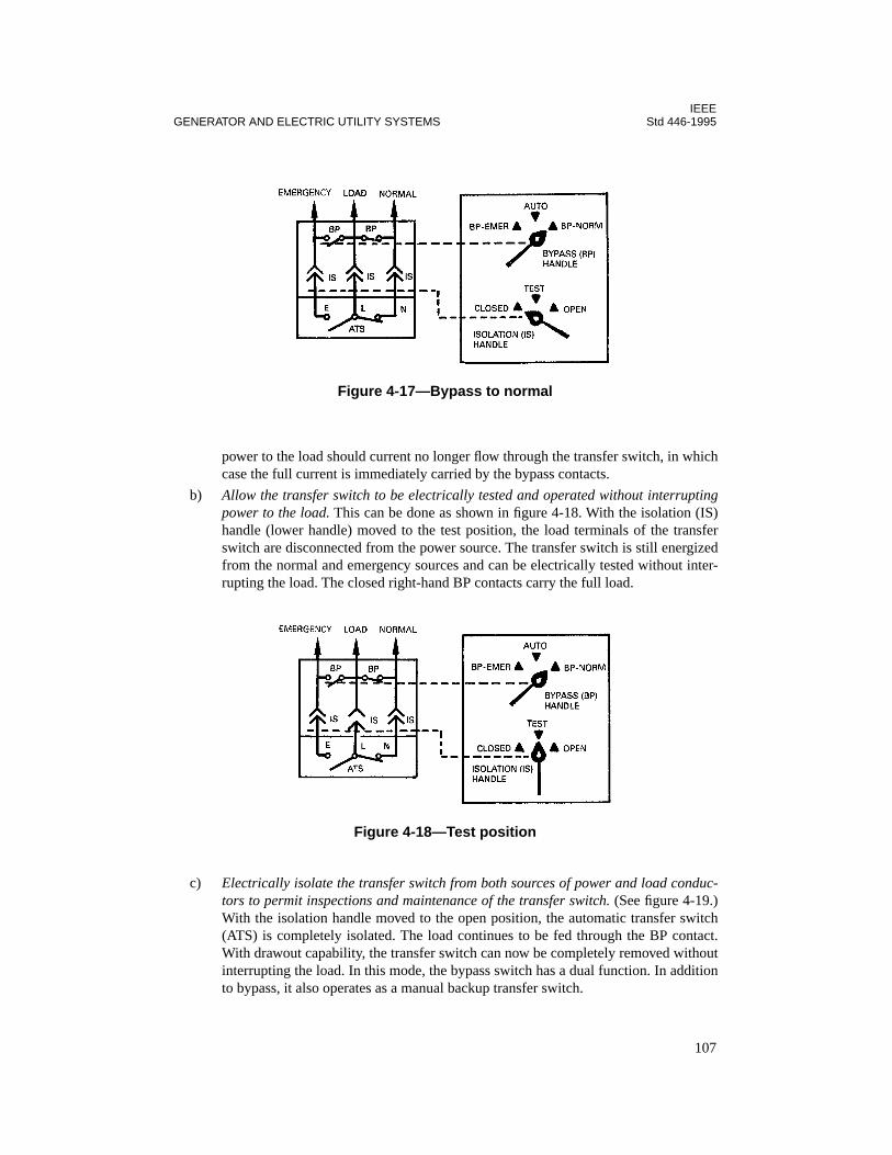
IEEEGENERATOR AND ELECTRIC UTILITY SYSTEMS Std 446-1995
power to the load should current no longer flow through the transfer switch, in whichcase the full current is immediately carried by the bypass contacts.
b) Allow the transfer switch to be electrically tested and operated without interruptingpower to the load. This can be done as shown in figure 4-18. With the isolation (IS)handle (lower handle) moved to the test position, the load terminals of the transferswitch are disconnected from the power source. The transfer switch is still energizedfrom the normal and emergency sources and can be electrically tested without inter-rupting the load. The closed right-hand BP contacts carry the full load.
c) Electrically isolate the transfer switch from both sources of power and load conduc-tors to permit inspections and maintenance of the transfer switch. (See figure 4-19.)With the isolation handle moved to the open position, the automatic transfer switch(ATS) is completely isolated. The load continues to be fed through the BP contact.With drawout capability, the transfer switch can now be completely removed withoutinterrupting the load. In this mode, the bypass switch has a dual function. In additionto bypass, it also operates as a manual backup transfer switch.
Figure 4-17—Bypass to normal
Figure 4-18—Test position
107
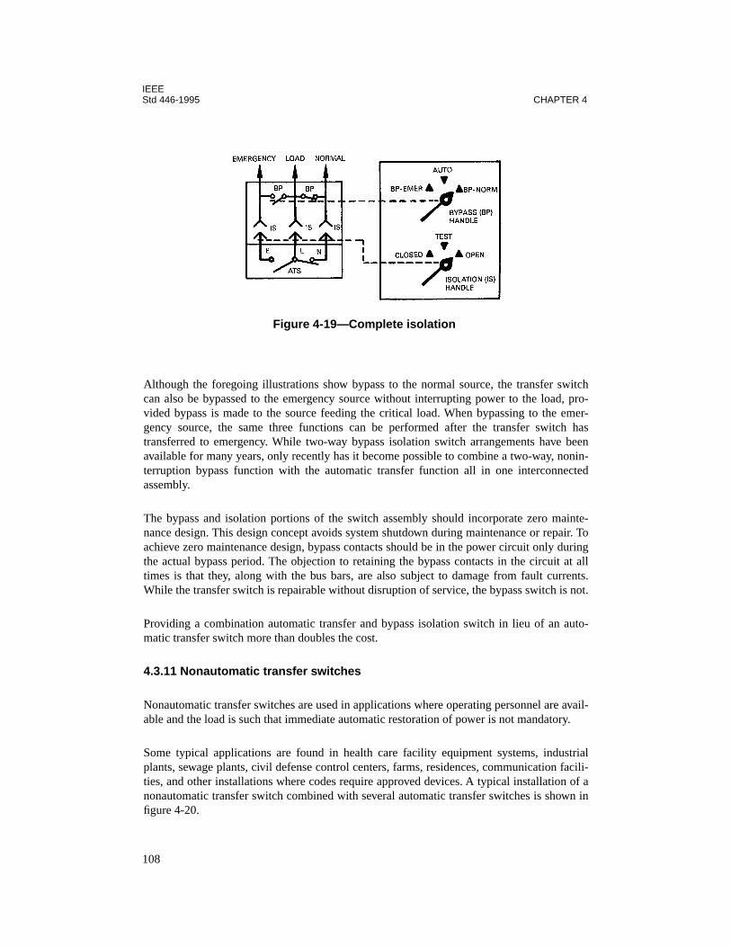
IEEEStd 446-1995 CHAPTER 4
Although the foregoing illustrations show bypass to the normal source, the transfer switchcan also be bypassed to the emergency source without interrupting power to the load, pro-vided bypass is made to the source feeding the critical load. When bypassing to the emer-gency source, the same three functions can be performed after the transfer switch hastransferred to emergency. While two-way bypass isolation switch arrangements have beenavailable for many years, only recently has it become possible to combine a two-way, nonin-terruption bypass function with the automatic transfer function all in one interconnectedassembly.
The bypass and isolation portions of the switch assembly should incorporate zero mainte-nance design. This design concept avoids system shutdown during maintenance or repair. Toachieve zero maintenance design, bypass contacts should be in the power circuit only duringthe actual bypass period. The objection to retaining the bypass contacts in the circuit at alltimes is that they, along with the bus bars, are also subject to damage from fault currents.While the transfer switch is repairable without disruption of service, the bypass switch is not.
Providing a combination automatic transfer and bypass isolation switch in lieu of an auto-matic transfer switch more than doubles the cost.
4.3.11 Nonautomatic transfer switches
Nonautomatic transfer switches are used in applications where operating personnel are avail-able and the load is such that immediate automatic restoration of power is not mandatory.
Some typical applications are found in health care facility equipment systems, industrialplants, sewage plants, civil defense control centers, farms, residences, communication facili-ties, and other installations where codes require approved devices. A typical installation of anonautomatic transfer switch combined with several automatic transfer switches is shown infigure 4-20.
Figure 4-19—Complete isolation
108
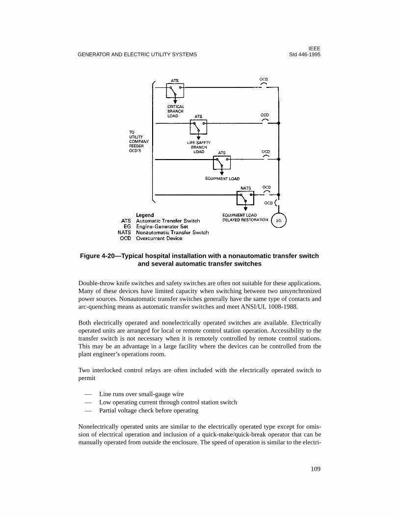
IEEEGENERATOR AND ELECTRIC UTILITY SYSTEMS Std 446-1995
Double-throw knife switches and safety switches are often not suitable for these applications.Many of these devices have limited capacity when switching between two unsynchronizedpower sources. Nonautomatic transfer switches generally have the same type of contacts andarc-quenching means as automatic transfer switches and meet ANSI/UL 1008-1988.
Both electrically operated and nonelectrically operated switches are available. Electricallyoperated units are arranged for local or remote control station operation. Accessibility to thetransfer switch is not necessary when it is remotely controlled by remote control stations.This may be an advantage in a large facility where the devices can be controlled from theplant engineer’s operations room.
Two interlocked control relays are often included with the electrically operated switch topermit
— Line runs over small-gauge wire— Low operating current through control station switch— Partial voltage check before operating
Nonelectrically operated units are similar to the electrically operated type except for omis-sion of electrical operation and inclusion of a quick-make/quick-break operator that can bemanually operated from outside the enclosure. The speed of operation is similar to the electri-
Figure 4-20—Typical hospital installation with a nonautomatic transfer switch and several automatic transfer switches
109

IEEEStd 446-1995 CHAPTER 4
cally operated arrangement owing to the preloading of the main operating springs, therebyproviding appropriate current make, break, and carry capabilities.
4.3.12 Conclusion
Approximately 90% of transfer schemes designed to switch from the prime power source tothe emergency source for commercial installations utilize conventional double-throw transferswitches. For maximum system reliability, the transfer switches are usually located close tothe load rather than at the incoming prime power source. The use of interlocked serviceentrance circuit breakers for transfer schemes is usually limited to medium-voltage primaryswitching.
Two parallel in-phase separate utility sources on line continuously with proper relaying on anormally closed tie circuit breaker provide increased reliability of electric power in someapplications. This possibility should be investigated with the utility company representatives.
4.4 Turbine-driven generators
4.4.1 Introduction
Two general types of turbine prime movers for electrical generators are available: steam andgas/oil.
4.4.2 Steam turbine generators
Steam is usually not available if all electric power has been lost, although there are indepen-dent steam supply systems that may themselves have uninterruptible electrical systems. Inthis case steam might be considered. There are compact steam turbines that could bringpower onto the line in about 5 min. This is a rather special source of supply, and details arenot presented.
Steam turbines are used to drive generators that are larger than those that can be driven bydiesel engines. However, steam turbines are designed for continuous operation and require aboiler with fuel supply and a source of water. Thus, they are expensive for use as an emer-gency or standby power supply and may have environmental problems involving fuel supply,noise, combustion product output, and heating of the condensing water.
Figure 4-21 shows an on-line steam turbine generator supplying a critical bus in parallel withone source of utility power. An alternate utility source can be manually switched on in aminute or so should there be a failure of the on-line utility source. The normal utility supplysystem should be large enough to supply the entire critical bus if the turbine is off. Relayingfor such a system should be worked out with the utility. A contract is required with the utilityto establish the right to parallel and the disposition of power purposely or inadvertentlyshipped to the utility. The system should function to interrupt generator input to utility faults,avoid out-of-synchronism, and detect is landing of the generator with a portion of the utilityload.
110

IEEEGENERATOR AND ELECTRIC UTILITY SYSTEMS Std 446-1995
111
4.4.3 Gas and oil turbine generators
The most common turbine-driven electric generator units employed today for emergency orstandby power use gas or oil for fuel. Various grades of oil and both natural and propane gasmay be used. Other less common sources of fuel are kerosene or gasoline. Service can berestored from about a 10 s minimum to several minutes, depending upon the turbine used.
Aircraft-type turbines driving generators have been commonly used where electric powermay be needed for a few hours to days. Small industrial units have been developed. A smallfuel storage facility for safety may be adequate, provided plans have been made by whichadditional fuel will be delivered when needed. Care should be taken to assure an adequate gassupply, should this be the source of energy, since an uninterruptible supply from a public util-ity company may be very expensive or unavailable. An interruptible supply may not be avail-able when needed during cold weather. Earthquakes may destroy extensive undergroundutility distribution systems, but local storage may be intact. Environmental considerationsmay require the use of low-sulfur oil, which may be difficult to obtain.
Savings are possible by the installation of a turbine for emergency and standby power whenused as a peak clipping unit to reduce the demand charge. This has the operating advantage ofchecking the unit often enough under load so that the operating personnel are familiar withthe equipment and the unit is known to be ready for an emergency.
Turbine designs fall between two extreme categories. Aircraft-type engines embody highlysophisticated techniques for very light weight in relation to horsepower (0.25–0.50 lb/hp).
Figure 4-21—Emergency and standby power system using steam-turbine and dual-utility supply
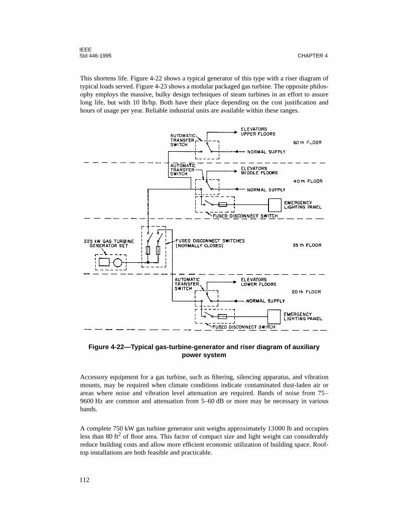
IEEEStd 446-1995 CHAPTER 4
112
This shortens life. Figure 4-22 shows a typical generator of this type with a riser diagram oftypical loads served. Figure 4-23 shows a modular packaged gas turbine. The opposite philos-ophy employs the massive, bulky design techniques of steam turbines in an effort to assurelong life, but with 10 lb/hp. Both have their place depending on the cost justification andhours of usage per year. Reliable industrial units are available within these ranges.
Accessory equipment for a gas turbine, such as filtering, silencing apparatus, and vibrationmounts, may be required when climate conditions indicate contaminated dust-laden air orareas where noise and vibration level attenuation are required. Bands of noise from 75–9600 Hz are common and attenuation from 5–60 dB or more may be necessary in variousbands.
A complete 750 kW gas turbine generator unit weighs approximately 13000 lb and occupiesless than 80 ft
2
of floor area. This factor of compact size and light weight can considerablyreduce building costs and allow more efficient economic utilization of building space. Roof-top installations are both feasible and practicable.
Figure 4-22—Typical gas-turbine-generator and riser diagram of auxiliary power system
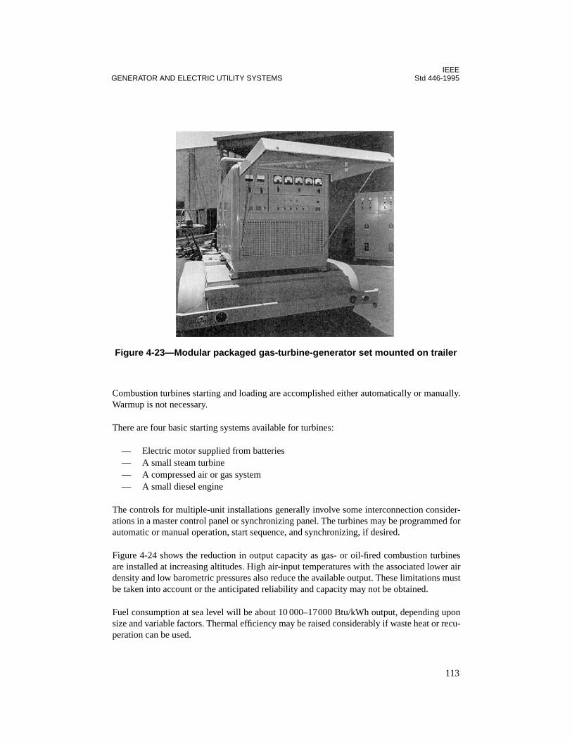
IEEEGENERATOR AND ELECTRIC UTILITY SYSTEMS Std 446-1995
113
Combustion turbines starting and loading are accomplished either automatically or manually.Warmup is not necessary.
There are four basic starting systems available for turbines:
— Electric motor supplied from batteries— A small steam turbine— A compressed air or gas system— A small diesel engine
The controls for multiple-unit installations generally involve some interconnection consider-ations in a master control panel or synchronizing panel. The turbines may be programmed forautomatic or manual operation, start sequence, and synchronizing, if desired.
Figure 4-24 shows the reduction in output capacity as gas- or oil-fired combustion turbinesare installed at increasing altitudes. High air-input temperatures with the associated lower airdensity and low barometric pressures also reduce the available output. These limitations mustbe taken into account or the anticipated reliability and capacity may not be obtained.
Fuel consumption at sea level will be about 10 000–17000 Btu/kWh output, depending uponsize and variable factors. Thermal efficiency may be raised considerably if waste heat or recu-peration can be used.
Figure 4-23—Modular packaged gas-turbine-generator set mounted on trailer
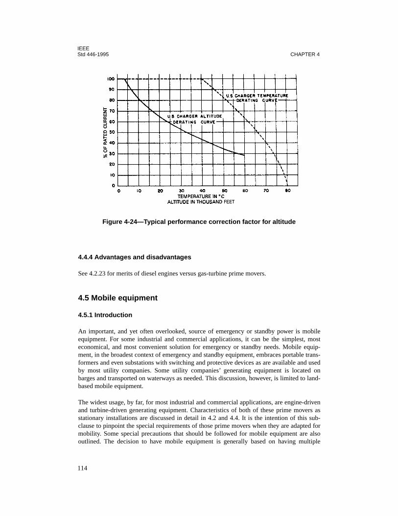
IEEEStd 446-1995 CHAPTER 4
114
4.4.4 Advantages and disadvantages
See 4.2.23 for merits of diesel engines versus gas-turbine prime movers.
4.5 Mobile equipment
4.5.1 Introduction
An important, and yet often overlooked, source of emergency or standby power is mobileequipment. For some industrial and commercial applications, it can be the simplest, mosteconomical, and most convenient solution for emergency or standby needs. Mobile equip-ment, in the broadest context of emergency and standby equipment, embraces portable trans-formers and even substations with switching and protective devices as are available and usedby most utility companies. Some utility companies’ generating equipment is located onbarges and transported on waterways as needed. This discussion, however, is limited to land-based mobile equipment.
The widest usage, by far, for most industrial and commercial applications, are engine-drivenand turbine-driven generating equipment. Characteristics of both of these prime movers asstationary installations are discussed in detail in 4.2 and 4.4. It is the intention of this sub-clause to pinpoint the special requirements of those prime movers when they are adapted formobility. Some special precautions that should be followed for mobile equipment are alsooutlined. The decision to have mobile equipment is generally based on having multiple
Figure 4-24—Typical performance correction factor for altitude

IEEEGENERATOR AND ELECTRIC UTILITY SYSTEMS Std 446-1995
usages. Thus, transportability to serve several load groups, with their varying needs and elec-trical characteristics, will place restraints on the design/selection process of such equipment.
4.5.2 Special requirements
Mobile generating units can take almost any form from only a prime mover and generatorassembly to a complete self-contained plant having its own transporting power. Smaller unitscan be considered mobile even if they are skid-mounted and have to be transported by load-ing on and unloading from another vehicle. Obviously, there is some limit beyond which it isnot practical, either because of weight or physical size, to load and unload a unit for trans-porting to achieve the necessary mobility. It is also obvious that a point can be reachedwhereby generating equipment, because of its physical size and weight, should not be consid-ered for mobile application, even if permanently installed on a truck-bed or a trailer assembly.In terms of capacity, the size break of practicality will vary with engine or turbine drives asprime movers, equipment handling facilities, and also with how much auxiliary equipment,for support of the unit, needs to be transported. Based on these premises, the following is anattempt to describe the several special requirements or needs of generating equipment when itis adapted for mobile applications.
Since mobile equipment may be required to be used outdoors or, when not in use, stored out-doors, it can be desirable to house it in a weather-proof enclosure. If its use may be in asound-sensitive area, provisions for noise attenuation may be necessary. Whatever type ofenclosure is employed, special precautions may be necessary to assure that the unit will havesufficient combustion and cooling air to operate within its rating. It may be necessary to equipthe unit with louvers that are arranged to open automatically when the unit is running. Forunits where soundproofing is required, a well-designed forced-air ventilating system willprobably be needed. For application in sound-critical areas, such as residential, an appropri-ate high sound attenuating exhaust silencer or muffler may be warranted.
To avoid possible duplication of fuel-storage facilities in all locations where the unit will finduse, it may be desirable to provide fuel storage with the unit. Storage capacity will depend oneach need; however, an 8 h supply as a minimum would seem to be a reasonable periodwithin which a portable fuel transport vehicle could be dispatched to replenish the fuel sup-ply. Fuel oil for a diesel engine is a good fuel choice because of its availability, transportabil-ity, and storability during periods of disuse and because it presents less hazard than gasolineor natural and bottled gases. Tank capacity should be based on the unit’s consumption whenoperating at full load.
If the mobile unit is to be a towed vehicle, it will probably be required to meet all of thestate’s (and possibly Interstate Commerce Commission’s) requirements for such items aslights and markings. The vehicle should be designed for a realistic road speed, have stoplights, and probably a braking system. Thus, the plug receptacle wiring connections and thehitch assembly need to be compatible with similar mating equipment of the towing vehicle.Figure 4-25 shows a typical trailer-mounted unit in the range of 15–45 kW. Figure 4-26shows a 2800 kW turbine-generator unit with self-contained switchgear.
115

IEEEStd 446-1995 CHAPTER 4
A careful selection of the generator output voltage, or voltages, phases, and frequency shouldbe made to be compatible with all envisioned load requirements. Multiwinding generatorscan be specified to enable field connection and selection of voltages. Most mobile rental unitshave multiple windings and are reconnectable for common utilization voltages.
Figure 4-25—Typical trailer-mounted model (15–45 kW capacity)
Figure 4-26—Typical 2800 kW mobile turbine-driven generator set
116
IEEEGENERATOR AND ELECTRIC UTILITY SYSTEMS Std 446-1995
Often with smaller mobile units it is advantageous to transport the cable connection with thegenerating equipment. If connection time is critical in restoring electrical service, the cableconnection can be hard-wired at the generator terminals, transported on an integral reel, andequipped with a plug to mate with the loadend receptacle. That receptacle could, in turn, behard-wired into the load facility’s electrical system. Many telephone building facilities andswitching centers are arranged for such a plug-in connection of a mobile standby unit. Thecable length should be determined for the extreme location where the equipment will be used.If a cable reel is used, the diameter should be selected after consideration of the manufac-turer’s recommended minimum bending radius for the cable. The cable should be of a porta-ble variety as recognized by the NEC.
A disconnect switch or a circuit breaker is often installed at the generator. See Chapter 6 forinformation on generator protection.
Speed control through governor and fuel supply systems selection for prime movers can be acritical choice for a mobile unit if no consideration of the demands of the connected load ismade. The same is true in a choice of voltage-regulating methods in combination with excita-tion systems for the generator. Suffice it to say that a more extensive analysis, before selec-tion, should be made for a mobile unit in comparison with a stationary installation. This isbecause of the several different possible demands that may be placed on a mobile unitthrough the more diversified demands of the loads. Improper selection of speed control orvoltage control, or both, could mean either money spent wastefully or could cause the unit tobe unresponsive to the more critical demands of some loads.
It is generally advantageous to arrange mobile units for starting with self-contained electricstorage batteries because of their transportability. A compressed-air start unit would require afairly large volume air receiver that would usually reach such large size and high weight pro-portions that its transportability would be difficult. If batteries are used, the permanent stor-age location, used when the mobile unit is not in service, should be arranged with a battery-charging unit.
If a reciprocating engine unit is to be used or stored outdoors, an ethylene glycol solution andan immersion heater should be used in the cooling system.
4.5.3 Special precautions
Mobile equipment, when compared with stationary equipment, will have some precautionsthat should be planned for and followed. Many of the items listed below are somewhat obvi-ous but nevertheless often overlooked, especially in the early stages of planning for themobile unit’s utilization and its related storage area.
If a single area is used for storing the unit when not in service, it should be equipped with ameans of heating the coolant and charging the unit’s batteries through a battery charger and aflexible plug and receptacle connection. If an air start is planned, an air compressor with flex-ible high-pressure lines and connectors should be used. If the storage space is unheated andoutdoors, in colder climates it may be advantageous to provide branch circuit wiring for con-nection of a unit’s immersion-type heater located in the unit’s cooling water jacket. If there
117
IEEEStd 446-1995 CHAPTER 4
are extended periods when the unit is not used, it may be advantageous to have a dummy loadbank for maintenance testing of the unit under load. Other additional features that couldprove valuable for installation at the storage facility are an annunciator unit, which monitorsgenerator set key functions, and an automatic exercising unit.
If a plug-in unit is to be planned, it is important that each load facility, where a mobile unit isto be used, be wired with a receptacle that mates with, and is rated for, the plug on the unit. Itshould be connected to the load through a transfer switch. Because of inherent characteristicsof a mobile generating unit, when compared with a facility’s normal source (often a utilitycompany), staged sequencing of returning the facility’s loads to service may be in order.Rarely will automatic load sequencing be preferred over manual sequencing through a well-planned start-up procedure.
Assuming that, in initial planning, it may be possible at the load facility to anticipate theoperating location of mobile equipment, the fresh air intakes for an adjacent or adjunct build-ing should be physically well-separated from the operating location for the unit.
4.5.4 Maintenance
Since mobile equipment’s usage is often unscheduled, necessary maintenance and testingprocedures can become sloppy with important items neglected. The unit should be kept readyto go at all times. If the unit is for backup of life safety equipment, it should be treated as sim-ilar, stationary, permanently installed equipment employed for the same function. As such, aregularly scheduled operating run of the unit for some representative duration under load willenable checking of such important functions as prime mover lubrication and cooling, chargedbatteries, and starting systems. This testing can often be accomplished through automaticexercising and alarm annunciation equipment installed at the storage location.
4.5.5 Application
Mobile equipment finds widespread application on multifaceted and physically scatteredfacilities such as might be operated by a municipality. Many municipalities will have suchdiversified operations, all of which will, on occasion, require emergency and standby power,such as sewage and waste water treatment and pumping plants, garbage and refuse collectionand disposal, central fire-alarm stations, centralized traffic-control facilities, convention,sports, and recreational complexes, and power and steam generating plants. Other users ofmobile equipment might include college and educational facilities, military bases, and largegovernmental, institutional, and industrial complexes, all typified by scattered individualbuildings, most having their own electrical service and, in many cases, privately owned elec-trical distribution facilities between buildings.
4.5.6 Rental
Often the expenses of purchase of a mobile unit cannot be justified when measured againsthow often the equipment is needed and used. There are several sources for the rental ofmobile generating equipment, namely, equipment manufacturers’ distributors and serviceorganizations, some utility companies, and large construction contracting firms. Rental
118

IEEEGENERATOR AND ELECTRIC UTILITY SYSTEMS Std 446-1995
houses generally charge approximately 10% of the list price of the equipment per monthbased on an 8 h day. The weekly rate is generally 1/3 the monthly rate and the daily rate, 1/3the weekly rate. For more than 8 h per day, the rate is 1-1/2 to 2 times the 8 h rate.
Sometimes power is lost from the normal utility supply source, but a lower or higher voltageis available close by. A mobile transformer can be used for emergency power secured in timeto prevent damage from freezing or in a quantity sufficient for partial production.
4.5.7 Fuel systems
Growing shortages of gas and liquid fuel sources require advanced planning for a firm. Adependable source of fuel supply, readily available under any foreseeable emergency condi-tion, should exist. When natural gas is planned, a firm source should be available; a back-upsource of propane should be considered. Where liquid fuels are planned, ready available stor-age at the point of usage should be considered. Since liquid fuels deteriorate during long stor-age, a system of use and replacement to assure a fresh supply should be planned.
4.5.8 Agricultural applications
Farm standby tractor-driven generators are available, practical, and usually reasonable incost, since the prime mover is serving a dual purpose and is usually on hand for other uses.
4.6 References
This chapter shall be used in conjunction with the following publications:
ANSI C84.1-1989, American National Standard Voltage Ratings for Electric Power Systemsand Equipment (60 Hz).3
ANSI/NEMA ICS 2-1993, Industrial Control and Systems Controllers, Contractors, andOverload Relays Rated Not More Than 2000 Volts AC or 750 Volts DC.4
ANSI/NEMA MG I-1993, Motors and Generators.
ANSI/NFPA 101-1994, Code for Safety to Life from Fire in Buildings and Structures.5
ANSI/UL 1008-1988, Safety Standard for Automatic Transfer Switches.6
3ANSI publications are available from the Sales Department, American National Standards Institute, 11 West 42ndStreet, 13th Floor, New York, NY 10036, USA.4NEMA publications are available from the National Electrical Manufacturers Association, 2101 L Street NW,Washington, DC 20037, USA.5NFPA publications are available from from the Sales Department, American National Standards Institute, 11 West42nd Street, 13th Floor, New York, NY 10036, USA.6UL publications are available from Underwriters Laboratories, Inc., 333 Pfingsten Road, Northbrook, IL 60062-2096, USA.
119

IEEEStd 446-1995 CHAPTER 4
EGSA 101G-1995, Glossary of Electrical and Mechanical Terminology and Definitions.7
EGSA 101P-1995, Performance Standard: For Engine Driven Generator Sets.
EGSA 101S-1995, Guideline Specifications: For Engine Driven Generator Sets, Emergencyor Standby.
IEEE C37.95-1989, IEEE Guide for Protective Relaying of Utility-Consumer Interconnec-tions (ANSI).8
IEEE Std 100-1992, The New IEEE Standard Dictionary of Electrical and Electronics Terms(ANSI).
IEEE Std 141-1993, IEEE Recommended Practice for Electric Power Distribution for Indus-trial Plants (IEEE Red Book) (ANSI).
IEEE Std 142-1991, IEEE Recommended Practice for Grounding of Industrial and Comme-cial Power Systems (IEEE Green Book) (ANSI).
IEEE Std 241-1990, IEEE Recommended Practice for Electric Power Systems in Commer-cial Buildings (IEEE Gray Book) (ANSI).
IEEE Std 387-1984, IEEE Standard Criteria for Diesel-Generator Units Applied as StandbyPower Supplies for Nuclear Power Generating Stations.9
NFPA 70-1996, National Electrical Code®.
4.7 Bibliography
Additional information may be found in the following sources:
[B1] Castenschiold, R., “Closed-Transition Switching of Essential Loads” IEEE Transactionson Industry Applications, vol. 25, no. 3, May/June 1989.
[B2] Daugherty, R. H., “Analysis of Transient Electrical Torques and Shaft Torques in Induc-tion Motors as a Result of Power Supply Disturbances,” IEEE Transactions on Power Appa-ratus and Systems, vol. PAS-101, no. 8, Aug. 1982.
[B3] Engineer’s Guidebook to Power Systems, Kohler Company, Kohler, WI.
7EGSA publications are available from the Electrical Generating Systems Association, 10251 W. Sample Rd., SuiteB, Coral Springs, FL 33065.8IEEE publications are available from the Institute of Electrical and Electronics Engineers, 445 Hoes Lane, P.O. Box1331, Piscataway, NJ 08855-1331, USA.9This standard has been withdrawn; however, copies can be obtained from the IEEE Standards Department, 445Hoes Lane, P.O. Box 1331, Piscataway, NJ 08855-1331, USA.
120
IEEEGENERATOR AND ELECTRIC UTILITY SYSTEMS Std 446-1995
[B4] Gill, J. D., “Transfer of Motor Loads Between Out of Phase Sources,” IEEE Transac-tions on Industry Applications, vol. IA-15, no. 4, pp. 376–381, Jul./Aug. 1979.
[B5] Heising, C. R. and Johnston, Jr, J. F., “Reliability Considerations in Systems Applica-tions of Uninterruptible Power Supplies,” IEEE Transactions on Industry Applications, vol.IA-8, pp. 104–107, Mar./Apr. 1972.
[B6] IEEE Committee Report. “Report on Reliability Survey of Industrial Plants, Part 1:Reliability of Electrical Equipment,” IEEE Transactions on Industry Application, vol IA-10,pp. 213-235, Mar./Apr. 1974.
[B7] Johnson, G. S., “Rethinking Motor Transfer,” Conference Record. IEEE Industry Appli-cations Society, Toronto, Ontario, Oct. 1985.
[B8] McFadden, R. H., “Re-energizing Large Motors After Brief Interruptions—Problemsand Solutions,” 1976 Pulp and Paper Conference, San Francisco, CA.
[B9] Onan Power Systems Manual, Onan Corporation, 1400 73rd Avenue, NE, Minneapolis,MN.
[B10] Sawyer, J. W., Gas Turbine Emergency/Standby Power Plants. Gas Turbine Interna-tional, Jan./Feb. 1972.
121

IEEEStd 446-1995 CHAPTER 4
122
Chapter 5Stored energy systems
5.1 Introduction
Energy usable for electrical power generation may be stored in many ways. For example, liq-uid and gaseous fuels are a form of energy stored for use in engines and turbines to turn gen-erators. In this chapter, the two most prevalent stored energy systems, i.e., battery systemsand mechanical stored energy systems, will be examined.
Battery systems store energy in electrochemical cells that convert chemical energy into elec-trical energy (figure 5-1). These cells are of the rechargeable storage type, designed forstandby application. They are also known as stationary cells. The name “stationary” isderived from the fact that these cells are designed for service in a permanent location. A bat-tery is made up of two or more cells connected together electrically, in series, parallel, or acombination of both, to obtain the desired battery voltage and capacity (in amperehours orwatthours) required for the application. This energy may be used directly to power dc equip-ment or may be converted to useful ac power by one of two means, either by a dc motor usedto drive an ac generator or by a static dc-ac converter (e.g., a static inverter).
Mechanical systems store energy in the form of kinetic energy in a rotating mass. This energyis converted to useful power by using the kinetic energy to turn an ac generator.
This chapter also discusses methods by which motor generator sets and static inverters havebeen configured into power conditioning systems and uninterruptible power supply (UPS)systems. Each system is designed to meet one or more of the following goals:
— To filter, regulate, and condition power for sensitive computers and other electronicequipment;
— To isolate the load from the power source;— To permit orderly, controlled shutdown of equipment in the event of a power failure; — To bridge the interval from the occurrence of a power failure until an emergency
standby generator can start and assume the load;— To provide continuous power uninterrupted by power failures.
Note that power conditioning and isolation are important benefits of energy storage systems.In fact, more UPS systems are installed for power conditioning purposes than for backuppower purposes since many power-related problems do not require the battery to come on-line. So, in selecting a system, careful attention should be paid to the quality of output powerin terms of harmonic distortion, stability, overload capacity, overload protection, andreliability.
The primary difference in the two energy storage systems is that a battery can be selected toprovide minutes or hours of backup time, while the mechanical stored energy system has apractical time limit of less than 10 s. Batteries used with UPS systems are most often sized to
123
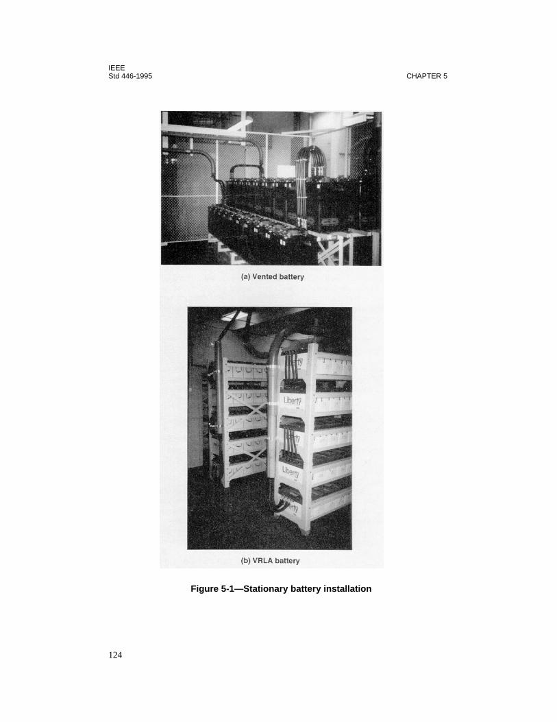
IEEEStd 446-1995 CHAPTER 5
Figure 5-1—Stationary battery installation
124

IEEESTORED ENERGY SYSTEMS Std 446-1995
provide 15 min of backup, during which time an emergency generator can be brought on-lineif the normal power has not been restored.
For this reason, most UPS systems (whether rotating or static) use batteries as their primarybackup power source. One notable exception is the engine/motor-generator (MG) systemdescribed in 5.6.8. The other exception is the engine-generator/motor-generator described in5.6.9. All other systems available today convert dc power provided by the battery to ac powerthrough an inverter, an ac generator, or some combination of the two.
This chapter addresses these systems by first discussing the two energy storage systems, i.e.,electrochemical (battery) and inertia (mechanical). Once this is done, the two basic methodsavailable for conversion of the stored energy to ac power, i.e., the ac generator and the staticinverter, are discussed for those instances where the dc power available from the battery willnot be used directly to power dc-rated devices. Static UPS systems are discussed in 5.5.Motor-generators and rotating UPS systems are discussed in 5.6. Both types of UPS systemsaccomplish one or more of the goals listed previously in 5.1.
5.2 Definitions
For definitions used in this chapter, see Chapter 2 of this publication, IEEE Std 100-1992,1
and other standards listed in 5.7.
5.3 Battery systems
5.3.1 Introduction
A battery is the most dependable source available for emergency or standby power and canalso be one of the most versatile when applied with other devices. There are various batterydesigns available, each of which is tailored to meet the specific needs of a particular applica-tion. For example, batteries may be characterized as either starting, lighting, and ignition(SLI) or industrial. The SLI batteries include those used in automobiles, marine application,golf carts, trucks, etc. SLI batteries are outside the scope of this standard. Industrial batteriesinclude motive power, railroad, and standby (including stationary) types. Motive power bat-teries are used for applications such as forklift trucks, mining equipment, airline groundequipment, and electric vehicles. Railroad batteries, as the name implies, are used for loco-motives, railway signaling, railcar air conditioning/lighting, and people movers. Batteries ofthe standby type are of interest in this chapter because of their relevance to the purpose of thisrecommended practice. They are used in the following applications:
— Telecommunication systems— Electric substations— Electric generating stations— UPS systems
1Information on references can be found in 5.7.
125
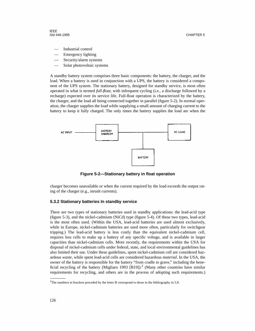
IEEEStd 446-1995 CHAPTER 5
— Industrial control— Emergency lighting— Security/alarm systems— Solar photovoltaic systems
A standby battery system comprises three basic components: the battery, the charger, and theload. When a battery is used in conjunction with a UPS, the battery is considered a compo-nent of the UPS system. The stationary battery, designed for standby service, is most oftenoperated in what is termed full-float, with infrequent cycling (i.e., a discharge followed by arecharge) expected over its service life. Full-float operation is characterized by the battery,the charger, and the load all being connected together in parallel (figure 5-2). In normal oper-ation, the charger supplies the load while supplying a small amount of charging current to thebattery to keep it fully charged. The only times the battery supplies the load are when the
charger becomes unavailable or when the current required by the load exceeds the output rat-ing of the charger (e.g., inrush currents).
5.3.2 Stationary batteries In standby service
There are two types of stationary batteries used in standby applications: the lead-acid type(figure 5-3), and the nickel-cadmium (NiCd) type (figure 5-4). Of these two types, lead-acidis the most often used. (Within the USA, lead-acid batteries are used almost exclusively,while in Europe, nickel-cadmium batteries are used more often, particularly for switchgeartripping.) The lead-acid battery is less costly than the equivalent nickel-cadmium cell,requires less cells to make up a battery of any specific voltage, and is available in largercapacities than nickel-cadmium cells. More recently, the requirements within the USA fordisposal of nickel-cadmium cells under federal, state, and local environmental guidelines hasalso limited their use. Under these guidelines, spent nickel-cadmium cell are considered haz-ardous waste, while spent lead-acid cells are considered hazardous material. In the USA, theowner of the battery is responsible for the battery “from cradle to grave,” including the bene-ficial recycling of the battery (Migliaro 1993 [B19]).2 (Many other countries have similarrequirements for recycling, and others are in the process of adopting such requirements.)
2The numbers in brackets preceded by the letter B correspond to those in the bibliography in 5.8.
Figure 5-2—Stationary battery in float operation
126

IEEESTORED ENERGY SYSTEMS Std 446-1995
Figure 5-3—A stationary lead-acid cell (vented type)
Figure 5-4—A Stationary nickel-cadmium cell
127
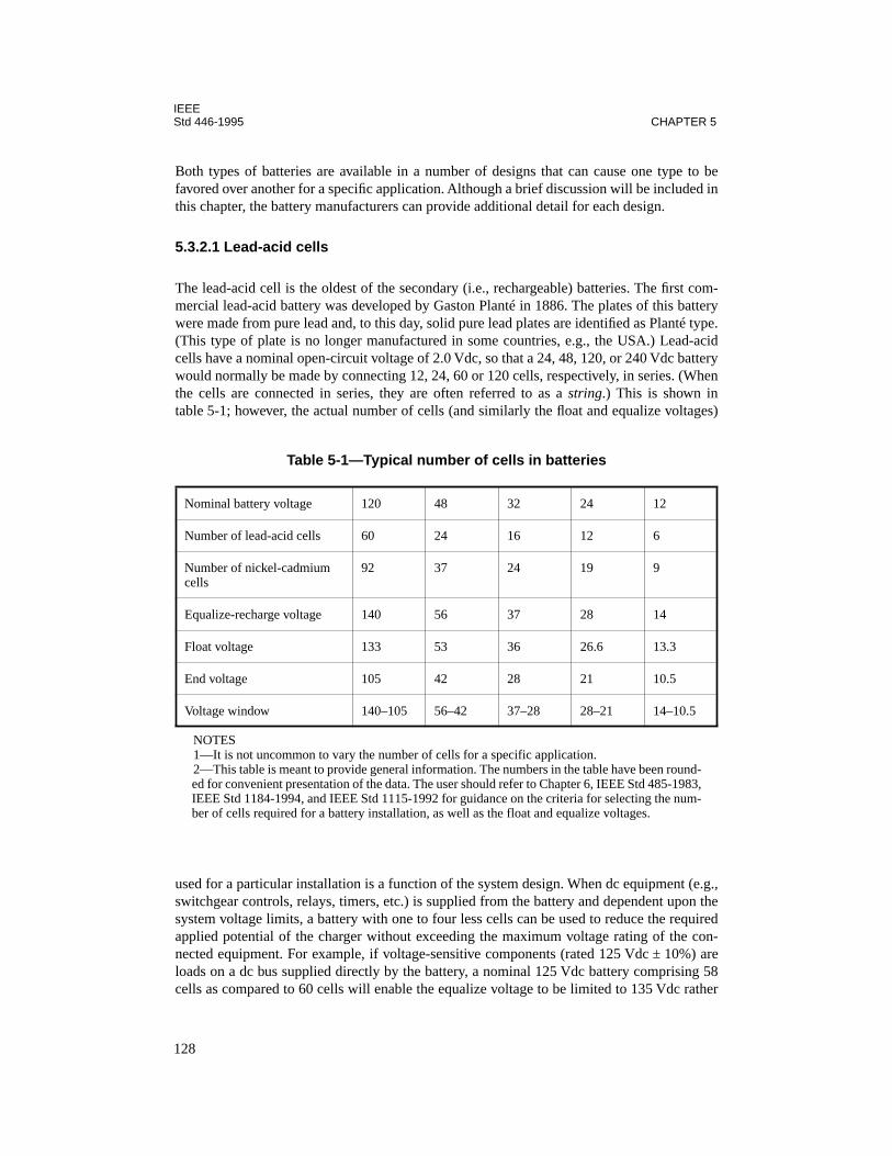
IEEEStd 446-1995 CHAPTER 5
Both types of batteries are available in a number of designs that can cause one type to befavored over another for a specific application. Although a brief discussion will be included inthis chapter, the battery manufacturers can provide additional detail for each design.
5.3.2.1 Lead-acid cells
The lead-acid cell is the oldest of the secondary (i.e., rechargeable) batteries. The first com-mercial lead-acid battery was developed by Gaston Planté in 1886. The plates of this batterywere made from pure lead and, to this day, solid pure lead plates are identified as Planté type.(This type of plate is no longer manufactured in some countries, e.g., the USA.) Lead-acidcells have a nominal open-circuit voltage of 2.0 Vdc, so that a 24, 48, 120, or 240 Vdc batterywould normally be made by connecting 12, 24, 60 or 120 cells, respectively, in series. (Whenthe cells are connected in series, they are often referred to as a string.) This is shown intable 5-1; however, the actual number of cells (and similarly the float and equalize voltages)
used for a particular installation is a function of the system design. When dc equipment (e.g.,switchgear controls, relays, timers, etc.) is supplied from the battery and dependent upon thesystem voltage limits, a battery with one to four less cells can be used to reduce the requiredapplied potential of the charger without exceeding the maximum voltage rating of the con-nected equipment. For example, if voltage-sensitive components (rated 125 Vdc ± 10%) areloads on a dc bus supplied directly by the battery, a nominal 125 Vdc battery comprising 58cells as compared to 60 cells will enable the equalize voltage to be limited to 135 Vdc rather
Table 5-1—Typical number of cells in batteries
Nominal battery voltage 120 48 32 24 12
Number of lead-acid cells 60 24 16 12 6
Number of nickel-cadmium cells
92 37 24 19 9
Equalize-recharge voltage 140 56 37 28 14
Float voltage 133 53 36 26.6 13.3
End voltage 105 42 28 21 10.5
Voltage window 140–105 56–42 37–28 28–21 14–10.5
NOTES1—It is not uncommon to vary the number of cells for a specific application.2—This table is meant to provide general information. The numbers in the table have been round-ed for convenient presentation of the data. The user should refer to Chapter 6, IEEE Std 485-1983,IEEE Std 1184-1994, and IEEE Std 1115-1992 for guidance on the criteria for selecting the num-ber of cells required for a battery installation, as well as the float and equalize voltages.
128
IEEESTORED ENERGY SYSTEMS Std 446-1995
than 140 Vdc when charging the cells at 2.33 V per cell, thus keeping the bus voltage withinthe rating of the component. When an installation uses a reduced number of cells, a largercapacity cell is required to serve the load, since a higher end-of-discharge voltage will berequired to meet the system minimum voltage requirements. Information on selecting thenumber of cells for a battery (as well as information on sizing a battery) can be found in IEEEStd 485-1983. Additionally, in industry, 120 V and 240 V batteries are often referred to as 125V and 250 V, respectively.
Lead-acid cells may be either the vented or valve-regulated type. They may be supplied asindividual units (i.e., single cells) or as multi-cell units (also referred to as monoblocs).Where more capacity is required than is available from a single battery string, individual bat-tery strings may be paralleled to provide the required capacity.
5.3.2.1.1 Vented cells (flooded cells)
Although the term vented cells is being used in the latest standards related to these cells todistinguish them from valve-regulated cells, much of the literature in the industry, includingmany battery manufacturers’ instruction manuals still uses the term flooded cells. Based uponthis, both terms are included in this recommended practice. The vented (flooded) cell is onein which the plates are flooded with electrolyte (figure 5-3). The electrolyte, which is dilutesulfuric acid in water, may spill from the cell if it is tilted or otherwise upset. Traditionally,the nominal full-charge specific gravity (SG) of the electrolyte for stationary-type ventedcells was 1.215 ± 0.010; however, cells that are currently available often use nominal SGs of1.250 and 1.300, particularly when they are applied in UPS systems. (Higher specific-gravityelectrolyte results in a cell with increased capacity; however, its expected life will be some-what reduced and its float voltage must be increased to compensate for higher internal losseswithin the cell.) In addition, when the battery is installed in a location where the averageambient temperature is 85 °F, a nominal SG of 1.170 may be supplied. (This is termed a trop-ical gravity cell.) The cell is vented and allows the escape of gases generated during charging(e.g., hydrogen and oxygen). To prevent the accidental ignition of these gases, the cell shouldbe fitted with a flame-arrestor-type vent (figure 5-5).
Assuming the battery is properly sized, installed, and maintained, the normal failure mecha-nism for the vented lead-acid cell is the corrosion of the positive plate. Because of this, anumber of positive plate designs are available:
— Rectangular flat plate. This plate is also known as a rectangular pasted plate orFauré plate. (The word rectangular is usually omitted when describing this plate.)This type of plate has two components: The first component is a support structurecalled a grid; the second component is the active material, which is applied to thegrid in the form of a paste. The grid is made of a lead alloy (which provides mechan-ical strength) and functions to support the active material and to carry current to andfrom the active material. The active material react chemically to produce or absorbenergy during the discharge or charge of the cell. (See figure 5-6.)
— Round pasted plate. This plate is also known as a round plate. It uses a grid madefrom pure lead, which is pasted with active material. When fabricated, these platesare positioned horizontally and have a slightly conical shape. (See figure 5-7.)
129

IEEEStd 446-1995 CHAPTER 5
— Tubular plate. This plate has four components. The first component is a lead alloycasting that has a top bar from which a number of spines extend. A porous fiber tubeis then fitted over each spine and the area between the spine and the tube is filled withlead oxide powder. The ends of the tubes are then closed with a plastic cap that holdsthe powder in the tubes. (See figure 5-8.)
— Modified Planté plate. This plate uses a lead alloy grid in which circular holes havebeen cast. Pure lead strips are corrugated and rolled into buttons called rosettes. Therosettes are then pressed into the grid. (See figure 5-9.)
The negative plate used with each type of positive plate is a pasted plate. In each case, theshape of the negative plate, i.e., round or rectangular, matches that of the positive plate.
Figure 5-5—Flame arrestor vents with dust covers
Figure 5-6—Flat plate (right) and grid (left)
130
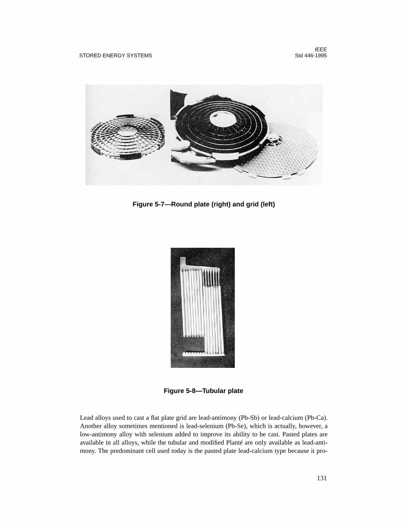
IEEESTORED ENERGY SYSTEMS Std 446-1995
Lead alloys used to cast a flat plate grid are lead-antimony (Pb-Sb) or lead-calcium (Pb-Ca).Another alloy sometimes mentioned is lead-selenium (Pb-Se), which is actually, however, alow-antimony alloy with selenium added to improve its ability to be cast. Pasted plates areavailable in all alloys, while the tubular and modified Planté are only available as lead-anti-mony. The predominant cell used today is the pasted plate lead-calcium type because it pro-
Figure 5-7—Round plate (right) and grid (left)
Figure 5-8—Tubular plate
131
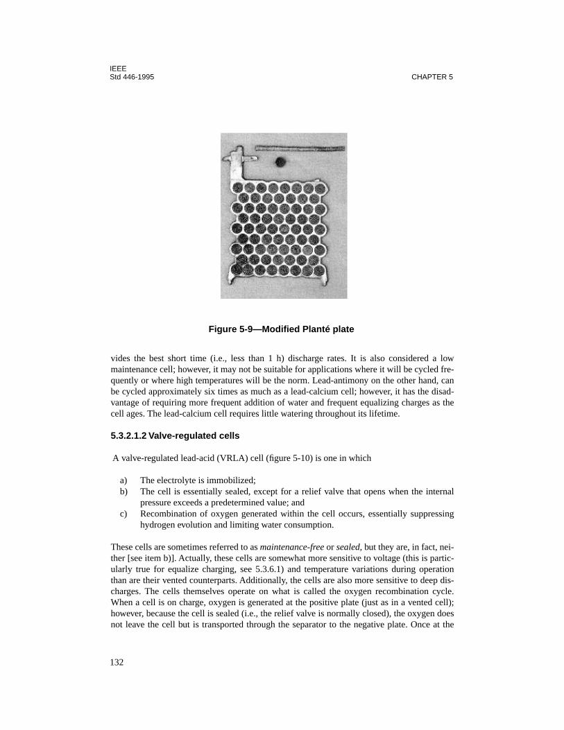
IEEEStd 446-1995 CHAPTER 5
vides the best short time (i.e., less than 1 h) discharge rates. It is also considered a lowmaintenance cell; however, it may not be suitable for applications where it will be cycled fre-quently or where high temperatures will be the norm. Lead-antimony on the other hand, canbe cycled approximately six times as much as a lead-calcium cell; however, it has the disad-vantage of requiring more frequent addition of water and frequent equalizing charges as thecell ages. The lead-calcium cell requires little watering throughout its lifetime.
5.3.2.1.2 Valve-regulated cells
A valve-regulated lead-acid (VRLA) cell (figure 5-10) is one in which
a) The electrolyte is immobilized; b) The cell is essentially sealed, except for a relief valve that opens when the internal
pressure exceeds a predetermined value; and c) Recombination of oxygen generated within the cell occurs, essentially suppressing
hydrogen evolution and limiting water consumption.
These cells are sometimes referred to as maintenance-free or sealed, but they are, in fact, nei-ther [see item b)]. Actually, these cells are somewhat more sensitive to voltage (this is partic-ularly true for equalize charging, see 5.3.6.1) and temperature variations during operationthan are their vented counterparts. Additionally, the cells are also more sensitive to deep dis-charges. The cells themselves operate on what is called the oxygen recombination cycle.When a cell is on charge, oxygen is generated at the positive plate (just as in a vented cell);however, because the cell is sealed (i.e., the relief valve is normally closed), the oxygen doesnot leave the cell but is transported through the separator to the negative plate. Once at the
Figure 5-9—Modified Planté plate
132
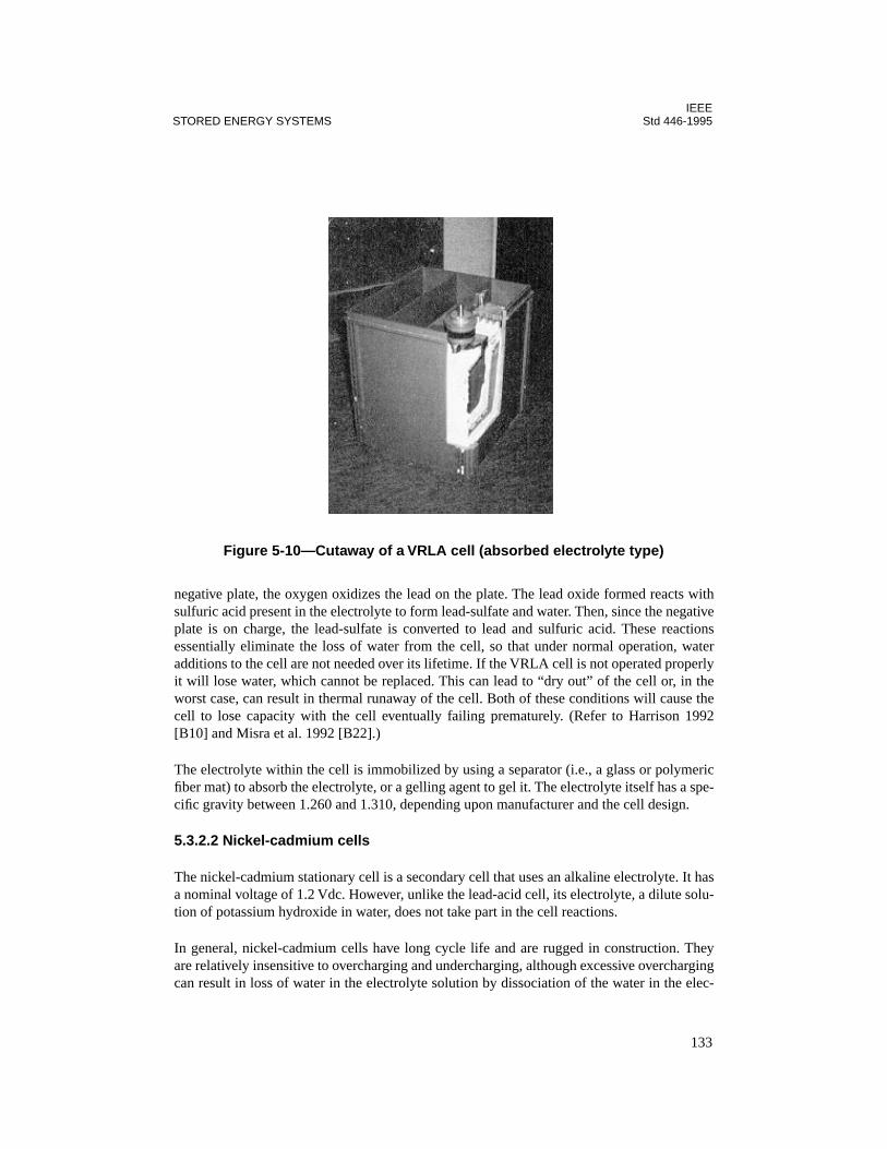
IEEESTORED ENERGY SYSTEMS Std 446-1995
negative plate, the oxygen oxidizes the lead on the plate. The lead oxide formed reacts withsulfuric acid present in the electrolyte to form lead-sulfate and water. Then, since the negativeplate is on charge, the lead-sulfate is converted to lead and sulfuric acid. These reactionsessentially eliminate the loss of water from the cell, so that under normal operation, wateradditions to the cell are not needed over its lifetime. If the VRLA cell is not operated properlyit will lose water, which cannot be replaced. This can lead to “dry out” of the cell or, in theworst case, can result in thermal runaway of the cell. Both of these conditions will cause thecell to lose capacity with the cell eventually failing prematurely. (Refer to Harrison 1992[B10] and Misra et al. 1992 [B22].)
The electrolyte within the cell is immobilized by using a separator (i.e., a glass or polymericfiber mat) to absorb the electrolyte, or a gelling agent to gel it. The electrolyte itself has a spe-cific gravity between 1.260 and 1.310, depending upon manufacturer and the cell design.
5.3.2.2 Nickel-cadmium cells
The nickel-cadmium stationary cell is a secondary cell that uses an alkaline electrolyte. It hasa nominal voltage of 1.2 Vdc. However, unlike the lead-acid cell, its electrolyte, a dilute solu-tion of potassium hydroxide in water, does not take part in the cell reactions.
In general, nickel-cadmium cells have long cycle life and are rugged in construction. Theyare relatively insensitive to overcharging and undercharging, although excessive overchargingcan result in loss of water in the electrolyte solution by dissociation of the water in the elec-
Figure 5-10—Cutaway of a VRLA cell (absorbed electrolyte type)
133

IEEEStd 446-1995 CHAPTER 5
trolyte into hydrogen and oxygen. These batteries are suitable for long-term storage, are con-sidered to have low maintenance requirements, and have good short-time discharge rates.They are particularly well-suited for applications in which the battery will be subjected totemperature extremes.
Two nickel-cadmium cell designs are used for stationary batteries in standby applications: thepocket-plate design and the fiber-plate design. Cells of either design are of the vented type,i.e., they have free electrolyte and long cycle life when compared to lead-acid stationary bat-teries.
Another design, called a sintered-plate, has an undesirable characteristic referred to as “mem-ory effect.” This characteristic is not observed in either the pocket-plate or fiber-plate designs;however, it is often mistakenly thought to apply to any nickel-cadmium cell. The sintered-plate design is available in vented or sealed types. This design is used in some emergencylighting units, particularly the fluorescent or decorator types.
5.3.2.2.1 Pocket-plate cells
This design derives its name from the fact that the active materials in the plates are held in“pockets” (figure 5-4). The pockets are fabricated from finely perforated steel strips. Two ofthese strips, formed into troughs, are used to sandwich the active material in the pocket.
5.3.2.2.2 Fiber-plate cells
The fiber-plate cell is the most recently introduced design for stationary applications. Theplate itself is a very porous fiber mat. The fibers are nickel-plated and then are impregnatedwith the active materials. This type of cell has a high power-to-weight ratio.
5.3.3 Installation design
IEEE Std 484-1996 provides guidance for the installation design for vented lead-acid batter-ies. A similar document, IEEE Std 1187-1996, was developed for VRLA batteries. ANSI/NFPA 111-1993 [B5] provides performance requirements for UPS systems, including limitedinformation on batteries.
Installation design should consider, but not be limited to, the following:
— Safety— Location— Mounting— Heating, ventilation, and air-conditioning— Seismic requirements— Maintenance requirements— Illumination— Instrumentation (including monitoring/alarms)— Overcurrent protection (see Chapter 6)
134
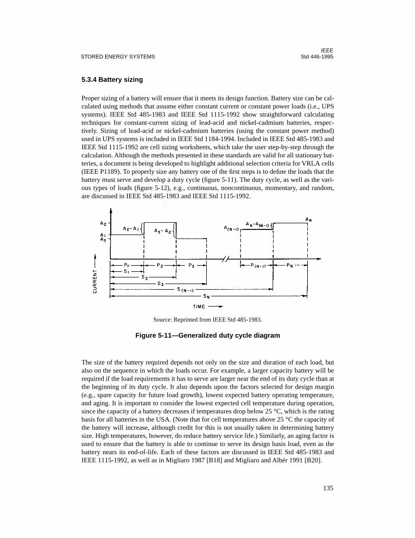
IEEESTORED ENERGY SYSTEMS Std 446-1995
5.3.4 Battery sizing
Proper sizing of a battery will ensure that it meets its design function. Battery size can be cal-culated using methods that assume either constant current or constant power loads (i.e., UPSsystems). IEEE Std 485-1983 and IEEE Std 1115-1992 show straightforward calculatingtechniques for constant-current sizing of lead-acid and nickel-cadmium batteries, respec-tively. Sizing of lead-acid or nickel-cadmium batteries (using the constant power method)used in UPS systems is included in IEEE Std 1184-1994. Included in IEEE Std 485-1983 andIEEE Std 1115-1992 are cell sizing worksheets, which take the user step-by-step through thecalculation. Although the methods presented in these standards are valid for all stationary bat-teries, a document is being developed to highlight additional selection criteria for VRLA cells(IEEE P1189). To properly size any battery one of the first steps is to define the loads that thebattery must serve and develop a duty cycle (figure 5-11). The duty cycle, as well as the vari-ous types of loads (figure 5-12), e.g., continuous, noncontinuous, momentary, and random,are discussed in IEEE Std 485-1983 and IEEE Std 1115-1992.
The size of the battery required depends not only on the size and duration of each load, butalso on the sequence in which the loads occur. For example, a larger capacity battery will berequired if the load requirements it has to serve are larger near the end of its duty cycle than atthe beginning of its duty cycle. It also depends upon the factors selected for design margin(e.g., spare capacity for future load growth), lowest expected battery operating temperature,and aging. It is important to consider the lowest expected cell temperature during operation,since the capacity of a battery decreases if temperatures drop below 25 °C, which is the ratingbasis for all batteries in the USA. (Note that for cell temperatures above 25 °C the capacity ofthe battery will increase, although credit for this is not usually taken in determining batterysize. High temperatures, however, do reduce battery service life.) Similarly, an aging factor isused to ensure that the battery is able to continue to serve its design basis load, even as thebattery nears its end-of-life. Each of these factors are discussed in IEEE Std 485-1983 andIEEE 1115-1992, as well as in Migliaro 1987 [B18] and Migliaro and Albér 1991 [B20].
Source: Reprinted from IEEE Std 485-1983.
Figure 5-11—Generalized duty cycle diagram
135
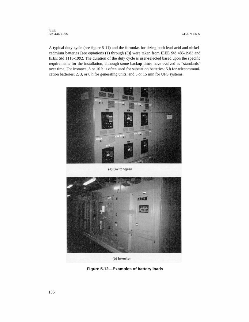
IEEEStd 446-1995 CHAPTER 5
A typical duty cycle (see figure 5-11) and the formulas for sizing both lead-acid and nickel-cadmium batteries [see equations (1) through (3)] were taken from IEEE Std 485-1983 andIEEE Std 1115-1992. The duration of the duty cycle is user-selected based upon the specificrequirements for the installation, although some backup times have evolved as “standards”over time. For instance, 8 or 10 h is often used for substation batteries; 5 h for telecommuni-cation batteries; 2, 3, or 8 h for generating units; and 5 or 15 min for UPS systems.
Figure 5-12—Examples of battery loads
136

IEEESTORED ENERGY SYSTEMS Std 446-1995
Figure 5-12—Examples of battery loads (Continued)
137
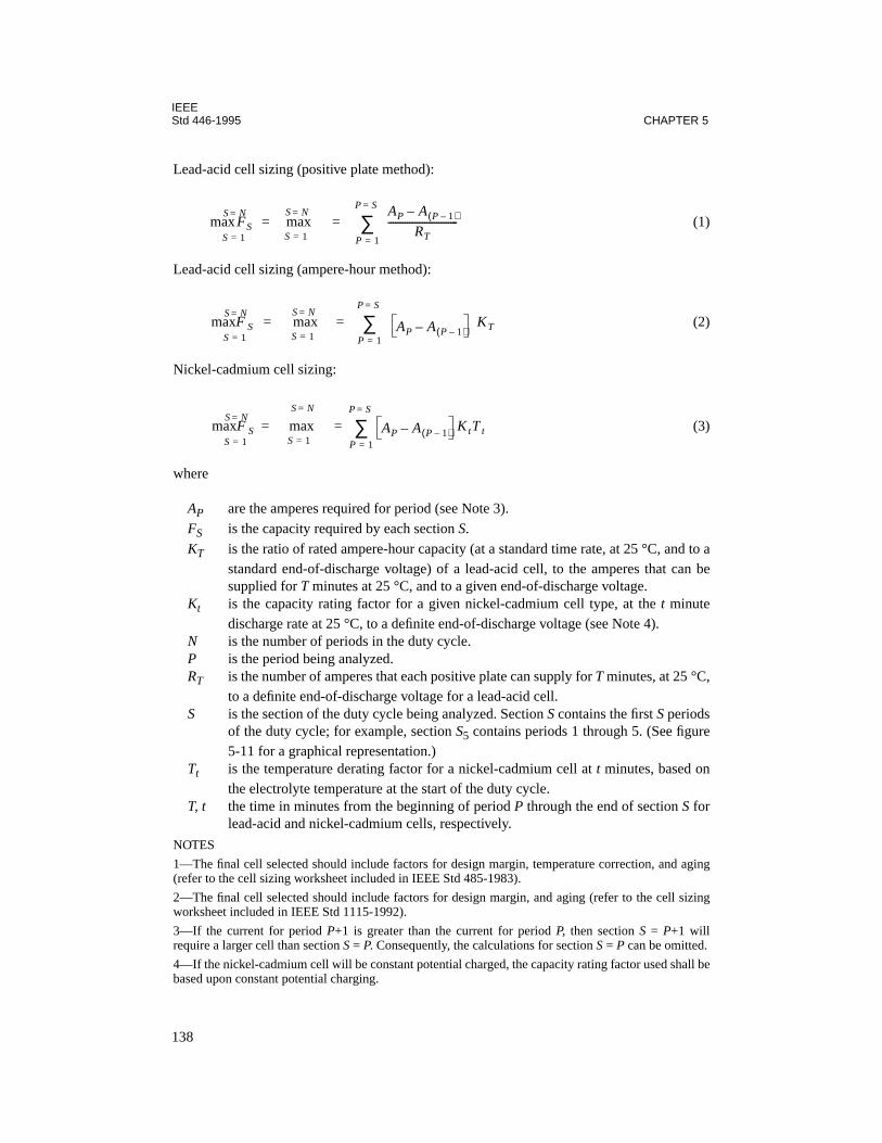
IEEEStd 446-1995 CHAPTER 5
Lead-acid cell sizing (positive plate method):
(1)
Lead-acid cell sizing (ampere-hour method):
(2)
Nickel-cadmium cell sizing:
(3)
where
AP are the amperes required for period (see Note 3).
FS is the capacity required by each section S.
KT is the ratio of rated ampere-hour capacity (at a standard time rate, at 25 °C, and to astandard end-of-discharge voltage) of a lead-acid cell, to the amperes that can besupplied for T minutes at 25 °C, and to a given end-of-discharge voltage.
Kt is the capacity rating factor for a given nickel-cadmium cell type, at the t minutedischarge rate at 25 °C, to a definite end-of-discharge voltage (see Note 4).
N is the number of periods in the duty cycle.P is the period being analyzed.RT is the number of amperes that each positive plate can supply for T minutes, at 25 °C,
to a definite end-of-discharge voltage for a lead-acid cell.S is the section of the duty cycle being analyzed. Section S contains the first S periods
of the duty cycle; for example, section S5 contains periods 1 through 5. (See figure5-11 for a graphical representation.)
Tt is the temperature derating factor for a nickel-cadmium cell at t minutes, based onthe electrolyte temperature at the start of the duty cycle.
T, t the time in minutes from the beginning of period P through the end of section S forlead-acid and nickel-cadmium cells, respectively.
NOTES
1—The final cell selected should include factors for design margin, temperature correction, and aging(refer to the cell sizing worksheet included in IEEE Std 485-1983).
2—The final cell selected should include factors for design margin, and aging (refer to the cell sizingworksheet included in IEEE Std 1115-1992).
3—If the current for period P+1 is greater than the current for period P, then section S = P+1 willrequire a larger cell than section S = P. Consequently, the calculations for section S = P can be omitted.
4—If the nickel-cadmium cell will be constant potential charged, the capacity rating factor used shall bebased upon constant potential charging.
max FSS 1=
S N=maxS 1=
S N==
AP A P 1–( )–
RT-----------------------------
P 1=
P S=
∑=
maxF SS 1=
S N=maxS 1=
S N=
AP A P 1–( )– KTP 1=
P S=
∑= =
maxF SS 1=
S N=maxS 1=
S N=
AP A P 1–( )– KtT tP 1=
P S=
∑= =
138
IEEESTORED ENERGY SYSTEMS Std 446-1995
In order to choose the appropriate size nickel-cadmium cell, the method to be used for charg-ing the cell must be considered. Nickel-cadmium ratings are based on constant current charg-ing; however, most standby batteries use constant potential charging. Prolonged constantpotential (i.e., float) charging of a nickel-cadmium battery may reduce its capacity fromrated, dependent upon the discharge rate. As a result, voltage decay upon discharge will occurfaster than that of a full-capacity battery. The effects of constant potential charging can beaccounted for during battery sizing by using capacity rating factors based upon this methodof charging (see IEEE Std 1115-1992). These factors should be obtained from the batterymanufacturer, as they vary between manufacturers. Caution: A sealed nickel-cadmium cellshould be charged with a constant-current charger only.
Once the loads are defined, a cell type must be selected as well as the number of cells thatwill make up the string. The predominant type of cell used for stationary batteries is the lead-calcium flat plate in either a vented or VRLA design. A few other types of cells, or differentnumbers of cells, can be evaluated to optimize the selection. The number of cells in a batteryfor any specific system is determined by considering any of the following as a limiting condi-tion: minimum system voltage, maximum system voltage, float voltage, and charging volt-age. The maximum and minimum voltages may not be as critical for UPS systems, since theinverter design can usually accommodate a large voltage variation (i.e., voltage window).
The battery is sized to support the critical load for the worst-case conditions until either thecritical load can be shut down in an orderly manner, the normal power source returns, or analternate standby ac source can be started and connected. Battery support times might be inminutes (e.g., 5, 10, 15 or 30 min) or in hours (e.g., 1.5, 2, 5, or 8 h). The shorter backuptimes are consistent with UPS system design, while the longer backup times are used for tele-communications, electric power, and emergency lighting systems. The longer the battery sup-ply time, the larger the battery capacity required to serve the load. Rather than purchasinglarger battery capacity (i.e., when a longer backup time is not a requirement of a code or stan-dard), the installation of an engine or combustion-turbine generator standby power sourceshould be evaluated.
5.3.5 Battery maintenance and testing
Requirements for maintenance and testing are discussed in Chapter 8. In addition, IEEE Std450-1995 and IEEE Std 1106-1995 provide guidance for the maintenance and testing ofvented lead-acid and nickel-cadmium batteries, respectively. A similar document is beingdeveloped for VRLA batteries (IEEE P1188); until it is approved and published, the guidancein IEEE Std 450-1995, in conjunction with the battery manufacturer’s maintenance instruc-tions for the VRLA battery, may be used. ANSI/NFPA 111-1993 [B5] provides requirementsfor maintenance and testing for batteries in certain legally required emergency and standbysystems.
139
IEEEStd 446-1995 CHAPTER 5
5.3.6 Recharge/equalize charging
5.3.6.1 Lead-acid batteries
Lead-acid stationary batteries are charged using a constant potential charger. Two values ofcharge voltage are usually specified. These are float and equalize voltage (also refer to Chap-ter 6). (The equalize voltage specified by the battery manufacturer is also the value used torecharge a battery after a discharge.) For each battery, the manufacturer’s instructions willspecify the voltage, or range of voltage, for float and equalize. In the case of a VRLA battery,the manufacturer may also provide a range of cell float voltages based upon cell temperature(i.e., temperature-compensated float voltage), or may simply provide a temperature correc-tion factor to be applied to the float voltage. It is important that the battery manufacturer’sinstructions for float voltage, equalize voltage, and charging be followed. For example, thebattery manufacturer may not specify an equalize voltage for a VRLA battery. The applica-tion of an improper (i.e., too high) voltage during charging for a VRLA battery can lead todry out of the cells or can result in thermal runaway. This can occur in either float or equalizeoperation if the VRLA battery’s charging voltage is improperly set.
Lead-calcium cells placed on float charge at the high end of their voltage range may notrequire equalize charges to be applied. An equalize charge may be required if the individualcell voltages or specific gravities drift too far apart (i.e., have too great a spread.) The reasonfor requiring an equalize charge is that some of the individual cells in the series string maynot get enough current to keep them fully charged while on float charge. This loss of charge isrelated to the self-discharge of the individual cell, which results in its voltage dropping overtime. When the battery is placed on equalize, the higher charge voltage causes an increasedcurrent to flow through the string. This higher current is sufficient to overcome the self-dis-charge of all the cells in the string, restoring each of them to full charge. Equalize chargesshould be given only when necessary and should be applied in accordance with the batterymanufacturer’s instructions. At one time equalize charges were considered to be part of peri-odic maintenance; however, today they are considered a maintenance corrective action. Lead-antimony alloy cells require more equalize charges than do other lead acid cells. This is dueto their increased self-discharge rate as they age.
While it is always best to have both float and equalize functions, some UPS system batterychargers do not have an equalize function. It may have been omitted from the specificationthrough oversight or because it was thought that setting the float voltage high enough wouldeliminate the need for equalize charges. If an equalize setting is not available, any charging ofthe battery (e.g., initial charge, recharge following a test, or a discharge) must be accom-plished at the float-voltage setting. This can result in extremely long charge times and mayeven require the use of supplemental chargers (e.g., single-cell chargers) to ensure that thebattery is maintained in good health. Caution: Charging of VRLA cells should be done instrict conformance with the battery manufacturer’s instructions.
5.3.6.2 Nickel-cadmium batteries
Nickel-cadmium vented-type batteries may be constant-potential charged but are more suitedto constant-current charging, if this type of charging can be tolerated by the load on the bat-
140

IEEESTORED ENERGY SYSTEMS Std 446-1995
tery. When a constant-current charge is used, recharge may be accomplished using a two-ratecharge, i.e., an initial (high-current) rate followed by a finish (low-current) rate that is begunonce the charge is approximately 80% complete. If constant-potential charging is used, anickel-cadmium battery may not be able to develop its rated capacity, depending upon therate at which it is discharged and the required minimum battery voltage (refer to 5.3.4 andIEEE Std 1115-1992). Caution: A sealed nickel-cadmium battery should only be applied witha constant-current charger.
5.3.6.3 Operation
Standby batteries are normally applied in float operation; the battery, battery charger, andload are connected in parallel (see figure 5-2). The charging equipment should be sized toprovide all of the power normally required by relatively steady loads, such as indicatinglamps and relay coils, and minor intermittent loads, plus enough additional power to keep thebattery at full charge. Relatively large intermittent loads will draw power from the battery;this power will be restored to the battery by the charger when the intermittent load ceases.Battery charger sizing is discussed in IEEE Std 946-1992.
When ac input power to the system is lost, the battery instantly assumes all of the connectedload. If the battery and charger are properly matched to the load and to each other, there willbe no discernible voltage dip when the system reverts to full battery operation.
When an emergency load on the system ends and charging power is restored, a constant-potential charger will deliver more current than if the battery were fully charged. Some con-stant-potential chargers will automatically increase their output voltage to the equalize settingafter power to the charger is restored. (Similarly, a constant-current charger may automati-cally increase its output to the high rate.) The charger must be properly sized to ensure that itcan serve the load and restore the battery to full charge within an acceptable time. Theincreased current delivered by a constant-potential charger during this restoration period willtaper off as the battery approaches full charge.
The charging rectifier, or battery charger, is an important part of the emergency power sys-tem, and consideration should be given to redundant chargers on critical systems. Refer tofigure 5-13 for a typical redundant system. The charger should be operated only with the bat-tery connected to the dc bus. Without this connection, excessive ripple on the system couldoccur, which could affect connected equipment (e.g., causing misoperation or failure). If asystem must be able to operate without the battery connected, then a battery eliminatorshould be specified. The battery charger output must be derated for altitude, when it isinstalled in locations above 3300 ft (1000 m), and for temperature, when the ambient temper-ature exceeds 50 °C. The battery charger manufacturer can provide these derating factors andshould account for them in the battery charger’s design.
5.3.7 Battery system short-circuit calculation
The short-circuit capability of a dc system should not be overlooked. Chapter 6 discussesthis; however, an in-depth discussion of the subject is included in IEEE Std 946-1992. This
141
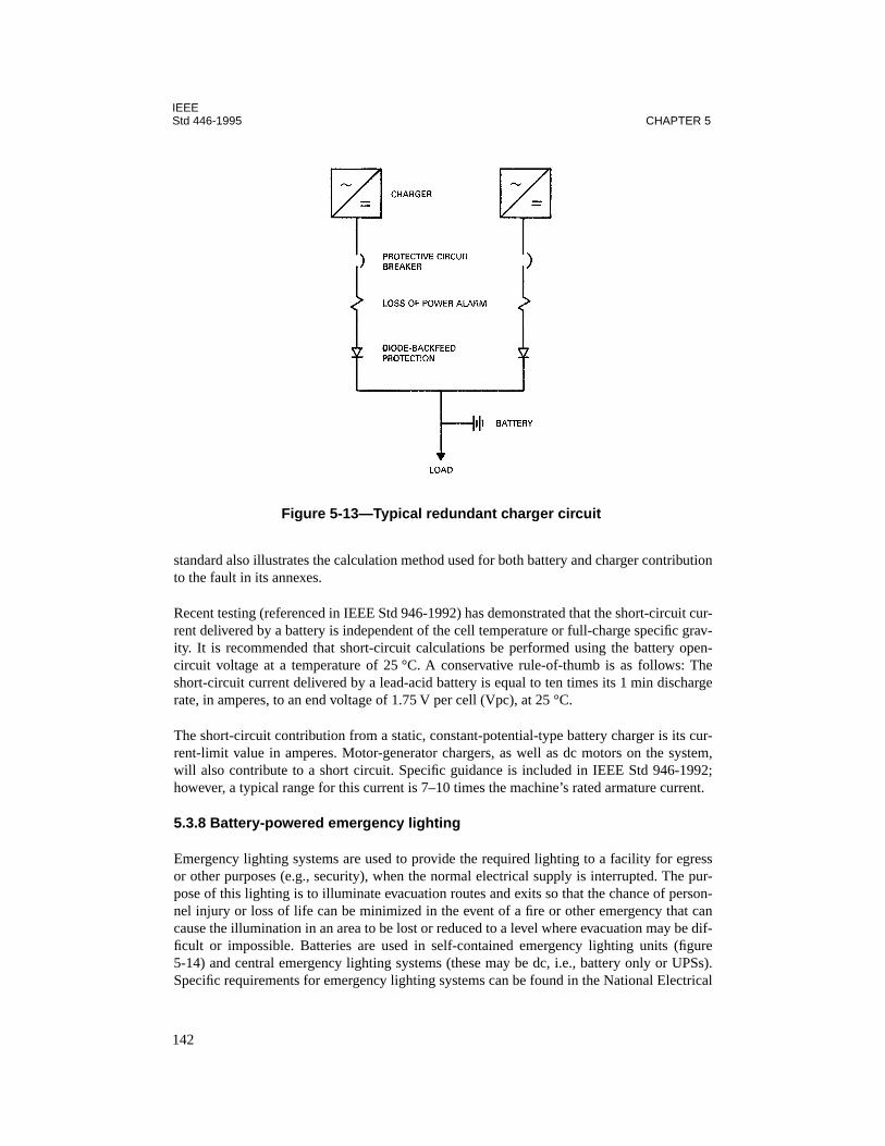
IEEEStd 446-1995 CHAPTER 5
standard also illustrates the calculation method used for both battery and charger contributionto the fault in its annexes.
Recent testing (referenced in IEEE Std 946-1992) has demonstrated that the short-circuit cur-rent delivered by a battery is independent of the cell temperature or full-charge specific grav-ity. It is recommended that short-circuit calculations be performed using the battery open-circuit voltage at a temperature of 25 °C. A conservative rule-of-thumb is as follows: Theshort-circuit current delivered by a lead-acid battery is equal to ten times its 1 min dischargerate, in amperes, to an end voltage of 1.75 V per cell (Vpc), at 25 °C.
The short-circuit contribution from a static, constant-potential-type battery charger is its cur-rent-limit value in amperes. Motor-generator chargers, as well as dc motors on the system,will also contribute to a short circuit. Specific guidance is included in IEEE Std 946-1992;however, a typical range for this current is 7–10 times the machine’s rated armature current.
5.3.8 Battery-powered emergency lighting
Emergency lighting systems are used to provide the required lighting to a facility for egressor other purposes (e.g., security), when the normal electrical supply is interrupted. The pur-pose of this lighting is to illuminate evacuation routes and exits so that the chance of person-nel injury or loss of life can be minimized in the event of a fire or other emergency that cancause the illumination in an area to be lost or reduced to a level where evacuation may be dif-ficult or impossible. Batteries are used in self-contained emergency lighting units (figure5-14) and central emergency lighting systems (these may be dc, i.e., battery only or UPSs).Specific requirements for emergency lighting systems can be found in the National Electrical
Figure 5-13—Typical redundant charger circuit
142
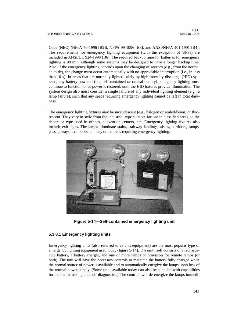
IEEESTORED ENERGY SYSTEMS Std 446-1995
Code (NEC) (NFPA 70-1996 [B2]), NFPA 99-1996 [B3], and ANSI/NFPA 101-1991 [B4].The requirements for emergency lighting equipment (with the exception of UPSs) areincluded in ANSI/UL 924-1990 [B6]. The required backup time for batteries for emergencylighting is 90 min, although some systems may be designed to have a longer backup time.Also, if the emergency lighting depends upon the changing of sources (e.g., from the normalac to dc), the change must occur automatically with no appreciable interruption (i.e., in lessthan 10 s). In areas that are normally lighted solely by high-intensity discharge (HID) sys-tems, any battery-powered (i.e., self-contained or central battery) emergency lighting mustcontinue to function, once power is restored, until the HID fixtures provide illumination. Thesystem design also must consider a single failure of any individual lighting element (e.g., alamp failure), such that any space requiring emergency lighting cannot be left in total dark-ness.
The emergency lighting fixtures may be incandescent (e.g., halogen or sealed-beam) or fluo-rescent. They vary in style from the industrial type suitable for use in classified areas, to thedecorator type used in offices, convention centers, etc. Emergency lighting fixtures alsoinclude exit signs. The lamps illuminate stairs, stairway landings, aisles, corridors, ramps,passageways, exit doors, and any other areas requiring emergency lighting.
5.3.8.1 Emergency lighting units
Emergency lighting units (also referred to as unit equipment) are the most popular type ofemergency lighting equipment used today (figure 5-14). The unit itself consists of a recharge-able battery, a battery charger, and one or more lamps or provision for remote lamps (orboth). The unit will have the necessary controls to maintain the battery fully charged whilethe normal source of power is available and to automatically energize the lamps upon loss ofthe normal power supply. (Some units available today can also be supplied with capabilitiesfor automatic testing and self-diagnostics.) The controls will de-energize the lamps immedi-
Figure 5-14—Self-contained emergency lighting unit
143

IEEEStd 446-1995 CHAPTER 5
ately, or after a time delay (e.g., for areas normally illuminated solely by HID fixtures), uponrestoration of the normal power supply. If the unit is used with a fluorescent fixture it will alsohave a high-frequency inverter and controls intended for that type of fixture.
These units can be supplied with any of the lead-acid or the pocket-plate nickel-cadmium bat-teries discussed previously in 5.3.2.1 and 5.3.2.2. This would include pure lead, lead-anti-mony, and lead-calcium cells and both vented and valve-regulated types. They may also besupplied with sintered-plate nickel-cadmium cells. In addition, the units may be suppliedwith chargers that have automatic temperature compensation of float/charge voltage. Thisfeature should be considered a must when a VRLA battery is supplied in the unit. The selec-tion of battery type depends upon the installation itself. For example, pocket-plate nickel-cad-mium batteries may be used in high-temperature areas, such as near an industrial boiler,while VRLA or sealed sintered-plate batteries may be used in an office area. All of these bat-teries require periodic maintenance and testing with the vented types requiring the periodicaddition of water as well.
The batteries in these types of units are either 6 Vdc or 12 Vdc. For the lead-acid cells, theelectrolyte SG is normally 1.225 or greater (the upper limit of SG is 1.310) and the cellcapacity is often expressed in ampere-hours (A-h) at the 10 h or 20 h discharge rate to 1.75 Vper cell (Vpc), at 25 °C.
5.3.8.2 Central battery supplied emergency lighting systems
Building-wide systems may also be used to connect many lamps to a central battery and bat-tery charger or dedicated emergency lighting UPS. These systems are generally 32, 48, or120 Vdc, although some 12 and 24 Vdc are also available. When a UPS system is used, thebattery voltage may be greater than 120 Vdc, depending up the size and design of the UPS.
The advantages of the central battery-supplied emergency lighting system are as follows:
— Centralized power source, eliminating the need for single units located throughoutthe building, use of less space (only lamps are in the areas to be protected), andremote location of the power source. This may result in a reduction in the time spentmaintaining and testing the system.
— Availability of alarm and protection circuits, which increases the flexibility of thesystem.
— The ability to supply fixtures with a lower current, at a higher voltage, resulting indecreased losses.
The disadvantages of the central battery supplied emergency lighting system are as follows:
— The initial installation design is more complex, requiring raceways and cable to beinstalled.
— The failure of a single branch or feeder circuit may disable the emergency lighting toa large area.
144
IEEESTORED ENERGY SYSTEMS Std 446-1995
5.3.8.3 Selecting emergency lighting systems
The selection of emergency lighting systems is based on the type of facility (e.g., offices,storage, laboratories, etc.) as well as the layout of the building, building areas, and theirusage. The areas that need to be illuminated, as well as the light level necessary, must beidentified. Guidance on determining the requirements for specific facilities, including illumi-nation levels, can be found in ANSI/NFPA 101-1991 [B4] and NFPA 99-1996 [B3]. The NEC[B2] is applicable for the installation of the systems; however, it does not determine whethersuch systems are required, nor does the NEC determine the location of equipment. The mini-mum initial illumination level, required by ANSI/NFPA 101-1991 [B4], is an average of 1.0fc (10 lx) and a minimum at any point of 0.1 fc (1 lx) measured along the path of egress atfloor level. This may decline to 0.6 fc (6 lx) average and 0.06 fc (0.6 lx) minimum at anypoint at the end of the emergency period.
5.4 Mechanical energy storage
5.4.1 Introduction
Significant amounts of energy may be stored in the form of kinetic energy (inertia) in a rotat-ing mass. This energy is created by an ac or dc motor imparting rotational energy to its rotorand the rotor of an ac generator (and flywheel, if used). The stored kinetic energy can be con-verted from inertia to useful ac power by the rotating ac generator.
5.4.2 Kinetic energy
The energy contained in a rotating mass is defined by the equation:
(4)
where
I = the mass moment of inertia, in kg·m2/rad2
A = the angular velocity, in rad/sJ = energy, in Joules (N·m)
This energy is created by an ac or dc motor turning itself and the ac generator. The rotors andshaft(s) of the motor and generator make up the rotating mass. A flywheel may be added toincrease the mass. The motor and generator may be coupled in a variety of ways. Couplingssuch as pulleys and belts increase the rotating mass.
The resulting stored kinetic energy (inertia) will continue turning the ac generator in theabsence of power to the motor. The length of time that useful power is generated (called ride-through time) is determined by some key criteria:
— The inertia of the rotating mass
J12--- I A
2( )=
145
IEEEStd 446-1995 CHAPTER 5
— The percentage of full-rated load placed on the ac generator — The acceptable tolerance on the output frequency
For motor-generators under full load with a maximum under-frequency tolerance of –1 Hzand no flywheel, typical ride-through times range from 50–100 ms. The addition of a fly-wheel can raise the time to 0.5 s or more. Motor-generators with flywheels have been builtwith ride-through times of many minutes, using a constant r/min coupling; however, thesehave not proven commercially useful.
5.5 Battery/inverter systems
5.5.1 Introduction
Dc systems, particularly when they are large, may supply static inverters as loads; theseinverters were, in the past, often referred to as uninterruptible power supplies. However, it isbecoming more common to utilize a dedicated battery, charger, inverter, and accessories (e.g.,a static transfer switch), when there is a need for an uninterruptible power source. This com-bination of battery, rectifier/charger, static inverter and accessories, represent today’s staticUPS system. The primary purpose of the UPS is to provide continuity and quality of power tothe critical load(s) supplied by it. The batteries used with UPS systems are the stationary typediscussed in 5.3.2.
These UPS systems are available in a number of designs and sizes, ranging from less than100 W to several megawatts. UPS systems may provide single-phase or three-phase power atpower frequencies (i.e., 50 or 60 Hz) or at higher frequencies (e.g., 400 Hz). In addition,static UPS systems, because of their wide range of design and application, may providepower of which the output purity may vary from a near-perfect sine wave (less than 1% totalharmonic distortion [THD]) to essentially a square wave (greater than 25% THD).
5.5.2 Static UPS system description
The static UPS system is an electronically controlled solid-state system designed to providean alternate source of conditioned, reliable, and break-free electrical power to a user’s equip-ment. This equipment is often referred to as the “critical” or “protected” load. A UPS systemmaintains power to the critical load in the event of a partial or total failure of the normalsource of power, typically, the power supplied by the electric utility.
There are a variety of UPS configurations available that provide for voltage regulation, lineconditioning, lightning protection, redundancy, EMI management, extended run time, loadtransfer to other units, and other such features required to protect the critical load(s) againstfailure of the normal ac source, or against other power system disturbances.
Today, UPS technology continues to change making it more appropriate to describe a UPSsystem by its performance characteristics, rather than its electronic components, which mayvary from system to system or change with time and technology. Therefore, a UPS systemshould have the following primary attributes as a minimum:
146
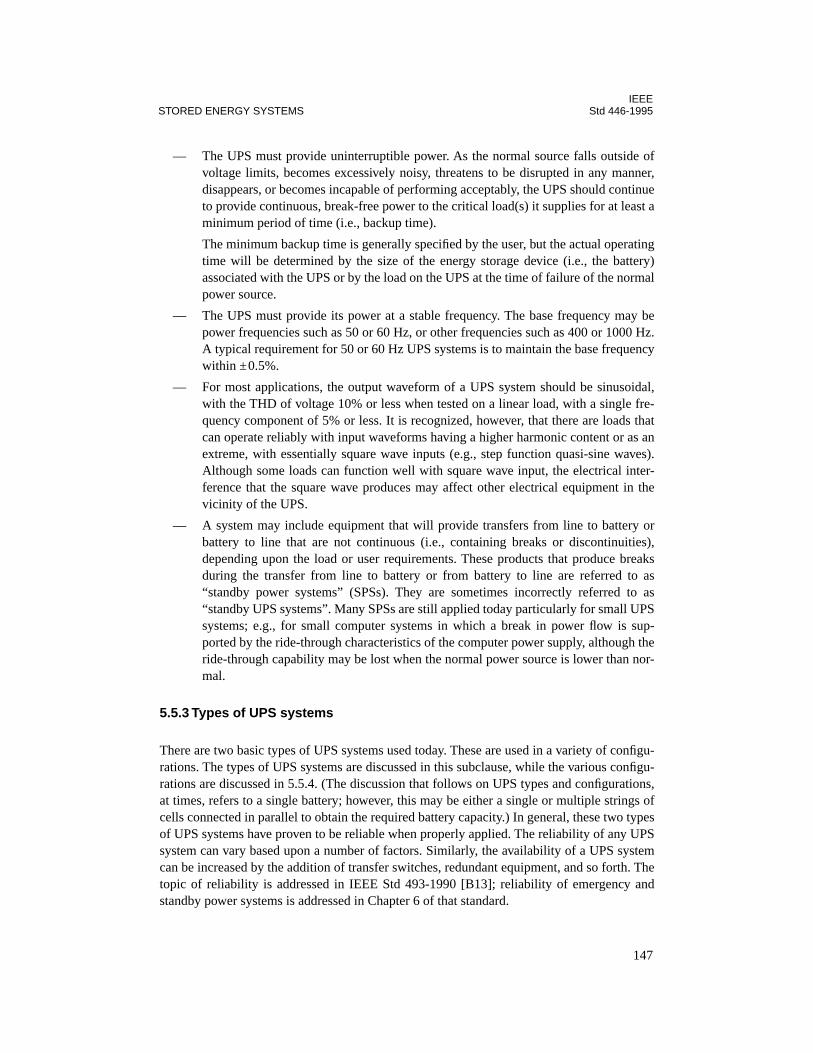
IEEESTORED ENERGY SYSTEMS Std 446-1995
— The UPS must provide uninterruptible power. As the normal source falls outside ofvoltage limits, becomes excessively noisy, threatens to be disrupted in any manner,disappears, or becomes incapable of performing acceptably, the UPS should continueto provide continuous, break-free power to the critical load(s) it supplies for at least aminimum period of time (i.e., backup time).
The minimum backup time is generally specified by the user, but the actual operatingtime will be determined by the size of the energy storage device (i.e., the battery)associated with the UPS or by the load on the UPS at the time of failure of the normalpower source.
— The UPS must provide its power at a stable frequency. The base frequency may bepower frequencies such as 50 or 60 Hz, or other frequencies such as 400 or 1000 Hz.A typical requirement for 50 or 60 Hz UPS systems is to maintain the base frequencywithin ±0.5%.
— For most applications, the output waveform of a UPS system should be sinusoidal,with the THD of voltage 10% or less when tested on a linear load, with a single fre-quency component of 5% or less. It is recognized, however, that there are loads thatcan operate reliably with input waveforms having a higher harmonic content or as anextreme, with essentially square wave inputs (e.g., step function quasi-sine waves).Although some loads can function well with square wave input, the electrical inter-ference that the square wave produces may affect other electrical equipment in thevicinity of the UPS.
— A system may include equipment that will provide transfers from line to battery orbattery to line that are not continuous (i.e., containing breaks or discontinuities),depending upon the load or user requirements. These products that produce breaksduring the transfer from line to battery or from battery to line are referred to as“standby power systems” (SPSs). They are sometimes incorrectly referred to as“standby UPS systems”. Many SPSs are still applied today particularly for small UPSsystems; e.g., for small computer systems in which a break in power flow is sup-ported by the ride-through characteristics of the computer power supply, although theride-through capability may be lost when the normal power source is lower than nor-mal.
5.5.3 Types of UPS systems
There are two basic types of UPS systems used today. These are used in a variety of configu-rations. The types of UPS systems are discussed in this subclause, while the various configu-rations are discussed in 5.5.4. (The discussion that follows on UPS types and configurations,at times, refers to a single battery; however, this may be either a single or multiple strings ofcells connected in parallel to obtain the required battery capacity.) In general, these two typesof UPS systems have proven to be reliable when properly applied. The reliability of any UPSsystem can vary based upon a number of factors. Similarly, the availability of a UPS systemcan be increased by the addition of transfer switches, redundant equipment, and so forth. Thetopic of reliability is addressed in IEEE Std 493-1990 [B13]; reliability of emergency andstandby power systems is addressed in Chapter 6 of that standard.
147

IEEEStd 446-1995 CHAPTER 5
5.5.3.1 Double-conversion systems
Double-conversions systems are characterized by their topology. In these systems, the incom-ing line is first converted to dc. The dc then provides input power to a dc-to-ac converter (i.e.,an inverter). The inverter output is ac, which is used to power the critical load. Many differenttypes of inverters are used, each employing a variant of available technology. (Note that therecently revised NEMA PE 1-1993 [B23], identifies the double-conversion system as a “rec-tifier-inverter.”)
Historically, the double-conversion UPS has found the most prominence in the industry. Thedouble-conversion UPS system has been available for many years and has proven to be reli-able when operated within its design limits. This type of system is the static electrical equiva-lent to the motor-generator set. The battery is connected in parallel with the dc input to theinverter, and provides continuous power to it any time the incoming line is outside of its spec-ification or fails. Switching to the battery is automatic, with no break in either the input to theinverter or the output from it.
The double-conversion system has several advantages:
— It provides excellent frequency stability.— There is a high degree of isolation from variations in incoming line voltage and fre-
quency.— A zero transfer time is possible.— Operation is relatively quiet.— Some systems can provide a sinusoidal output waveform with low distortion.
In the lower power UPS applications (0.1–20 kW), the double-conversion UPS has the fol-lowing disadvantages. (Many of these disadvantages can be minimized if the system is care-fully specified to use the latest topologies.)
— There is lower overall efficiency.— A large dc power supply is required (typically, 1.5 times the full rated load rating of
the UPS).— Noise isolation line to load can be poor.— There is greater heat dissipation, which may affect the service life of the UPS.
In addition, if the inverter is the pulse width modulated type, the high-frequency circuitrymay produce electromagnetic interference (EMI). This may require special filtering andshielding to protect sensitive equipment from radiated and conducted interference. The dou-ble-conversion UPS may also produce excessive battery ripple current, possibly resulting inreduced battery life (see IEEE Std 1184-1994).
5.5.3.2 Single-conversion systems
Single-conversion UPS systems are those in which, during normal operation, the incomingline is used to provide power to the critical load either through a transformer or in conjunc-tion with some series impedance. Some forms of single-conversion UPS products are classi-
148

IEEESTORED ENERGY SYSTEMS Std 446-1995
fied as “line interactive” (see 5.5.3.2.1). The single-conversion UPS usually provides a higheroperating efficiency at lower cost than the double-conversion UPS at a comparable systemreliability. (Note that the recently revised NEMA PE 1-1993 [B23], identifies the single-con-version system as a “single-conversion converter.”)
Unlike the double-conversion system, the incoming line to the single-conversion UPS is notrectified to produce dc power to provide input to the inverter. The normal ac power is supplieddirectly to the critical load through a series inductor or a linear or ferroresonant transformer.The normal ac also supplies a small charger used to maintain the UPS batteries in a fullycharged condition. Thus the battery is only used when inverter requires the battery’s output tosupplement or replace the normal power source. Single-conversion UPSs include the fer-roresonant type, some variants of the tri-port type, line interactive types, and some SPSdesigns. A discussion of some of these systems follows.
5.5.3.2.1 Line interactive systems
The line interactive UPS is rapidly achieving prominence in the industry. Lower cost, sim-plicity of design, and smaller “package” are some of the advantages of this design.
In the line interactive UPS, line power is not converted into dc but is fed directly to the criti-cal load through a series inductor or transformer. Regulation and continuous power to theload is achieved through use of inverter switching elements in combination with invertermagnetic components such as inductors, linear transformers, or ferroresonant transformers.
The term “line interactive UPS” derives from the fact that the inverter interacts with the lineto buck, boost, or replace incoming power as needed to maintain constant voltage to the criti-cal load. In the absence of line power, the line interactive UPS provides the total power to thecritical load. Some line interactive products exhibit a break in power to the critical load dur-ing line-to-battery or battery-to-line transfers (this type of system would be an SPS). Otherdesigns are capable of producing true unbroken power to the critical load. Line interactiveUPSs are available as single-phase or three-phase units.
5.5.3.2.2 Tri-port systems
The tri-port UPS provides line conditioning and good isolation from input to output by meansof a multi-winding linear transformer combined with suitable filtering. In this arrangement,the inverter runs continuously, and shares the same transformer core as the ac input winding.Phasing is adjusted so that the inverter, although operating continuously, normally provideslittle or no power to the critical load. In some cases, the inverter may be configured to act as abattery charger when not called into service to deliver power to the load. When the ac input isoutside of specification, or fails, the inverter responds and power to the inverter winding ismagnetically coupled to the load through the transformer core, supplying the critical load.Since the inverter runs continuously, there is a true no-break power transfer to the criticalload. In this arrangement power may be added or subtracted from the incoming line to main-tain regulation and power flow to the critical load. This power correction is often referred toas “line interaction,” and the tri-port UPS may be considered a form of line interactive UPS.
149

IEEEStd 446-1995 CHAPTER 5
The advantages of the tri-port system are that a higher overall efficiency can be achievedcompared to the double-conversion-type of UPS, and a separate battery charger may often beeliminated. A disadvantage of this type of system includes production of EMI due to thehigh-frequency inverter running continuously. This can require the addition of filtering andshielding to protect the critical load(s). Another disadvantage is that, because the transformeris linear, changes in input voltages may be transferred to the critical load and common-modenoise rejection may be low.
5.5.3.2.3 Ferroresonant systems
The ferroresonant transformer type of UPS is similar to the tri-port. It is also a form of line-interactive UPS. In this arrangement, a ferroresonant transformer magnetically couples the acinput to the critical load much like the linear tri-port transformer. The basic difference is thatin the ferroresonant-based UPS, the inverter is not running continuously.
When the system line monitor detects that the line voltage either is outside of specification,has excessive noise imposed upon it, or has failed, the incoming line is automatically discon-nected from the transformer primary and the inverter is simultaneously turned on. During thetransfer to inverter power, the energy that is stored in the tank circuit of the ferroresonanttransformer continues to provide power to the critical load, and since the inverter providespower to the core before this tank voltage can decay significantly, the load receives true, con-tinuous, no-break power. This energy storage feature makes the ferroresonant type of UPS atrue on-line UPS, even though the inverter is not running continuously.
While the ac input is present, the ferroresonant transformer provides line conditioning, light-ning protection, noise isolation, ground isolation, and voltage regulation with the ferroreso-nant load winding operating in saturation. Magnetic compensation in the ferroresonantdesign provides a good sine-wave to the critical load without the need for complicated andexpensive filtering elements. In the ferroresonant transformer, the windings are wound on dif-ferent sections of the core. This construction provides physical and noise isolation betweenthe primary and secondary winding. A Faraday shield provides additional noise isolation andenhanced lightning protection.
The ferroresonant transformer offers several advantages over the linear transformer in single-conversion UPS applications. For example, the ferroresonant transformer provides line regu-lation, typically ±3% for a 15% variation in the ac input. The ferroresonant transformer alsoprovides approximately 120 dB (i.e., one million to one) attenuation of common-modeincoming noise, and about 70 dB rejection of transverse-mode noise. With the unit on-line,typical operating efficiencies are 91% or greater, and when “on-inverter,” typical operatingefficiencies are 89% at full load. Efficiencies are slightly less as the amount of load on a sys-tem is decreased from full-load. Additionally, good common-mode noise rejection and isola-tion are provided. The ferroresonant transformer tends to smooth out the input power factor,presenting a near-unity power factor to the line when the transformer is loaded with poorpower factor loads. Typically, 0.7 pf (lagging) load is reflected back to the ferroresonanttransformer primary as a 0.97 pf load.
150
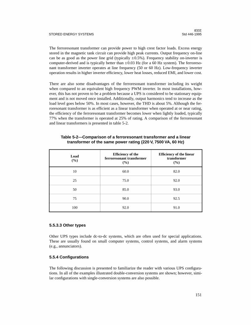
IEEESTORED ENERGY SYSTEMS Std 446-1995
The ferroresonant transformer can provide power to high crest factor loads. Excess energystored in the magnetic tank circuit can provide high peak currents. Output frequency on-linecan be as good as the power line grid (typically ±0.5%). Frequency stability on-inverter iscomputer-derived and is typically better than ±0.03 Hz (for a 60 Hz system). The ferroreso-nant transformer inverter operates at line frequency (50 or 60 Hz). Low-frequency inverteroperation results in higher inverter efficiency, lower heat losses, reduced EMI, and lower cost.
There are also some disadvantages of the ferroresonant transformer including its weightwhen compared to an equivalent high frequency PWM inverter. In most installations, how-ever, this has not proven to be a problem because a UPS is considered to be stationary equip-ment and is not moved once installed. Additionally, output harmonics tend to increase as theload level goes below 50%. In most cases, however, the THD is about 5%. Although the fer-roresonant transformer is as efficient as a linear transformer when operated at or near rating,the efficiency of the ferroresonant transformer becomes lower when lightly loaded, typically77% when the transformer is operated at 25% of rating. A comparison of the ferroresonantand linear transformers is presented in table 5-2.
5.5.3.3 Other types
Other UPS types include dc-to-dc systems, which are often used for special applications.These are usually found on small computer systems, control systems, and alarm systems(e.g., annunciators).
5.5.4 Configurations
The following discussion is presented to familiarize the reader with various UPS configura-tions. In all of the examples illustrated double-conversion systems are shown; however, simi-lar configurations with single-conversion systems are also possible.
Table 5-2—Comparison of a ferroresonant transformer and a lineartransformer of the same power rating (220 V, 7500 VA, 60 Hz)
Load(%)
Efficiency of the ferroresonant transformer
(%)
Efficiency of the linear transformer
(%)
10 60.0 82.0
25 75.0 92.0
50 85.0 93.0
75 90.0 92.5
100 92.0 91.0
151
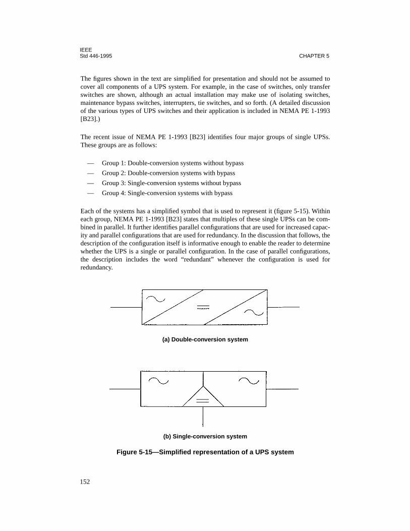
IEEEStd 446-1995 CHAPTER 5
The figures shown in the text are simplified for presentation and should not be assumed tocover all components of a UPS system. For example, in the case of switches, only transferswitches are shown, although an actual installation may make use of isolating switches,maintenance bypass switches, interrupters, tie switches, and so forth. (A detailed discussionof the various types of UPS switches and their application is included in NEMA PE 1-1993[B23].)
The recent issue of NEMA PE 1-1993 [B23] identifies four major groups of single UPSs.These groups are as follows:
— Group 1: Double-conversion systems without bypass
— Group 2: Double-conversion systems with bypass
— Group 3: Single-conversion systems without bypass
— Group 4: Single-conversion systems with bypass
Each of the systems has a simplified symbol that is used to represent it (figure 5-15). Withineach group, NEMA PE 1-1993 [B23] states that multiples of these single UPSs can be com-bined in parallel. It further identifies parallel configurations that are used for increased capac-ity and parallel configurations that are used for redundancy. In the discussion that follows, thedescription of the configuration itself is informative enough to enable the reader to determinewhether the UPS is a single or parallel configuration. In the case of parallel configurations,the description includes the word “redundant” whenever the configuration is used forredundancy.
(a) Double-conversion system
(b) Single-conversion system
Figure 5-15—Simplified representation of a UPS system
152
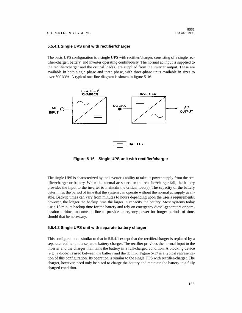
IEEESTORED ENERGY SYSTEMS Std 446-1995
5.5.4.1 Single UPS unit with rectifier/charger
The basic UPS configuration is a single UPS with rectifier/charger, consisting of a single rec-tifier/charger, battery, and inverter operating continuously. The normal ac input is supplied tothe rectifier/charger and the critical load(s) are supplied from the inverter output. These areavailable in both single phase and three phase, with three-phase units available in sizes toover 500 kVA. A typical one-line diagram is shown in figure 5-16.
The single UPS is characterized by the inverter’s ability to take its power supply from the rec-tifier/charger or battery. When the normal ac source or the rectifier/charger fail, the batteryprovides the input to the inverter to maintain the critical load(s). The capacity of the batterydetermines the period of time that the system can operate without the normal ac supply avail-able. Backup times can vary from minutes to hours depending upon the user’s requirements;however, the longer the backup time the larger in capacity the battery. Most systems todayuse a 15 minute backup time for the battery and rely on emergency diesel-generators or com-bustion-turbines to come on-line to provide emergency power for longer periods of time,should that be necessary.
5.5.4.2 Single UPS unit with separate battery charger
This configuration is similar to that in 5.5.4.1 except that the rectifier/charger is replaced by aseparate rectifier and a separate battery charger. The rectifier provides the normal input to theinverter and the charger maintains the battery in a full-charged condition. A blocking device(e.g., a diode) is used between the battery and the dc link. Figure 5-17 is a typical representa-tion of this configuration. Its operation is similar to the single UPS with rectifier/charger. Thecharger, however, need only be sized to charge the battery and maintain the battery in a fullycharged condition.
Figure 5-16—Single UPS unit with rectifier/charger
153
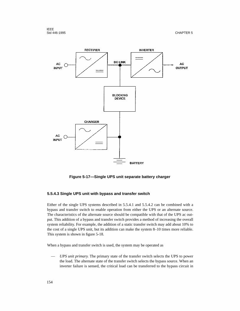
IEEEStd 446-1995 CHAPTER 5
5.5.4.3 Single UPS unit with bypass and transfer switch
Either of the single UPS systems described in 5.5.4.1 and 5.5.4.2 can be combined with abypass and transfer switch to enable operation from either the UPS or an alternate source.The characteristics of the alternate source should be compatible with that of the UPS ac out-put. This addition of a bypass and transfer switch provides a method of increasing the overallsystem reliability. For example, the addition of a static transfer switch may add about 10% tothe cost of a single UPS unit, but its addition can make the system 8–10 times more reliable.This system is shown in figure 5-18.
When a bypass and transfer switch is used, the system may be operated as
— UPS unit primary. The primary state of the transfer switch selects the UPS to powerthe load. The alternate state of the transfer switch selects the bypass source. When aninverter failure is sensed, the critical load can be transferred to the bypass circuit in
Figure 5-17—Single UPS unit separate battery charger
154

IEEESTORED ENERGY SYSTEMS Std 446-1995
less than 4 ms, assuming a static switch is used. Figure 5-19 is an oscillogram of theload voltage as supplied during a transfer of the power source with a static switch.
— Bypass primary. The primary state of the transfer switch selects the bypass source topower the load. The alternate state of the transfer switch selects the UPS.
5.5.4.4 Parallel UPS with individual battery
Parallel UPS units are used when more power is required than can be supplied by an individ-ual unit. The parallel units are treated as if they were one UPS with the output of the unitsconnected to a common point. In this configuration, each parallel UPS has its own rectifier/charger and battery (figure 5-20).
5.5.4.5 Parallel UPS with a single battery
In this configuration, all of the UPS modules have their dc links connected to a single battery(figure 5-21).
Figure 5-18—Single UPS unit with bypass and transfer switch
Figure 5-19—Oscillogram of UPS output during a transfer to the bypass source
155
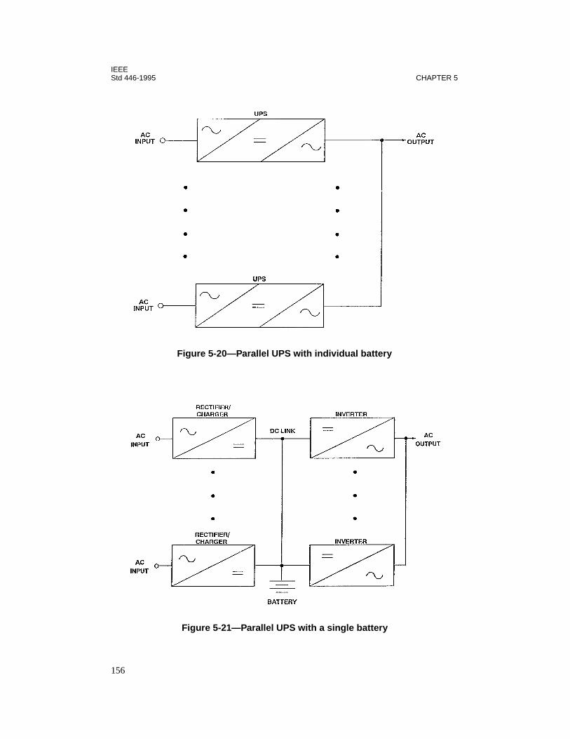
IEEEStd 446-1995 CHAPTER 5
Figure 5-20—Parallel UPS with individual battery
Figure 5-21—Parallel UPS with a single battery
156
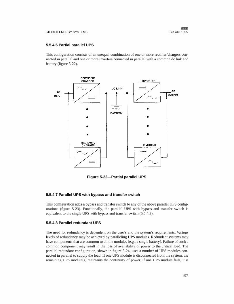
IEEESTORED ENERGY SYSTEMS Std 446-1995
5.5.4.6 Partial parallel UPS
This configuration consists of an unequal combination of one or more rectifier/chargers con-nected in parallel and one or more inverters connected in parallel with a common dc link andbattery (figure 5-22).
5.5.4.7 Parallel UPS with bypass and transfer switch
This configuration adds a bypass and transfer switch to any of the above parallel UPS config-urations (figure 5-23). Functionally, the parallel UPS with bypass and transfer switch isequivalent to the single UPS with bypass and transfer switch (5.5.4.3).
5.5.4.8 Parallel redundant UPS
The need for redundancy is dependent on the user’s and the system’s requirements. Variouslevels of redundancy may be achieved by paralleling UPS modules. Redundant systems mayhave components that are common to all the modules (e.g., a single battery). Failure of such acommon component may result in the loss of availability of power to the critical load. Theparallel redundant configuration, shown in figure 5-24, uses a number of UPS modules con-nected in parallel to supply the load. If one UPS module is disconnected from the system, theremaining UPS module(s) maintains the continuity of power. If one UPS module fails, it is
Figure 5-22—Partial parallel UPS
157

IEEEStd 446-1995 CHAPTER 5
isolated by the UPS switch to prevent it from interfering with the other UPS module(s) tomaintain continuity of the load.
5.5.4.9 Parallel redundant UPS with common dc link (single battery)
In this configuration a number of rectifier/chargers and inverters are connected in parallel,with a single battery connected to their dc link. If one rectifier/charger or inverter is discon-nected from the system, the remaining modules will maintain continuity of the load. If a mod-ule should fail it is isolated from the other modules which then maintain continuity of theload. (figure 5-25.)
Figure 5-23—Parallel UPS with bypass and transfer switch
Figure 5-24—Parallel redundant UPS
158

IEEESTORED ENERGY SYSTEMS Std 446-1995
5.5.4.10 Partial parallel redundant UPS
This configuration is characterized by an unequal combination of two or more rectifier/charg-ers connected in parallel and two or more inverters connected in parallel with a single battery.If one rectifier/charger or inverter is disconnected from the system, the remaining moduleswill maintain continuity of the load. If a module should fail, it is isolated from the other mod-ules, which then maintain continuity of the load (figure 5-26).
5.5.4.11 Parallel redundant UPS with bypass and transfer switch
This configuration adds a bypass and transfer switch to any of the above parallel redundantUPS configurations (figure 5-27.) Functionally, the parallel redundant UPS with bypass andtransfer switch is equivalent to the single UPS with bypass and transfer switch (5.5.4.3).
5.5.4.12 Standby redundant UPS
The standby redundant UPS, shown in figure 5-28, is made up of two UPSs and a transferswitch. Upon failure of the operating UPS the transfer switch will switch to the standby UPS.
Figure 5-25—Parallel redundant UPS with common dc link (single battery)
159
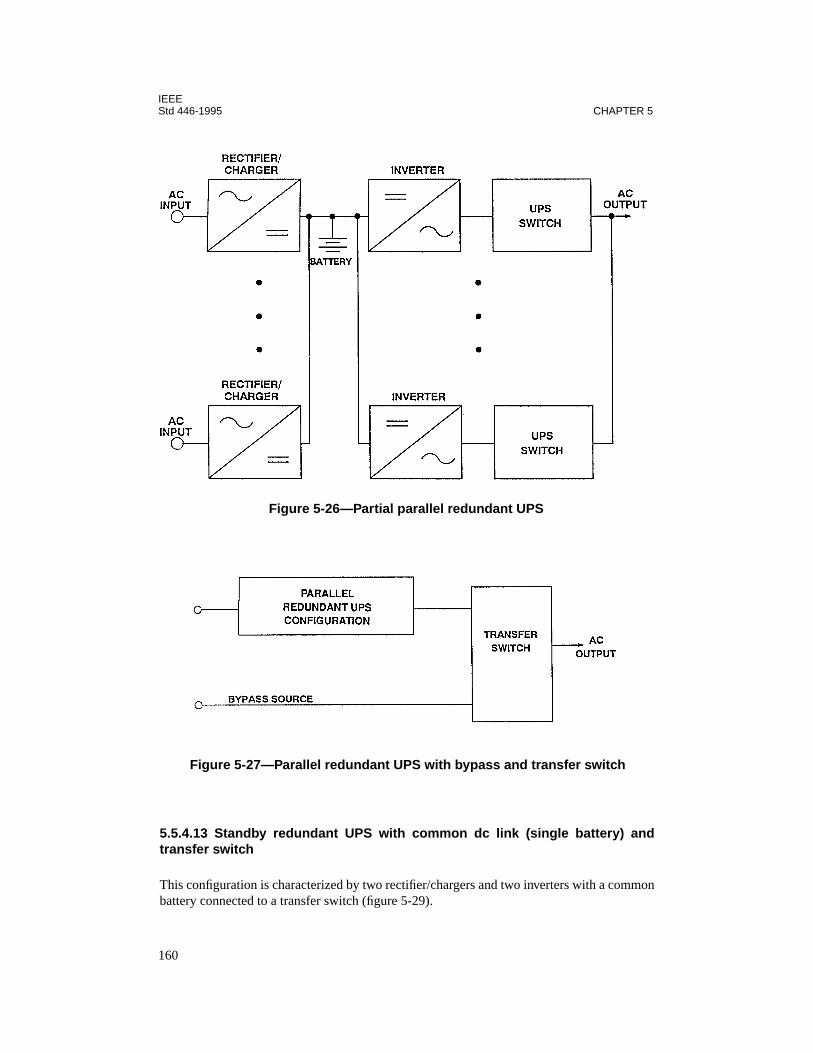
IEEEStd 446-1995 CHAPTER 5
5.5.4.13 Standby redundant UPS with common dc link (single battery) andtransfer switch
This configuration is characterized by two rectifier/chargers and two inverters with a commonbattery connected to a transfer switch (figure 5-29).
Figure 5-26—Partial parallel redundant UPS
Figure 5-27—Parallel redundant UPS with bypass and transfer switch
160

IEEESTORED ENERGY SYSTEMS Std 446-1995
5.5.4.14 Standby redundant UPS with bypass and transfer switch
This configuration adds a bypass and transfer switch to any of the above standby redundantUPS configurations (figure 5-30). Functionally, the standby redundant UPS with bypass andtransfer switch is equivalent to the single UPS with bypass and transfer switch (5.5.4.3).
Figure 5-28—Standby redundant UPS with transfer switch
Figure 5-29—Standby redundant UPS with common dc link (single battery) and transfer switch
161
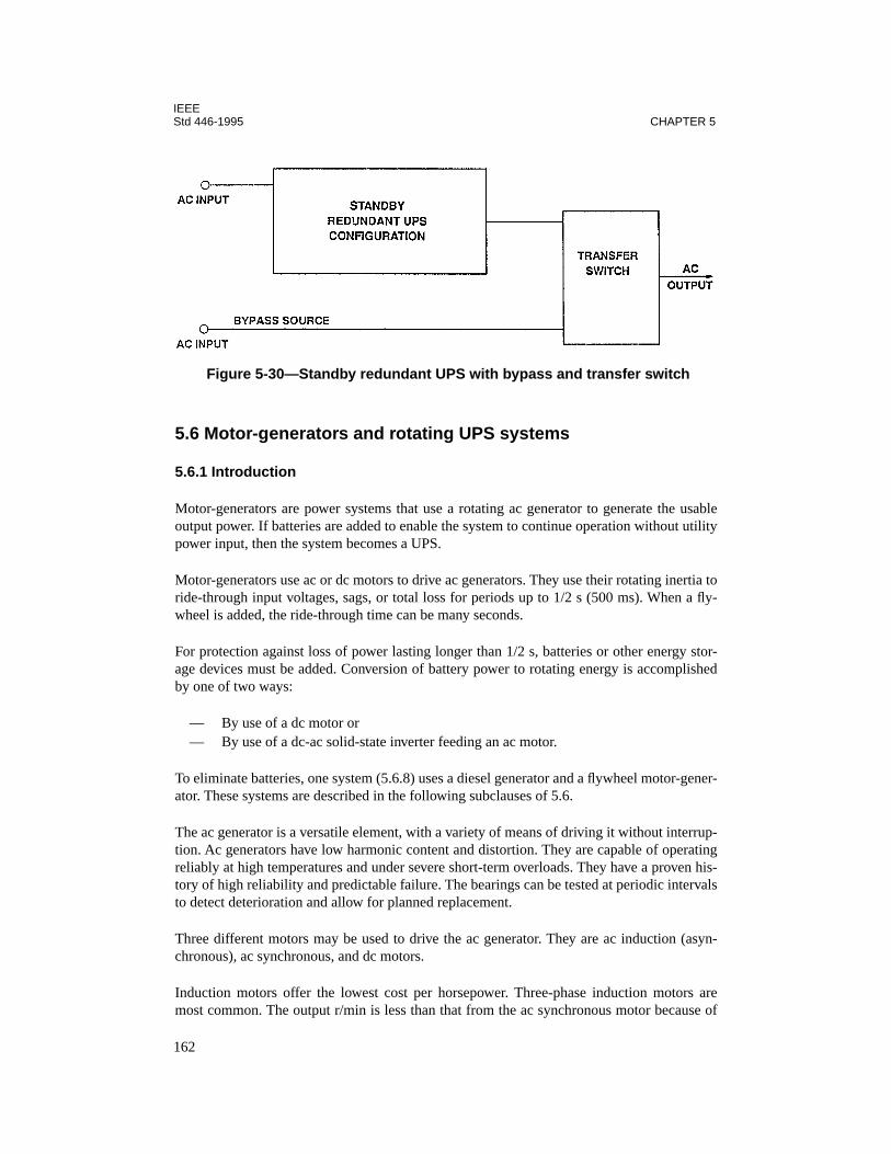
IEEEStd 446-1995 CHAPTER 5
5.6 Motor-generators and rotating UPS systems
5.6.1 Introduction
Motor-generators are power systems that use a rotating ac generator to generate the usableoutput power. If batteries are added to enable the system to continue operation without utilitypower input, then the system becomes a UPS.
Motor-generators use ac or dc motors to drive ac generators. They use their rotating inertia toride-through input voltages, sags, or total loss for periods up to 1/2 s (500 ms). When a fly-wheel is added, the ride-through time can be many seconds.
For protection against loss of power lasting longer than 1/2 s, batteries or other energy stor-age devices must be added. Conversion of battery power to rotating energy is accomplishedby one of two ways:
— By use of a dc motor or— By use of a dc-ac solid-state inverter feeding an ac motor.
To eliminate batteries, one system (5.6.8) uses a diesel generator and a flywheel motor-gener-ator. These systems are described in the following subclauses of 5.6.
The ac generator is a versatile element, with a variety of means of driving it without interrup-tion. Ac generators have low harmonic content and distortion. They are capable of operatingreliably at high temperatures and under severe short-term overloads. They have a proven his-tory of high reliability and predictable failure. The bearings can be tested at periodic intervalsto detect deterioration and allow for planned replacement.
Three different motors may be used to drive the ac generator. They are ac induction (asyn-chronous), ac synchronous, and dc motors.
Induction motors offer the lowest cost per horsepower. Three-phase induction motors aremost common. The output r/min is less than that from the ac synchronous motor because of
Figure 5-30—Standby redundant UPS with bypass and transfer switch
162
IEEESTORED ENERGY SYSTEMS Std 446-1995
slip. Torque increases as slip increases until the rotor stalls. Low-slip (0.4–0.7% slip) motorsare recommended and available in sizes up to 100 hp. These motors have been designed tooptimize slip, power factor, efficiency, and starting inrush. Typical slip is 0.4–0.7%, resultingin output of 1790 r/min under full load from a motor with a rated synchronous speed of1800 r/min. Low-slip motors are sometimes built using oversize motors. These motors mayhave reduced efficiency.
Synchronous motors maintain a constant shaft speed independent of load and input voltage.They remain locked to the input frequency up to their pull-out torque. Their efficiencies aretypically higher than induction motors.
Synchronous motors cannot develop torque at speeds lower than synchronous speed. For thisreason these motors are usually started as induction motors or, alternately, under no-load con-ditions. Synchronous motors offer power factor correction as an advantage in some applica-tions.
Dc motors offer the ability to regulate output frequency precisely. The speed of a dc motormay be varied by changing field excitation. For computer applications with tight frequencytolerance, a frequency regulator is used to adjust field excitation as input voltage and loadvary. Dc motors have brushes that wear over time and need periodic replacement. Alarm sys-tems are available that annunciate the need for their replacement. If brushes are regularlymaintained, dc motors have the same life expectancy as induction or synchronous motors.
5.6.2 AC motor-generators
Nearly all ac motor-generators built today use brushless synchronous generators. The motormay be either induction or synchronous. Induction motors have an inherent slip that causesthe output frequency of the system to be less than the input by a fraction of a cycle. Synchro-nous motors duplicate the incoming frequency precisely and track it. Most computer grademotor-generator sets utilize synchronous motors.
Several methods of construction are available, with the differences affecting ride-throughtime, isolation, and physical size (footprint). The smallest footprint is achieved by stackingthe motor and generator and coupling their horizontal shafts using toothed pulleys and a belt(figure 5-31), or by mounting the motor and generator on a common vertical shaft. Thestacked horizontal units get added ride-through from the mass of the pulleys and belt. Hori-zontal coupling can also be accomplished by building the motor and generator into a singleframe or by coupling two separate frames on a base. Maximum isolation is attained by sepa-rate frames, electrically isolated, and connected by an insulating coupling (figure 5-32).Motor-generator sets with a common motor and generator in one rotor offer the smallest hor-izontal size but the least isolation of transients from input to output (figure 5-33).
5.6.3 AC motor-generator with flywheel
The addition of a flywheel adds mass and therefore increases the ride-through time of amotor-generator set. This increased ride-through time is achieved at the expense of weight,size, efficiency, bearing life, and higher initial system cost. Air friction (or windage) increases
163
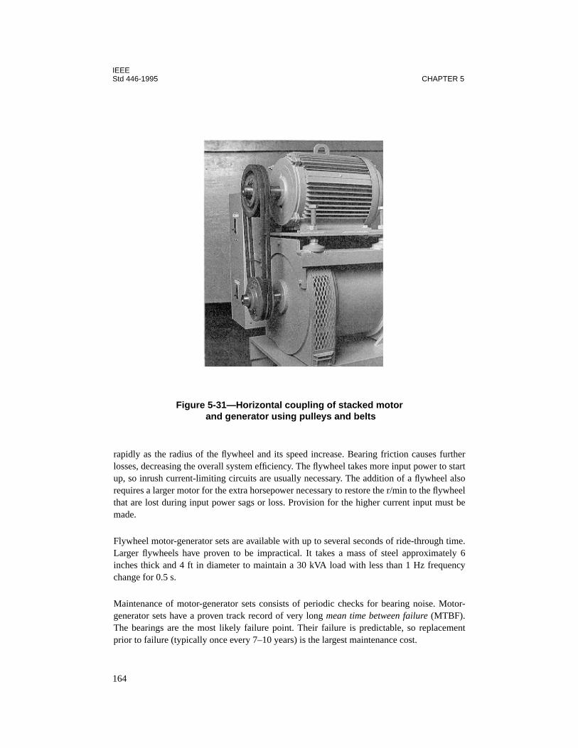
IEEEStd 446-1995 CHAPTER 5
rapidly as the radius of the flywheel and its speed increase. Bearing friction causes furtherlosses, decreasing the overall system efficiency. The flywheel takes more input power to startup, so inrush current-limiting circuits are usually necessary. The addition of a flywheel alsorequires a larger motor for the extra horsepower necessary to restore the r/min to the flywheelthat are lost during input power sags or loss. Provision for the higher current input must bemade.
Flywheel motor-generator sets are available with up to several seconds of ride-through time.Larger flywheels have proven to be impractical. It takes a mass of steel approximately 6inches thick and 4 ft in diameter to maintain a 30 kVA load with less than 1 Hz frequencychange for 0.5 s.
Maintenance of motor-generator sets consists of periodic checks for bearing noise. Motor-generator sets have a proven track record of very long mean time between failure (MTBF).The bearings are the most likely failure point. Their failure is predictable, so replacementprior to failure (typically once every 7–10 years) is the largest maintenance cost.
Figure 5-31—Horizontal coupling of stacked motor and generator using pulleys and belts
164

IEEESTORED ENERGY SYSTEMS Std 446-1995
The construction of a motor-generator set can make bearing replacement easy or difficult. Forexample, some vertical motor-generators have the load support bearing on top to allow easyaccess. This allows the main bearing to be changed without pulling the rotor out of the case.
5.6.4 Battery/dc motor/ac motor-generator set
This UPS uses a standard motor-generator set for continuous power conditioning (see figure5-34). When the normal power source is available, the dc motor is controlled by a field volt-
Figure 5-32—Horizontal coupling of motor and generator using two separate frames on a base
Figure 5-33—Motor and generator with common rotor
165

IEEEStd 446-1995 CHAPTER 5
age control circuit to operate as a generator, maintaining the battery voltage. When the nor-mal power source is disturbed or fails, the dc motor is changed by a field voltage controlcircuit from a generator to a motor. The dc motor draws battery power to continue driving theac motor-generator without interruption.
Advantages include the following:
— Excellent power conditioning and load isolation— Excellent overload and short-circuit capacity— Maintenance and repairs do not require specially qualified personnel.— Failure of dc circuits or motor does not affect power conditioning.
The disadvantage is as follows:
— Dc motor brushes require maintenance and replacement.
5.6.5 Battery/dc motor/ac generator
This UPS (figure 5-35) uses a dc motor to continuously drive the ac generator. A rectifier/charger converts the ac input to dc for the motor and battery. This system is less expensivethan the system described in 5.6.4, but it cannot continue to condition and isolate the powerline if any failure occurs. Some manufacturers of this type of system have separate circuitsfor the dc motor and the battery charger, and add a flywheel to ride through switchover timeduring the failure of the normal power source. Other manufacturers have simplified the sys-tem by reducing circuits and eliminating the flywheel.
Advantages include the following:
— Output frequency can be regulated very closely at all times.— It conditions power and isolates the load from the utility.— Maintenance and repairs do not require specially trained personnel.— Cost is lower than systems with both an ac and dc motor.— The output frequency remains stable over varying input frequencies.— It may be used as a frequency changer.
Figure 5-34—Battery/dc motor/ac motor-generator set
166
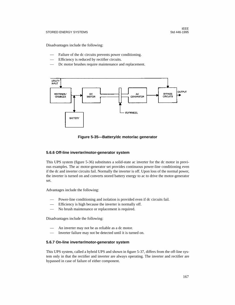
IEEESTORED ENERGY SYSTEMS Std 446-1995
Disadvantages include the following:
— Failure of the dc circuits prevents power conditioning.— Efficiency is reduced by rectifier circuits.— Dc motor brushes require maintenance and replacement.
5.6.6 Off-line inverter/motor-generator system
This UPS system (figure 5-36) substitutes a solid-state ac inverter for the dc motor in previ-ous examples. The ac motor-generator set provides continuous power-line conditioning evenif the dc and inverter circuits fail. Normally the inverter is off. Upon loss of the normal power,the inverter is turned on and converts stored battery energy to ac to drive the motor-generatorset.
Advantages include the following:
— Power-line conditioning and isolation is provided even if dc circuits fail.— Efficiency is high because the inverter is normally off.— No brush maintenance or replacement is required.
Disadvantages include the following:
— An inverter may not be as reliable as a dc motor.— Inverter failure may not be detected until it is turned on.
5.6.7 On-line inverter/motor-generator system
This UPS system, called a hybrid UPS and shown in figure 5-37, differs from the off-line sys-tem only in that the rectifier and inverter are always operating. The inverter and rectifier arebypassed in case of failure of either component.
Figure 5-35—Battery/dc motor/ac generator
167

IEEEStd 446-1995 CHAPTER 5
The advantage is as follows:
— A failure in rectifier or inverter does not affect power conditioning.
The disadvantage is as follows:
— An inverter is not as reliable as a dc motor.
5.6.8 Engine motor-generator system
This system (shown in figure 5-38) consists of an internal combustion engine, an electro-mechanical clutch or a magnetic clutch, a horizontal axis flywheel, an ac generator, and an acmotor (plus control and transfer equipment). In normal operation, the normal power source tothe ac motor drives the flywheel and ac generator, which in turn supplies power to the load.The flywheel stores kinetic energy.
Figure 5-36—Off-line inverter/motor-generator system
Figure 5-37—On-line inverter/motor-generator system
168

IEEESTORED ENERGY SYSTEMS Std 446-1995
When the normal power source is interrupted, the flywheel drives the ac generator and startsthe engine through the clutch. The engine then drives the ac generator, which continues tosupply power to the load without interruption. With proper selection of components to mini-mize the start-up and run-up times of the engine, the frequency dip can be kept to approxi-mately 1.5–2 Hz without paying a premium. Thus, with a steady-state frequency of 60.0 Hz,the transient frequency would be from 58–58.5 Hz. The time for the engine to start, come upto speed, and take the load, is normally less than 2–3 s.
Advantages include the following:
— Operating time after a normal power loss is limited only by fuel supply.— It offers excellent overload and short-circuit capacity.— Maintenance and repairs do not require specially qualified personnel.— The system has predictable failure modes.— There is no battery to maintain.
Disadvantages include the following:
— The mechanical clutch suffers wear and tear during each start and requires costly andfrequent maintenance.
— The engine crankshaft experiences high axial loads that require a special design; itsmaintenance and replacement parts are costly.
— An additional engine generator must be provided to supply the air conditioning, light-ing, and other similar loads if long-term operation is desired.
5.6.9 Engine generator/motor-generator system
This system consists of an ac motor-generator set with a flywheel and an engine-generator set(figure 5-39). In normal operation the normal power source supplies the ac motor-generatorset, which in turn supplies power to the load. The flywheel stores kinetic energy.
When the normal power source is interrupted, the flywheel energy supports the speed of theac motor-generator set. A transfer switch disconnects the normal power from the motor-gen-erator and connects the engine-generator output to the motor-generator. Simultaneously, theengine is started. As its speed increases, the output voltage rises, exciting the motor-generator
Figure 5-38—Engine/motor-generator system
169
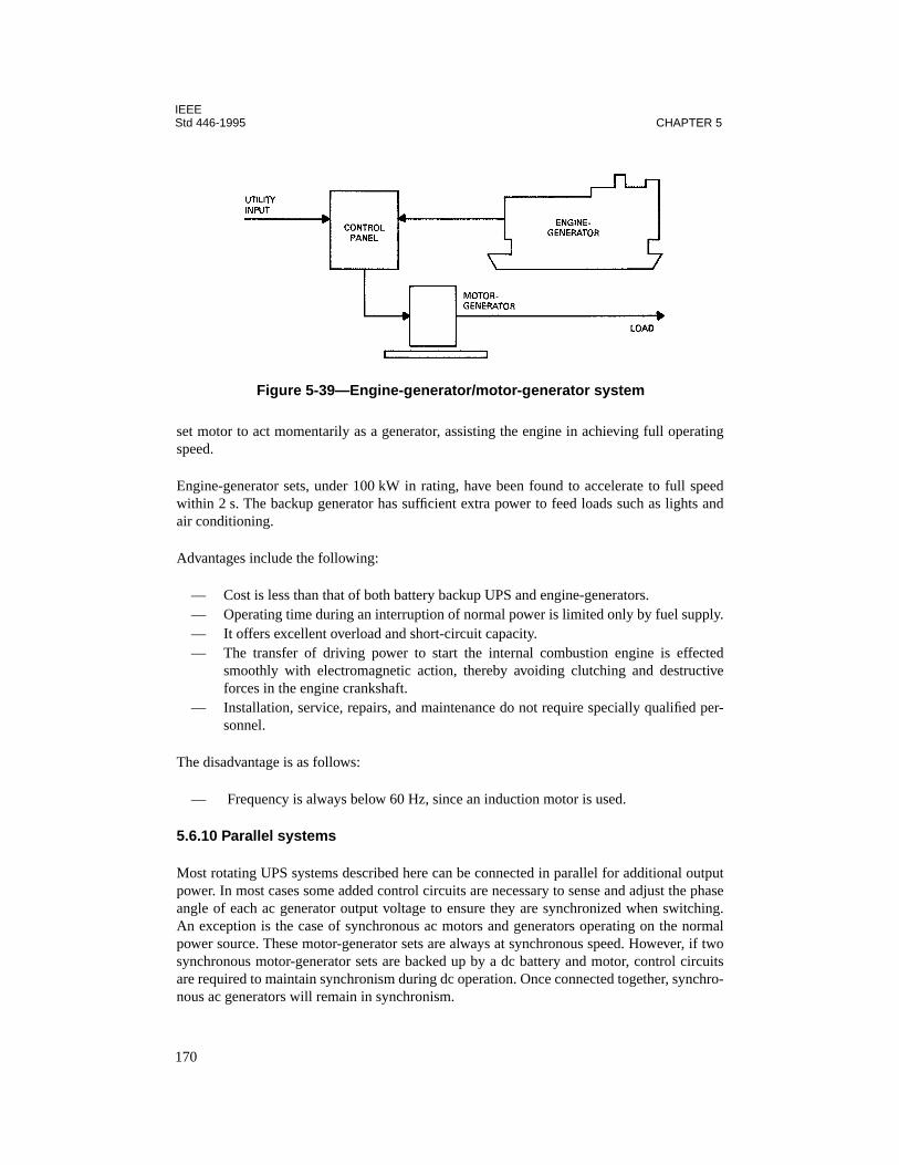
IEEEStd 446-1995 CHAPTER 5
set motor to act momentarily as a generator, assisting the engine in achieving full operatingspeed.
Engine-generator sets, under 100 kW in rating, have been found to accelerate to full speedwithin 2 s. The backup generator has sufficient extra power to feed loads such as lights andair conditioning.
Advantages include the following:
— Cost is less than that of both battery backup UPS and engine-generators.— Operating time during an interruption of normal power is limited only by fuel supply.— It offers excellent overload and short-circuit capacity.— The transfer of driving power to start the internal combustion engine is effected
smoothly with electromagnetic action, thereby avoiding clutching and destructiveforces in the engine crankshaft.
— Installation, service, repairs, and maintenance do not require specially qualified per-sonnel.
The disadvantage is as follows:
— Frequency is always below 60 Hz, since an induction motor is used.
5.6.10 Parallel systems
Most rotating UPS systems described here can be connected in parallel for additional outputpower. In most cases some added control circuits are necessary to sense and adjust the phaseangle of each ac generator output voltage to ensure they are synchronized when switching.An exception is the case of synchronous ac motors and generators operating on the normalpower source. These motor-generator sets are always at synchronous speed. However, if twosynchronous motor-generator sets are backed up by a dc battery and motor, control circuitsare required to maintain synchronism during dc operation. Once connected together, synchro-nous ac generators will remain in synchronism.
Figure 5-39—Engine-generator/motor-generator system
170
IEEESTORED ENERGY SYSTEMS Std 446-1995
5.6.11 Redundant systems
Most rotating systems described here may be connected to create redundant outputs. Thismay be accomplished by parallel operation at less than half power per system, or by connec-tion through a sensing and switching circuit.
Induction motor-generator sets are more difficult to parallel than synchronous sets due to thecontinuous slip of the induction motor. With one unit loaded, the other unit being brought on-line must be loaded with an external load bank until the two generator outputs are in phase.Only then may the outputs be connected to each other to supply the load in parallel.
5.6.12 Bypass circuits
UPS systems that have the same frequency and voltage input and output are usually suppliedwith a bypass circuit. This circuit consists of a static transfer switch or an electromechanicaltransfer switch, or both. The purpose of the bypass circuit is threefold: First, to connect thebypass source to the load in case of failure of the UPS; second, to enable bypass of the UPSfor maintenance; third, to assist the UPS output in supplying fault current if a fault occurs.However, most motor-generators and motor-generator-based UPS systems do not require acbypass to the utility to clear faults, since they have enough overload capacity to clear thefaults without assistance. Care should be taken to ensure that the output of the UPS or systemis in phase with the normal power supply (i.e., input). The initiation of an out-of-phaseclosure (e.g., during maintenance) of the bypass represents both a safety and equipmenthazard.
5.7 References
This chapter shall be used in conjunction with the following publications:
IEEE Std 100-1992, The New IEEE Standard Dictionary of Electrical and Electronics Terms(ANSI).3
IEEE Std 450-1995, IEEE Recommended Practice for Maintenance, Testing, and Replace-ment of Vented Lead-Acid Batteries for Stationary Applications.
IEEE Std 484-1996, IEEE Recommended Practice for Installation Design and Installation ofVented Lead-Acid Batteries for Stationary Applications.
IEEE Std 485-1983, IEEE Recommended Practice for Sizing Large Lead Storage Batteriesfor Generating Stations and Substations.
IEEE Std 946-1992, IEEE Recommended Practice for the Design of DC Auxiliary PowerSystems for Generating Stations (ANSI).
3IEEE publications are available from the Institute of Electrical and Electronics Engineers, 445 Hoes Lane, P.O. Box1331, Piscataway, NJ 08855-1331, USA.
171

IEEEStd 446-1995 CHAPTER 5
IEEE Std 1106-1995, IEEE Recommended Practice for Installation, Maintenance, Testing,and Replacement of Vented Nickel-Cadmium Batteries for Stationary Applications (ANSI).
IEEE Std 1115-1992, IEEE Recommended Practice for Sizing Nickel-Cadmium Batteries forStationary Applications (ANSI).
IEEE Std 1184-1994, IEEE Guide for the Selection and Sizing of Batteries for Uninterrupt-ible Power Systems.
IEEE Std 1187-1996, IEEE Recommended Practice for Installation Design and Installationof Valve-Regulated Lead-Acid Storage Batteries for Stationary Applications.
IEEE P1188, Draft Recommended Practice for Maintenance, Testing, and Replacement ofValve-Regulated Lead-Acid Batteries for Stationary Applications, Oct. 1995.4
IEEE P1189, Draft Guide for Selecting and Sizing Valve-Regulated Lead-Acid Batteries forStationary Applications, Oct. 1995.5
5.8 Bibliography
Additional information may be found in the following sources:
[B1] ANSI C84.1-1989, American National Standard Voltage Ratings for Electric Power Sys-tems and Equipment (60 Hz).6
[B2] ANSI/NFPA 101-1994, Code for Safety to Life from Fire in Buildings and Structures.7
[B3] ANSI/NFPA 111-1993, Stored Electrical Energy Emergency and Standby Power Sys-tems.
[B4] ANSI/UL 924-1990, Safety Standard for Emergency Lighting and Power Equipment.8
[B5] ANSI/UL 1778-1991, Uninterruptible Power Supply Equipment.
[B6] Bell Laboratories, “Lead-acid Battery,” The Bell System Technical Journal, vol. 49,no. 7, pp. 1249–1470.
4This IEEE standards project was not approved by the IEEE Standards Board at the time this publication went topress. For information about obtaining a draft, contact the IEEE.5See footnote 4.6ANSI publications are available from the Sales Department, American National Standards Institute, 11 West 42ndStreet, 13th Floor, New York, NY 10036, USA.7NFPA publications are available from Publications Sales, National Fire Protection Association, 1 BatterymarchPark, P.O. Box 9101, Quincy, MA 02269-9101, USA.8UL publications are available from Underwriters Laboratories, Inc., 333 Pfingsten Road, Northbrook, IL 60062-2096, USA.
172

IEEESTORED ENERGY SYSTEMS Std 446-1995
[B7] Griffith, D. C., Uninterruptible Power Supplies, New York: Marcel Dekker, Inc., 1989.
[B8] Harrison, A. I., “Thermal Management of High Energy Density Battery Equipments,”Conference Paper 92CH3195-5, Presented at 1992 IEEE INTELEC Conference, pp. 28–34.
[B9] IEEE Committee Report, “Reliability of Electrical Equipment, Part 1,” IEEE Transac-tions on Industry Applications, vol. IA-10, pp. 213–235, Mar./Apr. 1974.
[B10] IEEE Std 241-1990, IEEE Recommended Practice for Electric Power Systems in Com-mercial Buildings (The Gray Book) (ANSI).
[B11] IEEE Std 493-1990, IEEE Recommended Practice for the Design of Reliable Indus-trial and Commercial Power Systems (The Gold Book) (ANSI).
[B12] IEEE Std 602-1986, IEEE Recommended Practice for Electric Systems in Health CareFacilities (The White Book) (ANSI).9
[B13] IEEE Std 1100-1992, IEEE Recommended Practice for Powering and Grounding Sen-sitive Electronic Equipment (The Emerald Book) (ANSI).
[B14] Kiehne, H. A., Battery Technology Handbook, New York: Marcel Dekker, Inc., 1989.
[B15] Linden, D., Handbook of Batteries and Fuel Cells, New York: McGraw-Hill, 1984.
[B16] Migliaro, M. W., “Considerations for Selecting and Sizing Batteries,” IEEE Transac-tions on Industry Applications, vol. IA-23, no. 1, pp. 134–143, Jan./Feb. 1987.
[B17] Migliaro, M. W., “Stationary Batteries-Selected Topics,” Proceedings of the AmericanPower Conference, vol. 55-I, pp. 23–33, 1993.
[B18] Migliaro, M. W., and Albér, G., “Sizing UPS Batteries,” Proceedings of the FourthInternational Power Quality Conference, vol. 4, pp. 285–290, 1991.
[B19] Migliaro, M. W., and Mazzoni, O. S., “Battery Problems That Can Spell Disaster,”Disaster Avoidance & Recovery ’93 Conference, May 1993.
[B20] Misra, S. S., Noveske, T. M., and Williamson, A. W., “Thermal Effects in VRLA Cellsand Comparison with Wet Lead-Acid Cells Under Different Operating Conditions,” Confer-ence Paper 92CH3195-5, Presented at 1992 IEEE INTELEC Conference, pp. 35–40.
[B21] NEMA PE 1-1993, Uninterruptible Power Systems.10
9As this standard goes to press, IEEE Std 602-1996 is approved but not yet published. The draft standard is, however,available from the IEEE. Anticipated publication date is December 1996. Contact the IEEE Standards Department at1 (908) 562-3800 for status information.10NEMA publications are available from the National Electrical Manufacturers Association, 2101 L Street NW,Washington, DC 20037, USA.
173

IEEEStd 446-1995 CHAPTER 5
[B22] NFPA 70-1996, National Electrical Code®.11
[B23] NFPA 99-1996, Health Care Facilities Code.
[B24] Platts, J., and St. Aubyn, J., IEE Power Series 14: Uninterruptible Power Supplies.London: Peter Peregrinus, 1992.
[B25] Vinal, G. W., Storage Batteries, Fourth Edition. New York: John Wiley & Sons, 1955.
11NFPA publications are available from Publications Sales, National Fire Protection Association, 1 BatterymarchPark, P.O. Box 9101, Quincy, MA 02269-9101, USA.
174
Chapter 6Protection
6.1 Introduction
This chapter is presented to discuss recommended practices and guidelines for protection ofemergency and standby power systems. Even though standard practice for protection ofequipment should always be given full consideration when applying the equipment in emer-gency and standby use, reliability often warrants special consideration when a power supplyfor critical loads is designed. Although compliance with all national, state, and local codesand standards applicable to protection of the components that make up the emergency orstandby power system are necessary, it may be desirable to exceed these codes and standardsin the design process. It is not the intent of this chapter to list all applicable codes and stan-dards, but some pertinent ones are referenced where necessary to aid these recommendedpractice and guidelines.
Protection for individual components that make up the most common emergency and standbypower systems is discussed, with emphasis on maintaining the required integrity and reliabil-ity of the system. Proper application and maintenance of systems are discussed in other chap-ters and should be considered an important aspect of protection.
6.2 Short-circuit current considerations
Of the many areas of concern for protection of components that make up an emergency orstandby power system, one needing special consideration is that of magnitude and duration ofshort-circuit current available from the emergency or standby power source. Fault conditionsobviously have a direct effect on the availability of the power supply to serve its intended pur-pose. Studies should be made to determine available short-circuit current throughout the sys-tem supplied by an emergency or standby power supply, especially at switching and current-interrupting devices.
In evaluating the performance of an emergency or standby generator under fault conditions, acritical. concern is whether sufficient fault current is available for sufficient duration to selec-tively trip overcurrent devices in a properly coordinated system. In most cases, emergency orstandby power sources do not produce as much fault current as the normal source. When bothsources are designed to supply a distribution system, through automatic or manual switchingdevices, the magnitude of the fault current available from the normal supply usually deter-mines the required interrupting or withstand rating of the system components. Careful plan-ning is necessary to design a system that assures optimum selectivity and coordination withboth power sources. An emergency or standby generator’s available short-circuit currentshould be compared to the ratings of system overcurrent devices to determine how this coor-dination is to be achieved. Normally the emergency or standby power source should be con-nected into the power system so as to be physically and electrically as close to the loads as
175

IEEEStd 446-1995 CHAPTER 6
practical. This will minimize the number and size of distribution system circuit breakersinvolved and the number of coordination levels required.
Selective coordination of overcurrent devices is the process of applying these devices so thatone will operate before another under given levels of fault currents, thereby allowing effectiveisolation of the faulted circuit from unfaulted circuits. For a detailed analysis of the principalsof selective coordination, see IEEE Std 242-1986.1
Evaluating the available fault current from an emergency or standby generator includes deter-mining the magnitude of the fault current and how long the fault current will exist and how itmay change. Test information on generator short-circuit characteristics may be necessaryfrom the manufacturer. One should not assume that the speed of the generator will remainunchanged for a fault fed only by the generator; the effects of frequency changes and primemover load should also be accounted for. The coordination of the mechanical and electricalstored energy in a generator set and the type of excitation system will determine how long theengine and generator will sustain fault current and how rapidly this fault current will decay.In some cases, the initial power to a fault is higher (sometimes several times higher) than theprime mover power rating. The result can be a rapid reduction in speed. This overloading ofthe prime mover is more likely in small generator set applications than in larger power sys-tems since the X/R ratios of both the generator windings and distribution circuits in small sys-tems are lower.
An excitation system usually will not respond fast enough to significantly affect the first oneor two cycles of fault current, so at this point the type of excitation system does not matter. Ifthe fault is not cleared in the first 2–4 cycles, a serious concern is whether or not the generatorset can recover, after the fault is finally cleared, to maintain acceptable service to unfaultedbranch circuits. For systems where the fault current decays rapidly to levels below instanta-neous and delayed overcurrent trip settings, tripping will only be possible in the first fewcycles. This diminishes the ability to selectively trip the overcurrent devices, leaving only theinstantaneous settings to work with.
Figure 6-1 illustrates the rate of decay of three-phase fault current from tests on three typicalgenerators; the first two are separately excited (with fixed excitation) and tested at no load.The curves are approximations of actual test results. In figure 6-1(a), about 40 cycles elapsebefore the fault current decays to the full-load rating of the generator. In figure 6-1(b), thefault current decayed to the full-load rating in about 25 cycles. The quicker decline of faultcurrent from the smaller generator is a common occurrence. The current (I) shown is in perunit (pu) based on generator full-load current rating. Figure 6-1(c) illustrates an approxima-tion of short-circuit current of a shunt-excited generator without short-circuit sustaining capa-bility. In this case, the current has decayed to full-load rating in 10 cycles and to nearly zeroin 20 cycles.
When two circuit breakers equipped with instantaneous trips are applied in series, eventhough the upstream breaker is substantially larger, selective instantaneous tripping is notassured on faults below the downstream breaker unless the momentary fault current is less
1Information on references can be found in 6.11.
176
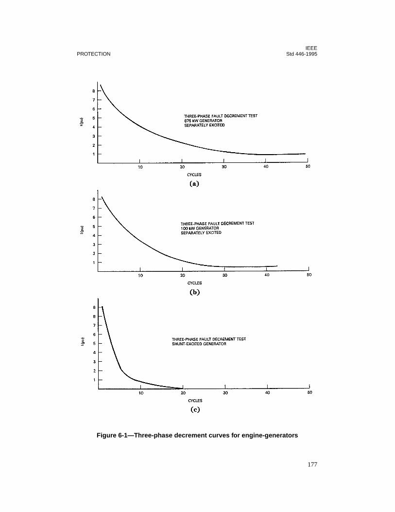
IEEEPROTECTION Std 446-1995
Figure 6-1—Three-phase decrement curves for engine-generators
177
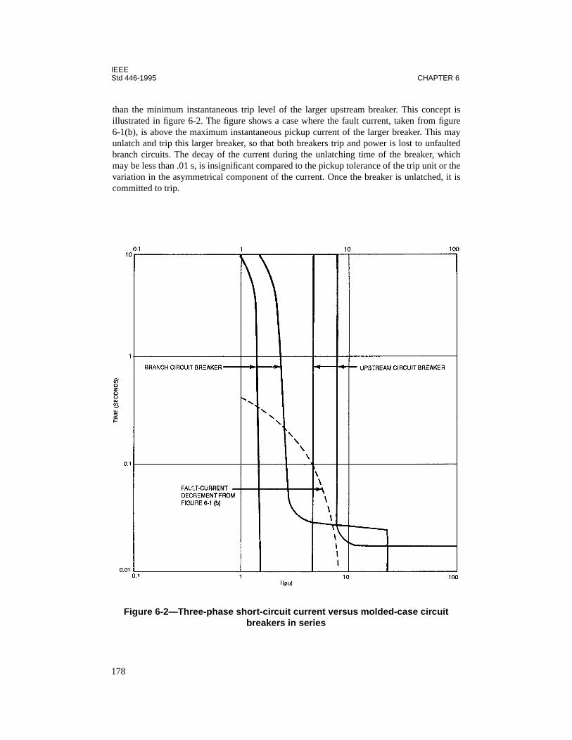
IEEEStd 446-1995 CHAPTER 6
than the minimum instantaneous trip level of the larger upstream breaker. This concept isillustrated in figure 6-2. The figure shows a case where the fault current, taken from figure6-1(b), is above the maximum instantaneous pickup current of the larger breaker. This mayunlatch and trip this larger breaker, so that both breakers trip and power is lost to unfaultedbranch circuits. The decay of the current during the unlatching time of the breaker, whichmay be less than .01 s, is insignificant compared to the pickup tolerance of the trip unit or thevariation in the asymmetrical component of the current. Once the breaker is unlatched, it iscommitted to trip.
Figure 6-2—Three-phase short-circuit current versus molded-case circuit breakers in series
178
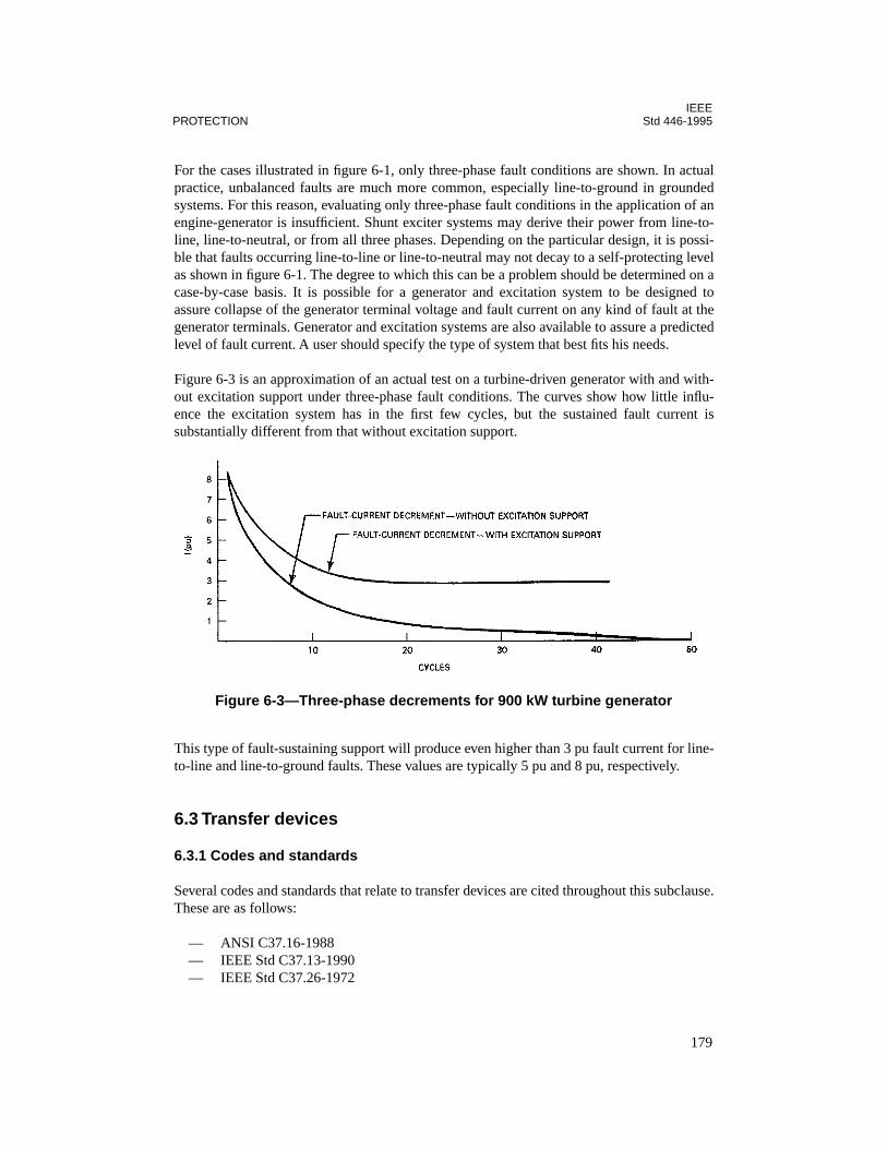
IEEEPROTECTION Std 446-1995
For the cases illustrated in figure 6-1, only three-phase fault conditions are shown. In actualpractice, unbalanced faults are much more common, especially line-to-ground in groundedsystems. For this reason, evaluating only three-phase fault conditions in the application of anengine-generator is insufficient. Shunt exciter systems may derive their power from line-to-line, line-to-neutral, or from all three phases. Depending on the particular design, it is possi-ble that faults occurring line-to-line or line-to-neutral may not decay to a self-protecting levelas shown in figure 6-1. The degree to which this can be a problem should be determined on acase-by-case basis. It is possible for a generator and excitation system to be designed toassure collapse of the generator terminal voltage and fault current on any kind of fault at thegenerator terminals. Generator and excitation systems are also available to assure a predictedlevel of fault current. A user should specify the type of system that best fits his needs.
Figure 6-3 is an approximation of an actual test on a turbine-driven generator with and with-out excitation support under three-phase fault conditions. The curves show how little influ-ence the excitation system has in the first few cycles, but the sustained fault current issubstantially different from that without excitation support.
This type of fault-sustaining support will produce even higher than 3 pu fault current for line-to-line and line-to-ground faults. These values are typically 5 pu and 8 pu, respectively.
6.3 Transfer devices
6.3.1 Codes and standards
Several codes and standards that relate to transfer devices are cited throughout this subclause.These are as follows:
— ANSI C37.16-1988— IEEE Std C37.13-1990— IEEE Std C37.26-1972
Figure 6-3—Three-phase decrements for 900 kW turbine generator
179
IEEEStd 446-1995 CHAPTER 6
— IEEE Std C37.90-1989— IEEE Std 141-1993— NEMA ICS 1-1993— The National Electrical Code (NEC) (NFPA 70-1996)— ANSI/NFPA 110-1993— ANSI/UL 1008-1989— CSA C22.2/No. 178-1987
Other standards not cited in this subclause that may serve as useful bibliographic referencesare as follows:
— ANSI/NEMA ICS 2-1993 [B2]2
— NFPA 99-1996 [B17]— IEEE Std 241-1990 [B12]
Codes and standards applicable to protection of transfer devices vary somewhat between dif-ferent usages of the equipment. The NEC, for instance, is limited in its requirements fortransfer equipment in emergency and standby power applications. ANSI/UL 1008-1989 con-tains considerable information on construction and testing of automatic transfer switches.Most users today place considerable emphasis on adequacy of equipment as determined bynationally recognized testing laboratories. For this reason, testing has been given specialattention in this subclause. The primary concern of these testing labs, however, is safety, andthe user should recognize reliability considerations in the proper selection and application ofa transfer switch. It should be noted that CSA C22.2/No. 178-1987, the Canadian standard onautomatic transfer switches, is similar to ANSI/UL 1008-1989. Also, because of worldwideneed, the International Electrotechnical Commission (IEC) has prepared a standard on auto-matic transfer switches: IEC 947-6-1: 1989 [B11].
6.3.2 Current withstand ratings
Proper operation of transfer switches are a vital part of the proper operation of the systemmaking careful application of the switches extremely important, maybe more so than otherbranch-circuit devices. The design, normal duty, and fault-current ratings of the switch playan important part in its application and protection scheme. It must be capable of closing intohigh inrush currents, of withstanding fault currents, and of severe duty cycle in switching nor-mal-rated load. All are important capability characteristics and thus important to protection,but emphasis in this chapter will be mainly on fault withstandability. The coordination ofovercurrent protection devices with transfer switch ratings, under fault conditions, is one ofthe most important aspects of maintaining the integrity and reliability necessary in the opera-tion of a standby or emergency power system.
The destructive effects of high fault currents consist mainly of two components: (1) magneticstresses that attempt to pry open the switch contacts and bend bus bars, and (2) heat energydeveloped that can melt, deform, or otherwise damage the switch. Either or both of thesecomponents can cause switch failure.
2The numbers in brackets preceded by the letter B correspond to those of the bibliography in 6.12.
180
IEEEPROTECTION Std 446-1995
A fault involving high short-circuit currents usually causes a substantial voltage drop that willbe sensed by the voltage sensing relays in the automatic transfer switch. It is imperative forprotection that the switch contacts remain closed until protective devices can clear the fault.Separation of contacts, prior to protective device operation, can develop enough arcing andheat to damage the switch. Normally employed time delay to prevent immediate transfer ofmechanically held mechanisms and contact structures specifically designed with high contactpressure, in some cases utilizing electromagnetic forces to increase contact pressure, combineto provide the reliability and protection necessary in automatic transfer switch operation. Itfollows that proper application of the switch within its withstand rating is important to pre-vent contacts from welding together and to prevent any other circuit path joints and connec-tions from overheating or deforming, thus prolonging the life and increasing reliability of theswitch.
ANSI/UL 1008-1989 presents specific test requirements to ensure the withstand capabilitiesof switches. Included are methods and types of overcurrent device application, availableshort-circuit currents required, and allowable damage criteria while still remaining operable.Also, power factor requirements of the test circuit are given. Manufacturers should be con-sulted to determine the method of testing applied to transfer switches. Determining whether afuse or circuit breaker (and what size and type) was used, and determining the X/R ratio of thetest circuit are both important aids in judging whether or not the switch is suitable for itsintended application. Current-limiting fuses or current-limiting circuit breakers, for example,would considerably limit the duration of short-circuit current compared to the application ofordinary circuit breakers. This is discussed further in 6.3.4. Specifications of switches shouldbe carefully examined to recognize when asymmetrical and instantaneous peak fault currentsare used to avoid being misled by specifications giving seemingly high numbers that mayactually be asymmetrical or peak current ratings. Normally, symmetrical rms amperes shouldbe used when coordinating time-current characteristics of switches and protective devices.
Additionally, ANSI/UL 1008-1989 establishes withstand ratings for transfer switches usingeither integrally designed overcurrent protection or external overcurrent protective devices. Inthe case where circuit breakers are integrally incorporated into the design, it should be notedthat the transfer switch contacts will not remain closed for the duration of a short circuit, butinstead will interrupt the current. Thus the withstand rating can be considered the same as theinterrupt rating. This interchange of the terms interrupting and withstand can lead to confu-sion, especially when transfer switches of the integral circuit breaker type with the trip unitsremoved are used with external overcurrent protective devices. Caution is advised when eval-uating the withstand rating for this case, since eliminating the trip unit can reduce the inter-rupting rating and therefore the withstand rating by as much as 2 or 3 times.
Table 6-1 shows an example of a manufacturer’s switch withstand current ratings when pro-tected by current-limiting fuses or ordinary circuit breakers. This table illustrates the differ-ence in withstand current ratings for switches, owing to the inherent differences betweenordinary breakers and fuses. The normal and emergency contacts have the same withstandratings even though the emergency contacts do not usually have to withstand currents as highas those of the normal source. The table is not intended as a guide for all switches as the datawill vary among manufacturers and types of switches.
181

IEEEStd 446-1995 CHAPTER 6
6.3.3 Significance of X/R ratio
It is the X/R ratio of a circuit that determines the maximum available peak current and thusthe maximum magnetic stresses that can occur. As the X/R ratio increases, both the fault with-standability of the switch and the capability of an overcurrent protective device must alsoincrease. Power factors, X/R ratios, and their relationships to peak current can be found inTable 2 of IEEE Std C37.26-1972. In many instances a circuit breaker symmetrical currentinterrupting rating or a transfer switch withstand rating must be reduced if applied at an X/Rratio greater than what the device safely withstood at test.
When current-limiting fuses are employed as protective devices for switches, the peak instan-taneous let-through current passed by the fuse should be no more than the instantaneous peakcurrent for which the switch has been tested. Also, the fuse interrupting rating and test X/Rratio should be greater than the circuit available fault current and rated X/R ratio, respectively.
Table 6-1—Example of automatic transfer switches suitable for available fault current
Switch rating (amperes)
Available symmetrical amperes rms at 480 Vac and X/R ratio of 6.6 or less
When used with class J and L current-limiting fuses
When used with molded-case circuit breakers
Withstand current rating
Maximum fuse size (amperes)
Withstand current rating
Maximum circuit breaker
trip rating (amperes)
30 100 000 60 10 000 50
100 100 000 300 22 000 150
260 200 000 400 22 000 600
400 200 000 800 35 000 600
600 200 000 1200 42 000 2500
800 200 000 1200 42 000 2500
1000 200 000 2000 65 000 2500
1200 200 000 2000 65 000 2500
1600 200 000 3000 85 000 2500
2000 200 000 3000 85 000 2500
4000 200 000 6000 100 000 5000
NOTE—X/R ratio, size of overcurrent protective devices, and withstand current ratings vary depending upon themanufacturer.
182

IEEEPROTECTION Std 446-1995
Tables 6-2 through 6-4 show how circuit breaker interrupting ratings, fuse interrupting rat-ings, and transfer switch withstand ratings vary with X/R ratios.
6.3.4 Withstand ratings with respect to time
Fault-current magnitude and time of duration determine the heat energy and thermal stressdeveloped during a fault, and this energy is normally designated as I2t. In addition to currentmagnitude withstand ratings, automatic transfer switches have I2t ratings that, if exceeded,can damage or possibly even destroy a switch.
Available I2t at a switch will vary with the magnitude of fault current and the clearing time ofthe overcurrent device protecting the switch. Thus, to know the available I2t, the type of over-current protective device must be known since different protective devices allow different
Table 6-2—Molded-case and low-voltage circuit-breaker-interrupting requirements
Interrupting rating (symmetrical amperes)Test power factor
(%) X/R ratioMolded-case
circuit breakersPower circuit
breakers
10 000 or less — 45–50 1.73–1.98
10 001–20 000 — 25–30 3.18–3.87
20 001 and more — 15–20 4.9–6.6
— All ratings 15 maximum 6.6 minimum
Sources: IEEE Std C37.13-1990 and ANSI/UL 489-1991 [B8].
Table 6-3—Automatic transfer switch withstand requirements
Withstand test available current
(symmetrical amperes)
Test power factor (%) X/R ratio
10 000 or less 45–50 1.73–2.29
10 001–20 000 25–30 3.18–3.87
20 001 and more 20 maximum 4 minimum
Source: ANSI/UL 1008-1989.
183
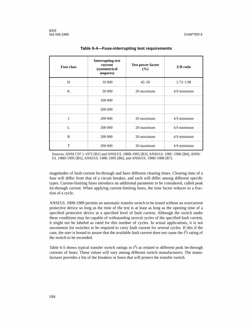
IEEEStd 446-1995 CHAPTER 6
magnitudes of fault-current let-through and have different clearing times. Clearing time of afuse will differ from that of a circuit breaker, and each will differ among different specifictypes. Current-limiting fuses introduce an additional parameter to be considered, called peaklet-through current. When applying current-limiting fuses, the time factor reduces to a frac-tion of a cycle.
ANSI/UL 1008-1989 permits an automatic transfer switch to be tested without an overcurrentprotective device so long as the time of the test is at least as long as the opening time of aspecified protective device at a specified level of fault current. Although the switch underthese conditions may be capable of withstanding several cycles of the specified fault current,it might not be labeled as rated for this number of cycles. In actual applications, it is notuncommon for switches to be required to carry fault current for several cycles. If this if thecase, the user is bound to assure that the available fault current does not cause the I2t rating ofthe switch to be exceeded.
Table 6-5 shows typical transfer switch ratings in I2t as related to different peak let-throughcurrents of fuses. These values will vary among different switch manufacturers. The manu-facturer provides a list of the breakers or fuses that will protect the transfer switch.
Table 6-4—Fuse-interrupting test requirements
Fuse class
Interrupting test current
(symmetrical amperes)
Test power factor (%) X/R ratio
H 10 000 45–50 1.73–1.98
K 50 000 20 maximum 4.9 minimum
100 000
200 000
J 200 000 20 maximum 4.9 minimum
L 200 000 20 maximum 4.9 minimum
R 200 000 20 maximum 4.9 minimum
T 200 000 20 maximum 4.9 minimum
Sources: ANSI C97.1-1972 [B1] and ANSI/UL 198B-1995 [B3], ANSI/UL 198C-1986 [B4], ANSI/UL 198D-1995 [B5], ANSI/UL 198E-1995 [B6], and ANSI/UL 198H-1988 [B7].
184

IEEEPROTECTION Std 446-1995
6.3.5 Automatic transfer switch dielectric strength
In addition to current-carrying capabilities, automatic transfer switches must be able to with-stand voltage surges to satisfy their reliability requirements. Control devices in an automatictransfer switch initiate the operation of transfer or retransfer and thus heavily affect the reli-ability of the switch. However, these control devices do not have the physical size and dielec-tric space inherent in the main load current-carrying parts of the switch. For this reason, it isimportant that high-quality products suitable for emergency equipment use are employed inthe switch.
ANSI/UL 1008-1989 requires dielectric voltage withstand tests of 1000 V plus twice-ratedvoltage. But the requirements are unclear as to what specific devices are to be tested andwhether or not control devices are to be included. ANSI/UL 1008-1989 requirements areintended mainly for safety, but to satisfy the reliability requirements of an emergency orstandby power system, consideration should be given to additional surge protection depend-ing on the exposure of the switch to voltage surges. Some considerations helpful in protectingthe dielectric strength of an automatic switch are
— Arc-breaking capability to minimize flashover between sources and deterioration ofdielectric.
— Contact construction to minimize heat generated at high currents.— Readily accessible contacts and components for easy visual inspection and replace-
ment.
Some common causes of voltage transients in ac systems that might affect automatic transferswitches are switching inductive loads, energizing and de-energizing transformers, and light-ning and commutation transients. In most cases, it is impossible to eliminate all the causes oftransients, and thus the transients themselves, so the next step is to assume they will occurand then take measures to protect sensitive equipment. It is recommended that transferswitches meet impulse withstand voltage test requirements as designated in ANSI/NEMA
Table 6-5—Typical transfer switch characteristics when used with fuses
Switch rating (amperes)
Available rms symmetrical fault current (amperes)
Peal let-through current (amperes)
I2t(amperes2-seconds)
125 200 000 26 000 600 × 103
225 200 000 45 000 2500 × 103
400 200 000 80 000 12 000 × 103
600 200 000 100 000 12 000 × 103
1000 200 000 150 000 35 000 × 103
185

IEEEStd 446-1995 CHAPTER 6
ICS 1-1993 and voltage surge withstand capability as designated in IEEE Std C37.90-1989.This is particularly important if solid-state voltage and frequency sensing is used.
IEEE Std 141-1993 provides an in-depth analysis of causes and effects of various kinds ofovervoltages.
6.3.6 Protection with circuit breakers
Principals of coordination and selectivity between the breakers and devices to be protected inthe distribution system follow those of most typical systems (assuming adequate fault-currentavailability). Reliability of power to critical loads will depend on selective breaker tripping.Two areas of concern regarding breakers and automatic transfer switches are evident: protect-ing the switch according to its withstand rating and, at the same time, achieving proper selec-tivity for service reliability. Selectivity becomes more of a problem when transfer switchingand overcurrent protection are combined as an integral unit. The integral protective devicefault clearing characteristics must be known to allow coordination with external overcurrentdevices.
Figures 6-4 and 6-5 show a simple illustration of a typical small system protected with circuitbreakers. Complete coordination is achieved by employing time delay in the short time regionon breakers A and B. The transfer switch is protected for any fault downstream of the switchby breakers B and C. In this case, the capability of the cable associated with the transfer
switch is the limiting factor and reduces the apparatus withstand rating. The switch by itselfwould have a higher rating. Also, in achieving coordination, the switch and associated wiringare required to withstand as much as 6 cycles of fault current for a fault between the switchand the branch breakers before the fault current is cleared in the short time region. The ratingof this switch will accommodate this requirement if the fault current does not exceed
Figure 6-4—Emergency power system with circuit breakers
186
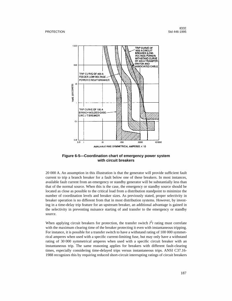
IEEEPROTECTION Std 446-1995
20 000 A. An assumption in this illustration is that the generator will provide sufficient faultcurrent to trip a branch breaker for a fault below one of these breakers. In most instances,available fault current from an emergency or standby generator will be substantially less thanthat of the normal source. When this is the case, the emergency or standby source should belocated as close as possible to the critical load from a distribution standpoint to minimize thenumber of coordination levels and breaker sizes. As previously stated, proper selectivity inbreaker operation is no different from that in most distribution systems. However, by invest-ing in a time-delay trip feature for an upstream breaker, an additional advantage is gained inthe selectivity in preventing nuisance starting of and transfer to the emergency or standbysource.
When applying circuit breakers for protection, the transfer switch I2t rating must correlatewith the maximum clearing time of the breaker protecting it even with instantaneous tripping.For instance, it is possible for a transfer switch to have a withstand rating of 100 000 symmet-rical amperes when used with a specific current-limiting fuse, but may only have a withstandrating of 30 000 symmetrical amperes when used with a specific circuit breaker with aninstantaneous trip. The same reasoning applies for breakers with different fault-clearingtimes, especially considering time-delayed trips versus instantaneous trips. ANSI C37.16-1988 recognizes this by requiring reduced short-circuit interrupting ratings of circuit breakers
Figure 6-5—Coordination chart of emergency power system with circuit breakers
187

IEEEStd 446-1995 CHAPTER 6
for short-time delay applications. For example, a 225 A frame low-voltage power circuitbreaker, with an instantaneous trip unit, has a 22 000 symmetrical amperes interrupting ratingat 480 V. The same breaker without an instantaneous trip has a reduced rating of 14 000 sym-metrical amperes at 480 V.
It is often difficult to predict future expansion with the present emphasis on cost-effective sys-tems. It is especially difficult to justify added capital expenditures for speculated load growth.A situation not so unusual is for available short-circuit current to eventually exceed breakerand transfer switch interrupting and withstand ratings when the normal supply transformerbank is increased in rating to accommodate unexpected load growth. A solution is to add cur-rent-limiting fuses in line with the existing breakers in accord with UL series ratings to pro-tect the equipment whose rating has been exceeded. The fuses should be applied inaccordance with recommendations from the circuit breaker manufacturers. This offers aneconomical compromise of limiting short-circuit current and I2t let-through and still main-taining some operating flexibility. However, coordination can be compromised. An alterna-tive solution is to apply current-limiting reactors whereby overcurrent device coordinationcan be maintained, providing X/R ratios do not become excessive.
6.3.7 Protection with fuses
First cost often favors fuse application over circuit breakers. Another advantage is that fusescan safely interrupt higher short-circuit currents than breakers and with faster clearing times.A disadvantage is the requirement to replace fuses after fault clearing. Breakers offer anadvantage where loads include three-phase motors, since their operation will not create a sin-gle-phase condition.
When fuses are used, peak let-through current and I2t energy let-through should be coordi-nated with the same characteristics of the transfer switch to be protected. These characteris-tics vary among fuse manufacturers and types of fuses and, therefore, the manufacturershould be consulted for each particular fuse considered. Additionally, transfer switches maybe rated for operation in series with a specific fuse for which they were tested. If another classof fuse with the same ampere rating and interrupting rating is substituted, the transfer switchcould possibly fail under fault conditions if the substitute fuse permits a higher peak currentand I2t energy let-through. The same reasoning applies when comparing a current-limitingfuse to a circuit breaker equipped with an instantaneous trip with a clearing time as fast as1-1/2 cycles. The circuit breaker will permit a higher peak current and I2t energy let-throughthan the current-limiting fuse, which can clear in a fraction of a cycle.
Table 6-1 shows an example of necessary application data for certain types of transferswitches suitable for use with fuses by specifying the circuit test data and fuse classes. Table6-5 illustrates an example of application data by specifying the peak current and I2t let-through limits of certain kinds of switches. Again, these characteristics will vary among dif-ferent manufacturers. In one case, the specific overcurrent protective devices are given alongwith the short-circuit test data, and in the other case the maximum limits of the switch ratingsare given. The user can compare the switch capabilities with any type of fuse to be employed.
188

IEEEPROTECTION Std 446-1995
Figures 6-6 and 6-7 show the example system previously discussed with figures 6-4 and 6-5except that current-limiting fuses are used instead of circuit breakers. The transfer switch hasa specific maximum allowable peak let-through current rating. Peak let-through curves basedon available fault current and the clearing time of the fuses in the current-limiting range areavailable from fuse manufacturers.
6.3.8 Ground-fault protection
Although ground-fault protection of equipment is not normally required on the alternatesource for emergency systems, ground-faults can occur on such systems and they can resultin equipment burn-down. Because of the emergency nature of such systems, automatic dis-connect in the event of a ground-fault is not required by code. However, detection of such afault is desirable. It is good practice to provide an audible and visual signal device to indicatea ground-fault condition. Instructions should also be provided to advise what course of actionshould be taken in the event of a ground-fault indication. Additional consideration should begiven to the possibility of a ground-fault on the load side of the transfer switch when ener-gized from either source. For further discussion, see Chapter 7.
6.4 Generator protection
When an emergency generator is running, it supplies the power for critical loads. In this roleit is the most critical and vital element in the power supply. Manufacturers may not alwaysprovide all the basic protection needs for generators and also leave options to choice by the
Figure 6-6—Emergency power system with fuses
189

IEEEStd 446-1995 CHAPTER 6
user. In any application, the user should evaluate his needs and the critical nature of the loadbefore deciding on the best protection scheme. The protection scheme chosen should ensurereliability of this power source. Unlike applying standard practice in generator protection, auser should also rely on operating experience and sound-judgment in determining whetherstandard protection schemes allow the required reliability of emergency power. For instance,whether an installation is remotely or locally operated may determine if an audible or visualalarm will suffice in a condition where normally an automatic shutdown is used. Wherepower is extremely critical, it is wise to evaluate the consequences of loss of power to criticalloads versus damage to the emergency power source. Caution should be exercised, however,when emphasizing reliability, to ensure that applicable codes and standards are not over-looked.
6.4.1 Codes and standards
Some codes and standards that address emergency or standby generator protection are listedin 6.11 as IEEE Std 141-1993, IEEE Std 242-1986, ANSI/NEMA MG 1-1993, NFPA 70-1996 (the NEC), EGSA 101P-1995.
Figure 6-7—Coordination chart of emergency power system fuses
190
IEEEPROTECTION Std 446-1995
6.4.2 Armature winding protection
Of most concern in winding protection is overcurrent, primarily from short circuits and over-loads. The basic protective devices employed are circuit breakers or fuses. But the size of thegenerator set can drastically influence the method of use and trip levels for such devices.Also, overvoltage protection needs will differ between large and small machines (that is,high-voltage and low-voltage ratings).
6.4.2.1 Overcurrent protection
The need for overcurrent protection for large machines is commonly taken for granted. Forpurposes of this chapter, these are machines that have enough mechanical and electricalstored energy, and thus available short-circuit current, to allow easy coordination between thegenerator and other load-side overcurrent protective devices. Overcurrent protection of thegenerator windings becomes important due to the cost of investment and also because protec-tion will not seriously compromise reliability of the power supply to critical loads since over-current device selectivity is reasonably easy. Design of the protection scheme should followstandard practice, as a rule. Standard practice can vary from a single, simple, molded-casecircuit breaker to a larger power circuit breaker with zone-selective interlocking. IEEE Std242-1986 provides a useful guideline for recommended generator protection.
Smaller generator sets pose a more perplexing problem regarding available short-circuit cur-rent. These are machines with relatively little mechanical and electrical stored energy andtypically low system X/R ratios, and under bolted fault conditions can slow down very rapidlyand have difficulty in supplying sustained fault current. This has been discussed, to someextent, in 6.2. Many users and specifiers of engine-generators often assume the need for agenerator breaker for protection of the windings under short-circuit conditions. There areconditions where unregulated short-circuit current is capable of damaging a small generator.However, it is probable that the output of the generator, with a specified excitation system,will reduce to practically zero before any serious damage occurs. Even for separate excita-tion, the output can be specified to reduce to the full-load rating or less. This was illustrated infigure 6-1. In this sense, it is inherently protected and an overcurrent device serves little pur-pose in protecting the windings against short-circuit current. The dangers of assuming inher-ent protection are the uncertain conditions of unbalanced faults. For instance, excitationcould be supplied from an unfaulted phase and unwanted sustained fault current could occur.If inherent protection is necessary, the user should specify this feature.
The initial per-unit fault current of a generator is 1/x"d, where x"d is the subtransient reac-tance of the generator and is determined from a short-circuit test of the generator. The initialshort-circuit current induces very high currents in the field and damper windings of the rotor(8–10 times the no-load value is common). The generator losses under a fault condition,therefore, involve not just stator winding losses, but also field and damper losses, as well asextra stray load losses in both rotor and stator steel. It is possible for these losses to breakcouplings and tear loose generator mounts if the generator is not securely mounted. At thepresent time there are no reliable parameters available in the industry to determine the exactlosses, but calculations based on the positive, negative, and zero sequence reactances andresistances will give approximate values. For a close analysis, these losses can be compared
191
IEEEStd 446-1995 CHAPTER 6
to the stored kinetic energy and the mechanical shaft energy input to determine the effect of afault on generator speed.
In the discussions above for large and small generator sets, obvious consequences and effectsof generator damage are assumed. In reality, the damaging effects of short-circuit current on agenerator are difficult to determine. Even for a manufacturer, the actual limits of short-circuitcurrent and duration are difficult to determine, since the tolerable damage can vary fromslight reduction in insulation life to actual physical winding damage rendering the machineinoperative. For the mechanical strength of a generator ANSI/NEMA MG 1-1993 specifiesthat a generator be capable of withstanding without injury a three-phase fault at its terminalsfor 30 s when operating at rated kVA and power factor with fixed excitation for 5% overvolt-age. The sustained current in this case is typically less than rated current, as evidenced in fig-ures 6-1(a) and (b), and hence does not test the windings for heating damage. Requirementsare also given for unbalanced fault conditions.
Assuming that any generator has an accurate damage curve readily available for use in coor-dination of overcurrent devices is erroneous. Of additional concern, is the allowance of anextra 25 °C rise in winding temperature for emergency or standby application of a generator,as designated in ANSI/NEMA MG 1-1993. Sometimes the regulator/exciter system is thelimiting factor in a damage curve. For instance, a common specification for a generator set isthat it sustains 3 pu fault current for 10 s (I2t = 90). This may actually be a limit for the regu-lator and exciter whereby the stator winding is capable of more. Further inquiry will revealthat rotor heating becomes a limiting feature during unbalanced faults. Rotor heating iscaused by the negative sequence current. ANSI/NEMA MG 1-1993 requires that generatorswithstand negative sequence current only to an I2
2t value of 40. During a line-to-line fault,which produces the highest negative sequence current content, this translates to a total I2t of120. However, if the protection is set at I2
2t = 120, a separate device would be needed to pro-tect the excitation system, if the excitation system is the limiting factor in the 90 I2
2t calcula-tion. Therefore, little is to be gained in coordinating capabilities by raising the overcurrentsetting above the total system limit. Through consultation with a manufacturer, assuring thatall conditions are understood, a reasonably accurate time-current limit can be estimated.
To avoid confusion and misconception about damage limit curves, a better descriptive mightbe capability limit. This is reasonable considering cases where it is difficult to determine lim-its other than from standards such as ANSI/NEMA MG 1-1993. The manufacturer should beconsulted in determining the capability of a generator since it should account for all compo-nents in identifying the weakest part. These components would include the stator, rotor,damper, and exciter windings. Semiconductors, as well as components of the regulator,should be included.
Thus, with fault-sustaining capability, the possibility exists for damage to the generator wind-ings (and possibly to the prime mover) if the fault condition is allowed to exist too long. Fig-ure 6-8 helps to illustrate this point. The figure shows an assumed generator capability curvebased on 90 I2t thermal limit and its relation to the fault-current decrement curves for a gener-ator with and without an excitation system designed to maintain fault current. The figure doesnot represent an actual case, but simply illustrates the maximum level at which the generatorprotective device must operate to provide minimum protection for the generator. The fault
192
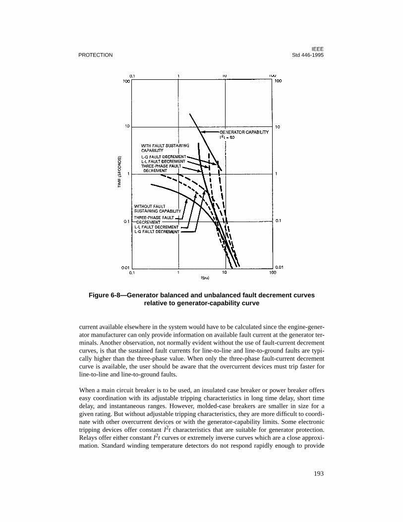
IEEEPROTECTION Std 446-1995
current available elsewhere in the system would have to be calculated since the engine-gener-ator manufacturer can only provide information on available fault current at the generator ter-minals. Another observation, not normally evident without the use of fault-current decrementcurves, is that the sustained fault currents for line-to-line and line-to-ground faults are typi-cally higher than the three-phase value. When only the three-phase fault-current decrementcurve is available, the user should be aware that the overcurrent devices must trip faster forline-to-line and line-to-ground faults.
When a main circuit breaker is to be used, an insulated case breaker or power breaker offerseasy coordination with its adjustable tripping characteristics in long time delay, short timedelay, and instantaneous ranges. However, molded-case breakers are smaller in size for agiven rating. But without adjustable tripping characteristics, they are more difficult to coordi-nate with other overcurrent devices or with the generator-capability limits. Some electronictripping devices offer constant I2t characteristics that are suitable for generator protection.Relays offer either constant I2t curves or extremely inverse curves which are a close approxi-mation. Standard winding temperature detectors do not respond rapidly enough to provide
Figure 6-8—Generator balanced and unbalanced fault decrement curves relative to generator-capability curve
193
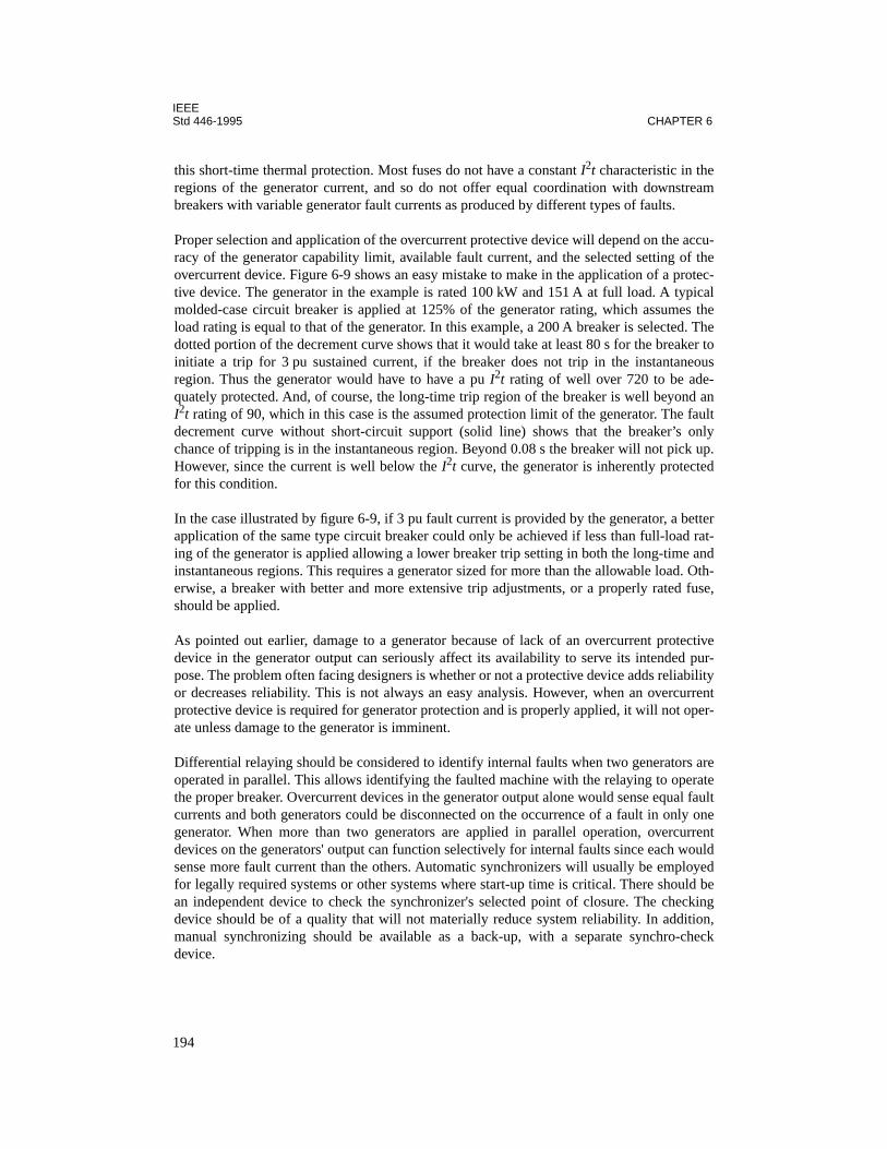
IEEEStd 446-1995 CHAPTER 6
this short-time thermal protection. Most fuses do not have a constant I2t characteristic in theregions of the generator current, and so do not offer equal coordination with downstreambreakers with variable generator fault currents as produced by different types of faults.
Proper selection and application of the overcurrent protective device will depend on the accu-racy of the generator capability limit, available fault current, and the selected setting of theovercurrent device. Figure 6-9 shows an easy mistake to make in the application of a protec-tive device. The generator in the example is rated 100 kW and 151 A at full load. A typicalmolded-case circuit breaker is applied at 125% of the generator rating, which assumes theload rating is equal to that of the generator. In this example, a 200 A breaker is selected. Thedotted portion of the decrement curve shows that it would take at least 80 s for the breaker toinitiate a trip for 3 pu sustained current, if the breaker does not trip in the instantaneousregion. Thus the generator would have to have a pu I2t rating of well over 720 to be ade-quately protected. And, of course, the long-time trip region of the breaker is well beyond anI2t rating of 90, which in this case is the assumed protection limit of the generator. The faultdecrement curve without short-circuit support (solid line) shows that the breaker’s onlychance of tripping is in the instantaneous region. Beyond 0.08 s the breaker will not pick up.However, since the current is well below the I2t curve, the generator is inherently protectedfor this condition.
In the case illustrated by figure 6-9, if 3 pu fault current is provided by the generator, a betterapplication of the same type circuit breaker could only be achieved if less than full-load rat-ing of the generator is applied allowing a lower breaker trip setting in both the long-time andinstantaneous regions. This requires a generator sized for more than the allowable load. Oth-erwise, a breaker with better and more extensive trip adjustments, or a properly rated fuse,should be applied.
As pointed out earlier, damage to a generator because of lack of an overcurrent protectivedevice in the generator output can seriously affect its availability to serve its intended pur-pose. The problem often facing designers is whether or not a protective device adds reliabilityor decreases reliability. This is not always an easy analysis. However, when an overcurrentprotective device is required for generator protection and is properly applied, it will not oper-ate unless damage to the generator is imminent.
Differential relaying should be considered to identify internal faults when two generators areoperated in parallel. This allows identifying the faulted machine with the relaying to operatethe proper breaker. Overcurrent devices in the generator output alone would sense equal faultcurrents and both generators could be disconnected on the occurrence of a fault in only onegenerator. When more than two generators are applied in parallel operation, overcurrentdevices on the generators' output can function selectively for internal faults since each wouldsense more fault current than the others. Automatic synchronizers will usually be employedfor legally required systems or other systems where start-up time is critical. There should bean independent device to check the synchronizer's selected point of closure. The checkingdevice should be of a quality that will not materially reduce system reliability. In addition,manual synchronizing should be available as a back-up, with a separate synchro-checkdevice.
194
IEEEPROTECTION Std 446-1995
When the power system is grounded, the scheme employed warrants special attention. Multi-ple neutral ground connections can cause problems if ground current paths are not carefullydesigned. On large systems using special ground fault sensors for the generator protection,incomplete sensing or erroneous tripping can occur if the ground-fault current does not fol-low a predictable path. This problem is not so serious, as far as generator protection is con-cerned, on small systems that depend on a phase overcurrent device to operate on a groundfault. Likewise, with an ungrounded system ground currents are not a critical concern to gen-erator overcurrent protection so long as proper detection is employed and single line-to-
Figure 6-9—Misapplication of typical molded-case circuit breaker with limited short-circuit current
195

IEEEStd 446-1995 CHAPTER 6
ground conditions are eliminated as soon as possible. Chapter 7 explores in detail variousaspects of grounding and handling of the system neutral.
6.4.2.2 Overvoltage protection
Overvoltage protection of the main generator windings is a necessity sometimes taken lightlyor even overlooked. Emergency and standby power systems and their associated distributionsystems are relatively small in overall power rating and number of components compared tobase-loaded systems (normal power supplies and distribution systems) and also often locatedwell within the overall distribution system. Consequently, they are not usually subject to thesame number and severity of overvoltage problems. But, because emergency and standbypower must be reliable, if effectively applied, overvoltage protection should always beincluded in the design and application process. Certainly it would be an unusual case if anemergency generator were physically connected to an electric utility system such that it wassubject to the same dangers of lightning transients. But other types of transient voltages fromswitching and restriking faults, for example, can be damaging and should be of concern.
Overvoltage protection is more critical for large generators with higher voltage ratings thanfor smaller ones with low voltage ratings (600 V). Protection of the investment is one reason,but another is the decreased margin of safety in the insulation as voltage ratings increase.That is, the ratio of insulating capacity to system voltage is normally higher for smaller unitsthan for larger, higher voltage-rated units. ANSI/NEMA MG 1-1993, for instance, stipulatesa suitable high potential test for armature windings of 1 000 V plus twice the rated voltage formost common types of ac generators. The test voltage for a 4160 V generator at this condi-tion would be 12% higher than twice the rating. The test voltage for a 480 V generator wouldbe about 100% higher than twice the rating.
Overvoltage conditions can be either of a transient nature or steady-state nature. The formeris considered higher in magnitude and frequency, but of considerably less duration than thelatter. Protection from each type of overvoltage condition is handled differently, but for thesame reason: to preserve the integrity of the insulation. Although difficult to measure or cal-culate, any overvoltage condition, no matter how short the duration, will stress the insulationand shorten its life. So this is always a concern.
Protection against transient voltages is most commonly provided by surge arresters in combi-nation with capacitors. But unless the transient is high, as it would be from a lightning strike,surge arresters are not always effective, although capacitors will attenuate a surge at anylevel. Switching surges would rarely reach the sparkover value of a lightning surge arrester.When an emergency or standby generator is situated to be subject to lightning-induced tran-sients, surge arresters should be applied preferably at the generator terminals and, if neces-sary, at the boundaries of the exposed part of the system, such as at the ends of the exposedportion of an overhead line. The margin of safety is greatly influenced by the expected fre-quency and magnitude of the surges, something a designer would determine largely by judg-ment. Each occurrence of an overvoltage will shorten the insulation life of the windings withan inverse relation between the magnitude and allowable duration. The generator manufac-turer can provide the necessary information on the withstand capability of the winding insula-tion.
196

IEEEPROTECTION Std 446-1995
This will aid in determining the upper limits of allowable overvoltage and duration. However,some additional margin of safety should be considered. IEEE Std 141-1993 suggests limitingthe magnitude to approximately four fifths of the certified test voltage. The permissible rateof rise of the transient is suggested as no more than the 60 Hz high-potential test peak value ata uniform rise time of 10 µs. This rate of rise is controlled by the application of appropriatesurge capacitors at the generator terminals.
Other types of transients, common to industrial and commercial systems, result from switch-ing actions that force current to zero, which in turn generate a transient voltage from the rapidcollapse of the magnetic field. This type of overvoltage can result from the operation ofdevices ranging from circuit breakers to SCRS. Even the opening of a circuit by a conductorburning itself free from a fault can produce a transient overvoltage. In ungrounded systems,the neutral is free to change its electrical reference to ground under certain conditions, whichcan. compound the transient effects of switching.
The most effective method of protecting an emergency generator from switching transients iscareful design of the installation. Switching transients, as mentioned above, are rarely assevere as those from lightning and are not normally given the same consideration. Eventhough their occurrence can be more frequent than those from lightning, there is also moreinherent protection within a distribution system, such as the number of cable circuits and con-nected equipment that act to greatly reduce the magnitude and slope of surge voltages.Grounding of a system neutral minimizes additional voltage-to-ground stress caused byswitching surges and ground faults (especially restriking ground faults). Additionally, regard-less of whether a system neutral is grounded or not, switching can cause overvoltage stressbetween windings from the oscillatory effect of voltage when a switch clears a fault. SeeIEEE Std 142-1991, Chapter 1.
IEEE Std 141-1993 provides a detailed analysis of the causes and effects of surge voltagesalong with recommended application practices that afford protection.
Steady-state overvoltage conditions are not as serious as transient overvoltages because oftheir lesser magnitude and because they are easier to control. They are of concern, however,because of their duration, and again it is emphasized, insulation life is shortened by theseovervoltages. Some common causes are over-excitation, accidental contact with a highervoltage source (this can sometimes be of a transient nature), and shifting of the system neu-tral in ungrounded systems.
Overexcitation can result from unlimited control of an exciter and voltage regulator or exces-sive leading reactive power from external devices like capacitors that are designed only foruse with the normal power supply. Accidental contact with a higher voltage source happens inrare cases. Perhaps as the result of insulation breakdown between a high and low winding in atransformer. In an ungrounded system, the neutral would be raised above ground reference byan amount equal to the high voltage and thus raise each phase above ground accordingly. Theoccurrence of this condition is so rare that deliberate measures to guard against it are rarelytaken. Proper enclosures and shielding of the conductor systems provide a reasonable safe-guard. In a grounded system, the ground of the secondary and primary (presuming the high-voltage side is physically referenced to ground) will complete a short-circuit path when the
197
IEEEStd 446-1995 CHAPTER 6
two voltage sources come in contact, allowing overcurrent devices to operate. An initial volt-age transient is not prevented but the duration is minimized.
Shifting of a system neutral and corresponding phase overvoltage to ground under steady-state conditions in an ungrounded or resistance grounded system is caused from single line-to-ground faults. Ground detection serves to protect a generator from the deteriorating effectsof overvoltage or a second internal or external ground fault, but only if prompt action is takento correct the unbalance when it occurs. ANSI/NEMA MG 1-1993 and ANSI C50.10-1990assure line-to-line voltage rating of the line-to-neutral winding in a wye-connected generator.Adherence with one of these standards should be specified.
6.4.2.3 Harmonics
The increased use of static power converters, fluorescent and high-intensity discharge light-ing, adjustable frequency drives, and switching mode power supplies have brought with it anincreased concern of the effects on emergency and standby power generators. Some of themost serious effects pertain to proper operation and quality of power. But, there is also causefor concern for generator protection. Some obvious concerns are as follows:
— High-frequency harmonies cause additional losses and heating in a generator. A sig-nificant portion of the losses occur in the rotor where heating is not measured.
— Overcurrent relays can become more sensitive because of the skin effect in the cur-rent-sensing elements. Electromechanical and static relays may have altered perfor-mances, with both the duration and amount of change following no predictablecriteria. The overall result is that a relay may not operate as accurately as specifica-tions show. NEMA AB 3-1991 provides information on the application of circuit-breakers with harmonic loads.
— Although little quantitative information exists on the effect of harmonics on circuitbreakers and fuses, it is expected that their current-carrying capacity would bereduced, as heating of thermal elements is increased due to skin effect.
6.4.3 Rotor and excitation system
A field circuit breaker is a positive means of protecting the rotor and excitation system fromdamaging over currents due to external faults, underspeed, certain load conditions, or compo-nent failure within the excitation system. A field breaker, however, is not considered adequateprotection by itself for the stator windings and should not replace an overcurrent device in thegenerator output, if one is required.
Solid-state exciter/regulator systems are commonly available. Common protection featuresinclude over- and under-excitation limiting, automatic voltage sensing between manual andautomatic regulation circuits to allow smooth transfer from automatic to manual operationand vice versa, and failed rectifier detection.
In the brush-type machines (including those with static exciters) a field breaker may belocated in the leads to the slip rings, in the field leads of an exciter, or in the regulator supply.On brushless generators only the last two locations are available, since the main rotor leads
198
IEEEPROTECTION Std 446-1995
are not accessible. Location in the regulator power input is usually preferred since it providesshort-circuit protection to the regulator and the regulator performs the field discharge func-tion. In this position, the breaker may contain additional contacts that provide short-circuitprotection for the voltage-sensing circuitry. Thus, excitation would be removed to preventover-excitation when sensing is lost due to a fault or protective-device operation.
6.5 Prime mover protection
6.5.1 General requirements
The most direct form of overload protection, still maintaining some degree of reliability,would be load shedding. Depending on the severity of stability problems, circuit breaker sta-tus or frequency sensing might be used to initiate action. Instantaneous automatic load shed-ding where multiple generator sets are used, when one or more generators are lost, wouldassure available power for the remaining, more critical loads. On smaller systems, especiallywhere only one generator is used, frequency sensing to shed load might provide a more reli-able power supply if conditions do not always require load shedding. A combination of thetwo methods would allow a system to instantaneously shed selected loads, with frequencysensing employed as backup to shed additional load as necessary. It is common practice insome cases to employ underfrequency relays as secondary sensing devices to trip selectedload breakers in multiple steps, with a time delay between each step. A stability study woulddetermine frequency settings at each successive step. The study would also determine howfast load shedding should occur and thus determine the type and speed of equipment to beused. The scheme would normally be designed to maintain enough generation to prevent totalblackout regardless of the load conditions.
Overload protection for a prime mover can also be aided by assuring that frequency sensitivevoltage regulation is used. Maintaining a constant voltage-to-frequency ratio minimizeseffects of overload and allows a unit to more easily regain normal voltage and frequency afteran overload. The output voltage of the generating set would decrease in proportion to the fre-quency (prime mover speed). The use of a non-frequency-sensitive voltage reference couldrequire, in some cases, a load reduction of from 50–60% to allow return to rated speed.Although some manufacturers can provide either type of voltage reference, it may be up tothe user to specify his preference. Application of frequency sensitive voltage regulation, how-ever, should not overshadow the importance of proper matching of generator or prime movertorque characteristics.
Reverse power relaying is an important form of protection for prime movers. It will preventmotoring when generator sets are operating in parallel and in another application preventsoverload of a generator set by fast relaying when power flow is into an electric utility system.In prevention of generator motoring, the user should be aware that some prime movers areless susceptible to damage than others. Sensitivity is more critical, for instance, on turbinesthan reciprocating engines, and nuisance tripping can occur if this is not accounted for.
Protection against motoring of a prime mover guards against overheating or cavitation ofblades on a turbine and possible fire or explosion from unburned fuel in a reciprocating
199
IEEEStd 446-1995 CHAPTER 6
engine. A relay to detect reverse power flow would normally be applied as backup protectionto mechanical devices designed to detect these conditions. A time delay can be applied to pre-vent nuisance tripping on momentary reverse power surges such as may occur during syn-chronizing. Some typical values are listed below showing reverse power required to motor agenerator when a prime mover is being spun at synchronous speed without input power:
— Condensing turbine: 3% of nameplate, in kilowatts— Noncondensing turbine: 3% of nameplate, in kilowatts— Diesel engine: 25% of nameplate, in kilowatts— Hydraulic turbine: 0.2–2.0% of nameplate, in kilowatts
6.5.2 Equipment malfunction protection
Standard protective devices and numerous options are provided with prime movers by manu-facturers. The equipment investment and nature of critical loads determine how to apply thisprotection. Some shutdown devices might be considered for alarm only, such as where instal-lations are attended, and a malfunction can be quickly investigated. When it is determinedthat a shutdown is necessary for a malfunction condition, protection integrity can be main-tained and power supply reliability enhanced if the malfunction is such that an alarm and sub-sequent shutdown can be employed.
High water temperature, high oil temperature, low oil pressure, overspeed, high exhaust tem-perature, and high vibration are typical examples of malfunctions that lend themselves totwo-level protection as suggested above. On large machines, this is usually an insignificantinvestment to make. It is common practice in many installations and often required bymachine manufacturers to also provide meters or displays for continuous monitoring of theabove parameters by personnel on site or at remote locations. When remote controlledmachines are located in areas not easily accessible, readouts of individual machine parame-ters become more significant. Cases have occurred where engines and turbines have beendamaged because operating personnel with remote control capability restarted the units orcontinued operation of the units under malfunction conditions without knowing specificallywhich malfunctions existed.
Large generator sets requiring sophisticated and complex control systems often utilize unin-terruptible power supply (UPS) systems for control power. Protection of power supplies ofthis nature is vital to the total machine protection.
Reciprocating engines and turbines require different philosophies for protection by nature oftheir design and operation. Smaller reciprocating engines typically have protection furnishedfor high water temperature, low oil pressure, overspeed, and failure to start. Larger unitsmight also include high oil temperature, high vibration, antimotoring, and protection forcomplex control and excitation systems.
Protection for combustion turbines would add such protective devices as failure to light, fail-ure to reach self-sustaining speed, and exhaust temperature limits and control. Overspeed andvibration are obviously more critical on turbines due to high-speed operation.
200
IEEEPROTECTION Std 446-1995
Electric motor-driven auxiliary equipment on large generator sets, such as lube oil pumps andcooling water pumps, are vital to the protection and reliability of the generator set. Reliabilitymight be increased and protection maintained in locally operated critical installations byremoving thermal overload trips from motor-control circuits and alarming only on an auxil-iary motor overload. In this instance, lube oil temperature and levels, cooling water tempera-ture, and auxiliary motor loading should be closely monitored to protect equipmentinvestment.
6.5.3 Fuel system protection
The importance of protection for fuel systems needs very little explanation regarding the reli-ability of the power supply. For instance, it is obvious that low pressure and level alarms canprevent needless shutdown or failures of emergency generator sets requiring a high degree ofreliability. Building codes and fire insurance regulations aid in determining optimum loca-tions of self-contained fuel systems. Refer to Chapter 4 for storage recommendations andANSI/NFPA 30-1993 for requirements on protection for fuel piping.
It should be noted that gasoline and diesel fuels can deteriorate if left standing unused forlong periods of time. Some provision should be made for periodically burning or replacingthe fuel at regular intervals and for treatment with appropriate additives.
6.6 Electric utility power supply
A second electric utility supply serving in a standby (emergency) role is typically protectedno differently than if it were the normal (preferred) supply, except for the problems associ-ated with connecting the two sources simultaneously. Usually this is intentionally prohibitedby the equipment, but if not, the two sources must be in synchronism before being closedsimultaneously (paralleled). However, if allowed, two sources may be operated continually inparallel to share the duty of providing power, with either one standing by to assume the entireload if the other source is lost. These may also be referred to as redundant sources.
Unlike the standby generator the standby utility source voltage is immediately available. Ifthe load contains large motors these motors must be protected from the closing of the standbysource when the residual voltage on the motors is out of phase with the standby source. If thetransfer is initiated by loss of the normal source, the motors will have slowed and willbecome out of phase. Transfer will need to be delayed by timer or voltage relay until voltagehas decayed to the acceptable level of 35%, as specified in ANSI/NEMA MG 1-1993. Thereis often some delay introduced to prevent transfer initiation by momentary dips in the utilityvoltage. If the transfer is to be between two sources both of which are at normal voltage, a“fast transfer” can be made if the two sources are first determined to be in phase. Alternately,a closed transition (momentary paralleling) transfer may be made. Refer to 4.3.8 for furtherdiscussion.
Switching from a standby power supply back to the normal supply would demand the samesynchronizing requirements whether the standby source is an electric utility or an in-plant
201
IEEEStd 446-1995 CHAPTER 6
generator. In either case, closed or open transition can be employed depending on loadrequirements, and the issue of synchronizing would be the same.
Because of the exposure of an electric utility line to uncontrollable disturbances, this sourceis rarely employed as an emergency source, as defined in this standard. Therefore, specialtechniques and protective equipment to preserve reliability, such as those recommended forother in-plant emergency or standby sources, are not considered necessary or practical. Stan-dard guidelines for protective equipment for electric utility ties are covered quite well inIEEE Std 242-1986. It will suffice to say that close cooperation between engineering repre-sentatives of the electric utility and user is necessary to assure the needs of each are clearlydefined and understood. An accurate description of the load and its effects on the utility sup-ply is essential in establishing proper protection of the supply while maximizing reliability.One additional important concern is that of ownership of the service equipment. If the userrequires protection and control equipment not normally employed by the utility, he maychoose to furnish and own the substation equipment to maintain this control. An electric util-ity may allow the customer to specify equipment not normally supplied by the electric utility,but require reimbursement for additional cost.
Protective schemes vary in complexity depending on the size, economic investment of thesystem, and consequences of power loss, but the objectives are the same. The utility supplymust be protected from the effects of faults and abnormalities in the user’s system and, con-versely, the user’s system must be protected. against the possible adverse conditions in theelectric utility system.
Protection against ground faults raises special issues. Ground-fault sensing can be a problemif not carefully planned; see Chapter 7 for methods and considerations in handling groundfaults.
6.7 Uninterruptible power supply (UPS) system
The basic components of a static UPS system are the battery, rectifier or battery charger,inverter, and often a static transfer switch. Technically, a motor-generator set is also a UPSsystem, but is often referred to as a mechanical stored energy or rotary system. The discus-sion here is limited to the static UPS system.
6.7.1 Battery protection
Batteries provide the source of emergency or standby power in the application of a UPS sys-tem. The reliability of the system will heavily depend on the protection provided for the bat-tery. Much of the protection provided is inherent in good maintenance practice as discussedin Chapter 8, but the importance of this subject warrants further discussion in this subclause.
Lead-acid batteries are especially susceptible to adverse effects from both being under-charged and overcharged. Continual undercharging promotes lead sulfate buildup, whichreduces battery capacity. Overcharging causes gassing of vented cells and heating of valve-regulated cells. A lead-antimony battery experiences objectionable water consumption if a
202

IEEEPROTECTION Std 446-1995
float voltage is too high and thus reduced battery life. Lead-calcium batteries are less suscep-tible to high water consumption.
Most battery specifications and recommendations are based on an ambient temperature of77 °F (25 °C). Float charging or equalize charging a lead-acid battery in an ambient tempera-ture higher than this optimum value can reduce battery life below its designed life if the volt-age is not reduced accordingly. Typical recommended float voltages for fully charged lead-acid batteries are shown in the following table. However, in any specific installation a manu-facturer's recommended values are the preferred choice.
When equalize charging by constant voltage is necessary to bring all cells to an acceptablecharge state, a voltage level higher than a normal float voltage is used (provided the voltagelevel does not exceed the maximum tolerable level for connected loads). Equalize charginghas a protection benefit for lead-antimony batteries because it counteracts the degradation ofnatural transfer of antimony from the positive to negative plate in an undercharged battery. Anequalize charge maintains the integrity of a battery, but should not be applied longer than nec-essary. The worst condition for hydrogen evolution is forcing maximum current into a fullycharged battery. Some recommended voltages and time periods for equalizing lead-acid bat-teries are shown in the following tables. These values are based on cell temperatures in therange of 70 °F (21 °C) to 90 °F (32 °C). As with the recommended values of float voltages inthe table above, manufacturers should be consulted for specific or unusual installations andespecially for charging requirements for other temperatures. Additionally, charging equip-ment should be evaluated as to whether it is ambient temperature compensated, thus account-ing for different cell temperatures.
Battery Volts per cell
Lead-antimony 2.15–2.17
Planté 2.17–2.19
Lead-calcium1.215 sp gr1.250 sp gr1.300 sp gr
2.17–2.252.23–2.332.28–2.37
Lead-antimony and Planté
Volts per cell Time (hours)
2.24 80
2.27 60
2.30 48
2.33 36
2.36 30
2.39 24
203

IEEEStd 446-1995 CHAPTER 6
The initial charging of a lead-acid battery after shipment or installation is very much likeequalize charging after a discharge. The difference is that the time period is longer—typicallytwice as long.
An important protection feature for a lead-calcium battery is correct sizing of the ampere-hour capacity. A lead-calcium battery cannot take deep discharges, so control of the dischargeend voltage is more critical than for other battery types.
Nickel-cadmium (NICAD) batteries, because of their construction and chemical composi-tion, are more tolerable to high charge rates and high ambient temperatures than lead-acidbatteries. However, overcharging (continued charge current after full charge reached) stillcauses oxygen and hydrogen evolution. A sealed cell would experience pressure buildup andtemperature rise.
A vented cell would experience gassing and loss of water from the electrolyte. Approximatecharge voltages per cell related to battery temperature are shown in figure 6-10 for vented-cell NICAD batteries.
The detrimental effects of overcharging batteries are compounded with high ambient temper-atures that add to the increased temperature resulting from charging. High temperatureincreases water consumption by evaporation, and the resulting increased charging currentfrom high temperature causes more water consumption through oxygen and hydrogen evolu-tion. Acid fumes from lead-acid batteries corrode terminals (and other equipment in closeproximity). Hydrogen evolution can create an explosive atmosphere if the area is not ade-quately ventilated. Sealed cells can build up dangerous pressures if temperature is too high.For these reasons, controlling ambient temperature may be the single best protection for pre-serving battery integrity and maximizing life.
Lead-calcium
Volts per cellTime (hours)
1.215 sp gr 1.250 sp gr 1.300 sp gr
2.24 222 — —
2.27 166 — —
2.30 105 — —
2.33 74 166 —
2.36 50 118 200
2.39 34 80 134
2.42 — 54 91
2.45 — 36 62
2.48 — — 42
204
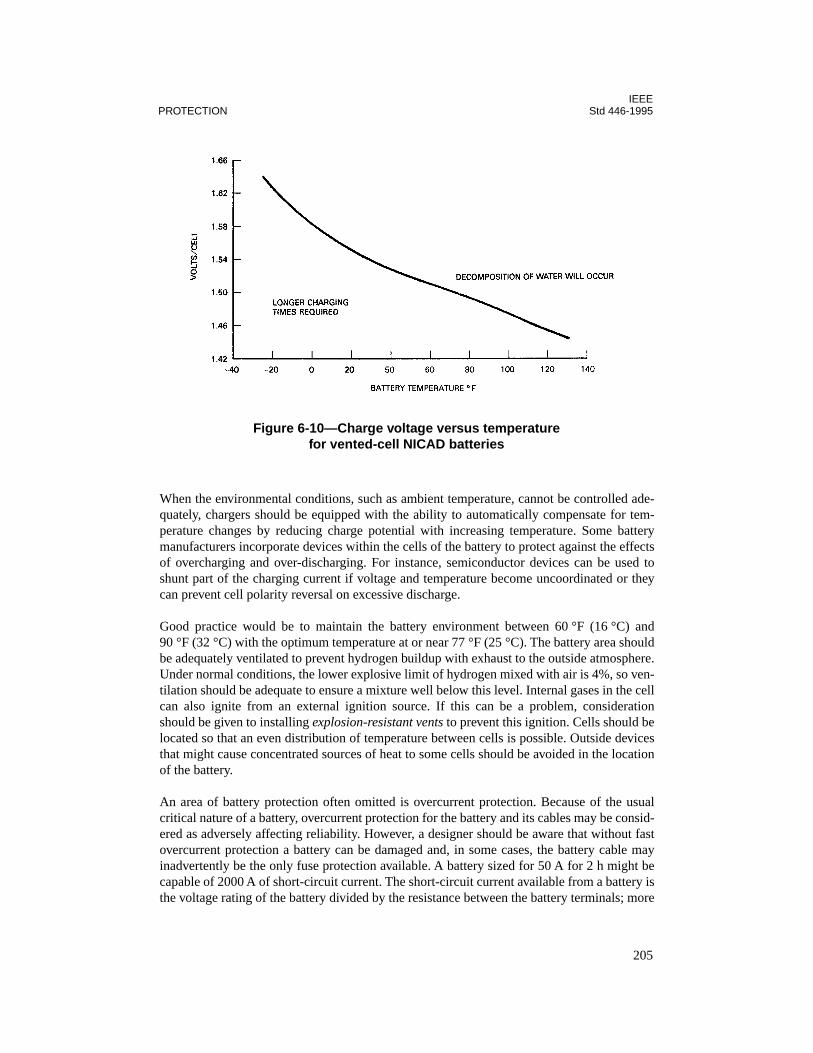
IEEEPROTECTION Std 446-1995
When the environmental conditions, such as ambient temperature, cannot be controlled ade-quately, chargers should be equipped with the ability to automatically compensate for tem-perature changes by reducing charge potential with increasing temperature. Some batterymanufacturers incorporate devices within the cells of the battery to protect against the effectsof overcharging and over-discharging. For instance, semiconductor devices can be used toshunt part of the charging current if voltage and temperature become uncoordinated or theycan prevent cell polarity reversal on excessive discharge.
Good practice would be to maintain the battery environment between 60 °F (16 °C) and90 °F (32 °C) with the optimum temperature at or near 77 °F (25 °C). The battery area shouldbe adequately ventilated to prevent hydrogen buildup with exhaust to the outside atmosphere.Under normal conditions, the lower explosive limit of hydrogen mixed with air is 4%, so ven-tilation should be adequate to ensure a mixture well below this level. Internal gases in the cellcan also ignite from an external ignition source. If this can be a problem, considerationshould be given to installing explosion-resistant vents to prevent this ignition. Cells should belocated so that an even distribution of temperature between cells is possible. Outside devicesthat might cause concentrated sources of heat to some cells should be avoided in the locationof the battery.
An area of battery protection often omitted is overcurrent protection. Because of the usualcritical nature of a battery, overcurrent protection for the battery and its cables may be consid-ered as adversely affecting reliability. However, a designer should be aware that without fastovercurrent protection a battery can be damaged and, in some cases, the battery cable mayinadvertently be the only fuse protection available. A battery sized for 50 A for 2 h might becapable of 2000 A of short-circuit current. The short-circuit current available from a battery isthe voltage rating of the battery divided by the resistance between the battery terminals; more
Figure 6-10—Charge voltage versus temperature for vented-cell NICAD batteries
205
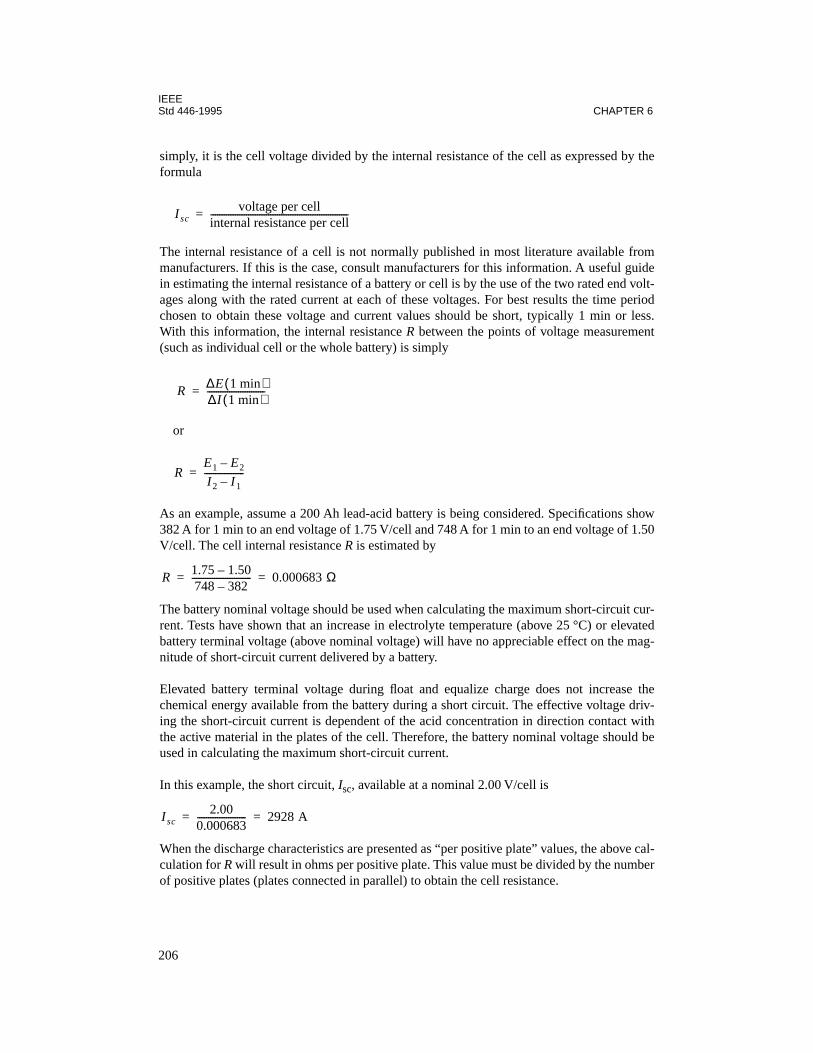
IEEEStd 446-1995 CHAPTER 6
simply, it is the cell voltage divided by the internal resistance of the cell as expressed by theformula
The internal resistance of a cell is not normally published in most literature available frommanufacturers. If this is the case, consult manufacturers for this information. A useful guidein estimating the internal resistance of a battery or cell is by the use of the two rated end volt-ages along with the rated current at each of these voltages. For best results the time periodchosen to obtain these voltage and current values should be short, typically 1 min or less.With this information, the internal resistance R between the points of voltage measurement(such as individual cell or the whole battery) is simply
or
As an example, assume a 200 Ah lead-acid battery is being considered. Specifications show382 A for 1 min to an end voltage of 1.75 V/cell and 748 A for 1 min to an end voltage of 1.50V/cell. The cell internal resistance R is estimated by
The battery nominal voltage should be used when calculating the maximum short-circuit cur-rent. Tests have shown that an increase in electrolyte temperature (above 25 °C) or elevatedbattery terminal voltage (above nominal voltage) will have no appreciable effect on the mag-nitude of short-circuit current delivered by a battery.
Elevated battery terminal voltage during float and equalize charge does not increase thechemical energy available from the battery during a short circuit. The effective voltage driv-ing the short-circuit current is dependent of the acid concentration in direction contact withthe active material in the plates of the cell. Therefore, the battery nominal voltage should beused in calculating the maximum short-circuit current.
In this example, the short circuit, Isc, available at a nominal 2.00 V/cell is
When the discharge characteristics are presented as “per positive plate” values, the above cal-culation for R will result in ohms per positive plate. This value must be divided by the numberof positive plates (plates connected in parallel) to obtain the cell resistance.
Iscvoltage per cell
internal resistance per cell--------------------------------------------------------------=
R∆E 1 min ( )∆
I
1 min ( )
--------------------------=
RE1 E2–
I2 I1–------------------=
R1.75 1.50–748 382–--------------------------- 0.000683 Ω = =
Isc2.00
0.000683---------------------- 2928 A= =
206

IEEEPROTECTION Std 446-1995
For the purpose of determining the maximum available dc short-circuit current (e.g., therequired withstand and interrupting capability of the distribution buses and disconnectingdevices), the total short-circuit current at its source is the sum of that delivered by the battery,charger, and motors (as applicable).
In current-limited chargers, the current-limiting circuits will typically act to reduce the cur-rent after the first zero crossing (i.e., 1/2 cycle, 8 ms or less) if internal protective devices,such as rectifier fuses, have not already acted to clear the fault. It is therefore conservative toassume that the maximum sustained fault current after 8 ms is the current-limiting value, acurrent not greater than the charger current-limit rating.
Tests on some current-limited SCR-type battery chargers have shown that the initial short-cir-cuit current can exceed the current-limit value. A large transient current spike may occur dueto the stored energy in filter circuits (capacitors). This peak short-circuit current mayapproach a value 200 times the charger rated value. However, the time of duration of the ini-tial transient is so short (in the order of 5 µs) that it need not be considered in determining therequired interrupting capability of external protective devices or the withstand rating ofbuses. After the stored energy in the filter circuits is dissipated, the magnitude of the transientshort-circuit current is dependent on the
X/R
ratio of the ac supply as well as the inductanceand resistance of the transformer-rectifier-fault circuit.
The fault current from a large lead storage battery resulting from a bolted short at the batteryterminals will typically exhibit a rate-of-rise that delivers the peak current within 17 ms. Thefault current for a short at the dc distribution switchgear or panelboard will peak later (typi-cally within 34–50 ms), due to the inductance of the dc system in series with the fault. Themagnitude of the fault current for a short at the distribution bus will also be lower than thevalue at the battery due to the resistance of the cables between the battery terminals and thebus.
For a typical dc system, the short-circuit current from the charger will already peak and decaybefore the short-circuit current from the battery reaches its peak. Due to this battery time con-stant, the maximum coincident short-circuit current can be conservatively calculated as thesum of that from the battery and that from the charger.
Dc motors, if operating, will contribute to the total fault current. The maximum current that adc motor will deliver at its terminals is limited by the effective transient armature resistance
r
d
of the range of 0.1–0.15 per unit. Thus, the maximum fault current for a fault at the motorterminals will typically range from 7–10 times the motors rated armature current. Therefore,it is conservative to estimate the maximum current that a motor will contribute is 10 times themotor’s rated full-load current. When a more accurate value is required, the short-circuit cur-rent should be calculated using specific rd data or from test data obtained from the motormanufacturer. (The reference for this information is IEEE Std 946-1992. For additional infor-mation, see IEEE Std 666-1991 [B13].)
Loads supplied by UPS systems are critical and low-voltage alarms are necessary to alert per-sonnel when the power supply integrity is in danger, so this protection feature is recom-mended with any type of battery system. However, a lead-acid battery is especially
207

IEEEStd 446-1995 CHAPTER 6
susceptible to damage if excessively discharged, so a low-voltage alarm serves to protect thebattery as well as the load.
6.7.2 Battery charger protection
Overcurrent protection for a battery charger, like most devices, should account for both over-load and short-circuit conditions. In the case of a charger, the current required in charging aseverely discharged battery can easily cause overload conditions aside from the inverter load.Simple overload protection should allow for the charging requirements of a battery.
To charge a battery that has been discharged to any large extent requires that the charger out-put current be regulated to stay within acceptable limits. This protects both the charger andthe battery. Of particular concern in a charger is the rectifier circuit, especially if it is con-nected directly to the output. Current ratings should be known in order to assure good protec-tion.
Most chargers are provided with a current-limiting feature for protection. Not all chargershave the same current-limiting characteristics. A user should evaluate the particular chargerunder consideration and the short-circuit characteristics of its output to assure proper over-current protection. Some chargers have current limiting features designed primarily for pro-tection in charging a discharged battery. Other simple overload conditions would also beprotected against. However, the charger may not be able to withstand a bolted fault on its out-put. The fault current at zero voltage could easily be higher than the charger's current-limitvalue. In this case, additional output protection is needed, such as breakers or fuses, unlessthe charger is equipped to automatically shut down when a dead short occurs. Some chargerspecifications include current limiting designed to allow withstand of a dead short on the out-put, even continually. In this case, an output breaker or fuse adds flexibility but is only redun-dant for short-circuit protection.
Regardless of the reason for a condition of current limiting, if it is expected to occur fre-quently or for long durations, consideration should be given to adding thermal protection inaddition to the current limiting feature. Some chargers are equipped with a thermal circuitthat automatically reduces output current if a predetermined temperature is exceeded.
If heavy inrush currents are possible (loads other than battery-charging current), a problemwith the charger going into current limiting or tripping of the output protective device canoccur. This can affect the applied load by dropping all or part of it off-line. Some chargers canbe equipped to allow gradual load application to prevent nuisance tripping or current limiting.
A protective device on the ac input to the charger is also necessary to protect the charger fromextensive damage from internal faults. Manufacturers provide charger input ratings makingprotective device ratings easy to determine.
Optional protective devices that would usually be supplied with a battery charger, althoughnot necessarily part of the protection scheme for the charger alone, should also be mentionedhere. Ground detection with light indication or voltmeter readout can be supplied forungrounded dc systems. High and low dc voltage relays serve to protect the load and charger.
208
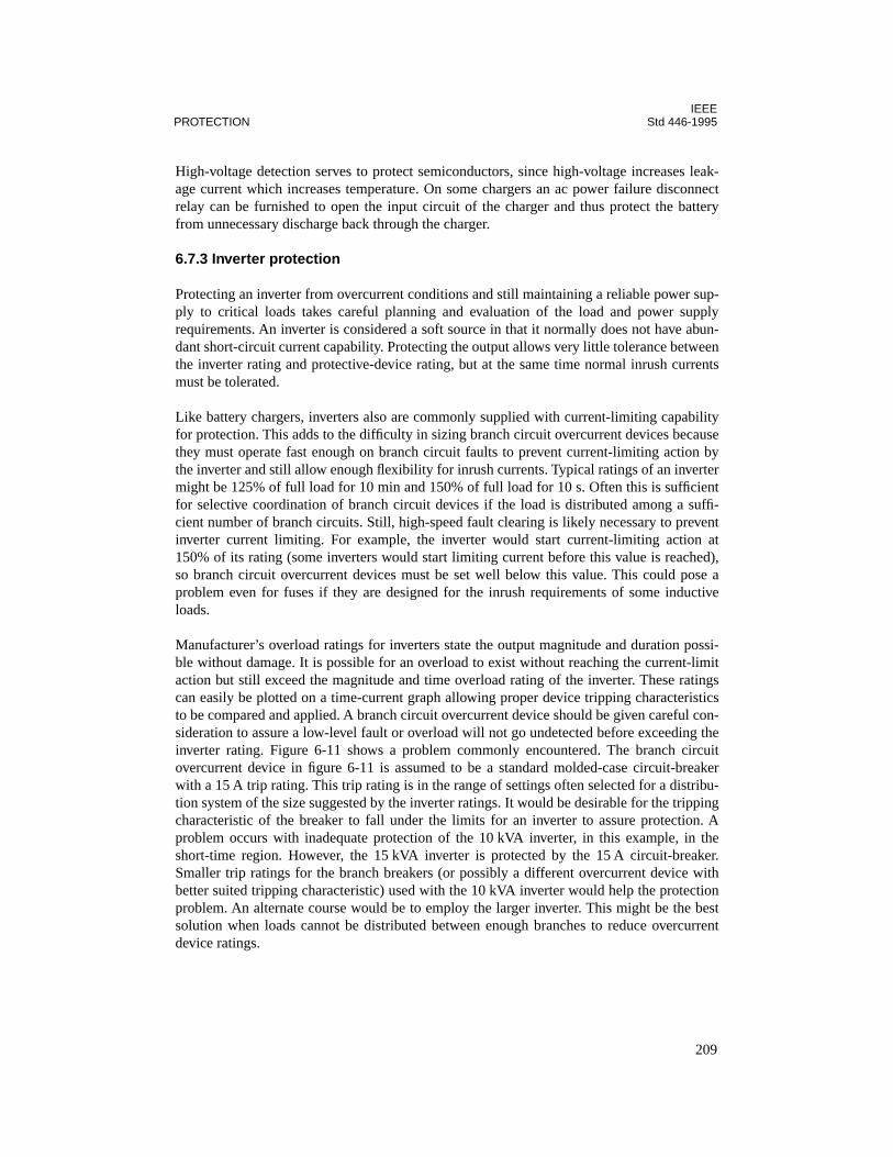
IEEEPROTECTION Std 446-1995
High-voltage detection serves to protect semiconductors, since high-voltage increases leak-age current which increases temperature. On some chargers an ac power failure disconnectrelay can be furnished to open the input circuit of the charger and thus protect the batteryfrom unnecessary discharge back through the charger.
6.7.3 Inverter protection
Protecting an inverter from overcurrent conditions and still maintaining a reliable power sup-ply to critical loads takes careful planning and evaluation of the load and power supplyrequirements. An inverter is considered a soft source in that it normally does not have abun-dant short-circuit current capability. Protecting the output allows very little tolerance betweenthe inverter rating and protective-device rating, but at the same time normal inrush currentsmust be tolerated.
Like battery chargers, inverters also are commonly supplied with current-limiting capabilityfor protection. This adds to the difficulty in sizing branch circuit overcurrent devices becausethey must operate fast enough on branch circuit faults to prevent current-limiting action bythe inverter and still allow enough flexibility for inrush currents. Typical ratings of an invertermight be 125% of full load for 10 min and 150% of full load for 10 s. Often this is sufficientfor selective coordination of branch circuit devices if the load is distributed among a suffi-cient number of branch circuits. Still, high-speed fault clearing is likely necessary to preventinverter current limiting. For example, the inverter would start current-limiting action at150% of its rating (some inverters would start limiting current before this value is reached),so branch circuit overcurrent devices must be set well below this value. This could pose aproblem even for fuses if they are designed for the inrush requirements of some inductiveloads.
Manufacturer’s overload ratings for inverters state the output magnitude and duration possi-ble without damage. It is possible for an overload to exist without reaching the current-limitaction but still exceed the magnitude and time overload rating of the inverter. These ratingscan easily be plotted on a time-current graph allowing proper device tripping characteristicsto be compared and applied. A branch circuit overcurrent device should be given careful con-sideration to assure a low-level fault or overload will not go undetected before exceeding theinverter rating. Figure 6-11 shows a problem commonly encountered. The branch circuitovercurrent device in figure 6-11 is assumed to be a standard molded-case circuit-breakerwith a 15 A trip rating. This trip rating is in the range of settings often selected for a distribu-tion system of the size suggested by the inverter ratings. It would be desirable for the trippingcharacteristic of the breaker to fall under the limits for an inverter to assure protection. Aproblem occurs with inadequate protection of the 10 kVA inverter, in this example, in theshort-time region. However, the 15 kVA inverter is protected by the 15 A circuit-breaker.Smaller trip ratings for the branch breakers (or possibly a different overcurrent device withbetter suited tripping characteristic) used with the 10 kVA inverter would help the protectionproblem. An alternate course would be to employ the larger inverter. This might be the bestsolution when loads cannot be distributed between enough branches to reduce overcurrentdevice ratings.
209
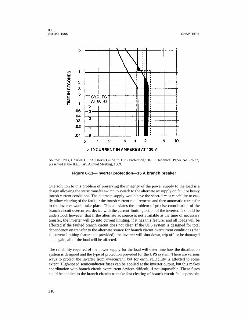
IEEEStd 446-1995 CHAPTER 6
One solution to this problem of preserving the integrity of the power supply to the load is adesign allowing the static transfer switch to switch to the alternate ac supply on fault or heavyinrush current conditions. The alternate supply would have the short-circuit capability to eas-ily allow clearing of the fault or the inrush current requirements and then automatic retransferto the inverter would take place. This alleviates the problem of precise coordination of thebranch circuit overcurrent device with the current-limiting action of the inverter. It should beunderstood, however, that if the alternate ac source is not available at the time of necessarytransfer, the inverter will go into current limiting, if it has this feature, and all loads will beaffected if the faulted branch circuit does not clear. If the UPS system is designed for totaldependency on transfer to the alternate source for branch circuit overcurrent conditions (thatis, current-limiting feature not provided), the inverter will shut down, trip off, or be damagedand, again, all of the load will be affected.
The reliability required of the power supply for the load will determine how the distributionsystem is designed and the type of protection provided for the UPS system. There are variousways to protect the inverter from overcurrent, but for each, reliability is affected to someextent. High-speed semiconductor fuses can be applied at the inverter output, but this makescoordination with branch circuit overcurrent devices difficult, if not impossible. These fusescould be applied to the branch circuits to make fast clearing of branch circuit faults possible.
Source: Potts, Charles D., “A User’s Guide to UPS Protection,” IEEE Technical Paper No. 89-37,presented at the IEEE IAS Annual Meeting, 1989.
Figure 6-11—Inverter protection—15 A branch breaker
210
IEEEPROTECTION Std 446-1995
The main disadvantage here is the high cost of these fuses. As mentioned above, availableshort-circuit capacity can sometimes be a problem. An oversized inverter would help to alle-viate this problem but, again, investment cost would be high. Applying a transfer scheme toautomatically transfer high inrush currents and short-circuit currents to an alternate powersupply offers a relatively simple approach to overcurrent protection. This makes selectivecoordination of overcurrent devices much easier. This protects the inverter and, in short-cir-cuit conditions, allows isolation of the faulted circuit, thus minimizing the disturbance.
Even though inverters are provided with current-limiting action, they are not always rated totolerate short-circuit conditions. To protect against the event of an alternate ac source notbeing available to handle short-circuit current conditions, an overcurrent device should beprovided in the inverter output. Since fuses are generally faster than breakers, they should begiven first consideration. However, since semiconductor devices are involved, even a fusecannot guarantee preventing all damage, but it can assure minimizing the damage. Anotherovercurrent condition that should be protected against on the output is out-of-phase switch-ing.
Another common problem in the application of UPS systems is inadequate ventilation for theinverter. Inverters generate a considerable amount of heat and some means of removing thisheat should be provided. Good ventilation is the best method of preventing overheating. Theinstallation design should assure that this ventilation is not blocked, and personnel should bemade aware of the danger to the inverter if ventilation is blocked. Each inverter has a maxi-mum operating temperature rating, and exceeding this temperature should be prevented.Inverters can also overheat under prolonged short-circuit conditions even though they may berated to withstand a continuous short circuit on their output. Thermal cutouts can be providedto protect against this heating effect. Rare cases have even been reported where overheatingoccurred at no-load conditions.
Input overcurrent devices for inverters will minimize damage caused by internal faults.Again, fuses should be given first consideration for high-speed clearing. Another source ofhigh current in the input protected against by fuses or breakers is an accidental reverse polar-ity connection. An important option offered for most inverters is a low-input voltage alarm.Since the input is connected to batteries in a UPS and to the output of a battery charger, thepossibility always exists for low-input voltage. The inverter can only maintain a specifiedvoltage at its output if the input is within specified limits. Strictly speaking, this feature pro-vides protection for the battery against excessive discharge, but it also provides protection forthe load against the adverse effects of low voltage, especially if transfer to an alternate acsource is initiated when the output low-voltage limit is reached.
6.7.4 Static transfer switch protection
Protecting a static transfer switch from excessive overcurrent requires coordination of theswitch rating with the available fault current from the ac supply with the highest availablefault current. Static transfer switches commonly have a short-circuit rating at least 1000% ofthe continuous rating for 1–5 cycles. This is more than adequate for the fault-current avail-ability of an inverter, but careful overcurrent device setting will be required when the faultcurrent is from a larger alternate source. Again, since semiconductor devices are involved,
211
IEEEStd 446-1995 CHAPTER 6
fast fuse operation is necessary for adequate protection. Another feature that adds protectionto the switch is fast removal of gating voltage, which effectively opens the switch. Most com-monly, switches are protected by applying the overcurrent device on the input side. The man-ufacturer or UPS supplier should be consulted for static transfer switch withstand ratings forproper application of overcurrent protection.
Even though the inverter source is not likely to supply a lot of short-circuit current, especiallyif it goes into current limiting on a short circuit, an inverter output protective device servesalso to protect the static switch. This can be the case when a fault occurs on the load side ofthe switch (or an overload) and the alternate source is unavailable for transfer.
A rating of 1000% for 1 cycle, along with semiconductor fuse ratings (when fuses are appliedto project SCRs, for example) can be coordinated with the overcurrent device in the branchcircuit. See figure 6-12.
6.7.5 Overvoltage protection
As previously stated, the basic components of a UPS system are the battery, a rectifier or bat-tery charger, inverter, and often a static transfer switch. These devices contain semiconduc-tors making protection uniquely different from that of more tolerant equipment, such asmotors, generators, transformers, electromechanical transfer switches, etc. In dealing withsemiconductors, surge protection becomes a critical application criteria. Simply increasinginsulation thickness and dielectric strength is not feasible because of the necessary propertiesof the devices, so effective protection must be applied externally. Sources of surges and tran-sients are many, and without proper protection semiconductors can be easily damaged. Evenif the damage is not visible, they can be stressed such that their life is drastically shortened.Even a relay coil can produce a surge in the order of thousands of volts under fast-contactcurrent-interrupting action if it is not itself equipped with surge suppression such as a diodeor varistor to handle the steep wavefront and high-frequency surge associated with the inter-ruption.
Equipment manufacturers are usually best suited to determine proper surge protection for thesemiconductors in their equipment. However, they cannot always be accurate in their assess-ment of the application of the equipment. Even though surge protection may be standard withsome manufacturers, the source and magnitude of possible voltage transients and applicationconditions are often underestimated. It is not uncommon for a surge suppressor to be dam-aged if operating conditions allow the suppressor to be subjected to steady-state voltagesexceeding its rating. If the user supplies this type of protection, he must know the dielectricstrength of the semiconductors to be protected to determine the rating of the surge suppressor.
There are many types of surge suppressors available with different operating characteristics.Some are fast acting but may allow a higher let-through voltage than another that is sloweracting but capable of lower threshold settings. Some of the more expensive surge suppressorpackages employ a combination of both characteristics for improve.d protection.
Isolating transformers provide some measure of surge protection because of the physical iso-lation effect on circuits. But because of their magnetic coupling and distributed capacitance
212

IEEEPROTECTION Std 446-1995
between windings, they are not perfect isolators and often additional surge protection isrequired. So-called
line conditioners
offer the best protection in that they provide line isola-tion, surge protection, high-speed voltage regulation, and, in some cases, a degree of wave-shape filtering for protection against harmonic distortion, all in an integrated package.
Methods used in grounding equipment cabinets affect the magnitude of insulation stress toground especially when equipment is exposed to high transients typical of lightning strikes.The inductive voltages (due to inductance of grounding conductors) can stress equipmentinsulation. Shortening ground conductor lengths or paralleling ground conductors, or both,are effective methods in reducing the inductance of ground circuits. Each installation will beunique in proper procedures for adequate protection and personnel safety.
Source: Potts, Charles D., “A User’s Guide to UPS Protection,” IEEE Technical Paper No. 89-37,presented at the IEEE IAS Annual Meeting, 1989.
Figure 6-12—Static transfer switch fuse and branch breaker coordination
213
IEEEStd 446-1995 CHAPTER 6
6.8 Equipment physical protection
Engine-generator sets and fuel supplies and their associated equipment require careful plan-ning in application to prevent damage from physical abuse and environmental conditions.Radiator cooling on engines should be given special consideration, when possible, since aself-contained cooling system does not require external piping connections that could be sub-ject to damage. Some climates, such as where dust is prevalent, require that air inlet filters beof special design.
Most other devices and equipment discussed previously, when applied in emergency andstandby use, are usually located where only qualified personnel have access. When this is notpossible, enclosures should be designed to prevent easy access. Provisions for locking enclo-sures with hinged panels and doors can easily be supplied by most manufacturers. Manufac-turers should also be thoroughly knowledgeable of the location and environmental conditionsfor application of proper enclosures, materials, and seismic protection. For example, corro-sive or humid atmospheres may require heaters or special coating or materials to protectexposed metal parts or circuits. Locations in proximity to large reciprocating machinerymight require special seismic protection. Fuel systems require special consideration in pro-tection from leaks, contaminants, etc.
Manufacturers can usually provide suitable racks for batteries that provide protection andeasy maintenance. It is important to have properly sized racks that space cells to minimizeoverheating and corrosion problems, allow easy maintenance, and still utilize available spacein an optimum manner. Connections between cells should minimize strain on battery posts.Manufacturers can also assist in designing installations for extreme seismic conditions, suchas where earthquakes are a problem. Additional information on installation and environmen-tal conditions can be found in Chapter 5 of ANSI/NFPA 110-1993.
6.9 Grounding
Reliable ground fault protection schemes require a careful analysis of the system- and equip-ment-grounding arrangements. Chapter 7 covers the basic functions and requirements forsystem and equipment grounding. Several grounding arrangements that are applicable toemergency and standby power systems are illustrated in Chapter 7.
6.10 Conclusions
Protection of emergency and standby power systems determines to a great degree the reliabil-ity of the systems. Although the total system should be considered in the protection scheme,overall system protection and reliability is only as good as that of the individual components.With emphasis on protecting power supply investment, a designer must assure that thedesired reliability of the system is achieved. The designer should carefully evaluate standardand optional protection supplied with equipment and apply the design best suited for equip-ment protection and power supply reliability.
214
IEEEPROTECTION Std 446-1995
6.11 References
This chapter shall be used in conjunction with the following publications:
ANSI C37.16-1988, American National Standard Preferred Ratings, Related Requirements,and Application Recommendations for Low-Voltage Power Circuit Breakers and AC PowerCircuit Protectors.
3
ANSI C50.10-1990, American National Standard for Rotating Electrical Machinery—Syn-chronous Machines.
ANSI/NEMA ICS 1-1993, Industrial Control and Systems General Requirements.
4
ANSI/NEMA MG 1-1993, Motors and Generators.
ANSI/NFPA 30-1993, Flammable and Combustible Liquids Code.
5
ANSI/NFPA 110-1993, Emergency and Standby Power Systems.
ANSI/UL 1008-1989, Safety Standard for Automatic Transfer Switches.
6
CSA C22.2/No. 178-1987 (Reaff 1992), Automatic Transfer Switches.
7
EGSA 101P-1995, Performance Standards: For Engine Driven Generator Sets.
8
IEEE Std C37.13-1990, IEEE Standard for Low-Voltage AC Power Circuit Breakers Used inEnclosures (ANSI).
9
IEEE Std C37.26-1972 (Reaff 1990), IEEE Guide for Methods of Power-Factor Measure-ment for Low-Voltage Inductive Test Circuits (ANSI).
IEEE Std C37.90-1989, IEEE Standard for Relays and Relay Systems Associated with Elec-tric Power Apparatus (ANSI).
3
ANSI publications are available from the Sales Department, American National Standards Institute, 11 West 42ndStreet, 13th Floor, New York, NY 10036, USA.
4
NEMA publications are available from the National Electrical Manufacturers Association, 2101 L Street NW,Washington, DC 20037, USA.
5
NFPA publications are available from Publications Sales, National Fire Protection Association, 1 BatterymarchPark, P.O. Box 9101, Quincy, MA 02269-9101, USA.
6
UL publications are available from Underwriters Laboratories, Inc., 333 Pfingsten Road, Northbrook, IL 60062-
2096, USA.
7
CSA publications are available from the Canadian Standards Association (Standards Sales), 178 Rexdale Blvd.,Rexdale, Ontario, Canada M9W 193.
8
EGSA publications are available from the Electrical Generating Systems Association, 10251 W. Sample Rd., SuiteB, Coral Springs, FL 33065.
9
IEEE publications are available from the Institute of Electrical and Electronics Engineers, 445 Hoes Lane, P.O. Box1331, Piscataway, NJ 08855-1331, USA.
215

IEEEStd 446-1995 CHAPTER 6
IEEE Std C37.95-1989, IEEE Guide for Protective Relaying of Utility-Consumer Intercon-nections (ANSI).
IEEE Std 141-1993, IEEE Recommended Practice for Electric Power Distribution for Indus-trial Plants (IEEE Red Book) (ANSI).
IEEE Std 142-1991, IEEE Recommended Practice for Grounding of Industrial and Commer-cial Power Systems (IEEE Green Book) (ANSI).
IEEE Std 242-1986, IEEE Recommended Practice for Protection and Coordination of Indus-trial and Commercial Power Systems (IEEE Buff Book) (ANSI).
IEEE Std 946-1992, IEEE Recommended Practice for the Design of DC Auxiliary PowerSystems for Generating Stations (ANSI).
NFPA 70-1996, National Electrical Code®.
6.12 Bibliography
Additional information may be found in the following sources:
[B1] ANSI C97.1-1972 (Reaff 1978), American National Standard Low-Voltage CartridgeFuses 600 Volts or Less.
10
[B2] ANSI/NEMA ICS 2-1993, Industrial Control and Systems, Controllers, Contractors,and Overload Relays Rated Not More Than 2000 Volts AC or 750 Volts DC.
[B3] ANSI/UL 198B-1995, Safety Standard for Class H Fuses.
[B4] ANSI/UL 198C-1986, Safety Standard for High-Interrupting Capacity Fuses, Current-Limiting Types.
[B5] ANSI/UL 198D-1995, Safety Standard for Class K Fuses.
[B6] ANSI/UL 198E-1995, Safety Standard for Class R Fuses.
[B7] ANSI/UL 198H-1988, Safety Standard for Class T Fuses.
[B8] ANSI/UL 489-1991, Molded-Case Circuit Breakers and Circuit-Breaker Enclosures.
[B9] Castenschiold, R., Goldberg, D.L., Johnston, F.C., and O’Donnell, P., “New RatingRequirements for Automatic Transfer Switches,”
IEEE Conference Record
, Paper no.
78CH1302-91A, June 1978.
10
ANSI C97.1-1972 has been withdrawn; however, copies can be obtained from the American National StandardsInstitute, 11 West 42nd Street, 13th Floor, New York, NY 10036, USA.
216

IEEEPROTECTION Std 446-1995
[B10] Castenschiold, R., “Plant Engineer’s Guide to Understanding Automatic TransferSwitches,”
Plant Engineering
, Mar. 3, 1983.
[B11] IEC 947-6-1: 1989, Low-voltage switchgear and controlgear—Part 6: Multiple func-tion equipment. Section One—Automatic transfer switching equipment.
11
[B12] IEEE Std 241-1990, IEEE Recommended Practice for Electric Power Systems in Com-mercial Buildings (IEEE Gray Book) (ANSI).
[B13] IEEE Std 666-1991, IEEE Design Guide for Electric Power Service Systems for Gen-erating Stations (ANSI).
[B14] IEEE Tutorial Course Text, “Surge Protection in Power Systems,” IEEE Paper no.79EH0144-6-PWR.
[B15] Johnson, G. S., “Overcurrent Protection for Emergency and Standby Generating Sys-tems,”
Electrical Construction and Maintenance
, Apr. 1983.
See also:
Stromme, G., Discus-sion, Aug. 1983; Johnson, G. S., Discussion, Aug. 1983; Phelps, E. J., Jr., Discussion, Nov.1983; Editor's Note, Nov. 1983; Griffith, M. S., Discussion, Nov. 1983; Johnson, G. S., Dis-cussion, Feb. 1984.
[B16] NEMA AB 3-1991, Molded-Case Circuit Breakers and Their Applications.
[B17] NFPA 99-1996, Health Care Facilities Code.
[B18] Reichenstein, H. W., and Castenschiold, R., “Coordinating Overcurrent ProtectiveDevices with Automatic Transfer Switches in Commercial and Institutional Power Systems,”
IEEE Transactions on Industry Applications
, vol. IA-11, no. 6, Nov./Dec. 1975.
11
IEC publications are available from IEC Sales Department, Case Postale 131, 3 rue de Varembé, CH-1211, Genève20, Switzerland/Suisse. IEC publications are also available in the United States from the Sales Department, Ameri-can National Standards Institute, 11 West 42nd Street, 13th Floor, New York, NY 10036, USA.
217

IEEEStd 446-1995 CHAPTER 6
218
Chapter 7Grounding
7.1 Introduction
7.1.1 General
This chapter discusses recommended practices and guidelines for system and equipmentgrounding of emergency and standby power systems rated 600 V or less.
Fundamental design principles for system and equipment grounding and basic factors thatinfluence the selection of the type of system grounding are covered in detail in other IEEEColor Books, including IEEE Std 141-1993,1 IEEE Std 142-1991, and IEEE Std 1100-1992.Ground-fault protection is an important consideration that is covered in detail in IEEE Std242-1986. The purpose of this chapter is to further define these fundamental groundingrequirements and to illustrate grounding arrangements for several types of system groundingand transfer schemes that are most often selected for emergency and standby power systemsin industrial and commercial installations.
7.1.2 Grounding requirements
Grounding requirements for emergency and standby power systems are unique because ofmultiple power sources, ground-fault sensing conditions, and special code stipulations. Therequirements for grounding vary depending upon the type of system (emergency, standby, oroptional standby), whether or not the alternate power is a separately derived source, andwhether ground-fault protection is provided. Furthermore, reliable operation and protectionrequires coordinated design, proper installation, and maintenance of the following:
— Circuit-protective equipment
— Systems grounding
— Equipment grounding
— Transfer switching equipment
7.1.3 Circuit-protective equipment
Various types of circuit protection are satisfactory for ground-fault protection. Some com-monly used types are circuit breakers with series trips, circuit-interrupting equipment trippedby ground-fault current-sensing devices, and, to a lesser extent, fuses. Selection and applica-tion of circuit-protective equipment requires a detailed analysis of each system and circuit tobe protected, including the system and equipment grounding arrangements.
1Information on references can be found in 7.14.
219
IEEEStd 446-1995 CHAPTER 7
In addition to providing proper ground-fault protection, it is essential to coordinate over-current protective devices and transfer switches with maximum available short-circuit cur-rents. See Chapter 6 for further information on overcurrent protection.
7.1.4 Transfer switching equipment
Transfer switches transfer load conductor connections from one power source to another.These load conductors may or may not include the grounded conductor connection (neutral),thus determining whether the system is separately derived. This determines the design of thegrounding system, selection of transfer switching equipment, and feasibility of ground-faultprotection. See Chapter 4 for basic information on transfer switches.
7.2 System and equipment grounding functions
7.2.1 General
System grounding pertains to the manner in which a circuit conductor of a system is inten-tionally connected to earth, or to some conducting body that is effectively connected to earthor serves in place of earth. The following types of system grounding are discussed in thischapter:
— Solidly grounded. A grounding electrode conductor connects a terminal of the systemto the grounding electrode (s) and no impedance is intentionally inserted into the con-nection.
— Resistance grounded. A grounding resistor is inserted into the connection between aterminal of the system and the grounding electrode(s).
— Ungrounded. None of the circuit conductors of the system is intentionally grounded.
Equipment grounding is the process of bonding together, with equipment-grounding conduc-tors, all conductive enclosures for conductors and equipment within each circuit. Theseequipment-grounding conductors are required to run with or enclose the circuit conductors,and they provide a permanent, low-impedance conductive path for ground-fault current. Insolidly grounded systems, the equipment-grounding conductors are bonded to the groundedcircuit conductor and to the system-grounding conductor(s) per the National Electrical Code(NEC) (NFPA 70-1996), Section 250-50(a), at specific points, as shown in figures 7-1 and7-2.
7.2.2 System grounding functions
Systems and circuit conductors are grounded to overvoltages due to lightning, line surges, orunintentional contact with higher voltage lines, and to stabilize the voltage-to-ground duringnormal operation. Systems and circuit conductors are solidly grounded to facilitate overcur-rent device operation in case of ground faults, and to stabilize voltage-to-ground during faultconditions.
220
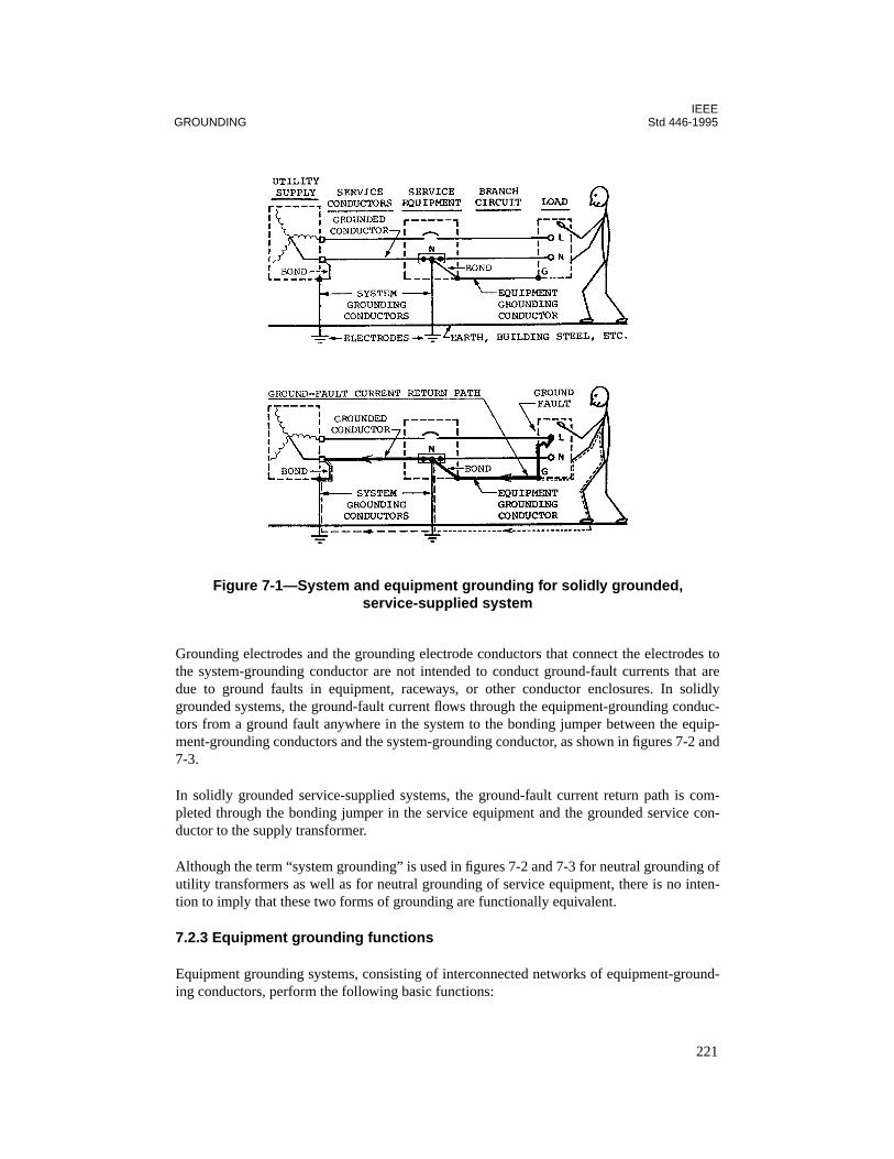
IEEEGROUNDING Std 446-1995
Grounding electrodes and the grounding electrode conductors that connect the electrodes tothe system-grounding conductor are not intended to conduct ground-fault currents that aredue to ground faults in equipment, raceways, or other conductor enclosures. In solidlygrounded systems, the ground-fault current flows through the equipment-grounding conduc-tors from a ground fault anywhere in the system to the bonding jumper between the equip-ment-grounding conductors and the system-grounding conductor, as shown in figures 7-2 and7-3.
In solidly grounded service-supplied systems, the ground-fault current return path is com-pleted through the bonding jumper in the service equipment and the grounded service con-ductor to the supply transformer.
Although the term “system grounding” is used in figures 7-2 and 7-3 for neutral grounding ofutility transformers as well as for neutral grounding of service equipment, there is no inten-tion to imply that these two forms of grounding are functionally equivalent.
7.2.3 Equipment grounding functions
Equipment grounding systems, consisting of interconnected networks of equipment-ground-ing conductors, perform the following basic functions:
Figure 7-1—System and equipment grounding for solidly grounded, service-supplied system
221

IEEEStd 446-1995 CHAPTER 7
— They limit the voltage to ground (shock voltage) on the exposed noncurrent-carryingmetal parts of equipment, raceways, and other conductor enclosures in case of groundfaults.
— They safely conduct ground-fault currents of sufficient magnitude for fast operationof the circuit-protective devices.
— They reduce electromagnetic interference (EMI), common-mode noise, and otherelectronic interference.
Figure 7-2—System and equipment grounding for solidly grounded, separately derived system
Figure 7-3—Supplemental equipment bonding for separately derived system
222

IEEEGROUNDING Std 446-1995
In order to ensure the performance of the above basic functions, equipment-grounding con-ductors should
— Be permanent and continuous;
— Have ample capacity to safely conduct any ground-fault current likely to be imposedon them;
— Have impedance sufficiently low to limit the voltage to ground to a safe magnitudeand to facilitate the operation of the circuit-protective devices.
As illustrated in figures 7-1 and 7-2, a person contacting a conductive enclosure in whichthere is a ground fault will be protected from shock injury if the equipment-grounding con-ductors provide a shunt path of sufficiently low impedance to limit the current through theperson's body to a safe magnitude. In solidly grounded systems, the ground-fault currentactuates the circuit-protective devices to automatically de-energize a faulted circuit andremove any destructive heating, arcing, and shock hazard.
The same network of equipment-grounding conductors should be provided for solidlygrounded systems, high-resistance grounded systems, and ungrounded systems. Equipment-grounding conductors are required in resistance grounded and ungrounded systems to pro-vide shock protection and to present a low-impedance path for phase-to-phase fault currentsin case the first ground fault is not located and cleared before another ground fault occurs ona different phase in the system.
7.3 Supplemental equipment bonding
Exposure to electrical shock can be reduced by additional supplemental equipment bondingbetween the conductive enclosures for conductors and equipment and adjacent conductivematerials.
The supplemental equipment bonding shown in figure 7-3 contributes to equalizing thepotential between exposed noncurrent-carrying metal parts of the electric system and adja-cent grounded building steel when ground faults occur. The inductive reactance of theground-fault circuit will normally prevent a significant amount of ground-fault current fromflowing through the supplemental bonding connections.
Ground-fault current will flow through the path that provides the lowest ground-fault circuitimpedance. The ground-fault current path that minimizes the inductive reactance of theground-fault circuit is through the equipment-grounding conductors that are required to runwith or enclose the circuit conductors. Therefore, practically all of the ground-fault currentwill flow through the equipment-grounding conductors, and the ground-fault current throughthe supplemental bonding connections will be no more than required to equalize the potentialat the bonding locations.
223

IEEEStd 446-1995 CHAPTER 7
7.4 Objectionable current through grounding conductors
System and equipment-grounding conductors should be installed and connected in a mannerthat will prevent an objectionable flow of current through the grounding conductors orgrounding paths. If a grounded (neutral) circuit conductor is connected to the equipment-grounding conductors at more than one point, or if it is grounded at more than one point,stray neutral current paths will be established. Stray neutral currents that flow through pathsother than the intended grounded (neutral) circuit conductors during normal operation of asystem will be objectionable if they contribute to any of the following:
— Interference with the proper operation of equipment, devices, or systems that are sen-sitive to electromagnetic interference, such as electronic equipment, communicationssystems, computer systems, etc.;
— Interference with the proper sensing and operation of ground-fault protection equip-ment;
— Arcing of sufficient energy to ignite flammable materials;— Detonation of explosives during production, storage, or testing;— Overheating due to heat generated in raceways, etc., as a result of stray current;— Electrochemical action, particularly in soil, that may damage nearby metallic ele-
ments.
If the supply transformer is utility-owned and is located outside the building, the groundedservice conductor should be grounded on the secondary side of the supply transformer by theutility. The grounded service conductor of service-supplied systems must be grounded at theservice equipment to meet NEC requirements. A grounding connection should not be made toany grounded (neutral) circuit conductor on the load side of the service disconnecting means.
When the transformer is owned by the user, the secondary power supply is referred to as a“separately derived” source. Such a separately derived source has to have its neutralgrounded at the transformer location per NEC, Section 250-26.
The stray neutral current illustrated in figure 7-4 is due to multiple grounding of the groundedservice conductor. Such multiple grounding of the neutral circuit conductor may cause straycurrents that are likely to be objectionable and will cause ground-fault current to flow in pathsthat may adversely affect the operation of ground-fault protection equipment.
Objectionable stray neutral currents are frequently caused by unintentional neutral-to-groundfaults as shown in figure 7-5. Neutral-to-ground faults are difficult to locate, but should besuspected if there are objectionable stray neutral currents (Zipse 1972 [B11]).2
The NEC requires a disconnecting point for the grounded circuit conductor for test purposeswhen a system is commissioned or updated. This connection can be temporarily opened inorder to test and assure that no downstream ground connection to the neutral exist. While thisconnection is open, safety precautions should be taken because of possible backfeed from theemergency or standby power source (Castenschiold and Hogrebe 1993 [B5]).
2The numbers in brackets preceded by the letter B correspond to those of the bibliography in 7.15.
224

IEEEGROUNDING Std 446-1995
7.5 System grounding requirements
Alternating-current systems of 50–1000 V should be solidly grounded where the maximumvoltage to ground on the ungrounded conductors will not exceed 150 V. Systems that supplyphase-to-neutral loads should also be solidly grounded. The following commonly used sys-tems are required to be solidly grounded:
— 120/240 V single-phase, three-wire— 208Y/120 V three-phase, four-wire— 480Y/277 V three-phase, four-wire— 240/120 V three-phase, four-wire delta (midpoint of one phase used as a grounded
circuit conductor)
Figure 7-4—Stray neutral current due to multiple grounding of grounded service conductor
Figure 7-5—Stray neutral current due to unintentional grounding of a grounded circuit conductor
225
IEEEStd 446-1995 CHAPTER 7
The following commonly used systems are not required to be solidly grounded:
— 240 V delta, three-phase, three-wire— 480 V three-phase, three-wire— 600 V three-phase, three-wire
Although most emergency and standby power systems are solidly grounded, there is a grow-ing trend towards resistance grounding where phase-to-neutral loads need not be served. Thisis particularly so for 480 V and 600 V three-phase systems in industrial facilities. High resis-tance system grounding combines some of the advantages of solidly grounded systems andungrounded systems. System overvoltages are held to acceptable levels during ground faults,and the potentially destructive effects of high-magnitude ground-fault currents that occur inhigh-capacity, solidly grounded systems are eliminated. Ground-fault current is limited bythe system grounding resistor to a magnitude that permits continued operating of a systemwhile a ground fault is located and cleared. However, if a ground fault is not located andcleared before another ground fault occurs on another phase in the system, the high magni-tude phase-to-phase fault current will flow through the equipment-grounding conductors andoperate the circuit-protective equipment. Factors that influence selecting the type of systemgrounding are covered in the standards referenced in 7.1.1. With high-resistance grounding,ground fault currents are usually limited to 10 A or less.
Low-resistance grounding may be used for systems where no neutral connected loads areinvolved as described above, and where limiting the ground-fault current is important. Suchgrounding may be used to limit damage to large motors or generators. There is also somewhatof a protective aspect to the limitation of ground fault current for personnel who may beworking on or near the system. The size of the resistor can be set to limit the ground fault cur-rent to at least 100 A; however, the 200–1000 A range is more typical. This provides suffi-cient current to operate the system-protective devices with a one line-ground fault.
7.6 Types of equipment-grounding conductors
Equipment grounding conductors represented in the diagrams in this chapter may be any ofthe types permitted in the NEC, Section 250-91(b), if this section is adopted by the authorityhaving jurisdiction. Where raceway, cable tray, cable armor, etc., are used as equipmentgrounding conductors, all joints and fittings must be made tight to provide an adequate con-ducting path for ground-fault currents.
Earth and the structural metal frame of a building may be sued for supplemental equipmentbonding, but they should not be used as the sole equipment-grounding conductor for ac sys-tems. Equipment grounding conductors for ac systems should run with or enclose the con-ductors of each circuit. These requirements are mandatory per Article 25? of the NEC.
Where copper or aluminum wire is used as equipment-grounding conductors for circuits hav-ing paralleled conductors in multiple metal raceways, an equipment-grounding conductorshould be run in each raceway. The size of each paralleled equipment-grounding conductor isa function of the rating of the circuit overcurrent protection.
226

IEEEGROUNDING Std 446-1995
Section 250-91(b) of the NEC permits the metallic enclosure or raceway containing the con-ductors to serve as the equipment-grounding conductor. The equipment-grounding conduc-tors will either be the grounding conductor run with the current-carrying conductors or theenclosure (or both where applicable). Even through the code permits the enclosure to be usedas the equipment-grounding conductor, a separate grounding conductor run in this enclosureis often elected or may be required by the specifying authority for purpose of avoiding con-tact resistances of enclosure joints, lower equipment-grounding conductor impedance, andgreater reliability.
All equipment-grounding conductors in one premise must ultimately connect to the ground-ing electrode conductors. A separate grounding system for specific equipment such as com-puters, is not only a violation of the NEC, but risks the damage to or misoperation of sensitivesystems and possibly danger to life.
— There are small differences in potential throughout the various components of anelectrical system. These differences can cause faulty information transfer or errone-ous control operations for sensitive equipment.
— With transients or surges that may be caused by switching, lightning (includinginduced currents or voltages), or faults, equipment may be damaged or misoperate. Inthe case of lightning, an improper grounding system may cause serious damage toequipment or injury to personnel.
Section 250-74, Exception 4, of the NEC does permit an “isolated” equipment-groundingconductor for purposes of electrical noise (EMI) control for sensitive equipment. However,this isolated conductor may run through one or more panelboards without connection to thegrounding bar, but it must ultimately connect to one of the equipment-grounding conductorsin a panelboard, and must run with the power conductors of the equipment to be grounded.
7.7 Grounding for separately derived and service-supplied systems
Basic grounding connections for solidly grounded separately derived and service-suppliedsystems are illustrated in figure 7-6 with reference to NEC Sections in which the groundingrequirements are specified.
The grounding requirements for separately derived systems and service-supplied systems aresimilar, but there are three important differences:
a) The system-grounding conductor for a separately derived system should be groundedat only one point. The single system-grounding point is specified as the source of theseparately derived system and ahead of any system disconnecting means or overcur-rent devices. Where the main system disconnecting means is adjacent to the generatoror transformer supplying a separately derived system, the grounding connection tothe system-grounding conductor may be made at, or ahead of, the system-disconnect-ing means.The system-grounding conductor for a service-supplied system should be groundedat the service equipment and elsewhere on the secondary of the transformer that sup-
227
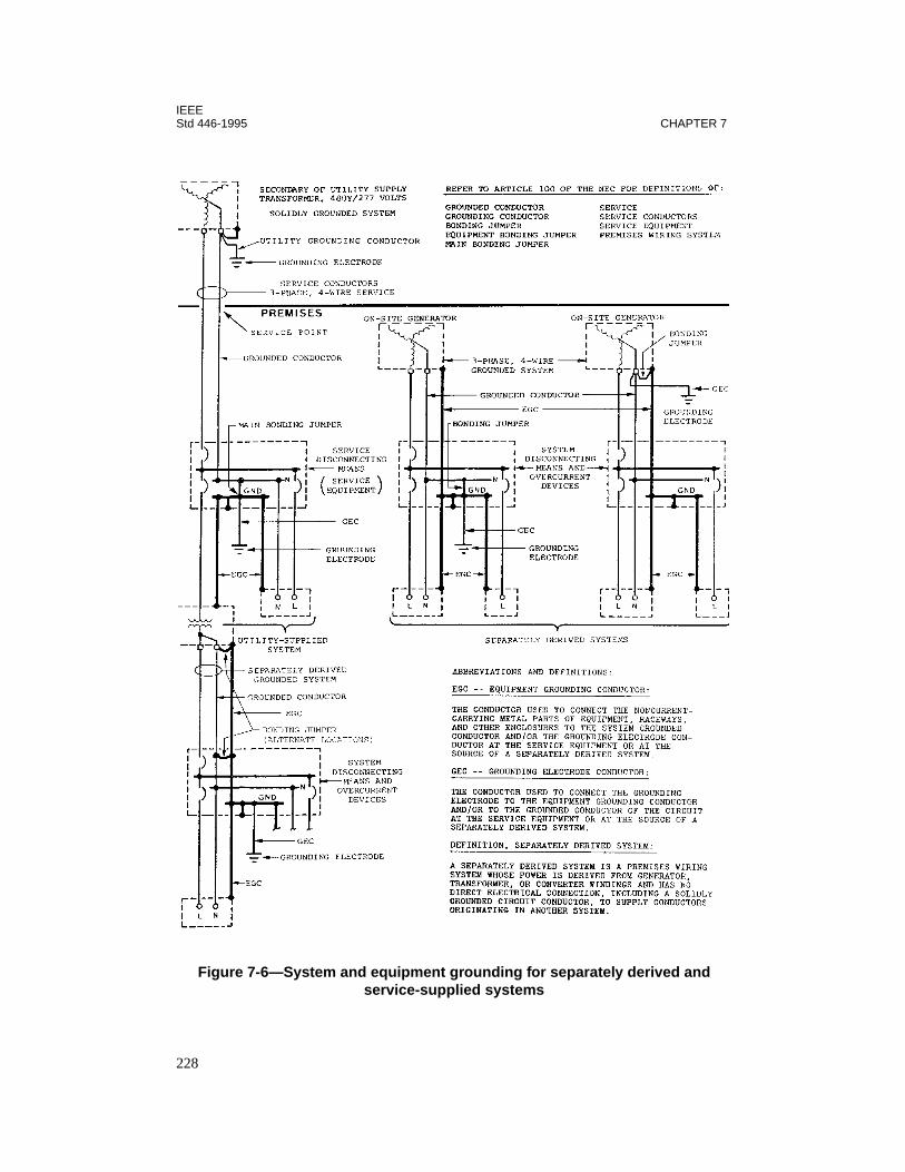
IEEEStd 446-1995 CHAPTER 7
Figure 7-6—System and equipment grounding for separately derived and service-supplied systems
228
IEEEGROUNDING Std 446-1995
plies the service, if the supply transformer is not in the same building as the serviceequipment.
b) The preferred grounding electrode for a separately derived system is the nearesteffectively grounded structural metal member of the structure or the nearest effec-tively grounded water pipe. The grounding electrode system for a service suppliedsystem should be in accordance with established code requirements.
c) In solidly grounded separately derived systems, the equipment-grounding conductorsshould be bonded to the system-grounding conductor and to the grounding electrodeconductor at or ahead of the main system disconnecting means or overcurrent device.The equipment-grounding conductor should always be connected to the enclosure ofthe supply transformer or generator, as shown in figure 7-6.
In solidly grounded utility-supplied systems, the equipment-grounding conductors should bebonded to the system-grounding conductor and to the grounding electrode conductor at theservice equipment. The grounded service conductor may be used to ground the noncurrent-carrying metal parts of equipment on the supply side of the service disconnecting means, andthe grounded service conductor may also serve as the ground-fault current return path fromthe service equipment to the transformer that supplies the service.
7.8 Grounding arrangements for emergency and standby powersystems
A primary consideration in designing emergency and standby power systems is to satisfy theuser's needs for continuity of electrical service. The type of system grounding that isemployed, and the arrangement of system and equipment-grounding conductors, will affectthe service continuity. Grounding conductors and connections must be arranged so thatobjectionable stray neutral currents will not exist and ground-fault currents will flow in low-impedance, predictable paths that will protect personnel from electrical shock and assureproper operation of the circuit-protective equipment.
Where phase-to-neutral loads must be served, systems are required to be solidly grounded.However, 600 V and 480 V systems may be high- or low-resistance grounded or ungroundedwhere a grounded circuit conductor is not used to supply phase-to-neutral loads. High-resis-tance grounded or ungrounded systems may provide a higher degree of service continuitythan solidly grounded systems.
This chapter discusses grounding arrangements for emergency and standby power systemsthat are solidly grounded, high-resistance grounded, and ungrounded.
7.9 Systems with a grounded circuit conductor
Where grounded (neutral) conductors are used as circuit conductors in systems that haveemergency or standby power supplies, the grounding arrangement should be carefullyplanned to avoid objectionable stray currents. For example, stray neutral currents and ground-fault currents in unplanned, undefined conducting paths may cause serious sensing errors by
229
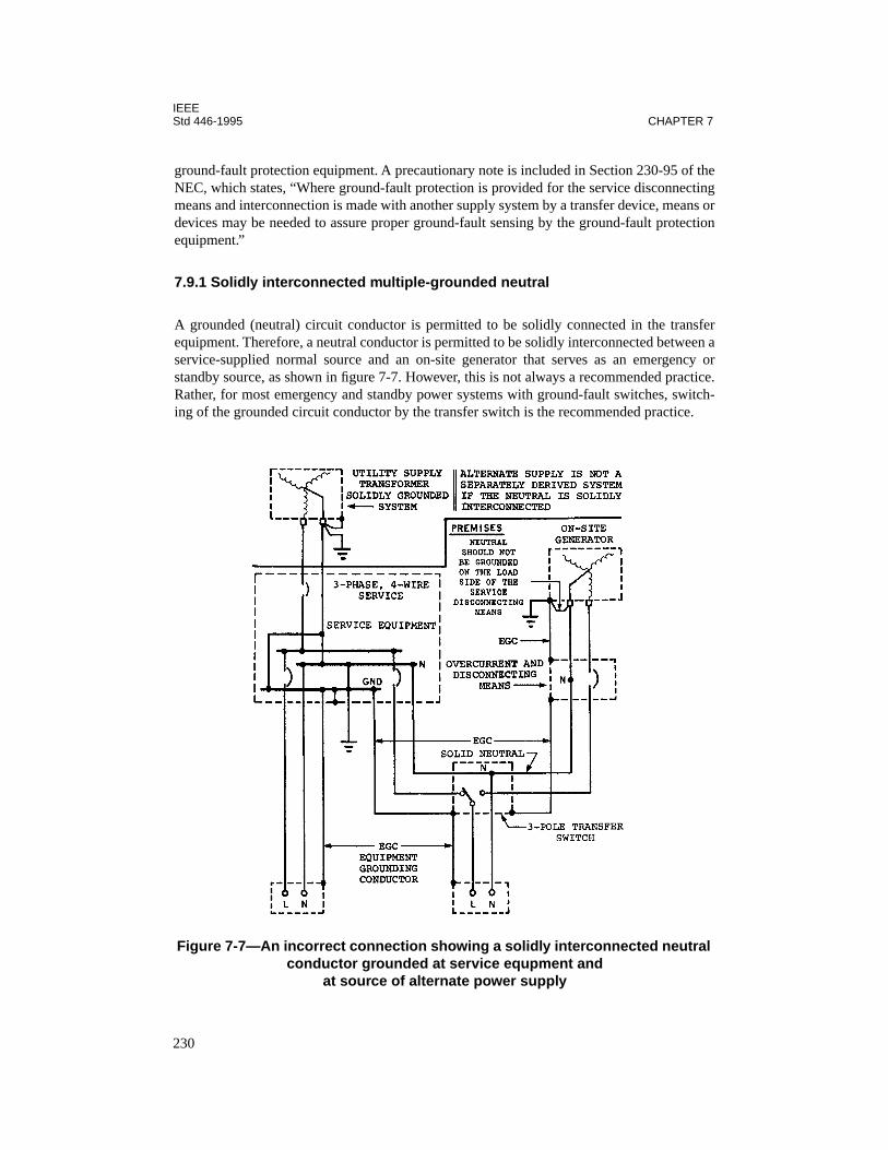
IEEEStd 446-1995 CHAPTER 7
ground-fault protection equipment. A precautionary note is included in Section 230-95 of theNEC, which states, “Where ground-fault protection is provided for the service disconnectingmeans and interconnection is made with another supply system by a transfer device, means ordevices may be needed to assure proper ground-fault sensing by the ground-fault protectionequipment.”
7.9.1 Solidly interconnected multiple-grounded neutral
A grounded (neutral) circuit conductor is permitted to be solidly connected in the transferequipment. Therefore, a neutral conductor is permitted to be solidly interconnected between aservice-supplied normal source and an on-site generator that serves as an emergency orstandby source, as shown in figure 7-7. However, this is not always a recommended practice.Rather, for most emergency and standby power systems with ground-fault switches, switch-ing of the grounded circuit conductor by the transfer switch is the recommended practice.
Figure 7-7—An incorrect connection showing a solidly interconnected neutral conductor grounded at service equpment and
at source of alternate power supply
230
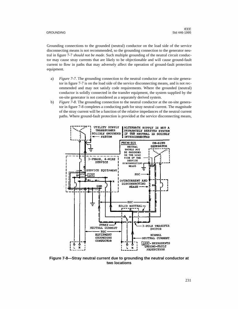
IEEEGROUNDING Std 446-1995
Grounding connections to the grounded (neutral) conductor on the load side of the servicedisconnecting means is not recommended, so the grounding connection to the generator neu-tral in figure 7-7 should not be made. Such multiple grounding of the neutral circuit conduc-tor may cause stray currents that are likely to be objectionable and will cause ground-faultcurrent to flow in paths that may adversely affect the operation of ground-fault protectionequipment.
a) Figure 7-7. The grounding connection to the neutral conductor at the on-site genera-tor in figure 7-7 is on the load side of the service disconnecting means, and is not rec-ommended and may not satisfy code requirements. Where the grounded (neutral)conductor is solidly connected in the transfer equipment, the system supplied by theon-site generator is not considered as a separately derived system.
b) Figure 7-8. The grounding connection to the neutral conductor at the on-site genera-tor in figure 7-8 completes a conducting path for stray neutral current. The magnitudeof the stray current will be a function of the relative impedances of the neutral currentpaths. Where ground-fault protection is provided at the service disconnecting means,
Figure 7-8—Stray neutral current due to grounding the neutral conductor at two locations
231

IEEEStd 446-1995 CHAPTER 7
the stray neutral current may adversely affect the operation of the ground-fault pro-tection equipment.
c) Figure 7-9. The grounding connection to the neutral, which is on the opposite side ofthe ground-fault sensor from the service entrance grounding, can cause ground-faultcurrent to return through the neutral, thus cancelling the sensing of this current by theground-fault sensor. It may also allow zero-sequence current to flow in the neutral,even though no phase conductor is faulted, thus causing unwarranted tripping of theservice entrance breaker.If ground-fault protection is applied on the feeder to the transfer switch, it may besimilarly affected. If neutral current continues to flow subsequent to tripping of thefeeder breaker, it may damage the ground-fault relay. This flow of neutral current isnot caused by the multiple grounds; they merely enable the flow. The current must bedrive 'n by some source, such as the induction due to unequal bus spacing, or evenvoltages from a different system.Where ground-fault protection is applied to a feeder from the service equipment tothe transfer equipment, the ground-fault current illustrated in figure 7-9 could not beaccurately detected by a zero-sequence ground-fault current sensor for the feeder.
Figure 7-9—Ground-fault current return paths to normal supply, neutral grounded at two locations
232
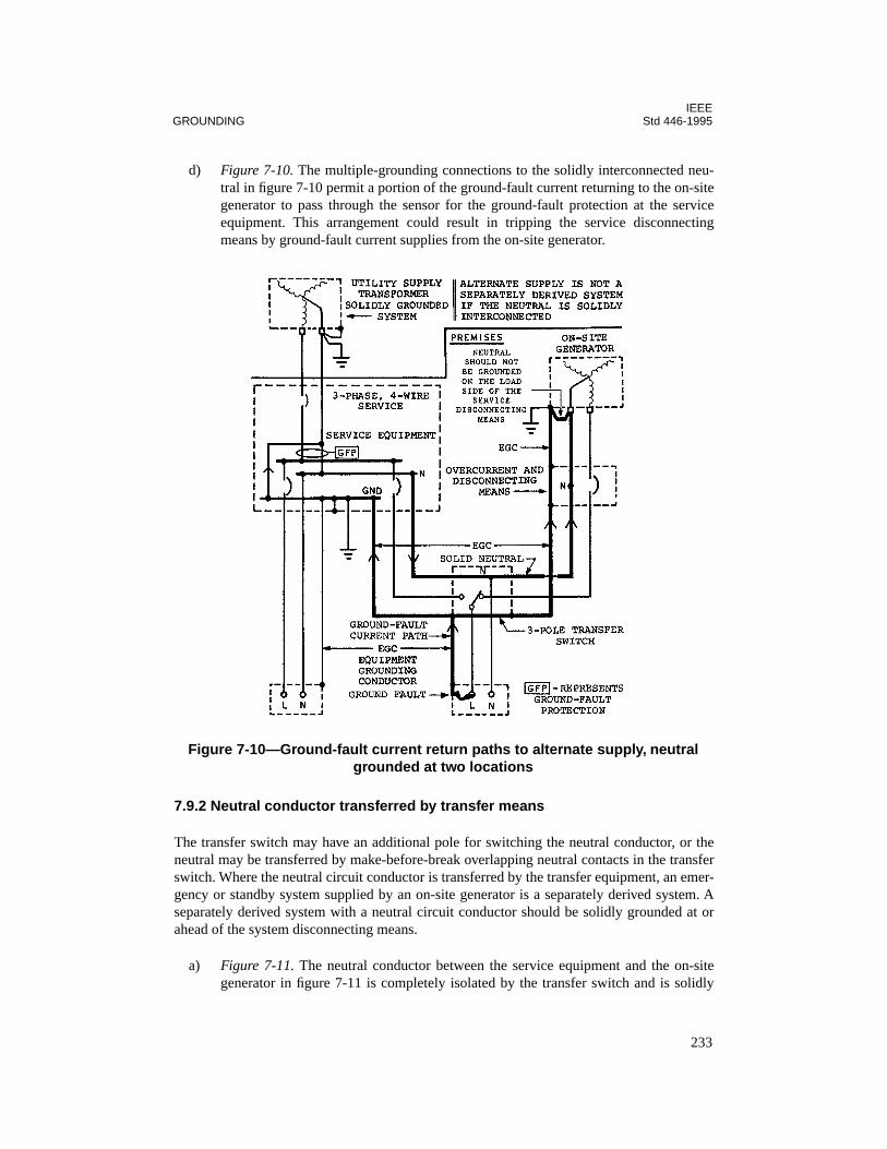
IEEEGROUNDING Std 446-1995
d) Figure 7-10. The multiple-grounding connections to the solidly interconnected neu-tral in figure 7-10 permit a portion of the ground-fault current returning to the on-sitegenerator to pass through the sensor for the ground-fault protection at the serviceequipment. This arrangement could result in tripping the service disconnectingmeans by ground-fault current supplies from the on-site generator.
7.9.2 Neutral conductor transferred by transfer means
The transfer switch may have an additional pole for switching the neutral conductor, or theneutral may be transferred by make-before-break overlapping neutral contacts in the transferswitch. Where the neutral circuit conductor is transferred by the transfer equipment, an emer-gency or standby system supplied by an on-site generator is a separately derived system. Aseparately derived system with a neutral circuit conductor should be solidly grounded at orahead of the system disconnecting means.
a) Figure 7-11. The neutral conductor between the service equipment and the on-sitegenerator in figure 7-11 is completely isolated by the transfer switch and is solidly
Figure 7-10—Ground-fault current return paths to alternate supply, neutral grounded at two locations
233

IEEEStd 446-1995 CHAPTER 7
grounded at the service equipment and at the on-site generator. Where the neutral cir-cuit conductor is switched by the transfer equipment, the stray neutral current pathsand the undesirable ground-fault current paths illustrated in figures 7-10, 7-11, and7-12 are eliminated.
The normal supply and the alternate supply in figure 7-13 are equivalent to two sepa-rate radial systems because all of the circuit conductors from both supplies areswitched by the transfer switch. Since both systems are completely isolated fromeach other and are solidly grounded, ground-fault sensing and protection can beapplied to the circuits of the normal source and the emergency or standby source as itis applied in a single radial system.
b) Figure 7-12. This diagram shows that unintentional neutral grounds will cause strayneutral currents that may be objectionable. Therefore, in addition to carefully plan-ning the intentional grounding connections, systems should be kept free of uninten-tional grounds on the neutral circuit conductors.
Figure 7-11—Transferred neutral conductor grounded at service equipment and at source of alternate power supply
234
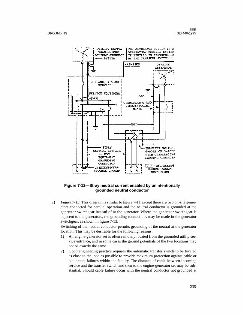
IEEEGROUNDING Std 446-1995
c) Figure 7-13. This diagram is similar to figure 7-11 except there are two on-site gener-ators connected for parallel operation and the neutral conductor is grounded at thegenerator switchgear instead of at the generator. Where the generator switchgear isadjacent to the generators, the grounding connections may be made in the generatorswitchgear, as shown in figure 7-13.Switching of the neutral conductor permits grounding of the neutral at the generatorlocation. This may be desirable for the following reasons:1) An engine-generator set is often remotely located from the grounded utility ser-
vice entrance, and in some cases the ground potentials of the two locations maynot be exactly the same.
2) Good engineering practice requires the automatic transfer switch to be locatedas close to the load as possible to provide maximum protection against cable orequipment failures within the facility. The distance of cable between incomingservice and the transfer switch and then to the engine-generator set may be sub-stantial. Should cable failure occur with the neutral conductor not grounded at
Figure 7-12—Stray neutral current enabled by unintentionally grounded neutral conductor
235

IEEEStd 446-1995 CHAPTER 7
the generator location, the load would be transferred to an ungrounded emer-gency power system. Concurrent failure of equipment (breakdown between lineand equipment ground) after transfer to emergency may not be detected.
3) Some local codes require ground-fault protection while the engine-generator isoperating. This may present a sensing problem if the neutral conductor of thegenerator is not connected to a grounding electrode at the generator site andproper isolation of neutrals is not provided. This may also present a problem inproviding a ground-fault signal as required according to NEC, Section 700-7(e).
4) When the transfer switch is in the emergency position, other problems mayoccur if the neutral is not grounded at the engine-generator set. A ground-faultcondition, as shown in figure 7-17(b), could cause nuisance tripping of the nor-mal source circuit breaker, even though load current is not flowing through thebreaker, and still not be cleared.The normal neutral conductor and the emergency neutral conductor would thenbe simultaneously vulnerable to the same ground-fault current. The ground-faultrelay can be damaged. Thus a single fault could jeopardize power to critical
Figure 7-13—Transferred neutral conductor grounded at servide equipment and at switchgear for two on-site generators connected in parallel
236

IEEEGROUNDING Std 446-1995
loads even though both utility and emergency power are available. Such a condi-tion may be in violation of codes requiring independent wiring and separateemergency feeders.
7.9.3 Neutral conductor isolated by a transformer
Where a transferable load is supplied by a system that is derived from an on-site isolatingtransformer and the transfer equipment is ahead of the transformer, as illustrated in figure7-14, a grounded (neutral) circuit conductor is not always required from either the normal oralternate supply to the transformer primary. The isolating transformer permits phase-to-neutral transferable loads to be supplied without a grounded (neutral) circuit conductor in thefeeders to the transfer switch.
This type of connection is practical where a power-conditioning module incorporating an iso-lation transformer is used to improve “power quality” and be a source of neutral current forcomputer or other applications.
Figure 7-14—Solidly grounded neutral conductor for transferred load isolated by transformer
237
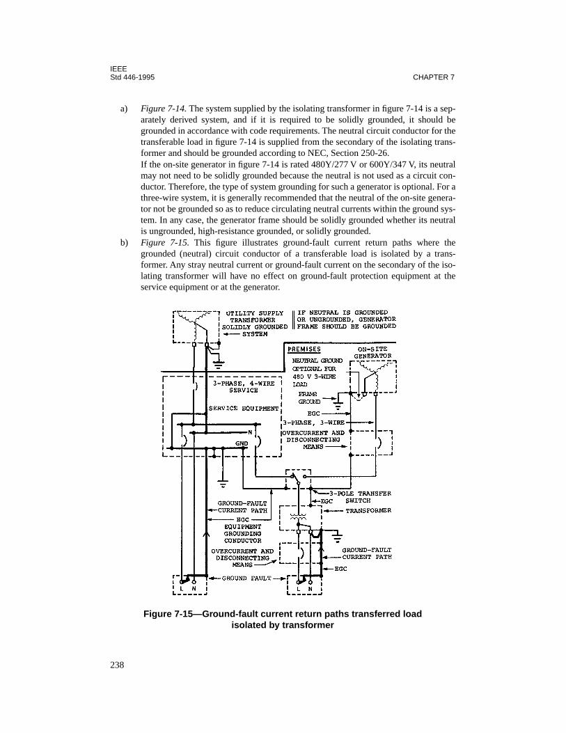
IEEEStd 446-1995 CHAPTER 7
a) Figure 7-14. The system supplied by the isolating transformer in figure 7-14 is a sep-arately derived system, and if it is required to be solidly grounded, it should begrounded in accordance with code requirements. The neutral circuit conductor for thetransferable load in figure 7-14 is supplied from the secondary of the isolating trans-former and should be grounded according to NEC, Section 250-26.If the on-site generator in figure 7-14 is rated 480Y/277 V or 600Y/347 V, its neutralmay not need to be solidly grounded because the neutral is not used as a circuit con-ductor. Therefore, the type of system grounding for such a generator is optional. For athree-wire system, it is generally recommended that the neutral of the on-site genera-tor not be grounded so as to reduce circulating neutral currents within the ground sys-tem. In any case, the generator frame should be solidly grounded whether its neutralis ungrounded, high-resistance grounded, or solidly grounded.
b) Figure 7-15. This figure illustrates ground-fault current return paths where thegrounded (neutral) circuit conductor of a transferable load is isolated by a trans-former. Any stray neutral current or ground-fault current on the secondary of the iso-lating transformer will have no effect on ground-fault protection equipment at theservice equipment or at the generator.
Figure 7-15—Ground-fault current return paths transferred load isolated by transformer
238
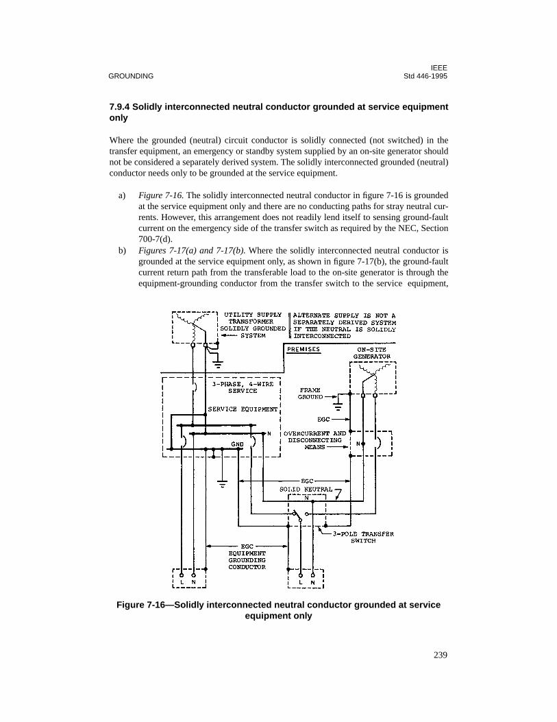
IEEEGROUNDING Std 446-1995
7.9.4 Solidly interconnected neutral conductor grounded at service equipmentonly
Where the grounded (neutral) circuit conductor is solidly connected (not switched) in thetransfer equipment, an emergency or standby system supplied by an on-site generator shouldnot be considered a separately derived system. The solidly interconnected grounded (neutral)conductor needs only to be grounded at the service equipment.
a) Figure 7-16. The solidly interconnected neutral conductor in figure 7-16 is groundedat the service equipment only and there are no conducting paths for stray neutral cur-rents. However, this arrangement does not readily lend itself to sensing ground-faultcurrent on the emergency side of the transfer switch as required by the NEC, Section700-7(d).
b) Figures 7-17(a) and 7-17(b). Where the solidly interconnected neutral conductor isgrounded at the service equipment only, as shown in figure 7-17(b), the ground-faultcurrent return path from the transferable load to the on-site generator is through theequipment-grounding conductor from the transfer switch to the service equipment,
Figure 7-16—Solidly interconnected neutral conductor grounded at service equipment only
239
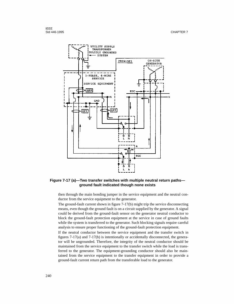
IEEEStd 446-1995 CHAPTER 7
then through the main bonding jumper in the service equipment and the neutral con-ductor from the service equipment to the generator.The ground-fault current shown in figure 7-17(b) might trip the service disconnectingmeans, even though the ground fault is on a circuit supplied by the generator. A signalcould be derived from the ground-fault sensor on the generator neutral conductor toblock the ground-fault protection equipment at the service in case of ground faultswhile the system is transferred to the generator. Such blocking signals require carefulanalysis to ensure proper functioning of the ground-fault protection equipment.If the neutral conductor between the service equipment and the transfer switch infigures 7-17(a) and 7-17(b) is intentionally or accidentally disconnected, the genera-tor will be ungrounded. Therefore, the integrity of the neutral conductor should bemaintained from the service equipment to the transfer switch while the load is trans-ferred to the generator. The equipment-grounding conductor should also be main-tained from the service equipment to the transfer equipment in order to provide aground-fault current return path from the transferable load to the generator.
Figure 7-17 (a)—Two transfer switches with multiple neutral return paths—ground fault indicated though none exists
240
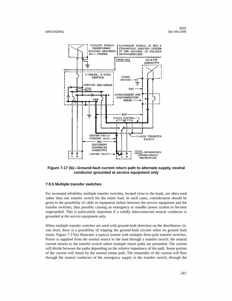
IEEEGROUNDING Std 446-1995
7.9.5 Multiple transfer switches
For increased reliability, multiple transfer switches, located close to the loads, are often usedrather than one transfer switch for the entire load. In such cases, consideration should begiven to the possibility of cable or equipment failure between the service equipment and thetransfer switches, thus possibly causing an emergency or standby power system to becomeungrounded. This is particularly important if a solidly interconnected neutral conductor isgrounded at the service equipment only.
When multiple transfer switches are used with ground-fault detection on the distribution cir-cuit level, there is a possibility of tripping the ground-fault circuits when no ground faultexists. Figure 7-17(a) illustrates a typical system with multiple three-pole transfer switches.Power is supplied from the normal source to the load through a transfer switch; the neutralcurrent returns to the transfer switch where multiple return paths are presented. The currentwill divide between the paths depending on the relative impedance of the path. Some portionof the current will return by the normal return path. The remainder of the current will flowthrough the neutral conductor of the emergency supply to the transfer switch, through the
Figure 7-17 (b)—Ground-fault current return path to alternate supply, neutral conductor grounded at service equipment only
241

IEEEStd 446-1995 CHAPTER 7
neutral conductor of the emergency distribution bus, through the neutral conductor of theemergency supply to the second transfer switch, then through the neutral conductor of thenormal supply to the second transfer switch to the neutral conductor of the normal distribu-tion bus, and finally back to the normal source.
This situation can occur independently of the grounding means chosen for the system, andcan cause tripping of both normal and emergency service distribution breakers if they are pro-tected by ground-fault devices even when no ground-fault exists. This problem can be cor-rected by the use of the three-pole transfer switches with overlapping neutral or four-poletransfer switches.
7.9.6 Multiple engine-generator sets
When several engine-generator sets are connected in parallel and serve as a common sourceof power, each generator neutral is usually connected to a common neutral bus within the par-alleling switchgear which, in turn, is grounded. The associated switchgear containing theneutral bus should be located in the vicinity of the generator sets. A single system-groundingconductor between the neutral bus and ground simplifies the addition of ground-fault sensingequipment. This also permits the use of a single grounding resistor for multiple engine-gener-ator sets.
It may be argued when individual grounding resistors are used, circulation of harmonic cur-rents between paralleled generators is not a problem, since the resistance limits the circulat-ing current to negligible values. However, if third harmonics are suppressed in the engine-generator sets, circulating currents are usually not a problem.
Multiple engine-generator sets that are physically separated and used for isolated loads maynecessitate additional neutral-to-ground connections. However, by using multiple four-poletransfer switches or three-pole switches with overlapping neutral contacts, proper isolationand ground-fault sensing can be obtained.
7.9.7 Transferring neutral conductor
The foregoing discussion and circuit diagrams indicate that four-pole transfer switches aresynonymous with three-pole transfer switches having overlapping neutral contacts. This istrue from the standpoint of providing isolation as needed for ground-fault protection. How-ever, there are other considerations.
Four-pole transfer switches can be satisfactorily applied where the loads are passive and rela-tively balanced. However, unbalanced loads may cause abnormal voltages for as long as 10–15 ms when the neutral conductor is momentarily opened during transfer of the load. Transferswitches may be called upon to operate during total load unbalance caused by a single-phas-ing condition. Inductive loads may cause additional high transient voltages in the microsec-ond range. Contacts of the fourth switch pole do interrupt current and are, therefore, subjectto arcing and contact erosion. A good maintenance program is recommended to reaffirm atintervals the integrity of the fourth pole as a current-carrying member with sufficiently lowimpedance.
242
IEEEGROUNDING Std 446-1995
With overlapping neutral contacts, the only time the neutrals of the normal and emergencypower sources are connected is during transfer and retransfer. The operating time of theground-fault relay should be set higher than the overlap time of the particular transfer switchused.
With overlapping neutral transfer contacts, the load neutral is always connected to one sourceof power. When the transfer switch operates, abnormal and transient voltages, which can pro-duce common-mode noise, are kept to a minimum because there is no momentary opening ofthe neutral conductor. Also, there is no erosion of the overlapping contacts due to arcing.
7.10 Ground-fault alarm
Most of the discussion on ground faults in this chapter has pertained to protection on the nor-mal side of the transfer switch. However, ground faults can also occur between the transferswitch and the on-site generator. It is usually not desirable that emergency loads be automati-cally disconnected from the on-site generator should such a ground-fault occur.
However, for the purpose of safety and to minimize the possibility of fire and equipmentdamage, a visual and audible alarm to indicate a ground fault in larger emergency power sys-tems is often recommended. This could alert personnel that corrective action should be taken.Instructions should be provided at or near the sensor location stating what course of action isto be taken in the event of a ground-fault indication.
Usually a ground-fault condition will show up during routine testing of the on-site generator.This then provides time to take corrective steps prior to an actual emergency condition.
7.11 Systems without a grounded circuit conductor
Three-phase, three-wire, 480 V and 600 V systems, which are extensively used in industrialestablishments, do not require the use of grounded conductors as circuit conductors. Thereare more system-grounding options where emergency and standby power systems do notrequire a grounded circuit conductor to supply phase-to-neutral loads.
7.11.1 Solidly grounded service
In many installations, the utility service to the premises will be solidly grounded, three-phase,four-wire, where a grounded (neutral) circuit conductor is not required for loads that are pro-vided with an on-site emergency or standby supply. An on-site emergency or standby supplyis not always required to have the same type of system grounding as the normal supply to thepremises.
a) Figure 7-18. The generator in figure 7-18 supplies a three-phase, three-wire system.If the generator is rated 480Y/277 V or 600Y/347 V, the neutral need not be used as acircuit conductor.
243
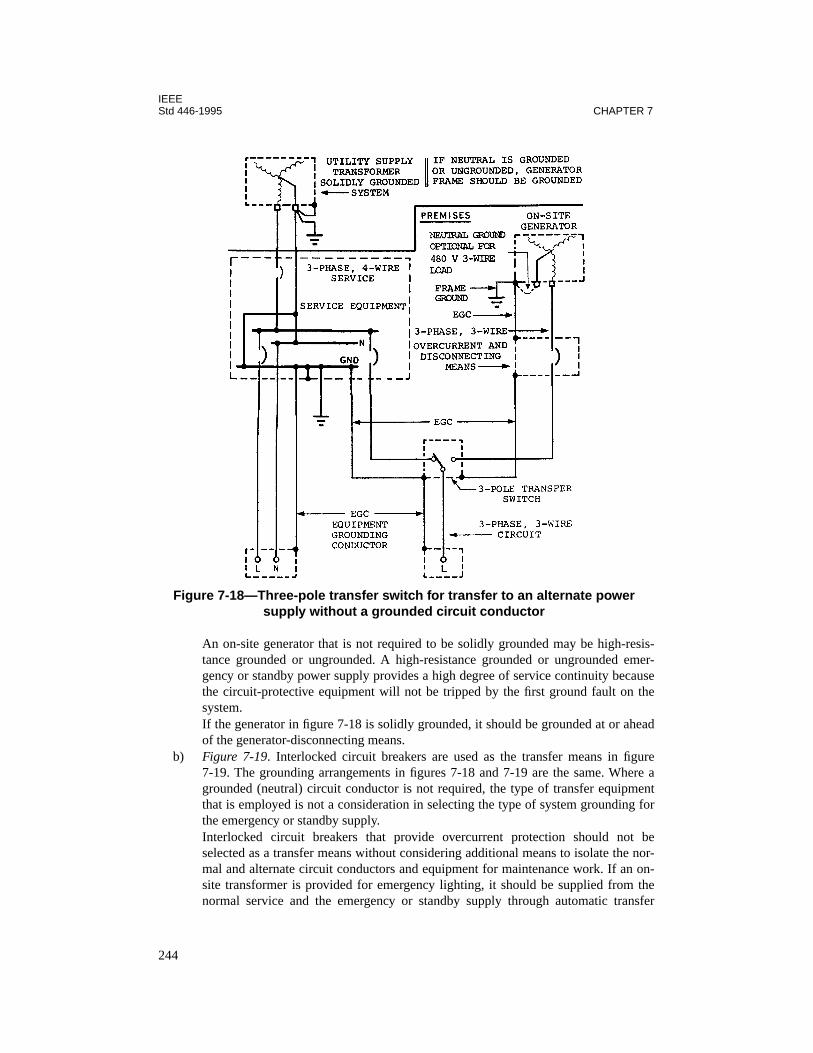
IEEEStd 446-1995 CHAPTER 7
An on-site generator that is not required to be solidly grounded may be high-resis-tance grounded or ungrounded. A high-resistance grounded or ungrounded emer-gency or standby power supply provides a high degree of service continuity becausethe circuit-protective equipment will not be tripped by the first ground fault on thesystem.If the generator in figure 7-18 is solidly grounded, it should be grounded at or aheadof the generator-disconnecting means.
b) Figure 7-19. Interlocked circuit breakers are used as the transfer means in figure7-19. The grounding arrangements in figures 7-18 and 7-19 are the same. Where agrounded (neutral) circuit conductor is not required, the type of transfer equipmentthat is employed is not a consideration in selecting the type of system grounding forthe emergency or standby supply.Interlocked circuit breakers that provide overcurrent protection should not beselected as a transfer means without considering additional means to isolate the nor-mal and alternate circuit conductors and equipment for maintenance work. If an on-site transformer is provided for emergency lighting, it should be supplied from thenormal service and the emergency or standby supply through automatic transfer
Figure 7-18—Three-pole transfer switch for transfer to an alternate power supply without a grounded circuit conductor
244

IEEEGROUNDING Std 446-1995
switching equipment. Ground-detection equipment should be installed to help pre-vent a prolonged single-fault condition. While it might not be a code violation to operate a generator as a three-wireungrounded system, as shown in figures 7-18 and 7-19, a situation of lesser reliabilityand increased safety problems may develop.
c) Figure 7-20. A 480 V or 600 V, three-phase, three-wire, on-site generator that is high-resistance grounded may serve as an emergency or standby power supply for a three-phase, three-wire system that is normally supplied by a solidly grounded service, asshown in figure 7-20.
7.11.2 High-resistance grounded service
Where the three-phase, three-wire, critical load is relatively large compared with loads thatrequire a grounded (neutral) circuit conductor, a high-resistance grounded service with ahigh-resistance grounded emergency or standby power supply is sometimes considered. This
Figure 7-19—Interlocked circuit breakers for transfer to an alternate power supply without a grounded circuit conductor
245
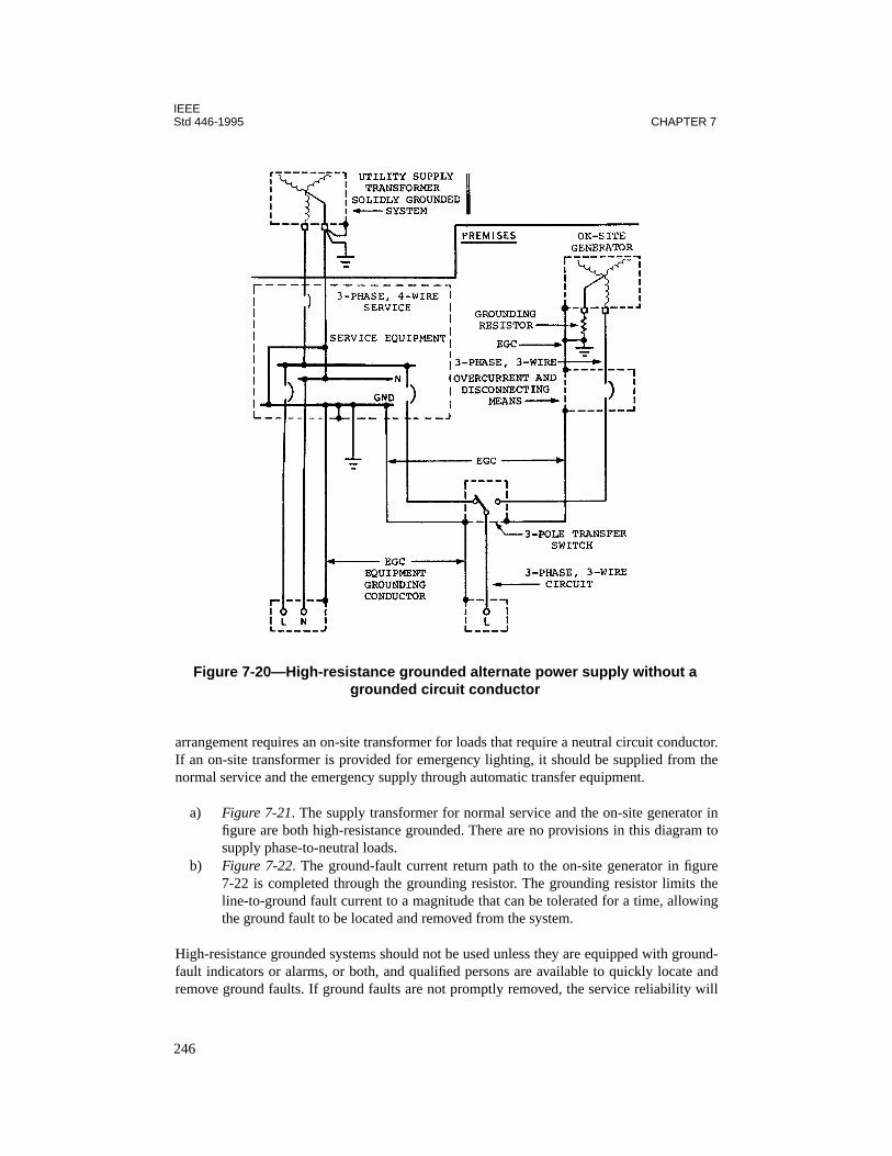
IEEEStd 446-1995 CHAPTER 7
arrangement requires an on-site transformer for loads that require a neutral circuit conductor.If an on-site transformer is provided for emergency lighting, it should be supplied from thenormal service and the emergency supply through automatic transfer equipment.
a) Figure 7-21. The supply transformer for normal service and the on-site generator infigure are both high-resistance grounded. There are no provisions in this diagram tosupply phase-to-neutral loads.
b) Figure 7-22. The ground-fault current return path to the on-site generator in figure7-22 is completed through the grounding resistor. The grounding resistor limits theline-to-ground fault current to a magnitude that can be tolerated for a time, allowingthe ground fault to be located and removed from the system.
High-resistance grounded systems should not be used unless they are equipped with ground-fault indicators or alarms, or both, and qualified persons are available to quickly locate andremove ground faults. If ground faults are not promptly removed, the service reliability will
Figure 7-20—High-resistance grounded alternate power supply without a grounded circuit conductor
246
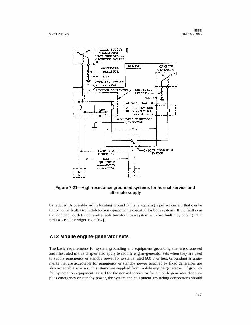
IEEEGROUNDING Std 446-1995
be reduced. A possible aid in locating ground faults is applying a pulsed current that can betraced to the fault. Ground-detection equipment is essential for both systems. If the fault is inthe load and not detected, undesirable transfer into a system with one fault may occur (IEEEStd 141-1993; Bridger 1983 [B2]).
7.12 Mobile engine-generator sets
The basic requirements for system grounding and equipment grounding that are discussedand illustrated in this chapter also apply to mobile engine-generator sets when they are usedto supply emergency or standby power for systems rated 600 V or less. Grounding arrange-ments that are acceptable for emergency or standby power supplied by fixed generators arealso acceptable where such systems are supplied from mobile engine-generators. If ground-fault-protection equipment is used for the normal service or for a mobile generator that sup-plies emergency or standby power, the system and equipment grounding connections should
Figure 7-21—High-resistance grounded systems for normal service and alternate supply
247
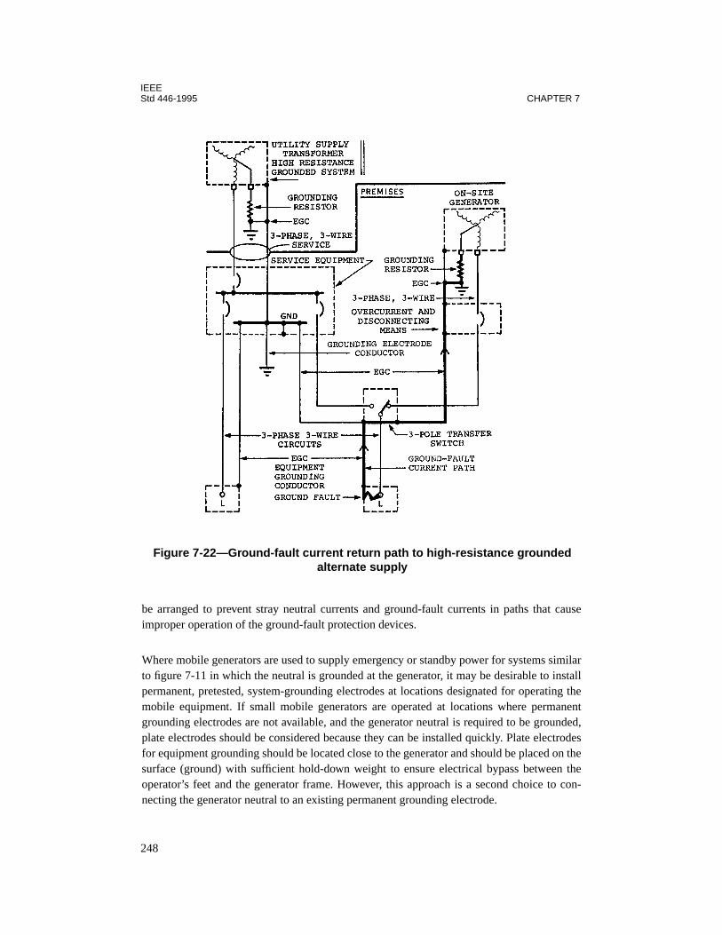
IEEEStd 446-1995 CHAPTER 7
be arranged to prevent stray neutral currents and ground-fault currents in paths that causeimproper operation of the ground-fault protection devices.
Where mobile generators are used to supply emergency or standby power for systems similarto figure 7-11 in which the neutral is grounded at the generator, it may be desirable to installpermanent, pretested, system-grounding electrodes at locations designated for operating themobile equipment. If small mobile generators are operated at locations where permanentgrounding electrodes are not available, and the generator neutral is required to be grounded,plate electrodes should be considered because they can be installed quickly. Plate electrodesfor equipment grounding should be located close to the generator and should be placed on thesurface (ground) with sufficient hold-down weight to ensure electrical bypass between theoperator’s feet and the generator frame. However, this approach is a second choice to con-necting the generator neutral to an existing permanent grounding electrode.
Figure 7-22—Ground-fault current return path to high-resistance grounded alternate supply
248
IEEEGROUNDING Std 446-1995
Equipment grounding conductors should be provided with the mobile generator circuit con-ductors as illustrated in the figures in this chapter. If flexible cords or cables are used to con-nect mobile generators to emergency or standby power systems, each cord or cable shouldhave an equipment-grounding conductor.
Supplemental equipment bonding, which is discussed in 7.3, will reduce the risk of electricalshock for persons who contact the exposed noncurrent-carrying metal parts of the mobileequipment. Supplemental equipment bonding should be installed between the mobile genera-tor frame and adjacent conductive surfaces such as structural steel, metal piping systems, andmetal equipment enclosures. If the neutral of a mobile generator is not grounded, the genera-tor frame should be connected to a grounding electrode, as shown in figure 7-17(a), in addi-tion to its connection to the equipment-grounding conductor network.
7.13 Uninterruptible power supply (UPS) systems
As with any electrical system, correct grounding procedures are essential to overall safetyand operation of a UPS system. In particular, personnel safety, equipment safety, equipmentprotection, and sensitive electronic system performance can all be jeopardized by incorrect orineffective grounding systems. The grounding of the UPS system is very important whensuch systems supply power to critical computer loads.
The NEC does not require the installation of UPS systems, and much of Articles 517, 700,and 701 is not applicable. However, Articles 250 and 645 are applicable to the grounding ofUPS systems.
Many UPS system modules have a wye-connected inverter output, and require the bypassinput to be fed from a wye-connected source. The inverter portion of the UPS system moduleis a separately derived source, in that the input to the rectifier/charger is electrically isolatedfrom the inverter output. However, because the bypass input neutral is directly connected tothe inverter output neutral, the UPS system may or may not be considered a separatelyderived system, depending on the particular arrangement for the bypass input neutral.
The design of UPS systems vary considerably, thus affecting the grounding schemes. For fur-ther discussion, see IEEE Std 142-1991.
7.14 References
This chapter shall be used in conjunction with the following publications:
IEEE Std 141-1993, IEEE Recommended Practice for Electric Power Distribution for Indus-trial Plants (The Red Book) (ANSI).3
3IEEE publications are available from the Institute of Electrical and Electronics Engineers, 445 Hoes Lane, P.O. Box1331, Piscataway, NJ 08855-1331, USA.
249

IEEEStd 446-1995 CHAPTER 7
IEEE Std 142-1991, IEEE Recommended Practice for Grounding of Industrial and Commer-cial Power Systems (The Green Book) (ANSI).
IEEE Std 242-1986 (Reaff 1991), IEEE Recommended Practice for Protection and Coordina-tion of Industrial and Commercial Power Systems (The Buff Book) (ANSI).
IEEE Std 1100-1992, IEEE Recommended Practice for Powering and Grounding SensitiveElectronic Equipment (The Emerald Book) (ANSI).
NEMA PB 2.2-1988 (Reaff 1994), Application Guide for Ground Fault Protective Devicesfor Equipment.4
NFPA 70-1996, National Electrical Code®.5
ANSI/NFPA 110-1993, Emergency and Standby Power Systems.
7.15 Bibliography
Additional information may be found in the following sources:
[B1] Bloomquist, W. C., Owen, K. J., and Gooch, R. L., “High-Resistance Grounded PowerSystems—Why Not?” IEEE Transactions on Industry Applications, vol. IA-12, pp. 574–579,Nov./Dec. 1976.
[B2] Bridger, B., Jr., “High-Resistance Grounding,” IEEE Transactions on Industry Applica-tions,” vol. 1A-19, pp. 15–21, Jan./Feb. 1983.
[B3] Brinks, J. W., and Wolfinger, J. P., Jr.,“Systems Grounding, Protection, and Detection forCement Plants,” IEEE Transactions on Industry Applications, vol. IA-17, pp. 587–596, Nov./Dec. 1981.
[B4] Castenschiold, R., “Grounding of Alternate Power Sources,” Conference Record of the1977 IEEE Industry Applications Society, Technical Conference, paper 77CH 1 1246-8-IA,pp. 67–72.
[B5] Castenschiold, R., and Hogrebe, L. F., “Factors to Consider When Upgrading TransferSwitching Equipment to Present Codes and Standards,” IEEE Transactions on IndustryApplications, vol. IA-29, no. 3, pp. 510–514, May/June 1993.
4NEMA publications are available from the National Electrical Manufacturers Association, 2101 L Street NW,Washington, DC 20037, USA.5NFPA publications are available from Publications Sales, National Fire Protection Association, 1 BatterymarchPark, P.O. Box 9101, Quincy, MA 02269-9101, USA.
250

IEEEGROUNDING Std 446-1995
[B6] Castenschiold, R., “Ground-Fault Protection of Electrical Systems With Emergency orStandby Power,” IEEE Transactions on Industry Applications, vol. IA-13, pp. 517–523, Nov./Dec. 1977.
[B7] Kaufmann, R. H., “Some Fundamentals of Equipment-Grounding Circuit Design,”AIEE Transactions (Applications and Industry), pt. 11, vol. 73, pp. 227–232, Nov. 1954.
[B8] Richards, J. H., “Generator Neutral Grounding,” Electrical Construction, and Mainte-nance, p. 122, May 1984.
[B9] West, R. B., “Equipment Grounding for Reliable Ground Fault Protection in ElectricalSystems Below 600 V,” IEEE Transactions on Industry Applications, vol. IA-10, pp. 175–189, Mar./Apr. 1974.
[B10] West, R. B., “Grounding for Emergency and Standby Power Systems,” IEEE Transac-tions on Industry Applications, vol. IA-15, pp. 124–136, Mar./Apr. 1979.
[B11] Zipse, D. W., “Multiple Neutral to Ground Connections,” Conference Record of the1972 IEEE Industrial and Commercial Power Systems, Technical Conference, paper72CH0600-7-IA, pp. 60–64.
251

IEEEStd 446-1995 CHAPTER 7
252
Chapter 8Maintenance
8.1 Introduction
Once it has been determined by building codes, ANSI/NFPA 101-1994,1 or a reliability studythat an emergency or standby power system is justified or required, available systems must beevaluated to select one that satisfies the economic requirements. While economic consider-ations are primary, installation practices and maintenance procedures should be significantfactors in selecting the proper system. After the system has been selected and the responsibil-ity for maintenance established, plans for preventive maintenance must be made. The goal ofpreventive maintenance is to ensure that the system is in optimum operating condition. With-out proper emphasis on maintenance from design stage through operation, the system canrapidly become unreliable and fail to perform its intended function.
Preventive maintenance can be thought of as a science of anticipation and prediction of fail-ures. The system’s important emergency and standby function makes preventive maintenancea great challenge.
8.1.1 General description of preventive maintenance practices
Preventive maintenance for electrical equipment consists of planned inspections, testing,cleaning, drying, monitoring, adjusting, corrective modification, and minor repair in order tomaintain equipment in optimum operating condition and maximum reliability. In addition toroutine preventive maintenance, it is important to maintain written records that documentmaintenance performance and test measurements. Also, drawings, such as connection wiringdiagrams, one line diagrams, and block diagrams, are necessary in assistance with mainte-nance work.
8.1.2 Precautionary measures
Vital precautionary measures that should be considered a part of preventive maintenance areas follows:
— It should be made certain that the installation and ventilation of the emergency orstandby power systems will not be adversely affected by unauthorized storage oraccumulations of dirt.
— Regular test responsibilities should be placed on trained personnel, and tests shouldbe scheduled frequently to assure reliable operation.
NOTE—Use manufacturer’s recommended procedure frequencies to establish program andadjust from experience.
— Gasoline and, to a lesser extent, diesel fuels deteriorate when stored for extendedperiods of time. Inhibitors can be used to reduce the rate of deterioration, but it is
1Information on references can be found in 8.9.
253
IEEEStd 446-1995 CHAPTER 8
sound practice to operate a system utilizing these fuels such that total operating timewill result in a complete fuel change cycle every few months.
— In case of life-limited components, a sufficient quantity of spares should be main-tained, and they should be replaced according to the manufacturer’s directions.
8.1.3 Personnel requirements
Personnel who maintain standby or emergency power systems should be required to havespecific training and qualifications, as well as certain tools, manuals, and access to equip-ment, in order to ensure that preventive maintenance can be carried out effectively.
A list of these personnel requirements are as follows:
— An understanding of ANSI/NFPA 101-1994 and manufacturer’s test procedures andfrequency.
— Special training at manufacturer’s location for equipment start and routine mainte-nance.
— A complete set of specialized and normal tools for required maintenance procedureson site.
NOTE—Manufacturer can assist in developing this tool set.
— A complete set of shop manuals and list of required spare parts (with location notes).— A manual of test procedures with step-by-step details.— Physical access to system equipment to perform tests within required frequencies.— Management/supervisory support to perform the tests within required frequencies.
8.1.4 How to use this chapter
Many different types of emergency and standby power systems are on the market today. Thischapter presents a consolidation of general preventive maintenance recommendations that areorganized into subclauses (8.2–8.12) according to system components. These general recom-mendations can then be applied to emergency and standby power systems that are formedfrom the various components.
8.2 Internal combustion engines
8.2.1 General
Internal combustion engines that are commonly available include those that use natural andbottled gas, gasoline, and diesel fuel. Since there are more similarities than differences intheir maintenance requirements, these engines are grouped together.
Long life and high reliability are characteristics to be expected from these types of primemovers, but only if properly maintained. Preventive maintenance programs will greatly con-tribute to the service life and reliability.
254
IEEEMAINTENANCE Std 446-1995
In establishing a preventive maintenance program for these engines, the best starting point isthe manufacturer’s service manual. This will provide a guide for specific points to be checkedand for frequency of inspection. These reference points can then be modified to fit particularinstallation and operating conditions.
8.2.2 Operating factors affecting maintenance
More than any other factor, lubrication determines an engine’s useful life. Various parts of theengine may require different lubricants and different frequencies of lubricant application. It isimportant to follow the manufacturer’s recommendations as to type and frequency of lubrica-tion.
Because dirt and corrosion are major causes of equipment failure, no engine should be con-sidered properly maintained if it is not cleaned to a “like new” condition. Dirt increases thedifficulty of inspecting engine parts and interferes with heat conduction. Before performingany inspection on service, carefully clean all fittings, caps, fillers, level plugs, and their adja-cent surfaces to prevent contamination of lubricants and coolants. Keep all dirt, dust, water,and sediment out of the fuel to prevent engine damage and clogging of fuel filters and injec-tors. In addition, bacteria in the presence of water can form sludge over an extended period oftime, which will exacerbate the clogging of fuel filters and injectors. Frequently draining thewater from the bottom of the fuel tank is the best method to prevent sludge. Visual and labo-ratory tests of sample is also of great value.
8.2.3 Typical maintenance schedule
NOTE: The following maintenance items or schedule are significant but not necessarily complete. Eachsystem should have it’s own schedule developed from experience and early test results. In addition,table A-6-3.1 (a) from ANSI/NFPA 110-1993 can be helpful.
a) Weekly inspections. The following checks should be made weekly. Corrective actionshall be taken for any item found to be deficient.1) Check cooling system and lubrication oil levels. 2) Check air intake cleaner. 3) Check engine for oil, fuel leaks, and cooling system operation.4) Check for oil heater and/or jacket heater operation.
b) Monthly inspections. The following checks should be made monthly. Correctiveaction shall be taken for any item found to be deficient.1) Check radiator for restrictions.2) Check belt tension.3) Check fuel system level.
c) Semiannual inspections. The following action shall be made semiannually:1) Change lubrication oil and replace filters.2) Change coolant filter.3) Drain sediment and check fuel-line connections.
d) Annual inspections. The following action shall be made annually:1) Clean fan hub, pulley, and water pump.2) Replace fuel float tank breather.3) Tighten exhaust manifold bolts.
255
IEEEStd 446-1995 CHAPTER 8
8.3 Gas turbine
8.3.1 General
The combustion gas turbine, as with any rotating power equipment, requires a program ofscheduled inspection and maintenance to achieve optimum availability and reliability. Thecombustion gas turbine is a complete, self-contained prime mover. This combustion processrequires operation at high temperatures. When inspection marking on stainless steel parts isnecessary, a grease pencil should be used. Graphite particles from lead pencils will carburizestainless steel at the high temperature of gas turbine operation.
Starting reliability is of prime concern since a delay in starting usually means the need for theunit has passed.
8.3.2 Operating factors affecting maintenance
The factors having the greatest influence on scheduling of preventive maintenance are type offuel, starting frequency, environment, and reliability required.
a) Fuel. The effect of the type of fuel on parts is associated with the radiant energy inthe combustion process and the ability to atomize the fuel. Natural gas, which doesnot require atomization, has the lowest level of radiant energy and will produce thelongest life, and the crude oils and residual oils, with higher radiant energy and moredifficult atomization, will provide shorter life of parts.Contaminants in the fuel will also affect the maintenance interval. In liquid fuels, dirtresults in accelerated wear of pumps, metering elements, and fuel nozzles. Contami-nation in gas fuel systems can erode or corrode control valves and fuel nozzles. Fil-ters must be inspected and replaced to prevent carrying contaminants through the fuelsystem. Clean fuels will result in reduced maintenance and extended lives of parts.
b) Starting frequency. Each stop and start subjects a gas turbine to thermal cycling. Thisthermal cycling will cause a shortened parts life. Applications requiring frequentstarts and stops dictate a shorter maintenance interval.
c) Environment. The condition of inlet air to a combustion gas turbine can have a signif-icant effect on maintenance. Abrasives in the inlet air, such as ash particles, requirethat careful attention be paid to inlet filtering to minimize the effect of the abrasives.In the case of corrosive atmosphere, careful attention should be paid to inlet airarrangement and the application of correct materials and protective coatings.
d) Reliability required. The degree of reliability required will affect the scheduling ofmaintenance. The higher the reliability desired, the more frequent the maintenancerequired.
8.3.3 Typical maintenance schedule
NOTE: The following maintenance items or schedule are significant but not necessarily complete. Eachsystem should have it’s own schedule developed from experience and early test results. In addition,table A-6-3.1 (a) from ANSI/NFPA 110-1993 can be helpful.
256

IEEEMAINTENANCE Std 446-1995
a) Weekly inspections. The following checks should be made weekly. Corrective actionshall be taken for any item found to be deficient.1) Check oil level.2) Check fuel oil pressure.3) Check all nuts and other fasteners.4) Check for lubrication oil and fuel leakage.5) Check lines and hoses for wear.6) Check inlet air and exhaust for obstructions.
b) Every 250 hours of operation. The following checks or action shall be made:1) Replace oil filter.2) Replace fuel filters.3) Blow out air lines and filters with dry low-pressure air.4) Lubricate auxiliary motors.
c) Every 1000 hours of operation. The following checks or action shall be made:1) Inspect spark plug.2) Inspect fuel injectors and combustion parts.3) Blow dry low-pressure air through exhaust and combustion drain lines.4) Inspect entire engine for discoloration, cracks, wear, or chafing of hoses, lines,
and other unusual operating conditions.
8.4 Generators
8.4.1 General
The generator requires consideration for ambient temperature control, since the unit is in ade-energized state most of the time. Also, a program of scheduled inspections and mainte-nance is required to achieve optimum availability and reliability.
8.4.2 Operating factors affecting maintenance
Keeping equipment clean is of primary importance in generator preventive maintenance.Dust, oil, moisture, or other substances should not be allowed to accumulate on the equip-ment. Ventilation ducts should be kept clean to allow maximum cooling air in the generator.The importance of keeping windings clean cannot be overemphasized; dust, dirt, and otherforeign matter can restrict heat dissipation and deteriorate winding insulation. A layer of dustas thin as 30 mil can raise the operating temperature of generator windings l0 °C.
The best method for cleaning a generator of loose and dry particles is to use a vacuum cleanerwith proper fittings. Blowing with 30 lb/in2 compressed air can also be employed, but thismethod has a tendency to redeposit the particles. Wiping with a soft, clean rag has the disad-vantage of not being able to remove dust from grooves and inaccessible places. Buildup ofgrease and oil can be removed by conservative use of non-flammable solvents such as trichlo-roethylene. Megohmmeter readings should be taken after cleaning and drying. If the resis-tance is too low, dry out the machine with heat for several days. If low resistance persists, thecleaning should be repeated and followed by drying.
257
IEEEStd 446-1995 CHAPTER 8
Regularly scheduled inspections should include checking for tightness, checking of all wiresfor chafed, brittle, or otherwise damaged insulation; checking bearings brushes, and commu-tator for proper operating condition. Inspect for leakage of bearing grease inside generator. Ifmoisture has accumulated in the generator, the unit must be dried and strip heaters or othermethods must be utilized to prevent the condition from recurring. To dry the unit, externalheat should be applied to reduce the moisture content. Internal heat may then be applied byintroducing a low-voltage current through the windings. The winding temperature must bemonitored to prevent insulation damage during the drying operation.
Brushes and connecting shunts should be inspected for wear and deterioration. Remove thebrushes one at a time and check for length. Be sure the brushes move freely in their holders.Brush holders should be checked for proper tension. Most brushes will operate satisfactorilywith 2.5–3.0 lb/in2 of brush cross section, but manufacturer’s recommendation should bechecked. Replace or repair brush holders that cannot provide adequate tension. Brushesshould be replaced when worn to the point that tension cannot be adjusted properly, usually abrush length of about 1/2 in. In most cases, replace complete sets rather than single brushes.Be sure the shunt leads are properly connected. After placing new brushes in their holders,carefully fit the contact surface of the brushes to the commutator by using first #1, then #00,abrasive paper (aluminum oxide is recommended). Cut the abrasive paper into strips slightlywider than one brush. Insert the strip under the brush with the smooth side toward the com-mutator. Draw the strip in direction of rotation only until 90% contact has been made with arcof commutator. After the brushes have been seated, clean the carbon dust from the commuta-tor and brush assemblies.
Examine brushes for sparking under load. Commutator brushes may have slight sparking;slip ring brushes should have none at all. Examine brushes for chattering, or for frayed shuntsor chipped brushes indicative of chattering. If correction of spring tension does not alleviatethe chattering, consult an expert for advice on brush grades, brush current density, brush pres-sure, etc.
Commutators should be smooth and have a light-to-medium-brown color. A rough or black-ened generator commutator may be lightly polished with a commutator dressing stone fittedto the curvature of the commutator, but the underlying cause should be determined. If notavailable, use #00 abrasive paper with a block of wood shaped to fit the curvature of the com-mutator. Do not use emery cloth. All brushes should be lifted and the generator driven whileslowly moving the polishing block back and forth. The mica insulation between commutatorbars should be undercut 1/16–1/32 in. As the commutator wears down, the mica will causeridges resulting in bouncing of the brushes. If this condition exists the mica must be undercutand the commutator resurfaces by a qualified repairman. Do not use lubricants of any kind onthe commutator.
Generator bearings should be subjected to careful inspection at regularly scheduled intervals.The frequency of inspection, including addition or changing of oil or grease, is best deter-mined by a study of the particular operating conditions. Sealed bearings require no mainte-nance and must be replaced when worn or loose. When the generator is running, listen for/orrecord noise, and feel the bearing housing for vibration or excessive heat. Use equipment toobtain signature on antifriction bearings.
258

IEEEMAINTENANCE Std 446-1995
The failure of an insulation system is a common cause of problems in electrical equipment.Insulation is subject to many conditions that can cause failure, such as mechanical damage,vibration, excessive heat or cold, dirt, oil, corrosive vapors, and moisture from either pro-cesses or just humid weather. To aid in detecting any of these damaging effects, an insulation-resistance test is used to determine insulation quality. The test is simple, convenient, and non-destructive. A carefully controlled high-potential (hi-pot) test may be performed at less fre-quent intervals.
The location of the engine-generator set for an emergency or a standby power system is animportant aspect of maintenance. If located indoors, provisions should be made to ensurethere is space for repair/maintenance procedures to be accomplished. If located outdoors,dusty and corrosive environments should be avoided, and engines should be equipped with alubricating heater and engine-coolant heater.
With proper preventive maintenance, a generator will provide reliable and lengthy service.
8.4.3 Typical maintenance schedule
NOTE: The following maintenance items or schedule are significant but not necessarily complete. Eachsystem should have it’s own schedule developed from experience and early test results. In addition,table A-6-3.1 (a) from ANSI/NFPA 110-1993 can be helpful.
The following typical maintenance schedule is presented as a guide:
a) Weekly inspections. The following checks should be made weekly. Corrective actionshall be taken for any item found to be deficient.
1) Check battery charging system.
2) Start-run generator under full load for 30–60 min.
b) Monthly inspections. The following checks should be made monthly. Correctiveaction shall be taken for any item found to be deficient.
1) Check/verify meter readings.
2) Check intake filter.
3) Check battery level.
4) Check insulation resistance (surge arrestor must be disconnected).
c) Semiannual inspections. The following action shall be made semiannually.
1) Check for leaks.
d) Annual inspections. The following action shall be made annually:
1) Tighten mounting bolts.
2) Perform hi-pot test of windings (includes polarization index and step voltage).
3) Grease bearings.
4) Tighten electrical connections and thermal scan under load.
259
IEEEStd 446-1995 CHAPTER 8
8.5 Uninterruptible power supply (UPS) systems
8.5.1 General
UPS systems are installed because the load requires an uninterruptible source of power or apower source of specific quality. Therefore, precautions must be taken when isolating a UPSfor maintenance. Be familiar with the critical loads supplied by the UPS and notify the appro-priate personnel whenever the UPS must be removed from service for maintenance.
Whenever a shut-down of the system is required for maintenance, the UPS system should beplaced in the bypass mode, or for redundant systems, the load should be transferred to theredundant units.The UPS system to be maintained should be completely isolated from inputand output power, including batteries. Many UPS systems have a unique isolating procedureto prevent an outage to a critical load. These procedures, where available, should be followed.An additional safety precaution is required to ensure that stored energy capacitors are dis-charged.
8.5.2 Typical maintenance schedule for a static UPS system
A static UPS system is extremely reliable and requires minimal maintenance of the inverterand battery charger. See 8.7 for maintenance of batteries.
(The following maintenance items or schedule are significant but not necessarily complete.Each system should have its own schedule developed from experience and early test results.)
Preventive maintenance consists of cleaning and inspecting the UPS system periodically.Typical inspection intervals are daily, monthly, quarterly, and annually. In severe environ-ments, intervals should be decreased. When performing maintenance, follow all safety proce-dures using appropriate tools, test equipment, and safety equipment. The following itemsshould be included in the inspections:
a) Weekly inspections. The following checks should be made weekly. Corrective actionshall be taken for any item found to be deficient.1) Check all lamps using the “lamp test” feature.2) Check all meters to ensure they are operating.3) Check input, output, and bypass voltage and current.4) Verify that the disturbance monitor is operable, if the UPS system is so equipped.
b) Monthly inspections. The following checks should be made monthly. Correctiveaction shall be taken for any item found to be deficient.1) Complete all daily inspections.2) Check the appearance and cleanliness of all equipment, the room/area.3) Inspect the HVAC equipment and measure the room/area temperature and
humidity.4) Check all UPS equipment air intakes and exhausts, including all filters.
c) Quarterly inspections. The following checks should be made quarterly. Correctiveaction shall be taken for any item found to be deficient.
260
IEEEMAINTENANCE Std 446-1995
1) Complete all monthly inspections.2) Inspect all parts for evidence of overheating.3) Inspect all parts for evidence of physical damage, including worn insulation and
corrosion.4) Inspect terminals for loose or broken connections, burned insulation, etc.5) Check for liquid contamination (battery electrolyte, oil from capacitors, etc.).6) Clean the inside of all equipment enclosures and clean the components within.7) Measure the phase and neutral currents with a true rms ammeter.
d) Annual inspections. The following checks should be made annually. Correctiveaction shall be taken for any item found to be deficient.1) Complete all quarterly inspections.2) Check all connections, e.g., retorque or thermal scan under load.3) Check and test all circuit breakers (biannually only).4) Perform a complete operational test of the system, including operation at full
load, operation on batteries, overload checks, simulation of faults, loss of input,manual and automatic transfers, operation of redundant modules, and so forth(biannually only).
5) Check and adjust voltage output and frequency according to manufacturer’sspecifications.
6) Test alarm shutdown functions.
e) System restoration. If the UPS system has been removed from service for mainte-nance, follow procedures to place it back in service. After the UPS system has beenreconnected and if an operational test was not performed as part of the maintenance,check the output voltage and frequency under load. Simulate a power failure andcheck for proper system operation.
8.5.3 Typical maintenance schedule for a rotating UPS system
Like the static UPS system, preventive maintenance for the rotating UPS consists of cleaningand inspecting the UPS system periodically. Typical inspection intervals are daily, monthly,semiannually, and annually. In severe environments, intervals should be decreased. Whenperforming maintenance, follow all safety procedures and use appropriate tools, test equip-ment, and safety equipment. The following items should be included in the inspections.
a) Weekly inspections. The following checks should be made weekly. Corrective actionshall be taken for any item found to be deficient.1) Check all lamps using the “lamp test” feature.2) Check all meters to ensure they are operating.3) Check input, output, and bypass voltage and current.4) Verify that the disturbance monitor is operable, if the UPS system is so equipped.
b) Monthly inspections. The following checks should be made monthly. Correctiveaction shall be taken for any item found to be deficient.1) Complete all daily inspections.2) Check the appearance and cleanliness of all equipment, the room/area.3) Inspect the HVAC equipment and measure the room/area temperature and
humidity.
261
IEEEStd 446-1995 CHAPTER 8
4) Check all air intakes and exhausts, including all filters.5) Run unit at full-load for minimum of 30–60 min.
c) Semiannual inspections. The following checks should be made semiannually. Correc-tive action shall be taken for any item found to be deficient.1) Complete all monthly inspections.2) Inspect all parts for evidence of overheating.3) Inspect all parts for evidence of physical damage, including worn insulation and
corrosion.4) Inspect terminals for loose or broken connections, burned insulation, etc.5) Check for connections for tightness.6) Clean the inside of all equipment enclosures and clean the components within.7) Check all bearings and their lubrication.8) Run the unit at full-load and check all transfer functions.9) Test alarm shutdown functions.
d) Annual inspections. The following checks should be made annually. Correctiveaction shall be taken for any item found to be deficient.1) Complete all semiannual inspections.2) Check all connections, e.g., retorque or thermal scan under load.3) Check and test all circuit breakers (biannually only).4) Perform a complete operational test of the system, including operation at full
load, operation on batteries, overload checks, simulation of faults, loss of input,manual and automatic transfers, operation of redundant modules, and so forth(biannually only).
e) System restoration. If the UPS system has been removed from service for mainte-nance, follow procedures to place it back in service. After the UPS system has beenreconnected and if an operational test was not performed as part of the maintenance,check the output voltage and frequency under load. Simulate a power failure andcheck for proper system operation.
8.6 Stationary batteries
8.6.1 General
The primary objective of any battery maintenance program is to ensure that the battery instal-lation is able to meet the emergency requirements of the system to which it is connected, overits design life. Secondary objectives are to achieve optimum life of the battery and to deter-mine when the battery requires replacement. To be effective, the maintenance must be bothregular and consistent. In addition, since much of the analysis of the data relies upon compar-ison to previous data (i.e., trend analysis), the data must be corrected to standard references.For example, within the USA, the reference values are voltage and capacity at 25 °C, andelectrolyte full charge specific gravity at 25 °C and at a specific level reference (e.g., the high-level line or the midpoint between the high- and low-level lines).
Maintenance of a battery usually begins at the time of installation. However, if the batterywill be in storage for a period longer than that recommended by the battery manufacturer,
262
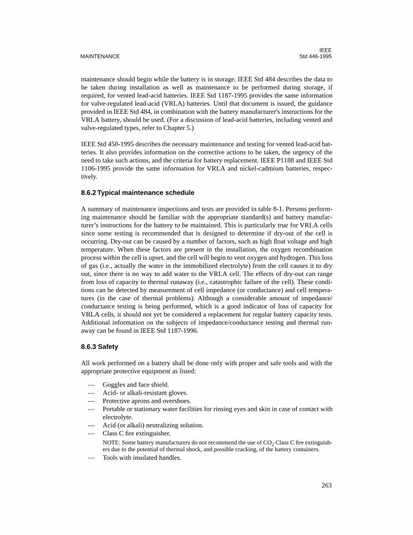
IEEEMAINTENANCE Std 446-1995
maintenance should begin while the battery is in storage. IEEE Std 484 describes the data tobe taken during installation as well as maintenance to be performed during storage, ifrequired, for vented lead-acid batteries. IEEE Std 1187-1995 provides the same informationfor valve-regulated lead-acid (VRLA) batteries. Until that document is issued, the guidanceprovided in IEEE Std 484, in combination with the battery manufacturer's instructions for theVRLA battery, should be used. (For a discussion of lead-acid batteries, including vented andvalve-regulated types, refer to Chapter 5.)
IEEE Std 450-1995 describes the necessary maintenance and testing for vented lead-acid bat-teries. It also provides information on the corrective actions to be taken, the urgency of theneed to take such actions, and the criteria for battery replacement. IEEE P1188 and IEEE Std1106-1995 provide the same information for VRLA and nickel-cadmium batteries, respec-tively.
8.6.2 Typical maintenance schedule
A summary of maintenance inspections and tests are provided in table 8-1. Persons perform-ing maintenance should be familiar with the appropriate standard(s) and battery manufac-turer’s instructions for the battery to be maintained. This is particularly true for VRLA cellssince some testing is recommended that is designed to determine if dry-out of the cell isoccurring. Dry-out can be caused by a number of factors, such as high float voltage and hightemperature. When these factors are present in the installation, the oxygen recombinationprocess within the cell is upset, and the cell will begin to vent oxygen and hydrogen. This lossof gas (i.e., actually the water in the immobilized electrolyte) from the cell causes it to dryout, since there is no way to add water to the VRLA cell. The effects of dry-out can rangefrom loss of capacity to thermal runaway (i.e., catastrophic failure of the cell). These condi-tions can be detected by measurement of cell impedance (or conductance) and cell tempera-tures (in the case of thermal problems). Although a considerable amount of impedance/conductance testing is being performed, which is a good indicator of loss of capacity forVRLA cells, it should not yet be considered a replacement for regular battery capacity tests.Additional information on the subjects of impedance/conductance testing and thermal run-away can be found in IEEE Std 1187-1996.
8.6.3 Safety
All work performed on a battery shall be done only with proper and safe tools and with theappropriate protective equipment as listed:
— Goggles and face shield.— Acid- or alkali-resistant gloves.— Protective aprons and overshoes.— Portable or stationary water facilities for rinsing eyes and skin in case of contact with
electrolyte.— Acid (or alkali) neutralizing solution.— Class C fire extinguisher.
NOTE: Some battery manufacturers do not recommend the use of CO2 Class C fire extinguish-ers due to the potential of thermal shock, and possible cracking, of the battery containers.
— Tools with insulated handles.
263
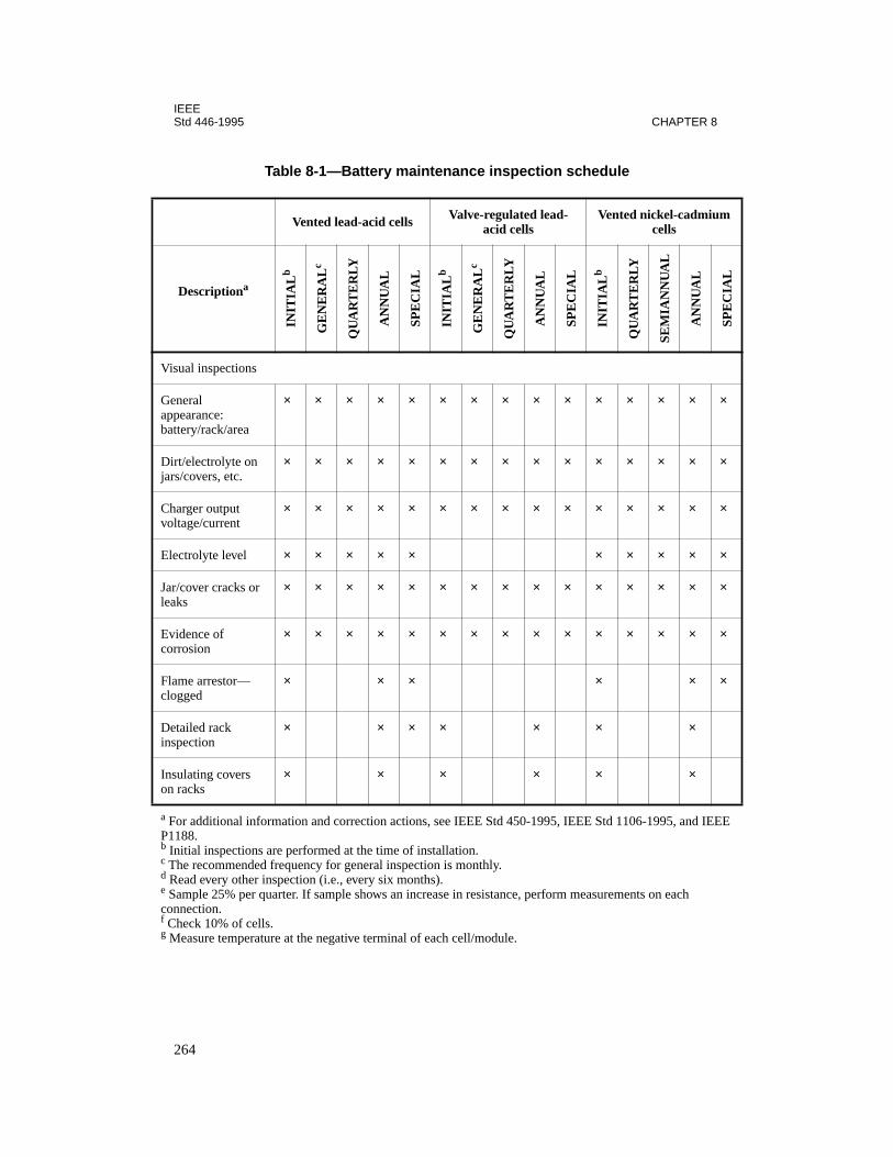
IEEEStd 446-1995 CHAPTER 8
V
Gab
Dj
Cv
E
Jl
Ec
Fc
Di
Io
a
P
b
c
d
e
c
f
g
Table 8-1—Battery maintenance inspection schedule
Vented lead-acid cells Valve-regulated lead-acid cells
Vented nickel-cadmium cells
DescriptionaIN
ITIA
Lb
GE
NE
RA
Lc
QU
AR
TE
RLY
AN
NU
AL
SPE
CIA
L
INIT
IAL
b
GE
NE
RA
Lc
QU
AR
TE
RLY
AN
NU
AL
SPE
CIA
L
INIT
IAL
b
QU
AR
TE
RLY
SEM
IAN
NU
AL
AN
NU
AL
SPE
CIA
L
isual inspections
eneralppearance:attery/rack/area
× × × × × × × × × × × × × × ×
irt/electrolyte on ars/covers, etc.
× × × × × × × × × × × × × × ×
harger output oltage/current
× × × × × × × × × × × × × × ×
lectrolyte level × × × × × × × × × ×
ar/cover cracks or eaks
× × × × × × × × × × × × × × ×
vidence oforrosion
× × × × × × × × × × × × × × ×
lame arrestor—logged
× × × × × ×
etailed rack nspection
× × × × × × ×
nsulating covers n racks
× × × × × ×
For additional information and correction actions, see IEEE Std 450-1995, IEEE Std 1106-1995, and IEEE 1188. Initial inspections are performed at the time of installation. The recommended frequency for general inspection is monthly. Read every other inspection (i.e., every six months). Sample 25% per quarter. If sample shows an increase in resistance, perform measurements on each onnection. Check 10% of cells. Measure temperature at the negative terminal of each cell/module.
264
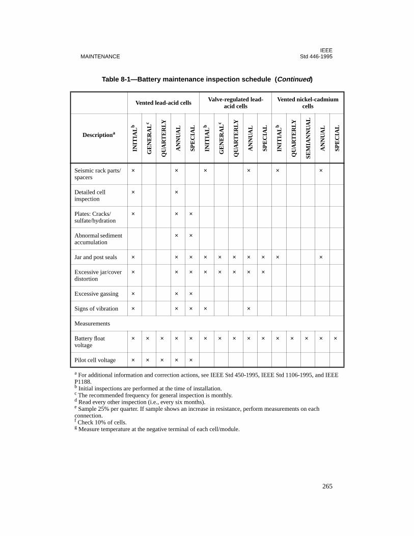
IEEEMAINTENANCE Std 446-1995
Ss
Di
Ps
Aa
J
Ed
E
S
M
Bv
P
a
P
b
c
d
e
c
f
g
eismic rack parts/pacers
× × × × × ×
etailed cell nspection
× ×
lates: Cracks/ulfate/hydration
× × ×
bnormal sediment ccumulation
× ×
ar and post seals × × × × × × × × × ×
xcessive jar/cover istortion
× × × × × × × ×
xcessive gassing × × ×
igns of vibration × × × × ×
easurements
attery float oltage
× × × × × × × × × × × × × × ×
ilot cell voltage × × × × ×
Table 8-1—Battery maintenance inspection schedule (Continued)
Vented lead-acid cells Valve-regulated lead-acid cells
Vented nickel-cadmium cells
DescriptionaIN
ITIA
Lb
GE
NE
RA
Lc
QU
AR
TE
RLY
AN
NU
AL
SPE
CIA
L
INIT
IAL
b
GE
NE
RA
Lc
QU
AR
TE
RLY
AN
NU
AL
SPE
CIA
L
INIT
IAL
b
QU
AR
TE
RLY
SEM
IAN
NU
AL
AN
NU
AL
SPE
CIA
L
For additional information and correction actions, see IEEE Std 450-1995, IEEE Std 1106-1995, and IEEE 1188. Initial inspections are performed at the time of installation. The recommended frequency for general inspection is monthly. Read every other inspection (i.e., every six months). Sample 25% per quarter. If sample shows an increase in resistance, perform measurements on each onnection. Check 10% of cells. Measure temperature at the negative terminal of each cell/module.
265

IEEEStd 446-1995 CHAPTER 8
Pet
Peg
Iv
Ieg
C
Icr
Ccr
Av
Ic
a
Pbcde
cfg
ilot cell lectrolyte emperature
× × × × × × × × × ×
ilot cell lectrolyte specific ravity
× × × × ×
ndividual cell oltage
× × × × × × d × × × × × ×
ndividual cell lectrolyte specific ravity
× × f × ×
ell temperature × × f × × ×
g × g ×
g × g
ntercell onnection esistance
× × × × e × ×
ell impedance/onductance/esistance
× × × ×
c ripple current/oltage
× × ×
ntercell onnection torque
× × ×
Table 8-1—Battery maintenance inspection schedule (Continued)
Vented lead-acid cells Valve-regulated lead-acid cells
Vented nickel-cadmium cells
DescriptionaIN
ITIA
Lb
GE
NE
RA
Lc
QU
AR
TE
RLY
AN
NU
AL
SPE
CIA
L
INIT
IAL
b
GE
NE
RA
Lc
QU
AR
TE
RLY
AN
NU
AL
SPE
CIA
L
INIT
IAL
b
QU
AR
TE
RLY
SEM
IAN
NU
AL
AN
NU
AL
SPE
CIA
L
For additional information and correction actions, see IEEE Std 450-1995, IEEE Std 1106-1995, and IEEE 1188. Initial inspections are performed at the time of installation. The recommended frequency for general inspection is monthly. Read every other inspection (i.e., every six months). Sample 25% per quarter. If sample shows an increase in resistance, perform measurements on each onnection. Check 10% of cells. Measure temperature at the negative terminal of each cell/module.
266
IEEEMAINTENANCE Std 446-1995
O
At
Vm
Ct
Ct
a
Pbcde
cfg
ther
mbient emperature
× × × × × × × × × × ×
entilation equip-ent adequacy
× × × × × × × × × × × × × × ×
heck/retorque bat-ery rack
× × ×
heck connections o ground
× × × × × ×
Table 8-1—Battery maintenance inspection schedule (Continued)
Vented lead-acid cells Valve-regulated lead-acid cells
Vented nickel-cadmium cells
DescriptionaIN
ITIA
Lb
GE
NE
RA
Lc
QU
AR
TE
RLY
AN
NU
AL
SPE
CIA
L
INIT
IAL
b
GE
NE
RA
Lc
QU
AR
TE
RLY
AN
NU
AL
SPE
CIA
L
INIT
IAL
b
QU
AR
TE
RLY
SEM
IAN
NU
AL
AN
NU
AL
SPE
CIA
L
For additional information and correction actions, see IEEE Std 450-1995, IEEE Std 1106-1995, and IEEE 1188. Initial inspections are performed at the time of installation. The recommended frequency for general inspection is monthly. Read every other inspection (i.e., every six months). Sample 25% per quarter. If sample shows an increase in resistance, perform measurements on each onnection. Check 10% of cells. Measure temperature at the negative terminal of each cell/module.
267

IEEEStd 446-1995 CHAPTER 8
Since much of the maintenance performed on a battery is done with the battery in service, thework methods used should follow the protective procedures outlined in the appropriate refer-ence listed in 8.9. In addition, these methods should preclude circuit interruption or arcing inthe vicinity of the battery. One of the reasons for this is that hydrogen is liberated from allvented-cell-type batteries while they are on float or equalize charge, or when they are nearingcompletion of a recharge. VRLA cells will also liberate hydrogen whenever their vent opens.Therefore, adequate ventilation by natural or mechanical means must be available to mini-mize hydrogen accumulation. Additionally, the battery area should be mandated as a “nosmoking” area.
8.7 Automatic transfer switches
Automatic transfer switches require maintenance, as do most components of electrical instal-lations. The automatic transfer switch is usually applied where two sources of power aremade available for the purpose of maintaining power to a critical load. The necessity of pro-viding safe maintenance and repair of an automatic transfer switch requires shutdown of bothpower sources or installation of a bypass switch. The bypass switch is used to isolate theautomatic transfer switch while maintaining power to the critical load. For periodic mainte-nance inspections where de-energization is impractical, a two-way bypass isolation switchcombined with an automatic transfer switch as part of UPS system can be provided. Althoughmore costly, this type of switch (covered in 4.3.10) allows for periodic testing and mainte-nance.
8.8 Conclusions
Maintenance is an essential requirement of any electrical installation. The critical nature ofemergency and standby power systems applications dictate the importance of properly main-taining the equipment involved. A good preventive maintenance program will aid in main-taining a reliable system.
8.9 References
This standard shall be used in conjunction with the following publications:
ANSI/NFPA 101-1994, Code for Safety to Life from Fire in Buildings and Structures.2
ANSI/NFPA 110-1993, Emergency and Standby Power Systems.
ANSI/NFPA 111-1993, Stored Electrical Energy Emergency and Standby Power Systems.
2NFPA publications are available from Publications Sales, National Fire Protection Association, 1 BatterymarchPark, P.O. Box 9101, Quincy, MA 02269-9101, USA.
268
IEEEMAINTENANCE Std 446-1995
IEEE Std 450-1995, IEEE Recommended Practice for Maintenance, Testing, and Replace-ment of Vented Lead-Acid Batteries for Stationary Applications.3
IEEE Std 484, IEEE Recommended Practice for the Installation Design and Installation ofLarge Lead Storage Batteries for Generating Stations and Substations.4
IEEE Std 1106-1995, IEEE Recommended Practice for Installation, Maintenance, Testing,and Replacement of Vented Nickel-Cadmium Batteries for Stationary Applications (ANSI).
IEEE Std 1187-1996, IEEE Recommended Practice for Installation Design and Installationof Valve-Regulated Lead-Acid Storage Batteries for Stationary Application.5
IEEE P1188, Draft Recommended Practice for Maintenance, Testing, and Replacement ofValve-Regulated Lead Acid Batteries for Stationary Applications, Oct. 1995.6
NFPA 70B-1994, Electrical Equipment Maintenance.
NFPA 70E-1995, Electrical Safety Requirements for Employee Work Places.
8.10 Bibliography
Additional information may be found in the following sources:
[B1] Demont, R. F., “Preventive Maintenance of Standby Generator Sets,” Electrical Con-struction and Maintenance Magazine, pt. 1, Mar. 1992; pt. 2, Apr. l992.
[B2] Feder, D. O., et al., “Field and Laboratory Studies to Assess the State of Health of Valve-Regulated Lead-Acid Batteries: Part I—Conductance/Capacity Correlation Studies.” in Con-ference Record 92CH3195-5, 1992 IEEE INTELEC Conference, pp. 218–233.
[B3] Gabriel, C. M., and Uhlir, K. W., “Battery Impedance—Single Cell Capacity Test Vs.Standard Every Cell Capacity Test,” in Proceedings of the American Power Conference,vol. 55-I, l993, pp. 38–43.
[B4] Harrison, A. I., “Thermal Management of High Energy Density Battery Equipments,” inConference Record 92CH3195-5, 1992 IEEE INTELEC Conference, pp. 28-34.
3IEEE publications are available from the Institute of Electrical and Electronics Engineers, 445 Hoes Lane, P.O. Box1331, Piscataway, NJ 08855-1331, USA.4IEEE Std 484 was conditionally approved at the March 1996 IEEE Standards Board meeting. It will be publishedafter the conditions are met. Copies of the draft standard are available from IEEE. Contact the IEEE StandardsDepartment at 1 (908) 562-3800 for status information.5As this standard goes to press, IEEE Std 1187-1996 is approved but not yet published. The draft standard is, how-ever, available from the IEEE. Anticipated publication date is June 1996. Contact the IEEE Standards Department at1 (908) 562-3800 for status information.6This authorized standards project was not approved by the IEEE Standards Board at the time this went to press. It isavailable from the IEEE Service Center.
269

IEEEStd 446-1995 CHAPTER 8
[B5] Markel, G. J., “AC Impedance Testing for Valve-Regulated Cells,” in Conference Record92CH3195-5, 1992 IEEE INTELEC Conference, pp. 212–217.
[B6] Migliaro, M. W., “Maintaining Stationary Batteries,” IEEE Transactions on IndustryApplications, vol. 1A-23, no. 4, pp. 765–772, Jul./Aug. l987.
[B7] Migliaro, M. W., “Maintaining Maintenance-Free Batteries,” in Conference Record89CH2738-3, 1989 IEEE IAS Industrial & Commercial Power Systems Conference, pp. 69–73.
[B8] Migliaro, M. W., “Stationary Batteries-Selected Topics,” in Proceedings of the AmericanPower Conference, vol. 55-1, pp. 23–33, l993.
[B9] Migliaro, M. W., and Mazzoni, O. S., “Battery Problems That Can Spell Disaster,”Disaster Avoidance & Recovery ‘93 Conference, May l993.
[B10] Misra, S. S., Noveske, T. M., and Williamson, A. W., “Thermal Effects in VRLA Cellsand Comparison with Wet Lead-Acid Cells Under Different Operating Conditions,” in Con-ference Record 92CH3195-5, l992 IEEE INTELEC Conference, pp. 35–40.
[B11] Soileau, R. D., Jr., A Diagnostic Testing Program for Large Lead-Acid Storage BatteryBanks, Conference Record 92-CH3186-4, IAS 39th Annual Petroleum and Chemical Indus-try Conference, pp. 27–35, Sept. l992.
[B12] Vaccarok, F. J., and Landwehrle, R. E., “Experiments on Thermal Run-A-Way and ItsManagement for Electrolyte Immobilized Lead-Acid Batteries,” in Conference Record91CH2970-2, 1991 IEEE INTELEC Conference, pp. 20–25.
270
Chapter 9Specific industry applications
9.1 General
This chapter summarizes needs for emergency or standby electric power observed in each ofseveral industries. Industries that have not demonstrated general need for such power are notlisted, although there is probably no industry that has not used standby power of some type atsome place or time. Even certain general uses of specific applications are ignored. Batterycontrol sources for electrical switchgear are not referenced since they are covered in IEEEC37.20-1969.1 Use of the common flashlight is not referenced unless the need for standbylighting is generally significant.
It is the intent of this chapter to catalog where standby power has been used, to point out howsuch power can serve to fulfill certain needs, and to provide some guidance in evaluating thedesirability of standby power. It is not the intent of this chapter to suggest or interpret legalrequirements for standby or emergency power. Such requirements, as may be included inbuilding or safety codes, are adopted and interpreted by authorities having jurisdiction oversuch matters. The significant reasons for adopting these requirements are far broader than theengineering considerations of the standby power system itself.
Needs for standby power appear to be growing as equipment and process complexities andcosts increase. As more industries find that standby power generally can be economically jus-tified, they will be added to the summaries.
It is sometimes difficult to establish the justification for standby power on an objective eco-nomic basis. Developing objective historical costing of power outages can be difficult, andprojecting costs can be more difficult. Data on power system outages are available in IEEEStd 493-1980, but local conditions of weather or utility service can result in performance atconsiderable variance with the standard data. Infrequency of outages in some locations tendsto restrict the data base and the accuracy of short-time predictions. Such data should be aug-mented with the user's and other local data. The American Insurance Association has adoptedthe National Building Code, which contains requirements for standby based upon types ofbuildings and occupancy classifications. Compliance with this code is encouraged throughadjustment of insurance rates.
Needs for standby power affecting human safety should not be evaluated purely on an eco-nomic basis. Standby power should be made available if there is a reasonable possibility thatloss of normal power could cause serious injury or loss of life. Emergency or standby powerhas been mandated by authorities in many situations, and such mandates will likely spread toother situations upon occurrence of injury or death.
1Information on references can be found in 9.2.
271

IEEEStd 446-1995 CHAPTER 9
Electrical standby power is not recommended as the correct or only solution to all problemsor hazards that result from loss of electrical power. There is risk that local electrical failurecould forestall use of the standby power. Alternate solutions may be attractive from both aneconomic and reliability standpoint. For example, cement plants often supply rotationalpower for the kiln from a mechanically coupled engine during power outages. While avoidingthe cost of a generator, this arrangement covers not only loss of utility power, but also thecontingencies of loss of in-plant distribution or failure of the electric kiln drive. Many juris-dictions also demand this type of drive as a standby for the electric drive on a chair lift.
Systems that are inherently safe will provide greater reliability than those dependent upon asource of electrical power to maintain safety. Designers are encouraged to produce systemsthat will assume a safe posture upon loss of electric power. Managers are encouraged toinvoke procedures that will avoid hazards when power is lost. In the case of a work force thatis required to carry flashlights, or a process controller with built-in battery backup, it may beargued whether they are inherently safe systems or whether they are examples of standbypower systems, but they are effective and economically attractive.
Standby power can more easily be justified if generators are also operated in the cogenerationmode. Cogeneration refers to obtaining a second form of energy from the generation process,usually heat, which increases the efficiency in the use of energy as well as the economics ofthe operation. By maintaining certain efficiencies and utilizations, a generator operator maybecome a qualifying facility under the auspices of PURPA (Public Utilities Regulatory Act of1978), which will allow them to operate in parallel with the utility. Parallel operation nor-mally increases the economic benefit to be derived from the generators, while allowing no-break standby power. Qualifying facility status can make the generator operator eligible forcertain tax benefits. With proper design and certain relaying and control additions, the basiccogeneration system can provide standby power, and this is commonly done.
Tables 9-1 through 9-10 itemize emergency and standby power needs that are at least some-what specific to the designated industry. There may be needs that are common to many indus-tries, but these are listed only once, under the industry with which they are most commonlyassociated. For instance, most industries have offices or occupancies to which the items intable 9-3 (commercial buildings) would apply. Most industries have some form of data pro-cessing, usually with some power supply needs. For larger data-processing installations, referto table 9-5 (financial data processing).
Process controllers are proliferating throughout industry, but the tables are intended toaddress the electrical needs of the process itself rather than the controller. The considerationof supplying power to a controller to prevent malfunction, damage, or loss of data is commonto all industries.
272
IEEESPECIFIC INDUSTRY APPLICATIONS Std 446-1995
NOTES TO TABLES 9-1 THROUGH 9-10:
NOTE A: Categories of purposes for emergency or standby power
1—Human safety and health. This includes preventing injury or death from causes such as falling,collisions, equipment operations or malfunctions, explosions, fire, release of toxic or explosivesubstances, failure of safety of life supporting devices, and actions of others. Emergency poweruses include signaling, lighting, conveyances for evacuation, control of machinery, combatingfire, and smoke or vapor dispersal.
2—Environmental protection. This includes prevention of damage to environment (temporary or per-manent), which includes effects on water quality, wildlife, or vegetation that do not immediatelyor significantly threaten human life or health.
3—Nonemergency evacuation. This covers requirements of evacuation for convenience or for pre-cautionary reasons where no immediate danger or urgency exists, and can include lighting andconveyances.
4—Protection of equipment, product, material, and property. This covers needs for orderly shut-down, limited operation or security, lack of which could result in economic loss due to repair orreplacement costs or unavailability of equipment or material.
5—Continuance of partial or full production. This covers needs where cessation of production couldresult in inordinate economic loss due to extended restart times or requirements of timely productdelivery.
NOTE B: Categories to types of standby or emergency power required
1—Uninterruptible ac power. Specially conditioned.2—Uninterruptible ac power. Suitable for computer use (see 3.11.3 for guidelines to computer
power requirements).3—Interruptible ac power. Specially conditioned to eliminate sags, spikes, flicker, harmonics, or
noise such as could be achieved with static or rotating power conditioner. Required for poweringequipment with no inherent immunity to these power system defects.
4—Interruptible ac power. Commercial grade such as defined by ANSI C84.1-1989 or ANSI/NEMAMG 1-1993 motor requirements. Suitable for equipment satisfactorily powered from conventionalutility source. Range of tolerable outage time to dictate whether fixed or portable, automatic ornonautomatic.
5—Permanently installed dc power maintained at full capability. Includes emergency lightingsources and internal or external battery backup for communications, computers, and processors.
6—Portable dc power. Includes power sources in flashlight, lanterns, and portable communicatingdevices, either installed or spare.
273
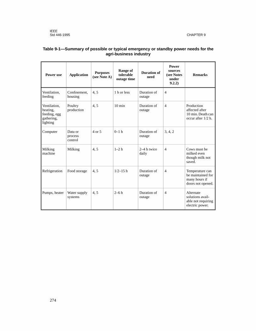
IEEEStd 446-1995 CHAPTER 9
Ta e
P
Venfee
Venheafeegatligh
an .
Co
Mima
Re r
d.
Pum
g
ble 9-1—Summary of possible or typical emergency or standby power needs for thagri-business industry
ower use Application Purposes (see Note A)
Range of tolerable
outage time
Duration of need
Power sources
(see Notes under 9.2.2)
Remarks
tilation, ding
Confinement, housing
4, 5 1 h or less Duration of outage
4
tilation, ting, ding, egg hering, ting
Poultry production
4, 5 10 min Duration of outage
4 Production affected after 10 min. Death coccur after 1/2 h
mputer Data or process control
4 or 5 0–1 h Duration of outage
3, 4, 2
lking chine
Milking 4, 5 1–2 h 2–4 h twice daily
4 Cows must be milked even though milk notsaved.
frigeration Food storage 4, 5 1/2–15 h Duration of outage
4 Temperature canbe maintained fomany hours if doors not opene
ps, heater Water supply systems
4, 5 2–6 h Duration of outage
4 Alternate solutions avail-able not requirinelectric power.
274
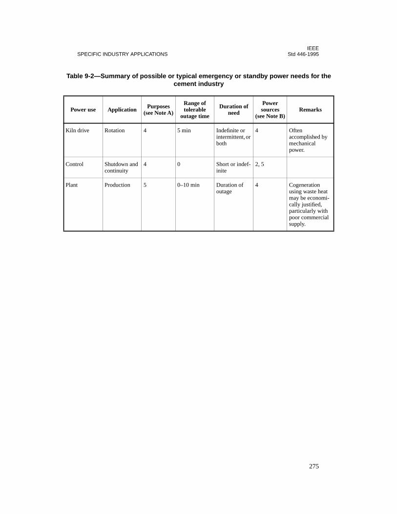
IEEESPECIFIC INDUSTRY APPLICATIONS Std 446-1995
Ta e
P
Kil
Co
Plat i-
l
ble 9-2—Summary of possible or typical emergency or standby power needs for thcement industry
ower use Application Purposes (see Note A)
Range of tolerable
outage time
Duration of need
Power sources
(see Note B)Remarks
n drive Rotation 4 5 min Indefinite or intermittent, or both
4 Often accomplished bymechanical power.
ntrol Shutdown and continuity
4 0 Short or indef-inite
2, 5
nt Production 5 0–10 min Duration of outage
4 Cogeneration using waste heamay be economcally justified, particularly withpoor commerciasupply.
275
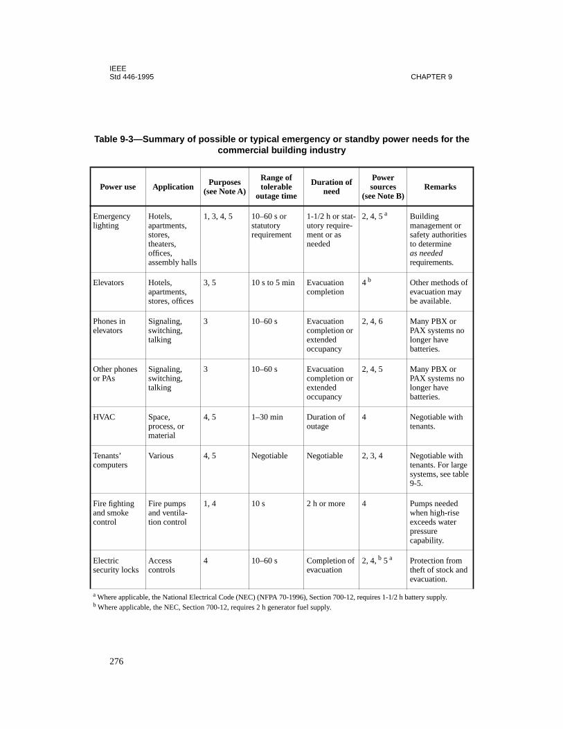
IEEEStd 446-1995 CHAPTER 9
Ta e
P
Emligh
s
Ele
f
Phoele
Othor P
HV
Tencom
e le
Firandcon
Elesec
d
a
W
b
W
ble 9-3—Summary of possible or typical emergency or standby power needs for thcommercial building industry
ower use Application Purposes (see Note A)
Range of tolerable
outage time
Duration of need
Power sources
(see Note B)Remarks
ergency ting
Hotels,apartments, stores, theaters, offices, assembly halls
1, 3, 4, 5 10–60 s or statutory requirement
1-1/2 h or stat-utory require-ment or as needed
2, 4, 5 a Building management or safety authoritieto determine as needed requirements.
vators Hotels, apartments, stores, offices
3, 5 10 s to 5 min Evacuation completion
4 b Other methods oevacuation maybe available.
nes in vators
Signaling, switching, talking
3 10–60 s Evacuation completion or extended occupancy
2, 4, 6 Many PBX or PAX systems nolonger have batteries.
er phones As
Signaling, switching, talking
3 10–60 s Evacuation completion or extended occupancy
2, 4, 5 Many PBX or PAX systems nolonger have batteries.
AC Space, process, or material
4, 5 1–30 min Duration of outage
4 Negotiable withtenants.
ants’ puters
Various 4, 5 Negotiable Negotiable 2, 3, 4 Negotiable withtenants. For largsystems, see tab9-5.
e fighting smoke trol
Fire pumps and ventila-tion control
1, 4 10 s 2 h or more 4 Pumps needed when high-rise exceeds water pressure capability.
ctric urity locks
Access controls
4 10–60 s Completion of evacuation
2, 4, b 5 a Protection fromtheft of stock anevacuation.
here applicable, the National Electrical Code (NEC) (NFPA 70-1996), Section 700-12, requires 1-1/2 h battery supply.here applicable, the NEC, Section 700-12, requires 2 h generator fuel supply.
276
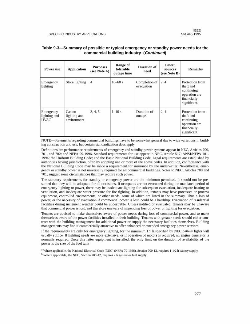
IEEESPECIFIC INDUSTRY APPLICATIONS Std 446-1995
Emligh
EmlighHV
NO ld-ing
De 0,701 1-199 byaut iththe er-gen nd701
Th re-sum ofem orven ssequ ofpow ialfac retha
Ten kethe n-trac ngma
If t illusu isnor hepow
Ta e
P
a
W
b
W
ergency ting
Store lighting 4 10–60 s Completion of evacuation
2, 4 Protection fromtheft and continuing operation are financially significant.
ergency ting and AC
Casino lighting and environment
3, 4, 5 1–10 s Duration of outage
2, 4 Protection fromtheft and continuing operation are financially significant.
TE—Statements regarding commercial buildings have to be somewhat general due to wide variations in bui construction and use, but certain standardization does apply.
finitions are performance requirements of emergency and standby power systems appear in NEC, Articles 70, and 702; and NFPA 99-1996. Standard requirements for use appear in NEC, Article 517; ANSI/NFPA 104; the Uniform Building Code; and the Basic National Building Code. Legal requirements are established
horities having jurisdiction, often by adopting one or more of the above codes. In addition, conformance w National Building Code may be made a requirement for insurance by the underwriter. Nevertheless, emcy or standby power is not universally required for all commercial buildings. Notes to NEC, Articles 700 a, suggest some circumstances that may require such power.
e statutory requirements for standby or emergency power are the minimum permitted. It should not be ped that they will be adequate for all occasions. If occupants are not evacuated during the mandated period
ergency lighting or power, there may be inadequate lighting for subsequent evacuation, inadequate heating tilation, and inadequate water pressure for fire fighting. In addition, tenants may have processes or proceipment, controlled environments, or other needs, some of which are listed in the summary. Thus a loss er, or the necessity of evacuation if commercial power is lost, could be a hardship. Evacuation of resident
ilities during inclement weather could be undesirable. Unless notified or evacuated, tenants may be unawat commercial power is lost, and therefore unaware of impending loss of power or lighting for evacuation.
ants are advised to make themselves aware of power needs during loss of commercial power, and to mamselves aware of the power facilities installed in their building. Tenants with greater needs should either cot with the building management for additional power or supply the necessary facilities themselves. Buildi
nagements may find it commercially attractive to offer enhanced or extended emergency power services.
he requirements are only for emergency lighting, for the minimum 1.5 h specified by NEC battery lights wally suffice. If lighting needs are more extensive, or if operation of motors is required, an engine generatormally required. Once this latter equipment is installed, the only limit on the duration of availability of ter is the size of the fuel tank
ble 9-3—Summary of possible or typical emergency or standby power needs for thcommercial building industry (Continued)
ower use Application Purposes (see Note A)
Range of tolerable
outage time
Duration of need
Power sources
(see Note B)Remarks
here applicable, the National Electrical Code (NEC) (NFPA 70-1996), Section 700-12, requires 1-1/2 h battery supply.here applicable, the NEC, Section 700-12, requires 2 h generator fuel supply.
277
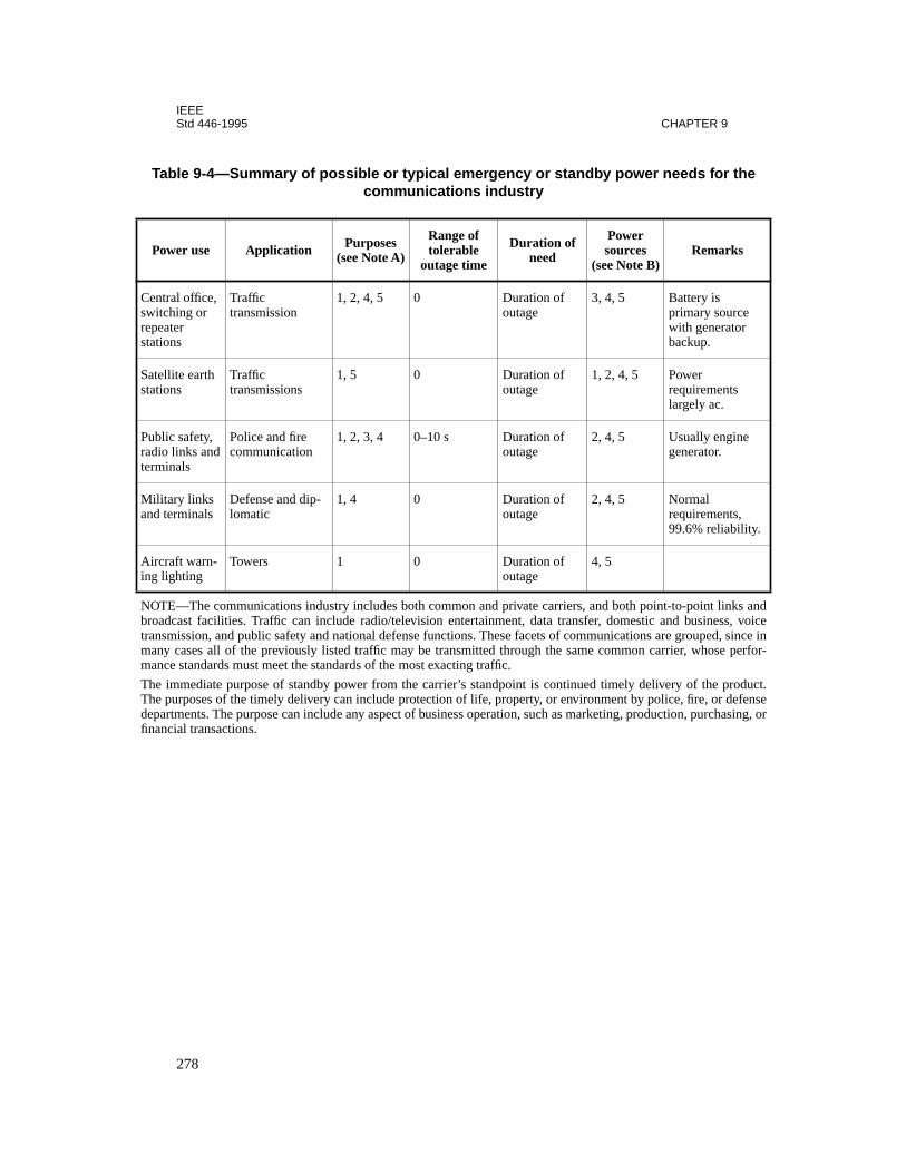
IEEEStd 446-1995 CHAPTER 9
Ta e
Po
Centswitcrepeastatio
e
Satelstatio
Publradioterm
e
Militand t
ity.
Aircring l
NOT andbroad oicetrans e inmany for-manc
The uct.The ensedepa , orfinan
ble 9-4—Summary of possible or typical emergency or standby power needs for thcommunications industry
wer use Application Purposes (see Note A)
Range of tolerable
outage time
Duration of need
Power sources
(see Note B)Remarks
ral office, hing or ter ns
Traffic transmission
1, 2, 4, 5 0 Duration of outage
3, 4, 5 Battery is primary sourcwith generatorbackup.
lite earth ns
Traffic transmissions
1, 5 0 Duration of outage
1, 2, 4, 5 Power requirements largely ac.
ic safety, links andinals
Police and fire communication
1, 2, 3, 4 0–10 s Duration of outage
2, 4, 5 Usually engingenerator.
ary links erminals
Defense and dip-lomatic
1, 4 0 Duration of outage
2, 4, 5 Normal requirements, 99.6% reliabil
aft warn-ighting
Towers 1 0 Duration of outage
4, 5
E—The communications industry includes both common and private carriers, and both point-to-point linkscast facilities. Traffic can include radio/television entertainment, data transfer, domestic and business, v
mission, and public safety and national defense functions. These facets of communications are grouped, sinc cases all of the previously listed traffic may be transmitted through the same common carrier, whose pere standards must meet the standards of the most exacting traffic.
immediate purpose of standby power from the carrier’s standpoint is continued timely delivery of the prodpurposes of the timely delivery can include protection of life, property, or environment by police, fire, or defrtments. The purpose can include any aspect of business operation, such as marketing, production, purchasingcial transactions.
278
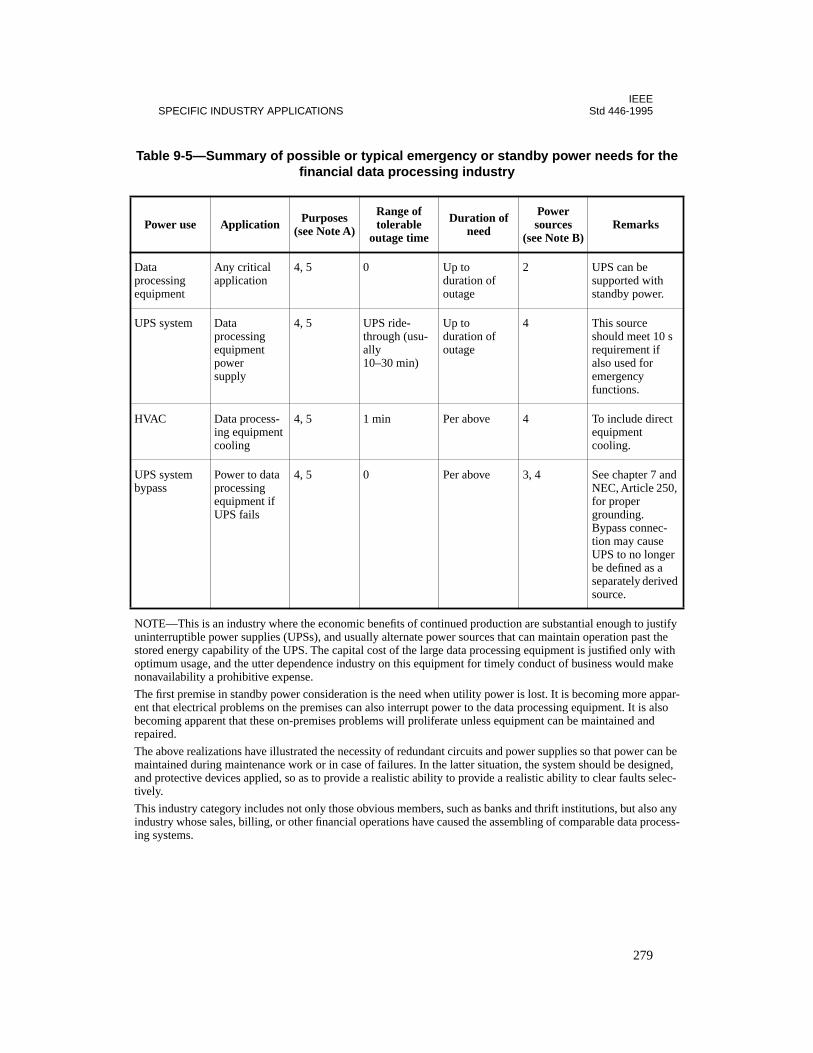
IEEESPECIFIC INDUSTRY APPLICATIONS Std 446-1995
Ta e
P
Daproequ
UPs
HV t
UPbyp
d 0,
r
ed
NO fy uni sto h opt e non
Th ar-ent becrep
Th e ma , and c-tive
Th y ind ss-ing
ble 9-5—Summary of possible or typical emergency or standby power needs for thfinancial data processing industry
ower use Application Purposes (see Note A)
Range of tolerable
outage time
Duration of need
Power sources
(see Note B)Remarks
tacessing ipment
Any critical application
4, 5 0 Up to duration of outage
2 UPS can be supported with standby power.
S system Data processing equipment power supply
4, 5 UPS ride-through (usu-ally 10–30 min)
Up to duration of outage
4 This source should meet 10 requirement if also used for emergency functions.
AC Data process-ing equipment cooling
4, 5 1 min Per above 4 To include direcequipment cooling.
S system ass
Power to data processing equipment if UPS fails
4, 5 0 Per above 3, 4 See chapter 7 anNEC, Article 25for proper grounding. Bypass connec-tion may cause UPS to no longebe defined as a separately derivsource.
TE—This is an industry where the economic benefits of continued production are substantial enough to justinterruptible power supplies (UPSs), and usually alternate power sources that can maintain operation past thered energy capability of the UPS. The capital cost of the large data processing equipment is justified only witimum usage, and the utter dependence industry on this equipment for timely conduct of business would makavailability a prohibitive expense.
e first premise in standby power consideration is the need when utility power is lost. It is becoming more app that electrical problems on the premises can also interrupt power to the data processing equipment. It is alsooming apparent that these on-premises problems will proliferate unless equipment can be maintained and aired.
e above realizations have illustrated the necessity of redundant circuits and power supplies so that power can bintained during maintenance work or in case of failures. In the latter situation, the system should be designed protective devices applied, so as to provide a realistic ability to provide a realistic ability to clear faults selely.
is industry category includes not only those obvious members, such as banks and thrift institutions, but also anustry whose sales, billing, or other financial operations have caused the assembling of comparable data proce systems.
279
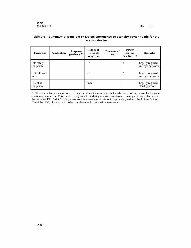
IEEEStd 446-1995 CHAPTER 9
Ta e
P
Lifequ
er.
Crime
er.
Essequ
NO s-erv s the d 700
ble 9-6—Summary of possible or typical emergency or standby power needs for thhealth industry
ower use Application Purposes (see Note A)
Range of tolerable
outage time
Duration of need
Power sources
(see Note B)Remarks
e safety ipment
10 s 4 Legally requiredemergency pow
tical equip-nt
10 s 4 Legally requiredemergency pow
ential ipment
1 min Legally requiredstandby power.
TE—These facilities have some of the greatest and the most regulated needs for emergency power for the preation of human life. This chapter recognizes this industry as a significant user of emergency power, but refer reader to IEEE Std 602-1996, where complete coverage of this topic is provided, and also the Articles 517 an of the NEC, plus any local codes or ordinances for detailed requirements.
280

IEEESPECIFIC INDUSTRY APPLICATIONS Std 446-1995
Ta e
P
Ho
e e
Fan
e e
Pum
e e
ble 9-7—Summary of possible or typical emergency or standby power needs for thmining industry
ower use Application Purposes (see Note A)
Range of tolerable
outage time
Duration of need
Power sources
(see Note B)Remarks
ists Personnel 3 1–10 min ± 1 h 4 Requirements vary greatly between sites; safety-related requirements arcovered under thCFR, Title 30.
s Ventilation 1 1 min 1 h or more 4 Requirements vary greatly between sites; safety-related requirements arcovered under thCFR, Title 30.
ps Drainage 1, 4 1–60 min Indefinite 4 Requirements vary greatly between sites; safety-related requirements arcovered under thCFR, Title 30.
281
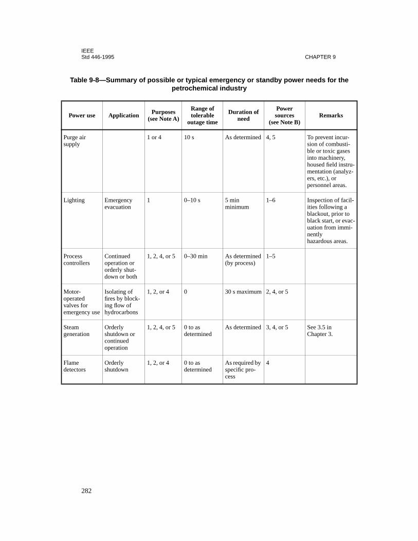
IEEEStd 446-1995 CHAPTER 9
Ta e
Pow
Purgesuppl
r-ti-es , stru-lyz-
s.
Light acil- a to vac-mi-
s.
Procecontr
Motooperavalveemerg
Steamgener
Flamdetec
ble 9-8—Summary of possible or typical emergency or standby power needs for thpetrochemical industry
er use Application Purposes (see Note A)
Range of tolerable
outage time
Duration of need
Power sources
(see Note B)Remarks
air y
1 or 4 10 s As determined 4, 5 To prevent incusion of combusble or toxic gasinto machineryhoused field inmentation (anaers, etc.), or personnel area
ing Emergency evacuation
1 0–10 s 5 min minimum
1–6 Inspection of fities followingblackout, priorblack start, or euation from imnently hazardous area
ss ollers
Continued operation or orderly shut-down or both
1, 2, 4, or 5 0–30 min As determined(by process)
1–5
r-ted s for ency use
Isolating of fires by block-ing flow of hydrocarbons
1, 2, or 4 0 30 s maximum 2, 4, or 5
ationOrderly shutdown or continued operation
1, 2, 4, or 5 0 to as determined
As determined 3, 4, or 5 See 3.5 in Chapter 3.
e tors
Orderly shutdown
1, 2, or 4 0 to as determined
As required by specific pro-cess
4
282
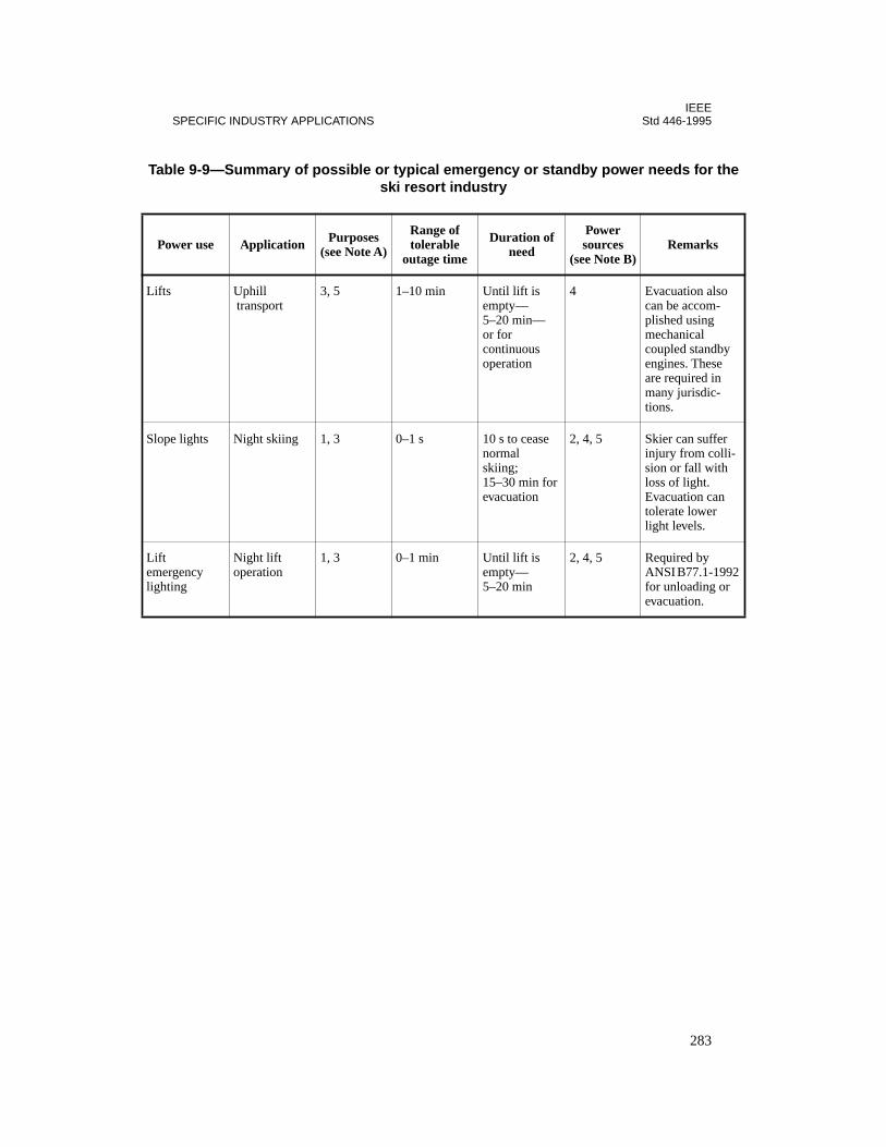
IEEESPECIFIC INDUSTRY APPLICATIONS Std 446-1995
Ta e
P
Lif
Slo i-
Lifemligh
2
ble 9-9—Summary of possible or typical emergency or standby power needs for thski resort industry
ower use Application Purposes (see Note A)
Range of tolerable
outage time
Duration of need
Power sources
(see Note B)Remarks
ts Uphill transport
3, 5 1–10 min Until lift is empty—5–20 min—or for continuous operation
4 Evacuation alsocan be accom-plished using mechanicalcoupled standbyengines. These are required in many jurisdic-tions.
pe lights Night skiing 1, 3 0–1 s 10 s to cease normal skiing; 15–30 min for evacuation
2, 4, 5 Skier can sufferinjury from collsion or fall withloss of light. Evacuation can tolerate lower light levels.
t ergencyting
Night lift operation
1, 3 0–1 min Until lift is empty—5–20 min
2, 4, 5 Required by ANSI B77.1-199for unloading orevacuation.
283

IEEEStd 446-1995 CHAPTER 9
Tab e
P
Pum
Protro
Tel al
y
NO
Fac ldreq es,and lepub ofcou ss-ing
Mi veach
Co usloc
le 9-10—Summary of possible or typical emergency or standby power needs for thwaste water industry
ower use Application Purposes (see Note A)
Range of tolerable
outage time
Duration of need
Power sources
(see Note B)Remarks
ps Influence, effluence, or processing of waste water
2, 4, 5 0–10 min Duration of outage
4 EPA or local statues, or both,define bypassingrestrictions.
cess con-llers
2, 4, 5 0–10 min Duration of outage
1, 2, 3, 4, 5 To meet above requirements.
ephones Signaling and talking
2, 4, 5 0–1 min Duration of outage
2, 4, 5 The geographicdispersion in thetypical facility requires a facilitcommunication system.
TES—Local power generation sometimes accomplished with digestor gas.
ilities are closely regulated and individually permitted under federal clean water laws. Loss of power couuire gravity bypassing of processes that require pumping. These processes may exceed permitted allowanc in no case is complete bypass allowed. Even permitted abnormal operation may receive extensive unfavorablicity and may be unacceptable to local citizens. Lack of adequate gravity bypass capability or control thereld cause flooding. It is usually necessary to maintain level, flow, and temperature monitors to oversee bypa or other contingency operations.
nimum standby power should be whatever is necessary to meet permit requirements. Many plants haieved 100% standby capability through the use of digestor gas to operate generators.
mmunication should be maintained to coordinate efforts involving manual control or monitoring at varioations. Many modern PBX systems depend upon commercial power for operation.
284
IEEESPECIFIC INDUSTRY APPLICATIONS Std 446-1995
9.2 References
This chapter shall be used in conjunction with the following publications:
ANSI B77.1-1992, American National Standard Safety Requirements for Passenger Tram-ways—Aerial Tramways, Aerial Lifts, Surface Lifts, and Tows.2
ANSI C84.1-1989, American National Standard Voltage Ratings for Electric Power Systemsand Equipment (60 Hz).
ANSI/NEMA MG 1-1993, Motors and Generators.3
ANSI/NFPA 101-1994, Code for Safety to Life from Fire in Buildings and Structures.4
IEEE Std C37.20.1-1993, IEEE Standard for Metal-Enclosed Low-Voltage Power CircuitBreaker Switchgear.5
IEEE Std C37.20.2-1993, IEEE Standard for Metal-Clad and Station-Type Cubicle Switch-gear.
IEEE Std C37.20.2b-1994, Supplement to IEEE Standard for Metal-Clad and Station-TypeCubicle Switchgear: Current Transformer Accuracies.
IEEE Std C37.20.3-1987 (Reaff 1992), IEEE Standard for Metal-Enclosed InterrupterSwitchgear (ANSI).
IEEE Std 493-1990, IEEE Recommended Practice for Design of Reliable Industrial andCommercial Power Systems (IEEE Gold Book) (ANSI).
IEEE Std 602-1996, IEEE Recommended Practice for Electric Systems in Health Care Facil-ities (IEEE White Book) (ANSI).6
NFPA 70-1996, National Electrical Code®.
NFPA 99-1996, Health Care Facilities Code.
2ANSI publications are available from the Sales Department, American National Standards Institute, 11 West 42ndStreet, 13th Floor, New York, NY 10036, USA.3NEMA publications are available from the Sales Department, American National Standards Institute, 11 West 42ndStreet, 13th Floor, New York, NY 10036, USA.4NFPA publications are available from Publications Sales, National Fire Protection Association, 1 BatterymarchPark, P.O. Box 9101, Quincy, MA 02269-9101, USA.5IEEE publications are available from the Institute of Electrical and Electronics Engineers, 445 Hoes Lane, P.O. Box1331, Piscataway, NJ 08855-1331, USA.6As this standard goes to press, IEEE Std 602-1996 is approved but not yet published. The draft standard is, however,available from the IEEE. Anticipated publication date is December 1996. Contact the IEEE Standards Department at1 (908) 562-3800 for status information.
285
IEEEStd 446-1995 CHAPTER 9
Basic National Building Code, Building Officials and Code Administrators (BOCA Interna-tional, Inc.).7
CFR (Code of Federal Regulations), Title 30: Mineral Resources (pts. 1–199), Mine Safetyand Health Administration, Department of Labor, July 1986.8
National Building Code, American Insurance Association.9
Uniform Building Code, International Congress of Building Officials.10
7This publication is available from BOCA International, Inc., 4051 West Flossmoor Road, Country Club Hills, IL60477-5795.8This document is available from the Superintendent of Documents, U.S. Government Printing Office, Washington,DC 20402.9This publication is available from the Publications Department, American Insurance Association, 85 John St., NewYork, NY 10038.10This publication is available from the International Conference of Building Officials, South Workman Mill Rd.,Whittier, CA 90601.
286
Chapter 10Design and operation considerations for improving the reliability of emergency power systems
10.1 Introduction
There are numerous factors that contribute to the reliability of standby and emergency powersystems. Many of these factors have been examined in the previous chapters of this standard.
Reliability, while frequently not a quantifiable value, is dependent on availability. The follow-ing definition of reliability reflects this dependence: The lack of unscheduled loss of avail-ability. There are two quantifiable terms that are used to define reliability:
— Mean time between failures (MTBF)— Mean time to repair after a failure (MTTR)
The common denominator for both of the above terms is time. By increasing MTBF and/orreducing MTTR, the system will obtain a higher availability due to reduced unscheduled sys-tem or component failures. This is greater reliability.
This chapter does not deal with rigorous analytical methods for improving reliability. IEEEStd 493-19901 should be consulted for an excellent detailed treatment of these methods.Although it is not the intent of this chapter to duplicate the information in IEEE Std 493-1990, some factors and concerns relating to reliability are addressed herein that should beconsidered by designers and users of standby and emergency systems in the application anduse of these systems. The information presented in this chapter is specifically geared towardsimproving the time factors in the two reliability terms discussed above, MTBF and MTTR.
The factors that will be examined in this chapter are the following:
— Applications— Environmental concerns— Specification and acceptance testing— Maintenance and training— Failure modes— Management awareness
10.2 Applications
The most basic factor that applies to the reliability of standby and emergency power systemsis its application. Incorrect application of equipment will, sooner or later, lead to poor systemreliability.
1Information on references can be found in 10.9.
287

IEEEStd 446-1995 CHAPTER 10
The designer should discuss with the user the function the system is expected to perform.Designing a reliable system requires that all of the following questions be considered in rela-tion to its function.
— What is user experience with specific types of equipment?
— What are possible locations for the equipment?
— What is the load profile and types of load the system must supply?
— What are the applicable codes and standards that will apply to the system, includinglocal codes and insurance requirements, if any?
— What is current system configuration and existing margin within the system?
— Does the system impact a utility company? What are the utility company require-ments that may exist?
— How will the system be used?
— Has a short-circuit study of the existing and proposed system been performed? Whatare the results?
— Has a protective coordination study of the proposed system been performed?
— Has the designer verified that all components of the proposed system are compatiblewith each other and the existing system? Specifically, are UPS and engine generatorsets compatible? Solid-state UPS systems draw harmonic currents that can interferewith generator controls. In other cases, the generator may not be able to supply therequired harmonics causing the UPS to malfunction.
— Have transient conditions been evaluated? Specifically, are there step loads on genera-tors? Can the generator set safely handle this load? Have inrush currents from UPSsystems and motor starts and their impact on the system been evaluated?
— What level of redundancy is required?
— What staff operating and maintenance skills are available?
In addition to considering these questions, the designer must also completely define total sys-tem performance requirements. The designer should not fall into the trap of expediency bysimply adding a uninterruptible power supply (UPS) system or a diesel generator. For exam-ple, a mainframe computer generally requires substantial cooling to keep operating. A designthat addresses only the power supply to the computer without addressing required supportsystems will lead to an unreliable design. Typically, the computer will shut down from over-heat in about 15 min. Batteries that operate only the computer are useless at this point.
The proliferation of personal computers and application software has lead to an abundance ofdesign tools. Applications programs now make it possible to fully model system perfor-mance, generator loading, transients, battery discharge, and other characteristics associatedwith standby systems. Full advantage should be taken of these during the design phase.
Designers of standby systems should also be aware of specific products that are available aswell as industry trends and topics.
288

IEEEIMPROVING THE RELIABILITY OF EMERGENCY POWER SYSTEMS Std 446-1995
10.3 Environmental concerns
Of significant concern to both the designer and user of standby and emergency systems is theoverall system environment. When equipment is not compatible with its operating environ-ment, both MTBF and MTTR will suffer. There are a number of questions and concerns thatneed to be addressed that can all fall under the broad heading of environmental concerns.
The first of these might be, “What technology am I introducing into this facility?” The skilleddesign engineer is familiar and comfortable with many available technologies. However, doesthe end user have personnel that can adapt to the equipment? The system must be designed tofit the personality of the user. In addition, the abilities of the user/operators need to be fac-tored into the design. If a new technology can be assimilated by the user, then it should by allmeans be used. If, however, assimilation poses a problem, then the equipment will mostlikely fall into disrepair and not be available when needed most. Further, a lack of under-standing may mean that abuse, with its subsequent high maintenance costs, may make thenew technology a poor investment.
Additional questions relative to the work rules within the facility should be asked. Who willbe in control of the system? How will maintenance and operation be handled? These do notfrequently pose significant problems; however, do they in this facility? The answers to thesequestions should always be determined before a new system is introduced into the workplace.Answers to these questions will aid in the ultimate design of a reliable system.
Another environmental concern is the physical surroundings of the equipment. There are spe-cific precautions that must be taken for dirty, hot, cold, corrosive, explosive, tropical, andother environments. An engine generator set in a cold climate, for example, will probablyrequire thermostatically controlled lubricating oil, coolant heaters, and radiator louvers. Foradvice on specific environmental requirements, such as the previous example, the equipmentmanufacturer should be consulted. All equipment manufacturers have requirements for tem-perature extremes, humidity, ventilation, etc., that need to be included in the design in orderfor their equipment to give satisfactory performance.
It is incumbent upon the design engineer to obtain all pertinent physical, electrical, and envi-ronmental recommendations and data from the manufacturer. These need to be properlyaddressed in the initial design of the facility for design of adequate support systems. For ret-rofits into existing facilities, these data need to be examined in detail to verify that an ade-quate environment will exist. If modifications need to be made, they should be identifiedearly and factored into the economic analysis of the system. It is possible that these modifica-tions may dictate the use of alternate technology or solutions.
As an example, the designer should obtain approximate weights of the proposed equipment.Batteries, chargers, inverters, generator sets, and other typical standby pieces of equipmentcan be quite heavy. The floor and structure should be checked to ensure that the new systemwill not cause structural problems. Required modifications should be planned ahead of timeand factored into the project.
289

IEEEStd 446-1995 CHAPTER 10
The designer also needs to determine approximate fuel consumption and requirements foradequate sizing of day tanks and storage tanks.
The design engineer should also consult applicable codes such as the National ElectricalCode (NEC) (NFPA 70-1996), Code for Safety to Life from Fire in Buildings and Structures(ANSI/NFPA 101-1994), national fire codes, OSHA, etc. Is adequate space and lightingavailable for routine maintenance activities? Can the equipment be removed for replacementor major overhaul activities? Will the overhead steel support chain falls for the positioning ofheavy items such as batteries? Will future modifications close off access to the equipment?
For engine generators, consideration should be given to either an overhead crane (large instal-lations) or provisions for a portable crane (small installations). There should also be a way toremove and install large components from the building during major maintenance activities.
The designer should ask how maintenance will be performed. If provisions for maintenanceactivities are made by the designer ahead of time, the process can proceed smoothly when itoccurs. As examples of problems that can occur when maintenance is not provided for, anautomatic transfer switch without a maintenance bypass will probably require a system out-age, with associated high costs, for routine maintenance, and an engine generator without an“auto-start lockout” can create a safety hazard during maintenance.
10.4 Specification and acceptance testing
The design engineer, having fully evaluated both the intended application and the operatingenvironment, must now take great pains to specify the equipment that is needed for the appli-cation and must ensure that all of the considerations have been accounted for. The engineershould avoid the use of “typical” manufacturer specifications for custom-engineered and pro-cured equipment. Specification and acceptance testing is crucial for the installation to be areliable system.
The design engineer should insist on review and approval of all shop drawings, test reports,and documentation. Engineering approval should be required prior to manufacture or assem-bly of the equipment.
The design engineer must also specify the required shop tests that are to be done before theequipment is released for delivery. Reliance upon standard manufacturer tests and methods isfrequently not enough for these systems. The design engineer should not be hesitant torequest that all features specified are to be tested and verified before equipment is releasedfrom the factory. Consideration should be given to having the following tests made:
— Running all load tests at rated power factor and not on a pure resistive load.
— Using oscillographs on transfer switches to see if transfers are “bumpless.”
— Having all equipment intended to be run together at the facility be run together at thefactory before release. This is of particular importance on engineered systems.
290
IEEEIMPROVING THE RELIABILITY OF EMERGENCY POWER SYSTEMS Std 446-1995
— Requiring that all test running times be sufficient to test for heating, overheating, fuelsupply, and the several load transfer steps, including transfer back to normal opera-tion.
The following steps are suggestions for the testing process of a UPS system that uses leadacid batteries. These test steps are to be performed after final assembly and quality control(including all normal factory tests) are completed:
a) Add blocks of load in 25% increments at specified power factor and observe outputwave form, voltage regulation, and voltage transients. These readings shall berecorded and transmitted to purchaser prior to shipment.
b) Using the static switch (by manual activation), transfer at no load and full load (atrated power factor) from the inverter to standby and then retransfer. All disturbancesoutside of specification limits shall be corrected, and this test shall be reperformed.
c) Operate the system (exclusive of battery and temporary testing dc power supply) atan elevated temperature of 40 °C for a period of 24 h under various load conditionswith the following conditions:
1) Minimum to maximum dc voltage: minimum = 1.75 V × number of cells: maxi-mum = 2.30 V × number of cells
2) Overcurrent limit (transfer and retransfer)
3) Automatic operation of static switch including transfer and retransfer at variousload conditions a minimum of 24 times
It is strongly recommended that the specifier, or a technically competent substitute, witnessall factory tests. Equipment should not be shipped until all tests are witnessed and satisfac-tory completion of the tests have been verified. This is of prime importance for custom-builtequipment. Witnessed testing may not be practical for all items that go on the system; a bal-ance between the cost of witnessed tests and the cost of site rework needs to be found. Themore difficult or expensive to rework an item after leaving the manufacturer, the more desir-able testing becomes.
The specifications should name the specifier as the final party in technical interpretations ofspecifications or contracts. Contract administrators and purchasing agents can and shouldhandle the legal side of the purchase; but they should not interfere with the technical aspectsof the purchase.
Another area of testing to consider in this process is the overall reliability of the system. If theuser requires that the system has a given overall success rate, a single test will not be a statis-tically valid test to verify this requirement. For this requirement, a series of tests will need tobe run. The test number will need to constitute a statistically valid population. The test (num-ber of tests and allowable failures) will also need to be constructed in such a manner to mini-mize the chances of both statistical errors of type I (rejecting a good system) and type II(accepting a bad system). Koval 1990 [B3]2 is recommended as a guide in this endeavor.
2The numbers in brackets preceded by the letter B correspond to those of the bibliography in 10.10.
291
IEEEStd 446-1995 CHAPTER 10
Careful attention paid during the specification, assembly, and acceptance of the system equip-ment will go a long way towards having a reliable system.
10.5 Maintenance and training
It is axiomatic that standby systems, particularly engine generators, need maintenance. Butthis area is frequently neglected.
The reader is referred to Chapter 8 of this standard for discussions of maintenance. Many ofthe items listed below are addressed only from the reliability standpoint; Chapter 8 treatsthem from a more detailed perspective. As stated in 10.1, many factors that directly affectreliability are contained in this standard and they should all be read in addition to this chapter.
A reasonable maintenance budget needs to be established by the owner or operator of the sys-tem. Included in this budget should be some or all of the following items as appropriate:
a) An adequate supply of fuel and lubricants for exercise, maintenance, and standby useshould be available at all times. Engine generator exercise periods should be set inaccordance with manufacturers recommendations, national codes such as ANSI/NFPA 110-1993, and local codes. Adequate records should be maintained of exerciseperiods, and a “squawk sheet” of problems should be kept and acted upon.It is important to maintain a realistic exercise schedule. A balance should be struckbetween too much exercise, which will lead to premature wear of components, andtoo little exercise, which may cause the system to be unavailable when needed.All moving parts need lubrication of some type, and lubricants should be replaced orreprocessed at regular intervals. An adequate supply of the proper lubricants needs tobe on hand for routine lubrication and for occasional required unplanned lubrication.Maintenance requirements for engines and turbines depend upon the number of run-ning hours and the quality of fuel burned.The user should ensure that all fuel delivered is of good quality and has been properlyspecified for the local area. As an example, diesel fuel needs to have its pour point6 °C below ambient temperature (ANSI/ASTM D975-92a). If you are using an out-door storage facility, this can be a very important specification item. A bad deliveryof fuel can cause major problems with an engine or turbine.
b) Maintenance and operations personnel need to be trained on the equipment. In orderfor facility personnel to be able to maintain the system, they should be adequatelytrained on the equipment. Initial and recurrent training needs to be included withinthe maintenance budget. This is also true of operations personnel. They should haveinstruction in how the equipment should be operated, what it can and cannot do, etc.Adequate up-front instructions will help eliminate abuse from operations due to lackof understanding.The results of good training will go beyond simply having better-educated mechanicson staff. Employees who are invested in by management feel a sense of pride andownership in the system. This investment will repay its cost many times over inreduced downtime, fewer maintenance calls, and increased morale. It is virtuallyimpossible to quantify the result of good training. However, the recent trend towards
292
IEEEIMPROVING THE RELIABILITY OF EMERGENCY POWER SYSTEMS Std 446-1995
improved quality, Baldridge Awards, etc., lend credence to this frequently overlookedarea in the reliability equation.
c) Adequate tools and documentation should be kept on hand. The budget should alsoinclude purchasing all required documentation and special tools. The best-educatedmaintenance person will still need to have proper equipment and documentation to doa proper job of maintaining the system. The engineer, when first putting the systemout for bids should consider including the cost of at least two sets of required specialtools and maintenance documents within the initial cost of the system. This willenable the end user to start with all necessary items. It is also possible that during thebidding process manufacturers will include these items at prices not normally avail-able if procured separately.
d) A preventive maintenance schedule should be established. The owner/operator of thesystem needs to establish a firm preventive maintenance schedule for all equipment.This schedule should be based upon the recommendation of the equipment supplier.There are also other general guidelines for maintenance schedules when this informa-tion is not available or needs to supplemented.
e) Maintenance records should be kept. Accurate and detailed records of all mainte-nance activities should be kept that are current, readily understandable, and easy toretrieve. These records will enable the user to keep adequate supplies of spare parts,fuel coolant, and lubrication supplies in stock. Pieces of equipment that are becominglabor-intensive and thus candidates for replacement should also be recorded. A goodset of records can form the starting point for a predictive maintenance schedule tofurther enhance system reliability. Lastly, these records are of vital importance forinput to management in the budget and decision-making process.
f) A clean environment should be considered mandatory for reliable operation. Dirtcontributes to the following:
1) Additional heating of components. Heat will contribute to shortened life ofalmost any part in a standby system. Cleanliness, along with its reduced heating,helps in this regard.
2) Infiltration of sensitive parts. When parts that have very tight tolerances, or aresensitive to infiltration by foreign objects, are not cleaned on a regular basis,failure will follow.
3) Hinderance of troubleshooting by maintenance personnel. It is difficult for any-one to perform work on equipment that is dirty. A clean system will aid in main-tenance and reduce downtime during maintenance periods.
The presence of dirt acts as an indicator of how well the system is being maintained.Systems that receive regular maintenance will be cleaner and, hence, more reliablethan dirty systems. No standby system should be considered operational until it isclean.
g) Outside services should be used as appropriate. There are some maintenance-relatedactivities that need to be contracted to outside concerns. Spectrometric analysis forlubrication oil on engine or turbine generator sets is a good example of one of theseactivities. It will give a very good idea of the condition of the generator set so appro-priate activities can be planned in advance. It should be done on a periodic basis; seeChapter 8.
293
IEEEStd 446-1995 CHAPTER 10
Another example of routine outside testing is one that checks for water in diesel fuel.Water will cause sludge to form in the tank. Testing will help keep the user informedand aid in recovery activities.
h) Instructions should be posted in a conspicuous location. The owner/operator of thesystem should post complete mimics or system diagrams in a conspicuous location.Included on or near the mimic should be clear instructions for both operation andmaintenance bypass of the system. The mimics should be either a single-line or aswitching diagram. The operators level of understanding and skill should be factoredinto the making of the instructions. Do not make the instructions and mimics so com-plex that the average operations or maintenance mechanic has trouble reading orinterpreting the information. Other information that should be posted nearby is a troubleshooting chart. This istypically a chart from the manufacturer and gives step-by-step instructions for cor-recting a given malfunction. This is not usually a detailed operation instruction anddoes not take the place of an instruction manual. It should, however, give typicalproblems and corrections.
i) An adequate supply of spare parts should be kept on hand. There should be an ade-quate supply of required spares for both planned and unplanned maintenance.Included in this collection of spares should be filters, fuses, etc. Manufacturersshould be consulted about the desirability of maintaining spare circuit boards,silicon-controlled rectifiers (SCRs), and various other items.
10.6 Failure modes
The designer of the system should anticipate certain failures. The following questions shouldbe considered:
— Is the fuel oil transfer pump powered from the diesel generator? — Will a fire in a riser cause the loss of both normal and emergency power? — Will loss of power cause a computer control system in the plant to reboot? — Will the system respond correctly to the restoration of normal power? — Has the protective relaying been examined for its response to abnormal conditions?
The designer and user are encouraged to examine their systems for other potential failuremodes.
10.7 Management awareness
None of the items discussed in this subclause can occur without the support of plant and com-pany management. This support is critical for reliable operation.
It is perhaps the most challenging task for the user to make management aware of the costsinvolved with standby systems. It is the job of the user to work with management to establishrealistic operating budgets and expectations. Both budgets and goals need to be balancedagainst the ultimate cost of a power loss. Management and the user need to make sure that
294

IEEEIMPROVING THE RELIABILITY OF EMERGENCY POWER SYSTEMS Std 446-1995
each is providing the other with realistic expectations and budgets. It is in this area that main-tenance records are of vital importance [refer to 10.5 e) for more detailed information]. Theyform the basis of accurately projecting cost estimates for the future based upon current actualcosts. Items that are consuming too much maintenance budget can be singled out for replace-ment.
Use of standard engineering economic analysis for budgeting can be easily performed whenaccurate records of costs are available. Records kept of power outages and interruptions, andthe costs avoided because of system availability, are also invaluable in this process.
10.8 Conclusions
This chapter has discussed some ways to improve the time factor in the terms generally usedto describe reliability. This is not, and should not be considered, the final statement on reli-able design and operation of standby power systems. There are many areas of this topic thatwarrant further review. There is also a significant lack of hard data on this subject, makingempirical recommendations difficult to prove. For example, there is virtually no data on thetrade-offs between maintenance and forced outages. It is axiomatic that some maintenance isrequired, but what is the optimum level? This question is not easily answered. However, thereare certain common elements on both reliable and unreliable systems. This chapter has triedto list these. These traits, when seriously considered, will help to increase the reliability of thesystem.
10.9 References
This chapter shall be used in conjunction with the following publications:
ANSI/ASTM D975-92a, Specification for Diesel Fuel Oils.3
ANSI/NFPA 101-1994, Code for Safety to Life from Fire in Buildings and Structures.
ANSI/NFPA 110-1993, Emergency and Standby Power Systems.
NFPA 70-1996, National Electrical Code®.4
3ANSI/ASTM publications are available from the Sales Department, American National Standards Institute, 11 West42nd Street, 13th Floor, New York, NY 10036, USA, or the Customer Service Department, American Society forTesting and Materials, 1916 Race Street, Philadelphia, PA 19103, USA.4ANSI/NFPA publications are available from the Sales Department, American National Standards Institute, 11 West42nd Street, 13th Floor, New York, NY 10036, USA, or from Publications Sales, National Fire Protection Associa-tion, 1 Batterymarch Park, P.O. Box 9101, Quincy, MA 02269-9101, USA.
295

IEEEStd 446-1995 CHAPTER 10
10.10 Bibliography
Additional information may be found in the following sources:
[B1] IEEE Std 493-1990, IEEE Recommended Practice for the Design of Reliable Industrialand Commercial Power Systems (IEEE Gold Book) (ANSI).5
[B2] IEEE Std 500-1984 (Reaff 1991), IEEE Guide to the Collection and Presentation ofElectrical, Electronic, Sensing Component and Mechanical Equipment Reliability Data forNuclear Power Generation Stations.
[B3] Koval, Don O., “Testing Required to Demonstrate Reliability of Emergency andStandby Power Equipment,” IEEE Paper 90CH2828-2/90/000-023.
5IEEE publications are available from the Institute of Electrical and Electronics Engineers, 445 Hoes Lane, P.O. Box1331, Piscataway, NJ 08855-1331, USA.
296

IEEEStd 1100-1992
INDEX
A
Absorbed electrolyte cell, definition of, 3Absorbed glass mat (AGM) cell, 3Ac motors, 162–163Acceptance testing, reliability and, 290–292AGM (absorbed glass mat) cell, 3Agri-business industry applications, 119,
274Air compressors, startup power, 18Air conditioning, 11, 23, 46. See also HVACAir pollution control, 24Air supply, generators, 91. See also Ventila-
tionAircraft warning lights, emergency or
standby power needs, 278Alarms
fire, 25, 72, 74–75for battery systems, 207ground fault, 243health care facilities, 74–75signal circuits. See Signal circuitsspace conditioning, 46
Aluminum wire, 226Application of emergency and standby
power systemsneed guidelines. See Need guidelinesreliability and, 287–288. See also Reli-
abilityspecific industries. See Industry applica-
tionsArmature winding protection
harmonics, 198overcurrent protection, 191–196overvoltage protection, 196–198
Armor, cable, 206Arson, 48Automatic transfer switches, 182, 185–186
definition of, 3engine-generator sets, 90maintenance, 268multiple utility services, 95–96
Auxiliary lighting, 25. See also Lighting
Auxiliary power systems. See Emergencypower systems; standby power systems
Availabilitydefinition of, 3reliability and, 287
B
Batteries and battery systems, 33, 125–145.See also Battery/inverter systems
chargers, protection of, 208–209charging, 93, 140–141definition of, 3emergency lighting, 142–145
central battery supplied emergencylighting systems, 144
emergency lighting units, 143–144selecting, 145
for generators, charging, 93industrial batteries, 125installation design, 134lead acid batteries. See Lead-acid batter-
ieslead-antimony batteries, 202–203lead-calcium batteries, 202–204maintenance, 139, 262–268
safety, 263, 268typical maintenance schedule, 263
motive power batteries, 125nickel-cadmium batteries. See Nickel-
cadmium batteriesoverview, 125–126protection, 202–208railroad batteries, 125recharge/equalize charging, 140–141
lead-acid batteries, 140nickel-cadmium batteries, 140–141operation, 141
short-circuit calculation, 141–142sizing, 135–139SLI (starting, lighting, and ignition) bat-
teries, 125standby batteries, 125–126
297
IEEEStd 446-1995 INDEX
startup power, 33stationary batteries in standby service,
126–134installation design, 134lead-acid cells. See Lead-acid batteries
testing, 139Battery rack, definition of, 3Battery/inverter systems, 146–162. See also
Batteries and battery systemsconfigurations, 151–162
parallel redundant UPS, 157–158parallel redundant UPS with bypass
and transfer switch, 159–160parallel redundant UPS with common
dc link (single battery), 158–159parallel UPS with a single battery,
155–156parallel UPS with bypass and transfer
switch, 157–158parallel UPS with individual battery,
155–156partial parallel redundant UPS, 159–
160partial parallel UPS, 157single UPS unit with bypass and trans-
fer switch, 154–155single UPS unit with rectifier/charger,
153single UPS unit with separate battery
charger, 153–154standby redundant UPS, 159, 161standby redundant UPS with bypass
and transfer switch, 161–162standby redundant UPS with common
dc link (single battery) and trans-fer switch, 160–161
overview, 146protection, 209–211static UPS systems, 146–147types of UPS systems, 146–147
double-conversion systems, 148ferroresonant systems, 150–151line interactive systems, 149single-conversion systems, 148–149tri-port systems, 149–150
Boilers, startup power, 18Bonding, equipment, 223
Brownouts, 11Brushes, maintenance of, 258Buffers, 81Building heating, 39. See also HeatingBypass isolation switches
definition of, 3multiple utility services, 106–108
C
Cable armor, 206Cable trays, 226Cement industry applications, 275Chemical processes, 21Circuit breakers, 178, 182–183, 186–188,
193, 195, 219harmonics and, 198
Closed-transition transfer, multiple utilityservices, 94
Codes, standards, and regulationsbuilding, 15–16electrical, 15–16emergency and standby power, 15–16fire protection, 47generator protection, 190heating and cooling, 23life safety, 15–16lighting, 30–31space conditioning, 45state-by-state, 15–16transfer devices, 179–180
Cogeneration, 272Commercial buildings, 276–277
need guidelines, 42signal circuits, 75
Commercial power, definition of, 3Communication systems, 27, 72–74
commonly used auxiliary power systems, 27, 73
evaluating the need for an auxiliary power system, 73–74
Communications industry applications, 278Compressed air systems, 36Compressors, startup power, 18Computer and data processing installations,
25, 49–68
298
IEEEINDEX Std 446-1995
agri-business industry, 274classification of systems, 49equipment power requirements, 11, 25,
52–57CPU memory, tape/disk storage,
peripherals, 25distortion, 55–56environmental considerations, 56–57frequency, 54–55humidity and temperature control, 25,
57phase angle displacement, 56steady-state voltage, 52voltage balance, 56voltage transients, 53
factors influencing systems, 57–60financial data processing industry, 279IEEE Std 1100 (The Emerald Book), 68justification of supplemental power, 61–
62off-line data processing systems, 49on-line data systems, 49–51power quality improvement techniques,
62–64process or operational controls. See Pro-
cess control operationsreal-time data processing, 51selection factors for supplemental power,
64, 67–68single-phase versus three-phase, 50tenants’, commercial building industry,
276user’s viewpoint of equipment needs, 50–
51Conductors, grounding, 226–227Control. See Process control operationsConveyors, 34–35Cooling
air conditioning. See Air conditioningcritical applications, 22water systems, 36
Copper wire, 226Critical equipment (health industry), emer-
gency or standby power needs, 280Cryogenics, 21Current withstand ratings, 180–185
definition of, 3
D
Data processing. See Computer and dataprocessing installations
Dc motors, 162–163Derating requirements, generators, 83Design of emergency and standby power
systemsgenerator and electric utility systems. See
Generator and electric utility sys-tems
grounding. See Groundingmaintenance. See Maintenanceneed guidelines. See Need guidelinesprotection. See Protectionreliability. See Reliabilityspecific industry applications. See Indus-
try applicationsstored energy systems. See Stored energy
systemsDesign tools, 288Diesel-engine generators, 81–82, 93Distortion, harmonic. See HarmonicsDocumentation, 293–294Double-conversion UPS systems, 148Dropout current, definition of, 4Dropout voltage, definition of, 4
E
Egg gathering (agri-business), emergency orstandby power needs, 274
Electric security locks, commercial buildingindustry, 276
Electric utilities. See Generator and electricutility systems
Elevators, 19, 34, 51, 276 telephones in, 276
Emergency lighting. See also Lightingbattery-powered, 142–145
central battery supplied emergencylighting systems, 144
emergency lighting units, 143–144selecting, 145
commercial building industry, 276–277ski lifts, 283
299
IEEEStd 446-1995 INDEX
Emergency power systems, 79, 86–87, 94.See also Standby power systems
definition of, 3–4generator and electric utility systems. See
Generator and electric utility sys-tems
grounding. See Groundingjustification of expenditure, 14maintenance. See Maintenanceneed guidelines. See Need guidelinesprotection. See Protectionreliability. See Reliabilityspecific industry applications. See Indus-
try applicationsstored energy systems. See Stored energy
systemsEngine-driven generators. See Generator
and electric utility systems, engine-driven generators
Environment, systemmaintenance and, 256reliability and, 289–290, 293
Equipmentbonding, 223grounding
conductors, types of, 226–227functions, 220–223
physical protection, 214repair, standby lighting for, 30
Escalators, 19, 34–35Essential equipment (health industry), emer-
gency or standby power needs, 280Evacuation lighting, 17, 29Exhaust, generators, 91. See also VentilationExplosion hazard, 24, 37, 40, 72, 81
F
Facsimile systems, 73Failure modes, reliability and, 294Fans. See also Ventilation
mechanical utility systems, 20mining industry, 281
Feeding (agri-business), emergency orstandby power needs, 274
Ferroresonance, 13
Ferroresonant UPS systems, 150–151Fiber-plate cells, 134Financial data processing industry applica-
tions, 279Fire fighting and smoke control, commercial
building industry, 276Fire protection, 25, 47–49, 72
alarms, 25, 72application considerations, 48arson, 48auxiliary lighting, 25codes, rules, and regulations, 47feeder routing to fire protection equip-
ment, 49generators, 81pumps, 25, 36, 72typical needs, 48
Flame arrestor vents (lead-acid batteries),129–130
Flame detectors, petrochemical industry,282
Flame supervision systems, 38Flooded cells. See Vented cellsFlywheels, 145, 163–164Forced outage, definition of, 4Frequency disturbances, 10, 12
tolerance, data processing equipment,54–55
Frequency drop, definition of, 4Frequency regulation, definition of, 4Fuel systems, 92, 119, 201, 256Fuses, 182, 184, 188–190, 210–213, 219
harmonics and, 198
G
Gas turbine generatorsdescription of, 111–114maintenance, 256–257
operating factors affecting mainte-nance, 256
typical maintenance schedule, 256–257Gas utility systems, 36Gasoline-engine generators, 83Gas-engine generators, 83
300
IEEEINDEX Std 446-1995
Gelled electrolyte cell (gel cell), definitionof, 4
Generator and electric utility systemscosts, 79–80engine-driven generators, 33, 81–93
advantages and disadvantages of die-sel-driven generators, 93
air supply and exhaust, 91automatic systems, 90automatic transfer devices, 90battery charging, 93construction and controls, 84derating requirements, 83diesel-engine generators, 81–82fuel systems, 92gasoline-engine generators, 83gas-engine generators, 83governors and regulation, 92load transient considerations, 89–90manual systems, 90motor-starting considerations, 88–89multiple engine-generator set systems,
83–84noise reduction, 91ratings, 82, 88reliability, 90–91special considerations, 88starting methods, 92typical systems, 84–87
guidelines, 79–81maintenance, 257–259
operating factors affecting mainte-nance, 257–259
typical maintenance schedule, 259mobile equipment, 114–119
agricultural applications, 119application, 118fuel systems, 119maintenance, 118rental, 118–119special precautions, 117–118special requirements, 115–117
multiple utility services, 94–111bypass isolation switches, 106–108closed-transition transfer, 94nonautomatic transfer switches, 108–
110
overcurrent protection, 96simple automatic transfer schemes, 95–
96 transfer device ratings and accessories,
96–100transferring motor loads, 100–102typical system, 102–106utility services separation, 94–95voltage tolerances, 100
overview, 79–81protection, 189–199
armature winding protection. See Armature winding protection
codes and standards, 190rotor and excitation system, 198–199
turbine-driven generators, 110–114gas and oil turbine generators, 111–114steam turbine generators, 110–111
Government (beyond scope of this stan-dard), 1
Grounding, 219–249data processing, 60emergency and standby power systems,
229equipment grounding functions, 220–223ground-fault alarm, 243mobile engine-generator sets, 247objectionable current through grounding
conductors, 224–225overview, 219–220circuit-protective equipment, 219–220transfer switching equipment, 220separately derived and service-supplied
systems, 227–229supplemental equipment bonding, 223system grounding functions, 220–222system grounding requirements, 225–226systems with a grounded circuit conduc-
tor, 229–243multiple engine-generator sets, 242multiple transfer switches, 241–242neutral conductor isolated by a trans-
former, 237–238neutral conductor transferred by trans-
fer means, 233–237solidly interconnected multiple-
grounded neutral, 230–233
301

IEEEStd 446-1995 INDEX
solidly interconnected neutral conduc-tor grounded at service equipmentonly, 239–240
transferring neutral conductor, 242–243
systems without a grounded circuit con-ductor, 243–247
high-resistance grounded service, 245–247
mobile engine-generator sets, 247–249solidly grounded service, 243–245
types of equipment-grounding conduc-tors, 226–227
uninterruptible power supply (UPS) sys-tems, 249
Guidelines. See Need guidelines
H
Harmonic content, definition of, 4Harmonics, 55, 59–60, 198Health care facilities, 26, 68–72
critical machines and services, 26, 71–72,280
lighting, 18, 26, 30nonautomatic transfer switches, 108–109power continuity requirement, 69–71power quality requirements, 71–72refrigeration, 26signal circuits, 74–75x-ray, 26, 71
Health industry applications, 280Heat waves, 11Heating, 20, 37–39. See also HVAC
agri-business, 274building heating, 23, 39food preparation, 20maintaining steam production, 37–38process heating, 20, 37–39
High-voltage discharge lighting systems,supplemental lighting for, 30
Hoists, mining industry, 281Humidity, 23HVAC. See also Air conditioning; Heating;
Ventilationcommercial building industry, 276–277
financial data processing industry, 279Hybrid UPS, 167Hydraulic systems, 36
I
IEEE Std 1100 (The Emerald Book), 68Immobilized electrolyte, definition of, 4Impulses, 10, 12, 65Induction motors, 162–163, 171Industrial batteries, 125Industry applications, 271–284
agri-business industry, 274cement industry, 275commercial building industry, 276–277communications industry, 278financial data processing industry, 279health industry, 280mining industry, 281overview, 271–272petrochemical industry, 282ski resort industry, 283waste water industry, 284
Intercommunications systems, 27Internal combustion engine maintenance,
254–255operating factors affecting, 255typical schedule, 255
Inverters. See Battery/inverter systemsIn-phase transfer, 101Isolation/bypass switch, definition of, 3
K
Kiln drive (cement industry), emergency orstandby power needs, 275
Kinetic energy, 145
L
Lead-acid batteries, 126–134, 206–207maintenance, 263–268recharge/equalize charging, 140, 202–204sizing, 138
302
IEEEINDEX Std 446-1995
testing of UPS system containing, 291valve-regulated lead-acid cells. See
VRLA batteriesvented cells (flooded cells). See Vented
cellsLead-antimony batteries, 202–203Lead-calcium batteries, 202–204Life safety and life support systems. See
Health care facilitiesLighting, 17–18, 29–31
agri-business, 274auxiliary, 25codes, rules, and regulations, 30–31emergency lighting. See Emergency light-
ingfor evacuation of personnel, 17, 29general, 17health care facilities, 18, 26, 30machine operators, to reduce hazards to,
30perimeter and security, 17, 29petrochemical industry, 282production lighting, 30recommended systems, 31–32standby lighting for equipment repair, 30startup power, 33supplemental, for high-voltage discharge
systems, 30warning lights, 17, 29
Lightning, 8Limiting oxygen index (LOI), 4–5Line interactive UPS systems, 149Load shedding, definition of, 4Load-selection system, 86Locks, electric, 276LOI (limiting oxygen index), 4–5
M
Machine operators, lighting to reduce haz-ards to, 30
Maintenance, 253–268automatic transfer switches, 268gas turbines, 256–257
operating factors affecting mainte-nance, 256
typical maintenance schedule, 256–257generators, 257–259
operating factors affecting mainte-nance, 257–259
typical maintenance schedule, 259internal combustion engines, 254–255
operating factors affecting mainte-nance, 255
typical maintenance schedule, 255nickel-cadmium batteries, 263–284overview, 253, 268
personnel requirements, 254precautionary measures, 253–254
reliability and, 292–294stationary batteries, 262–268
safety, 263, 268typical maintenance schedule, 263
uninterruptible power supply (UPS) sys-tems, 260–262
typical maintenance schedule for arotating UPS system, 261–262
typical maintenance schedule for astatic UPS system, 260–261
Management awareness, reliability and,294–295
Mean time between failures (MTBF), 287Mean time to repair after a failure (MTTR),
287Mechanical energy storage, 62, 145–146Mechanical utility systems, 19–20, 36–37
alternates to orderly shutdown, 37boiler power, 19fans, 20orderly shutdown, 36–37pumps, 20typical systems that may need reliable
power, 36water (cooling and general use), 19, 36water (drinking and sanitary), 19
Meters and instrumentation, 9Military links and terminals, communica-
tions industry, 278Milking machines, emergency or standby
power needs, 274Mining industry applications, 281Mobile engine-generator sets, grounding,
247–249
303
IEEEStd 446-1995 INDEX
Molded-case circuit breakers, 178, 182–183, 187, 193, 195
Motive power batteries, 125Motor generators and rotating UPS systems.
See Stored energy systems, motor-gen-erators and rotating UPS systems
Motorsac, 162–163dc, 162–163loads, transferring, multiple utility ser-
vices, 100–102starting considerations, 88–89, 92
MTBF (mean time between failures), 287MTTR (mean time to repair after a failure),
287Multiple utility services. See Generator and
electric utility systems, multiple utilityservices
N
National Electrical Code, 14Need guidelines, 7–29
codes, standards, and regulations, 14–16.See also Codes, standards, and regu-lations
communication systems. See Communi-cation systems
computers and data processing. See Com-puter and data processing installa-tions
fire protection. See Fire protectionfrequency disturbances. See Frequency
disturbancesheating. See Heatinglife safety and life support systems. See
Health care facilitieslighting. See Lightingmechanical utility systems. See Mechani-
cal utility systemsoverview, 7–12production. See Productionrefrigeration. See Refrigerationshort-duration disturbances. See Power
disturbances, short-durationsignal circuits. See Signal circuits
single-phasing, 13–14space conditioning. See Space condition-
ingstartup power. See Startup powertransportation. See Transportation
Nickel-cadmium (NICAD) batteries, 126–128, 133–134, 140–141, 204
fiber-plate cells, 134maintenance, 263–268pocket-plate cells, 134sizing, 138–139vented batteries, 204–205
Noise, 10, 12, 59–60generators, reduction, 91, 93sources of, 9
Nonautomatic transfer switches, 108–110
O
Off-line data processing systems, 49Oil turbine generators, 111–114On-line data systems, 49–51Operational control applications. See Pro-
cess control operationsOutages, 4–5, 10, 65–66Overcurrent protection
armature winding, 191–196devices, cause of power supply distur-
bances, 8, 198multiple utility services, 96
Overfrequency, 79Overvoltage, 12, 65–66, 79
protectionarmature winding, 196–198uninterruptible power supply (UPS)
system, 212–213Oxygen index, definition of, 4
P
Paging systems, 27, 73–74Parallel redundant UPS, 157–158Parallel redundant UPS with bypass and
transfer switch, 159–160
304
IEEEINDEX Std 446-1995
Parallel redundant UPS with common dclink (single battery), 158–159
Parallel stored energy systems 170Parallel UPS with a single battery, 155–156Parallel UPS with bypass and transfer
switch, 157–158Parallel UPS with individual battery, 155–
156Partial parallel redundant UPS, 159–160Partial parallel UPS, 157Peaking power control system, 85Perimeter lighting, 17, 29Petrochemical industry applications, 282Phase angle displacement, 56Phase relationships, 10, 12Plant (cement industry), emergency or
standby power needs, 275Pocket-plate cells, 134Power circuit breakers, 183, 187, 193Power conditioning equipment, 62
performance of, 63Power disturbances
classification of, 10frequency disturbances, 12long duration, 79medium duration, 79monitors, 9reducing or eliminating effects of, 9short-duration, 12, 79
half cycle to a few seconds (swell orsag), 10, 12, 65
less than 1 cycle (transient), 5, 12, 53,65–66, 89–90
more than a few seconds (overvoltageor undervoltage), 12, 65–66, 79
summary of, 65utility companies, 8weather and, 7–8, 11
Power factor, computer system, 58Power failure, definition of, 5Power interruptions, 10
costs of, calculating, 41–42likelihood of, determining, 42–44
Power outage, 10, 65–66definition of, 5
Power qualitydata processing, 62–64
health care, 71–72Pressure, 22Preventive maintenance. See MaintenancePrime mover
definition of, 5protection, 199–201
equipment malfunction, 200–201fuel system, 201general requirements, 199–200
Prime power, definition of, 5Process control operations, 21–22, 49, 51
cement industry, 275petrochemical industry, 282waste water industry, 284
Process heating, 37–39Production, 21–22, 40–45
commercial buildings, 42costs of power interruptions, calculating,
41–42critical process power, 21justification for maintaining production
during power failure, 40–41lighting, 30likelihood of power failures, determining,
42–44power reserves, 44process control power. See Process con-
trol operationsstandby power application examples, 44types of standby systems, 44–45
Protection, 175–214electric utility power supply, 201–202equipment physical protection, 214generator protection, 189–199
armature winding protection. See Armature winding protection
codes and standards, 190rotor and excitation system, 198–199
grounding, 214overview, 175, 214prime mover protection, 199–201
equipment malfunction protection,200–201
fuel system protection, 201general requirements, 199–200
short-circuit current considerations, 175–179
305

IEEEStd 446-1995 INDEX
transfer devices. See Transfer devicescodes and standards, 179–180
Public safety (communications industry),emergency or standby power needs,278
Pumpsagri-business industry, 274fire, 25, 36, 72mechanical utility systems, 20mining industry, 281waste water industry, 284
Purge air supply (petrochemical industry),emergency or standby power needs,282
R
Raceways, 226–227Radio links and terminals, 27, 73–74, 278Railroad batteries, 125Rated capacity (battery), definition of, 5Rating generators, 88Real-time data processing, 49, 51Redundancy, definition of, 5Redundant systems, 157–162Refineries, 51Refrigeration, 21, 39–40
agri-business industry, 274health care facilities, 26selected applications, 21, 39–40to reduce hazards, 40typical system to maintain refrigeration,
40Regenerated power, 34Regulations. See Codes, standards, and reg-
ulationsReliability
data processing, 64, 67definition of, 287emergency and standby power systems,
improving, 287–295applications, 287–288environmental concerns, 289–290failure modes, 294maintenance and training, 292–294management awareness, 294–295
overview, 287, 295specification and acceptance testing,
290–292Repeater stations (communications indus-
try), 278Resistance-grounded systems, 220Rolling blackouts, 11Rotating UPS systems. See Stored energy
systems, motor-generators and rotat-ing UPS systems
Rotor and excitation system protection,198–199
Rules. See Codes, standards, and regulations
S
Sags, 10, 12, 65Satellite earth stations (communications
industry), 278Scheduled outage, definition of, 5Security lighting, 17, 29Security locks, electric, 276Separate excitation, definition of, 5Short-circuit current considerations, 175–
179Short-duration disturbances. See Power dis-
turbances, short-durationShunt excitation, definition of, 5Signal circuits, 28, 46, 74–75. See also
Alarmsalarms and annunciation, 28health care facilities, 74–75industrial and commercial buildings, 75land-based aircraft, railroad, and ship
warning systems, 28types of auxiliary power systems, 75
Single-conversion UPS systems, 148–149Single-phase versus three-phase power (data
processing), 50Single phasing, 13–14Single UPS unit with bypass and transfer
switch, 154–155Single UPS unit with rectifier/charger, 153Single UPS unit with separate battery
charger, 153–154Sizing, battery, 135–139
306
IEEEINDEX Std 446-1995
Ski lifts, 283Ski resort industry applications 283SLI (starting, lighting, and ignition) batter-
ies, 125Slope lights (ski resort industry), emergency
or standby power needs for, 283Smoke control and fire fighting
commercial building industry, 276. Seealso Fire protection
Solidly grounded systems, 220–223, 243–245
Space conditioning, 22–24, 45–47application considerations, 46building heating and cooling, 23codes and standards, 45examples where auxiliary power may be
justified, 46–47humidity, 23pressure, 22static charge, 23temperature, 22typical auxiliary power systems, 47ventilation, 23–24. See also Ventilation
Spare parts, 294Specific industry applications. See Industry
applicationsSpecification testing, reliability and, 290–
292Spikes, 65Standards. See Codes, standards, and regu-
lationsStandby batteries, 125–126. See also Batter-
ies and battery systemsStandby power systems. See also Emer-
gency power systemsdefinition of, 3, 5generator and electric utility systems. See
Generator and electric utility sys-tems
grounding. See Groundingjustification of expenditure, 14maintenance. See Maintenanceprotection. See Protectionredundant UPS, 159, 161redundant UPS with bypass and transfer
switch, 161–162
redundant UPS with common dc link(single battery) and transfer switch,160–161
reliability. See Reliabilityspecific industry applications. See Indus-
try applicationsstored energy systems. See Stored energy
systemsStarting considerations, 88–89, 92Starting, lighting, and ignition (SLI) batter-
ies, 125Startup power, 18, 31–33
air compressors, 18battery systems, 33boilers, 18data processing, 58–59engine-driven generators, 33example, 32lighting, 33system justification, 31, 33
Starved electrolyte cell, 3, 5Static charges, 23Static inverters. See Battery/inverter systemsStatic transfer switch protection, 211–212Static UPS systems, 146–147Steady-state voltage, 52–53Steam generation, 36–38
petrochemical industry, 282Steam turbine generators, 110–111Steel mills, 21, 51Step or pulsing loads, data processing, 59Stored energy systems, 123–171
battery systems. See Batteries and batterysystems
battery/inverter systems. See Battery/inverter systems
mechanical energy storage, 145–146motor-generators and rotating UPS sys-
tems, 162–171AC motor-generators, 163AC motor-generators with flywheel,
163–165battery/dc motor/ac generator, 166–
167battery/dc motor/ac motor-generator
set, 165–166bypass circuits, 171
307
IEEEStd 446-1995 INDEX
engine generator/motor-generator sys-tem, 169–170
engine motor-generator system, 168–169
off-line inverter/motor-generator sys-tem, 167
on-line inverter/motor-generator sys-tem, 167–168
parallel systems, 170redundant systems, 171
overview, 123–125Sugar factories, 21Surges, 10, 65Swells, 10, 12, 65Switching stations (communications indus-
try), 278Synchronous motors, 162–163, 171System grounding. See Grounding
T
Telephones, 73–74commercial building industry, 276in elevators, 276waste water industry, 284
Television, 27, 73Temperature control, 22Testing, acceptance, 290–292The Emerald Book (IEEE Std 1100), 68Thunderstorms, 7–8Tornadoes, 7–8Toxic fumes, 23Training, reliability and, 292–294Transfer devices, 179–189
automatic transfer switch dielectricstrength, 185–186
circuit breakers, 186–188codes and standards, 179–180current withstand ratings, 180–182fuses, 188–189ground-fault protection, 189multiple utility services, 96–100nonautomatic, 108–110significance of X/R ratio, 182–183withstand ratings with respect to time,
183–185
Transients, 12, 53, 65–66, 89–90definition of, 5
Transport industry (beyond scope of thisstandard), 1
Transportation, 19, 33–35conveyors and escalators, 19, 34–35elevators. See Elevatorsmaterial handling, 19other transportation systems, 35
Trays, cable, 226Tri-port UPS systems, 149–150Tropical gravity cell, 129Turbine-driven generators, 110–114
gas and oil turbine generators, 111–114steam turbine generators, 110–111
U
Underfrequency, 79Underground systems, interruptions and, 7–
8Undervoltage, 12, 65–66, 79Ungrounded systems, 220Uninterruptible power supply (UPS) sys-
tems. See also Battery/inverter sys-tems; Stored energy systems
definition of, 5financial data processing industry, 279grounding, 249maintenance, 260–262
rotating system, 261–262static system, 260–261
protection, 202–213battery charger protection, 208–209battery protection, 202–208inverter protection, 209–211overvoltage protection, 212–213static transfer switch protection, 211–
212rotating systems. See Stored energy sys-
tems, motor-generators and rotatingUPS systems
static, 146–147, 260–261tri-port, 149–150
Utilities. See Generator and electric utilitysystems
308
IEEEINDEX Std 446-1995
V
Valves, motor-operated (petrochemicalindustry), 282
Valve-regulated lead-acid cells. See VRLAbatteries
Vented cells (flooded cells), 127, 129–132,204–205
definition of, 6maintenance, 263–268positive plate designs, 129–132
Ventilation, 36, 72. See also HVACagri-business industry, 274air pollution control, 24building, general, 24explosive atmosphere, 24generators, 91inverters, 211mechanical utility systems, 20mining industry, 281special equipment, 24toxic fumes, 23
Voltage disturbances, 10–11. See alsoPower disturbances; Transients
Voltage monitors, 98VRLA (valve-regulated lead-acid) batter-
ies, 3, 124, 132–133definition of, 6maintenance, 263–268
W
Warning lights, 17, 29Waste water industry applications, 284Water supply, 19, 36Wave shape disturbances, 10Weather and power interruptions, 7–8, 11Well or pumped water systems, 36Wet cell, 6Withstand ratings, 3, 180–185
X
X-ray requirements (health care facilities),26, 71
X/R ratio, 182–184
309


![IEEE recommended practice for the electrical design and ... · PDF file[261 ieee std 80-1986, ... and operation of windfarm generating stations ieee m / ) -+- , - :> &] ieee ieee recommended](https://img.pdfslide.net/doc/110x75/5a8d9ca77f8b9adb648ccbfd/ieee-recommended-practice-for-the-electrical-design-and-261-ieee-std-80-1986.jpg)