Embed Size (px)
Citation preview
IEEE TRANSACTIONS ON AUTOMATION SCIENCE AND ENGINEERING, VOL. 6, NO. 3, JULY 2009 525
Automation of Challenging Spatial-TemporalBiomedical Observations With the Adaptive
Scanning Optical Microscope (ASOM)Benjamin Potsaid, Member, IEEE, Fern P. Finger, and John T. Wen, Fellow, IEEE
Abstract—Biological studies, drug discovery, and medical di-agnostics benefit greatly from automated microscope platformsthat can outperform even the most skilled human operators incertain tasks. However, the small field-of-view of a traditionalmicroscope operating at high resolution poses a significant chal-lenge in practice. The common approach of using a moving stagesuffers from relatively low dynamic bandwidth and agitation tothe specimen. This paper describes an automated microscopestation based on the novel Adaptive Scanning Optical Microscope(ASOM), which combines a high-speed post-objective scanningmirror, a custom design scanner lens, and a microelectromechan-ical systems (MEMS) deformable mirror to achieve a greatlyexpanded field-of-view. After describing the layout and operatingprinciple of the ASOM imaging subsystem, we present a systemarchitecture for an automated microscope system suitable for theASOM’s unique wide field and high-speed imaging capabilities.We then describe a low-cost experimental prototype of the ASOMthat demonstrates all critical optical characteristics of the instru-ment, including the calibration of the MEMS deformable mirror.Finally, we present initial biological (living nematode worms)imaging results obtained with the experimental apparatus anddiscuss the impact of the ASOM on biomedical imaging activities.
Note to Practitioners—From an optical system design perspec-tive, it is particularly challenging to design and manufacture op-tical imaging systems that simultaneously achieve high resolution,a wide field-of-view, and a flat image field. Consequently, a costeffective and common solution is to use off-the-shelf microscopeobjectives for biomedical imaging applications. However, due tooptical limitations and a finite number of pixels on the camera,
Manuscript received October 17, 2008. First published May 26, 2009;current version published July 01, 2009. This paper was recommended forpublication by Associate Editor P. Fiorini and Editor D. Meldrum uponevaluation of the reviewers’ comments. This work was supported in part bythe National Science Foundation (NSF) Smart Lighting Engineering ResearchCenter (EEC-0812056) and the GOALI grant CMS-0301827, and in part by theCenter for Automation Technologies and Systems (CATS) under a block grantfrom the New York State Foundation for Science, Technology and Innovation(NYSTAR). J. T. Wen was supported in part by the NSFC Two-Bases Project(No. 60440420130), and the Outstanding Overseas Chinese Scholars Fundof Chinese Academy of Sciences (No. 2005-1-11), China. F. P. Finger wassupported in part by NSF Grant IOS-0745080.
B. Potsaid was with the Center for Automation Technologies, RensselaerPolytechnic Institute, Troy, NY 12180 USA. He is now with the Massachu-setts Institute of Technology and Thorlabs, Cambridge, MA 02139 USA (e-mail:ben.potsaid@ gmail.com).
F. P. Finger is with the Department of Biology and the Center for Biotech-nology and Interdisciplinary Studies, Rensselaer Polytechnic Institute, Troy, NY12180 USA (e-mail: [email protected]).
J. T. Wen is with the Department of Electrical, Computer, and Systems Engi-neering and the Center for Automation Technologies and Systems, RensselaerPolytechnic Institute, Troy, NY 12180 USA (e-mail: [email protected]).
Color versions of one or more of the figures in this paper are available onlineat http://ieeexplore.ieee.org.
This paper comes with two supplementary downloadable multimedia mp4format movie clips at http://ieeexplore.ieee.org.
Digital Object Identifier 10.1109/TASE.2009.2021358
the field size (observable region of the specimen) is quite smallat high resolution. A common solution is to use a moving stageto translate the specimen underneath the microscope. However,for high-throughput imaging or for challenging biological observa-tions, the moving stage is limited by a relatively slow dynamic speedand agitation of the specimen or workspace. A new microscope de-sign, called the ASOM uses a recently commercialized MEMS de-formable mirror technology in a novel optical configuration to ex-pand the field-of-view without sacrificing resolution. Described aspart of a microscope imaging workstation, the ASOM has the po-tential to improve throughput, increase productivity, and performchallenging spatial-temporal observations in certain biological andmedical applications.
Index Terms—Adaptive optics, biology, medicine, microscopy,wide field imaging.
I. INTRODUCTION
T HE introduction of digital cameras, motorized stages,and image processing to optical microscopy has had
a profound effect on fundamental biological research, drugdiscovery, and medical diagnostics. Combining automationof the imaging hardware with image processing and roboticmanipulation allows for monitoring and interacting with bi-ological samples in ways far beyond the capabilities of eventhe most skilled human operator. For example, such systemscan capture and track events that are much too fast for humanreaction times (e.g., tracking rapidly moving motile organisms[1]), large samples can be observed over a time frame of daysto weeks to glimpse rare events or increase the strength ofstatistical arguments [2], and large numbers of samples canbe automatically processed and scored as required in drugdiscovery efforts where only a small portion of the prospectivetreatments turn out to be effective.
In general, the motivation for applying automation to micro-scope-based workstations are related to the following issues orlimitations of the optical microscope.
• There is an inherent tradeoff between the field-of-view andresolution of the imaging system. Thus, large regions of asample can not be imaged at a high resolution with onecamera exposure.
• The depth of field associated with high numerical aperturemicroscope objectives is quite small, which causes blurringof the sample if it is not at the optimal distance from theobjective.
• Automated analysis or processing systems require that thesamples themselves be stored, transported, and loaded intothe microscope.
1545-5955/$25.00 © 2009 IEEE
526 IEEE TRANSACTIONS ON AUTOMATION SCIENCE AND ENGINEERING, VOL. 6, NO. 3, JULY 2009
• Samples may require precise in vivo manipulation ormeasurement as a part of the process, experiment, orobservation.
Most automated microscopy systems are structured around atraditional optical microscope design. Relatively low-cost andstandardized microscope objectives make this architecture at-tractive, but the small field-of-view at high resolution poses asignificant challenge in practice. The most common solution toaddress this field-of-view versus resolution tradeoff is to usea moving stage to reposition the sample relative to the micro-scope optics. Indeed, many automated imaging systems retrofita moving stage to a commercially available microscope to en-large the field-of-view by constructing an image mosaic out ofsequence of individual camera exposures [3]. However, as con-ceptually simple as this idea seems, the relatively large massof the moving stage results in a low dynamic bandwidth (stagespeed/acceleration) and the mechanical mechanism generatesconsiderable positioning and repeatability errors. Furthermore,there is generally a direct tradeoff between the speed of the stageand the amount of positioning error in the stage motion [4]. Dualdrive systems [5] combining lead screws with piezo positionsstages can help with this tradeoff. The dynamic limitations of amoving stage are compounded when the stage is moving a tem-perature regulated chamber or large well plate and certain sen-sitive biological observation tasks [1] are also adversely influ-enced by the agitation of the specimen resulting from the mod-erate accelerations of the moving stage platform [6]. From anautomated systems perspective, the moving stage is undesirablebecause the sample must be loaded and unloaded from the stageplatform, increasing the probability of sample or slide mishan-dling. Furthermore, the loading and unloading operations do notmodify or enhance the sample and it is a critical goal of effi-cient process implementation to eliminate nonvalued added op-erations from a production line [7]. Because of these dynamiclimitations during scanning and the need to load and unloadslides, the moving stage is often the source of a bottleneck inbiological research or automated medical diagnostics process orprevents the observation of challenging spatial-temporal eventsaltogether.
Recently, several novel approaches to expanding the field-of-view have been proposed, including a micro-array-based micro-scope [8] and wide field confocal MACROscope [9]. However,these approaches are useful for measuring predominately staticspecimens. This paper describes a recently developed wide fieldmicroscope concept, called the Adaptive Scanning Optical Mi-croscope (ASOM) and an implementation that addresses theshortcomings of a traditional microscope/moving stage design.By utilizing a fast steering mirror combined with a deformablemirror to correct for off-axis aberrations in a novel optical de-sign, the ASOM operates in a unique region of the performancedomain and exhibits the following desirable characteristics.
• Rapid dynamic scanning to enlarge the field-of-view whilemaintaining resolution.
• No agitation to the specimen or sample during scanning.• Efficient low light level imaging.• Convenient integration into automated production systems
using conveyor transports for part storage and presentation.
• Easy integration with robotic manipulators, sensors, orstimuli that facilitates high-speed operation and highpositioning accuracy during sample manipulation ormeasurement.
The large field-of-view, relatively long working distance,rapid and flexible scanning capability, and ability to scanwithout moving the workspace make the ASOM particularlysuitable for challenging biomedical imaging applications. Withrespect to throughput and dynamic imaging capabilities, thescanning mechanism provides scanning speeds on the orderof 10–100 times faster than a moving stage, depending on thestage payload. Furthermore, the area scan camera in the ASOMis more efficient than line scanning camera-based system con-figurations in low light imaging applications because the pixelscan be exposed simultaneously rather than sequentially. Whenmultiple manipulators, microinjectors, or sensors are required,the ASOM excels by offering a uniform and high resolutionover a greatly enlarged field-of-view. The moving stage doesnot offer such an attractive manipulation environment becauseeither (1) the robotic manipulator must be mounted on themoving stage [10] with the consequence of increasing thestage mass and considerably slowing down the stage motionor (2) the robotic manipulator must be fixed to the machinebase with the consequence of requiring the motion of themoving stage and the manipulator to be precisely coordinated,compromising speed and accuracy, or (3), the sample must bemoved relative to the fixed manipulator [11], possibly agitatingsensitive solutions. However, the field-of-view of the ASOM isnot as large as the virtually unlimited field-of-view associatedwith a moving stage due to optical considerations in the design.
Previous work related to this research has focused on the un-derlying optical design and imaging principle of the ASOM[12]. Basic deformable mirror shape optimization and controlmethods have been experimentally demonstrated [13], and au-tomatic tracking of nonrotating and fixed shape moving objectsin a robotic workspace has been shown [14]. This paper showsfor the first time the complete integration of the core ASOMtechnologies into an automated imaging platform with the ca-pability to track multiple freely moving biological samples thatare continuously changing shape and orientation. By identifyingthe different parts of the sample (head, tail, and midsection) andimaging each section with a single camera frame, the ASOM isable to efficiently construct high resolution images of the sam-ples over their entire body length. These are critical first stepstowards multiscale biological investigations, where observingindividual cells at the same time as organs, animals, and pop-ulations of freely moving specimens will provide new insightsinto biological processes and effects of the environment.
Section II describes the ASOM imaging subsystem itselfand presents simulated results of an example ASOM design.Section III describes how the ASOM can be integrated into anautomated imaging platform and the overall system operationand architecture. Section IV describes an experimental ASOMapparatus, while Section V describes improvements to theshape optimization and real-time control of the deformablemirror. Section VI presents the first results of automated liveorganism imaging using the experimental system. Conclusionsand future work are presented in Section VII.
POTSAID et al.: AUTOMATION OF CHALLENGING SPATIAL-TEMPORAL BIOMEDICAL OBSERVATIONS WITH THE ASOM 527
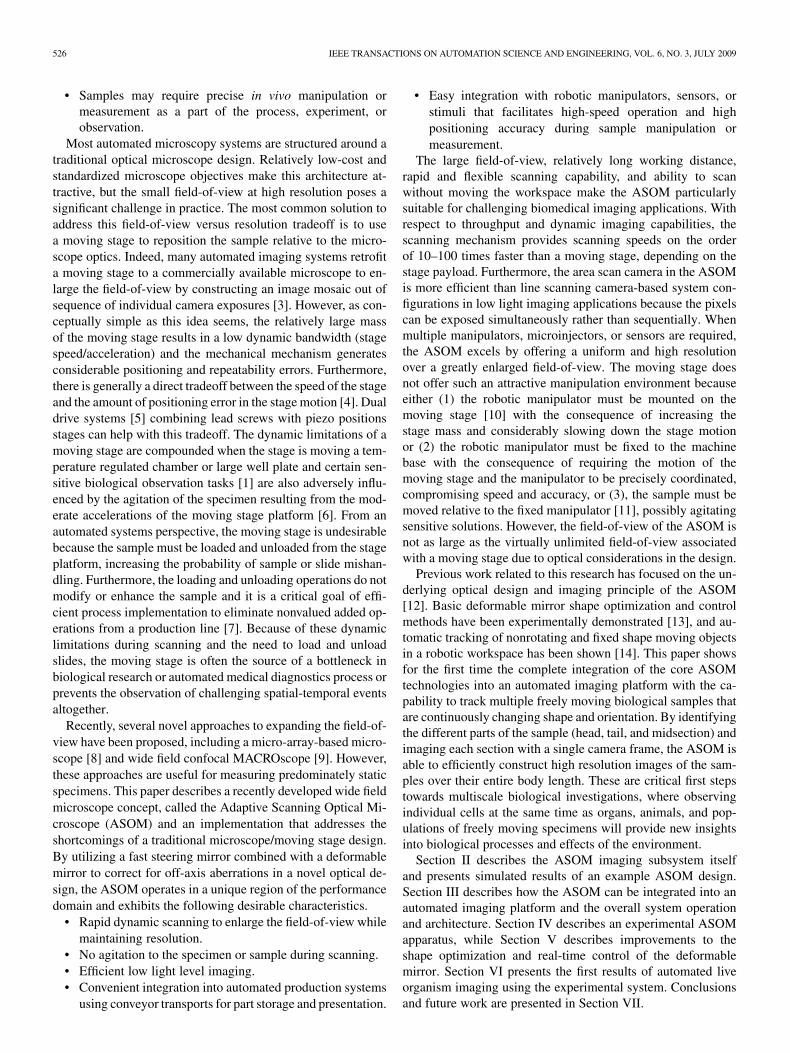
Fig. 1. (a) Preliminary ASOM design. (b) ASOM modes of operation (total field size and individual camera exposure regions are not to scale).
II. ASOM IMAGING SUBSYSTEM
At the heart of the imaging platform is the imaging subsystemitself, which consists of an ASOM. The underlying concept ofthe ASOM is to use a low mass steering mirror located betweenthe scanning lens and the imaging optics to form a post-objec-tive scanning configuration, as shown in Fig. 1(a). This allowsa small sub-field-of-view to be quickly scanned throughout theworkspace so that multiple disjoint or overlapping regions ofthe workspace can be visited and imaged in rapid succession, asillustrated in Fig. 1(b). Through image warping and mosaic con-struction, a large and continuous virtual image of the object orregion can then be constructed from the individual image tiles.The advantages of such an arrangement are: a large effectivefield-of-view at high resolution, no disturbance to the sample,and high scan rate operation. However, such a system config-uration also poses significant design and implementation chal-lenges. Compared to the moving stage or moving microscopedesigns, there is extensive off-axis imaging (i.e., images are ob-tained by looking diagonally through the scan lens), which in-troduces image distortion in addition to contrast degrading andresolution reducing aberrations (e.g., coma, astigmatism, fieldcurvature, etc.) [15] that have typically reduced the effective-ness of such an approach. In the ASOM, we address the off-axisaberrations by the following.
1) Explicitly incorporating field curvature into the design togreatly reduce the complexity of the scanning lens.
2) Introducing an actuated deformable mirror (DM) into theoptical path to correct for the residual aberrations.
3) Image processing to remove image distortion.Note that by combining dynamic components and algo-
rithmic techniques with traditional static optical elements, thelens count in the scanner lens is greatly reduced compared to acomparable static optics only design. This results in a potentialsavings in manufacturing and assembly costs (lithographic pro-jection lenses can cost in the millions of dollars [16]), makingthe ASOM accessible for research and production activities.
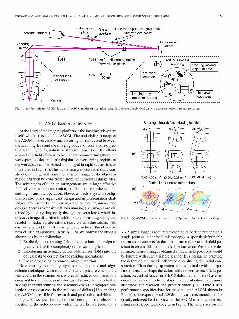
Fig. 2 shows how the angle of the steering mirror selects thelocation of the field-of-view within the workspace (note that a
Fig. 2. (a) ASOM scanning mechanism. (b) Optimal deformable mirror shapes.
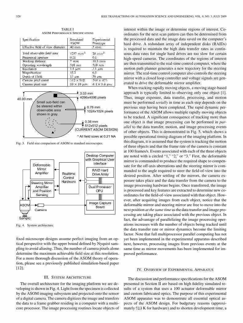
pixel image is acquired at each field location rather than asingle point as in confocal microscopy). A specific deformablemirror shape corrects for the aberrations unique to each field po-sition to obtain diffraction limited performance. Without the de-formable mirror, images obtained at these field positions wouldbe blurred with such a simple scanner lens design. In practice,the deformable mirror is calibrated once during the initial con-struction. Then during operation, a lookup table with interpo-lation is used to shape the deformable mirror for each field po-sition. Recent advances in MEMS deformable mirrors have re-duced the price of this technology, making adaptive optics moreaffordable for research and productization [17]. Table I listsperformance specifications for the simulated ASOM shown inFig. 1(a), the experimental ASOM that was constructed, and thegreatly enlarged field-of-view for the ASOM is compared to ex-isting microscope technologies in Fig. 3. The field sizes for the
528 IEEE TRANSACTIONS ON AUTOMATION SCIENCE AND ENGINEERING, VOL. 6, NO. 3, JULY 2009
TABLE IASOM PERFORMANCE SPECIFICATIONS
Fig. 3. Field size comparison of ASOM to standard microscopes.
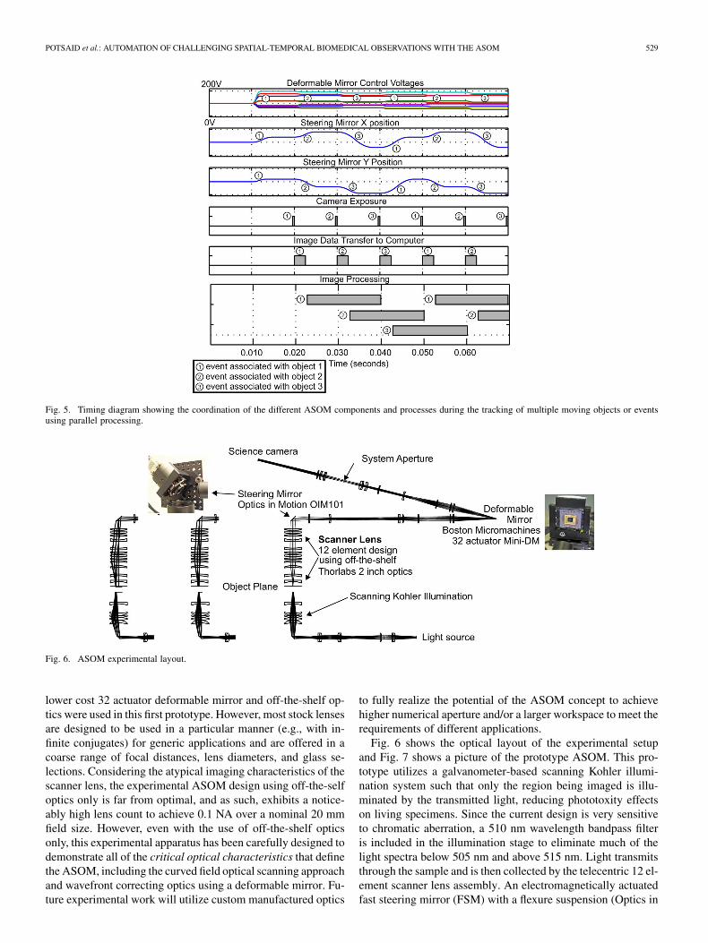
Fig. 4. System architecture.
fixed microscope designs assume perfect imaging from an op-tical perspective with the upper bound defined by Nyquist sam-pling to avoid aliasing. Thus, the number of camera pixels alonedetermine the maximum achievable field size at this resolution.For a more thorough discussion of the ASOM theory of opera-tion, please see a previously published simulation-based paper[12].
III. SYSTEM ARCHITECTURE
The overall architecture for the imaging platform we are de-veloping is shown in Fig. 4. Light from the specimen is collectedby the ASOM imaging subsystem and projected onto the sensorof a digital camera. The camera digitizes the image and transfersthe data to a frame grabber residing in a computer with a multi-core processor. The image processing routines locate objects of
interest within the image or determine regions of interest. Co-ordinates for the next scan pattern can then be determined fromthe processed data and the image data saved on the computer’shard drive. A redundant array of independent disks (RAIDs)is required to maintain the high data transfer rates as contin-uous data rates for single hard drives are too slow for certainhigh-speed cameras. The coordinates of the regions of interestare then transmitted to the real-time control computer, where themotion path planner generates a new trajectory for the steeringmirror. The real-time control computer also controls the steeringmirror with a closed loop controller and voltage signals are gen-erated to drive the deformable mirror amplifier.
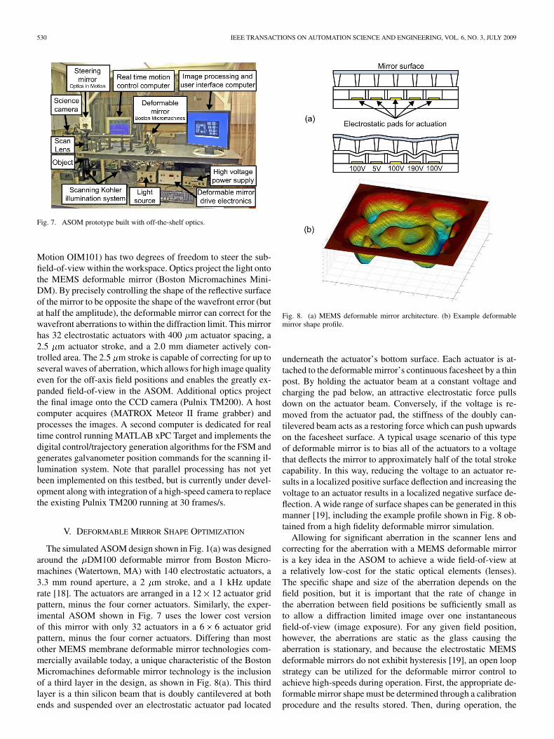
When tracking rapidly moving objects, a moving stage-basedapproach is typically limited to observing only one object [1].Thus, image exposure, data transfer, processing, and motionmust be performed serially in time as each step depends on theprevious step having been completed. The rapid dynamic per-formance of the ASOM allows multiple rapidly moving objectsto be tracked. A significant consequence of tracking more thanone object is that image processing can be performed in par-allel to the data transfer, motion, and image processing eventsof other objects. This is demonstrated in Fig. 5, which shows apossible operational timing diagram of the imaging platform. Inthis diagram, it is assumed that the system is tracking the motionof three objects and that the frame rate of the camera is constantat 100 frames/s. Events associated with each of the three objectsare noted with a circled “1,” “2,” or “3.” First, the deformablemirror is commanded to produce the required shape to compen-sate for the off-axis aberrations and the steering mirror is com-manded to the angle required to steer the field-of-view into thedesired position. After settling of the mirrors, the camera ex-posure takes place and the data transfer from the camera to theimage processing hardware begins. Once transferred, the imageis processed and key features are extracted to determine new co-ordinates for the field-of-view associated with that object. How-ever, after acquiring images from each object, notice that thedeformable mirror and steering mirror are free to move into thenext position at the same time as the data transfer and image pro-cessing are taking place associated with the previous object. Infact, the advantage of parallelizing the image processing oper-ations increases with the number of objects being tracked untilthe data transfer rate or mirror dynamics become the limitingfactor. Note that full multiprocessor parallel computing has notyet been implemented in the experimental apparatus describednext, however, processing images from previous events at thesame time as mirror movements has been implemented for im-proved performance.
IV. OVERVIEW OF EXPERIMENTAL APPARATUS
The discussion and performance specifications for the ASOMpresented in Section II are based on high fidelity simulated re-sults of a system that uses a 100 actuator deformable mirrorand custom fabricated optics. The purpose of this experimentalASOM apparatus was to demonstrate all essential optical as-pects of the ASOM design. For budgetary reasons (approxi-mately K for hardware) and to shorten development time, a
POTSAID et al.: AUTOMATION OF CHALLENGING SPATIAL-TEMPORAL BIOMEDICAL OBSERVATIONS WITH THE ASOM 529
Fig. 5. Timing diagram showing the coordination of the different ASOM components and processes during the tracking of multiple moving objects or eventsusing parallel processing.
Fig. 6. ASOM experimental layout.
lower cost 32 actuator deformable mirror and off-the-shelf op-tics were used in this first prototype. However, most stock lensesare designed to be used in a particular manner (e.g., with in-finite conjugates) for generic applications and are offered in acoarse range of focal distances, lens diameters, and glass se-lections. Considering the atypical imaging characteristics of thescanner lens, the experimental ASOM design using off-the-selfoptics only is far from optimal, and as such, exhibits a notice-ably high lens count to achieve 0.1 NA over a nominal 20 mmfield size. However, even with the use of off-the-shelf opticsonly, this experimental apparatus has been carefully designed todemonstrate all of the critical optical characteristics that definethe ASOM, including the curved field optical scanning approachand wavefront correcting optics using a deformable mirror. Fu-ture experimental work will utilize custom manufactured optics
to fully realize the potential of the ASOM concept to achievehigher numerical aperture and/or a larger workspace to meet therequirements of different applications.
Fig. 6 shows the optical layout of the experimental setupand Fig. 7 shows a picture of the prototype ASOM. This pro-totype utilizes a galvanometer-based scanning Kohler illumi-nation system such that only the region being imaged is illu-minated by the transmitted light, reducing phototoxity effectson living specimens. Since the current design is very sensitiveto chromatic aberration, a 510 nm wavelength bandpass filteris included in the illumination stage to eliminate much of thelight spectra below 505 nm and above 515 nm. Light transmitsthrough the sample and is then collected by the telecentric 12 el-ement scanner lens assembly. An electromagnetically actuatedfast steering mirror (FSM) with a flexure suspension (Optics in
530 IEEE TRANSACTIONS ON AUTOMATION SCIENCE AND ENGINEERING, VOL. 6, NO. 3, JULY 2009
Fig. 7. ASOM prototype built with off-the-shelf optics.
Motion OIM101) has two degrees of freedom to steer the sub-field-of-view within the workspace. Optics project the light ontothe MEMS deformable mirror (Boston Micromachines Mini-DM). By precisely controlling the shape of the reflective surfaceof the mirror to be opposite the shape of the wavefront error (butat half the amplitude), the deformable mirror can correct for thewavefront aberrations to within the diffraction limit. This mirrorhas 32 electrostatic actuators with 400 m actuator spacing, a2.5 m actuator stroke, and a 2.0 mm diameter actively con-trolled area. The 2.5 m stroke is capable of correcting for up toseveral waves of aberration, which allows for high image qualityeven for the off-axis field positions and enables the greatly ex-panded field-of-view in the ASOM. Additional optics projectthe final image onto the CCD camera (Pulnix TM200). A hostcomputer acquires (MATROX Meteor II frame grabber) andprocesses the images. A second computer is dedicated for realtime control running MATLAB xPC Target and implements thedigital control/trajectory generation algorithms for the FSM andgenerates galvanometer position commands for the scanning il-lumination system. Note that parallel processing has not yetbeen implemented on this testbed, but is currently under devel-opment along with integration of a high-speed camera to replacethe existing Pulnix TM200 running at 30 frames/s.
V. DEFORMABLE MIRROR SHAPE OPTIMIZATION
The simulated ASOM design shown in Fig. 1(a) was designedaround the DM100 deformable mirror from Boston Micro-machines (Watertown, MA) with 140 electrostatic actuators, a3.3 mm round aperture, a 2 m stroke, and a 1 kHz updaterate [18]. The actuators are arranged in a 12 12 actuator gridpattern, minus the four corner actuators. Similarly, the exper-imental ASOM shown in Fig. 7 uses the lower cost versionof this mirror with only 32 actuators in a 6 6 actuator gridpattern, minus the four corner actuators. Differing than mostother MEMS membrane deformable mirror technologies com-mercially available today, a unique characteristic of the BostonMicromachines deformable mirror technology is the inclusionof a third layer in the design, as shown in Fig. 8(a). This thirdlayer is a thin silicon beam that is doubly cantilevered at bothends and suspended over an electrostatic actuator pad located
Fig. 8. (a) MEMS deformable mirror architecture. (b) Example deformablemirror shape profile.
underneath the actuator’s bottom surface. Each actuator is at-tached to the deformable mirror’s continuous facesheet by a thinpost. By holding the actuator beam at a constant voltage andcharging the pad below, an attractive electrostatic force pullsdown on the actuator beam. Conversely, if the voltage is re-moved from the actuator pad, the stiffness of the doubly can-tilevered beam acts as a restoring force which can push upwardson the facesheet surface. A typical usage scenario of this typeof deformable mirror is to bias all of the actuators to a voltagethat deflects the mirror to approximately half of the total strokecapability. In this way, reducing the voltage to an actuator re-sults in a localized positive surface deflection and increasing thevoltage to an actuator results in a localized negative surface de-flection. A wide range of surface shapes can be generated in thismanner [19], including the example profile shown in Fig. 8 ob-tained from a high fidelity deformable mirror simulation.
Allowing for significant aberration in the scanner lens andcorrecting for the aberration with a MEMS deformable mirroris a key idea in the ASOM to achieve a wide field-of-view ata relatively low-cost for the static optical elements (lenses).The specific shape and size of the aberration depends on thefield position, but it is important that the rate of change inthe aberration between field positions be sufficiently small asto allow a diffraction limited image over one instantaneousfield-of-view (image exposure). For any given field position,however, the aberrations are static as the glass causing theaberration is stationary, and because the electrostatic MEMSdeformable mirrors do not exhibit hysteresis [19], an open loopstrategy can be utilized for the deformable mirror control toachieve high-speeds during operation. First, the appropriate de-formable mirror shape must be determined through a calibrationprocedure and the results stored. Then, during operation, the
POTSAID et al.: AUTOMATION OF CHALLENGING SPATIAL-TEMPORAL BIOMEDICAL OBSERVATIONS WITH THE ASOM 531
actuator voltages to the deformable mirror, are reconstructedas a function of the current field position as determined by thesteering mirror angles, and
(1)
In simulation, perfect knowledge of the wavefront shape isreadily available and it is straightforward to numerically de-termine the required mirror shape to correct for the specificaberrations associated with each field position. However,in practice, manufacturing tolerances and assembly errorsintroduce unmodeled aberrations into the optical system.Furthermore, internal residual stresses combined with man-ufacturing variations result in surface bowing in the MEMSdeformable mirror, as well as actuator performance variation[20]. Thus, experimental use of the deformable mirror requiresa method for the in situ shape optimization of the deformablemirror surface. If we consider the inputs of the optimizationto be the deformable mirror actuator voltages, , and to besome metric of the image quality or residual aberration, then theexperimental deformable mirror shape optimization requires:
• a metric to represent the image quality or residual aberra-tion, ;
• an optimization algorithm to minimize .The metric is, in general, a nonlinear function of the
actuator voltages, and is defined to decrease with im-proving image quality. The resulting optimization problem isalso subject to upper and lower bounds on the actuator voltages.Methods and approaches for optimization constitute an activefield of research on its own and there are many possible imagequality metrics and optimization methods that can potentially becombined for the ASOM deformable mirror shape optimization.
In practice, the wavefront cannot be measured directly, butmust be inferred from a related measurement of light intensity.Often a wavefront sensor (e.g., Shack Hartmann [21]) is used.Other common methods include interferometry or algorithmictechniques such as phase diversity using two or more camerasat different focal planes [22]. For the ASOM, it is advantageousfrom a cost and complexity perspective to use a technique basedon the image quality alone, not requiring any additional hard-ware or layout reconfiguration. Various metrics have been pro-posed for automatically assessing the quality of an image, in-cluding image entropy [23] and image sharpness via high-passfiltering [24].
The image quality metric used for the optimization in thisresearch is based on image sharpness as defined by Muller andBuffington [25], where the quality of the image is sharpest whenthe metric, , is minimized. Given an matrix of inten-sity values to represent the image, , the specific image qualitymetric, is defined as
(2)
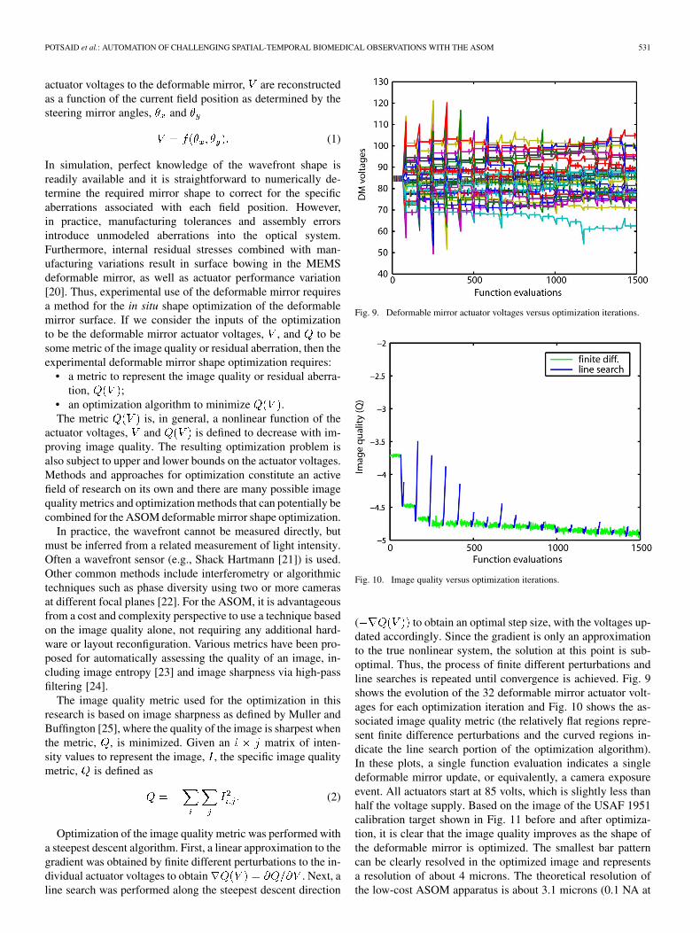
Optimization of the image quality metric was performed witha steepest descent algorithm. First, a linear approximation to thegradient was obtained by finite different perturbations to the in-dividual actuator voltages to obtain . Next, aline search was performed along the steepest descent direction
Fig. 9. Deformable mirror actuator voltages versus optimization iterations.
Fig. 10. Image quality versus optimization iterations.
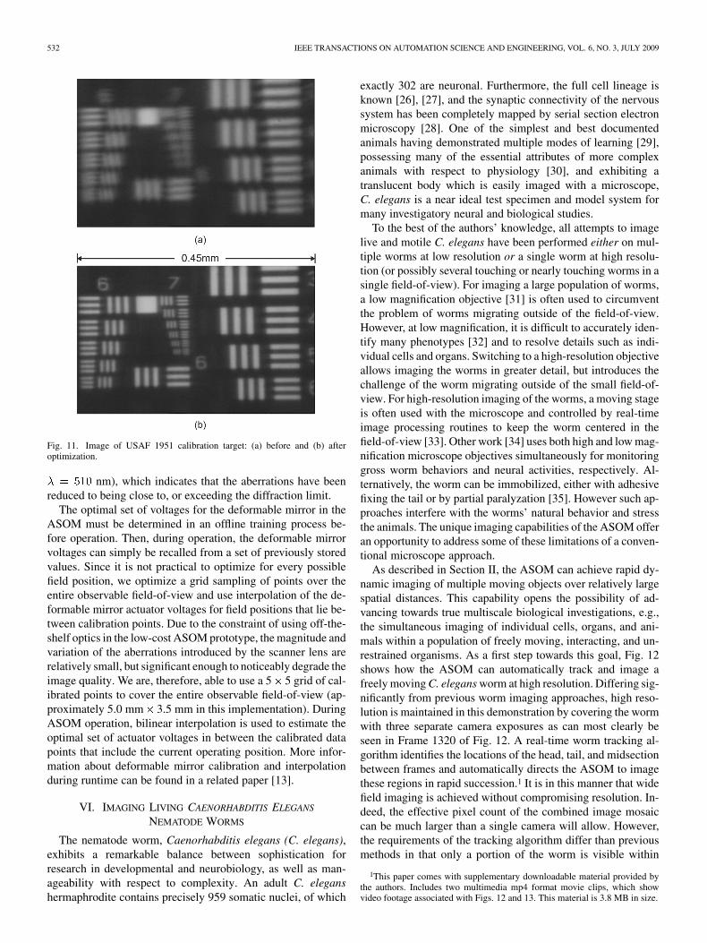
( to obtain an optimal step size, with the voltages up-dated accordingly. Since the gradient is only an approximationto the true nonlinear system, the solution at this point is sub-optimal. Thus, the process of finite different perturbations andline searches is repeated until convergence is achieved. Fig. 9shows the evolution of the 32 deformable mirror actuator volt-ages for each optimization iteration and Fig. 10 shows the as-sociated image quality metric (the relatively flat regions repre-sent finite difference perturbations and the curved regions in-dicate the line search portion of the optimization algorithm).In these plots, a single function evaluation indicates a singledeformable mirror update, or equivalently, a camera exposureevent. All actuators start at 85 volts, which is slightly less thanhalf the voltage supply. Based on the image of the USAF 1951calibration target shown in Fig. 11 before and after optimiza-tion, it is clear that the image quality improves as the shape ofthe deformable mirror is optimized. The smallest bar patterncan be clearly resolved in the optimized image and representsa resolution of about 4 microns. The theoretical resolution ofthe low-cost ASOM apparatus is about 3.1 microns (0.1 NA at
532 IEEE TRANSACTIONS ON AUTOMATION SCIENCE AND ENGINEERING, VOL. 6, NO. 3, JULY 2009
Fig. 11. Image of USAF 1951 calibration target: (a) before and (b) afteroptimization.
nm), which indicates that the aberrations have beenreduced to being close to, or exceeding the diffraction limit.
The optimal set of voltages for the deformable mirror in theASOM must be determined in an offline training process be-fore operation. Then, during operation, the deformable mirrorvoltages can simply be recalled from a set of previously storedvalues. Since it is not practical to optimize for every possiblefield position, we optimize a grid sampling of points over theentire observable field-of-view and use interpolation of the de-formable mirror actuator voltages for field positions that lie be-tween calibration points. Due to the constraint of using off-the-shelf optics in the low-cost ASOM prototype, the magnitude andvariation of the aberrations introduced by the scanner lens arerelatively small, but significant enough to noticeably degrade theimage quality. We are, therefore, able to use a 5 5 grid of cal-ibrated points to cover the entire observable field-of-view (ap-proximately 5.0 mm 3.5 mm in this implementation). DuringASOM operation, bilinear interpolation is used to estimate theoptimal set of actuator voltages in between the calibrated datapoints that include the current operating position. More infor-mation about deformable mirror calibration and interpolationduring runtime can be found in a related paper [13].
VI. IMAGING LIVING CAENORHABDITIS ELEGANS
NEMATODE WORMS
The nematode worm, Caenorhabditis elegans (C. elegans),exhibits a remarkable balance between sophistication forresearch in developmental and neurobiology, as well as man-ageability with respect to complexity. An adult C. eleganshermaphrodite contains precisely 959 somatic nuclei, of which
exactly 302 are neuronal. Furthermore, the full cell lineage isknown [26], [27], and the synaptic connectivity of the nervoussystem has been completely mapped by serial section electronmicroscopy [28]. One of the simplest and best documentedanimals having demonstrated multiple modes of learning [29],possessing many of the essential attributes of more complexanimals with respect to physiology [30], and exhibiting atranslucent body which is easily imaged with a microscope,C. elegans is a near ideal test specimen and model system formany investigatory neural and biological studies.
To the best of the authors’ knowledge, all attempts to imagelive and motile C. elegans have been performed either on mul-tiple worms at low resolution or a single worm at high resolu-tion (or possibly several touching or nearly touching worms in asingle field-of-view). For imaging a large population of worms,a low magnification objective [31] is often used to circumventthe problem of worms migrating outside of the field-of-view.However, at low magnification, it is difficult to accurately iden-tify many phenotypes [32] and to resolve details such as indi-vidual cells and organs. Switching to a high-resolution objectiveallows imaging the worms in greater detail, but introduces thechallenge of the worm migrating outside of the small field-of-view. For high-resolution imaging of the worms, a moving stageis often used with the microscope and controlled by real-timeimage processing routines to keep the worm centered in thefield-of-view [33]. Other work [34] uses both high and low mag-nification microscope objectives simultaneously for monitoringgross worm behaviors and neural activities, respectively. Al-ternatively, the worm can be immobilized, either with adhesivefixing the tail or by partial paralyzation [35]. However such ap-proaches interfere with the worms’ natural behavior and stressthe animals. The unique imaging capabilities of the ASOM offeran opportunity to address some of these limitations of a conven-tional microscope approach.
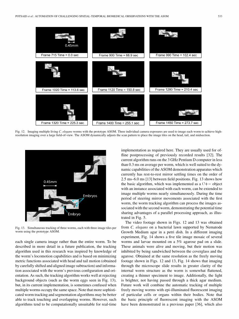
As described in Section II, the ASOM can achieve rapid dy-namic imaging of multiple moving objects over relatively largespatial distances. This capability opens the possibility of ad-vancing towards true multiscale biological investigations, e.g.,the simultaneous imaging of individual cells, organs, and ani-mals within a population of freely moving, interacting, and un-restrained organisms. As a first step towards this goal, Fig. 12shows how the ASOM can automatically track and image afreely moving C. elegans worm at high resolution. Differing sig-nificantly from previous worm imaging approaches, high reso-lution is maintained in this demonstration by covering the wormwith three separate camera exposures as can most clearly beseen in Frame 1320 of Fig. 12. A real-time worm tracking al-gorithm identifies the locations of the head, tail, and midsectionbetween frames and automatically directs the ASOM to imagethese regions in rapid succession.1 It is in this manner that widefield imaging is achieved without compromising resolution. In-deed, the effective pixel count of the combined image mosaiccan be much larger than a single camera will allow. However,the requirements of the tracking algorithm differ than previousmethods in that only a portion of the worm is visible within
1This paper comes with supplementary downloadable material provided bythe authors. Includes two multimedia mp4 format movie clips, which showvideo footage associated with Figs. 12 and 13. This material is 3.8 MB in size.
POTSAID et al.: AUTOMATION OF CHALLENGING SPATIAL-TEMPORAL BIOMEDICAL OBSERVATIONS WITH THE ASOM 533
Fig. 12. Imaging multiple living C. elegans worms with the prototype ASOM. Three individual camera exposures are used to image each worm to achieve high-resolution imaging over a large field-of-view. The ASOM dynamically adjusts the scan pattern to place the image tiles on the head, tail, and midsection.
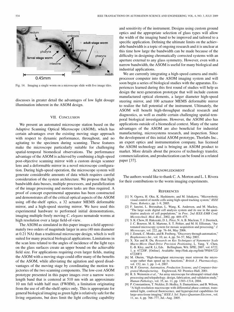
Fig. 13. Simultaneous tracking of three worms, each with three image tiles perworm using the prototype ASOM.
each single camera image rather than the entire worm. To bedescribed in more detail in a future publication, the trackingalgorithm used in this research was inspired by knowledge ofthe worm’s locomotion capabilities and is based on minimizingmetric functions associated with head and tail motion (obtainedby carefully shifted and aligned image subtraction) and informa-tion associated with the worm’s previous configuration and ori-entation. As such, the tracking algorithm works well at rejectingbackground objects (such as the worm eggs seen in Fig. 13),but, in its current implementation, is sometimes confused whenmultiple worms occupy the same space. Note that more sophisti-cated worm tracking and segmentation algorithms may be betterable to track touching and overlapping worms. However, suchalgorithms tend to be computationally unsuitable for real-time
implementation as required here. They are usually used for of-fline postprocessing of previously recorded results [32]. Thecurrent algorithm runs on the 3 GHz Pentium D computer in lessthan 0.3 ms on average per worm, which is well suited to the dy-namic capabilities of the ASOM demonstration apparatus whichcurrently has rest-to-rest mirror settling times on the order of2.5 ms–6.0 ms [13] between field positions. Fig. 13 shows howthe basic algorithm, which was implemented as a objectwith an instance associated with each worm, can be extended toimage multiple worms nearly simultaneously. During the timeperiod of steering mirror movements associated with the firstworm, the worm tracking algorithm can process the images as-sociated with the second worm, demonstrating the potential timesharing advantages of a parallel processing approach, as illus-trated in Fig. 5.
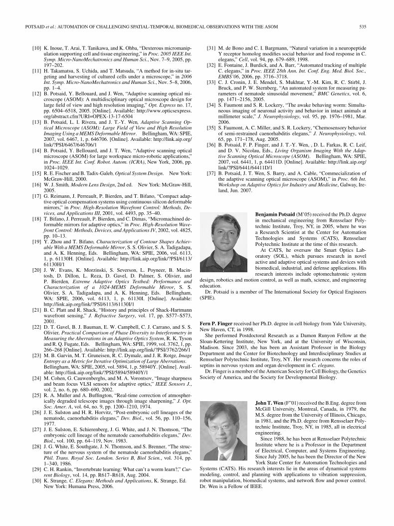
The video footage shown in Figs. 12 and 13 was obtainedfrom C. elegans on a bacterial lawn supported by NematodeGrowth Medium agar in a petri dish. In a different imagingexperiment, Fig. 14 shows a five tile image mosaic of severalworms and larvae mounted on a 5% agarose pad on a slide.These animals were alive and moving, but their motion wasinhibited by being sandwiched between the coverglass and theagarose. Obtained at the same resolution as the freely movingfootage shown in Figs. 12 and 13, Fig. 14 shows that imagingthrough the microscope slide results in greater clarity of theinternal worm structure as the worm is somewhat flattened,creating a thinner speciment to image. Additionally, the lightis brighter, not having passed through a thick agar medium.Future work will combine the automatic tracking of multiplefreely moving worms with epi-illuminated fluorescent imagingof particular cells or organs within their bodies. Note thatthe basic principle of fluorescent imaging with the ASOMhave been demonstrated in a previous paper [36], which also
534 IEEE TRANSACTIONS ON AUTOMATION SCIENCE AND ENGINEERING, VOL. 6, NO. 3, JULY 2009
Fig. 14. Imaging a single worm on a microscope slide with five image tiles.
discusses in greater detail the advantages of low light dosageillumination inherent in the ASOM design.
VII. CONCLUSION
We present an automated microscope station based on theAdaptive Scanning Optical Microscope (ASOM), which hascertain advantages over the existing moving stage approachwith respect to dynamic performance, throughout, and noagitating to the specimen during scanning. These featuresmake the microscope particularly suitable for challengingspatial-temporal biomedical observations. The performanceadvantage of the ASOM is achieved by combining a high-speedpost-objective scanning mirror with a custom design scannerlens and a deformable mirror in a novel microscope configura-tion. During high-speed operation, the microscope system willgenerate considerable amounts of data which requires carefulconsideration of the system architecture. We propose that highbandwidth data busses, multiple processors, and parallelizationof the image processing and motion tasks are thus required. Aproof of concept experimental apparatus has been constructedand demonstrates all of the critical optical aspects of the ASOMusing off-the-shelf optics, a 32 actuator MEMS deformablemirror, and a high-speed steering mirror. We have used thisexperimental hardware to performed initial demonstrations,imaging multiple freely moving C. elegans nematode worms athigh resolution over a large field-of-view.
The ASOM as simulated in this paper images a field approxi-mately two orders of magnitude larger in area (40 mm diameterat 0.21 NA) than a traditional microscope design, which is wellsuited for many practical biological applications. Limitations inthe scan lens related to the angles of incidence of the light rayson the glass surfaces create an upper bound on the achievablefield size. For applications requiring even larger fields, matingthe ASOM with a moving stage could offer many of the benefitsof the ASOM, while alleviating the agitation and speed disad-vantages of the moving stage by coordinating the motion tra-jectories of the two scanning components. The low-cost ASOMprototype presented in this paper images over a narrow wave-length band that is centered at 510 nm with an approximate10 nm full width half max (FWHM), a limitation originatingfrom the use of off-the-shelf optics only. This is appropriate forgeneral biological imaging as green light is relatively safe for theliving organisms, but does limit the light collecting capability
and sensitivity of the instrument. Designs using custom groundoptics and the appropriate selection of glass types will allowthe width of the imaging band to be improved and tailored to aspecific application. Defining the ultimate limits on the achiev-able bandwidth is a topic of ongoing research and it is unclear atthis time how large the bandwidth can be made because of thedifficulty in designing chromatically corrected systems with anaperture external to any glass symmetry. However, even with anarrow bandwidth, the ASOM is useful for many biological andindustrial applications.
We are currently integrating a high-speed camera and multi-processor computer into the ASOM imaging system and willsoon begin a series of biological studies with the apparatus. Ex-periences learned during this first round of studies will help usdesign the next-generation prototype that will include custommanufactured optical elements, a larger diameter high-speedsteering mirror, and 100 actuator MEMS deformable mirrorto realize the full potential of the instrument. Ultimately, theASOM will benefit high-throughput medical research anddiagnostics, as well as enable certain challenging spatial-tem-poral biological investigations. However, the ASOM also hasapplications outside of a biomedical context. Many of the sameadvantages of the ASOM are also beneficial for industrialmanufacturing, microsystems research, and inspection. Sincethe development of this initial ASOM prototype, Thorlabs Inc.,an expert optics and instrumentation company, has licensedthe ASOM technology and is bringing an ASOM product tomarket. More details about the process of technology transfer,commercialization, and productization can be found in a relatedpaper [37].
ACKNOWLEDGMENT
The authors would like to thank C. A. Morton and L. I. Riverafor their contributions to the worm imaging experiments.
REFERENCES
[1] N. Ogawa, H. Oku, K. Hashimoto, and M. Ishakawa, “Microroboticvisual control of motile cells using high-speed tracking system,” IEEETrans. Robotics, pp. 1–9, 2005.
[2] F. Ianzini, L. Bresnahan, L. Wang, K. Anderson, and M. Mackey,“The large scale digital cell analysis system and its use in the quan-titative analysis of cell populations,” in Proc. 2nd IEEE-EMB Conf.Microtechnol. Med. Biol., 2002, pp. 469–475.
[3] S. K. Chow, H. Hakozaki, D. L. Price, N. A. B. Maclean, T. J. Deerinck,J. C. Bouwer, M. E. Martone, S. T. Peltier, and M. H. Ellisman, “Au-tomated microscopy system for mosaic acquisition and processing,” J.Microscopy, vol. 222, pp. 76–84, May 2006.
[4] J. Zemek, C. Monks, and B. Freiberg, “Discovery through automation,”Biophotonics Int., vol. 10, no. 4, pp. 54–57, May 2003.
[5] X. Xie and R. Du, Research on Key Techniques of Nanometer ScaleMacro-Micro Dual-Drive Precision Positioning, L. Yang, Y. Chen,E.-B. Kley, and R. Li, Eds. Bellingham, WA: SPIE, 2007, vol. 6722,1, p. 67220F. [Online]. Available: http://link.aip.org/link/?PSI/6722/67220F/1
[6] M. Oheim, “High-throughput microscopy must reinvent the micro-scope rather than speed up its functions,” British J. Pharmacology,vol. 152, no. 1, pp. 1–4, 2007.
[7] M. P. Groover, Automation, Production Systems, and Computer-Inte-grated Manufacturing. Englewood, NJ: Prentice-Hall, 2001.
[8] R. S. Weinstein et al., “An array microscope for ultrarapid virtual slideprocessing and telepahology. design, fabrication, and validation study,”Human Pathology, vol. 35, no. 11, pp. 1303–1314, 2004.
[9] P. Constantinou, T. Nicklee, D. Hedley, S. Damaskinos, and B. Wilson,“A high-resolution macroscope with differential phase contrast, trans-mitted light, confocal fluorescence, and hyperspectral capabilities forlarge-area tissue imaging,” IEEE J. Sel. Topics Quantum Electron., vol.11, no. 4, pp. 766–777, Jul.–Aug. 2005.
POTSAID et al.: AUTOMATION OF CHALLENGING SPATIAL-TEMPORAL BIOMEDICAL OBSERVATIONS WITH THE ASOM 535
[10] K. Inoue, T. Arai, T. Tanikawa, and K. Ohba, “Dexterous micromanip-ulation supporting cell and tissue engineering,” in Proc. 2005 IEEE Int.Symp. Micro-NanoMechatronics and Human Sci., Nov. 7–9, 2005, pp.197–202.
[11] H. Takamatsu, S. Uchida, and T. Matsuda, “A method for in-situ tar-geting and harvesting of cultured cells under a microscope,” in 2006Int. Symp. Micro-NanoMechatronics and Human Sci., Nov. 5–8, 2006,pp. 1–4.
[12] B. Potsaid, Y. Bellouard, and J. Wen, “Adaptive scanning optical mi-croscope (ASOM): A multidisciplinary optical microscope design forlarge field of view and high resolution imaging,” Opt. Express no. 17,pp. 6504–6518, 2005. [Online]. Available: http://www.opticsexpress.org/abstract.cfm?URI=OPEX-13-17-6504
[13] B. Potsaid, L. I. Rivera, and J. T.-Y. Wen, Adaptive Scanning Op-tical Microscope (ASOM): Large Field of View and High ResolutionImaging Using a MEMS Deformable Mirror. Bellingham, WA: SPIE,2007, vol. 6467, 1, p. 646706. [Online]. Available: http://link.aip.org/link/?PSI/6467/646706/1
[14] B. Potsaid, Y. Bellouard, and J. T. Wen, “Adaptive scanning opticalmicroscope (ASOM) for large workspace micro-robotic applications,”in Proc. IEEE Int. Conf. Robot. Autom. (ICRA), New York, 2006, pp.1024–1029.
[15] R. E. Fischer and B. Tadix-Galeb, Optical System Design. New York:McGraw-Hill, 2000.
[16] W. J. Smith, Modern Lens Design, 2nd ed. New York: McGraw-Hill,2005.
[17] G. Reimann, J. Perreault, P. Bierden, and T. Bifano, “Compact adap-tive optical compensation systems using continuous silicon deformablemirrors,” in Proc. High-Resolution Wavefront Control: Methods, De-vices, and Applications III, 2001, vol. 4493, pp. 35–40.
[18] T. Bifano, J. Perreault, P. Bierden, and C. Dimas, “Micromachined de-formable mirrors for adaptive optics,” in Proc. High-Resolution Wave-front Control: Methods, Devices, and Applications IV, 2002, vol. 4825,pp. 10–13.
[19] Y. Zhou and T. Bifano, Characterization of Contour Shapes Achiev-able With a MEMS Deformable Mirror, S. S. Olivier, S. A. Tadigadapa,and A. K. Henning, Eds. Bellingham, WA: SPIE, 2006, vol. 6113,1, p. 61130H. [Online]. Available: http://link.aip.org/link/?PSI/6113/61130H/1
[20] J. W. Evans, K. Morzinski, S. Severson, L. Poyneer, B. Macin-tosh, D. Dillon, L. Reza, D. Gavel, D. Palmer, S. Olivier, andP. Bierden, Extreme Adaptive Optics Testbed: Performance andCharacterization of a 1024-MEMS Deformable Mirror, S. S.Olivier, S. A. Tadigadapa, and A. K. Henning, Eds. Bellingham,WA: SPIE, 2006, vol. 6113, 1, p. 61130I. [Online]. Available:http://link.aip.org/link/?PSI/6113/61130I/1
[21] B. C. Platt and R. Shack, “History and principles of Shack-Hartmannwavefront sensing,” J. Refractive Surgery, vol. 17, pp. S577–S573,2001.
[22] D. T. Gavel, B. J. Bauman, E. W. Campbell, C. J. Carrano, and S. S.Olivier, Practical Comparison of Phase Diversity to Interferometry inMeasuring the Aberrations in an Adaptive Optics System, R. K. Tysonand R. Q. Fugate, Eds. Bellingham, WA: SPIE, 1999, vol. 3762, 1, pp.266–268 [Online]. Available: http://link.aip.org/link/?PSI/3762/266/1
[23] M. B. Garvin, M. T. Gruneisen, R. C. Dymale, and J. R. Rotge, ImageEntropy as a Metric for Iterative Optimization of Large Aberrations.Bellingham, WA: SPIE, 2005, vol. 5894, 1, p. 58940Y. [Online]. Avail-able: http://link.aip.org/link/?PSI/5894/58940Y/1
[24] M. Cohen, G. Cauwenberghs, and M. A. Vorontsov, “Image sharpnessand beam focus VLSI sensors for adaptive optics,” IEEE Sensors J.,vol. 2, no. 6, pp. 680–690, 2002.
[25] R. A. Muller and A. Buffington, “Real-time correction of atmospher-ically degraded telescope images through image sharpening,” J. Opt.Soc. Amer. A, vol. 64, no. 9, pp. 1200–1210, 1974.
[26] J. E. Sulston and H. R. Horvitz, “Post-embryonic cell lineages of thenematode, caenorhabditis elegans,” Dev. Biol., vol. 56, pp. 110–156,1977.
[27] J. E. Sulston, E. Schierenberg, J. G. White, and J. N. Thomson, “Theembryonic cell lineage of the nematode caenorhabditis elegans,” Dev.Biol., vol. 100, pp. 64–119, Nov. 1983.
[28] J. G. White, E. Southgate, J. N. Thomson, and S. Brenner, “The struc-ture of the nervous system of the nematode caenorhabditis elegans,”Phil. Trans. Royal Soc. London. Series B, Biol Scien., vol. 314, pp.1–340, 1986.
[29] C. H. Rankin, “Invertebrate learning: What can’t a worm learn?,” Cur-rent Biology, vol. 14, pp. R617–R618, Aug. 2004.
[30] K. Strange, C. Elegans: Methods and Applications, K. Strange, Ed.New York: Humana Press, 2006.
[31] M. de Bono and C. I. Bargmann, “Natural variation in a neuropeptideY receptor homolog modifies social behavior and food response in C.elegans,” Cell, vol. 94, pp. 679–689, 1998.
[32] E. Fontaine, J. Burdick, and A. Barr, “Automated tracking of multipleC. elegans,” in Proc. IEEE 28th Ann. Int. Conf. Eng. Med. Biol. Soc.,EMBS’06, 2006, pp. 3716–3718.
[33] C. J. Cronin, J. E. Mendel, S. Mukhtar, Y.-M. Kim, R. C. Stirbl, J.Bruck, and P. W. Sternberg, “An automated system for measuring pa-rameters of nematode sinusoidal movement,” BMC Genetics, vol. 6,pp. 1471–2156, 2005.
[34] S. Faumont and S. R. Lockery, “The awake behaving worm: Simulta-neous imaging of neuronal activity and behavior in intact animals atmillimeter scale,” J. Neurophysiology, vol. 95, pp. 1976–1981, Mar.2006.
[35] S. Faumont, A. C. Miller, and S. R. Lockery, “Chemosensory behaviorof semi-restrained caenorhabditis elegans,” J. Neurophysiology, vol.65, pp. 171–178, Aug. 2005.
[36] B. Potsaid, F. P. Finger, and J. T.-Y. Wen, , D. L. Farkas, R. C. Leif,and D. V. Nicolau, Eds., Living Organism Imaging With the Adap-tive Scanning Optical Microscope (ASOM). Bellingham, WA: SPIE,2007, vol. 6441, 1, p. 64411D. [Online]. Available: http://link.aip.org/link/?PSI/6441/64411D/1
[37] B. Potsaid, J. T. Wen, S. Barry, and A. Cable, “Commecialization ofthe adaptive scanning optical microscope (ASOM),” in Proc. 6th Int.Workshop on Adaptive Optics for Industry and Medicine, Galway, Ire-land, Jun. 2007.
Benjamin Potsaid (M’05) received the Ph.D. degreein mechanical engineering from Rensselaer Poly-technic Institute, Troy, NY, in 2005, where he wasa Research Scientist at the Center for AutomationTechnologies and Systems (CATS), RensselaerPolytechnic Institute at the time of this research.
At CATS, he oversaw the Smart Optics Lab-oratory (SOL), which pursues research in novelactive and adaptive optical systems and devices withbiomedical, industrial, and defense applications. Hisresearch interests include optomechatronic system
design, robotics and motion control, as well as math, science, and engineeringeducation.
Dr. Potsaid is a member of The International Society for Optical Engineers(SPIE).
Fern P. Finger received her Ph.D. degree in cell biology from Yale University,New Haven, CT, in 1998.
She performed Postdoctoral Research as a Damon Runyon Fellow at theSloan-Kettering Institute, New York, and at the University of Wisconsin,Madison. Since 2003, she has been an Assistant Professor in the BiologyDepartment and the Center for Biotechnology and Interdisciplinary Studies atRensselaer Polytechnic Institute, Troy, NY. Her research concerns the roles ofseptins in nervous system and organ development in C. elegans.
Dr. Finger is a member of the American Society for Cell Biology, the GeneticsSociety of America, and the Society for Developmental Biology.
John T. Wen (F”01) received the B.Eng. degree fromMcGill University, Montreal, Canada, in 1979, theM.S. degree from the University of Illinois, Chicago,in 1981, and the Ph.D. degree from Rensselaer Poly-technic Institute, Troy, NY, in 1985, all in electricalengineering.
Since 1988, he has been at Rensselaer PolytechnicInstitute where he is a Professor in the Departmentof Electrical, Computer, and Systems Engineering.Since July 2005, he has been the Director of the NewYork State Center for Automation Technologies and
Systems (CATS). His research interests lie in the areas of dynamical systemsmodeling, control, and planning with applications to vibration suppression,robot manipulation, biomedical systems, and network flow and power control.Dr. Wen is a Fellow of IEEE.