Embed Size (px)
Citation preview
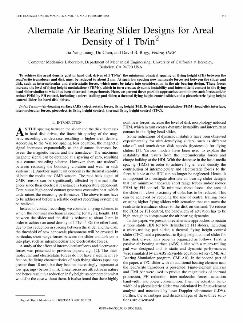
IEEE TRANSACTIONS ON MAGNETICS, VOL. 42, NO. 2, FEBRUARY 2006 241
Alternate Air Bearing Slider Designs for ArealDensity of 1 Tb/in2
Jia-Yang Juang, Du Chen, and David B. Bogy, Fellow, IEEE
Computer Mechanics Laboratory, Department of Mechanical Engineering, University of California at Berkeley,Berkeley, CA 94720 USA
To achieve the areal density goal in hard disk drives of 1 Tb/in2 the minimum physical spacing or flying height (FH) between theread/write transducer and disk must be reduced to about 2 nm. At such low spacing new nanoscale forces act between the slider anddisk, such as intermolecular and electrostatic forces, which must be taken into consideration in the air bearing design. These forcesincrease the level of flying height modulations (FHMs), which in turn creates dynamic instability and intermittent contact in the flyinghead slider similar to what has been observed in experiments. Here, we present three possible approaches to minimize such forces and/orreduce FHM by FH control, including a micro-trailing pad slider, a thermal flying height control slider, and a piezoelectric flying heightcontrol slider for hard disk drives.
Index Terms—Air-bearing surface (ABS), electrostatic forces, flying height (FH), flying height modulation (FHM), head-disk interface,inter-molecular forces, piezoelectric flying height control, thermal flying height control (TFC).
I. INTRODUCTION
AS THE spacing between the slider and the disk decreasesin hard disk drives, the linear bit spacing of the mag-
netic recording can decrease, resulting in higher areal density.According to the Wallace spacing loss equation, the magneticsignal increases exponentially as the distance decreases be-tween the magnetic media and the transducer. The maximummagnetic signal can be obtained at a spacing of zero, resultingin a contact recording scheme. However, there are tradeoffsbetween reducing the bouncing vibration and wear in suchsystems [1]. Another significant concern is the thermal stabilityof both the media and GMR sensors. The read-back signal ofGMR sensors can be significantly affected by thermal influ-ences since their electrical resistance is temperature dependent.Continuous high-speed contact generates excessive heat, whichundermines the recording performance. The above issues haveto be addressed before a reliable contact recording system canbe realized.
Instead of contact recording, we consider a flying scheme, inwhich the nominal mechanical spacing (or flying height, FH)between the slider and the disk is reduced to about 2 nm inorder to achieve an areal density of 1 Tb/in . On the other hand,due to this reduction in spacing between the slider and the disk,the threshold of new nanoscale phenomena will be crossed. Inparticular, short range forces between the slider and disk comeinto play, such as intermolecular and electrostatic forces.
A study of the effect of intermolecular forces and electrostaticforces was presented in previous papers, e.g., [2]. The inter-molecular and electrostatic forces do not have a significant ef-fect on the flying characteristics of high flying sliders (spacingsgreater than 10 nm), but they become increasingly important atlow spacings (below 5 nm). These forces are attractive in natureand hence result in a reduction in fly height as compared to whatwould be the case without them. It is also found that these highly
Digital Object Identifier 10.1109/TMAG.2005.861739
nonlinear forces increase the level of disk morphology inducedFHM, which in turn creates dynamic instability and intermittentcontact in the flying head slider.
Some indications of dynamic instability have been observedexperimentally for ultra-low-flying sliders, such as differenttake-off and touch-down disk speeds (hysteresis) for flyingsliders [3]. Various models have been used to explain theinstability that results from the intermolecular forces andcharge buildup at the HDI. With the decrease in the head-mediaspacing (HMS) in order to achieve higher areal density thecontribution of intermolecular and electrostatic forces to theforce balance at the HDI can no longer be neglected. Hence, itis important to investigate alternate air bearing slider designsthat can minimize nanoscale short range forces and/or reduceFHM by FH control. To minimize these forces, the area ofthe sliders in close proximity of disks has to be reduced. Thiscan be achieved by reducing the size of central trailing padsor using higher flying sliders with actuation that can move theread/write transducer closer to the disk on demand. To reducethe FHM by FH control, the bandwidth of actuation has to behigh enough to compensate the air bearing dynamics.
In this paper, we present three alternate approaches to sustaina more stable HDI for low (transducer) FH sliders, includinga micro-trailing pad slider, a thermal flying height controlslider (TFC), and a piezoelectric flying height control slider forhard disk drives. This paper is organized as follows. First, apassive air bearing surface (ABS) slider with a micro-trailingpad was designed and its static and dynamic performanceswere simulated by an ABS Reynolds equation solver (CML AirBearing Simulation program, CMLAir). In the second part ofthe paper, a TFC slider with an additional heating element nearthe read/write transducer is presented. Finite-element analysisand CMLAir were used to predict the magnitudes of thermalprotrusion, FH reduction, inter-molecular forces, actuationbandwidth, and power consumption. Then, the actuation band-width of a piezoelectric slider was calculated by finite-elementanalysis and measured by laser Doppler vibrometer (LDV).Further, the advantages and disadvantages of these three solu-tions are discussed.
0018-9464/$20.00 © 2006 IEEE
242 IEEE TRANSACTIONS ON MAGNETICS, VOL. 42, NO. 2, FEBRUARY 2006
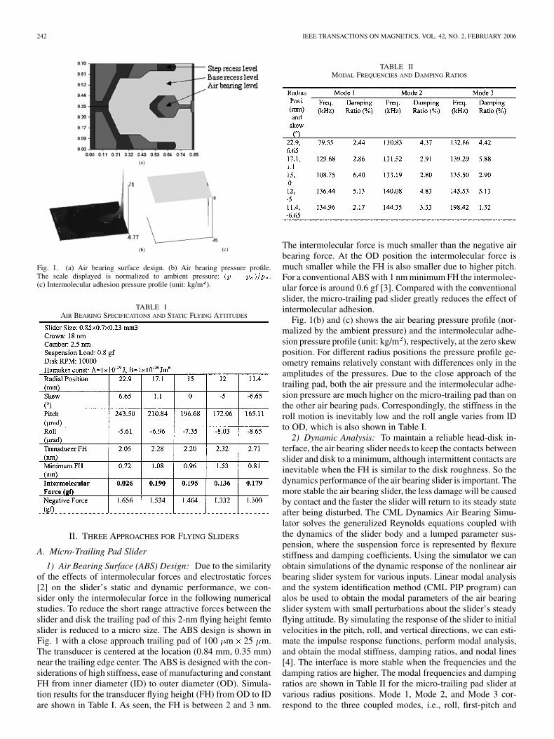
Fig. 1. (a) Air bearing surface design. (b) Air bearing pressure profile.The scale displayed is normalized to ambient pressure: (p � p )=p .(c) Intermolecular adhesion pressure profile (unit: kg/m ).
TABLE IAIR BEARING SPECIFICATIONS AND STATIC FLYING ATTITUDES
II. THREE APPROACHES FOR FLYING SLIDERS
A. Micro-Trailing Pad Slider
1) Air Bearing Surface (ABS) Design: Due to the similarityof the effects of intermolecular forces and electrostatic forces[2] on the slider’s static and dynamic performance, we con-sider only the intermolecular force in the following numericalstudies. To reduce the short range attractive forces between theslider and disk the trailing pad of this 2-nm flying height femtoslider is reduced to a micro size. The ABS design is shown inFig. 1 with a close approach trailing pad of 100 m 25 m.The transducer is centered at the location (0.84 mm, 0.35 mm)near the trailing edge center. The ABS is designed with the con-siderations of high stiffness, ease of manufacturing and constantFH from inner diameter (ID) to outer diameter (OD). Simula-tion results for the transducer flying height (FH) from OD to IDare shown in Table I. As seen, the FH is between 2 and 3 nm.
TABLE IIMODAL FREQUENCIES AND DAMPING RATIOS
The intermolecular force is much smaller than the negative airbearing force. At the OD position the intermolecular force ismuch smaller while the FH is also smaller due to higher pitch.For a conventional ABS with 1 nm minimum FH the intermolec-ular force is around 0.6 gf [3]. Compared with the conventionalslider, the micro-trailing pad slider greatly reduces the effect ofintermolecular adhesion.
Fig. 1(b) and (c) shows the air bearing pressure profile (nor-malized by the ambient pressure) and the intermolecular adhe-sion pressure profile (unit: kg/m ), respectively, at the zero skewposition. For different radius positions the pressure profile ge-ometry remains relatively constant with differences only in theamplitudes of the pressures. Due to the close approach of thetrailing pad, both the air pressure and the intermolecular adhe-sion pressure are much higher on the micro-trailing pad than onthe other air bearing pads. Correspondingly, the stiffness in theroll motion is inevitably low and the roll angle varies from IDto OD, which is also shown in Table I.
2) Dynamic Analysis: To maintain a reliable head-disk in-terface, the air bearing slider needs to keep the contacts betweenslider and disk to a minimum, although intermittent contacts areinevitable when the FH is similar to the disk roughness. So thedynamics performance of the air bearing slider is important. Themore stable the air bearing slider, the less damage will be causedby contact and the faster the slider will return to its steady stateafter being disturbed. The CML Dynamics Air Bearing Simu-lator solves the generalized Reynolds equations coupled withthe dynamics of the slider body and a lumped parameter sus-pension, where the suspension force is represented by flexurestiffness and damping coefficients. Using the simulator we canobtain simulations of the dynamic response of the nonlinear airbearing slider system for various inputs. Linear modal analysisand the system identification method (CML PIP program) canalos be used to obtain the modal parameters of the air bearingslider system with small perturbations about the slider’s steadyflying attitude. By simulating the response of the slider to initialvelocities in the pitch, roll, and vertical directions, we can esti-mate the impulse response functions, perform modal analysis,and obtain the modal stiffness, damping ratios, and nodal lines[4]. The interface is more stable when the frequencies and thedamping ratios are higher. The modal frequencies and dampingratios are shown in Table II for the micro-trailing pad slider atvarious radius positions. Mode 1, Mode 2, and Mode 3 cor-respond to the three coupled modes, i.e., roll, first-pitch and
JUANG et al.: ALTERNATE AIR BEARING SLIDER DESIGNS FOR AREAL DENSITY OF 1 Tb/in 243
TABLE IIIPLOTS OF TRANSDUCER FLYING HEIGHT VERSUS TIME FOR THE SLIDER AT
VARIOUS SKEW ANGLES ON TWO MEASURED DISK SURFACES
second-pitch. Due to the smaller gap between the slider anddisk, the modal frequencies are higher than those of some othersliders with sub-5 nm FH [5]. But the damping ratios are similar.
The spacing fluctuation between the transducer and the disk,or flying height modulation (FHM) is another important phe-nomenon and it also needs be held to a minimum. Again, usingthe CML Dynamics Air Bearing Simulator we obtained the re-sults in Table III, which show the transducer FHM of the slideron two measured disk surfaces, the RMSs of which were 0.6 and0.2 nm, respectively.
These results reveal that on the rougher disk surface (RMS0.6 nm) the FHM is about 2 nm when the skew angle is 0, 1.1or 5 . However, when the skew angle is 6.65 the slider isin contact with the disk. On the smooth disk (RMS 0.2 nm),the FHM is less than 1 nm when the skew angle is 0, 1.1 or
5 . But when skew angle is 6.65 , the slider bounces onthe smooth disk. This indicates that the slider’s dynamic perfor-
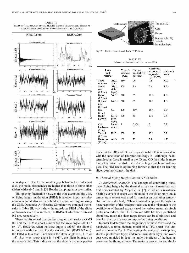
Fig. 2. Finite-element model of a TFC slider.
TABLE IVMATERIAL PROPERTIES USED IN THE FEA
mance at the OD and ID is still questionable. This is consistentwith the conclusion of Thornton and Bogy [6]. Although the in-termolecular force is small at the ID and OD the slider is morelikely to contact the disk there due to larger pitch and roll an-gles. The HDI needs optimizing further so that the air bearingslider does not contact the disk.
B. Thermal Flying Height Control (TFC) Slider
1) Numerical Analysis: The concept of controlling trans-ducer flying height by the thermal expansion of materials wasfirst demonstrated by Meyer et al. [7], in which a resistanceheating element (heater) was mounted to the slider body and atemperature sensor was used for sensing an operating temper-ature of the slider body. When a current is applied through theheater a portion of the head protrudes due to the mismatch of thecoefficients of thermal expansion of the various materials. Suchprotrusion reduces the FH. However, little has been publishedabout how much the short range forces can be diminished andhow fast such actuation can respond at flying conditions.
In order to determine the magnitudes of these forces and thebandwidth, a finite-element model of a TFC slider was cre-ated as shown in Fig. 2. The heating element, coil, write poles,shields, photoresist layer, undercoat insulation layer, and over-coat were modeled in detail to study the effects of the heatingpower on the flying attitude. The material properties and thick-
244 IEEE TRANSACTIONS ON MAGNETICS, VOL. 42, NO. 2, FEBRUARY 2006
Fig. 3. (a) An ABS design used in this study. (b) The air pressure distribution ofthis ABS. The scale displayed is normalized to ambient pressure: (p�p )=p .
Fig. 4. Steady-state FH and thermal protrusion were obtained after severalnumerical iterations at a heating power of 30 mW.
TABLE VCOMPARISON OF FLYING ATTITUDES
ness of each layer are shown in Table IV. The thermal conduc-tivities of thin layers are higher than the bulk values due to theheat carrier-boundary scattering and the altered microstructureof thin films [8].
The cooling effect of the air bearing plays a key role in this3-D heat transfer problem. We first used CMLAir to obtain thenominal FH, pitch, roll, and air pressure distribution of a 5-nmFH ABS slider as shown in Fig. 3. The effect of intermolec-ular forces was included with a nominal value of the Hamakerconstant ( J). Then we calculated the heat fluxthrough the air bearing based on the model developed by Chenet al. [9]. The temperature distributions and pole-tip protrusionswere then calculated based on the model and boundary condi-tions. Since the thermal protrusion causes deformation of theABS and hence changes the flying attitudes, an iteration ap-proach is used to obtain an equilibrium solution.
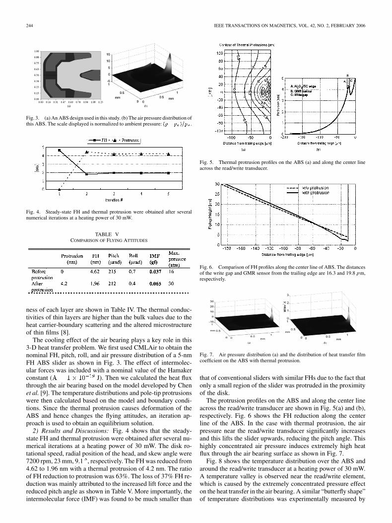
2) Results and Discussions: Fig. 4 shows that the steady-state FH and thermal protrusion were obtained after several nu-merical iterations at a heating power of 30 mW. The disk ro-tational speed, radial position of the head, and skew angle were7200 rpm, 23 mm, 9.1 , respectively. The FH was reduced from4.62 to 1.96 nm with a thermal protrusion of 4.2 nm. The ratioof FH reduction to protrusion was 63%. The loss of 37% FH re-duction was mainly attributed to the increased lift force and thereduced pitch angle as shown in Table V. More importantly, theintermolecular force (IMF) was found to be much smaller than
Fig. 5. Thermal protrusion profiles on the ABS (a) and along the center lineacross the read/write transducer.
Fig. 6. Comparison of FH profiles along the center line of ABS. The distancesof the write gap and GMR sensor from the trailing edge are 16.3 and 19.8 �m,respectively.
Fig. 7. Air pressure distribution (a) and the distribution of heat transfer filmcoefficient on the ABS with thermal protrusion.
that of conventional sliders with similar FHs due to the fact thatonly a small region of the slider was protruded in the proximityof the disk.
The protrusion profiles on the ABS and along the center lineacross the read/write transducer are shown in Fig. 5(a) and (b),respectively. Fig. 6 shows the FH reduction along the centerline of the ABS. In the case with thermal protrusion, the airpressure near the read/write transducer significantly increasesand this lifts the slider upwards, reducing the pitch angle. Thishighly concentrated air pressure induces extremely high heatflux through the air bearing surface as shown in Fig. 7.
Fig. 8 shows the temperature distribution over the ABS andaround the read/write transducer at a heating power of 30 mW.A temperature valley is observed near the read/write element,which is caused by the extremely concentrated pressure effecton the heat transfer in the air bearing. A similar “butterfly shape”of temperature distributions was experimentally measured by
JUANG et al.: ALTERNATE AIR BEARING SLIDER DESIGNS FOR AREAL DENSITY OF 1 Tb/in 245
Fig. 8. Temperature distributions of a flying slider with thermal protrusion ata heating power of 30 mW. Line distributions show a clear temperature valleynear the read/write head.
Fig. 9. Transient temperature changes of a flying slider with a varying heatingpower.
Xu et al. [10]. A lower temperature increase is beneficial forGMR sensors which are sensitive to temperature variation.
A transient thermal study was conducted to investigate thebandwidth of TFC sliders. The power to the heating elementwas set to 30 mW from 0 to 2.3 ms and was turn off at 2.5 ms.The temperature changes of both the GMR sensor and write gapwere monitored as shown in Fig. 9. It requires about 1 ms forthe read/write transducer to reach its steady-state values, corre-sponding to a bandwidth of 1 kHz. This is too slow for activecontrol of FHM.
C. Piezoelectric Flying Height Control Slider
The bandwidth of TFC sliders is much lower than the airbearing frequencies, which may be up to 200 kHz. For thisreason TFC sliders have little control over FHM and other dy-namic losses of FH. The inherent high power consumption ofthermal actuation also limits the stroke of protrusions. Severalresearch groups [11]–[15] have presented the FH control using apiezoelectric unimorph cantilever actuator. Some of their resultswere summarized in Table VI. However, their studies were fo-cused on compensating for static spacing loss caused by designtolerances and ambient pressure changes. Neither short rangesforces nor suppression of FHM was considered. Liu et al. [16]investigated an active FH control method for suppressing FHMby bonding a layer of piezoelectric film on one side of the sus-pension and using real-time spacing variation signals derivedfrom the read-back signal as feedback. However, the short range
TABLE VICOMPARISON OF THREE APPROACHES
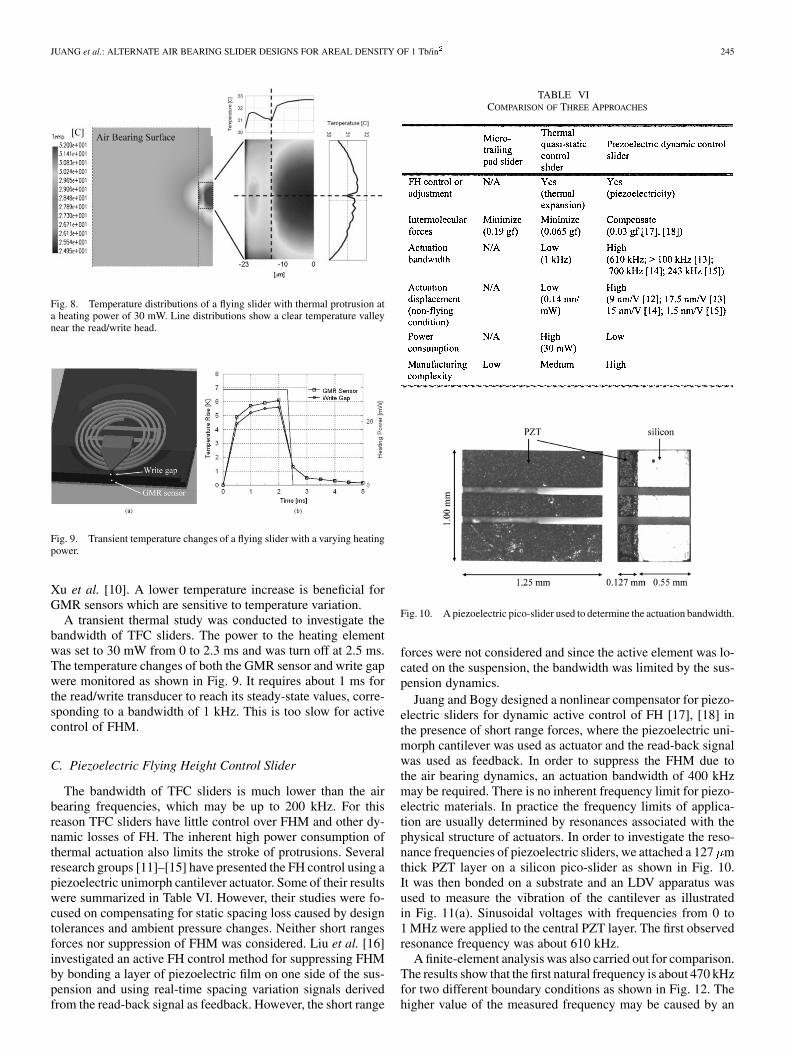
Fig. 10. A piezoelectric pico-slider used to determine the actuation bandwidth.
forces were not considered and since the active element was lo-cated on the suspension, the bandwidth was limited by the sus-pension dynamics.
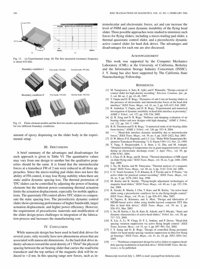
Juang and Bogy designed a nonlinear compensator for piezo-electric sliders for dynamic active control of FH [17], [18] inthe presence of short range forces, where the piezoelectric uni-morph cantilever was used as actuator and the read-back signalwas used as feedback. In order to suppress the FHM due tothe air bearing dynamics, an actuation bandwidth of 400 kHzmay be required. There is no inherent frequency limit for piezo-electric materials. In practice the frequency limits of applica-tion are usually determined by resonances associated with thephysical structure of actuators. In order to investigate the reso-nance frequencies of piezoelectric sliders, we attached a 127 mthick PZT layer on a silicon pico-slider as shown in Fig. 10.It was then bonded on a substrate and an LDV apparatus wasused to measure the vibration of the cantilever as illustratedin Fig. 11(a). Sinusoidal voltages with frequencies from 0 to1 MHz were applied to the central PZT layer. The first observedresonance frequency was about 610 kHz.
A finite-element analysis was also carried out for comparison.The results show that the first natural frequency is about 470 kHzfor two different boundary conditions as shown in Fig. 12. Thehigher value of the measured frequency may be caused by an
246 IEEE TRANSACTIONS ON MAGNETICS, VOL. 42, NO. 2, FEBRUARY 2006
Fig. 11. (a) Experimental setup. (b) The first measured resonance frequencyis about 610 kHz.
Fig. 12. Finite-element models and the first two modes and natural frequenciesfor two different boundary conditions.
amount of epoxy dispensing on the slider body in the experi-mental setup.
III. DISCUSSIONS
A brief summary of the advantages and disadvantages foreach approach is given in Table VI. The quantitative valuesmay vary from one design to another but the qualitative prop-erties should be the same. It is found that the intermolecularforces at a transducer FH of 2 nm were reduced in all three ap-proaches. Since the micro-trailing pad slider does not have theability of FH control, it may lose flying stability when there arestatic and/or dynamic spacing loss. The thermal protrusion ofTFC sliders can be controlled by adjusting the power of heatingelements but the inherent power-consuming thermal actuationlimits the actuation displacement, especially for mobile applica-tions. The quasistatic FH control allows TFC sliders to compen-sate the static spacing loss. The piezoelectric dynamic controlslider shows promising performance of higher bandwidth, largeractuation displacement, and higher power efficiency. However,the requirement of piezoelectric materials and modification ofthe slider design poses challenges in integration of the fabrica-tion process and increases the manufacturing cost.
IV. CONCLUSION
While nanoscale design has been used in hard disk drives forseveral years, only recently have new phenomena arisen that areassociated with nanoscale dimensions. As the hard disk drive in-dustry advances toward the areal density of 1 Tb/in the physicalspacing between the air bearing slider that carries the read/writetransducer and the top surface of the magnetic disk will be re-duced to nm. In this spacing range new forces, such as in-
termolecular and electrostatic forces, act and can increase thelevel of FHM and cause dynamic instability of the flying headslider. Three possible approaches were studied to minimize suchforces for flying sliders, including a micro-trailing pad slider, athermal quasistatic control slider, and a piezoelectric dynamicactive control slider for hard disk drives. The advantages anddisadvantages for each one are also discussed.
ACKNOWLEDGMENT
This work was supported by the Computer MechanicsLaboratory (CML) at the University of California, Berkeleyand the Information Storage Industry Consortium (INSIC).J. Y. Juang has also been supported by The California StateNanotechnology Fellowship.
REFERENCES
[1] M. Yanagisawa, A. Sato, K. Ajiki, and F. Watanabe, “Design concept ofcontact slider for high-density recording,” Electron. Commun. Jpn., pt.2, vol. 80, no. 2, pp. 43–48, 1997.
[2] V. Gupta and D. B. Bogy, “Dynamics of sub-5 nm air bearing sliders inthe presence of electrostatic and intermolecular forces at the head diskinterface,” IEEE Trans. Magn., vol. 41, no. 2, pp. 610–615, Feb. 2005.
[3] R. Ambekar, V. Gupta, and D. B. Bogy, “Experimental and numericalinvestigation of dynamic instability in head disk interface at proximity,”ASME J. Tribol., vol. 127, pp. 530–536, 2005.
[4] Q. H. Zeng and D. B. Bogy, “Stiffness and damping evaluation of airbearing sliders and new designs with high damping,” ASME J. Tribol.,vol. 121, pp. 341–7, 1999.
[5] B. H. Thornton and D. B. Bogy, “A numerical study of air-bearing sliderform-factors,” ASME J. Tribol., vol. 126, pp. 553–8, 2004.
[6] , “Head-disk interface dynamic instability due to intermolecularforces,” IEEE Trans. Magn., vol. 39, no. 5, pp. 2420–2422, Sep. 2003.
[7] D. W. Meyer, P. E. Kupinski, and J. C. Liu, “Slider With Temperature Re-sponsive Transducer Positioning,” U.S. Patent 5 991 113, Nov. 23, 1999.
[8] Y. Yang, S. Shojaeizadeh, J. A. Bain, J. G. Zhu, and M. Asheghi,“Detailed modeling of temperature rise in giant magnetoresistive sensorduring an electrostatic discharge event,” J. Appl. Phys., vol. 95, pp.6780–6782, 2004.
[9] L. Chen, D. B. Bogy, and B. Strom, “Thermal dependence of MR signalon slider flying state,” IEEE Trans. Magn., vol. 36, no. 5, pp. 2486–2489,Sep. 2000.
[10] J. Xu, M. Kurita, and M. Tokuyama, “Thermal analysis of a magnetichead,” IEEE Trans. Magn., vol. 40, no. 4, pp. 3142–3144, Jul. 2004.
[11] C. E. Yeack-Scranton, V. D. Khanna, K. F. Etzold, and A. P. Praino, “Anactive slider for practical contact recording,” IEEE Trans. Magn., vol.26, no. 5, pp. 2478–2483, Sep. 1990.
[12] M. Kurita and K. Suzuki, “Flying-height adjustment technologies ofmagnetic head sliders,” IEEE Trans. Magn., vol. 40, no. 1, pp. 332–336,Jan. 2004.
[13] K. Suzuki, R. Maeda, J. Chu, T. Kato, and M. Kurita, “An active headslider using a piezoelectric cantilever for in situ flying-height control,”IEEE Trans. Magn., vol. 39, no. 2, pp. 826–831, Mar. 2003.
[14] N. Tagawa, K. Kitamura, and A. Mori, “Design and fabrication ofMEMS-based active slider using double-layered composite PZT thinfilm in hard disk drives,” IEEE Trans. Magn., vol. 39, no. 2, pp.926–931, Mar. 2003.
[15] L. Su, M. Kurita, J. Xu, K. Kato, K. Adachi, and Y. Miyake, “Static anddynamic characteristics of active-head sliders,” Tribol. Int., vol. 38, pp.717–723, 2005.
[16] X. Liu, A. Li, W. Clegg, D. F. L. Jenkins, and P. Davey, “Head-diskspacing variation suppression via active flying height control,” IEEETrans. Instrum. Meas., vol. 51, no. 5, pp. 897–901, Oct. 2002.
[17] J. Y. Juang and D. B. Bogy, “Design of controlled flying proximitysliders for head-media spacing variation suppression in ultra-low flyingair bearings,” IEEE Trans. Magn., vol. 41, no. 10, pp. 3052–3054, Oct.2005.
[18] , “Nonlinear compensator design for active sliders to suppress head-disk spacing modulation in hard disk drive,” IEEE/ASME Trans. Mecha-tronics, to be published.
Manuscript received July 1, 2005 (e-mail: [email protected]).


![IEEE Transactions on Magnetics Volume 22 Issue 5 1986 [Doi 10.1109_tmag.1986.1064466] Sebastian, T.; Slemon, G.; Rahman, M. -- Modelling of Permanent Magnet Synchronous Motors](https://img.pdfslide.net/doc/110x75/577cdb711a28ab9e78a831b6/ieee-transactions-on-magnetics-volume-22-issue-5-1986-doi-101109tmag19861064466.jpg)