Embed Size (px)
Citation preview

IEEE TRANSACTIONS ON MICROWAVE THEORY AND TECHNIQUES, VOL. 56, NO. 4, APRIL 2008 793
Novel Miniature and Broadband Millimeter-WaveMonolithic Star Mixers
Che-Chung Kuo, Chun-Lin Kuo, Che-Jia Kuo, Stephen A. Maas, Fellow, IEEE, and Huei Wang, Fellow, IEEE
Abstract—In this paper, three monolithic star mixers using anew miniature dual balun are proposed. The first one is a doublespiral transformer mixer, and the second one is a trifilar trans-former mixer. Both of these are fabricated using a commercialGaAs pseudomorphic HEMT process. The third is a 3-D trans-former mixer, which is fabricated using a commercial CMOSprocess. These mixers exhibit bandwidths over 25–45 GHz (57%)with local oscillator isolations better than 20 dB. These star mixersare smaller than � � �� for the mixer core area. Comparedwith traditional star mixers, these mixers demonstrate 80% sizereduction, and achieve good performance with the smallest chipsize among all star mixers using monolithic microwave integratedcircuit processes.
Index Terms—Balun, diode mixer, double-balanced mixer(DBM), mixer, monolithic microwave integrated circuit (MMIC),resistive mixer, spiral transformer, star mixer, transformer.
I. INTRODUCTION
ALTHOUGH millimeter-wave (MMW) mixer techniquesare well developed, the high-performance and compact
monolithic mixer is still a popular research topic. The double-balanced mixer (DBM), which offers high spur suppression andwide dynamic range, is the most commonly used configuration.Compared to the traditional ring DBM, the advantage of the starDBM is low IF parasitic inductance, which results in wide IFbandwidth. In addition, the IF of the star DBM is dc coupled,allowing for direct conversion of signals to baseband [1]. There-fore, the star DBM is suitable for high data rate, even multigi-gabit direct-conversion transceiver applications. The traditionalstructure of the star DBM involves a dual balun, which is not aplanar structure [13]. One of the first planar star mixers is shownin Fig. 1. Two Marchand dual baluns were used in this circuitto form a cross arrangement [2]. A modified three-conductorMarchand dual balun with a multicoupled microstrip line balunwas reported by Ryu et al. [3]. A lumped miniature dual-balunstar mixer in the -band was presented by Chiou et al. [5]. Thestar mixers are often impractical in integrated circuit (IC) designbecause they need two rather large half-wavelength Marchand
Manuscript received July 25, 2007; revised November 22, 2007. Thiswork was supported in part by National Taiwan University under ExcellentResearch Project 95R0062-AE00-01 and by the National Science Council ofTaiwan, R.O.C. under Contract NSC 93-2752-E-002-002-PAE, Contract NSC93-2219-E-002-024, and Contract NSC 93-2213-E-002-033.
C.-C. Kuo, C.-L. Kuo, C.-J. Kuo, and H. Wang are with the Departmentof Electrical Engineering and the Graduate Institute of Communication Engi-neering, National Taiwan University, Taipei 106, Taiwan, R.O.C. (e-mail: [email protected]).
S. A. Maas is with Nonlinear Technologies Inc., Long Beach, CA 90807 USA.Digital Object Identifier 10.1109/TMTT.2008.919063
Fig. 1. (a) Marchand dual balun for star mixer. (b) First planar star mixer re-ported by Basu and Maas [2].
dual baluns, which increase the chip area. Therefore, the minia-ture dual balun is a key component of a star mixer.
In this paper, three novel miniature transformer-type Marc-hand dual baluns are proposed to further reduce the size ofthe star DBM. The first is a double-spiral transformer. Al-though spiral transformers are used extensively in monolithicmicrowave integrated circuit (MMIC) design, we propose anovel double-spiral transformer dual balun for a star mixer.The second is a trifilar transformer. Trifilar transformers arealso popular in ICs, but here we propose the use of a dualbalun consisting of two trifilar cascaded transformers. Thesetwo miniature transformer type Marchand dual baluns areimplemented in a commercial GaAs pseudomorphic HEMT(pHEMT) process for star mixers.
Besides, modern CMOS technology with downscaling of fea-ture dimensions, multilayer of interconnected metal, and fea-sibility of back-end integration becomes an interesting alter-native for MMW IC designs. Therefore, we further propose a3-D structure dual balun for a resistive star DBM using a stan-dard commercial CMOS process. To the authors’ knowledge,these mixers (using miniature transformer type Marchand dualbaluns) achieve the smallest chip sizes among the publishedMMIC star mixers in the MMW regime.
II. STAR MIXER CONFIGURATION
A single-balanced mixer uses 180 baluns to cancel thelocal oscillator (LO) signal at RF and IF ports, giving it goodLO-to-RF and LO-to-IF isolations [1]. However, RF-to-IFisolation is not very good due to the unbalanced RF signal atthe IF port and, thus, a low-pass filter is required to reject theRF signal at the IF terminal. Double-balanced ring mixers avoidthis problem by extracting the IF signal from the center tap ofthe RF balun. This mixer requires an ideal tapped transformerto realize the balun, and the IF connection in a ring mixer isusually difficult to realize using practical microwave baluns [1].
0018-9480/$25.00 © 2008 IEEE
Authorized licensed use limited to: National Taiwan University. Downloaded on February 24, 2009 at 23:17 from IEEE Xplore. Restrictions apply.

794 IEEE TRANSACTIONS ON MICROWAVE THEORY AND TECHNIQUES, VOL. 56, NO. 4, APRIL 2008
Fig. 2. Schematics of the: (a) star DBM, (b) star mixer using dual balun, and(c) resistive star mixer using dual balun.
The star mixer shown in Fig. 2(a) overcomes the IF connec-tion problem and has additional advantages as well, includinga wide IF bandwidth and dc coupled IF [1]. The four diodesare connected to the common node, which is the IF output. TheRF and LO signals are fed to the diode bridge through a set oftransformers, which are often realized as parallel transmissionline baluns. The circuit topology in Fig. 2(a) is identical to thetraditional star mixer in Fig. 1(b). The circuit structure imple-menting the novel dual balun proposed in this paper is shown inFig. 2(b), and the resistive star mixer using CMOS technologyis shown in Fig. 2(c).
III. TRANSFORMERS IN DUAL BALUNS
To design miniature mixers, three Marchand dual baluns(three-conductor coupled line baluns) are proposed in this
paper. These transformers are designed according to the respec-tive characteristics of the GaAs and CMOS MMIC processes.In a typical GaAs process, there are only two metal layers,which are not suitable for multilayer structures and, thus,the transformer must be designed in edge-coupled form. ACMOS process often supports multilayer metals; therefore, thetransformer can be designed using broadside-coupled lines in asmaller area.
A. Double Spiral Transformer (Edge Coupled)
A Marchand dual balun is composed of two series-connectedthree-conductor coupled-line sets [see Fig. 1(a)]. The two con-ductor coupled line can be used as a spiral transformer, whichis widely used in MMIC design [8], [9], and a three-conductorcoupled line spiral transformer, which uses a similar layout,called a double spiral transformer, is shown in Fig. 3(a), where
and are the metal width and spacing, respectively, andis the area of the metal to backside via. The Marchand
dual balun [see Fig. 1(a)] is composed of two series-connecteddouble spiral transformers. The crossover lines and ground arerealized by air bridges and backside vias, respectively. Thedouble spiral transformer is equivalent to a three-conductorcoupled-line transformer. Lines and [see Fig. 3(a)] areboth a quarter-wavelength long at the desired frequency. Forthe diode connection shown in the layout of Fig. 2(b), twooutput ports [ports 2 and 3 in Fig. 3(a)] are needed in the upperand lower sides of the transformer; therefore, these two linesare not wrapped in the same manner. The signal excites port 1and propagates along line , and the power is coupled to lines
and due to edge coupling. Line must be longer thanthe other lines to ensure that every section of the transformer isformed with three-conductor coupled lines. Port 4 is used forthe other cascaded identical transformer. Output port sets 2–2and 3–3 are two differential outputs of the dual balun.
B. Tifilar Transformer (Edge Coupled)
The trifilar balun [see Fig. 3(b)] is also widely used in MMICdesigns [8], [10]. Different from the double spiral transformer,the trifilar transformer is a symmetric transformer. Lines and
also have equal lengths of one quarter-wavelength at the de-sired frequency. For the diode connection [see Fig. 2(b)], thesetwo lines, which start at the outside turn and go to the insideturn and back to the outside turn repeatedly, are of equal lengthand wrapped in the same way. Line must also be somewhatlonger than the other two.
C. 3-D Transformer (Broadside Coupled)
Due to the multilayer dielectric offered in the CMOS process,the 3-D transformer is proposed, as shown in Fig. 3(c). The3-D dual balun can be divided into three-layer cascaded trans-formers; every part of the single-layer cascaded transformers is asingle spiral transformer. Lines and still are a quarter-wave-length long at the desired frequency. As shown in Fig. 3(d), port1 is the input port in the middle layer, and power is coupled to theupper and lower layers due to broadside coupling. The outputsignals at the two output port sets 2–2 and 3–3 are differential.
There are two benefits of a broadside-coupled transformercompared to the edge-coupled form. First, air bridges are not
Authorized licensed use limited to: National Taiwan University. Downloaded on February 24, 2009 at 23:17 from IEEE Xplore. Restrictions apply.
KUO et al.: NOVEL MINIATURE AND BROADBAND MMW MONOLITHIC STAR MIXERS 795
Fig. 3. Layouts of the: (a) double spiral transformer, (b) trifilar transformer,(c) 3-D transformer, and (d) side view of 3-D transformer dual balun.
needed; the air bridge induces a capacitive parasitic, which canreduce bandwidth. Therefore, a broadside-coupled transformerbalun will have a wider bandwidth than that of an edge-coupledtransformer. The other benefit is smaller size, which is very ob-vious.
IV. MARCHAND DUAL BALUN FOR STAR MIXER
The star mixer requires two sets of dual baluns for RF andLO signals, respectively. In order to optimize the mixer perfor-mance, the even-mode impedance needs to be as high as pos-sible, while the odd-mode impedance is approximately
(1)
where is the diode impedance or input impedance ofthe transistor, is the source impedance, and is theodd-mode impedance of the transformer or balun [2]. Since
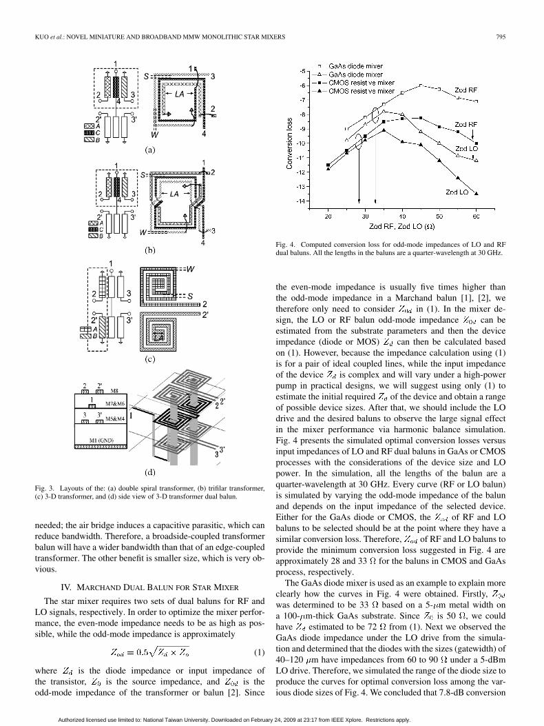
Fig. 4. Computed conversion loss for odd-mode impedances of LO and RFdual baluns. All the lengths in the baluns are a quarter-wavelength at 30 GHz.
the even-mode impedance is usually five times higher thanthe odd-mode impedance in a Marchand balun [1], [2], wetherefore only need to consider in (1). In the mixer de-sign, the LO or RF balun odd-mode impedance can beestimated from the substrate parameters and then the deviceimpedance (diode or MOS) can then be calculated basedon (1). However, because the impedance calculation using (1)is for a pair of ideal coupled lines, while the input impedanceof the device is complex and will vary under a high-powerpump in practical designs, we will suggest using only (1) toestimate the initial required of the device and obtain a rangeof possible device sizes. After that, we should include the LOdrive and the desired baluns to observe the large signal effectin the mixer performance via harmonic balance simulation.Fig. 4 presents the simulated optimal conversion losses versusinput impedances of LO and RF dual baluns in GaAs or CMOSprocesses with the considerations of the device size and LOpower. In the simulation, all the lengths of the balun are aquarter-wavelength at 30 GHz. Every curve (RF or LO balun)is simulated by varying the odd-mode impedance of the balunand depends on the input impedance of the selected device.Either for the GaAs diode or CMOS, the of RF and LObaluns to be selected should be at the point where they have asimilar conversion loss. Therefore, of RF and LO baluns toprovide the minimum conversion loss suggested in Fig. 4 areapproximately 28 and 33 for the baluns in CMOS and GaAsprocess, respectively.
The GaAs diode mixer is used as an example to explain moreclearly how the curves in Fig. 4 were obtained. Firstly,was determined to be 33 based on a 5- m metal width ona 100- m-thick GaAs substrate. Since is 50 , we couldhave estimated to be 72 from (1). Next we observed theGaAs diode impedance under the LO drive from the simula-tion and determined that the diodes with the sizes (gatewidth) of40–120 m have impedances from 60 to 90 under a 5-dBmLO drive. Therefore, we simulated the range of the diode size toproduce the curves for optimal conversion loss among the var-ious diode sizes of Fig. 4. We concluded that 7.8-dB conversion
Authorized licensed use limited to: National Taiwan University. Downloaded on February 24, 2009 at 23:17 from IEEE Xplore. Restrictions apply.

796 IEEE TRANSACTIONS ON MICROWAVE THEORY AND TECHNIQUES, VOL. 56, NO. 4, APRIL 2008
Fig. 5. Chip photograph of the double spiral transformer dual balun. �0.8 �0.5 mm �.
loss with a diode size of 40 m and of 32 is the lowestconversion loss achievable in this preliminary estimation, andthese parameters can be used for the mixer design. The curvesfor the CMOS mixer were similarly obtained.
The dual-balun design procedure is summarized as follows:1) calculate the quarter-wavelength for desired frequency ;2) determine (metal spacing) and (metal width) for the
appropriate even- and odd-mode impedance from Fig. 4;3) predict (number of turns);4) electromagnetic (EM) full-wave software simulation and
optimization.In the design using the GaAs process, and are 5 m
for maximum even-mode impedance and is 60 100 m .The even-mode impedance of 133 and odd impedance of33 (see Fig. 4) are chosen for optimum performance ofthe mixer. The center frequency is 40 GHz and performanceoptimization is achived through EM simulation (Agilent EEsofADS Momentum). These first two balun circuits are designedusing a 0.15- m GaAs pHEMT MMIC process, and waferprobe measurements employ a four-port network analyzer(Anritsu 37397D). The metal lines of RF pads and connectionsare deembedded in the balun measurement results.
A. Double Spiral Transformer Dual Balun
In the test circuit of the double spiral transformer dual balunshown in Fig. 5, one port is terminated by a thin-film resistorof 50 . The balun size is approximately 400 200 m . Theinsertion loss of an ideal dual balun is 6 dB, and the simulatedand measured insertion loss results are approximately 8 and 8 to10 dB. The simulated and measured amplitude differences are1 and 2 dB at a frequency range of 25–58 GHz. The simulatedand measured phase differences are from 178 to 187 andfrom 179 to 192 at the frequency range of 20 to 55 GHz(Fig. 6).
B. Trifilar Transformer Dual Balun
The second test circuit of the trifilar transformer balun isshown in Fig. 7. The design parameters are essentially thesame as those of the double spiral transformer dual balun. Oneport is terminated with 50 . The balun size is approximately400 230 m . The insertion loss of the ideal dual balun isagain 6 dB; the simulated and measured insertion loss resultsare approximately 7–8.5 dB and 11–9 dB. The simulated
Fig. 6. Double spiral transformer dual balun simulation and measurement re-sult of: (a) insertion loss and amplitude difference and (b) phase difference.
Fig. 7. Chip photograph of the trifilar transformer dual balun. �0.8�0.5 mm �.
and measured amplitude differences are 1 and 2 dB in thefrequency range of 25–58 GHz, the simulated and measuredphase difference are from 182 to 178 and from 183 to
171 in the frequency range of 20–50 GHz (Fig. 8). Thereare two main differences between these two edge coupledbaluns, the first is frequency response. The bandwidth of thedouble spiral transformer is wider than that of the trifilar trans-former, which uses more air bridges. As a result, the capacitiveparasitic and more junction discontinuities restrict the perfor-mance bandwidth and increase the insertion loss. Figs. 6(a)
Authorized licensed use limited to: National Taiwan University. Downloaded on February 24, 2009 at 23:17 from IEEE Xplore. Restrictions apply.

KUO et al.: NOVEL MINIATURE AND BROADBAND MMW MONOLITHIC STAR MIXERS 797
Fig. 8. Trifilar transformer dual balun simulation and measurement result of:(a) insertion loss and amplitude difference and (b) phase difference.
and 8(a) compare the two; the bandwidth of the double spiraltransformer covers 20–60 GHz, while the trifilar covers only20–50 GHz. Since the trifilar is a symmetric transformer, theoutput signal covers more, is almost symmetric, and the phasedifference is smaller, but the insertion loss is worse. Anotherissue is design complexity. The full-wave EM simulator of thedouble spiral transformer is computationally costly because itis not symmetric, and the adjustment of lines and (Fig. 3)is somewhat tedious. In contrast, the trifilar is symmetric so theequal lengths of lines and minimizes the adjustment andthus simulation cost.
C. 3-D Transformer Dual Balun
For the 3-D transformer dual balun, the selected technologyis a 0.13- m mixed-signal RF CMOS process. The foundryprocess provides eight metal layers; the top metal M8 (metal 8)is ultra-thick metal (UTM) and the other metals are thin metals.To reduce the metal loss, two thin metal layers are stacked intoone thick metal layer by using a vertical via. The bottom metal(M1) is the reference ground for the dual balun. A side-viewdiagram is shown in Fig. 3, where a 3- m metal width and a5- m gap are selected to provide the odd-mode impedance of28 , chosen from Fig. 4. The test circuit photograph is shownin Fig. 9. The dual balun exhibits wideband frequency perfor-mance due to broadside coupling. The simulated and measured
Fig. 9. Chip photograph of the 3-D transformer dual balun. �0.4� 0.3 mm �.
Fig. 10. 3-D transformer dual balun simulation and measurement result of:(a) insertion loss and amplitude difference and (b) phase difference.
amplitude difference are 1 and 3 dB at a frequency range of25–50 GHz; the simulated and measured phase differences arefrom 184 to 182 and from 186 to 176 at a frequencyrange of 20–50 GHz (Fig. 10).
There are some discrepancies between the simulated andmeasured results in the baluns. For the GaAs-based baluns,the maximum error is 3 dB within the band of interest, whichwe think it is due to the electrical parameters in the substrate,such as the conductivity of the metal, dielectric constant, metal
Authorized licensed use limited to: National Taiwan University. Downloaded on February 24, 2009 at 23:17 from IEEE Xplore. Restrictions apply.
798 IEEE TRANSACTIONS ON MICROWAVE THEORY AND TECHNIQUES, VOL. 56, NO. 4, APRIL 2008
Fig. 11. Chip photograph of star mixer using double spiral transformer dualbalun with a chip size of 1 � 1 mm .
loss, etc., being entered into the EM simulation tool perhapsnot being 100% accurate, especially in the MMW range.Although the balun in Fig. 3(a) is not as symmetrical as thatin Fig. 3(b), the frequency response of the balun in Fig. 3(b)suffers from additional capacitor effect caused by the air-bridgecrossover lines. The balun in the CMOS process even has alarger error because the simulation environment of the siliconlossy substrate might have more uncertainties. Moreover, allmeasurements have limited accuracy, especially these difficultmeasurements at very high frequencies. Inaccuracies are notnecessarily just the EM simulation. Fortunately, due to theDBM architecture, the imbalances of these baluns are not verycrucial to the circuit performance.
V. STAR MIXER DESIGN METHODOLOGY AND MEASUREMENT
Three Marchand dual baluns are proposed in this paper,and these three baluns are separately used in three star mixerdesigns. The first two mixers are GaAs-based mixers; theyare realized using a 0.15- m GaAs pHEMT MMIC process,and the third mixer is a silicon-base resistive mixer realizedin a 0.13- m mixed-signal RF CMOS process. These circuitsare simulated by a nonlinear circuit simulator (Agilent EEsofAdvanced Design System) and all three mixers are measuredvia probing. Agilent E8241C is used for the LO drive andHP83650B is used for the RF signal input.
A. Double Spiral Transformer Dual Balun Diode Mixer
The circuit in Fig. 2(b) is designed for a double spiral trans-former dual balun mixer. A chip photograph is shown in Fig. 11with a chip size of 1 1 mm and core size of 0.55 0.5 mm .The diodes of these mixers are all two-finger 20- m devices.The diode is realized by connecting the drain and source of thepHEMT as the cathode, while the gate metallization realizes theanode. The cutoff frequency is near 300 GHz. For this diode, asimple model of the parasitic includes a series resistance and ajunction capacitance; the series resistance is approximately 9 ,and the capacitance is approximately 0.05 pF. In Fig. 11, thecrossover lines are realized using metal air bridges. The shunt
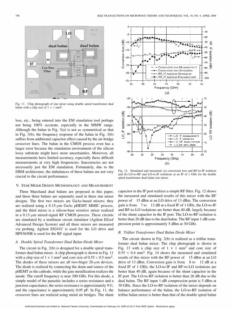
Fig. 12. Simulated and measured: (a) conversion loss and RF-to-IF isolationand (b) LO-to-RF and LO-to-IF isolations at an IF of 1 GHz for the doublespiral transformer dual balun star mixer.
capacitor in the IF port realizes a simple RF filter. Fig. 12 showsthe measured and simulated results of this mixer with the RFpower of 15 dBm at an LO drive of 13 dBm. The conversiongain is from 7 to 12 dB at a fixed IF of 1 GHz, the LO-to-IFand RF-to-LO isolations are better than 40 dB, largely becauseof the shunt capacitor in the IF port. The LO-to-RF isolation isbetter than 20 dB due to the dual balun. The RF input 1-dB com-pression point is approximately 5 dBm at 30 GHz.
B. Trifilar Transformer Dual Balun Diode Mixer
The circuit shown in Fig. 2(b) is realized as a trifilar trans-former dual balun mixer. The chip photograph is shown inFig. 13 with a chip size of 1 1 mm and core size of0.55 0.4 mm . Fig. 14 shows the measured and simulatedresults of this mixer with the RF power of 15 dBm at an LOdrive of 13 dBm. Conversion gain is from 8 to 12 dB at afixed IF of 1 GHz; the LO-to-IF and RF-to-LO isolations arebetter than 40 dB, again because of the shunt capacitor in theIF port. The LO-to-RF isolation is better than 26 dB due to thedual balun. The RF input 1-dB compression point is 5 dBm at30 GHz. Since the LO-to-RF isolation of the mixer depends onbalance performance of the balun, the LO-to-RF isolation oftrifilar balun mixer is better than that of the double spiral balun
Authorized licensed use limited to: National Taiwan University. Downloaded on February 24, 2009 at 23:17 from IEEE Xplore. Restrictions apply.

KUO et al.: NOVEL MINIATURE AND BROADBAND MMW MONOLITHIC STAR MIXERS 799
Fig. 13. Chip photograph of star mixer using trifilar transformer dual balunwith a chip size of 1 � 1 mm .
Fig. 14. Simulated and measured: (a) conversion loss and RF-to-IF isolationand (b) LO-to-RF and LO-to-IF isolations at an IF of 1 GHz for the trifilar trans-former dual balun star mixer.
mixer. The isolations of the double spiral balun mixer andtrifilar balun mixer are better than 20 and 27 dB, respectively.
Fig. 15. Chip photograph of star mixer using 3-D transformer dual balun witha chip size of 0.57 � 0.6 mm .
Fig. 16. Simulated and measured: (a) conversion loss and RF-to-IF isolationand (b) LO-to-RF and LO-to-IF isolations at IF of 1 GHz for the 3-D transformerdual balun star mixer.
Due to the higher insertion loss of the trifilar balun, the LOdrive required by the trifilar balun mixer is higher than thedouble spiral transformer mixer by 1.5 dB.
Authorized licensed use limited to: National Taiwan University. Downloaded on February 24, 2009 at 23:17 from IEEE Xplore. Restrictions apply.

800 IEEE TRANSACTIONS ON MICROWAVE THEORY AND TECHNIQUES, VOL. 56, NO. 4, APRIL 2008
TABLE IPERFORMANCE COMPARISION OF STAR MIXER
C. 3-D Transformer Dual Balun Resistive Mixer
The circuit shown in Fig. 2(c) is realized as the 3-D trans-former mixer. The chip photograph is shown in Fig. 15 with achip size of 0.57 0.6 mm and core size of 0.4 0.3 mm .nMOS and pMOS devices are cascaded to connect with baluns.For the same input impedance, the total width of 32 m is se-lected for the pMOS device, which is twice that of the NMOS.All transistors operate in a passive mode. The input impedanceof the MOS devices can be represented by a simple model,which is a series 20- resistor and 0.05-pF capacitor. Sincethe silicon subtrate is lossy, higher LO power than those in theGaAs-based mixers is needed. Therefore, dc bias of the tran-sistor near the turn-on region is required. 3-k resistors are con-nected to the gate of the MOS devices and dc pad, and four dcblocking capacitors are series connected to the balun and gateof the MOS devices. Two near-threshold voltages supply 0.5 Vand 0.5 V to the gate, and a bias-T is used to connect the IFand dc grounds. Since the devices are biased near the turn-onregion, LO power of only 7 dBm is required. Fig. 16 shows themeasured and simulated results of this mixer with the RF powerof 15 dBm and LO drive of 6 dBm. The conversion gain isfrom 8 to 14 dB at a fixed IF of 1 GHz, and the LO-to-IFand RF-to-LO isolations are better than 40 dB. The LO-to-RFisolation is better than 30 dB, due to the balance of dual balun;the output power level is approximately 30 dBm.
It is observed that the imbalances of the baluns are up to3-dB differences (Figs. 6, 8, and 10), but the LO-to-RF isola-tions of the mixers are still acceptable due to the natures of the
double-balanced mixers. We have seen this consistently withother star mixers. Regarding the LO-to-IF and RF-to-IF isola-tion since there is a low-pass filter with 3-dB cutoff frequency ofapproximately 7 GHz with over a 30-dB rejection above 25 GHzin the IF path, the isolations for 1-GHz IF are taken care of bythis low-pass filter.
Table I compares a number of published results of star mixerdesigns. In this table, an ultra-broadband mixer is proposed byChang et al. [4]; however, the mixer still needs two CPSlines, and a special absorber or suspended substrate for ultra-broadband performance. Therefore, it is difficult to realize inMMICs. Wideband performance and full -band performanceusing a traditional balun and novel hybrid Marchand dual balunand are presented by Yeom and Ko [6] and Kim et al. [7] witha complete analysis of drain–source and drain–gate connectedpHEMT diode performance is discussed [6]; however, the cir-cuits still need baluns and lead to large areas. A miniaturemixer using lumped-element baluns is proposed by Chiou et al.[5], but this circuit cannot be realized in the MMW range be-cause of the low self-resonant frequency of the lumped baluns.Therefore, the novel proposed star mixers in this paper indeeddemonstrate good performances with smallest size compared tothe previously reported star mixers.
VI. CONCLUSION
In this paper, three novel small-size and high-performancestar mixers have been proposed; the LO power is 13 and 15 dBmand 7 dBm for GaAs- and silicon-based mixers, respectively.
Authorized licensed use limited to: National Taiwan University. Downloaded on February 24, 2009 at 23:17 from IEEE Xplore. Restrictions apply.

KUO et al.: NOVEL MINIATURE AND BROADBAND MMW MONOLITHIC STAR MIXERS 801
These three mixer cores occupy only 500 500 mor smaller. Compared to the traditional star mixers, which typi-cally need a core area of , a size reduction of almost80% is achieved. Among these mixers, the 3-D balun mixer pro-vides the best isolations and smallest chip size, but requires amultilayer MMIC process. In the GaAs-based mixers, higherLO-to-RF isolation of the trifilar balun mixer can be achieved,with the requirement of a higher LO drive.
ACKNOWLEDGMENT
The authors would like to thank the staff of WIN Semicon-ductors, Tiawan, R.O.C., the Tiawan Semiconductor Manu-facturing Company (TSMC), Tiawan, R.O.C., and the ChipImplementation Center (CIC) Taiwan, R.O.C., and P. S. Wu,M. F. Lei, C. H. Wang, C. F. Chao, T. P. Wang, all with NationalTaiwan University, Taiwan, R.O.C., and Prof. H. K. Chiou andProf. H. Y. Chang, both with National Central University,Taiwan, R.O.C., for their helpful suggestions.
The chips used in this study were fabricated by WIN Semi-conductors and TSMC through the CIC.
REFERENCES
[1] S. A. Maas, Microwave Mixers, 2nd ed. Norwood, MA: ArtechHouse, 1993.
[2] S. Basu and S. A. Maas, “Design and performance of a planar starmixer,” IEEE Trans. Microw. Theory Tech., vol. 41, no. 11, pp.2028–2030, Nov. 1993.
[3] Y. I. Ryu, K. W. Kobayashi, and A. K. Oki, “A monolithic broadbanddoubly balanced EHF HBT star mixer with novel microstrip baluns,” inIEEE Microw. Millimeter-Wave Monolithic Circuits Symp. Dig., 1995,pp. 119–122.
[4] C. Y. Chang, C. W. Tang, and D. C. Niu, “Ultra-broad-band doubly bal-anced star mixers using planar Mouw’s hybrid junction,” IEEE Trans.Microw. Theory Tech., vol. 41, no. 6, pp. 1077–1085, Jun. 2001.
[5] H. K. Chiou, Y. R. Juang, and H. H. Lin, “Miniature MMIC star doublebalanced mixer using lumped dual balun,” Electron. Lett., vol. 33, no.6, pp. 503–505, Mar. 1997.
[6] K. W. Yeom and D. H. Ko, “A novel 60-GHz monolithic star mixerusing gate–drain-connected pHEMT diodes,” IEEE Tran. MicrowaveTheory Tech., vol. 53, no. 7, pp. 2435–2440, Jul. 2005.
[7] S. S. Kim, J. H. Lee, and K. W. Yeom, “A novel planar dual balun fordoubly balanced star mixer,” IEEE Microw. Wireless Compon. Lett.,vol. 14, no. 9, pp. 440–442, Sep. 2004.
[8] J. R. Long, “monolithic transformers for silicon RF IC design,”IEEE J. Solid-State Circuits, vol. 35, no. 9, pp. 1368–1382, Sep.2000.
[9] P. S. Wu, C. H. Wang, T. W. Huang, and H. Wang, “Compact andbroadband millimeter-wave monolithic transformer balanced mixers,”IEEE Trans. Microw. Theory Tech., vol. 53, no. 10, pp. 3106–3114,Oct. 2005.
[10] J. R. Long, “A low-voltage 5.1–5.8-GHz image-reject down converterRF IC,” IEEE J. Solid-State Circuits, vol. 35, no. 9, pp. 1320–1328,Sep. 2000.
[11] V. Trifunovic and B. Jokanovic, “Star mixer with high port-to-port iso-lation,” Electron. Lett., vol. 32, no. 24, pp. 2251–2252, Nov. 1996.
[12] J. Staudingerm and M. Friesen, “Fully integrated double balancedMMIC mixer using a star arrangement of diodes for extended IFperformance,” in IEEE MTT-S Int. Microw. Symp. Dig., Jun. 1–5,1992, vol. 3, pp. 1163–1166.
[13] B. R. Hallford, “100-mWatt output up converter using Schottkydiodes,” in IEEE MTT-S Int. Microw. Symp. Dig., 1979, pp. 492–494.
[14] N. Marchand, “Transmission-line conversion transformers,” Elec-tronics, vol. 17, pp. 142–145, Dec. 1944.
[15] R. B. Mouw, “A broadband hybrid junction and application to the starmodulator,” IEEE Trans. Microw. Theory Tech., vol. MTT-16, no. 11,pp. 154–161, Nov. 1968.
[16] I. Nam, B. Kim, and K. Lee, “CMOS RF amplifier and mixer circuitsutilizing complementary Characteristics of parallel combined nMOSand pMOS devices,” IEEE Trans. Microw. Theory Tech., vol. 53, no. 5,pp. 1662–1671, May 2005.
Che-Chung Kuo was born in Taipei, Taiwan,R.O.C., in 1980. He received the M.S. degree inelectric engineering from National Center University,Chung-Li, Taiwan, R.O.C., in 2005, and is currentlyworking toward the Ph.D. degree in communicationengineering at National Taiwan University, Taipei,Taiwan, R.O.C.
His research interests include microwave circuitsdesigns and microwave circuit system-on-packageintegration.
Chun-Lin Kuo was born in Kaohsiung, Taiwan,R.O.C., in 1983. He received the M.S. degree incommunication engineering from National TaiwanUniversity, Taipei, Taiwan, R.O.C., in 2007.
His research interests include microwave andMMW circuits designs.
Che-Jia Kuo was born in Yunlin, Taiwan, R.O.C.,in 1983. He received the B.S. degree in electrical en-gineering from National Taiwan University, Taipei,Taiwan, R.O.C., in 2005, and is currently workingtoward the Ph.D. degree at the Graduate Institute ofCommunication Engineering, National Taiwan Uni-versity.
His research interests include monolithic mi-crowave/MMW circuit design.
Stephen A. Maas (M’74–SM’89–F’93) receivedthe B.S. and M.S. degrees from the University ofPennsylvania, Philadelphia, in 1971 and 1972, re-spectively, and the Ph.D. degree from the Universityof California at Los Angeles (UCLA), in 1984, allin electrical engineering.
Since then, he has been involved in research,design, and development of low-noise and nonlinearmicrowave circuits and systems with the NationalRadio Astronomy Observatory (where he designedthe receivers for the Very Large Array), Hughes
Aircraft Co., TRW, the Aerospace Corporporation, and the Department ofElectrical Engineering, UCLA. He was subsequently an engineering consultantand founded Nonlinear Technologies Inc., Long Beach, CA, a consultingcompany, in 1993. He is also Chief Scientist of Applied Wave Research Inc.(AWR Inc.), El Segundo, CA. He authored Microwave Mixers (Artech House,1986 and 1992), Nonlinear Microwave Circuits (Artech House, 1988 and2003), The RF and Microwave Circuit Design Cookbook (Artech House, 1998),and Noise in Linear and Nonlinear Circuits (Artech House, 2005).
Dr. Maas was the editor-in-chief of the IEEE TRANSACTIONS ON MICROWAVE
THEORY AND TECHNIQUES (1990–1992). From 1990 to 1993, he was an IEEEMicrowave Theory and Techniques Society (IEEE MTT-S) AdministrativeCommittee (AdCom) member and publications chairman. He was the recipientof the 1989 Microwave Prize for his work on distortion in diode mixers and the2002 IEEE MTT-S Application Award.
Authorized licensed use limited to: National Taiwan University. Downloaded on February 24, 2009 at 23:17 from IEEE Xplore. Restrictions apply.

802 IEEE TRANSACTIONS ON MICROWAVE THEORY AND TECHNIQUES, VOL. 56, NO. 4, APRIL 2008
Huei Wang (S’83–M’87–SM’95–F’06) was born inTainan, Taiwan, R.O.C., on March 9, 1958. He re-ceived the B.S. degree in electrical engineering fromNational Taiwan University, Taipei, Taiwan, R.O.C.,in 1980, and the M.S. and Ph.D. degrees in electricalengineering from Michigan State University, EastLansing, in 1984 and 1987, respectively.
During his graduate study, he was engaged in re-search on theoretical and numerical analysis of EMradiation and scattering problems. He was also in-volved in the development of microwave remote de-
tecting/sensing systems. In 1987, he joined the Electronic Systems and Tech-nology Division, TRW Inc. He has been an MTS and Staff Engineer respon-sible for MMIC modeling of computer-aided design (CAD) tools, MMIC testingevaluation, and design and became the Senior Section Manager of the Mil-
limeter-Wave (MMW) Sensor Product Section, RF Product Center. In 1993, hevisited the Institute of Electronics, National Chiao-Tung University, Hsinchu,Taiwan, R.O.C., to teach MMIC-related topics. In 1994, he returned to TRW Inc.In February 1998, he joined the faculty of the Department of Electrical Engi-neering, National Taiwan University, as a Professor. He is currently the Directorof the Graduate Institute of Communication Engineering, National Taiwan Uni-versity.
Dr. Wang is a member of Phi Kappa Phi and Tau Beta Pi. He was the recipientof the Distinguished Research Award of the National Science Council, R.O.C.(2003–2006). In 2005, he was elected as the first Richard M. Hong EndowedChair Professor of National Taiwan University. He has been appointed an IEEEDistinguished Microwave Lecturer for the 2007–2009 term. He was the recip-ient of the 2007 Academic Achievement Award presented by the Ministry ofEducation, R.O.C.
Authorized licensed use limited to: National Taiwan University. Downloaded on February 24, 2009 at 23:17 from IEEE Xplore. Restrictions apply.