Embed Size (px)
Citation preview

Information Raining and Optimal Link-LayerDesign for Mobile Hotspots
Daniel H. Ho, Member, IEEE, and Shahrokh Valaee, Senior Member, IEEE
Abstract—In this paper, we propose a link layer design for mobile hotspots. We design a novel system architecture that enables high-
speed Internet access in railway systems. The proposed design uses a number of repeaters placed along the track and multiple
antennas installed on the roof of a vehicle. Each packet is decomposed into smaller fragments and relayed to the vehicle via adjacent
repeaters. We also use erasure coding to add parity fragments to original data. This approach is called information raining since
fragments are rained upon the vehicle from adjacent repeaters. We investigate two instances of information raining. In blind
information raining, all repeaters awaken when they sense the presence of the vehicle. The fragments are then blindly transmitted via
awakened repeaters. A vehicle station installed inside the train is responsible for aggregating a large enough number of fragments. In
the throughput-optimized information raining, the vehicle station selects a bipartite matching between repeaters and roof-top antennas
and activates only a subset of the repeaters. It also dictates the amount of transmission power of each activated repeater. Both the
bipartite matching and power allocations are individually shown to be NP-complete. Matching heuristics based on the Hungarian
algorithm and Gale-Shapley algorithm are proposed. A simplex-type algorithm is proposed as the power allocation heuristics.
Index Terms—Emerging technologies, network architecture and design, wireless communication, network protocols, mobile
communication systems, mobile environments, medium access control, mobile hotspots, graphs and networks, linear programming,
constrained optimization, graph theory, combinatorial algorithms.
�
1 INTRODUCTION
HOTSPOT technology has become very popular recently.We witness the proliferation of hotspots in hotels,
airports, coffee shops, shopping malls, etc. An apparentquestion is whether it would be possible to extend hotspotsto mobile vehicles. This paper proposes a novel architectureto realize mobile hotspots for mass transportation vehiclessuch as trains, subways, and buses. If the hotspottechnology is extended to this truly mobile environment,business travelers may connect to their corporate officesthrough Virtual Private Networks (VPNs) to check theire-mail, do video-conferencing, and finish their work.Leisure travelers may also send instant messages, surf theWeb, and use multimedia applications for entertainment.Although the focus of this paper is on the application ofhotspot technology in trains and subways, similar ap-proaches can be used for buses and automobiles.
Using conventional approaches to extend Internet accessto vehicles is challenging. The direct application of accesspoints (AP) of wireless local area networks (WLANs) alongthe track is highly unscalable. For instance, a vehicletravelling at 72km/h demands handoff every 10 secondswith AP coverage of 100m radius. These handoff rates areinfeasible with the current Mobile IP architecture [1], [2].Overall, the WLAN technology is designed for users withlow mobility, thus it is not suitable to be directly used formobile hotspots in mass transportation systems.
The challenges with cellular systems are similar toWLANs. For instance, there is an issue with cellularplanning. Terrain obstacles such as hills, buildings, andtunnels may cause shadowing and a large delay spread ofseveral microseconds [3] to certain sections of these routes,which impair transmission quality in terms of bit-error-rate(BER) and achievable bandwidth. Therefore, the use ofmicrocells along the transportation route is justified.However, these microcells result in frequent handoffs dueto high mobility and may generate interference to existingmacrocells in the vicinity. Very high velocity movementsmay also induce Doppler effects that are unanticipated bythe system. For example, Maglev trains are intended toreach velocities up to 430km/h [4], whereas GSM isdesigned to handle up to 250km/h at 900MHz. Indeed,the International Telecommunication Union (ITU) Interna-tional Mobile Telecommunications-2000 (IMT-2000) expects3G to only provide a data rate of 144 kbps or higher in highmobility traffic, compared with the expected data rate of2 Mbps or higher in indoor traffic. High Doppler rates arealso known to create “floor phenomena” to BER curves,such that an increase in received signal level does notimprove transmission quality [5], [6].
For rural environments, Low Earth Orbit (LEO) satelliteservices may be used to facilitate Internet access to trainsand ships. A large constellation of LEO satellites orbitaround 500km to 2,000km above the Earth, providing globalcoverage to rural areas. The primary advantage of the LEOsystem is the satellites’ proximity to the ground, thus thereis less propagation delay (about 10ms) and less transmis-sion power is needed compared to the traditional Geosta-tionary Earth Orbit (GEO) satellite system. However, theservice cost of LEO satellites is prohibitive for ordinarycivilian uses. In current LEO satellite services, anybandwidth demand greater than voice-like transmissionsrequires mobile equipment sizes that are not easily portable.
Mass transportation system operators see additionalbenefitswith reliable high-speed accesswithin their vehicles.
IEEE TRANSACTIONS ON MOBILE COMPUTING, VOL. 4, NO. 3, MAY/JUNE 2005 271
. D.H. Ho is with Redknee Inc., 2560 Matheson Blvd. East, Suite 500,Mississauga, ON Canada L4W 4Y9. E-mail: [email protected].
. S. Valaee is with the Department of Electrical and Computer Engineering,University of Toronto, 10 King’s College Road, Toronto, ON, M5S 3G4,Canada. E-mail: [email protected].
Manuscript received 28 July 2004; revised 21 Dec. 2004; accepted 24 Jan.2005; published online 29 Mar. 2005.For information on obtaining reprints of this article, please send e-mail to:[email protected], and reference IEEECS Log Number TMC-0236-0704.
1536-1233/05/$20.00 � 2005 IEEE Published by the IEEE CS, CASS, ComSoc, IES, & SPS

The service may replace their Private Mobile Radio (PMR)system to provide voice communication among drivers,central operators, and maintenance staff. Additional func-tionalities such as signaling control, scheduling, and logisticsupport may be integrated into such a network to assist theirexisting infrastructure. Multimedia entertainment featuressuch as movies and TV on demand may also be madeavailable to passengers if broadband access is provisioned.Indeed, in 1993, Commission 7 of the International Union ofRailways (UIC) decided to adopt GSM as its basis tostandardize pan-European railway communication such thattrains in Europe may communicate with rail stations acrossEuropean countries. The decision sparked an interest inintegrating PMR with cellular systems. In response, Eur-opean Telecommunications Standards Institute (ETSI) elabo-rated a GSM specification for railway uses named GSM-R.Completed in 2000, GSM-R is not an extension version ofGSM, but rather an integral part of the GSM standard. Itprovides important services, including voice broadcast andvoice group call, call priority, and fast call setup, that satisfymost needs of railway operators. With the ever-growingdemand for mobile connectivity, it is reasonable to expectintegration of PMR and public Internet access in masstransportation systems to flourish.
1.1 Related Work
The research result on high-speed access for railway systemsis very limited. To our best knowledge, the only investiga-tions that relate high-speed access on railway systems arebriefly described in [7] and [8], where microcells arepositioned at 1.0km to 1.1km intervals along a railroad, withone mobile station antenna mounted at each end of the traincapable of short-distance communications over a length of800 to 900mwith the closest base stations. Thus, two separatechannelsmaybeestablishedwithnegligible interferencewitheach other. Our systemarchitecture ismore general and takesfull advantage of spatial diversity based on the vehicle’s sizeand surrounding environment.
At the time of this writing, there are several industrialefforts to implement mobile hotspot in railway systems [9],[10], [11], [12], [13]. All of these solutions rely on an existingnetworking infrastructure, such as cellular and satellitesystems, to provide Internet connectivity. As such, coverageof the hotspot service is bounded by the limitations of theunderlying technologies. For instance, coverage ceases attunnels if no relay equipment exists at the entrances. Ingeneral, these solutions provide a smart “hack” to existingsystems and are only satisfactory on an interim basis.
In the research community, a multihop wireless systemis proposed wherein intermediate mobile terminals mayrelay information of other terminals when they are neitherthe initial transmitter nor the final receiver [14], [15], [16],[17]. Among other benefits, wireless multihop routingexpands the existing coverage area with low deploymentcost in cellular networks. Integrated with mesh connectivityand load balancing schemes [18], [19], multihop networksmay provide an adaptive solution to mobile hotspots inmass transportation systems. Indeed, wireless mesh net-works allow every mobile user to act as a cooperativeforwarding node and can be used as a backbone networkthat can transmit data to/from mobile vehicles [20].
However, there are several major shortcomings in theapplication of a multihop wireless system to a mobilehotspot. The first weakness is the assumption of coopera-tion. Mobile users usually turn off their handhelds andlaptops when the device is not in use; even if they areturned on, devices have no incentive to use their limitedbattery power to relay the information of other devices. The
second weakness is the security issues. Because informationis relayed by untrusted parties, security schemes must beapplied to provide assured communication. Processingoverhead and network overhead associated with securitycoding, connection management, and key managementmust be discounted in multihop networks. Third, aspreviously discussed, mobile users in the same vehicleshare the same large-scale path loss and shadowing to basestations, rendering multihop with other nodes in the vehicleineffective. For instance, when a train travels across anunderground section, all mobile users in the vehicle losetheir connectivity and, thus, hopping to their peers is futile.Overall, a multihop wireless system can be an inefficient,overcomplicating the solution when applied to a mobilehotspot scenario in mass transportation systems.
1.2 Contributions and Paper OrganizationIn this paper, we propose a novel system architecture tofacilitate mobile hotspots that is applicable to both WLANand cellular systems. This is coherent with the recentdevelopment in the convergence of these two technologies.Although some concepts are applicable to other vehicularsystems, we shall focus on long-haul railway and metropo-litan subway systems. We then consider design issues whenimplementing our architecture at the link layer, followed bysystem modeling, optimization analysis, and simulationresults. For the rest of this paper, we shall limit ourdiscussion to downlink traffic forwarding due to theemergence of asymmetric data applications in mobiledevices, although our architecture allows for traffic flowin both directions.
Our research intent is to investigate link layer design andoptimization techniques of our proposed architecturespecific to railway systems. Nonetheless, the scope of theproblem is vast; this paper subsequently focuses on only themost noteworthy section (in the authors’ opinion) of thearchitecture, which is the wireless environment betweenmultiple repeaters and vehicle antennas that is described in thenext section. Furthermore, we restrict our optimizationobjective to throughput maximization. However, we shouldmention that the definition of throughput in this paper doesnot match the conventional definition of throughput, whichis the average number of successfully received packets atthe destination. Instead, we think of the throughput as theaverage number of packets transmitted to the vehicle, whilenoting that, in certain conditions, some of these packetsmight be repeated and hence redundant.
In the following section, we propose an open architecturethat employs repeaters located along the trackside andmultiple antennas mounted on the exterior of the vehicle.We then suggest two general methods of transmissionbetween each repeater-antenna pair. First, we introduce andanalyze the blind information raining method in Section 3. Inblind information raining, downlink data is equally dis-tributed among multiple repeaters to be blindly transmittedto the air interface with equal power and data rate. Multiplevehicle antennas act as receivers where each of themindependently tunes to one of the repeaters to recoverinformation. Section 4 presents the interference model usedbetween the set of active repeaters and antennas. Then, inSection 5, we propose a throughput-optimized methodbased on resource allocation. In addition to traditionalresource considerations such as power, rate, and signal-to-noise ratios, we consider the freedom of matchings betweenrepeaters and antennas as another significant resourceallocation problem. Unfortunately, the mathematical com-plexity of the problem is shown to be NP-complete. Several
272 IEEE TRANSACTIONS ON MOBILE COMPUTING, VOL. 4, NO. 3, MAY/JUNE 2005

heuristic algorithms are proposed as a consequence inSection 6 and Section 7.
Last, we compare techniques presented in Section 3 andSection 5 through simulation analysis in Section 8. Weinvestigate how some of the parameters of the modeledrailway environment affect performance in terms of systemthroughput. We also provide system enhancements basedon these insights. From these simulations, we are able toobtain interesting insights about our setting and relate themto other works. Finally, conclusions are presented at the endof the paper.
2 SYSTEM ARCHITECTURE
All handheld devices have critical constraints in hardwarecomponent size, computation power, and battery power.Consequently, they can only process relatively simpleprocedures and only one small antenna can be installed inmost devices. Conversely, one common feature amongtrains is their large physical size. More powerful network-ing equipment can be installed inside vehicles withoutpractical space and battery power limitations. It is also idealto install several more powerful antennas around vehicles,connecting them to the networking equipment.
Furthermore, unlike generic mobile users, trains have anetwork of defined paths to travel. By installing repeaters atclose vicinity along the network of paths, line-of-sight (LOS)can be guaranteed between repeaters and vehicles thatmove along the network.
We propose a system architecture for mobile hotspots inrailway systems, as shown in Fig. 1. Similar to backbonenetworks and mobile switching centers of cellular systems,the mass transportation system communications network isa cloud of networking equipment that is responsible forrouting traffic between the Internet and local informationdistribution centers that we refer to as zone controllers (ZC).Zone controllers are responsible for traffic disseminationwithin their local region, such as a railway section of severalkilometers. They are also responsible for detecting thepresence of vehicles and their mobile users. The ZC neednot be standalone equipment, but a functional procedureinside the “transportation communications network” and,thus, the implementation may leverage resources of theexisting network. Stationary repeaters are positioned along
the responsible path. Repeaters and ZC may be connectedvia fiber cables or via daisy chaining of wireless links withintermediate repeaters. These repeaters then relay the trafficof the ZC to multiple antennas that are installed on top ofmoving vehicles. A vehicle station (VS) that gathers trafficfrom vehicle antennas and relays them to access points islocated inside each vehicle. Thus, passengers enjoy seam-less mobile hotspot service with no adjustment at themobile terminal.
We categorize system implementation alternatives of ourparadigm into three approaches, distinguished by differentnetworking layers. At the physical layer viewpoint, thedescribed paradigm can be modeled as a MIMO channel,where channel gain and coding gain may be achieved withspace-time codes [21], [22]. At the network layer viewpoint,the described paradigm can be modeled as a multipathnetwork, where benefits in throughput and fault tolerancemay be achieved with multipath routing [18], [23]. Thesetwo models are well understood in general; as an alter-native, in this paper, we are interested in designing ourarchitecture at the link layer.
3 BLIND INFORMATION RAINING
In link layer design, the ZC receives downlink data from thesystem network and disseminates data to multiple repeatersin the vicinity of the vehicle. The overall system diagram fordownlink traffic is shown in Fig. 2. Each repeater forms a one-to-onewireless channel to eachvehicle antenna and transmitssuch data via the channel. The VS at the vehicle receives thepackets and forwards them accordingly. (For brevity, weshall refer to vehicle antennas simply as “antennas” hence-forth.) Thus, the handoff of wireless links within the zone isimplicitly handled by link acquirement renewals.
Similarly to multipath routing techniques, it is possibleto improve system reliability with erasure coding onpackets [24], [25], [19]. Instead of error detection andcorrection, erasure codes are added to provide faulttolerance if a segment of data is lost or “erased” duringtransmission. By segmenting the encoded data into seg-ments of equal length, these segments can be disseminatedto the repeaters, which act as dumb terminals that repeatsegments to the air interface. Since each wireless link may
HO AND VALAEE: INFORMATION RAINING AND OPTIMAL LINK-LAYER DESIGN FOR MOBILE HOTSPOTS 273
Fig. 1. Proposed architecture for mobile high-speed access in railway system.

temporarily lose link due to fading and interference, notevery segment may be received by the correspondingantenna. However, the decoder at VS can reconstruct theoriginal data if a certain number of unique segments arrivesuccessfully, regardless of the specific subset of segmentarrivals.1 Effectively, erasure coding enhances robustness tothe inherently unreliable wireless channels. From a networklayer standpoint, the traffic flow between ZC and thevehicle is viewed as a single transparent link. Wemetaphorically describe this approach as information rain-ing, where segments of information are rained upon thevehicle by repeaters and antennas resemble buckets thatretrieve as much information as possible.
We propose a general MAC layer structure, as shown inFig. 3. One master antenna is employed at the vehicle tobroadcast a beacon signal to repeaters in the vicinity.Repeaters that detect the presence of this signal “awaken”and broadcast their unique identification signals as anacknowledgment. Each antenna detects their existence andperforms subchannel estimation on each awakened repea-ter. One simple scheme is to allow each antenna to tuneindependently to the repeater that yields the strongest linkgain; we label this scheme as blind information raining. Allrepeaters then broadcast segments during the frame pay-load of constant length in time. A similar procedure occursin uplink frames, but with repeaters and vehicle antennas inreversed-role.
At the end of each frame, some packets are successfullyrecovered. It would be redundant for repeaters to transmitsegments of packets that are successfully recovered inprevious frames. Consequently, we recommend a redun-dant-segment flushing process. The master antenna broad-casts a packet recovery update record (FlushingUpdate in Fig. 3)after the beacon signal. Repeaters thendiscard all segments ofthe corresponding packets that remain in their buffer. Thisscheme effectively increases throughput of the system and isparticularly important when the system employs erasurecoding with high protection ratio. The redundant-segmentflushing update occurs only after a downlink frame because,
in uplink, ZC is unlikely able to quickly feed back packetrecovery updates to repeaters at the next frame header andthere is no equivalency of the master antenna to broadcast tothevehicle even if such information is available.Regardless oftraffic direction, a complimentary segment-timeout mechan-ismmust be implemented at bothVS and repeaters to discardlingering segments.
Information raining allows minimal intelligence from therepeaters and the possibility of building them withrelatively cheap, standards-ready components. This isimportant for deployment cost because numerous repeatersmust be installed along the transportation system.
Clearly, blind information raining is not performance-oriented; for instance, multiple antennas may tune to thesame repeater, resulting in retrieval of redundant segments.However, the simple scheme has several implementationadvantages. First, link establishment decisions are decen-tralized to the antennas. With off-the-shelf wireless compo-nents, it may be infeasible to pass channel estimation data toVS in real-time (i.e., with respect to channel coherence time)to generate a centralized decision. Second, there is no needfor explicit MAC layer control. The repeaters and antennasare not required to “communicate” with each other in termsof per-link synchronization and addressing; repeaters onlyneed to blindly transmit and antennas only need to listen.
4 INTERFERENCE MODEL
Let us model our link layer architecture with downlinkinformation traveling from ZC to VS, as shown in Fig. 4. Mrepeaters are assumed to be positioned in the vicinity of thevehicle, with distance dr apart from each other. We assumethat dr, the horizontal distance, is larger than the coherencedistance. These repeaters are assumed to receive segmentsfrom ZC via high quality links. At the vehicle side,N vehicleantennas are connected to the VS with high quality links,with distances da apart from each other. Let the shortestpossible distance between a repeater and a vehicle antennabe dv, the vertical distance.
At the physical layer, the air interface is shared byM transmitters andN receivers.We assume the employmentof omnidirectional antennas. A simple fading model isconsidered; all M �N possible subchannels exhibit flat-fading and slow-fading such that fading coefficients of allsubchannels remain constant over one frame. It is assumedthat the noise is additive white-Gaussian with constant noisepower N0. Fading is considered to be contributed by twofactors, one from the small-scale variations due to randommultipath components and the other from large-scale pathloss, which is distance dependent. Thus, link (power) gainfrom repeater i to antenna j is modeled as
274 IEEE TRANSACTIONS ON MOBILE COMPUTING, VOL. 4, NO. 3, MAY/JUNE 2005
1. Any repeated segment is only used once in the received set ofsegments.
Fig. 2. System block diagram for downlink traffic with information raining.
Fig. 3. MAC layer frame format for blind information raining.

Gij ¼ �2ijL0
dijd0
� ���
; ð1Þ
where �ij is a Rician distributed random variable whichrepresents the envelope of a nonzero mean complexGaussian random variable with Rician factor K, dij is thedistance separating repeater i and antenna j, � is the pathloss exponent, and L0 is the signal attenuation level at theclose-in reference distance d0. The second term follows thepopular log-distance path loss model. The model isappropriate because a direct line-of-sight can be observedin all subchannels. For simplicity, we assume that eachantenna j can estimate Gij for each repeater i with no error.
Because dr and da are farther than coherence distance, �sof all subchannels are assumed to be mutually independent.Therefore, the elements in link gain matrix G ¼ ðGijÞ are alsomutually independent. We further assume that G updatesindependently for every frame. Because the signals areRician and multiple interference signals are also Rician,regardless of matching decision, the model is referred to asRician/Rician fading environment in the literature.
We model the environment of M repeaters and Nantennas as a complete weighted bipartite graph,2 as shown inFig. 4. The antennas and repeaters are represented by twoseparate sets of vertices. The wireless link between everypossible repeater-antenna pair is represented by an edge ofthe graph, with each end incident with a vertex of adifferent set. The link gain Gij is associated as the weight ofeach edge ði; jÞ. The choice of transmission with multiplewireless links among all repeater-antenna pairs, with therestriction of one-to-one connection at each repeater andantenna, corresponds to a matching3 of the bipartite graph.For notation convenience, we define a matching X of thebipartite graph in two equivalent ways:
. In the form of a set of edges X ¼ fði; jÞg1�i�M;1�j�N ,where all edges ði; jÞ 2 X may be incident onrepeater i or antenna j only once.
. In the form of a matrix X ¼ ðxijÞ1�i�M;1�j�N , wherexij ¼ 1 if the link between repeater i and antenna j is
chosen toward the matching and xij ¼ 0 if the link isnot chosen. Clearly, the sum of every row or columnof X must be 0 or 1 to qualify as a matching matrix.
Any one of the two notations is sufficient to define abipartite matching. The use of either notation will be implicithenceforth. Moreover, a matching X has a cardinality of kwhen it contains k edges; we write jXj ¼ k in this case.
We further model each repeater i to transmit with signalpower Pi and link rate ri. Clearly, Pi ¼ 0 and ri ¼ 0 if therepeater is inactive. We respectively define power allocationvector and link rate allocation vector as PP ¼ ½Pi�1�i�M andrr ¼ ½ri�1�i�M .
We further assume all wireless links communicate by theDS/SSMA technique. Given a matching X, the popularEb=ðN0 þ I0Þ metric on matched link ði; jÞ is
�ij ¼W
ri
� �GijPi
N0 þP
ðk;lÞ2X;k6¼i GkjPk; ð2Þ
where W is the system bandwidth. The summation in thedenominator is the interference experienced by link ði; jÞ.Notice that W
ri> 1 is the processing gain of the link.
Similarly to the outage probability definition, we say thateach link must exceed a required threshold �th to maintainlink fidelity. For brevity, we shall henceforth refer to thiscriterion as the SINR criterion. If this condition is notsatisfied, no segments are successfully received from thelink. Therefore, ignoring the effects of erasure coding, wedefine system throughput as the normalized aggregate linkrate from multiple links,
Rsystem ¼ �thW
Xði; jÞ 2 X�ij � �th
ri: ð3Þ
5 THROUGHPUT OPTIMIZATION
In this section, we maximize the system throughput. Wenow consider VS with the freedom to decide upon matchingX, power PP , and link rate allocation vector rr, given linkgain matrix GG ¼ ½Gij� among all repeaters and antennas.
As defined previously, any link ði; jÞ must satisfy theSINR criterion to successfully receive segments. For anygiven X and PP , we propose setting each link rate ri suchthat �ij is equal to (or barely exceeds) �th. The strategy is toutilize every excessive SINR to maximize system through-put. Since the minimum processing gain is 1, the link rate isupper bounded by W . For simplicity, we further assumethat ri 2 IR.
Consequently, neglecting the W bound, we set each ri as
ri ¼W
�th
� �GijPi
N0 þP
ðk;lÞ2X;k6¼i GkjPkð4Þ
and, thus, the system throughput defined in (3) becomes
Rsystem ¼ �thW
Xði;jÞ2X
ri
¼X
ði;jÞ2X
GijPi
N0 þP
ðk;lÞ2X;k6¼i GkjPk
ð5Þ
which is our maximization objective function. We are nowready to pose our optimization problem:
HO AND VALAEE: INFORMATION RAINING AND OPTIMAL LINK-LAYER DESIGN FOR MOBILE HOTSPOTS 275
Fig. 4. System model from zone controller to vehicle station.
2. A bipartite graph is any graph G ¼ ðV ;EÞ that can be partitioned intotwo mutually disjoint sets of vertices V ¼ X _[[Y for which every edge in Ehas one vertex inX and the other in Y . A complete weighted bipartite graphis a bipartite graph where every pair of vertices with one vertex in X andthe other in Y is an edge with an associated real number, or “weight,” in thegraph.
3. A matching in any graph G is defined as a set of edges, no two ofwhich have a common end-vertex.

maximize Rsystem
subject toPN
j¼1 xij ¼ 0 or 1 ð1�i�MÞPMi¼1 xij ¼ 0 or 1 ð1�j�NÞ
xij 2 f0; 1g ð1�i�M;1�j�NÞGijPi
N0þP
ðk;lÞ2X;k6¼iGkjPk
� �th ð8 xij¼1Þ
0 � Pi � Pmax ð1�i�MÞ:
ð6Þ
The first three constraints arise from the definition ofbipartite matching. If repeater i or antenna j is active, therow sum or column sum equals 1, respectively. If it isinactive, the sum is 0. The fourth constraint stems from theprocessing gain restriction of link rates. Because a proces-sing gain cannot be less than 1, ri > W is unrealizable.Bounding (4) with ri � W yields the fourth constraint.Henceforth, we shall refer to this constraint as the “W upperbound.” Intuitively, there is no incentive for the system toprovide a �ij so high that it breaks the fourth constraint; Pi
can be decreased to reduce interference of other linkswithout shrinking its link rate ri ¼ W , for instance. Finally,the last constraint is the regulatory or system limitations ontransmitting power.
The MAC layer framer of throughput-optimized infor-mation raining is illustrated in Fig. 5. Notice that somerepeaters and antennas may be inactive, which is governedby the matching decision X. Individual link rates andpower allocation may also differ from one another. There-fore, each active antenna must engage its matched repeater,based on repeater identification signals, to perform link rateand power allocation. The link engagement phase (Signal Ein Fig. 5) may also include PN sequence synchronization,symbols training, and MAC addressing.
Before a formal attempt to solve (6), we would like toprovide some intuition to the problem. The freedom of“matching,” to the best of our knowledge, has not beenconsidered in previous optimization literature on wirelesssystems. In a general wireless network such as cellularsystems or ad hoc wireless systems, pairs of transmittersand receivers communicate with each other with a fixedpartner. Conversely, in our setting, all matched links serveto transfer information between ZC and VS and, thus, anylink may be “sacrificed” in the optimization problem for thesake of interference reduction to increase system through-put. As such, the cardinality of X does not need to be equalto the number of antennas N ; that is, not all antennas mustbe active to achieve the maximum system throughput.Consider an example where there exist only two antennasand two repeaters, with link gain G11 ¼ G12 ¼ G21 ¼ G22 ¼1 and N0 ¼ 0:5mW , with power P1 ¼ P2 ¼ 1mW . Then,activating one link achieves a better system throughputthan activating both links.
Often, one’s immediate instinct to the matching problemis that we shall match each antenna to its nearest repeater.This may be true in some cases, but may not hold in otherinstances. In general, the matching decision and cardinalityof X depends on the background noise power N0 and thedistribution of the link gain matrix G, which, in turn,depends on other physical parameters such as repeater-antenna distances and fading effects.
In addition to bipartite matching, we need to find theoptimal power allocation vector. The optimization problemof interest can be viewed as an integration of two problemsof different qualities; a bipartite matching problem that iscombinatorial in nature and a power allocation problemthat is algebraic in nature. Despite much effort, we areunable to produce an integrated algorithm that generates ajoint solution for the power allocation vector and matching.As such, we shall consider our problem as two separate
optimization problems: one problem concerning optimalmatching X and the other concerning optimal powerallocation PP . We propose first solving the matchingproblem and then using the resulting matching X to solvethe corresponding power allocation problem. Clearly, ourprocess is heuristic because the resulting power allocationand matching cannot guarantee a global maximum insystem throughput among all combinations of powerallocations and matchings. However, one can think ofiterating the two problems to arrive at a globally optimumsolution. We do not study possible convergence of suchprocedure in this paper and defer it to a later work.Nonetheless, as we shall see, both the power allocationproblem and the matching problem are individually “hard”problems to solve.
6 BIPARTITE MATCHING
Our first objective is to develop matching algorithms suchthat a high Rsystem may be reached when power allocationalgorithms are processed with these “good” matchings.However, it is analytically difficult to derive a cleardefinition of good matchings because the SINR criteria isa function of both PP and X.
In order to be fair among possible links, we set equalconstant power P 0 � Pmax among all repeaters, soPi ¼ P 0 8i. It is clear that the resulting problem is anInteger Program, the class of which are known to be NP-complete in general [26].
A related classical problem on matchings in bipartitegraphs is the assignment problem [26], which is the quest tofind the optimal assignment of workers to jobs thatmaximizes the sum of ratings, given all nonnegativeratings cij of each worker i to each job j. Posed as anoptimization problem, the assignment problem is asfollows:
maximizePN
i¼1
PNj¼1 cijxij
subject toPN
i¼1 xij ¼ 1 ð1�j�NÞPNj¼1 xij ¼ 1 ð1�i�NÞ
xij 2 f0; 1g ð1�i�N;1�j�NÞ:
ð7Þ
The last constraint, xij 2 f0; 1g, in (7) suggests that thisis an Integer Linear Program (ILP)—the class of programswhere polynomial-time algorithms do not exist in general.However, if we change the last constraint to be real-valued such that xij � 0, the overall constraint setbecomes the so-called assignment polytope. The extremepoints in the assignment polytope are always integral inall xij. Furthermore, the set of extreme points are in one-to-one correspondence with the set of possible matchings.
276 IEEE TRANSACTIONS ON MOBILE COMPUTING, VOL. 4, NO. 3, MAY/JUNE 2005
Fig. 5. MAC layer frame format for throughput-optimized information
raining.

Consequently, when the constraint xij � 0 is added, theintegral constraint becomes redundant. The optimizationproblem in (7) becomes an LP of N2 variables, which canbe solved rather efficiently.
6.1 Hungarian Algorithm
The first polynomial-time solution of the assignmentproblem came from a combinatorial technique known asthe Hungarian method by Kuhn [27] in 1955, due to theimplicit work of Hungarian mathematicians Egevary andKonig on the algorithm. The complexity of the algorithmis OðN3Þ [28, p. 142]. The classic problem has beenstudied thoroughly since; more efficient algorithms havebeen found, where the best to date is the Hopcroft-Karpalgorithm [29], which is a modification of the Hungarianalgorithm that runs in OðN2:5Þ time. However, resultsfrom Mitra and Darby-Dowman [30] show that theHopcroft-Karp approach is inferior to the Hungarianapproach in practice due to the modified subproblembeing larger than the amount of several single augmenta-tions by running tests on a significant set of problems.
Returning to our matching problem, one simplification isto ignore the W upper bound, such that our matchingproblem has the potential to relax the integrality condition.This approach is employed in all matching algorithmsdescribed in this paper. We argue that this simplification istolerable because our power allocation algorithms canhandle the W upper bound. Consequently, we considerour bipartite matching optimization problem as follows:
maximizePM
i¼1
PNj¼1
"Gijxij
N0=P 0þPM
k¼1k 6¼i
PN
l¼1Gkjxkl
#
subject toPN
j¼1 xij ¼ 0 or 1 ð1�i�MÞPMi¼1 xij ¼ 0 or 1 ð1�j�NÞ
xij 2 f0; 1g ð1�i�M;1�j�NÞ:
ð8Þ
Due to these simplifications, we now resolve to createheuristics that yield “good” matchings. An obviousapproach is a direct application of the Hungarian method;by assuming equal and constant interference amongmatchings, i.e.,
N0=P0 þ
XMk¼1k6¼i
XNl¼1
Gkjxkl ¼ C;
where C is a constant, (8) takes the form of the assignmentproblem, where we directly apply the Hungarian methodon link gain matrix G to obtain matching.
The obvious weakness in this direct methodology is thatall interference terms are neglected, generating a set of linksthat are “inconsiderate” of other links. As such, one mayview the Hungarian method as a greedy approach to ourmatching problem. From this standpoint, it is also intuitivethat the Hungarian method always yields a maximalmatching.4 We then depend on our power allocationalgorithm to inactivate some of the links to reduceinterferences in order to maximize system throughput. Wesummarize the Hungarian algorithm in Algorithm 1 (seeFig. 6) and Algorithm 2 (see Fig. 7).
6.2 Hungarian Algorithm with Effective WeightsAn alternative approach considers the case where we fix asubset, denoted S � f1; 2; . . . ;Mg, of M repeaters to beactive and others inactive. Then, by setting all activerepeaters to operate at Pmax, the interference experiencedby each antenna is fixed. We denote G0
ij as the effectiveweight experienced by repeater i 2 S and antenna j,
G0ij ¼
Gij
N0=Pmax þP
k2Sk 6¼i
Gkj: ð9Þ
For a fixed S, we see that G0ij is constant. Furthermore,
our matching problem in (8) becomes
maximizeP
i2SPN
j¼1 G0ijxij
subject toPN
j¼1 xij ¼ 0 or 1 ði2SÞPi2S xij ¼ 0 or 1 ð1�j�NÞ
xij ¼ 0 ði=2S;1�j�NÞxij 2 f0; 1g ði2S;1�j�NÞ;
ð10Þ
which is an assignment problem corresponding to the activerepeaters i 2 S and can be solved by the Hungarianmethod. Given such a fixed instance of S, the solutionyields the optimal system throughput with Pi2S ¼ Pmax andthe omission of the W upper bound. Clearly, the effective-weight approach describes the system more accurately thanthe straightforward approach, given a subset S, but onlywith the application of such an S.
Ideally, we generate matchings from all 2M subsets ofrepeaters, which is exponential to our problem size. Clearly,that is not acceptable and, thus, we propose solving ourmatching problem with all repeaters being active. We labelthis approach as theHungarian algorithm with effective-weight.
6.3 Stable Matching
As the third heuristics, we describe the stable marriageproblem [31], [32], [33], which is the quest of finding stablematchings between N men and N women. Each personranks all members of the opposite sex in strict order ofpreference. Given a maximal matching X that “marries” offeach woman to each man, we denote pXðmÞ to be thewoman that is married to man m and pXðwÞ to be the manthat is married to woman w. A man m and a woman w aresaid to block the matching X if m prefers w over pXðmÞ andw prefers m over pXðwÞ. The existence of a blocking pairðm;wÞ represents a situation in real life in which the pairwould run off with each other, breaking matching X. Thus,a stable matching is a matching without such a blocking pairor, otherwise, it is an unstable matching. We illustrate aninstance of the stable marriage problem and its set ofsolutions in Table 1. For instance, man 1 prefers woman 2over woman 1, over woman 4, and over woman 3. Thisparticular example has three stable matchings, denoted asX0, X1, and X2.
One of the first astonishing facts about the stablemarriage problem is that every instance of the problemalways admits at least one stable matching. The Gale-Shapley (GS) algorithm [31] generates one such stablematching in OðN2Þ time; a runtime that is surprisinglyfast. Since Gale and Shapley’s fundamental result, thestable marriage problem has been explored in detail andefficient representations and algorithms to the problemhave been discovered. For instance, the set of all stablematchings X can be well-represented by the so-calledrotation poset, which can be constructed in OðN2Þ time,
HO AND VALAEE: INFORMATION RAINING AND OPTIMAL LINK-LAYER DESIGN FOR MOBILE HOTSPOTS 277
4. A maximal matching is a matching that is not a proper subset of anyother matchings in a graph. In our case, any matching X is a maximalmatching if and only if jXj ¼ N in our complete bipartite graph.

even though jXj may be exponential in N . Moreimportantly, the rotation poset may be utilized toenumerate all stable matchings in OðN2 þNjXjÞ time.
We cast our matching problem to the stable marriage
problem as follows: The “men’s preference lists” are con-
structed by ranking the link gain of all antennas experienced
by each repeater i. This is equivalent to sorting each row i of
the link gain matrix G ¼ ðGijÞ in decreasing order and
marking their original indices. Similarly, we construct the
“women’s preference lists” by ranking gain of all repeaters
experienced by each antenna j, by sorting each column j ofG.
These constructions can be done in OðN2Þ time.5
It has been shown in [34] that exactly one stable matching
can be found when solving for the corresponding stable
marriage problem of (8). The proof concerns the underlying
mathematical structure of the stable marriage problem,
which is out of the intended scope of this paper. None-
theless, because only one stable matching can be found, the
use of the GS algorithm is sufficient to find this one
matching; it is unnecessary to construct the rotation poset
and perform enumeration of “all” stable matchings. We
summarize our stable matching algorithm in Algorithm 3
(see Fig. 8); the GS algorithm is also presented as a routine.
7 POWER ALLOCATION
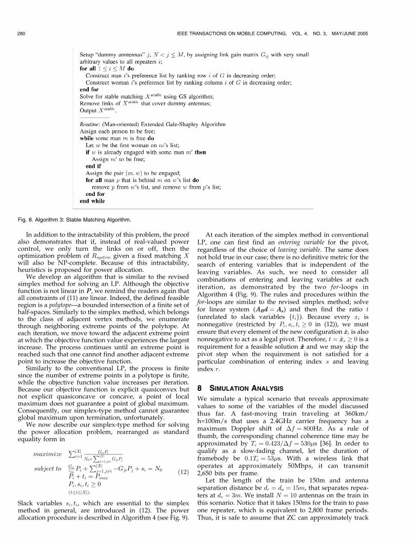
We develop power allocation algorithms based on theabove matching results. Let us consider a simpler problemof (6), where a fixed matching X has been given. Withoutloss of generality, let the matching X map each repeater i toantenna i, for all i ¼ 1; 2; . . . ; jXj � N . This can be achievedby appropriately reordering the indices of repeaters andantennas. Then, the optimization problem becomes
maximizePjXj
i¼1GiiPi
N0þPjXj
j¼1;j6¼iGjiPj
subject to GiiPi
N0þPjXj
j¼1;j6¼iGjiPj
� �th ð1�i�jXjÞ
0 � Pi � Pmax ð1�i�jXjÞ:
ð11Þ
Before we continue with our discussion, we require
several background definitions on convexity and linear
fractional programming [35, Ch. 2,3]. The notation xxk below
serves as an index to the vector variable.
Definition 1. A function f ispseudoconvex on a nonempty open
convex set X � IRn if f is differentiable and if 8 xx1; xx2 2 X,
ðxx1 � xx2ÞTrfðxx2Þ � 0¼)fðxx1Þ � fðxx2Þ or, equivalently,
fðxx1Þ < fðxx2Þ¼)ðxx1 � xx2ÞTrfðxx2Þ < 0:
278 IEEE TRANSACTIONS ON MOBILE COMPUTING, VOL. 4, NO. 3, MAY/JUNE 2005
5. To deal with an unequal number of repeaters and antennas whenmapping to the stable marriage problem, we setup “dummy antennas” suchthat the number of repeaters and antennas become the same. These dummyantennas have arbitrarily small link gain to repeaters and preference lists ofthe stable marriage problem are generated as usual. For any stablematching X found in the stable marriage problem, the links that coverthese dummy antennas are removed.
Fig. 6. Algorithm 1: The Hungarian Method.

Definition 2. A function f is explicit quasiconvex on nonemptyconvex set X � IRn if 8 xx1; xx2 2 X, fðxx1Þ 6¼ fðxx2Þ, and8 t 2 ð0; 1Þ,
f ½txx1 þ ð1� tÞxx2� < max½fðxx1Þ; fðxx2Þ�:
Definition 3. A linear fractional function f : IRn ! IR is ofthe form fðxxÞ ¼ ðccTxxþ c0Þ=ðddTxxþ d0Þ. A linear fractionalprogram is to maximize fðxxÞ subject to linear constraints,with the denominator ddTxxþ d0 maintaining a constant sign(say positive) throughout the domain of feasible solutions (i.e.,the set of points that satisfy all of the constraints).
Although a linear fraction is both explicit quasiconvexand explicit quasiconcave, nothing (either quasiconvex orquasiconcave) can be said about sums of linear fractions ingeneral, of which Rsystem takes the form. However, derivedin Appendix I (which can be found on the Computer SocietyDigital Library at http://computer.org/tkde/archives.htm),we show the below lemma holds true.
Lemma 7.1. The objective function in (11) is pseudoconvex on PP .
Since f is pseudoconvex, f is also explicit quasiconvex [35,p. 46]. Because f is explicit quasiconvex, we also know that freaches its global maximum in one or more extreme points inits feasible domain [35, p. 49]. In conclusion, we know that
the solution of (11) exists in one of the extreme pointsconfined by its constraints. Therefore, similarly to linearprogramming problems, we need to enumerate extremepoints of our feasible set to find our solution. Unfortunately,as shown in Appendix II (which can be found on theComputer Society Digital Library at http://computer.org/tkde/archives.htm), this is an NP-complete problem.
Theorem 7.2. The optimization problem (11) is NP-complete.
Proof. See Appendix II (which can be found on theComputer Society Digital Library at http://computer.org/tkde/archives.htm). tu
HO AND VALAEE: INFORMATION RAINING AND OPTIMAL LINK-LAYER DESIGN FOR MOBILE HOTSPOTS 279
TABLE 1Stable Marriage Instance of Size 4 and Its Set of Solutions
Fig. 7. Algorithm 2: Routine MaximumMatching.
In addition to the intractability of this problem, the proofalso demonstrates that if, instead of real-valued powercontrol, we only turn the links on or off, then theoptimization problem of Rsystem given a fixed matching Xwill also be NP-complete. Because of this intractability,heuristics is proposed for power allocation.
We develop an algorithm that is similar to the revisedsimplex method for solving an LP. Although the objectivefunction is not linear in PP , we remind the readers again thatall constraints of (11) are linear. Indeed, the defined feasibleregion is a polytope—a bounded intersection of a finite set ofhalf-spaces. Similarly to the simplex method, which belongsto the class of adjacent vertex methods, we enumeratethrough neighboring extreme points of the polytope. Ateach iteration, we move toward the adjacent extreme pointat which the objective function value experiences the largestincrease. The process continues until an extreme point isreached such that one cannot find another adjacent extremepoint to increase the objective function.
Similarly to the conventional LP, the process is finitesince the number of extreme points in a polytope is finite,while the objective function value increases per iteration.Because our objective function is explicit quasiconvex butnot explicit quasiconcave or concave, a point of localmaximum does not guarantee a point of global maximum.Consequently, our simplex-type method cannot guaranteeglobal maximum upon termination, unfortunately.
We now describe our simplex-type method for solvingthe power allocation problem, rearranged as standardequality form in
maximizePjXj
i¼1GiiPi
N0þPjXj
j¼1;j 6¼iGjiPj
subject to Gii
�thPi þ
PjXjj¼1;j 6¼i �GjiPj þ si ¼ N0
Pi þ ti ¼ Pmax
Pi; si; ti � 0ð1�i�jXjÞ:
ð12Þ
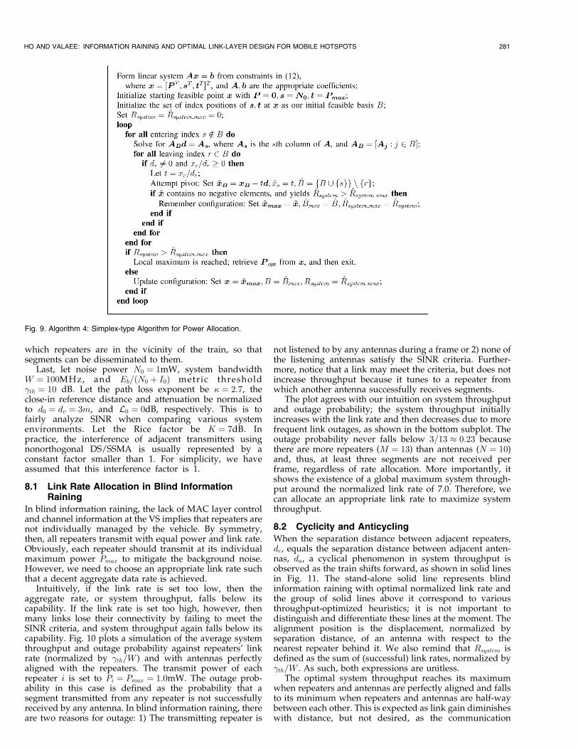
Slack variables si; ti, which are essential to the simplexmethod in general, are introduced in (12). The powerallocation procedure is described in Algorithm 4 (see Fig. 9).
At each iteration of the simplex method in conventionalLP, one can first find an entering variable for the pivot,regardless of the choice of leaving variable. The same doesnot hold true in our case; there is no definitive metric for thesearch of entering variables that is independent of theleaving variables. As such, we need to consider allcombinations of entering and leaving variables at eachiteration, as demonstrated by the two for-loops inAlgorithm 4 (Fig. 9). The rules and procedures within thefor-loops are similar to the revised simplex method; solvefor linear system (ABABdd ¼ AsAs) and then find the ratio t(unrelated to slack variables ftig). Because every xi isnonnegative (restricted by Pi; si; ti � 0 in (12)), we mustensure that every element of the new configuration xxi is alsononnegative to act as a legal pivot. Therefore, t ¼ xxs � 0 is arequirement for a feasible solution xxxx and we may skip thepivot step when the requirement is not satisfied for aparticular combination of entering index s and leavingindex r.
8 SIMULATION ANALYSIS
We simulate a typical scenario that reveals approximatevalues to some of the variables of the model discussedthus far. A fast-moving train traveling at 360km/h=100m/s that uses a 2.4GHz carrier frequency has amaximum Doppler shift of �f ¼ 800Hz. As a rule ofthumb, the corresponding channel coherence time may beapproximated by Tc ¼ 0:423=�f ¼ 530�s [36]. In order toqualify as a slow-fading channel, let the duration offramebody be 0:1Tc ¼ 53�s. With a wireless link thatoperates at approximately 50Mbps, it can transmit2,650 bits per frame.
Let the length of the train be 150m and antennaseparation distance be dr ¼ da ¼ 15m, that separates repea-ters at dv ¼ 3m. We install N ¼ 10 antennas on the train inthis scenario. Notice that it takes 150ms for the train to passone repeater, which is equivalent to 2,800 frame periods.Thus, it is safe to assume that ZC can approximately track
280 IEEE TRANSACTIONS ON MOBILE COMPUTING, VOL. 4, NO. 3, MAY/JUNE 2005
Fig. 8. Algorithm 3: Stable Matching Algorithm.
which repeaters are in the vicinity of the train, so thatsegments can be disseminated to them.
Last, let noise power N0 ¼ 1mW, system bandwidthW ¼ 100MHz, and Eb=ðN0 þ I0Þ metric threshold�th ¼ 10 dB. Let the path loss exponent be � ¼ 2:7, theclose-in reference distance and attenuation be normalizedto d0 ¼ dv ¼ 3m, and L0 ¼ 0dB, respectively. This is tofairly analyze SINR when comparing various systemenvironments. Let the Rice factor be K ¼ 7dB. Inpractice, the interference of adjacent transmitters usingnonorthogonal DS/SSMA is usually represented by aconstant factor smaller than 1. For simplicity, we haveassumed that this interference factor is 1.
8.1 Link Rate Allocation in Blind InformationRaining
In blind information raining, the lack of MAC layer controland channel information at the VS implies that repeaters arenot individually managed by the vehicle. By symmetry,then, all repeaters transmit with equal power and link rate.Obviously, each repeater should transmit at its individualmaximum power Pmax to mitigate the background noise.However, we need to choose an appropriate link rate suchthat a decent aggregate data rate is achieved.
Intuitively, if the link rate is set too low, then theaggregate rate, or system throughput, falls below itscapability. If the link rate is set too high, however, thenmany links lose their connectivity by failing to meet theSINR criteria, and system throughput again falls below itscapability. Fig. 10 plots a simulation of the average systemthroughput and outage probability against repeaters’ linkrate (normalized by �th=W ) and with antennas perfectlyaligned with the repeaters. The transmit power of eachrepeater i is set to Pi ¼ Pmax ¼ 1:0mW. The outage prob-ability in this case is defined as the probability that asegment transmitted from any repeater is not successfullyreceived by any antenna. In blind information raining, thereare two reasons for outage: 1) The transmitting repeater is
not listened to by any antennas during a frame or 2) none ofthe listening antennas satisfy the SINR criteria. Further-more, notice that a link may meet the criteria, but does notincrease throughput because it tunes to a repeater fromwhich another antenna successfully receives segments.
The plot agrees with our intuition on system throughputand outage probability; the system throughput initiallyincreases with the link rate and then decreases due to morefrequent link outages, as shown in the bottom subplot. Theoutage probability never falls below 3=13 � 0:23 becausethere are more repeaters (M ¼ 13) than antennas (N ¼ 10)and, thus, at least three segments are not received perframe, regardless of rate allocation. More importantly, itshows the existence of a global maximum system through-put around the normalized link rate of 7.0. Therefore, wecan allocate an appropriate link rate to maximize systemthroughput.
8.2 Cyclicity and Anticycling
When the separation distance between adjacent repeaters,dr, equals the separation distance between adjacent anten-nas, da, a cyclical phenomenon in system throughput isobserved as the train shifts forward, as shown in solid linesin Fig. 11. The stand-alone solid line represents blindinformation raining with optimal normalized link rate andthe group of solid lines above it correspond to variousthroughput-optimized heuristics; it is not important todistinguish and differentiate these lines at the moment. Thealignment position is the displacement, normalized byseparation distance, of an antenna with respect to thenearest repeater behind it. We also remind that Rsystem isdefined as the sum of (successful) link rates, normalized by�th=W . As such, both expressions are unitless.
The optimal system throughput reaches its maximumwhen repeaters and antennas are perfectly aligned and fallsto its minimum when repeaters and antennas are half-waybetween each other. This is expected as link gain diminisheswith distance, but not desired, as the communication
HO AND VALAEE: INFORMATION RAINING AND OPTIMAL LINK-LAYER DESIGN FOR MOBILE HOTSPOTS 281
Fig. 9. Algorithm 4: Simplex-type Algorithm for Power Allocation.

service becomes fluctuational. Moreover, the optimal linkrate also fluctuates with alignment position, which maybecome a problem to the system.
A simple approach to significantly reduce cyclicity is tovary separation distances. For instance, we may increaserepeater separation distance by a small amount such thatsome repeaters are aligned with the nearest antennas, whileothers are misaligned, at any alignment position. Thedashed lines of Fig. 11 plot the scenario at which therepeater separation distance, denoted as dr, is N=ðN � 1Þtimes the antenna separation distance, da, where N is thenumber of antennas on the train. Clearly, the fluctuation insystem throughput is mostly eliminated at the cost of adecrease in system throughput. This is due to greaterrepeater separation distances, resulting in less availablerepeaters in the vicinity of the train.
We refer to the process of avoiding cyclicity throughspecific setup of separation distances as anticycling. Inanticycling, the choice of dr is not only restricted to thevalue above. In Fig. 12, we plot the maximum and
minimum system throughput, which is achievable in allalignment positions versus different repeater separationdistances. We continue to fix da ¼ 15m and use stablematching with simplex-type power allocation in this plot.The difference between maximum and minimum systemthroughput is also plotted. As repeaters are separatedfurther apart, the difference is decreased in general.However, at specific ranges of repeater separation dis-tances, this difference can have local peaks and troughs. Forinstance, peaks can be observed when dr=da reach integervalues. This is expected because nearest pairs tend to meetand leave each other synchronously again.
8.3 The Role of Interference
We categorize some of these parameter variations withrespect to interference power that is generated when allrepeaters are active. We consider two extremes; when achange of some parameters results in high-level of inter-ference experienced by antennas, we consider the environ-ment interference-limited. Conversely, when a change ofsome parameters results in a low-level of interference withrespect to background noise, we consider it noise-limited.Table 2 lists the parameter changes that result in either ofthe extremes.
To illustrate the role of interference in the railwaysetting, let us consider a hypothetical scenario, where a trainwith a fix length dtrain is given. We then install N antennason the train, spreading them apart with da ¼ dtrain=N . Weset the relationship dr ¼ N
N�1 da for anticycling. We ask, howwould an increase in the number of antennas installedenhance system throughput?
Fig. 13 plots the system throughput and the number ofsuccessful links versus N under such a scenario with blind
282 IEEE TRANSACTIONS ON MOBILE COMPUTING, VOL. 4, NO. 3, MAY/JUNE 2005
Fig. 10. System throughput and outage probability versus normalized
link rate.
Fig. 11. System throughput versus alignment position in the cycling and
anticycling scenario.
Fig. 12. System throughput fluctuation versus separation distance ratios.
TABLE 2Factors of Inducing Interference-Limited
versus Noise-Limited Environments

information raining (with optimal link rate chosen witheach N), Hungarian algorithm, Hungarian algorithm witheffective-weight, and stable matching algorithm. Thesimplex-type power allocation algorithm is employed inall heuristics. The number of successful links is defined asthe average amount of links that count toward systemthroughput.
Notice that the system throughput of blind informationraining is inferior to all heuristics, among which they arecomparable with one another. Since the GS algorithm hasthe fastest runtime at OðN2Þ, compared with OðN3Þ withHungarian algorithm, we recommend the stable matchingalgorithm as the preferred matching algorithm in ourproposed system.
When the number of antennas installed are few, they aredistributed far apart from one another, which induces anoise-limited environment. Thus, it is possible to add anextra antenna to increase system throughput, as plotted bythe figures. However, when a large number of antennas areinstalled, the environment becomes interference-limited.Adding an antenna in this crowded setup yields only asmall benefit as plots in this region reveal a “saturation” insystem throughput.
The argument is further justified by observing thenumber of successful links in all heuristics with these twocases. With a small N , almost all antennas are activelyreceiving, revealing that it is noise-limited. As N becomeslarger, the number of successful links begins to saturatetoward a threshold as the power allocation algorithminactivates links to reduce interference.
In blind information raining, the number of successfullinks do not appear to saturate with a large number ofantennas installed; however, the resulting system through-put is much inferior to heuristics. Because all repeaters aretransmitting in a dense area, the optimal link rate is chosento be very low, as discussed in previous simulations, and,thus, a low system throughput is obtained. The systemthroughput is only comparable with heuristics when thenumber of antennas installed are very few (N � 4) and farapart, where the environment is strongly noise-limited.Although blind information raining cannot match heuristicsin system throughput under most scenarios, it has severalimplementation advantages, as discussed previously.
The above observation demonstrates an analogy ofDS-CDMA systems in cellular networks that are considered
to be interference-limited. In order to reduce interference,many works have proposed a time-division multiplexingscheme in CDMA for nonrealtime data such that each basestation only transmits to at most one user at a time [37], [38],[39]. In the framework of power allocation in CDMA, this isequivalent to allocating all power to one such user. Indeed,this scheme is shown to be energy efficient [40] andmaximizes throughput in CDMA [41] and information-theoretic sum-capacity [42]. The inferior system throughputof blind information raining in the interference-limitedscenario is explained by the lack of power allocationmechanism.
We can now appreciate the potential of spatial diversityin the railway setting. When very few antennas areinstalled, we are not exploiting the diversity that isinherited in the system, thus the system throughputattained is inferior, in magnitude, to the achievable systemthroughput. This is a noteworthy observation; as spectrumlicenses auctioned from governmental organization becomeprohibitively expensive, the pressing need of efficientbandwidth management is evident. Together, our proposedarchitecture and information raining illustrate that a veryhigh system throughput (per bandwidth W ) is realizable inthe railway system. Furthermore, because repeaters andantennas are near one another, transmission power is muchlower than in cellular systems. Thus, bandwidth assigned tothe railway system may be reused in other wireless systems,with minimal interference.
9 CONCLUSIONS
In this paper, we have investigated a novel systemarchitecture that enables high-speed access in railwaysystems. We further investigate the link layer designapproach of the architecture. We have proposed blind andthroughput-optimized information raining as transmissionschemes between multiple repeaters and vehicle antennas.In throughput optimization, both matching and powerallocation problems are individually shown to be NP-complete. Matching heuristics based on Hungarian algo-rithm and Gale-Shapley algorithm are proposed; theSimplex-type approach is proposed in power allocationheuristics. Cyclicity, link rate allocation in informationraining, and the role of interference are investigatedthrough simulations of the setting.
REFERENCES
[1] C. Perkins, “IP Mobility Support for IPv4,” RFC 3344, Aug. 2002.[2] D. Johnson, C. Perkins, and J. Arkko, “Mobility Support in IPv6,”
IETF Mobile IP Working Group Internet-Draft, June 2003.[3] T.S. Rappaport, S.Y. Seidel, and R. Singh, “900 MHz Multipath
Propagation Measurements for US Digital Cellular Radiotele-phone,” IEEE Trans. Vehicular Technology, vol. 39, pp. 132-139, May1990.
[4] P. Holmer, “Faster than a Speeding Bullet Train,” IEEE Spectrum,vol. 40, pp. 30-34, Aug. 2003.
[5] N.W. Whinnett, “Tetra High Speed Performance for Police andRail Applications,” Proc. Seventh IEE European Conf. Mobile andPersonal Comm., pp. 104-107, 1993.
[6] H. Hayashi, “1.5GHz Band Wave Propagation Characteristics andData Transmission Quality from Train to Ground,” Proc. IEEEVehicular Technology Conf. (VTC ’92), pp. 192-195, 1992.
[7] T. Hattori and K. Abe, “Analyses of Propagation Characteristics inFuture Railway Communication Systems Using 25GHz BandRadio,” Proc. 49th IEEE Vehicular Technology Conf., pp. 2288-2292,1999.
HO AND VALAEE: INFORMATION RAINING AND OPTIMAL LINK-LAYER DESIGN FOR MOBILE HOTSPOTS 283
Fig. 13. System throughput and the number of successful links versus
number of antennas, with fixed size of train.
[8] T. Hattori, “System Design Technique in the Railway RadioCommunication Using Microwave and Millimeter-Wave,” Proc.IEEE Vehicular Technology Conf., pp. 703-707, 2001.
[9] “Stay Connected with Accesszone from Bell Canada,”http://www.viarail.ca/wirelessinternet/, 2005.
[10] B. Brewin, “Wi-Fi to Ride California Passenger Rails,” http://www.computerworld.com/mobiletopics/mobile/story/0,10801,83930,00.html, 2005.
[11] “Gner Mobile Office—How Does It Work? http://www.gnermobileoffice.co.uk/GNERMobileOffice/howdoesitwork/, 2005.
[12] M. Williams, “Nec Shows Wi-fi at 205mph,” http://www.infoworld.com/article/03/10/20/HNnecwifi_1.html, 2005.
[13] E. Kuun and W. Rickard, “Open Standards for CBTC and CCTVRadio-Based Communication,” Alcatel Telecomm. Rev., pp. 243-252,second quarter, 2004.
[14] H. Wu, C. Qiao, S. De, and O. Tonguz, “Integrated Cellular andAd Hoc Relaying Systems: iCAR,” IEEE J. Selected Areas Comm.,vol. 19, pp. 2105-2115, Oct. 2001.
[15] Y. Bejerano, “Efficient Integration of Multi-Hop Wireless andWired Networks with QoS Constraints,” Proc. Eighth Ann. Int’lConf. Mobile Computing and Networking, pp. 215-226, 2002.
[16] J. Boyer, D. Falconer, and H. Yanikomeroglu, “A TheoreticalCharacterization of the Multihop Wireless CommunicationsChannel with Diversity,” Proc. IEEE GLOBECOM, pp. 841-845,2001.
[17] H. Yanikomeroglu, “Cellular Multihop Communications: Infra-structure-Based Relay Network Architecture for 4G WirelessSystems,” Proc. 22nd Queen’s Biennial Symp. Comm. (QBSC ’04),pp. 76-78, 2004.
[18] A. Tsirigos and Z.J. Haas, “Multipath Routing in the Presence ofFrequent Topological Changes,” IEEE Comm. Magazine, vol. 39,pp. 132-138, Nov. 2001.
[19] E. Ayano�gglu, C.-L. I, R.D. Gitlin, and J.E. Mazo, “Diversity Codingfor Transparent Self-Healing and Fault-Tolerant CommunicationNetworks,” IEEE Trans. Comm., vol. 41, pp. 1677-1686, Nov. 1993.
[20] S.M. Cherry, “Broadband a Go-Go,” IEEE Spectrum, vol. 40, pp. 20-25, June 2003.
[21] V. Tarokh, N. Seshadri, and A.R. Calderbank, “Space-Time Codesfor High Data Rate Wireless Communication: PerformanceCriterion and Code Construction,” IEEE Trans. Information Theory,vol. 44, pp. 744-765, Mar. 1998.
[22] V. Tarokh, A. Naguib, N. Seshadri, and A.R. Calderbank,“Combined Array Processing and Space-Time Coding,” IEEETrans. Information Theory, vol. 45, pp. 1121-1128, May 1999.
[23] P. Djukic, “Optimum Resource Allocation in Multipath Ad HocNetworks,” MASc thesis, Univ. of Toronto, Toronto, Canada, Aug.2003.
[24] M.O. Rabin, “Efficient Dispersal of Information for Security, LoadBalancing, and Fault Tolerance,” J. ACM, vol. 36, pp. 335-348, Apr.1989.
[25] A.J. McAuley, “Reliable Broadband Communication Using a BurstErasure Correcting Code,” Proc. ACM SIGCOMM ’90, special issuecomputer communication review, pp. 297-306, 1990.
[26] C.H. Papadimitriou, Combinatorial Optimization: Algorithms andComplexity. Prentice Hall, 1982.
[27] H.W. Kuhn, “The Hungarian Method for the AssignmentProblem,” Naval Research Logistics Quarterly, vol. 2, pp. 83-97, 1955.
[28] U. Derigs, “Programming in Networks and Graphs: On theCombinatorial Background and Near-Equivalence of NetworkFlow and Matching Algorithms,” Lecture Notes in Economics andMath. Systems, Berlin Heidelberg: Springer-Verlag, 1988.
[29] J.E. Hopcroft and R.M. Karp, “An n5=2 Algorithm for MaximumMatchings in Bipartite Graphs,” SIAM J. Computing, pp. 225-231,1973.
[30] G. Mitra and K. Darby-Dowman, “An Investigation of AlgorithmsUsed in Restructuring of Linear Programming Basis MatricesPrior to Inversion, Studies on Graphs and Discrete Programming,”Annals of Discrete Math., studies on graphs and discrete program-ming, vol. 11, pp. 69-93, 1981.
[31] D. Gale and L. Shapley, “College Admissions and the Stability ofMarriage,” Am. Math. Monthly, vol. 69, pp. 9-15, 1962.
[32] D.E. Knuth, “Stable Marriage and Its Relation to Other Combina-torial Problems: An Introduction to the Mathematical Analysis ofAlgorithms,” CRM Proc. & Lecture Notes, 1997, originallypublished in French in 1981; translated by M. Goldstein.
[33] D. Gusfield and R.W. Irving, The Stable Marriage Problem: Structureand Algorithms. Cambridge, Mass.: The MIT Press, 1989.
[34] D. Ho, “Link-Layer Design and Throughput Optimization ofMobile Hotspot in Railway System,” MASc thesis, Univ. ofToronto, Toronto, Canada, 2004.
[35] I. Stancu-Minasian, Fractional Programming: Theory, Methods andApplications. Academic Publishers, 1997.
[36] T.S. Rappaport, Wireless Communications: Principles and Practice.Piscataway, N.J.: IEEE Press, 1996.
[37] A.W. Anpalagan and E.S. Sousa, “A Tagging-Based MediumAccess Scheme for Wireless Data Applications in CDMA/TDMNetworks,” Proc. IEEE Int’l Symp. Personal, Indoor, and Mobile RadioComm., pp. E-152-E-156, 2001.
[38] M.L. Honig and U. Madhow, “Hybrid Intra-Cell TDMA/Inter-Cell CDMA with Inter-Cell Interference Suppression for WirelessNetworks,” Proc. IEEE Vehicular Technology Conf., pp. 309-312,1993.
[39] K. Navaie and S. Valaee, “Impact of Heavy Tail Call Duration onTotal Interference in Cellular CDMA,” Proc. Eighth CanadianWorkshop Information Theory, pp. 208-211, 2003.
[40] F. Berggren, S.-L. Kim, R. Jantti, and J. Zander, “Joint PowerControl and Intracell Scheduling of DS-CDMA Nonreal TimeData,” IEEE J. Selected Areas Comm., vol. 19, pp. 1860-1870, Oct.2001.
[41] A. Bedekar, S. Borst, K. Ramanan, P. Whiting, and E. Yeh,“Downlink Scheduling in CDMA Data Networks,” Proc. IEEEGLOBECOM, pp. 2653-2657, 1999.
[42] R. Knopp and P.A. Humblet, “Information Capacity and PowerControl in Single-Cell Multiuser Communications,” Proc. IEEEInt’l Conf. Comm. (ICC ’95), pp. 331-335, 1995.
[43] T.H. Cormen, C.E. Leiserson, R.L. Rivest, and C. Stein, Introductionto Algorithms, second ed. MIT Press and McGraw-Hill, 2001.
Daniel H. Ho received the BSc degree inelectrical and computer engineering from theUniversity of Waterloo, Canada, in 2002, andthe MSc degree in electrical and computerengineering from the University of Toronto,Canada, in 2004. His research interests includeQoS provisioning, traffic modelling, and mobilitymanagement in mobile communication net-works. He is currently a system designer in theOSS/BSS Group of Redknee Inc. He is amember of the IEEE.
Shahrokh Valaee received the BSc and MScdegrees from Tehran University, Tehran, Iran,and the PhD degree from McGill University,Montreal, Canada, all in electrical engineering.From 1994 to 1995, he was a researchassociate at INRS Telecom, University ofQuebec, Montreal, Canada. From 1996 to2001, he was an assistant professor in theDepartment of Electrical Engineering, TarbiatModares University, Tehran, Iran, and in the
Department of Electrical Engineering, Sharif University of Technology,Tehran, Iran. During this period, he was also a consultant to the IranTelecommunications Research Center and the private sector. SinceSeptember 2001, he has been an associate professor in the Edward S.Rogers Sr. Department of Electrical and Computer Engineering,University of Toronto, Toronto, Ontario, Canada, and holds the NortelInstitute Junior Chair of Communication Networks. His current researchinterests are in wireless ad hoc, sensor, and cellular networks. He is asenior member of the IEEE.
. For more information on this or any other computing topic,please visit our Digital Library at www.computer.org/publications/dlib.
284 IEEE TRANSACTIONS ON MOBILE COMPUTING, VOL. 4, NO. 3, MAY/JUNE 2005