Embed Size (px)
Citation preview
IEEE TRANSACTIONS ON PATTERN ANALYSIS AND MACHINE INTELLIGENCE, MANUSCRIPT ID 1
Towards Contactless, Low-Cost and Accurate 3D Fingerprint Identification
Ajay Kumar, Cyril Kwong Abstract—Human recognition using fingerprint impressions has been widely studied and employed for more than 2000 years.
Despite new advancements in 3D imaging technologies, widely accepted representation of 3D fingerprint features and matching
methodology is yet to emerge. This paper investigates 3D representation of widely employed 2D minutiae features by
recovering and incorporating (i) minutiae height z and (ii) its 3D orientation information and develops an effective matching
strategy for matching popular minutiae features extended in 3D space. One of the obstacles of the emerging 3D fingerprint
identification systems to replace the conventional 2D fingerprint system lies in their bulk and high cost, which is mainly
contributed from the usage of structured lighting system or multiple cameras. This paper attempts to addresses such key
limitations of the current 3D fingerprint technologies by developing the single-camera-based 3D fingerprint identification system.
We develop a generalized 3D minutiae matching model and recover extended 3D fingerprint features from the reconstructed 3D
fingerprints. 2D fingerprint images acquired for the 3D fingerprint reconstruction can themselves be employed for performance
improvement and has been illustrated in the work described in this paper. This paper also attempts to answer one of the most
fundamental questions on the availability of inherent discriminable information from 3D fingerprint. The experimental results are
presented on a database of 240 client’s 3D fingerprints, which is made publicly available to further research efforts in this area,
and illustrate discriminant power of 3D minutiae representation and matching to achieve performance improvement.
Index Terms — Biometrics, Fingerprint Recognition, Personal Identification, Contactless and 3D Fingerprint Identification.
—————————— ——————————
1. INTRODUCTION
IOMETRICS based human identification is one of the most critical and challenging tasks to meet the grow-ing demand for stringent security. The fingerprints
impressions have been used for personal identification for over 2000 years and automated fingerprint identification systems have been used for decades. Compared with oth-er extrinsic biometric features, fingerprint is considered to be the most invariant and reliable, and occupies the larg-est share in the global biometrics market. Nearly all fo-rensics and law enforcement agencies worldwide utilize Automatic Fingerprint Identification Systems (AFIS). Emergence of low-cost and compact fingerprint readers has made fingerprint modality a preferred choice in a wide range of civilian and commercial applications. The traditional acquisition of fingerprint scans by press-ing or rolling of the finger against the hard surface (glass, silicon, polymer) or paper often results in partial or de-graded quality images due to improper finger placement, skin deformation, slippages, smearing or sensor noise. Live fingerprint scans employed for commercial and law-enforcement applications often have to cope with the res-idue of dirt, moisture, and sweat left from the previous fingerprint scans, e.g., manual cleaning of the sensor sur-face. The non-contact, i.e., contactless or touchless finger-print systems can avoid direct contact between the imag-ing sensor and the elastic finger surface. Such contactless fingerprint imaging approach can avoid fingerprint de-formation and achieve higher accuracy in the automated fingerprint recognition.
1.1 Motivation and Related Work
Automated fingerprint identification has been widely studied in last two decades and significant advancements have been made to deliver relatively good performance. However, the performance from the state-of-the-art fin-gerprint matchers is still much below [5], [28] the expecta-tions and theoretical estimation. Increasing use of finger-print identification technologies in a very large scale of applications, e.g. Aadhaar project [39] to identify billion plus people, and under wide-operating scenari-os/conditions have further raised the expectations from fingerprint recognition technologies. Therefore further efforts are required to improve the accuracy, speed and convenience in the use/deployment of fingerprint recog-nition technologies. In order to avail the benefits of higher user convenience, hygiene, and improved accuracy, con-tactless 3D fingerprint recognition techniques (Table 1) have recently been introduced in the literature [1], [3]-[4], [33]. Parziale et al. [1], [8] have proposed a contactless fingerprint identification system that uses multiple cam-eras to systematically acquire multiple views of the pre-sented finger. These views are combined to reconstruct 3D representation of the acquired fingerprint. The core technology in this system is based on the shape from sil-houette, which requires views of fingerprint from different viewpoints and under different illuminations. The corre-sponding silhouettes are extracted to reconstruct 3D rep-
xxxx-xxxx/0x/$xx.00 © 200x IEEE
B
————————————————
Ajay Kumar and Cyril Kwong are with the Department of Computing, The Hong Kong Polytechnic University, Hong Kong;
The algorithm(s) and the system described in this paper are part of pending US Patent Filed in 2012.
Manuscript received (insert date of submission if desired). Please note that all acknowledgments should be placed at the end of the paper, before the bibliography.
2 IEEE TRANSACTIONS ON JOURNAL NAME, MANUSCRIPT ID
resentation of fingerprint images. While the shape from silhouette approach for the 3D fingerprint reconstruction can significantly reduce the fingerprint deformations, it has not been successful to exploit 3D fingerprint ridge details. In order to address such limitations, Wang et al. [3]-[4] have recently proposed the use of 3D fingerprint reconstruction under structured lighting illumination using phase measuring profilometry which can also rec-ord 3D ridge details. This is a highly exciting effort which has shown its promises on the database of 11 subjects with genuine accept rate of ~45% at 0.1% false acceptance rate when only relying on such 3D ridge matches. Both of these 3D fingerprint recognition systems [1], [3] have demonstrated to achieve higher recognition accuracy and response time than currently popular conventional 2D fingerprint technologies. There are several other promis-ing references [40]-[41] which detail contactless 3D fin-gerprint identification techniques and the proposed fin-gerprint unwrapping models [37], [42] to match 3D fin-gerprint images with 2D fingerprint images which are largely available in legacy databases. One of the key limi-tations of these emerging 3D fingerprint technologies to replace the conventional 2D fingerprint system is their bulk and high cost, which mainly results from the nature of imaging technologies employed for the 3D fingerprint reconstruction. In [3] five cameras are required while the system in [1], [8] requires a specialized projector and a high-speed camera to implement 3D fingerprint scanning. Therefore there is a strong motivation and need to devel-op low-cost solutions for 3D fingerprint identification. It may be noted that [14], [38] the availability of low-cost 2D fingerprint imaging techniques is the key reason for the popularity of 2D fingerprint technologies that are widely deployed today. Therefore low-cost 3D fingerprint tech-nologies can significantly enhance the applicability of such fingerprint recognition technologies in a wide range of civilian and commercial applications.
1.2 Our Work and Contributions
This paper focuses on addressing key limitations of current 3D fingerprint recognition technologies by devel-oping 3D fingerprint minutiae representation and match-ing model that can account for the live 3D finger surface characteristics to recover extended fingerprint features, from 3D fingerprint images reconstructed from a single 2D imaging sensor, and adaptively match them for accurate fingerprint identification. We recover the 3D profile of the fingerprint surface using a single camera, with a fixed viewpoint, that simultaneously acquires/uses multiple 2D fingerprint images under different illuminations. Such photometric-stereo inspired approach can provide a low-cost alternative to the currently available 3D fingerprint recognition systems which either use structured lighting [3], [31] or multiple cameras [35]. The accuracy of recover-ing surface normal using photometric stereo is higher than that possible by using triangulation based methods which is primarily due to the fact that such approaches estimate the depth of 3D surface and requires differentia-tion of depth map for computing/estimating surface normal. In addition to the lower cost and bulk resulting
from the use of single fixed camera, the developed ap-proach can also help to enhance the anti-spoofing capabil-ities while significantly improving the accuracy of con-tactless 2D fingerprint recognition as the extended fin-gerprint features are simultaneously integrated for the performance improvement. The experimental result show that the developed standalone single camera-based con-tactless 3D fingerprint system can achieve significantly improved performance, than using only contactless 2D fingerprint images, both for verification and recognition applications.
The key contributions of this paper can be summarized as follows: 1. Among the variety of popular features, e.g., minutiae,
ridge feature map, orientation field, etc., available for the fingerprint recognition, minutiae features are con-sidered as most reliable [5], [28] and also widely em-ployed by the law-enforcement experts and most of the commercial fingerprint systems available today. Their location in X-Y plane, type, and orientation is considered to be the most distinctive for the conven-tional fingerprint recognition. This paper attempts to further improve such distinctiveness by incorporating (i) minutiae height z and (ii) its 3D orientation . We systematically develop and evaluate composite match-ing strategy for the resulting 3D minutiae1 representa-tion using experimental results from the real 3D fin-gerprint dataset.
2. A new framework for 3D fingerprint identification using single fixed camera is proposed. We reconstruct 3D fin-gerprint images using such imaging to identify and recover 3D minutiae fingerprint features and present comparative performance from the matching of recon-structed 3D fingerprint surface by using the local cur-vature information. The 2D fingerprint images ac-quired for the 3D fingerprint image reconstruction can themselves be also employed to further improve the matching accuracy for 3D fingerprint identification. We illustrate such experimental results from a 240 cli-ent’s 3D fingerprint database which suggest the suc-cess of the single-camera-based approach for the con-tactless 3D fingerprint identification.
3. We attempt to answer one of the most fundamental questions on the availability of inherent discriminable information from the 3D fingerprints (further details in section 4.5). This paper also develops a unified ma-tric (section 4.3) to match such 3D minutiae features which can account for nonlinear variations in the 3D fingerprint features, and achieve superior perfor-mance than the linear strategy.
4. Lack of any 3D fingerprint database in public domain is one of the limitations to promote further research ef-forts in this area. Therefore we also introduces first 3D
fingerprint database in public domain consisting of
100,80 fingerprint images acquired from 240 clients. Rest of this paper is organized as follows. In section 2, the system is overviewed with the help of a simplified block-
1 This approach of 3D minutiae representation and matching is generalized with wide applications, and can also be employed to match 3D fingerprint imag-es reconstructed from structured lighting imaging or using multiple cameras.
AUTHOR ET AL.: TITLE 3
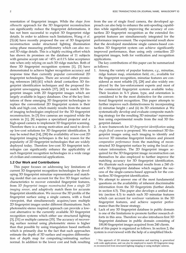
diagram of the developed system. Section 3 presents the methodology for 3D fingerprint reconstruction employed in this work. This section also details the postprocessing performed on the reconstructed 3D fingerprints. The fea-ture extraction and matching strategy developed in this paper is detailed in section 4 while section 5 details the surface curvature based approach for the 3D fingerprint matching. The experimental results are illustrated in sec-tion 6. Section 7 presents’ the summary of key conclusions from this paper and suggests further work directions.
2. SYSTEM OVERVIEW AND BLOCK DIAGRAM
A simplified block diagram of the single-camera based 3D fingerprint identification approach developed in this pa-per is illustrated in figure 1. This work uses a calibrated setup of multiple light (LED) sources in space which il-luminate in a sequence to acquire multiple 2D fingerprint images. We also developed the required hardware to con-trol the illumination sequence and synchronize the image acquisition using a computer (with the help of a graphical user/imaging interface which ia developed for this sys-tem, please see supplementary material). We employ sev-en symmetrically distributed LED for the illumination and a low-cost digital camera which can acquire 1280 × 1024 pixel images with 15 frames per second. We make several assumptions which are quite standard for photo-metric stereo based 3D image reconstruction; single point source is used to illuminate the fingerprint surface at in-finity, the camera is orthographic and all its parameters are known. The position of LEDs on the acquired images is calibrated and the fingerprint surface is assumed to be described by Lambertian surface with constant albedo.
3. 3D FINGERPRINT RECONSTRUCTION USING
PHOTOMETRIC STEREO
The reconstruction of fingerprint is based on the shape from shading technique. Given a 2D image E (x, y), the shape from shading technique is used in this work to re-cover 3D fingerprint surface z (x, y). The surface reflec-tance R relates the observed 2D fingerprint image pixel intensities in E (x, y) to the surface orientations/gradients for a given source direction and the surface reflectance in the direction of imaging/camera as in the following. ( ) ( ( ) ( )) (1) where is the albedo and I0 is the incident radiance. The surface gradients p (x, y) and q (x, y) can be defined as follows: ( ) ( ) , ( ) ( ( )) (2) The 3D fingerprint surface can be reconstructed by recov-ering the surface height information z = f (x, y). We ap-proximate/consider finger surface as the Lambertian sur-face which is illuminated by multiple, say m, fixed light sources, i.e., . Each of these light sources (LED’s) is fixed with a known direction
and
radiance‖ ‖. Let be the unit surface nor-
mal vectors at some point of interest on the 3D fingerprint surface. The observed image pixel intensities y, from the m 2D fingerprint images, corresponding to the respective illumination sources can be written as follows; (3) where
. We as-sume that the light source directions are not co-planer so that the matrix L is non-singular. Equation (3) illustrates a linear relationship between 3D fingerprint surface, ob-served pixel intensities from 2D fingerprint image and the unit surface normal vectors x. The unknown vector x can be estimated from the standard [2], [6] least squared error technique using the following equation. ( ) (4) Since n is of unit length, the length of recovered vector x is the absolute reflectance (albedo) and the surface normal is represented by the direction of unit vector n. The recovered surface normals are then integrated to re-cover the 3D fingerprint surface z (x, y).
3.1 Postprocessing Reconstructed 3D Fingerprints
The reconstructed 3D fingerprint is essentially 3D cloud point data which requires some processing to sup-press the accompanying noise. This cloud point data z (x, y) is firstly subjected to smoothing process which firstly applies a 5 × 5 median filter to suppress speckle-like noise. The resulting image is then subjected to 3D variant of Laplacian smoothing which has been found to be quite effective in denoising point clouds [9], [20]. For a vertex 𝒛 within the image z = f (x, y), with its neighbors 𝒛 , the up-dated vertexes 𝒛 ̅ are computed as follows:
𝒛 ̅ (1 − 𝜖)𝒛 +
∑ ∑ 𝑤 𝒛 (5)
where 𝑤 is a finite support weighting function and is chosen as the inverse of distance between vertex 𝒛 and its neighbors 𝒛 , i.e., 𝑤 ‖𝒛 − 𝒛 ‖
The reconstructed 3D
fingerprint surface is smoothed after 40 iterations with ϵ = 0.5 and the neighbors j are chosen within ±2 pixel in the x and y directions from vertex 𝒛 The normal vectors of the cloud point fingerprint data for the smoothed surface are then computed by the gradi-ent of z = f (x, y). The normal vector is an upward normal with (-gx, -gy, 1), where gx and gy are the gradient along x and y directions. These normalized surface normals are then used for estimating the principle curvature as will be detailed in section 5.
4. FEATURE EXTRACTION AND MATCHING
The 3D representation of minutiae and corresponding matching strategy is introduced in this section (4.2). Dur-ing 3D fingerprint reconstruction, we ignore those pixels in the acquired 2D fingerprint images which can be con-sidered as being influenced by specular reflection. One of
4 IEEE TRANSACTIONS ON JOURNAL NAME, MANUSCRIPT ID
the simpler but effective approaches is to consider top k% high intensity pixels from all the 2D fingerprint images, with different illumination profile which are acquired for a 3D fingerprint reconstruction, as the specular reflec-tions. The magnitude of k is empirically determined and set as 0.228. Each of the 2D fingerprint images acquired for the 3D fingerprint reconstruction, although with varying illumi-nation profile, can also be simultaneously exploited for the 2D minutiae extraction and matching2, which is brief-ly summarized in the following section. Since 2D finger-print images are acquired from a distance (figure 1), which is ~10 cm during our imaging, the observed contrast of intensity between the valley and the ridge is quite low. Therefore each of the acquired images requires contrast enhancement before subjecting them to Gabor filter based [5], [15] fingerprint enhancement algorithm. In this work we use homomorphic filters based contrast enhancement approach which has been described in reference [1].
4.1 Conventional Minutiae Representation in 2D Space and Matching
Each of the enhanced 2D fingerprint images are used to
locate the minutiae features using the conventional ap-
proach [21]. We select a minutiae pair, consisting of a mi-
nutia from the reference template image (Q) and a minu-
tia from the query template image (P), to generate match
distances between them using the alignment-based ap-
proach. All the other minutiae in P are also converted to
the spherical coordinate as [r, As, Aθ, T] which center at
the reference minutia in Q and align the angle with θref.
√( − ) + ( − )
(5)
(
) − (6)
( − ) (7)
where r is the distance of respective minutiae with the
reference minutia, As is the angular separation of the mi-
nutia, Aθ is the orientation of the minutia, and T is the
type of minutia. If the difference between [ri, Asi, Aθi, Ti] in
P and [rj, Asj, Aθj, Tj] in Q is smaller than a predetermined
threshold and Ti = Tj, then the minutia i in P and minutia j
in Q are considered as the matched pair. The matching
score is generated by the popular approach as follows:
(8)
where m is the total number of matched minutiae pairs
and MP, MQ is the number of minutiae in query and tem-
plate image respectively. The maximum score of all the
possible reference minutia pair in P is selected as the final
matching score between fingerprint image P and Q.
4.2 Extended Minutiae Representation in 3D Space and Matching
Conventional fingerprint templates typically include 2D minutiae details (x, y, θ, q) consisting of position of the minutiae (x, y) along with the angle θ representing the
2 Such simultaneously generated 2D fingerprint image matching scores can be fused to improve the performance for the 3D fingerprint matching.
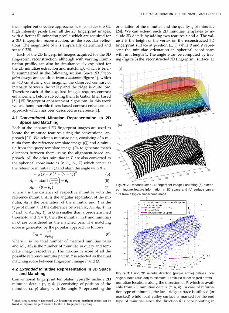
orientation of the minutiae and the quality q of minutiae [24]. We can extend such 2D minutiae templates to in-clude 3D details by adding two features z and . The val-ue z is the height of the vertex on the reconstructed 3D fingerprint surface at position (x, y) while θ and repre-sent the minutiae orientation in spherical coordinates with unit length 1. The angle can be computed by trac-ing (figure 3) the reconstructed 3D fingerprint surface at
Figure 2: Reconstructed 3D fingerprint image illustrating (a) extend-
ed minutiae feature information in 3D space and (b) surface curva-
ture from a typical fingerprint image.
Figure 3: Using 2D minutia direction (purple arrow) defines local
ridge surface (blue dot) to estimate 3D minutia direction (red arrow).
minutiae locations along the direction of θ, which is avail-able from 2D minutiae details (x, y, θ). In case of bifurca-tion type of minutiae, the local ridge surface is utilized (or masked) while local valley surface is masked for the end type of minutiae since the direction θ is here pointing in
(a)
(b)

AUTHOR ET AL.: TITLE 5
an outward direction. The angle is then computed by estimating the principle axes [16] of the masked ridge surface. The extended minutiae representation in 3D space can be localized as (x, y, z, θ, ), where (x, y, θ) is the respective minutiae representation in 2D space. In rest of this paper, the extended minutiae representation (x, y, z, θ, ), is referred to as 3D minutiae.
4.3 Matching Extended Minutiae Representation in 3D Space
The 3D minutia matching algorithm developed to gener-ate the matching score between two 3D minutiae from the two fingerprint templates, say P and Q, is detailed in the following. Firstly a reference minutia from the template P and template Q are selected and all the other minutiae are transformed to the spherical coordinates. Then the (two) reference minutiae are aligned with the x-axes and z-axes. This alignment ensures that the aligned reference minuti-ae (in both template P and Q) location can serve as the universal origin/reference (figure 4) to measure other minutiae distances in the respective templates. If an aligned minutia is represented as mr = [xr, yr, zr, θr, r] in template P, the relative representation of other 3D minu-tiae in template P3, say m (see figure 4 to visualize relative representation of two 3D minutiae), can be denoted as m = [r, As, Aθ, Ag, A]; where r is the radial distance with reference minutiae, Aθ is the azimuth angle and A is the elevation angle that localizes the minutiae m in 3D plane, while As and Ag are the azimuth and the elevation angles respectively that localize the radial vector r (with respect to reference minutiae mr) in 3D space. Let Rz(θ) and Ry() be the rotation matrix along z and y direction in cartesian coordinate, and sph(x, y, z) be the cartesian to spherical coordinate transformation with unit length 1:
R ( ) [cos − si 0si cos 0
0 0 1], R (𝜙) [
cos𝜙 0 − si 𝜙0 1 0
si 𝜙 0 cos𝜙]
sph( 𝑧 ) ( ) si 𝑧 (9) where atan2 is the four-quadrant inverse tangent function [25]. The parameters for the relative representation (fea-ture vector) of minutiae m are computed as follows: √( − )
+ ( − ) + (𝑧 − 𝑧 )
(11)
𝑧′ R (−𝜙 )R (− )
− − 𝑧 − 𝑧
(12)
[ ] sph( 𝑧′ ) (13)
[ ] sph ((R (−𝜙 )R (− )(sph ( 𝜙 )) )
) (14)
Two 3D minutiae in the two fingerprint template P and Q are considered as the matched pair if the difference be-tween their feature vectors (
, ) and
( A
,
) is smaller than a given threshold (or tolerance limit). ∆ | − | (15) ∆
mi (| −
| 360° − | −
|) (16)
∆ mi (|
− | 360° − |
− |) (17)
∆ |
− | (18)
∆ |
− | (19)
3 Also in template Q since the reference minutiae have been aligned to serve as the universal reference/origin.
If ∆ ≤ 𝑡ℎ , ∆ ≤ 𝑡ℎ
, ∆ ≤ 𝑡ℎ
, ∆ ≤ 𝑡ℎ
, and ∆
≤ 𝑡ℎ , the minutiae pair from P and Q is considered
as matched. Total numbers of such matched minutiae pairs (figure 5) are computed. The maximum number of matched minutiae pairs, among all the possibilities of every minutiae in P and Q being used as a reference, is used to compute the matching score. This matching score between the two 3D minutia templates P and Q is com-puted as follows:
(20)
where m is the total number of matched minutiae pairs and MP, MQ is the number of minutiae in template P and Q respectively.
Figure 4: Relative localization of a 3D minutiae with a reference
minutiae (mr) in a given 3D fingerprint template using relative dis-
tances/angles between the reference 3D minutia (mr) and other 3D
minutia (m). The x axis of cartesian coordinate is aligned with the
direction of mr (the bold arrow). The azimuthal angles As and Aθ are
in the range of [0, 360] degree. The polar angles Ag and A are in
the range of [-90, 90] degree. It may be noted that the magni-
tude/value of (r, As, Aθ, Ag , A) are exaggerated simply to illustrate
these values clearly (rather than use exact from upper left hand side
image) and most of the finger surface is convex. In the lower figure,
the green line for m illustrates orientation of 3D minutiae while the
red line illustrates its projection in x-y plane.
The fingerprint matching can be more effective [45] with the use of a function to compute the similarity score of minutiae and a threshold for the rejection of falsely matched minutiae. Assuming that there are some falsely matched minutiae pairs after the hard threshold, it is pos-sible to reject some of them by transforming all features to a scalar product. Therefore we explored a unified match-ing distance function for matching two 3D minutiae which can reject falsely matched minutiae using compari-son with a fixed decision threshold (calibrated during training stage). This function to combine the difference
6 IEEE TRANSACTIONS ON JOURNAL NAME, MANUSCRIPT ID
(a)
(b)
Figure 5: Matching two genuine 3D minutia templates in (a) and the
imposter templates in (b) from template P (in red color) and template
Q (in blue color). The color lines are links from the reference minutia
while the black lines illustrate the minutiae pairs that are regarded as
matched. vector in (15)-(19) for generating a unified matching dis-tance can be written as follows: (21) where ∆𝑣 is the vector of difference values as computed in (14) and cosN is the value of normal vector (figure 3) cosine similarity between two matched minutiae. In our experiments (section 7), if funRSG(∆v) is smaller than 1.825, then this pair of minutia is considered as the matched pair. The power term 0.8 makes the boundary of the high dimension space convex. Our study on the dif-ference of such vectors (figure C in supplementary file) suggests that the equation (21) may be generalized to more accurately account for relative variations in feature distances as follows: which has an independent set of power term {a, b,…,f} while f(r) can be some function of distance. The matching score between two 3D minutiae template P and Q can be computed from equation (20) using the number of matched minutia pairs.
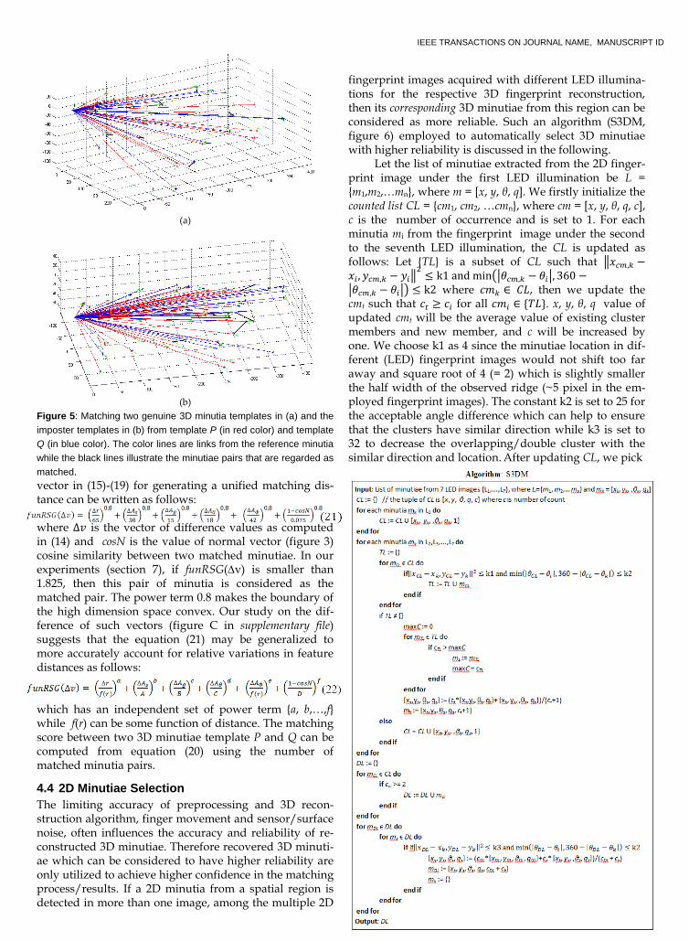
4.4 2D Minutiae Selection
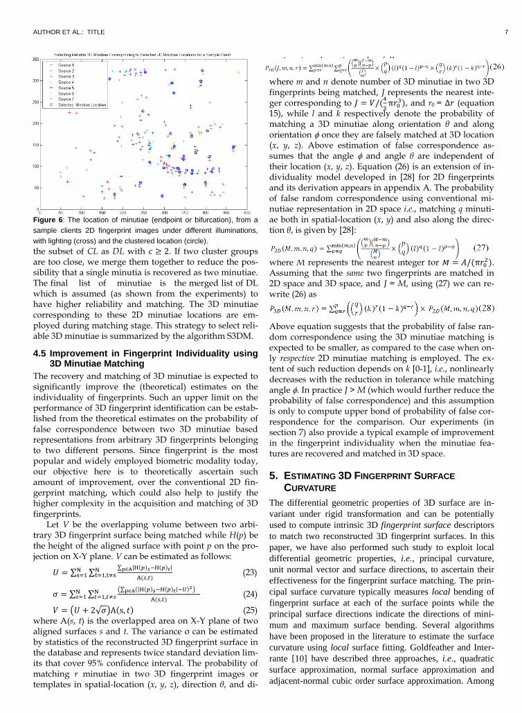
The limiting accuracy of preprocessing and 3D recon-struction algorithm, finger movement and sensor/surface noise, often influences the accuracy and reliability of re-constructed 3D minutiae. Therefore recovered 3D minuti-ae which can be considered to have higher reliability are only utilized to achieve higher confidence in the matching process/results. If a 2D minutia from a spatial region is detected in more than one image, among the multiple 2D
fingerprint images acquired with different LED illumina-tions for the respective 3D fingerprint reconstruction, then its corresponding 3D minutiae from this region can be considered as more reliable. Such an algorithm (S3DM, figure 6) employed to automatically select 3D minutiae with higher reliability is discussed in the following. Let the list of minutiae extracted from the 2D finger-print image under the first LED illumination be L = {m1,m2,…mn}, where m = [x, y, θ, q]. We firstly initialize the counted list CL = {cm1, cm2, …cmn}, where cm = [x, y, θ, q, c], c is the number of occurrence and is set to 1. For each minutia mi from the fingerprint image under the second to the seventh LED illumination, the CL is updated as follows: Let {TL} is a subset of CL such that ‖ − − ‖
≤ k1 mi (| − | 360 −
| − |) ≤ k where 𝑐𝑚 ∈ 𝐶𝐿, then we update the cmt such that 𝑐 ≥ 𝑐 for all 𝑐𝑚 ∈ {𝑇𝐿}. x, y, θ, q value of updated cmt will be the average value of existing cluster members and new member, and c will be increased by one. We choose k1 as 4 since the minutiae location in dif-ferent (LED) fingerprint images would not shift too far away and square root of 4 (= 2) which is slightly smaller the half width of the observed ridge (~5 pixel in the em-ployed fingerprint images). The constant k2 is set to 25 for the acceptable angle difference which can help to ensure that the clusters have similar direction while k3 is set to 32 to decrease the overlapping/double cluster with the similar direction and location. After updating CL, we pick
Algorithm: S3DM
AUTHOR ET AL.: TITLE 7
Figure 6: The location of minutiae (endpoint or bifurcation), from a
sample clients 2D fingerprint images under different illuminations,
with lighting (cross) and the clustered location (circle).
the subset of CL as DL with 𝑐 ≥ . If two cluster groups are too close, we merge them together to reduce the pos-sibility that a single minutia is recovered as two minutiae. The final list of minutiae is the merged list of DL which is assumed (as shown from the experiments) to have higher reliability and matching. The 3D minutiae corresponding to these 2D minutiae locations are em-ployed during matching stage. This strategy to select reli-able 3D minutiae is summarized by the algorithm S3DM.
4.5 Improvement in Fingerprint Individuality using 3D Minutiae Matching
The recovery and matching of 3D minutiae is expected to significantly improve the (theoretical) estimates on the individuality of fingerprints. Such an upper limit on the performance of 3D fingerprint identification can be estab-lished from the theoretical estimates on the probability of false correspondence between two 3D minutiae based representations from arbitrary 3D fingerprints belonging to two different persons. Since fingerprint is the most popular and widely employed biometric modality today, our objective here is to theoretically ascertain such amount of improvement, over the conventional 2D fin-gerprint matching, which could also help to justify the higher complexity in the acquisition and matching of 3D fingerprints.
Let V be the overlapping volume between two arbi-trary 3D fingerprint surface being matched while H(p) be the height of the aligned surface with point p on the pro-jection on X-Y plane. V can be estimated as follows:
𝑈 ∑ ∑∑ | ( ) ( ) | ∈
( )
(23)
𝜎 ∑ ∑(∑ (| ( ) ( ) | ) ∈ )
( )
(24)
𝑉 (𝑈 + √𝜎)A(s 𝑡) (25) where A(s, t) is the overlapped area on X-Y plane of two aligned surfaces s and t. The variance σ can be estimated by statistics of the reconstructed 3D fingerprint surface in the database and represents twice standard deviation lim-its that cover 95% confidence interval. The probability of matching r minutiae in two 3D fingerprint images or templates in spatial-location (x, y, z), direction θ, and di-
rection can be estimated as follows: where m and n denote number of 3D minutiae in two 3D fingerprints being matched, J represents the nearest inte-ger corresponding to 𝐽 𝑉 (
π
), and r0 = ∆ (equation 15), while l and k respectively denote the probability of matching a 3D minutiae along orientation θ and along orientation once they are falsely matched at 3D location (x, y, z). Above estimation of false correspondence as-sumes that the angle and angle θ are independent of their location (x, y, z). Equation (26) is an extension of in-dividuality model developed in [28] for 2D fingerprints and its derivation appears in appendix A. The probability of false random correspondence using conventional mi-nutiae representation in 2D space i.e., matching q minuti-ae both in spatial-location (x, y) and also along the direc-tion θ, is given by [28]:
where M represents the nearest integer for 𝑀 (π ).
Assuming that the same two fingerprints are matched in 2D space and 3D space, and J = M, using (27) we can re-write (26) as
Above equation suggests that the probability of false ran-dom correspondence using the 3D minutiae matching is expected to be smaller, as compared to the case when on-ly respective 2D minutiae matching is employed. The ex-tent of such reduction depends on k [0-1], i.e., nonlinearly decreases with the reduction in tolerance while matching angle . In practice J > M (which would further reduce the probability of false correspondence) and this assumption is only to compute upper bond of probability of false cor-respondence for the comparison. Our experiments (in section 7) also provide a typical example of improvement in the fingerprint individuality when the minutiae fea-tures are recovered and matched in 3D space.
5. ESTIMATING 3D FINGERPRINT SURFACE
CURVATURE
The differential geometric properties of 3D surface are in-
variant under rigid transformation and can be potentially
used to compute intrinsic 3D fingerprint surface descriptors
to match two reconstructed 3D fingerprint surfaces. In this
paper, we have also performed such study to exploit local
differential geometric properties, i.e., principal curvature,
unit normal vector and surface directions, to ascertain their
effectiveness for the fingerprint surface matching. The prin-
cipal surface curvature typically measures local bending of
fingerprint surface at each of the surface points while the
principal surface directions indicate the directions of mini-
mum and maximum surface bending. Several algorithms
have been proposed in the literature to estimate the surface
curvature using local surface fitting. Goldfeather and Inter-
rante [10] have described three approaches, i.e., quadratic
surface approximation, normal surface approximation and
adjacent-normal cubic order surface approximation. Among
8 IEEE TRANSACTIONS ON JOURNAL NAME, MANUSCRIPT ID
these three approaches, adjacent-normal cubic order approx-
imation algorithm works the best [2] and is used in our work.
Let a given surface point be s with its normal N and its u
neighbouring points be ti with their normal vectors Ki where
i = 1, 2, … u. In the coordinate system with s as the origin
(0, 0, 0) and N as the z-axis, the position of neighbours ti is
(xi, yi, zi) and the position of Ki is (ai, bi, ci). Using the adja-
cent-normal cubic order algorithm, we essentially attempt to
locate a surface that can fit the vertex and its neighbouring
points such that:
( )
+ +
+ + + +
(29)
The normal vector of the surface point s in the approximated
surface is written as
( ) ( ( ) ( ) −1) (30)
( + + 3 + + + c + + + 3 −1) (31)
The cubic-order surface fitting, for both the neighboring
surface points and their normal, generate following three
equations for each of the surface points.
where 𝑐 is the coefficient vector of the
cubic surface. Above equation is an over determined equa-
tion system and can be written in the following form:
R (33)
where K is 3u × 7 matrix (from left hand side of equation
30) and R is 3u × 1 vector. We can apply least-square fit to
find the best solution for equation (33) and construct
Weingarten curvature matrix W for the fitted surface using
only three coefficients.
( 𝑐
) (34)
The eiganvalues of Weigarten matrix are the maximum and
minimum principle curvatures of the surface (kmax and kmin),
and their eigenvectors are the principal direction vectors
(hmax and hmin) which can be directly computed. The shape
index of a surface at vertex s can quantify the local 3D shape
of the fingerprint surface. The curvature information de-
scribed using shape index Ci(s) is independent of scale and
can be computed as follows [12]:
𝐶 ( )
− (
) (
) (35)
The surface curvature map generated from the quantification
of local surface index is in the interval [0-1] and can also be
employed to match two 3D fingerprint surfaces. In this
work, we generated surface curvature map from every re-
constructed 3D fingerprints and also employed them to as-
certain possible performance improvement for the 3D fin-
gerprint identification.
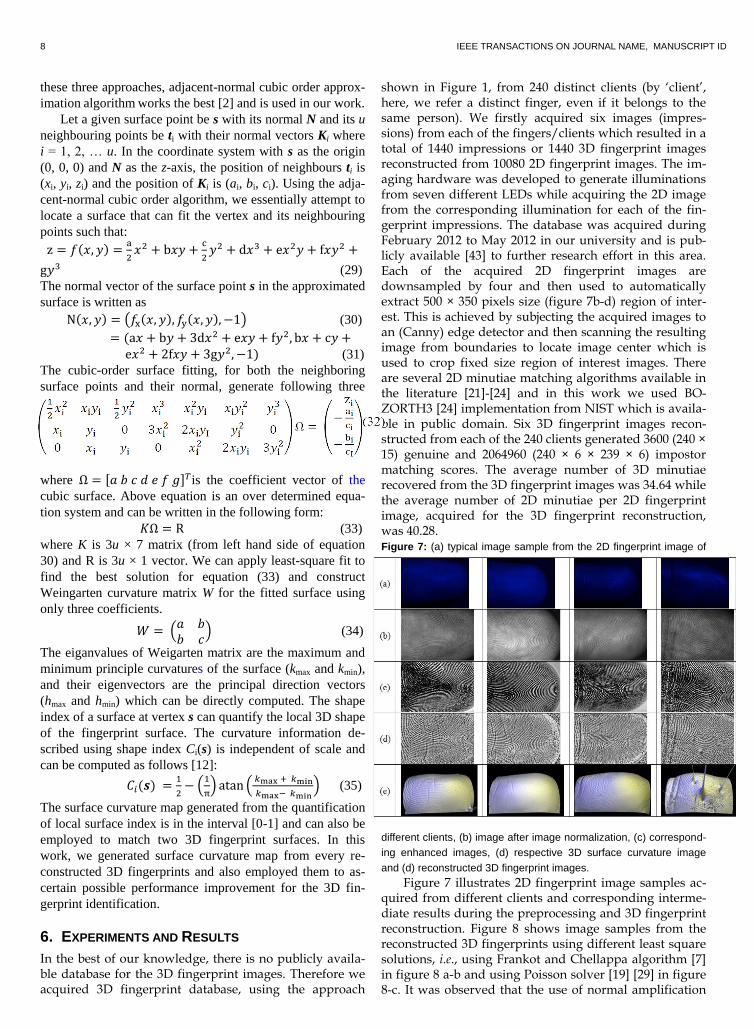
6. EXPERIMENTS AND RESULTS
In the best of our knowledge, there is no publicly availa-ble database for the 3D fingerprint images. Therefore we acquired 3D fingerprint database, using the approach
shown in Figure 1, from 240 distinct clients (by ‘client’, here, we refer a distinct finger, even if it belongs to the same person). We firstly acquired six images (impres-sions) from each of the fingers/clients which resulted in a total of 1440 impressions or 1440 3D fingerprint images reconstructed from 10080 2D fingerprint images. The im-aging hardware was developed to generate illuminations from seven different LEDs while acquiring the 2D image from the corresponding illumination for each of the fin-gerprint impressions. The database was acquired during February 2012 to May 2012 in our university and is pub-licly available [43] to further research effort in this area. Each of the acquired 2D fingerprint images are downsampled by four and then used to automatically extract 500 × 350 pixels size (figure 7b-d) region of inter-est. This is achieved by subjecting the acquired images to an (Canny) edge detector and then scanning the resulting image from boundaries to locate image center which is used to crop fixed size region of interest images. There are several 2D minutiae matching algorithms available in the literature [21]-[24] and in this work we used BO-ZORTH3 [24] implementation from NIST which is availa-ble in public domain. Six 3D fingerprint images recon-structed from each of the 240 clients generated 3600 (240 × 15) genuine and 2064960 (240 × 6 × 239 × 6) impostor matching scores. The average number of 3D minutiae recovered from the 3D fingerprint images was 34.64 while the average number of 2D minutiae per 2D fingerprint image, acquired for the 3D fingerprint reconstruction, was 40.28. Figure 7: (a) typical image sample from the 2D fingerprint image of
different clients, (b) image after image normalization, (c) correspond-
ing enhanced images, (d) respective 3D surface curvature image
and (d) reconstructed 3D fingerprint images.
Figure 7 illustrates 2D fingerprint image samples ac-quired from different clients and corresponding interme-diate results during the preprocessing and 3D fingerprint reconstruction. Figure 8 shows image samples from the reconstructed 3D fingerprints using different least square solutions, i.e., using Frankot and Chellappa algorithm [7] in figure 8 a-b and using Poisson solver [19] [29] in figure 8-c. It was observed that the use of normal amplification
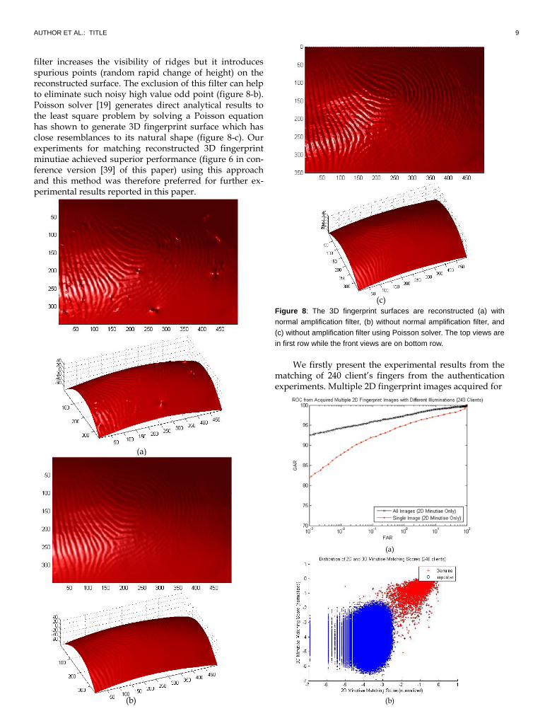
AUTHOR ET AL.: TITLE 9
filter increases the visibility of ridges but it introduces spurious points (random rapid change of height) on the reconstructed surface. The exclusion of this filter can help to eliminate such noisy high value odd point (figure 8-b). Poisson solver [19] generates direct analytical results to the least square problem by solving a Poisson equation has shown to generate 3D fingerprint surface which has close resemblances to its natural shape (figure 8-c). Our experiments for matching reconstructed 3D fingerprint minutiae achieved superior performance (figure 6 in con-ference version [39] of this paper) using this approach and this method was therefore preferred for further ex-perimental results reported in this paper.
(a)
(a)
(b)
(c)
Figure 8: The 3D fingerprint surfaces are reconstructed (a) with
normal amplification filter, (b) without normal amplification filter, and
(c) without amplification filter using Poisson solver. The top views are
in first row while the front views are on bottom row.
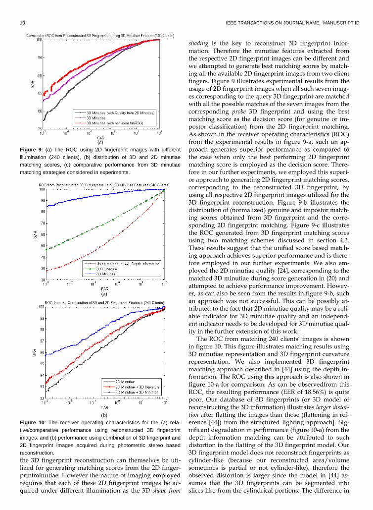
We firstly present the experimental results from the matching of 240 client’s fingers from the authentication experiments. Multiple 2D fingerprint images acquired for
(a)
(b)
(b)
10 IEEE TRANSACTIONS ON JOURNAL NAME, MANUSCRIPT ID
(c)
Figure 9: (a) The ROC using 2D fingerprint images with different
illumination (240 clients), (b) distribution of 3D and 2D minutiae
matching scores, (c) comparative performance from 3D minutiae
matching strategies considered in experiments.
(a)
(b)
Figure 10: The receiver operating characteristics for the (a) rela-
tive/comparative performance using reconstructed 3D fingerprint
images, and (b) performance using combination of 3D fingerprint and
2D fingerprint images acquired during photometric stereo based
reconstruction. the 3D fingerprint reconstruction can themselves be uti-lized for generating matching scores from the 2D finger-printminutiae. However the nature of imaging employed requires that each of these 2D fingerprint images be ac-quired under different illumination as the 3D shape from
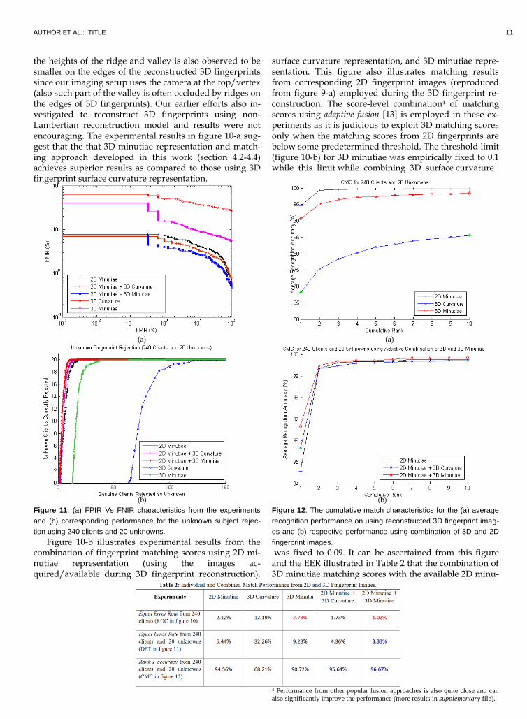
shading is the key to reconstruct 3D fingerprint infor-mation. Therefore the minutiae features extracted from the respective 2D fingerprint images can be different and we attempted to generate best matching scores by match-ing all the available 2D fingerprint images from two client fingers. Figure 9 illustrates experimental results from the usage of 2D fingerprint images when all such seven imag- es corresponding to the query 3D fingerprint are matched with all the possible matches of the seven images from the corresponding probe 3D fingerprint and using the best matching score as the decision score (for genuine or im-postor classification) from the 2D fingerprint matching. As shown in the receiver operating characteristics (ROC) from the experimental results in figure 9-a, such an ap-proach generates superior performance as compared to the case when only the best performing 2D fingerprint matching score is employed as the decision score. There-fore in our further experiments, we employed this superi-or approach to generating 2D fingerprint matching scores, corresponding to the reconstructed 3D fingerprint, by using all respective 2D fingerprint images utilized for the 3D fingerprint reconstruction. Figure 9-b illustrates the distribution of (normalized) genuine and impostor match-ing scores obtained from 3D fingerprint and the corre-sponding 2D fingerprint matching. Figure 9-c illustrates the ROC generated from 3D fingerprint matching scores using two matching schemes discussed in section 4.3. These results suggest that the unified score based match-ing approach achieves superior performance and is there-fore employed in our further experiments. We also em-ployed the 2D minutiae quality [24], corresponding to the matched 3D minutiae during score generation in (20) and attempted to achieve performance improvement. Howev-er, as can also be seen from the results in figure 9-b, such an approach was not successful. This can be possibly at-tributed to the fact that 2D minutiae quality may be a reli-able indicator for 3D minutiae quality and an independ-ent indicator needs to be developed for 3D minutiae qual-ity in the further extension of this work.
The ROC from matching 240 clients’ images is shown in figure 10. This figure illustrates matching results using 3D minutiae representation and 3D fingerprint curvature
representation. We also implemented 3D fingerprint matching approach described in [44] using the depth in-formation. The ROC using this approach is also shown in figure 10-a for comparison. As can be observedfrom this ROC, the resulting performance (EER of 18.56%) is quite poor. Our database of 3D fingerprints (or 3D model of reconstructing the 3D information) illustrates larger distor-tion after flatting the images than those (flattening in ref-erence [44]) from the structured lighting approach]. Sig-nificant degradation in performance (figure 10-a) from the depth information matching can be attributed to such distortion in the flatting of the 3D fingerprint model. Our 3D fingerprint model does not reconstruct fingerprints as cylinder-like (because our reconstructed area/volume sometimes is partial or not cylinder-like), therefore the observed distortion is larger since the model in [44] as-sumes that the 3D fingerprints can be segmented into slices like from the cylindrical portions. The difference in
AUTHOR ET AL.: TITLE 11
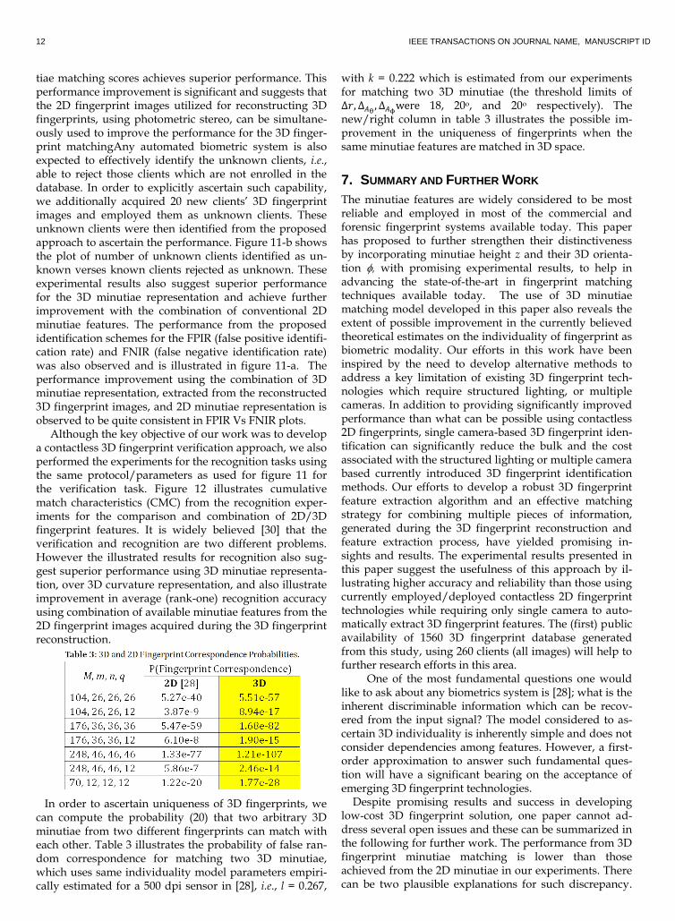
the heights of the ridge and valley is also observed to be smaller on the edges of the reconstructed 3D fingerprints since our imaging setup uses the camera at the top/vertex (also such part of the valley is often occluded by ridges on the edges of 3D fingerprints). Our earlier efforts also in-vestigated to reconstruct 3D fingerprints using non-Lambertian reconstruction model and results were not encouraging. The experimental results in figure 10-a sug-gest that the that 3D minutiae representation and match-ing approach developed in this work (section 4.2-4.4) achieves superior results as compared to those using 3D fingerprint surface curvature representation.
(a)
(b)
Figure 11: (a) FPIR Vs FNIR characteristics from the experiments
and (b) corresponding performance for the unknown subject rejec-
tion using 240 clients and 20 unknowns.
Figure 10-b illustrates experimental results from the combination of fingerprint matching scores using 2D mi-nutiae representation (using the images ac-quired/available during 3D fingerprint reconstruction),
3D surface curvature representation, and 3D minutiae 3D
surface curvature representation, and 3D minutiae repre-sentation. This figure also illustrates matching results from corresponding 2D fingerprint images (reproduced from figure 9-a) employed during the 3D fingerprint re-construction. The score-level combination4 of matching scores using adaptive fusion [13] is employed in these ex-periments as it is judicious to exploit 3D matching scores only when the matching scores from 2D fingerprints are below some predetermined threshold. The threshold limit (figure 10-b) for 3D minutiae was empirically fixed to 0.1 while this limit while combining 3D surface curvature (a)
(b)
Figure 12: The cumulative match characteristics for the (a) average
recognition performance on using reconstructed 3D fingerprint imag-
es and (b) respective performance using combination of 3D and 2D
fingerprint images. was fixed to 0.09. It can be ascertained from this figure and the EER illustrated in Table 2 that the combination of 3D minutiae matching scores with the available 2D minu-
4 Performance from other popular fusion approaches is also quite close and can also significantly improve the performance (more results in supplementary file).
12 IEEE TRANSACTIONS ON JOURNAL NAME, MANUSCRIPT ID
tiae matching scores achieves superior performance. This performance improvement is significant and suggests that the 2D fingerprint images utilized for reconstructing 3D fingerprints, using photometric stereo, can be simultane-ously used to improve the performance for the 3D finger-print matchingAny automated biometric system is also expected to effectively identify the unknown clients, i.e., able to reject those clients which are not enrolled in the database. In order to explicitly ascertain such capability, we additionally acquired 20 new clients’ 3D fingerprint images and employed them as unknown clients. These unknown clients were then identified from the proposed approach to ascertain the performance. Figure 11-b shows the plot of number of unknown clients identified as un-known verses known clients rejected as unknown. These experimental results also suggest superior performance for the 3D minutiae representation and achieve further improvement with the combination of conventional 2D minutiae features. The performance from the proposed identification schemes for the FPIR (false positive identifi-cation rate) and FNIR (false negative identification rate) was also observed and is illustrated in figure 11-a. The performance improvement using the combination of 3D minutiae representation, extracted from the reconstructed 3D fingerprint images, and 2D minutiae representation is observed to be quite consistent in FPIR Vs FNIR plots. Although the key objective of our work was to develop a contactless 3D fingerprint verification approach, we also performed the experiments for the recognition tasks using the same protocol/parameters as used for figure 11 for the verification task. Figure 12 illustrates cumulative match characteristics (CMC) from the recognition exper-iments for the comparison and combination of 2D/3D fingerprint features. It is widely believed [30] that the verification and recognition are two different problems. However the illustrated results for recognition also sug-gest superior performance using 3D minutiae representa-tion, over 3D curvature representation, and also illustrate improvement in average (rank-one) recognition accuracy using combination of available minutiae features from the 2D fingerprint images acquired during the 3D fingerprint reconstruction. In order to ascertain uniqueness of 3D fingerprints, we can compute the probability (20) that two arbitrary 3D minutiae from two different fingerprints can match with each other. Table 3 illustrates the probability of false ran-dom correspondence for matching two 3D minutiae, which uses same individuality model parameters empiri-cally estimated for a 500 dpi sensor in [28], i.e., l = 0.267,
with k = 0.222 which is estimated from our experiments for matching two 3D minutiae (the threshold limits of ∆ ∆
∆ w r 18, 20o, and 20o respectively). The
new/right column in table 3 illustrates the possible im-provement in the uniqueness of fingerprints when the same minutiae features are matched in 3D space.
7. SUMMARY AND FURTHER WORK
The minutiae features are widely considered to be most reliable and employed in most of the commercial and forensic fingerprint systems available today. This paper has proposed to further strengthen their distinctiveness by incorporating minutiae height z and their 3D orienta-tion , with promising experimental results, to help in advancing the state-of-the-art in fingerprint matching techniques available today. The use of 3D minutiae matching model developed in this paper also reveals the extent of possible improvement in the currently believed theoretical estimates on the individuality of fingerprint as biometric modality. Our efforts in this work have been inspired by the need to develop alternative methods to address a key limitation of existing 3D fingerprint tech-nologies which require structured lighting, or multiple cameras. In addition to providing significantly improved performance than what can be possible using contactless 2D fingerprints, single camera-based 3D fingerprint iden-tification can significantly reduce the bulk and the cost associated with the structured lighting or multiple camera based currently introduced 3D fingerprint identification methods. Our efforts to develop a robust 3D fingerprint feature extraction algorithm and an effective matching strategy for combining multiple pieces of information, generated during the 3D fingerprint reconstruction and feature extraction process, have yielded promising in-sights and results. The experimental results presented in this paper suggest the usefulness of this approach by il-lustrating higher accuracy and reliability than those using currently employed/deployed contactless 2D fingerprint technologies while requiring only single camera to auto-matically extract 3D fingerprint features. The (first) public availability of 1560 3D fingerprint database generated from this study, using 260 clients (all images) will help to further research efforts in this area.
One of the most fundamental questions one would like to ask about any biometrics system is [28]; what is the inherent discriminable information which can be recov-ered from the input signal? The model considered to as-certain 3D individuality is inherently simple and does not consider dependencies among features. However, a first-order approximation to answer such fundamental ques-tion will have a significant bearing on the acceptance of emerging 3D fingerprint technologies. Despite promising results and success in developing low-cost 3D fingerprint solution, one paper cannot ad-dress several open issues and these can be summarized in the following for further work. The performance from 3D fingerprint minutiae matching is lower than those achieved from the 2D minutiae in our experiments. There can be two plausible explanations for such discrepancy.
AUTHOR ET AL.: TITLE 13
Firstly, all the seven 2D fingerprint images are employed to generate 2D minutiae matching scores while only one reconstructed 3D fingerprint is used for generating 3D minutiae matching performance. Secondly, the recon-struction error in the 3D fingerprint surface reconstruc-tion can degrade 3D minutiae matching performance. When the reconstructed surface is not consistent, the dif-ference in depth value z and angle is expected to in-crease the distance between the 3D minutiae from the genuine matches resulting in performance degradation. Therefore further improvement in the reconstruction ac-curacy is expected to improve performance from 3D mi-nutiae matching. In this context, surface reconstruction using a continuum of solvers, e. g. regularization, m-estimators, diffusion, as attempted in [19], can be ex-plored in the further work to ascertain higher accuracy in the 3D fingerprint surface reconstruction. The matching matric explored in (22) needs to be further evaluated, es-pecially to ascertain f(r) which was fixed (21) in our exper-iments. The 3D fingerprint individuality model devel-oped in section 4.5 does not account for errors in the lo-calization and detection of 3D minutiae. Therefore this model requires improvement to account for uncertainty in recovering (true) 3D minutiae while considering some kind of interdependence between features. The quality of 3D reconstruction algorithm can impact the matching accuracy of 3D fingerprints which requires in depth study in the further extension of this work. In addition, further work is also required to ascertain 3D fingerprint defor-mations due to external pressure, wrinkles [46], and in-corporate such deformation models [47] for more accurate matching. The 3D fingerprint database made available from this work to the researchers and developers should help to promote further research efforts in this area. Alt-hough much more work remains to be done, the experimental results and generalized 3D minutiae matching model presented in this paper indicate that the contactless 3D fingerprint identi-fication can constitute a promising addition to state-of-the-art in biometrics security.
REFERENCES
[1] G. Parziale and Y. Chen, “Advanced technologies for touchless
fingerprint recognition,” Handbook of Remote Biometrics, M.
Tistarelli, Stan. Z. Li, R. Challeppa, (Eds.), pp. 83-109, Springer-
Verlag London, 2009.
[2] Shape from Shading, B. K. P. Horn and M. J. Brooks (Eds.), MIT
Press, Cambridge, MA, 1989.
[3] Y. Wang, Q. Hao, A. Fatehpuria, D. L. Lau and L. G. Has-
sebrook, “Data acquisition and quality analysis of 3-
Dimensional fingerprints,” Proc. IEEE conference on Biometrics,
Identity and Security, Tampa, Florida, Sep. 22-24, 2009.
[4] Y. Wang, D. L. Lau and L. G. Hassebrook, “Fit-sphere unwrap-
ping and performance analysis of 3D fingerprints,” Applied Op-
tics, vol. 49, no. 4, pp. 592-600, 2010.
[5] Handbook of Fingerprint Recognition, D. Maltoni, D. Maio, A. K.
Jain, and S. Prabhakar, Springer Verlag, Second Ed., 2009.
[6] R. J. Woodham, “Gradient and curvature from photometric
stereo including local confidence estimation," J. Opt. Soc. Ameri-
ca, no. 11, pp. 3050-3068, 1994.
[7] R. T. Frankot and R. Chellappa, “A method for enforcing inte-
grability in shape from shading algorithms," IEEE Trans. Pattern
Anal. Mach. Intell., vol. 10, no. 4, pp. 439 - 451, Jul. 1988.
[8] G. Parziale, E. Diaz-Santana and R. Hauke, “The surround
imager: A multi-camera touchless device to acquire 3d rolled-
equivalent fingerprints,” Proc. ICB 2006, LNCS, vol. 3832, 2006.
[9] A. Belyaev, “Mesh Smoothing and Enhancing. Curvature Esti-
mation,” Saarbrucken, 2006.
www.mpi-inf.mpg.de/~ag4-gm/handouts/06gm_surf3.pdf
[10] Goldfeather and V. Interrante, “A novel cubic-order algorithm
for approximating principal direction vectors,” ACM Trans.
Graphics, vol. 23, no. 1, pp. 45-63, 2004.
[11] S. Yoshizawa, A. Belyaev, and H.-P. Seidel, “Fast and robust
detection of crest lines on meshes,” Computer Aided Geometric
Design (CAGD), Vol. 25, Isue 8, pp. 545-560, 2008.
[12] C. Dorai and A. K. Jain, “COSMOS—A representation scheme
for 3D free-form objects,” IEEE Trans. Patt. Anal. Mach. Intell.,
vol. 19, no. 10, pp. 1115-1130, 1997.
[13] V. Kanhangad, A. Kumar and D. Zhang, “A unified framework
for contactless hand verification,” IEEE Trans. Info. Forensics &
Security, pp. 1014-1027, 2011.
[14] A. K. Jain and A. Kumar, “Biometrics of second generation: an
overview,” Second Generation Biometrics, E. Mordini, and T. Di-
mitros (Eds.), Springer 2012.
[15] L. Hong, Y. Wan and A. K. Jain, “Fingerprint image enhance-
ment: algorithms and performance evaluation,” IEEE Trans.
Patt. Anal. Mach. Intell., vol. 20, pp. 777-789, Aug. 1998.
[16] J.-F. Lalonde, N. Vandapel and M. Hebert, “Automatic three-
dimensional point cloud processing for forest inventory,” Tech-
nical Report No. MU-RI-TR-06-21, Robotics Institute, Pittsburgh,
PA, 2006.
[17] N. A. Vandal and M. Savvides, “CUDA accelerated iris tem-
plate matching on graphics processing,” Proc. BTAS 2010, pp. 1-
7, 27-29, Sept 2010.
[18] A. Kumar and Y. Zhou, “Human identification using finger
imaging,” IEEE Trans. Image Process., vol. 21, pp. 2228-2244,
April 2012
[19] A. Agrawal, R. Raskar and R. Chellappa, “What is the range of
surface reconstructions from a gradient field?,” Proc. 9th Europe-
an Conference on Computer Vision, Graz, Austria, May 2006.
http://mesh.brown.edu/taubin/pdfs/taubin-eg00star.pdf
[20] G. Taubin, “Geometric signal processing on polygonal meshes,”
Eurographics State of the Art Reports, 2000.
[21] A. K. Jain, L. Hong and R. Bolle, “On-line fingerprint verifica-
tion, IEEE Trans. Pattern Anal. Mach. Intell., vol. 19, no. 4, pp.
302-314, 1997.
[22] M. Tico and P. Kuosmanen, “Fingerprint matching using an
orientation-based minutiae descriptor,” IEEE Trans. Pattern
Anal. Mach. Intell., vol. 28, no. 8, pp. 1009-1014, Aug. 2003.
[23] B. V. K. Vijay Kumar, M. Savvides, C. Xie, K. Venkataramani, J.
Thorton, and A. Mahalanobis, “Biometric verification with cor-
relation filters,” Appl. Optics, vol. 43, 391-402, 2004.
[24] NIST Biometric Image Software, NBIS Release 4.1.0,
http://www.nist.gov/itl/iad/ig/nbis.cfm, 2011.
[25] http://en.wikipedia.org/wiki/Atan2, accessed Jan. 2012.
[26] B. Bringier, A. Bony and M. Khoudeir, “Specularity and shad-
ow detection for the multisource photometric reconstruction of
a textured surface,” J. Opt. Soc. Am. A., Opt Image Sci. Vis., vol.
29, pp. 11-21, Jan. 2012.
[27] M. Kucken and A. C. Newell, “Fingerprint formation,”, J. Th.
14 IEEE TRANSACTIONS ON JOURNAL NAME, MANUSCRIPT ID
Biology, vol. 235, pp. 73-81, 2005.
[28] S. Pankanti, S. Prabhakar, and A. K. Jain, “On the individuality
of fingerprints,” IEEE Trans. Pattern Anal. Mach. Intell., vol. 24,
pp. 1010-1025, Aug. 2002.
[29] T. Simchony, R. Chellappa, and M. Shao, “Direct analyatical
methods for solving poisson equations in computer vision
problems,” IEEE Trans. Pattern Anal. Mach. Intell., pp. 435-436,
Dec. 1990.
[30] R. M. Bolle, J. H. Connell, S. Pankanti, N. K. Ratha, A. W. Sen-
ior, “The relation between ROC and the CMC,” Proc. AutoID
2005, pp. 15-20, 2005.
[31] Flashscan3d, http://www.flashscan3d.com, accessed Aug. 2012
[32] T.-Y. Jea and V. Govindaraju, “A minutiae-based partial finger-
print recognition system,” Pattern Recognition, vol. 38, no. 10,
pp. 1672-1684, 2005.
[33] Y. Chen, G. Parziale, E. Diaz-Santana, and A. K. Jain, “3D
Touchless fingerprints: Compatibility with legacy rolled imag-
es,” Proc. BCC 2006, Tampa, 2006.
[34] J. Feng, “Combining minutiae descriptors for fingerprint
matching,” Pattern Recognition, vol. 41, no. 1, pp. 342-352, 2008.
[35] TBS, http://www.tbs-biometrics.com, Accessed August 2012
[36] Y. Wang and J. Hu, “Golden ridge orientation modeling for
partial fingerprint identification,” IEEE Trans. Patt. Anal. Mach.
Intell., vol. 33, pp. 72-87, Jan. 2011.
[37] S. Shafaei, T. Innac, L. G. Hassebrook, “A new approach to
unwrap a 3-D fingerprint to a 2-D Rolled equivalent finger-
print,” Proc. BTAS 2009, Washington DC, Sep. 2009.
[38] A. Kumar and Y. Zhou, “Contactless fingerprint identification
using level zero features,” Proc. CVPR 2011, pp. 114-119,
CVPRW’11,Colarado Springs, June 2011.
[39] A. Kumar and C. Kwong, "Towards Contactless, Low-Cost and
Accurate 3D Fingerprint Identification," Proc. CVPR 2013, pp.
3438-3443, Portland, Oregon, June 2013.
[40] H. Choi, K. Choi and J. Kim, “Mosaicing touchless and mirror-
reflected fingerprint images,” IEEE Trans. Info. Forensics & Secu-
rity, no. 5, pp. 52-61, Mar. 2010.
[41] F. Chen, “3D fingerprint and palm print data model and cap-
ture devices using multi structured lights and cameras,” US Pa-
tent No. 7609865, Oct. 2009.
[42] G. Paar, M. d. P. C. Perucha, Arnold Bauer, B. Nauschnegg,
“Photogrammetric fingerprint unwrapping,” J. Appl. Geodesy,
vol. 2, pp. 13-20, 2008.
[43] The Hong Kong Polytechnic University 3D Fingerprint Images
Database, 2012. http://www.comp.polyu.edu.hk/~csajaykr/3Dfingerprint.htm
[44] Y. Wang, L. G. Hassebrook, D. L. Lau, “Data acquisition and
processing of 3-D fingerprints,” IEEE Trans. Info. Forensics & Se-
curity, pp, 750-760, Dec. 2010.
[45] L. Liu, T. Jiang, J. Yang, and C. Zhu, "Fingerprint registration by
maximization of mutual information," IEEE Trans. Image Pro-
cess., vol. 15, no. 5, pp. 1100-1110, May 2006
[46] P. Krishnasamy, S. Belongie, D. Kriegman, “Wet fingerprint
recognition: challenges and opportunities,” Proc. IJCB 2011, pp.
1-7, Washington DC, Sep. 2011.
[47] K. Dandekar and M. A. Srinivasan, “Role of mechanics in tactile
sensing of shape,” Touch Lab Report 2, RLE TR-604, MIT, Cam-
bridge, 1997.
[48] S. C. Dass, “Assessing fingerprint individuality in presence of
noisy minutiae,” IEEE Trans. Info. Forensics & Security, vol. 5, no.
1, pp. 62-70, Mar. 2010.
AUTHOR ET AL.: TITLE 15
Appendix A Probability of False Random Correspondence using 3D Minutiae Matching
Let P and Q denote two typical 3D minutiae templates, with m and n number of recovered true minutiae respec-tively, available for the matching.
𝑃 {( 𝑧 𝜙 ) ( 𝑧 𝜙 )} (A1) 𝑄 {( ′ ′ 𝑧′ ′ 𝜙′ ) ( ′ ′ 𝑧′ ′ 𝜙′ )} (A2) After alignment, minutiae i in the template Q is matched to minutiae j in template P if and only if,
√( ′ − ) + ( ′ − )
+ (𝑧′ − 𝑧 )
≤ (A3)
mi (| ′ − | 360 − | ′ − |) ≤ (A4)
mi (|𝜙′ − 𝜙 |) ≤ 𝜙 (A5) where r0, θ0 and 𝜙 are the tolerance in distance and toler-ance in angles respectively. Let V be the overlapping vol-ume between two arbitrary 3D fingerprint surface being matched while H(p) be the height of the aligned surface with point p on the projection on X-Y plane. V can be es-timated as follows:
𝑈 ∑ ∑∑ | ( ) ( ) | ∈
( )
(A6)
𝜎 ∑ ∑(∑ (| ( ) ( ) | ) ∈ )
( )
(A7)
𝑉 (𝑈 + √𝜎)A(s 𝑡) (A8) where A(s, t) is the overlapped area on X-Y plane of two aligned surfaces s and t. The variance σ can be estimated by statistics of the reconstructed 3D fingerprint surface in the database and represents twice standard deviation lim-its that cover 95% confidence interval. The probability of a 3D minutiae in a template matched with an arbitrary mi-nutiae is given by:
Assuming (x, y, z) and ( ′, ′, 𝑧′) are independent in (9), θ and θ’ are independent in (10), and 𝜙 and 𝜙′ are inde-pendent. Let 𝐽
, and assuming J is the nearest integer.
We can use similar formulation as in [28] to compute the probability, when there can be exactly p matched minuti-ae among n minutiae in template Q and m minutiae in template P as follows: When p minutiae’s positions being matched as in above equation, the probability of q minutiae’s direction θ being matched can be estimated as follows:
( ) ( ) (1 − )
where l is same as computed in equation (10). The proba-bility of matching q minutiae in both position (x, y, z) and direction θ can be written as follows:
With q minutiae’s position and direction θ already be-
ing matched, the probability of r minutiae’s direction being matched can be estimated as follows:
( ) (𝑘) (1 − 𝑘) (A15)
where k is same as estimated using equation (A11). The probability of matching r minutiae in two 3D fingerprint templates in both position (x, y, z) and spatial-orientation θ and , can be written as follows:
The probability of false random correspondence using
conventional minutiae representation in 2D space i.e., matching q minutiae both in spatial-location (x, y) and also along the direction θ, is given by:
where M represents the nearest integer for 𝑀 (π ).
Assuming that the same two fingerprints are matched in 2D space and 3D space, and J = M, using (A17) we can rewrite (A16) as in the following.