Embed Size (px)
Citation preview
Inference of Segmented Color and TextureDescription by Tensor Voting
Jiaya Jia, Student Member, IEEE, and Chi-Keung Tang, Member, IEEE Computer Society
Abstract—A robust synthesis method is proposed to automatically infer missing color and texture information from a damaged2D image by ND tensor voting (N > 3). The same approach is generalized to range and 3D data in the presence of occlusion, missingdata and noise. Our method translates texture information into an adaptive ND tensor, followed by a voting process that infersnoniteratively the optimal color values in the ND texture space. A two-step method is proposed. First, we perform segmentation basedon insufficient geometry, color, and texture information in the input, and extrapolate partitioning boundaries by either 2D or 3D tensorvoting to generate a complete segmentation for the input. Missing colors are synthesized using ND tensor voting in each segment.Different feature scales in the input are automatically adapted by our tensor scale analysis. Results on a variety of difficult inputsdemonstrate the effectiveness of our tensor voting approach.
Index Terms—Image restoration, segmentation, color, texture, tensor voting, applications.
�
1 INTRODUCTION
THE human visual system enables us to make robustinference from insufficient data. We can perform an
amazing job of extrapolating shape and texture informationdespite severe occlusion and noise. In this paper, we present acomputational framework to fill in missing geometry, color,and texture information in large image holes, presentencouraging results in 2D and 3D, and propose usefulapplications:
. 2D data—from only a single image with large holes,our method synthesizes missing color and textureinformation seamlessly.
. Range or 3D data—from a single depth map, stereodata, or noisy 3D data, we recover missing data andcorrect erroneous geometry, and repair colors andtextures on surfaces.
No a priori complex scene or texture model is assumed inour tensor voting approach, which adopts an adaptivecontinuity constraint in 2D, 3D, and ND. Because of this, ourmethod has certain limitations which are absent from ourpowerfulvisualsystemwherepriorknowledgeareemployed.They will be discussed in the conclusion section. In this paper,we first approach the more difficult problem in 2D and thengeneralize our synthesis method to range and 3D data, whensome insufficient depth or geometry information exists. Byadoptingrecent texturesegmentationalgorithms,wedescribehow tensor voting provides a robust and effective methodol-ogy to perform image segmentation and to synthesize missinggeometry as well as color and texture information.
2 MOTIVATION
Let us first motivate our work by studying the 2D imagerepairing problem [21]. Today, powerful photo-editing
softwares and large varieties of retouching, painting,and drawing tools are available to assist users to refineor redefine images manually. For instance, we can easilyoutline and remove a large foreground object byintelligent scissors [30] or JetStream [32], leaving behinda large background hole. However, filling the back-ground hole seamlessly from existing neighborhoodinformation of damaged images is still a difficultproblem. A skilled art designer repairs them mostlythrough his experience and knowledge. Alternatively,some stereo algorithms [22], [37] use a dense set ofimages to infer the color of occluded pixels.
Given as few as one image and no additional knowledge,is it possible to automatically repair it? The main issues tobe addressed are as follows:
. How much color and shape information in theexisting part is needed to seamlessly fill the hole?
. How good can we achieve in order to reducepossible visual artifacts when the information avail-able is not sufficient?
Inpainting [8], [2] is an automatic method to fill smallholes by exploiting color and gradient information in theneighborhood of the holes. It successfully restores imageswith little visual artifact. However, when the method doesnot take texture information into account, blurring in atextured region will be introduced.
In this paper, we propose a unified approach to gather andanalyze statistical information so as to synthesize proper pixelvalues in image holes. This is achieved by computing a tensorto encode the underlying point and texture distribution(smooth or discontinuous), in the geometry and texture spacerespectively. Our method generalizes well to range and3D data under certain conditions to be discussed. Instead ofsimply extending neighboring color information, we use therobust, noniterativeND tensor voting [29] to globally infer themost suitable pixel value in the neighborhood under theMarkov Random Field (MRF) constraint. A texture-basedsegmentation [13] is adopted to partition images into differentregion segments. Depending on the data dimensionality, 2Dor 3D curve connections are voted for, in order to complete thesegmentation in image holes. Missing colors are synthesized
IEEE TRANSACTIONS ON PATTERN ANALYSIS AND MACHINE INTELLIGENCE, VOL. 26, NO. 6, JUNE 2004 771
. The authors are with the Department of Computer Science, Hong KongUniversity of Science and Technology, Clear Water Bay, Hong Kong.E-mail: {leojia, cktang}@cs.ust.hk.
Manuscript received 19 Apr. 2003; revised 5 Nov. 2003; accepted 13Nov. 2003.Recommended for acceptance by A. Khotanzad.For information on obtaining reprints of this article, please send e-mail to:[email protected], and reference IEEECS Log Number 0043-0403.
0162-8828/04/$20.00 � 2004 IEEE Published by the IEEE Computer Society
by ND tensor voting, which adapts to different feature andtexture scales.
The rest of this paper is organized as follows: We discussand compare related work in Section 3. In Section 4, we reviewthe tensor voting algorithm. In Section 5, we describe our2D method in detail, where the adaptiveND tensor voting forcolor and texture synthesis is introduced. In Section 6, 3D/range data repairing on geometry, color, and texture isdescribed, which is a generalization of 2D repairing. Detailedtime complexity analysis is given in Section 7. Our 2D and3D results are presented and explained in Section 8. Finally,we discuss the limitation of our approach, propose futurework and conclude our paper in Section 9.
The conference version of this paper first appeared in[21], which mainly focuses on 2D image repairing. In thiscoverage, we provide full details, expand our approach torange and 3D data, and present many new results.
3 PREVIOUS WORK
One contribution of our work is the robust synthesis ofmissing image or texture information in large holes. Toextrapolate details, the Markov Random Fields (MRF) havebeen widely used to describe textures [5], [15], [43],including this work. Texture synthesis techniques can beroughly categorized into three classes. The first class uses aparametric model to describe statistical textures. Portilla andSimoncelli [35] used joint wavelet coefficients to parameter-ize and synthesize textures. Heeger and Bergen [18] madeuse of Laplacians, steerable pyramids, and histogramanalysis of a texture sample to synthesize textures. Whileimpressive results are obtained for highly stochastictextures, these methods are not well-suited to representhighly structured textures such as that of a brick wall.
The second class consists of nonparametric sampling andsynthesis techniques. Efros and Leung [15] synthesizedtextures by copying pixels that are matched with theneighborhood of a pixel being synthesized. It works very wellto reproduce structured textures as well as stochastic textures.
The third class is to synthesize textures by proceduralmeans. Solid textures, proposed independently by Perlin [33]and Peachey [31], involve a function that returns a color valueat any given 3D point. Reaction-diffusion techniques [44]build up spot and stripe patterns which can be used tosynthesize textures.
To accelerate the synthesis process and avoid the problemsinherent in pixel-wise generation, Xu et al. [45] proposed ablock-wise synthesis algorithm to seamlessly copy samplepatches in an overlapping manner to create a new image.Image quilting [16] extends this algorithm by a minimumerror boundary cut so that synthesized patches naturallyconnect to each other. Wei et al. [43] described anotherhierarchical texture synthesis algorithm to speed up the per-pixel generation process by matching the neighborhood oflower resolution image pixels with the synthesized ones, andapplying tree-structured vector quantization to accelerate theprocess.
Masnou and Morel [28] presented a variational formula-tion to fill in, or inpaint regions to be disoccluded by joiningpoints of the isophotes. Inpainting [8], [2] is an algorithm torestore damaged 2D images. Instead of performing matchingand copying, the basic idea of image inpainting is to smoothlypropagate information from the surrounding areas in theisophotes direction. This algorithm generates satisfactoryresults when holes are small and the gradient information in
holes does not change abruptly. In more recent development,textures as well as structures are taken into consideration [3].However, in a situation where large holes and complex scenecomponents (e.g., single imageinputasshownin Fig.19)exist,we argue that segmentation information (such as disconti-nuity curves to partition distinct geometry and textures)should be considered. Moreover, in the texture synthesisprocess in [3], it requires either manual parameter adjustmentfordifferent texturepatterns,orsimpleconstant texture/colorassumption. Although there are some preset parameters inour method, our adaptive high dimensional tensor canautomatically measure different feature scales in the inputimage.Ourgoal issimilar to imagecompletion[14],whichalsorecovers a large portion of disoccluded missing background.One major difference is that explicit segmentation is con-sidered and robustly inferred in this work, in order not to blurimportant edges. In [46], images are restored by combiningtexture synthesis and image inpainting in multiresolution.Critical edge regions are still blurred. Criminisi et al. [10]combined texture synthesis and image inpainting. Levin et al.[24] inpaint images by taking global image statistics intoconsideration. A training image is used.
The secondary contribution is the robust inference ofgeometric features, such as curves inside image holes andmissing data in range and 3D images, to assist texture andcolor synthesis. In [29], a survey and comparison of tensorvoting with representative computer vision approaches insurface inference from a 3D cloud of points, e.g., deformablemodels [23] and computational geometry [19], are given.
For range and 3D data, unorganized sampled data arecommon input. To infer missing geometry or depth informa-tion, many algorithms have been proposed to regularize andreorganize the points [38], [20], [6], [17]. Turk and O’Brien [40]used variational implicit surfaces. Hoppe et al. [20] adopted acombinational energy function which takes connectivity anddistance factors into consideration to refine the originalmeshes. Curless and Levoy [11] set some additional unseenand empty states, and fill holes by a space carving step.Therefore, after isosurface extraction, aliasing artifacts in theholes are observed. In order to smooth these areas, postfilter-ing is performed to blur the hole-filled surface for generating asmooth connection. In their examples, holes are relativelysmall so that they can be filled by simple smooth surfaceelements. In the postrendering 3D warping algorithm [27], tofill an uncovered portion in image without obvious artifact,splat and mesh reconstructions are implemented. For eachgap area with high-connectedness, a set of quadrilateralmeshes are stretched to cover the hole, and the vertex colors ofthe reconstructed triangles are linearly interpolated. For low-connectedness, a heuristic is used to flat-shade the triangleusing vertex color, if it is far away from the reference frameviewpoint. Chang et al. [9] extended the layered depth image(LDI) tree algorithm to fill the gaps by two-pass pixel filtering.Instead of meshing the foreground and background, theiralgorithm fills the gap by splatting the filtered samples fromsurrounding surface patches in the output. Therefore, a betterresult can be obtained. However this splatting may notrespectsurface orientation discontinuities (e.g., corners).
In [1], a variational approach for filling in missing data in2D and 3D digital images is proposed, which is based on ajoint interpolation of the image gre-levels and gradient/isophotes direction. In [41], inpainting surface holes isachieved by extending the image inpainting algorithm. Holefilling algorithm in [42] deals with locally smooth structures,while our hole filling can deal with discontinuities. A locally
772 IEEE TRANSACTIONS ON PATTERN ANALYSIS AND MACHINE INTELLIGENCE, VOL. 26, NO. 6, JUNE 2004
smooth surface is also a requirement in [7], which uses radialbasis function for interpolating missing information fromdepth maps resulting from medical data. Pfeifle and Seidel[34] used B-splines for hole filling.
4 REVIEW OF TENSOR VOTING
In our method, Tensor Voting [29] is used to infer missingcurves and pixel values. It makes use of a tensor for tokenrepresentation, and voting for communication among tokens.Tensor and voting are brought together by a voting field,which is a dense tensor field for postulating smoothconnections among tokens. In this section, we first give aconcise review of the stick tensor and the stick voting field,which are used in the following sections. The key idea is thepropagation of an adaptive continuity or smoothnessconstraint in a finite neighborhood.
4.1 Token Representation and Communication
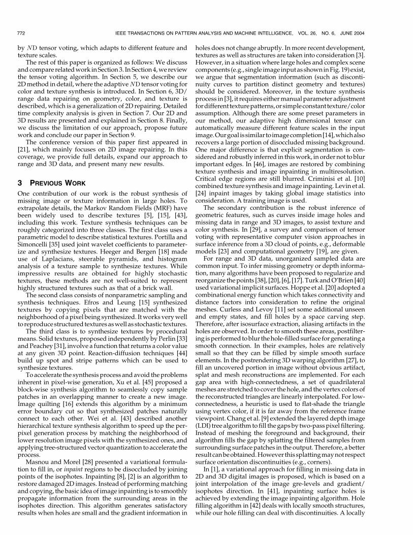
We are interested in answering the following geometricquestion in 2D, which can be generalized to higher dimensionreadily. Suppose there exists a smooth curve connecting theorigin O and a point P . Suppose also that the normal ~NN to thecurve at O is known. What is the most likely normal directionat P? Fig. 1a illustrates the situation. We claim that theosculating circle connecting O and P is the most likelyconnection since it keeps the curvature constant along thehypothesized circular arc. The most likely normal is given bythe normal to the circular arc atP (thick arrow in Fig. 1a). Thisnormal at P is oriented such that its inner product with ~NN isnonnegative. The length of this normal, which represents thevote strength, is inversely proportional to the arc length OPand also to the curvature of the underlying circular arc. Thedecay of the field takes the following form:
DF ðr; ’; �Þ ¼ e�ðr2þc’2
�2Þ; ð1Þ
where r is the arc length OP , ’ is the curvature, and c is aconstant which controls the decay with high curvature. �controls smoothness, which also determines the effectiveneighborhood size. If we consider all possible locations of Pwith nonnegative x coordinates in the 2D space, theresulting set of normal directions thus produced constitutesthe 2D stick voting field, Fig. 1b.
Given an input token A, how can it cast a stick vote toanother token B for inferring a smooth connection, assumingthat A’s normal is known? It is illustrated in Fig. 1b. First, wefix � to determine the size of the voting field. Then, we alignthe voting field with A’s normal, simply by translation androtation. If B is within A’s voting field neighborhood, Breceives a stick vote ½vx vy�T from the aligned field. Hence,voting is similar to convolution, and the voting field is like aconvolution mask, except that the voting result is not a scalar.
Other input tokens cast votes to B as well. Second ordertensor sums of all votes received at B are collected into acovariance matrix
S ¼P
v2xP
vxvyPvyvx
Pv2y
� �:
The corresponding eigensystem consists of two eigenva-lues �1 � �2 � 0 and two corresponding eigenvectors ee1 andee2. Therefore, S can be rewritten as S ¼ ð�1 � �2Þee1eeT1 þ�2ðee1eeT1 þ ee2ee
T2 Þ. ee1eeT1 is a 2D stick tensor with ee1 indicating
curve normal direction. ee1eeT1 þ ee2ee
T2 is a 2D ball tensor.
If A’s normal is unknown, we need to estimate it first.Normal estimation is also achieved by tensor voting: Eachpoint votes with the 2D ball voting field, which is obtained byintegrating or summing up the vote contributions from arotating 2D stick voting field.
In 3D,
S ¼ ð�1 � �2Þee1eeT1 þ ð�2 � �3Þðee1eeT1 þ ee2eeT2 Þ
þ �3ðee1eeT1 þ ee2eeT2 þ ee3ee
T3 Þ;
where ee1eeT1 is a 3D stick tensor, ee1ee
T1 þ ee2ee
T2 is a 3D plate
tensor, and ee1eeT1 þ ee2ee
T2 þ ee3ee
T3 is a 3D ball tensor.
4.2 Feature Extraction
When we have obtained normal directions at each inputsite, we can infer a smooth structure that connects thetokens with high feature saliencies (in 2D (respectively, 3D),curve (respectively, surface) saliency is represented by �1 ��2 [29]). Feature extraction can be achieved by casting votesto all discrete sites (input and noninput sites), using thesame voting fields and voting algorithm.
Given this dense information, in 2D (respectively, 3D),we extract true curve (respectively, surface) points andconnect them. The curve or surface mesh (triangular mesh)extraction algorithms are modified marching cubes algo-rithms [29]. Alternatively, we can use B-splines to obtain asmoother representation, by treating the inferred points ascontrol points.
5 2D REPAIRING
In this section, we describe image repairing [21] for2D image data, which generalizes well to 3D (Section 6).
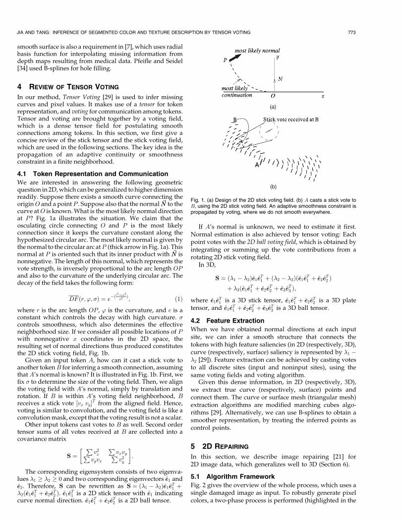
5.1 Algorithm Framework
Fig. 2 gives the overview of the whole process, which uses asingle damaged image as input. To robustly generate pixelcolors, a two-phase process is performed (highlighted in the
JIA AND TANG: INFERENCE OF SEGMENTED COLOR AND TEXTURE DESCRIPTION BY TENSOR VOTING 773
Fig. 1. (a) Design of the 2D stick voting field. (b) A casts a stick vote toB, using the 2D stick voting field. An adaptive smoothness constraint ispropagated by voting, where we do not smooth everywhere.
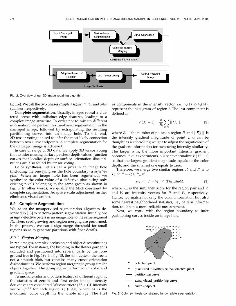
figure). We call the two phases complete segmentation and colorsynthesis, respectively.
Complete segmentation. Usually, images reveal a clut-tered scene with indistinct edge features, leading to acomplex image structure. In order not to mix up differentinformation, we perform texture-based segmentation in thedamaged image, followed by extrapolating the resultingpartitioning curves into an image hole. To this end,2D tensor voting is used to infer the most likely connectionbetween two curve endpoints. A complete segmentation forthe damaged image is achieved.
In case of range or 3D data, we apply 3D tensor votingfirst to infer missing surface patches/depth values. Junctioncurves that localize depth or surface orientation disconti-nuities are also found by tensor voting.
Color synthesis. Let us call a pixel in an image hole(including the one lying on the hole boundary) a defectivepixel. When an image hole has been segmented, wesynthesize the color value of a defective pixel using onlyexisting pixels belonging to the same group as shown inFig. 3. In other words, we qualify the MRF constraint bycomplete segmentation. Adaptive scale adjustment furthereliminates visual artifact.
5.2 Complete Segmentation
We adopt the unsupervised segmentation algorithm de-scribed in [13] to perform pattern segmentation. Initially, weassign defective pixels in an image hole to the same segmentP0. Then, seed growing and region merging are performed.In the process, we can assign merge threshold for smallregions so as to generate partitions with finer details.
5.2.1 Region Merging
In real images, complex occlusion and object discontinuitiesare typical. For instance, the building in the flower garden isoccluded and partitioned into several parts by the fore-ground tree in Fig. 19a. In Fig. 18, the silhouette of the tree isnot a smooth blob, but contains many curve orientationdiscontinuities. We perform region merging to group similarobjects together. The grouping is performed in color andgradient space.
To measure color and pattern feature of different regions,the statistics of zeroth and first order image intensityderivatives are considered. We construct a ðM þ 1ÞD intensityvector V Mþ1
i for each region Pi (i 6¼ 0) where M is themaximum color depth in the whole image. The first
M components in the intensity vector, i.e., Við1Þ to ViðMÞ,represent the histogram of region i. The last component is
defined as
ViðM þ 1Þ ¼ �
Ri
Xj2Pi
k rj k; ð2Þ
where Ri is the number of points in region Pi and k rj k is
the intensity gradient magnitude of point j. � can be
thought as a controlling weight to adjust the significance of
the gradient information for measuring intensity similarity.
The larger � is, the more important intensity gradient
becomes. In our experiments, � is set to normalize ViðM þ 1Þso that the largest gradient magnitude equals to the color
depth, and the smallest one equals to zero.Therefore, we merge two similar regions Pi and Pk into
P , or P ¼ Pi [ Pk, if
si;k ¼k Vi � Vk k� Threshold; ð3Þ
where si;k is the similarity score for the region pair and Vi
and Vk are intensity vectors for Pi and Pk, respectively.
Hence, we match not only the color information but also
some nearest neighborhood statistics, i.e., pattern informa-
tion, to obtain a more reliable measurement.Next, we work with the region boundary to infer
partitioning curves inside an image hole.
774 IEEE TRANSACTIONS ON PATTERN ANALYSIS AND MACHINE INTELLIGENCE, VOL. 26, NO. 6, JUNE 2004
Fig. 2. Overview of our 2D image repairing algorithm.
Fig. 3. Color synthesis constrained by complete segmentation.
5.2.2 Curve Connection by 2D Tensor Voting
After merging regions in the damaged image, we want toextrapolate the partitioning curves into the holes tocomplete our segmentation by inferring the most likelyconnection between curve endpoints. Normally, we do nothave any additional knowledge of the missing data. Theonly available constraint for extrapolating boundary curvesis to maintain existing geometrical features, e.g., curvatureand curve shape. In order not to oversmooth the synthe-sized curves and to preserve the shape of the segmentedregion, the robust tensor voting algorithm is used. Tensorvoting votes for the missing curve elements in image holesby gathering tensorial support in the neighborhood.
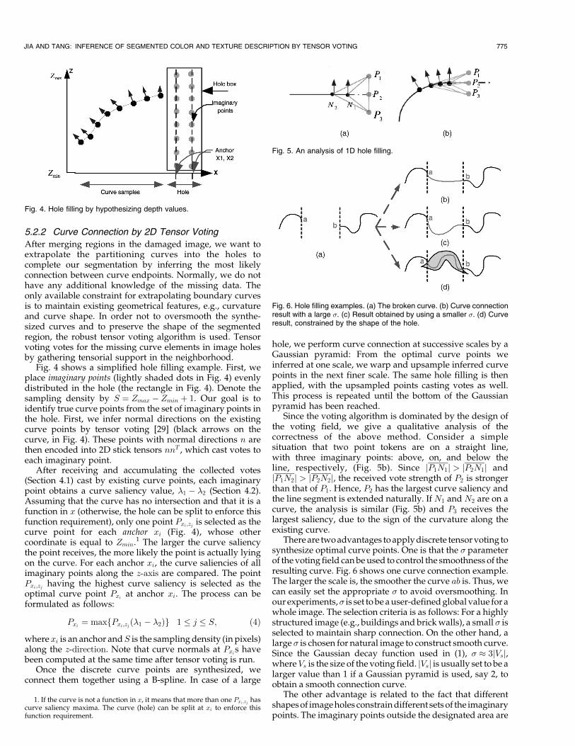
Fig. 4 shows a simplified hole filling example. First, weplace imaginary points (lightly shaded dots in Fig. 4) evenlydistributed in the hole (the rectangle in Fig. 4). Denote thesampling density by S ¼ Zmax � Zmin þ 1. Our goal is toidentify true curve points from the set of imaginary points inthe hole. First, we infer normal directions on the existingcurve points by tensor voting [29] (black arrows on thecurve, in Fig. 4). These points with normal directions n arethen encoded into 2D stick tensors nnT , which cast votes toeach imaginary point.
After receiving and accumulating the collected votes(Section 4.1) cast by existing curve points, each imaginarypoint obtains a curve saliency value, �1 � �2 (Section 4.2).Assuming that the curve has no intersection and that it is afunction in x (otherwise, the hole can be split to enforce thisfunction requirement), only one point Pxi;zj is selected as thecurve point for each anchor xi (Fig. 4), whose othercoordinate is equal to Zmin.1 The larger the curve saliencythe point receives, the more likely the point is actually lyingon the curve. For each anchor xi, the curve saliencies of allimaginary points along the z-axis are compared. The pointPxi;zj having the highest curve saliency is selected as theoptimal curve point Pxi at anchor xi. The process can beformulated as follows:
Pxi ¼ maxfPxi;zjð�1 � �2Þg 1 � j � S; ð4Þ
where xi is an anchor andS is the sampling density (in pixels)along the z-direction. Note that curve normals at Pxis havebeen computed at the same time after tensor voting is run.
Once the discrete curve points are synthesized, weconnect them together using a B-spline. In case of a large
hole, we perform curve connection at successive scales by aGaussian pyramid: From the optimal curve points weinferred at one scale, we warp and upsample inferred curvepoints in the next finer scale. The same hole filling is thenapplied, with the upsampled points casting votes as well.This process is repeated until the bottom of the Gaussianpyramid has been reached.
Since the voting algorithm is dominated by the design ofthe voting field, we give a qualitative analysis of thecorrectness of the above method. Consider a simplesituation that two point tokens are on a straight line,with three imaginary points: above, on, and below theline, respectively, (Fig. 5b). Since jP1N1j > jP2N1j andjP1N2j > jP2N2j, the received vote strength of P2 is strongerthan that of P1. Hence, P2 has the largest curve saliency andthe line segment is extended naturally. If N1 and N2 are on acurve, the analysis is similar (Fig. 5b) and P3 receives thelargest saliency, due to the sign of the curvature along theexisting curve.
There are two advantages to apply discrete tensor voting tosynthesize optimal curve points. One is that the � parameterof the voting field can be used to control the smoothness of theresulting curve. Fig. 6 shows one curve connection example.The larger the scale is, the smoother the curve ab is. Thus, wecan easily set the appropriate � to avoid oversmoothing. Inour experiments,� is set to be a user-defined global value for awhole image. The selection criteria is as follows: For a highlystructured image (e.g., buildings and brick walls), a small � isselected to maintain sharp connection. On the other hand, alarge � is chosen for natural image to construct smooth curve.Since the Gaussian decay function used in (1), � � 3jVsj,whereVs is the size of the voting field. jVsj is usually set to be alarger value than 1 if a Gaussian pyramid is used, say 2, toobtain a smooth connection curve.
The other advantage is related to the fact that differentshapes of image holes constrain different sets of the imaginarypoints. The imaginary points outside the designated area are
JIA AND TANG: INFERENCE OF SEGMENTED COLOR AND TEXTURE DESCRIPTION BY TENSOR VOTING 775
Fig. 4. Hole filling by hypothesizing depth values.
1. If the curve is not a function in x, it means that more than one Pxi;zj hascurve saliency maxima. The curve (hole) can be split at xi to enforce thisfunction requirement.
Fig. 5. An analysis of 1D hole filling.
Fig. 6. Hole filling examples. (a) The broken curve. (b) Curve connectionresult with a large �. (c) Result obtained by using a smaller �. (d) Curveresult, constrained by the shape of the hole.
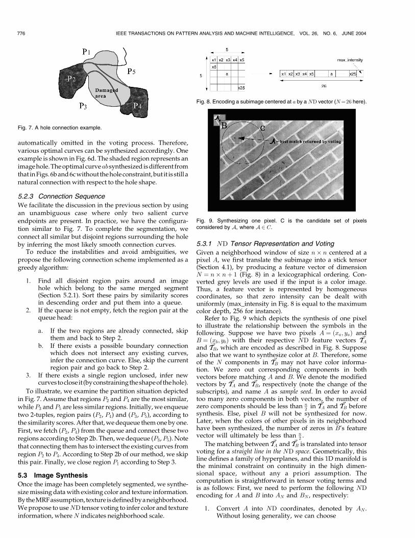
automatically omitted in the voting process. Therefore,various optimal curves can be synthesized accordingly. Oneexample is shown in Fig. 6d. The shaded region represents animage hole. The optimal curveab synthesized is different fromthat in Figs. 6b and 6c without the holeconstraint, but it is still anatural connection with respect to the hole shape.
5.2.3 Connection Sequence
We facilitate the discussion in the previous section by usingan unambiguous case where only two salient curveendpoints are present. In practice, we have the configura-tion similar to Fig. 7. To complete the segmentation, weconnect all similar but disjoint regions surrounding the holeby inferring the most likely smooth connection curves.
To reduce the instabilities and avoid ambiguities, wepropose the following connection scheme implemented as agreedy algorithm:
1. Find all disjoint region pairs around an imagehole which belong to the same merged segment(Section 5.2.1). Sort these pairs by similarity scoresin descending order and put them into a queue.
2. If the queue is not empty, fetch the region pair at thequeue head:
a. If the two regions are already connected, skipthem and back to Step 2.
b. If there exists a possible boundary connectionwhich does not intersect any existing curves,infer the connection curve. Else, skip the currentregion pair and go back to Step 2.
3. If there exists a single region unclosed, infer newcurvestoclose it (byconstrainingtheshapeofthehole).
To illustrate, we examine the partition situation depictedin Fig. 7. Assume that regions P2 and P4 are the most similar,while P3 andP5 are less similar regions. Initially, we enqueuetwo 2-tuples, region pairs (P2, P4) and (P3, P5), according tothe similarity scores. After that, we dequeue them one by one.First, we fetch (P2, P4) from the queue and connect these tworegions according to Step 2b. Then, we dequeue (P3,P5). Notethat connecting them has to intersect the existing curves fromregion P2 to P4. According to Step 2b of our method, we skipthis pair. Finally, we close region P1 according to Step 3.
5.3 Image Synthesis
Once the image has been completely segmented, we synthe-size missing data with existing color and texture information.BytheMRFassumption, texture isdefinedbyaneighborhood.We propose to useND tensor voting to infer color and textureinformation, where N indicates neighborhood scale.
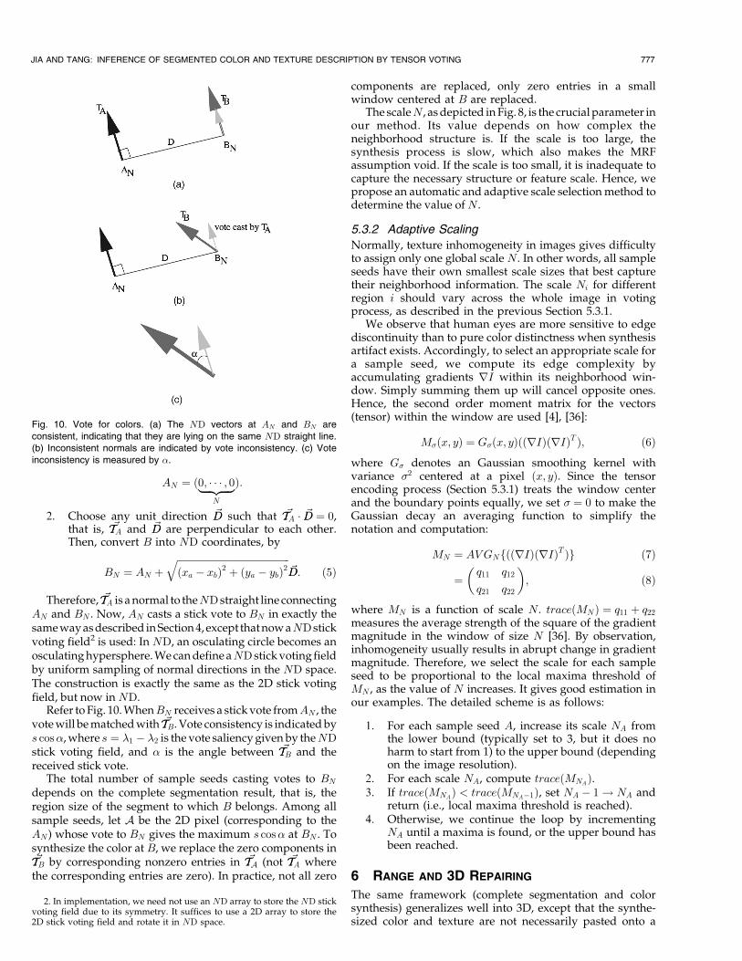
5.3.1 ND Tensor Representation and Voting
Given a neighborhood window of size n� n centered at apixel A, we first translate the subimage into a stick tensor(Section 4.1), by producing a feature vector of dimensionN ¼ n� nþ 1 (Fig. 8) in a lexicographical ordering. Con-verted grey levels are used if the input is a color image.Thus, a feature vector is represented by homogeneouscoordinates, so that zero intensity can be dealt withuniformly (max_intensity in Fig. 8 is equal to the maximumcolor depth, 256 for instance).
Refer to Fig. 9 which depicts the synthesis of one pixelto illustrate the relationship between the symbols in thefollowing. Suppose we have two pixels A ¼ ðxa; yaÞ andB ¼ ðxb; ybÞ with their respective ND feature vectors ~TTAand ~TTB, which are encoded as described in Fig. 8. Supposealso that we want to synthesize color at B. Therefore, someof the N components in ~TTB may not have color informa-tion. We zero out corresponding components in bothvectors before matching A and B. We denote the modifiedvectors by ~TTA and ~TTB, respectively (note the change of thesubscripts), and name A as sample seed. In order to avoidtoo many zero components in both vectors, the number ofzero components should be less than n
2 in ~TTA and ~TTB beforesynthesis. Else, pixel B will not be synthesized for now.Later, when the colors of other pixels in its neighborhoodhave been synthesized, the number of zeros in B’s featurevector will ultimately be less than n
2 .
The matching between ~TTA and ~TTB is translated into tensorvoting for a straight line in the ND space. Geometrically, thisline defines a family of hyperplanes, and this 1D manifold isthe minimal constraint on continuity in the high dimen-sional space, without any a priori assumption. Thecomputation is straightforward in tensor voting terms andis as follows: First, we need to perform the following NDencoding for A and B into AN and BN , respectively:
1. Convert A into ND coordinates, denoted by AN .Without losing generality, we can choose
776 IEEE TRANSACTIONS ON PATTERN ANALYSIS AND MACHINE INTELLIGENCE, VOL. 26, NO. 6, JUNE 2004
Fig. 7. A hole connection example.
Fig. 8. Encoding a subimage centered at a by aND vector (N¼26 here).
Fig. 9. Synthesizing one pixel. C is the candidate set of pixelsconsidered by A, where A 2 C.
AN ¼ ð0; � � � ; 0|fflfflfflffl{zfflfflfflffl}N
Þ:
2. Choose any unit direction ~DD such that ~TTA � ~DD ¼ 0,that is, ~TTA and ~DD are perpendicular to each other.Then, convert B into ND coordinates, by
BN ¼ AN þffiffiffiffiffiffiffiffiffiffiffiffiffiffiffiffiffiffiffiffiffiffiffiffiffiffiffiffiffiffiffiffiffiffiffiffiffiffiffiffiffiffiffiffiffiffiffiðxa � xbÞ2 þ ðya � ybÞ2
q~DD: ð5Þ
Therefore, ~TTA is a normal to theND straight line connectingAN and BN . Now, AN casts a stick vote to BN in exactly thesame way as described in Section 4, except that now aND stickvoting field2 is used: In ND, an osculating circle becomes anosculating hypersphere. We can define aND stick voting fieldby uniform sampling of normal directions in the ND space.The construction is exactly the same as the 2D stick votingfield, but now in ND.
Refer to Fig. 10. WhenBN receives a stick vote fromAN , thevote will be matched with ~TTB. Vote consistency is indicated bys cos�, where s ¼ �1 � �2 is the vote saliency given by theNDstick voting field, and � is the angle between ~TTB and thereceived stick vote.
The total number of sample seeds casting votes to BN
depends on the complete segmentation result, that is, theregion size of the segment to which B belongs. Among allsample seeds, let A be the 2D pixel (corresponding to theAN ) whose vote to BN gives the maximum s cos� at BN . Tosynthesize the color at B, we replace the zero components in~TTB by corresponding nonzero entries in ~TTA (not ~TTA where
the corresponding entries are zero). In practice, not all zero
components are replaced, only zero entries in a smallwindow centered at B are replaced.
The scaleN , as depicted in Fig. 8, is the crucial parameter inour method. Its value depends on how complex theneighborhood structure is. If the scale is too large, thesynthesis process is slow, which also makes the MRFassumption void. If the scale is too small, it is inadequate tocapture the necessary structure or feature scale. Hence, wepropose an automatic and adaptive scale selection method todetermine the value of N .
5.3.2 Adaptive Scaling
Normally, texture inhomogeneity in images gives difficultyto assign only one global scale N . In other words, all sampleseeds have their own smallest scale sizes that best capturetheir neighborhood information. The scale Ni for differentregion i should vary across the whole image in votingprocess, as described in the previous Section 5.3.1.
We observe that human eyes are more sensitive to edgediscontinuity than to pure color distinctness when synthesisartifact exists. Accordingly, to select an appropriate scale fora sample seed, we compute its edge complexity byaccumulating gradients rI within its neighborhood win-dow. Simply summing them up will cancel opposite ones.Hence, the second order moment matrix for the vectors(tensor) within the window are used [4], [36]:
M�ðx; yÞ ¼ G�ðx; yÞððrIÞðrIÞT Þ; ð6Þ
where G� denotes an Gaussian smoothing kernel withvariance �2 centered at a pixel ðx; yÞ. Since the tensorencoding process (Section 5.3.1) treats the window centerand the boundary points equally, we set � ¼ 0 to make theGaussian decay an averaging function to simplify thenotation and computation:
MN ¼ AVGNfððrIÞðrIÞT Þg ð7Þ
¼q11 q12
q21 q22
� �; ð8Þ
where MN is a function of scale N . traceðMNÞ ¼ q11 þ q22measures the average strength of the square of the gradientmagnitude in the window of size N [36]. By observation,inhomogeneity usually results in abrupt change in gradientmagnitude. Therefore, we select the scale for each sampleseed to be proportional to the local maxima threshold ofMN , as the value of N increases. It gives good estimation inour examples. The detailed scheme is as follows:
1. For each sample seed A, increase its scale NA fromthe lower bound (typically set to 3, but it does noharm to start from 1) to the upper bound (dependingon the image resolution).
2. For each scale NA, compute traceðMNAÞ.
3. If traceðMNAÞ < traceðMNA�1Þ, set NA � 1 ! NA and
return (i.e., local maxima threshold is reached).4. Otherwise, we continue the loop by incrementing
NA until a maxima is found, or the upper bound hasbeen reached.
6 RANGE AND 3D REPAIRING
The same framework (complete segmentation and colorsynthesis) generalizes well into 3D, except that the synthe-sized color and texture are not necessarily pasted onto a
JIA AND TANG: INFERENCE OF SEGMENTED COLOR AND TEXTURE DESCRIPTION BY TENSOR VOTING 777
2. In implementation, we need not use an ND array to store the ND stickvoting field due to its symmetry. It suffices to use a 2D array to store the2D stick voting field and rotate it in ND space.
Fig. 10. Vote for colors. (a) The ND vectors at AN and BN areconsistent, indicating that they are lying on the same ND straight line.(b) Inconsistent normals are indicated by vote inconsistency. (c) Voteinconsistency is measured by �.

planar surface. In this section, we show that the sameND colorsynthesis can be applied after performing complete segmen-tation accordingly. However, if there exist missing values inthe given range or 3D data, we need to infer them first.
For range data where each pixel can record only one depthvalue, missing data are mostly caused by occlusion. Wetherefore need to fill in the holes in the depth map, by inferringdiscrete depth values. The same occlusion situation exists in3D data. Moreover, missing data in 3D can also be caused byinsufficient data resolution due to undersampling. In ourmethod, we take a point cloud as 3D input and construct amesh first. Noisy range and 3D data are regularized andprocessed by 3D tensor voting, which removes noise, infersmissing data, and extracts a triangular surface mesh.
After all missing data have been filled, surface orienta-tion discontinuities are detected as curve junctions, also by3D tensor voting. The curves obtained serve the samepurpose as those in 2D image repairing, to avoid mixing uptextures with distinct statistical distribution. The 3D curveextraction algorithm can be found in [29], which isanalogous to the modified marching cubes algorithm as inthe case of 2D curve connection.
The extracted curves segment the range and 3D surfacemesh into separate patches with their respective color andtexture. Hence, 2D image repairing method can be applied toeach patch for complete segmentation and color synthesis.
In summary, the main steps for range and 3D repairingmethod are:
1. missing range or missing 3D data inference(Sections 6.1 and 6.2),
2. 3D curve extraction [29],3. mesh construction [29],4. mesh partitioning or segmentation according to the
extracted curves,5. image repairing are performed on each surface patch.
We use Fig. 11 as a running example to illustrate theoverall 3D data repairing process for shape and textureinference. Fig. 11a is obtained after missing data inference(Step 1), Normals shown in Fig. 11b and curve junctionsshown as thick lines in Fig. 11c are obtained by 3D tensorvoting in Step 2. A surface mesh can be extracted by amodified marching cubes algorithm, Fig. 11d (Step 3). Theinferred surfaces and curves segment the scene into a set ofpiecewise smooth patches (Step 4). The uniform samplingcriterion we enforce in Section 6.2 reduces distortion effect.To synthesize color and texture, 2D image repairing isapplied separately to each patch (Step 5), where automaticscale adaptation is also performed, Fig. 11e.
In the following sections, we focus on the inference ofmissing data in complete segmentation for range and
3D data (Step 1). Other steps are either described elsewhere(Steps 2 and 3 in [29], and Step 5 in Section 5), or easy toimplement (Step 4).
6.1 Inferring Missing Range Data
For range data, a pixel is defined as defective if it has no depthvalue, thus producing a hole in the range image. It is natural toextend the 2D tensor voting algorithm for hole filling wedescribed in Section 5.2.2 to fill in missing depth informationsince the uniqueness constraint along the line of sight appliesto depth map: Each pixel can contain only one depth value.
To achieve hole filling, we extend the voting space inFig. 4 into 3D, where the z-axis represents the depth axis,and ðx; yÞ are the image coordinates. Depth values (z values)vary from Zmin to Zmax. Hence, each defective pixel in theimage plane becomes an anchor. Instead of inferring a curvein Fig. 4, we infer a depth surface to cover up the anchors.Accordingly, we apply 3D tensor voting [29] to the volumeof discrete imaginary points to vote for the true surfacepoints: At each anchor ðx; yÞ, a total of Zmax � Zmin þ 1 votesare collected. The imaginary point ðx; y; dÞ, d 2 ½Zmin; Zmax�,is selected as the desired surface point if its surface saliencyis maximum along z direction for each anchor ðx; yÞ,analogous to the 2D situation (Fig. 4).
In order to accelerate the algorithm and not to over-smooth corners or surface orientation discontinuities in thevoting process, our implementation has the followingconsiderations:
. Incremental hole filling—If the hole size is small, we setthe voting field size (�) to be large enough so that thehole filling process can be accomplished in a singlepass. However, it is not feasible for large holes sincelarge voting field results in oversmoothing (andlonger computing time as well). Therefore, we adoptan incremental approach to fill large holes, startingfrom hole boundary toward the center. The max-imum number of passes is thus predetermined and issimply proportional to the size of the hole in pixels.
. Discontinuity preservation—Surface orientation dis-continuities (e.g., corners) should not be smoothedout. We observe that along the hole boundary, highcurvature points have fewer neighbors than lowcurvature ones. To preserve surface orientationdiscontinuity inside the hole, we assign higherpriority to lower curvature points. They will votefirst to incrementally fill the hole from the boundarytoward the center, by propagating the smoothnessconstraint. High curvature points are less preferredsince they do not propagate smoothness. Fig. 12cshows the hole filling result without curvature
778 IEEE TRANSACTIONS ON PATTERN ANALYSIS AND MACHINE INTELLIGENCE, VOL. 26, NO. 6, JUNE 2004
Fig. 11. Rundown of shape and texture syntheses.

priority consideration, while Fig. 12d has taken itinto account. The result in Fig. 12d preserves morecurvature details in the hole.
6.2 Inferring Missing 3D Data (Data Resampling)
Based on the method above, large holes (area with very lowresolution) in 3D triangle meshes can be filled in the sameway. However, we need to consider the sampling problem sothat resulting points are roughly uniformly distributed on theobject surface in 3D space. This reduces the distortion effectwhen surface textures are synthesized. In [26], an algorithm isdescribed to fill complicated holes in meshes, which can beused for this purpose. Complex holes can be filled by [12] toproduce a “watertight” surface mesh. Following, we presenta simpler solution, and more discussion on this alternative ispresented at the end of this section.
To satisfy the uniform sampling criterion, we adopt adivide-and-conquer method to locate anchors and reorganizethem. Inspired by the previous section about the range datahole filling, we associate each surface patch with a localcoordinate system and set anchors accordingly so thatexisting patches can be extrapolated to cover up a hole.Fig. 13a shows a triangulated mesh, [iSi, where Si is atriangle. Each triangle is associated with a local coordinatesystem, e.g.,Si with ðxi;yi; ziÞ, where ðxi;yiÞdefines the sameplane as triangleSi. Therefore, we apply hole filling algorithm
for range images in the previous section to each triangle and
vote for more surface points to obtain a finer triangulation.
These new points will be connected together to form a finer
resulting surface to increase sampling density, Fig. 13b.One minor modification is that instead of sampling
depth candidates from the given Zmin to Zmax, we constrain
the depth range from maxðZmin; SURÞ to minðZmax; SURÞfor each anchor ðxi; yiÞ, where SUR is the nearest surface
point along z or �z direction in ðxi; yiÞ position. The
detailed 3D hole filling algorithm is as follows:
1. Assign a coordinate system ðx;y; zÞ to the entire hole,Fig. 13c. Sample anchors in the hole area and applyhole filling for range data to infer initial surface points,which will be triangulated to form finer triangles. Thecomputation of ðx;y; zÞ will be explained shortly.
2. If there is any triangle Si whose area size is largerthan some threshold, i.e., insufficient samplingdensity, repeat the following steps.
3. Associate Si with a local coordinate system ðxi;yi; ziÞwhere the ðxi;yiÞ plane is the triangle plane Si, andzi direction is perpendicular to it (e.g., S1 in Fig. 13a).
4. Sample Si according to the assigned density value,and generate anchors in the ðxi;yiÞ plane (e.g., S1
and S2 in Fig. 13a).
JIA AND TANG: INFERENCE OF SEGMENTED COLOR AND TEXTURE DESCRIPTION BY TENSOR VOTING 779
Fig. 12. Priority in range data filling for complete segmentation. Lighter points near high curvature area have lower priority than the darker points. (c) isthe filling result without priority consideration, (d) shows better result with priority consideration, where high curvatures are not smoothed out.
Fig. 13. Three-dimensional data filling illustration for complete segmentation. (a) A 3D mesh with triangles S1; S2 . . .Sn, each of which is associatedwith a local coordinate system. ðxi;yiÞ defines a plane where the triangle Si is lying. The zi axis is perpendicular to this plane. Black dots (nonmeshvertices) represent anchors. (b) Optimal depth for each anchor in S1 is constructed along the z1 direction (e.g., A1 and A2). They are connected toform a finer mesh. (c) A more detailed illustration for constructing the initial local coordinate system. Local z-direction is the equal to the average ofthe hole boundary normal directions. The hole area is orthogonally projected onto ðx;yÞ plane, where anchors are sampled.
5. Hole filling algorithm for range data is applied togenerate new surface points for all anchors. They areconnected to form new triangles, Fig. 13b. To constructan integrated mesh given these new surface points, wecan either apply 3D tensor voting to the subset of newpoints for inferring the mesh to connect them, or usethe construction and optimization algorithm [19], [20]to generate the resulting mesh, Fig. 13b.
Here, we provide details for computing ðx;y; zÞ in Step 1.
Wewant to selectanoptimal ðx;yÞplanewhich maximizes the
orthogonal projection area of the hole. However, it is
expensive to accurately locate the maxima due to the varieties
of the hole shape. Alternatively, a more intuitive but stable
method is adopted to create the initial coordinate system
ðx;y; zÞ, shown in Fig. 13c, by first averaging the normal
directions of all hole boundary points as N , i.e., N ¼ðPNB
i¼1 normalðPiÞÞ=NB, where NB is the number of the
boundary points Pi. The normals at these boundary points
are either given (by the mesh) originally, or computed by
tensor voting [29].Then, we set the z-direction to be equal to N . The ðx;yÞ
plane is randomly selected as long as x, y, and z are
perpendicular to each other. Orthogonally project the hole
onto the ðx;yÞ plane and compute anchors according to the
sampling density (Fig. 13c).
6.3 Discussion
In this section, we have extended our methodology to repair a
3D mesh. Here, we qualify our proposed method, where the
four results depicted in Figs. 23, 24, and 25 also show the
limitation of our extension, and they can be improved in the
future. Our 3D extension works in the presence of disconti-
nuities (C0 continuous but C1 discontinuous), large amount
of noise and missing data, as long as the local geometric scales
remain approximately constant. When the hole to be repaired
covers geometric features of multiple scales, the complete
segmentation must be performed also in multiple scales,
which is under investigation [39]. For example, because of
self-occlusion, the hole may cover both the nose (small scale
geometric feature) and cheek (large scale geometric feature)
of a defective face mesh at the same time, when only a sparse
set of scans is available. The output of the complete
segmentation in multiscales is a segmented multiresolution
mesh where different scale features are coherently integrated
along scale transition (curves), in addition to discontinuity
curves described above for restricting the color/texture
synthesis, so that only relevant information in each segmen-
ted patch is used in the synthesis process.
7 TIME COMPLEXITY ANALYSIS
This section collectively analyzes the time complexity forour repairing methods. Let:
D2 = number of anchors in 2D repairing.D3 = number of anchors in range/3D repairing.B = number of pixels along hole boundary (B � D2; D3).T = number of nondefective pixels in the image.R = number of regions (R � T ).S = number of samples (S ¼ Zmax � Zmin þ 1).
There are two steps for 2D complete segmentation. In thetexture-based region segmentation (Section 5.2.1), it takesOðT Þ time to compute the joint intensity and gradientvector, and merge regions. It results in a total of R regions.For curve connection, it takes OðR2Þ time to pair up regions,before putting them into a priority queue (very efficient
780 IEEE TRANSACTIONS ON PATTERN ANALYSIS AND MACHINE INTELLIGENCE, VOL. 26, NO. 6, JUNE 2004
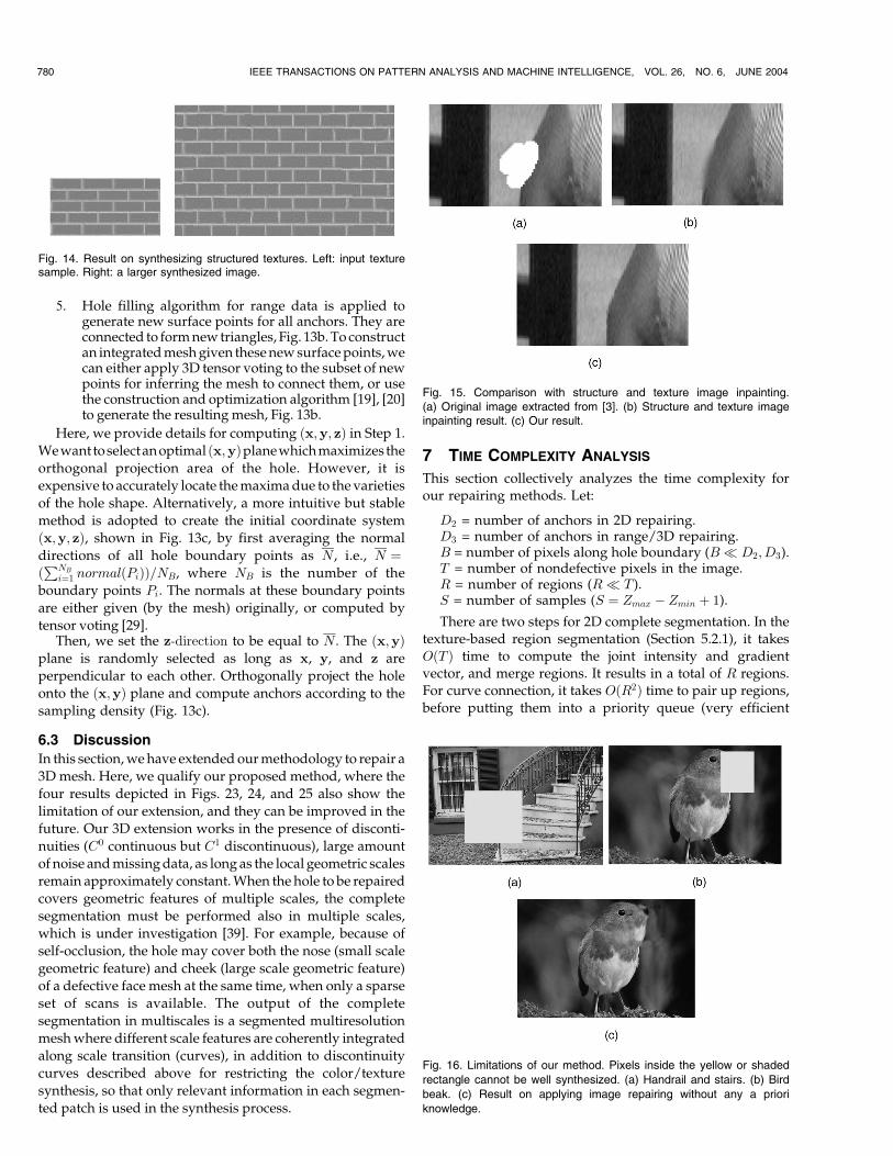
Fig. 14. Result on synthesizing structured textures. Left: input texturesample. Right: a larger synthesized image.
Fig. 15. Comparison with structure and texture image inpainting.(a) Original image extracted from [3]. (b) Structure and texture imageinpainting result. (c) Our result.
Fig. 16. Limitations of our method. Pixels inside the yellow or shaded
rectangle cannot be well synthesized. (a) Handrail and stairs. (b) Bird
beak. (c) Result on applying image repairing without any a priori
knowledge.
Fibonacci heap can be used to implement the queue).
OðSD2Þ time is spent for 2D tensor voting: SD2 tensor votes
are collected at the imaginary points inside the hole for
computing the optimal curve points. There are at most OðBÞendpoints with their finite neighborhood where we sample
the tensor votes for curve extrapolation. Summing up, the
total time is OðT þR2 þ SD2 þBÞ � OðT þ SD2Þ, that is,
linear with the total number of pixels in the given image.
For complete segmentation in range and 3D data, afterspending OðBÞ time to fix the local coordinate system,3D tensor voting is used to infer the (depth) surfaces andpartitioning curves, which takes OðSD3Þ time.
For color and texture synthesis, once the scale for a regionhas been chosen (the time spent on scale iteration is related toimage resolution and is linear with T , the total number ofpixels), we performND tensor voting. To synthesize the colorfor each anchor, only a finite neighborhood need to be
JIA AND TANG: INFERENCE OF SEGMENTED COLOR AND TEXTURE DESCRIPTION BY TENSOR VOTING 781
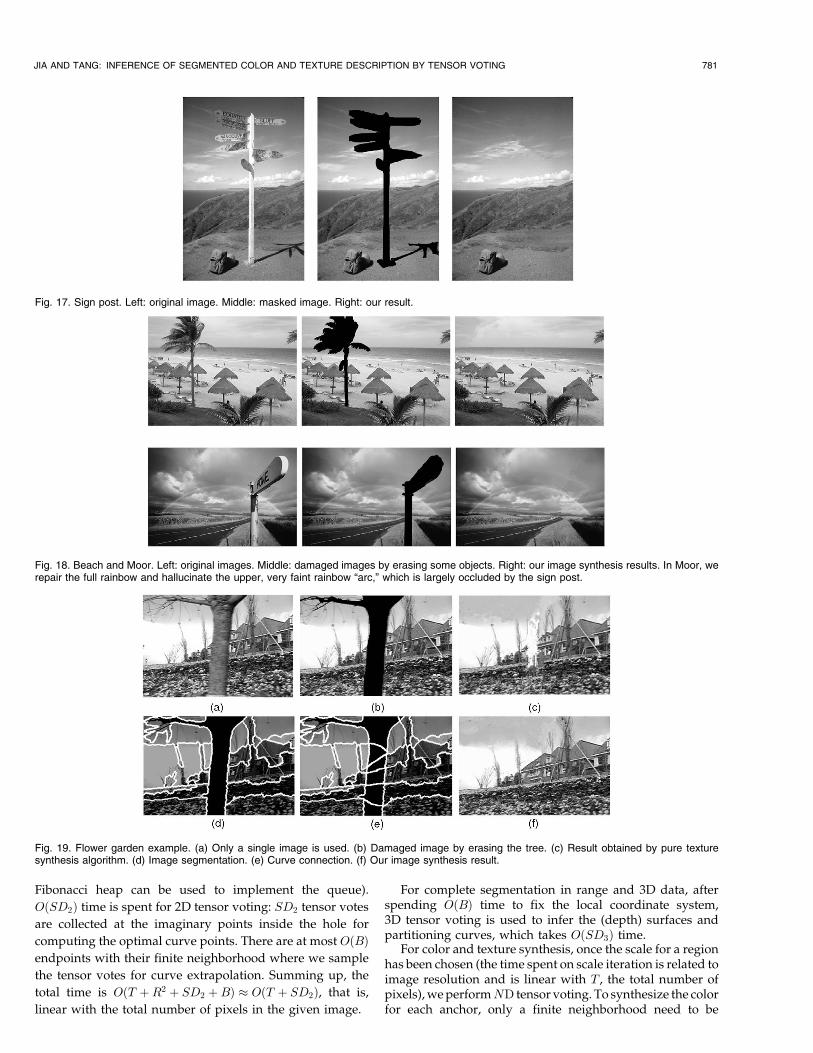
Fig. 17. Sign post. Left: original image. Middle: masked image. Right: our result.
Fig. 18. Beach and Moor. Left: original images. Middle: damaged images by erasing some objects. Right: our image synthesis results. In Moor, werepair the full rainbow and hallucinate the upper, very faint rainbow “arc,” which is largely occluded by the sign post.
Fig. 19. Flower garden example. (a) Only a single image is used. (b) Damaged image by erasing the tree. (c) Result obtained by pure texturesynthesis algorithm. (d) Image segmentation. (e) Curve connection. (f) Our image synthesis result.

considered, by the MRF assumption. Therefore, at mostOðT þ SD3Þ time is spent.
The above analysis is valid when the size of the voting fieldis not large. Except for very sparse data, applications such asimage/mesh restoration usually involves (quasi-)dense data,except at the hole. Therefore, �, which used to define thevoting field size, needs not be large. For large holes,incremental hole filling is performed to keep a small � ininference. Therefore, the size of the voting field can be treatedas a constant in 2D, 3D, or ND. Tensor voting is thus a linear-time algorithm regardless of dimensionality. Typical range of� we use is 1 to 2.
8 RESULTS
8.1 2D Image Results
We first show one texture synthesis result on regularlytextured patterns (Fig. 14) where rigid structures aremaintained.
One emphasis of this paper is repairing damaged imagesof real scenes. We have experimented a variety of suchdifficult natural images, most of them contain large andcomplex holes with difficult neighborhood topologies.
Figs. 17 and 18 show three examples. From a singledamaged or masked image (middle) with a large amount ofmissing complex information, we are capable of synthesiz-ing new pixels. By adaptively propagating neighborhoodinformation, our method smoothly generates texture pat-terns without blurring important feature curves (right). Theleft images are original images with the occluding objects.There exist many methods to erase these objects, which areout of the scope of this paper. The original images (left) areprovided for comparison.
Next, we also show some intermediate results for2D image repairing, in addition to the final repairedimages. From a single image of a flower garden with theoccluding tree removed, we synthesize the result in Fig. 19f.The detailed process is: We first segment the damagedimage. It is followed by a merging process described inSection 5.2.1 (Fig. 19d). Then, we complete our segmenta-tion by curve connection using 2D tensor voting describedin Section 5.2.2 (Fig. 19e). There are two key factors
contributing to the success of this difficult example. First,thanks to the automatic color and texture segmentation [13]in Fig. 19d, a set of reliable partitioning curves incident atthe hole boundaries is produced. Next, our completesegmentation infers the curves inside the hole, whichprovides sufficient information so that the color synthesisstep is capable of distinguishing which pixels are relevant inthe synthesis process. In this and other experiments, thoughthere is a set of default thresholds or parameters in ourimplementation, they are either unchanged or not critical,making our method fully automatic. Fig. 20 shows anotherresult, obtained using the same process. Some intermediateresults are also shown.
Fig. 15 compares our method with image structure andtexture image inpainting [3]. Since our method infers
782 IEEE TRANSACTIONS ON PATTERN ANALYSIS AND MACHINE INTELLIGENCE, VOL. 26, NO. 6, JUNE 2004
Fig. 20. Chair example. (a) Original image. (b) Image segmentation before curve connection, after removing the leftmost chair. (c) Complete
segmentation after curve connection. (d) The repaired image. (e) Complete segmentation after removing the chair second from right. Note the
complex shape of the curves inside the hole, which are inferred by our 2D hole filling algorithm using tensor voting. (f) Our result with two chairs left.
Fig. 21. Noisy corner example. (a) initial color image (the ball is an
occluder), (b) initial noisy range data, (c) the recovered background
layer (the occluded corner is not smoothed out), (d) the same view with
automatically recovered background texture which fills the background
hole and does not smooth out the corner.
explicit segmentation information and separates differentpattern information, it retains texture structures anddiscontinuities in regions, and does not introduce blurring.Another direct comparison is shown in Fig. 19c, whichshows that texture synthesis technique such as [15] is notsuitable in our task of repairing natural images. Withoutproper segmentation, pixels belonging to distinct statisticaldistributions are mixed together.
The actual running time of our method depends on theimage texture and hole complexity. In our experiments,given a 400� 300 pixels image and 10,000 pixels hole area,our method outputs the repaired images in less than15 minutes on a Pentium III 1GHz PC.
8.2 Three-Dimensional and Range Data Results
Fig. 21a shows the input color image and Fig. 21b shows thecorresponding depth map of the noisy corner example.Three-dimensional tensor voting is used to recover thebackground and fill the hole. Complete segmentation isrepresented by the inferred 3D surface, curve, and pointjunctions. As a result, the surface is optimally partitionedinto three patches and textures are synthesized accordinglywithout undesirable mixture, Fig. 21d.
The flower garden example with depth is used in Fig. 22.The input depth map is shown in Fig. 22a, where noise hasbeen removed. The background depth map is filled by3D repairing after removing the tree trunk, Fig. 22b. A hole
JIA AND TANG: INFERENCE OF SEGMENTED COLOR AND TEXTURE DESCRIPTION BY TENSOR VOTING 783
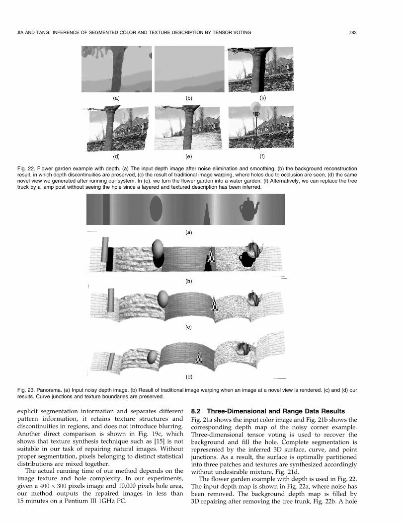
Fig. 22. Flower garden example with depth. (a) The input depth image after noise elimination and smoothing, (b) the background reconstructionresult, in which depth discontinuities are preserved, (c) the result of traditional image warping, where holes due to occlusion are seen, (d) the samenovel view we generated after running our system. In (e), we turn the flower garden into a water garden. (f) Alternatively, we can replace the treetruck by a lamp post without seeing the hole since a layered and textured description has been inferred.
Fig. 23. Panorama. (a) Input noisy depth image. (b) Result of traditional image warping when an image at a novel view is rendered. (c) and (d) ourresults. Curve junctions and texture boundaries are preserved.
is exposed when viewpoint changes, Fig. 22c. Notespecifically that, after segmenting the background intothree layers as shown in Fig. 22b, we input them to 2Dimage repairing separately (Section 6). The sky is distin-guished from the house in 2D image repairing process thatfollows, which guarantees that different patterns will not bemixed up in the synthesis process. The result rendered atanother viewpoint is shown in Fig. 22d. Figs. 22e and 22findicate some potential applications with the segmentedand textured description we inferred.
Fig. 23a shows a panoramic depth map we computed in[25] using multibaseline stereo. When viewpoint changes,the previously occluded background is exposed, Fig. 23b.Complete segmentation is performed by 3D tensor voting,which infers the missing depth values without smoothingout the junction curves, Fig. 23d. ND color and texturesynthesis are performed to fill up the holes. Two views of thedepth maps with color values are shown in Figs. 23c and 23d.
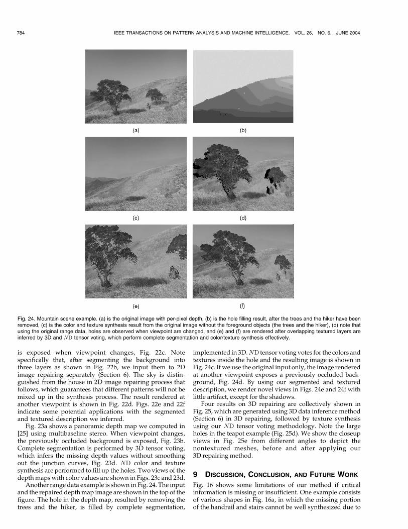
Another range data example is shown in Fig. 24. The inputand the repaired depth map image are shown in the top of thefigure. The hole in the depth map, resulted by removing thetrees and the hiker, is filled by complete segmentation,
implemented in 3D.ND tensor voting votes for the colors andtextures inside the hole and the resulting image is shown inFig. 24c. If we use the original input only, the image renderedat another viewpoint exposes a previously occluded back-ground, Fig. 24d. By using our segmented and textureddescription, we render novel views in Figs. 24e and 24f withlittle artifact, except for the shadows.
Four results on 3D repairing are collectively shown inFig. 25, which are generated using 3D data inference method(Section 6) in 3D repairing, followed by texture synthesisusing our ND tensor voting methodology. Note the largeholes in the teapot example (Fig. 25d). We show the closeupviews in Fig. 25e from different angles to depict thenontextured meshes, before and after applying our3D repairing method.
9 DISCUSSION, CONCLUSION, AND FUTURE WORK
Fig. 16 shows some limitations of our method if criticalinformation is missing or insufficient. One example consistsof various shapes in Fig. 16a, in which the missing portionof the handrail and stairs cannot be well synthesized due to
784 IEEE TRANSACTIONS ON PATTERN ANALYSIS AND MACHINE INTELLIGENCE, VOL. 26, NO. 6, JUNE 2004
Fig. 24. Mountain scene example. (a) is the original image with per-pixel depth, (b) is the hole filling result, after the trees and the hiker have beenremoved, (c) is the color and texture synthesis result from the original image without the foreground objects (the trees and the hiker), (d) note thatusing the original range data, holes are observed when viewpoint are changed, and (e) and (f) are rendered after overlapping textured layers areinferred by 3D and ND tensor voting, which perform complete segmentation and color/texture synthesis effectively.

a complex background and their irregular shapes. The otherexample consists of an entirely missing bird beak in Fig. 16b.Fig. 16c shows our 2D image repairing result, which isobviously incorrect without employing any knowledge. Inboth cases, additional knowledge on the scene is needed.Also, in the ambiguous situation where the missing areacovers the intersection of two perpendicular regions withsimilar textures, our complete segmentation may pick thesuboptimal interpretation in the absence of knowledge.
To conclude this paper, we have proposed a new methodto automatically repair and restore damaged images. Ourmethod is capable of dealing with large holes where missingdetails can be complex and inhomogeneous. They cannot bedescribed by a small set of statistical parameters. Pure texturesynthesis technique will fail on those input images. Realimages of natural scenes are typical examples. We addressthis difficult problem by complete segmentation and robustcurve connection. Adaptive ND tensor voting provides aunified basis to implement many of these tasks. Our imagerepairing can be generalized to range and 3D data as well:Complete segmentation is performed in 3D by 3D tensorvoting to infer missing data and partition surface patches.The same adaptive ND tensor voting for color/texturesynthesis is used in 2D, range, and 3D data. We have
demonstrated very encouraging results on natural imagesusing our method, and performed some comparison.
In the future, we propose to scale up the image repairingtechnique to process videos, and to repair damaged videosequence. It has important application to film restoration:Many films that are half a century old are in need ofrestoration. Image repairing produces spatially coherentand visually acceptable results for large image holes. Thechallenge for video repairing is the efficient exploitation ofspatial and temporal coherence inherent in the largenumber of frames to achieve visually plausible restoration.
ACKNOWLEDGMENTS
The authors would like to thank all the reviewers fortheir constructive comments to improve the final manu-script. This research is supported by the Research GrantCouncil of Hong Kong Special Administrative Region,China: HKUST6171/03E.
REFERENCES
[1] C. Ballester, V. Caselles, J. Verdera, M. Bertalmio, and G. Sapiro,“A Variational Model for Filling-In,” Proc. Int’l Conf. ImageProcessing, 2003.
JIA AND TANG: INFERENCE OF SEGMENTED COLOR AND TEXTURE DESCRIPTION BY TENSOR VOTING 785
Fig. 25. Some results in 3D. (a) cactus part, (b) car, (c) golf club, and (d) teapot. Defectivemesheswith holes, repaired and texturedmeshes are shown.(e) is two closeup views on teapot example with holes from different viewing angles, where the generated meshes are not textured for display clarity.
[2] M. Bertalmio, G. Sapiro, C. Ballester, and V. Caselles, “ImageInpainting,” Proc. SIGGRAPH 2000 Conf., pp. 417-424, 2000.
[3] M. Bertalmio, L. Vese, G. Sapiro, and S. Osher, “SimultaneousStructure and Texture Image Inpainting,” Proc. Conf. ComputerVision and Pattern Recognition, vol. 2, pp. 707-712, 2003.
[4] J. Bigun, “Local Symmetry Features in Image Processing,” PhDthesis, Linkoping Univ., Sweden, 1988.
[5] J.S. De Bonet, “Multiresolution Sampling Procedure for Analysisand Synthesis of Texture Images,” Proc. SIGGRAPH’97 Conf.,pp. 361-368, 1997.
[6] R.A. Brooks, “Model-Based Three-Dimensional Interpretations ofTwo-Dimensional Images,” IEEE Trans. Pattern Analysis andMachine Intelligence, vol. 5, no. 2, pp. 140-150, 1983.
[7] J.C. Carr, W.R. Fright, and R.K. Beatson, “Surface Interpolationwith Radial Basis Functions for Medical Imaging,” IEEE Trans.Medical Imaging, vol. 16, no. 1, pp. 96-107, 1997.
[8] T. Chan and J. Shen, “Non-Texture Inpaintings by Curvature-Driven Diffusions,” Technical Report 00-35, Dept. of Math., Univ.of Calif. at Los Angeles, 2000.
[9] C.-F. Chang, G. Bishop, and A. Lastra, “Ldi Tree: A HierarchicalRepresentation for Image-Based Rendering,” Proc. 26th Ann. Conf.Computer Graphics and Interactive Techniques, pp. 291-298, 1999.
[10] A. Criminisi, P. Perez, and K. Toyama, “Object Removal byExemplar-Based Inpainting,” Proc. Conf. Computer Vision andPattern Recognition, vol. 2, pp. 721-728, 2003.
[11] B. Curless and M. Levoy, “A Volumetric Method for BuildingComplex Models from Range Images,” Proc. 23rd Ann. Conf.Computer Graphics and Interactive Techniques, pp. 303-312, 1996.
[12] J. Davis, S. Marschner, M. Garr, and M. Levoy, “Filling Holes inComplex Surfaces Using Volumetric Diffusion,” Proc. First Int’lSymp. 3D Data Processing, Visualization, and Transmission, 2002.
[13] Y.DengandB.S.Manjunath, “UnsupervisedSegmentationofColor-Texture Regions in Images and Video,” IEEE Trans. Pattern AnalysisandMachine Intelligence, vol. 23, no. 8, pp. 800-810, Aug. 2001.
[14] I. Drori, D. Cohen-Or, and H. Yeshurun, “Fragment-Based ImageCompletion,” ACM Trans. Graphics, vol. 22, no. 3, pp. 303-312, 2003.
[15] A. Efros and T. K. Leung, “Texture Synthesis by Non-ParametricSampling,” Proc. Seventh Int’l Conf. Computer Vision, pp. 1033-1038,1999.
[16] A.A. Efros and W.T. Freeman, “Image Quilting for TextureSynthesis and Transfer,” Proc. 28th Ann. Conf. Computer Graphicsand Interactive Techniques, pp. 341-346, 2001.
[17] I. Guskov and Z. Wood, “Topological Noise Removal,” Proc.Graphics Interface Conf.,, 2001.
[18] D.J. Heeger and J.R. Bergen, “Pyramid-Based Texture Analysis/Synthesis,” Proc. 22nd Ann. Conf. Computer Graphics and InteractiveTechniques, pp. 229-238, 1995.
[19] H. Hoppe, T. DeRose, T. Duchamp, J. McDonald, and W. Stuetzle,“Surface Reconstruction from Unorganized Points,” Proc. 19th Ann.Conf. Computer Graphics and Interactive Techniques, pp. 71-78, 1992.
[20] H. Hoppe, T. DeRose, T. Duchamp, J. McDonald, and W. Stuetzle,“Mesh Optimization,” Proc. 20th Ann. Conf. Computer Graphics andInteractive Techniques, pp. 19-26, 1993.
[21] J. Jia and C.-K. Tang, “Image Repairing: Robust Image Synthesisby Adaptive ND Tensor Voting,” Proc. Conf. Computer Vision andPattern Recognition, vol. 1, pp. 643-650, 2003.
[22] S.B. Kang, R. Szeliski, and J. Chai, “Handling Occlusion in DenseMulti-View Stereo,” Proc. IEEE Conf. Computer Vision and PatternRecognition, 2001.
[23] M. Kass, A. Witkin, and D. Terzopoulous, “Snakes: An ActiveContour Models,” Int’l J. Computer Vision, vol. 1, no. 4, pp. 321-331,1987.
[24] A. Levin, A. Zomet, and Y. Weiss, “Learning How to Inpaint fromGlobal Image Statistics,” Proc. Int’l Conf. Computer Vision, pp. 305-312, 2003.
[25] Y. Li, C.-K. Tang, and H.-Y. Shum, “Efficient Dense DepthEstimation from Dense Multiperspective Panoramas,” Proc. EighthInt’l Conf. Computer Vision, pp. 119-126, 2001.
[26] P. Liepa, “Filling Holes in Meshes,” Proc. Eurographics Symp.Geometry Processing, vol. 2, pp. 721-728, 2003.
[27] W.R. Mark, L. McMillan, and G. Bishop, “Post-Rendering 3DWarping,” Proc. 1997 Symp. Interactive 3D Graphics, pp. 7-16, 1997.
[28] S. Masnou and J. Morel, “Level Line(s) Based Disocclusion,” Proc.Int’l Conf. Image Processing, pp. 259-263, 1998.
[29] G. Medioni, M.S. Lee, and C.K. Tang, A Computational Frameworkfor Feature Extraction and Segmentation. Elseviers Science, 2000.
[30] E.N. Mortensen and W.A. Barrett, “Intelligent Scissors for ImageComposition,” Proc. 22nd Ann. Conf. Computer Graphics andInteractive Techniques, pp. 191-198, 1995.
[31] D.R. Peachey, “Solid Texturing of Complex Surfaces,” Proc. 12thAnn. Conf. Computer Graphics and Interactive Techniques, pp. 279-286,1985.
[32] P. Perez, A. Blake, and M. Gangnet, “Jetstream: ProbabilisticContour Extraction with Particles,” Proc. Int’l Conf. ComputerVision, vol. 2, pp. 524-531, 2001.
[33] K. Perlin, “An Image Synthesizer,” Proc. 12th Ann. Conf. ComputerGraphics and Interactive Techniques, pp. 287-296, 1985.
[34] R. Pfeifle and H.-P. Seidel, “Triangular B-Splines for Blending andFilling of Polygonal Holes,” Proc. Graphics Interface Conf., pp. 186-193, 1996.
[35] J. Portilla and E.P. Simoncelli, “A Parametric Texture Model Basedon Joint Statistics of Complex Wavelet Coefficients,” Int’lJ. Computer Vision, vol. 40, no. 1, pp. 49-70, Oct. 2000.
[36] J. Garding and T. Lindeberg, “Direct Computation of Shape CuesUsing Scale-Adapted Spatial Derivative Operators,” Int’lJ. Computer Vision, vol. 17, no. 2, pp. 163-191, 1996.
[37] H.-Y. Shum and L.-W. He, “Rendering with Concentric Mosaics,”Proc. 26th Ann. Conf. Computer Graphics and Interactive Techniques,pp. 299-306, 1999.
[38] J.M. Snyder and J.T. Kajiya, “Generative Modeling: A SymbolicSystem for Geometric Modeling,” Proc. 19th Ann. Conf. ComputerGraphics and Interactive Techniques, pp. 369-378, 1992.
[39] W.-S. Tong and C.-K. Tang, “Multiscale Surface Reconstruction byTensor Voting,” technical report, Dept. of Computer Science,Hong Kong Univ. of Science and Technology, 2004.
[40] G. Turk and J.F. O’Brien, “Variational Implicit Surfaces,”Technical Report GIT-GVU-99-15, Graphics, Visualization, andUseability Center, Georgia Inst. of Technology, 1999.
[41] J. Verdera, V. Caselles, M. Bertalmio, and G. Sapiro, “InpaintingSurface Holes,” Proc. Int’l Conf. Image Processing, 2003.
[42] J. Wang and M.M. Oliveira, “A Hole Filling Strategy forReconstruction of Smooth Surfaces in Range Images,” Proc.Brazilian Symp. Computer Graphics and Image Processing (SIBGRA-PI03), 2003.
[43] L.-Y. Wei and M. Levoy, “Fast Texture Synthesis Using Tree-Structured Vector Quantization,” Proc. 27th Ann. Conf. ComputerGraphics and Interactive Techniques, pp. 479-488, 2000.
[44] A. Witkin and M. Kass, “Reaction-Diffusion Textures,” Proc. 18thAnn. Conf. Computer Graphics and Interactive Techniques, pp. 299-308, 1991.
[45] Y.Q. Xu, S.C. Zhu, B.N. Guo, and H.Y. Shum, “AsymptoticallyAdmissible Texture Synthesis,” Proc. Second Int’l WorkshopStatistical and Computational Theories of Vision, 2001.
[46] H. Yamauchi, J. Haber, and H.-P. Seidel, “Image RestorationUsing Multiresolution Texture Synthesis and Image Inpainting,”Proc. Computer Graphics International (CGI) Conf., pp. 120-125, 2003.
Jiaya Jia received the BSc degree in computerscience from the Fudan University, ROC, in 2000.He is pursuing the PhD degree in the Departmentof Computer Science, Hong Kong University ofScience and Technology. He is currently a visitingstudent at the Visual Computing Group of Micro-soft Research Asia. His research interests includeimage and video processing, image-based ren-dering and pattern recognition. He is a student
member of the IEEE Computer Society.
Chi-Keung Tang received the MS and PhDdegrees in computer science from the Universityof Southern California, Los Angeles, in 1999 and2000, respectively. He has been with the Com-puter Science Department at the Hong KongUniversity of Science and Technology since 2000,where he is currently an assistant professor. He isalso an adjunct researcher at the Visual Comput-ing Group of Microsoft Research, Asia, working
on various exciting research topics in computer vision and graphics. Hisresearch interests include low to midlevel vision such as segmentation,correspondence, shape analysis, and vision and graphics topics such asimage-based rendering and medical image analysis. He is a member ofthe IEEE Computer Society.
786 IEEE TRANSACTIONS ON PATTERN ANALYSIS AND MACHINE INTELLIGENCE, VOL. 26, NO. 6, JUNE 2004


![Pyramid Scene Parsing Network - Jiaya Jiajiaya.me/papers/PSPNet_cvpr17.pdf · new ADE20K dataset [43] is the most challenging one with a large and unrestricted open vocabulary and](https://img.pdfslide.net/doc/110x75/5f53a85517251a0f232a3129/pyramid-scene-parsing-network-jiaya-new-ade20k-dataset-43-is-the-most-challenging.jpg)


![pn-balebandung.go.id · Ked un Ketign Keen pal Menetapkan Panjar Biaya Pendaftaran Perkara Perdata pada Pengadilan Negeri Bale Bandunu Kelas IA man n I ; , ] .jiaya pendaftaran perkara](https://img.pdfslide.net/doc/110x75/5e2231c300c4ec62a2667caa/pn-ked-un-ketign-keen-pal-menetapkan-panjar-biaya-pendaftaran-perkara-perdata-pada.jpg)