Embed Size (px)
Citation preview
IEEE TRANSACTIONS ON VEHICULAR TECHNOLOGY, VOL. 53, NO. 5, SEPTEMBER 2004 1531
Performance Analysis of RLC/MAC and LLCLayers in a GPRS Protocol Stack
K. Premkumar and A. Chockalingam, Senior Member, IEEE
Abstract—In this paper, we analyze the performance of variouslayers of the general packet radio service (GPRS) protocol stack,including radio link control/medium-access control (RLC/MAC)layer and logical link-control (LLC) layer on the uplink. In theGPRS MAC protocol, several time-slotted uplink radio-frequencychannels are shared by the mobiles on a request-reservation-basedmultiple-access scheme. Using the theory of Markov chains, we de-rive expressions for the average throughput and delay performanceof the GPRS MAC protocol. We evaluate the performance of theRLC layer (in acknowledged mode) using block-level retransmis-sion (BLR), as defined in the current GPRS standard, and compareit with that of using slot-level retransmission (SLR). We show thatSLR at the RLC layer performs significantly better than the BLR,particularly when the channel-error rates are moderate to high.We further investigate the choice of parameters (e.g., number ofretransmission attempts) for the automatic repeat request schemesat the RLC and LLC layers. Our results show that it is more benefi-cial to do error recovery by allowing more retransmission attemptsat the RLC layer than at the LLC layer. We also evaluate the per-formance of transmission-control protocol with BLR and SLR atthe RLC layer.
Index Terms—Automatic repeat request (ARQ), block-levelretransmission (BLR), general packet radio service (GPRS), log-ical link control (LLC), radio link control/medium-access control(RLC/MAC), slot-level retransmission (SLR), transmission-con-trol protocol (TCP).
I. INTRODUCTION
THE first- and second-generation (1G and 2G) cellular sys-tems, including advanced mobile phone service (AMPS),
global system for mobile communications (GSM), IS-136, andIS-95, are circuit-switched (CS) systems designed primarilyfor voice communications. In addition to voice services, CSdata communications at low rates (maximum 14.4 kb/s) aresupported by 1G and 2G systems [e.g., cellular digital packetdata (CDPD) on AMPS and digital fax and asynchronousdata transfer on GSM, IS-95]. With the increasing demand forwireless mobile Internet access at high speeds, the evolutionof 2G systems to next-generation systems has been focused onsupporting “packet-switched operation over the air” in orderto make more efficient use of radio resources. For example,general packet radio services (GPRS) and enhanced data rates
Manuscript received May 14, 2003; revised October 6, 2003, and April20, 2004. This work was supported in part by the Department of Science andTechnology, Swarnajayanti Fellowship, New Delhi, Government of India,under Project Ref 6/3/2002-S.F. This work was presented in part at the NationalConference on Communications (NCC 2001), Indian Institute of Technology,Kanpur, India, January 2001.
The authors are with the Department of Electrical Communication En-gineering, Indian Institute of Science, Bangalore 560 012, India (e-mail:[email protected]; [email protected]).
Digital Object Identifier 10.1109/TVT.2004.832396
for GSM evolution (EDGE) are systems that upgrade (withpacket-routing nodes) and use the existing GSM infrastructureto provide high-speed (maximum 270 kb/s in GPRS and 384kb/s in EDGE) packet-mode data communications [1]–[3]. Thedesign and performance of protocol stacks in such wirelesssystems are largely influenced by the erroneous nature of thewireless channel (due to distance losses, shadowing, and mul-tipath fading), as well as the behavior of the commonly usedhigher layer protocols that are designed primarily for wirelinechannels that exhibit very low error rates. Transmission-controlprotocol (TCP), a widely used transport-layer protocol, isone such higher layer protocol [4]. It is well known that TCPperforms poorly on wireless channels in which error rates aretypically high [5]–[7]. This is because the channel-inducederrors often trigger the congestion control mechanism in TCPin such a way that the transmission window size is reduced,thus significantly degrading the TCP throughput. Hence, thelower layers in wireless protocol stacks [e.g., link layer (LL)and media access-control layer (MAC)] must be designed toaddress these issues of high error rates and higher layer-perfor-mance concerns.
Forward error correction (FEC) and automatic repeat request(ARQ) are commonly used error-control techniques on wirelesschannels. In FEC, redundant bits are added to information bitsto detect and correct channel-induced errors. In ARQ, on theother hand, error control is achieved not through error correc-tion, but through the retransmission of erroneous data packets.While FEC is applied at the physical layer, ARQ can be appliedat different layers of the protocol stack. Errors uncorrectable byFEC at the physical layer can be handled by the higher layerARQs. For example, the protocol stack in GPRS consists ofARQs at the radio link-control (RLC) and logical link-control(LLC) layers, in addition to employing FEC at the physical layer[2]. Our focus in this paper is the performance analysis of someof the key layers of the GPRS protocol stack.
Several studies have investigated the performance of the var-ious layers of the GPRS protocol stack, but mainly through sim-ulations [8]–[13]. One of our key contributions in this paper isthe analytical approach to performance evaluation of some ofthe key GPRS protocol layers, including MAC and RLC layerson the uplink. In the GPRS MAC protocol, several time-slotteduplink radio-frequency channels are shared by the mobiles ona request-reservation-based multiple-access scheme. Using thetheory of Markov chains, we derive expressions for the averagethroughput and delay performance of the GPRS MAC protocol[14]. We also evaluate the performance of the RLC layer (inacknowledged mode) using block-level retransmission (BLR),as defined in the current GPRS standard, and compare it with
0018-9545/04$20.00 © 2004 IEEE

1532 IEEE TRANSACTIONS ON VEHICULAR TECHNOLOGY, VOL. 53, NO. 5, SEPTEMBER 2004
Fig. 1. Network-layer PDU segmentation into LLC frames, RLC blocks, and MAC bursts.
that of using slot-level retransmission (SLR). We show that SLRat the RLC layer performs better than the BLR, particularlywhen the channel-error rates are high. We further investigate thechoice of parameters (e.g., number of retransmission attempts)for the ARQ schemes at the RLC and the LLC layers. Our resultsshow that it is more beneficial to do error recovery by allowingmore retransmissions at the RLC layer than at the LLC layer.We also evaluate the performance of TCP with BLR and SLRat the RLC layer.
The rest of this paper is organized as follows. In Section II, wepresent the functionalities of the GPRS LLC, RLC, and MAClayers that are relevant to our performance analysis. The per-formance analyses of the GPRS MAC and RLC layers are pre-sented in Section III. The performance of BLR and SLR at theRLC layer are compared. LLC and TCP performance resultswith BLR and SLR at the RLC layer are presented in Section IVand the conclusion is presented in Section V.
II. GPRS LLC/RLC/MAC LAYERS
GPRS networks provide Internet protocol (IP) connectivityto mobile users through GSM infrastructure using additionalsupport nodes for packet routing, namely, serving GPRS sup-port node (SGSN) and gateway GPRS support node (GGSN),and the associated protocol stacks. Refer to [1] and [2] for anintroduction to GPRS architecture, concepts, system opera-tion, and protocol functions. The over-the-air communicationbetween the mobile station (MS) and the GPRS network isdefined by the physical- and data-link-layer functionalities. Thephysical layer functions include modulation, demodulation,channel coding/decoding, etc. The data-link layer consistsof two sublayers, namely, logical link control (LLC) and theradio link control/medium-access control (RLC/MAC). In thissection, we present the functionalities of the LLC, RLC, andMAC layers that are relevant to our performance analysis.
LLC Layer: The LLC layer operates between the MS and theSGSN and provides a logical link between them [15]. Packetdata units (PDUs) from higher layers (IP layer) are segmented
into variable-size LLC frames (see Fig. 1). The functions of theLLC layer includes link-level flow control and ciphering. TheLLC layer can operate either in an acknowledged mode or in anunacknowledged mode. In the unacknowledged mode of opera-tion, the LLC layer does not attempt the recovery of erroneousLLC frames. LLC frames, erroneously received or otherwise,are passed on to the higher layers. In the acknowledged mode,the LLC layer provides an ARQ mechanism to retransmit erro-neous LLC frames. A frame-check sequence (FCS) is providedin each LLC frame to detect LLC frame errors. A retransmis-sion count variable N200 is defined [15]. The LLC is reset anderror recovery is passed on to higher layers (e.g., TCP) if LLCframes errors could not be recovered within N200 retransmis-sion attempts.
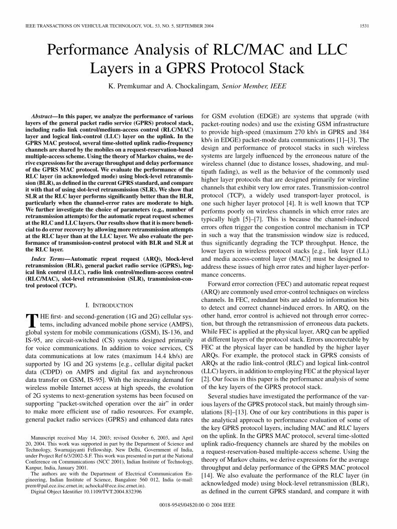
RLC Layer: The RLC layer is provided below the LLC layerand above the MAC layer [16]. The RLC peers are at the MS andthe base station system (BSS). On the transmit side, the RLClayer segments each LLC frame into several RLC data blocks(see Fig. 1). Each RLC data block occupies four time slots, ir-respective of the type of channel coding used. Coding schemesCS-1, CS-2, CS-3, and CS-4 are defined with rate-1/2, rate-2/3,rate-3/4, and rate-1 (i.e., no coding), respectively [16]. In thecase of coding scheme CS-1, each RLC block consists of 181 in-formation bits, 40 block-check-sequence (BCS) bits, and seventail/control bits. With single-slot operation [i.e., only one slotper GSM time-division multiple-access (TDMA) frame is al-lotted to a user], the information rate of coding scheme CS-1 is9.05 kb/s (i.e., 181 b in four TDMA frames, where each TDMAframe occupies 4.615 ms). Similarly, the maximum informa-tion rates possible using other coding schemes are 13.4 kb/s forCS-2, 15.6 kb/s for CS-3, and 21.4 kb/s for CS-4 (see Fig. 2).With multislot operation (i.e., allocation of up to eight slots in aTDMA frame to a user), these maximum possible informationrates are increased eight-fold.
Like the LLC, the RLC too can operate either in an acknowl-edged or unacknowledged mode. In the acknowledged mode,the RLC provides a selective repeat ARQ mechanism to re-cover erroneous RLC data blocks. A BCS is provided in each
PREMKUMAR AND CHOCKALINGAM: PERFORMANCE ANALYSIS OF RLC/MAC AND LLC LAYERS 1533
Fig. 2. RLC/MAC block structure and coding.
RLC data block to enable error detection. A RLC retransmissioncounter N3104, which keeps track of the number of times a RLCblock is retransmitted in the case of error, is defined [16]. TheRLC layer is allowed to attempt a maximum of N3104_MAXretransmissions to recover blocks in error. If an erroneous blockis not recovered within N3104_MAX retransmission attempts,then control is passed on to LLC to recover the error at the LLCframe level. In the RLC unacknowledged mode, there is no re-transmission of erroneous RLC data blocks. On the receive side,the RLC performs the reassembly of LLC frames.
MAC Layer: The GPRS MAC protocol operates on aslotted-ALOHA-based reservation protocol [16]. The MAClayer peers are at the MS and BSS. The MAC layer requests/re-serves resources in terms of the number of traffic data slots. TheMAC function provides arbitration between multiple mobilesattempting to transmit simultaneously and provides collisiondetection and recovery procedures.
The packet random-access channel (PRACH) is used by allthe mobiles, on a contention basis, for the purpose of sendingresource-request packets. Typically, TS0 slot in a GSM frameof eight slots can be used as PRACH. All mobiles are allowed totransmit on PRACH slots, following the slotted-ALOHA pro-tocol. Depending on the system load, the number of PRACHscan be increased. The packet data traffic channels (PDTCH),on the other hand, are used for the transfer of traffic datapackets. Resource requests are made by the mobiles in termsof the number of uplink PDTCH slots required. Based on theserequests, PDTCH slots are dynamically assigned to the mobilesby the base station (BS). Allocation can be done based oneither single-slot or multislot operation. If only one slot perTDMA frame is assigned to a user, then it is called single-slotoperation, whereas if more than one slot (up to eight slots) perTDMA frame is assigned to a user, then it is called multislotoperation.
When the MAC at the mobile side receives RLC data blocksto be transferred to the BS, it sends a request packet on the im-mediately following PRACH slot. The request packet indicates
, the number of PDTCH slots required. If the BS receives therequest packet without collision or channel errors and if PDTCHslots are available to honor the request, the BS informs the reser-vation information to the mobile on the downlink packet-ac-cess-grant channel (PAGCH) channel. The reservation informa-tion include the PDTCH frequency-time slots that can be usedby the mobile for data transfer. The mobile then sends data inthose reserved slots. On the other hand, if the request packetis lost (due to collision or channel errors) or if PDTCH slots arenot available, then the mobile will not get the reservation. Themobile will then reschedule its request packet-retransmission at-tempt to a later time (typically, after a random backoff time).
The MAC control parameters include MAX_RETRANS,PERSISTENCE_LEVEL, as defined in [16]. The MAC layercan send channel requests on the PRACH slots up to a max-imum of MAX RETRANS retransmission attempts inthe event of loss due to collision or channel errors. The delaybetween retransmission attempts is defined by the PERSIS-TENCE_LEVEL.
Thus, in summary, in terms of error recovery at differentlayers: 1) the MAC layer attempts to resolve collision of re-quest packets; 2) RLC layer attempts to recover RLC data blockerrors through a selective repeat ARQ mechanism; and 3) LLCattempts recovery of erroneous LLC frames through anotherARQ mechanism. Link errors unresolved at the LLC layer arepassed on to higher layers (e.g., transport layer) to resolve.
III. ANALYSIS OF GPRS MAC PROTOCOL
In this section, we present a Markov-chain-based analysis toevaluate the throughput and delay performance of the GPRS
1534 IEEE TRANSACTIONS ON VEHICULAR TECHNOLOGY, VOL. 53, NO. 5, SEPTEMBER 2004
Fig. 3. GPRS MAC protocol operation.
Fig. 4. MS state transition diagram.
MAC protocol. Consider a single-cell GPRS system with ,uplink channels and mobile users. Each channel cor-
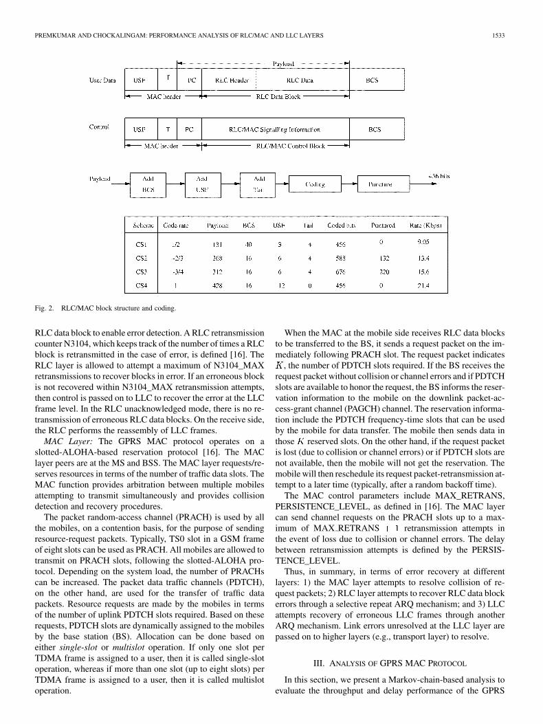
responds to a frequency-time slot pair in the MS-to-BS direc-tion. Out of channels, , , channels are usedas PRACHs and the remaining channels are used asPDTCHs. Typically, slot TS0 in all GSM TDMA frames on agiven frequency can form a PRACH. Likewise, on a given fre-quency, slot TS1 in all GSM TDMA frames can form PDTCH-1,slot TS2 can form PDTCH-2, and so on. We consider a single-slot operation in which only one slot per GSM TDMA frameis assigned to a user. For example, TS1 slots in consecutiveTDMA frames being assigned to a mo-bile for data transfer is a typical illustration of the single-slotoperation. Considering single-slot operation, all uplink chan-
nels can be modeled as synchronized slotted channels, as shownin Fig. 3. One request packet is one slot in size. One network(NW) layer PDU, including LLC/RLC headers and checksums,occupies several slots. Between the successful transmission ofa request packet on a PRACH slot and the corresponding datatransmission on the assigned PDTCH slots, some finite time iselapsed because of the propagation and processing delays in-volved. We are interested in analyzing the throughput and delayperformance of the GPRS MAC protocol. In order to carry outthe performance analysis, we assume the following.
1) NW layer PDU arrival process (hence, the new requestpacket generation process) is Bernoulli with arrival proba-bility in each slot. The number of LLC frames per NW layerPDU is assumed to be one. A new NW layer PDU is accepted
PREMKUMAR AND CHOCKALINGAM: PERFORMANCE ANALYSIS OF RLC/MAC AND LLC LAYERS 1535
only after the completion of the transfer of the previously ac-cepted NW layer PDU.2) Length of the NW layer PDU (including LLC/RLC
headers and checksums), measured in number of slots, isgeometrically distributed with parameter , .3) Loss of request packets on PRACH is only due to colli-
sion.4) Retransmission attempts of request packets following a
collision on PRACH (or nonavailability of PDTCH) are de-layed by geometrically distributed random delays with pa-rameter , . This parameter essentially modelsthe backoff delay (in the event of request packet loss), whichis characterized by the standards-defined parameter PERSIS-TENCE_LEVEL.5) Propagation and processing delays are assumed to be neg-
ligible. This assumption can be valid in our considered systemof single-slot operation in which the response from the BS cancome within one TDMA frame time itself.
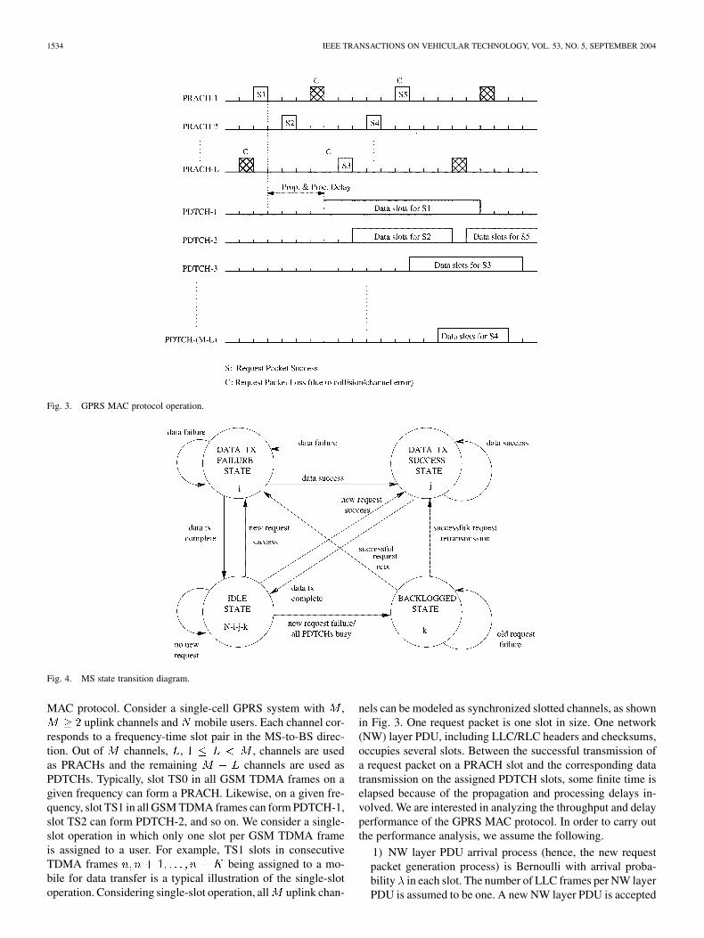
As per the GPRS MAC protocol and the system model de-scribed above, the mobile can be in any one of the followingstates in a slot, namely, the idle, backlogged, data_Tx_success,or data_Tx_failure states, as shown in Fig. 4. In the idle state,a mobile remains idle with probability and generatesa PDU with probability . If different mobiles send their re-quest packets on the same PRACH slot, then one or more re-quest packets can be received correctly, depending on the cap-ture probability. The mobiles who lost their request packets go tothe backlogged state. If a mobile’s request packet is successfullyreceived, but there are no available PDTCHs to serve the re-quest, then also the mobile goes to the backlogged state. On theother hand, if there are available PDTCHs to serve a successfullyreceived request, then the mobile goes to the data_Tx states,where it sends data on the assigned PDTCH slots. The data_Txstates include the data_Tx_success and data_Tx_failure states,corresponding to the transmission on a PDTCH slot being, re-spectively, a success or failure.
A. Throughput Analysis
Let represent the number of mobilesin the data_Tx_failure state, be thenumber of mobiles in the data_Tx_success state, and
be the number of mobiles in the backlogged state,at the beginning of slot . The three-dimensional (3-D) process
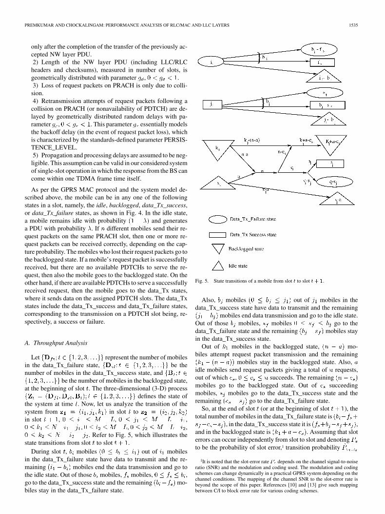
defines the state ofthe system at time . Now, let us analyze the transition of thesystem from in slot toin slot , , ,
, , ,. Refer to Fig. 5, which illustrates the
state transitions from slot to slot .During slot , mobiles out of mobiles
in the data_Tx_failure state have data to transmit and the re-maining mobiles end the data transmission and go tothe idle state. Out of those mobiles, mobiles, ,go to the data_Tx_success state and the remaining mo-biles stay in the data_Tx_failure state.
Fig. 5. State transitions of a mobile from slot t to slot t + 1.
Also, mobiles out of mobiles in thedata_Tx_success state have data to transmit and the remaining
mobiles end data transmission and go to the idle state.Out of those mobiles, mobiles go to thedata_Tx_failure state and the remaining mobiles stayin the data_Tx_success state.
Out of mobiles in the backlogged state, mo-biles attempt request packet transmission and the remaining
mobiles stay in the backlogged state. Also,idle mobiles send request packets giving a total of requests,out of which , succeeds. The remainingmobiles go to the backlogged state. Out of succeedingmobiles, mobiles go to the data_Tx_success state and theremaining go to the data_Tx_failure state.
So, at the end of slot (or at the beginning of slot ), thetotal number of mobiles in the data_Tx_failure state is
, in the data_Tx_success state it is ,and in the backlogged state is . Assuming that sloterrors can occur independently from slot to slot and denotingto be the probability of slot error,1 transition probability
1It is noted that the slot-error rate P depends on the channel signal-to-noiseratio (SNR) and the modulation and coding used. The modulation and codingschemes can change dynamically in a practical GPRS system depending on thechannel conditions. The mapping of the channel SNR to the slot-error rate isbeyond the scope of this paper. References [10] and [13] give such mappingbetween C/I to block error rate for various coding schemes.

1536 IEEE TRANSACTIONS ON VEHICULAR TECHNOLOGY, VOL. 53, NO. 5, SEPTEMBER 2004
can be written as shown in (1) at the bottom of the page where, is the number of requests sent, is the
number of successful requests in slot , ,, , , and
Prob ( successes given that requests are sent and thatPRACHs are available), which can be written as
cap (2)
where cap is the probability of capturing out of col-liding request packets. Equation (2) is terminated by fixing
cap . It is noted that the capture probabilityin the above can be obtained either by its analytical evalu-ation for a given channel model (for example, as derived in[17] and [18] for Rayleigh- and Rician-fading channels withlog-normal shadowing) or by using empirical capture models(for example, as given by the European TelecommunicationsStandards Institute (ETSI) in [19]), which has been used inseveral papers (e.g., [8]). In this paper, we use the empiricalcapture model given in the ETSI standard [19]. As in [19],we set cap , cap , cap ,cap , cap , cap ,cap for , and cap cap .
The above analysis assumes a large number of PDTCHs,so that a successful request always gets an assignment. If thenumber of PDTCHs is small compared to the number of users
, (i.e., ), then a successful request may not getan assignment, as all the PDTCHs may be busy. This eventoccurs if and
. This implies thatthe total number of idle channels . If
requests succeed in any time slot and the number of idle
channels is less than , then all requests arebacklogged. For those and satisfying the above condition,compute the probability and add to the corresponding
term calculated using (1). To do that, let represent thenumber of idle channels that is given by .represents the number of data transmissions ended during slot, which is given by , and
represents the new arrivals that are backlogged due to nonavail-ability of channels. The probability for the transitionfrom to is then given by
(3)
where , , , .Thus
(4)
The Markov chain has a finite numberof states and is positive recurrent [20]. Hence, it has a stationarysteady-state distribution and is found by solving
(5)
new arrivals
request packet transmissions from backlogged mobiles
out of continue to tx data out of go to success
out of continue to tx data out of go to failure
out of requests succeed and of go to success
(1)
PREMKUMAR AND CHOCKALINGAM: PERFORMANCE ANALYSIS OF RLC/MAC AND LLC LAYERS 1537
where , , ,is the steady-state probability vector. The
average system throughput is obtained as
(6)
The average per-channel throughput is then given by
(7)
B. Delay Analysis
Next, we derive the mean PDU transfer delay performance.The mean PDU transfer delay is defined as the averagenumber of slots elapsed from the slot where a PDU arrived tothe slot where the PDU transmission is complete. The numberof users in the nonidle state (i.e., data_Tx_failure, data_Tx_suc-cess, and backlogged states) contribute to the mean delay. Thereare nonidle users in the system and averagingit over steady-state distribution gives us
(8)
There are idle users and each will generate requestswith probability in each slot. The average arrival rate to thesystem is given by
(9)
From Little’s theorem, the average time an user spends in thesystem is given by the ratio between the number of users in thesystem to the average arrival rate. Hence
(10)
Note that the one in (10) is added to ensure that there is one slotdelay for the mobiles to enter into the nonidle state.
C. RLC Layer—Acknowledged Mode
Note that the analysis in Sections III-A and B corresponds tothe RLC/MAC protocol operation with RLC in the unacknowl-edged mode (i.e., there is no ARQ at the RLC). In the acknowl-edged mode, however, RLC retransmits erroneous data blocksusing a selective repeat ARQ mechanism. Each RLC data blockconsists of four slots. In our RLC layer analysis here, we con-sider a SLR mechanism by which a slot in error is repeatedlyretransmitted until it succeeds. This implies that the number ofretransmission attempts at the RLC layer is infinity. We derivethe throughput-delay performance of this SLR scheme as fol-lows.
Let the random variable represent the length of PDU innumber of slots and the random variable represent the numberof transmission attempts of the th slot until success. Thus, ,
the total number of slots required to successfully transmit a PDUof length slots, is given by
(11)
The distribution of is geometric (by assumption) and is givenby
(12)
and the distribution of [ ’s being independent and identi-cally distributed (i.i.d.), since we consider i.i.d. slot errors] isgiven by
(13)
where is the slot-error rate. The distribution of in (11) canbe evaluated using Transform techniques, as follows:
(14)
Therefore
(15)
Now, in order to obtain the average throughput and mean delayfor the RLC (acknowledged mode) with SLR, we need to simplychange the parameter to in (1) and (3).
Note that the above analysis is for infinite number of re-transmission attempts at the RLC with SLR. The effect of fi-nite number of retransmission attempts at the RLC with SLR isevaluated through simulations. Likewise, the performance usingBLR at RLC is also evaluated through simulations.

1538 IEEE TRANSACTIONS ON VEHICULAR TECHNOLOGY, VOL. 53, NO. 5, SEPTEMBER 2004
Fig. 6. RLC/MAC average per channel throughput � versus new request arrival probability �. N = 10, M = 10, L = 1, g = 0:1, and g = 0:1.
D. RLC/MAC Performance Results
In this section, we present the results and discussions of theGPRS RLC/MAC performance obtained through both of theanalyses above, as well as simulations. In Fig. 6, numerical re-sults for the average per-channel throughput of the RLC/MACprotocol, obtained from (7), for , , ,
, and are plotted as a function of the newrequest arrival probability . It is noted that the value of 0.1implies that the average backoff delay after collision is ten slots.Likewise, the value of 0.1 implies that the average lengthof the PDU measured in number of slots is 10. According tothe throughput computation in (7), the PRACH slots do notcontribute to the effective throughput. In other words, forchannels out of which channels are PRACH, the maximumcapacity is given by . The effect of slot errorswith/without RLC SLR is also plotted for a slot-error rate of10% (corresponding to poor channel conditions). These resultsare compared with the corresponding RLC BLR performanceobtained through simulation.
It is noted that the average per-channel throughput in Fig. 6gives the average number of successful slots and the averagenumber of successful blocks for slot level and block retrans-missions, respectively. In order to convert this normalizedthroughput to an equivalent data rate in kilobits/second, thenumber of information and control bits [including BCS andslot-check sequence (SCS) bits] defined in the various codingschemes CS-1, CS-2, CS-3, and CS-4 needs to be takeninto account. For example, when CS-1 is used, a normalizedper-channel throughput of, say, 0.45 corresponds to an effectivedata rate of 4.07 kb/s (i.e., 0.45 9.05 kb/s) for block-levelretransmission. For SLR, assuming 10 b of SCS in each slot,
TABLE IEFFECTIVE PER-CHANNEL THROUGHPUT (IN KILOBITS PER SECOND) FOR BLRVERSUS SLR FOR VARIOUS CODING SCHEMES. N = 10, M = 10, L = 1,
g = g = 0:1, � = 1, AND P = 10%. (SEE FIG. 6)
the effective data rate becomes 3.9 kb/s (i.e., 0.45 8.7 kb/s).Note that the maximum information rate of 8.7 kb/s in theabove is obtained as follows: Each slot carries 114 (rate 1/2)coded bits, so that 40 information bits, ten SCS bits, and sevencontrol bits constitute one slot before coding. Forty informationbits sent every 4.615 ms results in an effective information rateof 8.7 kb/s. The effective data rates for other coding schemesCS-2, CS-3, and CS-4 can be obtained likewise. It is noted thatwhen the slot-error rate is zero (or very low values of ) BLRperforms slightly better than SLR (i.e., maximum informationrate of 9.05 versus 8.7 kb/s), which is due to the increasedoverheads due to the tail/control bits in SLR. However, as wewill see subsequently, SLR performs much better than BLRwhen channel conditions are poor (moderate to high values of
).From Fig. 6 we observe that the throughput results obtained
from (7) closely match the results obtained through simulation(in fact, since there are no approximations involved in the anal-ysis, this close match is expected). It is observed that for lowvalues of new request arrival probability the system spendsmost time in the idle state, resulting in very low throughputs.For the case of , the average time duration between ar-rivals is and during this time interval the average number of
PREMKUMAR AND CHOCKALINGAM: PERFORMANCE ANALYSIS OF RLC/MAC AND LLC LAYERS 1539
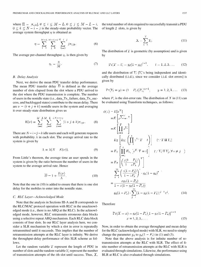
Fig. 7. Mean PDU transfer delay (in number of slots) at RLC/MAC versus new request arrival probability �.N = 10,M = 10,L = 1, g = 0:1, and g = 0:1.
successful slots are given by . Thus, the average per channelthroughput is given by
For , , , , and , is0.09, which is very close to the value shown in Fig. 6. As in-creases, the fraction of time the system spends in the idle statedecreases, which results in increased throughput. When thereare no slot errors (i.e., ), all the slots carrying datatraffic are successful, which represents the best possible perfor-mance. For example, for the per-channel throughputachieved is 0.09 (i.e., an effective data rate of 666 b/s usingcoding scheme CS-1) and for values closer to unity the per-channel throughput increases to 0.54 (4 kb/s using CS-1).
It is noted that the “No Retx” plot in Fig. 6 corresponds toGPRS MAC with RLC in the unacknowledged mode of oper-ation. For high slot-error rates (say, ), when thereare no RLC retransmissions, the fraction of successful slots de-creases and, hence, the throughput decreases. On the other hand,for the same slot-error rate (of 10%), SLR at the RLC improvesthe throughput performance. This is because the fraction of timethe channel is left idle is reduced due to the retransmission at-tempts. As long as the slot-error rate is reasonably good, thiswould result in increased throughput. Another observation inFig. 6 is that the throughput achieved with BLR at the RLCis much lower than the SLR. This is because, in BLR, even ifone slot in a block is in error, the entire block (of four slots)will be retransmitted; this considerably reduces the throughput.For example, for high arrival rates , the normalizedper-channel throughput , achieved using BLR, is 0.46 (effec-tive data rate of 4.16 kb/s using CS-1), whereas SLR achievesa per-channel throughput of 0.52 (effective data rate of 4.52
kb/s using CS-1). Likewise, for these SLR and BLR throughputvalues at , the effective data rate (in kilobits per second)achieved using CS-2, CS-3, and CS-4 are computed and givenin Table I, from which it is observed that gains in throughput arepossible with SLR as compared to BLR.
The mean PDU transfer delay performance of the GPRSRLC/MAC protocol is evaluated using (10) for the same setof parameters used in Fig. 6. The mean PDU transfer delay innumber of slots is plotted in Fig. 7 as a function of . In thecase of No Retx (i.e., the RLC unacknowledged mode), it takesthe same number of slots to carry the traffic as in the no-errorcase. Hence, the delay is the same for both the no-error caseas well as the error case with no retransmission. The delay forSLR increases as it takes more slots to successfully deliver thedata slots. In BLR, since the entire block gets retransmittedeven if one slot in a block is in error, the delay performance isworse than SLR. For example, for values near unity the meandelay is 19 slots for SLR and 23 slots for BLR.
The effect of the number of channels on the throughputcharacteristics of the RLC/MAC protocol is shown in Fig. 8for , , , , and . Thetotal number of channels is varied in the range from two toten. From Fig. 8, we observe the following. The per-channelthroughput increases as increases, up to a certain a value of
, beyond which the throughput decreases. This is because,at low values of , requests are backlogged due to the non-availability of PDTCHs, whereas PDTCHs are idle most of thetime at high values of . More interestingly, around the op-timum value of for the chosen set of parameters and trafficload, SLR significantly outperforms BLR. For example, when
, BLR gives a per-channel throughput of 0.47, whereasSLR gives 0.64. The mean PDU transfer delay performance forthe same set of parameters used in Fig. 8 is illustrated in Fig. 9.

1540 IEEE TRANSACTIONS ON VEHICULAR TECHNOLOGY, VOL. 53, NO. 5, SEPTEMBER 2004
Fig. 8. RLC/MAC average per-channel throughput � versus number of channels M . N = 10, L = 1, � = 1, g = 0:1, and g = 0:1.
Fig. 9. Mean PDU transfer delay at RLC/MAC versus number of channels M . N = 10, L = 1, � = 1, g = 0:1, and g = 0:1.
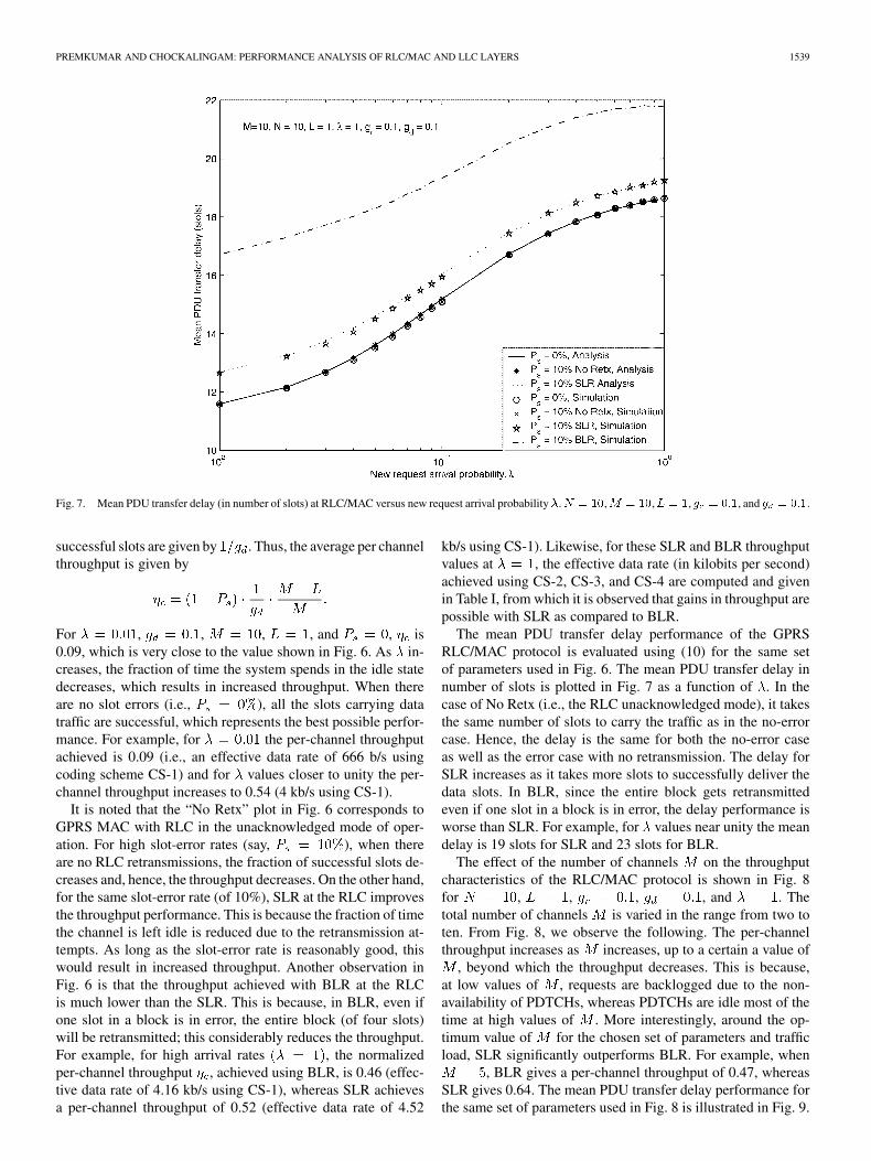
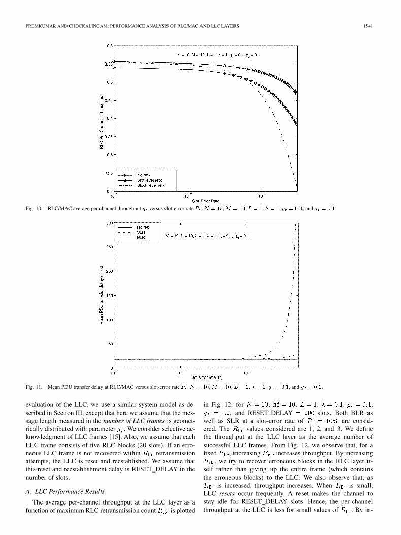
The effect of slot-error rate on the per-channel throughputand delay performance is shown in Figs. 10 and 11, for ,
, , , and . The plot shows the per-formance of RLC in unacknowledged mode (No Retx) as wellas the RLC in acknowledged mode with SLR and BLR. As ex-pected, the per-channel throughput decreases as the slot-errorrate increases. As mentioned before, when the slot-error rate issmall (good channel condition), BLR performs slightly betterthan SLR due to a larger number of overhead bits in SLR as com-pared to BLR. However, as the slot-error rate increases, BLRperforms more poorly than even the unacknowledged mode.This is because even if one slot goes into error, all the four slotsof a block are retransmitted. Also, SLR is found to significantlyoutperform both unacknowledged mode and BLR. This perfor-mance gain is more when the slot-error rate is high. Thus, from
Fig. 6–9, we observe that significant improvement in throughputand delay performance is possible using SLR instead of the BLRdefined in the GPRS standard.
IV. LLC AND TCP PERFORMANCE
In this section, we evaluate the throughput of the LLC andTCP, with the RLC/MAC layers below, through simulations.We consider the LLC acknowledged mode of operation. Of par-ticular interest here from the performance point of view is theeffect and optimum choice of the maximum LLC retransmis-sion count (LLC parameter N200 defined in the standard)and the maximum RLC retransmission count (RLC param-eter N3104_MAX defined in the standard). In the performance
PREMKUMAR AND CHOCKALINGAM: PERFORMANCE ANALYSIS OF RLC/MAC AND LLC LAYERS 1541
Fig. 10. RLC/MAC average per channel throughput � versus slot-error rate P . N = 10, M = 10, L = 1, � = 1, g = 0:1, and g = 0:1.
Fig. 11. Mean PDU transfer delay at RLC/MAC versus slot-error rate P . N = 10, M = 10, L = 1, � = 1, g = 0:1, and g = 0:1.
evaluation of the LLC, we use a similar system model as de-scribed in Section III, except that here we assume that the mes-sage length measured in the number of LLC frames is geomet-rically distributed with parameter . We consider selective ac-knowledgment of LLC frames [15]. Also, we assume that eachLLC frame consists of five RLC blocks (20 slots). If an erro-neous LLC frame is not recovered within retransmissionattempts, the LLC is reset and reestablished. We assume thatthis reset and reestablishment delay is RESET_DELAY in thenumber of slots.
A. LLC Performance Results
The average per-channel throughput at the LLC layer as afunction of maximum RLC retransmission count is plotted
in Fig. 12, for , , , , ,, and RESET DELAY slots. Both BLR as
well as SLR at a slot-error rate of are consid-ered. The values considered are 1, 2, and 3. We definethe throughput at the LLC layer as the average number ofsuccessful LLC frames. From Fig. 12, we observe that, for afixed , increasing increases throughput. By increasing
, we try to recover erroneous blocks in the RLC layer it-self rather than giving up the entire frame (which containsthe erroneous blocks) to the LLC. We also observe that, as
is increased, throughput increases. When is small,LLC resets occur frequently. A reset makes the channel tostay idle for RESET_DELAY slots. Hence, the per-channelthroughput at the LLC is less for small values of . By in-

1542 IEEE TRANSACTIONS ON VEHICULAR TECHNOLOGY, VOL. 53, NO. 5, SEPTEMBER 2004
Fig. 12. LLC average per-channel throughput versus maximum number of RLC retransmissions R . N = 10, M = 10, L = 1, � = 0:1, P = 10%,g = 0:1, and g = 0:2.
Fig. 13. Mean PDU transfer delay at LLC versus the maximum number of RLC retransmissions R . N = 10, M = 10, L = 1, � = 0:1, P = 10%,g = 0:1, and g = 0:2.
creasing , we try to avoid too many resets, which resultsin a better throughput.
The delay performance at the LLC layer for the same systemparameter values in Fig. 12 is plotted in Fig. 13. When both
and are small, the LLC resets will occur frequently,which will increase the PDU transfer delay. Thus, for small ,the delay performance improves by increasing . Whenis large enough (e.g., ), the delay performance for
2 or 3 is approximately the same. This is because most ofthe erroneous RLC blocks are recovered at the RLC layer itselfand fewer errors are being passed to the LLC to recover. FromFigs. 12 and 13, it can be seen that improved throughput and
delay performance are achieved at the LLC layer using SLR atthe RLC than using BLR.
The effect of slot-error rate on the per-channel throughputand delay performance at the LLC is shown in Figs. 14 and 15,again for the same system parameter values in Fig. 12. Fig. 14shows the throughput performance for and fortaking values one and for both BLR and SLR. Note that
and corresponds to no error recovery atRLC at complete recovery at LLC. Also, corre-sponds to complete recovery at RLC (and no recovery at LLC).From Figs. 14 and 15, we can infer that SLR performs signifi-cantly better than BLR in terms of both throughput and delay.

PREMKUMAR AND CHOCKALINGAM: PERFORMANCE ANALYSIS OF RLC/MAC AND LLC LAYERS 1543
Fig. 14. LLC average per-channel throughput versus slot-error rate P . N = 10, M = 10, L = 1, � = 0:1, g = 0:1, and g = 0:2.
Fig. 15. Mean PDU transfer delay at LLC versus slot-error rate P . N = 10,M = 10, L = 1, � = 0:1, g = 0:1, and g = 0:2.
From the average LLC throughput , shown in Figs. 12and 14, we can compute the effective data rate at LLC in kilobitsper second using the relation
kb/s (16)
where represents the number of information bits in eachRLC block including the LLC header and checksum. FL rep-resents the LLC frame length in terms of the number of RLCblocks, BL represents the RLC block length in terms of numberof slots, and OH represents the number of overhead bits per LLC
frame. Note that the 4.615 in the denominator of the above ex-pression accounts for the one slot duration, which is equivalentto one TDMA frame length of 4.615 ms. For the coding schemeCS-1, b for BLR and b for SLR. In oursimulations, we set FL and BL for BLR and FLand BL for SLR. The overhead bits OH corresponds toLLC header and checksum bits. Note that in Fig. 14corresponds to full recovery in the RLC layer. This means thatthe per-channel throughput is the same at both RLC and LLClayers, but the effective data rates in kb/s are different. For SLR(see Fig. 14), the per-channel throughput at is 0.77,which corresponds to an effective data rate of 6.19 kb/s at the

1544 IEEE TRANSACTIONS ON VEHICULAR TECHNOLOGY, VOL. 53, NO. 5, SEPTEMBER 2004
Fig. 16. Evolution of the TCP window size W [i] versus the slot index i. M = 2, N = 20, L = 1, R = 3, K = 3, P = 7%, and W = 24 TCPpackets. rto=5000 slots.
LLC layer. The corresponding effective data rate at the RLClayer is given by 6.68 kb/s.
B. TCP Performance Results
TCP is a well-known transport-layer protocol in the IP suite[4]. TCP is a reliable connection-oriented protocol that iswidely used in popular applications such as http, ftp, telnet,etc. Several studies have analyzed the performance of TCPon wireless, but without considering ARQ in the link layer[5]–[7]. The performance of TCP with an RLP at the link layerin IS-95A code-division multiple-access (CDMA) system hasbeen studied in [21]. In this section, we estimate the throughputperformance of TCP on the GPRS uplink with the associatedLLC/RLC/MAC layers. Being a connection-oriented protocol,TCP has call-setup, data-transfer, and call-clear phases. Thebulk throughput performance of TCP is determined primarilyby the data-transfer phase. In this study, we are interested inevaluating the TCP throughput in the data-transfer phase andfollow the TCP data-transfer phase model described in [6].
We consider an ON–OFF traffic model, such as the web ande-mail traffic. Internet traffic typically exhibits a significantprobability for long sessions and long interarrival times betweensessions and packets. This leads to heavy-tailed (long-tailed)complementary cumulative distribution functions (ccdfs) forthese typical measures [22]. Much work is done to find asuitable description of Internet traffic. A common approach isto approximate the empirical heavy-tailed ccdfs with Pareto,Weibull, hyperexponential, or power law distributions. Sucha theoretical distribution allows the easy implementation of agenerator that produces values of the described measure witha similar characteristic. In our simulations, to evaluate the per-formance of TCP over GPRS, we consider each TCP source to
generate a traffic pattern in which the interarrival time betweenpackets (i.e., the OFF period) follows a Pareto distribution.The classical Pareto distribution with shape parameter andlocation parameter has the cumulative distribution function(cdf)
(17)
with the corresponding probability density function (pdf). We model the ON period to consist of a
geometrically distributed number of TCP packets. We assumethat one TCP packet consists of five LLC frames and that eachLLC frame contains 536 B. An LLC frame is segmented into 25RLC blocks, each four slots in size. An erroneous RLC blockcan be retransmitted up to times by the ARQ mechanismat the RLC layer. If the RLC layer cannot recover the erroneousblocks, they are passed on to the LLC layer. The ARQ mech-anism at the LLC layer then tries to recover erroneous LLCframes by retransmission up to times. TCP takes care ofthe unrecovered erroneous LLC frames. We simulated 20 TCPsessions from mobile users (i.e., ), each sending TCPpackets to some hosts in an external packet-data network andevaluated the performance. The ON times of the sessions havea mean of five TCP packets. The Tahoe version of TCP with afast retransmit threshold of is used in the simulations[7].
Fig. 16 shows the evolution of TCP window size as afunction of time for a slot-error rate of , ,
, , , maximum window size ofTCP packets, and a round trip timeout (rto) value of 5000

PREMKUMAR AND CHOCKALINGAM: PERFORMANCE ANALYSIS OF RLC/MAC AND LLC LAYERS 1545
Fig. 17. TCP throughput performance as a function of P and R .M = 2,N = 20, L = 1, R = 3,K = 3, andW = 24 TCP packets. rto=5000slots.
slots. The window evolution of four different cases are plottedas follows.
1) BLR with .2) BLR with .3) SLR with .4) SLR with .
In Fig. 16, a comparison between versus forboth BLR and SLR indicates that the TCP window size is moreopen for than . This is because forthe recovery of erroneous blocks can be incomplete, whichcan result in more TCP timeouts and fast retransmits, whichshrinks the TCP window size to 1. Since larger instantaneouswindow widths are good for achieving higher throughput, thechoice of parameter value is preferred over .Also, a comparison between the window evolutions for BLRand SLR with reveals that the SLR results in largerinstantaneous window widths as compared to BLR. This largerinstantaneous window widths in SLR directly translate intohigher TCP throughput compared to BLR, which is illustratedin Fig. 17. From Fig. 17, we observe that as is increased,TCP throughput increases as expected. When is large,more erroneous blocks are retransmitted and recovered in theRLC layer itself, rather than leaving them to LLC or TCP torecover by retransmitting the LLC frame or the entire TCPpacket. From the TCP throughput values plotted in Fig. 17,
, we can compute the effective data rate in kb/s at the TCPlayer using the relation
kb/s (18)
where represents the number of information bits in eachRLC block including the IP/LLC headers and checksum,represents the TCP packet length in terms of number of LLCframes, FL represents the LLC frame length in terms of the
number of RLC blocks, BL represents the RLC block lengthin terms of number of GSM slots, and OH represents the totalnumber of overhead bits per TCP packet (IP header, LLCheader/checksum). The 4.615 in the denominator of the aboveexpression accounts for the one-slot duration that is equivalentto one TDMA frame length of 4.615 ms. For the coding schemeCS-1, 181 for BLR and 40 for SLR. In oursimulations, we set PL 5, FL 25, and BL 4 for BLR andPL 5, FL 100, and BL 1 for SLR. The number of OH bitsper TCP packet is 376 (320 IP header bits 56 LLC overheadbits). In Fig. 17, for the TCP throughput is 0.1021for BLR, which corresponds to an effective date rate of 0.93kb/s at the TCP layer. For the same system parameters, forSLR, the TCP throughput is 0.7087, which corresponds to aneffective date rate of 6.02 kb/s at the TCP layer. Thus, there isa substantial improvement in the effective data rate at the TCPlayer as we go from block level to SLR at the RLC, particularlyfor moderate-to-high channel-error rates.
V. CONCLUSION
We analyzed the performance of various layers(TCP/LLC/RLC/MAC) of the GPRS protocol stack. Usingthe theory of Markov chains, we derived the throughput anddelay performance of the GPRS MAC protocol. We showedthat the SLR scheme at the RLC layer performs better than theBLR defined in the standard. We investigated the interactionbetween the ARQs at the RLC and LLC layers; in particular,we studied the effect of the choice of the maximum number ofretransmission attempts allowed at the RLC and LLC layers.Our performance results showed that it is more beneficial to doerror recovery by allowing more retransmissions at the RLClayer than at the LLC layer. We also evaluated the performanceof TCP with BLR and SLR at the RLC layer and showedthat TCP performed better with SLR than compared to with

1546 IEEE TRANSACTIONS ON VEHICULAR TECHNOLOGY, VOL. 53, NO. 5, SEPTEMBER 2004
BLR. As further investigation, the performance analysis canbe further extended for correlated channel errors, multislotoperation in GPRS, and EGPRS. Performance analysis on thedownlink is another topic for further investigation.
REFERENCES
[1] G. Brasche and B. Walke, “Concepts, services, and protocols of the newGSM phase 2+ general packet radio service,” IEEE Commun. Mag., vol.35, pp. 94–104, Aug. 1997.
[2] C. Bettstetter, H. J. Vögel, and J. Eberspächer. (1999) GSMphase 2+ general packet radio service GPRS: Architecture, pro-tocols, and air interface. IEEE Commun. Surv. [Online], pp.2–14. Available: http://www.comsoc.org/livepubs/surveys/public/3q99issue/bettstetter.html
[3] A. Furuskar, S. Mazur, F. Muller, and H. Olofsson, “EDGE: Enhanceddata rates for GSM and TDMA/136 evolution,” IEEE Pers. Commun.Mag., vol. 6, pp. 56–66, June 1999.
[4] W. R. Stevens, TCP/IP Illustrated. Reading, MA: Addison-Wesley,1994, vol. 1.
[5] T. V. Lakshman and U. Madhow, “The performance of TCP/IP fornetworks with high bandwidth-delay products and random loss,”IEEE/ACM Trans. Networking, vol. 5, pp. 336–350, June 1997.
[6] A. Kumar, “Comparative performance analysis of versions of TCP in alocal network with a lossy link,” ACM/IEEE Trans. Networking, vol. 6,pp. 485–498, Aug. 1998.
[7] M. Zorzi, A. Chockalingam, and R. R. Rao, “Throughput analysis ofTCP on channels with memory,” IEEE J. Select. Areas Commun., vol.18, pp. 1289–1300, July 2000.
[8] J. Cai and D. J. Goodman, “General packet radio service in GSM,” IEEECommun. Mag., vol. 35, pp. 122–131, Oct. 1997.
[9] G. Brasche and B. Walke, “Analysis of multi-slot MAC protocols pro-posed for the GSM phase 2+ general packet radio service,” in Proc.IEEE Vehicular Technology Conf. (VTC’97), 1997, pp. 1295–1300.
[10] S. Hoff, M. Meyer, and A. Schieder, “A performance evaluation of in-ternet access via the general packet radio service of GSM,” in Proc. IEEEVehicular Technology Conf. (VTC’98), vol. 3, May 1998, pp. 1760–1764.
[11] Y. Argyropoulos, A. Bigloo, and J. van Peursem, “GPRS delay andcapacity analysis for web browsing application,” in Proc. Int. Conf.Telecommunications, vol. 2, 1998, pp. 32–36.
[12] C. Demeterscu, “LLC-MAC analysis of general packet radio service inGSM,” Bell Lab.s Tech. J., pp. 37–50, 1999.
[13] R. Kalden, I. Meirick, and M. Meyer, “Wireless internet access based onGPRS,” IEEE Pers. Commun. Mag., vol. 7, pp. 8–18, Apr. 2000.
[14] K. Premkumar and A. Chockalingam, “Performance analysis ofRLC/MAC protocol in general packet radio service,” in Proc. Na-tional Conf. Communications (NCC’01), Kanpur, India, Jan. 2001, pp.173–177.
[15] Digital cellular telecommunications system (phase 2+); Generalpacket radio service (GPRS); mobile station-serving GPRS supportnode (MS-SGSN) logical link control (LLC) layer specification (GSM04.64). European Telecommunications Standards Institute (ETSI)TC-SMG GPRS ad hoc, Sophia Antipolis, France. [Online]. Available:http://www.etsi.org/
[16] Digital cellular telecommunications system (phase 2+); GeneralPacket radio service (GPRS); mobile station (MS)-BSS interface;radio link control/medium access control (RLC/MAC) protocol (GSM04.60). European Telecommunications Standards Institute (ETSI)TC-SMG GPRS ad hoc, Sophia Antipolis, France. [Online]. Available:http://www.etsi.org/
[17] M. Zorzi and R. R. Rao, “Capture and retransmission control in mobileradio,” IEEE J. Select. Areas Commun., vol. 12, pp. 1289–1298, Oct.1994.
[18] M. Zorzi, “Capture probabilities in random-access mobile communica-tions in the presence of Rician fading,” IEEE Trans. Veh. Technol., vol.46, pp. 96–101, Feb. 1997.
[19] Evaluation criteria for the GPRS radio channel Tdoc 56/95. EuropeanTelecommunications Standards Institute (ETSI) SMG2 GPRS ad hoc,Sophia Antipolis, France. [Online]. Available: http://www.etsi.org/
[20] R. W. Wolff, Stochastic Modeling and the Theory of Queues. Engle-wood Cliffs, NJ: Prentice-Hall, 1989.
[21] A. Chockalingam and G. Bao, “Performance of TCP/RLP protocolstack on correlated Rayleigh fading DS-CDMA links,” IEEE Trans.Veh. Technol., vol. 49, pp. 28–33, Jan. 2000.
[22] V. Paxson and S. Floyd, “Wide-area traffic: The failure of poisson mod-eling,” IEEE/ACM Trans. Networking, pp. 226–244, June 1995.
K. Premkumar was born in Chennai, India, onDecember 27, 1975. He received the B.E. degreein electronics and communication engineering fromthe Alagappa Chettiar College of Engineering andTechnology, Karaikkudi, India, in 1997 and theM.S. (research) degree in electrical communicationengineering from the Indian Institute of Science,Bangalore, in 2002.
From August 2001 to September 2003, he was withMotorola India, Bangalore, where he was involved inthe design and development of 3G systems and mul-
tiuser receivers. Since September 2003, he has been with the Indian Institute ofScience, doing research in MIMO multiuser information theory. His researchinterests include the performance analysis of wireless communications and net-works, power control, transmit diversity, and multiuser information theory.
A. Chockalingam (S’93–M’95–SM’98) receivedthe B.E. (Hons.) degree in electronics and com-munication engineering from the P. S. G. Collegeof Technology, Coimbatore, India, in 1984, theM.Tech. degree (with a specialization in satellitecommunications) from the Indian Institute of Tech-nology, Kharagpur, in 1985, and the Ph.D. degree inelectrical communication engineering (ECE) fromthe Indian Institute of Science (IISc), Bangalore,India, in 1993.
From 1986 to 1993, he was with the TransmissionR & D Division, Indian Telephone Industries Ltd., Bangalore. From December1993 to May 1996, he was a Postdoctoral Fellow and an Assistant Project Sci-entist in the Department of Electrical and Computer Engineering, Universityof California, San Diego (UCSD). From May 1996 to December 1998, he wasin the Systems Engineering Group, Qualcomm Inc., San Diego, CA, as a StaffEngineer/Manager. In December 1998, he joined the Faculty in the Departmentof Electrical Communication Engineering, IISc, where he is an Associate Pro-fessor, working in the area of wireless communications and networks. He wasa Visiting Faculty with UCSD during the summers of 1999–2002.
Dr. Chockalingam is a Recipient of the Swarnajayanti Fellowship from theDepartment of Science and Technology, New Delhi, India. He is an AssociateEditor for the IEEE TRANSACTIONS ON VEHICULAR TECHNOLOGY.


![IEEE TRANSACTIONS ON VEHICULAR TECHNOLOGY … · IEEE TRANSACTIONS ON VEHICULAR TECHNOLOGY 1 The Feasibility of Interference Alignment Over ... [18] to accommodate](https://img.pdfslide.net/doc/110x75/5ac9fc857f8b9a6b578d617b/ieee-transactions-on-vehicular-technology-transactions-on-vehicular-technology.jpg)